KR20150075008A - Cleaner - Google Patents
Cleaner Download PDFInfo
- Publication number
- KR20150075008A KR20150075008A KR1020140045033A KR20140045033A KR20150075008A KR 20150075008 A KR20150075008 A KR 20150075008A KR 1020140045033 A KR1020140045033 A KR 1020140045033A KR 20140045033 A KR20140045033 A KR 20140045033A KR 20150075008 A KR20150075008 A KR 20150075008A
- Authority
- KR
- South Korea
- Prior art keywords
- impeller
- return channel
- inner frame
- unit
- blades
- Prior art date
- Legal status (The legal status is an assumption and is not a legal conclusion. Google has not performed a legal analysis and makes no representation as to the accuracy of the status listed.)
- Granted
Links
Images


Classifications
-
- A—HUMAN NECESSITIES
- A47—FURNITURE; DOMESTIC ARTICLES OR APPLIANCES; COFFEE MILLS; SPICE MILLS; SUCTION CLEANERS IN GENERAL
- A47L—DOMESTIC WASHING OR CLEANING; SUCTION CLEANERS IN GENERAL
- A47L9/00—Details or accessories of suction cleaners, e.g. mechanical means for controlling the suction or for effecting pulsating action; Storing devices specially adapted to suction cleaners or parts thereof; Carrying-vehicles specially adapted for suction cleaners
- A47L9/22—Mountings for motor fan assemblies
-
- A—HUMAN NECESSITIES
- A47—FURNITURE; DOMESTIC ARTICLES OR APPLIANCES; COFFEE MILLS; SPICE MILLS; SUCTION CLEANERS IN GENERAL
- A47L—DOMESTIC WASHING OR CLEANING; SUCTION CLEANERS IN GENERAL
- A47L9/00—Details or accessories of suction cleaners, e.g. mechanical means for controlling the suction or for effecting pulsating action; Storing devices specially adapted to suction cleaners or parts thereof; Carrying-vehicles specially adapted for suction cleaners
- A47L9/0081—Means for exhaust-air diffusion; Means for sound or vibration damping
-
- F—MECHANICAL ENGINEERING; LIGHTING; HEATING; WEAPONS; BLASTING
- F04—POSITIVE - DISPLACEMENT MACHINES FOR LIQUIDS; PUMPS FOR LIQUIDS OR ELASTIC FLUIDS
- F04D—NON-POSITIVE-DISPLACEMENT PUMPS
- F04D29/00—Details, component parts, or accessories
- F04D29/40—Casings; Connections of working fluid
- F04D29/42—Casings; Connections of working fluid for radial or helico-centrifugal pumps
- F04D29/4206—Casings; Connections of working fluid for radial or helico-centrifugal pumps especially adapted for elastic fluid pumps
- F04D29/4226—Fan casings
-
- F—MECHANICAL ENGINEERING; LIGHTING; HEATING; WEAPONS; BLASTING
- F04—POSITIVE - DISPLACEMENT MACHINES FOR LIQUIDS; PUMPS FOR LIQUIDS OR ELASTIC FLUIDS
- F04D—NON-POSITIVE-DISPLACEMENT PUMPS
- F04D29/00—Details, component parts, or accessories
- F04D29/40—Casings; Connections of working fluid
- F04D29/42—Casings; Connections of working fluid for radial or helico-centrifugal pumps
- F04D29/44—Fluid-guiding means, e.g. diffusers
- F04D29/441—Fluid-guiding means, e.g. diffusers especially adapted for elastic fluid pumps
- F04D29/444—Bladed diffusers
-
- F—MECHANICAL ENGINEERING; LIGHTING; HEATING; WEAPONS; BLASTING
- F04—POSITIVE - DISPLACEMENT MACHINES FOR LIQUIDS; PUMPS FOR LIQUIDS OR ELASTIC FLUIDS
- F04D—NON-POSITIVE-DISPLACEMENT PUMPS
- F04D29/00—Details, component parts, or accessories
- F04D29/60—Mounting; Assembling; Disassembling
- F04D29/62—Mounting; Assembling; Disassembling of radial or helico-centrifugal pumps
- F04D29/624—Mounting; Assembling; Disassembling of radial or helico-centrifugal pumps especially adapted for elastic fluid pumps
- F04D29/626—Mounting or removal of fans
-
- A—HUMAN NECESSITIES
- A47—FURNITURE; DOMESTIC ARTICLES OR APPLIANCES; COFFEE MILLS; SPICE MILLS; SUCTION CLEANERS IN GENERAL
- A47L—DOMESTIC WASHING OR CLEANING; SUCTION CLEANERS IN GENERAL
- A47L2201/00—Robotic cleaning machines, i.e. with automatic control of the travelling movement or the cleaning operation
-
- F—MECHANICAL ENGINEERING; LIGHTING; HEATING; WEAPONS; BLASTING
- F05—INDEXING SCHEMES RELATING TO ENGINES OR PUMPS IN VARIOUS SUBCLASSES OF CLASSES F01-F04
- F05D—INDEXING SCHEME FOR ASPECTS RELATING TO NON-POSITIVE-DISPLACEMENT MACHINES OR ENGINES, GAS-TURBINES OR JET-PROPULSION PLANTS
- F05D2250/00—Geometry
- F05D2250/50—Inlet or outlet
- F05D2250/52—Outlet
Landscapes
- Engineering & Computer Science (AREA)
- Mechanical Engineering (AREA)
- General Engineering & Computer Science (AREA)
- Structures Of Non-Positive Displacement Pumps (AREA)
- Nozzles For Electric Vacuum Cleaners (AREA)
Abstract
청소성능을 향상시킬 수 있도록 개선된 구조를 가지는 청소기를 개시한다. 본 발명의 사상에 따른 청소기는 공기를 본체 내부로 흡입하기 위한 흡입력을 발생시키는 흡입유닛을 포함하고, 상기 흡입유닛은 회전 가능한 임펠러(IMPELLER), 흡기구가 형성되는 임펠러 커버(IMPELLER COVER) 및 내부에 상기 임펠러를 수용하도록 상기 임펠러 커버와 결합하는 리턴 채널(RETURN CHANNEL)을 포함하고, 상기 리턴 채널은 이너 프레임(INNER FRAME) 및 상기 이너 프레임과 이격되도록 상기 이너 프레임의 외측에 위치하는 아우터 프레임(OUTER FRAME)을 포함하고, 상기 이너 프레임 및 상기 아우터 프레임의 사이에는 복수의 날개가 배치되는 것을 특징으로 한다.Disclosed is a vacuum cleaner having an improved structure for improving cleaning performance. The vacuum cleaner according to the present invention includes a suction unit for generating a suction force for sucking air into the main body. The suction unit includes a rotatable impeller, an impeller cover having an inlet port, And a return channel coupled to the impeller cover to receive the impeller, wherein the return channel includes an inner frame and an outer frame located outside the inner frame to be spaced apart from the inner frame And a plurality of blades are disposed between the inner frame and the outer frame.
Description
본 발명은 청소기에 관한 것으로, 상세하게는 청소성능을 향상시킬 수 있도록 개선된 구조를 가지는 청소기에 관한 것이다.BACKGROUND OF THE
일반적으로 청소기는 피청소면의 오물을 포함한 공기를 흡입한 후, 공기로부터 오물을 분리하여 수거하고, 정화된 공기는 본체 외부로 배출하는 장치이다.Generally, a vacuum cleaner sucks air containing dirt on a surface to be cleaned, separates and collects dirt from the air, and discharges the purified air to the outside of the main body.
이러한 청소기는 그 형태별로 본체와 흡입노즐이 분리되어 소정의 관으로 연결되는 캐니스터(Canister) 방식과, 흡입노즐과 본체가 하나로 마련되는 업라이트(Up-right)방식으로 구별된다.Such a cleaner is divided into a canister type in which the main body and the suction nozzle are separated from each other by a predetermined pipe, and an up-right type in which the suction nozzle and the main body are provided in one.
최근에는 사용자의 조작 없이도 청소하고자 하는 영역을 스스로 주행하면서 바닥면으로부터 먼지 등의 이물질을 흡입함으로써, 청소하고자 하는 영역을 자동으로 청소하는 로봇 청소기가 각광받고 있다.In recent years, a robot cleaner has been spotlighted for automatically cleaning an area to be cleaned by suctioning foreign substances such as dust from the floor surface while traveling the area to be cleaned without user's operation.
청소기는 흡입력을 결정하는 구성 요소로써, 임펠러(IMPELLER), 디퓨저(DIFFUSER) 및 과류 제거 장치(DESWIRLER)를 포함할 수 있다.The cleaner is a component that determines the suction force and may include an impeller, a diffuser, and a deswirler.
본체 내부로 흡입된 공기는 수 차례 구부러진 유로를 따라 임펠러, 디퓨저 및 과류 제거 장치를 차례로 통과한다. 이 과정에서, 공기의 압력손실이 증가하게 되고, 압력손실에 따른 흡입력 감소를 보완하기 위해 임펠러 및 디퓨저의 간격을 좁게 설계한다. 그러나 임펠러 및 디퓨저의 간격을 좁게 할수록 압력섭동에 의한 소음이 발생할 수 있다. 소음을 방지하기 위해서는 임펠러 및 임펠러에 결합되는 모터의 크기를 증가시킬 수 있으나, 이 경우 청소기의 크기 또한 증가되므로 컴팩트(COMPACT)한 제품을 요하는 최근 시장 추세에 부합하지 않는다.The air sucked into the main body flows through the impeller, the diffuser, and the superfluidizer in turn along the bent flow path several times. In this process, the pressure loss of the air increases, and the spacing between the impeller and the diffuser is designed to be narrow to compensate for the reduction of the suction force due to the pressure loss. However, as the gap between the impeller and the diffuser is narrowed, noise due to pressure perturbation may occur. In order to prevent noise, the size of the motor coupled to the impeller and the impeller can be increased, but the size of the cleaner is also increased, so that it does not meet the recent market trend requiring a compact product.
본 발명의 일 측면은 흡입력을 향상시킬 수 있도록 개선된 구조를 가지는 청소기를 제공한다.One aspect of the present invention provides a vacuum cleaner having an improved structure for improving a suction force.
본 발명의 다른 일 측면은 소형화 내지 컴팩트(COMPACT)화가 가능하도록 개선된 구조를 가지는 청소기를 제공한다.Another aspect of the present invention provides a vacuum cleaner having an improved structure capable of miniaturization and compacting.
본 발명의 또 다른 일 측면은 소음을 방지할 수 있도록 개선된 구조를 가지는 청소기를 제공한다.Another aspect of the present invention provides a vacuum cleaner having an improved structure to prevent noise.
본 발명의 또 다른 일 측면은 제조가 용이하도록 개선된 구조를 가지는 청소기를 제공한다.Another aspect of the present invention provides a vacuum cleaner having an improved structure for facilitating manufacture.
본 발명의 사상에 따른 청소기는 공기를 본체 내부로 흡입하기 위한 흡입력을 발생시키는 흡입유닛을 포함하고, 상기 흡입유닛은 회전 가능한 임펠러(IMPELLER), 흡기구가 형성되는 임펠러 커버(IMPELLER COVER) 및 내부에 상기 임펠러를 수용하도록 상기 임펠러 커버와 결합하는 리턴 채널(RETURN CHANNEL)을 포함하고, 상기 리턴 채널은 이너 프레임(INNER FRAME) 및 상기 이너 프레임과 이격되도록 상기 이너 프레임의 외측에 위치하는 아우터 프레임(OUTER FRAME)을 포함하고, 상기 이너 프레임 및 상기 아우터 프레임의 사이에는 복수의 날개가 배치되는 것을 특징으로 한다.The vacuum cleaner according to the present invention includes a suction unit for generating a suction force for sucking air into the main body. The suction unit includes a rotatable impeller, an impeller cover having an inlet port, And a return channel coupled to the impeller cover to receive the impeller, wherein the return channel includes an inner frame and an outer frame located outside the inner frame to be spaced apart from the inner frame And a plurality of blades are disposed between the inner frame and the outer frame.
상기 리턴 채널은 상기 임펠러를 통과한 공기가 유입될 수 있도록 상기 임펠러에 직결될 수 있다.The return channel may be directly connected to the impeller so that air passing through the impeller may be introduced.
상기 복수의 날개는 상기 임펠러의 축방향(X)에 대하여 경사를 형성할 수 있다.The plurality of blades may form an inclination with respect to the axial direction (X) of the impeller.
상기 임펠러는 제 1방향(H)을 향하여 회전하고, 상기 복수의 날개는 상기 임펠러의 축방향(X)에 대하여 상기 제 1방향(H)과 반대방향인 제 2방향(I)을 따라 경사를 형성할 수 있다.The impeller rotates in a first direction (H) and the plurality of blades are inclined in a second direction (I) opposite to the first direction (H) with respect to the axial direction (X) of the impeller .
상기 복수의 날개는 곡면을 포함할 수 있다.The plurality of blades may include a curved surface.
상기 복수의 날개는 서로 이격되어 상기 임펠러를 통과한 공기가 이동하는 배출유로를 형성하고, 상기 배출유로는 상기 임펠러를 향하는 일 단부에 형성되는 입구 및 상기 입구와 이격되도록 다른 단부에 형성되는 출구를 포함하고, 상기 입구를 통해 상기 배출유로로 유입된 공기는 상기 출구를 통해 상기 흡입유닛의 외측으로 토출되는 것을 특징으로 한다.Wherein the plurality of blades are spaced apart from each other to form an exhaust passage through which the air having passed through the impeller moves, the exhaust passage having an inlet formed at one end portion facing the impeller and an outlet formed at another end portion spaced apart from the inlet portion And the air introduced into the discharge passage through the inlet is discharged to the outside of the suction unit through the outlet.
상기 임펠러 커버는 상기 임펠러를 통과한 공기를 상기 입구로 가이드하도록 상기 아우터 프레임에 결합하는 가이드부를 포함하고, 상기 가이드부는 곡면을 가질 수 있다.The impeller cover includes a guide portion coupled to the outer frame to guide the air passing through the impeller to the inlet, and the guide portion may have a curved surface.
상기 가이드부는 상기 임펠러 커버의 외측을 향하여 볼록하고, 곡률 반지름이 1mm 이상인 곡면을 가질 수 있다.The guide portion may be convex toward the outside of the impeller cover, and may have a curved surface having a radius of curvature of 1 mm or more.
상기 복수의 날개는 상기 이너 프레임의 외면과 마주하고, 시작점(M)을 포함하는 제 1면 및 상기 아우터 프레임의 내면과 마주하고, 상기 시작점(M)과 함께 상기 입구를 형성하는 시작점(N)을 포함하는 제 2면을 포함할 수 있다.Wherein the plurality of vanes face the outer surface of the inner frame and have a first surface including a starting point M and a starting point N facing the inner surface of the outer frame and forming the inlet with the starting point M, And a second surface including the second surface.
상기 제 1면의 시작점(M) 및 상기 제 2면의 시작점(N)을 연결하는 직선(A)은 상기 임펠러의 축방향(X)에 대하여 5ㅀ이상 85ㅀ이하의 경사를 형성할 수 있다.The straight line A connecting the starting point M of the first surface and the starting point N of the second surface may form an inclination of 5 to 85 에 with respect to the axial direction X of the impeller .
상기 임펠러의 축방향(X)에 대하여 수직을 이루는 수평방향(Y)으로 상기 리턴 채널을 자른 단면(Q) 상에서, 상기 임펠러 커버를 향하는 상기 제 1면의 일 단부 및 상기 제 2면의 일 단부를 연결한 직선(B)이 상기 리턴 채널의 중심 및 상기 임펠러 커버를 향하는 상기 제 1면의 일 단부를 연결한 직선(C)과 이루는 각도(θ)는 0ㅀ이상 80ㅀ이하인 것을 특징으로 한다.On one end of the first surface facing the impeller cover and on one end of the second surface facing the impeller cover on a cross section Q of the return channel cut in a horizontal direction Y perpendicular to the axial direction X of the impeller, And the straight line connecting the center of the return channel and the one end of the first surface facing the impeller cover is not less than 0 and not more than 80 ㅀ .
상기 제 2면의 시작점(N)은 상기 제 1면의 시작점(M)보다 상기 임펠러 커버를 향하여 더 연장될 수 있다.The starting point N of the second surface may be further extended toward the impeller cover than the starting point M of the first surface.
상기 복수의 날개는 상기 제 1면의 시작점(M) 및 상기 제 2면의 시작점(N)을 연결하는 연결부를 더 포함하고, 상기 연결부는 곡면 및 평면 중 적어도 하나를 포함할 수 있다.The plurality of blades may further include a connecting portion connecting a starting point (M) of the first surface and a starting point (N) of the second surface, and the connecting portion may include at least one of a curved surface and a flat surface.
상기 연결부는 상기 제 1면의 시작점(M) 및 상기 제 2면의 시작점(N) 중 적어도 하나보다 상기 임펠러 커버를 향하여 더 연장되는 최고점을 포함할 수 있다.The connecting portion may include a peak that further extends toward the impeller cover than at least one of a starting point (M) of the first surface and a starting point (N) of the second surface.
상기 흡입유닛은 상기 임펠러가 회전할 수 있는 원동력을 제공하도록 상기 임펠러와 결합하는 모터축을 가지고, 상기 리턴 채널의 내부에 마련되는 모터를 더 포함할 수 있다.The suction unit may further include a motor provided inside the return channel, having a motor shaft coupled with the impeller to provide a driving force for rotating the impeller.
본 발명의 사상에 따른 청소기는 공기를 본체 내부로 흡입하기 위한 흡입력을 발생시키는 흡입유닛을 포함하고, 상기 흡입유닛은 회전 가능한 임펠러(IMPELLER), 흡기구가 형성되는 임펠러 커버(IMPELLER COVER) 및 내부에 상기 임펠러를 수용하도록 상기 임펠러 커버와 결합하고, 상기 임펠러를 통과한 공기가 유입될 수 있도록 상기 임펠러에 직결되는 리턴 채널(RETURN CHANNEL)을 포함하고, 상기 리턴 채널은 서로 분리 가능한 복수의 유닛이 결합되어 형성되는 것을 특징으로 한다.The vacuum cleaner according to the present invention includes a suction unit for generating a suction force for sucking air into the main body. The suction unit includes a rotatable impeller, an impeller cover having an inlet port, And a return channel coupled to the impeller cover to receive the impeller and directly connected to the impeller to allow air passing through the impeller to flow therethrough, wherein the return channel includes a plurality of units detachable from each other, Is formed.
상기 복수의 유닛은 상기 임펠러의 축방향(X)에 대하여 경사를 형성하도록 분리 가능한 것을 특징으로 한다.And the plurality of units are separable so as to form an inclination with respect to the axial direction (X) of the impeller.
상기 복수의 유닛은 상기 임펠러의 축방향(X)에 대하여 수직을 이루는 수평방향(Y)으로 분리 가능한 것을 특징으로 한다.And the plurality of units are separable in a horizontal direction (Y) perpendicular to the axial direction (X) of the impeller.
상기 리턴 채널은 이너 프레임(INNER FRAME), 상기 이너 프레임과 이격되도록 상기 이너 프레임의 외측에 위치하는 아우터 프레임(OUTER FRAME) 및 상기 이너 프레임 및 상기 아우터 프레임의 사이에 배치되는 복수의 날개를 포함하고, 상기 복수의 유닛은 상기 임펠러의 축방향(X)에 대하여 수직을 이루는 수평방향(Y)으로 분리 가능한 것을 특징으로 한다.The return channel may include an inner frame, an outer frame positioned outside the inner frame to be spaced apart from the inner frame, and a plurality of blades disposed between the inner frame and the outer frame, , And the plurality of units are separable in a horizontal direction (Y) perpendicular to the axial direction (X) of the impeller.
상기 복수의 날개는 상기 임펠러의 축방향(X)에 대하여 경사를 형성하고, 곡면을 포함할 수 있다.The plurality of blades may form a slope with respect to the axial direction (X) of the impeller, and may include a curved surface.
상기 리턴 채널은 상기 복수의 유닛을 결합시키는 적어도 하나의 회전방지유닛을 더 포함할 수 있다.The return channel may further include at least one anti-rotation unit coupling the plurality of units.
상기 적어도 하나의 회전방지유닛은 서로 이격되도록 상기 리턴 채널의 내측에 형성될 수 있다.The at least one anti-rotation unit may be formed inside the return channel to be spaced apart from each other.
상기 복수의 유닛은 상기 임펠러를 통과한 공기가 이동하는 방향(G)의 상류측에 위치하는 제 1유닛 및 상기 임펠러를 통과한 공기가 이동하는 방향(G)의 하류측에 위치하는 제 2유닛을 포함하고, 상기 적어도 하나의 회전방지유닛은 상기 제 1유닛 및 상기 제 2유닛 중 어느 하나의 내측에 마련되는 돌기를 포함할 수 있다.Wherein the plurality of units includes a first unit positioned on an upstream side of a direction (G) in which air passing through the impeller moves, and a second unit positioned on a downstream side of a direction (G) And the at least one rotation preventing unit may include a protrusion provided inside one of the first unit and the second unit.
상기 적어도 하나의 회전방지유닛은 상기 제 1유닛 및 상기 제 2유닛 중 다른 하나의 내측에 마련되고, 상기 돌기와 분리 가능하도록 결합하는 체결부를 더 포함할 수 있다.The at least one rotation preventing unit may further include a fastening part provided inside the other one of the first unit and the second unit and detachably coupled to the projection.
본 발명의 사상에 따른 청소기는 공기를 본체 내부로 흡입하기 위한 흡입력을 발생시키는 흡입유닛을 포함하고, 상기 흡입유닛은 회전 가능한 임펠러(IMPELLER), 흡기구가 형성되는 임펠러 커버(IMPELLER COVER) 및 내부에 상기 임펠러를 수용하도록 상기 임펠러 커버와 결합하고, 상기 임펠러를 통과한 공기가 유입될 수 있도록 상기 임펠러에 직결되는 리턴 채널(RETURN CHANNEL)을 포함하고, 상기 리턴 채널에는 상기 임펠러의 축방향(X)에 대하여 경사를 형성하는 복수의 날개가 배치될 수 있다.The vacuum cleaner according to the present invention includes a suction unit for generating a suction force for sucking air into the main body. The suction unit includes a rotatable impeller, an impeller cover having an inlet port, And a return channel coupled to the impeller cover to receive the impeller and directly connected to the impeller so that air passing through the impeller can be introduced into the impeller, A plurality of vanes may be disposed to form an inclination with respect to the base.
상기 복수의 날개는 곡면을 포함할 수 있다.The plurality of blades may include a curved surface.
상기 임펠러는 제 1방향(H)을 향하여 회전하고, 상기 복수의 날개는 상기 임펠러의 축방향(X)에 대하여 상기 제 1방향(H)과 반대방향인 제 2방향(I)을 따라 경사를 형성할 수 있다.The impeller rotates in a first direction (H) and the plurality of blades are inclined in a second direction (I) opposite to the first direction (H) with respect to the axial direction (X) of the impeller .
상기 리턴 채널은 이너 프레임(INNER FRAME) 및 상기 이너 프레임과 이격되도록 상기 이너 프레임의 외측에 위치하는 아우터 프레임(OUTER FRAME)을 포함하고, 상기 복수의 날개는 상기 이너 프레임 및 상기 아우터 프레임의 사이에 배치될 수 있다.Wherein the return channel includes an inner frame and an outer frame positioned outside the inner frame so as to be spaced apart from the inner frame, and the plurality of blades are disposed between the inner frame and the outer frame .
리턴 채널에 임펠러의 축방향(X)에 대하여 경사를 형성하는 복수의 날개를 배치함으로써, 유로의 구부러진 형상을 감소시킬 수 있고, 그에 따라 공기의 압력손실을 줄일 수 있어 청소기의 흡입력을 향상시킬 수 있다.The bent shape of the flow path can be reduced and the pressure loss of the air can be reduced by arranging a plurality of vanes that form a slope in the return channel with respect to the axial direction X of the impeller to improve the suction force of the vacuum cleaner have.
디퓨저 역할을 겸하는 리턴 채널을 사용함으로써 리턴 채널 및 임펠러 사이의 간격을 기존 디퓨저 및 임펠러 사이의 간격보다 증가시킬 수 있고, 그에 따라 압력섭동에 의해 발생하는 청소기의 소음을 줄일 수 있다.By using a return channel that also serves as a diffuser, the gap between the return channel and the impeller can be increased above the gap between the existing diffuser and the impeller, thereby reducing the noise of the vacuum cleaner caused by pressure perturbations.
임펠러의 축방향(X)에 대하여 경사를 형성하는 복수의 날개가 배치되는 리턴 채널을 사용함으로써 청소기의 흡입력을 향상시킴과 동시에 청소기의 소형화를 도모할 수 있다.The suction force of the vacuum cleaner can be improved and the size of the vacuum cleaner can be reduced by using the return channel in which a plurality of vanes forming an inclination with respect to the axial direction X of the impeller are disposed.
서로 분리 가능한 복수의 유닛을 결합하여 리턴 채널을 형성함으로써 청소기의 제조 내지 양산 용이성을 향상시킬 수 있다.By combining a plurality of detachable units to form a return channel, it is possible to improve the ease of manufacturing or mass production of the vacuum cleaner.
도 1은 본 발명의 일 실시예에 따른 청소기의 외관을 도시한 도면
도 2는 본 발명의 일 실시예에 따른 청소기의 제2하우징의 외측 하우징을 제거한 상태를 도시한 평면도
도 3은 본 발명의 일 실시예에 따른 청소기의 제1하우징과 제2하우징의 외측 하우징 및 먼지통을 제거한 상태를 도시한 평면도
도 4는 본 발명의 일 실시예에 따른 청소기의 흡입유닛을 도시한 사시도
도 5는 본 발명의 일 실시예에 따른 청소기의 흡입유닛 분해사시도
도 6은 본 발명의 일 실시예에 따른 청소기의 흡입유닛 일부를 상부에서 도시한 도면
도 7은 본 발명의 일 실시예에 따른 청소기의 흡입유닛에 있어서, 리턴 채널에 마련되는 복수의 날개를 도시한 도면
도 8은 본 발명의 일 실시예에 따른 청소기의 흡입유닛에 있어서, 리턴 채널에 마련되는 복수의 날개 및 적어도 하나의 서브 날개를 도시한 도면
도 9는 본 발명의 일 실시예에 따른 청소기의 흡입유닛을 정면에서 도시한 도면
도 10은 본 발명의 일 실시예에 따른 청소기의 흡입유닛 일부를 확대하여 도시한 단면도
도 11은 본 발명의 일 실시예에 따른 청소기의 흡입유닛에 있어서, 리턴채널의 제 1유닛을 하부에서 도시한 도면
도 12는 본 발명의 일 실시예에 따른 청소기의 흡입유닛에 있어서, 리턴채널의 제 2유닛을 상부에서 도시한 도면
도 13a 및 13b는 본 발명의 일 실시예에 따른 청소기의 흡입유닛에 있어서, 리턴채널의 제 1유닛 및 제 2유닛의 결합구조를 도시한 단면도
도 14는 본 발명의 일 실시예에 따른 청소기의 흡입유닛에 있어서, 노즈콘을 포함하는 구조를 도시한 도면
도 15는 본 발명의 다른 실시예에 따른 청소기의 외관을 도시한 도면
도 16은 본 발명의 다른 실시예에 따른 청소기의 본체를 도시한 단면도
도 17은 본 발명의 다른 실시예에 따른 청소기의 흡입유닛을 도시한 사시도
도 18은 본 발명의 다른 실시예에 따른 청소기의 흡입유닛 분해사시도
도 19는 본발명의 다른 실시예에 따른 청소기의 흡입유닛 일부를 확대하여 도시한 사시도
도 20은 본 발명의 다른 실시예에 따른 청소기의 흡입유닛 단면도
도 21은 본 발명의 다른 실시예에 따른 청소기의 흡입유닛 일부를 확대하여 도시한 단면도
도 22는 본 발명의 다른 실시예에 따른 청소기의 흡입유닛의 다른 일부를 확대하여 도시한 단면도
도 23은 본 발명의 다른 실시예에 따른 청소기에 있어서, 이너 프레임 및 아우터 프레임 사이에 배치되는 복수의 날개의 일부를 도시한 도면
도 24a 내지 도 24p는 도 23의 복수의 날개의 연결부의 다양한 형상을 측면에서 개략적으로 도시한 도면
도 25는 본 발명의 다른 실시예에 따른 청소기의 흡입유닛 측면도
도 26은 본 발명의 다른 실시예에 따른 청소기에 있어서, 임펠러의 회전방향과 같은 방향으로 기울어진 복수의 날개를 확대하여 도시한 단면도
도 27은 본 발명의 다른 실시예에 따른 청소기에 있어서, 임펠러의 회전방향과 반대방향으로 기울어진 복수의 날개를 확대하여 도시한 단면도
도 28은 본 발명의 다른 실시예에 따른 청소기의 냉각구조의 제 1실시예를 도시한 사시도
도 29는 본 발명의 다른 실시예에 따른 청소기의 냉각구조의 제 2실시예를 도시한 사시도
도 30은 도 29의 냉각구조의 제 2실시예를 도시한 단면도
도 31은 본 발명의 다른 실시예에 따른 청소기의 냉각구조의 제 3실시예를 도시한 단면도
도 32는 본 발명의 다른 실시예에 따른 청소기의 냉각구조의 제 4실시예를 도시한 단면도
도 33은 본 발명의 다른 실시예에 따른 청소기의 냉각구조의 제 5실시예를 도시한 단면도
도 34는 본 발명의 다른 실시예에 따른 청소기에 있어서, 복수의 날개의 배치구조의 제 1실시예를 도시한 단면도
도 35는 도 34를 수평방향(Y)으로 절단한 일부 도면
도 36은 본 발명의 다른 실시예에 따른 청소기에 있어서, 복수의 날개의 배치구조의 제 2실시예를 도시한 도면
도 37은 본 발명의 다른 실시예에 따른 청소기에 있어서, 복수의 날개의 배치구조의 제 3실시예를 도시한 도면
도 38은 본 발명의 또 다른 실시예에 따른 청소기의 흡입유닛 단면도
도 39는 본 발명의 또 다른 실시예에 따른 청소기의 본체를 도시한 단면도
도 40은 본 발명의 또 다른 실시예에 따른 청소기의 흡입유닛을 도시한 사시도
도 41은 본 발명의 또 다른 실시예에 따른 청소기의 흡입유닛 분해사시도
도 42는 본 발명의 또 다른 실시예에 따른 청소기의 흡입유닛 일부를 확대하여 도시한 사시도
도 43은 본 발명의 또 다른 실시예에 따른 청소기의 흡입유닛 단면도
도 44는 본 발명의 또 다른 실시예에 따른 청소기의 흡입유닛 일부를 확대하여 도시한 단면도
도 45는 본 발명의 또 다른 실시예에 따른 청소기의 복수의 날개 일부를 확대하여 도시한 단면도
도 46은 제 1면의 시작점(M) 및 제 2면의 시작점(N)을 연결하는 직선(A)의 임펠러의 축방향(X)에 대한 경사도 및 본 발명의 일 실시예에 따른 청소기의 흡입력 사이의 관계를 나타내는 그래프
도 47은 임펠러의 축방향(X)에 대하여 수직을 이루는 수평방향(Y)으로 리턴 채널을 자른 단면(Q)상에서, 제 1면의 일 단부 및 제 2면의 일 단부를 연결한 직선(B)과 리턴 채널의 중심 및 제 1면의 일 단부를 연결한 직선(C)이 이루는 각도 및 본 발명의 일 실시예에 따른 청소기의 흡입력 사이의 관계를 나타내는 그래프1 is a view showing an appearance of a vacuum cleaner according to an embodiment of the present invention;
2 is a plan view showing a state in which the outer housing of the second housing of the vacuum cleaner according to the embodiment of the present invention is removed;
3 is a plan view showing a state in which the outer housing and the dust container of the first housing and the second housing of the vacuum cleaner according to the embodiment of the present invention are removed;
4 is a perspective view illustrating a suction unit of a vacuum cleaner according to an embodiment of the present invention.
5 is an exploded perspective view of the suction unit of the vacuum cleaner according to the embodiment of the present invention.
6 is a top view of a suction unit of a vacuum cleaner according to an embodiment of the present invention.
7 is a view showing a plurality of vanes provided on a return channel in a suction unit of a vacuum cleaner according to an embodiment of the present invention;
8 is a view illustrating a suction unit of a vacuum cleaner according to an embodiment of the present invention, in which a plurality of blades and at least one sub-
9 is a front view of the suction unit of the vacuum cleaner according to the embodiment of the present invention.
10 is an enlarged cross-sectional view of a part of the suction unit of the vacuum cleaner according to the embodiment of the present invention.
Fig. 11 is a view of the suction unit of the vacuum cleaner according to the embodiment of the present invention, showing the first unit of the return channel
12 shows a suction unit of a vacuum cleaner according to an embodiment of the present invention,
13A and 13B are cross-sectional views showing the coupling structure of the first unit and the second unit of the return channel in the suction unit of the vacuum cleaner according to the embodiment of the present invention
14 is a view showing a structure including a nosecone in a suction unit of a vacuum cleaner according to an embodiment of the present invention
15 is a view showing the appearance of a vacuum cleaner according to another embodiment of the present invention
16 is a cross-sectional view showing the main body of the vacuum cleaner according to another embodiment of the present invention
17 is a perspective view showing a suction unit of a vacuum cleaner according to another embodiment of the present invention.
18 is an exploded perspective view of the suction unit of the vacuum cleaner according to another embodiment of the present invention.
19 is an enlarged perspective view of a suction unit of a vacuum cleaner according to another embodiment of the present invention.
20 is a sectional view of the suction unit of the vacuum cleaner according to another embodiment of the present invention
21 is an enlarged cross-sectional view of a part of the suction unit of the vacuum cleaner according to another embodiment of the present invention
22 is an enlarged cross-sectional view of another portion of the suction unit of the vacuum cleaner according to another embodiment of the present invention;
23 is a view showing a part of a plurality of vanes arranged between an inner frame and an outer frame in a vacuum cleaner according to another embodiment of the present invention
24A to 24P schematically show various shapes of connection portions of the plurality of blades of Fig. 23 from the side; Fig.
25 is a side view of the suction unit of the vacuum cleaner according to another embodiment of the present invention
26 is a cross-sectional view of an enlarged view of a plurality of vanes inclined in the same direction as the direction of rotation of the impeller, according to another embodiment of the present invention.
27 is a cross-sectional view of an enlarged view of a plurality of vanes inclined in a direction opposite to the rotating direction of the impeller, according to another embodiment of the present invention.
28 is a perspective view showing a first embodiment of a cooling structure of a vacuum cleaner according to another embodiment of the present invention.
29 is a perspective view showing a second embodiment of a cooling structure of a vacuum cleaner according to another embodiment of the present invention.
Fig. 30 is a sectional view showing a second embodiment of the cooling structure of Fig. 29
31 is a sectional view showing a third embodiment of the cooling structure of a vacuum cleaner according to another embodiment of the present invention
32 is a sectional view showing a fourth embodiment of a cooling structure of a vacuum cleaner according to another embodiment of the present invention
33 is a cross-sectional view showing a fifth embodiment of a cooling structure of a vacuum cleaner according to another embodiment of the present invention
34 is a cross-sectional view showing a first embodiment of the arrangement structure of a plurality of vanes in a vacuum cleaner according to another embodiment of the present invention
Fig. 35 is a partial plan view of Fig. 34 taken along the horizontal direction (Y)
36 is a view showing a second embodiment of the arrangement structure of a plurality of vanes in a vacuum cleaner according to another embodiment of the present invention
37 is a view showing a third embodiment of the arrangement structure of a plurality of vanes in a vacuum cleaner according to another embodiment of the present invention
38 is a sectional view of the suction unit of the vacuum cleaner according to another embodiment of the present invention
39 is a cross-sectional view illustrating a main body of a vacuum cleaner according to another embodiment of the present invention
40 is a perspective view showing a suction unit of a vacuum cleaner according to another embodiment of the present invention;
41 is an exploded perspective view of the suction unit of the vacuum cleaner according to another embodiment of the present invention.
42 is an enlarged perspective view of a suction unit of a vacuum cleaner according to another embodiment of the present invention.
43 is a sectional view of the suction unit of the cleaner according to another embodiment of the present invention
FIG. 44 is an enlarged cross-sectional view of a suction unit of a vacuum cleaner according to another embodiment of the present invention; FIG.
45 is an enlarged cross-sectional view of a plurality of wings of a cleaner according to another embodiment of the present invention;
FIG. 46 is a view showing the inclination of the impeller of the straight line A connecting the starting point M of the first surface and the starting point N of the second surface with respect to the axial direction X and the suction force of the cleaner according to the embodiment of the present invention Graph showing the relationship between
Fig. 47 is a cross-sectional view showing a cross section Q on which a return channel is cut in a horizontal direction Y perpendicular to the axial direction X of the impeller, and a straight line B connecting one end of the first surface and one end of the second surface ) And the straight line C connecting the center of the return channel and one end of the first surface and the suction force of the vacuum cleaner according to an embodiment of the present invention
이하에서는 본 발명에 따른 바람직한 실시예를 첨부된 도면을 참조하여 상세히 설명한다.Hereinafter, preferred embodiments of the present invention will be described in detail with reference to the accompanying drawings.
아래의 설명에서 사용된 용어 "선단", "후단", "상부", "하부", "상단" 및 "하단" 등은 도면을 기준으로 정의한 것이며, 이 용어에 의하여 각 구성요소의 형상 및 위치가 제한되는 것은 아니다.The terms "tip", "rear end", "upper", "lower", "upper" and "lower", etc. used in the following description are defined with reference to the drawings, Is not limited.
도 1은 본 발명의 일 실시예에 따른 청소기의 외관을 도시한 도면이다.1 is a view showing an appearance of a vacuum cleaner according to an embodiment of the present invention.
도 1에 도시된 바와 같이, 청소기는 로봇 청소기(1000)를 포함할 수 있다. 로봇 청소기(1000)는 외관을 형성하는 본체와, 본체의 외관의 적어도 일부분을 형성하는 하우징(300)을 포함할 수 있다.As shown in FIG. 1, the vacuum cleaner may include a
하우징(300)은 전방에 형성되는 제1하우징(400)과, 제1하우징(400)의 후방에 형성되는 제2하우징(500)을 포함할 수 있다. 제1하우징(400)과 제2하우징(500)의 사이에는 제1하우징(400)과 제2하우징(500)을 연결시키는 연결부재(600)가 위치할 수 있다.The
제2하우징(500)에는 먼지를 저장하도록 구성되는 집진 유닛(530)이 결합될 수 있다. 집진 유닛(530)은 먼지를 흡입하는 동력을 제공하는 흡입유닛(100)과, 흡입된 먼지를 저장하는 집진통(510)을 포함할 수 있다.The
집진통(510)에는 사용자가 파지할 수 있도록 오목하게 마련되는 파지부(511)가 마련될 수 있다. 사용자는 파지부(511)를 파지하여 집진통(510)을 회전시켜 제2하우징(500)으로부터 집진통(510)을 분리할 수 있다. 집진통(510)을 분리하여 사용자는 집진통(510) 내의 누적된 먼지를 제거할 수 있다. 제2하우징(500)의 측면에는 본체를 구동시키는 구동 유닛이 마련될 수 있다. 구동 유닛은 본체의 주행을 위한 구동휠(540)과, 본체의 주행 부하를 최소화하기 위해 회전이 가능하도록 마련되는 롤러(미도시)를 포함할 수 있다. 구동휠(540)은 제2하우징(500)의 양 측면에 결합될 수 있다.The
제1하우징(400)에는 바닥의 먼지를 쓸어 담도록 구성되는 브러시 유닛(미도시)이 마련될 수 있다. 제1하우징(400)의 전면부에는 로봇청소기(1b)의 주행 시, 로봇청소기(1b)가 벽면에 부딪혀 발생하는 소음과 충격을 완화하기 위한 범퍼(700)가 결합될 수 있다. 또한, 범퍼(700)에는 별도의 완충부재(710)가 결합될 수 있다.The
제1하우징(400)의 상면에는 진입 차단 센서(720)가 돌출되도록 마련될 수 있다. 진입 차단 센서(720)는 적외선을 감지하여 소정의 구간에 로봇청소기(1b)가 진입하는 것을 방지할 수 있다. 진입 차단 센서(720)는 제1하우징(400)의 양측에 마련될 수 있다.An
도 2는 본 발명의 일 실시예에 따른 청소기의 제2하우징의 외측 하우징을 제거한 상태를 도시한 평면도이고, 도 3은 본 발명의 일 실시예에 따른 청소기의 제1하우징과 제2하우징의 외측 하우징 및 먼지통을 제거한 상태를 도시한 평면도이다.FIG. 2 is a plan view showing a state where the outer housing of the second housing of the vacuum cleaner according to the embodiment of the present invention is removed, FIG. 3 is a side view of the first and second housings of the vacuum cleaner according to the embodiment of the present invention, Fig. 6 is a plan view showing a state where the housing and the dust container are removed. Fig.
도 2 및 도 3에 도시된 바와 같이, 제 2하우징(500)의 내측에는 본체를 구동시키기 위한 전력을 공급하는 전원유닛(550)이 결합될 수 있다. 전원유닛(550)은 배터리(미도시)와, 메인보드(551)와, 메인보드(551)의 상측에 위치하며 로봇 청소기(1000)의 상태를 표시하는 디스플레이부(미도시)를 포함할 수 있다. 전원유닛(550)은 집진 유닛(530)의 후방에 위치하도록 배치될 수 있다.As shown in FIGS. 2 and 3, a
배터리(미도시)는 재충전이 가능한 2차 배터리로 마련되며, 본체가 청소 과정을 완료하고 도킹스테이션(미도시)에 결합된 경우 도킹스테이션(미도시)로부터 전력을 공급받아 충전된다.The battery (not shown) is provided with a rechargeable secondary battery. When the main body completes the cleaning process and is coupled to a docking station (not shown), the battery is charged with power from a docking station (not shown).
집진통(510)을 제거하면 먼지를 흡입하여 집진통(510) 내부로 이동시키기 위한 송풍팬(미도시)이 마련될 수 있다. 송풍팬의 작동으로 인하여 집진통(510)에 먼지가 누적되고 사용자는 집진통(510)을 분리하여 먼지를 용이하게 배출시킬 수 있다. When the
흡입유닛(100b)은 흡입 유닛 하우징(미도시)의 내측에 위치할 수 있다. 흡입유닛(100b)은 집진통(510)의 측면에 결합될 수 있다. 본 발명의 일 실시예에 따르면, 구동휠(540)은 집진통(510)과 흡입유닛(100b)의 각각의 측면에 배치될 수 있다. 즉 구동휠(540)은 제1구동휠(541)과 제2구동휠(542)을 포함할 수 있다. 제1구동휠(541)은 흡입유닛(100b)의 측면에 배치되고, 제2구동휠(542)은 집진통(510)의 측면에 배치될 수 있다.The
이에 따라, 집진통(510), 흡입유닛(100b) 및 구동휠(540)은 본체의 횡방향으로 배치될 수 있다. 즉, 집진통(510), 흡입유닛(100b) 및 구동휠(540)은 일직선에 근접하도록 배치될 수 있다.Accordingly, the
흡입유닛(100b)에 대한 상세한 설명은 후술한다.Details of the
도 4는 본 발명의 일 실시예에 따른 청소기의 흡입유닛을 도시한 사시도이고, 도 5는 본 발명의 일 실시예에 따른 청소기의 흡입유닛 분해사시도이다. 도 6은 본 발명의 일 실시예에 따른 청소기의 흡입유닛 일부를 상부에서 도시한 도면이다.FIG. 4 is a perspective view illustrating a suction unit of a vacuum cleaner according to an embodiment of the present invention, and FIG. 5 is an exploded perspective view of a suction unit of a vacuum cleaner according to an embodiment of the present invention. 6 is a top view of a suction unit of a vacuum cleaner according to an embodiment of the present invention.
도 4 내지 도 6에 도시된 바와 같이, 로봇 청소기(1000)는 외부공기를 본체 내부로 흡입하기 위한 흡입력을 발생시키는 흡입유닛(100b)을 포함할 수 있다.4 to 6, the
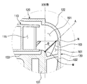
흡입유닛(100b)은 임펠러(IMPELLER)(110), 임펠러 커버(IMPELLER COVER)(120) 및 리턴 채널(RETURN CHANNEL)(130b)을 포함할 수 있다.The
임펠러 커버(120)에는 흡기구(121)가 형성될 수 있다.The
회전 가능한 임펠러(110)는 임펠러 커버(120)의 내측에 마련될 수 있다.The
임펠러(110)는 모터(140)에 연결되어 회전함으로써 공기를 흡입유닛(100b)의 내부로 흡입하는 역할을 한다.The
임펠러(110)는 임펠러(110)의 축방향(X)으로 공기를 흡입하여 반경방향으로 토출하는 원심팬으로 구성될 수 있다.The
임펠러(110)는 제 1플레이트(111), 제 2플레이트(112) 및 복수의 회전날개(113)를 포함할 수 있다.The
제 1플레이트(111) 및 제 2플레이트(112)는 서로 마주하도록 상하로 배치될 수 있고, 제 1플레이트(111) 및 제 2플레이트(112) 사이에는 복수의 회전날개(113)가 위치할 수 있다.The
복수의 회전날개(113)의 상면은 복수의 회전날개(113) 상부에 위치하는 제 1플레이트(111)에 결합되고, 복수의 회전날개(113)의 하면은 복수의 회전날개(113) 하부에 위치하는 제 2플레이트(112)에 결합될 수 있다. 따라서, 제 1플레이트(111), 제 2플레이트(112) 및 복수의 회전날개(113)는 일체로 회전할 수 있다.The upper surface of the plurality of
제 1플레이트(111)에는 임펠러 커버(120)의 흡기구(121)에 대응하는 개구홀(114)이 형성될 수 있다. 흡기구(121)를 통과한 공기는 개구홀(114)을 거쳐 임펠러(110) 내부로 유입될 수 있다.The
제 2플레이트(112)에는 모터축(141)의 일 단부가 고정될 수 있다. 따라서, 제 1플레이트(111), 제 2플레이트(112) 및 복수의 회전날개(113)는 모터축(141)을 중심으로 일체로 회전할 수 있다.One end of the
서로 이격되도록 제 1플레이트(111) 및 제 2플레이트(112) 사이에 위치하는 복수의 회전날개(113)는 유로(115)를 형성할 수 있다. 개구홀(114)을 통과하여 임펠러(110) 내부로 유입된 공기는 유로(115)를 따라 이동하여 리턴 채널(130b)에 형성되는 배출유로(161)로 전달된다.A plurality of
임펠러(110)는 반경방향으로 갈수록 낮아지는 형상을 가지는 바디(Body) 및 블레이드(Blade)를 포함하는 3D 임펠러를 포함할 수 있다.The
임펠러(110)의 형상은 다양하게 변형 가능하며, 상기 예에 한정하지 않는다.The shape of the
리턴 채널(130b)은 임펠러(110)에 의해 흡입유닛(100b)의 내부로 흡입된 공기의 운동에너지를 압력에너지로 변환시키는 역할을 한다. 구체적으로, 개구홀(114)을 통해 임펠러(110) 내부로 유입된 공기는 회전운동을 한 후, 리턴 채널(130b)로 전달된다. 리턴 채널(130b)은 임펠러(110)를 통과한 공기를 수거하여 동압을 정압으로 전환시킨다. 또한, 리턴 채널(130b)은 공기가 흡입유닛(100b)을 통과하는 과정에서 발생할 수 있는 소음을 방지할 수도 있다. 즉, 리턴 채널(130b)은 디퓨져(DIFFUSER) 및 디스월러(DESWIRLER)의 역할을 동시에 할 수 있다.The
리턴 채널(130b)은 임펠러 커버(120)와 결합하여 내부에 임펠러(110)를 수용할 수 있는 임펠러 수용공간(134)을 형성할 수 있다.The
리턴 채널(130b)은 임펠러(110)의 하측에 배치될 수 있다.The
리턴 채널(130b)은 임펠러(110)를 통과한 공기가 바로 유입될 수 있도록 임펠러(110)에 직결될 수 있다.The
리턴 채널(130b)은 분리 가능하다. 즉, 리턴 채널(130b)은 서로 분리 가능한 복수의 유닛(139a,139b)이 결합되어 형성될 수 있다.The
복수의 유닛(139a,139b)은 임펠러(110)의 축방향(X)에 대하여 경사를 형성하도록 분리 가능하다. 바람직하게는, 복수의 유닛(139a,139b)은 임펠러(110)의 축방향(X)에 대하여 수직을 이루는 수평방향(Y)으로 분리될 수 있다.The plurality of
복수의 유닛(139a,139b)은 제 1유닛(139a) 및 제 2유닛(139b)을 포함할 수 있다.The plurality of
제 1유닛(139a)은 임펠러(110)를 통과한 공기가 이동하는 방향(G)의 상류측에 위치하고, 제 2유닛(139b)은 임펠러(110)를 통과한 공기가 이동하는 방향(G)의 하류측에 위치할 수 있다.The
제 1유닛(139a)은 임펠러 커버(120)와 결합할 수 있다. 제 2유닛(139b)은 분리 가능하도록 제 1유닛(139a)의 하부에 결합될 수 있다.The
제 1유닛(139a) 및 제 2유닛(139b)은 서로 단차를 형성하도록 결합할 수 있다.The
제 2유닛(139b)은 제 1유닛(139a)보다 더 넓은 너비를 가질 수 있다. 즉, 제 2유닛(139b)은 제 1유닛(139a)보다 임펠러(110)의 축방향(X)에 대하여 수직을 이루는 수평방향(Y)으로 외측을 향하여 더 돌출될 수 있다.The
복수의 유닛(139a,139b)은 제 1유닛(139a) 및 제 2유닛(139b)에 한정하지 않는다.The plurality of
리턴 채널(130b)은 이너 프레임(INNER FRAME)(131), 아우터 프레임(OUTER FRAME)(132) 및 복수의 날개(160)를 포함할 수 있다.The
아우터 프레임(132)은 이너 프레임(131)의 외주면을 따라 이너 프레임(131)의 외측에 위치하고, 임펠러 커버(120)와 결합하여 임펠러(110)를 수용하는 임펠러 수용공간(134)을 형성할 수 있다.The
리턴 채널(130b)은 임펠러(110)의 하부에 위치할 수 있고, 이너 프레임(131)의 상면에는 임펠러(110)가 안착되는 안착부(133)가 형성될 수 있다. 즉, 임펠러(110)가 안착되는 안착부(133)는 제 1유닛(139a)의 이너 프레임(131)의 상면에 형성될 수 있다.The
이너 프레임(131)과 아우터 프레임(132)은 일체로 형성될 수 있다.The
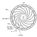
복수의 날개(160)는 이너 프레임(131) 및 아우터 프레임(132) 사이에 길게 배치될 수 있다. 구체적으로, 복수의 날개(160)는 임펠러(110)의 축방향(X)을 따라 이너 프레임(131) 및 아우터 프레임(132) 사이에 길게 형성될 수 있다. 이에 따라 복수의 날개(160)는 임펠러(110)의 축방향(X)으로 긴 배출유로(161)를 형성할 수 있고, 추가적인 정압을 상승시켜 흡입유닛(100b)의 흡입성능을 향상시킬 수 있다.The plurality of
복수의 날개(160)에 대한 상세한 설명은 후술한다.A detailed description of the plurality of
흡입유닛(100b)은 인쇄회로기판(210) 및 지지유닛(200)을 더 포함할 수 있다.The
인쇄회로기판(210)은 임펠러(110)의 축방향(X)으로 리턴 채널(130b)의 하부에 위치할 수 있다. 즉, 인쇄회로기판(210)은 배출유로(161)의 출구(135)와 인접하도록 리턴 채널(130b)의 하부에 위치할 수 있다. 인쇄회로기판(210)은 배출유로(161)를 막지 않도록 리턴 채널(130b)의 내측 하부에 위치할 수 있다.The printed
지지유닛(200)은 임펠러(110)의 축방향(X)으로 인쇄회로기판(210)의 하부에 위치할 수 있다. 지지유닛(200)은 리턴 채널(130b)의 내부에 마련되는 모터(140) 및 인쇄회로기판(210)을 리턴 채널(130b)의 하부에서 지지하는 역할을 한다.The
지지유닛(200)은 고정부재(960)에 의해 리턴 채널(130b)의 내부에 형성되는 적어도 하나의 돌기(220)에 결합될 수 있다.The
리턴 채널(130b)의 너비는 임펠러(110)의 너비보다 더 넓을 수 있다.The width of the
임펠러(110)의 축방향(X)에 대하여 수직을 이루는 수평방향(Y)으로 아우터 프레임(132)을 가로지르는 리턴 채널(130b)의 너비(이하, 이를 "리턴 채널의 너비(W)"라 칭한다.)는 임펠러(110)의 축방향(X)에 대하여 수직을 이루는 수평방향(Y)으로 임펠러(110)를 가로지르는 임펠러(110)의 너비(이하, 이를 "임펠러의 너비(Z)"라 칭한다.)보다 더 넓을 수 있다.The width of the
임펠러의 너비(Z)는 리턴 채널의 너비(W)의 70%이상 100%미만에 해당할 수 있다. 구체적으로, 임펠러(110)의 제 2플레이트(112)의 직경은 리턴 채널(130b)의 아우터 프레임(132)의 직경의 70%이상 100%미만에 해당할 수 있다.The width (Z) of the impeller may correspond to 70% to less than 100% of the width (W) of the return channel. Specifically, the diameter of the
임펠러의 너비(Z) 및 리턴 채널의 너비(W)가 동일한 경우, 즉, 임펠러의 너비(Z)가 리턴 채널의 너비(W)의 100%에 해당하는 경우에는 임펠러(110)를 통과한 공기가 리턴 채널(130b)에 형성되는 배출유로(161)에 전달되기 어렵다.When the width Z of the impeller and the width W of the return channel are equal, that is, when the width Z of the impeller corresponds to 100% of the width W of the return channel, the air passing through the
임펠러(110)의 제 2플레이트(112) 및 리턴 채널(130b)의 아우터 프레임(132) 사이의 이격 정도는 4mm이상 8mm이하일 수 있다. 이는 흡입유닛(100b)의 형상 및 크기에 따라 다양하게 변형 가능하다.The distance between the
흡입유닛(100b)은 임펠러(110)가 회전할 수 있는 원동력을 제공하는 모터(140)를 더 포함할 수 있다.The
모터(140)는 BLDC모터, DC모터 및 AC모터를 포함할 수 있다.The
모터(140)는 리턴 채널(130b)의 내부에 마련될 수 있다. 구체적으로, 모터(140)는 이너 프레임(131)의 내부에 마련될 수 있다.The
모터(140)는 모터축(141)을 포함할 수 있다. 모터축(141)의 일 단부는 임펠러(110)의 제 2플레이트(112)에 연결되고, 모터축(141)의 다른 단부는 모터(140)에 연결된다.The
이너 프레임(131)의 안착부(133)에는 모터축(141)의 일 단부가 이너 프레임(131) 상부에 위치하는 임펠러(110)의 제 2플레이트(112)에 연결되도록 모터축관통홀(136)이 형성될 수 있다.A motor shaft through
도 7은 본 발명의 일 실시예에 따른 청소기의 흡입유닛에 있어서, 리턴 채널에 마련되는 복수의 날개를 도시한 도면이고, 도 8은 본 발명의 일 실시예에 따른 청소기의 흡입유닛에 있어서, 리턴 채널에 마련되는 복수의 날개 및 적어도 하나의 서브 날개를 도시한 도면이다. 도 7 및 도 8에서는 설명의 편의를 위하여 리턴 채널(130b)의 아우터 프레임(132)을 생략한다. 미도시된 도면 부호는 도 1 내지 도 6을 참조한다.FIG. 7 is a view showing a plurality of vanes provided on a return channel in a suction unit of a vacuum cleaner according to an embodiment of the present invention, FIG. 8 is a view illustrating a suction unit of a vacuum cleaner according to an embodiment of the present invention, A plurality of wings provided on the return channel and at least one sub-wing. 7 and 8, the
도 7 및 도 8에 도시된 바와 같이, 리턴 채널(130b)에는 복수의 날개(160)가 배치될 수 있다.As shown in FIGS. 7 and 8, a plurality of
앞서 설명한 바와 같이, 복수의 날개(160)는 임펠러(110)의 축방향(X)을 따라 이너 프레임(131) 및 아우터 프레임(132) 사이에 길게 형성될 수 있다.The plurality of
복수의 날개(160)는 임펠러(110)의 축방향(X)에 대하여 경사를 형성하도록 리턴 채널(130b)에 배치될 수 있다. 구체적으로, 복수의 날개(160)는 이너 프레임(131) 및 아우터 프레임(132) 사이에 경사를 형성하도록 배치될 수 있다.The plurality of
복수의 날개(160)는 서로 이격되어 이너 프레임(131) 및 아우터 프레임(132) 사이에 배치될 수 있다. 서로 이격된 복수의 날개(160)는 임펠러(110)를 통과한 공기가 이동하는 배출유로(161)를 형성할 수 있다.The plurality of
배출유로(161)는 입구(137) 및 출구(135)를 포함할 수 있다. 배출유로(161)의 입구(137)는 임펠러(110)를 통과한 공기가 입구(137)를 통해 배출유로(161)로 유입될 수 있도록 임펠러(110)를 향하는 배출유로(161)의 상단부에 형성될 수 있다. 배출유로(161)의 출구(135)는 배출유로(161)를 따라 이동하는 공기가 출구(135)를 통해 흡입유닛(100b)의 외측으로 토출될 수 있도록 배출유로(161)의 하단부에 형성될 수 있다.The
배출유로(161)의 출구(135)를 향할수록 복수의 날개(160) 사이의 이격 정도는 커질 수 있다. 즉, 출구(135)에 가까워질수록 배출유로(161)의 폭이 넓어질 수 있다.The distance between the
복수의 날개(160)는 제 1면(162) 및 제 2면(163)을 포함할 수 있다.The plurality of
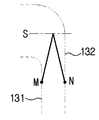
제 1면(162)은 이너 프레임(131)의 외면과 마주하고, 제 2면(163)은 아우터 프레임(132)의 내면과 마주할 수 있다. 제 1면(162)은 제 1면(162)의 상단부에 위치하는 시작점(M)을 포함할 수 있다. 제 2면(163)은 제 2면(163)의 상단부에 위치하는 시작점(N)을 포함할 수 있다. 제 2면(163)의 시작점(N)은 제 1면(162)의 시작점(M)과 함께 배출유로(161)의 입구(137)를 형성할 수 있다.The
배출유로(161)의 입구(137)를 형성하는 복수의 날개(160)는 임펠러(110)의 축방향(X)에 대하여 0ㅀ이상 90ㅀ이하 기울어 질 수 있다. 구체적으로, 임펠러(110)의 축방향(X)에 대하여 배출유로(161)의 입구(137)를 형성하는 복수의 날개(160)의 제 2면(163)이 이루는 각도(θ)는 0ㅀ이상 90ㅀ이하일 수 있다.The plurality of
또는, 임펠러(110)의 축방향(X)에 대하여 배출유로(161)의 입구(137)를 형성하는 복수의 날개(160)의 접선이 이루는 각도(θ)는 0ㅀ이상 90ㅀ이하일 수 있다.Or an angle formed by a tangent of the plurality of
배출유로(161)의 출구(135)를 형성하는 복수의 날개(160)는 임펠러(110)의 축방향(X)에 대하여 0ㅀ이상 90ㅀ이하 기울어 질 수 있다. 구체적으로, 임펠러(110)의 축방향(X)에 대하여 배출유로(161)의 출구(135)를 형성하는 복수의 날개(160)의 제 2면(163)이 이루는 각도(θ)는 0ㅀ이상 90ㅀ이하일 수 있다.The plurality of
또는, 임펠러(110)의 축방향(X)에 대하여 배출유로(161)의 출구(135)를 형성하는 복수의 날개(160)의 접선이 이루는 각도(θ)는 0ㅀ이상 90ㅀ이하일 수 있다.The angle θ formed by the tangents of the plurality of
복수의 날개(160)의 제 1면(162)은 이너 프레임(131)의 외면에 결합될 수 있고, 복수의 날개(160)의 제 2면(163)은 아우터 프레임(132)의 내면에 결합될 수 있다.The
복수의 날개(160)는 곡면을 포함할 수 있다.The plurality of
복수의 날개(160)가 기울어진 방향은 임펠러(110)의 회전방향과 관계가 있다. 구체적으로, 임펠러(110)가 제 1방향(H)을 향하여 회전하는 경우, 복수의 날개(160)는 임펠러(110)의 축방향(X)에 대하여 제 1방향(H)과 반대방향인 제 2방향(I)을 따라 기울어질 수 있다.The direction in which the plurality of
리턴 채널(130b)의 복수의 날개(160)의 개수는 임펠러(110)의 복수의 회전날개(113)의 개수와 관계가 있을 수 있다. 구체적으로, 복수의 날개(160)의 개수 및 복수의 회전날개(113)의 개수 중 어느 하나를 다른 하나로 나눌 경우, 그 값은 무한소수일 수 있다.The number of the plurality of
복수의 날개(160) 및 복수의 회전날개(113) 중 적어도 하나의 개수는 홀수일 수 있다. 일 예로써, 리턴 채널(130b)의 복수의 날개(160)의 개수는 13개 이상 23개 이하의 홀수일 수 있다. 다만, 복수의 날개(160)의 개수는 상기 예에 한정하지 않는다.At least one of the plurality of
리턴 채널(130b)은 적어도 하나의 서브 날개(800)를 더 포함할 수 있다.The
적어도 하나의 서브 날개(800)는 공기가 흡입유닛(100b)을 통과하는 과정에서 발생할 수 있는 소음을 감소시키는 역할을 한다.At least one
적어도 하나의 서브 날개(800)는 배출유로(161) 상에 형성될 수 있다.At least one sub blade (800) may be formed on the discharge passage (161).
적어도 하나의 서브 날개(800)는 배출유로(161)를 형성하는 복수의 날개(160)와 동일한 경사를 가지도록 복수의 날개(160) 사이에 마련될 수 있다.At least one
적어도 하나의 서브 날개(800)는 배출유로(161)의 입구(137) 및 출구(135) 중 적어도 하나에 형성될 수 있다.At least one
적어도 하나의 서브 날개(800)는 임펠러(110)의 축방향(X)으로 복수의 날개(160)보다 낮은 높이를 가질 수 있다. 바람직하게는 적어도 하나의 서브 날개(800)는 임펠러(110)의 축방향(X)으로 복수의 날개(160)의 50% 이하의 높이를 가질 수 있다.At least one
적어도 하나의 서브 날개(800)는 임펠러(110)의 축방향(X)으로 서로 다른 높이를 가질 수 있다. 또는, 적어도 하나의 서브 날개(800)는 임펠러(110)의 축방향(X)으로 서로 동일한 높이를 가질 수 있다.At least one
적어도 하나의 서브 날개(800)는 제 1면(162a) 및 제 2면(163a)을 포함할 수 있다.At least one
제 1면(162a)은 이너 프레임(131)의 외면과 마주하고, 제 2면(163a)은 아우터 프레임(132)의 내면과 마주할 수 있다.The
적어도 하나의 서브 날개(800)의 제 1면(162a)은 이너 프레임(131)의 외면에 결합되고, 제 2면(163a)은 아우터 프레임(132)의 내면에 결합될 수 있다.The
또는, 적어도 하나의 서브 날개(800)의 제 1면(162a)은 이너 프레임(131)의 외면에 결합되고, 제 2면(163a)은 아우터 프레임(132)의 내면에서 이격될 수 있다.Alternatively, the
또는, 적어도 하나의 서브 날개(800)의 제 1면(162a)은 이너 프레임(131)의 외면에서 이격되고, 제 2면(163a)은 아우터 프레임(132)의 내면에 결합될 수 있다.Alternatively, the
도 9는 본 발명의 일 실시예에 따른 청소기의 흡입유닛을 정면에서 도시한 도면이다.9 is a front view of a suction unit of a vacuum cleaner according to an embodiment of the present invention.
도 9에 도시된 바와 같이, 복수의 날개(160)는 임펠러(110)의 축방향(X)으로 흡입유닛(100b)의 80% 이상의 높이를 가질 수 있다. 구체적으로, 복수의 날개(160)의 제 2면(163)은 임펠러(110)의 축방향(X)으로 흡입유닛(100b)의 80%이상의 높이를 가질 수 있다. 흡입유닛(100b)의 높이(E)는 임펠러 커버(120) 및 리턴 채널(130b)이 서로 결합된 상태에 있어서, 임펠러 커버(120)의 상단부에서 리턴 채널(130b)의 하단부에 이르는 거리는 가리킨다.As shown in FIG. 9, the plurality of
배출유로(161)의 입구(137)에 대응하는 복수의 날개(160)는 흡입유닛(100b) 높이(E)의 상단부에서 임펠러(110)의 축방향(X)으로 하방을 향하여 일정 간격 이격될 수 있다. 구체적으로, 배출유로(161)의 입구(137)를 형성하는 제 2면(163)의 시작점(N)은 흡입유닛(100b) 높이(E)의 상단부에서 임펠러(110)의 축방향(X)으로 하방을 향하여 일정 간격 이격될 수 있다.The plurality of
배출유로(161)의 출구(135)에 대응하는 복수의 날개(160)는 흡입유닛(100b) 높이(E)의 하단부와 임펠러(110)의 축방향(X)으로 동일한 위치에 위치할 수 있다. 구체적으로, 배출유로(161)의 출구(135)를 형성하는 제 2면(163)은 흡입유닛(100b) 높이(E)의 하단부와 임펠러(110)의 축방향(X)으로 동일한 위치에 위치할 수 있다.The plurality of
도 10은 본 발명의 일 실시예에 따른 청소기의 흡입유닛 일부를 확대하여 도시한 단면도이다. 미도시된 도면 부호는 도 1 내지 도 9를 참조한다.10 is an enlarged cross-sectional view of a suction unit of a vacuum cleaner according to an embodiment of the present invention. Reference numerals not shown refer to Figs. 1 to 9.
도 10에 도시된 바와 같이, 복수의 날개(160)의 제 2면(163)의 시작점(N)은 제 1면(162)의 시작점(M)보다 임펠러 커버(120)를 향하여 상방으로 더 연장될 수 있다. 즉, 제 2면(163)의 시작점(N)은 제 1면(162)의 시작점(M)보다 임펠러(110)의 축방향(X)으로 더 높은 위치에 형성될 수 있다.10, the starting point N of the
제 2면(163)의 시작점(N)은 임펠러(110)의 축방향(X)으로 임펠러(110)에 형성되는 유로(115) 높이의 10%이상 70%이하에 해당하는 위치에 위치할 수 있다. 임펠러(110)에 형성되는 유로(115) 높이는 제 1플레이트(111) 및 제 2플레이트(112) 사이의 간격을 가리킨다.The starting point N of the
도 11은 본 발명의 일 실시예에 따른 청소기의 흡입유닛에 있어서, 리턴채널의 제 1유닛을 하부에서 도시한 도면이고, 도 12는 본 발명의 일 실시예에 따른 청소기의 흡입유닛에 있어서, 리턴채널의 제 2유닛을 상부에서 도시한 도면이다. 도 13a 및 13b는 본 발명의 일 실시예에 따른 청소기의 흡입유닛에 있어서, 리턴채널의 제 1유닛 및 제 2유닛의 결합구조를 도시한 단면도이다. 미도시된 도면 부호는 도 1 내지 도 10을 참조한다.FIG. 11 is a bottom view of a first unit of a return channel in a suction unit of a vacuum cleaner according to an embodiment of the present invention, FIG. 12 is a suction unit of a vacuum cleaner according to an embodiment of the present invention, Lt; RTI ID = 0.0 > a < / RTI > second channel of the return channel. 13A and 13B are sectional views showing a coupling structure of a first unit and a second unit of a return channel in a suction unit of a vacuum cleaner according to an embodiment of the present invention. Reference numerals not shown refer to Figs. 1 to 10.
도 11 내지 도 13b에 도시된 바와 같이, 리턴 채널(130b)은 복수의 유닛(139a,139b)을 결합시키는 적어도 하나의 회전방지유닛(900)을 더 포함할 수 있다.As shown in FIGS. 11 to 13B, the
적어도 하나의 회전방지유닛(900)은 서로 이격되도록 리턴 채널(130b)의 내측에 형성될 수 있다. 적어도 하나의 회전방지유닛(900)은 서로 일정간격 이격될 수 있다.At least one
적어도 하나의 회전방지유닛(900)은 돌기(910) 및 체결부(920)를 포함할 수 있다.At least one
돌기(910)는 제 1유닛(139a) 및 제 2유닛(139b) 중 어느 하나의 내측에 마련될 수 있다.구체적으로, 돌기(910)는 제 1유닛(139a) 및 제 2유닛(139b) 중 어느 하나의 이너 프레임(131)에 마련될 수 있다.The projection 910 may be provided inside any one of the
체결부(920)는 제 1유닛(139a) 및 제 2유닛(139b) 중 다른 하나의 내측에 마련될 수 있다. 구체적으로, 체결부(920)는 제 1유닛(139a) 및 제 2유닛(139b) 중 다른 하나의 이너 프레임(131)에 마련될 수 있다. 돌기(910)는 체결부(920)에 분리 가능하도록 결합될 수 있다.The
바람직하게는 돌기(910)는 제 1유닛(139a)의 내측에 마련될 수 있다. 돌기(910)는 임펠러(110)의 축방향(X)을 따라 하방을 향하여 돌출되도록 제 1유닛(139a)의 이너 프레임(131)에 마련될 수 있다. 돌기(910)는 제 1유닛(139a)의 이너 프레임(131)과 일체로 형성될 수 있다.Preferably, the projection 910 may be provided inside the
돌기(910)는 원돌기 형상을 가질 수 있으나, 이에 한정하지 않는다.The projection 910 may have a circular projection shape, but is not limited thereto.
돌기(910)에는 이너 프레임(131)의 내측을 향하여 돌출되는 리브(911)가 형성될 수 있다. 리브(911)는 임펠러(110)의 축방향(X)을 따라 하방을 향할수록 이너 프레임(131)의 내측을 향한 돌출 정도가 작아지도록 돌기(910)에 연결될 수 있다. 리브(911)는 돌기(910)와 일체로 형성될 수 있다.A
체결부(920)는 제 2유닛(139b)의 내측에 마련될 수 있다. 체결부(920)는 제 2유닛(139b)의 이너 프레임(131)의 내면에 마련될 수 있다.The
제 1유닛(139a)에 형성되는 돌기(910)는 제 2유닛(139b)에 마련되는 체결부(920)에 결합될 수 있다. 이 때, 임펠러(110)의 축방향(X)을 따라 하방을 향하는 리브(911)의 일 단부는 체결부(920)의 내면에 마련된 체결홈(미도시)에 결합되어 고정될 수 있다.The protrusion 910 formed in the
제 1유닛(139a)의 이너 프레임(131)은 임펠러(110)의 축방향(X)을 따라 하방을 향하여 돌출되는 연장부(131a)를 포함할 수 있다. 연장부(131a)는 이너 프레임(131)보다 작은 직경을 가지는 원돌기 형상을 가질 수 있다. 다만, 연장부(131a)의 형상은 원돌기에 한정하지 않는다. 연장부(131a)는 제 2유닛(139b)의 내측에 결합될 수 있다. 연장부(131a)는 제 2유닛(139b)의 이너 프레임(131)의 내측에 결합될 수 있다.The
제 1유닛(139a)의 돌기(910)는 연장부(131a)에 마련될 수 있다.The projection 910 of the
제 1유닛(139a)의 돌기(910)는 연장부(131a)의 일부를 형성할 수 있다.The projection 910 of the
연장부(131a)의 외면에는 제 1유닛(139a)의 외측을 향하여 돌출되는 적어도 하나의 고정부(930)가 마련될 수 있다. 즉, 적어도 하나의 고정부(930)는 제 1유닛(139a)의 반경방향을 향하여 외측으로 돌출될 수 있다. 이 때, 적어도 하나의 고정부(930)는 배출유로(161)를 막지 않는다.At least one fixing
적어도 하나의 고정부(930)는 제 2유닛(139b)의 이너 프레임(131)에 마련되는 고정홈(940)에 결합될 수 있다. 고정홈(940)은 제 2유닛(139b)의 이너 프레임(131)의 내면에 마련될 수 있다. 적어도 하나의 고정부(930)는 고정홈(940)에 분리 가능하게 결합될 수 있다. 고정홈(940) 및 적어도 하나의 고정부(930)의 개수는 서로 동일할 수 있다.At least one fixing
따라서, 리턴 채널(130b)의 제 1유닛(139a) 및 제 2유닛(139b)은 적어도 하나의 회전방지유닛(900)에 의해 분리 가능하게 결합할 수 있다. 또한, 적어도 하나의 고정부(930) 및 고정홈(940)의 결합에 의해 제 1유닛(139a) 및 제 2유닛(139b)의 결합을 더욱 견고히 할 수 있다.Thus, the
도 14는 본 발명의 일 실시예에 따른 청소기의 흡입유닛에 있어서, 노즈콘을 포함하는 구조를 도시한 도면이다. 미도시된 도면 부호는 도 1 내지 도 13b를 참조한다.FIG. 14 is a view showing a structure including a nosecone in a suction unit of a vacuum cleaner according to an embodiment of the present invention. Reference numerals not shown refer to Figs. 1 to 13B.
도 14에 도시된 바와 같이, 흡입유닛(100b)은 노즈콘(NOSE CONE)(950)을 더 포함할 수 있다. 노즈콘(950)은 공기역학적 저항이 작도록 유선형으로 디자인될 수 있다. 노즈콘(950)은 임펠러(110)의 제 1플레이트(111)에 형성되는 개구홀(114)의 위치에 대응하도록 임펠러(110)의 제 2플레이트(112) 상에 마련될 수 있다. 노즈콘(950)은 제 2플레이트(112)에 고정되는 모터축(141)의 일 단부에 결합될 수 있다. 임펠러(110)의 제 2플레이트(112)에 노즈콘(950)을 설치함으로써 개구홀(114)을 통해 임펠러(110)의 내부로 유입된 공기의 저항을 줄여 흡입유닛(100b)의 흡입효율을 향상시킬 수 있다.As shown in FIG. 14, the
도 15는 본 발명의 다른 실시예에 따른 청소기의 외관을 도시한 도면이다.15 is a view showing the appearance of a vacuum cleaner according to another embodiment of the present invention.
도 15에 도시된 바와 같이, 청소기(1)는 공기의 흡입력에 의해 이물질을 흡입하는 흡입부(11) 및 흡입부(11)에 의해 흡입된 이물질이 포집되는 본체(10)를 포함할 수 있다.15, the
본체(10)와 흡입부(11) 사이에는 본체(10)에서 발생시킨 흡입력이 흡입부(11)에 전달될 수 있도록 연결호스(12)와 연결관(13)으로 연결되며 연결호스(12)와 연결관(13) 사이에는 사용자가 손으로 파지할 수 있도록 손잡이(14)가 마련될 수 있다.A
연결호스(12)는 신축 가능한 주름관 등으로 형성되며, 연결호스(12)의 일 단부는 본체(10)에 연결되고, 연결호스(12)의 다른 단부는 손잡이(14)에 연결되어 흡입부(11)가 본체(10)를 중심으로 일정반경 내에서 자유롭게 움직일 수 있도록 한다. 연결관(13)은 소정 길이를 가지도록 형성될 수 있다. 연결관(13)의 일 단부는 흡입부(11)에 연결되고, 연결관(13)의 다른 단부는 손잡이(14)에 연결되어 사용자는 서 있는 상태에서 바닥의 이물질을 청소할 수 있다.The connecting
도 16은 본 발명의 다른 실시예에 따른 청소기의 본체를 도시한 단면도이고, 도 17은 본 발명의 다른 실시예에 따른 청소기의 흡입유닛을 도시한 사시도이다. 도 18은 본 발명의 다른 실시예에 따른 청소기의 흡입유닛 분해사시도이고, 도 19는 본 발명의 다른 실시예에 따른 청소기의 흡입유닛 일부를 확대하여 도시한 사시도이다. 도 20은 본 발명의 다른 실시예에 따른 청소기의 흡입유닛 단면도이고, 도 21은 본 발명의 다른 실시예에 따른 청소기의 흡입유닛 일부를 확대하여 도시한 단면도이다.FIG. 16 is a cross-sectional view illustrating a main body of a vacuum cleaner according to another embodiment of the present invention, and FIG. 17 is a perspective view illustrating a suction unit of a vacuum cleaner according to another embodiment of the present invention. FIG. 18 is an exploded perspective view of a suction unit of a vacuum cleaner according to another embodiment of the present invention, and FIG. 19 is an enlarged perspective view of a suction unit of a vacuum cleaner according to another embodiment of the present invention. FIG. 20 is a sectional view of a suction unit of a vacuum cleaner according to another embodiment of the present invention, and FIG. 21 is an enlarged sectional view of a suction unit of a vacuum cleaner according to another embodiment of the present invention.
도 16 내지 도 21에 도시된 바와 같이, 본체(10)의 전방에는 연결호스(12)가 연결되고, 흡입부(11)가 흡입한 공기는 연결호스(12)를 따라 본체(10) 내부로 전달될 수 있다. 본체(10)의 후방 상부에는 본체(10)의 내부에 마련되는 집진장치(20)에 의해 이물질이 걸러진 공기가 본체(10) 외부로 배기될 수 있도록 배기부(15)가 형성될 수 있다. 또한, 본체(10)의 내부는 집진장치(20)가 설치되는 집진실(10a), 흡입유닛(100) 및 배기유로(16)가 마련되는 흡입실(10b) 및 전원코드(미도시)가 마련되는 코드실(미도시)로 구획될 수 있다.16 to 21, a connecting
집진실(10a)에는 연결호스(12)를 통해 집진실(10a) 내부로 흡입된 먼지를 모으는 집진장치(20)가 설치될 수 있다. 본 실시예에서는 집진장치(20)로 흡입된 공기 중의 이물질을 원심력을 이용하여 분리하는 사이클론장치를 사용하였으나, 먼지를 모으는 먼지통 등이 사용될 수도 있다. 또한, 집진장치(20)를 착탈할 수 있도록 집진실(10a)의 상부에는 커버(21)가 힌지결합될 수 있다.A
청소기(1)는 외부공기를 본체(10) 내부로 흡입하기 위한 흡입력을 발생시키는 흡입유닛(100)을 포함할 수 있다. 흡입유닛(100)은 흡입실(10b) 내부에 설치될 수 있다.The
흡입유닛(100)은 임펠러(IMPELLER)(110), 임펠러 커버(IMPELLER COVER)(120) 및 리턴 채널(RETURN CHANNEL)(130)을 포함할 수 있다.The
임펠러 커버(120)에는 흡기구(121)가 형성될 수 있다. 흡기구(121)는 연결배관(17)에 의해 집진장치(20)의 토출구(22)와 연결되어 집진장치(20)에 흡입력을 발생시킬 수 있다.The
회전 가능한 임펠러(110)는 임펠러 커버(120)의 내측에 마련될 수 있다.The
임펠러(110)는 임펠러(110)의 축방향으로 공기를 흡입하여 반경방향으로 토출하는 원심팬으로 구성될 수 있다.The
임펠러(110)는 제 1플레이트(111), 제 2플레이트(112) 및 복수의 회전날개(113)를 포함할 수 있다.The
제 1플레이트(111) 및 제 2플레이트(112)는 서로 마주하도록 상하로 배치될 수 있고, 제 1플레이트(111) 및 제 2플레이트(112) 사이에는 복수의 회전날개(113)가 위치할 수 있다.The
복수의 회전날개(113)의 상면은 복수의 회전날개(113) 상부에 위치하는 제 1플레이트(111)에 결합되고, 복수의 회전날개(113)의 하면은 복수의 회전날개(113) 하부에 위치하는 제 2플레이트(112)에 결합될 수 있다. 따라서, 제 1플레이트(111), 제 2플레이트(112) 및 복수의 회전날개(113)는 일체로 회전할 수 있다.The upper surface of the plurality of
제 1플레이트(111)에는 임펠러 커버(120)의 흡기구(121)에 대응하는 개구홀(114)이 형성될 수 있다. 흡기구(121)를 통과한 공기는 개구홀(114)을 거쳐 임펠러(110) 내부로 유입될 수 있다.The
제 2플레이트(112)에는 모터축(141)의 일 단부가 고정된다. 따라서, 제 1플레이트(111), 제 2플레이트(112) 및 복수의 회전날개(113)는 모터축(141)을 중심으로 일체로 회전할 수 있다.One end of the
서로 이격되도록 제 1플레이트(111) 및 제 2플레이트(112) 사이에 위치하는 복수의 회전날개(113)는 유로(115)를 형성할 수 있다. 개구홀(114)을 통과하여 임펠러(110) 내부로 유입된 공기는 유로(115)를 따라 이동하여 리턴 채널(130)에 형성되는 배출유로(161)로 전달된다.A plurality of
임펠러(110)는 반경방향으로 갈수록 낮아지는 형상을 가지는 바디(Body) 및 블레이드(Blade)를 포함하는 3D 임펠러를 포함할 수 있다.The
임펠러(110)의 형상은 다양하게 변형 가능하며, 상기 예에 한정하지 않는다.The shape of the
리턴 채널(130)은 임펠러(110)에 의해 흡입된 공기의 운동에너지를 압력에너지로 변환시키는 역할을 하고, 임펠러 커버(120)와 결합하여 내부에 임펠러(110)를 수용할 수 있는 임펠러 수용공간(134)을 형성할 수 있다.The
리턴 채널(130)은 임펠러(110)의 하측에 배치될 수 있다.The
리턴 채널(130)은 임펠러(110)를 통과한 공기가 바로 유입될 수 있도록 임펠러(110)에 직결될 수 있다.The
리턴 채널(130)은 이너 프레임(INNER FRAME)(131) 및 아우터 프레임(OUTER FRAME)(132)을 포함할 수 있다.The
리턴 채널(130)은 임펠러(110)의 하부에 위치할 수 있고, 이너 프레임(131)의 상면에는 임펠러(110)가 안착되는 안착부(133)가 형성될 수 있다.The
안착부(133)는 임펠러 커버(120)를 향하여 상방으로 돌출 형성되는 돌출부(133a)를 포함할 수 있다. 돌출부(133a)는 안착부(133)의 가장자리를 따라 형성될 수 있다. 임펠러(110)는 돌출부(133a)의 내측에 위치하도록 안착부(133)에 안착될 수 있다.The
돌출부(133a)는 곡면을 가질 수 있다.The
돌출부(133a)는 이너 프레임(131)의 외측을 향하여 볼록한 곡면을 가질 수 있다.The projecting
아우터 프레임(132)은 이너 프레임(131)의 외주면을 따라 이너 프레임(131)의 외측에 위치하고, 임펠러 커버(120)와 결합하여 임펠러(110)를 수용하는 임펠러 수용공간(134)을 형성할 수 있다.The
이너 프레임(131)과 아우터 프레임(132)은 일체로 형성될 수 있다.The
리턴 채널(130)에는 복수의 날개(160)가 배치될 수 있다.A plurality of
복수의 날개(160)는 임펠러(110)의 축방향(X)을 따라 이너 프레임(131) 및 아우터 프레임(132) 사이에 길게 형성될 수 있다. 이에 따라 복수의 날개(160)는 임펠러(110)의 축방향(X)으로 긴 배출유로(161)를 형성할 수 있고, 흡입유닛(100)의 흡입성능을 향상시킬 수 있다.The plurality of
복수의 날개(160)는 임펠러(110)의 축방향(X)에 대하여 경사를 형성하도록 리턴 채널(130)에 배치될 수 있다. 구체적으로, 복수의 날개(160)는 이너 프레임(131) 및 아우터 프레임(132) 사이에 배치될 수 있다.The plurality of
복수의 날개(160)는 서로 이격되어 이너 프레임(131) 및 아우터 프레임(132) 사이에 배치될 수 있다. 서로 이격된 복수의 날개(160)는 임펠러(110)를 통과한 공기가 이동하는 배출유로(161)를 형성할 수 있다.The plurality of
배출유로(161)는 입구(137) 및 출구(135)를 포함할 수 있다. 배출유로(161)의 입구(137)는 임펠러(110)를 통과한 공기가 입구(137)를 통해 배출유로(161)로 유입될 수 있도록 임펠러(110)를 향하는 배출유로(161)의 상단부에 형성될 수 있다. 배출유로(161)의 출구(135)는 배출유로(161)를 따라 이동하는 공기가 출구(135)를 통해 흡입유닛(100)의 외측으로 토출될 수 있도록 배출유로(161)의 하단부에 형성될 수 있다.The
배출유로(161)의 출구(135)를 향할수록 복수의 날개(160) 사이의 이격 정도가 커질 수 있다. 즉, 출구(135)에 가까워질수록 배출유로(161)의 폭이 넓어질 수 있다.The degree of separation between the plurality of
복수의 날개(160)는 제 1면(162) 및 제 2면(163)을 포함할 수 있다.The plurality of
제 1면(162)은 이너 프레임(131)의 외면과 마주하고, 제 2면(163)은 아우터 프레임(132)의 내면과 마주할 수 있다. 제 1면(162)은 제 1면(162)의 상단부에 위치하는 시작점(M)을 포함할 수 있다. 제 2면(163)은 제 2면(163)의 상단부에 위치하는 시작점(N)을 포함할 수 있다. 제 2면(163)의 시작점(N)은 제 1면(162)의 시작점(M)과 함께 배출유로(161)의 입구(137)를 형성할 수 있다.The
복수의 날개(160)의 제 1면(162)은 이너 프레임(131)의 외면에 결합될 수 있고, 복수의 날개(160)의 제 2면(163)은 아우터 프레임(132)의 내면에 결합될 수 있다.The
복수의 날개(160)의 제 1면(162)은 돌출부(133a)의 외면에도 결합될 수 있다. 즉, 제 1면(162)의 시작점(M)은 이너 프레임(131)의 외측을 향하여 볼록한 돌출부(133a)의 외면에도 결합될 수 있다.The
복수의 날개(160)는 제 1면(162)의 시작점(M) 및 제 2면(163)의 시작점(N)을 연결하는 연결부(164)를 더 포함할 수 있다. 연결부(164)의 다양한 형상에 대한 설명은 후술한다.The plurality of
복수의 날개(160)는 곡면을 가질 수 있다.The plurality of
복수의 날개(160)가 기울어진 방향은 임펠러(110)의 회전방향과 관계가 있다. 구체적으로, 임펠러(110)가 제 1방향(H)을 향하여 회전하는 경우, 복수의 날개(160)는 임펠러(110)의 축방향(X)에 대하여 제 1방향(H)과 반대방향인 제 2방향(I)을 따라 기울어질 수 있다.The direction in which the plurality of
임펠러 커버(120)는 가이드부(122)를 포함할 수 있다. 구체적으로, 가이드부(122)는 임펠러(110)의 유로(115)를 통과한 공기를 배출유로(161)의 입구(137)로 가이드하는 역할을 한다.The
가이드부(122)는 유로(115)를 통과한 공기가 배출유로(161)의 입구(137)로 도입되기 전까지 임펠러(110) 및 리턴 채널(130) 사이에 형성되는 스페이스(191)에 머무르는 것을 방지하도록 곡면을 가질 수 있다. 가이드부(122)는 임펠러 커버(120)의 외측을 향하여 볼록한 곡면을 가질 수 있다.The
가이드부(122)는 곡률 반지름이 1mm 이상의 곡면을 가질 수 있다.The
임펠러(110)에 마련되는 유로(115)를 통과한 공기는 가이드부(122)를 따라 리턴 채널(130)에 마련되는 배출유로(161)로 도입된다.Air that has passed through the
가이드부(122)를 기준으로 공기의 이동방향이 변할 수 있다. 구체적으로, 개구홀(114)을 통과하여 임펠러(110) 내부로 유입된 공기는 유로(115)를 따라 수평방향으로 이동하고, 유로(115)를 통과한 공기는 가이드부(122)에 충돌하여 배출유로(161)를 향하여 수직방향으로 이동한다.The moving direction of the air can be changed with respect to the
하방을 향하는 가이드부(122)의 일 단부는 아우터 프레임(132)에 결합될 수 있다.One end of the downwardly directed
흡입유닛(100)은 임펠러(110)가 회전할 수 있는 원동력을 제공하는 모터(140)를 더 포함할 수 있다.The
모터(140)는 BLDC모터, DC모터 및 AC모터를 포함할 수 있다.The
모터(140)는 리턴 채널(130)의 내부에 마련될 수 있다. 구체적으로, 모터(140)는 이너 프레임(131)의 내부에 마련될 수 있다.The
모터(140)는 모터축(141)을 포함할 수 있다. 모터축(141)의 일 단부는 임펠러(110)의 제 2플레이트(112)에 연결되고, 모터축(141)의 다른 단부는 모터(140)에 연결된다.The
이너 프레임(131)의 안착부(133)에는 모터축(141)의 일 단부가 이너 프레임(131) 상부에 위치하는 임펠러(110)의 제 2플레이트(112)에 연결되도록 모터축관통홀(136)이 형성될 수 있다.A motor shaft through
배출유로(161)의 일 단부에 형성되는 출구(135)로 토출된 공기는 흡입유닛(100)을 감싸는 케이스(40) 내부에 형성된 내부유로(41)를 통해 흡입유닛(100)의 하부에 형성되는 배출구(42)를 통해 배출된다. 배출구(42)를 통해 배출된 공기는 배기유로(16)를 경유하여 배기부(15)로 배기된다. 여기서 배기유로(16)는 흡입유닛(100)의 배출구(42)로부터 배출된 공기가 배기부(15)까지 이르게 되는 유로를 의미한다.The air discharged to the
집진장치(20)와 흡입유닛(100) 사이에 형성되는 공간은 배기유로(16)의 일부를 형성할 수 있다.The space formed between the
배기유로(16)는 적어도 한 번 절곡될 수 있다. 배기유로(16)는 흡입유닛(100)의 배출구(42)로부터 집진장치(20)와 흡입유닛(100) 사이의 공간에 이르는 제 1유로(16a), 제 1유로(16a)로부터 연장되어 집진장치(20)와 흡입유닛(100) 사이에 형성되는 제 2유로(16b) 및 제 2유로(16b)와 배기부(15)를 연결하는 제 3유로(16c)를 포함할 수 있다.The
배기유로(16) 상에는 집진장치(20)에서 제거되지 않은 이물질을 분리하기 위한 배기필터(18)가 설치될 수 있다. 배기필터(18)는 제 1유로(16a) 또는 제 2유로(16b) 상에 설치되는 것이 바람직하다. 이는 배기필터(18)가 제 1유로(16a) 또는 제 2유로(16b) 상에 설치되면 배기필터(18)로부터 배기부(15)까지 충분한 거리를 확보할 수 있어 공기가 배기필터(18)를 통과할 때 발생하는 소음이 충분히 감소된 후 배기부(15)를 통해 배기될 수 있기 때문이다. 또한, 단면적이 상대적으로 큰 제 1유로(16a) 또는 제 2유로(16b)에 배기필터(18)를 설치함으로써 충분한 배기필터(18)의 면적을 확보할 수 있고, 그에 따라 공기가 배기필터(18)를 통과할 때 발생하는 압력손실을 줄일 수 있기 때문이다.An
본체(10)의 바닥면에는 배기필터(18)의 교체가 용이하도록 도어(미도시)에 의해 개폐 가능한 개구부(미도시)가 형성될 수 있다.An opening (not shown) that can be opened and closed by a door (not shown) may be formed on the bottom surface of the
도 22는 본 발명의 다른 실시예에 따른 청소기의 흡입유닛의 다른 일부를 확대하여 도시한 단면도이다.22 is an enlarged cross-sectional view showing another portion of a suction unit of a vacuum cleaner according to another embodiment of the present invention.
도 22에 도시된 바와 같이, 이너 프레임(131)에 결합되는 제 1면(162)의 시작점(M) 및 아우터 프레임(132)에 결합되는 제 2면(163)의 시작점(N)을 연결하는 직선(A)은 임펠러(110)의 축방향(X)에 대하여 5ㅀ이상 85ㅀ이하의 경사를 형성할 수 있다.As shown in Fig. 22, connecting the starting point M of the
또한, 앞서 설명한 바와 같이, 가이드부(122)는 임펠러 커버(120)의 외측을 향하여 볼록하고, 곡률 반지름이 1mm 이상인 곡면을 가질 수 있다. 가이드부(122)는 2차곡선 형상의 곡면을 가질 수도 있다.As described above, the
도 23은 본 발명의 다른 실시예에 따른 청소기에 있어서, 이너 프레임 및 아우터 프레임 사이에 배치되는 복수의 날개의 일부를 도시한 도면이고, 도 24a 내지 도 24p는 도 23의 복수의 날개의 연결부의 다양한 형상을 측면에서 개략적으로 도시한 도면이다.23 is a view showing a part of a plurality of vanes disposed between an inner frame and an outer frame in a vacuum cleaner according to another embodiment of the present invention, And schematically showing various shapes on the side.
도 23 내지 도 24p에 도시된 바와 같이, 복수의 날개(160)의 연결부(164)는 다양한 형상을 가질 수 있다.23 to 24P, the connecting
연결부(164)는 곡면 및 평면 중 적어도 하나를 포함할 수 있다.The
연결부(164)는 서로 다른 곡률을 가지는 곡면을 포함할 수 있다.The connecting
연결부(164)는 변곡점을 가지는 곡면을 포함할 수 있다.The connecting
연결부(164)는 기울기가 일정한 평면을 포함할 수 있다.The connecting
연결부(164)는 기울기가 상이한 복수의 평면을 포함할 수 있다. 즉, 연결부(164)를 형성하는 평면은 절곡될 수 있다.The connecting
연결부(164)는 곡면과 평면을 동시에 포함할 수 있다.The connecting
제 2면(163)의 시작점(N)은 제 1면(162)의 시작점(M)보다 임펠러 커버(120)를 향하여 상방으로 더 연장될 수 있다. 즉, 제 2면(163)의 시작점(N)은 제 1면(162)의 시작점(M)보다 임펠러(110)의 축방향(X)으로 더 높은 위치에 형성될 수 있다.The starting point N of the
또는, 제 2면(163)의 시작점(N)은 제 1면(162)의 시작점(M)과 동일한 만큼 임펠러 커버(120)를 향하여 상방으로 연장될 수 있다. 즉, 제 2면(163)의 시작점(N)과 제 1면(162)의 시작점(M)은 임펠러(110)의 축방향(X)으로 같은 높이를 가질 수 있다.Or the starting point N of the
연결부(164)는 제 1면(162)의 시작점(M) 및 제 2면(163)의 시작점(N) 중 적어도 하나보다 임펠러 커버(120)를 향하여 상방으로 더 연장되는 최고점(S)을 포함할 수 있다. 바람직하게는, 최고점(S)은 제 1면(162)의 시작점(M)보다 임펠러 커버(120)를 향하여 상방으로 더 연장될 수 있다.The connecting
도 25는 본 발명의 다른 실시예에 따른 청소기의 흡입유닛 측면도이고, 도 26은 본 발명의 다른 실시예에 따른 청소기에 있어서, 임펠러의 회전방향과 같은 방향으로 기울어진 복수의 날개 일부를 확대하여 도시한 단면도이다. 도 27은 본 발명의 다른 실시예에 따른 청소기에 있어서, 임펠러의 회전방향과 반대방향으로 기울어진 복수의 날개 일부를 확대하여 도시한 단면도이다.FIG. 25 is a side view of a suction unit of a vacuum cleaner according to another embodiment of the present invention, and FIG. 26 is a perspective view of a vacuum cleaner according to another embodiment of the present invention in which a portion of a plurality of blades, which are inclined in the same direction as the rotating direction of the impeller, Fig. FIG. 27 is an enlarged cross-sectional view of a portion of a plurality of blades which are inclined in a direction opposite to a rotating direction of an impeller in a vacuum cleaner according to another embodiment of the present invention. FIG.
도 25 내지 도 27에 도시된 바와 같이, 임펠러(110)의 축방향(X)에 대하여 수직을 이루는 수평방향(Y)으로 리턴 채널(130)을 자른 단면(Q)상에서, 상방을 향하는 제 1면(162)의 상 단부(162b)와 제 2면(163)의 상 단부(163b)를 연결한 직선(B)이 리턴 채널(130)의 중심(O)과 제 1면(162)의 상 단부(162b)를 연결한 직선(C)과 이루는 각도(θ)는 0ㅀ이상 80ㅀ이하일 수 있다. 구체적으로, 임펠러(110)가 제 1방향(H)을 향하여 회전하는 경우, 제 1면(162)의 상 단부(162b)와 제 2면(163)의 상 단부(163b)를 연결한 직선(B)은 리턴 채널(130)의 중심(O)과 제 1면(162)의 상 단부(162b)를 연결한 직선(C)에 대하여 제 1방향(H)을 향하여 0ㅀ이상 80ㅀ이하 기울어 질 수 있다. 또한, 임펠러(110)가 제 1방향(H)을 향하여 회전하는 경우, 제 1면(162)의 상 단부(162b)와 제 2면(163)의 상 단부(163b)를 연결한 직선(B)은 리턴 채널(130)의 중심(O)과 제 1면(162)의 상 단부(162b)를 연결한 직선(C)에 대하여 제 2방향(I)을 향하여 0ㅀ이상 80ㅀ이하 기울어 질 수 있다.25 to 27, on the end face Q on which the
임펠러(110)의 축방향(X)에 대하여 수직을 이루는 수평방향(Y)으로 리턴 채널(130)을 자른 단면(Q)상에서, 상방을 향하는 제 1면(162)의 상 단부(162b)와 제 2면(163)의 상 단부(163b)는 직선 또는 곡선으로 연결될 수 있다.The
도 28은 본 발명의 다른 실시예에 따른 청소기의 냉각구조의 제 1실시예를 도시한 사시도이다. 이하, 도 28 내지 도 33은 흡입유닛(100)을 뒤집어 높은 모습을 나타낸다. 따라서, 리턴 채널(130)의 상방은 배출유로(161)의 입구(137)측을 가리키고, 리턴 채널(130)의 하방은 배출유로(161)의 출구(135)측을 가리킨다.28 is a perspective view illustrating a first embodiment of a cooling structure of a vacuum cleaner according to another embodiment of the present invention. Hereinafter, Figs. 28 to 33 show a high appearance by turning the
도 28에 도시된 바와 같이, 흡입유닛(100)은 인쇄회로기판(210) 및 지지유닛(200)을 더 포함할 수 있다.As shown in FIG. 28, the
인쇄회로기판(210)은 임펠러(110)의 축방향(X)으로 리턴 채널(130)의 하부에 위치할 수 있다. 즉, 인쇄회로기판(210)은 배출유로(161)의 출구(135)와 인접하도록 리턴 채널(130)의 하부에 위치할 수 있다. 인쇄회로기판(210)은 배출유로(161)를 막지 않도록 리턴 채널(130)의 내측 하부에 위치할 수 있다.The printed
지지유닛(200)은 임펠러(110)의 축방향(X)으로 인쇄회로기판(210)의 하부에 위치할 수 있다. 지지유닛(200)은 리턴 채널(130)의 내부에 마련되는 모터(140) 및 인쇄회로기판(210)을 리턴 채널(130)의 하부에서 지지하는 역할을 한다.The
지지유닛(200)은 리턴 채널(130)의 내부에 형성되는 적어도 하나의 돌기(220,도 18참고)에 결합될 수 있다.The
적어도 하나의 돌기(220)은 모터(140)의 외측에 위치하도록 리턴 채널(130)의 내부에 형성될 수 있다. 또한, 적어도 하나의 돌기(220)은 리턴 채널(130)과 일체로 형성될 수 있다.At least one
지지유닛(200)은 금속재질을 포함할 수 있다.The
지지유닛(200)은 바디(201) 및 냉각핀(202)을 포함할 수 있다.The
바디(201)는 리턴 채널(130)의 내부에 마련되는 모터(140) 및 인쇄회로기판(210)을 지지할 수 있도록 리턴 채널(130)의 내측 하부에 배치될 수 있다. 바디(201)는 배출유로(161)를 막지 않도록 리턴 채널(130)의 내측 하부에 배치될 수 있다.The
냉각핀(202)은 배출유로(161)의 출구(135)와 인접하도록 지지유닛(200)의 단부에 형성될 수 있다. 냉각핀(202)은 바디(201)의 가장자리에 형성될 수 있다. 냉각핀(202)은 바디(201)의 외측방향을 향하여 방사상으로 돌출 형성될 수 있다.The cooling
냉각핀(202)은 배출유로(161)의 출구(135)로 배출되는 공기의 흐름을 방해하지 않도록 배출유로(161)의 출구(135)의 하부에 배치될 수 있다.The cooling
인쇄회로기판(210) 및 모터(140)에서 발생한 열은 바디(201)를 거쳐 냉각핀(202)에 전달될 수 있다. 배출유로(161)의 출구(135)로 배출된 공기는 냉각핀(202)을 통과하는 과정에서 냉각핀(202)에 전달된 열을 냉각시킬 수 있다.Heat generated in the printed
또한, 냉각핀(202)은 배출유로(161)를 임펠러(110)의 축방향(X)으로 연장시키는 역할을 하여 흡입유닛(100)의 흡입력 상승에 기여할 수 있다.The cooling
냉각핀(202)은 바디(201)와 일체로 형성될 수 있다.The cooling
냉각핀(202)은 인쇄회로기판(210) 및 모터(140)의 발열량에 따라 배출유로(161)의 출구(135) 의 전부 또는 일부에 배치될 수 있다.The cooling
도 29는 본 발명의 다른 실시예에 따른 청소기의 냉각구조의 제 2실시예를 도시한 사시도이고, 도 30은 도 29의 냉각구조의 제 2실시예를 도시한 단면도이다. 이하, 도 28과 중복되는 설명은 생략한다.FIG. 29 is a perspective view showing a second embodiment of a cooling structure of a vacuum cleaner according to another embodiment of the present invention, and FIG. 30 is a sectional view showing a second embodiment of the cooling structure of FIG. Hereinafter, a description overlapping with Fig. 28 will be omitted.
도 29 및 도 30에 도시된 바와 같이, 지지유닛(200)은 배출유로(161)의 출구(135)를 폐쇄하지 않도록 인쇄회로기판(210)의 하부에 배치될 수 있다.29 and 30, the
지지유닛(200)의 바디(201)는 원 형상을 가질 수 있고, 냉각핀(202)은 바디(201)의 원주를 따라 형성될 수 있다. 냉각핀(202)은 배출유로(161)의 출구(135)의 전부에 배치될 수 있다. 즉, 냉각핀(202)은 배출유로(161)의 출구(135)의 하부에 배치될 수 있다.The
냉각핀(202)의 개수가 증가할수록 냉각효율은 증가할 수 있다.As the number of
도 31은 본 발명의 다른 실시예에 따른 청소기의 냉각구조의 제 3실시예를 도시한 단면도이다. 도 28 내지 도 30과 중복되는 내용은 생략한다.31 is a sectional view showing a third embodiment of a cooling structure of a vacuum cleaner according to another embodiment of the present invention. The contents overlapping with those in Fig. 28 to Fig. 30 will be omitted.
도 31에 도시된 바와 같이, 지지유닛(200)은 모터(140) 및 인쇄회로기판(210)을 지지하도록 리턴 채널(130)의 내부에 형성될 수 있다. 즉, 지지유닛(200)의 바디(201)에서 바디(201)의 외측방향을 향하여 돌출되는 냉각핀(202)은 아우터 프레임(132)의 내면과 마주할 수 있다. 냉각핀(202)은 아우터 프레임(132)의 내면에 접하거나 결합할 수 있다.The
지지유닛(200)은 모터(140) 및 인쇄회로기판(210)을 지지하도록 인쇄회로기판(210)의 하부에 위치할 수 있다. 이 때, 리턴 채널(130)의 아우터 프레임(132)은 냉각핀(202)이 아우터 프레임(132)의 내면에 접하도록 리턴 채널(130)의 하방을 향하여 더 연장될 수 있다. 즉, 리턴 채널(130)의 하방을 향하는 아우터 프레임(132)의 일 단부는 지지유닛(200)과 동일선상에 배치될 수 있다.The
도 32는 본 발명의 다른 실시예에 따른 청소기의 냉각구조의 제 4실시예를 도시한 단면도이다. 도 28 내지 도 31과 중복되는 내용은 생략한다.32 is a cross-sectional view illustrating a fourth embodiment of a cooling structure of a vacuum cleaner according to another embodiment of the present invention. 28 to 31 will be omitted.
도 32에 도시된 바와 같이, 지지유닛(200)은 리턴 채널(130)의 내부에 수용될 수 있다. 지지유닛(200)은 모터(140)를 지지하도록 리턴 채널(130)의 내측 하부에 위치할 수 있다. 인쇄회로기판(210)은 지지유닛(200)의 하부에 마련될 수 있다.As shown in FIG. 32, the
지지유닛(200)의 바디(201)에서 바디(201)의 외측방향을 향하여 돌출되는 냉각핀(202)은 아우터 프레임(132)의 내면과 마주할 수 있다. 냉각핀(202)은 아우터 프레임(132)의 내면에 접하거나 결합할 수 있다.The cooling
리턴 채널(130)의 아우터 프레임(132)은 리턴 채널(130)의 하방을 향하여 더 연장될 수 있다. 구체적으로, 리턴 채널(130)의 하방을 향하는 아우터 프레임(132)의 일 단부는 인쇄회로기판(210)과 동일선상에 배치될 수 있다.The
도 33은 본 발명의 다른 실시예에 따른 청소기의 냉각구조의 제 5실시예를 도시한 단면도이다. 도 28 내지 도 32와 중복되는 내용은 생략한다.33 is a sectional view showing a fifth embodiment of a cooling structure of a vacuum cleaner according to another embodiment of the present invention. The contents overlapping with those in Fig. 28 to Fig. 32 will be omitted.
도 33에 도시된 바와 같이, 리턴 채널(130)의 하부에는 복수의 지지유닛(200)이 배치될 수 있다. 구체적으로, 복수의 지지유닛(200)은 임펠러(110)의 축방향(X)으로 인쇄회로기판(210)의 상부 및 하부에 각각 배치될 수 있다. 모터(140)와 마주하는 지지유닛(200)의 냉각핀(202)은 아우터 프레임(132)의 내면을 향하도록 바디(201)로부터 연장될 수 있다. 인쇄회로기판(210)의 하부에 마련되는 지지유닛(200)의 냉각핀(202)은 바디(201)의 외측을 향하여 돌출 형성될 수 있다. 인쇄회로기판(210)의 하부에 마련되는 지지유닛(200)의 냉각핀(202)은 리턴 채널(130)의 외부로 노출될 수 있다.As shown in FIG. 33, a plurality of
도 34는 본 발명의 다른 실시예에 따른 청소기에 있어서, 복수의 날개의 배치구조의 제 1실시예를 도시한 단면도이고, 도 35는 도 34를 수평방향(Y)으로 절단한 일부 도면이다. 도 35 내지 도 37은 임펠러(110)의 축방향(X)에 대하여 수직을 이루는 수평방향(Y)으로 리턴 채널(130)을 자른 단면(Q)의 일부를 나타낸다.Fig. 34 is a sectional view showing a first embodiment of the arrangement structure of a plurality of vanes in a vacuum cleaner according to another embodiment of the present invention, and Fig. 35 is a partial view of Fig. 34 cut in the horizontal direction Y. Fig. 35 to 37 show a part of a section Q cut by the
도 34 및 도 35에 도시된 바와 같이, 복수의 날개(160)는 리턴 채널(130)의 이너 프레임(131) 및 아우터 프레임(132)의 사이에 배치될 수 있다. 복수의 날개(160)는 임펠러(110)의 축방향(X)에 대하여 경사를 형성하도록 이너 프레임(131) 및 아우터 프레임(132)의 사이에 배치될 수 있다.34 and 35, a plurality of
복수의 날개(160)는 아우터 프레임(132)과 이격되도록 이너 프레임(131) 및 아우터 프레임(132)의 사이에 배치될 수 있다. 구체적으로, 복수의 날개(160)의 제 1면(162)은 이너 프레임(131)의 외면에 결합되고, 제 2면(163)은 아우터 프레임(132)의 내면에서 이격될 수 있다.The plurality of
복수의 날개(160)의 제 2면(163)은 배출유로(161)의 입구(137)에서 출구(135)에 이르기까지 전부 아우터 프레임(132)의 내면에서 이격될 수 있다.The
또는, 복수의 날개(160)의 제 2면(163)은 배출유로(161)의 입구(137)에서 출구(135)에 이르기까지 일부 아우터 프레임(132)의 내면에서 이격될 수 있다. 바람직하게는, 복수의 날개(160)의 제 2면(163)은 배출유로(161)의 출구(135)에 가까워질수록 아우터 프레임(132)의 내면에서 이격될 수 있다. 즉, 배출유로(161)의 입구(137)에 인접한 제 2면(163)은 아우터 프레임(132)의 내면에 결합되고, 배출유로(161)의 출구(135)에 인접한 제 2면(163)은 아우터 프레임(132)의 내면에서 이격될 수 있다.Alternatively, the
아우터 프레임(132)의 내면 및 제 2면(163)의 이격 정도는 임펠러(110)의 축방향(X)을 따라 상이할 수 있다.The degree of separation between the inner surface of the
복수의 날개(160)는 이너 프레임(131)과 일체로 형성될 수 있다.The plurality of
제 2면(163)이 아우터 프레임(132)의 내면에서 이격될수록 배출유로(161)에서 발생하는 공기의 박리현상을 줄일 수 있고, 그에 따라 흡입유닛(100)의 흡입력을 향상시킬 수 있다.As the
도 36은 본 발명의 다른 실시예에 따른 청소기에 있어서, 복수의 날개의 배치구조의 제 2실시예를 도시한 단면도이다.36 is a cross-sectional view showing a second embodiment of the arrangement structure of a plurality of vanes in a vacuum cleaner according to another embodiment of the present invention.
도 36에 도시된 바와 같이, 복수의 날개(160)는 임펠러(110)의 축방향(X)에 대하여 경사를 형성하도록 이너 프레임(131) 및 아우터 프레임(132)의 사이에 배치될 수 있다.36, the plurality of
복수의 날개(160)는 이너 프레임(131)과 이격되도록 이너 프레임(131) 및 아우터 프레임(132)의 사이에 배치될 수 있다. 구체적으로, 복수의 날개(160)의 제 2면(163)은 아우터 프레임(132)의 내면에 결합되고, 제 1면(162)은 이너 프레임(131)의 외면에서 이격될 수 있다.The plurality of
복수의 날개(160)의 제 1면(162)은 배출유로(161)의 입구(137)에서 출구(135)에 이르기까지 전부 이너 프레임(131)의 외면에서 이격될 수 있다.The
또는, 복수의 날개(160)의 제 1면(162)은 배출유로(161)의 입구(137)에서 출구(135)에 이르기까지 일부 이너 프레임(131)의 외면에서 이격될 수 있다.Alternatively, the
이너 프레임(131)의 외면 및 제 1면(162)의 이격 정도는 임펠러(110)의 축방향(X)을 따라 상이할 수 있다.The outer surface of the
복수의 날개(160)는 아우터 프레임(132)과 일체로 형성될 수 있다.The plurality of
도 37은 본 발명의 다른 실시예에 따른 청소기에 있어서, 복수의 날개의 배치구조의 제 3실시예를 도시한 단면도이다.37 is a cross-sectional view showing a third embodiment of the arrangement structure of a plurality of vanes in a vacuum cleaner according to another embodiment of the present invention.
도 37에 도시된 바와 같이, 복수의 날개(160)는 이너 프레임(131) 및 아우터 프레임(132) 사이에 배치되는 제 1날개(165) 및 제 2날개(166)를 포함할 수 있다. 제 1날개(165)는 이너 프레임(131)의 외면에 결합하고, 제 2날개(166)는 아우터 프레임(132)의 내면에 결합할 수 있다.37, the plurality of
아우터 프레임(132)의 내면을 향하는 제 1날개(165)의 일 단부는 이너 프레임(131)의 외면을 향하는 제 2날개(166)의 일 단부와 이격될 수 있다.One end of the
제 1날개(165) 및 제 2날개(166)는 서로 교대로 위치할 수 있다.The
임펠러(110)의 축방향(X)에 대하여 수직을 이루는 수평방향(Y)으로 리턴 채널(130)을 자른 단면(Q)상에서, 이너 프레임(131)의 외면을 향하는 제 2날개(166)의 일 단부는 아우터 프레임(132)의 내면을 향하는 제 1날개(165)의 일 단부 및 리턴 채널(130)의 중심(O)을 연결한 직선(J) 상에 위치하지 않는다.A portion of the
도 38은 본 발명의 또 다른 실시예에 따른 청소기의 흡입유닛 단면도이다. 도 15 내지 도 36과 중복되는 설명은 생략한다.38 is a sectional view of a suction unit of a vacuum cleaner according to another embodiment of the present invention. The description overlapping with Figs. 15 to 36 is omitted.
도 38에 도시된 바와 같이, 리턴 채널(130)은 임펠러(110)의 하부에 위치할 수 있고, 이너 프레임(131)의 상면에는 임펠러(110)가 안착되는 안착부(133)가 형성될 수 있다.38, the
안착부(133)는 평평한 표면을 가질 수 있다. 즉, 안착부(133)의 가장자리를 따라 형성되는 돌출부(133a,도20참고)는 생략될 수 있다.The
도 39는 본 발명의 또 다른 실시예에 따른 청소기의 본체를 도시한 단면도이고, 도 40은 본 발명의 또 다른 실시예에 따른 청소기의 흡입유닛을 도시한 사시도이다. 도 41은 본 발명의 또 다른 실시예에 따른 청소기의 흡입유닛 분해사시도이고, 도 42은 본 발명의 또 다른 실시예에 따른 청소기의 흡입유닛 일부를 확대하여 도시한 사시도이다. 도 43는 본 발명의 또 다른 실시예에 따른 청소기의 흡입유닛 단면도이다. 이하, 도 15 내지 도 38에서 이미 설명한 것과 중복되는 설명은 생략한다.FIG. 39 is a cross-sectional view illustrating a main body of a vacuum cleaner according to another embodiment of the present invention, and FIG. 40 is a perspective view illustrating a suction unit of a vacuum cleaner according to another embodiment of the present invention. FIG. 41 is an exploded perspective view of a suction unit of a vacuum cleaner according to another embodiment of the present invention, and FIG. 42 is an enlarged perspective view of a suction unit of a vacuum cleaner according to another embodiment of the present invention. 43 is a sectional view of a suction unit of a vacuum cleaner according to another embodiment of the present invention. Hereinafter, a description overlapping with those already described in Figs. 15 to 38 will be omitted.
도 39 내지 도 43에 도시된 바와 같이, 청소기(1a)의 흡입유닛(100a)은 임펠러(110a), 리턴 채널(130a) 및 커버(170)를 포함할 수 있다.39 to 43, the
커버(170)의 상면에는 흡기구(121a)가 형성될 수 있다. 커버(170)의 내측에는 회전 가능한 임펠러(110a) 및 리턴 채널(130a)이 배치될 수 있다.The upper surface of the
리턴 채널(130a)은 임펠러(110a)의 하측에 배치될 수 있다.The
리턴 채널(130a)은 임펠러(110a)를 통과한 공기가 바로 유입될 수 있도록 임펠러(110a)에 직결될 수 있다.The
흡입유닛(100a)은 모터(140a) 및 모터하우징(150)을 더 포함할 수 있다.The
모터(140a)는 임펠러(110a)가 회전할 수 있도록 원동력을 제공하고, 모터하우징(150) 내부에 마련된다. 모터하우징(150)은 리턴 채널(130a) 하부에 위치하고, 커버(170)와 결합하여 내부에 임펠러(110a) 및 리턴 채널(130a)을 수용할 수 있는 수용공간(180)을 형성할 수 있다.The
모터하우징(150)에는 적어도 하나의 출구(135a)가 형성될 수 있다. 출구(135a)는 모터하우징(150)의 하단부에 형성될 수 있으나, 출구(135a)의 위치는 이에 한정하지 않는다.At least one
리턴 채널(130a) 및 커버(170) 사이에는 리턴 채널(130a)의 외주면을 따라 복수의 날개(160a)가 배치될 수 있다. 복수의 날개(160a)는 임펠러(110a)의 축방향(X)에 대하여 경사를 형성할 수 있다. 구체적으로, 임펠러(110a)가 제 2방향(I)을 향하여 회전하는 경우, 복수의 날개(160a)는 임펠러(110a)의 축방향(X)에 대하여 제 2방향(I)과 반대방향인 제 1방향(H)을 따라 기울어 질 수 있다.A plurality of
복수의 날개(160a)는 제 2방향(I)을 따라 경사를 형성하도록 임펠러(110a)의 축방향(X)으로 길게 형성될 수 있다.The plurality of
복수의 날개(160a)는 리턴 채널(130a)과 마주하도록 모터하우징(150)의 외측을 향하여 연장되는 연장부(151)에 고정될 수 있다. 구체적으로, 복수의 날개(160a)의 하 단부는 리턴 채널(130a) 및 연장부(151) 사이에 위치하도록 연장부(151)에 고정될 수 있다.The plurality of
복수의 날개(160a)는 임펠러(110a)의 회전방향과 동일한 제 1방향(H)을 향하여 볼록한 곡면을 형성할 수 있다.The plurality of
복수의 날개(160a)는 제 1면(190) 및 제 2면(200)을 포함할 수 있다. 제 1면(190)은 리턴 채널(130a)의 외면에 결합되고, 제 2면(200)은 커버(170)의 내면에 결합될 수 있다. 제 2면(200)의 상 단부(200a)는 제 1면(190)의 상 단부(190a)보다 상방을 향하여 더 연장될 수 있다.The plurality of
흡기구(121a)로 유입되어 임펠러(110a)에 마련된 유로(115a)를 통과한 공기는 복수의 날개(160a)가 형성하는 배출유로(161a)를 따라 모터하우징(150) 내부로 이동하고, 모터하우징(150) 내부에서 모터(140a)를 냉각시킨다. 그 후, 공기는 모터하우징(150)에 마련되는 적어도 하나의 출구(135a)를 통해 반경방향으로 토출된다.The air that has flowed into the
커버(170)는 임펠러(110a)의 유로(115a)를 통과한 공기를 배출유로(161a)로 가이드하는 가이드부(122a)를 포함할 수 있다.The
도 44는 본 발명의 또 다른 실시예에 따른 청소기의 흡입유닛 일부를 확대하여 도시한 단면도이다.44 is an enlarged cross-sectional view of a suction unit of a vacuum cleaner according to another embodiment of the present invention.
도 44에 도시된 바와 같이, 복수의 날개(160a)의 제 1면(190)의 시작점(M)과 제 2면(200)의 시작점(N)을 연결하는 직선(A)은 임펠러(110a)의 축방향(X)에 대하여 5ㅀ 이상 85ㅀ 이하의 경사를 형성할 수 있다.44, a straight line A connecting the starting point M of the
도 45은 본 발명의 또 다른 실시예에 따른 청소기의 복수의 날개 일부를 확대하여 도시한 단면도이다.45 is an enlarged cross-sectional view of a plurality of wings of a vacuum cleaner according to another embodiment of the present invention.
도 45에 도시된 바와 같이, 임펠러(110a)의 축방향(X)에 대하여 수직을 이루는 수평방향(Y)으로 리턴 채널(130a)을 자른 단면(Q)상에서, 상방을 향하는 제 1면(190)의 상 단부(190b) 및 제 2면(200)의 상 단부(200b)를 연결한 직선(B)이 리턴 채널(130a)의 중심(O) 및 제 1면(190)의 상 단부(190b)를 연결한 직선(C)과 이루는 각도(θ)는 0ㅀ이상 80ㅀ이하일 수 있다.45, on the end face Q cut off the
도 46는 제 1면의 시작점(M) 및 제 2면의 시작점(N)을 연결하는 직선(A)의 임펠러의 축방향(X)에 대한 경사도 및 본 발명의 일 실시예에 따른 청소기의 흡입력 사이의 관계를 나타내는 그래프이다.46 shows the inclination of the impeller of the straight line A connecting the starting point M of the first surface and the starting point N of the second surface with respect to the axial direction X and the suction force of the vacuum cleaner according to the embodiment of the present invention . ≪ / RTI >
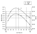
도 46의 그래프에서, 복수의 날개(160,160a)의 제 1면(162,190)의 시작점(M)과 제 2면(163,200)의 시작점(N)을 연결하는 직선(A)이 임펠러(110,110a)의 축방향(X)에 대하여 5ㅀ이상 85ㅀ이하의 경사를 형성할수록 흡입유닛(100,100a)의 흡입력이 증가하는 양상을 확인할 수 있다.46, a straight line A connecting the starting point M of the first surface 162,190 of the plurality of blades 160,160a to the starting point N of the second surface 163,200 is connected to the impeller 110,110a, It is possible to confirm that the suction force of the
도 47은 임펠러의 축방향(X)에 대하여 수직을 이루는 수평방향(Y)으로 리턴 채널을 자른 단면(Q)상에서, 제 1면의 일 단부 및 제 2면의 일 단부를 연결한 직선(B)과 리턴 채널의 중심 및 제 1면의 일 단부를 연결한 직선(C)이 이루는 각도 및 본 발명의 일 실시예에 따른 청소기의 흡입력 사이의 관계를 나타내는 그래프이다.Fig. 47 is a cross-sectional view showing a cross section Q on which a return channel is cut in a horizontal direction Y perpendicular to the axial direction X of the impeller, and a straight line B connecting one end of the first surface and one end of the second surface And the straight line C connecting the center of the return channel and one end of the first surface and the suction force of the vacuum cleaner according to an embodiment of the present invention.
도 47의 그래프에 나타난 바와 같이, 임펠러(110,110a)의 축방향(X)에 대하여 수직을 이루는 수평방향(Y)으로 리턴 채널(130,130a)을 자른 단면(Q)상에서, 상방을 향하는 제 1면(162,190)의 상 단부(162b,190b)와 제 2면(163,200)의 상 단부(163b,200b)를 연결한 직선(B)이 리턴 채널(130,130a)의 중심(O)과 제 1면(162,190)의 상 단부(162b,190b)를 연결한 직선(C)과 이루는 각도(θ)는 0ㅀ이상 80ㅀ이하일 수 있다.As shown in the graph of Fig. 47, on the section Q cut off the
또한, 상방을 향하는 제 1면(162,190)의 상 단부(162b,190b)와 제 2면(163,200)의 상 단부(163b,200b)를 연결한 직선(B)이 리턴 채널(130,130a)의 중심(O)과 제 1면(162,190)의 상 단부(162b,190b)를 연결한 직선(C)과 이루는 각도(θ)가 0ㅀ에 가까울수록 흡입력 및 효율이 우수하다.The straight line B connecting the upper ends 162b and 190b of the upwardly facing
각도(θ)의 표현 중 "-" 및 "+"는 임펠러(110)의 회전방향과의 관계를 나타낸다. 즉, 제 1면(162,190)의 상 단부(162b,190b)와 제 2면(163,200)의 상 단부(163b,200b)를 연결한 직선(B)이 리턴 채널(130,130a)의 중심(O)과 제 1면(162,190)의 상 단부(162b,190b)를 연결한 직선(C)에 대하여 임펠러(110,110a)의 회전방향과 동일한 방향을 향하여 기울어지면 "+"로 표현한다. 반면, 제 1면(162,190)의 상 단부(162b,190b)와 제 2면(163,200)의 상 단부(163b,200b)를 연결한 직선(B)이 리턴 채널(130,130a)의 중심(O)과 제 1면(162,190)의 상 단부(162b,190b)를 연결한 직선(C)에 대하여 임펠러(110,110a)의 회전방향과 반대 방향을 향하여 기울어지면 "-"로 표현한다.&Quot; - "and" + "in the expression of the angle [theta] represent the relationship with the rotational direction of the
이상에서 설명한 흡입유닛(100,100a,100b)은 청소기(1,1a,1000)의 종류에 상관없이 적용 가능하다. 즉, 흡입유닛(100)은 로봇 청소기, 캐니스터(Canister) 방식의 청소기 및 업라이트(Up-right)방식의 청소기에도 적용 가능하다.The
이상에서는 특정의 실시예에 대하여 도시하고 설명하였다. 그러나, 상기한 실시예에만 한정되지 않으며, 발명이 속하는 기술분야에서 통상의 지식을 가진 자라면 이하의 청구범위에 기재된 발명의 기술적 사상의 요지를 벗어남이 없이 얼마든지 다양하게 변경 실시할 수 있을 것이다.The foregoing has shown and described specific embodiments. However, it should be understood that the present invention is not limited to the above-described embodiment, and various changes and modifications may be made without departing from the technical idea of the present invention described in the following claims .
1,1a : 청소기 10 : 본체
10a : 집진실 10b : 흡입실
11 : 흡입부 12 : 연결호스
13 : 연결관 14 : 손잡이
15 : 배기부 16 : 배기유로
16a : 제 1유로 16b : 제 2유로
16c : 제 3유로 17 : 연결배관
18 : 배기필터 20 : 집진장치
21 : 집진장치 커버 22 : 집진장치의 토출구
40 : 케이스 41 : 내부유로
42 : 배출구 100,100a,100b : 흡입유닛
110,110a : 임펠러 111 : 제 1플레이트
112 : 제 2플레이트 113 : 회전날개
114 : 개구홀 115,115a : 유로
120 : 임펠러 커버 121,121a : 흡기구
122,122a : 가이드부 130,130a,130b : 리턴 채널
131 : 이너 프레임 132 : 아우터 프레임
133 : 안착부 134 : 임펠러 수용공간
135,135a : 출구 136 : 모터축관통홀
140,140a : 모터 141 : 모터축
150 : 모터하우징 151 : 연장부
160,160a : 날개 161,161a : 배출유로
162,190,162a : 제 1면 162b,190b : 상 단부
163,200,163a : 제 2면 163b,200b : 상 단부
164 : 연결부 170 : 커버
180 : 수용공간 191 : 스페이스
1000 : 로봇청소기 133a : 돌출부
137 : 입구 200 : 지지유닛
201 : 바디 202 : 냉각핀
210 : 인쇄회로기판 220 : 돌기
165 : 제 1날개 166 : 제 2날개
300 : 하우징 400 : 제 1하우징
410 : 장애물감지센서 500 : 제 2하우징
510 : 집진통 530 : 집진 유닛
540 : 구동휠 541 : 제1구동휠
542 : 제2구동휠 550 : 전원유닛
551 : 메인보드 600 : 연결부재
700 : 범퍼 710 : 완충부재
720 : 진입 차단 센서 511 : 파지부
139a : 제 1유닛 139b : 제 2유닛
131a : 연장부 800 : 서브 날개
900 : 회전방지유닛 911 : 리브
920 : 체결부 930 : 고정부
940 : 고정홈 950 : 노즈콘
960 : 고정부재 1.1a: Cleaner 10: Body
10a:
11: Suction part 12: Connection hose
13: Connector 14: Handle
15: exhaust part 16: exhaust air flow
16a:
16c: third flow path 17: connection piping
18: exhaust filter 20: dust collecting device
21: dust collecting device cover 22: discharge port of the dust collecting device
40: Case 41: Inner channel
42:
110, 110a: impeller 111: first plate
112: second plate 113: rotating blade
114:
120:
122, 122a: guide
131: Inner frame 132: Outer frame
133: seat part 134: impeller accommodation space
135, 135a: Outlet 136: Motor shaft through hole
140, 140a: motor 141: motor shaft
150: motor housing 151: extension
160, 160a:
162, 190, 162a:
163, 200, 163a:
164: connection 170: cover
180: accommodation space 191: space
1000: robot cleaner 133a:
137: inlet 200: support unit
201: body 202: cooling pin
210: printed circuit board 220: projection
165: first wing 166: second wing
300: housing 400: first housing
410: Obstacle detection sensor 500: Second housing
510: dust collecting box 530: dust collecting unit
540: driving wheel 541: first driving wheel
542: second driving wheel 550: power source unit
551: main board 600: connecting member
700: bumper 710: buffer member
720: Entry blocking sensor 511:
139a:
131a: extension part 800:
900: rotation preventing unit 911: rib
920: fastening part 930:
940: Fixing groove 950:
960: Fixing member
Claims (28)
상기 흡입유닛은,
회전 가능한 임펠러(IMPELLER);
흡기구가 형성되는 임펠러 커버(IMPELLER COVER); 및
내부에 상기 임펠러를 수용하도록 상기 임펠러 커버와 결합하는 리턴 채널(RETURN CHANNEL);을 포함하고,
상기 리턴 채널은,
이너 프레임(INNER FRAME); 및
상기 이너 프레임과 이격되도록 상기 이너 프레임의 외측에 위치하는 아우터 프레임(OUTER FRAME);을 포함하고,
상기 이너 프레임 및 상기 아우터 프레임의 사이에는 복수의 날개가 배치되는 것을 특징으로 하는 청소기.A vacuum cleaner comprising a suction unit for generating a suction force for sucking air into the main body,
The suction unit includes:
A rotatable impeller;
An impeller cover having an inlet port formed therein; And
And a return channel coupled to the impeller cover to receive the impeller therein,
The return channel includes:
Inner frame (INNER FRAME); And
And an outer frame (OUTER FRAME) positioned outside the inner frame to be spaced apart from the inner frame,
Wherein a plurality of blades are disposed between the inner frame and the outer frame.
상기 리턴 채널은 상기 임펠러를 통과한 공기가 유입될 수 있도록 상기 임펠러에 직결되는 것을 특징으로 하는 청소기.The method according to claim 1,
Wherein the return channel is directly connected to the impeller so that air passing through the impeller can be introduced.
상기 복수의 날개는 상기 임펠러의 축방향(X)에 대하여 경사를 형성하는 것을 특징으로 하는 청소기.The method according to claim 1,
Wherein the plurality of blades form a slope with respect to an axial direction (X) of the impeller.
상기 임펠러는 제 1방향(H)을 향하여 회전하고,
상기 복수의 날개는 상기 임펠러의 축방향(X)에 대하여 상기 제 1방향(H)과 반대방향인 제 2방향(I)을 따라 경사를 형성하는 것을 특징으로 하는 청소기.The method of claim 3,
The impeller rotates in a first direction (H)
Wherein the plurality of blades form a slope along a second direction (I) opposite to the first direction (H) with respect to an axial direction (X) of the impeller.
상기 복수의 날개는 곡면을 포함하는 것을 특징으로 하는 청소기.The method according to claim 1,
Wherein the plurality of blades include a curved surface.
상기 복수의 날개는 서로 이격되어 상기 임펠러를 통과한 공기가 이동하는 배출유로를 형성하고,
상기 배출유로는,
상기 임펠러를 향하는 일 단부에 형성되는 입구; 및
상기 입구와 이격되도록 다른 단부에 형성되는 출구;를 포함하고,
상기 입구를 통해 상기 배출유로로 유입된 공기는 상기 출구를 통해 상기 흡입유닛의 외측으로 토출되는 것을 특징으로 하는 청소기.The method according to claim 1,
Wherein the plurality of vanes are spaced apart from each other to form an exhaust passage through which the air having passed through the impeller moves,
The discharge passage
An inlet formed at one end facing the impeller; And
And an outlet formed at the other end to be spaced apart from the inlet,
And the air introduced into the discharge passage through the inlet is discharged to the outside of the suction unit through the outlet.
상기 임펠러 커버는 상기 임펠러를 통과한 공기를 상기 입구로 가이드하도록 상기 아우터 프레임에 결합하는 가이드부를 포함하고,
상기 가이드부는 곡면을 가지는 것을 특징으로 하는 청소기.The method according to claim 6,
Wherein the impeller cover includes a guide portion coupled to the outer frame to guide air passing through the impeller to the inlet,
Wherein the guide portion has a curved surface.
상기 가이드부는 상기 임펠러 커버의 외측을 향하여 볼록하고, 곡률 반지름이 1mm 이상인 곡면을 가지는 것을 특징으로 하는 청소기.8. The method of claim 7,
Wherein the guide portion is convex toward the outside of the impeller cover and has a curved surface having a radius of curvature of 1 mm or more.
상기 복수의 날개는,
상기 이너 프레임의 외면과 마주하고, 시작점(M)을 포함하는 제 1면; 및
상기 아우터 프레임의 내면과 마주하고, 상기 시작점(M)과 함께 상기 입구를 형성하는 시작점(N)을 포함하는 제 2면;을 포함하는 것을 특징으로 하는 청소기.The method according to claim 6,
Wherein the plurality of blades
A first surface facing the outer surface of the inner frame and including a starting point (M); And
And a second surface facing the inner surface of the outer frame and including a starting point (N) forming the inlet with the starting point (M).
상기 제 1면의 시작점(M) 및 상기 제 2면의 시작점(N)을 연결하는 직선(A)은 상기 임펠러의 축방향(X)에 대하여 5ㅀ이상 85ㅀ이하의 경사를 형성하는 것을 특징으로 하는 청소기.10. The method of claim 9,
The straight line A connecting the starting point M of the first surface and the starting point N of the second surface forms a slope of not less than 5 ㅀ and not more than 85 에 with respect to the axial direction X of the impeller Cleaner.
상기 임펠러의 축방향(X)에 대하여 수직을 이루는 수평방향(Y)으로 상기 리턴 채널을 자른 단면(Q) 상에서,
상기 임펠러 커버를 향하는 상기 제 1면의 일 단부 및 상기 제 2면의 일 단부를 연결한 직선(B)이 상기 리턴 채널의 중심 및 상기 임펠러 커버를 향하는 상기 제 1면의 일 단부를 연결한 직선(C)과 이루는 각도(θ)는 0ㅀ이상 80ㅀ이하인 것을 특징으로 하는 청소기.10. The method of claim 9,
On a section (Q) of the return channel cut in a horizontal direction (Y) perpendicular to the axial direction (X) of the impeller,
And a straight line (B) connecting one end of the first surface facing the impeller cover and one end of the second surface is a straight line connecting the center of the return channel and one end of the first surface facing the impeller cover And the angle (?) With the center axis (C) is equal to or larger than 0 mm and equal to or smaller than 80 mm.
상기 제 2면의 시작점(N)은 상기 제 1면의 시작점(M)보다 상기 임펠러 커버를 향하여 더 연장되는 것을 특징으로 하는 청소기.10. The method of claim 9,
Wherein the starting point (N) of the second surface further extends toward the impeller cover than a starting point (M) of the first surface.
상기 복수의 날개는 상기 제 1면의 시작점(M) 및 상기 제 2면의 시작점(N)을 연결하는 연결부를 더 포함하고,
상기 연결부는 곡면 및 평면 중 적어도 하나를 포함하는 것을 특징으로 하는 청소기.10. The method of claim 9,
Wherein the plurality of blades further include a connecting portion connecting a starting point (M) of the first surface and a starting point (N) of the second surface,
Wherein the connection portion includes at least one of a curved surface and a flat surface.
상기 연결부는 상기 제 1면의 시작점(M) 및 상기 제 2면의 시작점(N) 중 적어도 하나보다 상기 임펠러 커버를 향하여 더 연장되는 최고점을 포함하는 것을 특징으로 하는 청소기.14. The method of claim 13,
Wherein the connection portion includes a maximum point extending further toward the impeller cover than at least one of a starting point (M) of the first surface and a starting point (N) of the second surface.
상기 흡입유닛은 상기 임펠러가 회전할 수 있는 원동력을 제공하도록 상기 임펠러와 결합하는 모터축을 가지고, 상기 리턴 채널의 내부에 마련되는 모터를 더 포함하는 것을 특징으로 하는 청소기.The method according to claim 1,
Wherein the suction unit further comprises a motor provided inside the return channel, having a motor shaft coupled with the impeller to provide a driving force for rotating the impeller.
상기 흡입유닛은,
회전 가능한 임펠러(IMPELLER);
흡기구가 형성되는 임펠러 커버(IMPELLER COVER); 및
내부에 상기 임펠러를 수용하도록 상기 임펠러 커버와 결합하고, 상기 임펠러를 통과한 공기가 유입될 수 있도록 상기 임펠러에 직결되는 리턴 채널(RETURN CHANNEL);을 포함하고,
상기 리턴 채널은 서로 분리 가능한 복수의 유닛이 결합되어 형성되는 것을 특징으로 하는 청소기.A vacuum cleaner comprising a suction unit for generating a suction force for sucking air into the main body,
The suction unit includes:
A rotatable impeller;
An impeller cover having an inlet port formed therein; And
And a return channel coupled to the impeller cover to receive the impeller therein and directly connected to the impeller so that air passing through the impeller can be introduced,
Wherein the return channel is formed by combining a plurality of units detachable from each other.
상기 복수의 유닛은 상기 임펠러의 축방향(X)에 대하여 경사를 형성하도록 분리 가능한 것을 특징으로 하는 청소기.17. The method of claim 16,
Wherein the plurality of units are separable so as to form an inclination with respect to an axial direction (X) of the impeller.
상기 복수의 유닛은 상기 임펠러의 축방향(X)에 대하여 수직을 이루는 수평방향(Y)으로 분리 가능한 것을 특징으로 하는 청소기.17. The method of claim 16,
Wherein the plurality of units are separable in a horizontal direction (Y) perpendicular to an axial direction (X) of the impeller.
상기 리턴 채널은,
이너 프레임(INNER FRAME);
상기 이너 프레임과 이격되도록 상기 이너 프레임의 외측에 위치하는 아우터 프레임(OUTER FRAME); 및
상기 이너 프레임 및 상기 아우터 프레임의 사이에 배치되는 복수의 날개;를 포함하고,
상기 복수의 유닛은 상기 임펠러의 축방향(X)에 대하여 수직을 이루는 수평방향(Y)으로 분리 가능한 것을 특징으로 하는 청소기.17. The method of claim 16,
The return channel includes:
Inner frame (INNER FRAME);
An outer frame (OUTER FRAME) positioned outside the inner frame to be spaced apart from the inner frame; And
And a plurality of vanes disposed between the inner frame and the outer frame,
Wherein the plurality of units are separable in a horizontal direction (Y) perpendicular to an axial direction (X) of the impeller.
상기 복수의 날개는 상기 임펠러의 축방향(X)에 대하여 경사를 형성하고, 곡면을 포함하는 것을 특징으로 하는 청소기.20. The method of claim 19,
Wherein the plurality of blades form a slope with respect to an axial direction (X) of the impeller, and include curved surfaces.
상기 리턴 채널은 상기 복수의 유닛을 결합시키는 적어도 하나의 회전방지유닛을 더 포함하는 것을 특징으로 하는 청소기.20. The method of claim 19,
Wherein the return channel further comprises at least one anti-rotation unit coupling the plurality of units.
상기 적어도 하나의 회전방지유닛은 서로 이격되도록 상기 리턴 채널의 내측에 형성되는 것을 특징으로 하는 청소기.22. The method of claim 21,
Wherein the at least one anti-rotation unit is formed inside the return channel to be spaced apart from each other.
상기 복수의 유닛은,
상기 임펠러를 통과한 공기가 이동하는 방향(G)의 상류측에 위치하는 제 1유닛; 및
상기 임펠러를 통과한 공기가 이동하는 방향(G)의 하류측에 위치하는 제 2유닛;을 포함하고,
상기 적어도 하나의 회전방지유닛은 상기 제 1유닛 및 상기 제 2유닛 중 어느 하나의 내측에 마련되는 돌기를 포함하는 것을 특징으로 하는 청소기.22. The method of claim 21,
Wherein the plurality of units include:
A first unit positioned on an upstream side of a direction (G) in which air passing through the impeller moves; And
And a second unit located on a downstream side of a direction (G) in which air passing through the impeller moves,
Wherein the at least one rotation preventing unit includes a projection provided inside one of the first unit and the second unit.
상기 적어도 하나의 회전방지유닛은 상기 제 1유닛 및 상기 제 2유닛 중 다른 하나의 내측에 마련되고, 상기 돌기와 분리 가능하도록 결합하는 체결부를 더 포함하는 것을 특징으로 하는 청소기.24. The method of claim 23,
Wherein the at least one rotation preventing unit is provided inside the other of the first unit and the second unit and further comprises a fastening part detachably coupled to the projection.
상기 흡입유닛은,
회전 가능한 임펠러(IMPELLER);
흡기구가 형성되는 임펠러 커버(IMPELLER COVER); 및
내부에 상기 임펠러를 수용하도록 상기 임펠러 커버와 결합하고, 상기 임펠러를 통과한 공기가 유입될 수 있도록 상기 임펠러에 직결되는 리턴 채널(RETURN CHANNEL);을 포함하고,
상기 리턴 채널에는 상기 임펠러의 축방향(X)에 대하여 경사를 형성하는 복수의 날개가 배치되는 것을 특징으로 하는 청소기.A vacuum cleaner comprising a suction unit for generating a suction force for sucking air into the main body,
The suction unit includes:
A rotatable impeller;
An impeller cover having an inlet port formed therein; And
And a return channel coupled to the impeller cover to receive the impeller therein and directly connected to the impeller so that air passing through the impeller can be introduced,
Wherein a plurality of blades forming an inclination with respect to an axial direction (X) of the impeller are disposed in the return channel.
상기 복수의 날개는 곡면을 포함하는 것을 특징으로 하는 청소기.26. The method of claim 25,
Wherein the plurality of blades include a curved surface.
상기 임펠러는 제 1방향(H)을 향하여 회전하고,
상기 복수의 날개는 상기 임펠러의 축방향(X)에 대하여 상기 제 1방향(H)과 반대방향인 제 2방향(I)을 따라 경사를 형성하는 것을 특징으로 하는 청소기.26. The method of claim 25,
The impeller rotates in a first direction (H)
Wherein the plurality of blades form a slope along a second direction (I) opposite to the first direction (H) with respect to an axial direction (X) of the impeller.
상기 리턴 채널은,
이너 프레임(INNER FRAME); 및
상기 이너 프레임과 이격되도록 상기 이너 프레임의 외측에 위치하는 아우터 프레임(OUTER FRAME);을 포함하고,
상기 복수의 날개는 상기 이너 프레임 및 상기 아우터 프레임의 사이에 배치되는 것을 특징으로 하는 청소기.26. The method of claim 25,
The return channel includes:
Inner frame (INNER FRAME); And
And an outer frame (OUTER FRAME) positioned outside the inner frame to be spaced apart from the inner frame,
Wherein the plurality of blades are disposed between the inner frame and the outer frame.
Priority Applications (6)
| Application Number | Priority Date | Filing Date | Title |
|---|---|---|---|
| US14/524,603 US9757000B2 (en) | 2013-12-24 | 2014-10-27 | Cleaning device |
| AU2014370740A AU2014370740B2 (en) | 2013-12-24 | 2014-12-16 | Cleaning device |
| PCT/KR2014/012407 WO2015099350A1 (en) | 2013-12-24 | 2014-12-16 | Cleaning device |
| EP14873210.0A EP3086699B1 (en) | 2013-12-24 | 2014-12-16 | Cleaning device |
| CN201480070651.6A CN105848544B (en) | 2013-12-24 | 2014-12-16 | Cleaning device |
| US15/670,660 US10470633B2 (en) | 2013-12-24 | 2017-08-07 | Cleaning device |
Applications Claiming Priority (2)
| Application Number | Priority Date | Filing Date | Title |
|---|---|---|---|
| KR1020130162088 | 2013-12-24 | ||
| KR20130162088 | 2013-12-24 |
Publications (2)
| Publication Number | Publication Date |
|---|---|
| KR20150075008A true KR20150075008A (en) | 2015-07-02 |
| KR102171271B1 KR102171271B1 (en) | 2020-10-28 |
Family
ID=53788032
Family Applications (1)
| Application Number | Title | Priority Date | Filing Date |
|---|---|---|---|
| KR1020140045033A Active KR102171271B1 (en) | 2013-12-24 | 2014-04-15 | Cleaner |
Country Status (4)
| Country | Link |
|---|---|
| EP (1) | EP3086699B1 (en) |
| KR (1) | KR102171271B1 (en) |
| CN (1) | CN105848544B (en) |
| AU (1) | AU2014370740B2 (en) |
Cited By (2)
| Publication number | Priority date | Publication date | Assignee | Title |
|---|---|---|---|---|
| EP3135169A1 (en) * | 2015-08-24 | 2017-03-01 | Lg Electronics Inc. | Robot cleaner |
| EP3450766B1 (en) * | 2017-08-31 | 2025-10-08 | BSH Hausgeräte GmbH | Fan for an electrical device |
Families Citing this family (2)
| Publication number | Priority date | Publication date | Assignee | Title |
|---|---|---|---|---|
| CN109340187B (en) * | 2018-10-08 | 2021-04-20 | 江苏美的清洁电器股份有限公司 | Fixed impeller for dust collector, fan and dust collector |
| WO2023026264A1 (en) * | 2021-08-27 | 2023-03-02 | Be Wtr Sa | Tap for dispensing either a first or a second liquid |
Citations (6)
| Publication number | Priority date | Publication date | Assignee | Title |
|---|---|---|---|---|
| US6719541B2 (en) * | 2002-04-30 | 2004-04-13 | Northland/Scott Fetzer Company | Fan assembly with application to vacuum cleaners |
| JP3801855B2 (en) * | 2000-11-07 | 2006-07-26 | 株式会社日立製作所 | Electric blower and vacuum cleaner provided with the same |
| JP2011080427A (en) * | 2009-10-08 | 2011-04-21 | Panasonic Corp | Electric blower and vacuum cleaner using the same |
| US20110277267A1 (en) * | 2009-02-06 | 2011-11-17 | Panasonic Corporation | Electric blower and electric vacuum cleaner utilizing the same |
| WO2012103053A2 (en) * | 2011-01-25 | 2012-08-02 | Techtronic Floor Care Technology Limited | Diffuser for a vacuum cleaner motor-fan assembly |
| WO2013053920A1 (en) * | 2011-10-13 | 2013-04-18 | Aktiebolaget Electrolux | Vacuum cleaner |
Family Cites Families (5)
| Publication number | Priority date | Publication date | Assignee | Title |
|---|---|---|---|---|
| CN2083907U (en) * | 1990-12-29 | 1991-09-04 | 朱霖 | Internal circulation type dust collector |
| SE9303599L (en) * | 1993-11-02 | 1995-05-03 | Electrolux Ab | Device for cooling an electric motor driven turbo fan assembly |
| KR970009718A (en) * | 1995-08-31 | 1997-03-27 | 배순훈 | Sound absorption room which lengthened exhaust channel of vacuum cleaner |
| JPH0998918A (en) * | 1995-10-03 | 1997-04-15 | Hitachi Ltd | Electric vacuum cleaner |
| JP2010281232A (en) * | 2009-06-03 | 2010-12-16 | Panasonic Corp | Electric blower and electric vacuum cleaner using the same |
-
2014
- 2014-04-15 KR KR1020140045033A patent/KR102171271B1/en active Active
- 2014-12-16 EP EP14873210.0A patent/EP3086699B1/en active Active
- 2014-12-16 CN CN201480070651.6A patent/CN105848544B/en active Active
- 2014-12-16 AU AU2014370740A patent/AU2014370740B2/en active Active
Patent Citations (6)
| Publication number | Priority date | Publication date | Assignee | Title |
|---|---|---|---|---|
| JP3801855B2 (en) * | 2000-11-07 | 2006-07-26 | 株式会社日立製作所 | Electric blower and vacuum cleaner provided with the same |
| US6719541B2 (en) * | 2002-04-30 | 2004-04-13 | Northland/Scott Fetzer Company | Fan assembly with application to vacuum cleaners |
| US20110277267A1 (en) * | 2009-02-06 | 2011-11-17 | Panasonic Corporation | Electric blower and electric vacuum cleaner utilizing the same |
| JP2011080427A (en) * | 2009-10-08 | 2011-04-21 | Panasonic Corp | Electric blower and vacuum cleaner using the same |
| WO2012103053A2 (en) * | 2011-01-25 | 2012-08-02 | Techtronic Floor Care Technology Limited | Diffuser for a vacuum cleaner motor-fan assembly |
| WO2013053920A1 (en) * | 2011-10-13 | 2013-04-18 | Aktiebolaget Electrolux | Vacuum cleaner |
Cited By (3)
| Publication number | Priority date | Publication date | Assignee | Title |
|---|---|---|---|---|
| EP3135169A1 (en) * | 2015-08-24 | 2017-03-01 | Lg Electronics Inc. | Robot cleaner |
| US10517457B2 (en) | 2015-08-24 | 2019-12-31 | Lg Electronics Inc. | Robot cleaner |
| EP3450766B1 (en) * | 2017-08-31 | 2025-10-08 | BSH Hausgeräte GmbH | Fan for an electrical device |
Also Published As
| Publication number | Publication date |
|---|---|
| EP3086699A4 (en) | 2017-08-23 |
| KR102171271B1 (en) | 2020-10-28 |
| EP3086699A1 (en) | 2016-11-02 |
| CN105848544A (en) | 2016-08-10 |
| AU2014370740A1 (en) | 2016-07-07 |
| EP3086699B1 (en) | 2022-02-02 |
| CN105848544B (en) | 2020-06-30 |
| AU2014370740B2 (en) | 2017-07-13 |
Similar Documents
| Publication | Publication Date | Title |
|---|---|---|
| US10470633B2 (en) | Cleaning device | |
| US12075965B2 (en) | Cleaner | |
| KR102043068B1 (en) | Mechanical fan and Air conditioner comprising the same | |
| US8863353B2 (en) | Vacuum cleaner having dirt cup assembly with internal air guide | |
| US11311162B2 (en) | Vacuum cleaner | |
| KR101970245B1 (en) | Mechanical fan and Air conditioner comprising the same | |
| CN104644057B (en) | Cyclone type vacuum cleaner and dust separator | |
| KR20100116834A (en) | Upright type vacuum cleaner | |
| US10299645B2 (en) | Vacuum cleaner | |
| KR102171271B1 (en) | Cleaner | |
| KR102099346B1 (en) | Fan motor assembly and vacuum cleaner having the same | |
| KR102195707B1 (en) | Cleaner | |
| CA2908157C (en) | Efficient vacuum cleaner fan inlet | |
| CN113520219A (en) | Vertical dust collector | |
| CN110192808B (en) | Vertical dust collector | |
| US10299646B2 (en) | Vacuum cleaner | |
| KR102194862B1 (en) | Fan motor assembly and vacuum cleaner having the same | |
| KR102159581B1 (en) | Vacuum cleaner | |
| KR102171874B1 (en) | Cleaner | |
| KR20150141796A (en) | Cleaner | |
| CN113273925B (en) | Dust collecting device of vacuum cleaner | |
| KR20090118804A (en) | Cyclone dust collecting apparatus and vacuum cleaner having the same | |
| KR102280929B1 (en) | Vacuum cleaner | |
| CN102599851A (en) | Motor box structure for lowering noise of motor |
Legal Events
| Date | Code | Title | Description |
|---|---|---|---|
| PA0109 | Patent application |
St.27 status event code: A-0-1-A10-A12-nap-PA0109 |
|
| PG1501 | Laying open of application |
St.27 status event code: A-1-1-Q10-Q12-nap-PG1501 |
|
| P22-X000 | Classification modified |
St.27 status event code: A-2-2-P10-P22-nap-X000 |
|
| A201 | Request for examination | ||
| PA0201 | Request for examination |
St.27 status event code: A-1-2-D10-D11-exm-PA0201 |
|
| E902 | Notification of reason for refusal | ||
| PE0902 | Notice of grounds for rejection |
St.27 status event code: A-1-2-D10-D21-exm-PE0902 |
|
| E13-X000 | Pre-grant limitation requested |
St.27 status event code: A-2-3-E10-E13-lim-X000 |
|
| P11-X000 | Amendment of application requested |
St.27 status event code: A-2-2-P10-P11-nap-X000 |
|
| P13-X000 | Application amended |
St.27 status event code: A-2-2-P10-P13-nap-X000 |
|
| E701 | Decision to grant or registration of patent right | ||
| PE0701 | Decision of registration |
St.27 status event code: A-1-2-D10-D22-exm-PE0701 |
|
| GRNT | Written decision to grant | ||
| PR0701 | Registration of establishment |
St.27 status event code: A-2-4-F10-F11-exm-PR0701 |
|
| PR1002 | Payment of registration fee |
St.27 status event code: A-2-2-U10-U11-oth-PR1002 Fee payment year number: 1 |
|
| PG1601 | Publication of registration |
St.27 status event code: A-4-4-Q10-Q13-nap-PG1601 |
|
| L13-X000 | Limitation or reissue of ip right requested |
St.27 status event code: A-2-3-L10-L13-lim-X000 |
|
| PR1001 | Payment of annual fee |
St.27 status event code: A-4-4-U10-U11-oth-PR1001 Fee payment year number: 4 |
|
| PR1001 | Payment of annual fee |
St.27 status event code: A-4-4-U10-U11-oth-PR1001 Fee payment year number: 5 |
|
| PR1001 | Payment of annual fee |
St.27 status event code: A-4-4-U10-U11-oth-PR1001 Fee payment year number: 6 |
|
| U11 | Full renewal or maintenance fee paid |
Free format text: ST27 STATUS EVENT CODE: A-4-4-U10-U11-OTH-PR1001 (AS PROVIDED BY THE NATIONAL OFFICE) Year of fee payment: 6 |