KR20150058712A - Touch Screen Controller generating single-ended touch signal, Touch Screen System and Operating Method thereof - Google Patents
Touch Screen Controller generating single-ended touch signal, Touch Screen System and Operating Method thereof Download PDFInfo
- Publication number
- KR20150058712A KR20150058712A KR1020130141586A KR20130141586A KR20150058712A KR 20150058712 A KR20150058712 A KR 20150058712A KR 1020130141586 A KR1020130141586 A KR 1020130141586A KR 20130141586 A KR20130141586 A KR 20130141586A KR 20150058712 A KR20150058712 A KR 20150058712A
- Authority
- KR
- South Korea
- Prior art keywords
- signal
- touch
- differential
- signals
- transmission
- Prior art date
- Legal status (The legal status is an assumption and is not a legal conclusion. Google has not performed a legal analysis and makes no representation as to the accuracy of the status listed.)
- Withdrawn
Links
Images


Classifications
-
- G—PHYSICS
- G06—COMPUTING OR CALCULATING; COUNTING
- G06F—ELECTRIC DIGITAL DATA PROCESSING
- G06F3/00—Input arrangements for transferring data to be processed into a form capable of being handled by the computer; Output arrangements for transferring data from processing unit to output unit, e.g. interface arrangements
- G06F3/01—Input arrangements or combined input and output arrangements for interaction between user and computer
- G06F3/03—Arrangements for converting the position or the displacement of a member into a coded form
- G06F3/041—Digitisers, e.g. for touch screens or touch pads, characterised by the transducing means
- G06F3/0412—Digitisers structurally integrated in a display
-
- G—PHYSICS
- G06—COMPUTING OR CALCULATING; COUNTING
- G06F—ELECTRIC DIGITAL DATA PROCESSING
- G06F3/00—Input arrangements for transferring data to be processed into a form capable of being handled by the computer; Output arrangements for transferring data from processing unit to output unit, e.g. interface arrangements
- G06F3/01—Input arrangements or combined input and output arrangements for interaction between user and computer
- G06F3/03—Arrangements for converting the position or the displacement of a member into a coded form
- G06F3/041—Digitisers, e.g. for touch screens or touch pads, characterised by the transducing means
- G06F3/0416—Control or interface arrangements specially adapted for digitisers
- G06F3/04166—Details of scanning methods, e.g. sampling time, grouping of sub areas or time sharing with display driving
-
- G—PHYSICS
- G06—COMPUTING OR CALCULATING; COUNTING
- G06F—ELECTRIC DIGITAL DATA PROCESSING
- G06F3/00—Input arrangements for transferring data to be processed into a form capable of being handled by the computer; Output arrangements for transferring data from processing unit to output unit, e.g. interface arrangements
- G06F3/01—Input arrangements or combined input and output arrangements for interaction between user and computer
- G06F3/03—Arrangements for converting the position or the displacement of a member into a coded form
- G06F3/041—Digitisers, e.g. for touch screens or touch pads, characterised by the transducing means
- G06F3/0416—Control or interface arrangements specially adapted for digitisers
- G06F3/0418—Control or interface arrangements specially adapted for digitisers for error correction or compensation, e.g. based on parallax, calibration or alignment
-
- G—PHYSICS
- G06—COMPUTING OR CALCULATING; COUNTING
- G06F—ELECTRIC DIGITAL DATA PROCESSING
- G06F3/00—Input arrangements for transferring data to be processed into a form capable of being handled by the computer; Output arrangements for transferring data from processing unit to output unit, e.g. interface arrangements
- G06F3/01—Input arrangements or combined input and output arrangements for interaction between user and computer
- G06F3/03—Arrangements for converting the position or the displacement of a member into a coded form
- G06F3/041—Digitisers, e.g. for touch screens or touch pads, characterised by the transducing means
- G06F3/044—Digitisers, e.g. for touch screens or touch pads, characterised by the transducing means by capacitive means
- G06F3/0446—Digitisers, e.g. for touch screens or touch pads, characterised by the transducing means by capacitive means using a grid-like structure of electrodes in at least two directions, e.g. using row and column electrodes
Landscapes
- Engineering & Computer Science (AREA)
- General Engineering & Computer Science (AREA)
- Theoretical Computer Science (AREA)
- Human Computer Interaction (AREA)
- Physics & Mathematics (AREA)
- General Physics & Mathematics (AREA)
- Position Input By Displaying (AREA)
Abstract
터치 스크린 콘트롤러, 터치 스크린 시스템 및 이를 포함하는 디스플레이 장치가 개시된다. 본 발명의 일 실시예에 따른 터치 스크린 콘트롤러는, 제1 센싱 라인으로 제1 전송 신호를 제공하고, 상기 제1 센싱 라인과 인접한 제2 센싱 라인으로 제2 전송 신호를 제공하며, 상기 제1 및 제2 센싱 라인으로부터 차동 터치 신호를 수신하며, 상기 차동 터치 신호에 대한 연산 처리를 통해 싱글 엔드 터치 신호를 생성하는 터치 데이터 발생부 및 상기 터치 데이터 발생부로부터의 싱글 엔드 터치 신호를 이용하여 터치 좌표를 산출하는 제어 로직을 구비하며, 상기 제1 전송 신호와 상기 제2 전송 신호는 주파수 및 위상 중 적어도 하나가 서로 다른 것을 특징으로 한다.A touch screen controller, a touch screen system and a display device including the same are disclosed. A touch screen controller according to an embodiment of the present invention provides a first transmission signal to a first sensing line and a second transmission signal to a second sensing line adjacent to the first sensing line, A touch data generating unit for receiving a differential touch signal from the second sensing line and generating a single end touch signal through an arithmetic process on the differential touch signal, Wherein the first transmission signal and the second transmission signal have at least one of a frequency and a phase different from each other.
Description
본 발명은 터치 스크린 콘트롤러에 관한 것으로, 자세하게는 싱글 엔드 터치 신호를 생성하는 터치 스크린 콘트롤러, 터치 스크린 시스템 및 이를 포함하는 디스플레이 장치에 관한 것이다. BACKGROUND OF THE
일반적으로 화면을 출력하기 위하여 액정 디스플레이 장치(Liquid Crystal Display, LCD), OLED(Organic Light Emitting Diode) 등의 평판 디스플레이 장치가 널리 이용되고 있다. 평판 디스플레이 장치는 화상을 구현하는 패널을 구비하며, 상기 패널에는 복수 개의 픽셀들이 배치된다. 디스플레이 구동회로(Display Driving IC, DDI)는 패널을 구동하기 위해 이용되며, 디스플레이 구동회로에서 제공되는 데이터 신호(디스플레이 데이터)에 의해 픽셀들이 구동됨에 따라 패널에 화상이 표시된다. In general, flat panel display devices such as a liquid crystal display (LCD) and an organic light emitting diode (OLED) are widely used for outputting a screen. A flat panel display device includes a panel for implementing an image, and a plurality of pixels are disposed on the panel. A display driving IC (DDI) is used to drive a panel, and an image is displayed on a panel as pixels are driven by a data signal (display data) provided in the display driving circuit.
한편, 터치 스크린 시스템은 터치 스크린 패널과 터치 스크린 콘트롤러를 포함할 수 있다. 터치 스크린 패널(일예로서, 커패시티브 터치 스크린 패널)은 복수의 센싱 유닛(sensing unit)을 포함하며, 화면 위에 손가락 또는 터치 펜 등의 물체가 근접하거나 접촉되는 경우 센싱 유닛의 커패시턴스 값이 변화된다. 터치 스크린 프로세서는 상기 센싱 유닛의 커패시턴스 변화를 센싱 라인을 통해 센싱함으로써 터치 데이터를 발생하고, 터치 데이터를 프로세싱함으로써 터치 스크린 패널 상에서 손가락 또는 터치 펜 등의 접촉 유무 및 접촉 위치를 판단한다. Meanwhile, the touch screen system may include a touch screen panel and a touch screen controller. A touch screen panel (e.g., a capacitive touch screen panel) includes a plurality of sensing units, and the capacitance value of the sensing unit is changed when an object such as a finger or a touch pen touches or touches the screen . The touch screen processor generates touch data by sensing a change in capacitance of the sensing unit through a sensing line, processes the touch data, and determines whether or not a finger or a touch pen touches and touches the touch screen panel.
터치 데이터를 발생하는 신호 처리 방식의 일 예로서 차동 입력 방식이 적용될 수 있으며, 차동 입력 방식에서는, 인접하는 센싱라인들로부터 차동 터치 신호가 입력되고, 이로부터 공통 모드 노이즈(Common Mode Noise)가 제거된 터치 데이터가 얻어질 수 있다. 그러나, 차동 입력 방식에서는 싱글 엔드 터치 신호(Single-Ended Touch Signal)를 얻기 위한 추가 처리 과정이 필요하며, 이러한 과정에서 에러 텀(Error Term)이 발생될 수 있는 등 오류가 발생될 수 있다. 또한, 터치 데이터를 발생하는 신호 처리 방식의 다른 예로서 싱글 엔드 입력 방식이 이용될 수 있으며, 싱글 엔드 입력 방식에서는 공통 모드 노이즈(Common Mode Noise) 제거가 어려울 뿐 아니라, 센싱 신호를 처리하기 위한 프로세싱 블록의 개수가 증가하는 등의 문제가 발생될 수 있다. A differential input method can be applied as an example of a signal processing method of generating touch data. In the differential input method, a differential touch signal is input from adjacent sensing lines, and common mode noise is removed The obtained touch data can be obtained. However, in the differential input method, an additional process is required to obtain a single-ended touch signal. In such a process, an error term may be generated. In addition, a single-ended input method can be used as another example of a signal processing method for generating touch data. In the single-ended input method, it is difficult to remove common mode noise, A problem such as an increase in the number of blocks may occur.
본 발명은 상기와 같은 문제점을 해결하기 위한 것으로, 센싱 신호로부터 터치 데이터를 생성함에 있어서 그 정확도를 향상함과 함께, 센싱 블록의 개수를 줄임으로써 구현 면적을 최적화할 수 있는 터치 스크린 콘트롤러, 터치 스크린 시스템 및 이를 포함하는 디스플레이 장치를 제공하는 것을 목적으로 한다.SUMMARY OF THE INVENTION The present invention has been made to solve the above problems and it is an object of the present invention to provide a touch screen controller capable of improving the accuracy in generating touch data from a sensing signal and reducing the number of sensing blocks, System and a display device including the same.
상기와 같은 목적을 달성하기 위해, 본 발명의 일 실시예에 따른 터치 스크린 콘트롤러는, 제1 센싱 라인으로 제1 전송 신호를 제공하고, 상기 제1 센싱 라인과 인접한 제2 센싱 라인으로 제2 전송 신호를 제공하며, 상기 제1 및 제2 센싱 라인으로부터 차동 터치 신호를 수신하며, 상기 차동 터치 신호에 대한 연산 처리를 통해 싱글 엔드 터치 신호를 생성하는 터치 데이터 발생부 및 상기 터치 데이터 발생부로부터의 싱글 엔드 터치 신호를 이용하여 터치 좌표를 산출하는 제어 로직을 구비하며, 상기 제1 전송 신호와 상기 제2 전송 신호는 주파수 및 위상 중 적어도 하나가 서로 다른 것을 특징으로 한다.In order to achieve the above object, a touch screen controller according to an embodiment of the present invention provides a first transmission signal to a first sensing line, a second transmission line to a second sensing line adjacent to the first sensing line, A touch data generator for receiving a differential touch signal from the first and second sensing lines and generating a single end touch signal through an arithmetic operation on the differential touch signal, And a control logic for calculating touch coordinates using a single end touch signal, wherein at least one of the first transmission signal and the second transmission signal is different in frequency and phase.
바람직하게는, 상기 터치 데이터 발생부는, 동일한 주파수를 가지며, 서로 다른 위상을 갖는 상기 제1 및 제2 전송 신호를 생성하는 전송 신호 생성부를 포함하는 것을 특징으로 한다.Preferably, the touch data generator includes a transmission signal generator for generating the first and second transmission signals having the same frequency and different phases.
또한 바람직하게는, 상기 터치 데이터 발생부는, 상기 제1 및 제2 전송 신호의 제공에 의해 여기되는 차동 터치 신호를 수신하는 터치 신호 수신부를 더 포함하는 것을 특징으로 한다.Preferably, the touch data generating unit further includes a touch signal receiving unit for receiving a differential touch signal which is excited by the provision of the first and second transmission signals.
또한 바람직하게는, 상기 터치 데이터 발생부는 신호 처리부를 더 포함하고, 상기 신호 처리부는, 상기 제1 센싱 라인으로부터의 제1 터치 신호를 디모듈레이션하는 제1 디모듈레이터와, 상기 제2 센싱 라인으로부터의 제2 터치 신호를 디모듈레이션하는 제2 디모듈레이터 및 상기 제1 및 제2 디모듈레이터의 출력을 연산함에 의하여, 상기 차동 터치 신호에 대응하는 적어도 하나의 차분 신호를 산출하는 것을 특징으로 한다.Preferably, the touch data generator further includes a signal processor, and the signal processor includes a first demodulator for demodulating a first touch signal from the first sensing line, a second demodulator for demodulating the first touch signal from the second sensing line, A second demodulator for demodulating the first touch signal and the second touch signal, and calculating an output of the first and second demodulators, thereby calculating at least one differential signal corresponding to the differential touch signal.
또한 바람직하게는, 상기 터치 데이터 발생부는, 상기 적어도 하나의 차분 신호를 이용한 연산 동작에 기반하여, 상기 제1 센싱 라인에 대응하는 제1 싱글 엔드 터치 신호 및 상기 제2 센싱 라인에 대응하는 제2 싱글 엔드 터치 신호를 생성하는 싱글 엔드 신호 생성부를 더 포함하는 것을 특징으로 한다.Also, it is preferable that the touch data generation unit generates a touch signal based on the first single-ended touch signal corresponding to the first sensing line and the second single-ended touch signal corresponding to the second sensing line based on the calculation operation using the at least one differential signal. And a single-ended signal generator for generating a single-ended touch signal.
또한 바람직하게는, 상기 터치 데이터 발생부는, 첫 번째 단계에서 서로 위상이 동일한 상기 제1 전송 신호 및 제2 전송 신호를 생성하고, 두 번째 단계에서 서로 반대의 위상을 갖는 상기 제1 전송 신호 및 제2 전송 신호를 생성하는 것을 특징으로 한다.Preferably, the touch data generator generates the first transmission signal and the second transmission signal having the same phase as each other in a first step, and generates the first transmission signal and the second transmission signal having opposite phases in a second step, 2 transmission signal.
또한 바람직하게는, 상기 터치 데이터 발생부는, 상기 첫 번째 단계에서 수신된 제1 차동 터치 신호에 대한 디모듈레이션 및 감산 동작을 통해 제1 차분 신호를 생성하고, 상기 두 번째 단계에서 수신된 제2 차동 터치 신호에 대한 디모듈레이션 및 감산 동작을 통해 제2 차분 신호를 생성하며, 상기 제1 및 제2 차분 신호를 연산함에 의해 상기 싱글 엔드 터치 신호를 생성하는 것을 특징으로 한다.Preferably, the touch data generation unit generates a first difference signal by demodulating and subtracting the first differential touch signal received in the first step, and the second differential signal received in the second step, A second difference signal is generated through demodulation and subtraction operations on the touch signal, and the single ended touch signal is generated by calculating the first and second difference signals.
또한 바람직하게는, 상기 터치 데이터 발생부는, 상기 제1 및 제2 차분 신호에 대한 감산 동작에 기반하여 상기 제1 센싱 라인에 대응하는 제1 싱글 엔드 터치 신호를 생성하며, 상기 제1 및 제2 차분 신호에 대한 합산 동작에 기반하여 상기 제2 센싱 라인에 대응하는 제2 싱글 엔드 터치 신호를 생성하는 것을 특징으로 한다. Preferably, the touch data generator generates a first single-ended touch signal corresponding to the first sensing line based on a subtraction operation on the first and second differential signals, And generates a second single-ended touch signal corresponding to the second sensing line based on a summing operation on the difference signal.
또한 바람직하게는, 상기 터치 데이터 발생부는, 서로 다른 위상을 갖는 적어도 두 개의 베이스 신호들을 수신하고, 상기 베이스 신호들을 제1 방식으로 중합하여 상기 제1 전송 신호를 생성하고, 상기 베이스 신호들을 제2 방식으로 중합하여 상기 제2 전송 신호를 생성하는 것을 특징으로 한다.Preferably, the touch data generator receives at least two base signals having different phases, generates the first transmission signal by superimposing the base signals in a first manner, and outputs the base signals to a second And the second transmission signal is generated.
또한 바람직하게는, 상기 터치 데이터 발생부는, 상기 차동 터치 신호에 대한 제1 디모듈레이션을 통해 제1 및 제2 신호를 생성하고, 상기 차동 터치 신호에 대한 제2 디모듈레이션을 통해 제3 및 제4 신호를 생성하며, 상기 제1 및 제2 신호를 연산하여 제1 차분 신호를 생성하고, 상기 제3 및 제4 신호를 연산하여 제2 차분 신호를 생성하는 것을 특징으로 한다.Preferably, the touch data generator generates first and second signals through a first demodulation for the differential touch signal, and generates second and fourth signals through a second demodulation for the differential touch signal. A first difference signal is generated by operating the first and second signals, and a second difference signal is generated by operating the third and fourth signals.
또한 바람직하게는, 상기 터치 데이터 발생부는, 상기 제1 및 제2 차분 신호에 대한 감산 동작에 기반하여 상기 제1 센싱 라인에 대응하는 제1 싱글 엔드 터치 신호를 생성하며, 상기 제1 및 제2 차분 신호에 대한 합산 동작에 기반하여 상기 제2 센싱 라인에 대응하는 제2 싱글 엔드 터치 신호를 생성하는 것을 특징으로 한다.Preferably, the touch data generator generates a first single-ended touch signal corresponding to the first sensing line based on a subtraction operation on the first and second differential signals, And generates a second single-ended touch signal corresponding to the second sensing line based on a summing operation on the difference signal.
한편, 상기 터치 데이터 발생부는, 적어도 하나의 베이스 신호를 수신하고 이를 코딩하여 상기 제1 및 제2 전송 신호를 생성하며, 상기 차동 터치 신호에 대한 제1 연산 처리를 통해 상기 제1 센싱 라인에 대응하는 제1 싱글 엔드 터치 신호를 생성하고, 상기 차동 터치 신호에 대한 제2 연산 처리를 통해 상기 제2 센싱 라인에 대응하는 제2 싱글 엔드 터치 신호를 생성할 수 있다.The touch data generator receives the at least one base signal and codes the at least one base signal to generate the first and second transmission signals. The touch data generator generates a first transmission signal by corresponding to the first sensing line End touch signal corresponding to the second sensing line through the second calculation process for the differential touch signal.
한편, 본 발명의 다른 실시예에 따른 터치 스크린 콘트롤러는, 주파수 및 위상 중 적어도 하나가 서로 다른 제1 및 제2 전송 신호를 생성하고, 상기 제1 전송 신호를 제1 센싱 라인으로 제공하며, 상기 제2 전송 신호를 상기 제1 센싱 라인에 인접한 제2 센싱 라인으로 제공하는 전송 신호 생성부와, 상기 제1 및 제2 센싱 라인으로부터 차동 터치 신호를 수신하는 터치 신호 수신부 및 상기 차동 터치 신호를 처리하여 터치 좌표 산출에 이용되는 적어도 하나의 신호를 출력하는 신호 처리부를 구비하는 것을 특징으로 한다.Meanwhile, a touch screen controller according to another embodiment of the present invention generates first and second transmission signals having at least one of a frequency and a phase different from each other, provides the first transmission signal as a first sensing line, A transmission signal generator for providing a second transmission signal to a second sensing line adjacent to the first sensing line, a touch signal receiver for receiving a differential touch signal from the first and second sensing lines, And a signal processing unit for outputting at least one signal used for touch coordinate calculation.
한편, 본 발명의 일 실시예에 따른 디스플레이 구동회로는, 패널에 화상을 구현하는 디스플레이 구동부 및 터치 스크린 패널 상의 터치 동작을 센싱하는 터치 스크린 콘트롤러부를 구비하며, 상기 터치 스크린 콘트롤러부는, 상기 터치 스크린 패널 상의 제1 센싱 라인으로 제1 전송 신호를 제공하고, 상기 제1 센싱 라인과 인접한 제2 센싱 라인으로 상기 제1 전송 신호와 주파수 및 위상 중 적어도 하나가 서로 다른 제2 전송 신호를 제공하는 터치 데이터 발생부를 포함하는 것을 특징으로 한다.Meanwhile, the display driving circuit according to an exemplary embodiment of the present invention includes a display driver for implementing an image on a panel, and a touch screen controller for sensing a touch operation on a touch screen panel, wherein the touch screen controller includes: Providing a first transmission signal on the first sensing line and providing a second transmission signal having at least one of a frequency and a phase different from the first transmission signal to a second sensing line adjacent to the first sensing line, And a generating unit.
한편, 본 발명의 일 실시예에 따른 터치 스크린 콘트롤러의 동작방법은, 제1 전송 신호를 제1 센싱 라인으로 제공하는 단계와, 상기 제1 전송 신호와 주파수 및 위상 중 적어도 하나가 서로 다른 제2 전송 신호를 상기 제1 전송 신호에 인접한 제2 센싱 라인으로 제공하는 단계와, 상기 제1 및 제2 센싱 라인으로부터 차동 터치 신호를 수신하는 단계와, 상기 차동 터치 신호에 대한 디모듈레이션 및 연산 과정을 수행하는 단계 및 상기 연산 과정을 통해 얻어진 차분 신호를 연산하여 상기 제1 및 제2 센싱 라인에 각각 대응하는 제1 및 제2 싱글 터치 엔드 신호를 생성하는 단계를 구비하는 것을 특징으로 한다.According to another aspect of the present invention, there is provided a method of operating a touch screen controller, the method comprising: providing a first transmission signal to a first sensing line; The method comprising: providing a transmission signal to a second sensing line adjacent to the first transmission signal; receiving a differential touch signal from the first and second sensing lines; demodulating and computing the differential touch signal; And generating first and second single touch end signals corresponding to the first and second sensing lines, respectively, by calculating a difference signal obtained through the calculation process.
본 발명의 일 실시예의 터치 스크린 콘트롤러, 터치 스크린 시스템 및 이를 포함하는 디스플레이 장치에 따르면, 차동 입력 방식에 따른 차동 터치 신호를 수신하여 이를 처리함으로써 공통 모드 노이즈를 제거할 수 있는 효과가 있다.According to the touch screen controller, the touch screen system, and the display device including the touch screen controller of the embodiment of the present invention, the common mode noise can be removed by receiving and processing the differential touch signal according to the differential input method.
또한, 본 발명의 일 실시예의 터치 스크린 콘트롤러, 터치 스크린 시스템 및 이를 포함하는 디스플레이 장치에 따르면, 싱글 엔드 터치 신호를 터치 데이터로서 후처리 시스템으로 제공할 수 있으므로 터치 좌표 산출을 위한 처리가 용이할 수 있으며, 터치 스크린 콘트롤러에 구비되는 신호 처리 블록의 개수를 감소할 수 있으므로 집적도 향상의 효과가 있다.In addition, according to the touch screen controller, the touch screen system, and the display device including the touch screen controller of the embodiment of the present invention, the single-end touch signal can be provided to the post-processing system as the touch data, Since the number of signal processing blocks provided in the touch screen controller can be reduced, the degree of integration can be improved.
도 1은 본 발명의 실시예에 따른 터치 스크린 콘트롤러가 적용되는 터치 스크린 시스템을 나타내는 블록도이다.
도 2a,b는 본 발명에 적용되는 터치 스크린 패널의 센싱 유닛들에 발생되는 기생 커패시턴스 성분을 나타내는 블록도 및 그래프이다.
도 3은 본 발명의 일 실시예에 따른 터치 스크린 콘트롤러를 나타내는 블록도이다.
도 4는 도 3의 터치 스크린 콘트롤러의 일 구현예를 나타내는 블록도이다.
도 5는 도 4의 터치 데이터 발생부의 일 구현예를 나타내는 블록도이다.
도 6은 다수의 수평 라인들 및 수직 라인들을 포함하는 터치 스크린 패널의 일 예를 나타내는 도면이다.
도 7은 차동 터치 신호로부터 싱글 엔드 터치 신호를 생성하는 일 예를 나타내는 블록도이다.
도 8은 터치 데이터 발생부의 일 구현예를 나타내는 회로도이다.
도 9는 모듈레이션된 전송 신호의 일예를 나타내는 파형도이다.
도 10은 다수 노드들 각각에 인가되는 신호의 일예를 나타내는 표이다.
도 11은 본 발명의 일 실시예에 따른 터치 스크린 콘트롤러의 동작방법을 나타내는 플로우차트이다.
도 12는 본 발명의 다른 실시예에 따른 터치 스크린 콘트롤러의 동작방법을 나타내는 플로우차트이다.
도 13은 본 발명의 다른 실시예에 따른 터치 스크린 콘트롤러의 일 구현예를 나타내는 블록도이다.
도 14는 터치 데이터 발생부의 일 구현예를 나타내는 회로도이다.
도 15는 모듈레이션된 전송 신호의 일예를 나타내는 파형도이다.
도 16은 다수 노드들 각각에 인가되는 신호의 일예를 나타내는 표이다.
도 17은 본 발명의 또 다른 실시예에 따른 터치 스크린 콘트롤러의 동작방법을 나타내는 플로우차트이다.
도 18은 본 발명의 터치 스크린 콘트롤러를 포함하는 터치 디스플레이 구동회로의 일 예를 나타내는 블록도이다.
도 19는 본 발명의 일실시예에 따른 터치 스크린 패널이 장착된 디스플레이 장치의 PCB 구조를 나타내는 도면이다.
도 20a,b는 본 발명의 일 실시예에 따른 터치 스크린 콘트롤러가 내장된 반도체 칩을 장착한 디스플레이 장치를 나타내는 도면이다.
도 21은 본 발명의 일실시예에 따른 터치 스크린 콘트롤러를 포함하는 사용자 장치를 나타내는 블록도이다.1 is a block diagram illustrating a touch screen system to which a touch screen controller according to an embodiment of the present invention is applied.
2A and 2B are a block diagram and a graph showing parasitic capacitance components generated in sensing units of a touch screen panel according to the present invention.
3 is a block diagram illustrating a touch screen controller according to an embodiment of the present invention.
4 is a block diagram illustrating an embodiment of the touch screen controller of FIG.
5 is a block diagram showing an embodiment of the touch data generator of FIG.
6 is a diagram illustrating an example of a touch screen panel including a plurality of horizontal lines and vertical lines.
7 is a block diagram showing an example of generating a single-ended touch signal from a differential touch signal.
8 is a circuit diagram showing an embodiment of the touch data generator.
9 is a waveform diagram showing an example of a modulated transmission signal.
10 is a table showing an example of a signal applied to each of the plurality of nodes.
11 is a flowchart illustrating an operation method of a touch screen controller according to an exemplary embodiment of the present invention.
12 is a flowchart illustrating an operation method of a touch screen controller according to another embodiment of the present invention.
13 is a block diagram illustrating an embodiment of a touch screen controller according to another embodiment of the present invention.
14 is a circuit diagram showing an embodiment of the touch data generating section.
15 is a waveform diagram showing an example of a modulated transmission signal.
16 is a table showing an example of a signal applied to each of the plurality of nodes.
17 is a flowchart illustrating a method of operating a touch screen controller according to another embodiment of the present invention.
18 is a block diagram showing an example of a touch display driving circuit including the touch screen controller of the present invention.
19 is a view showing a PCB structure of a display device equipped with a touch screen panel according to an embodiment of the present invention.
20A and 20B are views showing a display device equipped with a semiconductor chip having a touch screen controller according to an embodiment of the present invention.
21 is a block diagram illustrating a user device including a touch screen controller in accordance with an embodiment of the present invention.
본 발명과 본 발명의 동작상의 이점 및 본 발명의 실시에 의하여 달성되는 목적을 충분히 이해하기 위해서는 본 발명의 바람직한 실시 예를 예시하는 첨부 도면 및 도면에 기재된 내용을 참조하여야 한다. In order to fully understand the present invention, operational advantages of the present invention, and objects achieved by the practice of the present invention, reference should be made to the accompanying drawings and the accompanying drawings which illustrate preferred embodiments of the present invention.
이하, 첨부한 도면을 참조하여 본 발명의 바람직한 실시 예를 설명함으로써, 본 발명을 상세히 설명한다. 각 도면에 제시된 동일한 참조부호는 동일한 부재를 나타낸다. BEST MODE FOR CARRYING OUT THE INVENTION Hereinafter, the present invention will be described in detail with reference to the preferred embodiments of the present invention with reference to the accompanying drawings. Like reference symbols in the drawings denote like elements.
도 1은 본 발명의 실시예에 따른 터치 스크린 콘트롤러가 적용되는 터치 스크린 시스템을 나타내는 블록도이다. 도시된 바와 같이 도 1의 터치 스크린 시스템(100)은, 복수의 센싱 유닛을 포함하는 터치 스크린 패널(110)과 상기 터치 스크린 패널(110)의 센싱 유닛의 커패시턴스 변화를 센싱하고 이를 처리하여 터치 동작의 유무 및 터치 스크린 상에서의 터치 위치를 판단하는 터치 스크린 콘트롤러(1000)를 포함한다. 터치 스크린 패널(110)은 손가락, 터치 펜 등의 물체(또는, 도전체)의 터치(또는 호버링(hovering))에 의하여 발생되는 라인 커패시턴스 변화를 생성하여 터치 스크린 콘트롤러(1000)로 제공한다. 터치나 호버링의 위치가 검출될 수 있도록, 터치 스크린 패널(110)은 수평 라인과 수직 라인들의 격자 구조를 가질 수 있다. 이하에서 언급되는 터치 동작은, 실제 터치 스크린 패널(110) 상에 손가락이나 터치 펜 등의 도전체가 접촉된 경우 및 상기 도전체가 터치 스크린 패널(110)에 근접한 경우를 포함할 수 있다. 1 is a block diagram illustrating a touch screen system to which a touch screen controller according to an embodiment of the present invention is applied. As shown in FIG. 1, the
터치 스크린 패널(110)은 다수의 센싱 유닛들을 포함하며, 예컨대 로우 방향으로 배치된 복수의 센싱 유닛들과 칼럼 방향으로 배치된 복수의 센싱 유닛들을 포함한다. 도 1에 도시된 바와 같이 터치 스크린 패널(110)은 센싱 유닛이 배치되는 복수 개의 로우를 구비하며, 각각의 로우에는 복수 개의 센싱 유닛이 배치된다. 각각의 로우에 배치되는 센싱 유닛들은 서로 전기적으로 연결된다. 또한 터치 스크린 패널(110)은 센싱 유닛이 배치되는 복수 개의 칼럼을 구비하며, 각각의 칼럼에는 복수 개의 센싱 유닛이 배치된다. 각각의 칼럼에 배치되는 센싱 유닛들은 서로 전기적으로 연결된다. The
터치 스크린 콘트롤러(1000)는 터치 스크린 패널(110)의 센싱 유닛의 커패시턴스 변화를 센싱한 센싱 신호를 발생함과 함께, 상기 센싱 신호를 처리하여 터치 데이터를 발생한다. 일예로서, 복수 개의 로우 및 복수 개의 칼럼의 센싱 유닛으로부터의 커패시턴스 변화를 센싱함으로써, 상기 터치 스크린 패널(110) 상에서 터치 동작의 유무 및 터치 위치를 판단한다. The
도 2a,b는 본 발명에 적용되는 터치 스크린 패널의 센싱 유닛들에 발생되는 기생 커패시턴스 성분을 나타내는 블록도 및 그래프이다. 2A and 2B are a block diagram and a graph showing parasitic capacitance components generated in sensing units of a touch screen panel according to the present invention.
도 2a에 도시된 바와 같이 터치 스크린 패널(110)은 복수의 센싱 유닛들(SU)을 포함하며, 상기 센싱 유닛들은 화상을 디스플레이 하기 위한 디스플레이 패널(DSP Panel)에 인접하게 배치되거나 디스플레이 패널 상에 부착될 수 있다. 일예로서 도 2a에 도시된 디스플레이 패널은 소정의 전극 전압(VCOM)이 제공되는 디스플레이 패널의 상판을 나타낸다. 일예로서 액정 디스플레이 패널의 상판으로는 VCOM 전압이 공통 전극 전압으로서 제공될 수 있으며, 유기 발광 디스플레이 패널에서는 DC 전압을 갖는 캐소드(cathode) 전압이 제공될 수 있다. 2A, the
터치 스크린 패널(110)은, 로우 방향(x 방향)으로 배치되는 복수의 센싱 라인에 연결되는 센싱 유닛들(SU)과, 칼럼 방향(y 방향)으로 배치되는 복수의 센싱 라인에 연결되는 센싱 유닛들(SU)을 구비한다. 터치 동작에 따라 센싱 유닛들의 커패시턴스 값이 변화된다. 상기 센싱 유닛의 커패시턴스 변화를 복수의 센싱 라인들을 통하여 센싱하고, 센싱 신호로부터 발생된 터치 데이터를 처리함으로써, 터치 스크린 패널(110) 상의 터치 여부 및 터치 위치가 판단될 수 있다. The
상기 센싱 유닛들(SU)은 그 배치 구조상 기생 커패시턴스 성분이 존재하게 된다. 일예로서, 상기 기생 커패시턴스 성분은, 서로 인접하는 센싱 유닛들간에 발생하는 수평 기생 커패시턴스 성분(Ch)과, 센싱 유닛과 디스플레이 패널 사이에서 발생하는 수직 기생 커패시턴스 성분(Cv)을 포함할 수 있다. The sensing units (SU) have a parasitic capacitance component in their arrangement structure. For example, the parasitic capacitance component may include a horizontal parasitic capacitance component Ch generated between adjacent sensing units and a vertical parasitic capacitance component Cv generated between the sensing unit and the display panel.
도 2b에 도시된 바와 같이, 각각의 센싱 유닛(SU)은 기생 커패시턴스 성분을 포함하여 기본 커패시턴스 성분(Cb)을 가지며, 손가락 또는 터치 펜 등의 물체의 근접 또는 접촉에 의하여 그 커패시턴스 값이 변화하게 된다. 일예로서, 센싱 유닛 상에 도전 물질(conductive object)이 근접하거나 접촉하는 경우에는 센싱 유닛의 커패시턴스 값이 증가하게 된다. 도 2b의 A 구간은 도전 물질이 접촉하지 않은 상태로서, 센싱 유닛의 커패시턴스 값은 Cb 값을 가질 수 있다. 도 2b의 B 구간은 도전 물질이 센싱 유닛에 접촉한 경우를 나타내며, C 구간은 도전 물질이 센싱 유닛에 근접하는 경우를 나타낸다. 도시된 바와 같이 도전 물질이 센싱 유닛에 접촉한 경우 커패시턴스 값의 상승량(Csig)이 커지게 되며, 도전 물질이 센싱 유닛에 근접한 경우 커패시턴스 값의 상승량(Csig')은 상대적으로 작아질 수 있다. As shown in FIG. 2B, each sensing unit SU includes a parasitic capacitance component and has a basic capacitance component Cb, and its capacitance value changes by proximity or contact of an object such as a finger or a touch pen do. For example, when a conductive object comes in contact with or touches the sensing unit, the capacitance value of the sensing unit is increased. The section A in FIG. 2B is a state in which the conductive material is not in contact, and the capacitance value of the sensing unit may have a Cb value. Section B of FIG. 2B shows a case where the conductive material contacts the sensing unit, and section C shows the case where the conductive material comes close to the sensing unit. As shown in the figure, the increase amount Csig of the capacitance value becomes large when the conductive material contacts the sensing unit, and the increase amount Csig 'of the capacitance value can be relatively small when the conductive material is close to the sensing unit.
이는 예시적인 것으로서, 센싱 유닛들의 배치 구조 등의 설계 변화를 통해 커패시턴스 값의 변동이 다른 방식으로 이루어지도록 할 수 있다 .일예로서, 도전체가 접촉되거나 접근되는 경우 커패시턴스 값이 감소되는 형태로 변동될 수도 있다. This may be done by way of example, and variations in the capacitance value may be made in a different way through design changes, such as the arrangement of the sensing units, etc. For example, if the conductor is touched or approached, the capacitance value may be reduced .
도 3은 본 발명의 일 실시예에 따른 터치 스크린 콘트롤러를 나타내는 블록도이다. 도 3에서는 터치 스크린 콘트롤러(1000) 이외에 터치 정보(예컨대, 터치 유무 및 터치 위치에 관련된 정보)를 처리하는 프로세서(120)가 함께 도시된다. 3 is a block diagram illustrating a touch screen controller according to an embodiment of the present invention. In FIG. 3, a
터치 스크린 콘트롤러(1000)는 터치 데이터 발생부(1100) 및 제어 로직(1200)을 포함할 수 있다. 제어 로직(1200)은 터치 스크린 동작과 관련하여 터치 스크린 콘트롤러(1000) 내부의 회로의 전체적인 제어 동작을 수행한다. 또한 터치 데이터 발생부(1100)는 센싱 라인을 통하여 복수의 센싱 유닛들(SU)과 전기적으로 연결되며, 터치 동작에 의한 센싱 유닛들(SU)의 커패시턴스 변화를 센싱함에 의하여 센싱 신호를 발생한다. 또한 상기 발생된 센싱 신호를 처리함에 의하여 터치 데이터(Data_T)를 발생하여 출력한다. 제어 로직(1200) 또는 프로세서(120)는 터치 데이터(Data_T)에 기반하여 소정의 논리 연산을 수행함으로써, 터치 스크린 상에 터치 동작이 수행되었는지 여부와 터치 동작이 수행된 위치를 판별할 수 있다.The
제어 로직(1200)은 센싱 동작 및 터치 데이터(Data_T) 발생 동작과 관련하여 적어도 하나의 제어신호(Ctrl)를 터치 데이터 발생부(1100)로 제공할 수 있다. 예컨대, 터치 데이터 발생부(1100)는 제어신호(Ctrl)에 응답하여 그 내부에서의 신호(예컨대, 터치 스크린 패널로의 전송 신호)의 발생 및 터치 데이터(Data_T) 생성을 위한 샘플링 등 각종 동작을 제어할 수 있다. 터치 데이터 발생부(1100)는 터치 스크린 콘트롤러(1000) 내에서 아날로그 신호들을 처리하는 아날로그 처리부에 해당하고, 제어부(1200)는 수신된 터치 데이터(Data_T)에 대한 디지털 신호 처리 동작을 통해 터치 유무 및 위치를 검출하는 디지털 처리부에 해당할 수 있다. The
본 발명의 실시예에 따르면, 터치 데이터 발생부(1100)는 차동 입력 방식에 따른 차동 터치 신호를 수신하고, 이를 터치 좌표 검출에 적합한 싱글 엔드 터치 신호로 변환하는 변환부를 포함할 수 있다. 예컨대, 터치 데이터 발생부(1100)는 인접하는 센싱 라인들(인접하는 두 개의 센싱 라인들)로부터의 차동 터치 신호를 수신하고, 차동 터치 신호에 대한 차분값을 구함으로써 공통 모드 노이즈가 제거된 차분 신호를 산출하며, 상기 차분 신호를 연산함에 따라 후처리(Post-processing) 동작에 적합한 싱글 엔드 신호를 생성하는 동작을 수행할 수 있다. According to an embodiment of the present invention, the touch
또한, 상기 실시예에 따르면, 터치 데이터 발생부(1100)는 차동 터치 신호를 근거로 하여 신호 처리동작을 수행하고, 이로부터 인접한 센싱 라인들 각각에 대응하는 싱글 엔드 터치 신호가 생성될 수 있으므로, 싱글 엔드 신호 입력 구조에 비하여 센싱 블록의 개수를 줄일 수 있다. 또한, 싱글 엔드 터치 신호가 터치 데이터로서 제공될 수 있으므로, 이후의 시스템(예컨대, 도 3의 제어부나 프로세서)에서의 추가적인 신호 처리 동작이 스킵되도록 할 수 있다. Also, according to the embodiment, the
도 3에 도시된 터치 스크린 콘트롤러의 보다 구체적인 동작을 도 4를 참조하여 설명하면 다음과 같다. 도 4는 도 3의 터치 스크린 콘트롤러의 일 구현예를 나타내는 블록도이다.A more specific operation of the touch screen controller shown in FIG. 3 will be described with reference to FIG. 4 is a block diagram illustrating an embodiment of the touch screen controller of FIG.
도 4에 도시된 바와 같이, 터치 스크린 콘트롤러는 터치 데이터 발생부(1100)와 제어 로직(1200)을 포함할 수 있으며, 터치 데이터 발생부(1100)는 전송 신호 생성부(1110), 터치 신호 수신부(1120), 신호 처리부(1130) 및 싱글 엔드 신호 생성부(1140)를 포함할 수 있다. 터치 데이터 발생부(1100)는 제어 로직(1200)으로부터의 적어도 하나의 제어신호(Ctrl)를 수신하여 터치 데이터(Data_T) 발생 동작을 수행할 수 있으며, 또한 제어 로직(1200)은 터치 데이터(Data_T)에 대한 연산 처리 동작을 통해 터치 유무 및 위치(이하, 터치 좌표로 지칭함)를 검출할 수 있다. 4, the touch screen controller may include a touch
전송 신호 생성부(1110)는 인접하는 센싱 라인들에 대응하여 배치될 수 있으며, 예컨대 한 쌍의 센싱 라인들에 대응하여 배치될 수 있다. 다르게 표현하면, 전송 신호 생성부(1110)는 홀수 번째 센싱 라인에 대응하는 제1 센싱 라인과 짝수 번째 센싱 라인에 대응하는 제2 센싱 라인으로 전송 신호(Tx)를 출력할 수 있다. 또한, 전송 신호 생성부(1110)는 전송 신호(Tx)의 위상 및/또는 주파수를 변경하여 생성할 수 있으며, 또한 서로 다른 위상 및/또는 주파수를 갖는 신호들(예컨대, 베이스 신호들)을 다중화할 수 있는 신호 변조 기능을 구비할 수 있다. The transmission
터치 신호 수신부(1120)는 인접한 두 개의 센싱 라인들(이하, 제1 및 제2센싱 라인으로 지칭함, SL(m), SL(m+1))의 터치 입력 신호를 수신한다. 상기 터치 입력 신호는, 전송 신호(Tx)가 제1 및 제2 센싱 라인들(SL(m), SL(m+1))을 통해 센싱 유닛으로 제공됨에 의해 여기된 신호일 수 있다. 터치 신호 수신부(1120)는 제1 및 제2 센싱 라인들(SL(m), SL(m+1)) 각각에 대응하는 제1 및 제2 증폭기를 포함할 수 있다. 터치 신호 수신부(1120)로부터의 출력은 차동 터치 신호로서 신호 처리부(1130)로 제공될 수 있다.The touch
한편, 신호 처리부(1130)는 수신된 차동 터치 신호에 대한 각종 신호 처리 동작을 수행할 수 있다. 예컨대, 전류를 전압을 변환하는 전류-전압 변환 동작, 전송 신호(Tx)의 모듈레이션 방식에 대응하는 디모듈레이션 동작, 차동 터치 신호 사이의 차분 값(differentiation value)을 산출하는 동작 및 아날로그-디지털 변환 동작 등을 수행할 수 있다. 싱글 엔드 신호 생성부(1140)는 신호 처리부(1130)로부터의 차동 출력을 이용하여 싱글 엔드 터치 신호를 생성하는 동작을 수행할 수 있다. 싱글 엔드 신호 생성부(1140)로부터 생성된 싱글 엔드 터치 신호가 터치 데이터(Data_T)로서 출력될 수 있다. Meanwhile, the
도 4에서는, 터치 데이터 발생부(1100)에 구비되는 구성으로서, 한 쌍의센싱 라인들(예컨대, 제1 및 제2 센싱 라인들(SL(m), SL(m+1))에 대응하여 배치되는 전송 신호 생성부(1110), 터치 신호 수신부(1120), 신호 처리부(1130) 및 싱글 엔드 신호 생성부(1140)가 도시되었으나, 실질적으로 터치 데이터 발생부(1100)는 다수의 쌍들의 센싱 라인들로부터 터치 데이터(Data_T)를 각각 생성할 수 있다. 이에 따라, 터치 데이터 발생부(1100)는 도 4에 도시된 각종 기능 블록들 각각을 복수 개 구비할 수 있다. 4, the touch
도 4에 도시된 기능 블록들을 하나의 그룹의 기능 블록으로 정의할 때, 상기 하나의 그룹의 기능 블록은 한 쌍의 센싱 라인들에 대응하여 배치되므로, 전체 센싱 라인들의 개수가 m 개인 것으로 가정할 때, m/2 개의 그룹의 기능 블록들만이 배치될 수 있다. When the functional blocks shown in FIG. 4 are defined as one group of functional blocks, the functional blocks of one group are arranged corresponding to the pair of sensing lines, so that it is assumed that the total number of sensing lines is m , Only m / 2 groups of functional blocks can be placed.
도 4에 도시된 터치 데이터 발생부(1100)의 일 구현예를 도 5를 참조하여 설명하면 다음과 같다. An example of the
도 5에 도시된 바와 같이, 터치 데이터 발생부(1100)는 한 쌍의 센싱 라인(SL(m), SL(m+1)) 대한 터치 데이터 발생을 위한 기능 블록들을 포함하며, 다른 쌍의 센싱 라인들에 대응하여 도 5에 도시된 기능 블록들이 터치 데이터 발생부(1100)에 추가로 구비될 수 있다. 도 4의 전송 신호 생성부(1110)는, 제1 센싱 라인(SL(m))에 대응하는 제1 전송 신호 생성부(1111)와 제2 센싱 라인(SL(m+1))에 대응하는 제2 전송 신호 생성부(1112)를 포함할 수 있다. 5, the
제1 및 제2 전송 신호 생성부(1111, 1112)는 각각 특정 주파수와 위상을 갖는 전송 신호를 생성하여 이를 터치 스크린 패널로 전송할 수 있다. 예컨대, 제1 전송 신호 생성부(1111)로부터의 제1 전송 신호(Tx(m))는 제2 전송 신호 생성부(1112)로부터의 제2 전송 신호(Tx(m+1))와 위상 및 주파수 중 적어도 하나가 상이할 수 있다. 위상 및/또는 주파수 변조된 신호가 생성되기 위하여, 베이스 신호(Sb)가 제1 및 제2 전송 신호 생성부(1111, 1112)로 각각 제공될 수 있다. 제1 및 제2 전송 신호 생성부(1111, 1112)는 베이스 신호(Sb)의 주파수 및/또는 위상을 변조하여 제1 및 제2 전송 신호(Tx(m), Tx(m+1))를 각각 생성할 수 있다. The first and second
다른 실시예로서, 서로 다른 주파수나 위상을 갖는 두 개 이상의 베이스 신호들이 제1 및 제2 전송 신호 생성부(1111, 1112)로 각각 제공될 수 있으며, 제1 및 제2 전송 신호 생성부(1111, 1112) 각각은 다수의 베이스 신호들을 시간적 또는 공간적으로 중합하여 제1 및 제2 전송 신호(Tx(m), Tx(m+1))를 각각 생성할 수도 있다. As another example, two or more base signals having different frequencies or phases may be provided to the first and second
도 4의 터치 신호 수신부(1120)는, 도 5에 도시된 바와 같이 제1 센싱 라인(SL(m))에 대응하는 제1 터치 신호 수신부(1121)와 제2 센싱 라인(SL(m+1))에 대응하는 제2 터치 신호 수신부(1122)를 포함할 수 있다. 제1 및 제2 전송 신호(Tx(m), Tx(m+1))가 터치 스크린 패널로 제공됨에 따라, 제1 터치 신호(Rx(m)) 및 제2 터치 신호(Rx(m+1))가 제1 및 제2 터치 신호 수신부(1121, 1122)로 각각 제공될 수 있다. 제1 및 제2 터치 신호 수신부(1121, 1122)는 각각 증폭기를 포함할 수 있으며, 한 쌍의 증폭기로부터 차동 터치 신호가 출력될 수 있다. 4, the touch
제1 및 제2 터치 신호 수신부(1121, 1122)로부터의 차동 터치 신호는 신호 처리부(1130)로 제공되며, 신호 처리부(1130)는 터치 스크린 패널에 대한 터치 동작에 따른 커패시턴스 변화가 반영된 차동 터치 신호로부터 차분 신호(differential signal)를 산출한다. 상기 인접한 제1 및 제2 센싱 라인들(SL(m), SL(m+1))에 대한 차분 신호(differential signal)를 산출함에 의하여 공통 모드 노이즈가 제거될 수 있다. 이외에도, 신호 처리부(1130)는 전류-전압 변환 동작, 디모듈레이션 동작, 연산 동작 및 아날로그-디지털 변환 등의 동작을 통해 차분 신호(differential signal)를 생성한다. 싱글 엔드 신호 생성부(1140)는 신호 처리부(1130)로부터의 차분 신호(differential signal)를 이용한 변환 동작을 통해, 제1 및 제2 센싱 라인들(SL(m), SL(m+1)) 각각에 대한 싱글 엔드 터치 신호를 생성하고, 이를 터치 데이터(Data_T(m), Data_T(m+1))로서 출력한다.The differential touch signals from the first and second touch
이하, 본 발명의 다양한 실시예들에 따른 터치 데이터 생성 동작을 설명하면 다음과 같다. 도 6은 다수의 수평 라인들 및 수직 라인들을 포함하는 터치 스크린 패널의 일 예를 나타내는 도면이다. Hereinafter, the operation of generating touch data according to various embodiments of the present invention will be described. 6 is a diagram illustrating an example of a touch screen panel including a plurality of horizontal lines and vertical lines.
도 6에 도시된 바와 같이, 터치 스크린 패널(TSP)는 H 개의 수평 라인들(1~NH)과 V 개의 수직 라인들(1~NV)을 포함할 수 있다. 터치 스크린 패널(TSP)에 대한 터치 동작에 따른 커패시턴스 변화를 센싱함으로써, 터치(또는 호버링)에 의한 터치 좌표, 터치 형태 및 터치 운동성 등에 대한 터치 정보가 추출될 수 있으며, 터치 스크린 패널(TSP)에 구비되는 모든 수평 라인들(1~NH)과 모든 수직 라인들(1~NV)의 터치 신호가 센싱될 수 있다. 전체 수평 라인들(1~NH)과 수직 라인들(1~NV)을 센싱함에 있어서, 적어도 2 회 이상에 걸쳐 센싱 동작이 이루어질 수 있으며, 예컨대 수직 라인들(1~NV)의 개수가 수평 라인들(1~NH)의 개수보다 많을 경우(예컨대, NH < NV < 2* NH)인 경우, 수직 라인들(1~NV)에 대한 센싱 동작은 적어도 2 회 이상으로 나뉘어 수행될 수 있다. As shown in FIG. 6, the touch screen panel TSP may include H
도 7은 차동 터치 신호로부터 싱글 엔드 터치 신호를 생성하는 일 예를 나타내는 블록도이다. 도 7에는 터치 데이터 발생부에 구비되는 신호 처리부 및 싱글 엔드 신호 생성부의 일 구현 예가 도시된다. 7 is a block diagram showing an example of generating a single-ended touch signal from a differential touch signal. 7 shows an example of a signal processing unit and a single-ended signal generator included in the touch data generator.
도 7에 도시된 바와 같이, 신호 처리부(2300)는 하나 이상의 디모듈레이터(2310, 2320) 및 연산부(2330)를 포함할 수 있다. 또한, 싱글 엔드 신호 생성부(2400)는 하나 이상의 연산부(2410, 2420) 및 하나 이상의 레지스터(2430, 2440)를 포함할 수 있다. 한 쌍의 센싱 라인을 도시함에 있어서, 홀수 번째 센싱 라인과 짝수 번째 센싱 라인을 구분하기 위하여, 제1 센싱 라인을 홀수 번째 센싱 라인(2n-1)으로 지칭하며, 제2 센싱 라인을 짝수 번째 센싱 라인(2n)으로 지칭한다.7, the
모듈레이션 동작을 통해 소정의 주파수를 갖는 제1 전송 신호(Tx(2n-1)) 및 제2 전송 신호(Tx(2n))가 터치 스크린 패널의 인접한 센싱 라인들로 제공될 수 있으며, 제1 전송 신호(Tx(2n-1))와 제2 전송 신호(Tx(2n))는 위상 및 주파수 중 적어도 하나가 다른 값을 가질 수 있다. 또한, 전송 신호를 모듈레이션 함에 있어서 시분할 방식이 적용될 수 있으며, 예컨대 하나의 베이스 신호를 두 개의 코드(예컨대, 1, 1 또는 1, -1)로 시분할 코딩하여 제1 및 제2 센싱 라인들로 제공되는 제1 전송 신호(Tx(2n-1)) 및 제2 전송 신호(Tx(2n))가 생성될 수 있다. 또한, 시분할 코딩을 수행함에 있어서 2 개의 단계(Stage) 코딩이 적용될 수 있으며, 예컨대 첫 번째 단계(Stage 1)에서는 제1 전송 신호(Tx(2n-1)) 및 제2 전송 신호(Tx(2n))가 서로 동일한 주파수 및 서로 동일한 위상을 가질 수 있으며, 반면에 두 번째 단계(Stage 2)에서는 제1 전송 신호(Tx(2n-1)) 및 제2 전송 신호(Tx(2n))가 서로 동일한 주파수 및 서로 다른 위상을 가질 수 있다. 예컨대, 두 번째 단계(Stage 2)에서, 제1 전송 신호(Tx(2n-1))와 제2 전송 신호(Tx(2n))는 180도 위상 차를 가짐으로써 서로 반전된 파형을 가질 수 있다. The first transmission signal Tx (2n-1) and the second transmission signal Tx (2n) having a predetermined frequency can be provided to the adjacent sensing lines of the touch screen panel through the modulation operation, At least one of the phase and the frequency of the signal Tx (2n-1) and the second transmission signal Tx (2n) may have different values. Also, a time division scheme may be applied in modulating a transmission signal. For example, the base signal may be time-division-coded into two codes (e.g., 1, 1, or 1, -1) and provided to first and second sensing lines A first transmission signal Tx (2n-1) and a second transmission signal Tx (2n) may be generated. For example, in the first stage (Stage 1), the first transmission signal Tx (2n-1) and the second transmission signal Tx (2n-1) may be applied in performing the time- The first transmission signal Tx (2n-1) and the second transmission signal Tx (2n) may have the same frequency and the same phase with each other in the second stage (Stage 2) They can have the same frequency and different phases. For example, in the second stage (Stage 2), the first transmission signal Tx (2n-1) and the second transmission signal Tx (2n) may have waveforms inverted from each other by having a 180 degree phase difference .
제1 및 제2 센싱 라인을 통해 각각 수신되는 제1 수신 신호(Rx(2n-1)) 및 제2 수신 신호(Rx(2n))는 각각 소정의 파형을 가지며 노이즈를 포함하는 신호일 수 있다. 예컨대, 상기 제1 및 제2 수신 신호(Rx(2n-1), Rx(2n))는 각각 사인(sine) 또는 코사인(cos) 파형을 가질 수 있으며, 디모듈레이터(2310, 2320)를 통해 각각 디모듈레이션되어 연산부(2330)로 제공된다.The first reception signal Rx (2n-1) and the second reception signal Rx (2n) respectively received through the first and second sensing lines may be a signal having a predetermined waveform and including noise. For example, the first and second reception signals Rx (2n-1) and Rx (2n) may have sine or cosine waveforms, respectively, and
연산부(2330)는 수신된 제1 및 제2 수신 신호(Rx(2n-1), Rx(2n))에 대한 연산 처리를 수행할 수 있으며, 예컨대 차분 신호를 얻기 위한 감산 연산을 할 수 있다. 상기 디모듈레이션 동작 및 감산 동작은 두 개의 단계(Stage)들 각각에 대해 수행될 수 있으며, 첫 번째 단계(Stage 1)에서의 차분 신호(예컨대, 제1 차분 신호 Diff_1) 및 두 번째 단계(Stage 2)에서의 차분 신호(예컨대, 제2 차분 신호 Diff_2)가 생성되어 싱글 엔드 신호 생성부(2400)로 제공될 수 있다. 차동 터치 입력에 대한 차분 값이 산출되므로, 상기 싱글 엔드 신호 생성부(2400)로 제공되는 차분 신호들(Diff_1, Diff_2)은 공통 모드 노이즈가 제거된 신호일 수 있다. The calculating
싱글 엔드 신호 생성부(2400)는 제1 연산부(2410) 및 제2 연산부(2420)를 포함할 수 있다. 제1 연산부(2410) 및 제2 연산부(2420)는 서로 다른 연산을 수행할 수 있으며, 예컨대 제1 연산부(2410)는 감산 연산을 수행하고 제2 연산부(2420)는 합산 연산을 수행할 수 있다. 또한, 제1 연산부(2410) 및 제2 연산부(2420) 각각은 제1 차분 신호(Diff_1)와 제2 차분 신호(Diff_2)에 대한 연산을 수행할 수 있다. 시간적으로 선행되어 입력되는 제1 차분 신호(Diff_1)를 일시 저장하기 위하여, 하나 이상의 레지스터(2430, 2440)가 싱글 엔드 신호 생성부(2400)에 구비될 수 있다. The single-ended
제1 연산부(2410)로부터의 연산 결과는 제1 센싱 라인에 대응하는 제1 터치 데이터(Data_T(2n-1))로서 출력될 수 있으며, 또한 제2 연산부(2420)로부터의 연산 결과는 제2 센싱 라인에 대응하는 제2 터치 데이터(Data_T(2n))로서 출력될 수 있다. 상기 제1 및 제2 터치 데이터(Data_T(2n-1), Data_T(2n))는 제1 및 제2 센싱 라인에 각각 대응하는 싱글 엔드 터치 신호로서, 터치 스크린 콘트롤러 내의 제어부 또는 터치 스크린 콘트롤러 외부의 프로세서로 제공됨에 따라 터치 좌표가 산출될 수 있다. The operation result from the
도 7의 터치 데이터 발생부의 보다 구체적인 동작을 도 8 내지 도 10을 참조하여 설명하면 다음과 같다. 도 8은 터치 데이터 발생부의 일 구현예를 나타내는 회로도이며, 도 9는 모듈레이션된 전송 신호의 일예를 나타내는 파형도, 도 10은 다수 노드들 각각에 인가되는 신호의 일예를 나타내는 표이다. A more specific operation of the touch data generator of FIG. 7 will be described with reference to FIGS. 8 to 10. FIG. FIG. 8 is a circuit diagram showing an embodiment of the touch data generator, FIG. 9 is a waveform diagram showing an example of a modulated transmission signal, and FIG. 10 is a table showing an example of a signal applied to each of the plurality of nodes.
도 8에 도시된 바와 같이, 터치 데이터 발생부(2000)는 홀수 번째 센싱 라인(이하, 제1 센싱 라인)에 연결된 제1 터치 신호 수신부(2210)와 짝수 번째 센싱 라인(이하, 제2 센싱 라인)에 연결된 제2 터치 신호 수신부(2220)를 포함할 수 있다. 제1 및 제2 터치 신호 수신부(2210, 2220)는 각각 증폭기를 포함할 수 있으며, 증폭기의 제1 입력단이 제1 센싱 라인 또는 제2 센싱 라인에 연결될 수 있다. 8, the
또한, 터치 데이터 발생부(2000)는 제1 센싱 라인으로 모듈레이션된 제1 전송 신호(Tx(2n-1))를 제공하는 제1 전송 신호 생성부(2110) 및 제2 센싱 라인으로 모듈레이션된 제2 전송 신호(Tx(2n))를 제공하는 제2 전송 신호 생성부(2120)를 포함할 수 있다. 제1 전송 신호 생성부(2110)는 제1 터치 신호 수신부(2210)에 포함되는 증폭기의 제2 입력단에 연결될 수 있으며, 또한 제2 전송 신호 생성부(2120)는 제2 터치 신호 수신부(2220)에 포함되는 증폭기의 제2 입력단에 연결될 수 있다. 증폭기들이 이상적인 연결 상태에 있다고 가정할 때, 제1 전송 신호(Tx(2n-1))는 제1 터치 신호 수신부(2210)에 포함되는 증폭기의 제1 입력단으로 전달되어 터치 스크린 패널로 제공될 수 있으며, 이와 동일 또는 유사한 방식에 따라 제2 전송 신호(Tx(2n))가 터치 스크린 패널(TSP)로 제공될 수 있다. 또한, 증폭기(예컨대, 제1 증폭기, 2210)로의 터치 입력 신호(Rx(2n-1))와 제1 증폭기(2210)로부터의 출력은 해당 증폭기의 이득 값에 따라 서로 같을 수도, 또는 다를 수도 있으나, 이하에서는 제1 증폭기(2210)로 입력되는 터치 입력 신호(Rx(2n-1))와 제1 증폭기(2210)의 출력이 실질적으로 동일한 것으로 가정한다. 이와 같은 가정은 제2 증폭기(2220)의 입출력에 대해서도 동일하게 적용될 수 있다. The
도 9에 도시된 바와 같이, 터치 스크린 패널(TSP)의 수평 라인들에 대한 센싱 동작이 수행됨과 함께, 수직 라인들에 대한 센싱 동작이 수행될 수 있다. 또한, 수직 라인들의 개수가 상대적으로 많은 경우, 상기 수직 라인들에 대한 센싱 동작은 2 회에 걸쳐 수행될 수 있다(이하, 제1 및 제2 수직 라인 센싱 동작으로 지칭함). 수평 라인 센싱 동작과 제1 및 제2 수직 라인 센싱 동작은 실질적으로 동일 또는 유사하게 수행되므로, 수평 라인 센싱 동작을 참조하여 본 발명의 실시예를 설명하면 다음과 같다. As shown in FIG. 9, the sensing operation for the horizontal lines of the touch screen panel TSP may be performed, and the sensing operation for the vertical lines may be performed. In addition, when the number of vertical lines is relatively large, the sensing operation for the vertical lines may be performed twice (hereinafter, referred to as first and second vertical line sensing operations). Since the horizontal line sensing operation and the first and second vertical line sensing operations are performed substantially the same or similar, an embodiment of the present invention will be described with reference to a horizontal line sensing operation.
첫 번째 단계(1st stage)에서 제1 및 제2 센싱 라인들로 동일한 위상의 제1 전송 신호(Tx(2n-1))와 제2 전송 신호(Tx(2n))가 제공된다. 터치 스크린 패널(TSP)의 터치(또는, 호버링)에 의한 커패시턴스 변화에 대응하는 터치 입력 신호(Rx(2n-1), Rx(2n))가 터치 신호 수신부(2210, 2220)로 제공된다. 터치 신호 수신부(2210, 2220)는 수신된 터치 입력 신호(Rx(2n-1), Rx(2n))에 대응하는 차동 터치 신호를 출력한다. 예컨대, 첫 번째 단계(1st stage)에서 제1 터치 신호 수신부(2210)의 출력은 제1 노드(A)에 해당하는 신호로서, 도 10에 도시된 바와 같이 공통 모드 노이즈를 포함하는 사인 파형을 가질 수 있다. 또한, 첫 번째 단계(1st stage)에서 제2 터치 신호 수신부(2220)로부터의 출력은 제2 노드(B)에 해당하는 신호로서, 도 10에 도시된 바와 같이 공통 모드 노이즈를 포함하는 사인 파형을 가질 수 있다The first transmission signal Tx (2n-1) and the second transmission signal Tx (2n) of the same phase are provided to the first and second sensing lines in the first stage. The touch input signals Rx (2n-1) and Rx (2n) corresponding to the capacitance change caused by the touch (or hovering) of the touch screen panel TSP are provided to the touch
신호 처리부(2300)는 제1 및 제2 디모듈레이터(2310, 2320) 및 연산부(2330)를 포함할 수 있으며, 제1 노드(A) 및 제2 노드(B)로부터의 신호가 차동 터치 신호로서 신호 처리부(2300)로 제공될 수 있다. 차동 터치 신호에 대한 디모듈레이션 및 감산 연산이 수행되고, 감산 연산에 따른 결과는 제3 노드(C)에 대응하는 신호로서, 도 10에 도시된 바와 같이 공통 모드 노이즈가 제거된 차분 신호일 수 있다.The
싱글 엔드 신호 생성부(2400)는 제1 및 제2 연산부(2410, 2420)와 제1 및 제2 레지스터(2430, 2440)를 포함할 수 있다. 상기 공통 모드 노이즈가 제거된 제3 노드(C)의 신호는 제1 및 제2 레지스터(2430, 2440)에 각각 저장될 수 있다. 즉, 첫 번째 단계에서 생성된 제3 노드(C)의 신호가 제1 및 제2 레지스터(2430, 2440)에 공통하게 저장되므로, 도 10에 도시된 바와 같이, 첫 번째 단계(1st stage)에서 제4 및 제5 노드(D, E)의 신호는 서로 동일한 값을 가질 수 있다. 상기 제1 및 제2 레지스터(2430, 2440)에 각각 저장된 제3 노드(C)의 신호는 다음의 두 번째 단계(2nd stage)에서 연산에 이용될 수 있다. The single
한편, 두 번째 단계(2nd stage)에서 두 인접한 센싱 라인들로 반대 위상을 갖는 제1 전송 신호(Tx(2n-1))와 제2 전송 신호(Tx(2n))가 제공된다. 터치 스크린 패널(TSP)의 터치(또는, 호버링)에 의한 커패시턴스 변화에 대응하는 터치 입력 신호가 터치 신호 수신부(2210, 2220)로 제공된다.On the other hand, in the second stage, the first transmission signal Tx (2n-1) and the second transmission signal Tx (2n) having opposite phases are provided to two adjacent sensing lines. A touch input signal corresponding to a change in capacitance due to touch (or hovering) of the touch screen panel TSP is provided to the touch
두 번째 단계(2nd stage)에서 수신되는 제1 수신 신호(Rx(m)) 및 제2 수신 신호(Rx(m+1))에 대응하는 차동 터치 신호에 대한 디모듈레이션 및 연산 과정을 거친 신호가 제3 노드(C)로 제공된다. 두 번째 단계(2nd stage)에서 제3 노드(C)로 제공된 신호 또한 공통 모드 노이즈가 제거된 차분 신호일 수 있으며, 상기 두 번째 단계(2nd stage)에서의 차분 신호가 싱글 엔드 신호 생성부(2400)의 제1 및 제2 연산부(2410, 2420)로 각각 제공된다.The demodulation and computation processes of the differential touch signal corresponding to the first reception signal Rx (m) and the second reception signal Rx (m + 1) received in the second stage (second stage) And is provided to the third node (C). The signal provided to the third node C in the second stage may also be a differential signal from which the common mode noise is removed and the differential signal in the second stage may be output to the single- The first and
두 개의 단계들(1st stage, 2nd stage)에 걸쳐 각각 획득된 두 개의 차분 신호들에 대한 연산이 수행되며, 예컨대 제1 연산부(2410)는 두 개의 차분 신호들에 대한 감산 동작을 수행할 수 있으며, 또한 제2 연산부(2420)는 두 개의 차분 신호들에 대한 합산 동작을 수행할 수 있다. 상기 감산 및 합산 연산 결과에 따라, 두 인접하는 라인 각각에 대한 커패시턴스 변화에 대응하는 싱글 엔드 터치 신호가 산출될 수 있다. 도 10에 도시된 바와 같이, 제4 노드(D)에는 제1 센싱 라인에 대응하는 싱글 엔드 터치 신호가 제공되며, 제5 노드(E)에는 제2 센싱 라인에 대응하는 싱글 엔드 터치 신호가 제공된다. 상기와 같이 얻어진 싱글 엔드 터치 신호를 소정의 기준 값(미도시)와의 연산을 통하여, 제1 및 제2 센싱 라인들 각각에 대한 커패시턴스 변화 값이 산출될 수 있다. For example, the
전술한 터치 데이터를 발생하기 위한 동작들은 수직 센싱 라인들에 대해서도 동일 또는 유사하게 수행될 수 있다. 예컨대, 수직 센싱 라인들에 대한 터치 데이터 발생 동작은 2 회로 나뉘어 수행될 수 있으며, 첫 번째 수직 센싱 라인 검출 구간에서 또한 전송 신호가 시분할 코딩되어 제공되고, 첫 번째 단계에서 산출된 차분 신호와 두 번째 단계에서 산출된 차분 신호를 연산함에 의해 싱글 엔드 터치 신호가 생성될 수 있다. 이는 두 번째 수직 센싱 라인 검출 구간에서도 동일한 동작이 수행될 수 있다. The above-described operations for generating the touch data may be performed in the same or similar manner with respect to the vertical sensing lines. For example, the touch data generation operation for the vertical sensing lines can be performed in two divided circuits. In the first vertical sensing line detection period, the transmission signal is also supplied in time division coding, and the difference signal generated in the first stage and the A single-ended touch signal can be generated by calculating the difference signal calculated in the step of FIG. The same operation can be performed in the second vertical sensing line detection period.
상기와 같은 터치 데이터 산출을 위한 디모듈레이션 방식의 차동 터치 센싱 방법에 따르면, 해당 시스템의 구현을 위해 필요한 리소스로서 두 개의 수평 센싱 라인에 대응하여 하나의 신호 처리부만을 필요로 하므로, 전체 수평 라인들의 개수의 절반에 해당하는 신호 처리부들만이 배치되어도 무방하므로 전체 리소스를 감소시킬 수 있다. 이는 수직 센싱 라인들에 대해서도 동일하게 적용될 수 있다. 또한, 차동 터치 데이터 대신에 싱글 엔드 터치 신호를 터치 데이터로서 후처리 시스템에 리포트(Report)할 수 있으므로, 터치 좌표 산출을 위한 처리 작업을 감소시킬 수 있음과 함께 에러 텀(Error Term) 발생을 방지할 수 있다. According to the differential touch sensing method of the demodulation scheme for calculating touch data as described above, since only one signal processing unit is required in correspondence with two horizontal sensing lines as resources necessary for implementing the corresponding system, Only the signal processing units corresponding to half of the total number of the signal processing units can be disposed. The same can be applied to the vertical sensing lines. In addition, since the single-ended touch signal can be reported to the post-processing system as touch data instead of the differential touch data, it is possible to reduce the processing work for calculating the touch coordinates and prevent the occurrence of error term can do.
도 11은 본 발명의 일 실시예에 따른 터치 스크린 콘트롤러의 동작방법을 나타내는 플로우차트이다. 11 is a flowchart illustrating an operation method of a touch screen controller according to an exemplary embodiment of the present invention.
먼저, 전송 신호(Tx)를 모듈레이션하여 터치 스크린 패널로 제공하며(S11), 전송 신호(Tx)를 모듈레이션함에 있어서 인접하는 두 센싱 라인들로 주파수 및 위상 중 적어도 하나가 다른 전송 신호(Tx)를 상기 인접하는 두 센싱 라인들로 제공한다. 전술한 실시예에서와 같이, 어느 하나의 베이스 신호를 시분할 코딩할 수 있으며, 또는 두 개 이상의 베이스 신호들을 중합함에 의하여 전송 신호(Tx)가 생성될 수 있다. First, the transmission signal Tx is modulated and provided to the touch screen panel S11. At the modulation of the transmission signal Tx, at least one of the frequency and the phase is transmitted to the adjacent two sensing lines by another transmission signal Tx And provides the two adjacent sensing lines. As in the above embodiment, either one of the base signals can be time-division-coded, or the transmission signal Tx can be generated by superimposing two or more base signals.
전송 신호(Tx)의 제공에 의해 차동 터치 입력이 여기되고, 이에 대응하는 차동 터치 신호가 터치 스크린 콘트롤러의 터치 데이터 발생부에서 수신된다(S12). 수신된 차동 터치 신호에 대한 디모듈레이션이 수행되며(S13), 또한 디모듈레이션된 차동 터치 신호에 대한 연산값이 산출된다(S14). 연산값 산출 결과에 따라 각각의 센싱 라인에 대응하는 싱글 엔드 터치 신호가 생성되며(S16), 상기 생성된 싱글 엔드 터치 신호에 따른 터치 데이터가 생성된다(S16). 생성된 터치 데이터는 후처리 동작을 위한 시스템으로 제공되며, 예컨대 터치 스크린 콘트롤러 내의 제어부에 의한 후처리 동작에 의해 터치 좌표가 검출된다(S17).The differential touch input is excited by the provision of the transmission signal Tx, and the corresponding differential touch signal is received by the touch data generator of the touch screen controller (S12). The demodulation of the received differential touch signal is performed (S13), and the calculated value for the demodulated differential touch signal is calculated (S14). A single-end touch signal corresponding to each sensing line is generated according to the calculation result of calculation value (S16), and touch data corresponding to the generated single-end touch signal is generated (S16). The generated touch data is provided to a system for a post-processing operation. For example, touch coordinates are detected by a post-processing operation by a control unit in the touch screen controller (S17).
도 12는 본 발명의 다른 실시예에 따른 터치 스크린 콘트롤러의 동작방법을 나타내는 플로우차트이다. 도 12에서는 전술한 실시예에서 설명된 시분할 특성을 갖는 전송 신호 모듈레이션에 의한 싱글 엔드 터치 신호의 생성 과정이 도시된다. 12 is a flowchart illustrating an operation method of a touch screen controller according to another embodiment of the present invention. 12 shows a process of generating a single-ended touch signal by the transmission signal modulation having the time-sharing characteristic described in the above-described embodiment.
먼저, 수평 센싱 라인들(또는, 수직 센싱 라인들)에 대한 센싱 동작을 위해 두 개의 단계가 정의될 수 있으며, 첫 번째 단계에서 한 쌍의 센싱 라인(예컨대, 제1 및 제2 센싱 라인들)에 대응하여 제1 위상 차를 갖는 제1 전송 신호 및 제2 전송 신호가 생성된다(S21). 상기 제1 위상 차는 소정의 값을 가지며, 예컨대 제1 전송 신호 및 제2 전송 신호는 동일한 위상 값을 가질 수 있다. First, two steps may be defined for the sensing operation on the horizontal sensing lines (or vertical sensing lines), and in a first stage a pair of sensing lines (e.g., first and second sensing lines) A first transmission signal and a second transmission signal having a first phase difference are generated (S21). The first phase difference has a predetermined value, for example, the first transmission signal and the second transmission signal may have the same phase value.
제1 및 제2 전송 신호가 각각 제1 및 제2 센싱 라인들로 제공됨에 따라 제1 및 제2 수신 신호가 여기되고, 상기 제1 및 제2 수신 신호는 제1 및 제2 센싱 라인들에 대응하는 제1 차동 터치 신호로서 수신된다(S22). 수신된 제1 차동 터치 신호에 대한 디모듈레이션 및 연산 동작이 수행되며, 예컨대 감산 동작을 통해 제1 차분 신호가 생성된다(S23). 상기 생성된 제1 차분 신호는 이후의 두 번째 단계에서의 연산에 이용되기 위하여 일시 저장될 수 있다(S24).As the first and second transmission signals are provided to the first and second sensing lines, respectively, the first and second reception signals are excited, and the first and second reception signals are applied to the first and second sensing lines Is received as the corresponding first differential touch signal (S22). The demodulation and calculation operation of the received first differential touch signal are performed, and a first differential signal is generated, for example, by a subtraction operation (S23). The generated first difference signal may be temporarily stored in order to be used for the calculation in the second stage (S24).
이후, 수평 센싱 라인들(또는, 수직 센싱 라인들)에 대한 센싱 동작을 위한 두 번째 단계가 수행되고, 두 번째 단계에서 한 쌍의 센싱 라인(예컨대, 제1 및 제2 센싱 라인들)에 대응하여 제2 위상 차를 갖는 제1 전송 신호 및 제2 전송 신호가 생성된다(S25). 상기 제2 위상 차는 소정의 값을 가지며, 예컨대 제1 전송 신호 및 제2 전송 신호는 180도 위상 차이를 가질 수 있다. 즉, 제1 전송 신호와 제2 전송 신호는 서로 반전된 파형을 갖는 신호일 수 있다.Thereafter, a second step for sensing the horizontal sensing lines (or vertical sensing lines) is performed, and a second step is performed for a pair of sensing lines (e.g., first and second sensing lines) A first transmission signal and a second transmission signal having a second phase difference are generated (S25). The second phase difference has a predetermined value, for example, the first transmission signal and the second transmission signal may have a 180 degree phase difference. That is, the first transmission signal and the second transmission signal may be signals having inverted waveforms.
180도 위상 차이를 갖는 제1 및 제2 전송 신호가 각각 제1 및 제2 센싱 라인들로 제공됨에 따라, 이에 대응하는 제2 차동 터치 신호가 수신된다(S26). 전술한 디모듈레이션 및 연산 동작을 통하여 제2 차분 신호가 생성되며(S27), 첫 번째 단계에서 생성된 제1 차분 신호와 두 번째 단계에서 생성된 제2 차분 신호에 대해 연산 동작이 수행된다(S28). 연산 동작 수행 결과에 따라 싱글 엔드 터치 신호가 생성되며(S29), 예컨대, 제1 차분 신호와 제2 차분 신호에 대한 합산 및 감산 중 어느 하나의 동작을 통해 제1 센싱 라인에 대응하는 제1 싱글 엔드 터치 신호가 생성될 수 있다. 또한, 제1 차분 신호와 제2 차분 신호에 대한 합산 및 감산 중 다른 하나의 동작을 통해 제2 센싱 라인에 대응하는 제2 싱글 엔드 터치 신호가 생성될 수 있다.As the first and second transmission signals having a phase difference of 180 degrees are provided to the first and second sensing lines, respectively, the corresponding second differential touch signal is received (S26). The second differential signal is generated through the above-described demodulation and arithmetic operation (S27), and a calculation operation is performed on the first differential signal generated in the first stage and the second differential signal generated in the second stage (S28 ). A single-ended touch signal is generated in accordance with the result of the arithmetic operation (S29). For example, the first and second differential signals are summed and subtracted, End touch signal can be generated. Also, a second single-ended touch signal corresponding to the second sensing line may be generated through another operation of summing and subtracting the first difference signal and the second difference signal.
도 13은 본 발명의 다른 실시예에 따른 터치 스크린 콘트롤러의 일 구현예를 나타내는 블록도이다. 도 13에는 터치 데이터 발생부에 구비되는 신호 처리부 및 싱글 엔드 신호 생성부의 일 구현 예가 도시된다. 13 is a block diagram illustrating an embodiment of a touch screen controller according to another embodiment of the present invention. FIG. 13 shows an example of a signal processing unit and a single-ended signal generating unit included in the touch data generating unit.
도 13에 도시된 바와 같이, 터치 데이터 발생부(3000)는 신호 처리부(3300) 및 싱글 엔드 신호 생성부(3400)를 포함할 수 있다. 신호 처리부(3300)는 하나 이상의 디모듈레이터(3310, 3320) 및 하나 이상의 연산부(3330, 3340)를 포함할 수 있다. 또한, 싱글 엔드 신호 생성부(3400)는 하나 이상의 연산부(3410, 3420)를 포함할 수 있다. As shown in FIG. 13, the
모듈레이션 동작을 통해 소정의 주파수를 갖는 제1 전송 신호(Tx(2n-1)) 및 제2 전송 신호(Tx(2n))가 터치 스크린 패널로 제공될 수 있으며, 제1 전송 신호(Tx(2n-1))와 제2 전송 신호(Tx(2n))는 위상 및 주파수 중 적어도 하나가 다른 값을 가질 수 있다. 본 실시예에서는, 전송 신호를 모듈레이션 함에 있어서 공간 분할 방식이 적용될 수 있으며, 예컨대 서로 다른 위상을 갖는 두 개 이상의 베이스 신호들을 두 개의 코드(1, 1 또는 1, -1)로 코딩 및 중합하여 제1 및 제2 센싱 라인들로 제공되는 제1 전송 신호(Tx(2n-1)) 및 제2 전송 신호(Tx(2n))가 생성될 수 있다. 일 실시예로서, 90도 위상 차이를 갖는 두 개의 베이스 신호를 제1 연산한 신호(예컨대, 두 베이스 신호를 합산한 신호)가 제1 전송 신호(Tx(2n-1))로서 생성될 수 있으며, 두 개의 베이스 신호를 제1 연산한 신호(예컨대, 두 베이스 신호를 감산한 신호)가 제2 전송 신호(Tx(2n))로서 생성될 수 있다.The first transmission signal Tx (2n-1) and the second transmission signal Tx (2n) having a predetermined frequency can be provided to the touch screen panel through the modulation operation and the first transmission signal Tx -1) and the second transmission signal Tx (2n) may have different values of at least one of a phase and a frequency. In this embodiment, a spatial division scheme may be applied in modulating a transmission signal. For example, two or more base signals having different phases may be coded and polymerized into two codes (1, 1 or 1, -1) A first transmission signal Tx (2n-1) and a second transmission signal Tx (2n) provided to the first and second sensing lines may be generated. In one embodiment, a first calculated signal (e.g., a sum of two base signals) of two base signals having a 90 degree phase difference may be generated as a first transmitted signal Tx (2n-1) , A signal obtained by performing a first calculation on two base signals (e.g., a signal obtained by subtracting two base signals) may be generated as a second transmission signal Tx (2n).
하나 이상의 디모듈레이터(3310, 3320)로서, 제1 디모듈레이터(3310)는 제1 수신 신호(2n-1)를 입력받고 이에 대한 디모듈레이션을 수행하며, 또한 제2 디모듈레이터(3320)는 제2 수신 신호(Rx(2n))를 입력받고 이에 대한 디모듈레이션을 수행한다. 전송 신호가 두 개의 베이스 신호를 중합함에 의해 생성된 것에 대응하여, 제1 및 제2 디모듈레이터(3310, 3320) 각각은 두 개 이상의 디모듈레이터를 포함할 수 있으며, 예컨대 제1 디모듈레이터(3310)는 제1 방식의 처리를 수행하는 디모듈레이터와 제2 방식의 처리를 수행하는 디모듈레이터를 포함할 수 있다. 제2 디모듈레이터(3320) 또한 제1 방식의 처리 및 제2 방식의 처리를 각각 수행하는 디모듈레이터들을 포함할 수 있다. The
또한, 하나 이상의 연산부(3330, 3340)로서 제1 연산부(3330)는 제1 및 제2 디모듈레이터(3310, 3320)로부터 신호를 제1 연산하며, 제2 연산부(3340)는 제1 및 제2 디모듈레이터(3310, 3320)로부터 신호를 제2 연산할 수 있다. 예컨대, 제1 연산부(3330)는 제1 방식에 따라 디모듈레이션된 제1 및 제2수신 신호(Rx(2n-1), Rx(2n))에 대한 연산으로서 감산 연산을 수행함으로써 제1 차분 신호(Diff_1)를 생성할 수 있으며, 또한 제2 연산부(3340)는 제2 방식에 따라 디모듈레이션된 제1 및 제2수신 신호(Rx(2n-1), Rx(2n))에 대한 연산으로서 합산 연산을 수행함으로써 제2 차분 신호(Diff_2)를 생성할 수 있다.The
상기와 같이 차동 터치 신호에 대한 디모듈레이션 및 연산 처리에 의해 차분 신호들(Diff_1, Diff_2)이 생성되어 싱글 엔드 신호 생성부(3400)로 제공될 수 있다. 싱글 엔드 신호 생성부(3400)는 제1 연산부(3410) 및 제2 연산부(3420)를 포함할 수 있으며, 각각 제1 및 제2 차분 신호(Diff_1, Diff_2)에 대한 연산 동작을 수행함에 의하여 제1 센싱 라인에 대응하는 제1 터치 데이터(Data_T(2n-1)) 및 제2 센싱 라인에 대응하는 제2 터치 데이터(Data_T(2n))가 생성될 수 있다. 예컨대, 제1 연산부(3410)는 제1 및 제2 차분 신호(Diff_1, Diff_2)에 대한 감산 연산을 수행할 수 있으며, 제2 연산부(3420)는 제1 및 제2 차분 신호(Diff_1, Diff_2)에 대한 합산 연산을 수행할 수 있다.As described above, the differential signals Diff_ 1 and
도 13의 터치 데이터 발생부의 보다 구체적인 동작을 도 14 내지 도 16을 참조하여 설명하면 다음과 같다. 도 14는 터치 데이터 발생부의 일 구현예를 나타내는 회로도이며, 도 15는 모듈레이션된 전송 신호의 일예를 나타내는 파형도, 도 16은 다수 노드들 각각에 인가되는 신호의 일예를 나타내는 표이다. 전술한 실시예에서와 유사하게, 수평 라인 센싱 동작과 제1 및 제2 수직 라인 센싱 동작은 실질적으로 동일 또는 유사하게 수행되므로, 수평 라인 센싱 동작을 참조하여 본 발명의 실시예를 설명하면 다음과 같다. A more specific operation of the touch data generator of FIG. 13 will be described with reference to FIGS. 14 to 16. FIG. FIG. 14 is a circuit diagram showing an embodiment of the touch data generator, FIG. 15 is a waveform diagram showing an example of a modulated transmission signal, and FIG. 16 is a table showing an example of a signal applied to each of a plurality of nodes. Similar to the above-described embodiments, the horizontal line sensing operation and the first and second vertical line sensing operations are performed substantially the same or similar to each other. Therefore, an embodiment of the present invention will be described with reference to a horizontal line sensing operation. same.
도 14에 도시된 바와 같이, 터치 데이터 발생부(3000)는 홀수 번째 센싱 라인(이하, 제1 센싱 라인)에 연결된 제1 터치 신호 수신부(3210)와 짝수 번째 센싱 라인(이하, 제2 센싱 라인)에 연결된 제2 터치 신호 수신부(3220)를 포함할 수 있다. 또한, 터치 데이터 발생부(3000)는 제1 센싱 라인으로 모듈레이션된 제1 전송 신호를 제공하는 제1 전송 신호 생성부(3110) 및 제2 센싱 라인으로 모듈레이션된 제2 전송 신호를 제공하는 제2 전송 신호 생성부(3120)를 포함할 수 있다.14, the
도 15에 도시된 바와 같이, 제1 및 제2 전송 신호 생성부(3110, 3120)는 각각 두 개의 베이스 신호들(Sb1, Sb2)을 이용하여 제1 전송 신호(Tx(2n-1)) 및 제2 전송 신호(Tx(2n))를 생성한다. 예컨대, 제1 베이스 신호(Sb1)와 제2 베이스 신호(Sb2)는 동일한 주파수를 가지며 그 위상이 직교(orthogonal)하는 관계를 갖는 신호일 수 있다. 제1 및 제2 베이스 신호들(Sb1, Sb2)을 중합함에 있어서, 예컨대 제1 베이스 신호(Sb1)와 제2 베이스 신호(Sb2)를 합산한 신호가 제1 전송 신호(Tx(2n-1))로서 생성될 수 있으며, 제2 베이스 신호(Sb2)를 위상 반전한 후 제1 베이스 신호(Sb1)와 위상 반전된 제2 베이스 신호(Sb2_b)를 합산한 신호가 제2 전송 신호(Tx(2n))로서 생성될 수 있다.15, the first and second
제1 터치 신호 수신부(3210)의 출력단에 연결되는 제1 노드(A)로는 도 16에 도시된 바와 같이 소정의 파형(예컨대, 사인 파형)을 갖는 성분과 함께 공통 모드 노이즈를 포함하는 신호가 제공될 수 있다. 이와 유사하게, 제2 터치 신호 수신부(3220)의 출력단에 연결되는 제2 노드(B) 또한, 도 16에 도시된 바와 같이 소정의 파형(예컨대, 사인 파형)을 갖는 성분과 함께 공통 모드 노이즈를 포함하는 신호가 제공될 수 있다.As shown in FIG. 16, the first node A connected to the output terminal of the first touch
전술한 바와 같이, 제1 디모듈레이터(3310)는 두 개 이상의 디모듈레이션 수단들을 포함할 수 있으며, 예컨대 두 개의 베이스 신호들(Sb1, Sb2) 각각에 대응하여 제1 방식의 모듈레이션을 수행하는 제1 모듈레이션 수단(3311) 및 제2 방식의 모듈레이션을 수행하는 제2 모듈레이션 수단(3312)을 포함할 수 있다. 이와 유사하게, 제2 디모듈레이터(3320)는 제1 방식의 모듈레이션을 수행하는 제3 모듈레이션 수단(3321) 및 제2 방식의 모듈레이션을 수행하는 제4 모듈레이션 수단(3322)을 포함할 수 있다. 상기 제1 및 제2 방식의 모듈레이션에 의하여, 제1 수신 신호(Rx(2n-1)) 및 제2 수신 신호(Rx(2n))는 각각 직교한 신호들로 분리된다. 도 14에는 도시되지 않았으나, 디모듈레이션의 정확도를 높이기 위하여, 차동 터치 신호의 라우팅 과정에서 발생될 수 있는 딜레이를 보상하기 위한 회로가 신호 처리부(3300)에 더 구비될 수 있다. As described above, the
제1 내지 제4 모듈레이션 수단들(3311~3322)에 의한 출력단에 연결되는 노드들(예컨대, 제3 내지 제6 노드들, C, D, E, F)의 신호는 도 16에 도시된 표와 같으며, 제3 노드(C)와 제5 노드(E)의 신호가 서로 감산되어 제7 노드(G)의 신호가 생성되며, 또한, 제4 노드(D)와 제6 노드(F)의 신호가 서로 감산되어 제8 노드(H)의 신호가 생성된다. Signals of nodes (e.g., third to sixth nodes, C, D, E, and F) connected to output terminals by the first to fourth modulation units 3311 to 3322 are shown in the table shown in FIG. 16 The signals of the third node C and the fifth node E are subtracted from each other to generate a signal of the seventh node G and the signals of the fourth node D and the sixth node F are generated, The signals are subtracted from each other to generate a signal at the eighth node (H).
상기와 같은 디모듈레이션 및 연산 동작에 의해 제7 노드(G)의 신호와 제8 노드(H)의 신호를 포함하는 차분 신호가 싱글 엔드 신호 생성부(3400)로 제공된다. 싱글 엔드 신호 생성부(2400)는 상기 차분 신호에 대한 제1 연산 및 제2 연산 동작을 수행하며, 예컨대 제1 연산부(3410)는 차분 신호에 대한 감산 동작을 수행하여 제9 노드(I)의 신호를 제1 센싱 라인에 대응하는 싱글 엔드 터치 신호로서 제공할 수 있다. 또한, 제2 연산부(3420)는 차분 신호에 대한 감산 동작을 수행하여 제10 노드(J)의 신호를 제2 센싱 라인에 대응하는 싱글 엔드 터치 신호로서 제공할 수 있다.The differential signal including the signal of the seventh node G and the signal of the eighth node H is provided to the single-ended
상기와 같은 동작에 따라, 터치 동작에 의한 제1 및 제2 센싱 라인들 각각의 커패시턴스 값을 공통 모드 노이즈를 제거하고 구할 수 있다. 또한, 특정 시점의 기준 값과 싱글 엔드 터치 신호와 연산함에 의하여, 터치 동작에 의한 제1 및 제2 센싱 라인들 각각의 커패시턴스 변화량이 산출될 수 있다. 또한, 상기 실시예에 따르면 전술한 2 단계의 센싱 동작에 비하여 센싱 시간을 절반으로 감소할 수 있다.According to the above operation, the capacitance value of each of the first and second sensing lines by the touch operation can be obtained by removing the common mode noise. Also, by computing the reference value at a specific point in time and the single-ended touch signal, the amount of capacitance change of each of the first and second sensing lines due to the touch operation can be calculated. In addition, according to the embodiment, the sensing time can be reduced by half as compared with the sensing operation of the two stages described above.
도 17은 본 발명의 또 다른 실시예에 따른 터치 스크린 콘트롤러의 동작방법을 나타내는 플로우차트이다. 도 17에서는 서로 다른 위상을 갖는 두 개의 베이스 신호들을 코딩 및 중합하여 전송 신호를 생성하고, 이로부터 싱글 엔드 터치 신호가 생성되는 예가 도시된다.17 is a flowchart illustrating a method of operating a touch screen controller according to another embodiment of the present invention. In FIG. 17, an example is shown in which two base signals having different phases are coded and superimposed to generate a transmission signal, from which a single-ended touch signal is generated.
먼저, 서로 다른 위상을 갖는 제1 베이스 신호 및 제2 베이스 신호를 코딩 및 중합하여 인접하는 센싱 라인들로 제공되는 제1 및 제2 전송 신호를 생성한다(S31). 제1 베이스 신호 및 제2 베이스 신호는 소정의 위상 차를 가질 수 있으며, 예컨대 제1 베이스 신호 및 제2 베이스 신호는 직교(orthogonal)하는 관계를 갖는 신호일 수 있다. 제1 전송 신호는 제1 베이스 신호와 제2 베이스 신호를 합산하여 생성될 수 있으며, 제2 전송 신호는 제1 베이스 신호와 위상 반전된 제2 베이스 신호를 합산하여 생성될 수 있다.First, a first base signal and a second base signal having different phases are coded and polymerized to generate first and second transmission signals provided to adjacent sensing lines (S31). The first base signal and the second base signal may have a predetermined phase difference, and for example, the first base signal and the second base signal may be signals having an orthogonal relationship. The first transmission signal may be generated by summing the first base signal and the second base signal, and the second transmission signal may be generated by summing the first base signal and the second base signal that is phase-inverted.
제1 및 제2 전송 신호가 각각 인접하는 제1 및 제2 센싱 라인들로 제공됨에 따라, 제1 및 제2 센싱 라인들 각각에 제1 및 제2 수신 신호가 여기된다. 상기 여기된 제1 및 제2 수신 신호가 차동 터치 신호로서 터치 스크린 콘트롤러 내 터치 데이터 발생부에서 수신된다(S32).As the first and second transmission signals are provided to the adjacent first and second sensing lines, respectively, the first and second reception signals are excited in the first and second sensing lines, respectively. The excited first and second received signals are received as a differential touch signal in the touch data generator in the touch screen controller (S32).
제1 및 제2 베이스 신호 각각에 대한 모듈레이션에 대응하여, 차동 터치 신호에 대한 디모듈레이션 동작이 수행된다(S33). 예컨대, 차동 터치 신호에 대한 제1 방식의 디모듈레이션을 통해 제1 차동 터치 신호가 생성되며, 또한 차동 터치 신호에 대한 제2 방식의 디모듈레이션을 통해 제2 차동 터치 신호가 생성된다. 상기와 같은 디모듈레이션된 차동 신호들에 대한 차분 신호가 산출될 수 있으며, 예컨대 제1 차동 터치 신호에 대한 감산 동작을 통해 제1 차분 신호가 산출되고, 제2 차동 터치 신호에 대한 감산 동작을 통해 제2 차분 신호가 산출될 수 있다.In accordance with the modulation for each of the first and second base signals, a demodulation operation for the differential touch signal is performed (S33). For example, a first differential touch signal is generated through a first-type demodulation of the differential touch signal, and a second differential touch signal is generated through a second-type demodulation of the differential touch signal. The difference signal for the demodulated differential signals can be calculated. For example, the first differential signal is calculated through the subtraction operation with respect to the first differential touch signal, and the subtraction operation with respect to the second differential touch signal is performed A second difference signal can be calculated.
상기 산출된 제1 및 제2 차분 신호들로부터 터치 데이터가 발생될 수 있다. 예컨대, 제1 및 제2 차분 신호들에 대한 연산 동작이 수행되며(S35), 일 실시예로서 제1 및 제2 차분 신호들 사이의 감산 동작을 통해 제1 센싱 라인에 대응하는 제1 싱글 엔드 신호가 생성되며, 제1 및 제2 차분 신호들 사이의 합산 동작을 통해 제2 센싱 라인에 대응하는 제2 싱글 엔드 신호가 생성될 수 있다(S36). 이는 싱글 엔드 터치 신호를 산출하기 위한 일 예에 불과한 것으로서, 다른 다양한 형태의 연산 동작을 통해 차분 신호로부터 싱글 엔드 터치 신호가 생성되어도 무방하다.Touch data may be generated from the calculated first and second differential signals. For example, a calculation operation is performed on the first and second differential signals (S35). In one embodiment, the first and second differential signals corresponding to the first sensing line are subjected to a subtraction operation between the first and second differential signals A signal is generated, and a second single-ended signal corresponding to the second sensing line may be generated through a summing operation between the first and second differential signals (S36). This is merely an example for calculating a single end touch signal, and a single end touch signal may be generated from a differential signal through various other types of arithmetic operations.
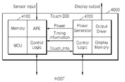
도 18은 본 발명의 터치 스크린 콘트롤러를 포함하는 터치 디스플레이 구동회로의 일 예를 나타내는 블록도이다. 본 발명의 일실시예에 따른 터치 스크린 콘트롤러는 디스플레이 패널을 구동하여 화상을 출력하기 위한 디스플레이 구동회로와 하나의 칩에 집적된 집적 IC 형태로 구현될 수 있다. 터치 스크린 콘트롤러와 디스플레이 구동회로를 하나의 반도체 칩에 집적함에 의하여 생산 비용을 절감할 수 있으며, 또한 디스플레이 동작에 관련된 다양한 형태의 타이밍 신호를 터치 데이터 발생 동작에 이용되도록 할 수 있으므로 터치 스크린 동작시 노이즈에 의한 영향을 감소시킬 수 있도록 한다.18 is a block diagram showing an example of a touch display driving circuit including the touch screen controller of the present invention. The touch screen controller according to an exemplary embodiment of the present invention may be implemented as a display driver circuit for driving a display panel to output an image and an integrated IC integrated on one chip. Since the production cost can be reduced by integrating the touch screen controller and the display drive circuit in one semiconductor chip and various types of timing signals related to the display operation can be used for the touch data generation operation, Thereby reducing the influence of the radiation.
도 18에 도시된 바와 같이, 디스플레이 패널을 구동하기 위한 반도체 칩(4000)은 터치 콘트롤러부(4100)와 디스플레이 구동부(4200)를 포함할 수 있다. 터치 콘트롤러부(4100)는 메모리, AFE, MCU 및 제어 로직 등을 포함할 수 있으며, 디스플레이 구동부(4200)는 전력 발생부, 출력 드라이버, 제어 로직 및 디스플레이 메모리 등을 포함할 수 있다. 상기 터치 콘트롤러부(4100)와 디스플레이 구동부(4200)는 서로 타이밍 정보, 상태 정보 등의 적어도 하나의 정보를 서로 송수신할 수 있다. 또한 터치 콘트롤러부(4100)와 디스플레이 구동부(4200)는 서로 전원전압을 제공하거나 수신할 수 있다. As shown in FIG. 18, the
도 18에는 설명의 편의상 터치 콘트롤러부(4100)와 디스플레이 구동부(4200)가 간략히 도시되었으며, 터치 콘트롤러부(4100)에 구비되는 AFE(Analog Front End)는 전술한 실시예에서의 전송 신호 생성부, 터치 신호 수신부, 신호 처리부 및 싱글 엔드 신호 생성부를 포함하는 블록일 수 있다. AFE(Analog Front End)로부터 생성된 터치 데이터는 호스트나 디스플레이 구동부(4200)로 제공될 수 있으며, 상기 터치 데이터에 근거하여 터치 좌표가 산출될 수 있다. 또한, 전술한 실시예들 중 적어도 하나가 AFE(Analog Front End)에 적용될 수 있으며, 이에 따라 AFE(Analog Front End)는 차동 터치 신호에 대한 차분 신호 산출 및 이에 대한 연산 처리를 통해 싱글 엔드 신호를 산출하는 동작을 수행할 수 있다. 18, the
도 19는 본 발명의 일실시예에 따른 터치 스크린 패널이 장착된 디스플레이 장치의 PCB 구조를 나타내는 도면이다. 도 19에서는 터치 스크린 패널과 디스플레이 패널이 서로 구분되는 구조를 갖는 디스플레이 장치를 나타낸다. 19 is a view showing a PCB structure of a display device equipped with a touch screen panel according to an embodiment of the present invention. 19 shows a display device having a structure in which a touch screen panel and a display panel are distinguished from each other.
도 19에 도시된 바와 같이, 상기 디스플레이 장치(5000)는 윈도우 글라스(5100), 터치 스크린 패널(5200) 및 디스플레이 패널(5400)을 구비할 수 있다. 또한 터치 스크린 패널(5200)과 디스플레이 패널(5400)의 사이에는 광학적 특성을 위해 편광판(5300)이 더 배치될 수 있다.As shown in FIG. 19, the
윈도우 글라스(5100)는 일반적으로 아크릴이나 강화유리 등의 소재로 제작되어, 외부 충격이나 반복적인 터치에 의한 긁힘으로부터 모듈을 보호한다. 터치 스크린 패널(5200)은 유리기판이나 PET(Polyethylene Terephthlate) 필름 위에 ITO(Indium Tin Oxide)와 같은 투명 전극을 이용하여 전극을 패터닝하여 형성된다. 터치 스크린 콘트롤러(5210)는 FPCB(Flexible Printed Circuit Board) 위에 COB(Chip on Board) 형태로 실장될 수 있으며, 각각의 전극으로부터의 커패시턴스 변화를 감지하여 터치 좌표를 추출하고 이를 호스트로 제공한다. 디스플레이 패널(5400)은 일반적으로 상판과 하판으로 이루어진 두 장의 유리를 접합하여 형성된다. 또한 일반적으로 모바일용 디스플레이 패널에는 디스플레이 구동회로(5410)가 COG(Chip on Glass) 형태로 부착될 수 있다. 도 19에서는 터치 스크린 콘트롤러와 디스플레이 구동회로가 별도의 칩으로 구현되는 예가 도시되었으나, 전술한 바와 같이 터치 스크린 콘트롤러와 디스플레이 구동회로는 하나의 칩으로 구현되어 디스플레이 장치(5000)에 장착될 수도 있다.The
도 20a,b는 본 발명의 일 실시예에 따른 터치 스크린 콘트롤러가 내장된 반도체 칩을 장착한 디스플레이 장치를 나타내는 도면이다. 도 20a는 반도체 칩이 디스플레이 패널의 글라스(Glass)에 COG(Chip on Glass) 형태로 배치된 일예를 나타내며, 도 20b는 반도체 칩이 디스플레이 패널의 필름(Film) 상에 COF(Chip on Film) 형태로 배치된 일예를 나타낸다. 터치 콘트롤러와 디스플레이 구동회로가 서로 구분되는 칩으로 배치되는 경우에는, 터치 콘트롤러는 COF 형태로 배치되고 디스플레이 구동회로는 COG 형태로 배치될 수 있다. 또한, 일 실시예로서, 터치 스크린 콘트롤러와 디스플레이 구동회로가 집적된 반도체 칩은 상기 COG 및 COF 중 어느 하나의 형태로 배치되어도 무방하다.20A and 20B are views showing a display device equipped with a semiconductor chip having a touch screen controller according to an embodiment of the present invention. 20A shows an example in which a semiconductor chip is arranged in a COG (Chip on Glass) form on a glass of a display panel, FIG. 20B shows an example in which a semiconductor chip is formed on a film of a display panel in the form of a COF As shown in Fig. When the touch controller and the display driving circuit are arranged as chips that are separated from each other, the touch controller may be arranged in a COF form and the display driving circuit may be arranged in a COG form. In one embodiment, the semiconductor chip on which the touch screen controller and the display driving circuit are integrated may be disposed in any one of the COG and the COF.
도 21은 본 발명의 일실시예에 따른 터치 스크린 콘트롤러를 포함하는 사용자 장치를 나타내는 블록도이다. 도 21에 도시된 바와 같이, 사용자 장치(6000)는 중앙 처리 장치(6100), 메모리부(6200), 오디오부(6300), 파워 공급부(6400), 디스플레이 구동회로(6500) 및 디스플레이 패널(6600)을 포함할 수 있다. 디스플레이 구동회로(6500) 내에 본 발명의 실시예에 따른 터치 스크린 콘트롤러가 구비될 수 있다.21 is a block diagram illustrating a user device including a touch screen controller in accordance with an embodiment of the present invention. 21, the
중앙 처리 장치(6100)는 사용자 장치(6000)의 전반적인 동작을 제어하며, 예컨대 전원이 공급됨에 따라 사용자 장치(6000)의 부팅 과정을 제어할 수 있다. 또는, 중앙 처리 장치(6100)는 사용자 장치(6000)를 제어하기 위한 펌웨어를 구동할 수 있다. 상기 펌웨어는 메모리부(6200)에 로딩되어 구동될 수 있다. The central processing unit 6100 controls the overall operation of the
한편, 메모리부(6200)는 디램과 같은 휘발성 메모리 장치, 또는 롬(ROM)이나 플래시 메모리 장치와 같은 불휘발성 메모리 장치를 포함할 수 있다. 예컨대, 메모리부(6200)에는 사용자 장치(6000)를 구동하기 위한 운영 체제, 어플리케이션 프로그램, 펌웨어 등이 저장될 수 있다. 또한 메모리부(6200)에 포함되는 휘발성 메모리 장치에는 중앙 처리 장치(6100)의 제어에 따라 운영 체제, 어플리케이션 프로그램 및 펌웨어 등이 로딩될 수 있다. On the other hand, the memory unit 6200 may include a volatile memory device such as a DRAM, or a non-volatile memory device such as a ROM or a flash memory device. For example, an operating system, an application program, firmware, and the like for driving the
오디오부(6300)는 중앙 처리 장치(6100)의 제어에 따라 음성 데이터를 재생할 수 있으며, 파워 공급부(6400)는 사용자 장치(6000)를 구동하기 위해 필요한 전력을 제공한다. 한편, 디스플레이 구동부(6500)는 전술한 실시예에서와 같은 터치 스크린 콘트롤러를 포함할 수 있으며, 디스플레이 패널(6600)에 포함되는 터치 스크린 패널(미도시) 상의 센싱 유닛의 커패시턴스 변화를 검출하여 터치 데이터를 생성할 수 있다. 예컨대, 디스플레이 구동부(6500)의 터치 스크린 콘트롤러는, 하나 이상의 베이스 신호를 모듈하여 전송 신호를 생성하고, 이로부터 여기된 차동 터치 신호를 디모듈 및 연산하여 싱글 엔드 신호를 생성하는 터치 데이터 발생부를 포함할 수 있다. 또한, 디스플레이 구동부(6500) 내에서 싱글 엔드 신호로부터 터치 좌표를 검출하는 동작이 수행되거나, 또는 디스플레이 구동부(6500)로부터의 터치 데이터에 근거하여 중앙 처리 장치(6100)에서 터치 좌표 검출을 위한 동작이 수행될 수도 있다.The audio unit 6300 can reproduce the voice data under the control of the central processing unit 6100 and the power supply unit 6400 provides the power necessary for driving the
본 발명은 도면에 도시된 실시 예를 참고로 설명되었으나 이는 예시적인 것에 불과하며, 본 기술 분야의 통상의 지식을 가진 자라면 이로부터 다양한 변형 및 균등한 다른 실시 예가 가능하다는 점을 이해할 것이다. 따라서, 본 발명의 진정한 기술적 보호 범위는 첨부된 특허청구범위의 기술적 사상에 의하여 정해져야 할 것이다. While the present invention has been described with reference to exemplary embodiments, it is to be understood that the invention is not limited to the disclosed exemplary embodiments, but, on the contrary, is intended to cover various modifications and equivalent arrangements included within the spirit and scope of the appended claims. Accordingly, the true scope of the present invention should be determined by the technical idea of the appended claims.
Claims (20)
상기 터치 데이터 발생부로부터의 싱글 엔드 터치 신호를 이용하여 터치 좌표를 산출하는 제어 로직을 구비하며,
상기 제1 전송 신호와 상기 제2 전송 신호는 주파수 및 위상 중 적어도 하나가 서로 다른 것을 특징으로 하는 터치 스크린 콘트롤러.Providing a first transmission signal to a first sensing line, providing a second transmission signal to a second sensing line adjacent to the first sensing line, receiving a differential touch signal from the first and second sensing lines, A touch data generator for generating a single-ended touch signal through an arithmetic process on the differential touch signal; And
And a control logic for calculating touch coordinates using the single-ended touch signal from the touch data generator,
Wherein the first transmission signal and the second transmission signal have at least one of frequency and phase different from each other.
동일한 주파수를 가지며, 서로 다른 위상을 갖는 상기 제1 및 제2 전송 신호를 생성하는 전송 신호 생성부를 포함하는 것을 특징으로 하는 터치 스크린 콘트롤러.The apparatus of claim 1, wherein the touch data generator comprises:
And a transmission signal generator for generating the first and second transmission signals having the same frequency and different phases.
상기 제1 및 제2 전송 신호의 제공에 의해 여기되는 차동 터치 신호를 수신하는 터치 신호 수신부를 더 포함하는 것을 특징으로 하는 터치 스크린 콘트롤러.The apparatus of claim 2, wherein the touch data generator comprises:
Further comprising a touch signal receiver for receiving a differential touch signal excited by the provision of the first and second transmission signals.
상기 터치 데이터 발생부는 신호 처리부를 더 포함하고,
상기 신호 처리부는,
상기 제1 센싱 라인으로부터의 제1 터치 신호를 디모듈레이션하는 제1 디모듈레이터;
상기 제2 센싱 라인으로부터의 제2 터치 신호를 디모듈레이션하는 제2 디모듈레이터; 및
상기 제1 및 제2 디모듈레이터의 출력을 연산함에 의하여, 상기 차동 터치 신호에 대응하는 적어도 하나의 차분 신호를 산출하는 것을 특징으로 하는 터치 스크린 콘트롤러.The method of claim 3,
Wherein the touch data generator further comprises a signal processor,
The signal processing unit,
A first demodulator for demodulating a first touch signal from the first sensing line;
A second demodulator for demodulating a second touch signal from the second sensing line; And
And calculates at least one differential signal corresponding to the differential touch signal by calculating outputs of the first and second demodulators.
상기 적어도 하나의 차분 신호를 이용한 연산 동작에 기반하여, 상기 제1 센싱 라인에 대응하는 제1 싱글 엔드 터치 신호 및 상기 제2 센싱 라인에 대응하는 제2 싱글 엔드 터치 신호를 생성하는 싱글 엔드 신호 생성부를 더 포함하는 것을 특징으로 하는 터치 스크린 콘트롤러.The apparatus of claim 4, wherein the touch data generator comprises:
Generating a first single-ended touch signal corresponding to the first sensing line and a second single-ended touch signal corresponding to the second sensing line based on a calculation operation using the at least one differential signal, Wherein the touch screen controller further comprises a touch panel.
첫 번째 단계에서 서로 위상이 동일한 상기 제1 전송 신호 및 제2 전송 신호를 생성하고, 두 번째 단계에서 서로 반대의 위상을 갖는 상기 제1 전송 신호 및 제2 전송 신호를 생성하는 것을 특징으로 하는 터치 스크린 콘트롤러.The apparatus of claim 1, wherein the touch data generator comprises:
The first transmission signal and the second transmission signal having the same phase are generated in a first step and the first transmission signal and a second transmission signal having opposite phases are generated in a second phase, Screen controller.
상기 첫 번째 단계에서 수신된 제1 차동 터치 신호에 대한 디모듈레이션 및 감산 동작을 통해 제1 차분 신호를 생성하고, 상기 두 번째 단계에서 수신된 제2 차동 터치 신호에 대한 디모듈레이션 및 감산 동작을 통해 제2 차분 신호를 생성하며, 상기 제1 및 제2 차분 신호를 연산함에 의해 상기 싱글 엔드 터치 신호를 생성하는 것을 특징으로 하는 터치 스크린 콘트롤러.The apparatus of claim 6, wherein the touch data generator comprises:
A first differential signal is generated through a demodulation and a subtraction operation on the first differential touch signal received in the first step and a demodulation and a subtraction operation are performed on the second differential touch signal received in the second step End touch signal by generating a second difference signal and computing the first and second difference signals.
상기 제1 및 제2 차분 신호에 대한 감산 동작에 기반하여 상기 제1 센싱 라인에 대응하는 제1 싱글 엔드 터치 신호를 생성하며, 상기 제1 및 제2 차분 신호에 대한 합산 동작에 기반하여 상기 제2 센싱 라인에 대응하는 제2 싱글 엔드 터치 신호를 생성하는 것을 특징으로 하는 터치 스크린 콘트롤러. The apparatus of claim 7, wherein the touch data generator comprises:
End touch signals corresponding to the first sensing line based on a subtraction operation on the first and second differential signals, and generates a first single-ended touch signal corresponding to the first and second differential signals based on the sum operation on the first and second differential signals. End touch signal corresponding to the first sensing line and the second sensing line.
서로 다른 위상을 갖는 적어도 두 개의 베이스 신호들을 수신하고, 상기 베이스 신호들을 제1 방식으로 중합하여 상기 제1 전송 신호를 생성하고, 상기 베이스 신호들을 제2 방식으로 중합하여 상기 제2 전송 신호를 생성하는 것을 특징으로 하는 터치 스크린 콘트롤러.The apparatus of claim 1, wherein the touch data generator comprises:
A method for generating at least two base signals having different phases, polymerizing the base signals in a first manner to generate the first transmission signal, and polymerizing the base signals in a second manner to generate the second transmission signal Wherein the touch screen is a touch screen.
상기 차동 터치 신호에 대한 제1 디모듈레이션을 통해 제1 및 제2 신호를 생성하고, 상기 차동 터치 신호에 대한 제2 디모듈레이션을 통해 제3 및 제4 신호를 생성하며,
상기 제1 및 제2 신호를 연산하여 제1 차분 신호를 생성하고, 상기 제3 및 제4 신호를 연산하여 제2 차분 신호를 생성하는 것을 특징으로 하는 터치 스크린 콘트롤러.The apparatus of claim 9, wherein the touch data generator comprises:
Generating first and second signals through first demodulation for the differential touch signal, generating third and fourth signals through a second demodulation for the differential touch signal,
Wherein the first and second signals are operated to generate a first difference signal, and the third and fourth signals are operated to generate a second difference signal.
상기 제1 및 제2 차분 신호에 대한 감산 동작에 기반하여 상기 제1 센싱 라인에 대응하는 제1 싱글 엔드 터치 신호를 생성하며, 상기 제1 및 제2 차분 신호에 대한 합산 동작에 기반하여 상기 제2 센싱 라인에 대응하는 제2 싱글 엔드 터치 신호를 생성하는 것을 특징으로 하는 터치 스크린 콘트롤러.The apparatus of claim 10, wherein the touch data generator comprises:
End touch signals corresponding to the first sensing line based on a subtraction operation on the first and second differential signals, and generates a first single-ended touch signal corresponding to the first and second differential signals based on the sum operation on the first and second differential signals. End touch signal corresponding to the first sensing line and the second sensing line.
적어도 하나의 베이스 신호를 수신하고 이를 코딩하여 상기 제1 및 제2 전송 신호를 생성하며,
상기 차동 터치 신호에 대한 제1 연산 처리를 통해 상기 제1 센싱 라인에 대응하는 제1 싱글 엔드 터치 신호를 생성하고, 상기 차동 터치 신호에 대한 제2 연산 처리를 통해 상기 제2 센싱 라인에 대응하는 제2 싱글 엔드 터치 신호를 생성하는 것을 특징으로 하는 터치 스크린 콘트롤러.The apparatus of claim 1, wherein the touch data generator comprises:
Receiving and encoding at least one base signal to generate the first and second transmission signals,
End touch signal corresponding to the first sensing line through a first calculation process on the differential touch signal and a second single-end touch signal corresponding to the second sensing line through a second calculation process on the differential touch signal And generates a second single-ended touch signal.
상기 제1 및 제2 센싱 라인으로부터 차동 터치 신호를 수신하는 터치 신호 수신부; 및
상기 차동 터치 신호를 처리하여 터치 좌표 산출에 이용되는 적어도 하나의 신호를 출력하는 신호 처리부를 구비하는 것을 특징으로 하는 터치 스크린 콘트롤러.Generating a first transmission signal having at least one of a frequency and a phase different from each other, providing the first transmission signal to a first sensing line, and transmitting the second transmission signal to a second sensing A transmission signal generator for providing a line;
A touch signal receiving unit for receiving a differential touch signal from the first and second sensing lines; And
And a signal processing unit for processing the differential touch signal and outputting at least one signal used for calculating touch coordinates.
적어도 하나의 베이스 신호를 수신하고, 상기 베이스 신호에 대한 모듈레이션을 통해 서로 위상이 상이한 상기 제1 및 제2 전송 신호를 생성하는 것을 특징으로 하는 터치 스크린 콘트롤러.14. The apparatus of claim 13, wherein the transmission signal generator comprises:
Receiving at least one base signal and modulating the base signal to generate the first and second transmission signals having different phases from each other.
상기 차동 터치 신호에 대하여, 상기 모듈레이션에 대응하는 디모듈레이션을 수행하는 것을 특징으로 하는 터치 스크린 콘트롤러.The signal processing apparatus according to claim 14,
And performs demodulation on the differential touch signal corresponding to the modulation.
상기 신호 처리부로부터 상기 차동 터치 신호에 대응하는 적어도 하나의 차분 신호를 수신하고, 적어도 하나의 차분 신호에 대한 연산 동작을 통해 싱글 엔드 터치 신호를 생성하는 싱글 엔드 신호 생성부를 더 구비하는 것을 특징으로 하는 터치 스크린 콘트롤러.14. The method of claim 13,
And a single-ended signal generator for receiving at least one differential signal corresponding to the differential touch signal from the signal processor and generating a single-ended touch signal by performing an arithmetic operation on at least one differential signal Touch screen controller.
상기 제1 전송 신호와 주파수 및 위상 중 적어도 하나가 서로 다른 제2 전송 신호를 상기 제1 전송 신호에 인접한 제2 센싱 라인으로 제공하는 단계;
상기 제1 및 제2 센싱 라인으로부터 차동 터치 신호를 수신하는 단계;
상기 차동 터치 신호에 대한 디모듈레이션 및 연산 과정을 수행하는 단계; 및
상기 연산 과정을 통해 얻어진 차분 신호를 연산하여 상기 제1 및 제2 센싱 라인에 각각 대응하는 제1 및 제2 싱글 터치 엔드 신호를 생성하는 단계를 구비하는 것을 특징으로 하는 터치 스크린 콘트롤러의 동작방법.Providing a first transmission signal to a first sensing line;
Providing a second transmission signal having at least one of a frequency and a phase different from the first transmission signal to a second sensing line adjacent to the first transmission signal;
Receiving a differential touch signal from the first and second sensing lines;
Performing a demodulation and a calculation process on the differential touch signal; And
And generating first and second single touch end signals corresponding to the first and second sensing lines by calculating a differential signal obtained through the calculation process.
상기 연산 과정을 통해 얻어진 차분 신호는 공통 모드 노이즈가 제거된 신호인 것을 특징으로 하는 터치 스크린 콘트롤러의 동작방법.18. The method of claim 17,
Wherein the difference signal obtained through the calculation is a signal from which the common mode noise is removed.
시간적으로 첫 번째 단계에서 상기 제1 및 제2 전송 신호는 제1 위상 차를 가지며, 시간적으로 두 번째 단계에서 상기 제1 및 제2 전송 신호는 제2 위상 차를 가지며,
제1 및 제2 싱글 터치 엔드 신호를 생성하는 단계는,
상기 첫 번째 단계에서 얻어진 제1 차분 신호와 상기 두 번째 단계에서 얻어진 제2 차분 신호를 연산함에 의해 상기 제1 및 제2 싱글 터치 엔드 신호를 생성하는 것을 특징으로 하는 터치 스크린 콘트롤러의 동작방법.18. The method of claim 17,
Wherein the first and second transmission signals have a first phase difference in a temporal first stage and the first and second transmission signals have a second phase difference in a second temporal phase,
The step of generating the first and second single touch-
Wherein the first and second single touch end signals are generated by computing a first difference signal obtained in the first step and a second difference signal obtained in the second step.
상기 제1 및 제2 전송 신호는 서로 다른 위상을 가지며,
제1 및 제2 싱글 터치 엔드 신호를 생성하는 단계는,
상기 제1 및 제2 전송 신호를 제1 방식으로 디모듈레이션함에 의해 얻어진 제1 차분 신호와, 상기 제1 및 제2 전송 신호을 제2 방식으로 디모듈레이션함에 의해 얻어진 제2 차분 신호를 연산함에 의해 상기 제1 및 제2 싱글 터치 엔드 신호를 생성하는 것을 특징으로 하는 터치 스크린 콘트롤러의 동작방법.18. The method of claim 17,
Wherein the first and second transmission signals have different phases,
The step of generating the first and second single touch-
By calculating a first difference signal obtained by demodulating the first and second transmission signals in a first manner and a second difference signal obtained by demodulating the first and second transmission signals in a second manner, And generating a first and a second single touch end signal.
Priority Applications (2)
| Application Number | Priority Date | Filing Date | Title |
|---|---|---|---|
| KR1020130141586A KR20150058712A (en) | 2013-11-20 | 2013-11-20 | Touch Screen Controller generating single-ended touch signal, Touch Screen System and Operating Method thereof |
| US14/532,153 US20150138145A1 (en) | 2013-11-20 | 2014-11-04 | Touch screen controller to generate single-ended touch signal, and touch screen system and display apparatus including the same |
Applications Claiming Priority (1)
| Application Number | Priority Date | Filing Date | Title |
|---|---|---|---|
| KR1020130141586A KR20150058712A (en) | 2013-11-20 | 2013-11-20 | Touch Screen Controller generating single-ended touch signal, Touch Screen System and Operating Method thereof |
Publications (1)
| Publication Number | Publication Date |
|---|---|
| KR20150058712A true KR20150058712A (en) | 2015-05-29 |
Family
ID=53172810
Family Applications (1)
| Application Number | Title | Priority Date | Filing Date |
|---|---|---|---|
| KR1020130141586A Withdrawn KR20150058712A (en) | 2013-11-20 | 2013-11-20 | Touch Screen Controller generating single-ended touch signal, Touch Screen System and Operating Method thereof |
Country Status (2)
| Country | Link |
|---|---|
| US (1) | US20150138145A1 (en) |
| KR (1) | KR20150058712A (en) |
Families Citing this family (17)
| Publication number | Priority date | Publication date | Assignee | Title |
|---|---|---|---|---|
| KR102047007B1 (en) * | 2013-08-02 | 2019-11-21 | 삼성디스플레이 주식회사 | Organic light emitting display apparatus and method of manufacturing thereof |
| US9886142B2 (en) * | 2013-12-03 | 2018-02-06 | Pixart Imaging Inc. | Capacitive touch sensing system |
| US9864466B2 (en) | 2015-12-31 | 2018-01-09 | Synaptics Incorporated | Mitigating common mode display noise using hybrid estimation approach |
| US9817535B2 (en) | 2016-03-07 | 2017-11-14 | Synaptics Incorporated | Mitigating spatially correlated noise in data from capacitive sensors |
| US10540035B2 (en) | 2016-06-30 | 2020-01-21 | Synaptics Incorporated | Normalizing capacitive sensing measurements to reduce effects of low ground mass and noise |
| KR102670998B1 (en) * | 2016-08-02 | 2024-05-30 | 삼성전자주식회사 | Analog front end for read-out signals from on-display fingerprint sensor and device having the same |
| WO2018027452A1 (en) | 2016-08-08 | 2018-02-15 | 深圳市汇顶科技股份有限公司 | Common mode noise processing method and common mode noise processing device |
| KR102600592B1 (en) * | 2016-08-29 | 2023-11-10 | 삼성디스플레이 주식회사 | Touch sensor and display device including the same |
| US10606386B2 (en) * | 2017-08-24 | 2020-03-31 | Synaptics Incorporated | Mixer circuit |
| US10871852B2 (en) | 2017-09-08 | 2020-12-22 | Lg Display Co., Ltd. | Touch display device, touch circuit, and touch sensing method |
| US20190187828A1 (en) * | 2017-12-15 | 2019-06-20 | Texas Instruments Incorporated | Location detection for a touch system |
| US20190187854A1 (en) * | 2017-12-15 | 2019-06-20 | Texas Instruments Incorporated | Touch force detection for a touch system |
| EP3547092A4 (en) * | 2018-02-05 | 2020-02-12 | Shenzhen Goodix Technology Co., Ltd. | TOUCH CONTROL UNIT, DEMODULATION METHOD AND TOUCH CONTROL SYSTEM |
| JP6703794B2 (en) * | 2018-06-29 | 2020-06-03 | 双葉電子工業株式会社 | Touch panel drive device, touch panel device, touch panel drive method |
| KR20210148537A (en) * | 2020-05-29 | 2021-12-08 | 삼성디스플레이 주식회사 | Display device |
| CN111897459B (en) * | 2020-08-19 | 2023-04-07 | RealMe重庆移动通信有限公司 | Blind hole position signal processing method, storage medium, device and equipment of blind hole screen |
| US12535913B2 (en) * | 2024-06-14 | 2026-01-27 | G2Touch Co., Ltd. | Touch signal detection apparatus for calibrating quantization error of touch signal |
Family Cites Families (38)
| Publication number | Priority date | Publication date | Assignee | Title |
|---|---|---|---|---|
| US4644102A (en) * | 1985-03-29 | 1987-02-17 | Pencept, Inc. | Digitizing tablet system |
| US5920309A (en) * | 1996-01-04 | 1999-07-06 | Logitech, Inc. | Touch sensing method and apparatus |
| US5945980A (en) * | 1997-11-14 | 1999-08-31 | Logitech, Inc. | Touchpad with active plane for pen detection |
| EP1509833A2 (en) * | 2002-06-05 | 2005-03-02 | Synaptics (UK) Limited | Signal transfer method and apparatus |
| US8743060B2 (en) * | 2006-07-06 | 2014-06-03 | Apple Inc. | Mutual capacitance touch sensing device |
| US8058937B2 (en) * | 2007-01-30 | 2011-11-15 | Cypress Semiconductor Corporation | Setting a discharge rate and a charge rate of a relaxation oscillator circuit |
| US8493331B2 (en) * | 2007-06-13 | 2013-07-23 | Apple Inc. | Touch detection using multiple simultaneous frequencies |
| KR101427586B1 (en) * | 2007-12-26 | 2014-08-07 | 삼성디스플레이 주식회사 | Display device and driving method thereof |
| US8659556B2 (en) * | 2008-09-10 | 2014-02-25 | Apple Inc. | Advanced receive channel architecture |
| US9927924B2 (en) * | 2008-09-26 | 2018-03-27 | Apple Inc. | Differential sensing for a touch panel |
| DE102009046177A1 (en) * | 2008-10-30 | 2010-06-10 | Samsung Electronics Co., Ltd., Suwon | Touch data generator |
| TW201017501A (en) * | 2008-10-31 | 2010-05-01 | Elan Microelectronics Corp | The control circuit, method, and applications of capacitive touch panel |
| US8866500B2 (en) * | 2009-03-26 | 2014-10-21 | Cypress Semiconductor Corporation | Multi-functional capacitance sensing circuit with a current conveyor |
| TWI443554B (en) * | 2009-08-05 | 2014-07-01 | Silicon Integrated Sys Corp | Touch detecting device and method thereof |
| US8390582B2 (en) * | 2009-08-25 | 2013-03-05 | Apple Inc. | Integrated touch screen |
| US9036650B2 (en) * | 2009-09-11 | 2015-05-19 | Apple Inc. | Automatic low noise frequency selection |
| TWI428661B (en) * | 2009-11-09 | 2014-03-01 | Silicon Integrated Sys Corp | Touch display apparatus |
| US8493356B2 (en) * | 2010-04-22 | 2013-07-23 | Maxim Integrated Products, Inc. | Noise cancellation technique for capacitive touchscreen controller using differential sensing |
| JP4955116B1 (en) * | 2010-12-28 | 2012-06-20 | シャープ株式会社 | Touch panel system and electronic device |
| WO2012108911A1 (en) * | 2011-02-07 | 2012-08-16 | Cypress Semiconductor Corporation | Noise filtering devices, systems and methods for capacitance sensing devices |
| WO2012176637A1 (en) * | 2011-06-22 | 2012-12-27 | Sharp Kabushiki Kaisha | Touch panel system and electronic device |
| WO2012176638A1 (en) * | 2011-06-22 | 2012-12-27 | Sharp Kabushiki Kaisha | Touch panel system and electronic device |
| TW201303679A (en) * | 2011-07-07 | 2013-01-16 | Raydium Semiconductor Corp | Touch control sensing apparatus and method thereof |
| TWI443563B (en) * | 2011-09-29 | 2014-07-01 | Mstar Semiconductor Inc | Touch sensing device and electronic system including the same |
| US8766949B2 (en) * | 2011-12-22 | 2014-07-01 | Synaptics Incorporated | Systems and methods for determining user input using simultaneous transmission from multiple electrodes |
| US9134827B2 (en) * | 2011-12-28 | 2015-09-15 | Synaptics Incorporated | System and method for mathematically independent signaling in gradient sensor devices |
| US8766939B2 (en) * | 2012-01-09 | 2014-07-01 | Broadcom Corporation | Highly configurable analog preamp with analog to digital converter |
| US9013429B1 (en) * | 2012-01-14 | 2015-04-21 | Cypress Semiconductor Corporation | Multi-stage stylus detection |
| US20130300690A1 (en) * | 2012-04-25 | 2013-11-14 | Silicon Works Co., Ltd. | Control circuit of touch screen and noise removing method |
| CN103577004B (en) * | 2012-07-31 | 2016-07-06 | 敦泰科技有限公司 | A kind of touch panel device |
| US9389256B2 (en) * | 2012-09-14 | 2016-07-12 | Stmicroelectronics Asia Pacific Pte Ltd | High signal to noise ratio capacitive sensing analog front-end |
| CN103902084B (en) * | 2012-12-27 | 2017-06-13 | 上海天马微电子有限公司 | Touch screen |
| US9007341B2 (en) * | 2013-06-25 | 2015-04-14 | Himax Technologies Limited | Touch system |
| KR20150042366A (en) * | 2013-10-10 | 2015-04-21 | 삼성전자주식회사 | Touch screen sensror integrated circuit, method thereof, and system having the same |
| CN108255319B (en) * | 2013-11-08 | 2021-07-06 | 禾瑞亚科技股份有限公司 | Digital demodulator and digital demodulation method |
| US9886142B2 (en) * | 2013-12-03 | 2018-02-06 | Pixart Imaging Inc. | Capacitive touch sensing system |
| KR101606404B1 (en) * | 2014-03-05 | 2016-03-25 | 주식회사 동부하이텍 | A touch sensor |
| TWI509533B (en) * | 2014-04-23 | 2015-11-21 | Novatek Microelectronics Corp | Phase compensation method for multi-scan in touch sensing system and phase compensation circuit thereof |
-
2013
- 2013-11-20 KR KR1020130141586A patent/KR20150058712A/en not_active Withdrawn
-
2014
- 2014-11-04 US US14/532,153 patent/US20150138145A1/en not_active Abandoned
Also Published As
| Publication number | Publication date |
|---|---|
| US20150138145A1 (en) | 2015-05-21 |
Similar Documents
| Publication | Publication Date | Title |
|---|---|---|
| KR20150058712A (en) | Touch Screen Controller generating single-ended touch signal, Touch Screen System and Operating Method thereof | |
| KR102673925B1 (en) | Multi-sensor touch integrated display driver configuration for capacitive sensing devices | |
| US10488978B2 (en) | Driving chip, circuit film, chip-on-film type driving circuit, and display device having built-in touchscreen | |
| US20210373711A1 (en) | Differential drive and sense for touch sensor panel | |
| US11755147B2 (en) | Display device having touch sensor | |
| JP6042763B2 (en) | Display device with touch detection function and electronic device | |
| US10481724B2 (en) | Touch screen controller, system and method | |
| US20150212643A1 (en) | Touch sensing controller, touch sensing device and touch sensing system including the same | |
| KR20190112593A (en) | Touch screen controller, touch sensing device, and touch sensing method | |
| WO2012176857A1 (en) | Touch panel system and electronic device | |
| KR102705654B1 (en) | Touch display device, touch driving circuit and touch driving method thereof | |
| US8766624B2 (en) | Position detector and position detection method | |
| JP2012230657A (en) | Display panel, driving circuit, driving method, and electronic device | |
| CN113900538A (en) | Reducing display artifacts caused by sensing signals proximate to an input device | |
| KR20150042625A (en) | Touch Controller, Electronic Device and Display Device including Touch Controller, and Method for Touch Sensing | |
| KR101531162B1 (en) | Touch panel input apparatus and input detection method thereof | |
| CN107957805B (en) | Touch controller employing signal combining and simultaneous I/Q demodulation | |
| KR20170081127A (en) | Touch sensing system including active stylus pen | |
| US20140152609A1 (en) | Touch sensing device and touch sensing method | |
| KR20180134089A (en) | Touch screen having MUX and sensor switch | |
| KR102468754B1 (en) | Touch driving circuit, touch display device and method for driving touch circuit | |
| KR20250058992A (en) | Touch sensor controller, touch screen driving circuit, and touch screen driving method | |
| KR20150038911A (en) | Display device with touch screen | |
| KR101504031B1 (en) | Touchscreen | |
| KR20150041265A (en) | Display device with touch screen |
Legal Events
| Date | Code | Title | Description |
|---|---|---|---|
| PA0109 | Patent application |
Patent event code: PA01091R01D Comment text: Patent Application Patent event date: 20131120 |
|
| PG1501 | Laying open of application | ||
| PC1203 | Withdrawal of no request for examination | ||
| WITN | Application deemed withdrawn, e.g. because no request for examination was filed or no examination fee was paid |