KR20150030527A - Apparatus for storing portable device - Google Patents
Apparatus for storing portable device Download PDFInfo
- Publication number
- KR20150030527A KR20150030527A KR20130109915A KR20130109915A KR20150030527A KR 20150030527 A KR20150030527 A KR 20150030527A KR 20130109915 A KR20130109915 A KR 20130109915A KR 20130109915 A KR20130109915 A KR 20130109915A KR 20150030527 A KR20150030527 A KR 20150030527A
- Authority
- KR
- South Korea
- Prior art keywords
- portable device
- groove
- wireless charging
- seating
- receiving groove
- Prior art date
- Legal status (The legal status is an assumption and is not a legal conclusion. Google has not performed a legal analysis and makes no representation as to the accuracy of the status listed.)
- Ceased
Links
- 150000002500 ions Chemical class 0.000 claims description 17
- 238000005286 illumination Methods 0.000 claims description 16
- 230000001678 irradiating effect Effects 0.000 claims description 7
- 238000007599 discharging Methods 0.000 claims description 3
- 150000001450 anions Chemical class 0.000 claims description 2
- 150000001768 cations Chemical class 0.000 claims description 2
- 230000001681 protective effect Effects 0.000 claims description 2
- 238000000034 method Methods 0.000 claims 14
- 238000000605 extraction Methods 0.000 claims 1
- 238000003780 insertion Methods 0.000 claims 1
- 230000037431 insertion Effects 0.000 claims 1
- 230000004308 accommodation Effects 0.000 description 27
- 241000894006 Bacteria Species 0.000 description 4
- 230000005540 biological transmission Effects 0.000 description 3
- 241000233866 Fungi Species 0.000 description 2
- -1 MP3s Polymers 0.000 description 1
- 208000006930 Pseudomyxoma Peritonei Diseases 0.000 description 1
- 238000007664 blowing Methods 0.000 description 1
- 239000003086 colorant Substances 0.000 description 1
- 239000000356 contaminant Substances 0.000 description 1
- 230000003247 decreasing effect Effects 0.000 description 1
- 238000005516 engineering process Methods 0.000 description 1
- 239000003344 environmental pollutant Substances 0.000 description 1
- 210000003195 fascia Anatomy 0.000 description 1
- 231100000719 pollutant Toxicity 0.000 description 1
- 229920001690 polydopamine Polymers 0.000 description 1
- 229920000306 polymethylpentene Polymers 0.000 description 1
Images


Classifications
-
- B—PERFORMING OPERATIONS; TRANSPORTING
- B60—VEHICLES IN GENERAL
- B60R—VEHICLES, VEHICLE FITTINGS, OR VEHICLE PARTS, NOT OTHERWISE PROVIDED FOR
- B60R11/00—Arrangements for holding or mounting articles, not otherwise provided for
- B60R11/02—Arrangements for holding or mounting articles, not otherwise provided for for radio sets, television sets, telephones, or the like; Arrangement of controls thereof
-
- B—PERFORMING OPERATIONS; TRANSPORTING
- B60—VEHICLES IN GENERAL
- B60R—VEHICLES, VEHICLE FITTINGS, OR VEHICLE PARTS, NOT OTHERWISE PROVIDED FOR
- B60R7/00—Stowing or holding appliances inside vehicle primarily intended for personal property smaller than suit-cases, e.g. travelling articles, or maps
- B60R7/04—Stowing or holding appliances inside vehicle primarily intended for personal property smaller than suit-cases, e.g. travelling articles, or maps in driver or passenger space, e.g. using racks
- B60R7/06—Stowing or holding appliances inside vehicle primarily intended for personal property smaller than suit-cases, e.g. travelling articles, or maps in driver or passenger space, e.g. using racks mounted on or below dashboards
-
- H—ELECTRICITY
- H02—GENERATION; CONVERSION OR DISTRIBUTION OF ELECTRIC POWER
- H02J—CIRCUIT ARRANGEMENTS OR SYSTEMS FOR SUPPLYING OR DISTRIBUTING ELECTRIC POWER; SYSTEMS FOR STORING ELECTRIC ENERGY
- H02J50/00—Circuit arrangements or systems for wireless supply or distribution of electric power
- H02J50/10—Circuit arrangements or systems for wireless supply or distribution of electric power using inductive coupling
Landscapes
- Engineering & Computer Science (AREA)
- Mechanical Engineering (AREA)
- Computer Networks & Wireless Communication (AREA)
- Power Engineering (AREA)
- Telephone Set Structure (AREA)
Abstract
Description
본 발명의 실시예는 수납 장치에 관한 것으로, 보다 상세하게는 휴대 기기 수납 장치에 관한 것이다.
BACKGROUND OF THE INVENTION 1. Field of the Invention The present invention relates to a storage device, and more particularly, to a portable device storage device.
정보통신기술이 발달하면서 대부분의 사람들이 스마트폰, 모바일폰, PDA, MP3, PMP, 태블릿 PC 등의 휴대 기기를 소지하고 다니는 실정임에도 불구하고, 차량 내부에는 휴대 기기를 안정적으로 거치시킬 수 있는 공간이 따로 제공되고 있지 않는 경우가 많다. 설령, 차량 내 휴대 기기를 거치시킬 수 있는 별도의 장비를 설치한다고 해도 단지 휴대 기기를 수납할 수 있는 공간만을 제공할 뿐이어서, 활용도가 떨어지는 문제점이 있다. 차량용 컵 홀더에 휴대 기기를 함께 거치시켜 차량 내 공간 활용성을 높이고자 하는 방안으로는 다음과 같은 선행기술문헌이 있다.As the information and communication technology has developed, most people are carrying mobile devices such as smart phones, mobile phones, PDAs, MP3s, PMPs, and tablet PCs. However, Is often not provided separately. Even if a separate device that can mount the portable device in the vehicle is provided, only the space for accommodating the portable device is provided, and the utilization is reduced. There are the following prior art documents as a way to increase the space utilization in the vehicle by mounting the portable device together with the cup holder of the vehicle.
한국공개특허공보 제10-2007-0031002(2007.03.19)
Korean Patent Publication No. 10-2007-0031002 (Mar. 19, 2007)
본 발명의 실시예는 다양한 기능을 구비한 휴대 기기 수납 장치를 제공하고자 한다.
Embodiments of the present invention are intended to provide a portable device storage device having various functions.
본 발명의 일 실시예에 따른 휴대 기기 수납 장치는, 차량 내부 구조물 내에 형성되고 휴대 기기가 삽입되어 수납되는 휴대 기기 수납홈; 및 상기 차량 내부 구조물 내에 형성되고 상기 휴대 기기 수납홈에 수납된 휴대 기기를 무선 충전 모듈을 포함한다.
A portable device storage device according to an embodiment of the present invention includes a portable device storage groove formed in an internal structure of a vehicle and in which a portable device is inserted and stored; And a wireless charging module, which is formed in the vehicle interior structure and is housed in the portable device accommodation groove.
본 발명의 실시예에 의하면, 차량 내에 휴대 기기를 수납하면서 휴대 기기를 무선으로 충전할 수 있게 된다. 그리고, 자외선으로 휴대 기기를 살균하여 휴대 기기에 묻은 세균 또는 오염 물질 등을 제거할 수 있다. 또한, 이온을 발생시켜 휴대 기기를 정화시킬 뿐만 아니라 차량 실내의 공기를 정화시킬 수 있게 된다. 또한, 휴대 기기 크기 별로 안착홈을 구비하여 다양한 휴대 기기를 안정적으로 고정시킬 수 있게 된다. 또한, 조명부를 통해 무선 충전 여부 및 무선 충전 가능 영역을 표시할 수 있게 된다.
According to the embodiment of the present invention, the portable device can be charged wirelessly while the portable device is stored in the vehicle. In addition, the portable device can be sterilized with ultraviolet rays to remove bacteria or contaminants that are adhered to the portable device. In addition, it is possible not only to purify the portable device by generating ions, but also purify air in the vehicle interior. In addition, it is possible to stably fix various portable devices by providing a seating groove for each size of the portable device. Also, it is possible to display the wireless charging state and the wireless chargeable region through the illumination unit.
도 1은 본 발명의 일 실시예에 따른 휴대 기기 수납 장치가 차량 내부에 설치되는 위치를 나타낸 도면.
도 2는 본 발명의 일 실시예에 따른 휴대 기기 수납 장치에 휴대 기기가 수납되는 상태를 나타낸 도면.
도 3은 본 발명의 일 실시예에 따른 안착홈을 나타낸 도면.
도 4는 본 발명의 다른 실시예에 따른 휴대 기기 수납 장치에 휴대 기기가 수납되는 상태를 나타낸 도면.
도 5는 본 발명의 또 다른 실시예에 따른 휴대 기기 수납 장치에 휴대 기기가 수납되는 상태를 나타낸 도면.BRIEF DESCRIPTION OF THE DRAWINGS FIG. 1 is a view showing a position where a portable device storage device according to an embodiment of the present invention is installed in a vehicle. FIG.
2 is a view showing a state in which a portable device is housed in a portable device accommodating apparatus according to an embodiment of the present invention.
3 is a view illustrating a seating groove according to an embodiment of the present invention.
4 is a view showing a state in which a portable device is housed in a portable device accommodating apparatus according to another embodiment of the present invention.
5 is a view showing a state in which a portable device is housed in a portable device accommodating apparatus according to another embodiment of the present invention.
이하, 도 1 내지 도 5를 참조하여 본 발명의 휴대 기기 수납 장치에 대해 상세히 설명하기로 한다. 그러나 이는 예시적 실시예에 불과하며 본 발명은 이에 제한되지 않는다.Hereinafter, the portable device storage device of the present invention will be described in detail with reference to FIGS. 1 to 5. FIG. However, this is an exemplary embodiment only and the present invention is not limited thereto.
본 발명을 설명함에 있어서, 본 발명과 관련된 공지기술에 대한 구체적인 설명이 본 발명의 요지를 불필요하게 흐릴 수 있다고 판단되는 경우에는 그 상세한 설명을 생략하기로 한다. 그리고, 후술되는 용어들은 본 발명에서의 기능을 고려하여 정의된 용어들로서 이는 사용자, 운용자의 의도 또는 관례 등에 따라 달라질 수 있다. 그러므로 그 정의는 본 명세서 전반에 걸친 내용을 토대로 내려져야 할 것이다.In the following description, a detailed description of known functions and configurations incorporated herein will be omitted when it may make the subject matter of the present invention rather unclear. The following terms are defined in consideration of the functions of the present invention, and may be changed according to the intention or custom of the user, the operator, and the like. Therefore, the definition should be based on the contents throughout this specification.
본 발명의 기술적 사상은 청구범위에 의해 결정되며, 이하 실시예는 진보적인 본 발명의 기술적 사상을 본 발명이 속하는 기술분야에서 통상의 지식을 가진자에게 효율적으로 설명하기 위한 일 수단일 뿐이다.
The technical idea of the present invention is determined by the claims, and the following embodiments are merely a means for efficiently describing the technical idea of the present invention to a person having ordinary skill in the art to which the present invention belongs.
도 1은 본 발명의 일 실시예에 따른 휴대 기기 수납 장치가 차량 내부에 설치되는 위치를 나타낸 도면이다.1 is a view showing a position where a portable device storage device according to an embodiment of the present invention is installed in a vehicle.
도 1을 참조하면, 휴대 기기 수납 장치(100)는 차량 내부 구조물(50) 내에 설치될 수 있다. 여기서는, 차량 내부 구조물(50)이 센터페시아인 것으로 도시하였으나, 이에 한정되는 것은 아니며 차량 내부 구조물(50)로는 예를 들어, 콘솔 박스, 글로브 박스, 암레스트, 앞 도어, 뒷 도어, 좌석 시트 쿠션 하부, 앞 좌석 시트 백, 및 대시보드 중 적어도 하나가 될 수 있다.
Referring to FIG. 1, the portable
도 2는 본 발명의 일 실시예에 따른 휴대 기기 수납 장치에 휴대 기기가 수납되는 상태를 나타낸 도면이다. 2 is a view illustrating a state in which a portable device is housed in a portable device storage device according to an embodiment of the present invention.
도 2를 참조하면, 휴대 기기 수납 장치(100)는 휴대 기기 수납홈(102), 안착홈(104), 무선 충전 모듈(106), 이온 발생기(108), 입구 커버(110), 자외선 조사부(112), 및 충전 상태 알림부(114)를 포함한다.2, the portable
휴대 기기 수납홈(102)은 차량 내부 구조물(50) 내에 형성된다. 휴대 기기 수납홈(102)은 휴대 기기(90)에 삽입되어 수납될 수 있는 수납 공간(S)을 구비한다. 휴대 기기(90)는 예를 들어, 스마트 폰, 모바일 폰, PDA(Personal Digital Assistants), MP3, 태블릿 PC, PMP(Portable Multimedia Player) 등이 될 수 있으나, 이에 한정되는 것은 아니며 그 이외의 다양한 휴대 기기가 적용될 수 있다. 휴대 기기(90)는 휴대 기기 수납홈(102)으로 삽입되어 수납되게 된다. 휴대 기기(90)가 휴대 기기 수납홈(102)에 삽입된 경우, 휴대 기기(90)를 용이하게 빼내기 위해 휴대 기기(90)의 일부는 외부로 노출될 수 있다. The portable
안착홈(104)은 휴대 기기 수납홈(102)의 바닥면에 형성된다. 안착홈(104)은 휴대 기기(90)의 크기에 대응하여 형성될 수 있다. 이 경우, 휴대 기기 수납홈(102)에 수납된 휴대 기기(90)는 안착홈(104)에 의해 고정될 수 있게 된다. 즉, 휴대 기기(90)가 안착홈(104)에 안착되면서 휴대 기기(90)의 측면이 안착홈(104)의 내벽에 의해 고정되게 된다. 안착홈(104)은 휴대 기기(90)의 크기에 따라 복수 개가 형성될 수 있다. 이에 대한 자세한 설명은 도 3을 참조하여 후술하기로 한다.The
안착홈(104)에는 보호 패드(116)가 형성될 수 있다. 보호 패드(116)는 휴대 기기(90)가 안착홈(104)에 안착될 때 충격으로부터 휴대 기기(90)를 보호하고 소음이 발생하는 것을 방지하는 역할을 한다. 또한, 보호 패드(116)는 휴대 기기 수납홈(102) 내에서 휴대 기기(90)가 미끄러지는 것을 방지하는 역할을 할 수 있다. 보호 패드(116)는 안착홈(104) 중 무선 충전 모듈(106)이 형성된 위치를 제외한 영역에 형성될 수 있다. 즉, 무선 충전 모듈(106)이 휴대 기기 수납홈(102)의 하부에 형성되는 경우, 휴대 기기(90)의 무선 충전 시 충전 효율이 저하되는 것을 방지하기 위해 보호 패드(116)는 무선 충전 모듈(106)이 형성된 위치를 제외한 영역에 형성될 수 있다. 그러나, 이에 한정되는 것은 아니며 보호 패드(116)는 안착홈(104) 중 무선 충전 모듈(106)이 형성된 영역의 일부에 형성될 수도 있다. A
무선 충전 모듈(106)은 휴대 기기 수납홈(102)의 하부에 형성될 수 있다. 구체적으로, 무선 충전 모듈(106)은 안착홈(104)의 하부에 형성될 수 있다. 여기서는, 무선 충전 모듈(106)이 휴대 기기 수납홈(102)의 하부에 형성된 것으로 도시하였으나, 이에 한정되는 것은 아니며 휴대 기기 수납홈(102)의 상부에 형성될 수도 있다. 무선 충전 모듈(106)은 에너지를 무선으로 전송하여 휴대 기기(90)의 배터리를 충전시킬 수 있다. 무선 충전 모듈(106)은 충전 제어 회로 및 전력 송신부를 포함한다. 전력 송신부는 충전 제어 회로의 제어에 따라 무선 전력을 공기 중으로 방사하여 휴대 기기(90)의 배터리를 충전시키게 된다. 전력 송신부로는 예를 들어, 충전 코일 또는 방사체가 있을 수 있다. 여기서, 무선 충전 모듈(106) 중 전력 송신부만이 휴대 기기 수납홈(102)의 하부에 형성되고, 충전 제어 회로는 다른 위치에 형성될 수 있다. 그러나, 이에 한정되는 것은 아니며 전력 송신부 및 충전 제어 회로가 모두 휴대 기기 수납홈(102)의 하부에 형성될 수도 있다. The
이온 발생기(108)는 휴대 기기 수납홈(102)의 일측에 형성될 수 있다. 여기서는, 이온 발생기(108)가 휴대 기기 수납홈(102)의 후방에 위치한 것으로 도시하였으나, 이에 한정되는 것은 아니다. 이온 발생기(108)는 휴대 기기(90)로 음이온 및 양이온 중 적어도 하나를 발생시킬 수 있다. 이온 발생기(108)는 발생시킨 이온을 휴대 기기(90)로 불어보내기 위한 송풍팬(미도시)을 포함할 수 있다. 이온 발생기(108)가 발생시킨 음이온 및 양이온은 휴대 기기 수납홈(102) 내의 각종 세균과 곰팡이를 살균 및 탈취하여 휴대 기기 수납홈(102) 내의 공기를 정화시키게 된다. 이때, 음이온 및 양이온은 휴대 기기 수납홈(102)에 수납된 휴대 기기(90)를 살균할 수 있다. 그리고, 휴대 기기 수납홈(102)을 빠져나온 음이온 및 양이온은 차량 내의 각종 세균과 곰팡이를 살균 및 탈취하여 차량 내 공기를 정화시킬 수도 있다. The
입구 커버(110)는 휴대 기기 수납홈(102)의 입구에 형성된다. 입구 커버(110)는 힌지(110-1)를 통해 차량 내부 구조물(50)에 회전 가능하게 결합될 수 있다. 휴대 기기(90)가 휴대 기기 수납홈(102)으로 삽입되는 경우, 입구 커버(110)는 시계 방향으로 회전하여 휴대 기기 수납홈(102)의 내벽에 밀착하게 된다. 휴대 기기(90)가 휴대 기기 수납홈(102)에서 인출되는 경우, 입구 커버(110)는 반시계 방향으로 회전하여 휴대 기기 수납홈(102)의 입구를 닫게 된다.The
자외선 조사부(112)는 휴대 기기 수납홈(102) 내에 형성될 수 있다. 자외선 조사부(112)는 휴대 기기 수납홈(102) 내로 자외선을 조사하여 휴대 기기(90)를 살균하는 역할을 한다. 자외선 조사부(112)는 예를 들어, LED 또는 자외선 램프 등으로 이루어질 수 있다. 자외선 조사부(112)는 무선 충전 모듈(106)과 함께 동작할 수 있다. 이 경우, 휴대 기기(90)의 배터리를 충전하면서 휴대 기기(90)를 살균할 수 있게 된다. 그러나, 이에 한정되는 것은 아니며 자외선 조사부(112)는 무선 충전 모듈(106)과 별도로 동작할 수도 있다.The ultraviolet
충전 상태 알림부(114)는 휴대 기기 수납홈(102)이 형성된 차량 내부 구조물(50)에 형성될 수 있다. 충전 상태 알림부(114)는 차량 내부 구조물(50)에서 휴대 기기 수납홈(102)의 입구 근처에 형성될 수 있으나, 이에 한정되는 것은 아니다. 충전 상태 알림부(114)는 휴대 기기(90)의 충전 상태를 알려주는 역할을 한다. 예를 들어, 충전 상태 알림부(114)는 휴대 기기(90)의 충전된 정도에 따라 휴대 기기(90)의 충전 상태를 단계 별로 표시할 수 있다. 그리고, 충전 상태 알림부(114)는 휴대 기기(90)의 무선 충전이 완료된 경우, 휴대 기기(90)의 충전 완료 사실을 화면에 표시할 수 있다. 그러나, 이에 한정되는 것은 아니며 충전 상태 알림부(114)는 휴대 기기(90)의 충전 상태를 소리로 알려줄 수 있다. 또한, 충전 상태 알림부(114)는 휴대 기기(90)의 충전 상태를 화면에 표시하면서 소리로도 알려줄 수 있다.
The state of
도 3은 본 발명의 일 실시예에 따른 안착홈을 나타낸 도면이다. 도 3의 (a)는 휴대 기기 수납홈 내에서 휴대 기기 수납홈을 위에서 바라본 도면이고, 도 3의 (b)는 도 3의 (a)에서 A-A' 부분을 나타낸 단면도이다.3 is a view illustrating a seating groove according to an embodiment of the present invention. Fig. 3 (a) is a top view of the portable device receiving groove in the portable device receiving groove, and Fig. 3 (b) is a cross sectional view showing the portion A-A 'in Fig.
도 3을 참조하면, 안착홈(104)은 휴대 기기 수납홈(102)의 바닥면에 복수 개가 형성될 수 있다. 예를 들어, 안착홈(104)은 제1 안착홈(104-1), 제2 안착홈(104-2), 및 제3 안착홈(104-3)을 포함할 수 있다. 여기서는, 안착홈(104)이 제1 안착홈(104-1) 내지 제3 안착홈(104-3)을 포함하는 것으로 도시하였으나, 이에 한정되는 것은 아니며 안착홈(104)은 그 이외의 다양한 개수로 형성될 수 있다. Referring to FIG. 3, a plurality of
제1 안착홈(104-1) 내지 제3 안착홈(104-3)은 휴대 기기 수납홈(102)의 바닥면 내측에서 외측 방향으로 단계적으로 단차를 형성하며 확장될 수 있다. 제1 안착홈(104-1) 내지 제3 안착홈(104-3)은 각각 다양한 크기를 갖는 휴대 기기(90)들과 대응하여 형성될 수 있다. 예를 들어, 제1 크기의 휴대 기기(90)는 제1 안착홈(104-1)에 안착되어 고정될 수 있다. 제2 크기의 휴대 기기(90)는 제2 안착홈(104-2)에 안착되어 고정될 수 있다. 제3 크기의 휴대 기기(90)는 제3 안착홈(104-3)에 안착되어 고정될 수 있다. 여기서, 휴대 기기 수납홈(102)의 입구는 개방되어 있으므로, 휴대 기기(90)가 안착홈(104)에 안착될 때 휴대 기기(90)의 세 측면이 안착홈(104)에 의해 고정되게 된다. 여기서, 무선 충전 모듈(106)은 제1 안착홈(104-1) 내지 제3 안착홈(104-3)의 하부에 각각 형성될 수 있다. 예를 들어, 제1 안착홈(104-1) 내지 제3 안착홈(104-3)의 하부에는 무선 충전 모듈(106)의 전력 송신부(충전 코일 또는 방사체 등)가 각각 형성될 수 있다. 그러나, 이에 한정되는 것은 아니며 안착홈(104)이 복수 개로 형성되는 경우, 무선 충전 모듈(106)은 복수 개의 안착홈(104) 중 적어도 하나의 하부에 형성될 수 있다.The first seating grooves 104-1 through the third seating grooves 104-3 can be extended by stepping outwardly from the inside of the bottom surface of the portable
한편, 안착홈(104)에는 조명부(121)가 형성될 수 있다. 조명부(121)는 안착홈(104)의 테두리를 따라 형성될 수 있다. 예를 들어, 조명부(121)는 안착홈(104)의 테두리를 따라 라인 형태로 구성되어 그 자체로 휴대 기기(90)가 안착될 위치를 표시해 줄 수 있다. 여기서는, 조명부(121)가 라인 형태로 형성된 것으로 도시하였으나, 이에 한정되는 것은 아니며 그 이외의 다양한 형태(예를 들어, 점선 형태)로 형성될 수도 있다. 조명부(121)는 휴대 기기(90)의 충전 상태에 따라 밝기 레벨, 색 온도 레벨, 및 색상 중 적어도 하나가 변동될 수 있다. 예를 들어, 휴대 기기(90)의 충전 상태에 따라 조명부(121)의 밝기가 점점 밝아지거나 어두워지도록 구현할 수 있다. 그리고, 휴대 기기(90)의 충전 상태에 따라 조명부(121)의 색 온도가 시원한 계통의 색 온도(예를 들어, 5,000 ~ 8,000K)에서 점차 따뜻한 계통의 색 온도(예를 들어, 1,000 ~ 4,000K)로 변하거나 따뜻한 계통의 색 온도에서 점차 시원한 계통의 색 온도로 변하도록 구현할 수 있다. 그리고, 휴대 기기(90)의 충전 상태에 따라 조명부(121)의 색상이 예를 들어, 빨간색, 노란색, 녹색 등으로 순차적으로 변하도록 구현할 수 있다. On the other hand, the
안착홈(104)이 복수 개가 형성된 경우, 조명부(121)도 복수 개가 형성될 수 있다. 예를 들어, 안착홈(104)이 제1 안착홈(104-1) 내지 제3 안착홈(104-3)을 포함하는 경우, 조명부(121)는 제1 안착홈(104-1)의 테두리를 따라 형성되는 제1 조명부(121-1), 제2 안착홈(104-2)의 테두리를 따라 형성되는 제2 조명부(121-2), 및 제3 안착홈(104-3)의 테두리를 따라 형성되는 제3 조명부(121-3)를 포함할 수 있다. 이때, 각 조명부(121-1, 121-2, 121-3)는 각 안착홈(104-1, 104-2, 104-3)들의 경계 부분(즉, 단차가 형성되는 부분)에 형성될 수 있다. 그리고, 조명부(121)는 안착홈(104) 내에서 매립되어 형성될 수 있다. When a plurality of
여기서는, 조명부(121)가 안착홈(104)에 형성되는 것으로 설명하였으나, 이에 한정되는 것은 아니며 조명부(121)는 안착홈(104)이 형성되어 있지 않은 경우, 휴대 기기 수납홈(102)의 바닥면에 형성될 수 있다. 이때, 조명부(121)는 무선 충전 모듈(106)과 대응되는 위치에 형성되어 그 자체로 무선 충전 가능 영역을 표시해 줄 수 있다. 조명부(121)는 무선 충전 가능 영역(무선 충전 모듈(106)과 대응되는 영역)을 표시해주는 모양으로 형성될 수 있다. 조명부(121)는 무선 충전 모듈(106)에서 발생하는 무선 충전 가부 신호에 따라 서로 다른 색상의 빛을 발생하여 무선 충전 가능 여부를 표시할 수 있다. 즉, 무선 충전 모듈(106)은 휴대 기기(90)로부터 피드백되는 응답 신호에 따라 무선 충전 가부 신호를 발생시킨다. 예를 들어, 무선 충전 모듈(106)은 휴대 기기(90)로부터 피드백되는 응답 신호의 신호 세기가 기 설정된 임계값을 초과하는 경우, 무선 충전 가능 신호를 발생시킬 수 있다. 그리고, 무선 충전 모듈(106)은 휴대 기기(90)로부터 피드백되는 응답 신호가 없거나 응답 신호의 세기가 기 설정된 임계값 미만인 경우, 무선 충전 불가 신호를 발생시킬 수 있다. 무선 충전 모듈(106)에서 무선 충전 가능 신호가 발생된 경우, 조명부(121)는 파란색의 빛을 발생시켜 무선 충전이 가능하다는 사실을 표시할 수 있다. 그리고, 무선 충전 모듈(106)에서 무선 충전 불가 신호가 발생된 경우, 조명부(121)는 빨간색의 빛을 발생시켜 무선 충전이 어렵다는 사실을 표시할 수 있다.
However, the present invention is not limited to this, and the
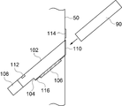
도 4는 본 발명의 다른 실시예에 따른 휴대 기기 수납 장치에 휴대 기기가 수납되는 상태를 나타낸 도면이다. 4 is a view illustrating a state in which a portable device is housed in a portable device storage device according to another embodiment of the present invention.
도 4를 참조하면, 휴대 기기 수납홈(102)은 차량 내부 구조물(50) 내에서 하부로 경사지게 형성될 수 있다. 이 경우, 휴대 기기(90)는 휴대 기기 수납홈(102) 내에서 안정적으로 수납될 수 있고, 차량이 흔들리더라도 휴대 기기(90)가 휴대 기기 수납홈(102) 밖으로 빠져 나오는 것을 방지할 수 있게 된다.
Referring to FIG. 4, the portable
도 5는 본 발명의 또 다른 실시예에 따른 휴대 기기 수납 장치에 휴대 기기가 수납되는 상태를 나타낸 도면이다. 5 is a view illustrating a state in which a portable device is housed in a portable device storage device according to another embodiment of the present invention.
도 5의 (a)를 참조하면, 휴대 기기 수납홈(102)의 바닥면은 수평하게 형성될 수 있다. 그리고, 휴대 기기 수납홈(102)의 상부면은 휴대 기기 수납홈(102)의 바닥면과 경사지게 형성될 수 있다. 휴대 기기 수납홈(102)은 내측에서 입구로 갈수록 수납 공간(S)의 단면적이 넓어지게 형성될 수 있다. 휴대 기기 수납홈(102)의 상부면에는 반사부(118)가 형성될 수 있다. 반사부(118)는 빛을 반사시켜 사용자가 휴대 기기(90)의 표면을 용이하게 확인할 수 있도록 한다. 즉, 휴대 기기(90)가 휴대 기기 수납홈(102)에 수납되어 있으면, 사용자가 휴대 기기(90)의 상태(예를 들어, 메시지가 오거나 진동 상태에서 전화가 걸려온 경우 등)을 확인하기 어렵게 된다. 이때, 휴대 기기 수납홈(102)의 상부면에 반사부(118)를 형성하면, 휴대 기기(90)와 반사부(118) 사이에서 빛이 반사되어 나오기 때문에 휴대 기기(90)의 상태를 보다 용이하게 확인할 수 있게 된다. 여기서는, 반사부(118)가 휴대 기기 수납홈(102)의 상부면에 형성되는 것으로 도시하였으나, 이에 한정되는 것은 아니고 반사부(118)는 휴대 기기 수납홈(102)의 측면에 형성될 수도 있다. 그리고, 반사부(118)는 휴대 기기 수납홈(102)의 바닥면의 일부(예를 들어, 안착홈(104)이 형성되지 않은 부분)에 형성될 수도 있다.5 (a), the bottom surface of the portable
도 5의 (b)를 참조하면, 휴대 기기 수납홈(102)의 바닥면 및 휴대 기기 수납홈(102)의 상부면은 각각 하부로 경사지게 형성될 수 있다. 이때, 휴대 기기 수납홈(102)의 상부면의 경사진 각도가 휴대 기기 수납홈(102)의 바닥면의 경사진 각도보다 크게 할 수 있다. 휴대 기기 수납홈(102)은 내측에서 입구로 갈수록 수납 공간(S)의 단면적이 넓어지게 형성될 수 있다. Referring to FIG. 5 (b), the bottom surface of the portable
본 발명의 실시예에 의하면, 차량 내에 휴대 기기(90)를 수납하면서 휴대 기기(90)를 무선으로 충전할 수 있게 된다. 그리고, 자외선으로 휴대 기기(90)를 살균하여 휴대 기기에 묻은 세균 또는 오염 물질 등을 제거할 수 있다. 또한, 이온을 발생시켜 휴대 기기(90)를 정화시킬 뿐만 아니라 차량 실내의 공기를 정화시킬 수 있게 된다. 또한, 휴대 기기(90) 크기 별로 안착홈을 구비하여 다양한 휴대 기기를 안정적으로 고정시킬 수 있게 된다. 또한, 조명부(121)를 통해 무선 충전 여부 및 무선 충전 가능 영역을 표시할 수 있게 된다.
According to the embodiment of the present invention, the
이상에서 대표적인 실시예를 통하여 본 발명에 대하여 상세하게 설명하였으나, 본 발명이 속하는 기술분야에서 통상의 지식을 가진 자는 상술한 실시예에 대하여 본 발명의 범주에서 벗어나지 않는 한도 내에서 다양한 변형이 가능함을 이해할 것이다. 그러므로 본 발명의 권리범위는 설명된 실시예에 국한되어 정해져서는 안 되며, 후술하는 특허청구범위뿐만 아니라 이 특허청구범위와 균등한 것들에 의해 정해져야 한다.
While the present invention has been particularly shown and described with reference to exemplary embodiments thereof, it is clearly understood that the same is by way of illustration and example only and is not to be taken by way of limitation, I will understand. Therefore, the scope of the present invention should not be limited to the above-described embodiments, but should be determined by equivalents to the appended claims, as well as the appended claims.
100 : 휴대 기기 수납 장치
102 : 휴대 기기 수납홈 104 : 안착홈
106 : 무선 충전 모듈 108 : 이온 발생기
110 : 입구 커버 110-1 : 힌지
112 : 자외선 조사부 114 : 충전 상태 알림부
116 : 보호 패드 118 : 반사부
121 : 조명부100: Portable storage device
102: Portable device storage slot 104:
106: wireless charging module 108: ion generator
110: inlet cover 110-1: hinge
112: ultraviolet ray irradiation unit 114: charge state notification unit
116: protection pad 118: reflective part
121:
Claims (15)
상기 차량 내부 구조물 내에 형성되고 상기 휴대 기기 수납홈에 수납된 휴대 기기를 무선 충전 모듈을 포함하는, 휴대 기기 수납 장치.
A portable device storage groove formed in the internal structure of the vehicle and in which the portable device is inserted and stored; And
And a wireless charging module formed in the vehicle interior structure and housed in the portable device storage groove.
상기 휴대 기기 수납홈은,
하부로 경사지게 형성되는, 휴대 기기 수납 장치.
The method according to claim 1,
The portable device storage groove may include:
And is inclined downward.
상기 휴대 기기 수납 장치는,
상기 휴대 기기 수납홈의 바닥면에 형성되고, 상기 휴대 기기가 안착되어 고정되는 안착홈을 더 포함하는, 휴대 기기 수납 장치.
The method according to claim 1,
The portable device accommodating device includes:
Further comprising: a seating groove formed on a bottom surface of the portable device receiving groove, the seating groove being seated and fixed to the portable device.
상기 무선 충전 모듈은,
상기 안착홈의 하부에 형성되는, 휴대 기기 수납 장치.
The method of claim 3,
The wireless charging module includes:
And is formed at a lower portion of the seating groove.
상기 안착홈은,
상기 휴대 기기의 크기에 따라 복수 개가 형성되고, 복수 개의 안착홈은 상기 바닥면의 내측에서 외측 방향으로 단계적으로 단차를 형성하며 확장되는, 휴대 기기 수납 장치.
The method of claim 3,
The seating groove
Wherein a plurality of seating grooves are formed to form a stepped step from the inside to the outside of the bottom surface in accordance with the size of the portable device.
상기 무선 충전 모듈은,
상기 복수 개의 안착홈의 하부에 각각 형성되는, 휴대 기기 수납 장치.
6. The method of claim 5,
The wireless charging module includes:
And each of the plurality of seating grooves is formed at a lower portion of the plurality of seating grooves.
상기 휴대 기기 수납 장치는,
상기 휴대 기기 수납홈의 바닥면에 형성되는 보호 패드를 더 포함하는, 휴대 기기 수납 장치.
The method according to claim 1,
The portable device accommodating device includes:
And a protective pad formed on a bottom surface of the portable device receiving groove.
상기 휴대 기기 수납 장치는,
상기 차량 내부 구조물 내에 형성되고, 상기 휴대 기기로 음이온 및 양이온 중 적어도 하나를 발생시키는 이온 발생기를 더 포함하는, 휴대 기기 수납 장치.
The method according to claim 1,
The portable device accommodating device includes:
Further comprising an ion generator formed in the vehicle interior structure and generating at least one of an anion and a cation with the portable device.
상기 휴대 기기 수납 장치는,
상기 차량 내부 구조물에 형성되고, 상기 휴대 기기의 충전 상태를 알려주는 충전 상태 알림부를 더 포함하는, 휴대 기기 수납 장치.
The method according to claim 1,
The portable device accommodating device includes:
Further comprising: a charge state notification unit that is formed in the vehicle interior structure and notifies the state of charge of the portable device.
상기 휴대 기기 수납 장치는,
상기 차량 내부 구조물의 상기 휴대 기기 수납홈의 입구에 형성되고, 상기 휴대 기기의 삽입 및 인출에 따라 회전되어 개폐되는 입구 커버를 더 포함하는, 휴대 기기 수납 장치.
The method according to claim 1,
The portable device accommodating device includes:
Further comprising an inlet cover which is formed at an entrance of the portable device receiving groove of the vehicle interior structure and is rotated and opened by insertion and extraction of the portable device.
상기 휴대 기기 수납 장치는,
상기 휴대 기기 수납홈 내부에 형성되고 상기 휴대 기기로 자외선을 조사하는 자외선 조사부를 더 포함하는, 휴대 기기 수납 장치.
The method according to claim 1,
The portable device accommodating device includes:
Further comprising an ultraviolet ray irradiating portion formed in the portable device accommodating groove and irradiating ultraviolet rays to the portable device.
상기 휴대 기기 수납 장치는,
상기 휴대 기기 수납홈의 내면에 형성되고 상기 휴대 기기 수납홈 내에서 빛을 반사시키는 반사부를 더 포함하는, 휴대 기기 수납 장치.
3. The method according to claim 1 or 2,
The portable device accommodating device includes:
Further comprising a reflecting portion formed on an inner surface of the portable device receiving groove for reflecting light in the portable device receiving groove.
상기 휴대 기기 수납홈은,
상기 휴대 기기 수납홈의 상부면이 상기 휴대 기기 수납홈의 바닥면과 소정 각도로 경사지게 형성되는, 휴대 기기 수납 장치.
13. The method of claim 12,
The portable device storage groove may include:
And the upper surface of the portable device receiving groove is formed to be inclined at a predetermined angle with the bottom surface of the portable device receiving groove.
상기 휴대 기기 수납 장치는,
상기 무선 충전 모듈의 무선 충전 가부 신호에 따라 상기 휴대 기기의 무선 충전 가능 여부를 표시해주는 적어도 하나의 조명부를 더 포함하는, 휴대 기기 수납 장치.
The method according to claim 1,
The portable device accommodating device includes:
Further comprising at least one illumination unit for indicating whether the portable device can be charged wirelessly according to a wireless charging / discharging signal of the wireless charging module.
상기 조명부는,
상기 휴대 기기의 충전 상태에 따라 밝기 레벨, 색 온도 레벨, 및 색상 중 적어도 하나가 변동되는, 휴대 기기 수납 장치.
15. The method of claim 14,
The illumination unit includes:
Wherein at least one of a brightness level, a color temperature level, and a hue varies depending on a state of charge of the portable device.
Priority Applications (2)
| Application Number | Priority Date | Filing Date | Title |
|---|---|---|---|
| KR20130109915A KR20150030527A (en) | 2013-09-12 | 2013-09-12 | Apparatus for storing portable device |
| PCT/KR2014/002372 WO2014148853A1 (en) | 2013-03-20 | 2014-03-20 | Wireless charging apparatus |
Applications Claiming Priority (1)
| Application Number | Priority Date | Filing Date | Title |
|---|---|---|---|
| KR20130109915A KR20150030527A (en) | 2013-09-12 | 2013-09-12 | Apparatus for storing portable device |
Publications (1)
| Publication Number | Publication Date |
|---|---|
| KR20150030527A true KR20150030527A (en) | 2015-03-20 |
Family
ID=53024556
Family Applications (1)
| Application Number | Title | Priority Date | Filing Date |
|---|---|---|---|
| KR20130109915A Ceased KR20150030527A (en) | 2013-03-20 | 2013-09-12 | Apparatus for storing portable device |
Country Status (1)
| Country | Link |
|---|---|
| KR (1) | KR20150030527A (en) |
Cited By (1)
| Publication number | Priority date | Publication date | Assignee | Title |
|---|---|---|---|---|
| WO2022008282A1 (en) * | 2020-07-06 | 2022-01-13 | Daimler Ag | Storage compartment for a vehicle |
-
2013
- 2013-09-12 KR KR20130109915A patent/KR20150030527A/en not_active Ceased
Cited By (3)
| Publication number | Priority date | Publication date | Assignee | Title |
|---|---|---|---|---|
| WO2022008282A1 (en) * | 2020-07-06 | 2022-01-13 | Daimler Ag | Storage compartment for a vehicle |
| KR20230011387A (en) * | 2020-07-06 | 2023-01-20 | 메르세데스-벤츠 그룹 아게 | car storage box |
| CN115734898A (en) * | 2020-07-06 | 2023-03-03 | 梅赛德斯-奔驰集团股份公司 | vehicle storage box |
Similar Documents
| Publication | Publication Date | Title |
|---|---|---|
| KR102081718B1 (en) | Cup holder | |
| US9583968B2 (en) | Photoluminescent disinfecting and charging bin | |
| US10128890B2 (en) | Privacy and security systems and methods of use | |
| US20140264075A1 (en) | Portable electronic device sanitizer | |
| US20050180129A1 (en) | Electrical power system for crash helmets | |
| JPWO2012144222A1 (en) | In-vehicle charger and vehicle equipped with the same | |
| US10728640B2 (en) | Electronic device with heat radiation structure using audio device | |
| KR20140095938A (en) | Apparatus for storing portable device in vehicle | |
| EP4272768B1 (en) | Electronic device | |
| KR20150066139A (en) | Apparatus for storing portable device in vehicle | |
| US20180283624A1 (en) | Multi-functional bluetooth lighting devices | |
| JP6123604B2 (en) | Vehicle terminal installation structure | |
| KR20160007849A (en) | Apparatus for both storing portable device and door handle in vehicle | |
| US11316379B2 (en) | Wireless charging system, wireless charging device and wireless powered device | |
| KR20150032079A (en) | Apparatus for storing portable device | |
| KR20160148299A (en) | Electronic device | |
| KR20150030527A (en) | Apparatus for storing portable device | |
| JP2018196258A (en) | Charge port structure | |
| CN111092473B (en) | Illuminable mobile power supply with heat dissipation device | |
| US12049134B2 (en) | Smart safe console system | |
| KR102158366B1 (en) | Apparatus for storing portable device in vehicle | |
| KR20140126126A (en) | Apparatus for storing portable device in vehicle | |
| KR20150107671A (en) | Wireless charging device | |
| KR20140008487A (en) | Protection case for mobile terminal | |
| KR20160065337A (en) | Apparatus for sterilizing mobile device |
Legal Events
| Date | Code | Title | Description |
|---|---|---|---|
| PA0109 | Patent application |
Patent event code: PA01091R01D Comment text: Patent Application Patent event date: 20130912 |
|
| PG1501 | Laying open of application | ||
| A201 | Request for examination | ||
| PA0201 | Request for examination |
Patent event code: PA02012R01D Patent event date: 20180912 Comment text: Request for Examination of Application Patent event code: PA02011R01I Patent event date: 20130912 Comment text: Patent Application |
|
| E902 | Notification of reason for refusal | ||
| PE0902 | Notice of grounds for rejection |
Comment text: Notification of reason for refusal Patent event date: 20190919 Patent event code: PE09021S01D |
|
| E601 | Decision to refuse application | ||
| PE0601 | Decision on rejection of patent |
Patent event date: 20200713 Comment text: Decision to Refuse Application Patent event code: PE06012S01D Patent event date: 20190919 Comment text: Notification of reason for refusal Patent event code: PE06011S01I |