KR20150021811A - Method of manufacturing the semiconductor device - Google Patents
Method of manufacturing the semiconductor device Download PDFInfo
- Publication number
- KR20150021811A KR20150021811A KR20130099233A KR20130099233A KR20150021811A KR 20150021811 A KR20150021811 A KR 20150021811A KR 20130099233 A KR20130099233 A KR 20130099233A KR 20130099233 A KR20130099233 A KR 20130099233A KR 20150021811 A KR20150021811 A KR 20150021811A
- Authority
- KR
- South Korea
- Prior art keywords
- gate electrode
- material film
- electrode material
- etching
- film
- Prior art date
- Legal status (The legal status is an assumption and is not a legal conclusion. Google has not performed a legal analysis and makes no representation as to the accuracy of the status listed.)
- Withdrawn
Links
Images


Classifications
-
- H—ELECTRICITY
- H10—SEMICONDUCTOR DEVICES; ELECTRIC SOLID-STATE DEVICES NOT OTHERWISE PROVIDED FOR
- H10D—INORGANIC ELECTRIC SEMICONDUCTOR DEVICES
- H10D30/00—Field-effect transistors [FET]
- H10D30/01—Manufacture or treatment
- H10D30/021—Manufacture or treatment of FETs having insulated gates [IGFET]
- H10D30/024—Manufacture or treatment of FETs having insulated gates [IGFET] of fin field-effect transistors [FinFET]
-
- H—ELECTRICITY
- H10—SEMICONDUCTOR DEVICES; ELECTRIC SOLID-STATE DEVICES NOT OTHERWISE PROVIDED FOR
- H10D—INORGANIC ELECTRIC SEMICONDUCTOR DEVICES
- H10D64/00—Electrodes of devices having potential barriers
- H10D64/20—Electrodes characterised by their shapes, relative sizes or dispositions
- H10D64/27—Electrodes not carrying the current to be rectified, amplified, oscillated or switched, e.g. gates
- H10D64/311—Gate electrodes for field-effect devices
- H10D64/411—Gate electrodes for field-effect devices for FETs
- H10D64/511—Gate electrodes for field-effect devices for FETs for IGFETs
- H10D64/514—Gate electrodes for field-effect devices for FETs for IGFETs characterised by the insulating layers
-
- H—ELECTRICITY
- H10—SEMICONDUCTOR DEVICES; ELECTRIC SOLID-STATE DEVICES NOT OTHERWISE PROVIDED FOR
- H10D—INORGANIC ELECTRIC SEMICONDUCTOR DEVICES
- H10D30/00—Field-effect transistors [FET]
- H10D30/01—Manufacture or treatment
-
- H—ELECTRICITY
- H10—SEMICONDUCTOR DEVICES; ELECTRIC SOLID-STATE DEVICES NOT OTHERWISE PROVIDED FOR
- H10D—INORGANIC ELECTRIC SEMICONDUCTOR DEVICES
- H10D30/00—Field-effect transistors [FET]
- H10D30/01—Manufacture or treatment
- H10D30/021—Manufacture or treatment of FETs having insulated gates [IGFET]
- H10D30/028—Manufacture or treatment of FETs having insulated gates [IGFET] of double-diffused metal oxide semiconductor [DMOS] FETs
- H10D30/0291—Manufacture or treatment of FETs having insulated gates [IGFET] of double-diffused metal oxide semiconductor [DMOS] FETs of vertical DMOS [VDMOS] FETs
-
- H—ELECTRICITY
- H10—SEMICONDUCTOR DEVICES; ELECTRIC SOLID-STATE DEVICES NOT OTHERWISE PROVIDED FOR
- H10D—INORGANIC ELECTRIC SEMICONDUCTOR DEVICES
- H10D30/00—Field-effect transistors [FET]
- H10D30/60—Insulated-gate field-effect transistors [IGFET]
- H10D30/62—Fin field-effect transistors [FinFET]
-
- H10D64/013—
-
- H—ELECTRICITY
- H10—SEMICONDUCTOR DEVICES; ELECTRIC SOLID-STATE DEVICES NOT OTHERWISE PROVIDED FOR
- H10D—INORGANIC ELECTRIC SEMICONDUCTOR DEVICES
- H10D64/00—Electrodes of devices having potential barriers
- H10D64/20—Electrodes characterised by their shapes, relative sizes or dispositions
- H10D64/27—Electrodes not carrying the current to be rectified, amplified, oscillated or switched, e.g. gates
- H10D64/311—Gate electrodes for field-effect devices
- H10D64/411—Gate electrodes for field-effect devices for FETs
- H10D64/511—Gate electrodes for field-effect devices for FETs for IGFETs
- H10D64/512—Disposition of the gate electrodes, e.g. buried gates
-
- H10P50/267—
-
- H10P52/00—
-
- H10P52/403—
-
- H10P95/04—
-
- H10P50/71—
Landscapes
- Engineering & Computer Science (AREA)
- Microelectronics & Electronic Packaging (AREA)
- Condensed Matter Physics & Semiconductors (AREA)
- General Physics & Mathematics (AREA)
- Manufacturing & Machinery (AREA)
- Computer Hardware Design (AREA)
- Physics & Mathematics (AREA)
- Power Engineering (AREA)
- Chemical & Material Sciences (AREA)
- Chemical Kinetics & Catalysis (AREA)
- General Chemical & Material Sciences (AREA)
- Insulated Gate Type Field-Effect Transistor (AREA)
- Thin Film Transistor (AREA)
Abstract
본 발명의 기술적 사상은 게이트를 최종단계에서 형성시키는 FinFET 반도체 소자에서 핀 모양의 돌출된 부분에서 발생하는 게이트 전극 물질막의 단차를 평탄화시키는 개선된 화학적기계적연마 공정을 포함하는 일련의 단계를 통한 반도체 소자의 제조방법을 제공한다. 그 반도체 소자의 제조방법은 돌출된 채널 영역을 포함하는 반도체 기판을 제공하는 단계; 상기 돌출된 채널 영역 위에 단차를 갖는 게이트 전극 물질막을 형성하는 단계; 상기 게이트 전극 물질막 위에 상기 게이트 전극 물질막과 식각 선택비를 갖는 희생 물질막을 형성하는 단계; 상기 게이트 전극 물질막의 상부 표면이 노출될 때까지 상기 희생 물질막을 식각하는 단계; 상기 게이트 전극 물질막과 희생 물질막을 막질 선택비 없이 소정 깊이 식각하여 상기 단차를 평탄화하는 단계를 포함하는 것을 특징으로 할 수 있다.The technical idea of the present invention is to provide a FinFET semiconductor device in which a gate is formed in a final step, a semiconductor device, such as a semiconductor device, through a series of steps including an improved chemical mechanical polishing process for flattening a step of a gate electrode material film, Of the present invention. The method of manufacturing a semiconductor device includes the steps of: providing a semiconductor substrate including a protruded channel region; Forming a gate electrode material film having a step on the projected channel region; Forming a sacrificial material film having an etch selectivity with the gate electrode material film on the gate electrode material film; Etching the sacrificial material film until the upper surface of the gate electrode material film is exposed; And planarizing the gate electrode material layer and the sacrificial material layer by etching the gate electrode material layer and the sacrificial material layer to a predetermined depth without selecting the film quality.
Description
본 발명의 기술적 사상은 반도체 소자에 관한 것으로서, 상세하게는 반도체 소자의 평탄화 방법에 관한 것이다.Technical aspects of the present invention relate to a semiconductor device, and more particularly, to a method of planarizing a semiconductor device.
반도체 소자의 메모리 용량의 증가 현상에 따라 단위 면적당 소자의 집적도를 늘리기 위하여 소자의 밀도를 높여야 하는데, 이러한 소자의 밀도는 소자 개개의 크기를 줄이고 소자간 간격을 좁힘으로써 가능하다. 그러나 수평 채널 반도체 소자의 크기를 축소할 경우 채널의 길이가 짧아지고, 단채널 효과(Short Channel Effect)가 발생하는 문제가 있다. 따라서 FinFET(Fin Field Effect Transistor)과 같이 게이트에 핀(fin)을 형성하여 유효채널 길이를 확보하고 작동 전류크기를 증가시키는 반도체 소자가 있다. FinFET에서 핀(fin)의 높이로 인해 게이트 폴리막의 단차가 형성되는데 이를 평탄화하는 방법으로 화학적기계적연마(Chemical Mechanical Polishing) 기술이 있다. As the memory capacity of a semiconductor device increases, the density of the device must be increased in order to increase the degree of integration of the device per unit area. Such a device density can be reduced by reducing the size of each device and narrowing the interval between devices. However, when the size of the horizontal channel semiconductor device is reduced, the channel length is shortened and a short channel effect is generated. Accordingly, there is a semiconductor device such as FinFET (Fin Field Effect Transistor) which forms a fin on a gate to secure an effective channel length and increase the operating current magnitude. In the FinFET, the step height of the gate poly film due to the height of the fin is formed, and there is a chemical mechanical polishing technique as a method of planarizing the step.
본 발명의 기술적 사상이 해결하고자 하는 과제는 기존의 화학적기계적연마 공정을 개선하여, 막질에 따른 선택비 차이를 이용한 EPD(End Point Detector) 방법을 사용하고, 건식식각 및 습식식각 공정을 적용하여 산포를 최소화하고, 핀(fin)의 높이로 인해 형성된 게이트 전극 물질막의 단차를 제거하도록 하는 반도체 소자의 평탄화방법을 제공하려는데 있다.SUMMARY OF THE INVENTION The object of the present invention is to improve the conventional chemical mechanical polishing process by using an EPD (End Point Detector) method using selectivity differences according to film quality, and applying a dry etching and a wet etching process, And to remove the step of the gate electrode material film formed due to the height of the fin, thereby providing a method of planarizing a semiconductor device.
상기 과제를 해결하기 위하여, 본 발명의 기술적 사상은 돌출된 채널 영역을 포함하는 반도체 기판을 제공하는 단계; 상기 돌출된 채널 영역 위에 단차를 갖는 게이트 전극 물질막을 형성하는 단계; 상기 게이트 전극 물질막 위에 상기 게이트 전극 물질막과 식각 선택비를 갖는 희생 물질막을 형성하는 단계; 상기 게이트 전극 물질막의 상부 표면이 노출되도록 상기 희생 물질막을 평탄화하는 단계; 및 상기 게이트 전극 물질막의 노출된 부분을 제거하여 상기 게이트 전극 물질막의 단차를 감소시키는 단계를 포함하는 반도체 소자의 제조방법을 제공한다.In order to solve the above problems, the technical idea of the present invention is to provide a semiconductor substrate including a protruded channel region; Forming a gate electrode material film having a step on the projected channel region; Forming a sacrificial material film having an etch selectivity with the gate electrode material film on the gate electrode material film; Planarizing the sacrificial material film so that the upper surface of the gate electrode material film is exposed; And removing exposed portions of the gate electrode material layer to reduce a step of the gate electrode material layer.
본 발명의 일 실시예에 있어서, 상기 게이트 전극 물질막의 단차를 감소시키는 단계는 상기 희생물질막을 식각마스크로 하여 상기 게이트 전극 물질막의 노출된 부분을 제거하는 단계를 포함하는 것을 특징으로 한다.In one embodiment of the present invention, the step of reducing the level difference of the gate electrode material layer includes removing the exposed portion of the gate electrode material layer using the sacrificial material layer as an etching mask.
본 발명의 일 실시예에 있어서, 상기 게이트 전극 물질막의 단차를 감소시크는 단계 이후에 상기 희생물질막을 제거하는 단계를 더 포함하는 것을 특징으로 한다.In one embodiment of the present invention, the method further includes removing the sacrificial material layer after the step of reducing the step of the gate electrode material layer.
본 발명의 일 실시예에 있어서, 상기 희생 물질막 제거하는 단계 이후, 상기 게이트 전극 물질막을 화학적기계적연마 공정으로 식각하여 단차를 제거하는 단계를 더 포함하는 것을 특징으로 한다.In one embodiment of the present invention, the step of removing the sacrificial material film further includes a step of etching the gate electrode material film by a chemical mechanical polishing process to remove the step.
본 발명의 일 실시예에 있어서, 상기 단차를 제거하는 단계는 식각시간(Polishing Time)을 이용한 공정인 것을 특징으로 한다. In one embodiment of the present invention, the step of removing the step is a process using an etching time (Polishing Time).
본 발명의 일 실시예에 있어서, 상기 희생물질막 평탄화 단계는 화학적기계적연마(Chemical Mechanical Polishing) 공정을 사용하는 것을 특징으로 한다.In one embodiment of the present invention, the sacrificial material film planarization step is characterized by using a chemical mechanical polishing process.
본 발명의 일 실시예에 있어서, 상기 평탄화 단계는 상기 희생 물질막을 EPD(End Point Detector) 공정 적용하여 서로 막질이 다른 계면의 선택비 차이를 이용하여 식각하는 것을 특징으로 한다.According to an embodiment of the present invention, the sacrificial material layer is etched by using an EPD (End Point Detector) process to etch the sacrificial material layer using different selectivity ratios of different interfaces.
본 발명의 일 실시예에 있어서, 상기 희생 물질막을 평탄화하는 단계에서 상기 희생 물질막의 상부표면이 상기 게이트 전극 물질막의 상부표면보다 더욱 낮은 레벨을 갖도록 상기 희생물질막을 과식각하는 단계를 더 포함하는 것을 특징으로 한다.In one embodiment of the present invention, the step of planarizing the sacrificial material film further includes the step of overasting the sacrificial material film so that the upper surface of the sacrificial material film has a lower level than the upper surface of the gate electrode material film .
본 발명의 일 실시예에 있어서, 상기 게이트 전극 물질막을 건식식각 공정을 통해 식각하는 것을 특징으로 한다.In one embodiment of the present invention, the gate electrode material layer is etched through a dry etching process.
본 발명의 일 실시예에 있어서, 상기 게이트 전극 물질막의 단차를 감소시키는 단계가 상기 게이트 전극 물질막 및 상기 희생물질막을 식각하여 상기 단차를 감소시키는 단계를 포함하고, 상기 게이트 전극 물질막과 상기 희생물질막을 실질적으로 동일한 식각속도로 제거하는 것을 특징으로 한다.In one embodiment of the present invention, the step of reducing the step of the gate electrode material film includes etching the gate electrode material film and the sacrificial material film to reduce the step, wherein the gate electrode material film and the sacrificial material And removing the material film at substantially the same etching rate.
상기 과제를 해결하기 위하여, 본 발명의 기술적 사상은 또한, 돌출된 채널 영역을 포함하는 반도체 기판을 제공하는 단계; 상기 돌출된 채널 영역 위에 단차를 갖는 게이트 전극 물질막을 형성하는 단계; 상기 게이트 전극 물질막 위에 상기 게이트 전극 물질막과 식각 선택비를 갖는 희생 물질막을 형성하는 단계; 상기 게이트 전극 물질막의 상부 표면이 노출될 때까지 상기 희생 물질막을 식각하는 단계; 상기 게이트 전극 물질막과 희생 물질막을 막질 선택비 없이 소정 깊이 식각하여 상기 단차를 평탄화하는 단계를 포함하는 것을 특징으로 하는 반도체 소자의 제조방법을 제공한다.In order to solve the above problems, the technical idea of the present invention also provides a method of manufacturing a semiconductor device, comprising: providing a semiconductor substrate including a protruded channel region; Forming a gate electrode material film having a step on the projected channel region; Forming a sacrificial material film having an etch selectivity with the gate electrode material film on the gate electrode material film; Etching the sacrificial material film until the upper surface of the gate electrode material film is exposed; And planarizing the gate electrode material layer and the sacrificial material layer by etching the gate electrode material layer and the sacrificial material layer at a predetermined depth without any selection of the film quality.
본 발명의 일 실시예에 있어서, 상기 희생 물질막을 식각하는 단계는 화학적기계적연마 공정을 사용하는 것을 특징으로 한다.In one embodiment of the present invention, the step of etching the sacrificial material film uses a chemical mechanical polishing process.
본 발명의 일 실시예에 있어서, 상기 게이트 전극 물질막과 희생 물질막 식각하는 단계에서 식각속도가 실질적으로 동일한 것을 특징으로 한다.In one embodiment of the present invention, the etch rate is substantially the same in the step of etching the gate electrode material layer and the sacrificial material layer.
본 발명의 일 실시예에 있어서, 상기 게이트 전극 물질막과 희생 물질막 식각시 GCIB(Gas Cluster Ion Beam) 공정을 사용하는 것을 특징으로 한다.In one embodiment of the present invention, a gas cluster ion beam (GCIB) process is used when the gate electrode material layer and the sacrificial material layer are etched.
본 발명의 일 실시예에 있어서, GCIB 공정 적용시 형성되는 산화막을 제거하는 단계를 추가하는 것을 특징으로 한다.In an embodiment of the present invention, a step of removing an oxide film formed in the GCIB process is added.
본 발명의 기술적 사상에 따른 반도체 소자의 제조방법은 FinFET에서 fin의 형성으로 인해 발생하는 단차를 극복하기 위해 개선된 형태의 화학적기계적연마 공정과 건식식각 및 습식식각 공정 등의 일련의 단계를 통해 종래의 화학적기계적연마 공정의 막질 제거비 변동에 의한 게이트 전극 물질막의 높이가 일정하지 않는 문제를 해결하고, 단차는 제거하면서 산포 또한 최소화할 수 있다. The method for fabricating a semiconductor device according to the technical idea of the present invention is a method for manufacturing a semiconductor device by a series of steps such as an improved type of chemical mechanical polishing process and a dry etching and wet etching process in order to overcome a step caused by fin formation in a FinFET It is possible to solve the problem that the height of the gate electrode material film is not constant due to the fluctuation of the film quality removal rate in the chemical mechanical polishing process, and the dispersion can be minimized while removing the step.
본 발명의 기술적 사상에 따른 반도체 소자의 제조방법은 또한 막질 선택비 없이 진행하는 식각공정을 통해서 반도체 소자의 산포를 줄이면서 게이트 전극 물질막의 높이를 일정하게 할 수 있다.The method of manufacturing a semiconductor device according to the technical idea of the present invention can also make the height of the gate electrode material film constant by reducing the scattering of semiconductor devices through an etching process which proceeds without selecting a film quality.
도 1a는 본 발명의 일 실시예에 따른 핀(fin)이 형성된 FinFET 반도체 소자의 도면이다.
도 1b는 도1a의 A-A'선 단면도이다.
도 2a 내지 도 2f는 본 발명의 일 실시예에 따른 게이트 전극 물질막의 단차 제거를 통한 반도체 소자의 평탄화 방법을 단계별로 나타내는 단면도들이다.
도 3a 및 도 3b는 도 2b의 희생 물질막 식각 시 게이트 높이에 의한 단차보다 희생 물질막 과식각이 된 경우의 일 실시예에 대한 단면도들이다.
도4a 및 도4b는 도 2c에 도시된 단계에서 게이트 전극 물질막과 희생 물질막을 막질 선택비 없이 균등하게 식각하여 게이트 전극 물질막의 단차를 제거하는 일 실시예에 대한 단면도이다.
도 4c은 도 4a에서 GCIB(Gas Cluster Ion Beam) 공정을 통해 식각 시 형성되는 산화막을 나타내는 단면도이다.
도 5는 본 발명의 기술적 사상에 의한 반도체 소자를 포함하는 메모리 모듈의 평면도이다.
도 6은 본 발명의 기술적 사상에 의한 반도체 소자를 포함하는 메모리 카드의 개략도이다.
도 7은 본 발명의 일 실시 예에 따른 산화물 층의 형성 방법을 이용하여 형성되는 반도체 소자를 포함하는 메모리 장치의 일 예를 도시한 블록도이다.
도 8은 본 발명의 일 실시 예에 따른 산화물 층의 형성 방법을 이용하여 형성되는 반도체 소자를 포함하는 전자 시스템의 일 예를 도시한 블록도이다.BRIEF DESCRIPTION OF THE DRAWINGS FIG. 1A is a diagram of a FinFET semiconductor device formed with a fin according to an embodiment of the present invention. FIG.
1B is a cross-sectional view taken along the line A-A 'in FIG. 1A.
FIGS. 2A to 2F are cross-sectional views illustrating steps of planarizing a semiconductor device by removing a stepped portion of a gate electrode material layer according to an embodiment of the present invention.
FIGS. 3A and 3B are cross-sectional views of an embodiment in which the sacrificial material film overexposure angle is greater than the step height by gate height in the sacrificial material etching of FIG. 2B.
FIGS. 4A and 4B are cross-sectional views illustrating an embodiment in which the gate electrode material layer and the sacrificial material layer are etched uniformly without film quality selection in the step shown in FIG. 2C to remove the stepped portion of the gate electrode material layer.
4C is a cross-sectional view illustrating an oxide film formed during a gas cluster ion beam (GCIB) process in FIG. 4A.
5 is a plan view of a memory module including a semiconductor device according to the technical idea of the present invention.
6 is a schematic view of a memory card including a semiconductor device according to the technical idea of the present invention.
7 is a block diagram illustrating an example of a memory device including a semiconductor device formed using a method of forming an oxide layer according to an embodiment of the present invention.
8 is a block diagram illustrating an example of an electronic system including a semiconductor device formed using a method of forming an oxide layer according to an embodiment of the present invention.
이하, 첨부된 도면을 참조하여 본 발명의 실시예들을 상세히 설명하기로 한다. Hereinafter, embodiments of the present invention will be described in detail with reference to the accompanying drawings.
본 발명의 실시예들은 당해 기술 분야에서 통상의 지식을 가진 자에게 본 발명을 더욱 완전하게 설명하기 위하여 제공되는 것이고, 하기 실시예는 여러 가지 다른 형태로 변형될 수 있으며, 본 발명의 기술적 사상의 범위가 하기 실시예에 한정되는 것은 아니다. 오히려 이들 실시예들은 본 개시를 더욱 충실하게 완전하게 하고, 당업자에게 본 발명의 기술적 사상을 완전하게 전달하기 위하여 제공되는 것이다. It is to be understood that both the foregoing general description and the following detailed description of the present invention are exemplary and explanatory and are intended to provide further explanation of the invention as claimed. The scope of the present invention is not limited to the following examples. Rather, these embodiments are provided so that this disclosure will be more thorough and complete, and will fully convey the scope of the invention to those skilled in the art.
본 명세서에서 사용된 용어는 특정 실시예를 설명하기 위하여 사용되며, 본 발명을 제한하기 위한 것이 아니다. 본 명세서에서 사용된 바와 같이, 단수 형태는 문맥상 다른 경우를 분명히 지적하는 것이 아니라면, 복수의 형태를 포함할 수 있다. 또한, 본 명세서에서 사용되는 경우 “포함한다(comprising)” 및/또는 “포함하는(comprising)”은 언급한 형상들, 숫자, 단계, 동작, 부재, 요소 및/또는 이들 그룹의 존재를 특정하는 것이며, 하나 이상의 다른 형상, 숫자, 동작, 부재, 요소 및/또는 그룹들의 존재 또는 부가를 배제하는 것이 아니다. The terminology used herein is for the purpose of describing particular embodiments only and is not intended to be limiting of the invention. As used herein, the singular forms "a," "an," and "the" include singular forms unless the context clearly dictates otherwise. Also, " comprising " and / or " comprising " when used herein should be interpreted as specifying the presence of stated shapes, numbers, steps, operations, elements, elements and / And does not preclude the presence or addition of one or more other features, integers, operations, elements, elements, and / or groups.
제1, 제2 등의 용어는 다양한 구성요소들을 설명하는데는 사용될 수 있지만, 상기 구성요소들은 상기 용어들에 의해 한정되어서는 안된다. 상기 용어들은 하나의 구성요소를 다른 구성요소로부터 구별하는 목적으로만 사용될 수 있다. 예를 들어, 본 발명의 권리 범위를 벗어나지 않으면서 제1 구성요소는 제2 구성요소로 명명될 수 있고, 유사하게 제2 구성요소도 제1 구성요소로 명명될 수 있다. The terms first, second, etc. may be used to describe various components, but the components should not be limited by the terms. The terms may only be used for the purpose of distinguishing one element from another. For example, without departing from the scope of the present invention, the first component may be referred to as a second component, and similarly, the second component may also be referred to as a first component.
달리 정의되지 않는 한, 여기에 사용되는 모든 용어들은 기술 용어와 과학 용어를 포함하여 본 발명 개념이 속하는 기술 분야에서 통상의 지식을 가진 자가 공통적으로 이해하고 있는 바와 동일한 의미를 지닌다. 또한, 통상적으로 사용되는, 사전에 정의된 바와 같은 용어들은 관련되는 기술의 맥락에서 이들이 의미하는 바와 일관되는 의미를 갖는 것으로 해석되어야 하며, 여기에 명시적으로 정의하지 않는 한 과도하게 형식적인 의미로 해석되어서는 아니 될 것임은 이해될 것이다.Unless otherwise defined, all terms used herein have the same meaning as commonly understood by one of ordinary skill in the art to which the inventive concept belongs, including technical terms and scientific terms. In addition, commonly used, predefined terms are to be interpreted as having a meaning consistent with what they mean in the context of the relevant art, and unless otherwise expressly defined, have an overly formal meaning It will be understood that it will not be interpreted.
도면에서 각 구성 요소의 구조나 크기는 설명의 편의 및 명확성을 위하여 과장되었고, 설명과 관계없는 부분은 생략되었다. 도면상에서 동일 부호는 동일한 요소를 지칭한다. 도면상에서 사선이나 점선으로 도시된 것은 서로 다른 막질층으로 이루어진 것을 의미하는 것이지, 막질의 물성이나 외관을 특정하기 위한 것은 아니다. 한편, 사용되는 용어들은 단지 본 발명을 설명하기 위한 목적에서 사용된 것이지 의미 한정이나 특허청구범위에 기재된 발명의 범위를 제한하기 위하여 사용된 것은 아니다. In the drawings, the structure and size of each component are exaggerated for convenience and clarity of description, and the parts that are not related to the description are omitted. Wherein like reference numerals refer to like elements throughout. In the drawing, hatched lines or dotted lines indicate different membrane layers, but are not intended to specify the physical properties or appearance of the membrane. It is to be understood that the terminology used is for the purpose of describing the present invention only and is not used to limit the scope of the invention described in the claims or the meaning of the claims.
도 1a는 본 발명의 일 실시예인 FinFET 반도체 소자의 3차원 형상을 나타내는 도면이다. 1A is a view showing a three-dimensional shape of a FinFET semiconductor device according to an embodiment of the present invention.
도 1a를 참조하면, 본 실시예에 따른 반도체 소자(100)는 반도체, 예컨대 Ⅳ족 반도체, 또는 Ⅱ-Ⅵ족 산화물 반도체로 구성된 반도체 기판 상에 형성될 수 있다. 선택적으로, 상기 반도체 소자(100)는 벌크(bulk) 기판 상에 형성될 수 있다. 여기서는 벌크 기판 상에 형성되는 실시예를 도시하나, 통상의 기술자는 다른 종류의 기판 상에 형성될 수도 있음을 이해할 것이다. 예컨대, SOI(Silicon-on-insulator) 기판 상에 형성될 수 있다. Referring to FIG. 1A, the
상기 반도체 소자(100)는 벌크 기판(101) 상에 형성될 수 있으며, 특히 소자분리막(130) 위의 활성 영역(110)에 형성될 수 있다. 상기 활성 영역(110)은, 예를 들면 실리콘으로 이루어질 수 있고, 상기 소자분리막(130)은 실리콘 산화막으로 이루어질 수 있다. The
상기 활성 영역(110)은 소스 영역(114), 드레인 영역(116) 및 상기 소스 영역 및 드레인 영역 사이에 배치된 채널 영역(112)을 포함할 수 있다. The
상기 채널 영역(112)은 도 1a에 도시된 바와 같이 위로 돌출된 형태를 가질 수 있다. 고집적 회로의 단위 반도체 소자 MOSFET은 성능 및 집적도 향상을 위해 크기를 축소시키는 경우 소스와 드레인 사이의 거리가 짧아져서 단채널 효과(Short Channel Effect)가 나타난다. 이로 인해서 게이트의 채널 제어능력이 낮아지는데, 이로 인해 DIBL(Drain-Induced Barrier Lowering) 현상이 나타날 수 있다. 이의 해결을 위해 다양한 3차원의 복수 게이트 트랜지스터가 제시되었는데 그 중 하나가 FinFET(Fin Field Effect Transistor)이다. FinFET 형태의 반도체 소자는 돌출된 채널 영역을 갖는 게이트를 포함하므로 복수의 면에서 채널을 제어할 수 있어 게이트의 채널 제어성이 증가될 수 있다. The
게이트 전극 물질막(120)은 상기 채널 영역(112) 위에 적층된 형태로 형성될 수 있다. 상기 게이트 전극 물질막(120)은, 예를 들면 화학기상증착(Chemical Vapor Deposition) 또는 물리기상증착(Physical Vapor Deposition)의 방법으로 형성될 수 있다. 상기 게이트 전극 물질막(120)은 폴리실리콘(p-Si) 또는 비정질실리콘(a-Si)을 포함할 수 있다. The gate
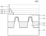
도 1b는 도 1a의 A-A' 선단면도이다. 1B is a cross-sectional view taken along the line A-A 'in FIG. 1A.
도 1b를 참조하면, 하나의 FinFET 반도체 소자는 벌크 기판(101), 활성 영역(110), 게이트 절연막(115), 게이트 전극 물질막(120) 및 소자분리막(130)으로 이루어질 수 있다. 상기 벌크 기판(101)은 실리콘(Si)으로 이루어질 수 있다. 활성 영역(110)은 핀(fin) 모양으로 소정의 높이를 가지고, 단차를 형성할 수 있다. 상기 핀 모양의 높이는 수백Å일 수 있다. 예컨대, 상기 핀 모양으로 인한 실리콘 층의 단차는 400Å일 수 있다. 상기 활성 영역(110)의 핀 모양의 상부 및 양 측부에는 게이트 절연막(115)이 형성될 수 있다. 상기 게이트 절연막(115)은 게이트를 게이트 전극 물질막(120)와 분리시켜 채널이 형성되게 할 수 있다. 게이트 절연막(115)은 상기 활성 영역(110)과는 다른 물질로 이루어질 수 있다. 예컨대 실리콘 산화막(Silicon oxide)으로 이루어질 수 있다. Referring to FIG. 1B, one FinFET semiconductor device may include a
게이트 전극 물질막(120)은 상기 활성 영역(110), 게이트 절연막(115) 및 소자분리막(130)의 상부를 덮는 형태로 형성될 수 있다. 상기 게이트 전극 물질막(120)은 화학 기상 증착(Chemical Vapor Deposition), 물리 기상 증착(Physical Vapor Deposition), 실리콘 에피탁시(Silicon Epitaxy) 등의 방법으로 형성할 수 있다. The gate
소자분리막(130)은 상기 활성 영역(110)의 핀 모양의 측면에 형성될 수 있다. 상기 소자분리막(130)은 실리콘 산화막으로 이루어질 수 있다. 이하 도 2에서 설명하겠지만, 소자분리막(130)은 활성영역과 소자분리영역을 정의해주는 역할을 할 수 있다. The
종래 FinFET 형태 반도체 소자의 제조방법의 경우 소자분리영역에서 수백Å의 핀의 형성으로 인하여 단차는 크게 형성될 수 있다. 따라서 상기 단차를 제거하기 위해서 화학적기계적연마 공정을 진행하는데, 식각시간(Polishing time)을 계산하여 화학적기계적연마 공정을 사용하면, 게이트의 높이를 정확하게 맞출 수 없는 단점이 있다. 이는 설비상의 소모재 수명의 경과에 따라 제거속도(Removal rate)가 달라지게 될 수도 있기 때문이다. In the case of the conventional method of manufacturing a FinFET type semiconductor device, the step can be formed largely due to the formation of the pin of several hundred angstroms in the device isolation region. Therefore, the chemical mechanical polishing process is performed to remove the step, and when the chemical mechanical polishing process is used to calculate the polishing time, the height of the gate can not be precisely adjusted. This is because the removal rate may vary with the life of the consumable material in the facility.
도 2a 내지 도 2f는 도 1a 및 도 1b에 도시한 본 발명의 일 실시예에 따른 반도체 소자(100)의 제조방법을 순서에 따라 단계별로 나타낸 단면도들이다. 도 2a 내지 도 2f에서 활성 영역(110)이 2개로 도시되어 있으나 이는 설명의 편의를 위한 예시적인 것이고, 핀 모양의 실리콘 층이 2개로 한정되는 것은 아니다. FIGS. 2A to 2F are cross-sectional views sequentially illustrating steps of a method of manufacturing the
도 2a는 도 1a의 FinFET이 복수개인 경우, 즉, 적어도 하나 이상의 핀과 그 위에 형성된 게이트 전극 물질막의 단차를 갖는 반도체 소자(100-a)의 단면도이다. 도 2a를 참조하면, 상기 반도체 소자(100-a)는 벌크 기판(101), 2개의 활성 영역(110), 게이트 절연막(115), 게이트 전극 물질막(120) 및 소자분리막(130)dmf 포함할 수 있다. 도 2a를 참조하면, 구성 요소 각각이 서로 다른 무늬로 도시되어 있는데, 이는 각 구성 요소를 구별하기 위한 것이다.2A is a cross-sectional view of a semiconductor device 100-a having a plurality of FinFETs of FIG. 1A, that is, a semiconductor device 100-a having a step of a gate electrode material film formed thereon and at least one pin. 2A, the semiconductor device 100-a includes a
상기 활성 영역(110)의 핀 높이로 인해 상기 게이트 전극 물질막(120)의 단차1(120-1)이 형성될 수 있다.The step 1 120-1 of the gate
소자분리막(130)은 벌크 기판(101)을 활성 영역(110)과 소자분리영역(110-2)을 분리하여 정의할 수 있다. 게이트 전극 물질막 하부의 활성영역에 채널영역이 형성될 수 있다. The
도 2b는 도 2a의 FinFET 반도체 소자 위에 추가로 희생물질막을 형성하는 단계를 나타내는 단면도이다. FIG. 2B is a cross-sectional view showing the step of forming a sacrificial material film on the FinFET semiconductor element of FIG. 2A.
도 2b를 참조하면, 도 2a에 도시된 핀 높이에 의한 단차를 갖는 반도체 소자(100-b)의 게이트 전극 물질막 위에 희생물질막(200)을 형성시킨다. 상기 희생물질막(200)의 형성 시 증착의 방법을 사용할 수 있다. 상기 증착 방법으로는 화학 기상 증착(Chemical Vapor Deposition), 물리 기상 증착(Physical Vapor Deposition) 등이 사용될 수 있다. 희생물질막(200)은 실리콘 산화막, 탄소계물질, 또는 실리콘 질화막(Silicon Nitride) 등으로 이루어질 수 있다. 상기 희생물질막(200)은 본 발명의 일 실시예에서 TEOS(Tetra EthOxy Silane)로 이루어질 수 있다. TEOS는 산화막증착용재료로 많이 쓰이며, 상온에서 액상으로써 산화물의 형성 온도가 낮으며, 후속 공정인 희생물질막과 게이트 전극 물질막의 막질 선택비 차이를 이용한 화학적기계적연마 공정에 활용할 수 있다. 희생물질막이 상기 나열한 물질로 한정되는 것은 아니고, 게이트 전극 물질막과의 식각시 막질 선택비를 가지기만 하면 충분하다. Referring to FIG. 2B, the
도 2c는 도 2b에 도시된 희생물질막(200)이 소정 깊이만큼 식각된 단계를 나타내는 단면도이다. FIG. 2C is a cross-sectional view illustrating a step in which the
도 2c를 참조하면, 본 실시예에 따른 반도체 소자(100-c)에서 상기 희생물질막(200)의 일부분이 식각되어 제거되었다. 희생물질막의 제거는 막질 선택비의 차이를 이용한 식각방법을 사용할 수 있다. 예컨대, EPD(End Point Detector) 방법으로 희생물질막과는 다른 막질, 본 발명의 일 실시예인 TEOS와 같은 산화막을 희생물질막으로써 식각시키고, 게이트 전극 물질막이 노출될 때까지만 식각시킬 수 있다. Referring to FIG. 2C, a part of the
희생물질막의 제거방법은 화학적기계적연마(Chemical Mechanical Polishing) 공정을 활용할 수 있다. 본 발명의 기술적 사상인 개선된 화학적기계적연마는 전술한 바와 같이 막질 선택비의 차이를 이용하여 선택적으로 식각하는 공정을 의미할 수 있다. The removal method of the sacrificial material film can utilize a chemical mechanical polishing process. The improved chemical mechanical polishing, which is a technical idea of the present invention, may mean a process of selectively etching using difference in film quality selection ratio as described above.
상기 개선된 화학적기계적연마 공정에서 막질 선택비는 클수록 유리하다. 본 발명의 일 실시예에서는 게이트 전극 물질막 : 희생물질막이 1:10, 또는 그 이상일 수 있다. 즉, 게이트 전극 물질막을 1의 비율만큼 식각하는 동안 희생물질막을 10의 비율 또는 그 이상 식각할 수 있음을 의미한다. The larger the film quality selection ratio in the improved chemical mechanical polishing process, the more advantageous it is. In one embodiment of the present invention, the gate electrode material film: sacrificial material film may be 1:10 or more. That is, it means that the sacrificial material film can be etched at a rate of 10 or more while the gate electrode material film is etched by a ratio of 1.
상기 개선된 화학적기계적연마 방식으로 식각하는 경우 희생물질막은 막질 선택비에 의해 제거되는데에 사용될 수 있다. 식각되는 막질과 다른 막질이 노출되었을 경우 식각을 멈추는데, 핀 모양의 활성 영역(110)에 의해 게이트 전극 물질막(120)의 단차가 생기므로 그 단차에 해당하는 부분에 희생물질막의 잔여부(200-2)가 잔존할 수 있다. 예컨대, TEOS 막을 화학적기계적연마 공정으로 식각하는 과정에서 게이트 전극 물질막이 노출되는 경우 식각을 중단하나, 게이트 전극 물질막의 단차로 인해 TEOS의 일부가 식각되지 않고 잔존할 수 있다. 상기 잔존하는 희생물질막의 잔여부(200-2)는 식각마스크로 활용할 수 있다.When etching with the improved chemical mechanical polishing method, the sacrificial material film can be used to be removed by the film quality selection ratio. When the etchant is exposed to a different film quality, the etch is stopped. The stepped portion of the gate
도 2d는 도 2c의 FinFET 반도체 소자에서 게이트 전극 물질막만을 소정의 깊이만큼 선택적으로 식각한 것을 나타내는 단면도이다. FIG. 2D is a cross-sectional view showing that only the gate electrode material film is selectively etched by a predetermined depth in the FinFET semiconductor device of FIG. 2C.
도 2d를 참조하면, 본 실시예의 반도체 소자(100-d)에서 희생물질막의 잔여부(200-2)는 도 2c에서와 실질적으로 동일한 상태로 유지되는데 비해 게이트 전극 물질막은 단차2(120-2)만큼 식각된다. 희생물질막은 식각되지 않고, 게이트 전극 물질막만이 식각되었기 때문이다. 이를 위해서는 큰 막질 선택비를 가지는 방법으로 식각할 수 있다. 본 발명의 일 실시예에서는 건식식각(dry etch) 방법을 통한 식각(dry recess)을 할 수 있다. 2D, the residual 200-2 of the sacrificial material film in the semiconductor device 100-d of this embodiment is kept substantially the same as that in FIG. 2C, while the gate electrode material film remains in the step 2 (120-2 ). The sacrificial material film is not etched, and only the gate electrode material film is etched. This can be done by etching with a large film selectivity. In an embodiment of the present invention, a dry recess can be performed by a dry etch method.
앞서 설명한 바와 같이 상기 희생물질막(200)은 게이트 전극 물질막(120)과 높은 식각선택비를 갖도록 선택되므로, 상기 희생물질막의 잔여부(200-2)는 식각마스크로 작용하게 되고, 따라서 식각되지 않는다. 상기 희생물질막의 잔여부(200-2)는 상기 게이트 전극 물질막(120)과 다른 막질이어야 하므로, 실리콘 산화막, 탄소계물질, 실리콘 질화막, TEOS 등으로 이루어질 수 있다. As described above, since the
도 2e는 도 2d의 FinFET 반도체 소자에서 잔존하는 희생물질막을 제거하는 단계를 나타내는 단면도이다. FIG. 2E is a cross-sectional view showing the step of removing the remaining sacrificial material film in the FinFET semiconductor device of FIG. 2D. FIG.
도 2e를 참조하면, 본 실시예의 반도체 소자(100-e)는 도 2d에서 잔존해있던 희생물질막의 잔여부(200-2)를 제거한다. 상기 희생물질막의 잔여부(200-2)는 실리콘 산화막, 예컨대 TEOS로 이루어질 수 있으므로, TEOS만을 제거하기에 유리한 방법으로 제거할 수 있다. 제거 방법으로는 습식식각(wet etch) 방법을 사용할 수 있다. 습식식각은 TEOS와 같은 실리콘 산화막을 다른 막에 비해 선택적으로 제거할 수 있다.Referring to FIG. 2E, the semiconductor device 100-e of this embodiment removes the remnant 200-2 of the sacrificial material film remaining in FIG. 2D. The remnant 200-2 of the sacrificial material film may be made of a silicon oxide film, for example, TEOS, and thus can be removed in a manner advantageous for removing only TEOS. As a removal method, a wet etch method can be used. The wet etch can selectively remove a silicon oxide film such as TEOS relative to other films.
상기 희생물질막의 잔여부(200-2)를 제거하는 이유는 도 2d에서 도시된 것처럼 희생물질막이 식각마스크로 활용되어 막질 선택비를 가지는 개선된 화학적기계적연마 공정에 의해 게이트 전극 물질막이 선택적으로 제거되었으므로 그 역할을 다 했기 때문이다. 희생물질막의 잔여부(200-2)의 높이로 인해 그 제거된 자리에는 게이트 전극 물질막(120)에 단차3(120-3)가 잔존할 수 있다. 그러나 상기 단차3(120-3)은 상기 단차1(120-1)에 대비하여 현저하게 작게 형성된다.The reason for removing the residue 200-2 of the sacrificial material film is that the sacrificial material film is used as an etching mask to selectively remove the gate electrode material film by an improved chemical mechanical polishing process having a film quality selection ratio, It is because we have done its part. The step 3 (120-3) may remain in the gate
도 2f는 도 2a 내지 도 2e의 일련의 단계를 통해 게이트 전극 물질막의 높이가 일정하게 평탄화된 FinFET 반도체 소자(100-f)의 단면도이다. FIG. 2F is a cross-sectional view of the FinFET semiconductor device 100-f in which the height of the gate electrode material layer is uniformly planarized through the series of steps of FIGS. 2A to 2E.
도 2f를 참조하면, FinFET 반도체 소자(100-f)의 활성영역의 게이트 전극 물질막에는 단차가 존재하지 않고 평탄화 되어 있다. 도 2f를 참조하면, 게이트 전극 물질막에 단차3(120-3)이 존재하는데, 상기 단차3(120-3)은 추가적인 식각단계를 거쳐 제거될 수 있다. 추가적인 식각단계는 화학적기계적연마 공정일 수 있다. 이 때의 화학적기계적연마 공정은 식각시간(Polishing time)을 계산하여 식각하는 방법이 사용될 수 있다. 상기 식각시간은 상기 단차3(120-3)을 제거하는 시간에 추가적으로 소정의 단차를 더 제거하는 시간으로 계산될 수 있다. 본 발명의 일 실시예에서는 단차4(120-4)만큼 더 식각하는 시간으로 계산될 수 있다. Referring to FIG. 2F, the gate electrode material film in the active region of the FinFET semiconductor device 100-f is planarized without a step. Referring to FIG. 2F, there is a step 3 (120-3) in the gate electrode material film, and the step 3 (120-3) can be removed through an additional etching step. The additional etching step may be a chemical-mechanical polishing process. In this case, the chemical mechanical polishing process can be performed by calculating the etching time (polishing time). The etch time may be calculated as a time for further removing a predetermined step in addition to the time for removing the step 3 (120-3). In an embodiment of the present invention, the etching time can be calculated by the step 4 (120-4).
종래 식각시간을 활용한 화학적기계적연마 공정은 설비상 소모재의 수명 문제로 인해 제거속도(Removal Rate)의 변동으로 정확한 높이로 평탄화 할 수 없는 문제가 있었으나, 상기 공정은 단차3(120-3)의 미세한 높이를 식각하는 것이므로 짧은 시간 식각하면 되어 문제가 발생하지 않는다. The chemical mechanical polishing process utilizing the conventional etching time has a problem in that it can not be planarized to an accurate height due to fluctuation of the removal rate due to the life of the consumable material in the facility, Since the etching is performed at a fine height, the etching is performed for a short time, so that no problem occurs.
도 2 a내지 도 2f에 도시된 일련의 단계를 통해 개선된 화학적기계적연마 공정과 건식식각 또는 습식식각을 통해 단차가 제거되어 최종적으로 도 2f에 도시된 것과 같이 게이트 전극 물질막이 평탄화될 수 있다. 도 2f에는 초기에 가지고 있던 단차1 내지 단차4의 높이가 도시되어 있어 어느 정도로 식각되었는지를 상대적으로 알 수 있다. 즉, 단차1(120-1)은 최초 게이트 전극 물질막이 형성되는 단계에서 발생된 것이고, 단차2(120-2)는 희생물질막이 식각마스크로 활용되어 게이트 전극 물질막을 식각하는 단계에서 발생하는 것이고, 단차3(120-3)은 상기 식각마스크가 제거되면서 상기 식각마스크가 존재하였던 높이로 인해 형성되는 것이며, 단차4(120-4)는 상기 단차3(120-3)을 제거함에 있어서 소정의 식각을 추가적으로 하면서 평탄화하는 과정에서 발생되는 단차를 나타낼 수 있다. Through the series of steps shown in FIGS. 2A to 2F, the step is removed through the improved chemical mechanical polishing process and dry etching or wet etching, and finally the gate electrode material film can be planarized as shown in FIG. 2F. In FIG. 2F, the heights of the steps 1 to 4, which were initially held, are shown, and it can be known relatively to what extent they are etched. That is, the step 1 (120-1) is generated in the step of forming the initial gate electrode material film, the step 2 (120-2) occurs in the step of etching the gate electrode material film by using the sacrificial material film as an etching mask The step 3 120-3 is formed due to the height of the etch mask while the etch mask is removed, and the step 4 120-4 is formed by removing the step 3 120-3, It is possible to represent a step that occurs in the process of planarizing while additionally etching.
도 3a 및 도 3b는 도 2b의 희생 물질막 식각 시 게이트 높이에 의한 단차보다 희생 물질막 과도식각된 경우의 게이트 전극 물질막의 평탄화 방법을 나타내는 단면도들이다. FIGS. 3A and 3B are cross-sectional views illustrating a method of planarizing a gate electrode material film in a case where the sacrificial material layer is etched more than the stepped portion by the gate height in the sacrificial material layer etching of FIG. 2B.
도 2b 및 도 2c에 나타낸 바와 같이 게이트 전극 물질막(120)의 상부 표면이 노출된 때까지 희생물질막(200)을 제거하기 위하여 화학적기계적연마가 사용될 수 있음은 앞에서 설명한 바와 같다. 이러한 화학적기계적연마를 사용하는 경우, 공정 조건에 따라 상당한 정도의 디싱(dishing)이 수반될 수 있다. 따라서 엔드 포인트(End Point)를 적절히 제어하지 않으면 상대적으로 다량 연마되는 위치에서는 게이트 전극 물질막(120)의 돌출부 사이의 희생물질막(200)이 모두 제거되는 경우가 발생할 수 있다.As described above, chemical mechanical polishing can be used to remove the
도 3a를 참조하면, 상기 화학적기계적연마를 하였을 경우 제1 영역(110-a)에서의 식각 정도가 제2 영역(110-b)에 비하여 더 빠르다고 가정하였을 경우, 제1 영역(110-a)에서 엔드 포인트로서 게이트 전극 물질막(120)이 검출되는 즉시 상기 화학적기계적연마를 중단할 수 있다. 이 때, 제2 영역(110-b)에서의 식각 정도가 상대적으로 미흡하게 이루어지므로 제2 영역(110-b)에서는 아직 상기 게이트 전극 물질막(120)의 상부 표면이 노출되지 않을 수 있다. 상기 희생물질막(200)의 과도식각이 발생하면, 전술한 바와 같이 부분적으로 게이트 전극 물질막(120)이 노출되며 식각과정이 멈추게 되므로 일부의 반도체 소자에서는 상기 희생물질막(200)이 식각마스크로써의 역할을 할 수 없어, 도 2d 내지 도 2f의 일련의 추후 공정을 진행하지 못할 수 있다. 상기 문제를 해결하기 위한 방법은 도 3b에서 추가적으로 설명하기로 한다.3A, if it is assumed that the degree of etching in the first region 110-a is higher than that in the second region 110-b when the chemical mechanical polishing is performed, the first region 110- The chemical mechanical polishing can be stopped as soon as the gate
도 3b는 도 3a에서 발생할 수 있는 과도식각으로 인한 문제점을 극복하고 게이트 전극 물질막의 단차를 제거하는 방법을 나타내는 단면도이다.FIG. 3B is a cross-sectional view illustrating a method of overcoming the problem caused by the transient etching that may occur in FIG. 3A and removing the step of the gate electrode material layer.
도 3b를 참조하면, 도 3a에 도시된 것과 같이 이른바 디싱현상이 일어난 제1 영역(110-a) 때문에 희생물질막(200)의 제거가 제대로 이루어지지 않은 제2 영역(110-b)의 게이트 전극 물질막(120)을 평탄화할 수 있다. 상기 제2 영역(110-b)에서는 게이트 전극 물질막(120)이 노출되지 않은 상태로 식각과정이 종료되었기 때문에 임의의 식각방법을 추가로 진행해서 상기 게이트 전극 물질막(120)이 노출되도록 할 수 있다. 예를 들면, 상기 희생물질막(200)과 상기 게이트 전극 물질막(120) 사이의 식각 선택비를 갖는 식각액을 이용한 습식 식각(wet etch)이 이용될 수 있다. 상기 습식 식각을 이용하는 경우 제1 영역(110-a)과 제2 영역(110-b)에서 실질적으로 동일한 식각 속도로 상기 희생물질막(200)이 제거될 수 있다. Referring to FIG. 3B, in the second region 110-b where the
이후 단계에서, 도 2d에 도시된 공정을 계속 진행하여 화학적기계적연마를 하는 공정에서 디싱이 발생하더라도 식각마스크로 사용될 희생물질막(200)이 모두 제거되는 현상이 방지될 수 있다.In the subsequent step, the process shown in FIG. 2D can be continued to prevent the
도 4a 및 도 4b는 도 2c의 게이트 전극 물질막(120)과 희생물질막(200)을 막질 선택비 없이 균등하게 식각하여 게이트의 단차를 제거하는 일 실시예에 대한 반도체 소자의 단면도이다. FIGS. 4A and 4B are cross-sectional views of a semiconductor device for an embodiment in which the gate
도 4a를 참조하면, 본 실시예가 적용되는 반도체 소자는 도 2b의 단계에서와 같이 서로 다른 물질막의 막질 선택비를 이용한 EPD 방법으로 게이트 전극 물질막이 노출된 상태까지 식각이 진행될 수 있다. 도 4a에 도시된 희생물질막(200)은 게이트 전극 물질막(120)과는 다른 식각 선택비를 갖는 물질이어야 하며, 실리콘 산화막, 탄소계물질, 또는 실리콘 질화막으로 이루어질 수 있다. 본 발명의 일 실시예에서는 TEOS로 이루어질 수 있다. 도 4a에 도시된 단계가 도 2c에 도시된 단계와 다른 점은 단차5(120-5)만큼을 막질의 식각선택비 없이 균등하게 식각하는 점이다. 상기 과정은 이하 도 4b에서 설명하기로 한다.Referring to FIG. 4A, the semiconductor device to which the present embodiment is applied may be etched until the gate electrode material layer is exposed by the EPD method using the film quality selection ratio of different material layers as in the step of FIG. 2B. The
도 4b를 참조하면, 본 실시예가 적용되는 반도체 소자는 도 4a에 존재하던 단차5(120-5)만큼 희생물질막의 전부와 게이트 전극 물질막(120)의 일부가 제거될 수 있다. 상기 단차5(120-5)의 제거방법으로는 물질막의 식각 선택비가 없이 실질적으로 균등하게 식각하는 방법을 사용할 수 있다. 예컨대, 게이트 폴리막과 산화막이 1:1의 비율로 균등하게 식각되는 공정을 사용할 수 있다. 식각방법으로는 균등하게 식각되도록 식각조건이 조절된 화학적기계적연마, 건식식각, 또는 습식식각 방법을 사용할 수 있으며, 예를 들면, GCIB(Gas Cluster Ion Beam) 방법을 사용할 수 있다. Referring to FIG. 4B, the semiconductor device to which the present embodiment is applied can remove all of the sacrificial material film and a part of the gate
GCIB 공정은 고압의 가스를 진공상태에 가하여 단열팽창 시킨 후 냉각 응축시켜 클러스터를 형성하는 방법으로 나노 단위 크기의 결정질 표면을 만들 수 있어 막질 표면의 평탄화 작업에 사용될 수 있다. 고압의 가스로는 아르곤 가스가 사용될 수 있다. 막질 표면의 평탄화 작업에는 B2H6가 가스가 사용될 수 있고, 식각시에는 NF3 가스가 사용될 수 있다. The GCIB process can be used to planarize the surface of a film by forming a nano-sized crystalline surface by applying a high pressure gas to a vacuum and expanding it to form a cluster by cooling and condensing. As the high-pressure gas, argon gas may be used. A B2H6 gas may be used for planarization of the film surface, and NF3 gas may be used for etching.
도 4b의 과정에서는, 서로 다른 막질에 대한 식각 선택비만 없으면 식각의 방법을 고려하지 않아도 된다. 상기 단차5(120-5)만큼 식각됨으로써 핀의 높이만큼 단차가 발생하였던 게이트 전극 물질막(120)이 평탄화될 수 있다. In the process of FIG. 4B, if there is no etching selectivity for different film quality, the etching method need not be considered. The gate
도 4c는 GCIB 공정으로 게이트 전극 물질막 및 희생물질막을 식각하였을 경우 형성될 수 있는 산화막 층을 포함하는 반도체 소자의 단면도이다. 4C is a cross-sectional view of a semiconductor device including a gate electrode material layer and an oxide layer that can be formed when a sacrificial material layer is etched by a GCIB process.
도 4c를 참조하면, GCIB 공정을 사용하여 반도체 소자의 표면을 식각하는 단계는 공정의 결과물로서 게이트 전극 물질막의 표면에 나노 단위의 산화실리콘 층(300)이 형성될 수 있다. 상기 산화실리콘 층(300)은 공정의 결과물로써 형성된 것일 수 있으며, 반도체 소자에 불필요한 경우 제거될 수 있다. 제거하는 방법으로는 화학적기계적연마, 건식식각, 또는 습식식각 방법을 사용할 수 있다. 본 발명의 일 실시예에서는 습식식각 방법을 사용할 수 있다. Referring to FIG. 4C, the step of etching the surface of the semiconductor device using the GCIB process may form a nano-sized
도 5는 본 발명의 기술적 사상에 의한 반도체 소자를 포함하는 메모리 모듈(1000)의 평면도이다. 5 is a plan view of a
구체적으로, 메모리 모듈(1000)은 인쇄회로 기판(1100) 및 복수의 반도체 패키지(1200)를 포함할 수 있다. In particular, the
복수의 반도체 패키지(1200)는 본 발명의 기술적 사상에 의한 실시예들에 따른 반도체 메모리 소자를 포함할 수 있다. 특히, 복수의 반도체 패키지(1200)는 앞에서 설명한 본 발명의 기술적 사상에 의한 실시예에 따른 반도체 메모리 소자들 중에서 선택되는 적어도 하나의 반도체 메모리 소자의 구조를 포함할 수 있다. The plurality of
본 발명의 기술적 사상에 따른 메모리 모듈(1000)은 인쇄회로 기판의 한쪽 면에만 복수의 반도체 패키지(1200)를 탑재한 SIMM (single in-lined memory module), 또는 복수의 반도체 패키지(1200)가 양면에 배열된 DIMM (dual in-lined memory module)일 수 있다. 또한, 본 발명의 기술적 사상에 따른 메모리 모듈(1000)은 외부로부터의 신호들을 복수의 반도체 패키지(1200)에 각각 제공하는 AMB (advanced memory buffer)를 갖는 FBDIMM (fully buffered DIMM)일 수 있다. The
도 6은 본 발명의 기술적 사상에 의한 반도체 소자를 포함하는 메모리 카드(2000)의 개략도이다. 6 is a schematic view of a
구체적으로, 메모리 카드(2000)는 제어기(2100)와 메모리(2200)가 전기적인 신호를 교환하도록 배치될 수 있다. 예를 들면, 제어기(2100)에서 명령을 내리면, 메모리(2200)는 데이터를 전송할 수 있다. Specifically, the
메모리(2200)는 본 발명의 기술적 사상에 의한 실시예들에 따른 반도체 메모리 소자를 포함할 수 있다. 특히, 메모리(2200)는 앞에서 설명한 본 발명의 기술적 사상에 의한 실시예들에 따른 반도체 메모리 소자들 중에서 선택되는 적어도 하나의 반도체 소자의 구조를 포함할 수 있다. The
메모리 카드(2000)는 다양한 종류의 카드, 예를 들어 메모리 스틱 카드 (memory stick card), 스마트 미디어 카드 (smart media card: SM), 씨큐어 디지털 카드 (secure digital card: SD), 미니-씨큐어 디지털 카드 (mini-secure digital card: 미니 SD), 및 멀티미디어 카드 (multimedia card: MMC) 등과 같은 다양한 메모리 카드를 구성할 수 있다. The
도 7은 본 발명의 일 실시 예에 따른 산화물 층의 형성 방법을 이용하여 형성되는 반도체 소자를 포함하는 메모리 장치의 일 예를 도시한 블록도이다.7 is a block diagram illustrating an example of a memory device including a semiconductor device formed using a method of forming an oxide layer according to an embodiment of the present invention.
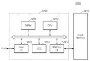
도 7을 참조하면, 본 발명의 일 실시 예에 따른 메모리 장치(3200)는 메모리 모듈(3210)을 포함한다. 상기 메모리 모듈(3210)은 상술된 실시예들에 개시된 방법에 의해 형성되는 반도체 소자들 중에서 적어도 하나를 포함할 수 있다. 또한, 상기 메모리 모듈(3210)은 다른 형태의 반도체 기억 소자(ex, 비휘발성 기억 장치 및/또는 에스램 장치등)를 더 포함할 수 있다. 상기 메모리 장치(3200)는 호스트(Host)와 상기 메모리 모듈(3210) 간의 데이터 교환을 제어하는 메모리 컨트롤러(3220)를 포함할 수 있다.Referring to FIG. 7, a
상기 메모리 컨트롤러(3220)는 메모리 카드의 전반적인 동작을 제어하는 프로세싱 유닛(3222)을 포함할 수 있다. 또한, 상기 메모리 컨트롤러(3220)는 상기 프로세싱 유닛(3222)의 동작 메모리로써 사용되는 에스램(3221, SRAM)을 포함할 수 있다. 이에 더하여, 상기 메모리 컨트롤러(3220)는 호스트 인터페이스(3223), 메모리 인터페이스(3225)를 더 포함할 수 있다. 상기 호스트 인터페이스(3223)는 메모리 장치(3200)와 호스트(Host)간의 데이터 교환 프로토콜을 구비할 수 있다. 상기 메모리 인터페이스(3225)는 상기 메모리 컨트롤러(3220)와 상기 기억 장치(3210)를 접속시킬 수 있다. 더 나아가서, 상기 메모리 컨트롤러(3220)는 에러 정정 블록(3224, ECC)를 더 포함할 수 있다. 상기 에러 정정 블록(3224)은 상기 메모리 모듈(3210)로부터 독출된 데이터의 에러를 검출 및 정정할 수 있다. 도시하지 않았지만, 상기 메모리 장치(3200)는 호스트(Host)와의 인터페이싱을 위한 코드 데이터를 저장하는 롬 장치(ROM device)를 더 포함할 수도 있다. 상기 메모리 장치(3200)는 컴퓨터 시스템의 하드디스크를 대체할 수 있는 고상 디스크(SSD, Solid State Disk)로도 구현될 수 있다.The
도 8은 본 발명의 일 실시 예에 따른 산화물 층의 형성 방법을 이용하여 형성되는 반도체 소자를 포함하는 전자 시스템의 일 예를 도시한 블록도이다.8 is a block diagram illustrating an example of an electronic system including a semiconductor device formed using a method of forming an oxide layer according to an embodiment of the present invention.
도 8을 참조하면, 본 발명의 일 실시 예에 따른 전자 시스템(4100)은 컨트롤러(4110), 입출력 장치(4120, I/O), 메모리 장치(4130, memory device), 인터페이스(4140) 및 버스(4150, bus)를 포함할 수 있다. 상기 컨트롤러(4110), 입출력 장치(4120), 메모리 장치(4130a) 및/또는 인터페이스(4140)는 상기 버스(4150)를 통하여 서로 결합 될 수 있다. 상기 버스(4150)는 데이터들이 이동되는 통로(path)에 해당한다.8, an
상기 컨트롤러(4110)는 마이크로프로세서, 디지털 신호 프로세스, 마이크로 컨트롤러, 및 이들과 유사한 기능을 수행할 수 있는 논리 소자들 중에서 적어도 하나를 포함할 수 있다. 상기 입출력 장치(4120)는 키패드(keypad), 키보드 및 디스플레이 장치 등을 포함할 수 있다. 상기 메모리 장치(4130a)는 데이터 및/또는 명령어 등을 저장할 수 있다. 상기 메모리 장치(4130a)는 상술된 실시 예들에 개시된 반도체 메모리 소자들 중에서 적어도 하나를 포함할 수 있다. 또한, 상기 메모리 장치(4130a)는 다른 형태의 반도체 메모리 소자(ex, 비휘발성 메모리 장치 및/또는 에스램 장치등)를 더 포함할 수 있다. 상기 인터페이스(4140)는 통신 네트워크로 데이터를 전송하거나 통신 네트워크로부터 데이터를 수신하는 기능을 수행할 수 있다. 상기 인터페이스(4140)는 유선 또는 무선 형태일 수 있다. 예컨대, 상기 인터페이스(4140)는 안테나 또는 유무선 트랜시버 등을 포함할 수 있다. 도시하지 않았지만, 상기 전자 시스템(4100)은 상기 컨트롤러(4110)의 동작을 향상시키기 위한 동작 메모리 소자로서, 고속의 디램 소자 및/또는 에스램 소자 등을 더 포함할 수도 있다.The
상기 전자 시스템(4100)은 개인 휴대용 정보 단말기(PDA, personal digital assistant) 포터블 컴퓨터(portable computer), 웹 타블렛(web tablet), 무선 전화기(wireless phone), 모바일 폰(mobile phone), 디지털 뮤직 플레이어(digital music player), 메모리 카드(memory card), 또는 정보를 무선환경에서 송신 및/또는 수신할 수 있는 모든 전자 제품에 적용될 수 있다.The
이상에서 살펴본 바와 같이 본 발명의 실시예들에 대해 상세히 기술되었지만, 본 발명이 속하는 기술분야에 있어서 통상의 지식을 가진 사람이라면, 첨부된 청구 범위에 정의된 본 발명의 정신 및 범위를 벗어나지 않으면서 본 발명을 여러 가지로 변형하여 실시할 수 있을 것이다. 따라서 본 발명의 앞으로의 실시예들의 변경은 본 발명의 기술을 벗어날 수 없을 것이다.While the present invention has been particularly shown and described with reference to exemplary embodiments thereof, it will be understood by those of ordinary skill in the art that various changes in form and details may be made therein without departing from the spirit and scope of the invention as defined by the appended claims. The present invention may be modified in various ways. Therefore, modifications of the embodiments of the present invention will not depart from the scope of the present invention.
100: 반도체 소자, 101: 벌크 기판, 110: 활성 영역, 110-2: 소자분리영역, 112: 채널 영역, 114: 소스 영역, 115: 게이트 절연막, 116: 드레인 영역, 120: 게이트 전극 물질막, 120-1: 단차1, 120-2: 단차2, 120-3: 단차3, 120-4: 단차4, 120-5: 단차5, 130: 소자분리막, 200: 희생물질막, 200-2: 희생물질막의 잔여부, 200-3: 희생물질막의 잔여부, 300: 산화실리콘 층, 1000: 메모리 모듈, 1100: 인쇄회로 기판, 1200: 반도체 패키지, 2000: 메모리 카드, 2100: 제어기, 2200: 메모리, 3200: 메모리 장치, 3210: 메모리 모듈, 3220: 메모리 컨트롤러, 3221: SRAM, 3222: 프로세싱 유닛, 3223: 호스트 인터페이스, 3224: 에러 정정 블록, 3225: 메모리 인터페이스, 4100: 전자 시스템, 4110: 컨트롤러, 4120: 입출력 장치, 4130, 4130a: 메모리 장치, 4140: 인터페이스, 4150: 버스The semiconductor device according to claim 1, wherein the gate insulating film is formed on the gate insulating film. The semiconductor device according to claim 1, 120-1: Step 1, 120-2: Step 2, 120-3: Step 3, 120-4: Step 4, 120-5: Step 5, 130: Device separator, 200: A semiconductor memory device having a plurality of memory cells arranged in a matrix and a plurality of memory cells arranged in the memory cell array, 3200: memory device 3210: memory module 3220: memory controller 3221: SRAM 3222: processing unit 3223: host interface 3224: error correction block 3225: memory interface 4100: electronic system 4110: controller, 4120: input / output device, 4130, 4130a: memory device, 4140: interface, 4150: bus
Claims (10)
상기 돌출된 채널 영역 위에 단차를 갖는 게이트 전극 물질막을 형성하는 단계;
상기 게이트 전극 물질막 위에 상기 게이트 전극 물질막과 식각 선택비를 갖는 희생 물질막을 형성하는 단계;
상기 게이트 전극 물질막의 상부 표면이 노출되도록 상기 희생 물질막을 평탄화하는 단계; 및
상기 게이트 전극 물질막의 노출된 부분을 제거하여 상기 게이트 전극 물질막의 단차를 감소시키는 단계;
를 포함하는 반도체 소자의 제조방법.Providing a semiconductor substrate comprising a projected channel region;
Forming a gate electrode material film having a step on the projected channel region;
Forming a sacrificial material film having an etch selectivity with the gate electrode material film on the gate electrode material film;
Planarizing the sacrificial material film so that the upper surface of the gate electrode material film is exposed; And
Removing exposed portions of the gate electrode material layer to reduce a level difference of the gate electrode material layer;
Wherein the semiconductor device is a semiconductor device.
상기 게이트 전극 물질막의 단차를 감소시키는 단계는 상기 희생물질막을 식각마스크로 하여 상기 게이트 전극 물질막의 노출된 부분을 제거하는 단계;
상기 희생물질막을 제거하는 단계를 더 포함하는 것을 특징으로 하는 반도체 소자의 제조방법. The method according to claim 1,
The step of reducing the level difference of the gate electrode material layer may include removing the exposed portion of the gate electrode material layer using the sacrificial material layer as an etching mask;
Further comprising removing the sacrificial material film. ≪ Desc / Clms Page number 20 >
상기 단차를 감소시키는 단계는 식각시간(Polishing Time)을 이용한 공정인 것을 특징으로 하는 반도체 소자의 제조방법.3. The method of claim 2,
Wherein the step of reducing the step difference is a process using an etching time (Polishing Time).
상기 희생 물질막을 평탄화하는 단계에서 상기 희생 물질막의 상부표면이 상기 게이트 전극 물질막의 상부표면보다 더욱 낮은 레벨을 갖도록 상기 희생물질막을 과식각하는 단계를 더 포함하는 것을 특징으로 하는 반도체 소자의 제조방법. The method according to claim 1,
Further comprising the step of over-etching the sacrificial material film so that the upper surface of the sacrificial material film has a lower level than the upper surface of the gate electrode material film in planarizing the sacrificial material film.
상기 게이트 전극 물질막을 건식식각 공정을 통해 식각하는 것을 특징으로 하는 반도체 소자의 제조방법. The method according to claim 1,
Wherein the gate electrode material film is etched through a dry etching process.
상기 게이트 전극 물질막의 단차를 감소시키는 단계가 상기 게이트 전극 물질막 및 상기 희생물질막을 식각하여 상기 단차를 감소시키는 단계를 포함하고, 상기 게이트 전극 물질막과 상기 희생물질막을 실질적으로 동일한 식각속도로 제거하는 것을 특징으로 하는 반도체 소자의 제조방법. The method according to claim 1,
Wherein the step of reducing the step of the gate electrode material film includes etching the gate electrode material film and the sacrificial material film to reduce the step, wherein the step of removing the gate electrode material film and the sacrificial material film at substantially the same etching rate And a second step of forming a second insulating film on the semiconductor substrate.
상기 돌출된 채널 영역 위에 단차를 갖는 게이트 전극 물질막을 형성하는 단계;
상기 게이트 전극 물질막 위에 상기 게이트 전극 물질막과 식각 선택비를 갖는 희생 물질막을 형성하는 단계;
상기 게이트 전극 물질막의 상부 표면이 노출될 때까지 상기 희생 물질막을 식각하는 단계;
상기 게이트 전극 물질막과 희생 물질막을 막질 선택비 없이 소정 깊이 식각하여 상기 단차를 평탄화하는 단계를 포함하는 것을 특징으로 하는 반도체 소자의 제조방법. Providing a semiconductor substrate comprising a projected channel region;
Forming a gate electrode material film having a step on the projected channel region;
Forming a sacrificial material film having an etch selectivity with the gate electrode material film on the gate electrode material film;
Etching the sacrificial material film until the upper surface of the gate electrode material film is exposed;
And planarizing the gate electrode material layer and the sacrificial layer by etching the gate electrode layer and the sacrificial layer at a predetermined depth without selecting a film quality ratio.
상기 희생 물질막을 식각하는 단계는 화학적기계적연마 공정을 사용하는 것을 특징으로 하는 반도체 소자의 제조방법. 8. The method of claim 7,
Wherein the step of etching the sacrificial material film uses a chemical mechanical polishing process.
상기 게이트 전극 물질막과 희생 물질막 식각하는 단계에서 식각속도가 실질적으로 동일한 것을 특징으로 하는 반도체 소자의 제조방법. 8. The method of claim 7,
Wherein the etch rate is substantially the same in the step of etching the gate electrode material layer and the sacrificial material layer.
상기 게이트 전극 물질막과 희생 물질막 식각시 GCIB(Gas Cluster Ion Beam) 공정을 사용하고, 공정 적용시 형성되는 산화막을 제거하는 단계를 추가하는 것을 특징으로 하는 반도체 소자의 제조방법. 8. The method of claim 7,
Wherein a gas cluster ion beam (GCIB) process is used for etching the gate electrode material layer and the sacrificial material layer, and removing an oxide layer formed during the process application.
Priority Applications (2)
| Application Number | Priority Date | Filing Date | Title |
|---|---|---|---|
| KR20130099233A KR20150021811A (en) | 2013-08-21 | 2013-08-21 | Method of manufacturing the semiconductor device |
| US14/445,284 US20150056795A1 (en) | 2013-08-21 | 2014-07-29 | Method of manufacturing semiconductor device |
Applications Claiming Priority (1)
| Application Number | Priority Date | Filing Date | Title |
|---|---|---|---|
| KR20130099233A KR20150021811A (en) | 2013-08-21 | 2013-08-21 | Method of manufacturing the semiconductor device |
Publications (1)
| Publication Number | Publication Date |
|---|---|
| KR20150021811A true KR20150021811A (en) | 2015-03-03 |
Family
ID=52480736
Family Applications (1)
| Application Number | Title | Priority Date | Filing Date |
|---|---|---|---|
| KR20130099233A Withdrawn KR20150021811A (en) | 2013-08-21 | 2013-08-21 | Method of manufacturing the semiconductor device |
Country Status (2)
| Country | Link |
|---|---|
| US (1) | US20150056795A1 (en) |
| KR (1) | KR20150021811A (en) |
Families Citing this family (7)
| Publication number | Priority date | Publication date | Assignee | Title |
|---|---|---|---|---|
| US20150200111A1 (en) * | 2014-01-13 | 2015-07-16 | Globalfoundries Inc. | Planarization scheme for finfet gate height uniformity control |
| KR102373687B1 (en) * | 2015-05-11 | 2022-03-17 | 삼성디스플레이 주식회사 | Display device and method for fabricating the same |
| US9761455B2 (en) | 2015-12-15 | 2017-09-12 | International Business Machines Corporation | Material removal process for self-aligned contacts |
| CN107154457B (en) * | 2016-03-03 | 2019-12-10 | 华邦电子股份有限公司 | Electrode manufacturing method and resistive random access memory |
| US10541139B2 (en) * | 2016-03-24 | 2020-01-21 | Taiwan Semiconductor Manufacturing Co., Ltd. | Planarization control in semiconductor manufacturing process |
| CN109841521B (en) * | 2017-11-24 | 2022-05-13 | 中芯国际集成电路制造(上海)有限公司 | Semiconductor device and method of forming the same |
| US12125851B2 (en) * | 2021-04-28 | 2024-10-22 | Taiwan Semiconductor Manufacturing Company, Ltd. | FinFET device and method of forming the same |
Family Cites Families (20)
| Publication number | Priority date | Publication date | Assignee | Title |
|---|---|---|---|---|
| US4962064A (en) * | 1988-05-12 | 1990-10-09 | Advanced Micro Devices, Inc. | Method of planarization of topologies in integrated circuit structures |
| JP2687948B2 (en) * | 1995-10-05 | 1997-12-08 | 日本電気株式会社 | Method for manufacturing semiconductor device |
| US6395620B1 (en) * | 1996-10-08 | 2002-05-28 | Micron Technology, Inc. | Method for forming a planar surface over low density field areas on a semiconductor wafer |
| US5721172A (en) * | 1996-12-02 | 1998-02-24 | Taiwan Semiconductor Manufacturing Company, Ltd. | Self-aligned polish stop layer hard masking method for forming planarized aperture fill layers |
| US6103592A (en) * | 1997-05-01 | 2000-08-15 | International Business Machines Corp. | Manufacturing self-aligned polysilicon fet devices isolated with maskless shallow trench isolation and gate conductor fill technology with active devices and dummy doped regions formed in mesas |
| US6093656A (en) * | 1998-02-26 | 2000-07-25 | Vlsi Technology, Inc. | Method of minimizing dishing during chemical mechanical polishing of semiconductor metals for making a semiconductor device |
| US6207533B1 (en) * | 1999-10-08 | 2001-03-27 | Chartered Semiconductor Manufacturing Ltd. | Method for forming an integrated circuit |
| US6756643B1 (en) * | 2003-06-12 | 2004-06-29 | Advanced Micro Devices, Inc. | Dual silicon layer for chemical mechanical polishing planarization |
| US7176092B2 (en) * | 2004-04-16 | 2007-02-13 | Taiwan Semiconductor Manufacturing Company | Gate electrode for a semiconductor fin device |
| CN100459100C (en) * | 2006-09-30 | 2009-02-04 | 中芯国际集成电路制造(上海)有限公司 | Planarization method and method for forming isolation structure of top metal layer |
| DE102008059646B4 (en) * | 2008-11-28 | 2010-12-30 | Advanced Micro Devices, Inc., Sunnyvale | A method of manufacturing a semiconductor device as a multi-gate transistor having lands of a length defined by the gate electrode and semiconductor device |
| CN102034831B (en) * | 2009-09-28 | 2012-12-12 | 中芯国际集成电路制造(上海)有限公司 | Circle stacking grid fin type field-effect transistor memory device and forming method thereof |
| US8334184B2 (en) * | 2009-12-23 | 2012-12-18 | Intel Corporation | Polish to remove topography in sacrificial gate layer prior to gate patterning |
| US8497210B2 (en) * | 2010-10-04 | 2013-07-30 | International Business Machines Corporation | Shallow trench isolation chemical mechanical planarization |
| US8252689B2 (en) * | 2010-11-30 | 2012-08-28 | Institute of Microelectronics, Chinese Academy of Sciences | Chemical-mechanical planarization method and method for fabricating metal gate in gate-last process |
| DE102011003232B4 (en) * | 2011-01-27 | 2013-03-28 | GLOBALFOUNDRIES Dresden Module One Ltd. Liability Company & Co. KG | A manufacturing method for large-sized metal gate electrode structures made by an exchange gate method based on improved flatness of dummy materials |
| US20120196410A1 (en) * | 2011-01-31 | 2012-08-02 | United Microelectronics Corp | Method for fabricating fin field effect transistor |
| US9087796B2 (en) * | 2013-02-26 | 2015-07-21 | International Business Machines Corporation | Semiconductor fabrication method using stop layer |
| US20150200111A1 (en) * | 2014-01-13 | 2015-07-16 | Globalfoundries Inc. | Planarization scheme for finfet gate height uniformity control |
| US9299584B2 (en) * | 2014-06-25 | 2016-03-29 | GlobalFoundries, Inc. | Methods of forming integrated circuits with a planarized permanent layer and methods for forming FinFET devices with a planarized permanent layer |
-
2013
- 2013-08-21 KR KR20130099233A patent/KR20150021811A/en not_active Withdrawn
-
2014
- 2014-07-29 US US14/445,284 patent/US20150056795A1/en not_active Abandoned
Also Published As
| Publication number | Publication date |
|---|---|
| US20150056795A1 (en) | 2015-02-26 |
Similar Documents
| Publication | Publication Date | Title |
|---|---|---|
| US10867997B2 (en) | Semiconductor device | |
| US11764299B2 (en) | FinFETs having step sided contact plugs and methods of manufacturing the same | |
| US9960241B2 (en) | Semiconductor device for manufacturing | |
| KR20150021811A (en) | Method of manufacturing the semiconductor device | |
| KR101064467B1 (en) | Fin Field Effect Transistor Manufacturing System and Method | |
| US9576959B1 (en) | Semiconductor device having first and second gate electrodes and method of manufacturing the same | |
| US9853111B2 (en) | Method of manufacturing a semiconductor device | |
| CN103456770B (en) | Semiconductor device with embedded strain-inducing pattern and method of forming same | |
| US9825034B2 (en) | Semiconductor device and method of fabricating the same | |
| US20150084041A1 (en) | Semiconductor devices and methods of fabricating the same | |
| US9530870B2 (en) | Methods of fabricating a semiconductor device | |
| US9391172B2 (en) | Methods of shaping a channel region in a semiconductor fin using doping | |
| CN106024870B (en) | Semiconductor device including gate contact portion | |
| KR20160042561A (en) | Vertical channel semiconductor apparatus | |
| TW201729300A (en) | Backside fin recess control with multiple HSI options | |
| TW201820426A (en) | Multi-voltage threshold transistor penetration process and design trigger multi-work function | |
| US8735248B2 (en) | Method of manufacturing semiconductor device | |
| US20140061743A1 (en) | Semiconductor devices and method of fabricating the same | |
| US20160056269A1 (en) | Method of fabricating a semiconductor device | |
| KR20150019307A (en) | Method of forming semiconductor device having multilayered plug and related device | |
| US20160322495A1 (en) | Semiconductor device and method of manufacturing the same | |
| US11114443B2 (en) | Semiconductor structure formation | |
| CN108807403B (en) | Semiconductor device, manufacturing method thereof and electronic device | |
| US20250293156A1 (en) | Merged control line formation for memory with vertical transistors | |
| US20250159864A1 (en) | Memory device having vertical transistors and methods for forming the same |
Legal Events
| Date | Code | Title | Description |
|---|---|---|---|
| PA0109 | Patent application |
St.27 status event code: A-0-1-A10-A12-nap-PA0109 |
|
| PG1501 | Laying open of application |
St.27 status event code: A-1-1-Q10-Q12-nap-PG1501 |
|
| PC1203 | Withdrawal of no request for examination |
St.27 status event code: N-1-6-B10-B12-nap-PC1203 |
|
| WITN | Application deemed withdrawn, e.g. because no request for examination was filed or no examination fee was paid | ||
| P22-X000 | Classification modified |
St.27 status event code: A-2-2-P10-P22-nap-X000 |
|
| P22-X000 | Classification modified |
St.27 status event code: A-2-2-P10-P22-nap-X000 |