KR20150017231A - Inspection system for the external appearance of panel having scan structure - Google Patents
Inspection system for the external appearance of panel having scan structure Download PDFInfo
- Publication number
- KR20150017231A KR20150017231A KR1020130093238A KR20130093238A KR20150017231A KR 20150017231 A KR20150017231 A KR 20150017231A KR 1020130093238 A KR1020130093238 A KR 1020130093238A KR 20130093238 A KR20130093238 A KR 20130093238A KR 20150017231 A KR20150017231 A KR 20150017231A
- Authority
- KR
- South Korea
- Prior art keywords
- panel
- scan
- module
- appearance
- area
- Prior art date
- Legal status (The legal status is an assumption and is not a legal conclusion. Google has not performed a legal analysis and makes no representation as to the accuracy of the status listed.)
- Abandoned
Links
Images


Classifications
-
- G—PHYSICS
- G01—MEASURING; TESTING
- G01B—MEASURING LENGTH, THICKNESS OR SIMILAR LINEAR DIMENSIONS; MEASURING ANGLES; MEASURING AREAS; MEASURING IRREGULARITIES OF SURFACES OR CONTOURS
- G01B11/00—Measuring arrangements characterised by the use of optical techniques
- G01B11/30—Measuring arrangements characterised by the use of optical techniques for measuring roughness or irregularity of surfaces
-
- G—PHYSICS
- G01—MEASURING; TESTING
- G01N—INVESTIGATING OR ANALYSING MATERIALS BY DETERMINING THEIR CHEMICAL OR PHYSICAL PROPERTIES
- G01N21/00—Investigating or analysing materials by the use of optical means, i.e. using sub-millimetre waves, infrared, visible or ultraviolet light
- G01N21/84—Systems specially adapted for particular applications
- G01N21/88—Investigating the presence of flaws or contamination
- G01N21/95—Investigating the presence of flaws or contamination characterised by the material or shape of the object to be examined
- G01N21/956—Inspecting patterns on the surface of objects
- G01N21/95607—Inspecting patterns on the surface of objects using a comparative method
-
- G—PHYSICS
- G02—OPTICS
- G02F—OPTICAL DEVICES OR ARRANGEMENTS FOR THE CONTROL OF LIGHT BY MODIFICATION OF THE OPTICAL PROPERTIES OF THE MEDIA OF THE ELEMENTS INVOLVED THEREIN; NON-LINEAR OPTICS; FREQUENCY-CHANGING OF LIGHT; OPTICAL LOGIC ELEMENTS; OPTICAL ANALOGUE/DIGITAL CONVERTERS
- G02F1/00—Devices or arrangements for the control of the intensity, colour, phase, polarisation or direction of light arriving from an independent light source, e.g. switching, gating or modulating; Non-linear optics
- G02F1/01—Devices or arrangements for the control of the intensity, colour, phase, polarisation or direction of light arriving from an independent light source, e.g. switching, gating or modulating; Non-linear optics for the control of the intensity, phase, polarisation or colour
- G02F1/13—Devices or arrangements for the control of the intensity, colour, phase, polarisation or direction of light arriving from an independent light source, e.g. switching, gating or modulating; Non-linear optics for the control of the intensity, phase, polarisation or colour based on liquid crystals, e.g. single liquid crystal display cells
- G02F1/1306—Details
- G02F1/1309—Repairing; Testing
Landscapes
- Physics & Mathematics (AREA)
- General Physics & Mathematics (AREA)
- Nonlinear Science (AREA)
- Chemical & Material Sciences (AREA)
- General Health & Medical Sciences (AREA)
- Biochemistry (AREA)
- Analytical Chemistry (AREA)
- Life Sciences & Earth Sciences (AREA)
- Immunology (AREA)
- Pathology (AREA)
- Crystallography & Structural Chemistry (AREA)
- Health & Medical Sciences (AREA)
- Optics & Photonics (AREA)
- Investigating Materials By The Use Of Optical Means Adapted For Particular Applications (AREA)
Abstract
본 발명은 패널의 외관을 스캔하고, 상기 스캔된 패널의 외관 영상을 분석하여 패널 외관의 결함 여부를 검사하는 정밀 스캔구조를 갖는 패널의 외관 검사시스템에 관한 것으로,
본 발명에서는 스캔영역 내로 진입된 패널의 외관 영상을 촬영하는 스캔모듈을 포함하여 구성된 패널의 외관 검사시스템에 있어서,
상기 스캔모듈은, 패널을 안착시키는 캐리어암과;
상기 캐리어암을 진퇴시켜 캐리어암에 안착된 패널이 스캔영역 내에 진출입하도록 하는 진퇴부재; 및
상기 스캔영역 내로 진출입되는 패널의 외관을 스캔하는 스캔 카메라를 포함하여 구성된 것을 특징으로 하고 있다.The present invention relates to an external inspection system for a panel having an accurate scan structure for scanning the external appearance of the panel and analyzing the external appearance image of the scanned panel to check whether the external appearance of the panel is defective,
In the present invention, a visual inspection system for a panel including a scan module for photographing an appearance image of a panel that has entered a scan area,
The scan module includes: a carrier arm for seating the panel;
A forward / backward member for moving the carrier arm forward and backward so as to allow the panel, which is seated on the carrier arm, And
And a scan camera that scans an outer surface of the panel that enters and exits into the scan area.
Description
본 발명은 정밀 스캔구조를 갖는 패널의 외관 검사시스템에 관한 것으로, 패널의 외관을 스캔하고, 상기 스캔된 패널의 외관 영상을 분석하여 패널 외관의 결함 여부를 검사하는 정밀 스캔구조를 갖는 패널의 외관 검사시스템에 관한 것이다.The present invention relates to an appearance inspection system for a panel having a precision scan structure, and more particularly, to an appearance inspection system for a panel having a precision scan structure in which the appearance of a panel is scanned and an appearance image of the scanned panel is analyzed, ≪ / RTI >
일반적으로, 스마트폰, 타플릿 PC, 디지털 스캔 카메라 등 각종 전자제품에는 커버 글라스나 터치패널 등의 패널이 설치되며, 이들 패널에는 다양한 문양이나 패턴이 인쇄를 통해 형성된다.In general, various electronic products such as a smart phone, a tablet PC, and a digital scan camera are provided with panels such as a cover glass and a touch panel, and various patterns and patterns are formed through printing on these panels.
그런데, 상기 패널의 외관에는 인쇄나 코팅 불량, 스크레치나 찍힘을 포함하는 외관 결함이 불가피하게 발생될 수 있고, 이와 같이 결함이 발생된 패널을 전자제품에 구비할 경우 제품의 신뢰도가 크게 하락하는 문제점이 발생될 수 있다.However, external defects such as printing, coating defects, scratches and scratches may inevitably occur on the outer surface of the panel, and when a panel having such defects is provided in an electronic product, the reliability of the product is greatly reduced May occur.
이를 예방하기 위해 실시되는 패널의 외관 검사는, 전통적으로 작업자가 직접 육안으로 패널의 외관을 검사하는 육안 검사가 주류를 이루었으나, 이는 패널의 검사에 따른 생산성이 저하되고 작업자의 숙련도에 따라 검사 정밀도가 다르며, 자칫 패널의 외관 결함을 발견하지 못할 소지를 항시 갖고 있는 관계로 패널의 외관 검사에 따른 신뢰성을 담보하기 어렵다.In order to prevent this, the visual inspection of the panel has traditionally been performed by a visual inspection in which the operator visually inspects the appearance of the panel. However, this results in a decrease in productivity due to inspection of the panel, And it is difficult to guarantee reliability due to the appearance inspection of the panel because it always has the possibility of not being able to detect the appearance defect of the panel.
이를 해소하기 위해, 당 분야에서는 패널의 표면을 스캔하여 패널의 표면 영상을 수득하고, 상기 수득된 영상을 판독하여 패널의 결함 발생 여부를 검사하는 외관 검사장치들을 제안하고 있다.In order to solve this problem, in the related art, there have been proposed visual inspection devices for scanning a surface of a panel to obtain a surface image of the panel, and reading the obtained image to check whether a panel is defective.
특히, 본 발명자는 대한민국 특허등록공고 제 10-1076010호를 통해, 이송벨트에 안착되어 이동되는 패널의 이동 경로 상에 스캔 카메라와 조명부재를 각각 배치하여 스캔 카메라를 통해 보다 신뢰성 높은 패널의 표면 영상을 취득하도록 하고 있다.Particularly, the present inventors have proposed a technique of arranging a scan camera and an illuminating member on a moving path of a panel which is seated on a conveyance belt and moved on a conveying belt through Korean Patent Registration No. 10-1076010, .
그런데, 상기 외관 검사장치는 단일 스캔공정을 통해 패널의 외관을 검사하도록 구성되고, 또 상기 패널이 이동과정에 잦은 진동 내지 요동이 발생되는 이송 컨베이어의 이송벨트에 안착된 상태로 이동되므로, 패널이 이송벨트를 따라 이동되는 과정에 진동이나 요동에 의해 위치나 방향이 쉽게 흐트려지는 문제점이 야기될 수 있다.However, since the visual inspection apparatus is configured to inspect the external appearance of the panel through a single scanning process, and the panel moves in a state of being seated on the conveyance belt of the conveyance conveyor where frequent vibration or fluctuation occurs during the movement, The position or direction may be easily disturbed by vibration or fluctuation during the movement along the conveyance belt.
이와 같이 패널의 위치나 방향이 흐트러지면, 패널의 외관을 스캔한 외관 영상의 수득이 어렵고, 특히 단일 영상을 통해서는 패널의 외관을 전체적으로 검사하기 어려운 관계로, 패널 외관 검사에 따른 신뢰성을 확보하지 어려운 문제점이 지적되고 있다.If the position or orientation of the panel is disturbed, it is difficult to obtain an appearance image obtained by scanning the external appearance of the panel. In particular, since it is difficult to inspect the appearance of the panel as a whole through a single image, A difficult problem is pointed out.
상기한 문제점을 해소하기 위해 안출된 본 발명의 목적은, 패널의 외관을 스캔하고 상기 스캔된 패널의 외관 영상을 분석하여 패널 외관의 결함 여부를 검사함에 있어, 스캔영역에 진출입되는 패널을 분할 스캔하도록 구성하여 패널의 외관 검사에 따른 향상된 신뢰성이 확보되도록 한 정밀 스캔구조를 갖는 패널의 외관 검사시스템을 제공함에 있다.In order to solve the above problems, it is an object of the present invention to provide a method and apparatus for scanning an outer appearance of a panel and analyzing an external appearance image of the panel, The present invention also provides a system for inspecting the appearance of a panel having a precision scan structure in which an improved reliability according to the appearance inspection of the panel is ensured.
상기한 목적은, 본 발명에서 제공되는 하기 구성에 의해 달성된다.The above object is achieved by the following constitutions provided in the present invention.
본 발명에 따른 정밀 스캔구조를 갖는 패널의 외관 검사시스템은, A system for inspecting the appearance of a panel having a precision scan structure according to the present invention includes:
스캔영역 내로 진입된 패널의 외관 영상을 촬영하는 스캔모듈을 포함하여 구성된 패널의 외관 검사시스템에 있어서, And a scan module for photographing an exterior image of the panel that has entered the scan area, the system comprising:
상기 스캔모듈은, 패널을 안착시키는 캐리어암과; The scan module includes: a carrier arm for seating the panel;
상기 캐리어암을 진퇴시켜, 캐리어암에 안착된 패널이 스캔영역 내에 진출입되도록 하는 직진 이송부재; 및 A rectilinear transferring member for advancing and retracting the carrier arm to allow the panel mounted on the carrier arm to enter and exit the scan area; And
상기 스캔영역 내로 진출입되는 패널의 외관을 스캔하는 스캔 카메라를 포함하여 구성된 것을 특징으로 한다.And a scan camera that scans an outer surface of the panel that enters and exits into the scan area.
바람직하게는, 상기 스캔모듈에는 스캔 카메라를 이동시켜 스캔 카메라의 스캔영역을 변경하는 스캔영역 변경유닛이 구비되어, 패널이 스캔영역에 진입하는 과정에서는 스캔영역 변경유닛에 의해 스캔 카메라는 일측으로 이동하여 패널의 일측 외관을 스캔하고, 패널이 스캔영역에서 진출하는 과정에서는 스캔영역 변경유닛에 의해 스캔 카메라는 타측으로 이동하여 패널의 타측 외관을 스캔하도록 구성되어, Preferably, the scan module is provided with a scan area changing unit for moving the scan camera to change the scan area of the scan camera. In the process of the panel entering the scan area, the scan camera is moved to one side And the scan camera is moved to the other side by the scan area changing unit to scan the outer surface of the other side of the panel,
상기 스캔 카메라는 스캔영역에 진출입하는 패널을 분할되게 스캔하여, 고 해상의 패널 외관 영상을 취득하도록 구성한다.The scan camera scans the panel that enters and exits the scan area in a divided manner to acquire a panel appearance image of a high resolution.
보다 바람직하게는, 상기 스캔영역 변경유닛은 정역 회전력을 생성하는 서보모터와, 상기 서보모터에 볼 스크루 구조로 연결되어 서보모터의 정역 회전에 따라 이동하는 가동자를 포함하여 구성되어, More preferably, the scan area changing unit includes a servo motor for generating a forward and reverse rotational force, and a mover connected to the servo motor by a ball screw structure and moving according to forward and reverse rotation of the servo motor,
상기 스캔 카메라는 서보모터의 정역 회전에 의한 가동자의 이동에 의해 일측과 타측으로 이동하여 스캔영역을 변경하도록 구성된다.The scan camera is configured to move to one side and the other side by moving the mover due to normal / reverse rotation of the servo motor to change the scan area.
본 발명에서는 스캔모듈을 통해 패널의 외관 영상을 스캔하는 복수의 검사 스테이지를 패널의 이동경로 상에 복수 배치하고, 이들 스캔모듈들 사이에 각 검사 스테이지를 따라 패널을 단계적으로 이동시키는 트랜스퍼 모듈을 배치하고 있다.In the present invention, a plurality of inspection stages for scanning the exterior image of the panel through the scan module are disposed on the movement path of the panel, and a transfer module for moving the panel stepwise along each inspection stage is disposed between the scan modules .
따라서, 본 발명은 트랜스퍼 모듈에 의해 패널이 각 검사 스테이지를 따라 단계적으로 이동하면서, 각 검사 스테이지에 설치된 스캔모듈에 의해 외관이 다양한 형태로 스캔한 패널 외관 영상들이 취득되고, 이를 통해 패널 외관의 결함여부를 보다 정밀하게 검사할 수 있다.Accordingly, in the present invention, while the panel is moved step by step along each inspection stage by the transfer module, the panel appearance images scanned in various forms by the scan module installed in each inspection stage are acquired, Or more precisely.
그리고, 상기 트랜스퍼 모듈을 통해 스캔모듈이 형성된 검사 스테이지에 패널이 위치되도록 구성하면, 스캔모듈이 구비된 각 검사 스테이지에 단계적으로 이동되는 패널이 연속적으로 투입되므로, 각 검사 스테이지들에 위치된 스캔모듈은 단계적으로 이동되는 패널의 외관 스캔할 수 있어서 패널 외관 영상의 취득에 따른 신속성이 확보되므로, 향상된 생산성을 갖는다.In addition, when the panel is positioned on the inspection stage in which the scan module is formed through the transfer module, the panel that is moved in stages is continuously inserted into each inspection stage provided with the scan module, It is possible to scan the exterior of the panel moved step by step, thereby ensuring promptness in acquiring the appearance image of the panel, and thus has an improved productivity.
특히, 상기 트랜스퍼 모듈을 통한 패널의 단계적인 이동과, 캐리어암을 통한 패널의 진출입을 도모하면 패널의 이동 및 스캔과정에 진동이나 요동 발생이 억제되므로, 패널은 정밀한 위치와 속도, 초점거리를 유지하여 스캔모듈의 스캔영역에 진출입하므로, 보다 높은 정밀도를 갖는 패널 외관 영상의 취득이 가능하다.Particularly, since the step movement of the panel through the transfer module and the entrance and exit of the panel through the carrier arm are suppressed, the panel can maintain the precise position, speed, and focal distance, And enters and exits the scan area of the scan module, it is possible to acquire the panel appearance image with higher precision.
도 1과 도 2는 본 발명에서 바람직한 실시예로 제안하고 있는 패널의 외관 검사시스템의 전체 구성과 패널의 외관 스캔과정을 전체적으로 보여주는 상태도이고,
도 3은 본 발명에서 바람직한 실시예로 제안하고 있는 패널의 외관 검사시스템에 있어, 이송모듈과 공급대에 형성된 교정유닛의 작용상태를 보여주는 것이며,
도 4는 본 발명에서 바람직한 실시예로 제안하고 있는 패널의 외관 검사시스템에 있어, 트랜스퍼 모듈의 전체 구성, 및 작용상태를 모여주는 것이며,
도 5는 본 발명에서 바람직한 실시예로 제안하고 있는 패널의 외관 검사시스템에 있어, 트랜스퍼 모듈의 전체 구성, 및 작용상태를 모여주는 것이며,
도 6 내지 도 8은 본 발명에서 바람직한 실시예로 제안하고 있는 패널의 외관 검사시스템에 있어, 각 검사 스테이지에 형성된 스캔모듈을 통한 패널 외관의 스캔상태를 보여주는 것이며,
도 9는 본 발명에서 바람직한 실시예로 제안하고 있는 스캔모듈에 형성된 스캔 카메라와 조명의 배치상태를 보여주는 것이다.FIG. 1 and FIG. 2 are views showing the entire configuration of a visual inspection system for a panel proposed in the preferred embodiment of the present invention,
FIG. 3 is a view showing an operation state of a calibration module formed on a conveying module and a supply stand in a panel visual inspection system proposed in the preferred embodiment of the present invention,
FIG. 4 is a block diagram of a panel visual inspection system proposed in the preferred embodiment of the present invention, which collects the entire configuration and operating state of the transfer module,
FIG. 5 is a block diagram of a panel visual inspection system proposed in the preferred embodiment of the present invention, which collects the overall configuration and operational state of the transfer module,
6 to 8 show a scan state of a panel appearance through a scan module formed in each inspection stage in a panel appearance inspection system proposed in the preferred embodiment of the present invention,
FIG. 9 is a view showing an arrangement state of a scan camera and a light formed in a scan module proposed in the preferred embodiment of the present invention.
이하, 첨부된 도면을 참조하여 본 발명에서 바람직한 실시예로 제안하고 있는 패널의 외관 검사시스템을 상세히 설명하기로 한다.DETAILED DESCRIPTION OF THE PREFERRED EMBODIMENTS Exemplary embodiments of the present invention will now be described in detail with reference to the accompanying drawings.
도 1과 도 2는 본 발명에서 바람직한 실시예로 제안하고 있는 패널의 외관 검사시스템의 전체 구성과 패널의 외관 스캔과정을 전체적으로 보여주는 상태도이고, 도 3은 본 발명에서 바람직한 실시예로 제안하고 있는 패널의 외관 검사시스템에 있어, 이송모듈과 공급대에 형성된 교정유닛의 작용상태를 보여주는 것이며, 도 4는 본 발명에서 바람직한 실시예로 제안하고 있는 패널의 외관 검사시스템에 있어, 트랜스퍼 모듈의 전체 구성, 및 작용상태를 모여주는 것이며, 도 5는 본 발명에서 바람직한 실시예로 제안하고 있는 패널의 외관 검사시스템에 있어, 트랜스퍼 모듈의 전체 구성, 및 작용상태를 모여주는 것이며, 도 6 내지 도 7은 본 발명에서 바람직한 실시예로 제안하고 있는 패널의 외관 검사시스템에 있어, 각 검사 스테이지에 형성된 스캔모듈을 통한 패널 외관의 스캔상태를 보여주는 것이며, 도 8은 본 발명에서 바람직한 실시예로 제안하고 있는 스캔모듈에 형성된 스캔 카메라와 조명의 배치상태를 보여주는 것이다.FIG. 1 and FIG. 2 are views showing the overall configuration of a visual inspection system for a panel, which is a preferred embodiment of the present invention, and an appearance scanning process of the panel as a whole. FIG. 4 is a block diagram showing the overall appearance of the transfer module, and FIG. 4 is a sectional view of the transfer module shown in FIG. And FIG. 5 is a view for collecting the overall configuration and operating state of the transfer module in the panel inspection system proposed in the preferred embodiment of the present invention, and FIGS. 6 to 7 are views In a visual inspection system for a panel proposed as a preferred embodiment of the invention, a scan module Will show the status of the scan through the panel exterior, Figure 8 shows the arrangement of the scanning cameras and lights formed in the scan module proposed in the present invention in its preferred embodiment.
본 발명에서 바람직한 실시예로 제안하고 있는 패널의 외관 검사시스템(1)은, 조명이나 스캔각이 다른 스캔모듈(40, 50)이 형성된 복수의 검사 스테이지(S)에 검사를 요하는 패널(G)을 단계적으로 진출입시켜 외관을 스캔하고, 상기 각 스캔모듈(40, 50)에 의해 취득된 다양한 패널 외관 영상을 판독 및 분석하여 패널(G) 외관의 결함여부를 정밀하게 검사하는 것이다.The panel visual inspection system 1 proposed in the preferred embodiment of the present invention includes a plurality of inspection stages S on which
상기 패널의 외관 검사시스템(1)은, 도 1 내지 도 2에서 보는 바와 같이 패널(G)을 단계적으로 이동시켜 각 검사 스테이지(S)의 졍선지점(P)에 패널(G)을 트랜스퍼 방식을 통해 단계적으로 이동 및 위치시키는 트랜스퍼 모듈(30)과; 상기 졍선지점(P)에 위치된 낱장의 패널(G)을 스캔영역으로 진출입시켜 패널(G))의 외관 영상을 취득하는 스캔모듈(40, 50)을 포함하며 구성된다.As shown in FIGS. 1 and 2, the visual inspection system 1 of the above-described panel moves the panel G in a stepwise manner to transfer the panel G to the fulcrum point P of each inspection stage S by a transfer method A transfer module (30) for shifting and positioning stepwise through the transfer module (30); And a scan module (40, 50) for acquiring an appearance image of the panel (G) by advancing / falling a single panel (G) located at the fulcrum point (P) into the scan area.
그리고, 상기 각 스캔모듈(40, 50)에서 취득된 패널(G)의 외관 영상들은 판독장치(미도시)에 의해 판독 및 분석되어, 패널(G)의 외관 결함 여부를 검사하게 된다.Appearance images of the panel G obtained by the
여기서, 판독장치(미도시)는, 각 스캔모듈(40, 50)을 통해 취득된 패널 외관 영상의 에지나 패턴을 분석하여 데이터 베이스에 저장된 표본 영상과 에지 추출기법이나 패턴 매칭기법을 통해 패널 외관의 결함 여부를 검사하게 된다.Here, the reading device (not shown) analyzes edges and patterns of the panel appearance image acquired through the
이러한, 에지 추출기법이나 패턴 매칭기법을 통해 패널 외관의 결함여부를 검사하는 기술은, 당 분야인 비젼 검사분야에서 공공연히 실시되는 주지관용의 기술이므로 본 명세서에서는 설명의 편의상 이에 따른 도면의 도시 및 상세한 설명을 생략하고 있다.The technique for checking whether the appearance of the panel is defective through the edge extraction technique or the pattern matching technique is a well-known technology that is publicly disclosed in the field of vision inspection in this field. Therefore, for convenience of description, The description is omitted.
다만, 본 실시예에서는 조명이나 스캔각이 다른 스캔모듈(40, 50)이 형성된 복수의 검사 스테이지(S)를 각각 단계적으로 형성하고, 이들 각 검사 스테이지(S)에 검사를 요하는 패널(G)이 트랜스퍼 모듈(30)에 의해 단계적으로 위치 및 이동하도록 구성하여, 각 검사 스테이지(S)를 단계적으로 이동하는 낱장의 패널(G)이 진동이나 요동 발생 없이 정형화된 궤적으로 각 스캔모듈(40, 50)의 스캔영역으로 동시 진출입하여 단시간 내에 고 정밀의 패널(G)의 외관 영상을 취득하도록 하고 있으며, 이를 본원의 기술적 요지로 예정하고 있다.In this embodiment, however, a plurality of inspection stages S having
상기 패널(G)의 단계 이송을 구현하는 트랜스퍼 모듈(30)은, 도 4 내지 도 5에서 보는 바와 같이 패널(G)을 흡착하는 흡착구(31a)가 형성된 트랜스퍼암(31)들과; 상기 트랜스퍼암(31)들을 승강시켜 위상을 조절하는 승강부재(32); 및 상기 승강부재(32)에 의해 거상된 트랜스퍼암(31)들을 횡방향으로 왕복 이동시키는 직진 이송부재(33)를 포함한다.The
도면을 보면 상기 승강부재(32)에는 복수의 트랜스퍼암(31)을 고정시킨 연결 브라켓(32a)이 형성되어, 단일 승강부재(32)에 의해 복수의 트랜스퍼암(31)들이 일괄하여 승강하도록 구성된다.Referring to the drawing, the
그리고, 상기 연결 브라켓(32a)에는 한 쌍이 한 조를 이룬 트랜스퍼암(31)들이 이격되게 배치되어, 한 조를 이룬 트랜스퍼암(31)에 의해 패널(G)의 양변이 각각 견착되도록 한다.The pair of
이때, 한 조를 이루어 연결 브라켓(32a)에 배치된 트랜스퍼암(31)은 횡방향으로 위치 이동이 가능하도록 구성되어, 한 조를 이룬 트랜스퍼암(31) 사이의 폭 조절을 통해 다양한 폭을 갖는 패널(G)을 공용하여 견착하게 된다.At this time, the
그리고, 상기 트랜스퍼 모듈(30)의 전방에는 도 2와 도 3에서 보는 바와 같이 로봇암(미도시) 등에 의해 패널(G)이 안착되는 공급대(10)가 형성되며, 상기 공급대(10)와 트랜스퍼 모듈(30)의 트랜스퍼암(31) 사이에는 공급대(10)에 안착된 패널(G)의 표면을 흡착하여 트랜스퍼 모듈(30)의 트랜스퍼암(31)으로 이동시켜 안착시키는 픽업모듈(20)이 배치된다.2 and 3, there is formed a
상기 픽업모듈(20)은, 저면에 형성된 흡착구(21a)를 통해 패널(G)의 표면을 흡착하는 흡착판(21)과; 상기 흡착판(21)을 승강시키는 승강부재(22); 및 상기 흡착판(21)을 승강시킨 승강부재(22)를 왕복으로 직진 이동시키는 직진 이송부재(23)를 포함하여 구성되어, 흡착판(21)은 공급대(10)와 트랜스퍼 모듈(30)의 트랜스퍼암(31) 사이를 왕복 이동하면서 공급대(10)에 안착된 낱장의 패널(G)을 흡착시켜 한 조를 이룬 트랜스퍼 모듈(30)의 트랜스퍼암(31)에 안착시키게 된다.The pick-
그리고, 상기 공급대(10)의 가장자리에는 패널(G)의 측면 가압을 도모하여, 공급대(10)에 안착된 패널(G)의 위치를 정렬하는 교정유닛(11)이 배치된다.A
상기 교정유닛(11)은 도 3b와 같이 공급대(10)의 상부면에 형성된 기준블럭(12)과; 교정블럭(13a)을 통해 패널(G)의 종변을 종방향으로 가압하여 기준블럭(12)에 패널(12)의 양측변을 밀착시키는 종방향 정렬부재(13)와, 교정블럭(14a)를 통해 패널(G)의 횡변을 횡방향으로 가압하는 횡방향 정렬부재(14)를 포함한다.The
도면을 보면 상기 종방향 정렬부재(13)와 횡방향 정렬부재(14)를 구성하는 교정블럭(13a, 14a)은 정역모터(13b, 14b)와 볼 스크루(13c, 14c) 구조로 연결되어, 정역모터(13b, 14b)의 정역 회전에 의해 종방향, 또는 횡방향으로 이동하면서, 공급대(10)에 안착된 패널(G)을 기준블럭(12)을 기준으로 하여 정 위치에 정렬한다.The calibration blocks 13a and 14a constituting the
그리고, 상기 종방향 정렬부재(13)와, 교정블럭(14a)에 형성된 교정블럭(13a, 14a)에는 스프링(13a-a, 14a-a)에 의해 탄지된 탄지편(13a-b, 14a-b)이 각각 형성되어서, 위치 교정을 위한 패널(G) 종변과 횡변의 가압시 패널(G)에 가해지는 충격을 완화시켜 패널(G)의 파손의 물리적인 손상을 방지하도록 한다.The
따라서, 로봇암에 의해 공급대(10)에 낱장의 패널(G)이 안착되면, 교정유닛(11)은 교정블럭(13a, 14a)들을 통해 패널의 종변과 횡변을 종방향, 또는 횡방향으로 가압하여, 공급대(10)에 안착된 패널(G)을 기준블럭(12)을 기준으로 하여 정 위치시킨다.Therefore, when a single panel G is seated on the supply stand 10 by the robot arm, the
이후, 상기 픽업모듈(20)의 흡착판(21)은 저면에 형성된 흡착구(21a)를 통해 공급대(10)에 위치 정렬된 패널(G)을 흡착하여, 트랜스퍼 모듈(30)의 트랜스퍼암(31)에 안착시킨다.The
그리고, 상기 흡착구(31a)를 통해 낱장의 패널(G)의 저면을 흡착한 트랜스퍼 모듈(30)의 트랜스퍼암(31)은, 승강부재(32)와 직진 이송부재(33)의 순차적인 구동에 의해 상승 - 횡방향 이동 - 하강 - 횡방향 이동(복귀)하는 일련의 트랜스퍼 공정을 실시하여, 검사 스테이지(S)에 형성된 졍선지점(P)으로 패널(G)을 단계적으로 이동시키게 된다.The
이와 동시에, 상기 트랜스퍼 모듈(30)에 형성된 또 다른 트랜스퍼암(31)들은 검사 스테이지(S)의 스캔모듈(40, 50)을 통해 외관 스캔을 마치고 졍선지점(P)에 재 위치된 낱장의 패널(G)의 저면을 흡착하고, 승강부재(32)와 직진 이송부재(33)의 순차적인 구동에 의해 상승 - 이동 - 하강 - 복귀하는 일련의 트랜스퍼 공정을 실시하여 다음 단계에 형성된 검사 스테이지(S)의 졍선지점(P)으로 패널(G)을 단계적으로 이동시키게 된다.At the same time, another
그리하여, 본 실시예에서 채택하고 있는 트랜스퍼 모듈(30)은 연결 브라켓(32a)에 배치된 복수의 트랜스퍼암(31)들을 통해, 단일 트랜스퍼 공정을 통해 각 검사 스테이지(S)에 낱장의 패널(G)을 동시에 이동 및 위치시킬 수 있다.The
특히, 패널(G)은 이동과정에 트랜스퍼암(31)에 흡착된 상태로 고정되고 직진 이송부재(33)는 저 진동과 안정된 정밀한 이동이 가능한 LM 모터로 이루어진 관계로, 이동과정에 진동이나 관성 등에 의해 위치가 이탈하는 현상이 방지될 수 있다.Particularly, since the panel G is fixed in a state of being attracted to the
그리고, 상기 트랜스퍼 모듈(30)에 의해 졍선지점(P)에 위치된 패널(G)을 스캔영역 내로 진출입시켜 패널(G)의 외관 영상을 취득한 다음 졍선지점(P)으로 재 이동하는 스캔모듈(40, 50)은, 도 1과 2 및 도 5 내지 8에서 보는 바와 같이 패널(G)에 조명을 조사하는 조명부재(41, 51)와; 상기 조명(41, 51)이 조사된 패널(G)의 외관을 라인스캔(Line scan) 또는 에어리어 스캔(Area scan)하는 스캔 카메라(42, 42', 52)와; 상기 정션지점(P)에 위치된 패널(G)의 저면을 흡착구(43a, 53a)를 통해 흡착하는 캐리어암(43, 53); 및 상기 패널(G)을 흡착한 캐리어암(43, 53)을 레일을 따라 스캔영역으로 진출입시키는 직진 이송부재(44, 53)를 포함한다.A scan module for acquiring an external image of the panel G by advancing and retracting the panel G positioned at the fulcrum point P by the
바람직한 실시예를 보여주는 도면을 보면 각 스캔모듈(40, 50)에는 한 쌍의 캐리어암(43, 53)이 이격되게 배치되어, 이들 이격된 캐리어암(43, 53)에 형성된 흡착구(43a, 53a)에 패널(G)의 양변이 흡착되도록 하고 있다.A pair of
상기 픽업모듈(20)과 트랜스퍼 모듈(30), 및 스캔모듈(40, 50)의 직진 이송부재(23, 33)로는 저진동과 정밀한 직진 이송이 가능한 LM 모터형이 채택될 수 있고, 서보모터와 볼스크루를 포함하는 구성되어 볼스크루의 정역 회전에 의해 정형화된 직진 이동이 구현되는 볼 스크루형의 직진 이송부재를 채택할 수 있다.The LM motor type which can perform the low vibration and the accurate linear movement can be adopted as the linearly moving
이러한 LM 모터형이나 볼 스크루형의 직진 이송부재는 패널(G)의 이동이나 진출입 과정에 진동이나 관성 등에 의한 위치 이탈 없이 일정한 속도로 패널의 이동이나 진출입을 수행하게 된다.The LM motor type or ball screw type linear transporting member performs the movement or entry / exit of the panel at a constant speed without displacement due to vibration, inertia, or the like during the movement or entry / exit of the panel G.
필요에 따라, 직진 이송을 도모하는 실린더 구조나 랙과 피니언 구조를 통해 직진 왕복 이동을 구현하는 직진 이송부재를 활용될 수도 있다.If necessary, a straight feed member for realizing a straight reciprocating movement through a cylinder structure or a rack and pinion structure for straight feed can be utilized.
따라서, 본 실시예에 따른 패널의 외관 검사시스템(1)은, 트랜스퍼 모듈(30)에 의해 단계적으로 위치된 각 검사 스테이션(S)의 졍선지점(P)에 패널(G)이 동시에 위치되고, 각 검사 스테이션(S)에 위치된 패널(P)은 해당 스캔모듈(40, 50)에 동시에 진출입하여 외관이 스캔된다.Therefore, in the visual inspection system 1 of the panel according to the present embodiment, the panel G is simultaneously located at the fulcrum point P of each inspection station S positioned step by step by the
그리하여, 상기 패널(G)의 신속하고 정밀한 외관 영상의 취득이 가능하고, 판독장치는 각 스캔모듈을 통해 취득된 패널의 외관 영상들을 판독 및 분석하여, 해당 패널의 외관 불량 여부를 판정하게 된다.Thus, it is possible to acquire a quick and precise appearance image of the panel G, and the reading device reads out and analyzes the appearance images of the panel acquired through the respective scan modules to determine whether the appearance of the panel is defective or not.
이와 더불어, 본 실시예에서는 도 1과 도 2 및 도 5와 6에서 보는 바와 같이 패널(G)을 종방향으로 진입시켜 종방향으로 진입되는 패널(G)의 외관 영상을 스캔하는 종방향 스캔장치(40)와; 도 1과 도 2 및 도 8에서 보는 바와 같이 패널(G)을 횡방향으로 진입시켜 횡방향으로 진입되는 패널(G)의 외관 영상을 스캔하는 횡방향 스캔장치(50)를 각각 배치하여, 패널(G)을 임의 회전시켜 스캔영역 내로 진입되는 패널의 진출입 방향을 변경시키지 아니하면서 종방향과 횡방향으로 진입되는 패널의 검사영상을 각각 취득하도록 한다.In addition, in the present embodiment, as shown in FIGS. 1, 2, 5 and 6, a longitudinal scanning device for scanning the exterior image of the panel G entering the longitudinal direction by entering the panel G in the longitudinal direction, (40); As shown in FIGS. 1, 2 and 8, the
즉, 본 발명에서는 단일 방향으로 스캔한 검사영상으로는 발견되지 아니하는 패널의 결함을 판독하고자, 종방향으로 패널을 스캔한 검사영상과 횡방향으로 패널을 스캔한 검사영상을 각각 취득하여 이들 검사영상들을 통해 패널의 보다 정밀한 외관 검사를 실시함에 있어, 패널 자체를 회전시켜 패널의 진입방향을 전환하지 아니하고, 패널의 진출입 방향이 다른 스캔모듈을 각각 구비하여 종방향과 횡방향으로 진입되는 패널의 검사영상을 각각 취득하도록 하고 있는 것이다.That is, in the present invention, in order to read a defect of a panel that is not found in a scan image scanned in a single direction, a test image in which a panel is scanned in a longitudinal direction and a test image in which a panel is scanned in a lateral direction are respectively acquired, In order to perform a more precise visual inspection of the panel through the images, it is necessary to rotate the panel itself so as not to switch the entering direction of the panel, And acquire the inspection images, respectively.
이와 같이 구성하면, 패널의 회전과정이 불필요하므로, 패널의 회전에 따른 회전각 오차나 위치 이동에 의해 스캔을 요하는 패널이 정형화된 각도나 위치에서 이탈하는 현상이 문제점이 해소되므로, 보다 정밀한 패널의 외관 영상을 취득하는 것이 가능하다.This configuration eliminates the problem of the deviation of the panel requiring a scan due to the rotational angle error or the positional movement due to the rotation of the panel at a fixed angle or position, It is possible to acquire the appearance image of the image.
바람직한 실시예를 보여주는 도면을 보면 상기 트랜스퍼 모듈(30)의 측부에는 라인 스캔스캔 카메라가 장착된 복수의 종방향 스캔모듈(40)과; 에어리어 스캔스캔 카메라(42')가 장착된 1개의 종방향 스캔모듈(40)이 순차적으로 배치된다.In the drawings, a plurality of
그리고, 이들 각 종방향 스캔모듈(40)에는 LM모터로 이루어진 단일 직진 이송부재(44)에 의해 종방향으로 진퇴하는 한 쌍의 캐리어암(43)이 이격되게 배치된다.Each of the
따라서, 상기 트랜스퍼 모듈(30)에 의해 정션지점(P)으로 이동한 패널(G)는 종방향 스캔모듈(40)에 형성된 캐리어암(43)의 흡착구(43a)에 의해 양변이 흡착된 다음, 스캔영역에 종방향으로 진출입하면서 라인 스캔 카메라에 의해 외관 영상이 단계적으로 스캔되고, 이후 에어리어 스캔 카메라가 배치된 스캔영역에 종방향으로 진출입하면서 에어리어 스캔 카메라에 의해 외관 영상이 스캔된다.Therefore, the panel G moved to the junction point P by the
이때, 상기 스캔장치(40)에는 라인 스캔 카메라(42)를 횡방향으로 이동시켜 라인 스캔 카메라(42)의 스캔영역을 변경하는 스캔영역 변환유닛(45)이 형성된다.At this time, a scan
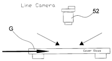
상기 스캔영역 변환유닛(45)은 도 5b와 도 5c와 같이 정역 회전력을 생성하는 서보모터(45a)와, 상기 서보모터에 볼 스크루(45b) 구조로 연결되어 서보모터의 정역 회전에 따라 이동하는 가동자(45c)를 포함하여 구성되어, 가동자(45c)에 고정된 라인 스캔 카메라(42)가 서보모터(45a)의 정역 회전에 의해 이동하여 스캔영역을 좌우로 변경하도록 구성된다.The scan
따라서, 상기 라인 스캔 카메라(42)는 패널(G)이 스캔영역에 진입하는 과정에서는 스캔영역 변환유닛(45)에 의해 스캔영역을 일측으로 이동시켜 패널(G)의 일측 외관을 스캔하고, 패널(G)이 졍선지점(P)으로 진출하는 과정에서는 스캔영역 변환유닛(45)에 의해 스캔영역을 타측으로 이동시켜 패널(G)의 타측 외관을 스캔하므로, 라인 스캔 카메라(42)는 스캔영역에 진출입하는 패널(G)을 분할하여 스캔하여 보다 높은 해상도의 패널(G)의 외관 영상을 취득할 수 있다.Accordingly, in the process of the panel G entering the scan area, the
한편, 본 실시예에서는 패널(G)을 횡방향으로 단계 이송시키는 트랜스퍼 모듈(30)의 측부에, 정션지점(P)에 위치된 패널(G)을 종방향으로 진출입시켜 종방향으로 진출입되는 패널(G)의 외관 영상을 스캔하는 종방향 스캔모듈(40)을 갖는 복수의 검사 스테이지(S)를 배치하고 있다.In this embodiment, on the side of the
도 8은 상기 종방향 스캔모듈들과 후술되는 횡방향 스캔모듈에 형성된 조명부재와 스캔 카메라의 배치 예를 모식적으로 보여주는 것으로, 상기 종방향 스캔모듈과 횡방향 스캔모듈의 설치개수나, 조명부재나 스캔 카메라의 배치형태는 제품이나 사용형태에 따라 다양한 변형 실시가 가능하다.FIG. 8 is a schematic view showing an example of arrangement of the illumination members and the scan cameras formed in the longitudinal scan modules, the laterally-scanned scan module to be described later, and the number of the longitudinal scan modules and the lateral scan modules, The arrangement of the scan camera can be variously modified according to the product or the usage type.
본 실시예에 따르면, 상기 복수의 종방향 스캔모듈(40) 중, 4개의 종방향 스캔모듈(40)에는 도 5와 같이 각각 종방향으로 평행하는 한 쌍의 캐리어암(43)이 이격되게 배치되어 캐리어암(43)이 패널(G)의 종변(W)을 견착하여 종방향으로 진출입하면, 라인 스캔 카메라(42)는 캐리어암(43)에 의해 종변(W)이 견착된 패널(G)을 라인 스캔하는 형태로 이루어진다.According to the present embodiment, among the plurality of
그리고, 나머지 하나는 도 6에서 보는 바와 같이 패널(G)의 횡변(L)을 견착한 캐리어암(43)이 종방향으로 진출입하면, 에어리어 스캔 카메라(42')는 캐리어암(43)에 횡변이 견착된 패널(G)을 에어리어 스캔하는 형태로 이루어진다.6, when the
이와 같이 캐리어암(43)에 의한 패널(G)의 견착지점을 변경하면 최초 도 5에 도시된 종방향 스캔모듈의 캐리어암에 의해 가려지는 패널의 종변(W)이, 5번째 스캔모듈의 스캔과정에서는 촬영되므로, 이들 패널(G)의 견착부위를 달리하는 종방향 스캔모듈들에 의해 패널의 전체적인 영상을 취득할 수 있다.When the point of tilting of the panel G by the
그리고, 상기 트랜스퍼 모듈(30)의 후방에는 졍선지점(P)에 위치된 패널(G)을 횡방향으로 진출입시켜 횡방향으로 진출입하는 패널의 외관 영상을 스캔하는 횡방향 스캔모듈(50)을 갖는 1개의 검사 스테이지(S)가 배치된다.A
또한, 상기 종방향 스캔모듈(40)과 횡방향 스캔모듈(50) 사이에는, 도 1과 도 2에서 보는 바와 같이 저면에 형성된 흡착구(21a)를 통해 패널(G)의 표면을 흡착하는 흡착판(21); 상기 흡착판(21)을 승강시키는 승강부재(22); 및 상기 흡착판(21)을 승강시킨 승강부재(22)를 레일을 따라 이동시키는 직진 이송부재(23)를 포함하여 구성된 픽업모듈(20')이 배치된다.1 and 2, a
따라서, 본 발명은 트랜스퍼 모듈(30)에 의해 횡방향으로 단계 이송되는 패널(G)을 종방향 스캔모듈(40)이 배치된 각 검사 스테이지(S)에 종방향으로 순차 진출입시켜 패널(G)을 종방향으로 스캔한 검사 영상을 취득한 다음, 패널(G)을 횡방향으로 진출입시켜서 패널(G)을 횡방향으로 스캔한 검사 영상을 취득한다.The panel G is moved in the longitudinal direction to the inspection stage S in which the
한편, 이와 같이 구성된 패널의 외관 검사시스템(1)을 통한 패널(G)의 외관 촬영과정을 상술하자면, 최초 로봇암(미도시)이 공급대(10)에 낱장의 패널(G)을 안착시키면, 교정유닛(11)에 형성된 종방향 정렬부재(13)와 횡방향 정렬부재(14)는 패널(G)의 종변(W)과 횡변(L)을 각각 가압하여 패널(G)이 기준블럭(12)을 기준으로 정렬되도록 한다.When the first robot arm (not shown) seats a single panel G on the
이때, 상기 종방향 정렬부재(13)와 횡방향 정렬부재(14)를 구성하는 교정블럭(13a, 14a)은, 스프링(13a-a, 14a-a)에 의해 탄지된 탄지편(13a-b, 14a-b)을 통해 패널(G)의 종변(W)과 횡변(L)을 각각 가압하므로, 교정블럭(13a, 14a)의 가압에 의한 패널(G)의 손상이 예방된다.At this time, the calibration blocks 13a and 14a constituting the
이 상태에서, 픽업모듈(20)은 흡착판(21)을 통해 공급대(10)에 정렬된 패널(G)의 표면을 흡착하여, 트랜스퍼 모듈(30)의 트랜스퍼암(31)에 낱장의 패널(G)을 안착시키고, 트랜스퍼 모듈(30)은 트랜스퍼암(31)을 단계적으로 이동시켜 각 검사 스테이지(S)에 형성된 정션지점(P)에 패널(G)을 위치시키는 트랜스퍼 공정을 실시하고, 트랜스퍼 공정에 의해 각 검사 스테이지(S)에 형성된 스캔모듈(40)은 캐리어암(41)을 종방향으로 진출입시켜 스캔구역을 따라 종방향으로 진출입하는 패널(G)을 스캔하는 스캔공정을 실시하게 된다. In this state, the pick-up
이러한 트랜스퍼 공정과 스캔공정을 교번 반복적으로 실시하여, 공급대(10)에 공급된 패널(G)는 각 검사 스테이지(S)에 형성된 스캔모듈에 의해 라인 스캔 과정과, 에어리어 스캔과정을 포함하는 종방향 스캔이 이루어진다.The transfer process and the scanning process are alternately and repeatedly performed and the panel G supplied to the
이때, 라인 스캔과정에서는 패널(G)는 캐리어암(41)의 흡착구(41a)에 의해 종변(W)이 각각 견착된 상태로 종방향으로 진출입되고, 에어리어 스캔과정에서는 패널(G)는 캐리어암의 흡착구에 횡변(L)이 각각 견착된 상태로 종방향으로 진출입하도록 구성되어서 라인스캔 과정에 캐리어암의 흡착구에 의해 국부적으로 가려진 부위가, 에어리어 스캔과정에서는 가려지지 아니하도록 함으로써, 견착부위의 변경을 통해 가려지는 부위 없이 패널의 전체적인 외관 영상을 취득할 수 있다.At this time, in the line scan process, the panel G is vertically moved in the longitudinal direction with the longitudinal sides W thereof being respectively fixed by the suction port 41a of the
또한, 상기 스캔모듈(40)은 패널(G)이 종방향으로 진입하는 과정에서는 도 5b와 같이 스캔 카메라(42)는 일측에 위치하여 패널의 일측 외관을 스캔하고, 도 5c와 같이 패널이 졍선지점으로 진출하는 과정에서는 스캔 카메라(42)를 스캔영역 변환유닛에 의해 타측으로 이동시켜 패널(G)의 타측 외관을 스캔하므로, 상기 종방향 스캔모듈의 라인 스캔 카메라는 종방향으로 진출입하는 패널을 분할되게 촬영하여, 고 해상도를 갖는 패널(G)의 외관 영상을 취득한다.5B, the
따라서, 스캔 카메라(42)는 스캔영역 변환유닛에 의해 스캔영역을 변환시키서, 스캔영역 보다 넓은 폭의 패널의 외관을 안정되게 취득할 수 있다.Therefore, the
이후, 종방향 스캔 과정이 완료되면, 패널(G)는 종방향 스캔모듈(40)과 횡방향 스캔모듈(50) 사이에 배치된 픽업모듈(20)에 의해 횡방향 촬영모듈(50)의 캐리어암(53)으로 이동하고, 상기 패널(G)는 횡방향 촬영모듈(50)의 캐리어암(53)에 의해 횡방향으로 진출입하면서 라인 스캔 카메라(52)에 의해 외관이 스캔된다.When the longitudinal scanning process is completed, the panel G is moved by the pick-up
그리하여, 본 발명에 따른 패널의 외관 검사시스템(1)은 패널(G)을 종방향으로 진출입시키면서 라인스캔 및 에어리어 스캔을 통해 외관을 스캔하여 종방향으로 진출되는 패널의 외관영상들을 취득하고, 각 스캔모듈(40, 50)을 통해 취득된 패널(G)의 외관 영상들은 판독모듈(미도시)에 의해 판독 및 분석되어서, 해당 패널(G)의 외관 불량 여부가 판정된다.Thus, the external appearance inspection system 1 of the panel according to the present invention acquires the external appearance images of the panel advancing in the longitudinal direction by scanning the exterior through the line scan and the area scan while advancing and retracting the panel G in the longitudinal direction, Appearance images of the panel G obtained through the
그리고, 본 실시예에와 같이 패널(G)의 회전시켜 스캔영역 내로 진출입하는 패널(G)의 진출입 방향을 전환하지 아니하고, 패널(G)을 각기 다른 방향으로 진출입시켜 스캔하는 종방향 스캔모듈(40)과 횡방향 스캔모듈(50)을 각각 배치하여, 패널(G)의 종방향 진입영상과 횡방향 진입 영상을 각각 취득하게 된다.As in the present embodiment, the vertical scanning module (not shown) that scans the panel G in different directions without changing the entry / exit direction of the panel G moving in and out of the scan area by rotating the
따라서, 패널(G)는 보다 정확한 각도와 위치로 스캔영역 내에 진입하여 외관이 스캔되어 고정밀도의 패널의 외관 영상을 취득할 수 있어서, 이를 통해 패널의 외관 검사에 따른 보다 높은 검사 신뢰성을 확보할 수 있다.Accordingly, the panel G enters the scan area at a more accurate angle and position, and the external appearance is scanned to obtain the appearance image of the high-precision panel, thereby ensuring higher inspection reliability according to the appearance inspection of the panel .
1. 패널의 외관 검사시스템
10. 공급대
11. 교정유닛 12. 기준블럭
13. 종방향 정렬부재 13a. 교정블럭
13a-a. 스프링 13a-b. 탄지편
13b. 정역모터 13c. 볼 스크루
14. 횡방향 정렬부재 14a. 교정블럭
14a-a. 스프링 14a-b. 탄지편
14b. 정역모터 14c. 볼 스크루
20, 20'. 픽업모듈 21. 흡착판
21a. 흡착구 22. 승강부재
23. 직진 이송부재
30. 트랜스퍼 모듈
31. 트랜스퍼암 31a. 흡착구
32. 승강부재 32a. 승강 브라켓
33. 직진 이송부재
40. 종방향 스캔모듈 41. 조명부재
42. 라인 스캔 카메라 42'. 에어리어 스캔 카메라
43. 캐리어암 44. 직진 이송부재
45. 스캔영역 변환유닛 45a. 서보모터
45b. 볼 스크루 45c. 가동자
50. 횡방향 스캔모듈 51. 조명부재
52. 라인 스캔 카메라 53. 캐리어암
54. 직진 이송부재
G. 패널 S. 검사 스테이지
P. 졍선지점1. Panel appearance inspection system
10. Feeder
11.
13.
13a-a.
13b. Forward and
14.
14a-a.
14b. Forward and
20, 20 '.
21a. The
23. Straight feed member
30. Transfer module
31.
32.
33. Straight feed member
40.
42. line scan camera 42 '. Area Scan Camera
43.
45. Scan
45b.
50. Lateral scanning module 51. Illumination element
52.
54. Straight transfer member
G. Panel S. Inspection Stage
P. Yusen Branch
Claims (3)
상기 스캔모듈은, 패널을 안착시키는 캐리어암과;
상기 캐리어암을 진퇴시켜, 캐리어암에 안착된 패널이 스캔영역 내에 진출입되도록 하는 직진 이송부재; 및
상기 스캔영역 내로 진출입되는 패널의 외관을 스캔하는 스캔 카메라를 포함하여 구성된 것을 특징으로 하는 정밀 스캔구조를 갖는 패널의 외관 검사시스템.And a scan module for photographing an exterior image of the panel that has entered the scan area, the system comprising:
The scan module includes: a carrier arm for seating the panel;
A rectilinear transferring member for advancing and retracting the carrier arm to allow the panel mounted on the carrier arm to enter and exit the scan area; And
And a scan camera that scans an outer appearance of the panel that enters and exits into the scan area.
상기 스캔 카메라는 스캔영역에 진출입하는 패널을 분할되게 스캔하여, 고 해상의 패널 외관 영상을 취득하도록 구성한 것을 특징으로 하는 정밀 스캔구조를 갖는 패널의 외관 검사시스템.The apparatus of claim 1, wherein the scan module includes a scan area changing unit for moving a scan camera to change a scan area of the scan camera. In the process of the panel entering the scan area, The scan camera is moved to the other side by the scan area changing unit to scan the other side of the panel,
Wherein the scan camera is configured to scan the panel entering and exiting the scan area in a divided manner to obtain a high resolution panel appearance image.
상기 스캔 카메라는 서보모터의 정역 회전에 의한 가동자의 이동에 의해 일측과 타측으로 이동하여 스캔영역을 변경하도록 구성된 것을 특징으로 하는 정밀 스캔구조를 갖는 패널의 외관 검사시스템.
The apparatus of claim 1, wherein the scan area changing unit comprises: a servomotor for generating a forward and reverse rotational force; and a mover connected to the servo motor by a ball screw structure and moving according to forward and reverse rotation of the servo motor,
Wherein the scan camera is configured to move to one side and the other side by moving the mover due to normal / reverse rotation of the servo motor to change the scan area.
Priority Applications (1)
| Application Number | Priority Date | Filing Date | Title |
|---|---|---|---|
| KR1020130093238A KR20150017231A (en) | 2013-08-06 | 2013-08-06 | Inspection system for the external appearance of panel having scan structure |
Applications Claiming Priority (1)
| Application Number | Priority Date | Filing Date | Title |
|---|---|---|---|
| KR1020130093238A KR20150017231A (en) | 2013-08-06 | 2013-08-06 | Inspection system for the external appearance of panel having scan structure |
Publications (1)
| Publication Number | Publication Date |
|---|---|
| KR20150017231A true KR20150017231A (en) | 2015-02-16 |
Family
ID=53046184
Family Applications (1)
| Application Number | Title | Priority Date | Filing Date |
|---|---|---|---|
| KR1020130093238A Abandoned KR20150017231A (en) | 2013-08-06 | 2013-08-06 | Inspection system for the external appearance of panel having scan structure |
Country Status (1)
| Country | Link |
|---|---|
| KR (1) | KR20150017231A (en) |
Cited By (3)
| Publication number | Priority date | Publication date | Assignee | Title |
|---|---|---|---|---|
| CN105548212A (en) * | 2016-02-03 | 2016-05-04 | 杭州晶耐科光电技术有限公司 | System and method for online automatically detecting defects on glass surface of touch screen |
| WO2019184353A1 (en) * | 2018-03-30 | 2019-10-03 | 江苏迪佳电子有限公司 | Production testing device for mobile phone touch screen |
| CN116659426A (en) * | 2023-06-16 | 2023-08-29 | 珠海博杰电子股份有限公司 | A flatness testing device |
-
2013
- 2013-08-06 KR KR1020130093238A patent/KR20150017231A/en not_active Abandoned
Cited By (3)
| Publication number | Priority date | Publication date | Assignee | Title |
|---|---|---|---|---|
| CN105548212A (en) * | 2016-02-03 | 2016-05-04 | 杭州晶耐科光电技术有限公司 | System and method for online automatically detecting defects on glass surface of touch screen |
| WO2019184353A1 (en) * | 2018-03-30 | 2019-10-03 | 江苏迪佳电子有限公司 | Production testing device for mobile phone touch screen |
| CN116659426A (en) * | 2023-06-16 | 2023-08-29 | 珠海博杰电子股份有限公司 | A flatness testing device |
Similar Documents
| Publication | Publication Date | Title |
|---|---|---|
| US12168274B2 (en) | End effector and light bar assembling device | |
| CN100368794C (en) | Substrate inspection device | |
| CN103376269B (en) | The check device of printed circuit board (PCB) | |
| CN104597055B (en) | The product appearance detecting system of multiplexing parallel-by-bit | |
| TWI393878B (en) | Panel inspection device and inspection method of panel | |
| KR101954416B1 (en) | Inspection apparatus | |
| KR101683589B1 (en) | Vision inspection apparatus and vision inspection method therefor | |
| KR101170928B1 (en) | Substrate inspection apparatus and substrate inspection method | |
| CN211014913U (en) | Liquid crystal display panel detection device | |
| KR101175770B1 (en) | Lense inspection system and lense inspection method using the same | |
| CN115973549B (en) | A smart wearable testing pipeline | |
| KR20120122316A (en) | Mobile Camera Lens Inspection System | |
| KR101440310B1 (en) | Apparatus for Auto Testing Trace of Pannel | |
| CN210676002U (en) | ULED screen substrate detection/measurement equipment | |
| KR20150017231A (en) | Inspection system for the external appearance of panel having scan structure | |
| KR101074394B1 (en) | Apparatus for Testing LCD Panel | |
| CN210690982U (en) | Pre-alignment device of ULED screen substrate detection/measurement equipment | |
| CN115060739A (en) | Panel detection device and panel detection method | |
| CN217369288U (en) | Defect detection device for polyhedral material | |
| CN113567360B (en) | A color difference gloss detection device compatible with multiple products and its operation method | |
| KR20150017222A (en) | Inspection system for the external appearance of panel having emproved transfer structure | |
| JP2006329714A (en) | Lens inspection apparatus | |
| CN206990465U (en) | The defects of liquid crystal panel detection means | |
| CN111665194A (en) | Appearance detection system and detection method | |
| CN114384093A (en) | Panel detection device and panel detection method |
Legal Events
| Date | Code | Title | Description |
|---|---|---|---|
| A201 | Request for examination | ||
| PA0109 | Patent application |
Patent event code: PA01091R01D Comment text: Patent Application Patent event date: 20130806 |
|
| PA0201 | Request for examination | ||
| N231 | Notification of change of applicant | ||
| PN2301 | Change of applicant |
Patent event date: 20140513 Comment text: Notification of Change of Applicant Patent event code: PN23011R01D |
|
| E902 | Notification of reason for refusal | ||
| PE0902 | Notice of grounds for rejection |
Comment text: Notification of reason for refusal Patent event date: 20140723 Patent event code: PE09021S01D |
|
| E701 | Decision to grant or registration of patent right | ||
| PE0701 | Decision of registration |
Patent event code: PE07011S01D Comment text: Decision to Grant Registration Patent event date: 20141029 |
|
| PG1501 | Laying open of application | ||
| PC1904 | Unpaid initial registration fee |