KR20150001803A - Compressed-air energy-storage system - Google Patents
Compressed-air energy-storage system Download PDFInfo
- Publication number
- KR20150001803A KR20150001803A KR1020147031336A KR20147031336A KR20150001803A KR 20150001803 A KR20150001803 A KR 20150001803A KR 1020147031336 A KR1020147031336 A KR 1020147031336A KR 20147031336 A KR20147031336 A KR 20147031336A KR 20150001803 A KR20150001803 A KR 20150001803A
- Authority
- KR
- South Korea
- Prior art keywords
- compressed air
- pressure
- air
- variable nozzle
- energy storage
- Prior art date
- Legal status (The legal status is an assumption and is not a legal conclusion. Google has not performed a legal analysis and makes no representation as to the accuracy of the status listed.)
- Withdrawn
Links
- 238000004146 energy storage Methods 0.000 title claims abstract description 57
- 239000000567 combustion gas Substances 0.000 claims abstract description 26
- 239000000446 fuel Substances 0.000 claims abstract description 18
- 230000002441 reversible effect Effects 0.000 claims description 49
- 238000000034 method Methods 0.000 claims description 33
- 238000009826 distribution Methods 0.000 claims description 27
- 238000003860 storage Methods 0.000 claims description 21
- 238000010248 power generation Methods 0.000 claims description 17
- 230000006835 compression Effects 0.000 claims description 16
- 238000007906 compression Methods 0.000 claims description 16
- 239000007789 gas Substances 0.000 claims description 9
- 238000011084 recovery Methods 0.000 claims description 9
- 238000012546 transfer Methods 0.000 claims description 7
- 238000011144 upstream manufacturing Methods 0.000 claims description 5
- 238000010438 heat treatment Methods 0.000 claims description 3
- 238000002485 combustion reaction Methods 0.000 description 26
- 239000000203 mixture Substances 0.000 description 5
- 238000004891 communication Methods 0.000 description 4
- 239000012530 fluid Substances 0.000 description 4
- 230000001105 regulatory effect Effects 0.000 description 4
- 238000010276 construction Methods 0.000 description 2
- 239000002826 coolant Substances 0.000 description 2
- 238000001816 cooling Methods 0.000 description 2
- 238000013461 design Methods 0.000 description 2
- 230000000694 effects Effects 0.000 description 2
- 238000005338 heat storage Methods 0.000 description 2
- 238000012986 modification Methods 0.000 description 2
- 230000004048 modification Effects 0.000 description 2
- 150000003839 salts Chemical class 0.000 description 2
- 230000002411 adverse Effects 0.000 description 1
- 230000001276 controlling effect Effects 0.000 description 1
- 238000010586 diagram Methods 0.000 description 1
- 230000005611 electricity Effects 0.000 description 1
- 238000005516 engineering process Methods 0.000 description 1
- 238000004519 manufacturing process Methods 0.000 description 1
- 238000005381 potential energy Methods 0.000 description 1
- 230000008569 process Effects 0.000 description 1
- 230000009467 reduction Effects 0.000 description 1
- 230000001172 regenerating effect Effects 0.000 description 1
- 238000000518 rheometry Methods 0.000 description 1
- 239000011232 storage material Substances 0.000 description 1
- 239000002699 waste material Substances 0.000 description 1
Images


Classifications
-
- F—MECHANICAL ENGINEERING; LIGHTING; HEATING; WEAPONS; BLASTING
- F02—COMBUSTION ENGINES; HOT-GAS OR COMBUSTION-PRODUCT ENGINE PLANTS
- F02C—GAS-TURBINE PLANTS; AIR INTAKES FOR JET-PROPULSION PLANTS; CONTROLLING FUEL SUPPLY IN AIR-BREATHING JET-PROPULSION PLANTS
- F02C6/00—Plural gas-turbine plants; Combinations of gas-turbine plants with other apparatus; Adaptations of gas-turbine plants for special use
- F02C6/14—Gas-turbine plants having means for storing energy, e.g. for meeting peak loads
- F02C6/16—Gas-turbine plants having means for storing energy, e.g. for meeting peak loads for storing compressed air
-
- F—MECHANICAL ENGINEERING; LIGHTING; HEATING; WEAPONS; BLASTING
- F02—COMBUSTION ENGINES; HOT-GAS OR COMBUSTION-PRODUCT ENGINE PLANTS
- F02C—GAS-TURBINE PLANTS; AIR INTAKES FOR JET-PROPULSION PLANTS; CONTROLLING FUEL SUPPLY IN AIR-BREATHING JET-PROPULSION PLANTS
- F02C1/00—Gas-turbine plants characterised by the use of hot gases or unheated pressurised gases, as the working fluid
- F02C1/04—Gas-turbine plants characterised by the use of hot gases or unheated pressurised gases, as the working fluid the working fluid being heated indirectly
-
- F—MECHANICAL ENGINEERING; LIGHTING; HEATING; WEAPONS; BLASTING
- F02—COMBUSTION ENGINES; HOT-GAS OR COMBUSTION-PRODUCT ENGINE PLANTS
- F02C—GAS-TURBINE PLANTS; AIR INTAKES FOR JET-PROPULSION PLANTS; CONTROLLING FUEL SUPPLY IN AIR-BREATHING JET-PROPULSION PLANTS
- F02C3/00—Gas-turbine plants characterised by the use of combustion products as the working fluid
- F02C3/04—Gas-turbine plants characterised by the use of combustion products as the working fluid having a turbine driving a compressor
- F02C3/13—Gas-turbine plants characterised by the use of combustion products as the working fluid having a turbine driving a compressor having variable working fluid interconnections between turbines or compressors or stages of different rotors
-
- F—MECHANICAL ENGINEERING; LIGHTING; HEATING; WEAPONS; BLASTING
- F02—COMBUSTION ENGINES; HOT-GAS OR COMBUSTION-PRODUCT ENGINE PLANTS
- F02C—GAS-TURBINE PLANTS; AIR INTAKES FOR JET-PROPULSION PLANTS; CONTROLLING FUEL SUPPLY IN AIR-BREATHING JET-PROPULSION PLANTS
- F02C7/00—Features, components parts, details or accessories, not provided for in, or of interest apart form groups F02C1/00 - F02C6/00; Air intakes for jet-propulsion plants
- F02C7/08—Heating air supply before combustion, e.g. by exhaust gases
-
- F—MECHANICAL ENGINEERING; LIGHTING; HEATING; WEAPONS; BLASTING
- F05—INDEXING SCHEMES RELATING TO ENGINES OR PUMPS IN VARIOUS SUBCLASSES OF CLASSES F01-F04
- F05D—INDEXING SCHEME FOR ASPECTS RELATING TO NON-POSITIVE-DISPLACEMENT MACHINES OR ENGINES, GAS-TURBINES OR JET-PROPULSION PLANTS
- F05D2220/00—Application
- F05D2220/70—Application in combination with
- F05D2220/76—Application in combination with an electrical generator
-
- Y—GENERAL TAGGING OF NEW TECHNOLOGICAL DEVELOPMENTS; GENERAL TAGGING OF CROSS-SECTIONAL TECHNOLOGIES SPANNING OVER SEVERAL SECTIONS OF THE IPC; TECHNICAL SUBJECTS COVERED BY FORMER USPC CROSS-REFERENCE ART COLLECTIONS [XRACs] AND DIGESTS
- Y02—TECHNOLOGIES OR APPLICATIONS FOR MITIGATION OR ADAPTATION AGAINST CLIMATE CHANGE
- Y02E—REDUCTION OF GREENHOUSE GAS [GHG] EMISSIONS, RELATED TO ENERGY GENERATION, TRANSMISSION OR DISTRIBUTION
- Y02E60/00—Enabling technologies; Technologies with a potential or indirect contribution to GHG emissions mitigation
- Y02E60/16—Mechanical energy storage, e.g. flywheels or pressurised fluids
Landscapes
- Engineering & Computer Science (AREA)
- Chemical & Material Sciences (AREA)
- Combustion & Propulsion (AREA)
- Mechanical Engineering (AREA)
- General Engineering & Computer Science (AREA)
- Engine Equipment That Uses Special Cycles (AREA)
Abstract
본 발명은 압축 공기 에너지 저장 시스템에 관한 것으로서, 압축 공기 에너지 저장 시스템은, 제1 압력에서 공기 유동을 수용하고 제2 압력에서 공기 유동을 부분적으로 팽창시키도록 구성되는 가변 노즐 팽창기(115, 115A)로서, 제2 압력은 제1 압력보다 낮으며 가변 노즐 팽창기에서의 공기 유동의 팽창이 유효 기계력을 생성하는 것인, 가변 노즐 팽창기와, 가변 노즐 팽창기로부터의 부분적으로 팽창된 공기 유동 및 연료를 수용하도록 구성되는 열 발생기 요소(125)와, 열 발생기 요소(125)로부터 연소 가스를 수용하고 그리고 유효 기계력을 생성하는 연소 가스를 팽창시키도록 구성되는 터빈(131)을 포함한다. The present invention relates to a compressed air energy storage system comprising a variable nozzle inflator (115, 115A) configured to receive an air flow at a first pressure and partially expand an air flow at a second pressure, Wherein the second pressure is lower than the first pressure and the expansion of the air flow at the variable nozzle inflator produces effective mechanical force; and a second nozzle inflator adapted to receive the partially expanded air flow from the variable nozzle inflator and the fuel And a turbine 131 configured to inflate the combustion gases that receive the combustion gases from the heat generator elements 125 and produce effective mechanical forces.
Description
본 발명은 약칭으로 CAES 시스템이라고 칭해지는 압축 공기 에너지 저장 시스템에 관한 것이다. 또한, 본 발명은 CAES 시스템을 이용하는 에너지 저장 및 전기 에너지 생성 방법에 관한 것이다. The present invention relates to a compressed air energy storage system, which is abbreviated CAES system. The present invention also relates to a method of energy storage and electrical energy generation using a CAES system.
CAES 파워 플랜트 및 시스템은 통상 에너지의 이용을 최적화하는 수단으로서 이용된다. 당업자에게 공지된 바와 같이, 전기 분배 그리드가 필요로 하는 전기 에너지는 낮 동안의 피크 및 야간의 감소된 파워 요구에 따라 달라진다. 대형 스팀 파워 플랜트 또는 재생가능 파워 플랜트는 임의로 변경될 수 없는 임의량의 파워를 생산한다. 이로 인해 야간에는 전기 분배 그리드에서 이용가능한 파워가 초과되고 피크 시간 동안에는 파워가 부족해진다. 가스 터빈, 특히 공기유도 가스 터빈을 이용하는 소형 파워 플랜트가 피크 파워 요구를 커버하기 위해 실시되어 왔다. 이런 플랜트는 24 시간 동안의 가변 파워 요건에 따라 작동 및 정지될 수 있다. 그럼에도 불구하고, 야간에 생성된 초과 에너지를 저장하기 위해 그리고 피크 시간 동안 전력 생산을 증가시키도록 저장된 에너지를 회수하는 것이 또한 충족되어야 한다. 이런 목적을 위해 이용되는 방법들 중 하나가 CAES 기술이다. 이런 시스템은 통상 하나 이상의 압축기를 갖는 압축 트레인을 포함하며, 하나 이상의 압축기는 야간 동안, 즉 그리드에서 이용가능한 것보다 적은 파워가 요구될 때 그리드로부터의 전력에 의해 구동된다. 후속하여, 압축 공기가 낮 동안 그리드로부터의 피크 파워 요구를 커버하도록 이용되는데, 압축 공기를 적절한 아력으로 팽창시켜 압축 챔버에서 공기/연료 혼합물을 연소시켜 연소 가스를 생성하는데, 이 연소 가스는 파워 생성을 위해 터빈에서 팽창된다. CAES power plants and systems are typically used as a means of optimizing the use of energy. As is known to those skilled in the art, the electrical energy required by the electrical distribution grid depends on the peak power during the day and the reduced power demand at night. Large steam power plants or renewable power plants produce any amount of power that can not be arbitrarily changed. This causes the available power in the electricity distribution grid to be exceeded at night and the power to run out during peak hours. Small power plants using gas turbines, especially air-driven gas turbines, have been implemented to cover peak power requirements. Such a plant can be turned on and off in accordance with variable power requirements for 24 hours. Nonetheless, it must also be satisfied to store the excess energy generated at night and to recover stored energy to increase power production during peak hours. One of the methods used for this purpose is CAES technology. Such systems typically include a compression train having one or more compressors, and one or more compressors are driven by power from the grid during nighttime, i.e. when less power is required than is available in the grid. Subsequently, compressed air is used to cover the peak power demand from the grid during the day, which expands the compressed air with the appropriate force to combust the air / fuel mixture in the compression chamber to produce a combustion gas, In the turbine.
종래 기술에 따른 압축 공기 에너지 저장 시스템이 도 1에 도시되어 있다. 시스템은 압축 공기 저장 체적부(1)을 포함한다. 저장 체적부는 자연 또는 인공 공동일 수 있다. 다른 적절한 체적부가 압축 공기를 저장하는데 이용될 수 있다. 본 명세서에선 "공동"이라는 용어를 구체적으로 참조하지만, 임의의 다른 적절한 체적부가 이용될 수 있다는 것을 당업자들은 알 것이다. 초과 전력이 전기 분배 그리드(G)에서 이용가능할 때, 가역 전기 기계(3)는 기계적 샤프트(7)를 통해 압축기 또는 압축기 트레인(5)을 구동시키기 위해 전기 분배 그리드(G)로부터 이용할 수 있는 전력을 기계력으로 변환시킨다. 선택적으로 압축기 또는 압축기 트레인(5)을 가역 전기 기계(3)에 연결시키고 그리고 압축기 또는 압축기 트레인(5)을 가역 전기 기계(3)로부터 분리시키기 위해 클러치(9)가 제공된다. 압축기 또는 압축기 트레인(5)으로부터의 압축 공기는 압축 공기 라인(11)에 의해 밸브(13)를 통해 공동(1) 내로 이송된다. A prior art compressed air energy storage system is shown in Fig. The system comprises a compressed air storage volume (1). The storage volume can be a natural or artificial cavity. Other suitable volume compartments may be used to store compressed air. Although specific reference may be made in this text to the term "cavity ", those skilled in the art will recognize that any other suitable volume may be utilized. When excess power is available in the electric distribution grid G, the reversible electric machine 3 is able to utilize the power available from the electric distribution grid G to drive the compressor or
더 많은 전력이 전기 분배 그리드(G)로부터 요구되는 경우, CAES 시스템의 파워 생성 섹션(15)이 작동된다. 파워 생성 섹션(15)은 하나 이상의 팽창기를 포함한다. 도 1에 도시된 실시예에서, 제1 고압 팽창기(17)는 제2 저압 팽창기(19)와 직렬로 배치된다. 2개의 팽창기(17, 19)는 통상 하나의 동일한 기계적 샤프트(21)에 연결된다. 기계적 샤프트(21)는 클러치(23)를 통해 가역 전기 모터에 연결되거나 가역 전기 모터로부터 분리될 수 있다. 공동(1)으로부터의 압축 공기는 고압 파이프(25)를 통해 고압 압축기(17)로 공급된다. When more power is required from the electrical distribution grid G, the
공동(1)으로부터의 압축 공기는 고압 팽창기(17)에서 팽창된다. 팽창 공기는 연소 챔버(29)로 이송된다. 제2 저압 팽창기(19)에서 팽창되는 연소 가스를 생성하기 위해 연료(F)가 부분적으로 팽창된 공기의 유동에 추가된다. 후속하여, 배기된 연소 가스가 도면부호 31에서 저압 팽창기로부터 배출된다. 압축 챔버(29) 내의 압력은 연소 챔버를 정확히 작동시키기 위해 신중하게 제어되어야 한다. 따라서, 공동(1)으로부터의 공기의 압력은 고압 팽창기(17)에서의 공기의 팽창 이전에 정밀하게 제어되어, 부분적으로 팽창된 공기가 정확한 압력에서 연소 챔버(29)에 유입되는 것이 필수적이다. The compressed air from the cavity (1) is expanded in the high-pressure inflator (17). The expanded air is transferred to the combustion chamber (29). Fuel (F) is added to the flow of partially expanded air to produce a combustion gas which is expanded in the second low pressure inflator (19). Subsequently, the exhausted combustion gas is exhausted from the low pressure inflator at 31. The pressure in the
공동(1) 내의 압력은 공동(1) 내에서 압축 및 저장되는 공기의 양에 따라 변화된다. 고압 파이프(25) 내의 공기압은 사실상 일정한 값으로 유지되어야 한다. 이를 위해, 공동(1)으로부터의 공기의 압력을 고압 팽창기(17)의 유출구에서 정확한 연소 압력을 달성하는데 적절한 값으로 감소시키기 위해 압력 조절 밸브(27)가 고압 파이프(25)를 따라 제공된다. 압력 조절 밸브(27) 내의 공기의 팽창은 가압 공기에 포함된 에너지를 감소시키지만, 고압 팽창기(17)의 하류에 있는 연소 챔버(29)에 유입될 때 공기의 적절한 압력값을 달성하는데 있어서는 필수적이다. 압력 조절 밸브(27)는 고압 팽창기의 유입구에서 공기의 압력을 공동(1) 내의 가변 공기압과 상관없는 사실상 일정한 값으로 유지시킨다. The pressure in the cavity (1) varies with the amount of air compressed and stored in the cavity (1). The air pressure in the high-
압력 조절 밸브(27) 내의 공기의 팽창은 상당한 에너지 손실을 야기하여 CAES 시스템의 전효율에 악영향을 미친다. The expansion of the air in the
CAES 시스템 또는 파워 플랜트의 최적화된 전효율은 본 명세서에서 "가변 노즐 팽창기"로도 칭해지는 가변 구조의 유입 노즐을 갖춘 팽창기를 제공함으로써 달성된다. 저장 체적부, 예컨대 공동으로부터의 압축 공기는 가변 노즐 팽창기로 이송되어 고압에서 저압으로 부분적으로 팽창된다. "부분적으로 팽창된(partly expanded)"이라는 용어는 가변 노즐 팽창기의 이송 측에서의 공기가 여전히 가압된 상태로 유지된다라는 것을, 즉 주위 압력보다 더 높은 압력을 갖는다는 것을 의미한다. The optimized total efficiency of the CAES system or power plant is achieved by providing an inflator with a variable structure inflow nozzle, also referred to herein as a "variable nozzle inflator ". The storage volume, e.g. compressed air from the cavity, is delivered to the variable nozzle expander and is partially expanded from high pressure to low pressure. The term " partly expanded "means that the air at the transfer side of the variable nozzle expander is still kept under pressure, i.e., has a pressure higher than the ambient pressure.
기계력은 이런 압축 공기 유동의 제1 팽창 동안 가변 노즐 팽창기에 의해 생성된다. 가변 노즐 팽창기의 유입 노즐 구조는 작동 중에 변경될 수 있어, 가변 노즐 팽창기의 유출구에서의 최종 공기 유동 압력이 사실상 일정한 값으로 유지되거나, 적어도 대략 공칭 압력의 허용 오차의 범위 내에서 유지된다. 이런 값 또는 값 범위는 터빈의 연소 챔버 내의 작동 조건에 의해 설정되며, 부분적으로 팽창된 공기 유동은 연료와 혼합되고, 공기/연효 혼합물은 연소 가스 유동을 생성하도록 점화된 후에, 파워 생성을 위해 터빈에서 추가로 팽창된다. 본 명세서에서, 연소 챔버는 임의의 열 발생기 요소일 수도 있다. 가변 노즐 구조는 유입 공기 유동 압력이 변동되는 경우에도 팽창기 유출 압력을 소정의 값으로 또는 대략 소정의 값으로 유지시킨다. 따라서, 압력 감소 및 조절은 기계력을 추출할 수 있는 기계류에 의해 달성된다. The mechanical force is produced by the variable nozzle inflator during the first expansion of this compressed air flow. The inflow nozzle structure of the variable nozzle inflator can be changed during operation so that the final air flow pressure at the outlet of the variable nozzle inflator is maintained at a substantially constant value or at least within a tolerance of the nominal pressure. This value or range of values is set by the operating conditions in the combustion chamber of the turbine, the partially expanded air flow is mixed with the fuel, the air / rheology mixture is ignited to produce the combustion gas flow, Lt; / RTI > In this specification, the combustion chamber may be any heat generator element. The variable nozzle arrangement maintains the inflator outlet pressure at or near a predetermined value even when the inflow air flow pressure fluctuates. Thus, pressure reduction and regulation is achieved by machinery that can extract mechanical power.
따라서, 본 발명의 목적은 CAES 시스템을 이용하는 개선된 에너지 저장 및 전기 에너지 생성 방법을 제공하는 것이다. It is therefore an object of the present invention to provide an improved energy storage and electrical energy generation method using a CAES system.
본 발명의 예시적인 실시예에 따르면, 압축 공기 에너지 저장 시스템으로서, 제1 압력에서 공기 유동을 수용하고 제2 압력에서 공기 유동을 부분적으로 팽창시키도록 구성되는 적어도 하나의 가변 노즐 팽창기(variable-nozzle expander)로서, 제2 압력은 제1 압력보다 낮으며 가변 노즐 팽창기에서의 공기 유동의 팽창이 유효 기계력(useful mechanical power)을 생성하는 가변 노즐 팽창기와, 가변 노즐 팽창기로부터의 부분적으로 팽창된 공기 유동 및 연료를 수용하도록 구성되는 적어도 하나의 열 발생기 요소와, 열 발생기 요소로부터 연소 가스를 수용하고 그리고 유효 기계력을 생성하는 연소 가스를 팽창시키도록 구성되는 적어도 하나의 터빈을 포함하는, 압축 공기 에너지 저장 시스템이 제공된다. According to an exemplary embodiment of the present invention there is provided a compressed air energy storage system comprising at least one variable-nozzle inflator configured to receive an air flow at a first pressure and partially expand an air flow at a second pressure, wherein the second pressure is lower than the first pressure and the expansion of the air flow at the variable nozzle inflator produces a useful mechanical power; and a partially expanded air flow from the variable nozzle inflator And at least one heat generator element configured to receive fuel and at least one turbine configured to receive combustion gas from the heat generator element and to expand the combustion gas to produce effective mechanical power. System is provided.
몇몇 실시예에 따르면, 가변 노즐 팽창기는 제2 압력을 소정의 압력 범위 내에서 대략 일정한 압력 값, 즉 공칭값 또는 정격값으로 유지시키도록 구성된다. 예컨대, 공칭값은 연소 챔버 또는 열 생성기 요소의 설계에 의해 결정될 수 있다.According to some embodiments, the variable nozzle expander is configured to maintain the second pressure within a predetermined pressure range at a substantially constant pressure value, i.e., a nominal value or a nominal value. For example, the nominal value may be determined by the design of the combustion chamber or heat generator element.
예컨대, 제2 압력,즉 가변 노즐 팽창기의 유출구에서의 압력은 바람직하게는 대략 공칭값의 20% 미만 만큼, 보다 바람직하는 대략 공칭값의 10% 미만 만큼 변동될 수 있다. 다른 바람직한 실시예에서, 압력 변동은 대략 공칭값의 6% 내, 예컨대 대략 4% 내이다. For example, the second pressure, the pressure at the outlet of the variable nozzle expander, may preferably be varied by less than about 20% of the nominal value, more preferably by less than about 10% of the nominal value. In another preferred embodiment, the pressure variation is within about 6% of the nominal value, for example within about 4%.
몇몇 실시예에 따르면, 본 발명의 시스템은 터빈 및/또는 가변 노즐 팽창기에 의해 생성된 유효 기계력을 전기력으로 변환시키도록 구성 및 배치되는 적어도 하나의 전기 기계를 포함한다. 또한, 전력은 하나 이상의 기계에 전력을 공급하는데 이용되고 그리고/또는 전기 에너지 분배 그리드에서 분배될 수 있다. According to some embodiments, the system of the present invention includes at least one electrical machine configured and arranged to convert the effective mechanical force generated by the turbine and / or the variable nozzle inflator into an electrical force. The power may also be used to power one or more machines and / or be distributed in an electrical energy distribution grid.
특히 바람직한 실시예에서, 기계력은 선택적으로 기계력을 전력으로 변환시키도록 또는 전기 분배 그리드(electric distribution grid)로부터의 전력을 기계력으로 변환시키도록 구성된다. 몇몇 실시예에 따르면, 본 발명의 시스템은 적어도 하나의 공기 압축기를 더 포함한다. 전기 기계는 가변 노즐 팽착기 및 터빈에 의해 생성된 기계력을 이용하는 전력을 선택적으로 생성하도록 구성 및 배치되거나, 전기 분배 그리드로부터의 전력을 기계력으로 변환시킬 때 적어도 하나의 공기 압축기를 회전 구동시키도록 구성 및 배치된다. 또한, 본 발명의 시스템은 에너지를 압축 공기의 형태로 저장하기 위해 적어도 하나의 압축 공기 라인 경로에 의해 적어도 하나의 공기 압축기에 연결되는 적어도 하나의 압축 공기 저장 체적부(volume)를 포함할 수 있다. In a particularly preferred embodiment, the mechanical force is optionally configured to convert the mechanical force to electrical power or to convert the electrical power from the electric power distribution grid to mechanical power. According to some embodiments, the system of the present invention further comprises at least one air compressor. The electrical machine is configured and arranged to selectively generate power using the mechanical force generated by the variable nozzle expander and the turbine or configured to rotationally drive at least one air compressor when converting power from the electrical distribution grid to mechanical power Respectively. The system of the present invention may also include at least one compressed air storage volume connected to the at least one air compressor by at least one compressed air line path for storing energy in the form of compressed air .
몇몇 실시예에서, 가변 노즐 팽창기와 노즐은 공통 샤프트를 갖는다. 전기 기계는 공통 샤프트에 또는 적어도 하나의 공기 압축기에 선택적으로 연결될 수 있다. In some embodiments, the variable nozzle expander and the nozzle have a common shaft. The electrical machine may be selectively connected to a common shaft or to at least one air compressor.
다른 실시예에서, 가변 노즐 팽창기와 터빈은 2개의 독립적인 출력 샤프트를 갖는다. 이런 경우, 본 발명의 시스템은, 가변 노즐 팽창기에 의해 생성된 유효 기계력을 전력으로 변환시키도록 구성 및 배치되는 제1 전기 기계와, 터빈에 의해 생성된 유효 기계력을 전력으로 변환시키도록 구성 및 배치되는 제2 전기 기계를 더 포함한다. 제1 전기 기계 또는 제2 전기 기계, 또는 제1 전기 기계와 제2 전기 기계는 선택적으로 유효 기계력을 전력으로 변환시키거나 전기 분배 그리드에 의해 전력이 공급될때 기계력을 생성하도록 구성 및 배치되는 가역 전기 기계일 수 있다. In another embodiment, the variable nozzle inflator and the turbine have two independent output shafts. In such a case, the system of the present invention comprises a first electrical machine constructed and arranged to convert the effective mechanical force generated by the variable nozzle expander into electric power, and a second electric machine constructed and arranged to convert the effective mechanical force generated by the turbine into electric power And a second electric machine connected to the second electric machine. The first electric machine or the second electric machine, or the first electric machine and the second electric machine, may optionally be constructed and arranged to convert the effective mechanical force into electric power or to generate a mechanical force when powered by the electric distribution grid. Machine.
몇몇 실시예에서, 본 발명의 시스템은 선택적으로 제1 전기 기계에 연결되거나 제1 전기 기계로부터 분리될 수 있는 제1 공기 압축기와, 선택적으로 제2 전기 기계에 연결되거나 제2 전기 기계로부터 분리될 수 있는 제2 공기 압축기를 포함할 수 있다. 제1 및 제2 공기 압축기는 압축 공기 라인에 의해 적어도 하나의 압축 공기 저장 체적부, 예컨대 공동에 연결된다. In some embodiments, the system of the present invention optionally includes a first air compressor, which may be coupled to or disconnected from the first electrical machine, and a second air compressor, optionally coupled to or separate from the second electrical machine And a second air compressor, The first and second air compressors are connected to at least one compressed air storage volume, e.g., cavity, by a compressed air line.
공기의 압축은 온도 상승을 유발시킨다. 압축 동안 공기 유동에서 생성된 열은 시스템의 전효율을 증가시키도록 회수될 수 있다. 따라서, 몇몇 개선된 실시예에 따르면, 본 발명의 시스템은 하나 이상의 열 에너지 저장 장치를 포함한다. 유리하게는, 열 에너지 저장 장치(들)는 하나 이상의 압축기에 의해 전달된 압축 공기의 유동으로부터 추출되는 열을 저장하도록 구성된다. 이와는 반대로, 압축 공기가 압축 공기 저장 체적부로부터 가변 노즐 팽창기를 향해 유동하는 경우, 열은 열 에너지 저장 장치(들)로부터 공기 유동으로 전달되어 공기의 에너지 양을 증시키며, 후속하여 가변 노즐 팽창기 및/또는 터빈에서 이용될 수 있다. 복수의 열 에너지 저장 장치가 제공되는 경우, 복수의 열 에너지 저장 장치는 상이한 압력 레벨에서 압축 공기 유동으로부터 열을 제거하도록 배치될 수 있다. 몇몇 실시예에서, 열 에너지 저장 장치는 2개의 연속으로 배치된 압축 스테이지 사이에서 공기를 냉각시키도록 배치될 수 있다. 이런 경우 열 에너지 저장 장치의 효과는 인터쿨링과 유사할 것이며, 압축기 장치의 전효율을 증가시킨다. 사실상, 열 에너지 저장 장치는 열 교환기를 포함하며, 공기는 냉각 매체에 의해 열을 교환한다. 냉각 매체는 열 저장 매체로서 기능할 수 있다. 냉각 공기는 더 높은 밀도를 가지며, 추가적인 압축에 더 적은 파워가 요구된다. Compression of air causes temperature rise. The heat generated in the air flow during compression can be recovered to increase the overall efficiency of the system. Thus, in accordance with some improved embodiments, the system of the present invention includes one or more thermal energy storage devices. Advantageously, the thermal energy storage device (s) is configured to store heat extracted from the flow of compressed air delivered by the one or more compressors. Conversely, when compressed air flows from the compressed air storage volume toward the variable nozzle expander, heat is transferred from the thermal energy storage device (s) to the air flow to increase the amount of energy in the air and subsequently to the variable nozzle inflator and / ≪ / RTI > turbines. When a plurality of thermal energy storage devices are provided, the plurality of thermal energy storage devices may be arranged to remove heat from the compressed air flow at different pressure levels. In some embodiments, the thermal energy storage device can be arranged to cool the air between two consecutively arranged compression stages. In this case, the effect of the thermal energy storage will be similar to intercooling, increasing the overall efficiency of the compressor device. In effect, the thermal energy storage device includes a heat exchanger, and the air exchanges heat by the cooling medium. The cooling medium may function as a heat storage medium. Cooling air has a higher density and requires less power for further compression.
압축 공기를 가변 노즐 팽창기 및/또는 터빈을 향해 이송할 때 열이 회수될 수 있다. 열은 가변 노즐 팽창기의 상류에 있는 압축 공기의 유동으로 다시 전달되거나, 가변 노즐 팽창기와 터빈 사이로 다시 전달되거나, 가변 노즐 팽창기의 상류에 있는 압축 공기의 유동으로 그리고 가변 노즐 팽창기와 터빈 사이로 다시 전달될 수 있다. Heat can be recovered when the compressed air is conveyed toward the variable nozzle expander and / or the turbine. The heat is transferred back to the flow of compressed air upstream of the variable nozzle expander or back again between the variable nozzle expander and the turbine or to the flow of compressed air upstream of the variable nozzle expander and back again between the variable nozzle expander and the turbine .
몇몇 실시예에서, 열은 터빈 배출부에서 연소 가스로부터 또한 회수될 수 있다. 이러한 회수는 열 교환기에 의해 달성될 수 있으며, 압축 공기는 터빈으로부터 배출되는 배기 연소 가스와의 열 교환에 의해 가열된다. 연소 가스로부터의 열의 회수는 열 에너지 저장 장치로부터의 열 회수와 조합되어 이용될 수 있거나, 그런 열 에너지 저장 장치 없이 이용될 수 있다. In some embodiments, heat may also be recovered from the combustion gases at the turbine discharge. This recovery can be accomplished by a heat exchanger and the compressed air is heated by heat exchange with the exhaust combustion gases exiting the turbine. The recovery of heat from the combustion gas can be used in combination with heat recovery from the thermal energy storage, or can be used without such a thermal energy storage.
터빈 및/또는 가변 노즐 팽창기 내에서의 공기의 팽창 이전에 공기를 가열하기 위한 압축 공기의 유동과의 열 교환을 통한 열의 회수가 바람직하지만, 회수된 열은 또한 다른 방식으로, 예컨대 가열 또는 공기 조절 목적으로 이용될 수 있다.While it is desirable to recover heat through heat exchange with the flow of compressed air to heat the air prior to expansion of the air in the turbine and / or variable nozzle expander, the recovered heat may also be delivered in other manners, Can be used for the purpose.
본 발명의 다른 양태에 따르면, 본 발명은 압축 공기 에너지 저장 시스템으로부터 에너지를 생성하기 위한 방법으로서, 압축 공기 유동을 가변 노즐 팽창기에서 제1 압력에서 제2 압력으로 적어도 부분적으로 팽창시켜 유효 기계력을 생성하는 단계와, 부분적으로 팽창된 공기 유동을 제2 압력에서 열 발생기 요소로 이송하여 부분적으로 팽창된 공기 유동에 연료를 혼합시켜 고온 가압 연소 가스를 생성하는 단계와, 연소 가스를 터빈에서 팽창시켜 유효 기계력을 생성하는 단계를 포함하며, 제1 압력은 제2 압력보다 높은 에너지 생성 방법에 관한 것이다. According to another aspect of the present invention, there is provided a method for generating energy from a compressed air energy storage system, the method comprising: at least partially expanding a compressed air flow from a first pressure to a second pressure in a variable nozzle expander, Transferring the partially expanded air flow from the second pressure to the heat generator element to mix the fuel with the partially expanded air flow to produce a hot pressurized combustion gas; Generating a mechanical force, wherein the first pressure is higher than the second pressure.
몇몇 바람직한 실시예에 따르면, 본 발명의 방법은 제2 압력을 소정 범위의 압력 값 내에서 그리고 바람직하게는 사실상 일정한 값으로 유지시키기 위해 가변 노즐 팽창기를 이용하여 공기 유동의 제2 압력을 제어하는 단계를 포함한다. "사실상 일정한(substantially constat)"이란 용어는 대략 소정의 값의 바람직하게는 20% 미만, 보다 바람직하게는 10% 미만, 가장 바람직하게는 6% 미만으로 변동되는 압력을 의미한다. According to some preferred embodiments, the method of the present invention includes controlling the second pressure of the air flow using a variable nozzle inflator to maintain the second pressure within a predetermined range of pressure values, and preferably at a substantially constant value . The term " substantially constatable " means a pressure that varies approximately below a predetermined value, preferably less than 20%, more preferably less than 10%, most preferably less than 6%.
몇몇 실시예에 따르면, 본 발명의 방법은 가변 노즐 팽창기 및/또는 터빈에 의해 생성된 유효 기계력을 적어도 하나의 제1 가역 전기 기계를 이용하여 전력으로 변환시키는 단계를 포함한다. According to some embodiments, the method of the present invention includes converting the effective mechanical force generated by the variable nozzle inflator and / or turbine to power using at least one first reversible electric machine.
예컨대, 본 발명의 방법은 공기 압축 단계 동안 적어도 하나의 가역 전기 기계에 의해 구동되는 적어도 하나의 공기 압축기를 이용하여 압축 공기 저장 체적부 내의 공기를 압축하는 단계와, 파워 생성 단계 동안 압축 공기 유동을 생성하기 위해 압축 공기 저장 체적부로부터의 압축 공기를 이용하는 단계를 포함할 수 있다. 바람직하게는, 본 발명의 방법은 공기 압축 단계 동안 적어도 하나의 공기 압축기에 의해 압축된 공기로부터 열을 회수 및 저장하는 단계를 더 포함한다. 또한, 본 발명의 방법은 공기 압축 단계 동안 저장된 열을 이용하여 파워 생성 단계 동안 압축 공기 유동을 가열하는 단계를 더 포함할 수 있다. 저장된 열은 예컨대 대기 조절을 위한 독립적인 에너지원으로서 이용될 수 있다. 다른 실시예에서, 본 발명의 방법은 공기 유동을 가열하기 위해 터빈에서 팽창된 가스로부터 열을 회수하는 단계를 포함한다. For example, the method of the present invention includes the steps of compressing air in the compressed air storage volume using at least one air compressor driven by at least one reversible electric machine during the air compression step, And using compressed air from the compressed air storage volume to create the compressed air. Preferably, the method of the present invention further comprises the step of recovering and storing heat from the air compressed by the at least one air compressor during the air compressing step. The method of the present invention may further include heating the compressed air flow during the power generation step using heat stored during the air compression step. The stored heat can be used, for example, as an independent energy source for atmospheric control. In another embodiment, the method of the present invention comprises recovering heat from the expanded gas in the turbine to heat the air flow.
도 1은 종래 기술에 따른 CAES 파워 플랜트의 도면이다.
도 2 내지 도 6은 본 발명에 따른 CAES 파워 플랜트 또는 시스템의 5개의 실시예의 도면이다.1 is a diagram of a CAES power plant according to the prior art.
Figures 2-6 are views of five embodiments of a CAES power plant or system in accordance with the present invention.
본 발명의 구성요소 및 실시예가 이하에 기술되며, 본 명세서의 일부분으로서 첨부된 특허청구범위에 추가로 기술된다. 상술된 내용은 이하의 상세한 설명을 더 잘 이해할 수 있도록 그리고 종래 기술에 대한 본 발명의 개선점을 더 잘 이해할 수 있도록 본 발명의 다양한 실시예의 구성요소를 기술하고 있다. 물론, 본 발명의 다른 구성요소들은 이하에서 그리고 첨부된 특허청구범위에 기술될 것이다. 이런 점에서, 본 발명의 몇몇 실시예에 대한 상세한 설명 이전에, 본 발명의 다양한 실시예들은 이하의 상세한 설명에 기술된 그리고 도면에 도시된 구성요소의 구조 및 배치에 대한 상세 사항으로 본 발명의 실시예의 적용을 제한하는 것이 아니다. 본 발명은 다른 실시예로 실시될 수 있으며, 다양한 방식으로 실시 및 구현될 수 있다. 또한, 본 명세서에 기술된 용어들은 설명을 위한 것일 뿐 제한적인 것이 아니다. The components and embodiments of the present invention are described below and are further described in the appended claims as a part of this specification. The foregoing describes components of various embodiments of the present invention in order to better understand the following detailed description and to better understand the improvements of the present invention to the prior art. Of course, other elements of the invention will be described below and in the appended claims. In this regard, prior to the detailed description of some embodiments of the present invention, various embodiments of the present invention are described in detail in the following detailed description and the detailed description of the structure and arrangement of the components shown in the drawings, And does not limit the application of the embodiment. The present invention can be embodied in other embodiments and can be implemented and implemented in various ways. Also, the terms described herein are intended to be illustrative, not limiting.
또한, 본 개시 내용의 기초가 되는 개념은 본 발명의 몇몇 목적을 수행하기 위한 다른 구조체, 방법 및/또는 시스템을 구성하는데 있어서도 기초로서 이용될 수 있음을 당업자들은 알 것이다. 따라서, 첨부된 특허청구범위는 그런 등가 구성이 본 발명의 기술사상 및 범주를 벗어나지 않는 한 그런 등가 구성을 포함하는 것으로 간주되어야 한다. It will also be appreciated by those skilled in the art that the underlying concept of the present disclosure can be used as a basis for constructing other structures, methods, and / or systems for performing some of the objects of the present invention. It is therefore intended that the appended claims be construed to include such equivalent constructions insofar as such equivalent constructions do not depart from the spirit and scope of the invention.
첨부된 도면과 함께 이하의 상세한 설명을 참조하면 개시된 본 발명의 실시예 및 수반되는 많은 이점을 더 잘 이해할 수 있을 것이다. BRIEF DESCRIPTION OF THE DRAWINGS The above and other objects, features and advantages of the present invention will become more apparent from the following detailed description taken in conjunction with the accompanying drawings, in which: FIG.
예시적인 실시예에 대한 이하의 상세한 설명은 첨부 도면을 참조한다. 상이한 도면들 내의 동일한 도면 부호는 동일한 또는 유사한 구성요소를 나타낸다. 또한, 도면들은 일정한 비율로 도시될 필요는 없다. 또한, 이하의 상세한 설명은 본 발명을 제한하는 것이 아니다. 대신에, 본 발명의 범주는 첨부된 특허청구범위에 의해 한정된다. The following detailed description of exemplary embodiments refers to the accompanying drawings. The same reference numerals in different drawings represent the same or similar components. Also, the drawings need not be drawn to scale. In addition, the following detailed description does not limit the present invention. Instead, the scope of the present invention is defined by the appended claims.
본 명세서 전반에 걸쳐 "(일) 실시예" 또는 "몇몇 실시예"라는 용어는 임의의 실시예와 관련하여 기술된 특정한 구성요소, 구조 또는 특성이 본 발명의 적어도 하나의 실시예에 포함된다는 것을 의미한다. 따라서, 본 명세서 전반에 걸쳐 다양한 위치에 기술되는 "(일) 실시예에서" 또는 "몇몇 실시예에서"라는 문구는 동일한 실시예(들)를 나태내는 것은 아니다. 또한, 특정한 구성요소, 구조 또는 특성은 하나 이상의 실시예에서 임의의 적절한 방식으로 조합될 수도 있다. Throughout this specification, the term " (one) embodiment "or" some embodiments "means that a particular element, structure, or characteristic described in connection with any embodiment is included in at least one embodiment of the invention it means. Thus, the phrases "in one embodiment" or "in some embodiments ", as described in various places throughout this specification, do not imply the same embodiment (s). Furthermore, a particular element, structure, or characteristic may be combined in any suitable manner in one or more embodiments.
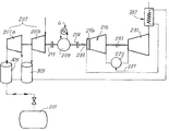
본 발명에 따른 CAES 파워 플랜트의 제1 실시예가 도 2에 도시되어 있다. 전체적으로 도면부호 102로 표시된 파워 플랜트 또는 시스템은 압축 공기 저장 체적부(101)를 포함하며, 도면부호 G로 개략적으로 도시된 전력 분배 그리드에서 초과 전력이 이용가능한 경우에 압축 공기가 저장된다. 본 명세서의 이하에선 압축 공기 저장 체적부(101)는 "공동(cavern)"으로도 칭해질 것이다. A first embodiment of a CAES power plant according to the present invention is shown in Fig. A power plant or system generally indicated at 102 includes a compressed
압축 공기는 압축 공기 라인 경로(103)를 통해 공동(101)으로 공급되며, 밸브(105)가 압축 공기 라인 경로(103)를 따라 제공될 수 있다. 압축 공기는 압축기 트레인(107)에 의해 이송된다. 압축기 트레인은 유량 및 압축률에 따라 직렬 또는 병렬인 복수의 압축기, 또는 단일 압축기를 포함할 수 있다. 따라서, 본 명세서의 이하에서 "압축기 트레인(compressor train)"이란 용어는 직렬 또는 병렬인 압축기의 세트, 또는 단일 압축기를 포함하는 것으로 이해하여야 한다. The compressed air is supplied to the
압축기 트레인(107)은 가역 전기 기계(109)에 의해 구동된다. "가역 전기 기계(reversible electric machine)"라는 용어는 전력으로부터 기계력을 그리고 유효 기계력으로부터 전력을 선택적으로 생성할 수 있는 임의의 장치로 이해하여야 한다. The
가역 전기 기계(109)는 샤프트(111)와 클러치(113)에 의해 압축기 트레인(107)에 연결되거나 압축기 트레인(107)으로부터 분리될 수 있다. The reversible
또한, 가역 전기 기계(109)는 선택적으로 팽창기(115)에 연결되거나 팽창기(115)로부터 분리될 수 있다. 가역 전기 기계(109)와 팽창기(115) 사이의 연결은 샤프트(117)와 클러치(119)를 통해 달성된다. 클러치(113, 119)는 가역 전기 기계(109)를 압축기 또는 압축기 트레인(107)에, 또는 팽창기(115)에 선택적으로 연결시키도록 제어된다. In addition, the reversible
팽창기(115)는 가변 노즐 팽창기, 즉 팽창기의 효율을 최적화하기 위해 팽창기의 유입구에서의 공기의 압력에 따라 변경될 수 있는 구조의 유입 노즐을 포함하는 팽창기이다. 고압 유입 라인(121)은 도면부호 115A로 개략적으로 표시된 가변 노즐 팽창기(115)의 노즐에 공동(101)을 연결시킨다. The
몇몇 실시예에서, 3방향 밸브(123)가 고압 유입 라인(121)과 가변 노즐 팽창기(115)를 연결시키도록 제공될 수 있는데, 3방향 밸브(123)는 공동(101)으로부터의 공기를 (이하에서 기술되는 바와 같이)본 명세서에서 연소 챔버(125)로 칭해지는 열 발생기 요소를 향해 부분적으로 또는 전체적으로 전환시킨다.
가변 노즐 팽창기(115)는 연료 이송부에 또한 연결되는 연소 챔버(125)와 유체 연통된다. 몇몇 예시적인 실시예에서, 연료 이송부는 기체 연료를 이송하기 위한 가스 그리드(127)를 포함한다. 연소 챔버(125) 내에서의 공기/가스 혼합물의 연소는 연결부(129)를 통해 터빈(131)으로 이송되는 연소 가스를 생성시킨다. The
터빈(131)은 샤프트(133)를 통해 제2 가역 전기 기계(135)에 기계적으로 연결된다. 샤프트(133) 상의 클러치(137)는 선택적으로 가역 전기 기계(135)를 터빈(131)에 연결시키거나 가역 전기 기계(135)를 터빈(131)으로부터 분리시킬 수 있다. 클러치(141)를 갖춘 추가의 샤프트(139)는 선택적으로 가역 전기 기계(135)를 제2 압축기 또는 압축기 트레인(143)에 연결시키거나 가역 전기 기계(135)를 제2 압축기 또는 압축기 트레인(143)으로부터 분리시킨다. 압축기 트레인(107)과 관련하여 상술된 바와 같이, 압축기 트레인(143)도 직렬 또는 병렬로 배치된 복수의 압축기, 또는 단일 압축기를 포함할 수 있다. The
제2 압축 공기 라인 경로(145)가 압축기 트레인(143)의 유출구를 공동(101)에 연결시킨다. 밸브(147)가 압축 공기 라인 경로(145)를 따라 제공될 수 있다.A second compressed
지금까지 기술된 CAES 파워 플랜트(102)는 다음과 같이 작동된다. 전력 생성 단계 동안, 공동(101)으로부터의 압축 공기가 고압 유입 라인(121)을 통해 가변 노즐 팽창기(115)로 이송된다. 공동(101)으로부터의 공기 유동이 가변 노즐 팽창기(115)를 통해 부분적으로 팽창되어, 공기 유동의 압력이 제1의 고압에서 제2의 저압으로 강하된다. 가변 노즐 팽창기(115)의 구조는 가변 노즐 팽창기(115)의 출력부에서의 제2의 저압이 좁은 범위 내에서, 바람직하게는 대략 소정의 압력값으로 유지되도록 제어된다. 이런 압력값은 연소 챔버(125)의 설계 제한에 의해 결정된다. 가변 노즐 팽창기(115)의 구조는 유입 압력, 즉 공동(101)으로부터의 공기 유동의 압력의 변화에 대응하도록 변화될 수 있다. The
상술된 바와 같이, 공동(101) 내의 압력은 사실상 전력 생성 단계 동안 변경될 수 있는데, 그 이유는 공동(101) 내의 공기의 양이 점진적으로 감소되어 공동(101) 내의 압력이 감압되기 때문이다. 통상, CAES 파워 플랜트의 공동 내의 공기 압력은 30 바아 내지 120 바아일 수 있다. 이런 값은 예시적인 값일 뿐 본 발명의 범주를 제한하려는 것이 아니다. As described above, the pressure in the
가변 노즐 팽창기(115)는, 공기 압력이 가변 노즐 팽창기 유입구에서의 제1의 고압에서 가변 노즐 팽창기의 유출구에서의 제2의 저압으로 감소될 때, 연소 챔버(125)의 유입구에서의 압력을 조절하고 그리고 공기 유동의 압력을 유효 기계력으로 변환시키는 두 가지 기능을 위해 제공된다. The
제1의 고압에서 제2의 저압으로의 공기 유동의 팽창은 가변 노즐 팽창기(115)의 출력 샤프트(117)에서 이용가능한 기계력을 생성한다. 전력 생성 단계 동안, 클러치(119)는 가변 노즐 팽창기(115)를 제1 가역 전기 기계(109)에 연결시킴으로써, 제1 가역 전기 기계(109)가 샤프트(117)로부터 수용된 유효 기계력을 유효 전력으로 변환시키며, 이런 유효 전력은 전기 분배 그리드(G)에 전달된다. The expansion of the air flow from the first high pressure to the second low pressure creates a mechanical force available at the
가변 노즐 팽창기(115)의 출력부에 이송된 부분적으로 팽창된 공기 유동은 연소 챔버(125)로 공급되어, 고온 압축 연소 가스를 생성하도록 기체 연료 또는 다른 연료가 추가되며, 이런 고온의 압축 연소 가스는 연결부(129)를 통해 터빈(131)으로 이송된다. 터빈(131) 내에서 연소 가스가 팽창되어, 연소 가스에 포함된 에너지가 유효 기계력으로 변환된다. 샤프트(133)에서 이용가능한 유효 기계력은 제2 가역 전기 기계(135)에 의해 전력으로 변환되며, 제2 가역 전기 기계(135)는 클러치(137)와 샤프트(133)에 의해 터빈(131)에 연결된다. 따라서, 추가적인 전력이 전기 분배 그리드(G)에 유입된다. The partially expanded air flow delivered to the output of the
전력 생성 단계 동안, 클러치(113, 114)는 압축기 또는 압축기 트레인(107, 143)이 작동되지 않도록 분리된다. During the power generation phase, the
따라서, 공동(101) 내에 저장된 압축 공기는 더 많은 파워가 전기 분배 그리드(G)로부터 요구될 때 피크 시간 동안 전력을 생성하는데 이용된다. Thus, the compressed air stored in the
초과 전력이 전기 분배 그리드(G)에서 이용가능할 때, CAES 파워 플랜트는 다음과 같이 반대로 작동된다. When excess power is available in the electrical distribution grid (G), the CAES power plant operates in reverse as follows.
클러치(119, 137)가 분리되고 클러치(113, 141)가 결합되어, 제1 가역 전기 기계(109)와 제2 가역 전기 기계(135)가 제1 압축기 또는 압축기 트레인(107) 및 제2 압축기 또는 압축기 트레인(143)을 각각 회전 구동시킬 수 있다. 압축기 트레인은 압축 공기 저장 체적부, 즉 공동(101) 내의 대기를 임계 압력이 달성될 때까지 또는 파워가 전기 분배 그리드(G)로부터 이용가능할 때까지 압축시킨다. The
이런 방식으로, 전기 분배 그리드(G)에서 이용가능한 잉여 파워가 낭비되지 않으며 압축 공기의 포텐셜 에너지의 형태로 공동(101) 내에 저장되며, 필요한 경우 가변 노즐 팽창기(115)와 터빈(131) 내에서의 순차적인 팽창에 의해 이용될 수 있다. In this way, the surplus power available in the electric distribution grid G is not wasted and is stored in the
가변 노즐 팽창기(115)를 이용함으로써, 파워 플랜트의 전효율을 증가시킬 수 있는데, 즉 전력 생성 단계 동안 전기 에너지로 변환될 수 있는 공동(101) 내에 저장된 피크 오프(peak-off) 에너지의 양을 증가시킬 수 있다. By using the
상술된 바와 같이 실제로는, 고압 유입 라인(121)에서의 큰 압력 변동은 전력 생성 단계 동안의 공동(101) 내에서의 점진적인 압력 강하에 의해 유발된다. 종래 기술에 따른 CAES 파워 플랜트에선, 적어도 가압 공기의 형태로 저장된 에너지의 일부가 터빈의 연소 챔버로 이송되는 정압 공기 유동을 생성하기 위한 압력 제어 밸브를 통한 팽창 과정 중에 낭비된다. 공동 내의 압력이 더 높을수록, 더 많은 양의 파워가 압력 조절 및 압력 제어를 위한 팽창으로 인해 낭비된다. In practice, as noted above, the large pressure fluctuations in the high
역으로 도 2의 파워 플랜트에선, 공동(101)으로부터의 압축 공기 유동으로 이용가능한 사실상 전체 에너지가 낭비 없이 파워 생성을 위해 이용될 수 있는데, 그 이유는 압력 제어의 기능이 가변 노즐 팽창기(115)에 의해 수행되기 때문이다. 이런 기계는 공기 유동을 고압의 유입 압력에서 사실상 일정한 저압의 유출 압력으로 팽창시켜, 압력 강하를 유효 기계력으로 변환시킬 수 있다. Conversely, in the power plant of FIG. 2, virtually total energy available for compressed air flow from the
3방향 밸브(123)가 제공되는 경우, 3방향 밸브(123)는 공동(101)으로부터의 압축 공기를 가변 노즐 팽창기(115)를 우회하여 보조 라인(151)을 통해 연소 챔버(125)로 직접 이송하는데 이용될 수 있다.
도 3은 본 발명에 따른 CAES 파워 플랜트 또는 시스템의 다른 실시예를 도시한다. 도2의 CAES 파워 플랜트와 다른 점은 도 3의 CAES 파워 플랜트에는 단 하나의 가역 전기 기계가 제공된다는 것이다. 가변 노즐 팽창기와 터빈은 동일한 샤프트에 연결되며, 선택적으로 가역 전기 모터에 연결되거나 가역 전기 모터로부터 분리될 수 있다. Figure 3 illustrates another embodiment of a CAES power plant or system in accordance with the present invention. Unlike the CAES power plant of FIG. 2, the CAES power plant of FIG. 3 is provided with only one reversible electrical machine. The variable nozzle inflator and the turbine are connected to the same shaft, and optionally can be connected to a reversible electric motor or separated from a reversible electric motor.
보다 구체적으로는, 전체적으로 도면부호 202로 표시된 도 3의 CAES 파워 플랜트는 압축 공기 저장 체적부(201), 예컨대 공동을 이용한다. 공동(201)은 가변 노즐 팽창기(215)와 유체 연통된다. 도면부호 215A는 가변 구조 유입 노즐을 개략적으로 나타낸다. 가변 노즐 팽창기(215)는 연소 챔버(225)와 유체 연통되는데, 연료는 예컨대 가스 분배 그리드(227)를 통해 연소 챔버(225)로 이송된다. 연소 챔버(225)의 유출구는 도면부호 229에서 터빈(231)에 연결된다. More specifically, the CAES power plant of Figure 3, generally indicated at 202, utilizes compressed
단일의 기계적 샤프트(233)와 클러치(219)가 선택적으로 터빈(231)의 로터와 가변 노즐 팽창기(215)의 로터를 가역 전기 기계(29)에 연결시키거나 가역 전기 기계(29)로부터 분리시킨다. A single
도 2의 가역 전기 기계(109) 및 가역 전기 기계(135)와 유사하게, 가역 전기 기계(209)는 전기 모터로서 또는 발전기로서 선택적으로 작동될 수 있다. Similar to the reversible
샤프트(211)와 클러치(213)를 통해, 가역 전기 기계(209)는 압축기 또는 압축기 트레인(207)에 선택적으로 연결되어, 결과적으로 압축 공기 라인(203)을 통해 공동(201)과 유체 연통될 수 있다. Through the
도 3의 CAES 파워 플랜트(202)는 다음과 같이 작동된다. The
전력 생성 단계 동안, 압축 공기는 공동(201)으로부터 압축 공기 라인(221)을 통해 가변 노즐 팽창기(215)로 이송된다. 가변 노즐 팽창기(215)로 이송된 공기 유동은 가변 유입 압력에서 더 낮은 유출 압력으로 팽창되는데, 이런 유출 압력은 사실상 일정하게 유지되거나 좁은 압력 범위 내에서 유지된다. 유출 압력의 적절한 변동 범위는 정격값의 대략 4%이다. 이런 값은 이 실시예의 바람직한 예로서 제공될 뿐, 본 발명의 범주를 제한하는 것이 아니다. 유효 기계력은 공기 유동의 제1 팽창에 의해 생성되며, 기계적 샤프트(233)에서 이용가능하다. 부분적으로 팽창된 공기 유동은 연소 챔버(225) 내에서 기체 연료 또는 다른 연료와 혼합되며, 공기/연료 혼합물은 터빈(231) 내에서 팽창되는 고온 압축 연소 가스의 유동을 생성하도록 점화된다. 터빈(231) 내에서의 연소 가스의 팽창은 샤프트(233)에서 이용가능한 유효 기계력을 생성한다. During the power generation step, compressed air is delivered from the
상술된 공기 유동 및 연소 가스의 순차적인 이중 팽창으로 생성된 기계력은 가역 전기 기계(209)를 구동시키는데 이용된다. 가역 전기 기계(209)는 기계력을 전기 분배 그리드(G)에 유입되는 전력으로 변환시킨다. The mechanical force generated by the sequential double expansion of the above-described air flow and combustion gases is used to drive the reversible
공기 압축 단계 동안, 잉여 전력이 전기 분배 그리드(G)에서 이용가능할 때, 가역 전기 기계(209)는 클러치(219)의 분리에 의해 기계적 샤프트(233)로부터 분리되어, 클러치(213)와 샤프트(211)에 의해 압축기 또는 압축기 트레인(207)에 선택적으로 연결된다. 전기 분배 그리드(G)로부터의 전력은 공동(201) 내의 공기를 압축시키는데 이용된다. During the air compression phase, when excess power is available in the electric distribution grid G, the reversible
도 4는 본 발명에 따른 또 다른 CAES 파워 플랜트를 도시한다. 도 3과 동일한 도면 부호는 파워 플랜트의 동일한 또는 등가의 부품을 나타내는데 이용된다. 도 4의 파워 플랜트는 열 에너지 회수 장치가 제공되어 있다는 점에서 도 3의 파워 플랜트와 상이한데, 이 열 에너지 회수 장치는 공기 압축 단계 동안 압축 공기로부터 열을 회수 및 저장하고 그리고 전력 생성 단계 동안 압축 공기의 팽창 이전에 압축 공기를 가열하도록 구성된다. Figure 4 shows another CAES power plant according to the present invention. The same reference numerals as in Fig. 3 are used to indicate the same or equivalent parts of the power plant. The power plant of FIG. 4 differs from the power plant of FIG. 3 in that a heat energy recovery device is provided, which recovers and stores heat from the compressed air during the air compression phase and compresses And is configured to heat the compressed air prior to expansion of the air.
보다 구체적으로는, 도 4에 도시된 실시예에서 압축기 트레인(207)은 직렬로 배열되는 2개 이상의 압축기를 포함할 수 있다. 다른 실시예에선 단일 압축기가 이용될 수 있다. 주변 환경으로부터의 공기는 압축기(207)에 의해 흡입되어 라인(301)을 통해 열 에너지 저장 장치(303)로 이송된다. 몇몇 예시적인 실시예에서, 열 에너지 저장 장치(303)는 예컨대 열 에너지를 액화열의 형태로 저장하는 솔트와 같은 축열 물질을 포함할 수 있다. 압축 공기는 열 에너지 저장 장치(303)를 통해 유동되며, 열은 열 에너지 저장 장치(303)로부터 제어되어 예컨대 다량의 축열 솔트에 액화열의 형태로 저장된다. 따라서, 제1 열 에너지 저장 장치(303)는 인터쿨러 열 교환기와 유사하게 기능하지만, 압축 공기 유동으로부터 추출된 열은 대기 중으로 방출되지 않고 축적된다. 열 에너지 저장 장치(303)에서의 냉각 이후에, 공기는 압축 공기 라인(203)을 통해 압축 공기 저장 체적부 또는 공동(201) 내로 이송된다. More specifically, in the embodiment shown in FIG. 4, the
이런 장치 배열에 의해, 공기 압축 단계 동안 전기 분배 그리드(G)에서 이용가능한 잉여 전력, 즉 피크 오프 에너지는 공동(201)에 저장되는 압력 에너지로 부분적으로 변환되고 그리고 열 에너지 저장 장치(303에 저장되는 열 에너지로 부분적으로 변환된다. With this arrangement, the surplus power available in the electric distribution grid (G) during the air compression phase, that is, the peak off energy, is partially converted to the pressure energy stored in the
추가적인 전력이 전기 분배 그리드(G)에서 요구될 때, 전력 생성 단계가 개시된다. 압축 공기가 공동(201)으로부터 가변 노즐 팽창기(215) 및 연소 챔버(225)로 이송된다. 연소 챔버(225) 내에서 가스 그리드(227) 등으로부터의연료가 가변 노즐 팽창기(215)로부터 이송된 부분적으로 팽창된 공기 유동과 혼합된다. 공기/연료 혼합물이 점화된다. 따라서, 압축 고온 연소 가스가 생성되고, 후속하여 터빈(231)에서 팽창되어, 가변 노즐 팽창기(215)에 의해 생성된 유효 기계력과 함께 샤프트(233)에서 이용가능한 유효 기계력이 생성되며, 가역 전기 기계(209)에 의해 전력으로 변환된다. When additional power is required in the electrical distribution grid (G), the power generation step is initiated. Compressed air is delivered from the
압축 공기 라인(203, 221)에 유입되는 압축 공기는 열 에너지 저장 장치(203)을 통해 유동되고 가열된다. 따라서, 열 에너지 저장 장치(203)에 저장된 열 에너지가 회수되어 가변 노즐 팽창기 내에서의 팽창 이전에 공기 유동 온도를 상승시키는데 이용된다. 또한, 이런 열 에너지의 일부는 가역 전기 기계를 구동시키기 위한 샤프트(223)에서 이용가능한 추가의 유효 기계력으로 변환된다. The compressed air entering the
도 5는 본 발명에 따른 또 다른 CAES 파워 플랜트를 도시한다. 동일한 도면 부호는 도 3 및 도 4의 동일한 또는 등가의 부품을 나타낸다. Figure 5 shows another CAES power plant according to the present invention. The same reference numerals denote the same or equivalent parts of Figs. 3 and 4. Fig.
도 5의 실시예와 도 4의 실시예의 주요한 차이점은 제2 열 에너지 저장 장치(305)와, 2개의 압축기(207A, 207B)를 포함하는 압축기 트레인을 이용한다는 점이다. 압축기(207A)를 떠나는 압축 공기로부터 열이 회수되어 열 에너지 저장 장치(303)에 축적된다. 압축기(207B)로부터 회수된 열은 제2 열 에너지 저장 장치(305)에 축적된다. The main difference between the embodiment of FIG. 5 and the embodiment of FIG. 4 is the use of a second thermal
도 5에서, 제1 열 에너지 저장 장치(303)는 가변 노즐 팽창기(215)의 유출구와 연소 챔버(225)의 유입구 사이의 연결부에 배치된다. 제2 열 에너지 저장 장치(305)는 공동(201)과 가변 노즐 팽창기(215)의 유입구 사이의 연결 라인에 배치된다. In FIG. 5, the first thermal
이런 장치 배열에 의해, 공기 압축 단계 동안 회수되는 열 에너지의 일부가 가변 노즐 팽창기(215) 내에서의 제1 팽창 이전에 공동(201)으로부터의 압축 공기 유동을 가열하는데 이용된다. 이와는 반대로, 열 에너지의 제2 부분은 연소 챔버(225)로의 유입 이전에 가변 노즐 팽창기(215)에 유입되는 부분적으로 팽창된 공기 유동의 가열에 의해 회수된다. With this arrangement, a portion of the heat energy recovered during the air compression step is used to heat the compressed air flow from the
도 6은 본 발명에 따른 또 다른 CAES 파워 플랜트를 도시한다. 도 4 및 도 5와 동일한 도면 부호는 동일한 또는 등가의 부품을 나타내는데 이용된다.Figure 6 shows another CAES power plant according to the present invention. 4 and 5 are used to denote the same or equivalent parts.
도 6의 파워 플랜트는 추가적인 열 회수 장치가 제공된다는 점에서 주로 도 4의 파워 플랜트와 상이하다. 전력 생성 단계 동안, 공동(201)으로부터의 압축된 공기 유동은 열 에너지 저장 장치(305)와 열 에너지 저장 장치(303)에서 순차적으로 가열된다. 후속하여, 가열된 압축 공기 유동은 터빈(231)을 떠나 열 교환기(307)에 유입되는 배기 연소 가스에 대한 열 교환에 의해 추가로 가열된다. 후속하여, 압축되고 가열된 공기 유동은 가변 노즐 팽창기(215)로 이송된다. The power plant of Figure 6 differs from the power plant of Figure 4 mainly in that an additional heat recovery device is provided. During the power generation step, the compressed air flow from the
상술된 실시예에서, 가역 전기 기계가 기계력 또는 전력을 교번적으로 생성하도록 시스템에서 이용된다. 다시 말해, 이점이 더 적은 실시예나 별개의 전기 기계가 전력 생성 및 기계력 생성을 위해 이용될 수 있으며, 적절한 클러치 장치가 시스템의 다양한 구성요소들 사이의 정확한 기계적 연결을 달성하도록 제공될 수 있다. In the above-described embodiment, a reversible electric machine is used in the system to alternately generate mechanical power or power. In other words, less advantageous embodiments or separate electric machines can be used for power generation and mechanical power generation, and suitable clutch devices can be provided to achieve an accurate mechanical connection between the various components of the system.
본 명세서에 개시된 본 발명의 특정 실시예들이 도면에 도시되고 몇몇 예시적인 실시예와 관련되어 구체적이고 상세하게 완전히 상술되었지만, 다양한 변형예, 변경예 및 생략예들이 본 명세서에 개시된 신규한 기술사상, 원리 및 개념과, 첨부된 특허청구범위에 개시된 본 발명의 이점으로부터 사실상 벗어나지 않고 이루어질 수 있음을 당업자들은 알 것이다. 따라서, 개시된 본 발명의 적절한 범주는 그런 모든 변형예, 변경예 및 생략예를 포함하도록 첨부된 특허청구범위의 가장 넓은 해석에 의해서만 결정되어야 한다. 다양한 실시예의 상이한 구성요소, 구조 및 수단들은 다양하게 조합될 수 있다. 예컨대, 열 에너지 회수 장치가 도 2 및/또는 도 3의 실시예에 조합될 수도 있다. 유사하게, 터빈으로부터의 연소 가스로부터의 열 회수도 도 2, 도 3, 도 4 및 도 5의 실시예에서 제공될 수 있다. Although specific embodiments of the invention disclosed herein have been illustrated and fully described in detail and with reference to certain exemplary embodiments in full, it is evident that many alternatives, modifications, and alternatives are possible within the scope of novel technical ideas, Principles and concepts of the present invention, and the advantages of the present invention as set forth in the appended claims. Accordingly, the appropriate scope of the disclosed invention should be determined only by the broadest interpretation of the appended claims, including all such variations, modifications and omissions. The different elements, structures and means of various embodiments may be combined in various ways. For example, a heat energy recovery device may be combined with the embodiment of FIG. 2 and / or FIG. Similarly, heat recovery from the combustion gases from the turbine may also be provided in the embodiments of FIGS. 2, 3, 4 and 5.
101 : 압축 공기 저장 체적부 102 : 파워 플랜트 또는 시스템
105, 147 : 밸브 107 : 압축기 트레인
109 : 가역 전기 기계 115 : 팽창기
125 : 연소 챔버 131 : 터빈
135 : 제2 가역 전기 기계 143 : 제2 압축기 또는 압축기 트레인
G : 전력 분배 그리드 101: Compressed air storage volume 102: Power plant or system
105, 147: valve 107: compressor train
109: reversible electric machine 115: inflator
125: combustion chamber 131: turbine
135: second reversible electric machine 143: second compressor or compressor train
G: Power distribution grid
Claims (30)
제1 압력에서 공기 유동을 수용하고 제2 압력에서 상기 공기 유동을 부분적으로 팽창시키도록 구성되는 적어도 하나의 가변 노즐 팽창기로서, 상기 제2 압력은 상기 제1 압력보다 낮으며 상기 가변 노즐 팽창기에서의 상기 공기 유동의 팽창이 유효 기계력을 생성하는 것인, 가변 노즐 팽창기와,
상기 가변 노즐 팽창기로부터의 부분적으로 팽창된 공기 유동 및 연료를 수용하도록 구성되는 적어도 하나의 열 발생기 요소와,
상기 열 발생기 요소로부터 연소 가스를 수용하고 그리고 유효 기계력을 생성하는 상기 연소 가스를 팽창시키도록 구성되는 적어도 하나의 터빈을 포함하는
압축 공기 에너지 저장 시스템.A compressed air energy storage system,
At least one variable nozzle inflator configured to receive an air flow at a first pressure and partially inflate the air flow at a second pressure, wherein the second pressure is lower than the first pressure, and wherein the variable nozzle inflator Wherein the inflation of the air flow produces effective mechanical force; a variable nozzle inflator;
At least one heat generator element configured to receive the partially expanded air flow and fuel from the variable nozzle expander,
At least one turbine configured to receive a combustion gas from the heat generator element and to expand the combustion gas to produce effective mechanical power
Compressed air energy storage system.
적어도 하나의 공기 압축기와,
상기 적어도 하나의 공기 압축기에 의해 이송되는 압축 공기를 저장하기 위해 적어도 하나의 압축 공기 라인 경로에 의해 상기 적어도 하나의 공기 압축기에 연결되는 적어도 하나의 압축 공기 저장 체적부를 더 포함하는 압축 공기 에너지 저장 시스템.5. The apparatus of any one of claims 1 to 4, comprising at least one electric machine constructed and arranged to convert electrical power from the electrical distribution grid to mechanical power,
At least one air compressor,
Further comprising at least one compressed air storage volume connected to the at least one air compressor by at least one compressed air line path for storing compressed air carried by the at least one air compressor. .
상기 압축 공기 에너지 저장 시스템은, 적어도 하나의 공기 압축기와, 적어도 하나의 압축 공기 라인 경로에 의해 상기 적어도 하나의 공기 압축기에 연결되는 적어도 하나의 압축 공기 저장 체적부를 더 포함하고,
상기 적어도 하나의 전기 기계는 상기 전기 분배 그리드로부터의 전력을 기계력으로 변환시킬 때 선택적으로 상기 전력을 생성하거나 상기 적어도 하나의 공기 압축기를 구동시키도록 구성 및 배치되는 것인 압축 공기 에너지 저장 시스템.6. The at least one electrical machine according to any one of claims 1 to 5, wherein the at least one electric machine is a reversible electric machine configured to selectively convert mechanical power into electrical power or from electrical distribution grid,
The compressed air energy storage system further comprising at least one air compressor and at least one compressed air storage volume connected to the at least one air compressor by at least one compressed air line path,
Wherein said at least one electrical machine is configured and arranged to selectively generate said power or drive said at least one air compressor when converting electrical power from said electrical distribution grid to mechanical power.
상기 압축 공기 에너지 저장 시스템은, 상기 가변 노즐 팽창기에 의해 생성된 상기 유효 기계력을 전력으로 변환시키도록 구성 및 배치되는 적어도 하나의 제1 전기 기계와, 상기 터빈에 의해 생성된 상기 유효 기계력을 전력으로 변환시키도록 구성 및 배치되는 적어도 하나의 제2 전기 기계를 더 포함하는 압축 공기 에너지 저장 시스템.9. A method according to any one of claims 1 to 8, wherein the variable nozzle expander and the turbine have two independent output shafts,
Wherein the compressed air energy storage system comprises at least one first electric machine constructed and arranged to convert the effective mechanical force generated by the variable nozzle expander into electric power and a second electric machine configured to convert the effective mechanical force generated by the turbine into electric power Further comprising at least one second electric machine configured and arranged to convert the compressed air energy stored in the compressed air energy storage system.
압축 공기 유동을 가변 노즐 팽창기에서 제1 압력에서 제2 압력으로 적어도 부분적으로 팽창시켜 유효 기계력을 생성하는 단계와,
상기 부분적으로 팽창된 공기 유동을 상기 제2 압력에서 열 발생기 요소로 이송하여 상기 부분적으로 팽창된 공기 유동에 연료를 혼합시켜 고온 가압 연소 가스를 생성하는 단계와,
상기 연소 가스를 터빈에서 팽창시켜 유효 기계력을 생성하는 단계를 포함하며,
상기 제1 압력은 상기 제2 압력보다 높은 것인
에너지 생성 방법.A method for generating energy from a compressed air energy storage system,
Expanding the compressed air flow at least partially from a first pressure to a second pressure in a variable nozzle expander to produce an effective mechanical force,
Transferring the partially expanded air flow to the heat generator element at the second pressure to mix the fuel with the partially expanded air flow to produce a hot pressurized combustion gas;
Expanding the combustion gas in the turbine to produce effective mechanical power,
Wherein the first pressure is higher than the second pressure
Energy generation method.
파워 생성 단계 동안 상기 압축 공기 유동을 생성하기 위해 상기 압축 공기 저장 체적부로부터의 압축 공기를 이용하는 단계를 더 포함하는 에너지 생성 방법.27. A method according to any one of claims 20 to 26, comprising the steps of compressing air in the compressed air storage volume using at least one air compressor driven by at least one electric machine during the air compression step,
And using compressed air from the compressed air storage volume to create the compressed air flow during the power generation step.
상기 에너지 생성 방법은, 상기 유효 기계력을 전력으로 변환시키기 위해 상기 가역 전기 기계를 선택적으로 이용하는 단계 또는 전기 분배 그리드로부터의 전력을 상기 적어도 하나의 공기 압축기를 구동시키기 위한 기계력으로 변환시키는 단계를 더 포함하는 에너지 생성 방법.28. A method as claimed in any of claims 20 to 27, wherein the at least one electric machine is a reversible electric machine,
The energy generation method further includes selectively using the reversible electric machine to convert the effective mechanical power into electrical power or converting electrical power from the electrical distribution grid into mechanical power for driving the at least one air compressor ≪ / RTI >
상기 공기 압축 단계 동안 저장된 열을 이용하여 상기 파워 생성 단계 동안 상기 압축 공기 유동을 가열하는 단계를 더 포함하는 에너지 생성 방법.29. The method of any of claims 20 to 28, further comprising: recovering and storing heat from the air compressed by the at least one air compressor during the air compression step;
And heating the compressed air flow during the power generation step using heat stored during the air compression step.
Applications Claiming Priority (3)
| Application Number | Priority Date | Filing Date | Title |
|---|---|---|---|
| IT000075A ITFI20120075A1 (en) | 2012-04-12 | 2012-04-12 | "COMPRESSED-AIR ENERGY-STORAGE SYSTEM" |
| ITFI2012A000075 | 2012-04-12 | ||
| PCT/EP2013/057286 WO2013153019A1 (en) | 2012-04-12 | 2013-04-08 | Compressed-air energy-storage system |
Publications (1)
| Publication Number | Publication Date |
|---|---|
| KR20150001803A true KR20150001803A (en) | 2015-01-06 |
Family
ID=46262145
Family Applications (1)
| Application Number | Title | Priority Date | Filing Date |
|---|---|---|---|
| KR1020147031336A Withdrawn KR20150001803A (en) | 2012-04-12 | 2013-04-08 | Compressed-air energy-storage system |
Country Status (11)
| Country | Link |
|---|---|
| US (1) | US10683803B2 (en) |
| EP (1) | EP2836693B1 (en) |
| JP (1) | JP2015513040A (en) |
| KR (1) | KR20150001803A (en) |
| CN (1) | CN104395583B (en) |
| BR (1) | BR112014024140A8 (en) |
| CA (1) | CA2869432C (en) |
| IT (1) | ITFI20120075A1 (en) |
| MX (1) | MX2014012308A (en) |
| RU (1) | RU2014139980A (en) |
| WO (1) | WO2013153019A1 (en) |
Cited By (2)
| Publication number | Priority date | Publication date | Assignee | Title |
|---|---|---|---|---|
| KR20210025654A (en) * | 2018-07-05 | 2021-03-09 | 지멘스 악티엔게젤샤프트 | Extended gas turbine process including natural gas regasification |
| KR102340148B1 (en) | 2020-08-31 | 2021-12-16 | 고등기술연구원연구조합 | Air Power Generation and Electric Vehicle Charging System Using Solar Heat |
Families Citing this family (22)
| Publication number | Priority date | Publication date | Assignee | Title |
|---|---|---|---|---|
| ITFI20130299A1 (en) * | 2013-12-16 | 2015-06-17 | Nuovo Pignone Srl | "IMPROVEMENTS IN COMPRESSED-AIR-ENERGY-STORAGE (CAES) SYSTEMS AND METHODS" |
| FR3033836B1 (en) * | 2015-03-19 | 2018-08-03 | Valeo Systemes De Controle Moteur | SYSTEM FOR PRODUCING ENERGY OR TORQUE |
| JP6571491B2 (en) * | 2015-10-28 | 2019-09-04 | 株式会社神戸製鋼所 | heat pump |
| JP6419058B2 (en) * | 2015-11-06 | 2018-11-07 | 株式会社神戸製鋼所 | Compressed air storage power generation apparatus and compressed air storage power generation method |
| JP6621348B2 (en) * | 2016-03-10 | 2019-12-18 | 株式会社神戸製鋼所 | Compressed air storage generator |
| US11506121B2 (en) | 2016-05-26 | 2022-11-22 | Hamilton Sundstrand Corporation | Multiple nozzle configurations for a turbine of an environmental control system |
| EP3249195B1 (en) * | 2016-05-26 | 2023-07-05 | Hamilton Sundstrand Corporation | An energy flow of an advanced environmental control system |
| US11511867B2 (en) | 2016-05-26 | 2022-11-29 | Hamilton Sundstrand Corporation | Mixing ram and bleed air in a dual entry turbine system |
| EP3249196B1 (en) | 2016-05-26 | 2020-12-02 | Hamilton Sundstrand Corporation | An energy flow of an advanced environmental control system |
| JP6889604B2 (en) * | 2017-04-26 | 2021-06-18 | 株式会社神戸製鋼所 | Compressed air storage power generator |
| US11788466B2 (en) | 2017-12-08 | 2023-10-17 | Schlumberger Technology Corporation | Compressed N2 for energy storage |
| CN113202572B (en) * | 2021-06-09 | 2023-01-24 | 中国科学院工程热物理研究所 | A power generation and energy storage dual-mode power system |
| CN113883077B (en) * | 2021-10-27 | 2024-03-26 | 西安陕鼓动力股份有限公司 | Control method of multi-machine tandem operation single-shaft compressor unit system |
| GB2612836B (en) * | 2021-11-15 | 2025-08-27 | Bae Systems Plc | Heat engine system |
| CN114810351B (en) * | 2022-04-12 | 2024-08-13 | 西安热工研究院有限公司 | Combustion engine system coupled with energy storage system and adjustable in compression flow and control method |
| CN114718690B (en) * | 2022-06-08 | 2022-08-26 | 西安热工研究院有限公司 | Gravity compressed air energy storage system |
| CN114718688B (en) * | 2022-06-08 | 2022-08-26 | 西安热工研究院有限公司 | Gravity compressed air energy storage system and method based on magnetic suspension balance |
| CN114718683B (en) * | 2022-06-08 | 2022-08-26 | 西安热工研究院有限公司 | Graded-sealing gravity compressed air energy storage system and method |
| CN114810262B (en) * | 2022-06-23 | 2022-10-11 | 西安热工研究院有限公司 | Membrane-type sealed gravity compressed air energy storage system and method |
| CN114810261B (en) * | 2022-06-23 | 2022-10-11 | 西安热工研究院有限公司 | Gravity type compressed air energy storage system and method |
| CN115333249B (en) * | 2022-10-13 | 2023-01-13 | 中国科学院电工研究所 | Control method of mixed working condition compressed air energy storage system |
| CN118030473B (en) * | 2024-02-04 | 2024-10-11 | 中国电力工程顾问集团中南电力设计院有限公司 | Constant-pressure energy storage system and method combining pumped storage and compressed air energy storage |
Family Cites Families (21)
| Publication number | Priority date | Publication date | Assignee | Title |
|---|---|---|---|---|
| US3677008A (en) * | 1971-02-12 | 1972-07-18 | Gulf Oil Corp | Energy storage system and method |
| DE2236059C2 (en) * | 1972-07-22 | 1974-08-22 | Rheinisch-Westfaelisches Elektrizitaetswerk Ag, 4300 Essen | Air pump storage plant for power plants |
| GB1583648A (en) * | 1976-10-04 | 1981-01-28 | Acres Consulting Services | Compressed air power storage systems |
| US4237692A (en) | 1979-02-28 | 1980-12-09 | The United States Of America As Represented By The United States Department Of Energy | Air ejector augmented compressed air energy storage system |
| JPS58176407A (en) | 1982-04-08 | 1983-10-15 | Nippon Sanso Kk | Multi spindle compound cycle power generating method |
| US4765142A (en) * | 1987-05-12 | 1988-08-23 | Gibbs & Hill, Inc. | Compressed air energy storage turbomachinery cycle with compression heat recovery, storage, steam generation and utilization during power generation |
| US4885912A (en) | 1987-05-13 | 1989-12-12 | Gibbs & Hill, Inc. | Compressed air turbomachinery cycle with reheat and high pressure air preheating in recuperator |
| JPH0245622A (en) | 1988-08-08 | 1990-02-15 | Mitsubishi Heavy Ind Ltd | Compressed air storage type power generator |
| US4942736A (en) * | 1988-09-19 | 1990-07-24 | Ormat Inc. | Method of and apparatus for producing power from solar energy |
| WO1996001942A1 (en) | 1994-07-11 | 1996-01-25 | Westinghouse Electric Corporation | Improved compressed air energy storage system |
| US5778675A (en) * | 1997-06-20 | 1998-07-14 | Electric Power Research Institute, Inc. | Method of power generation and load management with hybrid mode of operation of a combustion turbine derivative power plant |
| US6276123B1 (en) * | 2000-09-21 | 2001-08-21 | Siemens Westinghouse Power Corporation | Two stage expansion and single stage combustion power plant |
| JP2002339760A (en) | 2001-05-16 | 2002-11-27 | Hitachi Ltd | Gas turbine power generation method and apparatus |
| JP2003301798A (en) | 2002-04-09 | 2003-10-24 | Mitsubishi Heavy Ind Ltd | Compressor and gas turbine |
| US7325401B1 (en) * | 2004-04-13 | 2008-02-05 | Brayton Energy, Llc | Power conversion systems |
| US7669423B2 (en) * | 2007-01-25 | 2010-03-02 | Michael Nakhamkin | Operating method for CAES plant using humidified air in a bottoming cycle expander |
| US7640643B2 (en) | 2007-01-25 | 2010-01-05 | Michael Nakhamkin | Conversion of combined cycle power plant to compressed air energy storage power plant |
| US8011189B2 (en) * | 2007-01-25 | 2011-09-06 | Michael Nakhamkin | Retrofit of simple cycle gas turbine for compressed air energy storage application having expander for additional power generation |
| US8341964B2 (en) | 2009-10-27 | 2013-01-01 | General Electric Company | System and method of using a compressed air storage system with a gas turbine |
| US20110094231A1 (en) * | 2009-10-28 | 2011-04-28 | Freund Sebastian W | Adiabatic compressed air energy storage system with multi-stage thermal energy storage |
| US8572972B2 (en) | 2009-11-13 | 2013-11-05 | General Electric Company | System and method for secondary energy production in a compressed air energy storage system |
-
2012
- 2012-04-12 IT IT000075A patent/ITFI20120075A1/en unknown
-
2013
- 2013-04-08 CN CN201380019401.5A patent/CN104395583B/en active Active
- 2013-04-08 WO PCT/EP2013/057286 patent/WO2013153019A1/en not_active Ceased
- 2013-04-08 BR BR112014024140A patent/BR112014024140A8/en not_active IP Right Cessation
- 2013-04-08 EP EP13714920.9A patent/EP2836693B1/en active Active
- 2013-04-08 MX MX2014012308A patent/MX2014012308A/en unknown
- 2013-04-08 US US14/391,493 patent/US10683803B2/en active Active
- 2013-04-08 KR KR1020147031336A patent/KR20150001803A/en not_active Withdrawn
- 2013-04-08 RU RU2014139980A patent/RU2014139980A/en unknown
- 2013-04-08 CA CA2869432A patent/CA2869432C/en active Active
- 2013-04-08 JP JP2015504917A patent/JP2015513040A/en active Pending
Cited By (2)
| Publication number | Priority date | Publication date | Assignee | Title |
|---|---|---|---|---|
| KR20210025654A (en) * | 2018-07-05 | 2021-03-09 | 지멘스 악티엔게젤샤프트 | Extended gas turbine process including natural gas regasification |
| KR102340148B1 (en) | 2020-08-31 | 2021-12-16 | 고등기술연구원연구조합 | Air Power Generation and Electric Vehicle Charging System Using Solar Heat |
Also Published As
| Publication number | Publication date |
|---|---|
| MX2014012308A (en) | 2014-11-14 |
| US20150075173A1 (en) | 2015-03-19 |
| EP2836693A1 (en) | 2015-02-18 |
| CN104395583A (en) | 2015-03-04 |
| CA2869432A1 (en) | 2013-10-17 |
| CN104395583B (en) | 2017-02-22 |
| EP2836693B1 (en) | 2021-02-17 |
| WO2013153019A1 (en) | 2013-10-17 |
| ITFI20120075A1 (en) | 2013-10-13 |
| US10683803B2 (en) | 2020-06-16 |
| JP2015513040A (en) | 2015-04-30 |
| BR112014024140A2 (en) | 2017-06-20 |
| CA2869432C (en) | 2020-10-27 |
| RU2014139980A (en) | 2016-06-10 |
| BR112014024140A8 (en) | 2017-07-25 |
Similar Documents
| Publication | Publication Date | Title |
|---|---|---|
| KR20150001803A (en) | Compressed-air energy-storage system | |
| US8261552B2 (en) | Advanced adiabatic compressed air energy storage system | |
| CN102953823B (en) | Adiabatic compressed air energy-storing electricity device system and method | |
| US5778675A (en) | Method of power generation and load management with hybrid mode of operation of a combustion turbine derivative power plant | |
| EP2494164B1 (en) | Compressed air energy storage system with reversible compressor-expander unit and corresponding method | |
| US10584634B2 (en) | Compressed-air-energy-storage (CAES) system and method | |
| EP2494166B1 (en) | Adiabatic compressed air energy storage system with multi-stage thermal energy storage | |
| JP6006639B2 (en) | Adiabatic compressed air energy storage system with combustion device | |
| EP2581584A1 (en) | Compressed air energy storage system and method for operating this system | |
| EP2586997A2 (en) | Compressed air energy storage system and method of operating such a system | |
| GB2636059A (en) | Hybrid compressed air energy storage system |
Legal Events
| Date | Code | Title | Description |
|---|---|---|---|
| PA0105 | International application |
Patent event date: 20141107 Patent event code: PA01051R01D Comment text: International Patent Application |
|
| PG1501 | Laying open of application | ||
| PC1203 | Withdrawal of no request for examination | ||
| WITN | Application deemed withdrawn, e.g. because no request for examination was filed or no examination fee was paid |