KR20140059213A - Head mounted display with iris scan profiling - Google Patents
Head mounted display with iris scan profiling Download PDFInfo
- Publication number
- KR20140059213A KR20140059213A KR1020147005268A KR20147005268A KR20140059213A KR 20140059213 A KR20140059213 A KR 20140059213A KR 1020147005268 A KR1020147005268 A KR 1020147005268A KR 20147005268 A KR20147005268 A KR 20147005268A KR 20140059213 A KR20140059213 A KR 20140059213A
- Authority
- KR
- South Korea
- Prior art keywords
- user
- display
- eye
- optical system
- data
- Prior art date
- Legal status (The legal status is an assumption and is not a legal conclusion. Google has not performed a legal analysis and makes no representation as to the accuracy of the status listed.)
- Withdrawn
Links
Images


Classifications
-
- G—PHYSICS
- G06—COMPUTING OR CALCULATING; COUNTING
- G06V—IMAGE OR VIDEO RECOGNITION OR UNDERSTANDING
- G06V40/00—Recognition of biometric, human-related or animal-related patterns in image or video data
- G06V40/10—Human or animal bodies, e.g. vehicle occupants or pedestrians; Body parts, e.g. hands
- G06V40/18—Eye characteristics, e.g. of the iris
-
- G—PHYSICS
- G02—OPTICS
- G02B—OPTICAL ELEMENTS, SYSTEMS OR APPARATUS
- G02B27/00—Optical systems or apparatus not provided for by any of the groups G02B1/00 - G02B26/00, G02B30/00
- G02B27/0093—Optical systems or apparatus not provided for by any of the groups G02B1/00 - G02B26/00, G02B30/00 with means for monitoring data relating to the user, e.g. head-tracking, eye-tracking
-
- G—PHYSICS
- G02—OPTICS
- G02B—OPTICAL ELEMENTS, SYSTEMS OR APPARATUS
- G02B27/00—Optical systems or apparatus not provided for by any of the groups G02B1/00 - G02B26/00, G02B30/00
- G02B27/01—Head-up displays
- G02B27/017—Head mounted
- G02B27/0172—Head mounted characterised by optical features
-
- G—PHYSICS
- G02—OPTICS
- G02B—OPTICAL ELEMENTS, SYSTEMS OR APPARATUS
- G02B27/00—Optical systems or apparatus not provided for by any of the groups G02B1/00 - G02B26/00, G02B30/00
- G02B27/02—Viewing or reading apparatus
-
- G—PHYSICS
- G06—COMPUTING OR CALCULATING; COUNTING
- G06F—ELECTRIC DIGITAL DATA PROCESSING
- G06F21/00—Security arrangements for protecting computers, components thereof, programs or data against unauthorised activity
- G06F21/30—Authentication, i.e. establishing the identity or authorisation of security principals
- G06F21/31—User authentication
- G06F21/32—User authentication using biometric data, e.g. fingerprints, iris scans or voiceprints
-
- G—PHYSICS
- G06—COMPUTING OR CALCULATING; COUNTING
- G06F—ELECTRIC DIGITAL DATA PROCESSING
- G06F3/00—Input arrangements for transferring data to be processed into a form capable of being handled by the computer; Output arrangements for transferring data from processing unit to output unit, e.g. interface arrangements
- G06F3/01—Input arrangements or combined input and output arrangements for interaction between user and computer
- G06F3/011—Arrangements for interaction with the human body, e.g. for user immersion in virtual reality
- G06F3/013—Eye tracking input arrangements
-
- G—PHYSICS
- G06—COMPUTING OR CALCULATING; COUNTING
- G06F—ELECTRIC DIGITAL DATA PROCESSING
- G06F3/00—Input arrangements for transferring data to be processed into a form capable of being handled by the computer; Output arrangements for transferring data from processing unit to output unit, e.g. interface arrangements
- G06F3/14—Digital output to display device ; Cooperation and interconnection of the display device with other functional units
- G06F3/147—Digital output to display device ; Cooperation and interconnection of the display device with other functional units using display panels
-
- G—PHYSICS
- G06—COMPUTING OR CALCULATING; COUNTING
- G06Q—INFORMATION AND COMMUNICATION TECHNOLOGY [ICT] SPECIALLY ADAPTED FOR ADMINISTRATIVE, COMMERCIAL, FINANCIAL, MANAGERIAL OR SUPERVISORY PURPOSES; SYSTEMS OR METHODS SPECIALLY ADAPTED FOR ADMINISTRATIVE, COMMERCIAL, FINANCIAL, MANAGERIAL OR SUPERVISORY PURPOSES, NOT OTHERWISE PROVIDED FOR
- G06Q20/00—Payment architectures, schemes or protocols
- G06Q20/38—Payment protocols; Details thereof
- G06Q20/40—Authorisation, e.g. identification of payer or payee, verification of customer or shop credentials; Review and approval of payers, e.g. check credit lines or negative lists
- G06Q20/401—Transaction verification
- G06Q20/4014—Identity check for transactions
- G06Q20/40145—Biometric identity checks
-
- G—PHYSICS
- G06—COMPUTING OR CALCULATING; COUNTING
- G06V—IMAGE OR VIDEO RECOGNITION OR UNDERSTANDING
- G06V40/00—Recognition of biometric, human-related or animal-related patterns in image or video data
- G06V40/10—Human or animal bodies, e.g. vehicle occupants or pedestrians; Body parts, e.g. hands
- G06V40/18—Eye characteristics, e.g. of the iris
- G06V40/193—Preprocessing; Feature extraction
-
- G—PHYSICS
- G06—COMPUTING OR CALCULATING; COUNTING
- G06V—IMAGE OR VIDEO RECOGNITION OR UNDERSTANDING
- G06V40/00—Recognition of biometric, human-related or animal-related patterns in image or video data
- G06V40/10—Human or animal bodies, e.g. vehicle occupants or pedestrians; Body parts, e.g. hands
- G06V40/18—Eye characteristics, e.g. of the iris
- G06V40/197—Matching; Classification
-
- G—PHYSICS
- G09—EDUCATION; CRYPTOGRAPHY; DISPLAY; ADVERTISING; SEALS
- G09G—ARRANGEMENTS OR CIRCUITS FOR CONTROL OF INDICATING DEVICES USING STATIC MEANS TO PRESENT VARIABLE INFORMATION
- G09G3/00—Control arrangements or circuits, of interest only in connection with visual indicators other than cathode-ray tubes
- G09G3/001—Control arrangements or circuits, of interest only in connection with visual indicators other than cathode-ray tubes using specific devices not provided for in groups G09G3/02 - G09G3/36, e.g. using an intermediate record carrier such as a film slide; Projection systems; Display of non-alphanumerical information, solely or in combination with alphanumerical information, e.g. digital display on projected diapositive as background
-
- G—PHYSICS
- G09—EDUCATION; CRYPTOGRAPHY; DISPLAY; ADVERTISING; SEALS
- G09G—ARRANGEMENTS OR CIRCUITS FOR CONTROL OF INDICATING DEVICES USING STATIC MEANS TO PRESENT VARIABLE INFORMATION
- G09G5/00—Control arrangements or circuits for visual indicators common to cathode-ray tube indicators and other visual indicators
- G09G5/36—Control arrangements or circuits for visual indicators common to cathode-ray tube indicators and other visual indicators characterised by the display of a graphic pattern, e.g. using an all-points-addressable [APA] memory
- G09G5/363—Graphics controllers
-
- G—PHYSICS
- G09—EDUCATION; CRYPTOGRAPHY; DISPLAY; ADVERTISING; SEALS
- G09G—ARRANGEMENTS OR CIRCUITS FOR CONTROL OF INDICATING DEVICES USING STATIC MEANS TO PRESENT VARIABLE INFORMATION
- G09G5/00—Control arrangements or circuits for visual indicators common to cathode-ray tube indicators and other visual indicators
- G09G5/36—Control arrangements or circuits for visual indicators common to cathode-ray tube indicators and other visual indicators characterised by the display of a graphic pattern, e.g. using an all-points-addressable [APA] memory
- G09G5/37—Details of the operation on graphic patterns
- G09G5/377—Details of the operation on graphic patterns for mixing or overlaying two or more graphic patterns
-
- H—ELECTRICITY
- H04—ELECTRIC COMMUNICATION TECHNIQUE
- H04L—TRANSMISSION OF DIGITAL INFORMATION, e.g. TELEGRAPHIC COMMUNICATION
- H04L63/00—Network architectures or network communication protocols for network security
- H04L63/08—Network architectures or network communication protocols for network security for authentication of entities
- H04L63/0861—Network architectures or network communication protocols for network security for authentication of entities using biometrical features, e.g. fingerprint, retina-scan
-
- H—ELECTRICITY
- H04—ELECTRIC COMMUNICATION TECHNIQUE
- H04L—TRANSMISSION OF DIGITAL INFORMATION, e.g. TELEGRAPHIC COMMUNICATION
- H04L9/00—Cryptographic mechanisms or cryptographic arrangements for secret or secure communications; Network security protocols
- H04L9/08—Key distribution or management, e.g. generation, sharing or updating, of cryptographic keys or passwords
- H04L9/0861—Generation of secret information including derivation or calculation of cryptographic keys or passwords
- H04L9/0866—Generation of secret information including derivation or calculation of cryptographic keys or passwords involving user or device identifiers, e.g. serial number, physical or biometrical information, DNA, hand-signature or measurable physical characteristics
-
- H—ELECTRICITY
- H04—ELECTRIC COMMUNICATION TECHNIQUE
- H04L—TRANSMISSION OF DIGITAL INFORMATION, e.g. TELEGRAPHIC COMMUNICATION
- H04L9/00—Cryptographic mechanisms or cryptographic arrangements for secret or secure communications; Network security protocols
- H04L9/32—Cryptographic mechanisms or cryptographic arrangements for secret or secure communications; Network security protocols including means for verifying the identity or authority of a user of the system or for message authentication, e.g. authorization, entity authentication, data integrity or data verification, non-repudiation, key authentication or verification of credentials
- H04L9/3226—Cryptographic mechanisms or cryptographic arrangements for secret or secure communications; Network security protocols including means for verifying the identity or authority of a user of the system or for message authentication, e.g. authorization, entity authentication, data integrity or data verification, non-repudiation, key authentication or verification of credentials using a predetermined code, e.g. password, passphrase or PIN
- H04L9/3231—Biological data, e.g. fingerprint, voice or retina
-
- G—PHYSICS
- G02—OPTICS
- G02B—OPTICAL ELEMENTS, SYSTEMS OR APPARATUS
- G02B27/00—Optical systems or apparatus not provided for by any of the groups G02B1/00 - G02B26/00, G02B30/00
- G02B27/01—Head-up displays
- G02B27/0101—Head-up displays characterised by optical features
- G02B2027/0132—Head-up displays characterised by optical features comprising binocular systems
- G02B2027/0134—Head-up displays characterised by optical features comprising binocular systems of stereoscopic type
-
- G—PHYSICS
- G02—OPTICS
- G02B—OPTICAL ELEMENTS, SYSTEMS OR APPARATUS
- G02B27/00—Optical systems or apparatus not provided for by any of the groups G02B1/00 - G02B26/00, G02B30/00
- G02B27/01—Head-up displays
- G02B27/0101—Head-up displays characterised by optical features
- G02B2027/014—Head-up displays characterised by optical features comprising information/image processing systems
-
- G—PHYSICS
- G02—OPTICS
- G02B—OPTICAL ELEMENTS, SYSTEMS OR APPARATUS
- G02B27/00—Optical systems or apparatus not provided for by any of the groups G02B1/00 - G02B26/00, G02B30/00
- G02B27/01—Head-up displays
- G02B27/0149—Head-up displays characterised by mechanical features
- G02B2027/0154—Head-up displays characterised by mechanical features with movable elements
- G02B2027/0159—Head-up displays characterised by mechanical features with movable elements with mechanical means other than scaning means for positioning the whole image
-
- G—PHYSICS
- G02—OPTICS
- G02B—OPTICAL ELEMENTS, SYSTEMS OR APPARATUS
- G02B27/00—Optical systems or apparatus not provided for by any of the groups G02B1/00 - G02B26/00, G02B30/00
- G02B27/01—Head-up displays
- G02B27/0149—Head-up displays characterised by mechanical features
- G02B2027/0161—Head-up displays characterised by mechanical features characterised by the relative positioning of the constitutive elements
- G02B2027/0163—Electric or electronic control thereof
-
- G—PHYSICS
- G06—COMPUTING OR CALCULATING; COUNTING
- G06F—ELECTRIC DIGITAL DATA PROCESSING
- G06F2203/00—Indexing scheme relating to G06F3/00 - G06F3/048
- G06F2203/01—Indexing scheme relating to G06F3/01
- G06F2203/011—Emotion or mood input determined on the basis of sensed human body parameters such as pulse, heart rate or beat, temperature of skin, facial expressions, iris, voice pitch, brain activity patterns
-
- G—PHYSICS
- G09—EDUCATION; CRYPTOGRAPHY; DISPLAY; ADVERTISING; SEALS
- G09G—ARRANGEMENTS OR CIRCUITS FOR CONTROL OF INDICATING DEVICES USING STATIC MEANS TO PRESENT VARIABLE INFORMATION
- G09G2320/00—Control of display operating conditions
- G09G2320/06—Adjustment of display parameters
- G09G2320/0693—Calibration of display systems
-
- G—PHYSICS
- G09—EDUCATION; CRYPTOGRAPHY; DISPLAY; ADVERTISING; SEALS
- G09G—ARRANGEMENTS OR CIRCUITS FOR CONTROL OF INDICATING DEVICES USING STATIC MEANS TO PRESENT VARIABLE INFORMATION
- G09G2370/00—Aspects of data communication
- G09G2370/02—Networking aspects
-
- G—PHYSICS
- G09—EDUCATION; CRYPTOGRAPHY; DISPLAY; ADVERTISING; SEALS
- G09G—ARRANGEMENTS OR CIRCUITS FOR CONTROL OF INDICATING DEVICES USING STATIC MEANS TO PRESENT VARIABLE INFORMATION
- G09G2370/00—Aspects of data communication
- G09G2370/04—Exchange of auxiliary data, i.e. other than image data, between monitor and graphics controller
Landscapes
- Engineering & Computer Science (AREA)
- Physics & Mathematics (AREA)
- Theoretical Computer Science (AREA)
- General Physics & Mathematics (AREA)
- Computer Security & Cryptography (AREA)
- General Engineering & Computer Science (AREA)
- Human Computer Interaction (AREA)
- General Health & Medical Sciences (AREA)
- Health & Medical Sciences (AREA)
- Computer Hardware Design (AREA)
- Business, Economics & Management (AREA)
- Multimedia (AREA)
- Ophthalmology & Optometry (AREA)
- Signal Processing (AREA)
- Computer Networks & Wireless Communication (AREA)
- Optics & Photonics (AREA)
- Biomedical Technology (AREA)
- Accounting & Taxation (AREA)
- Life Sciences & Earth Sciences (AREA)
- Biodiversity & Conservation Biology (AREA)
- Computer Vision & Pattern Recognition (AREA)
- Computer Graphics (AREA)
- Software Systems (AREA)
- Finance (AREA)
- Strategic Management (AREA)
- General Business, Economics & Management (AREA)
- Computing Systems (AREA)
- User Interface Of Digital Computer (AREA)
- Processing Or Creating Images (AREA)
- Collating Specific Patterns (AREA)
- Image Input (AREA)
Abstract
본 발명에 따르면 시스루 헤드 마운티드 디스플레이 및 사용자 프로파일을 자동으로 참조함으로써 디스플레이의 수행을 최적화하도록 이러한 디스플레이를 동작하는 방법이 제공된다. 사용자의 신원은, 시스루 헤드 마운티드 디스플레이를 이용하여 사용자의 경험을 개선하도록 사용자 프로파일 정보가 검색되고 사용될 수 있게 하는 사용자의 홍채 스캔 및 인식을 수행함으로써 결정된다. 사용자 프로파일은 시스루 헤드 마운티드 디스플레이 내의 디스플레이 요소의 위치를 최적화하는 디스플레이 조정 정보뿐 아니라, 시스루 헤드 마운티드 디스플레이에 증강 현실 이미지를 제공하는 서비스와 관련된 사용자 선호도를 포함할 수 있다. According to the present invention there is provided a method of operating such a display to optimize the performance of the display by automatically referencing the see-through head-mounted display and the user profile. The identity of the user is determined by performing a user ' s iris scan and recognition that allows the user profile information to be retrieved and used to improve the user ' s experience using a see-through head-mounted display. The user profile may include display preference information that optimizes the position of the display element within the see-through head-mounted display, as well as user preferences associated with the service that provides the augmented reality image to the see-head head-mounted display.
Description
헤드 마운티드 디스플레이와 바이노큘러(binoculars)는 사용자의 양쪽 눈 각각이 장면(scene)을 보기 위한 광학 시스템(optical system)이 있는 바이노큘러 뷰잉 시스템(binocular viewing system)의 예시이다. 증강 현실(AR)은 현실 세계 환경(또는 현실 세계 환경을 나타내는 데이터)에 대한 인식이 컴퓨터-생성된 가상 데이터로 증강되거나 수정된 증강 현실 세계 환경을 제공하는 것과 관련된다. 예를 들어, 현실 세계 환경을 나타내는 데이터는 카메라 또는 마이크로폰과 같은 감각 입력 디바이스를 이용하여 실시간으로 캡처될 수 있고 가상 이미지 및 가상 사운드를 포함하는 컴퓨터-생성된 가상 데이터로 증강될 수 있다. 가상 데이터는 또한 현실 세계 환경 내의 현실 세계 객체와 연관된 텍스트 설명과 같은 현실 세계 환경과 관련된 정보를 포함할 수 있다. AR 환경은 비디오 게임, 맵핑(mapping), 네비게이션 및 모바일 디바이스 애플리케이션을 포함하는 다수의 애플리케이션을 향상시키도록 사용될 수 있다.A head-mounted display and binoculars are examples of binocular viewing systems in which each of the user's eyes has an optical system for viewing a scene. Augmented Reality (AR) relates to providing augmented reality world environment in which the perception of the real world environment (or data representing the real world environment) is enhanced or modified into computer-generated virtual data. For example, data representing a real world environment can be captured in real time using a sensory input device such as a camera or microphone, and can be augmented with computer-generated virtual data including virtual images and virtual sounds. The virtual data may also include information related to the real-world environment, such as a textual description associated with a real-world object within the real-world environment. The AR environment can be used to enhance multiple applications, including video games, mapping, navigation and mobile device applications.
일부 AR 환경은 실제 객체(즉, 특정한 현실 세계 환경에 존재하는 객체)와 가상 객체(즉, 특정한 현실 세계 환경에 존재하지 않는 객체) 사이의 실시간 상호작용에 대한 인식을 가능하게 한다. 헤드 장착된 디스플레이를 적절하게 정렬하는 것은 가상 객체들을 디스플레이의 AR 환경으로 현실성 있게 통합하기 위해 디스플레이를 이용하는 AR 시스템의 능력을 향상시킨다.
Some AR environments enable real-time interactions between real objects (i.e., objects that exist in a particular real world environment) and virtual objects (i.e., objects that do not exist in a particular real world environment). Properly aligning the head mounted display improves the ability of the AR system to utilize the display to more realistically integrate virtual objects into the AR environment of the display.
본 발명에 따르면 자동으로 사용자 프로파일을 참조함으로써 디스플레이의 성능을 최적화하기 위한 아이 이미징 기술(eye imaging technology)을 이용하여 시스루 헤드 마운티드 디스플레이(see-through head mounted-display)를 가능하게 하는 기술이 제공된다. 사용자의 신원이 사용자의 홍채 스캔(iris scan) 및 인식을 수행함으로써 결정되며, 시스루 헤드 마운티드 디스플레이를 이용하여 사용자의 경험을 향상시키도록 사용자 프로파일 정보가 검색 및 사용된다. 사용자 프로파일은 시스루 헤드 마운티드 디스플레이에 증강 현실 이미지를 제공하는 서비스와 관련된 사용자 선호도뿐 아니라 시스루 헤드 마운티드 디스플레이 내의 디스플레이 요소들의 위치를 최적화하는 디스플레이 조정 정보를 포함할 수 있다.According to the present invention, there is provided a technique for enabling a see-through head mounted display using eye imaging technology for optimizing the performance of a display by automatically referring to a user profile . The identity of the user is determined by performing iris scans and recognition of the user, and user profile information is retrieved and used to improve the user experience using a see-through headed display. The user profile may include display preference information that optimizes the location of display elements within the see-through head-mounted display, as well as user preferences associated with services that provide the augmented reality image on the see-through head-mounted display.
일 측면에서, 본 발명에 따른 시스루 헤드 마운티드 디스플레이 디바이스 제어 방법은 시스루 근안 합성 현실 디스플레이(see through, near eye, mixed reality display)로 사용자의 적어도 하나의 눈을 이미징하는 화상(imagery)을 제공하는 단계를 포함한다. 디스플레이는 각각의 눈에 대해 눈의 이미지 데이터를 생성하는 적어도 하나의 센서를 포함하는 광학 시스템 및 디스플레이를 포함한다. 이 방법은 적어도 하나의 눈의 홍채의 이미지 내의 패턴을 결정하고, 사용자를 식별하도록 상기 패턴에 기초하여 사용자 프로파일 정보를 사용자와 연관시킨다. 그 다음 디바이스는 사용자 프로파일 내의 사용자 선호도에 기초하여 디스플레이 광학 시스템 내의 사용자에게 증강 현실 이미지를 제공하도록 동작한다.In one aspect, a method of controlling a see-through head-mounted display device in accordance with the present invention includes the steps of providing an imagery that imaged at least one eye of a user with a see-through near-eye, mixed reality display . The display includes an optical system and a display comprising at least one sensor for generating image data of the eye for each eye. The method determines a pattern in the image of the at least one eye iris and associates the user profile information with the user based on the pattern to identify the user. The device then operates to provide an augmented reality image to a user in the display optical system based on user preferences in the user profile.
본 요약부는 아래의 상세한 설명에서 추가로 기술되는 개념들의 선택을 단순화된 형식으로 소개하도록 제공되었다. 본 요약부는 청구된 청구사항의 중요 특성 또는 기본 특성을 식별하기 위한 것이 아니며, 청구된 청구사항의 범주를 결정하도록 사용된 것 역시 아니다.
This Summary is provided to introduce the selection of concepts further described in the following detailed description in a simplified form. This summary is not intended to identify key features or essential characteristics of the claimed claim, nor is it used to determine the scope of the claimed claim.
도 1a는 사용자가 시스루 HMD를 착용함으로써 보여지는 시야의 일 실시예를 도시한 도면.
도 1b는 시스루 합성 현실 디스플레이 디바이스의 다른 실시예의 예시적인 구성요소를 도시한 블록도.
도 2는 본 발명에 따른 방법을 도시한 순서도.
도 3a는 홍채 스캔 절차를 도시한 순서도.
도 3b는 눈의 홍채의 이미지를 도시한 도면.
도 3c는 홍채 스캔 인식을 위한 프로세스를 도시한 순서도.
도 4는 사용자 프로파일을 생성하기 위한 절차를 도시한 순서도.
도 5a는 홍채 스캔에 기초하여 사용자 구성을 설정하고 사용자 프로파일 설정에 이용하여 디바이스를 동작하는 방법을 도시한 순서도.
도 5b는 사용자의 동공 사이 거리에 대해 사용자 디바이스 선호도 설정을 결정하는 방법을 도시한 순서도.
도 6a는 캡처된 데이터에 기초하여 사용자의 IPD를 자동으로 결정하는 방법의 순서도.
도 6b는 이미지 포맷 내의 각 눈에 대한 동공의 이미지 데이터에 기초한 사용자의 IPD로 시스루 근안 합성 현실 디스플레이 디바이스를 정렬하는 방법을 도시한 도면.
도 6c는 적어도 하나의 조정값을 결정하는 프로세스의 순서도.
도 7a 및 7b는 조정가능한 IPD로 시스루 합성 현실 디스플레이 디바이스의 실시예의 예시적인 구성요소를 도시한 블록도.
도 8a는 시선 검출 요소를 포함하는 이동가능한 디스플레이 광학 시스템을 갖는 안경으로서 시스루 헤드 마운티드 디스플레이가 구현된, 시스루의 예시적인 배열을 도시한 도면.
도 8b는 시선 검출 요소를 포함하는 이동가능한 디스플레이 광학 시스템을 갖는 안경으로서 시스루 헤드 마운티드 디스플레이가 구현된, 시스루의 다른 예시적인 배열을 도시한 도면.
도 8c는 시선 검출 요소를 포함하는 이동가능한 디스플레이 광학 시스템을 갖는 안경으로서 시스루 헤드 마운티드 디스플레이가 구현된, 시스루의 또 다른 예시적인 배열을 도시한 도면.
도 9a는 하드웨어 및 소프트웨어 구성요소에 대한 지지를 제공하는 합성 현실 디스플레이 디바이스의 실시예에서의 안경 템플의 측면을 도시한 도면.
도 9b는 하드웨어 및 소프트웨어 구성요소 및 마이크로디스플레이 어셈블리의 3차원 조정에 대한 지지를 제공하는 합성 현실 디스플레이 디바이스의 실시예에서의 안경 템플의 측면을 도시한 도면.
도 10a는 시선 검출 요소의 배열을 포함하는 시스루 근안 합성 현실 디바이스의 이동가능한 디스플레이 광학 시스템의 실시예의 상면도.
도 10b는 시선 검출 요소의 배열을 포함하는 시스루 근안 합성 현실 디바이스의 이동가능한 디스플레이 광학 시스템의 다른 실시예의 상면도.
도 10c는 시선 검출 요소의 배열을 포함하는 시스루 근안 합성 현실 디바이스의 이동가능한 디스플레이 광학 시스템의 제 3 실시예의 상면도.
도 10d는 시선 검출 요소의 배열을 포함하는 시스루 근안 합성 현실 디바이스의 이동가능한 디스플레이 광학 시스템의 제 4 실시예의 상면도.
도 11은 하나 이상의 실시예와 사용될 수 있는 시스루 근안 디스플레이 유닛의 하드웨어 및 소프트웨어 구성요소의 일 실시예의 블록도.
도 12는 시스루 근안 합성 현실 디스플레이 유닛과 연관된 처리 장치의 하드웨어 및 소프트웨어 구성요소의 일 실시예의 블록도.
도 13은 기술의 실시예에서 동작할 수 있는 예시적인 모바일 디바이스의 블록도.
도 14는 허브 컴퓨팅 시스템을 구현하도록 사용될 수 있는 컴퓨팅 시스템의 일 실시예의 블록도.1A shows an embodiment of a field of view seen by a user wearing a see-through HMD;
1B is a block diagram illustrating exemplary components of another embodiment of a see-through composite reality display device.
2 is a flow chart illustrating a method according to the present invention;
3A is a flowchart showing an iris scanning procedure;
FIG. 3B is a view showing an image of an iris of an eye; FIG.
3C is a flow chart illustrating a process for recognizing an iris scan;
4 is a flowchart showing a procedure for generating a user profile;
5A is a flow diagram illustrating a method of setting a user configuration based on iris scans and using the device in user profile settings to operate the device.
5B is a flow chart illustrating a method for determining user device preference settings for a user's pupillary distance.
6A is a flowchart of a method for automatically determining a user's IPD based on captured data.
6B illustrates a method for aligning a near-see composite reality display device with a user's IPD based on image data of a pupil for each eye in an image format;
Figure 6c is a flowchart of a process for determining at least one adjustment value.
7A and 7B are block diagrams illustrating exemplary components of an embodiment of a see-through composite reality display device with an adjustable IPD.
8A shows an exemplary arrangement of a see-through in which a see-through head-mounted display is implemented as a spectacle with a movable display optical system including a visual-detecting element.
8B illustrates another exemplary arrangement of a see-through with a see-through head-mounted display implemented as a spectacle with a movable display optical system including a visual-detecting element.
FIG. 8C illustrates another exemplary arrangement of a see-through in which a see-through head-mounted display is implemented as a spectacle with a movable display optical system including a line of sight detection element; FIG.
FIG. 9A illustrates a side view of a spectacle temple in an embodiment of a composite synthetic display device providing support for hardware and software components; FIG.
Figure 9B illustrates a side view of a spectacle temple in an embodiment of a composite display device that provides support for three-dimensional adjustment of hardware and software components and micro-display assemblies.
10A is a top view of an embodiment of a mobile display optical system of a near-field synthetic real-time device including an array of eye-detection elements.
10B is a top view of another embodiment of a moveable display optical system of a near-far-sight synthetic real-time device including an array of eye-sight detecting elements.
Figure 10C is a top view of a third embodiment of a moveable display optical system of a near-far-sight synthetic real-time device including an array of eye-sight detecting elements.
Figure 10d is a top view of a fourth embodiment of a moveable display optical system of a near-field synthetic real-world device including an array of eye-sight detecting elements.
11 is a block diagram of one embodiment of hardware and software components of a near-far sight display unit that may be used with one or more embodiments.
12 is a block diagram of one embodiment of the hardware and software components of a processing device associated with a near-sight synthesized reality display unit.
13 is a block diagram of an exemplary mobile device that may operate in an embodiment of the technology.
14 is a block diagram of one embodiment of a computing system that may be used to implement a hub computing system.
본 발명에서 사용자의 홍채 스캔 및 인식을 수행하여 사용자의 프로파일 정보가 검색될 수 있도록 카메라 기술을 갖는 시스루 헤드 마운티드 디스플레이를 활용하고 시스루 헤드 마운티드 디스플레이를 이용하여 사용자의 경험을 향상시키는 기술이 제시되었다. 사용자 프로파일은 시스루 헤드 마운티드 디스플레이에 증강 현실 이미지를 제공하는 서비스와 관련된 사용자 선호도뿐 아니라 시스루 헤드 마운티드 디스플레이 내의 디스플레이 요소들의 위치를 최적화하는 디스플레이 조정 정보를 포함할 수 있다.In the present invention, there has been proposed a technique of utilizing a see-through head-mounted display having a camera technology and improving a user's experience by using a see-through head-mounted display so that a user's profile information can be retrieved by performing iris scanning and recognition of the user. The user profile may include display preference information that optimizes the location of display elements within the see-through head-mounted display, as well as user preferences associated with services that provide the augmented reality image on the see-through head-mounted display.
도 1a는 도 1b, 7a 및 7b와 관련하여 도시되고 기술되는 시스루 헤드 마운티드 디바이스(see through head mounted device)(150)를 사용자가 착용함으로써 보여지는 시야를 나타낸 일 실시예를 도시한다. 사용자는 시야 내에서 실제 객체 및 가상 객체 모두를 볼 수 있다. 실제 객체는 의자(16)와 허브 컴퓨팅 시스템(10) 및 디스플레이를 포함할 수 있다. 가상 객체는 가상 괴물(17)을 포함할 수 있다. 가상 괴물(17)이 HMD의 시스루 렌즈를 통해서 인식되는 현실 세계 환경 위에 디스플레이되거나 겹쳐지기 때문에, 사용자는 가상 괴물(17)이 현실 세계 환경 내에 존재한다고 인식할 수 있다.FIG. 1A illustrates an embodiment that illustrates the view shown by a user wearing a see-through head mounted
환경은 두 개의 헤드 마운티드 디스플레이 디바이스(150(1), 150(2))를 포함한다. 허브 컴퓨팅 시스템(10)은 컴퓨팅 환경(12), 하나 이상의 캡처 디바이스(21) 및 디스플레이(11)를 포함할 수 있으며, 이들은 모두 서로 결합된다. 컴퓨팅 환경(12)은 하나 이상의 프로세서를 포함할 수 있다. 캡처 디바이스(21)는 특정한 환경 내의 하나 이상의 다른 객체와 사람을 포함하는 하나 이상의 타겟을 시각적으로 모니터하도록 사용될 수 있는 컬러 또는 깊이 감지 카메라를 포함할 수 있다. 일 예시에서, 캡처 디바이스(21)는 RGB 또는 깊이 카메라를 포함할 수 있고 컴퓨팅 환경(12)은 셋톱박스 또는 게임 콘솔을 포함할 수 있다. 허브 컴퓨팅 시스템(10)은 복수의 헤드 마운티드 디스플레이를 지지할 수 있다.The environment includes two head-mounted display devices 150 (1), 150 (2). The
도 1a에 도시된 바와 같이, 사용자(28)는 시스루 헤드 마운티드 디스플레이(18)(150(1))를 착용하고 사용자(29)는 시스루 헤드 마운티드 디스플레이(19)(150(2))를 착용한다. 시스루 헤드 마운티드 디스플레이(150(1), 150(2))를 착용하면 가상 객체가 각각의 모바일 디바이스를 통해 디스플레이되는 시야 내에 존재하는 것으로 인식되도록 본 명세서에 기술된 바와 같은 허브 컴퓨팅 시스템(10)을 포함하는 다수의 프로세싱 디바이스 중 임의의 디바이스로부터 가상 데이터를 수신할 수 있다. 예를 들어, 시스루 헤드 마운티드 디스플레이(1)를 통해 사용자(28)에 의해서 보여지는 것과 같이, 가상 객체는 가상 괴물(17)의 뒷모습(도시되지 않음)으로서 디스플레이된다. 시스루 헤드 마운티드 디스플레이(150(1))를 통해 사용자(29)에 의해 보여지는 바와 같이, 가상 객체는 의자(16)의 뒷모습 위에 나타난 가상 괴물(17)의 정면으로서 디스플레이된다.1A, the
도 1b는 본 발명을 구현하는 시스템 및 시스루 헤드 마운티드 디스플레이(150)의 블록도를 도시한다. 헤드 마운티드 디스플레이 디바이스(150)는 본 명세서에 개시된 임의의 프로세싱 디바이스를 포함할 수 있는 처리 장치(20)에 연결되며, 이러한 프로세싱 디바이스는 전술된 처리 장치(4), 모바일 디바이스(5), 또는 허브 컴퓨팅 시스템(12)을 포함하지만 이것으로 한정되는 것은 아니다. 디스플레이 프로세서는 네트워크 인터페이스(25), 프로세서(26) 및 메모리(27)를 포함할 수 있으며, 메모리(27)는 하나 이상의 애플리케이션(30)을 포함하고 사용자 프로파일 정보(280)를 저장한다. 애플리케이션(30)은 디스플레이 프로세서의 메모리(27) 내에 존재할 수 있으며 사용자에게 시스루 헤드 마운티드 디바이스의 디스플레이 내에 덮어씌워진 정보를 제공할 수 있다. 디스플레이 프로세서는 아래에서 기술되는 다수의 다양한 수단을 통해 헤드 마운티드 디스플레이 디바이스(150)에 연결될 것이다. 처리 장치(20)는 예로서 디스플레이 애플리케이션(30)에 데이터를 제공하는 증강 현실 서비스(90)를 헤드 마운티드 디스플레이 디바이스(150)를 연결하도록 네트워크 인터페이스(25)를 이용하여 예로서 인터넷과 같은 네트워크(80)와 상호작용한다. FIG. 1B shows a block diagram of a system and a see-through head mounted
증강 현실 서비스(90)는 이미지 데이터를 제공하는 하나 이상의 서버(92), 다른 정보 디스플레이 애플리케이션(35), 디스플레이 애플리케이션(30)에 의해 사용하기 위한 사용자 포지셔닝 서비스(34)를 제공할 수 있다. 추가 정보 제공자 자신이 추가적인 이벤트 데이터를 생성 및 제공할 수 있거나, 또는 제 3 자 이벤트 데이터 제공자로부터 사용자의 시스루 헤드 마운티드 디스플레이로 이벤트 데이터를 전송하는 서비스를 제공할 수 있다. 복수의 추가 정보 제공자 및 제 3 자 이벤트 데이터 제공자는 현재의 기술로 이용될 수 있다.The augmented reality service 90 may provide one or more servers 92 that provide image data, another information display application 35, and a
프로세서(26)는 애플리케이션(30)을 구현하기 위한 프로그램 명령 및 본 명세서에 기술된 다른 서비스를 실행할 수 있다. 처리 장치(20)는 본 명세서에 기술된 프로세싱 디바이스의 임의의 예시를 포함할 수 있다.The processor 26 may execute program instructions for implementing the application 30 and other services described herein. The processing unit 20 may include any example of the processing device described herein.
도 1b에는 예시적인 사용자 프로파일(280)이 도시되었다. 도 1b에 도시된 바와 같이, 사용자 프로파일(280)은 디스플레이 디바이스(150)와 연관된 처리 장치(20) 상에 저장될 수 있거나, 또는 증강 현실 서비스(90)에 의해 저장될 수 있다. 프로파일(280)은 증강 현실 서비스(90), 서비스 선호도 정보, 정보 필터 정보, 사용자 디바이스 물리적 세팅 및 사용자 디바이스 동작 세팅에 의해 제공된 임의의 서비스에 대한 로그인 정보를 포함할 수 있다.An
증강 현실 서비스(90)는 시스루 헤드 마운티드 디스플레이 디바이스(150)를 활용하는 다수의 서비스를 제공할 수 있다. 이러한 서비스의 예시는 (발명의 명칭 "EVENT AUGMENTATION WITH REAL-TIME INFORMATION"인 미국 특허출원번호 No.13/112,919에서 기술된 예시로서의) 이벤트 기반의 실시간 정보 서비스, (발명의 명칭 "CONTEXTUAL BASED INFORMATION AGGREGATION SYSTEM"인 미국 특허출원번호 No.12/818,106에서 기술된 예시로서의) 라이프 레이더 추적 서비스 및 (발명의 명칭 "LIFE STREAMING"인 미국 특허출원번호 No.13/031,033에 기술된 예시로서의) 라이프 스트리밍 서비스를 포함하며, 이들은 모두 본 명세서에서 참조로서 특별히 포함되었다. 각각의 서비스에 대해서, 서비스에 대해 사용자를 식별할 뿐 아니라 사용자의 보안 및 프라이버시를 보호하도록 사용자로부터의 로그인 정보가 요구될 수 있다. 서비스 선호도 정보는 제공되는 서비스에 대해 특정된 사용자 명시된 서비스 수행 선호도를 포함할 수 있다. 정보 필터 정보는 사용자가 시스루 헤드 마운티드 디스플레이 내에 디스플레이되길 희망하는 정보의 유형에 대한 제한을 포함할 수 있다. 디바이스 물리적 세팅은 사용자에게 가상 객체를 적절하게 디스플레이하도록 사용자의 시선(gaze)에 대해 시스루 헤드 마운티드 디스플레이 디바이스를 적절하게 정렬하기 위한 포지셔닝 정보를 포함할 수 있으며, 이는 아래에서 추가로 기술된다. 디바이스 동작 세팅은 사용자가 디바이스를 착용하였을 때 선호하는 밝기, 대비 및 그 외의 설정들을 포함할 수 있다. The augmented reality service 90 may provide a number of services utilizing the see-through head-mounted
각 사용자 프로파일은 전술된 유형의 정보들의 서브셋 또는 전부를 포함할 수 있다. 사용자 프로파일은 제한된 수의 정규 사용자들이 일관적으로 디바이스(150)를 사용하는 처리 장치(20) 상에 저장될 수 있다. 프로파일(280)은 서비스(90)에 액세스할 수 있는 임의의 잠재적인 시스루 헤드 마운티드 디스플레이(150)에 대해 사용자를 식별하기 위해 서비스(90)와 저장될 수 있으며, 이는 사용자가 다양한 서로 다른 디바이스들에 걸쳐 동일한 사용자 경험을 획득하도록 서비스(90)에 대한 액세스를 갖는 임의의 디바이스(150)와 상호작용할 수 있게 한다.Each user profile may include a subset or all of the types of information described above. The user profile may be stored on the processing device 20 that uses the
이러한 기술에 따르면, 시스루 헤드 마운티드 디스플레이(150)의 시스템은, 시스루 헤드 마운티드 디스플레이(150)를 착용함으로써 사용자의 신원이 자동으로 결정되고 사용자의 프로파일이 검색되어 사용자 프로파일에 따라 사용자 경험이 조정될 수 있도록 사용자 신원이 사용자 프로파일과 함께 저장될 수 있게 한다. 다양한 예시들이 아래에 기술되었다. 일 측면에서, 하나 이상의 증강 현실 서비스와 상호작용하기 위한 사용자의 선호도 정보가 자동으로 액세스된다. 다른 측면에서, 사용자의 개별적인 물리적 디바이스 조정이 자동으로 이루어진다.According to this technique, the system of the see-through head-mounted
사용자 신원 정보(37)는 처리 장치(20) 상에 저장될 수 있거나 증강 현실 애플리케이션 서비스(90)에 저장될 수 있거나 또는 둘 모두에 저장될 수 있다. 사용자 식별은 사용자가 시스루 헤드 마운티드 디스플레이(150)를 착용하였을 때 사용자의 신원을 확립하기 위해서 사용자의 홍채 스캔을 수행하도록 본 명세서에 개시된 시스루 헤드 마운티드 디스플레이(150)의 눈 캡처 기술을 이용하여 수행된다. 일 측면에서, 시스템은 사용자의 저장된 선호도에 대해 증강 현실 서비스 및 시스루 헤드 마운티드 디스플레이를 자동으로 조정하도록 사용자 신원을 사용할 수 있다. 일 측면에서, 사용자 프로파일은 시스루 헤드 마운티드 디스플레이(150)의 디스플레이 요소의 동공 사이 거리(inter-pupillary distance)를 자동으로 조정하도록 사용될 수 있다. 동공 사이 거리(IPD; inter-pupillary distance)는 전형적으로 사용자의 동공들 사이의 수평 거리를 지칭한다. 이러한 기술은 수직 또는 높이 길이를 포함할 수 있는 IPD를 제공한다. 또한, 디스플레이 광학 시스템으로부터 각각의 눈까지의 깊이 거리가 IPD 데이터 내에 저장될 수 있다. 이러한 깊이 거리는 사용자의 눈과 관련된 디스플레이 디바이스의 움직임을 검출하고 IPD 정렬 검사를 트리거하도록 모니터될 수 있다. 일 실시예에서, 사용자 프로파일 데이터(280)는 오직 디스플레이 프로세서(20)와 같은 로컬 디바이스 상에만 저장된다. 이와 달리, 또는 프로파일 데이터의 로컬 디바이스 저장과 결합하여, 신원과 프로파일 정보(280)는 다른 현실 서비스(90)에 저장될 수 있다. 일 실시예에서, 모든 정보가 로컬로 저장되며 서비스가 제공되지 않는다.The
사용자 프로파일 정보는 IPD 데이터 세트를 포함할 수 있다. 저장된 IPD 데이터 세트는 IPD 정렬 검사를 시작하기 위한 디스플레이 디바이스에 대한 초기 설정으로서 적어도 사용될 수 있다. 일부 실시예에서, 하나 이상의 프로세서는 IPD 데이터 세트 내의 각 광학축(optical axis)의 위치를 저장한다. 사용자에 대한 IPD는 비대칭적일 수 있다. 초기 위치로부터의 각 디스플레이 광학 시스템에 대한 디스플레이 조정 메커니즘의 조정값이 IPD 데이터 세트 내에 저장될 수 있다. 디스플레이 조정 메커니즘의 초기 위치는 정지된 프레임 부분에 대해 고정된 위치를 가질 수 있다. 또한, 사용자의 코에 대한 각 동공의 위치 벡터는 조정값과 브릿지 상의 포인트에 대한 고정된 위치에 기초하여 각 눈에 대해 예측될 수 있다. 각 눈에 대한 두 위치 벡터는 적어도 수평 거리 구성요소이며, 수직 거리 구성요소도 포함할 수 있다. 하나 이상의 거리에서의 동공 사이 거리 IPD는 이들 거리 구성요소들로부터 유도될 수 있다. 또한, IPD 데이터 세트는 각막 반경, 광학축으로부터의 비주얼 축 오프셋 등과 같은 시선 추적(eyetracking)에 사용되는 임의의 개인 캘리브레이션의 결과들을 포함할 수 있으며, 사용자가 이를 한번 이상 겪는 것을 방지한다. The user profile information may include an IPD data set. The stored IPD data set may at least be used as an initial setting for the display device to initiate the IPD alignment check. In some embodiments, the one or more processors store the location of each optical axis in the IPD data set. The IPD for the user may be asymmetric. The adjustment value of the display adjustment mechanism for each display optical system from the initial position can be stored in the IPD data set. The initial position of the display adjustment mechanism may have a fixed position relative to the stationary frame portion. In addition, the position vector of each pupil relative to the user's nose can be predicted for each eye based on the adjustment value and a fixed position for the point on the bridge. The two position vectors for each eye are at least a horizontal distance component and may also include a vertical distance component. The pupillary distance IPD at one or more distances can be derived from these distance components. In addition, the IPD data set may include the results of any personal calibration used for eyetracking, such as corneal radii, visual axis offsets from the optical axis, etc., to prevent the user from experiencing more than once.
시스루 헤드 마운티드 디스플레이는 사용자의 눈의 각각에 의해 보여지도록 위치된 광학축을 갖는 디스플레이 광학 시스템을 포함한다. 각 디스플레이 광학 시스템의 광학축이 각각의 동공과 정렬되었을 때 가장 가까운 디스플레이 디바이스는 사용자의 IPD와 정렬된다. 광학축에 따라 눈으로부터 반사되는 광을 수신하도록 위치된 검출 영역을 갖는 적어도 하나의 센서를 구비함으로써, 각각의 동공과 각각의 디스플레이 광학 시스템의 광학축의 정렬은 IPD를 측정하기 위한 광학축을 통한 방향과 사전결정된 거리에서 가상 객체의 디스플레이 동안 캡처된 반사된 빛의 데이터로부터 결정될 수 있다. 가상 객체는 이미지 내의 사과 또는 친구와 같은 실제 아이템으로서 나타날 수 있다. 사과 또는 친구가 당신 앞의 3차원 공간에 있는 것으로 나타나고 실제로 당신 앞에 있는 현실 세계 아이템 상에 앉아있다고 할지라도 사과 또는 당신의 친구가 실제로는 당신의 현실 세계 시야에 실제로 존재하지 않는다. 만약 각 동공이 광학축과 기준 내에서 정렬되지 않으면, 정렬이 기준을 만족할 때까지 각각의 디스플레이 광학 시스템이 조정된다. 기준의 예시는 예를 들어 1㎜의 거리이다. 시선, IPD 및 자동 조정을 검출할 수 있는 예시적인 시스루 헤드 마운티드 디스플레이가 다음의 발명: John R. Lewis, Yichen Wei, Robert L. Corocco, Benjamin I. Vaught, Alex Aben-Athar Kipman 및 Kathryn Stone Perez가 발명하였으며 본 발명의 양수인에게 양도되어 2011년 8월 30일 출원된, 발명의 명칭 "GAZE DETECTION IN A NEAR-EYE DISPLAY"인 코-펜딩 특허출원번호 No.13/221,739(변호사 도켓 넘버 No.01466); John R. Lewis, Kathryn Stone Perez, Robert L. Corocco 및 Alex Aben-Athar Kipman이 발명하였으며 본 발명의 양수인에게 양도되어 2011년 8월 30일 출원된, 발명의 명칭 "ADJUSTMENT OF A MIXED REALITY DISPLAY FOR INTER-PUPILLARY DISTANCE ALIGNMENT"인 코-펜딩 특허출원번호 No.13/221,707(변호사 도켓 넘버 No.01467); 및 John R. Lewis, Yichen Wei, Robert L. Corocco, Benjamin I. Vaught, Kathryn Stone Perez 및 Alex Aben-Athar Kipman이 발명하였으며 본 발명의 양수인에게 양도되어 2011년 8월 30일 출원된, 발명의 명칭 "ALIGNING INTER-PUPILLARY DISTANCE IN A NEAR-EYE DISPLAY SYSTEM"인 코-펜딩 특허출원번호 No.13/221,662(변호사 도켓 넘버 No.01469)에 개시되었으며, 이들은 그 전부가 본 명세서에 참조로서 포함된다.The see-through head-mounted display includes a display optical system having an optical axis positioned to be seen by each of the user's eyes. The closest display device is aligned with the user's IPD when the optical axis of each display optical system is aligned with each pupil. By having at least one sensor having a detection area positioned to receive light reflected from the eye along the optical axis, the alignment of the optical axis of each pupil with the optical axis of each display optical system is determined by the direction through the optical axis for measuring the IPD Can be determined from the data of the reflected light captured during display of the virtual object at a predetermined distance. The virtual object may appear as an actual item, such as an apple or a friend, in the image. Although an apple or friend appears to be in a three-dimensional space in front of you and actually sits on a real-world item in front of you, your apology or your friend does not actually exist in your real world view. If each pupil is not aligned within the reference with the optical axis, each display optical system is adjusted until the alignment meets the criterion. An example of a reference is a distance of, for example, 1 mm. Exemplary see-through head-mounted displays capable of detecting line of sight, IPD and automatic adjustment are as follows: John R. Lewis, Yichen Wei, Robert L. Corocco, Benjamin I. Vaught, Alex Aben-Athar Kipman and Kathryn Stone Perez Patent Application No. No.13 / 221,739, entitled " GAZE DETECTION IN A NEAR-EYE DISPLAY ", filed on August 30, 2011, assigned to the assignee of the present invention (Attorney Docket No.01466 ); John R. Lewis, Kathryn Stone Perez, Robert L. Corocco and Alex Aben-Athar Kipman, assigned to the assignee of the present invention and filed on August 30, 2011, entitled ADJUSTMENT OF A MIXED REALITY DISPLAY FOR INTER -PUPILLARY DISTANCE ALIGNMENT ", co-pending patent application No.13 / 221,707 (Attorney Docket No.01467); Invented by John R. Lewis, Yichen Wei, Robert L. Corocco, Benjamin I. Vaught, Kathryn Stone Perez and Alex Aben-Athar Kipman, assigned to the assignee of the present invention and filed on August 30, Pending patent application No. < RTI ID = 0.0 > No.13 / 221,662 < / RTI > (Attorney Docket No. 01469), which is incorporated herein by reference in its entirety.
아래에서 기술되는 실시예에서, 각각의 디스플레이 광학 시스템은 디스플레이 조정 메커니즘에 의해 위치가 조정될 수 있는 지지 구조 내에 위치된다. 다수의 예시에서, 조정은 프로세서의 제어 하에서 자동으로 수행된다. 예를 들어, 하나보다 많은 방향에서의 조정은 디스플레이 광학 시스템을 수직으로, 수평으로, 또는 깊이 방향으로 이동시킬 수 있는 모터들의 집합에 의해 수행될 수 있다. 다른 실시예에서, 디스플레이 조정 메커니즘은 디스플레이된 명령 또는 오디오 명령에 따라서 디스플레이 광학 시스템을 위치시키기 위해 사용자를 동작시키는 메커니즘식 디스플레이 조정 메커니즘이다. 아래에서 설명되는 일부 예시에서, 메커니즘식 디스플레이 조정 메커니즘의 제어는 각각의 작동이 디스플레이 광학 시스템이 특정 방향으로 이동되는 거리의 측정에 상응하도록 캘리브레이션된다.In the embodiment described below, each display optical system is positioned within a support structure that can be positionally adjusted by a display adjustment mechanism. In many instances, adjustments are performed automatically under the control of the processor. For example, adjustment in more than one direction can be performed by a collection of motors that can move the display optical system vertically, horizontally, or depthwise. In another embodiment, the display adjustment mechanism is a mechanism-based display adjustment mechanism that operates the user to position the display optical system in accordance with the displayed command or audio command. In some examples described below, control of the mechanism-based display adjustment mechanism is calibrated such that each operation corresponds to a measurement of the distance that the display optical system is moved in a particular direction.
사용자 신원 정보(37)가 하나 이상의 프라이버시 법률 및 우려를 겪는 정보를 포함할 수 있기 때문에, 홍채 정보를 암호화된 포맷으로 저장하기 위한 노력이 이루어질 수 있다. 예를 들어, 사용자 신원 데이터의 각 스캔이 사용자의 프로파일 정보(280)와 연관된 암호화된 해시로서 저장될 수 있으며, 홍채 스캔의 이미지 데이터는 폐기된다. 이것은 사용자의 실제 홍채 데이터가 저장되지 않지만 프로파일 정보가 후속하는 스캔 동안 검색될 수 있음을 보장할 것이다.Since the
도 2는 본 발명에 따라 사용자를 식별하는 프로세스를 도시한 순서도이다. 단계(202)에서, 프로세스는 다수의 다양한 수단에 의해 개시된다. 사용자가 시스루 헤드 마운티드 디스플레이를 장착하면 프로세스가 자동으로 시작할 수 있으며, STHMD가 홍채의 이미지를 검출하자마자 프로세스가 시작할 수 있거나, 또는 사용자가 프로세스를 시작하기 위해서 물리적인 버튼을 클릭하는 것과 같은 입력 방법을 선택하였을 때 시작할 수도 있다. 단계(204)에서, 사용자 홍채 스캔이 수행된다. 홍채 스캔 절차는 아래에서 논의된다.2 is a flow chart illustrating a process for identifying a user in accordance with the present invention. In
단계(206)에서, 홍채 스캔의 결과가 사용자 프로파일 데이터 스토어에 비교되어 사용자 프로파일과 연관된 저장된 홍채 패턴과 스캔된 홍채 패턴 사이에서 일치하는 것이 존재하는지 여부가 결정된다. 일 실시예에서, 단계(206)에서의 비교는 디스플레이 프로세서 메모리(27) 내의 로컬로 저장된 프로파일 데이터에 대해 발생할 수 있다. 만약 프로파일 정보가 로컬 프로세싱 디바이스 상에서 발견되지 않으면, 신원 및 프로파일 정보가 서비스(90) 내에서 검사된다. 일 실시예에서, 서비스는 제공되지 않으며 모든 정보가 로컬로 저장된다. 만약 단계(208)에서 프로파일이 발견되었다면, 사용자 프로파일 구성 설정이 사용되어 사용자 프로파일에 기초하여 시스루 헤드 마운티드 디스플레이를 구성한다. 만약 단계(208)에서 프로파일이 발견되지 않았다면, 프로파일이 단계(212)에서 생성되어 단계(214)에서 저장될 수 있다. 저장은 프로파일을 처리 장치(20) 상에 저장하는 것 또는 증강 현실 서비스 제공자(90)와 저장하는 것을 포함할 수 있다. 사용자 프로파일의 생성 및 저장은 사용자에 대해 선택적인 것임을 인지하여라. 즉, 증강 현실 서비스(90)를 이용하기 위해 사용자 프로파일을 저장하는 것이 사용자에게 요구되지 않는다.In
도 3a는 사용자의 신원을 확립하도록 사용자의 눈을 스캐닝하는 프로세스(204)를 도시한 순서도이다. 단계(302)에서 선택적으로, 사용자는 사용자의 눈을 소정의 위치에 위치시키고 시스루 헤드 마운티드 디스플레이의 카메라(들)에 홍채의 명확한 뷰를 허용하도록 사용자의 눈을 크게 뜨도록 (스크린 디스플레이 또는 오디오 신호와 같은 다른 수단을 통해) 지시될 수 있다. 단계(304)에서, 사용자의 눈의 하나 이상의 이미지가 시스루 헤드 마운티드 디스플레이 카메라를 이용하도록 만들어진다. 단계(306)에서 홍채 인식 프로세싱이 수행된다. 예시적인 방법이 도 3a에 도시되었다. 단계(308)에서, 패턴 결정 알고리즘이 사용자의 홍채 내의 패턴을 시스템에 의해 요구되는 정확도의 정도까지 결정하도록 사용된다. 일 실시예에서, 시스템이 적은 수의 사용자들을 구별할 수 있게 하기 위해서 베이직 패턴이 검출된다. 다른 실시예에서, 다수의 사용자를 추가로 구별하도록 보다 상세한 정확도 레벨이 이용된다. 단계(310)에서, 패턴이 출력되어 패턴 매칭 엔진이 패턴을 사용자 프로파일과 매칭시킬 수 있도록 한다.FIG. 3A is a flow chart illustrating a
도 3b는 사용자 홍채를 도시한다. 홍채 스캐닝은 개별적인 눈의 이미지의 패턴-인식 기술을 사용한다. 본 발명에서, 아래에서 논의되는 시스루 헤드 마운티드 디스플레이 실시예의 조명원(illumination source) 및 홍채 인식 카메라 시스템이 이미지를 생성한다. 이러한 이미지는 사용자를 식별하기 위해서 홍채의 패턴화된 표현으로 변환될 수 있다. 가시적인 또는 적외선 이미징 기술이 사용될 수도 있다.3B shows the user iris. Iris scanning uses pattern-recognition techniques for individual eye images. In the present invention, an illumination source and an iris recognition camera system of the see-through head-mounted display embodiment discussed below produce an image. This image can be converted to a patterned representation of the iris to identify the user. Visible or infrared imaging techniques may be used.
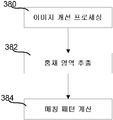
도 3c는 홍채 인식을 위한 프로세스를 도시한 순서도이다. 단계(380)에서, 이미지 개선 프로세싱이 발생한다. 본 명세서에서 논의되는 시스루 헤드 마운티드 디스플레이 내의 이미지 캡처 디바이스는 사용자의 눈(들)의 이미지를 획득할 수 있다. 그 다음 이미지는 대비(contrast)를 향상시키고, 노이즈를 감소시키며, 인식에 필요하지 않은 이미지로부터의 요소들을 제거하도록 프로세싱될 수 있다. 단계(382)에서, 홍채 영역이 분리된다. 일반적으로, 홍채 시스템의 국부화(localization) 방법은 홍채의 경계에 해당하는 모서리의 위치를 신호하도록 이미지 인텐시티(intensity)의 제 1 파생물을 이용한다. 일반적으로, 다수의 홍채 인식 알고리즘이 눈의 사진 내의 동공과 홍채의 대략적인 동심 원의 외부 경계를 식별하도록 활용될 수 있다. 일반적으로, 동공을 형성하는 홍채의 내부 경계는 동공의 경계가 기본적으로 원형 모서리라는 사실을 이용하여 결정될 수 있다. 동공은 일반적으로 어두운 반면 홍채는 더 다양한 색소를 가지고 더욱 밝다. 동공 경계를 검출하는 방법은 광이 원을 따라 모아졌을 때 돌연 갑작스러운 변화를 검사한다. 일 실시예에서, 동공 내의 타원의 폐곡선 적분이 계산되어 축의 길이를 증가시키기 위해 타원의 축 방향에서의 적분 미분이 계산된다. 동일한 방법이 눈꺼풀 경계를 검출하기 위해서 사용될 수 있다.3C is a flowchart showing a process for iris recognition. At
오직 홍채만을 커버하는 픽셀들의 세트가 두 개의 홍채 이미지 사이의 통계적으로 의미있는 비교를 위해 필수적인 정보를 보존하는 패턴으로 변환된다. 식별(일대다 템플릿 매칭) 또는 증명(일대일 템플릿 매칭)을 통해 인증하기 위해서, 홍채를 이미징함으로서 생성된 템플릿은 데이터베이스 내의 저장된 값 템플릿에 비교된다.The set of pixels covering only the iris is converted into a pattern that preserves the information necessary for a statistically meaningful comparison between the two iris images. To authenticate through identification (one-to-many template matching) or proof (one-to-one template matching), the template created by imaging the iris is compared to the stored value template in the database.
단계(384)에서, 하나 이상의 알고리즘을 이용하여 매칭 패턴이 계산된다. 패턴 매칭은 새롭게 획득된 홍채 패턴을 후보 데이터베이스 엔트리와의 공간 정렬로 가져오는 것, 구별되는 패턴을 명확하게 하는 정렬된 홍채 패턴의 표현 선택, 후보와 데이터베이스 표현 사이의 매칭의 우수성 평가 및 매칭 성공에 대한 결정을 포함한다. 눈과 같은 얼굴 특징을 발견하고 추적하기 위한 다수의 다른 대안들이 존재한다. 다양한 홍채 인식 기술은: 미국 특허번호 No.7,336,806, 미국 특허번호 No.6,641,349, 미국 특허번호 No.5,291,560 및 2004년 1월의 IEEE TRANSACTIONS ON CIRCUITS AND SYSTEMS FOR VIDEO TECHNOLOGY Vol.14, No.1, Daugman의 "How Iris Recognition Works"에서 기술되었으며, 이들 각각은 그 전체가 특별히 본 명세서에 참조로서 포함되었다.At
도 6은 사용자 프로파일(280)의 생성 및 업데이트를 도시한 순서도이다. 사용자 프로파일의 생성이 서비스 제공자가 구성을 허용하길 원하는 임의의 수의 파라미터의 저장을 가능하게 할 수 있음을 이해해야만 한다. 도 6에 도시된 단계들 각각은 사용자 프로파일을 생성하기 위해서 별개로 그리고 비동시적으로 수행될 수 있다. 즉, 각 단계가 현존하는 사용자 프로파일을 생성 또는 추가하기 위해 수행될 수 있다. 단계(602)에서, 만약 사용자가 하나 이상의 증강 현실 서비스에 대해 명시된 서비스 선호도를 갖는다면, 사용자 서비스 선호도가 저장될 수 있다. 예를 들어, 만약 사용자가 코-펜딩(co-pending) 출원번호 no.(MSFT1425)에 개시된 바와 같은 이벤트 기반 정보 시스템을 위한 시스루 헤드 마운티드 디스플레이에 대한 정보 공급에 가입하면, 사용자는 서비스 공급에서 제시되는 정보의 유형을 제한하길 원할 수 있다. 서비스와 관련된 사용자 선호도는 단계(602)에서 사용자의 사용자 프로파일(280) 내에 저장된다. 단계(604)에서 사용자가 다수의 서비스 중 하나에 로그인할 수 있게 하는 크리덴셜(credential)을 제공할 때, 로그인 크리덴셜은 사용자 프로파일(280)과 저장될 수 있고 사용자 신원의 결정에 기초하여 자동으로 검색될 수 있다. 단계(606)에서, 증강 현실 서비스 제공자(90)에 의해 제공되는 정보와 관련하여 사용자에 의해 지정된 정보 필터가 사용자 프로파일(280)에 저장된다. 정보 필터는 시스루 헤드 마운티드 디스플레이 내의 사용자에게 제시될 수 있는 정보량 및 정보의 유형을 제한하며, 정보가 사용자에게 제공될 때 사용자에 의해 정의될 수 있다. 예를 들어, 특정한 유형의 정보가 증강 현실 서비스에 의해 디스플레이될 때, 사용자는 해당 유형의 정보가 미래에는 서비스에 의해 디스플레이되지 않아야 한다고 나타낼 수 있다. 정보의 일 유형은 제품의 특정 유형과 관련된 광고 또는 트래픽 알림을 포함할 수 있다. 소정 유형의 정보가 디스플레이되지 않아야 한다는 표시가 사용자에 의해 이루어지면, 필터가 생성되고 프로파일(280)이 필터를 저장할 수 있다.6 is a flow chart illustrating creation and update of a
단계(608)에서 디바이스 설정 선호도가 설정될 수 있다. 전술된 바와 같이, 시스템은 사용자의 저장된 선호도에 대해 증강 현실 서비스와 시스루 헤드 마운티드 디스플레이를 자동으로 조정하도록 사용자 신원을 이용할 수 있다. 일 측면에서, 사용자 프로파일은 시스루 헤드 마운티드 디스플레이(150)의 디스플레이 요소들의 동공 사이 거리를 자동으로 조정하도록 사용될 수 있다. 시스루 헤드 마운티드 디스플레이는 IPD의 자동 조정을 가능하게 하며 디스플레이 광학 시스템으로부터 각각의 눈까지의 깊이 거리 및/또는 수직 및/또는 높이 길이를 포함할 수 있다.At
도 5a는 단계(210)에서 사용자 프로파일에 기초하여 구성을 설정하는 방법을 도시한 순서도로서, 이때 구성은 하나 이상의 사용자의 동공 사이 거리(IPD)와의 정렬을 위해 시스루 근안 합성 현실 디스플레이 디바이스(see-through, near eye, mixed reality display)를 조정하기 위한 것이며, 그 후에 단계(214)에서 디바이스가 동작한다. 단계(542)에서, 사용자 프로파일에 정의된 것과 같이 디스플레이가 사용자 IPD와 정렬되었는지 여부에 대한 초기 결정이 이루어진다. 단계(542)에서, 예로서 아래에서 기술될 도 7a의 프로세서(210)와 같은 제어 회로(136)의 하나 이상의 프로세서, 처리 장치(6, 5), 허브 컴퓨팅 시스템(12) 또는 이들의 조합이, 시스루 근안 합성 현실 디스플레이 디바이스가 정렬 기준에 따라서 사용자의 IPD와 정렬되었는지 여부를 자동으로 결정한다. 만약 시스루 근안 합성 현실 디스플레이 디바이스가 사용자 IPD와 정렬되었다고 결정되면, 이 방법은 단계(546)로 이동하여 정렬에서의 변화를 모니터한다.5A is a flow chart illustrating a method for configuring a configuration based on a user profile at
만약 디스플레이가 정렬되지 않았다면, 단계(544)에서 식별된 사용자에 대한 사용자 프로파일로부터 IPD가 선택된다.If the display is not aligned, the IPD is selected from the user profile for the user identified in
디스플레이 디바이스(2)(도 7a, 7b)는 각 눈에 대해 디스플레이 광학 시스템을 구비하며, 일부 실시예에서, 하나 이상의 프로세서가 IPD를 정렬 기준을 만족시키는 위치에서의 디스플레이 광학 시스템의 광학축들 사이의 거리로서 저장한다. 일부 실시예에서, 하나 이상의 프로세서는 사용자 프로파일 내의 IPD 데이터 세트 내의 각 광학축의 위치를 저장한다. 사용자에 대한 IPD는 예를 들어 사용자에 코에 대해서 비대칭적일 수 있다. 예를 들어, 왼쪽 눈이 오른쪽 눈보다 코에 조금 더 가까울 수 있다. 일 예시에서, 초기 위치로부터 각 디스플레이 광학 시스템에 대한 디스플레이 조정 메커니즘의 조정값이 사용자 프로파일 내의 IPD 데이터 세트 내에 저장될 수 있다. 디스플레이 조정 메커니즘의 초기 위치는 예를 들어 브릿지(104) 상의 포인트와 같이 고정 프레임 부분에 대해 고정된 위치를 가질 수 있다. 고정된 프레임 부분에 대해 고정된 위치 및 이동의 하나 이상의 방향에 대한 조정값에 기초하여, 고정 프레임 부분에 대한 각 광학축의 위치는 각 디스플레이 광학 시스템에 대한 동공 정렬 위치로서 저장될 수 있다. 또한, 고정 프레임 부분이 브릿지 상의 포인트인 경우에서, 사용자의 코에 대한 각각의 동공의 위치 벡터는 브릿지 상의 포인트에 대한 고정된 위치 및 조정값에 기초하여 각 눈에 대해 예측될 수 있다. 각 눈에 대한 두 개의 위치 벡터는 적어도 수평 거리 구성요소를 제공하며, 수직 거리 구성요소도 포함할 수 있다. 하나 이상의 방향에서의 동공 사이 거리 IPD는 이들 거리 구성요소로부터 파생될 수 있다.The display device 2 (Figs. 7A and 7B) has a display optical system for each eye, and in some embodiments, one or more processors may be arranged between the optical axes of the display optical system As a distance. In some embodiments, the one or more processors store the location of each optical axis within the IPD data set in the user profile. The IPD for the user may be asymmetric to the user ' s nose, for example. For example, the left eye may be a little closer to the nose than the right eye. In one example, the adjustment value of the display adjustment mechanism for each display optical system from the initial position may be stored in the IPD data set in the user profile. The initial position of the display adjustment mechanism may have a fixed position relative to the stationary frame portion, such as a point on the
단계(545)에서, 하나 이상의 조정값이 적어도 하나의 디스플레이 광학 시스템에 대한 정렬 기준을 만족시키기 위한 적어도 하나의 디스플레이 조정 메커니즘에 대해 결정된 IPD 데이터 세트로부터 검색된다. 단계(546)에서, 처리 장치(20)는 도 8a-8c와 관련하여 논의되는 메커니즘과 같은 디스플레이 조정 메커니즘으로 하여금 단계(546)에서 선택된 IPD와의 정렬을 위해 각 눈에 대한 디스플레이 광학 시스템(814)을 자동으로 조정하게 한다. 이와 달리, 사용자는 시스루 헤드 마운티드 디스플레이에 대해 수동으로 조정하라고 지시될 수도 있다.At
단계(547)에서, 서비스 선호도, 서비스에 대한 로그인 정보 및 정보 필터와 같은 추가적인 사용자 선호도가 사용자 프로파일로부터 검색된다.At
단계(548)에서, 사용자 선호도에 따라 디바이스가 동작한다. 단계(548)에서, 더 이상 정렬 기준을 만족시키지 않는 선택된 IPD와의 정렬을 나타내는 처리 장치(20)에 의해 변화가 검출될 수 있으며, 단계(550)에서 정렬 기준을 만족시키기 위한 적어도 하나의 디스플레이 광학 시스템을 자동으로 재조정하기 위해 프로세서를 트리거링한다. 정렬 기준은 예로서 3㎜와 같은 몇 밀리미터의 거리일 수 있다. 사용자의 초점을 추적하기 위해 지속적으로 수행되는 시선(gaze) 결정 방법이 변화를 검출할 수도 있다.At
도 5b는 시스루 근안 합성 현실 디스플레이의 하나 이상의 사용자에 대해 디바이스(214)를 동작할 때, 조정가능한 IPD 정렬을 자동으로 제공할 수 있는 사용자 설정에 대한 사용자 프로파일 엔트리를 생성하는 방법(608)의 일 실시예를 도시한 순서도이다. 단계(518)에서, 처리 장치(20)는 각각의 눈으로부터 반사된 빛의 캡처된 데이터에 기초하여 사용자의 IPD를 자동으로 결정하고, 단계(520)에서 사용자 프로파일 내에 사용자와 연관된 IPD 데이터를 저장한다. 단계(546)에서, 시스루 헤드 마운티드 디스플레이는 결정된 IPD에 기초하여 디스플레이의 각 눈에 대한 디스플레이 광학 시스템을 자동으로 조정한다. 단계(519)에서, IPD 및 사용자의 특정 특징에 대해 하나 이상의 조정값이 결정된다. IPD 데이터 및 조정값이 일반적으로 어른에 맞춰지기 때문에, 인간의 두개골의 범위로 인해 IPD 데이터가 한번 결정되어 단계(520)에서 저장될 수 있다. 디스플레이가 단계(546)에서 조정되면, 방법은 IPD 데이터 세트와 사용자 선호도를 저장하는 단계(410)에서 완료되고, 도 2의 방법은 단계(214, 216)에서 완료된다.5B is a flowchart of a
IPD를 결정하고 저장하기 위한 다양한 방법이 코-펜딩 출원번호 no.1467에서 개시되었다. 다른 실시예에서, 사용자 프로파일이 근거리 IPD와 원거리 IPD를 저장하며, 처리 장치(20)는 시선 데이터에 기초하여 시선의 포인트의 거리를 결정하고, 주시점 방향(point of gaze)의 거리에 기초하여 근거리 IPD 또는 원거리 IPD로서 IPD를 선택한다. Various methods for determining and storing IPD have been disclosed in co-pending application no. In another embodiment, the user profile stores a near IPD and a far IPD, and the processing device 20 determines the distance of the point of the gaze based on the gaze data, and based on the distance of the point of gaze Select IPD as the near or remote IPD.
도 6a-6c는 시스루 근안 합성 현실 디스플레이를 IPD와 정렬하는 방법을 도시한다.6A-6C illustrate a method of aligning a near-sighted synthetic reality display with an IPD.
도 6a는 시스루 근안 합성 현실 디스플레이를 IPD와 정렬하는 방법 실시예(600)의 순서도이다. 단계(602) 내지 단계(606)는 시스루 근안 합성 현실 디스플레이 디바이스가 정렬 기준에 따라서 사용자의 IPD와 정렬되었는지 여부를 자동으로 결정하기 위한 단계(542)의 예시의 세부사항을 도시한다. 단계(607) 및 단계(608)는 단계(548)에서와 같이 디바이스를 사용자 IPD와 정렬시키기 위해 디스플레이 디바이스를 조정하기 위한 예시의 더욱 상세한 단계들을 도시한다. 도 3c에서 논의된 바와 같이, 조정은 기계적 조정을 위해 사용자에게 전기적으로 제공되는 명령 또는 프로세서에 의해 자동으로 수행될 수 있다.6A is a flowchart of a
도 6a 및 아래에서 도 8a-10d와 관련하여 개시되는 실시예를 참조하면, 단계(602)에서, 처리 장치(4), 모바일 디바이스(5), 또는 허브 컴퓨팅 시스템(12) 내의 제어 회로의 프로세서(210)와 같은 시스루 근안 합성 현실 시스템의 하나 이상의 프로세서가 독립적으로 또는 결합적으로, IPD를 결정하기 위한 방향 및 거리에서의 사용자 시야 내의 객체를 식별한다. 원거리 IPD에 있어서, 예로서 5피트 초과와 같은 거리가 효율적인 무한대에 있으며, 방향은 각 디스플레이 광학 시스템의 광학축에 대해서 바로 앞이다. 다시 말하면, 거리 및 방향은 각 동공이 각 광학축과 정렬되었을 때 사용자가 바로 앞을 바라보는 거리 및 방향이 된다. 단계(603)에서, 하나 이상의 프로세서는 객체에 대한 사용자의 초점을 도시하기 위한 프로세싱을 수행한다. 일 예시에서, 하나 이상의 프로세서는 사용자에게 식별된 실제 객체를 바라보라고 요청하는 지시를 전기적으로 제공한다. 일부 예시에서, 사용자는 단순히 정면을 바라보도록 요청될 수 있다. Referring to the embodiment disclosed with reference to Figures 6a and 8a-10d below, at
단계(604)에서, 각각의 디스플레이 광학 시스템에 대한 시선 검출 요소들의 정렬에서 센서(134) 또는 광검출기(152) 또는 둘 모두와 같은 적어도 하나의 센서가 객체에 대한 관찰 기간 동안 각 눈에 대한 데이터를 캡처한다. 일 예시에서, 캡처된 데이터는 IR 카메라에 의해 캡처된 각 눈으로부터 반사된 글린트(glint) 및 IR 이미지 데이터일 수 있다. 다른 예시에서, 적어도 하나의 센서가 위치 민감성 거물기와 같은 IR 센서이다. 적어도 하나의 센서는 또한 IR 광검출기일 수도 있다. 일부 예시에서, 적어도 하나의 센서가 가시광 카메라일 수 있다.At
단계(606)에서, 하나 이상의 프로세서가 캡처된 데이터 및 시선 검출 요소들의 배열에 기초하여 정렬 기준에 따라 각 동공이 자신의 각각의 디스플레이 광학 시스템의 광학축과 정렬되었는지 여부를 결정한다. 정렬 기준은 예로서 2㎜와 같은 광학축으로부터의 거리일 수 있다. 만약 그렇다면, 디스플레이 디바이스(2)는 각 동공과 정렬된 것이고 따라서 IPD과도 정렬되었으며, 단계(609)에서 하나 이상의 프로세서가 IPD 데이터 세트 내의 각 광학축의 위치를 저장한다.At
만약 정렬 기준이 만족되지 않았다면, 단계(607)에서, 하나 이상의 프로세서가 적어도 하나의 디스플레이 광학 시스템에 대한 정렬 기준을 만족시키기 위해 적어도 하나의 디스플레이 정렬 메커니즘에 대한 하나 이상의 조정값을 자동으로 결정한다. "자동으로 결정하는" 수단에 의해, 사용자가 기계적인 조정을 통해 조정값을 식별하지 않고 하나 이상의 프로세서가 값들을 결정한다. 다수의 실시예에서, 저장된 디바이스 구성 데이터에 기초하여, 지지 구조의 고정된 포인트에 대한 광학축의 현재 위치가 추적된다. 단계(608)에서, 프로세서는 하나 이상의 조정값에 기초하여 적어도 하나의 각각의 디스플레이 광학 시스템의 조정을 발생시킨다. 자동 조정에서, 하나 이상의 프로세서가 하나 이상의 조정값에 기초하여 적어도 하나의 각각의 디스플레이 광학 시스템을 이동시키기 위해 하나 이상의 디스플레이 조정 메커니즘 드라이버(245)를 통해 적어도 하나의 디스플레이 조정 메커니즘(2030을 제어한다. 기계적인 조정 접근에서, 프로세서는 기계적인 컨트롤러를 통해 하나 이상의 조정값을 적어도 하나의 디스플레이 조정 메커니즘에 적용하기 위해 사용자에게 전기적으로 지시를 제공한다. 방법 실시예의 단계들은 사전결정된 횟수만큼 또는 정렬 기준이 만족될 때까지 반복될 수 있다.If the alignment criterion is not satisfied, then in
도 6b는 이미지 포맷 내의 각 눈에 대한 동공의 이미지 데이터에 기초한 사용자의 IPD와 시스루 근안 합성 현실 디스플레이의 정렬의 구현 예시에 대한 방법 실시예(610)의 순서도이다. 이미지 포맷은 예를 들어 이미지 센서 크기 및 형태에 의해 설정될 수 있는 것과 같은 사전결정된 크기 및 형태를 갖는다. 이미지 포맷의 예시는 이미지 프레임이다. 포맷은 이미지 데이터 내의 위치를 추적하기 위해서 좌표 시스템, 예로서 오리진으로서의 중심을 제공하기 위한 것이다. 예로서 IR 카메라 또는 원한다면 가시광 카메라와 같은 이미지 센서의 검출 영역이 디스플레이 광학 시스템(14)의 광학축(142) 상에 중심을 둔다면, 이미지 포맷 내의 이미지 데이터는 광학축(142) 상에 중심을 둔다. 이미지 중심으로부터 동공 중심이 얼마나 떨어져 있는지는 동공이 광학축과 충분히 정렬되었는지 여부를 결정하기 위한 기초이다.6B is a flow diagram of a
단계(612)에서, IPD를 결정하기 위한 거리 및 방향에서의 사용자 시야에서 실제 객체가 식별되며, 단계(613)에서 하나 이상의 프로세서가 사용자의 초점을 실제 객체로 끌기 위한 프로세싱을 수행한다. 단계(614)에서, 각각의 디스플레이 광학 시스템의 광학축과 정렬된 적어도 하나의 센서에 의해서 실제 객체에 대한 관찰 기간 동안 이미지 포맷의 각 눈의 이미지 데이터를 캡처된다. 단계(615)에서 각각의 광학축에 대한 각각의 동공 위치가 이미지 데이터로부터 결정된다. 이미지 데이터 내의 동공 영역은 밝기값(intensity value)을 스레드홀딩(thresholding) 함으로써 식별될 수 있다. 타원 피팅 알고리즘이 동공의 크기 및 형태를 근사화하기 위해 적용될 수 있으며, 결과적인 타원의 중심이 동공의 중심으로서 선택될 수 있다. 이상적으로, 동공의 중심은 디스플레이 광학 시스템의 광학축과 정렬된다. 단계(616)에서, 하나 이상의 프로세서는 정렬 기준에 따라 예로서 이미지 프레임과 같은 이미지 포맷 내의 동공 위치에 기초하여 각각의 광학축과 각 동공이 정렬되었는지 여부를 결정한다. 검출 영역(139)이 광학축(142) 상에 중심을 가자는 경우에, 하나 이상의 프로세서는 정렬 기준에 따라서 동공 위치가 예로서 이미지 프레임과 같은 이미지 포맷 내에 중심을 갖는지 여부를 결정한다. 동공 위치는 광학축과 관련하여 각 눈에 대해 수평 및 수직 방향에서 결정될 수 있다. At
만약 정렬 기준이 만족되면, 단계(609)에서 하나 이상의 프로세서가 IPD 데이터 세트 내의 각 광학축의 위치를 저장한다. 만약 그렇지 않다면, 단계(617)에서, 하나 이상의 프로세서가 정렬 기준을 만족시키지 않는 각 디스플레이 광학 시스템에 대한 적어도 하나의 센서의 맵핑 기준에 기초하여 각각의 디스플레이 조정 메커니즘에 대한 적어도 하나의 조정값을 결정한다. 단계(618)에서, 하나 이상의 프로세서가 적어도 하나의 조정값에 기초하여 각각의 디스플레이 광학 시스템을 이동시키기 위해 각각의 디스플레이 조정 메커니즘을 제어한다. 방법 실시예의 단계들은 사전결정된 횟수만큼 또는 정렬 기준이 만족될 때까지 반복될 수 있다.If the alignment criteria are met, then in
도 6c는 적어도 하나의 조정값을 결정하기 위해 단계(617)를 구현하는데에 사용될 수 있는 방법 실시예의 순서도이다. 단계(642)에서, 적어도 하나의 센서에 대한 맵핑 기준에 기초하여, 하나 이상의 프로세서가 수평 동공 위치 차이 벡터를 결정한다. 거리 맵핑 기준에 대한 픽셀이 조정이 제공되는 각 방향에 대해 사용될 수 있다. 맵핑 기준은 이미지 센서의 검출 영역의 형태에 의존하여 수평에 대한 것과 수직에 대한 것이 서로 상이할 수 있다. 단계(644)에서, 적어도 하나의 센서에 대한 맵핑 기준에 기초하여, 수직 동공 위치 차이 벡터도 결정된다. 단계(646)에서, 적어도 하나의 프로세서는 수평 동공 위치 차이 벡터를 수평 조정값에 상관시키고, 단계(648)에서, 수직 동공 위치 차이 벡터를 수직 조정값에 상관시킨다(correlate). 6C is a flow diagram of a method embodiment that may be used to implement
수평 IPD가 25 내지 30㎜의 범위를 가질 수 있기 때문에, 디스플레이 조정 메커니즘은 임의의 방향으로 디스플레이 광학 시스템을 이동시키기 위한 거리의 범위 제한을 가질 수 있다. 깊이 조정은 수평 또는 수직 방향에서 범위 밖의 조정값을 범위 내에 있게 하는 것을 도울 수 있다. 선택적인 단계(651, 653)가 수행될 수 있다. 하나 이상의 프로세서는 단계(651)에서 임의의 수평 또는 수직 조정값이 범위 밖에 있는지 여부를 결정한다. 만약 그렇지 않다면, 디스플레이 광학 시스템의 정렬이 2차원 평면에서의 이동에 의해 달성될 수 있으며, 단계(618)가 수행될 수 있다. 만약 적어도 하나의 조정값이 범위 밖에 있으면, 하나 이상의 프로세서가 선택적 단계(653)에서 범위 밖에 있는 임의의 수평 또는 수직 조정값을 범위 제한에 보다 가깝게 또는 범위 내에 가져가기 위해 깊이 조정값을 결정하며, 단계(618)는 디스플레이 광학 시스템을 조정하도록 수행될 수 있다.Because the horizontal IPD may have a range of 25 to 30 mm, the display adjustment mechanism may have a range limitation of distance to move the display optical system in any direction. The depth adjustment can help to keep the adjustment values out of range in the horizontal or vertical direction within the range.
예시로서, 만약 광학축이 오른쪽으로 12㎜에 있고 디스플레이 조정 메커니즘이 디스플레이 광학 시스템을 왼쪽으로 6㎜만 이동시킬 수 있다면, 디스플레이 광학 시스템과 동공 사이의 깊이를 증가시킴으로써 광학축의 위치에 대해 정면을 바라볼 때 동공으로부터의 각도가 감소되며, 따라서 좌측으로의 6㎜ 조정과 함께 깊이 증가가 광학축을 정렬 기준에 따라 동공과 더 가깝게 정렬하게 만든다. 수직 길이에 대한 깊이 변화의 효과도 고려될 수 있으며, 그에 따라 수직 조정도 필요할 수 있거나 깊이 조정값이 수정된다.By way of example, if the optical axis is at 12 mm to the right and the display adjustment mechanism is capable of moving the display optical system only 6 mm to the left, look for the position of the optical axis by increasing the depth between the display optical system and the pupil The angle from the pupil when viewed is reduced so that the depth increase with a 6 mm adjustment to the left makes the optical axis more closely aligned with the pupil according to the alignment reference. The effect of depth variation on the vertical length may also be considered, so that vertical adjustment may be required or the depth adjustment value may be modified.
도 6b 및 6c의 실시예는 또한 글린트가 서로에 대한 지리적 관계를 가질 때 각 눈으로부터 글린트 데이터에 적용될 수 있으며, 센서는 픽셀과 같은 별개의 센서의 표면을 갖는다. 예를 들어, 조명기(illuminator)에 의해 생성된 눈에 대한 글린트는 조명기의 위치에 의해 눈에 대한 각각의 디스플레이 광학 시스템의 광학축과 정렬된 다른 지리적 형태 또는 박스를 형성한다. 만약 센서가 글린트를 검출하기 위한 위치 민감성 검출기(PSD)이면, 고정된 조명기로부터 생성된 글린트에 대해 검출된 세기값과 센서 상의 위치가 동공의 위치를 맵핑하도록 사용된다. IR 카메라, 또는 가시 카메라로부터의 이미지 데이터는 동공 위치 결정을 위해 더욱 큰 정확도를 제공하지만, 글린트 데이터 접근법은 더 적은 양의 데이터를 프로세싱하고 따라서 계산 강도가 더 낮다.The embodiments of Figures 6b and 6c can also be applied to glint data from each eye when the glints have a geographic relationship to each other, and the sensor has a surface of a separate sensor, such as a pixel. For example, a glint for an eye produced by an illuminator forms a different geographic form or box aligned with the optical axis of each display optical system relative to the eye by the position of the illuminator. If the sensor is a position sensitive detector (PSD) for detecting glint, the detected intensity value for the glint produced from the fixed fixture and the position on the sensor are used to map the pupil position. Image data from an IR camera, or from a visible camera, provides greater accuracy for pupil positioning, but the glint data approach processes less amount of data and is therefore less computationally robust.
다른 실시예는 시선 데이터에 기초하여 IPD와 시스루 근안 합성 현실 디스플레이를 정렬시키기 위한 구현을 이용할 수 있다. 이러한 실시예에서, 하나 이상의 프로세서는 디스플레이 광학 시스템에 대한 시선 검출 요소의 배열에 기초하여 각각의 디스플레이 광학 시스템의 광학축을 통과하는 실제 객체를 각 눈에 대한 시선 벡터가 참조할 것을 결정한다. 시선 결정 방법에 대한 실시예는 출원번호 no.1467에서 개시되었다.Another embodiment may utilize an implementation for aligning the IPD and the near-sighted synthesized reality display based on the gaze data. In such an embodiment, the one or more processors determine, based on the arrangement of the line of sight detection elements for the display optical system, that the eye vector for each eye refers to the actual object passing through the optical axis of each display optical system. An embodiment of a line of sight determination method is disclosed in Application No. 1467.
글린트 데이터가 시선을 결정하도록 사용될 때 전술된 방법들이 사용될 수 있다. 일 실시예에서, 글린트 반사는 눈들의 훨씬 큰 이미지 데이터 세트를 프로세싱하기보다는, 글린트에 대해 검출된 세기값의 몇몇 데이터 포인트들에 기초하여 시선을 예측할 수 있다. 안경 프레임(115) 상의 조명기(153)의 위치 또는 눈 부근의 디스플레이 디바이스의 다른 지지 구조가 고정될 수 있으며, 그에 따라 하나 이상의 센서에 의해 검출된 글린트의 위치가 센서 검출 영역 내에서 고정된다.The above-described methods can be used when glint data is used to determine gaze. In one embodiment, the glint reflex can predict the line of sight based on some data points of the intensity value detected for the glint rather than processing a much larger set of image data of the eyes. The position of the
도 7a는 디바이스가 동작할 수 있는 시스템 환경의 조정가능한 IPD를 갖는 시스루 합성 현실 디스플레이 디바이스의 일 실시예의 예시적인 구성요소를 도시한 블록도이다. 시스템(10)은 와이어(6)를 통해 처리 장치(4)와 통신하는 눈 부근, 헤드 마운티드 디스플레이 디바이스(150)로서의 시스루 디스플레이 디바이스를 포함한다. 다른 실시예에서, 헤드 마운티드 디스플레이 디바이스(150)는 무선 통신을 통해 처리 장치(4)와 통신한다. 일 실시예에서 프레임(115) 내의 안경의 형태인 헤드 마운티드 디스플레이 디바이스(150)는 사용자의 머리 위에 착용되어 이 예시에서 사용자가 각 눈에 대한 디스플레이 광학 시스템(14)으로서 구현된 디스플레이를 통해 볼 수 있으며, 그에 따라 사용자 앞의 공간의 실질적인 다이렉트 뷰를 갖는다. 7A is a block diagram illustrating exemplary components of an embodiment of a see-through composite reality display device with an adjustable IPD in a system environment in which the device may operate. The
본 명세서에 지칭된 "실질적인 다이렉트 뷰"는 객체의 생성된 이미지 표현을 보는 것이 아닌 사람의 눈으로 직접 현실 세계 객체를 보기 위한 능력을 지칭한다. 예를 들어, 안경을 통해 방을 바라보는 것은 사용자가 방의 실질적인 다이렉트 뷰를 가지도록 하는 반면, 텔레비전 상에서 방의 비디오를 보는 것은 방의 실질적인 다이렉트 뷰가 아니다. 예를 들어 게임 애플리케이션과 같은 소프트웨어 실행의 맥락에 기초하여, 시스템은 시스루 디스플레이 디바이스를 착용하고 있는 사람에 의해 보여질 수 있는 디스플레이 상에서 때때로 가상 이미지로 지칭되는 가상 객체들의 이미지를 투영할 수 있는 동시에, 디스플레이를 통해서 실제 세계 객체들도 보게 된다.The term "substantial direct view " as referred to herein refers to the ability to view real-world objects directly at the human eye, rather than viewing the generated image representation of the object. For example, looking at a room through a pair of glasses allows the user to have a substantial direct view of the room, while viewing a room's video on a television is not a substantial direct view of the room. Based on the context of software execution, such as, for example, a gaming application, the system can project images of virtual objects, sometimes referred to as virtual images, on a display that can be viewed by a person wearing a see-through display device, You will also see real world objects through the display.
프레임(115)은 전기적 접속을 위한 도관(conduit)뿐 아니라 시스템의 요소들을 위치에 홀딩하는 것을 돕는다. 이러한 실시예에서, 프레임(115)은 아래에서 추가로 논의되는 시스템의 요소들에 대한 지지대로서 편리한 안경 프레임을 제공한다. 다른 실시예에서, 다른 지지 구조가 사용될 수 있다. 이러한 구조의 예시는 바이저(visor) 또는 고글이다. 프레임(115)은 사용자의 각각의 귀에 걸쳐지는 템플(temple) 또는 사이드 암(side arm)을 포함한다. 템플(temple)(102)은 우측 템플의 실시예를 대표하며 디스플레이 디바이스(150)에 대한 제어 회로(136)를 포함한다. 프레임의 코받침(nose bridge)(104)은 사운드를 녹음하고 오디오 데이터를 처리 장치(4)로 전송하기 위한 마이크로폰(110)을 포함한다.The
일 실시예에서, 처리 장치(4)는 사용자의 손목에 착용되며 시스루 헤드 마운티드 디스플레이(150)를 동작시키도록 사용되는 많은 컴퓨팅 파워를 포함한다. 처리 장치(4)는 하나 이상의 허브 컴퓨팅 시스템(12)에 무선으로 통신할 수 있다(예로서, WiFi, 블루투스, 적외선, 또는 다른 무선 통신 수단). In one embodiment, the processing device 4 includes a large amount of computing power that is worn on the wearer's wrist and used to operate the see-through head-mounted
허브 컴퓨팅 시스템(10)은 컴퓨터, 게임 시스템 또는 콘솔 등일 수 있다. 예시적인 실시예에 따르면, 허브 컴퓨팅 시스템(10)은 하드웨어 구성요소 및/또는 소프트웨어 구성요소를 포함할 수 있으며, 그에 따라 허브 컴퓨팅 시스템(10)은 게임 애플리케이션, 비-게임 애플리케이션 등과 같은 애플리케이션을 실행하기 위해 이용될 수 있다. 일 실시예에서, 허브 컴퓨팅 시스템(10)은 본 명세서에 기술된 프로세스를 수행하기 위해 프로세서 판독가능한 저장 디바이스 상에 저장되는 명령을 실행할 수 있는 표준화된 프로세서, 전용화된 프로세서, 마이크로프로세서 등과 같은 프로세서를 포함할 수 있다. The
허브 컴퓨팅 시스템(10)은 또한 캡처 디바이스(21a, 21b)와 같은 하나 이상의 캡처 디바이스를 포함한다. 다른 실시예에서, 2개보다 많거나 더 적은 캡처 디바이스가 방 또는 사용자의 다른 물리적 환경을 캡처하는데에 사용될 수 있다.The
캡처 디바이스(21a, 21b)는 애플리케이션 내에서 하나 이상의 제어 또는 동작을 수행하고/하거나 아바타 또는 온-스크린 캐릭터를 애니메이션화 하는 것을 수행하기 위해서 예를 들어 하나 이상의 사용자에 의해 수행되는 제스처 및/또는 움직임뿐 아니라 주변 공간의 구조가 캡처, 분석 및 추적될 수 있도록 주변 공간과 하나 이상의 사용자를 시각적으로 모니터하는 카메라일 수 있다. 애플리케이션은 아래에서 모바일 디바이스(5)에 대해 논의되는 바와 같은 디스플레이 디바이스(150), 허브 컴퓨팅 시스템(10), 또는 이들의 조합 사에서 실행될 수 있다.The capture devices 21a and 21b may be used to perform, for example, gestures and / or movements performed by, for example, one or more users, to perform one or more controls or actions within the application and / or to animate an avatar or an on- But can also be a camera that visually monitors the surrounding space and one or more users so that the structure of the surrounding space can be captured, analyzed and tracked. The application may be executed in a
허브 컴퓨팅 시스템(10)은 게임 또는 애플리케이션 비주얼을 제공할 수 있는 텔레비전, 모니터, 고해상도 티비(HDTV) 등과 같은 시청각 디바이스(11)에 접속될 수 있다. 예를 들어, 허브 컴퓨팅 시스템(10)은 게임 애플리케이션, 비-게임 애플리케이션 등과 연관된 시청각 신호를 제공할 수 있는 그래픽 카드와 같은 비디오 어댑터 및/또는 사운드 카드와 같은 오디오 어댑터를 포함할 수 있다. 시청각 디바이스(11)는 허브 컴퓨팅 시스템(10)으로부터 시청각 신호를 수신할 수 있고 그 다음 시청각 신호와 연관된 게임 또는 애플리케이션 시각 및/또는 청각을 출력할 수 있다. 일 실시예에 따르면, 시청각 디바이스(11)는 예를 들어 S-Video 케이블, 동축 케이블, HDMI 케이블, DVI 케이블, VGA 케이블, 구성요소 비디오 케이블, RCA 케이블 등을 통해 허브 컴퓨팅 시스템(10)에 접속될 수 있다. 일 예시에서, 시청각 디바이스(11)는 내부 스피커를 포함한다. 다른 실시예에서, 시청각 디바이스(11), 개별적인 스테레오 또는 허브 컴퓨팅 시스템(10)이 외부 스피커(22)에 접속된다.The
도 7b는 조정가능한 IPD를 갖는 시스루 합성 현실 디스플레이 디바이스의 다른 실시예의 예시적인 구성요소를 도시한 블록도이다. 이러한 실시예에서, 시스루 헤드 마운티드 디스플레이(150)는 처리 장치(4)의 예시적인 실시예로서 모바일 컴퓨팅 디바이스(5)와 통신한다. 설명된 예시에서, 모바일 디바이스(5)는 와이어(6)를 통해 통신하지만, 다른 예시에서 무선으로 통신할 수도 있다.7B is a block diagram illustrating an exemplary component of another embodiment of a see-through composite reality display device with an adjustable IPD. In this embodiment, the see-saw head mounted
또한, 허브 컴퓨팅 시스템(10)에서와 같이, 게임 및 비-게임 애플리케이션은 사용자 동작이 제어하거나 사용자 동작이 디바이스(5)의 디스플레이(7) 상의 디스플레이될 수 있는 것과 같이 아바타를 애니메이션하는 모바일 디바이스(5)의 프로세서 상에서 실행할 수 있다. 모바일 디바이스(5)는 또한 인터넷 상에서 또는 유선 또는 무선 통신 매체를 통한 다른 통신 네트워크를 통해 허브 컴퓨팅 시스템(10)과 같은 다른 컴퓨팅 디바이스와 통신하기 위해 네트워크 인터페이스를 제공한다. 예를 들어, 사용자는 허브 컴퓨팅 시스템(10)과 같은 더욱 파워풀한 시스템 상에서 플레이하는 다른 모바일 디바이스 사용자들과의 온라인 게임 세션에 참여할 수 있다. 스마트폰 또는 태블릿 컴퓨팅 디바이스 내에 구현될 수 있는 것과 같은 모바일 디바이스(5)의 하드웨어 및 소프트웨어 구성요소의 예시가 도 20에서 기술되었다. 모바일 디바이스(5)의 일부 다른 예시는 랩탑 또는 노트북 컴퓨터 및 넷북 컴퓨터이다. Game and non-game applications may also be controlled by a user device such as a mobile device (e.g., a mobile device) that animates an avatar such as a user action may be controlled or a user action may be displayed on the
도 8a는 시선 검출 요소를 포함하는 이동가능한 디스플레이 광학 시스템을 갖는 안경으로 구현된 시스루 헤드 마운티드 디스플레이의 예시적인 배열을 도시한다. 예로서 (14r) 및 (14l)과 같이 각각의 눈에 대해 렌즈로서 나타난 것은 각 눈에 대한 디스플레이 광학 시스템(14)을 나타낸다. 디스플레이 광학 시스템은 전형적인 안경에서와 같이 도 7a, 7b, 9a-9b 및 10a, 10b에서의 예로서 렌즈(116, 118)와 같은 시스루 렌즈를 포함하지만, 렌즈(116, 118)를 통해 보여진 실제의 직접적인 현실 세계 뷰를 가상 콘텐츠와 매끄럽게 합성하기 위한 광학 요소들(예로서, 거울, 필터)도 포함한다. 디스플레이 광학 시스템(14)은 일반적으로 시스루 렌즈(116, 118)의 중심에 있는 광학축을 가지며, 여기에서 일반적으로 광이 왜곡없는(distortionaless) 뷰를 제공하기 위해서 조준된다. 예를 들어, 눈 관리 전문가가 전형적인 한 쌍의 안경을 사용자의 얼굴에 맞추었을 때, 각 동공이 각각의 렌즈의 중심 또는 광학축과 정렬되는 위치에 있도록 사용자의 코 위에 안경이 놓이게 함으로써 명확하거나 왜곡 없는 뷰를 위해 일반적으로 사용자의 눈에 도달하는 광이 조준되도록 하는 것이 목표이다.FIG. 8A illustrates an exemplary arrangement of a see-through head mounted display implemented in a spectacle with a movable display optical system including a line of sight detection element. Illustrated as lenses for each eye, such as (14r) and (14l) for example, is the display optical system 14 for each eye. The display optical system includes a see-through lens, such as
도 8a의 예시에서, 적어도 하나의 센서의 검출 영역(139r, 139l)은 자신의 각 디스플레이 광학 시스템(14r, 14l)의 광학축과 정렬되어 검출 영역(139r, 139l)의 중심이 광학축을 따라 광을 캡처하게 한다. 만약 디스플레이 광학 시스템(14)이 사용자의 동공과 정렬되면, 각각의 센서(134)의 각 검출 영역(139)이 사용자의 동공과 정렬된다. 검출 영역(139)의 반사된 광은 하나 이상의 광학 요소를 통해 카메라의 실제 이미지 센서(134)로 전송된다.8A, the
일 예시에서, 흔히 RGB 카메라로도 지칭되는 가시광 카메라는 센서일 수 있으며, 광학 요소 또는 광 다이렉팅 요소의 예시는 부분적으로 투과성이고 부분적으로 반사성인 가시광 반사 거울이다. 일부 예시에서, 카메라는 예로서 2㎜×2㎜만큼 작을 수 있다. 다른 예시에서, 적어도 하나의 센서(134)는 IR 방사가 다이렉팅될 수 있는 위치 민감성 검출기(PSD) 또는 IR 카메라이다. 예를 들어, 뜨거운 반사 표면은 가시광을 전달하지만 IR 방사는 반사시킬 수 있다. 일부 예시에서, 센서(134)는 RGB 및 IR 카메라의 결합일 수 있으며, 광 다이렉팅 요소는 가시광 반사 또는 방향전환(diverting) 요소 및 IR 복사 반사 또는 방향전환 요소를 포함할 수 있다.In one example, a visible light camera, also commonly referred to as an RGB camera, may be a sensor, and an example of an optical element or light directing element is a partially transmissive, partially reflective, visible light reflective mirror. In some examples, the camera may be as small as, for example, 2 mm x 2 mm. In another example, at least one
도 8a의 예시에서, 4 세트의 광검출기(152)와 쌍을 이룬 조명기(153)가 존재하며 이들은 광검출기(152)에서 수신된 반사된 광과 조명기(153)에 의해 생성된 입사광 사이에서의 간섭을 방지하기 위해서 장벽(barrier)(154)에 의해 분리된다. 도면에서의 불필요한 어수선함을 방지하기 위해, 도면 번호는 대표적인 쌍에 대해서 도시되었다. 각 조명기는 사전결정된 파장에서 좁은 광선을 생성하는 적외선(IR) 조명기일 수 있다. 광검출기 각각은 사전결정된 파장에서의 광을 캡처하도록 선택될 수 있다. 적외선은 또한 적외선 부근 광을 포함할 수도 있다.In the example of FIG. 8A, there are four sets of
아래에서 기술되는 바와 같이, 시선 벡터, 두 개의 글린트를 결정하는 것의 일부로서 각막 중심을 계산하는 일부 실시예에서, 따라서 두 개의 조명기가 충분할 것이다. 그러나, 다른 실시예가 동공 위치를 결정할 때 추가적인 글린트를 사용할 수 있으며, 따라서 시선 벡터를 사용할 수 있다. 예를 들어 30개의 프레임에서 2차 또는 더 많은 수로 글린트와 눈 데이터가 반복적으로 캡처되기 때문에, 하나의 글린트에 대한 데이터가 눈썹 또는 속눈썹에 의해서 차단될 수 있지만, 데이터는 다른 조명기에 의해서 생성된 글린트에 의해 수집될 수 있다.In some embodiments of calculating corneal center as part of determining the line of sight, two glints, as described below, then two fixtures will suffice. However, other embodiments may use additional glints when determining the pupil location, and thus use a line of sight vector. For example, data for one glint may be blocked by eyebrows or eyelashes, since glint and eye data is captured repeatedly in a second or greater number of frames over 30 frames, but data is generated by another fixture And can be collected by the resulting glints.
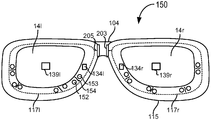
도 8a에서, 각 디스플레이 광학 시스템(14) 및 카메라(134) 및 그 검출 영역(139)과 같은 각 눈을 마주하는 시선 검출 요소의 배치, 광학적 정렬 요소(이 도면에서 도시되지 않았음; 6a-6d를 참조), 조명기(153) 및 광검출기(152)는 이동가능한 내부 프레임 부분(117l, 117r) 상에 위치된다. 이러한 예시에서, 디스플레이 조정 메커니즘은 3차원 중 적어도 하나에서 객체를 밀고 당기기 위해서 객체에 부착하는 섀프트(shaft)(205)를 구비하는 하나 이상의 모터(203)를 포함한다. 이러한 예시에서, 객체는 모터(203)에 의해 구동된 섀프트(205)의 전력 및 가디언스 하에서 프레임(115) 내에서 왼쪽에서 오른쪽으로 또는 그 반대로 슬라이드하는 내부 프레임 부분(117)이다. 다른 실시예에서, 하나의 모터(203)는 두 내부 프레임 모두를 구동할 수 있다. 도 9a 및 9b를 참조하여 논의된 것과 같이, 디스플레이 디바이스(150)의 제어 회로(136)의 프로세서는 모터(203)에 의한 섀프트(205)의 서로 다른 방향에서의 조정을 제어하기 위해 프레임(115) 내에서의 전기 접속을 통해 하나 이상의 모터(203)로 접속할 수 있다. 또한, 모터(203)는 프레임(115)의 전기 접속을 통해서도 파워 서플라이에 액세스한다.8A, the arrangement of the eye detecting elements facing each eye, such as each of the display optical system 14 and the
도 8b는 시선 검출 요소를 포함하는 이동가능한 디스플레이 광학 시스템을 갖는 안경으로서 구현된 시스루 헤드 마운티드 디스플레이의 다른 예시적인 배치를 도시한다. 이러한 실시예에서, 각 디스플레이 광학 시스템(14)은 모터(203)에 의해서 개별적으로 이동가능한 별개의 안경 프레임된 섹션인 별개의 프레임 부분(115l, 115r) 내에 밀폐된다. 일부 실시예에서, 임의의 길이 내의 이동 범위는 10㎜보다 작다. 일부 실시예에서, 제품에 대해 제공되는 프레임 크기의 범위에 의존하여 이동 범위는 6㎜보다 작다. 수평 방향에 있어서, 각 프레임을 수 밀리미터 왼쪽 또는 오른쪽으로 이동시키는 것은 예로서 안경 템플(temple)(102)과 같은 디스플레이 광학 시스템(14)을 사용자의 머리에 부착하는 안경 템플들 사이의 폭에 뚜렷한 영향을 미치지 않을 것이다.8B shows another exemplary arrangement of a see-through head mounted display implemented as a pair of glasses with a movable display optical system including a line of sight detection element. In this embodiment, each display optical system 14 is enclosed within
도 8c는 시선 검출 요소를 포함하는 이동가능한 디스플레이 광학 시스템을 갖는 안경으로서 구현된 시스루 헤드 마운티드 디스플레이의 다른 예시적인 배치를 도시한다. 이러한 예시에서, 센서(134r, 134l) 자신은 자신의 각각의 디스플레이 광학 시스템(14r, 14l)의 중심에서 광학축과 정렬되거나 일렬로 존재하지만 시스템(14) 아래의 프레임(115) 상에 위치된다. 또한, 일부 실시예에서, 카메라(134)는 깊이 카메라이거나 또는 깊이 카메라를 포함한다. 이러한 예시에서, 2 세트의 조명기(153) 및 광검출기(152)가 존재한다. 8C shows another exemplary arrangement of a see-through head mounted display implemented as a spectacle with a movable display optical system including a visual line sensing element. In this example, the
동공 사이 거리는 수평 방향에서의 사용자의 동공 사이의 거리를 기술할 수 있지만, 수직 차이도 결정될 수 있다. 또한, 눈과 디스플레이 디바이스(150) 사이의 깊이 방향에서 디스플레이 광학 시스템을 이동시키는 것은 또한 광학축을 사용자의 동공과 정렬시키는 것을 도울 수 있다. 사용자는 실제로 서로 다른 깊이의 두개골 내의 아이볼을 가질 수 있다. 머리에 대한 깊이 방향에서의 디스플레이 디바이스의 움직임은 또한 디스플레이 광학 시스템(14)의 광학축과 자신의 각각의 동공 사이의 비정렬(misalignment)을 도입할 수 있다.The pupillary distance can describe the distance between the user's pupils in the horizontal direction, but the vertical difference can also be determined. Moving the display optical system in the depth direction between the eye and the
이러한 예시에서, 모터는 3차원에서 각 디스플레이 광학 시스템(14)을 이동시키기 위한 XYZ 메커니즘의 예시를 형성한다. 이러한 예시에서 모터(203)는 외부 프레임(115) 상에 위치되며 그들의 섀프트(205)는 각각의 내부 프레임 부분(117)의 상단과 바닥에 부착된다. 모터(203)의 동작은 제어 회로(136) 프로세서(210)에 의한 그들의 섀프트 이동에 동기화된다. 또한, 이것인 합성 현실 디바이스이기 때문에, 각각의 디스플레이 광학 시스템(14) 내의 디스플레이에 대한 가상 이미지 또는 가상 객체의 이미지를 생성하기 위한 각각의 마이크로디스플레이 어셈블리(173)는 디스플레이 광학 시스템과의 광학적 정렬을 유지하기 위해 모터 및 섀프트에 의해 이동된다. 마이크로디스플레이 어셈블리(173)의 예시는 아래에서 추가로 기술된다. 이 예시에서, 모터(203)는 3개의 축 모터이거나 3차원에서 그들의 섀프트를 이동시킬 수 있다. 예를 들어, 섀프트는 크로스-헤어 가이드의 중심을 따라 한 축의 방향에서 밀고 당겨질 수 있으며 크로스-헤어 가이드의 직교하는 오프닝 내에서 동일한 평면 내의 직교하는 두 방향의 각각에서 이동한다.In this example, the motor forms an example of an XYZ mechanism for moving each display optical system 14 in three dimensions. In this example, the
도 9a는 하드웨어 및 소프트웨어 구성요소에 대한 지지를 제공하는 시스루 합성 현실 디스플레이 디바이스의 실시예에서 프레임(115)의 안경 템플(102)의 측면을 도시한다. 프레임(115)의 정면에는 비디오 및 스틸 이미지를 캡처할 수 있는 물리적 환경 페이싱 비디오 카메라(113)가 존재한다. 특히 디스플레이 디바이스(150)가 허브 시스템(12)의 캡처 디바이스(21a, 21b)와 같은 깊이 카메라와 관련하여 동작하지 않는 실시예에서, 물리적 환경 페이싱 카메라(113)는 가시광 민감성 카메라뿐 아니라 깊이 카메라이기도 하다. 예를 들어, 깊이 카메라는 다른 유형의 깊이 센서 또는 CCD로 조명기에 의해 전송되는 파장 범위 내의 반사된 IR 방사를 다이렉팅하고 가시광선은 통과시키는 가시 이미지 센서의 앞에 있는 뜨거운 거울과 같은 뜨거운 반사 표면 및 IR 조명기 전송기를 포함할 수 있다. 센서로부터의 데이터는 처리 장치(6, 5) 또는 제어 회로(136)의 프로세서(210), 또는 둘 모두로 전송될 수 있으며, 이는 데이터를 프로세싱할 수 있지만 유닛(6, 5)은 프로세싱을 위해 허브 컴퓨팅 시스템(12) 또는 네트워크 상에서 컴퓨터 시스템으로 전송할 수도 있다. 프로세싱은 에지 검출 기술 및 이미지 분할을 통해 객체를 식별하며, 사용자의 현실 세계 시야 내에 있는 객체에 깊이를 맵핑한다. 또한, 물리적 환경 페이싱 카메라(113)는 또한 주변 광을 측정하기 위해 광 미터를 포함할 수 있다.9A illustrates a side view of a
제어 회로(136)는 헤드 마운티드 디스플레이 디바이스(150)의 다른 구성요소를 지지하는 다양한 전자기기를 제공한다. 제어 회로(136)의 다른 세부사항들이 도 7과 관련하여 아래에서 제공된다. 이어폰(130), 관성 센서(132), GPS 송수신기(144) 및 온도 센서(138)가 템플(102)에 장착되거나 템플(102) 내에 존재한다. 일 실시예에서, 관성 센서(132)는 세 개의 축 자기력계(132a), 세 개의 축 자이로(132b) 및 세 개의 축 가속도계(132c)(도 7을 참조)를 포함한다. 관성 센서는 헤드 마운티드 디스플레이 디바이스(150)의 위치, 방향 및 갑작스러운 가속을 감지하기 위한 것이다. 이러한 움직임으로부터, 헤드 위치도 결정될 수 있다.The
디스플레이 디바이스(150)는 하나 이상의 가상 객체의 이미지를 생성할 수 있는 디스플레이 요소의 유형을 제공한다. 일부 실시예에서, 마이크로디스플레이는 디스플레이 요소로서 사용될 수 있다. 이러한 예시에서 마이크로디스플레이 어셈블리(173)는 가변 초점 조정기(135) 및 광 프로세싱 요소를 포함한다. 광 프로세싱 요소의 예시는 마이크로디스플레이 유닛(120)이다. 다른 예시는 렌즈 시스템(122)의 한 이상의 렌즈와 같은 하나 이상의 광학 요소 및 도 10a 내지 10d에서의 표면(124, 124a, 124b)과 같은 하나 이상의 반사 요소를 포함한다. 렌즈 시스템(122)은 단일 렌즈 또는 복수의 렌즈를 포함할 수 있다.
템플(102)에 장착되거나 내부에 존재하는 마이크로디스플레이 유닛(120)은 이미지 소스를 포함하며 가상 객체의 이미지를 생성한다. 마이크로디스플레이 유닛(120)은 아래의 도면에서 도시된 바와 같이 반사 표면(124) 또는 반사 표면(124a, 124b) 및 렌즈 시스템(122)과 광학적으로 정렬된다. 광학적 정렬은 하나 이상의 광학축을 포함하는 광학적 경로(133) 또는 광학축(133)을 따라 이루어질 수 있다. 마이크로디스플레이 유닛(120)은 렌즈 시스템(122)을 통해 가상 객체의 이미지를 투영하며, 이러한 렌즈 시스템(122)은 이미지 광을 도 6c 및 6d에서와 같이 광을 광가이드 광학 요소(122)로 다이렉팅하는 반사 요소(124) 상으로 다이렉팅할 수 있거나 또는 도 6a-6d에서와 같이 광학축(142)을 따르는 자연적인 또는 실제 다이렉트 뷰와 경로(133)를 따르는 가상 이미지 뷰를 결합하는 부분적으로 반사하는 요소(124b)로 가상 이미지의 광을 다이렉팅하는 반사 표면(124a)(예로서, 거울 또는 다른 표면) 도는 부분적 반사 요소(124b)로 이미지 광을 다이렉팅할 수 있다. 뷰들의 결합은 사용자의 눈으로 다이렉팅된다.A
가변 초점 조정기(135)는 마이크로디스플레이 어셈블리 내의 요소의 광출력(optical power) 또는 마이크로디스플레이 어셈블리의 광학적 경로 내의 한 이상의 광 프로세싱 요소 사이의 이동을 변경한다. 렌즈의 광출력은 예로서 1/초점 길이와 같은 초점 길이의 역수로서 정의되며, 따라서 하나에서의 변화가 다른 것에도 영향을 미친다. 이러한 변화는 예로서 소정의 거리에 있는 영역과 같은 시야의 영역에서의 변화를 발생시키며, 이는 마이크로디스플레이 어셈블리(173)에 의해 생성된 이미지에 대한 초점 내에 존재한다.The
이동 변화를 만드는 마이크로디스플레이 어셈블리(173)의 일 예시에서, 이동 변화는 이러한 예시에서 마이크로디스플레이(120) 및 렌즈 시스템(122)과 같은 적어도 하나의 프로세싱 요소를 지지하는 전기자(armature)(137) 내에서 가이드된다. 전기자(137)는 선택된 이동 또는 광출력을 획득하기 위해 요소의 물리적 이동 동안 광학적 경로(133)에 따른 정렬을 안정화하는 것을 돕는다. 일부 예시에서, 조정기(135)는 전기자(137) 내의 렌즈 시스템(122)에서의 렌즈와 같은 하나 이상의 광학 요소를 이동시킬 수 있다. 다른 예시에서, 전기자는 광 프로세싱 요소 주변 영역 내의 공간 또는 그루브(groove)를 가질 수 있으며, 따라서 광 프로세싱 요소를 이동시키지 않고, 예를 들어 마이크로디스플레이(120)와 같은 요소에 대해 슬라이드한다. 렌즈 시스템(122)과 같은 전기자 내의 다른 요소는, 시스템(122) 또는 렌즈가 움직이는 전기자(137)와 슬라이드하거나 이동하도록 부착된다. 이동 범위는 전형적으로 대략 수 밀리미터이다. 일 예시에서, 범위는 1-2㎜이다. 다른 예시에서, 전기자(137)는 이동보다 다른 물리적 파라미터의 조정을 포함하는 초점 조정 기술에 대한 렌즈 시스템(122)에 대한 지지를 제공할 수 있다.In one example of a
일 예시에서, 조정기(135)는 압전기 모터와 같은 액추에이터(actuator)일 수 있다. 액추에이터에 대한 다른 기술도 사용될 수 있으며, 이러한 기술의 일부 예시는 코일과 영구자석으로 형성된 음성 코일, 자기변형(magnetostriction) 요소 및 전기변형(electrostriction) 요소이다. In one example, the
마이크로디스플레이(120)를 구현하도록 사용될 수 있는 서로 다른 이미지 생성 기술이 존재한다. 예를 들어, 마이크로디스플레이(120)는 전달되는 투영 기술을 이용하여 구현될 수 있으며, 여기에서 광소스가 광학적으로 활성화된 재료인, 백색광을 갖는 역광(backlit)에 의해 변조된다. 이러한 기술은 일반적으로 파워풀한 백라이트 및 높은 광학적 에너지 밀도를 갖는 LCD 타입 디스플레이를 이용하여 구현된다. 마이크로디스플레이(120)는 또한 외부 광이 광학적으로 활성화된 재료에 의해서 반사되고 변조되는 반사 기술을 이용하여 구현될 수도 있다. 조명은 기술에 의존하여 화이트 소스 또는 RGB 소스에 의한 전광(forward lit)이다. 디지털 광 프로세싱(DLP), 실리콘 상의 액정(LCOS) 및 Qualcomm, Inc사로부터의 Mirasol® 디스플레이 기술은 대부분의 에너지가 변조된 구성으로부터 반사되기 때문에 효율적인 반사 기술의 예시이며, 본 명세서에 기술된 시스템에서 이용될 수 있다. 또한, 마이크로디스플레이(120)는 광이 디스플레이에 의해 생성되는 방출 기술을 이용하여 구현될 수 있다. 예를 들어, Microvision, Inc사로부터의 PicoP™ 엔진은 전달가능한 요소로서 동작하는 작은 스크린상으로 조종하거나 눈으로 직접 빔되는(예로서, 레이저) 마이크로 미러로 레이저 신호를 방출한다.There are different image generation techniques that can be used to implement
전술된 바와 같이, 마이크로디스플레이 어셈블리(173)의 광 프로세싱 요소의 구성은 가상 객체가 이미지 내에 나타나는 초점 영역 또는 초점 거리를 생성한다. 구성을 변경하는 것은 가상 객체 이미지에 대한 초점 영역을 변경한다. 광 프로세싱 요소에 의해 결정되는 초점 영역은 등식 1/S1+1/S2=1/f에 기초하여 결정되고 변경될 수 있다.As described above, the configuration of the light processing element of the
심볼 f는 마이크로디스플레이 어셈블리(173) 내의 렌즈 시스템(122)과 같은 렌즈의 초점 길이를 표현한다. 렌즈 시스템(122)은 전방 교점(front nodal point) 및 후방 교점(rear nodal point)을 갖는다. 만약 광선이 광학축과 관련된 주어진 각도에서 둘 중 하나의 교점으로 다이렉팅된다면, 광선은 광학축에 대해 동등한 각도에서 다른 교점으로부터 드러날 것이다. 일 예시에서, 렌즈 시스템(122)의 후방 교점은 자신과 마이크로디스플레이(120) 사이에 있을 것이다. 후방 교점으로부터 마이크로디스플레이(120)로의 거리는 S2로서 표기될 수 있다. 전방 교점은 전형적으로 렌즈 시스템(122)의 수 ㎜ 내에 존재한다. 타겟 위치는 3차원 물리적 공간 내의 마이크로디스플레이(120)에 의해 생성될 가상 객체 이미지의 위치이다. 전방 교점으로부터 가상 이미지의 타겟 위치까지의 거리는 S1으로서 표기될 수 있다. 이러한 이미지는 마이크로디스플레이(120)와 동일한 렌즈의 측면 상에 나타나는 가상 이미지이기 때문에, 사인 변환은 S1가 음의 값을 갖게 한다.Symbol f represents the focal length of the lens, such as
만약 렌즈의 초점 길이가 고정되면, S1 및 S2는 서로 다른 깊이에서 초점 가상 객체로 달라진다. 예를 들어, 초기 위치는 무한정으로 설정된 S1 및 렌즈 시스템(122)의 초점 길이와 동일한 S2를 가질 수 있다. 렌즈 시스템(122)이 10㎜의 초점 길이를 갖는다고 가정하면, 가상 객체가 약 1피트 또는 300㎜ 사용자의 시야 안에 배치되는 예시를 고려한다. S1은 이제 약 -300㎜이고, 이는 렌즈 시스템(122)의 후방 교점이 마이크로디스플레이(120)로부터 10㎜에 있음을 의미한다. 렌즈(122)와 마이크로디스플레이(120) 사이의 새로운 이동 또는 새로운 거리는 ㎜ 단위에서 1/(-300)+1/S2=1/10에 기초하여 결정된다. 이러한 결과는 S2에 대해서는 약 9.67이다.If the focal length of the lens is fixed, then S1 and S2 will be different focal virtual objects at different depths. For example, the initial position may have S 1 that is set to infinity and
일 예시에서, 처리 장치(4)는 S1 및 S2에 대한 이동값을 계산할 수 있으며, 초점 길이 f를 고정된 채로 남겨두고 제어 회로(136)가 예를 들어 가변 가상 초점 조정기(135)가 광학적 경로(133)를 따라 렌즈 시스템(122)을 이동시키게 하도록 가변 조정기 드라이버(237)(도 6 참조)로 하여금 드라이브 신호를 전송한다. 다른 실시예에서, 마이크로디스플레이 유닛(120)은 렌즈 시스템(122)을 이동시키는 것에 추가하여 또는 그 대신 이동될 수 있다. 다른 실시예에서, 렌즈 시스템(122) 내의 적어도 하나의 렌즈의 초점 길이가 광학적 경로(133)에 따른 이동에서의 변화와 함께 또는 그 대신 변경될 수 있다.In one example, the processing device 4 may calculate a shift value for S1 and S2, and the focal length f is left fixed and the
도 9b는 마이크로디스플레이 어셈블리의 3차원 조정과 하드웨어 및 소프트웨어 구성요소에 대한 지지를 제공하는 합성 현실 디스플레이 디바이스의 다른 실시예에서의 템플의 측면을 도시한다. 앞서 도 5a에서 도시된 숫자들 중 일부는 도면에서의 어수선함을 방지하기 위해 제거되었다. 디스플레이 광학 시스템(14)이 3차원 중 임의의 차원에서 이동되는 실시예에서, 반사 표면(124) 및 예로서(120, 122)와 같은 마이크로디스플레이 어셈블리(173)의 다른 요소들에 의해 표현되는 광학 요소들 또한 가상 이미지의 광의 광학적 경로(133)를 유지하기 위해서 디스플레이 광학 시스템으로 이동될 수 있다. 제어 회로(136)의 프로세서(210)의 제어 하에서의 섀프트(205) 및 모터 블록(203)에 의해 표현되는 하나 이상의 모터로 구성되는 이러한 예시에서의 XYZ 메커니즘은 마이크로디스플레이 어셈블리(173)의 요소들의 움직임을 제어한다. 사용될 수 있는 모터들의 예시는 압전기 모터이다. 도시된 예시에서, 하나의 모터가 전기자(137)에 부착되고 가변 초점 조정기(135)를 이동시키며, 다른 대표적인 모터(203)는 반사 요소(124)의 이동을 제어한다.Figure 9b illustrates a side view of a temple in another embodiment of a composite display device that provides three dimensional adjustment of the microdisplay assembly and support for hardware and software components. Some of the numbers previously shown in Fig. 5A have been removed to prevent clutter in the figure. In an embodiment in which the display optical system 14 is moved in any of the three dimensions, the
도 10a는 시선 검출 요소의 배치를 포함하는 시스루 근안 합성 현실 디바이스(2)의 이동가능한 디스플레이 광학 시스템(14)의 실시예의 상단 모습이다. 시스루 헤드 마운티드 디스플레이(150)의 프레임(115)의 일부분은 디스플레이 광학 시스템(14)을 둘러싸고 도시된 바와 같이 마이크로디스플레이(120) 및 그와 함께하는 요소들을 포함하는 마이크로디스플레이 어셈블리(173)의 실시예의 요소들에 대한 지지를 제공한다. 디스플레이 시스템(14)의 구성요소들을 나타내기 위해서, 이러한 경우에서 오른쪽 눈 시스템에 대한 (14r), 디스플레이 광학 시스템을 둘러싸는 프레임(115)의 상단 부분이 도시되지 않았다. 또한, 브릿지(104) 내의 마이크로폰(110)은 디스플레이 조정 메커니즘(203)의 동작에 대해 집중하기 위해 여기에서 도시되지 않았다. 도 6c에서의 예시에서와 같이, 이러한 실시예에서의 디스플레이 광학 시스템(14)은 이러한 예시에서 마이크로디스플레이 어셈블리(173)를 둘러싸는 내부 프레임(117r)을 이동시킴으로써 이동된다. 디스플레이 조정 메커니즘은 이 실시예에서 디스플레이 광학 시스템(14)을 번역하기 위해 내부 프레임(117r)으로 자신의 섀프트(205)를 부착하는 세 개의 축 모터(203)로서 구현되었으며, 이러한 실시예에서 이러한 디스플레이 광학 시스템(14)은 이동의 세 개의 축을 나타내는 심볼(144)에 의해 표기된 3차원 중 임의의 차원에서 마이크로디스플레이 어셈블리(173)를 포함한다.10A is a top view of an embodiment of a movable display optical system 14 of a near-far-sight synthesized
이러한 실시예에서의 디스플레이 광학 시스템(14)은 광학축(142)을 구비하며 사용자에게 현실 세계의 실제 다이렉트 뷰를 허용하는 시스루 렌즈(118)를 포함한다. 이러한 예시에서, 시스루 렌즈(118)는 안경 내에서 사용되는 (처방을 포함하지 않는) 표준 렌즈이며 임의의 처방(prescription)으로 만들어질 수 있다. 다른 실시예에서, 시스루 렌즈(118)는 가변 처방 렌즈에 의해 재배치될 수 있다. 일부 실시예에서, 시스루 헤드 마운티드 디스플레이(150)는 추가적인 렌즈를 포함할 것이다.The display optical system 14 in this embodiment has an
디스플레이 광학 시스템(14)은 추가로 대표적인 부분 반사 표면(124b)을 포함한다. 이러한 실시예에서, 마이크로디스플레이(120)로부터의 광은 광학축(142)을 따라 자연적인 또는 실질적인 다이렉트 뷰와 광학적 경로(133)를 따라 이동하는 가상 이미지 뷰를 결합시키는 렌즈(118) 내에 포함된 부분적인 반사 요소(124b)를 통해 광학적 요소(133)에 따라 다이렉팅되어, 결합된 뷰가 광학축에서 사용자의 눈으로 다이렉팅되게 하며, 가장 명확한 뷰에 대해 가장 콜리메이트된(collimated) 광을 갖는 위치이다. The display optical system 14 further includes an exemplary partially
광센서의 검출 영역(139r)은 디스플레이 광학 시스템(14r)의 부분이다. 광학 요소(125)는 광학축(1420을 따라 수신되는 사용자의 눈으로부터 반사된 광을 캡처함으로써 검출 영역(139r)을 구현하고, 이러한 예시에서 내부 프레임(117r) 내의 렌즈(118) 내에 위치되는 센서(134r)에 캡처된 광을 다이렉팅한다. 일 예시에서, 센서(134r)는 RGB/IR 카메라의 결합 또는 가시광 카메라이며, 광학 요소(125)는 예를 들어 부분 반사 미러와 같이 사용자의 눈으로부터 반사된 가시광을 반사시키는 광학 요소를 포함한다. 다른 실시예에서, 센서(134r)는 IR 카메라와 같은 IR 민감성 디바이스이고, 요소(125)는 가시광이 통과하여 IR 방사를 센서(134r)로 반사시키는 뜨거운 반사 표면을 포함한다. IR 센서의 다른 예시는 위치 민감성 디바이스(PSD)이다. The
도 10a-10d에서의 반사 요소(125, 124, 124a, 124b)의 도시는 이들의 기능을 표현한다. 표면은 임의의 수의 형태를 취할 수 있고, 사용자의 눈 또는 카메라 센서와 같은 의도된 목적지로 광을 다이렉팅하기 위해 하나 이상의 배치에서 하나 이상의 광학적 구성요소와 구현될 수 있다. 도시된 바와 같이, 배치는 센서의 검출 영역(139)이 자신의 중심이 디스플레이 광학 시스템(14)의 중심과 그의 중심이 정렬될 수 있게 한다. 이미지 센서(134r)는 검출 영역(139)을 캡처하며, 따라서 이미지 센서에서 캡처된 이미지는 검출 영역(139)이 그러하기 때문에 광학축 상에 중심을 갖게 된다.The views of the
검출 영역(139) 또는 이미지 센서(134r)가 디스플레이의 광학축 상에 효과적으로 중심에 위치한 경우, 사용자가 정면을 바라볼 때, 그리고 사용자의 동공의 중심이 사용자의 눈의 캡처된 이미지 내의 중심에 놓일 때, 디스플레이 광학 시스템(14r)은 동공과 정렬된다. 두 디스플레이 광학 시스템(14) 모두가 그들 각각의 동공과 정렬되었을 때, 광학적 중심들이 일치하거나 또는 사용자의 동공 사이 거리와 정렬된다. 도 6a의 예시에서, 동공 사이 거리는 3차원에서 디스플레이 광학 시스템(14)과 정렬될 수 있다.When the detection area 139 or the
일 실시예에서, 만약 센서(134)에 의해 캡처되는 데이터가 동공이 광학축과 정렬되지 않는다고 나타낸다면, 처리 장치(20) 또는 제어 회로(136) 또는 둘 모두의 하나 이상의 프로세서가, 동공의 이미지가 광학축(142)으로부터 얼마나 멀리에 있는지를 결정하기 위해서 거리 또는 길이 측정 단위를 이미지의 영역 또는 다른 이산의 단위 또는 픽셀에 매칭하는 맵핑값을 사용한다. 결정된 거리에 기초하여, 하나 이상의 프로세서는 얼마나 긴 거리에서 그리고 어떤 방향에서 디스플레이 광학 시스템(14r)이 광학축(142)을 동공과 정렬시키기 위해서 이동되는지에 대한 조정을 결정한다. 제어 신호는 하나 이상의 디스플레이 조정 메커니즘 드라이버(245)에 의해 예로서 모터(203)와 같은 구성요소들 각각에 적용되며, 이는 하나 이상의 디스플레이 조정 메커니즘(203)을 구성한다. 이러한 예시에서의 모터의 경우에, 모터는 제어 신호에 의해 표시된 적어도 하나의 방향에서 내부 프레임(117r)을 이동시키기 위해 그들의 섀프트(205)를 이동시킨다. 내부 프레임(117r)의 템플 옆에는 프레임(115)의 신축성 있는 구간이 존재하며, 이는 일 단부에서 내부 프레임(117r)에 부착되고, 디스플레이 광학 시스템(14)이 각각의 동공에 대한 폭, 높이 또는 깊이 변화에 대한 임의의 세 방향에서 움직일 때 프레임(115)으로 내부 프레임(117)을 앵커(anchor)하도록 템플 프레임(115)의 내부의 그루브(217a, 217b) 내에서 슬라이드한다. In one embodiment, if the data captured by the
센서에 추가하여, 디스플레이 광학 시스템(14)은 다른 시선 검출 요소를 포함한다. 이러한 실시예에서, 사용자의 각막의 표면상에서 각각의 글린트를 생성하도록 사용자의 눈에서 특정한 파장 범위 내에 있는 좁은 적외선 광선을 다이렉팅하는 적어도 2개 또는 그 이상의 적외선(IR) 조명 디바이스(153)가 렌즈(118)의 측면 상의 프레임(117r)에 부착된다. 다른 실시예에서, 조명기 및 임의의 광다이오드는 예를 들어 코너 또는 에지에서 렌즈 상에 존재할 수 있다. 이러한 실시예에서, 적어도 2개의 적외선(IR) 조명 디바이스(153)에 추가로 광검출기(152)도 존재한다. 각 광검출기(152)는 렌즈(118)를 가로질러 상응하는 IR 조명기(153)의 특정한 파장 범위 내에 존재하는 IR 방사에 대해 민감하며 각각의 글린트를 검출하도록 위치된다. 도 6a-4c에서 도시된 바와 같이, 조명기 및 광검출기는 조명기(153)로부터의 입사 IR 광이 광검출기(152)에서 수신되는 반사된 IR 광과 간섭하지 않도록 장벽(154)에 의해 분리된다. 센서가 IR 센서인 경우에, 광검출기(152)는 필요하지 않을 수 있거나 또는 추가적인 캡처 소스일 수 있다. 가시광 카메라에서, 광검출기(152)는 글린트로부터의 광을 캡처하며 글린트 세기값을 생성한다.In addition to the sensors, the display optical system 14 includes other eye-detection elements. In this embodiment, at least two or more infrared (IR)
일부 실시예에서, 센서(134r)는 글린트를 캡처할 뿐 아니라 동공을 포함하는 사용자의 눈의 적외선 또는 적외선 근접 이미지를 캡처하는 IR 카메라일 수 있다. 다른 실시예에서, 센서 디바이스(134r)는 때때로 광학적 위치 센서로 지칭되는 위치 민감성 디바이스(PSD)이다. 센서의 표면에서 검출되는 광의 위치가 식별된다. 글린트에 대해 IR 조명기의 파장 범위에 민감성인 PSD가 선택될 수 있다. 위치 민감성 디바이스의 파장 범위 내에 있는 광이 디바이스의 광 민감성 부분 또는 센서 상에서 검출되며, 검출기의 표면 상의 위치를 식별하는 전기 신호가 식별된다. 일부 실시예에서, 광의 위치가 결정될 수 있는 픽셀들과 같은 분리 센서들로 PSD의 표면이 분할된다. 다른 예시에서, PSD 등방성(isotropic) 센서가 사용될 수 있으며, 여기에서 표면상의 로컬 저항성에서의 변화가 PSD 상의 광 스팟의 위치를 식별하기 위해 사용될 수 있다. PSD의 다른 실시예도 사용될 수 있다. 사전결정된 시퀀스에서 조명기(153)를 동작함으로써, PSD의 글린트의 반사의 위치가 식별될 수 있으며, 따라서 각막 표면 상에서 그들의 위치로 다시 관련된다.In some embodiments, the
도 10a-10d에서, 예로서 검출 영역(139) 및 조명기(153) 및 광검출기(152)와 같은 시선 검출 요소의 위치는 디스플레이 광학 시스템(14)의 광학축에 대해 고정된다. 이들 요소들은 디스플레이 광학 시스템(14r)과 이동할 수 있으며, 따라서 내부 프레임 상의 자신의 광학축과 이동할 수 있지만, 광학축(142)에 대한 공간적 관계는 변하지 않는다.10A-10D, the detection area 139 and the position of the line of sight detection elements, such as the
도 10b는 시선 검출 요소의 배치를 포함하는 시스루 근안 합성 현실 디바이스의 이동가능한 디스플레이 광학 시스템의 다른 실시예의 상단 모습이다. 이러한 실시예에서, 광 센서(134r)는 종종 RGB 카메라로 지칭되는 가시광 카메라로서 구현될 수 있거나, 또는 IR 카메라 또는 예로서 깊이 카메라와 같이 IR 범위와 가시 범위 모두에서 광을 프로세싱할 수 있는 카메라로서 구현될 수 있다. 이러한 예시에서, 이미지 센서(134r)는 검출 영역(139r)이다. 카메라의 이미지 센서(134)는 디스플레이 광학 시스템의 광학축(142) 상에 수직으로 위치된다. 일부 예시에서, 카메라는 시스루 렌즈(118) 위 또는 아래에 또는 렌즈(118) 내에 포함된 프레임(115) 상에 위치될 수 있다. 일부 실시예에서, 조명기(153)는 카메라에 대해 광을 제공하며, 다른 실시예에서 카메라는 주변 라이팅을 갖는 이미지를 캡처한다. 캡처된 이미지 데이터는 광학축과 동공의 정렬을 결정하도록 사용될 수 있다. 이미지 데이터, 글린트 데이터 또는 둘 모두에 기초한 시선 결정 기술은 시선 검출 요소의 지리학적 구조에 기초하여 사용될 수 있다.10B is a top view of another embodiment of a moveable display optical system of a near-far-sight synthetic real-time device including an arrangement of a line-of-sight detecting element. In this embodiment, the
이러한 예시에서, 브릿지(104) 내의 모터(203)는 방향 심볼(144)에 의해 표시되는 것과 같이 사용자의 눈에 대한 수평 방향에서 디스플레이 광학 시스템(14r)을 이동시킨다. 시스템(14)이 이동될 때 신축성 있는 프레임 부분(215a, 215b)은 그루브(217a,, 217b) 내에서 슬라이드한다. 이러한 예시에서, 마이크로디스플레이 어셈블리(173) 실시예의 반사 요소(124a)는 고정되었다. IPD가 전형적으로 한번 결정되어 저장되면, 수행될 수 있는 마이크로디스플레이(120)와 반사 요소(124a) 사이의 초점 거리의 임의의 조정이 예를 들어 전기자(137) 내의 마이크로디스플레이 요소의 조정을 통해서 마이크로디스플레이 어셈블리에 의해 달성될 수 있다.In this example, the
도 10c는 시선 검출 요소의 배치를 포함하는 시스루 근안 합성 현실 디바이스의 이동가능한 디스플레이 광학 시스템의 제 3 시스템의 상단도이다. 디스플레이 광학 시스템(14)은 IR 조명기(153) 및 광검출기(152)를 포함하는 시선 검출 요소 및 광학축(142) 아래 또는 위에 있는 렌즈(118) 또는 프레임(115) 상에 위치된 광 센서(134r)의 유사한 배치를 갖는다. 이러한 예시에서, 디스플레이 광학 시스템(14)은 사용자의 눈으로 가상 이미지를 다이렉팅하기 위한 반사 요소와 같은 광 가이드 광학 요소(112)를 포함하고 추가 시스루 렌즈(116)와 시스루 렌즈(118) 사이에 위치된다. 반사 요소(124)가 광가이드 광학 요소 내에 있고 요소(112)와 이동하기 때문에, 마이크로디스플레이 어셈블리(173)의 실시예는 이러한 예시에서의 템플(102) 상에서 마이크로디스플레이 어셈블리를 이동시키기 위한 적어도 하나를 포함하는 섀프트(205)를 갖는 세 개의 축 모터(203)의 세트로서 구현되는 디스플레이 광학 시스템(14)에 대한 디스플레이 조정 메커니즘(203)에 부착된다. 브릿지(104) 상의 하나 이상의 모터(203)는 이동(144)의 세 개의 축을 제공하는 디스플레이 조정 메커니즘(203)의 다른 구성요소의 표현이다. 다른 실시예에서, 모터는 수평 방향에서 자신의 부착된 섀프트(205)를 통해 오직 디바이스를 이동시키기 위해 동작할 수 있다. 마이크로디스플레이 어셈블리(173)에 대한 모터(203)는 또한 반사 요소(124)와 마이크로디스플레이(120)로부터 나오는 광 사이의 정렬을 유지하기 위해 이것을 수평으로 이동시킬 수 있다. 제어 회로(도 7 참조)의 프로세서(210)는 자신의 움직임을 조직화한다.FIG. 10C is a top view of a third system of a mobile display optical system of a near-field synthetic real-time device including an arrangement of a line-of-sight detecting element. FIG. The display optical system 14 includes a visual indicator element including an
광가이드 광학 요소(112)는 헤드 마운티드 디스플레이 디바이스(150)를 장착한 사용자의 눈으로 마이크로디스플레이(120)로부터의 광을 전송한다. 광가이드 광학 요소(112)는 또한 헤드 마운티드 디스플레이 디바이스(150) 앞으로부터의 광이 광가이드 광학 요소(112)를 통해 사용자의 눈에 전송될 수 있게 하며, 그에 따라 사용자가 마이크로디스플레이(120)로부터의 가상 이미지를 수신하는 것에 더하여 헤드 마운티드 디스플레이 디바이스(150)의 앞에 있는 공간의 실질적인 다이렉트 뷰를 갖게 한다. 따라서, 광가이드 광학 요소(112)의 벽은 시스루이다. 광가이드 광학 요소(112)는 제 1 반사 표면(124)(예로서, 거울 또는 다른 표면)을 포함한다. 마이크로디스플레이(120)로부터의 광은 렌즈(122)를 통과하여 반사 표면(124) 상에 입사된다. 반사 표면(124)은 마이크로디스플레이(120)로부터의 입사광을 반사시켜, 내부 반사에 의해 광가이드 광학 요소(112)를 포함하는 평면의 기판 내부에 광이 가두어지게 한다.The light guide optical element 112 transmits light from the
기판의 표면으로부터의 몇 번의 반사 후에, 가두어진 광 파장이 선택적으로 반사 표면(126)의 어레이에 도달한다. 도면이 너무 복잡해지는 것을 방지하기 위해 5개의 표면들 중 오직 하나만이 참조번호(126)로 표기되었다. 반사 표면(126)은 기판 밖으로 표면에 반사하는 입사 광 파장을 사용자의 눈으로 연결시킨다. 서로 다른 광선이 서로 다른 각도에서 기판의 내부를 돌아다니고 산란할 것이기 때문에, 서로 다른 광선이 서로 다른 각도에서 다양한 반사 표면(126)을 가열할 것이다. 따라서, 서로 다른 광선이 서로 다른 반사 표면에 의해 기판의 밖으로 반사될 것이다. 어느 관성이 어느 표면(126)에 의해 기판 밖으로 반사될 것인지에 대한 선택은 표면(126)의 적절한 각도를 선택함으로써 조작된다. 광가이드 광학 요소의 더 많은 세부사항이 2008년 11월 20일 공개된 발명의 명칭 "Substrate-Guided Optical Devices"인 미국 특허출원 공개번호 2008/0285140, 일련번호 No.12/214,366에서 찾아볼 수 있으며, 이는 본 명세서에서 참조로서 포함되었다. 일 실시예에서, 각각의 눈은 자체의 광가이드 광학 요소(112)를 가질 것이다. 헤드 마운티드 디스플레이 디바이스가 두 개의 광가이드 광학 요소를 구비할 때, 각각의 눈은 두 눈 내의 동일한 이미지 또는 두 눈에서 서로 다른 이미지를 디스플레이할 수 있는 자체의 마이크로디스플레이(120)를 구비할 수 있다. 다른 실시예에서, 두 눈으로 광을 반사시키는 하나의 광가이드 광학 요소가 존재할 수 있다. After several reflections from the surface of the substrate, the confined light wavelength selectively reaches the array of
도 10d는 시선 검출 요소의 배치를 포함하는 시스루 근안 합성 현실 디바이스의 이동가능한 디스플레이 광학 시스템의 제 4 실시예의 상단 모습이다. 이러한 실시예는 광 가이드 광학 요소(112)를 포함하는 도 6c와 유사하다. 그러나 유일한 광 검출기는 IR 광검출기(152)이며, 따라서 이 실시예는 아래의 실시예에서 논의되는 바와 같이 오직 시선 검출에 대한 글린트 검출에만 의존한다. 10D is a top view of a fourth embodiment of a moveable display optical system of a near-far-sight synthesized reality device including an arrangement of a line of sight detection element. This embodiment is similar to Fig. 6C, which includes a light guiding optical element 112. However, the only photodetector is the
전술된 실시예에서, 도시된 특정한 수의 렌즈는 단지 예시이다. 동일한 원리 상에서 동작하는 다른 수와 다른 구성의 렌즈들이 사용될 수 있다. 또한, 전술된 예시에서, 오직 시스루 근안 디스플레이(2)의 오른쪽 측면만이 도시되었다. 전체 눈 부근의 합성 현실 디스플레이 디바이스는 예시로서 렌즈(116) 및/또는 렌즈(118)의 다른 세트, 도 6c 및 6d의 실시예에 대한 다른 광가이드 광학 요소(112), 다른 마이크로디스플레이(120), 다른 렌즈 시스템(122), 유사한 다른 공간 페이싱 카메라(113), 도 6a 내지 6d의 실시예에 대한 다른 시선 추적(eye tracking) 카메라(134), 이어폰(130) 및 온도 센서(138)를 포함할 것이다.In the above-described embodiments, the specific number of lenses shown is exemplary only. Lenses of different configurations than those of other numbers operating on the same principle may be used. Further, in the above-mentioned example, only the right side of the see-through near
도 11은 일 실시예와 사용될 수 있는 것과 같은 시스루 근안 디스플레이 유닛(2)의 하드웨어 및 소프트웨어 구성요소의 일 실시예의 블록도이다. 도 12는 처리 장치(20)의 다양한 구성요소를 기술한 블록도이다. 이러한 실시예에서, 시스루 헤드 마운티드 디스플레이(150)는 처리 장치(20)로부터 가상 이미지에 대한 지시를 수신하며, 센서 정보를 다시 처리 장치(20)로 제공한다. 처리 장치(20)에서 구현될 수 있는 소프트웨어 및 하드웨어 구성요소는 디스플레이 디바이스(150)로부터 감각 정보를 수신할 것이며 또한 허브 컴퓨팅 디바이스(12)로부터 감각 정보를 수신할 수 있다. 이러한 정보에 기초하여, 처리 장치(20)는 어디에서 언제 가상 이미지를 사용자에게 제공하고 그에 따라 디스플레이 디바이스(150)의 제어 회로(136)로 지시를 전송할지를 결정할 것이다.11 is a block diagram of one embodiment of the hardware and software components of the see-through near
도 11의 구성요소들의 일부(예로서, 물리적 환경 페이싱 카메라(113), 아이 카메라(eye camera)(134), 가변적 가상 초점 조정기(135), 광검출기 인터페이스(139), 마이크로 디스플레이(120), 조명 디바이스(153) 또는 조명기, 이어폰(130), 온도 센서(138), 디스플레이 조정 메커니즘(203))가 이들 각각의 디바이스들 각각이 2개씩 존재한다는 것을 나타내기 위해 그늘이 지도록 도시되었으며, 이들 중 하나는 헤드 마운티드 디스플레이 디바이스(150)의 좌측에 존재하고 하나는 헤드 마운티드 디스플레이 디바이스(150)의 우측에 존재한다. 도 6은 전력 관리 회로(202)와 통신하는 제어 회로(200)를 도시한다. 제어 회로(200)는 프로세서(210), 메모리(214)(예로서, DRAM)와 통신하는 메모리 컨트롤러(212), 카메라 인터페이스(216), 카메라 버퍼(218), 디스플레이 드라이버(220), 디스플레이 포맷터(formatter)(222), 타이밍 생성기(226), 디스플레이 아웃(out) 인터페이스(228) 및 디스플레이 인(in) 인터페이스(230)를 포함한다. 일 실시예에서, 제어 회로(200)의 모든 구성요소는 하나 이상의 버스의 전용 라인을 통해서 서로 통신한다. 다른 실시예에서, 제어 회로(200)의 구성요소들 각각은 프로세서(210)와 통신한다. (E.g., a physical
카메라 인터페이스(216)는 두 개의 물리적 환경 페이싱 카메라(113) 및 각각의 아이 카메라(134)로의 인터페이스를 제공하며, 카메라 버퍼(218) 내의 카메라(113, 134)로부터 수신된 각각의 이미지를 저장한다. 디스플레이 드라이버(220)는 마이크로디스플레이(120)를 구동할 것이다. 디스플레이 포맷터(222)는 증강 현실 시스템을 위한 프로세싱을 수행하는 예로서 시스템(20, 12, 210)과 같은 하나 이상의 컴퓨터 시스템의 하나 이상의 프로세서로 마이크로디스플레이(120) 상에 디스플레이된 가상 이미지에 대한 정보를 제공할 수 있다. 타이밍 생성기(226)는 시스템에 대한 타이밍 데이터를 제공하기 위해 사용된다. 디스플레이 아웃(228)은 물리적 환경 페이싱 카메라(113) 및 아이 카메라(134)로부터 처리 장치(4)로 이미지를 제공하기 위한 버퍼이다. 디스플레이 인(230)은 마이크로디스플레이(120) 상에서 디스플레이될 가상 이미지와 같은 이미지를 수신하기 위한 버퍼이다. 디스플레이 아웃(228) 및 디스플레이 인(230)은 처리 장치(4)로의 인터페이스인 대역 인터페이스(232)와 통신한다.The
전력 관리 회로(202)는 전압 조정기(voltage regulator)(234), 시선 추적 조명 드라이브(236), 가변 조정기 드라이버(237), 광검출기 인터페이스(239), 오디오 DAC 및 증폭기(238), 마이크로폰 전치증폭기(preamplifier) 및 오디오 ADC(240), 온도 센서 인터페이스(242), 디스플레이 조정 메커니즘 드라이버(들)(245) 및 클록 생성기(244)를 포함한다. 전압 조정기(234)는 대역 인터페이스(232)를 통해 처리 장치(4)로부터 전력을 수신하여 그 전력을 헤드 마운티드 디스플레이 디바이스(140)의 다른 구성요소로 제공한다. 조명 드라이버(236)는 전술된 바와 같은 조명 디바이스(153)에 IR 광소스를 제공한다. 오디오 DAC 및 증폭기(238)는 이어폰(130)으로부터 오디오 정보를 수신한다. 마이크로폰 전치증폭기 및 오디오 ADC(240)는 마이크로폰(110)에 대한 인터페이스를 제공한다. 온도 센서 인터페이스(242)는 온도 센서(138)에 대한 인터페이스이다. 하나 이상의 디스플레이 조정 드라이버(245)는 하나 이상의 모터 또는 세 방향 중 적어도 하나의 방향에서의 이동의 조정 정도를 표현하는지를 나타내는 각 디스플레이 조정 메커니즘(203)을 구성하는 다른 디바이스에 제어 신호를 제공한다. 전력 관리 유닛(202)은 또한 전력을 제공하고 세 개의 축 자기력계(132A), 세 개의 축 자이로(gyro)(132B) 및 세 개의 축 가속도계(132C)로부터 다시 데이터를 수신한다.The
가변 조정기 드라이버(237)는 처리 장치(4) 또는 허브 컴퓨터(12) 또는 둘 모두에서 소프트웨어 실행함으로써 계산된 초점 영역에 대한 이동을 획득하기 위해 마이크로디스플레이 어셈블리(173)의 하나 이상의 요소를 이동시키기 위해 예를 들어 구동 전류 또는 구동 전압과 같은 제어 신호를 제어기(135)에 제공한다. 이동 범위를 통한 스위핑(sweeping) 및 그에 따른 초점 영역의 범위를 통한 스위핑의 실시예에서, 가변 조정기 드라이버(237)는 프로그램된 레이트 또는 빈도수로 동작하기 위해서 타이밍 생성기(226) 또는 이와 달리 클록 생성기(244)로부터 타이밍 신호를 수신한다. The
광검출기 인터페이스(239)는 각각의 광 검출기로부터 전압 또는 전류 판독에 필요한 임의의 아날로그로부터 디지털로의 변환을 수행하고, 메모리 컨트롤러(212)를 통해 메모리 내의 프로세서 판독가능한 포맷에서의 판독을 저장하며, 온도 및 파장 정확성과 같은 광검출기(152)의 동작 파라미터를 모니터링한다.The
도 12는 시스루 근안 디스플레이 유닛과 연관된 처리 장치(4)의 하드웨어 및 소프트웨어 구성요소의 일 실시예의 블록도이다. 모바일 디바이스(5)는 하드웨어 및 소프트웨어 구성요소의 실시예뿐 아니라, 또는 하드웨어 및 소프트웨어 구성요소의 실시예 또는 유사한 기능들을 수행하는 유사한 구성요소들을 포함할 수 있다. 도 8은 전력 관리 회로(306)와 통신하는 제어 회로(304)를 도시한다. 제어 회로(304)는 중앙 처리 장치(CPU)(320), 그래픽 처리 장치(GPU)(322), 캐시(324), RAM(326), 메모리(330)(예로서, DRAM)와 통신하는 메모리 제어(328), 플래시 메모리(334)(또는 다른 유형의 비휘발성 스토리지)와 통신하는 플래시 메모리 컨트롤러(332), 대역 인터페이스(302) 및 대역 인터페이스)(232)를 통해 시스루 근안 헤드 마운티드 디스플레이(150)와 통신하는 디스플레이 아웃 버퍼(336), 대역 인터페이스(302) 및 대역 인터페이스(232)를 통해 시스루 헤드 마운티드 디스플레이(150)와 통신하는 디스플레이 인 버퍼(338), 마이크로폰에 접속하기 위한 외부 마이크로폰 커넥터(342)와 통신하는 마이크로폰 인터페이스(340), 무선 통신 디바이스(346)와 접속하기 위한 PCI 익스프레스 인터페이스 및 USB 포트(들)(348)를 포함한다.12 is a block diagram of one embodiment of the hardware and software components of the processing device 4 associated with the near-sight display unit. The
일 실시예에서, 무선 통신 구성요소(346)는 WiFi 인에이블된 통신 디바이스, 블루투스 통신 디바이스, 적외선 통신 디바이스 등을 포함할 수 있다. USB 포트는 충전 처리 장치(4)뿐 아니라 처리 장치(20) 상에 소프트웨어 또는 데이터를 로딩하기 위해서 처리 장치(4)를 허브 컴퓨팅 디바이스(12)에 도킹하도록 사용될 수 있다. 일 실시예에서, CPU(320) 및 GPU(322)는 언제 어디에서 어떻게 이미지를 사용자의 시야에 삽입할지를 결정하기 위한 주요 워크호스(workhorse)이다. In one embodiment, the
전력 관리 회로(306)는 클록 생성기(360), 아날로그-디지털 변환기(362), 배터리 충전기(364), 전압 조정기(366), 시스루 근안 디스플레이 전력 소스(376) 및 (처리 장치(4)의 손목 밴드 상에 위치된) 온도 센서(374)와 통신하는 온도 센서 인터페이스(372)를 포함한다. 교류전류로부터 직류전류로의 변환기(362)는 AC 서플라이를 수신하고 시스템을 위한 DC 서플라이를 생성하기 위한 충전 잭(jack)(370)에 접속되었다. 전압 조정기(366)는 시스템에 전력을 공급하기 위한 배터리(368)와 통신한다. 배터리 충전기(364)는 충전 잭(370)으로부터 전력을 수신함에 따라 (전압 조정기(366)를 통해) 배터리(368)를 충전하도록 사용된다. 디바이스 전력 인터페이스(376)는 디스플레이 디바이스(150)에 전력을 제공한다.The
전술된 도면들은 디스플레이 광학 시스템에 대한 요소들의 기하학적 구조의 예시를 제공하며, 이는 아래의 도면들에서 논의되는 바와 같이 IPD를 결정하는 서로 다른 방법들에 대한 기초를 제공한다. 방법 실시예는 예시적인 맥락에서 전술된 시스템 및 구조의 요소들을 지칭할 수 있지만, 방법 실시예는 전술된 것과는 다른 시스템 또는 구조 실시예들에서 동작할 수도 있다.The foregoing figures provide an illustration of the geometry of the elements for a display optical system, which provides a basis for the different methods of determining an IPD as discussed in the following Figures. Method embodiments may refer to the elements of the systems and structures described above in the exemplary context, but the method embodiments may operate in systems or structural embodiments other than those described above.
도 13은 기술의 실시예에서 동작할 수 있는 예시적인 모바일 디바이스의 블록도이다. 전형적인 모바일폰의 예시적인 전자 회로가 도시되었다. 폰(900)은 하나 이상의 마이크로프로세서(912) 및 (예로서, ROM과 같은 비휘발성 메모리 및 RAM과 같은 휘발성 메모리인) 메모리(1010)를 포함하며, 이는 본 명세서에 기술된 기능성을 구현하기 위해 제어 프로세서(912)의 하나 이상의 프로세서에 의해 실행되는 프로세서-판독가능한 코드를 저장한다.13 is a block diagram of an exemplary mobile device that may operate in an embodiment of the techniques. An exemplary electronic circuit of a typical mobile phone is shown. The
모바일 디바이스(900)는 예를 들어, 프로세서(912), 애플리케이션을 포함하는 메모리(1010) 및 비휘발성 스토리지를 포함할 수 있다. 프로세서(912)는 본 명세서에 논의된 상호작용 애플리케이션을 포함하는 임의의 수의 애플리케이션뿐 아니라 통신을 구현할 수 있다. 메모리(1010)는 비휘발성 및 휘발성 메모리를 포함하는 임의의 다양한 메모리 저장 매체 유형일 수 있다. 디바이스 운영 시스템은 모바일 디바이스(900)의 서로 다른 동작들을 다루며, 전화 통화의 배치 및 수신, 텍스트 메시징, 음성메일 확인 등과 같은 동작들에 대한 사용자 인터페이스를 포함할 수 있다. 애플리케이션(1030)은 사진 및/또는 비디오를 위한 카메라 애플리케이션, 어드레스 북, 캘린더 애플리케이션, 미디어 플레이어, 인터넷 브라우저, 게임, 다른 멀티미디어 애플리케이션, 알람 애플리케이션, 다른 제3자 애플리케이션, 본 명세서에서 논의된 상호작용 애플리케이션 등과 같은 임의의 프로그램들의 모음일 수 있다. 메모리(1010) 내의 비휘발성 저장 구성요소(1040)는 웹 캐시, 음악, 사진, 연락처 데이터, 스케줄링 데이터 및 그외의 파일들과 같은 데이터를 포함한다.
프로세서(912)는 또한 안테나(902)에 연결되는 RF 송신/수신 회로(906), 적외선 송신기/수신기(908), WiFi 또는 블루투스와 같은 임의의 추가적인 통신 채널(1060) 및 가속도계와 같은 이동/방향 센서(914)와도 통신한다. 지능적인 사용자 인터페이스와 같은 이러한 애플리케이션이 사용자에게 제스처, GPS 위성과의 접촉이 끊어진 후에 디바이스의 이동 및 방향을 계산하는 실내의 GPS 기능을 통해 커맨드를 입력하게 하고 디바이스의 방향을 검출하고 폰이 회전되었을 때 인물사진으로부터 풍경으로 디스플레이를 자동으로 변경하도록 가속도계는 모바일 디바이스에 결합되었다. 가속도계는 예로서 반도체 칩 상에 설계된 (마이크로미터 길이의) 작은 기계적인 디바이스인 마이크로-전자기계적 시스템(MEMS)에 의해 제공될 수 있다. 가속도 방향, 배향, 진동 및 충격이 감지될 수 있다. 프로세서(912)는 또한 링거(ringer)/바이브레이터(vibrator)(916), 사용자 인터페이스 키패드/스크린, 생체인식(biometric) 센서 시스템(918), 스피커(1020), 마이크로폰(922), 카메라(924), 광 센서(926) 및 온도 센서(928)와 통신한다. The processor 912 also includes an RF transmit / receive circuitry 906 coupled to the antenna 902, an infrared transmitter /
프로세서(912)는 무선 신호의 송신 및 수신을 제어한다. 송신 모드 동안, 프로세서(912)는 마이크로폰(922)으로부터의 음성 신호 또는 다른 데이터 신호를 RF 송신/수신 회로(906)에 제공한다. 송신/수신 회로(906)는 안테나(902)를 통해 통신하기 위해 신호를 원거리 스테이션으로 전송한다(예로서, 고정 스테이션, 오퍼레이터, 그 외의 셀룰러 폰 등). 링거/바이브레이터(916)는 수신 전화, 텍스트 미시지, 캘린더 리마인더, 알람 시계 리마인더, 또는 사용자에 대한 다른 통지를 신호하도록 사용된다. 수신 모드 동안, 송신/수신 회로(906)는 안테나(902)를 통해 원거리 스테이션으로부터 음성 또는 다른 데이터 신호를 수신한다. 수신된 음성 신호는 스피커(1020)에 제공되는 반면 다른 수신된 데이터 신호도 적절하게 프로세싱된다.Processor 912 controls the transmission and reception of wireless signals. During the transmit mode, the processor 912 provides a speech signal or other data signal from the
또한, 물리적 커넥터(988)는 AC 어댑터 또는 파워된 도킹 스테이션과 같은 외부 전력 소스로 모바일 디바이스(900)를 접속하도록 사용될 수 있다. 물리적 커넥터(988)는 또한 컴퓨팅 디바이스로의 데이터 접속으로서 사용될 수도 있다. 데이터 접속은 다른 디바이스 상의 컴퓨팅 데이터와의 모바일 디바이스의 동기화와 같은 동작을 가능하게 한다.The physical connector 988 may also be used to connect the
사용자 애플리케이션의 위치를 릴레이하기 위해 위성 기반의 무선 네비게이션을 활용하는 GPS 수신기(965)는 이러한 서비스에 대해 인에이블된다.A
도면들에 도시된 예시적인 컴퓨터 시스템들은 컴퓨터 판독가능한 저장 매체의 예시를 포함한다. 컴퓨터 판독가능한 저자 매체는 또한 프로세서 판독가능한 저장 매체이다. 이러한 매체는 컴퓨터 판독가능한 지시, 데이터 구조, 프로그램 모듈 또는 다른 데이터와 같은 정보의 저장을 위한 임의의 방법 또는 기술에서 구현되는 휘발성 및 비휘발성, 제거가능 및 제거 불가능 매체를 포함할 수 있다. 컴퓨터 저장 매체는 RAM, ROM, EEPROM, 캐시, 플래시 메모리 또는 다른 메모리 기술, CD-ROM, DVD 또는 다른 광학적 디스크 스토리지, 메모리 스틱 또는 카드, 자기 카세트, 자기 테이프, 미디어 드라이브, 하드 디스크, 자기 디스크 스토리지 또는 다른 자기 스토리지 디바이스, 또는 원하는 정보를 저장하도록 사용될 수 있고 컴퓨터에 의해 액세스될 수 있는 임의의 다른 매체를 포함하지만, 이것으로 한정되는 것은 아니다.Exemplary computer systems shown in the figures include examples of computer-readable storage media. The computer readable author medium is also a processor readable storage medium. Such media may include volatile and nonvolatile, removable and non-removable media implemented in any method or technology for storage of information such as computer readable instructions, data structures, program modules or other data. Computer storage media includes, but is not limited to, RAM, ROM, EEPROM, cache, flash memory or other memory technology, CD ROM, DVD or other optical disk storage, memory stick or card, magnetic cassette, magnetic tape, media drive, Or other magnetic storage device, or any other medium which can be used to store the desired information and which can be accessed by a computer.
도 13은 개인 컴퓨터와 같은 적절한 컴퓨팅 시스템 환경(700)의 예시를 도시한다.FIG. 13 illustrates an example of a suitable computing system environment 700, such as a personal computer.
도 13을 참조하면, 기술을 구현하기 위한 예시적인 시스템은 컴퓨터(710)의 형태인 범용 컴퓨팅 디바이스를 포함한다. 컴퓨터(710)의 구성요소들은 처리 장치(720), 시스템 메모리(730) 및 시스템 메모리를 포함하는 다양한 시스템 구성요소들을 처리 장치(720)에 연결시키는 시스템 버스(721)를 포함할 수 있지만 이것으로 한정되는 것은 아니다. 시스템 버스(721)는 임의의 다양한 버스 아키텍처를 이용하는 메모리 버스 또는 메모리 컨트롤러, 주변 버스 및 로컬 버스를 포함하는 버스 구조의 임의의 몇몇 유형들일 수 있다. 예시로서, 이러한 아키텍처는 산업 표준 아키텍처(ISA) 버스, 마이크로 채널 아키텍처(MCA) 버스, 개선된 ISA(EISA) 버스, 비디오 전자 표준 연합(VESA) 로컬 버스 및 메자닌(Mezzanine) 버스로도 알려진 주변 기기 상호접속(PCI) 버스를 포함하지만, 이것으로 한정된 것은 아니다.13, an exemplary system for implementing the techniques includes a general purpose computing device in the form of a computer 710. [ The components of computer 710 may include a system bus 721 that couples various system components including processing unit 720, system memory 730 and system memory to processing unit 720, But is not limited thereto. The system bus 721 may be any of several types of bus structures, including memory bus or memory controller, peripheral bus, and local bus, using any of a variety of bus architectures. By way of example, these architectures can be used in conjunction with a peripheral known as an Industry Standard Architecture (ISA) bus, a Micro Channel Architecture (MCA) bus, an Enhanced ISA (EISA) bus, a Video Electronics Standards Association (VESA) local bus, and a Mezzanine bus And a device interconnect (PCI) bus.
컴퓨터(710)는 전형적으로 다양한 컴퓨터 판독가능한 매체를 포함한다. 컴퓨터 판독가능한 매체는 컴퓨터(710)에 의해 액세스될 수 있는 임의의 입수가능한 매체일 수 있으며, 휘발성 및 비휘발성 매체, 제거가능 및 제거 불가능 매체 모두를 포함한다. 예시로서, 컴퓨터 판독가능한 매체는 컴퓨터 저장 매체와 통신 매체를 포함할 수 있지만 이것으로 한정되는 것은 아니다. 컴퓨터 저장 매체는 컴퓨터 판독가능한 지시, 데이터 구조, 프로그램 모듈 또는 다른 데이터와 같은 정보의 저장을 위해 임의의 방법 또는 기술로 구현된 휘발성 및 비휘발성, 제거가능 및 제거 불가능 매체를 모두 포함한다. 컴퓨터 저장 매체는 RAM, ROM, EEPROM, 플래시 메모리 또는 다른 메모리 기술, CD-ROM, DVD 또는 다른 광학적 디스크 스토리지, 자기 카세트, 자기 테이프, 자기 디스크 스토리지 또는 다른 자기 스토리지 디바이스, 또는 컴퓨터(710)에 의해 액세스될 수 있고 원하는 정보를 저장하도록 사용될 수 있는 임의의 다른 매체를 포함하지만, 이것으로 한정되지는 않는다. 통신 매체는 전형적으로 컴퓨터 판독가능한 지시, 데이터 구조, 프로그램 모듈 또는 반송파와 같은 변조된 데이터 신호 또는 다른 수송 메커니즘 내의 다른 데이터를 포함하며 임의의 정보 전달 매체를 포함한다. "변조된 데이터 신호"라는 용어는 신호 내의 정보를 인코딩하는 것과 관련된 방식으로 변경된 또는 설정된 하나 이상의 자신의 특징을 갖는 신호를 의미한다. 예시로서, 통신 매체는 유선 네트워크 또는 다이렉트-와이어드 접속과 같은 유선 매체 및 음향, RF, 적외선 및 다른 무선 매체와 같은 무선 매체를 포함한다. 이들의 조합 역시 컴퓨터 판독가능한 매체의 범주 내에 포함되어야만 한다.Computer 710 typically includes a variety of computer readable media. Computer readable media can be any available media that can be accessed by computer 710 and includes both volatile and nonvolatile media, removable and non-removable media. By way of example, and not limitation, computer readable media may comprise computer storage media and communication media. Computer storage media includes both volatile and nonvolatile, removable and non-removable media implemented in any method or technology for storage of information such as computer readable instructions, data structures, program modules or other data. Computer storage media may be embodied by a computer, such as RAM, ROM, EEPROM, flash memory or other memory technology, CD-ROM, DVD or other optical disk storage, magnetic cassettes, magnetic tape, magnetic disk storage or other magnetic storage devices, But is not limited to, any other medium that can be used to store the desired information and which can be accessed. Communication media typically includes any information delivery media, including computer readable instructions, data structures, program modules or other data in a modulated data signal such as a carrier wave or other transport mechanism. The term "modulated data signal" means a signal having one or more of its characteristics altered or set in such a manner as to encode information in the signal. By way of example, communication media includes wired media such as a wired network or direct-wired connection and wireless media such as acoustic, RF, infrared and other wireless media. Combinations of these should also be included within the scope of computer readable media.
시스템 메모리(730)는 판독 전용 메모리(ROM)(731) 및 랜덤 액세스 메모리(RAM)(732)와 같은 휘발성 및/또는 비휘발성 메모리의 형태인 컴퓨터 저장 매체를 포함한다. 예로서 스타트-업 동안 컴퓨터(710) 내의 요소들 사이에서 정보를 전달하는 것을 돕는 베이직 루틴을 포함하는 베이직 입력/출력 시스템(733)(BIOS)이 전형적으로 ROM(731) 내에 저장된다. RAM(732)은 전형적으로 처리 장치(720)에 의해 현재 동작되고/되거나 즉시 액세스가능한 데이터 및/또는 프로그램을 포함한다. 예시로서 도 7은 운영 시스템(734), 애플리케이션(735), 다른 프로그램 모듈(736) 및 프로그램 데이터(737)를 도시하지만, 이것으로 한정되는 것은 아니다. The system memory 730 includes computer storage media in the form of volatile and / or nonvolatile memory such as read only memory (ROM) 731 and random access memory (RAM) A basic input / output system 733 (BIOS) is typically stored in the ROM 731, which includes a basic routine to help convey information between elements within the computer 710 during start-up, for example. The RAM 732 typically includes data and / or programs that are currently operated and / or immediately accessible by the processing unit 720. By way of illustration, FIG. 7 illustrates operating system 734, application 735, other program modules 736, and program data 737, but is not limited thereto.
컴퓨터(710)는 또한 다른 제거가능/제거 불가능, 휘발성/비휘발성 컴퓨터 저장 매체를 포함할 수 있다. 단지 예시로서, 도 13은 제거 불가능한 비휘발성 자기 매체로부터 판독가능하거나 또는 기록하는 하드 디스크 드라이브(740), 제거가능한 비휘발성 자기 디스크(752)로부터 판독하거나 또는 기록하는 자기 디스크 드라이브(751) 및 CD ROM 또는 다른 광학 매체와 같은 제거가능한 비휘발성 광학적 디스크(756)로부터 판독하거나 또는 기록하는 광학적 디스크 드라이브(755)를 도시한다. 예시적인 운영 환경에서 사용될 수 있는 다른 휘발성/비휘발성 컴퓨터 저장 매체는 자기 테이프 카세트, 플래시 메모리 카드, 디지털 다용도 디스크, 디지털 비디오 테이프, 고체 상태 RAM, 고체 상태 ROM 등을 포함하지만, 이것으로 한정되는 것은 아니다. 하드 디스크 드라이브(741)는 전형적으로 인터페이스(740)와 같은 제거 불가능한 메모리 인터페이스를 통해 시스템 버스(721)로 접속되고, 자기 디스크 드라이브(751) 및 광학적 디스크 드라이브(755)는 전형적으로 인터페이스(750)와 같은 제거가능한 메모리 인터페이스에 의해 시스템 버스(721)로 접속된다.The computer 710 may also include other removable / nonremovable, volatile / nonvolatile computer storage media. By way of example only, FIG. 13 illustrates a hard disk drive 740 that is readable or writable from non-removable, nonvolatile magnetic media, a magnetic disk drive 751 that reads from or writes to a removable, nonvolatile magnetic disk 752, And an optical disk drive 755 that reads from or writes to a removable, nonvolatile optical disk 756, such as read-only memory (ROM) or other optical media. Other volatile / nonvolatile computer storage media that may be used in the exemplary operating environment include, but are not limited to, magnetic tape cassettes, flash memory cards, digital versatile disks, digital video tape, solid state RAM, solid state ROM, no. The hard disk drive 741 is typically connected to the system bus 721 via an unremovable memory interface such as interface 740 and the magnetic disk drive 751 and the optical disk drive 755 are typically connected to the interface 750 via a removable memory interface, To a system bus 721 via a removable memory interface, such as the < RTI ID = 0.0 >
전술되고 도 13에 도시된 드라이브 및 그와 연관된 컴퓨터 저장 매체는 컴퓨터 판독가능한 지시, 데이터 구조, 프로그램 모듈 및 컴퓨터(710)에 대한 다른 데이터의 저장을 제공한다. 도 13에서, 예를 들어, 하드 디스크 드라이브(741)는 운영 시스템(744), 애플리케이션 프로그램(745), 다른 프로그램 모듈(746) 및 프로그램 데이터(747)를 저장하는 것으로 도시되었다. 이러한 구성요소들이 운영 시스템(734), 애플리케이션 프로그램(735), 다른 프로그램 모듈(736) 및 프로그램 데이터(737)와 동일할 수 있거나 또는 이들과 상이할 수 있다. 운영 시스템(744), 애플리케이션 프로그램(745), 다른 프로그램 모듈(746) 및 프로그램 데이터(747)는 최소한 이들이 서로 다른 카피임을 도시하도록 서로 다른 번호로 주어졌다. 사용자는 키보드(762) 및 흔히 마우스, 트랙볼 또는 터치 패드로 지칭되는 포인팅 디바이스(761)와 같은 입력 디바이스를 통해 컴퓨터(20) 내에 커맨드 및 정보를 입력할 수 있다. 다른 입력 디바이스(도시되지 않음)는 마이크로폰, 조이스틱, 게임 패트, 위성 접시, 스캐너 등을 포함할 수 있다. 이러한 입력 디바이스들과 그 외의 입력 디바이스들이 종종 시스템 버스에 연결된 사용자 입력 인터페이스(760)를 통해 처리 장치(720)에 접속되지만, 병렬 포트, 게임 포트 또는 USB와 같은 버스 구조 및 다른 인터페이스에 의해서 접속될 수도 있다. 모니터(791) 또는 다른 유형의 디스플레이 디바이스 또한 비디오 인터페이스(790)와 같은 인터페이스를 통해 시스템 버스(721)에 접속된다. 모니터에 더하여, 컴퓨터는 출력 주변 인터페이스(790)를 통해 접속될 수 있는 스피커(797) 및 프린터(796)와 같은 다른 주변 출력 디바이스를 포함할 수 있다.The drives and their associated computer storage media discussed above and shown in FIG. 13 provide for the storage of computer readable instructions, data structures, program modules, and other data for the computer 710. In FIG. 13, for example, hard disk drive 741 is shown storing operating system 744, application programs 745, other program modules 746, and program data 747. These components may or may not be the same as operating system 734, application programs 735, other program modules 736, and program data 737. Operating system 744, application programs 745, other program modules 746 and program data 747 have been given different numbers to illustrate that at least they are different copies. A user may enter commands and information into the computer 20 via an input device, such as a keyboard 762 and a pointing device 761, often referred to as a mouse, trackball or touch pad. Other input devices (not shown) may include a microphone, joystick, game pad, satellite dish, scanner, or the like. These input devices and other input devices are often connected to the processing unit 720 via a user input interface 760 connected to the system bus but may be connected by a bus structure such as a parallel port, It is possible. A monitor 791 or other type of display device is also connected to the system bus 721 via an interface, such as a video interface 790. In addition to the monitor, the computer may include other peripheral output devices, such as a speaker 797 and a printer 796, which may be connected via an output peripheral interface 790. [
컴퓨터(710)는 원거리 컴퓨터(780)와 같은 하나 이상의 원거리 컴퓨터로의 논리적 접속을 이용하여 네트워킹된 환경에서 동작할 수 있다. 원거리 컴퓨터(780)는 개인 컴퓨터, 서버, 라우터, 네트워크 PC, 피어 디바이스 또는 다른 공동 네트워크 노드일 수 있으며, 오직 메모리 저장 디바이스(781)만이 도 7에서 도시되었지만, 전형적으로 컴퓨터(710)에 대해 전술된 다수의 또는 모든 요소들을 포함한다. 도 7에 도시된 논리적 접속은 로컬 영역 네트워크(LAN)(771) 및 광역 네트워크(WAN)(773)를 포함하지만, 다른 네트워크도 포함할 수 있다. 이러한 네트워킹 환경은 사무실, 전사적 컴퓨터 네트워크, 인트라넷 및 인터넷에서 일반적이다.The computer 710 may operate in a networked environment using logical connections to one or more remote computers, such as a remote computer 780. Although only a memory storage device 781 is shown in FIG. 7, the remote computer 780 may be a personal computer, a server, a router, a network PC, a peer device or other shared network node, Or < / RTI > The logical connections depicted in FIG. 7 include a local area network (LAN) 771 and a wide area network (WAN) 773, but may also include other networks. Such networking environments are commonplace in offices, enterprise-wide computer networks, intranets, and the Internet.
LAN 네트워킹 환경에서 사용될 때, 컴퓨터(710)는 네트워크 인터페이스 또는 어댑터(770)를 통해 LAN(771)으로 접속된다. WAN 네트워킹 환경에서 사용될 때, 컴퓨터(710)는 전형적으로 인터넷과 같은 WAN(773) 상에서 통신을 확립하기 위한 다른 수단 또는 모뎀(772)을 포함한다. 내부 또는 외부일 수 있는 모뎀(772)은 사용자 입력 인터페이스(760) 또는 다른 적절한 메커니즘을 통해 시스템 버스(721)에 접속될 수 있다. 네트워킹된 환경에서, 컴퓨터(710) 또는 그의 부분에 대해 도시된 프로그램 모듈은 원거리 메모리 스토리지 디바이스 내에 저장될 수 있다. 예시로서, 도 13은 원거리 애플리케이션 프로그램(785)이 메모리 디바이스(781) 상에 존재하는 것으로 도시되었지만, 이것으로 한정되는 것은 아니다. 도시된 네트워크 접속이 예시적인 것이며, 컴퓨터들 사이의 통신 링크를 확립하기 위한 다른 수단이 사용될 수 있음을 이해할 것이다.When used in a LAN networking environment, the computer 710 is connected to the LAN 771 via a network interface or adapter 770. When used in a WAN networking environment, the computer 710 typically includes a modem 772 or other means for establishing communications over the WAN 773, such as the Internet. A modem 772, which may be internal or external, may be connected to the system bus 721 via a user input interface 760 or other appropriate mechanism. In a networked environment, program modules depicted relative to computer 710, or portions thereof, may be stored in a remote memory storage device. By way of illustration, FIG. 13 shows remote application program 785 as being on memory device 781, but is not so limited. It will be appreciated that the network connections shown are exemplary and other means for establishing a communication link between the computers may be used.
컴퓨팅 시스템 환경(700)은 단지 적절한 컴퓨팅 환경의 일 예시이며, 기술의 용도 또는 기능의 범주에 대한 어떠한 제한을 제안하기 위한 것이 아니다. 컴퓨팅 환경(700)이 예시적인 운영 환경(700)에서 도시된 구성요소들 중 하나 또는 구성요소들의 조합과 관련된 어떠한 의존성 또는 필수사항을 갖는 것으로 해석되어서는 안된다. The computing system environment 700 is merely an example of a suitable computing environment and is not intended to suggest any limitation as to the scope of use or functionality of the technology. The computing environment 700 should not be interpreted as having any dependency or necessity associated with one of the components or a combination of components illustrated in the exemplary operating environment 700.
이러한 기술은 다수의 다른 범용 또는 전용 컴퓨팅 시스템 환경 또는 구성과 동작가능하다. 이러한 기술과 함께 사용하기에 적합할 수 있는 잘 알려진 컴퓨팅 시스템, 환경, 및/또는 구성의 예시는 개인 컴퓨터, 서버 컴퓨터, 휴대용 또는 랩탑 디바이스, 멀티프로세서 시스템, 마이크로프로세서 기반의 시스템, 셋톱박스, 프로그램 가능한 소비자 전자기기, 네트워크 PC, 미니컴퓨터, 메인프레임 컴퓨터, 임의의 전술된 시스템 또는 디바이스를 포함하는 분산 컴퓨팅 환경 등을 포함하지만, 이것으로 한정되는 것은 아니다.These techniques are operable with many other general purpose or dedicated computing system environments or configurations. Examples of well known computing systems, environments, and / or configurations that may be suitable for use with such techniques include, but are not limited to, personal computers, server computers, portable or laptop devices, multiprocessor systems, microprocessor- But are not limited to, a consumer electronic device, a network PC, a minicomputer, a mainframe computer, a distributed computing environment including any of the aforementioned systems or devices, and the like.
이러한 기술은 컴퓨터에 의해 실행되는 프로그램 모듈과 같은 컴퓨터 실행가능한 지시의 일반적인 맥락에서 기술될 수 있다. 일반적으로, 프로그램 모듈은 특정한 태스크를 수행하거나 특정한 추출 데이터 유형을 구현하는 루틴, 프로그램, 객체, 구성요소, 데이터 구조 등을 포함한다. 이러한 기술은 또한 태스크가 통신 네트워크를 통해 링크되는 원격 프로세싱 디바이스에 의해 수행되는 분산 컴퓨팅 환경에서 실시될 수 있다. 분산 컴퓨팅 환경에서, 프로그램 모듈은 메모리 저장 디바이스를 포함하는 로컬 및 원거리 컴퓨터 저장 매체 모두에 위치될 수 있다.Such techniques may be described in the general context of computer-executable instructions, such as program modules, being executed by a computer. Generally, program modules include routines, programs, objects, components, data structures, etc. that perform particular tasks or implement particular extracted data types. Such techniques may also be practiced in distributed computing environments where tasks are performed by remote processing devices that are linked through a communications network. In a distributed computing environment, program modules may be located on both local and remote computer storage media including memory storage devices.
청구사항이 구조적인 특성 및/또는 방법론적 동작들에 대해 특정한 언어로 기술되었지만, 첨부된 특허청구범위에서 정의된 청구사항이 반드시 전술된 특정한 특성들 또는 동작들로 제한되는 것은 아님을 이해해야 한다. 오히려, 전술된 특정한 특성들 및 동작들은 특허청구범위를 구현하는 예시적인 형태로서 개시된 것이다.While claims have been described in language specific to structural features and / or methodological acts, it should be understood that the claims defined in the appended claims are not necessarily limited to the specific features or acts described above. Rather, the specific features and acts described above are disclosed as exemplary forms of implementing the claims.
Claims (11)
시스루 근안 혼합 현실 디스플레이(see-through, near-eye, mixed reality display)를 이용하여 사용자의 적어도 하나의 눈의 이미지를 생성하는 단계 -상기 디스플레이는 각각의 눈에 대해 디스플레이 광학 시스템을 포함하고, 홍채 이미지를 제공하도록 상기 눈의 이미지 데이터를 생성하는 적어도 하나의 센서를 포함함- 와,
상기 적어도 하나의 눈의 상기 홍채 이미지 내의 패턴을 결정하는 단계와,
상기 사용자를 식별하도록 상기 패턴에 기초하여 사용자 선호도를 포함하는 사용자 프로파일 정보를 상기 사용자와 연관시키는 단계와,
상기 사용자 프로파일 내의 상기 사용자 선호도에 기초하여 상기 디스플레이 광학 시스템 내의 상기 사용자에게 증강 현실 이미지(augmented reality image)를 제공하도록 상기 시스루 근안 혼합 현실 디스플레이를 동작하는 단계를 포함하는
방법.
A method of controlling a see-through head-mounted display device,
A method of generating an image of at least one eye of a user using a see-through, near-eye, mixed reality display, the display comprising a display optical system for each eye, And at least one sensor for generating image data of the eye to provide an image;
Determining a pattern in the iris image of the at least one eye;
Associating user profile information, including user preferences, with the user based on the pattern to identify the user;
Operating the near-far sight mixed reality display to provide an augmented reality image to the user in the display optical system based on the user preference in the user profile
Way.
상기 패턴을 결정하는 단계는, 상기 홍채 이미지 내의 동공(pupil)을 검출하는 단계와, 상기 홍채 이미지 내의 상기 홍채 둘레의 홍채 고리를 검출하는 단계와, 상기 홍채 이미지로부터 노이즈를 제거하는 단계와, 적어도 하나의 사용자 홍채를 이용하는 패턴을 생성하는 단계를 포함하는
방법.
The method according to claim 1,
Wherein the step of determining the pattern comprises the steps of: detecting a pupil in the iris image; detecting an iris ring around the iris in the iris image; removing noise from the iris image; And generating a pattern using one user iris
Way.
상기 사용자 프로파일은 동공 사이 거리(IPD; inter-pupillary distance) 조정 데이터를 포함하고,
상기 동작하는 단계는, 각각의 사용자 눈의 광학축(optical axis)을 상기 디스플레이 광학 시스템 내의 디스플레이 디바이스와 정렬시키도록 상기 디스플레이 광학 시스템을 조작하는 단계를 포함하는
방법.
The method according to claim 1,
Wherein the user profile comprises inter-pupillary distance (IPD) adjustment data,
Wherein the acting comprises manipulating the display optical system to align an optical axis of each user eye with a display device in the display optical system
Way.
상기 IPD 조정 데이터는 상기 디스플레이 광학 시스템을 3차원 내에 위치시키기 위한 데이터를 포함하는
방법.
The method of claim 3,
Wherein the IPD adjustment data comprises data for positioning the display optical system in three dimensions
Way.
사용자에 대한 사용자 프로파일이 존재하는지 여부를 결정하고, 만약 사용자 프로파일이 존재하지 않으면 사용자 프로파일을 생성하는 단계를 더 포함하되,
상기 사용자 프로파일을 생성하는 단계는,
캡처된 데이터 내에서 식별된 동공 위치와 수평 방향 및 수직 방향에서의 각각의 광학축 위치 사이의 동공 위치 차이를 결정하는 단계와,
상기 동공 위치 차이에 기초하여 적어도 하나의 디스플레이 조정 메커니즘에 대한 적어도 하나의 조정값(adjustment value)을 자동으로 결정하는 단계와,
상기 사용자 프로파일 내에 상기 조정값을 저장하는 단계
를 포함하는
방법.
The method according to claim 1,
Determining whether a user profile exists for the user, and if the user profile does not exist, generating a user profile,
Wherein the generating the user profile comprises:
Determining a pupil position difference between the identified pupil position in the captured data and the respective optical axis position in the horizontal and vertical directions,
Automatically determining at least one adjustment value for at least one display adjustment mechanism based on the pupil position difference;
Storing the adjustment value in the user profile
Containing
Way.
각 눈에 대해 디스플레이 광학 시스템을 포함하는 시스루 근안 혼합 현실 디스플레이 -각 디스플레이 광학 시스템은 광학축을 가지고 각각의 눈을 통해 보이도록 위치되며, 각 디스플레이 광학 시스템의 하나 이상의 광학 요소를 지지하는 각각의 이동가능한 지지 구조를 포함함- 와,
상기 각각의 눈으로부터 캡처된 반사된 광의 눈 데이터를 생성하기 위한 적어도 하나의 센서를 포함하는 한편, IPD를 측정하기 위한 거리 및 방향에서 이미지를 디스플레이하는 상기 디스플레이 광학 시스템과,
사용자 홍채에 기초한 홍채 인식 패턴을 사용자 프로파일과 연관된 사용자 홍채 인식 패턴의 데이터 스토어에 비교하는 상기 사용자의 적어도 하나의 눈의 이미지 데이터에 대한 평가에 기초하여 사용자 신원을 결정하고, 상기 사용자 신원과 저장된 사용자 프로파일 사이에 일치성이 존재하는지 여부를 결정하도록 프로세서에 지시하는 코드를 포함하는 프로세서와,
하나 이상의 위치 조정값에 따라 적어도 하나의 이동가능한 지지 구조를 이동시키기 위해 상기 각각의 이동가능한 지지 구조에 접속되는 적어도 하나의 디스플레이 조정 메커니즘을 포함하는
시스템.
A system comprising a near-sighted mixed reality display,
A see-through near-field mixed real-world display comprising a display optical system for each eye, each display optical system being positioned so as to be visible through each eye with an optical axis, and each movable optical system supporting one or more optical elements of each display optical system Comprising a support structure,
The display optical system including at least one sensor for generating eye data of the reflected light captured from each eye, while displaying an image in a distance and direction for measuring the IPD;
Determining a user identity based on an evaluation of image data of at least one eye of the user comparing an iris recognition pattern based on the user iris with a data store of a user iris recognition pattern associated with the user profile, A processor that includes code that instructs the processor to determine whether there is a correspondence between the profiles;
And at least one display adjustment mechanism connected to each of the moveable support structures for moving the at least one moveable support structure in accordance with the at least one position adjustment value
system.
상기 이동가능한 지지 구조에 대한 상기 하나 이상의 위치 조정값을 상기 사용자 프로파일로부터 검색하고,
상기 적어도 하나의 이동가능한 지지 구조를 상기 디스플레이 광학 시스템의 상기 하나 이상의 요소에 따라 상기 사용자에 대한 동공 사이 거리를 정의하는 사전결정된 특징으로 이동하도록
상기 프로세서에 지시하는 코드를 더 포함하는
시스템.
The method according to claim 6,
Retrieving the one or more position adjustment values for the movable support structure from the user profile,
To move the at least one movable support structure to a predetermined feature that defines a pupil distance for the user in accordance with the at least one element of the display optical system
Further comprising code for instructing the processor
system.
상기 하나 이상의 위치 조정값은 상기 디스플레이 광학 시스템을 3차원 내에 위치시키기 위한 데이터를 포함하는
시스템.
8. The method of claim 7,
Wherein the one or more position adjustment values comprise data for positioning the display optical system in three dimensions
system.
사용자에 대한 사용자 프로파일이 존재하는지 여부를 결정하고, 만약 사용자 프로파일이 존재하지 않으면 사용자 프로파일을 생성하도록 상기 프로세서에 지시하는 코드를 더 포함하는
시스템.
8. The method of claim 7,
Further comprising code for determining whether a user profile exists for the user and for instructing the processor to generate a user profile if the user profile does not exist
system.
캡처된 데이터 내에서 식별된 동공 위치와 수평 방향 및 수직 방향에서의 각각의 눈 광학축 위치 사이의 동공 위치 차이를 결정하고,
상기 동공 위치 차이에 기초하여 적어도 하나의 디스플레이 조정 메커니즘에 대한 상기 하나 이상의 조정값을 자동으로 결정하도록
상기 프로세서에 지시하는 코드를 더 포함하는
시스템.
8. The method of claim 7,
Determining a pupil position difference between the pupil position identified in the captured data and the respective eye optical axis position in the horizontal and vertical directions,
To automatically determine the one or more adjustment values for the at least one display adjustment mechanism based on the pupil position difference
Further comprising code for instructing the processor
system.
상기 사용자 프로파일은, 증강 현실 서비스 사용자 선호도, 사용자 IPD 조정 데이터 및 증강 현실 정보 필터 중 하나 이상을 포함하는
시스템.8. The method of claim 7,
Wherein the user profile comprises at least one of augmented reality service user preference, user IPD adjustment data, and augmented reality information filter
system.
Applications Claiming Priority (3)
| Application Number | Priority Date | Filing Date | Title |
|---|---|---|---|
| US201113221669A | 2011-08-30 | 2011-08-30 | |
| US13/221,669 | 2011-08-30 | ||
| PCT/US2012/052839 WO2013033195A2 (en) | 2011-08-30 | 2012-08-29 | Head mounted display with iris scan profiling |
Publications (1)
| Publication Number | Publication Date |
|---|---|
| KR20140059213A true KR20140059213A (en) | 2014-05-15 |
Family
ID=47757153
Family Applications (1)
| Application Number | Title | Priority Date | Filing Date |
|---|---|---|---|
| KR1020147005268A Withdrawn KR20140059213A (en) | 2011-08-30 | 2012-08-29 | Head mounted display with iris scan profiling |
Country Status (6)
| Country | Link |
|---|---|
| US (1) | US9202443B2 (en) |
| EP (1) | EP2751609B1 (en) |
| JP (1) | JP6144681B2 (en) |
| KR (1) | KR20140059213A (en) |
| CN (1) | CN103033936A (en) |
| WO (1) | WO2013033195A2 (en) |
Cited By (10)
| Publication number | Priority date | Publication date | Assignee | Title |
|---|---|---|---|---|
| KR20160016524A (en) * | 2014-07-31 | 2016-02-15 | 삼성전자주식회사 | Wearable glasses and method for displaying image therethrough |
| KR20170128608A (en) * | 2015-05-29 | 2017-11-22 | 선전 로욜 테크놀로지스 컴퍼니 리미티드 | Display adjustment techniques and head-mounted display devices |
| KR20180121594A (en) * | 2016-03-07 | 2018-11-07 | 매직 립, 인코포레이티드 | Blue light adjustment for biometric authentication security |
| KR20190069563A (en) * | 2016-10-26 | 2019-06-19 | 밸브 코포레이션 | Use of pupil position to correct optical lens distortion |
| WO2020189864A1 (en) * | 2019-03-19 | 2020-09-24 | 엘지전자 주식회사 | Electronic device |
| WO2021040083A1 (en) * | 2019-08-28 | 2021-03-04 | 엘지전자 주식회사 | Head-wearable electronic device |
| WO2022005006A1 (en) * | 2020-06-30 | 2022-01-06 | 삼성전자 주식회사 | Electronic device for biometric authentication, operating method thereof, and storage medium |
| KR20220136510A (en) * | 2016-07-14 | 2022-10-07 | 매직 립, 인코포레이티드 | Deep neural network for iris identification |
| KR20230003464A (en) * | 2016-01-19 | 2023-01-05 | 매직 립, 인코포레이티드 | Eye image collection, selection, and combination |
| WO2024019293A1 (en) * | 2022-07-19 | 2024-01-25 | 삼성전자 주식회사 | Wearable electronic device including lensless camera and image processing method using same |
Families Citing this family (130)
| Publication number | Priority date | Publication date | Assignee | Title |
|---|---|---|---|---|
| US9132352B1 (en) | 2010-06-24 | 2015-09-15 | Gregory S. Rabin | Interactive system and method for rendering an object |
| US9563265B2 (en) * | 2012-01-12 | 2017-02-07 | Qualcomm Incorporated | Augmented reality with sound and geometric analysis |
| US9710483B1 (en) * | 2012-03-16 | 2017-07-18 | Miller Nelson LLC | Location-conscious social networking apparatuses, methods and systems |
| US8798332B2 (en) * | 2012-05-15 | 2014-08-05 | Google Inc. | Contact lenses |
| US9600068B2 (en) * | 2013-03-13 | 2017-03-21 | Sony Interactive Entertainment Inc. | Digital inter-pupillary distance adjustment |
| NZ751593A (en) * | 2013-03-15 | 2020-01-31 | Magic Leap Inc | Display system and method |
| US20140362110A1 (en) * | 2013-06-08 | 2014-12-11 | Sony Computer Entertainment Inc. | Systems and methods for customizing optical representation of views provided by a head mounted display based on optical prescription of a user |
| US10345903B2 (en) | 2013-07-30 | 2019-07-09 | Microsoft Technology Licensing, Llc | Feedback for optic positioning in display devices |
| CN103440036B (en) * | 2013-08-23 | 2018-04-17 | Tcl集团股份有限公司 | The display of 3-D view and interactive operation method and device |
| US10310597B2 (en) | 2013-09-03 | 2019-06-04 | Tobii Ab | Portable eye tracking device |
| EP3042312B1 (en) * | 2013-09-03 | 2021-06-09 | Seeing Machines Limited | Low power eye tracking system and method |
| KR101926942B1 (en) | 2013-09-03 | 2019-03-07 | 토비 에이비 | Portable eye tracking device |
| US10686972B2 (en) | 2013-09-03 | 2020-06-16 | Tobii Ab | Gaze assisted field of view control |
| US9630105B2 (en) | 2013-09-30 | 2017-04-25 | Sony Interactive Entertainment Inc. | Camera based safety mechanisms for users of head mounted displays |
| CN103785169A (en) * | 2013-12-18 | 2014-05-14 | 微软公司 | Mixed reality arena |
| IN2013CH06147A (en) * | 2013-12-30 | 2015-07-03 | Samsung Electronics Co Ltd | |
| KR102191151B1 (en) | 2013-12-30 | 2020-12-16 | 삼성디스플레이 주식회사 | Electronic device and method of operating electronic device |
| CN104808778B (en) * | 2014-01-24 | 2019-03-01 | 北京奇虎科技有限公司 | Judge the device and method of head-wearing type intelligent equipment operation validity |
| WO2015109887A1 (en) * | 2014-01-24 | 2015-07-30 | 北京奇虎科技有限公司 | Apparatus and method for determining validation of operation and authentication information of head-mounted intelligent device |
| CN104808775B (en) * | 2014-01-24 | 2018-07-10 | 北京奇虎科技有限公司 | Judge the device and method of head-wearing type intelligent device authentication effectiveness of information |
| CN104809380B (en) * | 2014-01-24 | 2018-10-30 | 北京奇虎科技有限公司 | The judgment method of the identity coherence of head-wearing type intelligent equipment and its user |
| CN104809371B (en) * | 2014-01-24 | 2018-12-11 | 北京奇虎科技有限公司 | Judge the device and method of the authentication information validity of head-wearing type intelligent equipment |
| CN106233227B (en) | 2014-03-14 | 2020-04-28 | 索尼互动娱乐股份有限公司 | Game device with volume sensing |
| DE102014207251A1 (en) * | 2014-04-15 | 2015-10-15 | Siemens Aktiengesellschaft | Smart glasses, data transmission network and wireless data exchange method |
| US10620700B2 (en) * | 2014-05-09 | 2020-04-14 | Google Llc | Systems and methods for biomechanically-based eye signals for interacting with real and virtual objects |
| US9323983B2 (en) * | 2014-05-29 | 2016-04-26 | Comcast Cable Communications, Llc | Real-time image and audio replacement for visual acquisition devices |
| CN106663187B (en) * | 2014-07-09 | 2020-11-06 | 三星电子株式会社 | Method and apparatus for identifying biometric information |
| KR102437104B1 (en) | 2014-07-29 | 2022-08-29 | 삼성전자주식회사 | Mobile device and method for pairing with electric device |
| WO2016017945A1 (en) | 2014-07-29 | 2016-02-04 | Samsung Electronics Co., Ltd. | Mobile device and method of pairing the same with electronic device |
| US10540907B2 (en) | 2014-07-31 | 2020-01-21 | Intelligent Technologies International, Inc. | Biometric identification headpiece system for test taking |
| US9965030B2 (en) | 2014-07-31 | 2018-05-08 | Samsung Electronics Co., Ltd. | Wearable glasses and method of displaying image via the wearable glasses |
| US10410535B2 (en) | 2014-08-22 | 2019-09-10 | Intelligent Technologies International, Inc. | Secure testing device |
| US9959777B2 (en) * | 2014-08-22 | 2018-05-01 | Intelligent Technologies International, Inc. | Secure testing device, system and method |
| JP6574939B2 (en) * | 2014-09-16 | 2019-09-18 | ソニー株式会社 | Display control device, display control method, display control system, and head-mounted display |
| JP6701631B2 (en) * | 2015-06-22 | 2020-05-27 | セイコーエプソン株式会社 | Display device, display device control method, display system, and program |
| JP6539981B2 (en) * | 2014-10-24 | 2019-07-10 | セイコーエプソン株式会社 | Display device, control method of display device, display system, and program |
| US10438106B2 (en) | 2014-11-04 | 2019-10-08 | Intellignet Technologies International, Inc. | Smartcard |
| US20160131902A1 (en) * | 2014-11-12 | 2016-05-12 | Anthony J. Ambrus | System for automatic eye tracking calibration of head mounted display device |
| US9886598B2 (en) * | 2014-12-29 | 2018-02-06 | Paypal, Inc. | Automatic adjustment of a display to obscure data |
| US10154239B2 (en) | 2014-12-30 | 2018-12-11 | Onpoint Medical, Inc. | Image-guided surgery with surface reconstruction and augmented reality visualization |
| US10521012B2 (en) * | 2015-03-13 | 2019-12-31 | Apple Inc. | Method for automatically identifying at least one user of an eye tracking device and eye tracking device |
| CA2983015A1 (en) * | 2015-04-16 | 2016-10-20 | Tobii Ab | Identification and/or authentication of a user using gaze information |
| US10678897B2 (en) | 2015-04-16 | 2020-06-09 | Tobii Ab | Identification, authentication, and/or guiding of a user using gaze information |
| US9690119B2 (en) | 2015-05-15 | 2017-06-27 | Vertical Optics, LLC | Wearable vision redirecting devices |
| IL244255A (en) | 2016-02-23 | 2017-04-30 | Vertical Optics Llc | Wearable vision redirecting devices |
| IL295437B2 (en) * | 2015-05-19 | 2024-11-01 | Magic Leap Inc | Dual integrated light field device |
| US20160342835A1 (en) * | 2015-05-20 | 2016-11-24 | Magic Leap, Inc. | Tilt shift iris imaging |
| US11252399B2 (en) | 2015-05-28 | 2022-02-15 | Microsoft Technology Licensing, Llc | Determining inter-pupillary distance |
| US9824499B2 (en) * | 2015-06-23 | 2017-11-21 | Microsoft Technology Licensing, Llc | Mixed-reality image capture |
| CN112836664A (en) | 2015-08-21 | 2021-05-25 | 奇跃公司 | Eyelid shape estimation using eye pose measurements |
| IL283014B (en) * | 2015-08-21 | 2022-07-01 | Magic Leap Inc | Assessment of eyelid shape |
| JP6897831B2 (en) * | 2015-09-03 | 2021-07-07 | 日本電気株式会社 | Authentication device, security system, control method and program by authentication device |
| JP2017049867A (en) * | 2015-09-03 | 2017-03-09 | 日本電気株式会社 | Authentication device, crime prevention system, authentication method and program |
| US9298283B1 (en) | 2015-09-10 | 2016-03-29 | Connectivity Labs Inc. | Sedentary virtual reality method and systems |
| CN114140867A (en) * | 2015-10-16 | 2022-03-04 | 奇跃公司 | Eye pose recognition using eye features |
| AU2016349891B9 (en) | 2015-11-04 | 2021-05-06 | Magic Leap, Inc. | Dynamic display calibration based on eye-tracking |
| US9965819B1 (en) | 2015-11-25 | 2018-05-08 | John DeVries | Real-time school bus and student tracking |
| US10678958B2 (en) | 2015-12-28 | 2020-06-09 | Intelligent Technologies International, Inc. | Intrusion-protected memory component |
| US20170185805A1 (en) * | 2015-12-28 | 2017-06-29 | Intelligent Technologies International, Inc. | Intrusion-protected memory component |
| CN109310476B (en) | 2016-03-12 | 2020-04-03 | P·K·朗 | Devices and methods for surgery |
| CN105955476A (en) * | 2016-04-28 | 2016-09-21 | 乐视控股(北京)有限公司 | Command triggering method and device for electronic device, and electronic device |
| CN105930816A (en) * | 2016-05-05 | 2016-09-07 | 上海聚虹光电科技有限公司 | Iris identification system based on virtual reality device |
| CN105954875A (en) * | 2016-05-19 | 2016-09-21 | 华为技术有限公司 | VR (Virtual Reality) glasses and adjustment method thereof |
| JP6560463B1 (en) * | 2016-06-03 | 2019-08-14 | フェイスブック・テクノロジーズ・リミテッド・ライアビリティ・カンパニーFacebook Technologies, Llc | Face and eye tracking and facial animation using face sensors in head mounted displays |
| US10430988B2 (en) | 2016-06-03 | 2019-10-01 | Facebook Technologies, Llc | Facial animation using facial sensors within a head-mounted display |
| US9959678B2 (en) | 2016-06-03 | 2018-05-01 | Oculus Vr, Llc | Face and eye tracking using facial sensors within a head-mounted display |
| US10692113B2 (en) * | 2016-06-21 | 2020-06-23 | Htc Corporation | Method for providing customized information through advertising in simulation environment, and associated simulation system |
| CN106054386A (en) * | 2016-06-25 | 2016-10-26 | 深圳市虚拟现实科技有限公司 | Self-adaptive near-eye display device |
| CN106249885B (en) * | 2016-07-26 | 2019-08-06 | 北京小米移动软件有限公司 | A device adjustment method and device for a virtual reality device, and a virtual reality device |
| US10732414B2 (en) * | 2016-08-17 | 2020-08-04 | Microsoft Technology Licensing, Llc | Scanning in optical systems |
| TWI619967B (en) * | 2016-09-26 | 2018-04-01 | 緯創資通股份有限公司 | Adjustable virtual reality device capable of adjusting display modules |
| IL265520B2 (en) | 2016-09-28 | 2023-09-01 | Magic Leap Inc | Face model capture by a wearable device |
| KR102657100B1 (en) * | 2016-10-05 | 2024-04-12 | 매직 립, 인코포레이티드 | Periocular test for mixed reality calibration |
| US10394033B2 (en) | 2016-10-11 | 2019-08-27 | Microsoft Technology Licensing, Llc | Parallel beam flexure mechanism for interpupillary distance adjustment |
| US10397438B2 (en) * | 2016-10-26 | 2019-08-27 | Orcam Technologies Ltd. | Systems and methods for causing execution of an action based on physical presence of a detected person |
| CN107066079A (en) | 2016-11-29 | 2017-08-18 | 阿里巴巴集团控股有限公司 | Service implementation method and device based on virtual reality scenario |
| US10698482B2 (en) * | 2016-12-01 | 2020-06-30 | Varjo Technologies Oy | Gaze tracking using non-circular lights |
| CA3049379A1 (en) * | 2017-01-05 | 2018-07-12 | Philipp K. Lang | Improved accuracy of displayed virtual data with optical head mount displays for mixed reality |
| US11751944B2 (en) | 2017-01-16 | 2023-09-12 | Philipp K. Lang | Optical guidance for surgical, medical, and dental procedures |
| US10154254B2 (en) * | 2017-01-17 | 2018-12-11 | Facebook Technologies, Llc | Time-of-flight depth sensing for eye tracking |
| US10298840B2 (en) | 2017-01-31 | 2019-05-21 | Microsoft Technology Licensing, Llc | Foveated camera for video augmented reality and head mounted display |
| US11187909B2 (en) | 2017-01-31 | 2021-11-30 | Microsoft Technology Licensing, Llc | Text rendering by microshifting the display in a head mounted display |
| US10354140B2 (en) | 2017-01-31 | 2019-07-16 | Microsoft Technology Licensing, Llc | Video noise reduction for video augmented reality system |
| US10504397B2 (en) | 2017-01-31 | 2019-12-10 | Microsoft Technology Licensing, Llc | Curved narrowband illuminant display for head mounted display |
| CN106873158A (en) * | 2017-02-27 | 2017-06-20 | 阿里巴巴集团控股有限公司 | Virtual reality helmet |
| CN107122642A (en) * | 2017-03-15 | 2017-09-01 | 阿里巴巴集团控股有限公司 | Identity identifying method and device based on reality environment |
| CN107132656A (en) * | 2017-04-28 | 2017-09-05 | 陈超平 | A kind of helmet and its data processing method |
| US11801114B2 (en) | 2017-09-11 | 2023-10-31 | Philipp K. Lang | Augmented reality display for vascular and other interventions, compensation for cardiac and respiratory motion |
| CN108257112B (en) * | 2017-12-27 | 2020-08-18 | 北京七鑫易维信息技术有限公司 | Method and device for filtering light spots |
| US10523930B2 (en) | 2017-12-29 | 2019-12-31 | Microsoft Technology Licensing, Llc | Mitigating binocular rivalry in near-eye displays |
| US11348257B2 (en) | 2018-01-29 | 2022-05-31 | Philipp K. Lang | Augmented reality guidance for orthopedic and other surgical procedures |
| JP7021361B2 (en) | 2018-02-06 | 2022-02-16 | ウォルマート アポロ,エルエルシー | Customized augmented reality item filtering system |
| WO2020010008A1 (en) * | 2018-07-03 | 2020-01-09 | Tarseer, Inc. | Methods and systems for vision monitoring |
| WO2020023542A1 (en) | 2018-07-24 | 2020-01-30 | Magic Leap, Inc. | Display systems and methods for determining registration between a display and eyes of a user |
| US10871627B1 (en) | 2018-12-12 | 2020-12-22 | Facebook Technologies, Llc | Head-mounted display device with direct-current (DC) motors for moving displays |
| US11009713B1 (en) * | 2018-12-12 | 2021-05-18 | Facebook Technologies, Llc | Head-mounted display device with voice coil motors for moving displays |
| US11454779B1 (en) | 2018-12-12 | 2022-09-27 | Meta Platforms Technologies, Llc | Head-mounted display device with stepper motors for moving displays |
| US10802281B2 (en) | 2018-12-20 | 2020-10-13 | General Electric Company | Periodic lenses systems for augmented reality |
| US11857378B1 (en) | 2019-02-14 | 2024-01-02 | Onpoint Medical, Inc. | Systems for adjusting and tracking head mounted displays during surgery including with surgical helmets |
| US11553969B1 (en) | 2019-02-14 | 2023-01-17 | Onpoint Medical, Inc. | System for computation of object coordinates accounting for movement of a surgical site for spinal and other procedures |
| US10698483B1 (en) * | 2019-04-22 | 2020-06-30 | Facebook Technologies, Llc | Eye-tracking systems, head-mounted displays including the same, and related methods |
| US12211151B1 (en) | 2019-07-30 | 2025-01-28 | Onpoint Medical, Inc. | Systems for optimizing augmented reality displays for surgical procedures |
| US10991343B2 (en) * | 2019-08-05 | 2021-04-27 | Facebook Technologies, Llc | Automatic image alignment with head mounted display optics |
| US11333888B2 (en) | 2019-08-05 | 2022-05-17 | Facebook Technologies, Llc | Automatic position determination of head mounted display optics |
| KR20190106878A (en) * | 2019-08-28 | 2019-09-18 | 엘지전자 주식회사 | Electronic device |
| AU2020345715A1 (en) * | 2019-09-09 | 2022-04-21 | Securetest Llc | Secure testing device with optical element |
| EP4073689B1 (en) * | 2019-12-09 | 2026-02-11 | Magic Leap, Inc. | Systems and methods for operating a head-mounted display system based on user identity |
| US11300784B2 (en) | 2020-02-21 | 2022-04-12 | Fotonation Limited | Multi-perspective eye acquisition |
| JP7424143B2 (en) * | 2020-03-19 | 2024-01-30 | 株式会社リコー | Display device and light input device |
| JP7151830B2 (en) * | 2020-03-23 | 2022-10-12 | 日本電気株式会社 | Information processing device, security system, information processing method and program |
| US11709365B1 (en) | 2020-05-12 | 2023-07-25 | Apple Inc. | Motor temperature sensor for head-mountable device |
| US20210365533A1 (en) * | 2020-05-20 | 2021-11-25 | Facebook Technologies, Llc | Systems and methods for authenticating a user of a head-mounted display |
| CN112213859B (en) | 2020-10-12 | 2022-09-23 | 歌尔科技有限公司 | Head-mounted display device and imaging method thereof |
| CN116724265A (en) * | 2020-11-30 | 2023-09-08 | 苹果公司 | System and method for optical alignment |
| US12053247B1 (en) | 2020-12-04 | 2024-08-06 | Onpoint Medical, Inc. | System for multi-directional tracking of head mounted displays for real-time augmented reality guidance of surgical procedures |
| US11347307B1 (en) * | 2021-02-09 | 2022-05-31 | Dell Products L.P. | Self-adjusting headset |
| EP4304490A4 (en) | 2021-03-10 | 2025-04-09 | Onpoint Medical, Inc. | Augmented reality guidance for imaging systems and robotic surgery |
| US20220398302A1 (en) * | 2021-06-10 | 2022-12-15 | Trivver, Inc. | Secure wearable lens apparatus |
| GB2609009B (en) * | 2021-07-16 | 2024-01-03 | Sony Interactive Entertainment Inc | Head-mountable display systems and methods |
| US12242580B1 (en) * | 2021-07-23 | 2025-03-04 | United Services Automobile Association (Usaa) | Gaze detection and application |
| US12334216B2 (en) | 2021-08-04 | 2025-06-17 | Kyndryl, Inc. | Automatic and remote visuo-mechanics auditing |
| JP7176792B1 (en) * | 2021-09-09 | 2022-11-22 | 株式会社Synamon | Information processing system and information processing method |
| KR102572591B1 (en) * | 2021-11-04 | 2023-09-01 | 주식회사 피앤씨솔루션 | View matching type optical apparatus for ar glasses and ar glasses apparatus including thereof |
| US20230222197A1 (en) * | 2022-01-07 | 2023-07-13 | Jumio Corporation | Biometric Authentication Using Head-Mounted Devices |
| US12433761B1 (en) | 2022-01-20 | 2025-10-07 | Onpoint Medical, Inc. | Systems and methods for determining the shape of spinal rods and spinal interbody devices for use with augmented reality displays, navigation systems and robots in minimally invasive spine procedures |
| CN114662990B (en) * | 2022-04-27 | 2023-04-28 | 数字丝路新疆产业投资集团有限公司 | Intelligent network management system based on big data |
| US12045387B2 (en) * | 2022-09-16 | 2024-07-23 | Meta Platforms Technologies, Llc | Eye tracking system with in-plane illumination |
| WO2023039617A2 (en) * | 2022-11-02 | 2023-03-16 | Futurewei Technologies, Inc. | Device having combination 2d-3d display |
| US12072500B2 (en) * | 2023-01-12 | 2024-08-27 | Lemon Inc. | Optical device with addressable VCSEL arrays |
| JP2024143295A (en) | 2023-03-30 | 2024-10-11 | ソニーグループ株式会社 | Information processing device, information processing method, and program |
Family Cites Families (97)
| Publication number | Priority date | Publication date | Assignee | Title |
|---|---|---|---|---|
| US4634384A (en) | 1984-02-02 | 1987-01-06 | General Electric Company | Head and/or eye tracked optically blended display system |
| US5557364A (en) | 1987-12-17 | 1996-09-17 | Asahi Kogaku Kogyo Kabushiki Kaisha | Eye direction detecting apparatus |
| US5016282A (en) | 1988-07-14 | 1991-05-14 | Atr Communication Systems Research Laboratories | Eye tracking image pickup apparatus for separating noise from feature portions |
| US5572361A (en) * | 1991-10-17 | 1996-11-05 | Minolta Camera Kabushiki Kaisha | Binocular system with automatic diopter power adjustment |
| US5539422A (en) * | 1993-04-12 | 1996-07-23 | Virtual Vision, Inc. | Head mounted display system |
| US5471542A (en) | 1993-09-27 | 1995-11-28 | Ragland; Richard R. | Point-of-gaze tracker |
| EP0724758A4 (en) | 1993-10-07 | 1998-03-04 | Virtual Vision Inc | Binocular head mounted display system |
| US5815126A (en) * | 1993-10-22 | 1998-09-29 | Kopin Corporation | Monocular portable communication and display system |
| US7310072B2 (en) * | 1993-10-22 | 2007-12-18 | Kopin Corporation | Portable communication display device |
| JPH09163267A (en) * | 1995-12-06 | 1997-06-20 | Sony Corp | Optical vision device |
| US5771124A (en) | 1996-07-02 | 1998-06-23 | Siliscape | Compact display system with two stage magnification and immersed beam splitter |
| GB2315858A (en) | 1996-08-01 | 1998-02-11 | Sharp Kk | System for eye detection and gaze direction determination |
| US5689619A (en) | 1996-08-09 | 1997-11-18 | The United States Of America As Represented By The Secretary Of The Army | Eyetracker control of heads-up displays |
| JPH1070742A (en) | 1996-08-29 | 1998-03-10 | Olympus Optical Co Ltd | Twin-lens video display device |
| JP3962115B2 (en) * | 1996-11-08 | 2007-08-22 | オリンパス株式会社 | Video observation device |
| US6069608A (en) | 1996-12-03 | 2000-05-30 | Sony Corporation | Display device having perception image for improving depth perception of a virtual image |
| US6034653A (en) | 1997-08-01 | 2000-03-07 | Colorado Microdisplay, Inc. | Head-set display device |
| US6154321A (en) * | 1998-01-20 | 2000-11-28 | University Of Washington | Virtual retinal display with eye tracking |
| JP2000013818A (en) | 1998-06-23 | 2000-01-14 | Nec Corp | Stereoscopic display device and stereoscopic display method |
| US6396461B1 (en) | 1998-08-05 | 2002-05-28 | Microvision, Inc. | Personal display with vision tracking |
| US6433760B1 (en) | 1999-01-14 | 2002-08-13 | University Of Central Florida | Head mounted display with eyetracking capability |
| WO2000062543A1 (en) | 1999-04-08 | 2000-10-19 | New York University | Extremely high resolution foveated display |
| US6619799B1 (en) | 1999-07-02 | 2003-09-16 | E-Vision, Llc | Optical lens system with electro-active lens having alterably different focal lengths |
| US6864910B1 (en) | 1999-06-30 | 2005-03-08 | Canon Kabushiki Kaisha | Optical apparatus |
| US6480174B1 (en) * | 1999-10-09 | 2002-11-12 | Optimize Incorporated | Eyeglass-mount display having personalized fit module |
| DE19953835C1 (en) | 1999-10-30 | 2001-05-23 | Hertz Inst Heinrich | Computer-aided method for contactless, video-based gaze direction determination of a user's eye for eye-guided human-computer interaction and device for carrying out the method |
| US6456262B1 (en) | 2000-05-09 | 2002-09-24 | Intel Corporation | Microdisplay with eye gaze detection |
| US6603491B2 (en) | 2000-05-26 | 2003-08-05 | Jerome H. Lemelson | System and methods for controlling automatic scrolling of information on a display or screen |
| US20020044152A1 (en) * | 2000-10-16 | 2002-04-18 | Abbott Kenneth H. | Dynamic integration of computer generated and real world images |
| KR100406945B1 (en) * | 2001-02-19 | 2003-11-28 | 삼성전자주식회사 | Wearable display apparatus |
| US6578962B1 (en) | 2001-04-27 | 2003-06-17 | International Business Machines Corporation | Calibration-free eye gaze tracking |
| US6886137B2 (en) | 2001-05-29 | 2005-04-26 | International Business Machines Corporation | Eye gaze control of dynamic information presentation |
| GB0119859D0 (en) | 2001-08-15 | 2001-10-10 | Qinetiq Ltd | Eye tracking system |
| WO2003034705A2 (en) | 2001-10-19 | 2003-04-24 | University Of North Carolina At Chapel Hill | Methods and systems for dynamic virtual convergence and head mountable display |
| US6659611B2 (en) | 2001-12-28 | 2003-12-09 | International Business Machines Corporation | System and method for eye gaze tracking using corneal image mapping |
| US7229174B2 (en) | 2002-03-28 | 2007-06-12 | Nokia Corporation | Method to detect misalignment and distortion in near-eye displays |
| US7883415B2 (en) | 2003-09-15 | 2011-02-08 | Sony Computer Entertainment Inc. | Method and apparatus for adjusting a view of a scene being displayed according to tracked head motion |
| US6943754B2 (en) | 2002-09-27 | 2005-09-13 | The Boeing Company | Gaze tracking system, eye-tracking assembly and an associated method of calibration |
| JP3984907B2 (en) | 2002-11-29 | 2007-10-03 | キヤノン株式会社 | Image observation system |
| WO2004061519A1 (en) * | 2002-12-24 | 2004-07-22 | Nikon Corporation | Head mount display |
| US7401920B1 (en) * | 2003-05-20 | 2008-07-22 | Elbit Systems Ltd. | Head mounted eye tracking and display system |
| US20050047629A1 (en) | 2003-08-25 | 2005-03-03 | International Business Machines Corporation | System and method for selectively expanding or contracting a portion of a display using eye-gaze tracking |
| ITTO20030662A1 (en) * | 2003-08-29 | 2005-02-28 | Fiat Ricerche | VIRTUAL VISUALIZATION ARRANGEMENT FOR A FRAMEWORK |
| IL157837A (en) | 2003-09-10 | 2012-12-31 | Yaakov Amitai | Substrate-guided optical device particularly for three-dimensional displays |
| WO2005046465A1 (en) | 2003-11-14 | 2005-05-26 | Queen's University At Kingston | Method and apparatus for calibration-free eye tracking |
| EP1690126A4 (en) | 2003-11-26 | 2010-06-02 | Rafael Armament Dev Authority | Helmet system for information or weapon systems |
| EP1691547A4 (en) | 2003-12-03 | 2008-01-16 | Nikon Corp | Information display device and wireless remote controller |
| US7532230B2 (en) | 2004-01-29 | 2009-05-12 | Hewlett-Packard Development Company, L.P. | Method and system for communicating gaze in an immersive virtual environment |
| JP4364002B2 (en) | 2004-02-06 | 2009-11-11 | オリンパス株式会社 | Head-mounted camera and photographing method using head-mounted camera |
| JP4604190B2 (en) | 2004-02-17 | 2010-12-22 | 国立大学法人静岡大学 | Gaze detection device using distance image sensor |
| US8094927B2 (en) | 2004-02-27 | 2012-01-10 | Eastman Kodak Company | Stereoscopic display system with flexible rendering of disparity map according to the stereoscopic fusing capability of the observer |
| US7336806B2 (en) * | 2004-03-22 | 2008-02-26 | Microsoft Corporation | Iris-based biometric identification |
| WO2005098777A1 (en) * | 2004-03-22 | 2005-10-20 | Volvo Technology Corporation | Method and system for perceptual suitability test of a driver |
| AU2005269256B2 (en) | 2004-08-03 | 2008-08-07 | Silverbrook Research Pty Ltd | Head mounted display with wave front modulator |
| WO2006017771A1 (en) | 2004-08-06 | 2006-02-16 | University Of Washington | Variable fixation viewing distance scanned light displays |
| KR100594117B1 (en) * | 2004-09-20 | 2006-06-28 | 삼성전자주식회사 | Apparatus and method for inputting key using biosignal in HMD information terminal |
| JP4965800B2 (en) * | 2004-10-01 | 2012-07-04 | キヤノン株式会社 | Image display system |
| JP4560368B2 (en) | 2004-10-08 | 2010-10-13 | キヤノン株式会社 | Eye detection device and image display device |
| US7396129B2 (en) | 2004-11-22 | 2008-07-08 | Carestream Health, Inc. | Diagnostic system having gaze tracking |
| US7457434B2 (en) | 2005-04-04 | 2008-11-25 | Massachusetts Eye & Ear Infirmary | Adaptively focusing extra-ocular vision prostheses |
| WO2006108017A2 (en) | 2005-04-04 | 2006-10-12 | Lc Technologies, Inc. | Explicit raytracing for gimbal-based gazepoint trackers |
| US20060250322A1 (en) * | 2005-05-09 | 2006-11-09 | Optics 1, Inc. | Dynamic vergence and focus control for head-mounted displays |
| JP2007003745A (en) * | 2005-06-23 | 2007-01-11 | Aruze Corp | Image display device and image display system |
| US20070052672A1 (en) * | 2005-09-08 | 2007-03-08 | Swisscom Mobile Ag | Communication device, system and method |
| DE102005047594A1 (en) * | 2005-10-05 | 2007-04-12 | Carl Zeiss Jena Gmbh | Arrangement for automated adjusting of microscope to particular user, comprises electrically operated telescopic intermediate body |
| US7522344B1 (en) | 2005-12-14 | 2009-04-21 | University Of Central Florida Research Foundation, Inc. | Projection-based head-mounted display with eye-tracking capabilities |
| CN101336089A (en) | 2006-01-26 | 2008-12-31 | 诺基亚公司 | eye tracker device |
| FR2900475B1 (en) | 2006-04-26 | 2008-10-31 | Essilor Int | DISPLAY COMPRISING A PAIR OF BINOCULAR GLASSES AND WITH A DEVICE FOR ADJUSTING THE IMAGE |
| US20070273983A1 (en) * | 2006-05-26 | 2007-11-29 | Hebert Raymond T | Devices, methods, and systems for image viewing |
| US7542210B2 (en) | 2006-06-29 | 2009-06-02 | Chirieleison Sr Anthony | Eye tracking head mounted display |
| KR100809479B1 (en) | 2006-07-27 | 2008-03-03 | 한국전자통신연구원 | Face Wearable Display Devices for Mixed Reality Environments |
| JP4961914B2 (en) * | 2006-09-08 | 2012-06-27 | ソニー株式会社 | Imaging display device and imaging display method |
| WO2008032448A1 (en) * | 2006-09-13 | 2008-03-20 | Nikon Corporation | Headgear type display |
| JP5228307B2 (en) * | 2006-10-16 | 2013-07-03 | ソニー株式会社 | Display device and display method |
| JP2008198028A (en) * | 2007-02-14 | 2008-08-28 | Sony Corp | Wearable device, authentication method, and program |
| EP2150170B1 (en) | 2007-05-23 | 2016-05-11 | Mirametrix Inc. | Methods and apparatus for estimating point-of-gaze in three dimensions |
| CN100487568C (en) * | 2007-05-29 | 2009-05-13 | 南京航空航天大学 | Enhanced real natural interactive helmet with sight line follow-up function |
| US8269692B2 (en) * | 2007-11-20 | 2012-09-18 | Panasonic Corporation | Image display apparatus, display method thereof, program, integrated circuit, goggle-type head-mounted display, vehicle, binoculars, and desktop display |
| US7618144B2 (en) | 2008-01-07 | 2009-11-17 | Optical Physics Company | System and method for tracking eye movement |
| KR100917100B1 (en) * | 2008-01-14 | 2009-09-15 | 에스케이 텔레콤주식회사 | 3D image display device and method of adjusting display unit position in 3D image display device |
| US20100149073A1 (en) * | 2008-11-02 | 2010-06-17 | David Chaum | Near to Eye Display System and Appliance |
| KR100947990B1 (en) | 2008-05-15 | 2010-03-18 | 성균관대학교산학협력단 | Gaze Tracking Device Using Differential Image Entropy and Its Method |
| US7736000B2 (en) | 2008-08-27 | 2010-06-15 | Locarna Systems, Inc. | Method and apparatus for tracking eye movement |
| JP5104679B2 (en) * | 2008-09-11 | 2012-12-19 | ブラザー工業株式会社 | Head mounted display |
| US8957835B2 (en) * | 2008-09-30 | 2015-02-17 | Apple Inc. | Head-mounted display apparatus for retaining a portable electronic device with display |
| US20100110368A1 (en) * | 2008-11-02 | 2010-05-06 | David Chaum | System and apparatus for eyeglass appliance platform |
| JP2010124191A (en) * | 2008-11-19 | 2010-06-03 | Canon Inc | Video image display device |
| US20100186072A1 (en) | 2009-01-21 | 2010-07-22 | Akshay Kumar | Distributed secure telework |
| JP2011064894A (en) * | 2009-09-16 | 2011-03-31 | Fujifilm Corp | Stereoscopic image display apparatus |
| WO2011097564A1 (en) * | 2010-02-05 | 2011-08-11 | Kopin Corporation | Touch sensor for controlling eyewear |
| US20110214082A1 (en) | 2010-02-28 | 2011-09-01 | Osterhout Group, Inc. | Projection triggering through an external marker in an augmented reality eyepiece |
| US8531355B2 (en) | 2010-07-23 | 2013-09-10 | Gregory A. Maltz | Unitized, vision-controlled, wireless eyeglass transceiver |
| US8629815B2 (en) | 2011-08-09 | 2014-01-14 | Google Inc. | Laser alignment of binocular head mounted display |
| US9285592B2 (en) | 2011-08-18 | 2016-03-15 | Google Inc. | Wearable device with input and output structures |
| CA2750287C (en) | 2011-08-29 | 2012-07-03 | Microsoft Corporation | Gaze detection in a see-through, near-eye, mixed reality display |
| US9213163B2 (en) | 2011-08-30 | 2015-12-15 | Microsoft Technology Licensing, Llc | Aligning inter-pupillary distance in a near-eye display system |
| US9025252B2 (en) | 2011-08-30 | 2015-05-05 | Microsoft Technology Licensing, Llc | Adjustment of a mixed reality display for inter-pupillary distance alignment |
-
2012
- 2012-08-29 KR KR1020147005268A patent/KR20140059213A/en not_active Withdrawn
- 2012-08-29 CN CN2012103135529A patent/CN103033936A/en active Pending
- 2012-08-29 JP JP2014528545A patent/JP6144681B2/en active Active
- 2012-08-29 WO PCT/US2012/052839 patent/WO2013033195A2/en not_active Ceased
- 2012-08-29 EP EP12827964.3A patent/EP2751609B1/en not_active Not-in-force
- 2012-11-29 US US13/689,542 patent/US9202443B2/en active Active
Cited By (15)
| Publication number | Priority date | Publication date | Assignee | Title |
|---|---|---|---|---|
| KR20160016524A (en) * | 2014-07-31 | 2016-02-15 | 삼성전자주식회사 | Wearable glasses and method for displaying image therethrough |
| KR20170128608A (en) * | 2015-05-29 | 2017-11-22 | 선전 로욜 테크놀로지스 컴퍼니 리미티드 | Display adjustment techniques and head-mounted display devices |
| KR20230003464A (en) * | 2016-01-19 | 2023-01-05 | 매직 립, 인코포레이티드 | Eye image collection, selection, and combination |
| KR20220017535A (en) * | 2016-03-07 | 2022-02-11 | 매직 립, 인코포레이티드 | Blue light adjustment for biometric security |
| KR20180121594A (en) * | 2016-03-07 | 2018-11-07 | 매직 립, 인코포레이티드 | Blue light adjustment for biometric authentication security |
| US11288350B2 (en) | 2016-03-07 | 2022-03-29 | Magic Leap, Inc. | Blue light adjustment for biometric security |
| KR20220136510A (en) * | 2016-07-14 | 2022-10-07 | 매직 립, 인코포레이티드 | Deep neural network for iris identification |
| KR20190069563A (en) * | 2016-10-26 | 2019-06-19 | 밸브 코포레이션 | Use of pupil position to correct optical lens distortion |
| US11509883B2 (en) | 2019-03-19 | 2022-11-22 | Lg Electronics Inc. | Electronic device |
| WO2020189864A1 (en) * | 2019-03-19 | 2020-09-24 | 엘지전자 주식회사 | Electronic device |
| US11307416B2 (en) | 2019-08-28 | 2022-04-19 | Lg Electronics Inc. | Wearable electronic device on head |
| WO2021040083A1 (en) * | 2019-08-28 | 2021-03-04 | 엘지전자 주식회사 | Head-wearable electronic device |
| KR20220001889A (en) * | 2020-06-30 | 2022-01-06 | 삼성전자주식회사 | Electronic device for biometric authentication, method for operating thereof and storage medium |
| WO2022005006A1 (en) * | 2020-06-30 | 2022-01-06 | 삼성전자 주식회사 | Electronic device for biometric authentication, operating method thereof, and storage medium |
| WO2024019293A1 (en) * | 2022-07-19 | 2024-01-25 | 삼성전자 주식회사 | Wearable electronic device including lensless camera and image processing method using same |
Also Published As
| Publication number | Publication date |
|---|---|
| EP2751609B1 (en) | 2017-08-16 |
| EP2751609A4 (en) | 2015-02-18 |
| JP6144681B2 (en) | 2017-06-07 |
| WO2013033195A2 (en) | 2013-03-07 |
| JP2014534655A (en) | 2014-12-18 |
| US20130169683A1 (en) | 2013-07-04 |
| EP2751609A2 (en) | 2014-07-09 |
| WO2013033195A3 (en) | 2013-05-10 |
| US9202443B2 (en) | 2015-12-01 |
| CN103033936A (en) | 2013-04-10 |
Similar Documents
| Publication | Publication Date | Title |
|---|---|---|
| EP2751609B1 (en) | Head mounted display with iris scan profiling | |
| US9824698B2 (en) | Wearable emotion detection and feedback system | |
| US8752963B2 (en) | See-through display brightness control | |
| US9110504B2 (en) | Gaze detection in a see-through, near-eye, mixed reality display | |
| US9213163B2 (en) | Aligning inter-pupillary distance in a near-eye display system | |
| US9323325B2 (en) | Enhancing an object of interest in a see-through, mixed reality display device | |
| US9395543B2 (en) | Wearable behavior-based vision system | |
| US9035970B2 (en) | Constraint based information inference | |
| US9105210B2 (en) | Multi-node poster location | |
| US9384737B2 (en) | Method and device for adjusting sound levels of sources based on sound source priority | |
| US20140152558A1 (en) | Direct hologram manipulation using imu | |
| HK1181465A (en) | Head mounted display with iris scan profiling | |
| HK1183105B (en) | See-through display brightness control |
Legal Events
| Date | Code | Title | Description |
|---|---|---|---|
| PA0105 | International application |
Patent event date: 20140227 Patent event code: PA01051R01D Comment text: International Patent Application |
|
| PG1501 | Laying open of application | ||
| N231 | Notification of change of applicant | ||
| PN2301 | Change of applicant |
Patent event date: 20150708 Comment text: Notification of Change of Applicant Patent event code: PN23011R01D |
|
| PC1203 | Withdrawal of no request for examination | ||
| WITN | Application deemed withdrawn, e.g. because no request for examination was filed or no examination fee was paid |