KR20140047876A - Light control system and method for the same - Google Patents
Light control system and method for the same Download PDFInfo
- Publication number
- KR20140047876A KR20140047876A KR1020120114145A KR20120114145A KR20140047876A KR 20140047876 A KR20140047876 A KR 20140047876A KR 1020120114145 A KR1020120114145 A KR 1020120114145A KR 20120114145 A KR20120114145 A KR 20120114145A KR 20140047876 A KR20140047876 A KR 20140047876A
- Authority
- KR
- South Korea
- Prior art keywords
- control
- lighting
- information
- area
- server
- Prior art date
- Legal status (The legal status is an assumption and is not a legal conclusion. Google has not performed a legal analysis and makes no representation as to the accuracy of the status listed.)
- Ceased
Links
Images


Classifications
-
- H—ELECTRICITY
- H05—ELECTRIC TECHNIQUES NOT OTHERWISE PROVIDED FOR
- H05B—ELECTRIC HEATING; ELECTRIC LIGHT SOURCES NOT OTHERWISE PROVIDED FOR; CIRCUIT ARRANGEMENTS FOR ELECTRIC LIGHT SOURCES, IN GENERAL
- H05B47/00—Circuit arrangements for operating light sources in general, i.e. where the type of light source is not relevant
- H05B47/10—Controlling the light source
- H05B47/155—Coordinated control of two or more light sources
-
- H—ELECTRICITY
- H05—ELECTRIC TECHNIQUES NOT OTHERWISE PROVIDED FOR
- H05B—ELECTRIC HEATING; ELECTRIC LIGHT SOURCES NOT OTHERWISE PROVIDED FOR; CIRCUIT ARRANGEMENTS FOR ELECTRIC LIGHT SOURCES, IN GENERAL
- H05B47/00—Circuit arrangements for operating light sources in general, i.e. where the type of light source is not relevant
- H05B47/10—Controlling the light source
- H05B47/105—Controlling the light source in response to determined parameters
- H05B47/115—Controlling the light source in response to determined parameters by determining the presence or movement of objects or living beings
- H05B47/125—Controlling the light source in response to determined parameters by determining the presence or movement of objects or living beings by using cameras
-
- H—ELECTRICITY
- H05—ELECTRIC TECHNIQUES NOT OTHERWISE PROVIDED FOR
- H05B—ELECTRIC HEATING; ELECTRIC LIGHT SOURCES NOT OTHERWISE PROVIDED FOR; CIRCUIT ARRANGEMENTS FOR ELECTRIC LIGHT SOURCES, IN GENERAL
- H05B47/00—Circuit arrangements for operating light sources in general, i.e. where the type of light source is not relevant
- H05B47/10—Controlling the light source
- H05B47/175—Controlling the light source by remote control
- H05B47/196—Controlling the light source by remote control characterised by user interface arrangements
- H05B47/1965—Controlling the light source by remote control characterised by user interface arrangements using handheld communication devices
-
- Y—GENERAL TAGGING OF NEW TECHNOLOGICAL DEVELOPMENTS; GENERAL TAGGING OF CROSS-SECTIONAL TECHNOLOGIES SPANNING OVER SEVERAL SECTIONS OF THE IPC; TECHNICAL SUBJECTS COVERED BY FORMER USPC CROSS-REFERENCE ART COLLECTIONS [XRACs] AND DIGESTS
- Y02—TECHNOLOGIES OR APPLICATIONS FOR MITIGATION OR ADAPTATION AGAINST CLIMATE CHANGE
- Y02B—CLIMATE CHANGE MITIGATION TECHNOLOGIES RELATED TO BUILDINGS, e.g. HOUSING, HOUSE APPLIANCES OR RELATED END-USER APPLICATIONS
- Y02B20/00—Energy efficient lighting technologies, e.g. halogen lamps or gas discharge lamps
- Y02B20/72—Energy efficient lighting technologies, e.g. halogen lamps or gas discharge lamps in street lighting
Landscapes
- Circuit Arrangement For Electric Light Sources In General (AREA)
Abstract
본 발명은 대도시나 시, 도, 군 등 소정 지역 내에 널리 분포하는 버스정류장 등을 기점으로 각 기점에 무선공유기를 설치하고 해당 지역 내에 존재하는 가로등, 보안등, 옥외등 등의 각종 조명장치들이 각 기점의 무선공유기를 통해 무선 인터넷 연결되어 관제 서버의 관제를 받도록 하여 각 지역 내의 각종 조명장치들이 상기 관제 서버에 의한 통합적인 제어를 받을 수 있도록 함으로써 정확한 조명 제어가 가능하며 효율적인 조명 제어를 구현하여 불필요한 전력 손실 등을 방지할 수 있도록 하는 조명 제어 시스템 및 조명 제어 방법을 제공하기 위한 것이다.The present invention is to install a wireless router at each starting point from a bus stop widely distributed in a predetermined area, such as a large city, a city, a province, a county, and various lighting devices such as street lamps, security lamps, and outdoor lights. The wireless router is connected to the wireless Internet to receive the control of the control server so that various lighting devices in each region can receive integrated control by the control server, enabling accurate lighting control and implementing efficient lighting control. An object of the present invention is to provide a lighting control system and a lighting control method for preventing power loss.

Description
본 발명은 조명 제어 시스템 및 조명 제어 방법에 관한 것으로 더욱 상세하게는, 소정의 지역 내에 설치된 가로등, 보안등, 경관등, 기타 옥외등 등의 소정의 조명장치들에 대한 원격 제어에 관한 조명 제어 시스템 및 조명 제어 방법에 관한 것이다.The present invention relates to a lighting control system and a lighting control method, and more particularly, to a lighting control system for remote control of predetermined lighting devices such as street lights, security lights, landscape lights, and other outdoor lights installed in a predetermined area. And a lighting control method.
대도시를 비롯한 시, 도, 군 단위의 각 지역에는 주민들과 차량들의 편의를 위해 가로등이 설치되거나 보안등이 설치되기도 하며, 공원 등의 공공장소에는 경관등이나 보행등 등의 옥외등이 설치된 곳이 많다.In each area of city, province, and county, including large cities, street lamps or security lamps are installed for the convenience of residents and vehicles, and there are many places where outdoor lights such as landscapes and walking lights are installed in public places such as parks. .
이러한 각종 조명장치들은 주민들의 편의를 도모할 뿐만 아니라 교통 안전과 치안 등 여러 가지 측면에서 반드시 필요한 것이기는 하지만, 지역 내에 설치된 이와 같은 조명장치들이 상당히 많기 때문에 적절하게 조명 제어가 이루어지지 않을 경우 불필요한 조명이 발생하는 등 전체적으로 커다란 전력 손실을 야기하거나 과잉 조명으로 사회적 문제를 야기하게 되는 경우도 발생할 수 있게 된다.These lighting devices are not only intended for the convenience of the residents but also necessary for various aspects such as traffic safety and security. However, there are many lighting devices installed in the area, so if the lighting is not properly controlled, unnecessary lighting is required. This can lead to large power losses as a whole or social problems caused by excessive lighting.
이와 같이 여러 조명장치들을 통합적으로 제어하기 위해서는 상기 각 조명장치들이 서버와 통신 가능하도록 통신망이 구축되어 있어야 하는데, 이에 대해 종래에는 각 조명장치를 연결하여 전력을 공급하도록 하는 전력선(PLC)을 이용하여 각 조명장치와 서버가 통신하며 조명 제어가 이루어지도록 하였었다.In order to control various lighting devices as described above, a communication network must be established so that each lighting device can communicate with a server. In the related art, a power line (PLC) connecting each lighting device to supply power is conventionally used. Each lighting device and server communicated with each other to control lighting.
그러나, 전력선은 전력을 전달할 목적으로 설계되었기 때문에 여러 가지 노이즈와 다양한 감쇄 특성으로 말미암아 조명장치에 대한 정확한 제어가 어렵고 전력선 부하의 변화에 따라 신호의 변화가 심하다는 문제점이 있다.However, since power lines are designed for power transmission, accurate control of lighting devices is difficult due to various noises and various attenuation characteristics, and there is a problem in that signal changes severely with changes in power line load.
본 발명은 대도시나 시, 도, 군 등 소정 지역 내에 널리 분포하는 버스정류장 등을 기점으로 각 기점에 무선공유기를 설치하고 해당 지역 내에 존재하는 가로등, 보안등, 옥외등 등의 각종 조명장치들이 각 기점의 무선공유기를 통해 무선 인터넷 연결되어 관제 서버의 관제를 받도록 하여 각 지역 내의 각종 조명장치들이 상기 관제 서버에 의한 통합적인 제어를 받을 수 있도록 함으로써 정확한 조명 제어가 가능하며 효율적인 조명 제어를 구현하여 불필요한 전력 손실 등을 방지할 수 있도록 하는 조명 제어 시스템 및 조명 제어 방법을 제공하기 위한 것이다.The present invention is to install a wireless router at each starting point from a bus stop widely distributed in a predetermined area, such as a large city, a city, a province, a county, and various lighting devices such as street lamps, security lamps, and outdoor lights. The wireless router is connected to the wireless Internet to receive the control of the control server so that various lighting devices in each region can receive integrated control by the control server, enabling accurate lighting control and implementing efficient lighting control. An object of the present invention is to provide a lighting control system and a lighting control method for preventing power loss.
본 발명의 일 실시예에 따른 조명 제어 방법은, 소정의 지역 내에 존재하는 다수의 조명장치들에 대한 조명 제어 방법에 있어서, 지역 내 다수의 기점 각각에 설치되는 무선접속장치를 통해 무선 인터넷 연결을 위한 신호가 송출되는 단계; 상기 각 기점에 설치된 무선접속장치의 미리 설정된 통신 범위 내에서 각각의 조명장치들에 대해 조명을 제어하는 제어단말이 각각 무선 인터넷 연결되어 원격 제어를 위한 관제 서버와 네트워크 연결되는 단계; 상기 관제 서버에서 생성된 소정의 조명 제어 정보가 상기 각 제어단말로 전송되는 단계; 및 상기 전송된 조명 제어 정보에 따라 상기 각 제어단말이 해당 조명장치들을 제어하는 단계를 포함한다.Lighting control method according to an embodiment of the present invention, in the lighting control method for a plurality of lighting devices existing in a predetermined area, a wireless Internet connection through a wireless connection device installed in each of a plurality of origin in the area Transmitting a signal for; A control terminal for controlling lighting for each of the lighting apparatuses within a preset communication range of the wireless access apparatus installed at each of the base stations, each of which is wirelessly connected to a network and a control server for remote control; Transmitting predetermined lighting control information generated in the control server to each of the control terminals; And controlling each lighting device by the control terminal according to the transmitted lighting control information.
또한 바람직하게는, 상기 조명 제어 정보가 상기 각 제어단말로 전송되는 단계를 통해, 상기 지역 내 조명장치들에 대한 일괄 조명 제어, 상기 지역을 복수개의 세부 지역으로 구분하고 각 세부 지역 내 조명장치들에 대한 세부 지역별 조명 제어, 상기 지역 내 조명장치들을 종류별로 구분하고 각 종류별 조명장치들에 대한 종류별 조명 제어 및 상기 지역 내 조명장치들 각각에 대한 개별 조명 제어 중 어느 하나에 대한 조명 제어 정보가 생성되어 각 제어단말로 전송되는 단계를 포함하는 것을 특징으로 한다.Also preferably, through the step of transmitting the lighting control information to each control terminal, the collective lighting control for the lighting devices in the area, the area is divided into a plurality of sub-regions and the lighting devices in each sub-region Detailed lighting control for each region, classifying the lighting devices in the region by type, and lighting control information for any one of the type lighting control for each type of lighting devices and the individual lighting control for each of the lighting devices in the area is generated And is transmitted to each control terminal.
또한 바람직하게는, 상기 조명 제어 정보가 상기 각 제어단말로 전송되는 단계는, 상기 관제 서버가 소정의 정보를 제공하는 외부 서버로부터 수집한 정보에 따른 조명 제어 정보를 생성하여 각 제어단말로 전송하는 단계를 포함하는 것을 특징으로 한다.Also preferably, the step of transmitting the lighting control information to each control terminal, the control server to generate the lighting control information according to the information collected from an external server providing a predetermined information to transmit to each control terminal Characterized in that it comprises a step.
또한 바람직하게는, 상기 조명 제어 정보가 상기 각 제어단말로 전송되는 단계는, 상기 각 기점을 중심으로 소정 범위 내에 설치되는 감시카메라가 취득한 영상의 분석 정보에 따른 조명 제어 정보가 생성되어 각 제어단말로 전송되는 단계를 포함하는 것을 특징으로 한다.Also preferably, the step of transmitting the lighting control information to each control terminal, the lighting control information according to the analysis information of the image acquired by the surveillance camera installed in a predetermined range around the respective origin is generated to each control terminal Characterized in that it comprises the step of transmitting to.
또한 바람직하게는, 상기 각 제어단말로부터 상기 관제 서버로 상기 각 제어단말에 의해 제어되는 조명장치의 조명 상태 또는 동작 상태에 관한 정보가 전송되는 단계와, 상기 전송된 정보로부터 어느 조명장치에서 오작동 또는 고장이 발생하였는지 여부를 파악하여 해당 조명장치에 대한 점검 또는 수리가 이루어질 수 있도록 하기 위한 미리 설정된 프로세스가 진행되도록 하는 단계를 더 포함하는 것을 특징으로 한다.Also preferably, the step of transmitting the information on the lighting state or the operating state of the lighting device controlled by each control terminal from each of the control terminal to the control server, and from the transmitted information in any lighting device or The method may further include a step of determining whether a failure has occurred and allowing a predetermined process to be performed to check or repair the lighting device.
한편, 본 발명의 다른 일 실시예에 따른 조명 제어 방법은, 소정의 지역 내에 존재하는 다수의 조명장치들에 대한 조명 제어 방법에 있어서, 상기 지역을 복수개의 세부 지역으로 구분하고, 각 세부 지역별로 존재하는 다수의 기점 각각에 설치되는 무선접속장치를 통해 상기 무선접속장치의 통신 범위 내의 조명장치들의 제어단말이 각각 무선 인터넷 연결되어 각 세부 지역별 서브 관제 서버에 각각 네트워크 연결되는 단계; 상기 각 서브 관제 서버는 중앙 관제 서버와 연결되며, 상기 중앙 관제 서버에서 생성된 소정의 조명 제어 정보가 상기 각 서브 관제 서버를 통해 각 제어단말로 전송되거나, 상기 각 서브 관제 서버에서 각각 생성된 소정의 조명 제어 정보가 각 제어단말로 전송되는 단계; 및 상기 전송된 조명 제어 정보에 따라 상기 각 제어단말이 해당 조명장치들을 제어하는 단계를 포함한다.On the other hand, the lighting control method according to another embodiment of the present invention, in the lighting control method for a plurality of lighting devices existing in a predetermined area, the area is divided into a plurality of detailed areas, for each detailed area A control terminal of the lighting devices within the communication range of the wireless access device is wirelessly connected to each other through a wireless access device installed at each of a plurality of starting points, respectively, and connected to a sub-control server for each subregion; Each sub-control server is connected to a central control server, and predetermined lighting control information generated at the central control server is transmitted to each control terminal through the sub-control server, or generated at each sub-control server. Transmitting lighting control information to each control terminal; And controlling each lighting device by the control terminal according to the transmitted lighting control information.
한편, 본 발명의 또 다른 일 실시예에 따른 조명 제어 방법은, 특정 지역에 존재하는 다수의 버스정류장에 대해, 각 버스정류장을 중심으로 소정 범위 내에 존재하는 가로등 조명장치들에 대한 원격 제어가 가능한 조명 제어 방법에 있어서, 상기 각 버스정류장에 설치된 무선접속장치의 미리 설정된 통신 범위 내에서 상기 가로등 조명장치들에 대해 조명을 제어하는 적어도 하나의 제어단말이 무선 인터넷 연결되어 원격 제어를 위한 관제 서버와 네트워크 연결되는 단계; 상기 가로등 주변의 교통량에 관한 정보가 상기 관제 서버로 수집되는 단계; 상기 관제 서버에서 상기 수집된 교통량에 관한 정보에 따른 상기 가로등 조명장치에 대한 조명 제어 정보가 생성되어 상기 적어도 하나의 제어단말로 전송되는 단계; 및 상기 전송된 조명 제어 정보에 따라 상기 적어도 하나의 제어단말이 상기 가로등 조명장치들을 제어하는 단계를 포함한다.On the other hand, the lighting control method according to another embodiment of the present invention, for a plurality of bus stops in a specific area, it is possible to remotely control the street light lighting devices existing within a predetermined range around each bus stop. In the lighting control method, at least one control terminal for controlling the lighting for the street light lighting devices within a preset communication range of the wireless connection device installed in each bus station is connected to the wireless Internet and the control server for remote control Network connection; Collecting information about the traffic volume around the street light to the control server; Generating, by the control server, lighting control information for the street light apparatus according to the collected traffic volume information and transmitting the generated lighting control information to the at least one control terminal; And controlling, by the at least one control terminal, the street lamp lighting apparatuses according to the transmitted lighting control information.
한편, 본 발명의 일 실시예에 따른 조명 제어 시스템은, 소정의 지역 내에 존재하는 다수의 조명장치들에 대한 원격 제어가 가능한 조명 제어 시스템에 있어서, 지역 내 다수의 기점 각각을 중심으로 소정 범위 내에 존재하는 조명장치들 각각에 대해 조명을 제어하도록 구비되는 제어단말; 상기 각 기점에 설치되어 미리 설정된 통신 범위 내에 존재하는 각 제어단말에 대한 무선 인터넷 연결이 가능하도록 하는 무선접속장치; 및 상기 각 기점의 무선접속장치를 통해 무선 인터넷 연결된 각각의 제어단말을 통해 각 제어단말이 제어하는 조명장치의 조명 상태에 관한 정보를 수집하며, 상기 각 제어단말로 소정의 조명 제어 정보를 전송하여 상기 전송된 조명 제어 정보에 따라 상기 각 제어단말이 제어하는 조명장치에 대한 조명 제어가 이루어지도록 하는 관제 서버를 포함한다.On the other hand, the lighting control system according to an embodiment of the present invention, in the lighting control system capable of remote control of a plurality of lighting devices existing in a predetermined area, within a predetermined range around each of a plurality of origins in the area A control terminal provided to control lighting for each of the existing lighting devices; A wireless access device installed at each of the base points to enable a wireless Internet connection to each control terminal existing within a preset communication range; And collecting information about an illumination state of a lighting device controlled by each control terminal through each control terminal connected to the wireless Internet through a wireless access device of each base station, and transmitting predetermined lighting control information to each control terminal. And a control server configured to control lighting of the lighting apparatus controlled by each control terminal according to the transmitted lighting control information.
또한 바람직하게는, 상기 제어단말은, 하나의 조명장치에 대한 조명을 제어하도록 구성되거나, 복수개의 조명장치에 대한 일괄적 제어 또는 각각 독립적으로 제어하도록 구성되는 것을 특징으로 한다.Also preferably, the control terminal is configured to control lighting for one lighting device, or collectively control for a plurality of lighting devices, or are configured to control each independently.
또한 바람직하게는, 상기 특정 지역 내의 버스정류장을 상기 기점으로 하여 상기 각 버스정류장에 상기 무선접속장치가 설치되도록 구성되고, 상기 특정 지역 내에 존재하는 조명장치들에 대한 조명을 제어하는 제어단말들은 상기 각 버스정류장에 설치된 무선접속장치의 미리 설정된 통신 범위에 따라 결정되는 제어 영역별로 구분되어 해당 제어 영역의 무선접속장치를 통해 무선 인터넷 연결이 이루어져 상기 관제 서버와 네트워크 연결되도록 구성되는 것을 특징으로 한다.Also preferably, the wireless connection device is installed at each bus station with the bus stop in the specific area as the starting point, and the control terminals for controlling the lighting of the lighting devices existing in the specific area are provided. The control unit may be divided according to a predetermined communication range of a wireless access device installed at each bus stop, and the wireless Internet connection may be made through the wireless access device of the corresponding control area.
또한 바람직하게는, 상기 관제 서버가 상기 특정 지역 내 일정 범위별 상황을 분석하여 상기 조명 제어 정보를 생성할 수 있도록, 상기 일정 범위별로 해당 범위에 대한 영상을 취득하여 해당 무선접속장치를 통해 상기 관제 서버로 전송하도록 구성되는 감시 카메라를 더 포함하는 것을 특징으로 한다.Also preferably, the control server acquires an image of the corresponding range by the predetermined range so that the control server analyzes the situation of the predetermined range within the specific region and generates the lighting control information. It further comprises a surveillance camera configured to transmit to the server.
또한 바람직하게는, 상기 관제 서버는, 상기 조명장치의 ON/OFF 시간에 관한 미리 설정된 정보, 상기 조명장치에 대한 시간대별 조도에 관한 미리 설정된 정보, 기상 정보에 따른 상기 조명장치에 대한 ON/OFF 또는 조도 제어에 관한 정보, 긴급상황에 따른 상기 조명장치에 대한 ON/OFF 또는 조도 제어에 관한 정보 및 감시 카메라를 통해 분석된 교통량 또는 유동 인구 정보에 따른 상기 조명장치에 대한 ON/OFF 또는 조도 제어에 관한 정보 중 적어도 하나의 정보에 따라 상기 조명 제어 정보를 생성하여 상기 각 제어단말로 전송하도록 구성되는 것을 특징으로 한다.Also preferably, the control server, the preset information on the ON / OFF time of the lighting device, the preset information on the illumination of the time zone for the lighting device, the ON / OFF for the lighting device according to the weather information Or on / off or illuminance control of the illuminator according to information on illuminance control, on / off of the illuminator according to an emergency situation or information on illuminance control and traffic volume or flow population information analyzed through a surveillance camera And generate and transmit the lighting control information according to at least one of the information about the control terminal.
또한 바람직하게는, 상기 관제 서버는, 상기 지역 내 조명장치들에 대한 일괄 조명 제어, 상기 지역을 복수개의 세부 지역으로 구분하고 각 세부 지역 내 조명장치들에 대한 세부 지역별 조명 제어, 상기 지역 내 조명장치들을 종류별로 구분하고 각 종류별 조명장치들에 대한 종류별 조명 제어 및 상기 지역 내 조명장치들 각각에 대한 개별 조명 제어 중 어느 하나에 대한 조명 제어 정보를 생성하여 각 제어단말로 전송하도록 구성되는 것을 특징으로 한다.Also preferably, the control server, the collective lighting control for the lighting devices in the area, divides the area into a plurality of sub-regions and control the detailed area-specific lighting for the lighting devices in each sub-region, the illumination in the area The apparatus is configured to classify the devices by type and to generate lighting control information for any one of the type of lighting control for each type of lighting device and the individual lighting control for each of the lighting devices in the area and transmit them to each control terminal. It is done.
한편, 본 발명의 다른 일 실시예에 따른 조명 제어 시스템은, 소정의 지역 내에 존재하는 다수의 조명장치들에 대한 원격 제어가 가능한 조명 제어 시스템에 있어서, 상기 지역을 복수개의 세부 지역으로 구분하고, 각 세부 지역별로 존재하는 다수의 기점 각각을 중심으로 소정 범위 내에 존재하는 조명장치들 각각에 대해 조명을 제어하도록 구비되는 제어단말; 상기 각 기점에 설치되어 미리 설정된 통신 범위 내에 존재하는 각 제어단말에 대한 무선 인터넷 연결이 가능하도록 하는 무선접속장치; 상기 각 세부 지역별로 해당 세부 지역의 조명장치들의 제어단말들과 상기 무선접속장치를 통해 무선 인터넷 연결되는 서브 관제 서버; 및 상기 각 서브 관제 서버와 통신 가능하도록 연결되며, 상기 각 서브 관제 서버가 각각 해당 세부 지역의 조명장치들에 대한 조명을 제어하는 것을 관제하는 중앙 관제 서버를 포함한다.On the other hand, the lighting control system according to another embodiment of the present invention, in the lighting control system capable of remote control for a plurality of lighting devices existing in a predetermined area, the area is divided into a plurality of detailed areas, A control terminal provided to control lighting for each of the lighting devices existing within a predetermined range around each of a plurality of origins existing in each detailed area; A wireless access device installed at each of the base points to enable a wireless Internet connection to each control terminal existing within a preset communication range; A sub-control server connected to the wireless terminals through the control terminals of the lighting devices of the corresponding detailed area and the wireless access device for each detailed area; And a central control server connected to each of the sub-control servers so as to communicate with each sub-control server to control the lighting of the lighting devices of the corresponding sub-regions.
본 발명에 따른 조명 제어 시스템 및 조명 제어 방법은 대도시나 시, 도, 군 등 소정 지역 내에 널리 분포하는 버스정류장 등을 기점으로 각 기점에 무선공유기를 설치하고 해당 지역 내에 존재하는 가로등, 보안등, 옥외등 등의 각종 조명장치들이 각 기점의 무선공유기를 통해 무선 인터넷 연결되어 관제 서버의 관제를 받도록 하여 각 지역 내의 각종 조명장치들이 상기 관제 서버에 의한 통합적인 제어를 받을 수 있도록 함으로써 정확한 조명 제어가 가능하며 효율적인 조명 제어를 구현하여 불필요한 전력 손실 등을 방지할 수 있도록 하는 효과가 있다.The lighting control system and the lighting control method according to the present invention install a wireless router at each starting point based on a bus station widely distributed in a predetermined area such as a large city, a city, a province, a county, a street light, a security lamp, etc. Various lighting devices such as outdoor lights are connected to the wireless Internet through wireless routers at each base point to control the control server so that various lighting devices in each area can be integrated control by the control server. Possible and effective lighting control is implemented to prevent unnecessary power loss.
도 1은 버스정류장 주변의 조명장치들에 대한 일 예에 관하여 나타낸 도면이다.
도 2는 본 발명의 일 실시예에 따른 조명 제어 시스템에서 하나의 제어 영역 내 조명장치들의 제어에 관하여 나타낸 도면이다.
도 3은 본 발명의 일 실시예에 따른 조명 제어 시스템의 구성에 관하여 나타낸 도면이다.
도 4 및 도 5는 각각 본 발명의 다른 일 실시예 및 또 다른 일 실시예의 구성에 관하여 각각 나타낸 도면들이다.
도 6 및 도 7은 본 발명의 여러 실시예에 따른 조명 제어 시스템이 서울 지역에 적용된 경우를 도식적으로 나타낸 도면들이다.
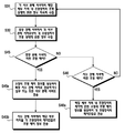
도 8 내지 도 10은 본 발명에 따른 조명 제어 방법에 관한 여러 실시예에 관하여 나타낸 플로우차트이다.1 is a diagram illustrating an example of lighting devices around a bus stop.
2 is a view showing the control of the lighting devices in one control area in the lighting control system according to an embodiment of the present invention.
3 is a view showing the configuration of a lighting control system according to an embodiment of the present invention.
4 and 5 are views showing the configuration of another embodiment and another embodiment of the present invention, respectively.
6 and 7 are diagrams illustrating a case in which the lighting control system according to various embodiments of the present invention is applied to the Seoul area.
8 to 10 are flowcharts illustrating various embodiments of a lighting control method according to the present invention.
본 발명에 따른 조명 제어 시스템 및 조명 제어 방법에 관한 구체적인 사항을 도면을 참조하여 실시예를 통해 설명하도록 한다.Specific details regarding the lighting control system and the lighting control method according to the present invention will be described with reference to the accompanying drawings.
본 발명에 따른 조명 제어 시스템은 기본적으로 소정 지역 내에 존재하는 가로등, 보안등, 기타 각종 옥외등 등의 조명장치를 관제 서버가 통합적으로 제어할 수 있도록 하는 시스템으로서, 특히 기존에 전력선을 이용한 통신의 한계를 극복하여 무선 인터넷망을 이용하여 관제 서버가 각종 조명장치를 제어할 수 있도록 한 것을 특징으로 한다.The lighting control system according to the present invention is a system that allows the control server to integrally control lighting devices such as street lamps, security lamps, and various outdoor lights existing in a predetermined area, and in particular, communication communication using a power line. By overcoming the limitations, it is characterized in that the control server can control various lighting devices using the wireless Internet network.
특히 본 발명은 지역 내에서 도로를 따라 고르게 분포하는 버스정류장에 무선접속장치를 설치하여 버스정류장 주변 소정 반경 범위 내에 존재하는 조명장치들에 대해 무선 인터넷 연결이 가능하도록 함으로써, 버스정류장을 이용하는 고객들이 Wi-Fi 통신과 같은 무선 인터넷 서비스를 이용할 수 있도록 하면서도 그 주변의 조명장치들의 조명 제어까지 할 수 있도록 한다.In particular, the present invention provides a wireless connection to the bus station evenly distributed along the road in the region to enable wireless Internet connection to the lighting devices that exist within a predetermined radius around the bus station, so that customers using the bus station It allows you to use wireless Internet services such as Wi-Fi communication while also controlling the lighting of the surrounding lighting devices.
도 1은 버스정류장 주변의 조명장치들에 대한 일 예에 관하여 나타낸 도면이다.1 is a diagram illustrating an example of lighting devices around a bus stop.
도 1에 도시된 바와 같이 각 버스정류장(BS)에 설치되어 버스 이용객들의 편의를 위해 제공되는 버스 쉘터(10)에 설치되거나 또는 그와 분리되어 설치되는 무선접속장치(100)가 미리 설정된 통신 범위 내의 통신 기기들에 대해 무선 인터넷 연결이 가능하도록 신호를 송출하면, 그 주변의 가로등(210), 보행등(220), 보안등(230) 등의 각종 조명장치들이 무선접속장치(100)를 통해 무선 인터넷 연결됨으로써 관제 서버와 무선 통신이 가능하게 된다.As shown in FIG. 1, a
이와 같은 본 발명에 따른 조명 제어 시스템의 일 예에 관한 개략적인 구성을 도 2에서 블록도로서 나타내고 있다.Such a schematic configuration of an example of a lighting control system according to the present invention is shown as a block diagram in FIG.
도 2에 도시된 바와 같이 버스정류장(BS)에 설치된 무선접속장치(100)를 통해 그 주변의 각종 조명장치들(가로등(210), 보행등(220), 보안등(230), 경관등(240) 등)이 무선 인터넷 연결되어 관제 서버(500)와 무선 통신 가능하도록 연결된다.As shown in FIG. 2, various lighting devices (a
여기서 버스정류장(BS)에 설치된 무선접속장치(100)는 신호가 유효하게 작용하는 통신 가능 범위가 있고 상기 무선접속장치(100)의 통신 가능 범위의 영역을 제어 영역(CR)이라 하기로 한다.Herein, the
버스정류장(BS)을 중심으로 제어 영역(CR) 내에 존재하는 각종 조명장치들(210, 220, 230, 240)은 각각 제어단말(211, 221, 231, 241)과 연결되며 각각의 제어단말(211, 221, 231, 241)이 버스정류장(BS)의 무선접속장치(100)를 통해 무선 인터넷 연결되어 관제 서버(500)와 통신하게 되는 것이다.The
상기 각 제어단말(211, 221, 231, 241)은 상기 무선접속장치(100)에서 송출하는 신호를 받아서 무선 인터넷 연결할 수 있도록 하는 소정의 통신 모듈 내지는 통신 장치를 포함한다. 예컨대 상기 무선접속장치(100)가 Wi-Fi 무선랜 연결을 위한 AP(Access Point) 기기로서 구현될 경우 각 제어단말은 상기 AP 기기를 통해 무선랜 연결을 할 수 있는 무선랜카드 등의 하드웨어를 포함한다.Each
그리고 상기 각 제어단말(211, 221, 231, 241)은 관제 서버로부터 전송되는 조명 제어 정보를 수신하여 그에 따라 해당 조명장치의 ON/OFF 또는 조도의 제어를 수행할 수 있는 컨트롤러를 포함한다.Each of the
이와 같은 제어단말은 각각의 조명등마다 연결될 수도 있고 복수개의 조명등에 동시에 연결될 수도 있다.Such a control terminal may be connected to each lamp or may be simultaneously connected to a plurality of lamps.
도 2에 도시된 예에서는 가로등(210)의 경우 복수개의 가로등(210)이 전력선 또는 소정의 전기적 연결을 위한 케이블로 연결될 수 있고 이에 가로등 제어용 제어단말(211)이 연결되어 설치된 경우에 관하여 나타내고 있다.In the example illustrated in FIG. 2, a plurality of
보행등(220)과 경관등(240)도 각각 복수개의 조명등이 하나의 제어단말(221 또는 241)에 연결된 경우를 나타내고 있다. 그리고 보안등(230)은 각각 하나씩 제어단말(231)과 연결된 경우를 나타내고 있다.The
물론 도 2에서 나타내고 있는 구성은 하나의 예에 불과하고 각각의 조명등이 각각 하나씩 제어단말과 연결될 수도 있고 복수개의 조명등이 동시에 하나의 제어단말에 연결되는 경우도 가능하다.Of course, the configuration shown in FIG. 2 is just one example, and each lamp may be connected to the control terminal one by one, or a plurality of lamps may be simultaneously connected to one control terminal.
하나의 조명등이 하나의 제어단말에 연결되어 구성되는 경우에는 그 제어단말기 해당 조명등에 대해 ON/OFF 또는 조도의 조절이 가능하도록 조명 제어를 할 수 있다. When one lamp is connected to one control terminal, the control terminal may control lighting to enable ON / OFF or adjustment of illumination of the corresponding lamp.
또한 복수개의 조명등이 하나의 제어단말에 연결되어 구성되는 경우에도, 그 제어단말은 연결되어 있는 복수개의 조명등 모두에 대해 일괄적으로 ON/OFF 또는 조도의 조절을 하도록 제어할 수 있음은 물론, 제어단말이 복수개의 조명등 중 일부만 ON/OFF 또는 조도 제어를 하는 것도 가능하도록 구성됨이 바람직하다.In addition, even when a plurality of lamps are connected to one control terminal, the control terminal can control to collectively control ON / OFF or illumination of all the plurality of connected lamps, as well as control. Preferably, the terminal is configured to enable ON / OFF or illuminance control of only a part of the plurality of lamps.
예컨대 관제 서버로부터 가로등(210)의 조도를 50%로 제어할 것에 관한 정보를 가로등 제어용 제어단말(211)이 수신한 경우, 상기 가로등 제어용 제어단말(211)은 그와 연결된 복수개의 가로등(210)에 대해 각각 동일한 조도를 나타내도록 제어함으로써 전체 조도를 50%로 하거나, 하나의 가로등은 조도를 100%로 하고 그 다음 가로등은 OFF 하고 다시 그 다음 가로등은 조도를 100%로 하는 등 복수개의 가로등에 대해 교대로 ON/OFF를 조절함으로써 전체적으로 조도 50%가 되도록 제어할 수도 있다.For example, when the
한편, 본 발명은 실시예에 따라 버스정류장(BS)을 중심으로 한 제어 영역(CR) 내에 감시카메라(250)를 설치하고 그 감시카메라(250)에 감시카메라 제어용 제어단말(251)을 연결하여 무선 인터넷을 통해 관제 서버(500)와 통신하도록 구성할 수도 있다.On the other hand, according to an embodiment of the present invention by installing a
상기 감시카메라(250)를 통해 얻은 영상을 분석하여 교통량이나 보행자의 유동 현황 등을 파악하고 그에 따라 각 조명장치들을 적절하게 제어하도록 할 수 있다. By analyzing the image obtained through the
여기서 상기 감시카메라 제어용 제어단말(251)이 영상 분석 수단을 구비하여 감시카메라(250)를 통해 얻은 영상을 분석하여 그 분석 정보를 관제 서버(500)로 제공하도록 구성할 수도 있고, 상기 감시카메라 제어용 제어단말(251)이 감시카메라(250)가 획득한 영상을 단순히 관제 서버(500)로 전송하도록 하고 그 영상의 분석은 관제 서버(500)가 수행하도록 구성할 수도 있다.In this case, the
도 2에서는 감시카메라(250)를 제어 영역(CR) 내에 설치하고 그와 연결된 제어단말(251)을 통해 관제 서버(500)와 통신하여 관제 서버(500)의 제어를 받는 것으로 구성된 경우를 나타내고 있으나, 제어 영역(CR) 내에 감시카메라(250)를 설치하지 않고 기존에 지역 내 곳곳에 설치된 감시카메라로부터 정보를 얻는 외부 서버(감시카메라 서버)와 연동하여 그로부터 관제 서버(500)가 소정의 정보를 전달받아 각 조명장치의 조명 제어에 이용하도록 구성할 수도 있다.FIG. 2 illustrates a case in which the
한편, 본 발명은 한 지역 내에 존재하는 다수의 각종 조명장치들을 각각의 버스정류장의 무선접속장치를 통해 무선 통신으로 관제 서버에 의해 제어하도록 하는 조명 제어 시스템에 관한 것으로서, 도 2에 도시된 바와 같이 하나의 제어 영역(CR)이 아니라 한 지역 내 다수의 제어 영역(CR)이 형성되는데, 이에 대해 도 3에서 개략적으로 도시하고 있다.On the other hand, the present invention relates to a lighting control system for controlling a plurality of various lighting devices existing in one area by a control server by wireless communication through a wireless connection device of each bus station, as shown in FIG. Instead of one control region CR, a plurality of control regions CR in one region are formed, which is schematically illustrated in FIG. 3.
즉 도 3은 전체 지역(D) 내에 존재하는 다수의 버스정류장 각각을 기점으로 하여 형성된 다수의 제어 영역(CR)에 관하여 나타내고 있다. 여기서 각각의 제어 영역(CR)은 도 2에 도시된 제어 영역(CR)과 동일하다.3 shows a plurality of control areas CR formed starting from each of a plurality of bus stops existing in the entire area D. As shown in FIG. Each control region CR is the same as the control region CR shown in FIG. 2.
각각의 제어 영역(CR) 별로 그 영역 범위 내에 존재하는 조명장치들은 각각 해당 무선접속장치를 통해 각각 무선 인터넷 연결되어 관제 서버(500)와 네트워크 연결된다.Each of the lighting devices existing within the area range of each control area CR are wirelessly connected to the
상기 관제 서버(500)는 지역(D) 내에 존재하는 모든 무선 인터넷 연결된 조명장치들에 대해 일괄 조명 제어를 하거나, 그룹별로 조명 제어를 하거나, 개별적으로 조명 제어를 할 수 있으며, 조명 제어를 할 때 상기 관제 서버(500)는 조명 ON/OFF 또는 조도 등에 관한 조명 제어 정보를 생성하여 각 제어 영역(CR) 내 제어단말에 전송하고 각각의 제어 단말은 해당 조명장치를 제어함으로써 지역(D) 조명장치들에 대한 통합적인 조명 제어가 가능하게 되는 것이다.The
또한 상기 관제 서버는 소정의 정보를 제공하는 외부 서버(600)로부터 수집한 정보에 따른 조명 제어 정보를 생성하여 각 제어 영역(CR) 내의 각 제어 단말들에 전송하여 상기 외부 서버(600)로부터 얻은 정보에 따른 조명의 제어도 가능하게 한다.In addition, the control server generates lighting control information according to the information collected from the
예컨대 지역 내 곳곳에 설치된 감시카메라와 연결된 감시카메라 서버를 상기 외부 서버(600)로 하여 그로부터 특정 구역의 감시 결과에 따라 해당 구역에 대한 가로등이나 보안등 등의 조명장치를 ON 또는 OFF 하거나 조도를 조절하도록 하는 조명 제어 정보를 해당 조명장치들의 제어 단말들로 전송하여 적절한 조명 제어가 이루어지도록 할 수 있다.For example, a surveillance camera server connected to surveillance cameras installed in various places in an area is used as the
이와 같은 다수의 제어 영역(CR)이 존재하는 한 지역(D) 내에서의 각 조명장치들에 대한 조명 제어는, 해당 지역(D)을 복수개의 세부 지역으로 구분하여 각 세부 지역별로 조명 제어가 이루어지도록 하여 조명 제어의 효율성을 더욱 향상시키도록 하는 것도 가능한데, 이러한 구성에 관하여 도 4에서 도시하고 있다.Lighting control for each lighting device in a region (D) in which a plurality of such control regions (CR) exist, the lighting control is divided into a plurality of sub-regions to control the lighting for each sub-region. It is also possible to further improve the efficiency of the lighting control, which is shown in Figure 4 with respect to this configuration.
도 4에 도시된 바와 같이 한 지역을 다수의 세부 지역(SD1, SD2, SD3 등)으로 구분하고 각 세부 지역(SD1, SD2, SD3 등) 내에 존재하는 버스정류장들에 각각 무선접속장치를 설치하여 각각 제어 영역(CR)을 형성하여 각 제어 영역(CR) 내에 존재하는 조명장치들을 무선 통신으로 관제 서버(500)가 제어할 수 있도록 구성할 수 있으며, 이때 관제 서버(500)는 특정 세부 지역에 대한 일괄 조명 제어를 할 수도 있고 각 조명장치들을 개별적으로 제어할 수도 있다.As shown in FIG. 4, one area is divided into a plurality of detailed areas (SD1, SD2, SD3, etc.), and wireless access devices are installed at bus stops existing in each detailed area (SD1, SD2, SD3, etc.). Each control area CR may be formed to control the lighting devices existing in each control area CR so that the
한편, 도 5에서는 본 발명의 또 다른 일 실시예에 따른 조명 제어 시스템에 관한 구성을 나타내고 있는데, 각각의 세부 지역(SD1, SD2, SD3 등)이 상당히 큰 경우에 모든 세부 지역들을 하나의 관제 서버가 모두 관제하는 것은 비효율적일 수 있는 바, 도 5에 도시된 바와 같이 각각의 세부 지역별로 서브 관제 서버(511, 512, 513 등)를 마련하여 각각의 세부 지역별 조명 제어는 각각의 서브 관제 서버(511, 512, 513 등)가 자율적으로 수행하되 각 서브 관제 서버(511, 512, 513 등)는 중앙 관제 서버(510)에 의해 제어될 수 있도록 구성하는 것이 가능하다.On the other hand, Figure 5 shows the configuration of the lighting control system according to another embodiment of the present invention, in the case where each detailed area (SD1, SD2, SD3, etc.) is quite large, all the detailed areas in one control server It may be inefficient to control all of the bar, as shown in Figure 5 by providing a sub-control server (511, 512, 513, etc.) for each sub-region, each sub-region lighting control is controlled by each sub-control server ( 511, 512, 513, etc.) can be performed autonomously, but each
즉 중앙 관제 서버(510)는 지역 전체의 조명 제어에 관한 정보나 세부 지역별 조명 제어에 관한 정보 등을 서브 관제 서버(511, 512, 513 등)로 전송하고 조명장치들에 대한 제어는 각각 서브 관제 서버(511, 512, 513 등)가 수행하도록 할 수 있다. That is, the
그리고 중앙 관제 서버(510)는 외부 서버(600)와 연동하여 상기 외부 서버(600)로부터 전달받은 정보에 따라 필요한 조명 제어를 위해 서브 관제 서버(511, 512, 513 등)로 전송하여 해당 서브 관제 서버에 의해 조명 제어가 이루어지도록 할 수 있다.In addition, the
한편, 도 6 및 도 7은 본 발명에 따른 조명 제어 시스템 및 방법에 대한 일 예로서 서울 지역 내의 각종 조명장치들에 대한 조명의 제어에 관하여 나타낸 것이다.6 and 7 illustrate control of lighting for various lighting devices in the Seoul area as an example of the lighting control system and method according to the present invention.
먼저 도 6은 서울 지역을 구 단위로 구분하여 나타내고 각 구에 분포된 버스정류장을 중심으로 한 제어 영역(CR)들에 관하여 나타내고 있다. 여기서 도 6에 나타낸 버스정류장은 실제 위치와 다를 수 있다.First, FIG. 6 illustrates the Seoul area in terms of districts and shows control areas CR centered on bus stations distributed in each district. Here, the bus stop shown in FIG. 6 may be different from the actual position.
여기서 도 6 및 도 7에 각각 도시된 각각의 제어 영역(CR)은 도 2에 도시된 바와 같다(감시카메라의 경우 포함될 수도 있고 포함되지 않을 수 있으며, 조명장치의 경우에도 모든 종류의 조명장치를 모두 포함할 수도 있고 일부 종류의 조명장치함 포함할 수도 있다).6 and 7, respectively, are shown in FIG. 2 as shown in FIG. 2 (in the case of a surveillance camera, it may or may not be included. All or some kind of lighting box).
그리고 서울 지역 내 각각의 버스정류장을 중심으로 한 제어 영역(CR)은 그 영역 내의 조명장치들의 제어 단말이 무선 인터넷 연결되어 각각 관제 서버(500)와 네트워크 연결되어 있다.In the control area CR centered on each bus stop in the Seoul area, the control terminals of the lighting devices in the area are wirelessly connected to the
상기 관제 서버(500)는 상기한 바와 같이 네트워크 연결되어 있는 서울 지역 내 모든 통신 가능한 조명장치의 제어 단말과 각각 일대일 통신하며 조명을 제어할 수 있을 뿐만 아니라, 구 단위로 각 구에 존재하는 조명장치들을 그룹별로 제어할 수도 있고 서울 지역 전체 통신 가능한 조명장치들에 대한 일괄 제어도 가능하다.The
또한 관제 서버(500)에 연결된 각종 조명장치들에 대해 조명장치의 종류별로 조명 제어하도록 할 수도 있다.In addition, various lighting devices connected to the
예컨대 서울 지역 내 무선 연결된 조명장치들 중 가로등에 대해서만 별도의 조명 제어를 하거나, 보안등에 대해서만 별도의 조명 제어를 할 수 있다.For example, a separate lighting control may be performed only for a street lamp among wirelessly connected lighting devices in Seoul, or a separate lighting control may be performed only for a security lamp.
그리고 각 세부 지역별로 조명장치의 종류별 조명 제어가 가능하다. 예컨대 서울 지역의 강남구 지역의 가로등에 대해서만 전체 조도를 50%로 유지하도록 하는 조명 제어를 할 수 있다.In addition, lighting control by type of lighting device is possible in each detailed region. For example, lighting control can be performed to maintain the total illumination at 50% only for streetlights in Gangnam-gu, Seoul.
또한 예컨대 서울 지역의 강남구의 전력 소모가 허용한계를 넘은 경우 긴급 조치로서 강남구의 각 제어 영역에 존재하는 조명장치들에 대한 조명의 조도를 일괄적으로 10% 낮게 되도록 제어할 수도 있다.For example, when the power consumption of Gangnam-gu in Seoul exceeds the allowable limit, it may be controlled to reduce the illuminance of the illumination of the lighting devices present in each control area of Gangnam-gu by 10% in a batch.
또한 예컨대 서울 지역의 상암동(마포구)에서 국가간 A매치 축구 경기를 야간에 하는 경우 해당 지역 주변의 조명장치들에 대한 조도를 10% 높게 하도록 하는 제어를 할 수도 있다.In addition, for example, when the A-match soccer game is played at night in Sangam-dong (Mapo-gu) in Seoul, it may be controlled to increase the illumination of the lighting devices around the area by 10%.
또한 예컨대 강남구의 일부 지역의 감시카메라 분석 결과 유동 인구가 특별히 많은 것으로 분석된 지역의 경우 해당 지역의 조명장치에 대한 조도를 10% 높이도록 하는 제어를 할 수도 있고, 일부 도로의 가로등이 100% 조도를 유지하고 있는 가운데 그 주변 감시카메라 분석 결과 교통량이 전혀 없는 경우 조도를 50%로 낮추도록 하는 조명 제어를 할 수도 있다.In addition, for example, in areas where Gangnam-gu surveillance camera analysis shows that the floating population is particularly high, it is possible to control to increase the illuminance of the lighting device of the region by 10%. In the event that there is no traffic at all, the lighting control can be controlled to reduce the illuminance to 50%.
상기 관제 서버(500)는 도 6에 도시된 바와 같이 특정 지역의 이미 정해진 행정구역 단위로 그룹별 제어가 이루어지도록 할 수도 있지만, 임의로 세부 지역을 구분하고 그 임의로 구분된 각 세부 지역별 조명 제어가 이루어지도록 할 수도 있다.As shown in FIG. 6, the
한편, 도 6에 도시된 예에서는 관제 서버가 서울 지역 전체의 조명장치의 조명을 관제하도록 구성되는 경우를 나타내었는데, 이와 같이 하나의 관제 서버가 너무 많은 수의 조명장치를 관제하는 것이 상당히 비효율적일 수 있는 바, 이와 같은 경우에는 도 7에 도시된 바와 같이 각 세부 지역별로 서브 관제 서버를 두고 각 서브 관제 서버는 해당 세부 지역을 관제하고 각각의 서브 관제 서버를 관제하는 중앙 관제 서버(510)를 별도로 구비하도록 시스템을 구성하면 더욱 효율적인 버스정류장 조명 제어가 이루어지도록 할 수 있다.Meanwhile, in the example shown in FIG. 6, the control server is configured to control the lighting of the lighting devices of the entire Seoul area. As such, it may be quite inefficient for one control server to control too many lighting devices. In this case, as shown in FIG. 7, each sub-control server is provided for each sub-region, and each sub-control server controls the sub-control area and controls the
즉 도 7에 도시된 바와 같이 각각의 구마다 또는 둘 이상의 구마다 서브 관제 서버를 두고 이들 모든 서브 관제 서버는 중앙 관제 서버가 관제하도록 구성할 수 있다.That is, as shown in FIG. 7, each sub-control server is provided for each or two or more sections, and all of these sub-control servers may be configured to be controlled by the central control server.
예컨대 강남구 지역의 전력 소모가 허용한계를 넘어서는 것으로 파악된 경우, 중앙 관제 서버가 강남구 지역을 관할하는 서브 관제 서버에 각 조명장치의 조명의 조도를 소정 비율로 감소시키도록 하는 조명 제어 정보를 전송하고 상기 강남구 지역 관할 서브 관제 서버는 강남구 지역 내의 조명장치들의 각 제어단말로 조도를 소정 비율 감소시키도록 하는 조명 제어 정보를 전송할 수 있다.For example, if it is determined that the power consumption of the Gangnam-gu region exceeds the allowable limit, the central control server transmits the lighting control information to reduce the illuminance of the lighting of each lighting device by a predetermined ratio to the sub-control server that manages the Gangnam-gu region. The sub-control server under the jurisdiction of the Gangnam-gu region may transmit lighting control information to reduce the illuminance by a predetermined ratio to each control terminal of the lighting devices in the Gangnam-gu region.
그리고 중앙 관제 서버가 각 조명장치를 개별적으로 제어하는 것도 가능한데, 중앙 관제 서버는 해당 조명장치가 존재하는 구를 관할하는 서브 관제 서버로 해당 조명장치의 조명의 제어에 관한 정보를 전송하고 상기 해당 서브 관제 서버는 해당 조명장치의 조명 제어를 할 수 있다.In addition, the central control server may control each lighting device individually. The central control server transmits information on the control of the lighting of the lighting device to the sub-control server that manages the sphere in which the lighting device exists. The control server may control the lighting of the lighting device.
또한, 중앙 관제 서버에 의하지 않고 각 서브 관제 서버가 해당 세부 지역의 조명장치들에 대한 조명의 제어를 독립적으로 수행하도록 하는 것도 가능하다.In addition, it is also possible to allow each sub-control server to independently control the lighting of the lighting devices of the corresponding sub-region, without the central control server.
한편, 본 발명에 따른 조명 제어 방법에 관한 다양한 실시예를 도 8 내지 도 10에 각각 도시된 플로우차트를 통해 좀 더 구체적으로 설명한다.On the other hand, various embodiments of the lighting control method according to the present invention will be described in more detail through the flow chart shown in Figs.
먼저 도 8을 참조하여 본 발명의 일 실시예에 따른 조명 제어 방법에 관하여 설명한다.First, a lighting control method according to an exemplary embodiment of the present invention will be described with reference to FIG. 8.
먼저, 각 기점, 즉 각 버스정류장에 설치되는 무선접속장치를 통해 무선 인터넷 연결을 위한 신호가 송출된다(S10). First, a signal for wireless internet connection is transmitted through a wireless access device installed at each starting point, that is, at each bus stop (S10).
각 기점에 설치된 무선접속장치의 미리 설정된 통신 범위 내의 조명장치들에 대해 조명을 제어하는 복수개의 제어단말이 각각 무선 인터넷 연결되어 관제 서버와 네트워크 연결된다(S20). 여기서 각 기점의 무선접속장치를 중심으로 상기 무선접속장치의 통신 가능 범위를 제어 영역이라고 하고 각 제어 영역 내에는 해당 무선접속장치를 통해 무선 인터넷 연결되는 각종 조명장치들이 존재한다는 것에 대해서는 앞서 설명한 바와 같다.A plurality of control terminals for controlling lighting for lighting devices within a preset communication range of a wireless access device installed at each starting point are wirelessly connected to the Internet and connected to a control server (S20). Herein, the communication range of the wireless access device is referred to as a control area around the wireless access device at each starting point, and the various lighting devices connected to the wireless Internet through the corresponding wireless access device exist in each control area as described above. .
관제 서버는 각 제어 영역의 조명장치들의 제어 단말들로부터 각 조명장치의 상태에 관한 정보를 지속적으로 수집하여 체크한다(S30). 이때 특정 조명장치에서 이상이 감지된 경우 해당 조명장치에 대해 오작동 또는 고장 여부를 판단하여 조명장치에 대한 점검 또는 수리 업무를 수행할 수 있는 기관이나 전문가에게 유무선 통신을 통해 통보를 하는 등의 방법으로 해당 조명장치에 대한 점검 또는 수리를 요청할 수 있다.The control server continuously collects and checks information on the state of each lighting device from the control terminals of the lighting devices in each control area (S30). At this time, if an abnormality is detected in a specific lighting device, it is possible to determine whether there is a malfunction or failure of the lighting device by notifying an institution or an expert who can perform inspection or repair work on the lighting device through wired or wireless communication. You may request to inspect or repair the lighting.
한편, 관제 서버는 각 제어 영역 내 조명장치들에 대한 일괄 조명 제어, 각 세부 지역별 조명장치들에 대한 세부 지역별 조명 제어, 지역 내 조명장치들을 종류별로 구분하고 각 종류별 조명장치들에 대한 종류별 조명 제어 및 상기 지역 내 조명장치들 각각에 대한 개별 조명 제어 중 어느 하나에 대한 조명 제어 정보를 생성하여 각 제어단말로 전송하도록 한다(S50).On the other hand, the control server is a collective lighting control for the lighting devices in each control area, lighting control by the detailed area for the lighting devices of each sub-region, classify the lighting devices in the area by type and lighting control by type for each type of lighting devices And generating lighting control information for any one of individual lighting controls for each of the lighting devices in the region and transmitting the generated lighting control information to each control terminal (S50).
관제 서버는 외부 서버(예컨대 감시카메라에 대한 관리 서버나 기상 정보 서버, 교통 정보 서버 등)로부터 교통량에 관한 정보, 유동 인구에 관한 정보, 기상에 관한 정보, 긴급 상황에 관한 정보 등을 수집하는 경우(S60), 그 수집된 정보에 따라 적절한 조명 제어 정보를 생성하여 조명 제어가 필요한 조명장치의 제어 단말로 전송하도록 한다(S70).The control server collects information on traffic volume, information on floating population, weather information, emergency information, etc. from an external server (e.g., a management server for a surveillance camera, a weather information server, a traffic information server, etc.). In operation S60, appropriate lighting control information is generated according to the collected information and transmitted to the control terminal of the lighting apparatus that requires lighting control (S70).
한편, 도 8에 도시된 플로우차트에서 S40 단계 및 S50 단계, 즉 각 조명장치에 대한 조명 제어 정보를 제어 단말로 전송하는 것과 관련하여, 여러 가지 실시예가 있는데, 도 9 및 도 10에서는 이와 관련한 각 실시예에 관하여 나타내고 있다.On the other hand, in the flowchart shown in Figure 8 S40 and S50, that is, in connection with the transmission of the lighting control information for each lighting device to the control terminal, there are various embodiments, in Figures 9 and 10 It shows about an Example.
도 9에서는 관제 서버가 해당 지역 내 각 제어 영역 내의 조명장치들에 대한 조명 제어 유형에 따라 구분된 프로세스에 관하여 나타내고 있다.9 shows a process in which the control server is divided according to the type of lighting control for lighting devices in each control area in the region.
도 9에 도시된 바와 같이, 관제 서버는 특정 지역 전체의 모든 제어 영역 내의 조명장치들의 조명을 일괄적으로 제어하는 경우(S41), 특정 지역을 복수개의 세부 지역으로 구분하고 각 세부 지역별로 존재하는 각 제어 영역 내 조명장치들의 조명을 제어하는 경우(S42), 조명장치의 종류별로 각 종류별 조명 제어를 하는 경우(S43), 그리고 특정 조명장치의 조명을 개별적으로 제어하는 경우(S44) 등을 수행할 수 있다.As shown in FIG. 9, when the control server collectively controls the lighting of lighting devices in all control areas of the entire area (S41), the control server divides a specific area into a plurality of detailed areas and exists for each detailed area. When controlling the lighting of the lighting devices in each control area (S42), when controlling the lighting for each type of lighting device (S43), and individually controlling the lighting of a specific lighting device (S44), etc. can do.
상기 각각의 경우에 해당 제어의 유형별로 적절한 조명 제어 정보를 각각 생성하여 해당 조명장치의 제어 단말로 전송하도록 하고, 각 제어 단말은 해당 조명 제어 정보에 따라 각 조명장치를 제어함으로써 효율적인 조명 제어가 이루어지도록 할 수 있다(S41a, S42a, S43a, S44a).In each case, the appropriate lighting control information is generated for each type of control and transmitted to the control terminal of the lighting device, and each control terminal controls the lighting device according to the lighting control information, thereby making efficient lighting control. (S41a, S42a, S43a, S44a).
한편, 도 10에서는 특정 지역 내 복수개의 세부 지역 각각의 서브 관제 서버가 해당 세부 지역 내 조명장치들의 조명을 관제하고, 중앙 관제 서버는 각 서브 관제 서버를 관제하도록 하는 시스템에서의 조명 제어 방법에 관한 것이다.On the other hand, Figure 10 relates to a lighting control method in a system in which the sub-control server of each of the plurality of sub-regions in a specific area to control the lighting of the lighting devices in the sub-region, the central control server to control each sub-control server. will be.
이때 서브 관제 서버는 하나의 세부 지역을 관할할 수도 있고 둘 이상의 세부 지역을 통합하여 관제할 수도 있다.At this time, the sub-control server may manage one subregion or may integrate and control two or more subregions.
각 서브 관제 서버는 해당 세부 지역 내 제어 영역들의 조명장치 각각의 상태에 관한 정보를 지속적으로 수집하여(S31), 이를 중앙 관제 서버로 보낸다(S32). 중앙 관제 서버는 각 서브 관제 서버로부터 전송된 각 세부 지역별 제어 영역들 내의 조명장치들의 조명 상태를 체크하고 관리한다.Each sub-control server continuously collects information on the state of each of the lighting devices of the control areas in the corresponding detailed area (S31), and sends it to the central control server (S32). The central control server checks and manages lighting conditions of lighting devices in control areas for each sub-region transmitted from each sub-control server.
본 실시예에 따른 시스템에서는 중앙 관제 서버에 의한 조명 제어가 가능할 뿐만 아니라 각각의 서브 관제 서버에 의해 각 세부 지역별로 버스정류장의 조명 제어가 이루어지는 경우도 가능하다.In the system according to the present embodiment, not only the lighting control by the central control server is possible, but also the lighting control of the bus station may be performed by each sub-control server by each sub-region.
중앙 관제 서버에 의한 조명 제어가 이루어지는 경우(S45)는, 지역 전체의 모든 제어 영역 내 조명장치들의 조명을 일괄적으로 제어하는 경우, 각 세부 지역별로 조명장치들의 조명을 제어하는 경우, 조명장치의 종류별로 조명 제어를 하는 경우, 그리고 특정 조명장치의 조명을 개별적으로 제어하는 경우 등이 있을 수 있다.When the lighting control is performed by the central control server (S45), when collectively controlling the lighting of the lighting devices in all the control areas of the entire area, when controlling the lighting of the lighting devices for each sub-region, There may be a case of controlling the lighting by type, and individually controlling the lighting of a specific lighting device.
중앙 관제 서버는 이들 각각의 경우에 대한 소정의 조명 제어 정보를 생성하여 특정 서브 관제 서버로 전송하거나 일부 또는 모든 서브 관제 서버로 상기 조명 제어 정보를 전송하고(S45a), 이를 전송받은 서브 관제 서버는 해당 세부 지역별 각 조명장치의 제어 단말로 조명 제어 정보를 전송하여 조명 제어가 이루어지도록 한다(S45b).The central control server generates predetermined light control information for each of these cases and transmits it to a specific sub control server or transmits the light control information to some or all sub control servers (S45a), and the received sub control server receives The lighting control is transmitted by transmitting the lighting control information to the control terminal of each lighting apparatus for each detailed region (S45b).
한편, 서브 관제 서버에 의한 조명 제어가 이루어지는 경우(S46)는, 해당 세부 지역 내 각 제어 영역들의 조명장치들에 대한 일괄 제어가 이루어지는 경우나, 해당 세부 지역 내 조명장치들을 종류별로 개별 또는 그룹 제어를 하는 경우나, 특정 조명장치의 조명에 대한 개별 제어를 하는 경우 등을 포함할 있다.On the other hand, when the lighting control is performed by the sub-control server (S46), when the collective control of the lighting devices of the respective control areas in the detailed area is made, or the individual or group control of the lighting devices in the detailed area by type It may include the case of, or the case of individual control for the lighting of a specific lighting device.
서브 관제 서버는 해당 세부 지역 내 조명장치의 제어에 관한 소정의 조명 제어 정보를 생성하여 각 조명장치의 제어 단말로 전송함으로써 각 제어 단말이 조명장치의 조명을 제어하도록 할 수 있다(S46a).The sub-control server may generate predetermined lighting control information regarding the control of the lighting apparatus in the corresponding detailed area and transmit the predetermined lighting control information to the control terminal of each lighting apparatus so that each control terminal controls the lighting of the lighting apparatus (S46a).
10: 버스 쉘터, BS: 버스정류장
100: 무선접속장치, CR: 제어 영역
210: 가로등, 211: 가로등 제어용 제어 단말
220: 보행등, 221: 보행등 제어용 제어 단말
230: 보안등, 231: 보안등 제어용 제어 단말
240: 경관등, 241: 경관등 제어용 제어 단말
500: 관제 서버, 510: 중앙 관제 서버
511, 512, 513: 서브 관제 서버10: bus shelter, BS: bus stop
100: radio access device, CR: control area
210: street light, 211: control terminal for street light control
220: pedestrian light, 221: control terminal for pedestrian light control
230: security light, 231: control terminal for security light control
240: landscape light, 241: control terminal for landscape light control
500: control server, 510: central control server
511, 512, 513: sub control server
Claims (14)
지역 내 다수의 기점 각각에 설치되는 무선접속장치를 통해 무선 인터넷 연결을 위한 신호가 송출되는 단계;
상기 각 기점에 설치된 무선접속장치의 미리 설정된 통신 범위 내에서 각각의 조명장치들에 대해 조명을 제어하는 제어단말이 각각 무선 인터넷 연결되어 원격 제어를 위한 관제 서버와 네트워크 연결되는 단계;
상기 관제 서버에서 생성된 소정의 조명 제어 정보가 상기 각 제어단말로 전송되는 단계; 및
상기 전송된 조명 제어 정보에 따라 상기 각 제어단말이 해당 조명장치들을 제어하는 단계;
를 포함하는 조명 제어 방법.In the lighting control method for a plurality of lighting devices existing in a predetermined area,
Transmitting a signal for a wireless Internet connection through a wireless access device installed at each of a plurality of origins in the region;
A control terminal for controlling lighting for each of the lighting apparatuses within a preset communication range of the wireless access apparatus installed at each of the base stations, each of which is wirelessly connected to a network and a control server for remote control;
Transmitting predetermined lighting control information generated in the control server to each of the control terminals; And
Controlling each lighting device by the control terminal according to the transmitted lighting control information;
≪ / RTI >
상기 관제 서버가 소정의 정보를 제공하는 외부 서버로부터 수집한 정보에 따른 조명 제어 정보를 생성하여 각 제어단말로 전송하는 단계를 포함하는 것을 특징으로 하는 조명 제어 방법.The method of claim 1, wherein the lighting control information is transmitted to each of the control terminals.
And generating, by the control server, lighting control information according to information collected from an external server providing predetermined information, and transmitting the generated lighting control information to each control terminal.
상기 각 기점을 중심으로 소정 범위 내에 설치되는 감시카메라가 취득한 영상의 분석 정보에 따른 조명 제어 정보가 생성되어 각 제어단말로 전송되는 단계를 포함하는 것을 특징으로 하는 조명 제어 방법.The method of claim 1, wherein the lighting control information is transmitted to each of the control terminals.
Lighting control information according to the analysis information of the image acquired by the surveillance cameras installed within a predetermined range around each of the starting point is generated and transmitted to each control terminal.
상기 각 제어단말로부터 상기 관제 서버로 상기 각 제어단말에 의해 제어되는 조명장치의 조명 상태 또는 동작 상태에 관한 정보가 전송되는 단계와,
상기 전송된 정보로부터 어느 조명장치에서 오작동 또는 고장이 발생하였는지 여부를 파악하여 해당 조명장치에 대한 점검 또는 수리가 이루어질 수 있도록 하기 위한 미리 설정된 프로세스가 진행되도록 하는 단계를 더 포함하는 것을 특징으로 하는 조명 제어 방법.The method of claim 1,
Transmitting information regarding an illumination state or an operation state of an illumination device controlled by each control terminal from each control terminal to the control server;
The lighting device further comprises the step of determining whether a malfunction or failure occurred in the lighting device from the transmitted information so that a predetermined process for checking or repairing the lighting device can be performed. Control method.
상기 지역을 복수개의 세부 지역으로 구분하고, 각 세부 지역별로 존재하는 다수의 기점 각각에 설치되는 무선접속장치를 통해 상기 무선접속장치의 통신 범위 내의 조명장치들의 제어단말이 각각 무선 인터넷 연결되어 각 세부 지역별 서브 관제 서버에 각각 네트워크 연결되는 단계;
상기 각 서브 관제 서버는 중앙 관제 서버와 연결되며, 상기 중앙 관제 서버에서 생성된 소정의 조명 제어 정보가 상기 각 서브 관제 서버를 통해 각 제어단말로 전송되거나, 상기 각 서브 관제 서버에서 각각 생성된 소정의 조명 제어 정보가 각 제어단말로 전송되는 단계; 및
상기 전송된 조명 제어 정보에 따라 상기 각 제어단말이 해당 조명장치들을 제어하는 단계;
를 포함하는 조명 제어 방법.In the lighting control method for a plurality of lighting devices existing in a predetermined area,
The control terminals of the lighting devices within the communication range of the wireless access device are wirelessly connected to each other by dividing the area into a plurality of detailed areas, and through a wireless access device installed at each of a plurality of base points existing in each detailed area. Network connection to a sub-control server for each region;
Each sub-control server is connected to a central control server, and predetermined lighting control information generated at the central control server is transmitted to each control terminal through the sub-control server, or generated at each sub-control server. Transmitting lighting control information to each control terminal; And
Controlling each lighting device by the control terminal according to the transmitted lighting control information;
≪ / RTI >
상기 각 버스정류장에 설치된 무선접속장치의 미리 설정된 통신 범위 내에서 상기 가로등 조명장치들에 대해 조명을 제어하는 적어도 하나의 제어단말이 무선 인터넷 연결되어 원격 제어를 위한 관제 서버와 네트워크 연결되는 단계;
상기 가로등 주변의 교통량에 관한 정보가 상기 관제 서버로 수집되는 단계;
상기 관제 서버에서 상기 수집된 교통량에 관한 정보에 따른 상기 가로등 조명장치에 대한 조명 제어 정보가 생성되어 상기 적어도 하나의 제어단말로 전송되는 단계; 및
상기 전송된 조명 제어 정보에 따라 상기 적어도 하나의 제어단말이 상기 가로등 조명장치들을 제어하는 단계;
를 포함하는 조명 제어 방법.In the lighting control method capable of remote control of a plurality of bus stops existing in a specific area, the street lamp lighting devices existing within a predetermined range around each bus stop,
At least one control terminal for controlling lighting for the street lamp lighting apparatuses within a preset communication range of a wireless access apparatus installed at each bus stop, connected to a control server for remote control via a wireless Internet connection;
Collecting information about the traffic volume around the street light to the control server;
Generating, by the control server, lighting control information for the street light apparatus according to the collected traffic volume information and transmitting the generated lighting control information to the at least one control terminal; And
Controlling, by the at least one control terminal, the streetlight lighting apparatuses according to the transmitted lighting control information;
≪ / RTI >
지역 내 다수의 기점 각각을 중심으로 소정 범위 내에 존재하는 조명장치들 각각에 대해 조명을 제어하도록 구비되는 제어단말;
상기 각 기점에 설치되어 미리 설정된 통신 범위 내에 존재하는 각 제어단말에 대한 무선 인터넷 연결이 가능하도록 하는 무선접속장치; 및
상기 각 기점의 무선접속장치를 통해 무선 인터넷 연결된 각각의 제어단말을 통해 각 제어단말이 제어하는 조명장치의 조명 상태에 관한 정보를 수집하며, 상기 각 제어단말로 소정의 조명 제어 정보를 전송하여 상기 전송된 조명 제어 정보에 따라 상기 각 제어단말이 제어하는 조명장치에 대한 조명 제어가 이루어지도록 하는 관제 서버;
를 포함하는 조명 제어 시스템.A lighting control system capable of remote control of a plurality of lighting devices existing within a predetermined area,
A control terminal provided to control lighting for each of the lighting devices existing within a predetermined range around each of a plurality of starting points in the region;
A wireless access device installed at each of the base points to enable a wireless Internet connection to each control terminal existing within a preset communication range; And
Collecting information on the lighting state of the lighting device controlled by each control terminal through each control terminal connected to the wireless Internet through the wireless access device of each base station, and transmits predetermined lighting control information to each control terminal A control server configured to control light of a lighting device controlled by each control terminal according to the transmitted light control information;
≪ / RTI >
하나의 조명장치에 대한 조명을 제어하도록 구성되거나, 복수개의 조명장치에 대한 일괄적 제어 또는 각각 독립적으로 제어하도록 구성되는 것을 특징으로 하는 조명 제어 시스템.The method of claim 8, wherein the control terminal,
The lighting control system, characterized in that it is configured to control the lighting for one lighting device, or collectively control each of a plurality of lighting devices or independently control.
상기 특정 지역 내의 버스정류장을 상기 기점으로 하여 상기 각 버스정류장에 상기 무선접속장치가 설치되도록 구성되고,
상기 특정 지역 내에 존재하는 조명장치들에 대한 조명을 제어하는 제어단말들은 상기 각 버스정류장에 설치된 무선접속장치의 미리 설정된 통신 범위에 따라 결정되는 제어 영역별로 구분되어 해당 제어 영역의 무선접속장치를 통해 무선 인터넷 연결이 이루어져 상기 관제 서버와 네트워크 연결되도록 구성되는 것을 특징으로 하는 조명 제어 시스템.9. The method of claim 8,
The wireless connection device is configured to be installed at each bus stop with the bus stop in the specific area as the starting point,
The control terminals for controlling the lighting of the lighting devices existing in the specific area are divided by the control area determined according to a preset communication range of the wireless access device installed in each bus stop, and then through the wireless access device of the corresponding control area. Lighting control system, characterized in that configured to be connected to the network and the wireless connection to the control server.
상기 관제 서버가 상기 특정 지역 내 일정 범위별 상황을 분석하여 상기 조명 제어 정보를 생성할 수 있도록, 상기 일정 범위별로 해당 범위에 대한 영상을 취득하여 해당 무선접속장치를 통해 상기 관제 서버로 전송하도록 구성되는 감시 카메라를 더 포함하는 것을 특징으로 하는 조명 제어 시스템.9. The method of claim 8,
It is configured to acquire an image of the corresponding range by the predetermined range and transmit the image to the control server through the wireless access device so that the control server analyzes the situation by a certain range in the specific region to generate the lighting control information. Lighting control system further comprises a surveillance camera.
상기 조명장치의 ON/OFF 시간에 관한 미리 설정된 정보, 상기 조명장치에 대한 시간대별 조도에 관한 미리 설정된 정보, 기상 정보에 따른 상기 조명장치에 대한 ON/OFF 또는 조도 제어에 관한 정보, 긴급상황에 따른 상기 조명장치에 대한 ON/OFF 또는 조도 제어에 관한 정보 및 감시 카메라를 통해 분석된 교통량 또는 유동 인구 정보에 따른 상기 조명장치에 대한 ON/OFF 또는 조도 제어에 관한 정보 중 적어도 하나의 정보에 따라 상기 조명 제어 정보를 생성하여 상기 각 제어단말로 전송하도록 구성되는 것을 특징으로 하는 조명 제어 시스템.The method of claim 8, wherein the control server,
Preset information on the ON / OFF time of the lighting device, preset information on the illumination of the time zone for the lighting device, information on the ON / OFF or illumination control for the lighting device according to the weather information, emergency situation According to at least one of information on ON / OFF or illuminance control of the lighting device and information on ON / OFF or illuminance control of the lighting device according to the traffic volume or flow population information analyzed through the surveillance camera And generate and transmit the illumination control information to each of the control terminals.
상기 지역 내 조명장치들에 대한 일괄 조명 제어, 상기 지역을 복수개의 세부 지역으로 구분하고 각 세부 지역 내 조명장치들에 대한 세부 지역별 조명 제어, 상기 지역 내 조명장치들을 종류별로 구분하고 각 종류별 조명장치들에 대한 종류별 조명 제어 및 상기 지역 내 조명장치들 각각에 대한 개별 조명 제어 중 어느 하나에 대한 조명 제어 정보를 생성하여 각 제어단말로 전송하도록 구성되는 것을 특징으로 하는 조명 제어 시스템.The method of claim 8, wherein the control server,
Batch lighting control for the lighting devices in the area, divide the area into a plurality of detailed areas and control the detailed area lighting for the lighting devices in each detailed area, classify the lighting devices in the area by type and each type of lighting device Lighting control information for any one of a type of light control for each of the light and the individual light control for each of the lighting devices in the area and configured to transmit to each control terminal.
상기 지역을 복수개의 세부 지역으로 구분하고, 각 세부 지역별로 존재하는 다수의 기점 각각을 중심으로 소정 범위 내에 존재하는 조명장치들 각각에 대해 조명을 제어하도록 구비되는 제어단말;
상기 각 기점에 설치되어 미리 설정된 통신 범위 내에 존재하는 각 제어단말에 대한 무선 인터넷 연결이 가능하도록 하는 무선접속장치;
상기 각 세부 지역별로 해당 세부 지역의 조명장치들의 제어단말들과 상기 무선접속장치를 통해 무선 인터넷 연결되는 서브 관제 서버; 및
상기 각 서브 관제 서버와 통신 가능하도록 연결되며, 상기 각 서브 관제 서버가 각각 해당 세부 지역의 조명장치들에 대한 조명을 제어하는 것을 관제하는 중앙 관제 서버;
를 포함하는 조명 제어 시스템.A lighting control system capable of remote control of a plurality of lighting devices existing within a predetermined area,
A control terminal configured to divide the area into a plurality of detailed areas, and control lighting for each of the lighting devices existing within a predetermined range around each of a plurality of origins existing in each detailed area;
A wireless access device installed at each of the base points to enable a wireless Internet connection to each control terminal existing within a preset communication range;
A sub-control server connected to the wireless terminals through the control terminals of the lighting devices of the corresponding detailed area and the wireless access device for each detailed area; And
A central control server connected to each of the sub-control servers so as to communicate with each sub-control server to control lighting of lighting devices of the corresponding sub-regions;
≪ / RTI >
Priority Applications (1)
| Application Number | Priority Date | Filing Date | Title |
|---|---|---|---|
| KR1020120114145A KR20140047876A (en) | 2012-10-15 | 2012-10-15 | Light control system and method for the same |
Applications Claiming Priority (1)
| Application Number | Priority Date | Filing Date | Title |
|---|---|---|---|
| KR1020120114145A KR20140047876A (en) | 2012-10-15 | 2012-10-15 | Light control system and method for the same |
Publications (1)
| Publication Number | Publication Date |
|---|---|
| KR20140047876A true KR20140047876A (en) | 2014-04-23 |
Family
ID=50654226
Family Applications (1)
| Application Number | Title | Priority Date | Filing Date |
|---|---|---|---|
| KR1020120114145A Ceased KR20140047876A (en) | 2012-10-15 | 2012-10-15 | Light control system and method for the same |
Country Status (1)
| Country | Link |
|---|---|
| KR (1) | KR20140047876A (en) |
Cited By (7)
| Publication number | Priority date | Publication date | Assignee | Title |
|---|---|---|---|---|
| KR20160014278A (en) * | 2014-07-29 | 2016-02-11 | (주)케이에프 | Apparatus for collecting a defect equipment information and circumference environment information |
| KR20160086104A (en) * | 2015-01-09 | 2016-07-19 | 주식회사 아이티원 | A method for synchronizing the time of a lighting apparatus and the apparatus for synchronizing the time thereof |
| KR20180047906A (en) * | 2016-11-01 | 2018-05-10 | 주식회사 에스원 | System and method for detecting light diagnosis based image analysis |
| KR20190050635A (en) | 2017-11-03 | 2019-05-13 | 호남대학교 산학협력단 | Control system of lighting apparatus provided with solar power generating means and control method of lighting apparatus using the same |
| KR102219364B1 (en) | 2019-09-19 | 2021-02-25 | 주식회사 싸인텔레콤 | Lighting control system based image capturing apparatus for bus stop and lighting control method using the same |
| CN114501753A (en) * | 2021-12-09 | 2022-05-13 | 深圳市伟标辉建设有限公司 | Urban road illumination monitoring system |
| KR20230076185A (en) * | 2021-11-24 | 2023-05-31 | 한국전자기술연구원 | Intelligent lighting control method based on occupancy detection AI |
-
2012
- 2012-10-15 KR KR1020120114145A patent/KR20140047876A/en not_active Ceased
Cited By (7)
| Publication number | Priority date | Publication date | Assignee | Title |
|---|---|---|---|---|
| KR20160014278A (en) * | 2014-07-29 | 2016-02-11 | (주)케이에프 | Apparatus for collecting a defect equipment information and circumference environment information |
| KR20160086104A (en) * | 2015-01-09 | 2016-07-19 | 주식회사 아이티원 | A method for synchronizing the time of a lighting apparatus and the apparatus for synchronizing the time thereof |
| KR20180047906A (en) * | 2016-11-01 | 2018-05-10 | 주식회사 에스원 | System and method for detecting light diagnosis based image analysis |
| KR20190050635A (en) | 2017-11-03 | 2019-05-13 | 호남대학교 산학협력단 | Control system of lighting apparatus provided with solar power generating means and control method of lighting apparatus using the same |
| KR102219364B1 (en) | 2019-09-19 | 2021-02-25 | 주식회사 싸인텔레콤 | Lighting control system based image capturing apparatus for bus stop and lighting control method using the same |
| KR20230076185A (en) * | 2021-11-24 | 2023-05-31 | 한국전자기술연구원 | Intelligent lighting control method based on occupancy detection AI |
| CN114501753A (en) * | 2021-12-09 | 2022-05-13 | 深圳市伟标辉建设有限公司 | Urban road illumination monitoring system |
Similar Documents
| Publication | Publication Date | Title |
|---|---|---|
| US11612028B2 (en) | Methods and apparatus for information management and control of outdoor lighting networks | |
| US10605473B2 (en) | Intelligent LED bulb and vent method, apparatus and system | |
| KR20140047876A (en) | Light control system and method for the same | |
| US10582593B2 (en) | Methods and apparatus for information management and control of outdoor lighting networks | |
| KR101863838B1 (en) | Intelligent street lights controlling and dimming management system | |
| KR101829040B1 (en) | Intelligent system that tele-diagonoses, and tele-operates modular devices attached to a modular facility | |
| KR20190063554A (en) | DIMMING CONTROL SYSTEM OF LED STREETLIGHT AND SECURITY LIGHT BASED ON IoT | |
| KR101822541B1 (en) | Smart street lamp and system for smart street lamp and operation method thereof | |
| CN102437868A (en) | An urban Internet of Things system based on smart street lights | |
| KR102361372B1 (en) | System for monitoring to network in smartcity coverage employing IoT sensor module | |
| KR20220131744A (en) | Integrated monitoring system based on smart street light | |
| KR102101619B1 (en) | Video surveillance system that can control power of streetlight using motion detection technology | |
| KR20130120326A (en) | Intelligent street light system | |
| KR102020048B1 (en) | Street lamp and system for managing atmosphere environment and operation method thereof | |
| KR101962344B1 (en) | Street lamp and system for providing local information and operation method thereof | |
| Beccali et al. | A multifunctional public lighting infrastructure, design and experimental test | |
| JP6072976B2 (en) | Decision support system for lighting network | |
| KR102125064B1 (en) | Remote lighting controllable street lighting system | |
| CN105989715A (en) | Intelligent traffic signal control system of city | |
| Estaji et al. | Street lighting simulation for energy efficiency improvement | |
| KR20240055388A (en) | Smart Streetlight System using NB-IoT | |
| Ullman et al. | New development in control system ČEPS, as electrical substation outdoor lighting | |
| RU2747458C1 (en) | Method for illumination of territory of spatially oriented object by modular light fixtures and autonomous intelligent information system for implementation thereof | |
| CN121125794A (en) | Intelligent illumination personalized guiding method and system based on Internet of things | |
| KR20170007048A (en) | Led illumination control integration operating system |
Legal Events
| Date | Code | Title | Description |
|---|---|---|---|
| A201 | Request for examination | ||
| PA0109 | Patent application |
St.27 status event code: A-0-1-A10-A12-nap-PA0109 |
|
| PA0201 | Request for examination |
St.27 status event code: A-1-2-D10-D11-exm-PA0201 |
|
| E902 | Notification of reason for refusal | ||
| PE0902 | Notice of grounds for rejection |
St.27 status event code: A-1-2-D10-D21-exm-PE0902 |
|
| PG1501 | Laying open of application |
St.27 status event code: A-1-1-Q10-Q12-nap-PG1501 |
|
| T11-X000 | Administrative time limit extension requested |
St.27 status event code: U-3-3-T10-T11-oth-X000 |
|
| T11-X000 | Administrative time limit extension requested |
St.27 status event code: U-3-3-T10-T11-oth-X000 |
|
| E601 | Decision to refuse application | ||
| PE0601 | Decision on rejection of patent |
St.27 status event code: N-2-6-B10-B15-exm-PE0601 |
|
| R18-X000 | Changes to party contact information recorded |
St.27 status event code: A-3-3-R10-R18-oth-X000 |
|
| R18-X000 | Changes to party contact information recorded |
St.27 status event code: A-3-3-R10-R18-oth-X000 |
|
| R18-X000 | Changes to party contact information recorded |
St.27 status event code: A-3-3-R10-R18-oth-X000 |
|
| P22-X000 | Classification modified |
St.27 status event code: A-2-2-P10-P22-nap-X000 |
|
| P22-X000 | Classification modified |
St.27 status event code: A-2-2-P10-P22-nap-X000 |
|
| R18-X000 | Changes to party contact information recorded |
St.27 status event code: A-3-3-R10-R18-oth-X000 |
|
| R18-X000 | Changes to party contact information recorded |
St.27 status event code: A-3-3-R10-R18-oth-X000 |
|
| P22-X000 | Classification modified |
St.27 status event code: A-2-2-P10-P22-nap-X000 |