KR20140045505A - Apparatus and method to separate carrier liquid vapor from ink - Google Patents
Apparatus and method to separate carrier liquid vapor from ink Download PDFInfo
- Publication number
- KR20140045505A KR20140045505A KR1020147001405A KR20147001405A KR20140045505A KR 20140045505 A KR20140045505 A KR 20140045505A KR 1020147001405 A KR1020147001405 A KR 1020147001405A KR 20147001405 A KR20147001405 A KR 20147001405A KR 20140045505 A KR20140045505 A KR 20140045505A
- Authority
- KR
- South Korea
- Prior art keywords
- substrate
- gas
- length
- ink
- pixel
- Prior art date
- Legal status (The legal status is an assumption and is not a legal conclusion. Google has not performed a legal analysis and makes no representation as to the accuracy of the status listed.)
- Ceased
Links
Images


Classifications
-
- H—ELECTRICITY
- H10—SEMICONDUCTOR DEVICES; ELECTRIC SOLID-STATE DEVICES NOT OTHERWISE PROVIDED FOR
- H10K—ORGANIC ELECTRIC SOLID-STATE DEVICES
- H10K71/00—Manufacture or treatment specially adapted for the organic devices covered by this subclass
- H10K71/10—Deposition of organic active material
- H10K71/12—Deposition of organic active material using liquid deposition, e.g. spin coating
- H10K71/13—Deposition of organic active material using liquid deposition, e.g. spin coating using printing techniques, e.g. ink-jet printing or screen printing
- H10K71/135—Deposition of organic active material using liquid deposition, e.g. spin coating using printing techniques, e.g. ink-jet printing or screen printing using ink-jet printing
-
- G—PHYSICS
- G03—PHOTOGRAPHY; CINEMATOGRAPHY; ANALOGOUS TECHNIQUES USING WAVES OTHER THAN OPTICAL WAVES; ELECTROGRAPHY; HOLOGRAPHY
- G03F—PHOTOMECHANICAL PRODUCTION OF TEXTURED OR PATTERNED SURFACES, e.g. FOR PRINTING, FOR PROCESSING OF SEMICONDUCTOR DEVICES; MATERIALS THEREFOR; ORIGINALS THEREFOR; APPARATUS SPECIALLY ADAPTED THEREFOR
- G03F7/00—Photomechanical, e.g. photolithographic, production of textured or patterned surfaces, e.g. printing surfaces; Materials therefor, e.g. comprising photoresists; Apparatus specially adapted therefor
- G03F7/20—Exposure; Apparatus therefor
- G03F7/2002—Exposure; Apparatus therefor with visible light or UV light, through an original having an opaque pattern on a transparent support, e.g. film printing, projection printing; by reflection of visible or UV light from an original such as a printed image
- G03F7/2014—Contact or film exposure of light sensitive plates such as lithographic plates or circuit boards, e.g. in a vacuum frame
- G03F7/2016—Contact mask being integral part of the photosensitive element and subject to destructive removal during post-exposure processing
- G03F7/2018—Masking pattern obtained by selective application of an ink or a toner, e.g. ink jet printing
-
- H—ELECTRICITY
- H10—SEMICONDUCTOR DEVICES; ELECTRIC SOLID-STATE DEVICES NOT OTHERWISE PROVIDED FOR
- H10K—ORGANIC ELECTRIC SOLID-STATE DEVICES
- H10K71/00—Manufacture or treatment specially adapted for the organic devices covered by this subclass
- H10K71/40—Thermal treatment, e.g. annealing in the presence of a solvent vapour
- H10K71/441—Thermal treatment, e.g. annealing in the presence of a solvent vapour in the presence of solvent vapors, e.g. solvent vapour annealing
-
- H—ELECTRICITY
- H10—SEMICONDUCTOR DEVICES; ELECTRIC SOLID-STATE DEVICES NOT OTHERWISE PROVIDED FOR
- H10K—ORGANIC ELECTRIC SOLID-STATE DEVICES
- H10K71/00—Manufacture or treatment specially adapted for the organic devices covered by this subclass
Landscapes
- Engineering & Computer Science (AREA)
- Manufacturing & Machinery (AREA)
- Physics & Mathematics (AREA)
- General Physics & Mathematics (AREA)
- Electroluminescent Light Sources (AREA)
- Coating Apparatus (AREA)
- Application Of Or Painting With Fluid Materials (AREA)
- Nozzles (AREA)
- Ink Jet (AREA)
- Drying Of Solid Materials (AREA)
Abstract
잉크젯 잉크의 파일-업을 방지하고 일정한 특징부의 치수를 가지며 기판 상에 필름 층을 형성하기 위해 척, 잉크젯 프린트헤드 및 가스 나이프를 포함하거나 또는 이를 사용하는 시스템, 장치 및 방법이 제공된다. 일부 시스템에서, 가스 이동 장치는 가스 나이프 대신에 사용된다. 시스템, 장치 및 방법이 유기 발광 장치 내에서 사용되는 기판 상에서 층을 프린팅하기 위해 사용될 수 있다.Systems, apparatus, and methods are provided that include or use chucks, inkjet printheads, and gas knives to prevent pile-up of inkjet inks, to have dimensions of certain features, and to form a film layer on a substrate. In some systems, gas moving devices are used instead of gas knives. Systems, devices, and methods can be used to print layers on substrates used in organic light emitting devices.

Description
본 발명은 2012년 5월 25일자에 출원된 미국 가특허 출원 제61/651,847호 및 2011년 7월 1일에 출원된 미국 가특허 출원 제61/504,051호를 우선권 주장하며, 둘 모두는 그 전체가 본 명세서에서 참조로 인용된다. 본 발명은 또한 2012년 4월 17일자에 출원된 미국 가특허 출원 제61/625,659호를 참조로 인용한다.The present invention claims priority to US Provisional Patent Application No. 61 / 651,847, filed May 25, 2012, and US Provisional Patent Application No. 61 / 504,051, filed July 1, 2011, both of which are incorporated in their entirety. Is incorporated herein by reference. The present invention is also incorporated by reference in United States Provisional Patent Application 61 / 625,659, filed April 17, 2012.
본 발명은 다양한 제품, 예를 들어, 유기 발광 장치를 제조 시에 기판 상으로 잉크를 프린팅하는 동안에 잉크로부터 캐리어 액체 증기를 분리하기 위한 방법, 장치 및 시스템에 관한 것이다.
The present invention relates to a method, apparatus and system for separating carrier liquid vapor from ink during printing of ink onto a substrate in the manufacture of various products, such as organic light emitting devices.
유기 발광 장치(OLED)의 제조는 고객의 기대에 부응하고 적절히 기능을 하는 제품을 형성하기 위하여 높은 정확도를 필요로 한다. 이러한 장치 내에서 픽셀을 형성하기 위해 기판 상으로 유기 재료의 프린팅은 다양한 요구가 있다. 이 목적은 일정 위치에서 재료의 균일한 증착에 따라 기판 상의 위치에 유기 재료를 증착하는 것이다. 이 목적은 일반적으로, 예를 들어 열 프린팅 및 잉크젯 프린팅과 같은 프린팅 기술에 적용될 수 있다. 이에 따라 제조된 OLED가 설계 요건에 부합될 때, 특성 공급원에 대한 실패를 야기한다. 심지어 프린팅이 실패를 야기하는 것과 분리되는 경우, 이는 대개 프린팅의 특징이 신뢰할 만지를 결정할 수 없고, 또한 문제점을 정하기도 어렵다.The manufacture of organic light emitting devices (OLEDs) requires high accuracy in order to form products that meet customer expectations and function properly. Printing organic materials onto substrates to form pixels in such devices has a variety of needs. The purpose is to deposit organic material at a location on the substrate according to uniform deposition of the material at a certain location. This object is generally applicable to printing techniques such as, for example, thermal printing and inkjet printing. When the OLED thus manufactured meets the design requirements, it causes a failure for the characteristic source. Even when printing is separated from what causes failure, it is usually not possible to determine if the features of the printing are reliable or also to pinpoint a problem.
미국 특허 출원 공보 제US 2008/0308037 Al호, 제US 2008/0311307 Al호, 제US 2010/0171780 Al호, 및 제US 2010/0188457 Al호에는 필름과 같이 기판 상으로 잉크의 형태인 유기 재료를 증착하기 위한 전달 표면을 포함하는 열 프린팅 장치가 기재된다. 미국 특허 출원 공보 제US 2011/0293818 Al호에는 증착된 필름의 일부가 아닌 재료, 예를 들어, 잉크로부터 캐리어 액체를 퍼징하기 위한 컨디셔닝 유닛이 기재된다. 컨디셔닝 유닛은 열 및/또는 가스 공급원일 수 있고, 방사선, 대류 열, 또는 전도성 열을 전달 표면에 전달할 수 있다. 다양한 조건에서, 그러나 열 단독은 캐리어 액체 증기를 보낼 필요가 없고, 가스는 이를 장치의 상이한 부분으로 간단히 보낸다. 이러한 조건에서, 캐리어 액체 증기는 충분히 제거되지 않을 수 있고, 예를 들어, 증착 시스템의 다양한 부분에서 또는 전달 표면의 다양한 위치에서 재응축될 수 있다. 재응축은 장치 내에서 바람직하지 못한 재료의 형성을 야기할 수 있다. 전달 표면 상에서 이러한 형성은 증착된 필름의 요염 또는 재-용해가능성을 야기하며, 원하는 기판에 캐리어 액체의 전달을 야기할 수 있다.
US 2008/0308037 Al, US 2008/0311307 Al, US 2010/0171780 Al, and US 2010/0188457 Al disclose an organic material in the form of an ink on a substrate, such as a film. A thermal printing apparatus is described that includes a transfer surface for deposition. US 2011/0293818 Al describes a conditioning unit for purging a carrier liquid from a material that is not part of a deposited film, such as ink. The conditioning unit may be a heat and / or gas source and may transmit radiation, convective heat, or conductive heat to the transfer surface. Under various conditions, however, heat alone does not need to send carrier liquid vapor, and the gas simply sends it to different parts of the device. In such conditions, the carrier liquid vapor may not be sufficiently removed and may, for example, be recondensed in various parts of the deposition system or at various locations on the transfer surface. Recondensation can cause the formation of undesirable materials in the device. Such formation on the transfer surface leads to the possibility of glazing or re-dissolution of the deposited film and can result in the delivery of carrier liquid to the desired substrate.
본 발명의 다양한 실시 형태에 따라서, 척, 잉크젯 프린트헤드, 및 가스 나이프를 포함하는 기판 프린팅 시스템이 제공된다. 척은 기판을 보유하도록 구성된 상부 표면을 포함한다. 잉크젯 프린트헤드는 척에 의해 보유된 기판의 프린트 표면 상으로 잉크젯 프린팅을 위해 구성된다. 가스 나이프는 가압된 가스 공급원으로부터 가압된 가스를 수용하기 위한 입구 및 척에 의해 보유된 기판을 향하여 시트 유동 내에서 가스 나이프로부터 가압된 가스를 유도하도록 구성되는 소정 길이를 갖는 출구 슬롯을 포함한다. 잉크젯 프린트헤드는 잉크의 공급원과 유체 연통될 수 있다. 잉크는 잉크젯 잉크일 수 있고, 캐리어 유체 및 캐리어 유체 내에 용해되거나 또는 이 내에 부유하는 필름-형성 유기 재료를 포함할 수 있다. 필름-형성 유기 재료는 유기 발광 장치의 기능적 측을 형성하는데 유용할 수 있다. 일부 실시 형태에서, 기판은 척에 의해 보유되고, 기판은 픽셀 뱅크의 둘 이상의 열을 포함한다. 각각의 픽셀 뱅크는 건조 시에 유기 발광 장치에 대한 픽셀을 형성할 수 있는 유기 재료를 가두도록 구성될 수 있다. 픽셀 뱅크의 각각의 열은 소정의 길이를 갖고, 각각의 픽셀 뱅크는 소정의 길이 및 상기 길이보다 짧은 폭을 갖는다. 일부 실시 형태에서, 각각의 열 내에서 픽셀 뱅크의 길이는 각각의 열의 길이에 대해 실질적으로 수직으로 배열된다. 출구 슬롯의 길이는 각각의 픽셀 뱅크의 길이에 대해 실질적으로 평행으로 배열되고 각각의 열의 길이에 대해 실질적으로 수직으로 배열될 수 있다. 다른 실시 형태에서, 출구 슬롯의 길이는 각각의 열의 길이에 대해 실질적으로 평행하게 배향되고 각각의 픽셀 뱅크의 길이에 대해 실질적으로 수직으로 배향된다.According to various embodiments of the present invention, a substrate printing system is provided that includes a chuck, an inkjet printhead, and a gas knife. The chuck includes a top surface configured to hold a substrate. The inkjet printhead is configured for inkjet printing onto the print surface of the substrate held by the chuck. The gas knife includes an inlet for receiving the pressurized gas from the pressurized gas source and an outlet slot having a predetermined length configured to direct the pressurized gas from the gas knife in the sheet flow toward the substrate held by the chuck. The inkjet printhead may be in fluid communication with a source of ink. The ink may be an inkjet ink and may comprise a carrier fluid and a film-forming organic material dissolved in or suspended in the carrier fluid. Film-forming organic materials can be useful for forming the functional side of organic light emitting devices. In some embodiments, the substrate is held by the chuck and the substrate comprises two or more rows of pixel banks. Each pixel bank can be configured to contain an organic material that can form pixels for the organic light emitting device upon drying. Each column of pixel banks has a predetermined length, and each pixel bank has a predetermined length and a width shorter than the length. In some embodiments, the length of the pixel bank within each column is arranged substantially perpendicular to the length of each column. The length of the outlet slots can be arranged substantially parallel to the length of each pixel bank and can be arranged substantially perpendicular to the length of each column. In another embodiment, the length of the outlet slots is oriented substantially parallel to the length of each column and substantially perpendicular to the length of each pixel bank.
다양한 실시 형태에 따라서, 기판 프린팅 시스템은 배출 포트 및 배출 포트와 유체 연통되는 진공 공급원을 추가로 포함할 수 있다. 배출 포트는 가스 나이프에 의해 생성된 가스의 시트 유동이 배출 포트를 통하여 흡입되도록 가스 나이프에 대해 배열될 수 있다. 배출 포트는 잉크젯 프린트헤드에 인접하게 장착될 수 있고, 배출 포트와 잉크젯 프린트헤드는 척의 상부 표면에 대해 동시에 이동하도록 구성될 수 있다.According to various embodiments, the substrate printing system may further comprise an outlet port and a vacuum source in fluid communication with the outlet port. The discharge port may be arranged relative to the gas knife such that a sheet flow of gas generated by the gas knife is sucked through the discharge port. The discharge port may be mounted adjacent to the inkjet printhead, and the discharge port and the inkjet printhead may be configured to move simultaneously with respect to the upper surface of the chuck.
일부 실시 형태에서, 기판은 척의 상부 표면에 배열될 수 있고, 기판은 상부 표면, 횡방향 에지, 소정의 길이 및 소정의 폭을 포함하고, 가스 나이프는 제1 거리만큼 횡방향 에지로부터 이격된다. 제1 거리는 기판의 길이의 2배 이상이고, 기판의 길이는 출구 슬롯의 길이에 실질적으로 수직으로 배향될 수 있다. 일부 경우에, 제1 거리는 기판의 폭의 2배 이상일 수 있고, 기판의 폭은 출구 슬롯의 길이에 대해 실질적으로 수직일 수 있다.In some embodiments, the substrate can be arranged on the top surface of the chuck, the substrate comprising a top surface, a lateral edge, a predetermined length and a predetermined width, and the gas knife is spaced apart from the lateral edge by a first distance. The first distance is at least twice the length of the substrate, and the length of the substrate may be oriented substantially perpendicular to the length of the outlet slot. In some cases, the first distance may be at least twice the width of the substrate and the width of the substrate may be substantially perpendicular to the length of the outlet slot.
일부 실시 형태에서, 기판 프린팅 시스템은 엔클로져가 척, 잉크젯 프린트헤드 및 가스 나이프를 포함하도록 엔클로져 내에서 둘러싸인다. 엔클로져는 불활성 대기 및 이러한 대기를 생성 및 유지하도록 구성된 순환 시스템을 포함할 수 있다. 불활성 대기는 질소 가스 대기, 등일 수 있다.In some embodiments, the substrate printing system is enclosed within the enclosure such that the enclosure includes a chuck, an inkjet printhead, and a gas knife. The enclosure may include an inert atmosphere and a circulation system configured to generate and maintain such an atmosphere. The inert atmosphere can be a nitrogen gas atmosphere, and the like.
기판 프린팅 시스템은 또한 척에 의해 보유된 기판 상으로 프린팅 동안에 잉크젯 프린트헤드에 대해 가스 나이프 및 척을 이동시키도록 구성된 하나 이상의 액추에이터를 추가로 포함할 수 있다. 일부 경우에, 하나 이상의 액추에이터는 프린팅 동안에 잉크젯 프린트헤드에 대해 가스 나이프 및 척을 이동시키도록 제공될 수 있다.The substrate printing system may further include one or more actuators configured to move the gas knife and chuck relative to the inkjet printhead during printing onto the substrate held by the chuck. In some cases, one or more actuators may be provided to move the gas knife and chuck relative to the inkjet printhead during printing.
본 발명의 다른 실시 형태에서, 방법은 기판 상에 형성된 픽셀 뱅크 내에서 필름-형성 유기 재료의 실질적으로 균등한 분배를 구현하기 위하여 제공된다. 방법은 또한 척으로 기판을 보유하는 단계 - 기판의 프린트 표면 상에 형성된 복수의 픽셀 뱅크를 포함함 - 를 포함할 수 있다. 잉크 파일-업 없이 픽셀 뱅크 내에서 잉크의 균일한 층을 형성하고 각각의 픽셀 뱅크 내에서 잉크젯 잉크의 균등한 분배를 돕기 위하여 가스의 시트 유동이 기판의 프린트 표면을 향하여 가스 나이프의 출구 슬롯으로부터 유도될 수 있다. 가스 나이프는 소정 길이를 갖는 출구 슬롯을 포함할 수 있다. 방법은 기판 상에 형성된 제1 복수의 픽셀 뱅크 상으로 제1 잉크젯 프린트헤드로부터 제1 잉크젯 잉크를 프린팅하는 단계를 포함할 수 있다. 그 뒤에, 하나 이상의 잉크젯 잉크, 또는 상이한 (제2) 잉크젯이 기판 상에 형성된 제2 복수의 픽셀 뱅크 상으로 상이한 잉크젯 프린트헤드로부터 또는 동일한 잉크젯 프린트헤드로부터 프린팅될 수 있다. 일부 경우에, 제1 잉크젯 프린트헤드와 제2 잉크젯 프린트헤드는 동일한 잉크젯 프린트헤드일 수 있다. 다른 경우에, 상이한 잉크젯 프린트헤드 및/도는 상이한 잉크가 사용된다. 프린트 표면에서 유도되는 가스의 시트 유동은 각각의 픽셀 내에서 잉크젯 잉크의 균등한 분배를 도울 수 있고 각각의 픽셀 뱅크 내에서 잉크의 소위 "파일-업" 현상을 방지할 수 있다.In another embodiment of the present invention, a method is provided to achieve substantially even distribution of film-forming organic material within a pixel bank formed on a substrate. The method may also include holding the substrate with the chuck, including a plurality of banks of pixels formed on the print surface of the substrate. A sheet flow of gas is directed from the exit slot of the gas knife towards the print surface of the substrate to form a uniform layer of ink in the pixel bank without ink pile-up and to help distribute the inkjet ink evenly within each pixel bank. Can be. The gas knife may comprise an outlet slot having a predetermined length. The method may include printing a first inkjet ink from a first inkjet printhead onto a first plurality of pixel banks formed on a substrate. Thereafter, one or more inkjet inks, or different (second) inkjets, can be printed from different inkjet printheads or from the same inkjet printhead onto a second plurality of pixel banks formed on a substrate. In some cases, the first inkjet printhead and the second inkjet printhead may be the same inkjet printhead. In other cases, different inkjet printheads and / or different inks are used. The sheet flow of gas induced at the print surface may aid in even distribution of the inkjet ink within each pixel and may prevent the so-called "pile-up" phenomenon of the ink within each pixel bank.
일부 실시 형태에서, 방법은 제1 복수의 및 제2 복수의 픽셀 뱅크 둘 모두를 프린팅하는 동안에 기판을 향하여 가스의 시트 유동을 유도하는 단계를 포함할 수 있다. 가스의 시트 유동은 임의의 적합한 압력에서 가스 나이프로부터 유도될 수 있고, 약 1.0 psig 내지 약 25 psig 또는 약 2.0 psig 내지 약 15 psig의 압력으로 유도된다. 기판의 프린트 표면은 픽셀 뱅크의 둘 이상의 열을 포함하고, 각각의 열은 소정의 길이를 가지며, 각각의 픽셀 뱅크는 소정의 길이 및 길이보다 짧은 폭을 가지며, 각각의 픽셀 뱅크의 길이는 이의 각각의 열의 길이에 실질적으로 수직으로 배열될 수 있다.In some embodiments, the method may include inducing a sheet flow of gas towards the substrate while printing both the first plurality and the second plurality of pixel banks. The sheet flow of gas may be derived from the gas knife at any suitable pressure and may be derived from a pressure of about 1.0 psig to about 25 psig or about 2.0 psig to about 15 psig. The print surface of the substrate comprises two or more rows of pixel banks, each row having a predetermined length, each pixel bank having a predetermined length and a width shorter than the length, and the length of each pixel bank being its respective one. It can be arranged substantially perpendicular to the length of the column of.
일부 경우에, 가스 나이프의 출구 슬롯은 각각의 열의 길이와 실질적으로 수직이고 각각의 픽셀 뱅크의 길이에 실질적으로 수평인 길이를 갖는다. 다른 경우에, 가스 나이프의 출구 슬롯은 각각의 열의 길이와 실질적으로 평행하고 각각의 픽셀 뱅크의 길이에 실질적으로 수직인 길이를 갖는다. 상이한 잉크의 경우, 상이한 점도 및 다른 특성과 상이한 배향이 선호될 수 있다. 본 발명은 또한 가스의 시트 유동이 기판을 향하여 유도된 후에 가스의 시트 유동을 흡인하기 위해 배출 포트를 통하여 진공을 인가하는 단계를 포함할 수 있다.In some cases, the exit slot of the gas knife has a length substantially perpendicular to the length of each row and substantially horizontal to the length of each pixel bank. In other cases, the outlet slot of the gas knife has a length substantially parallel to the length of each row and substantially perpendicular to the length of each pixel bank. For different inks, different viscosities and different properties and different orientations may be preferred. The invention may also include applying a vacuum through the discharge port to suck the sheet flow of gas after the sheet flow of gas is directed towards the substrate.
본 발명의 다른 실시 형태에서, 척, 잉크젯 프린트헤드 및 잉크젯 프린트헤드에 대해 고정되고 이에 인접하게 배열된 가스 이동 장치를 포함하는 기판 프린팅 시스템이 제공된다. 척은 이 위에 기판을 보유하도록 구성된 상부 표면을 포함할 수 있다. 잉크젯 프린트헤드는 기판이 척에 의해 보유되는 동안 기판의 프린트 표면 상으로 잉크젯 잉크를 프린팅하도록 구성될 수 있다. 잉크젯 프린트헤드와 유체 연통되는 잉크젯 잉크의 공급원이 제공될 수 있으며, 잉크젯 잉크는 캐리어 유체 내에 부유하거나 또는 이 내에 용해되는 필름-형성 유기 재료 및 캐리어 유체를 포함할 수 있다. 가스 이동 장치는 잉크젯 프린트헤드가 프린트 표면 상으로 잉크젯 프린트를 프린팅하는 동안 기판의 프린트 표면 상으로 가스의 유동을 유도하도록 구성될 수 있다. 가스 이동 장치는 팬, 둘 이상의 팬 또는 가스 나이프를 포함할 수 있다. 가스 이동 장치는 불활성 가스의 공급원, 예컨대 질소 가스의 공급원과 유체 연통될 수 있다. In another embodiment of the present invention, a substrate printing system is provided that includes a chuck, an inkjet printhead, and a gas transfer device fixed to and arranged adjacent to the inkjet printhead. The chuck can include a top surface configured to hold a substrate thereon. The inkjet printhead may be configured to print inkjet ink onto the print surface of the substrate while the substrate is held by the chuck. A source of inkjet ink in fluid communication with the inkjet printhead may be provided, and the inkjet ink may comprise a film-forming organic material and a carrier fluid suspended or dissolved in the carrier fluid. The gas transfer device can be configured to direct the flow of gas onto the print surface of the substrate while the inkjet printhead prints the inkjet print onto the print surface. The gas shift device can include a fan, two or more fans, or a gas knife. The gas shift device can be in fluid communication with a source of inert gas, such as a source of nitrogen gas.
일부 실시 형태에서, 기판 프린팅 시스템은 배출 포트 및 배출 포트와 유체 연통되는 진공 공급원을 추가로 포함할 수 있다. 배출 포트는 가스 이동 장치에 의해 생성된 가스의 유동이 배출 포트를 통하여 프린트 표면으로부터 이격되는 방향으로 흡인되도록 가스 이동 장치에 대해 배열될 수 있다. 일부 경우에, 척, 잉크젯 프린트헤드 및 가스 이동 장치를 포함하는 엔클로져를 추가로 제공될 수 있고, 엔클로져는 질소 가스를 포함하는 불활성 대기를 포함할 수 있다. 척에 의해 보유된 기판을 가열하도록 구성된 하나 이상의 히터를 추가로 제공될 수 있다. 예시적인 실시 형태에서, 가스 이동 장치는 2개 이상의 팬을 포함하고, 가스의 유동은 약 0.5 m/s 내지 약 5.0 m/s의 속도로 유도된다. In some embodiments, the substrate printing system can further include an outlet port and a vacuum source in fluid communication with the outlet port. The discharge port may be arranged relative to the gas shift device such that the flow of gas generated by the gas shift device is sucked in the direction away from the print surface through the discharge port. In some cases, an enclosure may be further provided that includes a chuck, an inkjet printhead, and a gas transfer device, and the enclosure may include an inert atmosphere that includes nitrogen gas. One or more heaters may be further provided configured to heat the substrate held by the chuck. In an exemplary embodiment, the gas shift device includes two or more fans and the flow of gas is directed at a speed of about 0.5 m / s to about 5.0 m / s.
본 발명의 또 다른 실시 형태에서, 캐리어 액체 내에서 필름-형성 재료를 건조하기 위한 장치가 제공된다. 상기 장치는 열 프린팅을 위해 유용할 수 있고, 예를 들어, 기판 상으로 건조된 필름-형성 재료를 증착하고, 캐리어 액체 내에 필름-형성 재료를 수용하기 위한 전달 부재를 포함할 수 있다. 장치는 전달 부재의 표면 부분에 의해 적어도 일부가 형성된 증발 영역을 포함할 수 있다. 표면 부분은 제1 평면을 따라 배열되고 추가로 증발 영역은 캐리어 액체 내에 필름-형성 재료의 일부를 지지하도록 구성될 수 있다. 증발 영역을 가열하기에 적합한 히터가 배열될 수 있다. 실질적으로 제1 평면에 대해 수직인 증발 영역으로부터 이격되는 방향으로 연장되는 선과 교차하고 증발 영역에 인접한 배출 포트가 제공될 수 있다. 추가로 배출 포트와 유체 연통되는 진공 공급원이 제공될 수 있다. 이에 따라 작동 중에 진공 공급원은 증발 영역에 또는 이에 인접하게 위치된 증기를 제거하고 반출하기에 충분히 배출 포트를 통하여 증발 영역으로부터 연장되는 가스 유동을 유도할 수 있다.In another embodiment of the present invention, an apparatus for drying a film-forming material in a carrier liquid is provided. The apparatus may be useful for thermal printing and may include, for example, a transfer member for depositing a dried film-forming material onto a substrate and receiving the film-forming material in a carrier liquid. The apparatus may comprise an evaporation region formed at least in part by the surface portion of the delivery member. The surface portion is arranged along the first plane and further the evaporation region can be configured to support a portion of the film-forming material in the carrier liquid. A heater suitable for heating the evaporation zone can be arranged. A discharge port may be provided that intersects a line extending in a direction spaced apart from the evaporation region substantially perpendicular to the first plane and adjacent the evaporation region. In addition, a vacuum source may be provided in fluid communication with the discharge port. During operation, the vacuum source can thus induce a gas flow extending from the evaporation zone through the discharge port sufficient to remove and unload vapor located at or adjacent to the evaporation zone.
다양한 실시 형태에 따라서, 단일의 배출 포트 대신에, 장치는 실질적으로 제1 평면에 대해 수직인 증발 영역으로부터 이격되는 방향으로 연장되는 선과 교차하고 증발 영역에 인접한 배출 포트의 어레이를 추가로 포함하고, 배출 포트는 배출 포트의 어레이의 일부이다. 이러한 경우에, 진공 공급원은 배출 포트의 어레이와 유체 연통되도록 구성될 수 있다. 작동 중에 진공 공급원은 증발 영역에 또는 이에 인접하게 위치된 증기를 제거하고 반출하기에 충분히 배출 포트의 어레이를 통하여 증발 영역으로부터 연장되는 가스 유동을 유도할 수 있다.According to various embodiments, instead of a single discharge port, the apparatus further includes an array of discharge ports intersecting the line extending in a direction spaced from the evaporation region substantially perpendicular to the first plane and adjacent the evaporation region, The outlet port is part of an array of outlet ports. In such a case, the vacuum source may be configured to be in fluid communication with the array of outlet ports. During operation, the vacuum source may induce a gas flow extending from the evaporation zone through the array of discharge ports sufficient to remove and unload vapor located at or adjacent to the evaporation zone.
다른 실시 형태에서, 장치는 배출 포트에 마주보는 증발 영역의 측면 상에서 제1 평면 내에 위치되고 증발 영역에 인접한 퍼지 가스 포트를 포함할 수 있다. 퍼지 가스 포트와 유체 연통되는 퍼지 가스 공급원이 제공될 수 있다. 작동 중에 퍼지 가스 공급원은 증발 영역에 또는 이에 인접하게 위치된 증기를 제거하고 반출하기에 충분히 배출 포트를 통하여 그리고 증발 영역에 대해 실질적으로 평행하게 그리고 이의 주변을 통해 연장되는 유동 경로를 따라 가스 유동을 유도할 수 있다.
In another embodiment, the apparatus may include a purge gas port located in the first plane and adjacent the evaporation region on the side of the evaporation region opposite the discharge port. A purge gas source may be provided in fluid communication with the purge gas port. During operation, the purge gas source is directed to a gas flow along a flow path extending substantially parallel to and through the periphery of the evaporation zone and sufficient to remove and unload vapor located at or adjacent to the evaporation zone. Can be induced.
도 1a는 본 발명의 다양한 실시 형태에 따라 프린팅될 수 있는 기판의 평면도.
도 1b는 하나 이상의 잉크로 프린팅되는 도 1a에 도시된 기판의 평면도.
도 1c는 하나 이상의 잉크로 프린팅되는 도 1a에 도시된 기판의 평면도.
도 2a는 본 발명의 다양한 실시 형태에 따라 부분적으로 프린팅될 수 있는 기판의 단면도.
도 2b는 제1 및 제2 프린터 이동에 의해 프린팅되는 도 2a에 도시된 기판의 단면도.
도 2c는 프린팅되고 부분적으로 건조되는 도 2a에 도시된 기판의 단면도.
도 3a는 잉크젯 프린트헤드의 적어도 두 이동을 이용하여 하나 이상의 잉크로 프린팅되는 기판의 평면도.
도 3b는 본 발명의 다양한 실시 형태에 따라 잉크젯 프린트헤드의 적어도 두 이동을 사용하여 하나 이상의 잉크로 프린팅되는 기판의 평면도.
도 4는 마란고니 효과를 나타내는 도식적 도면.
도 5a는 복수의 픽셀의 길이와 나란한 방향으로 기판을 가로질러 공기의 시트 유동 스트림을 유도하는 가스 나이프 및 복수의 픽셀을 포함하는 기판의 평면도.
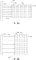
도 5b는 가스의 스트림이 복수의 픽셀의 길이에 대해 수직하도록 기판이 구성되고, 기판을 가로질러 가스의 시트 유동 스트림을 유도하는 가스 나이프 및 복수의 픽셀을 포함하는 기판의 평면도.
도 6a는 가스 나이프 및 척 상에 배열된 복수의 픽셀을 포함하는 기판이 복수의 픽셀의 길이와 나란한 방향으로 기판을 가로질러 가스의 시트 유동 스트림을 생성할 수 있도록 구성된, 본 발명의 다양한 실시 형태에 따른 잉크젯 프린팅 시스템의 상부 우측 사시도.
도 6b는 도 6a에 도시된 잉크젯 프린팅 시스템에 대한 대안으로의 확대된 상부 우측 사시도.
도 6c는 도 6a에 도시된 잉크젯 프린팅 시스템에 대한 대안으로의 상부 우측 사시도.
도 6d는 도 6a에 도시된 잉크젯 프린팅 시스템의 평면도.
도 7a는 가스 나이프가 복수의 픽셀의 길이에 대해 수직으로 기판을 가로질러 가스의 시트 유동 스트림을 유도하도록 가스 나이프 및 복수의 픽셀을 포함하는 기판이 구성되고, 본 발명의 다양한 실시 형태에 다른 잉크젯 프린팅 시스템의 상부 우측 사시도.
도 7b는 도 7a에 도시된 잉크젯 프린팅 시스템에 대한 대안으로의 상부 우측 사시도.
도 7c는 도 7a에 도시된 잉크젯 프린팅 시스템의 평면도.
도 7d는 도 7a에 도시된 잉크젯 프린팅 시스템의 상부 좌측 사시도.
도 8은 본 발명의 다양한 실시 형태에 따른 용매 증기 제거 장치를 도식적으로 도시하는 도면.
도 9는 본 발명의 다양한 실시 형태에 따른 전달 표면과의 임시 관계에 있을 수 있는 용매 증기 제거 장치를 도식적으로 도시하는 도면.
도 10은 상이한 시점에서의 도 9와 동일한 장치를 도시하는 도면.
도 11은 본 발명의 다양한 실시 형태에 따른 전달 표면과의 임시 관계에 있을 수 있는 용매 증기 제거 장치를 도식적으로 도시하는 도면.
도 12는 상이한 시점에서의 도 11과 동일한 장치를 도시하는 도면.
도 13은 본 발명의 다른 실시 형태에 따른 전달 표면과 임시 관계에 있을 수 있는 용매 증기 제거 장치를 도식적으로 도시하는 도면.
도 14는 본 발명의 다양한 실시 형태에 따른 도 9의 용매 증기 제거 장치의 다수의 유닛들을 포함하는 용매 증기 제거 장치를 도식적으로 도시하는 도면.
도 15는 본 발명의 다양한 실시 형태에 따른 도 8의 용매 증기 제거 장치의 더 큰 유닛들을 포함하는 용매 증기 제거 장치를 도식적으로 도시하는 도면.
도 16은 본 발명의 다른 실시 형태에 따른 회전식 드럼 증착 시스템의 일부로서 용매 증기 제거 장치를 도식적으로 도시하는 도면.
도 17은 본 발명의 다른 실시 형태에 따른 회전식 파셋 드럼 증착 시스템의 일부로서 용매 증기 제거 장치를 도식적으로 도시하는 도면.
도 18은 본 발명의 다른 실시 형태에 따른 필름-형성 장치의 일부인 용매 증기 제거 장치를 도식적으로 도시하는 도면.
도 19는 본 발명의 다른 실시 형태에 따른 필름-형성 장치의 일부인 용매 증기 제거 장치를 도식적으로 도시하는 도면.
도 20은 본 발명의 다른 실시 형태에 따른 도 18의 용매 증기 제거 장치의 다수의 유닛을 포함하는 용매 증기 제거 장치를 도시하는 도면.
도 21은 본 발명의 다양한 실시 형태에 따라 필름을 형성하기 위한 방법을 도시하는 흐름도.
도 22는 본 발명의 다양한 실시 형태에 따라 필름을 형성하기 위한 방법을 도시하는 흐름도.
도 23은 본 발명의 다양한 실시 형태에 따라 기판 상의 다양한 위치에서 상이한 가스 속도를 도시하는 도식적인 도면.
도 24는 본 발명의 다양한 실시 형태에 따라 건조 시간이 상이한 다양한 위치에서 프린팅되는 상이한 가스 속도를 나타내는 도식적인 도면.
도 25는 본 발명의 다양한 실시 형태에 따라 건조 시간이 상이한 기판의 다양한 위치를 나타내고 하나 이상의 잉크로 프린팅된 기판의 도식적인 도면.1A is a plan view of a substrate that may be printed in accordance with various embodiments of the invention.
FIG. 1B is a plan view of the substrate shown in FIG. 1A printed with one or more inks. FIG.
1C is a plan view of the substrate shown in FIG. 1A printed with one or more inks.
2A is a cross-sectional view of a substrate that can be partially printed in accordance with various embodiments of the invention.
FIG. 2B is a cross-sectional view of the substrate shown in FIG. 2A printed by first and second printer movement. FIG.
FIG. 2C is a cross-sectional view of the substrate shown in FIG. 2A printed and partially dried. FIG.
3A is a plan view of a substrate printed with one or more inks using at least two movements of the inkjet printhead.
3B is a plan view of a substrate printed with one or more inks using at least two movements of the inkjet printhead in accordance with various embodiments of the present disclosure.
4 is a schematic representation of the marangoni effect.
5A is a top view of a substrate including a plurality of pixels and a gas knife that directs a sheet flow stream of air across the substrate in a direction parallel to the length of the plurality of pixels;
FIG. 5B is a top view of a substrate including a plurality of pixels and a gas knife that directs the substrate to a stream of gas that is perpendicular to the length of the plurality of pixels and directs a sheet flow stream of gas across the substrate;
FIG. 6A illustrates various embodiments of the invention, wherein the substrate including a plurality of pixels arranged on a gas knife and the chuck is capable of generating a sheet flow stream of gas across the substrate in a direction parallel to the length of the plurality of pixels. Top right perspective view of an inkjet printing system according to FIG.
FIG. 6B is an enlarged top right perspective view of an alternative to the inkjet printing system shown in FIG. 6A.
6C is a top, right perspective view of an alternative to the inkjet printing system shown in FIG. 6A.
6D is a plan view of the inkjet printing system shown in FIG. 6A.
FIG. 7A illustrates a substrate comprising a gas knife and a plurality of pixels such that the gas knife directs a sheet flow stream of gas across the substrate perpendicular to the length of the plurality of pixels, and inkjet according to various embodiments of the present invention. Top right perspective view of the printing system.
FIG. 7B is a top, right perspective view of an alternative to the inkjet printing system shown in FIG. 7A.
FIG. 7C is a plan view of the inkjet printing system shown in FIG. 7A.
FIG. 7D is a top left perspective view of the inkjet printing system shown in FIG. 7A.
8 schematically illustrates a solvent vapor removal apparatus according to various embodiments of the present disclosure.
9 schematically depicts a solvent vapor removal apparatus that may be in a temporary relationship with a transfer surface in accordance with various embodiments of the present disclosure.
10 shows the same apparatus as in FIG. 9 at different points in time.
11 schematically illustrates a solvent vapor removal apparatus that may be in a temporary relationship with a transfer surface in accordance with various embodiments of the present disclosure.
FIG. 12 shows the same apparatus as FIG. 11 at different time points. FIG.
FIG. 13 schematically illustrates a solvent vapor removal apparatus that may be in a temporary relationship with a transfer surface in accordance with another embodiment of the present disclosure. FIG.
FIG. 14 schematically illustrates a solvent vapor removal apparatus including multiple units of the solvent vapor removal apparatus of FIG. 9, in accordance with various embodiments of the present disclosure. FIG.
FIG. 15 schematically illustrates a solvent vapor removal apparatus including larger units of the solvent vapor removal apparatus of FIG. 8, in accordance with various embodiments of the present disclosure. FIG.
FIG. 16 schematically illustrates a solvent vapor removal apparatus as part of a rotary drum deposition system according to another embodiment of the present invention. FIG.
17 schematically illustrates a solvent vapor removal apparatus as part of a rotary facet drum deposition system in accordance with another embodiment of the present invention.
18 schematically illustrates a solvent vapor removal apparatus that is part of a film-forming apparatus according to another embodiment of the present invention.
19 schematically illustrates a solvent vapor removal apparatus that is part of a film-forming apparatus according to another embodiment of the present invention.
20 illustrates a solvent vapor removal apparatus including multiple units of the solvent vapor removal apparatus of FIG. 18 in accordance with another embodiment of the present invention.
21 is a flow chart illustrating a method for forming a film in accordance with various embodiments of the invention.
22 is a flow chart illustrating a method for forming a film in accordance with various embodiments of the present teachings.
23 is a schematic diagram illustrating different gas velocities at various locations on a substrate in accordance with various embodiments of the present disclosure.
24 is a diagrammatic representation of different gas velocities printed at various locations with different drying times in accordance with various embodiments of the present invention.
25 is a schematic drawing of a substrate printed with one or more inks and showing various locations of the substrate with different drying times in accordance with various embodiments of the present disclosure.
본 발명은 기판 상에서 다양한 잉크의 프린팅과 관련된 바람직하지 못한 문제점의 해결 방법 및 이의 발견에 관한 것이다. 이 문제점은 본 명세서에서 "파일-업(pile-up)"으로 불리는 현상을 수반한다. 파일-업은 픽셀의 제1 영역이 기판 상에 프린팅되고 인접한 제2 영역이 동일한 기판 상에 프린팅될 때 발생될 수 있다. 두 영역들 간의 계면에서, 제1 프린팅 영역에서 열을 이루는 픽셀은 파일-업을 겪을 수 있으며, 잉크는 더 많은 잉크가 픽셀 뱅크(pixel bank)의 마주보는 단부에서보다 픽셀 뱅크의 일 단부에서 형성되도록 건조된다. 그 결과, 불균일한 픽셀이 생성된다. 이 현상은 도 1a, 도 1b, 및 도 1c를 참조하여 더 잘 이해될 수 있다.The present invention relates to a method for solving the undesirable problems associated with the printing of various inks on a substrate and to the discovery thereof. This problem involves a phenomenon referred to herein as " pile-up. &Quot; The pile-up may occur when a first region of a pixel is printed on a substrate and an adjacent second region is printed on the same substrate. At the interface between the two regions, the rows of pixels in the first printing region may undergo pile-up, and ink is formed at one end of the pixel bank than at the opposite end of the pixel bank with more ink. Dry as much as possible. As a result, nonuniform pixels are produced. This phenomenon can be better understood with reference to FIGS. 1A, 1B, and 1C.
도 1a는 기판(40)의 예시적인 형상의 평면도이다. 기판(40)은 두 영역, 즉 제1 영역(42)과 제2 영역으로 분할된 것으로 도시되고, 두 영역들의 계면은 경계(43)이다. 픽셀 뱅크(48)는 제1 영역(42)에서 픽셀 뱅크(46)의 제1 열로 도시된다. 제2 픽셀 뱅크(52)는 제2 영역(44)에서 픽셀 뱅크(50)의 제2 열로 도시된다. 도 1b에는 제2 영역(44)과 제1 영역(42)에서 프린팅의 여효과가 도시된다. 흑색으로 도시된 잉크는 제2 영역(44)에서 열(52)의 픽셀 뱅크로 균등히 분포된다. 잉크는 영역(42)의 열(46) 내에서 픽셀 뱅크의 일 단부에 집중된 것으로 도시된다. 열(46)의 픽셀 뱅크는 파일-업의 현상을 겪는다. 도 1c에는 본 발명에 따라 구현될 수 있는 기판(40)의 프린팅된 기판이 도시되며, 그 결과 제2 열(50)과 제1 열(46) 모두의 픽셀 뱅크 내에서 잉크가 균등하게 분포된다.1A is a top view of an exemplary shape of
도 2a, 도 2b 및 도 2c는 제1 픽셀 뱅크(62)와 제2 픽셀 뱅크(64)를 포함하는 기판(60)의 단면도이다. 도 2a에는 잉크젯 프린트헤드의 제1 이동이 수행되고 잉크 액적(66)이 픽셀 뱅크(62) 내에 증착된 이후의 기판(60)이 도시된다. 도 2b에는 잉크젯 프린트헤드의 제1 이동과 제2 이동 모두가 수행된 이후의 기판(60)이 도시된다. 잉크젯 프린트헤드의 제2 이동은 제2 잉크 액적(68)을 픽셀 뱅크(64)에 증착시킨다. 이에 따른 스냅샷에서, 도면부호(66)에서의 제1 잉크 액적은 균일한 상태로 건조된다. 도 2c에는 도 2b에 도시된 시점 이후의 단시간 내에 기판(60)의 단면도가 도시된다. 이 시점에서, 제2 잉크 액적(68)은 실질적으로 균일하게 건조되는 반면 파일-업의 효과로 인해 도면부호(66)에서의 제1 잉크 액적은 불균일하게 건조된다. 도면부호(66)에서의 제1 잉크 액적은 픽셀 뱅크(62)의 떨어진 측면에서 덩어리로 되고, 제1 픽셀 뱅크(62)의 근접 측면으로부터 멀어진다.2A, 2B, and 2C are cross-sectional views of a
도 3a는 제1 영역(72)과 제2 영역(74)으로 분할되는 기판(70)의 평면도이다. 이들 영역 둘 모두는 열과 행으로 배열된 복수의 픽셀을 포함한다. 제1 영역(72)은 잉크젯 프린트헤드의 제1 이동으로부터 하나 이상의 잉크가 프린팅되고, 경계(76)의 다른 측면 상에서 픽셀은 제2 영역(74)에서 잉크젯 프린트헤드의 제2 이동 동안에 하나 이상의 잉크로 잉크칠해진다. 행(78)은 제1 영역(72)에서 경계(76)에 인접한 것으로 도시된다. 제1 열(78)에서의 픽셀들은 파일-업의 현상을 겪고, 제2 영역(74)과 영역(72)에서 다른 픽셀보다 덜한 강도(intensity)를 나타낸다. 역으로, 경계(76)에 인접하고 영역(74)에서 픽셀의 열(80)은 잉크로 균일하게 증착되고 뿐만 아니라 균일하게 건조된다.3A is a plan view of a
도 3b에는 본 발명에 따라 하나 이상의 잉크가 프린팅된 기판(84)의 평면도가 도시되며, 이는 파일-업의 현상을 나타내지 않는다. 도 3a에서의 기판(70)과 유사한 기판(84)은 경계(90)에 의해 제1 영역(86)과 제2 영역(88)으로 분할된다. 제1 영역(86)은 잉크젯 프린트헤드의 제1 이동에 따라 프린팅되고, 제2 영역(88)은 잉크젯 프린트헤드의 제2 이동에 따라 프린팅된다. 경계(90)에 인접한 제1 영역(86)에서 픽셀(92)의 제1 열은 도 3a에서 제1 열(78)과 상반된 파일-업의 현상을 나타내지 않는다. 경계(90)에 인접한 제2 픽셀 열(94)은 제2 열(92)에서 픽셀의 분포와 비교되는 픽셀에서 잉크의 균일한 분포를 나타낸다. 도 3b에는 본 명세서에 기재된 다양한 발명에 따라 구현될 수 있는 놀랍고 예상치 못한 결과를 나타내진다.3B shows a top view of a
도 4는 마란고니 효과(Marangoni effect)의 도식적 도면이다. 기판(96) 상에서 물의 액적(98)이 점선으로 도시된 바와 같이 방향(100)으로 이동하는 것으로 도시된다. 아이소프로판올 증기 공급원(102)이 물 액적(98)에 인접한 것으로 도시된다. 점선 화살표(104)는 물 액적(98) 상에 충돌하는 증기 방향을 나타낸다. 위치(108)에서 아이소프로판올 증기의 비교적 낮은 농도에 비해 위치(106)에서 아이소프로판올 증기의 비교적 높은 농도로 인해, 물 액적(98)은 마란고니 효과의 결과로서 점선 화살표(100)로 도시된 방향으로 이동한다. 예를 들어, 아이소프로판올 증기(약 22 다인/cm의 표면 장력)는 유리 표면으로부터 물 (약 72 다인/cm의 표면 장력) 액적을 "가압"하기 위해 사용될 수 있다. 마란고니 효과는 본 발명에 따라 해결되는 파일-업 효과를 초래할 수 있다. 그러나, 본 발명은 파일-업 현상의 발생과 관련한 임의의 특정 이론에 의존되기 않고 이에 의해 제한되지 않는다.4 is a schematic representation of the Marangoni effect. Drops of
유체 내의 표면 장력의 구배는 더 높은 표면 장력의 방향으로 유체에 대해 힘을 인가한다. 이 표면 장력 구배는 전형적으로 유체 조성물의 구배로 인함이다. 이 효과는 관찰된 액적 건조 현상에서 관찰되며, 액적의 다양한 영역에서 상이한 건조 속도(중심에 비해 에지에서 더 빨리 건조됨)와 다양한 구성요소의 상이한 건조 속도의 조합으로 인해 잉크 액적의 조성물의 구배가 있다. 이러한 구배는 또한 다음의 두 가지의 현상을 통하여 주위 증기 구배로 인해 발생될 수 있다: 유체 내로 증기의 흡수 및/또는 액적의 억제된 건조(둘 모두의 경우 공간적으로 변화하는 농도에 대해 비례).The gradient of surface tension in the fluid exerts a force on the fluid in the direction of the higher surface tension. This surface tension gradient is typically due to the gradient of the fluid composition. This effect is observed in the observed droplet drying phenomena, and due to the combination of different drying rates in the various areas of the droplets (drying faster at the edges relative to the center) and different drying rates of the various components, the gradient of the composition of the ink droplets have. This gradient can also occur due to the ambient vapor gradient through two phenomena: absorption of vapor into the fluid and / or suppressed drying of the droplets (in both cases proportional to the spatially varying concentration).
도 5a는 본 발명의 다앙한 실시 형태에 따른 잉크젯 프린팅 시스템 및 방법의 일부의 도식적 도면의 평면도이다. 잉크젯 프린팅 시스템(110) 내에서, 가스 나이프(gas knife, 112)는 잘린 화살표로 도시된 가스 스트림(114)의 방향이 다양한 픽셀의 길이와 일치되도록 기판(116)에 걸쳐서 시트 유동의 형태로 가스 스트림(114)을 방출한다. 즉, 가스 유동(114)은 "인-픽셀(in-pixel)"이라는 배향으로 기판(115)의 표면 상에서 열(116)과 행(118) 내에서 픽셀을 가로질러 이동한다. 도 5b는 시트 유동의 형태로 가스 스트림(114)을 방출하는 가스 나이프(112)를 도시하는 잉크젯 프린팅 시스템(120)의 대안의 형상의 도식적 도면이다. 이 구성에서, 열(116)에 걸쳐서 그리고 행(118)에 수직하게 뿐만 아니라 "크로스-픽셀(cross-pixel)"이라는 배향으로 열(116) 내에서 픽셀의 길이에 대해 수직으로 가스 스트림이 이동한다.5A is a top view of a schematic diagram of a portion of an inkjet printing system and method according to various embodiments of the present invention. Within the inkjet printing system 110, a
도 6a는 본 발명의 다양한 실시 형태에 따르는 잉크젯 프린팅 시스템(130)의 상부 우측 사시도이다. 시스템(130)의 다양한 구성요소가 기저(132)에 부착된다. 척(134)은 척 마운트(136)를 통하여 기저(132)에 부착된다. 척(134)은 상부 척 표면(140)을 갖는 상부 척 층(136)을 포함한다. 상부 척 표면(140)은 기판(142)을 지지할 수 있다. 가스 나이프(144)는 가스 나이프 지지부(146)를 통하여 기저(132)에 연결된다. 가스 나이프(144)는 인-픽셀 구성으로 기판(142)을 가로질러 가스의 스트림을 유동시키도록 배향된다. 갠트리(gantry, 148)는 x-축 방향으로 잉크젯 프린트헤드 조립체(152)의 이동을 허용하는 레일 빔(rail beam, 150)을 포함한다. 잉크젯 프린트헤드 조립체(152)는 제1 잉크 카트리지(156)를 수용하는 제1 잉크 카트리지 슬롯(154)을 포함한다. 수직 액추에이터(158)는 잉크젯 프린트헤드 조립체(152)의 z-축 방향으로 이동을 허용하고 이와 작동가능하게 연계된다. 제1 y-축 액추에이터(160)와 제2 y-축 액추에이터(162)에 따라 갠트리(148)가 y-축 방향으로 이동될 수 있다. 잉크젯 카트리지 공급 랙(164)이 갠트리(148)를 따라 잉크젯 프린트헤드 조립체(152)에 마주본다. 잉크젯 공급 랙(164)은 제2 잉크 카트리지 슬롯(166), 제3 잉크 카트리지 슬롯(168), 제4 잉크 카트리지 슬롯(170), 제5 잉크 카트리지 슬롯(172), 및 제6 잉크 카트리지 슬롯(174)을 포함한다. 제2 잉크 카트리지(176)는 제2 잉크 카트리지 슬롯(166)에 의해 수용되고, 제3 잉크 카트리지(178)는 제3 잉크 카트리지 슬롯(168)에 의해 수용되고, 제4 잉크 카트리지(180)는 제4 잉크 카트리지 슬롯(170)에 의해 수용되며, 제5 잉크 카트리지(182)는 제5 잉크 카트리지 슬롯(172)에 의해 수용되고, 제6 잉크 카트리지(184)는 제6 잉크 카트리지 슬롯(174)에 의해 수용된다.6A is a top, right perspective view of an
도 6b는 도 6a에 도시된 잉크젯 프린팅 시스템(130)의 대안의 상부 우측 사시도이다. 척 상부 표면(140)은 인-픽셀 구성으로 점선 화살표(186)로 도시된 가스 스트림을 방출하는 가스 나이프(144)에 대해 기판(142)을 지지한다. 도 6c는 도 6a에 도시된 잉크젯 프린팅 시스템(130)의 또 다른 대안의 상부 우측 사시도이다. 기판(142)은 척 상부 표면(140)에 배열되고 가스 나이프(144)에 대해 배치된다. 점선 화살표(186)에 의해 도시된 가스의 스트림은 인-픽셀 구성으로 그리고 기판(142)에 걸쳐서 에어 나이프(144)에 의해 방출된다. 도 6d는 도 6a에 도시된 잉크젯 프린팅 시스템(130)의 평면도이다. 기판(142)은 재차 상부 척 표면(140)에 의해 지지된다. 가스 나이프(144)는 기판(142)에 대해 인-픽셀 구성으로 점선 화살표(186)로 도시된 가스의 스트림을 방출한다.6B is a top, right perspective view of an alternative to the
도 7a는 크로스-픽셀 구성을 도시하는 잉크젯 프린팅 시스템(130)의 상부 우측 사시도이다. 척(134)은 척 지지부(136)를 통하여 기저(132)에 부착된다. 상부 척 층(138)은 기판(142)을 지지하는 상부 척 표면(140)을 갖는다. 가스 나이프(144)는 가스 나이프 지지부(146)를 통하여 기저(132)에 연결된다. 가스 나이프(144)는 크로스-픽셀 구성으로 기판(142)에 걸쳐서 가스 스트림을 블로잉하기 위해 기판(142)에 대해 구성된다. 갠트리(148)는 잉크젯 프린트헤드 조립체(152)의 움직임을 허용하는 트랙 빔(150)을 포함한다. 도 7b는 도 7a에 도시된 잉크젯 프린팅 시스템(130)의 대안의 상부 우측 사시도이다. 척 상부 표면(140)은 가스 나이프(144)에 대해 기판(142)을 지지한다. 가스 스트림(188)은 가스 나이프(144)에 의해 방출되고 크로스-픽셀 구성으로 기판(142)에 걸쳐 이동한다. 도 7c는 도 7a에 도시된 잉크젯 프린팅 시스템(130)의 평면도이다. 척 상부 표면(140)은 가스 나이프(144)에 대해 기판(142)을 지지한다. 가스 스트림(188)은 크로스-픽셀 구성으로 기판(142)에 걸쳐 가스 나이프(144)로부터 방출된다. 도 7d는 도 7a에 도시된 잉크젯 프린팅 시스템(130)의 상부 좌측 사시도이다. 척 상부 표면(140)은 기판(142)을 지지한다. 가스 나이프(144)는 가스 스트림(188)이 가스 나이프(144)에 의해 방출되고 크로스-픽셀 구성으로 기판(142)에 걸쳐서 블로잉되도록 배향된다.7A is a top right perspective view of an
본 발명의 다양한 실시 형태에 따라서, 척, 잉크젯 및 프린트헤드를 포함하는 기판 프린팅 시스템이 제공된다. 척은 기판을 보유하도록 구성된 상부 표면을 포함할 수 있다. 잉크젯 프린트헤드는 기판 상으로 프린팅되는 잉크젯에 대해 구성될 수 있다. 가스 나이프는 가압된 가스 공급원으로부터 가압된 가스를 수용하기 위한 입구 및 척에 의해 보유된 기판을 향하여 시트 유동 내에서 가스 나이프로부터 가압된 가스를 유도하도록 구성되며 길이를 갖는 출구 슬롯을 포함한다.According to various embodiments of the present invention, a substrate printing system is provided that includes a chuck, an inkjet, and a printhead. The chuck can include a top surface configured to hold a substrate. Inkjet printheads can be configured for inkjet printed onto a substrate. The gas knife includes an inlet slot for receiving the pressurized gas from the pressurized gas source and an outlet slot having a length and configured to direct the pressurized gas from the gas knife in the sheet flow toward the substrate held by the chuck.
잉크젯 프린트헤드는 잉크의 공급원과 유체연통될 수 있고, 잉크는 캐리어 유체 내에서 부유하거나 또는 이 내에 용해되는 캐리어 유체 및 필름-형성 유기 재료를 포함한다. 임의의 적합한 잉크가 사용될 수 있다. 잉크의 예에는 발광 층, 정공 수송층(hole transport layer), 정공 주입층, 유기 발광 장치의 임의의 다른 층, 등을 구성하는 것들이 포함된다.The inkjet printhead may be in fluid communication with a source of ink, the ink comprising a carrier fluid and a film-forming organic material suspended or dissolved in the carrier fluid. Any suitable ink can be used. Examples of inks include those constituting a light emitting layer, a hole transport layer, a hole injection layer, any other layer of the organic light emitting device, and the like.
임의의 적합한 척이 기판 프린팅 시스템의 포트로서 사용될 수 있다. 예를 들어, 상이한 크기의 기판을 보유할 수 있는 다-기판 또는 유니버셜 척이 사용될 수 있다. 척은 다수의 층을 포함할 수 있고, 이러한 하나 이상의 층이 특정 위치설정 제어부를 제공할 수 있다. 기판 프린팅 시스템은 추가로 척에 의해 보유되는 기판을 추가로 포함할 수 있다. 임의의 적합한 유형의 기판이 사용될 수 있다. 예를 들어, 유리 기판이 사용될 수 있고 기판은 인듐 주석 산화물(ITO)을 포함한다. 기판은 잉크를 수용하고 가두도록 구성된 픽셀 뱅크 및 다양한 통합 전자 구성요소를 제공하기 위해 기판 프린팅 시스템에 의해 처리되기 전에 미리 층화될 수 있다(pre-layered). 기판은 임의의 개수의 픽셀, 픽셀 뱅크, 픽셀 열, 열을 이루는 픽셀 뱅크, 픽셀 행, 및 열을 이루는 픽셀 행을 포함할 수 있다. 일부 실시 형태에서, 기판은 적어도 두 열의 픽셀 뱅크를 포함하고, 각각의 픽셀 뱅크는 픽셀을 형성하기 위하여 유기 재료를 가두도록 구성되고, 각각의 열은 길이를 가지며, 각각의 픽셀 뱅크는 길이를 갖고, 각각의 픽셀 뱅크는 이의 길이보다 더 짧은 폭을 갖는다. 각각의 열 내에서 픽셀 뱅크의 길이는 각각의 열의 길이에 대해 실질적으로 수직으로 배열될 수 있고, 가스 나이프의 출구 슬롯의 길이는 각각의 열의 길이에 대해 실질적으로 수직으로 그리고 각각의 픽셀 뱅크의 길이에 대해 실질적으로 평행하게 배향될 수 있다.Any suitable chuck can be used as the port of the substrate printing system. For example, a multi-substrate or universal chuck can be used that can hold substrates of different sizes. The chuck can include multiple floors, and one or more of these floors can provide a particular positioning control. The substrate printing system may further comprise a substrate held by the chuck. Any suitable type of substrate can be used. For example, a glass substrate can be used and the substrate comprises indium tin oxide (ITO). The substrate may be pre-layered before being processed by the substrate printing system to provide pixel banks and various integrated electronic components configured to receive and trap ink. The substrate may include any number of pixels, pixel banks, pixel columns, column banks, pixel rows, and column row pixels. In some embodiments, the substrate comprises at least two rows of pixel banks, each pixel bank configured to trap organic material to form a pixel, each column having a length, and each pixel bank having a length , Each pixel bank has a width shorter than its length. The length of the pixel bank within each column may be arranged substantially perpendicular to the length of each column, and the length of the outlet slot of the gas knife is substantially perpendicular to the length of each column and the length of each pixel bank May be oriented substantially parallel to.
일부 실시 형태에서, 기판은 적어도 두 열의 픽셀 뱅크를 포함하고, 각각의 픽셀 뱅크는 픽셀을 형성하기 위해 유기 재료를 가두도록 구성된다. 각각의 열은 길이를 가지며, 각각의 픽셀 뱅크는 길이 및 길이보다 더 작은 폭을 갖는다. 각각의 열 내에서 픽셀 뱅크의 길이는 각각의 열의 길이에 대해 실질적으로 수직하게 배열될 수 있으며, 가스 나이프의 출구 슬롯의 길이는 각각의 열의 길이에 대해 실질적으로 평행하고 그리고 각각의 픽셀 뱅크의 길이에 대해 실질적으로 수직하게 배향될 수 있다.In some embodiments, the substrate comprises at least two rows of pixel banks, each pixel bank configured to trap organic material to form a pixel. Each column has a length, and each pixel bank has a length and a width smaller than the length. The length of the pixel banks within each column can be arranged substantially perpendicular to the length of each column, and the length of the outlet slot of the gas knife is substantially parallel to the length of each column and the length of each pixel bank May be oriented substantially perpendicular to.
임의의 적합한 진공 공급원 및 수반된 진공 장치가 기판 프린팅 시스템의 일부로서 및/또는 이와 공동으로 사용될 수 있다. 일부 실시 형태에서, 기판 프린팅 시스템은 배출 포트 및 배출 포트와 유체 연통되는 진공 공급원을 포함하고, 배출 포트는 가스 나이프에 의해 생성된 가스의 시트 유동이 배출 포트를 통하여 흡인되도록 가스 나이프에 대해 배치된다. 배출 포트는 잉크젯 프린트헤드에 인접하게 장착될 수 있으며, 배출 포트와 잉크젯 프린트헤드는 척의 상부 표면에 대해 일렬로 이동하도록 구성된다. 배출 포트는 이러한 배치에 추가로 또는 대안으로 다른 위치에 배치될 수 있다. 임의의 적합한 개수의 배출 포트가 사용될 수 있다. 임의의 적합한 강도의 진공이 사용될 수 있다. 예를 들어, 진공은 약 -3.0 psig 내지 약 -13 psig, 약 -5.0 psig 내지 약 -10 psig, 또는 약 -7.5 psig의 음압으로 배출 포트를 통하여 배출될 수 있다.Any suitable vacuum source and accompanying vacuum apparatus can be used as part of and / or in conjunction with the substrate printing system. In some embodiments, the substrate printing system includes a discharge port and a vacuum source in fluid communication with the discharge port, wherein the discharge port is disposed relative to the gas knife such that a sheet flow of gas generated by the gas knife is sucked through the discharge port. . The discharge port may be mounted adjacent to the inkjet printhead, wherein the discharge port and the inkjet printhead are configured to move in line with the top surface of the chuck. The discharge port may be arranged in other locations in addition to or alternatively to this arrangement. Any suitable number of outlet ports can be used. Any suitable strength vacuum can be used. For example, the vacuum can be discharged through the discharge port at a negative pressure of about -3.0 psig to about -13 psig, about -5.0 psig to about -10 psig, or about -7.5 psig.
척 상에서 기판에 대한 에어 나이프의 위치는 가스의 적합한 공급, 유동, 압력 및 속도가 기판의 표면에 걸쳐서 및/또는 이에 적용되도록 변화할 수 있다. 일부 실시 형태에서, 기판은 척의 상부 표면에 배치된다. 깊은 상부 표면, 횡방향 에지, 길이 및 폭을 포함하고, 가스 나이프는 제1 거리만큼 횡방향 에지로부터 이격된다. 제1 거리는 기판의 길이보다 더 클 수 있으며, 예를 들어, 기판의 길이의 적어도 2배이다. 기판의 길이는 출구 슬롯의 길이에 대해 실질적으로 수직으로 배향될 수 있다. 일부 실시 형태에서, 제1 거리는 기판의 폭의 절반보다 크거나, 또는 기판의 폭과 대략 동일하거나, 또는 기판의 폭보다 더 크거나, 또는 기판의 폭의 적어도 2배이다. 기판의 폭은 출구 슬롯의 길이에 대해 실질적으로 수직, 실질적으로 평행, 또는 일부 다른 각 배향으로 배열될 수 있다.The position of the air knife relative to the substrate on the chuck can be varied such that a suitable supply, flow, pressure and velocity of gas is applied over and / or applied to the surface of the substrate. In some embodiments, the substrate is disposed on the top surface of the chuck. A deep top surface, a lateral edge, a length and a width, wherein the gas knife is spaced apart from the lateral edge by a first distance. The first distance may be greater than the length of the substrate, for example at least twice the length of the substrate. The length of the substrate may be oriented substantially perpendicular to the length of the outlet slot. In some embodiments, the first distance is greater than half the width of the substrate, or approximately equal to the width of the substrate, or greater than the width of the substrate, or at least twice the width of the substrate. The width of the substrate may be arranged in a substantially perpendicular, substantially parallel, or some other angle orientation with respect to the length of the outlet slot.
기판 프린팅 시스템은 척, 잉크젯 프린트헤드, 및 가스 나이프를 수용하는 엔클로져에 의해 둘러싸일 수 있다. 엔클로져는 가스 나이프로부터 방출된 가스 또는 가스들과 동일하거나 또는 상이한 하나 이상의 가스를 포함하는 대기를 수용할 수 있다. 일부 실시 형태에서, 가스 또는 가스들은 불활성 가스를 포함하다. 일부 실시 형태에서, 가스 또는 가스들의 반응성 가스 함량은 가스 스트림 또는 가스 대기의 총 부피의 1.0 부피% 미만이다. 적합한 불활성 가스의 예에는 질소, 노블 가스(예컨대, 아르곤), 또는 이의 임의의 조합을 포함한다.The substrate printing system may be surrounded by an enclosure containing the chuck, the inkjet printhead, and the gas knife. The enclosure may contain an atmosphere comprising one or more gases that are the same as or different from the gas or gases released from the gas knife. In some embodiments, the gas or gases include an inert gas. In some embodiments, the reactive gas content of the gas or gases is less than 1.0 volume percent of the total volume of the gas stream or gas atmosphere. Examples of suitable inert gases include nitrogen, noble gases (eg argon), or any combination thereof.
기판 프린팅 시스템은 잉크젯 프린트헤드 조립체, 척 및 기판과 같은 하나 이상의 구성요소를 이동시키기 위한 하나 이상의 액추에이터를 포함할 수 있다. 일부 실시 형태에서, 척에 의해 보유된 기판 상으로 프린팅 동안에 척에 대해 잉크젯 프린트헤드를 이동시키도록 구성되는 프린트헤드 액추에이터가 제공된다. 일부 실시 형태에서, 프린팅 동안에 잉크젯 프린트헤드에 대해 가스 나이프와 척을 이동시키기 위해 하나 이상의 액추에이터가 제공되고 구성된다.Substrate printing systems can include one or more actuators for moving one or more components, such as inkjet printhead assemblies, chucks, and substrates. In some embodiments, a printhead actuator is provided that is configured to move the inkjet printhead relative to the chuck during printing onto a substrate held by the chuck. In some embodiments, one or more actuators are provided and configured to move the gas knife and chuck relative to the inkjet printhead during printing.
본 발명의 다양한 실시 형태에 따라서, 픽셀 뱅크 내에서 필름-형성 유기 재료의 실질적으로 균등한 분배를 구현하기 위한 방법은 예를 들어 기판 상에 형성된 픽셀 뱅크 내에 제공된다. 방법은 하나 이상의 하기 단계 또는 특징을 포함할 수 있다. 기판은 척에 의해 보유될 수 있다. 기판은 이의 프린트 표면 상에 형성된 복수의 픽셀 뱅크를 포함할 수 있다. 가스 나이프의 출구 슬롯으로부터 가스의 시트 유동은 척에 의해 보유된 기판을 향하여 유도될 수 있다. 출구 슬롯은 높이와 길이를 가질 수 있으며 길이는 높이의 치수의 수배일 수 있다.In accordance with various embodiments of the present invention, a method for implementing substantially even distribution of film-forming organic material in a pixel bank is provided, for example, in a pixel bank formed on a substrate. The method may include one or more of the following steps or features. The substrate may be held by the chuck. The substrate may comprise a plurality of pixel banks formed on its printed surface. The sheet flow of gas from the outlet slot of the gas knife may be directed towards the substrate held by the chuck. The outlet slot may have a height and a length and the length may be several times the dimension of the height.
잉크젯 잉크는 프린트 표면에 형성된 제1 복수의 픽셀 뱅크 상으로 제1 잉크젯 프린트헤드로부터 프린팅될 수 있다. 동일한 프린트헤드 또는 제2 잉크젯 프린트헤드로부터 잉크젯 잉크는 기판 상에 형성된 제2 복수의 픽셀 뱅크 상으로 프린팅될 수 있다. 제1 및 제2 잉크는 동일하거나 또는 상이할 수 있다. 가스의 시트 유동이 각각의 픽셀 뱅크 내에서 잉크젯 잉크의 균등한 분포를 돕고 각각의 픽셀 뱅크 내에서 잉크젯 잉크의 파일-업을 방지하도록 방법이 수행될 수 있다. 일부 실시 형태에서, 제1 잉크젯 프린트헤드와 제2 잉크젯 프린트헤드는 동일한 잉크젯 프린트헤드이다.Inkjet inks may be printed from the first inkjet printhead onto a first plurality of pixel banks formed on the print surface. Inkjet ink from the same printhead or second inkjet printhead may be printed onto a second plurality of pixel banks formed on a substrate. The first and second inks may be the same or different. The method may be performed such that a sheet flow of gas assists an even distribution of the inkjet ink within each pixel bank and prevents file-up of the inkjet ink within each pixel bank. In some embodiments, the first inkjet printhead and the second inkjet printhead are the same inkjet printhead.
방법은 임의의 적합한 잉크젯 프린팅 시스템 또는 이의 구성요소를 이용할 수 있다. 예를 들어, 방법은 그 전체가 본 명세서에 참조로 인용되는 2012년 4월 17일자에 출원된 미국 특허 출원 제61/625,659호에 기재된 바와 같이 잉크젯 프린터 툴 또는 이의 임의의 구성요소를 이용할 수 있다.The method may utilize any suitable inkjet printing system or component thereof. For example, the method may utilize an inkjet printer tool or any component thereof as described in US patent application Ser. No. 61 / 625,659, filed April 17, 2012, which is incorporated herein by reference in its entirety. .
가스의 유동은 형상, 압력, 속도, 온도 및 방향이 변화할 수 있다. 에컨대, 종래의 에어 나이프와 같은 임의의 적합한 가스 나이프가 가스의 유동을 제공하기 위하여 사용될 수 있다. 예를 들어, 엑스에어 코포레이션(Exair Corporation)(미국 오아이오 신시네티 소재), 에어티엑스 인터내셔널(AirTX International)(미국 오아이오 신시네티 소재), 제트에어 테크놀로지스, 엘엘씨(JetAir Technologies, LLC)(미국 캘리포니아 벤투라 수재), 스트림텍(STREAMTEK)(미국 노쓰 캐롤라이나 샤로테 소재), 소닉 에어 시스템즈(Sonic Air Systems)(미국 캘리포니아 브레아 소재), 또는 넥스 플로우 에어 프로덕츠 코포레이션(Nex Flow Air Products Corp)(미국 뉴욕 윌리암스빌 소재)으로부터 입수가능한 에어 나이프가 사용될 수 있다. 일부 실시 형태에서, 가스의 시트 유동은 제1 복수의 및 제2 복수의 픽셀 뱅크 모두 상으로 프린팅 동안에 기판을 향하여 유도된다. 일부 실시 형태에서, 가스의 시트 유동은 약 1.0 psig 내지 약 25 psig, 약 2.0 psig 내지 약 20 psig, 약 3.0 psig 내지 약 12 psig, 또는 약 5 psig 내지 약 10 psig의 압력으로 가스 나이프로부터 유도된다. 일부 실시 형태에서, 진공은 가스의 시트 유동이 기판을 향하여 유도된 후에 가스의 시트 유동을 흡입하기 위하여 배출 포트를 통해 적용된다.The flow of gas can vary in shape, pressure, speed, temperature and direction. For example, any suitable gas knife, such as a conventional air knife, can be used to provide a flow of gas. For example, Exair Corporation (Cincinnati, IA), AirTX International (Cincinnati, IA), JetAir Technologies, JetAir Technologies, LLC (California, USA) Ventura, STREAMTEK (Charlotte, North Carolina, USA), Sonic Air Systems (Brea, CA, USA), or Nex Flow Air Products Corp (New York, USA) Air knives available from Williamsville) may be used. In some embodiments, the sheet flow of gas is directed towards the substrate during printing onto both the first plurality of and the second plurality of pixel banks. In some embodiments, the sheet flow of gas is derived from the gas knife at a pressure of about 1.0 psig to about 25 psig, about 2.0 psig to about 20 psig, about 3.0 psig to about 12 psig, or about 5 psig to about 10 psig. . In some embodiments, a vacuum is applied through the discharge port to suck the sheet flow of gas after the sheet flow of gas is directed towards the substrate.
일부 실시 형태에서, 기판의 프린트 표면은 적어두 두 열의 픽셀 뱅크를 포함할 수 있고, 각각의 열은 길이를 가지며, 각각의 픽셀 뱅크는 길이 및 길이보다 더 짧은 폭을 가지며, 각각의 픽셀 뱅크의 길이는 각각의 열의 길이에 실질적으로 수직으로 배열된다. 이러한 경우에, 가스 나이프의 출구 슬롯은 각각의 열의 길이에 실질적으로 수직이고 각각의 픽셀 뱅크의 길이에 실질적으로 평행한 길이를 가질 수 있다.In some embodiments, the print surface of the substrate may comprise at least two rows of pixel banks, each row having a length, each pixel bank having a length and a width shorter than the length, The lengths are arranged substantially perpendicular to the length of each column. In such a case, the outlet slot of the gas knife may have a length substantially perpendicular to the length of each row and substantially parallel to the length of each pixel bank.
일부 실시 형태에서, 기판의 프린트 표면은 적어두 두 열의 픽셀 뱅크를 포함할 수 있고, 각각의 열은 길이를 가지며, 각각의 픽셀 뱅크는 길이 및 길이보다 더 짧은 폭을 가지며, 각각의 픽셀 뱅크의 길이는 각각의 열의 길이에 실질적으로 수직으로 배열된다. 이러한 경우에, 가스 나이프의 출구 슬롯은 각각의 열의 길이에 실질적으로 수평이고 각각의 픽셀 뱅크의 길이에 실질적으로 수직인 길이를 가질 수 있다.In some embodiments, the print surface of the substrate may comprise at least two rows of pixel banks, each row having a length, each pixel bank having a length and a width shorter than the length, The lengths are arranged substantially perpendicular to the length of each column. In such a case, the exit slot of the gas knife may have a length substantially horizontal to the length of each row and substantially perpendicular to the length of each pixel bank.
본 발명의 다앙한 실시 형태에 따라서, 척, 잉크젯 프린트헤드, 잉크젯 잉크의 공급부 및 가스 이동 장치를 포함하는 기판 프린팅 시스템이 제공된다. 가스 이동 장치는 본 명세서에서 기재된 가스 나이프와 상이할 수 있고, 예를 들어, 팬, 둘 이상의 팬, 노즐, 공기 펌프, 등을 포함할 수 있다. 척은 상부 표면 상에 기판을 보유하도록 구성될 수 있고, 상부 표면을 포함할 수 있다. 척은 진공 척일 수 있거나 또는 클램프, 정렬 핀, 또는 다른 고정 특징부 또는 체결구를 포함할 수 있다. 잉크젯 프린트헤드는 기판이 척에 의해 보유된 상태에서 기판의 프린트 표면 상으로 잉크젯 잉크를 프린팅하도록 구성될 수 있다. 잉크젯 잉크의 공급부는 잉크젯 프린트헤드와 유체 연통될 수 있고, 잉크젯 잉크는 캐리어 유체 및 캐리어 유체 내에 용해되거나 또는 이 내에서 부유하는 필름-형성 유기 재료를 포함할 수 있다. 가스 이동 장치는 잉크젯 프린트헤드에 인접하게 그리고 이에 대해 고정된 관계로 배열될 수 있다. 가스 이동 장치는 잉크젯 프린트헤드가 프린트 표면 상으로 잉크젯 잉크를 프린팅하는 동안 기판의 프린트 표면 상으로 가스의 유동을 유도하도록 구성될 수 있다. 일부 실시 형태에서, 가스 이동 장치는 질소 가스와 같이 불활성 가스의 공급원과 유체 연통된다.According to various embodiments of the present invention, a substrate printing system is provided that includes a chuck, an inkjet printhead, a supply of inkjet ink, and a gas transfer device. The gas moving device may be different from the gas knife described herein and may include, for example, a fan, two or more fans, nozzles, air pumps, and the like. The chuck can be configured to hold a substrate on the top surface and can include the top surface. The chuck can be a vacuum chuck or can include a clamp, alignment pin, or other fastening feature or fastener. The inkjet printhead may be configured to print inkjet ink onto the print surface of the substrate with the substrate held by the chuck. The supply of inkjet ink may be in fluid communication with the inkjet printhead, and the inkjet ink may comprise a carrier fluid and a film-forming organic material that is dissolved within or suspended in the carrier fluid. The gas movement devices can be arranged adjacent to and in relation to the inkjet printhead. The gas transfer device can be configured to direct the flow of gas onto the print surface of the substrate while the inkjet printhead prints the inkjet ink onto the print surface. In some embodiments, the gas shift device is in fluid communication with a source of inert gas, such as nitrogen gas.
기판 프린팅 시스템은 배출 포트와 유체 연통되는 진공 공급원 및 배출 포트를 포함할 수 있으며, 배출 포트는 가스 이동 장치에 의해 생성된 가스의 유동이 배출 포트를 통하여 프린트 표면으로부터 흡입되도록 가스 이동 장치에 대해 배열된다. 기판 프린팅 시스템은 척, 잉크젯 프린트헤드 및 가스 이동 장치를 수용하는 엔클로져 내에서 둘러싸일 수 있다. 엔클로져는 예를 들어, 질소 가스를 포함하는 불활성 가스 대기를 포함할 수 있다. 기판 프린팅 시스템은 척에 의해 보유된 기판을 가열하도록 구성된 하나 이상의 히터를 포함할 수 있다. 일부 실시 형태에서, 가스 이동 장치는 가스의 유동을 생성하는 적어도 2개의 팬을 포함한다. 가스의 유동은 임의의 적합한 형상, 유동 속도, 압력 또는 속도로 공급될 수 있다. 예시적인 실시 형태에서, 가스 유동은 약 0.1 m/s 내지 약 10 m/s, 약 0.5 m/s 내지 약 5.0 m/s, 약 1.0 m/s 내지 약 3.5 m/s, 또는 약 1.5 m/s 내지 약 2.5 m/s의 속도로 가스 이동 장치로부터 유도될 수 있다.The substrate printing system may include a vacuum source and a discharge port in fluid communication with the discharge port, the discharge port arranged relative to the gas mover such that a flow of gas generated by the gas mover is sucked from the print surface through the discharge port. do. The substrate printing system can be enclosed within an enclosure that houses the chuck, the inkjet printhead, and the gas transfer device. The enclosure may comprise an inert gas atmosphere, for example comprising nitrogen gas. The substrate printing system can include one or more heaters configured to heat the substrate held by the chuck. In some embodiments, the gas movement device includes at least two fans that produce a flow of gas. The flow of gas can be supplied in any suitable shape, flow rate, pressure or velocity. In an exemplary embodiment, the gas flow is about 0.1 m / s to about 10 m / s, about 0.5 m / s to about 5.0 m / s, about 1.0 m / s to about 3.5 m / s, or about 1.5 m / can be derived from the gas shifter at a speed of from s to about 2.5 m / s.
방법 및 장치는 또한 캐리어 액체의 재응축을 방지하고 잉크로부터 증발된 캐리어 액체를 제거하기 위해 제공된다. 보다 구체적으로, 방법 및 장치는 고체 잉크, 예를 들어, 유기 발광 장치 재료를 기판 상에 층착시키는 반면 유기 재료가 분산 또는 용해되는 증발식 캐리어 액체를 제거하기 위해 사용될 수 있다. 장치는 전달 부재, 증발 영역, 히터, 배출 포트 및 진공 포트를 포함할 수 있다. 전달 부재는 캐리어 액체 내에 유기 재료를 수용하고 유기 재료를 건조시키며, 기판 상에 건조된 유기 재료를 증착시키도록 구성될 수 있다. 유기 재료는 유기 발광 장치의 하나 이상의 층을 형성하는데 유용한 유기 필름-형성 재료일 수 있다. 증발 영역은 전달 부재의 표면 일부에 의해 적어도 부분적으로 형성될 수 있으며, 표면 부분은 제1 평면을 따라 배열되고, 추가로 증발 영역은 캐리어 액체 내에 필름-형성 재료의 일부를 지지하도록 구성된다. 히터는 증발 영역을 가열하기에 적합할 수 있다. 배출 포트는 증발 영역에 인접하게 배열될 수 있으며 제1 평면에 실질적으로 수직인 증발 영역으로부터 이격되어 연장되는 선과 교차된다. 진공 공급원은 배출 포트와 유체 연통되기에 적합할 수 있다. 작동 중에, 진공 공급원은 증발 영역에 또는 이에 근접하게 위치된 증기를 제거하고 반출하기에 충분한 부피와 유동 속도 및 배출 포트를 통하여 증발 영역으로부터 연장되는 가스 유동을 유도할 수 있다.The method and apparatus are also provided to prevent recondensation of the carrier liquid and to remove the evaporated carrier liquid from the ink. More specifically, the method and apparatus can be used to deposit a solid ink, such as an evaporative carrier liquid, on which an organic light emitting device material is deposited on a substrate while the organic material is dispersed or dissolved. The apparatus can include a delivery member, an evaporation zone, a heater, an exhaust port and a vacuum port. The transfer member may be configured to receive the organic material in the carrier liquid, dry the organic material, and deposit the dried organic material on the substrate. The organic material may be an organic film-forming material useful for forming one or more layers of an organic light emitting device. The evaporation region may be at least partially formed by a portion of the surface of the delivery member, the surface portion being arranged along the first plane, and further the evaporation region is configured to support a portion of the film-forming material in the carrier liquid. The heater may be suitable for heating the evaporation zone. The discharge port may be arranged adjacent to the evaporation region and intersects a line extending away from the evaporation region that is substantially perpendicular to the first plane. The vacuum source may be suitable for fluid communication with the discharge port. During operation, the vacuum source may induce a gas flow extending from the evaporation zone through the discharge port and with a volume and flow rate sufficient to remove and unload vapor located at or near the evaporation zone.
본 발명의 다양한 실시 형태에 따라서, 캐리어 액체 내의 필름-형성 재료를 건조하기 위한 장치가 제공된다. 장치는 전달 부재, 증발 영역, 히터, 배출 포트의 어레이, 및 진공 공급원을 포함할 수 있다. 전달 부재는 캐리어 액체 내에 필름-형성 재료를 수용하고 기판 상으로 건조된 필름-형성 재료를 증착시키도록 구성될 수 있다. 증발 영역은 전달 부재의 표면 부분에 의해 적어도 일부가 형성될 수 있고, 표면 부분은 제1 평면을 따라 배열되고, 추가로 증발 영역은 액적의 어레이 내에 배열된 캐리어 액체 내에 필름-형성 재료의 일부를 지지하도록 구성된다. 히터는 증발 영역을 가열하도록 구성될 수 있다. 배출 포트의 어레이는 증발 영역에 인접하게 제공될 수 있고 제1 평면에 실질적으로 수직으로 그리고 증발 영역으로부터 이격되는 방향으로 연장되는 선과 교차하며, 배출 포트의 어레이는 액적의 어레이에 대해 개수, 어레이 크기 및 어레이 형상에 대응한다. 진공 공급원은 배출 포트와 유체연통되기에 적합할 수 있다. 작동 중에, 진공 공급원은 증발 영역에서 또는 이에 인접하게 위치된 증기를 반출 및 제거하기에 충분한 부피 및 유동 속도와 배출 포트를 통한 증발 영역으로부터 연장되는 가스 유동을 유도할 수 있다.According to various embodiments of the present invention, an apparatus for drying a film-forming material in a carrier liquid is provided. The apparatus can include a delivery member, an evaporation zone, a heater, an array of discharge ports, and a vacuum source. The delivery member may be configured to receive the film-forming material in the carrier liquid and to deposit the dried film-forming material onto the substrate. The evaporation region may be formed at least in part by the surface portion of the transfer member, the surface portion arranged along the first plane, and the evaporation region further comprises a portion of the film-forming material in the carrier liquid arranged in the array of droplets. Configured to support. The heater may be configured to heat the evaporation region. The array of discharge ports can be provided adjacent to the evaporation region and intersect a line extending substantially perpendicular to the first plane and in a direction away from the evaporation region, the array of discharge ports being numbered, array size for the array of droplets. And an array shape. The vacuum source may be suitable for being in fluid communication with the discharge port. During operation, the vacuum source may induce a gas flow extending from the evaporation zone through the discharge port and with a volume and flow rate sufficient to unload and remove the vapor located in or adjacent to the evaporation zone.
본 발명의 다양한 실시 형태에 따라서, 캐리어 액체 내에서 필름-형성 재료를 건조하기 위한 장치가 제공된다. 장치는 전달 부재, 증발 영역, 히터, 배출 포트, 진공 공급원, 퍼지 가스 포트, 및 퍼지 가스 공급원을 포함할 수 있다. 전달 부재는 캐리어 액체 내에 필름-형성 재료를 수용하고 기판 상으로 건조된 필름-형성 재료를 증착시키도록 구성될 수 있다. 증발 영역은 전달 부재의 표면 부분에 의해 적어도 일부가 형성될 수 있고, 표면 부분은 제1 평면을 따라 배열되고, 추가로 증발 영역은 캐리어 액체 내에 필름-형성 재료의 일부를 지지하도록 구성된다. 히터는 증발 영역을 가열하도록 구성될 수 있다. 배출 포트는 증발 영역에 인접하게 제공될 수 있고 제1 평면에 배열된다. 진공 공급원은 배출 포트와 유체 연통되기에 적합할 수 있다. 퍼지 가스 포트는 증발 영역에 인접하게 배열될 수 있고, 배출 포트에 마주보는 증발 영역의 측면 상에서 제1 평면 내에 배열된다. 퍼지 가스 공급원은 퍼지 가스 포트와 유체 연통되기에 적합할 수 있다. 작동 중에, 퍼지 가스 공급원과 진공 공급원은 배출 포트를 통하여 실질적으로 증발 영역에 대해 평행하게 그리고 이의 주변을 통해 연장되는 유동 경로를 따라 가스 유동을 유도한다. 가스 유동은 증발 영역에서 또는 이에 인접하게 배열된 증기를 반출 및 제거하기에 충분한 부피 및 유동 속도를 가질 수 있다.According to various embodiments of the present invention, an apparatus for drying a film-forming material in a carrier liquid is provided. The apparatus may include a delivery member, an evaporation zone, a heater, an exhaust port, a vacuum source, a purge gas port, and a purge gas source. The delivery member may be configured to receive the film-forming material in the carrier liquid and to deposit the dried film-forming material onto the substrate. The evaporation region can be at least partially formed by the surface portion of the delivery member, the surface portion arranged along the first plane, and further configured to support a portion of the film-forming material in the carrier liquid. The heater may be configured to heat the evaporation region. The discharge port may be provided adjacent to the evaporation zone and arranged in the first plane. The vacuum source may be suitable for fluid communication with the discharge port. The purge gas port may be arranged adjacent to the evaporation region and arranged in a first plane on the side of the evaporation region opposite the discharge port. The purge gas source may be suitable for fluid communication with the purge gas port. In operation, the purge gas source and the vacuum source direct gas flow through the discharge port along a flow path extending substantially parallel to and through the periphery of the evaporation region. The gas flow may have a volume and flow rate sufficient to unload and remove vapors arranged in or adjacent to the evaporation zone.
일부 실시 형태에서, 가스 유동은 약 0.03 내지 약 1.5 slm(standard liters per minute) 또는 약 0.1 내지 약 0.8 slm의 유동 속도를 갖는다. 배출 포트는 약 50 내지 약 300 마이크로미터, 또는 약 100 내지 약 200 마이크로미터의 직경을 가질 수 있다. 일부 실시 형태에서, 배출 포트는 약 50 내지 약 200 마이크로미터, 또는 약 100 내지 약 200 마이크로미터의 거리에 의해 증발 영역으로부터 분리될 수 있다. 일부 실시 형태에서, 배출 포트와 진공 공급원과 유체 연통되는 용매 트랩이 있을 수 있다. 필름-형성 재료는 예를 들어, OLED의 층을 형성하기 위한 유기 발광 장치 재료를 포함할 수 있다. 일부 실시 형태에서, 배출 포트와 증발 영역이 서로에 대해 이동가능할 수 있다.In some embodiments, the gas flow has a flow rate of about 0.03 to about 1.5 standard liters per minute or about 0.1 to about 0.8 slm. The discharge port can have a diameter of about 50 to about 300 micrometers, or about 100 to about 200 micrometers. In some embodiments, the discharge port may be separated from the evaporation zone by a distance of about 50 to about 200 micrometers, or about 100 to about 200 micrometers. In some embodiments, there may be a solvent trap in fluid communication with the evacuation port and the vacuum source. The film-forming material may include, for example, an organic light emitting device material for forming a layer of OLED. In some embodiments, the discharge port and the evaporation region may be movable relative to each other.
표면 부분은 적어도 하나의 표면 특징부를 포함할 수 있다. 일부 실시 형태에서, 적어도 하나의 표면 특징부는 전달 부재의 제1 면 상에 제1 개구를 포함하고, 전달 부재는 전달 부재의 제2 마주보는 면 상에 형성된 제2 개구로 전달 부재를 통하여 제1 개구로부터 연장되는 채널을 포함한다. 증발 영역은 어레이 내에 배열된 다수의 액적과 같이 캐리어 액체 내에 필름-형성 재료의 일부를 지지하도록 구성될 수 있으며, 배출 포트는 증발 영역에 또는 이에 인접하게 배열된 증기를 반출 및 제거하기에 충분한 전체 어레이에 걸쳐서 가스 유동을 유도하기에 적합하다. 일부 실시 형태에서, 가스 유동은 필름-형성 재료의 액적에 대해 약 0.03 내지 약 1.5 slm, 또는 필름-형성 재료의 액적에 대해 약 0.1 내지 약 0.8 slm의 유동 속도를 갖는다.The surface portion may comprise at least one surface feature. In some embodiments, the at least one surface feature includes a first opening on a first side of the transfer member, the transfer member through the transfer member with a second opening formed on a second facing side of the transfer member. A channel extending from the opening. The evaporation zone may be configured to support a portion of the film-forming material in the carrier liquid, such as a number of droplets arranged in the array, the outlet port being full enough to carry out and remove vapors arranged in or adjacent to the evaporation zone. It is suitable for directing gas flow across the array. In some embodiments, the gas flow has a flow rate of about 0.03 to about 1.5 slm for droplets of the film-forming material, or about 0.1 to about 0.8 slm for droplets of the film-forming material.
일부 실시 형태에서, 증발 영역은 어레이 내에 배열된 다수의 액적과 같이 캐리어 액체 내에 필름-형성 재료의 일부를 지지하도록 구성된다. 가스 유동은 필름-형성 재료의 액적에 대해 약 0.03 내지 약 1.5 slm, 또는 필름-형성 재료의 액적에 대해 약 0.1 내지 약 0.8 slm의 유동 속도를 가질 수 있다. 퍼지 가스 포트와 배출 포트는 포트 내에서 가스 속도가 마하 1 미만이도록 크기가 형성될 수 있다. 일부 실시 형태에서, 퍼지 가스 포트와 배출 포트는 약 200 마이크로미터 내지 약 2 밀리미터만큼 증발 영역으로부터 분리된다. 퍼지 가스 포트 및/또는 배출 포트는 신장될 수 있다. 퍼지 가스 포트 및/또는 배출 포트의 선형 어레이가 제공될 수 있다.In some embodiments, the vaporization region is configured to support a portion of the film-forming material in the carrier liquid, such as a number of droplets arranged in the array. The gas flow may have a flow rate of about 0.03 to about 1.5 slm for droplets of the film-forming material, or about 0.1 to about 0.8 slm for droplets of the film-forming material. The purge gas port and the discharge port can be sized such that the gas velocity within the port is less than Mach 1. In some embodiments, the purge gas port and the discharge port are separated from the evaporation zone by about 200 micrometers to about 2 millimeters. The purge gas port and / or the discharge port may be extended. A linear array of purge gas ports and / or discharge ports may be provided.
본 발명의 다양한 실시 형태에 따라서, 캐리어 액체 내에서 필름-형성 재료를 건조하기 위한 장치가 제공된다. 장치는 전달 부재, 다수의 증발 영역, 히터, 배출 포트의 어레이, 진공 공급원, 퍼지 가스 포트의 어레이 및 퍼지 가스 공급원을 포함할 수 있다. 전달 부재는 캐리어 액체 내에 필름-형성 재료를 수용하고 기판 상에 건조된 필름-형성 재료를 증착하도록 구성될 수 있다. 다수의 증발 영역이 어레이 내에 배열될 수 있고, 각각의 증발 영역이 전달 부재의 각각의 표면 부분에 의해 적어도 부분적으로 형성되며, 각각의 표면 부분은 제1 평면을 따라 배열되고, 추가로 증발 영역은 캐리어 액체 내에 필름-형성 재료의 각각의 부분을 지지하도록 구성된다. 히터는 증발 영역의 어레이를 가열하기에 적합할 수 있다. 배출 포트의 어레이는 적어도 하나의 배출 포트가 각각의 증발 영역에 인접하도록 제1 평면 내에 배열될 수 있다. 진공 공급원은 배출 포트와 유체 연통되기에 적합할 수 있다. 퍼지 가스 포트의 어레이는 적어도 하나의 퍼지 가스 포트가 각각의 증발 영역에 인접하고 증발 영역에 인접한 배출 포트에 마주보는 증발 영역의 측면 상에 배열되도록 제1 평면 내에 위치될 수 있다. 퍼지 가스 공급원은 퍼지 가스 포트와 유체 연통되기에 적합할 수 있다. 작동 중에, 퍼지 가스 공급원과 진공 공급원은 증발 영역에 또는 이에 인접하게 위치된 증기를 반출 또는 제거하기에 충분히 배출 포트를 통하여 그리고 증발 영역에 실질적으로 평행하게 이 주변을 통해 연장되는 유동 경로를 따라 가스 유동을 유도한다. 일부 실시 형태에서, 가스 유동은 필름-형성 재료의 액적에 대해 약 0.03 내지 약 1.5 slm, 또는 필름-형성 재료의 액적에 대해 약 0.1 내지 약 0.8 slm의 유동 속도를 갖는다. 퍼지 가스 포트와 배출 포트는 포트 내에서 가스 속도가 마하 1 미만이도록 크기가 형성될 수 있다.According to various embodiments of the present invention, an apparatus for drying a film-forming material in a carrier liquid is provided. The apparatus may include a transfer member, a plurality of evaporation zones, a heater, an array of discharge ports, a vacuum source, an array of purge gas ports, and a purge gas source. The delivery member may be configured to receive the film-forming material in the carrier liquid and to deposit the dried film-forming material onto the substrate. Multiple evaporation regions can be arranged in the array, each evaporation region being at least partially formed by each surface portion of the delivery member, each surface portion arranged along the first plane, and further evaporating regions And to support each portion of the film-forming material in the carrier liquid. The heater may be suitable for heating the array of vaporization regions. The array of discharge ports can be arranged in the first plane such that at least one discharge port is adjacent to each evaporation region. The vacuum source may be suitable for fluid communication with the discharge port. The array of purge gas ports may be located in the first plane such that at least one purge gas port is arranged on the side of the evaporation region adjacent to each evaporation region and facing the discharge port adjacent to the evaporation region. The purge gas source may be suitable for fluid communication with the purge gas port. During operation, the purge gas source and the vacuum source may pass gas through a discharge port and along a flow path extending through this periphery substantially parallel to the evaporation zone to carry out or remove vapors located in or adjacent to the evaporation zone. Induce flow. In some embodiments, the gas flow has a flow rate of about 0.03 to about 1.5 slm for droplets of the film-forming material, or about 0.1 to about 0.8 slm for droplets of the film-forming material. The purge gas port and the discharge port can be sized such that the gas velocity within the port is less than Mach 1.
본 발명의 다양한 실시 형태에 따라서, 캐리어 액체 내에서 필름-형성 재료를 건조하고 기판에 건조된 필름-형성 장치를 전달하기 위한 장치가 제공된다. 장치는 회전식 드럼 필름-형성 재료, 필름 재료 전달 기구, 용매 증기 제거 장치, 히터 및 재료 전달 장치를 포함할 수 있다. 전달 표면을 갖는 회전식 드럼 필름-형성 장치는 제1 배향으로 캐리어 액체 내에 필름-형성 재료를 수용하고 지지하며, 제2 배향으로 기판 상으로 건조된 필름-형성 재료를 증착하도록 구성될 수 있다. 필름 재료 전달 기구는 캐리어 액체 내의 필름-형성 재료로부터 제1 배향으로 전달 표면 상으로 미터링하기에 적합할 수 있다. 용매 증기 제거 장치는 제1 배향과 제2 배향 사이의 중간 배향으로 전달 표면에 인접하게 배열될 수 있고, 용매 증기 제거 장치는 하나 이상의 배출 포트와 유체 연통되는 하나 이상의 배출 포트와 진공 공급원을 포함한다. 히터는 중간 배향으로 전달 표면을 가열하기에 적합할 수 있다. 제2 배향으로 재료 전달 장치는 실질적으로 건조된 필름-형성 재료를 기판에 전달하기에 적합할 수 있다. 작동 중에 캐리어 액체 내의 필름-형성 재료는 제1 배향으로 미터링될 수 있고, 중간 배향으로 용매 증기 제거 장치 내로 유도된 가스 유동에 의해 반출을 통하여 캐리어 액체 증기를 이용하여 가열 및 건조되고, 제2 배향으로 실질적으로 건조된 형태로 기판에 전달된다.According to various embodiments of the present invention, an apparatus is provided for drying a film-forming material in a carrier liquid and delivering the dried film-forming device to a substrate. The apparatus may include a rotary drum film-forming material, a film material delivery mechanism, a solvent vapor removal device, a heater and a material delivery device. The rotary drum film-forming apparatus having a transfer surface can be configured to receive and support the film-forming material in the carrier liquid in a first orientation and to deposit the dried film-forming material onto the substrate in a second orientation. The film material transfer mechanism may be suitable for metering onto the transfer surface in a first orientation from the film-forming material in the carrier liquid. The solvent vapor removal apparatus may be arranged adjacent to the delivery surface in an intermediate orientation between the first and second orientations, the solvent vapor removal apparatus including one or more outlet ports and a vacuum source in fluid communication with the one or more outlet ports. . The heater may be suitable for heating the transfer surface in an intermediate orientation. The material delivery device in the second orientation may be suitable for delivering the substantially dried film-forming material to the substrate. During operation, the film-forming material in the carrier liquid can be metered in the first orientation, heated and dried with the carrier liquid vapor through export by gas flow directed into the solvent vapor removal apparatus in the intermediate orientation, and in the second orientation. It is delivered to the substrate in a substantially dried form.
일부 실시 형태에서, 회전식 드럼 필름-형성 장치는 파셋 드럼(faceted drum)을 포함한다. 제2 배향으로 재료 전달 장치는 열에 의해 필름-형성 재료를 전달하기 위한 광학 경로 및 광학 소스를 포함할 수 있다. 일부 실시 형태에서, 제2 배향으로 재료 전달 장치는 교반에 의해 필름-형성 재료를 전달하기 위한 압전 재료를 포함한다. 가스 유동은 필름-형성 재료의 10-피코리터 미터링 부분에 대해 약 0.03 내지 약 1.5 slm, 또는 필름-형성 재료의 10-피코리터 미터링 부분에 대해 약 0.1 내지 약 0.8 slm의 중간 배향으로 유동 속도를 가질 수 있다. 일부 실시 형태에서, 용매 증기 제거 장치는 100 마이크로미터 내지 200 마이크로미터의 거리만큼 전달 표면으로부터 분리된다. 용매 트랩이 진공 공급원과 하나 이상의 배출 포트와 유체 연통되도록 제공될 수 있다. 일부 실시 형태에서, 필름-형성 재료는 OLED 재료를 포함한다.In some embodiments, the rotary drum film-forming apparatus includes a faceted drum. The material delivery device in the second orientation may include an optical path and an optical source for transferring the film-forming material by heat. In some embodiments, the material delivery device in the second orientation comprises a piezoelectric material for delivering the film-forming material by stirring. The gas flow may be at a flow rate in an intermediate orientation of about 0.03 to about 1.5 slm for the 10-picoliter metering portion of the film-forming material, or about 0.1 to about 0.8 slm for the 10-picoliter metering portion of the film-forming material. Can have In some embodiments, the solvent vapor removal apparatus is separated from the transfer surface by a distance of 100 micrometers to 200 micrometers. A solvent trap may be provided in fluid communication with the vacuum source and one or more outlet ports. In some embodiments, the film-forming material comprises an OLED material.
본 발명의 다양한 다른 양태에 따라서, 필름을 형성하기 위한 방법이 제공된다. 방법은 하나 이상의 하기 단계를 포함할 수 있다. 필름-형성 재료의 액적이 원하는 부위에서 캐리어 액체 내에서 지지되고, 부위는 제1 평면을 형성한다. 캐리어 액체는 증발되어 상기 부위의 주변에서 캐리어-액체 증기를 형성하고, 실질적으로 필름-형성 재료가 건조된다. 가스 유동은 제1 평면에 실질적으로 수직인 선을 따라서 부위의 주변으로부터 이격되는 방향으로 연장되는 경로를 따라 형성된다. 캐리어-액체 증기는 가스 유동 내에서 이를 반출시킴으로써 부위의 주변에서 제거된다. 실질적으로 건조된 필름-형성 재료가 기판에 전달되고, 이에 따라 필름이 형성된다. According to various other aspects of the present invention, a method for forming a film is provided. The method may comprise one or more of the following steps. Droplets of the film-forming material are supported in the carrier liquid at the desired sites, the sites forming the first plane. The carrier liquid is evaporated to form carrier-liquid vapor around the site, and the film-forming material is substantially dried. The gas flow is formed along a path extending in a direction spaced from the periphery of the site along a line substantially perpendicular to the first plane. Carrier-liquid vapor is removed at the periphery of the site by withdrawing it in the gas flow. Substantially dried film-forming material is transferred to the substrate, thereby forming a film.
본 발명의 다양한 실시 형태에 따라서, 필름을 형성하기 위한 방법이 제공된다. 방법은 하나 이상의 하기 단계를 포함할 수 있다. 필름-형성 재료의 액적은 원하는 부위에서 캐리어 액체 내에 지지되고 상기 부위는 제1 평면을 형성한다. 캐리어 액체는 증발되어 부위의 주변에서 캐리어-액체 증기가 형성되고 필름-형성 재료가 실질적으로 건조된다. 가스 유동은 제1 평면에 대해 실질적으로 평행한 선을 따라 부위의 주변에서 경로를 따라 형성된다. 부위의 주변에서 캐리어-액체 증기는 가스 유동 내에서 이를 반출함으로써 제거된다. 실질적으로 건조된 필름-형성 재료가 기판에 전달되고, 필름이 형성된다. 대안의 잉크젯 응용에서, 필름-형성 재료는 이 재료가 전달되기보다는 사용될 기판 상으로 직접 건조될 수 있다.In accordance with various embodiments of the present invention, a method for forming a film is provided. The method may comprise one or more of the following steps. Droplets of the film-forming material are supported in the carrier liquid at the desired site and the site forms a first plane. The carrier liquid is evaporated to form carrier-liquid vapor around the site and the film-forming material to substantially dry. The gas flow is formed along the path at the periphery of the site along a line substantially parallel to the first plane. At the periphery of the site, the carrier-liquid vapor is removed by withdrawing it in the gas flow. The substantially dried film-forming material is transferred to the substrate and the film is formed. In alternative inkjet applications, the film-forming material may be dried directly onto the substrate to be used, rather than being transferred to this material.
일부 실시 형태에서, 기판에 실질적으로 건조된 필름-형성 재료를 전달하는 단계는 실질적으로 건조된 필름-형성 재료를 증발하고, 기판과 증발된 필름-형성 재료를 접촉하는 단계를 포함한다. 필름-형성 재료는 유기 발광 장치 재료를 포함할 수 있다. 제1 평면 내에서 복수의 원하는 부위가 포함될 수 있으며, 각각의 부위는 캐리어 액체 내에서 필름-형성 재료의 액적을 지지한다.In some embodiments, delivering the substantially dried film-forming material to the substrate comprises evaporating the substantially dried film-forming material and contacting the substrate with the evaporated film-forming material. The film-forming material may comprise an organic light emitting device material. A plurality of desired portions can be included within the first plane, each portion supporting droplets of film-forming material in the carrier liquid.
본 발명은 균일한 두께의 필름을 기판 상으로 프린팅하는데 형성된 캐리어 액체 증기를 제거하는 장치 및 방법을 제공한다. 필름-형성 재료는 유기 잉크 조성물을 포함할 수 있다. 본 명세서에서 사용된 용어 "잉크"는 일반적으로 장치의 작동에 유용한 온도 범위 내에서 액체 상태인 소정 부피의 캐리어 액체(또한 유체 성분, 캐리어 액체 또는 캐리어 액체로 불림) 내에서 소정 부피의 필름-형성 재료(또한 고체 재료 또는 고체 부분으로 불림)를 갖는 임의의 혼합물로서 정의된다. 이러한 일반화된 "잉크"의 예에는 캐리어 액체 내에 고체 재료의 용액 및 캐리어 액체 내에 부유하거나 또는 분산된 고체 입자의 혼합물을 포함한다. 일부 실시 형태에서, 캐리어 액체는 주위 온도에서 고상일 수 있지만 장치의 작동 중에 유용한 더 높은 온도에서 액체 상태일 수 있다. 고체 재료는 주위 온도에서 고상이지만 일부 실시 형태에서 장치가 작동 중에 사용되는 더 높은 온도에서 액체 상태일 수 있다. 고체 재료에 대한 캐리어 액체의 상당한 특성은 캐리어 액체가 고체 재료의 증발 또는 승화 온도보다 낮은 온도에서 증발되어 캐리어 액체의 선택적 증발이 가능하다는 데 있다.The present invention provides an apparatus and method for removing carrier liquid vapors formed for printing films of uniform thickness onto a substrate. The film-forming material may comprise an organic ink composition. As used herein, the term “ink” generally refers to the formation of a volume of film-forming in a volume of carrier liquid (also called a fluid component, carrier liquid or carrier liquid) in a liquid state within a temperature range useful for operation of the device. It is defined as any mixture having a material (also called a solid material or solid portion). Examples of such generalized “inks” include a mixture of solid particles suspended or dispersed in a carrier liquid and a solution of solid material in the carrier liquid. In some embodiments, the carrier liquid may be solid at ambient temperature but liquid at higher temperatures useful during operation of the device. The solid material may be solid at ambient temperature but in some embodiments may be liquid at the higher temperatures at which the apparatus is used during operation. A significant property of the carrier liquid relative to the solid material is that the carrier liquid is evaporated at a temperature lower than the evaporation or sublimation temperature of the solid material to allow selective evaporation of the carrier liquid.
열 프린팅 적용 동안에, 캐리어 액체는 필름-형성 공정 동안에 전달 부재 상에서 열에 의해 증발된다. 전달 부재는 캐리어 액체 내에 필름-형성 재료를 수용하고 기판 상을 건조된 필름-형성 재료를 증착하기에 적합할 수 있다. 다양한 실시 형태에서, 전달 부재는 캐리어 액체를 증발시키는 증발 영역을 포함할 수 있고, 그 뒤에 원하는 부분, 예를 들어 기판에 건조된 필름-형성 재료를 전달할 수 있다. 본 발명은 특히 예를 들어, 캐리어 액체 증기를 제거하고 장치 또는 기판 상의 어느 곳에서 캐리어 액체가 응축되는 것을 방지 또는 제지하기 위한 용매 증기 제거 장치를 포함하는 장치의 다양한 실시 형태를 기재한다.During thermal printing application, the carrier liquid is evaporated by heat on the transfer member during the film-forming process. The transfer member may be suitable for receiving the film-forming material in the carrier liquid and for depositing the dried film-forming material on the substrate. In various embodiments, the delivery member can include an evaporation region that evaporates the carrier liquid, followed by delivery of the dried film-forming material to a desired portion, such as a substrate. The present invention describes, in particular, various embodiments of an apparatus comprising a solvent vapor removal apparatus for removing carrier liquid vapor and preventing or restraining carrier liquid from condensing anywhere on the apparatus or substrate.
장치의 다양한 실시 형태에서, 용매 증기 제거 장치는 증발 영역에 걸쳐서, 즉 증발 영역에 실질적으로 수직으로 위치된다. 용매 증기 제거 장치는 소정 양의 잉크 조성물이 제공되는 증발 영역에 걸쳐서 위치된 하나 이상의 배출 포트를 포함한다. 소정 양의 잉크는 예를 들어 10 마이크로미터 내지 200 마이크로미터 직경의 액적일 수 있고, 증발 영역은 200 마이크로미터의 직경을 가질 수 있고, 하나 이상의 배출 포트는 증발 영역과 동일한 직경을 가질 수 있다. 잉크 조성물이 배열되는 증발 영역은 캐리어 액체를 증발시키기에 충분히 고온일 수 있다. 대안으로, 증발 영역은 우선 캐리어 액체가 실질적으로 증발되지 않는 온도일 수 있고, 그 뒤에 캐리어 액체를 증발시키기에 충분한 온도로 가열될 수 있다. 증발 영역은 외부 공급원에 의해 가열되거나 또는 직접 가열될 수 있다. 용매 증기 제거 장치의 하나 이상의 배출 포트는 증발 영역에 대해 실질적으로 수직인 방향으로 용매 증기 제거 장치의 배출 포트를 통하여 가스 유동을 배출시키도록 제공되는 진공 공급원과 연통된다. 이 작용은 또한 캐리어 액체를 반출하고 이를 배출 포트를 통하여 배출한다. 다양한 실시 형태에 따라서, 용매 증기 제거 장치는 캐리어 액체 증기를 제거하고 증발된 액체를 회수하며 진공 공급원의 오염을 방지하기 위한 목적으로 배출 포트와 진공 공급원 사이의 경로 내에 배열되는 용매 트랩 또는 칠러(chiller)를 포함할 수 있다. 현저히 다음 사항이 고려된다: 이 장치의 효율은 캐리어 액체 증기의 공급원에 근접해야 하는 가스 유동의 위치, 임의의 재응축이 수행되기 전에 필름-형성 장치로부터 캐리어 액체 증기를 이동시키도록 유도되어야 하는 가스 유동 방향, 및 필름-형성 공정 동안에 중단되지 않고 캐리어 액체 증기 분자가 증발 영역 또는 필름-형성 장치의 다른 부분으로 배출 또는 복귀되는 것을 방지하기에 충분해야 하는 유동 속도를 포함한다. 일 비-제한적인 실시 형태에서, 잉크 액적 직경은 최대 200 마이크로미터, 예를 들어, 10 내지 100 마이크로미터일 수 있고, 용매 증기 제거 장치 배출 포트는 50 내지 300 마이크로미터의 직경을 가질 수 있고, 배출 포트는 가열된 잉크 액적 위에서 50 내지 200 마이크로미터의 간격으로 배열될 수 있고, 가스 유동 속도는 0.1 내지 1.5 slm일 수 있다.In various embodiments of the apparatus, the solvent vapor removal apparatus is located over the evaporation region, ie substantially perpendicular to the evaporation region. The solvent vapor removal apparatus includes one or more discharge ports located over an evaporation region in which a predetermined amount of ink composition is provided. The predetermined amount of ink may be, for example, 10 micrometers to 200 micrometers in diameter droplets, the evaporation zone may have a diameter of 200 micrometers, and one or more discharge ports may have the same diameter as the evaporation zone. The evaporation region in which the ink composition is arranged may be hot enough to evaporate the carrier liquid. Alternatively, the evaporation zone may first be at a temperature at which the carrier liquid is not substantially evaporated and then heated to a temperature sufficient to evaporate the carrier liquid. The evaporation zone can be heated by an external source or directly. One or more outlet ports of the solvent vapor removal apparatus are in communication with a vacuum source provided to exhaust gas flow through the outlet port of the solvent vapor removal apparatus in a direction substantially perpendicular to the evaporation region. This action also ejects the carrier liquid and discharges it through the discharge port. According to various embodiments, a solvent vapor removal apparatus is a solvent trap or chiller arranged in a path between an outlet port and a vacuum source for the purpose of removing carrier liquid vapor, recovering evaporated liquid, and preventing contamination of the vacuum source. ) May be included. Significantly the following considerations are taken into account: The efficiency of this device is the location of the gas flow that should be close to the source of carrier liquid vapor, the gas that must be induced to move the carrier liquid vapor from the film-forming device before any recondensation is performed. Flow direction, and a flow rate that should be sufficient to prevent carrier liquid vapor molecules from exiting or returning to the evaporation region or other portion of the film-forming apparatus without interruption during the film-forming process. In one non-limiting embodiment, the ink droplet diameter can be up to 200 micrometers, for example 10 to 100 micrometers, the solvent vapor removal apparatus discharge port can have a diameter of 50 to 300 micrometers, The discharge ports may be arranged at intervals of 50 to 200 micrometers over the heated ink droplets, and the gas flow rate may be 0.1 to 1.5 slm.
다양한 실시 형태에서, 배출 포트와 용매 증기 제거 장치는 증발 영역에 대해 고정된 위치에 배열될 수 있다. 다른 실시 형태에서, 배출 포트와 용매 증기 제거 장치는 증발 영역에 대해 임시 배향으로 배열될 수 있다. 본 명세서에서, 용어 "임시 배향" 또는 "임시 관계(temporary relationship)"는 각각의 요소들이 서로에 대해 이동될 수 있는 것을 의미한다. 상대 운동은 증발 영역과의 관계로 및 이러한 관계로부터 벗어나 배출 포트를 이동시키기 위해 제공될 수 있다. 이러한 실시 형태에 따라 캐리어 액체 증기가 일 배향으로 제거될 수 있는 동시에 또한 다른 배향으로 잉크가 적재 또는 배출될 수 있다.In various embodiments, the discharge port and the solvent vapor removal apparatus can be arranged in a fixed position relative to the evaporation zone. In another embodiment, the discharge port and the solvent vapor removal apparatus may be arranged in a temporary orientation relative to the evaporation zone. As used herein, the term "temporary orientation" or "temporary relationship" means that each of the elements can be moved relative to each other. Relative motion may be provided to move the discharge port in relation to and away from the evaporation region. According to this embodiment the carrier liquid vapor can be removed in one orientation while the ink can be loaded or discharged in another orientation as well.
다양한 실시 형태에서, 상기 용매 증기 제거 장치의 다수의 액체는 어레이 내에서 동시에 잉크의 다수의 액적으로 제공 및 가열할 수 있는 필름-형성 장치를 수용하는 어레이로 배열될 수 있다.In various embodiments, the plurality of liquids of the solvent vapor removal apparatus may be arranged in an array containing a film-forming apparatus capable of providing and heating multiple droplets of ink simultaneously in the array.
추가 실시 형태에서, 본 발명은 필름-형성 재료가 실질적으로 고상으로 기판을 증착시키도록 필름-형성 재료를 제2 배향으로 기판에 제공하고 일 배향으로 필름-형성 재료가 공급되는 하나 이상의 전달 표면을 갖는 회전 또는 이동 시스템의 일부로서 상기 용매 증기 제거 장치를 제공한다. 제1 배향으로 공급된 필름-형성 재료는 전술된 바와 같이 잉크, 즉 캐리어 액체 내에 제공된 고체 필름-형성 재료일 수 있다. 용매 증기 제거 스테이션은 캐리어 액체를 제거하기 위한 수단이 회전 시스템의 전달 표면을 가열함으로써 달성될 수 있도록 제1 배향과 제2 배향 사이에 제공될 수 있다. 용매 증기 제거 스테이션은 회전 기구의 표면에 근접하게 그리고 진공 공급원과 연통되는 배출 포트 또는 배출 포트의 어레어일 수 있다. 이러한 배열은 배출 포트를 통하여 캐리어 액체 증기 및 가스를 배출하기 위해 제공될 수 있다. 따라서, 이는 캐리어 액체 증기 분자가 최종 원하는 필름을 오염시키고 필름-형성 장치의 다른 부분 또는 가열된 표면 상에 재응축되는 것을 실질적으로 방지 또는 제지하기 위해 제공된다.In a further embodiment, the invention provides one or more transfer surfaces to provide a film-forming material to the substrate in a second orientation and to supply the film-forming material in one orientation such that the film-forming material deposits the substrate in a substantially solid phase. The solvent vapor removal device is provided as part of a rotating or moving system having. The film-forming material supplied in the first orientation may be a solid film-forming material provided in an ink, ie, a carrier liquid, as described above. The solvent vapor removal station may be provided between the first and second orientations such that means for removing the carrier liquid may be achieved by heating the transfer surface of the rotating system. The solvent vapor removal station may be an outlet port or an array of outlet ports in close proximity to the surface of the rotating mechanism and in communication with the vacuum source. This arrangement may be provided for discharging the carrier liquid vapor and gas through the discharge port. Thus, it is provided to substantially prevent or restrain the carrier liquid vapor molecules from contaminating the final desired film and recondensing on other parts of the film-forming apparatus or on the heated surface.
다양한 실시 형태에서, 본 발명은 가스의 퍼지 유동이 증발 영역에 걸쳐 그리고 이에 대해 평행하게 제공되는 장치를 제공한다. 장치는 예를 들어, 증발 영역에 의해 형성된 평면 내에 또는 이에 근접하게 그리고 증발 영역에 인접하게 배열된 배출 포트를 포함할 수 있다. 소정 양의 잉크는 최대 200 마이크로미터 직경, 전형적으로 10 내지 100 마이크로미터 직경의 부피 내에서 10 피코리터의 액적일 수 있다. 가스 유동 출구는 즉 약 50 내지 약 300 마이크로미터인 증발 영역과 동일한 직경일 수 있다. 액적 부피는 더 크거나 또는 더 작을 수 있고, 액적 크기에 기초한 본 발명의 요소의 크기 및 배치의 변형이 본 발명의 교시에 따라 당업자에 의해 구현될 수 있다.In various embodiments, the present invention provides an apparatus in which a purge flow of gas is provided over and parallel to the vaporization region. The apparatus may include, for example, a discharge port arranged in or near the plane formed by the evaporation region and adjacent to the evaporation region. The amount of ink may be 10 picoliters of droplets in a volume of up to 200 micrometers in diameter, typically 10-100 micrometers in diameter. The gas flow outlet may be the same diameter as the evaporation zone, ie about 50 to about 300 micrometers. Droplet volumes can be larger or smaller, and variations in the size and arrangement of the elements of the present invention based on the droplet size can be implemented by those skilled in the art in accordance with the teachings of the present invention.
잉크 조성물이 배치되는 증발 영역이 캐리어 액체를 증발시키기에 충분히 고온일 수 있거나, 또는 캐리어 액체가 실질적으로 증발되지 않는 온도일 수 있고 그 뒤에 캐리어 액체를 증발시키기에 충분한 온도로 가열될 수 있다. 배출 포트는 배출 포트를 통하여 가스 유동을 배출시키기 위해 제공된 진공 공급원과 연통된다. 퍼지 가스 포트는 배출 포트에 대해 증발 영역 및 잉크의 마주보는 측면에서 증발 영역에 의해 형성된 평면 내에서 또는 이에 근접한 증발 영역에 인접하게 배열된다. 퍼지 가스 포트의 직경은 60 내지 300 마이크로미터이어야 한다. 퍼지 가스는 퍼지 가스 포트에 공급된다. 퍼지 가스 포트와 잉크 사이 그리고 잉크와 배출 포트 사이의 간격은 200 마이크로미터 이하이다. 배출 포트와 연통되는 진공 공급원과 퍼지 가스 공급원에 공급된 퍼지 가스의 조합에 따라 가스는 증발 영역에 평행한 방향으로 잉크 및 증발 영역에 걸쳐 유동하고, 배출 포트에 대해 그리고 잉크 위의 영역으로부터 캐리어 액체 증기를 배출한다. 이는 캐리어 액체 증기가 최종 원하는 필름을 오염시키고 증발 영역 또는 필름-형성 장치의 다른 부분으로 배출 또는 복귀되는 경향을 줄이거나 배제시킨다. 가스 유동 속도는 0.1 내지 1.5 slm의 범위일 수 있다. 배출 포트는 또한 진공 공급원의 오염을 방지하고 캐리어 액체 증기를 제거하기 위한 목적으로 배출 포트와 진공 공급원 사이의 경로 내에 배열된 용매 트랩을 포함할 수 있다. 현저히 다음 사항이 고려된다: 이 장치는 캐리어 액체 증기의 공급원에 근접해야 하는 가스 유동의 위치, 임의의 재응축이 수행되기 전에 필름-형성 장치로부터 이격되는 방향으로 캐리어 액체 증기를 이동시키도록 유도되어야 하는 가스 유동, 및 필름-형성 공정 동안에 중단되지 않고 캐리어 액체 증기 분자가 절단 표면 또는 필름-형성 장치의 다른 부분으로 배출 또는 복귀되는 것을 방지하기에 충분해야 하는 유동 속도를 포함한다The evaporation region in which the ink composition is placed may be hot enough to evaporate the carrier liquid, or may be a temperature at which the carrier liquid does not substantially evaporate and then heated to a temperature sufficient to evaporate the carrier liquid. The discharge port is in communication with a vacuum source provided for discharging the gas flow through the discharge port. The purge gas port is arranged adjacent to the vaporization region in or near the plane formed by the vaporization region on the opposite side of the ink and the vaporization region with respect to the discharge port. The diameter of the purge gas port should be 60 to 300 micrometers. The purge gas is supplied to the purge gas port. The gap between the purge gas port and the ink and between the ink and the discharge port is 200 micrometers or less. According to the combination of the purge gas supplied to the purge gas source and the vacuum source in communication with the discharge port, the gas flows over the ink and the evaporation area in a direction parallel to the evaporation area, and the carrier liquid to and from the discharge port and from the area above the ink. Vent the steam. This reduces or eliminates the tendency for the carrier liquid vapor to contaminate the final desired film and to be discharged or returned to the evaporation zone or other parts of the film-forming apparatus. The gas flow rate can range from 0.1 to 1.5 slm. The discharge port may also include a solvent trap arranged in the path between the discharge port and the vacuum source for the purpose of preventing contamination of the vacuum source and removing carrier liquid vapor. Remarkably, the following considerations are taken into account: the device must be directed to move the carrier liquid vapor in a position away from the film-forming device before any recondensation is performed, the location of the gas flow that must be close to the source of carrier liquid vapor. Gas flow, and a flow rate that must be sufficient to prevent the carrier liquid vapor molecules from exiting or returning to the cutting surface or other portion of the film-forming apparatus without interruption during the film-forming process.
일부 실시 형태에서, 상기 장치의 다수의 유닛은 필름-형성 장치가 동시에 어레이 내에서 잉크의 다수의 액적을 가열하고 제공할 수 있는 어레이로 배열될 수 있다.In some embodiments, the plurality of units of the apparatus may be arranged in an array in which the film-forming apparatus may simultaneously heat and provide multiple droplets of ink within the array.
다양한 실시 형태에서, 전술된 가스-유동 장치는 프린트헤드 기구의 일부이다. 예를 들어, 캐리어 액체를 포함하는 잉크의 액적이 증발 영역에 공급될 수 있다. 증발 영역은 미세공극(micropore), 미세-필러(micro-pillar), 미세-채널 또는 다른 미세 패턴 구조물을 포함할 수 있다. 캐리어 액체는 실질적으로 증발 영역에 걸쳐서 증발된다. 퍼지 가스 포트로부터 배출 포트의 가스 유동은 잉크 위를 지나가며 잉크 위의 영역으로부터 배출 포트에 대해 캐리어 액체 증기를 배출시킨다. 이는 캐리어 액체 증기가 증발 영역 또는 필름-형성 장치의 다른 부분으로 배출 또는 복귀되는 경향을 감소 또는 배제시킨다. 필름-형성 재료는 그 뒤에 기판에 전달될 수 있다.In various embodiments, the gas-flow apparatus described above is part of a printhead mechanism. For example, droplets of ink containing a carrier liquid can be supplied to the evaporation region. The evaporation region may comprise micropores, micro-pillars, micro-channels or other micro pattern structures. The carrier liquid is evaporated substantially over the evaporation zone. The gas flow from the purge gas port to the discharge port passes over the ink and discharges carrier liquid vapor to the discharge port from the area above the ink. This reduces or eliminates the tendency for the carrier liquid vapor to be discharged or returned to the evaporation zone or other part of the film-forming apparatus. The film-forming material may then be transferred to the substrate.
다양한 실시 형태에서, 잉크를 가열함으로써 생성되는 캐리어 액체 증기를 제거하기 위한 방법이 제공된다. 다양한 실시 형태에 따라서, 상기 방법은 원하는 부위에서 캐리어 액체 내의 필름-형성 재료의 액적을 지지하는 단계 - 상기 부위는 제1 평면을 형성함 - , 캐리어 액체를 증발시키는 단계 - 이에 따라 상기 부위의 주변에서 캐리어 액체 증기가 형성되고 실질적으로 필름-형성 재료가 건조됨 - , 제1 평면에 대해 실질적으로 수직인 선을 따라 상기 부위의 주변으로부터 이격되는 방향으로 연장되는 경로를 따라 가스 유동을 형성하는 단계, 가스 유동 내에 증기를 반출시킴으로써 상기 부위의 주변에서 캐리어 액체 증기를 제거하는 단계 및 실질적으로 건조된 필름-형성 재료를 기판에 전달하는 단계 - 이에 따라 필름이 형성됨 - 를 포함할 수 있다.In various embodiments, a method for removing carrier liquid vapor generated by heating an ink is provided. According to various embodiments, the method comprises supporting droplets of film-forming material in a carrier liquid at a desired site, the sites forming a first plane, evaporating the carrier liquid, and thus surrounding the site. In which a carrier liquid vapor is formed and substantially the film-forming material is dried, forming a gas flow along a path extending in a direction spaced apart from the periphery of the region along a line substantially perpendicular to the first plane. Removing the carrier liquid vapor at the periphery of the site by venting vapor into the gas flow and delivering the substantially dried film-forming material to the substrate, whereby the film is formed.
다른 실시 형태에 따라서, 방법은 원하는 부위에서 캐리어 액체 내의 필름-형성 재료의 액적을 지지하는 단계 - 상기 부위는 제1 평면을 형성함 - , 캐리어 액체를 증발시키는 단계 - 이에 따라 상기 부위의 주변에서 캐리어 액체 증기가 형성되고 실질적으로 필름-형성 재료가 건조됨 - , 제1 평면에 대해 실질적으로 수직인 선을 따라 상기 부위의 주변에서 경로를 따라 가스 유동을 형성하는 단계, 가스 유동 내에 증기를 반출시킴으로써 상기 부위의 주변에서 캐리어 액체 증기를 제거하는 단계 및 실질적으로 건조된 필름-형성 재료를 기판에 전달하는 단계 - 이에 따라 필름이 형성됨 - 를 포함할 수 있다. 기판 상에 증착된 필름 재료는 패턴 형상을 가질 수 있거나 또는 전체 증착 영역에 걸쳐 균일한 코팅일 수 있다.According to another embodiment, the method comprises supporting droplets of film-forming material in a carrier liquid at a desired site, the site forming a first plane, evaporating the carrier liquid, and thus at the periphery of the site. Carrier liquid vapor is formed and substantially the film-forming material is dried, forming a gas flow along a path around the site along a line substantially perpendicular to the first plane, withdrawing vapor into the gas flow Thereby removing the carrier liquid vapor around the site and delivering the substantially dried film-forming material to the substrate, whereby the film is formed. The film material deposited on the substrate may have a pattern shape or may be a uniform coating over the entire deposition area.
도 8에는 본 발명에 따른 캐리어 액체 내에서 필름-형성 재료를 건조하기 위한 장치가 도식적으로 도시된다. 용매 증기 제거 장치(200)는 배출 포트(220) 및 진공 공급원(235)을 포함한다. 용매 증기 제거 장치(200)는 배출 포트(220)와 진공 공급원(235)을 포함한다. 진공 공급원(235)은 배출 포트(220)를 통하여 진공 공급원(235)으로 가스 유동(예를 들어, 가스 유동(240))을 유도하기 위해 배출 포트(220)와 유체 연통되기에 적합할 수 있다. 가스 유동(240)은 주변 환성, 예를 들어 공기로부터 유입될 수 있다. 일부 실시 형태에서, 용매 증기 제거 장치(200)는 용매 트랩(230)을 포함할 수 있다.8 schematically shows an apparatus for drying a film-forming material in a carrier liquid according to the invention. The solvent
캐리어 액체 내에서 필름-형성 재료를 건조하기 위한 장치는 추가로 전달 부재(203)를 포함한다. 일부 유용한 실시 형태에서, 전달 부재(203)는 증발 영역(205)과 비-증발 영역(270)을 포함한다. 증발 영역(205)은 전달 부재(203)의 표면 부분에 의해 적어도 부분적으로 형성되고, 증발 영역(205)은 제1 평면을 형성한다. 다양한 실시 형태에서, 전달 부재(203)는 또한 비-증발 영역(270)을 포함할수 있다. 증발 영역(205)은 잉크(210)로 도시된 바와 같이 캐리어 액체 내에 필름-형성 재료의 일부를 지지하도록 구성된다. 배출 포트(220)는 배출 포트(220)가 증발 영역(205)에 의해 형성된 평면에 실질적으로 수직인 방향으로 증발 영역(205)으로부터 이격되는 방향으로 연장되는 선(212)과 교차하도록 증발 영역(205)에 인접하게 배열된다. 본 발명의 설명을 간략히 하기 위하여, 배출 포트(220)는 증발 영역(205)에 "걸치거나" 또는 "걸쳐 배열되는" 것으로 기재될 수 있다. 용어 "걸쳐" 및 "걸쳐 배열되는"은 본 명세서에서 특징부들의 절대 배향을 고려하지 않고 서로에 대해 배출 포트(220)와 증발 영역(205)의 위치를 지칭하는 것으로 이해될 것이다.The apparatus for drying the film-forming material in the carrier liquid further includes a
전달 부재(203)는 기판 상의 필름과 같이 유기 재료를 증착하기 위한 장치 또는 장치의 일부일 수 있다. 전달 부재(203)는 기판 상에 유기 발광 다이오드 필름을 증착하기 위한 장치 또는 장치의 일부일 수 있다. 또한 열 제트 프린터 또는 열 제트 프린팅 장치로 불리는 이러한 장치는 미국 특허 출원 공보 제US 2008/0308037 Al호, 제US 2008/0311307 Al호, 제US 2010/0171780 Al호, ? 제US 2010/0188457 Al호에 기재되며, 이의 내용은 그 전체가 본 명세서에서 참조로 인용된다. 증발 영역은 비패턴 표면일 수 있거나, 또는 전달 부재(203)를 통하여 제1 개구로부터 전달 부재의 제2 마주보는 면 상에 형성된 제2 개구로 연장되는 미세공극, 미세-필러, 미세-채널과 같은 미세-패턴 표면 특징부 또는 다른 미세- 또는 나노- 패턴 구조물을 포함할 수 있고, 추가로 이러한 구조물의 어레이를 포함할 수 있다(상호호환적으로 미세-어레이). 캐리어 액체 내의 필름-형성 재료를 건조하기 위한 장치는 또한 증발 영역(205)을 가열하기에 적합한 히터를 포함한다. 히터(도시되지 않음)는 당업자에게 잘 공지된 임의의 히터일 수 있다. 일부 비-제한적인 실시 형태에서, 일부 실시 형태에서 증발 영역(205)을 선택적으로 가열하도록 설계된 저항성 유형의 히터가 전달 부재(203) 내로 통합될 수 있다. 일부 실시 형태에서, 히터는 복사 유형 히터, 예를 들어, 증발 영역(205)을 선택적으로 가열하도록 설계되고 증발 영역(205) 위에 배열된 적외선 또는 마이크로파일 수 있다.The
잉크(210)는 증발 영역(205) 상으로 증착된다. 본 개시의 목적으로, 잉크(210)는 고체 부분과 캐리어 부분을 갖는 혼합물이고, 캐리어 액체 부분은 고체 부분보다 더 낮은 온도에서 증발된다. 이러한 일반화된 잉크의 예는 캐리어 액체 내에 고체 재료의 용액 및 캐리어 액체 내에서 부유하는 고체 부분의 혼합물을 포함한다. 용어 "고체"는 통상 주변 온도에서 고체 상태인 재료를 설명하기 위하여 사용된다. 고체 입자와 용해된 고체 재료는 필름-형성 재료를 포함한다. 본 발명의 다양한 실시 형태에서, 잉크(210)의 고체 재료는 실질적으로 고체 상태인 필름과 같이 기판 상에 증착되는 유기 발광 다이오드 재료를 포함한다. 증발 영역(205)은 그 뒤에 잉크(210) 내의 캐리어 액체를 증발시키기에 충분히 가열될 수 있으며, 이에 따라 증발 영역(205)에 걸쳐서 캐리어 액체 증기(215)가 형성된다. 증발 이후에 이의 구성 고체 재료로 필수적으로 구성되는 잉크(210)는 그 뒤에 더 높은 온도로의 추가 가열의 순간 펄스, 압전 펄스, 또는 가스 방전과 같은 이러한 방법에 의해 후속 단계에서 배출될 수 있다.
진공 공급원(235)은 증발 영역(205)으로부터 배출 포트(220) 내로 가스 유동(240)을 유도하고 배출 포트(220)와 유체 연통되기에 적합하다. 가스 유동(240)은 캐리어 액체 증기(215)를 반출하고 증발 영역(205)에 또는 이의 근처에 배열된 캐리어 액체 증기(215)를 제거하기에 충분하여 캐리어 액체 증기(215)가 또한 캐리어 액체 증기 유동(245)으로 도시된 바와 같이 배출 포트(220) 내로 보내진다. 배출 포트(220)는 구멍 직경(260) 및 증발 영역(205)으로부터 분리 거리(265)를 갖는다. 증발 영역(205)에 대한 배출 포트(220)의 위치는 고정될 수 있거나 또는 임시 관계일 수 있다. 이는 본 발명의 추가 실시 형태에서 명확해질 것이다. 본 개시의 일 실시 형태에서, 구멍 직경(260)과 분리 거리(265)는 증발 영역(205)의 직경과 동일한 크기이다. 일부 유용한 실시 형태에서, 구멍 직경(260)은 50 내지 300 마이크로미터의 범위이고, 분리 거리(265)는 100 내지 200 마이크로미터의 범위이며, 증발 영역(205)의 직경은 200 마이크로미터 이하이다. 이 장치의 성능 변화는 가스 유동(240)의 위치를 포함하는 고려되며, 다양한 실시 형태에서 캐리어 액체 증기(215)의 공급원에 근접해야 한다. 가스 유동(240)은 임의의 재응축이 수행될 수 있기 전에 증발 영역(205)과 같이 필름-형성 장치의 전달 표면으로부터 이격되는 방향으로 캐리어 액체 증기(215)를 나르도록 기능을 해야 한다. 가스 유동(240)은 장치의 환경으로부터의 공기일 수 있다. 가스 유동 속도는 캐리어 액체 증기 분자가 증발 영역(205) 또는 필름-형성 장치의 다른 부분으로 빠져나가거나 또는 복귀되는 것을 방지하기에 충분하며 예를 들어, 캐리어 액체가 증발되기 전에 잉크 액적(210)을 비틀음으로써 필름-형성 공정을 차단할 정도로 크지는 않다. 일 실시 형태에서, 예를 들어, 잉크 액적(210)은 10 피코리터의 부피를 가지며, 최대 200 마이크로미터 및 전형적으로 10 내지 100 마이크로미터의 직경을 갖는다. 이 실시 형태에서, 배출 포트(220)가 대략 300 마이크로미터의 구멍 직경(260)을 가지며 분리 거리(265)가 200 마이크로미터 이하이고 유동 속도가 0.1 내지 1.5 slm일 때 우수한 퍼지 조건이 수득될 수 있다.Vacuum
추가 이론적 및 실제 고려사상은 최적의 분리 거리, 구멍 직경 및 가스 유동 속도뿐만 아니라 이들 인자들 간의 상호작용을 결정하는데 고려된다. 분리 거리(265)는 전달 부재(203)와 배출 포트(220) 사이의 공기 유동을 허용하기에 충분할 수 있다. 이는 장치의 작동 압력에서 공기 분자의 평균 자유 경로보다 더 큰 분리 거리(265)를 형성함으로써 수행될 수 있다. 주위 압력에서, 이는 0.1 마이크로미터 미만이고, 이에 따라 이보다 큰 분리 거리(265)는 비-점성 공기 유동을 허용할 것이다. 그러나, 실제 고려사항은 분리 거리(265)에 대해 최소값을 설정함으로써 배출 포트(220)와의 전달 부재(203)의 충돌을 방지하는 것이다. 실시 형태에서, 고려를 위한 상당한 인자가 제조 공차, 작동 중의 장치 진동 및 서로에 대한 부분들의 운동을 포함하며, 전달 부재(203)와 배출 포트(220)는 서로에 대해 임시 관계이다. 이들 인자들의 정확한 특성은 분리 거리(265)에 대한 최소값이 주어진 시스템 내에 있는 것을 결정할 수 있을지라도, 50 내지 100 마이크로미터의 일반적인 최소값이 특정될 수 있다. 분리 거리(265)의 최대값은 장치의 효율성에 의해 결정된다. 캐리어 액체 증기(215)는 분리 거리(265)가 200 마이크로미터 이하일 때 실질적으로 제거될 수 있다.Additional theoretical and practical considerations are taken into account to determine the optimum separation distance, hole diameter and gas flow rate as well as the interaction between these factors.
잉크 액적(210)의 부피는 전형적으로 10 피코리터이다. 캐리어 액체 증기(215)의 상당한 제거를 위해, 가스 유동(240)의 속도는 적어도 0.03 slm이어야 하고, 우수한 결과가 0.1 slm에 따라 얻어진다. 구멍 직경(260)은 구멍을 통한 가스 유동의 선형 속도가 마하 1(음속) 미만인 것이 충분하다(대기압에서 대략 340 m/s). 이에 따라 0.1 slm의 유동 속도를 보조하기 위해 대략 100 마이크로미터의 원하는 최소 직경과 0.03 slm의 유동 속도를 보조하기 위하여 대략 50 마이크로미터의 원하는 최소 구멍 직경이 야기된다. 최대 구멍 직경(260)은 본 명세서에 개시된 일부 실시 형태에서(하기) 기하학적 형상을 고려함으로써, 특히 다수의 잉크 액적(210)의 크기와 간격, 이에 따라 다수의 배출 포트(220) 간의 허용가능한 거리를 고려함으로써 결정된다. 실제 최대 구멍 직경(260)은 실시 형태의 경우 1.5 slm의 최대 가스 유동 속도를 야기하도록 300 마이크로미터이고, 단일의 배출 포트(220)가 단일의 잉크 액적(210)으로부터 캐리어 액체 증기를 제거하도록 설계된다. The volume of
증발 영역(205)은 고립되어 존재하지 않지만 더 큰 장치의 일부로서 다수의 부분들이 가열되지 않을 수 잇는 것으로 이해되어야 한다. 예를 들어, 비-증발 영역(270)은 증발 영역(205)을 둘러쌀 수 있다. 잉크는 비-증발 영역(270)에 제공되지 않고 비-증발 영역(270)은 가열되지 않는다. 따라서, 캐리어 액체 증기(215)가 증발 영역(205) 상에서 재응축되지 않을지라도, 이는 증발 영역(205)의 장치의 다른 부분 상에서 재응축될 수 있다. 캐리어 액체 증기(215)가 증발 영역(205) 근처에서 재응축되는 경우, 이는 잉크(210)의 고체 부분과 함께 증발될 수 있고 원하는 필름을 오염시킬 수 있다. 용매 증기 제거 장치(200)에 의한 캐리어 액체 증기(215)의 상당한 제거가 이들 문제점을 상당히 감소 또는 제거할 수 있다.It is to be understood that the
진공 공급원(235)은 본 명세서에서 개시된 공기 유동 속도를 생성할 수 있는 당업자에게 잘 공지된 임의의 진공 공급원일 수 있다. 용매 트랩(230)은 심지어 감소된 압력 하에서 캐리어 액체 증기를 응축시킬 수 있는 냉간 트랩(cold trap)일 수 있다. 용매 트랩(230)이 예를 들어, 진공 공급원(235)의 작동 모드 및 특성과 캐리어 액체 증기(215)의 특성에 의해 결정되는 것이 바람직할 수 있다.Vacuum
도 9에는 본 개시의 다른 다양한 실시 형태에 따라 증발 영역과 임시 관계일 수 있는 용매 증기 제거 장치가 도식적으로 도시된다. 도 10에는 동일한 장치이지만 상이한 시점에서 있는 상태가 도시된다. 용매 증기 제거 장치는 진공 공급원(235) 및 일부 실시 형태에서 용매 트랩(230)과 유체 연통되는 배출 포트(220)를 포함하는 도 8에 대해 기재된 바와 같이 형성된다. 이 장치 내에서, 용매 증기 제거 장치는 잉크 공급원(275)을 포함하는 프린트헤드 기구의 일부이다. 증발 영역(205)은 또한 화살표(237)로 도시된 바와 같이 용매 증기 제거 장치와 잉크 공급원에 대해 이동될 수 있고, 프린트헤드 기구의 일부이다. 도 9에서, 증발 영역(205)은 잉크 로딩 위치에 있다. 잉크(280)는 증발 영역(205) 상에 잉크(210)를 형성하기 위한 잉크 공급원(275)에 의해 제공될 수 있다. 상대 운동이 그 뒤에 제공될 수 있고, 증발 영역(205)은 도 9의 잉크 로딩 위치로부터 제거되고 화살표(237)로 도시된 바와 같이 도 10에 도시된 잉크 증발 위치에 배치된다. 도 10의 잉크 증발 위치에서, 잉크(210)는 캐리어 액체 증기를 형성하기 위해 가열될 수 있고, 증발 영역(205)에서 또는 이의 근처에서 캐리어 액체 증기는 도 8에 도시된 바와 같이 배출 포트(220)에 의해 실질적으로 제거될 수 있다.9 is a schematic depiction of a solvent vapor removal apparatus that may be in a temporary relationship with an evaporation region in accordance with various other embodiments of the present disclosure. 10 shows a state of the same device but at different times. The solvent vapor removal apparatus is formed as described with respect to FIG. 8 that includes a
도 11에는 본 발명의 다양한 실시 형태에 따라 증발 영역과 임시 관계일 수 있는 용매 증기 제거 장치가 도식적으로 도시된다. 도 12에는 동일한 장치이지만 상이한 시점에서 있는 상태가 도시된다. 용매 증기 제거 장치는 진공 공급원(235) 및 일부 실시 형태에서 용매 트랩(230)과 유체 연통되는 배출 포트(220)를 포함하는 도 8에 대해 기재된 바와 같이 형성된다. 이 장치는 또한 잉크 공급원(275)을 포함한다. 전달 부재(203)는 용매 증기 제거 장치와 잉크 공급원에 대해 회전할 수 있다. 도 11에서, 증발 영역(205)은 잉크 로딩 위치에 있다. 잉크(280)는 증발 영역(205) 상에 잉크(210)를 형성하기 위해 잉크 공급원(275)에 의해 제공될 수 있다. 전달 부재(203)는 그 뒤에 도 11의 잉크 로딩 위치로부터 화살표(255)에 의해 도시된 바와 같이 회전하고, 도 12에 도시된 바와 같이 잉크 증발 위치에 배열된다. 이 위치에서, 잉크(210)는 캐리어 액체 증기를 형성하기 위하여 가열될 수 있으며, 증발 영역(205)에서 또는 이의 근처에서 캐리어 액체 증기는 도 8에 대해 전술된 바와 같이 배출 포트(220)에 의해 실질적으로 제거될 수 있다.11 schematically illustrates a solvent vapor removal apparatus that may be in a temporary relationship with an evaporation region in accordance with various embodiments of the present invention. 12 shows a state of the same device but at different times. The solvent vapor removal apparatus is formed as described with respect to FIG. 8 that includes a
도 13에는 본 발명의 다양한 실시 형태에 따라 증발 영역과 임시 관계일 수 있는 용매 증기 제거 장치가 도식적으로 도시된다. 진공 공급원(235), 일부 실시 형태에서 용매 트랩(230)과 연통하는 배출 포트(220)를 포함하는 용매 증기 제거 장치(200)가 도 8에 대해 전술된 바와 같이 형성된다. 이 장치 내에서, 용매 증기 제거 장치(200)는 증발 영역에 대해 이동할 수 있다. 전달 부재(283)는 미국 특허 출원 공보 제US 2008/0308037 Al호에 개시된 바와 같이 증발 영역(285) 내에 공극(290)의 어레이를 가지며, 프린트헤드 기구의 일부이다. 공극(290)은 제1 개구로부터 전달 부재(283)를 통하여 전달 부재(283)의 제2 마주보는 면 상의 제2 개구까지 연장되는 채널을 갖는 전달 부재(283)의 제1 면 상의 제1 개구이다. 잉크(280)는 증발 영역(285)에서 잉크(210)를 형성하기 위하여 잉크 공급원(275)에 의해 제공될 수 있다. 공극(290)에 따라 잉크(210)는 전달 부재(283)를 통과할 수 있고, 궁극적으로 기판(293) 상에 증착될 수 있다. 용매 증기 제거 장치(200)와 기판(293)은 증발 영역(285)에 대해 수직인 위치 내로 화살표(295)로 도시된 바와 같이 전달 부재(283)에 대해 이동할 수 있고, 그 뒤에 잉크(210)는 도 8에 대해 전술된 바와 같이 배출 포트(220)에 의해 실질적으로 제거될 수 있는 캐리어 액체 증기를 형성하기 위해 가열될 수 있다. 그 후에, 용매 증기 제거 장치는 화살표(297)로 도시된 바와 같이 도 13에 도시된 비-증기 제거 위치로 재차 이동할 수 있고, 잉크(210)는 그 뒤에 기판(293)에 전달되어 실질적으로 캐리어 액체 오염이 없는 필름을 형성할 수 있다.13 is a schematic depiction of a solvent vapor removal apparatus that may be in a temporary relationship with an evaporation zone in accordance with various embodiments of the present invention. A solvent
도 14에는 본 발명의 다양한 실시 형태에 따라 캐리어 액체 내에서 필름-형성 재료를 건조하기 위한 장치가 도식적으로 도시되며, 용매 증기 제거 장치는 도 8의 용매 증기 제거 장치의 다수의 유닛을 포함한다. 용매 증기 제거 장치(300)는 배출 포트(220)를 통하여 가스 유동을 진공 공급원(235)에 유도하기 위하여 매니폴드(375)를 통해 배출 포트(220)와 유체 연통되기에 적합한 진공 공급원(235) 및 다수의 배출 포트(220)를 포함한다. 용매 증기 제거 장치(300)는 또한 일부 실시 형태에서 용매 트랩(230)을 포함할 수 있다.14 schematically illustrates an apparatus for drying film-forming material in a carrier liquid in accordance with various embodiments of the present invention, wherein the solvent vapor removal apparatus includes a number of units of the solvent vapor removal apparatus of FIG. 8. The solvent
전달 부재(303)는 기판 상의 필름과 같이 유기 재료를 증착하기 위한 장치이며, 예를 들어, 본 명세서에 언급된 하나 이상의 참조 특허 공보 출원에 기재된 기판 상으로 OLED 필름을 증착하기 위한 장치일 수 있다. 전달 부재(303)는 비-증발 영역(370)에 의해 경계가 형성되고, 잉크(210)의 액적의 어레이가 증착되는 하나의 증발 영역(305)일 수 있다. 다른 실시 형태에서, 전달 부재(303)는 더 작은 증발 영역(예를 들어, 도 8의 증발 영역(205))의 어레이를 포함할 수 있고, 잉크(210)는 증발 영역의 각각의 어레이 상으로 증착될 수 있고, 증발 영역의 어레이는 비-증발 영역에 의해 분리된다. 잉크 액적의 상기 어레이는 잉크(210)의 2-차원 어레이 또는 도시된 바와 같이 잉크(210)의 1-차원 어레이를 포함할 수 있다. 어레이는 잉크(210)의 임의의 개수의 액적을 포함할 수 있고, 임의의 원하는 패턴, 예를 들어, 정사각형, 직사각형, 원형, 삼각형, 갈매기-형, 또는 다른 원하는 형상일 수 있다. 용매 증기 제거 장치(300)는 잉크(210)의 액적의 어레이에 대한 개수, 어레이 크기 및 어레이 형상에 해당하는 배출 포트의 어레이를 포함한다. 용매 증기 제거 장치(300)의 배출 포트(220)는 증발 영역(305)에 걸쳐 위치된다. 증발 영역(305)에 대한 배출 포트(220)의 위치는 고정될 수 있거나, 또는 예를 들어 상기 도 9 내지 도 13에 도시된 바와 같이 임시 관계일 수 있다. 본 발명의 다양한 실시 형태에서, 배출 포트(220)의 직경과 증발 영역(305)과 배출 포트(220) 사이의 분리 거리는 잉크 액적(210)의 직경과 동일한 크기이고, 가스 유동 속도는 전술된 바와 같이 0.1 내지 1.5 slm이다. 잉크 액적(210)은 최대 200 마이크로미터의 직경일 수 있고, 전형적으로 10 내지 100 마이크로미터의 직경이다. 배출 포트(220)는 50 내지 300 마이크로미터 범위의 직경을 가질 수 있고, 분리 거리(265)는 200 마이크로미터 이하일 수 있다.The
잉크(210)는 증발 영역(305)에 수용된다. 증발 영역(305)은 잉크(210) 내의 캐리어 액체를 증발시키기에 충분히 가열될 수 있고, 이에 따라 잉크(210)와 증발 영역(305) 위에 캐리어 액체 증기(215)가 형성된다. 증발 이후에 실질적으로 이의 구성 고체 재료로 구성되는 잉크(210)는 그 뒤에 후속 단계에서 배출될 수 있다. 진공 공급원(235)은 가스 유동(240)에 의해 도시된 바와 같이(점선) 배출 포트(220) 내로 가스를 유동하게 하고 배출 포트(220)와 유체 연통되기에 적합하다. 배출 포트(220)를 통하여 증발 영역(305)으로부터 연장되는 가스 유동(240)은 캐리어 액체 증기 유동(245)에 의해 도시된 바와 같이 배출 포트(220) 내로 캐리어 액체 증기(215)를 반출시키기에 충분하며, 이에 따라 캐리어 액체 증기의 임의의 재응축이 수행되기 전에 증발 영역(305)에 또는 이에 근접한 위치에서 캐리어 액체 증기(215)가 제거된다. 가스 유동(240)은 장치를 둘러싸는 환경에 의해 공급될 수 있다. 용매 증기 제거 장치(300)에 의한 캐리어 액체 증기(215)의 상당한 제거는 필름-형성 장치 상으로 캐리어 액체 증기가 재응축되는 문제점을 상당히 감소 또는 제거할 수 있다. 용매 증기 제거 장치(300)에 의한 캐리어 액체 증기(215)의 상당한 제거는 필름-형성 장치 상으로 캐리어 액체 증기가 재응축되는 문제점을 상당히 감소 또는 제거할 수 있다.
도 15에는 본 발명의 다양한 실시 형태에 따른 용매 증기 제거 장치가 도식적으로 도시되며, 용매 증기 제거 장치는 도 8의 용매 증기 제거 장치의 더 큰 유닛을 포함한다. 용매 증기 제거 장치(350)는 배출 포트(320), 및 진공 공급원(235)에 배출 포트(320)를 통하여 가스 유동을 유도하기 위하여 배출 포트(320)와 유체 연통되기에 적합한 진공 공급원(235)을 포함한다. 용매 증기 제거 장치(350)는 또한 용매 트랩(230)을 포함할 수 있다. 15 schematically illustrates a solvent vapor removal apparatus in accordance with various embodiments of the present invention, wherein the solvent vapor removal apparatus includes a larger unit of the solvent vapor removal apparatus of FIG. 8. The solvent
전달 부재(303)는 도 14에 대해 전술된 바와 같이 기판 상의 필름과 같이 유기 재료를 증착하기 위한 장치이다. 배출 포트(320)는 잉크(210)의 액적의 어레이에 대해 크기와 형상이 일치된다. 용매 증기 제거 장치(300)의 배출 포트(220)는 증발 영역(305)에 걸쳐 위치된다. 증발 영역(305)에 대한 배출 포트(320)의 위치는 고정될 수 있거나 또는 예를 들어, 도 9 내지 도 13에서와 같이 임시 관계일 수 있다. 본 개시의 다양한 실시 형태에서, 증발 영역(305)과 배출 포트(320) 사이의 분리 거리는 전술된 바와 같이 잉크 액적(210)의 직경과 동일하다. 잉크 액적(210)은 최대 200 마이크로미터의 직경일 수 있고, 전형적으로 10 내지 100 마이크로미터의 직경을 가질 수 있다. 분리 거리(265)는 200 마이크로미터 이하이다. 가스 유동 속도는 잉크 액적(210)에 대해 0.03 내지 1.5 slm일 수 있고, 바람직하게는 잉크 액적(210)에 대해 0.1 내지 0.8 slm이다. The
잉크(210)는 증발 영역(305) 상에 수용된다. 증발 영역(305)은 그 뒤에 잉크(210) 내의 캐리어 액체를 증발시키기에 충분히 가열될 수 있고, 이에 따라 잉크(210)와 증발 영역(305) 위에 캐리어 액체 증기(215)가 형성된다. 증발 이후에 실질적으로 이의 구성 고체 재료로 구성되는 잉크(210)는 그 뒤에 후속 단계에서 배출될 수 있다. 진공 공급원(235)은 가스 유동(240)에 의해 도시된 바와 같이 배출 포트(320) 내로 가스를 유동하게 하고 배출 포트(320)와 유체 연통되기에 적합하다. 배출 포트(320)를 통하여 증발 영역(305)으로부터 연장되는 가스 유동(240)은 캐리어 액체 증기 유동(245)에 의해 도시된 바와 같이 배출 포트(320) 내로 캐리어 액체 증기(215)를 반출시키기에 충분하며, 이에 따라 캐리어 액체 증기의 임의의 재응축이 수행되기 전에 증발 영역(305)에 또는 이에 근접한 위치에서 캐리어 액체 증기(215)가 제거된다. 용매 증기 제거 장치(350)에 의한 캐리어 액체 증기(215)의 상당한 제거는 필름-형성 장치 상으로 캐리어 액체 증기가 재응축되는 문제점을 상당히 감소 또는 제거할 수 있다.
도 16에는 본 발명의 다양한 실시 형태에 따른 회전식 드럼 필름-형성 장치의 일부로서 용매 증기 제거 장치가 도식적으로 도시된다. 용매 증기 제거 장치가 없는 이러한 회전식 드럼 필름-형성 장치는 미국 특허 출원 공보 제US 2011/0293818 Al호에 상세히 개시되며, 이의 내용은 그 전체가 참조로 본 명세서에 인용된다. 공보로 개시된 바와 같이, 회전식 드럼(415)은 본 개시의 다른 실시 형태의 증발 영역과 동일할 수 있는 전달 표면을 갖는다. 필름 재료 전달 기구(420)는 본 명세서에 개시된 바와 같이 회전식 드럼(415)의 전달 표면 상으로 캐리어 액체 내의 필름-형성 재료일 수 있는 필름 재료(425)로부터 미터링된다(metered out). 미터링된 필름 재료(425)는 하나 이상의 액적 또는 스트림과 같이 미터링될 수 있다. 일 실시 형태에서, 필름 재료(425)는 액체 잉크로서 전달될 수 있고, 액체 상태인 회전식 드럼(415)의 전달 표면 상에 증착될 수 있다. 회전식 드럼(415)의 전달 표면은 제1 배향으로 미터링된 필름 재료(425)를 수용하고, 그 뒤에 증착 표면, 예를 들어, 기판(405) 상으로 제2 배향으로 상기 재료를 전달하도록 기능을 할 수 있다. 제1 배향으로 회전식 드럼(415)의 전달 표면 상에 수용된 미터링된 필름 재료(425)는 기판(405)을 향하여 이동하고, 화살표(430)로 도시된 바와 같이 드럼의 회전에 의해 제2 배향으로 이동한다. 제2 배향에서, 회전식 드럼(415)의 전달 표면 상에 있는 미터링된 필름 재료(425)는 일체형 압전 재료로부터 교반 또는 압력에 의해 또는 기판(405) 상의 증착된 필름(410)을 형성하기 위해 광학 소스(435) 또는 광학 경로(440)로부터 광학적으로 여기된 영역(445)으로 열에 의해 이탈될 수 있다.Figure 16 schematically illustrates a solvent vapor removal apparatus as part of a rotary drum film-forming apparatus according to various embodiments of the present invention. Such rotary drum film-forming apparatus without solvent vapor removal apparatus is disclosed in detail in US 2011/0293818 Al, the contents of which are incorporated herein by reference in their entirety. As disclosed in the publication, the
일 실시 형태로서, 미국 특허 출원 공보 제US 2011/0293818 Al호는 증착된 필름(410)의 일부가 아닌 재료, 예를 들어, 잉크로부터 캐리어 액체를 퍼징하기 위해 제1 배향, 제2 배향, 또는 상이한 중간 배향으로 커디셔닝 유닛을 개시한다. 이 공보에 개시된 커디셔닝 유닛은 열 및/또는 가스 공급원일 수 있고, 방사선, 대류, 또는 전도 가열을 전달 표면에 전달할 수 있다. 다양한 상태에서, 열 단독은 그러나 캐리어 액체 증기를 스위핑할 필요가 없을 수 있고, 가스는 단순히 시스템의 다양한 부분으로 스위핑된다. 이러한 상태에서, 캐리어 액체 증기는 충분히 제거되지 않을 수 있고, 증착 시스템의 상이한 부분 또는 회전 드럼(415)의 전달 표면의 상이한 위치에서 재응축될 수 있다.In one embodiment, US patent application publication no. US 2011/0293818 Al discloses a first orientation, a second orientation, or The conditioning unit is started in different intermediate orientations. The conditioning unit disclosed in this publication can be a heat and / or gas source and can deliver radiation, convection, or conduction heating to the transfer surface. In various conditions, heat alone may not need to sweep the carrier liquid vapor, however, the gas is simply swept into various parts of the system. In this state, the carrier liquid vapor may not be sufficiently removed and may be recondensed at different parts of the deposition system or at different locations of the transfer surface of the
도 16에서, 회전식 드럼(415)의 전달 표면에 근접한 위치에서 중간 배향으로 용매 증기 제거 장치(400)의 배치는 캐리어 액체 증기 재응축을 감소 또는 제거할 수 있다. 용매 증기 제거 장치(400)의 배출 포트 구조물(455)은 용매 증기 제거 장치(200) 내에서와 같이 배출 포트(220), 용매 증기 제거 장치(300) 내에서와 같이 배출 포트의 어레이, 용매 증기 제거 장치(350) 내에서와 같이 더 큰 배출 포트(320) 또는 회전식 드럼(415)의 전달 표면에 걸쳐 그리고 이에 인접하게 배열된 이러한 더 큰 배출 포트의 어레이를 포함할 수 있다. 회전식 드럼(415)의 전달 표면과 배출 포트 구조물의 내부 표면 사이의 분리 거리는 300 마이크로미터 이하이다. 용매 증기 제거 장치(400)는 또한 상기에 개시된 바와 같이 진공 공급원(235)을 포함하고, 또한 용매 트랩(230)을 포함할 수 있다. 회전식 드럼(415)의 전달 표면 상으로 증착되는 잉크는 회전식 드럼(415)의 회전에 의해 용매 증기 제거 장치(400)와 임시 관계로 배열된다. 열은 예를 들어, 배출 포트 구조물(455) 내의 하나 이상의 히터에 의해 또는 회전식 드럼(415) 내의 하나 이상의 히터에 의해 잉크에 공급된다. 따라서, 회전식 드럼(415)의 전달 표면은 본 개시에서 다른 실시 형태의 증발 영역과 동일하다. 잉크의 가열은 회전식 드럼(415)의 전달 표면(증발 영역) 위에서 그리고 잉크 위에서 캐리어 액체 증기를 형성한다. 본 발명의 다른 실시 형태에 대해 기재된 바와 같이, 용매 증기 제거 장치(400)의 진공 공급원은 배출 포트 또는 포트를 통하여 회전식 드럼의 인접한 전달 표면으로부터 연장되는 가스 유동을 유도하는 용매 증기 제거 장치(400)의 포트 또는 배출 포트와 유체 연통되기에 적합하다. 가스 유동은 배출 포트 구조물(455)의 하나 이상의 배출 포트 내로 인접한 전달 표면에 또는 이에 인접하게 배열된 캐리어 액체 증기를 반출 및 제거하기에 충분하다. In FIG. 16, the placement of the solvent
도 17에는 본 발명의 다양한 실시 형태에 따른 회전식 파셋 드럼 필름-형성 장치의 일부로서 용매 증기 제거 장치가 도식적으로 도시된다. 용매 증기 제거 장치가 없는 이러한 회전식 파셋 드럼 필름-형성 장치는 미국 특허 출원 공보 제US 2011/0293818 Al호에 개시된다. 회전식 파셋 드럼(465)은 일련의 전달 표면을 가지며 상기 전달 표면 각각은 본 발명의 다른 실시 형태의 증발 영역과 동일할 수 있다. 필름 재료 전달 기구(420)는 본 명세서에서 잉크일 수 있고 하나 이상의 액적으로 미터링될 수 있는 필름 재료(425)를 미터링한다. 일 실시 형태에서, 필름 재료(425)는 액체 잉크와 같이 전달될 수 있고, 액체 상태로 회전식 파셋 드럼(465)의 전달 표면 상에 증착될 수 있다. 회전식 파셋 드럼(465)의 전달 표면은 제1 배향으로 미터링된 필름 재료(425)를 수용하도록 기능을 하고, 드럼은 화살표(470)로 도시된 바와 같이 회전할 수 있고, 미터링된 필름 재료는 그 뒤에 회전식 드럼(415)에 대해 전술된 수단에 의해 증착 표면, 예를 들어, 기판(405) 상으로 제2 배향으로 전달될 수 있다.17 schematically shows a solvent vapor removal apparatus as part of a rotary facet drum film-forming apparatus according to various embodiments of the present disclosure. Such rotary facet drum film-forming apparatus without solvent vapor removal apparatus is disclosed in US 2011/0293818 Al.
도 17에서, 회전식 파셋 드럼(465)의 전달 표면에 근접하게 중간 배향으로 용매 증기 제거 장치(45)의 배열은 캐리어 액체 증기 재응축을 감소 또는 제거시킬 수 있다. 용매 증기 제거 장치(450)의 배출 포트 구조물(460)은 용매 증기 제거 장치(200) 내에서와 같이 배출 포트(220), 용매 증기 제거 장치(300) 내에서와 같이 배출 포트의 어레이, 용매 증기 제거 장치(350) 내에서와 같이 더 큰 배출 포트(320) 또는 회전식 드럼(415)의 전달 표면에 걸쳐 그리고 이에 인접하게 배열된 이러한 더 큰 배출 포트의 어레이를 포함할 수 있다. 용매 증기 제거 장치(450)는 또한 상기에 개시된 바와 같이 진공 공급원(235)을 포함하고, 또한 용매 트랩(230)을 포함할 수 있다. 회전식 파셋 드럼(465)의 전달 표면 상으로 증착되는 잉크는 회전식 파셋 드럼(465)의 회전에 의해 용매 증기 제거 장치(450)와 임시 관계로 배열된다. 열은 예를 들어, 배출 포트 구조물(460) 내의 하나 이상의 히터에 의해 또는 회전식 파셋 드럼(465) 내의 하나 이상의 히터에 의해 잉크에 공급된다. 따라서, 회전식 파셋 드럼(465)의 전달 표면은 본 개시에서 다른 실시 형태의 증발 영역과 동일하다. 잉크의 가열은 회전식 파셋 드럼(465)의 전달 표면(증발 영역) 위에서 그리고 잉크 위에서 캐리어 액체 증기를 형성한다. 본 발명의 다른 실시 형태에 대해 기재된 바와 같이, 용매 증기 제거 장치(450)의 진공 공급원은 배출 포트 또는 포트를 통하여 회전식 파셋 드럼(465)의 인접한 전달 표면으로부터 연장되는 가스 유동을 유도하는 용매 증기 제거 장치(450)의 포트 또는 배출 포트와 유체 연통되기에 적합하다. 가스 유동은 용매 증기 제거 장치(450)의 하나 이상의 배출 포트 내로 인접한 전달 표면에 또는 이에 인접하게 배열된 캐리어 액체 증기를 반출 및 제거하기에 충분하며, 이에 따라 시스템 내에서 캐리어 액체 증기의 재응축이 감소 또는 배제된다.In FIG. 17, the arrangement of the solvent vapor removal apparatus 45 in an intermediate orientation close to the transfer surface of the
도 18에는 본 발명의 다양한 실시 형태에 따른 필름-형성 장치의 일부인 용매 증기 제거 장치가 도식적으로 도시된다. 필름-형성 장치(500)는 증발 영역(505)을 갖는 전달 부재(503)를 포함한다. 전달 부재(503)는 캐리어 액체 내에 필름-형성 재료를 수용하고 기판 상으로 건조된 필름-형성 재료를 증착하도록 구성된다. 증발 영역(505)은 제1 평면을 따라 배열되고 전달 부재(503)의 표면 부분에 의해 적어도 부분으로 형성된다. 증발 영역(505)은 캐리어 액체, 예를 들어 잉크(210) 내에서 필름-형성 재료의 일부를 지지하도록 구성된다. 전달 부재(503)는 증발 영역(505)을 가열하기에 적합한 히터(도시되지 않음)를 추가로 포함할 수 있다. 전달 부재(503)는 제1 평면에 배열되고 증발 영역(505)에 인접한 배출 포트(520) 및 배출 포트(520)에 맞주보게 증발 영역(505)의 측면 상의 제1 평면 내에 배열되고 증발 영역(505)에 인접한 퍼지 가스 포트(525)를 추가로 포함한다. 진공 공급원(235)은 배출 포트(520)와 유체 연통되도록 구성되며, 퍼지 가스 공급원(555)은 퍼지 가스 포트(525)와 유체 연통되도록 구성된다. 퍼지 가스는 질소 또는 노블 가스, 예를 들어 아르곤일 수 있다. 18 schematically shows a solvent vapor removal apparatus that is part of a film-forming apparatus according to various embodiments of the present invention. The film-forming
일부 실시 형태에서, 필름-형성 장치(500)가 또한 용매 트랩(230)을 포함할 수 있다. 퍼지 가스 공급원(555)과 진공 공급원(235)은 증발 영역(505)에 또는 이에 인접하게 위치된 캐리어 액체 증기(215)를 반출 및 제거하기에 충분하게 배출 포트(520)를 통하여 그리고 증발 영역(505)의 주변을 통해 그리고 이에 대해 실질적으로 평행하게 연장되는 유동 경로를 따라 가스 유동(540)을 유발한다. 증발 영역(505)은 기판 상으로 유기 발광 다이오드 필름과 같은 필름과 같이 유기 재료를 증착하기 위한 장치의 일부일 수 있다. 증발 영역(505)은 비패턴 표면일 수 있거나, 또는 전달 부재의 제2 마주보는 면 상에 형성된 제2 개구로 전달 부재(503)를 통하여 제1 개구로부터 연장되는 미세공극, 미세-필러, 미세-채널과 같은 미세-패턴 표면 특징부 또는 다른 미세- 또는 나노- 패턴 구조물을 포함할 수 있고 추가로 이러한 구조물의 어레이를 포함할 수 있다(상호호환적으로 미세-어레이). In some embodiments, film-forming
잉크(210)는 증발 영역(505) 상으로 수용된다. 증발 영역(505)은 그 뒤에 잉크(210) 내의 캐리어 액체를 증발시키기에 충분히 가열될 수 있고, 이에 따라 잉크(210)와 증발 영역(505)에 근접하게 캐리어 액체 증기(215)가 형성된다. 증발 이후에 실질적으로 이의 구성 고체 재료로 구성되는 잉크(210)는 그 뒤에 후속 단계에서 배출될 수 있다. 일부 실시 형태에서, 증발 영역(505)은 도시된 바와 같이 고체 또는 실질적으로 고체 표면일 수 있다. 대안으로 다른 실시 형태에서, 증발 영역(505)은 일련의 채널을 가질 수 있거나 또는 이와는 달리 잉크(210)가 전달 부재(503)를 통과하도록 잉크(210)에 대해 투과성일 수 있고, 잉크가 원래 증착되는 방향에 대해 상반된 방향으로 전달된다. 배출 포트(520)와 퍼지 가스 포트(525)는 증발 영역(505)에 의해 형성된 평면 내에서 또는 이의 근처에서 그리고 증발 영역(505)의 마주보는 측면 근처에 그리고 이 위에 배열된다. 잉크(210) 및 증발 영역(505)에 걸친 가스 유동(540)은 존재 시에 잉크(210) 및 증발 영역(505)의 근처로부터 배출 포트(520)로, 이에 따라 진공 공급원(235) 또는 용매 트랩(230)으로 캐리어 액체 증기(215)를 배출시키기 위해 제공된다. 이는 캐리어 액체 증기(215)가 증발 영역(505) 또는 필름-형성 장치의 다른 부분으로 배출 또는 복귀되는 경향을 감소 또는 배제시키며, 이에 따라 캐리어 액체에 의해 원하는 최종 필름의 오염을 감소 또는 배제시키며, 필름-형성 장치의 임의의 부분 상에 캐리어 액체 증기(215)의 재응축을 상당히 감소 또는 배제시킨다.
이 실시 형태의 성능 변화는 포트와 잉크 간의 거리, 포트의 직경 및 가스 유동 속도를 포함하는 것이 고려된다. 다양한 실시 형태에서, 잉크 액적(210)은 최대 200 마이크로미터, 전형적으로 10 마이크로미터 내지 100 마이크로미터의 직경을 가질 수 있다. 배출 포트(520)와 퍼지 가스 포트(525)의 직경은 50 마이크로미터 내지 300 마이크로미터이어야 한다. 분리 거리(565)는 잉크(210)의 중심과 포트의 중심 간의 거리이고, 100 마이크로미터 내지 200 마이크로미터이어야 한다. 가스 유동 속도는 캐리어 액체 증기 분자가 증발 영역(505) 또는 필름-형성 장치의 다른 부분으로 빠져나가거나 또는 복귀되는 것을 방지하기에 충분하며 예를 들어, 캐리어 액체가 증발되기 전에 잉크 액적(210)을 비틀음으로써 필름-형성 공정을 차단할 정도로 크지는 않다. 가스 유동 속도는 0.03 내지 1.5 slm 및 바람직하게는 0.1 내지 0.8 slm의 범위일 수 있다.Performance variations of this embodiment are considered to include the distance between the port and the ink, the diameter of the port and the gas flow rate. In various embodiments,
도 19에는 본 발명의 다른 실시 형태에 따르는 필름-형성 장치(508)의 일부인 용매 증기 제거 장치가 도식적으로 도시된다. 도 19에는 도 18의 실시 형태의 변형예가 도시되며, 전달 부재(510)는 어레이 내에 배열된 다수의 잉크 액적(210)을 전달하고 수용하도록 설계된다. 이 실시 형태에서, 배출 포트(520)와 퍼지 가스 포트(525)는 잉크 액적(210)의 어레이의 외측에 배열된다. 배출 포트(520)와 퍼지 가스 포트(525)는 단일의 포트 또는 포트의 선형 어레이일 수 있고, 원형 또는 신장될 수 있으며, 포트의 형상 및 개수의 선택이 캐리어 액체가 제거될 잉크 액적의 어레이의 형상 및 크기에 따를 것이다. 전달 부재(510)의 전달 표면(512)은 잉크 액적(210)을 수용하고 전달하도록 설계된 영역과 같이 형성된다. 전달 표면(512)은 증발된 캐리어 액체(215)와 같이 잉크 액적(210)의 캐리어 액체를 증발시키기 위하여 가열될 수 있다. 배출 포트(520)와 퍼지 가스 포트(525)는 가스 유동(540)이 증발된 캐리어 액체(215)를 배출 포트(520)로 보내기 위해 잉크 액적(210)에 걸쳐서 유도되도록 배치된다. 이는 캐리어 액체 증기(215)가 증발 영역(512) 또는 필름-형성 장치의 다른 부분으로 배출 또는 복귀되는 경향을 감소 또는 배제시키며, 이에 따라 캐리어 액체에 의해 원하는 최종 필름의 오염을 감소 또는 배제시키며, 필름-형성 장치의 임의의 부분 상에 캐리어 액체 증기(215)의 재응축을 상당히 감소 또는 배제시킨다. 가스 유동 속도는 잉크 액적당 0.03 내지 1.5 slm의 범위일 수 있고 바람직하게는 잉크 액적당 0.1 내지 0.8 slm의 범위일 수 있다. 배출 포트(520)와 가스 퍼지 포트(525)는 원하는 가스 유동 속도를 허용하기 위해 본 명세서에서 교시된 바와 같이 크기가 형성된다. 19 schematically shows a solvent vapor removal apparatus that is part of a film-forming
도 20에는 본 발명의 다양한 실시 형태에 따른 필름-형성 장치의 일부인 용매 증기 제거 장치가 도식적으로 도시되며, 용매 증기 제거 장치는 더 큰 필름-형성 장치의 다수의 증발 영역과 통합된 도 18의 용매 증기 제거 장치의 다수의 유닛을 포함한다. 필름-형성 장치(600)는 다수의 증발 영역(505), 다수의 퍼지 가스 포트(525), 및 배출 포트(520)를 포함하고, 기판 상으로 필름과 같은 유기 재료를 증착하기 위한 장치이다. 각각의 증발 영역(505)은 전달 부재의 각각의 표면 부분에 의해 적어도 부분적으로 형성되며, 각각의 표면 부분은 제1 평면을 따라 배열된다. 필름-형성 장치(600)는 본 명세서에서 참조된 미국 특허 출원 공보에 개시된 바와 같이 기판 상으로 OLED 필름을 증착하기 위한 장치일 수 있다. 필름-형성 장치(600)는 도시된 바와 같이 퍼지 가스 포트(525) 및 연계된 배출 포트(520)와 증발 영역(505)의 1-차원 어레이 또는 퍼지 가스 포트(525)와 연계된 배출 포트(520) 및 증발 영역(505)의 2-차원 어레이를 포함할 수 있다. 어레이는 임의의 개수의 증발 영역(505)을 포함할 수 있고, 임의의 선호되는 패턴, 예를 들어, 정사각형, 직사각형, 원형, 삼각형, 기러기-형, 또는 다른 원하는 형상일 수 있다.FIG. 20 schematically illustrates a solvent vapor removal apparatus that is part of a film-forming apparatus according to various embodiments of the present invention, wherein the solvent vapor removal apparatus is integrated with the multiple evaporation regions of a larger film-forming apparatus. A plurality of units of the vapor removal device. The film-forming
배출 포트(520)와 퍼지 가스 포트(525)는 열을 이루는 교대 패턴으로 증발 영역(505)들 사이에 배열될 수 있거나 또는 2-차원 어레이로 증발 영역(505)의 열들 사이에 배열될 수 있거나 또는 둘 모두일 수 있다. 증발 영역(505)은 본 명세서에서 정의된 바와 같이 캐리어 액체, 예를 들어 잉크 내에 필름-형성 재료의 각각의 부분을 각각 지지하도록 구성된다. 다수의 배출 포트(520)는 매니폴드(명확함을 위해 도시되지 않음)를 통하여 진공 공급원과 연통되고, 다수의 퍼지 가스 포트(525)는 제2 매니폴드(도시되지 않음)를 통하여 퍼지 가스 공급원과 연통되어 배출 포트(520)를 통하여 그리고 증발 영역(505)에 대해 실질적으로 평행하게 그리고 이의 주변을 통해 연장되는 유동 경로를 따라 퍼지 가스 포트(525)로부터 가스의 유동을 제공한다. 가스 유동은 증발 영역(505)에 또는 이에 근접하게 위치된 캐리어 액체 증기를 반출 및 제거하기에 충분하다. 장치는 또한 일부 실시 형태에서 전술된 바와 같이 용매 트랩을 포함할 수 있다. 본 발명의 일부 실시 형태에서, 증발 영역(505)과 배출 포트(520) 사이의 분리 거리와 배출 포트(520)의 직경은 잉크 액적의 직경과 동일한 크기일 수 있고, 가스 유동 속도는 전술된 바와 같이 잉크 액적당 0.03 내지 1.5 slm이다. The
잉크 리저버(530)로부터의 잉크는 각각의 증발 영역(505) 상으로 잉크 증착 시스템(535)에 의해 증착된다. 도 20의 장치 내에서, 증발 영역(505)은 채널을 갖거나 또는 잉크에 대해 투과성이다. 증발 영역(505)은 그 뒤에 잉크 내의 캐리어 액체를 증발시키기에 충분히 가열될 수 있고, 이에 따라 잉크와 증발 영역(505) 위에 캐리어 액체 증기가 형성된다. 증발 이후에 실질적으로 이의 구성 고체 재료로 구성되는 잉크는 그 뒤에 후속 단계에서 기판(515) 상으로 배출될 수 있다. 퍼지 가스 포트(525)로부터 배출 포트(520)로의 가스 유동에 따라 증발 영역(505)에 걸쳐서 가스의 유동이 야기되고, 캐리어 액체 증기의 임의의 재응축이 수행되기 전에 캐리어 액체 증기는 배출 포트(520) 내로 반출된다. 캐리어 액체 증기의 상당한 제거는 잉크의 필름-형성 고체 부분과 함께 증착되고 필름-형성 장치(600) 상으로 캐리어 액체 증기가 재응축되는 문제점을 배제한다.Ink from the
도 21은 본 발명의 다양한 실시 형태에 따라 필름을 형성하기 위한 방법을 도시하는 흐름도이다. 도 21은 예를 들어, 도 8과 함께 본 명세서에서 기재된 다양한 장치 실시 형태에 따라 이해될 수 있다. 단계(1000)에서, 캐리어 액체(잉크) 내의 소정 양의 필름-형성 재료가 원하는 부위(증발 영역)에서 수용되고 이에 의해 지지된다. 원하는 부위는 제1 평면을 형성한다. 단계(1005)에서, 잉크는 가열되어 캐리어 액체가 증발되고, 이 부위 그리고 실질적으로 건조된 필름-형성 재료의 주변에서 캐리어 액체 증기가 형성된다. 단계(1010)에서, 상기 부위의 주변으로부터 연장되는 경로를 따라 가스 유동이 형성되고, 가스 유동 경로는 제1 평면에 대해 실질적으로 수직인 선을 따른다. 단계(1015)에서, 가스 유동은 캐리어 액체 증기를 반출시켜서 상기 부위의 주변으로부터 제거된다. 단계(1020)에서, 이제 실질적으로 건조되는 필름-형성 재료는 기판에 전달되어 필름을 형성한다. 21 is a flow chart illustrating a method for forming a film in accordance with various embodiments of the present invention. FIG. 21 may be understood, for example, in accordance with various device embodiments described herein in conjunction with FIG. 8. In step 1000, a predetermined amount of film-forming material in the carrier liquid (ink) is received and supported by the desired site (evaporation area). The desired site forms the first plane. In
도 22는 본 발명의 다양한 실시 형태에 따라 필름을 형성하기 위한 방법을 도시하는 흐름도이다. 도 22는 예를 들어, 도 18과 함께 본 명세서에서 기재된 다양한 장치 실시 형태에 따라 이해될 수 있다. 단계(1100)에서, 캐리어 액체(잉크) 내의 소정 양의 필름-형성 재료가 원하는 부위(증발 영역)에서 수용되고 이에 의해 지지된다. 원하는 부위는 제1 평면을 형성한다. 단계(1105)에서, 잉크는 가열되어 캐리어 액체가 증발되고, 이 부위 그리고 실질적으로 건조된 필름-형성 재료의 주변에서 캐리어 액체 증기가 형성된다. 단계(1110)에서, 상기 부위의 주변으로부터 연장되는 경로를 따라 가스 유동이 형성되고, 가스 유동 경로는 제1 평면에 대해 실질적으로 수직인 선을 따른다. 단계(1015)에서, 가스 유동은 캐리어 액체 증기를 반출시켜서 상기 부위의 주변으로부터 제거된다. 단계(1020)에서, 이제 실질적으로 건조되는 필름-형성 재료는 기판에 전달되어 필름을 형성한다. 22 is a flowchart illustrating a method for forming a film according to various embodiments of the present disclosure. FIG. 22 may be understood, for example, in accordance with various device embodiments described herein in conjunction with FIG. 18. In
실시예Example
하기 실시예는 본 발명의 특징을 나타내기 위해 제공된다. 그러나, 본 발명은 이들 실시예를 기초로 한 특정 조건 또는 세부사항으로 제한되지 않는다.The following examples are provided to illustrate features of the present invention. However, the present invention is not limited to the specific conditions or details based on these examples.
실시예 1Example 1
이 실시예는 본 발명의 우수한 이점을 나타낸다. 엑스에어 코포레이션(Exair Corporation)(미국 오하이오 신시네티 소재)으로부터의 3-인치의 에어 나이프를 개방 글로브 박스 내에서 사용하고 질소 가스 공급원에 연결하였다. 에어 나이프를 에어 나이프로부터 방출된 질소 가스가 기판을 보유하는 척의 상부 표면의 높이이도록 장착하였다. 에어 나이프를 기판으로부터 대략 10 인치 떨어진 거리에 배치하였다. 기판을 중간 베이킹 단계뿐만 아니라 전체 전달 층과 전체 주입 층 그리고 전자 회로 층을 갖도록 미리 제조하였다. 잉크젯 프린팅을 기판의 각각의 영역에서 인-픽셀 및 크로스-픽셀 구성 둘 모두로 기판 상에서 수행하였다. 기판에 걸쳐서 잉크젯 프린트헤드의 각각의 이동의 경우, 픽셀당 단지 제1의 5개의 노즐이 사용될지라도 120개의 노즐이 픽셀당 10개의 노즐을 허용되도록 이용된다. 각각의 특정 영역의 경우, 기판을 가로질러 잉크젯 프린트헤드의 2회의 이동이 수행된다. 기판을 보유하는 척은 실온 또는 대략 25.3°C로 유지된다. 질소는 10 psig의 압력에서 에어 나이프로부터 방출된다. 총 7회의 시험을 기판에 대응하는 프라이밍된 유리 패널(primed glass panel) 상에서 수행하였다. 패널의 영역 또는 시험 섹션은 T1 내지 T7로 지정된다. T1은 에어 나이프가 작동 중단되는 대조예로서 제공되는 시험이다. 시험 섹션 T2 내지 T4는 크로스-픽셀 배향이다. 시험 섹션 T5 내지 T7은 인-픽셀 배향이다. 크로스-픽셀 및 인-픽셀 배향 시험 둘 모두의 경우, 잉크젯 프린트헤드의 제1 이동 이후에만 에어 나이프가 작동되는 시험이 있고, 이는 항시 에어 나이프를 가지며, 잉크젯 프린트헤드의 제2 이동 이후에만 에어 나이프가 작동되는 하나의 시험이 있다. 시험 T1 내지 T7의 결과가 표 1에 도시된다. 명확하듯이, 모든 시간에 에어 나이프는 픽셀 뱅크 내에서 발생되는 잉크의 파일-업 없이 최상의 결과를 제공한다. T5에 대한 40/60 명칭은 픽셀 뱅크의 대략 60%가 도포된 잉크의 파일-업을 경험하는 것을 나타낸다. 시험 중에 기판에 도포된 잉크는 G24이었다.This example shows the excellent advantages of the present invention. A 3-inch air knife from Exair Corporation (Cincinnati, Ohio) was used in an open glove box and connected to a nitrogen gas source. The air knife was mounted so that the nitrogen gas released from the air knife was at the height of the upper surface of the chuck holding the substrate. The air knife was placed about 10 inches away from the substrate. The substrate was prefabricated to have the entire transfer layer, the entire injection layer and the electronic circuit layer as well as the intermediate baking step. Inkjet printing was performed on the substrate in both in-pixel and cross-pixel configurations in each region of the substrate. For each movement of the inkjet printhead across the substrate, 120 nozzles are used to allow 10 nozzles per pixel, even though only the first five nozzles per pixel are used. For each particular area, two movements of the inkjet printhead are performed across the substrate. The chuck holding the substrate is kept at room temperature or approximately 25.3 ° C. Nitrogen is released from the air knife at a pressure of 10 psig. A total of seven tests were performed on a primed glass panel corresponding to the substrate. The area or test section of the panel is designated T1 to T7. T1 is a test provided as a control in which the air knife is shut down. Test sections T2 through T4 are cross-pixel orientations. Test sections T5 through T7 are in-pixel orientations. For both the cross-pixel and in-pixel orientation tests, there is a test in which the air knife operates only after the first movement of the inkjet printhead, which always has an air knife, and only after the second movement of the inkjet printhead There is one test that works. The results of the tests T1 to T7 are shown in Table 1. As is clear, air knives at all times provide the best results without the pile-up of ink generated within the pixel bank. The 40/60 designation for T5 indicates that approximately 60% of the pixel banks experience a file-up of the applied ink. The ink applied to the substrate during the test was G24.
실시예 2Example 2
이 실시 형태는 본 발명의 더 우수한 이점을 나타낸다. 실시예 1에서 사용되는 기판과 유사한 기판이 재차 잉크젯 프린트헤드를 사용하여 프린팅된다. 이 실험에서, 잉크젯 프린트헤드는 잉크젯 및 진공 오리피스의 움직임이 기판의 프린팅 동안에 동시에 이동하도록 잉크젯 프린트헤드에 연결되는 진공 오리피스와 쌍을 이룬다. 기판은 상이한 시험 조건에 해당하는 14개의 영역으로 분할된다. 각각의 영역에서, 2개의 잉크젯 프린팅 이동은 제2 잉크젯 프린트 이동이 제1 잉크젯 프린트헤드 이동에 인접하도록 수행된다. 다양한 시험 조건에서, 진공이 적용되거나 또는 적용되지 않고 에어 나이프가 적용되거나 또는 적용되지 않는다. 에어 나이프가 적용 시에 이는 크로스-픽셀 구성으로 기판에 걸쳐서 질소를 송풍하기 위하여 사용된다. 하기 시험 조건이 이용된다: 진동 및 에어 나이프 둘 모두가 작동중단되는 제어 시험 조건, 5 psig의 질소 가스를 사용하는 에어 나이프, 10 psig의 질소 가스를 사용하는 에어 나이프, 15 psig의 질소 가스를 사용하는 에어 나이프, 12 psig의 질소 가스를 사용하는 에어 나이프, 25 psig의 질소 가스를 사용하는 에어 나이프, 30 psig의 질소 가스를 사용하는 에어 나이프, 2 psig의 질소 가스를 사용하는 진공 에어 나이프, 5 psig의 질소 가스를 사용하는 진공 에어 나이프, 10 psig의 질소 가스를 사용하는 진공 에어 나이프, 단독으로 사용되는 높은 파워의 진공, 단독으로 사용되는 중간 파워의 진공, 단독으로 사용되는 낮은 파워의 진공. 이 시험의 결과는 원활히 작용하는 진공 없이 최대 30 psig의 에어 나이프 압력을 사용함을 나타낸다. 진공을 단독으로 사용함에 따라 에어 나이프를 단독으로 사용하는 것보다 저하되는 것으로 보여진다. 중간/높은 동력의 진공은 최악의 경우를 나타낸다. 에어 나이프와 조합하여 진공의 적용은 픽셀 뱅크의 외측에서 방출 층(emitting laye; EML)을 이동시킬 수 있다.This embodiment represents a further advantage of the present invention. A substrate similar to the substrate used in Example 1 was printed again using an inkjet printhead. In this experiment, the inkjet printhead is paired with a vacuum orifice that is connected to the inkjet printhead such that the movement of the inkjet and vacuum orifice moves simultaneously during printing of the substrate. The substrate is divided into 14 regions corresponding to different test conditions. In each area, two inkjet printing movements are performed such that the second inkjet printing movement is adjacent to the first inkjet printhead movement. Under various test conditions, no vacuum is applied or no air knife is applied or not. When applied, an air knife is used to blow nitrogen across the substrate in a cross-pixel configuration. The following test conditions are used: control test conditions in which both vibration and air knife are shut down, air knife using 5 psig nitrogen gas, air knife using 10 psig nitrogen gas, using 15 psig nitrogen gas Air knife, air knife using 12 psig nitrogen gas, air knife using 25 psig nitrogen gas, air knife using 30 psig nitrogen gas, vacuum air knife using 2 psig nitrogen gas, 5 Vacuum air knife using psig nitrogen gas, vacuum air knife using 10 psig nitrogen gas, high power vacuum used alone, medium power vacuum used alone, low power vacuum used alone. The results of this test indicate that air knife pressures of up to 30 psig are used without a well acting vacuum. The use of a vacuum alone is seen to be lower than the use of an air knife alone. Medium / high powered vacuums represent the worst case. Application of a vacuum in combination with an air knife may move the emitting layer (EML) outside of the pixel bank.
실시예 3Example 3
이 실시예는 본 발명의 더 우수한 이점을 나타낸다. 이 실험 설정에서, 9-인치 길이의 구멍을 갖는 에어 나이프를 크로스-픽셀 구성에서 2.9 m/s의 속도로 기판을 가로질러 일정한 속도로 질소 가스를 방출하기 위하여 사용하였다. 에어 나이프를 기판으로부터 약 10 인치의 거리에서 실시예 1에 기재된 것과 유사하게 장착 및 배치하였다. 잉크젯 프린팅을 기판의 길이를 따라 다양한 영역에서 수행하였다. 잉크젯 프린팅을 이들 프린팅 구동 각각에 대해 기판의 전체 폭을 가로질러 수행하였고, 이들 각각은 재차 잉크젯 프린트헤드의 제1 이동과 제2 이동에 따라 수행된다. 각각의 이들 시험 영역은 에어 나이프가 10 psig의 압력에 따라 항시 작동되는 잉크젯 프린팅을 수반한다. 기판의 폭의 대략 절반에 걸쳐 있는 제어 영역이 에어 나이프 없이 프린팅되었다. 제어 영역에 인접하게, 서로에 대해 폭의 대략 절반이며, 잉크젯 프린팅의 제1 이동이 수행된 후에만 에어 나이프가 부분 대조예 내에서 작동된다. 제어 영역은 다양한 픽셀 뱅크 내에서 증착된 잉크의 파일-업을 나타낸다. 에어 나이프가 항시 작동되는 기판의 전체 폭을 가로질러 모든 시험 영역에서, 파일-업이 관찰되지 않는다.This example represents a further advantage of the present invention. In this experimental setup, an air knife with a 9-inch long hole was used to release nitrogen gas at a constant rate across the substrate at a speed of 2.9 m / s in a cross-pixel configuration. The air knife was mounted and placed similar to that described in Example 1 at a distance of about 10 inches from the substrate. Inkjet printing was performed in various areas along the length of the substrate. Inkjet printing was performed across the entire width of the substrate for each of these printing drives, each of which was again performed in accordance with the first and second movements of the inkjet printhead. Each of these test areas involves inkjet printing in which the air knife is always operated at a pressure of 10 psig. A control area over approximately half the width of the substrate was printed without an air knife. Adjacent to the control area, the air knife is operated in the partial control only approximately half the width relative to each other, and only after the first movement of the inkjet printing is performed. The control region represents the file-up of the deposited ink within the various pixel banks. In all test areas across the entire width of the substrate on which the air knife is always operated, pile-up is not observed.
도 23은 9-인치의 구멍 길이를 갖는 에어 나이프가 정렬되고 질소 가스가 기판에 걸쳐서 송풍되는 기판(1200)의 도식적인 도면이다. 이 시험을 질소 가스 환경을 포함하는 밀폐된 글로브 박스 내에서 그리고 주위 공기로 개방된 개방 글로브 박스 환경 모두에서 수행하였다. 둘 모두의 시험에서, 에어 나이프는 10 psig의 압력의 질소 가스를 방출한다. 도 23에서의 점선 화살표(1205)는 에어 나이프로부터 질소 가스의 유동 방향을 나타낸다. 9개의 상이한 위치(1210, 1220, 1230, 1240, 1250, 1260, 1270, 1280, 1290)에서, 기판에 걸쳐 질소 가스의 속도가 측정된다. 필수적으로 질소 가스 속도에 대한 동일한 값들이 밀폐된 질소 가스 대기에서 그리고 개방된 공기 대기에서 에어 나이프를 이용할 때 감지된다. 도 23에서의 다양한 위치에서 도시된 값은 m/s이다. 2.8 m/s의 평균 질소 가스 속도는 질소 가스 밀폐된 글로브 박스 환경과 개방-공기 환경 모두에서 측정된다.FIG. 23 is a schematic diagram of a
도 24에는 3가지의 상이한 10 x 10 픽셀 영역(1305, 1320, 1330)과 기판(1300)의 도식적인 도면이 도시되고, 여기서 다양한 픽셀 뱅크 내에서 잉크의 건조 시간은 잉크젯 프린팅 동안에 기판을 가로질러 질소를 송풍하거나 또는 질소 공급원을 사용하여 동일한 9-인치 에어 나이프를 사용하여 조사된다. 모두 3개의 영역에서, 영역의 에지를 향하는 픽셀 및 영역의 중심에서의 픽셀이 다양한 픽셀 내에서 잉크를 건조하는데 걸리는 시간 동안에 관찰된다. 영역(1305)은 에어 나이프가 작동중단되는 대조예로서 제공된다. 영역(1305)에서 45초의 건조 시간이 중심 픽셀(1310)에서 관찰되고, 26초의 건조 시간이 에지 픽셀(1315)에서 관찰된다. 이는 19초의 에지와 중심 간의 건조 시간의 차이에 해당한다. 영역(1320)에서, 에어 나이프는 질소 가스가 10 psig의 압력에서 방출됨에 따라 작동된다. 건조는 중심 픽셀(1325)에서 18초가 걸리고, 에지 픽셀(1330)에서 15초가 걸린다. 이들 건조 시간은 단지 3초의 차이에 해당한다. 영역(1330)에서, 에어 나이프로부터 방출된 질소 가스의 5 psig의 압력이 사용된다. 중심 픽셀(1335)에서, 20초의 건조 시간이 측정되고, 에지 픽셀(1340)에서 17초의 건조 시간이 측정된다. 재차 건조 시간의 단지 3초의 차이가 중심과 에지 사이에서 관찰된다. FIG. 24 shows a schematic view of three different 10 x 10
도 25에는 중심 픽셀(1405)과 에지 픽셀(1410)을 포함하는 다양한 픽셀 뱅크 위치에서 기판의 전체 표면을 가로질러 프린팅되는 기판(1400)의 도식적 도면이 도시된다. 프린팅은 20 psig의 질소 가스를 사용하여 에어 나이프에 의해 수행되고, 시험은 또한 에어 나이프를 사용하지 않는 대조예로서 수행하였다. 에어 나이프를 사용함으로써, 31초 미만의 건조 시간이 에어 나이프가 없는 110.3초와 비교하여 픽셀(1405)에서 관찰된다. 에지 픽셀(1410)에서, 22초의 건조 시간이 에어 나이프를 사용할 때 관찰되고, 에어 나이프가 사용되지 않을 때 42.7 초의 건조 시간이 관찰된다. 에어 나이프의 사용은 에어 나이프가 사용되지 않을 때 약 68초의 건조 시간의 차이에 비해 단지 약 9초의 건조 시간의 차이를 야기한다. 이들 결과는 프린팅된 기판의 보다 신속한 처리를 허용하는 비교적 일정한 건조 시간을 구현하기 위하여 에어 나이프의 사용을 나타낸다. FIG. 25 is a schematic diagram of a
실시예 4Example 4
이 실시예는 본 발명의 더 우수한 이점을 나타낸다. 이 실험 설정에서 에어 나이프가 사용되지 않는다. 에어 나이프를 사용하는 대신에 2개의 팬이 사용된다. 2개의 팬은 2개의 팬이 프린팅 동안에 잉크젯 프린트헤드와 함께 동시에 이동하도록 잉크젯 프린트헤드에 인접하게 장착된다. 듀얼 전기식 팬 하드웨어 설정은 보다 국부적인 건조 또는 용매 클라우드 붕괴(solvent cloud disruption)가 가스 나이프 실험에 따라 관찰되는 결과와 유사한 결과를 제시하는 경우를 시험하기 위하여 사용된다. 2개의 팬은 가변 12V 파워 서플라이와 평행하게 와이어링되고 선반으로부터 장착된다. 이들은 C-클램프를 갖는 프린트 스테이션 상으로 클램핑고정된다. 2개의 팬 각각은 8.5 CFM의 최대 공기 유동, 30 dBA의 소음 수준, 40mm x 40mm x 20mm의 크기, 단일 볼 베어링, 및 7200 RPM의 속도를 갖는다. 프린팅은 실시예 1에서 사용된 기판과 유사한 기판 상에서 수행된다. 프린팅은 질소 가스 환경에서 밀폐된 글로브 박스 내에서 수행된다. 팬에 인가된 전압은 대략 1.4 m/s 내지 3.8 m/s의 속도 범위를 달성하기 위해 변화한다. 표 2에는 팬에 의해 송풍된 질소 가스의 해당 속도와 다양한 시험 중에 이용된 전압을 나타낸다. 대조예는 팬이 작동 중단된 상태에서 수행된다. 대조예 상태에서, 다양한 픽셀 뱅크 내에서 파일-업이 발생된다. 팬이 작동되는 시험 조건에서는 잉크의 파일-업이 발생되지 않는다. 이들 결과는 에어 나이프를 사용하여 다른 실시예에서 기재된 것과 유사하다.This example represents a further advantage of the present invention. No air knife is used in this experimental setup. Instead of using an air knife, two fans are used. Two fans are mounted adjacent to the inkjet printhead such that the two fans move simultaneously with the inkjet printhead during printing. Dual electric fan hardware setups are used to test where more local drying or solvent cloud disruption gives results similar to those observed according to gas knife experiments. Two fans are wired parallel to the variable 12V power supply and mounted from the shelf. They are clamped onto the print station with the C-clamps. Each of the two fans has a maximum air flow of 8.5 CFM, a noise level of 30 dBA, a size of 40 mm x 40 mm x 20 mm, a single ball bearing, and a speed of 7200 RPM. Printing is performed on a substrate similar to the substrate used in Example 1. Printing is performed in a closed glove box in a nitrogen gas environment. The voltage applied to the fan varies to achieve a speed range of approximately 1.4 m / s to 3.8 m / s. Table 2 shows the corresponding rates of nitrogen gas blown by the fans and the voltages used during the various tests. The control example is performed with the fan down. In the control state, file-up occurs in the various pixel banks. Under test conditions in which the fan is running, no file-up of ink occurs. These results are similar to those described in other examples using air knives.
본 명세서에서 언급된 모든 공보, 특허 및 특허 출원은 각각의 개별 공보, 특허, 또는 특허 출원이 참조로 인용되는 것으로 구체적으로 개별적으로 언급되는 경우에 동일한 정도로 참조로 본 명세서에서 인용된다.All publications, patents, and patent applications mentioned in this specification are herein incorporated by reference to the same extent if each individual publication, patent, or patent application is specifically incorporated by reference.
본 발명의 실시 형태가 본 명세서에서 도시 및 기재될지라도, 이는 단지 예로서 이러한 실시 형태가 제공되는 것은 당업자에게 자명할 것이다. 다양한 변형, 변경, 대체가 본 발명의 범위로부터 벗어나지 않고 당업자에게 자명할 것이다. 본 명세서에 기재된 본 발명의 실시 형태에 대한 다양한 대체가 본 발명을 실시하는데 이용될 수 있다.Although embodiments of the invention are shown and described herein, it will be apparent to those skilled in the art that these embodiments are provided by way of example only. Various modifications, changes and substitutions will be apparent to those skilled in the art without departing from the scope of the present invention. Various alternatives to the embodiments of the invention described herein may be used to practice the invention.
Claims (27)
기판을 보유하도록 구성된 상부 표면을 포함하는 척,
기판 상으로 잉크젯 프린팅을 위한 잉크젯 프린트헤드, 및
가압된 가스 공급원으로부터 가압된 가스를 수용하기 위한 입구 및 척에 의해 보유된 기판을 향하여 시트 유동 내에서 가스 나이프로부터 가압된 가스를 유도하도록 구성되는 소정 길이를 갖는 출구 슬롯을 포함하는 가스 나이프를 포함하는 기판 프린팅 시스템.Substrate printing system,
A chuck comprising a top surface configured to hold a substrate,
Inkjet printheads for inkjet printing onto a substrate, and
A gas knife comprising an inlet for receiving the pressurized gas from the pressurized gas source and an outlet slot having a predetermined length configured to direct the pressurized gas from the gas knife in the sheet flow towards the substrate held by the chuck Substrate printing system.
척으로 기판을 보유하는 단계 - 기판의 프린트 표면 상에 형성된 복수의 픽셀 뱅크를 포함함 - ,
척에 의해 보유된 기판을 향하여 가스 나이프의 출구 슬롯으로부터 가스의 시트 유동을 유도하는 단계 - 출구 슬롯은 소정의 길이를 가짐 - ,
기판 상에 형성된 제1 복수의 픽셀 뱅크 상으로 제1 잉크젯 프린트헤드로부터 잉크젯 잉크를 프린팅하는 단계, 및
기판 상에 형성된 제2 복수의 픽셀 뱅크 상으로 제2 잉크젯 프린트헤드로부터 잉크젯 잉크를 프린팅하는 단계를 포함하고, 가스의 시트 유동은 각각의 픽셀 뱅크 내에서 잉크젯 잉크의 파일-업을 방지하고 각각의 픽셀 뱅크 내에 잉크젯 잉크의 균등한 분배를 돕는 하는 방법.A method for performing substantially uniform distribution of a film-forming organic material in a pixel bank formed on a substrate, the method comprising:
Holding the substrate with the chuck, the plurality of banks of pixels formed on the printed surface of the substrate;
Directing a sheet flow of gas from the outlet slot of the gas knife towards the substrate held by the chuck, the outlet slot having a predetermined length;
Printing inkjet ink from a first inkjet printhead onto a first plurality of pixel banks formed on a substrate, and
Printing inkjet ink from a second inkjet printhead onto a second plurality of pixel banks formed on a substrate, wherein a sheet flow of gas prevents pile-up of inkjet ink within each pixel bank and A method for assisting the even distribution of inkjet inks within a pixel bank.
상부 표면 상에 기판을 보유하도록 구성되고 상부 표면을 포함하는 척,
기판이 척에 의해 보유되는 동안 기판의 프린트 표면 상으로 잉크젯 잉크를 프린팅하도록 구성된 잉크젯 프린트헤드,
잉크젯 프린트헤드와 유체 연통되는 잉크젯 잉크의 공급원 - 잉크젯 잉크는 캐리어 유체 내에 부유하거나 또는 이 내에 용해되는 필름-형성 유기 재료 및 캐리어 유체를 포함함 - , 및
잉크젯 프린트헤드에 인접하고 이에 대해 고정된 상태로 배열되는 가스 이동 장치 - 가스 이동 장치는 잉크젯 프린트헤드가 프린트 표면 상으로 잉크젯 프린트를 프린팅하는 동안 기판의 프린트 표면 상으로 가스의 유동을 유도하도록 구성됨 - 를 포함하는 기판 프린팅 시스템.Substrate printing system,
A chuck configured to hold a substrate on the top surface and including the top surface,
An inkjet printhead configured to print inkjet ink onto the print surface of the substrate while the substrate is held by the chuck,
A source of inkjet ink in fluid communication with the inkjet printhead, the inkjet ink comprising a film-forming organic material and a carrier fluid suspended or dissolved in the carrier fluid; and
A gas shifter arranged adjacent to and fixed to the inkjet printhead, the gas shifter configured to direct a flow of gas onto the print surface of the substrate while the inkjet printhead prints the inkjet print onto the print surface Substrate printing system comprising a.
기판 상으로 건조된 필름-형성 재료를 증착하고, 캐리어 액체 내에 필름-형성 재료를 수용하기 위한 전달 부재,
전달 부재의 표면 부분에 의해 적어도 일부가 형성된 증발 영역 - 표면 부분은 제1 평면을 따라 배열되고 추가로 증발 영역은 캐리어 액체 내에 필름-형성 재료의 일부를 지지하도록 구성됨 - ,
증발 영역을 가열하기에 적합한 히터,
실질적으로 제1 평면에 대해 수직인 증발 영역으로부터 이격되는 방향으로 연장되는 선과 교차하고 증발 영역에 인접한 배출 포트, 및
배출 포트와 유체 연통되는 진공 공급원 - 이에 따라 작동 중에 진공 공급원은 증발 영역에 또는 이에 인접하게 위치된 증기를 제거하고 반출하기에 충분히 배출 포트를 통하여 증발 영역으로부터 연장되는 가스 유동을 유도함 - 을 포함하는 장치.An apparatus for drying a film-forming material in a carrier liquid,
A transfer member for depositing the dried film-forming material onto the substrate and receiving the film-forming material in the carrier liquid,
An evaporation region formed at least in part by the surface portion of the transfer member, the surface portion being arranged along the first plane and further configured to support a portion of the film-forming material in the carrier liquid;
A heater suitable for heating the evaporation zone,
An outlet port intersecting the line extending in a direction spaced apart from the evaporation region substantially perpendicular to the first plane and adjacent the evaporation region, and
A vacuum source in fluid communication with the evacuation port, such that during operation the vacuum source induces a gas flow extending from the evaporation region through the evacuation port sufficient to remove and unload vapor located at or adjacent to the evaporation region. Device.
배출 포트에 마주보는 증발 영역의 측면 상에서 제1 평면 내에 위치되고 증발 영역에 인접한 퍼지 가스 포트, 및
퍼지 가스 포트와 유체 연통되는 퍼지 가스 공급원을 추가로 포함하고, 작동 중에 퍼지 가스 공급원은 증발 영역에 또는 이에 인접하게 위치된 증기를 제거하고 반출하기에 충분히 배출 포트를 통하여 그리고 증발 영역에 대해 실질적으로 평행하게 그리고 이의 주변을 통해 연장되는 유동 경로를 따라 가스 유동을 유도하는 장치.26. The method of claim 25,
A purge gas port located in the first plane on the side of the evaporation region opposite the discharge port and adjacent to the evaporation region, and
And further comprising a purge gas source in fluid communication with the purge gas port, wherein during operation the purge gas source is substantially through and with respect to the evaporation region sufficient to remove and unload vapor located at or adjacent to the evaporation region. A device for directing gas flow along a flow path extending in parallel and through its periphery.
Applications Claiming Priority (5)
| Application Number | Priority Date | Filing Date | Title |
|---|---|---|---|
| US201161504051P | 2011-07-01 | 2011-07-01 | |
| US61/504,051 | 2011-07-01 | ||
| US201261651847P | 2012-05-25 | 2012-05-25 | |
| US61/651,847 | 2012-05-25 | ||
| PCT/US2012/045178 WO2013006524A2 (en) | 2011-07-01 | 2012-07-01 | Apparatus and method to separate carrier liquid vapor from ink |
Related Child Applications (2)
| Application Number | Title | Priority Date | Filing Date |
|---|---|---|---|
| KR1020167023437A Division KR101864055B1 (en) | 2011-07-01 | 2012-07-01 | Apparatus and method to separate carrier liquid vapor from ink |
| KR1020177015800A Division KR101835292B1 (en) | 2011-07-01 | 2012-07-01 | Apparatus and method to separate carrier liquid vapor from ink |
Publications (1)
| Publication Number | Publication Date |
|---|---|
| KR20140045505A true KR20140045505A (en) | 2014-04-16 |
Family
ID=47390943
Family Applications (4)
| Application Number | Title | Priority Date | Filing Date |
|---|---|---|---|
| KR1020177015800A Active KR101835292B1 (en) | 2011-07-01 | 2012-07-01 | Apparatus and method to separate carrier liquid vapor from ink |
| KR1020147001405A Ceased KR20140045505A (en) | 2011-07-01 | 2012-07-01 | Apparatus and method to separate carrier liquid vapor from ink |
| KR1020177034190A Abandoned KR20170134778A (en) | 2011-07-01 | 2012-07-01 | Apparatus and method to separate carrier liquid vapor from ink |
| KR1020167023437A Active KR101864055B1 (en) | 2011-07-01 | 2012-07-01 | Apparatus and method to separate carrier liquid vapor from ink |
Family Applications Before (1)
| Application Number | Title | Priority Date | Filing Date |
|---|---|---|---|
| KR1020177015800A Active KR101835292B1 (en) | 2011-07-01 | 2012-07-01 | Apparatus and method to separate carrier liquid vapor from ink |
Family Applications After (2)
| Application Number | Title | Priority Date | Filing Date |
|---|---|---|---|
| KR1020177034190A Abandoned KR20170134778A (en) | 2011-07-01 | 2012-07-01 | Apparatus and method to separate carrier liquid vapor from ink |
| KR1020167023437A Active KR101864055B1 (en) | 2011-07-01 | 2012-07-01 | Apparatus and method to separate carrier liquid vapor from ink |
Country Status (5)
| Country | Link |
|---|---|
| US (1) | US20130004656A1 (en) |
| JP (3) | JP6082392B2 (en) |
| KR (4) | KR101835292B1 (en) |
| CN (1) | CN103620812B (en) |
| WO (1) | WO2013006524A2 (en) |
Families Citing this family (31)
| Publication number | Priority date | Publication date | Assignee | Title |
|---|---|---|---|---|
| US12064979B2 (en) | 2008-06-13 | 2024-08-20 | Kateeva, Inc. | Low-particle gas enclosure systems and methods |
| US10434804B2 (en) | 2008-06-13 | 2019-10-08 | Kateeva, Inc. | Low particle gas enclosure systems and methods |
| US8899171B2 (en) | 2008-06-13 | 2014-12-02 | Kateeva, Inc. | Gas enclosure assembly and system |
| US9604245B2 (en) | 2008-06-13 | 2017-03-28 | Kateeva, Inc. | Gas enclosure systems and methods utilizing an auxiliary enclosure |
| US9048344B2 (en) | 2008-06-13 | 2015-06-02 | Kateeva, Inc. | Gas enclosure assembly and system |
| US8383202B2 (en) | 2008-06-13 | 2013-02-26 | Kateeva, Inc. | Method and apparatus for load-locked printing |
| US12018857B2 (en) | 2008-06-13 | 2024-06-25 | Kateeva, Inc. | Gas enclosure assembly and system |
| US11975546B2 (en) | 2008-06-13 | 2024-05-07 | Kateeva, Inc. | Gas enclosure assembly and system |
| US10442226B2 (en) | 2008-06-13 | 2019-10-15 | Kateeva, Inc. | Gas enclosure assembly and system |
| KR101903921B1 (en) | 2011-08-09 | 2018-10-02 | 카티바, 인크. | Face-down printing apparatus and method |
| US9120344B2 (en) | 2011-08-09 | 2015-09-01 | Kateeva, Inc. | Apparatus and method for control of print gap |
| KR20190007536A (en) | 2012-04-17 | 2019-01-22 | 카티바, 인크. | Printhead unit assembly for use with an inkjet printing system |
| KR102470120B1 (en) * | 2013-03-13 | 2022-11-22 | 카티바, 인크. | Gas enclosure systems and methods utilizing an auxiliary enclosure |
| WO2014200642A1 (en) * | 2013-06-10 | 2014-12-18 | Kateeva, Inc | Low-particle gas enclosure systems and methods |
| JP6392874B2 (en) | 2013-12-26 | 2018-09-19 | カティーバ, インコーポレイテッド | Apparatus and techniques for heat treatment of electronic devices |
| US9343678B2 (en) | 2014-01-21 | 2016-05-17 | Kateeva, Inc. | Apparatus and techniques for electronic device encapsulation |
| KR101813828B1 (en) | 2014-01-21 | 2017-12-29 | 카티바, 인크. | Apparatus and techniques for electronic device encapsulation |
| KR102390045B1 (en) | 2014-04-30 | 2022-04-22 | 카티바, 인크. | Gas cushion apparatus and techniques for substrate coating |
| CN106489212B (en) * | 2014-07-18 | 2019-07-12 | 科迪华公司 | Gas containment system and method utilizing multi-zone circulation and filtration |
| CN114273154B (en) | 2014-11-26 | 2023-05-23 | 科迪华公司 | Environmentally controlled coating system |
| CN105870359B (en) * | 2016-04-12 | 2017-08-11 | 京东方科技集团股份有限公司 | Preparation method, temperature control equipment and the system for preparing film of film |
| US10457059B2 (en) | 2016-07-18 | 2019-10-29 | Kateeva, Inc. | Printing system assemblies and techniques |
| CN106299118B (en) * | 2016-08-26 | 2020-04-14 | 纳晶科技股份有限公司 | Pre-drying device, film layer preparation method, light-emitting device and preparation method thereof |
| KR102473127B1 (en) * | 2017-03-29 | 2022-12-01 | 메르크 파텐트 게엠베하 | Dosing device for dosing particulate material, spraying device, and method for applying particulate material to a substrate |
| US20180323373A1 (en) * | 2017-05-05 | 2018-11-08 | Universal Display Corporation | Capacitive sensor for positioning in ovjp printing |
| KR102474206B1 (en) | 2017-12-06 | 2022-12-06 | 삼성디스플레이 주식회사 | Inkjet printing apparatus and printing method using the same |
| KR102631453B1 (en) | 2018-10-02 | 2024-01-31 | 삼성디스플레이 주식회사 | Inkjet printing apparatus |
| TWI839413B (en) * | 2018-12-21 | 2024-04-21 | 美商凱特伊夫公司 | Devices, systems, and methods for controlling floatation of a substrate |
| CN110116559A (en) * | 2019-04-23 | 2019-08-13 | 深圳市华星光电半导体显示技术有限公司 | Vacuum dryer |
| WO2023058613A1 (en) * | 2021-10-07 | 2023-04-13 | 富士フイルム株式会社 | Film formation method, electronic device production method, and film formation device |
| CN117227325B (en) * | 2023-10-31 | 2025-12-16 | 北京京东方创元科技有限公司 | Jet printing control method, jet printing control device, storage medium and printing nozzle |
Family Cites Families (27)
| Publication number | Priority date | Publication date | Assignee | Title |
|---|---|---|---|---|
| US4306358A (en) * | 1979-08-15 | 1981-12-22 | Amf Incorporated | Air drying apparatus |
| US5547343A (en) * | 1995-03-24 | 1996-08-20 | Duracraft Corporation | Table fan with vise clamp |
| US6291800B1 (en) * | 1998-02-20 | 2001-09-18 | Tokyo Electron Limited | Heat treatment apparatus and substrate processing system |
| US6260231B1 (en) * | 1999-02-19 | 2001-07-17 | Speedline Technologies, Inc. | Air knife drying system |
| GB2360489A (en) * | 2000-03-23 | 2001-09-26 | Seiko Epson Corp | Deposition of soluble materials |
| US6709699B2 (en) * | 2000-09-27 | 2004-03-23 | Kabushiki Kaisha Toshiba | Film-forming method, film-forming apparatus and liquid film drying apparatus |
| US6808749B2 (en) * | 2001-10-10 | 2004-10-26 | Seiko Epson Corporation | Thin film forming method, solution and apparatus for use in the method, and electronic device fabricating method |
| JP2003297569A (en) * | 2002-01-30 | 2003-10-17 | Toshiba Corp | Display device manufacturing method and manufacturing device |
| JP4440523B2 (en) * | 2002-09-19 | 2010-03-24 | 大日本印刷株式会社 | Organic EL display device by inkjet method, color filter manufacturing method, manufacturing device |
| JP3979354B2 (en) * | 2002-11-08 | 2007-09-19 | セイコーエプソン株式会社 | Method for manufacturing membranous component |
| JP4055570B2 (en) * | 2002-12-19 | 2008-03-05 | セイコーエプソン株式会社 | Droplet discharge device |
| JP4652120B2 (en) * | 2004-05-21 | 2011-03-16 | 株式会社半導体エネルギー研究所 | Semiconductor device manufacturing apparatus and pattern forming method |
| JP4805555B2 (en) * | 2004-07-12 | 2011-11-02 | 株式会社東芝 | Coating apparatus and coating method |
| JP2006044021A (en) * | 2004-08-04 | 2006-02-16 | Seiko Epson Corp | Inkjet printer |
| JP2006240078A (en) * | 2005-03-03 | 2006-09-14 | Canon Inc | Inkjet recording device |
| US20060219274A1 (en) * | 2005-03-29 | 2006-10-05 | Dainippon Screen Mfg. Co., Ltd. | Substrate processing apparatus |
| JP2007021378A (en) * | 2005-07-15 | 2007-02-01 | Sharp Corp | Method for producing three-dimensional structure, spacer produced by the method, and droplet drying apparatus used in the method |
| JP4993973B2 (en) * | 2006-09-08 | 2012-08-08 | 株式会社ジャパンディスプレイイースト | Liquid crystal display |
| JP5052942B2 (en) * | 2007-04-06 | 2012-10-17 | 大日本スクリーン製造株式会社 | Coating device |
| CA2690392A1 (en) * | 2007-06-14 | 2008-12-24 | Massachusetts Institute Of Technology | Method and apparatus for controlling film deposition |
| JP2009072727A (en) * | 2007-09-21 | 2009-04-09 | Seiko Epson Corp | Droplet drying method for droplet discharge device and droplet discharge device |
| JP2009086388A (en) * | 2007-09-29 | 2009-04-23 | Dainippon Printing Co Ltd | Color filter manufacturing apparatus, color filter manufacturing method, display apparatus manufacturing apparatus, display apparatus manufacturing method |
| JP2009292130A (en) * | 2008-06-09 | 2009-12-17 | Seiko Epson Corp | Liquid injection device |
| WO2011075299A1 (en) * | 2009-11-27 | 2011-06-23 | Kateeva, Inc | Method and apparatus for depositing a film using a rotating source |
| JP5251479B2 (en) * | 2008-12-16 | 2013-07-31 | セイコーエプソン株式会社 | Recording device |
| KR101014406B1 (en) * | 2009-02-02 | 2011-02-15 | 한국과학기술원 | Printing apparatus and method of flat panel display |
| US20110149000A1 (en) * | 2009-12-23 | 2011-06-23 | Ulvac, Inc. | Inkjet printhead module with adjustable alignment |
-
2012
- 2012-07-01 KR KR1020177015800A patent/KR101835292B1/en active Active
- 2012-07-01 JP JP2014519214A patent/JP6082392B2/en active Active
- 2012-07-01 KR KR1020147001405A patent/KR20140045505A/en not_active Ceased
- 2012-07-01 WO PCT/US2012/045178 patent/WO2013006524A2/en not_active Ceased
- 2012-07-01 US US13/539,492 patent/US20130004656A1/en not_active Abandoned
- 2012-07-01 KR KR1020177034190A patent/KR20170134778A/en not_active Abandoned
- 2012-07-01 CN CN201280032939.5A patent/CN103620812B/en active Active
- 2012-07-01 KR KR1020167023437A patent/KR101864055B1/en active Active
-
2016
- 2016-07-13 JP JP2016138175A patent/JP6431006B2/en active Active
-
2018
- 2018-11-01 JP JP2018206501A patent/JP2019070515A/en not_active Ceased
Also Published As
| Publication number | Publication date |
|---|---|
| JP6431006B2 (en) | 2018-11-28 |
| JP2019070515A (en) | 2019-05-09 |
| JP2016221515A (en) | 2016-12-28 |
| KR20160104109A (en) | 2016-09-02 |
| CN103620812B (en) | 2018-05-04 |
| KR101835292B1 (en) | 2018-03-06 |
| WO2013006524A3 (en) | 2013-04-18 |
| KR20170069302A (en) | 2017-06-20 |
| KR20170134778A (en) | 2017-12-06 |
| CN103620812A (en) | 2014-03-05 |
| JP6082392B2 (en) | 2017-02-15 |
| JP2014528821A (en) | 2014-10-30 |
| KR101864055B1 (en) | 2018-06-01 |
| WO2013006524A2 (en) | 2013-01-10 |
| US20130004656A1 (en) | 2013-01-03 |
Similar Documents
| Publication | Publication Date | Title |
|---|---|---|
| KR101835292B1 (en) | Apparatus and method to separate carrier liquid vapor from ink | |
| JP6194396B2 (en) | Downward printing apparatus and method | |
| US20110293818A1 (en) | Method and Apparatus for Depositing A Film Using A Rotating Source | |
| KR20170002513A (en) | Gas cushion apparatus and techniques for substrate coating | |
| KR20050000344A (en) | Apparatus and method for applying coating | |
| JP2022513842A (en) | Devices, systems, and methods that control board floating | |
| US8632145B2 (en) | Method and apparatus for printing using a facetted drum | |
| JP4808454B2 (en) | Printing head and printing apparatus | |
| TW201304236A (en) | Apparatus and method to separate carrier liquid vapor from ink | |
| JP2006289355A (en) | Apparatus and method for forming thin film | |
| TWI546004B (en) | Method and apparatus for printing using a facetted drum | |
| WO2007108364A1 (en) | Thin film forming device and thin film forming method |
Legal Events
| Date | Code | Title | Description |
|---|---|---|---|
| PA0105 | International application |
Patent event date: 20140117 Patent event code: PA01051R01D Comment text: International Patent Application |
|
| PG1501 | Laying open of application | ||
| A201 | Request for examination | ||
| PA0201 | Request for examination |
Patent event code: PA02012R01D Patent event date: 20150413 Comment text: Request for Examination of Application |
|
| E902 | Notification of reason for refusal | ||
| PE0902 | Notice of grounds for rejection |
Comment text: Notification of reason for refusal Patent event date: 20160328 Patent event code: PE09021S01D |
|
| A107 | Divisional application of patent | ||
| AMND | Amendment | ||
| PA0104 | Divisional application for international application |
Comment text: Divisional Application for International Patent Patent event code: PA01041R01D Patent event date: 20160825 |
|
| E601 | Decision to refuse application | ||
| PE0601 | Decision on rejection of patent |
Patent event date: 20170119 Comment text: Decision to Refuse Application Patent event code: PE06012S01D Patent event date: 20160328 Comment text: Notification of reason for refusal Patent event code: PE06011S01I |
|
| PX0901 | Re-examination |
Patent event code: PX09011S01I Patent event date: 20170119 Comment text: Decision to Refuse Application Patent event code: PX09012R01I Patent event date: 20160825 Comment text: Amendment to Specification, etc. |
|
| E601 | Decision to refuse application | ||
| E801 | Decision on dismissal of amendment | ||
| PE0601 | Decision on rejection of patent |
Patent event date: 20170510 Comment text: Decision to Refuse Application Patent event code: PE06012S01D Patent event date: 20160328 Comment text: Notification of reason for refusal Patent event code: PE06011S01I |
|
| PE0801 | Dismissal of amendment |
Patent event code: PE08012E01D Comment text: Decision on Dismissal of Amendment Patent event date: 20170510 Patent event code: PE08011R01I Comment text: Amendment to Specification, etc. Patent event date: 20170420 Patent event code: PE08011R01I Comment text: Amendment to Specification, etc. Patent event date: 20160825 |
|
| A107 | Divisional application of patent | ||
| PA0104 | Divisional application for international application |
Comment text: Divisional Application for International Patent Patent event code: PA01041R01D Patent event date: 20170609 |