KR20140039001A - Oscillation device, goods conveyance device, and goods classification device - Google Patents
Oscillation device, goods conveyance device, and goods classification device Download PDFInfo
- Publication number
- KR20140039001A KR20140039001A KR1020137034435A KR20137034435A KR20140039001A KR 20140039001 A KR20140039001 A KR 20140039001A KR 1020137034435 A KR1020137034435 A KR 1020137034435A KR 20137034435 A KR20137034435 A KR 20137034435A KR 20140039001 A KR20140039001 A KR 20140039001A
- Authority
- KR
- South Korea
- Prior art keywords
- horizontal
- elastic support
- movable table
- base
- support means
- Prior art date
- Legal status (The legal status is an assumption and is not a legal conclusion. Google has not performed a legal analysis and makes no representation as to the accuracy of the status listed.)
- Granted
Links
Images


Classifications
-
- B—PERFORMING OPERATIONS; TRANSPORTING
- B65—CONVEYING; PACKING; STORING; HANDLING THIN OR FILAMENTARY MATERIAL
- B65G—TRANSPORT OR STORAGE DEVICES, e.g. CONVEYORS FOR LOADING OR TIPPING, SHOP CONVEYOR SYSTEMS OR PNEUMATIC TUBE CONVEYORS
- B65G27/00—Jigging conveyors
- B65G27/10—Applications of devices for generating or transmitting jigging movements
- B65G27/16—Applications of devices for generating or transmitting jigging movements of vibrators, i.e. devices for producing movements of high frequency and small amplitude
- B65G27/18—Mechanical devices
-
- B—PERFORMING OPERATIONS; TRANSPORTING
- B65—CONVEYING; PACKING; STORING; HANDLING THIN OR FILAMENTARY MATERIAL
- B65G—TRANSPORT OR STORAGE DEVICES, e.g. CONVEYORS FOR LOADING OR TIPPING, SHOP CONVEYOR SYSTEMS OR PNEUMATIC TUBE CONVEYORS
- B65G27/00—Jigging conveyors
- B65G27/10—Applications of devices for generating or transmitting jigging movements
- B65G27/16—Applications of devices for generating or transmitting jigging movements of vibrators, i.e. devices for producing movements of high frequency and small amplitude
- B65G27/24—Electromagnetic devices
-
- B—PERFORMING OPERATIONS; TRANSPORTING
- B65—CONVEYING; PACKING; STORING; HANDLING THIN OR FILAMENTARY MATERIAL
- B65G—TRANSPORT OR STORAGE DEVICES, e.g. CONVEYORS FOR LOADING OR TIPPING, SHOP CONVEYOR SYSTEMS OR PNEUMATIC TUBE CONVEYORS
- B65G27/00—Jigging conveyors
- B65G27/10—Applications of devices for generating or transmitting jigging movements
- B65G27/32—Applications of devices for generating or transmitting jigging movements with means for controlling direction, frequency or amplitude of vibration or shaking movement
-
- B—PERFORMING OPERATIONS; TRANSPORTING
- B06—GENERATING OR TRANSMITTING MECHANICAL VIBRATIONS IN GENERAL
- B06B—METHODS OR APPARATUS FOR GENERATING OR TRANSMITTING MECHANICAL VIBRATIONS OF INFRASONIC, SONIC, OR ULTRASONIC FREQUENCY, e.g. FOR PERFORMING MECHANICAL WORK IN GENERAL
- B06B1/00—Methods or apparatus for generating mechanical vibrations of infrasonic, sonic, or ultrasonic frequency
- B06B1/02—Methods or apparatus for generating mechanical vibrations of infrasonic, sonic, or ultrasonic frequency making use of electrical energy
- B06B1/06—Methods or apparatus for generating mechanical vibrations of infrasonic, sonic, or ultrasonic frequency making use of electrical energy operating with piezoelectric effect or with electrostriction
- B06B1/0603—Methods or apparatus for generating mechanical vibrations of infrasonic, sonic, or ultrasonic frequency making use of electrical energy operating with piezoelectric effect or with electrostriction using a piezoelectric bender, e.g. bimorph
-
- B—PERFORMING OPERATIONS; TRANSPORTING
- B07—SEPARATING SOLIDS FROM SOLIDS; SORTING
- B07B—SEPARATING SOLIDS FROM SOLIDS BY SIEVING, SCREENING, SIFTING OR BY USING GAS CURRENTS; SEPARATING BY OTHER DRY METHODS APPLICABLE TO BULK MATERIAL, e.g. LOOSE ARTICLES FIT TO BE HANDLED LIKE BULK MATERIAL
- B07B13/00—Grading or sorting solid materials by dry methods, not otherwise provided for; Sorting articles otherwise than by indirectly controlled devices
- B07B13/10—Grading or sorting solid materials by dry methods, not otherwise provided for; Sorting articles otherwise than by indirectly controlled devices using momentum effects
- B07B13/11—Grading or sorting solid materials by dry methods, not otherwise provided for; Sorting articles otherwise than by indirectly controlled devices using momentum effects involving travel of particles over surfaces which separate by centrifugal force or by relative friction between particles and such surfaces, e.g. helical sorters
- B07B13/113—Grading or sorting solid materials by dry methods, not otherwise provided for; Sorting articles otherwise than by indirectly controlled devices using momentum effects involving travel of particles over surfaces which separate by centrifugal force or by relative friction between particles and such surfaces, e.g. helical sorters shaking tables
-
- B—PERFORMING OPERATIONS; TRANSPORTING
- B65—CONVEYING; PACKING; STORING; HANDLING THIN OR FILAMENTARY MATERIAL
- B65G—TRANSPORT OR STORAGE DEVICES, e.g. CONVEYORS FOR LOADING OR TIPPING, SHOP CONVEYOR SYSTEMS OR PNEUMATIC TUBE CONVEYORS
- B65G27/00—Jigging conveyors
- B65G27/10—Applications of devices for generating or transmitting jigging movements
- B65G27/16—Applications of devices for generating or transmitting jigging movements of vibrators, i.e. devices for producing movements of high frequency and small amplitude
- B65G27/26—Applications of devices for generating or transmitting jigging movements of vibrators, i.e. devices for producing movements of high frequency and small amplitude with elastic coupling between vibrator and load carrier
-
- B—PERFORMING OPERATIONS; TRANSPORTING
- B65—CONVEYING; PACKING; STORING; HANDLING THIN OR FILAMENTARY MATERIAL
- B65G—TRANSPORT OR STORAGE DEVICES, e.g. CONVEYORS FOR LOADING OR TIPPING, SHOP CONVEYOR SYSTEMS OR PNEUMATIC TUBE CONVEYORS
- B65G2812/00—Indexing codes relating to the kind or type of conveyors
- B65G2812/03—Vibrating conveyors
- B65G2812/0304—Driving means or auxiliary devices
- B65G2812/0308—Driving means
-
- Y—GENERAL TAGGING OF NEW TECHNOLOGICAL DEVELOPMENTS; GENERAL TAGGING OF CROSS-SECTIONAL TECHNOLOGIES SPANNING OVER SEVERAL SECTIONS OF THE IPC; TECHNICAL SUBJECTS COVERED BY FORMER USPC CROSS-REFERENCE ART COLLECTIONS [XRACs] AND DIGESTS
- Y10—TECHNICAL SUBJECTS COVERED BY FORMER USPC
- Y10T—TECHNICAL SUBJECTS COVERED BY FORMER US CLASSIFICATION
- Y10T74/00—Machine element or mechanism
- Y10T74/18—Mechanical movements
- Y10T74/18856—Oscillating to oscillating
Landscapes
- Engineering & Computer Science (AREA)
- Mechanical Engineering (AREA)
- Physics & Mathematics (AREA)
- Electromagnetism (AREA)
- Jigging Conveyors (AREA)
- Vibration Prevention Devices (AREA)
- Apparatuses For Generation Of Mechanical Vibrations (AREA)
- Exposure And Positioning Against Photoresist Photosensitive Materials (AREA)
Abstract
베이스(4)와, 베이스(4)에 대하여 탄성적으로 지지된 가동대(6)와, 가동대(6)를 제1 수평 방향으로 진동시키는 제1 수평 가진 수단(81)과, 가동대(6)를 제1 수평 방향과 교차하는 제2 수평 방향으로 진동시키는 제2 수평 가진 수단(82)과, 가동대(6)를 수직 방향으로 진동시키는 수직 가진 수단(83)을 구비한 진동 장치(2)로서, 베이스(4)와 가동대(6)의 사이에 제1 중간대(51)와 제2 중간대(52)를 구비함과 함께, 베이스(4), 제1 중간대(51), 제2 중간대(52) 및 가동대(6)를 순차 제1 수평 방향, 제2 수평 방향 및 수직 방향으로 탄성적으로 접속하는 제1 내지 제3 판상 스프링 부재(71 내지 73)를 구비하고 있는 진동 장치(2).The base 4, the movable table 6 elastically supported with respect to the base 4, the first horizontal excitation means 81 for vibrating the movable table 6 in the first horizontal direction, and the movable table ( Vibration apparatus having a second horizontal excitation means 82 for vibrating 6) in a second horizontal direction crossing the first horizontal direction, and a vertical excitation means 83 for vibrating the movable table 6 in the vertical direction ( 2), the base 4, the first intermediate stand 51, and the second intermediate stand 51 and the second intermediate stand 52 are provided between the base 4 and the movable stand 6; Vibration apparatus provided with the 1st-3rd plate-shaped spring members 71-73 which elastically connect the intermediate | middle stand 52 and the movable stand 6 in a 1st horizontal direction, a 2nd horizontal direction, and a vertical direction ( 2).

Description
본 발명은 가동대의 진동에 의해 가동대 위의 물품을 반송하는 물품 반송 장치, 가동대 위의 복수의 물품을 분별하는 물품 분별 장치 및 이들에 적용하는 것이 가능한 진동 장치에 관한 것이다.The present invention relates to an article conveying apparatus for conveying an article on a movable table by vibration of a movable table, an article separating device for separating a plurality of articles on a movable table, and a vibration device that can be applied to these.
종래부터 물품의 반송을 행함과 함께 물품의 반송 라인 위에서 임의로 반송 방향을 바꾸는 것이 가능한 물품 반송 장치로서, 다양한 타입의 것이 알려져 있다.BACKGROUND ART Conventionally, various types of articles are known as article conveying apparatuses capable of conveying articles and changing the conveying direction arbitrarily on a conveying line of articles.
예를 들어, 특허문헌 1과 같이, 물품의 반송면 위에 정전 액추에이터를 격자 형상으로 다수 배치한 타입의 것이 있다. 이것은, 반송면 위에 다수의 상자형 고정자를 설치하고, 그 중에서 반송자를 스프링 부재를 개재하여 현가해 놓고, 고정자 내의 저면 및 측면에 설치한 흡인 전극을 조작하는 것에 의해 반송자의 동작을 제어함으로써, 반송자 위의 물품을 이동시키는 것이다.For example, as in
또한, 특허문헌 2에서는, 물품의 반송면 위에 회전축이 반송면과 평행해지도록 소형의 롤러를 다수 배치하고, 그들 롤러의 회전과 방향을 제어함으로써, 그들에 적재된 물품의 반송 방향을 제어하는 기술이 개시되어 있다.Moreover, in
또한, 특허문헌 3에서는, 반송면 위에 서로 직교하는 회전축을 갖는 롤러를, 교대로 배치하고, 이들 롤러의 회전을 제어함으로써 물품의 반송 방향을 제어하는 것이 개시되어 있다.Moreover, in
이들 특허문헌 1 내지 3의 선행 기술에 따른 물품 반송 장치는, 정전 액추에이터나 소형 롤러 등 다수의 기기로 구성되며, 그들을 동시에 구동할 필요가 있기 때문에, 구성이 복잡해짐과 함께 제어 방식도 복잡한 것으로 된다. 그로 인해, 제조 비용이나 유지 보수 비용이 높아질 뿐만 아니라 기기의 문제점도 발생하기 쉬워진다. 또한, 이러한 구성에서는, 물품이 접촉하는 반송면에 요철이 발생하기 때문에, 당해 요철에 대하여 물품이 작아질수록 반송하는 것이 어려워진다. 따라서, 1개의 물품 반송 장치로 소형의 것부터 대형의 것까지 폭넓은 크기의 물품을 반송 가능하게 하는 것은 곤란하다.Since the article conveying apparatus which concerns on the prior art of these patent documents 1-3 consists of many apparatuses, such as an electrostatic actuator and a small roller, and needs to drive them simultaneously, it becomes complicated and a control system becomes complicated. . Therefore, not only the manufacturing cost and the maintenance cost become high, but also the problem of a device becomes easy to occur. In addition, in such a structure, since unevenness | corrugation generate | occur | produces in the conveyance surface which an article contacts, it becomes difficult to convey, so that an article becomes small with respect to the said unevenness | corrugation. Therefore, it is difficult to make it possible to convey articles of a wide range of sizes from small to large by one article carrying apparatus.
이러한 문제가 발생하지 않는 장치로서, 물품을 적재하는 반송면을 갖는 가동대에 대하여 진동을 부여함으로써 물품을 반송시키는 것도 제안되어 있다.As an apparatus in which such a problem does not arise, it is also proposed to convey an article by giving a vibration to the movable stand which has a conveyance surface on which an article is loaded.
예를 들어, 특허문헌 4에서는, 물품 반송용 궤도를 갖는 가동체(가동대)에 대하여 수직 및 수평 방향의 동일 주파수의 진동을 가함으로써 타원 진동을 발생시켜서, 마찰 계수에 따라서 각각의 방향의 진동 위상차를 설정함으로써, 반송 방향을 상이하게 하는 기술이 개시되어 있다. 이 물품 반송 장치에서는, 가동대 위의 반송면을 평면으로서 구성할 수 있기 때문에, 다양한 형상이나 크기의 물품을 반송하는 것이 가능해진다. 또한, 이 물품 반송 장치는, 기계 장치부인 진동 장치와, 이 진동 장치의 진동을 제어하기 위한 제어 시스템 중 어느 것이나 간단하게 구성할 수 있기 때문에, 소형화나 제조 비용의 점에서 이점이 많다.For example, in
또한, 이 물품 반송 장치는, 물품의 마찰 계수에 따라서 반송 방향을 제어할 수 있는 것이기 때문에, 제어 시스템만을 상이하게 하여 마찰 계수가 상이한 복수 종류의 물품을 분별하기 위한 물품 분별 장치로서도 사용할 수 있다. 이 경우에 있어서도, 물품 반송 장치의 경우와 마찬가지로, 간단한 구성으로 할 수 있기 때문에 소형화나 제조 비용면에서 이점이 많다.Moreover, since this conveyance direction can control a conveyance direction according to the friction coefficient of an article, it can be used also as an article classification apparatus for classifying a several kind of article from which a friction coefficient differs only by making a control system different. Also in this case, since it can be set as a simple structure similarly to the case of an article conveyance apparatus, there are many advantages in size reduction and manufacturing cost.
본 발명에 있어서는, 전술한 물품 반송 장치와 물품 분별 장치를 합쳐서 '물품 이동 장치'라 칭하고, 이 중에는 물품의 반송 또는 분별 중 어느 한쪽, 또는 양쪽의 기능을 갖는 것을 포함한다. 또한, 이들에 공통적으로 사용 가능한 기계 장치부를 '진동 장치'라 칭하기로 한다.In the present invention, the above-mentioned article carrying apparatus and article sorting apparatus are collectively called "article moving apparatuses", and these include those having a function of either or both of conveying and classifying articles. In addition, the mechanical apparatus part which can be commonly used to these is called a "vibration apparatus."
그러나, 상기한 진동 장치는 2방향의 진동 위상차를 상이하게 함으로써 반송면을 갖는 가동대에 타원 진동을 발생시켜서, 이것을 이용하여 물품의 반송 또는 분별을 행하는 것으로, 발생시키는 타원 진동의 방향이 한정되어 있기 때문에 물품을 이동시키는 방향의 자유도가 낮다.However, the above-mentioned vibration apparatus generates elliptic vibration in the movable table having a conveying surface by making the vibration phase difference in two directions different, and conveys or fractionates an article using this, and the direction of the elliptic vibration to generate is limited. Because of this, the degree of freedom in moving the article is low.
따라서, 이 특허문헌 4에 기재된 진동 장치를 더 발전시켜서, 반송면을 갖는 가동대를 2방향뿐만 아니라, 서로 다른 3방향으로 독립하여 3차원적으로 진동할 수 있도록 구성하여, 물품의 이동 방향의 자유도를 증가시키는 것이 고려된다.Therefore, by further developing the vibration device described in
그러나, 가동대를 3방향으로 독립하여 진동 가능하게 하기 위해서는, 이 3방향 각각에 대하여 가동대를 탄성적으로 지지하는 수단과, 진동을 부여하기 위한 수단이 필요해지기 때문에, 구성이 복잡화한다. 또한, 상기한 수단을 가동대 아래에 조립할 필요가 있기 때문에, 반송면까지의 높이가 증가하여 무게 중심 위치가 높아지는 경향이 있어, 가동대의 피칭이나 롤링이 발생하기 쉬워져서 물품을 이동시키기 위한 제어가 곤란해지는 것이 고려된다.However, in order to make the movable stand independent of vibration in three directions, a means for elastically supporting the movable table in each of these three directions and a means for imparting vibrations are required, which makes the configuration complicated. In addition, since it is necessary to assemble the above-described means under the movable table, the height to the conveying surface tends to increase, and the center of gravity position tends to be high, so that pitching and rolling of the movable table tends to occur and control for moving the article It is considered difficult.
나아가, 상기한 특허문헌 4에 따른 진동 장치를 사용하는 경우, 이 진동이 설치면에 전파되는 일이 없도록, 베이스의 하면에 방진 스프링을 설치하여 진동 장치 전체를 설치면에 대하여 탄성 지지한 상태로 하는 것이 일반적이다. 이렇게 함으로써, 주변 장치에 대한 진동의 전달이나 소음의 발생을 억제하여, 주변 환경을 적절하게 유지하는 것이 가능하게 되어 있다.Furthermore, in the case of using the vibration device according to
그러나, 이와 같은 구성에서는 가동대에 대하여 가진력을 작용시켰을 때, 베이스와 가동대의 사이에서 회전 모멘트가 발생하여, 방진 스프링을 개재하여 지지되어 있는 베이스의 자세가 불안정한 상태로 된다. 그로 인해, 고정대에 대하여 탄성 지지되어 있는 가동대의 진동도 불안정해져서, 가동대에 원하는 진동을 발생시킬 수 없게 되는 것도 고려된다.However, in such a configuration, when an excitation force is applied to the movable table, a rotation moment is generated between the base and the movable table, and the posture of the base supported via the anti-vibration spring becomes unstable. Therefore, it is also considered that the vibration of the movable table that is elastically supported with respect to the fixed table is also unstable, so that desired vibration cannot be generated in the movable table.
이상과 같은 문제점을 해소하기 위해서, 본원에 있어서의 제1 발명은, 간단한 구성이면서, 가동대를 효과적으로 탄성 지지할 수 있음과 함께, 반송면까지의 높이를 작게 할 수 있어서 피칭이나 롤링을 억제할 수 있는 진동 장치와, 이 진동 장치를 사용한 제어성이 우수한 물품 이동 장치로서의 물품 반송 장치나 물품 분별 장치를 제공하는 것을 목적으로 한다.In order to solve the problems as described above, the first invention in the present application has a simple configuration, can effectively support the movable table, and can reduce the height to the carrying surface to suppress pitching and rolling. It is an object of the present invention to provide an article conveying device and an article separating device as an article moving device having excellent controllability using a vibrating device capable of using this vibration device.
또한, 본원에 있어서의 제2 발명은, 간단한 구성이면서, 가동대에 가진력을 작용시킬 때 베이스의 자세를 안정시킴으로써, 보다 가동대에 안정된 진동을 발생시킬 수 있는 진동 장치와, 이 진동 장치를 사용한 제어성이 우수한 물품 이동 장치로서의 물품 반송 장치나 물품 분별 장치를 제공하는 것을 목적으로 한다.Moreover, the 2nd invention in this application is a simple structure and the vibration apparatus which can generate | occur | produce a stable vibration to a movable stage by stabilizing the attitude | position of a base when applying excitation force to a movable stage, and using this vibrating apparatus. An object of the present invention is to provide an article carrying apparatus and an article separating apparatus as an article moving apparatus having excellent controllability.
본 발명은 이러한 목적을 달성하기 위해서, 다음과 같은 수단을 강구한 것이다.In order to achieve this object, the present invention has devised the following means.
즉, 제1 발명의 진동 장치는, 베이스와, 당해 베이스에 대하여 탄성적으로 지지된 가동대와, 당해 가동대를 제1 수평 방향으로 진동시키는 제1 수평 가진 수단과, 상기 가동대를 제1 수평 방향과 교차하는 제2 수평 방향으로 진동시키는 제2 수평 가진 수단과, 상기 가동대를 수직 방향으로 진동시키는 수직 가진 수단을 구비한 진동 장치로서, 상기 베이스와 상기 가동대의 사이에 제1 중간대와 제2 중간대를 구비함과 함께, 상기 베이스, 상기 제1 중간대, 상기 제2 중간대 및 상기 가동대를 순차 상기 제1 수평 방향, 제2 수평 방향 및 수직 방향으로 탄성적으로 접속하는 제1 수평 탄성 지지 수단과, 제2 수평 탄성 지지 수단과, 수직 탄성 지지 수단을 구비하고 있으며, 상기 제1 수평 탄성 지지 수단이 두께 방향을 상기 제1 수평 방향으로 거의 합치시킴과 함께 길이 방향을 수평한 방향으로 배치한 제1 판상 스프링 부재로 구성되고, 상기 제2 수평 탄성 지지 수단이 두께 방향을 상기 제2 수평 방향으로 거의 합치시킴과 함께 길이 방향을 수평한 방향으로 배치한 제2 판상 스프링 부재로 구성되며, 상기 수직 탄성 지지 수단이 두께 방향을 상기 수직 방향으로 거의 합치시킴과 함께 길이 방향을 수평한 방향으로 배치한 제3 판상 스프링 부재로 구성되어 있는 것을 특징으로 한다.That is, the vibration device of the first invention includes a base, a movable table that is elastically supported with respect to the base, first horizontal excitation means for vibrating the movable table in a first horizontal direction, and the movable table as a first unit. A vibrating device comprising: a second horizontal excitation means for vibrating in a second horizontal direction intersecting a horizontal direction; and a vertical excitation means for vibrating the movable table in a vertical direction, comprising: a first intermediate stand between the base and the movable table; First horizontal elasticity which has a 2nd intermediate stand and elastically connects the said base, the said 1st intermediate stand, the said 2nd intermediate stand, and the said movable stand in the said 1st horizontal direction, the 2nd horizontal direction, and the vertical direction. And a support means, a second horizontal elastic support means, and a vertical elastic support means, wherein the first horizontal elastic support means substantially matches the thickness direction in the first horizontal direction. A first plate-like spring member in which the longitudinal direction is arranged in a horizontal direction, wherein the second horizontal elastic support means substantially merges the thickness direction in the second horizontal direction, and the longitudinal direction in the horizontal direction; It is comprised by the 2 plate-shaped spring member, The said vertical elastic support means is comprised by the 3rd plate-shaped spring member which made the longitudinal direction substantially match, and arrange | positioned the longitudinal direction in the horizontal direction.
이와 같이 구성하면, 3방향 각각에 설치한 판상 스프링 부재에 의해 가동대를 3방향으로 탄성 지지시킬 수 있음과 함께, 이들 판상 스프링 부재는, 각각 탄성 지지하는 판 두께 방향 이외의 방향으로는 큰 강성을 갖기 때문에, 서로 영향을 미치지 않고 독립하여 진동을 제어시킬 수 있다. 또한, 이들 판상 스프링 부재를 길이 방향이 수평해지는 방향으로 배치하고 있는 점에서, 베이스에서 가동대까지의 높이를 억제할 수 있어, 가동대의 롤링이나 피칭을 억제하는 것이 가능해진다.In such a configuration, the movable table can be elastically supported in three directions by the plate spring members provided in each of the three directions, and these plate spring members are large in rigidity in directions other than the plate thickness direction each of which is elastically supported. Because of this, vibrations can be controlled independently without affecting each other. Moreover, since these plate-shaped spring members are arrange | positioned in the direction from which a longitudinal direction is horizontal, the height from a base to a movable stand can be suppressed, and rolling and pitching of a movable stand can be suppressed.
또한, 상기와 같은 3방향으로의 병진 이동을 규제하면서, 각 판상 스프링 부재의 비틀림 형태에서의 변형이 발생하지 않도록 하기 위해서는, 베이스와, 당해 베이스에 대하여 탄성적으로 지지된 가동대와, 당해 가동대를 제1 수평 방향으로 진동시키는 제1 수평 가진 수단과, 상기 가동대를 제1 수평 방향과 교차하는 제2 수평 방향으로 진동시키는 제2 수평 가진 수단과, 상기 가동대를 수직 방향으로 진동시키는 수직 가진 수단을 구비한 진동 장치로서, 상기 베이스와 상기 가동대의 사이에 제1 중간대와 제2 중간대를 구비함과 함께, 상기 베이스, 상기 제1 중간대, 상기 제2 중간대 및 상기 가동대를 순차 상기 제1 수평 방향, 제2 수평 방향 및 수직 방향으로 탄성적으로 접속하는 제1 수평 탄성 지지 수단과, 제2 수평 탄성 지지 수단과, 수직 탄성 지지 수단을 구비하고 있으며, 상기 제1 수평 탄성 지지 수단이 두께 방향을 상기 제1 수평 방향으로 거의 합치시킴과 함께 길이 방향을 수평한 방향으로 배치한 제1 판상 스프링 부재로 구성되고, 상기 제2 수평 탄성 지지 수단이 두께 방향을 상기 제2 수평 방향으로 거의 합치시킴과 함께 길이 방향을 수평한 방향으로 배치한 제2 판상 스프링 부재로 구성되고,Moreover, in order to prevent the deformation | transformation in the torsional form of each plate-shaped spring member, restricting the translational movement to three directions as mentioned above, the base, the movable table elastically supported with respect to the said base, and the said movable First horizontal vibrating means for vibrating the stage in a first horizontal direction, second horizontal vibrating means for vibrating the movable table in a second horizontal direction crossing the first horizontal direction, and vibrating the movable table in the vertical direction An oscillation device having a vertical excitation means, comprising: a first intermediate zone and a second intermediate zone between the base and the movable table, and sequentially the base, the first intermediate table, the second intermediate table, and the movable table. First horizontal elastic support means for elastically connecting in a first horizontal direction, a second horizontal direction, and a vertical direction, a second horizontal elastic support means, and a vertical elastic support means And the first horizontal elastic support means comprises a first plate-like spring member which substantially overlaps the thickness direction in the first horizontal direction and arranges the longitudinal direction in the horizontal direction, wherein the second horizontal elastic The support means is comprised by the 2nd plate-shaped spring member which made the thickness direction substantially match with the thickness direction in the said 2nd horizontal direction, and arrange | positioned in the horizontal direction,
상기 수직 탄성 지지 수단이 두께 방향을 상기 수직 방향으로 거의 합치시킴과 함께 길이 방향을 수평한 방향으로 배치한 제3 판상 스프링 부재로 구성되며, 상기 제1 내지 제3 판상 스프링 부재 중 적어도 어느 하나가, 소정 거리 이격하여 평행하게 복수개 설치되어 있도록 구성하는 것이 적합하다.The vertical elastic support means is composed of a third plate-like spring member arranged in the horizontal direction while substantially matching the thickness direction in the vertical direction, wherein at least one of the first to third plate-like spring members It is suitable to comprise so that a plurality may be provided in parallel and spaced apart by a predetermined distance.
또한, 한층 구성을 간단하게 하면서 콤팩트화를 도모하기 위해서는, 탄성 지지 수단과 가진 수단을 일체화하는 것이 효과적이기 때문에, 베이스와, 당해 베이스에 대하여 탄성적으로 지지된 가동대와, 당해 가동대를 제1 수평 방향으로 진동시키는 제1 수평 가진 수단과, 상기 가동대를 제1 수평 방향과 교차하는 제2 수평 방향으로 진동시키는 제2 수평 가진 수단과, 상기 가동대를 수직 방향으로 진동시키는 수직 가진 수단을 구비한 진동 장치로서, 상기 베이스와 상기 가동대의 사이에 제1 중간대와 제2 중간대를 구비함과 함께, 상기 베이스, 상기 제1 중간대, 상기 제2 중간대 및 상기 가동대를 순차 상기 제1 수평 방향, 제2 수평 방향 및 수직 방향으로 탄성적으로 접속하는 제1 수평 탄성 지지 수단과, 제2 수평 탄성 지지 수단과, 수직 탄성 지지 수단을 구비하고 있으며, 상기 제1 수평 탄성 지지 수단이 두께 방향을 상기 제1 수평 방향으로 거의 합치시킴과 함께 길이 방향을 수평한 방향으로 배치한 제1 판상 스프링 부재로 구성되고, 상기 제2 수평 탄성 지지 수단이 두께 방향을 상기 제2 수평 방향으로 거의 합치시킴과 함께 길이 방향을 수평한 방향으로 배치한 제2 판상 스프링 부재로 구성되고, 상기 수직 탄성 지지 수단이 두께 방향을 상기 수직 방향으로 거의 합치시킴과 함께 길이 방향을 수평한 방향으로 배치한 제3 판상 스프링 부재로 구성되며, 상기 제1 및 제2 수평 가진 수단 및 상기 수직 가진 수단이 상기 제1 내지 제3 판상 스프링 부재의 적어도 편면에 부착 설치된 압전 소자이며, 이들 압전 소자에 정현 전압을 부여하여 주기적인 신장을 발생시킴으로써, 상기 제1 내지 제3 판상 스프링 부재를 진동시키도록 구성하는 것이 적합하다.In addition, in order to make the compactness simpler, it is effective to integrate the means with the elastic support means, so that the base, the movable table elastically supported relative to the base, and the movable table are removed. First horizontal excitation means for vibrating in a horizontal direction, second horizontal excitation means for vibrating said movable platform in a second horizontal direction crossing said first horizontal direction, and vertical excitation means for vibrating said movable platform in a vertical direction; An oscillation device having a first intermediate bar and a second intermediate bar between the base and the movable table, and the base, the first intermediate table, the second intermediate table, and the movable table sequentially arranged in the first horizontal direction. The first horizontal elastic support means, the second horizontal elastic support means, and the vertical elastic support means for elastically connecting in the directions, the second horizontal direction and the vertical direction. The first horizontal elastic support means is composed of a first plate-like spring member in which the thickness direction is substantially aligned in the first horizontal direction and the longitudinal direction is arranged in the horizontal direction. The means is composed of a second plate-like spring member having the thickness direction substantially aligned in the second horizontal direction and the longitudinal direction disposed in the horizontal direction, wherein the vertical elastic support means substantially merges the thickness direction in the vertical direction. And a third plate-like spring member arranged in a horizontal direction along the longitudinal direction, wherein the first and second horizontal excitation means and the vertical excitation means are attached to at least one side of the first to third plate-like spring members. A piezoelectric element, wherein the first to third plate spring members are formed by applying a sinusoidal voltage to these piezoelectric elements to generate periodic elongation. It is suitable to configure to vibrate.
또한, 가동대의 3방향으로의 병진 이동을 규제하면서, 각 판상 스프링 부재의 비틀림 형태에서의 변형이 발생하지 않도록 함과 함께, 탄성 지지 수단과 가진 수단을 일체화시켜서 한층 구성을 간단하게 하면서 콤팩트화를 도모하기 위해서는, 베이스와, 당해 베이스에 대하여 탄성적으로 지지된 가동대와, 당해 가동대를 제1 수평 방향으로 진동시키는 제1 수평 가진 수단과, 상기 가동대를 제1 수평 방향과 교차하는 제2 수평 방향으로 진동시키는 제2 수평 가진 수단과, 상기 가동대를 수직 방향으로 진동시키는 수직 가진 수단을 구비한 진동 장치로서, 상기 베이스와 상기 가동대의 사이에 제1 중간대와 제2 중간대를 구비함과 함께, 상기 베이스, 상기 제1 중간대, 상기 제2 중간대 및 상기 가동대를 순차 상기 제1 수평 방향, 제2 수평 방향 및 수직 방향으로 탄성적으로 접속하는 제1 수평 탄성 지지 수단과, 제2 수평 탄성 지지 수단과, 수직 탄성 지지 수단을 구비하고 있으며, 상기 제1 수평 탄성 지지 수단이 두께 방향을 상기 제1 수평 방향으로 거의 합치시킴과 함께 길이 방향을 수평한 방향으로 배치한 제1 판상 스프링 부재로 구성되고, 상기 제2 수평 탄성 지지 수단이 두께 방향을 상기 제2 수평 방향으로 거의 합치시킴과 함께 길이 방향을 수평한 방향으로 배치한 제2 판상 스프링 부재로 구성되고, 상기 수직 탄성 지지 수단이 두께 방향을 상기 수직 방향으로 거의 합치시킴과 함께 길이 방향을 수평한 방향으로 배치한 제3 판상 스프링 부재로 구성되며, 상기 제1 내지 제3 판상 스프링 부재 중 적어도 어느 하나가, 소정 거리 이격하여 평행하도록 복수개 설치되어 있고, 나아가 상기 제1 및 제2 수평 가진 수단 및 상기 수직 가진 수단이 상기 제1 내지 제3 판상 스프링 부재의 적어도 편면에 부착 설치된 압전 소자이며, 이들 압전 소자에 정현 전압을 부여하여 주기적인 신장을 발생시킴으로써, 상기 제1 내지 제3 판상 스프링 부재를 진동시키도록 구성하는 것이 적합하다.In addition, while restricting the translational movement in three directions of the movable table, it is possible to prevent deformation in the torsional form of each of the plate-shaped spring members, and to integrate the means with the elastic support means to further simplify the configuration. In order to achieve this, a base, a movable table elastically supported with respect to the base, a first horizontal excitation means for vibrating the movable table in a first horizontal direction, and an agent intersecting the movable table with the first
또한, 각 방향에 대한 고유 진동수를 이격시키거나, 근접시키거나 하는 조정을 간단하게 행할 수 있도록 하기 위해서, 각 판상 스프링 부재의 유효 길이를 변경 가능하게 하는 것이 바람직하며, 그를 위해서는, 상기 베이스와 상기 제1 중간대 중 적어도 어느 하나와 상기 제1 판상 스프링 부재 사이, 및 상기 제1 중간대와 상기 제2 중간대 중 적어도 어느 하나와 상기 제2 판상 스프링 부재 사이에 각각 스프링 시트가 설치되어 있으며, 당해 스프링 시트의 위치가 각각 상기 제1 및 제2 판상 스프링 부재의 길이 방향에 대하여 변경 가능하게 구성되어 있는 것이 적합하다.In addition, in order to make it easy to adjust the spacing or proximity of the natural frequencies in each direction, it is preferable to make it possible to change the effective length of each of the plate-shaped spring members. A spring sheet is provided between at least one of the first intermediate zones and the first plate-like spring member, and between at least one of the first intermediate zones and the second intermediate zones and the second plate-shaped spring member, respectively. It is preferable that the position of is configured so that change is possible with respect to the longitudinal direction of the said 1st and 2nd plate-shaped spring member, respectively.
또한, 제2 발명의 진동 장치는, 방진 스프링을 개재하여 접지면 위에 지지된 베이스와, 당해 베이스에 대하여 탄성적으로 지지된 가동대와, 당해 가동대를 제1 수평 방향으로 진동시키는 제1 수평 가진 수단과, 상기 가동대를 제1 수평 방향과 교차하는 제2 수평 방향으로 진동시키는 제2 수평 가진 수단과, 상기 가동대를 수직 방향으로 진동시키는 수직 가진 수단을 구비한 진동 장치로서, 상기 베이스와 상기 가동대의 사이에 제1 중간대와 제2 중간대를 구비함과 함께, 상기 베이스, 상기 제1 중간대, 상기 제2 중간대 및 상기 가동대를 순차 상기 제1 수평 방향, 제2 수평 방향 및 수직 방향으로 탄성적으로 접속하는 복수의 제1 수평 탄성 지지 수단과, 복수의 제2 수평 탄성 지지 수단과, 복수의 수직 탄성 지지 수단을 구비하고 있으며, 장치 전체를 상기 제1 수평 탄성 지지 수단과 제2 수평 탄성 지지 수단을 경계로 하는 제1 질량체, 제2 질량체 및 제3 질량체라고 상정했을 때, 이들 질량체의 각 무게 중심 위치가 수직 방향 및 수평 방향에 대략 동일해지도록 구성한 것을 특징으로 한다.The vibration device according to the second aspect of the present invention also provides a base supported on a ground plane via a vibration-proof spring, a movable table elastically supported with respect to the base, and a first horizontal plate for vibrating the movable table in a first horizontal direction. A vibration device comprising: an excitation means, a second horizontal excitation means for vibrating the movable table in a second horizontal direction crossing the first horizontal direction, and a vertical excitation means for vibrating the movable table in the vertical direction, the base comprising: And a first intermediate zone and a second intermediate zone between the base and the movable table, and the base, the first intermediate zone, the second intermediate zone, and the movable platform in the first horizontal direction, the second horizontal direction, and the vertical direction. A plurality of first horizontal elastic support means, a plurality of second horizontal elastic support means, and a plurality of vertical elastic support means for elastically connecting each other, When it is assumed that the first mass, the second mass, and the third mass bounded by the horizontal elastic support means and the second horizontal elastic support means, the centers of gravity of these masses are configured to be substantially equal to the vertical direction and the horizontal direction. It is characterized by.
이와 같이 구성하면, 가동대를 수평 2방향과 수직 방향의 3방향으로 탄성 지지하고, 각 방향으로 가진함으로써 가동대에 3차원적인 진동을 발생시킬 수 있음과 함께, 수평 방향으로의 가진에 수반하여 발생하는 회전 모멘트를 억제하여 베이스의 자세를 안정시켜서, 가동대에 정확하게 진동을 발생시킬 수 있게 된다. 또한, 설치면에 대한 진동의 전파를 억제할 수 있어, 소음이나 진동의 발생을 방지하여 작업 환경의 개선을 도모하는 것이 가능해진다.With this configuration, the movable table can be elastically supported in three directions of two horizontal directions and two vertical directions, and the three-dimensional vibration can be generated in the movable table by excitation in each direction. By suppressing the generated rotation moment to stabilize the posture of the base, it is possible to accurately generate vibration on the movable table. In addition, the propagation of vibration to the mounting surface can be suppressed, and the occurrence of noise and vibration can be prevented and the work environment can be improved.
또한, 이 구성을 기본으로 하면서, 수평 탄성 지지 수단을 개재하여 설치되는 부재의 자세를 보다 안정시켜서 진동을 발생시킬 수 있도록 하기 위해서는, 방진 스프링을 개재하여 접지면 위에 지지된 베이스와, 당해 베이스에 대하여 탄성적으로 지지된 가동대와, 당해 가동대를 제1 수평 방향으로 진동시키는 제1 수평 가진 수단과, 상기 가동대를 제1 수평 방향과 교차하는 제2 수평 방향으로 진동시키는 제2 수평 가진 수단과, 상기 가동대를 수직 방향으로 진동시키는 수직 가진 수단을 구비한 진동 장치로서, 상기 베이스와 상기 가동대의 사이에 제1 중간대와 제2 중간대를 구비함과 함께, 상기 베이스, 상기 제1 중간대, 상기 제2 중간대 및 상기 가동대를 순차 상기 제1 수평 방향, 제2 수평 방향 및 수직 방향으로 탄성적으로 접속하는 복수의 제1 수평 탄성 지지 수단과, 복수의 제2 수평 탄성 지지 수단과, 복수의 수직 탄성 지지 수단을 구비하고 있으며, 장치 전체를 상기 제1 수평 탄성 지지 수단과 제2 수평 탄성 지지 수단을 경계로 하는 제1 질량체, 제2 질량체 및 제3 질량체라고 상정했을 때, 이들 질량체의 각 무게 중심 위치가 수직 방향 및 수평 방향에 대략 동일해지면서, 상기 각 질량체 무게 중심 위치와 각 수평 탄성 지지 수단의 설치 위치가 수직 방향에 대략 동일해지도록 구성하는 것이 적합하다.Moreover, in order to make the attitude | position of the member installed through a horizontal elastic support means more stable, and to generate | occur | produce vibration based on this structure, it is based on the base supported on the ground plane via the vibration-proof spring, and the said base. A movable table that is elastically supported with respect to the support, a first horizontal excitation means for vibrating the movable platform in a first horizontal direction, and a second horizontal excitation that vibrates the movable table in a second horizontal direction crossing the first horizontal direction; A vibrating device having means and a vertical excitation means for vibrating said movable table in a vertical direction, said base and said first intermediate table having a first intermediate zone and a second intermediate zone between said base and said movable table. And a plurality of first horizontal lines for elastically connecting the second intermediate stand and the movable table in the first horizontal direction, the second horizontal direction, and the vertical direction. A first mass body having sex support means, a plurality of second horizontal elastic support means, and a plurality of vertical elastic support means, and the entire apparatus as a boundary between the first horizontal elastic support means and the second horizontal elastic support means. When assuming that the second mass and the third mass are each mass center positions of these mass bodies approximately equal to the vertical direction and the horizontal direction, the mass center positions of the mass bodies and the installation positions of the horizontal elastic support means are perpendicular to each other. It is suitable to be configured to be approximately equal to.
또한, 수직 탄성 지지 수단에 의해 지지되는 가동대의 세차 운동 등, 예기치 않은 진동이 발생하는 것을 방지하기 위해서는, 방진 스프링을 개재하여 접지면 위에 지지된 베이스와, 당해 베이스에 대하여 탄성적으로 지지된 가동대와, 당해 가동대를 제1 수평 방향으로 진동시키는 제1 수평 가진 수단과, 상기 가동대를 제1 수평 방향과 교차하는 제2 수평 방향으로 진동시키는 제2 수평 가진 수단과, 상기 가동대를 수직 방향으로 진동시키는 수직 가진 수단을 구비한 진동 장치로서, 상기 베이스와 상기 가동대의 사이에 제1 중간대와 제2 중간대를 구비함과 함께, 상기 베이스, 상기 제1 중간대, 상기 제2 중간대 및 상기 가동대를 순차 상기 제1 수평 방향, 제2 수평 방향 및 수직 방향으로 탄성적으로 접속하는 복수의 제1 수평 탄성 지지 수단과, 복수의 제2 수평 탄성 지지 수단과, 복수의 수직 탄성 지지 수단을 구비하고 있으며, 장치 전체를 상기 제1 수평 탄성 지지 수단과 제2 수평 탄성 지지 수단을 경계로 하는 제1 질량체, 제2 질량체 및 제3 질량체라고 상정했을 때, 이들 질량체의 각 무게 중심 위치가 수직 방향 및 수평 방향에 대략 동일해지도록 되어 있으며, 나아가 상기 복수의 수직 탄성 지지 수단이 상기 각 질량체의 무게 중심 위치를 중심으로 하여 각 가진 방향에 대하여 대칭이 되도록 설치되어 있음과 함께, 이들 수직 탄성 지지 수단을 끼워 대칭이 되는 위치에 상기 가동대에 대한 카운터 웨이트가 설치되어 있도록 구성하는 것이 적합하다.In addition, in order to prevent unexpected vibration such as precession of the movable table supported by the vertical elastic support means, a base supported on the ground plane via a vibration-proof spring, and a movable supported elastically with respect to the base. A first horizontal excitation means for vibrating the movable table in a first horizontal direction, a second horizontal excitation means for vibrating the movable table in a second horizontal direction crossing the first horizontal direction, and the movable table. A vibrating device having a vertical excitation means for vibrating in a vertical direction, comprising: a base, a first intermediate zone, a second intermediate zone, and the first intermediate zone and a second intermediate zone between the base and the movable table. A plurality of first horizontal elastic support means for elastically connecting the movable table in the first horizontal direction, the second horizontal direction and the vertical direction, and a plurality of second It is provided with a flat elastic support means and a plurality of vertical elastic support means, and the whole apparatus is called the 1st mass body, the 2nd mass body, and the 3rd mass body which boundary the said 1st horizontal elastic support means and a 2nd horizontal elastic support means. Assuming that each of the mass center positions of these masses is made substantially the same in the vertical direction and the horizontal direction, and the plurality of vertical elastic support means are provided with respect to each of the excitation directions centering on the center of gravity position of the masses. It is suitable to comprise so that it may be provided symmetrically, and the counterweight with respect to the said movable stand is provided in the position which becomes symmetrical by fitting these vertical elastic support means.
또한, 수평 탄성 지지 수단을 개재하여 설치되는 부재의 자세 안정화와, 수직 탄성 지지 수단에 의해 지지되는 가동대의 세차 운동의 억제를 동시에 도모하기 위해서는, 방진 스프링을 개재하여 접지면 위에 지지된 베이스와, 당해 베이스에 대하여 탄성적으로 지지된 가동대와, 당해 가동대를 제1 수평 방향으로 진동시키는 제1 수평 가진 수단과, 상기 가동대를 제1 수평 방향과 교차하는 제2 수평 방향으로 진동시키는 제2 수평 가진 수단과, 상기 가동대를 수직 방향으로 진동시키는 수직 가진 수단을 구비한 진동 장치로서, 상기 베이스와 상기 가동대의 사이에 제1 중간대와 제2 중간대를 구비함과 함께, 상기 베이스, 상기 제1 중간대, 상기 제2 중간대 및 상기 가동대를 순차 상기 제1 수평 방향, 제2 수평 방향 및 수직 방향으로 탄성적으로 접속하는 복수의 제1 수평 탄성 지지 수단과, 복수의 제2 수평 탄성 지지 수단과, 복수의 수직 탄성 지지 수단을 구비하고 있으며, 장치 전체를 상기 제1 수평 탄성 지지 수단과 제2 수평 탄성 지지 수단을 경계로 하는 제1 질량체, 제2 질량체 및 제3 질량체라고 상정했을 때, 이들 질량체의 각 무게 중심 위치가 수직 방향 및 수평 방향에 대략 동일해지면서, 상기 각 질량체의 무게 중심 위치와 각 수평 탄성 지지 수단의 설치 위치가 수직 방향에 대략 동일해지도록 되어 있으며, 또한, 상기 복수의 수직 탄성 지지 수단이 상기 각 질량체의 무게 중심 위치를 중심으로 하여 각 가진 방향에 대하여 대칭이 되도록 설치되어 있음과 함께, 이들 수직 탄성 지지 수단을 끼워 대칭이 되는 위치에 상기 가동대에 대한 카운터 웨이트가 설치되어 있도록 구성하는 것이 적합하다.In addition, in order to simultaneously stabilize the posture of the member provided via the horizontal elastic support means, and to suppress the precession of the movable table supported by the vertical elastic support means, the base supported on the ground plane via the anti-vibration spring, A movable table elastically supported with respect to the base, a first horizontal excitation means for vibrating the movable table in a first horizontal direction, and an agent for vibrating the movable table in a second horizontal direction crossing the first horizontal direction A vibrating device having two horizontal excitation means and a vertical excitation means for vibrating said movable table in a vertical direction, said base having said first intermediate zone and said second intermediate zone between said base and said movable table. The first intermediate zone, the second intermediate zone and the movable table are elastically connected in the first horizontal direction, the second horizontal direction and the vertical direction in order First horizontal elastic support means, a plurality of second horizontal elastic support means, and a plurality of vertical elastic support means, and the entire apparatus is bounded by the first horizontal elastic support means and the second horizontal elastic support means. When assumed to be a first mass, a second mass and a third mass, the centers of gravity of the masses are substantially the same in the vertical direction and the horizontal direction, and the centers of gravity of the masses and the horizontal elastic support means The installation positions are made to be substantially the same in the vertical direction, and the plurality of vertical elastic support means are provided so as to be symmetrical with respect to the respective excitation directions with respect to the center of gravity of the masses. It is suitable to comprise so that the counterweight with respect to the said movable stand is provided in the position which becomes symmetrical with elastic support means.
또한, 이 제2 발명의 다른 구성으로서는, 방진 스프링을 개재하여 접지면 위에 지지된 베이스와, 당해 베이스에 대하여 탄성적으로 지지된 가동대와, 당해 가동대를 수평 방향으로 진동시키는 수평 가진 수단과, 상기 가동대를 수직 방향으로 진동시키는 수직 가진 수단을 구비한 진동 장치로서, 상기 베이스와 상기 가동대의 사이에 중간대를 구비함과 함께, 상기 베이스, 중간대 및 상기 가동대를 순차 수평 방향 및 수직 방향으로 탄성적으로 접속하는 복수의 수평 탄성 지지 수단과 복수의 수직 탄성 지지 수단을 구비하고 있으며, 장치 전체를 상기 수평 탄성 지지 수단을 경계로 하는 2개의 질량체라고 상정했을 때, 이들 질량체의 각 무게 중심 위치가 수직 방향 및 수평 방향에 대략 동일해지도록 구성한 것을 들 수 있다.In addition, another configuration of the second invention includes a base supported on the ground plane via a vibration-proof spring, a movable table elastically supported with respect to the base, horizontal vibrating means for vibrating the movable table in a horizontal direction; And a vibrating device having vertical vibrating means for vibrating the movable table in a vertical direction, the intermediate device being provided between the base and the movable table, and the base, the intermediate table, and the movable table being sequentially and horizontally and vertically moved. Centers of gravity of these mass bodies when a plurality of horizontal elastic support means and a plurality of vertical elastic support means are elastically connected to each other, and the entire apparatus is assumed to be two masses bounded by the horizontal elastic support means. The structure comprised so that a position may become substantially equal to a vertical direction and a horizontal direction is mentioned.
이와 같이 구성하여도, 수평 탄성 지지 수단을 개재하여 접속되고, 수평 방향으로 상대 이동하는 질량체의 무게 중심 위치를 수직 방향에서 대략 동일하게 함으로써, 수평 방향의 가진력에 의해 부수적으로 발생하는 회전 모멘트를 억제하여 베이스의 자세를 안정시켜서, 가동대에 정확하게 진동을 발생시킬 수 있게 된다. 또한, 설치면에 대한 진동의 전파를 억제할 수 있어, 소음이나 진동의 발생을 방지하여 작업 환경의 개선을 도모하는 것이 가능해진다.Even if it is comprised in this way, the rotational moment which arises incidentally by the horizontal excitation force is restrained by making the center of gravity position of the mass body connected via a horizontal elastic support means and moving relatively in a horizontal direction substantially the same in a vertical direction. By stabilizing the posture of the base, it is possible to accurately generate vibration on the movable table. In addition, the propagation of vibration to the mounting surface can be suppressed, and the occurrence of noise and vibration can be prevented and the work environment can be improved.
또한, 이 구성을 기본으로 하면서, 수평 탄성 지지 수단을 개재하여 설치되는 부재의 자세를 보다 안정시켜서 진동을 발생시킬 수 있도록 하기 위해서는, 방진 스프링을 개재하여 접지면 위에 지지된 베이스와, 당해 베이스에 대하여 탄성적으로 지지된 가동대와, 당해 가동대를 수평 방향으로 진동시키는 수평 가진 수단과, 상기 가동대를 수직 방향으로 진동시키는 수직 가진 수단을 구비한 진동 장치로서, 상기 베이스와 상기 가동대의 사이에 중간대를 구비함과 함께, 상기 베이스, 중간대 및 상기 가동대를 순차 수평 방향 및 수직 방향으로 탄성적으로 접속하는 복수의 수평 탄성 지지 수단과 복수의 수직 탄성 지지 수단을 구비하고 있으며, 장치 전체를 상기 수평 탄성 지지 수단을 경계로 하는 2개의 질량체라고 상정했을 때, 이들 질량체의 각 무게 중심 위치가 수직 방향 및 수평 방향에 대략 동일해지면서, 상기 각 질량체의 무게 중심 위치와 각 수평 탄성 지지 수단의 설치 위치가 수직 방향에 대략 동일해지도록 구성하는 것이 적합하다.Moreover, in order to make the attitude | position of the member installed through a horizontal elastic support means more stable, and to generate | occur | produce vibration based on this structure, it is based on the base supported on the ground plane via the vibration-proof spring, and the said base. A vibrating device comprising: a movable table elastically supported relative to the movable platform; horizontal vibrating means for vibrating the movable table in a horizontal direction; and vertical vibrating means for vibrating the movable table in a vertical direction. And a plurality of horizontal elastic support means and a plurality of vertical elastic support means for elastically connecting the base, the intermediate table, and the movable table in the horizontal and vertical directions sequentially, Each weight of these mass bodies when it is assumed that they are two mass bodies which have the said horizontal elastic support means as a boundary It is suitable to configure so that the center of gravity of each said mass body and the installation position of each horizontal elastic support means become substantially the same in the vertical direction, while the center position becomes substantially the same in the vertical direction and the horizontal direction.
또한, 수직 탄성 지지 수단에 의해 지지되는 가동대의 세차 운동 등, 예기치 않은 진동이 발생하는 것을 방지하기 위해서는, 방진 스프링을 개재하여 접지면 위에 지지된 베이스와, 당해 베이스에 대하여 탄성적으로 지지된 가동대와, 당해 가동대를 수평 방향으로 진동시키는 수평 가진 수단과, 상기 가동대를 수직 방향으로 진동시키는 수직 가진 수단을 구비한 진동 장치로서, 상기 베이스와 상기 가동대의 사이에 중간대를 구비함과 함께, 상기 베이스, 중간대 및 상기 가동대를 순차 수평 방향 및 수직 방향으로 탄성적으로 접속하는 복수의 수평 탄성 지지 수단과 복수의 수직 탄성 지지 수단을 구비하고 있으며, 장치 전체를 상기 수평 탄성 지지 수단을 경계로 하는 2개의 질량체라고 상정했을 때, 이들 질량체의 각 무게 중심 위치가 수직 방향 및 수평 방향에 대략 동일해지도록 되어 있으면서, 상기 복수의 수직 탄성 지지 수단이 상기 각 질량체의 무게 중심 위치를 중심으로 하여 각 가진 방향에 대하여 대칭이 되도록 설치되어 있음과 함께, 이들 수직 탄성 지지 수단을 끼워서 대칭이 되는 위치에 상기 가동대에 대한 카운터 웨이트가 설치되어 있도록 구성하는 것이 적합하다.In addition, in order to prevent unexpected vibration such as precession of the movable table supported by the vertical elastic support means, a base supported on the ground plane via a vibration-proof spring, and a movable supported elastically with respect to the base. A vibrating device comprising: a stand, horizontal vibrating means for vibrating the movable table in a horizontal direction, and vertical vibrating means for vibrating the movable table in a vertical direction, the intermediate apparatus being provided between the base and the movable table. And a plurality of horizontal elastic support means and a plurality of vertical elastic support means for elastically connecting the base, the intermediate band, and the movable table in the horizontal and vertical directions sequentially, and the entire apparatus bounds the horizontal elastic support means. Assuming two masses, the centers of gravity of these masses are the vertical direction and the number The plurality of vertical elastic support means are provided to be symmetrical with respect to the respective excitation directions with respect to the center of gravity of the mass body, while being substantially the same in the horizontal direction. It is suitable to configure so that the counter weight with respect to the said movable platform is provided in the position which becomes symmetrical.
또한, 수평 탄성 지지 수단을 개재하여 설치되는 부재의 자세 안정화와, 수직 탄성 지지 수단에 의해 지지되는 가동대의 세차 운동의 억제를 동시에 도모하기 위해서는, 방진 스프링을 개재하여 접지면 위에 지지된 베이스와, 당해 베이스에 대하여 탄성적으로 지지된 가동대와, 당해 가동대를 수평 방향으로 진동시키는 수평 가진 수단과, 상기 가동대를 수직 방향으로 진동시키는 수직 가진 수단을 구비한 진동 장치로서, 상기 베이스와 상기 가동대의 사이에 중간대를 구비함과 함께, 상기 베이스, 중간대 및 상기 가동대를 순차 수평 방향 및 수직 방향으로 탄성적으로 접속하는 복수의 수평 탄성 지지 수단과 복수의 수직 탄성 지지 수단을 구비하고 있으며, 장치 전체를 상기 수평 탄성 지지 수단을 경계로 하는 2개의 질량체라고 상정했을 때, 이들 질량체의 각 무게 중심 위치가 수직 방향 및 수평 방향에 대략 동일해지면서, 상기 각 질량체의 무게 중심 위치와 각 수평 탄성 지지 수단의 설치 위치가 수직 방향에 대략 동일해지도록 되어 있으며, 나아가 상기 복수의 수직 탄성 지지 수단이 상기 각 질량체 무게 중심 위치를 중심으로 하여 각 가진 방향에 대하여 대칭이 되도록 설치되어 있음과 함께, 이들 수직 탄성 지지 수단을 끼워서 대칭이 되는 위치에 상기 가동대에 대한 카운터 웨이트가 설치되어 있도록 구성하는 것이 적합하다.In addition, in order to simultaneously stabilize the posture of the member provided via the horizontal elastic support means, and to suppress the precession of the movable table supported by the vertical elastic support means, the base supported on the ground plane via the anti-vibration spring, A vibrating device comprising a movable table elastically supported with respect to the base, horizontal vibrating means for vibrating the movable table in a horizontal direction, and vertical vibrating means for vibrating the movable table in a vertical direction, the base and the And a plurality of horizontal elastic support means and a plurality of vertical elastic support means for elastically connecting the base, the intermediate table, and the movable table in the horizontal direction and the vertical direction, while providing an intermediate stand between the movable tables. When the entire apparatus is assumed to be two masses bounded by the horizontal elastic support means, these While the center of gravity of each mass is substantially the same in the vertical direction and the horizontal direction, the center of gravity of the mass and the installation position of each horizontal elastic support means are made to be substantially the same in the vertical direction. The elastic support means are provided so as to be symmetrical with respect to the respective excitation directions with respect to each of the mass center of gravity positions, and the counterweight for the movable table is provided at the position symmetrical with these vertical elastic support means inserted. It is suitable to configure so that.
또한, 상기 제2 발명 중 어느 하나의 구성을 기초로 한 경우이더라도, 베이스의 무게 중심 위치를 높게 하여, 베이스 위에 설치하는 다른 부재에 무게 중심 위치를 맞추기 쉽게 함과 함께, 가진 수단 등의 구동 장치를 보호 가능하게 하기 위해서는, 상기 베이스의 외주연 근방으로부터 상승한 주위 벽부를 설치하고 있으며, 상기 주위 벽부가 상기 탄성 지지 수단 및 상기 가진 수단을 둘러싸도록 구성되어 있음과 함께, 상기 베이스의 무게 중심 위치를 조정하는 무게 중심 조정 부재로서 구성하는 것이 적합하다.Moreover, even if it is based on the structure in any one of said 2nd invention, the center of gravity position of a base is made high, it is easy to match the center of gravity position with the other member installed on a base, and a drive apparatus, such as an excitation means, etc. In order to enable protection, the peripheral wall portion raised from the outer periphery of the base is provided, and the peripheral wall portion is configured to surround the elastic support means and the excitation means, and the center of gravity position of the base is provided. It is suitable to comprise as a center of gravity adjustment member to adjust.
가동대 위의 물품을 임의의 방향으로 반송하는 것이 가능한 제어성이 우수한 물품 반송 장치로서 구성하기 위해서는, 가동대의 진동에 의해 가동대 위에 적재된 물품을 반송하는 물품 반송 장치로서, 전술한 어느 하나의 진동 장치와, 당해 진동 장치가 갖는 복수의 가진 수단에 의한 주기적 가진력을, 위상차를 가지면서 동일한 주파수로 동시에 발생시켜 상기 가동대에 3차원의 진동 궤적을 발생시키도록 상기 각 가진 수단을 제어하는 진동 제어 수단과, 상기 각 가진 수단에 의한 주기적 가진력의 진폭과 위상차를 전환하는 진동 전환 수단을 구비하도록 하여 구성하는 것이 적합하다.In order to comprise the article carrying apparatus which is excellent in the controllability which can convey the article on a movable stand in arbitrary directions, as an article carrying apparatus which conveys the goods loaded on the movable stand by the vibration of a movable stand, Vibration for controlling the respective excitation means to generate a three-dimensional vibration trajectory on the movable table by simultaneously generating a periodic excitation force by a vibrating device and a plurality of excitation means of the vibrating device at the same frequency with a phase difference. It is suitable to comprise the control means and the vibration switching means for switching the amplitude and phase difference of the periodic excitation force by each said excitation means.
또한, 가동대 위의 복수의 물품을 마찰 계수에 따라서 분별하는 것이 가능한 제어성이 우수한 물품 분별 장치로서 구성하기 위해서는, 가동대 진동에 의해 가동대 위에 적재된 복수의 물품을 분별하는 물품 분별 장치로서, 전술한 어느 하나의 진동 장치와, 당해 진동 장치가 갖는 복수 가진 수단에 의한 주기적 가진력을, 위상차를 가지면서 동일한 주파수로 동시에 발생시켜서 상기 가동대에 3차원의 진동 궤적을 발생시키도록 상기 각 가진 수단을 제어하는 진동 제어 수단을 구비하고, 상기 수평 가진 수단에 의한 주기적 가진력과 상기 수직 가진 수단에 의한 주기적 가진력의 위상차를, 소정의 기준 마찰 계수를 경계로 하여 개개의 물품이 갖는 마찰 계수의 상기 기준 마찰 계수에 대한 대소 관계에 기초하여 각 물품이 상이한 방향으로 이동하도록 설정함으로써, 상기 가동대 위에 적재된 복수의 물품을 동시에 분별하도록 구성하는 것이 적합하다.Moreover, in order to comprise as a goods sorting apparatus which is excellent in the controllability which can classify the several articles on a movable stand according to a friction coefficient, it is an article sorting apparatus which sorts the some goods mounted on the movable table by the movable stand vibration. And generating the three-dimensional vibration trajectory on the movable table by simultaneously generating the periodic excitation force by any one of the vibration devices described above and the plural excitation means of the vibration device at the same frequency with the phase difference. And a vibration control means for controlling the means, wherein the phase difference between the periodic excitation force by the horizontal excitation means and the periodic excitation force by the vertical excitation means is based on a predetermined reference friction coefficient, To move each article in a different direction based on the magnitude relationship to the reference coefficient of friction By constant, it is preferable to configured to discern a plurality of articles loaded on said movable about the same time.
이상 설명한 제1 발명에 의하면, 간단한 구성이면서, 가동대를 3방향으로 독립하여 효과적으로 탄성 지지하는 것이 가능하면서, 반송면까지의 높이가 작아 가동대의 피칭이나 롤링을 억제할 수 있는 진동 장치와, 이 진동 장치를 사용한 제어성이 우수한 물품 반송 장치 및 물품 분별 장치를 제공하는 것이 가능해진다. 또한, 제2 발명에 의하면, 가동대에 가진력을 작용시켰을 때 발생하는 회전 모멘트를 더 효과적으로 억제할 수 있기 때문에, 방진 스프링을 개재하여 베이스를 지지시킨 형태이더라도 베이스의 자세를 안정시킬 수 있고, 이것에 지지시키는 가동대의 진동을 보다 안정시켜서 동작 정밀도를 향상시키는 것이 가능해짐과 함께, 설치면에의 진동의 전파를 억제하여 소음이나 진동 등을 방지하여 작업 환경을 개선할 수 있는 진동 장치와, 이 진동 장치를 사용한 제어성이 우수한 물품 반송 장치 및 물품 분별 장치를 제공하는 것이 가능해진다.According to the first invention described above, a vibration device capable of suppressing pitching and rolling of the movable table with a simple configuration, capable of effectively elastically supporting the movable table independently in three directions, and having a small height to the carrying surface, It becomes possible to provide an article carrying apparatus and an article separating apparatus excellent in controllability using a vibrating apparatus. Further, according to the second aspect of the invention, since the rotational moment generated when the excitation force is applied to the movable table can be more effectively suppressed, the posture of the base can be stabilized even when the base is supported through the anti-vibration spring. It is possible to improve the operation accuracy by more stable the vibration of the movable table to be supported on the support, and to suppress the propagation of the vibration to the mounting surface to prevent noise or vibration, and to improve the working environment. It becomes possible to provide an article carrying apparatus and an article separating apparatus excellent in controllability using a vibrating apparatus.
도 1은 본 발명의 제1 실시 형태에 따른 진동 장치와, 이 진동 장치를 사용한 물품 반송 장치의 시스템 구성도.
도 2는 상기 진동 장치의 사시도.
도 3은 상기 진동 장치의 분해 사시도.
도 4는 상기 진동 장치의 주요부를 나타내는 사시도.
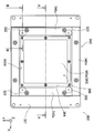
도 5는 상기 진동 장치의 주요부를 나타내는 평면도.
도 6은 상기 진동 장치의 주요부를 나타내는 정면도.
도 7은 상기 진동 장치에 있어서의 가동대가 제1 수평 방향으로 이동했을 때를 나타내는 평면도.
도 8은 상기 진동 장치에 있어서의 가동대가 제2 수평 방향으로 이동했을 때를 나타내는 평면도.
도 9는 상기 진동 장치에 있어서의 가동대가 수직 방향으로 이동했을 때를 나타내는 정면도.
도 10은 상기 진동 장치의 가진 방향을 나타내는 개념도.
도 11은 상기 진동 장치에 있어서의 각 방향으로의 주기적 가진력 간의 위상차와 물품의 반송 속도의 관계를 나타내는 도면.
도 12는 상기 진동 장치에 있어서의 각 방향으로의 주기적 가진력 간의 위상차와 물품의 반송 속도와 마찰 계수의 관계를 나타내는 도면.
도 13은 상기 진동 장치에 있어서의 수평 방향으로의 주기적 가진력의 진폭과 물품의 반송 속도의 관계를 나타내는 도면.
도 14는 상기 진동 장치를 사용하여 물품을 반송한 경우의 반송 궤적을 예시한 평면도.
도 15는 본 발명의 제2 실시 형태에 따른 진동 장치와, 상기 진동 장치를 사용한 물품 분별 장치의 시스템 구성도.
도 16은 상기 진동 장치에 있어서의 각 방향으로의 주기적 가진력 간의 위상차와 물품의 이동 속도의 관계를 나타내는 도면.
도 17은 상기 진동 장치를 사용하여 마찰 계수가 서로 다른 복수의 물품을 이동시킬 때의 이동 영역을 나타낸 평면도.
도 18은 상기 진동 장치를 사용하여 X, Y 방향의 위상차를 변화시켰을 때의, 마찰 계수가 서로 다른 복수의 물품 각각의 이동 영역을 나타낸 설명도.
도 19는 상기 진동 장치를 사용하여 X, Y 방향의 위상차를 변화시켰을 때의, 마찰 계수가 서로 다른 복수의 물품 각각의 이동 영역을 나타낸 설명도.
도 20은 도 18의 (a), (b)에 도시한 조건 시의 물품의 이동 방향을 나타내는 평면도.
도 21은 본 발명의 제3 실시 형태에 따른 진동 장치를 나타내는 사시도.
도 22는 본 발명의 제4 실시 형태에 따른 진동 장치와, 상기 진동 장치를 사용한 물품 반송 장치의 시스템 구성도.
도 23은 상기 진동 장치의 사시도.
도 24는 상기 진동 장치의 평면도.
도 25는 상기 진동 장치의 일부를 떼어낸 상태에 있어서의 사시도.
도 26은 상기 진동 장치의 주요부를 나타내는 사시도.
도 27은 상기 진동 장치의 주요부를 나타내는 평면도.
도 28은 도 24에 있어서의 A-A 단면 화살표도.
도 29는 도 24에 있어서의 B-B 단면 화살표도.
도 30은 본 발명의 제5 실시 형태에 따른 진동 장치와, 상기 진동 장치를 사용한 물품 분별 장치의 시스템 구성도.
도 31은 본 발명의 제6 실시 형태에 따른 진동 장치의 사시도.
도 32는 상기 진동 장치의 일부를 떼어낸 상태에 있어서의 사시도.
도 33은 상기 진동 장치의 평면도.
도 34는 도 33에 있어서의 A-A 단면 화살표도.
도 35는 본 발명의 제7 실시 형태에 따른 진동 장치의 사시도.
도 36은 상기 진동 장치의 일부를 떼어낸 상태에 있어서의 사시도.
도 37은 상기 진동 장치의 평면도.
도 38은 도 37에 있어서의 A-A 단면 화살표도.BRIEF DESCRIPTION OF THE DRAWINGS The system block diagram of the vibration apparatus which concerns on 1st Embodiment of this invention, and the article conveyance apparatus using this vibration apparatus.
2 is a perspective view of the vibration device.
3 is an exploded perspective view of the vibration device.
4 is a perspective view showing a main part of the vibration device;
Fig. 5 is a plan view showing a main part of the vibration device.
Fig. 6 is a front view showing the main part of the vibration device.
Fig. 7 is a plan view showing the movable table in the vibrating device moved in the first horizontal direction.
Fig. 8 is a plan view illustrating the movable table in the vibrating device moved in the second horizontal direction.
Fig. 9 is a front view showing the movable table in the vibrating device moved in the vertical direction.
10 is a conceptual diagram showing an excitation direction of the vibration device.
Fig. 11 is a diagram showing the relationship between the phase difference between the periodic excitation force in each direction in the vibration device and the conveyance speed of the article.
Fig. 12 is a diagram showing the relationship between the phase difference between the periodic excitation force in each direction in the vibration device, the conveyance speed of the article, and the friction coefficient.
The figure which shows the relationship between the amplitude of the periodic excitation force in the horizontal direction, and the conveyance speed of an article in the said vibration apparatus.
14 is a plan view illustrating a conveyance trajectory when the article is conveyed using the vibration device.
The system block diagram of the vibration apparatus which concerns on 2nd Embodiment of this invention, and the article classification apparatus which used the said vibration apparatus.
Fig. 16 is a diagram showing the relationship between the phase difference between the periodic excitation force in each direction in the vibration device and the moving speed of the article.
Fig. 17 is a plan view showing a moving area when the plurality of articles having different friction coefficients are moved using the vibration device.
Fig. 18 is an explanatory diagram showing a moving region of each of a plurality of articles having different friction coefficients when the phase difference in the X and Y directions is changed using the vibration device.
Fig. 19 is an explanatory diagram showing a moving region of each of a plurality of articles having different friction coefficients when the phase difference in the X and Y directions is changed using the vibration device.
20 is a plan view showing a moving direction of an article under the conditions shown in FIGS. 18A and 18B.
The perspective view which shows the vibration apparatus which concerns on 3rd Embodiment of this invention.
The system block diagram of the vibration apparatus which concerns on 4th Embodiment of this invention, and the article conveyance apparatus using the said vibration apparatus.
23 is a perspective view of the vibration device.
24 is a plan view of the vibration device.
The perspective view in the state which removed one part of the said vibration apparatus.
The perspective view which shows the principal part of the said vibration apparatus.
The top view which shows the principal part of the said vibration apparatus.
28 is a cross-sectional view taken along the line AA in FIG. 24.
29 is a cross-sectional view taken along line BB in FIG. 24.
The system block diagram of the vibration apparatus which concerns on 5th Embodiment of this invention, and the article classification apparatus which used the said vibration apparatus.
31 is a perspective view of a vibration device according to a sixth embodiment of the present invention.
The perspective view in the state which removed one part of the said vibration apparatus.
33 is a plan view of the vibration device.
34 is a cross-sectional view taken along the line AA in FIG. 33.
35 is a perspective view of a vibration device according to a seventh embodiment of the present invention.
36 is a perspective view in a state where a part of the vibration device is removed.
37 is a plan view of the vibration device.
38 is a cross-sectional view taken along the line AA in FIG. 37;
이하, 본 발명의 실시 형태를, 도면을 참조하여 설명한다.DESCRIPTION OF THE PREFERRED EMBODIMENTS Hereinafter, embodiments of the present invention will be described with reference to the drawings.
<제1 실시 형태>≪ First Embodiment >
도 1에, 본 발명의 제1 실시 형태에 따른 진동 장치(2)와, 이것을 제어하기 위한 제어 시스템부(3)를 추가하여, 물품 이동 장치의 하나인 물품 반송 장치(1)로서 구성한 형태를 나타낸다.1, the
이 제어 시스템부(3)는 후술하는 바와 같이 진동 장치(2)에 내장된 압전 소자(81, 82, 83)의 제어를 행함으로써, 진동 장치(2)에 제1 수평 방향으로서의 X, 제2 수평 방향으로서의 Y, 수직 방향으로의 Z의 각 방향의 주기적 가진력을 부여하여 진동을 발생시키도록 구성하고 있다.As described later, the
또한, X, Y, Z의 각 방향은 도면 중에 도시한 좌표축으로 나타낸 대로 정의하기로 하고, 이하에 있어서도 적절히 도면 중에서 도시한 좌표축을 따라 설명을 해나가도록 한다.In addition, each direction of X, Y, and Z is defined as shown by the coordinate axis shown in drawing, and below, it demonstrates suitably along the coordinate axis shown in drawing in below.
도 2는, 상기 진동 장치(2)를 실제로 사용하는 상태로서 나타낸 것이다. 이 상태에서는, 베이스(4) 위에 설치되는 커버(42)에 의해 정면과 배면 및 측면의 사면이 덮여 있다. 또한, 상면에는 가동대(6)의 일부를 구성하는 직사각 형상의 반송대(63)가 설치되어 있으며, 그 반송대(63)의 상면(63a)은 반송면으로서 반송하는 물품(9)을 적재할 수 있도록 되어 있다.2 shows a state in which the
도 3에, 상기한 진동 장치(2)로부터 반송대(63)를 떼어낸 상태를 나타낸다. 진동 장치(2)는 그 내부에서 X, Y, Z의 3축 방향에 대하여 탄성적으로 지지된 직육면체 형상이 블록으로서의 가동 받침대(61)를 갖고 있으며, 당해 가동 받침대(61)에 대하여 4개의 접시 나사(62a 내지 62a: 도면 중에서는 2개만 기재)에 의해 직사각형 플레이트 형상의 가동판(62)이 접속되어 있다. 그리고, 가동판(62)의 상면에는 전술한 반송대(63)가 설치되고, 가동판(62)과 반송대(63)는 네 코너의 근방에 설치된 나사 구멍(62b 내지 62b)과 나사(63b 내지 63b)를 사용하여 체결되어 있다.3, the state which removed the
이들 가동 받침대(61), 가동판(62) 및 반송대(63)는 가동대(6)로서 일체화되어 진동 장치(2)의 내부에서 탄성적으로 지지됨과 함께, 후술하는 가진 수단에 의해 진동이 부여된다.These
상기한 커버(42), 가동판(62) 및 반송대(63)를 떼어낸 상태를 도 4에 도시한다. 이하, 이 도면을 이용하여, 본 실시 형태에 따른 진동 장치(2)의 구성을 상세하게 설명한다.The state which removed the said
이 진동 장치(2)는 베이스(2)에 대하여 가동 받침대(61)를 X, Y, Z의 3방향으로 탄성 지지하도록 구성되어 있으며, 강체 부분으로서의 베이스(4), 제1 중간대(51, 51), 제2 중간대(52) 및 가동 받침대(61)를 순차 접속하도록 하여, 제1 수평 탄성 지지 수단으로서의 제1 판상 스프링 부재(71, 71), 제2 수평 탄성 지지 수단으로서의 제2 판상 스프링 부재(72, 72) 및 수직 탄성 지지 수단으로서의 제3 판상 스프링 부재(73, 73)를 설치하고 있다. 각 판상 스프링 부재(71 내지 73)는 각각판 두께 방향이 X, Y, Z 방향이 되도록 배치되어 있기 때문에, 당해 방향에 대하여 탄성 변형을 행하기 쉽게 되어 있다.The
또한, 가동 받침대(61)를 X, Y, Z의 3방향으로 진동시키기 위한 가진 수단으로서의 제1 내지 제3 압전 소자(81 내지 83)를 구비하고 있다.Moreover, the 1st thru | or 3rd piezoelectric elements 81-83 as an excitation means for vibrating the
이하, 이들 구성에 대하여 더 상세히 설명을 행하여 간다.Hereinafter, these structures are demonstrated in detail.
우선, 베이스(4)는 직사각 형상의 플레이트로서 구성되어 있으며, 네 코너에는 도시를 생략한 외부 기기 또는 바닥면에 설치하기 위한 볼트 구멍이 형성되어 있다. 베이스(4) 아래에는, 도시를 생략한 방진 고무 등의 스프링 상수가 작은 탄성체를 설치하면, 설치면에서의 반력을 저감시킬 수 있어서 적합하다.First, the
그리고, 네 코너보다 약간 중심 근방의 위치에 4개소, 직사각 형상으로 배치되도록 하여 설치 블록(41)이 설치되어 있다. 이 도면에서는 기재를 생략하고 있지만, 도 5에 도시한 바와 같이, 각 설치 블록(41)은 나사를 사용하여 베이스(4)에 대하여 고정되도록 하고 있다.And the
도 4로 되돌아가서, 설치 블록(41)은 각각 L자형의 단면을 갖는 블록으로서 형성되어 있으며, L자를 형성하는 한쪽 변을 베이스(4)에 대하여 접촉시킨 상태로 하여, 다른 쪽 변이 기립한 상태로 되어 있다. 그리고, 기립한 변은, X 방향에 대하여 직교하는 YZ 평면을 형성하도록 되어 있다. 그리고, Y 방향으로 쌍을 이뤄 인접하는 설치 블록(41, 41)에 접속하도록 하여, 제1 판상 스프링 부재(71, 71)가 설치되어 있다. 이 제1 판상 스프링 부재(71, 71)는, 전술한 각각의 설치 블록(41 내지 41)이 갖는 YZ 평면에 설치되기 때문에, 판 두께 방향은 X 방향으로 되고 길이 방향은 Y 방향으로 된다.Returning to FIG. 4, the
또한, 제1 판상 스프링 부재(71, 71)는, 2대의 설치 블록(41 내지 41)에 각각 설치되기 때문에, X 방향으로 소정 거리 이격된 상태에서 평행하게 2개 설치되게 된다.In addition, since the 1st plate-shaped
또한, 제1 판상 스프링 부재(71, 71)의 양단부는, 직사각 형상의 스프링 누름대(71d 내지 71d)와 상기 각 설치 블록(41 내지 41)이 갖는 YZ 평면 사이에서 끼워 넣어지도록 하고, 도시를 생략한 나사를 사용하여 고정되어 있기 때문에, 처짐각이 규제되도록 하여 지지된다.In addition, both ends of the first plate-shaped
그리고, 제1 판상 스프링 부재(71, 71)의 길이 방향 중심 부근에는 스프링 시트(71c 내지 71c)를 개재하여 제1 중간대(51, 51)가 각각 접속되어 있다. 제1 중간대(51)는 각각 Y 방향으로 연장되는 직육면체 형상으로 형성되어 있다.The first
스프링 시트(71c 내지 71c)는 제1 판상 스프링 부재(71, 71)에 각각 2개 설치되어 있음과 함께, 이들 각 스프링 시트(71c 내지 71c)와 대향하도록 하여 스프링 누름대(71e 내지 71e)가 설치되어 있다. 제1 판상 스프링 부재(71, 71)는, 대향하는 스프링 시트(71c 내지 71c)와 스프링 누름대(71e 내지 71e)에 의해 끼워 넣어지도록 하여 처짐각이 규제되고, 이들 부분에서 나사(도 5 참조)에 의해 상기 제1 중간대(51, 51)에 접속된다. 제1 중간대(51, 51)는, 2개로 분할된 구성으로 되어 있지만, 후술하는 제2 판상 스프링 부재(72, 72)에 의해 접속되어 있기 때문에, 일체로서 동작을 행하게 된다.Two
상기 제1 중간대(51, 51)는 전술한 바와 같이 직육면체 형상으로 형성되어 있으며, 6면 각각이 X, Y, Z축의 각 면에 직교하는 방향이 되도록 배치되어 있다. 그리고, 각각이 갖는 Y축에 직교하는 XZ면 간을 접속하도록 하고, 2개의 제2 판상 스프링 부재(72, 72)가 설치되어 있다.The first
이와 같이 설치함으로써, 2개의 제2 판상 스프링 부재(72, 72)는, 각각 판 두께 방향이 Y축에 대하여 직교하면서, 길이 방향이 X 방향을 향하게 됨과 함께, 서로 Y 방향으로 소정 거리 이격하여 평행하게 배치되게 된다.By providing in this way, the two second plate-shaped
제2 판상 스프링 부재(72, 72)는, 양단부를 직사각 형상의 스프링 누름대(72d 내지 72d)와 상기 제1 중간대(51, 51)가 갖는 XZ 평면 사이에서 끼워 넣어지도록 하여, 당해 부분에 있어서 나사(도 5 참조)에 의해 고정되어 있기 때문에, 처짐각이 규제되도록 하여 지지되어 있다.The second plate-
제2 판상 스프링 부재(72, 72)의 길이 방향 중심 부근에는 스프링 시트(72c 내지 72c)를 개재하여, 제2 중간대(52)가 접속되어 있다.The 2nd intermediate |
스프링 시트(72c 내지 72c)는 제2 판상 스프링 부재(72, 72)에 각각 2개 설치되어 있음과 함께, 이들 각 스프링 시트(72c 내지 72c)와 대향하도록 하여 스프링 누름대(72e 내지 72e)가 설치되어 있다. 제2 판상 스프링 부재(72, 72)는, 대향하는 스프링 시트(72c 내지 72c)와 스프링 누름대(72e 내지 72e)에 의해 끼워 넣어지도록 하여 처짐각이 규제되고, 이들 부분에서 나사(도 5 참조)에 의해 상기 제2 중간대(52)에 접속된다.Two
제2 중간대(52)는 도 5의 평면도에 도시한 바와 같이, 직사각형의 프레임체로서 구성되어 있으며 X, Y, Z 방향으로 직교하는 6면을 갖는 직육면체의 블록을 4개 조합함으로써 형성되어 있다.As shown in the plan view of FIG. 5, the second
스프링 시트(72c 내지 72c)와 스프링 누름대(72e 내지 72e)에는, 도 6에 도시한 바와 같이 긴 구멍이 형성되어 있으며, 도 5와 같이 하여 당해 긴 구멍을 삽입 관통하는 나사에 의해 제2 중간대(52)에 제2 판상 스프링 부재(72, 72)가 접속되도록 되어 있다. 스프링 시트(72c 내지 72c)와 스프링 누름대(72e 내지 72e)는 그 긴 구멍만큼 X 방향, 즉 제2 판상 스프링 부재(72, 72)의 길이 방향으로 이동할 수 있도록 되어 있으며, 이에 의해 제2 판상 스프링 부재(72, 72)는, 스프링으로서 작용하는 유효 길이를 바꿀 수 있도록 되어 있다.Long holes are formed in the
마찬가지로, 전술한 제1 판상 스프링 부재(71, 71)를 제1 중간대(51, 51)에 대하여 접속하기 위한 스프링 시트(71c 내지 71c)와 스프링 누름대(71e 내지 71e)에 대해서도 긴 구멍이 형성되어 있으며, 그 긴 구멍만큼 Y 방향으로 이동할 수 있도록 되어 있기 때문에, 이에 의해 제1 판상 스프링 부재(71, 71)의 유효 길이도 바꿀 수 있도록 되어 있다.Similarly, long holes are also formed in the
상기한 바와 같이 제1 판상 스프링 부재(71, 71) 및 제2 판상 스프링 부재(72, 72)는 각각, 유효 길이를 변화함으로써, 스프링 상수를 변화시킴과 함께 고유 진동수도 또한 변화시킬 수 있다.As described above, the first plate-shaped
도 4로 되돌아가서, 직사각형의 프레임체로서 구성되어 있는 제2 중간대(52)의 상면과, 하면에는 각각, 2개씩 계 4개의 제3 판상 스프링 부재(73 내지 73)가 설치되어 있다. 제3 판상 스프링 부재(73 내지 73)는 각각 제2 중간대(52)를 형성하는 직사각형을 구성하는 변 중, Y 방향에 평행한 2변의 위치에 존재하는 부분의 상면 및 하면으로서 형성되는 각 XY 평면 사이를 X 방향으로 접속하도록 하여 설치되어 있다. 제3 판상 스프링 부재(73 내지 73)는 양단부를 직사각 형상의 스프링 누름대(73c 내지 73c)와 상기 제2 중간대(52)가 갖는 XY 평면 사이에서 끼워 넣어지도록 하여, 이 부분에서 나사(도 5 참조)를 사용하여 고정되어 있기 때문에, 처짐각이 규제되도록 하여 지지되어 있다.Returning to FIG. 4, four third plate-
또한, 제2 중간대(52)의 상면에 접속되는 제3 판상 스프링 부재(73, 73)와, 제2 중간대(52)의 하면에 접속되는 제3 판상 스프링 부재(73, 73: 도 5 참조)의 중앙부 근방에는, 양자 간격을 유지하기 위해 간극에 스프링 간 블록(73e)이 설치되어 있다.Further, third
또한, 상기 스프링 간 블록(73e)의 하방에는, 제2 중간대(52)의 하면에 접속되는 제3 판상 스프링 부재(73, 73)를 끼워, 스프링 누름대(73e)가 설치되어 있다. 스프링 누름대(73e)는 2개의 제3 판상 스프링 부재(73, 73)를 제2 중간대(52)의 하면 사이에서 끼워 넣은 상태로 하여, 도시를 생략한 나사를 사용하여 고정을 행할 수 있다.Moreover, below the said
또한, 상기 스프링 간 블록(73e)의 상방에는, 제2 중간대(52)의 상면에 접속되는 제3 판상 스프링 부재(73, 73)를 끼워, 전술한 가동 받침대(61)가 설치되어 있다. 가동 받침대(61)는 2개의 제3 판상 스프링 부재(73, 73)를 제2 중간대(52)의 상면 사이에서 끼워 넣은 상태로 하여, 도 5에 도시한 바와 같은 형태로 나사를 사용하여 고정을 행할 수 있다. 가동 받침대(61)의 상면에는 도 3과 같이 가동판(62)의 설치를 행하기 위해서, 상기한 나사는 헤드가 튀어나오지 않도록 배려하고 있다.Moreover, above the said
상기한 바와 같이, 도 4에 도시한 본 실시 형태의 진동 장치(2)에서는, 베이스(4)에 대하여 제1 중간대(51, 51)가 제1 판상 스프링 부재(71, 71)를 사용하여 X 방향으로 탄성적으로 지지되고, 제1 중간대(51, 51)에 대하여 제2 중간대(52)가 제2 판상 스프링 부재(72)를 사용하여 Y 방향으로 탄성적으로 지지되며, 제2 중간대(52)에 대하여 가동 받침대(61)가 제3 판상 스프링 부재(73)를 사용하여 Z 방향으로 탄성적으로 지지되는 구성으로 되어 있다. 이에 의해, 가동대(6)는 베이스(4)에 대하여 X, Y, Z의 각 방향으로 탄성적으로 지지되도록 되어 있다.As mentioned above, in the
각 판상 스프링 부재(71 내지 73)는 각각 판 두께 방향이 되는 X, Y, Z 방향으로 탄성을 가짐과 함께, 이와 직교하는 폭 방향, 길이 방향으로는 충분한 강성을 갖는다. 그로 인해, 각 방향으로의 지지는 독립적인 것이라고 생각할 수 있다.Each of the plate-shaped
또한, 각 방향에 대하여 제1 내지 제3 판상 스프링 부재(71 내지 73)를 각각 평행하게 설치하고, 쌍을 이뤄 지지시킴으로써, 마치 평행 링크의 일부를 구성하듯이 구성하고 있다. 이에 의해, 각 판상 스프링 부재(71 내지 73)는 비틀림 운동을 행하지 않고, 쌍을 이루는 것끼리 사이에서 간극을 일정하게 한 관계를 유지한 채 변위할 수 있도록 되어 있다.Further, the first to third plate-
또한, 본 실시 형태의 진동 장치에서는, X, Y, Z 방향으로 독립한 제1 수평 가진 수단(81), 제2 수평 가진 수단(82) 및 수직 가진 수단(83)을 갖고 있다.Moreover, the vibration apparatus of this embodiment has the 1st horizontal excitation means 81, the 2nd horizontal excitation means 82, and the vertical excitation means 83 independent in the X, Y, and Z directions.
우선, X 방향으로의 가진 수단인 제1 수평 가진 수단은, 2개의 제1 판상 스프링 부재(71, 71)의 표면에 각각 2개씩 부착 설치된 합계 4개의 제1 압전 소자(81 내지 81)로 구성된다. 이 제1 압전 소자(81 내지 81)는 전압을 인가함으로써, Y 방향으로 신장 또는 수축이 발생하고, 제1 판상 스프링 부재(71, 71)에 굽힘을 발생시킴으로써 X 방향의 변위를 발생시키는 것이 가능하게 되어 있다.First, the first horizontal excitation means, which is an excitation means in the X direction, is composed of four first
제1 판상 스프링 부재(71, 71)는 단부의 스프링 누름대(71d)에 의해 위치 결정되는 베이스측 접속점(71a)으로부터, 중앙의 스프링 시트(71c)와 스프링 누름대(71e)에 의해 위치 결정되는 제1 중간대 측 접속점(71b) 사이에서, 그 중앙에 굽힘 방향이 변화하는 굴곡점을 갖기 때문에, 당해 부분으로까지 제1 압전 소자(81 내지 81)를 접착하는 것은, 오히려 변형을 저해하여 효율을 저하시키게 된다. 그로 인해, 제1 압전 소자(81 내지 81)는 스프링 유효 길이의 중앙을 피하여, 어느 한쪽의 단부 근방에 설치하는 것이 효율적이다.The first plate-shaped
제1 압전 소자(81 내지 81)는 각각 단부에서 동일한 위치에 설치되어 있음과 함께, 출력을 조정함으로써 동일한 변형을 발생시킬 수 있다. 이와 같이 함으로써, 도 7과 같이, X 방향으로 이격시킨 제1 판상 스프링 부재(71, 71)의 간격을 유지한 채 동일하게 변형시킬 수 있어, 제1 중간대(51, 51)를, 수평 상태를 유지한 채 X 방향으로만 변위시킬 수 있다.The first
다음으로, 도 4로 되돌아가서, Y 방향으로의 가진 수단인 제2 수평 가진 수단은, 전술한 제1 수평 가진 수단과 마찬가지로, 2개의 제2 판상 스프링 부재(72, 72)의 표면에 각각 2개씩 부착 설치된 합계 4개의 제2 압전 소자(82 내지 82)로 구성된다. 이 제2 압전 소자(82 내지 82)는 전압이 인가됨으로써, X 방향으로 신장 또는 수축이 발생하고, 제2 판상 스프링 부재(72, 72)에 굽힘을 발생시킴으로써 Y 방향의 변위를 발생시키는 것이 가능하게 되어 있다. 제2 압전 소자(82 내지 82)도, 제1 압전 소자(81 내지 81)와 마찬가지의 위치에 설치가 이루어져 있으며, 이와 같이 함으로써, 도 8과 같이, Y 방향으로 이격시킨 제2 판상 스프링 부재(72, 72)의 간격을 유지한 채 동일하게 변형시킬 수 있어, 제2 중간대(52)를 수평 상태를 유지한 채 Y 방향으로만 변위시킬 수 있다.Next, returning to FIG. 4, the second horizontal excitation means, which is the excitation means in the Y direction, is provided on the surfaces of the two second plate-
또한, 도 4로 되돌아가서, Z 방향으로의 가진 수단인 수직 가진 수단은, 상하에 2개씩 설치되어 있는 판상 스프링 부재(73 내지 73) 중 상측의 2개의 판상 스프링 부재(73, 73)의 표면에 각각 2개씩 부착 설치된 합계 4개의 제3 압전 소자(83 내지 83)로 구성된다. 이 제3 압전 소자(83 내지 83)는 전압이 인가됨으로써, X 방향으로 신장 또는 수축을 발생하고, 제3 판상 스프링 부재(73, 73)에 굽힘을 발생시킴으로써 Z 방향의 변위를 발생시키는 것이 가능하게 되어 있다. 제3 압전 소자(83 내지 83)도, 제1 압전 소자(81 내지 81) 및 제2 압전 소자(82 내지 82)와 마찬가지의 위치에 설치가 이루어져 있으며, 이와 같이 함으로써, 도 9와 같이, Z 방향으로 이격시킨 제3 판상 스프링 부재(73, 73)의 간격을 유지한 채 동일하게 변형시킬 수 있어, 가동 받침대(61)를 수평 상태를 유지한 채 Z 방향으로만 변위시킬 수 있다. 또한, 제3 압전 소자(83 내지 83)를 하측에 설치하고 있는 2개의 제3 판상 스프링 부재(73, 73)에 설치하는 것도 가능하며, 상측과 하측의 계 4개의 제3 판상 스프링 부재(73 내지 73)에 설치하는 것도 가능하다.4, the vertical excitation means which is an excitation means in a Z direction is the surface of the upper two plate-shaped
상기한 바와 같이 X, Y, Z의 각 방향으로 변위를 부여할 수 있는 전압을 각각 정현파 형상으로 변화시킴으로써 가동 받침대(61)에 대하여 각 방향으로 주기적인 가진력을 부여할 수 있다.As described above, periodic excitation force can be applied to the
상기와 같이 하여 구성한 진동 장치(2)에 대하여 도 1에 도시한 제어 시스템부(3)는 제1 압전 소자(81), 제2 압전 소자(82) 및 제3 압전 소자(83)에 각각 정현파 형상의 제어 전압을 부여함으로써, X, Y, Z의 각 방향의 진동을 발생시키기 위한 주기적 가진력을 발생시킨다.The
그로 인해, 제어 시스템부(3)는 정현 전압을 발생시키는 발진기(34)를 구비하고 있으며, 이 정현 전압을 증폭기(35)에 의해 증폭한 후에, 각 압전 소자(81, 82, 83)로 출력한다. 또한, 상기 제어 시스템부(3)는 X, Y, Z의 각 방향의 제어 전압을 상세하게 조정하기 위한 진동 제어 수단(31)을 갖고 있다. 또한, 발진기(34)에 의해 발생시키는 진동의 주파수는, X, Y, Z 방향 중 어느 한쪽의 진동계와 공진하는 주파수로 함으로써, 진동을 증폭하여 전력 절약화를 도모하도록 하고 있다. 이때, 모든 방향의 진동계의 진동이 간섭하는 것을 피하기 위해서는, 각 방향의 고유 진동수를 이격하여도 된다. 그 경우, 각 방향의 고유 진동수는 예를 들어 -10% 내지 +10% 정도 이격하도록 한다.Therefore, the
또한, 본 실시 형태에 있어서는, 전술한 바와 같이 제1 판상 스프링 부재(71, 71) 및 제2 판상 스프링 부재(72, 72)의 유효 길이를, 스프링 시트(71c 내지 71c, 72c 내지 72c)에 의해 각각 변경하는 것이 가능하다. 그로 인해, Z 방향의 고유 진동수를 기준으로 하여, X 방향 및 Y 방향의 고유 진동수를 각각 적절한 값으로 되도록 변경 조정하는 것이 가능하다.In addition, in this embodiment, as mentioned above, the effective length of the 1st plate-shaped
진동 제어 수단(31)은 크게는, X, Y, Z의 각 방향의 제어 전압의 진폭을 조정하는 진폭 조정 회로(31a)와, 각각의 위상차를 조정하기 위한 위상 조정 회로(31b)로 이루어진다. 본 실시 형태에서는, X, Y, Z의 각 제어 전압에 각각 대응한 진폭 조정 회로(31a)를 가짐과 함께, Z 방향의 제어 전압의 위상을 기준으로 하여, 이와 소정의 위상차가 되도록 제어 전압의 위상을 조정하는 위상 조정 회로(31b)를 X, Y의 제어 전압에 대하여 각각 설치하도록 구성하고 있다.The vibration control means 31 consists of the
그리고, 제어 시스템부(3)는 반송하는 물품(9)에 따른 반송 경로 및 반송 속도를 결정하기 위한 반송 경로 결정 수단(33)과, 결정한 반송 경로와 반송 속도에 따라서 각 진폭 조정 회로(31a) 및 각 위상 조정 회로(31b)에 구체적인 제어값을 변경하기 위한 명령을 내리는 진동 전환 수단(32)을 갖고 있다.And the
그리고, 반송 경로 결정 수단(33)은 반송하는 물품(9)에 따른 반송 경로와 반송 속도의 데이터를 내부에 복수 보존하고 있으며, 그 중에서 도시를 생략한 외부로부터의 지시에 의해 반송 경로와 반송 속도를 선택한 후에, 거기에서 선택한 반송 경로 및 반송 속도에 맞춰서 진동 형태를 전환하도록 진동 전환 수단(32)에 대하여 명령을 부여한다.The conveying path determining means 33 stores a plurality of data of the conveying path and conveying speed in accordance with the
또한, 진동 전환 수단(32)에서는 반송 경로나 반송 속도가 명령된 목표값이 되도록, 각 진폭 조정 회로(31a) 및 각 위상 조정 회로(31b) 각각의 구체적인 제어값을 결정하여 당해 제어값으로 전환하도록 명령을 출력한다.In addition, in the vibration switching means 32, specific control values of each of the
상기와 같이 구성한 물품 반송 장치(1)는 구체적으로는 다음과 같이 동작하고, 가동대(6)에 적재한 물품(9)의 반송이나 분별 등을 행한다.The
여기서, 도 10의 모식도에 도시한 바와 같이 간략화하여, 가동대(6)가 베이스(4)에 대하여 X, Y, Z의 각 방향으로 탄성체(74, 75, 76)에 의해 탄성적으로 지지함과 함께, 각 방향의 가진 수단(84, 85, 86)을 설치하고 있는 경우를 상정한다. 이와 같이 구성함으로써, X, Y, Z의 3방향으로 설치한 가진 수단(84, 85, 86)에 의해 가동대(6)를 3방향으로 동작시키는 것이 가능하게 되어 있다. 도 10의 모식도에 있어서의 탄성체(74 내지 76)는 제1 내지 제3 판상 스프링 부재(71 내지 73: 도 4 참조)에 상당함과 함께, 가진 수단(84 내지 86)은 각각 제1 및 제2 수평 가진 수단 및 수직 가진 수단으로서의 제1 내지 제3 압전 소자(81 내지 83: 도 4 참조)에 상당한다.Here, as shown in the schematic diagram of FIG. 10, the movable table 6 is elastically supported by the
도 10에 도시한 모델의 가동대(6)에 대하여 Z 방향으로 Z=Z0×sinωt로 표현되는 주기적인 진동 변위를 부여한다. 여기서, Z0은 Z 방향의 진폭을, ω는 각 주파수를, t는 시간을 나타낸다. 또한, X, Y 방향으로도 각각 Z 방향과 동일 주파수의 진동을, X=X0×sin(ωt+φx), Y=Y0×sin(ωt+φy)의 식과 같이 부여하기로 한다. 여기서, X0, Y0은 각각 X 방향, Y의 진폭을, φx, φy는 각각 X 방향, Z 방향의 진동의 Z 방향의 진동에 대한 위상차를 나타낸다.To the movable table 6 of the model shown in FIG. 10, periodic vibration displacement expressed by Z = Z 0 × sinωt in the Z direction is given. Here, Z 0 represents the amplitude in the Z direction, ω represents each frequency, and t represents time. In addition, in the X and Y directions, vibrations of the same frequency as the Z direction are respectively given by the formulas of X = X 0 × sin (ωt + φx) and Y = Y 0 × sin (ωt + φy). Here, X 0 and Y 0 each represent the amplitude of the X direction and Y, and φx and φy represent the phase differences with respect to the vibration in the Z direction of the vibrations in the X direction and the Z direction, respectively.
이와 같이, X, Y, Z의 각 방향으로 정현파 형상의 주기적인 진동 변위를 가함으로써, 가동대(6)에는 이들이 합성된 3차원적인 진동을 발생시킬 수 있다. 예를 들어, 도 10에 도시한 바와 같이, Z 방향의 진동 성분에 대하여 φx, φy의 위상차를 갖게 하여 X, Y 방향의 진동을 발생시켰을 때, 2차원적으로는 XZ 평면 위에서 우측을 위로 한 타원궤도를 갖는 진동이 발생하고, YZ 평면 위에서 우측을 아래로 한 타원궤도를 갖는 진동이 발생한다. 그리고, 또한 이 2개를 합성함으로써, 도면 중 우측 아래에 도시한 바와 같이 3차원 공간상에서의 타원궤도가 발생한다.As described above, by applying a sine wave-shaped periodic vibration displacement in each of X, Y, and Z directions, the movable table 6 can generate three-dimensional vibrations. For example, as shown in Fig. 10, when the vibration component in the Z direction has a phase difference of φx and φy to generate vibrations in the X and Y directions, two-dimensionally, the right side is upward on the XZ plane. Vibration with an elliptical orbit occurs, and vibration with an elliptical orbit with the right side down on the YZ plane occurs. Further, by combining these two, an elliptic orbit in three-dimensional space is generated as shown in the lower right of the figure.
그리고, 각 방향의 진동 변위의 진폭 및 위상을 바꿈으로써, XZ 평면, YZ 평면 내의 2차원 타원궤도의 크기나 방향을 변경할 수 있고, 대응하여 3차원 공간상의 타원궤도의 크기나 방향을 자유롭게 변경할 수 있다. 또한, 이와 같이 각 방향으로의 주기적인 진동 변위를 부여하기 위해서, 제어상은 각 방향으로의 주기적 가진력을 부여함으로써 대응을 행하고 있다.By changing the amplitude and phase of the vibration displacement in each direction, the magnitude or direction of the two-dimensional elliptical orbit in the XZ plane and the YZ plane can be changed, and the magnitude or direction of the elliptical orbit in the three-dimensional space can be freely changed. have. In addition, in order to give periodic vibration displacement in each direction in this way, a control phase respond | corresponds by giving periodic excitation force in each direction.
이상과 같이, 가동대(6)가 타원궤도를 그리면서 진동함으로써, 가동대(6) 위에 적재된 물품(9)은 이동을 행한다. 그리고, 이 이동 중 X 방향으로의 이동 속도 성분은 상기 XZ 평면 내의 타원궤도에 의해 제어할 수 있고, Y 방향으로의 이동 속도 성분은 상기 YZ 평면 내의 타원궤도에 의해 제어할 수 있다. 즉, Z 방향으로의 진동 성분을 기준으로 하여 X 방향, Y 방향 각각의 진동의 진폭과 위상차를 변화시킴으로써, X, Y 방향으로의 이동 속도 성분을 변화시켜서, 임의의 방향으로 반송시키는 것이 가능해진다.As described above, when the movable table 6 vibrates while drawing an elliptical orbit, the
구체적으로는 이동 속도의 변경은 다음과 같이 하여 행한다.Specifically, the movement speed is changed as follows.
발명자들의 지견에 따라 도 10을 참조하면서 도 11을 이용하여 설명하면, 위상차 φx(φy)에 의해 물품(9)의 이동 속도 Vx(Yy)는 정현파에 유사한 커브를 그리도록 변화한다. 그로 인해, Z 방향의 진동 성분에 대한 X 방향의 진동 성분의 위상차를 도 10에 있어서의 φ12로 설정했을 때에는 X가 정으로 되는 방향으로 물품(9)은 반송되어 간다. 또한, 위상차를 φ14로 설정했을 때에는, X가 부로 되는 방향으로 물품(9)은 반송되어 간다. 이들에 대하여 위상차를 φ11, φ13으로 설정했을 때에는, 이동 속도 Vx는 0으로 되어, 물품(9)은 X 방향으로 정지한 상태로 된다. 또한, φ11 내지 φ13의 사이 또는 φ13 내지 π(-π) 내지 φ11의 사이에서 위상차를 변화시킴으로써, 각각 정의 방향, 부의 방향에 대한 속도를 증감시킬 수 있다. 이러한 관계는, X 방향뿐만 아니라 Y 방향으로도 성립되고, 마찬가지로 Z 방향의 진동 성분에 대한 위상차를 설정함으로써 이동 방향과 이동 속도를 변화시킬 수 있다.Referring to FIG. 11 with reference to FIG. 10 in accordance with the inventors' knowledge, the moving speed Vx (Yy) of the
이와 같이, X, Y 각 방향의 진동 성분의 진폭 X0, Y0과, Z 방향 진동 성분에 대한 위상차 φx, φy를 변화시킴으로써, X, Y 방향으로의 이동 속도 Vx, Vy를 변화시킬 수 있다.In this way, by changing the amplitudes X 0 , Y 0 of the vibration components in each of the X and Y directions and the phase differences φx and φy with respect to the Z-direction vibration components, the moving speeds Vx and Vy in the X and Y directions can be changed. .
또한, 발명자들의 지견에 따라 도 10을 참조하면서 설명하면, 도 11에서 도시한 위상차와 물품(9)의 이동 속도 Vx(Yy)의 관계를 나타내는 커브는, 물품(9)과 가동대(6)의 마찰 계수에 따라 변화하고, 도 12에 도시한 관계로 된다. 즉, 2종류의 물품 W11, W12와 가동대(6) 사이의 마찰 계수를 각각 μ11, μ12로 하여 μ11<μ12의 관계가 있을 때, W12일 때의 이동 속도의 그래프는, W11일 때의 이동 속도의 커브를 위상차가 정으로 되는 방향으로 어긋난 형상으로 된다. 그로 인해, 타원 진동을 행하는 가동대(6) 위에 동시에 마찰 계수가 서로 다른 물품(9)을 놓은 경우에는, 이동 속도 및 이동 방향이 상이하게 된다.In addition, with reference to FIG. 10 according to the knowledge of the inventors, the curve which shows the relationship between the phase difference shown in FIG. 11 and the moving speed Vx (Yy) of the
구체적으로는, 도 12에 도시한 위상차 φ11로 설정하고 있는 경우에는 W11은 이동하지 않고, W12가 부의 방향으로 이동하게 된다. 또한, 위상차를 φ11로부터 φ12 사이로 설정한 경우에는, W11을 정의 방향으로, W12를 부의 방향으로 이동시킬 수 있다. 그리고, φ12로 설정하면, W12를 이동시키지 않고, W11만을 정의 방향으로 이동시킬 수 있다. 또한, φ12로부터 φ14의 사이로 설정하면, W11, W12 모두 정의 방향으로 이동시킬 수 있지만, φ13을 경계로 W11과 W12의 속도의 대소를 교체할 수 있다. 또한, φ12로부터 φ14의 범위에서 위상차를 미세하게 변경하면, W11과 W12의 속도비도 변경할 수 있다.Specifically, in the case where the phase difference? 11 shown in Fig. 12 is set, W11 does not move, and W12 moves in the negative direction. When the phase difference is set between φ11 and φ12, W11 can be moved in the positive direction and W12 in the negative direction. And if it sets to (phi) 12, only W11 can be moved to a positive direction, without moving W12. Moreover, if it sets between φ12 and φ14, both W11 and W12 can be moved to a positive direction, but the magnitude of the speed of W11 and W12 can be changed around phi13. If the phase difference is minutely changed in the range of φ12 to φ14, the speed ratio between W11 and W12 can also be changed.
그리고, 위상차를 φ14로 하면, W11을 이동시키지 않고, W12만을 정방향으로 이동시킬 수 있다. 또한, 위상차를 φ14로부터 φ15의 사이로 설정하면, W12를 정 방향으로, W11을 부의 방향으로 이동시킬 수 있다. 위상차를 φ15로 설정하면, W12를 이동시키지 않고 W11만을 부의 방향으로 이동시킬 수 있다. 그리고, 위상차를 φ15로부터 π의 범위로 했을 때에는, W11과 W12의 양쪽 모두 부의 방향으로 이동시킬 수 있고, 이 범위에서 위상차를 바꿈으로써 양자의 이동 속도의 비를 변경할 수도 있다.When the phase difference is 14, only W12 can be moved in the forward direction without moving W11. If the phase difference is set between φ14 and φ15, W12 can be moved in the positive direction and W11 can be moved in the negative direction. If the phase difference is set to φ15, only W11 can be moved in the negative direction without moving W12. When the phase difference is in the range of φ15 to π, both of W11 and W12 can be moved in the negative direction, and the ratio of the moving speeds of both can be changed by changing the phase difference in this range.
또한, 발명자들의 지견에 따라 도 10을 참조하면서 도 13을 이용하여 설명하면, 위상차 φx(φy)와 물품(9)의 이동 속도 Vx(Yy)의 관계는, 진폭 X0(Y0)을 바꿈으로써도 변화한다. 즉, 위상차 φx(φy)에 대한 물품(9)의 이동 속도 Vx(Yy)인 정현파 유사의 커브는, 대강 진동 변위의 진폭 X0(Y0)에 비례하여 변화한다. 이러한 점에서, 물품(9)의 이동 속도 Vx(Yy)를 2배로 하고자 하는 경우에는, 대체로 X(Y) 방향의 진동 변위의 진폭을 2배로 하면 된다. 그를 위해서는, 그에 따른 가진력을 부여하기 위해, 제어 전압의 진폭을 변화시키면 된다.Further, if described with reference to figure 13, with reference to Figure 10 according to the knowledge of the inventors, the phase difference between the φx (φy) and the article (9) moving velocity Vx (Yy) of the can, varying the amplitude X 0 (Y 0) Also changes. That is, the sine wave-like curve, which is the moving speed Vx (Yy) of the
이와 같이 하여, 마찰 계수가 서로 다른 2종의 물품(9)을 X(Y) 방향으로 반송하는 경우에 있어서는, Z 방향의 진동에 대한 X(Y) 방향의 진동 위상차 φx(φy)를 변경함으로써, 2종의 물품(9) 중 어느 쪽만을 이동시키는 것이나, 이동 방향을 바꾸면서 속도비를 바꿀 수 있게 되고, 또한 X(Y) 방향의 진동의 진폭을 바꿈으로써, 이동 속도의 절댓값을 제어할 수 있다. 이들을 조합함으로써, 한쪽의 속도를 유지한 채로, 다른 쪽의 속도를 변경하는 것이나 반송 방향을 변경하는 것도 가능해진다.In this way, when conveying two kinds of
이상과 같은, 1방향으로의 반송 속도 및 방향 제어를, 2방향으로 전개함으로써 XY 평면 내에서 자유롭게 이동시키는 것이 가능해진다. 즉, 수평 방향의 진동을 X, Y의 2방향으로 하여, Z 방향의 진동과 각각 조합함으로써, XZ 평면 내의 타원 진동, YZ 평면 내의 타원 진동을 각각 만들어내고, 이들을 합성한 3차원적인 타원 진동을 발생시켜서, 이 타원 진동의 방향이나 크기를 3차원적으로 전환함으로써, 보다 상세하게 물품(9)의 이동 방향이나 이동 속도를 제어할 수 있다. 그리고, Z 방향의 제어 전압에 의해 발생하는 주기적 가진력을 기준으로 하여, X 방향, Y 방향의 제어 전압에 의해 발생하는 주기적 가진력의 진폭이나 위상을 각각 변경함으로써, XZ 평면 내의 타원 진동 성분과 YZ 평면 내의 타원 진동 성분을 각각 변경하면, 전술한 도 11 내지 도 13의 관계를 따라서 각각 X 방향, Y 방향의 이동 속도 성분을 물품(9)에 부여하는 것이 가능해진다.By developing the conveyance speed and direction control in one direction as mentioned above in two directions, it becomes possible to move freely in an XY plane. In other words, by making the vibrations in the horizontal direction into two directions of X and Y, and combining them with the vibrations in the Z direction, respectively, an elliptic vibration in the XZ plane and an elliptic vibration in the YZ plane are generated, respectively, and a three-dimensional elliptic vibration obtained by combining them is obtained. By generating and changing the direction and magnitude | size of this elliptic vibration three-dimensionally, the moving direction and the moving speed of the
이러한 점에서, 구체적으로는 다음과 같이 하여 물품(9)의 반송을 행하게 하는 것이 가능해진다. 이하, 도 1을 참조하면서, 도 14의 (a 내지 f)의 각 물품의 반송 형태를 예시한 평면도에 따라서 설명을 행한다.In this regard, it is possible to specifically carry out the conveyance of the
우선, 물품(9)이 1종만인 경우에는, 도 14의 (a)에 도시한 바와 같이, 물품(9)을 초기(T0)의 시점보다 X 방향으로 이동시켜서, 어떤 시점(T1)보다 Y 방향의 이동 속도 성분도 추가하여 방향을 바꾸어 이동시킬 수 있다. 이러한 경우에는, 물품(9)의 종류에 따라서 반송처를 변경하는 경우나, 별도로 설치한 카메라에 의한 검사 데이터에 기초하여 당해 물품(9)을 불량품이라 판단하여 라인 밖으로 반송하는 경우가 있다. 이와 같은 형태의 반송을 행하기 위해서, 도 1에 있어서의 반송 경로 결정 수단(33)은 외부로부터 피 반송물 관련 데이터로서 반송하는 물품(9)의 종류가 입력되고, 미리 내부에 보존된 데이터에 기초하여 물품(9)에 따른 반송 경로와 반송 속도를 선택하거나, 또는 피 반송물 관련 데이터로서의 검사 데이터에 기초하여 반송 방향과 반송 속도를 결정하여 진동 전환 수단(32)으로 출력한다. 당해 진동 전환 수단(32)에 있어서는, 그 반송 방향과 반송 속도에 대응하여 각 방향의 진동 형태의 전환 필요 여부를 판단함과 함께, 전환이 필요한 경우에는 각 방향의 주기적 가진력의 진폭과 위상을 조정하기 위해 각 진폭 조정 회로(31a) 및 위상 조정 회로(31b)에 구체적인 제어값을 명령한다.First, when there is only one kind of
그리고, 이러한 반송 경로 변경의 판단을 수시 행하여, 진동 전환 수단(32)에 의해 진폭, 위상을 조정해 가면, 도 14의 (b)에 도시한 바와 같이 XY 방향으로 자유 자재의 궤적을 그리게 하면서 물품(9)을 이동시키는 것이 가능해진다. 반송 경로 변경의 판단은, 미리 설정한 타이밍에 의한 것이어도, 외부로부터의 신호에 따라서 행하는 것이어도 된다.Then, when the conveyance path change is judged at any time, and the amplitude and phase are adjusted by the vibration switching means 32, as shown in Fig. 14B, the article is made to draw the trajectory of the free material in the XY direction. It becomes possible to move (9). The determination of the transfer path change may be based on a preset timing or may be performed according to a signal from the outside.
또한, 도 14의 (c)에 도시한 바와 같이, 물품(9a, 9b)이 마찰 계수가 서로 다른 2종의 것인 경우에는 초기 단계(T0)는 1방향으로 동일 속도로 반송해 놓고, 어떤 시점(T1)으로부터 서로 다른 방향으로 분기시켜 이동시키는 것도 가능하다. 이 경우에는 초기 단계(T0)에서는, X 방향으로는 도 12에 있어서의 위상차 φ13으로 진동시켜서, Y 방향으로는 진동을 발생시키지 않게 해놓고, T1의 시점부터 Y 방향으로도 진동을 발생시켜 Z 방향과의 진동 위상차를 φ11과 φ12 사이 또는 φ14와 φ15 사이에서 전환한 것이다. 동시에 X 방향의 속도에 있어서도 Z 방향에 대한 진동 위상차를 φ13보다 어긋나게 함으로써, 물품(9a, 9b) 사이에 X 방향의 속도차를 갖게 하도록 전환하고 있다. 이 진동의 전환에 있어서도, 도 1에 있어서의 반송 경로 결정 수단(33)이 설정된 타이밍에 따라서, 또는 외부로부터 입력된 피 반송물 관련 데이터에 기초하여 적절한 반송 경로와 반송 속도를 결정하고, 그것에 기초하여 진동 전환 수단(32)에 반송 방향 및 반송 속도의 변경 명령을 내린다. 그리고, 당해 진동 전환 수단(32)에 있어서는, 명령된 반송 방향 및 반송 속도에 대응한 각 방향의 진폭, 위상의 구체적 제어값을 결정하고, 각 진폭 조정 회로(31a), 위상 조정 회로(31b)에 당해 제어값으로 변경하도록 명령을 내린다.As shown in Fig. 14C, when the
또한, 마찬가지의 제어를 행함으로써, 도 14의 (d)와 같이 물품(9a, 9b) 중, 한쪽만을 움직이게 하는 것이나, 양자에 속도차를 설치하는 것도 가능하다. 또한, 도 14의 (e)와 같이, 임의의 방향을 선택한 후에, 그 방향을 따라서 서로 역방향으로 이동시키는 것도 가능하다.In addition, by performing the same control, it is also possible to move only one of the
또한, 이와 같은 반송 경로 및 속도의 변경을 연속하여 행함으로써, 도 14의 (f)와 같이 물품(9a, 9b)의 반송 경로와 반송 속도를 XY 평면 내에서, 각각 독립시켜서 동시에 제어하는 것이 가능해진다.In addition, by continuously changing such a conveying path and a speed, as shown in FIG. 14 (f), the conveying path and the conveying speed of the
또한, 상기와 같이 마찰 계수가 서로 다른 물품(9)을 상이한 반송 방향으로 반송시키도록 제어함으로써, 엄밀하게는 마찰 계수가 동일한 것이더라도 표면 형상이 상이한 등, 외관상 마찰 계수를 서로 다르게끔 취할 수 있는 것에 대해서도 반송 방향을 상이하게 할 수도 있다. 예를 들어, 동일 부재의 표면과 이면이더라도, 면의 요철이 서로 달라 가동대(6)와의 접촉 면적이 크게 상이한 경우가 해당한다.In addition, by controlling the conveyance of the
이상과 같이, 본 실시 형태에 따른 진동 장치(2)는 베이스(4)와, 당해 베이스(4)에 대하여 탄성적으로 지지된 가동대(6)와, 당해 가동대(6)를 제1 수평 방향으로서의 X 방향으로 진동시키는 제1 수평 가진 수단(81)과, 상기 가동대(6)를 제1 수평 방향과 교차하는 제2 수평 방향으로서의 Y 방향으로 진동시키는 제2 수평 가진 수단(82)과, 상기 가동대(6)를 수직 방향으로서의 Z 방향으로 진동시키는 수직 가진 수단(83)을 구비한 것으로서, 상기 베이스(4)와 상기 가동대(6) 사이에 제1 중간대(51, 51)와 제2 중간대(52)를 구비함과 함께, 상기 베이스(4), 상기 제1 중간대(51), 상기 제2 중간대(52) 및 상기 가동대(6)를 순차 X, Y, Z의 각 방향으로 탄성적으로 접속하는 제1 수평 탄성 지지 수단과, 제2 수평 탄성 지지 수단과, 수직 탄성 지지 수단을 구비하고 있으며, 제1 수평 탄성 지지 수단이 두께 방향을 상기 제1 수평 방향으로 거의 합치시킴과 함께 길이 방향을 수평한 방향으로 배치한 제1 판상 스프링 부재(71)로 구성되고, 상기 제2 수평 탄성 지지 수단이 두께 방향을 상기 제2 수평 방향으로 거의 합치시킴과 함께 길이 방향을 수평한 방향으로 배치한 제2 판상 스프링 부재(72)로 구성되며, 상기 수직 탄성 지지 수단이 두께 방향을 상기 수직 방향으로 거의 합치시킴과 함께 길이 방향을 수평한 방향으로 배치한 제3 판상 스프링 부재(73)로 구성한 것이다.As described above, the
이와 같이 구성하고 있기 때문에, 가동대(6)를 탄성적으로 지지하는 탄성 지지 수단으로서의 제1 내지 제3 판상 스프링 부재(71 내지 73)를 X, Y, Z의 각 방향으로 탄성 변형하기 쉬운 방향으로 갖고 있음과 함께, 각 판상 스프링 부재(71 내지 73)는 판 두께 방향과는 상이한 방향으로는 큰 강성을 갖고 있기 때문에, 가동대(6)를 각 방향으로 각각 독립적으로 탄성 지지시킬 수 있다. 그로 인해, 제1 수평 가진 수단(81), 제2 수평 가진 수단(82) 및 수직 가진 수단(83)에 의해 각자 방향으로 진동시키는 경우에, 서로의 방향에 영향을 주지 않고 독립적으로 진동을 제어시킬 수 있다. 또한, 이들 판상 스프링 부재(71 내지 73)를 각각 길이 방향이 수평해지는 방향으로 배치하고 있는 점에서, 베이스(4)로부터 가동대(6)까지의 높이를 억제할 수 있어, 가동대(6)의 피칭이나 롤링을 억제할 수 있다.Since it is comprised in this way, the direction which is easy to elastically deform the 1st-3rd plate-shaped spring member 71-73 as an elastic support means which elastically supports the
또한, 상기 제1 내지 제3 판상 스프링 부재(71 내지 73)가 소정 거리 이격하여 평행하게 복수개 설치되어 있도록 구성하고 있기 때문에, 각 판상 스프링 부재(71 내지 73)는 평행 링크의 일부를 구성하도록 접속되기 때문에, 각 방향에 대하여 간격을 일정하게 한 상태를 유지한 채 변위하기 쉬워진다. 그로 인해, 각 판상 스프링 부재(71 내지 73)는 비틀림 형태에서의 변형이 억제되기 때문에, 보다 상기한 3방향으로의 지지를 안정적으로 행하게 할 수 있게 된다.Moreover, since the said 1st-3rd plate-shaped spring members 71-73 are comprised so that it may be provided in parallel and spaced apart by the predetermined distance, each plate-shaped spring member 71-73 is connected so that it may comprise a part of parallel link. Therefore, it becomes easy to displace, maintaining the state which fixed the space | interval for each direction. Therefore, since each deformation | transformation in a torsional form is suppressed in each plate-shaped spring member 71-73, it becomes possible to carry out support to the above-mentioned three directions more stably.
또한, 각 가진 수단이 상기 제1 내지 제3 판상 스프링 부재(71 내지 73)의 적어도 편면에 부착 설치된 압전 소자(81 내지 83)이며, 이들 압전 소자(81 내지 83)에 정현 전압을 부여하여 주기적인 신장을 발생시킴으로써, 상기 제1 내지 제3 판상 스프링 부재(71 내지 73)를 진동시키도록 구성하고 있기 때문에, 탄성 지지 수단으로서의 각 판상 스프링 부재(71 내지 73)와, 가진 수단(81 내지 83)을 일체화함으로써 구성을 간단하게 하여 콤팩트화를 행하는 것이 가능해진다.Moreover, each excitation means is the piezoelectric elements 81-83 attached to at least one surface of the said 1st-3rd plate-shaped spring members 71-73, and give a sine voltage to these piezoelectric elements 81-83. Since the first to third plate-shaped
또한, 상기 제1 중간대(51)와 상기 제1 판상 스프링 부재(71)의 사이, 및 상기 제2 중간대(52)와 상기 제2 판상 스프링 부재(72) 사이에 각각 스프링 시트(71c 내지 72c)가 설치되어 있으며, 당해 스프링 시트(71c 내지 72c)의 위치가 각각 상기 제1 및 제2 판상 스프링 부재(71, 72)의 길이 방향에 대하여 변경 가능하게 구성되어 있기 때문에, 각 스프링 시트(71c 내지 72c)의 위치를 판상 스프링 부재(71, 72)의 길이 방향에 대하여 변경함으로써, 간단하게 판상 스프링 부재(71, 72)의 고유 진동수를 바꿀 수 있다. 이에 의해, 각 방향에 대한 고유 진동수를 이격시키거나, 근접시키거나 하는 조정을 간단하게 행할 수 있게 된다.Further,
또한, 본 실시 형태에 따른 물품 반송 장치(1)는 가동대(6)의 진동에 의해 가동대(6) 위에 적재된 물품(9)을 반송하는 것으로서, 상기한 진동 장치(2)와, 당해 진동 장치(2)가 갖는 복수의 가진 수단(81 내지 83)에 의한 주기적 가진력을, 위상차를 가지면서 동일한 주파수로 동시에 발생시켜 상기 가동대(6)에 3차원의 진동 궤적을 발생시키도록 상기 각 가진 수단(81 내지 83)을 제어하는 진동 제어 수단(31)과, 상기 각 가진 수단(81 내지 83)에 의한 주기적 가진력의 진폭과 위상차를 전환하는 진동 전환 수단(32)을 구비하도록 하여 구성한 것이다.In addition, the
이와 같이 구성하고 있기 때문에, 가동대(6) 위의 물품(9)을 임의의 방향으로 반송하는 것이 가능한 제어성이 우수한 물품 반송 장치(1)를 구성할 수 있다.Since it is comprised in this way, the
<제2 실시 형태>≪ Second Embodiment >
도 15는, 본 발명의 진동 장치(2)를 사용하여, 물품 이동 장치의 하나인 물품 분별 장치(101)로서 구성한 제2 실시 형태를 나타내는 것이다. 제1 실시 형태의 경우와 동일한 부분에는 동일한 부호를 부여하고, 설명을 생략한다.FIG. 15: shows 2nd Embodiment comprised as the
이 실시 형태에 있어서는, 진동 장치(2)로서의 구성은 제1 실시 형태의 경우와 마찬가지이며, 이것을 제어하기 위한 제어 시스템부(103)가 상이한 것에 그친다. 구체적으로는, 도 1과 같이 제1 실시 형태에 있어서의 제어 시스템부(3)가 갖고 있던 진동 전환 수단(32), 반송 경로 결정 수단(33)이 없고, 이들을 대신하는 것으로서 도 15와 같이 위상차 입력부(132)를 갖고 있다. 위상차 입력부(132)에서는 Z 방향의 제어 전압의 위상을 기준으로 한, X 방향, Y 방향 각각의 위상차를 입력함으로써, 당해 위상차로 설정하도록 X, Y 방향에 대응하는 각 위상 조정 회로(31b)에 명령을 내리도록 되어 있다.In this embodiment, the structure as the vibrating
여기서, 본 실시 형태에 있어서의 물품 분별 장치(101)의 동작 원리도, 전술한 제1 실시 형태에 있어서 도 10 내지 13을 이용하여 설명한 것과 마찬가지이며, 가동대(6)와 물품(9)의 마찰 계수와 각 방향의 진동 위상차 및 진폭에 의해, 물품(9)의 이동 속도와 이동 방향을 변경하는 것이다.Here, the operation principle of the
구체적으로는 다음과 같이 하여, 물품(9)의 분별을 행한다.Specifically, the
발명자들의 지견에 따라 도 10을 참조하면서 도 16을 이용하여 설명하면, 위상차 φx(φy)에 의해 물품(9)의 이동 속도 Vx(Yy)는 정현파에 유사한 커브를 그리도록 변화함과 함께, 물품(9)과 가동대(6) 사이의 마찰 계수에 의해서도 변화한다. 즉, 3종류의 물품 W21, W22, W23과 가동대(6) 사이의 마찰 계수를 각각 μ21, μ22, μ23으로서 μ21<μ22<μ23의 관계가 있을 때, W22일 때의 이동 속도의 그래프는, W21일 때의 이동 속도의 커브를 위상차가 정으로 되는 방향으로 어긋난 형상으로 되고, W23일 때의 이동 속도의 그래프는 그것을 위상차가 정으로 되는 방향으로 더 어긋나게 한 형상으로 된다. 그로 인해, 타원 진동을 행하는 가동대(6) 위에 동시에 마찰 계수가 서로 다른 물품(9)을 놓은 경우에는, 이동 속도 및 이동 방향이 상이하게 된다.Referring to FIG. 16 with reference to FIG. 10 according to the inventors' knowledge, the moving speed Vx (Yy) of the
구체적으로는, 도 16에 도시한 위상차 φ21로 설정하고 있을 때에는, W21은 정의 방향으로 진행하고, W22와 W23은 동일한 부의 방향으로 진행하지만 W23의 쪽이 W22보다도 이동 속도가 커진다. 또한 위상차 φ22로 설정하면, W21은 정 방향으로, W22는 W21보다도 작은 속도로 정방향으로 진행하고, W23은 부의 방향으로 진행한다. 위상차를 φ23으로 설정하면, W21은 부의 방향으로 진행하고, W22는 정 방향으로, W23은 W22보다도 큰 속도로 정방향으로 진행한다. 위상차를 φ24로 설정하면, W21은 부의 방향으로, W22는 W21보다도 작은 속도로 부의 방향으로 진행하고, W23은 정의 방향으로 진행한다. 이러한 φ21 내지 φ24 이외에도 위상은 임의로 설정 가능하며, W21로부터 W23을 모두 정방향 또는 역방향으로 이동시키는 것이나, 이동 속도의 크기 순서를 변경하는 것도 가능하다.Specifically, when the phase difference? 21 shown in Fig. 16 is set, W21 advances in the positive direction, and W22 and W23 advance in the same negative direction, but the movement speed of W23 is higher than that of W22. If the phase difference is set to 22, W21 goes in the positive direction, W22 goes in the positive direction at a speed smaller than W21, and W23 goes in the negative direction. If the phase difference is set to? 23, W21 proceeds in the negative direction, W22 proceeds in the positive direction, and W23 proceeds in the forward direction at a speed greater than W22. If the phase difference is set to? 24, W21 proceeds in the negative direction, W22 proceeds in the negative direction at a speed smaller than W21, and W23 advances in the positive direction. In addition to these? 21 to? 24, the phase can be arbitrarily set, and it is also possible to move all of W21 to W23 in the forward or reverse direction, or to change the order of the magnitude of the moving speed.
또한, 도 13을 이용하여 전술한 바와 같이, 위상차 φx(φy)와 물품(9)의 이동 속도 Vx(Yy)의 관계는, 진폭 X0(Y0)을 바꿈으로써도 변화한다. 즉, 위상차 φx(φy)에 대한 물품(9)의 이동 속도 Vx(Yy)인 정현파 유사의 커브는, 대체로 진동 변위의 진폭 X0(Y0)에 비례하여 변화한다. 이러한 점에서, 물품(9)의 이동 속도 Vx(Yy)를 2배로 하려고 하는 경우에는, 대체로 X(Y) 방향의 진동 변위의 진폭을 2배로 하면 된다. 그를 위해서는, 그에 따른 가진력을 부여하기 위해, 제어 전압의 진폭을 변화시키면 된다.As described above with reference to FIG. 13, the relationship between the phase difference φx (φy) and the moving speed Vx (Yy) of the
이와 같은 1방향에 대한 진동 제어를, 직교하는 X, Y 방향에 대하여 동시에 행함으로써, 복수 종류의 물품(9)을 가동대(6) 위에서 분별하여 상이한 방향으로 이동할 수 있다.By simultaneously performing such vibration control in one direction in the orthogonal X and Y directions, the plurality of kinds of
이하, 도 17에 도시한 바와 같이, 가동대(6) 위에 W21, W22, W23의 3종의 물품이 적재되어 있는 것을 상정하여 설명을 행한다. 또한, 각각의 마찰 계수는 μ21, μ22, μ23으로 하고, 이들 사이에 μ21<μ22<μ23의 관계가 있는 것으로 한다.Hereinafter, as shown in FIG. 17, it demonstrates that three kinds of articles, W21, W22, and W23, are mounted on the
이와 같은 물품을 가동대(6) 위에서 이동시키는 속도는, X 방향 이동 속도 성분 Vx, Y 방향 이동 속도 성분 Vx로 분해하여 생각할 수 있으며, 전술한 바와 같이 Vx, Vy는 각각 XZ 평면 내의 타원궤도, YZ 평면 내의 타원궤도에 의해 제어할 수 있어, 각각 Z 방향의 진동 성분에 대한 위상차와의 관계에서, 전술한 도 16의 관계를 갖는다.The speed at which such an article is moved on the movable table 6 can be considered to be decomposed into the X-direction moving speed component Vx and the Y-direction moving speed component Vx. As described above, Vx and Vy each represent an elliptical orbit in the XZ plane, It can be controlled by the elliptical orbit in the YZ plane, and has the relationship of FIG. 16 described above in relation to the phase difference with respect to the vibration component in the Z direction, respectively.
여기서, 마찰 계수가 서로 다른 물품 W21, W22, W23을 이동하는 방향으로서, 도 17과 같이 상하 좌우로 영역을 나누고, 각각 A, B, C, D 영역이라 한다. X, Y의 진동 성분의 Z 방향 진동 성분에 대한 위상차 φx, φy를 변화시킴으로써, 이동 방향을 이들 영역 중 어느 하나로 설정하는 것이 가능해진다.Here, as the direction of moving articles W21, W22, W23 having different friction coefficients, the regions are divided up, down, left and right as shown in Fig. 17, and are referred to as A, B, C, and D regions, respectively. By changing the phase differences phi x and phi y with respect to the Z-direction vibration components of the vibration components of X and Y, the movement direction can be set to any of these regions.
예를 들어, φx, φy를 각각, 도 16에 도시한 φ21, φ22로 설정했을 때, 도 18의 (a)의 표에 나타낸 바와 같이, W21, W22, W23의 X 방향 이동 속도 성분 Vx는, 각각 정(+), 부(-), 부(-)의 값으로 되고, Y 방향 이동 속도 성분 Vy는, 각각 정(+), 정(+), 부(-)의 값으로 된다. 즉, 도 17에 도시한 영역에서는, W21은 D 영역에, W22는 C 영역에, W23은 A 영역으로 이동하고자 함으로써 이루어지고, 그 결과, 도 20의 (a)에 도시한 바와 같이 W21 내지 W23은 각각의 영역으로 분별되면서 이동한다.For example, when φx and φy are set to φ21 and φ22 respectively shown in FIG. 16, as shown in the table of FIG. 18A, the X-direction moving speed components Vx of W21, W22, and W23, The positive, negative, and negative values are respectively positive, and the Y-direction moving speed component Vy is positive, positive, and negative values, respectively. That is, in the region shown in FIG. 17, W21 is moved to the D region, W22 is the C region, and W23 is moved to the A region. As a result, as shown in FIG. 20 (a), W21 to W23 Moves to each area.
이와 마찬가지로 도 18의 (b)의 표에 나타낸 바와 같이, φx=φ21, φy=φ24일 때는 W21, W22, W23은 각각 B, A, C 영역을 향하고, 그 결과, 도 20의 (b)에 도시한 바와 같이 W21 내지 W23은 각각의 영역으로 분별되면서 이동한다.Similarly, as shown in the table of FIG. 18B, when φx = φ21 and φy = φ24, W21, W22, and W23 face the B, A, and C regions, respectively, and as a result, in FIG. 20B. As shown in the figure, W21 to W23 move while being classified into each area.
또한, 도 18의 (c), (d) 및 도 19의 (e 내지 h)에 도시한 바와 같이, φx=φ22, φy=φ21일 때는 W21, W22, W23은 각각 D, B, A 영역에, φx=φ22, φy=φ23일 때는 W21, W22, W23은 각각 B, D, C 영역에, φx=φ23, φy=φ22일 때는 W21, W22, W23은 각각 C, D, B 영역에, φx=φ23, φy=φ24일 때는 W21, W22, W23은 각각 A, B, D 영역에, φx=φ24, φy=φ21일 때는 W21, W22, W23은 각각 C, A, B 영역에, φx=φ24, φy=φ23일 때는 W21, W22, W23은 각각 A, C, D 영역으로 분별되면서 이동하게 된다.18 (c), 18 (d) and 19 (e to h), when φx = φ22 and φy = φ21, W21, W22, and W23 are respectively located in the D, B, and A regions. φx = φ22, φy = φ23, W21, W22, W23 are in B, D, C area, respectively, φx = φ23, φy = φ22, W21, W22, W23 are in C, D, B area respectively, φx When φ23 and φy = φ24, W21, W22, and W23 are in the A, B, and D regions, respectively, φx = φ24, and when φy = φ21, W21, W22, and W23 are in the C, A, and B regions, respectively, and φx = φ24. When φy = φ23, W21, W22, and W23 move while being classified into A, C, and D regions, respectively.
이와 같이 마찰 계수가 서로 다른 물품(9)이면 각각 다른 방향으로 이동할 수 있음과 함께, 각각을 임의의 이동 방향으로 변경하는 것도 가능하다.Thus, if
상기와 같은 원리를 이용하여, 구체적으로는, 다음과 같이 본 물품 분별 장치(101)를 사용하여 물품(9)의 분별을 행한다. 이하, 도 15 및 도 16을 이용하여 설명을 행한다.Using the above principle, specifically, the
우선, 위상차 입력부(132)로부터 Z 방향의 진동 성분에 대한 X 방향, Y 방향의 진동 성분 각각의 위상차 φx, φy를 입력한다. 이 입력값에 따라서 위상차 입력부(132)는 X, Y 방향의 진동 위상을 φx 또는 φy 어긋나도록, 각각에 대응하는 위상 조정 회로(31b, 31b)에 명령한다. 그리고, 위상 조정 회로(31b)는, 원래의 발진기(34)의 신호로부터 위상을 φx 또는 φy 어긋나게 하여 제어 전압으로서 제1 압전 소자(81), 제2 압전 소자(82)에 가함으로써 Z 방향의 진동 성분과의 위상차를 부여한다. 이와 같이 하여, 예를 들어 위상차 입력부(132)로부터 φx=φ23, φx=φ22로 설정하는 것으로서 입력하면, 상기한 W21, W22, W23의 성질을 갖는 물품(9)은 각각 도 19의 (e)의 케이스와 마찬가지로 하여, 도 17의 C, D, B 영역으로 분별할 수 있다.First, phase differences φx and φy of the vibration components in the X and Y directions with respect to the vibration components in the Z direction are input from the phase
또한, 위상차 입력부(132)로부터 도 18, 도 19에 도시한 바와 같은 위상차를 설정하면, 각각의 표 중에 기재된 대로 물품(9)을 분별할 수 있다.If the phase difference as shown in Figs. 18 and 19 is set from the phase
여기서, 본 발명에 있어서는, 상기 분별을 행하기 위한 위상차로 설정했을 때, 이동 속도가 0이 되는 마찰 계수를 기준 마찰 계수로서 정의한다. 즉, 도 16에 있어서의 위상차 φ21, φ23에 대응하는 기준 마찰 계수는 μa이며, φ22, φ24에 대응하는 기준 마찰 계수는 μb이다. 즉, 위상차를 φ23으로 설정하는 것은, 분별을 행하는 경계로서 기준 마찰 계수를 μa로 설정하면서, 이에 의해 마찰 계수가 큰 물품(9)은 정의 방향으로, 마찰 계수가 작은 물품(9)은 부의 방향으로 진행시키도록 설정하는 것과 동일한 의미이다. 마찬가지로, 위상차를 φ22로 설정하는 것은, 분별을 행하는 경계로서 기준 마찰 계수를 μb로 설정하면서, 이에 의해 마찰 계수가 큰 물품(9)은 부의 방향으로, 마찰 계수가 작은 물품(9)은 정의 방향으로 진행시키도록 설정하는 것과 동일한 의미이다.Here, in the present invention, the friction coefficient at which the movement speed becomes zero when set to the phase difference for performing the above-mentioned classification is defined as the reference friction coefficient. That is, the reference friction coefficients corresponding to the phase differences φ 21 and
따라서, 상기한 위상차 입력부(132)를 X, Y의 각 방향으로 분별하는 기준으로서 위상차 그 자체를 입력하는 것이 아니라, X, Y의 각 방향에 대한 기준 마찰 계수와, 당해 기준 마찰 계수에 대한 마찰 계수의 대소에 따라서 물품이 진행하는 정부 중 어느 한쪽 방향을 입력하는 것으로서, 이들 정보로부터 내부에 보존해 둔 도 16의 그래프를 기초로 하여 자동으로 위상차를 설정하여 출력하도록 구성하는 것도 가능하다.Therefore, instead of inputting the phase difference itself as a reference for separating the above-described phase
또한, 도 16에서 알 수 있는 바와 같이, Z 방향의 진동에 대하여 진동 위상차를 바꿈으로써, 마찰 계수가 서로 다른 물품(9)의 이동 방향을 변경할 수 있음과 함께, 속도차를 설정하는 것도 가능하다. 그로 인해, 본 물품 분별 장치(101)는 가동대(6) 위의 네 코너에 대응하는 영역으로 분별해갈 뿐만 아니라, 그들 영역의 중간 등의 더 미세한 영역 설정을 행한 후에, 4종류 이상으로 분별시키는 것도 가능하다.As can be seen from FIG. 16, by changing the vibration phase difference with respect to the vibration in the Z direction, the moving direction of the
또한, 상기와 같이 마찰 계수가 서로 다른 물품(9)을 분별시키도록 제어함으로써, 엄밀하게는 마찰 계수가 동일한 것이더라도 표면 형상이 상이한 등, 외관상 마찰 계수를 상이하게끔 취할 수 있는 것에 대해서도 분별할 수 있다. 예를 들어, 동일 부재의 표면과 이면이더라도, 면의 요철이 서로 달라 가동대(6)와의 접촉 면적이 크게 상이한 바와 같은 경우가 해당한다.In addition, by controlling the separation of
이상과 같이, 본 실시 형태의 물품 분별 장치(101)는 가동대(6)의 진동에 의해 가동대(6) 위에 적재된 복수의 물품(9)을 분별하는 것으로서, 전술한 진동 장치(2)와, 당해 진동 장치(2)가 갖는 복수의 가진 수단(81 내지 83)에 의한 주기적 가진력을 위상차를 가지면서 동일한 주파수로 동시에 발생시켜 상기 가동대(6)에 3차원의 진동 궤적을 발생시키도록 상기 각 가진 수단(81 내지 83)을 제어하는 진동 제어 수단(31)을 구비하고, 상기 제1 수평 가진 수단(81)에 의한 주기적 가진력과 상기 수직 가진 수단(83)에 의한 주기적 가진력의 위상차 및 상기 제2 수평 가진 수단(82)에 의한 주기적 가진력과 상기 수직 가진 수단(83)에 의한 주기적 가진력의 위상차를, 각각 소정의 기준 마찰 계수를 경계로 하여 개개의 물품(9)이 갖는 마찰 계수의 상기 기준 마찰 계수에 대한 대소 관계에 기초하여 각 물품이 상이한 방향으로 이동하도록 설정함으로써, 상기 가동대(6) 위에 적재된 복수의 물품(9)을 동시에 분별하도록 하여 구성한 것이다.As described above, the
이와 같이 구성하고 있기 때문에, 가동대(6) 위의 복수의 물품(9)을 마찰 계수에 따라서 분별하는 것이 가능한 제어성이 우수한 물품 분별 장치(101)를 구성할 수 있다.Since it is comprised in this way, the
<제3 실시 형태>≪ Third Embodiment >
도 21은, 전술한 제1 실시 형태 및 제2 실시 형태에 공통되는 진동 장치(2)를 대신하는, 서로 다른 형태의 진동 장치(202)를 나타내는 것이다. 제1 실시 형태 및 제2 실시 형태의 경우와 동일한 부분에는 동일한 부호를 부여하고, 설명을 생략한다.FIG. 21 shows
이 실시 형태에 있어서는, 베이스(4)로부터 순차 접속하는 제1 판상 스프링 부재(71), 제1 중간대(51), 제2 스프링 부재(72)까지의 형태는, 도 4에 있어서의 것과 거의 동일하다.In this embodiment, the form from the
도 21과 같이, 제2 판상 스프링 부재(72)와 스프링 시트(72c)를 개재하여 접속되는 제2 중간대(252)가 직육면체의 블록 형상의 형상으로 되어 있다. 그리고, 그 제2 중간대(252)의 상면 및 하면으로부터, 각각 X 방향 양측을 향하여 제3 판상 스프링 부재(73 내지 73)가 연장하도록 하여 설치되어 있으며, 제1 판상 스프링 부재(71, 71)의 외측의 각각에 배치된, 직육면체 형상의 블록으로서 형성된 스프링 간 블록(273e, 273e)에 접속되어 있다.As shown in FIG. 21, the 2nd
스프링 간 블록(273e, 273e)에 대해서는, 각각, Z 방향으로 이격하여 평행해지도록 배치된 제3 판상 스프링 부재(73 내지 73)가 한 쌍씩 접속되어 있으며, 하측 방향으로부터 스프링 누름대(273d 내지 273d)에 의해, 상측 방향으로부터는 가동 받침대(261, 261)와의 사이에서 끼워 넣어지도록 하여 고정되어 있다.As for the
본 실시 형태에 있어서는, 가동 받침대(261, 261)는, 도 3의 경우와 달리, X 방향으로 이격한 형태로 되기 때문에, 가동판(62: 도 3 참조)을 설치하지 않아도 직접 반송대(63)를 가동 받침대(261, 261)에 고정할 수 있다. 이에 반하여, 도 3에 기재한 진동 장치(1)와 같이 가동 받침대(61)가 중앙 부근에 있는 경우에는, 반송대(63)의 중앙 부근에 나사를 설치하는 것을 회피하기 위해 가동 받침대(61)와 반송대(63) 사이에 가동판(62)을 설치하고, 나사 위치를 어긋나게 하는 구성으로 하는 것이 필요해진다. 따라서, 이러한 구성과 비교한 경우, 본 실시 형태와 같은 구성으로 하면, 가동 부분의 경량화가 가능해진다.In the present embodiment, the
이상과 같이 구성한 경우이더라도, 제1 실시 형태 및 제2 실시 형태로서 설명한 진동 장치(2)의 경우와, 마찬가지의 효과를 얻는 것이 가능하다. 또한, 제1 실시 형태에 있어서의 진동 장치(2) 대신에 본 실시 형태의 진동 장치(202)를 사용하여, 제어 시스템부(3)와 조합함으로써 물품 반송 장치로서 구성하는 것도 가능하며, 그 경우에는 제1 실시 형태에서 설명한 물품 반송 장치와 마찬가지의 효과를 얻을 수 있다. 또한, 제2 실시 형태에 있어서의 진동 장치(2) 대신에 본 실시 형태의 진동 장치(202)를 사용하여, 제어 시스템부(103)와 조합함으로써 물품 반송 장치로서 구성하는 것도 가능하며, 그 경우에는 제2 실시 형태에서 설명한 물품 분별 장치와 마찬가지의 효과를 얻을 수 있다.Even in the case of the above-described configuration, it is possible to obtain the same effects as in the case of the
<제4 실시 형태>≪ Fourth Embodiment &
도 22에, 본 발명의 제4 실시 형태에 따른 진동 장치(302)와, 이것을 제어하기 위한 제어 시스템부(3)를 추가하여, 물품 이동 장치의 하나인 물품 반송 장치(301)로서 구성한 형태를 나타낸다.22, the
이 도 22에 도시한 진동 장치(302)는 후술하는 적재대나 주위 벽부를 떼어낸 상태로 되어 구동부(325)가 노출된 상태로 되어 있으며, 이 구동부(325)는 베이스(304) 위에서 탄성 지지됨과 함께, 이 중에는 가진 수단으로서의 압전 소자(381, 382, 383)가 설치되어 있다. 또한, 베이스(304)는 고정대(321) 위에서 탄성 지지되어 있다.The
제어 시스템부(3)는 압전 소자(381, 382, 383)에 인가하는 전압의 제어를 행함으로써, 진동 장치(302)에 제1 수평 방향으로서의 X, 제2 수평 방향으로서의 Y, 수직 방향으로서의 Z의 각 방향의 주기적 가진력을 부여하여 진동을 발생시키도록 구성하고 있다.The
또한, X, Y, Z의 각 방향은 전술한 다른 실시 형태와 마찬가지로, 도면 중에 도시한 좌표축에 나타낸 대로 정의하기로 하고, 이하에 있어서도 적절하게 도면 중에서 나타내는 좌표축을 따라 설명을 진행해 간다.In addition, each direction of X, Y, Z is defined as shown to the coordinate axis shown in drawing like the other embodiment mentioned above, and below, it demonstrates along the coordinate axis shown in drawing suitably.
도 23은, 상기 진동 장치(302)를 실제로 사용하는 상태로서 나타낸 사시도이며, 도 24는 이것을 평면도로서 나타낸 것이다. 도 23 및 도 24에 도시한 바와 같이, 이 상태에서는, 베이스(304)의 외주연을 따라서 설치되는 전술한 주위 벽부(342)에 의해 정면과 배면 및 측면의 사면이 덮여 있다. 또한, 상면에는 가동대(306)의 일부를 구성하는 직사각 형상의 적재대(363)가 설치되어 있으며, 그 적재대(363)의 상면(363a)은 적재면으로서, 반송하는 물품(9)을 적재할 수 있도록 되어 있다.FIG. 23 is a perspective view showing a state in which the
주위 벽부(342)는 구동부(325: 도 22 참조)의 사면을 덮어 보호하는 기능과, 베이스(304)의 중량을 증가시키면서 무게 중심 위치를 조정하기 위한 기능을 구비하고 있으며, 블록 형상으로 형성된 하부 추(342a 내지 342b), 상부 추(342c 내지 342d)를 조합함으로써 구성되어 있다.The
베이스(304)는 하면의 네 코너에 배치된 방진 스프링(322 내지 322)을 개재하여 고정대(321) 위에서 탄성 지지되어 있으며, 고정대(321)는 임의의 설치면에 설치하는 것이 가능하도록 되어 있다. 고정대(321)에는 X 방향으로 이격시켜서 한 쌍의 손잡이(323, 323)를 설치하고 있기 때문에, 이 손잡이(323, 323)를 파지하여 진동 장치(302)의 운반을 용이하게 행하는 것이 가능하게 되어 있다.The
상기와 같이 방진 스프링(322 내지 322)을 개재하여 베이스(304)가 탄성 지지되는 구성으로 되어 있기 때문에, 가동대(306)에 진동을 발생시킨 경우에서도 그 진동의 고정대(321)로의 전파가 억제되어, 설치면에 대한 진동의 전달을 방지하는 것이 가능하게 되어 있다. 또한, 본 실시 형태에 있어서의 진동 장치(302)에서는, 운반 및 설치를 용이하게 행하기 위해 베이스(304)의 하측에 고정대(321)를 설치하고 있지만, 방진 스프링(322 내지 322)을 개재하여 직접 설치면에 설치하는 것도 가능하다. 즉, 본 실시 형태에 있어서는 가반성의 관점에서 고정대(321)를 설치하는 구성으로 하고 있지만, 본 발명의 주지로서는 고정대(321)는 필수적인 구성 요소라 할 수 없으며, 이 고정대(321)는 설치면과 동일시하는 것이 가능하다. 본 발명에서는, 후술하는 바와 같이, 장치 전체의 질량을 복수의 질량체가 접속된 것이라 파악하여, 이들 질량체 사이에 있어서의 무게 중심 위치에 관련성을 갖게 함에 특징을 갖는다. 여기에서 말하는 장치 전체의 질량이란, 방진 스프링(322 내지 322)에 의해 탄성 지지된 베이스(304) 이상의 부분 총 질량을 나타내는 것이며, 본 발명에 있어서 필수적이라고는 할 수 없다고 설명한 고정대(321)의 질량은 고려하지 않는 것으로 한다.Since the
도 23의 진동 장치(302)로부터, 가동대(306)를 구성하는 일부 부재와, 하부 추(342a 내지 342b), 상부 추(342c 내지 342d)의 일부와, 손잡이(323, 323)를 떼어낸 상태를 도 25에 나타내었다.From the vibrating
진동 장치(302)는 그 내부에서 X, Y, Z의 3축 방향에 대하여 탄성적으로 지지된 가동 받침대(361)를 갖고 있으며, 이 가동 받침대(361)는 직육면체 형상의 블록으로서 형성되어 있다. 이 가동 받침대(361)의 상부에는, 전술한 적재대(363: 도 23 참조)가 설치된다. 가동 받침대(361)는 적재대(363)와 일체로 되어 가동대(306)를 구성하여, 진동 장치(302)의 내부에서 베이스(304)에 대하여 탄성적으로 지지됨과 함께, 후술하는 가진 수단에 의해 진동이 부여된다.The vibrating
도 24에 도시한 바와 같이, 베이스(304)를 고정대(321)에 대하여 탄성 지지하기 위한 방진 스프링(322 내지 322)은 베이스(304)의 네 코너에 배치되어 있다. 도 25에 도시한 바와 같이, 방진 스프링(322 내지 322)은 베이스(304)로부터 돌출되도록 설치되어 있으며, 그 선단은, Y 방향으로 연장되도록 배치된 하부 추(342a, 342a)와 접속되어, 이들을 개재하여 베이스(304)를 탄성 지지하도록 되어 있다.As shown in FIG. 24, the anti-vibration springs 322-322 for elastically supporting the base 304 with respect to the fixing
구체적인 방진 스프링(322)의 접속 구성에 대하여, 도 29를 이용하여 설명을 행한다. 이 도 29는, 도 24에 있어서의 B-B 단면 화살표도로 되어 있다.The connection structure of the
방진 스프링(322)으로서는, 일반적인 형태의 것을 사용 가능하며, 여기서는 중앙에 원통 형상의 탄성부를 가짐과 함께, 이것을 사이에 두고 양측에 원반 형상의 플레이트를 구비하고, 이 플레이트로부터 양측에 나사부(322a, 322a)가 돌출된 것을 사용하고 있다. 방진 스프링(322)은 편측 단부면을 고정대(321)의 상면에 접촉시키면서, 고정대(321)에 형성한 구멍부(321a)에 대하여 너트를 사용하여 나사부(322a)를 고정한다. 또한 반대측 단부면은 베이스(304)에 형성한 구멍부(304b)를 삽입 관통한 상태에서, 하부 추(342a)의 하면에 접촉할 때까지 나사부(322a)를 나입(螺入)하도록 되어 있다.As the
이와 같이 하여 방진 스프링(322)은 하부 추(342a)와 접속된 베이스(304)를 고정대(321)에 대하여 탄성적으로 지지시키는 것이 가능하게 되어 있다. 전술한 바와 같이, 고정대(321)를 사용하지 않는 구성으로 하는 경우에는, 하단부에 나사부(322a)를 갖지 않은 방진 스프링(322)을 사용하여, 직접적으로 방진 스프링(322)을 설치면 위에 배치하는 구성으로 하면 된다.In this way, the
도 25의 상태의 진동 장치(302)로부터, 나아가 주위 벽부(342)를 제거한 상태를 도 26에 나타내었다. 또한, 본래 주위 벽부(342)를 제거함으로써 베이스(304)는 지지를 상실하여 고정대(321)와의 사이에서 이격한 상태를 유지할 수는 없지만, 본 도면에서는 베이스(304)가 탄성 지지된 통상의 위치 관계로 기재하고 있다.The state which removed the
이하, 이 도 26을 이용하여, 본 실시 형태에 따른 진동 장치(302)의 구성을 상세히 설명한다.Hereinafter, the structure of the
이 진동 장치(302)는 설치면과 거의 동일시할 수 있는 고정대(321) 위에서 상기한 방진 스프링(322)을 사용하여 탄성 지지되어 있는 베이스(304)에 대하여 가동 받침대(361)를 X, Y, Z의 3방향으로 탄성 지지하도록 구성되어 있으며, 강체 부분으로서의 베이스(304), 제1 중간대(351, 351), 제2 중간대(352) 및 가동 받침대(361)를 순차 접속하도록 하여, 제1 수평 탄성 지지 수단으로서의 제1 판상 스프링 부재(371, 371), 제2 수평 탄성 지지 수단으로서의 제2 판상 스프링 부재(372, 372) 및 수직 탄성 지지 수단으로서의 제3 판상 스프링 부재(373, 373)를 설치하고 있다. 각 판상 스프링 부재(371 내지 373)는 각각 판 두께 방향이 X, Y, Z 방향이 되도록 배치되어 있기 때문에, 당해 방향에 대하여 탄성 변형을 행하기 쉽게 되어 있다.The vibrating
또한, 가동 받침대(361)를 X, Y, Z의 3방향으로 진동시키기 위한 제1 수평 가진 수단으로서의 제1 압전 소자(381 내지 381), 제2 수평 가진 수단으로서의 제2 압전 소자(382 내지 382), 수직 가진 수단으로서의 제3 압전 소자(383 내지 383)를 구비하고 있다.Further, the first
이하, 이들 구성에 대하여 더 상세히 설명을 행하여 간다.Hereinafter, these structures are demonstrated in detail.
우선, 고정대(321) 및 베이스(304)는 직사각 형상의 플레이트로서 각각 형성되어 있으며, 전술한 바와 같이 베이스(304)는 네 코너에 설치한 방진 스프링(322 내지 322)에 의해 고정대(321) 위에서 탄성 지지되어 있다. 이 방진 스프링(322 내지 322)은 각 방향으로 설치한 전술한 판상 스프링 부재(371 내지 373)에 비하여, 약 1/10 정도의 스프링 상수를 갖는 약한 스프링 특성을 나타내는 것을 사용하고 있으며, 베이스(304)로부터 설치면에 대한 진동의 전파를 억제함과 함께, 설치면에서의 반력을 저감시켜 베이스(304)의 자세를 안정시키도록 하고 있다. 또한, 가동대(306)가 베이스(304)와 역 위상으로 진동하는 형태에서의 X, Y, Z 각 방향의 공진 주파수에 대하여 베이스(304) 위의 장치 전체가 일체로서 고정대(321)에 대하여 진동하는 형태의 Z 방향의 공진 주파수를 1/10 이하로 그치게 하여, 가동대(306)에 진동을 발생시킬 때에도 베이스(304)의 안정화를 도모할 수 있도록 하고 있다.First, the
그리고, 베이스(304) 위에는, 방진 고무(322 내지 322)보다도 약간 중심 근방의 위치에 4개소, 직사각 형상으로 배치되도록 하여 설치 블록(341)이 고정되어 있다. 설치 블록(341)은 각각 L자형의 단면을 갖는 블록으로서 형성되어 있으며, L자를 형성하는 한쪽 변을 베이스(304)에 대하여 접촉시킨 상태로 하여, 다른 쪽 변이 기립한 상태로 되어 있다. 그리고, 기립한 변은, X 방향에 대하여 직교하는 YZ 평면을 형성하도록 되어 있다. 그리고, Y 방향으로 쌍을 이뤄 인접하는 설치 블록(341, 341)에 접속하도록 하여, 제1 판상 스프링 부재(371, 371)가 설치되어 있다. 이 제1 판상 스프링 부재(371, 371)는, 전술한 각각의 설치 블록(341 내지 341)이 갖는 YZ 평면에 설치되기 때문에, 판 두께 방향은 X 방향으로 되고 길이 방향은 Y 방향으로 된다.And the mounting
또한, 제1 판상 스프링 부재(371, 371)는, 2대의 설치 블록(341 내지 341)에 각각 설치되기 때문에, X 방향으로 소정 거리 이격된 상태에서 평행하게 2개 설치되게 된다.In addition, since the 1st plate-shaped
또한, 제1 판상 스프링 부재(371, 371)의 양단부는, 직사각 형상의 스프링 누름대(371d 내지 371d)와 상기 각 설치 블록(341 내지 341)이 갖는 YZ 평면 사이에서 끼워 넣어지도록 하여, 볼트를 사용하여 고정되어 있기 때문에, 처짐각이 규제되도록 하여 지지된다.Further, both ends of the first plate-shaped
그리고, 제1 판상 스프링 부재(371, 371)의 길이 방향 중심 부근에는 스프링 시트(371c)를 개재하여 제1 중간대(351, 351)가 각각 접속되어 있다. 제1 중간대(351)는 각각 Y 방향으로 연장되는 직육면체 형상으로 형성되어 있다. 또한, 각 스프링 시트(371c, 371c)와 대향하도록 하여 스프링 누름대(371e, 371e)가 각각 설치되어 있다. 제1 판상 스프링 부재(371, 371)는, 대향하는 스프링 시트(371c, 371c)와 스프링 누름대(371e, 371e)에 의해 각각 끼워 넣어지도록 하여 처짐각이 규제되고, 이들 부분에서 볼트 고정됨으로써 상기 제1 중간대(351, 351)에 접속된다. 제1 중간대(351, 351)는, 도 27의 평면도에 도시한 바와 같이 2개로 분할된 구성으로 되어 있지만, 후술하는 제2 판상 스프링 부재(372, 372)에 의해 접속되어 있기 때문에, 일체화되어 동작을 행하게 된다.The first
도 26으로 되돌아가서, 상기 제1 중간대(351, 351)는 전술한 바와 같이 직육면체 형상으로 형성되어 있으며, 6면 각각이 X, Y, Z축의 각 면에 직교하는 방향으로 되도록 배치되어 있다. 그리고, 각각이 갖는 Y축에 직교하는 XZ면 간을 접속하도록 하여, 2개의 제2 판상 스프링 부재(372, 372)가 설치되어 있다.Returning to FIG. 26, the first
이와 같이 설치함으로써, 2개의 제2 판상 스프링 부재(372, 372)는, 각각 판 두께 방향이 Y축에 대하여 직교하면서, 길이 방향이 X 방향을 향하게 됨과 함께, 서로 Y 방향으로 소정 거리 이격하여 평행하게 배치되게 된다.By providing in this way, the two second plate-shaped
제2 판상 스프링 부재(372, 372)는, 양단부를 직사각 형상의 스프링 누름대(372d 내지 372d)와 상기 제1 중간대(351, 351)가 갖는 XZ 평면 사이에서 끼워 넣어지도록 하여, 당해 부분에 있어서 볼트 고정에 의해 고정되어 있기 때문에, 처짐각이 규제되도록 하여 지지되어 있다.The second plate-
제2 판상 스프링 부재(372, 372)의 길이 방향 중심 부근에는 스프링 시트(372c, 372c)를 개재하여, 제2 중간대(352)가 접속되어 있다. 또한, 각 스프링 시트(372c, 372c)와 대향하도록 하여 스프링 누름대(372e, 372e)가 설치되어 있다. 제2 판상 스프링 부재(372, 372)는, 대향하는 스프링 시트(372c, 372c)와 스프링 누름대(372e 내지 372e)에 의해 각각 끼워 넣어지도록 하여 처짐각이 규제되고, 이들 부분에서 볼트 고정됨으로써 상기 제2 중간대(352)에 접속된다.The 2nd
제2 중간대(352)는 도 27의 평면도에 도시한 바와 같이, 직사각형의 프레임체로서 구성되어 있으며 X, Y, Z 방향으로 직교하는 6면을 갖는 직육면체의 블록을4개 조합함으로써 형성되어 있다.As shown in the plan view of FIG. 27, the second
상기한 바와 같이 제1 판상 스프링 부재(371, 371) 및 제2 판상 스프링 부재(372, 372)는 스프링 시트(371c 내지 371c)와 스프링 누름대(371e 내지 371e)의 크기를 변경함으로써 유효 길이를 변화시키거나, 두께나 폭이 서로 다른 것을 사용함으로써 스프링 상수를 변화시킴과 함께, 고유 진동수도 또한 변화시킬 수 있다.As described above, the first plate-
여기서, 도 24에 있어서의 A-A 단면 화살표도를 도 28에 나타내고, 도 26 외에 도 28을 보조적으로 이용하여 설명을 계속한다.Here, the A-A cross-sectional arrow diagram in FIG. 24 is shown in FIG. 28, and description is continued using FIG. 28 other than FIG.
직사각형의 프레임체로서 구성되어 있는 제2 중간대(352)의 상면과, 하면에는 각각 2개씩 계 4개의 제3 판상 스프링 부재(373 내지 373)가 설치되어 있다. 제3 판상 스프링 부재(373 내지 373)는 제2 중간대(352)를 형성하는 직사각형을 구성하는 변 중, Y 방향에 평행한 2변의 위치에 존재하는 부분의 상면 및 하면으로서 형성되는 각 XY 평면의 사이를 X 방향으로 접속하도록 하여 설치되어 있다. 제3 판상 스프링 부재(373 내지 373)의 양단부는, 직사각 형상의 스프링 누름대(373c 내지 373c)와 상기 제2 중간대(352)가 갖는 XY 평면 사이에서 끼워 넣어지도록 하여, 볼트 고정에 의해 고정되어 있기 때문에, 이 부분에서 처짐각이 규제되도록 지지되어 있다.Four third plate-
또한, 제2 중간대(352)의 상면에 접속되는 제3 판상 스프링 부재(373, 373)와, 제2 중간대(352)의 하면에 접속되는 제3 판상 스프링 부재(373, 373)의 중앙부 근방에는, 양자 간격을 유지하기 위해 스프링 간 블록(373d)이 설치되어 있다.Moreover, in the vicinity of the center part of the 3rd plate-shaped
또한, 상기 스프링 간 블록(373d)의 하방에는, 제2 중간대(352)의 하면에 접속되는 제3 판상 스프링 부재(373, 373)를 끼워, 스프링 누름대(373e)가 설치되어 있다. 스프링 누름대(373e)는 2개의 제3 판상 스프링 부재(373, 373)를 제2 중간대(352)의 하면 사이에서 끼워 넣은 상태로 하여, 도시를 생략한 나사를 사용하여 고정을 행할 수 있다.Further, below the
또한, 상기 스프링 간 블록(373d)의 상방에는, 제2 중간대(352)의 상면에 접속되는 제3 판상 스프링 부재(373, 373)를 끼워, 전술한 가동 받침대(361)가 설치되어 있다. 가동 받침대(361)는 2개의 제3 판상 스프링 부재(373, 373)를 제2 중간대(352)의 상면 사이에서 끼워 넣은 상태로 하여, 나사를 사용하여 고정을 행할 수 있다. 가동 받침대(361)의 상면에는 직사각형 플레이트 형상으로 형성된 가동판(362)을 설치하고, 그 상면에 적재대(363)가 프레임 부재(364)와 함께 나사 고정된다. 이 적재대(363)의 상면은 물품을 적재하기 위한 적재면(363a)으로 된다. 이들 적재대(363), 프레임 부재(364), 가동판(362)은 가동 받침대(361)와 함께 전술한 가동대(306: 도 24 참조)를 구성한다.Moreover, above the said
또한, 스프링 누름대(373e)의 좌우로 돌출되도록, 블록 형상으로 형성된 카운터 웨이트(373f, 373f)가 설치되어 있으며, 가동대(306)와의 밸런스를 취하여, 제3 판상 스프링 부재(373, 373)에 의해 지지되는 가동대(306) 측 전체의 무게 중심 위치가, 제3 판상 스프링 부재(373, 373) 사이의 중심에 대하여 수평 방향 및 수직 방향으로서 대략 동일한 위치로 되도록 하고 있다. 이하, 이 무게 중심 위치를 「가동대(306)에 있어서의 무게 중심 위치」라 칭한다.In addition,
이와 같이, 「가동대(306)에 있어서의 무게 중심 위치」가 제3 판상 스프링 부재(373, 373) 사이의 수평 방향 및 수직 방향의 중심에 위치하도록 함으로써, 가동대(306)에 대하여 X 방향, Y 방향의 진동을 발생시킨 경우이더라도, 관성력의 영향에 의해 가동대(306)가 기울어지는, 소위 '세차 운동 현상'을 억제하는 것이 가능하게 되어 있다.In this way, the " center of gravity position in the movable table 306 " is located in the center of the horizontal direction and the vertical direction between the third plate-shaped
상기한 바와 같이 도 26에 도시한 본 실시 형태의 진동 장치(302)에서는, 베이스(304)에 대하여 제1 중간대(351, 351)가 제1 판상 스프링 부재(371, 371)에 의해 X 방향으로 탄성적으로 지지되고, 제1 중간대(351, 351)에 대하여 제2 중간대(352)가 제2 판상 스프링 부재(372 내지 372)에 의해 Y 방향으로 탄성적으로 지지되고, 제2 중간대(352)에 대하여 가동 받침대(361)가 제3 판상 스프링 부재(373 내지 373)에 의해 Z 방향으로 탄성적으로 지지되는 구성으로 되어 있다. 이러한 구성으로 함으로써 가동대(306)는 베이스(304)에 대하여 X, Y, Z의 각 방향으로 탄성적으로 지지되도록 되어 있다.As described above, in the
각 판상 스프링 부재(371 내지 373)는 각각 판 두께 방향이 되는 X, Y, Z 방향으로 탄성을 가짐과 함께, 이와 직교하는 폭 방향, 길이 방향으로는 충분한 강성을 갖는다. 그로 인해, 각 방향으로의 지지는 독립적인 것이라고 생각할 수 있다.Each of the plate-shaped
또한, 각 방향에 대하여 제1 내지 제3 판상 스프링 부재(371 내지 373)를 각각 평행하게 설치하여, 쌍을 이뤄 지지시킴으로써, 마치 평행 링크의 일부를 구성하듯이 구성하고 있다. 이에 의해, 각 판상 스프링 부재(371 내지 373)는 비틀림 운동을 행하지 않고, 쌍을 이루는 것끼리의 사이에서 간극을 일정하게 한 관계를 유지한 채 변위할 수 있도록 되어 있다.Further, the first to third plate-shaped
또한, 본 실시 형태의 진동 장치(302)에 있어서는, 도 23 및 도 24에 도시한 바와 같이 베이스(304) 위에 무게 중심 조정 부재로서의 기능을 갖는 주위 벽부(342)를 설치함으로써, 베이스(304)와 주위 벽부(342) 및 이들에 대하여 고정된 부재의 무게 중심 위치를 조정 가능하게 구성하고 있다. 이하, 이 무게 중심 위치를 「베이스(304)에 있어서의 무게 중심 위치」라 칭한다. 베이스(304)는 도 28에 도시한 바와 같이 중앙부에 개구부(304a)를 설치하여 경량화하고 있기 때문에, 주위 벽부(342)를 설치함으로써 용이하게 베이스(304)의 무게 중심 위치를 높은 위치로 조정할 수 있다. 이렇게 함으로써 베이스(304)의 무게 중심 위치를 상기 가동대(306)에 있어서의 무게 중심 위치와, 수평 방향 및 수직 방향에 대략 동일해지는 위치로 설정하고 있다.In addition, in the
주위 벽부(342)는 4개의 블록으로 구성되는 하부 추(342a 내지 342b)와, 마찬가지로 4개의 블록으로 구성되는 상부 추(342c 내지 342d)가 상하로 접속된 구성으로 되어 있기 때문에, 수평 방향 및 상하 방향의 무게 중심 위치를 미세하게 조정하는 것이 가능하도록 되어 있다. 특히, 상부 추(342c 내지 342d)는 외부에 드러나 있기 때문에 교체를 용이하게 행하는 것이 가능하며, 검사기 등의 부가적으로 접속하는 기기 사이에서의 밸런스 조정이나, 반송을 행하는 물품의 중량과의 밸런스 조정 등, 장치 조건이나 사용 조건 등의 다양한 조건 변경에 대해서도 즉시 대응하는 것이 가능해진다.Since the
또한, 베이스(304)에 대하여 주위 벽부(342)로서의 추를 설치함으로써, 베이스(304)는 가동대(306)의 질량에 대하여 약 10배의 질량을 갖도록 하고 있다. 이렇게 함으로써, 가동대(306)에 대하여 X, Y, Z의 각 방향으로 가진력을 부여한 경우이더라도, 그 반력에 의해 베이스(304)에 발생하는 진동 변위를 작게 하는 것이 가능하게 되어 있다. 그로 인해, 동작 시에도 베이스(304)의 위치를 안정시켜서, 가동대(306)를 보다 높은 정밀도로 진동시킬 수 있도록 되어 있다.Moreover, by providing the weight as the
또한, 주위 벽부(342)를 구동부(325)의 보호라고 하는 관점에서 본 경우에는, 적어도 탄성 지지 수단으로서의 판상 스프링 부재(371 내지 373), 및 이에 설치된 압전 소자(381 내지 383)를 외부로부터 덮도록 구성되어 있는 것이 바람직하다.In addition, when the
전술한 바와 같이 정의한 「베이스(304)의 무게 중심 위치」에 대하여 제1 판상 스프링 부재(371 내지 371)로부터 제2 판상 스프링 부재(372 내지 372)까지 사이에 위치하는 강체 부분을 「제1 중간대(351)에 있어서의 무게 중심 위치」라 칭하고, 제2 판상 스프링 부재(372 내지 372)로부터 제3 판상 스프링 부재(373 내지 373)까지의 사이에 위치하는 강체 부분을 「제2 중간대(352)에 있어서의 무게 중심 위치」라 칭하기로 한다. 제1 판상 스프링 부재(371 내지 371) 및 제2 판상 스프링 부재(372 내지 372)는 각각 Z 방향에 대략 동일해지는 설치 위치에 설치함과 함께, 상기 가동대(306)를 중심으로 하여 균등하게 배치하고 있다. 이로 인해, 「제1 중간대(351)에 있어서의 무게 중심 위치」와 「제2 중간대(352)에 있어서의 무게 중심 위치」중 어느 것이나 상기 「가동대(306)에 있어서의 무게 중심 위치」 및 「베이스(430)의 무게 중심 위치」에 대하여 수평 방향 및 수직 방향에 대하여 대략 동일해지도록 구성되어 있다. 또한, 판상 스프링 부재(371 내지 373)를 Z 방향으로 분할하여 설치하는 경우에는, 그들 중심의 위치를 갖고 상기한 설치 위치라 생각하기에 충분하다.A rigid body portion located between the first plate-
전술한 무게 중심 위치의 관계에 대하여 다시 말하면, 방진 스프링(322 내지 322)을 사용하여 탄성 지지되어 있는 장치 전체의 질량을, 베이스(304) 측으로부터 제1 판상 스프링 부재(371 내지 371) 및 제2 판상 스프링 부재(372 내지 372)를 개재하여 순차 접속되는 제1 질량체, 제2 질량체 및 제3 질량체라고 상정했을 때, 이들 질량체는 각각의 무게 중심 위치가 수평 방향 및 수직 방향으로 서로 대략 동일해지는 관계에 있다.In other words, with respect to the above-described relationship of the center of gravity position, the mass of the entire apparatus that is elastically supported by using the anti-vibration springs 322 to 322 is obtained from the first plate-shaped
이와 같이 구성되어 있기 때문에, 제1 판상 스프링 부재(371 내지 371)를 개재하여 X 방향으로 탄성적으로 접속된 베이스(304) 측의 질량체(제1 질량체)와, 제1 중간대(351) 측의 질량체(제2 질량체+제3 질량체)의 2개의 질량체로서 고려한 경우, 이들 2개의 질량체의 무게 중심 위치는 수평 방향 및 수직 방향 중 어느 쪽에 대해서도 대략 동일해진다. 그로 인해, 제1 중간대(351) 측의 부분이 일체로 되어 X 방향으로 진동을 발생했을 때, 양쪽의 질량체 사이에서 회전 모멘트가 발생하는 경우가 없기 때문에, 베이스(304) 측에 기울기가 발생하는 일이 없이 자세가 안정되어, 결과적으로 가동대(306)의 동작 안정화를 달성할 수 있다.Since it is comprised in this way, the mass body (1st mass body) by the side of the base 304 side elastically connected to the X direction via the 1st plate-shaped spring members 371-371, and the 1st
또한, 장치 전체를 제2 판상 스프링 부재(371 내지 371)를 개재하여 Y 방향으로 탄성적으로 접속된 제1 중간대(351) 측의 질량체(제1 질량체+제2 질량체)와, 제2 중간대(352) 측의 질량체(제3 질량체)의 2개의 질량체로서 고려한 경우, 이들 2개의 질량체의 무게 중심 위치는 수평 방향 및 수직 방향 중 어느 한쪽에 대해서도 대략 동일해진다. 그로 인해, Y 방향에 대해서도 상기와 마찬가지의 효과가 얻어진다.Moreover, the mass body (1st mass body + 2nd mass body) by the side of the 1st intermediate |
도 26에 도시한 본 실시 형태의 진동 장치(302)에서는, X, Y, Z 방향으로 독립된 가진 수단(381 내지 383)을 갖고 있다.In the
우선, X 방향으로의 가진 수단인 제1 수평 가진 수단은, 2개의 제1 판상 스프링 부재(371, 371)의 양쪽 단부 근방의 표리에 각각 2개씩 부착 설치된 합계 8개의 제1 압전 소자(381 내지 381)로 구성된다. 이 제1 압전 소자(381 내지 381)는 전압이 인가됨으로써, Y 방향으로 신장 또는 수축을 발생하고, 제1 판상 스프링 부재(371, 371)에 굽힘을 발생시킴으로써 X 방향의 변위를 발생시키는 것이 가능하도록 되어 있다.First, the first horizontal excitation means, which is an excitation means in the X direction, includes eight first
제1 판상 스프링 부재(371)는 단부의 스프링 누름대(371d)에 의해 위치 결정되는 베이스측 접속점(371a)으로부터, 중앙의 스프링 시트(371c)과 스프링 누름대(371e)에 의해 위치 결정되는 제1 중간대측 접속점(371b) 사이에서, 그 중앙에 굽힘 방향이 변화하는 굴곡점을 갖기 때문에, 당해 부분으로까지 제1 압전 소자(381 내지 381)를 접착하는 것은, 오히려 변형을 저해하여 효율을 저하시키게 된다. 그로 인해, 제1 압전 소자(381 내지 381)는 스프링 유효 길이의 중앙을 피하여, 어느 한쪽의 단부 근방에 설치하는 것이 효율적이다.The first plate-shaped
제1 압전 소자(381 내지 381)는 각각 단부로부터 동일한 위치에 설치되어 있음과 함께, 출력을 조정함으로써 동일한 변형을 발생시킬 수 있다. 이렇게 함으로써, X 방향으로 이격시킨 제1 판상 스프링 부재(371, 371)의 간격을 유지한 채 동일하게 변형시킬 수 있어, 제1 중간대(351, 351)를, 수평 상태를 유지한 채 X 방향으로만 변위시킬 수 있다.The first
다음으로, Y 방향으로의 가진 수단인 제2 수평 가진 수단은, 전술한 제1 수평 가진 수단과 마찬가지로, 2개의 제2 판상 스프링 부재(372, 372)의 양단부 근방의 표리에 각각 2개씩 부착 설치된 합계 8개의 제2 압전 소자(382 내지 382)로 구성된다. 이 제2 압전 소자(382 내지 382)는 전압을 인가함으로써, X 방향으로 신장 또는 수축을 발생하고, 제2 판상 스프링 부재(372, 372)에 굽힘을 발생시킴으로써 Y 방향의 변위를 발생시키는 것이 가능하게 되어 있다. 제2 압전 소자(382 내지 382)도, 제1 압전 소자(381 내지 381)와 마찬가지의 위치에 설치가 이루어져 있으며, 이렇게 함으로써, Y 방향으로 이격시킨 제2 판상 스프링 부재(372, 372)의 간격을 유지한 채 동일하게 변형시킬 수 있어, 제2 중간대(352)를 수평 상태를 유지한 채 Y 방향으로만 변위시킬 수 있다.Next, the second horizontal excitation means, which is the excitation means in the Y direction, is attached to the front and back sides of the two end portions of the two second plate-
또한, Z 방향으로의 가진 수단인 수직 가진 수단은, 상하에 2개씩 설치되어 있는 판상 스프링 부재(373 내지 373) 중 상측의 2개의 판상 스프링 부재(373, 373)의 양쪽 단부 근방의 표리에 각각 2개씩 부착 설치된 합계 8개의 제3 압전 소자(383 내지 383)로 구성된다. 이 제3 압전 소자(383 내지 383)는 전압을 인가함으로써, X 방향으로 신장 또는 수축을 발생하고, 제3 판상 스프링 부재(373, 373)에 굽힘을 발생시킴으로써 Z 방향의 변위를 발생시키는 것이 가능하게 되어 있다. 제3 압전 소자(383 내지 383)도, 제1 압전 소자(381 내지 381) 및 제2 압전 소자(382 내지 382)와 마찬가지의 위치에 설치가 이루어지고 있으며, 이렇게 함으로써, Z 방향으로 이격시킨 제3 판상 스프링 부재(373, 373)의 간격을 유지한 채 동일하게 변형시킬 수 있어, 가동 받침대(361)를 수평 상태를 유지한 채 Z 방향으로만 변위시킬 수 있다. 또한, 제3 압전 소자(383 내지 383)를 하측에 설치하고 있는 2개의 제3 판상 스프링 부재(373, 373)에 설치하는 것도 가능하며, 상측과 하측의 계 4개의 제3 판상 스프링 부재(373 내지 373)에 설치하는 것도 가능하다.In addition, the vertical excitation means which is an excitation means in a Z direction is respectively located in the front and back of both ends of two upper plate-
상기한 바와 같이 X, Y, Z의 각 방향으로 변위를 부여할 수 있는 전압을 각각 정현파 형상으로 변화시킴으로써 가동 받침대(361)에 대하여 각 방향으로 주기적인 가진력을 부여할 수 있다.As described above, by periodically changing the voltage capable of imparting a displacement in each of the X, Y, and Z directions to a sinusoidal shape, a periodic excitation force can be applied to the
상기와 같이 하여 구성한 진동 장치(302)에 대하여 전술한 제1 실시 형태와 마찬가지로, 도 22에 도시한 바와 같이 제어 시스템부(3)가 구성되어 있으며, 제1 압전 소자(381), 제2 압전 소자(382) 및 제3 압전 소자(383)에 각각 정현파 형상의 제어 전압을 부여함으로써, X, Y, Z의 각 방향의 진동을 발생시키기 위한 주기적 가진력을 발생시킨다.As with the first embodiment described above with respect to the
제어 시스템부(3)는 제1 실시 형태에서 설명한 것과 동일하며, 동일하게 진동 장치(302)를 제어하는 것이 가능하게 되어 있으며, 진동 장치(302)와 서로 맞물려 물품 이동 장치의 하나인 물품 반송 장치(301)를 구성하고 있다.The
이와 같이 구성한 물품 반송 장치(301)이더라도, 제1 실시 형태에 있어서의 물품 반송 장치(1: 도 1 참조)와 마찬가지로, 가동대(306: 도 23 참조) 위에 적재한 물품(9)의 반송이나 분별을 행할 수 있다.Even in the
구체적으로는, 본 실시 형태의 진동 장치(302)이더라도, 제1 실시 형태의 경우와 마찬가지로, 도 10에 도시한 바와 같이 모식적으로 나타낼 수 있음과 함께, 도 11 내지 도 13에 도시한 바와 같은 특성을 얻을 수 있다. 그리고, 이러한 특성을 이용하여, 제1 실시 형태로서 도 14의 (a 내지 f)를 이용하여 설명한 바와 같은, 가동대(6: 306) 위에서의 물품(9)의 반송이나 분별을 행하는 것이 가능하게 되어 있다.Specifically, even in the vibrating
상기한 바와 같이 본 실시 형태에 있어서의 진동 장치(302)를 사용하여, 물품 이동 장치로서의 물품 반송 장치(301)를 구성함으로써, 물품(9)을 임의 방향으로 반송시키는 것이 가능해진다. 또한, 본 실시 형태에 있어서의 진동 장치(302)는 전술한 바와 같이 제1 내지 제3 질량체의 무게 중심 위치 관계가 구성되어 있기 때문에, 제1 판상 스프링 부재(371 내지 371)를 개재하여 X 방향으로 탄성적으로 접속되는 부분의 무게 중심 위치가 수평 방향 및 수직 방향으로 대략 동일하게 구성되면서, 제2 판상 스프링 부재(372 내지 372)를 개재하여 Y 방향으로 탄성적으로 접속되는 부분의 무게 중심 위치가 수평 방향 및 수직 방향에 대략 동일하게 구성되게 되어, X 방향 및 Y 방향으로의 진동 시에 베이스(304) 측과, 가동대(306) 측 사이에서의 회전 모멘트의 발생을 억제하는 것이 가능해진다. 이렇게 함으로써, 베이스(304)는 방진 스프링(322 내지 322)에 의해 고정대(321) 위에서 탄성적으로 지지되어 있지만, 기울기를 발생하지 않고 자세를 안정적으로 유지하는 것이 가능해진다. 그로 인해, 베이스(304)에 지지되는 가동대(306) 측에 안정적으로 진동을 발생시키는 것이 가능하게 되어, 보다 정밀도가 높은 물품(9)의 반송을 행하게 하는 것이 가능해진다. 또한, 베이스(304)의 자세가 안정됨으로써, 불필요한 진동이 고정대(321) 및 설치면에 대하여 전달하는 경우가 없어져서, 진동의 전달 및 소음의 발생을 억제하여 작업 환경의 향상에 기여시킬 수 있다.As mentioned above, the
또한, 제1 판상 스프링 부재(371 내지 371) 및 제2 판상 스프링 부재(372 내지 372)가 제1 내지 제3 질량체의 무게 중심 위치에 대하여, 수직 방향에 대략 동일해지도록 설치되어 있기 때문에, 제1 압전 소자(381 내지 381) 및 제2 압전 소자(382 내지 382)에 의한 X 방향 및 Y 방향으로의 가진력이 무게 중심 방향으로 작용하게 되어 있다. 그로 인해, 상기 제1 내지 제3 질량체의 자세를 안정시켜서, 가동대(306)의 동작을 보다 안정화시키는 것이 가능하게 되어 있다.Further, since the first plate-shaped
또한, 본 실시 형태에 있어서의 진동 장치(302)에 있어서는, 전술한 제3 질량체의 일부를 구성하는 가동대(306)에 카운터 웨이트(373f, 373f)를 설치하여 가동대(306)의 무게 중심 위치를, 제3 판상 스프링 부재(373 내지 373) 사이의 중심과 대략 동일하도록 구성하고 있다. 그로 인해, X, Y 방향으로 진동을 발생시킬 때, 관성력의 작용으로 가동대(306)에 기울기가 발생하고, 소위 세차 현상이 발생하는 경우가 없으며, 가동대(306)를 보다 안정적으로 진동시키는 것이 가능하게 되어, 한층 정밀도가 높은 동작을 행하게 하는 것이 가능해진다.In addition, in the
나아가서는, 베이스(304)는 주위 벽부(342)가 설치되어 있음으로써, 구동부(325)의 보호가 도모됨과 함께, 베이스(304) 측의 질량이 증가함으로써 가진력의 반력에 의한 베이스(304)의 변위를 작게 할 수 있기 때문에, 보다 가동대(306)의 동작 안정성을 향상시키는 것이 가능하게 되어 있다.Furthermore, the
이상과 같이, 본 실시 형태에 따른 진동 장치(302)는 방진 스프링(322)을 개재하여 접지면 위에 지지된 베이스(304)와, 당해 베이스(304)에 대하여 탄성적으로 지지된 가동대(306)와, 당해 가동대(306)를 X 방향으로 진동시키는 제1 압전 소자(381 내지 381)와, 상기 가동대(306)를 Y 방향으로 진동시키는 제2 압전 소자(382 내지 382)와, 상기 가동대(306)를 Z 방향으로 진동시키는 제3 압전 소자(383 내지 383)를 구비한 진동 장치(302)로서, 상기 베이스(304)와 상기 가동대(306) 사이에 제1 중간대(351, 351)와 제2 중간대(352)를 구비함과 함께, 상기 베이스(304), 상기 제1 중간대(351, 351), 상기 제2 중간대(352) 및 상기 가동대(306)를 순차 X 방향, Y 방향 및 Z 방향으로 탄성적으로 접속하는 복수의 제1 판상 스프링 부재(371 내지 371)와, 복수의 제2 판상 스프링 부재(372 내지 372)와, 복수의 제3 판상 스프링 부재(373 내지 373)를 구비하고 있으며, 장치 전체를 상기 제1 판상 스프링 부재(371 내지 371)와 제2 판상 스프링 부재(372 내지 372)를 경계로 하는 제1 질량체, 제2 질량체 및 제3 질량체라고 상정했을 때, 이들 질량체의 각 무게 중심 위치가 수직 방향 및 수평 방향에 대략 동일해지도록 구성한 것이다.As described above, the
이와 같이 구성하고 있기 때문에, XY의 수평 2방향과 수직 방향(Z 방향)의 3방향으로 가진하여 가동대(306)에 3차원적인 진동을 발생시킬 수 있음과 함께, 베이스(304) 아래에 방진 스프링(322 내지 322)을 설치하는 구성으로 하여도, 수평 방향으로 가진력을 발생시킬 때 회전 모멘트의 발생을 억제하여 베이스(304)의 자세를 안정시켜서, 가동대(306)에 정확하게 진동을 발생시킬 수 있게 된다. 또한, 설치면에 대하여 진동의 전파를 행하게 하는 경우가 없어, 주변에 대한 진동의 전달이나 소음의 발생을 억제하여 작업 환경의 개선도 도모하는 것이 가능해진다.Since it is comprised in this way, it can generate three-dimensional vibration to the
또한, 상기 각 질량체의 무게 중심 위치와 각 판상 스프링 부재(371 내지 373)의 설치 위치가 수직 방향으로 대략 동일해지도록 구성하고 있기 때문에, 수평 2방향에 대하여 가동대(306)의 자세를 보다 안정시키면서 진동을 발생시킬 수 있게 된다.In addition, since the center of gravity position of each mass and the installation position of each of the
또한, 상기 복수의 제3 판상 스프링 부재(373 내지 373)가 상기 각 질량체의 무게 중심 위치를 중심으로 하여 각 가진 방향에 대하여 대칭이 되도록 설치되어 있음과 함께, 이들 제3 판상 스프링 부재(373 내지 373)를 사이에 두고 대칭이 되는 위치에 상기 가동대(306)에 대한 카운터 웨이트(373f, 373f)가 설치되어 있도록 구성하고 있기 때문에, 동작 시의 가동대(306)의 세차 현상 등 예기치 않은 진동을 억제하는 것도 가능해진다.Further, the plurality of third plate-
또한, 상기 베이스(304)의 외주연 근방으로부터 상승한 주위 벽부(342)를 설치하고 있으며, 상기 주위 벽부(342)가 판상 스프링 부재(371 내지 373) 및 압전 소자(381 내지 383)를 둘러싸도록 구성함과 함께, 베이스(304)의 무게 중심 위치를 조정하는 무게 중심 조정 부재로 하도록 구성하고 있기 때문에, 베이스(304)의 무게 중심 위치를 높게 하여, 상기한 질량체마다의 무게 중심 위치를 맞추기 쉽게 함과 함께, 구동부(325)를 보호하기 위한 커버로서 기능시키는 것이 가능해진다.Moreover, the
또한, 본 실시 형태에 따른 물품 이동 장치로서의 물품 반송 장치(301)는 상기와 같이 구성한 진동 장치(302)와, 당해 진동 장치(302)가 갖는 복수의 가진 수단으로서의 압전 소자(381 내지 383)에 의한 주기적 가진력을, 위상차를 가지면서 동일한 주파수로 동시에 발생시켜서 상기 가동대(306)에 3차원의 타원 진동 궤적을 발생시키도록 상기 각 압전 소자(381 내지 383)를 제어하는 진동 제어 수단(31)과, 각 가진 수단에 의한 주기적 가진력의 진폭과 위상차를 전환하는 진동 전환 수단(32)을 구비하도록 구성한 것이다. 이와 같이 하고 있기 때문에, 가동대(306) 위의 물품(9)을 임의의 방향으로 반송하는 것이 가능한 제어성이 우수한 물품 반송 장치(301)로서 유효하게 구성할 수 있다.In addition, the
<제5 실시 형태>≪ Embodiment 5 >
제5 실시 형태는, 도 30에 도시한 바와 같이, 제4 실시 형태에 있어서의 것과 동일한 진동 장치(302)를 사용하여, 물품 이동 장치의 하나인 물품 분별 장치(401)를 구성한 것이다. 제4 실시 형태의 경우와 동일한 부분에는 동일한 부호를 부여하고, 설명을 생략한다.As shown in FIG. 30, 5th Embodiment uses the
이 실시 형태에 있어서는, 진동 장치(302)로서의 구성은 제4 실시 형태의 경우와 마찬가지이며, 이것을 제어하기 위한 제어 시스템부(103)가 상이한 것에 그친다. 제어 시스템부(103)는 제2 실시 형태로서 도 15에 도시한 것과 동일한 것을 이용하고 있다.In this embodiment, the structure as the
그로 인해, 제2 실시 형태에 있어서 도 16 내지 도 20을 이용하여 설명한 것과 동일한 작용을 발생시켜서, 이와 마찬가지로, 적절하게 물품(9)의 분별을 행하는 것이 가능해진다.Therefore, the same effect as what was demonstrated using FIG. 16 thru | or 20 in 2nd Embodiment is produced, and it becomes possible to classify the
이상과 같이 본 실시 형태에서는, 제4 실시 형태에서 설명한 진동 장치(302)와 동일한 것을 사용하고 있기 때문에, 전술한 제4 실시 형태에서 설명한 진동 장치(302)와 동일한 효과를 얻는 것이 가능하게 되어 있다.As mentioned above, since the same thing as the
그 외에, 본 실시 형태에 따른 물품 이동 장치로서의 물품 분별 장치(401)는 전술한 진동 장치(302)와, 당해 진동 장치(302)가 갖는 복수의 가진 수단으로서의 압전 소자(381 내지 383)에 의한 주기적 가진력을, 위상차를 가지면서 동일한 주파수로 동시에 발생시켜 상기 가동대(306)에 3차원의 진동 궤적을 발생시키도록 상기 압전 소자(381 내지 383)를 제어하는 진동 제어 수단(31)을 구비하고, 수평 가진 수단으로서의 압전 소자(381, 382)에 의한 주기적 가진력과 수직 가진 수단으로서의 압전 소자(383)에 의한 주기적 가진력의 위상차를, 각각 소정의 기준 마찰 계수를 경계로 하여 개개의 물품이 갖는 마찰 계수의 상기 기준 마찰 계수에 대한 대소 관계에 기초하여 각 물품이 서로 다른 방향으로 이동하도록 설정함으로써, 상기 가동대(306) 위에 적재된 복수의 물품(9)을 동시에 분별하게 구성한 것이다.In addition, the
이와 같이 함으로써, 가동대(306) 상의 복수의 물품(9)을 마찰 계수에 따라서 분별하는 것이 가능한 제어성이 우수한 물품 분별 장치(401)를 유효하게 구성할 수 있다.By doing in this way, the
<제6 실시 형태>≪ Sixth Embodiment &
제6 실시 형태는, 도 31에 도시한 바와 같이, 제1 내지 제5 실시 형태에 있어서의 것과는 다른 진동 장치(502)로서 구성한 것이다. 제1 내지 제5 실시 형태의 경우와 동일한 부분에는 동일한 부호를 부여하고, 설명을 생략한다.As shown in FIG. 31, 6th Embodiment is comprised as the
이 진동 장치(502)는 후술하는 바와 같이, 가동대(506)에 대하여 X 방향 및 Z 방향의 가진력을 부여함으로써, XZ 평면 내에서 임의의 타원 진동 궤적을 발생시키는 것이 가능하며, 제1 실시 형태 및 제4 실시 형태와 마찬가지의 제어 시스템부(3: 도 1 및 도 22 참조)를 추가함으로써, 이것을 구비한 물품 이동 장치(501)를 X의 정역 방향에 대하여 물품의 반송을 행하는 물품 반송 장치로서 구성할 수 있다. 나아가, 제2 실시 형태 및 제5 실시 형태와 마찬가지의 제어 시스템부(103: 도 15 및 도 30 참조)를 가함으로써, 이것을 구비한 물품 이동 장치(501)를 X의 정역 방향에 대하여 물품의 분별을 행하는 물품 분별 장치로서도 구성할 수 있다.As described later, the
본 실시 형태에서 사용하는 제어 시스템부에 관한 상세한 구성 설명은 생략하지만, 도 1 또는 도 22에 있어서의 제어 시스템부(3), 또는 도 15 또는 도 30에 있어서의 제어 시스템부(103)으로부터, Y 방향의 가진력을 제어하기 위한 위상 조정 회로(31b), 진폭 조정 회로(31a) 및 증폭기(35)를 생략한 구성으로 하는 것만으로 충분하다.Although the detailed structural description regarding the control system part used by this embodiment is abbreviate | omitted, from the
본 실시 형태에 있어서의 진동 장치(502)는 도 31 및 도 33에 도시한 바와 같이, 직사각형 플레이트 형상으로 형성된 고정대(521)의 상부에, 방진 스프링(322 내지 322)을 개재하여 베이스(504)가 탄성적으로 지지되어 있다. 베이스(504)에 대해서는, 후술하는 바와 같이 가동대(506)가 X 방향 및 Z 방향에 대하여 탄성 지지되어 있음과 함께, 이들 지지부를 덮도록 베이스(504)의 외주연을 따라서 주위 벽부(542)가 설치되어 있다. 주위 벽부(542)는 4개의 블록으로 이루어지는 하부 추(542a 내지 542b)를 직사각 형상의 프레임체로서 구성하고, 그 상부에 2개의 블록으로 이루어지는 상부 추(542c, 542c)를 설치함으로써 구성하고 있다.As shown in FIGS. 31 and 33, the
가동대(506)의 상부에는, X 방향으로 연장되는 적재대(563)가 설치되어 있으며, 이 적재대(563)의 상면은 적재면(563a)으로서 물품(9)을 적재하는 것이 가능하게 구성되어 있다. 그리고, 적재면(563a)을 폭 방향으로 끼우도록 하여 Y의 정역 방향 각각에 단차부(563b, 563b)가 설치되어 있으며, 적재면(563a)에 적재한 물품(9)의 Y 방향으로의 이동을 규제하도록 하고 있다.A mounting table 563 extending in the X direction is provided on the upper portion of the movable table 506, and the upper surface of the mounting table 563 is configured to allow the
도 31의 상태로부터 적재대(563) 및 주위 벽부(542)의 일부를 제거한 상태를 도 32에 나타내었다.32 shows a state in which a part of the mounting table 563 and the
가동대(506)를 중심으로 하는 탄성 지지 수단 및 가진 수단의 기본적인 구성은, 도 26에 도시한 제4 실시 형태에 있어서의 진동 장치(302)와 거의 마찬가지이며, 이것에 의해 Y 방향에 관한 제2 판상 스프링 부재(372, 372) 및 제2 압전 소자(382 내지 382)를 제거하고, 제1 중간대(351, 351)에 대하여 직접 제3 판상 스프링 부재(373, 373)를 지지시킨 구성이라 할 수 있다.The basic structure of the elastic support means and the excitation means centered on the movable table 506 is almost the same as that of the
도 32를 이용하여 간단하게 설명하면, 우선 베이스(504)에 대하여 수평 방향인 X 방향으로 탄성 변위 가능하게 구성된 2개의 제1 판상 스프링 부재(571, 571)를 개재해서 2개의 중간대(551)가 탄성 지지되어 있다. 또한, 중간대(551)에 대하여 수직 방향인 Z 방향으로 탄성 변위 가능하게 구성된 4개의 제3 판상 스프링 부재(573 내지 573)를 개재하여 가동 받침대(561)가 탄성 지지되어 있다.Briefly referring to FIG. 32, first, two
여기서, 도 33에 있어서의 A-A 단면 화살표도를 도 34에 나타내었다. 이 도면에서 알 수 있는 바와 같이, 제3 판상 스프링 부재(573 내지 573)는 스프링 간 블록(573d)을 사이에 두고 상하로 평행하게 배치되어 있으며, 또한 그 상부에는 제3 판상 스프링 부재(573)를 끼워 가동 받침대(561)가, 하부에는 제3 판상 스프링 부재(573)를 끼워 스프링 시트(573e)가 설치되어 있다.Here, A-A cross-sectional arrow diagram in FIG. 33 is shown in FIG. As can be seen from this figure, the third plate-
가동 받침대(561)는 그 상부에 적재대(563)가 설치됨으로써, 이와 일체화하여 가동대(506)를 구성한다.The
또한, 스프링 시트(573e)에는, 카운터 웨이트(573f, 573f)가 설치되어 있으며, 가동대(506)와의 밸런스를 취하여, 제3 판상 스프링 부재(573 내지 573)를 개재하여 탄성 접속되어 있는 가동대(506) 측 전체의 무게 중심 위치가 제3 판상 스프링 부재(573 내지 573) 사이의 중심 위치에 대하여 수평 방향 및 수직 방향에 대략 동일한 관계가 되도록 구성하고 있다.In addition, the
또한, 이 무게 중심 위치에 대하여 제3 판상 스프링 부재(573 내지 573)의 중심 위치도 수직 방향으로 동일해지도록 하고 있다. 또한, 중간대(551, 551), 제1 판상 스프링 부재(571, 571) 및 제3 판상 스프링 부재(573 내지 573)는 모두, 상기 무게 중심 위치를 중심으로 X, Y, Z의 각 방향에 대하여 대칭이 되도록 설치하고 있다. 그로 인해, 제1 판상 스프링 부재(571, 571)에 의해 지지되는 중간대(551, 551) 측의 질량 전체의 무게 중심 위치는, 제3 판상 스프링 부재(573 내지 573) 사이의 중심과 수평 방향 및 수직 방향에 대략 동일한 위치가 된다.The center positions of the third plate-shaped
또한, 베이스(504)에 대하여 주위 벽부(542)를 설치함으로써, 베이스(504) 측의 무게 중심 위치를 조정 가능하게 구성하고 있다. 이렇게 함으로써, 베이스(504) 측의 무게 중심 위치도 상기 제3 판상 스프링 부재(573 내지 573) 사이의 중심과 수평 방향 및 수직 방향에 대략 동일한 위치로 되어 있다.Moreover, by providing the
상기한 점을 다시 말하면, 장치 전체를 제1 판상 스프링 부재(571, 571)를 경계로 하는 베이스(504) 측의 질량체와, 중간대(551) 측의 질량체로 이루어지는 2개의 질량체로 치환하여 고려한 경우, 이들 질량체 무게 중심 위치가 수평 방향 및 수직 방향에 대하여 대략 동일한 위치가 되는 관계로 되어 있는 것이라고 할 수 있다.In other words, when the whole apparatus is considered to be replaced by two masses consisting of a mass on the side of the base 504 bounded by the first plate-shaped
또한, 이 진동 장치(502)에 있어서는, 제1 판상 스프링 부재(571, 571) 및 제3 판상 스프링 부재(573 내지 573) 중 상방에 위치하는 것에 대하여 각각 압전 소자(581, 581, 583, 583)가 설치되어 있으며, 이것을 전압에 의해 제어함으로써 각 방향으로의 가진을 행할 수 있도록 되어 있다.In this vibrating
이 진동 장치(502)를 사용한 물품 이동 장치(501)를 제1 실시 형태나 제4 실시 형태와 같은 물품 반송 장치로서 구성한 경우에는, 도 33에 도시한 바와 같이 적재면(563a) 위에 적재된 물품(9)을 X의 정방향 또는 역방향의 임의의 방향으로, 나아가 속도를 변경하면서 반송을 행하게 하는 것이 가능해진다. 또한, 제2 실시 형태나 제5 실시 형태와 같은 물품 분별 장치로서 구성하면, 물품(9)이 마찰 계수가 서로 다른 물품(9a, 9b)인 경우에는, 한쪽을 X의 정방향으로 이동시키면서 다른 쪽을 역방향으로 이동시킴으로써 양자를 분별시키는 것도 가능해진다.When the
이와 같은 동작을 행하게 하는 경우에 있어서, 전술한 바와 같은 무게 중심 위치의 관계로 되어 있기 때문에 베이스(504)의 자세를 안정화시켜서, 가동대(506)의 진동을 고정밀도로 발생시키는 것이 가능해진다. 또한, 가동대(506)에 대하여 카운터 웨이트(573f, 573f)가 설치되어 무게 중심 위치가 적정화되어 있음으로써, 가동대(506)의 세차 현상도 억제되어 보다 정밀도가 향상된다. 또한, 베이스(504)에 대하여 주위 벽부(542)가 설치되어 있음으로써 구동부(525)의 보호를 도모할 수 있음과 함께, 베이스(504)의 중량을 증대시켜서, 가진력에 대한 반력에 의한 베이스(504)의 동작을 작게 하여, 보다 상기한 효과를 높이는 것이 가능해진다.In the case where such an operation is performed, since it is in the relationship of the center of gravity position mentioned above, the attitude | position of the base 504 can be stabilized and the vibration of the
이상과 같이, 본 실시 형태에 있어서의 진동 장치(502)는 방진 스프링(322 내지 322)을 개재하여 접지면 위에 지지된 베이스(521)와, 당해 베이스(521)에 대하여 탄성적으로 지지된 가동대(506)와, 당해 가동대(506)를 수평 방향으로 진동시키는 제1 압전 소자(581 내지 581)와, 상기 가동대(506)를 수직 방향으로 진동시키는 제3 압전 소자(583 내지 583)를 구비한 진동 장치로서, 상기 베이스(521)와 상기 가동대(506) 사이에 중간대(551, 551)를 구비함과 함께, 상기 베이스(521), 중간대(551) 및 상기 가동대(506)를 순차 수평 방향 및 수직 방향으로 탄성적으로 접속하는 복수의 제1 판상 스프링 부재(571, 571)와 복수의 제3 판상 스프링 부재(573 내지 573)를 구비하고 있으며, 장치 전체를 제1 판상 스프링 부재(571, 571)를 경계로 하는 2개의 질량체라고 상정했을 때, 이들 질량체의 각 무게 중심 위치가 수직 방향 및 수평 방향에 대략 동일해지도록 구성한 것이다.As described above, the
이와 같이 구성하고 있기 때문에, 수평 방향과 수직 방향으로 가진하여 가동대(506)에 타원 진동 궤적을 발생시킬 수 있음과 함께, 베이스(504) 아래에 방진 스프링(322 내지 322)을 설치하는 구성으로서도, 수평 방향으로 가진력을 발생시킨 때 회전 모멘트의 발생을 억제하여 베이스(504)의 자세를 안정시켜서, 가동대(506)에 정확하게 진동을 발생시킬 수 있게 된다. 또한, 설치면에 대하여 진동의 전파를 행하게 하는 경우가 없어, 주변에 대한 진동의 전달이나 소음의 발생을 억제하여 작업 환경의 개선도 도모하는 것이 가능해진다.Since it is comprised in this way, an elliptic vibration trajectory can be generated in the
<제7 실시 형태>≪ Seventh Embodiment &
제7 실시 형태는, 도 35에 도시한 바와 같이, 제1 내지 제6 실시 형태에 있어서의 것과는 다른 진동 장치(602)로서 구성한 것이다. 제1 내지 제6 실시 형태의 경우와 동일한 부분에는 동일한 부호를 부여하고, 설명을 생략한다.As shown in FIG. 35, 7th Embodiment is comprised as the
이 진동 장치(602)는 제6 실시 형태의 경우와 마찬가지로, 가동대(606)에 대하여 X 방향 및 Z 방향의 가진력을 부여함으로써, XZ 평면 내에서 임의의 타원 진동 궤적을 발생시키는 것이 가능한 것으로, 제6 실시 형태의 진동 장치(502: 도 31 참조)의 경우와 비교하여, 높이 방향(Z 방향)으로 크고, 기회 폭 방향(Y 방향)으로 작아지도록 구성한 것이다. 이 진동 장치(602)에 있어서도, 제6 실시 형태의 경우와 동일하게, 제1 실시 형태 및 제4 실시 형태와 마찬가지의 제어 시스템부(3: 도 1 및 도 22 참조)를 추가함으로써, 이것을 구비한 물품 이동 장치(601)를 X의 정역 방향에 대하여 물품의 반송을 행하는 물품 반송 장치로서 구성할 수 있으며, 제2 실시 형태 및 제5 실시 형태와 마찬가지의 제어 시스템부(103: 도 15 및 도 30 참조)를 추가함으로써, 이것을 구비한 물품 이동 장치(601)를 X의 정역 방향에 대하여 물품의 분별을 행하는 물품 분별 장치로서 구성할 수 있다.As in the case of the sixth embodiment, the
본 실시 형태에 있어서의 진동 장치(602)는 도 35 및 도 37에 도시한 바와 같이 X 방향으로 연장되는 직사각형 플레이트 형상으로 형성된 고정대(621)의 상부에, 방진 스프링(322 내지 322)을 개재하여 베이스(604)가 탄성적으로 지지되어 있다. 베이스(604)에 대해서는, 후술하는 바와 같이 가동대(606)가 X 방향 및 Z 방향에 대하여 탄성 지지되어 있음과 함께, 이들 지지부를 덮도록 베이스(604)의 외주연을 따라서 주위 벽부(642)가 설치되어 있다. 주위 벽부(642)는 4개의 블록으로 이루어지는 추 부재(642a 내지 642b)로부터 직사각 형상의 프레임체로서 구성하고 있다.As shown in FIGS. 35 and 37, the
가동대(606)의 상부에는, X 방향으로 연장되는 적재대(663)가 설치되어 있으며, 적재대(663)의 상면은 적재면(663a)으로서 물품(9)을 적재하는 것이 가능하게 구성되어 있다. 그리고, 적재면(663a)을 사이에 끼우도록 하여 Y의 정역 방향 각각에 단차부(663b, 663b)가 설치되어 있으며, 적재면(663a)에 적재한 물품(9)의 Y 방향으로의 이동을 규제하도록 하고 있다.On the upper side of the movable table 606, a mounting table 663 extending in the X direction is provided, and the upper surface of the mounting table 663 is configured to be capable of loading the
도 35의 상태로부터 적재대(663) 및 주위 벽부(642)의 일부를 제거한 상태를 도 36에 나타내었다.36 shows a state in which a portion of the mounting table 663 and the
가동대(606)를 중심으로 하는 탄성 지지 수단 및 가진 수단의 기본적인 구성은, 도 32에 도시한 제6 실시 형태에 있어서의 진동 장치(502)와 거의 마찬가지이며, 베이스(504)에 대하여 가동대(506) 측을 X 방향으로 탄성 지지하기 위한 제1 판상 스프링 부재(571, 571)의 설치 방향 및 중간대(551, 551)의 구성이 상이한 것이다.The basic configuration of the elastic support means and the excitation means centered on the movable table 606 is almost the same as that of the
도 36을 이용하여 간단하게 설명하면, 우선 베이스(604)에 대하여 한 쌍의 제1 판상 스프링 부재(671, 671)를 X 방향으로 이격시키면서 평행하게 배치하여, Z 방향으로 구동하도록 설치하고 있다. 그리고, 그들 상부에 중간대(651)의 일부를 구성하는 2개의 블록(651a, 651a)을 접속하고 있다. 이렇게 함으로써, 이들 블록(651a, 651a)이 베이스(604)에 대하여 X 방향으로 탄성 지지된다.Briefly referring to FIG. 36, first, the pair of first plate-shaped
또한, 이들 블록(651a, 651a) 간에 걸쳐서, 법선 방향을 Z 방향을 향하면서 상하로 대향하여 배치한 한 쌍의 제3 판상 스프링 부재(671, 671)를 설치하고, 이들에 지지시킴으로써 가동 받침대(661)를 Z 방향으로 탄성 지지하도록 하고 있다. 한 쌍의 제3 판상 스프링 부재(671, 671)의 각 단부 사이에는 블록(651b, 651b)이 설치되어 있으며, 제3 판상 스프링 부재(671, 671) 사이의 평행을 유지할 수 있도록 하고 있다. 또한, 이들 위치 관계를 유지 가능하게 하기 위해서, 한 쌍의 플레이트(651c, 651c)를 보강 부재로서 설치하고 있으며, 이들에 의해 끼워 넣는 구성으로 하고 있다. 상기한 블록(651a, 651a), 블록(651b, 651b) 및 플레이트(651c, 651c)는 강체로서의 1개의 중간대(651)를 구성하고, 거의 일정한 형상을 유지하도록 되어 있다.In addition, a pair of third plate-
여기서, 도 37에 있어서의 A-A 단면 화살표도를 도 38에 나타내었다. 이 도면으로부터 알 수 있는 바와 같이, 제3 판상 스프링 부재(673, 673)는 스프링 간 블록(673d)을 끼워서 상하로 평행하게 배치되어 있으며, 또한 그 상부에는 제3 판상 스프링 부재(673)를 끼워서 가동 받침대(661)가, 하부에는 제3 판상 스프링 부재(673)를 끼워서 스프링 시트(673e)가 설치되어 있다.Here, A-A cross-sectional arrow diagram in FIG. 37 is shown in FIG. As can be seen from this figure, the third
가동 받침대(661)는 그 상부에 적재대(663)가 설치됨으로써, 이것과 일체화하여 가동대(606)를 구성한다.The
또한, 스프링 시트(673e)에는, 카운터 웨이트(673f)가 설치되어 있으며, 가동대(606)와의 밸런스를 취하여, 제3 판상 스프링 부재(673, 673)를 개재하여 탄성 접속되어 있는 가동대(606) 측 전체의 무게 중심 위치가, 제3 판상 스프링 부재(673, 673) 사이의 중심 위치에 대하여 수평 방향 및 수직 방향에 대략 동일한 관계가 되도록 구성하고 있다.Moreover, the
또한, 제1 판상 스프링 부재(671, 671)를 경계로 하는 질량 간의 무게 중심 위치의 관계 및 제3 판상 스프링 부재(673, 673)를 경계로 하는 질량 간의 무게 중심 위치의 관계에 대해서도, 제6 실시 형태와 마찬가지로 구성하고 있다. 제6 실시 형태와 상이한 점은, 제3 판상 스프링 부재(673, 673) 사이의 중심과 제1 판상 스프링 부재(671, 671) 사이의 중심이 Z 방향으로 약간 어긋나게 구성되어 있는 점만이라고 할 수 있다.The sixth aspect also relates to the relationship between the center of gravity position between the masses bounding the first plate-shaped
상기한 바와 같이 구성한 경우에도, 제6 실시 형태의 경우와 마찬가지로, 가동대(606)에 대하여 X, Z 방향으로 진동을 발생시키는 것이 가능하게 되어, 제어 시스템부를 첨가하여 물품 이동 장치(601)로서 구성함으로써 물품의 반송 및 분별이 가능해진다.Even when it is comprised as mentioned above, similarly to the case of 6th Embodiment, it becomes possible to generate | occur | produce vibration with respect to the
이 실시 형태에 있어서의 진동 장치(602)는 제6 실시 형태의 경우와 마찬가지의 무게 중심 위치 관계로 되어 있음으로써, 동작 중의 베이스(604)의 자세를 안정화시켜서, 가동대(606)의 진동을 고정밀도로 발생시키는 것이 가능해진다. 또한, 가동대(606)에 대하여 카운터 웨이트(673f)가 설치되어 무게 중심 위치가 적정화되어 있음으로써 세차 현상도 억제되어, 보다 동작 정밀도가 향상된다. 또한, 베이스(604)에 대하여 주위 벽부(642)가 설치되어 있음으로써 구동부(625)의 보호를 도모할 수 있음과 함께, 베이스(604)의 중량을 증대시켜서, 가진력에 대한 반력에 의한 베이스(604)의 동작을 작게 하여, 보다 상기한 효과를 높이는 것이 가능하게 되어 있다.The
또한, 각 부의 구체적인 구성은, 전술한 제1 내지 제7 실시 형태에만 한정되는 것은 아니다.In addition, the specific structure of each part is not limited only to 1st-7th embodiment mentioned above.
예를 들어, 제1 실시 형태에 있어서는, 각 방향으로의 가진 수단(81 내지 83)을 각각 X, Y, Z의 서로 직교하는 방향으로 가진력을 부여하도록 구성하였지만, 가동대(6)에 3차원적으로 합성한 진동 궤적을 생성·변경 가능한 한 반드시 직교시키는 것은 필요하지 않으며, 간단히 각각의 방향을 교차시키는 것만이어도 된다. 또한, 각 가진 수단(81 내지 83)은 엄밀하게 수직, 수평 방향으로 설정하는 것도 필요하지 않으며, 베이스(4)를 기울이는 것이나, 수직으로 설치하는 등의 다양한 이용 형태도 가능하다. 보다 구체적으로는, 가진 수단을 기울여서 설치한 경우에는 1개의 가진 수단에 의해 수평과 수직 방향의 복수의 방향의 성분을 포함하는 가진력을 발생시키는 것도 가능하다. 이러한 점들은 다른 제2 내지 제7 실시 형태에 있어서도 마찬가지이다.For example, in the first embodiment, the excitation means 81 to 83 in each direction are configured to impart an excitation force in directions perpendicular to each other of X, Y, and Z, respectively, but the movable table 6 is three-dimensional. It is not necessary to necessarily orthogonally cross as many as possible to generate and change the synthesized vibration trajectory, and may simply cross each direction. In addition, it is not necessary to set each of the excitation means 81 to 83 strictly in the vertical and horizontal directions, and various forms of use such as tilting the
또한, 제1 실시 형태에 있어서, 제1 내지 제3 판상 스프링 부재(71 내지 73)에 접착하는 제1 내지 제3 압전 소자(81 내지 83)를 표리 중 어느 한쪽 면에 설치한 유니몰프형으로 하고 있었지만, 양면 모두 설치한 바이몰프형으로서, 나아가 가진력을 증가하도록 구성하는 것도 가능하다. 이러한 점들은 다른 제2 내지 제7 실시 형태에 있어서도 마찬가지이며, 유니몰프형, 바이몰프형 중 어느 것으로도 구성하는 것이 가능하다.Moreover, in 1st Embodiment, it is the unimorph type which provided the 1st-3rd piezoelectric elements 81-83 adhere | attached to the 1st-3rd plate-shaped spring members 71-73 on either side of the front and back. Although it is a bimorph type which provided both surfaces, it can also be comprised so that an excitation force may be increased. These points are the same also in other 2nd-7th embodiment, and can be comprised by either a unimorph type or a bimorph type.
또한, 제1 실시 형태에 있어서는, 도 4에 기재한 바와 같이, 제1 내지 제3 압전 소자(81 내지 83)는 제1 내지 제3 판상 스프링 부재(71 내지 73) 각각 외측 절반에 접착하고 있지만, 이것을 내측 절반에 접착하는 구성으로 하는 것도 가능하고, 외측 절반과 내측 절반 각각에 설치하도록 구성하는 것도 가능하다. 또한, 각 압전 소자(81 내지 83)는 판상 스프링 부재(71 내지 73) 각각 외측 절반에 접착하고 있지만, 이것을 반대로 하여 내측 절반에 접착하는 구성으로 하는 것도 가능하고, 외측 절반과 내측 절반 각각에 설치하도록 구성하는 것도 가능하다. 이러한 점들에 대해서도, 다른 제2 내지 제7 실시 형태에 있어서 마찬가지라고 할 수 있다.In addition, in the first embodiment, as shown in FIG. 4, the first to third
또한, 제1 실시 형태에 있어서, 제1 내지 제3 판상 스프링 부재(71 내지 73)을 각각 단부에서 지지하면서, 중앙에서 다른 부재를 지지하는 구성으로 하고 있었지만, 중앙 부근에서 분할하여 각각 2개의 판상 스프링 부재로서 구성하는 것도 가능하다. 이러한 점에 대해서도, 다른 제2 내지 제7 실시 형태에 있어서 마찬가지라고 할 수 있다.In addition, in 1st Embodiment, although it set it as the structure which supports the other member in the center, respectively supporting the 1st-3rd plate-shaped spring members 71-73 at the edge part, it divides in the vicinity of the center, and each has two plate shape. It is also possible to comprise as a spring member. This point can also be said to be the same in other second to seventh embodiments.
또한, 제1 실시 형태에서는, 탄성 지지를 행하기 위한 제1 내지 제3 판상 스프링 부재(71 내지 73)와, 각 방향으로의 가진을 행하는 제1 내지 제3 가진 수단(81 내지 83)으로서의 압전 소자를 일체화하여 구성하고 있었지만, 콤팩트화의 요구가 적은 경우에는, 가진 수단으로서 전자석을 사용하고, 판상 스프링 부재(71 내지 73)와는 독립하여 구성하는 것도 가능하다. 이 점에 대해서도, 다른 제2 내지 제7 실시 형태에 있어서 마찬가지이며, 전자석을 사용한 구성으로 하는 것이 가능하다.Moreover, in 1st Embodiment, the piezoelectric as 1st thru | or 3rd plate-shaped spring members 71-73 for performing elastic support, and 1st thru | or 3rd excitation means 81-83 which perform excitation in each direction is provided. Although the element was integrated and configured, when the demand for compacting is small, it is also possible to use the electromagnet as an excitation means and to configure it independently of the plate-shaped spring members 71-73. This point is the same in other 2nd-7th embodiment, and can be set as the structure using an electromagnet.
또한, 전술한 실시 형태에서는, Z 방향의 주기적 가진력의 위상을 기준으로 하여, X 방향의 주기적 가진력과 Y 방향의 주기적 가진력의 위상을 조정하는 제어 회로로 하고 있었지만, Z 방향의 주기적 가진력과 X 방향 및 Y 방향의 각 주기적 가진력 사이의 위상차를 소정의 값으로 하는 것이 가능한 한, 방향의 주기적 가진력의 위상을 변경하도록 구성하여도 된다.In addition, in the above-mentioned embodiment, although it was set as the control circuit which adjusts the phase of the periodic excitation force in the X direction and the periodic excitation force in the Y direction based on the phase of the periodic excitation force in the Z direction, the periodic excitation force in the Z direction and the X direction And changing the phase of the periodic excitation force in the direction as long as possible to set the phase difference between the respective periodic excitation forces in the Y direction to a predetermined value.
제4 실시 형태에 있어서 개시한 방진 스프링(322)으로서는, 판상 스프링 부재(371 내지 373)에 대하여 충분히 낮은 스프링 상수를 갖는 것인 한, 금속 스프링 구성의 것이어도, 고무 등의 탄성체에 의한 구성의 것이어도 지장 없이 바람직하게 사용 가능하다. 이 점은, 다른 제5 내지 제7 실시 형태에 있어서도 마찬가지이다.As the
그 밖의 구성도, 본 발명의 취지를 일탈하지 않는 범위에서 다양하게 변형이 가능하다.Other configurations are also possible without departing from the spirit of the present invention.
이상과 같이 상술한 제1 발명에 의하면, 간단한 구성이면서, 가동대를 효과적으로 탄성 지지하는 것이 가능하면서, 반송면까지의 높이가 작아 가동대의 피칭이나 롤링을 억제할 수 있는 진동 장치와, 이 진동 장치를 사용한 제어성이 우수한 물품 반송 장치 및 물품 분별 장치를 제공하는 것이 가능해진다. 또한, 제2 발명에 의하면, 가동대에 가진력을 작용시켰을 때 발생하는 회전 모멘트를 억제할 수 있기 때문에, 방진 스프링을 개재하여 베이스를 지지시킨 형태에서도 베이스의 자세를 안정시킬 수 있고, 이것에 지지시키는 가동대의 진동을 의해 안정시켜서 동작 정밀도를 향상시키는 것이 가능하게 됨과 함께, 설치면에의 진동의 전파를 억제하여 소음이나 진동 등을 방지하여 작업 환경을 개선할 수 있는 진동 장치와, 이 진동 장치를 사용한 제어성이 우수한 물품 반송 장치 및 물품 분별 장치를 제공하는 것이 가능해진다.According to the 1st invention mentioned above as above, the oscillation apparatus which is a simple structure and can elastically support a movable stand effectively, and the height to a conveyance surface is small, and can suppress pitching and rolling of a movable stand, and this vibrating apparatus It becomes possible to provide an article carrying apparatus and an article separating apparatus excellent in controllability using the present invention. Further, according to the second aspect of the present invention, since the rotational moment generated when the excitation force is applied to the movable table can be suppressed, the attitude of the base can be stabilized even when the base is supported through the anti-vibration spring. Vibration device which can stabilize the vibration of the movable table to improve operation accuracy, suppress the propagation of vibration to the mounting surface, prevent noise or vibration, and improve the working environment. It becomes possible to provide an article carrying apparatus and an article separating apparatus excellent in controllability using the present invention.
1: 물품 반송 장치(물품 이동 장치)
2: 진동 장치
3: 제어 시스템부
4: 베이스
6: 가동대
9, 9a, 9b: 물품
31: 진동 제어 수단
32: 진동 전환 수단
33: 반송 경로 결정 수단
34: 발진기
35: 제어 전압 증폭기
42: 커버
51: 제1 중간대
52: 제2 중간대
61: 가동 받침대
62: 가동판
63: 반송대
71: 제1 판상 스프링 부재(제1 수평 탄성 지지 수단)
72: 제2 판상 스프링 부재(제2 수평 탄성 지지 수단)
71: 제3 판상 스프링 부재(수직 탄성 지지 수단)
81: 제1 압전 소자(제1 수평 가진 수단)
82: 제2 압전 소자(제2 수평 가진 수단)
83: 제3 압전 소자(수직 가진 수단)
101: 물품 분별 장치(물품 이동 장치)
132: 위상차 입력부
322: 방진 스프링
373f: 카운터 웨이트 1: Goods conveying device (article moving device)
2: vibration device
3: control system
4: base
6: movable table
9, 9a, 9b: article
31: vibration control means
32: vibration switching means
33: return path determining means
34: oscillator
35: control voltage amplifier
42: cover
51: first middle band
52: second intermediate band
61: movable stand
62: movable plate
63: carrier
71: first plate-like spring member (first horizontal elastic support means)
72: second plate spring member (second horizontal elastic support means)
71: third plate spring member (vertical elastic support means)
81: first piezoelectric element (first horizontal excitation means)
82: second piezoelectric element (second horizontal excitation means)
83: third piezoelectric element (vertical excitation means)
101: article classification device (article moving device)
132: phase difference input unit
322: dustproof spring
373f: counterweight
Claims (16)
상기 베이스와 상기 가동대의 사이에 제1 중간대와 제2 중간대를 구비함과 함께, 상기 베이스, 상기 제1 중간대, 상기 제2 중간대 및 상기 가동대를 순차 상기 제1 수평 방향, 제2 수평 방향 및 수직 방향으로 탄성적으로 접속하는 제1 수평 탄성 지지 수단과, 제2 수평 탄성 지지 수단과, 수직 탄성 지지 수단을 구비하고 있으며,
상기 제1 수평 탄성 지지 수단이 두께 방향을 상기 제1 수평 방향으로 거의 합치시킴과 함께 길이 방향을 수평한 방향으로 배치한 제1 판상 스프링 부재로 구성되고,
상기 제2 수평 탄성 지지 수단이 두께 방향을 상기 제2 수평 방향으로 거의 합치시킴과 함께 길이 방향을 수평한 방향으로 배치한 제2 판상 스프링 부재로 구성되며,
상기 수직 탄성 지지 수단이 두께 방향을 상기 수직 방향으로 거의 합치시킴과 함께 길이 방향을 수평한 방향으로 배치한 제3 판상 스프링 부재로 구성되어 있는 것을 특징으로 하는 진동 장치.A base, a movable table elastically supported with respect to the base, first horizontal excitation means for vibrating the movable table in a first horizontal direction, and a second horizontal direction crossing the movable table with the first horizontal direction A vibrating device having a second horizontal excitation means for vibrating and a vertical excitation means for vibrating the movable table in a vertical direction,
A first intermediate zone and a second intermediate zone are provided between the base and the movable platform, and the base, the first intermediate platform, the second intermediate platform, and the movable platform are sequentially arranged in the first horizontal direction, the second horizontal direction, and A first horizontal elastic support means for elastically connecting in the vertical direction, a second horizontal elastic support means, and a vertical elastic support means,
The first horizontal elastic support means is constituted by a first plate-like spring member which substantially overlaps the thickness direction in the first horizontal direction and arranges the longitudinal direction in the horizontal direction,
The second horizontal elastic support means is composed of a second plate-like spring member that substantially matches the thickness direction in the second horizontal direction and is arranged in the horizontal direction in the longitudinal direction,
And said vertical elastic support means is constituted by a third plate-like spring member which substantially matches the thickness direction in the vertical direction and arranges the longitudinal direction in the horizontal direction.
상기 베이스와 상기 가동대의 사이에 제1 중간대와 제2 중간대를 구비함과 함께, 상기 베이스, 상기 제1 중간대, 상기 제2 중간대 및 상기 가동대를 순차 상기 제1 수평 방향, 제2 수평 방향 및 수직 방향으로 탄성적으로 접속하는 제1 수평 탄성 지지 수단과, 제2 수평 탄성 지지 수단과, 수직 탄성 지지 수단을 구비하고 있으며,
상기 제1 수평 탄성 지지 수단이 두께 방향을 상기 제1 수평 방향으로 거의 합치시킴과 함께 길이 방향을 수평한 방향으로 배치한 제1 판상 스프링 부재로 구성되고,
상기 제2 수평 탄성 지지 수단이 두께 방향을 상기 제2 수평 방향으로 거의 합치시킴과 함께 길이 방향을 수평한 방향으로 배치한 제2 판상 스프링 부재로 구성되고,
상기 수직 탄성 지지 수단이 두께 방향을 상기 수직 방향으로 거의 합치시킴과 함께 길이 방향을 수평한 방향으로 배치한 제3 판상 스프링 부재로 구성되며,
상기 제1 내지 제3 판상 스프링 부재 중 적어도 어느 하나가, 소정 거리 이격하여 평행하게 복수개 설치되어 있는 것을 특징으로 하는 진동 장치.A base, a movable table elastically supported with respect to the base, first horizontal excitation means for vibrating the movable table in a first horizontal direction, and a second horizontal direction crossing the movable table with the first horizontal direction A vibrating device having a second horizontal excitation means for vibrating and a vertical excitation means for vibrating the movable table in a vertical direction,
A first intermediate zone and a second intermediate zone are provided between the base and the movable platform, and the base, the first intermediate platform, the second intermediate platform, and the movable platform are sequentially arranged in the first horizontal direction, the second horizontal direction, and A first horizontal elastic support means for elastically connecting in the vertical direction, a second horizontal elastic support means, and a vertical elastic support means,
The first horizontal elastic support means is constituted by a first plate-like spring member which substantially overlaps the thickness direction in the first horizontal direction and arranges the longitudinal direction in the horizontal direction,
The second horizontal elastic support means is constituted by a second plate-like spring member which substantially overlaps the thickness direction in the second horizontal direction and arranges the longitudinal direction in the horizontal direction,
The vertical elastic support means is composed of a third plate-like spring member which substantially matches the thickness direction in the vertical direction and arranges the longitudinal direction in the horizontal direction.
At least one of the said 1st-3rd plate-shaped spring member is provided in multiple numbers in parallel at a predetermined distance, and a vibration apparatus characterized by the above-mentioned.
상기 베이스와 상기 가동대의 사이에 제1 중간대와 제2 중간대를 구비함과 함께, 상기 베이스, 상기 제1 중간대, 상기 제2 중간대 및 상기 가동대를 순차 상기 제1 수평 방향, 제2 수평 방향 및 수직 방향으로 탄성적으로 접속하는 제1 수평 탄성 지지 수단과, 제2 수평 탄성 지지 수단과, 수직 탄성 지지 수단을 구비하고 있으며,
상기 제1 수평 탄성 지지 수단이 두께 방향을 상기 제1 수평 방향으로 거의 합치시킴과 함께 길이 방향을 수평한 방향으로 배치한 제1 판상 스프링 부재로 구성되고,
상기 제2 수평 탄성 지지 수단이 두께 방향을 상기 제2 수평 방향으로 거의 합치시킴과 함께 길이 방향을 수평한 방향으로 배치한 제2 판상 스프링 부재로 구성되고,
상기 수직 탄성 지지 수단이 두께 방향을 상기 수직 방향으로 거의 합치시킴과 함께 길이 방향을 수평한 방향으로 배치한 제3 판상 스프링 부재로 구성되며,
상기 제1 및 제2 수평 가진 수단 및 상기 수직 가진 수단이 상기 제1 내지 제3 판상 스프링 부재의 적어도 편면에 부착 설치된 압전 소자이며, 이들 압전 소자에 정현 전압을 부여하여 주기적인 신장을 발생시킴으로써, 상기 제1 내지 제3 판상 스프링 부재를 진동시키는 것을 특징으로 하는 진동 장치.A base, a movable table elastically supported with respect to the base, first horizontal excitation means for vibrating the movable table in a first horizontal direction, and a second horizontal direction crossing the movable table with the first horizontal direction A vibrating device having a second horizontal excitation means for vibrating and a vertical excitation means for vibrating the movable table in a vertical direction,
A first intermediate zone and a second intermediate zone are provided between the base and the movable platform, and the base, the first intermediate platform, the second intermediate platform, and the movable platform are sequentially arranged in the first horizontal direction, the second horizontal direction, and A first horizontal elastic support means for elastically connecting in the vertical direction, a second horizontal elastic support means, and a vertical elastic support means,
The first horizontal elastic support means is constituted by a first plate-like spring member which substantially overlaps the thickness direction in the first horizontal direction and arranges the longitudinal direction in the horizontal direction,
The second horizontal elastic support means is constituted by a second plate-like spring member which substantially overlaps the thickness direction in the second horizontal direction and arranges the longitudinal direction in the horizontal direction,
The vertical elastic support means is composed of a third plate-like spring member which substantially matches the thickness direction in the vertical direction and arranges the longitudinal direction in the horizontal direction.
The first and second horizontal excitation means and the vertical excitation means are piezoelectric elements attached to at least one side of the first to third plate-shaped spring members, by applying sinusoidal voltage to these piezoelectric elements to generate periodic elongation, And vibrating the first to third plate-shaped spring members.
상기 베이스와 상기 가동대의 사이에 제1 중간대와 제2 중간대를 구비함과 함께, 상기 베이스, 상기 제1 중간대, 상기 제2 중간대 및 상기 가동대를 순차 상기 제1 수평 방향, 제2 수평 방향 및 수직 방향으로 탄성적으로 접속하는 제1 수평 탄성 지지 수단과, 제2 수평 탄성 지지 수단과, 수직 탄성 지지 수단을 구비하고 있으며,
상기 제1 수평 탄성 지지 수단이 두께 방향을 상기 제1 수평 방향으로 거의 합치시킴과 함께 길이 방향을 수평한 방향으로 배치한 제1 판상 스프링 부재로 구성되고,
상기 제2 수평 탄성 지지 수단이 두께 방향을 상기 제2 수평 방향으로 거의 합치시킴과 함께 길이 방향을 수평한 방향으로 배치한 제2 판상 스프링 부재로 구성되고,
상기 수직 탄성 지지 수단이 두께 방향을 상기 수직 방향으로 거의 합치시킴과 함께 길이 방향을 수평한 방향으로 배치한 제3 판상 스프링 부재로 구성되며,
상기 제1 내지 제3 판상 스프링 부재 중 적어도 어느 하나가, 소정 거리 이격하여 평행하게 복수개 설치되어 있으며, 또한,
상기 제1 및 제2 수평 가진 수단 및 상기 수직 가진 수단이 상기 제1 내지 제3 판상 스프링 부재의 적어도 편면에 부착 설치된 압전 소자이며, 이들 압전 소자에 정현 전압을 부여하여 주기적인 신장을 발생시킴으로써, 상기 제1 내지 제3 판상 스프링 부재를 진동시키는 것을 특징으로 하는 진동 장치.A base, a movable table elastically supported with respect to the base, first horizontal excitation means for vibrating the movable table in a first horizontal direction, and a second horizontal direction crossing the movable table with the first horizontal direction A vibrating device having a second horizontal excitation means for vibrating and a vertical excitation means for vibrating the movable table in a vertical direction,
A first intermediate zone and a second intermediate zone are provided between the base and the movable platform, and the base, the first intermediate platform, the second intermediate platform, and the movable platform are sequentially arranged in the first horizontal direction, the second horizontal direction, and A first horizontal elastic support means for elastically connecting in the vertical direction, a second horizontal elastic support means, and a vertical elastic support means,
The first horizontal elastic support means is constituted by a first plate-like spring member which substantially overlaps the thickness direction in the first horizontal direction and arranges the longitudinal direction in the horizontal direction,
The second horizontal elastic support means is constituted by a second plate-like spring member which substantially overlaps the thickness direction in the second horizontal direction and arranges the longitudinal direction in the horizontal direction,
The vertical elastic support means is composed of a third plate-like spring member which substantially matches the thickness direction in the vertical direction and arranges the longitudinal direction in the horizontal direction.
At least one of the first to third plate-like spring members is provided in plural in parallel with a predetermined distance apart from each other,
The first and second horizontal excitation means and the vertical excitation means are piezoelectric elements attached to at least one side of the first to third plate-shaped spring members, by applying sinusoidal voltage to these piezoelectric elements to generate periodic elongation, And vibrating the first to third plate-shaped spring members.
상기 베이스와 상기 제1 중간대 중 적어도 어느 하나와 상기 제1 판상 스프링 부재 사이, 및 상기 제1 중간대와 상기 제2 중간대 중 적어도 어느 하나와 상기 제2 판상 스프링 부재 사이에 각각 스프링 시트가 설치되어 있으며, 당해 스프링 시트의 위치가 각각 상기 제1 및 제2 판상 스프링 부재의 길이 방향에 대하여 변경 가능하게 구성되어 있는 것을 특징으로 하는 진동 장치.5. The method according to any one of claims 1 to 4,
A spring sheet is provided between at least one of the base and the first intermediate zone and the first plate-like spring member, and between at least one of the first intermediate zone and the second intermediate zone and the second plate-like spring member, respectively. And the position of the said spring sheet is comprised so that change is possible with respect to the longitudinal direction of the said 1st and 2nd plate-shaped spring member, respectively.
상기 베이스와 상기 가동대의 사이에 제1 중간대와 제2 중간대를 구비함과 함께, 상기 베이스, 상기 제1 중간대, 상기 제2 중간대 및 상기 가동대를 순차 상기 제1 수평 방향, 제2 수평 방향 및 수직 방향으로 탄성적으로 접속하는 복수의 제1 수평 탄성 지지 수단과, 복수의 제2 수평 탄성 지지 수단과, 복수의 수직 탄성 지지 수단을 구비하고 있으며,
장치 전체를 상기 제1 수평 탄성 지지 수단과 제2 수평 탄성 지지 수단을 경계로 하는 제1 질량체, 제2 질량체 및 제3 질량체라고 상정했을 때, 이들 질량체의 각 무게 중심 위치가 수직 방향 및 수평 방향에 대략 동일해지도록 구성한 것을 특징으로 하는 진동 장치.A base supported on the ground plane via a vibration-proof spring, a movable table elastically supported with respect to the base, first horizontal excitation means for vibrating the movable table in a first horizontal direction, and the movable table being first A vibrating device having a second horizontal excitation means for vibrating in a second horizontal direction crossing the horizontal direction and a vertical excitation means for vibrating the movable table in a vertical direction,
A first intermediate zone and a second intermediate zone are provided between the base and the movable platform, and the base, the first intermediate platform, the second intermediate platform, and the movable platform are sequentially arranged in the first horizontal direction, the second horizontal direction, and And a plurality of first horizontal elastic support means, a plurality of second horizontal elastic support means, and a plurality of vertical elastic support means for elastically connecting in the vertical direction,
When the entire apparatus is assumed to be a first mass, a second mass and a third mass bounding the first horizontal elastic support means and the second horizontal elastic support means, the respective centers of gravity of these mass bodies are in the vertical direction and the horizontal direction. Vibration device, characterized in that configured to be approximately the same.
상기 베이스와 상기 가동대의 사이에 제1 중간대와 제2 중간대를 구비함과 함께, 상기 베이스, 상기 제1 중간대, 상기 제2 중간대 및 상기 가동대를 순차 상기 제1 수평 방향, 제2 수평 방향 및 수직 방향으로 탄성적으로 접속하는 복수의 제1 수평 탄성 지지 수단과, 복수의 제2 수평 탄성 지지 수단과, 복수의 수직 탄성 지지 수단을 구비하고 있으며,
장치 전체를 상기 제1 수평 탄성 지지 수단과 제2 수평 탄성 지지 수단을 경계로 하는 제1 질량체, 제2 질량체 및 제3 질량체라고 상정했을 때, 이들 질량체의 각 무게 중심 위치가 수직 방향 및 수평 방향에 대략 동일해지면서, 상기 각 질량체의 무게 중심 위치와 각 수평 탄성 지지 수단의 설치 위치가 수직 방향에 대략 동일해지도록 구성한 것을 특징으로 하는 진동 장치.A base supported on the ground plane via a vibration-proof spring, a movable table elastically supported with respect to the base, first horizontal excitation means for vibrating the movable table in a first horizontal direction, and the movable table being first A vibrating device having a second horizontal excitation means for vibrating in a second horizontal direction crossing the horizontal direction and a vertical excitation means for vibrating the movable table in a vertical direction,
A first intermediate zone and a second intermediate zone are provided between the base and the movable platform, and the base, the first intermediate platform, the second intermediate platform, and the movable platform are sequentially arranged in the first horizontal direction, the second horizontal direction, and And a plurality of first horizontal elastic support means, a plurality of second horizontal elastic support means, and a plurality of vertical elastic support means for elastically connecting in the vertical direction,
When the entire apparatus is assumed to be a first mass, a second mass and a third mass bounding the first horizontal elastic support means and the second horizontal elastic support means, the respective centers of gravity of these mass bodies are in the vertical direction and the horizontal direction. The vibration device according to claim 1, wherein the center of gravity of each mass and the installation position of each horizontal elastic support means are made substantially the same in the vertical direction.
상기 베이스와 상기 가동대의 사이에 제1 중간대와 제2 중간대를 구비함과 함께, 상기 베이스, 상기 제1 중간대, 상기 제2 중간대 및 상기 가동대를 순차 상기 제1 수평 방향, 제2 수평 방향 및 수직 방향으로 탄성적으로 접속하는 복수의 제1 수평 탄성 지지 수단과, 복수의 제2 수평 탄성 지지 수단과, 복수의 수직 탄성 지지 수단을 구비하고 있으며,
장치 전체를 상기 제1 수평 탄성 지지 수단과 제2 수평 탄성 지지 수단을 경계로 하는 제1 질량체, 제2 질량체 및 제3 질량체라고 상정했을 때, 이들 질량체의 각 무게 중심 위치가 수직 방향 및 수평 방향에 대략 동일해지도록 되어 있으며, 또한,
상기 복수의 수직 탄성 지지 수단이 상기 각 질량체의 무게 중심 위치를 중심으로 하여 각 가진 방향에 대하여 대칭이 되도록 설치되어 있음과 함께, 이들 수직 탄성 지지 수단을 끼워서 대칭이 되는 위치에 상기 가동대에 대한 카운터 웨이트가 설치되어 있는 것을 특징으로 하는 진동 장치.A base supported on the ground plane via a vibration-proof spring, a movable table elastically supported with respect to the base, first horizontal excitation means for vibrating the movable table in a first horizontal direction, and the movable table being first A vibrating device having a second horizontal excitation means for vibrating in a second horizontal direction crossing the horizontal direction and a vertical excitation means for vibrating the movable table in a vertical direction,
A first intermediate zone and a second intermediate zone are provided between the base and the movable platform, and the base, the first intermediate platform, the second intermediate platform, and the movable platform are sequentially arranged in the first horizontal direction, the second horizontal direction, and And a plurality of first horizontal elastic support means, a plurality of second horizontal elastic support means, and a plurality of vertical elastic support means for elastically connecting in the vertical direction,
When the entire apparatus is assumed to be a first mass, a second mass and a third mass bounding the first horizontal elastic support means and the second horizontal elastic support means, the respective centers of gravity of these mass bodies are in the vertical direction and the horizontal direction. Is approximately equal to,
The plurality of vertical elastic support means are provided so as to be symmetrical with respect to the respective excitation directions with respect to the center of gravity of the mass bodies, and the vertical elastic support means is inserted into the symmetrical position with respect to the movable table. Vibration apparatus characterized in that the counter weight is provided.
상기 베이스와 상기 가동대의 사이에 제1 중간대와 제2 중간대를 구비함과 함께, 상기 베이스, 상기 제1 중간대, 상기 제2 중간대 및 상기 가동대를 순차 상기 제1 수평 방향, 제2 수평 방향 및 수직 방향으로 탄성적으로 접속하는 복수의 제1 수평 탄성 지지 수단과, 복수의 제2 수평 탄성 지지 수단과, 복수의 수직 탄성 지지 수단을 구비하고 있으며,
장치 전체를 상기 제1 수평 탄성 지지 수단과 제2 수평 탄성 지지 수단을 경계로 하는 제1 질량체, 제2 질량체 및 제3 질량체라고 상정했을 때, 이들 질량체의 각 무게 중심 위치가 수직 방향 및 수평 방향에 대략 동일해지면서, 상기 각 질량체의 무게 중심 위치와 각 수평 탄성 지지 수단의 설치 위치가 수직 방향에 대략 동일해지도록 되어 있으며, 또한,
상기 복수의 수직 탄성 지지 수단이 상기 각 질량체의 무게 중심 위치를 중심으로 하여 각 가진 방향에 대하여 대칭이 되도록 설치되어 있음과 함께, 이들 수직 탄성 지지 수단을 끼워서 대칭이 되는 위치에 상기 가동대에 대한 카운터 웨이트가 설치되어 있는 것을 특징으로 하는 진동 장치.A base supported on the ground plane via a vibration-proof spring, a movable table elastically supported with respect to the base, first horizontal excitation means for vibrating the movable table in a first horizontal direction, and the movable table being first A vibrating device having a second horizontal excitation means for vibrating in a second horizontal direction crossing the horizontal direction and a vertical excitation means for vibrating the movable table in a vertical direction,
A first intermediate zone and a second intermediate zone are provided between the base and the movable platform, and the base, the first intermediate platform, the second intermediate platform, and the movable platform are sequentially arranged in the first horizontal direction, the second horizontal direction, and And a plurality of first horizontal elastic support means, a plurality of second horizontal elastic support means, and a plurality of vertical elastic support means for elastically connecting in the vertical direction,
When the entire apparatus is assumed to be a first mass, a second mass and a third mass bounding the first horizontal elastic support means and the second horizontal elastic support means, the respective centers of gravity of these mass bodies are in the vertical direction and the horizontal direction. While being substantially equal to, the center of gravity of each mass and the installation position of each horizontal elastic support means are made to be substantially the same in the vertical direction,
The plurality of vertical elastic support means are provided so as to be symmetrical with respect to the respective excitation directions with respect to the center of gravity of the mass bodies, and the vertical elastic support means is inserted into the symmetrical position with respect to the movable table. Vibration apparatus characterized in that the counter weight is provided.
상기 베이스와 상기 가동대의 사이에 중간대를 구비함과 함께, 상기 베이스, 중간대 및 상기 가동대를 순차 수평 방향 및 수직 방향으로 탄성적으로 접속하는 복수의 수평 탄성 지지 수단과 복수의 수직 탄성 지지 수단을 구비하고 있으며,
장치 전체를 상기 수평 탄성 지지 수단을 경계로 하는 2개의 질량체라고 상정했을 때, 이들 질량체 각 무게 중심 위치가 수직 방향 및 수평 방향에 대략 동일해지도록 구성한 것을 특징으로 하는 진동 장치.A base supported on the ground plane via a vibration-proof spring, a movable table elastically supported with respect to the base, horizontal vibrating means for vibrating the movable table in a horizontal direction, and a vertical type for vibrating the movable table in a vertical direction Vibration device with an excitation means,
A plurality of horizontal elastic support means and a plurality of vertical elastic support means for providing an intermediate band between the base and the movable table and elastically connecting the base, the intermediate table and the movable table in the horizontal direction and the vertical direction sequentially We have
When the whole apparatus is assumed to be two masses bounded by the horizontal elastic support means, the vibrating device is configured such that each mass center position of these masses is substantially equal to the vertical direction and the horizontal direction.
상기 베이스와 상기 가동대의 사이에 중간대를 구비함과 함께, 상기 베이스, 중간대 및 상기 가동대를 순차 수평 방향 및 수직 방향으로 탄성적으로 접속하는 복수의 수평 탄성 지지 수단과 복수의 수직 탄성 지지 수단을 구비하고 있으며,
장치 전체를 상기 수평 탄성 지지 수단을 경계로 하는 2개의 질량체라고 상정했을 때, 이들 질량체 각 무게 중심 위치가 수직 방향 및 수평 방향에 대략 동일해지면서, 상기 각 질량체의 무게 중심 위치와 각 수평 탄성 지지 수단의 설치 위치가 수직 방향에 대략 동일해지도록 구성한 것을 특징으로 하는 진동 장치.A base supported on the ground plane via a vibration-proof spring, a movable table elastically supported with respect to the base, horizontal vibrating means for vibrating the movable table in a horizontal direction, and a vertical type for vibrating the movable table in a vertical direction Vibration device with an excitation means,
A plurality of horizontal elastic support means and a plurality of vertical elastic support means for providing an intermediate band between the base and the movable table and elastically connecting the base, the intermediate table and the movable table in the horizontal direction and the vertical direction sequentially We have
When the entire apparatus is assumed to be two masses bounded by the horizontal elastic support means, the centers of gravity of each of these masses are approximately the same in the vertical direction and the horizontal direction, while the centers of gravity of the masses and the respective horizontal elastic supports A vibration device, characterized in that the installation position of the means is made substantially equal to the vertical direction.
상기 베이스와 상기 가동대의 사이에 중간대를 구비함과 함께, 상기 베이스, 중간대 및 상기 가동대를 순차 수평 방향 및 수직 방향으로 탄성적으로 접속하는 복수의 수평 탄성 지지 수단과 복수의 수직 탄성 지지 수단을 구비하고 있으며,
장치 전체를 상기 수평 탄성 지지 수단을 경계로 하는 2개의 질량체라고 상정했을 때, 이들 질량체 각 무게 중심 위치가 수직 방향 및 수평 방향에 대략 동일해지도록되어 있으며, 또한,
상기 복수의 수직 탄성 지지 수단이 상기 각 질량체의 무게 중심 위치를 중심으로 하여 각 가진 방향에 대하여 대칭이 되도록 설치되어 있음과 함께, 이들 수직 탄성 지지 수단을 끼워서 대칭이 되는 위치에 상기 가동대에 대한 카운터 웨이트가 설치되어 있는 것을 특징으로 하는 진동 장치.A base supported on the ground plane via a vibration-proof spring, a movable table elastically supported with respect to the base, horizontal vibrating means for vibrating the movable table in a horizontal direction, and a vertical type for vibrating the movable table in a vertical direction Vibration device with an excitation means,
A plurality of horizontal elastic support means and a plurality of vertical elastic support means for providing an intermediate band between the base and the movable table and elastically connecting the base, the intermediate table and the movable table in the horizontal direction and the vertical direction sequentially We have
When the entire apparatus is assumed to be two masses bounded by the horizontal elastic support means, the centers of gravity of these masses are made to be approximately equal to the vertical direction and the horizontal direction.
The plurality of vertical elastic support means are provided so as to be symmetrical with respect to the respective excitation directions with respect to the center of gravity of the mass bodies, and the vertical elastic support means is inserted into the symmetrical position with respect to the movable table. Vibration apparatus characterized in that the counter weight is provided.
상기 베이스와 상기 가동대의 사이에 중간대를 구비함과 함께, 상기 베이스, 중간대 및 상기 가동대를 순차 수평 방향 및 수직 방향으로 탄성적으로 접속하는 복수의 수평 탄성 지지 수단과 복수의 수직 탄성 지지 수단을 구비하고 있으며,
장치 전체를 상기 수평 탄성 지지 수단을 경계로 하는 2개의 질량체라고 상정했을 때, 이들 질량체 각 무게 중심 위치가 수직 방향 및 수평 방향에 대략 동일해지면서, 상기 각 질량체의 무게 중심 위치와 각 수평 탄성 지지 수단의 설치 위치가 수직 방향에 대략 동일해지도록 되어 있으며, 또한,
상기 복수의 수직 탄성 지지 수단이 상기 각 질량체의 무게 중심 위치를 중심으로 하여 각 가진 방향에 대하여 대칭이 되도록 설치되어 있음과 함께, 이들 수직 탄성 지지 수단을 끼워서 대칭이 되는 위치에 상기 가동대에 대한 카운터 웨이트가 설치되어 있는 것을 특징으로 하는 진동 장치.A base supported on the ground plane via a vibration-proof spring, a movable table elastically supported with respect to the base, horizontal vibrating means for vibrating the movable table in a horizontal direction, and a vertical type for vibrating the movable table in a vertical direction Vibration device with an excitation means,
A plurality of horizontal elastic support means and a plurality of vertical elastic support means for providing an intermediate band between the base and the movable table and elastically connecting the base, the intermediate table and the movable table in the horizontal direction and the vertical direction sequentially We have
When the entire apparatus is assumed to be two masses bounded by the horizontal elastic support means, the centers of gravity of each of these masses are approximately the same in the vertical direction and the horizontal direction, while the centers of gravity of the masses and the respective horizontal elastic supports The installation position of the means is made to be approximately equal to the vertical direction,
The plurality of vertical elastic support means are provided so as to be symmetrical with respect to the respective excitation directions with respect to the center of gravity of the mass bodies, and the vertical elastic support means is inserted into the symmetrical position with respect to the movable table. Vibration apparatus characterized in that the counter weight is provided.
상기 베이스의 외주연 근방으로부터 상승한 주위 벽부를 설치하고 있으며,
상기 주위 벽부가 상기 탄성 지지 수단 및 상기 가진 수단을 둘러싸도록 구성되어 있음과 함께, 상기 베이스의 무게 중심 위치를 조정하는 무게 중심 조정 부재로서 구성되어 있는 것을 특징으로 하는 진동 장치.14. The method according to any one of claims 6 to 13,
Peripheral wall portions raised from the outer periphery of the base are provided,
And the peripheral wall portion is configured to surround the elastic support means and the excitation means, and is configured as a center of gravity adjusting member for adjusting the center of gravity position of the base.
제1항 내지 제14항 중 어느 한 항에 기재된 진동 장치와, 당해 진동 장치가 갖는 복수의 가진 수단에 의한 주기적 가진력을, 위상차를 가지면서 동일한 주파수로 동시에 발생시켜 상기 가동대에 3차원의 진동 궤적을 발생시키도록 상기 각 가진 수단을 제어하는 진동 제어 수단과, 상기 각 가진 수단에 의한 주기적 가진력의 진폭과 위상차를 전환하는 진동 전환 수단을 구비하는 것을 특징으로 하는 물품 반송 장치.It is an article conveying apparatus which conveys the goods loaded on the movable table by the vibration of the movable table,
The vibration device according to any one of claims 1 to 14 and the periodic excitation force by a plurality of vibration means of the vibration device are simultaneously generated at the same frequency while having a phase difference to cause vibration on the movable table in three dimensions. And vibration control means for controlling said angle excitation means to generate a trajectory, and vibration switching means for switching the amplitude and phase difference of the periodic excitation force by said angle excitation means.
제1항 내지 제14항 중 어느 한 항에 기재된 진동 장치와, 당해 진동 장치가 갖는 복수의 가진 수단에 의한 주기적 가진력을, 위상차를 가지면서 동일한 주파수로 동시에 발생시켜 상기 가동대에 3차원의 진동 궤적을 발생시키도록 상기 각 가진 수단을 제어하는 진동 제어 수단을 구비하고,
상기 수평 가진 수단에 의한 주기적 가진력과 상기 수직 가진 수단에 의한 주기적 가진력의 위상차를, 소정의 기준 마찰 계수를 경계로서 개개의 물품이 갖는 마찰 계수의 상기 기준 마찰 계수에 대한 대소 관계에 기초하여 각 물품이 상이한 방향으로 이동하도록 설정함으로써, 상기 가동대 위에 적재된 복수의 물품을 동시에 분별하는 것을 특징으로 하는 물품 분별 장치.It is an article classification device which classifies the several goods loaded on the movable table by the vibration of the movable table,
The vibration device according to any one of claims 1 to 14 and the periodic excitation force by a plurality of vibration means of the vibration device are simultaneously generated at the same frequency while having a phase difference to cause vibration on the movable table in three dimensions. And vibration control means for controlling the angular excitation means to generate a trajectory,
The phase difference between the periodic excitation force by the horizontal excitation means and the periodic excitation force by the vertical excitation means is based on the magnitude relationship of the friction coefficient of the individual article with the boundary of a predetermined reference friction coefficient to the reference friction coefficient. By setting to move in this different direction, the article classification apparatus characterized by simultaneously classifying the some goods loaded on the said movable stand.
Applications Claiming Priority (5)
| Application Number | Priority Date | Filing Date | Title |
|---|---|---|---|
| JP2011152340A JP5803359B2 (en) | 2011-07-08 | 2011-07-08 | Vibrating apparatus, article conveying apparatus, and article sorting apparatus |
| JPJP-P-2011-152340 | 2011-07-08 | ||
| JPJP-P-2011-271098 | 2011-12-12 | ||
| JP2011271098A JP6182827B2 (en) | 2011-12-12 | 2011-12-12 | Vibration device and article moving device |
| PCT/JP2012/064064 WO2013008553A1 (en) | 2011-07-08 | 2012-05-31 | Oscillation device, goods conveyance device, and goods classification device |
Related Child Applications (2)
| Application Number | Title | Priority Date | Filing Date |
|---|---|---|---|
| KR1020187026000A Division KR101968460B1 (en) | 2011-07-08 | 2012-05-31 | Oscillation device, goods conveyance device, and goods classification device |
| KR1020187026002A Division KR101968461B1 (en) | 2011-07-08 | 2012-05-31 | Oscillation device, goods conveyance device, and goods classification device |
Publications (2)
| Publication Number | Publication Date |
|---|---|
| KR20140039001A true KR20140039001A (en) | 2014-03-31 |
| KR101945558B1 KR101945558B1 (en) | 2019-02-07 |
Family
ID=47505851
Family Applications (3)
| Application Number | Title | Priority Date | Filing Date |
|---|---|---|---|
| KR1020187026000A Expired - Fee Related KR101968460B1 (en) | 2011-07-08 | 2012-05-31 | Oscillation device, goods conveyance device, and goods classification device |
| KR1020187026002A Expired - Fee Related KR101968461B1 (en) | 2011-07-08 | 2012-05-31 | Oscillation device, goods conveyance device, and goods classification device |
| KR1020137034435A Expired - Fee Related KR101945558B1 (en) | 2011-07-08 | 2012-05-31 | Oscillation device, goods conveyance device, and goods classification device |
Family Applications Before (2)
| Application Number | Title | Priority Date | Filing Date |
|---|---|---|---|
| KR1020187026000A Expired - Fee Related KR101968460B1 (en) | 2011-07-08 | 2012-05-31 | Oscillation device, goods conveyance device, and goods classification device |
| KR1020187026002A Expired - Fee Related KR101968461B1 (en) | 2011-07-08 | 2012-05-31 | Oscillation device, goods conveyance device, and goods classification device |
Country Status (5)
| Country | Link |
|---|---|
| US (2) | US9315330B2 (en) |
| KR (3) | KR101968460B1 (en) |
| CN (1) | CN103648930B (en) |
| TW (1) | TWI591005B (en) |
| WO (1) | WO2013008553A1 (en) |
Cited By (1)
| Publication number | Priority date | Publication date | Assignee | Title |
|---|---|---|---|---|
| KR102316748B1 (en) * | 2021-02-16 | 2021-10-25 | 주식회사 한신 | Flexible parts feeder |
Families Citing this family (17)
| Publication number | Priority date | Publication date | Assignee | Title |
|---|---|---|---|---|
| JP6343618B2 (en) * | 2013-10-01 | 2018-06-13 | 住友理工株式会社 | Transport device |
| JP6154406B2 (en) * | 2015-01-14 | 2017-06-28 | 株式会社ダイシン | Conveyed object inspection system and conveying apparatus |
| CN118294091A (en) * | 2016-01-15 | 2024-07-05 | 国际计测器株式会社 | Vibration device |
| JP6718112B2 (en) * | 2016-04-13 | 2020-07-08 | シンフォニアテクノロジー株式会社 | Article carrier |
| US11613387B2 (en) | 2016-05-25 | 2023-03-28 | Bobst Mex Sa | Vibrating device for the orderly rearrangement of folding boxes in a container, discharging conveyor and method for discharging containers |
| JP7130221B2 (en) | 2016-06-30 | 2022-09-05 | 国際計測器株式会社 | Vibrator |
| WO2018105591A1 (en) * | 2016-12-07 | 2018-06-14 | 株式会社村田製作所 | Vibratory feeding method and device for electronic components |
| CN108994829A (en) * | 2017-06-06 | 2018-12-14 | 精工爱普生株式会社 | control device and robot system |
| CN107934408B (en) * | 2017-11-22 | 2019-06-28 | 南京凡泰科技有限公司 | Three-axis vibration controllable intelligent feeder |
| JP6820484B2 (en) * | 2018-04-19 | 2021-01-27 | シンフォニアテクノロジー株式会社 | Vibration system control device and work transfer device |
| CN110255092B (en) * | 2019-06-06 | 2021-06-18 | 株式会社Bfc | Circular vibration type conveying device |
| CN110255093B (en) * | 2019-06-11 | 2021-06-18 | 株式会社Bfc | High-speed direct vibration with stable feeding |
| CN110562675B (en) * | 2019-09-29 | 2021-02-19 | 武汉大学 | Multi-source vibration plate and part attitude adjustment method |
| WO2022113132A1 (en) * | 2020-11-30 | 2022-06-02 | Brovind Vibratori S.P.A. | System for the controlled spatial movement of a structure |
| WO2022162915A1 (en) * | 2021-01-29 | 2022-08-04 | 株式会社Fuji | Bulk feeder and component mounting machine |
| CN118019595A (en) | 2021-09-22 | 2024-05-10 | 山特维克岩石加工澳大利亚私人有限公司 | Exciter with separate housing and mounting plate |
| US12473150B2 (en) * | 2023-07-28 | 2025-11-18 | Mike Dudley | Solid state gravimetric vibratory dosing feeder |
Citations (1)
| Publication number | Priority date | Publication date | Assignee | Title |
|---|---|---|---|---|
| US5205395A (en) * | 1991-06-10 | 1993-04-27 | Electro Scientific Industries, Inc. | Vibratory movement and manipulation apparatus and method |
Family Cites Families (14)
| Publication number | Priority date | Publication date | Assignee | Title |
|---|---|---|---|---|
| US4732258A (en) * | 1981-10-09 | 1988-03-22 | Burgess Jr Warren C | Vibratory feeding work station module and system |
| JPS6175716A (en) * | 1984-09-19 | 1986-04-18 | Shinko Electric Co Ltd | Electromagnetic vibrator |
| JPH0243118A (en) * | 1988-07-29 | 1990-02-13 | Shinko Electric Co Ltd | Electromagnetic oscillation feeder |
| JP2883822B2 (en) | 1994-10-18 | 1999-04-19 | 株式会社富士電機総合研究所 | Micro transfer device |
| JP4211073B2 (en) * | 1997-12-15 | 2009-01-21 | 神鋼電機株式会社 | Drive control method and apparatus for elliptical vibration feeder |
| JPH11199026A (en) | 1998-01-06 | 1999-07-27 | Shinko Electric Co Ltd | Vibration equipment |
| US6464070B1 (en) * | 2000-03-14 | 2002-10-15 | Ishida Co. Ltd. | Linear conveyor and method for controlling the same |
| JP2002060041A (en) * | 2000-08-11 | 2002-02-26 | Ykk Corp | Control method and device for piezoelectric vibration type part feeder |
| JP3516343B1 (en) | 2002-06-20 | 2004-04-05 | 旭精機工業株式会社 | Transfer device and transfer system |
| US6854585B2 (en) * | 2002-12-17 | 2005-02-15 | David Brooks | Multidirectional part transporter and sorter |
| JP4604522B2 (en) | 2004-03-12 | 2011-01-05 | シンフォニアテクノロジー株式会社 | Parts conveying apparatus and article conveying method |
| JP4303258B2 (en) * | 2005-10-20 | 2009-07-29 | 株式会社ダイシン | Vibrating transfer device |
| JP2008168956A (en) | 2007-01-09 | 2008-07-24 | Apm Corp | Conveyance machine with two-degree of freedom |
| CN101837878B (en) * | 2009-03-20 | 2012-07-11 | 株式会社大伸 | Vibrating type conveyer |
-
2012
- 2012-05-31 CN CN201280034042.6A patent/CN103648930B/en active Active
- 2012-05-31 US US14/129,489 patent/US9315330B2/en not_active Expired - Fee Related
- 2012-05-31 WO PCT/JP2012/064064 patent/WO2013008553A1/en not_active Ceased
- 2012-05-31 KR KR1020187026000A patent/KR101968460B1/en not_active Expired - Fee Related
- 2012-05-31 KR KR1020187026002A patent/KR101968461B1/en not_active Expired - Fee Related
- 2012-05-31 KR KR1020137034435A patent/KR101945558B1/en not_active Expired - Fee Related
- 2012-06-26 TW TW101122823A patent/TWI591005B/en not_active IP Right Cessation
-
2015
- 2015-08-21 US US14/832,266 patent/US9745138B2/en not_active Expired - Fee Related
Patent Citations (1)
| Publication number | Priority date | Publication date | Assignee | Title |
|---|---|---|---|---|
| US5205395A (en) * | 1991-06-10 | 1993-04-27 | Electro Scientific Industries, Inc. | Vibratory movement and manipulation apparatus and method |
Cited By (2)
| Publication number | Priority date | Publication date | Assignee | Title |
|---|---|---|---|---|
| KR102316748B1 (en) * | 2021-02-16 | 2021-10-25 | 주식회사 한신 | Flexible parts feeder |
| WO2022177142A1 (en) * | 2021-02-16 | 2022-08-25 | 주식회사 한신 | Flexible parts feeder |
Also Published As
| Publication number | Publication date |
|---|---|
| HK1193386A1 (en) | 2014-09-19 |
| KR20180104170A (en) | 2018-09-19 |
| CN103648930B (en) | 2015-09-23 |
| US20150360873A1 (en) | 2015-12-17 |
| KR20180104169A (en) | 2018-09-19 |
| WO2013008553A1 (en) | 2013-01-17 |
| CN103648930A (en) | 2014-03-19 |
| KR101968461B1 (en) | 2019-04-11 |
| US20140190791A1 (en) | 2014-07-10 |
| TWI591005B (en) | 2017-07-11 |
| KR101945558B1 (en) | 2019-02-07 |
| TW201311528A (en) | 2013-03-16 |
| US9315330B2 (en) | 2016-04-19 |
| KR101968460B1 (en) | 2019-04-11 |
| US9745138B2 (en) | 2017-08-29 |
Similar Documents
| Publication | Publication Date | Title |
|---|---|---|
| KR20140039001A (en) | Oscillation device, goods conveyance device, and goods classification device | |
| KR101913450B1 (en) | Article separation and conveyance device | |
| CN105073608B (en) | Vibrating Parts Conveyor | |
| JP2014172699A (en) | Vibration type conveyor | |
| JP2012229118A (en) | Article sorting device | |
| JP6182827B2 (en) | Vibration device and article moving device | |
| JP4872221B2 (en) | Parts conveyor | |
| JP5803359B2 (en) | Vibrating apparatus, article conveying apparatus, and article sorting apparatus | |
| JP2015129041A (en) | Vibrating transfer device | |
| KR101316442B1 (en) | Parts conveying device | |
| JP5696577B2 (en) | Article conveying device | |
| KR102350275B1 (en) | Article conveying apparatus | |
| JP5793941B2 (en) | Article conveying device | |
| JP2012229120A (en) | Article separation and conveyance device | |
| HK1193386B (en) | Oscillation device, goods conveyance device, and goods classification device | |
| RU2756393C1 (en) | Device for forming specific modes of the dynamic state of the working organ of a vibrating technological machine and a method for its implementation | |
| JP6163343B2 (en) | Vibrating parts conveyor | |
| JP5853538B2 (en) | Work rotation conveyor | |
| HK1189866B (en) | Article separation and conveyance device |
Legal Events
| Date | Code | Title | Description |
|---|---|---|---|
| PA0105 | International application |
St.27 status event code: A-0-1-A10-A15-nap-PA0105 |
|
| PG1501 | Laying open of application |
St.27 status event code: A-1-1-Q10-Q12-nap-PG1501 |
|
| A201 | Request for examination | ||
| E13-X000 | Pre-grant limitation requested |
St.27 status event code: A-2-3-E10-E13-lim-X000 |
|
| P11-X000 | Amendment of application requested |
St.27 status event code: A-2-2-P10-P11-nap-X000 |
|
| P13-X000 | Application amended |
St.27 status event code: A-2-2-P10-P13-nap-X000 |
|
| PA0201 | Request for examination |
St.27 status event code: A-1-2-D10-D11-exm-PA0201 |
|
| E902 | Notification of reason for refusal | ||
| PE0902 | Notice of grounds for rejection |
St.27 status event code: A-1-2-D10-D21-exm-PE0902 |
|
| E13-X000 | Pre-grant limitation requested |
St.27 status event code: A-2-3-E10-E13-lim-X000 |
|
| P11-X000 | Amendment of application requested |
St.27 status event code: A-2-2-P10-P11-nap-X000 |
|
| P13-X000 | Application amended |
St.27 status event code: A-2-2-P10-P13-nap-X000 |
|
| PA0104 | Divisional application for international application |
St.27 status event code: A-0-1-A10-A18-div-PA0104 St.27 status event code: A-0-1-A10-A16-div-PA0104 |
|
| E701 | Decision to grant or registration of patent right | ||
| PE0701 | Decision of registration |
St.27 status event code: A-1-2-D10-D22-exm-PE0701 |
|
| GRNT | Written decision to grant | ||
| PR0701 | Registration of establishment |
St.27 status event code: A-2-4-F10-F11-exm-PR0701 |
|
| PR1002 | Payment of registration fee |
St.27 status event code: A-2-2-U10-U12-oth-PR1002 Fee payment year number: 1 |
|
| PG1601 | Publication of registration |
St.27 status event code: A-4-4-Q10-Q13-nap-PG1601 |
|
| PR1001 | Payment of annual fee |
St.27 status event code: A-4-4-U10-U11-oth-PR1001 Fee payment year number: 4 |
|
| PR1001 | Payment of annual fee |
St.27 status event code: A-4-4-U10-U11-oth-PR1001 Fee payment year number: 5 |
|
| PR1001 | Payment of annual fee |
St.27 status event code: A-4-4-U10-U11-oth-PR1001 Fee payment year number: 6 |
|
| PC1903 | Unpaid annual fee |
St.27 status event code: A-4-4-U10-U13-oth-PC1903 Not in force date: 20250130 Payment event data comment text: Termination Category : DEFAULT_OF_REGISTRATION_FEE |
|
| H13 | Ip right lapsed |
Free format text: ST27 STATUS EVENT CODE: N-4-6-H10-H13-OTH-PC1903 (AS PROVIDED BY THE NATIONAL OFFICE); TERMINATION CATEGORY : DEFAULT_OF_REGISTRATION_FEE Effective date: 20250130 |
|
| PC1903 | Unpaid annual fee |
St.27 status event code: N-4-6-H10-H13-oth-PC1903 Ip right cessation event data comment text: Termination Category : DEFAULT_OF_REGISTRATION_FEE Not in force date: 20250130 |