KR20140025930A - Head-mount type display apparatus and control method thereof - Google Patents
Head-mount type display apparatus and control method thereof Download PDFInfo
- Publication number
- KR20140025930A KR20140025930A KR1020120092628A KR20120092628A KR20140025930A KR 20140025930 A KR20140025930 A KR 20140025930A KR 1020120092628 A KR1020120092628 A KR 1020120092628A KR 20120092628 A KR20120092628 A KR 20120092628A KR 20140025930 A KR20140025930 A KR 20140025930A
- Authority
- KR
- South Korea
- Prior art keywords
- electronic device
- transmittance
- unit
- image
- user
- Prior art date
- Legal status (The legal status is an assumption and is not a legal conclusion. Google has not performed a legal analysis and makes no representation as to the accuracy of the status listed.)
- Withdrawn
Links
Images


Classifications
-
- G—PHYSICS
- G02—OPTICS
- G02B—OPTICAL ELEMENTS, SYSTEMS OR APPARATUS
- G02B27/00—Optical systems or apparatus not provided for by any of the groups G02B1/00 - G02B26/00, G02B30/00
- G02B27/01—Head-up displays
- G02B27/017—Head mounted
- G02B27/0172—Head mounted characterised by optical features
-
- G—PHYSICS
- G02—OPTICS
- G02B—OPTICAL ELEMENTS, SYSTEMS OR APPARATUS
- G02B27/00—Optical systems or apparatus not provided for by any of the groups G02B1/00 - G02B26/00, G02B30/00
- G02B27/02—Viewing or reading apparatus
-
- G—PHYSICS
- G02—OPTICS
- G02B—OPTICAL ELEMENTS, SYSTEMS OR APPARATUS
- G02B27/00—Optical systems or apparatus not provided for by any of the groups G02B1/00 - G02B26/00, G02B30/00
- G02B27/01—Head-up displays
- G02B27/0101—Head-up displays characterised by optical features
- G02B2027/0138—Head-up displays characterised by optical features comprising image capture systems, e.g. camera
-
- G—PHYSICS
- G02—OPTICS
- G02B—OPTICAL ELEMENTS, SYSTEMS OR APPARATUS
- G02B27/00—Optical systems or apparatus not provided for by any of the groups G02B1/00 - G02B26/00, G02B30/00
- G02B27/01—Head-up displays
- G02B27/0101—Head-up displays characterised by optical features
- G02B2027/014—Head-up displays characterised by optical features comprising information/image processing systems
Landscapes
- Physics & Mathematics (AREA)
- General Physics & Mathematics (AREA)
- Optics & Photonics (AREA)
- Controls And Circuits For Display Device (AREA)
Abstract
본 발명의 실시예에 따른 헤드마운트형 디스플레이장치는, 디스플레이부와; 외부로부터 수신되는 영상신호를 디스플레이부에 영상으로 표시되게 처리하는 신호처리부와; 사용자의 양안에 대한 외부광의 투과를 선택적으로 허용하도록 셔터링 동작 가능한 셔터부와; 외부 환경을 감지 및 촬영하는 카메라와; 디스플레이부에 영상이 표시될 때에 셔터부가 외부광을 투과시키는 투과율을 기 설정된 제1투과율로 유지하고, 디스플레이부에 영상이 표시되는 동안에 카메라가 외부 전자장치를 감지하면 제1투과율보다 높은 제2투과율로 셔터부의 투과율을 조정하는 제어부를 포함하는 것을 특징으로 한다.Head mounted display device according to an embodiment of the present invention, the display unit; A signal processor which processes an image signal received from the outside to be displayed as an image on a display unit; A shutter unit operable to shutter to selectively allow transmission of external light to both eyes of a user; A camera for sensing and photographing an external environment; When the image is displayed on the display unit, the shutter transmits external light at a preset first transmittance, and when the camera detects the external electronic device while the image is displayed on the display unit, the second transmittance higher than the first transmittance. And it characterized in that it comprises a control unit for adjusting the transmittance of the shutter unit.
Description
본 발명은 사람의 머리에 장착 가능한 헤드마운트형 디스플레이장치 및 그 제어방법에 관한 것으로서, 상세하게는 외부 환경의 변화에 따라서 사용자의 좌우 양안에 대한 외부광의 투과 방식을 선택적으로 제어하는 구조의 헤드마운트형 디스플레이장치 및 그 제어방법에 관한 것이다.The present invention relates to a head mounted display device which can be mounted on a human head and a control method thereof, and more particularly, to a head mount of a structure that selectively controls the transmission method of external light to both left and right eyes of a user according to a change in external environment. The present invention relates to a display device and a control method thereof.
디스플레이장치는 영상을 표시하는 디스플레이 패널을 구비하여 외부로부터 수신되는 다양한 포맷의 영상신호/영상데이터를 패널 상에 영상으로 표시할 수 있는 장치로서, 일반적으로 TV 또는 모니터 등으로 구현된다. 이러한 디스플레이 패널은 그 특성에 따라서 액정 패널, 플라즈마 패널 등과 같은 다양한 구성 형식으로 구현되어 각종 디스플레이장치에 적용되고 있으며, 40인치 이상의 대형화면을 구현하는 패널이 적용된 디스플레이장치가 일반 사용자들에게 제공되고 있다.The display apparatus includes a display panel for displaying an image and can display image signals / image data of various formats received from the outside as images on the panel, and is generally implemented as a TV or a monitor. Such display panels are implemented in various configurations such as liquid crystal panels, plasma panels, etc. according to their characteristics, and are applied to various display apparatuses. Display apparatuses with panels for realizing a large screen of 40 inches or more are provided to general users. .
디스플레이장치는 기술의 발전에 따라서 다양한 형태의 장치가 제안되고 있는 바, 그 일례로서 헤드마운트형(head-mount type) 디스플레이장치가 있다. 헤드마운트형 디스플레이장치는 사람의 머리에 장착할 수 있는 안경의 형태로 구현되는 바, 예를 들면 사용자의 좌우 양안을 커버하는 글래스를 사용자의 머리에 장착되는 프레임이 지지하는 구조를 가진다. 이러한 프레임 내에는 영상신호의 처리를 위한 처리모듈, 배터리 등이 내장된다.Various types of apparatuses have been proposed according to the development of the technology, and an example thereof is a head-mount type display apparatus. The head mounted display device is implemented in the form of glasses that can be mounted on a person's head. For example, the head mounted display device has a structure in which a frame mounted on the user's head supports a glass covering both left and right eyes of the user. In such a frame, a processing module, a battery, and the like for processing an image signal are embedded.
헤드마운트형 디스플레이장치는 영상을 표시할 때에는 사용자의 양안을 커버하는 글래스 상에 영상이 맺히도록 함으로써, 사용자가 해당 영상을 인지할 수 있도록 한다. 따라서, 헤드마운트형 디스플레이장치는 비교적 소형화이면서도, 사용자의 양안에 근접하게 영상이 맺히도록 하므로 사용자가 해당 영상을 대형화면으로 인지할 수 있도록 구현할 수 있다.When the head mounted display device displays an image, the image is formed on a glass covering both eyes of the user so that the user can recognize the image. Accordingly, the head mounted display device can be implemented to allow the user to recognize the image as a large screen because the image is formed relatively close to both eyes of the user while being relatively small.
본 발명의 실시예에 따른 헤드마운트형 디스플레이장치는, 디스플레이부와; 외부로부터 수신되는 영상신호를 상기 디스플레이부에 영상으로 표시되게 처리하는 신호처리부와; 사용자의 양안에 대한 외부광의 투과를 선택적으로 허용하도록 셔터링 동작 가능한 셔터부와; 외부 환경을 감지 및 촬영하는 카메라와; 상기 디스플레이부에 상기 영상이 표시될 때에 상기 셔터부가 외부광을 투과시키는 투과율을 기 설정된 제1투과율로 유지하고, 상기 디스플레이부에 상기 영상이 표시되는 동안에 상기 카메라가 외부 전자장치를 감지하면 상기 제1투과율보다 높은 제2투과율로 상기 셔터부의 투과율을 조정하는 제어부를 포함하는 것을 특징으로 한다.Head mounted display device according to an embodiment of the present invention, the display unit; A signal processor which processes an image signal received from the outside to be displayed as an image on the display unit; A shutter unit operable to shutter to selectively allow transmission of external light to both eyes of a user; A camera for sensing and photographing an external environment; When the image is displayed on the display unit, the shutter transmits external light at a predetermined first transmittance, and when the camera detects an external electronic device while the image is displayed on the display unit, And a control unit for adjusting the transmittance of the shutter unit to a second transmittance higher than one transmittance.
여기서, 상기 제어부는, 상기 카메라에 의해 촬영된 상기 전자장치의 형상을 분석하여 상기 전자장치의 모델명을 판단하고, 상기 전자장치의 동작을 제어하기 위한 상기 전자장치와의 페어링(paring)을 수행하도록, 상기 판단한 모델명에 대응하는 페어링 코드를 취득할 수 있다.The controller may be configured to analyze a shape of the electronic device photographed by the camera to determine a model name of the electronic device and to perform pairing with the electronic device for controlling the operation of the electronic device. The pairing code corresponding to the determined model name can be obtained.
여기서, 외부와 통신하는 통신부를 더 포함하며, 상기 제어부는, 상기 통신부를 통해 외부 서버에 접속하고, 상기 판단한 모델명을 상기 접속된 서버에 전송함으로써 상기 서버로부터 상기 페어링 코드를 취득할 수 있다.The apparatus may further include a communication unit configured to communicate with the outside, and the control unit may acquire the pairing code from the server by connecting to an external server through the communication unit and transmitting the determined model name to the connected server.
또한, 사용자입력부를 더 포함하며, 상기 제어부는, 상기 사용자입력부를 통해 입력된 커맨드에 의해 상기 전자장치의 동작이 제어되도록 상기 입력된 커맨드에 대응하는 제어신호를 상기 전자장치에 전송할 수 있다.The electronic device may further include a user input unit, and the controller may transmit a control signal corresponding to the input command to the electronic device such that the operation of the electronic device is controlled by the command input through the user input unit.
여기서, 소리를 감지하는 마이크를 더 포함하며, 상기 제어부는, 상기 마이크를 통해 입력된 사용자의 기 설정된 음성 명령을 분석하고 상기 음성 명령에 대응하는 상기 제어신호를 생성할 수 있다.The apparatus may further include a microphone configured to detect a sound, and the controller may analyze a preset voice command of the user input through the microphone and generate the control signal corresponding to the voice command.
또한, 상기 제어부는, 상기 전자장치의 형상의 분석 시에 상기 전자장치에 설치된 사용자 입력 인터페이스의 배치 상태 및 대응 기능을 분석하고, 사용자에 의한 모션이 상기 전자장치의 상기 사용자 입력 인터페이스 상에 오버레이되어 발생하는 것으로 상기 카메라에 의해 감지되면 상기 사용자 입력 인터페이스의 상기 기능에 대응하는 제어신호를 생성하여 상기 전자장치에 전송할 수 있다.The controller may analyze an arrangement state and a corresponding function of a user input interface installed in the electronic device when analyzing the shape of the electronic device, and motion by the user may be overlaid on the user input interface of the electronic device. When detected by the camera as being generated, a control signal corresponding to the function of the user input interface may be generated and transmitted to the electronic device.
또한, 상기 제어부는, 상기 카메라에 의해 기 설정된 시간 동안 상기 전자장치가 감지되는 경우에 상기 셔터부의 투과율을 조정할 수 있다.The controller may adjust the transmittance of the shutter unit when the electronic device is detected for a preset time by the camera.
여기서, 소리를 감지하는 마이크를 더 포함하며, 상기 제어부는, 상기 마이크를 통한 사용자의 기 설정된 음성 명령이 감지되면 상기 셔터부의 투과율을 조정할 수 있다.The apparatus may further include a microphone configured to detect a sound, and the controller may adjust the transmittance of the shutter unit when a preset voice command of the user through the microphone is detected.
또한, 상기 제어부는, 상기 카메라가 상기 전자장치를 감지하면 상기 영상을 정지 상태로 유지하거나 또는 상기 영상이 표시되지 않게 제어할 수 있다.The controller may control the image to be stopped when the camera detects the electronic device or not to display the image.
또한, 본 발명의 실시예에 따른 디스플레이부와, 사용자의 양안에 대한 외부광의 투과를 선택적으로 허용하도록 셔터링 동작 가능한 셔터부와, 외부 환경을 감지 및 촬영하는 카메라를 포함하는 헤드마운트형 디스플레이장치의 제어방법은, 상기 디스플레이부에 상기 영상이 표시될 때에 상기 셔터부가 외부광을 투과시키는 투과율을 기 설정된 제1투과율로 유지시키는 단계와; 상기 디스플레이부에 상기 영상이 표시되는 동안에 상기 카메라가 외부 전자장치를 감지하면 상기 제1투과율보다 높은 제2투과율로 상기 셔터부의 투과율을 조정하는 단계를 포함하는 것을 특징으로 한다.In addition, a head mounted display device including a display unit according to an embodiment of the present invention, a shutter unit capable of shuttering to selectively allow transmission of external light to both eyes of a user, and a camera for sensing and photographing an external environment The control method may include maintaining a transmittance at which the shutter unit transmits external light when the image is displayed on the display unit at a preset first transmittance; And adjusting the transmittance of the shutter unit to a second transmittance higher than the first transmittance when the camera detects an external electronic device while the image is displayed on the display unit.
여기서, 상기 셔터부의 투과율을 조정하는 단계는, 상기 카메라에 의해 촬영된 상기 전자장치의 형상을 분석하여 상기 전자장치의 모델명을 판단하는 단계와; 상기 전자장치의 동작을 제어하기 위한 상기 전자장치와의 페어링을 수행하도록, 상기 판단한 모델명에 대응하는 페어링 코드를 취득하는 단계를 포함할 수 있다.The adjusting of the transmittance of the shutter unit may include determining a model name of the electronic device by analyzing a shape of the electronic device photographed by the camera; Acquiring a pairing code corresponding to the determined model name to perform pairing with the electronic device for controlling the operation of the electronic device.
여기서, 상기 판단한 모델명에 대응하는 페어링 코드를 취득하는 단계는, 외부 서버에 접속하여, 상기 판단한 모델명을 상기 접속된 서버에 전송하는 단계와; 상기 서버로부터 상기 판단한 모델명에 대응하는 상기 페어링 코드를 취득하는 단계를 포함할 수 있다.The acquiring a pairing code corresponding to the determined model name may include: connecting to an external server and transmitting the determined model name to the connected server; And acquiring the pairing code corresponding to the determined model name from the server.
또한, 상기 셔터부의 투과율을 조정하는 단계는, 상기 헤드마운트형 디스플레이장치의 사용자입력부를 통해 입력된 커맨드를 수신하는 단계와; 상기 입력된 커맨드에 의해 상기 전자장치의 동작이 제어되도록 상기 입력된 커맨드에 대응하는 제어신호를 상기 전자장치에 전송하는 단계를 더 포함할 수 있다.The adjusting of the transmittance of the shutter unit may include: receiving a command input through a user input unit of the head mounted display device; The method may further include transmitting a control signal corresponding to the input command to the electronic device such that the operation of the electronic device is controlled by the input command.
여기서, 상기 입력된 커맨드에 대응하는 제어신호를 상기 전자장치에 전송하는 단계는, 상기 헤드마운트형 디스플레이장치의 마이크를 통해 사용자의 기 설정된 음성 명령을 수신하는 단계와; 상기 음성 명령을 분석하여 상기 음성 명령에 대응하는 상기 제어신호를 생성하는 단계를 포함할 수 있다.The transmitting of a control signal corresponding to the input command to the electronic device may include: receiving a preset voice command of a user through a microphone of the head mounted display device; Analyzing the voice command to generate the control signal corresponding to the voice command.
또한, 상기 전자장치의 형상을 분석하여 상기 전자장치의 모델명을 판단하는 단계는, 상기 전자장치의 형상의 분석 시에 상기 전자장치에 설치된 사용자 입력 인터페이스의 배치 상태 및 대응 기능을 분석하는 단계와; 사용자에 의한 모션이 상기 전자장치의 상기 사용자 입력 인터페이스 상에 오버레이되어 발생하는 것으로 상기 카메라에 의해 감지되면 상기 사용자 입력 인터페이스의 상기 기능에 대응하는 제어신호를 생성하여 상기 전자장치에 전송하는 단계를 포함할 수 있다.The determining of the model name of the electronic device by analyzing the shape of the electronic device may include analyzing an arrangement state and a corresponding function of a user input interface installed in the electronic device when the shape of the electronic device is analyzed; Generating a control signal corresponding to the function of the user input interface and transmitting the generated control signal to the electronic device when the motion detected by the user is detected by the camera as being generated by being overlaid on the user input interface of the electronic device. can do.
또한, 상기 셔터부의 투과율을 조정하는 단계는, 상기 카메라에 의해 기 설정된 시간 동안 상기 전자장치가 감지되는 경우에 상기 셔터부의 투과율을 조정하는 단계를 포함할 수 있다.In addition, adjusting the transmittance of the shutter unit may include adjusting the transmittance of the shutter unit when the electronic device is detected by the camera for a preset time.
여기서, 상기 셔터부의 투과율을 조정하는 단계는, 상기 헤드마운트형 디스플레이장치의 마이크를 통한 사용자의 기 설정된 음성 명령이 감지되면 상기 셔터부의 투과율을 조정하는 단계를 포함할 수 있다.The adjusting of the transmittance of the shutter unit may include adjusting a transmittance of the shutter unit when a preset voice command of a user through a microphone of the head mounted display device is detected.
또한, 상기 셔터부의 투과율을 조정하는 단계는, 상기 카메라가 상기 전자장치를 감지하면 상기 영상을 정지 상태로 유지하거나 또는 상기 영상을 표시하지 않는 단계를 포함할 수 있다.The adjusting of the transmittance of the shutter unit may include maintaining the image still state or not displaying the image when the camera detects the electronic device.
도 1은 본 발명의 실시예에 따른 디스플레이장치의 외형을 나타내는 사시도,
도 2는 도 1의 디스플레이장치의 구성 블록도,
도 3은 도 1의 디스플레이장치에서 디스플레이부가 표시하는 영상이 사용자의 좌안에 맺히는 구조를 나타내는 예시도,
도 4는 도 1의 디스플레이장치가 외부디스플레이장치와 동기하여 동작하는 모습을 나타내는 예시도,
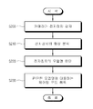
도 5는 도 1의 디스플레이장치가 영상표시 모드 시에 셔터부를 제어하는 과정을 나타내는 제어 흐름도,
도 6은 도 1의 디스플레이장치에서 카메라가 전자장치를 감지하는 화면의 예시도,
도 7은 도 1의 디스플레이장치를 전자장치와 페어링하는 과정을 나타내는 제어 흐름도,
도 8은 도 1의 디스플레이장치에서 카메라가 전자장치를 감지하고 있는 화면에서, 사용자에 의해 모션이 발생한 경우의 화면을 나타내는 예시도이다.1 is a perspective view showing the appearance of a display device according to an embodiment of the present invention;
Fig. 2 is a block diagram of the configuration of the display device of Fig. 1,
3 is an exemplary view illustrating a structure in which an image displayed by a display unit is formed on the left eye of a user in the display apparatus of FIG. 1;
4 is an exemplary view illustrating a display device of FIG. 1 operating in synchronization with an external display device;
5 is a control flowchart illustrating a process of controlling a shutter unit in an image display mode by the display apparatus of FIG. 1;
6 illustrates an example of a screen of a camera sensing an electronic device in the display device of FIG. 1;
7 is a control flowchart illustrating a process of pairing the display device of FIG. 1 with an electronic device;
FIG. 8 is an exemplary view illustrating a screen when a motion is generated by a user in a screen in which a camera senses an electronic device in the display device of FIG. 1.
이하에서는 첨부도면을 참조하여 본 발명에 대해 상세히 설명한다. 이하 실시예에서는 본 발명의 사상과 직접적인 관련이 있는 구성들에 관해서만 설명하며, 그 외의 구성에 관해서는 설명을 생략한다. 그러나, 본 발명의 사상이 적용된 장치 또는 시스템을 구현함에 있어서, 이와 같이 설명이 생략된 구성이 불필요함을 의미하는 것이 아님을 밝힌다.Hereinafter, the present invention will be described in detail with reference to the accompanying drawings. In the following embodiments, only configurations directly related to the concept of the present invention will be described, and description of other configurations will be omitted. However, it is to be understood that, in the implementation of the apparatus or system to which the spirit of the present invention is applied, it is not meant that the configuration omitted from the description is unnecessary.
도 1은 본 발명의 실시예에 따른 디스플레이장치(1)의 외형을 나타내는 사시도이다.1 is a perspective view showing the external appearance of a
도 1에 도시된 바와 같이, 본 실시예에 따른 디스플레이장치(1)는 사람의 머리에 장착하는 헤드마운트형(head-mount type) 디스플레이장치(1)이다. 디스플레이장치(1)는 일반적인 안경과 유사한 형태를 가지는 바, 사람의 머리 또는 귀에 걸쳐지도록 마련된 프레임(10)과, 프레임(10)에 의해 지지되며 사용자의 좌안 및 우안 각각의 시야를 커버하는 글래스부(20)를 포함한다.As shown in FIG. 1, the
프레임(10) 및 글래스부(20)는 형상 또는 재질이 한정되지 않고 다양하게 적용될 수 있다. 다만, 프레임(10) 및 글래스부(20)는 디스플레이장치(1)의 후술할 다양한 구성들을 수용할 수 있도록, 내부에 공간을 형성한다. 또한, 글래스부(20)는 광의 투과가 가능하도록 투명한 재질로 구현된다.The
이하, 디스플레이장치(1)의 구체적인 구성에 관해 도 2를 참조하여 설명한다.Hereinafter, the specific structure of the
도 2는 디스플레이장치(1)의 구성 블록도이다. 본 도면에 도시된 디스플레이장치(1)의 각 구성들은 도 1의 프레임(10) 또는 글래스부(20)에 수용되며, 이 구성들이 수용되는 형태 또는 방식은 프레임(10) 및 글래스부(20)의 형상에 따라서 가변적이므로 본 발명의 사상을 한정하는 사항이 아니다.2 is a block diagram of the
또한, 본 도면에 도시된 구성들은 디스플레이장치(1)의 하나의 예시일 뿐으로서, 본 발명의 사상이 구현된 디스플레이장치(1)에서 본 도면에 도시되거나 또는 설명되지 않은 구성이 불필요하거나, 또는 디스플레이장치(1)가 본 도면에 도시된 구성들만을 포함하여야 함을 의미하는 것은 아니다.In addition, the components shown in this drawing are only one example of the
도 2에 도시된 바와 같이, 디스플레이장치(1)는 외부로부터 영상신호를 수신하는 신호수신부(110)와, 신호수신부(110)에 수신되는 영상신호를 기 설정된 영상처리 프로세스에 따라서 처리하는 신호처리부(120)와, 신호처리부(120)에 의해 처리되는 영상신호를 영상으로 표시하는 디스플레이부(130)와, 사용자의 양안에 대한 외부광의 투과를 선택적으로 허용하도록 셔터링 동작하는 셔터부(140)와, 다양한 외부장치(미도시)와 통신하는 통신부(150)와, 사용자의 조작에 의하여 기 설정된 제어 커맨드가 생성되는 사용자입력부(160)와, 데이터를 저장하는 저장부(170)와, 디스플레이장치(1)의 각 구성에 동작 전원을 공급하는 전원공급부(180)와, 디스플레이장치(1)의 제반 동작을 제어하는 제어부(190)를 포함한다.As shown in FIG. 2, the
추가적으로, 디스플레이장치(1)는 외부 환경에 대한 동영상/정지영상을 촬영/촬상하는 카메라(210)와, 외부 환경의 소리를 감지하는 마이크(220)와, 소리를 출력하는 이어폰(230)을 더 포함할 수 있다.In addition, the
신호수신부(110)는 외부로부터 유선/무선으로 전달되는 영상신호/영상데이터를 수신하여 신호처리부(120) 또는 제어부(190)에 전달한다. 예를 들면, 신호수신부(110)는 방송국(미도시)으로부터 송출되는 RF(radio frequency)신호를 무선으로 수신하거나, 컴포지트(composite) 비디오, 컴포넌트(component) 비디오, 슈퍼 비디오(super video), SCART, HDMI(high definition multimedia interface), 디스플레이포트(DisplayPort), UDI(unified display interface), 또는 와이어리스(wireless) HD 규격 등에 의한 영상신호를 유선으로 수신할 수 있다.The
본 실시예에서 신호수신부(110)는 통신부(150)와 별도의 구성인 것으로 표현하였으나, 설계방식에 따라서 신호수신부(110) 및 통신부(150)는 통신 인터페이스(interface)로 통합될 수도 있다.In the present exemplary embodiment, the
신호처리부(120)는 신호수신부(110)에 수신되는 영상신호에 대해 다양한 영상처리 프로세스를 수행한다. 신호처리부(120)는 이러한 프로세스를 수행한 영상신호를 디스플레이부(130)에 출력함으로써, 디스플레이부(130)에 해당 영상신호에 기초하는 영상이 표시되게 한다.The
신호처리부(120)가 수행하는 영상처리 프로세스의 종류는 한정되지 않는 바, 예를 들면 영상데이터의 영상 포맷에 대응하는 디코딩(decoding), 인터레이스(interlace) 방식의 영상데이터를 프로그레시브(progressive) 방식으로 변환하는 디인터레이싱(de-interlacing), 영상데이터를 기 설정된 해상도로 조정하는 스케일링(scaling), 영상 화질 개선을 위한 노이즈 감소(noise reduction), 디테일 강화(detail enhancement), 프레임 리프레시 레이트(frame refresh rate) 변환 등을 포함할 수 있다.The type of the image processing process performed by the
신호처리부(120)는 이러한 여러 기능을 통합시킨 SOC(system-on-chip), 또는 이러한 각 프로세스를 독자적으로 수행할 수 있는 개별적인 구성들이 인쇄회로기판 상에 장착됨으로써 영상처리보드(미도시)로 구현되어 디스플레이장치(1)에 내장된다.The
디스플레이부(130)는 신호처리부(120)에서 처리된 영상신호를 사용자의 양안에 근접하게 영상으로 맺히도록 표시한다. 디스플레이부(130)가 영상을 표시하기 위한 보다 자세한 구조는 후술한다.The
셔터부(140)는 사용자의 양안에 대해 외부광이 투과되는 것을 선택적으로 허용/차단하도록 셔터링(shuttering) 동작한다. 셔터부(140)는 제어부(190)에 의해 광투과율이 조정되는 액정 셔터 글래스로 구현되며, 글래스부(20, 도 1 참조)의 외측에 사용자의 양안을 커버하도록 설치된다.The
셔터부(140)가 수행하는 셔터링 동작은, 사용자의 좌안 및 우안에 대해 각각 선택적으로 이루어지거나 또는 동일하게 이루어질 수 있다. 예를 들면, 셔터부(140)는 사용자의 좌안에 대해서 광차단이, 사용자의 우안에 대해서 광투과가 수행되도록 셔터링 동작한다. 또는, 셔터부(140)는 사용자의 좌안에 대해서 광투과가, 사용자의 우안에 대해서 광차단이 수행되도록 셔터링 동작한다. 또는, 셔터부(140)는 사용자의 좌안 및 우안에 대해 동일하게 광차단 또는 광투과가 수행되도록 할 수도 있다. 또는, 셔터부(140)는 사용자의 양안에 대해 광투과 또는 광차단을 수행하되, 외부광이 투과되는 투과율을 조정할 수도 있다.The shuttering operation performed by the
통신부(150)는 유선/무선을 통해 다양한 종류의 외부장치(미도시)와 양방향 통신을 수행한다. 통신부(150)는 설계방식에 따라서 신호수신부(110)와 함께 통신 인터페이스를 구성할 수도 있다. 본 실시예에 따른 통신부(150)는 RF(radio frequency), 블루투스(Bluetooth)와 같은 양방향 RF 무선통신규격에 따라서 무선 통신을 수행한다.The
사용자입력부(160)는 사용자에 의해 조작됨으로써 기 설정된 제어 커맨드를 생성하여 제어부(190)에 전달한다. 예를 들면, 사용자입력부(160)는 프레임(10, 도 1 참조)에 설치된 입력 키 패드(미도시)나, 글래스(20, 도 1 참조) 상의 터치스크린(미도시) 또는 터치센서(미도시)로 구현될 수 있다.The
또는, 사용자입력부(160)는 디스플레이장치(1)와 별도로 분리된 리모트 컨트롤러(remote controller) 또는 모바일 폰과 같은 외부장치(미도시)로 구현될 수도 있다. 이 경우, 사용자입력부(160)는 통신부(150)와 통신함으로써 제어 커맨드를 제어부(190)에 전달한다.Alternatively, the
저장부(170)는 제어부(190)의 제어에 따라서 한정되지 않은 데이터가 저장된다. 저장부(170)는 플래시메모리(flash-memory), 하드디스크 드라이브(hard-disc drive)와 같은 비휘발성 메모리로 구현된다. 저장부(170)는 제어부(190)에 의해 액세스되며, 제어부(190)에 의한 데이터의 독취/기록/수정/삭제/갱신 등이 수행된다.The
전원공급부(180)는 디스플레이장치(1)의 제반 구성이 동작하기 위한 직류전원을 제공한다. 전원공급부(180)는 1차전지 또는 2차전지로 구현될 수 있지만, 활용성을 위해 외부전원으로 충전 가능한 2차전지로 구현됨이 바람직하다. 전원공급부(180)는 제어부(190)에 의해 전원 공급이 제어되는 바, 예를 들면 특정 구성요소에 대한 전원의 출력 여부, 출력 전압의 레벨, 출력 듀티(duty)의 조정 등이 제어된다.The
카메라(210)는 프레임(10, 도 1 참조)의 외측에 설치되며, 디스플레이장치(1)의 외부 환경을 감지 및 촬영한다. 카메라(210)는 소정 시점의 외부 환경을 촬상하여 정지화상을 생성하거나, 또는 기 설정된 시간 동안에 외부 환경을 촬영하여 동영상을 생성할 수 있다.The
카메라(210)는 소정 시간 동안에 외부 환경을 모니터링할 수 있다. 예를 들면, 디스플레이장치(1)를 착용한 상태의 사용자가 시선 또는 고개를 돌림으로써, 카메라(210)는 외부 환경에서 전자장치(미도시)를 새로이 감지할 수 있다. 이 경우, 카메라(210)는 전자장치(40)가 감지되었음을 제어부(190)에게 알리며, 감지된 전자장치(40)를 촬상 또는 촬영한 정지화상/동영상을 제어부(190)에 전달한다.The
이하, 디스플레이부(130)에 영상을 표시하는 구조에 관해 도 3을 참조하여 설명한다.Hereinafter, a structure of displaying an image on the
도 3은 디스플레이부(130)가 표시하는 영상이 사용자의 좌안에 맺히는 구조를 나타내는 예시도이다. 디스플레이부(130)에 있어서 사용자의 좌안에 관련된 구조 및 사용자의 우안에 관련된 구조는 상호 대칭적이므로, 사용자의 우안에 영상이 맺히는 구조는 본 실시예를 응용할 수 있는 바 해당 설명을 생략한다.3 is an exemplary view illustrating a structure in which an image displayed by the
도 3에 도시된 바와 같이, 디스플레이부(130)는 신호처리부(120)에 의해 처리되는 영상신호가 영상으로 표시되는 디스플레이소자(131)와, 디스플레이소자(131) 상에 표시되는 영상이 반사되는 전반사미러(133)와, 전반사미러(133)에 의해 반사되는 영상이 맺히는 반투명미러(135)를 포함한다.As illustrated in FIG. 3, the
좌안셔터(141)는 좌안글래스(21)의 외측을 커버함으로써, 사용자의 좌안에 대한 외부광의 투과를 선택적으로 제어한다.The
디스플레이소자(131)는 프레임(10, 도 1 참조) 내에 설치된다. 디스플레이소자(131)는 액정패널로 구현되며, 신호처리부(120)에 의해 영상이 표시된다.The
전반사미러(133) 및 반투명미러(135)는 사용자의 좌안에 대응하는 좌안글래스(21) 내에 설치된다. 전반사미러(133)는 좌안글래스(21) 내에서 사용자의 시선에서 벗어난 위치에 배치되며, 디스플레이소자(131)에 표시된 영상을 반사하도록 전반사 특성을 가진다. 한편, 반투명미러(135)는 사용자의 시선방향 상에 위치하며, 입사광의 일부는 투과사키고 입사광의 나머지는 판면 상에 결상시키는 특성을 가진다.The
좌안셔터(141)가 광투과를 허용하고 디스플레이소자(131)에 영상이 표시되지 않는 경우, 외부광은 좌안셔터(141), 좌안글래스(21) 및 반투명미러(135)를 투과하여 사용자의 좌안에 도달할 수 있다. 따라서, 이 경우에 디스플레이장치(1)를 장착한 사용자는 외부 환경을 좌안에 의해 인지할 수 있다.When the
한편, 디스플레이소자(131)에 영상이 표시되는 경우, 디스플레이소자(131)에 표시된 영상은 전반사미러(133)로 입사된다(P1). 이 단계(P1)에서, 광특성을 조절하기 위한 렌즈(미도시)나, 파이버(fiber)와 같이 영상을 전달하는 영상전달덕트(미도시)와 같은 구성이 프레임(10, 도 1 참조) 내에 설치될 수도 있다.Meanwhile, when an image is displayed on the
전반사미러(133)에 의해 반사된 영상은 반투명미러(135)에 결상된다(P2). 반투명미러(135) 상에 맺힌 영상은 사용자의 좌안에 의해 인지될 수 있다. 만일 좌안셔터(141)가 광투과를 허용하는 상태라면, 사용자는 반투명미러(135) 상에 영상이 맺힌 상태에서 반투명미러(135)를 통해 외부 환경을 인지할 수 있다.The image reflected by the
또는, 외부광에 의해 반투명미러(135) 상의 영상을 인지하기에 용이하지 않은 경우라면, 사용자는 좌안셔터(141)가 광차단하게 동작하도록 함으로써 외부광에 의한 간섭을 방지할 수도 있다.Alternatively, if it is not easy to recognize the image on the
이와 같이, 디스플레이장치(1)는 외부로부터 수신되거나 또는 자체 저장된 영상신호에 기초하는 영상을 표시할 수 있다.As such, the
도 4는 디스플레이장치(1)가 동기동작 모드, 즉 외부디스플레이장치(30)와 동기하여 동작하는 모습을 나타내는 예시도이다.FIG. 4 is an exemplary view showing the
도 4에 도시된 바와 같이, 디스플레이장치(1)는 통신부(150, 도 2 참조)를 통해 TV와 같은 외부디스플레이장치(30)와 양방향 통신을 수행한다. 디스플레이장치(1) 및 외부디스플레이장치(30)는 상호간에 페어링(pairing)이 완료된 이후, 다양한 종류의 신호/데이터/정보를 교환할 수 있다.As shown in FIG. 4, the
외부디스플레이장치(30)가 3차원 영상을 표시하는 경우, 외부디스플레이장치(30)는 주기적으로 좌안영상 및 우안영상을 교대로 표시한다. 그리고, 외부디스플레이장치(30)는 좌안영상 및 우안영상의 표시주기에 대응하는 동기신호를 생성하여 디스플레이장치(1)에 전송한다.When the
디스플레이장치(1)는 이러한 동기신호를 수신하면, 수신되는 동기신호에 따라서 셔터부(140)의 셔터링 동작을 제어한다. 구체적으로, 디스플레이장치(1)는 외부디스플레이장치(30)에 좌안영상이 표시되어 있는 동안에, 사용자의 좌안에 대해 광투과가 허용되고 사용자의 우안에 대해 광차단되도록 셔터부(140)를 제어한다. 반면, 외부디스플레이장치(30)에 우안영상이 표시되어 있는 동안에, 사용자의 좌안에 대해 광차단되고 사용자의 우안에 대해 광투과가 허용되도록 셔터부(140)를 제어한다. 만일, 외부디스플레이장치(30)에 좌안영상 또는 우안영상이 혼재되어 표시되는 상태, 즉 좌안영상 또는 우안영상이 스캐닝되고 있는 상태에서는, 디스플레이장치(1)는 사용자의 좌안 및 우안에 대해 모두 광차단되도록 제어할 수 있다.When the
물론, 디스플레이장치(1)는 이와 같이 동작하는 동안에는 디스플레이부(130)에 영상이 표시되지 않도록 한다.Of course, the
이상 설명한 바와 같이, 본 실시예에 따른 디스플레이장치(1)는 외부디스플레이장치(30)에 표시되는 외부 영상의 표시주기에 대응하여 동작하는 동기동작 모드와, 신호처리부(120)에 의해 처리되는 영상신호를 디스플레이부(130)에 영상으로 표시하는 영상표시 모드 중 어느 하나의 모드로 동작할 수 있다.As described above, the
각 모드의 선택은 사용자입력부(160)를 통하여 해당 모드로의 전환을 지시하는 제어신호에 의해 발생할 수 있다. 또는, 디스플레이장치(1)는 외부디스플레이장치(30)와의 페어링이 수행되면 자동적으로 동기동작 모드로 진입할 수 있다. 또는, 디스플레이장치(1)는 외부디스플레이장치(30)와의 페어링이 해제되면 자동적으로 영상표시 모드나 별도의 대기모드로 진입할 수 있다.The selection of each mode may be generated by a control signal instructing to switch to the corresponding mode through the
별도의 대기모드는 설계방식에 따라서 다양한 상태의 적용이 가능하며, 예를 들면 셔터부(140)에 의해 사용자의 양안에 대한 광투과를 허용하고 디스플레이부(130)에 영상을 표시하지 않는 상태를 대기모드로 지정할 수 있다.The separate standby mode may be applied in various states according to a design method. For example, the
이하, 디스플레이장치(1)가 영상표시 모드일 때에 카메라(210)가 전자장치(40)를 감지하는 경우의 동작에 관해 도 5 및 도 6을 참조하여 설명한다. 본 실시예에서 전자장치(40)는 TV, 모니터, 셋탑박스, 생활가전, 컴퓨터, 모바일 장치 등 통상적인 개념의 전자/전기 디바이스에 해당하는 장치는 모두 해당할 수 있다.Hereinafter, operations when the
도 5는 디스플레이장치(1)가 영상표시 모드 시에 셔터부(140)를 제어하는 과정을 나타내는 제어 흐름도이다.5 is a control flowchart illustrating a process in which the
도 6은 카메라(210)가 전자장치(40)를 감지하는 화면(310)의 예시도이다.6 illustrates an example of a
도 5 및 도 6에 도시된 바와 같이, 디스플레이장치(1)가 영상표시 모드로 동작하고 있는 동안에, 신호처리부(120)는 영상신호를 처리하여 디스플레이부(130) 상에 영상을 표시하며(S100), 셔터부(140)는 기 설정된 제1투과율로 사용자의 양안에 대한 외부광의 투과를 유지시킨다(S110).5 and 6, while the
여기서, 제1투과율의 구체적인 수치는 한정할 수 있는 사항이 아니며 다양한 변경 적용이 가능하나, 디스플레이부(130)에 표시되는 영상을 일반 사용자가 용이하게 인지할 수 있도록 외부광의 차단 비율이 상대적으로 높다고 판단되는 범위 내에서 결정될 수 있다.Here, the specific numerical value of the first transmittance is not limited and various modifications may be applied, but the blocking ratio of external light is relatively high so that the general user can easily recognize the image displayed on the
즉, 셔터부(140)는 디스플레이부(130)에 영상이 표시되는 동안에 제1투과율을 유지함으로써 사용자의 양안에 대한 외부광의 간섭을 억제시키고, 사용자가 영상을 용이하게 인지하도록 할 수 있다.That is, the
이와 같은 디스플레이장치(1)의 영상표시 모드 동안, 카메라(210)는 외부 환경에 대한 모니터링을 수행한다(S120). 이러한 카메라(210)의 모니터링 동작은, 디스플레이장치(1)가 영상표시 모드에 진입하면 자동적으로 수행될 수 있으며, 또는 디스플레이장치(1)가 영상표시 모드에 진입한 이후 사용자입력부(160)를 통한 입력이나 마이크(220)를 통한 음성 명령에 의해 활성화될 수도 있다.During the image display mode of the
카메라(210)는 모니터링 동안에 도 6에 도시된 바와 같이 새로운 전자장치(40)를 감지할 수 있다.The
카메라(210)는 외부 환경에서 전자장치(40)가 감지되면(S130), 감지 결과를 제어부(190)에 전달한다. 여기서, 카메라(210)는 전자장치(40)가 기 설정 시간 동안에 전자장치(40)가 계속 감지되는 경우에, 감지 결과를 제어부(190)에 전달할 수 있다.When the
제어부(190)는 카메라(210)에 의해 전자장치(40)가 감지되면(S130), 셔터부(140)의 광투과율을 제1투과율보다 높은 제2투과율로 조정한다(S140). 즉, 제어부(190)는 영상 표시 중에 사용자가 고개 또는 시선을 돌리는 등의 동작으로 인해 카메라(210)에 전자장치(40)가 감지되면, 셔터부(140)를 통한 외부광의 광투과 상태를 상대적으로 높아지게 제어한다.When the
제2투과율의 구체적인 수치는 한정할 수 있는 사항이 아니며 다양한 변경 적용이 가능하나, 다만 제1투과율보다 높은 수치를 가지도록 결정된다.The specific value of the second transmittance is not limited and various modifications can be applied, but it is determined to have a higher value than the first transmittance.
이 때, 제어부(190)는 제2투과율로 셔터부(140)를 제어하고, 디스플레이부(130)에 표시되는 영상을 정지 상태로 유지시키거나 또는 디스플레이부(130) 상에 영상이 표시되지 않게 제어한다(S150).At this time, the
이에 의하여, 디스플레이장치(1)를 착용한 사용자가 전자장치(40)를 용이하게 인지할 수 있도록 한다.As a result, a user wearing the
제어부(190)가 셔터부(140)의 투과율을 조정하는 방법은 다양한 구성이 적용될 수 있는 바, 예를 들면 셔터부(140)에 인가되는 구동전압의 레벨을 조정하는 방법과, 셔터부(140)에 인가되는 구동전압의 듀티 폭을 조정하는 방법이 있다.The
전자의 경우, 셔터부(140)는 액정 셔터 글래스를 포함하므로, 액정에 인가되는 전압의 크기가 클수록 액정의 투과율이 증가한다. 따라서, 구동전압의 레벨을 높일수록 셔터부(140)의 투과율이 높아지고, 구동전압의 레벨을 낮출수록 셔터부(140)의 투과율이 낮아질 수 있다.In the former case, since the
후자의 경우, 액정이 전압에 따라서 온(ON)되는 동안의 시간을 듀티라고 하면, 듀티의 폭이 길수록 셔터부(140)가 오픈되는 시간이 길어짐을 의미한다. 그리고, 셔터부(140)의 오픈 시간이 길어지는 것은 광이 액정을 통과하는 시간이 길다는 것을 의미한다. 따라서, 구동전압의 듀티 폭을 길게 할수록 셔터부(140)의 투과율이 높아지고, 구동전압의 듀티 폭을 짧게 할수록 셔터부(140)의 투과율이 낮아질 수 있다.In the latter case, when the time during which the liquid crystal is ON according to the voltage is a duty, the longer the width of the duty, the longer the time that the
이러한 방법에 따라서, 셔터부(140)의 투과율을 조정할 수 있다.According to this method, the transmittance of the
이하, 디스플레이장치(1) 및 전자장치(40)를 페어링하는 과정에 관해 도 7을 참조하여 설명한다.Hereinafter, a process of pairing the
도 7은 디스플레이장치(1) 및 전자장치(40)를 페어링하는 과정을 나타내는 제어 흐름도이다.7 is a control flowchart illustrating a process of pairing the
도 7에 도시된 바와 같이, 상기와 같이 카메라(210)가 전자장치(40)를 감지함에 있어서(S200), 제어부(190)는 카메라(210)에 의해 촬영된 전자장치(40)의 형상을 분석함으로써(S210) 해당 전자장치(40)의 모델명을 판단할 수 있다(S220). 형상 분석에 의해 전자장치(40)의 모델명을 판단하는 방법은 다양한 기술 또는 구조가 적용될 수 있는 바, 본 발명의 사상을 한정하지 않는다.As shown in FIG. 7, when the
또한, 제어부(190)는 카메라(210)에 촬영된 전자장치(40)의 영상에서 해당 전자장치(40)의 모델을 인식할 수 있도록 하는 다양한 마크(mark), 예를 들면 바코드(bar-code)나 QR(quick response) 코드가 인식되는 경우, 해당 마크에 기초하여 전자장치(40)의 모델명을 판단할 수도 있다.In addition, the
제어부(190)는 판단한 모델명에 대응하는 페어링(pairing) 코드를 취득함으로써(S230), 전자장치(40) 및 디스플레이장치(1)의 페어링을 수행한다. 페어링은 디스플레이장치(1) 및 전자장치(40)가 상호 동기 또는 연동하여 동작할 수 있도록 양 장치를 기능적으로 결합시키는 제어동작을 의미한다. 예를 들면, 디스플레이장치(1) 및 전자장치(40)에 페어링이 완료되면, 디스플레이장치(1)는 전자장치(40)의 소정 동작을 제어할 수 있도록 전자장치(40)에 대해 해당 동작을 지시하는 제어신호를 전송할 수 있다.The
여기서, 제어부(190)가 판단한 모델명에 대응하는 페어링 코드를 취득하는 방법은 다양하게 적용될 수 있다. 하나의 방법으로는, 저장부(170)에 모델명 및 페어링 코드의 관계 테이블이 저장되어 있는 경우, 제어부(190)는 저장부(170)의 관계 테이블에 억세스함으로써, 모델명에 대응하는 페어링 코드를 취득할 수 있다.Here, the method of acquiring the pairing code corresponding to the model name determined by the
또는, 제어부(190)는 통신부(150)를 통해 외부 서버(미도시)에 접속하고, 판단한 모델명을 서버(미도시)에 전송한다. 제어부(190)는 서버(미도시)로부터 모델명에 대응하는 페어링 코드를 수신함으로써, 해당 페어링 코드를 취득할 수도 있다.Alternatively, the
이러한 페어링 코드의 취득을 통해 디스플레이장치(1) 및 전자장치(40)의 페어링이 완료하면, 디스플레이장치(1)를 통한 전자장치(40)의 동작 제어가 가능하다.When the pairing of the
이러한 상태에서 만일 사용자가 사용자입력부(160)를 통해 소정의 커맨드를 입력하면, 제어부(190)는 해당 커맨드에 의해 전자장치(40)의 동작이 제어되도록 해당 커맨드에 대응하는 제어신호를 전자장치(40)에 전송한다. 이에, 전자장치(40)는 수신된 제어신호에 대응하는 동작을 수행한다.In this state, if the user inputs a predetermined command through the
또는, 마이크(220)에 의해 사용자의 소정 음성 명령이 감지되면, 제어부(190)는 해당 음성 명령에 의해 전자장치(40)의 동작이 제어되도록 해당 음성 명령에 대응하는 제어신호를 전자장치(40)에 전송할 수도 있다.Alternatively, when a predetermined voice command of the user is detected by the
한편, 카메라(210)에 촬영된 전자장치(40)의 모델명을 판단하기 위해 전자장치(40)의 형상을 분석하는 과정에서, 제어부(190)는 전자장치(40)에 설치된 다양한 방식의 사용자 입력 인터페이스(interface)의 배치 상태 및 대응 기능을 함께 분석할 수도 있다.Meanwhile, in the process of analyzing the shape of the
사용자 입력 인터페이스는 사용자가 입력 또는 조작 가능하도록 전자장치(40)에 설치된 입력 인터페이스를 의미하는 것으로서, 예를 들면 버튼, 키, 터치패드, 터치스크린 등 다양한 형태로 구현될 수 있다.The user input interface refers to an input interface installed in the
사용자 입력 인터페이스의 배치 상태는 카메라(210)에 촬영된 전자장치(40)에서 해당 사용자 입력 인터페이스가 어느 위치에 배치되어 있는지에 관한 정보이다. 사용자 입력 인터페이스의 대응 기능은 해당 사용자 입력 인터페이스를 사용자가 조작할 경우에 전자장치(40)가 수행하는 동작 또는 기능에 관한 정보이다.The arrangement state of the user input interface is information regarding a location of the corresponding user input interface in the
도 6에 도시된 바와 같이, 제어부(190)는 전자장치(40)의 형상 분석을 통해 해당 전자장치(40)의 종류 및 모델명의 정보를 판단한다. 이 때, 제어부(190)는 판단한 정보에 기초하여 전자장치(40)에 설치된 사용자 입력 인터페이스(41, 42, 43, 44, 45)의 배치 상태 및 대응 기능을 판단한다. 예를 들면, 제어부(190)는 전자장치(40)는 셋탑박스이고, 사용자 입력 인터페이스(41, 42, 43, 44, 45)는 전원 온/오프 버튼(41), 채널 업 버튼(42), 채널 다운 버튼(43), 음량 업 버튼(44), 음량 다운 버튼(45)을 포함하는 것을 판단할 수 있다.As shown in FIG. 6, the
이와 같이 카메라(210)가 전자장치(40)를 감지 및 모니터링하고, 제어부(190)가 전자장치(40)의 모델명 및 사용자 입력 인터페이스(41, 42, 43, 44, 45)를 판단한 상태에서, 도 8과 같이 사용자에 의해 액션 또는 모션(U)이 발생할 수 있다.As described above, the
도 8은 카메라(210)가 전자장치(40)를 감지하고 있는 화면에서 사용자에 의해 모션(U)이 발생한 경우의 화면(320)을 나타내는 예시도이다.FIG. 8 is an exemplary diagram illustrating a
도 8에 도시된 바와 같이, 카메라(210)에 의해 사용자가 손끝을 움직이거나 터치하는 등의 사용자에 의한 모션(U)이 감지될 수 있다. 이 경우, 제어부(190)는 모션(U)이 전자장치(40)의 사용자 입력 인터페이스(41, 42, 43, 44, 45) 상에 오버레이(overlay)되어 발생하였는지 판단한다. 그리고, 제어부(190)는 모션(U)이 오버레이된 사용자 입력 인터페이스(41, 42, 43, 44, 45)의 기능에 대응하는 제어신호를 생성하여 전자장치(40)에 전송한다.As shown in FIG. 8, the motion U may be sensed by the
예를 들어 본 도면에 따르면, 모션(U)은 사용자 입력 인터페이스(41, 42, 43, 44, 45) 중에서 전원 온/오프 버튼(41) 상에 오버레이되어 발생하였음을 알 수 있다. 이에, 제어부(190)는 전원 온/오프 버튼(41)의 기능에 대응하는 전원 온/오프를 지시하는 제어신호를 생성하여 전자장치(40)에 전송한다.For example, according to this drawing, it can be seen that the motion U is generated by being overlaid on the power on / off
이에, 전자장치(40)는 해당 제어신호를 수신함에 따라서, 사용자가 전원 온/오프 버튼(41)을 클릭했을 경우와 동일하게 전원 온/오프 동작을 수행한다.Accordingly, when the
만일, 사용자의 모션(U)이 음량 업 버튼(44) 상에 오버레이되어 발생한 경우, 제어부(190)는 전자장치(40)가 음량 업 버튼(44)에 대응하는 기능인 음량 업 동작을 수행하도록, 음량 업 동작을 지시하는 제어신호를 전자장치(40)에 전송한다.If the motion U of the user is overlaid on the volume up
이와 같은 방법에 따라서, 디스플레이장치(1)를 착용한 사용자가 용이하게 전자장치(40)의 동작을 제어하도록 할 수 있다.According to this method, a user wearing the
상기한 실시예는 예시적인 것에 불과한 것으로, 당해 기술 분야의 통상의 지식을 가진 자라면 다양한 변형 및 균등한 타 실시예가 가능하다. 따라서, 본 발명의 진정한 기술적 보호범위는 하기의 특허청구범위에 기재된 발명의 기술적 사상에 의해 정해져야 할 것이다.The above-described embodiments are merely illustrative, and various modifications and equivalents may be made by those skilled in the art. Accordingly, the true scope of protection of the present invention should be determined by the technical idea of the invention described in the following claims.
1 : 디스플레이장치
10 : 프레임
20 : 글래스부
30 : 외부디스플레이장치
110 : 신호수신부
120 : 신호처리부
130 : 디스플레이부
140 : 셔터부
150 : 통신부
160 : 사용자입력부
170 : 저장부
180 : 전원공급부
210 : 카메라
220 : 마이크
230 : 이어폰1: Display device
10: frame
20: glass part
30: external display device
110:
120: Signal processor
130:
140: shutter unit
150:
160: User input
170:
180: Power supply
210: camera
220: microphone
230: Earphone
Claims (18)
디스플레이부와;
외부로부터 수신되는 영상신호를 상기 디스플레이부에 영상으로 표시되게 처리하는 신호처리부와;
사용자의 양안에 대한 외부광의 투과를 선택적으로 허용하도록 셔터링 동작 가능한 셔터부와;
외부 환경을 감지 및 촬영하는 카메라와;
상기 디스플레이부에 상기 영상이 표시될 때에 상기 셔터부가 외부광을 투과시키는 투과율을 기 설정된 제1투과율로 유지하고, 상기 디스플레이부에 상기 영상이 표시되는 동안에 상기 카메라가 외부 전자장치를 감지하면 상기 제1투과율보다 높은 제2투과율로 상기 셔터부의 투과율을 조정하는 제어부를 포함하는 것을 특징으로 하는 헤드마운트형 디스플레이장치.In the head mounted display device,
A display unit;
A signal processor which processes an image signal received from the outside to be displayed as an image on the display unit;
A shutter unit operable to shutter to selectively allow transmission of external light to both eyes of a user;
A camera for sensing and photographing an external environment;
When the image is displayed on the display unit, the shutter transmits external light at a predetermined first transmittance, and when the camera detects an external electronic device while the image is displayed on the display unit, And a control unit for adjusting the transmittance of the shutter unit to a second transmittance higher than one transmittance.
상기 제어부는, 상기 카메라에 의해 촬영된 상기 전자장치의 형상을 분석하여 상기 전자장치의 모델명을 판단하고, 상기 전자장치의 동작을 제어하기 위한 상기 전자장치와의 페어링(paring)을 수행하도록, 상기 판단한 모델명에 대응하는 페어링 코드를 취득하는 것을 특징으로 하는 헤드마운트형 디스플레이장치.The method of claim 1,
The controller may determine a model name of the electronic device by analyzing the shape of the electronic device photographed by the camera, and perform pairing with the electronic device for controlling the operation of the electronic device. And a pairing code corresponding to the determined model name.
외부와 통신하는 통신부를 더 포함하며,
상기 제어부는, 상기 통신부를 통해 외부 서버에 접속하고, 상기 판단한 모델명을 상기 접속된 서버에 전송함으로써 상기 서버로부터 상기 페어링 코드를 취득하는 것을 특징으로 하는 헤드마운트형 디스플레이장치.3. The method of claim 2,
Further comprising a communication unit for communicating with the outside,
The control unit connects to an external server through the communication unit, and obtains the pairing code from the server by transmitting the determined model name to the connected server.
사용자입력부를 더 포함하며,
상기 제어부는, 상기 사용자입력부를 통해 입력된 커맨드에 의해 상기 전자장치의 동작이 제어되도록 상기 입력된 커맨드에 대응하는 제어신호를 상기 전자장치에 전송하는 것을 특징으로 하는 헤드마운트형 디스플레이장치.3. The method of claim 2,
Further comprising a user input portion,
And the control unit transmits a control signal corresponding to the input command to the electronic device such that the operation of the electronic device is controlled by the command input through the user input unit.
소리를 감지하는 마이크를 더 포함하며,
상기 제어부는, 상기 마이크를 통해 입력된 사용자의 기 설정된 음성 명령을 분석하고 상기 음성 명령에 대응하는 상기 제어신호를 생성하는 것을 특징으로 하는 헤드마운트형 디스플레이장치.5. The method of claim 4,
It further includes a microphone for detecting the sound,
The control unit, the head mounted display device, characterized in that for analyzing the user's preset voice command input through the microphone and generating the control signal corresponding to the voice command.
상기 제어부는, 상기 전자장치의 형상의 분석 시에 상기 전자장치에 설치된 사용자 입력 인터페이스의 배치 상태 및 대응 기능을 분석하고, 사용자에 의한 모션이 상기 전자장치의 상기 사용자 입력 인터페이스 상에 오버레이되어 발생하는 것으로 상기 카메라에 의해 감지되면 상기 사용자 입력 인터페이스의 상기 기능에 대응하는 제어신호를 생성하여 상기 전자장치에 전송하는 것을 특징으로 하는 헤드마운트형 디스플레이장치.3. The method of claim 2,
The controller analyzes an arrangement state and a corresponding function of a user input interface installed in the electronic device when analyzing the shape of the electronic device, and the motion generated by the user is overlaid on the user input interface of the electronic device. And when detected by the camera, generates a control signal corresponding to the function of the user input interface and transmits the control signal to the electronic device.
상기 제어부는, 상기 카메라에 의해 기 설정된 시간 동안 상기 전자장치가 감지되는 경우에 상기 셔터부의 투과율을 조정하는 것을 특징으로 하는 헤드마운트형 디스플레이장치.The method of claim 1,
The controller may adjust the transmittance of the shutter unit when the electronic device is detected by the camera for a preset time.
소리를 감지하는 마이크를 더 포함하며,
상기 제어부는, 상기 마이크를 통한 사용자의 기 설정된 음성 명령이 감지되면 상기 셔터부의 투과율을 조정하는 것을 특징으로 하는 헤드마운트형 디스플레이장치.8. The method of claim 7,
It further includes a microphone for detecting the sound,
The control unit, the head mounted display device, characterized in that for adjusting the transmittance of the shutter unit when a predetermined voice command of the user through the microphone.
상기 제어부는, 상기 카메라가 상기 전자장치를 감지하면 상기 영상을 정지 상태로 유지하거나 또는 상기 영상이 표시되지 않게 제어하는 것을 특징으로 하는 헤드마운트형 디스플레이장치.The method of claim 1,
The control unit, if the camera detects the electronic device, the head-mounted display device, characterized in that to maintain the image or to stop the display of the image.
상기 디스플레이부에 상기 영상이 표시될 때에 상기 셔터부가 외부광을 투과시키는 투과율을 기 설정된 제1투과율로 유지시키는 단계와;
상기 디스플레이부에 상기 영상이 표시되는 동안에 상기 카메라가 외부 전자장치를 감지하면 상기 제1투과율보다 높은 제2투과율로 상기 셔터부의 투과율을 조정하는 단계를 포함하는 것을 특징으로 하는 헤드마운트형 디스플레이장치의 제어방법.A control method of a head mounted display device comprising a display unit, a shutter unit operable to shutter to selectively allow transmission of external light to both eyes of a user, and a camera for sensing and photographing an external environment,
Maintaining the transmittance at which the shutter transmits external light when the image is displayed on the display unit at a predetermined first transmittance;
And adjusting the transmittance of the shutter unit to a second transmittance higher than the first transmittance when the camera detects an external electronic device while the image is displayed on the display unit. Control method.
상기 셔터부의 투과율을 조정하는 단계는,
상기 카메라에 의해 촬영된 상기 전자장치의 형상을 분석하여 상기 전자장치의 모델명을 판단하는 단계와;
상기 전자장치의 동작을 제어하기 위한 상기 전자장치와의 페어링을 수행하도록, 상기 판단한 모델명에 대응하는 페어링 코드를 취득하는 단계를 포함하는 것을 특징으로 하는 헤드마운트형 디스플레이장치의 제어방법.11. The method of claim 10,
Adjusting the transmittance of the shutter unit,
Determining a model name of the electronic device by analyzing a shape of the electronic device photographed by the camera;
And acquiring a pairing code corresponding to the determined model name to perform pairing with the electronic device for controlling the operation of the electronic device.
상기 판단한 모델명에 대응하는 페어링 코드를 취득하는 단계는,
외부 서버에 접속하여, 상기 판단한 모델명을 상기 접속된 서버에 전송하는 단계와;
상기 서버로부터 상기 판단한 모델명에 대응하는 상기 페어링 코드를 취득하는 단계를 포함하는 것을 특징으로 하는 헤드마운트형 디스플레이장치의 제어방법.12. The method of claim 11,
Acquiring a pairing code corresponding to the determined model name,
Connecting to an external server and transmitting the determined model name to the connected server;
And acquiring the pairing code corresponding to the determined model name from the server.
상기 셔터부의 투과율을 조정하는 단계는,
상기 헤드마운트형 디스플레이장치의 사용자입력부를 통해 입력된 커맨드를 수신하는 단계와;
상기 입력된 커맨드에 의해 상기 전자장치의 동작이 제어되도록 상기 입력된 커맨드에 대응하는 제어신호를 상기 전자장치에 전송하는 단계를 더 포함하는 것을 특징으로 하는 헤드마운트형 디스플레이장치의 제어방법.12. The method of claim 11,
Adjusting the transmittance of the shutter unit,
Receiving a command input through a user input unit of the head mounted display device;
And transmitting a control signal corresponding to the input command to the electronic device such that the operation of the electronic device is controlled by the input command.
상기 입력된 커맨드에 대응하는 제어신호를 상기 전자장치에 전송하는 단계는,
상기 헤드마운트형 디스플레이장치의 마이크를 통해 사용자의 기 설정된 음성 명령을 수신하는 단계와;
상기 음성 명령을 분석하여 상기 음성 명령에 대응하는 상기 제어신호를 생성하는 단계를 포함하는 것을 특징으로 하는 헤드마운트형 디스플레이장치의 제어방법.14. The method of claim 13,
The step of transmitting a control signal corresponding to the input command to the electronic device,
Receiving a user's preset voice command through a microphone of the head mounted display device;
And analyzing the voice command to generate the control signal corresponding to the voice command.
상기 전자장치의 형상을 분석하여 상기 전자장치의 모델명을 판단하는 단계는,
상기 전자장치의 형상의 분석 시에 상기 전자장치에 설치된 사용자 입력 인터페이스의 배치 상태 및 대응 기능을 분석하는 단계와;
사용자에 의한 모션이 상기 전자장치의 상기 사용자 입력 인터페이스 상에 오버레이되어 발생하는 것으로 상기 카메라에 의해 감지되면 상기 사용자 입력 인터페이스의 상기 기능에 대응하는 제어신호를 생성하여 상기 전자장치에 전송하는 단계를 포함하는 것을 특징으로 하는 헤드마운트형 디스플레이장치의 제어방법.12. The method of claim 11,
Determining the model name of the electronic device by analyzing the shape of the electronic device,
Analyzing an arrangement state and a corresponding function of a user input interface installed in the electronic device when analyzing the shape of the electronic device;
Generating a control signal corresponding to the function of the user input interface and transmitting the generated control signal to the electronic device when the motion detected by the user is detected by the camera as being generated by being overlaid on the user input interface of the electronic device. Control method of a head mounted display device, characterized in that.
상기 셔터부의 투과율을 조정하는 단계는, 상기 카메라에 의해 기 설정된 시간 동안 상기 전자장치가 감지되는 경우에 상기 셔터부의 투과율을 조정하는 단계를 포함하는 것을 특징으로 하는 헤드마운트형 디스플레이장치의 제어방법.11. The method of claim 10,
The adjusting of the transmittance of the shutter unit may include adjusting the transmittance of the shutter unit when the electronic device is detected by the camera for a preset time.
상기 셔터부의 투과율을 조정하는 단계는, 상기 헤드마운트형 디스플레이장치의 마이크를 통한 사용자의 기 설정된 음성 명령이 감지되면 상기 셔터부의 투과율을 조정하는 단계를 포함하는 것을 특징으로 하는 헤드마운트형 디스플레이장치의 제어방법.17. The method of claim 16,
The adjusting of the transmittance of the shutter unit may include adjusting the transmittance of the shutter unit when a preset voice command of a user through a microphone of the head mounted display apparatus is detected. Control method.
상기 셔터부의 투과율을 조정하는 단계는, 상기 카메라가 상기 전자장치를 감지하면 상기 영상을 정지 상태로 유지하거나 또는 상기 영상을 표시하지 않는 단계를 포함하는 것을 특징으로 하는 헤드마운트형 디스플레이장치의 제어방법.
11. The method of claim 10,
Adjusting the transmittance of the shutter unit, if the camera detects the electronic device, the control method of the head-mounted display device comprising the step of maintaining the image still or do not display the image. .
Priority Applications (2)
| Application Number | Priority Date | Filing Date | Title |
|---|---|---|---|
| KR1020120092628A KR20140025930A (en) | 2012-08-23 | 2012-08-23 | Head-mount type display apparatus and control method thereof |
| US13/868,549 US20140085183A1 (en) | 2012-08-23 | 2013-04-23 | Head-mounted display apparatus and control method thereof |
Applications Claiming Priority (1)
| Application Number | Priority Date | Filing Date | Title |
|---|---|---|---|
| KR1020120092628A KR20140025930A (en) | 2012-08-23 | 2012-08-23 | Head-mount type display apparatus and control method thereof |
Publications (1)
| Publication Number | Publication Date |
|---|---|
| KR20140025930A true KR20140025930A (en) | 2014-03-05 |
Family
ID=50338338
Family Applications (1)
| Application Number | Title | Priority Date | Filing Date |
|---|---|---|---|
| KR1020120092628A Withdrawn KR20140025930A (en) | 2012-08-23 | 2012-08-23 | Head-mount type display apparatus and control method thereof |
Country Status (2)
| Country | Link |
|---|---|
| US (1) | US20140085183A1 (en) |
| KR (1) | KR20140025930A (en) |
Cited By (1)
| Publication number | Priority date | Publication date | Assignee | Title |
|---|---|---|---|---|
| KR101601527B1 (en) * | 2014-11-04 | 2016-03-08 | 현대자동차주식회사 | Head-up display apparatus and controlling method thereof |
Families Citing this family (13)
| Publication number | Priority date | Publication date | Assignee | Title |
|---|---|---|---|---|
| US10137361B2 (en) * | 2013-06-07 | 2018-11-27 | Sony Interactive Entertainment America Llc | Systems and methods for using reduced hops to generate an augmented virtual reality scene within a head mounted system |
| US10905943B2 (en) * | 2013-06-07 | 2021-02-02 | Sony Interactive Entertainment LLC | Systems and methods for reducing hops associated with a head mounted system |
| US20160011422A1 (en) * | 2014-03-10 | 2016-01-14 | Ion Virtual Technology Corporation | Method and system for reducing motion blur when experiencing virtual or augmented reality environments |
| GB2533573A (en) * | 2014-12-22 | 2016-06-29 | Nokia Technologies Oy | Image processing method and device |
| KR102144515B1 (en) | 2015-01-07 | 2020-08-14 | 삼성전자주식회사 | Master device, slave device and control method thereof |
| US10444018B2 (en) | 2015-02-27 | 2019-10-15 | Microsoft Technology Licensing, Llc | Computer-implemented method to test the sensitivity of a sensor for detecting movement of a tracking device within an established frame of reference of a moving platform |
| US10111620B2 (en) | 2015-02-27 | 2018-10-30 | Microsoft Technology Licensing, Llc | Enhanced motion tracking using transportable inertial sensors to determine that a frame of reference is established |
| CN106444043A (en) * | 2016-12-07 | 2017-02-22 | 浙江红谱科技有限公司 | Head-mounted visualization device and method |
| US10904449B2 (en) | 2017-07-31 | 2021-01-26 | Disney Enterprises, Inc. | Intrinsic color camera |
| US10532814B2 (en) * | 2017-09-11 | 2020-01-14 | Disney Enterprises, Inc. | Augmented reality travel route planning |
| CN113227940A (en) | 2018-11-09 | 2021-08-06 | 贝克曼库尔特有限公司 | Service glasses with selective data provision |
| EP3956858B1 (en) | 2019-04-18 | 2025-12-03 | Beckman Coulter, Inc. | Securing data of objects in a laboratory environment |
| WO2022091398A1 (en) * | 2020-11-01 | 2022-05-05 | 正典 伊原 | Display device including transmittance control unit |
Family Cites Families (9)
| Publication number | Priority date | Publication date | Assignee | Title |
|---|---|---|---|---|
| US5579026A (en) * | 1993-05-14 | 1996-11-26 | Olympus Optical Co., Ltd. | Image display apparatus of head mounted type |
| US6867752B1 (en) * | 1998-08-31 | 2005-03-15 | Semiconductor Energy Laboratory Co., Ltd. | Portable information processing system |
| US20120050044A1 (en) * | 2010-08-25 | 2012-03-01 | Border John N | Head-mounted display with biological state detection |
| US8619005B2 (en) * | 2010-09-09 | 2013-12-31 | Eastman Kodak Company | Switchable head-mounted display transition |
| US8941559B2 (en) * | 2010-09-21 | 2015-01-27 | Microsoft Corporation | Opacity filter for display device |
| US10036891B2 (en) * | 2010-10-12 | 2018-07-31 | DISH Technologies L.L.C. | Variable transparency heads up displays |
| US8576276B2 (en) * | 2010-11-18 | 2013-11-05 | Microsoft Corporation | Head-mounted display device which provides surround video |
| US9217867B2 (en) * | 2011-03-24 | 2015-12-22 | Seiko Epson Corporation | Head-mounted display device and control method for the head-mounted display device |
| US20130147686A1 (en) * | 2011-12-12 | 2013-06-13 | John Clavin | Connecting Head Mounted Displays To External Displays And Other Communication Networks |
-
2012
- 2012-08-23 KR KR1020120092628A patent/KR20140025930A/en not_active Withdrawn
-
2013
- 2013-04-23 US US13/868,549 patent/US20140085183A1/en not_active Abandoned
Cited By (1)
| Publication number | Priority date | Publication date | Assignee | Title |
|---|---|---|---|---|
| KR101601527B1 (en) * | 2014-11-04 | 2016-03-08 | 현대자동차주식회사 | Head-up display apparatus and controlling method thereof |
Also Published As
| Publication number | Publication date |
|---|---|
| US20140085183A1 (en) | 2014-03-27 |
Similar Documents
| Publication | Publication Date | Title |
|---|---|---|
| KR20140025930A (en) | Head-mount type display apparatus and control method thereof | |
| KR101385681B1 (en) | Head-mount type display apparatus and control method thereof | |
| US9191662B2 (en) | Display apparatus and associated glasses | |
| US9652036B2 (en) | Device, head mounted display, control method of device and control method of head mounted display | |
| CN103529929B (en) | Gesture recognition system and glasses capable of recognizing gesture actions | |
| US20160342220A1 (en) | Wearable device and method for controlling display of the same | |
| KR20170055295A (en) | Mobile terminal and method for controlling the same | |
| JP2010154533A (en) | Stereoscopic image display apparatus, and control method thereof | |
| JP2017117159A (en) | Terminal device and bidirectional communication system | |
| JP2011257682A (en) | Display control program, display controller, display control method and display control system | |
| KR20170046969A (en) | Mobile device and, the method thereof | |
| KR20180028211A (en) | Head mounted display and method for controlling the same | |
| CN109379539A (en) | A kind of screen fill light method and terminal | |
| JP2011239029A (en) | Image display unit, power saving control unit and power saving method | |
| KR20170064901A (en) | Mobile device and, the method thereof | |
| KR20180005521A (en) | Mobile terminal and method for controlling the same | |
| KR20140105319A (en) | Head mount display apparatus | |
| KR20170084443A (en) | Method for controlling head mount display device | |
| CN103609103A (en) | System and method for controlling the display of a stereoscopic video stream | |
| KR20130033815A (en) | Image display apparatus, and method for operating the same | |
| KR101786515B1 (en) | Head mounted display and method for controlling the same | |
| KR20170074372A (en) | Mobile terminal and method for controlling the same | |
| WO2024183503A1 (en) | Screen state control method and electronic device | |
| CN102136185B (en) | Signal processing system, electronic device and lighting method for peripheral devices thereof | |
| KR20170014629A (en) | Mobile terminal |
Legal Events
| Date | Code | Title | Description |
|---|---|---|---|
| PA0109 | Patent application |
Patent event code: PA01091R01D Comment text: Patent Application Patent event date: 20120823 |
|
| PG1501 | Laying open of application | ||
| PC1203 | Withdrawal of no request for examination | ||
| WITN | Application deemed withdrawn, e.g. because no request for examination was filed or no examination fee was paid |