KR20140014252A - Turbine rotor blade - Google Patents
Turbine rotor blade Download PDFInfo
- Publication number
- KR20140014252A KR20140014252A KR1020137030827A KR20137030827A KR20140014252A KR 20140014252 A KR20140014252 A KR 20140014252A KR 1020137030827 A KR1020137030827 A KR 1020137030827A KR 20137030827 A KR20137030827 A KR 20137030827A KR 20140014252 A KR20140014252 A KR 20140014252A
- Authority
- KR
- South Korea
- Prior art keywords
- trailing edge
- rotor
- platform
- cooling
- airfoil
- Prior art date
- Legal status (The legal status is an assumption and is not a legal conclusion. Google has not performed a legal analysis and makes no representation as to the accuracy of the status listed.)
- Granted
Links
Images


Classifications
-
- F—MECHANICAL ENGINEERING; LIGHTING; HEATING; WEAPONS; BLASTING
- F01—MACHINES OR ENGINES IN GENERAL; ENGINE PLANTS IN GENERAL; STEAM ENGINES
- F01D—NON-POSITIVE DISPLACEMENT MACHINES OR ENGINES, e.g. STEAM TURBINES
- F01D5/00—Blades; Blade-carrying members; Heating, heat-insulating, cooling or antivibration means on the blades or the members
- F01D5/12—Blades
- F01D5/14—Form or construction
- F01D5/18—Hollow blades, i.e. blades with cooling or heating channels or cavities; Heating, heat-insulating or cooling means on blades
- F01D5/187—Convection cooling
-
- F—MECHANICAL ENGINEERING; LIGHTING; HEATING; WEAPONS; BLASTING
- F01—MACHINES OR ENGINES IN GENERAL; ENGINE PLANTS IN GENERAL; STEAM ENGINES
- F01D—NON-POSITIVE DISPLACEMENT MACHINES OR ENGINES, e.g. STEAM TURBINES
- F01D5/00—Blades; Blade-carrying members; Heating, heat-insulating, cooling or antivibration means on the blades or the members
- F01D5/12—Blades
- F01D5/14—Form or construction
- F01D5/18—Hollow blades, i.e. blades with cooling or heating channels or cavities; Heating, heat-insulating or cooling means on blades
-
- F—MECHANICAL ENGINEERING; LIGHTING; HEATING; WEAPONS; BLASTING
- F05—INDEXING SCHEMES RELATING TO ENGINES OR PUMPS IN VARIOUS SUBCLASSES OF CLASSES F01-F04
- F05D—INDEXING SCHEME FOR ASPECTS RELATING TO NON-POSITIVE-DISPLACEMENT MACHINES OR ENGINES, GAS-TURBINES OR JET-PROPULSION PLANTS
- F05D2240/00—Components
- F05D2240/80—Platforms for stationary or moving blades
- F05D2240/81—Cooled platforms
-
- F—MECHANICAL ENGINEERING; LIGHTING; HEATING; WEAPONS; BLASTING
- F05—INDEXING SCHEMES RELATING TO ENGINES OR PUMPS IN VARIOUS SUBCLASSES OF CLASSES F01-F04
- F05D—INDEXING SCHEME FOR ASPECTS RELATING TO NON-POSITIVE-DISPLACEMENT MACHINES OR ENGINES, GAS-TURBINES OR JET-PROPULSION PLANTS
- F05D2260/00—Function
- F05D2260/20—Heat transfer, e.g. cooling
- F05D2260/201—Heat transfer, e.g. cooling by impingement of a fluid
-
- F—MECHANICAL ENGINEERING; LIGHTING; HEATING; WEAPONS; BLASTING
- F05—INDEXING SCHEMES RELATING TO ENGINES OR PUMPS IN VARIOUS SUBCLASSES OF CLASSES F01-F04
- F05D—INDEXING SCHEME FOR ASPECTS RELATING TO NON-POSITIVE-DISPLACEMENT MACHINES OR ENGINES, GAS-TURBINES OR JET-PROPULSION PLANTS
- F05D2260/00—Function
- F05D2260/94—Functionality given by mechanical stress related aspects such as low cycle fatigue [LCF] of high cycle fatigue [HCF]
- F05D2260/941—Functionality given by mechanical stress related aspects such as low cycle fatigue [LCF] of high cycle fatigue [HCF] particularly aimed at mechanical or thermal stress reduction
Landscapes
- Engineering & Computer Science (AREA)
- Mechanical Engineering (AREA)
- General Engineering & Computer Science (AREA)
- Turbine Rotor Nozzle Sealing (AREA)
Abstract
플랫폼(16)의 후연측의 단면(18)에는, 로터 둘레 방향을 따른 오목부(리세스부)(20)가 형성되어 있다. 이 오목부(리세스부)의 로터 직경 방향 외측에 위치하는 후연측의 단면(18)의 외측 영역(22)에 냉각 유로(14)의 개구(15)가 형성되어 있다. 냉각 유로의 개구 근방의 외측 영역의 로터 직경 방향에 있어서의 두께(L1)는, 플랫폼에 접속되는 익형부(12)의 허브(13)의 후연측 단부에 대응하는 외측 영역의 로터의 직경 방향에 있어서의 두께(L2)보다 커지고 있다.In the end surface 18 of the trailing edge side of the platform 16, the recessed part (recess part) 20 along the rotor circumferential direction is formed. The opening 15 of the cooling flow passage 14 is formed in the outer region 22 of the end face 18 on the trailing edge side located outside the rotor radial direction of the recess. The thickness L1 in the rotor radial direction of the outer region near the opening of the cooling passage is in the radial direction of the rotor of the outer region corresponding to the trailing edge side end portion of the hub 13 of the airfoil portion 12 connected to the platform. It is larger than the thickness L2 in the.
Description
본 발명은 냉각 유로가 형성된 플랫폼을 구비하는 터빈 동익에 관한 것이다.
The present invention relates to a turbine rotor blade having a platform on which a cooling passage is formed.
가스 터빈 내를 흐르는 고온 연소 가스에 의해서 터빈 동익의 익형부(翼形部) 및 플랫폼이 고온으로 되면, 로터 직경 방향 외측을 향하여 열 신장이 발생한다. 이 때, 익형부 및 플랫폼은 각각 열 신장량이 상이하기 때문에, 익형부의 허브와 해당 허브가 접속되어 있는 플랫폼 사이에 열응력이 발생한다. 열응력이 발생하면, 특히 허브의 후연측 단부에 집중하여 작용하기 때문에, 이 후연측 단부에 크랙이 생기기 쉽다. 그 때문에, 익형부 및 플랫폼의 온도 상승을 억제하는 동시에, 이 열응력을 저감할 필요가 있다.When the airfoil part and platform of a turbine rotor blade become high temperature by the high temperature combustion gas which flows in a gas turbine, thermal elongation will arise toward a rotor radial direction outer side. At this time, since the thermal elongation of the airfoil and the platform are different from each other, thermal stress occurs between the hub of the airfoil and the platform to which the hub is connected. When thermal stress occurs, it is particularly concentrated on the trailing edge end of the hub, so that cracks tend to occur at the trailing edge end. Therefore, it is necessary to suppress the temperature rise of the airfoil and the platform and to reduce the thermal stress.
그래서, 특허문헌 1에는, 도 10에 도시하는 바와 같이, 익형부(12) 내 및 플랫폼(60) 내에 각각 냉각 유로(61 내지 64)를 마련하는 동시에, 로터 둘레 방향(도 10의 지면을 관통하는 방향)을 따라서 플랫폼(60)의 후연측의 단면(18)에 오목부(20)를 마련하는 방법이 개시되어 있다. 익형부(12) 내에는, 복수의 냉각 유로(61 내지 63)가 로터 직경 방향을 따라서 기단부(2)로부터 익형부(12)까지 형성되어 있다. 또한, 플랫폼(60) 내에는, 냉각 유로(64)가 로터 축 방향을 따라서 플랫폼(60)의 후연측의 단면(18)으로부터 전연측 단부까지 형성되어 있다. 그리고, 익형부(12) 내 및 플랫폼(60) 내에 냉각 공기를 흐르게 하는 것에 의해 냉각을 실행하여, 익형부(12) 및 플랫폼(60)의 온도 상승을 억제하고 있다.Therefore, in
또한, 익형부(12)가 로터 직경 방향 외측으로 열 신장하면, 그 열 신장에 추종하여, 플랫폼(60)에 형성된 상기 오목부(20)의 로터 직경 방향 외측에 위치하는 후연측의 단면(18)의 외측 영역(22)이 로터 직경 방향 외측으로 변형함으로써, 열응력이 허브(13)의 후연측 단부에 집중하는 것을 억제하고 있다.
Moreover, when the
상술한 특허문헌 1에 기재의 방법에서는, 플랫폼(60)의 냉각 효과를 높이기 위해서, 플랫폼(60)의 로터 축 방향으로 대경의 냉각 유로를 형성하려고 하면, 오목부(20)의 로터 직경 방향 외측에 위치하는 후연측의 단면(18)의 외측 영역(22)을 두껍게 해야 한다. 그렇지만, 해당 외측 영역(22)을 두껍게 하면 플랫폼(60)의 후연측 단부가 변형하기 어려워지기 때문에, 열응력의 저감 효과가 충분히 얻어지지 않게 된다. 그래서, 해당 외측 영역(22)을 두껍게 하는 일이 없이, 냉각 유로의 직경을 크게 하면, 도 11에 도시하는 바와 같이, 후연측 단부에는 냉각 유로(65)의 상반 부분(66)만이 형성되며, 냉각 유로(65)의 하반분은 해방된 상태가 된다. 후연측 단부 부근에 도달한 냉각 공기는 개구(67)로부터 주위에 확산하기 때문에, 후연측 단부를 냉각하는 기능이 현저하게 저하되어 버린다.In the method of
그래서, 본 발명에서는, 허브와 플랫폼 사이에 작용하는 열응력을 저감 가능하며, 또한 효율적으로 냉각 가능한 플랫폼을 구비한 터빈 동익을 제공하는 것을 목적으로 하는 것이다.
Therefore, an object of the present invention is to provide a turbine rotor blade having a platform capable of reducing thermal stress acting between a hub and a platform and cooling efficiently.
상술한 과제를 해결하는 본 발명에 따른 터빈 동익은,Turbine rotor blade according to the present invention for solving the above problems,
로터에 고정되는 기단부와,A proximal end fixed to the rotor,
상기 로터의 직경 방향으로 연장하여, 전연과 후연 사이에 있어서의 날개 형상을 형성하는 복측(腹側) 및 배측(背側)의 익면을 갖는 익형부와,The airfoil part which extends in the radial direction of the said rotor, and has a blade | wing surface of the ventral side and the back side which form the blade shape between a leading edge and a trailing edge,
상기 기단부와 상기 익형부 사이에 마련되며, 상기 로터의 둘레 방향을 따른 오목부가 상기 후연측의 단면에 형성되며, 해당 오목부의 상기 로터의 직경 방향 외측에 위치하는 상기 단면의 외측 영역으로 개구하는 냉각 유로가 내부에 형성된 플랫폼을 구비하는 터빈 동익에 있어서,Cooling provided between the proximal end and the airfoil, wherein a recess along the circumferential direction of the rotor is formed in the cross section of the trailing edge side, and is opened to an outer region of the cross section located outside the radial direction of the rotor of the recess. In the turbine rotor blade having a platform having a flow path formed therein,
상기 단면의 상기 외측 영역으로 개구하는 상기 냉각 유로의 상기 외측 영역의 로터 직경 방향에 있어서의 두께는, 상기 플랫폼에 접속되는 상기 익형부의 허브의 후연측 단부에 대응하는 상기 외측 영역의 상기 로터의 직경 방향에 있어서의 두께보다 커지는 것을 특징으로 한다.The thickness in the rotor radial direction of the outer region of the cooling passage opening to the outer region of the cross section is the diameter of the rotor of the outer region corresponding to the trailing edge side end of the hub of the airfoil connected to the platform. It is characterized by becoming larger than the thickness in a direction.
상기 터빈 동익에 의하면, 익형부의 허브의 후연측 단부에 대응하는 외측 영역의 로터 직경 방향에 있어서의 두께를, 외측 영역의 다른 부분보다 작게 할 수 있으므로, 허브의 후연측 단부가 접속되어 있는 플랫폼의 후연측 단부 부근이 익형부의 열 신장에 따라 변형하기 쉬워져, 후연측 단부 부근에 발생하는 열응력을 억제할 수 있다.According to the turbine rotor blade, the thickness in the rotor radial direction of the outer region corresponding to the trailing edge side end of the hub of the airfoil can be made smaller than other portions of the outer region, so that the trailing edge side of the hub is connected. It is easy to deform | transform along the thermal extension of a airfoil part, and the thermal stress generate | occur | produced in the vicinity of a trailing edge side edge part can be suppressed.
또한, 구경이 큰 냉각 유로의 형성이 가능해져, 플랫폼의 냉각 능력이 향상하기 때문에, 고온으로 이용되는 터빈에 적용하는 것이 가능해진다.In addition, it is possible to form a cooling flow passage having a large diameter and to improve the cooling capacity of the platform, so that it can be applied to a turbine used at a high temperature.
또한, 상기 플랫폼의 후연측의 상기 단면에 있어서, 상기 외측 영역의 로터 직경 방향에 있어서의 두께는 상기 익형부의 배측으로부터 상기 허브의 상기 후연측 단부를 향하여 서서히 작게 하여도 좋다.Moreover, in the said cross section by the trailing edge side of the said platform, the thickness in the rotor radial direction of the said outer area may be made small gradually toward the said trailing edge side edge part of the said hub from the back side of the said airfoil part.
이와 같이, 플랫폼의 후연측의 단면에 있어서, 외측 영역의 로터 직경 방향에 있어서의 두께는, 익형부의 배측으로부터 허브의 상기 후연측 단부를 향하여 서서히 작게 하고, 플랫폼의 배측의 두께를 가장 크게 했기 때문에, 배측의 로터 축 방향의 단면을 따라서 냉각 유로의 배치가 가능해져, 배측의 플랫폼의 냉각 능력이 향상한다.Thus, in the cross section of the trailing edge side of a platform, since the thickness in the rotor radial direction of an outer area | region was made small gradually toward the said trailing edge side edge part of the hub from the back side of the airfoil part, and the thickness of the back side of the platform was the largest. The cooling flow path can be arranged along the cross section in the rotor axial direction on the back side, and the cooling capacity of the platform on the back side is improved.
또한, 상기 냉각 유로는 상기 로터의 축 방향을 따라서 상기 플랫폼 내에 복수 형성되며,In addition, a plurality of cooling passages are formed in the platform along the axial direction of the rotor,
서로 인접하는 상기 냉각 유로 중 상기 익형부의 복측에 배치된 상기 냉각 유로의 직경은 상기 익형부의 배측에 배치된 상기 냉각 유로의 직경보다 작은 것으로 하여도 좋다.The diameter of the said cooling flow path arrange | positioned at the abdominal side of the said airfoil part among the said cooling flow paths adjacent to each other may be made smaller than the diameter of the said cooling flow path arrange | positioned at the back side of the said airfoil part.
이와 같이, 서로 인접하는 냉각 유로 중 익형부의 복측에 배치된 냉각 유로의 직경을 익형부의 배측에 배치된 냉각 유로의 직경보다 작게 함으로써, 복수의 냉각 유로를 플랫폼 내에 형성할 수 있다.In this way, a plurality of cooling flow paths can be formed in the platform by making the diameter of the cooling flow path disposed on the ventral side of the airfoil part smaller than the diameter of the cooling flow path disposed on the back side of the airfoil part.
그리고, 복수의 냉각 유로가 플랫폼 내에 형성됨으로써, 플랫폼의 냉각 효과를 대폭 증대시킬 수 있다.And since a some cooling flow path is formed in a platform, the cooling effect of a platform can be significantly increased.
또한, 상기 플랫폼의 후연측의 상기 단면에 있어서, 상기 외측 영역의 상기 로터의 직경 방향에 있어서의 두께는 상기 익형부의 배측으로부터 상기 허브의 후연측 단부를 향하여 서서히 작아지고, 상기 익형부의 복측으로부터 상기 허브의 후연측 단부를 향하여 서서히 작아지는 것으로 하여도 좋다.Moreover, in the said cross section by the trailing edge side of the said platform, the thickness in the radial direction of the said rotor of the said outer area becomes small gradually toward the trailing edge side edge part of the said hub from the back side of the said airfoil part, It may be gradually smaller toward the trailing edge end of the hub.
이와 같이, 외측 영역의 로터 직경 방향에 있어서의 두께를 상기 익형부의 배측으로부터 상기 허브의 후연측 단부를 향하여 서서히 작게 하고, 상기 익형부의 복측으로부터 상기 허브의 후연측 단부를 향하여 서서히 작게 하기 때문에, 허브의 후연측 단부를 사이에 두고 로터의 둘레 방향 양측에 각각 대경의 냉각 유로를 형성할 수 있다. 이것에 의해서, 플랫폼의 냉각 기능이 대폭 향상한다.Thus, since the thickness in the rotor radial direction of an outer area | region is made small gradually toward the trailing edge side edge part of the said hub from the back side of the said airfoil part, and gradually decreases toward the trailing edge side edge part of the said hub from the abdomen of the said airfoil part, the hub A large diameter cooling passage can be formed on both sides of the rotor in the circumferential direction with the trailing edge side end of the rotor interposed therebetween. This greatly improves the cooling function of the platform.
또한, 상기 냉각 유로는 상기 로터의 축 방향을 따라서 상기 플랫폼 내에 복수 형성되며,In addition, a plurality of cooling passages are formed in the platform along the axial direction of the rotor,
서로 인접하는 상기 냉각 유로 중 상기 허브의 후연 단부에 가까운 쪽의 상기 냉각 유로의 직경은 상기 허브의 후연 단부로부터 먼 쪽의 상기 냉각 유로의 직경보다 작아져도 좋다.The diameter of the said cooling flow path of the said cooling flow path which adjoins to the trailing edge end of the hub among the said cooling flow paths adjacent to each other may be made smaller than the diameter of the said cooling flow path of the side far from the trailing edge end of the said hub.
이와 같이, 서로 인접하는 냉각 유로 중 허브의 후연 단부에 가까운 쪽의 냉각 유로의 직경을 허브의 후연 단부로부터 먼 쪽의 냉각 유로의 직경보다 작게 함으로써, 복수의 냉각 유로를 플랫폼 내에 형성할 수 있다.In this way, a plurality of cooling flow paths can be formed in the platform by making the diameter of the cooling flow path adjacent to the trailing edge end of the hub smaller than the diameter of the cooling flow path farther from the trailing edge end of the hub.
그리고, 복수의 냉각 유로가 플랫폼 내에 형성됨으로써, 플랫폼의 냉각 효과를 대폭 증대시킬 수 있다.And since a some cooling flow path is formed in a platform, the cooling effect of a platform can be significantly increased.
또한, 상기 냉각 유로는 상기 배측의 익면의 후연측 형상을 따라서 상기 플랫폼의 후연측 단부에 형성되어도 좋다.Further, the cooling passage may be formed at the trailing edge side end portion of the platform along the trailing edge shape of the blade surface on the back side.
이와 같이, 냉각 유로가 배측의 익면의 후연측 형상을 따라서 플랫폼의 후연측 단부에 형성됨으로써, 플랫폼의 후연측 단부를 확실히 냉각할 수 있다.
Thus, the cooling flow path is formed in the trailing edge side edge part of the platform along the trailing edge side shape of the back surface of the back side, and can reliably cool the trailing edge side edge part of a platform.
본 발명에 의하면, 플랫폼을 효율적으로 냉각할 수 있으며, 또한 허브와 플랫폼 사이에 작용하는 응력을 저감할 수 있다.
According to the present invention, the platform can be cooled efficiently, and the stress acting between the hub and the platform can be reduced.
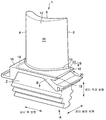
도 1은 본 발명의 제 1 실시형태에 따른 터빈 동익을 도시하는 사시도이다.
도 2는 도 1의 A 화살표에서 본 도면이며, 플랫폼의 후연측 단부 부근을 확대한 도면이다.
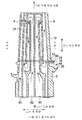
도 3은 도 1의 B-B 단면도이다.
도 4는 터빈 동익 부근의 냉각 공기의 흐름을 나타내는 가스 터빈의 단면도이다.
도 5는 플랫폼 내에 형성되는 냉각 유로의 다른 실시예를 도시하는 도면이다.
도 6은 플랫폼 내에 형성되는 냉각 유로의 다른 실시예를 도시하는 도면이다.
도 7은 본 발명의 제 2 실시형태에 따른 터빈 동익을 후연측으로부터 화살표에서 본 도면이다.
도 8은 본 발명의 제 3 실시형태에 따른 플랫폼을 도시하는 단면도이다.
도 9는 본 발명의 제 4 실시형태에 따른 터빈 동익을 후연측으로부터 화살표에서 본 도면이다.
도 10은 종래의 터빈 동익의 연직 단면도이다.
도 11은 플랫폼의 후연측 단부를 확대하여 도시하는 사시도이다.1 is a perspective view showing a turbine rotor blade according to a first embodiment of the present invention.
FIG. 2 is a view seen from the arrow A in FIG. 1 and is an enlarged view of the vicinity of the trailing edge end of the platform.
3 is a cross-sectional view taken along line BB of FIG. 1.
4 is a cross-sectional view of a gas turbine showing a flow of cooling air near the turbine rotor blade.
5 is a view showing another embodiment of a cooling passage formed in the platform.
6 is a view showing another embodiment of a cooling passage formed in the platform.
It is a figure which looked at the turbine rotor blade which concerns on 2nd Embodiment of this invention from the trailing edge side.
8 is a cross-sectional view showing a platform according to a third embodiment of the present invention.
It is a figure which looked at the turbine rotor blade which concerns on 4th Embodiment of this invention from the trailing edge side.
10 is a vertical sectional view of a conventional turbine rotor blade.
It is a perspective view which expands and shows the trailing edge side edge part of a platform.
이하, 본 발명에 따른 터빈 동익의 실시형태에 대해 도면을 이용하여 상세하게 설명한다. 또한, 이하의 설명에서는, 터빈 동익을 가스 터빈에 적용했을 경우에 대해 설명하지만, 이것에 한정되는 것이 아니며, 증기 터빈에도 적용할 수 있다. 또한, 이하의 실시예에 기재되어 있는 구성 부품의 치수, 재질, 형상, 그 상대 배치 등은 특히 특정적인 기재가 없는 한, 본 발명의 범위를 그것에만 한정하는 취지가 아니며, 단순한 설명 예에 지나지 않는다.EMBODIMENT OF THE INVENTION Hereinafter, embodiment of the turbine rotor blade which concerns on this invention is described in detail using drawing. In addition, although the following description demonstrates the case where a turbine rotor blade is applied to a gas turbine, it is not limited to this, It is applicable also to a steam turbine. In addition, the dimension, material, shape, the relative arrangement, etc. of the component parts described in the following example are not the meaning which limits the scope of this invention only to those in particular, unless there is particular notice, and are only a mere description example. Do not.
도 1은 본 발명의 제 1 실시형태에 따른 터빈 동익을 도시하는 사시도이다. 또한, 도 2는 도 1의 A 화살표에서 본 도면이며, 플랫폼의 후연측 단부 부근을 확대한 도면이다.1 is a perspective view showing a turbine rotor blade according to a first embodiment of the present invention. FIG. 2 is a view seen from the arrow A in FIG. 1 and is an enlarged view of the vicinity of the trailing edge end of the platform.
도 1 및 도 2에 도시하는 바와 같이, 본 발명의 제 1 실시형태는, 익형부(12)의 배측의 플랫폼(16)의 열응력을 저감하기 위해, 배측의 플랫폼(16)에 냉각 유로(14)를 마련한 예이다.As shown in FIG. 1 and FIG. 2, in the first embodiment of the present invention, in order to reduce thermal stress of the
가스 터빈의 터빈 동익(1)은, 로터에 고정되는 기단부(2)와, 로터의 직경 방향으로 연장되어, 전연(4)과 후연(6) 사이에 있어서의 날개 형상을 형성하는 복측 및 배측의 익면(8, 10)을 갖는 익형부(12)와, 냉각 공기를 흐르게 하기 위한 냉각 유로(14)가 내부에 형성된 플랫폼(16)을 구비하고 있다.The
플랫폼(16)의 후연측의 단면(18)에는, 로터 둘레 방향을 따른 오목부(20), 소위 리세스부가 형성되어 있다. 이 리세스부의 로터 직경 방향 외측에 위치하는 후연측의 단면(18)의 외측 영역(22)에 냉각 유로(14)의 개구(15)가 형성되어 있다.In the
외측 영역(22)의 로터 직경 방향에 있어서의 두께(L)는 익형부(12)의 배측으로부터 허브(13)의 후연측 단부를 향하여 서서히 작아지고 있다. 즉, 외측 영역(22)의 로터 직경 방향에 있어서의 두께(L)는, 로터 축 방향을 따라서 형성된 냉각 유로(14)의 개구(15) 근방의 외측 영역(22(L1))으로부터, 허브(13)의 후연측 단부 바로 아래의 외측 영역(22(L2))까지의 사이는 서서히 작아지고 있다.The thickness L in the rotor radial direction of the
또한, 본 실시형태에서는, 익형부(12)의 복측의 플랫폼(16)에는, 로터 축 방향을 따른 냉각 유로를 마련하지 않고 있다. 따라서, 허브(13)의 후연측 단부 바로 아래의 외측 영역(22)으로부터 익형부(12)의 복측의 단면까지의 사이의 외측 영역(22)의 로터 직경 방향의 두께(L)는 복측의 단면을 향하여 서서히 작게 하여도 좋고, 동일한 두께로 하여도 좋다.In addition, in this embodiment, the cooling channel along the rotor axial direction is not provided in the
로터 둘레 방향에 있어서의 허브(13)의 후연측 단부의 접속 위치 바로 아래의 외측 영역(22)의 두께(L2)는 익형부(12)의 열 신장에 추종하여 변형 가능한 두께이며, 배경 기술의 란에서 설명한 특허문헌 1에 기재된 플랫폼(60)의 외측 영역(22)의 두께(L3)(도 10 참조)도 거의 동일하다. 따라서, 로터 축 방향에 따른 냉각 유로(14)의 개구(15) 위치의 외측 영역(22)의 두께(L1)는 특허문헌 1에 기재한 플랫폼(60)의 외측 영역(22)의 두께(L3)보다 크게 형성되어 있다. 이것에 의해, 종래의 플랫폼(60)에 형성되는 냉각 유로(64)의 직경보다 대경의 냉각 유로(14)를 형성할 수 있다.The thickness L2 of the
도 3은 도 1의 B-B 단면도이다. 도 3에 도시하는 바와 같이, 냉각 유로(14)의 일단은, 터빈 동익(1)의 기단부(2)로부터 익형부(12)까지 연통하는 전연측의 냉각 유로(24)에 연통하고 있다. 또한, 냉각 유로(14)는 냉각 유로(24)로부터 플랫폼(16)의 전연 하측 단부(도 3의 좌측 하단)를 향하여 연장되며, 해당 전방 하측 단부 부근에서 후연측으로 굴곡하며, 후연측을 향하여 로터 축 방향을 따라서 형성되어 있다.3 is a cross-sectional view taken along line B-B in FIG. 1. As shown in FIG. 3, one end of the
그리고, 냉각 유로(14)에는, 냉각 유로(24) 내를 흐르는 냉각 공기의 일부가 유입한다. 냉각 유로(14)에 유입한 냉각 공기는 냉각 유로(14) 내를 통과하여, 후연측의 개구(15)로부터 배출된다.And a part of cooling air which flows in the
허브(13)와 후연측의 단면(18)의 외측 영역(22)이 가장 접근하는 위치는, 강성이 높은 플랫폼측으로부터의 구속력이 크고, 후연에 가까운 익형부(12)나 허브(13)에 가해지는 열응력이 커지기 쉽다. 그 때문에, 전술과 같이, 이러한 열응력을 억제하기 위해, 후연측의 단면(18)에 오목부(20)(소위, 리세스부)를 마련하고 있다. 즉, 허브(13)와 후연측의 단면(18)이 가장 접근하는 위치는 허브(13)의 후연측 단부의 접속 위치 바로 아래이며, 이 근방에서의 플랫폼(16)으로부터의 구속을 해방할 필요가 있다. 구체적으로는, 도 3에 도시하는 바와 같이, 후연(6)으로부터 로터 축 방향으로 평행선을 긋고, 외측 영역(22)과의 교점을 A점이라고 하면, A점 근방의 외측 영역(22)이 허브측에 가장 접근하는 위치이다. 즉, 배측 및 복측의 플랫폼(16)의 후연측의 단면(18)의 외측 영역(22)이 로터 축 방향을 따른 냉각 유로(14)의 개구(15)를 구비하는 경우, 높은 리세스 효과를 얻기 위해서는, A점 근방에서의 외측 영역(22)의 로터 직경 방향의 두께(L)를 가장 얇게 할 필요가 있다.The position where the
도 4는 터빈 동익(1) 부근의 냉각 공기의 흐름을 나타내는 가스 터빈의 단면도이다.4 is a cross-sectional view of the gas turbine showing the flow of cooling air in the vicinity of the
도 4에 도시하는 바와 같이, 차실로부터 송급된 냉각 공기는 로터(30) 내의 디스크 캐비티(31)에 유입하고, 로터 디스크(32)에 마련된 래디얼 홀(33)을 통과하여 기단부(2) 내의 냉각 유로(24)에 인도된다. 그리고, 익형부(12)를 향하여 흐르는 도중에, 냉각 공기의 일부가 플랫폼(16)의 냉각 유로(14)에 유입한다.As shown in FIG. 4, the cooling air supplied from the vehicle compartment flows into the
또한, 냉각 유로(14)로의 냉각 공기의 공급 계통은 이것에 한정되는 것이 아니며, 다른 계통을 이용하여도 좋다.In addition, the supply system of the cooling air to the
상술한 바와 같이, 본 실시형태에 있어서의 터빈 동익(1)에 의하면, 플랫폼(16)의 후연측의 단면(18) 중 외측 영역(22)의 로터 직경 방향에 있어서의 두께(L)는, 익형부(12)의 허브(13)의 후연측 단부 바로 아래에 대응하는 위치(도 3 중의 A점 근방 참조)의 외측 영역(22(L2))보다도 냉각 유로(14)의 개구(15) 위치의 외측 영역(22(L1))이 크기 때문에, 플랫폼(16)의 냉각 능력이 향상한다.As mentioned above, according to the
한편, 허브(13)의 후연측 단부 바로 아래에 대응하는 외측 영역(22)의 두께(L2)는 냉각 유로(14)의 개구(15) 위치의 외측 영역(22)의 두께(L1)보다 작기 때문에, 허브(13)의 후연측 단부가 접속되어 있는 외측 영역(22)의 주위가 익형부(12)의 열 신장에 따라 변형하기 쉬워져, 후연측 단부 부근에 발생하는 열응력을 억제할 수 있다.On the other hand, the thickness L2 of the
또한, 익형부(12)의 배측의 플랫폼(16) 내에 구경이 큰 냉각 유로(14)의 형성이 가능해져, 플랫폼(16)의 냉각 능력이 향상하기 때문에, 고온으로 이용되는 터빈에 적용하는 것이 가능해진다.In addition, since the cooling
또한, 외측 영역(22)의 로터 직경 방향에 있어서의 두께(L)는 익형부(12)의 배측으로부터 허브(13)의 후연측 단부를 향하여 서서히 작아지고 있기 때문에, 열부하가 높은 익형부(12)의 배측의 플랫폼(16)의 냉각 능력이 향상한다. 그리고, 외측 영역(22)의 로터 직경 방향에 있어서의 두께(L)를 익형부(12)의 배측으로부터 허브(13)의 후연측 단부를 향하여 서서히 작아지도록 형성하는 가공은 용이하며, 수고 및 비용이 증가하는 일은 없다.Moreover, since the thickness L in the rotor radial direction of the outer side area |
또한, 상술한 실시형태에서는, 익형부(12)의 배측에 1개의 냉각 유로(14)를 마련했을 경우에 대해 설명했지만, 이것에 한정되는 것은 아니다. 플랫폼면의 열부하 및 발생하는 열응력의 크기에 의해, 냉각 유로(14)의 필요 여부, 유로 구경은 임의로 선정할 수 있다. 예를 들면, 도 5 및 도 6에 도시하는 바와 같이, 허브(13)의 후연측 단부 바로 아래의 외측 영역(22)으로부터 익형부(12)의 복측의 단면까지의 사이의 외측 영역(22)의 로터 직경 방향의 두께(L)를 동일한 두께로 하여, 익형부(12)의 배측에 복수의 냉각 유로(14, 26)를 마련하는 동시에, 복측에도 냉각 유로(28)를 마련하여도 좋다. 이러한 경우에는, 각 냉각 유로(14, 26, 28)의 유로 구경의 크기는 익형부(12)의 배측으로부터 복측을 향하여 서서히 작아지고 있다.In addition, although the above-mentioned embodiment demonstrated the case where one
이와 같이, 냉각 유로(26, 28)의 직경을 냉각 유로(14)의 직경보다 작게 함으로써, 외측 영역(22)의 로터 직경 방향에 있어서의 두께(L)가 작은 개소에도 냉각 유로(26, 28)를 형성할 수 있다.Thus, by making the diameter of the
그리고, 복수의 냉각 유로(14, 26, 28)가 플랫폼(16) 내에 형성됨으로써, 플랫폼(16)의 냉각 효과를 대폭 증대시킬 수 있다.And since the some
다음에, 터빈 동익(1)의 다른 실시형태에 대해 설명한다. 이하의 설명에 있어서, 상기의 실시형태에 대응하는 부분에는 동일한 도면부호를 부여하고 설명을 생략하며, 주로 차이점에 대해 설명한다.Next, another embodiment of the
도 7은 본 발명의 제 2 실시형태에 따른 터빈 동익(41)을 후연측으로부터 화살표에서 본 도면이다.7 is a view of the
도 7에 도시하는 바와 같이, 본 발명의 제 2 실시형태는, 배측 및 복측의 양측의 플랫폼의 열응력을 저감하기 위해, 배측 및 복측의 쌍방의 플랫폼(42)에 냉각 유로(14, 26, 44)를 마련하여, 이들 냉각 유로(14, 26, 44)의 배치에 맞추어 오목부(리세스부)(20)의 형상을 바꾼 예이다.As shown in FIG. 7, in 2nd embodiment of this invention, in order to reduce the thermal stress of the platform of both sides of a back side and a abdomen, the
터빈 동익(41)의 플랫폼(42)에, 복수의 냉각 유로(14, 26, 44)가 형성되어 있다. 그리고, 각 냉각 유로(14, 26, 44)에 대응한 개구(15, 27, 45)가 후연측의 단면(18)의 외측 영역(22)에 형성되어 있다. 구체적으로는, 냉각 유로(14, 26)에 대응한 개구(15, 27)는 외측 영역(22)의 배측 단부에 각각 형성되어 있다. 또한, 냉각 유로(44)에 대응한 개구(45)는 외측 영역(22)의 복측 단부에 형성되어 있다.A plurality of
상술의 냉각 유로(14, 26, 44)의 배치에 대하여 형성되는 오목부(리세스부)의 형상의 일 예를 도 7에 도시하고 있다. 허브(13)의 후연측 단부의 접속 위치 바로 아래의 위치를 점(A)으로 하고, 그 위치에서의 후연측 단부의 하단의 위치를 점(D)으로 하면, 오목부(20)의 형상은 선 BCDEF로 나타내는 형상이 된다. 즉, 점(D)을 중간에 로터 직경 방향의 길이(L0)가 일정 폭의 직선부 CDE를 천정으로 하고, 배측 및 복측의 단면을 향하여 완만한 경사면을 형성하여, 전체적으로 D점을 정점으로 한 산형상으로 형성되어 있다.An example of the shape of the recessed part (recess part) formed with respect to the above-mentioned arrangement of the
이와 같은 오목부(20)의 형상으로 했을 경우, 외측 영역(22)의 로터 직경 방향에 있어서의 두께(L)는, 허브(13)의 후연측 단부의 접속 위치 바로 아래의 외측 영역(22)의 두께(L0)(점 A로부터 점 D까지)가 가장 작아지고 있다. 즉, 로터 축 방향을 따라서 형성된 냉각 유로(14, 26, 44)의 개구(15, 27, 45)의 위치의 외측 영역(22)의 두께(L4, L5, L6)가 로터 둘레 방향에 있어서의 허브(13)의 후연측 단부의 접속 위치 바로 아래의 외측 영역(22)의 두께(L0)보다 커지고 있다.In the case of such a
본 실시형태에서는, 허브(13)의 후연측 단부의 접속 위치 바로 아래에 있어서의 외측 영역(22)의 두께(L0)는, 제 1 실시형태와 마찬가지로, 배경 기술의 란에서 설명한 특허문헌 1에 기재된 플랫폼(60)의 외측 영역(22)의 두께(L3)와 거의 동일하다. 따라서, 로터 둘레 방향에 있어서의 냉각 유로(14, 26, 44)의 개구(15, 27, 45) 위치의 외측 영역(22)의 두께(L4, L5, L6)는 특허문헌 1에 기재한 플랫폼(60)의 외측 영역(22)의 두께(L3)보다 크게 형성되어 있기 때문에, 종래의 플랫폼(60)에 형성되는 냉각 유로의 직경보다 대경의 냉각 유로(14, 26, 44)를 형성할 수 있다.In the present embodiment, the thickness L0 of the
상술한 바와 같이, 본 실시형태에 있어서의 터빈 동익(41)에 의하면, 제 1 실시형태에 따른 효과에 부가하여, 종래의 플랫폼(60)에 형성되는 냉각 유로(64)보다 대경의 냉각 유로(14, 26, 44)를 구비하고 있으므로, 플랫폼(16)의 냉각 능력을 대폭 향상시킬 수 있다.As described above, according to the
다음에, 터빈 동익의 제 3 실시형태에 대하여 설명한다. 본 발명의 제 3 실시형태는, 제 1 실시형태의 플랫폼(16) 내에, 익형부(12)의 배측의 익면(8) 형상에 따른 냉각 유로(54)를 추가로 마련한 것이다.Next, a third embodiment of the turbine rotor blade will be described. In the third embodiment of the present invention, the cooling
도 8은 본 발명의 제 3 실시형태에 따른 플랫폼(16)을 도시하는 단면도이다.8 is a cross-sectional view showing a
도 8에 도시하는 바와 같이, 냉각 유로(54)는, 익면(10)의 후연측의 형상에 따라서, 익형부(12)의 배측의 플랫폼(16) 내에 형성되어 있다.As shown in FIG. 8, the
냉각 유로(54)의 일단측은 플랫폼(16)의 후연측의 단면(18)에 있어서의 외측 영역(22)으로 개구(55)되어 있다. 냉각 유로(54)의 직경은 냉각 유로(14)의 직경보다 작게 형성되어 있다. 또한, 냉각 유로(54)의 타단측은 플랫폼(16)의 기단부(2)측의 표면으로 개구(56)되어 있다.One end side of the
다음에, 로터(30) 내로부터 냉각 유로(54)까지의 냉각 공기의 흐름에 대하여 설명한다.Next, the flow of cooling air from the
도 4에 도시하는 바와 같이, 냉각 공기는, 로터(30) 내의 시일 디스크(34) 및 디스크 캐비티(35)를 통해서, 플랫폼 캐비티(36)에 유입하며, 플랫폼(16)의 기단부(2)측의 표면에 형성되어 있는 개구(56)로부터 냉각 유로(54)에 유입한다. 냉각 유로(54)에 유입한 냉각 공기는 플랫폼(16)을 냉각하고, 후연측의 개구(55)로부터 배출된다.As shown in FIG. 4, cooling air flows into the
또한, 냉각 공기의 공급 계통은 이것에 한정되는 것이 아니며, 예를 들면 제 1 실시형태에서 설명한 익형부(12)에 연통하는 냉각 유로(24)에 냉각 유로(54)의 타단을 접속하고, 냉각 유로(24)로부터 분기하는 것으로 하여도 좋다.In addition, the supply system of cooling air is not limited to this, For example, the other end of the
또한, 본 실시형태에서는, 냉각 유로(54)를 제 1 실시형태의 플랫폼(16)에 적용했을 경우에 대하여 설명했지만, 이것에 한정되는 것이 아니며, 제 2 실시형태의 플랫폼(42)에도 적용 가능하다.In addition, in this embodiment, although the case where the
상술한 바와 같이, 본 실시형태에 있어서의 터빈 동익(51)에 의하면, 제 1 및 제 2 실시형태에 따른 효과에 부가하여, 냉각 유로(54)를 구비하고 있으므로, 플랫폼(16)의 후연측 단부의 냉각 능력을 대폭 향상시킬 수 있다.As mentioned above, according to the
다음에, 터빈 동익의 제 4 실시형태에 대해 도 9에 기초하여 설명한다. 본 발명의 제 4 실시형태는, 플랫폼(16)의 후연측의 단면(18)에 있어서의 외측 영역(22)의 로터 직경 방향에 있어서의 두께를 바꾼 것을 제외하고, 다른 부분은 제 1 실시형태와 동일하다.Next, 4th Embodiment of a turbine rotor blade is described based on FIG. The fourth embodiment of the present invention is the first embodiment except that the thickness in the rotor radial direction of the
즉, 도 9에 도시하는 바와 같이, 본 실시형태에서는, 플랫폼(16)의 후연측의 단면(18)에 있어서의 외측 영역(22)의 로터 직경 방향에 있어서의 두께를, 플랫폼(16)의 배측의 로터 축 방향으로 배치된 냉각 유로(14)의 개구(15) 근방에서는, 개구(15)가 배치될 수 있는 두께(L1)로 하고, 거기로부터 후연측 단부 바로 아래를 지나 복측 단부까지의 사이의 외측 영역은 두께(L1)보다 얇은 동일한 두께(L2)로 형성하여도 좋다. 본 실시형태의 경우도, 제 1 실시형태와 동일한 작용, 효과를 얻을 수 있다.That is, as shown in FIG. 9, in this embodiment, the thickness in the rotor radial direction of the outer area |
Claims (6)
상기 로터의 직경 방향으로 연장되며, 전연과 후연 사이에 있어서의 날개 형상을 형성하는 복측(腹側) 및 배측(背側)의 익면을 갖는 익형부(翼形部)와,
상기 기단부와 상기 익형부 사이에 마련되며, 상기 로터의 둘레 방향을 따른 오목부가 상기 후연측의 단면에 형성되며, 상기 오목부의 상기 로터의 직경 방향 외측에 위치하는 상기 단면의 외측 영역으로 개구하는 냉각 유로가 내부에 형성된 플랫폼을 구비하는 터빈 동익에 있어서,
상기 단면의 상기 외측 영역으로 개구하는 상기 냉각 유로의 상기 외측 영역의 로터 직경 방향에 있어서의 두께는, 상기 플랫폼에 접속되는 상기 익형부의 허브의 후연측 단부에 대응하는 상기 외측 영역의 상기 로터의 직경 방향에 있어서의 두께보다 커지는 것을 특징으로 하는
터빈 동익.A proximal end fixed to the rotor,
Airfoils extending in the radial direction of the rotor and having a wing surface of the ventral side and the ventral side forming a blade shape between the leading edge and the trailing edge,
Cooling provided between the proximal end and the airfoil, wherein a recess along the circumferential direction of the rotor is formed in the cross section of the trailing edge side, and is opened to an outer region of the cross section located outside the radial direction of the rotor of the recess. In the turbine rotor blade having a platform having a flow path formed therein,
The thickness in the rotor radial direction of the outer region of the cooling passage opening to the outer region of the cross section is the diameter of the rotor of the outer region corresponding to the trailing edge side end of the hub of the airfoil connected to the platform. It becomes larger than thickness in the direction characterized by the above-mentioned
Turbine rotor.
상기 플랫폼의 후연측의 상기 단면에 있어서, 상기 외측 영역의 상기 로터의 직경 방향에 있어서의 두께는, 상기 익형부의 배측으로부터 상기 허브의 상기 후연측 단부를 향하여 서서히 작아지는 것을 특징으로 하는
터빈 동익.The method of claim 1,
In the cross section at the trailing edge side of the platform, the thickness in the radial direction of the rotor in the outer region gradually decreases from the side of the airfoil to the trailing edge side of the hub.
Turbine rotor.
상기 냉각 유로는 상기 로터의 축 방향을 따라서 상기 플랫폼 내에 복수 형성되며,
서로 인접하는 상기 냉각 유로 중 상기 익형부의 복측에 배치된 상기 냉각 유로의 직경은 상기 익형부의 배측에 배치된 상기 냉각 유로의 직경보다 작은 것을 특징으로 하는
터빈 동익.3. The method according to claim 1 or 2,
The cooling passage is formed in the plurality of the platform along the axial direction of the rotor,
The diameter of the cooling passage disposed on the ventral side of the airfoil portion of the cooling passages adjacent to each other is smaller than the diameter of the cooling passage disposed on the back side of the airfoil portion.
Turbine rotor.
상기 플랫폼의 후연측의 상기 단면에 있어서, 상기 외측 영역의 상기 로터의 직경 방향에 있어서의 두께는, 상기 익형부의 배측으로부터 상기 허브의 후연측 단부를 향하여 서서히 작아지고, 상기 익형부의 복측으로부터 상기 허브의 후연측 단부를 향하여 서서히 작아지는 것을 특징으로 하는
터빈 동익.The method of claim 1,
In the cross section at the trailing edge side of the platform, the thickness in the radial direction of the rotor in the outer region gradually decreases from the air vent side of the airfoil to the trailing edge end of the hub, and from the ventral side of the airfoil to the hub. It gradually decreases toward the trailing edge end of the
Turbine rotor.
상기 냉각 유로는 상기 로터의 축 방향을 따라서 상기 플랫폼 내에 복수 형성되며,
서로 인접하는 상기 냉각 유로 중 상기 허브의 후연 단부에 가까운 쪽의 상기 냉각 유로의 직경은 상기 허브의 후연 단부로부터 먼 쪽의 상기 냉각 유로의 직경보다 작은 것을 특징으로 하는
터빈 동익.The method according to claim 1 or 4,
The cooling passage is formed in the plurality of the platform along the axial direction of the rotor,
The diameter of the cooling passage near the trailing edge end of the hub of the cooling passages adjacent to each other is smaller than the diameter of the cooling passage away from the trailing edge end of the hub.
Turbine rotor.
상기 냉각 유로는 상기 배측의 익면의 후연측 형상을 따라서 상기 플랫폼의 후연측 단부에 형성되는 것을 특징으로 하는
터빈 동익.6. The method according to any one of claims 1 to 5,
The cooling passage is formed at the trailing edge side end portion of the platform along the trailing edge shape of the blade surface of the back side.
Turbine rotor.
Applications Claiming Priority (3)
| Application Number | Priority Date | Filing Date | Title |
|---|---|---|---|
| JP2011128958 | 2011-06-09 | ||
| JPJP-P-2011-128958 | 2011-06-09 | ||
| PCT/JP2011/080056 WO2012169092A1 (en) | 2011-06-09 | 2011-12-26 | Turbine blade |
Publications (2)
| Publication Number | Publication Date |
|---|---|
| KR20140014252A true KR20140014252A (en) | 2014-02-05 |
| KR101538258B1 KR101538258B1 (en) | 2015-07-20 |
Family
ID=47293344
Family Applications (1)
| Application Number | Title | Priority Date | Filing Date |
|---|---|---|---|
| KR1020137030827A Active KR101538258B1 (en) | 2011-06-09 | 2011-12-26 | Turbine blade |
Country Status (6)
| Country | Link |
|---|---|
| US (1) | US8967968B2 (en) |
| EP (1) | EP2719863B1 (en) |
| JP (1) | JP5716189B2 (en) |
| KR (1) | KR101538258B1 (en) |
| CN (1) | CN103502575B (en) |
| WO (1) | WO2012169092A1 (en) |
Cited By (1)
| Publication number | Priority date | Publication date | Assignee | Title |
|---|---|---|---|---|
| US10844731B2 (en) | 2017-06-20 | 2020-11-24 | DOOSAN Heavy Industries Construction Co., LTD | Cantilevered vane and gas turbine including the same |
Families Citing this family (5)
| Publication number | Priority date | Publication date | Assignee | Title |
|---|---|---|---|---|
| JP5606648B1 (en) * | 2014-06-27 | 2014-10-15 | 三菱日立パワーシステムズ株式会社 | Rotor blade and gas turbine provided with the same |
| EP3112593A1 (en) * | 2015-07-03 | 2017-01-04 | Siemens Aktiengesellschaft | Internally cooled turbine blade |
| GB201512810D0 (en) | 2015-07-21 | 2015-09-02 | Rolls Royce Plc | Thermal shielding in a gas turbine |
| EP3147452B1 (en) * | 2015-09-22 | 2018-07-25 | Ansaldo Energia IP UK Limited | Turboengine blading member |
| JP6943706B2 (en) * | 2017-09-22 | 2021-10-06 | 三菱パワー株式会社 | Turbine blades and gas turbines |
Family Cites Families (12)
| Publication number | Priority date | Publication date | Assignee | Title |
|---|---|---|---|---|
| CN1162345A (en) * | 1994-10-31 | 1997-10-15 | 西屋电气公司 | Gas turbine blades with cooled platforms |
| KR100364183B1 (en) * | 1994-10-31 | 2003-02-19 | 웨스팅하우스 일렉트릭 코포레이션 | Gas turbine blade with a cooled platform |
| JP3316418B2 (en) * | 1997-06-12 | 2002-08-19 | 三菱重工業株式会社 | Gas turbine cooling blade |
| CA2262064C (en) * | 1998-02-23 | 2002-09-03 | Mitsubishi Heavy Industries, Ltd. | Gas turbine moving blade platform |
| JP3546135B2 (en) * | 1998-02-23 | 2004-07-21 | 三菱重工業株式会社 | Gas turbine blade platform |
| US6190130B1 (en) * | 1998-03-03 | 2001-02-20 | Mitsubishi Heavy Industries, Ltd. | Gas turbine moving blade platform |
| JP2001152804A (en) * | 1999-11-19 | 2001-06-05 | Mitsubishi Heavy Ind Ltd | Gas turbine facility and turbine blade |
| JP2001271603A (en) * | 2000-03-24 | 2001-10-05 | Mitsubishi Heavy Ind Ltd | Gas turbine moving blade |
| CA2334071C (en) * | 2000-02-23 | 2005-05-24 | Mitsubishi Heavy Industries, Ltd. | Gas turbine moving blade |
| US6945749B2 (en) * | 2003-09-12 | 2005-09-20 | Siemens Westinghouse Power Corporation | Turbine blade platform cooling system |
| US7766606B2 (en) * | 2006-08-17 | 2010-08-03 | Siemens Energy, Inc. | Turbine airfoil cooling system with platform cooling channels with diffusion slots |
| US7695247B1 (en) * | 2006-09-01 | 2010-04-13 | Florida Turbine Technologies, Inc. | Turbine blade platform with near-wall cooling |
-
2011
- 2011-12-26 EP EP11867536.2A patent/EP2719863B1/en active Active
- 2011-12-26 KR KR1020137030827A patent/KR101538258B1/en active Active
- 2011-12-26 JP JP2013519345A patent/JP5716189B2/en active Active
- 2011-12-26 CN CN201180070460.6A patent/CN103502575B/en active Active
- 2011-12-26 WO PCT/JP2011/080056 patent/WO2012169092A1/en not_active Ceased
-
2012
- 2012-01-31 US US13/362,755 patent/US8967968B2/en active Active
Cited By (1)
| Publication number | Priority date | Publication date | Assignee | Title |
|---|---|---|---|---|
| US10844731B2 (en) | 2017-06-20 | 2020-11-24 | DOOSAN Heavy Industries Construction Co., LTD | Cantilevered vane and gas turbine including the same |
Also Published As
| Publication number | Publication date |
|---|---|
| EP2719863A4 (en) | 2015-03-11 |
| KR101538258B1 (en) | 2015-07-20 |
| US20120315150A1 (en) | 2012-12-13 |
| CN103502575B (en) | 2016-03-30 |
| WO2012169092A1 (en) | 2012-12-13 |
| EP2719863B1 (en) | 2017-03-08 |
| JP5716189B2 (en) | 2015-05-13 |
| JPWO2012169092A1 (en) | 2015-02-23 |
| EP2719863A1 (en) | 2014-04-16 |
| CN103502575A (en) | 2014-01-08 |
| US8967968B2 (en) | 2015-03-03 |
Similar Documents
| Publication | Publication Date | Title |
|---|---|---|
| EP2801701B1 (en) | Turbine blades | |
| KR20140014252A (en) | Turbine rotor blade | |
| US20140023497A1 (en) | Cooled turbine blade tip shroud with film/purge holes | |
| JP4929097B2 (en) | Gas turbine blade | |
| EP2374997B1 (en) | Component for a gas turbine engine | |
| EP2792851B1 (en) | Turbine blade | |
| US20090252615A1 (en) | Cooled Turbine Rotor Blade | |
| US9528381B2 (en) | Structural configurations and cooling circuits in turbine blades | |
| US20120201694A1 (en) | Turbine blade | |
| US20160201469A1 (en) | Mateface surfaces having a geometry on turbomachinery hardware | |
| US9879547B2 (en) | Interior cooling circuits in turbine blades | |
| WO2010052784A1 (en) | Turbine blade | |
| KR20170128128A (en) | Blade with stress-reducing bulbous projection at turn opening of coolant passages | |
| JP2010169089A (en) | Turbine blade or vane with improved cooling efficiency | |
| US20140348661A1 (en) | Blade row, blade and turbomachine | |
| US8727726B2 (en) | Turbine endwall cooling arrangement | |
| US8714927B1 (en) | Microcircuit skin core cut back to reduce microcircuit trailing edge stresses | |
| JP5518235B2 (en) | Split ring cooling structure and gas turbine | |
| US7458779B2 (en) | Gas turbine or compressor blade | |
| BR102012027855A2 (en) | airfoil and gas turbine engine | |
| US7708528B2 (en) | Platform mate face contours for turbine airfoils | |
| JP6986834B2 (en) | Articles and methods for cooling articles | |
| US11035234B2 (en) | Airfoil having a tip capacity | |
| US20180112544A1 (en) | Turbine rotor blade, turbine rotor arrangement and method for manufacturing a turbine rotor blade | |
| JP2007211618A (en) | Gas turbine |
Legal Events
| Date | Code | Title | Description |
|---|---|---|---|
| A201 | Request for examination | ||
| PA0105 | International application |
Patent event date: 20131120 Patent event code: PA01051R01D Comment text: International Patent Application |
|
| PA0201 | Request for examination | ||
| PG1501 | Laying open of application | ||
| E902 | Notification of reason for refusal | ||
| PE0902 | Notice of grounds for rejection |
Comment text: Notification of reason for refusal Patent event date: 20141029 Patent event code: PE09021S01D |
|
| N231 | Notification of change of applicant | ||
| PN2301 | Change of applicant |
Patent event date: 20150209 Comment text: Notification of Change of Applicant Patent event code: PN23011R01D |
|
| E701 | Decision to grant or registration of patent right | ||
| PE0701 | Decision of registration |
Patent event code: PE07011S01D Comment text: Decision to Grant Registration Patent event date: 20150514 |
|
| GRNT | Written decision to grant | ||
| PR0701 | Registration of establishment |
Comment text: Registration of Establishment Patent event date: 20150714 Patent event code: PR07011E01D |
|
| PR1002 | Payment of registration fee |
Payment date: 20150714 End annual number: 3 Start annual number: 1 |
|
| PG1601 | Publication of registration | ||
| FPAY | Annual fee payment |
Payment date: 20180628 Year of fee payment: 4 |
|
| PR1001 | Payment of annual fee |
Payment date: 20180628 Start annual number: 4 End annual number: 4 |
|
| PR1001 | Payment of annual fee |
Payment date: 20200630 Start annual number: 6 End annual number: 6 |
|
| PR1001 | Payment of annual fee |
Payment date: 20230619 Start annual number: 9 End annual number: 9 |
|
| PR1001 | Payment of annual fee |
Payment date: 20250619 Start annual number: 11 End annual number: 11 |