KR20130135647A - Mobile terminal - Google Patents
Mobile terminal Download PDFInfo
- Publication number
- KR20130135647A KR20130135647A KR1020120059404A KR20120059404A KR20130135647A KR 20130135647 A KR20130135647 A KR 20130135647A KR 1020120059404 A KR1020120059404 A KR 1020120059404A KR 20120059404 A KR20120059404 A KR 20120059404A KR 20130135647 A KR20130135647 A KR 20130135647A
- Authority
- KR
- South Korea
- Prior art keywords
- slide door
- mobile terminal
- slot
- support frame
- slide
- Prior art date
- Legal status (The legal status is an assumption and is not a legal conclusion. Google has not performed a legal analysis and makes no representation as to the accuracy of the status listed.)
- Withdrawn
Links
Images


Classifications
-
- H—ELECTRICITY
- H04—ELECTRIC COMMUNICATION TECHNIQUE
- H04B—TRANSMISSION
- H04B1/00—Details of transmission systems, not covered by a single one of groups H04B3/00 - H04B13/00; Details of transmission systems not characterised by the medium used for transmission
- H04B1/38—Transceivers, i.e. devices in which transmitter and receiver form a structural unit and in which at least one part is used for functions of transmitting and receiving
- H04B1/3816—Mechanical arrangements for accommodating identification devices, e.g. cards or chips; with connectors for programming identification devices
-
- H—ELECTRICITY
- H04—ELECTRIC COMMUNICATION TECHNIQUE
- H04M—TELEPHONIC COMMUNICATION
- H04M1/00—Substation equipment, e.g. for use by subscribers
- H04M1/02—Constructional features of telephone sets
- H04M1/0202—Portable telephone sets, e.g. cordless phones, mobile phones or bar type handsets
- H04M1/026—Details of the structure or mounting of specific components
- H04M1/0274—Details of the structure or mounting of specific components for an electrical connector module
Landscapes
- Engineering & Computer Science (AREA)
- Signal Processing (AREA)
- Computer Networks & Wireless Communication (AREA)
- Telephone Set Structure (AREA)
Abstract
본 발명의 일 실시예에 따르는 이동 단말기는, 외부 기기가 접속될 수 있도록 내부에 소켓이 장착되는 단말기 본체와, 상기 본체의 적어도 일측면을 덮어 외관을 형성하는 케이스와, 상기 케이스에 일체로 형성되고, 상기 소켓에 연통되는 슬롯부와, 상기 슬롯부의 내측면에 결합되는 지지 프레임 및 상기 슬롯부와 상기 지지 프레임 사이에 배치되어 상기 소켓을 개폐하도록 슬라이드 이동하는 슬라이드 도어를 포함하고, 상기 지지 프레임은 닫힌 상태 또는 열린 상태에서 상기 슬라이드 도어의 위치를 고정할 수 있도록 상기 슬라이드 도어와 결합하는 제1 결합부와 제2 결합부를 구비한다.A mobile terminal according to an embodiment of the present invention includes a terminal main body having a socket mounted therein so that external devices can be connected, a case covering at least one side of the main body to form an appearance, and integrally formed in the case And a slot part in communication with the socket, a support frame coupled to an inner surface of the slot part, and a slide door disposed between the slot part and the support frame to slide to open and close the socket, wherein the support frame Has a first engaging portion and a second engaging portion engaging with the slide door so as to fix the position of the slide door in a closed state or an open state.
Description
본 발명의 일실시예들은 이동 단말기에 장착되는 소켓을 개폐하는 장치에 관한 것이다.
One embodiment of the present invention relates to an apparatus for opening and closing a socket mounted to a mobile terminal.
단말기(terminal)는 기능이 다양화됨에 따라 예를 들어, 사진이나 동영상의 촬영, 음악이나 동영상 파일의 재생, 게임, 방송의 수신 등의 복합적인 기능들을 갖춘 멀티미디어 기기(Multimedia player) 형태로 구현되고 있다. As the functions are diversified, the terminal is implemented in the form of a multimedia device having a complex function of, for example, taking pictures or moving pictures, playing music or moving picture files, receiving games and receiving broadcasts have.
단말기는 이동 가능 여부에 따라 휴대용 단말기(mobile/portable terminal) 및 고정 단말기(stationary terminal)으로 나뉠 수 있다. 휴대용 단말기는 휴대가 가능하면서 음성 및 영상 통화를 수행할 수 있는 기능, 정보를 입·출력할 수 있는 기능 및 데이터를 저장할 수 있는 기능 등을 하나 이상 갖춘 휴대용 기기이다.The terminal can move And may be divided into a mobile terminal and a stationary terminal depending on whether the mobile terminal is a mobile terminal or a mobile terminal. A portable terminal is a portable device having one or more functions capable of performing voice and video communication, capable of inputting / outputting information, and storing data, which can be carried while being portable.
이러한 단말기의 기능 지지 및 증대를 위해, 단말기의 구조적인 부분 및/또는 소프트웨어적인 부분을 개량하는 것이 고려될 수 있다.In order to support and enhance the functionality of such terminals, it may be considered to improve the structural and / or software parts of the terminal.
특히, 외부 기기가 삽입되는 소켓을 구비한 이동 단말기에 있어서, 소켓는 외부로 직접 노출되거나 별도의 부재에 의해 가려진 상태에서 조작을 통해 선택적으로 외부로 노출되게 구성된다. In particular, in a mobile terminal having a socket into which an external device is inserted, the socket is configured to be selectively exposed to the outside through an operation in a state directly exposed to the outside or covered by a separate member.
슬라이드 도어가 슬라이드 이동되어 소켓를 가리거나 노출시키는 구조의 경우, 슬라이드 도어의 작동 및 고정을 위한 일반적인 레일 형태의 구조는 복잡하고, 치수 관리가 어려우며, 이동 단말기의 슬림화를 저해한다.
In the case of a structure in which the slide door slides to cover or expose the socket, a general rail-shaped structure for operating and fixing the slide door is complicated, difficult to manage dimensions, and hinder the slimming of the mobile terminal.
본 발명의 일 목적은 종래와 다른 타입의 슬라이드 도어 타입의 소켓 개폐 구조를 구비하는 이동 단말기를 제공하기 위한 것이다.One object of the present invention is to provide a mobile terminal having a socket opening and closing structure of a slide door type different from the prior art.
본 발명의 다른 일 목적은 보다 단순한 구조를 통해 슬림화된 이동 단말기를 구현하기 위한 것이다.
Another object of the present invention is to implement a slimmed mobile terminal through a simpler structure.
이와 같은 본 발명의 해결 과제를 달성하기 위하여, 본 발명의 일 실시예에 따르는 이동 단말기는, 외부 기기가 접속될 수 있도록 내부에 소켓이 장착되는 단말기 본체와, 상기 본체의 적어도 일측면을 덮어 외관을 형성하는 케이스와, 상기 케이스에 일체로 형성되고, 상기 소켓에 연통되는 슬롯부와, 상기 슬롯부의 내측면에 결합되는 지지 프레임 및 상기 슬롯부와 상기 지지 프레임 사이에 배치되어 상기 소켓을 개폐하도록 슬라이드 이동하는 슬라이드 도어를 포함하고, 상기 지지 프레임은 닫힌 상태 또는 열린 상태에서 상기 슬라이드 도어의 위치를 고정할 수 있도록 상기 슬라이드 도어와 결합하는 제1 결합부와 제2 결합부를 구비한다.In order to achieve the above object of the present invention, a mobile terminal according to an embodiment of the present invention, the terminal body is mounted inside the socket so that external devices can be connected, and at least one side surface of the main body A case which is formed integrally with the case, is formed integrally with the case, and is connected between the slot part, a support frame coupled to the inner surface of the slot part, and disposed between the slot part and the support frame to open and close the socket. And a slide door for sliding movement, wherein the support frame includes a first coupling part and a second coupling part that engage with the slide door to fix the position of the slide door in a closed state or an open state.
본 발명과 관련한 일 예에 따르면, 상기 제1 결합부와 제2 결합부는 각각 후크를 구비하고, 상기 슬라이드 도어는 닫힌 상태 또는 열린 상태에서 상기 후크에 결합되는 돌기를 구비할 수 있다.According to an example related to the present invention, the first coupling portion and the second coupling portion may each include a hook, and the slide door may include a protrusion coupled to the hook in a closed state or an open state.
본 발명과 관련한 일 예에 따르면, 상기 지지 프레임은, 상기 슬롯을 구비하는 바디 및 상기 슬롯을 가로질러 연장되고 상기 제1 결합부와 제2 결합부의 일단이 고정되는 지지부를 포함할 수 있다.According to an example related to the present invention, the support frame may include a body having the slot and a support portion extending across the slot and having one end of the first coupling portion and the second coupling portion fixed thereto.
본 발명과 관련한 일 예에 따르면, 상기 지지 프레임은, 상기 바디의 단부로부터 돌출되어 상기 슬라이드 도어의 적어도 일측면을 감싸도록 형성되는 가이드 멤버를 더 포함할 수 있다.According to an example related to the present invention, the support frame may further include a guide member protruding from an end of the body to surround at least one side of the slide door.
본 발명과 관련한 일 예에 따르면, 상기 제1 결합부와 제2 결합부는 상기 지지부에 고정되는 일단으로부터 연장되는 외팔보의 형상으로 이루어지고, 상기 후크가 형성되는 상기 결합부들의 자유단 부분은 전진 또는 후퇴하여 상기 슬라이드 도어의 돌기와 결합 또는 결합 해제되도록 탄성 변형가능하게 형성될 수 있다.According to an example related to the present invention, the first coupling portion and the second coupling portion are formed in the shape of a cantilever beam extending from one end fixed to the support portion, and the free end portions of the coupling portions where the hook is formed are forward or It may be elastically deformable to retract and engage or disengage with the protrusions of the slide door.
본 발명과 관련한 일 예에 따르면, 상기 슬라이드 도어는 상기 슬롯부를 관통하여 외부로 노출되는 노브를 구비하고, 슬라이드 이동시 상기 노브는 상기 슬롯부의 슬롯을 한정하는 내주면과 접촉하도록 형성될 수 있다.
According to an example related to the present disclosure, the slide door may include a knob that is exposed to the outside through the slot part, and the knob may be formed to contact an inner circumferential surface defining a slot of the slot part when the slide is moved.
상기와 같이 구성되는 본 발명의 적어도 하나의 실시예에 관련된 이동 단말기는 지지 프레임이 슬라이드 도어의 슬라이드 이동을 가이드하는 가이드 멤버를 구비할 뿐만 아니라 슬라이드 도어의 닫힌 상태와 열린 상태에서 돌기와 결합하는 홈이 형성된 결합부들을 구비함으로써 슬라이드 도어와 지지 프레임을 합한 두께를 최소화한 이동 단말기를 제공할 수 있다.The mobile terminal according to at least one embodiment of the present invention configured as described above has a guide member for guiding the slide movement of the slide door as well as a groove for engaging the protrusion in the closed and open states of the slide door. By providing the coupling parts formed, it is possible to provide a mobile terminal minimizing the combined thickness of the slide door and the support frame.
또한, 이로 인해 단말기의 베젤을 최소화하여 보다 큰 디스플레이 영역을 형성할 수 있다.
In addition, this can minimize the bezel of the terminal to form a larger display area.
도 1은 본 발명의 일 예와 관련된 이동 단말기의 블록 구성도.
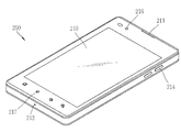
도 2는 일 실시예와 관련된 이동 단말기의 전면 사시도.
도 3a와 도 3b는 각각 소켓의 닫힌 상태와 열린 상태를 도시한 도 2의 이동 단말기의 배면 사시도.
도 4는 도 3에 도시한 이동 단말기의 분해 사시도.
도 5 내지 도 6는 본 발명의 일 실시예와 관련된 슬롯부, 슬라이드 도어 및 지지 프레임간의 결합 관계를 도시한 개념도.
도 7은 본 발명의 일 실시예와 관련된 슬롯부, 슬라이드 도어 및 지지 프레임간의 결합 관계를 도시한 단면도.
도 8은 본 발명의 일 실시예와 관련된 슬라이드 도어의 개념도.
도 9은 본 발명의 일 실시예와 관련된 지지 프레임의 개념도.
도 10a와 도 10b는 본 발명의 실시예들과 관련된 슬라이드 도어의 동작 상태도.1 is a block diagram of a mobile terminal according to an embodiment of the present invention;
2 is a front perspective view of a mobile terminal associated with one embodiment;
3A and 3B are rear perspective views of the mobile terminal of FIG. 2, showing the closed and open states of the socket, respectively.
4 is an exploded perspective view of the mobile terminal shown in FIG.
5 to 6 is a conceptual diagram showing a coupling relationship between the slot portion, the slide door and the support frame according to an embodiment of the present invention.
Figure 7 is a cross-sectional view showing a coupling relationship between the slot portion, the slide door and the support frame related to an embodiment of the present invention.
8 is a conceptual diagram of a slide door according to an embodiment of the present invention.
9 is a conceptual diagram of a support frame associated with an embodiment of the present invention.
10A and 10B are operational state diagrams of a slide door according to embodiments of the present invention.
이하, 본 발명에 관련된 이동 단말기에 대하여 도면을 참조하여 보다 상세하게 설명한다. 이하의 설명에서 사용되는 구성요소에 대한 접미사 "모듈" 및 "부"는 명세서 작성의 용이함만이 고려되어 부여되거나 혼용되는 것으로서, 그 자체로 서로 구별되는 의미 또는 역할을 갖는 것은 아니다. 본 명세서에서는 서로 다른 실시예라도 동일·유사한 구성에 대해서는 동일·유사한 참조번호를 부여하고, 그 설명은 처음 설명으로 갈음한다. 본 명세서에서 사용되는 단수의 표현은 문맥상 명백하게 다르게 뜻하지 않는 한, 복수의 표현을 포함한다. Hereinafter, a mobile terminal according to the present invention will be described in detail with reference to the drawings. The suffix "module" and " part "for the components used in the following description are given or mixed in consideration of ease of specification, and do not have their own meaning or role. In the present specification, the same or similar reference numerals are given to different embodiments in the same or similar configurations. As used herein, the singular forms "a", "an" and "the" include plural referents unless the context clearly dictates otherwise.
본 명세서에서 설명되는 이동 단말기에는 휴대폰, 스마트 폰(smart phone), 노트북 컴퓨터(laptop computer), 디지털방송용 단말기, PDA(Personal Digital Assistants), PMP(Portable Multimedia Player), 네비게이션 등이 포함될 수 있다. 그러나 본 명세서에 기재된 실시예에 따른 구성은 이동 단말기에만 적용 가능한 경우를 제외하면, 디지털 TV, 데스크탑 컴퓨터 등과 같은 고정 단말기에도 적용될 수도 있음을 본 기술분야의 당업자라면 쉽게 알 수 있을 것이다.The mobile terminal described in this specification may include a mobile phone, a smart phone, a laptop computer, a digital broadcasting terminal, a PDA (Personal Digital Assistants), a PMP (Portable Multimedia Player), and navigation. However, it will be understood by those skilled in the art that the configuration according to the embodiments described herein may be applied to a fixed terminal such as a digital TV, a desktop computer, and the like, unless the configuration is applicable only to a mobile terminal.
상기 이동 단말기(100)는 무선 통신부(110), A/V(Audio/Video) 입력부(120), 사용자 입력부(130), 센싱부(140), 출력부(150), 메모리(160), 인터페이스부(170), 제어부(180) 및 전원 공급부(190) 등을 포함할 수 있다. 도 1에 도시된 구성요소들이 필수적인 것은 아니어서, 그보다 많은 구성요소들을 갖거나 그보다 적은 구성요소들을 갖는 이동 단말기가 구현될 수도 있다. 이하, 상기 구성요소들에 대해 차례로 살펴본다.The
무선 통신부(110)는 이동 단말기(100)와 무선 통신 시스템 사이 또는 이동 단말기(100)와 이동 단말기(100)가 위치한 네트워크 사이의 무선 통신을 가능하게 하는 하나 이상의 모듈을 포함할 수 있다. 예를 들어, 무선 통신부(110)는 방송 수신 모듈(111), 이동통신 모듈(112), 무선 인터넷 모듈(113), 근거리 통신 모듈(114) 및 위치정보 모듈(115) 등을 포함할 수 있다.The
방송 수신 모듈(111)은 방송 채널을 통하여 외부의 방송 관리 서버로부터 방송 신호 및/또는 방송 관련된 정보를 수신한다. The
상기 방송 채널은 위성 채널, 지상파 채널을 포함할 수 있다. 상기 방송 관리 서버는, 방송 신호 및/또는 방송 관련 정보를 생성하여 송신하는 서버 또는 기 생성된 방송 신호 및/또는 방송 관련 정보를 제공받아 단말기에 송신하는 서버를 의미할 수 있다. 상기 방송 신호는, TV 방송 신호, 라디오 방송 신호, 데이터 방송 신호를 포함할 뿐만 아니라, TV 방송 신호 또는 라디오 방송 신호에 데이터 방송 신호가 결합한 형태의 방송 신호도 포함할 수 있다. The broadcast channel may include a satellite channel and a terrestrial channel. The broadcast management server may refer to a server for generating and transmitting broadcast signals and / or broadcast related information, or a server for receiving broadcast signals and / or broadcast related information generated by the broadcast management server and transmitting the generated broadcast signals and / or broadcast related information. The broadcast signal may include a TV broadcast signal, a radio broadcast signal, a data broadcast signal, and a broadcast signal in which a data broadcast signal is combined with a TV broadcast signal or a radio broadcast signal.
상기 방송 관련 정보는, 방송 채널, 방송 프로그램 또는 방송 서비스 제공자에 관련한 정보를 의미할 수 있다. 상기 방송 관련 정보는, 이동통신망을 통하여도 제공될 수 있다. 이러한 경우에는 상기 이동통신 모듈(112)에 의해 수신될 수 있다.The broadcast-related information may refer to a broadcast channel, a broadcast program, or information related to a broadcast service provider. The broadcast related information may also be provided through a mobile communication network. In this case, it may be received by the mobile communication module 112.
상기 방송 관련 정보는 다양한 형태로 존재할 수 있다. 예를 들어, DMB(Digital Multimedia Broadcasting)의 EPG(Electronic Program Guide) 또는 DVB-H(Digital Video Broadcast-Handheld)의 ESG(Electronic Service Guide) 등의 형태로 존재할 수 있다.The broadcast-related information may exist in various forms. For example, it may exist in the form of Electronic Program Guide (EPG) of Digital Multimedia Broadcasting (DMB) or Electronic Service Guide (ESG) of Digital Video Broadcast-Handheld (DVB-H).
상기 방송 수신 모듈(111)은, 예를 들어, DMB-T(Digital Multimedia Broadcasting-Terrestrial), DMB-S(Digital Multimedia Broadcasting-Satellite), Media FLO(Media Forward Link Only), DVB-H(Digital Video Broadcast-Handheld), ISDB-T(Integrated Services Digital Broadcast-Terrestrial) 등의 디지털 방송 시스템을 이용하여 디지털 방송 신호를 수신할 수 있다. 물론, 상기 방송 수신 모듈(111)은, 상술한 디지털 방송 시스템뿐만 아니라 다른 방송 시스템에 적합하도록 구성될 수도 있다.For example, the
방송 수신 모듈(111)을 통해 수신된 방송 신호 및/또는 방송 관련 정보는 메모리(160)에 저장될 수 있다.The broadcast signal and / or broadcast related information received through the
이동통신 모듈(112)은, 이동 통신망 상에서 기지국, 외부의 단말, 서버 중 적어도 하나와 무선 신호를 송수신한다. 상기 무선 신호는, 음성 호 신호, 화상 통화 호 신호 또는 문자/멀티미디어 메시지 송수신에 따른 다양한 형태의 데이터를 포함할 수 있다. The mobile communication module 112 transmits and receives radio signals to at least one of a base station, an external terminal, and a server on a mobile communication network. The wireless signal may include various types of data depending on a voice call signal, a video call signal or a text / multimedia message transmission / reception.
무선 인터넷 모듈(113)은 무선 인터넷 접속을 위한 모듈을 말하는 것으로, 이동 단말기(100)에 내장되거나 외장될 수 있다. 무선 인터넷 기술로는 WLAN(Wireless LAN)(Wi-Fi), Wibro(Wireless broadband), Wimax(World Interoperability for Microwave Access), HSDPA(High Speed Downlink Packet Access) 등이 이용될 수 있다. The
근거리 통신 모듈(114)은 근거리 통신을 위한 모듈을 말한다. 근거리 통신(short range communication) 기술로 블루투스(Bluetooth), RFID(Radio Frequency Identification), 적외선 통신(IrDA, infrared Data Association), UWB(Ultra Wideband), ZigBee 등이 이용될 수 있다.The short-
위치정보 모듈(115)은 이동 단말기의 위치를 획득하기 위한 모듈로서, 그의 대표적인 예로는 GPS(Global Position System) 모듈이 있다.The
도 1을 참조하면, A/V(Audio/Video) 입력부(120)는 오디오 신호 또는 비디오 신호 입력을 위한 것으로, 이에는 카메라(121)와 마이크(122) 등이 포함될 수 있다. 카메라(121)는 화상 통화모드 또는 촬영 모드에서 이미지 센서에 의해 얻어지는 정지영상 또는 동영상 등의 화상 프레임을 처리한다. 처리된 화상 프레임은 베이스부(265)부(151)에 표시될 수 있다.Referring to FIG. 1, an A / V (Audio / Video)
카메라(121)에서 처리된 화상 프레임은 메모리(160)에 저장되거나 무선 통신부(110)를 통하여 외부로 전송될 수 있다. 카메라(121)는 사용 환경에 따라 2개 이상이 구비될 수도 있다.The image frame processed by the
마이크(122)는 통화모드 또는 녹음모드, 음성인식 모드 등에서 마이크로폰(Microphone)에 의해 외부의 음향 신호를 입력 받아 전기적인 음성 데이터로 처리한다. 처리된 음성 데이터는 통화 모드인 경우 이동통신 모듈(112)을 통하여 이동통신 기지국으로 송신 가능한 형태로 변환되어 출력될 수 있다. 마이크(122)에는 외부의 음향 신호를 입력 받는 과정에서 발생되는 잡음(noise)을 제거하기 위한 다양한 잡음 제거 알고리즘이 구현될 수 있다.The
사용자 입력부(130)는 사용자가 단말기의 동작 제어를 위한 입력 데이터를 발생시킨다. 사용자 입력부(130)는 키 패드(key pad) 돔 스위치 (dome switch), 터치 패드(정압/정전), 조그 휠, 조그 스위치 등으로 구성될 수 있다. The user input unit 130 generates input data for a user to control the operation of the terminal. The user input unit 130 may include a key pad dome switch, a touch pad (static pressure / capacitance), a jog wheel, a jog switch, and the like.
센싱부(140)는 이동 단말기(100)의 개폐 상태, 이동 단말기(100)의 위치, 사용자 접촉 유무, 이동 단말기의 방위, 이동 단말기의 가속/감속 등과 같이 이동 단말기(100)의 현 상태를 감지하여 이동 단말기(100)의 동작을 제어하기 위한 센싱 신호를 발생시킨다. 예를 들어 이동 단말기(100)가 슬라이드 폰 형태인 경우 슬라이드 폰의 개폐 여부를 센싱할 수 있다. 또한, 전원 공급부(190)의 전원 공급 여부, 인터페이스부(170)의 외부 기기 결합 여부 등을 센싱할 수도 있다. 한편, 상기 센싱부(140)는 근접 센서(141)를 포함할 수 있다. The
출력부(150)는 시각, 청각 또는 촉각 등과 관련된 출력을 발생시키기 위한 것으로, 이에는 디스플레이부(151), 음향 출력 모듈(152), 알람부(153), 및 햅틱 모듈(154) 등이 포함될 수 있다.The
디스플레이부(151)는 이동 단말기(100)에서 처리되는 정보를 표시(출력)한다. 예를 들어, 이동 단말기가 통화 모드인 경우 통화와 관련된 UI(User Interface) 또는 GUI(Graphic User Interface)를 표시한다. 이동 단말기(100)가 화상 통화 모드 또는 촬영 모드인 경우에는 촬영 또는/및 수신된 영상 또는 UI, GUI를 표시한다. The
디스플레이부(151)는 액정 디스플레이(liquid crystal display, LCD), 박막 트랜지스터 액정 디스플레이(thin film transistor-liquid crystal display, TFT LCD), 유기 발광 다이오드(organic light-emitting diode, OLED), 플렉시블 디스플레이(flexible display), 3차원 디스플레이(3D display) 중에서 적어도 하나를 포함할 수 있다. The
이들 중 일부 디스플레이는 그를 통해 외부를 볼 수 있도록 투명형 또는 광투과형으로 구성될 수 있다. 이는 투명 디스플레이라 호칭될 수 있는데, 상기 투명 디스플레이의 대표적인 예로는 TOLED(Transparent OLED) 등이 있다. 디스플레이부(151)의 후방 구조 또한 광 투과형 구조로 구성될 수 있다. 이러한 구조에 의하여, 사용자는 단말기 바디의 디스플레이부(151)가 차지하는 영역을 통해 단말기 바디의 후방에 위치한 사물을 볼 수 있다.Some of these displays may be transparent or light transmissive so that they can be seen through. This can be referred to as a transparent display, and a typical example of the transparent display is TOLED (Transparent OLED) and the like. The rear structure of the
이동 단말기(100)의 구현 형태에 따라 디스플레이부(151)이 2개 이상 존재할 수 있다. 예를 들어, 이동 단말기(100)에는 복수의 디스플레이부들이 하나의 면에 이격 되거나 일체로 배치될 수 있고, 또한 서로 다른 면에 각각 배치될 수도 있다. There may be two or
디스플레이부(151)와 터치 동작을 감지하는 센서(이하, '터치 센서'라 함)가 상호 레이어 구조를 이루는 경우(이하, '터치 스크린'이라 함)에, 디스플레이부(151)는 출력 장치 이외에 입력 장치로도 사용될 수 있다. 터치 센서는, 예를 들어, 터치 필름, 터치 시트, 터치 패드 등의 형태를 가질 수 있다.When the
터치 센서는 디스플레이부(151)의 특정 부위에 가해진 압력 또는 디스플레이부(151)의 특정 부위에 발생하는 정전 용량 등의 변화를 전기적인 입력신호로 변환하도록 구성될 수 있다. 터치 센서는 터치 되는 위치 및 면적뿐만 아니라, 터치 시의 압력까지도 검출할 수 있도록 구성될 수 있다. The touch sensor may be configured to convert a change in a pressure applied to a specific portion of the
터치 센서에 대한 터치 입력이 있는 경우, 그에 대응하는 신호(들)는 터치 제어기로 보내진다. 터치 제어기는 그 신호(들)를 처리한 다음 대응하는 데이터를 제어부(180)로 전송한다. 이로써, 제어부(180)는 디스플레이부(151)의 어느 영역이 터치 되었는지 여부 등을 알 수 있게 된다.If there is a touch input to the touch sensor, the corresponding signal (s) is sent to the touch controller. The touch controller processes the signal (s) and transmits the corresponding data to the
도 1을 참조하면, 상기 터치스크린에 의해 감싸지는 이동 단말기의 내부 영역 또는 상기 터치 스크린의 근처에 근접 센서(141)가 배치될 수 있다. 상기 근접 센서는 소정의 검출면에 접근하는 물체, 혹은 근방에 존재하는 물체의 유무를 전자계의 힘 또는 적외선을 이용하여 기계적 접촉이 없이 검출하는 센서를 말한다. 근접 센서는 접촉식 센서보다는 그 수명이 길며 그 활용도 또한 높다. Referring to FIG. 1, a
상기 근접 센서의 예로는 투과형 광전 센서, 직접 반사형 광전 센서, 미러 반사형 광전 센서, 고주파 발진형 근접 센서, 정전용량형 근접 센서, 자기형 근접 센서, 적외선 근접 센서 등이 있다. 상기 터치스크린이 정전식인 경우에는 상기 포인터의 근접에 따른 전계의 변화로 상기 포인터의 근접을 검출하도록 구성된다. 이 경우 상기 터치 스크린(터치 센서)은 근접 센서로 분류될 수도 있다.Examples of the proximity sensor include a transmission photoelectric sensor, a direct reflection photoelectric sensor, a mirror reflection photoelectric sensor, a high frequency oscillation proximity sensor, a capacitive proximity sensor, a magnetic proximity sensor, and an infrared proximity sensor. And to detect the proximity of the pointer by the change of the electric field along the proximity of the pointer when the touch screen is electrostatic. In this case, the touch screen (touch sensor) may be classified as a proximity sensor.
이하에서는 설명의 편의를 위해, 상기 터치스크린 상에 포인터가 접촉되지 않으면서 근접되어 상기 포인터가 상기 터치스크린 상에 위치함이 인식되도록 하는 행위를 "근접 터치(proximity touch)"라고 칭하고, 상기 터치스크린 상에 포인터가 실제로 접촉되는 행위를 "접촉 터치(contact touch)"라고 칭한다. 상기 터치스크린 상에서 포인터로 근접 터치가 되는 위치라 함은, 상기 포인터가 근접 터치될 때 상기 포인터가 상기 터치스크린에 대해 수직으로 대응되는 위치를 의미한다.Hereinafter, for convenience of explanation, the act of allowing the pointer to be recognized without being in contact with the touch screen so that the pointer is located on the touch screen is referred to as a "proximity touch", and the touch The act of actually touching the pointer on the screen is called "contact touch." The position where the pointer is proximately touched on the touch screen means a position where the pointer is vertically corresponding to the touch screen when the pointer is touched.
상기 근접센서는, 근접 터치와, 근접 터치 패턴(예를 들어, 근접 터치 거리, 근접 터치 방향, 근접 터치 속도, 근접 터치 시간, 근접 터치 위치, 근접 터치 이동 상태 등)을 감지한다. 상기 감지된 근접 터치 동작 및 근접 터치 패턴에 상응하는 정보는 터치 스크린상에 출력될 수 있다. The proximity sensor detects a proximity touch and a proximity touch pattern (e.g., a proximity touch distance, a proximity touch direction, a proximity touch speed, a proximity touch time, a proximity touch position, a proximity touch movement state, and the like). Information corresponding to the detected proximity touch operation and the proximity touch pattern may be output on the touch screen.
음향 출력 모듈(152)은 호신호 수신, 통화모드 또는 녹음 모드, 음성인식 모드, 방송수신 모드 등에서 무선 통신부(110)로부터 수신되거나 메모리(160)에 저장된 오디오 데이터를 출력할 수 있다. 음향 출력 모듈(152)은 이동 단말기(100)에서 수행되는 기능(예를 들어, 호신호 수신음, 메시지 수신음 등)과 관련된 음향 신호를 출력하기도 한다. 이러한 음향 출력 모듈(152)에는 리시버(Receiver), 스피커(speaker), 버저(Buzzer) 등이 포함될 수 있다.The
알람부(153)는 이동 단말기(100)의 이벤트 발생을 알리기 위한 신호를 출력한다. 이동 단말기에서 발생 되는 이벤트의 예로는 호 신호 수신, 메시지 수신, 키 신호 입력, 터치 입력 등이 있다. 알람부(153)는 비디오 신호나 오디오 신호 이외에 다른 형태, 예를 들어 진동으로 이벤트 발생을 알리기 위한 신호를 출력할 수도 있다. 상기 비디오 신호나 오디오 신호는 디스플레이부(151)나 음성 출력 모듈(152)을 통해서도 출력될 수 있어서, 그들(151,152)은 알람부(153)의 일부로 분류될 수도 있다.The
햅틱 모듈(haptic module)(154)은 사용자가 느낄 수 있는 다양한 촉각 효과를 발생시킨다. 햅틱 모듈(154)이 발생시키는 촉각 효과의 대표적인 예로는 진동이 있다. 햅택 모듈(154)이 발생하는 진동의 세기와 패턴 등은 제어 가능하다. 예를 들어, 서로 다른 진동을 합성하여 출력하거나 순차적으로 출력할 수도 있다. The
햅틱 모듈(154)은, 진동 외에도, 접촉 피부면에 대해 수직 운동하는 핀 배열, 분사구나 흡입구를 통한 공기의 분사력이나 흡입력, 피부 표면에 대한 스침, 전극(electrode)의 접촉, 정전기력 등의 자극에 의한 효과와, 흡열이나 발열 가능한 소자를 이용한 냉온감 재현에 의한 효과 등 다양한 촉각 효과를 발생시킬 수 있다. In addition to the vibration, the
햅틱 모듈(154)은 직접적인 접촉을 통해 촉각 효과의 전달할 수 있을 뿐만 아니라, 사용자가 손가락이나 팔 등의 근 감각을 통해 촉각 효과를 느낄 수 있도록 구현할 수도 있다. 햅틱 모듈(154)은 휴대 단말기(100)의 구성 태양에 따라 2개 이상이 구비될 수 있다.The
메모리(160)는 제어부(180)의 동작을 위한 프로그램을 저장할 수 있고, 입/출력되는 데이터들(예를 들어, 폰북, 메시지, 정지영상, 동영상 등)을 임시 저장할 수도 있다. 상기 메모리(160)는 상기 터치스크린 상의 터치 입력시 출력되는 다양한 패턴의 진동 및 음향에 관한 데이터를 저장할 수 있다.The
메모리(160)는 플래시 메모리 타입(flash memory type), 하드디스크 타입(hard disk type), 멀티미디어 카드 마이크로 타입(multimedia card micro type), 카드 타입의 메모리(예를 들어 SD 또는 XD 메모리 등), 램(Random Access Memory, RAM), SRAM(Static Random Access Memory), 롬(Read-Only Memory, ROM), EEPROM(Electrically Erasable Programmable Read-Only Memory), PROM(Programmable Read-Only Memory), 자기 메모리, 자기 디스크, 광디스크 중 적어도 하나의 타입의 저장매체를 포함할 수 있다. 이동 단말기(100)는 인터넷(internet)상에서 상기 메모리(160)의 저장 기능을 수행하는 웹 스토리지(web storage)와 관련되어 동작할 수도 있다.The
인터페이스부(170)는 이동 단말기(100)에 연결되는 모든 외부 기기와의 통로 역할을 한다. 인터페이스부(170)는 외부 기기로부터 데이터를 전송 받거나, 전원을 공급받아 이동 단말기(100) 내부의 각 구성 요소에 전달하거나, 이동 단말기(100) 내부의 데이터가 외부 기기로 전송되도록 한다. 예를 들어, 유/무선 헤드 셋 포트, 외부 충전기 포트, 유/무선 데이터 포트, 메모리 카드(memory card) 포트, 식별 모듈이 구비된 장치를 연결하는 포트, 오디오 I/O(Input/Output) 포트, 비디오 I/O(Input/Output) 포트, 이어폰 포트 등이 인터페이스부(170)에 포함될 수 있다. The
식별 모듈은 이동 단말기(100)의 사용 권한을 인증하기 위한 각종 정보를 저장한 칩으로서, 사용자 인증 모듈(User Identify Module, UIM), 가입자 인증 모듈(Subscriber Identify Module, SIM), 범용 사용자 인증 모듈(Universal Subscriber Identity Module, USIM) 등을 포함할 수 있다. 식별 모듈이 구비된 장치(이하 '식별 장치')는, 스마트 카드(smart card) 형식으로 제작될 수 있다. 따라서 식별 장치는 포트를 통하여 단말기(100)와 연결될 수 있다. The identification module is a chip for storing various information for authenticating the use right of the
상기 인터페이스부(170)는 이동단말기(100)가 외부 크래들(cradle)과 연결될 때 상기 크래들로부터의 전원이 상기 이동단말기(100)에 공급되는 통로가 되거나, 사용자에 의해 상기 크래들에서 입력되는 각종 명령 신호가 상기 이동단말기로 전달되는 통로가 될 수 있다. 상기 크래들로부터 입력되는 각종 명령 신호 또는 상기 전원은 상기 이동단말기가 상기 크래들에 정확히 장착되었음을 인지하기 위한 신호로 동작될 수도 있다.When the
제어부(controller, 180)는 통상적으로 이동 단말기의 전반적인 동작을 제어한다. 예를 들어 음성 통화, 데이터 통신, 화상 통화 등을 위한 관련된 제어 및 처리를 수행한다. 제어부(180)는 멀티 미디어 재생을 위한 멀티미디어 모듈(181)을 구비할 수도 있다. 멀티미디어 모듈(181)은 제어부(180) 내에 구현될 수도 있고, 제어부(180)와 별도로 구현될 수도 있다.The
상기 제어부(180)는 상기 터치스크린 상에서 행해지는 필기 입력 또는 그림 그리기 입력을 각각 문자 및 이미지로 인식할 수 있는 패턴 인식 처리를 행할 수 있다. The
전원 공급부(190)는 제어부(180)의 제어에 의해 외부의 전원, 내부의 전원을 인가 받아 각 구성요소들의 동작에 필요한 전원을 공급한다.The
여기에 설명되는 다양한 실시예는 예를 들어, 소프트웨어, 하드웨어 또는 이들의 조합된 것을 이용하여 컴퓨터 또는 이와 유사한 장치로 읽을 수 있는 기록매체 내에서 구현될 수 있다.The various embodiments described herein may be embodied in a recording medium readable by a computer or similar device using, for example, software, hardware, or a combination thereof.
하드웨어적인 구현에 의하면, 여기에 설명되는 실시예는 ASICs (application specific integrated circuits), DSPs (digital signal processors), DSPDs (digital signal processing devices), PLDs (programmable logic devices), FPGAs (field programmable gate arrays, 프로세서(processors), 제어기(controllers), 마이크로 컨트롤러(micro-controllers), 마이크로 프로세서(microprocessors), 기타 기능 수행을 위한 전기적인 유닛 중 적어도 하나를 이용하여 구현될 수 있다. 일부의 경우에 본 명세서에서 설명되는 실시예들이 제어부(180) 자체로 구현될 수 있다.According to a hardware implementation, the embodiments described herein include application specific integrated circuits (ASICs), digital signal processors (DSPs), digital signal processing devices (DSPDs), programmable logic devices (PLDs), field programmable gate arrays (FPGAs), and the like. It may be implemented using at least one of processors, controllers, micro-controllers, microprocessors, and electrical units for performing other functions. The described embodiments may be implemented by the
소프트웨어적인 구현에 의하면, 본 명세서에서 설명되는 절차 및 기능과 같은 실시예들은 별도의 소프트웨어 모듈들로 구현될 수 있다. 상기 소프트웨어 모듈들 각각은 본 명세서에서 설명되는 하나 이상의 기능 및 작동을 수행할 수 있다. 적절한 프로그램 언어로 쓰여진 소프트웨어 어플리케이션으로 소프트웨어 코드가 구현될 수 있다. 상기 소프트웨어 코드는 메모리(160)에 저장되고, 제어부(180)에 의해 실행될 수 있다.
According to the software implementation, embodiments such as the procedures and functions described herein may be implemented as separate software modules. Each of the software modules may perform one or more of the functions and operations described herein. Software code can be implemented in a software application written in a suitable programming language. The software code is stored in the
도 2는 본 발명과 관련된 이동 단말기의 일 예를 전면에서 바라본 사시도이고, 도 3은 도 2에 도시된 이동 단말기의 후면 사시도이다.FIG. 2 is a perspective view of a mobile terminal according to an embodiment of the present invention, and FIG. 3 is a rear perspective view of the mobile terminal shown in FIG. 2. Referring to FIG.
도 2, 도 3을 참조하면, 이동 단말기(200)는 바 형태의 단말기 바디를 구비하고 있다. 다만, 본 발명은 여기에 한정되지 않고, 2 이상의 바디들이 상대 이동 가능하게 결합되는 슬라이드 타입, 폴더 타입, 스윙 타입 등 다양한 구조에 적용이 가능하다. 나아가, 본 명세서에서 설명되는 이동 단말기는 카메라 및 플래시를 갖는 임의의 휴대 전자 장치, 예를 들어, 휴대폰, 스마트 폰(smart phone), 노트북 컴퓨터(notebook computer), 디지털방송용 단말기, PDA(Personal Digital Assistants), PMO(Portable Multimedia Player) 등에도 적용될 수 있다.2 and 3, the
단말기 바디(204)는 외관을 이루는 케이스(케이싱, 하우징, 커버 등으로 불릴 수 있다)를 포함한다. 상기 케이스는 프론트 케이스(201), 상기 프론트 케이스(201)와 반대되는 면을 덮는 리어 케이스(202) 및 상기 리어 케이스(202)와 결합하여 상기 이동 단말기(200)의 후면을 구성하는 배터리 커버(203)을 포함한다. The terminal body 204 includes a case (which may be referred to as a casing, a housing, a cover, etc.) forming an external appearance. The case may be coupled to the
배터리 커버(203)는 배터리(260)와 리어 케이스(202)를 덮도록 형성될 수 있다. The
상기 프론트 케이스(201) 및 상기 리어 케이스(202) 사이에 형성된 공간에는 각종 전자 부품들이 내장된다. 케이스들은 합성수지를 사출하여 형성되거나 금속 재질, 예를 들어 스테인레스 스틸(STS) 또는 티타늄(Ti) 등과 같은 금속 재질을 갖도록 형성될 수도 있다.Various electronic components are embedded in the space formed between the
단말기 바디의 전면에는 디스플레이부(210), 제1 음향 출력부(211), 전면 카메라부(216), 사이드키(214), 인터페이스부(215) 및 신호입력부(217)를 포함한다. The front surface of the terminal body includes a
디스플레이부(210)는 정보를 시각적으로 표현하는 LCD(liquid crystal display) 모듈, OLED(Organic Light Emitting Diodes) 모듈, 이페이퍼(e-paper) 등을 포함한다. 상기 디스플레이부(210)는 터치방식에 의하여 입력할 수 있게 터치감지수단을 포함할 수 있다. 이하에서는 터치감지수단을 포함한 디스플레이부(210)를 '터치스크린'으로 칭하기로 한다. 터치스크린(210) 상의 어느 한 곳에 대하여 터치가 있으면 그 터치된 위치에 대응하는 내용이 입력된다. 터치방식에 의하여 입력되는 내용은 문자 또는 숫자이거나, 각종 모드에서의 지시 또는 지정 가능한 메뉴항목 등일 수 있다. 터치감지수단은 디스플레이부가 보일 수 있도록 투광성으로 형성되어 있으며, 밝은 곳에서 터치스크린의 시인성(visibility)을 높이기 위한 구조가 포함될 수 있다. 도 2에 의하면, 터치스크린(210)은 프론트 케이스(201)의 전면(front surface)의 대부분을 차지한다.The
상기 제1 음향출력부(211)는 통화음을 사용자의 귀에 전달시키는 리시버(receiver) 또는 각종 알람음이나 멀티미디어의 재생음을 출력하는 라우드 스피커(loud speaker)의 형태로 구현될 수 있다.The first
상기 전면 카메라부(216)는 화상 통화모드 또는 촬영 모드에서 이미지 센서에 의해 얻어지는 정지영상 또는 동영상 등의 화상 프레임을 처리한다. 처리된 화상 프레임은 디스플레이부(210)에 표시될 수 있다.The
상기 전면 카메라(216)에서 처리된 화상 프레임은 메모리(160)에 저장되거나 무선 통신부(110)를 통하여 외부로 전송될 수 있다. 상기 전면 카메라(216)는 사용 환경에 따라 2개 이상이 구비될 수도 있다.The image frame processed by the
상기 신호입력부(217)는 이동 단말기(200)의 동작을 제어하기 위한 명령을 입력 받기 위해 조작되는 것으로서, 복수의 입력키들을 포함할 수 있다. 입력키들은 조작부(manipulating portion)로도 통칭될 수 있으며, 사용자가 촉각적인 느낌을 가지며 조작하게 되는 방식(tactile manner)이라면 어떤 방식이든 채용될 수 있다. The
예를 들어 사용자의 푸시 또는 터치 조작에 의해 명령 또는 정보를 입력받을 수 있는 돔 스위치 또는 터치 스크린, 터치 패드로 구현되거나, 키를 회전시키는 휠 또는 조그 방식이나 조이스틱과 같이 조작하는 방식으로도 구현될 수 있다. 상기 신호입력부(217)에 의하여 입력되는 내용은 다양하게 설정될 수 있다. 예를 들어 시작, 종료, 스크롤 등을 입력하기 위한 것일 수 있다. For example, a dome switch or touch screen capable of receiving a command or information by a push or touch operation of a user, a touch pad, or a wheel, a jog type or a joystick for rotating a key . The contents input by the
상기 프론트 케이스(201)의 측면에는 사이드키(214), 인터페이스부(215) 및 음향입력부(213) 등이 배치된다.
상기 사이드키(214)는 조작유닛으로 통칭될 수 있으며, 이동 단말기(200)의 동작을 제어하기 위한 명령을 입력 받을 수 있게 되어 있다. 사이드키(214)는 사용자가 촉각적인 느낌을 가면서 조작하게 되는 방식(tactile manner)이라면 어떤 방식이든 채용될 수 있다. 사이드키(214)에 의하여 입력되는 내용은 다양하게 설정될 수 있다. 예를 들어, 사이드키(214)에 의하여, 영상입력부(216, 221)의 제어, 음향출력부(211)에서 출력되는 음향의 크기 조절 또는 디스플레이부(210)의 터치 인식 모드로의 전환 등과 같은 명령을 입력받을 수 있다.The
상기 음향입력부(213)는 사용자의 음성, 기타 소리 등을 입력 받기 위해, 예를 들어 마이크로폰(microphone)과 같은 형태로 구현될 수 있다.The
상기 인터페이스부(215)는 본 발명과 관련된 이동 단말기(200)가 외부 기기와 데이터 교환 등을 할 수 있게 하는 통로가 된다. 예를 들어, 인터페이스부(215)는 유선 또는 무선으로, 이어폰과 연결하기 위한 접속단자, 근거리 통신을 위한 포트{예를 들어 적외선 포트(IrDA Port), 블루투스 포트(Bluetooth Port), 무선 랜 포트(Wireless LAN Port)등}, 또는 이동 단말기(200)에 전원을 공급하기 위한 전원공급 단자들 중 적어도 하나일 수 있다. 이러한 인터페이스부(215)는 SIM(Subscriber Identification Module) 또는 UIM(User Identity Module), 정보 저장을 위한 메모리 카드 등의 외장형 카드를 수용하는 소켓의 형태로 구현될 수 있다.The
단말기 바디의 후면에는 전원 공급부(260), 후면 카메라부(221)가 배치된다. The
상기 후면 카메라부(221)에 인접하게 플래쉬(222) 및 거울(미도시)이 배치될 수 있다. 상기 플래쉬는 상기 후면 카메라부(221)로 피사체를 촬영하는 경우에 피사체를 향하여 빛을 비춘다.A
상기 거울은 사용자가 상기 후면 카메라부(221)을 이용하여 자신을 촬영(셀프 촬영)하고자 하는 경우에, 사용자 자신의 얼굴 등을 비춰볼 수 있게 한다.The mirror allows the user to illuminate the user's own face or the like in the case where the user intends to photograph (self-photograph) himself / herself by using the
상기 후면 카메라부(221)은 전면에 배치되는 전면 카메라부(216)와 실질적으로 반대되는 촬영 방향을 가지며, 상기 전면 카메라부(216)와 서로 다른 화소를 가지는 카메라 일 수 있다,The
예를 들어, 전면 카메라부(216)는 화상 통화 등의 경우에 사용자의 얼굴을 촬영하여 상대방에 전송함에 무리가 없도록 저 화소를 가지며, 상기 후면 카메라부(221)는 일반적인 피사체를 촬영하고 바로 전송하지는 않는 경우가 많기 때문에 고 화소를 가지는 것이 바람직하다. 상기 전면 및 후면 카메라부(216, 221)은 회전 또는 팝업(pop-up) 가능하게 단말기 바디에 설치될 수 있다. For example, the
전원 공급부(260)는 이동 단말기(200)에 전원을 공급한다. 상기 전원 공급부(260)는 단말기 바디에 내장되거나, 단말기 바디의 외부에서 직접 탈착될 수 있게 구성될 수 있다.
The
도 4는 도 3에 도시한 이동 단말기의 분해 사시도이다.4 is an exploded perspective view of the mobile terminal illustrated in FIG. 3.
도 4를 참조하면, 프론트 케이스(201)와 리어 케이스(202)에 의하여 형성되는 단말기 본체의 내부 공간에는 회로기판(270)이 배치된다. 회로기판(270)은 도시된 바와 같이 리어 케이스(202)에 장착되거나, 별도의 내부 구조물에 장착될 수 있다. 회로기판(270)은 이동 단말기의 각종 기능을 동작시키기 위한 제어부의 일 예로서 구성될 수 있다.Referring to FIG. 4, a
회로기판(270)의 일면에는 회로기판(270)과 전기적으로 연결되는 디스플레이(210b)가 배치된다. 디스플레이(210b)는 윈도우(210a)의 빛이 투과되는 영역에 대응되는 면적을 가질 수 있다. 이를 통하여 사용자는 디스플레이(210b)에서 출력되는 시각 정보를 외부에서 인지할 수 있게 된다.On one side of the
단말기 본체의 내부 공간에는 회로기판(270)과 전기적으로 연결되며, 외부 기기와 접속 가능하게 이루어지는 소켓(240)이 배치된다. In the inner space of the terminal body, a
소켓(240)에 삽입되는 외부 기기의 일 예로서, SIM 카드를 들 수 있다. 심카드(SIM Card ; Scriber Identify Module Card)는 개인정보를 저장할 수 있는 카드를 말하는데, 이외에도 티-플래쉬 카드(T-Flash Card)와 같이 흔히 마이크로 에스디(Micro SD)라고도 하는 메모리 카드, 엠에스엠 칩(MSM Chip ;Mobile Station Modem Chip)과 같은 모뎀용 칩이 삽입될 수 있다. As an example of an external device inserted into the
그리고, 외부 기기로써, 멀티미디어 인터페이스 커넥터(MMI Connector ; Multimedia Interface Connector)와 같은 충전용이나 통화 이어폰용 또는 데이터케이블용 포트 등과 같은 인터페이스 장치가 소켓(240)에 삽입될 수 있다.
In addition, as an external device, an interface device such as a charging terminal such as a multimedia interface connector (MMI Connector) or a port for a telephone earphone or a data cable may be inserted into the
도 5 내지 도 6는 본 발명의 일 실시예와 관련된 슬롯부(230), 슬라이드 도어(250) 및 지지 프레임간의 결합 관계를 도시한 개념도이고, 도 7은 본 발명의 일 실시예와 관련된 슬롯부(230), 슬라이드 도어(250) 및 지지 프레임(280)간의 결합 관계를 도시한 단면도이다.5 to 6 are conceptual views illustrating a coupling relationship between the
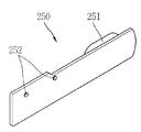
그리고, 도 8은 본 발명의 일 실시예와 관련된 슬라이드 도어(250)의 개념도이고, 도 9은 본 발명의 일 실시예와 관련된 지지 프레임(280)의 개념도이다.8 is a conceptual diagram of a
본 발명의 실시예들에 따르면, 인터페이스부(215)가 단말기의 일측에 형성된다. 인터페이스부(215)는 적어도 하나의 소켓(240)을 구비하여 형성될 수 있다. 소켓(240)은 회로기판에 결합되거나, 케이스나 프레임에 결합될 수 있다.According to embodiments of the present invention, the
소켓(240)에 외부 기기(291)가 삽입되므로, 이러한 외부 기기(291)가 삽입될 수 있게 단말기의 일측에는 소켓(240)에 대응하는 슬롯(233)이 형성될 수 있다. Since the external device 291 is inserted into the
여기서 슬롯(233)을 감싸는 케이스의 일부를 슬롯부(230)라고 하기로 한다. 슬롯(233)은 단말기의 길이 방향으로 슬라이드 도어(250)가 이동할 수 있도록 형성된다. 슬라이드 도어(250)는 단말기의 길이 방향으로 슬롯(233)을 따라 좌우 이동하도록 형성된다.Here, a part of the case surrounding the
슬롯부(230)의 내측면 즉 배면에 지지 프레임(280)이 결합된다. The
지지 프레임(280)과 슬롯부(230) 사이에 슬라이드 도어(250)가 이동 가능하도록 공간이 형성되고, 슬라이드 도어(250)가 상기 공간 내에서 좌우로 슬라이드 이동 가능하게 배치된다.A space is formed between the
지지 프레임(280)은 슬롯부(230)와의 사이에서 슬라이드 도어(250)가 이동할 수 있도록 공간을 형성하며, 슬라이드 도어(250)가 이동시 이를 안내하는 역할을 한다. 지지 프레임(280)은 탄성 변형 가능한 금속 재질로 형성될 수 있으며, 슬라이드 도어(250)는 절연성을 구비한 합성 수지로 형성될 수 있다. 또한, 슬라이드 도어(250)는 적어도 일부가 금속 재질로 형성될 수 있다.
The
도 8과 도 9를 참조하여, 슬라이드 도어(250)와 지지 프레임(280)의 구조를 보다 상세하게 살펴보기로 한다. 8 and 9, the structure of the
도 5와 도 8을 참조하면, 슬라이드 도어(250)는 일면에 형성되는 돌기(252)와 타면에 형성되고, 적어도 일부가 슬롯에 끼워지는 노브(251)를 포함한다. 돌기(252)는 후술하는 지지 프레임(280)의 결합부들과 결합할 수 있도록 슬라이드 도어(250)의 일면으로부터 돌출되는 부분이다.5 and 8, the
도 6과 도 9를 참조하면, 지지 프레임(280)은 바디(281), 지지부(284) 및 결합부들(282, 283)을 포함할 수 있다. 바디(281)는 슬롯(286)을 구비하여 이루어지고, 지지부(284)는 슬롯(286)을 가로질러 슬롯(286)을 한정하는 바디(281)의 양측면에 결합된다.6 and 9, the
지지 프레임(280)의 바디(281)는 단부로부터 돌출되는 가이드 멤버(285)를 포함한다. 가이드 멤버(285)는 슬라이드 도어(250)의 적어도 일 측면을 감쌀 수 있게 형성된다. 슬라이드 도어(250)는 이동시 가이드 멤버(285)로부터 미끄럼 이동할 수 있게 형성된다.The
결합부들(282, 283)은 지지부(284)로부터 각각 양측으로 연장된다. 결합부들(282, 283)은 제1 결합부(282)와 제2 결합부(283)로 나뉠 수 있다. 제1 결합부(282)는 슬라이드 도어(250)가 닫힌 상태에서 슬라이드 도어(250)의 돌기(252)가 결합될 수 있도록 후크(287)를 구비한다. 제2 결합부(283)는 슬라이드 도어(250)가 열린 상태에서 슬라이드 도어(250)의 돌기(252)가 결합될 수 있도록 후크(288)를 구비한다. 후크는 결합부의 일면으로부터 돌출되거나 일면에서 내측으로 함몰될 수 있다.
결합부들(282, 283)은 지지부(284)에 고정되는 일단으로부터 연장되는 외팔보의 형상으로 이루어질 수 있다. 이 때, 고정되는 일단으로부터 이격되는 타단은 자유단이 된다. 여기서 외팔보의 후크(287, 288)가 형성되는 부분은 단말기의 내측을 향하여 변형될 수 있도록 형성된다.The
외팔보가 변형되지 않고, 바디(281)와 평행하게 위치한 상태가 제1 상태가 되고, 슬라이드 도어(250)가 이동하면서 돌기(252)가 외팔보를 내측을 향하여 밀어내어 외팔보가 내측을 향하여 변형되는 상태가 제2 상태가 된다. 외팔보는 제2 상태에서 탄성에너지를 축적하고 있다가 돌기(252)가 후크(287, 288)에 끼워져 돌기(252)에 의한 구속력이 해제되면 제1 상태로 복원된다.A state in which the cantilever is not deformed and positioned in parallel with the
슬라이드 도어(250)는 노브(251)를 구비한다. 노브(251)는 슬라이드 도어(250)의 일면으로부터 돌출되는 부분으로서 슬롯부(230)의 슬롯을 따라 이동할 수 있게 형성된다. 즉, 노브(251)의 외주가 슬롯을 한정하는 내주면과 접촉하도록 형성된다.The
상기와 같은 구조로 인하여, 슬라이드 도어(250)와 지지 프레임(280)의 두께를 최소화할 수 있다. 즉, 지지 프레임(280)이 슬라이드 도어(250)의 슬라이드 이동을 가이드하는 가이드 멤버(285)를 구비할 뿐만 아니라 슬라이드 도어(250)의 닫힌 상태와 열린 상태에서 돌기(252)와 결합하는 후크(287, 288)가 형성된 결합부들(282, 283)을 구비함으로써 슬라이드 도어(250)와 지지 프레임(280)을 합한 두께를 최소화할 수 있다. Due to the structure as described above, it is possible to minimize the thickness of the
이로 인해, 단말기의 베젤을 최소화하여 보다 큰 디스플레이 영역을 형성할 수 있다.
As a result, a larger display area can be formed by minimizing the bezel of the terminal.
본 발명에 따르면, 단말기 본체에 슬롯부(230), 슬라이드 도어(250) 및 지지 프레임(280)을 결합시켜 조립하는 공정이 보다 단순화될 수 있다. According to the present invention, a process of assembling the
공정을 살펴보면 다음과 같다. 도 5와 도 6에 도시된 바와 같이, 우선 슬라이드 도어(250)가 슬롯을 따라 이동할 수 있도록 슬롯부(230)에 슬라이드 도어(250)를 밀착시킨다. 이 때, 슬라이드 도어(250)의 노브(251)가 슬롯에 삽입되어야 한다. 그리고, 지지 프레임(280)이 슬라이드 도어(250)를 덮도록 슬롯부(230)에 결합시킨다. 이러한 결합은 슬롯부(230)로부터 돌출되는 돌출체에 지지 프레임(280)을 끼움 결합하거나, 지지 프레임(280)을 슬롯부(230)에 열융착함으로써 이루어 질 수 있다.The process is as follows. As shown in FIGS. 5 and 6, first, the
도 10a와 도 10b는 본 발명의 실시예들과 관련된 슬라이드 도어(250)의 동작 상태도이다. 도 10a는 슬라이드 도어(250)가 소켓(240)을 덮은 닫힌 상태를 도시하고 있으며, 슬라이드 도어(250)가 소켓(240)을 노출시키는 열린 상태를 도시하고 있다. 10A and 10B are operational state diagrams of a
도 10a에서 보는 바와 같이, 닫힌 상태에서 슬라이드 도어(250)의 돌기(252)는 제1 결합부(282)의 후크(287)에 삽입되어 결합된다. 사용자가 노브(251)를 잡아당기나 밀게 되면, 슬라이드 도어(250)의 돌기(252)가 후크으로부터 빠져 나오면서 제1 결합부(282)의 후크가 형성된 부분을 밀게 되고 돌기(252)와 접촉하는 제1 결합부(282)의 일부가 후퇴하게 된다. As shown in FIG. 10A, the
그리고 슬라이드 도어(250)가 이동하다가 제2 결합부(283)와 돌기(252)가 접촉하게 되면, 제2 결합부(283)가 후퇴하게 된다. 일정 거리까지 이동하다가 후크(288)가 형성된 부분까지 돌기(252)가 이동하게 되면 제2 결합부(283)가 복원력에 의해 바디(281)와 평행하게 되고, 도 10b에 도시된 바와 같이 제2 결합부(283)의 후크에 돌기(252)가 결합된다. When the
닫힌 상태 또는 열린 상태에서 일정 이상의 힘이 가해지지 않는 한 후크(287, 288)와 돌기(252)가 서로 결합한 상태를 유지하게 된다. The
열린 상태에서 외부기기가 소켓(240)에 삽입되어 소켓(240)과 외부기기가 전기적으로 연결된다.In the open state, an external device is inserted into the
상기와 같이 설명된 이동 단말기는 상기 설명된 실시예들의 구성과 방법이 한정되게 적용될 수 있는 것이 아니라, 상기 실시예들은 다양한 변형이 이루어질 수 있도록 각 실시예들의 전부 또는 일부가 선택적으로 조합되어 구성될 수도 있다.The mobile terminal described above can be applied to not only the configuration and method of the embodiments described above but also all or some of the embodiments may be selectively combined so that various modifications may be made to the embodiments It is possible.
Claims (6)
상기 본체의 적어도 일측면을 덮어 외관을 형성하는 케이스;
상기 케이스에 일체로 형성되고, 상기 소켓에 연통되는 슬롯부;
상기 슬롯부의 내측면에 결합되는 지지 프레임; 및
상기 슬롯부와 상기 지지 프레임 사이에 배치되어 상기 소켓을 개폐하도록 슬라이드 이동하는 슬라이드 도어를 포함하고,
상기 지지 프레임은 닫힌 상태 또는 열린 상태에서 상기 슬라이드 도어의 위치를 고정할 수 있도록 상기 슬라이드 도어와 결합하는 제1 결합부와 제2 결합부를 구비하는 것을 특징으로 하는 이동 단말기. A terminal main body having a socket mounted therein so that an external device can be connected;
A case covering at least one side of the main body to form an appearance;
A slot part formed integrally with the case and communicating with the socket;
A support frame coupled to an inner surface of the slot part; And
A slide door which is disposed between the slot part and the support frame and slides to open and close the socket,
The support frame is a mobile terminal, characterized in that it has a first engaging portion and a second engaging portion for engaging with the slide door to fix the position of the slide door in a closed state or an open state.
상기 제1 결합부와 제2 결합부는 각각 후크를 구비하고,
상기 슬라이드 도어는 닫힌 상태 또는 열린 상태에서 상기 후크에 결합되는 돌기를 구비하는 것을 특징으로 하는 이동 단말기.The method of claim 1,
The first coupling portion and the second coupling portion are each provided with a hook,
The slide door has a mobile terminal, characterized in that it has a projection coupled to the hook in a closed state or an open state.
상기 지지 프레임은,
상기 슬롯을 구비하는 바디; 및
상기 슬롯을 가로질러 연장되고 상기 제1 결합부와 제2 결합부의 일단이 고정되는 지지부를 포함하는 것을 특징으로 하는 이동 단말기.3. The method of claim 2,
The support frame includes:
A body having said slot; And
And a support portion extending across the slot and having one end of the first coupling portion and the second coupling portion fixed thereto.
상기 지지 프레임은,
상기 바디의 단부로부터 돌출되어 상기 슬라이드 도어의 적어도 일측면을 감싸도록 형성되는 가이드 멤버를 더 포함하는 것을 특징으로 하는 이동 단말기.The method of claim 3,
The support frame includes:
And a guide member protruding from an end of the body to surround at least one side of the slide door.
상기 제1 결합부와 제2 결합부는 상기 지지부에 고정되는 일단으로부터 연장되는 외팔보의 형상으로 이루어지고, 상기 후크가 형성되는 상기 결합부들(282, 283)의 자유단 부분은 전진 또는 후퇴하여 상기 슬라이드 도어의 돌기와 결합 또는 결합 해제되도록 탄성 변형가능하게 형성되는 것을 특징으로 하는 이동 단말기. The method of claim 3,
The first coupling portion and the second coupling portion are formed in the shape of a cantilever beam extending from one end fixed to the support portion, and the free end portions of the coupling portions 282 and 283 in which the hook is formed are advanced or retracted to slide the slide. A mobile terminal, characterized in that it is formed elastically deformable to engage or disengage the protrusion of the door.
상기 슬라이드 도어는 상기 슬롯부를 관통하여 외부로 노출되는 노브를 구비하고,
슬라이드 이동시 상기 노브는 상기 슬롯부의 슬롯을 한정하는 내주면과 접촉하도록 형성되는 것을 특징으로 하는 이동 단말기.The method of claim 1,
The slide door has a knob exposed through the slot portion to the outside,
The knob is formed to be in contact with the inner peripheral surface defining the slot of the slot when the slide movement.
Priority Applications (1)
| Application Number | Priority Date | Filing Date | Title |
|---|---|---|---|
| KR1020120059404A KR20130135647A (en) | 2012-06-01 | 2012-06-01 | Mobile terminal |
Applications Claiming Priority (1)
| Application Number | Priority Date | Filing Date | Title |
|---|---|---|---|
| KR1020120059404A KR20130135647A (en) | 2012-06-01 | 2012-06-01 | Mobile terminal |
Publications (1)
| Publication Number | Publication Date |
|---|---|
| KR20130135647A true KR20130135647A (en) | 2013-12-11 |
Family
ID=49982839
Family Applications (1)
| Application Number | Title | Priority Date | Filing Date |
|---|---|---|---|
| KR1020120059404A Withdrawn KR20130135647A (en) | 2012-06-01 | 2012-06-01 | Mobile terminal |
Country Status (1)
| Country | Link |
|---|---|
| KR (1) | KR20130135647A (en) |
Cited By (3)
| Publication number | Priority date | Publication date | Assignee | Title |
|---|---|---|---|---|
| CN105781360A (en) * | 2014-12-23 | 2016-07-20 | 重庆宁来科贸有限公司 | Early-warning type antitheft safety door capable of being automatically opened or closed |
| WO2023286996A1 (en) * | 2021-07-14 | 2023-01-19 | 삼성전자주식회사 | Electronic device comprising battery cover fastening structure |
| US12075570B2 (en) | 2021-07-14 | 2024-08-27 | Samsung Electronics Co., Ltd. | Electronic device including battery cover fastening structure |
-
2012
- 2012-06-01 KR KR1020120059404A patent/KR20130135647A/en not_active Withdrawn
Cited By (3)
| Publication number | Priority date | Publication date | Assignee | Title |
|---|---|---|---|---|
| CN105781360A (en) * | 2014-12-23 | 2016-07-20 | 重庆宁来科贸有限公司 | Early-warning type antitheft safety door capable of being automatically opened or closed |
| WO2023286996A1 (en) * | 2021-07-14 | 2023-01-19 | 삼성전자주식회사 | Electronic device comprising battery cover fastening structure |
| US12075570B2 (en) | 2021-07-14 | 2024-08-27 | Samsung Electronics Co., Ltd. | Electronic device including battery cover fastening structure |
Similar Documents
| Publication | Publication Date | Title |
|---|---|---|
| KR101978956B1 (en) | Mobile terminal | |
| KR101917684B1 (en) | Mobile terminal | |
| KR20130098053A (en) | Mobile terminal | |
| KR101923472B1 (en) | Socket module and terminal having the same | |
| KR20130083237A (en) | Mobile terminal | |
| KR101829835B1 (en) | Mobile terminal | |
| KR20130094613A (en) | Mobile terminal | |
| KR101786545B1 (en) | Mobile terminal | |
| KR20130135647A (en) | Mobile terminal | |
| KR101923437B1 (en) | Mobile Terminal | |
| KR101275189B1 (en) | Portable terminal | |
| KR101667709B1 (en) | Mobile terminal | |
| KR20130090594A (en) | Mobile terminal | |
| KR20130062751A (en) | Mobile terminal | |
| KR101999733B1 (en) | Electronic device connecting to mobile terminal | |
| KR20140052481A (en) | Mobile terminal | |
| KR101934291B1 (en) | Mobile terminal | |
| KR20130078378A (en) | Mobile/portable terminal | |
| KR20130063323A (en) | Mobile terminal | |
| KR20130098054A (en) | Mobile terminal | |
| KR20130119260A (en) | Mobile terminal | |
| KR101938243B1 (en) | Mobile terminal | |
| KR101332554B1 (en) | Portable terminal | |
| KR20140054774A (en) | Mobile terminal | |
| KR101279517B1 (en) | Portable terminal |
Legal Events
| Date | Code | Title | Description |
|---|---|---|---|
| PA0109 | Patent application |
Patent event code: PA01091R01D Comment text: Patent Application Patent event date: 20120601 |
|
| PG1501 | Laying open of application | ||
| PC1203 | Withdrawal of no request for examination | ||
| WITN | Application deemed withdrawn, e.g. because no request for examination was filed or no examination fee was paid |