KR20130102753A - Cube injection mold simultaneous possible multi-extraction as well as multi-injection and the injection method thereof - Google Patents
Cube injection mold simultaneous possible multi-extraction as well as multi-injection and the injection method thereof Download PDFInfo
- Publication number
- KR20130102753A KR20130102753A KR1020120023833A KR20120023833A KR20130102753A KR 20130102753 A KR20130102753 A KR 20130102753A KR 1020120023833 A KR1020120023833 A KR 1020120023833A KR 20120023833 A KR20120023833 A KR 20120023833A KR 20130102753 A KR20130102753 A KR 20130102753A
- Authority
- KR
- South Korea
- Prior art keywords
- cube
- mold
- injection
- block
- cube block
- Prior art date
- Legal status (The legal status is an assumption and is not a legal conclusion. Google has not performed a legal analysis and makes no representation as to the accuracy of the status listed.)
- Granted
Links
Images


Classifications
-
- B—PERFORMING OPERATIONS; TRANSPORTING
- B29—WORKING OF PLASTICS; WORKING OF SUBSTANCES IN A PLASTIC STATE IN GENERAL
- B29C—SHAPING OR JOINING OF PLASTICS; SHAPING OF MATERIAL IN A PLASTIC STATE, NOT OTHERWISE PROVIDED FOR; AFTER-TREATMENT OF THE SHAPED PRODUCTS, e.g. REPAIRING
- B29C45/00—Injection moulding, i.e. forcing the required volume of moulding material through a nozzle into a closed mould; Apparatus therefor
- B29C45/03—Injection moulding apparatus
- B29C45/04—Injection moulding apparatus using movable moulds or mould halves
- B29C45/0441—Injection moulding apparatus using movable moulds or mould halves involving a rotational movement
-
- B—PERFORMING OPERATIONS; TRANSPORTING
- B29—WORKING OF PLASTICS; WORKING OF SUBSTANCES IN A PLASTIC STATE IN GENERAL
- B29C—SHAPING OR JOINING OF PLASTICS; SHAPING OF MATERIAL IN A PLASTIC STATE, NOT OTHERWISE PROVIDED FOR; AFTER-TREATMENT OF THE SHAPED PRODUCTS, e.g. REPAIRING
- B29C45/00—Injection moulding, i.e. forcing the required volume of moulding material through a nozzle into a closed mould; Apparatus therefor
- B29C45/16—Making multilayered or multicoloured articles
- B29C45/1615—The materials being injected at different moulding stations
- B29C45/1628—The materials being injected at different moulding stations using a mould carrier rotatable about an axis perpendicular to the opening and closing axis of the moulding stations
-
- B—PERFORMING OPERATIONS; TRANSPORTING
- B29—WORKING OF PLASTICS; WORKING OF SUBSTANCES IN A PLASTIC STATE IN GENERAL
- B29C—SHAPING OR JOINING OF PLASTICS; SHAPING OF MATERIAL IN A PLASTIC STATE, NOT OTHERWISE PROVIDED FOR; AFTER-TREATMENT OF THE SHAPED PRODUCTS, e.g. REPAIRING
- B29C45/00—Injection moulding, i.e. forcing the required volume of moulding material through a nozzle into a closed mould; Apparatus therefor
- B29C45/17—Component parts, details or accessories; Auxiliary operations
- B29C45/26—Moulds
- B29C45/27—Sprue channels ; Runner channels or runner nozzles
- B29C45/2725—Manifolds
-
- B—PERFORMING OPERATIONS; TRANSPORTING
- B29—WORKING OF PLASTICS; WORKING OF SUBSTANCES IN A PLASTIC STATE IN GENERAL
- B29C—SHAPING OR JOINING OF PLASTICS; SHAPING OF MATERIAL IN A PLASTIC STATE, NOT OTHERWISE PROVIDED FOR; AFTER-TREATMENT OF THE SHAPED PRODUCTS, e.g. REPAIRING
- B29C45/00—Injection moulding, i.e. forcing the required volume of moulding material through a nozzle into a closed mould; Apparatus therefor
- B29C45/17—Component parts, details or accessories; Auxiliary operations
- B29C45/26—Moulds
- B29C45/27—Sprue channels ; Runner channels or runner nozzles
- B29C45/28—Closure devices therefor
-
- B—PERFORMING OPERATIONS; TRANSPORTING
- B29—WORKING OF PLASTICS; WORKING OF SUBSTANCES IN A PLASTIC STATE IN GENERAL
- B29C—SHAPING OR JOINING OF PLASTICS; SHAPING OF MATERIAL IN A PLASTIC STATE, NOT OTHERWISE PROVIDED FOR; AFTER-TREATMENT OF THE SHAPED PRODUCTS, e.g. REPAIRING
- B29C45/00—Injection moulding, i.e. forcing the required volume of moulding material through a nozzle into a closed mould; Apparatus therefor
- B29C45/17—Component parts, details or accessories; Auxiliary operations
- B29C45/40—Removing or ejecting moulded articles
-
- B—PERFORMING OPERATIONS; TRANSPORTING
- B29—WORKING OF PLASTICS; WORKING OF SUBSTANCES IN A PLASTIC STATE IN GENERAL
- B29C—SHAPING OR JOINING OF PLASTICS; SHAPING OF MATERIAL IN A PLASTIC STATE, NOT OTHERWISE PROVIDED FOR; AFTER-TREATMENT OF THE SHAPED PRODUCTS, e.g. REPAIRING
- B29C45/00—Injection moulding, i.e. forcing the required volume of moulding material through a nozzle into a closed mould; Apparatus therefor
- B29C45/17—Component parts, details or accessories; Auxiliary operations
- B29C45/64—Mould opening, closing or clamping devices
-
- B—PERFORMING OPERATIONS; TRANSPORTING
- B29—WORKING OF PLASTICS; WORKING OF SUBSTANCES IN A PLASTIC STATE IN GENERAL
- B29C—SHAPING OR JOINING OF PLASTICS; SHAPING OF MATERIAL IN A PLASTIC STATE, NOT OTHERWISE PROVIDED FOR; AFTER-TREATMENT OF THE SHAPED PRODUCTS, e.g. REPAIRING
- B29C45/00—Injection moulding, i.e. forcing the required volume of moulding material through a nozzle into a closed mould; Apparatus therefor
- B29C45/17—Component parts, details or accessories; Auxiliary operations
- B29C45/72—Heating or cooling
-
- B—PERFORMING OPERATIONS; TRANSPORTING
- B29—WORKING OF PLASTICS; WORKING OF SUBSTANCES IN A PLASTIC STATE IN GENERAL
- B29C—SHAPING OR JOINING OF PLASTICS; SHAPING OF MATERIAL IN A PLASTIC STATE, NOT OTHERWISE PROVIDED FOR; AFTER-TREATMENT OF THE SHAPED PRODUCTS, e.g. REPAIRING
- B29C45/00—Injection moulding, i.e. forcing the required volume of moulding material through a nozzle into a closed mould; Apparatus therefor
- B29C45/17—Component parts, details or accessories; Auxiliary operations
- B29C45/76—Measuring, controlling or regulating
-
- B—PERFORMING OPERATIONS; TRANSPORTING
- B29—WORKING OF PLASTICS; WORKING OF SUBSTANCES IN A PLASTIC STATE IN GENERAL
- B29C—SHAPING OR JOINING OF PLASTICS; SHAPING OF MATERIAL IN A PLASTIC STATE, NOT OTHERWISE PROVIDED FOR; AFTER-TREATMENT OF THE SHAPED PRODUCTS, e.g. REPAIRING
- B29C45/00—Injection moulding, i.e. forcing the required volume of moulding material through a nozzle into a closed mould; Apparatus therefor
- B29C45/16—Making multilayered or multicoloured articles
- B29C45/1615—The materials being injected at different moulding stations
- B29C45/1628—The materials being injected at different moulding stations using a mould carrier rotatable about an axis perpendicular to the opening and closing axis of the moulding stations
- B29C2045/1629—The materials being injected at different moulding stations using a mould carrier rotatable about an axis perpendicular to the opening and closing axis of the moulding stations turrets with incorporated ejection means
-
- B—PERFORMING OPERATIONS; TRANSPORTING
- B29—WORKING OF PLASTICS; WORKING OF SUBSTANCES IN A PLASTIC STATE IN GENERAL
- B29C—SHAPING OR JOINING OF PLASTICS; SHAPING OF MATERIAL IN A PLASTIC STATE, NOT OTHERWISE PROVIDED FOR; AFTER-TREATMENT OF THE SHAPED PRODUCTS, e.g. REPAIRING
- B29C45/00—Injection moulding, i.e. forcing the required volume of moulding material through a nozzle into a closed mould; Apparatus therefor
- B29C45/17—Component parts, details or accessories; Auxiliary operations
- B29C2045/1784—Component parts, details or accessories not otherwise provided for; Auxiliary operations not otherwise provided for
- B29C2045/1792—Machine parts driven by an electric motor, e.g. electric servomotor
-
- B—PERFORMING OPERATIONS; TRANSPORTING
- B29—WORKING OF PLASTICS; WORKING OF SUBSTANCES IN A PLASTIC STATE IN GENERAL
- B29C—SHAPING OR JOINING OF PLASTICS; SHAPING OF MATERIAL IN A PLASTIC STATE, NOT OTHERWISE PROVIDED FOR; AFTER-TREATMENT OF THE SHAPED PRODUCTS, e.g. REPAIRING
- B29C45/00—Injection moulding, i.e. forcing the required volume of moulding material through a nozzle into a closed mould; Apparatus therefor
- B29C45/17—Component parts, details or accessories; Auxiliary operations
- B29C45/26—Moulds
- B29C2045/2683—Plurality of independent mould cavities in a single mould
-
- B—PERFORMING OPERATIONS; TRANSPORTING
- B29—WORKING OF PLASTICS; WORKING OF SUBSTANCES IN A PLASTIC STATE IN GENERAL
- B29C—SHAPING OR JOINING OF PLASTICS; SHAPING OF MATERIAL IN A PLASTIC STATE, NOT OTHERWISE PROVIDED FOR; AFTER-TREATMENT OF THE SHAPED PRODUCTS, e.g. REPAIRING
- B29C45/00—Injection moulding, i.e. forcing the required volume of moulding material through a nozzle into a closed mould; Apparatus therefor
- B29C45/17—Component parts, details or accessories; Auxiliary operations
- B29C45/64—Mould opening, closing or clamping devices
- B29C2045/648—Rack and pinion means for mould opening and closing a pair of mould halves
-
- B—PERFORMING OPERATIONS; TRANSPORTING
- B29—WORKING OF PLASTICS; WORKING OF SUBSTANCES IN A PLASTIC STATE IN GENERAL
- B29C—SHAPING OR JOINING OF PLASTICS; SHAPING OF MATERIAL IN A PLASTIC STATE, NOT OTHERWISE PROVIDED FOR; AFTER-TREATMENT OF THE SHAPED PRODUCTS, e.g. REPAIRING
- B29C2945/00—Indexing scheme relating to injection moulding, i.e. forcing the required volume of moulding material through a nozzle into a closed mould
- B29C2945/76—Measuring, controlling or regulating
- B29C2945/76655—Location of control
- B29C2945/76658—Injection unit
- B29C2945/76692—Injection unit drive means
Landscapes
- Engineering & Computer Science (AREA)
- Manufacturing & Machinery (AREA)
- Mechanical Engineering (AREA)
- Moulds For Moulding Plastics Or The Like (AREA)
- Injection Moulding Of Plastics Or The Like (AREA)
Abstract
본 발명의 멀티사출 및 멀티취출이 동시 가능한 큐브 사출 금형은, 제품의 외관을 성형하기 위한 멀티캐비티를 구성하기 위해 제1 및 제2 캐비티를 각각 조합하여 사출기 고정측과 이동측에 각각 클램핑(Clamping)되는 상하부금형과; 상기 상하부금형 내에서 상기 제1 및 제2 캐비티에 각각 형성되어 핫런너밸브(Hot Runner Valve)를 포함하고, 사출레진(Resin)의 유동주입구의 역할을 수행하는 상하부 핫런너시스템과; 상기 상하부금형 사이에 위치되어 회전 및 진퇴 가능한 큐브(Cube) 형태의 블록(Block)으로, 상기 제1 및 제2 캐비티와 형합 및 형분리되고, 블록(Block) 내에 상기 제1 및 제2 캐비티의 일부를 이루는 제1 코어(Core), 제2 코어, 제3 코어, 제4 코어를 갖으며, 외측에는 연관부품을 구성하기 위하여 큐브플레이트(Cube Plate)가 설치되며, 상기 상하부금형에 각각 위치한 상하부 핫런너시스템을 연결하는 큐브블록 핫런너시스템이 형성되는 큐브블록(Cube Block)과; 상기 큐브블록 상단에 설치되어 상기 큐브블록의 회전동작을 90도씩 360도 회전하도록 축회동시키는 엑츄에이터(Actuator)를 구비하여, 사출성형과 취출을 동시에 진행하며, 사출중 일정 냉각시간이 지나면 금형 형개후 상기 큐브블록이 상기 엑츄에이터에 의해 90도 회전하여 형합후 사출성형과 취출이 반복되어 사출하여서 이루어진다.
또한, 본 발명의 멀티사출 및 멀티취출이 동시 가능한 큐브 사출 방법은, 예열이 완료된 상태에서 회동되는 큐브블록의 상호 대향되는 일측면과 타측면에 각각 상부금형과 하부금형이 형합 형폐되어 제1 캐비티와 제2 캐비티가 형성되면 상부금형의 상부 핫런너시스템과 큐브블록의 큐브블록 핫런너시스템을 거치고 하부금형의 하부 핫런너시스템을 통해서 상기 제1 캐비티와 제2 캐비티에 각각 수지를 주입하여 보압을 이루고 천이온도까지 냉각이 이루어져 사출물을 성형하는 초기사출성형단계와; 상기 사출물이 성형된 후 형개하여 상기 상부금형과 하부금형 및 큐브블록을 형개하여 형분리시키고 취출가능 온도까지 냉각시키며 상기 큐브블록이 큐브플레이트 상에서 90도 축회전하고 상부금형과 하부금형 및 큐브블록을 형합하여 형폐시키는 큐브블록회동단계와; 상기 상부금형과 하부금형 및 큐브블록이 형합되어 형성된 제1 캐비티와 제2 캐비티에 상부금형의 상부 핫런너시스템과 큐브블록의 큐브블록 핫런너시스템을 거치고 하부금형의 하부 핫런너시스템을 통해서 수지를 주입하여 보압을 이루고 천이온도까지 냉각이 이루어져 사출물을 성형함과 동시에 사출성형이 완료된 사출품을 상기 큐브블록에서 취출하고 상기 큐브블록회동단계를 지속적으로 반복하는 멀티사출 및 멀티취출단계로 이루어진다.
이러한 본 발명은 회전 및 진퇴 가능한 큐브(Cube) 형태의 블록(Block)인 큐브블록 내에 4개의 코어(Core)를 구성하고 핫런너밸브(Hot Runner Valve)를 포함한 2개의 캐비티(Cavity)로 조합하여 구성함으로써, 사출성형과 취출을 동시에 진행하며, 금형 형개후 큐브블록이 엑츄에이터에 의해 90도 회전하여 형합후 사출성형과 취출이 반복되어 사출함으로써, 멀티(Multy)사출 및 멀티(Multy)취출이 동시 가능하여 연속 생산이 가능하고, 사출과 동시 냉각/취출이 가능하도록 하여 싸이클타임(Cycle-Time)을 크게 단축시킬 수 있으며, 이에 작업 및 제품의 생산성이 크게 향상되는 효과가 있다.The multi-injection and multi-outjection cube injection molds of the present invention are clamped on the fixed side and the moving side of the injection machine by combining the first and second cavities, respectively, to form a multi-cavity for molding the appearance of the product. Upper and lower molds; Upper and lower hot runner systems each of which is formed in the first and second cavities in the upper and lower molds and includes a hot runner valve and serves as a flow inlet of the injection resin; A cube-shaped block positioned between the upper and lower molds and rotating and retracting, which is formed and separated from the first and second cavities, and is separated from the first and second cavities in the block. It has a first core (Core), a second core, a third core, a fourth core constituting a part, the outer side is provided with a cube plate (cube plate) to form an associated part, the upper and lower parts respectively located in the upper and lower molds A cube block connecting the hot runner system and a cube block on which a hot runner system is formed; It is installed on the top of the cube block and equipped with an actuator (Actuator) for pivoting the rotation operation of the cube block by 360 degrees by 90 degrees, the injection molding and ejection proceeds at the same time, after a certain cooling time during the injection mold after opening the mold The cube block is rotated by 90 degrees by the actuator, and after injection molding and ejection are repeatedly performed.
In addition, the cube injection method of the multi-injection and multi-outtake of the present invention, the upper mold and the lower mold are mold-molded on the opposite side and the other side of the cube block rotated in the pre-heated state, respectively, the first cavity When the second cavity is formed, the resin is injected into the first cavity and the second cavity through the upper hot runner system of the upper mold and the cube block hot runner system of the cube block, and through the lower hot runner system of the lower mold, respectively. An initial injection molding step of forming an injection molded product by cooling to a transition temperature; After the injection molding is molded, the mold is opened, the upper mold, the lower mold, and the cube block are opened, the mold is separated and cooled to a takeable temperature. The cube block is rotated 90 degrees on the cube plate and the upper mold, the lower mold, and the cube block are opened. Cube block rotation step of forming and closing; The upper mold, the lower mold and the cube block are formed by joining the resin through the upper hot runner system of the upper mold and the cube block hot runner system of the cube block in the first cavity and the second cavity formed through the resin. The injection molding is carried out to cool down to a transition temperature, and the injection molding is performed, and at the same time, the injection-molded injection product is taken out of the cube block, and a multi-injection and multi ejection step of continuously repeating the cube block rotation step is performed.
The present invention comprises four cores in a cube block that is a cube-shaped block that can be rotated and retracted, and combined into two cavities including a hot runner valve. In this way, injection molding and ejection proceed at the same time, and the cube block is rotated 90 degrees by the actuator after mold opening, and injection molding and ejection are repeatedly injected after molding, so that multiple injection and multiple ejection are performed simultaneously. It is possible to make continuous production, and to simultaneously cool / take out the injection can greatly reduce the cycle time (Cycle-Time), thereby improving the productivity of work and products.
Description
본 발명은 멀티사출 및 멀티취출이 동시 가능한 큐브 사출 금형 및 그 제조방법에 관한 것으로서, 보다 상세하게는 회전 및 진퇴 가능한 큐브(Cube) 형태의 블록(Block)인 큐브블록 내에 4개의 코어(Core)를 구성하고 핫런너밸브(Hot Runner Valve)를 포함한 2개의 캐비티(Cavity)로 조합하여 구성함으로써, 사출성형과 취출을 동시에 진행하며, 금형 형개후 큐브블록이 엑츄에이터에 의해 90도 회전하여 형합후 사출성형과 취출이 반복되어 사출함으로써, 멀티(Multy)사출 및 멀티(Multy)취출이 동시 가능하여 연속 생산이 가능하고, 사출과 동시 냉각/취출이 가능하도록 하여 싸이클타임(Cycle-Time)을 크게 단축시킬 수 있으며, 이에 작업 및 제품의 생산성이 크게 향상되는 멀티사출 및 멀티취출이 동시 가능한 큐브 사출 금형 및 그 제조방법에 관한 것이다. The present invention relates to a cube injection mold capable of simultaneous multi-injection and multi-outtake, and a method for manufacturing the same. More specifically, four cores are provided in a cube block, which is a block of a cube shape that can be rotated and retracted. By combining the two cavities (Hot Runner Valve), including the hot runner valve, injection molding and ejection at the same time, after opening the mold, the cube block is rotated 90 degrees by the actuator and injected after molding By repeating injection molding and taking out, multi injection and multi take out are possible at the same time, so that continuous production is possible and injection and simultaneous cooling and take out are possible, which greatly reduces the cycle time. The present invention relates to a cube injection mold and a method of manufacturing the same, which can simultaneously perform multi-injection and multi-outtake which greatly improve the productivity of the work and the product.
일반적으로 금형은, 제품의 외관을 가지는 메인캐비티(Main Cavity)를 상부금형과, 상기 상부금형과 형합 및 형분리되어 캐비티의 일부를 이루는 메인코어판(Main Core)을 갖는 하부금형으로 이루어진다. 이런 종래기술은 일반적인 공지기술로, 제품을 사출하기 위해서는 금형 형폐 → 사출 → 보압 → 냉각 → 금형 형개 → 취출(Ejecting)과 같은 사출공정을 갖는다. In general, the mold is composed of a main cavity (Main Cavity) having the appearance of the product of the upper mold, and a lower mold having a main core plate (Main Core) forming a part of the cavity by being combined with the upper mold. This conventional technology is a general known technique, and has a injection process such as mold mold closing → injection → holding pressure → cooling → mold opening → ejecting (Ejecting).
그러나, 이런 일반적인 금형은 제품 캐비티(Cavity) 1개 이상의 멀티캐비티(Multy) 구현시 금형 사이즈 제품의 수량에 따라 커지며, 사출기 형체력이 커지는 문제점을 갖는다.However, such a general mold is large according to the number of mold size products when one or more product cavities are implemented, and the mold clamping force is increased.
또한, 이중성형품 자동생산이 가능한 사출성형기 및 이를 이용한 이중성형품 제조방법으로, 이중사출을 위하여 사각블록안에 4개의 캐비티를 구성하며, 상기 캐비티와 형합 및 형개하는 코어부는 성형부를 상이하게 조합하여 상부금형 및 하부금형에 구성하는 것으로, 사출시 1차 캐비티 및 2차 캐비티로 이루어진 사각블록을 회전하며 사출하여 이중성형품을 제조하는 발명이 특허출원 출원번호 10-2008-0050592호로 공지되어 있다. In addition, an injection molding machine capable of automatic production of a double molded article and a method of manufacturing a double molded article using the same, constituting four cavities in a square block for double injection, and the core part to mold and open the cavity is differently combined with the molding part to form an upper mold. And to constitute in the lower mold, the invention for producing a double molded article by rotating the injection of the square block consisting of the primary cavity and the secondary cavity during injection is known as a patent application No. 10-2008-0050592.
이런 종래기술은 상부금형 및 하부금형에 서로 다른 이종재질을 사출할 수 있도록 유동주입구를 설치하며, 사각블록에 캐비티와 형합후 이중성형을 실시하며 형개후 사출기 내에 구성된 무빙테이블(Moving Table)에 의해 사각블록이 회전하여 형합후 이중성형을 반복되도록 한다. 사각블록중 상부금형 및 하부금형에 형폐하지 않는 부분은 성형된 제품에 마킹(Marking)하고, 취출부를 상부 및 하부금형에 구성한다. 이런, 종래기술의 목적은 이중성형품 자동생산이고, 사각블록 회전방법은 별도의 무빙테이블을 장착하여 회전하는 구조이며, 제품을 사출하기 위하여 다음과 같은 사출공정을 갖는다. 공정은 상부금형부터 진행한다. This conventional technology installs a flow inlet for injecting different dissimilar materials into the upper mold and the lower mold, performs double molding after the cavity and the mold in the square block, and by a moving table configured in the injection molding machine. The square block is rotated to repeat the double molding after molding. The portion of the rectangular block not molded to the upper mold and the lower mold is marked on the molded product, and the ejection portion is formed in the upper and lower molds. The purpose of the prior art is automatic production of a double molded article, the square block rotating method is a structure that rotates by mounting a separate moving table, and has the following injection process to inject the product. The process starts with the upper mold.
초기 공정시 : 금형 형폐 → 사출 → 보압 → 냉각 → 금형 형개 → 취출(제품 상측물림) → 금형회전 → 금형 형폐 → 사출 → 보압 → 냉각 → 금형 형개 → 이중제품 취출 ; 상부 및 하부금형 사출시 마킹작업Initial process: mold closing → injection → holding pressure → cooling → mold opening → taking out (upper part biting) → mold rotation → mold closing → injection → holding pressure → cooling → mold opening → double product taking out; Marking work for injection of upper and lower molds
연속 공정시 : 금형 형폐 → 사출 → 보압 → 냉각 → 금형 형개 → 취출 ; 연속 공정의 사출은 상부. 하부 금형 동시 사출이며 2캐비티 마킹 작업Continuous process: mold closing → injection → holding pressure → cooling → mold opening → taking out; Injection of the continuous process is top. Simultaneous injection of lower mold and 2 cavity marking
이런 종래기술은 사각블록에 회전하는 구조가 없어 고가의 무빙테이블이 필요하고, 사출기 또한 이중사출기를 사용해야 하는 금형구조이며, 이중제품을 구현 및 마킹을 위하여 싸이클 타임이 길어지는 문제점을 가진다.Such a prior art has a structure that does not have a rotating structure in the square block, an expensive moving table is required, and the injection molding machine also has a mold structure in which a double injection machine is used, and a cycle time is long for implementing and marking a double product.
또한, 회전형 금형장치 및 이를 이용한 성형물 제조방법으로, 사각블록내에 부착부재가 부착될 수 있는 공간과 성형부를 4캐비티를 구성하며, 상기 캐비티에 형개 및 형폐하는 상부 및 하부금형을 구성한 종래기술이 특허출원 제10-2008-0070965호로 공지된바 있다. 이런 종래기술은 4캐비티에 흡입장치를 구성하여 2캐비티는 부착부재를 부착한 상태에 나머지 2캐비티는 부착부재가 장착된 상태에 사출하는 구조이며, 별도의 취출장치는 없는 것으로 사료된다. 이런 종래기술의 목적은 부착부재를 부착하는 금형으로 제품을 사출하기 위하여 다음과 같은 사출공정을 갖는다. In addition, a rotating mold apparatus and a method for manufacturing a molded article using the same, the prior art that constitutes a cavity for attaching the attachment member in the rectangular block and the forming
연속 공정 : 금형 형폐(사출기 노즐부 이동) → 사출 → 보압 → 냉각 → 금형 형개(사출기 노즐부 이동) → 취출 ; 연속 공정의 사출은 상부/하부 금형 동시 사출이며 2캐비티 부착부재 부착작업 실시(작업자 수동 부착 개념)Continuous process: Mold mold closing (injector nozzle part movement) → injection → holding pressure → cooling → mold opening (injector nozzle part movement) → take out; Injection of continuous process is simultaneous injection of upper / lower mold and attachment of 2 cavity attachment member (worker manual attachment concept)
이런 종래기술의 목적은 부착부재를 사각블록에 부착하여 사출하는 것이 목적으로, 사각블록 하단에 별도의 지지블록과 사각블록이 회전할 수 있도록 별도의 액추에이터를 구성하는 구조이고, 액추에이터의 구성품인 모터와 기어, 샤프트 등은 기계공학상 공지된 기술이다. 또한 종래기술의 액추에이터는 개념의 구조로서 샤프트의 지지구조를 확인할 수 없다. 이런 종래기술의 액추에이터는 별도 공간에 구성되는 구조이다.The purpose of this prior art is to attach and attach the attachment member to the square block, and the structure to configure a separate actuator so that a separate support block and the square block can rotate at the bottom of the square block, the motor is a component of the actuator And gears, shafts and the like are well known techniques in mechanical engineering. In addition, the actuator of the prior art can not confirm the support structure of the shaft as a concept structure. This prior art actuator is structured in a separate space.
이런 종래기술은 금형내 사출성형시 사출기 노즐(Nozzle)이 진퇴하여 형합 및 형폐를 하여, 싸이클타임(Cycle-Time)이 증가하는 문제점을 갖고 있고, 사출기 노즐이 진퇴를 반복하여 금형 유동주입구에 지속적 충격으로 인하여 유동주입구가 금속 피로 한도에 의해 크랙(Crack)이 발생하는 문제점이 있게 된다.
This prior art has a problem that the injection-molding nozzle (nozzle) to advance and mold and mold closing during the injection molding in the mold, the cycle time (Cycle-Time) is increased, and the injection nozzle is repeated in the mold flow inlet continuously Due to the impact, there is a problem that cracks are generated by the flow inlet due to the metal fatigue limit.
본 발명은 상기와 같은 문제점을 해결하기 위한 것으로서, 회전 및 진퇴 가능한 큐브(Cube) 형태의 블록(Block)인 큐브블록 내에 4개의 코어(Core)를 구성하고 핫런너밸브(Hot Runner Valve)를 포함한 2개의 캐비티(Cavity)로 조합하여 구성함으로써, 사출성형과 취출을 동시에 진행하며, 금형 형개후 큐브블록이 엑츄에이터에 의해 90도 회전하여 형합후 사출성형과 취출이 반복되어 사출함으로써, 멀티(Multy)사출 및 멀티(Multy)취출이 동시 가능하여 연속 생산이 가능하고, 사출과 동시 냉각/취출이 가능하도록 하여 싸이클타임(Cycle-Time)을 크게 단축시킬 수 있으며, 이에 작업 및 제품의 생산성이 크게 향상되는 멀티사출 및 멀티취출이 동시 가능한 큐브 사출 금형 및 그 제조방법을 제공함에 그 목적이 있다.The present invention is to solve the above problems, comprising four core (Core) in the cube block of the block (Cube) of the rotating and retractable form (Cube) and includes a hot runner valve (Hot Runner Valve) By combining the two cavities, injection molding and ejection proceed simultaneously, and the cube block is rotated 90 degrees by the actuator after mold opening. Injection and multi ejection are possible at the same time for continuous production, and injection and simultaneous cooling / dispensing are possible to greatly reduce cycle time, which greatly improves productivity of work and product. It is an object of the present invention to provide a cube injection mold and a method of manufacturing the same, which is capable of multi-injection and multi-outtake.
이와 같은 목적을 달성하기 위하여, 본 발명의 멀티사출 및 멀티취출이 동시 가능한 큐브 사출 방법은, 예열이 완료된 상태에서 회동되는 큐브블록의 상호 대향되는 일측면과 타측면에 각각 상부금형과 하부금형이 형합 형폐되어 제1 캐비티와 제2 캐비티가 형성되면 상부금형의 상부 핫런너시스템과 큐브블록의 큐브블록 핫런너시스템을 거치고 하부금형의 하부 핫런너시스템을 통해서 상기 제1 캐비티와 제2 캐비티에 각각 수지를 주입하여 보압을 이루고 천이온도까지 냉각이 이루어져 사출물을 성형하는 초기사출성형단계와; 상기 사출물이 성형된 후 형개하여 상기 상부금형과 하부금형 및 큐브블록을 형개하여 형분리시키고 취출가능 온도까지 냉각시키며 상기 큐브블록이 큐브플레이트 상에서 90도 축회전하고 상부금형과 하부금형 및 큐브블록을 형합하여 형폐시키는 큐브블록회동단계와; 상기 상부금형과 하부금형 및 큐브블록이 형합되어 형성된 제1 캐비티와 제2 캐비티에 상부금형의 상부 핫런너시스템과 큐브블록의 큐브블록 핫런너시스템을 거치고 하부금형의 하부 핫런너시스템을 통해서 수지를 주입하여 보압을 이루고 천이온도까지 냉각이 이루어져 사출물을 성형함과 동시에 사출성형이 완료된 사출품을 상기 큐브블록에서 취출하고 상기 큐브블록회동단계를 지속적으로 반복하는 멀티사출 및 멀티취출단계로 이루어진다.In order to achieve the above object, the multi-injection and multi-outtake cube injection method of the present invention, the upper mold and the lower mold, respectively on the opposite side and the other side of the cube block rotated in the state of preheating is respectively When the mold is closed and the first cavity and the second cavity are formed, the first and second cavities are respectively passed through the upper hot runner system of the upper mold and the cube block hot runner system of the cube block and through the lower hot runner system of the lower mold. An initial injection molding step of forming an injection molding by injecting a resin to achieve holding pressure and cooling to a transition temperature; After the injection molding is molded, the mold is opened, the upper mold, the lower mold, and the cube block are opened, the mold is separated and cooled to a takeable temperature. The cube block is rotated 90 degrees on the cube plate and the upper mold, the lower mold, and the cube block are opened. Cube block rotation step of forming and closing; The upper mold, the lower mold and the cube block are formed by joining the resin through the upper hot runner system of the upper mold and the cube block hot runner system of the cube block in the first cavity and the second cavity formed through the resin. The injection molding is carried out to cool down to a transition temperature, and the injection molding is performed, and at the same time, the injection-molded injection product is taken out of the cube block, and a multi-injection and multi ejection step of continuously repeating the cube block rotation step is performed.
또한, 멀티사출 및 멀티취출이 동시 가능한 큐브 사출 금형은, 제품의 외관을 성형하기 위한 멀티캐비티를 구성하기 위해 제1 및 제2 캐비티)를 각각 조합하여 사출기 고정측과 이동측에 각각 클램핑(Clamping)되는 상하부금형과; 상기 상하부금형 내에서 상기 제1 및 제2 캐비티에 각각 형성되어 핫런너밸브(Hot Runner Valve)를 포함하고, 사출레진(Resin)의 유동주입구의 역할을 수행하는 상하부 핫런너시스템과; 상기 상하부금형 사이에 위치되어 회전 및 진퇴 가능한 큐브(Cube) 형태의 블록(Block)으로, 상기 제1 및 제2 캐비티와 형합 및 형분리되고, 블록(Block) 내에 상기 제1 및 제2 캐비티의 일부를 이루는 제1 코어(Core), 제2 코어, 제3 코어, 제4 코어를 갖으며, 외측에는 연관부품을 구성하기 위하여 큐브플레이트(Cube Plate)가 설치되며, 상기 상하부금형에 각각 위치한 상하부 핫런너시스템을 연결하는 큐브블록 핫런너시스템이 형성되는 큐브블록(Cube Block)과; 상기 큐브블록 상단에 설치되어 상기 큐브블록의 회전동작을 90도씩 360도 회전하도록 축회동시키는 엑츄에이터(Actuator)를 구비하여, 사출성형과 취출을 동시에 진행하며, 사출중 일정 냉각시간이 지나면 금형 형개후 상기 큐브블록이 상기 엑츄에이터에 의해 90도 회전하여 형합후 사출성형과 취출이 반복되어 사출하여서 이루어진다.In addition, the cube injection mold capable of multi-injection and multi-extraction simultaneously clamps the fixed and moving sides of the injection machine by combining the first and second cavities, respectively, to form a multi-cavity for molding the appearance of the product. Upper and lower molds; Upper and lower hot runner systems each of which is formed in the first and second cavities in the upper and lower molds and includes a hot runner valve and serves as a flow inlet of the injection resin; A cube-shaped block positioned between the upper and lower molds and rotating and retracting, which is formed and separated from the first and second cavities, and is separated from the first and second cavities in the block. It has a first core (Core), a second core, a third core, a fourth core constituting a part, the outer side is provided with a cube plate (cube plate) to form an associated part, the upper and lower parts respectively located in the upper and lower molds A cube block connecting the hot runner system and a cube block on which a hot runner system is formed; It is installed on the top of the cube block and equipped with an actuator (Actuator) for pivoting the rotation operation of the cube block by 360 degrees by 90 degrees, the injection molding and ejection proceeds at the same time, after a certain cooling time during the injection mold after opening the mold The cube block is rotated by 90 degrees by the actuator, and after injection molding and ejection are repeatedly performed.
이와 같이, 본 발명은 회전 및 진퇴 가능한 큐브(Cube) 형태의 블록(Block)인 큐브블록 내에 4개의 코어(Core)를 구성하고 핫런너밸브(Hot Runner Valve)를 포함한 2개의 캐비티(Cavity)로 조합하여 구성함으로써, 사출성형과 취출을 동시에 진행하며, 금형 형개후 큐브블록이 엑츄에이터에 의해 90도 회전하여 형합후 사출성형과 취출이 반복되어 사출함으로써, 멀티(Multy)사출 및 멀티(Multy)취출이 동시 가능하여 연속 생산이 가능하고, 사출과 동시 냉각/취출이 가능하도록 하여 싸이클타임(Cycle-Time)을 크게 단축시킬 수 있으며, 이에 작업 및 제품의 생산성이 크게 향상되는 효과가 있다.As such, the present invention comprises four cores in a cube block that is a cube-shaped block that can be rotated and retracted, and comprises two cavities including a hot runner valve. By combining, the injection molding and ejection proceed at the same time, the cube block is rotated 90 degrees by the actuator after mold opening and the injection molding and ejection are repeatedly ejected after molding, thereby producing multi-shot and multi-outlet. The simultaneous and continuous production is possible, and the injection and simultaneous cooling / take-out can be greatly shortened the cycle time (Cycle-Time), thereby improving the productivity of the work and products.
본 발명은 상술한 특정의 바람직한 실시 예에 한정되지 아니하며, 청구범위에서 청구하는 본 발명의 요지를 벗어남이 없이 당해 발명이 속하는 기술분야에서 통상의 지식을 가진 자라면 누구든지 다양한 변형 실시가 가능한 것은 물론이고, 그와 같은 변경은 청구범위 기재의 범위 내에 있게 된다.
It will be understood by those skilled in the art that various changes in form and details may be made therein without departing from the spirit and scope of the invention as defined in the appended claims and their equivalents. Of course, such modifications are within the scope of the claims.
도 1은 본 발명 실시 예인 멀티사출 및 멀티취출이 동시 가능한 큐브 사출 금형의 모습을 보인 사시도 및 정면도,
도 2는 본 발명에 따른 큐브(Cube)블록(30) 금형구조의 투시된 각 방향별 뷰어(Viewer)를 도시한 설명도,
도 3은 본 발명에 따른 큐브블록의 회전 및 엑츄에이터의 모습을 도시한 설명도,
도 4는 본 발명에 따른 큐브블록 및 조합부품에 따라 동작을 위한 단면 상세구조를 도시한 측단면도,
도 5는 본 발명에 따른 큐브블록의 회동구조 및 고정구조의 모습을 보인 설명도,
도 6은 본 발명에 따른 큐브블록의 지지 및 처짐방지구조를 도시한 설명도,
도 7은 본 발명에 따른 큐브금형의 형폐 및 형분리 발란스(Balance) 구조의 모습을 보인 설명도,
도 8은 본 발명에 따른 큐브금형의 핫런너시스템(Hot Runner System) 구조를 보인 설명도,
도 9는 본 발명에 따른 큐브금형의 제품 취출(Ejecting) 구조를 보인 설명도,
도 10은 본 발명 멀티사출 및 멀티취출이 동시 가능한 큐브 사출 방법을 순차적으로 도시한 순서도,
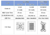
도 11은 일반금형 멀티캐비티(96캐비티)와 본 발명의 큐브금형 멀티캐비티의 차이점을 표시한 도표.1 is a perspective view and a front view showing a state of the multi-injection and multi-extraction cube injection mold which is an embodiment of the present invention;
Figure 2 is an explanatory view showing a viewer for each direction of the perspective of the mold structure of the
3 is an explanatory diagram showing the rotation of the cube block and the actuator according to the present invention;
Figure 4 is a side cross-sectional view showing a detailed cross-sectional structure for operation in accordance with the cube block and combination parts according to the present invention;
5 is an explanatory view showing a rotating structure and a fixed structure of the cube block according to the present invention;
Figure 6 is an explanatory diagram showing a support and deflection prevention structure of the cube block according to the present invention,
Figure 7 is an explanatory view showing the shape of the mold mold and mold separation balance (Balance) structure of the cube mold according to the present invention,
8 is an explanatory diagram showing a hot runner system structure of a cube mold according to the present invention;
9 is an explanatory diagram showing a product ejecting structure of a cube mold according to the present invention;
10 is a flow chart sequentially showing a cube injection method capable of simultaneous multi-injection and multi-injection of the present invention;
Figure 11 is a diagram showing the difference between the general mold multi-cavity (96 cavity) and the cube mold multi-cavity of the present invention.
이하, 본 발명을 첨부된 도면에 의해 보다 상세하게 설명하면 다음과 같다.DETAILED DESCRIPTION OF THE PREFERRED EMBODIMENTS Hereinafter, the present invention will be described in more detail with reference to the accompanying drawings.
참고로 본 발명을 설명함에 있어 관련된 공지 기능 또는 구성에 대한 구체적인 설명이 본 발명의 요지를 불필요하게 흐릴 수 있다고 판단될 경우에는 그 상세한 설명을 생략하였다.In the following description of the present invention, a detailed description of known functions and configurations incorporated herein will be omitted when it may make the subject matter of the present invention rather unclear.
또한, 후술되는 용어들은 본 발명에서의 기능을 고려하여 정의된 용어들로서 이는 사용자, 운영자의 의도 또는 관례 등에 따라 달라질 수 있다.In addition, the terms described below are defined in consideration of the functions of the present invention, which may vary depending on the user, the intention or custom of the operator, and the like.
그러므로, 그 정의는 본 명세서 전반에 걸친 내용을 토대로 내려져야 할 것임은 물론이다.Therefore, it goes without saying that the definition should be based on the contents throughout this specification.
도 10은 본 발명 멀티사출 및 멀티취출이 동시 가능한 큐브 사출 방법을 순차적으로 도시한 순서도로, 초기사출성형단계와, 큐브블록회동단계와, 멀티사출 및 멀티취출단계로 이루어진다.10 is a flowchart sequentially illustrating a cube injection method capable of simultaneous multi-injection and multi-outtake, comprising an initial injection molding step, a cube block rotation step, and a multi-injection and multi-outtake step.
상기 초기사출성형단계는, 예열이 완료된 상태에서 회동되는 큐브블록(30)의 상호 대향되는 일측면과 타측면에 각각 상부금형(10)과 하부금형(20)이 형합 형폐되어 제1 캐비티(101)와 제2 캐비티(201)가 형성되면 상부금형(10)의 상부 핫런너시스템(111)과 큐브블록(30)의 큐브블록 핫런너시스템(311)을 거치고 하부금형(20)의 하부 핫런너시스템(211)을 통해서 상기 제1 캐비티(101)와 제2 캐비티(201)에 각각 수지를 주입하여 보압을 이루고 천이온도까지 냉각이 이루어져 사출물을 성형하는 초기단계이다. In the initial injection molding step, the upper mold 10 and the
상기 큐브블록회동단계는, 상기 사출물이 성형된 후 형개하여 상기 상부금형(10)과 하부금형(20) 및 큐브블록(30)을 형개하여 형분리시키고 취출가능 온도까지 냉각시키며 상기 큐브블록(30)이 큐브플레이트(310) 상에서 90도 축회전하고 상부금형(10)과 하부금형(20) 및 큐브블록(30)을 형합하여 형폐시키는 단계이다.In the cube block rotation step, after the injection molding is molded, the upper mold 10, the
상기 멀티사출 및 멀티취출단계는, 상기 상부금형(10)과 하부금형(20) 및 큐브블록(30)이 형합되어 형성된 제1 캐비티(101)와 제2 캐비티(201)에 상부금형(10)의 상부 핫런너시스템(111)과 큐브블록(30)의 큐브블록 핫런너시스템(311)을 거치고 하부금형(20)의 하부 핫런너시스템(211)을 통해서 수지를 주입하여 보압을 이루고 천이온도까지 냉각이 이루어져 사출물을 성형함과 동시에 사출성형이 완료된 사출품을 상기 큐브블록(30)에서 취출하고 상기 큐브블록회동단계를 지속적으로 반복하여서 이루어진다. The multi-injection and multi-extraction step, the upper mold 10 in the first cavity 101 and the
도 1은 본 발명에 따른 큐브(Cube) 금형구조를 도시한 도면으로, 본 발명의 멀티사출 및 멀티취출이 동시 가능한 큐브 사출 금형은 제품의 외관을 성형하기 위하여 캐비티(Cavity)를 구성하되, 멀티캐비티를 구성하기 위하여 제1 캐비티(101)을 조합하는 상부금형(10)과, 제2 캐비티(201)를 조합하는 하부금형(20)으로 구성한다. 상기 제1 및 제2 캐비티(101,201)에 사출레진(Resin)의 유동주입구인 상하부 핫런너시스템(111,211)을 각각 설치하되, 상부 핫런너시스템(111)을 상부금형(10) 내에 위치토록 하며, 하부 핫런너시스템(211)을 하부금형(20)에 위치토록 구성토록 한다. 상기, 제1 및 제2 캐비티(101,201)와 형합 및 형분리되어 캐비티의 일부를 이루는 제1, 제2, 제3, 제4 코어(Core)(301,302,303,304)를 갖는 큐브블록(Cube Block)(30)으로 이루어진다. 상기 큐브블록(30) 내의 제1 코어(301), 제2 코어(302), 제3 코어(303), 제4 코어(304)를 위치하게 하며, 또한 각각의 제1 취출부(501), 제2 취출부(502), 제3 취출부(503), 제4 취출부(504)를 구성한다. 큐브블록(30) 외측에는 연관부품을 구성하기 위하여 큐브플레이트(Cube Plate)(310)를 외측에 설치 구성한다. 또한, 상부금형(10)과 하부금형(20)에 위치한 상하부 핫런너시스템(111,211)을 연결하기 위하여 큐브블록 핫런너시스템(311)을 위치토록 구성한다. 또한, 본 발명 큐브블록(30)의 상단에 엑츄에이터(40) 및 관련부품을 구성하여, 큐브블록(30)의 회전동작을 90도 순으로 360도 회전하도록 한다. 또한, 형개시 사출기 내에서 큐브블록(30)의 지지 및 처짐방지를 위한 가이드바(Guide Bar)(60)를 상하부금형(10,20) 외측 4개소에 설치토록 구성하여, 상부금형(10)과 하부금형(20)에 지지토록 한다. 본 발명의 상부금형(10)은 사출기 고정측에 클램핑(Clamping)되며, 하부금형(20)은 사출기 이동측에 클램핑되는 구조로, 상부금형(10), 큐브블록(30), 하부금형(20) 순으로 구성된바, 금형 형폐 및 형분리의 발란스(Balance)를 위하여 기어링크(Gear Link)(50)를 상하부금형(10,20) 외측 4개소에 설치토록 구성한다.1 is a view showing a cube (cube) mold structure according to the present invention, the multi-injection and multi-outtake cube injection mold of the present invention comprises a cavity (cavity) to form the appearance of the product, multi In order to form a cavity, an upper mold 10 for combining the first cavity 101 and a
도 2는 본 발명에 따른 큐브(Cube)블록(30) 금형구조의 투시된 각 방향별 뷰어(Viewer)를 도시한 설명도이다.FIG. 2 is an explanatory view showing a viewer for each direction viewed through a mold structure of a
도 3은 본 발명에 따른 큐브블록의 회전 및 엑츄에이터를 도시한 도면으로, 정사각 또는 직사각형의 큐브블록(30)을 90도 순으로 회전한다. +90도 또는 -90도를 설정하여 360도 회전가능하게 하는 구조이다.3 is a view showing the rotation and actuator of the cube block according to the present invention, the square or
이런 본 발명의 큐브플레이트(Cube Plate)(310) 상단에 엑츄에이터(40)를 구성하되, 큐브블록(30) 상단에는 서보모터(Servo Motor)(401)를 위치토록 구성하며, 상기 서보모터(401)에는 회전 구동기어(411)를 조합 구성토록 한다. 큐브블록(30)의 회전동작을 유발하는 회전기어(412)는 큐브블록(30)과 연결 조립된 상부샤프트(Shaft)(421)에 연결 구성한다. 상기 회전 구동기어(411) 및 회전기어(412)는 기어의 상호작용을 통하여 큐브블록(30)을 회전시키면 회전기어(412)는 감속기어로 구성된다. 상기 서보모터(401)는 서보콘트롤라(Servo Controller)(402)와 인터페이스(Interface)를 통하여 회전을 제어하며, 사출기(490)와 서브콘트롤라(402)를 연결하여 사출기(490)의 형합 또는 형분리 신호 발생시 회전을 제어한다. 여기서 회전제어는 1도 이하 분 단위까지 위치제어가 가능하게 된다.The actuator 40 is configured on the top of the cube plate 310 of the present invention, but the servo motor 401 is positioned on the top of the
도 4는 본 발명에 따른 큐브블록 및 조합부품에 따라 동작을 위한 단면 상세구조를 도시한 측단면도로, 큐브블록(30) 내에 같은 형상으로 이루어진 제1 코어(301)부터 제2 코어(302), 제3 코어(303), 제4 코어(304)를 위치토록 하여 코어부를 이룬다. 본 발명인 멀티사출과 멀티취출을 위하여, 상기 큐브블록(30)안에는 상기 4개의 코어를 취출하기 위한 제1 취출부(501)부터 제2 취출부(502), 제3 취출부(503), 제4 취출부(504)까지의 취출부가 각각의 코어부에 각각 위치토록 하며, 상기 취출부는 취출용 실린더(511,512,513,514)를 코어부내측에 각각 조립하여 각각의 취출부가 진퇴하도록 구성한다. 본 발명의 큐브블록(30)을 회전하기 위하여 엑츄에이터(40)를 구성하도록 한다. 상기 엑츄에이터(40)는 다음과 같이 서보모터(Servo Motor)(401)를 위치토록 구성하며, 상기 서보모터(401)에는 회전 구동기어(411)를 조합 구성토록 한다. 큐브블록(30)의 회전동작을 유발하는 회전기어(412)는 큐브블록(30)과 연결 조립된 상부샤프트(Shaft)(421)에 연결 구성한다, 상기 회전 구동기어(411) 및 회전기어(412)는 기어의 상호작용을 통하여 큐브블록(30)을 회전시키면 회전기어(412)는 감속기어로 구성된다. 또한 하부샤프트(422)를 큐브블록(30) 하단에 위치토록 하여 큐브블록(30) 중앙에 고정볼트(441)로 고정하여 회전구조를 구성한다. 또한 서보모터(401)을 사용하여 회전위치제어가 가능하다. 상기 큐브블록(30)과 연결된 상부샤프트(421) 및 하부샤프트(422)는 회전체로서 회전을 지지하는 큐브플레이트(310)를 외측에 구성토록 하며, 상기 설명한 엑츄에이터부 및 회전을 위한 각각의 베어링을 위치토록 한다. 본 발명의 큐브블록(30)의 회전을 위하여 상부샤프트(421) 외측에 상부베어링(431)과 큐브상부베어링(432)을 위치토록 하며, 상기 큐브상부베어링(432)은 큐브블록(30)의 상부쪽을 회전가능하게 지지한다. 또한 하부샤프트(422) 외측에 하부베어링(435)과 큐브하부베어링(434)을 위치토록 하며, 상기 큐브하부베어링(434)는 큐브블록(30)의 하부쪽을 회전가능하게 지지한다. 또한 큐브베어링(433)은 큐브블록(30)의 전체적 하중을 회전 및 지지하는 역할을 갖는다.Figure 4 is a side cross-sectional view showing a detailed cross-sectional structure for operation in accordance with the cube block and combination parts according to the present invention, the first core 301 to the
도 5는 본 발명에 따른 큐브블록의 회동구조 및 고정구조의 모습을 보인 설명도로, 큐브블록(30)은 회전가능한 구조로 구성되어 있다. 서보모터(401) 및 서보콘트롤라(402)를 이용하여 정확한 제어가 가능하지만, 큐브블록(30)의 무게와 회전후 정지에 따른 약간의 유동이 발생할 수 있다. 약간의 유동으로 인한 금형 형폐시 금형 부품 및 캐비티와 코어의 긁힘이 발생할 수 있어 고정시킬 수 있는 구조를 다음과 같이 착안한다. 도 5를 참조하면, 큐브고정장치(451)는 유압실린더(452)와 실린더로드(453)로 구성되며, 진퇴가 가능한 구조로, 큐브블록(30)의 정지상태에서는 실린더로드(453)가 전진되어 실린더로드(453) 선단부가 큐브블록(30) 하단면의 고정홈(454)과 형합구조를 가지고, 큐브블록(30)의 회전시에는 실린더로드(453)가 후진되어 실린더로드(453) 선단부가 큐브블록(30) 하단면의 고정홈(454)과 형분리되는 구조를 갖는다.5 is an explanatory view showing the rotating structure and the fixed structure of the cube block according to the present invention, the
도 6은 본 발명에 따른 큐브블록의 지지 및 처짐방지구조를 도시한 설명도로, 금형 형개시 사출기(490) 내에서 큐브블록(30)의 지지 및 처짐방지를 위한 가이드바(Guide Bar)(60)를 금형외측 4개소에 설치토록 구성하여, 상부금형(10)과 하부금형(20)에 지지토록 한다. 무빙테이블(Moving Table)을 사용할 경우에는 큐브블록(30) 측을 진퇴 및 회전이 가능하나, 설치비용이 고가이며, 레이아웃이 커지는 문제점이 생긴다. 상기 가이드바(Guide Bar)(60)는, 큐브블록(30)에 고정볼트(631)과 맞춤핀(632)으로 조립 구성토록 한다. 상부금형(10)에는 상부가이드레일(601)과 상부연마판(611)을 위치토록 하여, 가이드바(60)와 미끄럼 운동을 지지하는 구조를 갖는다. 또한 하부금형(20)에는 상기 상부금형과 같이 하부가이드레일(602)과 하부연마판(612)을 위치토록 하여, 가이드바(60)와 미끄럼 운동을 지지하는 구조를 갖는다. 이런 가이드바(60)는 형개 및 형폐시 상하부금형(10,20)이 휘어지지 않고 수평을 유지하도록 지지하는 역할을 수행하게 된다.FIG. 6 is an explanatory view illustrating a structure for supporting and deflecting a cube block according to the present invention. A
도 7은 본 발명에 따른 큐브금형의 형폐 및 형분리 발란스(Balance) 구조의 모습을 보인 설명도로, 상부금형(10)은 사출기(490) 고정측에 클램핑(Clamping)되며, 하부금형(20)은 사출기(490) 이동측에 클램핑되는 구조로, 상부금형(10), 큐브블록(30), 하부금형(20) 순으로 구성된바, 금형 형폐 및 형분리의 발란스(Balance)를 위하여 기어링크(Gear Link)(50)를 금형외측 4개소에 설치토록 구성한다. 상기, 기어링크(50)는 래크와 피니언(Rack & Pinion)(51,52)(53)으로 구성되며, 래크(51,52)는 일단이 상부금형(10) 및 하부금형(20)에 각각 고정설치되며, 피니언(53)은 큐브플레이트(310)에 회동가능하게 축설치되고 상기 래크(51,52)와 기어결합된다. 이에 따라 이동측에 클램핑된 하부금형(20)이 형분리시 래크(51,52)에 조합된 피니언(53)의 동작으로 큐브블록(30)은 기어비에 따라 진퇴하는 구조이다.Figure 7 is an explanatory view showing the shape of the mold mold and mold separation balance (Balance) structure of the cube mold according to the present invention, the upper mold 10 is clamped (clamping) on the fixed side of the injection machine 490, the
도 8은 본 발명에 따른 큐브금형의 핫런너시스템(Hot Runner System) 구조를 보인 설명도로, 상기 핫런너시스템으로 본 발명의 상하부 핫런너시스템(111,211)과 큐브블록 핫런너시스템(311)은 캐비티와 코어가 형합했을 때 비어진 중공부분에 레진(Resin)을 공급하는 게이트(Gate)이다. 상부금형(10)은 1차 메니폴드(Manifold)로 구성한다. 통상적인 일반금형은 1차 메니폴드 구성으로만 사출이 가능하다. 본 발명의 멀티사출을 위하여 하부금형(20)에 3차 메니폴드(Manifold)로 구성한다. 즉, 1차 메니폴드인 상부 핫런너시스템(111)과 3차 메니폴드인 하부 핫런너시스템(211)를 연결하기 위한 2차 메니폴드인 큐브블록 핫런너시스템(311)을 큐브플레이트(310)에 위치 구성하는 것이 특징이며, 각각의 메니폴드를 연결하기 위하여 연결구가 위치하여 1차 및 3차 메니폴드인 상하부 핫런너시스템(111,211) 통로에는 凹형상으로 구성하며 2차 메니폴드인 큐브블록 핫런너시스템(311)에는 凸형상으로 구성토록 하여 형합시 레진이 공급하도록 하는 구조를 구성한다. 8 is an explanatory view showing a structure of a hot runner system of a cube mold according to the present invention, wherein the hot runner system has upper and lower hot runner systems 111 and 211 and a cube block hot runner system 311 as the hot runner system. Gate is a gate that supplies resin to the hollow part when the core is joined. The upper mold 10 is composed of a primary manifold. Conventional general molds can only be injected in the primary manifold configuration. For the multi-injection of the present invention, the
도 9는 본 발명에 따른 큐브금형의 제품 취출(Ejecting) 구조를 보인 설명도로, 큐브블록(30) 내에 제1 코어(301), 제2 코어(302), 제3 코어(303), 제4 코어(304)를 위치하게 각각 구성하며, 제1 코어(301), 제2 코어(302), 제3 코어(303), 제4 코어(304) 하단에 제1 취출부(501), 제2 취출부(502), 제3취출부(503), 제4 취출부(504)를 각각 구성한다. 각각의 취출부는 취출용 유압실린더(511,512,513,514)와 각각 연결 구성되어 유압실린더(511,512,513,514)의 진퇴동작을 통한 각각의 취출부가 진퇴한다. 상기 진퇴동작을 통하여 제품을 취출하는 구조를 갖는다. 본 금형의 제1 취출부(501), 제2 취출부(502), 제3취출부(503), 제4 취출부(504)는 큐브블록(30) 내에 설치한다.9 is an explanatory view showing a product ejecting structure of a cube mold according to the present invention. In the
이러한 본 발명은, 회전 및 진퇴 가능한 큐브(Cube) 형태의 블록(Block) 내에 4개의 코어(Core)를 구성하고, 핫런너밸브(Hot Runner Valve)를 포함한 2개의 캐비티(Cavity)로 조합하여 구성한 것으로, 다수 개의 멀티캐비티 구성으로 동일 사출기(490) 내에서 멀티(Multy)사출 및 멀티(Multy)취출이 동시 가능토록함으로서, 연속 생산이 가능하여 생산성 향상을 도모하며, 사출과 동시 냉각, 취출이 가능하도록 하여 싸이클타임(Cycle-Time)을 단축 실현할 수 있다. 도 11은 일반금형 멀티캐비티(96캐비티)와 본 발명의 큐브금형 멀티캐비티의 차이점을 표시한 도표로, 본 발명의 큐브금형 적용시 캐비티 수가 적음에도 불구하고, 싸이클타임의 단축이 가능하고, 일 생산량은 보다 증가하는 효과를 갖게된다.
The present invention comprises four cores in a cube-shaped block that can be rotated and retracted, and a combination of two cavities including a hot runner valve. By multi-cavity configuration, multi-injection and multi-outtake can be performed simultaneously in the same injection machine 490, so that continuous production is possible and productivity is improved. By doing so, cycle time can be shortened. 11 is a diagram showing the difference between the general mold multi-cavity (96 cavities) and the cube mold multi-cavity of the present invention, in spite of the small number of cavities when applying the cube mold of the present invention, it is possible to shorten the cycle time, Yields have an increasing effect.
10 : 상부금형
20 : 하부금형
30 : 큐브블록
40 : 액츄에이터
50 : 기어링크 51,52 : 래크
53 : 피니언
60 : 가이드바
101 : 제1 캐비티
111 : 상부 핫런너시스템
201 : 제2 캐비티
211 : 하부 핫런너시스템
301 : 제1 코어 302 : 제2 코어
303 : 제3 코어 304 : 제4 코어
310 : 큐브플레이트 311 : 큐브블록 핫런너시스템
401 : 서보모터 402 : 서보콘트롤라
411 : 구동기어 412 : 회전기어
421 : 상부샤프트 422 : 하부샤프트
431 : 상부베어링 432 : 큐브상부베어링
433 : 큐브베어링 434 : 큐브하부베어링
435 : 하부베어링 441 : 고정볼트
451 : 큐브고정장치 452 : 유압실린더
453 : 실린더로드 454 : 고정홈
490 : 사출기
501 : 제1 취출부 502 : 제2 취출부
503 : 제3 취출부 504 : 제4 취출부
511,512,513,514 : 취출용 실린더
601 : 상부가이드레일 602 : 하부가이드레일
611 : 상부연마판 612 : 하부연마판
631 : 고정볼트 632 : 맞춤핀10: upper mold
20: lower mold
30: cube block
40: Actuator
50:
53: pinion
60: guide bar
101: first cavity
111: upper hot runner system
201: second cavity
211: lower hot runner system
301: first core 302: second core
303: third core 304: fourth core
310: cube plate 311: cube block hot runner system
401: servo motor 402: servo controller
411: drive gear 412: rotary gear
421: upper shaft 422: lower shaft
431: upper bearing 432: cube upper bearing
433: cube bearing 434: cube lower bearing
435: lower bearing 441: fixing bolt
451: cube fixing device 452: hydraulic cylinder
453: cylinder rod 454: fixing groove
490: Injection Molding Machine
501: First extraction unit 502: Second extraction unit
503: third extraction part 504: fourth extraction part
511,512,513,514: ejection cylinder
601: upper guide rail 602: lower guide rail
611: upper abrasive plate 612: lower abrasive plate
631: fixing bolt 632: dowel pin
Claims (9)
상기 상하부금형(10,20) 내에서 상기 제1 및 제2 캐비티에 각각 형성되어 핫런너밸브(Hot Runner Valve)를 포함하고, 사출레진(Resin)의 유동주입구의 역할을 수행하는 상하부 핫런너시스템(111,211)과;
상기 상하부금형(10,20) 사이에 위치되어 회전 및 진퇴 가능한 큐브(Cube) 형태의 블록(Block)으로, 상기 제1 및 제2 캐비티(101,201)와 형합 및 형분리되고, 블록(Block) 내에 상기 제1 및 제2 캐비티(101,201)의 일부를 이루는 제1 코어(Core)(301), 제2 코어(302), 제3 코어(303), 제4 코어(304)를 갖으며, 외측에는 연관부품을 구성하기 위하여 큐브플레이트(Cube Plate)(310)가 설치되며, 상기 상하부금형(10,20)에 각각 위치한 상하부 핫런너시스템(11,211)을 연결하는 큐브블록 핫런너시스템(311)이 형성되는 큐브블록(Cube Block)(30)과;
상기 큐브블록(30) 상단에 설치되어 상기 큐브블록(30)의 회전동작을 90도씩 360도 회전하도록 축회동시키는 엑츄에이터(Actuator)(40)를 구비하여, 사출성형과 취출을 동시에 진행하며, 사출중 일정 냉각시간이 지나면 금형 형개후 상기 큐브블록(30)이 상기 엑츄에이터(40)에 의해 90도 회전하여 형합후 사출성형과 취출이 반복되어 사출함을 특징으로 하는 멀티사출 및 멀티취출이 동시 가능한 큐브 사출 금형. Upper and lower molds 10 and 20 clamped to the fixed side and the moving side of the injection machine 490 by combining the first and second cavities 101 and 201, respectively, to form a multi-cavity for forming the appearance of the product. ;
Upper and lower hot runner systems which are respectively formed in the first and second cavities in the upper and lower molds 10 and 20 to include a hot runner valve and serve as a flow inlet of the injection resin. (111,211);
A cube-shaped block positioned between the upper and lower molds 10 and 20 and capable of rotating and advancing, and is molded and separated from the first and second cavities 101 and 201, and within the block. It has a first core (301), a second core 302, a third core 303, a fourth core 304 forming part of the first and second cavities (101, 201), the outer side A cube plate 310 is installed to form an associated part, and a cube block hot runner system 311 is formed to connect upper and lower hot runner systems 11 and 211 respectively positioned at the upper and lower molds 10 and 20. A cube block 30;
It is installed on the cube block 30 is provided with an actuator (Actuator) 40 for pivoting the rotation operation of the cube block 30 by 360 degrees by 90 degrees, the injection molding and ejection proceeds at the same time, injection After a certain cooling time, the mold block is opened and then the cube block 30 is rotated by 90 degrees by the actuator 40, and the injection molding and the ejection are repeatedly repeated after injection. Cube injection mold.
상기 큐브블록(30)의 코어 중 제1 코어(301)와 제2 코어(302)는 상기 제1 캐비티(101)와 제2 캐비티(201) 금형과 형합하여 성형부를 구성하여 핫런너밸브를 이용하여 제품을 사출 성형할 수 있도록 하며;
상기 큐브블록(30)의 코어 중 제3 코어(303)와 제4 코어(304)는 성형된 제품을 취출할 수 있도록 취출부를 구성함을 특징으로 하는 멀티사출 및 멀티취출이 동시 가능한 큐브 사출 금형. The method of claim 1, further comprising:
Among the cores of the cube block 30, the first core 301 and the second core 302 are combined with the mold of the first cavity 101 and the second cavity 201 to form a molding part to use a hot runner valve. To enable injection molding of the product;
Among the cores of the cube block 30, the third core 303 and the fourth core 304 may be formed of a blower so as to take out the molded product. .
상기 엑츄에이터(Actuator)(40)는;
상기 큐브블록(30)과 연결 조립된 상부샤프트(Shaft)(421)에 연결 구성되어 상기 큐브블록(30)의 회전동작을 유발하면서 감속기어의 역할을 수행하는 회전기어(412)와;
상기 큐브블록(30) 상단에 위치되어 상기 회전기어(412)와 기어결합되는 회전 구동기어(411)를 구동시키는 서보모터(Servo Motor)(401)와;
상기 사출기(490)와 연결되어 사출기(490)의 형합 또는 형분리 신호 발생시 상기 서보모터(401)의 회전을 1도 이하 분 단위까지 위치 제어하는 인터페이스(Interface) 및 서보콘트롤라(Servo Controller)(402)를 구비함을 특징으로 하는 멀티사출 및 멀티취출이 동시 가능한 큐브 사출 금형.The method of claim 1, further comprising:
The actuator 40;
A rotary gear 412 connected to an upper shaft 421 connected to the cube block 30 to induce a rotation operation of the cube block 30 and to serve as a reduction gear;
A servo motor (401) positioned at the top of the cube block (30) to drive a rotation drive gear (411) geared to the rotary gear (412);
An interface and a servo controller 402 connected to the injection machine 490 to control the rotation of the servo motor 401 to a unit of less than 1 degree when the injection or mold separation signal of the injection machine 490 is generated. Cube injection mold capable of simultaneous multi-injection and multi-outtake, characterized in that it comprises a).
상기 큐브블록(30)은, 하단면에 내측으로 요부형성된 고정홈(454)이 형성되고, 회동 또는 정지되는 큐브블록(30)과 이격설치되어, 큐브블록(30)의 정지상태에서는 실린더로드(453)가 전진되어 실린더로드(453) 선단부가 큐브블록(30) 하단면의 고정홈(454)과 형합되고, 큐브블록(30)의 회전시에는 실린더로드(453)가 후진되어 실린더로드(453) 선단부가 큐브블록(30) 하단면의 고정홈(454)과 형분리되는 유압실린더를 갖는 큐브고정장치(451)를 더 구비함을 특징으로 하는 멀티사출 및 멀티취출이 동시 가능한 큐브 사출 금형.The method of claim 1, further comprising:
The cube block 30 has a fixed groove 454 recessed inwardly formed on the bottom surface thereof, and is spaced apart from the cube block 30 that is rotated or stopped, and the cylinder rod (in the stationary state of the cube block 30). 453 is advanced and the front end of the cylinder rod 453 is combined with the fixing groove 454 of the lower surface of the cube block 30, and when the cube block 30 is rotated, the cylinder rod 453 is reversed and the cylinder rod 453 is rotated. A cube injection mold capable of simultaneous multi-injection and multi-extraction, characterized in that the front end further comprises a cube fixing device 451 having a hydraulic cylinder that is separated from the fixing groove 454 of the bottom surface of the cube block (30).
측단면이 직사각형상의 긴 바로, 상기 큐브블록(30) 외측면의 전후방측 상하부 4개소에 상기 상하부금형(10,20)의 형개방향으로 수평되게 고정볼트(631)과 맞춤핀(632)으로 고정설치되고, 일측 선단부는 상부금형(10)에서 상하부 한 쌍의 상부가이드레일(601)과 상부연마판(611)을 위치시켜 미끄럼 운동을 지지하며, 타측 선단부는 하부금형(20)에서 상하부 한 쌍의 하부가이드레일(602)과 하부연마판(612)을 위치시켜 미끄럼 운동을 지지하는 가이드바(Guide Bar)(60)를 더 구비하여 금형 형개시 사출기(490) 내에서 큐브블록(30)를 지지함과 동시에 상기 상하부금형(10,20)의 처짐을 방지함을 특징으로 하는 멀티사출 및 멀티취출이 동시 가능한 큐브 사출 금형. The method of claim 1, further comprising:
Long side cross-section of the rectangular bar, fixed to the fixing block 631 and dowel pins 632 horizontally in the mold opening direction of the upper and lower molds (10, 20) to the four front and rear sides of the outer surface of the cube block (30). It is installed, one end portion of the upper mold 10 in the upper and lower pairs of the upper guide rail 601 and the upper polishing plate 611 to support the sliding movement, the other end portion in the lower mold 20, the upper and lower pairs The guide bar (60) for supporting the sliding motion by positioning the lower guide rail 602 and the lower polishing plate 612 of the cube block 30 in the injection molding machine 490 Simultaneous multi-injection and multi-outtake cube injection mold, characterized in that the support and at the same time prevent the deflection of the upper and lower molds (10,20).
일단이 상부금형(10) 및 하부금형(20)의 상하부 전후방측에 각각 인접되게 고정설치되는 래크(51,52)와, 상기 큐브플레이트(310)에 회동가능하게 축설치되어 상기 래크(51,52)와 기어결합되는 피니언(53)으로 구성된 기어링크(Gear Link, 50)가 더 구비되어 사출기(490)의 이동측에 클램핑된 하부금형(20)이 형분리시 래크(51,52)에 조합된 피니언(53)의 동작으로 큐브블록(30)은 기어비에 따라 진퇴하여 금형 형폐 및 형분리의 발란스(Balance)를 유지함을 특징으로 하는 멀티사출 및 멀티취출이 동시 가능한 큐브 사출 금형. The method of claim 1, further comprising:
One end of the upper mold 10 and the lower mold 20, the racks 51 and 52, which are fixedly installed adjacent to the front and rear sides, respectively, and are pivotally installed on the cube plate 310 so that the rack 51, Gear Link (Gear Link, 50) consisting of a pinion (53) which is geared with the 52 is further provided so that the lower mold 20 clamped on the moving side of the injection molding machine (490) to the rack (51, 52) at the time of mold separation Cube block 30 by the operation of the combined pinion 53 is retracted according to the gear ratio to maintain the balance of mold mold closing and mold separation (Balance), characterized in that the multi-injection and multi-drawable cube injection mold.
상기 상부금형(10)에는 1차 메니폴드인 상부 핫런너시스템(111)이 형성되고, 상기 하부금형에는 3차 메니폴드인 하부 핫런너시스템(211)이 형성되며, 이를 연결하기 위한 2차 메니폴드인 큐브블록 핫런너시스템(311)을 상기 큐브플레이트(310)에 형성하고, 각각의 메니폴드를 연결하기 위하여 1차 및 3차 메니폴드인 상하부 핫런너시스템(111,211) 통로에는 凹형상으로 형성하며, 2차 메니폴드인 큐브블록 핫런너시스템(311)에는 凸형상으로 형성한 연결구를 구성하여 형합시 레진이 원활하게 공급되는 것을 특징으로 하는 멀티사출 및 멀티취출이 동시 가능한 큐브 사출 금형.The method of claim 1, further comprising:
The upper mold 10 has an upper hot runner system 111 that is a primary manifold, and the lower mold has a lower hot runner system 211 that is a tertiary manifold, and is a secondary manifold for connecting the cube. Block hot runner system 311 is formed on the cube plate 310, and in order to connect the respective manifolds in the upper and lower hot runner system (111,211) passage, which is the primary and tertiary manifolds in the shape of a ,, secondary manifold In-cube block hot runner system (311) is a cube injection mold capable of simultaneous multi-injection and multi-outtake, characterized in that the resin is supplied smoothly when forming a mating connector formed in the shape of.
상기 큐브블록(30) 내측에는 제1 코어(301), 제2 코어(302), 제3 코어(303), 제4 코어(304) 하단에 제1 취출부(501), 제2 취출부(502), 제3 취출부(503), 제4 취출부(504)를 각각 구성하여 각각의 취출용 유압실린더(511,512,513,514)와 각각 연결 구성되어 유압실린더(511,512,513,514)의 진퇴동작을 통해 각각의 제품을 취출하는 것을 특징으로 하는 멀티사출 및 멀티취출이 동시 가능한 큐브 사출 금형.The method of claim 1, further comprising:
Inside the cube block 30, the first core 301, the second core 302, the third core 303, and the first core 301 and the second core 303 are disposed at the bottom of the fourth core 304. 502), the third blowout part 503, and the fourth blowout part 504 are respectively configured to be connected to each of the ejection hydraulic cylinders 511, 512, 513 and 514, respectively, so that the respective products are moved through the retraction operation of the hydraulic cylinders 511, 512, 513 and 514. Cube injection mold capable of simultaneous multi ejection and multi ejection, characterized in that the ejection.
상기 사출물이 성형된 후 형개하여 상기 상부금형(10)과 하부금형(20) 및 큐브블록(30)을 형개하여 형분리시키고 취출가능 온도까지 냉각시키며 상기 큐브블록(30)이 큐브플레이트(310) 상에서 90도 축회전하고 상부금형(10)과 하부금형(20) 및 큐브블록(30)을 형합하여 형폐시키는 큐브블록회동단계와;
상기 상부금형(10)과 하부금형(20) 및 큐브블록(30)이 형합되어 형성된 제1 캐비티(101)와 제2 캐비티(201)에 상부금형(10)의 상부 핫런너시스템(111)과 큐브블록(30)의 큐브블록 핫런너시스템(311)을 거치고 하부금형(20)의 하부 핫런너시스템(211)을 통해서 수지를 주입하여 보압을 이루고 천이온도까지 냉각이 이루어져 사출물을 성형함과 동시에 사출성형이 완료된 사출품을 상기 큐브블록(30)에서 취출하고 상기 큐브블록회동단계를 지속적으로 반복하는 멀티사출 및 멀티취출단계로 이루어짐을 특징으로 하는 멀티사출 및 멀티취출이 동시 가능한 큐브 사출 방법.The upper mold 10 and the lower mold 20 are mold-molded on one side and the other side of the cube block 30 which are rotated in the pre-heating state, respectively, so that the first cavity 101 and the second cavity 201 are closed. ) Is formed through the upper hot runner system 111 of the upper mold 10 and the cube block hot runner system 311 of the cube block 30 and through the lower hot runner system 211 of the lower mold 20. An initial injection molding step of injecting resin into each of the first cavity 101 and the second cavity 201 to achieve holding pressure and cooling to a transition temperature to form an injection molded product;
After the injection molding is molded, the mold is opened and the upper mold 10, the lower mold 20, and the cube block 30 are opened to be separated and cooled to a temperature at which the cube can be taken out. The cube block 30 is a cube plate 310. A cube block rotation step of rotating the shaft 90 degrees in the upper mold 10 and the lower mold 20 and the cube block 30 by shaping the mold;
The upper hot runner system 111 of the upper mold 10 and the first cavity 101 and the second cavity 201 formed by combining the upper mold 10, the lower mold 20, and the cube block 30. Through the cube block hot runner system 311 of the cube block 30 and the resin is injected through the lower hot runner system 211 of the lower mold 20 to achieve holding pressure and cooling to the transition temperature, thereby molding the injection molding. A multi-injection and multi-outtake cube injection method, characterized in that the injection molding is completed is the injection and the multi-injection and the multi-outtake step of taking out from the cube block 30 and repeating the cube block rotation step continuously.
Priority Applications (1)
| Application Number | Priority Date | Filing Date | Title |
|---|---|---|---|
| KR1020120023833A KR101353294B1 (en) | 2012-03-08 | 2012-03-08 | Cube Injection Mold simultaneous possible Multi-Extraction as well as Multi-Injection and the Injection Method Thereof |
Applications Claiming Priority (1)
| Application Number | Priority Date | Filing Date | Title |
|---|---|---|---|
| KR1020120023833A KR101353294B1 (en) | 2012-03-08 | 2012-03-08 | Cube Injection Mold simultaneous possible Multi-Extraction as well as Multi-Injection and the Injection Method Thereof |
Publications (2)
| Publication Number | Publication Date |
|---|---|
| KR20130102753A true KR20130102753A (en) | 2013-09-23 |
| KR101353294B1 KR101353294B1 (en) | 2014-01-23 |
Family
ID=49452296
Family Applications (1)
| Application Number | Title | Priority Date | Filing Date |
|---|---|---|---|
| KR1020120023833A Active KR101353294B1 (en) | 2012-03-08 | 2012-03-08 | Cube Injection Mold simultaneous possible Multi-Extraction as well as Multi-Injection and the Injection Method Thereof |
Country Status (1)
| Country | Link |
|---|---|
| KR (1) | KR101353294B1 (en) |
Cited By (2)
| Publication number | Priority date | Publication date | Assignee | Title |
|---|---|---|---|---|
| CN112172041A (en) * | 2020-10-16 | 2021-01-05 | 无锡凯利鼎自动化设备有限公司 | Injection mold |
| CN114311507A (en) * | 2021-12-17 | 2022-04-12 | 苏州优耐鑫模具科技有限公司 | Double-color multi-cavity rotary injection mold |
Families Citing this family (1)
| Publication number | Priority date | Publication date | Assignee | Title |
|---|---|---|---|---|
| KR102113649B1 (en) * | 2019-03-05 | 2020-05-20 | 주식회사 산양화학 | A mold for dust cover mould |
Family Cites Families (4)
| Publication number | Priority date | Publication date | Assignee | Title |
|---|---|---|---|---|
| JPS5826520U (en) * | 1981-08-18 | 1983-02-19 | 住友重機械工業株式会社 | 4-station injection blow molding machine |
| JPH06254906A (en) * | 1993-03-09 | 1994-09-13 | Mitsubishi Heavy Ind Ltd | Multi-material quality injection molding machine |
| PT103381B (en) * | 2005-11-11 | 2007-11-23 | Plasdan - Automação E Sist Lda | INTERCHANGEABLE SUPPORT SYSTEM FOR MOLDS IN MULTICOMPONENT INJECTION |
| KR100949943B1 (en) * | 2008-05-30 | 2010-03-30 | 최화식 | Injection molding machine capable of automatic production of double molded products and manufacturing method of double molded products using the same |
-
2012
- 2012-03-08 KR KR1020120023833A patent/KR101353294B1/en active Active
Cited By (3)
| Publication number | Priority date | Publication date | Assignee | Title |
|---|---|---|---|---|
| CN112172041A (en) * | 2020-10-16 | 2021-01-05 | 无锡凯利鼎自动化设备有限公司 | Injection mold |
| CN114311507A (en) * | 2021-12-17 | 2022-04-12 | 苏州优耐鑫模具科技有限公司 | Double-color multi-cavity rotary injection mold |
| CN114311507B (en) * | 2021-12-17 | 2024-02-20 | 苏州优耐鑫模具科技有限公司 | Double-colored multicavity rotary injection mold |
Also Published As
| Publication number | Publication date |
|---|---|
| KR101353294B1 (en) | 2014-01-23 |
Similar Documents
| Publication | Publication Date | Title |
|---|---|---|
| US8215941B2 (en) | Interchangeable support system for multi-component injection molds | |
| KR101835704B1 (en) | Injection molding machine for composite moldings | |
| JP4602869B2 (en) | Molding method of composite molded product and mold clamping device used therefor | |
| EP2032341B1 (en) | Method and apparatus for molding and assembling plural-part plastic assemblies | |
| CN102806628B (en) | Dual-mode synchronization injection molding machine | |
| JP2010064278A (en) | Multiple color molding mold | |
| US11186019B2 (en) | Tool for the injection molding of plastic molded parts and method for moving a slide of a tool half of the tool | |
| KR101342889B1 (en) | Injection molding machine for composite molded article and molding method thereof | |
| CN211709874U (en) | Double-gun-table rotating stack-mold injection molding system | |
| KR20130102753A (en) | Cube injection mold simultaneous possible multi-extraction as well as multi-injection and the injection method thereof | |
| JP2013132812A (en) | Injection molding machine for multi-material molding, and its molding method | |
| CN102950696A (en) | In-mold multi-station injection molding machine | |
| KR101487010B1 (en) | Multi-component injection mold and injection method | |
| CN202781598U (en) | Double-mold synchronous injection molding machine | |
| KR101392153B1 (en) | Apparatus for automatically forming casting core | |
| KR20120096321A (en) | Injection mold apparatus | |
| JP2011056927A (en) | Multi-material injection molding machine and multi-material injection molding method | |
| KR20160094796A (en) | Multi-component injection mold | |
| CN222328937U (en) | Injection mold and injection magnet | |
| CN111186121A (en) | Injection blow molding device and molding method | |
| CN108656458A (en) | Mold and the method for manufacturing moulding article | |
| CN219926801U (en) | Motorcycle front wall injection mold based on sequential valve hot runner feeding technology | |
| JP6926694B2 (en) | Injection molding equipment | |
| JP2010089520A (en) | Molding die clamping device and molding die device for composite molding, and method of molding composite molding | |
| KR102502455B1 (en) | An injection molding machine |
Legal Events
| Date | Code | Title | Description |
|---|---|---|---|
| A201 | Request for examination | ||
| PA0109 | Patent application |
Patent event code: PA01091R01D Comment text: Patent Application Patent event date: 20120308 |
|
| PA0201 | Request for examination | ||
| E902 | Notification of reason for refusal | ||
| PE0902 | Notice of grounds for rejection |
Comment text: Notification of reason for refusal Patent event date: 20130701 Patent event code: PE09021S01D |
|
| PG1501 | Laying open of application | ||
| E701 | Decision to grant or registration of patent right | ||
| PE0701 | Decision of registration |
Patent event code: PE07011S01D Comment text: Decision to Grant Registration Patent event date: 20140102 |
|
| GRNT | Written decision to grant | ||
| PR0701 | Registration of establishment |
Comment text: Registration of Establishment Patent event date: 20140114 Patent event code: PR07011E01D |
|
| PR1002 | Payment of registration fee |
Payment date: 20140114 End annual number: 3 Start annual number: 1 |
|
| PG1601 | Publication of registration | ||
| FPAY | Annual fee payment |
Payment date: 20190114 Year of fee payment: 6 |
|
| PR1001 | Payment of annual fee |
Payment date: 20190114 Start annual number: 6 End annual number: 6 |
|
| FPAY | Annual fee payment |
Payment date: 20191031 Year of fee payment: 7 |
|
| PR1001 | Payment of annual fee |
Payment date: 20191031 Start annual number: 7 End annual number: 7 |
|
| PR1001 | Payment of annual fee |
Payment date: 20210915 Start annual number: 9 End annual number: 9 |
|
| PR1001 | Payment of annual fee |
Payment date: 20221212 Start annual number: 10 End annual number: 10 |
|
| PR1001 | Payment of annual fee |
Payment date: 20231031 Start annual number: 11 End annual number: 11 |
|
| PR1001 | Payment of annual fee |
Payment date: 20250106 Start annual number: 12 End annual number: 12 |