KR20130102625A - Adaptive cooling using selectable target useful life - Google Patents
Adaptive cooling using selectable target useful life Download PDFInfo
- Publication number
- KR20130102625A KR20130102625A KR1020137016017A KR20137016017A KR20130102625A KR 20130102625 A KR20130102625 A KR 20130102625A KR 1020137016017 A KR1020137016017 A KR 1020137016017A KR 20137016017 A KR20137016017 A KR 20137016017A KR 20130102625 A KR20130102625 A KR 20130102625A
- Authority
- KR
- South Korea
- Prior art keywords
- cooling unit
- sensor
- value
- configuration information
- setting
- Prior art date
- Legal status (The legal status is an assumption and is not a legal conclusion. Google has not performed a legal analysis and makes no representation as to the accuracy of the status listed.)
- Granted
Links
Images


Classifications
-
- G—PHYSICS
- G06—COMPUTING OR CALCULATING; COUNTING
- G06F—ELECTRIC DIGITAL DATA PROCESSING
- G06F1/00—Details not covered by groups G06F3/00 - G06F13/00 and G06F21/00
- G06F1/16—Constructional details or arrangements
- G06F1/20—Cooling means
- G06F1/206—Cooling means comprising thermal management
-
- G—PHYSICS
- G05—CONTROLLING; REGULATING
- G05D—SYSTEMS FOR CONTROLLING OR REGULATING NON-ELECTRIC VARIABLES
- G05D23/00—Control of temperature
- G05D23/19—Control of temperature characterised by the use of electric means
-
- H—ELECTRICITY
- H05—ELECTRIC TECHNIQUES NOT OTHERWISE PROVIDED FOR
- H05K—PRINTED CIRCUITS; CASINGS OR CONSTRUCTIONAL DETAILS OF ELECTRIC APPARATUS; MANUFACTURE OF ASSEMBLAGES OF ELECTRICAL COMPONENTS
- H05K7/00—Constructional details common to different types of electric apparatus
- H05K7/20—Modifications to facilitate cooling, ventilating, or heating
- H05K7/20536—Modifications to facilitate cooling, ventilating, or heating for racks or cabinets of standardised dimensions, e.g. electronic racks for aircraft or telecommunication equipment
- H05K7/20554—Forced ventilation of a gaseous coolant
- H05K7/20563—Forced ventilation of a gaseous coolant within sub-racks for removing heat from electronic boards
-
- H—ELECTRICITY
- H05—ELECTRIC TECHNIQUES NOT OTHERWISE PROVIDED FOR
- H05K—PRINTED CIRCUITS; CASINGS OR CONSTRUCTIONAL DETAILS OF ELECTRIC APPARATUS; MANUFACTURE OF ASSEMBLAGES OF ELECTRICAL COMPONENTS
- H05K7/00—Constructional details common to different types of electric apparatus
- H05K7/20—Modifications to facilitate cooling, ventilating, or heating
- H05K7/20536—Modifications to facilitate cooling, ventilating, or heating for racks or cabinets of standardised dimensions, e.g. electronic racks for aircraft or telecommunication equipment
- H05K7/207—Thermal management, e.g. cabinet temperature control
Landscapes
- Engineering & Computer Science (AREA)
- Physics & Mathematics (AREA)
- Aviation & Aerospace Engineering (AREA)
- Thermal Sciences (AREA)
- Microelectronics & Electronic Packaging (AREA)
- Theoretical Computer Science (AREA)
- General Physics & Mathematics (AREA)
- Human Computer Interaction (AREA)
- General Engineering & Computer Science (AREA)
- Automation & Control Theory (AREA)
- Cooling Or The Like Of Electrical Apparatus (AREA)
- Control Of Temperature (AREA)
Abstract
원하는 유효 수명 목표에 따라 냉각 유닛의 작동 설정을 제어하기 위한 방법과 시스템이 개시된다. 본 방법과 시스템은 적응성 냉각 제어기를 포함하고, 이 제어기는 특정 냉각 유닛을 특정 부속 장비 위치와 관련시키기 위해 시스템 구성 정보를 사용하고 또한 냉각 유닛 작동을 각각의 센서와 관련시키기 위해 구성 정보를 사용한다. 주어진 냉각 유닛 설정에서, 적응성 냉각 제어기는 관련된 부속 장비에서의 센서 기록으로부터, 유효 수명 목표와 함께 부속 장비를 위한 구성 정보에 따라 냉각 유닛 설정 변경이 필요한지를 결정한다. 본 방법과 시스템은 본 기술 분야에서 알려져 있는 냉각 유닛 제어기의 부속 장비 변경을 수용하는 것과 관련한 어려움을 극복하는데 특히 유용하다. Methods and systems are disclosed for controlling the operating settings of a cooling unit in accordance with a desired useful life goal. The method and system include an adaptive cooling controller, which uses system configuration information to associate a particular cooling unit with a particular accessory equipment location and also uses configuration information to associate cooling unit operation with each sensor. . For a given refrigeration unit setup, the adaptive refrigeration controller determines, from the sensor records at the associated accessory equipment, whether a cooling unit setting change is necessary according to the configuration information for the accessory equipment with the useful life goal. The method and system are particularly useful in overcoming the difficulties associated with accommodating accessory equipment changes of cooling unit controllers known in the art.
Description
본 발명은 원하는 유효 수명을 달성하기 위한 장비 냉각 및 특히 냉각 성능에 관한 것이다. The present invention relates to equipment cooling and in particular cooling performance to achieve the desired useful life.
일반적으로 전자 부품은 적어도 두 종류의 스트레스, 즉 전기적 스트레스(전압, 전류 또는 전력으로 인한 브레이크다운(breakdown)의 경향이 증가됨) 및 열적 스트레스를 받게 되며, 이 열적 스트레스는 전자 부품 자체의 전력 소산(dissipation) 및 부분적으로는 이웃한 부품 및/또는 국소 환경의 총 소산에 기인한다. 전기적 및 열적 스트레스를 줄이면, 제품의 고장률이 개선되고 유효 수명이 연장된다. 이것이 부품 디레이팅(de-rating)이라고 하는 설계 양태이다.In general, electronic components are subject to at least two types of stress: electrical stress (increasing the tendency of breakdown due to voltage, current, or power) and thermal stress, which is the power dissipation of the electronic component itself ( dissipation) and in part due to total dissipation of neighboring parts and / or local environments. Reducing electrical and thermal stress improves product failure rates and extends useful life. This is a design aspect called component de-rating.
대부분의 산업 및 특히 이동통신 산업에서 이러한 양태는 제품의 설계 단계에서 통계적으로 규정되며 나중에 제품 수명 사이클에서는 변경하기가 어려운데, 왜냐하면 CAPEX(자본 지출) 및 OPEX(업무 지출) 모두의 면에서 높은 비용이 들기 때문이다. 제품이 최악의 경우의 목표 작동 조건을 만족하도록 하기 위해, 그의 부품 디레이팅 또는 스트레스 감소는, 보통 제시된 모든 작동 조건 범위에 대해 제품의 작동 악화 및 고장을 피하기 위해 제품의 최대 구성 및 전력 부하에 대해 추구된다. 예컨대, 냉각 공기 흡입구의 배터리를 갖는 선반(shelf) 어셈블리의 경우, 팬은 전체 장비가 작동하도록 되어 있는 최악의 경우의 전력 소산 및 주변 온도 조건을 수용하는 크기의 팬 속도와 체적 용량을 갖게 될 것이다. In most industries, and especially in the telecommunications industry, this aspect is statistically defined at the design stage of the product and difficult to change later in the product life cycle because high costs in terms of both CAPEX and OPEX Because In order to ensure that the product meets the worst-case target operating conditions, its component derating or stress reduction is usually performed with respect to the maximum configuration and power load of the product to avoid product degradation and failure for all suggested operating conditions ranges. Is pursued. For example, in the case of a shelf assembly with a battery of cooling air intakes, the fan will have a fan speed and volume capacity that is sized to accommodate the worst case power dissipation and ambient temperature conditions for which the entire equipment is intended to operate. .
그러나, 대부분의 경우에는 장비의 상당한 부분은 최악의 경우의 조건 아래에서 작동된다. 더욱이 주어진 동일한 제품은 목표 시장 드라이버(비용 감소, 배치 장소의 주변 조건의 큰 변동성 등)에 따라 다른 목표 유효 수명에 맞춰질 수 있다. 그래서, 동적으로 변하는 유효 수명 목표를 만족하기 위해 제품 냉각 능력을 감소시키거나 조절할 수 있는 능력 없이 정적 디레이팅 한계를 갖는 제품을 설계하면, 제품은 높은 설계 및 배치 비용을 유발시키게 된다. 예컨대, -5 내지 +40C의 온도 범위를 갖는 중앙 사무실 조건에 대해 20년의 유효 수명을 만족하게 설계된 시스템은, 제품을 재설계하거나 재배치할 필요 없이 5 년 또는 10 년의 유효 수명을 만족하는데 필요한 디레이팅 레벨을 조정하기 위해 시스템 열 흐름을 조정해서 확장된 온도 범위, 즉 -40C 내지 +65C에서 작동하도록 적합하게 될 수 없다. In most cases, however, a significant portion of the equipment will operate under worst case conditions. Moreover, a given product can be tailored to different target life expectancy depending on the target market driver (cost reduction, large variability in the ambient conditions of the deployment site, etc.). Thus, designing a product with a static derating limit without the ability to reduce or adjust product cooling capacity to meet dynamically changing shelf life goals will result in high design and deployment costs. For example, a system designed to meet a 20 year shelf life for a central office condition with a temperature range of -5 to +40 C would be required to meet a 5 or 10 year shelf life without having to redesign or relocate the product. Adjusting system heat flow to adjust the derating level may not be suitable to operate over an extended temperature range, i.e., -40C to + 65C.
또한, 대부분의 기존 전자 시스템의 열 해결 방안은 종종 공기 흡입 온도로 동적으로 조정될 수 있는 미리 설정된 냉각 레벨에서 작동하지만, 이 열 해결 방안은 특정의 신뢰성 목표를 만족해야 하는 내부 시스템 구성 또는 그의 전기 부하 변화에 따라 적합하게 되지 않는다. 이 결과, 대개는 시스템 설계가 비효율적으로 되어, 그러한 시스템을 개발하고 작동시키는데 드는 비용이 너무 높게 된다. 통상적으로, 전달되는 냉각량은, 최대 부품 디레이팅을 설계하여 제품의 정량화된 신뢰성과 유효 수명 목표를 달성할 수 있도록 정해진다. In addition, while the thermal solutions of most existing electronic systems often operate at preset cooling levels that can be dynamically adjusted to the air intake temperature, these thermal solutions can be internal system configurations or their electrical loads that must meet certain reliability targets. Not suitable for change As a result, system design is often inefficient, resulting in too high a cost for developing and operating such a system. Typically, the amount of cooling delivered is determined so that maximum component derating can be designed to achieve quantified reliability and useful life goals of the product.
불리하게도, 과도한 냉각 능력을 제공하면, 낭비되는 전력이 많게 되고, 제품의 신뢰성이 저하되며 팬의 유효 수명이 단축되고 또한 소음 레벨이 높게 된다. Disadvantageously, providing excessive cooling capacity results in a lot of wasted power, reduced product reliability, shortened fan life and high noise levels.
본 발명의 목적은 선택가능한 신뢰성 목표 또는 선택가능한 유효 수명 목표에 적합하게 되는 개선된 형태의 적응성 냉각을 제공하는 것이다. It is an object of the present invention to provide an improved form of adaptive cooling that is adapted to a selectable reliability target or a selectable useful life target.
본 발명의 일 양태에 따르면, 냉각 유닛의 설정을 조정하기 위한 방법이 제공되는 바, 이 방법은 시스템 구성 정보 및 원하는 유효 수명 목표 정보를 읽는 단계; 상기 시스템 구성 정보에 근거하여, 상기 냉각 유닛과 관련되는 센서 그룹을 관련시키는 단계; 상기 냉각 유닛과 관련되는 센서 그룹에 대해 센서 기록을 획득하는 단계; 상기 센서 기록, 시스템 구성 정보 및 원하는 유효 수명 목표 정보에 근거하여, 상기 냉각 유닛에 대한 설정 변경을 위한 값을 결정하는 단계; 및 상기 설정 변경을 상기 냉각 유닛에 적용하는 단계를 갖는다. According to one aspect of the present invention, there is provided a method for adjusting a setting of a cooling unit, the method comprising: reading system configuration information and desired useful life target information; Associating a group of sensors associated with the cooling unit based on the system configuration information; Acquiring a sensor record for a sensor group associated with the cooling unit; Determining a value for changing a setting for the cooling unit based on the sensor record, system configuration information and desired useful life target information; And applying the setting change to the cooling unit.
몇몇 실시 형태에서, 상기 냉각 유닛은 팬(fan)이고 상기 설정은 팬 속도 설정이고, 상기 시스템 구성 정보는 상기 냉각 유닛과 적어도 하나의 부속 장비 위치 사이의 연관을 확인한다. 또한, 상기 시스템 구성 정보는 적어도 하나의 부속 장비 위치와 그 부속 장비 위치에 설치되는 장치 사이의 연관을 확인할 수 있다. 몇몇 실시 형태에서, 부속 장비 위치는 장비 선반 내의 회로 카드 슬롯이다.In some embodiments, the cooling unit is a fan and the setting is a fan speed setting and the system configuration information confirms an association between the cooling unit and at least one accessory equipment location. In addition, the system configuration information may identify an association between at least one accessory equipment location and a device installed at the accessory equipment location. In some embodiments, the accessory equipment location is a circuit card slot within the equipment shelf.
몇몇 실시 형태에서, 상기 시스템 구성 정보는 부속 장비 위치에 배치되는 장치와 관련된 장치 구성 정보를 더 갖는다. 이 장치 구성 정보는 상기 장치와 관련된 센서에 대한 문턱값 기록과 냉각 유닛 설정 사이의 연관일 수 있고, 센서에 대한 상기 문턱값 기록은 특정의 유효 수명 목표값과 관련된다. 실시 형태의 몇몇 버젼에서는, 가드 밴드값(guard band)은 센서 문턱값 기록과 관련된다. In some embodiments, the system configuration information further has device configuration information associated with a device disposed at an accessory equipment location. This device configuration information may be an association between a threshold record for a sensor associated with the device and a cooling unit setting, wherein the threshold record for a sensor is associated with a particular useful life target value. In some versions of the embodiment, the guard band is associated with sensor threshold recording.
일 실시 형태에 따르면, 상기 냉각 유닛과 관련된 센서 그룹에 대한 센서 기록들 중의 어떤 것이라도 각각의 문턱값과 상기 가드 밴드 값을 더한값을 초과하는 경우, 상기 설정 변경 값은 상기 냉각 유닛의 냉각 효과를 증가시키도록 되어 있다. 대안적으로, 상기 냉각 유닛과 관련된 센서 그룹에 대한 센서 기록들 모두가 각각의 문턱값에서 상기 가드 밴드 값을 뺀 값보다 작은 경우, 상기 설정 변경 값은 상기 냉각 유닛의 냉각 효과를 감소시키도록 되어 있다. 또한, 상기 냉각 유닛과 관련된 센서 그룹에 대한 센서 기록들 중의 어떤 것도 각각의 문턱값과 상기 가드 밴드 값을 더한값을 초과하지 않는 경우, 및 상기 냉각 유닛과 관련된 센서 그룹에 대한 센서 기록들 중의 적어도 하나가 각각의 문턱값의 상기 가드 밴드 값 범위내에 있는 경우, 상기 설정 변경 값은 상기 냉각 유닛의 냉각 효과를 변화시키지 않도록 되어 있다.According to one embodiment, if any of the sensor records for the sensor group associated with the cooling unit exceeds the respective threshold value plus the guard band value, the set change value is the cooling effect of the cooling unit. Is to increase. Alternatively, if all of the sensor records for the sensor group associated with the cooling unit are less than each threshold minus the guard band value, the setting change value is adapted to reduce the cooling effect of the cooling unit. have. Further, if none of the sensor records for the sensor group associated with the cooling unit exceeds the respective threshold value plus the guard band value, and at least one of the sensor records for the sensor group associated with the cooling unit. When one is within the guard band value range of each threshold, the setting change value is such as not to change the cooling effect of the cooling unit.
본 발명의 다른 양태에 따르면, 냉각 유닛의 설정을 제어하기 위한 시스템이 개시되는 바, 이 시스템은 적응성 냉각 제어기; 서브 세트(sub-set)의 센서들을 상기 냉각 유닛에 관련시키는 제 1 시스템 구성 정보; 센서 기록을 냉각 유닛 설정에 관련시키는 제 2 시스템 구성 정보; 및 유효 수명 목표 값을 포함하고, 상기 적응성 냉각 제어기는, 상기 제 1 시스템 구성 정보에 의해 특정되는 상기 서브 세트의 센서들로부터 센서 기록을 얻고 상기 유효 수명 목표 값과 함께 상기 센서 기록 및 제 2 시스템 구성 정보에 근거하여 상기 냉각 유닛에 대한 설정 변경을 위한 설정 변경 값을 결정하며 또한 상기 설정 변경 값에 따라 상기 냉각 유닛의 설정을 변경한다. According to another aspect of the invention, a system for controlling the setting of a cooling unit is disclosed, the system comprising an adaptive cooling controller; First system configuration information associating a subset of sensors with the cooling unit; Second system configuration information relating the sensor record to the cooling unit settings; And a useful life target value, wherein the adaptive cooling controller obtains a sensor record from the subset of sensors specified by the first system configuration information and together with the valid life target value, the sensor record and a second system. A setting change value for changing the setting for the cooling unit is determined based on the configuration information, and the setting of the cooling unit is changed according to the setting change value.
이 양태의 몇몇 실시 형태에서, 상기 냉각 유닛은 팬이고, 상기 센서는 온도 센서이며 상기 설정은 팬의 속도에 대응한다. In some embodiments of this aspect, the cooling unit is a fan, the sensor is a temperature sensor and the setting corresponds to the speed of the fan.
몇몇 실시 형태에서, 상기 제 1 시스템 구성 정보는 상기 냉각 유닛을 적어도 하나의 부속 장비 위치에 더 관련시키고, 상기 서브 세트의 센서들 중의 일부는 상기 적어도 하나의 부속 장비 위치에 위치된다. 추가적으로, 상기 서브 세트의 센서들 중의 일부는 주변 조건을 감지하도록 위치된다. In some embodiments, the first system configuration information further relates the cooling unit to at least one accessory equipment location, wherein some of the subset of sensors are located at the at least one accessory equipment location. In addition, some of the subsets of sensors are positioned to sense ambient conditions.
몇몇 실시 형태에서, 상기 제 2 시스템 구성 정보는 냉각 유닛 설정과 서브 세트의 센서에 대한 문턱값 기록 사이의 연관을 갖는다. 이들 실시 형태에서, 각각의 문턱값과 관련되는 가드 밴드가 있을 수 있다. In some embodiments, the second system configuration information has an association between cooling unit settings and threshold recording for a subset of sensors. In these embodiments, there may be guard bands associated with each threshold.
일 실시 형태에 따르면, 상기 센서 기록들 중의 어떤 것이라도 현재의 냉각 유닛 설정에서 각각의 문턱값에 그 센서에 대한 가드 밴드 값을 더한값을 초과하는 값을 갖는 경우, 상기 적응성 냉각 제어기는 상기 냉각 유닛의 냉각 효과를 증가시키는 설정 변경을 위한 값을 결정하게 된다. 대안적으로, 상기 센서 기록들 모두가 현재의 냉각 유닛 설정에서 각각의 문턱값에서 그 센서에 대한 가드 밴드 값을 뺀값 미만인 값을 갖는 경우, 상기 적응성 냉각 제어기는 상기 냉각 유닛의 냉각 효과를 감소시키는 설정 변경을 위한 값을 결정하게 된다. 또한, 상기 센서 기록들 중의 어떤 것도 현재의 냉각 유닛 설정에서 각각의 문턱값에 그 센서에 대한 가드 밴드 값을 더한값을 초과하는 값을 갖지 않는 경우, 및 상기 센서 기록들 중의 적어도 하나가 상기 각각의 문턱값의 상기 가드 밴드 값 범위내에 있는 경우, 상기 적응성 냉각 제어기는 상기 냉각 유닛의 냉각 효과를 변화시키지 않는 설정 변경을 위한 값을 결정하게 된다. According to one embodiment, if any of the sensor records has a value exceeding each threshold in the current cooling unit setting plus the guard band value for that sensor, the adaptive cooling controller causes the cooling. A value for setting change is determined which increases the cooling effect of the unit. Alternatively, if all of the sensor records have a value less than the guard band value for that sensor at each threshold in the current cooling unit setting, the adaptive cooling controller reduces the cooling effect of the cooling unit. The value for changing the setting will be determined. Further, if none of the sensor records has a value exceeding each threshold in the current cooling unit setting plus the guard band value for that sensor, and at least one of the sensor records is each When within the guard band value range of the threshold of, the adaptive cooling controller determines a value for setting change that does not change the cooling effect of the cooling unit.
고려되는 실시 형태들 중의 일부에서, 상기 냉각 유닛은 팬이고, 상기 센서는 온도 센서이며, 그리고 상기 설정 변경은 팬 속도의 변화와 관련된다. In some of the contemplated embodiments, the cooling unit is a fan, the sensor is a temperature sensor, and the setting change is related to a change in fan speed.
주: 이하에서 다음의 설명과 도면은 단지 본 발명의 원리를 예시하는 것이다. 당업자라면 본원 발명에 명시적으로 설명되고 나타나 있지는 않지만 본 발명의 원리를 구현하고 그의 요지와 범위에 포함되는 다양한 구성을 창안할 수 있을 것이다. 게다가, 본원 발명에 설명되는 모든 실시예들은 읽는 사람이 본 발명자에 의해 기술 발전에 기여하는 개념 및 본 발명의 원리를 이해하는 것을 돕기 위해 교육적 목적으로만 주어진 것이고, 특별히 설명된 그러한 실시예와 조건에 한정되지 않는 것으로 생각되어야 한다. 더욱이, 여기서 본 발명의 원리, 양태 및 실시 형태 또한 그의 특정 실시예를 설명하는 모든 진술은 그의 균등물을 포함하는 것이다.Note: The following description and drawings below merely illustrate the principles of the present invention. Those skilled in the art will be able to devise various arrangements that, although not explicitly described and shown herein, embody the principles of the invention and are included in its spirit and scope. In addition, all of the embodiments described herein are given for educational purposes only to help the reader understand the concepts and principles of the present invention by which the inventors contribute to the development of the technology, and such embodiments and conditions specifically described. It should be considered not to be limited to. Moreover, all statements herein describing the principles, aspects, and embodiments of the invention, as well as specific examples thereof, are intended to include their equivalents.
본 발명의 전술한 그리고 다른 목적, 특징 및 이점은 첨부 도면에 도시되어 있는 바와 같은 바람직한 실시 형태에 대한 이하의 보다 상세한 설명으로부터 명확히 알 수 있을 것이다. The foregoing and other objects, features and advantages of the present invention will become apparent from the following more detailed description of the preferred embodiments as shown in the accompanying drawings.
도 1은 본 발명의 가능한 일 실시 형태에 따른 냉각 요구를 갖는 하우징 장비를 위한 냉각 인클로저를 도시하는 도면,
도 2는 본 발명의 일 실시 형태에 따른 적응성 냉각 시스템의 블럭도,
도 3은 본 발명의 일 실시 형태에 따른 흐름도,
도 4는 본원 발명에 설명되는 기능들을 수행하기 위해 사용되는데 적합한 컴퓨터 서브시스템의 고 레벨 블럭도.1 shows a cooling enclosure for housing equipment having a cooling demand in accordance with one possible embodiment of the present invention;
2 is a block diagram of an adaptive cooling system according to an embodiment of the present invention;
3 is a flowchart according to an embodiment of the present invention;
4 is a high level block diagram of a computer subsystem suitable for use in performing the functions described herein.
이하의 도면에서, 유사한 요소에는 유사한 참조 표시가 부여되어 있다.In the following figures, similar elements are given similar reference signs.
도 1을 참조하면, 본 발명의 일 실시 형태에 따른 냉각 시스템(100)을 볼 수 있다. 인클로저(enclosure; 110)는 전자 회로 카드 또는 모듈들이 배치되는 기계적 프레임을 제공한다. 이 실시 형태에서, 상기 회로 카드는 선반(shelf)을 따라 있는 책과 유사하게 슬롯안에 배치되며, 4개의 이러한 회로 카드(131, 132, 133, 134)가 나타나 있다. 나머지 슬롯들은 다른 회로 카드로 채워지며, 그 슬롯들 중의 일부는 아래에서 설명하는 바와 같이 냉각 공기 흐름을 잘 되게 하기 위한 것이다. Referring to FIG. 1, a
상기 인클로저(110) 아래에는 팬(fan) 어셈블리(120)가 분해도로 나타나 있는데, 이 팬 어셈블리는 다수의 팬을 포함하며, 이 팬은 냉각 공기(102)를 흡인하여 이 공기를 상기 인클로저(110) 안에 배치되어 있는 회로 카드 안으로 들어가 통과하게 순환시키도록 장착되어 있다. 인클로저(110)는, 따뜻해진 냉각 공기가 회로 카드들을 지나 순환한 후에 예컨대 그 인클로저의 후방부에 있는 포트(도 1에는 나타나 있지 않음)를 통과하여 배출되도록 설계되어 있다. 상기 팬 어셈블리(120)는 이 설명을 위해 인클로저(110)에서 분리된 상태로 나타나 있지만, 작동시 인클로저의 바닥부 내에 위치되거나 그 바닥부에 접하게 되고, 다수의 팬에 의해 흡인된 냉각 공기가 실질적으로 위쪽으로 인클로저 안으로 향하도록 고정된다. 또한 팬 어셈블리(120) 내부에는 팬(122, 124) 및 다른 팬들이 장착되어 있는 것을 볼 수 있다.Below the
어떤 경우에는, 인클로저(110) 안에 장착되는 모든 회로 카드들이 회로를 포함하는 것은 아니다. 도 1의 예시적인 실시 형태에서, 회로 카드(136, 137, 138, 139)는 전기 회로를 갖지 않는다. 상기 시스템에서 이들 회로 카드가 존재하는 목적은, 면판을 제공하여 공기 흐름이 인클로저에서 빠져 나가는 것을 방지하고 또한 어떤 실시에서는 공기 흐름이 그들이 차지하는 위치를 통과하는 것을 차단하는 수단을 제공하기 위한 것이다. 이러한 차단에 의해, 냉각 공기의 흐름이 실제로 냉각을 필요로 하는 카드로 쉽게 향할 수 있다. In some cases, not all circuit cards mounted in
팬 어셈블리(120) 안에 위치되는 팬들의 속도는, 팬의 RPM이 설정되고 모니터링될 수 있게 해주는 팬 속도 제어기(미도시)에 의해 제어된다. The speed of the fans located in
상기 인클로저(110) 내부에 배치되는 회로 카드는, 특정의 회로 카드가 냉각 공기 흐름의 조절을 필요로 하는 경우에는 적어도 하나, 가능하다면 복수의 온도 센서를 갖추고 있다. 이 온도 센서는 센서 근처에서의 측정 온도를 나타내는 기록(reading)을 보여준다. The circuit card disposed inside the
이제 도 2를 참조하면, 본 발명의 일 실시 형태에 따른 적응성 냉각 시스템의 블럭도(200)를 볼 수 있다. 이 블럭도의 중앙 위치에서는 적응성 냉각 제어 모듈(ACCM; 210)을 볼 수 있다. 이 모듈은 선호적으로는 프로세서에서 실행되는 소프트웨어를 통해 기술되는 일련의 기능들로 실시되는데, 대안적인 실시를 아래에서 도 4를 참조하여 논할 것이다. Referring now to FIG. 2, there is shown a block diagram 200 of an adaptive cooling system in accordance with an embodiment of the present invention. In the central position of this block diagram, an adaptive cooling control module (ACCM) 210 can be seen. This module is preferably implemented with a set of functions described through software running on a processor, alternative implementations will be discussed with reference to FIG. 4 below.
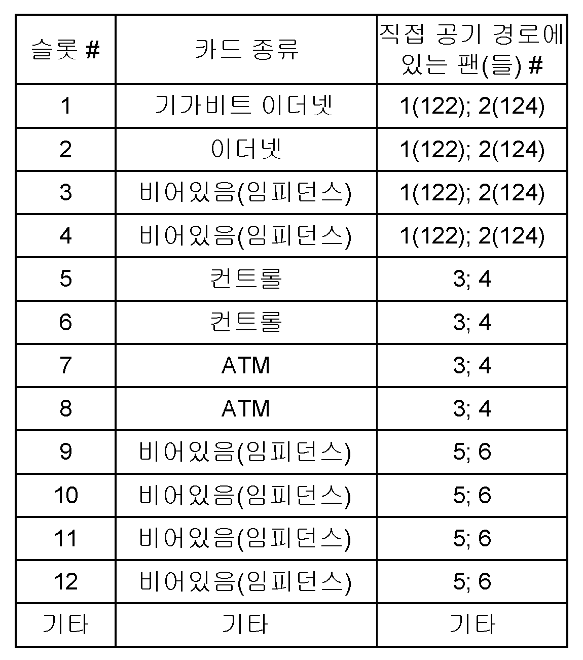
시스템 구성 정보(220) 및 장치 구성 정보(230)가 ACCM(210)에 접근할 수 있다. 이 정보는 ACCM(210)에게 여러 개의 중요한 고려 사항을 확인시켜준다. 상기 시스템 구성 정보(220)는 어떤 팬의 공기 흐름이 인클로저(110)에 있는 어떤 장치 장착 슬롯과 관련되어 있는지를 확인시켜 준다. 예컨대, 도 1을 참조하면, 시스템 구성 정보(220)는, 회로 카드(131, 132, 133, 134)를 포함하는 인클로저 슬롯이 팬(122, 124)에 의해 제공되는 공기 흐름과 관련되어 있음을 확인시켜 줄 것이다. 둘째, 시스템 구성 정보(220)는 인클로저 슬롯에 구비되는 장치의 종류를 확인시켜 준다.
예컨대, 본 발명의 일 실시 형태에 따르면, 상기 시스템 구성 정보(220)는 표 1에 포함되어 있는 것과 같은 정보로 이루어질 수 있다. For example, according to one embodiment of the present invention, the
또한, 시스템 구성 정보(220)의 일 부분으로서 장치 구성 정보(230)가 ACCM(210)에 접근할 수 있다. 이 장치 구성 정보는 인클로저(110)의 슬롯에 구비되어 있는 장치에 포함되어 있는 온도 센서로 측정되는 온도와 그 슬롯과 관련된 팬에 대한 팬 속도 요건 사이의 관계를 ACCM(210)에 제공한다. In addition, the
예컨대, 본 발명의 일 실시 형태에 따르면, 장치 구성 정보(230)는 표 2에 포함되어 있는 것과 같은 정보로 이루어질 수 있다. 이 표에서 각 카드에 위치되는 제 1 및 2 온도 센서와 공기 입구 온도 센서에 대한 최대 온도 기록과 팬 속도(RPM) 사이의 연관을 볼 수 있다.For example, according to an embodiment of the present invention, the
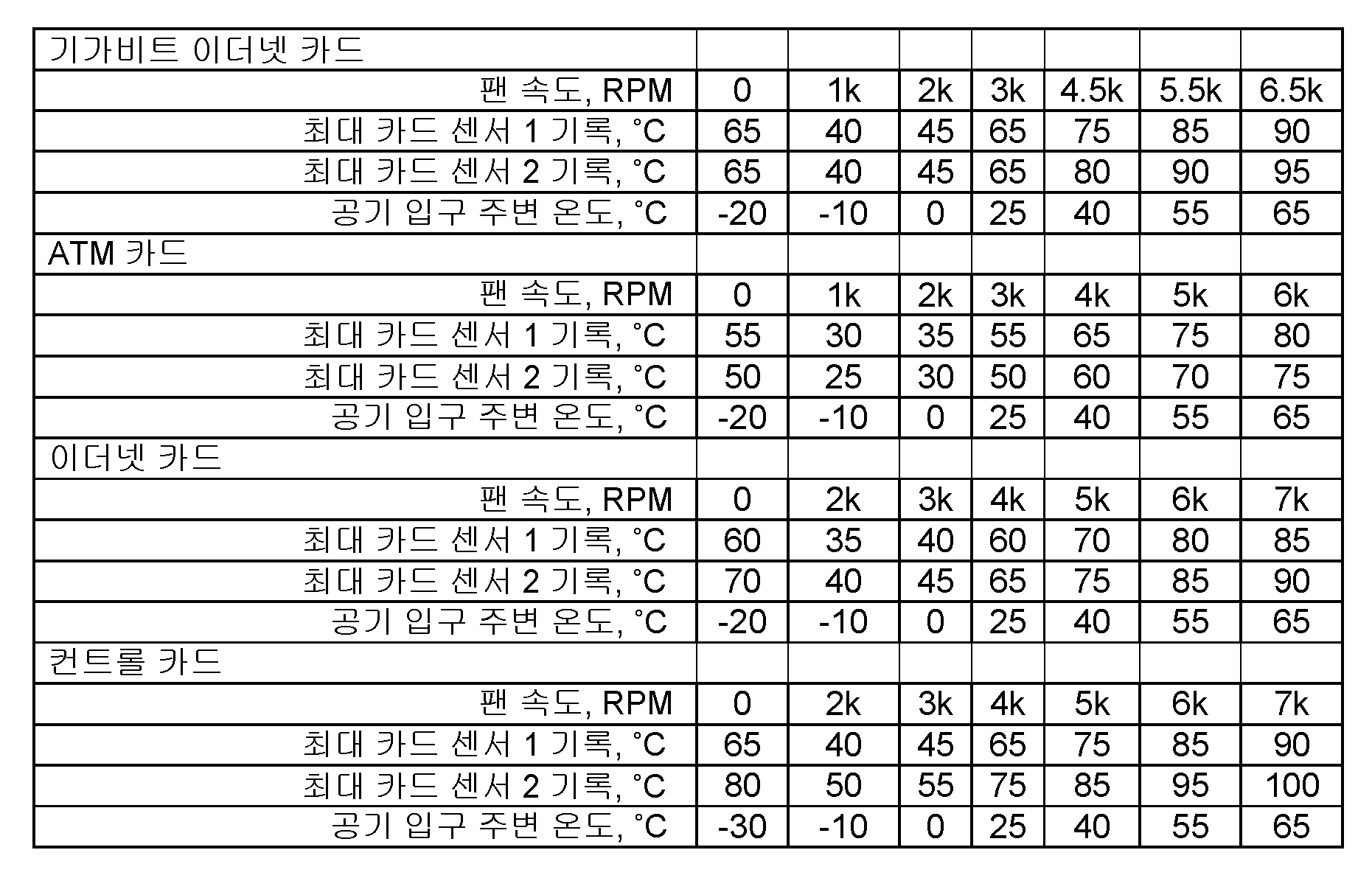
작동 온도 범위에서 요구되는 최고 RPM은 카드 마다 그 카드의 설계 및 확인 중에 수행되는 열 시험 결과에 근거하여 정해지며, 카드의 열 프로파일이 어떤 이유(예컨대, 더 새로운 SW 부하, 새로운 대체부 등...)로 변했으면 장치 구성 정보(230)의 업데이트를 통해 현장에서 업데이트될 수 있다. The highest RPM required in the operating temperature range is determined on a per card basis based on the results of thermal tests performed during the design and verification of the card, and the card's thermal profile is for some reason (eg, newer SW loads, new replacements, etc.). .) May be updated in the field through the update of the
표 2에 기재되어 있는 온도는 주어진 팬 RPM에서의 최고 허용 온도에 대한 문턱 온도를 나타낸다. 일반적으로, 주어진 팬 RPM 에서 센서에서 나타나는 온도가 상기 표에 나타나 있는 값을 초과하는 경우, 팬 속도는 증가된다. 마찬가지로, 센서에서 나타나는 온도가 표에 나타나 있는 값 보다 낮은 경우, 팬 속도는 감소될 수 있다. The temperatures listed in Table 2 represent the threshold temperatures for the highest permissible temperatures at a given fan RPM. In general, the fan speed is increased if the temperature present at the sensor at a given fan RPM exceeds the value shown in the table above. Likewise, if the temperature present at the sensor is lower than the value shown in the table, the fan speed may be reduced.
속도 요동을 방지하거나 적절한 팬 속도를 찾기 위해, 지시된 온도 주변에 온도의 가드 밴드(guard band)가 설정된다. 이 가드 밴드는 보통 시스템 구성 정보(220)에서 특정되지만, 또한 ACCM(210)에 저장될 수 있다. 이 가드 밴드는 인클로저 설계에 의해 또는 장비 특성화를 통해 결정되는 바와 같이 지시된 온도 주변에서 ±2°온도 범위이거나 또는 ±4°또는 ±6°또는 다른 적절한 범위일 수 있다. 그 센서에 대해 측정 온도가 특정된 가드 밴드내에 있는 경우, 팬 RPM의 변경은 필요 없다. To prevent speed fluctuations or to find a suitable fan speed, a guard band of temperature is set around the indicated temperature. This guard band is usually specified in
다시 도 2를 참조하면, ACCM(210)은 또한 팬 제어기(250)에 연결되며, 이 제어기에 팬 속도 요건을 제공하게 된다. 그리고 팬 제어기(250)는 팬 어셈블리(120)에 위치되는 개별 팬들을 ACCM(210)에 의해 특정되는 속도로 설정하기 위해 적절한 구동 전압을 그 팬들에 제공한다. Referring again to FIG. 2,
본 발명의 일 실시 형태에 따르면, 적절한 냉각 공기 흐름을 구비된 장치에 제공하기 위한 ACCM(210)의 작동은 다음과 같다.According to one embodiment of the invention, the operation of the
시스템 구성 정보(220)에서 제공되는 정보를 사용하여, ACCM(210)은 인클로저 슬롯에 설치되는 장비에 위치되어 있는 일 그룹의 온도 센서를 특정 팬에 관련시킬 수 있다. 특정 팬과 관련된 그 그룹의 센서들을 팬 센서 그룹(FSG)이라고 할 수 있다. 예컨대, 표 1을 참조하면, 팬(도 1의 팬(122))에 대한 FSG(1)는 4개의 제 1 인클로저 슬롯과 관련된 온도 센서(도 1의 장치 카드(131, 132, 133, 134)에 있는 온도 센서)이고 입구 공기 주변 온도 센서가 제공되어 있는 경우에도 또한 그들 센서이다.Using the information provided in
각각의 팬을 위해, 상기 ACCM(210)은 그 팬의 각각의 FGS에 대한 센서 기록을 수집한다. 팬의 RPM이 알려져 있고 ACCM(210)이 RPM을 설정하므로, 이 ACCM(210)은 장치 구성 정보(230)에 의해 제공되는 데이타를 사용하여, 특정 FSG의 온도 센서들 중의 어떤 것이라도 그의 최고 허용(가드 밴드를 더하여) 온도를 초과하는지를 판단할 수 있다. FSG에 있는 어떤 센서라도 초과를 하면, 각 팬의 속도가 증가된다. FSG의 온도 기록 중 어떤 것도 문턱 온도(가드 밴드를 더하여) 보다 높지 않으면, 현재의 팬 속도가 너무 낮은 것은 아니다. 그리고 ACCM(210)은 온도 기록 중의 어떤 것이라도 그 팬 속도에 대해 각각의 가드 밴드 내에 있는지를 판단한다. 온도 기록 중 어떤 것도 그의 각각의 가드 밴드 내에 있지 않으면, 모든 온도는 문턱값 보다 낮음이 틀림 없고 현재의 팬 속도는 감소될 수 있으며, ACCM(210)은 팬 제어기(250)에게 이 팬을 위해 팬 속도를 감소시키라고 지시한다. 그러나, 이때 FSG 내의 적어도 하나의 센서 기록이 그의 각각의 가드 밴드내에 있으면, 팬 속도는 증가 또는 감소될 필요가 없다. For each fan, the
표 2를 참조하면, 특정한 카드에 대해 주어진 팬 속도는 다른 장치를 위해서는 특정되지 않음을 알 수 있다. 예컨대, 표에 기재되어 있는 기가비트 이더넷 카드는 5.5k RPM의 팬 속도에 대한 센서 온도를 특정하고, 표 2의 다른 카드들은 5k RPM 및 6k RPM의 팬 속도에 대한 센서 온도만 특정한다. 팬 속도가 설정되어 있고 FSG의 일 부분인 장치에 대해 특정 온도가 주어져 있지 않는 경우에는, ACCM(210)은 문제되는 센서를 위한 적절한 온도를 계산할 것이다. 이 계산은 제공되는 문턱 온도로부터 통상적인 선형 보간이나 외삽을 사용하여 수행될 수 있다.Referring to Table 2, it can be seen that the fan speed given for a particular card is not specified for other devices. For example, the Gigabit Ethernet cards listed in the table specify sensor temperatures for fan speeds of 5.5k RPM, and the other cards in Table 2 only specify sensor temperatures for fan speeds of 5k RPM and 6k RPM. If the fan speed is set and no specific temperature is given for the device that is part of the FSG, the
표 2에 있는 장치 구성 정보가 구해진 신뢰성과 유효 수명 목표는 신뢰성과 유효 수명의 특별한 경우를 나타낸다. 고객의 요건에 따라, 바람직한 대안적인 경우가 있을 수 있다. 이러한 상황하에서, 장치 구성 정보(230)는, 인클로저(110)의 슬롯에 구비되어 있는 장치에 포함되어 있는 온도 센서로 측정되는 온도와 그 슬롯과 관련된 팬에 대한 팬 속도 요건 사이의 관계의 추가 경우로 보충될 수 있으며, 그 추가 경우는 신뢰성과 유효 수명의 다른 경우에 대한 관계를 나타낸다. The reliability and useful life targets for which the device configuration information in Table 2 is obtained represent a special case of reliability and useful life. Depending on the requirements of the customer, there may be a preferred alternative. Under these circumstances, the
예컨대, 본 발명의 일 실시 형태에 따르면, 상기 장치 구성 정보(230)는 표 3에 포함되어 있는 것과 같은 정보로 더 이루어질 수 있다. 이 표에서 특정의 목표 수명에 대해, 각각의 카드에 위치되는 제 1 및 2 온도 센서와 또한 공기 입구 온도 센서에 대한 최대 온도 기록과 팬 속도(RPM)의 연관을 볼 수 있다. 이 실시예를 위해, 하나의 특정 카드에 대해 복수의 경우가 나타나 있다. 실제 실시 형태에서는 제공되는 각각의 카드 또는 부속 장비에 대해 일반적으로 복수의 경우가 있게 될 것이다. For example, according to one embodiment of the present invention, the

표 3을 참조하면, 더 짧은 수명이 선택됨에 따라 더 낮은 팬 속도(RPM)가 더 높은 센서 온도와 관련되는 것을 명확히 알 수 있다. 또한, 표 3을 살펴 보면, 팬이 꺼진 상태에서(팬 속도는 0 RPM) 내부 장비 온도 상승은 증가된 센서 문턱값으로 인한 것임을 알 수 있다. 알 수 있는 바와 같이, 더 짧은 수명이 선택됨에 따라, 장비의 내부 작동 온도는 더 높은 온도를 허용해서 변하게 된다. 이러면, 팬 속도가 낮아질 수 있고, 팬 모터 전력 소비가 낮아져서 전력 절감을 증가시킬 수 있다. Referring to Table 3, it is clear that lower fan speeds (RPMs) are associated with higher sensor temperatures as shorter lifetimes are selected. In addition, looking at Table 3, it can be seen that the internal equipment temperature rise is due to an increased sensor threshold when the fan is off (fan speed is 0 RPM). As can be seen, as the shorter life is selected, the internal operating temperature of the equipment will change allowing for higher temperatures. This can result in lower fan speeds and lower fan motor power consumption, thus increasing power savings.
이제 도 3을 참조하면, 전술한 방법을 나타내는 흐름도를 볼 수 있다. 단계(310)에서 시작하여, 상기 ACCM은 장치 구성 정보를 포함한 시스템 구성 정보 및 원하는 유효 수명을 얻는다. 단계(312)에서는 이 정보를 사용하여, 제어를 필요로 하는 각각의 팬을 위한 팬 센서 그룹(FSG)를 확인한다. 단계(314)에서 초기 팬 RPM이 각각의 팬에 설정된다. 이 초기 팬 RPM은 팬의 최대 RPM의 공칭값, 예컨대 50%일 수 있거나, 또는 장비가 저온 환경에 위치되는 것으로 알려져 있고 또한 팬을 매우 낮은 온도에서 시동시키는 것이 바람직하지 않는 경우에는 0 RPM 일 수 있으며, 또는 대안적으로, 초기 팬 RPM은 FSG에 적합한 팬 설정, 예컨대 FSG와 관련된 장치를 위해 제공되는 제 2 최고 RPM으로부터 구해질 수 있다. Referring now to FIG. 3, a flow diagram illustrating the method described above can be seen. Beginning at
이제 단계(316)로 가면, 각각의 팬을 위해 ACCM은 각각의 FSG 내의 센서로부터 센서 기록을 얻는다. 이들 온도 기록은 센서들이 설정된 팬 RPM의 영향을 반영하도록 충분한 시간 지연 후에 얻어진다. Now moving to step 316, for each fan the ACCM obtains sensor records from the sensors in each FSG. These temperature records are obtained after a time delay sufficient for the sensors to reflect the effect of the set fan RPM.
단계(320)에서, ACCM은 원하는 수명 목표의 경우에 적합한 온도 문턱값을 사용하여, 고려 중인 FSG 내의 센서 기록들 중의 어떤 것이라도 그 센서에 대한 가드 밴드를 더한 관련된 온도 문턱값 보다 높은지를 확인한다. 센서 기록들 중 어떤 것이라도 가드 밴드를 더한 관련된 온도 문턱값을 초과하는 경우, 과정은 단계(322)로 가고, 이 단계에서 ACCM은 팬 속도를 증가시키게 된다. 그런 다음 제어는 단계(316)로 되돌아가 팬 속도 변화의 영향을 확인한다. In
대안적으로, 단계(320)에서, 고려 중인 FSG 내의 센서 기록들 중의 어떤 것이라도 관련된 온도 문턱값에 그 센서에 대한 가드 밴드를 더한값 보다 높지 않은 경우, 제어는 단계(330)으로 간다. Alternatively, in
단계(330)에서, 고려 중인 FSG 내의 센서 기록들 중의 어떤 것이라도 그 센서에 대한 관련된 온도 문턱값 주변의 가드 밴드내에 있는지를 판단한다. 고려 중인 FSG 내의 센서 기록 중의 어떤 것이라도 그 센서에 대한 관련된 온도 문턱값 주변의 가드 밴드내에 있지 않는 경우, 과정은 단계(332)로 가고 이 단계에서 ACCM은 팬 속도를 감소시킨다. 그런 다음 제어는 단계(316)로 되돌아가 팬 속도 변화의 영향을 확인한다. In
대안적으로, 단계(330)에서, 고려 중인 FSG 내의 센서 기록들 중의 적어도 하나가 그 센서에 대한 관련된 온도 문턱값 주변의 가드 밴드내에 있는 경우, 그 특정 팬의 속도는 이 시점에서 증가 또는 감소될 필요가 없다. 그런 다음 제어는 단계(316)로 가서 계속되는 성능을 모니터링한다. Alternatively, in
전술한 실시 형태에서, 장치는 각각 한쌍의 온도 센서를 구비하고 있다. 이는 단지 실례를 들기 위한 것이며, 대안적인 실시 형태는 단지 하나의 센서를 사용할 수도 있다. 그러나 일반적으로, 단일 센서의 고장으로 ACCM이 작동되지 못하는 일이 없도록 신뢰성을 위해는 복수의 센서가 바람직하다.In the above-mentioned embodiment, each device is equipped with a pair of temperature sensor. This is for illustrative purposes only, and alternative embodiments may use only one sensor. In general, however, multiple sensors are preferred for reliability so that a failure of a single sensor does not render the ACCM inoperable.
도 4를 참조하면, 본원 발명에 설명한 기능들을 수행하기 위해 사용되는데 적합한 컴퓨터 서브시스템의 고 레벨 블럭도를 볼 수 있다. 4, a high level block diagram of a computer subsystem suitable for use to perform the functions described herein can be seen.
도 4에 나타나 있는 바와 같이, 컴퓨터 서브시스템(400)은 프로세서 요소(402)(예컨대, 중앙 처리 유닛(CPU) 및/또는 다른 적절한 프로세서(들)), 메모리(404)(예컨대, 랜덤 액세스 메모리(RAM), 읽기 전용 메모리(ROM) 등), 상호협력 모듈/프로세스(405) 및 다양한 입력/출력 장치(406)(예컨대, 저장 장치(예컨대, 테이프 드라이브, 플로피 드라이브, 하드 디스크 드라이브, 캠팩트 디스크 드라이브, 비휘발성 메모리 장치 등, 또는 대안적으로 다른 프로세서에 대한 연결부))를 포함한다. As shown in FIG. 4,
본원 발명에 나타내고 설명하는 기능들은 소프트웨어 및/또는 하드웨어에서 실행될 수 있는데, 예컨대 일반 목적의 컴퓨터, 하나 이상의 특정 용도 집적 회로(ASIC) 및/또는 다른 하드웨어 상당물을 사용하여 실행될 수 있다. 일 실시 형태에서, 상기 상호협력 프로세스(405)는 메모리(404)에 로딩될 수 있고 프로세서(402)에 의해 실행되어 본원 발명에 논의되는 바와 같은 기능들을 실행할 수 있다. 따라서, 상호협력 프로세스(405)(관련된 데이타 구조를 포함)는 컴퓨터 판독가능한 저장 매체, 예컨대 RAM 메모리, 자기 또는 광학 드라이브 또는 디스켓, 비휘발성 메모리 장치 등에 저장될 수 있다. The functions shown and described in the present invention may be implemented in software and / or hardware, for example, using a general purpose computer, one or more special purpose integrated circuits (ASICs), and / or other hardware equivalents. In one embodiment, the
본원 발명의 소프트웨어 방법으로서 논의되는 단계들 중의 일부는, 예컨대 상기 프로세서와 협력하여 다양한 방법 단계들을 수행하는 회로로서의 하드웨어 내에서 실행될 수 있다. 본원 발명에 설명되는 기능/요소들의 일 부분은 컴퓨터 프로그램 제품으로서 실시될 수 있는데, 컴퓨터 지시는 컴퓨터로 처리되면 본원 발명에 설명되는 방법 및/또는 기술이 불러와 지거나 아니면 다르게 제공되도록 컴퓨터의 작동을 적합하게 한다. 본 발명의 방법을 불러오기 위한 지시는, 비일시적이고 유형인 고정된 또는 제거가능한 매체에 저장될 수 있고 그리고/또는 상기 지시에 따라 작동하는 계산 장치 내의 메모리내에 저장될 수 있다. Some of the steps discussed as the software method of the present invention may be executed in hardware, for example as circuitry for performing various method steps in cooperation with the processor. Some of the functions / elements described herein may be embodied as a computer program product, wherein the computer instructions, when processed by a computer, cause the computer to operate such that the methods and / or techniques described herein may be invoked or otherwise provided. To suit. Instructions for invoking the method of the invention may be stored on a non-transitory, tangible fixed or removable medium and / or stored in a memory in a computing device operating according to the instructions.
요컨대, 냉각 유닛 설정, 예컨대 팬 속도 설정을 갖춰진 특정 장비의 요건에 적합하게 하기 위해 시스템 구성 정보를 사용하는 수단을 제공하는 방법과 시스템이 개시되었다. 이 방법과 시스템은 시스템 구성 정보를 사용하여, 냉각 유닛을 부속 장비 위치에 관련시키고 이들 위치 및 다른 위치에 있는 센서들을 냉각 유닛과 관련시키며 또한 작동의 주어진 순간에서 설정의 어떤 변경이 적절한지를 판단한다. In short, a method and system have been disclosed that provide a means of using system configuration information to suit cooling unit settings, such as fan speed settings, to the requirements of a particular equipment equipped. The method and system use the system configuration information to relate the cooling unit to the accessory equipment locations, to associate the sensors at these and other locations with the cooling unit, and to determine what changes in settings are appropriate at any given moment of operation. .
본 발명의 특성을 설명하기 위해 설명되고 도시된 부품들의 상세, 재료 및 배치에 대한 다양한 변화가 다음의 청구 범위에 기재되어 있는 바와 같은 본 발명의 범위를 벗어남이 없이 당업자에 의해 이루어질 수 있음을 이해할 것이다. It will be appreciated that various changes in details, materials, and arrangements of components described and illustrated to illustrate the nature of the invention may be made by those skilled in the art without departing from the scope of the invention as set forth in the following claims. will be.
또한, 본원 발명에 제시된 예시적인 방법의 단계들은 반드시 설명된 순서로 수행될 필요는 없고 이러한 방법의 단계들의 순서는 단지 예시적인 것임을 이해해야 한다. 마찬가지로, 추가적인 단계들이 그러한 방법에 포함될 수 있고, 어떤 단계들은 본 발명의 다양한 실시 형태들에 따른 방법에서 생략되거나 그에 결합될 수 있다. In addition, it is to be understood that the steps of the example methods presented herein need not necessarily be performed in the order described, and that the order of steps of such methods is merely exemplary. Likewise, additional steps may be included in such a method, and certain steps may be omitted or combined in the method according to various embodiments of the present invention.
하기에 방법 청구항이 있는 경우, 그 방법 청구항에 있는 요소들이 상응하는 표시로 특정의 순서로 설명되지만, 청구항 기재가 그들 요소 중의 일부 또는 모두를 실행하기 위한 특정의 순서를 별도로 암시하지 않는다면, 그들 요소는 반드시 그 특정의 순서로 실행되는 것으로 제한되는 것은 아니다.Where there is a method claim below, the elements in the method claim are described in a particular order with a corresponding indication, but unless the claim description separately implies a specific order for executing some or all of those elements, those elements Is not necessarily limited to being executed in that particular order.
여기서 "하나의 실시 형태" 또는 "일 실시 형태" 라고 할 때, 이는 그 실시 형태와 관련하여 설명되는 특별한 요소, 구조 또는 특징은 본 발명의 적어도 하나의 실시 형태에 포함될 수 있음을 의미하는 것이다. 명세서내 여러 곳에서 "하나의 실시 형태에서" 라는 말이 있을 때, 이는 모두 반드시 동일한 실시 형태를 언급하는 것이 아니고 또한 다른 실시 형태를 반드시 서로 배제하는 별도의 또는 대안적인 실시 형태를 언급하는 것도 아니다. 이는 "실행" 이라는 용어에도 해당된다. 청구 범위에 규정되어 있는 본 발명의 범위에서 벗어남이 없이 전술한 본 발명의 실시 형태에 대해 많은 수정, 변화 및 개작이 이루어질 수 있다.
When referred to herein as "one embodiment" or "an embodiment," it is meant that a particular element, structure, or characteristic described in connection with the embodiment can be included in at least one embodiment of the present invention. When the word “in one embodiment” is used in various places in the specification, all do not necessarily refer to the same embodiment nor do they refer to separate or alternative embodiments necessarily excluding other embodiments. This also applies to the term "execution". Many modifications, variations and adaptations may be made to the above-described embodiments of the invention without departing from the scope of the invention as defined in the claims.
Claims (26)
시스템 구성 정보 및 원하는 유효 수명 목표 정보를 읽는 단계와,
상기 시스템 구성 정보에 근거하여, 상기 냉각 유닛과 관련되는 센서 그룹을 관련시키는 단계와,
상기 냉각 유닛과 관련되는 상기 센서 그룹에 대해 센서 기록을 획득하는 단계와,
상기 센서 기록, 시스템 구성 정보 및 원하는 유효 수명 목표 정보에 근거하여, 상기 냉각 유닛에 대한 설정 변경을 위한 값을 결정하는 단계와,
상기 설정 변경을 상기 냉각 유닛에 적용하는 단계를 포함하는
냉각 유닛 설정 조정 방법.In the method for adjusting the setting of the cooling unit,
Reading system configuration information and desired lifetime target information,
Associating a sensor group associated with the cooling unit based on the system configuration information;
Obtaining a sensor record for the sensor group associated with the cooling unit;
Determining a value for changing a setting for the cooling unit based on the sensor record, system configuration information, and desired useful life target information;
Applying the setting change to the cooling unit.
How to adjust cooling unit settings.
상기 냉각 유닛은 팬(fan)을 포함하고 상기 설정은 팬 속도 설정을 포함하는
냉각 유닛 설정 조정 방법.The method of claim 1,
The cooling unit includes a fan and the setting comprises a fan speed setting.
How to adjust cooling unit settings.
상기 시스템 구성 정보는 상기 냉각 유닛과 적어도 하나의 부속 장비 위치 사이의 연관을 포함하는
냉각 유닛 설정 조정 방법.The method of claim 1,
The system configuration information includes an association between the cooling unit and at least one accessory equipment location.
How to adjust cooling unit settings.
상기 냉각 유닛은 팬을 포함하고 상기 부속 장비 위치는 장비 선반(shelf) 내의 회로 카드 슬롯을 포함하는
냉각 유닛 설정 조정 방법.The method of claim 3, wherein
The cooling unit includes a fan and the accessory equipment location includes a circuit card slot in an equipment shelf.
How to adjust cooling unit settings.
상기 시스템 구성 정보는 적어도 하나의 부속 장비 위치와 이 부속 장비 위치에 설치된 장치 사이의 연관을 포함하는
냉각 유닛 설정 조정 방법. The method of claim 1,
The system configuration information includes an association between at least one accessory equipment location and a device installed at the accessory equipment location.
How to adjust cooling unit settings.
상기 시스템 구성 정보는 상기 장치와 관련된 장치 구성 정보를 더 포함하는
냉각 유닛 설정 조정 방법. The method of claim 5, wherein
The system configuration information further includes device configuration information associated with the device.
How to adjust cooling unit settings.
상기 장치 구성 정보는 상기 장치와 관련된 센서에 대한 문턱값 기록과 냉각 유닛 설정 사이의 연관을 포함하고,
센서에 대한 상기 문턱값 기록은 특정의 유효 수명 목표값과 관련되는
냉각 유닛 설정 조정 방법.The method according to claim 6,
The device configuration information includes an association between threshold recording and cooling unit settings for a sensor associated with the device,
The threshold recording for the sensor is associated with a particular useful life target value.
How to adjust cooling unit settings.
상기 결정하는 단계는 가드 밴드값(guard band value)을 상기 센서 문턱값 기록과 관련시키는 단계를 더 포함하고,
상기 냉각 유닛과 관련된 센서 그룹에 대한 센서 기록 중의 어떤 것이라도 각각의 문턱값과 상기 가드 밴드 값을 더한 값을 초과하는 경우, 상기 설정 변경 값은 상기 냉각 유닛의 냉각 효과를 증가시키도록 되어 있는
냉각 유닛 설정 조정 방법. The method of claim 7, wherein
The determining step further comprises associating a guard band value with the sensor threshold value recording,
If any of the sensor records for the sensor group associated with the cooling unit exceeds the respective threshold value plus the guard band value, the setting change value is adapted to increase the cooling effect of the cooling unit.
How to adjust cooling unit settings.
상기 냉각 유닛은 팬을 포함하고 상기 센서는 온도 센서를 포함하는
냉각 유닛 설정 조정 방법.The method of claim 8,
The cooling unit comprises a fan and the sensor comprises a temperature sensor
How to adjust cooling unit settings.
상기 결정하는 단계는 가드 밴드 값을 상기 센서 문턱값 기록과 관련시키는 단계를 더 포함하고,
상기 냉각 유닛과 관련된 센서 그룹에 대한 센서 기록 모두가 각각의 문턱값에서 상기 가드 밴드 값을 뺀 값보다 작은 경우, 상기 설정 변경 값은 상기 냉각 유닛의 냉각 효과를 감소시키도록 되어 있는
냉각 유닛 설정 조정 방법. The method of claim 7, wherein
The determining further includes associating a guard band value with the sensor threshold recording,
If all of the sensor records for the sensor group associated with the cooling unit are less than each threshold minus the guard band value, the setting change value is adapted to reduce the cooling effect of the cooling unit.
How to adjust cooling unit settings.
상기 냉각 유닛은 팬을 포함하고 상기 센서는 온도 센서를 포함하는
냉각 유닛 설정 조정 방법.11. The method of claim 10,
The cooling unit comprises a fan and the sensor comprises a temperature sensor
How to adjust cooling unit settings.
상기 결정하는 단계는 가드 밴드 값을 상기 센서 문턱값 기록과 관련시키는 단계를 더 포함하고,
상기 냉각 유닛과 관련된 센서 그룹에 대한 센서 기록 중의 어떤 것도 각각의 문턱값과 상기 가드 밴드 값을 더한값을 초과하지 않는 경우, 및 상기 냉각 유닛과 관련된 센서 그룹에 대한 센서 기록 중의 적어도 하나가 각각의 문턱값의 상기 가드 밴드 값 범위내에 있는 경우, 상기 설정 변경 값은 상기 냉각 유닛의 냉각 효과를 변화시키지 않도록 되어 있는
냉각 유닛 설정 조정 방법. The method of claim 7, wherein
The determining further includes associating a guard band value with the sensor threshold recording,
If none of the sensor records for the sensor group associated with the cooling unit exceeds the respective threshold value plus the guard band value, and at least one of the sensor records for the sensor group associated with the cooling unit is If the threshold value is within the guard band value range, the setting change value is such as not to change the cooling effect of the cooling unit.
How to adjust cooling unit settings.
상기 냉각 유닛은 팬을 포함하고 상기 센서는 온도 센서를 포함하는
냉각 유닛 설정 조정 방법.13. The method of claim 12,
The cooling unit comprises a fan and the sensor comprises a temperature sensor
How to adjust cooling unit settings.
적응성 냉각 제어기와,
서브 세트의 센서를 상기 냉각 유닛에 관련시키는 제 1 시스템 구성 정보와,
센서 기록을 냉각 유닛 설정에 관련시키는 제 2 시스템 구성 정보와,
유효 수명 목표 값을 포함하고,
상기 적응성 냉각 제어기는, 상기 제 1 시스템 구성 정보에 의해 특정되는 상기 서브 세트의 센서로부터 센서 기록을 얻고, 상기 유효 수명 목표 값과 함께 상기 센서 기록 및 상기 제 2 시스템 구성 정보에 근거하여 상기 냉각 유닛에 대한 설정 변경 값을 결정하며, 상기 설정 변경 값에 따라 상기 냉각 유닛의 설정을 변경하는
냉각 유닛 설정 제어 시스템.In the system for controlling the setting of the cooling unit,
With adaptive cooling controller,
First system configuration information for associating a subset of sensors to the cooling unit,
Second system configuration information relating the sensor record to the cooling unit settings,
Includes a valid lifetime target value,
The adaptive cooling controller obtains a sensor record from the subset of sensors specified by the first system configuration information, and based on the sensor record and the second system configuration information together with the valid lifetime target value, the cooling unit. Determine a setting change value for and change the setting of the cooling unit according to the setting change value.
Cooling unit setting control system.
상기 냉각 유닛은 팬이고, 상기 센서는 온도 센서이며, 상기 설정은 속도에 대응하는
냉각 유닛 설정 제어 시스템.15. The method of claim 14,
The cooling unit is a fan, the sensor is a temperature sensor, the setting corresponding to the speed
Cooling unit setting control system.
상기 제 1 시스템 구성 정보는 추가로 상기 냉각 유닛을 적어도 하나의 부속 장비 위치에 관련시키는
냉각 유닛 설정 제어 시스템.15. The method of claim 14,
The first system configuration information further relates the cooling unit to at least one accessory equipment location.
Cooling unit setting control system.
상기 서브 세트의 센서의 일부는 상기 적어도 하나의 부속 장비 위치에 위치되는
냉각 유닛 설정 제어 시스템.17. The method of claim 16,
A portion of the subset of sensors is located at the at least one accessory equipment location
Cooling unit setting control system.
상기 서브 세트의 센서의 일부는 주변 조건을 감지하도록 위치되는
냉각 유닛 설정 제어 시스템.15. The method of claim 14,
Some of the subset of sensors are positioned to sense ambient conditions
Cooling unit setting control system.
상기 제 2 시스템 구성 정보는 냉각 유닛 설정과 서브 세트의 센서에 대한 문턱값 기록 사이의 연관을 포함하는
냉각 유닛 설정 제어 시스템.15. The method of claim 14,
The second system configuration information includes an association between cooling unit settings and threshold recording for a subset of sensors.
Cooling unit setting control system.
상기 제 2 시스템 구성 정보는 냉각 유닛 설정과 상기 서브 세트의 센서에 있어서의 센서의 일부에 대한 각각의 문턱값 기록 사이의 연관을 포함하는
냉각 유닛 설정 제어 시스템.The method of claim 19,
The second system configuration information includes an association between cooling unit settings and respective threshold recordings for some of the sensors in the subset of sensors.
Cooling unit setting control system.
가드 밴드가 상기 각각의 문턱값과 관련되며,
상기 센서의 일부에 대한 상기 센서 기록 중의 어떤 것이라도 현재의 냉각 유닛 설정에서 각각의 문턱값과 그 센서에 대한 가드 밴드 값을 더한값을 초과하는 값을 가지는 경우, 상기 적응성 냉각 제어기는 상기 냉각 유닛의 냉각 효과를 증가시키는 설정 변경을 위한 값을 결정하는
냉각 유닛 설정 제어 시스템.21. The method of claim 20,
A guard band is associated with each of said thresholds,
If any of the sensor records for a portion of the sensor has a value that exceeds the respective threshold value plus the guard band value for that sensor in the current cooling unit setting, the adaptive cooling controller causes the cooling unit to fail. To determine the values for setting changes that increase the cooling effect of the
Cooling unit setting control system.
상기 냉각 유닛은 팬이고, 상기 센서는 온도 센서이며, 상기 설정 변경은 팬 속도의 증가와 관련되는
냉각 유닛 설정 제어 시스템.22. The method of claim 21,
The cooling unit is a fan, the sensor is a temperature sensor, and the setting change is related to an increase in the fan speed.
Cooling unit setting control system.
가드 밴드가 상기 각각의 문턱값과 관련되며,
상기 센서의 일부에 대한 상기 센서 기록 모두가 현재의 냉각 유닛 설정에서 각각의 문턱값에서 그 센서에 대한 가드 밴드 값을 뺀값 미만인 값을 가지는 경우, 상기 적응성 냉각 제어기는 상기 냉각 유닛의 냉각 효과를 감소시키는 설정 변경을 위한 값을 결정하는
냉각 유닛 설정 제어 시스템.21. The method of claim 20,
A guard band is associated with each of said thresholds,
The adaptive cooling controller reduces the cooling effect of the cooling unit if all of the sensor records for a portion of the sensor have a value that is less than each threshold value of the guard band value for that sensor in the current cooling unit setting. To determine the value for the setting change.
Cooling unit setting control system.
상기 냉각 유닛은 팬이고, 상기 센서는 온도 센서이며, 상기 설정 변경은 팬 속도의 감소와 관련되는
냉각 유닛 설정 제어 시스템.24. The method of claim 23,
The cooling unit is a fan, the sensor is a temperature sensor and the setting change is related to a decrease in fan speed.
Cooling unit setting control system.
가드 밴드가 상기 각각의 문턱값과 관련되고,
상기 센서의 일부에 대한 상기 센서 기록 중의 어떤 것도 현재의 냉각 유닛 설정에서 각각의 문턱값과 그 센서에 대한 가드 밴드 값을 더한값을 초과하는 값을 갖지 않는 경우, 및 상기 센서의 일부에 대한 상기 센서 기록 중의 적어도 하나가 상기 각각의 문턱값의 상기 가드 밴드 값 범위내에 있는 경우, 상기 적응성 냉각 제어기는 상기 냉각 유닛의 냉각 효과를 변화시키지 않는 설정 변경을 위한 값을 결정하는
냉각 유닛 설정 제어 시스템.21. The method of claim 20,
A guard band is associated with each of said thresholds,
If none of the sensor records for a portion of the sensor has a value that exceeds the respective threshold value plus the guard band value for that sensor in the current cooling unit setting, and for the portion of the sensor If at least one of the sensor records is within the guard band value range of each threshold, the adaptive cooling controller determines a value for setting change that does not change the cooling effect of the cooling unit.
Cooling unit setting control system.
상기 냉각 유닛은 팬이고, 상기 센서는 온도 센서이며, 상기 설정 변경은 팬 속도의 무시가능한 변화와 관련되는
냉각 유닛 설정 제어 시스템.The method of claim 25,
The cooling unit is a fan, the sensor is a temperature sensor, and the setting change is related to a negligible change in fan speed.
Cooling unit setting control system.
Applications Claiming Priority (3)
| Application Number | Priority Date | Filing Date | Title |
|---|---|---|---|
| US12/976,442 US8560142B2 (en) | 2010-12-22 | 2010-12-22 | Adaptive cooling using selectable target useful life |
| US12/976,442 | 2010-12-22 | ||
| PCT/CA2011/050750 WO2012088603A1 (en) | 2010-12-22 | 2011-12-06 | Adaptive cooling using selectable target useful life |
Publications (2)
| Publication Number | Publication Date |
|---|---|
| KR20130102625A true KR20130102625A (en) | 2013-09-17 |
| KR101528689B1 KR101528689B1 (en) | 2015-06-12 |
Family
ID=46315267
Family Applications (1)
| Application Number | Title | Priority Date | Filing Date |
|---|---|---|---|
| KR1020137016017A Expired - Fee Related KR101528689B1 (en) | 2010-12-22 | 2011-12-06 | Adaptive cooling using selectable target useful life |
Country Status (6)
| Country | Link |
|---|---|
| US (1) | US8560142B2 (en) |
| EP (1) | EP2656161A4 (en) |
| JP (1) | JP5524426B2 (en) |
| KR (1) | KR101528689B1 (en) |
| CN (1) | CN103270462B (en) |
| WO (1) | WO2012088603A1 (en) |
Families Citing this family (6)
| Publication number | Priority date | Publication date | Assignee | Title |
|---|---|---|---|---|
| JP2016021111A (en) * | 2014-07-14 | 2016-02-04 | Necプラットフォームズ株式会社 | COOLING CONTROL DEVICE, COOLING CONTROL METHOD, SERVER SYSTEM, AND COMPUTER PROGRAM |
| JP2016207782A (en) * | 2015-04-20 | 2016-12-08 | 富士通株式会社 | Electronic apparatus and cooling method |
| US9568923B1 (en) * | 2015-10-27 | 2017-02-14 | International Business Machines Corporation | Determining a time for corrective action in a data center |
| US10506743B2 (en) * | 2017-06-09 | 2019-12-10 | Dell Products, L.P. | Systems and methods of automated open-loop thermal control |
| CN111124079B (en) * | 2018-10-30 | 2021-05-07 | 深圳中瀚云科技股份有限公司 | Method and apparatus for controlling cooling of device, and storage medium |
| CN118793646B (en) * | 2024-09-12 | 2025-01-21 | 苏州元脑智能科技有限公司 | A fan speed regulation method, device, medium and program product |
Family Cites Families (19)
| Publication number | Priority date | Publication date | Assignee | Title |
|---|---|---|---|---|
| JPH1185323A (en) * | 1997-09-01 | 1999-03-30 | Toshiba Corp | Computer system and temperature control method thereof |
| US6470289B1 (en) * | 1999-08-05 | 2002-10-22 | Compaq Information Technologies Group, L.P. | Independently controlling passive and active cooling in a computer system |
| US7849332B1 (en) * | 2002-11-14 | 2010-12-07 | Nvidia Corporation | Processor voltage adjustment system and method |
| US8237386B2 (en) * | 2003-08-15 | 2012-08-07 | Apple Inc. | Methods and apparatuses for operating a data processing system |
| US7249718B2 (en) * | 2004-07-20 | 2007-07-31 | Hewlett-Packard Development Company, L.P. | Cooling system with a variable maximum operation level |
| US7305316B2 (en) * | 2004-12-23 | 2007-12-04 | Minebea Co., Ltd. | Microcontroller methods of improving reliability in DC brushless motors and cooling fans |
| US7426453B2 (en) * | 2005-01-14 | 2008-09-16 | Hewlett-Packard Development Company, L.P. | Workload placement based upon CRAC unit capacity utilizations |
| US7490479B2 (en) | 2005-03-30 | 2009-02-17 | Intel Corporation | Method and system of advanced fan speed control |
| WO2006111789A1 (en) * | 2005-04-22 | 2006-10-26 | Degree Controls, Inc. | Intelligent fan assisted tiles for adaptive environmental management |
| US7426109B2 (en) | 2005-11-16 | 2008-09-16 | Dell Products L.P. | System and method for adaptive information handling system cooling profiles |
| US7708056B2 (en) | 2006-03-30 | 2010-05-04 | Inventec Corporation | Fan controlling system and method |
| JP2007293605A (en) | 2006-04-25 | 2007-11-08 | Toshiba Corp | Information processing apparatus and control method |
| US7765412B1 (en) * | 2006-09-29 | 2010-07-27 | Burr James B | Methods and systems for dynamically changing device operating conditions |
| US7711659B2 (en) | 2006-12-28 | 2010-05-04 | Intel Corporation | Adaptive system for fan management |
| FR2917567A1 (en) * | 2007-06-12 | 2008-12-19 | Alcatel Lucent Sas | COOLING DEVICE FOR ELECTRONIC EQUIPMENT BOX. |
| JP4655100B2 (en) * | 2008-03-27 | 2011-03-23 | ソニー株式会社 | Information processing apparatus and cooling fan control method |
| CA2676213A1 (en) | 2008-08-19 | 2010-02-19 | Turner Logistics | Data center and methods for cooling thereof |
| JP4585598B1 (en) * | 2009-06-30 | 2010-11-24 | 株式会社東芝 | Information processing device |
| JP5198404B2 (en) | 2009-10-15 | 2013-05-15 | 株式会社東芝 | Humidity estimation apparatus and humidity estimation method |
-
2010
- 2010-12-22 US US12/976,442 patent/US8560142B2/en not_active Expired - Fee Related
-
2011
- 2011-12-06 CN CN201180062340.1A patent/CN103270462B/en active Active
- 2011-12-06 JP JP2013544985A patent/JP5524426B2/en active Active
- 2011-12-06 KR KR1020137016017A patent/KR101528689B1/en not_active Expired - Fee Related
- 2011-12-06 WO PCT/CA2011/050750 patent/WO2012088603A1/en not_active Ceased
- 2011-12-06 EP EP11853211.8A patent/EP2656161A4/en not_active Ceased
Also Published As
| Publication number | Publication date |
|---|---|
| CN103270462B (en) | 2016-07-06 |
| WO2012088603A8 (en) | 2013-08-01 |
| EP2656161A1 (en) | 2013-10-30 |
| JP5524426B2 (en) | 2014-06-18 |
| KR101528689B1 (en) | 2015-06-12 |
| US8560142B2 (en) | 2013-10-15 |
| EP2656161A4 (en) | 2017-03-29 |
| US20120160444A1 (en) | 2012-06-28 |
| JP2014504016A (en) | 2014-02-13 |
| CN103270462A (en) | 2013-08-28 |
| WO2012088603A1 (en) | 2012-07-05 |
Similar Documents
| Publication | Publication Date | Title |
|---|---|---|
| US7791301B2 (en) | Apparatus and method for fan auto-detection | |
| US20080313492A1 (en) | Adjusting a Cooling Device and a Server in Response to a Thermal Event | |
| KR20130102625A (en) | Adaptive cooling using selectable target useful life | |
| US20110103008A1 (en) | Fan Control System and Method for a Computer System Available at Different Altitudes | |
| US7768222B2 (en) | Automated control of rotational velocity of an air-moving device of an electronics rack responsive to an event | |
| US7577862B2 (en) | Self adjusting clocks in computer systems that adjust in response to changes in their environment | |
| US20030193777A1 (en) | Data center energy management system | |
| US8639963B2 (en) | System and method for indirect throttling of a system resource by a processor | |
| US20180359882A1 (en) | Systems and methods of automated open-loop thermal control | |
| US20050216221A1 (en) | Systems and methods for cooling storage devices | |
| US11500435B2 (en) | Information handling system having regional cooling | |
| JP2015161451A (en) | Data center, data center control method and control program | |
| US20090099792A1 (en) | System and Method for Increasing the Power Efficiency of Cooling Fans | |
| US8031454B2 (en) | Electronic system with dynamic thermal management | |
| US20120166014A1 (en) | Adaptive cooling using system configuration information | |
| US20120160469A1 (en) | Adaptive cooling using power monitoring | |
| US9176564B2 (en) | Systems and methods for thermal control of a storage enclosure | |
| US12174677B2 (en) | Dynamic control for fan speed during system boot and reboot in hot and cold environments | |
| EP2634668A2 (en) | ICT equipment | |
| US11755082B2 (en) | Methods and systems for processor-calibrated fan control | |
| US7881826B2 (en) | Preemptive thermal control by processor throttling in a modular computing system | |
| JP7419660B2 (en) | Control device, storage rack, fan control system, fan control method and computer program | |
| EP4612565A1 (en) | Systems and methods for configuring fan speeds | |
| CN119002662A (en) | Heat dissipation control method and electronic equipment | |
| JP2026016778A (en) | Electronic device and control method thereof |
Legal Events
| Date | Code | Title | Description |
|---|---|---|---|
| A201 | Request for examination | ||
| PA0105 | International application |
St.27 status event code: A-0-1-A10-A15-nap-PA0105 |
|
| PA0201 | Request for examination |
St.27 status event code: A-1-2-D10-D11-exm-PA0201 |
|
| P11-X000 | Amendment of application requested |
St.27 status event code: A-2-2-P10-P11-nap-X000 |
|
| P13-X000 | Application amended |
St.27 status event code: A-2-2-P10-P13-nap-X000 |
|
| PG1501 | Laying open of application |
St.27 status event code: A-1-1-Q10-Q12-nap-PG1501 |
|
| R18-X000 | Changes to party contact information recorded |
St.27 status event code: A-3-3-R10-R18-oth-X000 |
|
| E902 | Notification of reason for refusal | ||
| PE0902 | Notice of grounds for rejection |
St.27 status event code: A-1-2-D10-D21-exm-PE0902 |
|
| E13-X000 | Pre-grant limitation requested |
St.27 status event code: A-2-3-E10-E13-lim-X000 |
|
| P11-X000 | Amendment of application requested |
St.27 status event code: A-2-2-P10-P11-nap-X000 |
|
| P13-X000 | Application amended |
St.27 status event code: A-2-2-P10-P13-nap-X000 |
|
| E701 | Decision to grant or registration of patent right | ||
| PE0701 | Decision of registration |
St.27 status event code: A-1-2-D10-D22-exm-PE0701 |
|
| GRNT | Written decision to grant | ||
| PR0701 | Registration of establishment |
St.27 status event code: A-2-4-F10-F11-exm-PR0701 |
|
| PR1002 | Payment of registration fee |
St.27 status event code: A-2-2-U10-U12-oth-PR1002 Fee payment year number: 1 |
|
| PG1601 | Publication of registration |
St.27 status event code: A-4-4-Q10-Q13-nap-PG1601 |
|
| P14-X000 | Amendment of ip right document requested |
St.27 status event code: A-5-5-P10-P14-nap-X000 |
|
| P16-X000 | Ip right document amended |
St.27 status event code: A-5-5-P10-P16-nap-X000 |
|
| Q16-X000 | A copy of ip right certificate issued |
St.27 status event code: A-4-4-Q10-Q16-nap-X000 |
|
| PR1001 | Payment of annual fee |
St.27 status event code: A-4-4-U10-U11-oth-PR1001 Fee payment year number: 4 |
|
| R18-X000 | Changes to party contact information recorded |
St.27 status event code: A-5-5-R10-R18-oth-X000 |
|
| PC1903 | Unpaid annual fee |
St.27 status event code: A-4-4-U10-U13-oth-PC1903 Not in force date: 20190609 Payment event data comment text: Termination Category : DEFAULT_OF_REGISTRATION_FEE |
|
| PC1903 | Unpaid annual fee |
St.27 status event code: N-4-6-H10-H13-oth-PC1903 Ip right cessation event data comment text: Termination Category : DEFAULT_OF_REGISTRATION_FEE Not in force date: 20190609 |