KR20130072258A - Hearing aid and a method of improved audio reproduction - Google Patents
Hearing aid and a method of improved audio reproduction Download PDFInfo
- Publication number
- KR20130072258A KR20130072258A KR20137012290A KR20137012290A KR20130072258A KR 20130072258 A KR20130072258 A KR 20130072258A KR 20137012290 A KR20137012290 A KR 20137012290A KR 20137012290 A KR20137012290 A KR 20137012290A KR 20130072258 A KR20130072258 A KR 20130072258A
- Authority
- KR
- South Korea
- Prior art keywords
- frequency
- signal
- voice
- input signal
- band
- Prior art date
- Legal status (The legal status is an assumption and is not a legal conclusion. Google has not performed a legal analysis and makes no representation as to the accuracy of the status listed.)
- Granted
Links
- 238000000034 method Methods 0.000 title claims abstract description 31
- 230000002708 enhancing effect Effects 0.000 claims 2
- 230000000875 corresponding effect Effects 0.000 description 23
- 230000006870 function Effects 0.000 description 17
- 208000016354 hearing loss disease Diseases 0.000 description 11
- 238000010219 correlation analysis Methods 0.000 description 10
- 238000010586 diagram Methods 0.000 description 10
- 231100000888 hearing loss Toxicity 0.000 description 10
- 230000010370 hearing loss Effects 0.000 description 10
- 238000001228 spectrum Methods 0.000 description 10
- 206010011878 Deafness Diseases 0.000 description 9
- 238000004458 analytical method Methods 0.000 description 8
- 239000002131 composite material Substances 0.000 description 8
- 230000003321 amplification Effects 0.000 description 7
- 238000001514 detection method Methods 0.000 description 7
- 238000003199 nucleic acid amplification method Methods 0.000 description 7
- 239000003623 enhancer Substances 0.000 description 6
- 230000008569 process Effects 0.000 description 6
- 238000012546 transfer Methods 0.000 description 6
- 230000008901 benefit Effects 0.000 description 5
- 238000004364 calculation method Methods 0.000 description 5
- 230000008447 perception Effects 0.000 description 5
- 238000001914 filtration Methods 0.000 description 4
- 230000005236 sound signal Effects 0.000 description 4
- 208000032041 Hearing impaired Diseases 0.000 description 3
- 230000001276 controlling effect Effects 0.000 description 3
- 230000002596 correlated effect Effects 0.000 description 3
- 238000012545 processing Methods 0.000 description 3
- 230000009172 bursting Effects 0.000 description 2
- 230000001419 dependent effect Effects 0.000 description 2
- 238000005259 measurement Methods 0.000 description 2
- 238000005070 sampling Methods 0.000 description 2
- 208000000258 High-Frequency Hearing Loss Diseases 0.000 description 1
- 208000009966 Sensorineural Hearing Loss Diseases 0.000 description 1
- 206010061373 Sudden Hearing Loss Diseases 0.000 description 1
- 230000006978 adaptation Effects 0.000 description 1
- 238000013459 approach Methods 0.000 description 1
- 210000004556 brain Anatomy 0.000 description 1
- 230000015556 catabolic process Effects 0.000 description 1
- 230000008859 change Effects 0.000 description 1
- 210000003477 cochlea Anatomy 0.000 description 1
- 230000019771 cognition Effects 0.000 description 1
- 150000001875 compounds Chemical class 0.000 description 1
- 230000006835 compression Effects 0.000 description 1
- 238000007906 compression Methods 0.000 description 1
- 239000013078 crystal Substances 0.000 description 1
- 230000007423 decrease Effects 0.000 description 1
- 230000007812 deficiency Effects 0.000 description 1
- 238000006731 degradation reaction Methods 0.000 description 1
- 230000004069 differentiation Effects 0.000 description 1
- 230000001747 exhibiting effect Effects 0.000 description 1
- 238000011478 gradient descent method Methods 0.000 description 1
- 210000002768 hair cell Anatomy 0.000 description 1
- 231100000885 high-frequency hearing loss Toxicity 0.000 description 1
- 230000006872 improvement Effects 0.000 description 1
- 238000013507 mapping Methods 0.000 description 1
- 230000007246 mechanism Effects 0.000 description 1
- 239000000203 mixture Substances 0.000 description 1
- 230000003389 potentiating effect Effects 0.000 description 1
- 230000001105 regulatory effect Effects 0.000 description 1
- 230000017105 transposition Effects 0.000 description 1
- 238000005406 washing Methods 0.000 description 1
Images


Classifications
-
- G—PHYSICS
- G10—MUSICAL INSTRUMENTS; ACOUSTICS
- G10L—SPEECH ANALYSIS TECHNIQUES OR SPEECH SYNTHESIS; SPEECH RECOGNITION; SPEECH OR VOICE PROCESSING TECHNIQUES; SPEECH OR AUDIO CODING OR DECODING
- G10L25/00—Speech or voice analysis techniques not restricted to a single one of groups G10L15/00 - G10L21/00
-
- H—ELECTRICITY
- H04—ELECTRIC COMMUNICATION TECHNIQUE
- H04R—LOUDSPEAKERS, MICROPHONES, GRAMOPHONE PICK-UPS OR LIKE ACOUSTIC ELECTROMECHANICAL TRANSDUCERS; DEAF-AID SETS; PUBLIC ADDRESS SYSTEMS
- H04R25/00—Deaf-aid sets, i.e. electro-acoustic or electro-mechanical hearing aids; Electric tinnitus maskers providing an auditory perception
- H04R25/35—Deaf-aid sets, i.e. electro-acoustic or electro-mechanical hearing aids; Electric tinnitus maskers providing an auditory perception using translation techniques
- H04R25/353—Frequency, e.g. frequency shift or compression
-
- G—PHYSICS
- G10—MUSICAL INSTRUMENTS; ACOUSTICS
- G10L—SPEECH ANALYSIS TECHNIQUES OR SPEECH SYNTHESIS; SPEECH RECOGNITION; SPEECH OR VOICE PROCESSING TECHNIQUES; SPEECH OR AUDIO CODING OR DECODING
- G10L25/00—Speech or voice analysis techniques not restricted to a single one of groups G10L15/00 - G10L21/00
- G10L25/93—Discriminating between voiced and unvoiced parts of speech signals
-
- H—ELECTRICITY
- H04—ELECTRIC COMMUNICATION TECHNIQUE
- H04R—LOUDSPEAKERS, MICROPHONES, GRAMOPHONE PICK-UPS OR LIKE ACOUSTIC ELECTROMECHANICAL TRANSDUCERS; DEAF-AID SETS; PUBLIC ADDRESS SYSTEMS
- H04R25/00—Deaf-aid sets, i.e. electro-acoustic or electro-mechanical hearing aids; Electric tinnitus maskers providing an auditory perception
Landscapes
- Engineering & Computer Science (AREA)
- Physics & Mathematics (AREA)
- Signal Processing (AREA)
- Health & Medical Sciences (AREA)
- Acoustics & Sound (AREA)
- Multimedia (AREA)
- Human Computer Interaction (AREA)
- Audiology, Speech & Language Pathology (AREA)
- Computational Linguistics (AREA)
- General Health & Medical Sciences (AREA)
- Neurosurgery (AREA)
- Otolaryngology (AREA)
- Electrophonic Musical Instruments (AREA)
- Tone Control, Compression And Expansion, Limiting Amplitude (AREA)
- Telephone Function (AREA)
- Compression, Expansion, Code Conversion, And Decoders (AREA)
- Circuit For Audible Band Transducer (AREA)
Abstract
주파수 이동기(frequency shifter)(20)를 포함하는 보청기는 입력 신호에서 제 1 주파수 및 제 2 주파수를 검출하기 위한 수단(22)을 가진다. 주파수 이동기(20)는 검출된 제 1 주파수 및 제 2 주파수의 고정 관계의 존재에 기반하여, 입력 신호의 제 1 주파수 범위를 입력 신호의 제 2 주파수 범위로 전위한다(transpose). 제 1 주파수 및 제 2 주파수 간의 고정 관계를 검출하기 위한 수단(34, 35, 36)은 주파수 전위기(20)를 제어하기 위해 사용된다. 유성음 음성 및 무성음 음성의 존재를 검출하도록 구성된 음성 검출기(26)는 음성 포먼트를 보존하기 위해서, 유성음 음성 신호들의 전위를 억제하려고 제공된다. 보청기에서 이러한 방식으로 주파수 대역을 전위하는 것의 목적은, 신호의 원래의 포락선, 고조파 코히어런스, 및 음성 양해도를 유지하면서, 보청기 사용자가 들을 수 없는 주파수를 들을 수 있게 하기 위함이다. 본 발명은 또한 보청기에서 입력 신호의 주파수 범위를 이동시키는 방법을 제공한다.Hearing aids including a frequency shifter 20 have means 22 for detecting a first frequency and a second frequency in an input signal. The frequency shifter 20 transposes the first frequency range of the input signal to the second frequency range of the input signal based on the presence of a fixed relationship between the detected first frequency and the second frequency. Means 34, 35, 36 for detecting a fixed relationship between the first frequency and the second frequency are used to control the frequency potentiometer 20. A voice detector 26 configured to detect the presence of voiced voices and unvoiced voices is provided to suppress the potential of voiced voice signals in order to preserve voice formants. The purpose of displacing a frequency band in this manner in a hearing aid is to enable the hearing aid user to hear frequencies that are inaudible, while maintaining the original envelope, harmonic coherence, and speech intelligibility of the signal. The present invention also provides a method of shifting the frequency range of an input signal in a hearing aid.
Description
본 출원은 보청기에 관한 것이다. 본 발명은 좀 더 구체적으로, 청각 장애 사용자가 지각할 수 있는 한계 범위를 넘어서는 다른 주파수에서 소리를 재생하기 위한 수단을 갖는 보청기에 관한 것이다. 본 발명은 또한 보청기에서 신호를 처리하는 방법에 관한 것이다.This application relates to hearing aids. More particularly, the present invention relates to hearing aids having means for reproducing sound at other frequencies beyond the limits of hearing impaired users. The invention also relates to a method of processing a signal in a hearing aid.
퇴화된 청각을 가진 개인들은 생활에 있어서 여러 가지로 불편하거나 불리하다. 그러나, 잔여 지각이 존재한다면, 그들은 보청기, 즉 청각 장애(hearing deficiency)를 만회하기 위해 주변 소리를 적절히 증폭하도록 구성되는 전자 장치의 사용이 유용할 것이다. 보통, 청각 장애는 다양한 주파수들에서 만들어질(established) 것이고, 보청기는 그러한 주파수들에 따라 청각 손실을 보상하기 위하여 주파수의 함수로서 선택적인 증폭을 제공하도록 조정될 것이다.Individuals with degenerated hearing are uncomfortable or disadvantaged in many ways in their lives. However, if there is residual perception, it would be useful to use hearing aids, ie electronic devices that are configured to properly amplify the ambient sound to make up for hearing deficiency. Usually, hearing impairment will be established at various frequencies, and the hearing aid will be adjusted to provide selective amplification as a function of frequency to compensate for hearing loss according to those frequencies.
보청기는 청각 장애인의 귀 뒤에 또는 귀 안에 착용되도록 구성된, 마이크로폰, 오디오 프로세서, 음향 출력 변환기를 포함하는 배터리로 작동되는 소형의 장치로서 규정된다. 사용자의 청각 손실 측정으로부터 계산된 처방전에 따른 보청기 피팅에 의해서, 보청기는 특정 주파수 대역들을 증폭하여 그 주파수 대역들 내의 청각 손실을 보상할 수 있다. 정확하고 유연한 증폭을 제공하기 위해서, 대부분의 최신 보청기들은 디지털 종(variety)에 해당한다. 디지털 보청기는 처방전에 따라 마이크로폰으로부터의 오디오 신호를 음향 출력 변환기를 구동하기에 적합한 전기적 신호로 프로세싱하기 위한 디지털 신호 프로세서를 포함한다.Hearing aids are defined as small battery-powered devices that include a microphone, an audio processor, and an acoustic output transducer, configured to be worn behind or in the ear of a deaf person. By prescription hearing aid fitting calculated from a user's hearing loss measurement, the hearing aid can amplify certain frequency bands to compensate for hearing loss in those frequency bands. To provide accurate and flexible amplification, most modern hearing aids are digital varieties. The digital hearing aid includes a digital signal processor for processing the audio signal from the microphone into an electrical signal suitable for driving an acoustic output transducer in accordance with a prescription.
그러나, 고 주파수에서 매우 심각한 청각 손실을 가진 자들은 그러한 주파수 증폭으로 인하여 음성 지각에 있어서 어떠한 개선도 얻지 못한다. 청력은 고 주파수에서는 급격하게 감소하는 반면에 저 주파수에서는 거의 정상에 근접할 수 있다. 이러한 급추형 청력 손실(steeply sloping hearing losses)은 청력도에서 그러한 손실을 나타내기 위한 매우 특징적인 커브로 인해서 스키 슬로프 청력 손실(ski-slope hearing loss)로서도 지칭된다. 급추형 청력 손실은 감각 신경성 유형이고, 이는 달팽이관 내의 손상된 생모 세포에 따른 결과이다.However, those with very severe hearing loss at high frequencies do not get any improvement in speech perception due to such frequency amplification. Hearing decreases dramatically at high frequencies, while at low frequencies it can be nearly normal. Such steeply sloping hearing losses are also referred to as ski-slope hearing losses due to the very characteristic curves for indicating such losses in audiograms. Sudden hearing loss is a sensorineural type, which is the result of damaged live hair cells in the cochlea.
(통상적으로 2-8 kHz 이상의) 더 높은 주파수에서 음향 지각이 없는 자들은 음성 지각뿐만 아니라, 현대 사회에서 발생하는 다른 유용한 소리의 지각에 있어서도 어려움을 겪는다. 이러한 종류의 소리는 알람 소리, 초인종, 전화 벨, 또는 새소리일 수 있고, 또는 특정 교통 음이거나 즉각적인 주의를 요청하는 기계로부터의 소리 변화일 수 있다. 예를 들어, 세탁기의 베어링으로부터 나는 독특한 삐걱 소리는 정상 청력을 가진 자의 주의를 끌 수 있고, 이로 인해 고장 또는 위험한 상황이 발생하기 전에 베어링을 고정하거나 교체하기 위한 조치가 취해질 수 있다. 가장 최신의 보청기 성능을 넘어서는, 심각한 고 주파수 청력 손실을 가진 자는 보청기가 있더라도, 그 소리 내의 주요 주파수 성분이 인간의 유효 청각 범위를 벗어나서 있기 때문에, 이 소리를 완전히 알아채지 못하게 될 것이다. Those with no acoustic perception at higher frequencies (typically 2-8 kHz or more) struggle with not only speech perception, but also the perception of other useful sounds that occur in modern society. This kind of sound may be an alarm sound, a doorbell, a telephone ring, or a bird sound, or it may be a specific traffic sound or a sound change from a machine requesting immediate attention. For example, a unique squeaking sound from a bearing in a washing machine can attract the attention of a normal hearing person, which can lead to measures to fix or replace the bearing before failure or a dangerous situation occurs. Anyone with a severe high frequency hearing loss, beyond the latest hearing aid performance, will not be fully aware of the sound, even if there is a hearing aid, because the key frequency components within the sound are outside the human effective hearing range.
그러나, 고 주파수 정보가 상위(upper) 주파수 내의 음향 에너지를 지각할 수 없는 자에게 대안적인 방법으로 전달될 수 있다. 이 대안적인 방법은 선택된 주파수들의 범위 또는 대역을, 청각 손실이 있는 자가 감지할 수 없는 주파수 스펙트럼의 부분으로부터, 동일인이 적어도 일부 청각 능력이 여전히 남아 있는 주파수 스펙트럼의 다른 부분으로 전위하는(transposing) 것을 수반한다.However, high frequency information can be conveyed in an alternative way to those who are unable to perceive acoustic energy within the upper frequency. This alternative method involves transposing a range or band of selected frequencies from a portion of the frequency spectrum that the hearing loss cannot detect, to another portion of the frequency spectrum where at least some hearing capacity still remains. Entails.
WO-A1-2007/000161은 보청기 사용자가 지각할 수 있는 가청 주파수(audio frequency) 범위의 밖에서 발생하는 주파수를 재현하기 위한 수단을 갖는 보청기를 제공한다. 소스 대역(source band)으로 표시되는, 감지할 수 없는 주파수 범위가 선택되고, 적절한 대역 제한 이후에, 타겟 대역(target band)으로 표시되는, 보청기 사용자가 감지할 수 있는 가청 주파수 범위로 주파수 전위되어, 거기에서 신호의 비전위 부분과 믹싱된다. 주파수 이동(frequency shift)을 선택함에 있어서, 장치는 소스 대역 내의 우세 주파수(dominant frequency) 및 타겟 대역 내의 우세 주파수를 검출 및 추적하도록 구성되고, 소스 대역 내의 전위된 우세 주파수가 타겟 대역 내의 우세 주파수와 일치하도록 하기 위해 얼마나 소스 대역이 전위되어야 하는지, 보다 더 정확하게 결정하기 위해서 이러한 주파수들을 사용하도록 구성된다. 이 추적은 바람직하게는, 적응 가능한 노치 필터(an adaptable notch filter)에 의해서 수행되고, 여기에서 적응은 노치 필터의 출력을 최소화하는 방식으로 소스 대역의 우세 주파수를 향해 노치 필터의 중심 주파수를 이동할 수 있는 능력이다. 이것은 노치 필터의 중심 주파수가 우세 주파수에 일치할 때의 경우일 것이다.WO-A1-2007 / 000161 provides a hearing aid with means for reproducing a frequency occurring outside the range of audio frequencies that a hearing aid user can perceive. An undetectable frequency range, represented by the source band, is selected and after a suitable bandlimit, the frequency potential is shifted to an audible frequency range that can be detected by the hearing aid user, indicated by the target band , Where it is mixed with the non-potential portion of the signal. In selecting a frequency shift, the apparatus is configured to detect and track a dominant frequency in the source band and a dominant frequency in the target band, wherein the potential dominant frequency in the source band is equal to the dominant frequency in the target band. It is configured to use these frequencies to more accurately determine how much the source band should be shifted to match. This tracking is preferably performed by an adaptable notch filter, where the adaptation can shift the center frequency of the notch filter towards the dominant frequency of the source band in a manner that minimizes the output of the notch filter. It is the ability to be. This may be the case when the center frequency of the notch filter matches the dominant frequency.
타겟 주파수 대역은 보통 소스 주파수 대역보다 더 낮은 주파수를 포함하는데, 이것이 반드시 그러할 필요는 없다. 소스 대역 내의 우세 주파수 및 타겟 대역 내의 우세 주파수는 둘 다 동일한 기본 주파수를 갖는 고조파로 추정된다. 전위(transposition)는 소스 대역 내의 우세 주파수 및 타겟 대역 내의 우세 주파수가 항상 상호 고정 정수 배의 관계를 갖는다는 가정, 예를 들어 만약 소스 대역 내의 우세 주파수가 타겟 대역에 대응하는 우세 주파수보다 한 옥타브 위인 경우, 그 고정 정수 관계는 2가 되는 것과 같은 가정에 기반한다. 따라서, 만약 소스 대역이 주파수에 있어서 적절한 거리만큼 하향 전위되면, 전이된 우세 소스 주파수는 한 옥타브 아래의 주파수에서 타겟 대역 내의 대응하는 주파수에 일치할 것이다. 발명자는 일부 경우에, 이 가정이 불완전할 수 있다는 것을 발견하였다. 이것은 이하에서 더 상세히 설명될 것이다.The target frequency band usually includes frequencies lower than the source frequency band, but this need not be the case. The dominant frequency in the source band and the dominant frequency in the target band are both assumed to be harmonics having the same fundamental frequency. The transposition assumes that the dominant frequency in the source band and the dominant frequency in the target band always have a mutually fixed integer multiple, for example, if the dominant frequency in the source band is one octave above the corresponding dominant frequency in the target band. In that case, the fixed integer relationship is based on the same assumption as being two. Thus, if the source band is displaced downwards by an appropriate distance in frequency, the transitioned dominant source frequency will match the corresponding frequency in the target band at frequencies below one octave. The inventors have found that in some cases this assumption may be incomplete. This will be explained in more detail below.
기본 주파수와 다수의 고조파 주파수로 구성된 자연적으로 발생한 소리를 고려하자. 이 소리는 예컨대, 누군가의 말하는 음성 또는 새 소리와 같은 일부 자연 현상 또는 악기로부터 비롯할 수 있다. 제 1의 경우는, 소스 대역 내의 우세 주파수가 기본 주파수의 짝수 고조파가 될 수 있고, 즉 고조파의 주파수가 기본 주파수에 짝수를 곱한 것에 의해서 획득될 수 있다. 제 2의 경우는, 우세 고조파 주파수가 기본 주파수의 홀수 고조파가 될 수 있고, 즉 고조파의 주파수가 기본 주파수에 홀수를 곱한 것에 의하여 획득될 수 있다.Consider a naturally occurring sound consisting of a fundamental frequency and a number of harmonic frequencies. This sound may come from some natural phenomenon or musical instrument, such as someone's talking voice or bird sound, for example. In the first case, the dominant frequency in the source band may be an even harmonic of the fundamental frequency, that is, the frequency of the harmonics may be obtained by multiplying the fundamental frequency by an even number. In the second case, the dominant harmonic frequency can be an odd harmonic of the fundamental frequency, i.e. the harmonic frequency can be obtained by multiplying the fundamental frequency by an odd number.
만약 소스 주파수 대역 내의 우세 고조파 주파수가 타겟 대역 내의 기본 주파수의 짝수 고조파라면, 상기 언급된 종래 기술의 전위기(transposer) 알고리즘은, 전위된 우세 고조파 주파수를 타겟 주파수 대역 내의 또 다른 고조파 주파수에 일치시키는 방식으로, 소스 주파수 대역을 항상 전위시킬 수 있다. 그러나, 만약, 소스 주파수 대역 내의 우세 고조 주파수가 기본 주파수의 홀수 고조파라면, 우세 소스 주파수는 더 이상 타겟 대역 내에 존재하는 어떤 주파수와도 상호 고정 정수 관계를 공유하지 않으므로, 전위된 소스 주파수 대역은 타겟 주파수 대역 내의 대응하는 고조파 주파수와 일치하지 않을 것이다.If the dominant harmonic frequency in the source frequency band is an even harmonic of the fundamental frequency in the target band, the aforementioned prior art transposer algorithm matches the predominant dominant harmonic frequency with another harmonic frequency in the target frequency band. In this way, the source frequency band can always be shifted. However, if the dominant harmonics in the source frequency band are odd harmonics of the fundamental frequency, the dominant source frequencies no longer share a mutually fixed integer relationship with any of the frequencies present in the target band, so that the displaced source frequency band is the target. It will not match the corresponding harmonic frequency in the frequency band.
따라서, 전위된 소스 대역 및 타겟 대역이 결합된 소리의 결과는, 타겟 대역 및 전이된 소스 대역의 소리 간의 인식가능한 관계가 결합된 소리에서 더 이상 나타나지 않기 때문에, 청취자에게 혼란감 및 불쾌감으로 나타날 수 있다. Thus, the result of the combined sound of the displaced source band and the target band may appear confused and offensive to the listener, since the perceptible relationship between the target band and the transitioned source band no longer appears in the combined sound. have.
종래 기술의 전위기 알고리즘의 또 다른 고유한 문제는 신호를 전위할 때 음성의 존재를 고려하지 않는다는 것이다. 만약 유성음-음성 신호(voiced-speech signals)가 종래 기술의 알고리즘에 따라 전위된다면, 음성 신호에 존재하는 포먼트(formants)는 신호의 나머지와 함께 전위될 것이다. 이것은 양해도(intelligibility)의 심각한 손실로 이어질 수 있는데, 이는 포먼트 주파수가 인간의 두뇌에 있는 음성 이해 과정에 대해 중요한 핵심 특징이기 때문이다. 그러나, 파열음이나 마찰음 같은 무성음-음성 신호(unvoiced-speech signals)는, 특히 무성음-음성 신호의 주파수가 청각 장애인 사용자의 지각 가능한 주파수 범위를 벗어나는 경우에, 실제로 전위로부터 이익을 얻을 수 있다.Another inherent problem with prior art potentiometer algorithms is that they do not take into account the presence of voice when displacing a signal. If voiced-speech signals are displaced according to prior art algorithms, the formants present in the voice signal will be displaced with the rest of the signal. This can lead to a serious loss of intelligibility, because formant frequency is an important key feature for the speech understanding process in the human brain. However, unvoiced-speech signals, such as ruptured or rubbing, can actually benefit from the potential, especially if the frequency of the unvoiced-speech signal is outside the perceptible frequency range of a hearing impaired user.
본 발명에 따라, 보청기가 고안되고, 상기 보청기는 신호 프로세서를 가지며, 이 신호 프로세서는 입력 신호를 제 1 주파수 대역 및 제 2 주파수 대역으로 분할하기 위한 수단, 제 1 주파수 대역에서 제 1 특성 주파수를 검출할 수 있는 제 1 주파수 검출기, 제 2 주파수 대역에서 제 2 특성 주파수를 검출할 수 있는 제 2 주파수 검출기, 제 2 주파수 대역의 주파수 범위 안에 속하는 신호를 형성하기 위해 제 1 주파수 대역의 신호를 주파수 간격을 두고 이동(shift)시키기 위한 수단, 제 1 주파수 검출기 및 제 2 주파수 검출기에 의해 제어되는 적어도 하나의 발진기, 제 2 주파수 대역 범위 안에 속하는 주파수-이동된 신호를 생성하기 위해 발진기로부터의 출력 신호를 제 1 주파수 대역에서의 신호와 곱하는 수단, 제 2 주파수 대역 상에 주파수-이동된 신호를 겹치게 하기(superimposing) 위한 수단, 및 주파수-이동된 신호 및 제 2 주파수 대역의 결합 신호를 출력 변환기에 나타내기 위한 수단, 제 1 주파수 및 제 2 주파수 간의 고정 관계를 결정하는 수단에 의해 제어되는 제 1 주파수 대역의 신호를 이동시키기 위한 수단을 포함한다.According to the invention, a hearing aid is devised, the hearing aid having a signal processor, means for dividing an input signal into a first frequency band and a second frequency band, the first characteristic frequency in the first frequency band. A first frequency detector that is detectable, a second frequency detector that can detect a second characteristic frequency in the second frequency band, and a signal in the first frequency band to form a signal that falls within the frequency range of the second frequency band. Means for shifting at intervals, at least one oscillator controlled by the first frequency detector and the second frequency detector, an output signal from the oscillator to produce a frequency-shifted signal that falls within the second frequency band range Means for multiplying a signal with a signal in a first frequency band, overlapping the frequency-shifted signal on a second frequency band Means controlled by means for superimposing, means for indicating a combined signal of the frequency-shifted signal and the second frequency band to the output converter, means for determining a fixed relationship between the first frequency and the second frequency. Means for moving a signal in one frequency band.
오디오 신호 전위시에 제 1 주파수 및 제 2 주파수 간의 관계를 고려함으로써, 더 높은 성능으로(a higher fidelity of) 프로세싱된 신호가 얻어진다. By considering the relationship between the first frequency and the second frequency at the time of the audio signal potential, a processed signal is obtained with a higher fidelity of.
본 발명은 또한 보청기 내에서 가청 주파수들을 전위하는 방법에 관여한 것이다. 본 방법은 입력 신호를 획득하는 단계, 입력 신호 내의 제 1 우세 주파수를 검출하는 단계, 입력 신호 내의 제 2 우세 주파수를 검출하는 단계, 입력 신호의 제 1 주파수 범위를 입력 신호의 제 2 주파수 범위로 이동하는 단계, 입력 신호의 주파수-이동된 제 1 주파수 범위를 입력 신호로부터 구해진 파라미터 집합에 따라 입력 신호의 제 2 주파수 범위에 겹치게 하는 단계를 수반하고, 여기에서 제 1 우세 주파수 및 제 2 우세 주파수를 검출하는 단계는 제 1 우세 주파수 및 제 2 우세 주파수 간의 고정 관계의 존재를 결정하는 단계를 포함하고, 제 1 주파수 범위를 이동하는 단계는 제 1 우세 주파수 및 제 2 우세 주파수 간의 고정 관계에 의해 제어된다. The present invention also relates to a method of displacing audible frequencies in a hearing aid. The method includes acquiring an input signal, detecting a first dominant frequency in the input signal, detecting a second dominant frequency in the input signal, and converting the first frequency range of the input signal into a second frequency range of the input signal. Moving, overlapping the frequency-shifted first frequency range of the input signal with the second frequency range of the input signal according to a set of parameters obtained from the input signal, wherein the first dominant frequency and the second dominant frequency The detecting may include determining the existence of a fixed relationship between the first dominant frequency and the second dominant frequency, and the shifting the first frequency range may be determined by the fixed relationship between the first dominant frequency and the second dominant frequency. Controlled.
보청기 신호들의 전위를 제어하기 위해 제 1 검출된 주파수 및 제 2 검출된 주파수 간의 고정 관계를 이용함으로써, 좀 더 이해가능한 전위된 신호의 재생이 획득된다.By using a fixed relationship between the first detected frequency and the second detected frequency to control the potential of the hearing aid signals, a more understandable reproduction of the displaced signal is obtained.
도 1은 보청기에 대한 종래 기술의 주파수 전위기의 블록 도식이다.
도 2는 종래 기술의 주파수 전위기 동작을 도시하는 주파수 그래프이다.
도 3은 종래 기술에 따른 신호 전위의 문제를 도시하는 주파수 그래프이다.
도 4는 본 발명의 실시예에 따른 고조파 주파수 추적기를 포함하는 주파수 전위기의 블록 도식이다.
도 5는 본 발명과 함께 사용되기 위한 음성 검출기의 블록 도식이다.
도 6은 본 발명에서 사용되기 위한 복합 변조 믹서의 블록 도식이다.
도 7은 본 발명의 실시예에 따른 고조파 주파수 추적기의 블록 도식이다.
도 8은 고조파 주파수를 추적하여 신호를 전위하는 것을 도시하는 주파수 그래프이다.
도 9는 본 발명의 실시예에 따른 주파수 전위기를 포함하는 보청기의 블록 도식이다.1 is a block diagram of a prior art frequency potentiometer for a hearing aid.
2 is a frequency graph showing the frequency potentiometer operation of the prior art.
3 is a frequency graph showing the problem of signal potential according to the prior art.
4 is a block diagram of a frequency potentiometer including a harmonic frequency tracker in accordance with an embodiment of the present invention.
5 is a block diagram of a speech detector for use with the present invention.
6 is a block diagram of a complex modulation mixer for use in the present invention.
7 is a block diagram of a harmonic frequency tracker in accordance with an embodiment of the present invention.
8 is a frequency graph illustrating the potential of a signal by tracking harmonic frequencies.
9 is a block diagram of a hearing aid including a frequency potentiometer in accordance with an embodiment of the present invention.
추가적인 특징 및 실시예가 종속항에서 개시된다.Additional features and embodiments are disclosed in the dependent claims.
본 발명은 이제 도면을 참조하여 더 상세하게 설명될 것이다.The invention will now be described in more detail with reference to the drawings.
도 1은 보청기에 대한 종래 기술의 주파수 전위기(1)의 블록 도식을 도시한다. 주파수 전위기는 노치 분석 블록(2), 발진기 블록(3), 믹서(4) 및 대역 통과 필터 블록(5)을 포함한다. 입력 신호는 노치 분석 블록(2)의 입력으로 제시된다. 입력 신호는 재현되어 변경되지 않는 저-주파수 부분 및 전위되는 고-주파수 부분 모두를 포함하는 입력 신호이다.1 shows a block diagram of a prior
노치 분석 블록(2)에서는, 입력 신호에서 나타나는 우세 주파수가 검출되고 분석되며, 분석 결과는 발진기 블록(3)을 제어하기 위해 적합한 주파수 값이 된다. 발진기 블록(3)은 노치 분석 블록(2)에 의해 결정된 주파수를 가진 연속적인 사인 파동을 생성하고, 이 사인 파동은 믹서(4)에 대한 변조 신호로서 사용된다. 입력 신호가 캐리어 신호로서 믹서(4)의 입력으로 제시될 때, 상측파대(upper sideband) 및 하측파대(lower sideband)가 믹서(4)에서 발진기 블록(3)으로부터의 출력 신호와 변조되어 입력 신호로부터 생성된다.In the
상측파대는 대역 통과 필터 블록(5)에 의해 필터링된다. 타겟 주파수 대역에 부가되기 위해 준비되는 입력 신호의 주파수-전위된 버전을 포함하는 하측파대는, 필터(5)를 통과해서 주파수 전위기(1)의 출력으로 간다. 주파수 전위기(1)로부터의 주파수-전위된 출력 신호는 주파수-전위된 출력 신호의 전반적인 레벨과 입력 신호의 저-주파수 부분의 레벨을 신중하게 균형을 맞추기 위해서 적절히 증폭되고(증폭수단은 미도시), 따라서 입력 신호의 전이된 고-주파수 부분 및 입력 신호의 저-주파수 부분 둘 다 보청기 사용자가 들을 수 있게 한다.The upper band is filtered by the band
도 2에서 주파수 전위가 어떻게 동작하는지 도시하기 위해 일련의 고조파 주파수, 제 1 고조파, 제 2 고조파, 제 3 고조파 등, 제 22 고조파까지 포함하는 입력 신호의 주파수 스펙트럼이 도시된다. 명확성을 위해, 고조파 시리즈에 대응하는 신호의 기본 주파수는 도 2에 도시되지 않는다. 2 kHz 보다 위의 모든 주파수들을 지각할 수 없게 되는 청각 손실을 갖는 잠재적인 보청기 사용자를 고려하자. 이러한 사람은 신호의 일부분, 예를 들어, 2 kHz와 4 kHz 사이의 주파수의 선택된 대역이, 각각 1 kHz 및 2 kHz의 주파수들로 한정된 주파수 대역 내에 포함되도록 주파수가 하향 전위되게 하는 것으로부터 이익을 얻을 수 있고, 이는 원래 보청기 사용자가 들을 수 있는 최고의 주파수를 넘어서는 신호들을 지각할 수 있도록 하기 위함이다. 이것은 전위기에 대해 소스 대역으로 규정되는 제 1 구역(SB), 및 전위기에 대해 타겟 대역으로 규정되는 제 2 구역(TB)에 의해서 도 2에 도시된다. 도 2에서, 소스 주파수 대역(SB)은 2 kHz 폭이고 타겟 주파수 대역(TB)은 1 kHz 폭이다. 전위기 알고리즘이 전위된 주파수 대역을 정확하게 맵핑하기 위해서, 타겟 대역 상에 겹쳐 놓기 전에 1 kHz의 폭으로 대역을 제한한다. 이것은 전위를 위해 소스 대역으로부터 우세 주파수 주위의 1 kHz의 대역을 프레임화하는, "주파수 창"으로서 생각될 수 있다.In FIG. 2, the frequency spectrum of the input signal including the series of harmonic frequencies, the first harmonic, the second harmonic, the third harmonic, and the like, to the twenty-second harmonic is shown to show how the frequency potential operates. For clarity, the fundamental frequency of the signal corresponding to the harmonic series is not shown in FIG. Consider a potential hearing aid user who has a hearing loss that will not be able to perceive all frequencies above 2 kHz. Such a person would benefit from having the frequency shifted downward so that a portion of the signal, for example a selected band of frequencies between 2 kHz and 4 kHz, falls within a frequency band defined by frequencies of 1 kHz and 2 kHz, respectively. This is to allow the user to perceive signals beyond the highest frequency that the original hearing aid user can hear. This is shown in FIG. 2 by the first zone SB, which is defined as the source band for the potentiometer, and the second zone, TB, which is defined as the target band for the potentiometer. In Fig. 2, the source frequency band SB is 2 kHz wide and the target frequency band TB is 1 kHz wide. In order for the potentiometer algorithm to accurately map the displaced frequency band, the band is limited to a width of 1 kHz before overlapping on the target band. This can be thought of as a "frequency window", which frames the 1 kHz band around the dominant frequency from the source band for potential.
예를 들어, 도 2의 제 11 고조파 주파수 및 제 12 고조파 주파수는 사람의 한계 상위 주파수보다 높지만 소스 대역 주파수 제한 내에 있다. 따라서, 이러한 고조파 주파수들은, 예시에서 보청기 사용자에 의해 지각되기 위해 소스 대역으로 주파수 하향 전위되도록 주파수 대역을 제어하기 위한 우세 주파수의 후보가 된다. For example, the eleventh harmonic frequency and the twelfth harmonic frequency of FIG. 2 are higher than the human upper limit frequency but within the source band frequency limit. Thus, these harmonic frequencies are, in the example, candidates for the dominant frequency for controlling the frequency band such that it is frequency down potential into the source band to be perceived by the hearing aid user.
종래 기술의 전위기는 소스 대역(SB)을 적절한 대역 통과 필터링에 의해 대역제한하고, 전위 프로세스에 의해 소스 대역 내의 신호가 맵핑되는 타겟 대역 내의 타겟 주파수를 계산함에 의해서, 입력 신호의 대역 제한 부분을 타겟 대역으로 하향 전위한다. 타겟 주파수는 소스 대역 내의 우세 주파수를 추적하는 것과 우세 주파수에 대한 고정 팩터(fixed factor)에 의해 이 우세 주파수 근처의 1kHz 주파수 대역을 하향 전위하는 것에 의해서 계산된다. 즉, 만약 고정 팩터가 2이고 소스 대역 내에서 추적된 우세 주파수가, 예를 들어, 3200 Hz라면, 전위된 신호는 1600 Hz 주파수 근처에서 맵핑될 것이다. 전위된 신호는 그 이후에 타겟 대역 내에 이미 존재하는 신호 상으로 겹쳐지게 될 것이고, 결과적인 신호는 조절되어 보청기 사용자에게 제시된다.Prior art potentiometers band-limit portions of the input signal by band-limiting the source band SB by appropriate bandpass filtering, and by calculating a target frequency in the target band to which signals in the source band are mapped by the potential process. Potentially downward to the target band. The target frequency is calculated by tracking the dominant frequency in the source band and downwardly displacing the 1 kHz frequency band near this dominant frequency by a fixed factor for the dominant frequency. That is, if the fixed factor is 2 and the dominant frequency tracked in the source band is, for example, 3200 Hz, the displaced signal will be mapped near the 1600 Hz frequency. The displaced signal will then be superimposed on the signal already present in the target band and the resulting signal is adjusted and presented to the hearing aid user.
입력 신호의 소스 주파수 대역(SB)의 전위는 소스 주파수 대역 신호에 미리 계산된 사인파 함수를 곱함으로써 수행되고, 그 주파수는 전술한 방식으로 계산된다. 대부분의 자연적인 소리의 경우, 소스 대역 내의 추적된 주파수는 주파수 스펙트럼의 더 낮은 부분에서 동시에 발생하는 기본 주파수에 속하는 고조파 주파수가 될 것이다. 따라서, 검출된 주파수에 관해 하나 또는 두 옥타브만큼 소스 주파수 대역 신호를 하향 전이하는 것은, 이상적으로는 상기 청각 손실 주파수 제한 아래에 대응하는 고조파 주파수에 일치하도록 만들 것이고, 이는 신호의 비전위 부분과 쾌적하고 이해할 수 있는 방식으로 블렌딩하기 위함이다. The potential of the source frequency band SB of the input signal is performed by multiplying the source frequency band signal by a precomputed sinusoidal function, the frequency of which is calculated in the manner described above. For most natural sounds, the tracked frequency in the source band will be the harmonic frequency belonging to the fundamental frequency occurring simultaneously in the lower portion of the frequency spectrum. Thus, downconverting the source frequency band signal by one or two octaves with respect to the detected frequency would ideally match the harmonic frequency corresponding below the hearing loss frequency limit, which is pleasant to the non-potential portion of the signal. To blend in a way that is understandable.
그러나, 주파수 스펙트럼에서 소스 대역 신호를 전위하기 이전에, 소스 대역(SB) 내의 추적된 고조파 주파수와 타겟 대역(TB) 내의 대응하는 고조파 주파수 간의 정확한 고조파 관계를 보장하기 위해 주의가 취해지지 않는다면, 전위된 신호는, 전위된 소스 대역으로부터의 우세 고조파 주파수가 대응하는 타겟 대역 내의 고조파 주파수와 일치하지 않고, 그것으로부터의 일부 거리에 있는 주파수에서 끝나는 방식으로, 뜻하지 않게 전이될 수 있다. 이것은 사용자에게 조화를 이루지 못하고 불쾌한 소리의 경험을 겪게 하는 결과를 가져올 것인데, 이는 소스 대역로부터의 전위된 고조파 주파수 및 대응하는, 이미 타겟 대역 내에 나타난 비전위 고조파 주파수가 제어되지 않기 때문이다. 이러한 상황이 도 3에 도시된다.However, prior to dislocation of the source band signal in the frequency spectrum, if care is not taken to ensure an accurate harmonic relationship between the tracked harmonic frequency in the source band SB and the corresponding harmonic frequency in the target band TB, the potential The signal may be inadvertently transitioned in such a way that the dominant harmonic frequency from the displaced source band does not coincide with the harmonic frequency in the corresponding target band and ends at a frequency some distance therefrom. This will result in a harmonious and unpleasant sound experience for the user, since the displaced harmonic frequencies from the source band and the corresponding non-electrical harmonic frequencies already present in the target band are not controlled. This situation is shown in FIG.
도 3의 스펙트럼에서는, 도 2에 도시된 일련의 고조파 주파수들과 유사하게, 종래 기술에 따른 보청기 입력 신호의 일련의 고조파 주파수들이 도시된다. 전위기 알고리즘은 소스 대역(SB)을 타겟 대역(TB)에 일치시키기 위해 한 옥타브 하향 전위하도록 구성된다. 소스 대역(SB) 내에서, 제 11 고조파 주파수 및 제 12 고조파 주파수는 동일한 레벨을 가지며, 따라서 그것들은 소스 대역 신호 부분을 타겟 대역으로 하향 전위하기 위한 기준으로서 전위 알고리즘에 의해서 거의 동등하게 검출되고 추적될 수 있다. 만약 종래 기술의 전위 알고리즘이 전위를 위하여 사용되는 소스 주파수로서 제 11 고조파 주파수 및 제 12 고조파 주파수 사이에서 자유롭게 선택하는 것이 허용된다면, 어떤 경우에는 뜻하지 않게 제 12 고조파 주파수 대신 제 11 고조파 주파수를 선택할 수 있을 것이다. In the spectrum of FIG. 3, similar to the series of harmonic frequencies shown in FIG. 2, a series of harmonic frequencies of the hearing aid input signal according to the prior art are shown. The potentiometer algorithm is configured to displace one octave down to match the source band SB to the target band TB. Within the source band SB, the eleventh harmonic frequency and the twelfth harmonic frequency have the same level, so that they are almost equally detected and tracked by the potential algorithm as a reference for dislocation of the source band signal portion down to the target band. Can be. If the prior art's potential algorithm is allowed to freely select between the 11th and 12th harmonic frequencies as the source frequency used for the potential, then in some cases an eleventh harmonic frequency may be unintentionally selected instead of the 12th harmonic frequency. There will be.
도 3에서 제 11 고조파는 대략 2825 Hz의 주파수를 갖고, 그것을 TD1의 거리만큼 그 주파수의 절반으로 하향 전위하는 것으로, 대략 1412.5 Hz에 그것을 맵핑하고, 이는 전위된 소리가 청취자에게 불쾌하고 심지어 이해할 수 없게 하는 결과를 가져온다. 만약 2980 Hz의 주파수를 갖는 제 12 고조파 주파수가 전위를 위한 기초로서 알고리즘에 의해 선택되었다면, 전위된 제 12 고조파 주파수는 타겟 대역 내의 한 옥타브 아래인 1490 Hz에서 완벽하게 제 6 고조파 주파수와 일치하게 될 것이고, 결과적인 소리는 청취자에게 좀 더 편안하고 친화적일 것이다. 보청기 내에서 소리를 전위할 때 이러한 불확실성의 불편함이 본 발명에 의해 경감된다.The eleventh harmonic in FIG. 3 has a frequency of approximately 2825 Hz, and transposes it downwards to half of its frequency by the distance of TD 1 , mapping it to approximately 1412.5 Hz, which makes the dislocation sound unpleasant and even understandable to the listener. It results in disabling. If a twelfth harmonic frequency with a frequency of 2980 Hz was selected by the algorithm as the basis for the potential, then the displaced twelfth harmonic frequency would perfectly match the sixth harmonic frequency at 1490 Hz, one octave below the target band. The resulting sound will be more comfortable and friendly to the listener. This inconvenience of uncertainty is displaced by the present invention when displacing sound in a hearing aid.
본 발명에 따른 보청기에 대한 주파수 전위기(20)의 실시예가 도 4에 도시된다. 주파수 전위기(20)는 입력 선택기(21), 주파수 추적기(22), 제 1 믹서(23), 제 2 믹서(24), 및 출력 선택기(25)를 포함한다. 또한 음성 검출기(26) 및 음성 인핸서(enhancer) 블록(27)이 도 4에 도시된다. 입력 신호는 입력 신호의 주파수 스펙트럼 중 어떤 부분이 주파수-전위될 것인지 결정하는 입력 선택기(21)에 제시되고, 신호의 비전위 부분을 신호의 주파수-전위된 부분에 부가하는 출력 선택기(25)에 제시된다. 주파수 전위기(20)는 독립적으로 소스 신호의 두 개의 상이한 주파수 대역을 전위할 수 있고, 그러한 주파수 대역을 두 개의 상이한 타겟 대역 상에 독립적이고 동시적으로 맵핑한다. 이러한 특징은 보청기의 피팅 동안 전위기 주파수의 대역 제한에 있어서 더 유연한 셋업을 허용하고, 하나 이상의 소스 대역이 제공됨에 따라 좀 더 유연한 주파수 전위를 수행하는 것이 가능하도록 한다. 입력 선택기(21)는 또한 입력 신호의 부분들이 전위되지 않도록 적절한 필터링을 제공한다.An embodiment of a
입력 신호를 더 많은 수의 소스 부분 및 타겟 부분으로 분할하기 위해 구성되는 다른 실시예는 동일한 원리를 사용하여 실현될 수 있다. Other embodiments configured for dividing an input signal into a larger number of source and target portions can be realized using the same principle.
유성음-음성(Voiced-speech) 신호는, 전위로부터 이익을 얻을 수 있는 많은 다른 소리들과 동일한 방식으로, 기본 주파수 및 다수의 대응하는 고조파 주파수를 포함한다. 그러나, 만약 유성음-음성 신호가 유성음 음성에 나타난 포먼트 주파수들로 인하여 전위된다면, 유성음-음성 신호는 양해도 저하를 겪게 될 수 있다. 포먼트 주파수들은 음성 내의 상이한 모음들 간의 인식 및 구별과 연관된 인지 프로세스에서 매우 중요한 역할을 수행한다. 만약 포먼트 주파수가 주파수 스펙트럼 내에서 그들의 자연적인 위치로부터 멀리 이동하게 된다면, 또 다른 것으로부터 하나의 모음을 인식하는 것은 더 어렵게 된다. 반면에, 무성음-음성(Unvoiced-speech) 신호는, 전위로부터 실제로 이익을 얻을 수 있다. 음성 검출기(26)는 음성 신호의 존재를 검출하는 업무를 수행하고, 무성음-음성 신호를 전위하고 유성음-음성 신호를 비전위 상태로 남겨두는 방식으로 유성음과 무성음 음성 신호를 분리하는 업무를 수행한다. 이 목적을 위해, 음성 검출기(26)는 입력 선택기(21)를 위한 세 개의 제어 신호, 즉, 입력 신호 내의 음성 신호의 존재 확률의 측정을 나타내는 유성음-음성 확률 신호(VS), 입력 신호에서 음성의 존재를 표시하는 음성 플래그 신호(SF), 및 입력 신호에서 무성음 음성의 존재를 표시하는 무성음-음성 플래그(USF)를 생성한다. 음성 검출기는 또한 음성 인핸서(27)을 위한 출력 신호를 생성한다.The voiced-speech signal includes a fundamental frequency and a number of corresponding harmonic frequencies in the same way as many other sounds that may benefit from the potential. However, if the voiced-voice signal is displaced due to the formant frequencies shown in the voiced voice, the voiced-voice signal may suffer from degradation. Formant frequencies play a very important role in the cognitive process associated with recognition and differentiation between different vowels in speech. If the formant frequencies move away from their natural position in the frequency spectrum, it becomes more difficult to recognize one vowel from another. On the other hand, an unvoiced-speech signal can actually benefit from the potential. The
음성 검출기(26)로부터의 제어 신호 및 입력 신호로부터, 입력 선택기(21)는 6개의 상이한 신호들을 생성한다: 제 1 소스 대역 제어 신호(SC1), 제 2 소스 대역 제어 신호(SC2), 제 1 타겟 대역 제어 신호(TC1), 및 제 2 타겟 대역 제어 신호(TC2)는 이들 모두 주파수 추적기(22)를 위해 의도되는 것이고, 제 1 믹서(23)를 위해 의도되는 제 1 소스 대역 직접 신호(SD1), 제 2 믹서(24)를 위해 의도되는 제 2 소스 대역 직접 신호(SD2)가 있다. 내부적으로, 주파수 추적기(22)는 제 1 소스 대역 주파수, 제 2 소스 대역 주파수, 제 1 타겟 대역 주파수 및 제 2 타겟 대역 주파수를 각각 제 1 소스 대역 제어 신호(SC1), 제 2 소스 대역 제어 신호(SC2), 제 1 타겟 대역 제어 신호(TC1), 및 제 2 타겟 대역 제어 신호(TC2)로부터 결정한다. 소스 대역 주파수 및 타겟 대역 주파수가 알려질 때, 소스 주파수 및 타겟 주파수의 관계가 주파수 추적기(22)에 의해 계산될 수 있다.From the control signal and the input signal from the
제 1 소스 대역 주파수 및 제 2 소스 대역 주파수는 제 1 캐리어 신호(C1) 및 제 2 캐리어 신호(C2)를 각각 생성하기 위해 사용되며, 이는 각각 제 1 믹서(23) 내에서 제 1 소스 대역 직접 신호와 믹싱하고 제 2 믹서(24) 내에서 제 2 소스 대역 직접 신호와 믹싱하기 위한 것이며, 이는 각각 제 1 주파수-전위 신호(FT1) 및 제 2 주파수-전위 신호(FT2)를 생성하기 위함이다. 제 1 직접 신호(SD1) 및 제 2 직접 신호(SD2)는 전위될 신호의 대역-제한 부분이다.The first source band frequency and the second source band frequency are used to generate the first carrier signal C1 and the second carrier signal C2, respectively, which are respectively directly within the
음성 검출기(26)로부터의 유성음-음성 확률 신호(VS)의 레벨로써 표시되듯이, 유성음-음성 신호가 입력 신호에 나타나는 경우, 입력 신호는 전위되지 않아야 한다. 그러므로 입력 선택기(21)는 유성음-음성 신호가 검출되는 한 제 1 소스 대역 직접 신호(SD1) 및 제 2 소스 대역 직접 신호(SD2)의 레벨을 대략 12 dB 만큼 감소시키도록 구성되고, 만일 유성음-음성 확률 신호(VS)가 미리 결정된 레벨 밑으로 떨어지거나 음성 플래그(SF)가 논리 신호 LOW로 된다면 제 1 소스 대역 직접 신호(SD1) 및 제 2 소스 대역 직접 신호(SD2)의 레벨을 되돌리도록 구성된다. 이것은 입력 신호에서 유성음이 검출될 때마다 전위기(20)로부터 출력 신호 레벨을 감소시킬 것이다. 그러나, 이러한 메커니즘은 전위된 신호 및 비전위 신호의 레벨들 사이에 균형을 제어하기 위해 의도된 것임을 주목해야 한다. 복수의 주파수 대역들 중 각각의 주파수 대역에 적용될 적절한 증폭이 신호 프로세싱 체인의 후속 스테이지에서 결정된다. As indicated by the level of the voiced-voice probability signal VS from the
전술한 방법으로 음성 검출기(26)에 의해 생성되는 제어 신호들(VS, USF 및 SF)을 이용하기 위해서, 입력 선택기(21)는 이하의 방식으로 동작한다: 음성 플래그(SF)가 논리 신호 HIGH 일 때마다, 그것은 유성음 또는 무성음의 음성 신호가 전위될 입력 신호에 존재한다는 것을 입력 선택기(21)에게 나타낸다. 그러면, 입력 선택기는 입력 신호에 나타나는 유성음 음성의 양을 결정하기 위하여 유성음 음성 확률 레벨 신호(VS)를 사용한다.In order to use the control signals VS, USF and SF generated by the
유성음 음성 확률 레벨(VS)이 미리 결정된 제한을 초과할 때마다, 제 1 소스 대역 직접 신호(SD1) 및 제 2 소스 대역 직접 신호(SD2)의 진폭들은 대응하여 감소되고, 따라서 그에 부응하여, 출력 선택기(25)로 제시되는 제 1 믹서(23)로부터의 변조된 신호(FT1) 및 제 2 믹서(24)로부터의 변조된 신호(FT2)의 신호 레벨들이 감소한다. 최종 결론은, 유성음 음성 신호가 입력 신호에 나타날 때마다 신호의 전위된 부분이 억제되고, 그로 인해 유성음 음성 신호를 주파수 전위기(20)에 의해 전위되는 것으로부터 효과적으로 배제한다는 것이다.Each time the voiced speech probability level VS exceeds a predetermined limit, the amplitudes of the first source band direct signal SD1 and the second source band direct signal SD2 are correspondingly reduced and, accordingly, output The signal levels of the modulated signal FT1 from the
음성 검출기(26)로부터의 무성음-음성 플래그(USF)로써 표시되는 바와 같이, 무성음-음성 신호가 입력 신호에 나타나는 경우, 입력 신호는 전위되어야 한다. 그러므로, 입력 선택기(21)는 무성음-음성 신호의 지속기간 동안 무성음-음성 신호를 인핸스(enhance)하기 위하여 미리 결정된 양만큼 전위된 신호의 레벨을 증가하도록 구성된다. 입력 신호의 레벨 증가(increment)의 미리 결정된 양은 청력 손실에 의존하는 특정 정도(degree)가 되므로, 보청기의 피팅 동안 적합한 레벨로 조정될 수 있다. 이러한 방식으로, 전위기(20)는 무성음-음성 신호를 인지하는데 있어서 보청기 사용자에게 이익을 제공할 수 있다. As indicated by the unvoiced-voice flag USF from the
전위를 수행할 때 잔여(residual) 신호를 피하기 위해서, 도 4에 도시된 전위기 내의 믹서들(23, 24)은 바람직하게는 복합 믹서로서 구현된다. 복합 믹서는 일반적인 공식 y = xre·cos(![]()
![]()
![]()
![]()
![]()
![]()
또 다른 실시예에서, 실제(real)의 믹서 또는 변조기가 전위기 내에서 사용된다. 실제 믹서로 변조된 신호는 상측파대 및 하측파대를 생성하는 결과를 가져온다. 이 실시예에서, 상측파대는 기저대역 신호에 전위된 신호를 부가하기 이전에 필터에 의해 제거된다. 부가적인 필터를 가짐으로써 추가적인 복잡도가 나타나는 것 이외에도, 이 방법은 신호의 전위된 부분 내에 에일리어싱 잔여물을 필연적으로 남긴다. 이 실시예는 따라서 현재 덜 선호된다.In another embodiment, a real mixer or modulator is used in the potentiometer. The signal modulated by the actual mixer results in the generation of the upper and lower bands. In this embodiment, the upper band is removed by the filter before adding the signal that has been displaced to the baseband signal. In addition to exhibiting additional complexity by having additional filters, this method inevitably leaves aliasing residues within the displaced portion of the signal. This embodiment is therefore currently less preferred.
제 1 주파수-전위된 신호(FT1)는 한 옥타브만큼, 즉 2 팩터(a factor of 2)만큼 하향 전위된 제 1 소스 대역 내의 신호로서, 제 1 주파수-전위된 신호(FT1)를 제 1 타겟 주파수 대역 내의 대응하는 신호와 일치시키기 위한 것이다. 제 2 주파수-전위된 신호(FT2)는 3 팩터만큼 하향 전위된 제 2 소스 대역 내의 신호로서, 제 2 주파수-전위된 신호(FT2)를 제 2 타겟 주파수 대역 내의 대응하는 신호와 일치시키기 위한 것이다. 이 특징은 두 개의 상이한 소스 주파수 대역들이 동시적으로 전위되는 것을 가능하게 하고, 제 1 타겟 대역 및 제 2 타겟 대역이 서로 상이할 수 있다는 것을 의미한다.The first frequency-potentialized signal FT1 is a signal in the first source band that is downwardly displaced by one octave, that is, a factor of 2, and is used as the first target. To match the corresponding signal in the frequency band. The second frequency-potentialized signal FT2 is a signal in the second source band which is downpotted by three factors to match the second frequency-potentialized signal FT2 with a corresponding signal in the second target frequency band. . This feature enables two different source frequency bands to be shifted simultaneously, meaning that the first target band and the second target band may be different from each other.
제 1 소스 대역 직접 신호(SD1)와 주파수 추적기(22)로부터의 제 1 출력 신호(C1)를 제 1 믹서(23)에서 믹싱함으로써, 제 1 주파수-전위된 타겟 대역 신호(FT1)가 출력 선택기(25)를 위해 생성되고, 제 2 소스 대역 직접 신호(SD2)와 주파수 추적기(22)로부터의 제 2 출력 신호(C2)를 제 2 믹서(24)에서 믹싱함으로써, 제 2 주파수-전위된 타겟 대역 신호(FT2)가 출력 선택기(25)를 위해 생성된다. 출력 선택기(25)에서, 두 개의 주파수-전위된 신호들(FT1 및 FT2)은 각각 비전위 신호 부분의 레벨과 전위된 신호 부분의 레벨 간의 적절한 균형의 확립을 위해 적절한 레벨에서 입력 신호의 비전위 부분과 블렌딩된다.By mixing the first source band direct signal SD1 and the first output signal C1 from the
도 5에서는 본 발명과 함께 사용하기 위한 음성 검출기(26)의 블록 도식이 도시된다. 음성 검출기(26)는 입력 신호로부터 유성음 및 무성음 음성 신호를 검출하고 식별(discriminating)할 수 있고, 음성 검출기(26)는 유성음-음성 검출기(81), 무성음-음성 검출기(82), 무성음-음성 식별기(96), 유성음-음성 식별기(97), 및 OR 게이트(98)를 포함한다. 유성음-음성 검출기(81)는 음성 포락선 필터 블록(speech envelope filter block)(83), 포락선 대역 통과 필터 블록(84), 주파수 상관관계 계산 블록(85), 특성 주파수 룩업 테이블(86), 음성 주파수 카운트 블록(87), 유성음-음성 주파수 검출 블록(88), 및 유성음-음성 확률 블록(89)을 포함한다. 무성음-음성 검출기(82)는 저 레벨 잡음 식별기(91), 영점 교차 검출기(92), 영점 교차 카운터(93), 영점 교차 평균 카운터(94) 및 비교기(95)를 포함한다.5 shows a block diagram of a
음성 검출기(26)는 입력 신호 내에서 유성음 및 무성음인, 음성의 특성 및 존재를 결정하기 위한 역할을 한다. 이 정보는 음성 인핸스의 수행을 위해서 이용될 수 있으며, 또는 이 경우, 입력 신호 내의 유성음 음성의 존재를 검출하기 위해서 이용될 수 있다. 음성 검출기(26)로 입력되는 신호는 복수의 주파수 대역들로부터 대역 분할된 신호이다. 음성 검출기(26)는 유성음 및 무성음 음성을 각각 검출하기 위한 목적으로, 차례차례 각각의 주파수 대역 상에서 동작한다.
유성음 음성 신호들은 대략 75 Hz부터 약 285 Hz의 범위를 갖는 특성 포락선 주파수(characteristic envelope frequency)를 가진다. 따라서 주파수 대역 분할된 입력 신호에서 유성음-음성 신호의 존재를 검출하기 위한 신뢰할만한 방법은, 개별적인 주파수 대역 내의 입력 신호를 분석하는 것이고, 이는 모든 연관 주파수 대역 내의 동일한 포락선 주파수의 존재, 또는 두 배의 포락선 주파수의 존재를 결정하기 위함이다. 이것은 입력 신호로부터 포락선 주파수 신호를 격리하는 것, 다른 소리로부터 음성 주파수를 격리하기 위하여 포락선 신호를 대역 통과 필터링하는 것, 예컨대 대역 통과 필터링된 포락선 신호의 상관관계 분석을 수행함으로써, 대역 통과 필터링된 신호 내의 특성 포락선 주파수를 검출하는 것, 상관관계 분석에 의해 파생된, 검출된 특성 포락선 주파수들을 축적하는 것, 및 분석된 신호 내의 유성음 음성의 존재 확률 측정을 입력 신호로부터 파생된 이러한 팩터들로부터 계산하는 것에 의해 행해진다.Voiced speech signals have a characteristic envelope frequency that ranges from approximately 75 Hz to approximately 285 Hz. Thus, a reliable method for detecting the presence of a voiced-voice signal in a frequency band-divided input signal is to analyze the input signal in separate frequency bands, which is the same or double the presence of the same envelope frequency in all associated frequency bands. To determine the presence of the envelope frequency. This is a bandpass filtered signal by isolating the envelope frequency signal from the input signal, bandpass filtering the envelope signal to isolate voice frequencies from other sounds, such as by performing correlation analysis of the bandpass filtered envelope signal. Detecting the characteristic envelope frequencies within, accumulating the detected characteristic envelope frequencies derived by correlation analysis, and calculating the probability of presence of voiced speech in the analyzed signal from these factors derived from the input signal. Is done by.
특성 포락선 주파수의 검출을 위한 목적으로, 주파수 상관관계 계산 블록(85)에 의해서 수행되는 상관관계 분석은 자기 상관 분석이고,For the purpose of detecting characteristic envelope frequencies, the correlation analysis performed by the frequency
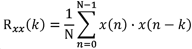
에 의해 근사된다.Approximated by
여기에서 k는 검출될 특성 주파수이고, n은 샘플이고, N은 상관계수 창에 의해 사용되는 샘플의 개수이다. 상관관계 분석에 의해 검출 가능한 최고 주파수는 시스템의 샘플링 주파수 ![]()
![]()
![]()
![]()
상관관계 분석은 지연 시간이 특성 주파수에 매칭할 때마다 상관계수가 가장 커지므로 지연 분석이 된다. 입력 신호는, 입력 신호의 음성 포락선이 음성 포락선 필터 블록(83)에 의해 추출되는, 유성음-음성 검출기(81)의 입력으로 들어가고, 음성 포락선 신호 내의 특성 음성 주파수들의 상하 주파수들이 필터링되는, 즉 대략 50 Hz 미만 주파수들 및 1 kHz 초과 주파수들이 필터링되는 포락선 대역 통과 필터 블록(84)의 입력으로 들어간다. 따라서 주파수 상관관계 계산 블록(85)은 특성 주파수 룩업 테이블(86) 내에 저장된 미리 결정된 포락선 주파수들 세트에 대해 검출된 포락선 주파수들을 비교함으로써 대역 통과 필터(84)로부터 출력 신호의 상관관계 분석을 수행하고, 그것의 출력으로서 상관관계 측정을 생성한다.The correlation analysis is a delay analysis because the correlation coefficient is the largest each time the delay time matches the characteristic frequency. The input signal enters the input of the voiced-
특성 주파수 룩업 테이블(84)은, 표 1에 나타난 세트와 유사하게, 한 세트의 쌍을 이룬, 특성 음성 포락선 주파수(Hz 단위)를 포함한다.The characteristic frequency lookup table 84 includes a set of paired characteristic speech envelope frequencies (in Hz), similar to the set shown in Table 1.

표 1. 쌍을 이룬, 특성 음성 포락선 주파수들.Table 1. Paired, characteristic voice envelope frequencies.
표 1의 상단 행은 상관관계 음성 포락선 주파수를 나타내고, 표 1의 하단 행은 대응하는 두 배 또는 절반의 상관관계 음성 포락선 주파수를 나타낸다. 상관관계 분석에서 상대적으로 적은 이산 주파수 테이블을 사용하는 이유는 테이블 크기, 검출 속도, 운영 안정성 및 충분한 정밀도 간의 절충을 하기 위한 의도이다. 상관관계 분석을 수행하는 목적은 우세한 화자(speaker)의 신호 존재를 검출하기 위함이기 때문에, 정확한 주파수는 필요하지 않으며, 따라서 상관관계 분석의 결과는 검출된 주파수들의 세트이다.The top row of Table 1 represents the correlated voice envelope frequencies, and the bottom row of Table 1 represents the corresponding double or half correlated voice envelope frequencies. The reason for using a relatively small discrete frequency table in correlation analysis is to make a tradeoff between table size, detection speed, operational stability and sufficient precision. Since the purpose of performing the correlation analysis is to detect the presence of the signal of the dominant speaker, the exact frequency is not necessary, so the result of the correlation analysis is a set of detected frequencies.
만약 단일 화자로부터 비롯된 순수한, 유성음의 음성 신호가 입력 신호로서 제시된다면, 적은 특성 포락선 주파수들만이 일정한 시점의 순간에서 입력 신호 내에 우위를 차지할 것이다. 만약 유성음 음성 신호가 부분적으로 잡음에 의해 가려진다면, 더 이상 그러하지 않을 것이다. 그러나, 만약 동일한 특성 포락선 주파수가 셋 또는 그 이상의 주파수 대역 내에서 발견된다면, 주파수 상관관계 계산 블록(85)에 의해서 유성음 음성이 여전히 충분한 정확도로 결정될 수 있을 것이다. If a pure, voiced voice signal from a single speaker is presented as the input signal, only a few characteristic envelope frequencies will prevail in the input signal at any given moment. If the voiced voice signal is partially obscured by noise, it will no longer be. However, if the same characteristic envelope frequencies are found within three or more frequency bands, the voiced speech may still be determined with sufficient accuracy by frequency
주파수 상관관계 계산 블록(85)은 음성 주파수 카운트 블록(87)의 입력으로 들어가는 출력 신호를 생성한다. 이 입력 신호는 상관관계 분석에 의해 발견되는 하나 이상의 주파수들로 구성된다. 음성 주파수 카운트 블록(87)은 입력 신호 내에서 특성 음성 포락선 주파수들의 발생을 카운트한다. 만약 특성 음성 포락선 주파수가 발견되지 않는다면, 입력 신호는 잡음으로 간주된다. 만약 하나의 특성 음성 포락선 주파수, 예를 들어, 100 Hz 또는 그것의 대응 고조파, 즉 200 Hz가 셋 이상의 주파수 대역 내에서 검출되면, 그 신호는 한 명의 화자로부터 발신되는 유성음 음성으로 간주된다. 그러나, 만약, 예를 들어 100 Hz와 167 Hz와 같은, 둘 이상의 상이한 기본 주파수가 검출되면, 유성음 음성은 아마도 둘 이상의 화자로부터 발신되는 것이다. 또한 이 상황은 프로세스에 의해 잡음으로 간주된다. The frequency
음성 주파수 카운트 블록(87)에 의해 구해지는 상관된, 특성 포락선 주파수의 수는 유성음-음성 주파수 검출 블록(88)으로의 입력으로서 사용되고, 여기에서 단일의 유성음 음성 신호의 우위의 정도는 상이한 포락선 주파수 쌍의 수를 상호 비교하여 결정된다. 만약 적어도 하나의 음성 주파수가 검출되고, 그것의 레벨이 입력 신호의 포락선 레벨보다 상당히 크다면, 유성음 음성이 시스템에 의해 검출되고, 유성음 음성 주파수 검출 블록(88)은 유성음-음성 확률 블록(89)으로의 입력 신호로서 유성음-음성 검출 값을 출력한다. 유성음-음성 확률 블록(89)에서, 유성음 음성 확률 값은 유성음-음성 주파수 검출 블록(88)에 의해서 결정된 유성음-음성 검출 값으로부터 파생된다. 유성음-음성 확률 값은 유성음-음성 검출기(81)로부터의 유성음-음성 확률 레벨 출력 신호로서 사용된다.The number of correlated, characteristic envelope frequencies obtained by the voice
마찰음, 치찰음, 파열음과 같은 무성음 음성 신호들은 임의의 잘 정의된 주파수가 없는 매우 짧은 파열음으로 간주되나, 높은 주파수 성분을 많이 가진다. 디지털 도메인에서 무성음 음성 신호의 존재를 검출하기 위한 비용-효율적이고 신뢰할 수 있는 방법은 영점 교차 검출기를 이용하는 것으로서, 이는 임펄스의 수를 카운트하고, 예컨대 0.1 초와 같이 미리 결정된 시간 구간 동안 입력 신호 내의 영점 교차 발생 횟수를 카운트하고 영점 라인을 교차하는 신호들의 횟수와 예컨대 5 초와 같이 한 구간 동안 축적된 평균 영점 교차 횟수를 비교하는 카운터와 결합하여, 신호 간의 부호(sign)가 바뀔 때마다 짧은 임펄스를 제공한다. 만약 유성음 음성이 최근, 즉 최종 3 초 내에 발생하였고, 영점 교차의 수가 평균 영점 교차 횟수보다 크다면, 무성음 음성이 입력 신호 내에 존재한다.Unvoiced speech signals such as rubbing, sibilant, and bursting sounds are considered very short bursting sounds without any well-defined frequency, but have many high frequency components. A cost-effective and reliable way to detect the presence of an unvoiced speech signal in the digital domain is to use a zero crossing detector, which counts the number of impulses and zeros in the input signal for a predetermined time period, for example 0.1 seconds. Combined with a counter that counts the number of crossings and compares the number of signals crossing the zero line with the average number of zero crossings accumulated over one interval, for example, 5 seconds, a short impulse is generated each time the sign between signals changes. to provide. If voiced voice has occurred recently, i.e. within the last 3 seconds, and the number of zero crossings is greater than the average number of zero crossings, an unvoiced voice exists in the input signal.
입력 신호는 또한 음성 검출기(26)의 무성음-음성 검출기(82)의 입력, 저-레벨 잡음 식별기(91)의 입력으로 들어간다. 저-레벨 잡음 식별기(91)는 무성음-음성 검출기(82)로 하여금 무성음-음성 신호로서 검출되는 것으로부터 배경 잡음을 배제할 수 있도록 하기 위해서, 특정 볼륨 임계값 아래의 신호는 거부한다. 입력 신호가 저-레벨 잡음 식별기(91)의 임계값보다 큰 것으로 간주될 때마다, 그것은 영점 교차 검출기(92)의 입력으로 들어간다.The input signal also enters the input of the unvoiced-
영점 교차 검출기(92)는 입력 신호의 신호 레벨이 영점을 교차할 때마다 검출하며, ![]()
![]()
유성음-음성 검출기(81)로부터의 출력 신호는 유성음-음성 확률 레벨을 반송하고 있는 직접 출력과 유성음-음성 식별기(97)의 입력으로 나누어진다. 유성음-음성 식별기(97)는 유성음-음성 검출기(81)로부터의 유성음-음성 확률 레벨이 제 1 미리 결정된 레벨보다 클 때마다 HIGH 논리 신호를 생성하고, 유성음-음성 검출기(81)로부터의 음성 확률 레벨이 제 1 미리 결정된 레벨보다 아래로 떨어질 때마다 LOW 논리 신호를 생성한다.The output signal from the voiced-
무성음-음성 검출기(82)로부터의 출력 신호는 무성음-음성 레벨을 반송하고 있는 직접 출력과 무성음-음성 식별기(96)의 제 1 입력으로 나누어진다. 유성음 음성 검출기(81)로부터의 분리된 신호는 무성음-음성 식별기(96)의 제 2 입력으로 들어간다. 이 신호는 유성음-음성이 예컨대 0.5 초와 같이 미리 결정된 주기 내에서 검출될 때마다 인에이블될 수 있다. 무성음-음성 식별기(96)는 무성음-음성 검출기(82)로부터의 무성음-음성 레벨이 제 2 미리 결정된 레벨보다 클 때마다 HIGH 논리 신호를 생성하고, 무성음-음성 검출기(82)로부터의 음성 레벨이 제 2 미리 결정된 레벨보다 아래로 떨어질 때마다 LOW 논리 신호를 생성한다.The output signal from unvoiced-
OR-게이트(98)는 무성음-음성 식별기(96) 및 유성음-음성 식별기(97)로부터의 각각의 논리 출력 신호를 두 개의 입력 신호로 받아들이고, 보청기 회로의 다른 부분에 의해서 이용하기 위한 논리 음성 플래그를 생성한다. OR-게이트(98)에 의해 생성된 음성 플래그는 유성음-음성 확률 레벨 또는 무성음-음성 레벨 중 하나가 그들 각각의 미리 결정된 레벨보다 크면 논리 신호 HIGH이고, 유성음-음성 확률 레벨 및 무성음-음성 레벨 둘 다 그들 각각의 미리 결정된 레벨보다 작으면 논리 신호 LOW이다. 따라서, OR-게이트(98)에 의해 생성된 음성 플래그는 음성이 입력 신호에 나타나는지 여부를 표시한다.OR-gate 98 accepts each logical output signal from unvoiced-
각각의 믹서(23, 24)들로 구현되어 본 발명에 사용되는 복합 믹서(70) 실시예의 블록 도식이 도 6에 도시된다. 복합 믹서의 목적은 희망하는 주파수 범위에서 원치않는 상측파대를 동시에 생성하지 않고 입력 신호의 하측파대의 주파수-이동된 버전을 생성하는 것으로서, 이에 따라 원치않는 상측파대를 제거하기 위한 역할을 하는 부가적인 저역 통과 필터의 필요가 없어진다. 복합 믹서(70)는 힐버트 변환기(71), 위상 축적기(72), 코사인 함수 블록(73), 사인 함수 블록(74), 제 1 곱셈기 노드(75), 제 2 곱셈기 노드(76), 합산기(77)를 포함한다. 복합 믹서(70)의 목적은 소스 신호 X를 소스 주파수 대역으로부터 타겟 주파수 대역으로 전위된 주파수 W와의 복소수 곱셈에 의해서 실제 전위를 수행하기 위함이고, 그 결과는 주파수-전위된 신호 y가 된다.A block diagram of a
전위될 신호는 복합 믹서(70)의 힐버트 변환기(71)로 입력 신호 X로서 들어가고, 이는 주파수-전위될 주파수들의 소스 대역을 나타낸다. 힐버트 변환기(71)는신호의 실수부 xre 및 신호의 실수부 xre 에 대해 -90°위상 이동된, 신호의 허수부 xim를 출력한다. 신호의 실수부 xre 는 제 1 곱셈기 노드(75)로 들어가고, 허수부 xim는 제 2 곱셈기 노드(76)으로 들어간다.The signal to be transposed enters the
전위 주파수 W는 위상 신호 ![]()
![]()
![]()
![]()
![]()
![]()
![]()
![]()
![]()
![]()
복합 믹서(70)의 합산기(77)에서, 위상 신호 ![]()
![]()
![]()
![]()
전위된 신호 내의 제 1 고조파 주파수가 항상 비전위된 신호의 제 2 고조파 주파수와 일치하도록 보장하기 위해서, 도 4에서 제 1 고조파 주파수 및 제 2 고조파 주파수는 둘 다 주파수 전위기(20)의 주파수 추적기(22)에 의해 검출되어야 한다. 제 1 고조파 주파수 및 제 2 고조파 주파수 간의 상호 주파수 관계는 제 1 고조파 주파수에 기반한 임의의 전위가 수행되기 이전에 입증되어야 한다. 짝수 고조파의 주파수는 항상 N 옥타브 아래의 대응하는 고조파 주파수의 N 배가 되기 때문에, 두 개의 고조파 주파수들이 함께 세트가 되는지를 결정하기 위한 열쇠(key)는 두 개의 노치 필터를 이용하는 것으로, 하나는 소스 대역 내에서 고조파를 검출하기 위한 것이고, 하나는 타겟 대역 내에서 대응하는 고조파를 검출하기 위한 것이며, 검출된 고조파 주파수들 간의 관계는 일정하게 유지된다. 이것은 바람직하게, 최신 기술의 디지털 신호 프로세서인, 디지털 보청기에 의해서 실행되는 적절한 알고리즘에 구현된다. 이러한 알고리즘은 이하에서 더 상세히 설명된다,In order to ensure that the first harmonic frequency in the displaced signal always coincides with the second harmonic frequency of the unpotentialized signal, both the first harmonic frequency and the second harmonic frequency in FIG. 4 are the frequency trackers of the
노치 필터는 바람직하게는 이하의 일반 전달 함수를 갖는 2차 IIR 필터로서 디지털 도메인에서 구현된다.The notch filter is preferably implemented in the digital domain as a second order IIR filter with the following general transfer function.

여기에서 c는 노치 상수이고 r은 필터의 극 반지름이다(0 < r < 1). 노치 상수 c는 라디안 단위의 주파수 w의 함수로서 표현될 수 있고, 따라서 Where c is the notch constant and r is the pole radius of the filter (0 <r <1). Notch constant c can be expressed as a function of frequency w in radians, thus
![]()
![]()
노치 필터의 주파수를 자유롭게 변할 수 있도록 하기 위해, 다양한 접근법이 종래 기술에서 알려져 있다. 본 발명의 목적을 위해 충분히 정확한 것으로 간주되는, 단순하지만, 효과적인 방법은, 간이 그래디언트 하강법(simplified gradient descent method)으로 알려진 근사 방법이다. 이러한 방법은 노치 필터 전달 함수 그래디언트의 근사를 필요로 하고, 이는 전달 함수 H(z)의 분자인 D(z)를 c에 대해 미분함으로서 구할 수 있고, 필터 전달 함수의 그래디언트는 따라서 다음과 같이 구한다.In order to be able to freely vary the frequency of the notch filter, various approaches are known in the art. A simple but effective method, which is considered sufficiently accurate for the purposes of the present invention, is an approximation method known as the simplified gradient descent method. This method requires an approximation of the notch filter transfer function gradient, which can be found by differentiating D (z), a molecule of transfer function H (z), for c, and the gradient of the filter transfer function is therefore .
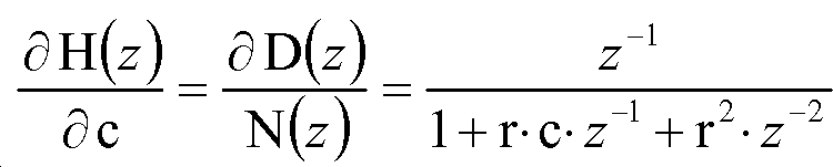
그렇다면, 노치 필터의 노치 주파수는 변환된 상수 c로서 근사화된 그래디언트를 노치 필터에 적용함에 의해 직접적으로 결정될 수 있다. If so, the notch frequency of the notch filter can be determined directly by applying the gradient approximated as the transformed constant c to the notch filter.
검출된 소스 주파수가 기본 주파수의 짝수 고조파인 것을 입증하기 위해서, 검출된 소스 주파수 및 검출된 타겟 주파수의 비는 전부 양의 상수 N 인 것으로, 즉 검출된 소스 주파수가 검출된 타겟 주파수의 N 배가 되는 것으로 추정된다. 이러한 가정에 기초하여, 소스 노치 필터의 노치 상수는 다음과 같이 표현될 수 있고,In order to prove that the detected source frequency is an even harmonic of the fundamental frequency, the ratio of the detected source frequency and the detected target frequency are all positive constants N, that is, the detected source frequency is N times the detected target frequency. It is estimated. Based on this assumption, the notch constant of the source notch filter can be expressed as
![]()
![]()
타겟 노치 필터의 노치 상수는 따라서 다음이 된다.The notch constant of the target notch filter is thus:
![]()
![]()
소스 주파수 및 타겟 주파수 간의 한 옥타브 고조파 관계, 즉 N = 2가 되기 위해서, cs 및 ct의 관계는 삼각함수 공식들을 사용하여 구해진다.In order to be one octave harmonic relationship between the source frequency and the target frequency, that is, N = 2, c s The relationship of and c t is obtained using trigonometric formulas.
![]()
![]()
따라서, 소스 노치 필터 그래디언트는 cs를 대입하고, 전술한 방법으로 ct에 대해 미분함에 의해서 구할 수 있다.Thus, the source notch filter gradient can be found by substituting c s and differentiating for c t in the manner described above.

따라서 두 개의 노치 필터의 결합된 간이 그래디언트 G(z)는 그들 각자의 간이 그래디언트의 가중된 합이 되고 다음과 같이 표현될 수 있다.Therefore, the combined simplified gradient G (z) of the two notch filters becomes the weighted sum of their respective simplified gradients and can be expressed as follows.

결합된 간이 그래디언트 G(z)으로서 두 개의 노치 필터의 그래디언트 가중된 합을 사용함으로써, 소스 대역의 전위를 위해 생성된 주파수가 전위된 소스 대역의 우세 주파수를 타겟 대역 내의 우세 주파수에 항상 정확하게 일치하게 하는 것을 보장한다. By using the gradient weighted sum of the two notch filters as the combined simplified gradient G (z), the frequency generated for the source band potential always matches the predominant frequency of the displaced source band exactly with the predominant frequency in the target band. To ensure that
결합된 간이 그래디언트 G(z)는 소스 대역 및 타겟 대역 내 각각, 입력 신호의 국소적 최소값(local minima)들을 구하기 위해서 전위기에 의해 사용된다. 만약 우세 주파수가 소스 주파수 대역 내에 존재한다면, G(z)의 제 1 개별 그래디언트 식은 우세 소스 주파수에서 국소적 최소값을 가지게 되고, 만약 대응하는 우세 주파수가 타겟 주파수 대역 내에 존재한다면, G(z)의 제 2 개별 그래디언트 식은 우세 타겟 주파수에서 국소적 최소값을 가지게 된다. 따라서, 만약 소스 주파수 및 타겟 주파수 모두 국소적 최소값이 되게 한다면, 소스 대역이 전위된다.The combined simplified gradient G (z) is used by the potentiometer to find the local minimas of the input signal, respectively, in the source band and the target band. If the dominant frequency is within the source frequency band, the first discrete gradient equation of G (z) has a local minimum at the dominant source frequency, and if the corresponding dominant frequency is within the target frequency band, The second discrete gradient equation will have a local minimum at the dominant target frequency. Thus, if both the source frequency and the target frequency are local minimums, the source band is displaced.
본 발명의 실시예에서, 전위 알고리즘을 수행하는 신호 프로세서는 32 kHz의 샘플링 레이트로 동작한다. 전술한 바에서 설명된 그래디언트-하강-기반의 알고리즘을 사용하여, 전위기(20)의 주파수 추적기(22)는, 통상의 추적 속도 2 - 10 Hz/샘플로 충분한 정밀성을 유지하면서, 60 Hz/샘플의 속도까지 입력 신호의 우세 주파수를 추적할 수 있다. In an embodiment of the invention, the signal processor performing the potential algorithm operates at a sampling rate of 32 kHz. Using the gradient-falling-based algorithm described above, the
하나의 전위기로 가능한 것보다 더 높은 고조파 주파수 대역을 전위하기 위하여, 고조파 소스 주파수보다 2 옥타브 아래의 즉, N=3이 되는 고조파 타겟 주파수를 활용하는 제 2 전위기 또한 동일한 원리를 적용하여 쉽게 이용될 수 있다. 이러한 제 2 전위기는 제 2 소스 노치 필터 및 제 2 타겟 노치 필터를 가지며, 팩터 4 만큼, 즉 2 옥타브만큼 전위된 것에 대응하는 더 높은 주파수 스펙트럼 내의 소스 대역 상에서 별개의 동작을 수행한다. 이 경우, N=3인 소스 노치 필터 그래디언트는 다음과 같다.In order to displace higher harmonic frequency bands than is possible with one potentiometer, a second potentiometer that utilizes

이런 식으로 둘 이상의 노치 필터들의 출력은 단일 노치 출력 및 적용될 단일 그래디언트를 형성하기 위해 결합될 수 있다. 유사하게, 더 높은 주파수 대역, 즉 더 높은 수의 N의 전위를 위한 소스 노치 필터 그래디언트는 타겟 주파수와 관련된 더 높은 고조파를 프로세싱하기 위해 본 발명에 의해서 이용될 수 있다. In this way the outputs of two or more notch filters can be combined to form a single notch output and a single gradient to be applied. Similarly, source notch filter gradients for higher frequency bands, ie higher numbers of N potentials, can be used by the present invention to process higher harmonics associated with the target frequency.
도 7에서 본 발명에 따른 주파수 추적기(22)의 실시예가 도시된다. 주파수 추적기(22)는 소스 노치 필터 블록(31), 타겟 노치 필터 블록(32), 합산기(33), 그래디언트 가중치 생성기 블록(34), 노치 적용 블록(35), 상수 컨버터 블록(36) 및 출력 위상 컨버터 블록(37)을 포함한다. 주파수 추적기(22)의 목적은 소스 대역 및 타겟 대역 각각에서 대응하는, 우세 주파수를 검출하는 것이고, 이는 전위 프로세스의 제어를 위한 목적이다.In figure 7 an embodiment of a
소스 노치 필터(31)는 소스 주파수 대역 신호(SRC) 및 소스 상수 신호(CS)를 그것의 입력 신호로서 받아들이고, 소스 노치 신호(NS) 및 소스 노치 그래디언트 신호(GS)를 생성한다. 소스 노치 신호(NS)는 합산기(33)에서 타겟 노치 주파수 신호(NT)에 부가되고, 노치 신호(N)를 생성한다. 소스 노치 그래디언트 신호(GS)는 그래디언트 가중 생성기 블록(34)으로의 제 1 입력 신호로서 사용된다. 타겟 노치 필터 블록(32)은 타겟 주파수 대역 신호(TGT) 및 타겟 상수 신호(CT)를 그것의 입력 신호로서 받아들이고 타겟 노치 신호(NT) 및 타겟 노치 그래디언트 신호(GT)를 생성한다. 타겟 노치 신호(NT)는 합산기(33)에서 소스 노치 신호(NS)에 부가되고, 전술한 바와 같이, 노치 신호(N)를 생성한다. 타겟 노치 그래디언트 신호(GT)는 그래디언트 가중치 생성기 블록(34)으로의 제 2 입력 신호로서 사용된다. The
그래디언트 가중치 생성기 블록(34)은 타겟 상수 신호(CT)로부터 그래디언트 신호(G)를 생성하고, 노치 그래디언트 신호 GS 및 GT를 소스 노치 필터(31) 및 타겟 노치 필터(32)로부터 각각 생성한다. 합산기(33)로부터의 노치 신호(N)는 노치 적용 블록(35)의 제 1 입력으로서 사용되고, 그래디언트 가중치 생성기 블록(34)으로부터의 그래디언트 신호(G)는 노치 적용 블록(35)의 제 2 입력으로서 사용되며, 이는 타겟 가중 신호(WT)를 생성하기 위함이다. 노치 적용 블록(35)으로부터의 타겟 가중 신호(WT)는 상수 신호 CS 및 CT를 각각 생성하기 위한 상수 컨버터 블록(36)으로의 입력 신호로서, 그리고 출력 위상 컨버터 블록(37)으로의 입력 신호로서 모두 사용된다.The gradient
출력 위상 컨버터 블록(37)은 소스 주파수 대역을 타겟 주파수 대역으로 전위하기 위해서, 가중된 믹서 제어 주파수 신호(WM)를 믹서(미도시)를 위해 생성한다. 가중된 믹서 제어 주파수 신호(WM)는 도 6에서 전위 주파수 입력(W)에 대응하고, 아래에 설명될 방식으로, 그 원점으로부터 소스 주파수 대역이 얼마나 멀리 전위될지를 직접 결정한다. The output
주파수 추적기(22)는 소스 주파수 대역 및 타겟 주파수 대역을 우세 주파수들에 대해 분석하는 것과 수행할 주파수 이동의 크기를 계산하기 위해서, 검출된 소스 주파수 대역 및 타겟 주파수 대역 내의 우세 주파수들 간의 관계를 사용하는 것에 의해, 전위될 소스 주파수 대역에 대한 최적의 주파수 이동을 결정한다. 본 발명에 의해 이러한 분석이 수행되는 방법은 이하에서 더 상세하게 설명된다.The
주파수 추적기(22)가 본 발명에 따른 전위기를 제어하기 위한 주파수를 생성하도록 하기 위해서, 소스 노치 필터 블록(31)에 의해 검출된 소스 노치 주파수는 기본 주파수의 짝수 고조파 주파수로 추정되고, 타겟 노치 필터 블록(32)에 의해 검출된 타겟 노치 주파수는 소스 주파수 대역의 짝수의 고조파에 대해 고정 관계를 갖는 고조파 주파수로 추정되고, 따라서 소스 노치 필터 블록(31) 및 타겟 노치 필터 블록(32)은 병렬로 작업해야 하고, 두 개의 노치 필터에 의해 검출된 두 개의 노치 주파수들 간의 고정 관계의 존재를 활용한다. 이것은 결합된 그래디언트가 주파수 추적기(22)에 이용가능함이 분명하다는 것을 의미한다. 결합된 그래디언트 G(z)는 전술한 것에서 설명한 알고리즘에 따라 소스 노치 필터(31) 및 타겟 노치 필터(32)의 그래디언트의 합으로서 표현될 수 있다. 따라서,In order for the
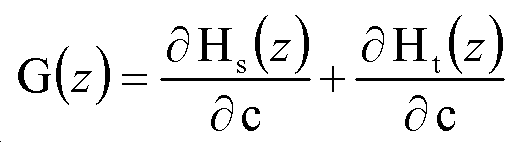
여기에서 Hs(z)는 소스 노치 필터 블록(31)의 전달 함수이고, Ht(z)는 타겟 노치 필터 블록(32)의 전달 함수이다.Where H s (z) is the transfer function of the source
도 8은 어떻게 타겟 주파수의 고조파 추적의 문제가 본 발명에 따른 주파수 전위기에 의해 올바르게 해결되는지를 도시하는 주파수 그래프이다. 도 8의 주파수 스펙트럼에서는 도 2에 도시된 일련의 고조파 주파수들과 유사한 식으로 본 발명에 따른 보청기의 입력 신호의 일련의 고조파 주파수들이 도시된다. 도 2 및 도 3과 같이, 일련의 고조파 주파수에 대응하는 기본 주파수는 도시되지 않는다. 전위기 알고리즘은 제 11 고조파 및 제 12 고조파 사이에서 자유롭게 선택하는 것이 허용되지 않지만, 대신 전위를 위한 기준으로서 소스 대역 내의 짝수 고조파 주파수를 선택하는 것이 강요된다. 앞서 도시된 것처럼, 모든 짝수 고조파 주파수들은 짝수 고조파 주파수의 절반의 주파수인, 대응하는 고조파 주파수를 갖는다. 따라서, 이 경우, 제 12 고조파 주파수는 주파수 전위기에 의해 전위를 위한 기준으로 선택된다. 제 12 고조파 주파수는 타겟 대역(TB) 상에서 TD2 거리만큼 한 옥타브 아래로 주파수가 전위될 때 제 6 고조파 주파수와 일치할 것이다. 마찬가지로, 도 8에 도시된 타겟 대역(TB) 내에서, 제 13 고조파 주파수는 제 7 고조파 주파수와 일치할 것이고 제 11 고조파 주파수는 제 5 고조파 주파수와 일치할 것이다. 8 is a frequency graph showing how the problem of harmonic tracking of a target frequency is correctly solved by a frequency potentiometer in accordance with the present invention. In the frequency spectrum of FIG. 8 there is shown a series of harmonic frequencies of the input signal of the hearing aid according to the invention in a manner similar to the series of harmonic frequencies shown in FIG. 2 and 3, the fundamental frequency corresponding to the series of harmonic frequencies is not shown. The potentiometer algorithm is not allowed to freely select between the 11th and 12th harmonics, but instead is forced to select an even harmonic frequency in the source band as a reference for the potential. As shown above, all even harmonic frequencies have a corresponding harmonic frequency, which is half the frequency of the even harmonic frequency. Thus, in this case, the twelfth harmonic frequency is selected by the frequency potentiometer as the reference for the potential. The twelfth harmonic frequency will coincide with the sixth harmonic frequency when the frequency is displaced one octave down by the TD 2 distance on the target band TB. Similarly, within the target band TB shown in FIG. 8, the thirteenth harmonic frequency will coincide with the seventh harmonic frequency and the eleventh harmonic frequency will coincide with the fifth harmonic frequency.
이 결과는 본 발명에 의해, 소스 대역(SB)에서 검출된 제 12 고조파 주파수 및 타겟 대역(TB)에서 검출된 대응하는 제 6 고조파 주파수를 분석함에 의해서 전위 이전에 달성되고, 이는 두 개의 주파수들 간의 고조파 관계가 존재하는 것을 증명하기 위함이다. 따라서, 더 적합한 전위 주파수 거리(TD2 )가 결정되고, 전위된 신호의 전위된 제 10, 11, 12, 13, 및 제 14 고조파 주파수들은 도 8에 더 가는(thinner) 윤곽으로 도시되며, 이제 전위된 소스 대역 신호가 타겟 대역 상으로 겹쳐질 때, 각각 타겟 대역(TB) 내의 대응하는 제 4, 5, 6, 7, 및 제 8 고조파 주파수들과 일치하게 되고, 사용자에게 좀 더 쾌적하고 듣기 좋은 소리가 들리게 하는 결과를 가져온다.This result is achieved by the present invention prior to potential by analyzing the twelfth harmonic frequency detected in the source band SB and the corresponding sixth harmonic frequency detected in the target band TB, which is two frequencies. This is to prove that the harmonic relationship between them exists. Thus, more and it is suitable potential frequency distance (TD 2) crystal, the first 10, 11, 12, 13, and 14th harmonic frequency potential of the potential signals are shown in a more thin (thinner) outline in Figure 8, is now When the sourced source band signal is superimposed on the target band, the corresponding fourth, fifth, sixth, seventh and eighth harmonic frequencies in the target band TB are respectively matched, making the user more pleasant and listening. This results in a good sound.
만약 소스 대역(SB) 내의 예컨대, 제 14 고조파 주파수가 제 12 고조파 주파수 대신에 전위를 위한 기준으로 선택된다면, 본 발명에 따른 전위기에 의해 전위될 때 타겟 대역(TB) 내의 제 7 고조파 주파수와 일치하게 되고, 전위된 소스 대역(SB)으로부터 이웃하는 고조파 주파수들은 유사한 방식으로 각각 그들의 대응하는 타겟 대역(TB) 내의 주파수들과 일치하게 된다. 소스 대역 주파수가 결합된 주파수 추적기에 의해서 기본 주파수의 짝수의 고조파 주파수임이 밝혀지는 한, 본 발명에 따른 전위기는 검출된, 짝수 고조파 주파수(the detected, even harmonic frequency) 주위의 주파수 대역을 거기에서 나타난 검출된 고조파 주파수와 일치하도록 더 낮은 주파수 대역으로 하향 전위할 수 있다.If, for example, the fourteenth harmonic frequency in the source band SB is selected as a reference for the potential instead of the twelfth harmonic frequency, then the seventh harmonic frequency in the target band TB when displaced by the potentiometer according to the present invention, Matching, neighboring harmonic frequencies from the displaced source band SB each coincide with frequencies in their corresponding target band TB in a similar manner. As long as the source band frequency is found to be an even harmonic frequency of the fundamental frequency by means of a combined frequency tracker, the potentiometer according to the invention has a frequency band around the detected, even harmonic frequency detected therein. It may be potential to shift down into the lower frequency band to match the detected harmonic frequency shown.
도 9는 본 발명에 따른 주파수 전위기(20)를 포함하는 보청기(50)를 나타내는 블록 도식이다. 보청기(50)는 마이크로폰(51), 대역 분할 필터(52), 입력 노드(53), 음성 검출기(26), 음성 인핸서(27), 주파수 전위기(20), 출력 노드(54), 압축기(55), 출력 변환기(56)를 포함한다. 명확성을 위해, 증폭기, 프로그램 저장 수단, 아날로그-디지털 컨버터, 디지털-아날로그 컨버터 및 보청기의 주파수-의존 처방 증폭 수단은 도 9에 도시되지 않는다.9 is a block diagram showing a
사용하는 동안, 음향 신호는 마이크로폰(51)에 의해서 포착되고(picked up) 보청기(50)에 의해서 증폭을 위해 적합한 전기적 신호로 전환된다. 전기적 신호는 대역 분할 필터(52)에서 복수의 주파수 대역으로 분리되고, 결과적으로 대역-분할 신호는 입력 노드(53)를 통해 주파수 전위기(20)로 들어온다. 주파수 전위기(20)에서, 신호는 도 4와 함께 나타난 방식으로 프로세싱된다.During use, the acoustic signal is picked up by the
대역 분할 필터(52)로부터의 출력 신호는 또한, (전술한 도 4의 맥락에서 설명된) 주파수 전위기 블록(20)을 위해 의도되는 세 개의 제어 신호(VS, USF 및 SF) 생성 및 음성 인핸서 블록(27)을 위해 의도되는 제 4 제어 신호의 생성을 위해, 음성 검출기(26)의 입력으로 들어간다. 음성 인핸서 블록(27)은 만약 광대역 잡음 레벨이 미리 결정된 제한보다 크다면 압축기(55)의 이득 값을 제어함으로써, 음성이 검출되는 주파수 대역 내의 신호 레벨을 증가시키는 작업을 수행한다. 만약 특정 주파수 대역에서 음성이 검출되고 잡음이 음성보다 우세하지 않다면, 음성 인핸서 블록(27)은 음성 인핸스 이득 값을 계산하고 각각의 주파수 대역 내의 신호에 적용되는 이득에 음성 인핸스 이득 값을 적용하기 위해서, 음성 검출기(26)로부터의 제어 신호를 사용한다. 이것은 음성 양해도 향상을 위해 음성 신호를 포함하는 주파수 대역이 광대역 잡음 위로 증폭되는 것이 가능하게 한다. The output signal from band split
주파수 전위기(20)로부터의 출력 신호는 출력 노드(54)를 통해 압축기(55)의 입력으로 들어간다. 압축기(55)의 목적은 보청기의 처방에 따라 결합된 출력 신호의 다이나믹 레인지(dynamic range)를 감축하는 것이고, 이는 보청기 사용자의, 소위 상위 안락 레벨(upper comfort limit; UCL)을 초과하는 큰(loud) 오디오 신호의 위험을 감소시키고, 부드러운(soft) 오디오 신호들은 보청기 사용자의 청취 임계 레벨(hearing threshold limit; HTL)을 초과하기에 충분하도록 증폭되기 위함이다. 압축은 신호의 주파수-전위된 부분이 보청기 처방에 따라 또한 압축되는 것을 보장하기 위해서 주파수-전위 뒤에 수행된다.The output signal from the
압축기(55)로부터의 출력 신호는 보청기(50)로부터의 출력 신호의 음향 재생을 위한 출력 변환기(56)를 구동하기 위해, 증폭되고 조절된다(증폭 및 조절을 위한 수단은 미도시). 신호는, 주파수-전위된 부분이 청각 장애인 사용자에게 지각 가능하게 되도록 하고 그렇지 않으면 그 부분의 주파수 범위를 지각하는 것이 불가능한 이러한 방식으로, 입력 신호의 비전위된 부분과 그 위에 겹쳐 놓은 입력 신호의 주파수-전위된 부분을 포함한다. 게다가, 입력 신호의 주파수-전위된 부분은 입력 신호의 비전위 부분과 가능한 한 일관되도록 하는 방식으로 청취되도록 한다.
The output signal from the
Claims (14)
상기 보청기는 신호 프로세서를 가지며, 상기 신호 프로세서는
입력 신호를 제 1 주파수 대역 및 제 2 주파수 대역으로 분할하기 위한 수단;
상기 제 1 주파수 대역에서 제 1 특성 주파수를 검출할 수 있는 제 1 주파수 검출기;
상기 제 2 주파수 대역에서 제 2 특성 주파수를 검출할 수 있는 제 2 주파수 검출기;
상기 제 2 주파수 대역의 주파수 범위 안에 속하는 신호를 형성하기 위해 상기 제 1 주파수 대역의 신호를 주파수 간격을 두고 이동(shift)시키기 위한 수단,
상기 제 1 주파수 검출기 및 상기 제 2 주파수 검출기에 의해 제어되는 적어도 하나의 발진기,
상기 제 2 주파수 대역 범위 안에 속하는 주파수-이동된 신호를 생성하기 위해 상기 발진기로부터의 출력 신호를 상기 제 1 주파수 대역에서의 신호와 곱하는 수단,
상기 제 2 주파수 대역 상에 상기 주파수-이동된 신호를 겹치게 하기(superimposing) 위한 수단, 및
상기 주파수-이동된 신호 및 상기 제 2 주파수 대역의 결합 신호를 출력 변환기에 나타내기(present) 위한 수단,
상기 제 1 주파수 및 상기 제 2 주파수 간의 고정 관계를 결정하는 수단에 의해 제어되는 상기 제 1 주파수 대역의 신호를 이동시키기 위한 수단을 포함하는 것인, 보청기.In hearing aids,
The hearing aid has a signal processor, the signal processor
Means for dividing the input signal into a first frequency band and a second frequency band;
A first frequency detector capable of detecting a first characteristic frequency in said first frequency band;
A second frequency detector capable of detecting a second characteristic frequency in said second frequency band;
Means for shifting the signal in the first frequency band at a frequency interval to form a signal that falls within the frequency range of the second frequency band,
At least one oscillator controlled by the first frequency detector and the second frequency detector,
Means for multiplying an output signal from the oscillator with a signal in the first frequency band to produce a frequency-shifted signal that falls within the second frequency band range,
Means for superimposing the frequency-shifted signal on the second frequency band, and
Means for presenting a combined signal of the frequency-shifted signal and the second frequency band to an output converter,
Means for moving a signal in the first frequency band controlled by means for determining a fixed relationship between the first frequency and the second frequency.
상기 입력 신호에서 제 1 주파수를 검출하기 위한 수단은 제 1 노치 그래디언트(notch gradient)를 갖는 제 1 노치 필터이고, 상기 입력 신호에서 제 2 주파수를 검출하기 위한 수단은 제 2 노치 그래디언트를 갖는 제 2 노치 필터인 것인, 보청기.The method of claim 1,
The means for detecting a first frequency in the input signal is a first notch filter having a first notch gradient, and the means for detecting a second frequency in the input signal is a second having a second notch gradient. Hearing aid which is notch filter.
상기 입력 신호에서 상기 제 1 주파수 및 상기 제 2 주파수 간의 고정 관계의 존재를 검출하기 위한 수단은 상기 제 1 노치 그래디언트 및 상기 제 2 노치 그래디언트를 결합함으로써 결합된 그래디언트(combined gradient)를 생성하기 위한 수단을 포함하는 것인, 보청기. The method of claim 1,
Means for detecting the presence of a fixed relationship between the first frequency and the second frequency in the input signal means for generating a combined gradient by combining the first notch gradient and the second notch gradient. To include, hearing aids.
상기 제 1 주파수 대역의 신호를 상기 제 2 주파수 대역으로 이동시키기 위한 수단은 결합된 그래디언트를 생성하기 위한 상기 수단에 의해 제어되는 것인, 보청기. The method of claim 3, wherein
Wherein the means for moving the signal of the first frequency band to the second frequency band is controlled by the means for generating a combined gradient.
상기 입력 신호에서 유성음-음성 신호(a voiced-speech signal)의 존재를 검출하기 위한 수단 및 상기 입력 신호에서 무성음-음성 신호(an unvoiced-speech signal)를 검출하기 위한 수단을 포함하는 것인, 보청기.The method of claim 1,
Means for detecting the presence of a voiced-speech signal in the input signal and means for detecting an unvoiced-speech signal in the input signal .
유성음-음성 신호의 존재를 검출하기 위한 상기 수단은 상기 유성음-음성 신호의 주파수 이동을 디스에이블링(disabling)하기 위한 수단을 포함하는 것인, 보청기.The method of claim 5, wherein
And the means for detecting the presence of a voiced voice-voice signal comprises means for disabling a frequency shift of the voiced voice-voice signal.
무성음-음성 신호의 존재를 검출하기 위한 상기 수단은 상기 무성음-음성 신호의 주파수 이동을 인에이블링(enabling)하기 위한 수단을 포함하는 것인, 보청기.The method of claim 5, wherein
And the means for detecting the presence of an unvoiced-voice signal comprises means for enabling a frequency shift of the unvoiced-voice signal.
유성음-음성 신호를 검출하기 위한 상기 수단은 상기 입력 신호로부터 포락선(envelope) 신호를 추출하기 위한 포락선 필터를 포함하는 것인, 보청기.The method of claim 5, wherein
Wherein said means for detecting a voiced-voice signal comprises an envelope filter for extracting an envelope signal from said input signal.
무성음-음성 신호를 검출하기 위한 상기 수단은 상기 포락선 신호에서 무성음-음성 레벨을 검출하기 위해서 영점 교차율(a zero-crossing rate) 카운터 및 평균 영점 교차율 카운터를 포함하는 것인, 보청기. The method of claim 5, wherein
And the means for detecting an unvoiced-voice signal comprises a zero-crossing rate counter and an average zero crossing rate counter for detecting unvoiced-voice levels in the envelope signal.
입력 신호를 획득하는 단계;
상기 입력 신호에서 제 1 우세 주파수를 검출하는 단계;
상기 입력 신호에서 제 2 우세 주파수를 검출하는 단계;
상기 입력 신호의 제 1 주파수 범위를 상기 입력 신호의 제 2 주파수 범위로 이동하는 단계;
상기 입력 신호의 주파수-이동된 상기 제 1 주파수 범위를 상기 입력 신호로부터 구해진 파라미터 집합에 따라 상기 입력 신호의 상기 제 2 주파수 범위에 겹치게 하는 단계를 포함하고,
상기 제 1 우세 주파수 및 상기 제 2 우세 주파수를 검출하는 단계는 상기 제 1 우세 주파수 및 상기 제 2 우세 주파수 간의 고정 관계의 존재를 결정하는 단계를 포함하고, 상기 제 1 주파수 범위를 이동하는 단계는 상기 제 1 우세 주파수 및 상기 제 2 우세 주파수 간의 고정 관계에 의해 제어되는 것인, 보청기 내에서 가청 주파수들을 이동시키는 방법. In a method of moving audio frequencies in a hearing aid,
Obtaining an input signal;
Detecting a first dominant frequency in the input signal;
Detecting a second dominant frequency in the input signal;
Moving the first frequency range of the input signal to a second frequency range of the input signal;
Overlapping the frequency-shifted first frequency range of the input signal with the second frequency range of the input signal according to a set of parameters obtained from the input signal,
Detecting the first dominant frequency and the second dominant frequency comprises determining a presence of a fixed relationship between the first dominant frequency and the second dominant frequency, wherein moving the first frequency range And controlled by a fixed relationship between the first dominant frequency and the second dominant frequency.
상기 입력 신호에서 제 1 우세 주파수 및 제 2 우세 주파수를 검출하는 상기 단계는 상기 입력 신호로부터 제 1 노치 그래디언트 및 제 2 노치 그래디언트를 유도하는(deriving) 단계를 포함하는 것인, 보청기 내에서 가청 주파수들을 이동시키는 방법. 11. The method of claim 10,
Detecting the first dominant frequency and the second dominant frequency in the input signal comprises deriving a first notch gradient and a second notch gradient from the input signal. How to move them.
상기 입력 신호에서 상기 제 1 우세 주파수 및 상기 제 2 우세 주파수 간의 고정 관계의 존재를 결정하는 상기 단계는, 상기 제 1 노치 그래디언트 및 상기 제 2 노치 그래디언트를 결합된 그래디언트로 결합하는 단계과, 상기 입력 신호의 상기 제 1 주파수 범위를 상기 입력 신호의 상기 제 2 주파수 범위로 이동시키기 위하여 상기 결합된 그래디언트를 사용하는 단계를 포함하는 것인, 보청기 내에서 가청 주파수들을 이동시키는 방법. The method of claim 11,
Determining the presence of a fixed relationship between the first dominant frequency and the second dominant frequency in the input signal comprises: combining the first notch gradient and the second notch gradient into a combined gradient; Using the combined gradient to shift the first frequency range of the input signal to the second frequency range of the input signal.
상기 주파수-이동된 제 1 주파수 범위를 상기 제 2 주파수 범위에 겹치게 하는 상기 단계는 상기 제 1 우세 주파수 및 상기 제 2 우세 주파수 간의 상기 고정 관계의 존재를 상기 주파수-이동된 제 1 주파수 범위의 출력 레벨을 결정하기 위한 파라미터로서 사용하는 것인, 보청기 내에서 가청 주파수들을 이동시키는 방법.11. The method of claim 10,
Overlapping the frequency-shifted first frequency range with the second frequency range is such that the presence of the fixed relationship between the first and second dominant frequencies is output of the frequency-shifted first frequency range. A method of moving audible frequencies within a hearing aid, which is used as a parameter for determining the level.
상기 제 1 우세 주파수 및 상기 제 2 우세 주파수를 검출하는 상기 단계는 상기 입력 신호에서 유성음-음성 신호 및 무성음-음성 신호의 존재를 각각 검출하는 단계, 상기 유성음-음성 신호의 주파수 이동을 인핸스하는(enhancing) 단계, 및 상기 무성음-음성 신호의 주파수 이동을 억제하는(suppressing) 단계를 포함하는 것인, 보청기 내에서 가청 주파수들을 이동시키는 방법.
The method of claim 11,
The detecting of the first dominant frequency and the second dominant frequency may include detecting presence of a voiced voice-voice signal and an unvoiced voice signal, respectively, in the input signal, thereby enhancing the frequency shift of the voiced voice-voice signal ( enhancing), and suppressing frequency shifting of the unvoiced-speech signal.
Applications Claiming Priority (1)
| Application Number | Priority Date | Filing Date | Title |
|---|---|---|---|
| PCT/EP2010/069145 WO2012076044A1 (en) | 2010-12-08 | 2010-12-08 | Hearing aid and a method of improved audio reproduction |
Publications (2)
| Publication Number | Publication Date |
|---|---|
| KR20130072258A true KR20130072258A (en) | 2013-07-01 |
| KR101465379B1 KR101465379B1 (en) | 2014-11-27 |
Family
ID=44269284
Family Applications (1)
| Application Number | Title | Priority Date | Filing Date |
|---|---|---|---|
| KR1020137012290A Active KR101465379B1 (en) | 2010-12-08 | 2010-12-08 | Hearing aid and a method of improved audio reproduction |
Country Status (10)
| Country | Link |
|---|---|
| US (1) | US9111549B2 (en) |
| EP (1) | EP2649813B1 (en) |
| JP (1) | JP5778778B2 (en) |
| KR (1) | KR101465379B1 (en) |
| CN (1) | CN103250209B (en) |
| AU (1) | AU2010365365B2 (en) |
| CA (1) | CA2820761C (en) |
| DK (1) | DK2649813T3 (en) |
| SG (1) | SG191025A1 (en) |
| WO (1) | WO2012076044A1 (en) |
Cited By (1)
| Publication number | Priority date | Publication date | Assignee | Title |
|---|---|---|---|---|
| KR20170136362A (en) * | 2016-06-01 | 2017-12-11 | 삼성전자주식회사 | Electronic device and method for correcting sound signal thereof |
Families Citing this family (35)
| Publication number | Priority date | Publication date | Assignee | Title |
|---|---|---|---|---|
| US10848118B2 (en) | 2004-08-10 | 2020-11-24 | Bongiovi Acoustics Llc | System and method for digital signal processing |
| US8284955B2 (en) | 2006-02-07 | 2012-10-09 | Bongiovi Acoustics Llc | System and method for digital signal processing |
| US11431312B2 (en) | 2004-08-10 | 2022-08-30 | Bongiovi Acoustics Llc | System and method for digital signal processing |
| US10158337B2 (en) | 2004-08-10 | 2018-12-18 | Bongiovi Acoustics Llc | System and method for digital signal processing |
| US10848867B2 (en) | 2006-02-07 | 2020-11-24 | Bongiovi Acoustics Llc | System and method for digital signal processing |
| US11202161B2 (en) | 2006-02-07 | 2021-12-14 | Bongiovi Acoustics Llc | System, method, and apparatus for generating and digitally processing a head related audio transfer function |
| US9185500B2 (en) | 2008-06-02 | 2015-11-10 | Starkey Laboratories, Inc. | Compression of spaced sources for hearing assistance devices |
| US9485589B2 (en) | 2008-06-02 | 2016-11-01 | Starkey Laboratories, Inc. | Enhanced dynamics processing of streaming audio by source separation and remixing |
| US8705751B2 (en) | 2008-06-02 | 2014-04-22 | Starkey Laboratories, Inc. | Compression and mixing for hearing assistance devices |
| SG191025A1 (en) * | 2010-12-08 | 2013-07-31 | Widex As | Hearing aid and a method of improved audio reproduction |
| DE102011006472B4 (en) * | 2011-03-31 | 2013-08-14 | Siemens Medical Instruments Pte. Ltd. | Method for improving speech intelligibility with a hearing aid device and hearing aid device |
| US9185499B2 (en) | 2012-07-06 | 2015-11-10 | Gn Resound A/S | Binaural hearing aid with frequency unmasking |
| US9173041B2 (en) | 2012-05-31 | 2015-10-27 | Purdue Research Foundation | Enhancing perception of frequency-lowered speech |
| WO2013189528A1 (en) | 2012-06-20 | 2013-12-27 | Widex A/S | Method of sound processing in a hearing aid and a hearing aid |
| DK2683179T3 (en) * | 2012-07-06 | 2015-04-20 | Gn Resound As | Hearing aid with frequency masking |
| US9060223B2 (en) | 2013-03-07 | 2015-06-16 | Aphex, Llc | Method and circuitry for processing audio signals |
| TWI576824B (en) * | 2013-05-30 | 2017-04-01 | 元鼎音訊股份有限公司 | Method and computer program product of processing voice segment and hearing aid |
| US9883318B2 (en) | 2013-06-12 | 2018-01-30 | Bongiovi Acoustics Llc | System and method for stereo field enhancement in two-channel audio systems |
| JP6001814B1 (en) | 2013-08-28 | 2016-10-05 | ドルビー ラボラトリーズ ライセンシング コーポレイション | Hybrid waveform coding and parametric coding speech enhancement |
| US20150092967A1 (en) * | 2013-10-01 | 2015-04-02 | Starkey Laboratories, Inc. | System and method for selective harmonic enhancement for hearing assistance devices |
| EP3052008B1 (en) * | 2013-10-01 | 2017-08-30 | Koninklijke Philips N.V. | Improved signal selection for obtaining a remote photoplethysmographic waveform |
| US9906858B2 (en) | 2013-10-22 | 2018-02-27 | Bongiovi Acoustics Llc | System and method for digital signal processing |
| US10820883B2 (en) | 2014-04-16 | 2020-11-03 | Bongiovi Acoustics Llc | Noise reduction assembly for auscultation of a body |
| TWI557729B (en) * | 2015-05-20 | 2016-11-11 | 宏碁股份有限公司 | Voice signal processing apparatus and voice signal processing method |
| CN106297814B (en) * | 2015-06-02 | 2019-08-06 | 宏碁股份有限公司 | Speech signal processing apparatus and speech signal processing method |
| CN106328162A (en) * | 2015-06-30 | 2017-01-11 | 张天慈 | Method of processing audio track |
| TWI578753B (en) * | 2015-07-03 | 2017-04-11 | 元鼎音訊股份有限公司 | A method of processing voice during phone communication and electronic device thereof |
| JP6624635B2 (en) * | 2015-12-24 | 2019-12-25 | リオン株式会社 | Hearing aid and feedback canceller |
| US11211043B2 (en) | 2018-04-11 | 2021-12-28 | Bongiovi Acoustics Llc | Audio enhanced hearing protection system |
| TWI662544B (en) * | 2018-05-28 | 2019-06-11 | 塞席爾商元鼎音訊股份有限公司 | Method for detecting ambient noise to change the playing voice frequency and sound playing device thereof |
| CN110570875A (en) * | 2018-06-05 | 2019-12-13 | 塞舌尔商元鼎音讯股份有限公司 | Method for detecting environmental noise to change playing voice frequency and voice playing device |
| CN110648686B (en) * | 2018-06-27 | 2023-06-23 | 达发科技股份有限公司 | Method for adjusting voice frequency and sound playing device thereof |
| US10959035B2 (en) | 2018-08-02 | 2021-03-23 | Bongiovi Acoustics Llc | System, method, and apparatus for generating and digitally processing a head related audio transfer function |
| EP3961624B1 (en) | 2020-08-28 | 2024-09-25 | Sivantos Pte. Ltd. | Method for operating a hearing aid depending on a speech signal |
| CN113192524B (en) * | 2021-04-28 | 2023-08-18 | 北京达佳互联信息技术有限公司 | Audio signal processing method and device |
Family Cites Families (15)
| Publication number | Priority date | Publication date | Assignee | Title |
|---|---|---|---|---|
| US3385937A (en) * | 1963-02-14 | 1968-05-28 | Centre Nat Rech Scient | Hearing aids |
| US4220160A (en) * | 1978-07-05 | 1980-09-02 | Clinical Systems Associates, Inc. | Method and apparatus for discrimination and detection of heart sounds |
| FR2598909B1 (en) * | 1986-05-23 | 1988-08-26 | Franche Comte Universite | IMPROVEMENTS ON HEARING AID DEVICES |
| US5014319A (en) * | 1988-02-15 | 1991-05-07 | Avr Communications Ltd. | Frequency transposing hearing aid |
| US5719528A (en) | 1996-04-23 | 1998-02-17 | Phonak Ag | Hearing aid device |
| US6285979B1 (en) * | 1998-03-27 | 2001-09-04 | Avr Communications Ltd. | Phoneme analyzer |
| FR2786908B1 (en) * | 1998-12-04 | 2001-06-08 | Thomson Csf | PROCESS AND DEVICE FOR THE PROCESSING OF SOUNDS FOR THE HEARING DISEASE |
| EP1191814B2 (en) | 2000-09-25 | 2015-07-29 | Widex A/S | A multiband hearing aid with multiband adaptive filters for acoustic feedback suppression. |
| US20040175010A1 (en) * | 2003-03-06 | 2004-09-09 | Silvia Allegro | Method for frequency transposition in a hearing device and a hearing device |
| DK1920632T3 (en) * | 2005-06-27 | 2010-03-08 | Widex As | Hearing aid with improved high frequency reproduction and method of processing an audio signal |
| US8351619B2 (en) * | 2007-10-30 | 2013-01-08 | Clarion Co., Ltd. | Auditory sense correction device |
| WO2009076949A1 (en) | 2007-12-19 | 2009-06-25 | Widex A/S | Hearing aid and a method of operating a hearing aid |
| US8588445B2 (en) | 2008-01-10 | 2013-11-19 | Panasonic Corporation | Hearing aid processing apparatus, adjustment apparatus, hearing aid processing system, hearing aid processing method, and program and integrated circuit thereof |
| JP4692606B2 (en) * | 2008-11-04 | 2011-06-01 | 沖電気工業株式会社 | Band restoration device and telephone |
| SG191025A1 (en) * | 2010-12-08 | 2013-07-31 | Widex As | Hearing aid and a method of improved audio reproduction |
-
2010
- 2010-12-08 SG SG2013043575A patent/SG191025A1/en unknown
- 2010-12-08 CN CN201080070566.1A patent/CN103250209B/en active Active
- 2010-12-08 EP EP10790834.5A patent/EP2649813B1/en active Active
- 2010-12-08 JP JP2013541221A patent/JP5778778B2/en active Active
- 2010-12-08 DK DK10790834.5T patent/DK2649813T3/en active
- 2010-12-08 CA CA2820761A patent/CA2820761C/en active Active
- 2010-12-08 AU AU2010365365A patent/AU2010365365B2/en active Active
- 2010-12-08 WO PCT/EP2010/069145 patent/WO2012076044A1/en not_active Ceased
- 2010-12-08 KR KR1020137012290A patent/KR101465379B1/en active Active
-
2013
- 2013-03-15 US US13/834,071 patent/US9111549B2/en active Active
Cited By (1)
| Publication number | Priority date | Publication date | Assignee | Title |
|---|---|---|---|---|
| KR20170136362A (en) * | 2016-06-01 | 2017-12-11 | 삼성전자주식회사 | Electronic device and method for correcting sound signal thereof |
Also Published As
| Publication number | Publication date |
|---|---|
| KR101465379B1 (en) | 2014-11-27 |
| WO2012076044A1 (en) | 2012-06-14 |
| CA2820761C (en) | 2015-05-19 |
| CN103250209B (en) | 2015-08-05 |
| US9111549B2 (en) | 2015-08-18 |
| CA2820761A1 (en) | 2012-06-14 |
| AU2010365365A1 (en) | 2013-06-06 |
| EP2649813A1 (en) | 2013-10-16 |
| SG191025A1 (en) | 2013-07-31 |
| EP2649813B1 (en) | 2017-07-12 |
| DK2649813T3 (en) | 2017-09-04 |
| US20130182875A1 (en) | 2013-07-18 |
| CN103250209A (en) | 2013-08-14 |
| JP5778778B2 (en) | 2015-09-16 |
| JP2013544476A (en) | 2013-12-12 |
| AU2010365365B2 (en) | 2014-11-27 |
Similar Documents
| Publication | Publication Date | Title |
|---|---|---|
| KR101465379B1 (en) | Hearing aid and a method of improved audio reproduction | |
| US9130523B2 (en) | Methods and apparatus for processing audio signals | |
| Koning et al. | The potential of onset enhancement for increased speech intelligibility in auditory prostheses | |
| US20100128911A1 (en) | Method to reduce feedback in hearing aids | |
| CN101208991A (en) | Hearing aid with enhanced high-frequency reproduction and method for processing audio signals | |
| US9420382B2 (en) | Binaural source enhancement | |
| EP1817769B1 (en) | Device and method for reducing stuttering | |
| US8670582B2 (en) | N band FM demodulation to aid cochlear hearing impaired persons | |
| JP4185984B2 (en) | Sound signal processing apparatus and processing method | |
| Zakis | Music perception and hearing aids | |
| Gockel et al. | Pitch discrimination interference between binaural and monaural or diotic pitches | |
| Arioz et al. | Preliminary results of a novel enhancement method for high-frequency hearing loss | |
| EP2184929B1 (en) | N band FM demodulation to aid cochlear hearing impaired persons | |
| Heckmann et al. | Sound source separation for a robot based on pitch | |
| Gockel et al. | Combining information across frequency regions in fundamental frequency discrimination | |
| Moshgelani et al. | Objective assessment of envelope enhancement algorithms for assistive hearing devices | |
| Kollmeier et al. | Modeling hearing impairment and its effect on auditory quality by auralization | |
| Vidyarthi et al. | Role of Encoding Temporal Fine Structure Cues in Time Compressed Word Recognition | |
| Mohanlal et al. | Role of Encoding Temporal Fine Structure Cues in Time Compressed Word Recognition |
Legal Events
| Date | Code | Title | Description |
|---|---|---|---|
| A201 | Request for examination | ||
| PA0105 | International application |
Patent event date: 20130513 Patent event code: PA01051R01D Comment text: International Patent Application |
|
| PA0201 | Request for examination | ||
| PG1501 | Laying open of application | ||
| E902 | Notification of reason for refusal | ||
| PE0902 | Notice of grounds for rejection |
Comment text: Notification of reason for refusal Patent event date: 20140523 Patent event code: PE09021S01D |
|
| E701 | Decision to grant or registration of patent right | ||
| PE0701 | Decision of registration |
Patent event code: PE07011S01D Comment text: Decision to Grant Registration Patent event date: 20141104 |
|
| GRNT | Written decision to grant | ||
| PR0701 | Registration of establishment |
Comment text: Registration of Establishment Patent event date: 20141119 Patent event code: PR07011E01D |
|
| PR1002 | Payment of registration fee |
Payment date: 20141119 End annual number: 3 Start annual number: 1 |
|
| PG1601 | Publication of registration | ||
| FPAY | Annual fee payment |
Payment date: 20171018 Year of fee payment: 4 |
|
| PR1001 | Payment of annual fee |
Payment date: 20171018 Start annual number: 4 End annual number: 4 |
|
| FPAY | Annual fee payment |
Payment date: 20181018 Year of fee payment: 5 |
|
| PR1001 | Payment of annual fee |
Payment date: 20181018 Start annual number: 5 End annual number: 5 |
|
| PR1001 | Payment of annual fee |
Payment date: 20211026 Start annual number: 8 End annual number: 8 |
|
| PR1001 | Payment of annual fee |
Payment date: 20221025 Start annual number: 9 End annual number: 9 |
|
| PR1001 | Payment of annual fee |
Payment date: 20231023 Start annual number: 10 End annual number: 10 |
|
| PR1001 | Payment of annual fee |
Payment date: 20241029 Start annual number: 11 End annual number: 11 |