KR20130066917A - Fringe field switching liquid crystal display device having align key and method of fabricating fringe field switching liquid crystal display device using thereof - Google Patents
Fringe field switching liquid crystal display device having align key and method of fabricating fringe field switching liquid crystal display device using thereof Download PDFInfo
- Publication number
- KR20130066917A KR20130066917A KR1020110133689A KR20110133689A KR20130066917A KR 20130066917 A KR20130066917 A KR 20130066917A KR 1020110133689 A KR1020110133689 A KR 1020110133689A KR 20110133689 A KR20110133689 A KR 20110133689A KR 20130066917 A KR20130066917 A KR 20130066917A
- Authority
- KR
- South Korea
- Prior art keywords
- pattern
- liquid crystal
- crystal display
- color filter
- display device
- Prior art date
- Legal status (The legal status is an assumption and is not a legal conclusion. Google has not performed a legal analysis and makes no representation as to the accuracy of the status listed.)
- Withdrawn
Links
Images


Classifications
-
- G—PHYSICS
- G02—OPTICS
- G02F—OPTICAL DEVICES OR ARRANGEMENTS FOR THE CONTROL OF LIGHT BY MODIFICATION OF THE OPTICAL PROPERTIES OF THE MEDIA OF THE ELEMENTS INVOLVED THEREIN; NON-LINEAR OPTICS; FREQUENCY-CHANGING OF LIGHT; OPTICAL LOGIC ELEMENTS; OPTICAL ANALOGUE/DIGITAL CONVERTERS
- G02F1/00—Devices or arrangements for the control of the intensity, colour, phase, polarisation or direction of light arriving from an independent light source, e.g. switching, gating or modulating; Non-linear optics
- G02F1/01—Devices or arrangements for the control of the intensity, colour, phase, polarisation or direction of light arriving from an independent light source, e.g. switching, gating or modulating; Non-linear optics for the control of the intensity, phase, polarisation or colour
- G02F1/13—Devices or arrangements for the control of the intensity, colour, phase, polarisation or direction of light arriving from an independent light source, e.g. switching, gating or modulating; Non-linear optics for the control of the intensity, phase, polarisation or colour based on liquid crystals, e.g. single liquid crystal display cells
- G02F1/133—Constructional arrangements; Operation of liquid crystal cells; Circuit arrangements
- G02F1/1333—Constructional arrangements; Manufacturing methods
- G02F1/1335—Structural association of cells with optical devices, e.g. polarisers or reflectors
- G02F1/133509—Filters, e.g. light shielding masks
- G02F1/133512—Light shielding layers, e.g. black matrix
-
- G—PHYSICS
- G02—OPTICS
- G02F—OPTICAL DEVICES OR ARRANGEMENTS FOR THE CONTROL OF LIGHT BY MODIFICATION OF THE OPTICAL PROPERTIES OF THE MEDIA OF THE ELEMENTS INVOLVED THEREIN; NON-LINEAR OPTICS; FREQUENCY-CHANGING OF LIGHT; OPTICAL LOGIC ELEMENTS; OPTICAL ANALOGUE/DIGITAL CONVERTERS
- G02F1/00—Devices or arrangements for the control of the intensity, colour, phase, polarisation or direction of light arriving from an independent light source, e.g. switching, gating or modulating; Non-linear optics
- G02F1/01—Devices or arrangements for the control of the intensity, colour, phase, polarisation or direction of light arriving from an independent light source, e.g. switching, gating or modulating; Non-linear optics for the control of the intensity, phase, polarisation or colour
- G02F1/13—Devices or arrangements for the control of the intensity, colour, phase, polarisation or direction of light arriving from an independent light source, e.g. switching, gating or modulating; Non-linear optics for the control of the intensity, phase, polarisation or colour based on liquid crystals, e.g. single liquid crystal display cells
- G02F1/133—Constructional arrangements; Operation of liquid crystal cells; Circuit arrangements
- G02F1/1333—Constructional arrangements; Manufacturing methods
- G02F1/1339—Gaskets; Spacers; Sealing of cells
- G02F1/13394—Gaskets; Spacers; Sealing of cells spacers regularly patterned on the cell subtrate, e.g. walls, pillars
-
- G—PHYSICS
- G02—OPTICS
- G02F—OPTICAL DEVICES OR ARRANGEMENTS FOR THE CONTROL OF LIGHT BY MODIFICATION OF THE OPTICAL PROPERTIES OF THE MEDIA OF THE ELEMENTS INVOLVED THEREIN; NON-LINEAR OPTICS; FREQUENCY-CHANGING OF LIGHT; OPTICAL LOGIC ELEMENTS; OPTICAL ANALOGUE/DIGITAL CONVERTERS
- G02F1/00—Devices or arrangements for the control of the intensity, colour, phase, polarisation or direction of light arriving from an independent light source, e.g. switching, gating or modulating; Non-linear optics
- G02F1/01—Devices or arrangements for the control of the intensity, colour, phase, polarisation or direction of light arriving from an independent light source, e.g. switching, gating or modulating; Non-linear optics for the control of the intensity, phase, polarisation or colour
- G02F1/13—Devices or arrangements for the control of the intensity, colour, phase, polarisation or direction of light arriving from an independent light source, e.g. switching, gating or modulating; Non-linear optics for the control of the intensity, phase, polarisation or colour based on liquid crystals, e.g. single liquid crystal display cells
- G02F1/133—Constructional arrangements; Operation of liquid crystal cells; Circuit arrangements
- G02F1/1333—Constructional arrangements; Manufacturing methods
- G02F1/1343—Electrodes
- G02F1/13439—Electrodes characterised by their electrical, optical, physical properties; materials therefor; method of making
-
- G—PHYSICS
- G02—OPTICS
- G02F—OPTICAL DEVICES OR ARRANGEMENTS FOR THE CONTROL OF LIGHT BY MODIFICATION OF THE OPTICAL PROPERTIES OF THE MEDIA OF THE ELEMENTS INVOLVED THEREIN; NON-LINEAR OPTICS; FREQUENCY-CHANGING OF LIGHT; OPTICAL LOGIC ELEMENTS; OPTICAL ANALOGUE/DIGITAL CONVERTERS
- G02F1/00—Devices or arrangements for the control of the intensity, colour, phase, polarisation or direction of light arriving from an independent light source, e.g. switching, gating or modulating; Non-linear optics
- G02F1/01—Devices or arrangements for the control of the intensity, colour, phase, polarisation or direction of light arriving from an independent light source, e.g. switching, gating or modulating; Non-linear optics for the control of the intensity, phase, polarisation or colour
- G02F1/13—Devices or arrangements for the control of the intensity, colour, phase, polarisation or direction of light arriving from an independent light source, e.g. switching, gating or modulating; Non-linear optics for the control of the intensity, phase, polarisation or colour based on liquid crystals, e.g. single liquid crystal display cells
- G02F1/133—Constructional arrangements; Operation of liquid crystal cells; Circuit arrangements
- G02F1/136—Liquid crystal cells structurally associated with a semi-conducting layer or substrate, e.g. cells forming part of an integrated circuit
- G02F1/1362—Active matrix addressed cells
- G02F1/136286—Wiring, e.g. gate line, drain line
-
- G—PHYSICS
- G02—OPTICS
- G02F—OPTICAL DEVICES OR ARRANGEMENTS FOR THE CONTROL OF LIGHT BY MODIFICATION OF THE OPTICAL PROPERTIES OF THE MEDIA OF THE ELEMENTS INVOLVED THEREIN; NON-LINEAR OPTICS; FREQUENCY-CHANGING OF LIGHT; OPTICAL LOGIC ELEMENTS; OPTICAL ANALOGUE/DIGITAL CONVERTERS
- G02F1/00—Devices or arrangements for the control of the intensity, colour, phase, polarisation or direction of light arriving from an independent light source, e.g. switching, gating or modulating; Non-linear optics
- G02F1/01—Devices or arrangements for the control of the intensity, colour, phase, polarisation or direction of light arriving from an independent light source, e.g. switching, gating or modulating; Non-linear optics for the control of the intensity, phase, polarisation or colour
- G02F1/13—Devices or arrangements for the control of the intensity, colour, phase, polarisation or direction of light arriving from an independent light source, e.g. switching, gating or modulating; Non-linear optics for the control of the intensity, phase, polarisation or colour based on liquid crystals, e.g. single liquid crystal display cells
- G02F1/133—Constructional arrangements; Operation of liquid crystal cells; Circuit arrangements
- G02F1/1333—Constructional arrangements; Manufacturing methods
- G02F1/133354—Arrangements for aligning or assembling substrates
-
- G—PHYSICS
- G02—OPTICS
- G02F—OPTICAL DEVICES OR ARRANGEMENTS FOR THE CONTROL OF LIGHT BY MODIFICATION OF THE OPTICAL PROPERTIES OF THE MEDIA OF THE ELEMENTS INVOLVED THEREIN; NON-LINEAR OPTICS; FREQUENCY-CHANGING OF LIGHT; OPTICAL LOGIC ELEMENTS; OPTICAL ANALOGUE/DIGITAL CONVERTERS
- G02F1/00—Devices or arrangements for the control of the intensity, colour, phase, polarisation or direction of light arriving from an independent light source, e.g. switching, gating or modulating; Non-linear optics
- G02F1/01—Devices or arrangements for the control of the intensity, colour, phase, polarisation or direction of light arriving from an independent light source, e.g. switching, gating or modulating; Non-linear optics for the control of the intensity, phase, polarisation or colour
- G02F1/13—Devices or arrangements for the control of the intensity, colour, phase, polarisation or direction of light arriving from an independent light source, e.g. switching, gating or modulating; Non-linear optics for the control of the intensity, phase, polarisation or colour based on liquid crystals, e.g. single liquid crystal display cells
- G02F1/133—Constructional arrangements; Operation of liquid crystal cells; Circuit arrangements
- G02F1/1333—Constructional arrangements; Manufacturing methods
- G02F1/1343—Electrodes
- G02F1/134309—Electrodes characterised by their geometrical arrangement
- G02F1/134372—Electrodes characterised by their geometrical arrangement for fringe field switching [FFS] where the common electrode is not patterned
Landscapes
- Physics & Mathematics (AREA)
- Nonlinear Science (AREA)
- Mathematical Physics (AREA)
- Chemical & Material Sciences (AREA)
- Crystallography & Structural Chemistry (AREA)
- General Physics & Mathematics (AREA)
- Optics & Photonics (AREA)
- Liquid Crystal (AREA)
- Engineering & Computer Science (AREA)
- Microelectronics & Electronic Packaging (AREA)
Abstract
본 발명의 합착키(align key)를 구비한 프린지 필드형(Fringe Field Switching; FFS) 액정표시장치 및 이를 이용한 프린지 필드형 액정표시장치의 제조방법은 전극부 공통전극과 블랙매트릭스(Black Matrix; BM) 사이의 정렬을 위한 키를 어레이 기판과 컬러필터 기판에 형성하여 패널 합착 시 오정렬(misalign)에 의한 개구부 빛샘을 방지하기 위한 것으로, 상기 어레이 기판의 더미영역에 형성되며, 다수의 패턴으로 이루어진 제 1 합착키; 및 상기 컬러필터 기판의 더미영역에 형성되며, 다수의 BM패턴으로 이루어진 제 2 합착키를 포함하며, 상기 어레이 기판과 컬러필터 기판의 합착 시 상기 제 1 합착키의 패턴과 제 2 합착키의 BM패턴을 이용하여 상기 어레이 기판의 공통전극과 상기 컬러필터 기판의 BM을 정렬시키는 것을 특징으로 한다.A method of manufacturing a fringe field switching (FFS) liquid crystal display device having an alignment key of the present invention and a fringe field type liquid crystal display device using the same includes an electrode common electrode and a black matrix (BM). A key for alignment between the array substrate and the color filter substrate is formed to prevent opening light leakage due to misalignment when the panel is bonded, and is formed in the dummy area of the array substrate and formed of a plurality of patterns. 1 lock key; And a second bonding key formed in a dummy region of the color filter substrate, the second bonding key having a plurality of BM patterns, and the BM of the pattern of the first bonding key and the second bonding key when the array substrate and the color filter substrate are bonded together. The BM of the color filter substrate and the common electrode of the array substrate may be aligned using a pattern.
Description
본 발명은 합착키를 구비한 프린지 필드형 액정표시장치 및 이를 이용한 프린지 필드형 액정표시장치의 제조방법에 관한 것이다.The present invention relates to a fringe field type liquid crystal display device having a bonding key and a method of manufacturing a fringe field type liquid crystal display device using the same.
최근 정보 디스플레이에 관한 관심이 고조되고 휴대가 가능한 정보매체를 이용하려는 요구가 높아지면서 기존의 표시장치인 브라운관(Cathode Ray Tube; CRT)을 대체하는 경량 박막형 평판표시장치(Flat Panel Display; FPD)에 대한 연구 및 상업화가 중점적으로 이루어지고 있다. 특히, 이러한 평판표시장치 중 액정표시장치(Liquid Crystal Display; LCD)는 액정의 광학적 이방성을 이용하여 이미지를 표현하는 장치로서, 해상도와 컬러표시 및 화질 등에서 우수하여 노트북이나 데스크탑 모니터 등에 활발하게 적용되고 있다.Recently, interest in information display has increased, and a demand for using portable information media has increased, and a light-weight flat panel display (FPD) that replaces a cathode ray tube (CRT) And research and commercialization are being carried out. Particularly, among such flat panel display devices, a liquid crystal display (LCD) is an apparatus for displaying an image using the optical anisotropy of a liquid crystal, and is excellent in resolution, color display and picture quality and is actively applied to a notebook or a desktop monitor have.
상기 액정표시장치는 크게 컬러필터(color filter) 기판과 어레이(array) 기판 및 상기 컬러필터 기판과 어레이 기판 사이에 형성된 액정층(liquid crystal layer)으로 구성된다.The liquid crystal display comprises a color filter substrate, an array substrate, and a liquid crystal layer formed between the color filter substrate and the array substrate.
이하, 도면을 참조하여 일반적인 액정표시장치에 대해서 상세히 설명한다.Hereinafter, a general liquid crystal display device will be described in detail with reference to the drawings.
도 1은 일반적인 액정표시장치의 구조를 개략적으로 나타내는 분해사시도이다.1 is an exploded perspective view schematically showing a structure of a general liquid crystal display device.
도면에 도시된 바와 같이, 일반적인 액정표시장치는 크게 컬러필터 기판(5)과 어레이 기판(10) 및 상기 컬러필터 기판(5)과 어레이 기판(10) 사이에 형성된 액정층(liquid crystal layer)(30)으로 구성된다.As shown in the figure, a general liquid crystal display device is largely a
상기 컬러필터 기판(5)은 적(Red; R), 녹(Green; G) 및 청(Blue; B)의 색상을 구현하는 다수의 서브-컬러필터(7)로 구성된 컬러필터(C)와 상기 서브-컬러필터(7) 사이를 구분하고 액정층(30)을 투과하는 광을 차단하는 블랙매트릭스(Black Matrix; BM)(6), 그리고 상기 액정층(30)에 전압을 인가하는 투명한 공통전극(8)으로 이루어져 있다.The
또한, 상기 어레이 기판(10)은 종횡으로 배열되어 다수의 화소영역(P)을 정의하는 다수의 게이트라인(16)과 데이터라인(17), 상기 게이트라인(16)과 데이터라인(17)의 교차영역에 형성된 스위칭소자인 박막 트랜지스터(T) 및 상기 화소영역(P) 위에 형성된 화소전극(18)으로 이루어져 있다.In addition, the
이와 같이 구성된 상기 컬러필터 기판(5)과 어레이 기판(10)은 화상표시 영역의 외곽에 형성된 실런트(sealant)(미도시)에 의해 대향하도록 합착되어 패널을 구성하며, 상기 컬러필터 기판(5)과 어레이 기판(10)의 합착은 상기 컬러필터 기판(5) 또는 어레이 기판(10)에 형성된 합착키(미도시)를 통해 이루어진다.The
이때, 상기 액정표시장치에 일반적으로 사용되는 구동방식으로 네마틱상의 액정분자를 기판에 대해 수직 방향으로 구동시키는 트위스티드 네마틱(Twisted Nematic; TN)방식이 있으나, 상기 트위스티드 네마틱방식의 액정표시장치는 시야각이 90도 정도로 좁다는 단점을 가지고 있다. 이것은 액정분자의 굴절률 이방성(refractive anisotropy)에 기인하는 것으로 기판과 수평하게 배향된 액정분자가 패널에 전압이 인가될 때 기판과 거의 수직방향으로 배향되기 때문이다.At this time, the driving method generally used in the liquid crystal display device is a twisted nematic (TN) method for driving the nematic liquid crystal molecules in a vertical direction with respect to the substrate, but the liquid crystal display device of the twisted nematic method Has the disadvantage that the viewing angle is as narrow as 90 degrees. This is due to the refractive anisotropy of the liquid crystal molecules because the liquid crystal molecules oriented horizontally with the substrate are oriented almost perpendicular to the substrate when a voltage is applied to the panel.
이에 액정분자를 기판에 대해 수평한 방향으로 구동시켜 시야각을 170도 이상으로 향상시킨 횡전계(In Plane Switching; IPS)방식 액정표시장치가 있으며, 이를 상세히 설명하면 다음과 같다.Accordingly, there is an In Plane Switching (IPS) type liquid crystal display device in which a liquid crystal molecule is driven in a horizontal direction with respect to a substrate to improve the viewing angle to 170 degrees or more.
도 2는 일반적인 횡전계방식 액정표시장치의 일부를 개략적으로 나타내는 단면도이다.2 is a cross-sectional view schematically illustrating a part of a general transverse electric field type liquid crystal display device.
도면에 도시된 바와 같이, 일반적인 횡전계방식 액정표시장치의 어레이 기판(10)에는 상기 투명한 어레이 기판(10) 위에 종횡으로 배열되어 화소영역을 정의하는 게이트라인(미도시)과 데이터라인(17)이 형성되어 있으며, 상기 게이트라인과 데이터라인(17)의 교차영역에는 스위칭소자인 박막 트랜지스터가 형성되어 있다.As shown in the figure, a gate line (not shown) and a
상기 박막 트랜지스터는 상기 게이트라인에 연결된 게이트전극(21), 상기 데이터라인(17)에 연결된 소오스전극(22) 및 화소전극(18)에 연결된 드레인전극(23)으로 구성된다. 또한, 상기 박막 트랜지스터는 상기 게이트전극(21)과 소오스/드레인전극(22, 23) 사이의 절연을 위한 게이트절연막(15a) 및 상기 게이트전극(21)에 공급되는 게이트전압에 의해 상기 소오스전극(22)과 드레인전극(23) 사이에 전도채널(conductive channel)을 형성하는 액티브층(24)을 포함한다.The thin film transistor includes a
이때, 상기 액티브층(24)의 소오스/드레인영역은 오믹-콘택층(ohmic contact layer)(25n)을 통해 상기 소오스/드레인전극(22, 23)과 오믹-콘택을 형성하게 된다.In this case, the source / drain regions of the
상기 화소영역 내에는 액정층에 수평전계를 발생시키기 위해 공통전극(8)과 화소전극(18)이 교대로 형성되어 있다.In the pixel region, the
이때, 상기 화소전극(18)은 제 1 보호막(15b)과 제 2 보호막(15c)에 형성된 콘택홀을 통해 상기 드레인전극(23)과 전기적으로 접속하게 된다.In this case, the
이와 같이 구성된 상기 어레이 기판(10)은 컬럼 스페이서(50)에 의해 일정한 셀갭이 유지된 상태에서 화상표시 영역의 외곽에 형성된 실런트(미도시)에 의해 컬러필터 기판(5)과 대향하여 합착되게 되는데, 이때 상기 컬러필터 기판(5)에는 상기 박막 트랜지스터와 게이트라인 및 데이터라인(17)으로 빛이 새는 것을 방지하는 블랙매트릭스(Black Matrix; BM)(6)와 적, 녹 및 청색의 컬러를 구현하는 서브-컬러필터(7)로 이루어진 컬러필터 및 오버코트층(overcoat layer)(9)이 형성되어 있다.The
이러한 횡전계방식 액정표시장치는 상기 어레이 기판과 컬러필터 기판의 합착에 게이트패턴과 BM패턴으로 이루어진 합착키를 이용하여 정렬이 이루어지게 된다.In the transverse electric field type liquid crystal display device, alignment is performed by using a bonding key formed of a gate pattern and a BM pattern to bond the array substrate and the color filter substrate.
한편, 상기 횡전계방식 액정표시장치에 비해 투과율과 시야각이 더욱 향상된 프린지 필드형 액정표시장치(Fringe Field Switching; FFS)가 있는데, 상기 프린지 필드형 액정표시장치의 경우에는 기존의 트위스티드 네마틱방식에 비해 추가된 공통전극과 BM 사이의 정렬에 관한 관리가 필요하게 된다.On the other hand, there is a Fringe Field Switching (FFS) with improved transmittance and viewing angle compared to the transverse electric field type liquid crystal display device. In the case of the Fringe Field type liquid crystal display device, the conventional twisted nematic method On the contrary, it is necessary to manage the alignment between the added common electrode and the BM.
즉, 횡전계방식 액정표시장치의 경우 공통전극과 화소전극 사이에만 수평전계가 발생하게 되어 전극부에서는 투과율이 낮은 구조이다. 따라서, 전극부 공통전극과 BM 사이의 정렬이 필수적이지 않다.That is, in the case of the transverse electric field type liquid crystal display device, a horizontal electric field is generated only between the common electrode and the pixel electrode, so that the transmittance is low in the electrode portion. Therefore, the alignment between the electrode part common electrode and the BM is not essential.
그러나, 프린지 필드형 액정표시장치의 경우 공통전극과 화소전극 사이에 수평전계뿐만 아니라 수직전계도 발생하기 때문에 전극부에서도 액정이 트위스티드(twist)가 되며, 따라서 전극부 투과율이 높은 구조이다. 이에 따라 전극부 공통전극과 BM의 정렬이 틀어질 경우 빛샘이 발생할 가능성이 있기 때문에 이에 대한 관리가 필요하다.However, in the case of the fringe field type liquid crystal display device, since not only a horizontal electric field but also a vertical electric field is generated between the common electrode and the pixel electrode, the liquid crystal is twisted in the electrode part, and thus the electrode part has a high transmittance. Accordingly, when the alignment between the electrode unit common electrode and the BM is misaligned, light leakage may occur, so it is necessary to manage it.
본 발명은 상기한 문제를 해결하기 위한 것으로, 고해상도 및 광시야각을 구현하기 위한 프린지 필드형 액정표시장치에 있어, 전극부 공통전극과 블랙매트릭스(Black Matrix; BM) 사이의 정렬에 관한 관리를 가능하도록 한 합착키를 구비한 프린지 필드형 액정표시장치 및 이를 이용한 프린지 필드형 액정표시장치의 제조방법을 제공하는데 있다.SUMMARY OF THE INVENTION The present invention has been made to solve the above problem, and in a fringe field type liquid crystal display device for realizing a high resolution and a wide viewing angle, it is possible to manage the alignment between the electrode unit common electrode and the black matrix (BM). The present invention provides a fringe field type liquid crystal display device having a bonding key, and a method of manufacturing the fringe field type liquid crystal display device using the same.
기타, 본 발명의 다른 목적 및 특징들은 후술되는 발명의 구성 및 특허청구범위에서 설명될 것이다.Other objects and features of the present invention will be described in the configuration and claims of the invention which will be described later.
상기한 목적을 달성하기 위하여, 본 발명의 프린지 필드형 액정표시장치의 제조방법은 어레이 기판에 박막 트랜지스터와 화소전극 및 공통전극을 형성하는 단계; 상기 어레이 기판의 더미영역에 다수의 패턴으로 이루어진 제 1 합착키를 형성하는 단계; 컬러필터 기판에 블랙매트릭스(Black Matrix; BM)와 컬러필터를 형성하는 단계; 상기 컬러필터 기판의 더미영역에 다수의 BM패턴으로 이루어진 제 2 합착키를 형성하는 단계; 상기 어레이 기판과 컬러필터 기판을 합착하여 패널을 형성하는 단계를 포함하며, 상기 어레이 기판과 컬러필터 기판의 합착 시 상기 제 1 합착키의 패턴과 제 2 합착키의 BM패턴을 이용하여 상기 어레이 기판의 공통전극과 상기 컬러필터 기판의 BM을 정렬시키는 것을 특징으로 한다.In order to achieve the above object, the manufacturing method of the fringe field type liquid crystal display device of the present invention comprises the steps of forming a thin film transistor, a pixel electrode and a common electrode on the array substrate; Forming a first bonding key having a plurality of patterns in the dummy region of the array substrate; Forming a black matrix (BM) and a color filter on the color filter substrate; Forming a second bonding key formed of a plurality of BM patterns in a dummy region of the color filter substrate; And forming a panel by bonding the array substrate and the color filter substrate together, wherein the array substrate is formed using the BM pattern of the first bonding key and the second bonding key when the array substrate and the color filter substrate are bonded together. And aligning the common electrode of the BM of the color filter substrate.
이때, 상기 공통전극은 화소영역 내에 다수의 슬릿을 가지며, 게이트전극의 우측 상부에 인접하여 꺾이는 부분이 사선으로 기울어지도록 패턴을 형성하는 것을 특징으로 한다.In this case, the common electrode may have a plurality of slits in the pixel area, and the pattern may be formed such that a portion bent adjacent to the upper right side of the gate electrode is inclined diagonally.
이때, 상기 제 1 합착키는 제 1 패턴, 제 2 패턴, 제 3 패턴, 제 4 패턴 및 제 5 패턴으로 이루어진 것을 특징으로 한다.At this time, the first bonding key is characterized by consisting of a first pattern, a second pattern, a third pattern, a fourth pattern and a fifth pattern.
이때, 상기 제 1 패턴과 제 2 패턴은 게이트 배선을 형성할 때 함께 형성하며, 상기 제 3 패턴은 데이트 배선을 형성할 때 함께 형성하는 것을 특징으로 한다.In this case, the first pattern and the second pattern are formed together when forming the gate wiring, and the third pattern is formed together when forming the data wiring.
상기 제 4 패턴은 컬럼 스페이서의 정렬을 위한 패턴이며, 상기 제 5 패턴은 공통전극을 형성할 때 함께 형성하는 것을 특징으로 한다.The fourth pattern is a pattern for aligning the column spacer, and the fifth pattern is formed together when forming the common electrode.
이때, 상기 제 5 패턴은 사각형 내에 5x5의 행렬로 배치된 구멍을 가지는 형태이며, 상기 게이트전극의 우측 상부에 인접하여 꺾이는 부분의 공통전극 패턴이 기울어진 각도에 일치하도록 기울어지게 형성하는 것을 특징으로 한다.In this case, the fifth pattern has a hole arranged in a matrix of 5x5 in the quadrangle, and the common electrode pattern of the portion bent adjacent to the upper right side of the gate electrode is inclined to match the inclination angle. do.
상기 제 2 합착키는 상기 제 1 합착키에 대응하여 제 1 BM패턴, 제 2 BM패턴, 제 3 BM패턴, 제 4 BM패턴 및 제 5 BM패턴으로 이루어진 것을 특징으로 한다.The second engagement key may include a first BM pattern, a second BM pattern, a third BM pattern, a fourth BM pattern, and a fifth BM pattern corresponding to the first engagement key.
이때, 상기 제 1 BM패턴, 제 2 BM패턴, 제 3 BM패턴, 제 4 BM패턴 및 제 5 BM패턴은 상기 컬러필터 기판에 BM을 형성할 때 함께 형성하는 것을 특징으로 한다.The first BM pattern, the second BM pattern, the third BM pattern, the fourth BM pattern, and the fifth BM pattern may be formed together when forming the BM on the color filter substrate.
상기 제 5 BM패턴은 상기 제 5 패턴의 5x5의 행렬로 배치된 구멍 내에 위치하도록 5x5의 행렬의 도트 형태를 가지며, 이러한 5x5의 행렬의 도트 형태는 상기 공통전극 패턴이 기울어진 각도에 일치하도록 기울어지게 형성하는 것을 특징으로 한다.The fifth BM pattern has a dot shape of a 5x5 matrix to be located in a hole arranged in a 5x5 matrix of the fifth pattern, and the dot shape of the 5x5 matrix is inclined to coincide with an inclination angle of the common electrode pattern. It is characterized by forming a fork.
상기 어레이 기판과 컬러필터 기판의 더미영역은 화상이 표시되지 않은 상기 어레이 기판과 컬러필터 기판의 모서리에 위치하는 것을 특징으로 한다.The dummy region of the array substrate and the color filter substrate may be positioned at corners of the array substrate and the color filter substrate on which no image is displayed.
본 발명의 합착키를 구비한 프린지 필드형 액정표시장치는 상기 어레이 기판의 더미영역에 형성되며, 다수의 패턴으로 이루어진 제 1 합착키; 및 상기 컬러필터 기판의 더미영역에 형성되며, 다수의 BM패턴으로 이루어진 제 2 합착키를 포함하며, 상기 어레이 기판과 컬러필터 기판의 합착 시 상기 제 1 합착키의 패턴과 제 2 합착키의 BM패턴을 이용하여 상기 어레이 기판의 공통전극과 상기 컬러필터 기판의 BM을 정렬시키는 것을 특징으로 한다.A fringe field type liquid crystal display device having a bonding key according to the present invention includes: a first bonding key formed in a dummy region of the array substrate and having a plurality of patterns; And a second bonding key formed in a dummy region of the color filter substrate, the second bonding key having a plurality of BM patterns, and the BM of the pattern of the first bonding key and the second bonding key when the array substrate and the color filter substrate are bonded together. The BM of the color filter substrate and the common electrode of the array substrate may be aligned using a pattern.
이때, 상기 공통전극은 화소영역 내에 다수의 슬릿을 가지며, 게이트전극의 우측 상부에 인접하여 꺾이는 부분이 사선으로 기울어지도록 패턴이 형성된 것을 특징으로 한다.In this case, the common electrode has a plurality of slits in the pixel region, and a pattern is formed such that a portion bent adjacent to the upper right side of the gate electrode is inclined diagonally.
이때, 상기 제 1 합착키는 제 1 패턴, 제 2 패턴, 제 3 패턴, 제 4 패턴 및 제 5 패턴으로 이루어진 것을 특징으로 한다.At this time, the first bonding key is characterized by consisting of a first pattern, a second pattern, a third pattern, a fourth pattern and a fifth pattern.
이때, 상기 제 1 패턴과 제 2 패턴은 게이트 배선을 형성할 때 함께 형성되게 되며, 상기 제 3 패턴은 데이트 배선을 형성할 때 함께 형성되는 것을 특징으로 한다.In this case, the first pattern and the second pattern is formed together when forming the gate wiring, and the third pattern is formed together when forming the data wiring.
상기 제 4 패턴은 컬럼 스페이서의 정렬을 위한 패턴이며, 상기 제 5 패턴은 공통전극을 형성할 때 함께 형성되는 것을 특징으로 한다.The fourth pattern is a pattern for aligning the column spacer, and the fifth pattern is formed together when forming the common electrode.
이때, 상기 제 5 패턴은 사각형 내에 5x5의 행렬로 배치된 구멍을 가지는 형태이며, 상기 게이트전극의 우측 상부에 인접하여 꺾이는 부분의 공통전극 패턴이 기울어진 각도에 일치하도록 기울어져 있는 것을 특징으로 한다.In this case, the fifth pattern has a hole arranged in a matrix of 5x5 in a quadrangle, and the common electrode pattern of a portion bent adjacent to the upper right side of the gate electrode is inclined to correspond to an inclination angle. .
상기 제 2 합착키는 상기 제 1 합착키에 대응하여 제 1 BM패턴, 제 2 BM패턴, 제 3 BM패턴, 제 4 BM패턴 및 제 5 BM패턴으로 이루어진 것을 특징으로 한다.The second engagement key may include a first BM pattern, a second BM pattern, a third BM pattern, a fourth BM pattern, and a fifth BM pattern corresponding to the first engagement key.
이때, 상기 제 1 BM패턴, 제 2 BM패턴, 제 3 BM패턴, 제 4 BM패턴 및 제 5 BM패턴은 상기 컬러필터 기판에 BM을 형성할 때 함께 형성되는 것을 특징으로 한다.In this case, the first BM pattern, the second BM pattern, the third BM pattern, the fourth BM pattern and the fifth BM pattern is characterized in that formed together when forming the BM on the color filter substrate.
상기 제 5 BM패턴은 상기 제 5 패턴의 5x5의 행렬로 배치된 구멍 내에 위치하도록 5x5의 행렬의 도트 형태를 가지며, 이러한 5x5의 행렬의 도트 형태는 상기 공통전극 패턴이 기울어진 각도에 일치하도록 기울어져 있는 것을 특징으로 한다.The fifth BM pattern has a dot shape of a 5x5 matrix to be located in a hole arranged in a 5x5 matrix of the fifth pattern, and the dot shape of the 5x5 matrix is inclined to coincide with an inclination angle of the common electrode pattern. It is characterized in that it is.
상기 어레이 기판과 컬러필터 기판의 더미영역은 화상이 표시되지 않은 상기 어레이 기판과 컬러필터 기판의 모서리에 위치하는 것을 특징으로 한다.The dummy region of the array substrate and the color filter substrate may be positioned at corners of the array substrate and the color filter substrate on which no image is displayed.
상술한 바와 같이, 본 발명에 따른 합착키를 구비한 프린지 필드형 액정표시장치 및 이를 이용한 프린지 필드형 액정표시장치의 제조방법은 전극부 공통전극과 BM 사이의 정렬을 위한 키를 어레이 기판과 컬러필터 기판에 형성함으로써 패널 합착 시 오정렬(misalign)에 의한 개구부 빛샘을 방지할 수 있게 된다. 이에 따라 프린지 필드형 액정표시장치의 투과율이 향상되는 효과를 얻을 수 있다.As described above, the fringe field type liquid crystal display device having the bonding key according to the present invention and the method for manufacturing the fringe field type liquid crystal display device using the same are provided with an array substrate and a color key for alignment between the common electrode and the BM. By forming on the filter substrate, opening light leakage due to misalignment during panel bonding can be prevented. Accordingly, the effect of improving the transmittance of the fringe field type liquid crystal display device can be obtained.
도 1은 일반적인 액정표시장치의 구조를 개략적으로 나타내는 분해사시도.
도 2는 일반적인 횡전계방식 액정표시장치의 일부를 개략적으로 나타내는 단면도.
도 3은 본 발명의 실시예에 따른 프린지 필드형 액정표시장치의 일부를 개략적으로 나타내는 단면도.
도 4는 본 발명의 실시예에 따른 프린지 필드형 액정표시장치의 어레이 기판 일부를 개략적으로 나타내는 평면도.
도 5는 본 발명의 실시예에 따른 다수의 패널영역이 할당된 모기판을 개략적으로 나타내는 평면도.
도 6은 본 발명의 실시예에 따른 어레이 기판에 형성된 합착키를 개략적으로 나타내는 도면.
도 7은 본 발명의 실시예에 따른 컬러필터 기판에 형성된 합착키를 개략적으로 나타내는 도면.
도 8은 본 발명의 실시예에 따른 프린지 필드형 액정표시장치의 제조방법을 순차적으로 나타내는 흐름도.
도 9는 본 발명의 실시예에 따른 프린지 필드형 액정표시장치의 다른 제조방법을 순차적으로 나타내는 흐름도.1 is an exploded perspective view schematically showing a structure of a general liquid crystal display device.
2 is a cross-sectional view schematically showing a part of a general transverse electric field type liquid crystal display device.
3 is a cross-sectional view schematically illustrating a part of a fringe field type liquid crystal display device according to an exemplary embodiment of the present invention.
4 is a plan view schematically illustrating a portion of an array substrate of a fringe field type liquid crystal display device according to an exemplary embodiment of the present invention.
5 is a plan view schematically illustrating a mother substrate to which a plurality of panel regions are allocated according to an exemplary embodiment of the present invention.
6 is a schematic representation of a cemented key formed on an array substrate in accordance with an embodiment of the present invention.
7 is a view schematically showing a bonding key formed on a color filter substrate according to an embodiment of the present invention.
8 is a flowchart sequentially illustrating a method of manufacturing a fringe field type liquid crystal display device according to an exemplary embodiment of the present invention.
9 is a flowchart sequentially illustrating another manufacturing method of a fringe field type liquid crystal display device according to an exemplary embodiment of the present invention.
이하, 첨부한 도면을 참조하여 본 발명에 따른 합착키를 구비한 프린지 필드형 액정표시장치 및 이를 이용한 프린지 필드형 액정표시장치의 제조방법의 바람직한 실시예를 상세히 설명한다.Hereinafter, with reference to the accompanying drawings will be described in detail a preferred embodiment of a fringe field type liquid crystal display device having a bonding key according to the present invention and a fringe field type liquid crystal display device using the same.
도 3은 본 발명의 실시예에 따른 프린지 필드형 액정표시장치의 일부를 개략적으로 나타내는 단면도로써, 화소전극과 공통전극 사이에 형성되는 프린지 필드가 슬릿을 관통하여 화소영역 및 화소전극 상에 위치하는 액정분자를 구동시킴으로써 화상을 구현하는 프린지 필드형 액정표시장치의 일부를 나타내고 있다.3 is a cross-sectional view schematically illustrating a portion of a fringe field type liquid crystal display according to an exemplary embodiment of the present invention, in which a fringe field formed between the pixel electrode and the common electrode is positioned on the pixel region and the pixel electrode through the slit. A portion of a fringe field type liquid crystal display device which realizes an image by driving liquid crystal molecules is shown.
또한, 도 4는 본 발명의 실시예에 따른 프린지 필드형 액정표시장치의 어레이 기판 일부를 개략적으로 나타내는 평면도이다.4 is a plan view schematically illustrating a portion of an array substrate of a fringe field type liquid crystal display device according to an exemplary embodiment of the present invention.
이때, 도면에는 설명의 편의를 위해 TFT 영역과 데이터라인 영역을 포함하는 하나의 화소를 나타내고 있으며, 실제의 액정표시장치에서는 N개의 게이트라인과 M개의 데이터라인이 교차하여 MxN개의 화소가 존재하지만 설명을 간단하게 하기 위해 도면에는 하나의 화소를 나타내고 있다.In this case, for convenience of description, one pixel including a TFT region and a data line region is shown. In an actual liquid crystal display device, N gate lines and M data lines cross and MxN pixels exist. For simplicity, one pixel is shown in the drawing.
상기 도면들에 도시된 바와 같이, 본 발명의 실시예에 따른 프린지 필드형 액정표시장치의 어레이 기판(110)에는 상기 어레이 기판(110) 위에 종횡으로 배열되어 화소영역을 정의하는 게이트라인(116)과 데이터라인(117)이 형성되어 있다. 또한, 상기 게이트라인(116)과 데이터라인(117)의 교차영역에는 스위칭소자인 박막 트랜지스터가 형성되어 있으며, 상기 화소영역 내에는 프린지 필드를 발생시켜 액정분자를 구동시키는 화소전극(118)과 다수의 슬릿(108s)을 가진 공통전극(108)이 형성되어 있다.As shown in the drawings, a
상기 박막 트랜지스터는 상기 게이트라인(116)에 연결된 게이트전극(121), 상기 데이터라인(117)에 연결된 소오스전극(122) 및 상기 화소전극(118)에 전기적으로 접속된 드레인전극(123)으로 구성되어 있다. 또한, 상기 박막 트랜지스터는 또한, 상기 박막 트랜지스터는 상기 게이트전극(121)과 소오스/드레인전극(122, 123) 사이의 절연을 위한 게이트절연막(115a) 및 상기 게이트전극(121)에 공급되는 게이트 전압에 의해 상기 소오스전극(122)과 드레인전극(123) 간에 전도채널을 형성하는 액티브층(124)을 포함한다.The thin film transistor includes a
이때, 상기 액티브층(124)의 소오스/드레인영역은 오믹-콘택층(125n)을 통해 상기 소오스/드레인전극(122, 123)과 오믹-콘택을 형성하게 된다.In this case, the source / drain regions of the
그리고, 상기 소오스전극(122)의 일부는 일 방향으로 연장되어 상기 데이터라인(117)에 연결되며, 상기 드레인전극(123)의 일부는 화소영역 쪽으로 연장되어 제 1 보호막(115b)과 제 2 보호막(115c)에 형성된 콘택홀(140)을 통해 상기 화소전극(118)에 전기적으로 접속하게 된다.A portion of the
전술한 바와 같이 상기 화소영역 내에는 프린지 필드를 발생시키기 위해 공통전극(108)과 화소전극(118)이 제 3 보호막(115d)을 사이에 두고 형성되어 있는데, 이때 상기 화소전극(118)은 화소영역 내에 사각형 형태로 형성될 수 있다. 그리고, 상기 공통전극(108)은 화소부 전체에 걸쳐 단일패턴으로 형성되어 있으며, 상기 화소영역 내에서 다수의 슬릿(108s)을 가지도록 형성될 수 있다.As described above, in order to generate a fringe field in the pixel area, the
다만, 본 발명이 상기 공통전극(108)과 화소전극(118)의 구조에 한정되는 것은 아니며, 다수의 슬릿을 가진 공통전극(108)과 화소전극(118)이 프린지 필드를 형성하기만 하면 어떠한 구조의 공통전극(108)과 화소전극(118)이라도 적용 가능하다.However, the present invention is not limited to the structures of the
이와 같이 구성된 상기 어레이 기판(110)은 상기 도 3에 도시된 바와 같이, 컬럼 스페이서(150)에 의해 일정한 셀갭이 유지된 상태에서 화상표시 영역의 외곽에 형성된 실런트(미도시)에 의해 컬러필터 기판(105)과 대향하여 합착되게 되는데, 이때 상기 컬러필터 기판(105)에는 상기 박막 트랜지스터와 게이트라인(116) 및 데이터라인(117)으로 빛이 새는 것을 방지하는 블랙매트릭스(Black Matrix; BM)(106)와 적, 녹 및 청색의 컬러를 구현하는 서브-컬러필터(107)로 이루어진 컬러필터 및 오버코트층(109)이 형성되어 있다.As illustrated in FIG. 3, the
이때, 전술한 바와 같이 일반적인 횡전계방식 액정표시장치의 경우에는 어레이 기판과 컬러필터 기판의 합착 시 게이트패턴과 BM패턴만으로 정렬이 가능하나, 프린지 필드형 액정표시장치는 전극부 공통전극(108)과 BM(106)의 정렬이 틀어질 경우 빛샘이 발생할 가능성이 있기 때문에 이에 대한 관리가 필요하다.In this case, as described above, in the case of the general transverse electric field type liquid crystal display device, the gate substrate and the BM pattern may be aligned only when the array substrate and the color filter substrate are bonded to each other, but the fringe field type liquid crystal display device includes the electrode unit
따라서, 본 발명에서는 마스크를 설계를 할 때 전극부 공통전극(108)과 BM(106) 사이의 정렬을 위한 키를 어레이 기판(110)과 컬러필터 기판(105)에 추가로 형성하도록 하며, 이에 따라 패널 합착 시 오정렬에 의한 빛샘을 방지할 수 있게 되어 공정능력 및 품질수준을 향상시킬 수 있게 된다.Therefore, in the present invention, when the mask is designed, a key for aligning the electrode
이때, BM(106)이 형성되는 영역은 전술한 바와 같이 박막 트랜지스터와 게이트라인(116) 및 데이터라인(117)이 형성된 영역이며, 이중에서 특히 전극부 공통전극(108)과 정렬이 필요한 영역, 즉 오정렬 시 빛샘이 발생하는 영역은 게이트전극(121)의 우측 상부에 인접하여 꺾이는 부분(상기 도 4에 도시된 A 부분)이다.In this case, the region where the
이때, 상기 개구부에서는 공통전극(108)의 패턴이 도시된 바와 같이 사선으로 기울어져 있으며, 이에 따라 키 패턴 역시 기울어지도록 형성할 필요가 있다.In this case, the pattern of the
도 5는 본 발명의 실시예에 따른 다수의 패널영역이 할당된 모기판을 개략적으로 나타내는 평면도이다.5 is a plan view schematically illustrating a mother substrate to which a plurality of panel regions are allocated according to an exemplary embodiment of the present invention.
또한, 도 6은 본 발명의 실시예에 따른 어레이 기판에 형성된 합착키를 개략적으로 나타내는 도면이며, 도 7은 본 발명의 실시예에 따른 컬러필터 기판에 형성된 합착키를 개략적으로 나타내는 도면이다.6 is a diagram schematically illustrating a bonding key formed on an array substrate according to an embodiment of the present invention, and FIG. 7 is a diagram schematically illustrating a bonding key formed on a color filter substrate according to an embodiment of the present invention.
상기 도 5를 참조하면, 컬러필터 기판(105)과 어레이 기판(110)은 대면적의 모기판(100) 각각에 다수개 구획되어 제조되게 된다. 다시 말해서, 대면적의 모기판(100)에 다수의 패널영역(150)이 정의되고, 상기 패널영역(150) 각각에 구동소자인 박막 트랜지스터 또는 컬러필터가 형성되게 된다.Referring to FIG. 5, a plurality of
이때, 상기 다수의 컬러필터 기판(105)과 어레이 기판(110)의 소정영역에는 상기 컬러필터 기판(105)과 어레이 기판(110)의 합착 시 정렬을 위한 합착키(160)가 형성되어 있다. 이때, 도면에는 상기 컬러필터 기판(105)과 어레이 기판(110)의4모서리에 각각 합착키(160)가 형성된 경우를 예를 들어 나타내고 있으나, 본 발명이 이에 한정되는 것은 아니다.In this case, a
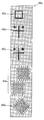
상기 도 6을 참조하면, 상기 어레이 기판(110)에 형성된 제 1 합착키(160a)는 제 1 패턴(161a), 제 2 패턴(162a), 제 3 패턴(163a), 제 4 패턴(164a) 및 제 5 패턴(165a)으로 이루어질 수 있다.Referring to FIG. 6, the
이때, 상기 제 1 패턴(161a)과 제 2 패턴(162a)은 게이트 배선, 즉 게이트전극과 게이트라인을 형성할 때 함께 형성되게 되며, 상기 제 3 패턴(163a)은 데이트 배선, 즉 소오스전극과 드레인전극 및 데이터라인을 형성할 때 함께 형성되게 된다.In this case, the
상기 제 4 패턴(164a)은 컬럼 스페이서의 정렬을 위한 패턴이며, 상기 제 5 패턴(165a)은 공통전극을 형성할 때 함께 형성되게 된다.The
이때, 상기 제 5 패턴(165a)은 사각형 내에 5x5의 행렬로 배치된 구멍을 가지는 형태이며, 게이트전극의 우측 상부에 인접하여 꺾이는 부분의 공통전극 패턴이 기울어진 각도에 일치하도록 기울어져 있는 것을 특징으로 한다. 다만, 본 발명이 상기 제 5 패턴(165a)의 형태에 한정되는 것은 아니며, 상기 공통전극 패턴이 기울어진 각도에 일치하도록 기울어져 형성되기만 하면 어떠한 형태라도 관계없다.In this case, the
그리고, 상기 도 7을 참조하면, 상기 컬러필터 기판(105)에 형성된 제 2 합착키(160b)는 상기 어레이 기판(110)의 제 1 합착키(160a)에 대응하여 제 1 BM패턴(161b), 제 2 BM패턴(162b), 제 3 BM패턴(163b), 제 4 BM패턴(164b) 및 제 5 BM패턴(165b)으로 이루어질 수 있다.In addition, referring to FIG. 7, the
상기 제 5 BM패턴(165b)은 상기 제 5 패턴(165a)의 5x5의 행렬로 배치된 구멍 내에 위치하도록 5x5의 행렬의 도트 형태를 가지며, 이러한 5x5의 행렬의 도트 형태 역시 공통전극 패턴이 기울어진 각도에 일치하도록 기울어져 있는 것을 특징으로 한다.The
이때, 상기 제 1 BM패턴(161b), 제 2 BM패턴(162b), 제 3 BM패턴(163b), 제 4 BM패턴(164b) 및 제 5 BM패턴(165b)은 상기 컬러필터 기판(105)에 BM을 형성할 때 함께 형성되게 된다.In this case, the
이와 같은 상기 제 1, 제 2 패턴(161a, 162a)과 제 1, 제 2 BM패턴(161b, 161b)의 정렬을 통해 게이트 배선과 BM이 정렬되게 되며, 상기 제 3 패턴(163a)과 제 3 BM패턴(163b)의 정렬을 통해 데이터 배선과 BM이 정렬되게 된다.Through the alignment of the first and
또한, 상기 제 5 패턴(165a)과 제 5 BM패턴(165b)의 정렬을 통해 공통전극과 BM이 정렬되게 된다.In addition, the common electrode and the BM are aligned through the alignment of the
이하, 상기와 같이 구성되는 본 발명의 실시예에 따른 합착키를 구비한 프린지 필드형 액정표시장치의 제조방법을 도면을 참조하여 상세히 설명한다.Hereinafter, a method of manufacturing a fringe field type liquid crystal display device having a bonding key according to an embodiment of the present invention configured as described above will be described in detail with reference to the accompanying drawings.
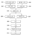
도 8은 본 발명의 실시예에 따른 프린지 필드형 액정표시장치의 제조방법을 순차적으로 나타내는 흐름도이며, 도 9는 본 발명의 실시예에 따른 프린지 필드형 액정표시장치의 다른 제조방법을 순차적으로 나타내는 흐름도이다.8 is a flowchart sequentially illustrating a method of manufacturing a fringe field type liquid crystal display device according to an exemplary embodiment of the present invention, and FIG. 9 is a flowchart of another manufacturing method of a fringe field type liquid crystal display device according to an exemplary embodiment of the present invention. It is a flow chart.
이때, 상기 도 8은 액정주입방식으로 액정층을 형성하는 경우의 프린지 필드형 액정표시장치의 제조방법을 나타내며, 상기 도 9는 액정적하방식으로 액정층을 형성하는 경우의 프린지 필드형 액정표시장치의 제조방법을 나타낸다.8 illustrates a method of manufacturing a fringe field type liquid crystal display device when a liquid crystal layer is formed by a liquid crystal injection method, and FIG. 9 illustrates a fringe field type liquid crystal display device when a liquid crystal layer is formed by a liquid crystal drop method. The manufacturing method of this is shown.
프린지 필드형 액정표시장치의 제조공정은 크게 하부 어레이 기판에 구동소자를 형성하는 구동소자 어레이공정과 상부 컬러필터 기판에 컬러필터를 형성하는 컬러필터공정 및 셀 공정으로 구분될 수 있다.The manufacturing process of the fringe field type liquid crystal display device may be classified into a driving element array process of forming a driving element on a lower array substrate, a color filter process of forming a color filter on an upper color filter substrate, and a cell process.
우선, 어레이공정에 의해 어레이 기판에 배열되어 화소영역을 정의하는 다수의 게이트라인과 데이터라인을 형성하고 상기 화소영역 각각에 상기 게이트라인과 데이터라인에 접속되는 구동소자인 박막 트랜지스터를 형성한다(S101). 또한, 상기 어레이공정을 통해 상기 박막 트랜지스터에 접속되어 박막 트랜지스터를 통해 신호가 인가됨에 따라 액정층을 구동하는 화소전극 및 공통전극을 형성한다.First, a plurality of gate lines and data lines which are arranged in an array substrate and define a pixel region are formed by an array process, and a thin film transistor which is a driving element connected to the gate line and the data line is formed in each of the pixel regions (S101 ). In addition, the pixel electrode and the common electrode for driving the liquid crystal layer are formed by being connected to the thin film transistor through the array process and applying a signal through the thin film transistor.
이때, 상기 어레이 기판의 소정영역에 제 1 패턴, 제 2 패턴, 제 3 패턴, 제 4 패턴 및 제 5 패턴으로 이루어진 제 1 합착키를 형성한다.In this case, a first bonding key including a first pattern, a second pattern, a third pattern, a fourth pattern, and a fifth pattern is formed in a predetermined region of the array substrate.
전술한 바와 같이 상기 제 1 합착키의 제 1 패턴과 제 2 패턴은 게이트 배선을 형성할 때 함께 형성되게 되며, 상기 제 3 패턴은 데이트 배선을 형성할 때 함께 형성되게 된다. 상기 제 4 패턴은 컬럼 스페이서의 정렬을 위한 패턴이며, 상기 제 5 패턴은 공통전극을 형성할 때 함께 형성되게 된다.As described above, the first pattern and the second pattern of the first bonding key are formed together when forming the gate wiring, and the third pattern is formed together when forming the data wiring. The fourth pattern is a pattern for aligning the column spacer, and the fifth pattern is formed together when forming the common electrode.
이때, 상기 공통전극은 화소영역 내에 다수의 슬릿을 가지는 한편, 게이트전극의 우측 상부에 인접하여 꺾이는 부분이 소정 각도로 기울어지도록 패턴이 형성되며, 이에 따라 상기 제 1 합착키의 제 5 패턴은 상기 공통전극 패턴이 기울어진 각도에 일치하도록 기울어져 형성된다.In this case, the common electrode has a plurality of slits in the pixel area, and a pattern is formed such that a portion bent adjacent to the upper right side of the gate electrode is inclined at a predetermined angle, so that the fifth pattern of the first bonding key is The common electrode pattern is formed to be inclined to match the inclined angle.
즉, 상기 제 5 패턴은 사각형 내에 5x5의 행렬로 배치된 구멍을 가지는 형태이며, 상기 공통전극 패턴이 기울어진 각도에 일치하도록 기울어져 있는 것을 특징으로 한다. 다만, 본 발명이 상기 제 5 패턴의 형태에 한정되는 것은 아니며, 상기 공통전극 패턴이 기울어진 각도에 일치하도록 기울어져 형성되기만 하면 어떠한 형태라도 관계없다.That is, the fifth pattern has holes arranged in a matrix of 5 × 5 in a quadrangle, and the common pattern is inclined to correspond to an inclined angle. However, the present invention is not limited to the shape of the fifth pattern, and may be any shape as long as the common electrode pattern is formed to be inclined to match the inclination angle.
그리고, 상기 컬러필터 기판에는 컬러필터공정에 의해 상기 박막 트랜지스터와 게이트라인 및 데이터라인으로 빛이 새는 것을 방지하는 BM과 컬러를 구현하는 적, 녹 및 청색의 서브컬러필터로 구성되는 컬러필터층을 형성한다(S103).In addition, a color filter layer is formed on the color filter substrate including a BM for preventing light from leaking to the thin film transistor, the gate line, and the data line by a color filter process, and a red, green, and blue sub-color filter for implementing color. (S103).
이때, 상기 컬러필터 기판의 소정영역(즉, 상기 어레이 기판에 형성된 제 1 합착키에 대응하는 영역)에 제 1 BM패턴, 제 2 BM패턴, 제 3 BM패턴, 제 4 BM패턴 및 제 5 BM패턴으로 이루어진 제 2 합착키를 형성한다.In this case, a first BM pattern, a second BM pattern, a third BM pattern, a fourth BM pattern, and a fifth BM are disposed in a predetermined region of the color filter substrate (ie, a region corresponding to the first bonding key formed on the array substrate). A second bonding key made of a pattern is formed.
전술한 바와 같이 상기 제 2 합착키의 제 1 BM패턴, 제 2 BM패턴, 제 3 BM패턴, 제 4 BM패턴 및 제 5 BM패턴은 상기 컬러필터 기판에 BM을 형성할 때 함께 형성되게 된다.As described above, the first BM pattern, the second BM pattern, the third BM pattern, the fourth BM pattern, and the fifth BM pattern of the second bonding key are formed together when forming the BM on the color filter substrate.
이때, 상기 제 5 BM패턴은 상기 제 5 패턴의 5x5의 행렬로 배치된 구멍 내에 위치하도록 5x5의 행렬의 도트 형태를 가지며, 이러한 5x5의 행렬의 도트 형태 역시 공통전극 패턴이 기울어진 각도에 일치하도록 기울어져 있는 것을 특징으로 한다.At this time, the fifth BM pattern has a dot shape of a 5x5 matrix so as to be located in a hole arranged in a 5x5 matrix of the fifth pattern, and the dot shape of the 5x5 matrix also corresponds to an inclination angle of the common electrode pattern. It is characterized by being inclined.
한편, 상기 컬러필터 기판과 어레이 기판은 대면적의 모기판 각각에 다수개 구획되어 제조되게 된다. 다시 말해서, 대면적의 모기판에 다수의 패널영역이 정의되고, 상기 패널영역 각각에 구동소자인 박막 트랜지스터 또는 컬러필터가 형성되게 된다.On the other hand, the color filter substrate and the array substrate are manufactured by partitioning a plurality of mother substrates each. In other words, a plurality of panel regions are defined in a large area mother substrate, and a thin film transistor or a color filter serving as a driving element is formed in each of the panel regions.
이어서, 상기 컬러필터 기판 및 어레이 기판에 각각 배향막을 인쇄한 후, 컬러필터 기판 및 어레이 기판 사이에 형성되는 액정층의 액정분자에 배향규제력 또는 표면고정력(즉, 프리틸트 각(pretilt angle)과 배향방향)을 제공하기 위해 상기 배향막을 러빙 처리한다(S102, S104).Subsequently, after the alignment film is printed on the color filter substrate and the array substrate, the alignment control force or the surface fixing force (that is, the pretilt angle and orientation) is applied to the liquid crystal molecules of the liquid crystal layer formed between the color filter substrate and the array substrate. Direction) to rub the alignment film (S102, S104).
상기 러빙공정을 마친 컬러필터 기판과 어레이 기판은 도 8 및 도 9에 도시된 바와 같이, 배향막 검사기를 통해 배향막의 불량여부를 검사하게 된다(S105).As shown in FIGS. 8 and 9, the color filter substrate and the array substrate which have completed the rubbing process are inspected for defects of the alignment layer through the alignment layer inspector (S105).
이와 같은 배향막 검사를 마친 상기 어레이 기판에는 도 8에 도시된 바와 같이, 셀갭을 일정하게 유지하기 위한 스페이서가 형성되고 상기 컬러필터 기판의 외곽부에는 실링재가 도포된 후 상기 컬러필터 기판과 어레이 기판에 압력을 가하여 합착하게 된다(S106, S107, S108). 이때, 상기 스페이서는 산포방식에 의한 볼 스페이서일 수 있으며, 또는 패터닝에 의한 컬럼 스페이서일 수 있다.As shown in FIG. 8, a spacer for maintaining a constant cell gap is formed on the array substrate after the alignment layer inspection, and a sealing material is coated on an outer portion of the color filter substrate. A pressure is applied and it adheres (S106, S107, S108). In this case, the spacer may be a ball spacer by a scattering method, or may be a column spacer by patterning.
이때, 상기 컬러필터 기판과 어레이 기판의 합착에는 상기 제 1, 제 2 합착키의 패턴들을 이용하여 정렬할 수 있다.In this case, the color filter substrate and the array substrate may be aligned by using the patterns of the first and second bonding keys.
즉, 상기 제 1 합착키의 제 1, 제 2 패턴과 상기 제 2 합착키의 제 1, 제 2 BM패턴의 정렬을 통해 게이트 배선과 BM이 정렬되게 되며, 상기 제 1 합착키의 제 3 패턴과 상기 제 2 합착키의 제 3 BM패턴의 정렬을 통해 데이터 배선과 BM이 정렬되게 된다.That is, the gate wiring and the BM are aligned by aligning the first and second patterns of the first cemented key and the first and second BM patterns of the second cemented key, and the third pattern of the first cemented key. The data line and the BM are aligned by aligning the third BM pattern of the second bonding key.
또한, 상기 제 1 합착키의 제 5 패턴과 상기 제 2 합착키의 제 5 BM패턴의 정렬을 통해 공통전극과 BM이 정렬되게 된다.In addition, the common electrode and the BM may be aligned by aligning the fifth pattern of the first bonding key and the fifth BM pattern of the second bonding key.
그리고, 전술한 바와 같이 대면적의 모기판에 다수의 패널영역이 형성되고, 상기 패널영역 각각에 구동소자인 박막 트랜지스터 및 컬러필터층이 형성되기 때문에 낱개의 액정표시패널을 제작하기 위해서는 모기판을 절단, 가공해야만 한다(S109).As described above, a plurality of panel regions are formed in a large area of the mother substrate, and a thin film transistor and a color filter layer serving as driving elements are formed in each of the panel regions. , Must be processed (S109).
이후, 상기와 같이 가공된 개개의 액정표시패널에 액정주입구를 통해 액정을 주입하고 상기 액정주입구를 봉지하여 액정층을 형성한 후 각 액정표시패널을 검사함으로써 액정표시장치를 제작하게 된다(S110, S111).Thereafter, the liquid crystal is injected into the liquid crystal display panel processed as described above through the liquid crystal inlet, and the liquid crystal inlet is encapsulated to form a liquid crystal layer. S111).
이때, 상기 액정의 주입은 압력 차를 이용한 진공주입방식을 사용하는데, 상기 진공주입방식은 대면적의 모기판으로부터 분리된 단위 액정표시패널의 액정주입구를 일정한 진공이 설정된 챔버 내에서 액정이 채워진 용기에 침액시킨 다음 진공 정도를 변화시킴으로써, 상기 액정표시패널 내부 및 외부의 압력 차에 의해 액정을 액정표시패널 내부로 주입시키는 방식으로, 이와 같이 액정이 액정표시패널 내부에 충진 되면, 액정주입구를 밀봉시켜 액정표시패널의 액정층을 형성한다. 따라서, 상기 액정표시패널에 진공주입방식을 통해 액정층을 형성하는 경우에는 실패턴의 일부가 개방되도록 형성하여 액정주입구의 기능을 갖도록 하여야 한다.At this time, the injection of the liquid crystal uses a vacuum injection method using a pressure difference, the vacuum injection method is a container in which a liquid crystal is filled in a chamber in which a constant vacuum is set at a liquid crystal injection hole of a unit liquid crystal display panel separated from a large area mother substrate. The liquid crystal is filled into the liquid crystal display panel by injecting the liquid crystal into the liquid crystal display panel by the pressure difference between the inside and the outside of the liquid crystal display panel by dipping the liquid into a liquid. The liquid crystal layer of the liquid crystal display panel is formed. Therefore, when the liquid crystal layer is formed on the liquid crystal display panel through a vacuum injection method, a part of the failure turn should be opened to have a function of the liquid crystal injection hole.
한편, 상기 도 9에 도시된 바와 같이, 상기 적하방식을 이용한 경우에는 배향막 검사(S105)를 마친 후, 상기 컬러필터 기판에 실런트로 소정의 실패턴을 형성하는 동시에 상기 어레이 기판에 액정층을 형성하게 된다(S106', S107').Meanwhile, as shown in FIG. 9, in the case of using the dropping method, after completing the alignment layer inspection (S105), a predetermined failure turn is formed with a sealant on the color filter substrate and a liquid crystal layer is formed on the array substrate. (S106 ', S107').
상기 적하방식은 디스펜서를 이용하여 다수의 어레이 기판이 배치된 대면적의 제 1 모기판이나 또는 다수의 컬러필터 기판이 배치된 제 2 모기판의 화상표시 영역에 액정을 적하 및 분배(dispensing)하고, 상기 제 1, 제 2 모기판을 합착하는 압력에 의해 액정을 화상표시 영역 전체에 균일하게 분포되도록 함으로써, 액정층을 형성하는 방식이다.The dropping method uses a dispenser to drop and dispense liquid crystals in an image display area of a large area of a first mother substrate on which a plurality of array substrates are arranged or a second mother substrate on which a plurality of color filter substrates are disposed. The liquid crystal layer is formed by uniformly distributing the liquid crystals to the entire image display area by the pressure for bonding the first and second mother substrates together.
따라서, 상기 액정표시패널에 적하방식을 통해 액정층을 형성하는 경우에는 액정이 화상표시 영역 외부로 누설되는 것을 방지할 수 있도록 실패턴이 화소부 영역 외곽을 감싸는 폐쇄된 패턴으로 형성되어야 한다.Therefore, when the liquid crystal layer is formed on the liquid crystal display panel by dropping, the failure turn should be formed in a closed pattern surrounding the pixel area region to prevent the liquid crystal from leaking out of the image display region.
상기 적하방식은 진공주입 방식에 비해 짧은 시간에 액정을 적하할 수 있으며, 액정표시패널이 대형화될 경우에도 액정층을 매우 신속하게 형성할 수 있다.The dropping method can drop the liquid crystal in a short time compared to the vacuum injection method, and can form the liquid crystal layer very quickly even when the liquid crystal display panel is enlarged.
또한, 기판 위에 액정을 필요한 양만 적하하기 때문에 진공주입 방식과 같이 고가의 액정을 폐기함에 따른 액정표시패널의 단가 상승을 방지하여 제품의 가격경쟁력을 강화시키게 된다.In addition, since only the required amount of liquid crystal is dropped on the substrate, the price competitiveness of the liquid crystal display panel due to the disposal of expensive liquid crystal, such as a vacuum injection method, is prevented, thereby enhancing the price competitiveness of the product.
이후, 상기와 같이 액정이 적하되고 실링재가 도포된 상기 제 1 모기판과 제 2 모기판을 정렬한 상태에서 압력을 가하여 상기 실링재에 의해 상기 제 1 모기판과 제 2 모기판을 합착 함과 동시에 압력의 인가에 의해 적하된 액정을 액정표시패널 전체에 걸쳐 균일하게 퍼지게 한다(S108').Thereafter, the first mother substrate and the second mother substrate are bonded together by the sealing material by applying pressure while the liquid crystal is dropped and the first mother substrate and the second mother substrate coated with the sealing material are aligned as described above. The liquid crystal dropped by the application of pressure is spread evenly over the entire liquid crystal display panel (S108 ').
이때, 상기 컬러필터 기판과 어레이 기판의 합착에는 전술한 바와 같이 상기 제 1, 제 2 합착키의 패턴들을 이용하여 정렬할 수 있다.At this time, the bonding of the color filter substrate and the array substrate may be aligned using the patterns of the first and second bonding keys as described above.
이와 같은 공정에 의해 대면적의 제 1, 제 2 모기판에는 액정층이 형성된 다수의 액정표시패널이 형성되며, 상기 제 1, 제 2 모기판을 가공, 절단하여 다수의 액정표시패널로 분리하고 각각의 액정표시패널을 검사함으로써 액정표시장치를 제작하게 된다(S109', S110').By such a process, a plurality of liquid crystal display panels having a liquid crystal layer are formed on the first and second mother substrates having a large area, and the first and second mother substrates are processed and cut and separated into a plurality of liquid crystal display panels. By inspecting each liquid crystal display panel, a liquid crystal display device is manufactured (S109 ', S110').
상기 본 발명의 실시예의 프린지 필드형 액정표시장치는 액티브층으로 비정질 실리콘 박막을 이용한 비정질 실리콘 박막 트랜지스터를 예를 들어 설명하고 있으나, 본 발명이 이에 한정되는 것은 아니며 본 발명은 상기 액티브층으로 다결정 실리콘 박막을 이용한 다결정 실리콘 박막 트랜지스터에도 적용된다.In the fringe field type liquid crystal display device according to the embodiment of the present invention, an amorphous silicon thin film transistor using an amorphous silicon thin film as an active layer is described as an example. However, the present invention is not limited thereto, and the present invention is not limited thereto. The same applies to polycrystalline silicon thin film transistors using thin films.
또한, 상기 본 발명의 실시예의 프린지 필드형 액정표시장치는 하부에 화소전극이 형성되고 상부에 공통전극이 형성된 경우를 예를 들어 설명하고 있으나, 본 발명이 이에 한정되는 것은 아니며 본 발명은 하부에 공통전극이 형성되고 상부에 화소전극이 형성되는 경우에도 적용 가능하다.In addition, the fringe field type liquid crystal display device according to an exemplary embodiment of the present invention has been described with an example in which a pixel electrode is formed at a lower portion and a common electrode is formed at an upper portion thereof, but the present invention is not limited thereto. It is also applicable to the case where a common electrode is formed and a pixel electrode is formed on the common electrode.
상기한 설명에 많은 사항이 구체적으로 기재되어 있으나 이것은 발명의 범위를 한정하는 것이라기보다 바람직한 실시예의 예시로서 해석되어야 한다. 따라서 발명은 설명된 실시예에 의하여 정할 것이 아니고 특허청구범위와 특허청구범위에 균등한 것에 의하여 정하여져야 한다.While a great many are described in the foregoing description, it should be construed as an example of preferred embodiments rather than limiting the scope of the invention. Therefore, the invention should not be construed as limited to the embodiments described, but should be determined by equivalents to the appended claims and the claims.
105 : 컬러필터 기판 110 : 어레이 기판
160,160a,160b : 합착키
161a,162a,163a,164a,165a : 패턴
161b,162b,163b,164b,165b : BM패턴105: color filter substrate 110: array substrate
160,160a, 160b: Locking key
161a, 162a, 163a, 164a, 165a: pattern
161b, 162b, 163b, 164b, 165b: BM pattern
Claims (20)
상기 어레이 기판의 더미영역에 다수의 패턴으로 이루어진 제 1 합착키를 형성하는 단계;
컬러필터 기판에 블랙매트릭스(Black Matrix; BM)와 컬러필터를 형성하는 단계;
상기 컬러필터 기판의 더미영역에 다수의 BM패턴으로 이루어진 제 2 합착키를 형성하는 단계;
상기 어레이 기판과 컬러필터 기판을 합착하여 패널을 형성하는 단계를 포함하며, 상기 어레이 기판과 컬러필터 기판의 합착 시 상기 제 1 합착키의 패턴과 제 2 합착키의 BM패턴을 이용하여 상기 어레이 기판의 공통전극과 상기 컬러필터 기판의 BM을 정렬시키는 것을 특징으로 하는 프린지 필드형 액정표시장치의 제조방법.Forming a thin film transistor, a pixel electrode, and a common electrode on the array substrate;
Forming a first bonding key having a plurality of patterns in the dummy region of the array substrate;
Forming a black matrix (BM) and a color filter on the color filter substrate;
Forming a second bonding key formed of a plurality of BM patterns in a dummy region of the color filter substrate;
And forming a panel by bonding the array substrate and the color filter substrate together, wherein the array substrate is formed using the BM pattern of the first bonding key and the second bonding key when the array substrate and the color filter substrate are bonded together. And a BM of the color filter substrate and the common electrode of the fringe field type liquid crystal display device.
상기 어레이 기판의 더미영역에 형성되며, 다수의 패턴으로 이루어진 제 1 합착키; 및
상기 컬러필터 기판의 더미영역에 형성되며, 다수의 BM패턴으로 이루어진 제 2 합착키를 포함하며, 상기 어레이 기판과 컬러필터 기판의 합착 시 상기 제 1 합착키의 패턴과 제 2 합착키의 BM패턴을 이용하여 상기 어레이 기판의 공통전극과 상기 컬러필터 기판의 BM을 정렬시키는 것을 특징으로 하는 프린지 필드형 액정표시장치.In the fringe field type liquid crystal display device, which is formed by combining an array substrate and a color filter substrate, and realizes an image by driving liquid crystal molecules through a fringe filed formed between a pixel electrode and a common electrode,
A first bonding key formed in the dummy region of the array substrate and having a plurality of patterns; And
A second bonding key formed in a dummy region of the color filter substrate and including a plurality of BM patterns, and the first bonding key pattern and the second bonding key BM pattern when the array substrate and the color filter substrate are bonded together; And aligning the common electrode of the array substrate and the BM of the color filter substrate using a fringe field type liquid crystal display.
Priority Applications (1)
| Application Number | Priority Date | Filing Date | Title |
|---|---|---|---|
| KR1020110133689A KR20130066917A (en) | 2011-12-13 | 2011-12-13 | Fringe field switching liquid crystal display device having align key and method of fabricating fringe field switching liquid crystal display device using thereof |
Applications Claiming Priority (1)
| Application Number | Priority Date | Filing Date | Title |
|---|---|---|---|
| KR1020110133689A KR20130066917A (en) | 2011-12-13 | 2011-12-13 | Fringe field switching liquid crystal display device having align key and method of fabricating fringe field switching liquid crystal display device using thereof |
Publications (1)
| Publication Number | Publication Date |
|---|---|
| KR20130066917A true KR20130066917A (en) | 2013-06-21 |
Family
ID=48862942
Family Applications (1)
| Application Number | Title | Priority Date | Filing Date |
|---|---|---|---|
| KR1020110133689A Withdrawn KR20130066917A (en) | 2011-12-13 | 2011-12-13 | Fringe field switching liquid crystal display device having align key and method of fabricating fringe field switching liquid crystal display device using thereof |
Country Status (1)
| Country | Link |
|---|---|
| KR (1) | KR20130066917A (en) |
Cited By (2)
| Publication number | Priority date | Publication date | Assignee | Title |
|---|---|---|---|---|
| US10804336B2 (en) | 2018-07-25 | 2020-10-13 | Samsung Display Co., Ltd. | Display device |
| US11387286B2 (en) | 2019-07-31 | 2022-07-12 | Samsung Display Co., Ltd. | Display device |
-
2011
- 2011-12-13 KR KR1020110133689A patent/KR20130066917A/en not_active Withdrawn
Cited By (3)
| Publication number | Priority date | Publication date | Assignee | Title |
|---|---|---|---|---|
| US10804336B2 (en) | 2018-07-25 | 2020-10-13 | Samsung Display Co., Ltd. | Display device |
| US11335737B2 (en) | 2018-07-25 | 2022-05-17 | Samsung Display Co., Ltd. | Display device |
| US11387286B2 (en) | 2019-07-31 | 2022-07-12 | Samsung Display Co., Ltd. | Display device |
Similar Documents
| Publication | Publication Date | Title |
|---|---|---|
| KR101073404B1 (en) | Liquid crystal display panel and method of fabricating the same | |
| US7656485B2 (en) | Method of fabricating liquid crystal display panels having various sizes | |
| WO2005001561A1 (en) | Liquid crystal display apparatus | |
| US7492430B2 (en) | In-plane switching mode liquid crystal display device and method of manufacturing the same | |
| US20050128382A1 (en) | Color filter substrate, fabrication method thereof and liquid crystal display panel having the same | |
| US20070040974A1 (en) | Liquid crystal display panel | |
| CN100485497C (en) | Liquid crystal device, method for manufacturing the same, and electronic apparatus | |
| WO2020088383A1 (en) | Display substrate, method for manufacturing same, and display device | |
| KR20060131319A (en) | Liquid Crystal Display Panel and Manufacturing Method Thereof | |
| KR20050000572A (en) | The method for fabricating retardation film and the method for fabricating liquid crystal display device using the same | |
| KR20130066917A (en) | Fringe field switching liquid crystal display device having align key and method of fabricating fringe field switching liquid crystal display device using thereof | |
| KR20110022381A (en) | Manufacturing Method of Liquid Crystal Display Panel | |
| KR100577299B1 (en) | LCD Display | |
| US7616286B2 (en) | Method of forming spacer using ink jet system and method of fabricating liquid crystal display device | |
| KR20100079089A (en) | Method of fabricating liquid crystal display panel | |
| US7646467B2 (en) | Method of fabricating liquid crystal display devices having various driving modes on a common substrate | |
| US20030142248A1 (en) | Liquid crystal display device and method for manufacturing the same | |
| KR20120122651A (en) | Liquid crystal display device | |
| JP2001166317A (en) | Electro-optical device, method of manufacturing the same, and projection display device | |
| KR101177571B1 (en) | Liquid Crystal Panel and Liquid Crystal Display device having the same | |
| KR20100093938A (en) | Method of fabricating liquid crystal display panel | |
| CN102414607B (en) | Liquid crystal display device and method for manufacturing transparent electrode | |
| KR20060093971A (en) | LCD panel and manufacturing method | |
| KR101285272B1 (en) | Liquid crystal display panel and method of fabricating thereof | |
| KR101108383B1 (en) | LCD panel and manufacturing method |
Legal Events
| Date | Code | Title | Description |
|---|---|---|---|
| PA0109 | Patent application |
Patent event code: PA01091R01D Comment text: Patent Application Patent event date: 20111213 |
|
| PG1501 | Laying open of application | ||
| PC1203 | Withdrawal of no request for examination | ||
| WITN | Application deemed withdrawn, e.g. because no request for examination was filed or no examination fee was paid |