KR20130062882A - Club head sets with varying characteristics and related methods - Google Patents
Club head sets with varying characteristics and related methods Download PDFInfo
- Publication number
- KR20130062882A KR20130062882A KR20120139441A KR20120139441A KR20130062882A KR 20130062882 A KR20130062882 A KR 20130062882A KR 20120139441 A KR20120139441 A KR 20120139441A KR 20120139441 A KR20120139441 A KR 20120139441A KR 20130062882 A KR20130062882 A KR 20130062882A
- Authority
- KR
- South Korea
- Prior art keywords
- club head
- stabilizing
- heel
- bar
- toe
- Prior art date
- Legal status (The legal status is an assumption and is not a legal conclusion. Google has not performed a legal analysis and makes no representation as to the accuracy of the status listed.)
- Granted
Links
Images


Classifications
-
- A—HUMAN NECESSITIES
- A63—SPORTS; GAMES; AMUSEMENTS
- A63B—APPARATUS FOR PHYSICAL TRAINING, GYMNASTICS, SWIMMING, CLIMBING, OR FENCING; BALL GAMES; TRAINING EQUIPMENT
- A63B53/00—Golf clubs
- A63B53/04—Heads
-
- A—HUMAN NECESSITIES
- A63—SPORTS; GAMES; AMUSEMENTS
- A63B—APPARATUS FOR PHYSICAL TRAINING, GYMNASTICS, SWIMMING, CLIMBING, OR FENCING; BALL GAMES; TRAINING EQUIPMENT
- A63B53/00—Golf clubs
- A63B53/04—Heads
- A63B53/0408—Heads characterised by specific dimensions, e.g. thickness
-
- A—HUMAN NECESSITIES
- A63—SPORTS; GAMES; AMUSEMENTS
- A63B—APPARATUS FOR PHYSICAL TRAINING, GYMNASTICS, SWIMMING, CLIMBING, OR FENCING; BALL GAMES; TRAINING EQUIPMENT
- A63B53/00—Golf clubs
- A63B53/04—Heads
- A63B53/045—Strengthening ribs
- A63B53/0454—Strengthening ribs on the rear surface of the impact face plate
-
- A—HUMAN NECESSITIES
- A63—SPORTS; GAMES; AMUSEMENTS
- A63B—APPARATUS FOR PHYSICAL TRAINING, GYMNASTICS, SWIMMING, CLIMBING, OR FENCING; BALL GAMES; TRAINING EQUIPMENT
- A63B53/00—Golf clubs
- A63B53/04—Heads
- A63B53/0458—Heads with non-uniform thickness of the impact face plate
-
- A—HUMAN NECESSITIES
- A63—SPORTS; GAMES; AMUSEMENTS
- A63B—APPARATUS FOR PHYSICAL TRAINING, GYMNASTICS, SWIMMING, CLIMBING, OR FENCING; BALL GAMES; TRAINING EQUIPMENT
- A63B53/00—Golf clubs
- A63B53/04—Heads
- A63B2053/0491—Heads with added weights, e.g. changeable, replaceable
-
- A—HUMAN NECESSITIES
- A63—SPORTS; GAMES; AMUSEMENTS
- A63B—APPARATUS FOR PHYSICAL TRAINING, GYMNASTICS, SWIMMING, CLIMBING, OR FENCING; BALL GAMES; TRAINING EQUIPMENT
- A63B2102/00—Application of clubs, bats, rackets or the like to the sporting activity ; particular sports involving the use of balls and clubs, bats, rackets, or the like
- A63B2102/32—Golf
Landscapes
- Health & Medical Sciences (AREA)
- General Health & Medical Sciences (AREA)
- Physical Education & Sports Medicine (AREA)
- Golf Clubs (AREA)
Abstract
가변 특성을 갖는 골프 클럽 헤드 세트의 실시예가 개시되어 있다. 그외 다른 예 및 관련 방법이 또한 개괄적으로 설명되어 있다.An embodiment of a golf club head set having variable characteristics is disclosed. Other examples and related methods are also outlined.
Description
본 특허 출원은 2010년 6월 1일자로 출원된 미국 특허 출원 제 12/791,734 호와, 2010년 6월 1일자로 출원된 미국 특허 출원 제 12/791,738 호, 그리고 2010년 6월 1일자로 출원된 미국 특허 출원 제 12/791,740 호를 기초로 우선권을 주장하는 일부 연속 출원으로서, 상기 각각의 특허 출원은 2010년 4월 12일자로 출원된 미국 특허 가출원 제 61/323,349 호를 기초로 우선권을 주장하는 정규 특허 출원이며, 또한 상기 각각의 특허 출원은 2007년 7월 25일자로 출원된 미국 특허 출원 제 11/828,260 호를 기초로 우선권 주장하는 일부 연속 출원이다.This patent application is filed on U.S. Patent Application No. 12 / 791,734, filed June 1, 2010, and U.S. Patent Application No. 12 / 791,738, filed June 1, 2010, and filed on June 1, 2010. Some consecutive applications claiming priority based on US patent application Ser. No. 12 / 791,740, wherein each patent application claims priority based on US patent provisional application 61 / 323,349, filed April 12, 2010. And a patent application, each of which is a sequential application of some claims, based on US patent application Ser. No. 11 / 828,260, filed Jul. 25, 2007.
마찬가지로, 본 특허 출원은 2011년 3월 17일자로 출원된 미국 특허 가출원 제 61/453,904 호를 기초로 우선권을 주장하는 정규 출원이며, 2011년 4월 28일자로 출원된 미국 특허 출원 제 13/096,944 호를 기초로 우선권을 주장하는 일부 연속 출원이다. 미국 특허 출원 제 13/096,944 호는 미국 특허 가출원 제 61/453,904 호를 기초로 우선권을 주장하는 정규 특허 출원이며, 미국 특허 출원 제 12/791,734 호와, 미국 특허 출원 제 12/791,738 호, 그리고 미국 특허 출원 제 12/791,740 호를 기초로 우선권을 주장하는 일부 연속 출원으로서, 상기 각각의 특허 출원은 미국 특허 가출원 제 61/323,349 호를 기초로 우선권을 주장하는 정규 특허 출원이며, 또한 상기 각각의 특허 출원은 미국 특허 출원 제 11/828,260 호를 기초로 우선권 주장하는 일부 연속 출원이다.Likewise, this patent application is a regular application claiming priority based on US Provisional Application No. 61 / 453,904, filed March 17, 2011, and US Patent Application No. 13 / 096,944, filed April 28, 2011. Some consecutive applications claim priority on the basis of a call. US patent application Ser. No. 13 / 096,944 is a formal patent application claiming priority based on US provisional patent application No. 61 / 453,904, and US patent application Ser. No. 12 / 791,734, US patent application Ser. No. 12 / 791,738, and US Some consecutive applications that claim priority based on patent application Ser. No. 12 / 791,740, each of which is a regular patent application claiming priority based on US Provisional Patent Application No. 61 / 323,349, and also each such patent. The application is some continuous application that claims priority based on US patent application Ser. No. 11 / 828,260.
또한, 본 특허 출원은 2011년 11월 18일자로 출원된 미국 특허 가출원 제 61/561,672 호를 기초로 우선권을 주장하는 정규 출원이다.This patent application is also a regular application claiming priority based on US Provisional Application No. 61 / 561,672, filed November 18, 2011.
참조 출원의 개시 내용이 본 명세서에 참조로써 인용된다.The disclosure of the reference application is incorporated herein by reference.
본 발명은 개괄적으로 스포츠 장비에 관한 것으로, 보다 구체적으로 설명하자면 클럽 헤드 및 관련 방법에 관한 것이다.The present invention relates generally to sports equipment and, more particularly, to club heads and related methods.
일반적으로, 사용자의 골프 스윙(swing) 및 이에 따른 골프 샷(shot) 능력을 향상시키기 위한 방향으로 다양한 디자인의 골프 클럽 및 구체적으로는 골프 클럽 헤드가 개발되어 왔다. 특히, 많은 사람들이 공을 "하향(down)" 타격하는 경우, 즉, 공을 정면을 향해 규칙적으로 타격하는 경우 타격에 어려움을 느끼거나 일관성을 유지하지 못할 수도 있다. 골프 클럽 디자인 및 특히, 골프 클럽 헤드 디자인에 따라 골프 클럽 헤드의 무게 중심의 위치 및 관성 모멘트와 같은 골프 클럽 헤드의 웨이팅(weighting) 방안을 최적화할 수도 있다. 이러한 디자인에 의하면 개인의 일관성 결여 문제를 완화할 수도 있다. 후방 웨이팅 및/또는 추가 하부 토우(toe)의 웨이팅을 통해 전략적으로 무게 중심의 위치를 설정할 수도 있으며, 사용자로 하여금 스윙 시에 공을 "하향" 타격할 수 있으며, 이에 따라 공을 정면으로 타격할 수 있도록 할 수도 있다. In general, golf clubs and specifically golf club heads of various designs have been developed in the direction to improve the golf swing of the user and thus the golf shot ability. In particular, when many people "down" hit the ball, that is, regularly hit the ball in front of the ball, it may be difficult or inconsistent to hit. Depending on the golf club design and, in particular, the golf club head design, the weighting scheme of the golf club head may be optimized, such as the position of the center of gravity of the golf club head and the moment of inertia. This design can alleviate the problem of individual inconsistency. The rear weighting and / or weighting of the additional lower toe may also strategically position the center of gravity, allowing the user to "down" the ball during a swing, thus hitting the ball straight ahead. You can also
본 발명의 목적은 골프 클럽 헤드의 최적의 중량 분포를 제공하는 골프 클럽 헤드 디자인을 제공하는 것이다.It is an object of the present invention to provide a golf club head design that provides an optimal weight distribution of the golf club head.
본 명세서에 설명된 골프 클럽 및 제조 방법의 일 실시예에 있어서, 골프 클럽 헤드는 토우 영역, 토우 영역 반대쪽의 힐 영역, 바닥 영역, 그리고 바닥 영역 반대쪽의 상측 영역을 구비한 몸체를 포함한다. 골프 클럽 헤드는 1 전면, 전면의 반대쪽 제 1 후면, 전면의 반대쪽에 마련되며 전면으로부터 제 1 후면으로 더 멀리 연장되는 제 2 후면을 추가로 포함한다. 제 2 후면이 힐 영역으로부터 토우 영역으로 연장되며, 또한 바닥 영역으로부터 이 바닥 영역과 상측 영역 사이의 대략 중점까지 연장된다. 골프 클럽 헤드는 제 1 후면과 제 2 후면 사이의 제 1 공동과, 토우 영역에서 제 2 후면과 일체형의 제 2 공동을 추가로 포함한다. 본 실시예는 제 1 공동에 삽입되는 제 1 추 및 제 2 공동에 삽입되는 제 2 추를 추가로 포함할 수 있다.In one embodiment of the golf club and manufacturing method described herein, the golf club head includes a body having a tow region, a heel region opposite the tow region, a bottom region, and an upper region opposite the bottom region. The golf club head further includes a first front side, a first rear side opposite the front side, a second rear side extending further from the front side to the first rear side. The second backside extends from the heel region to the toe region and also extends from the bottom region to the approximately midpoint between the bottom region and the upper region. The golf club head further includes a first cavity between the first back side and the second back side, and a second cavity integral with the second back side in the tow region. This embodiment may further include a first weight inserted into the first cavity and a second weight inserted into the second cavity.
골프 클럽 및 제조 방법의 다른 실시예에 있어서, 골프 클럽 헤드는 토우 영역, 힐 영역, 힐 영역 반대쪽의 상측 영역, 그리고 바닥 영역을 구비한 몸체를 포함한다. 바닥 영역은 힐 영역으로부터 토우 영역까지 연장되며, 또한 바닥 영역은 전면으로부터 후면 바닥 가장자리까지 연장된다. 골프 클럽 헤드는 바닥 영역 반대쪽의 상측 영역, 그리고 전면의 반대쪽으로 전면과 실질적으로 평행한 제 1 후면을 추가로 포함한다. 제 1 후면은 힐 영역으로부터 토우 영역까지 연장되며, 또한 상측 영역과 바닥 영역의 사이의 중점으로부터 상측 영역까지 연장된다. 골프 클럽 헤드는 후면 바닥 가장자리로부터 대략 중점까지 연장되는 제 1 전면의 반대쪽 제 2 후면을 추가로 포함한다. 골프 클럽 헤드는 제 2 후면과 전면 사이의 정방형 제 1 공동, 그리고 토우 영역에 제 2 후면과 일체형으로 형성되는 제 2 공동을 추가로 포함한다. 본 실시예는 제 1 공동에 삽입되는 제 1 추 그리고 제 2 공동에 삽입되는 제 2 추를 추가로 포함할 수도 있다.In another embodiment of the golf club and manufacturing method, the golf club head includes a body having a toe region, a heel region, an upper region opposite the heel region, and a bottom region. The bottom region extends from the heel region to the toe region and the bottom region also extends from the front to the rear bottom edge. The golf club head further includes an upper region opposite the bottom region, and a first rear surface substantially parallel to the front side opposite the front side. The first rear surface extends from the heel region to the toe region and also extends from the midpoint between the upper region and the bottom region to the upper region. The golf club head further includes a second rear side opposite the first front that extends from the rear bottom edge to approximately midpoint. The golf club head further includes a square first cavity between the second rear face and the front face, and a second cavity integrally formed with the second back face in the tow region. This embodiment may further include a first weight inserted into the first cavity and a second weight inserted into the second cavity.
골프 클럽 및 제조 방법의 다른 실시예에 있어서, 골프 클럽은 본 명세서에 설명되고 있는 샤프트에 결합된 골프 클럽 헤드를 포함한다. 골프 클럽은 0.75의 호젤 비율을 추가로 포함한다. 호젤 비율은 호젤 거리 대 전면 거리의 비율을 의미한다. 호젤 거리는 힐 영역의 일 지점으로부터 제 1 단부 반대쪽의 제 2 단부까지 연장되며, 전면 거리는 상기 일 지점으로부터 상측 가장자리까지 전면을 따라 바닥과 실질적으로 평행하게 측정한 거리이다. 골프 클럽은 제 1 공동을 차지하는 제 1 추 및 제 2 공동을 차지하는 제 2 추를 추가로 포함할 수도 있다. In another embodiment of a golf club and method of manufacture, the golf club includes a golf club head coupled to a shaft as described herein. Golf clubs additionally contain a hosel ratio of 0.75. The hosel ratio is the ratio of the hosel distance to the front distance. The hosel distance extends from one point of the heel area to a second end opposite the first end, wherein the front distance is the distance measured substantially parallel to the floor along the front face from the one point to the upper edge. The golf club may further comprise a first weight occupying the first cavity and a second weight occupying the second cavity.
골프 클럽 및 제조 방법의 일 실시예에 있어서, 골프 클럽 헤드 제조 방법은 토우 영역과, 토우 영역 반대쪽의 힐 영역과, 바닥 영역, 그리고 바닥 영역 반대쪽의 상측 영역을 구비하는 몸체를 제공하는 단계를 포함한다. 본 실시예는 전면과, 전면의 반대쪽 제 1 후면, 그리고 전면의 반대쪽으로 마련되며 전면으로부터 제 1 후면까지 더 멀리 연장되는 제 2 후면을 추가로 포함한다. 제 2 후면은 힐 영역으로부터 토우 영역까지 연장되며, 또한 바닥 영역으로부터 이 바닥 영역과 상측 영역 사이의 대략 중점까지 연장된다. 몸체는 제 1 후면과 제 2 후면 사이의 제 1 공동과, 토우 영역에서 제 2 후면과 일체형의 제 2 공동을 추가로 포함한다. 본 실시예는 제 1 공동에 삽입되는 제 1 추 및 제 2 공동에 삽입되는 제 2 추를 추가로 포함할 수도 있다.In one embodiment of a golf club and manufacturing method, a golf club head manufacturing method includes providing a body having a tow region, a heel region opposite the tow region, a bottom region, and an upper region opposite the bottom region. do. This embodiment further includes a front face, a first rear face opposite the front face, and a second rear face provided opposite the front face and extending further from the front face to the first rear face. The second backside extends from the heel region to the toe region and also extends from the bottom region to the approximately midpoint between this bottom region and the upper region. The body further includes a first cavity between the first back side and the second back side, and a second cavity integral with the second back side in the tow region. This embodiment may further include a first weight inserted into the first cavity and a second weight inserted into the second cavity.
두 개 이상의 클럽 헤드를 포함하며, 각각의 클럽 헤드는 로프트 각도와, 전면과, 상기 전면의 반대쪽 후면, 그리고 상기 후면으로부터 돌출되는 하나 이상의 지지 바를 포함하는 본 발명에 따른 예가 제공될 수 있다. 상기 로프트 각도는 상기 두 개 이상의 클럽 헤드에 걸쳐 증가하는 방식으로 변할 수 있으며, 상기 로프트 각도가 상기 두 개 이상의 클럽 헤드에 걸쳐 증가하는 방식으로 변함에 따라 상기 하나 이상의 지지 바의 일 특성값이 상기 두 개 이상의 클럽 헤드에 걸쳐 증가하는 방식으로 변한다.An example according to the invention may be provided comprising at least two club heads, each club head comprising a loft angle, a front face, an opposite rear face of the front face, and one or more support bars protruding from the back face. The loft angle may vary in an increasing manner across the two or more club heads, and one characteristic value of the one or more support bars may vary as the loft angle changes in an increasing manner across the two or more club heads. Change in an increasing manner across two or more club heads.
또한, 클럽 헤드 세트가 제 1 및 제 2 클럽 헤드를 포함할 수 있는 본 발명에 따른 예가 제공될 수 있다. 제 1 클럽 헤드는 제 1 로프트 각도와, 제 1 전면, 그리고 제 1 힐 영역, 제 1 토우 영역, 제 1 전면 반대쪽에 마련되며 제 1 힐 영역 및 제 1 토우 영역의 사이에서 연장되는 제 1 후면, 그리고 제 1 후면에 결합되는 하나 이상의 제 1 지지 바를 포함하는 제 1 후방부를 포함할 수 있다. 제 2 클럽 헤드는 제 2 로프트 각도와, 제 2 전면, 그리고 제 2 힐 영역, 제 2 토우 영역, 제 2 전면 반대쪽에 마련되며 제 2 힐 영역 및 제 2 토우 영역의 사이에서 연장되는 제 2 후면, 그리고 제 2 후면에 결합되는 하나 이상의 제 2 지지 바를 포함하는 제 2 후방부를 포함할 수 있다. 이러한 예에 있어서, 제 1 로프트 각도가 제 2 로프트 각도보다 크며, 하나 이상의 제 1 지지 바의 속성값이 하나 이상의 제 2 지지 바의 속성값보다 크다.In addition, an example according to the invention may be provided in which a set of club heads may comprise first and second club heads. The first club head is provided with a first loft angle, a first front side, and a first rear side opposite the first heel region, the first toe region, the first front side, and extending between the first heel region and the first toe region. And a first rear portion including one or more first support bars coupled to the first rear surface. The second club head is provided with a second loft angle, a second front side and a second rear side opposite the second heel region, the second toe region, the second front side and extending between the second heel region and the second toe region. And a second rear portion including one or more second support bars coupled to the second rear surface. In this example, the first loft angle is greater than the second loft angle, and the attribute value of the one or more first support bars is greater than the attribute value of the one or more second support bars.
또한, 클럽 헤드 세트를 제공하는 단계를 포함할 수 있는 방법에 관한 본 발명의 예가 제공될 수 있다. 클럽 헤드 세트를 제공하는 단계는 제 1 클럽 헤드를 제공하는 단계를 포함할 수 있으며, 제 1 클럽 헤드는 제 1 로프트 각도와, 제 1 전면, 그리고 제 1 힐 영역, 제 1 토우 영역, 제 1 전면 반대쪽에 마련되며 제 1 힐 영역 및 제 1 토우 영역의 사이에서 연장되는 제 1 후면, 그리고 제 1 후면에 결합되며 제 1 지지 바 특성값을 포함하는 하나 이상의 제 1 지지 바를 포함하는 제 1 후방부를 포함할 수 있다. 상기 클럽 헤드 세트를 제공하는 단계는 또한 제 2 클럽 헤드를 제공하는 단계를 포함할 수 있으며, 제 2 클럽 헤드는 제 2 로프트 각도와, 제 2 전면, 그리고 제 2 힐 영역, 제 2 토우 영역, 제 2 전면 반대쪽에 마련되며 제 2 힐 영역 및 제 2 토우 영역의 사이에서 연장되는 제 2 후면, 그리고 제 2 후면에 결합되며 제 2 지지 바 특성값을 포함하는 하나 이상의 제 2 지지 바를 포함하는 제 2 후방부를 포함할 수 있다. 이러한 예에 있어서, 상기 제 1 클럽 헤드를 제공하는 단계는 제 2 로프트 각도보다 큰 제 1 로프트 각도를 제공하는 단계, 그리고 제 2 지지 바 특성값보다 큰 제 1 지지 바 특성값을 제공하는 단계를 포함한다.In addition, examples of the present invention regarding methods that may include providing a club head set may be provided. Providing a set of club heads may include providing a first club head, the first club head having a first loft angle, a first front side, and a first heel region, a first toe region, a first A first rear side opposite the front side and extending between the first heel region and the first toe region, and a first rear side coupled to the first rear side and including one or more first support bars comprising the first support bar characteristic values; It may include wealth. Providing the set of club heads may also include providing a second club head, the second club head having a second loft angle, a second front, and a second heel area, a second toe area, A second back side provided opposite the second front side and extending between the second heel region and the second toe region and comprising one or more second support bars coupled to the second back side and including a second support bar characteristic value; It may include two rear parts. In this example, providing the first club head comprises providing a first loft angle greater than a second loft angle, and providing a first support bar characteristic value greater than the second support bar characteristic value. Include.
클럽 헤드 세트가 두 개 이상의 클럽 헤드를 포함할 수 있으며, 각각의 클럽 헤드는 로프트 각도와, 전면, 그리고 전면의 반대쪽 후면을 포함하는 후방부를 포함하며, 상기 후방부의 하부 토우 섹션에만 추가 마련되어 있는 본 발명에 따른 예가 또한 제공될 수 있다. 이러한 예에 있어서, 로프트 각도는 두 개 이상의 클럽 헤드에 걸쳐 변할 수 있으며, 추의 제 1 특성값이 두 개 이상의 클럽 헤드에 걸쳐 변할 수 있고, 추의 제 2 특성값이 두 개 이상의 클럽 헤드에 걸쳐 변할 수 있으며, 제 1 및 제 2 특성값이 서로 역비례 관계로 변할 수 있다.The club head set may include two or more club heads, each club head including a rear portion including a loft angle, a front side, and an opposite rear side of the front side, additionally provided only in the lower toe section of the rear portion. Examples according to the invention may also be provided. In this example, the loft angle may vary over two or more club heads, the first characteristic value of the weight may vary over two or more club heads, and the second characteristic value of the weight may change over two or more club heads. And the first and second characteristic values may change in inverse relationship with each other.
클럽 헤드 세트가 제 1 및 제 2 클럽 헤드를 포함할 수 있는 본 발명에 따른 예가 또한 제공될 수 있다. 제 1 클럽 헤드는 제 1 로프트 각도와, 제 1 전면, 그리고 제 1 후방부를 포함할 수 있고, 제 1 후방부는 제 1 힐 영역, 제 1 하부 토우 섹션을 포함하는 제 1 토우 영역, 그리고 제 1 힐 영역과 제 1 토우 영역 사이에서 연장되며 제 1 전면 반대쪽의 제 1 후면을 포함한다. 제 2 클럽 헤드는 제 2 로프트 각도와, 제 2 전면, 그리고 제 2 후방부를 포함할 수 있고, 제 2 후방부는 제 2 힐 영역, 제 2 하부 토우 섹션을 포함하는 제 2 토우 영역, 그리고 제 2 힐 영역과 제 2 토우 영역 사이에서 연장되며 제 2 전면 반대쪽의 제 2 후면을 포함한다. 제 1 클럽 헤드는 또한, 제 1 토우 영역의 제 1 하부 토우 섹션의 제 1 추를 포함할 수 있으며, 제 2 클럽 헤드는 또한, 제 2 토우 영역의 제 2 하부 토우 섹션의 제 2 추를 포함할 수 있다. 이러한 예에 있어서, 제 1 로프트 각도가 제 2 로프트 각도보다 클 수 있으며, 제 1 및 제 2 추가 실질적으로 유사한 질량을 포함할 수 있고, 제 1 및 제 2 추가 각각 서로 대응하는 제 1 치수를 포함하며, 제 1 및 제 2 추가 각각 서로 대응하는 제 2 치수를 포함한다. 제 1 추의 제 1 치수가 제 2 추의 제 1 치수보다 큰 경우, 제 2 추의 제 2 치수가 제 1 추의 제 2 치수보다 클 수 있다. 제 1 추의 제 2 치수가 제 2 추의 제 2 치수보다 큰 경우, 제 2 추의 제 1 치수가 제 1 추의 제 1 치수보다 클 수 있다.An example according to the invention can also be provided in which a set of club heads can comprise first and second club heads. The first club head may include a first loft angle, a first front side, and a first rear portion, the first rear portion including a first heel region, a first toe region comprising a first lower toe section, and a first It extends between the heel region and the first toe region and includes a first rear surface opposite the first front surface. The second club head may comprise a second loft angle, a second front side, and a second rear portion, wherein the second rear portion comprises a second heel region, a second toe region comprising a second lower toe section, and a second It extends between the heel region and the second toe region and includes a second rear surface opposite the second front surface. The first club head may also include a first weight of the first lower toe section of the first tow region, and the second club head may also include a second weight of the second lower toe section of the second tow region. can do. In this example, the first loft angle may be greater than the second loft angle, and the first and second additions may include substantially similar masses, and the first and second additions each include a first dimension corresponding to each other. And a first dimension and a second addition, respectively, corresponding second dimensions. If the first dimension of the first weight is greater than the first dimension of the second weight, the second dimension of the second weight may be larger than the second dimension of the first weight. If the second dimension of the first weight is greater than the second dimension of the second weight, the first dimension of the second weight may be larger than the first dimension of the first weight.
또한, 방법이 클럽 헤드 세트를 제공하는 단계를 포함할 수 있는 본 발명에 따른 예가 제공될 수 있다. 상기 클럽 헤드 세트를 제공하는 단계는 클럽 헤드 세트의 제 1 클럽 헤드를 제공하는 단계 및 클럽 헤드 세트의 제 2 클럽 헤드를 제공하는 단계를 포함할 수 있다. 제 1 클럽 헤드는 제 1 로프트 각도와, 제 1 전면, 그리고 제 1 후방부를 포함할 수 있고, 제 1 후방부는 제 1 전면의 반대쪽에 마련되며 제 1 후방부의 힐 영역과 토우 영역 사이에서 연장되는 제 1 후면 그리고 제 1 공동이 마련된 제 1 하부 토우 섹션을 포함한다. 제 2 클럽 헤드는 제 2 로프트 각도와, 제 2 전면, 그리고 제 21 후방부를 포함할 수 있고, 제 2 후방부는 제 2 전면의 반대쪽에 마련되며 제 2 후방부의 힐 영역과 토우 영역 사이에서 연장되는 제 2 후면 그리고 제 2 공동이 마련된 제 2 하부 토우 섹션을 포함한다. 상기 제 1 클럽 헤드를 제공하는 단계는 제 1 공동에 제 1 추를 제공하는 단계, 그리고 제 2 로프트 각도보다 큰 제 1 로프트 각도를 제공하는 단계를 포함할 수 있다. 상기 제 2 클럽 헤드를 제공하는 단계는 제 2 공동에 제 2 추를 제공하는 단계를 포함할 수 있다. 제 1 추를 제공하는 단계는 제 1 추의 제 1 길이, 제 1 폭 및 제 1 깊이를 제공하는 단계를 포함할 수 있다. 제 2 추를 제공하는 단계는 제 2 추의 제 2 길이가 제 1 추의 제 1 길이보다 크거나 제 2 추의 제 2 폭이 제 1 추의 제 1 폭보다 큰 조건 중 적어도 하나를 충족하도록 제 2 추의 제 2 길이 및 제 2 폭을 제공하는 단계를 포함할 수 있다. 제 2 추를 제공하는 단계는 또한, 제 1 추의 제 1 깊이가 제 2 추의 제 2 깊이보다 크도록 제 2 추의 제 2 길이를 제공하는 단계를 포함할 수 있다.In addition, an example according to the present invention may be provided in which the method may comprise providing a club head set. Providing the club head set may include providing a first club head of the club head set and providing a second club head of the club head set. The first club head may comprise a first loft angle, a first front side, and a first rear portion, the first rear portion being provided opposite the first front side and extending between the heel region and the toe region of the first rear portion And a first lower tow section provided with a first back side and a first cavity. The second club head may comprise a second loft angle, a second front side, and a twenty-first rear portion, the second rear portion being provided opposite the second front side and extending between the heel region and the toe region of the second rear portion. And a second lower tow section provided with a second back side and a second cavity. Providing the first club head may include providing a first weight to the first cavity, and providing a first loft angle greater than the second loft angle. Providing the second club head may include providing a second weight in a second cavity. Providing the first weight can include providing a first length, a first width, and a first depth of the first weight. Providing the second weight is such that it satisfies at least one of the conditions where the second length of the second weight is greater than the first length of the first weight or the second width of the second weight is greater than the first width of the first weight. Providing a second length and a second width of the second weight. Providing the second weight may also include providing a second length of the second weight such that the first depth of the first weight is greater than the second depth of the second weight.
또한, 골프 클럽 헤드가 전면과 후방부를 포함할 수 있는 본 발명에 따른 예가 제공될 수 있다. 후방부는 힐 영역, 토우 영역, 힐 영역과 토우 영역 사이의 중심 영역, 힐 영역과 토우 영역의 사이에서 연장되는 후방 단부, 그리고 공동을 포함할 수 있다. 공동은 공동의 힐 구역, 공동의 토우 구역, 공동의 힐 구역과 토우 구역 사이의 공동 중심 구역, 전면에 가까이 배치된 공동 내부 섹션, 그리고 후방 단부를 향해 배치된 공동 외부 섹션을 포함할 수 있다. 공동의 폭은 공동의 힐 구역 및 토우 구역에서보다 공동 중심 구역에서 더 넓을 수 있다.In addition, an example according to the invention may be provided in which the golf club head may comprise a front and a back. The back portion may include a heel region, toe region, a central region between the heel region and the toe region, a rear end extending between the heel region and the toe region, and a cavity. The cavity may comprise a cavity heel zone, a cavity tow zone, a cavity center zone between the cavity heel zone and a tow zone, a cavity interior section disposed close to the front side, and a cavity exterior section disposed toward the rear end. The width of the cavity may be wider in the cavity central zone than in the cavity hill and toe zones.
또한, 방법이 골프 클럽 헤드용 삽입부를 제공하는 단계 및/또는 클럽 헤드의 몸체를 제공하는 단계를 포함할 수 있는 본 발명에 따른 예가 제공될 수 있다. 삽입부를 제공하는 단계는 삽입부 힐 및 토우 구역을 제공하는 단계와, 삽입부 힐 구역과 토우 구역에서보다 두꺼운 삽입부 힐 구역과 토우 구역 사이의 삽입부 중심 구역을 제공하는 단계를 포함할 수 있다. 공동은 후면에 인접한 공동 내부 섹션, 후방 단부의 반대쪽 공동 외부 섹션, 공동의 힐 및 토우 구역, 그리고 공동의 힐 구역과 토우 구역 사이에 마련되며 공동의 힐 구역 및 토우 구역보다 두꺼운 공동 중심 구역을 포함할 수 있다. 삽입부는 공동에 적어도 부분적으로 수용되도록 제공될 수 있다.In addition, an example according to the invention may be provided in which the method may comprise providing an insert for a golf club head and / or providing a body of the club head. Providing an insert can include providing an insert heel and toe section and providing an insert center section between the insert heel section and the tow section thicker than the insert heel section and the tow section. . The cavity includes a cavity interior section adjacent to the rear, a cavity exterior section opposite the rear end, a cavity heel and toe section, and a cavity center section thicker than the cavity heel and tow section and located between the cavity heel and tow sections. can do. The insert can be provided to be at least partially received in the cavity.
또한, 골프 클럽 헤드가 클럽 헤드의 몸체의 후방부와 삽입부를 포함할 수 있는 본 발명에 따른 예가 제공될 수 있다. 후방부는 힐 영역, 토우 영역, 힐 영역과 토우 영역 사이의 중심 영역, 전면의 반대쪽에 마련되며 힐 영역과 토우 영역 사이에서 연장되는 후면, 힐 영역과 토우 영역 사이에서 연장되는 후방 벽부, 그리고 후면과 후방 벽부의 사이에 배치되는 공동을 포함할 수 있다. 공동은 공동의 힐 구역, 공동의 토우 영역, 공동의 힐 구역과 토우 구역 사이의 공동 중심 구역, 후면의 일부를 포함하는 공동 내부 벽부, 그리고 후방 벽부의 반대쪽에 배치되는 공동 외부 벽부를 포함할 수 있다. 삽입부는 삽입부 힐 구역, 삽입부 토우 구역, 삽입부 힐 구역과 토우 구역 사이의 삽입부 중심 구역, 공동 내부 벽부와 상보형의 삽입부 내부 벽부, 그리고 공동 외부 벽부와 상보형의 삽입부 외부 벽부를 포함할 수 있다. 골프 클럽 헤드는 중심 영역을 중심으로 한 관성 모멘트를 포함할 수 있다. 삽입부는 공동에 적어도 부분적으로 수용되도록 구성될 수 있다. 공동은 공동 내부 벽부로부터 공동 외부 벽부까지 공동의 힐 구역 및 토우 구역에서보다 공동의 중심 구역에서 폭이 더 넓게 형성될 수 있다. 삽입부는 삽입부 내부 벽부로부터 삽입부 외부 벽부까지 삽입부 힐 구역 및 토우 구역에서보다 삽입부 중심 구역에서 폭이 더 넓게 형성될 수 있다. 공동 내부 벽부의 분포 질량이 공동 중심 구역에 집중될 수 있다. 삽입부의 분포 질량이 삽입부 힐 구역 및 토우 구역으로부터 삽입부 중심 구역으로 이동될 수 있다. 골프 클럽 헤드의 몸체의 밀도가 삽입부의 밀도보다 클 수 있다. 공동의 힐 구역 및 토우 구역에서 클럽 헤드의 몸체에 의해 야기되는 관성 모멘트의 제 1 부분이 삽입부 힐 구역 및 토우 구역에서 삽입부에 의해 야기되는 관성 모멘트의 제 2 부분보다 클 수 있다. 삽입부 힐 구역 및 토우 구역은 삽입부 중심 구역을 중심으로 삽입부 내부 벽부를 따라 서로 둔각을 이루도록 형성될 수 있다. 공동 내부 벽부는 삽입부 내부 벽부와 상보형으로 둔각을 이루도록 형성될 수 있다. 삽입부는 공동으로부터 삽입부가 제거되는 동안 이를 돕기 위해 파지부를 포함할 수 있으며, 이러한 파지부는 삽입부가 공동에 수용되는 경우 공동의 외부에 유지되도록 구성될 수 있다.In addition, an example according to the invention may be provided in which the golf club head may comprise a rear portion and an insert of the body of the club head. The rear part is provided in the heel area, the toe area, the center area between the heel area and the toe area, the rear side extending from the heel area and the toe area, and the rear wall part extending between the heel area and the toe area, and It may include a cavity disposed between the rear wall portion. The cavity may include a cavity heel zone, a cavity tow zone, a cavity center zone between the cavity heel zone and a tow zone, a cavity interior wall portion including a portion of the rear face, and a cavity exterior wall portion disposed opposite the rear wall portion. have. The insert is the insert heel section, the insert toe section, the insert center section between the insert heel section and the toe section, the cavity inner wall and complementary insert inner wall, and the cavity outer wall and complementary insert outer wall It may include wealth. The golf club head may include a moment of inertia about a central region. The insert can be configured to be at least partially received in the cavity. The cavity may be formed wider in the central region of the cavity than in the heel and toe regions of the cavity from the cavity inner wall to the cavity outer wall. The insert can be formed wider in the insert center region than in the insert heel and toe regions from the insert inner wall to the insert outer wall. The distribution mass of the cavity inner wall can be concentrated in the cavity central zone. The distribution mass of the insert can be moved from the insert heel zone and the toe zone to the insert center zone. The density of the body of the golf club head may be greater than the density of the insert. The first portion of the moment of inertia caused by the body of the club head in the heel and toe regions of the cavity may be greater than the second portion of the moment of inertia caused by the insert in the insert heel and toe regions. The insert heel zone and toe zone may be formed to be obtuse with each other along the insert inner wall about the insert center zone. The cavity inner wall may be formed to be obtuse in complementary fashion with the insert inner wall. The insert can include a grip to assist with this while the insert is removed from the cavity, which can be configured to remain outside of the cavity when the insert is received in the cavity.
또한, 골프 클럽 헤드 세트가 제 1 타격면, 제 1 타격면 반대쪽 제 1 후면, 제 1 상측 단부, 제 1 상측 단부 반대쪽 제 1 하측 단부, 제 1 토우 단부, 제 1 토우 단부를 포함하는 제 1 토우 영역, 제 1 토우 단부 반대쪽 제 1 힐 단부, 제 1 힐 단부를 포함하는 제 1 힐 영역, 그리고 제 1 상측 단부와 제 1 하측 단부를 통하여 실질적으로 수직 방향으로 연장되며 제 1 힐 영역과 제 1 제 1 토우 영역 사이에서 연장되는 제 1 수직 축선을 포함하는 제 1 클럽 헤드를 포함할 수 있는 본 발명에 따른 예가 제공될 수 있다. 제 1 후면은 토우 영역에 배치되며 제 1 공동 기부와 제 1 공동 기부의 적어도 일부의 경계를 획정하는 제 1 공동 벽부를 포함하는 제 1 공동을 포함할 수 있다. 제 1 후면은 또한, 제 1 바를 포함할 수 있으며, 제 1 바는 제 1 바의 길이를 따라 연장되는 제 1 바 축선을 구비한다. 제 1 바는 제 1 공동 기부로부터 돌출되며 제 1 공동의 적어도 제 1 부분을 가로질러 제 1 수직 축선에 대해 대각선 방향으로 연장될 수 있다. 제 1 바 축선은 제 1 수직 축선과 교차할 수 있으며, 제 1 수직 축선으로부터 제 1 토우 단부 및 제 1 상측 단부를 향해 연장된다. The golf club head set further includes a first hit face, a first back face opposite the first hit face, a first upper end, a first lower end opposite the first upper end, a first tow end, a first tow end; Extending substantially in a vertical direction through the toe region, a first heel region opposite the first toe end, a first heel region comprising a first heel end, and a first upper end and a first lower end; An example according to the invention may be provided which may comprise a first club head comprising a first vertical axis extending between a first first tow region. The first back surface may include a first cavity disposed in the tow region and including a first cavity wall portion defining a boundary of at least a portion of the first cavity base and the first cavity base. The first back side may also include a first bar, the first bar having a first bar axis extending along the length of the first bar. The first bar may protrude from the first cavity base and extend diagonally with respect to the first vertical axis across at least the first portion of the first cavity. The first bar axis may intersect the first vertical axis and extend from the first vertical axis toward the first toe end and the first upper end.
또한, 골프 클럽 헤드 세트가 제 1 타격면, 제 1 타격면 반대쪽 제 1 후면, 제 1 상측 단부, 제 1 상측 단부 반대쪽 제 1 하측 단부, 제 1 토우 단부, 제 1 토우 단부를 포함하는 제 1 토우 영역, 제 1 토우 단부 반대쪽 제 1 힐 단부, 제 1 힐 단부를 포함하는 제 1 힐 영역, 그리고 제 1 상측 단부와 제 1 하측 단부를 통하여 실질적으로 수직 방향으로 연장되며 제 1 힐 영역과 제 1 제 1 토우 영역 사이에서 연장되는 제 1 수직 축선을 포함하는 제 1 클럽 헤드를 포함할 수 있는 본 발명에 따른 예가 제공될 수 있다. 제 1 후면은 토우 영역에 배치되며 제 1 공동 기부와 제 1 공동 기부의 경계를 획정하는 제 1 공동 벽부를 포함하는 제 1 공동을 포함할 수 있다. 제 1 후면은 또한, 제 1 공동 기부로부터 돌출되며 제 1 수직 축선과 제 1 바 각도를 이루며 제 1 공동을 가로질러 연장되는 제 1 바를 포함할 수 있다. 제 1 후면은 또한 제 1 후면으로부터 돌출되는 제 1 모래 시계형 지지부를 포함할 수 있으며, 제 1 모래 시계형 지지부는 상측부와 하측부, 그리고 상측부와 하측부보다 폭이 좁은 중간부, 그리고 상측부, 중간부, 하측부를 형성하는 힐 측벽 및 토우 측벽을 포함한다. 제 1 모래 시계형 지지부의 토우 측벽은 제 1 공동 기부 위로 돌출될 수 있다. 제 1 공동 벽부는 제 1 모래 시계형 지지부의 토우 측벽을 포함할 수 있다.The golf club head set further includes a first hit face, a first back face opposite the first hit face, a first upper end, a first lower end opposite the first upper end, a first tow end, a first tow end; Extending substantially in a vertical direction through the toe region, a first heel region opposite the first toe end, a first heel region comprising a first heel end, and a first upper end and a first lower end; An example according to the invention may be provided which may comprise a first club head comprising a first vertical axis extending between a first first tow region. The first back surface may include a first cavity disposed in the tow region and including a first cavity wall portion defining a boundary between the first cavity base and the first cavity base. The first back surface may also include a first bar that protrudes from the first cavity base and extends across the first cavity at a first bar angle with the first vertical axis. The first back side may also include a first hourglass support that protrudes from the first back side, wherein the first hourglass support includes an upper portion and a lower portion, and an intermediate portion narrower than the upper portion and the lower portion, and Heel sidewalls and toe sidewalls forming an upper portion, a middle portion, and a lower portion. The tow sidewall of the first hourglass support may protrude above the first cavity base. The first cavity wall portion may include a tow sidewall of the first hourglass-shaped support.
또한, 골프 클럽 헤드 세트를 제공하기 위한 방법이 대각선 안정화 바를 포함하는 하나 이상의 클럽 헤드 중 제 1 클럽 헤드를 제공하는 단계를 포함할 수 있는 본 발명에 따른 예가 제공될 수 있다. 제 1 수직 축선은 제 1 클럽 헤드의 제 1 상측 단부와 제 1 하측 단부를 통해 제 1 클럽 헤드의 제 1 힐 영역과 제 1 토우 영역의 사이에서 연장될 수 있다. 상기 제 1 클럽 헤드를 제공하는 단계는 제 1 클럽 헤드의 제 1 타격면 반대쪽으로 제 1 후면을 제공하는 단계와, 제 1 후면과 제 1 토우 영역에 제 1 공동을 제공하는 단계, 그리고 제 1 공동의 내부에 마련되며 제 1 공동으로부터 돌출되는 제 1 바를 제공하는 단계를 포함할 수 있다. 제 1 바는 제 1 바의 길이를 따라 연장되는 제 1 바 축선을 포함할 수 있다. 하나 이상의 클럽 헤드 중 대각선 안정화 바는 제 1 바를 포함할 수 있다. 제 1 공동을 제공하는 단계는 제 1 공동 기부를 제공하는 단계, 그리고 제 1 공동 기부의 경계를 획정하는 제 1 공동 벽부를 제공하는 단계를 포함할 수 있다. 상기 제 1 바를 제공하는 단계는, 제 1 바 축선이 제 1 수직 축선과 교차하며 제 1 수직 축선으로부터 제 1 클럽 헤드의 제 1 토우 단부와 제 1 상측 단부를 향해 연장되도록 제 1 수직 축선에 대해 제 1 바 각도로 대각선 방향으로 제 1 바를 정렬하는 단계를 포함할 수 있다.Furthermore, an example according to the present invention may be provided in which the method for providing a golf club head set may comprise providing a first club head of one or more club heads comprising a diagonal stabilizing bar. The first vertical axis may extend between the first heel region and the first toe region of the first club head through the first upper end and the first lower end of the first club head. Providing the first club head comprises providing a first rear surface opposite the first striking surface of the first club head, providing a first cavity in the first rear surface and the first toe region, and the first And providing a first bar provided within the cavity and protruding from the first cavity. The first bar may comprise a first bar axis extending along the length of the first bar. The diagonal stabilizing bar of one or more club heads may comprise a first bar. Providing the first cavity may include providing a first cavity base and providing a first cavity wall that defines a boundary of the first cavity base. The providing of the first bar may be performed with respect to the first vertical axis such that the first bar axis intersects with the first vertical axis and extends from the first vertical axis toward the first toe end and the first upper end of the first club head. And aligning the first bar in a diagonal direction at a first bar angle.
또한, 클럽 헤드 세트가 두 개 이상의 클럽 헤드를 포함할 수 있으며, 각각의 클럽 헤드는 로프트 각도, 전면, 전면의 반대쪽 후면, 그리고 후면으로부터 돌출되는 두 개 이상의 안정화 바를 포함하는 본 발명에 따른 예가 제공될 수 있다. 로프트 각도는 두 개 이상의 클럽 헤드에 걸쳐 증가하는 방식으로 변할 수 있다. 한편, 로프트 각도가 두 개 이상의 클럽 헤드에 걸쳐 증가하는 방식으로 변함에 따라 두 개 이상의 안정화 바의 특성값이 두 개 이상의 클럽 헤드에 걸쳐 증가하는 방식으로 변할 수 있다.In addition, a set of club heads may comprise two or more club heads, each club head comprising an loft angle, a front side, an opposite rear side of the front side, and two or more stabilizing bars protruding from the rear side. Can be. The loft angle can vary in an increasing manner across two or more club heads. On the other hand, as the loft angle changes in a way that increases over two or more club heads, the characteristic value of the two or more stabilizing bars may change in a way that increases over two or more club heads.
또한, 클럽 헤드 세트가 제 1 클럽 헤드와 제 2 클럽 헤드를 포함할 수 있는 본 발명에 따른 예가 제공될 수 있다. 제 1 클럽 헤드는 제 1 로프트 각도, 제 1 전면, 제 1 토우, 제 1 힐, 제 1 상측 단부, 제 1 하측 단부, 제 1 후방부, 그리고 제 1 수직 축선을 포함할 수 있다. 제 1 후방부는 제 1 전면 반대쪽의 제 1 후면을 포함할 수 있다. 한편, 제 1 후면은 제 1 토우 영역, 제 1 힐 영역, 그리고 두 개 이상의 안정화 바를 포함할 수 있다. 제 1 토우는 제 1 힐 영역보다 제 1 토우 영역에 가까이 배치될 수 있으며, 제 1 힐은 제 1 토우 영역보다 제 1 힐 영역에 가까이 배치될 수 있다. 제 1 수직 축선은 제 1 토우 영역과 제 1 힐 영역을 부분적으로 형성하도록 제 1 상측 단부와 제 1 하측 단부를 통하여 실질적으로 수직 방향으로 연장될 수 있다. 마찬가지로, 제 2 클럽 헤드는 제 2 로프트 각도, 제 2 전면, 제 2 토우, 제 2 힐, 제 2 상측 단부, 제 2 하측 단부, 제 2 후방부, 그리고 제 2 수직 축선을 포함할 수 있다. 제 2 후방부는 제 2 전면 반대쪽의 제 2 후면을 포함할 수 있다. 한편, 제 2 후면은 제 2 토우 영역, 제 2 힐 영역, 그리고 두 개 이상의 안정화 바를 포함할 수 있다. 제 2 토우는 제 2 힐 영역보다 제 2 토우 영역에 가까이 배치될 수 있으며, 제 2 힐은 제 2 토우 영역보다 제 2 힐 영역에 가까이 배치될 수 있다. 제 2 수직 축선은 제 2 토우 영역과 제 2 힐 영역을 부분적으로 형성하도록 제 2 상측 단부와 제 2 하측 단부를 통하여 실질적으로 수직 방향으로 연장될 수 있다. 제 1 로프트 각도가 제 2 로프트 각도보다 클 수 있다. 또한, 두 개 이상의 제 1 안정화 바의 속성값이 두 개 이상의 제 2 안정화 바의 속성값보다 클 수 있다.In addition, an example according to the present invention may be provided in which a set of club heads may comprise a first club head and a second club head. The first club head may include a first loft angle, a first front side, a first tow, a first heel, a first upper end, a first lower end, a first rear portion, and a first vertical axis. The first rear portion may comprise a first rear surface opposite the first front surface. Meanwhile, the first rear surface may include a first tow region, a first heel region, and two or more stabilization bars. The first tow may be disposed closer to the first tow region than the first heel region, and the first heel may be disposed closer to the first heel region than the first tow region. The first vertical axis may extend in a substantially vertical direction through the first upper end and the first lower end to partially form the first toe region and the first heel region. Similarly, the second club head may comprise a second loft angle, a second front side, a second toe, a second heel, a second upper end, a second lower end, a second rear end, and a second vertical axis. The second rear portion may comprise a second rear surface opposite the second front surface. Meanwhile, the second rear surface may include a second tow region, a second heel region, and two or more stabilization bars. The second toe may be disposed closer to the second toe region than the second heel region, and the second heel may be disposed closer to the second heel region than the second toe region. The second vertical axis may extend in a substantially vertical direction through the second upper end and the second lower end to partially form the second toe region and the second heel region. The first loft angle may be greater than the second loft angle. In addition, an attribute value of two or more first stabilization bars may be greater than an attribute value of two or more second stabilization bars.
또한, 클럽 헤드 세트를 제공하는 방법이 제 1 클럽 헤드를 제공하는 단계와 제 2 클럽 헤드를 제공하는 단계를 포함할 수 있는 본 발명에 따른 예가 제공될 수 있다. 제 1 클럽 헤드는 제 1 로프트 각도와, 제 1 전면과, 제 1 토우와, 제 1 힐과, 제 1 상측 단부와, 제 1 하측 단부와, 제 1 후방부, 그리고 제 1 수직 축선을 포함할 수 있다. 제 1 후방부는 상기 제 1 전면의 반대쪽으로 마련되는 제 1 후면을 포함할 수 있다. 한편, 제 1 후면은 제 1 토우 영역과, 제 1 힐 영역, 그리고 두 개 이상의 제 1 안정화 바를 포함할 수 있다. 상기 제 1 토우는 상기 제 1 힐 영역보다 상기 제 1 토우 영역에 가까이 배치되며 상기 제 1 힐은 상기 제 1 토우 영역보다 상기 제 1 힐 영역에 가까이 배치된다. 또한, 두 개 이상의 제 1 안정화 바는 제 1 안정화 바 특성값을 가질 수 있으며, 제 1 수직 축선은 제 1 상측 단부 및 상기 제 1 하측 단부로부터 실질적으로 수직 방향으로 연장되어 상기 제 1 토우 영역과 상기 제 1 힐 영역을 부분적으로 형성할 수 있다. 제 2 클럽 헤드는 제 2 로프트 각도와, 제 2 전면과, 제 2 토우와, 제 2 힐과, 제 2 상측 단부와, 제 2 하측 단부와, 제 2 후방부, 그리고 제 2 수직 축선을 포함할 수 있다. 제 2 후방부는 상기 제 2 전면의 반대쪽으로 마련되는 제 2 후면을 포함할 수 있다. 한편, 제 2 후면은 제 2 토우 영역과, 제 2 힐 영역, 그리고 두 개 이상의 제 2 안정화 바를 포함할 수 있다. 상기 제 2 토우는 상기 제 2 힐 영역보다 상기 제 2 토우 영역에 가까이 배치되며 상기 제 2 힐은 상기 제 2 토우 영역보다 상기 제 2 힐 영역에 가까이 배치된다. 또한, 두 개 이상의 제 2 안정화 바는 제 2 안정화 바 특성값을 가질 수 있으며, 제 2 수직 축선은 제 2 상측 단부 및 상기 제 2 하측 단부로부터 실질적으로 수직 방향으로 연장되어 상기 제 2 토우 영역과 상기 제 2 힐 영역을 부분적으로 형성할 수 있다. 상기 제 1 클럽 헤드를 제공하는 단계는 상기 제 2 로프트 각도보다 큰 상기 제 1 로프트 각도를 제공하는 단계, 그리고 상기 제 2 안정화 바 특성값보다 큰 상기 제 1 안정화 바 특성값을 제공하는 단계를 포함할 수 있다.In addition, an example according to the present invention may be provided in which a method of providing a set of club heads may include providing a first club head and providing a second club head. The first club head includes a first loft angle, a first front side, a first tow, a first heel, a first upper end, a first lower end, a first rear end, and a first vertical axis. can do. The first rear part may include a first rear surface provided to be opposite to the first front surface. Meanwhile, the first rear surface may include a first tow region, a first heel region, and two or more first stabilizing bars. The first tow is disposed closer to the first tow region than the first heel region and the first heel is disposed closer to the first heel region than the first tow region. In addition, two or more of the first stabilizing bars may have a first stabilizing bar characteristic value, wherein a first vertical axis extends substantially in a vertical direction from a first upper end and the first lower end to the first tow region. The first heel region may be partially formed. The second club head includes a second loft angle, a second front side, a second toe, a second heel, a second upper end, a second lower end, a second rear end, and a second vertical axis. can do. The second rear portion may include a second rear surface provided opposite to the second front surface. The second back surface may include a second tow region, a second heel region, and two or more second stabilizing bars. The second tow is disposed closer to the second tow region than the second heel region and the second heel is disposed closer to the second heel region than the second tow region. In addition, the two or more second stabilizing bars may have a second stabilizing bar characteristic value, wherein a second vertical axis extends substantially in a vertical direction from a second upper end and the second lower end to the second tow region. The second heel region may be partially formed. Providing the first club head includes providing the first loft angle greater than the second loft angle, and providing the first stabilizing bar characteristic value greater than the second stabilizing bar characteristic value. can do.
그외 다른 예 및 실시예가 본 명세서에 추가로 개시된다. 이러한 예 및 실시예는 본 발명의 도면, 특허청구범위, 및/또는 상세한 설명에서 확인될 수도 있다.Other examples and embodiments are further disclosed herein. Such examples and embodiments may be identified in the drawings, claims, and / or detailed description of the invention.
본 발명에 따른 골프 클럽 헤드 디자인에 의하면, 클럽 헤드 세트의 각각의 클럽 헤드가 특정 성능에 따른 무게 중심 및 편향도를 갖출 수 있도록 함으로써 골퍼의 스윙 능력 향상을 도모할 수 있다.According to the golf club head design according to the present invention, it is possible to improve the golfer's swing ability by allowing each club head of the club head set to have a center of gravity and deflection according to a specific performance.
도 1은 본 명세서에서 설명되고 있는 골프 클럽 및 제조 방법의 일 실시예에 따른 예시적인 골프 클럽 헤드를 도시한 분해도이다.
도 2는 도 1의 예시적인 골프 클럽 헤드를 도시한 정면도이다.
도 3은 도 1의 단면선 3-3을 따라 취한 예시적인 골프 클럽 헤드를 도시한 분해 단면도이다.
도 4는 도 1의 단면선 4-4를 따라 취한 예시적인 골프 클럽 헤드를 도시한 분해 단면도이다.
도 5는 도 1의 예시적인 골프 클럽 헤드를 도시한 사시도이다.
도 6은 골프 클럽 헤드가 제조될 수도 있는 일 방식을 도시한 순서도이다.
도 7은 골프 클럽이 제조될 수도 있는 일 방식을 도시한 순서도이다.
도 8은 본 명세서에서 설명되고 있는 골프 클럽 및 제조 방법의 일 실시예에 따른 가변 특성을 갖춘 클럽 헤드 세트의 클럽 헤드를 도시한 배면도이다.
도 9는 도 8의 클럽 헤드의 토우(toe)를 도시한 측면도이다.
도 10은 클럽 헤드의 조립 해제 상태에서의, 도 8의 클럽 헤드의 몸체를 도시한 배면도이다.
도 11은 클럽 헤드의 조립 해제 상태에서의, 도 8의 클럽 헤드의 클럽 헤드 세트에 포함된 다른 클럽 헤드의 몸체를 도시한 배면도이다.
도 12는 클럽 헤드의 조립 해제 상태에서의, 도 8의 클럽 헤드의 클럽 헤드 세트에 포함된 또 다른 클럽 헤드의 몸체를 도시한 배면도이다.
도 13은 도 10의 선 13-13을 따라 취한 도 8 및 도 10의 클럽 헤드를 도시한 단면도이다.
도 14는 도 11의 선 14-14를 따라 취한 도 11의 클럽 헤드를 도시한 단면도이다.
도 15는 도 12의 선 15-15를 따라 취한 도 12의 클럽 헤드를 도시한 단면도이다.
도 16은 도 8 내지 도 15의 예시적인 클럽 헤드 세트에 대한 로프트 각도(loft angle)와 지지 바의 폭 사이의 예시적인 관계를 도시한 도표이다.
도 17은 본 명세서에서 설명되고 있는 골프 클럽 및 제조 방법의 일 실시예에 따른 가변 특성을 갖춘 클럽 헤드 세트의 다수의 클럽 헤드를 도시한 도면이다.
도 18은 도 8의 선 18-18을 따라 취한 도 8의 클럽 헤드를 도시한 단면도이다.
도 19는 본 명세서에서 설명되고 있는 골프 클럽 및 제조 방법의 일 실시예에 따른, 도 8 내지 도 18의 예시적인 클럽 헤드의 전면과 하부 토우 삽입부 사이의 거리와 로프트 각도 사이의 예시적인 관계를 도시한 도표이다.
도 20은 도 8 내지 도 19에 설명된 클럽 헤드 세트와 유사한 클럽 헤드 세트를 제공하기 위한 방법을 도시한 순서도이다.
도 21은 본 명세서에서 설명되고 있는 골프 클럽 및 제조 방법의 일 실시예에 따른 도 8 내지 도 19에 설명된 클럽 헤드 세트와 유사한 클럽 헤드 세트를 제공하기 위한 다른 방법을 도시한 순서도이다.
도 22는 로프트 각도/클럽 헤드 개수와 지지 바의 폭 사이의 관계에 대한 표본 범위를 도시한 도표이다.
도 23은 로프트 각도/클럽 헤드 개수와 하부 토우 삽입부로부터 클럽 헤드 전면까지의 거리 사이의 관계에 대한 표본 범위를 도시한 도표이다.
도 24는 도 8 내지 도 10, 도 13 및 도 18에 도시된 클럽 헤드와 유사한 클럽 헤드를 제공하기 위한 방법을 도시한 순서도이다.
도 25는 본 명세서에서 설명되고 있는 골프 클럽 및 제조 방법의 일 실시예에 따른 가변 특성을 갖춘 클럽 헤드 세트의 클럽 헤드를 도시한 배면도이다.
도 26은 도 25의 클럽 헤드 세트의 다른 클럽 헤드를 도시한 배면도이다.
도 27은 도 25의 클럽 헤드 세트의 또 다른 클럽 헤드를 도시한 배면도이다.
도 28은 골프공을 칠 태세가 되어 있는 도 25의 클럽 헤드의 "x-레이" 상면도이다.
도 29는 도 25의 클럽 헤드와 유사하며 가변 안정화 바를 구비한 클럽 헤드를 도시한 배면도이다.
도 30은 도 25의 클럽 헤드와 유사하며 복수 개의 안정화 바를 구비한 클럽 헤드를 도시한 배면도이다.
도 31은 도 25 내지 도 30에 따른 클럽 헤드 세트를 제공하기 위한 방법을 도시한 순서도이다.
도 32는 본 명세서에서 설명되고 있는 골프 클럽 및 관련 제조 방법의 일 실시예에 따른 클럽 헤드 세트의 클럽 헤드를 도시한 배면도이다.
도 33은 도 32의 클럽 헤드 세트의 다른 클럽 헤드를 도시한 배면도이다.
도 34는 도 32의 클럽 헤드 세트의 또 다른 클럽 헤드를 도시한 배면도이다.
도 35는 도 32의 클럽 헤드 세트의 또 다른 클럽 헤드를 도시한 배면도이다.
도 36은 본 명세서에서 설명되고 있는 골프 클럽 및 관련 제조 방법의 다른 실시예에 따른 6개의 안정화 바를 포함하는 클럽 헤드 세트의 예시적인 클럽 헤드를 도시한 도면이다.
도 37은 도 32 내지 도 36에 따른 골프 클럽 헤드 세트를 제공하기 위한 방법을 도시한 순서도이다.
예시의 간명성 및 명료성을 위해, 도면에는 본 발명의 구성이 개괄적인 방식으로 도시되어 있으며, 골프 클럽 및 제조 방법이 불필요하게 불분명해지는 것을 방지하기 위하여 잘 알려진 특징 및 기술의 세부 사항 및 설명이 생략될 수도 있다. 또한, 도면의 구성 요소가 반드시 실제 크기로 도시되어야 하는 것은 아니다. 예를 들어, 골프 클럽 및 제조 방법의 실시예의 이해를 돕기 위하여 도면의 일부 구성 요소의 치수가 다른 구성 요소에 비해 과장되어 도시될 수도 있다. 서로 다른 도면에 걸쳐 동일한 도면 부호는 동일한 구성 요소를 지칭한다.
상세한 설명 및 특허청구범위의 용어 "제 1", 제 2", 제 3", 제 4" 등은 유사한 구성 요소 사이의 구별을 위해 사용되고 있으며, 특정 순서 또는 시간 순서를 설명하기 위해 사용되어야 하는 것은 아니다. 이와 같이 사용되는 용어가 본 명세서에서 설명되고 있는 골프 클럽 및 제조 방법의 실시예가, 예를 들어, 예시된 순서 또는 본 명세서에 설명되고 있는 그외 다른 순서로 작동할 수 있도록 적절한 환경 하에서 교체 가능함을 이해하여야 한다. 또한, 용어 "함유(contain)", "포함 (include)", "구비(have)" 및 그외 다른 변형 표현이 모두 비배타적인 포함의 의미를 포괄하기 위한 의도로 사용됨으로써, 일 목록의 구성 요소를 포함하는 공정, 방법, 물품 또는 장치가 반드시 이들 구성 요소로만 제한되어야 하는 것은 아니지만, 이러한 공정, 방법, 물품 또는 장치에 부수적인 또는 상기 목록에 표현되어 있지 않은 그외 다른 구성 요소를 포함할 수도 있다.
상세한 설명 및 특허청구범위의 용어 "좌측", "우측", "전방", "후방", "상측", "하측", "측면", "아래", "위" 등은 서술 목적으로 사용된 것으로 영구적인 상대 위치를 설명하기 위해 사용되어야 하는 것은 아니다. 이와 같이 사용되는 용어가 본 명세서에서 설명되고 있는 골프 클럽 및 제조 방법의 실시예가, 예를 들어, 예시된 방위 또는 본 명세서에 설명되고 있는 그외 다른 방위로 작동할 수 있도록 적절한 환경 하에서 교체 가능함을 이해하여야 한다. 본 명세서에 사용되고 있는 바와 같은 용어 "결합"은 전기적, 물리적, 기계적 또는 그외 다른 방식으로 직접적으로 또는 간접적으로 연결되는 것으로 정의된다.1 is an exploded view illustrating an exemplary golf club head according to one embodiment of a golf club and method of manufacture described herein.
2 is a front view illustrating the exemplary golf club head of FIG. 1.
3 is an exploded cross-sectional view illustrating an exemplary golf club head taken along section line 3-3 of FIG.
4 is an exploded cross-sectional view illustrating an exemplary golf club head taken along section line 4-4 of FIG. 1.
5 is a perspective view of the exemplary golf club head of FIG. 1.
6 is a flow chart illustrating one way in which a golf club head may be manufactured.
7 is a flow chart illustrating one way in which a golf club may be manufactured.
FIG. 8 is a rear view of the club head of a set of club heads with variable characteristics in accordance with one embodiment of the golf club and manufacturing method described herein.
FIG. 9 is a side view illustrating the toe of the club head of FIG. 8. FIG.
FIG. 10 is a rear view of the body of the club head of FIG. 8 in an unassembled state of the club head. FIG.
FIG. 11 is a rear view of the body of another club head included in the club head set of the club head of FIG. 8 in an unassembled state of the club head. FIG.
FIG. 12 is a rear view of the body of another club head included in the club head set of the club head of FIG. 8 in an unassembled state of the club head. FIG.
FIG. 13 is a cross-sectional view of the club head of FIGS. 8 and 10 taken along line 13-13 of FIG.
FIG. 14 is a cross-sectional view of the club head of FIG. 11 taken along line 14-14 of FIG.
15 is a cross-sectional view of the club head of FIG. 12 taken along line 15-15 of FIG.
FIG. 16 is a diagram illustrating an exemplary relationship between the loft angle and the width of the support bar for the exemplary club head set of FIGS. 8-15.
FIG. 17 illustrates a plurality of club heads of a set of club heads with variable characteristics in accordance with one embodiment of a golf club and method of manufacture described herein.
18 is a cross-sectional view of the club head of FIG. 8 taken along line 18-18 of FIG.
FIG. 19 illustrates an exemplary relationship between the loft angle and the distance between the front and lower toe inserts of the example club heads of FIGS. 8-18, in accordance with one embodiment of the golf club and manufacturing method described herein. This is a diagram.
20 is a flow chart illustrating a method for providing a club head set similar to the club head set described in FIGS. 8 to 19.
FIG. 21 is a flow chart illustrating another method for providing a club head set similar to the club head set described in FIGS. 8-19 according to one embodiment of the golf club and manufacturing method described herein.
FIG. 22 is a chart showing sample range for relationship between loft angle / club head number and width of support bar.
FIG. 23 is a plot showing a sample range for the relationship between loft angle / club head number and distance from the lower toe insert to the front of the club head.
24 is a flow chart illustrating a method for providing a club head similar to the club head shown in FIGS. 8 to 10, 13 and 18.
25 is a rear view of the club head of a set of club heads with variable characteristics in accordance with one embodiment of the golf club and method of manufacture described herein.
FIG. 26 is a rear view of another club head of the club head set of FIG. 25.
FIG. 27 is a rear view of another club head of the club head set of FIG. 25.
28 is an "x-ray" top view of the club head of FIG. 25 ready to hit a golf ball.
FIG. 29 is a rear view of the club head similar to the club head of FIG. 25 with a variable stabilizing bar.
30 is a rear view of the club head similar to the club head of FIG. 25 and having a plurality of stabilizing bars.
FIG. 31 is a flow chart illustrating a method for providing a club head set according to FIGS. 25 to 30.
32 is a rear view of the club head of a set of club heads in accordance with one embodiment of a golf club and associated manufacturing method described herein.
33 is a rear view of another club head of the club head set of FIG.
34 is a rear view of another club head of the club head set of FIG.
35 is a rear view of another club head of the club head set of FIG.
FIG. 36 illustrates an exemplary club head of a set of club heads including six stabilizing bars according to another embodiment of a golf club and associated manufacturing method described herein.
37 is a flow chart illustrating a method for providing a golf club head set according to FIGS. 32-36.
For simplicity and clarity of illustration, in the drawings the configuration of the invention is shown in a general manner, and details and descriptions of well-known features and techniques are omitted in order to avoid unnecessarily obscuring the golf club and manufacturing method. May be In addition, the components of the drawings are not necessarily drawn to scale. For example, the dimensions of some components in the figures may be exaggerated relative to other components to facilitate understanding of embodiments of golf clubs and manufacturing methods. Like reference numerals refer to like elements throughout.
The terms "first,""second,""third," and "four" in the description and claims are used to distinguish between similar components, and should be used to describe a specific order or time sequence. No. The terms so used are interchangeable under appropriate circumstances so that embodiments of the golf club and method of manufacture described herein can operate, for example, in the order illustrated or any other order described herein. In addition, the terms "contain", "include", "have", and other variations are all intended to cover the meaning of non-exclusive inclusion, Processes, methods, articles, or devices that include components in a to-do list are not necessarily limited to those components, but may be attached to such processes, methods, articles, or devices. Of or it may include other components that are not present in the other list.
The terms "left", "right", "front", "rear", "upper", "lower", "side", "below", "above", etc. in the description and claims are used for descriptive purposes. It does not have to be used to describe a permanent relative position. It is understood that the terminology used as such is interchangeable under appropriate circumstances so that embodiments of the golf club and method of manufacture described herein can operate in, for example, the illustrated orientation or other orientation described herein. shall. As used herein, the term "bond" is defined as being directly or indirectly connected in an electrical, physical, mechanical or other manner.
이하, 도면을 참조하면, 도 1은 골프 클럽 및 제조 방법의 일 실시예에 따른 예시적인 골프 클럽 헤드(100)를 후방에서 바라본 분해 사시도이며, 도 2는 골프 클럽 헤드(100)를 도시한 정면도이다. 본 명세서에 설명되고 있는 골프 클럽 및 제조 방법의 일 실시예에 있어서, 골프 클럽 헤드(100)는 토우(toe) 영역(110), 토우 영역(110)의 반대쪽 힐(heel) 영역(120), 힐 영역(120)의 호젤(105), 바닥 영역(130), 그리고 바닥 영역(130)의 반대쪽 상측 영역(140)을 구비한 몸체(101)를 포함한다. 바닥 영역(130)은 힐 영역(120)으로부터 토우 영역(110)까지 연장될 수도 있으며, 또한 바닥 영역(130)이 전면(250)(도 2)으로부터 후방 바닥 가장자리(165)까지 연장될 수도 있다. 상이한 일 실시예에 있어서, 골프 클럽 헤드(100)는 힐 영역(120)에 호젤(105) 대신 보어(도시하지 않음)를 구비할 수도 있다.Referring to the drawings, FIG. 1 is an exploded perspective view of an exemplary
골프 클럽 헤드(100)는, 아래에 보다 상세히 설명되는 바와 같이, 전면(250)(도 2)의 반대쪽 제 1 후면(160)(도 1)과, 전면(250)(도 2)의 반대쪽에 마련되며 전면(250)(도 2)으로부터 제 1 후면(160)보다 멀리 떨어진 위치에서 연장되는 제 2 후면(170)을 추가로 포함한다. 제 1 후면(160)은 전면(250)(도 2)과 실질적으로 평행할 수도 있으며, 또한 제 1 후면(160)은 힐 영역(120)으로부터 토우 영역(110)까지 연장될 수도 있다. 제 1 후면(160)은 또한, 바닥 영역(130)으로부터 이 바닥 영역(130)과 상측 영역(140)의 사이의 중점(115)(도 1)까지 연장될 수도 있으며, 중점(115)으로부터 상측 영역(140)까지 추가로 연장될 수도 있다. 도 1 및 도 5로부터 알 수 있는 바와 같이, 제 2 후면(170)(도 1)은 힐 영역(120)으로부터 토우 영역(110)까지 연장될 수도 있으며, 바닥 영역(130)으로부터 이 바닥 영역(130)과 상측 영역(140)의 사이의 대략 중점(115)(도 1)까지 연장될 수도 있다. 상이한 일 실시예에 있어서, 후면(170)(도 1)은 바닥 영역(130)으로부터 시작하여 중점(115)을 초과하여 연장될 수도 있으며, 또는 후면(170)이 바닥 영역(130)으로부터 중점(115)의 아래까지만 연장될 수도 있다.The
도 1 및 도 3에 도시된 바와 같이, 골프 클럽 헤드(100)는 제 1 후면(160)과 제 2 후면(170)의 사이의 제 1 공동(180)을 추가로 포함한다. 도 3에 도시된 바와 같이, 제 1 공동(180)은 제 1 후면(160)을 제 2 후면(170)으로부터 분리시키며, 또한 제 2 후면(170)을 제 1 후면(160)으로부터 분리시키는 역할을 한다. 본 명세서에 설명되고 있는 다양한 실시예에 따른 골프 클럽 및 제조 방법에 있어서, 제 1 공동(180)이 장방형으로 형성될 수도 있긴 하지만, 그외 다른 구성이 또한 고려될 수도 있다. 예를 들어, 제 1 공동(180)이 불규칙한 형상으로 형성될 수도 있으며, 또는, 예를 들어, 삼각형, 원형, 팔각형, 육각형 등과 같은 서로 다른 규칙적인 형상으로 형성될 수도 있다. 다른 예에 있어서, 제 1 공동(180)이 대칭형 또는 비대칭형으로 형성될 수도 있다. 또한, 제 1 공동(180)은 다양한 치수를 포함할 수도 있다.As shown in FIGS. 1 and 3, the
도 1 및 도 4에 도시된 바와 같이, 골프 클럽 헤드(100)는 또한, 하부 토우 영역(110)에 제 2 후면(170)과 일체형의 제 2 공동(190)을 포함한다. 제 1 공동(180)과 유사하게, 제 2 공동(190)도 다양한 형상 및 치수를 갖는 구성으로 형성될 수도 있다. 제 1 공동(180)과 제 2 공동(190)의 형상 및 치수는 골프 클럽 헤드(100)의 효용성을 최적화하는 변수에 의해 결정될 수도 있으며, 또한 관성 모멘트, 무게 중심 등을 조절하도록 결정될 수도 있다. 또한, 본 명세서에 설명되고 있는 골프 클럽 및 제조 방법에 있어서, 가변 체적의 공동의 사용이 추가로 포함될 수도 있으며, 상기 체적은 골프 클럽 헤드의 소망하는 디자인에 따라 결정될 수도 있다. 전술한 예에서 두 개의 공동(예를 들어, 제 1 및 제 2 공동(180, 190))이 설명되고 있긴 하지만, 본 명세서에 설명되고 있는 골프 클럽 및 제조 방법에 있어서 추가 공동의 사용이 포함될 수도 있다.As shown in FIGS. 1 and 4, the
본 실시예의 골프 클럽 헤드(100)는 제 1 공동(180)에 삽입되는 제 1 추(weight)(185) 및 제 2 공동(190)에 삽입되는 제 2 추(195)를 추가로 포함할 수도 있다. 본 명세서에 설명되고 있는 다양한 실시예에 따르면, 제 1 추(185)와 제 2 추(195)는 다양한 형상 및 치수를 갖는 구성으로 형성될 수도 있다. 예를 들어, 제 1 추(185)와 제 2 추(195)는 이들 추가 삽입되는 개개의 공동(예를 들어, 각각의 제 1 공동(180) 및 제 2 공동(190))과 상보형의 형상 및 치수를 갖도록 형성될 수도 있다. 다른 예에 있어서, 제 1 추(185)와 제 2 추(195)는 이들 추가 삽입되는 공동을 부분적으로만 차지하는 형상으로 형성될 수도 있으며, 또는 제 1 추(185)와 제 2 추(195)가 각각 제 1 공동(180)과 제 2 공동(190)을 완전히 채우는 형상을 갖도록 형성될 수도 있다. 제 1 추(185)와 제 2 추(195)는 다양한 재료로 형성될 수 있다. 일 실시예에 있어서, 제 1 추(185)는 금속 매트릭스 재료를 포함한다. 다른 실시예에 있어서, 제 1 추(185)는 폴리머를 포함하며, 열경화성 또는 열가소성 폴리머를 포함할 수도 있다. 몇몇 예에 있어서, 제 1 추(185)는 대략 1 g/cm3(입방 센티미터 당 그램) 내지 대략 9 g/cm3의 비중을 가질 수도 있다. 제 2 추(195)는 금속을 포함할 수도 있으며, 철과 같은 단일 요소 금속, 또는 텅스텐이나 티타늄 합금과 같은 금속 합금을 포함할 수도 있다. 본 실시예에 있어서, 제 1 추(185)는 일반적으로 가장 가벼운, 또는 최소 밀도의 금속 또는 금속 합금보다는 후면 중량을 조절하는 능력을 제공하기 때문에 금속 매트릭스 재료를 포함하며, 제 2 추(195)는 외부 토우 추가 골퍼로 하여금 "하향" 및 "외향" 스윙을 수행하도록 하기에 유리할 수도 있기 때문에 금속을 포함한다. 다른 실시예에 있어서, 제 1 추(185)와 제 2 추(195)는 폴리머, 합성물, 금속 또는 금속 합금과 같은 동일한 재료로 구성될 수도 있다. 몸체(101)는 철, 철 합금, 티타늄 합금 등과 같은 스탠다드 골프 클럽 헤드 재료를 포함할 수 있으며, 제 1 추(185)와 제 2 추(195)는 몸체(101)와 동일한 또는 상이한 재료를 포함할 수 있다. 제 1 및 제 2 공동의 형상 결정과 함께, 골프 클럽 헤드의 효용성을 최대화하는 변수에 따라 유사한 방식으로 재료가 결정될 수도 있으며, 구체적으로 설명된 바를 제외한 그외 다른 재료 구성이 또한 고려된다.The
골프 클럽 및 제조 방법의 다른 실시예에 있어서, 도 2를 참조하면, 골프 클럽(200)은 샤프트(208)에 결합되는 골프 클럽 헤드(100)를 포함한다. 본 실시예에 있어서, 골프 클럽(200)은 또한, 호젤 비율이 0.75가 되도록 형성될 수도 있다. 호젤 비율은 호젤 거리(203) 대 전면 거리(253)의 비를 의미한다. 호젤 거리(203)는 대략 힐 영역(120)에 위치한 제 1 단부(206)로부터 제 1 단부(206)의 반대쪽 제 2 단부(207)까지 측정한 거리이다. 제 1 단부(206)는 호젤(105)의 선형 부분이 전면(250) 내로 곡선형으로 형성되기 시작하는 지점(204)에 위치한다. 전면 거리(253)는 전면(250)을 따라 지점(204)으로부터 토우 가장자리(211)까지 실질적으로 바닥(130)과 평행하게 측정한 거리를 포함한다. 골프 클럽(200)은, 예를 들어, 도 1에 도시된 바와 같이, 제 1 공동(180)을 차지하는 제 1 추(185)와 제 2 공동(190)을 차지하는 제 2 추(195)를 추가로 포함할 수도 있다.In another embodiment of a golf club and method of manufacture, referring to FIG. 2, the
골프 클럽 헤드(100)의 공동 및 삽입 추를 구비하는 것으로 본 명세서에 설명되고 있는 바와 같은 골프 클럽(200)은 클럽 헤드(100)의 후방 추 및 토우 추의 주문 제작을 허용함으로써 골퍼가 자신의 스윙 능력을 향상시키는 것을 돕는 예시적인 골프 클럽을 제공한다. 또한, 본 명세서에 설명되고 있는 다양한 실시예 중에서, 골프 클럽과 그 제조 방법은 아이언(iron), 드라이버(driver), 페어웨이 우드(fairway wood), 하이브리드(hybrid), 퍼터(putter), 및/또는 그외 다른 적당한 유형의 클럽용일 수도 있다.
골프 클럽 및 제조 방법의 일 실시예에 있어서, 골프 클럽 헤드 제조 방법(600)은 골프 클럽 헤드를 제공하는 단계(블록(610))를 포함한다. 블록(610)의 골프 클럽 헤드는 도 1 내지 도 5에 도시된 골프 클럽 헤드(100)와 유사할 수도 있다. 방법(600)은 제 1 추를 결정하는 단계(블록(620))와, 제 1 추를 제 1 공동에 고정하는 단계(블록(630))와, 제 2 추를 결정하는 단계(블록(640)), 그리고 제 2 추를 제 2 공동에 고정하는 단계(블록(650))를 추가로 포함한다. 일 예로서, 블록(620)의 제 1 추는 도 1의 제 1 추(185)와 유사할 수도 있으며, 블록(640)의 제 2 추는 도 1의 제 2 추(195)와 유사할 수도 있다.In one embodiment of a golf club and manufacturing method, the golf club
또한, 블록(620)의 결정 단계는 전문 골프 기술자가 골퍼의 스윙을 분석하는 단계를 포함할 수도 있다. 전문 골프 기술자에 의해 이루어지는 스윙 분석에 따라, 보다 가볍거나 무거운 추가 결정될 수도 있다. 마찬가지로, 블록(640)의 결정 단계는 전문 골프 기술자에 의해 이루어지는 골퍼의 스윙 분석에 따라 보다 가벼운 추를 사용할지 또는 보다 무거운 추를 사용할지를 결정하는 단계를 포함할 수도 있다. 추가적으로 또는 대안으로서, 제 1 추를 결정하기 위하여(예를 들어, 개인별 골프 스윙과 연관된 다양한 매개 변수를 감시, 측정, 및/또는 분석하기 위하여), 소프트웨어, 펌웨어, 및/또는 하드웨어가 사용될 수도 있다.In addition, determining the
골프 클럽과 제조 방법의 일 실시예에 있어서, 골프 클럽을 제조하기 위한 방법(700)은 골프 클럽 헤드를 제공하는 단계(블록(610))와, 제 1 추를 결정하는 단계(블록(620))와, 제 1 추를 제 1 공동에 고정하는 단계(블록(630))와, 제 2 추를 결정하는 단계(블록(640))와, 제 2 추를 제 2 공동에 고정하는 단계(블록(650)), 그리고 몸체를 골프 클럽 샤프트에 결합하는 단계(블록(760))를 포함한다. 일 예로서, 블록(760)의 샤프트는 도 2의 샤프트(208)와 유사할 수도 있다. 또한, 블록(760)의 결합 단계는 탭핑(taping), 부착(adhering), 용접(welding), 스웨이징(swaging), 또는 다른 적당한 기술을 포함할 수 있다.In one embodiment of a golf club and manufacturing method, a
본 명세서에 설명되고 있는 실시예의 방법에 따르면, 제 1 및/또는 제 2 추(들)를 고정하기 위한 방법은 개개의 공동에 추를 고정하기 위한 공정을 포함한다. 예를 들어, 각각의 추는 금속으로 형성되며, 접착제에 의해 유사한 방식으로 접착 또는 고정될 수도 있고, 또한, 용접, 스웨이징 등과 같은 공동의 내부에 금속을 고정하기 위한 그외 다른 공지된 방법에 의해 고정될 수도 있다.According to the method of the embodiment described herein, the method for fixing the first and / or second weight (s) includes a process for fixing the weight in individual cavities. For example, each weight is formed of a metal and may be glued or fixed in a similar manner by an adhesive, and also fixed by some other known method for fixing the metal inside the cavity such as welding, swaging, or the like. May be
특정 작용 순서가 도 6 및 도 7에 도시되어 있긴 하지만, 이들 작용이 그외 다른 시간 순서로 수행될 수도 있다. 예를 들어, 도 6 및 도 7에 도시된 작용이 순차적으로, 동시에 또는 한번에 수행될 수도 있다. 또한, 블록(640)과 블록(650)이 블록(620)과 블록(630)의 이전에 수행될 수 있으며, 블록(620)과 블록(640)이 블록(630)과 블록(650)의 이전에 수행될 수도 있다.Although specific order of actions is shown in FIGS. 6 and 7, these actions may be performed in any other time order. For example, the actions shown in FIGS. 6 and 7 may be performed sequentially, simultaneously or at once. In addition, blocks 640 and 650 may be performed prior to
도 6 및 도 7의 개시된 방법의 제공 단계는 골프 클럽 헤드의 설계 및/또는 제조 단계를 포함할 수도 있다. 일 예로서, 도 5의 몸체(100)는 금속 주조 공정을 사용하여 제조될 수도 있다. 또한, 전술한 방법은 도 1 내지 도 5를 참조하여 전술한 몸체(100)를 제외한 다른 태양의 몸체를 제조하도록 사용될 수도 있다.The providing step of the disclosed method of FIGS. 6 and 7 may include the design and / or manufacture of a golf club head. As one example, the
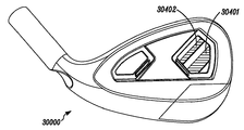
도면을 계속 참조하면, 도 8은 본 명세서에 설명된 골프 클럽 및 제조 방법의 일 실시예에 따른 클럽 헤드 세트(80)의 클럽 헤드(800)를 도시한 배면도이다. 도 9는 클럽 헤드(800)의 토우(toe)를 도시한 측면도이다. 도 10은 클럽 헤드(800)의 조립 해제 상태에서의, 클럽 헤드(800)의 몸체(801)를 도시한 배면도이다. 클럽 헤드(800)는 클럽 헤드(100)(도 1 내지 도 5)와 유사하며, 전면(950)(도 9)과 샤프트 보어 축선(806)의 사이의 로프트 각도(955)(도 9)를 포함한다. 도 9의 예에 있어서, 샤프트 보어 축선(806)은 호젤(805)의 보어에 의해 형성되지만, 그외 다른 호젤 생략 예가 가능할 수도 있으며, 이러한 예에 있어서는 샤프트 보어 축선(806)이 클럽 헤드 몸체의 힐에 위치한 샤프트 보어에 의해 형성될 수 있다. 도 8의 예에 있어서, 클럽 헤드(800)는 또한, 전면(950)(도 9)의 반대쪽 후면(860)을 포함하는 후방부(802)를 포함하며, 후면은 후방부(802)의 토우 영역(810)과 힐 영역(820)의 사이에서 연장된다. 몇몇 실시예에 있어서, 후방부(802)는 또한 클럽 헤드(800)의 후방 측면으로도 일컬어질 수 있다. 클럽 헤드(800)는 또한, 본 실시예의 삽입부(885, 895)를 포함한다. 삽입부(885)는 추(185)(도 1 및 도 3)와 유사할 수 있으며, 후방부(802)에서 클럽 헤드(100)의 공동(180)(도 1, 도 3 및 도 5)과 유사한 공동(1080)(도 10)의 내부로 삽입될 수 있다. 하부 토우 삽입부(895)는 클럽 헤드(100)의 추(195)(도 1 및 도 4)와 유사할 수 있다. 클럽 헤드(800)는 아래에 추가로 논의되는 바와 같이 두 개 이상의 골프 클럽의 클럽 헤드 세트(80)의 일부를 포함한다.With continued reference to the drawings, FIG. 8 is a rear view of the
클럽 헤드(800)는 또한, 본 실시예에 있어서, 삽입부 기부(863)에 위치한 삽입부(862)를 포함하며, 삽입부 기부는 후면(860)의 중심에 마련되어 있다. 도 8에 도시된 바와 같이, 삽입부(862)는 클럽 헤드(800)에 관한 로고(logo) 또는 그외 다른 식별 특징부를 포함할 수 있다. 삽입부(862)가 클럽 헤드(800)의 음향, 진동, 주파수 및/또는 질량 분포에 영향을 미치는, 도 1, 도 3 및 도 4의 추(185) 및/또는 추(195)에 대해 설명된 바와 같은 재료를 포함할 수도 있는 실시예를 고려할 수도 있다.The
클럽 헤드(800)는 중심 영역(864)이 가운데 개재되는 상태로 중심 영역으로부터 동일한 거리에 마련되도록 후면(860)에 결합되는 지지 바(861)를 포함한다는 점에서 클럽 헤드(100)(도 1 내지 도 5)와 상이하다. 지지 바(861)는 힐 영역(820)의 지지 바(8611), 그리고 토우 영역(810)의 지지 바(8612)를 포함하며, 양 지지 바는 모두 후면(860)으로부터 돌출된다. 그러나, 상이한 개수 및/또는 상이한 배열의 지지 바를 채용하는 그외 다른 예가 가능할 수도 있다. 예를 들어, 추가 지지 바가 지지 바(8611)와 힐 영역(820)의 힐 단부의 사이에 배치될 수도 있다. 마찬가지로, 추가 지지 바가 지지 바(8612)와 토우 영역(810)의 토우 단부의 사이에 배치될 수도 있다. 몇몇 예에 있어서, 삽입부 기부(863)가 또한 하나 이상의 지지 바를 포함하는 것으로 간주될 수도 있다. 예를 들어, 삽입부 기부(863)의 기단부(8613, 8614)가 또한 몇몇 예에서 후면(860)으로부터 돌출되는 지지 바로서 간주될 수 있다. 또한, 몇몇 예에 있어서, 삽입부 기부(863)가 후면(860)으로부터 돌출됨으로써 삽입부 기부(863) 자체가 지지 바로서 간주될 수도 있다.
본 실시예에 있어서, 지지 바(8611, 8612)는 실질적으로 동일한 지지 바 폭을 포함한다. 동일한 또는 그외 다른 실시예에 있어서, 지지 바 폭은 대략 0.03inch(0.75mm) 내지 대략 0.5inch(12.7mm)일 수 있다. 도 8의 예에 있어서, 양 지지 바(8611, 8612)의 지지 바 폭이 일정하긴 하지만, 다른 예에 있어서는 지지 바(8612) 및/또는 지지 바(8611)와 유사한 지지 바의 길이를 따라 점차 가늘어지거나 그외 다른 방식으로 변경될 수도 있다. 또한, 본 예에 있어서는, 지지 바(861)의 지지 바 폭이 또한 일정하긴 하지만, 다른 예에 있어서는 지지 바(8612) 및/또는 지지 바(8611)와 유사한 지지 바의 길이를 따라 후면(860)으로부터 측정된 바와 같이 점차 가늘어지거나 그외 다른 방식으로 변경될 수도 있다.In this embodiment, the support bars 8611, 8612 include substantially the same support bar widths. In the same or other embodiments, the support bar width can be approximately 0.03 inches (0.75 mm) to approximately 0.5 inches (12.7 mm). In the example of FIG. 8, although the support bar widths of both
본 실시예에 있어서, 지지 바(861)는 동일한 재료로 이루어진 부분을 포함함으로써 후면(860)과 일체형으로 형성된다. 예를 들어, 지지 바(861)는 후면(860)과 함께 주조 가공, 단조 가공, 또는 기계 가공될 수 있다. 그외 다른 실시예에 있어서는, 지지 바가 개개의 후면과 일체형으로 형성되지 않을 수도 있지만, 후면에 고정적으로 부착된다. 이러한 예에 있어서, 지지 바는 후면에 용접, 브레이징(brazing), 에폭시 접합, 또는 그외 다른 방법을 사용하여 부착될 수 있다.In this embodiment, the
본 실시예에 있어서, 지지 바(8611)는 중심 영역(864)을 향하여 수평 축선(807)으로부터 측정되는 각도(8615)를 포함한다. 마찬가지로, 지지 바(8612)는 또한 중심 영역(864)을 향하여 수평 축선(807)으로부터 측정되는 각도(8616)를 포함한다. 수평 축선(807)은 클럽 헤드(800)를 상부 절반부와 하부 절반부로 양분하는 축선이다. 각도(8615) 및/또는 각도(8616)가 수평 축선(807)으로부터 대략 30°내지 대략 90°의 예각을 포함하는 실시예가 가능할 수 있다. 동일한 또는 그외 다른 실시예에 있어서, 지지 바(8611, 8612)는 중심 영역(864)으로 수렴되는 각도로 형성된다. 또한, 각도(8615) 및/또는 각도(8616)가 수평 축선(807)으로부터 대략 90°내지 대략 150°의 각도 및/또는 둔각을 포함하는 실시예가 가능할 수도 있다. 도 8의 예에 있어서 각도(8615, 8616)가 모두 대략 68°를 포함하긴 하지만, 그외 다른 실시예에 있어서는 각도(8615, 8616)가 서로 동일하지 않을 수도 있으며, 및/또는 각도(8615) 및/또는 각도(8616) 중 적어도 하나가 중심 영역(864)에 대해 예각이 아닐 수도 있다. 각도(8615) 및/또는 각도(8616)가 클럽 헤드 세트(80)의 서로 다른 클럽 헤드에 걸쳐 일정하게 유지될 수도 있으며, 또는 동일한 클럽 헤드 세트의 일 클럽 헤드로부터 다른 클럽 헤드까지 변경될 수도 있다.In this embodiment, the
도 10은 조립 해제 상태의 클럽 헤드(800)의 몸체(801)를 도시한 배면도이다. 이전 도면을 뛰어 넘어, 도 18은 도 8의 선 18-18을 따라 취한 클럽 헤드(800)를 도시한 단면도이다. 간명성을 위해, 도 18에는 하부 토우 삽입부(895)에 대한 세부 구성이 도시되어 있지 않긴 하지만, 삽입부(885)가 공동(1080)에 삽입되는 것으로 도시되어 있음에 주목하여야 한다. 도 8, 도 10 및 도 18에 도시된 바와 같이, 클럽 헤드(800)의 후방부(802)는 힐 영역(820)과 토우 영역(810)의 사이에서 연장되는 후방 단부(870)를 포함하며, 후방 단부(870)는 클럽 헤드(100)의 제 2 후방 단부(170)(도 1, 도 3 내지 도 5)와 유사할 수 있다. 몇몇 예에 있어서, 후방 단부(870)는 후방 벽으로 일컬어질 수 있다. 공동(1080)이 또한 후면(860)과 후방 단부(870)의 사이로 후방부(802)에 위치하며, 공동의 힐 구역(1082), 공동의 토우 구역(1083), 공동의 중심 구역(1181), 전면(950)에 가까이 위치한 공동의 내부 섹션(1084), 그리고 후방 단부(870)에 가까이 위치한 공동의 외부 섹션(1885)으로 이루어진다. 본 예에 있어서, 공동의 내부 섹션(1084)이 후면(860)의 반대쪽에 배치되며, 공동의 외부 섹션(1885)이 후방 단부(870)의 반대쪽에 배치된다. 본 실시예에 있어서, 도 18에 도시된 바와 같이, 공동(1080)은 공동의 중심 구역(1181)에서의 폭이 공동의 힐 구역(1082) 또는 공동의 토우 구역(1083) 중 어느 하나의 폭보다 큰 형태로 형성된다. 예를 들어, 공동의 내부 섹션(1084)은 공동의 중심 구역(1181)에서 전면(950)에 대해 공동의 힐 구역(1082) 또는 공동의 토우 구역(1083) 중 어느 하나보다 얇게 형성된다. 몇몇 예에 있어서, 공동의 내부 섹션(1884)이 공동의 내벽으로 일컬어질 수 있으며, 및/또는 공동의 외부 섹션(1885)이 공동의 외벽으로 일컬어질 수 있다.10 is a rear view of the
본 예에 있어서, 전면(950)과 공동의 내부 섹션(1084)의 노출면 사이의 거리가 공동의 힐 구역(1082)에서 그리고 공동의 토우 구역(1083)에서 공동의 중심 구역(1181)에서보다 크다. 또한, 실시예에 따라, 후방 단부(870)와 공동의 외부 섹션(1885)의 노출면 사이의 거리가 공동의 힐 구역(1082)에서 그리고 공동의 토우 구역(1083)에서 공동의 중심 구역(1181)에서보다 클 수도 있다.In this example, the distance between the
삽입부(885)는 본 실시예에 있어서 삽입부 힐 구역(1886), 삽입부 토우 구역(1887), 그리고 삽입부 중심 구역(1888)을 포함하며, 삽입부 중심 구역(1888)이 삽입부 힐 구역(1886) 또는 삽입부 토우 구역(1887) 중 어느 하나보다 두껍게 형성되도록 공동(1080)과 상보형으로 형성된다. 도 18의 예에 있어서, 삽입부 힐 및 토우 구역(1886, 1887)은 삽입부 내벽(1889)을 따라 삽입부 중심 구역(1888)을 중심으로 서로에 대해 둔각을 이룬다. 마찬가지로, 공동의 내부 섹션(1084)은 삽입부 내벽(1889)과 상보형으로 둔각을 이룬다. 본 예에 있어서, 공동(1080)은 삽입부(885)가 클럽 헤드(800)에 대해 상측으로부터 바닥까지 일 방향으로 삽입 가능하도록 구성된다. 또한, 삽입부(885)가 다른 유사한 형상의 삽입부와 교체 가능할 수도 있는 예를 고려할 수도 있다.
몇몇 예에 있어서, 클럽 헤드(800)의 몸체(801)의 재료는 적어도 대략 5.0 g/cm3의 비중을 나타낼 수도 있으며, 및/또는 삽입부(885)의 재료는 적어도 대략 1.2 g/cm3의 비중을 나타낼 수도 있다. 동일한 또는 그외 다른 예에 있어서, 삽입부(885)의 질량은 대략 10g일 수도 있다.In some examples, the material of the
공동(1080)과 삽입부(885)에 대해 전술한 공동(1080)과 삽입부(885)의 사이의 치수 관계는, 예를 들어, 클럽 헤드(800)의 질량 분포 조절을 허용하기에 유리할 수 있다. 삽입부(885)의 재료의 밀도가 클럽 헤드(800)의 몸체(801)의 재료의 질량보다 낮은 본 실시예에 있어서, 공동의 중앙 구역(1181)에 대해 공동의 힐 구역(1082)과 공동의 토우 구역(1083)에서 공동의 내벽 섹션(1084)의 두께가 커질수록 그리고 삽입부 힐 구역(1886)과 삽입부 토우 구역(1887)에 대해 삽입부 중심 구역(1888)의 두께가 커질수록, 클럽 헤드(800)의 중심으로부터 힐 및 토우 영역(820, 810)을 향해 질량의 재분배가 이루어질 수 있다. 일 예로서, 공동의 내부 섹션(1084)의 분포 질량이 힐 영역(820)을 향해 그리고 토우 영역(810)을 향해 공동의 중심 구역(1181)의 반대 방향으로 이동된다. 또한, 삽입부(885)의 분포 질량이 삽입부 중심 구역(1888)에 집중되며, 삽입부 힐 구역(1886)으로 갈수록 그리고 삽입부 토우 구역(1887)으로 갈수록 감소한다.The dimensional relationship between the
이러한 질량 분포는 클럽 헤드(800)의 중심 영역을 중심으로 관성 모멘트를 증가시킬 수 있으며, 오프-센터(off-center) 충돌 시에 클럽 헤드의 비틀림을 감소시킴으로써 게임 방식을 개선할 수 있다. 예를 들어, 전술한 형상 및 구성으로 인해, 공동의 힐 구역(1082)에서 그리고 공동의 토우 구역(1083)에서 공동의 내부 섹션(1084)에 의해 발생되는 관성 모멘트의 일부가 삽입부 힐 구역(1886)에서 그리고 삽입부 토우 구역(1887)에서 삽입부(885)에 의해 발생되는 관성 모멘트의 일부보다 크다. 그외 다른 실시예에 있어서, 삽입부(885)와 공동(1080)의 사이의 그외 다른 형상 및/또는 밀도 관계가 다양한 소망하는 관성 모멘트 또는 질량 분포를 달성하도록 사용될 수도 있다.This mass distribution can increase the moment of inertia about the center area of the
도 8 및 도 18에 도시된 바와 같이, 삽입부(885)가 공동(1080)에 부분적으로 삽입됨으로써, 삽입부(885)의 파지부가 공동(1080)의 외부로 돌출되어. 예를 들어, 삽입부(885)의 공동(1080) 내부로의 삽입 또는 삽입부(885)의 공동(1080)으로부터 제거를 허용 또는 촉진하게 된다. 그러나, 그외 다른 실시예에 있어서, 삽입부(885)는 공동(1080)으로부터 돌출될 필요가 없다. 본 실시예에 있어서, 지지 바(861)가 또한 후면(860)으로부터 공동의 내부 섹션(1084)까지 연장되며, 공동의 내부 섹션(1084)이 후면(860)에 대해 적어도 지지 바(861)와 동일한 두께로 형성되어, 삽입부(885)의 공동(1080) 내부로의 삽입 또는 삽입부(885)의 공동(1080)으로부터 제거 동안 지지 바(861)의 간섭 현상을 방지하게 된다.As shown in FIGS. 8 and 18, the
다시 이전 도면으로 돌아가면, 도 10 내지 도 15에는 클럽 헤드 세트(80)의 예시적인 클럽 헤드가 도시되어 있다. 도 10은 클럽 헤드(800)의 조립 해제 상태에서의 클럽 헤드(800)의 몸체(801)를 도시한 배면도이다. 도 11은 클럽 헤드(1100)의 조립 해제 상태에서 클럽 헤드 세트(80)에 포함된 클럽 헤드(1100)의 몸체(1101)를 도시한 배면도이다. 도 12는 클럽 헤드(1200)의 조립 해제 상태에서 클럽 헤드 세트(80)에 포함된 클럽 헤드(1200)의 몸체(1201)를 도시한 배면도이다. 도 13은 도 10의 선 13-13을 따라 취한 클럽 헤드(800)를 도시한 단면도이다. 도 14는 도 11의 선 14-14를 따라 취한 클럽 헤드(1100)를 도시한 단면도이다. 도 15는 도 12의 선 15-15를 따라 취한 클럽 헤드(1200)를 도시한 단면도이다. 클럽 헤드(800, 1100, 1200)는 아래에 상세히 설명되는 바와 같이 서로 유사할 수 있다.Returning to the previous figures, FIGS. 10-15 illustrate exemplary club heads of club head set 80. 10 is a rear view of the
본 예에 있어서, 클럽 헤드(800, 1100, 1200)는 클럽 헤드 세트(80)가 두 개 이상의 클럽 헤드를 포함할 수 있는 관련 골프 클럽의 클럽 헤드 세트(80)의 일부를 형성한다. 간명성을 위해 도 10 내지 도 12에는 클럽 헤드 세트(80)의 단지 클럽 헤드(800, 1100, 1200)가 도시되어 있지만, 클럽 헤드 세트(80)가 세 개 이상의 클럽 헤드를 포함할 수 있다. 또한, 클럽 헤드 세트(80)가 단지 두 개의 클럽 헤드를 포함할 수 있는 그외 다른 실시예가 가능할 수도 있다. 클럽 헤드 세트(80)의 각각의 클럽 헤드는 개개의 후면으로부터 돌출되는 하나 이상의 지지 바를 포함한다. 예를 들어, 도 8 및 도 10에 도시된 바와 같이, 클럽 헤드(800)는 위에 보다 상세히 설명되는 바와 같이 후면(860)으로부터 돌출되는 지지 바(8611, 8612)를 포함하는 지지 바(861)를 포함한다. 도 11에 도시된 바와 같이, 클럽 헤드(1100)는 지지 바(1161), 즉, 후면(1160)으로부터 돌출되는 지지 바(11611, 11612)를 포함한다. 또한, 도 12에 도시된 바와 같이, 클럽 헤드(1200)는 지지 바(1261), 즉, 후면(1260)으로부터 돌출되는 지지 바(12611, 12612)를 포함한다.In this example, club heads 800, 1100, 1200 form part of a club head set 80 of an associated golf club in which the club head set 80 may include two or more club heads. For simplicity, only club heads 800, 1100, 1200 of club head set 80 are shown in FIGS. 10-12, but club head set 80 may include three or more club heads. In addition, other embodiments may be possible in which the club head set 80 may include only two club heads. Each club head of the club head set 80 includes one or more support bars protruding from the respective back side. For example, as shown in FIGS. 8 and 10, the
본 예에 있어서, 클럽 헤드 세트(80)의 클럽 헤드의 로프트 각도는 두 개 이상의 클럽 헤드에 걸쳐 증가하는 방식으로 변한다. 예를 들어, 클럽 헤드 세트(80)의 본 예에 있어서, 클럽 헤드(800)는 전면(950)과 샤프트 보어 축선(806)의 사이의 로프트 각도(955)(도 9)가 대략 18.5°인 2-아이언 클럽 헤드를 포함하며(도 13), 클럽 헤드(1100)는 전면(1450)과 샤프트 보어 축선(1406)의 사이의 로프트 각도(1455)가 대략 30.5°인 6-아이언 클럽 헤드를 포함하고(도 14), 클럽 헤드(1200)는 전면(1550)과 샤프트 보어 축선(1506)의 사이의 로프트 각도(1555)가 대략 47°인 웨지-아이언 클럽 헤드를 포함한다(도 15). 결과적으로, 클럽 헤드(1200)의 로프트 각도(1555)가 클럽 헤드(1100)의 로프트 각도(1455)보다 크며, 또한 클럽 헤드(1100)의 로프트 각도(1455)가 클럽 헤드(800)의 로프트 각도(955)보다 크다.In this example, the loft angle of the club head of club head set 80 varies in an increasing manner over two or more club heads. For example, in this example of club head set 80,
또한, 본 예에 있어서, 하나 이상의 지지 바의 특성값이 로프트 각도에 따라 두 개 이상의 클럽 헤드에 걸쳐 증가하는 방식으로 변한다. 예를 들어, 로프트 각도(1555)는 전술한 바와 같이 로프트 각도(1455)보다 크며, 이에 따라, 골프 클럽(1200)의 지지 바(1261)(도 12)의 속성값이 골프 클럽(1100)의 지지 바(1161)(도 11)의 속성값보다 크다. 본 예에 있어서, 지지 바의 폭이 가변적인 지지 바의 속성의 일 예로서, 지지 바(1261)(도 12)의 폭이 지지 바(1161)의 폭보다 크며(도 11), 지지 바(1161)(도 11)의 폭이 지지 바(861)(도 10)의 폭보다 크다.Also, in the present example, the characteristic value of one or more support bars varies in a way that increases over two or more club heads depending on the loft angle. For example, the
예시적인 클럽 헤드 세트(80)에 대한 로프트 각도에 대한 지지 바 폭의 변화가 도 16에 요약되어 있다. 본 예에 있어서, 클럽 헤드 세트(80)는 2-아이언 헤드로서의 클럽 헤드(800)와, 3-아이언 헤드로서의 클럽 헤드(1630)와, 4-아이언 헤드로서의 클럽 헤드(1640)와, 5-아이언 헤드로서의 클럽 헤드(1650)와, 6-아이언 헤드로서의 클럽 헤드(1100)와, 7-아이언 헤드로서의 클럽 헤드(1670)와, 8-아이언 헤드로서의 클럽 헤드(1680)와, 9-아이언 헤드로서의 클럽 헤드(1690), 그리고 웨지-아이언 헤드로서의 클럽 헤드(1200)를 포함한다. 도 16으로부터 알 수 있는 바와 같이, 로프트 각도가 일 클럽 헤드로부터 클럽 헤드 세트(80)의 인접부로 갈수록 증가함에 따라 지지 바 폭 속성값이 증가하는 방식으로 변한다. 결과적으로, 로프트 각도가 보다 큰 클럽의 지지 바 폭은 로프트 각도가 보다 작은 클럽의 지지 바 폭과 동일하거나 보다 크다. 그러나, 로프트 각도가 증가하는 경우 하나 이상의 지지 바의 특성값 및/또는 속성값이 증가하는 방식으로 변할 수 있어, 로프트 각도가 보다 큰 클럽의 지지 바 폭이 로프트 각도가 보다 작은 클럽의 지지 바 폭보다 큰 예를 또한 고려할 수도 있다. The change in support bar width versus loft angle for the exemplary club head set 80 is summarized in FIG. 16. In this example, the club head set 80 includes a
이전 도면을 뛰어 넘어, 도 22에 도시된 바와 같이, 지지 바 폭과 로프트 각도/클럽 헤드 개수 사이의 관계가 하나 이상의 범위 이내에 속할 수도 있다. 예를 들어, 클럽 헤드 세트(2281)는, 도 22에 지시된 바와 같이, 클럽 헤드와 클럽 헤드 사이에서 변하는 지지 바 폭이 보다 두꺼운 클럽 헤드를 포함한다. 마찬가지로, 다른 예에 있어서, 클럽 헤드 세트(2282)는, 도 22에 또한 지시된 바와 같이, 클럽 헤드와 클럽 헤드 사이에서 변하는 지지 바 폭이 보다 얇은 클럽 헤드를 포함한다. 그외 다른 클럽 헤드 세트에 대하여 그외 다른 예 또는 변화율이 또한 고려될 수 있다.Beyond the previous figures, as shown in FIG. 22, the relationship between the support bar width and the loft angle / club head number may fall within one or more ranges. For example, club head set 2231 includes a club head with a thicker support bar width that varies between the club head and the club head, as indicated in FIG. 22. Similarly, in another example, the club head set 2228 includes a club head with a thinner support bar width that varies between the club head and the club head, as also indicated in FIG. 22. Other examples or rates of change may also be considered for other club head sets.
동일한 또는 그외 다른 예에 있어서, 지지 바 폭은 하나 이상의 클럽 헤드 세트의 클럽 헤드에 대하여 로프트 각도 및/또는 클럽 헤드 개수에 따라 소정의 범위 이내에서 변할 수도 있다. 예를 들어, In the same or other examples, the support bar width may vary within a predetermined range depending on the loft angle and / or the number of club heads relative to the club heads of one or more club head sets. E.g,
2-아이언 헤드의 경우, 로프트 각도는 대략 18°내지 대략 20°의 범위일 수 있으며, 지지 바 폭은 대략 0.03inch(0.75mm) 내지 대략 0.2inch(5.1mm)의 범위일 수 있으며;For a two-iron head, the loft angle can range from about 18 ° to about 20 °, and the support bar width can range from about 0.03 inch (0.75 mm) to about 0.2 inch (5.1 mm);
3-아이언 헤드의 경우, 로프트 각도는 대략 20°내지 대략 23°의 범위일 수 있으며, 지지 바 폭은 대략 0.04inch(1.0mm) 내지 대략 0.21inch(5.3mm)의 범위일 수 있으며;For a three-iron head, the loft angle can range from approximately 20 ° to approximately 23 °, and the support bar width can range from approximately 0.04 inch (1.0 mm) to approximately 0.21 inch (5.3 mm);
4-아이언 헤드의 경우, 로프트 각도는 대략 21°내지 대략 25°의 범위일 수 있으며, 지지 바 폭은 대략 0.05inch(1.3mm) 내지 대략 0.23inch(5.8mm)의 범위일 수 있으며;For 4-iron heads, the loft angle can range from approximately 21 ° to approximately 25 °, and the support bar width can range from approximately 0.05 inches (1.3 mm) to approximately 0.23 inches (5.8 mm);
5-아이언 헤드의 경우, 로프트 각도는 대략 23°내지 대략 28°의 범위일 수 있으며, 지지 바 폭은 대략 0.06inch(1.5mm) 내지 대략 0.26inch(6.6mm)의 범위일 수 있으며;For 5-iron heads, the loft angle can range from approximately 23 ° to approximately 28 °, and the support bar width can range from approximately 0.06 inch (1.5 mm) to approximately 0.26 inch (6.6 mm);
6-아이언 헤드의 경우, 로프트 각도는 대략 26°내지 대략 32°의 범위일 수 있으며, 지지 바 폭은 대략 0.07inch(1.8mm) 내지 대략 0.30inch(7.6mm)의 범위일 수 있으며;For a six-iron head, the loft angle can range from approximately 26 ° to approximately 32 °, and the support bar width can range from approximately 0.07 inch (1.8 mm) to approximately 0.30 inch (7.6 mm);
7-아이언 헤드의 경우, 로프트 각도는 대략 29°내지 대략 36°의 범위일 수 있으며, 지지 바 폭은 대략 0.08inch(2.0mm) 내지 대략 0.34inch(8.7mm)의 범위일 수 있으며;For a 7-iron head, the loft angle can range from approximately 29 ° to approximately 36 ° and the support bar width can range from approximately 0.08 inch (2.0 mm) to approximately 0.34 inch (8.7 mm);
8-아이언 헤드의 경우, 로프트 각도는 대략 34°내지 대략 42°의 범위일 수 있으며, 지지 바 폭은 대략 0.09inch(2.3mm) 내지 대략 0.39inch(9.8mm)의 범위일 수 있으며;For an 8-iron head, the loft angle can range from approximately 34 ° to approximately 42 ° and the support bar width can range from approximately 0.09 inch (2.3 mm) to approximately 0.39 inch (9.8 mm);
9-아이언 헤드의 경우, 로프트 각도는 대략 38°내지 대략 45°의 범위일 수 있으며, 지지 바 폭은 대략 0.10inch(2.5mm) 내지 대략 0.44inch(11.2mm)의 범위일 수 있으며; 및/또는For a 9-iron head, the loft angle can range from about 38 ° to about 45 °, and the support bar width can range from about 0.10 inch (2.5 mm) to about 0.44 inch (11.2 mm); And / or
웨지-아이언 헤드의 경우, 로프트 각도는 대략 42°내지 대략 64°의 범위일 수 있으며, 지지 바 폭은 대략 0.11inch(2.8mm) 내지 대략 0.50inch(12.7mm)의 범위일 수 있다.For wedge-iron heads, the loft angle can range from approximately 42 ° to approximately 64 ° and the support bar width can range from approximately 0.11 inch (2.8 mm) to approximately 0.50 inch (12.7 mm).
동일한 또는 그외 다른 실시예에 있어서, 지지 바의 그외 다른 하나 이상의 특성값 또는 속성값이 지지 바 폭에 대해 전술한 바와 유사한 방식으로 지지 바 대신에, 지지 바에 추가하여, 지지 바 외에 변할 수 있다. 예를 들어, 일 실시예에 있어서, 그외 다른 특성값 또는 속성값은 로프트 각도에 따라 증가하는 방식으로 변할 수도 있는 후면으로부터 측정한 지지 바 두께를 포함할 수 있다. 이러한 일 예에 있어서, 도 12의 클럽 헤드(1200)의 지지 바(1261)의 두께는 도 11의 클럽 헤드(1100)의 지지 바(1161)의 두께보다 두꺼울 수 있으며, 및/또는 도 11의 클럽 헤드(1100)의 지지 바(1161)의 두께는 도 10의 클럽 헤드(800)의 지지 바(861)의 두께보다 두꺼울 수 있다.In the same or other embodiments, one or more other characteristic or attribute values of the support bar may be varied in addition to the support bar, in addition to the support bar, instead of the support bar in a manner similar to that described above for the support bar width. For example, in one embodiment, other characteristic or attribute values may include a support bar thickness measured from the back side, which may vary in a way that increases with the loft angle. In this example, the thickness of the
동일한 또는 다른 실시예에 있어서, 그외 다른 특성값 또는 속성값은 로프트 각도에 따라 증가하는 방식으로 변할 수도 있는 지지 바의 총 개수를 포함할 수 있다. 이러한 일 실시예가 클럽 헤드(800), 클럽 헤드(1100)와 유사한 클럽 헤드(1702), 그리고 클럽 헤드(1200)와 유사한 클럽 헤드(1703)를 포함하는 클럽 헤드 세트(171)에 대하여 도 17에 도시되어 있다. 도 17의 예에 있어서, 클럽 헤드(1703)에 대한 로프트 각도는 클럽 헤드(1702)에 대한 로프트 각도보다 크며, 클럽 헤드(1702)에 대한 로프트 각도는 클럽 헤드(1701)에 대한 로프트 각도보다 크게 형성됨으로써, 클럽 헤드(1703)에 대한 지지 바의 총 개수가 클럽 헤드(1702)에 대한 지지 바의 총 개수보다 크며, 클럽 헤드(1702)에 대한 지지 바의 총 개수가 클럽 헤드(1701)에 대한 지지 바의 총 개수보다 크다. 일 예에 있어서, 지지 바의 폭, 두께 및 각도는 단일 클럽 헤드의 각각의 지지 바에 대해 동일하게 유지된다. 그외 다른 예에 있어서, 하나 이상의 특성값 또는 속성값이 클럽 헤드 별로 변경되며, 및/또는 단일 클럽 헤드 내부의 지지 바가 상이한 폭, 두께 및/또는 각도를 포함할 수 있다.In the same or other embodiments, other characteristic or attribute values may include the total number of support bars that may vary in a way that increases with the loft angle. One such embodiment is shown in FIG. 17 for a club head set 171 that includes a
전술한 바와 같은 클럽 헤드 세트의 클럽 헤드의 후면에 지지 바가 합체되는 것이 여러 가지 이유로 인해 유리할 수 있다. 예를 들어, 클럽 헤드의 후면에 중심 영역에 인접하여 지지 바를 배치함으로써 골프 공에 가해지는 충격과 연관된 응력을 보다 잘 견디도록 전면 및/또는 전방 플레이트에 대한 지지력을 증가시킬 수 있다. 무게 절감 및/또는 무게 재분배를 고려하여 전방 플레이트의 두께가 최소화된 상황에서는 이러한 추가 지지력이 유용할 수 있다.It may be advantageous for a number of reasons that the support bars are incorporated in the rear of the club head of the club head set as described above. For example, by placing a support bar adjacent to the center region at the rear of the club head, it is possible to increase the bearing force on the front and / or front plate to better withstand the stresses associated with the impacts on the golf ball. This additional bearing capacity can be useful in situations where the thickness of the front plate is minimized in consideration of weight savings and / or weight redistribution.
도 12 및 도 15의 클럽 헤드(1200)와 동일한 웨지 헤드와 같은 짧은 아이언의 경우, 전면(1550)의 정 반대쪽 후면(1260)에 지지 바(1261)와 같은 폭이 더 넓으며 및/또는 두께가 더 두꺼운 지지 바를 배치함으로써, 클럽 헤드(1200)의 무게 중심을 전방으로 이동시키는 효과를 달성할 수 있다. 이러한 무게 중심의 이동은 전면(1550)과 골프공 사이의 기어 효과(gear effect)를 감소시켜, 개선된 궤도 제어를 위해 전면(1550)과 충돌 시에 골프공에 부과되는 스핀을 제한할 수 있다. 또한, 폭이 더 두꺼우며 및/또는 두께가 더 두꺼운 지지 바로 인해 충돌 시에 표면 안정성을 증가시킬 수 있으며 표면의 편향도를 감소시킬 수 있으며 그 결과 개선된 거리 제어 및 반복성이 달성될 수도 있다. 몇몇 예에 있어서, 또한, 도 17의 클럽 헤드(1703)의 지지 바(1761)의 경우에서와 같이 지지 바의 개수를 증가시킴으로써 유사한 결과가 달성될 수 있다. For short irons, such as wedge heads, such as the
도 8, 도 10 및 도 13의 클럽 헤드(800)와 동일한 2-아이언과 같은 긴 아이언의 경우, 지지 바 폭, 지지 바 두께, 및/또는 지지 바의 총 개수이든지 간에 지지 바의 관련 특성값 또는 속성값을 감소시킴으로써 개선된 제어 효과를 달성하기 위해 클럽 헤드의 관성 모멘트가 증가될 수 있어, 관성 모멘트 증가를 위해 클럽 헤드(800)의 더 큰 질량이 클럽 헤드(800)의 전면(950)의 가장자리를 향해 분포될 수 있다. 또한, 클럽 헤드의 전면 및/또는 전방 플레이트의 굴곡도가 증가될 수 있도록 함으로써 관련 지지 바의 특성값 감소로 인해 관통 비행 경로가 더 길어지며 및/또는 더 많아질 수도 있다.For long irons, such as two irons, such as the
또한, 도시된 바와 같은 클럽 헤드 세트(80)의 경우, 지지 바가 클럽 헤드의 후면에서 보일 수 있으므로, 지지 바의 배치를 증가하는 증가된 지지력, 강도 및 제어 특징을 이해할 수 있는 사용자의 경우에 사용자 신뢰 증가가 달성될 수도 있다. In addition, in the case of the club head set 80 as shown, the support bar can be seen from the rear of the club head, so that the user in the case of a user who can understand the increased bearing capacity, strength and control features that increase the placement of the support bar Increasing confidence may be achieved.
뒤로 돌아가 도 8을 참조하면, 클럽 헤드(800)는 또한, 삽입부(885)와 관련 공동(1080)(도 10)에 추가하여 하부 토우 삽입부(895)를 포함하는 것으로 도시되어 있다. 그러나, 하부 토우 삽입부(895) 없이 삽입부(885)와 공동(1080)을 포함하는 그외 다른 실시예 및/또는 삽입부(885)와 공동(1080) 없이 하부 토우 삽입부(895)를 포함하는 그외 다른 실시예가 가능할 수도 있다. 유사한 특징 변화가 개개의 클럽 헤드 세트의 그외 다른 클럽으로 확장 적용될 수 있다. 예를 들어, 클럽 헤드 세트(80)의 클럽 헤드 중 전부 또는 일부는, 삽입부(885) 및 관련 공동(1080)과 유사한 삽입부 및 관련 공동에 추가하여, 하부 토우 삽입부(895)와 유사한 하부 토우 삽입부를 포함할 수도 있다. 또한, 클럽 헤드 세트의 클럽 헤드 중 전부 또는 일부가 삽입부(885) 및 관련 공동(1080)과 유사한 삽입부 및 관련 공동을 포함할 수도 있지만, 하부 토우 삽입부(895)와 유사한 하부 토우 삽입부를 구비하지 않을 수도 있는 실시예가 가능할 수도 있다. 또한, 클럽 헤드 세트의 클럽 헤드 중 전부 또는 일부가 하부 토우 삽입부(895)와 유사한 하부 토우 삽입부를 포함할 수도 있지만, 삽입부(885) 및 관련 공동(1080)과 유사한 삽입부 및 관련 공동을 구비하지 않을 수도 있는 실시예가 가능할 수도 있다.Returning to FIG. 8, the
도 8을 계속 참조하면, 하부 토우 삽입부(895)는 클럽 헤드(100)의 추(195)(도 1 및 도 4)와 유사할 수 있으며, 본 예에 있어서, 또한, 추를 포함한다. 하부 토우 삽입부(895)는 후방부(802)의 하부 토우 섹션(811)에 배치되며, 클럽 헤드(800)가 둘레 추(875)를 포함하긴 하지만, 하부 토우 삽입부(895)가 하부 토우 섹션(811)에 배치된다. 본 예에 있어서, 하부 토우 삽입부(895)는 텅스텐 재료를 포함하며, 대략 10 g/cm3의 비중을 갖는다. 본 예에 있어서, 클럽 헤드 세트(80)의 그외 다른 클럽 헤드가 또한, 하부 토우 삽입부(895)와 유사한 대응하는 하부 토우 삽입부를 포함한다.With continued reference to FIG. 8, the
몇몇 예에 있어서, 하부 토우 삽입부(895) 및/또는 그외 다른 유사한 삽입부가 클럽 헤드(800)의 질량 재분포에 영향을 미치도록 하부 토우 부분(811)에 배치될 수 있다. 예를 들어, 하부 토우 삽입부(895)는 중심 영역(861)으로부터 반대 방향으로 토우 영역(810) 및/또는 하부 토우 섹션(811)을 향해 클럽 헤드(800)의 분포 질량이 이동됨으로써 클럽 헤드(800)의 관성 모멘트를 증가시키도록 구성될 수 있다. 동일한 또는 그외 다른 예에 있어서, 하부 토우 삽입부(895)는 클럽 헤드(800)의 힐 또는 상부 힐 부분에서 호젤(805)의 질량 균형을 달성하도록 구성될 수 있다. 호젤(805)과 하부 토우 삽입부(895)가 실질적으로 서로 반대쪽으로 배치됨으로써, 클럽 헤드(800)의 분포 질량이 클럽 헤드(800)의 단부를 향해 이동됨으로써 관성 모멘트와 면제 인자가 증가될 수 있다. 동일한 또는 그외 다른 예에 있어서, 하부 토우 삽입부(895)의 치수, 위치, 및/또는 질량이 클럽 헤드(800)의 무게 중심을 힐 영역(820) 및/또는 토우 영역(810)에 대해 상대적인 소망하는 위치로 조절 또는 정렬하도록 형성될 수 있다.In some examples, the
전술한 바와 같이, 본 예에 있어서, 클럽 헤드 세트(80)의 클럽 헤드의 로프트 각도는 두 개 이상의 클럽 헤드에 걸쳐 증가하는 방식으로 변한다. 또한, 대응 하부 토우 삽입부의 특성값 또는 치수가 또한, 로프트 각도 변화와 관련하여 클럽 헤드 세트(80)의 두 개 이상의 클럽 헤드에 걸쳐 변경된다. 예를 들어, 각각의 하부 토우 삽입부가 두 가지 특성값을 포함하는 경우, 로프트 각도가 변경됨에 따라 클럽 헤드 세트(80)의 클럽 헤드에 걸쳐 각각의 하부 토우 삽입부에 대하여 이 두 가지 특성값은 서로 상대적으로 역비례 관계로 변경될 수 있다. 일 예로서, 하부 토우 삽입부의 변경 특성값이 증가하는 방식으로 변할 수도 있는 반면, 하부 토우 삽입부의 정반대 특성값은 로프트 각도가 변경됨에 따라 감소하도록 변경된다.As noted above, in this example, the loft angle of the club heads of club head set 80 varies in a way that increases over two or more club heads. In addition, the characteristic value or dimension of the corresponding lower toe insert is also changed over two or more club heads of club head set 80 in relation to the loft angle change. For example, if each lower toe insert includes two characteristic values, the two characteristic values for each lower toe insert over the club head of club head set 80 as the loft angle is changed are It can be changed in inverse relationship with each other. As an example, the change characteristic value of the lower toe insert may be changed in a manner that increases, while the opposite characteristic value of the lower toe insert is changed to decrease as the loft angle is changed.
로프트 각도에 대한 상대적인 특성값 변화가 클럽 헤드(800, 1100, 1200)를 통해 클럽 헤드 세트(80)의 예를 보여주는 도 10 내지 도 15에 도시된 바로부터 이해할 수 있을 것이다. 도 13 내지 도 15에 도시된 바와 같이, 클럽 헤드(1200)의 로프트 각도(1555)는 클럽 헤드(1100)의 로프트 각도(1455)보다 크며, 클럽 헤드(1100)의 로프트 각도(1455)는 클럽 헤드(800)의 로프트 각도(955)보다 크다. 또한, 본 실시예의 경우, 로프트 각도가 일 클럽 헤드로부터 일 클럽 헤드로 갈수록 증가함에 따라, 클럽 헤드의 개개의 깊이 축선을 따라 측정한 바와 같은 하부 토우 두께가 일 클럽 헤드로부터 일 클럽 헤드로 갈수록 증가하는 경향이 있다. 동일한 그리고 그외 다른 실시예에 있어서, 클럽 헤드의 하부 토우 두께는 클럽 헤드의 바닥과 연관될 수 있으며 및/또는 클럽 헤드의 바닥에 의해 형성될 수 있다. 일 예로서, 클럽 헤드(1200)의 하부 토우 두께(15954)(도 15)가 클럽 헤드(1100)의 하부 토우 두께(14954)(도 14)보다 크며, 클럽 헤드(1100)의 하부 토우 두께(14954)가 클럽 헤드(800)의 하부 토우 두께(13954)(도 13)보다 크다. 마찬가지로, 클럽 헤드(800)의 하부 토우 두께(13954)가 바닥(13001)(도 13)의 두께에 의해 형성되며, 바닥(13001)의 두께 중 일부를 포함하는 반면, 클럽 헤드(1200)의 하부 토우 두께(15954)가 바닥(15001)(도 15)의 두께에 의해 형성되며, 바닥(15001)의 두께 중 일부를 포함함으로써, 바닥(15001)의 두께가 바닥(13001)의 두께보다 크다.Changes in the characteristic values relative to the loft angle can be understood from those shown in FIGS. 10-15 that show examples of club head sets 80 through club heads 800, 1100, 1200. As shown in FIGS. 13-15, the
클럽 헤드 세트(80)의 실시예에 있어서, 변경 특성값은 하부 토우 삽입부의 깊이일 수 있는 반면, 역비례 특성값은 하부 토우 삽입부의 면적일 수 있다. 일 예로서, 클럽 헤드(800)의 경우, 하부 토우 삽입부(895)의 삽입부 깊이(13952)(도 13)가 깊이 축선(13953)을 따라 측정되며, 깊이 축선(13953)은 하부 토우 삽입부(865)와 전면(950)의 사이의 최소 거리 지점(13955)을 가로질러 연장되며, 삽입부 면적(8951)(도 8 및 도 10)은 깊이 축선(13953)과 실질적으로 수직 방향의 하부 토우 삽입부(895)의 단면적을 나타내며 및/또는 깊이 축선(13953)은 바닥(13001)(도 13)과 실질적으로 평행하며 및/또는 샤프트 보어 축선(806)과 실질적으로 수직 방향이다. 마찬가지로, 클럽 헤드(1100)의 경우, 삽입부 깊이(14952)(도 14)가 깊이 축선(14953)을 따라 측정되며, 깊이 축선(14953)은 하부 토우 삽입부(1195)와 전면(1450)의 사이의 최소 거리 지점(14955)을 가로질러 연장되며, 삽입부 면적(11951)(도 11)은 깊이 축선(14953)과 실질적으로 수직 방향의 하부 토우 삽입부(1195)의 단면적을 나타내며 및/또는 깊이 축선(14953)은 바닥(14001)(도 14)과 실질적으로 평행하며 및/또는 샤프트 보어 축선(1406)과 실질적으로 수직 방향이다. 다른 예로서, 클럽 헤드(1200)의 경우, 삽입부 깊이(15952)(도 15)가 깊이 축선(15953)을 따라 측정되며, 깊이 축선(15953)은 하부 토우 삽입부(1295)와 전면(1550)의 사이의 최소 거리 지점(15955)을 가로질러 연장되며, 삽입부 면적(12951)(도 12)은 깊이 축선(15953)과 실질적으로 수직 방향의 하부 토우 삽입부(1295)의 단면적을 나타내며 및/또는 깊이 축선(15953)은 바닥(15001)(도 15)과 실질적으로 평행하며 및/또는 샤프트 보어 축선(1506)과 실질적으로 수직 방향이다. 이러한 예에서, 하부 토우 삽입부 깊이(13952, 14952, 15952)의 변경 특성값이 클럽 헤드(800)로부터 클럽 헤드(1200)로 가면서 증가되는 경우, 하부 토우 영역(8991, 11951, 12951)의 역비례 특성값이 클럽 헤드(800)로부터 클럽 헤드(1200)로 가면서 감소한다. 상이한 일 실시예에 있어서, 로프트 각도(955, 1455, 1555)가 증가함에 따라 하부 토우 삽입부 깊이(13952, 14952, 15952)가 증가된다.In an embodiment of the club head set 80, the change characteristic value may be the depth of the lower toe insert, while the inverse characteristic value may be the area of the lower toe insert. As an example, in the case of
동일한 또는 그외 다른 실시예에 있어서, 변경 특성값 또는 치수 중 하나는 개개의 클럽 헤드의 전면과 하부 토우 삽입부의 무게 중심 사이의 거리일 수 있다. 예를 들어, 하부 토우 삽입부의 무게 중심과 대응하는 로프트 각도가 더 작은 클럽 헤드의 전면 사이의 거리가 하부 토우 삽입부의 무게 중심과 대응하는 로프트 각도가 더 큰 클럽 헤드의 전면 사이의 거리보다 클 수 있다. 일 예로서, 하부 토우 삽입부(895)의 무게 중심(13956)과 클럽 헤드(800)의 전면(950)(도 13) 사이의 거리(13957)가 하부 토우 삽입부(1195)의 무게 중심(14956)과 클럽 헤드(1100)의 전면(1450)(도 14) 사이의 거리(14957)보다 크며, 하부 토우 삽입부(1195)의 무게 중심(14956)과 클럽 헤드(1100)의 전면(1450) 사이의 거리(14957)가 하부 토우 삽입부(1295)의 무게 중심(15956)과 클럽 헤드(1200)의 전면(1550)(도 15) 사이의 거리(15957)보다 크다. 이러한 예에 있어서, 하부 토우 삽입부 깊이(13952, 14952, 15952)의 변경 특성값이 클럽 헤드(800)로부터 클럽 헤드(1200)로 가면서 증가되는 경우, 무게 중심 거리(13957, 14957, 15957)의 역비례 특성값이 클럽 헤드(800)로부터 클럽 헤드(1200)로 가면서 감소한다. 상이한 일 실시예에 있어서, 로프트 각도(955, 1455, 1555)가 증가함에 따라 무게 중심 거리(13957, 14957, 15957)가 감소한다.In the same or other embodiments, one of the changing characteristic values or dimensions may be the distance between the front of the individual club head and the center of gravity of the lower toe insert. For example, the distance between the center of gravity of the lower toe insert and the front of the club head with the corresponding loft angle is smaller than the distance between the center of gravity of the lower toe insert and the front of the club head with the corresponding loft angle. have. As an example, the distance 13357 between the center of
전술한 바와 같이 로프트 각도에 따라 클럽 헤드의 치수가 변함에 따라 하부 토우 삽입부의 삽입부 깊이가 변할 수 있다. 예를 들어, 삽입부(1295)의 삽입부 깊이(15952)(도 15)가 삽입부(1195)의 삽입부 깊이(14952)(도 14)보다 크며, 삽입부(1195)의 삽입부 깊이(14952)가 하부 토우 삽입부(895)의 삽입부 깊이(13952)(도 13)보다 크다. 또한, 하부 토우 삽입부와 개개의 클럽 헤드 전면 사이의 거리가 이에 따라 변할 수 있다. 본 예의 클럽 헤드 세트(80)에 있어서, 클럽 헤드(800)의 삽입부와 표면 사이의 거리(1360)(도 13)는 대략 0.281inch(7.14mm)로, 대략 0.233inch(5.92mm)의 클럽 헤드(1100)의 삽입부와 표면 사이의 거리(1460)(도 14)보다 크며, 이 클럽 헤드(1100)의 삽입부와 표면 사이의 거리(1460)는 대략 0.195inch(4.95mm)의 클럽 헤드(1200)의 삽입부와 표면 사이의 거리(1560)(도 15)보다 크다.As described above, the depth of the insertion portion of the lower toe insert may change as the size of the club head changes according to the loft angle. For example, the insertion depth 15952 (FIG. 15) of the
이러한 하부 토우 삽입부의 삽입부 깊이 변화, 하부 토우 삽입부와 개개의 클럽 헤드 전면 사이의 거리 변화, 및/또는 하부 토우 삽입부의 무게 중심과 개개의 클럽 헤드 전면 사이의 거리 변화는 클럽 헤드의 질량 분포 변화를 초래하여, 클럽 헤드의 소정의 품질 조절이 가능하도록 할 수 있다.This change in the depth of the insertion of the lower toe insert, the change of the distance between the lower toe insert and the front of the individual club head, and / or the change of the distance between the center of gravity of the lower toe insert and the front of the individual club head are the mass distribution of the club head. A change can be effected to allow for a certain quality control of the club head.
예를 들어, 삽입부의 길이를 감소시킴으로써 및/또는 더 작은 로프트 각도 클럽 헤드에 대한 삽입부와 표면 사이의 거리를 증가시킴으로써, 이러한 클럽 헤드의 무게 중심이 개개의 클럽 헤드 전면으로부터 반대 방향으로 이동됨으로써, 클럽 헤드의 동적 로프트 및 부과 스핀이 증가하도록 하여, 예를 들어, 공에 충격이 가해지는 경우 비행 궤적 및/또는 발사 각도를 증가시킬 수 있다. 반대로, 삽입부의 길이를 증가시킴으로써 및/또는 더 큰 로프트 각도 클럽 헤드에 대한 삽입부와 표면 사이의 거리를 감소시킴으로써, 이러한 클럽 헤드의 무게 중심이 개개의 클럽 헤드 전면에 보다 가까이 이동됨으로써, 공에 충격이 가해지는 경우 관통 비행 경로가 증가될 수 있다.For example, by reducing the length of the insert and / or increasing the distance between the insert and the surface for a smaller loft angle club head, the center of gravity of this club head is moved in the opposite direction from the front of the individual club head. The dynamic loft and imposing spin of the club head can be increased, for example, to increase flight trajectory and / or launch angle when the ball is impacted. Conversely, by increasing the length of the insert and / or reducing the distance between the insert and the surface relative to the larger loft angle club head, the center of gravity of this club head is moved closer to the front of the individual club head, thereby providing In the event of an impact, the penetration flight path may be increased.
전술한 바와 같이 삽입부의 깊이가 변화함으로써 클럽 헤드의 서로 다른 하부 토우 삽입부의 질량 변화를 야기할 수 있다. 이러한 질량 변화에 대응하기 위하여, 또한 개개의 하부 토우 삽입부를 이용하여 개개의 호젤의 균형을 이루는 등 클럽 헤드의 그외 다른 품질에 영향을 미칠 수 있도록 하기 위하여, 하부 토우 삽입부의 그외 다른 특성값 또는 치수가 삽입부 깊이 변화에 대하여 역비례 관계로 변경될 수 있다. 예를 들어, 하부 토우 삽입부의 삽입부 깊이가 증가함에 따라, 하부 토우 삽입부의 면적이 감소할 수 있어, 모두 하부 토우 삽입부가 실질적으로 유사한 질량을 포함하게 된다. 몇몇 실시예에 있어서, 클럽 헤드 세트(80)의 하부 토우 삽입부 각각의 질량은 대략 10.25g이다. 동일한 또는 그외 다른 예에 있어서, 상기 질량은 대략 5g 내지 대략 50g의 범위일 수도 있다. 클럽 헤드 세트(80)의 예에 있어서, 삽입부 깊이가 삽입부 깊이(13952)(도 13)로부터 삽입부 깊이(14952)(도 14)까지 증가하며 또한 삽입부 깊이(14952)로부터 삽입부 깊이(15952)(도 15)까지 증가함에 따라, 삽입부의 대응 면적이 삽입부 면적(8951)(도 10)으로부터 삽입부 면적(11951)(도 10)으로 감소하며 또한 삽입부 면적(11951)(도 11)으로부터 삽입부 면적(12951)(도 12)으로 감소함으로써 역비례 관계로 변경될 수 있다.As described above, varying the depth of the insert may cause a change in mass of the different lower toe inserts of the club head. Other characteristics or dimensions of the lower toe inserts in order to counteract such mass changes and to affect other quality of the club head, such as balancing the individual hosels using the individual lower toe inserts. Can be changed in inverse proportion to the insertion depth change. For example, as the insert depth of the lower toe insert increases, the area of the lower toe insert may decrease, such that all of the lower toe inserts contain substantially similar mass. In some embodiments, the mass of each of the lower toe inserts of club head set 80 is approximately 10.25 g. In the same or other examples, the mass may range from about 5 g to about 50 g. In the example of club head set 80, the insert depth is increased from insert depth 13952 (FIG. 13) to insert depth 14952 (FIG. 14) and also from
도 19는 클럽 헤드 세트(80)의 실시예에 대한 하부 토우 삽입부와 전면 사이의 거리와 로프트 각도 사이의 예시적인 관계를 도시한 도표이다. 이전 도면을 뛰어 넘어, 도 23에 도시된 바와 같이, 로프트 각도/클럽 헤드 개수와 하부 토우 추와 전면 사이의 거리 사이의 관계는 하나 이상의 범위 이내에 속할 수도 있다. 예를 들어, 클럽 헤드 세트(2381)의 클럽 헤드는, 도 23에 지시된 바와 같이, 일 클럽 헤드로부터 다른 클럽 헤드까지 하부 토우 추와 전면 사이의 거리가 증가하도록 구성된다. 마찬가지로, 다른 예에 있어서, 클럽 헤드 세트(2382)의 클럽 헤드는, 도 23에 또한 지시된 바와 같이, 일 클럽 헤드로부터 다른 클럽 헤드까지 하부 토우 추와 전면 사이의 거리가 감소하도록 구성된다. 클럽 헤드 세트(2381)의 클럽 헤드의 바닥은, 클럽 헤드 세트(2382)의 클럽 헤드의 바닥과 비교하여, 클럽 헤드의 전면으로부터 후면까지 대체로 폭이 증가하도록 구성될 수 있다. 그외 다른 클럽 헤드 세트에 대하여 그외 다른 예 또는 변화율이 또한 적용 가능하다.19 is a diagram showing an exemplary relationship between the loft angle and the distance between the lower toe insert and the front for an embodiment of the club head set 80. Beyond the previous figures, as shown in FIG. 23, the relationship between the loft angle / number of club heads and the distance between the lower toe weight and the front may fall within one or more ranges. For example, the club head of club head set 2381 is configured to increase the distance between the lower toe weight and the front from one club head to another, as indicated in FIG. 23. Likewise, in another example, the club head of club head set 2382 is configured such that the distance between the lower toe weight and the front from the one club head to the other club head is reduced, as also indicated in FIG. 23. The bottom of the club head of club head set 2381 may be configured to increase in width substantially from the front to the back of the club head compared to the bottom of the club head of club head set 2382. Other examples or rates of change are also applicable for other club head sets.
동일한 또는 그외 다른 예에 있어서, 하나 이상의 클럽 헤드 세트의 클럽 헤드의 경우, 전면과 하부 토우 추 사이의 거리가 로프트 각도 및/또는 클럽 헤드 개수에 따라 소정의 범위 내에서 변할 수도 있다. 예를 들어,In the same or other examples, for club heads of one or more club head sets, the distance between the front and lower toe weights may vary within a predetermined range depending on the loft angle and / or the number of club heads. E.g,
2-아이언 전면과 하부 토우 추 사이의 거리는 대략 0.050inch(1.27mm) 내지 대략 1.2inch(28.08mm)의 범위를 포함할 수 있으며;The distance between the two-iron front and the lower toe weight may comprise a range of approximately 0.050 inch (1.27 mm) to approximately 1.2 inch (28.08 mm);
3-아이언 전면과 하부 토우 추 사이의 거리는 대략 0.048inch(1.22mm) 내지 대략 1.2inch(28.08mm)의 범위를 포함할 수 있으며;The distance between the three-iron front and the lower toe weight may include a range of approximately 0.048 inch (1.22 mm) to approximately 1.2 inch (28.08 mm);
4-아이언 전면과 하부 토우 추 사이의 거리는 대략 0.046inch(1.17mm) 내지 대략 1.19inch(27.85mm)의 범위를 포함할 수 있으며;The distance between the four-iron front and the lower toe weight can range from approximately 0.046 inches (1.17 mm) to approximately 1.19 inches (27.85 mm);
5-아이언 전면과 하부 토우 추 사이의 거리는 대략 0.044inch(1.12mm) 내지 대략 1.17inch(27.38mm)의 범위를 포함할 수 있으며;The distance between the five-iron front and the lower toe weight can include a range of approximately 0.044 inches (1.12 mm) to approximately 1.17 inches (27.38 mm);
6-아이언 전면과 하부 토우 추 사이의 거리는 대략 0.042inch(1.07mm) 내지 대략 1.16inch(27.14mm)의 범위를 포함할 수 있으며;The distance between the six-iron front and the lower toe weight can range from about 0.042 inches (1.07 mm) to about 1.16 inches (27.14 mm);
7-아이언 전면과 하부 토우 추 사이의 거리는 대략 0.040inch(1.02mm) 내지 대략 1.15inch(26.91mm)의 범위를 포함할 수 있으며;The distance between the 7-iron front and the lower toe weight can range from about 0.040 inch (1.02 mm) to about 1.15 inch (26.91 mm);
8-아이언 전면과 하부 토우 추 사이의 거리는 대략 0.038inch(0.97mm) 내지 대략 1.13inch(26.44mm)의 범위를 포함할 수 있으며;The distance between the eight-iron front and the lower toe weight may range from approximately 0.038 inches (0.97 mm) to approximately 1.13 inches (26.44 mm);
9-아이언 전면과 하부 토우 추 사이의 거리는 대략 0.036inch(0.91mm) 내지 대략 1.125inch(26.33mm)의 범위를 포함할 수 있으며; 및/또는The distance between the 9-iron front and the lower toe weight may range from approximately 0.036 inch (0.91 mm) to approximately 1.125 inch (26.33 mm); And / or
웨지 아이언 전면과 하부 토우 추 사이의 거리는 대략 0.034inch(0.86mm) 내지 대략 1.10inch(25.74mm)의 범위를 포함할 수 있다.The distance between the wedge iron front and the lower toe weight can range from about 0.034 inches (0.86 mm) to about 1.10 inches (25.74 mm).
도 13 내지 도 15를 참조하면, 간명성을 위해, 하부 토우 삽입부와 관련하여 로프트 각도가 큰 클럽 헤드와 로프트 각도가 작은 클럽 헤드 사이의 관계가 클럽 헤드 세트(80)의 클럽 헤드(800, 1200)를 참조하여 아래에 설명된다. 그외 다른 클럽 헤드 사이의 관계가 클럽 헤드(800, 1200)에 관한 아래의 설명을 기반으로 추론되거나 추가될 수도 있다.With reference to FIGS. 13-15, for simplicity, the relationship between the club head with a large loft angle and the club head with a small loft angle in relation to the lower toe insertion portion may be described. 1200, described below. Relationships between other club heads may be inferred or added based on the following description of club heads 800, 1200.
본 예의 클럽 헤드 세트(80)에 있어서, 클럽 헤드(800)의 하부 토우 삽입부(895)와 클럽 헤드(1200)의 하부 토우 삽입부(1295)는 실질적으로 유사한 질량을 갖는 추를 포함한다. 또한, 하부 토 삽입부(895, 1295)의 치수는 서로 대응하도록 형성되어, 하부 토우 삽입부(895)의 삽입부 깊이(13952)(도 13)가 하부 토우 삽입부(1295)의 삽입부 깊이(15952)(도 15)에 대응하며, 하부 토우 삽입부(895)의 삽입부 면적(8951)(도 10)이 하부 토우 삽입부(1295)의 삽입부 면적(12951)(도 12)에 대응한다. 삽입부 면적(8951, 12951)은 본 실시예 또는 그외 다른 실시예에 있어서 개개의 하부 토우 삽입부의 단면적 및/또는 후방 단부 면적을 나타낸다. 본 예에 있어서, 하부 토우 삽입부(1295)의 삽입부 깊이(15952)가 하부 토우 삽입부(895)의 삽입부 깊이(13952)보다 크기 때문에, 하부 토우 삽입부(895)의 삽입부 면적(8951)이 하부 토우 삽입부(1295)의 삽입부 면적(12951)보다 크다. 그 결과, 삽입부 면적과 삽입부 깊이 치수가 서로 역비례 관계로 변경된다.In the club head set 80 of this example, the
또한, 도 13 및 도 15에 도시된 바와 같이, 하부 토 삽입부(1595)와 전면(1550)의 사이의 삽입부와 표면 사이의 거리(1560)가 하부 토 삽입부(895)와 전면(950)의 사이의 삽입부와 표면 사이의 거리(1360)보다 크다. 본 예에 있어서, 삽입부와 표면 사이의 거리(1560)는 전면(1550)과 하부 토우 삽입부(1295)의 사이의 최단 거리를 포함하는 반면, 삽입부와 표면 사이의 거리(1360)는 전면(950)과 하부 토우 삽입부(895)의 사이의 최단 거리를 포함한다. 개개의 클럽 헤드(800, 1200)의 전면(950, 1550)과 하부 토우 삽입부(895, 1295)의 사이의 전술한 이러한 관계는 전면(950)에 대한 클럽 헤드(800)의 무게 중심 근접도와 비교하여 클럽 헤드(1200)의 무게 중심이 전면(1550)에 보다 가까이 위치할 수 있는 것으로 개개의 질량 분포를 정의한다.Further, as shown in FIGS. 13 and 15, the
본 예에 있어서, 하부 토우 삽입부(895, 1295)는 클럽 헤드(800, 1200)의 개개의 하부 토우 섹션에서 눈에 보인다. 몇몇 예에 있어서, 이와 같이 하부 토우 삽입부가 가시적임에 따라 사용자로 하여금 개개의 하부 토우 삽입부의 배치에 따라 제공되는 성능 향상 및 제어 특성을 인지할 수 있도록 할 수도 있다. 그러나, 하부 토우 삽입부가 가시적이지 않을 수도 있는 그외 다른 실시예가 또한 가능할 수도 있다. 예를 들어, 하부 토우 삽입부(895)와 하부 토우 섹션(811)의 사이의 계면이 뒤섞일 수도 있으며 또는 그렇지 않고 기계 가공 또는 연마 가공 단계 이후 알아보기 힘들어질 수도 있다.In this example, the lower toe inserts 895 and 1295 are visible in the individual lower toe sections of the club heads 800 and 1200. In some instances, this lower toe insert may be visible so that the user may be aware of the performance improvements and control characteristics provided in accordance with the placement of the individual lower toe insert. However, other embodiments may also be possible where the lower toe insert may not be visible. For example, the interface between the
본 예의 클럽 헤드 세트(80)에 있어서, 클럽 헤드(800)는 후방부(802)의 주변에 둘레부 추(875)를 포함하며, 클럽 헤드(1200)는 후방부(1202)의 주변에 둘레부 추(1275)를 포함한다. 둘레부 추(875)는 하부 토우 섹션(811)에 마련된 공동을 포함하며, 이 공동의 내부에 하부 토우 삽입부(895)가 배치된다. 마찬가지로, 둘레부 추(1275)는 하부 토우 섹션(1211)에 마련된 공동을 포함하며, 이 공동의 내부에 하부 토우 삽입부(1295)가 배치된다. 결과적으로, 이들 하부 토우 삽입부는 개개의 하부 토우 섹션에만 배치되면서도 개개의 둘레부 추와 일체형으로 형성될 수 있다. 또한, 본 예에 있어서, 하부 토우 삽입부(1295)가 클럽 헤드(800)의 하부 토우 섹션(811)의 공동과 함께 제공되지 않을 수도 있으며, 하부 토우 삽입부(895)가 클럽 헤드(1200)의 하부 토우 섹션(1211)의 공동과 함께 제공되지 않을 수도 있다.In the club head set 80 of this example, the
이전 도면으로 돌아가, 도 20은 클럽 헤드 세트를 제공하기 위한 방법(2000)의 순서도이다. 몇몇 예에 있어서, 방법(2000)의 클럽 헤드 세트는 도 8 내지 도 16 및 도 18 내지 도 19의 클럽 헤드 세트(80)와 유사할 수 있으며 및/또는 도 17의 클럽 헤드 세트와 유사할 수 있다.Returning to the previous figure, FIG. 20 is a flowchart of a method 2000 for providing a set of club heads. In some examples, the club head set of method 2000 may be similar to the club head set 80 of FIGS. 8-16 and 18-19 and / or may be similar to the club head set of FIG. 17. have.
방법(2000)의 블록(2010)은 클럽 헤드 세트의 제 1 클럽 헤드를 제공하는 단계를 포함하며, 제 1 클럽 헤드는 제 1 후면에 결합되는 하나 이상의 제 1 지지 바를 포함하고, 하나 이상의 제 1 지지 바는 제 1 지지 바 특성값을 포함한다. 몇몇 예에 있어서, 제 1 클럽 헤드는 클럽 헤드(1200)와 유사할 수 있으며(도 12, 도 15, 도 16 및 도 19), 하나 이상의 제 1 지지 바는 후면(1260)에 결합되는 지지 바(1261)(도 12) 또는 후면(1760)에 결합되는 지지 바(1761)(도 17)와 유사할 수 있다. 동일한 또는 그외 다른 예에 있어서, 제 1 지지 바 특성값에는 지지 바 폭, 지지 바 두께, 및/또는 지지 바의 총 개수가 포함될 수 있다.
방법(2000)의 블록(2020)은 클럽 헤드 세트의 제 2 클럽 헤드를 제공하는 단계를 포함하며, 제 2 클럽 헤드는 제 2 후면에 결합되는 하나 이상의 제 2 지지 바를 포함하고, 하나 이상의 제 2 지지 바는 제 2 지지 바 특성값을 포함한다. 몇몇 예에 있어서, 제 2 클럽 헤드는 클럽 헤드(800)와 유사할 수 있으며(도 8 내지 도 10, 도 13, 도 16 내지 도 19), 하나 이상의 제 1 지지 바는 후면(860)에 결합되는 지지 바(861)(도 8, 도 12 및 도 17)와 유사할 수 있다. 동일한 또는 그외 다른 예에 있어서, 제 2 지지 바 특성값에는 제 2 지지 바 폭, 제 2 지지 바 두께, 및/또는 제 2 지지 바의 총 개수가 포함될 수 있다.
방법(2000)의 블록(2030)은 제 2 클럽 헤드의 제 2 로프트 각도보다 큰 제 1 클럽 헤드의 제 1 로프트 각도를 제공하는 단계를 포함한다. 몇몇 예에 있어서, 제 1 로프트 각도는 클럽 헤드(1200)의 로프트 각도(1555)(도 15)와 유사할 수 있으며, 제 2 로프트 각도는 클럽 헤드(800)의 로프트 각도(955)(도 9 및 도 13)와 유사할 수 있다.
방법(2000)의 블록(2040)은 제 2 클럽 헤드의 제 2 지지 바 특성값보다 큰 제 1 제 1 클럽 헤드의 제 1 지지 바 특성값을 제공하는 단계를 포함한다. 결과적으로, 지지 바 특성값은 클럽 헤드의 로프트 각도가 증가하는 경우 증가한다. 일 예에 있어서, 도 12의 클럽 헤드(1200)의 제 1 지지 바 특성값은 지지 바(1261)의 지지 바 폭을 포함하는 반면, 도 10의 클럽 헤드(800)의 제 2 지지 바 특성값은 지지 바(861)의 지지 바 폭을 포함한다. 도 8 및 도 12를 비교하여 알 수 있는 바와 같이, 그리고 도 16의 그래프를 참조함으로써, 지지 바(1261)(도 12)의 지지 바 폭은 골프 클럽 세트(80)의 예의 지지 바(861)(도 10)의 지지 바 폭보다 크다. 동일한 또는 다른 예에 있어서, 지지 바 특성값이 지지 바 두께를 포함하는 경우, 지지 바(1261)(도 12)의 지지 바 두께가 지지 바(861)(도 10)의 지지 바 두께보다 두꺼울 수 있다. 도 17의 예에 있어서, 지지 바 특성값은 지지 바의 총 개수를 포함하며, 도 17의 클럽 헤드(800)와 클럽 헤드(1703)를 비교함으로써 알 수 있는 바와 같이, 클럽 헤드(1703)의 지지 바(1761)의 총 개수에는 지지 바(12611, 12612) 및 지지 바(17613 내지 17616)가 포함되며, 이에 따라, 지지 바(1761)의 총 개수가 지지 바(8611, 8612)를 포함하는 클럽 헤드(800)의 지지 바(861)의 총 개수보다 크다.
방법(2000)과 관련한 전술한 설명이 클럽 헤드 세트의 두 개 이상의 클럽 헤드 전체에 걸쳐 확장될 수 있는 예를 고려할 수도 있다. 예를 들어, 방법(2000)은 클럽 헤드 세트의 두 개 이상의 클럽 헤드를 제공하는 단계와, 두 개 이상의 클럽 헤드 각각의 지지 바 특성값을 제공하는 단계를 포함하며, 지지 바 특성값은 두 개 이상의 클럽 헤드에 걸친 로프트 각도 변화에 따라 두 개 이상의 클럽 헤드에 걸쳐 증가하는 방식으로 변한다. 이러한 일 예에 있어서, 두 개 이상의 클럽 헤드는 블록(2010, 2020)의 제 1 및 제 2 클럽 헤드를 포함한다. 또한, 제 1 클럽 헤드의 지지 바 특성값은 블록(2010, 2040)에 대하여 전술한 제 1 지지 바 특성값을 포함할 수 있는 반면, 제 2 클럽 헤드의 지지 바 특성값은 블록(2020, 2040)에 대하여 전술한 제 2 지지 바 특성값을 포함할 수 있다. 동일한 또는 그외 다른 예에 있어서, 두 개 이상의 클럽 헤드 각각의 지지 바 특성값을 제공하는 단계는 두 개 이상의 클럽 헤드에 걸쳐 각각의 로프트 각도가 증가하는 방식으로 변하는 경우 두 개 이상의 클럽 헤드에 걸쳐 지지 바 특성값을 점진적으로 증가시키는 단계를 포함할 수 있다.It is also contemplated that the above description with respect to method 2000 may be extended across two or more club heads of a club head set. For example, the method 2000 includes providing two or more club heads of a set of club heads, and providing support bar characteristic values of each of the two or more club heads, wherein the support bar characteristic values are two. The change in loft angle over the club head changes in a way that increases over two or more club heads. In this example, the two or more club heads include the first and second club heads of
몇몇 예에 있어서, 방법(2000)은 클럽 헤드 세트의 클럽 헤드용 호젤을 제공하는 단계와, 호젤의 균형을 맞추기 위하여 클럽 헤드의 후방부의 하부 토우 섹션에만 배치되는 균형 추를 제공하는 단계를 포함한다. 몇몇 예에 있어서, 균형 추는 블록(2010)의 제 1 클럽 헤드용으로, 블록(2020)의 제 2 클럽 헤드용으로, 및/또는 방법(2000)의 골프 클럽 세트의 모든 클럽 헤드용으로 제공될 수 있다. 몇몇 예에 있어서, 균형 추는 하부 토우 삽입부(895)(도 8, 도 10 및 도 13)와 유사할 수 있으며 및/또는 하부 토우 삽입부(1295)(도 12 및 도 15)와 유사할 수 있다.In some examples, the method 2000 includes providing a hosel for the club head of the club head set, and providing a balance weight disposed only in the lower toe section of the rear of the club head to balance the hosel. . In some examples, a balancing may be provided for the first club head of
또한, 삽입부가 마련되어 클럽 헤드의 후방부의 공동에 배치될 수 있는 방법(2000)의 예가 또한 고려될 수도 있다. 예를 들어, 제 1 클럽 헤드의 제 1 후방부는 힐 영역과 토우 영역 사이에서 연장되는 후방 벽부와, 제 1 후면과 상기 후방 벽부의 사이에 배치되는 제 1 공동을 추가로 포함할 수 있다. 제 1 공동은 공동의 힐 구역, 공동의 토우 구역, 공동의 중심 구역, 제 1 후면의 반대쪽에 위치한 공동의 내부 벽부, 그리고 후방 벽부의 반대쪽에 위치한 공동의 외부 벽부로 이루어질 수 있다. 또한, 제 1 공동의 공동 내부 벽부가 공동의 중심 구역에서보다 공동의 힐 구역 및 공동의 토우 구역에서 제 1 전면에 비해 두꺼울 수 있다. 몇몇 예에 있어서, 제 1 공동은 클럽 헤드(1200)(도 12)의 공동(1280)과 유사할 수 있으며, 또한 클럽 헤드(800)(도 10)의 공동(1080)과 유사할 수 있다. 또한, 제 1 클럽 헤드는 삽입부 힐 구역과, 삽입부 토우 구역, 그리고 삽입부 중심 구역으로 이루어진 제 1 삽입부를 추가로 포함할 수 있으며, 제 1 삽입부는 제 1 공동에 적어도 부분적으로 수용되도록 구성되고, 각각의 삽입부 힐 및 토우 구역은 삽입부 중심 구역보다 얇다. 제 1 삽입부는 공동 내부 벽부와 상보형의 삽입부 내부 벽부를 포함하여, 삽입부 힐 및 토우 구역은 삽입부 중심 구역을 중심으로 삽입부 내부 벽부를 따라 서로 둔각을 이루고, 및/또는 공동 내부 벽부는 삽입부 내부 벽부와 상보형으로 둔각을 이루도록 형성된다. 몇몇 예에 있어서, 제 1 삽입부는 도 8 및 도 18에 대하여 전술한 바와 같이 삽입부(885)와 유사할 수 있다. 이러한 배치는, 예를 들어, 클럽 헤드(800)의 삽입부(885) 및 공동(1080)(도 8 및 도 10)에 대하여 전술한 바와 같이 관성 모멘트를 증가시키도록 클럽 헤드의 중심으로부터 반대 방향으로 질량을 재분배하기에 유리할 수도 있다.Also contemplated is an example of a method 2000 in which an insert can be provided and placed in the cavity of the rear portion of the club head. For example, the first rear portion of the first club head may further include a rear wall portion extending between the heel region and the toe region, and a first cavity disposed between the first rear surface and the rear wall portion. The first cavity may consist of a cavity heel zone, a cavity tow zone, a cavity central zone, an interior wall portion of the cavity located opposite the first back side, and an exterior wall portion of the cavity located opposite the rear wall portion. In addition, the cavity inner wall of the first cavity may be thicker than the first front in the heel region of the cavity and the toe region of the cavity than in the central region of the cavity. In some examples, the first cavity may be similar to
몇몇 예에 있어서, 방법(2000)의 몇몇 블록은 하나 이상의 하위 블록으로 분할될 수 있다. 예를 들어, 블록(2010)은 후방부의 공동 및 삽입부와 같은 제 1 클럽 헤드의 상이한 부분을 제공하기 위해 전술한 바와 같이 다수의 하위 블록으로 분할될 수 있다.In some examples, some blocks of method 2000 may be divided into one or more subblocks. For example, block 2010 may be divided into a number of sub-blocks as described above to provide different portions of the first club head, such as the cavity and insert of the rear portion.
동일한 또는 그외 다른 예에 있어서, 방법(2000)의 하나 이상의 상이한 블록이 단일 블록으로 조합될 수 있으며 또는 동시에 수행될 수 있고, 및/또는 이러한 블록의 순서가 변경될 수 있다. 예를 들어, 블록(2030)은 제 1 클럽 헤드에 대한 블록(2010)과 동시에 발생할 수 있으며, 제 2 클럽 헤드에 대한 블록(2020)과 동시에 발생할 수 있다. 또한, 블록(2040)이 블록(2030)과 동시에 발생할 수 있다. 다른 예에 있어서, 제 1 클럽 헤드의 모든 세부 사항이 제 1 블록에서 수행될 수 있으며, 제 2 클럽 헤드의 모든 세부 사항이 제 2 블록에서 수행될 수 있다.In the same or other examples, one or more different blocks of the method 2000 may be combined into a single block or performed concurrently, and / or the order of such blocks may be changed. For example, block 2030 may occur concurrently with
블록(2000)이 추가의 또는 상이한 블록을 포함할 수 있는 다른 예가 또한 고려될 수도 있다. 일 예로서, 방법(2000)은 방법(2000)의 클럽 헤드 세트의 두 개 이상의 클럽 헤드 각각에 대한 블록(2010) 및/또는 블록(2020)과 유사한 개개의 블록을 추가로 포함할 수 있다. 본 발명의 범위를 벗어남이 없이 방법(2000)에 대해 그외 다른 변형예가 실시될 수 있다.Other examples may also be considered in which block 2000 may include additional or different blocks. As one example, the method 2000 may further include individual blocks similar to block 2010 and / or block 2020 for each of the two or more club heads of the set of club heads of the method 2000. Other modifications may be made to the method 2000 without departing from the scope of the present invention.
앞으로 넘어가, 도 21은 클럽 헤드 세트를 제공하기 위한 방법(2100)의 순서도이다. 몇몇 예에 있어서, 방법(2100)의 클럽 헤드 세트는 도 1 내지 도 16 및 도 19의 클럽 헤드 세트(80) 및/또는 도 17의 클럽 헤드 세트(171)와 유사할 수 있다.Moving forward, FIG. 21 is a flowchart of a method 2100 for providing a club head set. In some examples, the club head set of method 2100 may be similar to club head set 80 of FIGS. 1-16 and 19 and / or club head set 171 of FIG. 17.
방법(2100)의 블록(2110)은 클럽 헤드 세트의 제 1 클럽 헤드를 제공하는 단계를 포함하며, 제 1 클럽 헤드는 제 1 공동을 포함하는 제 1 후방 하부 토우 섹션과 제 1 로프트 각도를 포함한다. 몇몇 예에 있어서, 제 1 클럽 헤드는 클럽 헤드(1200)(도 12, 도 15, 도 16 및 도 19)와 유사할 수 있어, 제 1 로프트 각도가 로프트 각도(1555)(도 15)와 유사할 수 있으며, 제 1 공동이 클럽 헤드(1200)의 하부 토우 섹션(1211)의 공동(1596)과 유사할 수 있다(도 15).
방법(2100)의 블록(2120)은 제 1 공동에 제 1 추를 제공하는 단계를 포함한다. 몇몇 예에 있어서, 제 1 추는 클럽 헤드(1200)의 공동(1596)에 마련된 하부 토우 삽입부(1295)와 유사할 수 있다(도 15).
방법(2100)의 블록(2130)은 클럽 헤드 세트의 제 2 클럽 헤드를 제공하는 단계를 포함하며, 제 2 클럽 헤드는 제 2 공동을 포함하는 제 2 후방 하부 토우 섹션과 제 2 로프트 각도를 포함하고, 제 1 로프트 각도가 제 2 로프트 각도보다 크다. 제 2 클럽 헤드가 클럽 헤드(800)(도 8, 도 9, 도 10, 도 13, 도 17 및 도 18)와 유사할 수 있어, 제 2 로프트 각도가 로프트 각도(955)(도 9 및 도 13)와 유사할 수 있으며, 제 2 공동이 클럽 헤드(900)의 하부 토우 섹션(811)의 공동(1396)과 유사할 수 있는(도 13) 예가 또한 고려될 수도 있다. 그외 다른 예에 있어서, 제 2 클럽 헤드는 제 1 클럽 헤드의 로프트 각도보다 작은 로프트 각도를 갖는 클럽 헤드 세트의 다른 클럽 헤드일 수 있다.
방법(2100)의 블록(2140)은 제 2 공동에 제 2 추를 제공하는 단계를 포함하며, 제 1 추의 제 1 깊이가 제 2 추의 제 2 깊이보다 크며 제 2 추의 제 2 면적이 제 1 추의 제 1 면적보다 크다. 제 2 추가 클럽 헤드(800)의 공동(1396)에 마련된 하부 토우 삽입부(895)(도 13)와 유사할 수 있는 예가 또한 고려될 수도 있다. 이러한 예에 있어서, 제 1 추의 제 1 깊이와 제 1 면적은 각각 삽입부 깊이(15952)(도 15) 및 삽입부 면적(12951)(도 12)과 유사할 수 있으며, 제 2 깊이와 제 2 면적은 각각 삽입부 깊이(13952)(도 13) 및 삽입부 면적(8951)(도 10)과 유사할 수 있다. 결과적으로, 하부 토우 삽입부(1295)의 삽입부 깊이(15952)가 하부 토우 삽입부(895)의 삽입부 깊이(3952)보다 크며, 하부 토우 삽입부(895)의 삽입부 면적(8951)이 하부 토우 삽입부(1295)의 삽입부 면적(12951)보다 크다.
제 1 추 및 제 2 추의 제 1 면적 및 제 2 면적 사이의 전술한 관계가 제 1 추 및 제 2 추의 개개의 길이 및 폭을 변경함으로써 달성될 수 있는 방식으로 실시가 이루어질 수도 있다. 예를 들어, 제 2 추의 제 2 길이가 제 1 추의 제 1 길이보다 크게 형성될 수 있으며, 및/또는 제 2 추의 제 2 폭이 제 1 추의 제 1 폭보다 크게 형성될 수 있다. 클럽 헤드 세트(80)의 일 예에 있어서, 면적(8951)(도 10)이 하부 토우 삽입부(895)의 길이(8952)와 폭(8953)에 의해 정해지며 면적(12951)(도 12)이 길이(12952)와 폭(12953)에 의해 정해지는 경우, 길이(8952)가 길이(12952)보다 크며 및/또는 폭(8953)이 폭(12953)보다 크기 때문에 하부 토우 삽입부(895)의 면적(8951)이 하부 토우 삽입부(1295)의 면적(12951)보다 클 수 있다. 본 예에 있어서, 하부 토우 삽입부(895)의 길이(8952)와 폭(8953)은 실질적으로 서로 유사하여 대략 0.475inch(12.06mm)의 측정값을 나타내고, 하부 토우 삽입부(1295)의 길이(12952)와 폭(12953)은 또한 실질적으로 서로 유사하여 대략 0.425inch(10.8mm)의 측정값을 나타낸다. 하부 삽입부 추(1195)(도 11)의 대응하는 길이 및 폭의 측정값은 대략 0.450inch(11.43mm)이다. 그러나, 그외 다른 실시예에 있어서, 하부 토우 삽입부의 길이 및 면적이 실질적으로 서로 유사하여야 하는 것은 아니다.Implementation may be made in such a way that the above-described relationship between the first and second areas of the first and second weights can be achieved by changing the individual lengths and widths of the first and second weights. For example, the second length of the second weight may be formed larger than the first length of the first weight, and / or the second width of the second weight may be formed larger than the first width of the first weight. . In one example of the club head set 80, the area 8951 (FIG. 10) is defined by the
몇몇 실시예에 있어서, 방법(2100)의 블록(2140)은 제 1 추로부터 제 1 전면까지의 제 1 최소 거리보다 큰 제 2 추로부터 제 2 전면까지의 제 2 최소 거리를 제공하는 단계를 추가로 포함할 수 있다. 동일한 또는 그외 다른 실시예에 있어서, 블록(2140)은 또한, 제 2 클럽 헤드의 무게 중심이 제 2 전면에 가까이 위치한 것보다 제 1 전면에 가까이 위치한 제 1 클럽 헤드의 무게 중심을 제공하는 단계를 포함할 수 있다. 예를 들어, 제 2 최소 거리는 클럽 헤드(1200)의 하부 토우 삽입부(1295)와 전면(1550)의 사이의 삽입부와 전면 사이의 거리(1560)(도 15)와 유사할 수 있으며, 제 1 최소 거리는 클럽 헤드(800)의 하부 토우 삽입부(895)와 전면(950)의 사이의 삽입부와 전면 사이의 거리(1360)(도 13)와 유사할 수 있다. 동일한 또는 그외 다른 실시예에 있어서, 이러한 배치에 의하면 클럽 헤드(1200)와 동일하게 로프트 각도가 더 큰 클럽 헤드의 무게 중심이, 클럽 헤드(800)와 동일하게 로프트 각도가 더 작은 클럽 헤드의 무게 중심과 비교하여 개개의 전면에 더 가까이 마련될 수 있다. In some embodiments, block 2140 of method 2100 further provides providing a second minimum distance from the second weight to the second front surface that is greater than the first minimum distance from the first weight to the first front surface. It can be included as. In the same or other embodiments, block 2140 also provides for providing the center of gravity of the first club head located closer to the first front than the center of gravity of the second club head is located closer to the second front. It may include. For example, the second minimum distance may be similar to the distance 1560 (FIG. 15) between the insert and the front surface between the
전술한 방법(2000)과 유사하게 및/또는 클럽 헤드(800, 1200)의 공동(1080)(도 10) 및 공동(1280)(도 12)에 대하여 그리고 삽입부(885)(도 8 및 도 18)와 유사한 삽입부에 대하여 방법(2100)의 클럽 헤드 세트의 클럽 헤드의 후방부에 마련된 공동에 배치되도록 제공될 수 있는 방법(2100)의 예가 또한 고려될 수도 있다. 예를 들어, 공동의 공동 내부 벽부가 공동의 힐 및 토우 구역에서보다 공동의 중심 구역에서 보다 얇게 형성될 수도 있다. 마찬가지로, 삽입부 중심 구역이 상기 삽입부에 대한 삽입부 힐 및 토우 구역에서보다 두껍게 형성될 수도 있다. 이러한 배치는, 예를 들어, 클럽 헤드(800)의 삽입부(885) 및 공동(1080)(도 8 및 도 10)에 대하여 전술한 바와 같이 관성 모멘트를 증가시키도록 클럽 헤드의 중심으로부터 반대 방향으로 질량을 재분배하기에 유리할 수도 있다.Similar to the method 2000 described above and / or with respect to the cavity 1080 (FIG. 10) and the cavity 1280 (FIG. 12) of the club heads 800, 1200 and the insert 885 (FIGS. 8 and FIG. Also contemplated is an example of a method 2100 that may be provided to be placed in a cavity provided in the rear portion of the club head of the set of club heads of the method 2100 for an insert similar to 18). For example, the cavity inner wall of the cavity may be formed thinner in the central region of the cavity than in the heel and toe region of the cavity. Similarly, the insert center zone may be formed thicker than in the insert heel and toe zone for the insert. This arrangement is opposite from the center of the club head to increase the moment of inertia, for example, as described above with respect to the
전술한 설명이 클럽 헤드 세트의 두 개 이상의 클럽 헤드 전부 또는 일부에 걸쳐 확장될 수 있는 방법(2100)의 예가 또한 고려될 수도 있다. 예를 들어, 방법(2100)은 클럽 헤드 세트의 두 개 이상의 클럽 헤드를 제공하는 단계, 그리고 개개의 클럽 헤드의 로프트 각도가 클럽 헤드 세트의 두 개 이상의 클럽 헤드에 걸쳐 증가함에 따라 하부 토우 삽입부의 깊이와 면적을 역비례 관계로 변경하는 단계를 포함할 수 있다.Also contemplated is an example of a method 2100 in which the foregoing description may extend over all or part of two or more club heads of a club head set. For example, the method 2100 may include providing two or more club heads of a club head set, and as the loft angle of each club head increases across two or more club heads of a club head set, Changing the depth and area to an inverse relationship.
몇몇 예에 있어서, 방법(2100)의 블록 중 일부는 하나 이상의 하위 블록으로 분할될 수 있다. 예를 들어, 블록(2110)은 후방부의 공동 및 삽입부와 같은 제 1 클럽 헤드의 상이한 부분을 제공하기 위해 전술한 바와 같이 다수의 하위 블록으로 분할될 수 있다. 다른 예로서, 블록(2140)은 또한, 제 1 추의 질량과 실질적으로 유사한 제 2 추의 질량을 제공하는 단계를 포함할 수 있다. 방법(2100)에 있어서 클럽 헤드 세트의 모든 하부 토우 삽입부의 질량이 서로 실질적으로 유사하도록 유사한 제공 단계가 또한 수행될 수 있다.In some examples, some of the blocks of method 2100 may be divided into one or more subblocks. For example, block 2110 may be divided into a number of sub-blocks as described above to provide different portions of the first club head, such as the cavity and insert of the rear portion. As another example, block 2140 may also include providing a mass of a second weight that is substantially similar to the mass of the first weight. Similar provision steps may also be performed in the method 2100 such that the masses of all the lower toe inserts of the club head set are substantially similar to each other.
동일한 또는 그외 다른 예에 있어서, 방법(2100)의 상이한 블록 중 하나 이상이 단일 블록으로 조합될 수 있으며 또는 동시에 수행될 수 있고, 및/또는 이러한 블록의 순서가 변경될 수 있다. 예를 들어, 블록(2110)은 제 1 클럽 헤드에 대한 블록(2120)과 동시에 발생할 수 있으며, 및/또는 블록(2130)은 제 2 클럽 헤드에 대한 블록(2140)과 동시에 발생할 수 있다. In the same or other examples, one or more of the different blocks of the method 2100 may be combined into a single block or performed concurrently, and / or the order of such blocks may be changed. For example, block 2110 may occur concurrently with
방법(2100)이 추가의 또는 상이한 블록을 포함할 수 있는 다른 예가 또한 고려될 수도 있다. 일 예로서, 방법(2100)은 방법(2100)의 클럽 헤드 세트의 두 개 이상의 클럽 헤드 각각에 대한 블록(2110) 및/또는 블록(2120)과 유사한 개개의 블록을 추가로 포함할 수 있다. 본 발명의 범위를 벗어남이 없이 방법(2100)에 대해 그외 다른 변형예가 실시될 수 있다.Other examples may also be contemplated in which the method 2100 may include additional or different blocks. As an example, the method 2100 may further include individual blocks similar to block 2110 and / or block 2120 for each of two or more club heads of the set of club heads of the method 2100. Other variations may be made to the method 2100 without departing from the scope of the present invention.
이전 도면을 생략하고, 도 24는 클럽 헤드를 제공하기 위한 방법(2400)의 순서도이다. 몇몇 예에 있어서, 방법(2400)의 클럽 헤드는 도 8 내지 도 10 및 도 18의 클럽 헤드(800)와 유사할 수 있다.24 is a flowchart of a
방법(2400)의 블록(2410)은 방법(2400)의 골프 클럽 헤드용 삽입부를 제공하는 단계를 포함한다. 몇몇 예에 있어서, 삽입부는 삽입부(185)(도 1 및 도 3) 및/또는 삽입부(885)(도 8 및 도 18)와 유사할 수 있다. 삽입부는 힐, 토우, 그리고 중심 구역을 포함할 수 있으며, 중심 구역이 힐 및 토우 구역보다 두껍다.
방법(2400)의 블록(2420)은 골프 클럽 헤드의 몸체에 몸체의 후방부에 마련된 삽입부용 공동을 제공하는 단계를 포함한다. 이러한 몸체 제공 단계는 몸체의 후방부에 후방 단부와 후면을 제공하는 단계, 그리고 후면과 후방 단부의 사이에 공동을 제공하는 단계를 포함할 수 있다. 공동은 후면에 인접한 공동의 내부 섹션과, 후방 단부의 반대쪽 공동의 외부 섹션과, 공동의 힐 및 토우 구역, 그리고 공동의 힐 및 토우 구역보다 두꺼운 공동의 중심 구역을 포함할 수 있다. 몇몇 예에 있어서, 몸체는 클럽 헤드(800)의 몸체(801)와 유사할 수 있으며(도 8 및 도 18), 후면은 후면(860)과 유사할 수 있고(도 8 및 도 18), 후방 단부는 후방 단부(870)와 유사할 수 있으며(도 8 및 도 18), 그리고 공동은 공동(1080)과 유사할 수 있다(도 10 및 도 18).
방법(2400)의 블록(2430)은 골프 클럽 헤드의 몸체의 공동 내로 삽입부를 삽입하는 단계를 포함한다. 몇몇 예에 있어서, 블록(2430)은 공동에 삽입부를 부착하거나 그외 다른 방식으로 결합하는 단계를 포함할 수 있다.
몇몇 예에 있어서, 방법(2400)의 블록 중 일부는 하나 이상의 하위 블록으로 분할될 수 있다. 예를 들어, 블록(2420)은 클럽 헤드의 몸체의 상이한 부분을 제공하기 위한 다수 개의 하위 블록으로 분할될 수 있다.In some examples, some of the blocks of
동일한 또는 그외 다른 예에 있어서, 방법(2400)의 하나 이상의 상이한 블록은 단일 블록으로 조합될 수 있으며 또는 동시에 수행될 수 있고, 및/또는 이러한 블록의 순서가 변경될 수 있다. 예를 들어, 몇몇 예에 있어서, 블록(2410)은 블록(2420)과 동시에 또는 블록(2420)의 이후에 발생할 수 있다. 그외 다른 예에 있어서, 블록(2410) 또는 블록(2420) 중 하나는 선택 사항일 수도 있다. 방법(2400)이 추가의 또는 상이한 블록을 포함할 수 있는 예가 또한 고려될 수도 있다. 본 발명의 범위를 벗어남이 없이 방법(2400)의 그외 다른 변형예가 또한 실시될 수도 있다.In the same or other examples, one or more different blocks of the
도면을 계속 참조하면, 도 25는 본 명세서에서 설명되고 있는 골프 클럽 및 제조 방법의 일 실시예에 따른 클럽 헤드 세트(250)의 클럽 헤드(25000)를 도시한 배면도이다. 도 26은 클럽 헤드 세트(250)의 클럽 헤드(26000)를 도시한 배면도이며, 도 27은 클럽 헤드 세트(250)의 또 다른 클럽 헤드(27000)를 도시한 배면도이다. 클럽 헤드 세트(250)는 후면에 개개의 대각선 안정화 바를 구비하는 클럽 헤드(25000)(도 25), 클럽 헤드(26000)(도 26), 그리고 클럽 헤드(27000)(도 27)와 같은 하나 이상의 클럽 헤드를 포함한다. 아래에 설명되는 바와 같이, 이러한 대각선 안정화 바는 골프공과의 충돌 시에 클럽 헤드에 의한 진동을 방지하며 및/또는 클럽 헤드 변형을 감소시킴으로써 클럽 헤드의 강도를 증가시키기 위해 사용될 수 있다. 또한, 동일한 또는 그외 다른 예에 있어서, 이러한 대각선 안정화 바는, 클럽 헤드의 로프트 각도에 따라, 클럽 헤드의 타격 경로와 정렬되는 각도로 형성되어, 클럽 헤드의 변형 저항성을 더 증가시키며 및/또는 예상되는 충돌 지점 또는 경로를 따라 진동을 흡수하고 및/또는 충돌 골프공의 소망하는 방향성 제어 효과를 개선할 수도 있다.With continued reference to the drawings, FIG. 25 is a rear view of
도 25의 예에 있어서, 클럽 헤드(25000)는 타격면의 반대쪽 후면(25100)을 포함하는 웨지 아이언 헤드로서 도시되어 있다. 그러나, 로프트 각도가 더 크거나 작은 아이언 헤드 또는 아이언과 유사한 헤드와 같은 다른 유형의 클럽 헤드가 사용될 수도 있는 그외 다른 실시예가 가능할 수도 있다. 클럽 헤드(25000)는 또한, 토우 영역(25210), 힐 영역(25220), 토우 단부(25230), 힐 단부(25240), 상측 레일 또는 상측 단부(25250), 그리고 바닥 또는 하측 단부(25260)를 또한 포함한다. 수직 축선(25290)이 상측 단부(25250)와 하측 단부(25260)를 관통하여 연장되어, 힐 영역(25220)과 토우 영역(25210)의 사이의 클럽 헤드(25000)를 분할한다.In the example of FIG. 25,
본 예에 있어서, 클럽 헤드(25000)의 후면(25100)은 토우 영역(25210)에 배치되는 공동(25300)을 포함하며, 공동(25300)은 공동 기부(25310), 그리고 공동 기부(25310)의 적어도 일부의 경계를 획정하는 공동 벽부(25320)를 포함한다. 본 예에 있어서 공동 기부(25310)는 후면(25100)의 둘레부(25110)에 비해 함몰 형성되어, 둘레부(25110)가 공동 기부(25310)의 상부로 돌출되어 공동 벽부(25320)의 적어도 일부를 형성한다. 그러나, 공동 벽부(25320)가 공동 기부(25310)의 경계를 완전히 형성하지 않을 수도 있으며 및/또는 둘레부(25110)가 공동 기부(25310)의 상부로 돌출되지 않을 수도 있는 그외 다른 예가 고려될 수도 있다. 몇몇 실시예에 있어서, 둘레부(25110)는 둘레부 추이며, 및/또는 공동(25300)은 둘레부(25110)에 의해 형성되는 더 큰 후방 공동의 내부 또는 아래에 배치된다. 본 실시예에 있어서, 공동(25300)이 토우 영역(25210)에만 배치되긴 하지만, 공동(25300)이 힐 영역(25220)의 내부로 적어도 부분적으로 연장될 수도 있는 그외 다른 실시예가 가능할 수도 있다.In this example, the
후면(25100)은 또한, 수직 축선(25290)에 대해 대각선 방향으로 연장되며 공동 기부(25310)로부터 돌출되는 안정화 바(25400)를 포함한다. 안정화 바(25400)의 길이는 실시예에 따라 공동 기부(25310)를 가로질러 완전히 또는 부분적으로 연장될 수도 있다. 도 25에 도시된 바와 같이, 바 축선(25410)은 안정화 바(25400)의 길이를 따라 연장되며, 수직 축선(25290)과 교차하고, 수직 축선으로부터 후면(25100)의 상부 토우 부분으로 토우 단부(25230) 및 상측 단부(25250)를 향해 연장된다. 몇몇 예에 있어서, 공동 기부(25310)로부터의 안정화 바(25400)의 두께 또는 높이 및/또는 클럽 헤드 세트(250)의 그외 다른 안정화 바는 대략 0.010inch 내지 대략 0.25inch일 수도 있다. 동일한 또는 그외 다른 예에 있어서, 안정화 바(25400) 및/또는 그외 다른 안정화 바 또는 클럽 헤드 세트(250)의 그외 다른 클럽 헤드의 폭은 대략 0.050inch 내지 대략 0.75inch일 수도 있다. 동일한 또는 그외 다른 예에 있어서, 안정화 바(25400)의 두께 또는 폭이 후면(25100)의 상부 토우 부분으로 갈수록 증가하거나 감소하는 방식으로 길이를 따라 변할 수도 있다. 본 예에 있어서, 바 축선(25410)이 수직 축선(25290)과 대략 43°의 바 각도(25420)를 이룬다. 수직 축선(25290)과 바 축선(25410)의 사이의 각도가 대략 40°내지 대략 50°의 범위일 수도 있다. 클럽 헤드에 따라 클럽 헤드 세트(250)의 그외 다른 클럽 헤드는 개개의 수직 축선과 바 축선 사이의 대략 25°내지 대략 65°의 바 각도(25420)와 유사한 바 각도를 포함할 수도 있다.Back
이전 도면을 뛰어 넘어, 도 28은 골프공(28500)을 칠 태세가 되어 있는, 타격 경로(28100)를 따라 도시된 클럽 헤드(25000)의 "x-레이" 상면도이다. 본 예에 있어서, 안정화 바(25400)는 수직 축선(25290)(도 25)과 바 각도(25420)(도 25)를 이루도록 형성되어, 클럽 헤드(25000)가 골프공(28500)과의 충돌 지점(28600)에 근접하는 경우 바 축선(25410)(도 25)이 타격 경로(28100)와 실질적으로 정렬된다. 결과적으로, 안정화 바(25400)가, 예를 들어, 수직 축선(25290)과 평행하게 또는 직교하는 상태로 정렬되는 경우(도 25)와 비교하여, 골프공(28500)과의 충돌 시에 안정화 바(25400)가 길이를 따라 충돌 응력 및/또는 주파수를 수용하며, 약화시키며 및/또는 소멸시키도록 더 양호한 상태로 배치된다. 또한, 도 28의 상면도에 도시된 바와 같이, 안정화 바(25400)의 길이가 타격 경로(28100)와 실질적으로 평행하게 정렬되기 때문에, 안정하 바(25400)는 타격 경로(28100)와 골프공(2500)의 비행 경로가 정렬될 수 있도록 하기 위하여 추가로 일관성 및 방향성 제어 효과를 부과할 수도 있다.Beyond the previous figure, FIG. 28 is an “x-ray” top view of
도 28의 상면도로 알 수 있는 바와 같이, 클럽 헤드(25000)가 타겟 개방면 충돌각(28700)을 갖는 경우 안정화 바(25400)는 충돌 지점(28600)에 가까이 위치하면서 비행 경로(28100)와 실질적으로 정렬되는 각도로 형성된다. 몇몇 예에 있어서, 하나 이상의 클럽 헤드는 대략 30°내지 대략 50°의 타겟 개방면 충돌각에 대한 비행 경로(28100)와 실질적으로 정렬되는 각도로 안정화 바(25400)와 유사한 안정화 바를 구비할 수도 있다. 그러나, 클럽 헤드가 정사각형인 경우 또는 충돌 지점(28600)에 가까운 폐쇄면 충돌각을 갖는 경우, 안정화 바가 비행 경로(28100)와 정렬되는 각도로 형성될 수 있는 그외 다른 예가 또한 고려될 수도 있다.As can be seen from the top view of FIG. 28, when the
뒤로 돌아가 도 26을 참조하면, 클럽 헤드(26000)는 클럽 헤드(25000)(도 25)의 수직 축선(25290)(도 25)과 유사한 수직 축선(26290), 그리고 안정화 바(25400)(도 25)와 유사한, 공동(25300)에 마련된 안정화 바(26400)를 포함한다. 안정화 바(26400)는 수직 축선(26290)과 바 각도(26420)를 이루도록 형성된다. 도 27에는 클럽 헤드(25000)(도 25)의 수직 축선(25290)(도 25)과 유사한 수직 축선(27290), 그리고 안정화 바(25400)(도 25)와 유사한, 공동(27300)에 마련된 안정화 바(27400)를 포함하는 클럽 헤드(27000)가 도시되어 있다. 안정화 바(27400)는 수직 축선(27290)과 바 각도(27420)를 이루도록 형성된다. Returning to FIG. 26,
도 25 내지 도 27의 클럽 헤드는 각각 클럽 헤드 세트(250)의 일부를 구성하지만, 상이한 로프트 각도를 포함함에 따라 서로 상이하다. 본 예에 있어서, 클럽 헤드(27000)(도 27)의 로프트 각도가 클럽 헤드(26000)(도 26)의 로프트 각도보다 크며, 클럽 헤드(26000)(도 26)의 로프트 각도가 클럽 헤드(25000)(도 25)의 로프트 각도보다 크다. 클럽 헤드 세트(250)는 클럽 헤드의 바 각도가 클럽의 로프트 각도에 따라 변하도록 구성된다. 예를 들어, 바 각도(27420)(도 27)가 바 각도(26420)(도 26)보다 크며, 바 각도(26420)(도 26)가 바 각도(25420)(도 25)보다 크다. 이에 따라, 클럽 헤드(26000)가 클럽 헤드(25000)(도 25)의 타겟 개방면 충돌각(28700)(도 28)보다 큰 타겟 개방면 충돌각을 갖는 경우 타격 경로(28100)(도 28)와 실질적으로 정렬된다. 마찬가지로, 클럽 헤드(27000)가 클럽 헤드(26000)(도 26)에 대해 전술한 타겟 개방면 충돌각보다 큰 타겟 개방면 충돌각을 갖는 경우 타격 경로(28100)(도 28)와 실질적으로 정렬된다. The club heads of FIGS. 25-27 each constitute part of a set of club heads 250, but differ from one another as they include different loft angles. In this example, the loft angle of club head 27000 (FIG. 27) is greater than the loft angle of club head 26000 (FIG. 26), and the loft angle of club head 26000 (FIG. 26) is
전술한 바와 동일하게, 본 예에 있어서, 클럽 헤드(25000)(도 25)는 대략 52°의 로프트 각도를 포함하며, 대략 43°의 바 각도(25420)를 포함하며, 대략 37°의 타겟 개방면 충돌각(28700)용으로 구성된다. 클럽 헤드(26000)(도 26)는 대략 56°의 로프트 각도를 포함하며, 대략 44°의 바 각도(26420)를 포함하며, 대략 38°의 타겟 개방면 충돌각용으로 구성된다. 클럽 헤드(27000)(도 27)는 대략 60°의 로프트 각도를 포함하며, 대략 47°의 바 각도(27420)를 포함하며, 대략 42°의 타겟 개방면 충돌각(28700)용으로 구성된다. As described above, in this example, club head 25000 (FIG. 25) includes a loft angle of approximately 52 °, a
동일한 또는 그외 다른 실시예에 있어서, 클럽 헤드 세트(250)는, 클럽 헤드(25000, 26000, 및/또는 27000) 중 하나 이상에 추가하여 또는 대신하여, 상이한 로프트 각도 및 대응 특성값을 갖는 그외 다른 클럽 헤드를 포함할 수도 있다. 예를 들어, 클럽 헤드 세트(250)는, 대응하는 바 각도 및 타겟 개방면 충돌각 특성값을 갖는, 로프트 각도가 50°, 54°, 및/또는 58°인 클럽 헤드, 및/또는 로프트 각도가 작은 아이언을 포함할 수도 있다. In the same or other embodiments, the club head set 250 may have other loft angles and corresponding characteristic values in addition to or in place of one or more of the club heads 25000, 26000, and / or 27000. It may also include a club head. For example, a set of club heads 250 may include a club head having a loft angle of 50 °, 54 °, and / or 58 °, and / or a loft angle having corresponding bar angles and target open surface impact angle characteristic values. May contain small irons.
전술한 값에 대해 다수의 범위 이내에서 실시가 이루어질 수도 있다. 예를 들어, 클럽 헤드(25000)(도 25), 클럽 헤드(26000)(도 26), 클럽 헤드(27000)(도 27), 및/또는 클럽 헤드 세트(250)의 다른 클럽 헤드가 실시예가 대략 45°내지 대략 70°의 로프트 각도를 포함할 수 있으며, 대략 40°내지 대략 50°의 바 각도를 포함할 수 있으며, 및/또는 대략 30°내지 대략 50°의 타겟 개방면 충돌각용으로 구성될 수 있는 실시예가 가능할 수도 있다. 동일한 또는 그외 다른 실시예에 있어서, 로프트 각도가 작은 아이언이 포함되는 경우, 로프트 각도는 대략 18°내지 대략 70°의 범위일 수도 있으며, 바 각도는 대략 25°내지 대략 65°의 범위일 수도 있다.Implementations may be made within a number of ranges for the foregoing values. For example, club head 25000 (FIG. 25), club head 26000 (FIG. 26), club head 27000 (FIG. 27), and / or other club heads of club head set 250 are examples. May comprise a loft angle of approximately 45 ° to approximately 70 °, may comprise a bar angle of approximately 40 ° to approximately 50 °, and / or configured for a target open surface impact angle of approximately 30 ° to approximately 50 ° Embodiments may be possible. In the same or other embodiments, where irons with a small loft angle are included, the loft angle may range from approximately 18 ° to approximately 70 ° and the bar angle may range from approximately 25 ° to approximately 65 °. .
도 25 내지 도 27로부터 알 수 있는 바와 같이, 클럽 헤드 세트(250)의 클럽 헤드는 개개의 후면의 중간에 가까이 모래 시계형 지지부를 포함한다. 일 예로서, 클럽 헤드(25000)는 후면(25100)으로부터 돌출되는 모래 시계형 지지부(25600)를 포함하며, 모래 시계형 지지부(25600)는 상측부(25630)와, 하측부(25640), 그리고 중간부(25650)를 포함한다. 모래 시계형 지지부(25600)는 또한, 토우 측벽(25610)과 힐 측벽(25620)을 포함하여, 그 사이에 상측부(25630)와, 하측부(25640), 그리고 중간부(25650)를 형성한다. 본 예에 있어서, 공동의 벽부(25320)는 토우 측벽(25610)을 포함하여, 토우 측벽(25610)이 공동 기부(25310)의 위로 돌출된다. 또한, 본 예에서, 공동(25700)의 공동 벽부(25720)는 힐 측벽(25620)을 포함하여, 힐 측벽(25620)이 공동(25700)의 공동 기부 위로 돌출된다.As can be seen from FIGS. 25-27, the club head of club head set 250 includes an hourglass support close to the middle of the respective back. As an example,
모래 시계형 지지부(25600)는 클럽 헤드(25000)에 다수의 이점을 제공하도록 구성될 수 있다. 예를 들어, 상측부(25630)와 하측부(25640)의 사이의 질량의 대부분을 분할함으로써, 중간부(25650)가 비교적 경량으로 형성된다. 이러한 배치는 중간부(25650)의 반대쪽 및/또는 공동(25300 또는 25700)의 반대쪽 타격면에 중심 충돌 지점 상의 안정성을 개선하도록 중간부(25650)를 중심으로 개선된 관성 모멘트를 제공한다. 또한, 클럽 헤드(25000)의 상부에 배치된 모래 시계형 지지부의 상측부의 질량이 최적의 발사 조건에 대한 무게 중심의 위치를 설정하며 관성 모멘트를 증가시키기에 유리할 수 있다. 몇몇 예에 있어서, 모래 시계형 지지부(25600)의 중간부(25650)는 후면(25100)의 수평 중심선(25280)의 위에 배치되어, 클럽 헤드(25000)의 무게 중심을 추가로 상승시킬 수 있다. 모래 시계형 지지부(25600)를 통해 전술한 바와 같이 무게 중심을 상승시킴으로써, 보다 안정적인 골프공 비행 경로에 대하여 향상된 발사 제어를 제공하여 더 작은 발사 각도 및/또는 증가된 기어 효과 및 볼 스핀을 허용한다. 동일한 또는 그외 다른 실시예에 있어서, 상측부(25630)는 모래 시계형 지지부(25600)의 하측부(25640)보다 폭이 넓게 및/또는 두께가 두껍게 형성될 수 있다.Hourglass shaped
모래 시계형 지지부(25600)의 토우 측벽(25610)은 적어도 부분적으로 모래 시계형 지지부(25600)의 상측부(25630)를 형성하는 상측 세그먼트(25611)를 포함한다. 동일한 또는 그외 다른 예에 있어서, 상측 세그먼트(25611)는 실질적으로 안정화 바(25400)와 평행하다. 이러한 평행 관계에 의하면, 모래 시계형 지지부(25600)의 상측 세그먼트(25611) 및/또는 그외 다른 부분이 안정화 바(25400)와 협동하여 작용할 수 있도록 함으로써, 충돌 응력, 진동, 및/또는 주파수를 더 잘 수용하며, 약화시키며, 및/또는 소멸시킬 수 있으며, 및/또는 타격 경로(28100)(도 8)에 대해 정렬되는 경우 더 나은 골프공 방향성 제어 효과를 제공할 수 있다. 토우 측벽(25610)은 또한, 본 예에 있어서, 하측 세그먼트(25612)를 포함하여, 적어도 부분적으로 모래 시계형 지지부(25600)의 하측부(25640)를 형성한다. 몇몇 예에 있어서, 하측 세그먼트(25612)는 안정화 바(25400)와 실질적으로 수직 방향으로 형성될 수 있으며, 및/또는 안정화 바와 그외 다른 각도로 형성될 수 있다.
토우 측벽(25610)은 본 실시예에 있어서 모래 시계형 지지부(25600)의 중간부(25650)를 따라 실질적으로 비선형으로 형성된다. 특히, 본 예에 있어서, 토우 측벽(25610)은 중간부에서 대략 "U"-자형 또는 "V"-자형의 각도를 이루도록 형성됨으로써, 토우 측벽(25610)의 상측부(25611)와 하측부(25612)의 사이에 대략 80°내지 대략 100°의 각도가 존재할 수 있다.The tow sidewalls 25610 are formed substantially non-linearly along the
본 예에 있어서, 후면(25100)은 또한 힐 영역(25220)에 배치되는 공동(25700)을 포함한다. 공동(25700)은 공동(25300)과 유사할 수 있지만, 모래 시계형 지지부(25600)의 힐 측벽(25620)을 포함하는 공동 벽부(25720)를 포함한다. 도 25에서, 양 공동(25700, 25300)은 수평 중심선(25280)의 위에 배치된다. 본 예에 있어서, 공동(25700)은 안정화 바(25400)와 유사한 안정화 바를 구비하지 않는다. 그러나, 폐쇄면 충돌각용으로 구성되는 클럽 헤드에서와 같이 안정화 바가 공동(25700)에 제공되는 그외 다른 실시예가 있을 수도 있다. 안정화 바가 공동(25700)에 제공되는 이러한 예에 있어서, 이러한 안정화 바는 모래 시계형 지지부(25600)의 힐 측벽(25620)의 상측 세그먼트에 평행할 수도 있으며, 안정화 바(25400)의 각도와 평행할 수도 있고, 안정화 바(25400)의 각도와 실질적으로 수직 방향일 수도 있으며, 및/또는 타겟 개방면 충돌각에 있으면서 클럽 헤드의 타격 경로와 정렬되는 등과 같이 그외 다른 각도로 형성될 수도 있다. 동일한 또는 그외 다른 예에 있어서, 공동(25700)은 안정화 바를 포함하는 경우, 공동(25300)은 안정화 바(25400)를 포함하거나 포함하지 않을 수도 있다. In this example, the
도 25 내지 도 27로부터 알 수 있는 바와 같이, 클럽 헤드 세트(250)의 클럽 헤드는 또한, 클럽 헤드의 로프트 각도에 따라 변할 수 있는 개개의 토우 추를 포함한다. 예를 들어, 도 25에서, 클럽 헤드(25000)는 하측 단부(25260)에 가까이 토우 영역(25210)에 배치되는 토우 추(25800)를 포함한다. 토우 추(25800)는 힐 영역(25240)에 대면하는 추 표면(25810)을 포함하며, 추 표면(25810)은 수직 축선(25290)에 대해 각도를 이룬다. 마찬가지로, 도 26에서 클럽 헤드(26000)는 수직 축선(25290)에 대해 각도를 이루는 추 표면(26810)을 갖춘 토우 추(26800)를 포함하며, 도 27에서 클럽 헤드(27000)는 수직 축선(27290)에 대해 각도를 이루는 추 표면(27810)을 갖춘 토우 추(27800)를 포함한다. 클럽 헤드 세트(250)의 본 예에 있어서, 추 표면(25810)(도 25), 추 표면(26810)(도 26), 그리고 추 표면(27810)(도 27)의 각도는, 안정화 바(25400)(도 25), 안정화 바(26400)(도 26), 그리고 안정화 바(27400)(도 27)의 각도에 대하여 전술한 변화와 유사하게, 개개의 클럽 헤드의 로프트 각도에 따라 변한다. 예를 들어, 클럽 헤드(27000)의 로프트 각도가 클럽 헤드(26000)의 로프트 각도보다 크며, 클럽 헤드(26000)의 로프트 각도가 클럽 헤드(25000)의 로프트 각도보다 크고, 수직 축선에 대한 추 표면(27810)의 각도가 수직 축선에 대한 추 표면(26810)의 각도보다 크며, 수직 축선에 대한 추 표면(26810)의 각도가 수직 축선에 대한 추 표면(25810)의 각도보다 크다. 본 예에 있어서, 소정 각도의 추 표면은 대응 안정화 바와 실질적으로 평행하게 정렬됨으로써, 추 표면(25810)이 실질적으로 안정화 바(25400)(도 25)와 평행하며, 추 표면(26810)이 실질적으로 안정화 바(26400)(도 26)와 평행하고, 추 표면(27810)이 실질적으로 안정화 바(27400)(도 27)와 평행하다. 동일한 또는 그외 다른 예에 있어서, 추 표면의 이러한 각도 변화는, 예를 들어, 클럽 헤드가 개개의 타겟 개방면 충돌각에 있는 경우 개개의 타격 경로와 추 표면(25810, 26810, 27810)을 정렬함으로써 안정화 바(25400)(도 25), 안정화 바(26400)(도 26), 그리고 안정화 바(27400)(도 27)의 사이의 변화에 대하여 전술한 바와 유사한 이점을 제공할 수 있다. 그러나, 클럽 헤드 세트(250)와 유사한 클럽 헤드 세트의 클럽 헤드가 개개의 토우 추를 포함할 필요가 없으며, 또는 클럽 헤드가 클럽 헤드의 로프트 각도에 따라 변경이 불필요한 개개의 토우 추를 포함할 수도 있는 그외 다른 예가 가능할 수도 있다. As can be seen from FIGS. 25-27, the club head of club head set 250 also includes individual tow weights that may vary depending on the loft angle of the club head. For example, in FIG. 25,
도면을 계속 참조하면, 도 29는 클럽 헤드(29000)의 배면도이다. 클럽 헤드(29000)는 클럽 헤드(25000)(도 25)와 유사하지만, 안정화 바(29400)를 포함할 수 있다. 안정화 바(29400)는 안정화 바(25400)(도 25)와 유사하지만, 클럽 헤드(29000)의 상측 토우 단부로 갈수록 폭이 증가한다. 동일한 또는 그외 다른 예에 있어서, 안정화 바(29400)는 또한, 또는 대안으로서, 클럽 헤드(29000)의 상측 토우 단부로 갈수록 두께가 증가할 수 있다. 몇몇 예에 있어서, 클럽 헤드의 상측 토우 단부로 갈수록 안정화 바의 폭 또는 두께가 증가함으로써 상부 토우 영역에 추가적인 구조적 지지 효과를 제공할 수 있으며, 및/또는 골프공과의 충돌을 위해 정렬되는 더 폭 넓은 경로를 따라 추가의 보강 영역을 제공할 수 있다. 이러한 보강 효과는 추가로 변형 위험을 줄일 수 있으며 충돌 시의 응력을 추가로 흡수할 수 있다. 추가적으로, 폭 및/또는 두께가 증가함으로써 증가된 회전율 및 더 큰 관성 모멘트를 달성할 수 있도록 클럽 헤드의 무게 중심이 보다 높은 위치에 설정될 수 있다. With continued reference to the drawings, FIG. 29 is a rear view of
도 30은 클럽 헤드(30000)의 배면도이다. 클럽 헤드(30000)는 클럽 헤드(25000)(도 25)와 유사하지만, 안정화 바(25400)(도 25)와 같이 단지 하나의 안정화 바가 아닌 안정화 바(30401, 30402)를 포함할 수 있다. 본 예에 있어서, 안정화 바(30401, 30402)는 안정화 바(25400)(도 25)에 대해 전술한 바와 같이 각도를 이루도록 형성되지만, 안정화 바(30401)의 폭이 안정화 바(30402)의 폭보다 크며, 안정화 바(30402)보다 클럽 헤드(30000)의 토우 단부에 더 가까이 배치된다. 동일한 또는 그외 다른 예에 있어서, 안정화 바(30401)는, 안정화 바(30402)에 추가하여 또는 안정화 바(30402)를 대신하여, 안정화 바(30402)와 비교하여 더 두껍게 또는 더 높이 형성될 수 있다. 마찬가지로, 동일한 또는 그외 다른 예에 있어서, 안정화 바(30401, 30402)의 폭이 동일할 수 있다. 몇몇 실시예에 있어서, 추가의 안정화 바는 클럽 헤드의 토우 영역에 걸쳐 증가된 구조적 지지력을 제공할 수 있다. 단일 안정화 바가 특정 위치에서 보강 효과를 제공하지만, 추가된 바가 표면의 보다 큰 단면에 걸쳐 지지력을 증가시킬 수 있다.30 is a rear view of the
앞으로 나아가, 도 31은 골프 클럽 헤드 세트를 제공하기 위한 방법(31000)을 도시한 순서도이다. 몇몇 예에 있어서, 방법(31000)의 골프 클럽 헤드 세트는 도 25 내지 도 28에 대하여 설명된 골프 클럽 헤드 세트(250) 및/또는 도 29 및/또는 도 30의 클럽 헤드와 유사한 클럽 헤드를 포함하는 골프 클럽 헤드 세트와 유사할 수 있다. 골프 클럽 헤드 세트는 대각선 안정화 바를 포함하는 하나 이상의 클럽 헤드를 포함할 수도 있다.Moving forward, FIG. 31 is a flow chart illustrating a
방법(31000)의 블록(31100)은 제 1 대각선 안정화 바를 포함하는 제 1 클럽 헤드를 제공하는 단계를 포함한다. 몇몇 예에 있어서, 제 1 클럽 헤드는 클럽 헤드(25000)(도 25), 클럽 헤드(29000)(도 29), 또는 클럽 헤드(30000)(도 30)와 같은, 전술한 클럽 헤드 세트(250)의 클럽 헤드 중 하나와 유사할 수 있다. 제 1 수직 축선은 제 1 클럽 헤드의 제 1 상측 단부 및 제 1 하측 단부를 통하여 그리고 제 1 클럽 헤드의 제 1 힐 영역과 제 1 토우 영역 사이에서 연장되도록 형성될 수도 있다. 몇몇 예에 있어서, 제 1 수직 축선은 수직 축선(25290)(도 25)과 유사할 수 있으며, 제 1 토우 영역은 토우 영역(25210)(도 25)과 유사할 수 있다.
블록(31100)은, 몇몇 예에 있어서, 제 1 클럽 헤드의 제 1 후면을 제공하기 위한 하위 블록(31110)을 포함할 수 있다. 일 예로서, 제 1 후면은 클럽 헤드(25000)의 후면(25100)(도 25)과 유사할 수 있다. 제 1 후면은 제 1 클럽 헤드의 제 1 타격면의 반대쪽에 배치될 수 있다. 제 1 클럽 헤드는, 예를 들어, 주조 또는 단조 공정을 통해 제공될 수도 있다.
다음, 블록(31100)은 제 1 클럽 헤드의 제 1 토우 영역에서 제 1 후면 상에 제 1 공동을 제공하기 위한 하위 블록(31120)을 포함할 수 있다. 제 1 공동은 제 1 공동(25300)(도 25)과 유사할 수 있으며, 공동 기부(25310)와 유사한 제 1 공동 기부, 그리고 제 1 공동 기부의 경계를 획정하며 공동 벽부(25320)(도 25)와 유사한 제 1 공동 벽부를 포함할 수도 있다. 몇몇 예에 있어서, 제 1 클럽 헤드의 둘레부는 제 1 공동 기부 위로 돌출될 수도 있으며, 및/또는 공동 기부(25310)의 위로 돌출되는 둘레부(25110)에 대하여 도 25에 도시된 바와 같이 제 1 공동 벽부의 일부를 형성할 수도 있다. 동일한 또는 그외 다른 예에 있어서, 제 1 후면은 제 1 공동이 제 1 클럽 헤드의 제 1 토우 영역에만 배치되도록 구성될 수도 있다.Next, block 31100 may include a
방법(31000)의 블록(31100)은 또한, 제 1 공동으로부터 돌출되도록 제 1 클럽 헤드의 수직 축선에 대해 제 1 바 각도를 이루도록 제 1 공동의 내부에 제 1 대각선 안정화 바를 제공하기 위한 하위 블록(31130)을 포함할 수 있다. 제 1 대각선 안정화 바는 안정화 바(25400)(도 25)와 유사할 수도 있으며, 바 축선(25410)(도 25)과 유사한 제 1 바의 길이를 따라 연장되는 제 1 바 축선을 포함할 수도 있다. 제 1 바 축선은 제 1 수직 축선과 교차하며 제 1 수직 축선으로부터 제 1 클럽 헤드의 상부 토우 부분을 향해 연장되도록 정렬될 수 있다. 몇몇 예에 있어서, 제 1 대각선 안정화 바는 제 1 클럽 헤드와 함께 단조 또는 주조 가공될 수도 있으며, 및/또는 제 1 클럽 헤드로부터 기계 가공될 수도 있다. 제 1 대각선 안정화 바가 제 1 후면과 단일 재료 부분을 포함하지 않는 그외 다른 예가 가능할 수도 있다.
제 1 클럽 헤드가 타격 경로를 따라 골프공과의 충돌 지점에 가까이 위치한 경우 제 1 바 축선이 제 1 클럽 헤드의 타격 경로와 실질적으로 정렬될 수 있도록 제 1 바 축선이 제 1 바 각도로 형성될 수 있는 실시예가 있을 수도 있다. 몇몇 예에 있어서, 이러한 제 1 바 축선 및/또는 제 1 안정화 바의 정렬이 타격 경로(28100)와 관련하여 안정화 바(25400)에 대해 도 28을 참조하여 전술한 바와 같이 이루어질 수 있다. 동일한 또는 그외 다른 예에 있어서, 이러한 제 1 바 축선 및/또는 제 1 안정화 바의 정렬이 도 25 내지 도 28의 클럽 헤드에 대하여 전술한 바와 같이 타겟 개방면 충돌각에 대하여 구성될 수 있다.When the first club head is located close to the point of impact with the golf ball along the striking path, the first bar axis can be formed at a first bar angle such that the first bar axis can be substantially aligned with the striking path of the first club head. There may be embodiments. In some examples, such first bar axis and / or alignment of the first stabilizing bar may be made as described above with reference to FIG. 28 for stabilizing
또한, 제 1 대각선 안정화 바에 대해 그외 다른 구성을 갖는 실시예가 가능할 수도 있다. 일 예로서, 몇몇 실시예에 있어서, 제 1 대각선 안정화 바의 두께 또는 폭 중 적어도 하나는 도 25 및 도 29에 대하여 전술한 바와 같이 제 1 클럽 헤드의 제 1 상측 단부로 갈수록 증가하도록 구성될 수도 있다. 다른 예로서, 도 30에 대하여 전술한 바와 같이 제 2 대각선 안정화 바가 제 1 대각선 안정화 바와 평행하게 제 1 공동에 배치될 수도 있다. 이러한 예에 있어서, 제 2 대각선 안정화 바는 제 1 대각선 안정화 바보다 두께 및/또는 폭이 더 크게 형성될 수도 있으며, 제 1 대각선 안정화 바보다 제 1 클럽 헤드의 제 1 토우 단부에 더 가까이 배치될 수 있다.Also, embodiments having other configurations for the first diagonal stabilizing bar may be possible. As an example, in some embodiments, at least one of the thickness or width of the first diagonal stabilizing bar may be configured to increase toward the first upper end of the first club head as described above with respect to FIGS. 25 and 29. have. As another example, as described above with respect to FIG. 30, a second diagonal stabilizing bar may be disposed in the first cavity parallel to the first diagonal stabilizing bar. In this example, the second diagonal stabilizing bar may be formed thicker and / or wider than the first diagonal stabilizing bar, and may be disposed closer to the first toe end of the first club head than the first diagonal stabilizing bar. Can be.
몇몇 예에 있어서, 블록(31100)은 제 1 후면으로부터 돌출되는 제 1 모래 시계형 지지부를 제공하기 위한 하위 블록(31140)을 추가로 포함할 수도 있다. 제 1 모래 시계형 지지부가 모래 시계형 지지부(25600)(도 25)와 유사할 수도 있는 예가 가능할 수 있다. 제 1 모래 시계형 지지부는, 몇몇 예에 있어서, 제 1 후면에서 기계 가공될 수도 있지만, 제 1 모래 시계형 지지부가 제 1 후면과 단일 재료 부분을 포함할 필요가 없는 예가 또한 가능할 수도 있다. 몇몇 실시에 있어서, 제 1 모래 시계형 지지부는 모래 시계형 지지부(25600)(도 25)의 상측 부분(25630), 하측 부분(25640), 및/또는 중간 부분(25650)과 유사하게 각각 형성될 수도 있는 상측 부분, 하측 부분 및 중간 부분을 포함할 수도 있다. 제 1 모래 시계형 지지부는 또한, 모래 시계형 지지부(25600)(도 25)의 힐 측벽(25620) 및/또는 토우 측벽(25610)과 각각 유사할 수도 있는 모래 시계형 힐 및 토우 측벽을 포함할 수도 있다. 몇몇 실시예에 있어서, 모래 시계형 토우 측벽은 블록(31120)의 제 1 공동의 위로 돌출될 수도 있으며, 및/또는 제 1 공동 벽부의 일부를 포함할 수도 있다. 모래 시계형 토우 측벽의 토우 세그먼트가 제 1 대각선 안정화 바의 제 1 바 축선과 실질적으로 평행할 수 있는 예가 또한 가능할 수 있다. 동일한 또는 그외 다른 예에 있어서, 모래 시계형 토우 측벽은 도 25의 토우 측벽(25610)에 대해 알 수 있는 바와 같이 제 1 모래 시계형 지지부의 중간 모래 시계형 부분을 따라 비선형으로 형성될 수 있다. 동일한 또는 그외 다른 실시예에 있어서, 모래 시계형 힐 측벽은 제 1 클럽 헤드의 제 2 공동의 위로 돌출될 수도 있다. 예를 들어, 몇몇 실시예에 있어서, 이러한 제 2 공동은 제 1 클럽 헤드의 힐 영역에 배치될 수 있으며, 및/또는 공동(25700)(도 25)과 유사할 수 있다.In some examples, block 31100 may further include a
블록(31100)은, 몇몇 실시예에 있어서, 제 1 클럽 헤드의 힐 영역과 대면하며 제 1 추 각도를 이루도록 형성되는 제 1 추 표면을 포함하는 제 1 토우 추를 제공하기 위한 하위 블록(31150)을 포함할 수도 있다. 제 1 토우 추는 제 1 토우 영역에 제 1 클럽 헤드의 제 1 하측 단부를 향해 배치될 수 있으며, 제 1 추 표면은 제 1 클럽 헤드의 제 1 수직 축선과 제 1 추 각도로 제 1 힐 영역을 향해 형성될 수 있다. 몇몇 예에 있어서, 제 1 토우 추는 토우 추(25800)와 유사할 수 있으며, 제 1 추 표면은 추 표면(25810)(도 25)과 유사할 수 있다. 동일한 또는 그외 다른 예에 있어서, 제 1 토우 추는, 예를 들어, 유사한 재료(들)를 포함함으로써 삽입부(895)(도 8)와 유사할 수 있다.
몇몇 예에 있어서, 방법(31000)은 제 2 대각선 안정화 바를 포함하는 제 2 클럽 헤드를 제공하기 위한 블록(31200)을 포함할 수 있다. 제 2 클럽 헤드는, 몇몇 예에 있어서, 클럽 헤드(26000)(도 26) 또는 클럽 헤드(27000)(도 27) 중 하나와 같은 클럽 헤드 세트(250)의 클럽 헤드 중 다른 하나와 유사할 수 있다.In some examples, the
블록(31200)은 제 1 바 각도보다 큰 제 2 바 각도로 형성되는 제 2 대각선 안정화 바를 제공하기 위한 하위 블록(31210)을 포함한다. 몇몇 예에 있어서, 블록(31200)의 제 2 클럽 헤드의 로프트 각도가 블록(31100)의 제 1 클럽 헤드의 로프트 각도보다 커, 로프트 각도가 증가함에 따라 바 각도가 증가하도록 형성될 수 있다. 몇몇 실시예에 있어서, 제 2 대각선 안정화 바가 바 각도(26420)(도 26)의 안정화 바(26400)와 유사할 수 있다.
블록(31200)은 또한, 몇몇 예에 있어서, 제 1 추 각도보다 큰 제 2 추 각도로 형성되는 제 2 추 표면을 갖는 제 2 토우 추를 제공하기 위한 하위 블록(31220)을 포함할 수 있다. 제 2 토우 추가 추 표면(26810)을 갖는 토우 추(26800)와 유사할 수 있는 실시예가 있을 수도 있다.
몇몇 예에 있어서, 방법(31000)의 서로 다른 블록 중 하나 이상이 단일 블록으로 조합될 수 있으며 또는 동시에 수행될 수 있고, 및/또는 이러한 블록의 순서가 변경될 수 있다. 예를 들어, 하위 블록(31120, 31130)은 제 1 클럽 헤드의 주조, 단조 및/또는 기계 가공 시 등의 경우에 몇몇 예에서 하위 블록(31110)과 동시에 수행될 수도 있다. 동일한 또는 그외 다른 예에 있어서, 방법(31000)의 블록 중 일부가 다수의 하위 블록으로 분할될 수 있다. 예를 들어, 하위 블록(31150)은 용접에 의해 또는 접착제를 통해 제 1 클럽 헤드에 제 1 토우 추를 결합하기 위한 하위 블록을 포함할 수도 있다. 방법(31000)이 추가의 또는 상이한 블록을 포함할 수 있는 예가 또한 가능할 수도 있다. 일 예로서, 블록(31100) 및/또는 대응하는 하위 블록(31110, 31120, 31130, 31140, 및/또는 31150)과 유사한 다른 블록이 클럽 헤드(27000)(도 27) 또는 클럽 헤드 세트(250)의 그외 다른 클럽과 같은 제 3 대각선 안정화 바를 포함하는 제 3 클럽 헤드를 제공하기 위해 제공될 수도 있다. 또한, 방법(31000)이 전술한 단계 중 일부만을 포함할 수 있는 예가 가능할 수도 있다. 예를 들어, 하위 블록(31150)은 몇몇 실시예에 있어서 선택 사양일 수도 있다. 본 발명의 범위를 벗어남이 없이 방법(31000)에 대한 그외 다른 변형예가 실시될 수 있다.In some examples, one or more of the different blocks of the
도면을 계속 참조하면, 도 32는 본 명세서에서 설명되고 있는 골프 클럽 및 관련 제조 방법의 일 실시예에 따른 클럽 헤드 세트(3200)의 클럽 헤드(32000)를 도시한 배면도이다. 한편, 도 33은 클럽 헤드(33000)를 도시한 배면도이며, 도 34는 클럽 헤드(34000)를 도시한 배면도이고, 도 35는 클럽 헤드(3500)를 도시한 배면도이며, 각각의 클럽 헤드는 클럽 헤드 세트(3200)의 일부를 구성한다. 클럽 헤드 세트(3200)는 후면에 두 개 이상의 안정화 바(예를 들어, 안정화 바(32011)(도 32), 안정화 바(33011)(도 33), 안정화 바(34011)(도 34), 그리고 안정화 바(35011)(도 35))를 갖는 클럽 헤드(32000)(도 32), 클럽 헤드(33000)(도 33), 그리고 클럽 헤드(34000)(도 34)와 같은 하나 이상의 클럽 헤드를 포함한다. 아래에 설명되는 바와 같이, 이러한 안정화 바에 의하면, 각각의 클럽 헤드의 소망하는 및/또는 예정된 클럽의 특정 성능에 따른 무게 중심 및 편향도를 갖는 클럽 헤드 세트(3200)(도 32 내지 도 35)의 각각의 클럽 헤드가 주문 제작될 수 있다.With continued reference to the drawings, FIG. 32 is a rear view of
예를 들어, 클럽 헤드 세트(예를 들어, 클럽 헤드 세트(3200))의 각각의 클럽 헤드를 분류하기 위해 로프트 각도가 사용될 수 있다. 보다 구체적으로, 이러한 관례 하에서는, 각각의 클럽 헤드에 대해 로프트 각도가 대응 클럽 헤드 개수(예를 들어, 3개, 4개, 5개, 6개, 7개, 8개, 9개, 피칭 웨지(PW;pitching wedge) 등)를 결정할 수 있으며, 각각의 클럽 헤드 개수가 상이한 로프트 각도와 상응할 수 있다. 일반적으로 말하자면, 각각의 클럽 헤드의 로프트 각도가 증가함에 따라 각각의 클럽 헤드의 클럽 헤드 개수가 증가할 수 있다. 이와 동일한 관례 하에서, 로프트 각도/클럽 헤드 개수는 각각의 클럽 헤드의 개개의 클럽의 특정 성능(예를 들어, 의도한 타격 거리 및/또는 골프공의 대응 궤적)의 식별에 사용될 수 있다. 예를 들어, 3개 및 4개의 클럽 헤드 개수와 같은 더 낮은 번호의 클럽 헤드는 "롱 아이언(long iron)"으로 일컬어질 수 있으며, 따라서, 더 긴 타격 거리의 특정한 클럽 성능이 요구되는 경우 사용될 수 있다. 반면에, 예를 들어, 8개 및 9개의 클럽 헤드 개수와 같은 더 높은 번호의 클럽 헤드는 "쇼트 아이언(short iron)"으로 일컬어질 수 있으며, 따라서, 더 짧은 타격 거리의 특정한 클럽 성능이 요구되는 경우 사용될 수 있다.For example, a loft angle can be used to classify each club head of a club head set (eg, club head set 3200). More specifically, under this practice, the loft angle for each club head is determined by the number of corresponding club heads (e.g., three, four, five, six, seven, eight, nine, pitching wedges). Pitching wedges, etc.), and each club head number may correspond to a different loft angle. Generally speaking, the number of club heads of each club head may increase as the loft angle of each club head increases. Under this same convention, the loft angle / club head number can be used to identify the specific performance of each club of each club head (eg, the intended strike distance and / or the corresponding trajectory of the golf ball). For example, lower numbered club heads, such as the number of three and four club heads, may be referred to as "long irons" and, therefore, may be used if a certain club performance of longer hitting distance is required. Can be. On the other hand, higher numbered club heads, for example eight and nine club head counts, may be referred to as "short irons", thus requiring specific club performance with shorter hitting distances. Can be used if
더 긴 타격 거리의 특정 클럽 성능의 경우, 골프공과 클럽 헤드의 접촉 시에 공의 속도 전달이 강조될 수 있다. 더 짧은 타격 거리의 특정 클럽 성능의 경우, 골프공과 클럽 헤드의 접촉 시의 골프공의 스핀 전달이 강조될 수 있다. 로프트 각도가 골프공의 공 속도 및 스핀 전달에 어느 정도 영향을 미칠 수 있긴 하지만, 각각의 클럽 헤드의 무게 중심 및 편향도와 같은 클럽 헤드의 그외 다른 물리적 특성에 의해 제공되는 영향과 비교하여 무시할 수 있다. 예를 들어, 클럽 헤드의 무게 중심의 위치는 골프공의 발사 각도와 스핀 전달에 실질적으로 영향을 미칠 수 있다. 한편, 클럽 헤드의 로프트 각도와 조합하여 클럽 헤드의 편향도가 골프공의 비행 궤적과 공의 속도 전달에 실질적으로 영향을 미칠 수 있다. 이러한 영향의 추가적인 세부 사항이 아래의 수학식 3 내지 수학식 8과 관련하여 설명된다. For certain club performances with longer striking distances, the speed of the ball can be emphasized upon contact of the golf ball with the club head. For certain club performances with shorter hitting distances, the spin transfer of the golf ball upon contact of the golf ball with the club head may be emphasized. Although the loft angle may affect the ball speed and spin transfer of the golf ball to some extent, it can be ignored compared to the effects provided by the club head's other physical characteristics, such as the center of gravity and deflection of each club head. . For example, the position of the center of gravity of the club head can substantially affect the launch angle and spin transfer of the golf ball. On the other hand, the deflection of the club head in combination with the loft angle of the club head may substantially affect the flight trajectory of the golf ball and the speed transfer of the ball. Additional details of this effect are described in relation to Equations 3-8 below.
클럽 헤드 세트의 각각의 클럽 헤드 사이의 유일한 변화 값이 로프트 각도인 종래 기술의 클럽 헤드 세트에 있어서, 종래 기술의 클럽 헤드 세트의 클럽 헤드의 무게 중심 및 편향도 특성이 각각의 클럽 헤드에 걸쳐 상대적으로 변경되지 않은 상태로 유지될 수 있다. 그러나, 아래에 상세히 설명되는 바와 같이, 클럽 헤드 세트(3200)의 각각의 클럽 헤드(예를 들어, 클럽 헤드(32000)(도 32), 클럽 헤드(33000)(도 33), 클럽 헤드(34000)(도 34), 그리고 클럽 헤드(35000)(도 35))의 두 개 이상의 안정화 바(예를 들어, 안정화 바(32011)(도 32), 안정화 바(33011)(도 33), 안정화 바(34011)(도 34), 그리고 안정화 바(35011)(도 35))의 합체 및 주문 제작을 통해, 클럽 헤드 세트(3200)의 클럽 헤드의 무게 중심 및 편향도 특성이 클럽 헤드 세트(3200) 전체에 걸쳐 각각의 클럽 헤드의 유사한 외관을 유지하면서 각각의 클럽 헤드의 특정 클럽 성능에 따라 변경될 수 있다.In the prior art club head set wherein the only change value between each club head of the club head set is the loft angle, the center of gravity and deflection characteristics of the club head of the prior art club head set are relative across each club head. It can be kept unchanged. However, as described in detail below, each club head of the club head set 3200 (eg, club head 32000 (FIG. 32), club head 33000 (FIG. 33), club head 34000 (FIG. 34), and at least two stabilizing bars of the club head 35000 (FIG. 35) (e.g., stabilizing bar 32011) (FIG. 32), stabilizing bar 3301 (FIG. 33), stabilizing bar Through the incorporation and customization of (34011) (FIG. 34), and stabilization bar 35011 (FIG. 35), the center of gravity and deflection characteristics of the club head of the club head set 3200 are determined by the club head set 3200. It can be changed according to the specific club performance of each club head while maintaining the similar appearance of each club head throughout.
도면을 참조하면, 도 32에는 9-아이언 클럽 헤드로서의 클럽 헤드(32000)가 도시되어 있다. 그러나, 로프트 각도가 보다 높거나 낮은 아이언 또는 아이언 유형 클럽 헤드와 같은 그외 다른 유형의 클럽 헤드가 사용될 수 있는 그외 다른 실시예가 있을 수 있다. 클럽 헤드(32000)는 전면(32001), 토우(32002), 힐(32003), 상측 레일 또는 상측 단부(32004), 바닥 또는 하측 단부(32005), 후방부(32006), 그리고 수직 축선(32007)을 포함할 수 있다. 전면(32001)은 골프공을 타격하도록 구성되는 표면으로서 작용할 수 있다.Referring to the drawings, FIG. 32 shows a
후방부(32006)는 후면(32008)을 포함할 수 있다. 후방부(32006)와 후면(32008)은 전면(32001)과 반대쪽에 마련될 수 있다. 한편, 후면(32008)은 토우 영역(32009), 힐 영역(32010), 그리고 두 개 이상의 안정화 바(32001)를 포함할 수 있다. 다수의 실시예에 있어서, 안정화 바(32011)는 후면(32008)으로부터 돌출될 수 있다. 안정화 바(32011)는 후면(32008)에서 볼 수 있다. 마찬가지로, 안정화 바(32011)는 후면(32008)과 일체형으로 형성될 수 있으며, 및/또는 결합될 수 있다. 안정화 바(32011)는 안정화 바(32011)의 가장자리가 후면(32008)으로 부드럽게 이어질 수 있도록 구성될 수 있다.The
다수의 실시예에 있어서, 토우(32002)는 힐 영역(32010)보다 토우 영역(32009)에 가까이 배치될 수 있으며, 힐(32003)이 토우 영역(32009)보다 힐 영역(32010)에 가까이 배치될 수 있다. 수직 축선(32007)이 토우 영역(32009)과 힐 영역(32010)을 형성하도록 수직 축선(32007)이 상측 단부(32004) 및/또는 하측 단부(32005)를 통해 실질적으로 직교하도록 연장될 수 있다. 이에 따라, 몇몇 실시예에 있어서, 수직 축선(32007)이 후면(32008)을 토우 영역(32009)과 힐 영역(32010)으로 분할할 수 있다.In many embodiments, the
안정화 바(32011)는 토우 영역(32009)의 토우 안정화 바(32014) 및 힐 영역(32010)의 힐 안정화 바(32015)를 포함할 수 있다. 토우 안정화 바(32014)가 토우(32002)에 접근함에 따라 토우 안정화 바(32014)는 수직 축선(32007)으로부터 분기될 수 있다. 한편, 힐 안정화 바(32015)가 힐(32003)에 접근함에 따라 힐 안정화 바(32015)가 수직 축선(32007)으로부터 분기될 수 있다. 그외 다른 실시예에 있어서, 안정화 바(32011)는 토우 영역(32009)의 토우 안정화 바(32014)와 유사한 및/또는 평행한 하나 이상의 추가의 토우 안정화 바를 포함할 수 있다. 마찬가지로, 안정화 바(32011)는 힐 영역(32010)의 힐 안정화 바(32015)와 유사한 및/또는 평행한 하나 이상의 추가의 토우 안정화 바를 포함할 수 있다. 다양한 실시예에 있어서, 각각의 토우 안정화 바(예를 들어, 토우 안정화 바(32014))는 힐 안정화 바(예를 들어, 힐 안정화 바(32015))에 대응할 수 있는 반면, 그외 다른 실시예에 있어서는, 안정화 바(32011)가 힐 안정화 바보다 토우 안정화 바를 포함할 수 있고 또는 그 반대의 경우도 가능할 수 있다.The
토우 안정화 바(32014)는 토우 안정화 바 축선(32016)을 포함할 수 있다. 토우 안정화 바 축선(32016)은 수직 축선(32007)과 토우 안정화 바 기준 각도(32017)를 형성할 수 있다. 마찬가지로, 힐 안정화 바(32015)는 힐 안정화 바 축선(32018)을 포함할 수 있다. 힐 안정화 바 축선(32018)은 수직 축선(32007)과 힐 안정화 바 기준 각도(32020)를 형성할 수 있다. 이에 따라, 본 발명의 목적을 위해, 수직 축선(32007)이 안정화 바(32011)의 기준 각도(예를 들어, 토우 안정화 바 기준 각도(32017), 힐 안정화 바 기준 각도(32020))로서 작용할 수 있다. 따라서, 힐 안정화 바 기준 각도에 대하여 토우 안정화 바 기준 각도를 참조하면 또는 그 반대의 경우, 이러한 각도는 반드시 동일한 방향이어야 하는 것은 아니지만 대략 동일(예를 들어, 크기가)하여야 함을 알 수 있다.Tow stabilizing
한편, 토우 안정화 바(32014)는 토우 안정화 바 폭(32021), 토우 안정화 바 두께(도시하지 않음), 그리고 토우 안정화 바 길이(32023)을 포함할 수 있다. 토우 안정화 바 두께는 토우 안정화 바(32014)가 후면(32008)으로부터 돌출되는 수직 방향 거리를 가리킬 수 있다. 토우 안정화 바 길이(32023)는 토우 안정화 바 폭(32021)와 실질적으로 수직 방향이면서 후면(32008)과 실질적으로 평행한 방향으로 연장되는 토우 안정화 바(32014)의 길이를 가리킬 수 있다. 마찬가지로, 힐 안정화 바(32015)는 힐 안정화 바 폭(32022), 힐 안정화 바 두께(도시하지 않음), 그리고 힐 안정화 바 길이(32024)를 포함할 수 있다. 토우 안정화 바(32014)의 토우 안정화 바 두께와 마찬가지로, 힐 안정화 바 두께는 힐 안정화 바(32015)가 후면(32008)으로부터 돌출되는 수직 방향 거리를 가리킬 수 있다. 힐 안정화 바 길이(32024)는 힐 안정화 바 폭(32022)와 실질적으로 수직 방향이면서 후면(32008)과 실질적으로 평행한 방향으로 연장되는 힐 안정화 바(32015)의 길이를 가리킬 수 있다. Meanwhile, the
아래에 보다 상세히 설명되는 바와 같이, 토우 안정화 바 폭(32021), 토우 안정화 바 두께(도시하지 않음), 및/또는 토우 안정화 바 길이(32023)가 토우 안정화 바(32014)의 위치(예를 들어, 중간 지점, 종점, 그외 다른 적당한 기준 위치 등)에 대하여 측정될 수 있다. 몇몇 예에 있어서, 기준 위치는 토우 안정화 바 폭(32021), 토우 안정화 바 두께(도시하지 않음), 및/또는 토우 안정화 바 길이(32023) 각각에 대하여 개념적으로 및/또는 문자 그대로 동일하거나 상이할 수 있다(개념적으로는, 예를 들어, 각각의 중간 지점이 문자 그대로 동일한 위치이지만 중간 지점이 각각의 기준 지점으로서 사용되는 것을 의미하며, 문자 그대로는, 예를 들어, 각각의 중간 지점이 기준용으로 사용되며 각각에 대해 동일한 위치에 있음을 의미한다). 토우 안정화 바(32014)가 곡선형이며 및/또는 테이퍼형인 경우 위치가 개념적으로는 동일하지만 문자 그대로는 동일하지 않은 예가 발생할 수 있다. 토우 안정화 바 폭(32012)과 유사한 방식으로, 토우 안정화 바 두께 및/또는 토우 안정화 바 길이(32023), 힐 안정화 바 폭(32022), 힐 안정화 바 두께(도시하지 않음), 및/또는 힐 안정화 바 길이(32024)가 힐 안정화 바(32015)의 위치(예를 들어, 중간 지점, 종점, 그외 다른 적당한 기준 위치 등)에 대하여 측정될 수 있다. 토우 안정화 바(32014)에 대하여 선택된 관례(들)이 힐 안정화 바(32015)에 대하여 선택된 관계(들)와 동일한 수도 있으며 또는 상이할 수도 있다.As described in more detail below, the tow
다수의 실시예에 있어서, 토우 안정화 바 축선(32016)이 토우 안정화 바 길이(32023)와 평행할 수 있으며, 동일 선상일 수 있고, 및/또는 교차할 수 있다. 동일한 또는 상이한 실시예에 있어서, 토우 안정화 바 축선(32016)은 토우(32002)에 가장 가까운 토우 안정화 바(32014)의 가장자리와 평행할 수 있으며, 동일 선상일 수 있고, 및/또는 교차할 수 있다. 한편, 힐 안정화 바 축선(32018)이 힐 안정화 바 길이(32024)와 평행할 수 있으며, 동일 선상일 수 있고, 및/또는 교차할 수 있다. 동일한 또는 상이한 실시예에 있어서, 힐 안정화 바 축선은 힐(32003)에 가장 가까운 힐 안정화 바(32015)의 가장자리와 평행할 수 있으며, 동일 선상일 수 있고, 및/또는 교차할 수 있다. In many embodiments, tow stabilizing
다수의 실시예에 있어서, 토우 안정화 바 기준 각도(32017)가 힐 안정화 바 기준 각도(32020)와 대략 동일할 수 있다. 그외 다른 실시예에 있어서, 토우 안정화 바 기준 각도(32017)와 힐 안정화 바 기준 각도(32020)가 상이할 수 있다. 동일한 또는 그외 다른 실시예에 있어서, 토우 안정화 바 폭(32021), 토우 안정화 바 두께, 및/또는 토우 안정화 바 길이(32023)가 힐 안정화 바 폭(32022), 힐 안정화 바 두께, 및/또는 토우 안정화 바 길이(32024)와 각각 대략 동일할 수 있다. 그외 다른 실시예에 있어서, 토우 안정화 바 폭(32021), 토우 안정화 바 두께, 및/또는 토우 안정화 바 길이(32023) 중 하나 이상은 힐 안정화 바 폭(32022), 힐 안정화 바 두께 및/또는 힐 안정화 바 길이(32024)와 각각 상이할 수 있다.In many embodiments, toe stabilizing
후방부(32006)는 둘레부 추(32012)를 포함할 수 있다. 둘레부 추(32012)가 토우 영역(32009)과 힐 영역(32010)을 부분적으로 형성하도록 후방부(32006)로부터 돌출되는 추일 수 있다. 이에 따라, 둘레부 추(32012)는 또한 후방부(32006)의 공동(32013)을 형성할 수 있다. 이러한 실시예에 있어서, 안정화 바(32011)는 공동(32013)의 내부에 배치될 수 있다.The
한편, 후방부(32006)는 또한 튜닝(tuning) 포트(32025)를 포함할 수 있다. 튜닝 포트(32025)는 하나 이상의 삽입부(예를 들어, 추, 태그 등)를 수용하도록 구성될 수 있다. 다수의 실시예에 있어서, 각각의 안정화 바(32011)는 튜닝 포트(32025)로부터 둘레부 추(32012)까지 연장될 수 있다. 몇몇 실시예에 있어서, 튜닝 포트(32025)는 생략될 수 있다. 이러한 또는 그외 다른 실시예에 있어서, 각각의 안정화 바(32011)는, 예를 들어, 둘레부 추(32012)의 일 영역으로부터 둘레부 추(32012)의 다른 영역으로 후방부(32006) 및/또는 후면(32008)을 가로질러 연장될 수 있다.Meanwhile, the
다양한 실시예에 있어서, 튜닝 포트(32025)는 수직 축선(32007)과 각도를 이루도록 구성될 수 있다. 이에 따라, 튜닝 포트(32025)는 튜닝 포트 경사각을 포함할 수 있다. 튜닝 포트 경사각은 수직 축선과 교차하는 라인(32007) 및 튜닝 포트(32025)를 실질적으로 양분하는 라인의 사이에 형성될 수 있다.In various embodiments, tuning
몇몇 실시예에 있어서, 안정화 바 폭(예를 들어, 토우 안정화 바 폭(32021) 및/또는 힐 안정화 바 폭(32022)) 및/또는 안정화 바 두께(예를 들어, 안정화 바(32014)의 안정화 바 두께 및/또는 힐 안정화 바(32015)의 안정화 바 두께)이 점차 가늘어지도록 및/또는 안정화 바 축선(예를 들어, 토우 안정화 바 축선(32016) 및/또는 힐 안정화 바 축선(32018))으로 갈수록 수렴되도록 곡선형으로 형성되도록 안정화 바(32011)(예를 들어, 토우 안정화 바(32014) 및/또는 힐 안정화 바(32015))가 구성될 수 있다. 대안으로서, 안정화 바 폭 및/또는 안정화 바 두께가 일정하게 유지될 수 있다.In some embodiments, stabilization bar width (eg, tow
도면에는 도시되어 있지 않지만, 몇몇 실시예에 있어서, 안정화 바(32011)의 토우 안정화 바(32014) 및 힐 안정화 바(32015)는 일체형 안정화 바로 합쳐질 수 있다. 이러한 실시예에 있어서, 토우 안정화 바(32014)와 힐 안정화 바(32015)가 수직 축선(32007)에서 서로 접촉하도록 토우 안정화 바 폭(32021) 및 힐 안정화 바 폭(32022)이 각각 충분히 넓게 형성될 수 있다. 결과적으로, 토우 안정화 바(32014)와 힐 안정화 바(32015)가 전술한 바와 같이 일체형 안정화 바를 형성하도록 합쳐질 수 있다. 클럽 헤드 세트(3200)의 클럽 헤드가 일체형 안정화 바 구성으로 실시될 수 있긴 하지만, 이러한 실시예는 특히, 더 높은 로프트 각도(예를 들어, 8-아이언 클럽 헤드, 9-아이언 클럽 헤드(예를 들어, 클럽 헤드(32000)), 및/또는 웨지 헤드형 클럽 헤드(예를 들어, 클럽 헤드(35000)(도 35))를 포함하는 클럽 헤드 세트(3200)의 클럽 헤드에 대해 실시될 수 있으며, 아래에 상세히 설명되는 바와 같이 클럽 헤드 세트(32000)의 클럽 헤드가 변경되는 방식으로 이루어질 수 있다. Although not shown in the figures, in some embodiments, the
도면을 다시 참조하면, 도 33에는 6-아이언 클럽 헤드의 형태의 클럽 헤드(33000)가 도시되어 있다. 그러나, 로프트 각도가 더 높거나 낮은 아이언 또는 아이언과 유사한 클럽 헤드와 같은 그외 다른 유형의 클럽 헤드가 사용될 수 있는 그외 다른 실시예가 있을 수 있다. 클럽 헤드(33000)는 전면(33001), 토우(33002), 힐(33003), 상측 레일 또는 상측 단부(33004), 바닥 또는 하측 단부(33005), 후방부(33006), 그리고 수직 축선(33007)을 포함할 수 있다. 후방부(33006)는 전면(33001)의 반대쪽 후면(33008)을 포함할 수 있다. 한편, 후면(33008)은 토우 영역(33009), 힐 영역(33010), 그리고 두 개 이상의 안정화 바(33011)를 포함할 수 있다. 또한, 후방부(33006)는 튜닝 포트(33025)와 둘레부 추(33012)를 포함할 수 있으며, 둘레부 추(33012)는 후방부(33006)의 공동(33013)을 형성할 수 있다.Referring again to the drawings, FIG. 33 shows a
전면(33001), 토우(33002), 힐(33003), 상측 단부(33004), 하측 단부(33005), 후방부(33006), 그리고 수직 축선(33007)은 전면(32001), 토우(32002), 힐(32003), 상측 단부(32004), 하측 단부(32005), 후방부(32006), 그리고 수직 축선(32007)과 각각 유사할 수 있다. 후면(33008), 토우 영역(33009), 힐 영역(33010), 그리고 안정화 바(33011)가 후면(32008), 토우 영역(32009), 힐 영역(32010), 그리고 안정화 바(32011)와 각각 유사할 수 있다. 마찬가지로, 튜닝 포트(33025), 둘레부 추(33012), 그리고 공동(33013)은 각각 도 32의 튜닝 포트(32025), 둘레부 추(32012), 그리고 공동(32013)과 유사할 수 있다.Front (33001), toe (33002), heel (33003), upper end (33004), lower end (33005), rear (33006), and vertical axis (33007) are front (32001), toe (32002), It may be similar to
안정화 바(33011)는 토우 영역(33009)의 토우 안정화 바(33014)와 힐 영역(33010)의 힐 안정화 바(33015)를 포함할 수 있다. 토우 안정화 바(33014)는 토우 안정화 바 축선(32016)을 포함할 수 있으며, 토우 안정화 바 축선(32016)은 수직 축선(32007)과 토우 안정화 바 기준 각도(32017)를 형성할 수 있다. 마찬가지로, 힐 안정화 바(33015)는 힐 안정화 바 축선(32018)을 포함할 수 있으며, 힐 안정화 바 축선(32018)은 수직 축선(32007)과 힐 안정화 바 기준 각도(32020)를 형성할 수 있다. 한편, 토우 안정화 바(33014)는 토우 안정화 바 폭(33021), 토우 안정화 바 두께(도시하지 않음), 그리고 토우 안정화 바 길이(33023)를 포함할 수 있다. 마찬가지로, 힐 안정화 바(33015)는 힐 안정화 바 폭(33022), 힐 안정화 바 두께(도시하지 않음), 그리고 힐 안정화 바 길이(33024)를 포함할 수 있다.The
토우 안정화 바(33014)는 토우 안정화 바(32014)와 유사할 수 있으며, 힐 안정화 바(33015)는 힐 안정화 바(32015)와 유사할 수 있다. 이에 따라, 토우 안정화 바(33014)의 토우 안정화 바 축선(33016), 토우 안정화 바 기준 각도(33017), 토우 안정화 바 폭(33021), 토우 안정화 바 두께 및 토우 안정화 바 길이(33023)는 각각, 도 32의 토우 안정화 바(32014)의 토우 안정화 바 축선(32016), 토우 안정화 바 기준 각도(32017), 토우 안정화 바 폭(32021), 토우 안정화 바 두께 및 토우 안정화 바 길이(32023)와 유사할 수 있다. 마찬가지로, 힐 안정화 바(33015)의 힐 안정화 바 축선(33018), 힐 안정화 바 기준 각도(33020), 힐 안정화 바 폭(33022), 힐 안정화 바 두께 및 힐 안정화 바 길이(33024)는 각각, 도 32의 힐 안정화 바(32015)의 힐 안정화 바 축선(32018), 힐 안정화 바 기준 각도(32020), 힐 안정화 바 폭(32022), 힐 안정화 바 두께 및 힐 안정화 바 길이(32024)와 유사할 수 있다.Tow stabilizing bar 3014 may be similar to tow stabilizing
다음 도면을 참조하면, 도 34에는 3-아이언 클럽 헤드의 형태의 클럽 헤드(34000)가 도시되어 있다. 그러나, 로프트 각도가 더 높거나 낮은 아이언 또는 아이언과 유사한 클럽 헤드와 같은 그외 다른 유형의 클럽 헤드가 사용될 수 있는 그외 다른 실시예가 있을 수 있다. 클럽 헤드(34000)는 전면(34001), 토우(34002), 힐(34003), 상측 레일 또는 상측 단부(34004), 바닥 또는 하측 단부(34005), 후방부(34006), 그리고 수직 축선(34007)을 포함할 수 있다. 후방부(34006)는 전면(34001)의 반대쪽 후면(34008)을 포함할 수 있다. 한편, 후면(34008)은 토우 영역(34009), 힐 영역(34010), 그리고 두 개 이상의 안정화 바(34011)를 포함할 수 있다. 또한, 후방부(34006)는 튜닝 포트(34025)와 둘레부 추(34012)를 포함할 수 있으며, 둘레부 추(34012)는 후방부(34006)의 공동(34013)을 형성할 수 있다.Referring to the following figure, FIG. 34 shows a
전면(34001), 토우(34002), 힐(34003), 상측 단부(34004), 하측 단부(34005), 후방부(34006), 그리고 수직 축선(33007)은 전면(32001), 토우(32002), 힐(32003), 상측 단부(32004), 하측 단부(32005), 후방부(32006), 그리고 수직 축선(32007)과 각각 유사할 수 있다. 후면(34008), 토우 영역(34009), 힐 영역(34010), 그리고 안정화 바(34011)가 후면(32008), 토우 영역(32009), 힐 영역(32010), 그리고 안정화 바(32011)와 각각 유사할 수 있다. 마찬가지로, 튜닝 포트(34025), 둘레부 추(34012), 그리고 공동(34013)은 각각, 도 32의 튜닝 포트(32025), 둘레부 추(32012), 그리고 공동(32013)과 유사할 수 있다.The
안정화 바(34011)는 토우 영역(34009)의 토우 안정화 바(34014)와 힐 영역(34010)의 힐 안정화 바(34015)를 포함할 수 있다. 토우 안정화 바(34014)는 토우 안정화 바 축선(34016)을 포함할 수 있으며, 토우 안정화 바 축선(34016)은 수직 축선(34007)과 토우 안정화 바 기준 각도(34017)를 형성할 수 있다. 마찬가지로, 힐 안정화 바(34015)는 힐 안정화 바 축선(34018)을 포함할 수 있으며, 힐 안정화 바 축선(34018)은 수직 축선(34007)과 힐 안정화 바 기준 각도(34020)를 형성할 수 있다. 한편, 토우 안정화 바(34014)는 토우 안정화 바 폭(34021), 토우 안정화 바(34014)의 토우 안정화 바 두께(도시하지 않음), 그리고 토우 안정화 바 길이(34023)를 포함할 수 있다. 마찬가지로, 힐 안정화 바(34015)는 힐 안정화 바 폭(34022), 힐 안정화 바(34015)의 힐 안정화 바 두께(도시하지 않음), 그리고 힐 안정화 바 길이(34024)를 포함할 수 있다.The stabilization bar 3401 may include a tow stabilization bar 3414 of the tow region 3409 and a heel stabilization bar 3401 of the heel region 3410. Tow stabilizing bar 3414 may include tow stabilizing bar axis 3416, and tow stabilizing bar axis 3416 may form a
토우 안정화 바(34014)는 토우 안정화 바(32014)와 유사할 수 있으며, 힐 안정화 바(34015)는 힐 안정화 바(32015)와 유사할 수 있다. 이에 따라, 토우 안정화 바(34014)의 토우 안정화 바 축선(34016), 토우 안정화 바 기준 각도(34017), 토우 안정화 바 폭(34021), 토우 안정화 바 두께 및 토우 안정화 바 길이(34023)는 각각, 도 32의 토우 안정화 바(32014)의 토우 안정화 바 축선(32016), 토우 안정화 바 기준 각도(32017), 토우 안정화 바 폭(32021), 토우 안정화 바 두께 및 토우 안정화 바 길이(32023)와 유사할 수 있다. 마찬가지로, 힐 안정화 바(34015)의 힐 안정화 바 축선(34018), 힐 안정화 바 기준 각도(34020), 힐 안정화 바 폭(34022), 힐 안정화 바 두께 및 힐 안정화 바 길이(34024)는 각각, 도 32의 힐 안정화 바(32015)의 힐 안정화 바 축선(32018), 힐 안정화 바 기준 각도(32020), 힐 안정화 바 폭(32022), 힐 안정화 바 두께 및 힐 안정화 바 길이(32024)와 유사할 수 있다.Tow stabilizing bar 3414 may be similar to tow stabilizing
다음 도면을 다시 참조하면, 도 35에는 웨지 헤드 타입 클럽 헤드의 형태의 클럽 헤드(35000)가 도시되어 있다. 그러나, 로프트 각도가 더 높거나 낮은 아이언 또는 아이언과 유사한 클럽 헤드와 같은 그외 다른 유형의 클럽 헤드가 사용될 수 있는 그외 다른 실시예가 있을 수 있다. 클럽 헤드(35000)는 전면(35001), 토우(35002), 힐(35003), 상측 레일 또는 상측 단부(35004), 바닥 또는 하측 단부(35005), 후방부(35006), 그리고 수직 축선(35007)을 포함할 수 있다. 후방부(35006)는 전면(35001)의 반대쪽 후면(35008)을 포함할 수 있다. 한편, 후면(35008)은 토우 영역(35009), 힐 영역(35010), 그리고 두 개 이상의 안정화 바(35011)를 포함할 수 있다. 또한, 후방부(35006)는 튜닝 포트(35025)와 둘레부 추(35012)를 포함할 수 있으며, 둘레부 추(35012)는 후방부(35006)의 공동(35013)을 형성할 수 있다.Referring again to the following figure, FIG. 35 shows a
전면(35001), 토우(35002), 힐(35003), 상측 단부(35004), 하측 단부(35005), 후방부(35006), 그리고 수직 축선(35007)은 전면(32001), 토우(32002), 힐(32003), 상측 단부(32004), 하측 단부(32005), 후방부(32006), 그리고 수직 축선(32007)과 각각 유사할 수 있다. 후면(35008), 토우 영역(35009), 힐 영역(35010), 그리고 안정화 바(35011)가 후면(32008), 토우 영역(32009), 힐 영역(32010), 그리고 안정화 바(32011)와 각각 유사할 수 있다. 마찬가지로, 튜닝 포트(35025), 둘레부 추(35012), 그리고 공동(35013)은 각각, 도 32의 튜닝 포트(32025), 둘레부 추(32012), 그리고 공동(32013)과 유사할 수 있다.
안정화 바(35011)는 토우 영역(35009)의 토우 안정화 바(35014)와 힐 영역(35010)의 힐 안정화 바(35015)를 포함할 수 있다. 토우 안정화 바(35014)는 토우 안정화 바 축선(35016)을 포함할 수 있으며, 토우 안정화 바 축선(35016)은 수직 축선(35007)과 토우 안정화 바 기준 각도(35017)를 형성할 수 있다. 마찬가지로, 힐 안정화 바(35015)는 힐 안정화 바 축선(35018)을 포함할 수 있으며, 힐 안정화 바 축선(35018)은 수직 축선(35007)과 힐 안정화 바 기준 각도(35020)를 형성할 수 있다. 한편, 토우 안정화 바(35014)는 토우 안정화 바 폭(35021), 토우 안정화 바(35014)의 토우 안정화 바 두께(도시하지 않음), 그리고 토우 안정화 바 길이(35023)를 포함할 수 있다. 마찬가지로, 힐 안정화 바(35015)는 힐 안정화 바 폭(35022), 힐 안정화 바(35015)의 힐 안정화 바 두께(도시하지 않음), 그리고 힐 안정화 바 길이(35024)를 포함할 수 있다.The
토우 안정화 바(35014)는 토우 안정화 바(32014)와 유사할 수 있으며, 힐 안정화 바(35015)는 힐 안정화 바(32015)와 유사할 수 있다. 이에 따라, 토우 안정화 바(35014)의 토우 안정화 바 축선(35016), 토우 안정화 바 기준 각도(35017), 토우 안정화 바 폭(35021), 토우 안정화 바 두께 및 토우 안정화 바 길이(35023)는 각각, 도 32의 토우 안정화 바(32014)의 토우 안정화 바 축선(32016), 토우 안정화 바 기준 각도(32017), 토우 안정화 바 폭(32021), 토우 안정화 바 두께 및 토우 안정화 바 길이(32023)와 유사할 수 있다. 마찬가지로, 힐 안정화 바(35015)의 힐 안정화 바 축선(35018), 힐 안정화 바 기준 각도(35020), 힐 안정화 바 폭(35022), 힐 안정화 바 두께 및 힐 안정화 바 길이(35024)는 각각, 도 32의 힐 안정화 바(32015)의 힐 안정화 바 축선(32018), 힐 안정화 바 기준 각도(32020), 힐 안정화 바 폭(32022), 힐 안정화 바 두께 및 힐 안정화 바 길이(32024)와 유사할 수 있다.Tow stabilizing
도 32 내지 도 35의 클럽 헤드는 각각 클럽 헤드 세트(3200)의 일부를 구성할 수 있지만, 상이한 로프트 각도를 포함함으로써 서로 상이할 수 있다. 본 예에 있어서, 클럽 헤드(32000)(도 32)의 로프트 각도가 클럽 헤드(33000)(도 33)의 로프트 각도보다 크며, 클럽 헤드(33000)(도 33)의 로프트 각도가 클럽 헤드(34000)(도 34)의 로프트 각도보다 크다. 한편, 클럽 헤드(35000)(도 35)의 로프트 각도가 클럽 헤드(32000)(도 32)의 로프트 각도, 클럽 헤드(33000)(도 33)의 로프트 각도, 그리고 클럽 헤드(34000)(도 34)의 로프트 각도보다 크다. 클럽 헤드 세트(3200)는 클럽 헤드 세트(3200)의 각각의 클럽 헤드(예를 들어, 클럽 헤드(32000)(도 32), 클럽 헤드(33000)(도 33), 클럽 헤드(34000)(도 34), 클럽 헤드(35000)(도 35))의 두 개 이상의 안정화 바의 속성값/특성값이, 로프트 각도가 클럽 헤드 세트(3200)의 클럽 헤드에 걸쳐 증가하는 방식으로 변함에 따라, 클럽 헤드 세트(3200)의 클럽 헤드 중 하나 이상에 걸쳐 변경(예를 들어, 증가)될 수 있다. 예를 들어, 안정화 바(32011)(도 32)의 속성값/특성값이 안정화 바(33011)(도 33)의 대응 속성값/특성값과 대략 동일하거나 더 클 수 있다. 마찬가지로, 안정화 바(33011)(도 33)의 속성값/특성값이 안정화 바(34011)(도 34)의 대응 속성값/특성값과 대략 동일하거나 더 클 수 있다. 한편, 안정화 바(35011)(도 35)의 속성값/특성값이 안정화 바(32011)(도 32)의 대응 속성값/특성값과 대략 동일하거나 더 클 수 있다. 이에 따라, 몇몇 실시예에 있어서, 클럽 헤드 세트(3200)의 각각의 클럽 헤드(예를 들어, 클럽 헤드(32000)(도 32), 클럽 헤드(33000)(도 33), 클럽 헤드(34000)(도 34), 클럽 헤드(35000)(도 35))의 두 개 이상의 안정화 바의 속성값/특성값이 클럽 헤드의 로프트 각도의 각각의 변화에 맞춰 변경될 수 있다. 그외 다른 실시예에 있어서, 속성값/특성값이 클럽 헤드 중 몇몇 사이에서 단지 변경될 수 있다. 어느 경우에나, 다양한 실시예에 있어서, 더 높은 번호의 클럽 헤드(즉, 로프트 각도가 더 큰 클럽 헤드)의 속성값/특성값이 더 낮은 번호의 클럽 헤드 세트(3200)의 클럽 헤드의 대응 속성값/특성값보다 크지 않다면 적어도 대략 동일할 수 있다. 한편, 그외 다른 실시예에 있어서, 클럽 헤드 세트(3200)의 하나 이상의 클럽 헤드의 두 개 이상의 안정화 바 각각에 대해 두 개 이상의 안정화 바의 속성값/특성값이 동일하게 변경될 수 있으며, 또는 상이하게 변경될 수 있다. 그러나, 클럽 헤드 세트(3200)의 하나 이상의 클럽 헤드의 두 개 이상의 안정화 바 중 하나의 안정화 바의 속성값/특성값이 상이하게 변경된다면, 두 개 이상의 안정화 바의 각각의 안정화 바가 적어도 동일한 정도로 속성값/특성값에 대하여 변경될 수 있다.The club heads of FIGS. 32-35 may each form part of a set of club heads 3200, but may differ from one another by including different loft angles. In this example, the loft angle of club head 32000 (FIG. 32) is greater than the loft angle of club head 33000 (FIG. 33), and the loft angle of club head 33000 (FIG. 33) is
두 개 이상의 안정화 바의 속성값/특성값은 두 개 이상의 안정화 바 각각의 폭(예를 들어, 토우 안정화 바 폭(32021)(도 32), 토우 안정화 바 폭(33021)(도 33), 토우 안정화 바 폭(34021)(도 34), 및/또는 토우 안정화 바 폭(352021)(도 35)에 걸쳐 그리고 힐 안정화 바 폭(32022)(도 32), 힐 안정화 바 폭(33022)(도 33), 힐 안정화 바 폭(34022)(도 34), 및/또는 힐 안정화 바 폭(352022)(도 35)에 걸쳐)을 포함할 수 있다. 두 개 이상의 안정화 바의 속성값/특성값은 또한, 두 개 이상의 안정화 바 각각의 두께(예를 들어, 도 32, 도 33, 도 34 및/또는 도 35의 토우 안정화 바 두께에 걸쳐 그리고 도 32, 도 33, 도 34 및/또는 도 35의 힐 안정화 바 두께에 걸쳐)를 포함할 수 있다. 마찬가지로, 두 개 이상의 안정화 바의 속성값/특성값은 두 개 이상의 안정화 바(예를 들어, 안정화 바(32011)(도 32), 안정화 바(33011)(도 33), 안정화 바(34011)(도 34), 및/또는 안정화 바(35011)(도 35))의 총 개수를 추가로 포함할 수 있다. 두 개 이상의 안정화 바의 속성값/특성값은 또한, 두 개 이상의 안정화 바 각각의 기준 각도(예를 들어, 토우 안정화 바 기준 각도(32017)(도 32), 토우 안정화 바 기준 각도(33017)(도 33), 토우 안정화 바 기준 각도(34017)(도 34), 및/또는 토우 안정화 바 기준 각도(35017)(도 35)에 걸친, 그리고 힐 안정화 바 기준 각도(32020)(도 32), 힐 안정화 바 기준 각도(33020)(도 33), 힐 안정화 바 기준 각도(34020)(도 34), 및/또는 힐 안정화 바 기준 각도(35020)(도 35)에 걸친)를 포함할 수 있다.Attribute / characteristic values of two or more stabilizing bars are defined by the width of each of the two or more stabilizing bars (e.g., tow stabilizing bar width 32021 (FIG. 32), tow stabilizing bar width 3301 (FIG. 33), tow Over stabilization bar width 34221 (FIG. 34), and / or tow stabilizing bar width 352021 (FIG. 35) and heel stabilizing bar width 32022 (FIG. 32), heel stabilizing bar width 3302 (FIG. 33). ), Heel stabilizing bar width 3622 (FIG. 34), and / or heel stabilizing bar width 352022 (over FIG. 35). The property value / characteristic value of two or more stabilization bars may also vary the thickness of each of the two or more stabilization bars (eg, across the toe stabilization bar thicknesses of FIGS. 32, 33, 34 and / or 35 and FIG. 32). 33, 34, and / or 35 over the heel stabilization bar thickness). Similarly, the attribute value / characteristic value of two or more stabilization bars is defined by two or more stabilization bars (e.g., stabilization bar 32011 (FIG. 32), stabilization bar 330111 (FIG. 33), stabilization bar 3411) ( 34, and / or the total number of stabilization bars 35011 (FIG. 35). The attribute value / characteristic value of two or more stabilization bars may also refer to the reference angle of each of the two or more stabilization bars (e.g., tow stabilization bar reference angle 32017 (FIG. 32), tow stabilization bar reference angle 3301) 33), toe stabilization bar reference angle 3407 (FIG. 34), and / or toe stabilization bar reference angle 35017 (FIG. 35), and heel stabilization bar reference angle 3320 (FIG. 32), heel Stabilization bar reference angle 3020 (FIG. 33), heel stabilization bar reference angle 3340 (FIG. 34), and / or heel stabilization bar reference angle 3520 (FIG. 35).
속성값/특성값이 두 개 이상의 안정화 바의 총 개수를 포함하는 경우, 예외적으로, 더 높은 번호의 클럽 헤드(즉, 로프트 각도가 더 큰 클럽 헤드)가 클럽 헤드 세트(3200)의 더 낮은 번호의 클럽 헤드의 대응 속성값/특성값보다 크지 않다면 적어도 대략 동일할 수 있다는 개념이 성립될 수 있다. 예를 들어, 이러한 실시예에 있어서, 더 높은 번호의 클럽 헤드가 더 낮은 번호의 클럽 헤드보다 적은 개수의 안정화 바를 포함할 수 있다. 또한, 기준 각도 및/또는 안정화 바 폭은 통상, 아래의 수학식 1 및 수학식 2에 따라 구성될 수 있다. 여기서, θ는 기준 각도를 나타내며, d는 클럽 헤드 세트(3200)의 각각의 클럽 헤드의 안정화 바 중 적어도 하나의 안정화 바의 안정화 바 폭을 나타내고, 아래 첨자는 클럽 헤드의 클럽 헤드 번호에 대응한다.If the attribute value / property value includes the total number of two or more stabilizing bars, the exception is that the higher numbered club heads (ie, club heads with a higher loft angle) are the lower numbers of the set of club heads 3200. The notion may be at least approximately equal if not greater than the corresponding attribute value / characteristic value of the club head. For example, in this embodiment, higher numbered club heads may include fewer stabilizing bars than lower numbered club heads. Also, the reference angle and / or stabilization bar width may typically be configured according to
[수학식 1][Equation 1]
θ3≤θ4≤θ5≤θ6≤θ7≤θ8≤θ9≤θPW θ 3 ≤θ 4 ≤θ 5 ≤θ 6 ≤θ 7 ≤θ 8 ≤θ 9 ≤θ PW
[수학식 2]&Quot; (2) "
d3≤d4≤d5≤d6≤d7≤d8≤d9≤dPW d 3 ≤ d 4 ≤ d 5 ≤ d 6 ≤ d 7 ≤ d 8 ≤ d 9 ≤ d PW
한편, 속성값/특성값은 (a) 두 개 이상의 안정화 바 각각의 폭 및/또는 (b) 두 개 이상의 안정화 바 각각의 두께를 포함하며, 각각의 두 개 이상의 안정화 바의 폭 및/또는 각각의 두 개 이상의 안정화 바의 두께는 각각의 클럽 헤드의 및/또는 클럽 헤드 세트(3200)(도 32 내지 도 35)의 각각의 클럽 헤드에 걸쳐 두 개 이상의 안정화 바 각각의 대응 기준 위치(예를 들어, 중점, 종점, 그외 다른 적당한 반복 가능한 위치 등)에서 측정될 수 있다. 예를 들어, 몇몇 실시예에 있어서, 토우 안정화 바(32014)(도 32) 및 힐 안정화 바(32015)(도 32)의 개개의 폭이 토우 안정화 바(32014)(도 32)의 중점 및 힐 안정화 바(32015)(도 32)의 중점에서 각각 측정될 수 있다. 한편, 어떠한 측정 관계가 선택되는지에 따라, 해당 관계가 클럽 헤드 세트(3200)의 그외 다른 클럽 헤드 각각의 안정화 바의 폭 및/또는 두께를 측정하기 위해 유지될 수 있다. 예를 들어, 토우 안정화 바(32014)(도 32)의 개개의 폭이 토우 안정화 바(32014)의 중점에서 측정되면, 토우 안정화 바(33014)의 개개의 폭이 또한 토우 안정화 바(33014)의 중점에서 측정될 수 있다. 마찬가지로, 힐 안정화 바(32015)(도 32)의 개개의 폭이 힐 안정화 바(32015)의 중점에서 측정되면, 힐 안정화 바(33015)(도 33)의 개개의 폭이 또한 힐 안정화 바(33015)의 중점에서 측정될 수 있다.On the other hand, the attribute value / characteristic value includes (a) the width of each of the two or more stabilizing bars and / or (b) the thickness of each of the two or more stabilizing bars, and the width and / or the respective of the two or more stabilizing bars. The thickness of the two or more stabilization bars of may be such that the corresponding reference position of each of the two or more stabilization bars of each club head and / or over each club head of the set of club heads 3200 (FIGS. 32-35) (eg, For example, at midpoint, endpoint, and other suitable repeatable positions, etc.). For example, in some embodiments, the individual widths of the tow stabilization bar 32014 (FIG. 32) and the heel stabilization bar 32015 (FIG. 32) are the midpoint and the heel of the tow stabilization bar 32014 (FIG. 32). Each can be measured at the midpoint of the stabilization bar 32015 (FIG. 32). On the other hand, depending on which measurement relationship is selected, that relationship may be maintained to measure the width and / or thickness of the stabilization bars of each of the other club heads of the club head set 3200. For example, if the individual width of the tow stabilization bar 32014 (FIG. 32) is measured at the midpoint of the
로프트 각도가 클럽 헤드 세트(3200)의 클럽 헤드에 걸쳐 증가하는 방식으로 변함에 따라 클럽 헤드 세트(3200)의 각각의 클럽 헤드용의 안정화 바의 속성값/특성값이 클럽 헤드 세트(3200)의 클럽 헤드 중 하나 이상에 걸쳐 변경되도록 하나 이상의 클럽 헤드(예를 들어, 클럽 헤드 세트(3200)(도 32 내지 도 35)의 클럽 헤드(32000)(도 32), 클럽 헤드(33000)(도 33), 클럽 헤드(34000)(도 34) 및 클럽 헤드(35000)(도 35))의 안정화 바의 속성값/특성값을 변경함으로써, 클럽 헤드 세트(3200)의 하나 이상의 클럽 헤드가 전술한 바와 같이 소망하는 및/또는 예정된 특정 클럽 성능에 맞춰 주문 제작될 수 있다. 구체적으로, 클럽 헤드 세트(3200)(도 32 내지 도 35)의 각각의 클럽 헤드의 안정화 바의 속성값/특성값 변경에 의하면, 클럽 헤드의 무게 중심 및 편향도의 맞춤 설정이 가능해짐에 따라, 아래의 수학식 3 내지 수학식 8에 따라 클럽 헤드의 특정 클럽 성능을 결정할 수 있다.As the loft angle changes in a manner that increases over the club head of the club head set 3200, the attribute value / characteristic value of the stabilizing bar for each club head of the club head set 3200 is changed to that of the club head set 3200. One or more club heads (e.g., club head 32000 (FIG. 32), club head 33000 (FIG. 33) of a set of club heads 3200 (FIGS. 32-35) to be modified across one or more of the club heads. ), By changing the attribute / characteristic values of the stabilization bars of the club head 34000 (FIG. 34) and the club head 35000 (FIG. 35), one or more club heads of the club head set 3200 may be described above. Similarly, they can be customized to meet specific and desired club performance. Specifically, according to the attribute value / characteristic value change of the stabilization bar of each club head of the club head set 3200 (FIGS. 32 to 35), as the center of gravity and deflection of the club head can be customized, According to
[수학식 3]&Quot; (3) "

수학식 3으로부터 알 수 있는 바와 같이, 클럽 헤드 세트(3200)(도 32 내지 도 35)의 각각의 클럽 헤드의 편향도 변화는 클럽 헤드의 안정화 바의 안정화 바 폭 및 반사각 변화의 역수에 비례한다.As can be seen from equation (3), the deflection change of each club head of the club head set 3200 (FIGS. 32-35) is proportional to the inverse of the stabilization bar width and reflection angle change of the stabilization bar of the club head. .
[수학식 4]&Quot; (4) "
![]()
![]()
수학식 4로부터 알 수 있는 바와 같이, 클럽 헤드 세트(3200)(도 32 내지 도 35)의 각각의 클럽 헤드의 편향도 변화는 또한 골프공의 속도 변화에 비례한다.As can be seen from equation (4), the deflection change of each club head of the club head set 3200 (FIGS. 32-35) is also proportional to the speed change of the golf ball.
[수학식 5][Equation 5]
![]()
![]()
수학식 5로부터 알 수 있는 바와 같이, 클럽 헤드 세트(3200)(도 32 내지 도 35)의 각각의 클럽 헤드의 편향도 변화는 또한, 골프공의 스핀 변화에 비례하며, 골프공의 스핀 변화는 골프공의 궤적 변화에 비례한다.As can be seen from
[수학식 6]&Quot; (6) "
![]()
![]()
수학식 6으로부터 알 수 있는 바와 같이, 클럽 헤드 세트(3200)(도 32 내지 도 35)의 각각의 클럽 헤드의 무게 중심 변화는 또한, 클럽 헤드의 안정화 바의 안정화 바 폭 및 반사각 변화에 비례한다.As can be seen from equation (6), the change in the center of gravity of each club head of the club head set 3200 (FIGS. 32-35) is also proportional to the change in the stabilizing bar width and the reflection angle of the stabilizing bar of the club head. .
[수학식 7][Equation 7]
![]()
![]()
수학식 7로부터 알 수 있는 바와 같이, 클럽 헤드 세트(3200)(도 32 내지 도 35)의 각각의 클럽 헤드의 무게 중심 변화는 또한, 골프공의 스핀 변화에 비례한다.As can be seen from
[수학식 8][Equation 8]
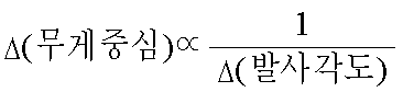
수학식 8로부터 알 수 있는 바와 같이, 클럽 헤드 세트(3200)(도 32 내지 도 35)의 각각의 클럽 헤드의 무게 중심 변화는 또한, 골프공의 발사 각도 변화의 역수에 비례한다.As can be seen from equation (8), the change in the center of gravity of each club head of the club head set 3200 (FIGS. 32-35) is also proportional to the inverse of the change in the firing angle of the golf ball.
예시적인 목적을 위해, 몇몇 실시예에 있어서, 토우 안정화 바 기준 각도(32017)(도 32)는 대략 30°이상 대략 90°이하일 수 있다. 한편, 토우 안정화 바 기준 각도(33017)(도 33)는 대략 30°이상이면서 대략 토우 안정화 바 기준 각도(32017)(도 32) 이하일 수 있다. 또한, 토우 안정화 바 기준 각도(34017)(도 34)는 대략 30°이상이며 대략 토우 안정화 바 기준 각도(32017)(도 32) 및 토우 안정화 바 기준 각도(33017)(도 33) 이하일 수 있다. 또한, 토우 안정화 바 기준 각도(35017)(도 35)는 대략 90°이하이며 또한 대략 토우 안정화 바 기준 각도(32017)(도 32) 이상일 수 있다.For illustrative purposes, in some embodiments, the tow stabilizing bar reference angle 32017 (FIG. 32) may be greater than or equal to about 30 ° and less than or equal to about 90 °. On the other hand, the tow stabilization bar reference angle (33017) (Fig. 33) may be about 30 degrees or more and less than the tow stabilization bar reference angle (32017) (Fig. 32). Further, the tow stabilization bar reference angle 3407 (FIG. 34) is greater than or equal to approximately 30 degrees and may be less than or equal to the tow stabilization bar reference angle 32017 (FIG. 32) and tow stabilization bar reference angle 3301 (FIG. 33). In addition, the tow stabilization bar reference angle 35017 (FIG. 35) may be approximately 90 degrees or less and may also be approximately tow stabilization bar reference angle 32017 (FIG. 32) or more.
한편, 동일한 또는 상이한 실시예에 있어서, 토우 안정화 바 폭(32021)(도 32)은 대략 1.270mm 이상이며 대략 10.16mm 이하일 수 있으며(또는 대략 2.030mm 이상이며 대략 7.620mm 이하일 수 있으며); 토우 안정화 바 폭(33021)(도 33)은 대략 1.270mm 이상일 수 있으며(또는 대략 2.030mm 이상일 수 있으며) 대략 토우 안정화 바 폭(32021) 이하일 수 있고; 토우 안정화 바 폭(34021)(도 34)은 대략 1.270mm 이상일 수 있으며(또는 대략 2.030mm 이상일 수 있으며) 대략 토우 안정화 바 폭(33021)(도 33) 및 토우 안정화 바 폭(34021)(도 34) 이하일 수 있다. 이러한 예의 경우, 토우 안정화 바 폭(35021)(도 35)은 대략 토우 안정화 바 폭(32021)(도 32) 이상일 수 있으며, 대략 10.16mm 이하일 수 있다(또는 대략 7.620mm 이하일 수 있다).On the other hand, in the same or different embodiments, the tow stabilizing bar width 32021 (FIG. 32) may be greater than or equal to about 1.270 mm and less than or equal to about 10.16 mm (or greater than or equal to about 2.030 mm and less than or equal to about 7.620 mm); Tow stabilizing bar width 3301 (FIG. 33) may be at least about 1.270 mm (or may be at least about 2.030 mm) and may be no greater than about tow stabilizing
또한, 동일한 또는 상이한 실시예에 있어서, 토우 안정화 바(32014)(도 32)의 토우 안정화 바 두께는 대략 0.6080mm 이상일 수 있으며 대략 6.350mm 이하일 수 있으며(또는 대략 1.270mm 이상일 수 있으며 대략 5.080mm 이하일 수 있으며); 토우 안정화 바(33014)(도 33)의 토우 안정화 바 두께는 대략 0.6080mm 이상일 수 있으며(또는 대략 1.270mm 이상일 수 있으며) 대략 토우 안정화 바 두께(34014)(도 32) 이하일 수 있고; 토우 안정화 바(34014)(도 34)의 토우 안정화 바 두께는 대략 0.6080mm 이하일 수 있으며(또는 대략 1.270mm 이하일 수 있으며) 대략 토우 안정화 바(32014)(도 32) 및 토우 안정화 바(33014)(도 33)의 토우 안정화 바 두께 이하일 수 있다. 이러한 예의 경우, 토우 안정화 바(35014)(도 35)의 토우 안정화 바 두께는 대략 토우 안정화 바(32014)(도 32)의 토우 안정화 바 두께 이상일 수 있으며, 대략 6.350mm 이하일 수 있다(또는 대략 5.080mm 이하일 수 있다).Further, in the same or different embodiments, the tow stabilizing bar thickness of the tow stabilizing bar 32014 (FIG. 32) may be at least about 0.6080 mm and may be at most about 6.350 mm (or at least about 1.270 mm and about 5.080 mm or less). Can); Tow stabilizing bar thickness of tow stabilizing bar 3014 (FIG. 33) may be at least about 0.6080 mm (or at least about 1.270 mm) and may be no greater than about tow stabilizing bar thickness 3340 (FIG. 32); Tow stabilizing bar thickness of tow stabilizing bar 3414 (FIG. 34) may be approximately 0.6080 mm or less (or may be approximately 1.270 mm or less) and approximately tow stabilizing bar 32014 (FIG. 32) and tow stabilizing bar 30014 ( 33 to or below the tow stabilizing bar thickness. For this example, the tow stabilization bar thickness of tow stabilization bar 3514 (FIG. 35) may be approximately greater than or equal to the tow stabilization bar thickness of tow stabilization bar 32014 (FIG. 32) and may be about 6.350 mm or less (or about 5.080). mm or less).
마찬가지로, 동일한 또는 상이한 실시예에 있어서, 안정화 바(32011)(도 32), 안정화 바(33011)(도 33), 안정화 바(34011)(도 34), 그리고 안정화 바(35011)(도 35)의 총 개수가 2개 이상이면서 8개 이하일 수 있다. 도 36에는 6개의 안정화 바(36030)를 포함하는 클럽 헤드 세트(3600)의 예시적인 클럽 헤드(36000)가 도시되어 있다. 클럽 헤드(36000)는 클럽 헤드(32000)(도 32)와 유사할 수 있으며, 클럽 헤드 세트(3600)는 클럽 헤드 세트(3200)와 유사할 수 있다. 안정화 바(36030)는 안정화 바(32011)(도 32)와 유사할 수 있다.Likewise, in the same or different embodiments, stabilization bar 32011 (FIG. 32), stabilization bar 330111 (FIG. 33), stabilization bar 3411 (FIG. 34), and stabilization bar 35011 (FIG. 35). The total number of can be two or more and eight or less. 36 shows an
그외 다른 실시예에 있어서, 안정화 바(32011)(도 32)의 길이(예를 들어, 토우 안정화 바 길이(32023) 및/또는 힐 안정화 바 길이(32024)), 안정화 바(33011)(도 33)의 길이(예를 들어, 토우 안정화 바 길이(33023) 및/또는 힐 안정화 바 길이(33024)), 안정화 바(34011)(도 34)의 길이(예를 들어, 토우 안정화 바 길이(34023) 및/또는 힐 안정화 바 길이(34024)), 및/또는 힐 안정화 바 길이(35024)가 대략 2.540mm 이상일 수 있으며 또한 대략 40.64mm 이하일 수 있으며(또는 대략 30.48mm 이하일 수 있다).In other embodiments, the length of stabilization bar 32011 (FIG. 32) (eg, tow stabilizing
전술한 종래의 클럽 헤드와 함께, 다수의 실시예에 있어서, 클럽 헤드 세트(3200)(도 32 내지 도 35)의 각각의 클럽 헤드는 2-아이언 헤드, 3-아이언 헤드, 4-아이언 헤드, 5-아이언 헤드, 6-아이언 헤드, 7-아이언 헤드, 8-아이언 헤드, 9-아이언 헤드, 또는 웨지 헤드(예를 들어, 피칭 웨지) 중 하나를 포함할 수 있다. 이에 따라, 클럽 헤드(32000)(도 32), 클럽 헤드(33000)(도 33), 클럽 헤드(34000)(도 34), 및/또는 클럽 헤드(35000)(도 35)는 2-아이언 헤드, 3-아이언 헤드(예를 들어, 클럽 헤드(34000)), 4-아이언 헤드, 5-아이언 헤드, 6-아이언 헤드(예를 들어, 클럽 헤드(33000)), 7-아이언 헤드, 8-아이언 헤드, 9-아이언 헤드(예를 들어, 클럽 헤드(32000)), 또는 웨지 헤드(예를 들어, 클럽 헤드(35000)) 중 서로 다른 클럽 헤드를 포함할 수 있다. In addition to the conventional club heads described above, in many embodiments, each club head of the club head set 3200 (FIGS. 32-35) is a two-iron head, a three-iron head, a four-iron head, One of a five-iron head, a six-iron head, a seven-iron head, an eight-iron head, a nine-iron head, or a wedge head (eg, a pitching wedge). Accordingly, club head 32000 (FIG. 32), club head 33000 (FIG. 33), club head 34000 (FIG. 34), and / or club head 35000 (FIG. 35) are two-iron heads. , 3-iron head (eg club head 34000), 4-iron head, 5-iron head, 6-iron head (eg club head 33000), 7-iron head, 8- It may include different club heads, such as iron heads, 9-iron heads (eg, club head 32000), or wedge heads (eg, club head 35000).
이러한 실시예에 있어서, 2-아이언 헤드는 대략 18°내지 대략 20°의 2-아이언 로프트 각도를 포함할 수 있다. 한편, 2-아이언 헤드는 대략 0.5mm 이상이면서 대략 5.1mm 이하의 2-아이언 토우 안정화 바 폭, 대략 0.5mm 이상이면서 대략 5.1mm 이하의 2-아이언 힐 안정화 바 폭, 대략 35°이상이면서 대략 95°이하의 2-아이언 토우 안정화 바 기준 각도, 및/또는 대략 40°이상이면서 대략 100°이하의 2-아이언 힐 안정화 바 기준 각도를 포함할 수 있다. 또한, 2-아이언 헤드는 대략 5°의 2-아이언 튜닝 포트 경사각을 포함할 수 있다.In such embodiments, the two-iron head may comprise a two-iron loft angle of approximately 18 degrees to approximately 20 degrees. On the other hand, the 2-iron head has a width of about 2-mm tow stabilizing bar of about 0.5 mm or more and about 5.1 mm or less, about 2-mm heel stabilizing bar width of about 0.5 mm or more and about 5.1 mm or less, about 95 ° and about 95 A 2-iron toe stabilization bar reference angle of less than or equal to, and / or a 2-iron heel stabilization bar reference angle of greater than or equal to about 40 ° and less than or equal to about 100 °. The two-iron head may also include a two-iron tuning port tilt angle of approximately 5 °.
이러한 실시예에 있어서, 3-아이언 헤드는 대략 20°내지 대략 23°의 3-아이언 로프트 각도를 포함할 수 있다. 한편, 3-아이언 헤드는 대략 0.8mm 이상이면서 대략 5.8mm 이하의 3-아이언 토우 안정화 바 폭, 대략 0.8mm 이상이면서 대략 5.8mm 이하의 3-아이언 힐 안정화 바 폭, 대략 31°이상이면서 대략 93°이하의 3-아이언 토우 안정화 바 기준 각도, 및/또는 대략 36°이상이면서 대략 98°이하의 3-아이언 힐 안정화 바 기준 각도를 포함할 수 있다. 또한, 3-아이언 헤드는 대략 5.25°의 3-아이언 튜닝 포트 경사각을 포함할 수 있다.In such embodiments, the three-iron head may comprise a three-iron loft angle of approximately 20 degrees to approximately 23 degrees. On the other hand, the 3-iron head is about 0.8 mm or more and about 5.8 mm or less of the 3-iron toe stabilizing bar width, about 0.8 mm or more and about 5.8 mm or less to the 3-iron heel stabilizing bar width, about 31 ° or more and about 93 3-iron toe stabilization bar reference angle of less than or equal to, and / or 3-iron heel stabilization bar reference angle of greater than or equal to about 36 ° and less than or equal to about 98 °. The 3-iron head may also include a 3-iron tuning port tilt angle of approximately 5.25 °.
이러한 실시예에 있어서, 4-아이언 헤드는 대략 21°내지 대략 25°의 4-아이언 로프트 각도를 포함할 수 있다. 한편, 4-아이언 헤드는 대략 1.0mm 이상이면서 대략 6.7mm 이하의 4-아이언 토우 안정화 바 폭, 대략 1.0mm 이상이면서 대략 6.7mm 이하의 4-아이언 힐 안정화 바 폭, 대략 27°이상이면서 대략 91°이하의 4-아이언 토우 안정화 바 기준 각도, 및/또는 대략 32°이상이면서 대략 96°이하의 4-아이언 힐 안정화 바 기준 각도를 포함할 수 있다. 또한, 4-아이언 헤드는 대략 5.5°의 4-아이언 튜닝 포트 경사각을 포함할 수 있다.In such embodiments, the four-iron head may comprise a four-iron loft angle of approximately 21 degrees to approximately 25 degrees. On the other hand, the 4-iron head is about 1.0 mm or more and 4-iron toe stabilizing bar width of about 6.7 mm or less, about 1.0 mm or more and 4-iron heel stabilizing bar width of about 6.7 mm or less, about 27 ° or more and about 91 4-iron toe stabilization bar reference angle of less than or equal to, and / or 4-iron heel stabilization bar reference angle of greater than or equal to about 32 ° and less than or equal to about 96 °. The four-iron head may also include a four-iron tuning port tilt angle of approximately 5.5 degrees.
이러한 실시예에 있어서, 5-아이언 헤드는 대략 23°내지 대략 28°의 5-아이언 로프트 각도를 포함할 수 있다. 한편, 5-아이언 헤드는 대략 1.3mm 이상이면서 대략 7.1mm 이하의 5-아이언 토우 안정화 바 폭, 대략 1.3mm 이상이면서 대략 7.1mm 이하의 5-아이언 힐 안정화 바 폭, 대략 22°이상이면서 대략 88°이하의 5-아이언 토우 안정화 바 기준 각도, 및/또는 대략 28°이상이면서 대략 94°이하의 5-아이언 힐 안정화 바 기준 각도를 포함할 수 있다. 또한, 5-아이언 헤드는 대략 6°의 5-아이언 튜닝 포트 경사각을 포함할 수 있다.In such embodiments, the five-iron head may comprise a five-iron loft angle of approximately 23 ° to approximately 28 °. Meanwhile, the 5-iron head has a width of about 5-mm toe stabilization bar of about 1.3 mm or more and about 7.1 mm or less, about 5-mm heel stabilization bar width of about 1.3 mm or more and about 7.1 mm or less, about 22 ° or more and about 88 5-iron toe stabilization bar reference angle of less than or equal to, and / or 5-iron heel stabilization bar reference angle of greater than or equal to about 28 ° and less than or equal to about 94 °. In addition, the 5-iron head may include a 5-iron tuning port tilt angle of approximately 6 °.
이러한 실시예에 있어서, 6-아이언 헤드는 대략 26°내지 대략 32°의 6-아이언 로프트 각도를 포함할 수 있다. 한편, 6-아이언 헤드는 대략 1.5mm 이상이면서 대략 8.0mm 이하의 6-아이언 토우 안정화 바 폭, 대략 1.5mm 이상이면서 대략 8.0mm 이하의 6-아이언 힐 안정화 바 폭, 대략 18°이상이면서 대략 86°이하의 6-아이언 토우 안정화 바 기준 각도, 및/또는 대략 24°이상이면서 대략 92°이하의 6-아이언 힐 안정화 바 기준 각도를 포함할 수 있다. 또한, 6-아이언 헤드는 대략 6.5°의 6-아이언 튜닝 포트 경사각을 포함할 수 있다.In such embodiments, the six-iron head may comprise a six-iron loft angle of approximately 26 ° to approximately 32 °. On the other hand, the 6-iron head has a 6-iron toe stabilizing bar width of about 1.5 mm or more and about 8.0 mm or less, a 6-iron heel stabilizing bar width of about 1.5 mm or more and about 8.0 mm or less, about 86 ° and about 86 6-iron toe stabilization bar reference angle of less than or equal to, and / or 6-iron heel stabilization bar reference angle of greater than or equal to about 24 ° and less than or equal to about 92 °. The six-iron head may also include a six-iron tuning port tilt angle of approximately 6.5 °.
이러한 실시예에 있어서, 7-아이언 헤드는 대략 29°내지 대략 36°의 7-아이언 로프트 각도를 포함할 수 있다. 한편, 7-아이언 헤드는 대략 1.8mm 이상이면서 대략 8.0mm 이하의 7-아이언 토우 안정화 바 폭, 대략 1.8mm 이상이면서 대략 8.0mm 이하의 7-아이언 힐 안정화 바 폭, 대략 14°이상이면서 대략 84°이하의 7-아이언 토우 안정화 바 기준 각도, 및/또는 대략 20°이상이면서 대략 90°이하의 7-아이언 힐 안정화 바 기준 각도를 포함할 수 있다. 또한, 7-아이언 헤드는 대략 6.5°의 7-아이언 튜닝 포트 경사각을 포함할 수 있다.In such embodiments, the 7-iron head may comprise a 7-iron loft angle of approximately 29 ° to approximately 36 °. On the other hand, the 7-iron head has a width of 7-iron toe stabilization bar of about 1.8 mm or more and about 8.0 mm or less, 7-iron heel stabilization bar width of about 1.8 mm or more and about 8.0 mm or less, about 14 ° or more and about 84 A 7-iron toe stabilization bar reference angle of less than or equal to, and / or a 7-iron heel stabilization bar reference angle of greater than or equal to about 20 ° and less than or equal to about 90 °. In addition, the 7-iron head may comprise a 7-iron tuning port tilt angle of approximately 6.5 °.
이러한 실시예에 있어서, 8-아이언 헤드는 대략 34°내지 대략 42°의 8-아이언 로프트 각도를 포함할 수 있다. 한편, 8-아이언 헤드는 대략 2.0mm 이상이면서 대략 8.0mm 이하의 8-아이언 토우 안정화 바 폭, 대략 2.0mm 이상이면서 대략 8.0mm 이하의 8-아이언 힐 안정화 바 폭, 대략 10°이상이면서 대략 82°이하의 8-아이언 토우 안정화 바 기준 각도, 및/또는 대략 16°이상이면서 대략 88°이하의 8-아이언 힐 안정화 바 기준 각도를 포함할 수 있다. 또한, 8-아이언 헤드는 대략 6.5°의 8-아이언 튜닝 포트 경사각을 포함할 수 있다.In such embodiments, the 8-iron head may comprise an 8-iron loft angle of approximately 34 ° to approximately 42 °. On the other hand, the 8-iron head has an 8-iron toe stabilizing bar width of about 2.0 mm or more and about 8.0 mm or less, an 8-iron heel stabilizing bar width of about 2.0 mm or more and about 8.0 mm or less, about 10 ° or more and about 82 8-iron toe stabilization bar reference angle of less than or equal to, and / or 8-iron heel stabilization bar reference angle of greater than or equal to about 16 ° and less than or equal to about 88 °. The 8-iron head may also include an 8-iron tuning port tilt angle of approximately 6.5 °.
이러한 실시예에 있어서, 9-아이언 헤드는 대략 38°내지 대략 45°의 9-아이언 로프트 각도를 포함할 수 있다. 한편, 9-아이언 헤드는 대략 2.3mm 이상이면서 대략 8.3mm 이하의 9-아이언 토우 안정화 바 폭, 대략 2.3mm 이상이면서 대략 8.3mm 이하의 9-아이언 힐 안정화 바 폭, 대략 6°이상이면서 대략 80°이하의 9-아이언 토우 안정화 바 기준 각도, 및/또는 대략 12°이상이면서 대략 86°이하의 9-아이언 힐 안정화 바 기준 각도를 포함할 수 있다. 또한, 9-아이언 헤드는 대략 6.5°의 9-아이언 튜닝 포트 경사각을 포함할 수 있다.In such embodiments, the 9-iron head may comprise a 9-iron loft angle of approximately 38 ° to approximately 45 °. On the other hand, the 9-iron head has a width of 9-iron toe stabilization bar of about 2.3 mm or more and about 8.3 mm or less, a width of 9-iron heel stabilization bar of about 2.3 mm or more and about 8.3 mm or less, about 6 ° or more and about 80 A 9-iron toe stabilization bar reference angle of less than or equal to, and / or a 9-iron heel stabilization bar reference angle of greater than or equal to about 12 ° and less than or equal to about 86 °. The 9-iron head may also include a 9-iron tuning port tilt angle of approximately 6.5 °.
이러한 실시예에 있어서, 웨지 헤드 아이언은 대략 42°내지 대략 64°의 웨지 로프트 각도를 포함할 수 있다. 웨지 헤드 아이언은 대략 2.5mm 이상이면서 대략 8.5mm 이하의 웨지 토우 안정화 바 폭, 대략 2.5mm 이상이면서 대략 8.5mm 이하의 웨지 힐 안정화 바 폭, 대략 1°이상이면서 대략 77°이하의 웨지 토우 안정화 바 기준 각도, 및/또는 대략 8°이상이면서 대략 84°이하의 웨지 힐 안정화 바 기준 각도를 포함할 수 있다. 또한, 웨지 헤드 아이언은 대략 7°의 웨지 헤드 튜닝 포트 경사각을 포함할 수 있다.In such embodiments, the wedge head iron may comprise a wedge loft angle of approximately 42 ° to approximately 64 °. The wedge head iron has a wedge toe stabilizing bar width of about 2.5 mm or more and about 8.5 mm or less, a wedge heel stabilizing bar width of about 2.5 mm or more and about 8.5 mm or less, and a wedge toe stabilizing bar of about 1 ° or more and about 77 ° or less Reference angle, and / or wedge heel stabilization bar reference angle of greater than or equal to about 8 ° and less than or equal to about 84 °. The wedge head iron may also comprise a wedge head tuning port tilt angle of approximately 7 °.
또한, 도 37은 골프 클럽 헤드 세트를 제공하기 위한 방법(37000)을 도시한 순서도이다. 몇몇 예에 있어서, 방법(37000)의 골프 클럽 헤드 세트는 도 32 내지 도 35에 대하여 전술한 골프 클럽 헤드 세트(3200)와 유사할 수 있으며, 및/또는 클럽 헤드(36000)(도 36)와 유사한 하나 이상의 클럽 헤드를 포함하는 골프 클럽 헤드 세트(3600)(도 3)와 유사할 수 있다.37 is a flowchart illustrating a
방법(37000)의 블록(37100)은 제 1 클럽 헤드를 제공하는 단계를 포함할 수 있다. 몇몇 예에 있어서, 제 1 클럽 헤드는 클럽 헤드 세트(3200)(도 32 내지 도 35) 및/또는 클럽 헤드 세트(3600)(도 36)의 클럽 헤드(32000)(도 32) 또는 클럽 헤드(36000)(도 36)와 같은 클럽 헤드 중 하나와 유사할 수 있다. 제 1 클럽 헤드는 로프트 각도(32001)(도 32)와 유사하거나 동일한 제 1 로프트 각도를 포함할 수 있다. 한편, 제 1 클럽 헤드는 또한 안정화 바(32011)(도 32)와 유사하거나 동일할 수 있는 두 개 이상의 제 1 안정화 바를 포함할 수 있다. 이에 따라, 제 1 안정화 바는 제 1 안정화 바 특성값을 포함할 수 있다. 제 1 안정화 바 특성값은 도 32 내지 도 35에 대하여 전술한 안정화 바의 속성값/특성값과 유사하거나 동일할 수 있다. 제 1 클럽은, 예를 들어, 주조 또는 단조 공정을 통해 제공될 수 있다.
방법(37000)의 블록(37200)은 제 2 클럽 헤드를 제공하는 단계를 포함할 수 있다. 몇몇 예에 있어서, 제 2 클럽 헤드는 클럽 헤드 세트(3200)(도 32 내지 도 35) 및/또는 클럽 헤드 세트(3600)(도 36)의 클럽 헤드(32000)(도 32), 클럽 헤드(33000)(도 33) 또는 클럽 헤드(34000)(도 34)와 같은 클럽 헤드 중 다른 하나와 유사할 수 있다. 제 2 클럽 헤드는, 제 2 클럽 헤드에 상응하는 클럽 헤드(32000)(도 32), 클럽 헤드(33000)(도 33), 그리고 클럽 헤드(34000)(도 34)에 따라, 로프트 각도(32001)(도 32), 로프트 각도(33001)(도 33), 또는 로프트 각도(34001)(도 34)와 유사하거나 동일한 제 2 로프트 각도를 포함할 수 있다. 한편, 제 2 클럽 헤드는 또한, 적용 가능한 경우, 안정화 바(32011)(도 32), 안정화 바(33011)(도 33), 또는 안정화 바(34011)(도 34)와 유사하거나 동일할 수 있는 두 개 이상의 제 2 안정화 바를 포함할 수 있다. 이에 따라, 제 2 안정화 바는 제 2 안정화 바 특성값을 포함할 수 있다. 제 2 안정화 바 특성값은 도 32 내지 도 34에 대하여 전술한 안정화 바의 속성값/특성값과 유사하거나 동일할 수 있다. 제 2 클럽은, 예를 들어, 주조 또는 단조 공정을 통해 제공될 수 있다.
다수의 실시예에 있어서, 블록(37100)은 제 2 로프트 각도보다 큰 제 1 로프트 각도를 제공하는 하위 블록(37110)을 포함할 수 있다. 한편, 블록(37100)은 또한, 제 2 안정화 바 특성값보다 큰 제 1 안정화 바 특성값을 제공하는 하위 블록(37120)을 포함할 수 있다. 동일한 또는 상이한 실시예에 있어서, 블록(37200)은 제 1 로프트 각도보다 작은 제 2 로프트 각도를 제공하는 하위 블록(37210)을 포함할 수 있다. 한편, 블록(37200)은 또한 제 1 안정화 바 특성값보다 작은 제 2 안정화 바 특성값을 제공하는 하위 블록(37220)을 포함할 수 있다. 물론, 하위 블록(37210)을 수행한 결과 또는 하위 블록(37210)의 일부로서 하위 블록(37110)이 수행될 수 있으며 그 반대의 경우도 가능하다. 마찬가지로, 하위 블록(37220)을 수행한 결과 또는 하위 블록(37220)의 일부로서 하위 블록(37120)이 수행될 수 있으며 그 반대의 경우도 가능하다. In many embodiments, block 37100 may include a
하위 블록(37110)은, (a) 제 2 안정화 바 각각의 제 2 폭보다 큰 제 1 안정화 바 각각의 제 1 폭을 제공하는 하위 블록(37111)과, (b) 제 2 안정화 바 각각의 제 2 두께보다 큰 제 1 안정화 바 각각의 제 1 두께를 제공하는 하위 블록(37112)과, (c) 제 2 안정화 바의 제 2 개수보다 큰 제 1 안정화 바의 제 1 개수를 제공하는 하위 블록(37113), 및/또는 (d) 제 2 안정화 바 각각의 제 2 기준 각도보다 큰 제 1 안정화 바 각각의 제 1 기준 각도를 제공하는 하위 블록(37114)을 포함할 수 있다. 마찬가지로, 하위 블록(37210)은, (a) 제 1 안정화 바 각각의 제 1 폭보다 작은 제 2 안정화 바 각각의 제 2 폭을 제공하는 하위 블록(37211)과, (b) 제 1 안정화 바 각각의 제 1 두께보다 작은 제 2 안정화 바 각각의 제 2 두께를 제공하는 하위 블록(37212)과, (c) 제 1 안정화 바의 제 1 개수보다 작은 제 2 안정화 바의 제 2 개수를 제공하는 하위 블록(37213), 및/또는 (d) 제 1 안정화 바 각각의 제 1 기준 각도보다 작은 제 2 안정화 바 각각의 제 2 기준 각도를 제공하는 하위 블록(37214)을 포함할 수 있다. 하위 블록(37111, 37211)의 제 1 폭 및 제 2 폭은 도 32 내지 도 35에 대하여 전술한 제 1 폭 및 제 2 폭과 유사하거나 동일할 수 있다. 하위 블록(37112, 37212)의 제 1 두께 및 제 2 두께는 도 32 내지 도 35에 대하여 전술한 제 1 두께 및 제 2 두께와 유사하거나 동일할 수 있다. 하위 블록(37113, 37213)의 제 1 안정화 바의 제 1 개수 및 제 2 안정화 바의 제 2 개수는 도 32 내지 도 35에 대하여 전술한 제 1 안정화 바의 제 1 개수 및 제 2 안정화 바의 제 2 개수와 유사하거나 동일할 수 있다. 하위 블록(37114, 37214)의 제 1 기준 각도 및 제 2 기준 각도는 도 32 내지 도 35에 대하여 전술한 제 1 기준 각도 및 제 2 기준 각도와 유사하거나 동일할 수 있다.The
다수의 실시예에 있어서, 하위 블록(37111, 37211)은 동일한 절차의 일부로서 동시에 또는 함께 수행될 수 있다. 동일한 또는 상이한 실시예에 있어서, 하위 블록(37112, 37212)은 동일한 절차의 일부로서 동시에 또는 함께 수행될 수 있다. 동일한 또는 상이한 실시예에 있어서, 하위 블록(37113, 37213)은 동일한 절차의 일부로서 동시에 또는 함께 수행될 수 있다. 동일한 또는 상이한 실시예에 있어서, 하위 블록(37114, 37214)은 동일한 절차의 일부로서 동시에 또는 함께 수행될 수 있다. In many embodiments,
한편, 하위 블록(37120)의 수행은 제 1 클럽 헤드의 제 1 무게 중심 및/또는 제 1 편향도를 제 1 클럽 헤드의 예정된 클럽의 특정한 제 1 성능으로 맞춤 설정하는 단계를 포함한다. 마찬가지로, 하위 블록(37220)의 수행은 제 2 클럽 헤드의 제 2 무게 중심 및/또는 제 2 편향도를 제 2 클럽 헤드의 예정된 클럽의 특정한 제 2 성능으로 맞춤 설정하는 단계를 포함한다. On the other hand, performance of the
방법(37000)의 전술한 설명이 클럽 헤드 세트의 두 개 이상의 클럽 헤드에 걸쳐 확장될 수 있는 예가 있을 수 있다. 예를 들어, 방법(37000)은 두 개 이상의 클럽 헤드를 제공하는 단계와, 복수의 로프트 각도 각각이 서로 변경되도록 두 개 이상의 클럽 헤드 각각에 대한 다수의 로프트 각도 중 서로 다른 로프트 각도를 제공하는 단계, 그리고 하나의 안정화 바 특성값이 두 개 이상의 클럽 헤드 각각의 상이한 로프트 각도에 따라 두 개 이상의 클럽 헤드에 대하여 변경되도록 두 개 이상의 클럽 헤드 각각의 두 개 이상의 안정화 바에 대한 다수의 안정화 바 특성값 중 일 안정화 바 특성값을 제공하는 단계를 포함할 수 있다. 이러한 일 예에 있어서, 두 개 이상의 클럽 헤드는 블록(37100)의 제 1 클럽 헤드 및 블록(37200)의 제 2 클럽 헤드를 포함한다. 한편, 다수의 로프트 각도는 블록(37100)의 제 1 로프트 각도와, 블록(37200)의 제 2 로프트 각도를 포함하며, 다수의 안정화 바 특성값은 블록(37100)의 제 1 안정화 바 특성값 및 블록(37200)의 제 2 안정화 바 특성값을 포함한다. 동일한 또는 그외 다른 예에 있어서, 두 개 이상의 클럽 헤드 각각에 대한 다수의 로프트 각도 중 서로 다른 로프트 각도를 제공하는 단계는 클럽 헤드 세트에 걸쳐 두 개 이상의 클럽 헤드 각각에 대한 서로 다른 로프트 각도를 증가하는 방식으로 변하는 단계를 포함할 수 있다. 마찬가지로, 다수의 안정화 바 특성값 중 일 안정화 바 특성값을 제공하는 단계는 클럽 헤드 세트에 걸쳐 두 개 이상의 클럽 헤드 각각에 대한 서로 다른 로프트 각도를 증가하는 방식으로 변화시키는 단계와 대응하도록 클럽 헤드 세트에 걸쳐 두 개 이상의 클럽 헤드 각각에 대한 일 안정화 바 특성값을 증가하는 방식으로 변화시키는 단계를 포함할 수 있다.There may be an example where the foregoing description of the
가변 특성을 갖는 클럽 헤드 세트 및 관련 방법이 특정 실시예를 참조하여 설명되어 있긴 하지만, 본 발명의 정신 또는 범위를 벗어남이 없이 다양한 변경이 이루어질 수 있다. 이러한 사양에 관한 추가 예 및 그외 다른 실시예가 전술한 설명에 제공되어 있다. 이에 따라, 가변 특성을 갖는 클럽 헤드 세트 및 관련 방법의 본 발명의 실시예는 본 발명의 범위를 예시하기 위해 주어진 것으로서 본 발명의 범위를 제한할 의도가 있는 것은 아니다. 예를 들어, 일 실시예에 있어서, 골프 클럽 헤드가 도 1 내지 도 5를 참조하여 설명된 그외 다른 특징과 함께 또는 이들 특징 없이 도 1 내지 도 5의 하나 이상의 특징을 갖출 수 있다. 다른 예에 있어서, 도 8 내지 도 21에 대하여 전술한 클럽 헤드 세트는 대략 도 16 및 도 19에 열거된 바와 같은 클럽 헤드를 포함할 수 있으며, 로프트 각도, 지지 바 특성값, 및/또는 하부 토우 삽입부 추 속성값이 서로 연관되어 있으면서도 도 8 내지 도 21의 예에서와 상이할 수 있다. 또 다른 예로서, 도 25 내지 도 31에 논의된 실시에 따른 클럽 헤드는 본 발명의 가르침을 받아들이면서도 직사각형, 삼각형, 사다리꼴, 원형, 초승달 모양, 및/또는 장방형과 같은 여러 가지 형상의 대응 안정화 바를 포함할 수 있으며, 및/또는 고형체, 격자 무늬, 움푹 파인 형상, 벌집 형상, 증가 및/또는 감소 패턴과 같은 여러 가지 패턴의 대응 안정화 바를 포함할 수 있다. 예를 들어, 일 실시예에 있어서, 골프 클럽 헤드는 도 32 내지 도 36을 참조하여 전술한 그외 다른 특징과 함께 또는 이러한 특징 없이 도 32 내지 도 36의 하나 이상의 특징을 포함할 수 있다. 마찬가지로, 다양한 도면의 특징 중 하나 이상을 갖는 서로 다른 실시예의 그외 다른 치환이 고려될 수 있다. 가변 특성을 갖는 클럽 헤드 및 관련 방법의 범위는 첨부된 특허 청구의 범위에서 요구되고 있는 범위로만 제한되어야 함을 이해하여야 한다.Although club head sets and associated methods with varying characteristics have been described with reference to specific embodiments, various changes may be made without departing from the spirit or scope of the invention. Further examples of this specification and other embodiments are provided in the foregoing description. Accordingly, embodiments of the invention of club head sets and associated methods having varying characteristics are given to illustrate the scope of the invention and are not intended to limit the scope of the invention. For example, in one embodiment, a golf club head may have one or more of the features of FIGS. 1-5 with or without the other features described with reference to FIGS. In another example, the club head set described above with respect to FIGS. 8-21 may include a club head as listed in approximately FIGS. 16 and 19, and may include loft angles, support bar characteristic values, and / or bottom tows. The insertion weight attribute values may be different from each other even in the example of FIGS. 8 to 21. As another example, a club head in accordance with the implementation discussed in FIGS. 25-31 may incorporate corresponding stabilizing bars of various shapes, such as rectangular, triangular, trapezoidal, circular, crescent, and / or rectangular, while accepting the teachings of the present invention. And / or corresponding stabilizing bars of various patterns, such as solids, lattice, dents, honeycomb shapes, increasing and / or decreasing patterns. For example, in one embodiment, the golf club head may include one or more of the features of FIGS. 32-36 with or without other features described above with reference to FIGS. 32-36. Likewise, other substitutions of different embodiments may be contemplated with one or more of the features of the various figures. It is to be understood that the scope of club heads and related methods with varying characteristics should be limited only to the extent required by the appended claims.
본 명세서에서 논의되고 있는 가변 특성을 갖는 클럽 헤드 및 관련 방법은 각종 실시예로 실시될 수 있으며, 이러한 실시예의 전술한 논의 내용은 모든 가능한 실시예의 완전한 설명을 나타낼 필요가 있는 것은 아니다. 오히려, 도면에 관한 상세한 설명 및 도면 그 자체가 적어도 하나의 바람직한 실시예를 개시하며, 또한 추가의 실시예를 개시할 수 있다.Club heads having variable characteristics and related methods discussed herein may be practiced in various embodiments, and the foregoing discussion of these embodiments need not represent a complete description of all possible embodiments. Rather, the detailed description of the drawings and the drawings themselves disclose at least one preferred embodiment, and further embodiments may be disclosed.
특정 청구항에 청구되고 있는 모든 요소는 특정 청구항에서 청구되고 있는 가변 특성을 갖는 클럽 헤드 세트 및 관련 방법에 필수적이다. 결과적으로, 하나 이상의 청구되고 있는 구성 요소의 교체는 재구성을 의미하는 것으로서 보수 유지 관리와는 상관이 없다. 추가의 이점, 그외 다른 장점 및 문제 해결 방안이 특정 실시예와 관련하여 설명되어 있다. 그러나, 이러한 이점, 장점 또는 해결 방안이 실시될 수 있도록 하거나 보다 잘 표명되도록 할 수도 있는 이점, 장점, 문제 해결 방안 및 구성 요소(들)는, 이러한 이점, 장점, 해결 방안, 또는 구성 요소가 이러한 청구항에 분명하게 증명되어 있지 않은 한, 이들 청구항 중 어느 하나 또는 전부의 중요한, 필요하거나 필수적인 특징 또는 구성 요소로서 해석되어야 하는 것은 아니다.All elements claimed in a particular claim are essential to a set of club heads and associated methods having variable characteristics as claimed in a particular claim. As a result, the replacement of one or more claimed components means reconfiguration and has nothing to do with maintenance. Additional advantages, other advantages, and troubleshooting solutions have been described with reference to specific embodiments. However, any of the advantages, advantages, solutions, or component (s) that may cause these benefits, advantages, or solutions to be implemented or may be better manifested may be such benefits, advantages, solutions, or components. Unless expressly evident in the claims, they should not be construed as significant, necessary or necessary features or components of any or all of these claims.
또한, 본 명세서에 개시된 실시예 및 도시 내용은, (1) 실시예 및/또는 제한 사항이 특허 청구 범위에 명확하게 청구되어 있지 않은 경우 그리고 (2) 실시예 및/또는 제한 사항이 등가물 주의를 기반으로 특허 청구 범위의 구성 요소 및/또는 제한 사항을 나타내는 등가물 또는 잠재적인 등가물인 경우 헌납 주의를 기반으로 공중에게 바쳐진 것은 아니다.In addition, the embodiments and illustrations disclosed herein are intended to address (1) where the embodiments and / or limitations are not expressly claimed in the claims and (2) the embodiments and / or limitations pay attention to equivalents. Equivalents or potential equivalents that represent the elements and / or limitations of the claims on the basis of this are not devoted to the public on the basis of dedication.
100 : 골프 클럽 헤드 105 : 호젤
110 : 토우 영역 120 : 힐 영역
130 : 바닥 영역 140 : 상측 영역
180 : 제 1 공동 185 : 제 1 추
190 : 제 2 공동 195 : 제 2 추100: golf club head 105: hosel
110: tow area 120: hill area
130: bottom area 140: upper area
180: first joint 185: first weight
190: second joint 195: second weight
Claims (24)
두 개 이상의 클럽 헤드를 포함하며, 각각의 클럽 헤드는,
로프트 각도와;
전면과;
상기 전면의 반대쪽 후면; 그리고
상기 후면으로부터 돌출되는 두 개 이상의 안정화 바를 포함하며,
상기 로프트 각도는 상기 두 개 이상의 클럽 헤드에 걸쳐 증가하는 방식으로 변하며,
상기 로프트 각도가 상기 두 개 이상의 클럽 헤드에 걸쳐 증가하는 방식으로 변함에 따라 상기 두 개 이상의 안정화 바의 특성값이 상기 두 개 이상의 클럽 헤드에 걸쳐 증가하는 방식으로 변하는 것인 클럽 헤드 세트.As a club head set,
Includes at least two club heads, each of which has a
Loft angle;
Front and back;
An opposite rear of the front; And
At least two stabilizing bars protruding from the rear,
The loft angle varies in an increasing manner across the two or more club heads,
And the characteristic value of the two or more stabilizing bars changes in a manner that increases over the two or more club heads as the loft angle changes in a way that increases over the two or more club heads.
상기 두 개 이상의 안정화 바 각각의 폭과;
상기 두 개 이상의 안정화 바 각각의 두께와;
상기 두 개 이상의 안정화 바의 총 개수; 또는
상기 두 개 이상의 안정화 바 각각의 기준 각도 중 적어도 하나를 포함하는 것인 클럽 헤드 세트.The method of claim 1, wherein the characteristic value of the two or more stabilization bar,
A width of each of the two or more stabilizing bars;
A thickness of each of the two or more stabilizing bars;
The total number of the two or more stabilizing bars; or
And at least one of a reference angle of each of the two or more stabilization bars.
제 1 로프트 각도와;
제 1 전면과;
제 1 토우(toe)와;
제 1 힐(heel)과;
제 1 상측 단부와;
제 1 하측 단부와;
상기 제 1 전면의 반대쪽에 제 1 후면을 포함하는 제 1 후방부로서, 상기 제 1 후면은 제 1 토우 영역과, 제 1 힐 영역, 그리고 두 개 이상의 제 1 안정화 바를 포함하고 상기 제 1 토우는 상기 제 1 힐 영역보다 상기 제 1 토우 영역에 가까이 배치되며 상기 제 1 힐은 상기 제 1 토우 영역보다 상기 제 1 힐 영역에 가까이 배치되는 것인 제 1 후방부; 그리고
상기 제 1 상측 단부 및 상기 제 1 하측 단부를 통해 실질적으로 수직 방향으로 연장되어 상기 제 1 토우 영역과 상기 제 1 힐 영역을 부분적으로 형성하는 제 1 수직 축선을 포함하는 제 1 클럽 헤드; 그리고
제 2 로프트 각도와;
제 2 전면과;
제 2 토우와;
제 2 힐과;
제 2 상측 단부와;
제 2 하측 단부와;
상기 제 2 전면의 반대쪽에 제 2 후면을 포함하는 제 2 후방부로서, 상기 제 2 후면은 제 2 토우 영역과, 제 2 힐 영역, 그리고 두 개 이상의 제 2 안정화 바를 포함하고, 상기 제 2 토우는 상기 제 2 힐 영역보다 상기 제 2 토우 영역에 가까이 배치되며 상기 제 2 힐은 상기 제 2 토우 영역보다 상기 제 2 힐 영역에 가까이 배치되는 것인 제 2 후방부; 그리고
상기 제 2 상측 단부 및 상기 제 2 하측 단부를 통해 실질적으로 수직 방향으로 연장되어 상기 제 2 토우 영역과 상기 제 2 힐 영역을 부분적으로 형성하는 제 2 수직 축선을 포함하는 제 2 클럽 헤드를 포함하며,
상기 제 1 로프트 각도가 상기 제 2 로프트 각도보다 크며;
상기 두 개 이상의 제 1 안정화 바의 속성값이 상기 두 개 이상의 제 2 안정화 바의 속성값보다 큰 것인 클럽 헤드 세트.As a club head set,
A first loft angle;
A first front surface;
A first toe;
A first heel;
A first upper end;
A first lower end;
A first rear portion including a first rear surface opposite the first front surface, wherein the first rear surface includes a first toe region, a first heel region, and at least two first stabilizing bars; A first rear portion disposed closer to the first toe region than the first heel region and wherein the first heel is disposed closer to the first heel region than the first toe region; And
A first club head comprising a first vertical axis extending substantially vertically through the first upper end and the first lower end to partially form the first toe region and the first heel region; And
A second loft angle;
A second front surface;
A second tow;
A second hill;
A second upper end;
A second lower end;
A second rear portion comprising a second rear surface opposite said second front surface, said second rear surface comprising a second toe region, a second heel region, and at least two second stabilizing bars; A second rear portion disposed closer to the second toe region than the second heel region and wherein the second heel is disposed closer to the second heel region than the second toe region; And
A second club head comprising a second vertical axis extending substantially vertically through the second upper end and the second lower end to partially form the second toe region and the second heel region; ,
The first loft angle is greater than the second loft angle;
And a set of attribute values of the at least two first stabilizing bars is greater than an attribute value of the at least two second stabilizing bars.
상기 두 개 이상의 제 2 안정화 바의 속성값은 상기 하나 이상의 제 2 안정화 바 각각의 제 2 안정화 바 폭을 포함하는 것인 클럽 헤드 세트.The method of claim 5, wherein the attribute value of the at least two first stabilizing bars comprises a first stabilizing bar width of each of the at least one first stabilizing bar,
And wherein the attribute value of the at least two second stabilizing bars includes a width of a second stabilizing bar of each of the at least one second stabilizing bar.
상기 두 개 이상의 제 2 안정화 바의 속성값은 상기 하나 이상의 제 2 안정화 바 각각의 제 2 안정화 바 두께를 포함하는 것인 클럽 헤드 세트.The method of claim 5, wherein the attribute value of the at least two first stabilizing bars comprises a thickness of a first stabilizing bar of each of the at least one first stabilizing bar,
And the attribute value of the at least two second stabilizing bars includes a thickness of a second stabilizing bar of each of the at least one second stabilizing bar.
상기 두 개 이상의 제 2 안정화 바의 속성값은 상기 두 개 이상의 제 2 안정화 바의 총 개수를 포함하는 것인 클럽 헤드 세트.The method of claim 5, wherein the attribute value of the at least two first stabilizing bars comprises a total number of the at least two first stabilizing bars,
And the attribute value of the at least two second stabilizing bars comprises a total number of the at least two second stabilizing bars.
상기 두 개 이상의 제 2 안정화 바의 속성값은 상기 두 개 이상의 제 2 안정화 바 각각의 제 2 안정화 바 기준 각도를 포함하고,
상기 제 1 안정화 바 기준 각도는 상기 제 1 수직 축선에 대하여 측정되며,
상기 제 2 안정화 바 기준 각도는 상기 제 2 수직 축선에 대하여 측정되는 것인 클럽 헤드 세트.The method of claim 5, wherein the attribute value of the at least two first stabilizing bars includes a first stabilizing bar reference angle of each of the at least two first stabilizing bars,
The attribute value of the at least two second stabilizing bars includes a second stabilizing bar reference angle of each of the at least two second stabilizing bars,
The first stabilization bar reference angle is measured with respect to the first vertical axis,
And said second stabilizing bar reference angle is measured with respect to said second vertical axis.
상기 제 2 후방부는 제 2 후방부로부터 돌출되는 제 2 둘레부 추를 포함하며, 상기 제 2 둘레부 추는 부분적으로 상기 제 2 토우 영역과 제 2 힐 영역 각각을 형성하는 것인 클럽 헤드 세트.6. The method of claim 5, wherein the first rear portion comprises a first circumference weight protruding from the first rear portion, wherein the first circumference weight partially forms each of the first toe region and the first heel region,
And the second rear portion includes a second circumferential weight projecting from the second rear portion, wherein the second circumference weight partially forms each of the second toe region and the second heel region.
상기 두 개 이상의 제 1 안정화 바는 상기 제 1 후면과 일체형이며, 상기 두 개 이상의 제 2 안정화 바는 상기 제 2 후면과 일체형인 것 중 적어도 하나를 포함하는 것인 클럽 헤드 세트.6. The apparatus of claim 5, wherein the at least two first stabilizing bars are visible at the first back side and the at least two second stabilizing bars are visible at the second back side; or
Wherein said at least two first stabilizing bars are integral with said first back side and said at least two second stabilizing bars comprise at least one of being integral with said second back side.
상기 제 1 토우 영역의 제 1 토우 안정화 바; 그리고
상기 제 1 힐 영역의 제 1 힐 안정화 바를 포함하며,
상기 두 개 이상의 제 2 안정화 바는,
상기 제 2 토우 영역의 제 2 토우 안정화 바; 그리고
상기 제 2 힐 영역의 제 2 힐 안정화 바를 포함하는 것인 클럽 헤드 세트.The method of claim 5, wherein the two or more first stabilization bar,
A first tow stabilizing bar in the first tow region; And
A first heel stabilizing bar in the first heel region,
The two or more second stabilizing bars,
A second tow stabilizing bar in the second tow region; And
And a second heel stabilizing bar in said second heel region.
상기 제 1 힐 안정화 바는 상기 제 1 힐에 접근함에 따라 상기 제 1 수직 축선으로부터 분기되고,
상기 제 2 토우 안정화 바는 상기 제 2 토우에 접근함에 따라 상기 제 2 수직 축선으로부터 분기되며,
상기 제 2 힐 안정화 바는 상기 제 2 힐에 접근함에 따라 상기 제 2 수직 축선으로부터 분기되는 것인 클럽 헤드 세트.13. The method of claim 12, wherein the first tow stabilizing bar branches from the first vertical axis as it approaches the first tow,
The first heel stabilizing bar branches from the first vertical axis as it approaches the first heel,
The second toe stabilizing bar branches from the second vertical axis as it approaches the second tow,
And said second heel stabilizing bar diverges from said second vertical axis as it approaches said second heel.
상기 제 1 힐 안정화 바는 상기 제 1 수직 축선과 제 1 힐 안정화 바 기준 각도를 형성하는 제 1 힐 안정화 바 축선을 포함하고,
상기 제 2 토우 안정화 바는 상기 제 2 수직 축선과 제 2 토우 안정화 바 기준 각도를 형성하는 제 2 토우 안정화 바 축선을 포함하며,
상기 제 2 힐 안정화 바는 상기 제 2 수직 축선과 제 2 힐 안정화 바 기준 각도를 형성하는 제 2 힐 안정화 바 축선을 포함하는 것인 클럽 헤드 세트.13. The method of claim 12, wherein the first toe stabilizing bar comprises a first toe stabilizing bar axis defining a first toe stabilizing bar reference angle with the first vertical axis,
The first heel stabilizing bar comprises a first heel stabilizing bar axis defining a first heel stabilizing bar reference angle with the first vertical axis,
The second toe stabilizing bar comprises a second toe stabilizing bar axis defining a second vertical axis and a second toe stabilizing bar reference angle,
And the second heel stabilizing bar comprises a second heel stabilizing bar axis forming a second heel stabilizing bar reference angle with the second vertical axis.
상기 제 2 토우 안정화 바 기준 각도는 상기 제 2 힐 안정화 바 기준 각도와 대략 동일한 것 중 적어도 하나를 포함하는 것인 클럽 헤드 세트.15. The method of claim 14, wherein the first toe stabilizing bar reference angle is approximately equal to the first heel stabilizing bar reference angle; or
And the second toe stabilizing bar reference angle comprises at least one of approximately equal to the second heel stabilizing bar reference angle.
상기 제 2 토우 안정화 바 기준 각도는 대략 30°이상이면서 대략 상기 제 1 토우 안정화 바 기준 각도 이하인 제 2 각도를 포함하는 것인 클럽 헤드 세트.The method of claim 14, wherein the first tow stabilizing bar reference angle comprises a first angle that is greater than or equal to about 30 ° and less than or equal to about 90 °,
And the second toe stabilizing bar reference angle comprises a second angle that is greater than or equal to about 30 ° and less than or equal to the first toe stabilizing bar reference angle.
상기 제 1 힐 안정화 바는 제 1 힐 안정화 바 폭 및 제 1 힐 안정화 바 두께를 포함하고,
상기 제 2 토우 안정화 바는 제 2 토우 안정화 바 폭 및 제 2 토우 안정화 바 두께를 포함하며,
상기 제 2 힐 안정화 바는 제 2 힐 안정화 바 폭 및 제 2 힐 안정화 바 두께를 포함하고, 그리고
상기 제 1 토우 안정화 바 폭은 상기 제 1 힐 안정화 바 폭과 대략 동일한 것;
상기 제 1 토우 안정화 바 두께는 상기 제 1 힐 안정화 바 두께와 대략 동일한 것;
상기 제 2 토우 안정화 바 폭은 상기 제 2 힐 안정화 바 폭과 대략 동일한 것; 또는
상기 제 2 토우 안정화 바 두께는 상기 제 2 힐 안정화 바 두께와 대략 동일한 것 중 적어도 하나를 포함하는 것인 클럽 헤드 세트.The method of claim 12, wherein the first toe stabilizing bar comprises a first toe stabilizing bar width and a first toe stabilizing bar thickness,
The first heel stabilizing bar comprises a first heel stabilizing bar width and a first heel stabilizing bar thickness,
The second toe stabilizing bar includes a second toe stabilizing bar width and a second toe stabilizing bar thickness,
The second heel stabilizing bar comprises a second heel stabilizing bar width and a second heel stabilizing bar thickness, and
The first toe stabilizing bar width is approximately equal to the first heel stabilizing bar width;
The first toe stabilizing bar thickness is approximately equal to the first heel stabilizing bar thickness;
The second toe stabilizing bar width is approximately equal to the second heel stabilizing bar width; or
And the second toe stabilizing bar thickness comprises at least one of about the same as the second heel stabilizing bar thickness.
상기 제 1 토우 안정화 바 두께는 대략 0.6080mm 이상이면서 대략 6.350mm 이하인 제 1 두께를 포함하며 상기 제 2 토우 안정화 바 두께는 대략 0.6080mm 이상이면서 대략 상기 제 1 토우 안정화 바 두께 이하인 제 2 두께를 포함하는 것 중 적어도 하나를 포함하는 것인 클럽 헤드 세트.18. The method of claim 17, wherein the first tow stabilizing bar width comprises a first width of at least about 1.270 mm and less than or equal to about 10.16 mm and the second tow stabilizing bar width is at least about 1.270 mm and approximately the first tow stabilizing bar width. Including a second width that is less than or equal to; or
The first tow stabilizing bar thickness includes a first thickness that is about 0.6080 mm or more and about 6.350 mm or less and the second tow stabilizing bar thickness includes a second thickness that is about 0.6080 mm or more and about the first tow stabilizing bar thickness or less. Club head set comprising at least one of the.
상기 제 2 클럽 헤드는 상기 2-아이언 헤드, 상기 3-아이언 헤드, 상기 4-아이언 헤드, 상기 5-아이언 헤드, 상기 6-아이언 헤드, 상기 7-아이언 헤드, 상기 8-아이언 헤드, 또는 상기 9-아이언 헤드 중 상이한 다른 하나를 포함하고,
상기 2-아이언 헤드는,
대략 18°내지 대략 20°의 2-아이언 로프트 각도; 그리고
대략 0.5mm 이상이면서 대략 5.1mm 이하인 2-아이언 토우 안정화 바 폭과;
대략 0.5mm 이상이면서 대략 5.1mm 이하인 2-아이언 힐 안정화 바 폭과;
대략 35°이상이면서 대략 95°이하인 2-아이언 토우 안정화 바 기준 각도; 또는
대략 40°이상이면서 대략 100°이하인 2-아이언 힐 안정화 바 기준 각도 중 적어도 하나를 포함하며,
상기 3-아이언 헤드는,
대략 20°내지 대략 23°의 3-아이언 로프트 각도; 그리고
대략 0.8mm 이상이면서 대략 5.8mm 이하인 3-아이언 토우 안정화 바 폭과;
대략 0.8mm 이상이면서 대략 5.8mm 이하인 3-아이언 힐 안정화 바 폭과;
대략 31°이상이면서 대략 93°이하인 3-아이언 토우 안정화 바 기준 각도; 또는
대략 36°이상이면서 대략 98°이하인 3-아이언 힐 안정화 바 기준 각도 중 적어도 하나를 포함하며,
상기 4-아이언 헤드는,
대략 21°내지 대략 25°의 4-아이언 로프트 각도; 그리고
대략 1.0mm 이상이면서 대략 6.7mm 이하인 4-아이언 토우 안정화 바 폭과;
대략 1.0mm 이상이면서 대략 6.7mm 이하인 4-아이언 힐 안정화 바 폭과;
대략 27°이상이면서 대략 91°이하인 4-아이언 토우 안정화 바 기준 각도; 또는
대략 32°이상이면서 대략 96°이하인 4-아이언 힐 안정화 바 기준 각도 중 적어도 하나를 포함하며,
상기 5-아이언 헤드는,
대략 23°내지 대략 28°의 2-아이언 로프트 각도; 그리고
대략 1.3mm 이상이면서 대략 7.1mm 이하인 5-아이언 토우 안정화 바 폭과;
대략 1.3mm 이상이면서 대략 7.1mm 이하인 5-아이언 힐 안정화 바 폭과;
대략 22°이상이면서 대략 88°이하인 5-아이언 토우 안정화 바 기준 각도; 또는
대략 28°이상이면서 대략 94°이하인 5-아이언 힐 안정화 바 기준 각도 중 적어도 하나를 포함하며,
상기 6-아이언 헤드는,
대략 26°내지 대략 32°의 6-아이언 로프트 각도; 그리고
대략 1.5mm 이상이면서 대략 8.0mm 이하인 6-아이언 토우 안정화 바 폭과;
대략 1.5mm 이상이면서 대략 8.0mm 이하인 6-아이언 힐 안정화 바 폭과;
대략 18°이상이면서 대략 86°이하인 6-아이언 토우 안정화 바 기준 각도; 또는
대략 24°이상이면서 대략 92°이하인 6-아이언 힐 안정화 바 기준 각도 중 적어도 하나를 포함하며,
상기 7-아이언 헤드는,
대략 29°내지 대략 36°의 7-아이언 로프트 각도; 그리고
대략 1.8mm 이상이면서 대략 8.0mm 이하인 7-아이언 토우 안정화 바 폭과;
대략 1.8mm 이상이면서 대략 8.0mm 이하인 7-아이언 힐 안정화 바 폭과;
대략 14°이상이면서 대략 84°이하인 7-아이언 토우 안정화 바 기준 각도; 또는
대략 20°이상이면서 대략 90°이하인 7-아이언 힐 안정화 바 기준 각도 중 적어도 하나를 포함하며,
상기 8-아이언 헤드는,
대략 34°내지 대략 42°의 8-아이언 로프트 각도; 그리고
대략 2.0mm 이상이면서 대략 8.0mm 이하인 8-아이언 토우 안정화 바 폭과;
대략 2.0mm 이상이면서 대략 8.0mm 이하인 8-아이언 힐 안정화 바 폭과;
대략 10°이상이면서 대략 82°이하인 8-아이언 토우 안정화 바 기준 각도; 또는
대략 16°이상이면서 대략 88°이하인 8-아이언 힐 안정화 바 기준 각도 중 적어도 하나를 포함하며,
상기 9-아이언 헤드는,
대략 38°내지 대략 45°의 8-아이언 로프트 각도; 그리고
대략 2.3mm 이상이면서 대략 8.3mm 이하인 9-아이언 토우 안정화 바 폭과;
대략 2.3mm 이상이면서 대략 8.3mm 이하인 9-아이언 힐 안정화 바 폭과;
대략 6°이상이면서 대략 80°이하인 9-아이언 토우 안정화 바 기준 각도; 또는
대략 12°이상이면서 대략 86°이하인 9-아이언 힐 안정화 바 기준 각도 중 적어도 하나를 포함하는 것인 클럽 헤드 세트.6. The method of claim 5, wherein the first club head is a 2-iron head, 3-iron head, 4-iron head, 5-iron head, 6-iron head, 7-iron head, 8-iron head, or 9- One of the iron heads,
The second club head includes the two-iron head, the three-iron head, the four-iron head, the five-iron head, the six-iron head, the seven-iron head, the eight-iron head, or the A different one of the nine-iron heads,
The two-iron head,
Two-iron loft angle of approximately 18 ° to approximately 20 °; And
A 2-iron toe stabilizing bar width of at least about 0.5 mm and about 5.1 mm or less;
A 2-iron heel stabilizing bar width of at least about 0.5 mm and about 5.1 mm or less;
2-iron toe stabilization bar reference angle greater than about 35 ° and less than about 95 °; or
At least one of a two iron heel stabilizing bar reference angle that is greater than or equal to about 40 ° and less than or equal to about 100 °,
The 3-iron head,
3-iron loft angle of approximately 20 ° to approximately 23 °; And
A 3-iron toe stabilizing bar width of at least about 0.8 mm and about 5.8 mm or less;
A 3-iron heel stabilizing bar width of at least about 0.8 mm and about 5.8 mm or less;
3-iron toe stabilization bar reference angle greater than about 31 ° and less than about 93 °; or
At least one of a three-iron heel stabilization bar reference angle that is greater than or equal to about 36 ° and less than or equal to about 98 °,
The four-iron head,
4-iron loft angle of approximately 21 ° to approximately 25 °; And
A four iron toe stabilizing bar width of at least about 1.0 mm and at most about 6.7 mm;
A 4-iron heel stabilizing bar width of at least about 1.0 mm and less than about 6.7 mm;
4-iron toe stabilization bar reference angle greater than about 27 ° and less than about 91 °; or
At least one of a four iron heel stabilization bar reference angle that is greater than or equal to about 32 ° and less than or equal to about 96 °,
The 5-iron head,
Two-iron loft angle of approximately 23 ° to approximately 28 °; And
A 5-iron toe stabilizing bar width of at least about 1.3 mm and less than about 7.1 mm;
A 5-iron heel stabilizing bar width of at least about 1.3 mm and about 7.1 mm or less;
5-iron toe stabilization bar reference angle greater than about 22 ° and less than about 88 °; or
At least one of a five iron heel stabilization bar reference angle that is greater than or equal to about 28 ° and less than or equal to about 94 °,
The 6-iron head,
A six-iron loft angle of approximately 26 ° to approximately 32 °; And
A 6-iron toe stabilizing bar width of at least about 1.5 mm and less than about 8.0 mm;
A 6-iron heel stabilizing bar width of at least about 1.5 mm and less than about 8.0 mm;
6-iron toe stabilization bar reference angle greater than about 18 ° and less than about 86 °; or
At least one of a six-iron heel stabilizing bar reference angle that is greater than or equal to about 24 ° and less than or equal to about 92 °,
The 7-iron head,
7-iron loft angle of approximately 29 ° to approximately 36 °; And
A 7-iron toe stabilizing bar width of at least about 1.8 mm and about 8.0 mm or less;
A 7-iron heel stabilizing bar width of at least about 1.8 mm and about 8.0 mm or less;
7-iron toe stabilization bar reference angle greater than about 14 ° and less than about 84 °; or
At least one of a 7-iron heel stabilization bar reference angle that is greater than or equal to about 20 ° and less than or equal to about 90 °,
The 8-iron head,
An 8-iron loft angle of approximately 34 ° to approximately 42 °; And
An 8-iron toe stabilizing bar width of at least about 2.0 mm and about 8.0 mm or less;
An 8-iron heel stabilizing bar width of at least about 2.0 mm and about 8.0 mm or less;
An 8-iron toe stabilizing bar reference angle that is greater than about 10 ° and less than about 82 °; or
At least one of an 8-iron heel stabilizing bar reference angle that is greater than or equal to about 16 ° and less than or equal to about 88 °,
The 9-iron head,
An 8-iron loft angle of approximately 38 ° to approximately 45 °; And
A 9-iron toe stabilizing bar width of at least about 2.3 mm and about 8.3 mm or less;
A 9-iron heel stabilizing bar width of at least about 2.3 mm and about 8.3 mm or less;
9-iron toe stabilization bar reference angle greater than about 6 ° and less than about 80 °; or
And at least one of a 9-iron heel stabilization bar reference angle that is greater than about 12 degrees and less than approximately 86 degrees.
상기 제 2 클럽 헤드는 상기 2-아이언 헤드, 상기 3-아이언 헤드, 상기 4-아이언 헤드, 상기 5-아이언 헤드, 상기 6-아이언 헤드, 상기 7-아이언 헤드, 상기 8-아이언 헤드, 상기 9-아이언 헤드, 또는 상기 웨지 헤드 중 상이한 다른 하나를 포함하고,
상기 웨지 헤드는,
대략 42°내지 대략 64°의 웨지 로프트 각도; 그리고
대략 2.5mm 이상이면서 대략 8.5mm 이하인 웨지 토우 안정화 바 폭과;
대략 2.5mm 이상이면서 대략 8.5mm 이하인 웨지 힐 안정화 바 폭과;
대략 1°이상이면서 대략 77°이하인 웨지 토우 안정화 바 기준 각도; 또는
대략 8°이상이면서 대략 84°이하인 웨지 힐 안정화 바 기준 각도 중 적어도 하나를 포함하는 것인 클럽 헤드 세트.20. The method of claim 19, wherein the first club head comprises a two-iron head, a three-iron head, a four-iron head, a five-iron head, a six-iron head, a seven-iron head, an eight-iron head, a nine-iron Head, or one of a wedge head,
The second club head includes the two-iron head, the three-iron head, the four-iron head, the five-iron head, the six-iron head, the seven-iron head, the eight-iron head, the nine An iron head, or a different one of said wedge heads,
The wedge head,
Wedge loft angle of approximately 42 ° to approximately 64 °; And
Wedge toe stabilizing bar width of at least about 2.5 mm and about 8.5 mm or less;
Wedge heel stabilizing bar width of at least about 2.5 mm and about 8.5 mm or less;
Wedge toe stabilization bar reference angle greater than about 1 ° and less than about 77 °; or
And at least one of a wedge heel stabilization bar reference angle that is greater than or equal to about 8 degrees and less than or equal to about 84 degrees.
제 1 로프트 각도와;
제 1 전면과;
제 1 토우와;
제 1 힐과;
제 1 상측 단부와;
제 1 하측 단부와;
상기 제 1 전면의 반대쪽에 제 1 후면을 포함하는 제 1 후방부로서, 상기 제 1 후면은 제 1 토우 영역과, 제 1 힐 영역, 그리고 제 1 안정화 바 특성값을 갖는 두 개 이상의 제 1 안정화 바를 포함하고, 상기 제 1 토우는 상기 제 1 힐 영역보다 상기 제 1 토우 영역에 가까이 배치되며 상기 제 1 힐은 상기 제 1 토우 영역보다 상기 제 1 힐 영역에 가까이 배치되는 것인 제 1 후방부; 그리고
상기 제 1 상측 단부 및 상기 제 1 하측 단부를 통해 실질적으로 수직 방향으로 연장되어 상기 제 1 토우 영역과 상기 제 1 힐 영역을 부분적으로 형성하는 제 1 수직 축선을 포함하고; 상기 제 2 클럽 헤드는,
제 2 로프트 각도와;
제 2 전면과;
제 2 토우와;
제 2 힐과;
제 2 상측 단부와;
제 2 하측 단부와;
상기 제 2 전면의 반대쪽에 제 2 후면을 포함하는 제 2 후방부로서, 상기 제 2 후면은 제 2 토우 영역과, 제 2 힐 영역, 그리고 제 2 안정화 바 특성값을 갖는 두 개 이상의 제 2 안정화 바를 포함하고, 상기 제 2 토우는 상기 제 2 힐 영역보다 상기 제 2 토우 영역에 가까이 배치되며 상기 제 2 힐은 상기 제 2 토우 영역보다 상기 제 2 힐 영역에 가까이 배치되는 것인 제 2 후방부; 그리고
상기 제 2 상측 단부 및 상기 제 2 하측 단부로부터 실질적으로 수직 방향으로 연장되어 상기 제 2 토우 영역과 상기 제 2 힐 영역을 부분적으로 형성하는 제 2 수직 축선을 포함하며,
상기 제 1 클럽 헤드 제공 단계는,
상기 제 2 로프트 각도보다 큰 상기 제 1 로프트 각도를 제공하는 단계; 그리고
상기 제 2 안정화 바 특성값보다 큰 상기 제 1 안정화 바 특성값을 제공하는 단계를 포함하는 것인 방법.A method comprising providing a club head set, the club head set providing step comprising a first club head providing step and a second club head providing step, wherein the first club head comprises:
A first loft angle;
A first front surface;
A first tow;
A first hill;
A first upper end;
A first lower end;
A first rear portion comprising a first rear surface opposite said first front surface, said first rear surface having at least two first stabilizations having a first tow region, a first heel region, and a first stabilizing bar characteristic value; A first rear toe, wherein the first toe is disposed closer to the first toe region than the first heel region and the first heel is disposed closer to the first heel region than the first toe region. ; And
A first vertical axis extending substantially vertically through the first upper end and the first lower end to partially form the first toe region and the first heel region; The second club head,
A second loft angle;
A second front surface;
A second tow;
A second hill;
A second upper end;
A second lower end;
A second rear portion comprising a second rear surface opposite said second front surface, said second rear surface having at least two second stabilization having a second toe region, a second heel region, and a second stabilizing bar characteristic value; A second rear portion, wherein the second tow is disposed closer to the second toe region than the second heel region and the second heel is disposed closer to the second heel region than the second toe region; ; And
A second vertical axis extending in a substantially vertical direction from the second upper end and the second lower end to partially form the second toe region and the second heel region,
The first club head providing step,
Providing the first loft angle greater than the second loft angle; And
Providing the first stabilizing bar characteristic value greater than the second stabilizing bar characteristic value.
상기 두 개 이상의 제 2 안정화 바 각각의 제 2 폭보다 큰 상기 두 개 이상의 제 1 안정화 바 각각의 제 1 폭을 제공하는 단계와;
상기 두 개 이상의 제 2 안정화 바 각각의 제 2 두께보다 큰 상기 두 개 이상의 제 1 안정화 바 각각의 제 1 두께를 제공하는 단계와;
상기 두 개 이상의 제 2 안정화 바의 제 2 개수보다 큰 상기 두 개 이상의 제 1 안정화 바의 제 1 개수를 제공하는 단계; 또는
상기 두 개 이상의 제 2 안정화 바 각각의 제 2 기준 각도보다 큰 상기 두 개 이상의 제 1 안정화 바 각각의 제 1 기준 각도를 제공하는 단계 중 적어도 하나를 포함하는 것인 방법.The method of claim 21, wherein providing a first stabilizing bar characteristic value that is greater than the second stabilizing bar characteristic value,
Providing a first width of each of the at least two first stabilizing bars greater than a second width of each of the at least two second stabilizing bars;
Providing a first thickness of each of the at least two first stabilizing bars greater than a second thickness of each of the at least two second stabilizing bars;
Providing a first number of said at least two first stabilizing bars greater than a second number of said at least two second stabilizing bars; or
Providing at least one first reference angle of each of the at least two first stabilizing bars greater than a second reference angle of each of the at least two second stabilizing bars.
상기 두 개 이상의 클럽 헤드 각각에 대한 상기 제 1 로프트 각도와 상기 제 2 로프트 각도를 포함하는 다수의 로프트 각도 각각이 서로 상이하도록 상기 다수의 로프트 각도 중 서로 다른 로프트 각도를 제공하는 단계; 그리고
상기 두 개 이상의 클럽 헤드 각각의 두 개 이상의 안정화 바에 대한 상기 제 1 안정화 바 특성값 및 상기 제 2 안정화 바 특성값을 포함하는 다수의 안정화 바 특성값 중 일 안정화 바 특성값이 상기 두 개 이상의 클럽 헤드 각각의 서로 다른 로프트 각도에 따라 상기 두 개 이상의 클럽 헤드 각각에 대해 변하도록 상기 다수의 안정화 바 특성값 중 일 안정화 바 특성값을 제공하는 단계를 추가로 포함하는 것인 방법.22. The method of claim 21, further comprising: providing at least two club heads comprising the first club head and the second club head of the set of club heads;
Providing a different loft angle of the plurality of loft angles such that each of the plurality of loft angles including the first loft angle and the second loft angle for each of the two or more club heads is different from each other; And
One stabilizing bar characteristic value among the plurality of stabilizing bar characteristic values including the first stabilizing bar characteristic value and the second stabilizing bar characteristic value for two or more stabilizing bars of each of the two or more club heads is the two or more clubs. And providing one of the plurality of stabilizing bar characteristic values to vary for each of the two or more club heads according to different loft angles of each of the heads.
상기 다수의 안정화 바 특성값 중 일 안정화 바 특성값을 제공하는 단계는 상기 클럽 헤드 세트에 걸쳐 상기 두 개 이상의 클럽 헤드 각각에 대한 서로 다른 로프트 각도를 증가하는 방식으로 변화시키는 단계에 대응하도록 상기 클럽 헤드 세트에 걸쳐 상기 두 개 이상의 클럽 헤드 각각에 대한 일 안정화 바 특성값을 증가하는 방식으로 변화시키는 단계를 포함하는 것인 방법.24. The method of claim 23, wherein providing a different loft angle of the plurality of loft angles for each of the two or more club heads comprises different loft angles for each of the two or more club heads over the set of club heads. Changing in increasing ways,
Providing one stabilizing bar characteristic value of the plurality of stabilizing bar characteristic values corresponds to the step of varying a different loft angle for each of the two or more club heads across the club head set in an increasing manner. Varying the one stabilizing bar characteristic value for each of the two or more club heads in an increasing manner over the head set.
Applications Claiming Priority (2)
| Application Number | Priority Date | Filing Date | Title |
|---|---|---|---|
| US13/311,304 | 2011-12-05 | ||
| US13/311,304 US9079080B2 (en) | 2007-07-25 | 2011-12-05 | Club head sets with varying characteristics and related methods |
Publications (2)
| Publication Number | Publication Date |
|---|---|
| KR20130062882A true KR20130062882A (en) | 2013-06-13 |
| KR102002177B1 KR102002177B1 (en) | 2019-07-19 |
Family
ID=48488521
Family Applications (1)
| Application Number | Title | Priority Date | Filing Date |
|---|---|---|---|
| KR1020120139441A Active KR102002177B1 (en) | 2011-12-05 | 2012-12-04 | Club head sets with varying characteristics and related methods |
Country Status (3)
| Country | Link |
|---|---|
| KR (1) | KR102002177B1 (en) |
| CN (1) | CN103127673B (en) |
| CA (1) | CA2791280A1 (en) |
Families Citing this family (9)
| Publication number | Priority date | Publication date | Assignee | Title |
|---|---|---|---|---|
| USD792538S1 (en) | 2016-10-21 | 2017-07-18 | Golf Tailor, Llc | Golf club head |
| USD823406S1 (en) | 2017-03-31 | 2018-07-17 | Golf Tailor, Llc | Golf club head |
| USD821513S1 (en) | 2017-03-31 | 2018-06-26 | Golf Tailor, Llc | Golf club head |
| USD834662S1 (en) | 2017-07-24 | 2018-11-27 | Golf Tailor, Llc | Golf club head |
| USD844725S1 (en) | 2017-11-07 | 2019-04-02 | Golf Tailor, Llc | Golf club head |
| USD844086S1 (en) | 2017-11-09 | 2019-03-26 | Golf Tailor, Llc | Golf club head |
| USD845412S1 (en) | 2017-12-01 | 2019-04-09 | Golf Tailor, Llc | Golf club head |
| US10695621B2 (en) * | 2017-12-28 | 2020-06-30 | Taylor Made Golf Company, Inc. | Golf club head |
| USD859548S1 (en) | 2018-07-24 | 2019-09-10 | Golf Tailor, Llc | Golf club head |
Citations (24)
| Publication number | Priority date | Publication date | Assignee | Title |
|---|---|---|---|---|
| US4919430A (en) * | 1987-03-12 | 1990-04-24 | Antonious A J | Golf club head |
| US4932658A (en) * | 1987-03-12 | 1990-06-12 | Antonious A J | Golf club head |
| US4938470A (en) * | 1988-12-23 | 1990-07-03 | Antonious A J | Perimeter weighted iron type golf club head with upper alignment and sighting area and complementary weighting system |
| US5026056A (en) * | 1987-09-15 | 1991-06-25 | Tommy Armour Golf Company | Weight-balanced golf club set |
| US5295686A (en) * | 1991-08-16 | 1994-03-22 | S2 Golf Inc. | Golf club set |
| US5328184A (en) * | 1988-12-28 | 1994-07-12 | Antonious A J | Iron type golf club head with improved weight configuration |
| US5435559A (en) * | 1994-08-24 | 1995-07-25 | Echelon Golf | Set of irons with progressive weighting system |
| US5547426A (en) * | 1995-12-18 | 1996-08-20 | Plop Golf Company | Progressive golf club having a diagonally balanced slot back |
| US5547194A (en) * | 1994-01-19 | 1996-08-20 | Daiwa Seiko, Inc. | Golf club head |
| US5549297A (en) * | 1995-07-18 | 1996-08-27 | Mahaffey; Steven J. | Golf club iron with vibration dampening ramp bar |
| US5695411A (en) * | 1995-12-15 | 1997-12-09 | Karsten Manufacturing Corporation | Golf club head with tuning and vibration control means |
| US5921869A (en) * | 1996-08-22 | 1999-07-13 | Lisco, Inc. | Perimeter weighted iron type golf club heads with multiple level weight pads |
| US5971868A (en) * | 1996-10-23 | 1999-10-26 | Callaway Golf Company | Contoured back surface of golf club face |
| US6077173A (en) * | 1997-12-12 | 2000-06-20 | Tom Stites & Associates, Inc. | Iron-type golf club head |
| US20010001774A1 (en) * | 1999-11-23 | 2001-05-24 | Antonious Anthony J. | Iron type golf club head |
| US20050003900A1 (en) * | 2002-12-06 | 2005-01-06 | Yasushi Sugimoto | Iron type golf club set |
| US20050137024A1 (en) * | 2003-12-23 | 2005-06-23 | Nike, Inc. | A golf club head having a bridge member and a weight positioning system |
| US20100160067A1 (en) * | 2008-12-24 | 2010-06-24 | Mizuno Usa, Inc | Iron golf club heads and golf club sets with variable weight distribution |
| US20100267461A1 (en) * | 2009-04-21 | 2010-10-21 | Nike, Inc. | Golf Clubs and Golf Club Heads |
| US20100267463A1 (en) * | 2009-04-21 | 2010-10-21 | Nike, Inc. | Golf Clubs and Golf Club Heads |
| US20100279796A1 (en) * | 2007-07-25 | 2010-11-04 | Karsten Manufacturing Corporation | Club Head Sets With Varying Characteristics And Related Methods |
| US20110124432A1 (en) * | 2009-11-23 | 2011-05-26 | Nike, Inc. | Golf Club with a Reinforcing Structure |
| US20110207551A1 (en) * | 2010-02-22 | 2011-08-25 | Breier Joshua G | Golf club |
| US20110207544A1 (en) * | 2009-04-01 | 2011-08-25 | Nike, Inc. | Golf Clubs and Golf Club Heads |
Family Cites Families (4)
| Publication number | Priority date | Publication date | Assignee | Title |
|---|---|---|---|---|
| CN100386125C (en) * | 2004-10-21 | 2008-05-07 | 复盛股份有限公司 | Golf club head and counterweight block combined structure |
| US8753230B2 (en) * | 2007-07-25 | 2014-06-17 | Karsten Manufacturing Corporation | Club head sets with varying characteristics |
| US20090029791A1 (en) * | 2007-07-25 | 2009-01-29 | Solheim John A | Golf Clubs and Methods of Manufacture |
| US8348782B2 (en) * | 2009-05-07 | 2013-01-08 | Sri Sports Limited | Golf club head |
-
2012
- 2012-09-28 CA CA 2791280 patent/CA2791280A1/en not_active Abandoned
- 2012-12-04 KR KR1020120139441A patent/KR102002177B1/en active Active
- 2012-12-05 CN CN201210518347.6A patent/CN103127673B/en not_active Expired - Fee Related
Patent Citations (25)
| Publication number | Priority date | Publication date | Assignee | Title |
|---|---|---|---|---|
| US4919430A (en) * | 1987-03-12 | 1990-04-24 | Antonious A J | Golf club head |
| US4932658A (en) * | 1987-03-12 | 1990-06-12 | Antonious A J | Golf club head |
| US5026056A (en) * | 1987-09-15 | 1991-06-25 | Tommy Armour Golf Company | Weight-balanced golf club set |
| US4938470A (en) * | 1988-12-23 | 1990-07-03 | Antonious A J | Perimeter weighted iron type golf club head with upper alignment and sighting area and complementary weighting system |
| US5328184A (en) * | 1988-12-28 | 1994-07-12 | Antonious A J | Iron type golf club head with improved weight configuration |
| US5328184B1 (en) * | 1988-12-28 | 1995-08-22 | Antonious A J | Iron type golf club head with improved weight configuration |
| US5295686A (en) * | 1991-08-16 | 1994-03-22 | S2 Golf Inc. | Golf club set |
| US5547194A (en) * | 1994-01-19 | 1996-08-20 | Daiwa Seiko, Inc. | Golf club head |
| US5435559A (en) * | 1994-08-24 | 1995-07-25 | Echelon Golf | Set of irons with progressive weighting system |
| US5549297A (en) * | 1995-07-18 | 1996-08-27 | Mahaffey; Steven J. | Golf club iron with vibration dampening ramp bar |
| US5695411A (en) * | 1995-12-15 | 1997-12-09 | Karsten Manufacturing Corporation | Golf club head with tuning and vibration control means |
| US5547426A (en) * | 1995-12-18 | 1996-08-20 | Plop Golf Company | Progressive golf club having a diagonally balanced slot back |
| US5921869A (en) * | 1996-08-22 | 1999-07-13 | Lisco, Inc. | Perimeter weighted iron type golf club heads with multiple level weight pads |
| US5971868A (en) * | 1996-10-23 | 1999-10-26 | Callaway Golf Company | Contoured back surface of golf club face |
| US6077173A (en) * | 1997-12-12 | 2000-06-20 | Tom Stites & Associates, Inc. | Iron-type golf club head |
| US20010001774A1 (en) * | 1999-11-23 | 2001-05-24 | Antonious Anthony J. | Iron type golf club head |
| US20050003900A1 (en) * | 2002-12-06 | 2005-01-06 | Yasushi Sugimoto | Iron type golf club set |
| US20050137024A1 (en) * | 2003-12-23 | 2005-06-23 | Nike, Inc. | A golf club head having a bridge member and a weight positioning system |
| US20100279796A1 (en) * | 2007-07-25 | 2010-11-04 | Karsten Manufacturing Corporation | Club Head Sets With Varying Characteristics And Related Methods |
| US20100160067A1 (en) * | 2008-12-24 | 2010-06-24 | Mizuno Usa, Inc | Iron golf club heads and golf club sets with variable weight distribution |
| US20110207544A1 (en) * | 2009-04-01 | 2011-08-25 | Nike, Inc. | Golf Clubs and Golf Club Heads |
| US20100267461A1 (en) * | 2009-04-21 | 2010-10-21 | Nike, Inc. | Golf Clubs and Golf Club Heads |
| US20100267463A1 (en) * | 2009-04-21 | 2010-10-21 | Nike, Inc. | Golf Clubs and Golf Club Heads |
| US20110124432A1 (en) * | 2009-11-23 | 2011-05-26 | Nike, Inc. | Golf Club with a Reinforcing Structure |
| US20110207551A1 (en) * | 2010-02-22 | 2011-08-25 | Breier Joshua G | Golf club |
Also Published As
| Publication number | Publication date |
|---|---|
| CN103127673B (en) | 2017-12-15 |
| CN103127673A (en) | 2013-06-05 |
| KR102002177B1 (en) | 2019-07-19 |
| CA2791280A1 (en) | 2013-06-05 |
Similar Documents
| Publication | Publication Date | Title |
|---|---|---|
| US9975013B2 (en) | Club head sets with varying characteristics and related methods | |
| US8753230B2 (en) | Club head sets with varying characteristics | |
| US9079080B2 (en) | Club head sets with varying characteristics and related methods | |
| KR102002177B1 (en) | Club head sets with varying characteristics and related methods | |
| KR102381977B1 (en) | Golf club head having a support to limit faceplate deformation | |
| US11090532B2 (en) | Golf club head | |
| US8657700B2 (en) | Club head sets with varying characteristics and related methods | |
| US8574094B2 (en) | Club head sets with varying characteristics and related methods | |
| US11465018B2 (en) | Club head sets with varying characteristics and related methods | |
| US8690710B2 (en) | Club head sets with varying characteristics and related methods | |
| US7500924B2 (en) | Golf club head | |
| US7147571B2 (en) | Transitioning hollow golf clubs | |
| US8235833B2 (en) | Transitioning hollow golf clubs | |
| KR102770472B1 (en) | Low and back crown mass for a golf club head | |
| US20170120112A1 (en) | Club head sets with varying characteristics and related methods | |
| GB2496719B (en) | Club head sets with varying characteristics and related methods | |
| JP7218331B2 (en) | CLUB HEADSET WITH VARIABLE CHARACTERISTICS AND ASSOCIATED METHODS |
Legal Events
| Date | Code | Title | Description |
|---|---|---|---|
| PA0109 | Patent application |
Patent event code: PA01091R01D Comment text: Patent Application Patent event date: 20121204 |
|
| PG1501 | Laying open of application | ||
| A201 | Request for examination | ||
| PA0201 | Request for examination |
Patent event code: PA02012R01D Patent event date: 20171201 Comment text: Request for Examination of Application Patent event code: PA02011R01I Patent event date: 20121204 Comment text: Patent Application |
|
| E902 | Notification of reason for refusal | ||
| PE0902 | Notice of grounds for rejection |
Comment text: Notification of reason for refusal Patent event date: 20181115 Patent event code: PE09021S01D |
|
| E701 | Decision to grant or registration of patent right | ||
| PE0701 | Decision of registration |
Patent event code: PE07011S01D Comment text: Decision to Grant Registration Patent event date: 20190415 |
|
| GRNT | Written decision to grant | ||
| PR0701 | Registration of establishment |
Comment text: Registration of Establishment Patent event date: 20190715 Patent event code: PR07011E01D |
|
| PR1002 | Payment of registration fee |
Payment date: 20190715 End annual number: 3 Start annual number: 1 |
|
| PG1601 | Publication of registration | ||
| PR1001 | Payment of annual fee |
Payment date: 20220630 Start annual number: 4 End annual number: 4 |
|
| PR1001 | Payment of annual fee |
Payment date: 20230629 Start annual number: 5 End annual number: 5 |
|
| PR1001 | Payment of annual fee |
Payment date: 20240625 Start annual number: 6 End annual number: 6 |
|
| PR1001 | Payment of annual fee |
Payment date: 20250625 Start annual number: 7 End annual number: 7 |