KR20130044714A - Device storage using package - Google Patents
Device storage using package Download PDFInfo
- Publication number
- KR20130044714A KR20130044714A KR1020110108917A KR20110108917A KR20130044714A KR 20130044714 A KR20130044714 A KR 20130044714A KR 1020110108917 A KR1020110108917 A KR 1020110108917A KR 20110108917 A KR20110108917 A KR 20110108917A KR 20130044714 A KR20130044714 A KR 20130044714A
- Authority
- KR
- South Korea
- Prior art keywords
- region
- device holder
- bent
- seating
- area
- Prior art date
- Legal status (The legal status is an assumption and is not a legal conclusion. Google has not performed a legal analysis and makes no representation as to the accuracy of the status listed.)
- Ceased
Links
- 238000005452 bending Methods 0.000 claims description 40
- 238000003780 insertion Methods 0.000 claims description 34
- 230000037431 insertion Effects 0.000 claims description 34
- 238000000034 method Methods 0.000 claims description 20
- 239000000463 material Substances 0.000 claims description 2
- 238000004891 communication Methods 0.000 description 2
- 238000010586 diagram Methods 0.000 description 2
- 238000005096 rolling process Methods 0.000 description 2
- NLYAJNPCOHFWQQ-UHFFFAOYSA-N kaolin Chemical compound O.O.O=[Al]O[Si](=O)O[Si](=O)O[Al]=O NLYAJNPCOHFWQQ-UHFFFAOYSA-N 0.000 description 1
- 238000012986 modification Methods 0.000 description 1
- 230000004048 modification Effects 0.000 description 1
- 238000004806 packaging method and process Methods 0.000 description 1
- 238000012545 processing Methods 0.000 description 1
- 229920003002 synthetic resin Polymers 0.000 description 1
- 239000000057 synthetic resin Substances 0.000 description 1
Images


Classifications
-
- B—PERFORMING OPERATIONS; TRANSPORTING
- B65—CONVEYING; PACKING; STORING; HANDLING THIN OR FILAMENTARY MATERIAL
- B65D—CONTAINERS FOR STORAGE OR TRANSPORT OF ARTICLES OR MATERIALS, e.g. BAGS, BARRELS, BOTTLES, BOXES, CANS, CARTONS, CRATES, DRUMS, JARS, TANKS, HOPPERS, FORWARDING CONTAINERS; ACCESSORIES, CLOSURES, OR FITTINGS THEREFOR; PACKAGING ELEMENTS; PACKAGES
- B65D5/00—Rigid or semi-rigid containers of polygonal cross-section, e.g. boxes, cartons or trays, formed by folding or erecting one or more blanks made of paper
- B65D5/42—Details of containers or of foldable or erectable container blanks
- B65D5/44—Integral, inserted or attached portions forming internal or external fittings
- B65D5/52—External stands or display elements for contents
- B65D5/5213—Internal elements supporting the contents and movable for displaying them, e.g. movable bottoms or trays
-
- H—ELECTRICITY
- H04—ELECTRIC COMMUNICATION TECHNIQUE
- H04B—TRANSMISSION
- H04B1/00—Details of transmission systems, not covered by a single one of groups H04B3/00 - H04B13/00; Details of transmission systems not characterised by the medium used for transmission
- H04B1/38—Transceivers, i.e. devices in which transmitter and receiver form a structural unit and in which at least one part is used for functions of transmitting and receiving
-
- B—PERFORMING OPERATIONS; TRANSPORTING
- B65—CONVEYING; PACKING; STORING; HANDLING THIN OR FILAMENTARY MATERIAL
- B65D—CONTAINERS FOR STORAGE OR TRANSPORT OF ARTICLES OR MATERIALS, e.g. BAGS, BARRELS, BOTTLES, BOXES, CANS, CARTONS, CRATES, DRUMS, JARS, TANKS, HOPPERS, FORWARDING CONTAINERS; ACCESSORIES, CLOSURES, OR FITTINGS THEREFOR; PACKAGING ELEMENTS; PACKAGES
- B65D5/00—Rigid or semi-rigid containers of polygonal cross-section, e.g. boxes, cartons or trays, formed by folding or erecting one or more blanks made of paper
- B65D5/42—Details of containers or of foldable or erectable container blanks
- B65D5/54—Lines of weakness to facilitate opening of container or dividing it into separate parts by cutting or tearing
-
- H—ELECTRICITY
- H04—ELECTRIC COMMUNICATION TECHNIQUE
- H04M—TELEPHONIC COMMUNICATION
- H04M1/00—Substation equipment, e.g. for use by subscribers
- H04M1/02—Constructional features of telephone sets
- H04M1/04—Supports for telephone transmitters or receivers
- H04M1/06—Hooks; Cradles
-
- A—HUMAN NECESSITIES
- A45—HAND OR TRAVELLING ARTICLES
- A45C—PURSES; LUGGAGE; HAND CARRIED BAGS
- A45C11/00—Receptacles for purposes not provided for in groups A45C1/00-A45C9/00
- A45C11/002—Receptacles for purposes not provided for in groups A45C1/00-A45C9/00 for storing portable handheld communication devices, e.g. pagers or smart phones
-
- A—HUMAN NECESSITIES
- A45—HAND OR TRAVELLING ARTICLES
- A45C—PURSES; LUGGAGE; HAND CARRIED BAGS
- A45C2200/00—Details not otherwise provided for in A45C
- A45C2200/15—Articles convertible into a stand, e.g. for displaying purposes
Landscapes
- Engineering & Computer Science (AREA)
- Mechanical Engineering (AREA)
- Signal Processing (AREA)
- Computer Networks & Wireless Communication (AREA)
- Packages (AREA)
- Buffer Packaging (AREA)
Abstract
본 발명에서는 패키지를 이용하여 디바이스 거치대로 사용할 수 있도록 함으로써, 사용자가 패키지를 버리지 않고 활용하도록 할 수 있는 디바이스 거치대가 개시된다.
일 예로, 디바이스가 삽입되기 위한 안착홀이 형성된 제 1 파트 및 상기 제 1 파트의 내부에 삽입되고, 상기 디바이스를 수용하는 제 2 파트를 포함하고, 상기 제 1 파트 및 제 2 파트는 함께 절곡되어 상기 디바이스를 거치할 수 있도록 지지하는 디바이스 거치대가 개시된다.The present invention discloses a device holder that can be used as a device holder by using a package, so that the user can utilize the package without discarding the package.
For example, a first part having a seating hole for inserting a device and a second part inserted into the first part and accommodating the device, wherein the first part and the second part are bent together. A device holder for supporting the device is disclosed.
Description
본 발명은 패키지를 이용한 디바이스 거치대에 관한 것이다.
The present invention relates to a device holder using a package.
최근 들어 다양한 형태의 통신 디바이스들이 등장하여 사용자 수가 늘어나고 있다. 이러한 통신 디바이스들은 각각 하나의 패키지로 포장되어 판매되고 있으며 사용자들은 일반적으로 패키지를 활용하지 않고 버리고 있다. 그러나 패키지는 버리게 되면 쓰레기가 되므로 사회적으로도 처리 비용이 발생하게 된다.
Recently, various types of communication devices have emerged and the number of users has increased. Each of these communication devices is packaged and sold in a single package, and users generally discard the package without using it. However, if the package is thrown away, it becomes garbage, so the processing cost is socially generated.
본 발명은 패키지를 이용하여 디바이스 거치대로 사용할 수 있도록 함으로써, 사용자가 패키지를 버리지 않고 활용하도록 할 수 있는 디바이스 거치대를 제공한다.
The present invention provides a device holder that can be used as a device holder by using a package, so that the user can utilize the package without throwing away the package.
본 발명에 따른 디바이스 거치대는 디바이스가 삽입되기 위한 안착홀이 형성된 제 1 파트; 및 상기 제 1 파트의 내부에 결합되고, 상기 디바이스를 수용하는 제 2 파트를 포함하고, 상기 제 1 파트 및 제 2 파트는 함께 절곡되어 분리되는 각각에 상기 디바이스를 수용하여 거치할 수 있도록 지지할 수 있다.The device holder according to the present invention includes a first part having a seating hole for inserting the device; And a second part coupled to the inside of the first part and accommodating the device, wherein the first part and the second part are supported to be accommodated and mounted on each of the bent and separated parts. Can be.
여기서, 상기 제 1 파트 및 제 2 파트는 길이 방향 또는 폭 방향 중에서 어느 하나의 방향으로 절곡될 수 있다.Here, the first part and the second part may be bent in one of the longitudinal direction and the width direction.
그리고 상기 제 1 파트는 상기 절곡된 일측 단부에서 타측 단부를 향해 연장되고, 상기 타측 단부에 결합되는 지지 부재를 포함할 수 있다.The first part may include a support member extending from the bent one end toward the other end and coupled to the other end.
또한, 상기 제 1 파트는 상기 절곡되는 기준이 되는 절곡 라인의 수직 방향에 절개홀을 더 포함하고, 상기 절개홀에서 절곡되는 양 방향으로 분리될 수 있다.In addition, the first part may further include a cutting hole in a vertical direction of the bending line as the reference to be bent, and may be separated in both directions bent from the cutting hole.
또한, 상기 제 1 파트 및 제 2 파트는 상기 절곡 라인과 상기 절개홀이 수평 방향에서 이격되어 있고, 상기 이격된 사이가 더 절개되어 있을 수 있다.In addition, the first part and the second part may have the bending line and the cutting hole spaced apart from each other in a horizontal direction, and the spaced portion may be further cut.
또한, 상기 제 1 파트 및 제 2 파트는 상기 절곡 이후 상기 절개홀에 의해 정의된 수납 공간을 더 포함할 수 있다.
The first part and the second part may further include a storage space defined by the cutting hole after the bending.
더불어, 본 발명에 따른 디바이스 거치대는 일측에 삽입부가 형성된 제 1 영역; 상기 제 1 영역의 타측에 연결되고, 연결된 경계에 삽입홀이 형성된 제 2 영역; 및 상기 제 2 영역에 연결되고, 연결된 경계에 삽입홀이 형성된 제 3 영역을 포함하고, 상기 제 1 영역 및 제 2 영역은 사이의 경계를 향해 말려지고, 상기 제 1 영역의 삽입부는 상기 제 2 영역 및 제 3 영역의 삽입홀에 삽입되어 체결될 수 있다.In addition, the device holder according to the present invention includes a first region having an insertion portion on one side; A second region connected to the other side of the first region and having an insertion hole formed at a boundary thereof; And a third region connected to the second region and having an insertion hole formed at the connected boundary, wherein the first region and the second region are rolled toward a boundary between the first region and the insertion portion of the first region. It can be inserted into and fastened to the insertion hole of the region and the third region.
여기서, 상기 제 1 영역과 제 2 영역의 경계 및 상기 제 2 영역과 상기 제 3 영역의 경계에는 각각 절곡 라인이 더 형성될 수 있다.Here, a bending line may be further formed at the boundary between the first region and the second region and the boundary between the second region and the third region.
그리고 상기 제 1 영역과 제 2 영역 사이의 절곡 라인은 상기 삽입부가 삽입되는 방향과 반대 방향으로 돌출하도록 절곡되고, 상기 제 2 영역과 제 3 영역 사이의 절곡 라인은 상기 삽입부가 삽입되는 방향으로 돌출하도록 절곡될 수 있다.The bending line between the first region and the second region is bent to protrude in a direction opposite to the direction in which the insertion portion is inserted, and the bending line between the second region and the third region protrudes in the direction in which the insertion portion is inserted. Can be bent.
또한, 상기 제 1 영역과 제 2 영역 사이의 절곡 라인 및 상기 제 2 영역과 제 3 영역 사이의 절곡 라인은 상기 삽입부가 삽입되는 방향에서 중첩되도록 위치할 수 있다.
In addition, the bending line between the first area and the second area and the bending line between the second area and the third area may be positioned to overlap each other in the direction in which the insertion part is inserted.
본 발명에 의한 디바이스 거치대는 디바이스 패키지를 구성하는 쉘을 절개홀을 중심으로 절곡하고, 절곡된 각 단부를 지지부재를 통해 연결함으로써, 디바이스가 거치되기 위한 공간을 제공할 수 있다.
The device holder according to the present invention can provide a space for mounting the device by bending the shell constituting the device package around the incision hole, and connecting the bent ends through the support member.
또한, 본 발명에 의한 디바이스 거치대는 절개홀에 의해 정의된 영역을 통해 연필이나 볼펜과 같은 물품을 수납할 수 있는 공간을 제공할 수 있다.
In addition, the device holder according to the present invention may provide a space for storing an article such as a pencil or a ballpoint pen through an area defined by an incision hole.
또한, 본 발명에 의한 디바이스 거치대는 디바이스 패키지를 구성하는 슬립의 제 1 영역과 제 2 영역을 경계를 향하도록 말고 제 1 영역의 단부에 형성된 삽입부를 경계에 형성된 삽입홀에 체결되도록 함으로써, 디바이스가 거치되기 위한 공간을 제공할 수 있다.
In addition, the device holder according to the present invention is to fasten the insertion portion formed at the end of the first region to the insertion hole formed at the boundary of the first region and the second region of the slip constituting the device package facing the boundary, so that the device is It can provide space for mounting.
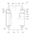
도 1은 본 발명에 따른 디바이스 거치대의 사시도이다.
도 2는 본 발명에 따른 디바이스 거치대의 사용상태도이다.
도 3은 본 발명의 일 실시예에 따른 디바이스 거치대의 사시도이다.
도 4는 본 발명의 일 실시예에 따른 디바이스 거치대의 제 1 파트의 전개도이다.
도 5는 본 발명의 일 실시예에 따른 디바이스 거치대의 제 1 파트의 사시도이다.
도 6은 본 발명의 일 실시예에 따른 디바이스 거치대의 제 2 파트의 전개도이다.
도 7은 본 발명의 일 실시예에 따른 디바이스 거치대의 제 2 파트의 사시도이다.
도 8은 본 발명의 일 실시예에 따른 디바이스 거치대의 제 1 파트에 제 2 파트가 삽입된 상태를 도시한 사시도이다.
도 9는 도 8을 절곡선을 따라 절곡한 상태의 사시도이다.
도 10은 도 9의 측면도이다.
도 11은 본 발명의 다른 실시예에 따른 디바이스 거치대의 제 1 파트의 전개도이다.
도 12는 본 발명의 다른 실시예에 따른 디바이스 거치대의 제 2 파트의 전개도이다.
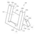
도 13은 본 발명의 다른 실시예에 따른 디바이스 거치대에서 제 1 파트에 제 2 파트가 삽입되고 절곡선을 따라 절곡한 상태의 사시도이다.
도 14는 도 13의 측면도이다.
도 15은 본 발명의 또 다른 실시예에 따른 디바이스 거치대의 전개도이다.
도 16은 도 15의 디바이스 거치대를 말아서 결합하는 과정을 도시한 사시도이다.
도 17은 도 16에 따라 완성된 본 발명의 또 다른 실시예에 따른 디바이스 거치대의 사시도이다.1 is a perspective view of a device holder according to the present invention.
2 is a state diagram used in the device holder according to the present invention.
3 is a perspective view of the device holder according to an embodiment of the present invention.
4 is an exploded view of a first part of a device holder according to an embodiment of the present invention.
5 is a perspective view of a first part of the device holder according to an embodiment of the present invention.
6 is an exploded view of a second part of the device holder according to an embodiment of the present invention.
7 is a perspective view of a second part of the device holder according to an embodiment of the present invention.
8 is a perspective view illustrating a state in which a second part is inserted into a first part of a device holder according to an embodiment of the present invention.
FIG. 9 is a perspective view of a state in which FIG. 8 is bent along a bending line.
10 is a side view of FIG. 9.
11 is an exploded view of a first part of a device holder according to another embodiment of the present invention.
12 is an exploded view of a second part of the device holder according to another embodiment of the present invention.
13 is a perspective view of a state in which a second part is inserted into a first part and bent along a bending line in a device holder according to another exemplary embodiment of the present invention.
14 is a side view of FIG. 13.
15 is an exploded view of the device holder according to another embodiment of the present invention.
FIG. 16 is a perspective view illustrating a process of rolling the device holder of FIG. 15.
17 is a perspective view of the device holder according to another embodiment of the present invention completed in accordance with FIG.
본 발명이 속하는 기술분야에 있어서 통상의 지식을 가진 자가 용이하게 실시할 수 있을 정도로 본 발명의 바람직한 실시예를 도면을 참조하여 상세하게 설명하면 다음과 같다.
DETAILED DESCRIPTION OF THE PREFERRED EMBODIMENTS Hereinafter, preferred embodiments of the present invention will be described in detail with reference to the accompanying drawings, so that those skilled in the art can easily carry out the present invention.
이하에서는 본 발명의 일 실시예에 따른 디바이스 거치대의 구성을 설명하도록 한다.Hereinafter will be described the configuration of the device holder according to an embodiment of the present invention.
도 1은 본 발명에 따른 디바이스 거치대의 사시도이고, 도 2는 본 발명에 따른 디바이스 거치대의 사용상태도이다.1 is a perspective view of a device holder according to the present invention, Figure 2 is a state diagram used in the device holder according to the present invention.
도 1 및 도 2를 참조하면, 본 발명에 따른 디바이스 거치대(100)는 디바이스(10)의 포장용 패키지에 사용되면서 디바이스 거치대로 활용 가능하도록 구성된다.1 and 2, the
이를 위하여 본 발명에 따른 디바이스 거치대(100)는 디바이스(10)가 안착될 수 있도록 함몰 형성되는 안착홈(120)을 구비한다. 안착홈(120)은 디바이스(10)가 안착될 수 있는 크기와 모양으로 형성하며, 바람직하게는 디바이스의 외관 테두리와 대칭되는 모양을 이루면서 디바이스의 크기와 적어도 같거나 크게 형성하도록 한다. 또한, 안착홈(120)의 각 테두리 부 중 적어도 하나의 테두리부에는 안착된 디바이스가 전방으로 넘어지거나 빠지는 것을 방지하기 위하여 안착홈의 내측 방향으로 돌출 형성되는 걸림턱(111a)을 구비하도록 한다. 바람직하게는, 안착홈의 하단부에 안착홈의 내측(도면에서 상부)으로 돌출 형성되는 걸림턱을 구비하도록 한다.To this end, the device holder 100 according to the present invention includes a
또한, 본 발명에 따른 디바이스 거치대(100)는 일부 영역이 일 방향으로 절곡되어 접힘으로써 디바이스를 지지하는 지지부를 형성한다. 이를 위하여, 디바이스 거치대의 일부 영역에는 절곡된 하나 이상의 절곡 영역(400)이 형성되는데, 바람직하게는 절곡 영역이 디바이스 거치대의 상하 수직 방향의 일정 영역에 좌우 수평 방향으로 형성되도록 한다. 따라서, 상기 절곡 영역을 중심으로 디바이스 거치대의 일부 영역이 일 방향으로 절곡되어 접히게 되어, 절곡 영역을 중심으로 일 영역(제 1 영역, 410)은 디바이스가 안착되는 안착부가 되고 다른 일 영역(제 2 영역, 420)은 디바이스 거치대를 지지하는 지지부가 된다. 이때, 안착부와 지지부는 서로 비스듬하게 형성되어 'A'자 형상을 이루도록 한다. 더욱 바람직하게는, 디바이스 거치대(100)가 디바이스(10)를 보다 안정적으로 거치할 수 있도록 안착부와 지지부 사이를 연결하는 지지편(430)을 더 포함하도록 한다.In addition, the device holder 100 according to the present invention forms a support portion for supporting the device by folding a partial region in one direction. To this end, one or more
한편, 도 1 및 도 2에 도시한 바와 같이 상기 절곡 영역은 안착홈(120) 내부의 일부 영역에 형성되도록 하는 것이 바람직하다. 이 경우 절곡 영역을 중심으로 디바이스 거치대(100)의 상부 영역(제 2 영역)이 후방으로 절곡되어 접힘으로써 지지부를 형성하고, 절곡 영역을 중심으로 디바이스 거치대의 하부 영역(제 1 영역)은 안착부를 형성하게 된다. 이때, 안착부의 안착홈(120)은 상면이 개방되고 좌우 측면과 저면만 형성된 형태를 이룸으로써 디바이스를 용이하게 거치할 수 있도록 한다. 또한, 도 1 및 도 2에 도시한 바와 같이 안착부가 후방으로 비스듬하게 기울어져 형성되면서 안착홈의 하단부에는 걸림턱(111a)이 형성되므로 디바이스를 안정적으로 거치할 수 있게 된다.Meanwhile, as shown in FIGS. 1 and 2, the bent region is preferably formed in a partial region inside the
한편, 본 발명에 따른 디바이스 거치대(100)는 다양한 재질로 일체형으로 형성할 수도 있으며, 조립/분리가 가능하도록 복수의 구성편으로 형성할 수 있다. 이때, 각 구성편은 종이 또는 합성수지류로 이루어진 판 형의 구성의 일부를 절곡하거나 걸개하여 형성할 수 있다. 이하에서는, 본 발명에 따른 디바이스 거치대(100)가 2개의 구성편으로 형성되는 실시예를 중심으로 설명하도록 한다.
On the other hand, the device holder 100 according to the present invention may be formed integrally with a variety of materials, it may be formed of a plurality of components to be assembled / separated. At this time, each component piece may be formed by bending or hanging part of the plate-like configuration consisting of paper or synthetic resin. Hereinafter, the device holder 100 according to the present invention will be described with reference to the embodiment formed of two components.
도 3은 본 발명의 일 실시예에 따른 디바이스 거치대의 사시도이다.3 is a perspective view of the device holder according to an embodiment of the present invention.
도 3을 참조하면, 본 발명의 일 실시예에 따른 디바이스 거치대(100)는 외부를 이루면서 형성된 제 1 파트(110), 상기 제 1 파트(110)의 내부에 위치한 제 2 파트(120)를 포함하여 구성된다.Referring to FIG. 3, the
상기 제 1 파트(110) 및 제 2 파트(120)로 이루어진 디바이스 거치대(100)는 디바이스(10)의 제품 포장시 디바이스 패키지 내에 구비되어 있으며, 내부에 안착홈이 형성된 쉘(Shell)을 이루어 패키지 내에서도 디바이스(10)를 보호하는 역할을 1차적으로 수행한다.The
그리고 상기 디바이스 거치대(100)는 패키지에서 분리된 이후 패키지와 독립하여 거치대로서의 기능을 수행할 수 있다. 이를 위해, 상기 디바이스 거치대(100)의 제 1 파트(110)는 일부 영역이 절개되고, 후면으로 절곡되어 도 1에서 보듯이 대략 삼각형 형상의 지지 구조를 형성한다. 또한, 상기 제 1 파트(110)의 개방된 안착홈을 통해 디바이스(10)가 삽입되어 안착된다. 따라서, 상기 디바이스 거치대(100)는 내부에 디바이스(10)를 거치하는 것이 가능하다.
The
이하에서는 본 발명의 일 실시예에 따른 디바이스 거치대의 구성을 보다 상세히 설명하도록 한다.Hereinafter will be described in more detail the configuration of the device holder according to an embodiment of the present invention.
도 4는 본 발명의 일 실시예에 따른 디바이스 거치대의 제 1 파트의 전개도이다.4 is an exploded view of a first part of a device holder according to an embodiment of the present invention.
도 4를 참조하면, 본 발명에 따른 디바이스 거치대(100)의 제 1 파트(110)는 제 1 영역(111), 상기 제 1 영역(111)의 일측에 연결된 제 2 영역(112), 상기 제 2 영역(112)에 연결된 제 3 영역(113), 상기 제 1 영역(111)의 타면에 연결된 제 4 영역(114), 상기 제 1 영역(111)의 상측에 형성된 제 5 영역(115), 상기 제 1 영역(111)의 하측에 형성된 제 6 영역(116)을 포함하여 구성될 수 있다. 여기서, 일측, 타측, 상측 및 하측의 용어는 각각 설명의 편의상 상기 제 1 영역(111)을 형성하는 네 가장자리를 지칭하는 것으로, 특정 영역에 국한된 것은 아니다.Referring to FIG. 4, the
상기 제 1 영역(111)은 가운데에 안착홀(110a)을 구비한다. 상기 안착홀(110a)은 이후 최종적인 구조에서 디바이스(10)가 안착되기 위한 영역을 형성하게 된다. 상기 제 1 영역(111)의 안착홀(110a)은 일부 및 그 반대면으로부터 상기 제 2 영역(112) 및 제 4 영역(114)을 가로지르도록 절단되어 형성된 절개홀(110b)이 형성된다. 상기 절개홀(110b)을 통해 상기 제 1 영역(111), 제 2 영역(112) 및 제 4 영역(114)의 상측은 분리되어 후방으로 절곡될 수 있다.The
상기 제 2 영역(112)은 상기 제 1 영역(111)의 일측에 형성되어 상기 제 1 영역(111)의 수직방향을 따라 동일한 길이로 형성된다. 상기 제 2 영역(111)은 이후 후방을 향해 대략 90도로 절곡되어 상기 제 1 영역(111)의 두께를 형성한다. 또한, 상기 절개홀(110b)은 상기 제 2 영역(112)을 가로지르며, 상기 제 2 영역(112)과 제 3 영역(113)의 경계를 따라서 일정 길이로 절개홀(110c)이 더 형성된다.The
상기 제 3 영역(113)은 상기 제 2 영역(112)에 연결된다. 이후, 상기 제 3 영역(113)은 상기 제 2 영역(112)과의 경계선에서 대략 90도로 절곡되어, 상기 제 1 면(111)과 대략 평행하게 형성된다. 또한, 상기 제 3 영역(113)의 단부는 상기 제 4 영역(114)과 결합되어 전체적으로 사각 기둥 형상이 될 수 있도록 한다. 또한, 상기 제 3 영역(113)은 절개홀(110d)과 접하는 부분에서 상기 제 3 영역(113)을 가로지르는 절곡 라인(110d)을 통해 후방으로 다시 한번 절곡된다. 또한, 상기 제 3 영역(113)은 내부에 지지 영역(113a)을 포함한다. 상기 지지 영역(113a)은 절곡되는 영역으로 연장되어 결합되며, 전체적인 디바이스 거치대(110)의 구조를 지지하게 된다. The
상기 제 4 영역(114)은 상기 제 1 영역(111)의 타측에 형성된다. 상기 제 4 영역(114) 역시 절개홀(110b)이 가로지르도록 형성된다. 또한, 상기 제 4 영역(114)은 절곡되어 상기 제 1 영역(111)의 후방으로 대략 90도의 각도를 이루게 된다. 또한, 상기 제 4 영역(114)의 내측에는 상기 제 3 영역(113)의 단부가 부착되어 결합되며, 그 결과 사각 기둥의 형상을 이루게된다.The fourth region 114 is formed at the other side of the
상기 제 5 영역(115)은 상기 제 1 영역(111)의 상측에 형성된다. 상기 제 5 영역은 후방으로 두 번 절곡되며, 절곡된 단부는 상기 제 1 영역(111)과 평행하게 형성된다. 또한, 상기 절곡된 단부는 상기 제 3 영역(113)에 접하도록 결합된다.The
상기 제 6 영역(116)은 상기 제 1 영역(111)의 하측에 형성된다. 상기 제 6 영역도 역시 후방으로 두 번 절곡되며, 절곡된 단부는 상기 제 3 영역(113)과 접하도록 결합된다.
The
도 5는 본 발명의 일 실시예에 따른 디바이스 거치대의 제 1 파트의 사시도이다. 5 is a perspective view of a first part of the device holder according to an embodiment of the present invention.
도 5를 참조하면, 상기 제 1 파트(110)은 상기 제 2 영역(112) 및 제 4 영역(114)이 대략 90도로 후방으로 절곡되고, 상기 제 3 영역(113)이 상기 제 2 영역(112)로부터 다시 대략 90도로 절곡된다. 또한, 상기 제 3 영역(113)의 단부는 상기 제 4 영역(114)와 접착되어 결합된다.Referring to FIG. 5, in the
또한, 상기 제 5 영역(115) 및 제 6 영역(116)은 각각 두 번 절곡되어 각 단부가 상기 제 1 영역(111)과 평행한 상태로 상기 제 3 영역(113)과 접하도록 결합된다. 따라서, 상기 제 1 파트(110)는 전체적인 윤곽이 대략 사각 기둥의 형상을 갖도록 형성된다.
In addition, the
도 6은 본 발명의 일 실시예에 따른 디바이스 거치대의 제 2 파트의 전개도이다.6 is an exploded view of a second part of the device holder according to an embodiment of the present invention.
도 6을 참조하면, 상기 제 2 파트(120)는 제 1 영역(121), 상기 제 1 여역(121)의 상측에 형성된 제 2 영역(122), 상기 제 1 영역(121)의 일측에 형성된 제 3 영역(123), 상기 제 3 영역(123)에 연결된 제 4 영역(124), 상기 제 1 영역(121)의 타측에 형성된 제 5 영역(125), 상기 제 5 영역(125)에 연결된 제 6 영역(126), 상기 제 1 영역(121)의 하측에 형성된 제 7 영역(127)을 포함하여 구성된다. 물론, 여기서, 상측, 하측, 일측 및 타측의 개념은 설명의 편의를 위해 상기 제 1 영역(121)의 네 가장자리를 지칭하기 위해 사용된 것으로 특정 위치를 한정하는 것은 아니다.Referring to FIG. 6, the
상기 제 1 영역(121)은 직사각형의 형상을 이루면서 형성되며, 상기 제 2 영역(122)은 상기 제 1 영역(121)의 상측에 형성된다. 상기 제 2 영역(122)은 상기 제 1 영역(121)과의 경계선에서 대략 90도로 절곡되며, 상기 제 1 영역(121)의 전방으로 세워진 형태를 갖게된다. 또한, 상기 제 2 영역(122)은 내부에 절곡 라인(122a)을 구비하여, 상기 제 2 영역(122)의 단부가 다시 대략 90도로 절곡되도록 하며, 그 결과 상기 제 2 영역(122)의 단부는 상기 제 1 영역(121)과 평행하게 형성될 수 있다. 또한, 상기 절곡 라인(122a)의 양 단부측에는 각각 삽입홀(122b)이 형성된다. 상기 삽입홀(122b)에는 상기 제 4 영역(124) 및 제 6 영역(126)의 일부가 삽입되어, 결과적으로 상기 제 2 영역(122)이 상기 제 4 영역(124) 및 제 6 영영역(126)과 결합되도록 한다.The
상기 제 3 영역(123)은 상기 제 1 영역(121)의 일측에 형성된다. 상기 제 3 영역(123)은 상기 제 1 영역(121)의 길이방향을 따라 형성된다. 이후, 상기 제 3 영역(123)은 상기 제 1 영역(121)로부터 대략 90도의 각도를 갖도록 전방으로 절곡된다. 즉, 상기 제 3 영역(123)은 상기 제 1 영역(121)로부터 세워진 형태로 절곡된다. 또한, 상기 제 3 영역(123)은 내부에 가로지르는 절개홀(120a)을 갖는다. 또한, 상기 제 3 영역(123)은 상기 제 1 영역(121)과의 경계 영역 중 상기 절개홀(120a)과 접하는 일부 영역에도 절개홀(120b)을 역시 구비한다. 따라서, 상기 제 3 영역(123)은 상기 제 1 영역(121)에 대해 절곡된 이후, 상기 절개홀(120a, 120b)을 통해 상측 영역이 독립하여 상기 제 1 영역(121)의 후방으로 재차 절곡될 수 있다.The
상기 제 4 영역(124)은 상기 제 3 영역(123)에 연결된다. 상기 제 4 영역(124)은 상기 제 3 영역(123)과의 경계에서 상기 제 3 영역(123)으로부터 대략 90도로 절곡된다. 따라서, 상기 제 4 영역(124)은 상기 제 1 영역(121)고 대략 평행한 상태가 될 수 있다. 또한, 상기 제 4 영역(124)은 상측 및 하측으로 돌출된 삽입부(124a, 124b)를 포함한다. 상기 삽입부(124a, 124b)는 각각 상기 제 2 영역(122)의 삽입홀(122b) 및 후술할 제 7 영역(127)의 삽입홀(127b)에 결합되어, 상기 제 4 영역(124)이 상기 제 2 영역(122)과 결합된 상태를 유지하도록 할 수 있다. 또한, 상기 제 4 영역(124)은 상기 제 3 영역(123)과 마찬가지로 내부를 가로지르는 절개홀(120a)을 구비하여, 상기 제 1 영역(121)의 후방으로 절곡될 수 있다.The
상기 제 5 영역(125)은 상기 제 1 영역(121)의 타측에 형성된다. 상기 제 5 영역(125)은 상기 제 3 영역(123)과 대칭되도록 절개홀(120a, 120b)을 구비한다. 상기 제 5 영역(125)은 이후 상기 제 3 영역(123)과 마찬가지로 상기 제 1 영역(121)으로부터 대략 90도를 이루도록 상기 제 1 영역(121)의 전방으로 절곡된다.The
상기 제 6 영역(126)은 상기 제 5 영역(125)에 연결된다. 상기 제 6 영역(126)은 상기 제 5 영역(125)과의 경계에서 대략 90도로 절곡되어 상기 제 1 영역(121)과 평행하게 형성된다. 상기 제 6 영역(126)은 상측과 하측에 삽입부(126a, 126b)를 각각 구비하여, 상기 제 2 영역(122)의 삽입홀(122b) 및 제 7 영역(127)의 삽입홀(127b)에 결합될 수 있다.The
상기 제 7 영역(127)은 상기 제 1 영역(121)의 하측에 형성된다. 상기 제 7 영역(127)은 상기 제 2 영역(122)과 대칭되도록 형성된다. 상기 제 7 영역(127) 역시 한 번의 절곡을 통해 상기 제 1 영역(121)에 수직하게 절곡되고, 절곡 라인(127a)을 따른 또 한번의 절곡을 통해 단부가 상기 제 1 영역(121)과 평행하게 형성된다. 또한, 상기 절곡 라인(127a)의 일부 영역에 형성된 삽입홀(127b)에 상기 제 4 영역(124)의 삽입부(124b) 및 제 6 영역(126)의 삽입부(126b)가 결합될 수 있다.
The
도 7은 본 발명의 일 실시예에 따른 디바이스 거치대의 제 2 파트의 사시도이다.7 is a perspective view of a second part of the device holder according to an embodiment of the present invention.
도 7을 참조하면, 상기 제 2 파트(120)는 상기 제 1 영역(121)을 중심으로 상기 제 2 영역(122) 및 제 7 영역(127)이 대략 90도의 각도를 이루도록 전방으로 절곡된다. 또한, 상기 제 2 영역(122) 및 제 7 영역(127)은 각각 단부가 다시 대략 90도로 절곡된다. 상기 제 3 영역(124) 및 제 5 영역(125)은 상기 제 1 영역(121)을 기준으로 측부에서 각각 대략 90도의 각도로 전방으로 절곡된다. 또한, 상기 제 4 영역(124) 및 제 6 영역(126)은 각각 상기 제 3 영역(123) 및 제 5 영역(125)로부터 절곡되어 상기 제 1 영역(121)과 평행하도록 형성된다. 또한, 상기 제 4 영역(124)의 삽입부(124a, 124b) 및 상기 제 6 영역(126)의 삽입부(126a, 126b)는 각각 상기 제 2 영역(122)의 삽입홀(122b) 및 상기 제 7 영역(127)의 삽입홀(127b)에 결합된다. 상기 제 2 파트(120)는 후술할 바와 같이 상기 제 1 파트(110)에 삽입된 이후 상기 절개홀(120a, 120b)을 따라 절개되고, 절개된 상측은 절곡 라인(120c)을 통해 후방으로 절곡될 수 있다.
Referring to FIG. 7, the
도 8은 본 발명의 일 실시예에 따른 디바이스 거치대의 제 1 파트에 제 2 파트가 삽입된 상태를 도시한 사시도이다. 8 is a perspective view illustrating a state in which a second part is inserted into a first part of a device holder according to an embodiment of the present invention.
도 8을 참조하면, 상기 제 1 파트(110)의 내부에 상기 제 2 파트(120)가 삽입된다. 이 때, 상기 제 1 파트(110)의 절개홀(110b, 110c)과 상기 제 2 파트(120)의 절개홀(120a, 120b)은 대응되는 위치에 형성되도록 결합된다. 또한, 상기 제 1 파트(110)의 절곡 라인(110d)와 제 2 파트(120)의 절곡 라인(120c) 역시 대응되는 위치에 형성되도록 결합된다.
Referring to FIG. 8, the
도 9은 도 8을 절곡선을 따라 절곡한 상태의 사시도이다. 도 10은 도 9의 측면도이다.FIG. 9 is a perspective view of a state in which FIG. 8 is bent along a bending line. 10 is a side view of FIG. 9.
도 9 및 도 10을 참조하면, 상기 제 1 파트(110) 및 제 2 파트(120)는 결합된 상태에서 절개홀(110b, 110c, 120a, 120b)을 중심으로 상측이 분리되고, 절곡 라인(110d, 120c)을 통해 분리된 상측이 후방으로 절곡된다. 또한, 여기서 상기 제 1 파트(110)의 지지 영역(113a)은 상기 제 3 영역(113)으로부터 절곡되어 상기 제 3 영역(113)과 제 5 영역(115)의 결합되는 틈에 삽입되며, 그 결과 상기 제 1 파트(110) 및 제 2 파트(120)가 절곡된 구조를 지지하게 된다.9 and 10, the
따라서, 상기 제 1 파트(110)의 안착홀(110a)내로 상부로부터 디바이스(10)가 삽입 안착될 수 있고, 상기 디바이스(10)는 상기 제 2 파트(120)의 제 1 영역(121)에 의해 후방이 지지되어 거치된 상태를 유지할 수 있다.Accordingly, the
또한, 상기 제 1 파트(110) 및 제 2 파트(120)가 절개되어 후방으로 절곡된 상태에서, 절곡홀(110b, 120c)에 의해 형성된 수납공간에 연필이나 볼펜과 같은 물품들을 수납하는 것도 가능하다.
In addition, in the state where the
상기와 같이 하여, 본 발명의 일 실시예에 따른 디바이스 거치대(100)는 패키지의 쉘을 간단하게 변형하여 디바이스(10)의 거치를 할 수 있도록 형성될 수 있고, 절곡을 통해 수납 공간을 형성하여 간단한 물품을 수납할 수 있도록 제공할 수 있다.
As described above, the
이하에서는 본 발명의 다른 실시예에 따른 디바이스 거치대의 구성을 설명하도록 한다.Hereinafter will be described the configuration of the device holder according to another embodiment of the present invention.
본 발명의 다른 실시예에 따른 디바이스 거치대(200)는 앞서 설명한 디바이스 거치대(100)와 기본적인 구조는 유사하므로, 차이점을 위주로 설명하도록 한다.Since the
도 11은 본 발명의 다른 실시예에 따른 디바이스 거치대의 제 1 파트의 전개도이다.11 is an exploded view of a first part of a device holder according to another embodiment of the present invention.
도 11을 참조하면, 본 발명의 다른 실시예에 따른 디바이스 거치대(200)를 구성하는 제 1 파트(210)는 제 1 영역(211) 내지 제 6 영역(216)을 포함하여 구성된다. 도 11의 전개도 상에서 상기 제 1 파트(210)의 영역들(211 내지 216)의 위치 관계는 앞의 실시예에서의 제 1 파트(110)와 동일하다.Referring to FIG. 11, the
상기 제 1 영역(211)은 안착홀(210a) 및 상기 안착홀(210a)의 양 측에서 연장되어 형성된 절개홀(210b)을 구비한다. 상기 절개홀(210a)은 앞의 실시예와 달리 상기 제 1 영역(210)의 길이 방향을 따라 형성된다. 따라서, 상기 제 1 파트(210)는 이후 상기 제 1 영역(211)의 길이 방향을 중심으로 절곡된다.The
상기 제 3 영역(213)은 길이 방향을 따라 절곡 라인(210c)이 형성된다. 따라서, 상기 절개홀(210b)을 따른 절개가 이루어진 후, 상기 제 1 파트(210)는 상기 절곡 라인(210c)을 따라 후방으로 절곡될 수 있다. 또한, 상기 제 3 영역(213)은 지지 영역(213a)을 구비하며, 상기 지지 영역(213a)은 상기 제 1 파트(210)의 절곡된 구조를 지지하게 된다.
The
도 12는 본 발명의 다른 실시예에 따른 디바이스 거치대의 제 2 파트의 전개도이다.12 is an exploded view of a second part of the device holder according to another embodiment of the present invention.
도 12를 참조하면, 상기 제 2 파트(220)은 제 1 영역(221) 내지 제 7 영역(227)을 포함하여 구성된다. 상기 제 2 파트(220)의 각 영역들(221 내지 227)간 연결관계는 앞선 실시예의 제 2 파트(220)와 동일하다.Referring to FIG. 12, the
다만, 상기 제 2 영역(222) 및 제 7 영역(227)에 절개홀(220a)이 형성되며, 상기 제 1 영역(221)의 길이 방향을 따라 형성된 절곡 라인(220b)은 상기 절개홀(220a)과 동일선상에 위치한다. 따라서, 상기 제 2 파트(220)는 상기 제 1 영역(211)의 길이 방향을 중심으로 절곡될 수 있다.
However, an
도 13은 본 발명의 다른 실시예에 따른 디바이스 거치대에서 제 1 파트에 제 2 파트가 삽입되고 절곡선을 따라 절곡한 상태의 사시도이다. 도 14는 도 13의 측면도이다.13 is a perspective view of a state in which a second part is inserted into a first part and bent along a bending line in a device holder according to another exemplary embodiment of the present invention. 14 is a side view of FIG. 13.
도 13 및 도 14를 참조하면, 앞의 실시예와 마찬가지로 상기 제 1 파트(210)의 내부에 상기 제 2 파트(220)가 삽입된 이후 상기 제 1 파트(210) 및 제 2 파트(220)는 절곡된다. 상기 절곡은 상기 제 1 파트(210) 및 제 2 파트(220)의 길이 방향을 중심으로 절곡되며, 상기 제 1 파트(210)의 지지부재(213a)는 절곡된 상태를 지지하게 된다.Referring to FIGS. 13 and 14, the
따라서, 상기 디바이스(10)는 상기 디바이스 거치대(200)의 길이 방향으로 형성된 면과 접촉하도록 안착되며, 그 결과 안정적인 거치가 가능하다.
Thus, the
이하에서는 본 발명의 또 다른 실시예에 따른 디바이스 거치대의 구성을 설명하도록 한다.Hereinafter will be described the configuration of the device holder according to another embodiment of the present invention.
도 15는 본 발명의 또 다른 실시예에 따른 디바이스 거치대의 전개도이다. 15 is an exploded view of the device holder according to another embodiment of the present invention.
도 15를 참조하면, 본 발명의 또 다른 실시예에 따른 디바이스 거치대(300)는 디바이스 패키지 내에서 바닥 또는 내부 측면을 보호하기 위한 슬립(slip)을 이용하여 형성될 수 있다.Referring to FIG. 15, the
상기 디바이스 거치대(300)는 제 1 영역(310), 상기 제 1 영역(310)에 연결된 제 2 영역(320), 상기 제 2 영역(320)에 연결된 제 3 영역(330)을 포함하여 구성된다.The
상기 제 1 영역(310)은 대략 직사각형의 형상으로 구성된다. 상기 제 1 영역(310)의 일측에는 적어도 하나의 삽입부(311)가 형성된다. 상기 삽입부(311)는 상기 제 1 영역(310)의 일측으로부터 돌출되어 형성된다.The
상기 제 2 영역(320)은 상기 제 1 영역(310)에 연결된다. 상기 제 2 영역(320)은 상기 제 1 영역(310)의 삽입부(311)와 반대되는 측면에 연결된다. 상기 제 2 영역(320)은 상기 제 1 영역(310)과의 경계에 절곡 라인(300a)을 구비하며, 상기 절곡 라인(300a)의 일부 영역에 삽입홀(300b)을 포함한다. 상기 삽입홀(300b)은 상기 삽입부(311)와 대응되도록 형성된다.The
상기 제 3 영역(330)은 상기 제 2 영역(320)에 연결된다. 상기 제 3 영역(330)은 상기 제 2 영역(320)과의 사이에 절곡 라인(300c)을 구비하며, 상기 절곡 라인(300c) 중 일부에 상기 삽입부(311)에 대응되도록 삽입홀(300d)을 구비한다.
The
도 16은 도 15의 디바이스 거치대를 말아서 결합하는 과정을 도시한 사시도이다. 도 17은 도 16에 따라 완성된 본 발명의 또 다른 실시예에 따른 디바이스 거치대의 사시도이다.FIG. 16 is a perspective view illustrating a process of rolling the device holder of FIG. 15. 17 is a perspective view of the device holder according to another embodiment of the present invention completed in accordance with FIG.
도 16 및 도 17을 참조하면, 상기 제 1 영역(310)과 제 2 영역(320)의 사이에 위치한 절곡 라인(300b)을 중심으로 상기 제 1 영역(310)과 제 2 영역(320)이 서로를 향해 말리게 된다. 또한, 상기 절곡 라인(300a)의 상부에 상기 제 2 영역(320)과 제 3 영역(330) 사이의 절곡 라인(300c)이 위치한 상태에서, 상기 제 1 영역(310)의 삽입부(311)가 수직 방향으로 상기 삽입홀(300d, 300b)을 관통하여 체결된다. 따라서, 본 발명의 또 다른 실시예에 따른 디바이스 거치대(300)는 도 15의 최종적인 형태를 이룰 수 있게 된다. 이 때, 디바이스(10)는 상기 제 2 영역(320)의 상부에 안착되고, 상기 제 1 영역(310)에 접하여 거치가 이루어질 수 있다.
16 and 17, the
이상에서 설명한 것은 본 발명에 의한 디바이스 거치대를 실시하기 위한 실시예에 불과한 것으로서, 본 발명은 상기 실시예에 한정되지 않고, 이하의 특허청구범위에서 청구하는 바와 같이 본 발명의 요지를 벗어남이 없이 당해 발명이 속하는 분야에서 통상의 지식을 가진 자라면 누구든지 다양한 변경 실시가 가능한 범위까지 본 발명의 기술적 정신이 있다고 할 것이다.
What has been described above is only an embodiment for carrying out the device holder according to the present invention, the present invention is not limited to the above embodiment, and as claimed in the following claims without departing from the gist of the present invention Anyone with ordinary knowledge in the field of the invention will have the technical spirit of the present invention to the extent that various modifications can be made.
100, 200, 300; 디바이스 거치대
110, 210; 제 1 파트 120, 220; 제 2 파트100, 200, 300; Device holder
110, 210;
Claims (20)
상기 안착부에 연결되고, 상기 안착부에 대해 기준 각도를 형성하기 위해 구부러질 수 있는 지지부; 및
상기 안착부 및 지지부에 연결된 지지 피스를 포함하는 디바이스 거치대.A seating unit supporting a mobile terminal;
A support portion connected to the seating portion and capable of being bent to form a reference angle with respect to the seating portion; And
And a support piece connected to the seating portion and the support portion.
상기 안착부는 안착홈을 포함하는 디바이스 거치대.The method of claim 1,
The mounting portion device holder including a seating groove.
상기 안착부는 상기 이동 단말기를 고정하기 위한 고정 돌기를 포함하는 디바이스 거치대.The method of claim 1,
The mounting portion device holder including a fixing projection for fixing the mobile terminal.
상기 안착부, 지지부 및 지지 피스 중 적어도 하나는 구부러질 수 있는 재질로 형성된 디바이스 거치대.The method of claim 1,
At least one of the seating portion, the support and the support piece is a device holder formed of a bendable material.
상기 이동 단말기를 지지할 수 있는 디바이스 거치대.The method of claim 1,
A device holder capable of supporting the mobile terminal.
이동 단말기를 안착하는 삽입을 형성하는 제 2 파트;
상기 제 1 파트 및 제 2 파트는 안착부와 지지부를 포함하는 지지 구조를 형성하기 위한 절곡 영역을 따라 구부러질 수 있는 디바이스 거치대.A first part forming an exterior;
A second part forming an insert for seating the mobile terminal;
Wherein the first part and the second part can be bent along a bent area to form a support structure comprising a seat and a support.
상기 제 1 파트는 상기 이동 단말기를 고정하기 위해 고정 돌기를 포함하는 디바이스 거치대.The method according to claim 6,
The first part is a device holder including a fixing projection for fixing the mobile terminal.
상기 제 1 파트는 상기 안착부 및 지지부에 연결되는 지지 피스를 포함하는 디바이스 거치대.The method according to claim 6,
And the first part includes a support piece connected to the seating portion and the support portion.
상기 제 1 파트는 상기 제 1 파트의 제 1 영역이 상기 제 1 파트의 제 2 영역에 대하여 구부러질 수 있도록 허용하기 위해 절개된 절개 영역을 포함하는 디바이스 거치대.The method according to claim 6,
And the first part includes an incision area cut away to allow the first area of the first part to bend relative to the second area of the first part.
상기 제 1 영역은 상기 지지부를 제공하기 위해 절곡되고, 상기 제 2 여역은 상기 안착부를 제공하는 디바이스 거치대.The method of claim 9,
Said first region being bent to provide said support and said second area providing said seating portion.
상기 제 1 파트의 제 1 영역은 상기 제 1 파트의 절곡 영역을 따라 절곡되는 디바이스 거치대.The method of claim 9,
And a first region of the first part is bent along a bending region of the first part.
상기 제 1 파트는 상기 이동 디바이스가 안착될 수 있는 안착홀을 포함하는 디바이스 거치대.The method according to claim 6,
The first part is a device holder including a mounting hole in which the mobile device can be mounted.
상기 제 2 파트는 상기 제 2 파트의 제 1 영역이 상기 제 2 파트의 제 2 영역에 대해 구부러질 수 있도록 허용하기 위해 절개된 절개 영역을 포함하는 디바이스 거치대.The method according to claim 6,
And the second part includes an incision area cut away to allow the first area of the second part to bend relative to the second area of the second part.
상기 제 2 파트의 제 1 영역은 상기 제 2 파트의 절곡 영역을 따라 절곡된 디바이스 거치대.The method of claim 13,
And a first region of the second part is bent along a bending region of the second part.
상기 제 2 파트는 상기 이동 디바이스가 안착될 수 있는 안착 영역을 포함하는 디바이스 거치대.The method according to claim 6,
And the second part includes a seating area on which the mobile device can be seated.
상기 제 2 파트는 삽입부를 포함하는 디바이스 거치대.The method according to claim 6,
And the second part includes an insert.
상기 제 2 파트는 상기 삽입부가 따라서 연장되는 삽입홀을 포함하는 디바이스 거치대.17. The method of claim 16,
And the second part includes an insertion hole extending along the insertion portion.
상기 제 2 파트는 상기 제 1 파트의 내부로 삽입되는 디바이스 거치대.The method according to claim 6,
And the second part is a device holder inserted into the first part.
상기 제 2 파트는 절곡 영역을 포함하는 디바이스 거치대.The method according to claim 6,
And the second part includes a bent region.
상기 이동 디바이스에 연결되는 전기 커넥터를 더 포함하는 디바이스 거치대.The method according to claim 6,
And a electrical connector coupled to the mobile device.
Priority Applications (2)
| Application Number | Priority Date | Filing Date | Title |
|---|---|---|---|
| KR1020110108917A KR20130044714A (en) | 2011-10-24 | 2011-10-24 | Device storage using package |
| US13/658,203 US20130098789A1 (en) | 2011-10-24 | 2012-10-23 | Device storage package |
Applications Claiming Priority (1)
| Application Number | Priority Date | Filing Date | Title |
|---|---|---|---|
| KR1020110108917A KR20130044714A (en) | 2011-10-24 | 2011-10-24 | Device storage using package |
Publications (1)
| Publication Number | Publication Date |
|---|---|
| KR20130044714A true KR20130044714A (en) | 2013-05-03 |
Family
ID=48135081
Family Applications (1)
| Application Number | Title | Priority Date | Filing Date |
|---|---|---|---|
| KR1020110108917A Ceased KR20130044714A (en) | 2011-10-24 | 2011-10-24 | Device storage using package |
Country Status (2)
| Country | Link |
|---|---|
| US (1) | US20130098789A1 (en) |
| KR (1) | KR20130044714A (en) |
Families Citing this family (9)
| Publication number | Priority date | Publication date | Assignee | Title |
|---|---|---|---|---|
| US9121541B2 (en) * | 2010-11-09 | 2015-09-01 | Terry G. Jones | Portable device support and organizer system and method |
| US9307656B2 (en) * | 2013-01-18 | 2016-04-05 | Blackberry Limited | Electronic device case |
| TW201505935A (en) * | 2013-08-02 | 2015-02-16 | Fih Hong Kong Ltd | Carrier and packaging box having the same |
| TW201507939A (en) * | 2013-08-28 | 2015-03-01 | Fih Hong Kong Ltd | Multi-function packaging box |
| CN105472914B (en) * | 2014-08-29 | 2019-04-12 | 富泰华工业(深圳)有限公司 | protective case |
| US9462865B2 (en) * | 2014-10-15 | 2016-10-11 | Logitech Europe S.A. | Foldable electronic device case |
| CN107145199A (en) * | 2017-04-28 | 2017-09-08 | 郑州云海信息技术有限公司 | The protector and method of a kind of labyrinth controller |
| US11689239B2 (en) | 2020-11-23 | 2023-06-27 | Speculative Product Design, Llc | Outer case for a foldable mobile device |
| US20240400262A1 (en) * | 2023-06-01 | 2024-12-05 | Apple Inc. | Packaging system and components for retail product |
-
2011
- 2011-10-24 KR KR1020110108917A patent/KR20130044714A/en not_active Ceased
-
2012
- 2012-10-23 US US13/658,203 patent/US20130098789A1/en not_active Abandoned
Also Published As
| Publication number | Publication date |
|---|---|
| US20130098789A1 (en) | 2013-04-25 |
Similar Documents
| Publication | Publication Date | Title |
|---|---|---|
| KR20130044714A (en) | Device storage using package | |
| JP6890961B2 (en) | Blanks and cartons | |
| US7296680B2 (en) | Packing structure and packing member of corrugated cardboard | |
| KR101289408B1 (en) | Folding packaging box | |
| JP2014058271A (en) | Vehicle console | |
| JP3162704U (en) | Packing container | |
| JP2713559B2 (en) | Writing implement holder and its storage case | |
| JP5953499B1 (en) | Flower stand | |
| KR102174071B1 (en) | Apparatus for standing mobile device | |
| JP3240518U (en) | container | |
| JP7151968B2 (en) | package | |
| JP2009096520A (en) | Packing tray | |
| JP2018193105A (en) | Battery case | |
| JP2004189234A (en) | Packing box with hanging | |
| JP5916351B2 (en) | Cosmetic box and blank used therefor | |
| JP6849527B2 (en) | Packaging box | |
| JP2020196545A (en) | Embossed tape | |
| CN113562307B (en) | Display protection device | |
| JP2019104506A (en) | Sheet for support body and package material set | |
| JP3240584U (en) | stand | |
| JP2004250017A (en) | Lens packaging box and lens packaging method | |
| JP2012246003A (en) | Article support | |
| JP2019113160A (en) | Wire material holder | |
| CN110002076A (en) | Packing case and packing method | |
| JP4926581B2 (en) | Stand rack |
Legal Events
| Date | Code | Title | Description |
|---|---|---|---|
| PA0109 | Patent application |
Patent event code: PA01091R01D Comment text: Patent Application Patent event date: 20111024 |
|
| A201 | Request for examination | ||
| PA0201 | Request for examination |
Patent event code: PA02012R01D Patent event date: 20130201 Comment text: Request for Examination of Application Patent event code: PA02011R01I Patent event date: 20111024 Comment text: Patent Application |
|
| PG1501 | Laying open of application | ||
| E902 | Notification of reason for refusal | ||
| PE0902 | Notice of grounds for rejection |
Comment text: Notification of reason for refusal Patent event date: 20140421 Patent event code: PE09021S01D |
|
| E601 | Decision to refuse application | ||
| PE0601 | Decision on rejection of patent |
Patent event date: 20140707 Comment text: Decision to Refuse Application Patent event code: PE06012S01D Patent event date: 20140421 Comment text: Notification of reason for refusal Patent event code: PE06011S01I |