KR20120062032A - Centrifugal dust removing device - Google Patents
Centrifugal dust removing device Download PDFInfo
- Publication number
- KR20120062032A KR20120062032A KR1020100074468A KR20100074468A KR20120062032A KR 20120062032 A KR20120062032 A KR 20120062032A KR 1020100074468 A KR1020100074468 A KR 1020100074468A KR 20100074468 A KR20100074468 A KR 20100074468A KR 20120062032 A KR20120062032 A KR 20120062032A
- Authority
- KR
- South Korea
- Prior art keywords
- rotor
- cleaning liquid
- processing gas
- centrifugal
- dust collector
- Prior art date
- Legal status (The legal status is an assumption and is not a legal conclusion. Google has not performed a legal analysis and makes no representation as to the accuracy of the status listed.)
- Pending
Links
Images


Classifications
-
- B—PERFORMING OPERATIONS; TRANSPORTING
- B01—PHYSICAL OR CHEMICAL PROCESSES OR APPARATUS IN GENERAL
- B01D—SEPARATION
- B01D47/00—Separating dispersed particles from gases, air or vapours by liquid as separating agent
- B01D47/16—Apparatus having rotary means, other than rotatable nozzles, for atomising the cleaning liquid
-
- B—PERFORMING OPERATIONS; TRANSPORTING
- B01—PHYSICAL OR CHEMICAL PROCESSES OR APPARATUS IN GENERAL
- B01D—SEPARATION
- B01D45/00—Separating dispersed particles from gases or vapours by gravity, inertia, or centrifugal forces
- B01D45/12—Separating dispersed particles from gases or vapours by gravity, inertia, or centrifugal forces by centrifugal forces
- B01D45/14—Separating dispersed particles from gases or vapours by gravity, inertia, or centrifugal forces by centrifugal forces generated by rotating vanes, discs, drums or brushes
-
- B—PERFORMING OPERATIONS; TRANSPORTING
- B01—PHYSICAL OR CHEMICAL PROCESSES OR APPARATUS IN GENERAL
- B01D—SEPARATION
- B01D47/00—Separating dispersed particles from gases, air or vapours by liquid as separating agent
- B01D47/06—Spray cleaning
- B01D47/08—Spray cleaning with rotary nozzles
-
- B—PERFORMING OPERATIONS; TRANSPORTING
- B01—PHYSICAL OR CHEMICAL PROCESSES OR APPARATUS IN GENERAL
- B01D—SEPARATION
- B01D50/00—Combinations of methods or devices for separating particles from gases or vapours
-
- B—PERFORMING OPERATIONS; TRANSPORTING
- B04—CENTRIFUGAL APPARATUS OR MACHINES FOR CARRYING-OUT PHYSICAL OR CHEMICAL PROCESSES
- B04B—CENTRIFUGES
- B04B1/00—Centrifuges with rotary bowls provided with solid jackets for separating predominantly liquid mixtures with or without solid particles
- B04B1/04—Centrifuges with rotary bowls provided with solid jackets for separating predominantly liquid mixtures with or without solid particles with inserted separating walls
-
- B—PERFORMING OPERATIONS; TRANSPORTING
- B04—CENTRIFUGAL APPARATUS OR MACHINES FOR CARRYING-OUT PHYSICAL OR CHEMICAL PROCESSES
- B04B—CENTRIFUGES
- B04B5/00—Other centrifuges
- B04B5/10—Centrifuges combined with other apparatus, e.g. electrostatic separators; Sets or systems of several centrifuges
Landscapes
- Chemical & Material Sciences (AREA)
- Chemical Kinetics & Catalysis (AREA)
- Separating Particles In Gases By Inertia (AREA)
- Separation Of Particles Using Liquids (AREA)
- Centrifugal Separators (AREA)
Abstract
본 발명은 집진장치로서, 처리기체의 유로에 위치하고, 회전 가능하게 구동 부에 결합되어 구비된 로터에 있어서, 상기 로터의 내측에 회전축과 나란한 방향으로 복수의 격벽이 회전대칭으로 배치된 별도의 내 측 로터와, 상기 내측 로터와 외측 로터 및 격벽으로 구성된 복수의 연통관이 구비되는 것을 특징으로 하는 원심분리 습식 집진장치를 제공한다.
상기 로터의 회전운동에 의해 상기의 연통관 사이를 통과하는 처리기체는 상기 로터의 회전운동에 의한 원심력 장에 노출되고, 상기 로터 내측에 세정 액과 처리기체 중의 입자상 오염물질의 충돌에 의해 오염물질 입자를 제거하는 것을 특징으로 하는 습식 원심분리 집진장치에 관한 것이다.
원심분리 로터 내측의 격 실을 통과하는 처리기체는, 원심력 장을 반드시 통과 하여야 하고, 처리기체 중의 오염입자는 세정 액에 충돌한 후에는 비가역적으로 제거된다. 강력한 원심력 장을 통과하는 입자성 오염물질은 세정 액과의 충돌로 제거되기 때문에, 원심분리 방식의 문제점인 분리되었던 입자의 재 혼입을 방지하는 특징이 있다.The present invention is a dust collector, a rotor disposed in the flow path of the processing gas, rotatably coupled to the drive unit, the inner side of the rotor in a plurality of partition walls arranged in a direction parallel to the axis of rotation in a separate inner symmetric Provided is a centrifugal wet dust collecting device comprising a side rotor, and a plurality of communication tubes including the inner rotor, the outer rotor, and the partition wall.
The processing gas passing between the communication tubes by the rotational movement of the rotor is exposed to the centrifugal force field caused by the rotational movement of the rotor, and contaminant particles are caused by the collision of the cleaning liquid and particulate contaminants in the processing gas inside the rotor. It relates to a wet centrifugal dust collector, characterized in that to remove the.
The treatment gas passing through the compartment inside the centrifugal rotor must pass through the centrifugal force field, and contaminants in the treatment gas are irreversibly removed after colliding with the cleaning liquid. Particulate contaminants that pass through the strong centrifugal force field are removed by collision with the cleaning liquid, which prevents re-incorporation of the separated particles, which is a problem of the centrifugal separation method.
Description
본 발명은 집진장치에 관한 것으로, 구체적으로는 세정 액 흡착방식의 원심분리 집진장치에 관한 것이다.The present invention relates to a dust collector, and more particularly, to a centrifugal dust collector of a cleaning liquid adsorption method.
원심분리 방식의 집진장치는 사이클론 방식의 집진장치가 개발되어 있고,로터의 회전작동에 의한 오염입자의 원심분리방법의 기술이 제시되어있다. As a centrifugal dust collector, a cyclone dust collector has been developed, and a technique of a centrifugal separation method of polluted particles by rotating a rotor has been proposed.
세정 액과의 접촉을 이용하여 처리기체중의 입자성 오염물질을 제거하는 통상의 스크러버가 제시되어 있다. Conventional scrubbers have been proposed for removing particulate contaminants in a treatment gas using contact with a cleaning liquid.
통상의 사이클론 또는, WO97/40915에 제시된 집진장치는 원심분리의 원리를 이용한 집진장치로 처리기체 중의 입자성 오염물질을 기체와의 비중차이를 이용하여 제거하는 장치로 비교적 커다란 입자의 제거엔 바람직한 성능을 나타내지만 미세입자의 제거에 어려운 문제점이 있다. The conventional cyclone or the dust collector described in WO97 / 40915 is a dust collector using centrifugal principle to remove particulate contaminants in the processing gas by using specific gravity difference with gas. However, there is a problem that is difficult to remove the fine particles.
EP 0 528 483 A1에 제시된 세정방식의 집진장치는 세정 액이 다량 필요한 문제점이 있다. The dust collector of the cleaning method shown in EP 0 528 483 A1 has a problem that a large amount of cleaning liquid is required.
한국 등록특허 10-0809468에 제시된 통상의 회전방식 적 층 디스크의 세정방식 공기청정기는 오염된 세정 액을 재사용하는 문제점이 있다. The conventional cleaning air purifier of the rotary lamination disk shown in Korean Patent 10-0809468 has a problem of reusing contaminated cleaning liquid.
본 발명은 이와 같은 문제점을 해결하기 위하여, 처리기체의 유로에 위치하고, 적어도 일 측이 구동 부에 회전 가능하게 결합되고 지지되는 로터와, 상기 로터의 내측에 회전축과 나란한 방향으로 복수의 격벽 또는 연통관이 회전대칭으로 배치되어 구비되며, 상기 로터의 회전운동에 의해 상기의 연통관을 통과하는 처리기체는 원심력 장에 노출되고, 상기 로터의 내측에 공급되는 세정 액은 상기 연통관에 원심력 작용으로 로터의 내주 면에 이동 및 분포되고, 상기 처리기체 중의 입자상 오염물질은 원심력 작용으로 세정 액에 충돌되어 비가역적으로 제거하는 것을 특징으로 하는 원심분리 집진장치를 제공한다.The present invention, in order to solve such a problem, a rotor located in the flow path of the processing gas, at least one side rotatably coupled and supported by the drive unit, a plurality of partitions or communication pipes in a direction parallel to the rotation axis inside the rotor The processing gas passing through the communication tube by the rotational movement of the rotor is exposed to the centrifugal force field, and the cleaning liquid supplied to the inside of the rotor is centrifugally acting on the communication tube by the rotational movement of the rotor. It is moved and distributed on the surface, and the particulate contaminants in the treated gas is impinged on the cleaning liquid by centrifugal force action to provide a centrifugal dust collector characterized in that the irreversible removal.
본 발명에 따른 원심분리 집진장치는 다음과 같은 특징과 효과가 있다. The centrifugal dust collector according to the present invention has the following features and effects.
처리기체는 원심분리 로터의 원심력 장을 통과 하게 되고, 이때 처리기체 중의 오염입자는 원심력작용으로 로터 내주 면의 세정 액에 충돌한 후에 비가역적으로 제거되며, 원심분리 방식의 문제점인 분리되었던 미세입자가 배출가스에 재 혼입되는 현상이 방지된다.The treatment gas passes through the centrifugal force field of the centrifugal rotor, and contaminated particles in the treatment gas are irreversibly removed after impinging on the cleaning liquid on the inner circumferential surface of the rotor by centrifugal force action. Re-incorporation into the exhaust gas is prevented.
원심분리 방식이므로 유로의 막힘 현상이 대폭 줄어들어 연속적인 가동이 가능하며, 세정 액에 포함된 오염물질을 장치의 작동 중에도 간편하게 연속적으로 제거될 수 있다. Because of the centrifugal separation method, the blockage of the flow path is greatly reduced and continuous operation is possible, and contaminants contained in the cleaning liquid can be easily and continuously removed even during operation of the apparatus.
본 발명에 따른 핵심기능을 유지하면서, 원심분리 로터의 형상과 회전속도에 따라 다양한 요구조건에 대응하여 실시가 가능하다. While maintaining the core function according to the present invention, it is possible to implement a variety of requirements according to the shape and rotation speed of the centrifugal rotor.
처리기체와 세정 액의 접촉방식이 분무방식이 아니고, 기존의 습식 집진장치에 비교하면, 세정 액 표면에 오염입자의 원심력작용에 의한 관성 충돌하는 방식이기 때문에 오염입자 제거에 필요한 세정 액의 양을 대폭 줄일 수 있는 특징이 있다. The contact method between the treatment gas and the cleaning liquid is not a spraying method, but compared with a conventional wet dust collector, since the inertial collision is caused by the centrifugal action of the contaminating particles on the surface of the cleaning liquid. There is a characteristic that can be greatly reduced.
공급된 세정 액은 별도의 분무장치 없이 로터의 회전에 따른 원심력작용이나 중력의 작용으로 로터 내측에 이동 및 분포되고, 로터의 회전속도를 증가시키거나, 로터 회전축의 기울기를 조절하거나, 추가로 세정 액을 공급함으로써 간단히 제거될 수 있다.The supplied cleaning liquid is moved and distributed inside the rotor by centrifugal action or gravity action according to the rotation of the rotor without a separate spray device, and increases the rotation speed of the rotor, adjusts the inclination of the rotor rotation axis, or further cleansing. It can be simply removed by supplying the liquid.
원심분리 로터와 처리기체 이송 팬을 하나의 회전체로 결합하여 처리기체를 장치 스스로 흡입하여 처리하므로, 처리중인 기체의 누출을 차단이 용이하며, 로터와 하우징의 밀폐로 인한 마찰이 없고, 장치의 처리능력에 비해 장치가 간소하고 부피가 줄어드는 특징이 있다.By combining the centrifugal rotor and the processing gas transfer fan with one rotating body, the processing gas is sucked and treated by the device itself, so that leakage of the processing gas can be easily blocked, and there is no friction due to the sealing of the rotor and the housing. Compared to the processing capacity, the device is simple and the volume is reduced.
세정 액을 공급하면서, 고압의 분무장치를 요구하지 않고 원심력에 의한 분포가 이루어 지기 때문에 세정 액 공급장치의 구조를 매우 단순하게 구성할 수 있다. While supplying the cleaning liquid, the distribution of the cleaning liquid supply device can be made very simple since distribution by centrifugal force is achieved without requiring a high pressure spray device.
세정 액에 탈취제, 산화제 또는 살균제를 첨가하여 처리기체중의 오염물질을 탈취, 산화, 살균작용을 기대할 수 있다.Deodorants, oxidants or fungicides may be added to the cleaning liquid to deodorize, oxidize and sterilize contaminants in the treatment gas.
이하 본 발명에 따른 집진장치의 개략적인 도면에 관한 설명이다.
도 1 ; 본 발명에 따른 버켓 형상 원심분리 집진장치의 (실시 예 1)의 처리기체와 세정 액 흐름 설명도.
도 2 ; 본 발명에 따른 버켓 형상 원심분리 집진장치의 (실시 예 1)의 (도1) 회전축 방향 절개 사시도.
도 3 ; 본 발명에 따른 버켓 형상 원심분리 집진장치의 (실시 예1)의 분해 사시도.
도 4 ; 본 발명에 따른 버켓 형상 원심분리 집진장치의 (실시 예1)의 결합 사시도.
도 5 ; 본 발명에 따른 실린더 형상 원심분리 집진장치의 (실시 예 2)의 처리기체와 세정 액 흐름 설명도.
도 6 ; 본 발명에 따른 실린더 형상 원심분리 집진장치의 (실시 예 2)의 회전축 방향 절개 사시도.
도 7 ; 본 발명에 따른 실린더 형상 원심분리 집진장치의 (실시 예 2)의 분해 사시도.
도 8 ; 버켓 형상 로터(실시 예 3)의 회전축방향 절개 사시도.
Hereinafter, a schematic view of a dust collecting apparatus according to the present invention.
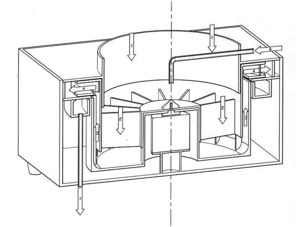
1; Explanatory drawing of the processing gas and the cleaning liquid of (Example 1) of the bucket-shaped centrifugal dust collector according to the present invention.
2; Fig. 1 is a perspective view showing the rotation axis direction of the bucket-shaped centrifugal dust collector according to the present invention (Example 1).
3; Exploded perspective view of (Example 1) of the bucket-shaped centrifugal dust collector according to the present invention.
4; Combined perspective view of (Example 1) of the bucket-shaped centrifugal dust collector according to the present invention.
5; Explanatory drawing of the processing gas and the cleaning liquid of (Example 2) of the cylindrical centrifugal dust collector according to the present invention.
6; Perspective cutaway view of the rotational axis of Example 2 of the cylindrical centrifugal dust collector according to the present invention.
7; Exploded perspective view of (Example 2) of the cylindrical centrifugal dust collector according to the present invention.
8; A perspective view of the axial incision of the bucket-shaped rotor (Example 3).
이하, 본 발명을 도면을 참조하면서 상세히 설명한다. 이해를 돕기 위해 첨부된 도면들에서 본 발명의 특징을 구분하는 요부를 제외한 각 구조체의 결합방식이나 세부 형상은 생략되거나 단순화되고 그 크기가 실제보다 축소되거나 확대된 것일 수 있다. 본 발명은 본 발명에 따른 장치의 핵심구조와 기능을 유지하는 범위 내에서 그 구조를 변경하는 것을 포함한다. 이하, 로터는 본 발명에 따른 원심분리 집진 로터를 의미한다.
Hereinafter, the present invention will be described in detail with reference to the drawings. For the sake of understanding, in the accompanying drawings, a coupling method or a detailed shape of each structure except for the main parts of the present invention may be omitted or simplified, and the size may be reduced or enlarged. The present invention includes changing the structure within the scope of maintaining the core structure and function of the device according to the present invention. Hereinafter, the rotor means a centrifugal dust collecting rotor according to the present invention.
본 발명에 따르면, 처리기체의 유로에 위치하고 연통할 수 있도록, 회전 가능하게 구동 부에 결합된 로터와, 상기 로터의 내측에 회전축과 나란한 방향으로 복수의 격 벽과 로터의 내주 면에 의해 마련된 연통관이 회전대칭으로 구비되고, 상기 로터 내측의 처리기체 유입 부 또는 배출 부에는 처리기체 이송 팬이 로터의 회전축과 동일 축으로 결합되며, 상기 관통 공에 세정 액을 회전축의 일층에 마련된 중공 축을 경유하여 공급되는 것을 특징으로 하는 원심분리 방식의 집진장치를 제공한다.According to the present invention, a communication tube provided by a rotor rotatably coupled to a drive unit so as to be located in communication with a flow path of a processing gas, and a plurality of partition walls and an inner circumferential surface of the rotor in a direction parallel to a rotation axis inside the rotor. The rotationally symmetrical, the processing gas inlet or outlet of the rotor inside the processing gas transfer fan is coupled to the same axis as the rotation axis of the rotor, the through-hole through the hollow shaft provided on the first floor of the rotating shaft Provided is a centrifugal dust collector.
버켓 형상의 로터가 회전함에 따라 로터 내측에 위치한 세정 액이 중력과 원심력의 작용이 균형을 이루는 표면 곡선으로 로터 내주 면으로 치우쳐 분포하게 된다.As the bucket-shaped rotor rotates, the cleaning liquid located inside the rotor is distributed to the inner circumferential surface of the rotor in a surface curve where gravity and centrifugal force are balanced.
로터의 내측에 연통관을 통과하는 처리기체에 포함된 오염 입자는 로터의 회전에 다른 원심력 장을 통과하게 되고, 원심력의 작용으로 세정 액 표면에 충돌하게 되어 흡착 제거작용이 이루어 지게 된다. The contaminant particles contained in the processing gas passing through the communication tube inside the rotor pass through the other centrifugal force field in the rotation of the rotor, and collide with the surface of the cleaning liquid by the action of the centrifugal force to perform the adsorption and removal action.
상기의 인용문헌인 Bucket argument의 내용을 참고하면, 회전축이 중력방향인 회전하는 버켓에 담긴 액체의 표면은 뉴톤의 법칙에 따라 그 단면이 곡선의 형태를 띄게 된다. 유체의 비중과 점도, 중력과 회전하는 각속도 등에 의해 곡면의 형상이 결정되는데, 회전축이 중력방향인 버켓 형상의 로터에 담긴 세정 액의 거동은, 로터의 회전속도와 회전축의 기울기 등에 의해 결정된다. 따라서, 고속으로 회전하는 로터의 내주 면에는 별도의 분무장치 없이도 세정 액이 원심력작용으로 분포될 수 있다. 이때 세정 처리기체가 로터 내측의 연통관을 통과하게 되면 세정 액과 동일한 방향의 원심력의 작용을 받게 되고 처리기체 중의 입자성 오염물질의 세정 액과의 충돌이 일어나게 된다. 이러한 충돌은 대부분 비가역적이어서 미세한 오염입자의 제거에 효과적이다. Referring to the contents of the cited Bucket argument, the surface of the liquid contained in the rotating bucket whose axis of rotation is gravity is curved according to Newton's law. The shape of the curved surface is determined by the specific gravity and viscosity of the fluid, the gravity and the rotating angular velocity. The behavior of the cleaning liquid contained in the bucket-shaped rotor whose rotation axis is the gravity direction is determined by the rotation speed of the rotor and the inclination of the rotation shaft. Therefore, the cleaning liquid may be distributed by centrifugal force on the inner circumferential surface of the rotor rotating at a high speed without a separate spray device. At this time, when the cleaning gas passes through the communication tube inside the rotor, the centrifugal force acts in the same direction as the cleaning liquid, and collision of the particulate contaminants in the processing gas with the cleaning liquid occurs. Most of these collisions are irreversible and are effective for removing fine contaminants.
본 발명에 따른 구성요소들을 구체적인 실시 예를 들어 설명하면 다음과 같다. Referring to the components according to the present invention with a specific embodiment as follows.
본 발명의 구동 부는 통상의 원심분리 장치와 동일한 구조이므로 원심분리 장치의 구성 부가 대부분 구비된다. 동력발생장치와 회전 조절 장치 및 모니터링 부분이 통상의 원심분리 장치와 유사하다. 다만 로터의 구조에서 세정 액의 저류를 위한 내주 면의 구조와 처리기체 및 세정 액의 공급과 배출 구조, 처리기체 이송 팬이 구비된 것이 상이한 부분이다. Since the driving part of the present invention has the same structure as a conventional centrifugal separator, most of the constituent parts of the centrifugal separator are provided. The power generator, rotation control device and monitoring part are similar to conventional centrifugal devices. However, in the rotor structure, the structure of the inner circumferential surface for the storage of the cleaning liquid, the processing gas, the supply and discharge structure of the cleaning liquid, and the processing gas transfer fan are different from each other.
구동 부는 구동모터 또는 동력 전달장치와 회전 지지 베어링으로 구성되며, 원심분리 로터의 회전운동을 구동하고 조절하는 구조가 구비된다. 상기 로터 회전축의 일 측에 로터와 구동 부와의 결합부가 구비된다. 장치를 간소화하기 위해서는 구동모터의 축과 로터의 회전축이 직접 결합되는 것이 바람직하다. The drive unit is composed of a drive motor or a power transmission device and a rotation support bearing, and is provided with a structure for driving and regulating the rotational motion of the centrifugal rotor. One side of the rotor rotation shaft is provided with a coupling portion between the rotor and the drive unit. In order to simplify the device, it is preferable that the axis of the drive motor and the axis of rotation of the rotor are directly coupled.
로터의 구동과 제동을 위한 수단이 함께 구비되는 것이 바람직하며 로터의 구동상태 또는 회전속도를 모니터할 수 있는 수단이 구비되는 것이 바람직하다. Means for driving and braking the rotor are preferably provided together, and means for monitoring the driving state or rotational speed of the rotor are preferably provided.
또한 로터의 구동에 따라 로터 하우징의 개폐 여부가 제한될 수 있도록 안전장치가 함께 구비되는 것이 바람직하다. In addition, it is preferable that the safety device is provided together so that the opening or closing of the rotor housing can be restricted according to the driving of the rotor.
회전에 의한 진동 때문에 구동 축과 로터의 결합방법은 풀림 방지 결합이 바람직하다. Due to the vibration caused by the rotation, the coupling method of the drive shaft and the rotor is preferably an anti-loosening coupling.
소음을 줄이기 위해 자기부상베어링을 구비하는 것이 실시가능하며, 이러한 실시 예 에서는 로터와 구동모터를 일체형으로 구성하는 것이 바람직하다.It is possible to provide a magnetic levitation bearing in order to reduce noise, and in this embodiment, it is preferable that the rotor and the driving motor are integrally formed.
로터의 구동방법은 일정한 속도로 회전하는 방법과 처리기체의 상태나 운전선택에 따라 회전속도를 달리 하는 방법이 선택가능하며, 세정 액이 분포되는 로터 내주 면의 기울기에 따라 로터의 회전속도를 결정하는 것이 바람직하다. The rotor can be rotated at a constant speed or a method of varying the rotational speed depending on the state of the processing gas or the operation selection. The rotor speed is determined by the inclination of the inner circumferential surface of the rotor where the cleaning liquid is distributed. It is desirable to.
테이퍼 형상의 로터 내주면은 일정속도이상의 회전속도에서 세정 액이 얇은 액 막을 형성하며 이동한다. 따라서 로터의 구동에 따라 세정 액의 저류와 배출을 선택할 수 있게 된다. The taper-shaped rotor inner circumferential surface moves at a rotational speed above a certain speed, forming a thin liquid film. Therefore, the storage and discharge of the cleaning liquid can be selected according to the driving of the rotor.
로터와 구동축의 결합방법은 미끄러짐 방지 홈을 구비한 끼움 축 연결방식이나 나사에 의한 결합방식이 실시가능하며 회전 진동에 의한 풀림 방지 수단을 구비하는 것이 바람직하다.The coupling method of the rotor and the drive shaft may be a fitting shaft connection method having a slip preventing groove or a coupling method by screws, and it is preferable to include a release preventing means by rotational vibration.
중력방향 회전축 로터의 경우 처리기체 이송 팬을 포함하는 로터 어셈블리와 구동모터의 결합 축과의 구동전달 연결방식은 구동 축에 미끄러짐 방지 홈이나 돌출부가 구비되고 이에 대응하는 돌출부나 홈이 로터 어셈블리의 결합 부에 구비되어 구동을 전달함에 있어서 미끄러짐이 발생하지 않고 정확하게 전다 가능하게 실시하는 것이 바람직하다. 통상의 원심분리장치의 로터 결합방식과 일치한다. In the case of the gravity rotating shaft rotor, the drive transmission connection method between the rotor assembly including the processing gas transfer fan and the coupling shaft of the driving motor is provided with a slip prevention groove or a protrusion on the driving shaft, and the corresponding protrusion or groove is coupled to the rotor assembly. It is preferable to be provided in the part so that slipping does not occur in transmitting a drive and can be carried out accurately. It is consistent with the rotor coupling method of the conventional centrifuge.
본 발명의 핵심 구성요소인 원심분리 로터의 구조를 설명하면, 통상의 원심분리 장치와 유사하게 회전축을 중심으로 회전 대칭으로 배열되어 구비된 복수의 연통관이 회전축과 나란한 방향으로 구비되며, 로터에 고속회전에도 안정적으로 중심을 유지하도록 로터의 무게중심은 회전축상에 위치하도록 구비하는 것이 바람직하다.Referring to the structure of the centrifugal rotor, which is a key component of the present invention, a plurality of communication pipes arranged in a rotational symmetry with respect to a rotating shaft similar to a conventional centrifugal separator are provided in a direction parallel to the rotating shaft, and the rotor has a high speed. The center of gravity of the rotor is preferably provided on the axis of rotation so as to maintain a stable center even during rotation.
로터의 내주 면에 수직이고, 회전축에 나란한 분리 격 벽은, 처리기체가 통과하면서 로터의 회전에 따라 함께 회전하도록 강제하며, 처리기체는 로터의 내주 면과 격 벽으로 구성된 통 공을 통과하면서 강력한 원심력 장의 영향하에 놓이게 된다. The separating bulkhead perpendicular to the inner circumferential surface of the rotor and parallel to the axis of rotation forces the processing gas to rotate together as the rotor rotates, while the processing gas passes through a hole consisting of the inner circumferential surface of the rotor and the partition wall. It is under the influence of the centrifugal field.
로터의 회전축과 나란하며, 회전축을 중심으로 회전대칭으로 복수의 연통관이 구비된 로터는, 세정 액이 분포되고, 처리기체가 통과되는 부분으로 본 발명의 요부이다.The rotor, which is parallel to the rotation axis of the rotor and is provided with a plurality of communication tubes in a rotational symmetry around the rotation axis, is a part of the present invention in which a cleaning liquid is distributed and a processing gas passes therethrough.
실시 예의 도면(도1,도4)에 따르면, 로터의 구조는 이중 결합 로터로 구비되는 것이 바람직하다. 내측 로터에는 격 벽이 회전대칭으로 구비되어 외부 로터와 결합 되면 처리기체가 통과되는 연통 관을 또는 통 공을 구성하게 된다.
According to the drawings of the embodiment (Fig. 1, Fig. 4), the structure of the rotor is preferably provided with a double coupling rotor. The inner rotor is provided with a partition symmetrically coupled to the outer rotor to form a communication tube or through-hole through which the processing gas passes.
중력의 영향에 의해 세정 액의 거동과 분포가 영향을 받고, 그로 인해 로터 회전축의 기울기에 따른 세정 액의 도입과 배출방법이 달라지게 된다. Gravity influences the behavior and distribution of the cleaning liquid, which causes the introduction and discharge of the cleaning liquid according to the inclination of the rotor shaft.
세정 액은 로터의 회전운동에 의한 원심력작용으로 외부 로터의 내주 면을 따라 분포하게 되며, 로터의 회전속도와 로터 회전축의 방향에 따라 분포를 달리한다. The cleaning liquid is distributed along the inner circumferential surface of the outer rotor by the centrifugal force action by the rotational movement of the rotor, and varies according to the rotational speed of the rotor and the direction of the rotor rotation axis.
로터가 정지한 상태에서는 중력의 작용이 세정 액의 분포를 전적으로 결정하지만 로터의 회전속도가 증가함에 따라 원심력의 작용이 세정 액 분포를 결정하게 된다.
While the rotor is stopped, the action of gravity entirely determines the distribution of the cleaning liquid, but as the rotor speed increases, the action of centrifugal force determines the cleaning liquid distribution.
회전축이 중력방향인 로터는 구동 축에 직접 결합하는 방법으로 로터를 구동하는 것이 바람직하며 로터의 길이가 길 경우에는 회전에 따른 안정성을 유지하기 위하여 로터의 상부에 별도의 지지베어링을 구비하는 것이 바람직하다.
The rotor with the rotational axis in the direction of gravity is preferably driven by a method of directly coupling to the drive shaft. When the rotor is long, it is preferable to have a separate support bearing on the top of the rotor in order to maintain stability due to rotation. Do.
회전축의 방향이 중력의 작용방향과 일치하는 것이 바람직하지만 약간 벗어나는 것도 실시 가능하여 반드시 일치할 필요는 없다. 이는 중력방향과 수직인 회전축에도 해당되며 회전축의 방향은 세정 액의 저류 및 배출에 영향을 주는 요소이므로 이를 기준으로 로터의 실시 예를 분류하는 것이다.
It is preferable that the direction of the rotation axis coincide with the direction of action of gravity, but a slight deviation may be possible, and it is not necessary to coincide. This also corresponds to the axis of rotation perpendicular to the direction of gravity and the direction of the axis of rotation is to classify the embodiment of the rotor based on this factor affects the storage and discharge of the cleaning liquid.
상기 회전축 중력방향 로터는 정밀한 대칭가공 정도에 따라, 회전에 의한 진동이 발생한다. 이를 흡수하면서도 안정적인 자세를 유지하는데 있어서 통상의 로터를 이용한 원심분리장치의 구동 축 구조를 그대로 이용하는 것이 바람직하다. 본 발명에 따른 로터의 회전속도 조절이나 모터의 축 결합방법, 가속과 감속 및 브레이크 작동 등은 통상의 원심분리기를 구동하는 방법과 일치 한다. 즉 진동을 흡수하고 안정적으로 회전운동에 다른 무게중심을 유지하기 위한 유연한 축 결합 수단이 구비되는 것이 바람직하다. 구동모터 축과 로터를 축 결합하고, 상기 모터를 하우징 내측에 탄성 결합하는 방법도 실시가능하며 바람직하다.
The rotation axis of the gravity direction rotor, depending on the precision of the symmetrical processing, the vibration caused by the rotation occurs. In order to absorb this and maintain a stable posture, it is preferable to use a drive shaft structure of a centrifugal separator using a conventional rotor as it is. The rotational speed control of the rotor or the shaft coupling method of the motor, the acceleration and deceleration, and the brake operation according to the present invention are consistent with the method of driving a conventional centrifuge. That is, it is preferable that a flexible shaft coupling means is provided for absorbing vibrations and stably maintaining other centers of gravity in rotational motion. A method of axially coupling the drive motor shaft and the rotor and elastically coupling the motor inside the housing is also possible and preferred.
정상적인 실시조건에서 구동되는 로터의 무게 중심부에 모터 구동 축과 송풍 팬과 로터가 같이 결합되는 것이 바람직하다. 그러기 위해서는 로터의 하부가 로터 내측으로 돌출되어 구비되는 것이 바람직하다. 로터 내부로 돌출된 공간에는 구동모터가 구비되는 것이 보다 바람직하다. 이러한 결합 방법은 로터의 회전에 의한 무게중심 유지의 안정성을 증가시키고 장치를 보다 단소하게 구성하는 것이 가능하게 한다. 물론 통상의 모터 결합방법도 실시 가능하다. 로터와 송풍 팬의 결합부가 일체로 착탈 가능하게 결합되고 상기 로터 결합체는 구동 축에 구비된 결합 별도로 결합되는 방법이 실시 능하다.It is preferable that the motor driving shaft, the blowing fan, and the rotor are coupled together at the center of gravity of the rotor driven under the normal operating conditions. For this purpose, the lower part of the rotor is preferably provided to protrude into the rotor. More preferably, the drive motor is provided in the space protruding into the rotor. This coupling method increases the stability of the center of gravity maintenance by the rotation of the rotor and makes it possible to make the device more compact. Of course, a conventional motor coupling method is also possible. The coupling portion of the rotor and the blower fan is integrally detachably coupled, and the rotor assembly is coupled to the coupling shaft provided on the drive shaft.
상기 로터 내측 벽의 형상을 세정 액의 특정 회전속도의 표면을 나타내는 곡면으로 구비되면 그 속도보다 약간 느린 회전속도에서는 세정 액이 로터 내측에 저류 하면서 액 막을 형성하게 된다. 세정 액의 유동이 로터의 회전 속도에 일치되고 통과하는 처리기체에 동일한 각속도로 회전운동이 이루어지기 위해서 로터 내측 세정 액 분포 부에 처리기체 통과를 위한 연통 관이 구비되는 것을 특징으로 한다. 연통 관은 로터의 회전축을 중심으로 회전대칭으로 구비되며 로터와 그 축이 나란한 것이 특징이다. 세정 액의 저류특성과 접촉 면적을 증가시키기 위해서 연통관의 세정 액 접촉면이 회전축을 기준으로 동일한 거리에 위치하는 실린더 형상의 내주 면과 일치하는 형상(도 1, 도 4)이 바람직하다. 이러한 요구조건을 만족하는 방법으로는 실린더 형상의 로터 내측에 복수의 격 벽을 구비한 내측 로터()를 구비하여 내측 로터() 외주면, 분리 격벽(), 외측 로터() 내주면으로 구성되는 연통 관이 구비되는 것이 바람직하다. 고속회전에서 견고한 내구성과 안정적인 무게중심을 유지하기 위해 내측 로터와 격벽, 외측 로터가 일체형으로 제작되는 것도 실시 가능하다.
If the shape of the inner wall of the rotor is provided as a curved surface representing the surface of the specific rotational speed of the cleaning liquid, the cleaning liquid is stored inside the rotor at a rotational speed slightly slower than that speed to form a liquid film. In order for the flow of the cleaning liquid to match the rotational speed of the rotor and to achieve the rotational movement at the same angular velocity in the processing gas passing therethrough, a communication tube for passing the processing gas is provided in the cleaning liquid distribution inside the rotor. The communication tube is provided with rotational symmetry around the rotation axis of the rotor, and the rotor and its axis are characterized by being parallel. In order to increase the storage characteristics and the contact area of the cleaning liquid, a shape in which the cleaning liquid contact surface of the communication tube coincides with the inner circumferential surface of the cylindrical shape located at the same distance with respect to the rotational axis is preferable (FIGS. 1 and 4). As a method of satisfying such a requirement, a communication tube comprising an inner rotor () having a plurality of partition walls inside the cylindrical rotor and comprising an inner rotor () outer circumferential surface, a separating partition (), and an outer rotor () inner circumferential surface It is preferable that this is provided. In order to maintain solid durability and stable center of gravity at high speed rotation, the inner rotor, the bulkhead, and the outer rotor may be manufactured integrally.
처리기체가 통과되는 연통 관은 회전축과 나란한 격 벽의 구성으로 구비되며 처리기체의 이동경로를 길게 하기 위해 복수의 층으로 구비되는 것이 실시 가능하다. 그러나 로터의 길이를 길게 늘리는 것보다 장치가 복잡하게 되므로 바람직하지 않다.
The communication tube through which the processing gas passes is provided with a configuration of a partition wall parallel to the rotating shaft, and may be provided with a plurality of layers to lengthen the movement path of the processing gas. However, it is not preferable because the device becomes more complicated than the length of the rotor longer.
상기의 격 벽은 내부 로터에 결합되어 구비되는 것이 분해와 결합 및 오염의 청소에 용이하며 바람직하다. 상기의 분리 격 벽의 외부 로터 내주 면에 접촉하는 부분에는 세정 액이 이동될 수 있는 틈이나 연통 공이 구비되는 것이 바람직하다. 상기 연통 공은 격 벽의 일부를 외부 로터 내주 면에 밀착시키지 않고 거리를 두는 방법으로 실시 가능하다.The partition wall is provided to be coupled to the inner rotor for easy disassembly, coupling and cleaning of contamination, and is preferable. It is preferable that a portion or contact hole for allowing the cleaning liquid to be moved is provided in the portion in contact with the inner circumferential surface of the outer rotor of the separation partition wall. The communication hole may be implemented by placing a part of the partition wall without distance to the outer circumferential surface of the outer rotor.
상기 로터에 통 공을 구비하여 처리기체와 세정 액을 통과시키는데 있어서 통 공의 구성방법이 외부 로터에 일체형으로 격벽을 구비하고 내부 로터는 착 탈 가능하게 구비하면, 일정시간 후 로터 내부의 처리기체와 세정 액 접촉 부를 세척하는데 용이한 특징이 있다.
If the rotor is provided with a through hole to pass through the processing gas and the cleaning liquid, the method for forming the through hole includes a partition wall integrally with the outer rotor and the inner rotor is detachably provided. And easy to clean the cleaning liquid contact portion.
분리 격 벽을 헬리컬 형상으로 제작하면, 축 류 팬의 블레이드의 기능과 처리기체의 회전운동을 강제하는 격 벽의 기능을 동시에 갖추게 되어 장치가 단순해지는 특징이 있다.When the separation partition is manufactured in a helical shape, the device has a simple function as it has the function of the blade of the axial fan and the partition forcing the rotation of the processing gas at the same time.
로터의 버켓형상의 로터의 회전축이 중력방향과 나란하고 개방된 방향이 위쪽인 경우 로터 내측에 저류 된 세정 액은 로터의 회전 수를 증가하더라도 완전히 제거하기 어렵다. 로터의 가동 중에, 작동을 멈추지 않고, 내부의 세정 액을 완전히 제거하려면, 위쪽으로 갈수록 넓어지는 테이퍼 형상으로 로터의 내주 면을 가공하거나, 곡면으로 가공하는 것이 바람직하다. 구동조건에 따라서 테이퍼 및 곡면으로 제작하고, 로터의 회전속도를 조절하여 세정 액이 저류 또는 배출되는 작동조건을 선택하게 된다. 로터의 회전속도를 조절하는 것은 사용자에게 매우 편하고 단순한 방법으로 실행 가능하며, 세정 액의 저류와 배출을 로터의 회전속도 변화시켜 조절할 수 있어서, 장치를 매우 단순하게 구성이 가능하고 작동이 편리한 특징이 있다. When the rotational axis of the bucket-shaped rotor of the rotor is parallel with the direction of gravity and the opening direction is upward, the cleaning liquid stored inside the rotor is difficult to remove completely even if the number of rotations of the rotor is increased. In order to completely remove the internal cleaning liquid without stopping the operation during the operation of the rotor, it is preferable to process the inner circumferential surface of the rotor in a tapered shape that increases toward the upper portion or to form a curved surface. The tapered and curved surfaces are manufactured according to the driving conditions, and the rotational speed of the rotor is adjusted to select the operating conditions in which the cleaning liquid is stored or discharged. Adjusting the rotational speed of the rotor is very convenient and simple for the user, and the storage and discharge of the cleaning liquid can be adjusted by changing the rotational speed of the rotor. have.
세정 액의 공급 부와 배출부의 높이에 따라 세정 액의 이동 및 배출 방식이 달라지게 된다. 배출 부의 높이가 도입부 보다 낮으면 세정 액의 배출이 용이하고, 세정 액 배출부의 높이가 공급 부에 비해 높으면 세정 액의 저류특성이 있다. 따라서, 세정 액의 배출부가 공급 부에 비해 높게 구성될 때에는 로터 내주 면을 테이퍼 형상으로 가공하는 것이 바람직하다.The moving and discharging method of the cleaning liquid is changed depending on the height of the supply and discharge portions of the cleaning liquid. If the height of the discharge portion is lower than the introduction portion, the washing liquid is easily discharged. If the height of the washing liquid discharge portion is higher than the supply portion, there is a storage characteristic of the washing liquid. Therefore, when the discharge part of the washing | cleaning liquid is comprised high compared with a supply part, it is preferable to process a rotor inner peripheral surface to taper shape.
로터의 회전축이 중력방향과 수직이면 세정 액 접촉면의 테이퍼 각도를 약간만 주어도 세정 액의 배출이 수월하게 이루어진다. 경우에 따라서는 회전축과 완전한 평행으로 세정 액 접촉면을 구성해도 실시 가능하다. If the rotation axis of the rotor is perpendicular to the direction of gravity, the cleaning liquid can be easily discharged even with a slight taper angle of the cleaning liquid contact surface. In some cases, even if it comprises a cleaning liquid contact surface in parallel with a rotating shaft, it can implement.
중력에 수직방향인 회전축 개방형 실린더 형상의 로터는 세정 액의 배출이 로터의 회전속도와 테이퍼 형상에 좌우된다. 회전수가 느리더라도 세정 액이 공급되는 한 저류 되지 않고 계속해서 흐르며, 연속적이 처리가 필요한 공정에 적합하다.
In the rotor of a rotating shaft-opening cylindrical shape perpendicular to gravity, the discharge of the cleaning liquid depends on the rotational speed and the taper shape of the rotor. Even if the rotation speed is low, the cleaning solution continues to flow without being stored as long as it is supplied, and is suitable for a process requiring continuous treatment.
세정 액은 중력방향 회전축 로터는 (도 1)의 실시 예와 같이 송풍 팬 회전중심부에 공급되고 중력에 의한 자유낙하에 의해 로터로 이동되고 회전하는 로터의 원심력작용과 중력의 작용으로 처리기체의 이동경로와 겹치는 경로를 따라 분배되고 이동하게 된다.The cleaning liquid is supplied to the blowing fan rotation center as shown in the embodiment of Fig. 1, and the cleaning liquid moves to the rotor by free fall due to gravity, and moves the processing gas by the centrifugal action and the action of gravity of the rotating rotor. It is distributed and moved along a path that overlaps the path.
실시 예 1에 따르면, 세정 액이 송풍 팬의 중심부에 공급되고 원심력작용으로 내측 로터로 이동된 후 중력작용으로 아래로 이동 후 로터의 원심력작용으로 외측 로터의 테이퍼 형상 내주 면을 따라 이동된 후 원심력작용으로 흩뿌려지게 되며 뿌려지는 위치에 대응하여 구비된 세정 액 수집 부에 수집되어 배출되는 경로를 거친다. 세정 액은 로터 내측을 이동하면서 처리기체와 이동경로가 겹치게 되는 부분에서 처리기체중의 입자성 오염물질이 흡착되고 배출된다.
According to Example 1, the cleaning liquid is supplied to the center of the blower fan, moved to the inner rotor by centrifugal force, then moved down by gravity, and then moved along the tapered inner peripheral surface of the outer rotor by centrifugal force of the rotor, followed by centrifugal force. It is scattered by the action and passes through the path collected and discharged to the cleaning liquid collection unit provided corresponding to the spraying position. As the cleaning liquid moves inside the rotor, particulate contaminants in the processing gas are adsorbed and discharged at portions where the processing gas and the movement path overlap.
회전축이 중력방향에 수직인 로터나, 로터의 회전 지지부가 두 측인 경우에는 세정 액의 공급방법이 로터의 회전축을 구성하는 중공 축을 경유하여 공급되는 것이 바람직하다. 중공 축을 경유한 세정 액은 분배 면의 회전운동에 따라 원심력작용으로 고르게 각각의 연통관으로 분배되어 이동되는 것이 실시가능하고 바람직하다.
In the case where the rotation axis is perpendicular to the direction of gravity or the rotation support portions of the rotor are two sides, it is preferable that the supply method of the cleaning liquid is supplied via the hollow shaft constituting the rotation axis of the rotor. It is feasible and preferable that the cleaning liquid via the hollow shaft is evenly distributed and moved to each communication tube by centrifugal force action in accordance with the rotational motion of the dispensing surface.
세정 액이 고압의 분사장치를 이용하여 추리기체의 유로에 분사되어 접촉 부를 형성한 후 로터에 흡입되어 원심분리과정을 거치면 기 액 분리과정을 거쳐 공기청정기능을 하는 장치로 적용될 수 있다. 이러한 기술적 사상의 연장선에서 습식 스크러버의 기 액 분리 장치로 본 발명에 따른 원심분리 로터를 적용하여 실시하는 것이 가능하다. The cleaning liquid is sprayed on the flow path of the inferential gas by using a high pressure injection device to form a contact portion, and then sucked into the rotor and subjected to centrifugal separation to be applied to the air cleaning function through the gas separation process. In the extension of this technical idea, it is possible to carry out by applying the centrifugal rotor according to the present invention as a gas-liquid separation device of a wet scrubber.
처리기체의 흡착을 위한 세정 액은 수용액과 비 수성용액이 적용될 수 있다.As the cleaning liquid for adsorption of the treatment gas, an aqueous solution and a non-aqueous solution may be applied.
수용액, 그 중에서도 물은 구하기 쉽고, 경제적이며, 공해를 유발하지 않는 장점이 있다. 그러나, 세정 액의 증발현상으로 인해 습도가 증가하는 특징이 있기 때문에, 처리기체의 온도가 높거나 습도조절이 중요한 장소에서는 제습기를 같이 적용하거나 오일과 같이 비점이 낮고 습도에 영향을 주지 않는 용액을 사용할 수 있다. 또한 수직회전축 버켓 형상 로터는 일정시간 세정 액이 저류 될 수 있어서 물이 아닌 세정 액, 특히 비점이 높은 오일 류를 적용하면 고온의 배기가스 청정장치로 적용 가능하다. 일정시간 세정 액이 로터에 저류 되는 특성으로 인해 적용조건과 경제성을 고려하더라도, 유기, 무기, 합성 오일 류가 세정 액으로 선택되어 공급되는 것이 실시 가능하다.
Aqueous solutions, especially water, are easy to obtain, economical, and do not cause pollution. However, since the humidity increases due to the evaporation of the cleaning liquid, in a place where the temperature of the processing gas is high or where humidity control is important, a dehumidifier may be used together or a solution having a low boiling point such as oil and which does not affect the humidity may be used. Can be used. In addition, the vertical rotating shaft bucket-shaped rotor can be stored for a certain period of time, it is possible to apply a high temperature exhaust gas purifier by applying a cleaning liquid rather than water, especially high boiling oil. Although the application conditions and economics are considered due to the characteristic that the cleaning liquid is stored in the rotor for a certain time, it is possible to select and supply organic, inorganic and synthetic oils as the cleaning liquid.
처리하고자 하는 기체의 오염물질 특성에 맞춰서 로터의 원심력과 세정 액의 공급속도를 조절하면 로터의 내주 면의 오염을 방지할 수 있다. 비가역적으로 침착 또는 흡착된 오염물질은 주기적으로 세정 액 량을 다량 공급하거나 세정 액에 산성세정제, 알칼리성세정제, 계면활성제와 같은 첨가제를 혼합하여 공급함으로써 오염을 제거 할 수 있다. 세정 액에 탈취제, 산화제 또는 살균제를 첨가하여 처리기체중의 오염물질을 탈취, 산화, 살균작용을 기대할 수 있다. By adjusting the centrifugal force of the rotor and the feed rate of the cleaning liquid in accordance with the pollutant characteristics of the gas to be treated, it is possible to prevent contamination of the inner peripheral surface of the rotor. The irreversibly deposited or adsorbed contaminants can be removed by periodically supplying a large amount of the cleaning liquid or by adding an additive such as an acid cleaner, an alkaline cleaner, and a surfactant to the cleaning liquid. Deodorants, oxidants or fungicides may be added to the cleaning liquid to deodorize, oxidize and sterilize contaminants in the treatment gas.
세정 액에 상기의 첨가제들을 처음부터 혼합할 수도 있고, 별도의 용기에 보관하고, 필요 시 물과 혼합해서 주입하는 방법으로 세정 액 조성을 바꿀 수 있다.The additives may be mixed with the cleaning solution from the beginning, or may be stored in a separate container and mixed with water if necessary to change the cleaning solution composition.
처리하고자 하는 기체의 오염원의 종류와 상태에 따라 세정 액의 조성을 조절하면 첨가제의 사용량을 제한하면서도 효과적인 청정효과를 기대할 수 있다. By adjusting the composition of the cleaning liquid according to the type and condition of the pollutant of the gas to be treated, an effective cleaning effect can be expected while limiting the amount of the additive used.
연통관 내에서 세정 액의 흐름 방향은 처리기체의 흐름방향과 동일하거나 반대방향 또는 혼합형으로 실시 가능하다. The flow direction of the cleaning liquid in the communication tube may be the same as the flow direction of the processing gas, or in the opposite direction or in a mixed form.
일반적인 실시조건에서는 세정 액의 흐름 방향이 처리기체의 흐름 방향과 반대 방향인 것이 오염입자의 로터 내주 면에의 흡착을 방지하고 이동거리를 짧게 하기 위해 바람직하다.In general embodiments, it is preferable that the flow direction of the cleaning liquid is opposite to the flow direction of the treatment gas in order to prevent the adsorption of contaminated particles on the inner circumferential surface of the rotor and to shorten the moving distance.
회전하는 물체에 기체를 통과시키기 위해서는 별도의 밀폐장치가 요구되며 밀폐도가 우수한 방법일수록 마찰이 증가하는 경향이 있다. 따라서, 본 발명에서는 처리기체의 우회를 막고 밀폐 요구도를 감소시키기 위해 로터의 회전축과 동일 축으로 처리기체 이송 팬을 결합하여 구비하는 것이 바람직한 실시 방법이다.
In order to pass gas through the rotating object, a separate sealing device is required, and the superior sealing method tends to increase friction. Therefore, in the present invention, in order to prevent the bypass of the processing gas and to reduce the sealing requirement, it is preferable to combine the processing gas conveyance fan with the same axis as the rotation axis of the rotor.
처리기체 이송 팬으로는 축류형과 원심형이 로터의 일측에 착 탈 가능하게 결합 되어 실시 가능하다.
As the processing gas conveying fan, the axial flow type and the centrifugal type can be detachably coupled to one side of the rotor.
집진 로터와 이송 팬이 동일 축으로 로터 내측 처리기체 유입 부에 결합되면, 처리기체의 배출 부에 결합된 것 보다 이송 효율이 더 좋고 바람직하다.
If the dust collection rotor and the transfer fan are coupled to the rotor inner processing gas inlet on the same axis, the transfer efficiency is better and desirable than that coupled to the outlet of the processing gas.
이송 팬이 로터에 결합되어 구비되면 처리기체가 능독적으로 로터로 흡입되고 배출되기 때문에, 바이패스의 가능성을 감소시키고, 로터와 하우징의 밀폐도를 줄일 수 있어서 로터의 회전에 따른 마찰을 방지할 수 있는 특징이 있다.
When the transfer fan is coupled to the rotor, the processing gas is effectively sucked into and discharged from the rotor, thereby reducing the possibility of bypass and reducing the seal between the rotor and the housing, thereby preventing friction due to the rotation of the rotor. There are features that can be.
이송 팬의 처리 유량이 유입되는 처리기체의 유량보다 크면 배출부의 압력이 유입부의 압력보다 커지기 때문에 배출되는 처리기체가 일부 추리기체 유입구로 재 흡입될 수 있는 가능성은 있지만 유입되는 치리 기체가 바이패스 할 가능성은 줄어들게 된다. 이러한 이유 때문에 로터와 하우징의 간극은 가능한 좁혀서 제작하는 것이 바람직하다.
If the feed flow rate of the feed fan is greater than the flow rate of the incoming process gas, the outlet pressure will be greater than the inlet pressure, so that the discharged process gas may be re-inhaled into some inferior gas inlets, but the incoming control gas may be bypassed. The likelihood is reduced. For this reason, it is desirable to make the gap between the rotor and the housing as narrow as possible.
처리기체의 유입부의 압력이 배출부의 압력보다 클 경우에는 이송 팬을 구비하지 않아도 처리기체가 로터를 자발적으로 통과하게 된다. 그러나 일부 기체가 틈새로 바이패스 할 가능성이 있으며, 이를 방지하기 위한 바람직한 방법은 이송 팬을 항상 구비하는 것이다.
If the pressure of the inlet of the treatment gas is greater than the pressure of the outlet, the treatment gas will spontaneously pass through the rotor even without a conveying fan. However, there is a possibility that some gases may bypass by gaps, and a preferred way to prevent this is to always have a transfer fan.
이송 팬은 착탈 가능하게 내측 또는 외측 로터에 결합되어 구비될 수 있고, 내측 또는 외측 로터에 일체형으로 결합되어 구비되는 것이 실시 가능하지만, 장치의 유지보수를 원활히 하기 위해서는 착탈 가능하게 결합되는 것이 보다 바람직하다.
The transfer fan may be detachably coupled to the inner or outer rotor, and may be provided integrally coupled to the inner or outer rotor. However, the transfer fan may be detachably coupled to facilitate the maintenance of the device. Do.
로터의 연통관을 구성하는 격 벽을 처리기체의 이송기능을 겸하게 설계할 수 있다.The partition wall constituting the communication pipe of the rotor can be designed to serve as a transfer function of the processing gas.
격 벽은 처리기체의 이동방향과 나란하게 구비되어 이송 팬의 기능이 없지만, 헬리컬 구조로 뒤틀림 설계를 하면 원심분리 격벽의 기능과 처리기체의 이송기능을 겸할 수 있지만, 제작이 복잡하여 바람직하지 않다. The partition wall is provided in parallel with the moving direction of the processing gas, and does not have a function of the transfer fan. However, if the helical structure is twisted, the partition wall may have the function of the centrifugal partition wall and the transfer of the processing gas. .
하우징은 로터와 구동 부, 세정액 수집 부를 지지하고 밀폐를 유지하는 기능을 하며 처리기체의 유입 부와 배출부가 구비되어있다.
The housing supports the rotor, the drive unit, and the cleaning liquid collection unit and maintains a seal, and is provided with an inlet and an outlet of the processing gas.
처리기체의 도입 부나 배출 부는 제한이 없으나, 로터의 회전축 방향이나 회전축에 수직인 방향으로 구비되는 것이 바람직하다.
There is no limitation on the introduction portion or the discharge portion of the treatment gas, but it is preferable to be provided in the direction of the rotation axis or perpendicular to the rotation axis of the rotor.
로터 회전축의 기울기를 장치의 가동 중에 변경하는 것이 가능한 구조로 구비되는 것이 가능한 구조는 세정 액의 저류와 배출을 용이하게 조절 가능하며 바람직하다. The structure which can be provided with the structure which can change the inclination of a rotor shaft during operation | movement of an apparatus is easy to adjust the storage and discharge | emission of a washing | cleaning liquid, and it is preferable.
이때는 로터 하우징 전체를 지지하는 구조를 회동 가능하게 구비하여야 한다.
At this time, the structure supporting the entire rotor housing should be rotatably provided.
처리기체 도입부에 다양한 전처리 장치를 부가하는 것이 가능한데, 입자의 크기가 큰 조 입자들은 사이클론 집진장치나 메쉬 필터를 통해 미리 걸러주는 것이 바람직하고, 오존발생장치와 같이 장치의 미생물오염을 방지하는 수단이 구비되는 것도 실시 가능하다.It is possible to add various pretreatment devices to the introduction of the treatment gas. It is preferable to filter the coarse particles having a large size in advance through a cyclone dust collector or a mesh filter, and means for preventing microbial contamination of the device, such as an ozone generator, It is also possible to provide.
장치의 처리기체 유로에 자외선 발생장치를 부가하여 미생물의 오염을 방지하는 수단으로 활용하는 것도 실시 가능하다.
It is also possible to add an ultraviolet generating device to the processing gas flow path of the device and to utilize it as a means for preventing microbial contamination.
정전집진방식의 특징을 도입하면 처리기체와 세정 액을 서로 반대되는 극으로 대전시키면 세정 액과 처리기체중의 미세입자의 충돌이 보다 효과적으로 이루어 진다. The introduction of the electrostatic precipitating method allows the treatment gas and the cleaning liquid to be charged to opposite poles so that the collision between the cleaning liquid and the fine particles in the processing gas is more effective.
(도 1)에 예시된 (실시 예 1)은 버켓 형상의 로터로서 회전축이 중력방향과 일치한다. 로터와 구동 부와의 결합은 1점 결합방식이며 세정 액은 로터의 회전축을 따라 중력에 의한 자유낙하박식으로 로터에 공급된다. (Example 1) illustrated in Fig. 1 is a bucket-shaped rotor whose axis of rotation coincides with the direction of gravity. The coupling between the rotor and the driving unit is a one-point coupling system, and the cleaning liquid is supplied to the rotor in a free fall type by gravity along the rotation axis of the rotor.
처리기체의 원심력 장을 형성하는 연통관은 1층으로 구성되며, 로터 구동 시 세정 액이 접촉하는 면은, 로터의 일정 가동조건에서 세정 액의 분포에 따른 표면 형상과 일치한다. 또는 로터의 세정 액 접촉면은 테이퍼 형상의 가공도 바람직하다. 본 실시 예에서 세정 액은 중력의 영향을 받아 분포하게 되며 로터의 회전속도가 증가함에 따라 원심력의 영향을 받아 분포하게 된다. 다라서 로터의 구동조건에 맞는 회전속도에서 세정 액이 적정량 로터 내주 면의 처리기체통과 연통관을 따라 분포하도록 연통관의 각도와 세정 액 접촉면의 곡면가공이 바람직하다. 본 실시 예에서는 내측 로터와 외측 로터가 착 탈 가능하게 구동 축에 결합되며, 처리기체 연통관의 구성은 내측 로터에 구비된 회전축과 나란하고 회전축을 중심으로 회전대칭으로 구비된 격 벽과 내측 로터의 외주면, 외측 로터의 내주 면으로 구성된다. 로터 구동 시 세정 액은 외측 로터의 내주 면에 치우쳐 분포하게 되며 처리기체가 통과될 때 원심력작용으로 세정 액에 충돌되는 과정을 거쳐 입자성오염물질이 제거된다. 처리기체 이송 팬은 로터의 처리기체의 도입부에 착 탈 가능하게 결합되어 구비되는 것이 바람직하다. The communication tube forming the centrifugal force field of the processing gas is composed of one layer, and the surface where the cleaning liquid contacts when the rotor is driven coincides with the surface shape according to the distribution of the cleaning liquid under constant operating conditions of the rotor. Alternatively, the cleaning liquid contact surface of the rotor is preferably tapered. In the present embodiment, the cleaning liquid is distributed under the influence of gravity and is distributed under the influence of the centrifugal force as the rotation speed of the rotor increases. Therefore, it is preferable to process the curved surface of the communication tube and the cleaning liquid contact surface so that the cleaning liquid is distributed along the processing gas cylinder and the communication tube of the appropriate amount of the inner circumferential surface of the rotor at a rotational speed suitable for the driving conditions of the rotor. In this embodiment, the inner rotor and the outer rotor are detachably coupled to the drive shaft, the configuration of the processing gas communication tube is parallel to the rotary shaft provided in the inner rotor and the partition of the partition and the inner rotor provided with rotational symmetry around the rotating shaft It consists of an outer peripheral surface and the inner peripheral surface of an outer rotor. When the rotor is driven, the cleaning liquid is distributed to the inner circumferential surface of the outer rotor and the particulate contaminant is removed through the process of colliding with the cleaning liquid by centrifugal force when the processing gas passes. The treatment gas conveying fan is preferably provided detachably coupled to the introduction portion of the treatment gas of the rotor.
(도 6)에 예시된 (실시 예2)는 개방형 실린더 구조의 회전축이 수평방향이며, 처리기체 이송 팬은 축 류형 팬이 적용되어 있다.
In Example 2 illustrated in FIG. 6, the axis of rotation of the open cylinder structure is horizontal, and the axial flow fan is applied to the processing gas transfer fan.
(도 8)에 예시된 (실시 예3)는 본 발명에 따른 집진 로터와 구동 축과의 결합방식의 또 다른 예를 보여준다.
(Example 3) illustrated in FIG. 8 shows another example of a coupling method of a dust collecting rotor and a drive shaft according to the present invention.
각종 집진 장치에 적용가능하며 세정 액 공급량에 제한이 있는 가정용 집진 장치에도 적합하다. Applicable to various dust collectors, it is also suitable for household dust collectors with limited supply of cleaning liquid.
처리기체에 기체에 포함된 고체나 액체상의 입자 모두 제거가 가능하여 다양한 미세입자가 섞여있는 처리기체를 세정하는데 적합하다.
It is possible to remove all the solid and liquid particles contained in the gas in the processing gas, which is suitable for cleaning the processing gas containing various fine particles.
예를 들어 진공청소기의 미세입자 제거장치로 사용 가능하다. 비교적 큰 입자의 오염물질은 사이클론 이나 집진필터를 이용하여 여과한 후 남아있는 미세입자의 제거에 본 발명에 따른 원심분리 집진장치를 적용하면 청소가 끝난 후 간편하게 세정 액을 버리는 것으로 미세입자를 제거할 수가 있다.
For example, it can be used as a device for removing microparticles in a vacuum cleaner. Contaminants of relatively large particles are filtered using a cyclone or dust collection filter, and the centrifugal dust collector according to the present invention is applied to the removal of the remaining fine particles. There is a number.
헤파 필터가 사용되는 환경이면 본 발명에 따른 원심분리 집진장치가 모두 적용 가능하다.If the HEPA filter is used in the environment, all of the centrifugal dust collectors according to the present invention can be applied.
고속으로 구동되는 로터의 구동이 멈추기 전에는 하우징 커버를 열리지 않도록 하고, 하우징 닫힌 조건에서만 구동모터가 작동되도록 안전장치를 구비하는 것이 바람직하다. 통상의 원심분리장치의 안전장치와 동일한 구조가 적용되는 것이 바람직하다.It is preferable to provide a safety device so as not to open the housing cover until the driving of the rotor driven at a high speed is stopped, and to operate the driving motor only in the closed condition of the housing. It is preferable that the same structure as that of the safety device of a conventional centrifugal separator is applied.
<실시 예 1>
1 ; 처리기체 유입.
2 ; 원심력 장 통과.(하강)
3 ; 원심력 장 통과.(상승)
4 ; 이송 팬에 의한 처리기체 배출
6 ; 세정 액 공급.
7 ; 세정 액 배출.
21 ; 처리기체 유입 부.
22 ; 세정 액 공급 부.
23 ; 로터의 구동 축 결합 부.
24 ; 로터 하단부의 내부 돌출 부.
25 ; 분리 격 벽 어셈블리의 구동 축 결합 부.
26 ; 분리 격 벽, 처리기체 이송 팬, 로터, 및 구동 축 결합 부 어셈블리 .
27 ; 로터.
28 ; 로터 격리 벽.
29 ; 로터 하우징.
30 ; 처리기체 배출 부.
31 ; 구동모터.
32 ; 구동축.
33 ; 구동모터 지지 부.
34 ; 세정 액 배출 부.
35 ; 세정 액 수집 부.
36 ; 로터 하우징 지지부.
40 ; 처리기체 이송 팬.
41 ; 처리기체 이송 팬 가이드.
<실시 예 2>
11 ; 처리기체 유입.
12 ; 송풍기로의 처리기체 이송.
13 ; 처리기체의 연통관 통과 (원심력 장 통과).
14 ; 처리기체 배출.
16 ; 세정 액 공급.
17 ; 세정 액 배출.
121 ; 처리기체 유입 부.
122 ; 세정 액 공급 부.
123 ; 세정 액 분배 부.
126 ; 내부 로터.
127 ; 외부 로터.
127-1 ; 외부 로터 처리기체 배출 부.
128 ; 분리 격 벽.
129 ; 로터 하우징.
130 ; 로터 하우징 처리기체 배출 부.
131 ; 구동 부.
132 ; 로터 구동 축.
133 ; 세정 액 배출 부.
134 ; 세정 액 수집 부.
137 ; 로터 회전축 지지 베어링.
138 ; 세정 액 공급용 중공 관 겸용 로터 회전축.
140 ; 처리기체 이송 팬.
*상대적으로 작은 화살표 ; 세정 액 이동 경로.
*상대적으로 큰 화살표 ; 처리기체 이동 경로.
<실시 예 3>
223 ; 구동 축 결합 부.
224 ; 구동 축 결합 부 보호커버.
225 ; 구동 축 결합 고정 부.
226 ; 내부 로터
227 ; 외부 로터.
228 ; 내측 분리 격 벽.
229 ; 외측 분리 격 벽.
232 ; 구동 축.
240 ; 처리 기체 이송 팬.<Example 1>
One ; Treatment gas inflow.
2 ; Centrifugal force passage (down)
3; Centrifugal force passage (up)
4 ; Treatment gas discharge by the transfer fan
6; Cleaning liquid supply.
7; Drain cleaning fluid.
21; Treatment gas inlet.
22; Cleaning liquid supply part.
23; Drive shaft coupling part of the rotor.
24; Internal protrusion of the bottom of the rotor.
25; Drive shaft coupling part of separation bulkhead assembly.
26; Separation bulkhead, processing gas transfer fan, rotor, and drive shaft coupling part assembly.
27; Rotor.
28; Rotor wall isolation.
29; Rotor housing.
30; Treatment gas discharge part.
31; Drive motor.
32; driving axle.
33; Drive motor support.
34; Cleaning liquid discharge part.
35; Cleaning liquid collection unit.
36; Rotor housing support.
40; Processor gas transfer fan.
41; Processor gas transfer fan guide.
<Example 2>
11; Treatment gas inflow.
12; Transfer of processing gas to the blower.
13; Passing through the communication tube of the processing gas (through the centrifugal field).
14; Treatment gas emissions.
16; Cleaning liquid supply.
17; Drain cleaning fluid.
121; Treatment gas inlet.
122; Cleaning liquid supply part.
123; Cleaning liquid distribution part.
126; Inner rotor.
127; Outer rotor.
127-1; External rotor treatment gas outlet.
128; Separation bulkhead.
129; Rotor housing.
130; Rotor housing disposal gas outlet.
131; Driving part.
132; Rotor driven shaft.
133; Cleaning liquid discharge part.
134; Cleaning liquid collection unit.
137; Rotor shaft support bearing.
138; Rotor shaft combined with hollow tube for cleaning liquid supply.
140; Processor gas transfer fan.
Relatively small arrows; Rinsing fluid migration path.
* Relatively large arrows; Processor gas flow path.
Example 3
223; Drive shaft coupling part.
224; Protective cover for the drive shaft coupling.
225; Drive shaft coupling fixture.
226; Inner rotor
227; Outer rotor.
228; Medial septum.
229; Outer separating septum.
232; Driving shaft.
240; Process gas transfer fan.
Claims (5)
Priority Applications (3)
| Application Number | Priority Date | Filing Date | Title |
|---|---|---|---|
| KR1020100074468A KR20120062032A (en) | 2010-07-31 | 2010-07-31 | Centrifugal dust removing device |
| KR1020137002023A KR20130073931A (en) | 2010-07-31 | 2011-08-01 | Centrifugal dust collector |
| PCT/KR2011/005646 WO2012018207A2 (en) | 2010-07-31 | 2011-08-01 | Centrifugal dust collector |
Applications Claiming Priority (1)
| Application Number | Priority Date | Filing Date | Title |
|---|---|---|---|
| KR1020100074468A KR20120062032A (en) | 2010-07-31 | 2010-07-31 | Centrifugal dust removing device |
Publications (1)
| Publication Number | Publication Date |
|---|---|
| KR20120062032A true KR20120062032A (en) | 2012-06-14 |
Family
ID=45559914
Family Applications (2)
| Application Number | Title | Priority Date | Filing Date |
|---|---|---|---|
| KR1020100074468A Pending KR20120062032A (en) | 2010-07-31 | 2010-07-31 | Centrifugal dust removing device |
| KR1020137002023A Ceased KR20130073931A (en) | 2010-07-31 | 2011-08-01 | Centrifugal dust collector |
Family Applications After (1)
| Application Number | Title | Priority Date | Filing Date |
|---|---|---|---|
| KR1020137002023A Ceased KR20130073931A (en) | 2010-07-31 | 2011-08-01 | Centrifugal dust collector |
Country Status (2)
| Country | Link |
|---|---|
| KR (2) | KR20120062032A (en) |
| WO (1) | WO2012018207A2 (en) |
Families Citing this family (1)
| Publication number | Priority date | Publication date | Assignee | Title |
|---|---|---|---|---|
| GB2563217A (en) * | 2017-06-05 | 2018-12-12 | Mann & Hummel Gmbh | Rotary vessel |
Family Cites Families (4)
| Publication number | Priority date | Publication date | Assignee | Title |
|---|---|---|---|---|
| IT1251171B (en) * | 1991-08-09 | 1995-05-04 | Gennaro Pieralisi | FUME EXTRACTION EQUIPMENT WITH CENTRIFUGAL WET COMBINATION OF DUST |
| SI9600138A (en) * | 1996-04-26 | 1997-10-31 | Ivo Glusic | Mechanical device for extracting dust particles from smoke gases |
| KR100594581B1 (en) * | 2005-03-29 | 2006-06-30 | 삼성광주전자 주식회사 | Multi Dust Collector |
| KR100662648B1 (en) * | 2006-01-06 | 2007-01-02 | 삼성광주전자 주식회사 | Cyclone unit and dust collector with same |
-
2010
- 2010-07-31 KR KR1020100074468A patent/KR20120062032A/en active Pending
-
2011
- 2011-08-01 WO PCT/KR2011/005646 patent/WO2012018207A2/en not_active Ceased
- 2011-08-01 KR KR1020137002023A patent/KR20130073931A/en not_active Ceased
Also Published As
| Publication number | Publication date |
|---|---|
| WO2012018207A3 (en) | 2012-05-31 |
| KR20130073931A (en) | 2013-07-03 |
| WO2012018207A2 (en) | 2012-02-09 |
Similar Documents
| Publication | Publication Date | Title |
|---|---|---|
| KR100653137B1 (en) | Centrifugal Wet Air Purifier Using Rotary Atomizer | |
| JP2021529089A (en) | Air cleaner | |
| JP5102360B2 (en) | Centrifuge and method for purifying gas | |
| CN102580408B (en) | Active centrifugal gas-liquid separation device | |
| US20140182453A1 (en) | Centrifugal wet type cleaner | |
| KR101882283B1 (en) | A Cyclone Air Purifier having Electro Spraying | |
| KR101527101B1 (en) | cyclone type humidifier and wet air purifier combination Device using centrifugal force | |
| JP2013501614A (en) | Centrifugal cleaning air cleaner | |
| KR100980303B1 (en) | Air purifier | |
| JP4744520B2 (en) | Electric dust collector | |
| KR20150052707A (en) | Wet type centrifugal seperation air cleaner | |
| RU2236284C2 (en) | Method and device for liquid cleaning of air | |
| KR20130119336A (en) | Gas purification apparatus | |
| KR20120062032A (en) | Centrifugal dust removing device | |
| KR20130092038A (en) | Wet typer of apparatus for filtering with function of cleaning, air freshener,sterilization and humidification | |
| JP2009136816A (en) | Dust collector | |
| JP2000033216A (en) | Moist generator | |
| KR102204943B1 (en) | Air cleaning apparatus | |
| KR101480266B1 (en) | Air cleaner | |
| KR20210024396A (en) | Air cleaning apparatus | |
| KR20210026262A (en) | Air cleaning apparatus | |
| KR102559208B1 (en) | Air cleaner | |
| KR101092910B1 (en) | Gas Purification System and Duct System Using Porous Cylinder | |
| KR20150140179A (en) | Apparatus for treating pollutant in gas | |
| JP2017064644A (en) | air purifier |
Legal Events
| Date | Code | Title | Description |
|---|---|---|---|
| PA0109 | Patent application |
St.27 status event code: A-0-1-A10-A12-nap-PA0109 |
|
| P11-X000 | Amendment of application requested |
St.27 status event code: A-2-2-P10-P11-nap-X000 |
|
| P13-X000 | Application amended |
St.27 status event code: A-2-2-P10-P13-nap-X000 |
|
| PG1501 | Laying open of application |
St.27 status event code: A-1-1-Q10-Q12-nap-PG1501 |
|
| PC1204 | Withdrawal of earlier application forming a basis of a priority claim |
St.27 status event code: N-1-6-B10-B12-nap-PC1204 |
|
| R18-X000 | Changes to party contact information recorded |
St.27 status event code: A-3-3-R10-R18-oth-X000 |
|
| PN2301 | Change of applicant |
St.27 status event code: A-3-3-R10-R13-asn-PN2301 St.27 status event code: A-3-3-R10-R11-asn-PN2301 |
|
| R11 | Change to the name of applicant or owner or transfer of ownership requested |
Free format text: ST27 STATUS EVENT CODE: A-3-3-R10-R11-ASN-PN2301 (AS PROVIDED BY THE NATIONAL OFFICE) |
|
| R13 | Change to the name of applicant or owner recorded |
Free format text: ST27 STATUS EVENT CODE: A-3-3-R10-R13-ASN-PN2301 (AS PROVIDED BY THE NATIONAL OFFICE) |
|
| R18 | Changes to party contact information recorded |
Free format text: ST27 STATUS EVENT CODE: A-3-3-R10-R18-OTH-X000 (AS PROVIDED BY THE NATIONAL OFFICE) |
|
| R18-X000 | Changes to party contact information recorded |
St.27 status event code: A-3-3-R10-R18-oth-X000 |