KR20120047782A - Electrode [anode and cathode] performance enhancement by composite formation with graphene oxide - Google Patents
Electrode [anode and cathode] performance enhancement by composite formation with graphene oxide Download PDFInfo
- Publication number
- KR20120047782A KR20120047782A KR1020110108363A KR20110108363A KR20120047782A KR 20120047782 A KR20120047782 A KR 20120047782A KR 1020110108363 A KR1020110108363 A KR 1020110108363A KR 20110108363 A KR20110108363 A KR 20110108363A KR 20120047782 A KR20120047782 A KR 20120047782A
- Authority
- KR
- South Korea
- Prior art keywords
- electrode
- lithium
- electronically active
- battery
- eam
- Prior art date
- Legal status (The legal status is an assumption and is not a legal conclusion. Google has not performed a legal analysis and makes no representation as to the accuracy of the status listed.)
- Granted
Links
Images


Classifications
-
- C—CHEMISTRY; METALLURGY
- C01—INORGANIC CHEMISTRY
- C01G—COMPOUNDS CONTAINING METALS NOT COVERED BY SUBCLASSES C01D OR C01F
- C01G31/00—Compounds of vanadium
-
- H—ELECTRICITY
- H01—ELECTRIC ELEMENTS
- H01M—PROCESSES OR MEANS, e.g. BATTERIES, FOR THE DIRECT CONVERSION OF CHEMICAL ENERGY INTO ELECTRICAL ENERGY
- H01M4/00—Electrodes
- H01M4/02—Electrodes composed of, or comprising, active material
- H01M4/36—Selection of substances as active materials, active masses, active liquids
- H01M4/58—Selection of substances as active materials, active masses, active liquids of inorganic compounds other than oxides or hydroxides, e.g. sulfides, selenides, tellurides, halogenides or LiCoFy; of polyanionic structures, e.g. phosphates, silicates or borates
- H01M4/583—Carbonaceous material, e.g. graphite-intercalation compounds or CFx
-
- H—ELECTRICITY
- H01—ELECTRIC ELEMENTS
- H01M—PROCESSES OR MEANS, e.g. BATTERIES, FOR THE DIRECT CONVERSION OF CHEMICAL ENERGY INTO ELECTRICAL ENERGY
- H01M4/00—Electrodes
- H01M4/02—Electrodes composed of, or comprising, active material
- H01M4/36—Selection of substances as active materials, active masses, active liquids
- H01M4/362—Composites
- H01M4/364—Composites as mixtures
-
- H—ELECTRICITY
- H01—ELECTRIC ELEMENTS
- H01M—PROCESSES OR MEANS, e.g. BATTERIES, FOR THE DIRECT CONVERSION OF CHEMICAL ENERGY INTO ELECTRICAL ENERGY
- H01M10/00—Secondary cells; Manufacture thereof
- H01M10/05—Accumulators with non-aqueous electrolyte
-
- H—ELECTRICITY
- H01—ELECTRIC ELEMENTS
- H01M—PROCESSES OR MEANS, e.g. BATTERIES, FOR THE DIRECT CONVERSION OF CHEMICAL ENERGY INTO ELECTRICAL ENERGY
- H01M10/00—Secondary cells; Manufacture thereof
- H01M10/05—Accumulators with non-aqueous electrolyte
- H01M10/058—Construction or manufacture
-
- H—ELECTRICITY
- H01—ELECTRIC ELEMENTS
- H01M—PROCESSES OR MEANS, e.g. BATTERIES, FOR THE DIRECT CONVERSION OF CHEMICAL ENERGY INTO ELECTRICAL ENERGY
- H01M10/00—Secondary cells; Manufacture thereof
- H01M10/42—Methods or arrangements for servicing or maintenance of secondary cells or secondary half-cells
- H01M10/44—Methods for charging or discharging
-
- H—ELECTRICITY
- H01—ELECTRIC ELEMENTS
- H01M—PROCESSES OR MEANS, e.g. BATTERIES, FOR THE DIRECT CONVERSION OF CHEMICAL ENERGY INTO ELECTRICAL ENERGY
- H01M4/00—Electrodes
- H01M4/02—Electrodes composed of, or comprising, active material
- H01M4/13—Electrodes for accumulators with non-aqueous electrolyte, e.g. for lithium-accumulators; Processes of manufacture thereof
- H01M4/131—Electrodes based on mixed oxides or hydroxides, or on mixtures of oxides or hydroxides, e.g. LiCoOx
-
- H—ELECTRICITY
- H01—ELECTRIC ELEMENTS
- H01M—PROCESSES OR MEANS, e.g. BATTERIES, FOR THE DIRECT CONVERSION OF CHEMICAL ENERGY INTO ELECTRICAL ENERGY
- H01M4/00—Electrodes
- H01M4/02—Electrodes composed of, or comprising, active material
- H01M4/13—Electrodes for accumulators with non-aqueous electrolyte, e.g. for lithium-accumulators; Processes of manufacture thereof
- H01M4/133—Electrodes based on carbonaceous material, e.g. graphite-intercalation compounds or CFx
-
- H—ELECTRICITY
- H01—ELECTRIC ELEMENTS
- H01M—PROCESSES OR MEANS, e.g. BATTERIES, FOR THE DIRECT CONVERSION OF CHEMICAL ENERGY INTO ELECTRICAL ENERGY
- H01M4/00—Electrodes
- H01M4/02—Electrodes composed of, or comprising, active material
- H01M4/13—Electrodes for accumulators with non-aqueous electrolyte, e.g. for lithium-accumulators; Processes of manufacture thereof
- H01M4/139—Processes of manufacture
- H01M4/1391—Processes of manufacture of electrodes based on mixed oxides or hydroxides, or on mixtures of oxides or hydroxides, e.g. LiCoOx
-
- H—ELECTRICITY
- H01—ELECTRIC ELEMENTS
- H01M—PROCESSES OR MEANS, e.g. BATTERIES, FOR THE DIRECT CONVERSION OF CHEMICAL ENERGY INTO ELECTRICAL ENERGY
- H01M4/00—Electrodes
- H01M4/02—Electrodes composed of, or comprising, active material
- H01M4/36—Selection of substances as active materials, active masses, active liquids
- H01M4/48—Selection of substances as active materials, active masses, active liquids of inorganic oxides or hydroxides
- H01M4/485—Selection of substances as active materials, active masses, active liquids of inorganic oxides or hydroxides of mixed oxides or hydroxides for inserting or intercalating light metals, e.g. LiTi2O4 or LiTi2OxFy
-
- H—ELECTRICITY
- H01—ELECTRIC ELEMENTS
- H01M—PROCESSES OR MEANS, e.g. BATTERIES, FOR THE DIRECT CONVERSION OF CHEMICAL ENERGY INTO ELECTRICAL ENERGY
- H01M4/00—Electrodes
- H01M4/02—Electrodes composed of, or comprising, active material
- H01M4/62—Selection of inactive substances as ingredients for active masses, e.g. binders, fillers
- H01M4/624—Electric conductive fillers
- H01M4/625—Carbon or graphite
-
- C—CHEMISTRY; METALLURGY
- C01—INORGANIC CHEMISTRY
- C01P—INDEXING SCHEME RELATING TO STRUCTURAL AND PHYSICAL ASPECTS OF SOLID INORGANIC COMPOUNDS
- C01P2002/00—Crystal-structural characteristics
- C01P2002/70—Crystal-structural characteristics defined by measured X-ray, neutron or electron diffraction data
- C01P2002/72—Crystal-structural characteristics defined by measured X-ray, neutron or electron diffraction data by d-values or two theta-values, e.g. as X-ray diagram
-
- C—CHEMISTRY; METALLURGY
- C01—INORGANIC CHEMISTRY
- C01P—INDEXING SCHEME RELATING TO STRUCTURAL AND PHYSICAL ASPECTS OF SOLID INORGANIC COMPOUNDS
- C01P2002/00—Crystal-structural characteristics
- C01P2002/70—Crystal-structural characteristics defined by measured X-ray, neutron or electron diffraction data
- C01P2002/77—Crystal-structural characteristics defined by measured X-ray, neutron or electron diffraction data by unit-cell parameters, atom positions or structure diagrams
-
- C—CHEMISTRY; METALLURGY
- C01—INORGANIC CHEMISTRY
- C01P—INDEXING SCHEME RELATING TO STRUCTURAL AND PHYSICAL ASPECTS OF SOLID INORGANIC COMPOUNDS
- C01P2004/00—Particle morphology
- C01P2004/01—Particle morphology depicted by an image
- C01P2004/03—Particle morphology depicted by an image obtained by SEM
-
- H—ELECTRICITY
- H01—ELECTRIC ELEMENTS
- H01M—PROCESSES OR MEANS, e.g. BATTERIES, FOR THE DIRECT CONVERSION OF CHEMICAL ENERGY INTO ELECTRICAL ENERGY
- H01M10/00—Secondary cells; Manufacture thereof
- H01M10/05—Accumulators with non-aqueous electrolyte
- H01M10/052—Li-accumulators
-
- H—ELECTRICITY
- H01—ELECTRIC ELEMENTS
- H01M—PROCESSES OR MEANS, e.g. BATTERIES, FOR THE DIRECT CONVERSION OF CHEMICAL ENERGY INTO ELECTRICAL ENERGY
- H01M4/00—Electrodes
- H01M4/02—Electrodes composed of, or comprising, active material
- H01M4/04—Processes of manufacture in general
- H01M4/0471—Processes of manufacture in general involving thermal treatment, e.g. firing, sintering, backing particulate active material, thermal decomposition, pyrolysis
-
- Y—GENERAL TAGGING OF NEW TECHNOLOGICAL DEVELOPMENTS; GENERAL TAGGING OF CROSS-SECTIONAL TECHNOLOGIES SPANNING OVER SEVERAL SECTIONS OF THE IPC; TECHNICAL SUBJECTS COVERED BY FORMER USPC CROSS-REFERENCE ART COLLECTIONS [XRACs] AND DIGESTS
- Y02—TECHNOLOGIES OR APPLICATIONS FOR MITIGATION OR ADAPTATION AGAINST CLIMATE CHANGE
- Y02E—REDUCTION OF GREENHOUSE GAS [GHG] EMISSIONS, RELATED TO ENERGY GENERATION, TRANSMISSION OR DISTRIBUTION
- Y02E60/00—Enabling technologies; Technologies with a potential or indirect contribution to GHG emissions mitigation
- Y02E60/10—Energy storage using batteries
-
- Y—GENERAL TAGGING OF NEW TECHNOLOGICAL DEVELOPMENTS; GENERAL TAGGING OF CROSS-SECTIONAL TECHNOLOGIES SPANNING OVER SEVERAL SECTIONS OF THE IPC; TECHNICAL SUBJECTS COVERED BY FORMER USPC CROSS-REFERENCE ART COLLECTIONS [XRACs] AND DIGESTS
- Y02—TECHNOLOGIES OR APPLICATIONS FOR MITIGATION OR ADAPTATION AGAINST CLIMATE CHANGE
- Y02P—CLIMATE CHANGE MITIGATION TECHNOLOGIES IN THE PRODUCTION OR PROCESSING OF GOODS
- Y02P70/00—Climate change mitigation technologies in the production process for final industrial or consumer products
- Y02P70/50—Manufacturing or production processes characterised by the final manufactured product
-
- Y—GENERAL TAGGING OF NEW TECHNOLOGICAL DEVELOPMENTS; GENERAL TAGGING OF CROSS-SECTIONAL TECHNOLOGIES SPANNING OVER SEVERAL SECTIONS OF THE IPC; TECHNICAL SUBJECTS COVERED BY FORMER USPC CROSS-REFERENCE ART COLLECTIONS [XRACs] AND DIGESTS
- Y10—TECHNICAL SUBJECTS COVERED BY FORMER USPC
- Y10T—TECHNICAL SUBJECTS COVERED BY FORMER US CLASSIFICATION
- Y10T29/00—Metal working
- Y10T29/49—Method of mechanical manufacture
- Y10T29/49002—Electrical device making
- Y10T29/49108—Electric battery cell making
Landscapes
- Chemical & Material Sciences (AREA)
- Chemical Kinetics & Catalysis (AREA)
- Electrochemistry (AREA)
- General Chemical & Material Sciences (AREA)
- Engineering & Computer Science (AREA)
- Manufacturing & Machinery (AREA)
- Inorganic Chemistry (AREA)
- Materials Engineering (AREA)
- Organic Chemistry (AREA)
- Composite Materials (AREA)
- Battery Electrode And Active Subsutance (AREA)
- Secondary Cells (AREA)
Abstract
매트릭스 및 나노미립자 형태의 전자적 활성 재료 (EAM) 를 포함하는, 바람직하게는 매트릭스 및 나노미립자 형태의 전자적 활성 재료 (EAM) 로 이루어진, 전극이 기재되어 있고, 상기 매트릭스는, 내부에 통합된 그래핀 플레이크들 및 선택적으로 이온성 리튬 소스를 갖는 열분해 생성물로 이루어진다. 또한, 그래핀 플레이크들을 통합한 열분해된 재료로부터 형성된 매트릭스를 포함하는, 입자계, 특히 섬유계 전극 재료를 제조하는 방법 및 이러한 전극들을 포함하는 재충전 가능한 배터리들이 기재되어 있다.An electrode is described, comprising an electronically active material (EAM) in matrix and nanoparticulate form, preferably consisting of an electronically active material (EAM) in matrix and nanoparticulate form, the matrix having graphene integrated therein Pyrolysis product with flakes and optionally an ionic lithium source. Also described are methods for making particulate, in particular fibrous, electrode materials comprising a matrix formed from pyrolyzed material incorporating graphene flakes and rechargeable batteries comprising such electrodes.
Description
본 발명은 개선된 전극 재료 및 이러한 개선된 전극 재료를 제조하는 방법 그리고 이러한 전극 재료를 포함하는 배터리에 관한 것이다.The present invention relates to an improved electrode material, a method of making such an improved electrode material, and a battery comprising such electrode material.
몇개의 재충전 가능한 배터리들이 알려져 있다. 그러나, 이들은 여전히 고 중량, 저 용량, 느린 충전, 빠른 에이징 (aging) 등과 같은 몇개의 단점들을 가지고 있다. 특히, 컴퓨터들, 자동차들 및 전기 자전거들과 같은 의도된 이동성 또는 감소된 장소로의 응용에 대해, 저 중량, 고 용량, 빠른 충전 및 긴 수명이 요구된다. 지난 몇 년 동안, 전극 재료들을 개선시키기 위해 또는 상기 서술된 단점들을 감소시키기 위해 각고의 노력이 이루어졌다.Several rechargeable batteries are known. However, they still have some disadvantages such as high weight, low capacity, slow filling, fast aging and the like. In particular, for applications to intended mobility or reduced locations such as computers, automobiles and electric bicycles, low weight, high capacity, fast charging and long life are required. In the last few years, great efforts have been made to improve electrode materials or to reduce the disadvantages described above.
지난 몇 년 동안 관심을 얻은 수많은 재료들은 나노미립자 형태로 사용된 세라믹계 재료들이다. 이들 나노미립자들은 다각형이거나, 구형이거나, 또는 그들을 섬유들로서 평하는 신장까지 일 방향으로 길게 되어 있을 수도 있다. 이러한 섬유질 재료들 중 하나는 H2V3O8 이다.Numerous materials of interest over the past few years are ceramic materials used in the form of nanoparticles. These nanoparticulates may be polygonal, spherical, or elongated in one direction until stretch to flatten them as fibers. One such fibrous material is H 2 V 3 O 8 .
H2V3O8 은, 1970 [1] 에 이미 기재되어 있고 1990 [2] 에서 구조적으로 분석되었던 알려진 화합물이다. 또한, 캐소드 재료로서 HyNa1 - yV3O8이 연구되고 있다 [3]. HyNa1 - yV3O8 은 제 1 방전 사이클 동안 3개의 리튬 이온들을 삽입하도록 기재되어 있다. 충전시에, 그 3개의 리튬 이온들이 탈리된다.H 2 V 3 O 8 is a known compound already described in 1970 [1] and structurally analyzed in 1990 [2]. Also, H y Na 1 as the cathode materials - a y V 3 O 8 have been studied [5]. H y Na 1 - y V 3 O 8 is described to insert three lithium ions during the first discharge cycle. Upon charging, those three lithium ions are released.
섬유질 H2V3O8 이 다량 (4.5 eq. 까지) 의 리튬을 가역적으로 교환할 수 있다하더라도 [4], 거기에 연결된 체적 변화로 인해, 섬유들은 특정한 프래그먼트화에서 최적의 교환능력을 나타내는 작은 프래그먼트들로 분해되며, 여기서 추가적인 프래그먼트화에서는 용량이 현저하게 감소되므로 전극의 안정성이 위협된다.Although fibrous H 2 V 3 O 8 can reversibly exchange a large amount (up to 4.5 eq.) Of lithium [4], due to the volume change associated with it, the fibers have a small degree of optimal exchange capacity in certain fragmentation. It breaks down into fragments, where further fragmentation threatens the stability of the electrode because the capacity is significantly reduced.
다른 캐소드 재료들은 Li4V3O8 [5], Na V3O8 [6] 및 Li1 .3- yCuyV3O8 [7], LixFePO4, LixCoO2, LixMn2O4, Lix(MnuCovNiyAlz)O2 (u+v+y+z![]()
![]()
또한, 적합한 애노드 재료들도 이미 알려져 있다. 이들은 LixC6 및 리튬 합금들을 포함한다.In addition, suitable anode materials are already known. These include Li x C 6 and lithium alloys.
적합한 EA 재료들은 통상, 그 자체로 전기 전도성일 수도 있는, 및/또는 예컨대, 전도성 카본 블랙 및/또는 그래파이트로, 전도성으로 채워지는 바인더에 의해 전극들로 형성된다. 바인더 및 전도성 필러들은, 충전 방전 사이클에 실제로 참여하지 않고서 배터리의 총 중량 및 체적에 대해 상당히 첨가된다.Suitable EA materials are typically formed into electrodes by a binder that may be electrically conductive on its own, and / or conductively filled with, for example, conductive carbon black and / or graphite. The binder and conductive fillers are added significantly to the total weight and volume of the battery without actually participating in the charge discharge cycle.
예컨대, 나노미립자 형태의 전도성 바인더를 이용함으로써 (유럽 특허 출원 공보 EP 2 228 855 참조), 또는 중합성 바인더에 대한 대용품으로서 열분해된 생성물을 조제함으로써, 바인더/필러 매트릭스의 중량을 감소시키고자 하는 몇몇 시도가 이미 이루어졌다. 상기 종래의 공보의 개시물은 그 전체가 본 명세서에 통합된다.Some attempt to reduce the weight of the binder / filler matrix, for example, by using a conductive binder in the form of nanoparticulates (see European Patent
이들 시도들은 일부 중량 감소를 가져왔지만, 더욱 감소된 양의 선택적으로 전도성으로 채워진 바인딩 재료에 대한 필요성이 여전히 존재한다. 전도성 필러를 선택적으로 포함하는 상기 바인딩 재료는 더욱 나아가 바인더 매트릭스 또는 매트릭스로서도 지칭된다.These attempts have led to some weight reduction, but there is still a need for a further reduced amount of selectively conductively filled binding material. The binding material optionally comprising a conductive filler is further referred to as a binder matrix or matrix.
[선행기술문헌][Prior Art Literature]
[1] Theobald, F. and R. Cabala, Comptes Rendus Hebdomadaires des Seances de L'Academie des Sciences, Serie C, 1970, 270(26), 2138.[1] Theobald, F. and R. Cabala, Comptes Rendus Hebdomadaires des Seances de L'Academie des Sciences, Serie C, 1970 , 270 (26), 2138.
[2] Oka, Y., T. Yao, and N. Yamamoto, Journal of Solid State Chemistry, 1990, 89(2), 372.[2] Oka, Y., T. Yao, and N. Yamamoto, Journal of Solid State Chemistry, 1990 , 89 (2), 372.
Oka, Y., T. Yao, and N. Yamamoto, Journal of Solid State Chemistry, 1990, 86(1), 116. Oka, Y., T. Yao, and N. Yamamoto, Journal of Solid State Chemistry, 1990 , 86 (1), 116.
[3] WO 01/74716[3] WO 01/74716
[4] Electrochimica Acta 54 (2009) 1115-1118[4] Electrochimica Acta 54 (2009) 1115-1118
[5] Chem. Eur. J. 2008, 14, 11141-11148[5] Chem. Eur. J. 2008, 14, 11141-11148
[6] J. Electrochem. Soc., Vol. 145, No. 2, 1998[6] J. Electrochem. Soc., Vol. 145, No. 2, 1998
[7] Chem. Mater. 2005, 17, 984-991[7] Chem. Mater. 2005, 17, 984-991
[8] H.P. Boehm et al.; Annalen der Chemie; 1965; 691; 1-8[8] H.P. Boehm et al .; Annalen der Chemie; 1965; 691; 1-8
그리하여, 본 발명의 일반적인 목적은, 큰 기계적 안정성에서 높은 매트릭스 전도성 및 낮은 또는 감소된 매트릭스 함량을 갖는 전극을 제공하는 것이다.Thus, it is a general object of the present invention to provide an electrode with high matrix conductivity and low or reduced matrix content at large mechanical stability.
본 발명의 다른 목적은, 큰 기계적 안정성에서 높은 매트릭스 전도성 및 낮은 매트릭스 함량을 갖는 전극들을 제조하는 방법을 제공하는 것이다.Another object of the present invention is to provide a method for producing electrodes having high matrix conductivity and low matrix content at large mechanical stability.
본 발명의 또 다른 목적은, 감소된 또는 낮은 매트릭스 함량을 갖는 캐소드 또는 애노드 중 적어도 하나, 바람직하게는 양방의 전극들 모두를 포함하는 배터리들을 제공하는 것이다.It is a further object of the present invention to provide batteries comprising at least one of the cathode or anode, preferably both electrodes, having a reduced or low matrix content.
본 발명의 또 다른 목적은, 강화된 사이클 안정성을 갖는 전극을 제공하는 것이다.Another object of the present invention is to provide an electrode having enhanced cycle stability.
이하, 설명이 진행됨에 따라 더욱 쉽게 명백해질 것인, 본 발명의 이들 목적들 및 추가적인 목적들을 실현하기 위해, 본 발명의 전극은, 매트릭스 및 나노미립자 형태의 전자적 활성 재료 (EAM) 를 포함하는, 바람직하게는 매트릭스 및 나노미립자 형태의 전자적 활성 재료 (EAM) 로 이루어지는 것을 특징으로 하고, 상기 매트릭스는, 내부에 통합된 그래핀 플레이크들 그리고 선택적으로 이온성 리튬 소스, 및 - EAM 에 의존하여 - 또한 선택적으로 안정화제 (H2V3O8 에 대해, 예컨대, 바나듐 (IV) 설페이트) 를 갖는 열분해 생성물로 이루어진다.In order to realize these and further objects of the invention, which will become more readily apparent as the description proceeds, the electrode of the invention comprises an electronically active material (EAM) in the form of a matrix and nanoparticulates, Preferably consisting of an electronically active material (EAM) in the form of a matrix and nanoparticulates, said matrix comprising graphene flakes integrated therein and optionally an ionic lithium source, and-depending on the EAM- Optionally consisting of a pyrolysis product with a stabilizer (eg, vanadium (IV) sulphate for H 2 V 3 O 8 ).
열분해 생성물은, 예컨대, 본 발명에 또한 속하는 방법에서, 적합하게 열분해 가능한 재료를 열분해함으로써 획득된다.Pyrolysis products are obtained, for example, by pyrolysing suitably pyrolysable materials in the process also belonging to the invention.
양호한 바인딩을 위해, 최종 생성물, 즉 활성 전극에서의 나노미립자 재료에 대한 매트릭스의 중량비는, 활성 전극, 즉, 각각 전자적 활성 코팅 또는 전류 컬렉터를 갖지 않는 전극의 중량에 대해서 최대 10 중량% 이고, 바람직하게는 5 ± 2 중량% 이다. 매트릭스는, 아몰퍼스 탄소질 재료 대 그래핀의 비율이 약 2 : 1 내지 약 1 : 1, 바람직하게는 약 3 : 2 이도록 그래핀 산화물을 포함한다.For good binding, the weight ratio of the final product, i.e. the matrix to the nanoparticulate material in the active electrode, is at most 10% by weight relative to the weight of the active electrode, ie the electrode without an electronically active coating or current collector, respectively, and is preferred. Preferably 5 ± 2% by weight. The matrix comprises graphene oxide such that the ratio of amorphous carbonaceous material to graphene is about 2: 1 to about 1: 1, preferably about 3: 2.
임의의 캐소드 재료들 및 또한 애노드 재료들은 EAM 으로서 사용될 수도 있으며, 다만, 그들은 나노입자들의 형태로 존재한다. 더욱 바람직한 EAM 은, 제 1 충전 또는 방전 이전에, LixH2 - xV3O8 이며, 상기 식 단위에서의 3개의 V 원자들 중 적어도 하나는 산화 상태 4+를 가지며, x는 0.1 내지 1.5이고, 통상 약 1 이다. 이러한 황록색 착색된 EAM은, 리튬 (상기 식 단위에서의 Lix) 의 적어도 부분이 제 1 충전 동안 제거될 수 있는 유리한 특징을 가진다.Any cathode materials and also anode materials may be used as EAM, provided they are in the form of nanoparticles. More preferred EAM is Li x H 2 - x V 3 O 8 , prior to the first charge or discharge, at least one of the three V atoms in the formula unit has an
입자계, 특히 섬유계 전극 재료를 제조하는 방법은, A method of producing particulate, in particular fibrous, electrode materials,
(A) 분산액을 포함하는 전자적 활성 전구체 재료를 조제하는 단계로서, 상기 현탁액은, (A) preparing an electronically active precursor material comprising a dispersion, the suspension comprising:
(i) 가용성 리튬 소스 및 수산화물 소스, 특히 리튬 수산화물, (i) soluble lithium and hydroxide sources, in particular lithium hydroxide,
(ii) 수용성이고, - 전자적 활성 재료와 혼합되어 - 열분해될 수 있는 적어도 부분적 유기 물질, (ii) an at least partially organic material which is water soluble and which can be pyrolyzed in admixture with an electronically active material,
(iii) 전자적 활성 재료 (EAM), 및 (iii) an electronically active material (EAM), and
(iv) 그래핀 산화물 (GO) 을 포함하는, 상기 전자적 활성 전구체 재료를 조제하는 단계,(iv) preparing the electronically active precursor material comprising graphene oxide (GO),
(B) 액체상으로부터 고체 전자적 활성 전구체 재료를 분리하는 단계,(B) separating the solid electronically active precursor material from the liquid phase,
(C) 상기 단계 (B) 의 전자적 활성 전구체 재료를 건조시키는 단계,(C) drying the electronically active precursor material of step (B),
(D) 활성 전극 재료를 산출하기 위해 상기 단계 (C) 의 전자적 활성 전구체 재료를 열분해하는 단계,(D) pyrolysing the electronically active precursor material of step (C) to yield an active electrode material,
그리고 선택적으로, And optionally
(E) 상기 단계 (B) 의 전자적 활성 전구체 재료를 기판, 특히, 전류 컬렉터에 공급하는 단계 및/또는 활성 전극 재료를 절단하여 형상화하고 전류 컬렉터 상에 활성 전극 재료를 배치하는 단계에 의해 나타내진다.(E) supplying the electronically active precursor material of step (B) to a substrate, in particular a current collector, and / or cutting and shaping the active electrode material and placing the active electrode material on the current collector. .
이러한 전극은, 적어도 하나의 세퍼레이터로 전극을 커버한 후 셀을 전해질로 채우고, 셀을 애노드로 완성한 후 셀을 기밀하게 밀폐함으로써 셀로 더욱 프로세싱될 수도 있다.Such an electrode may be further processed into the cell by covering the electrode with at least one separator and then filling the cell with electrolyte, completing the cell with an anode, and then sealing the cell hermetically.
이하, 사용된 일부 용어들을 더욱 정의한다:Below, some terms used are further defined:
- 전자적 활성 전구체 재료 = 열분해 단계 이전의 습윤 또는 건조 재료Electronically active precursor material = wet or dry material prior to the pyrolysis step
- 전자적 활성 코팅 또는 활성 전극 또는 활성 전극 재료 = 각각, 전극을 사용하기 위한 조제상태의 열분해된 재료, 또는 전류 컬렉터를 갖지 않는 전극An electronically active coating or active electrode or active electrode material = an electrode that does not have a current pyrolyzed material or current collector, respectively, for use of the electrode.
사용된 EAM에 따라, H2V3O8 을 안정화하기 위해, 예를 들면, 설페이트로서, V(IV) 와 같은 적합한 산화 상태의 금속을 포함하고 가용성인 금속성 화합물과 같은 안정화제를 첨가함으로써, 전극 제조 동안 EAM 을 안정화하는 것이 유리하거나 또는 심지어 필요할 수도 있다.Depending on the EAM used, to stabilize H 2 V 3 O 8 , for example, by adding as stabilizer a stabilizer such as a metallic compound comprising a metal in a suitable oxidation state such as V (IV) and being soluble, It may be advantageous or even necessary to stabilize the EAM during electrode fabrication.
제 1 특정 실시형태에 있어서, 입자계, 특히 섬유계 전극 재료를 제조하는 방법은, In a first specific embodiment, a method of producing a particulate, in particular fibrous, electrode material,
(a) 리튬 소스 및 수산화물 소스, 특히 리튬 수산화물, 및 수용성이고, - 전자적 활성 재료와 혼합되어 - 열분해될 수 있는 적어도 부분적 유기 물질을 포함하는 용액을 조제하는 단계로서, 상기 용액은, 유기 용매 및/또는 물에, 바람직하게는 물에 유기 화합물, 리튬 소스 및 수산화물 소스를 용해시킴으로써 조제되는, 상기 용액 조제 단계,(a) preparing a solution comprising a lithium source and a hydroxide source, in particular lithium hydroxide, and at least a partial organic material that is water soluble and can be thermally decomposed-mixed with an electronically active material, the solution comprising: an organic solvent and The solution preparation step, prepared by dissolving an organic compound, a lithium source and a hydroxide source in water, preferably in water,
(b) pH 가 8 과 10 사이에 유지되도록 하면서 그래핀 산화물의 수계 분산액/용액을 첨가하는 단계,(b) adding an aqueous dispersion / solution of graphene oxide while maintaining the pH between 8 and 10,
(c) 상기 단계 (b) 에서 조제된 분산액에 전자적 활성 재료 (EAM) 를 분산시키고 균질화하는 단계, (c) dispersing and homogenizing the electronically active material (EAM) in the dispersion prepared in step (b),
(d) 분산액을 포함하는 전자적 활성 전구체 재료를 야기하는 압력 강화 조건하에서 그래핀 산화물의 그래핀으로의 열분해 (thermolysis), 자기조립 및 리튬화를 위한 열수 (hydrothermal) 단계를 수행하는 단계로서, 상기 분산액은 내부에 치밀한 고체 부유물을 갖는 검은 액체의 형태로 존재하는, 상기 열수 단계를 수행하는 단계,(d) performing a hydrothermal step for thermolysis, self-assembly and lithiation of graphene oxide to graphene under pressure strengthening conditions resulting in an electronically active precursor material comprising the dispersion, wherein Performing the hydrothermal step, wherein the dispersion is in the form of a black liquid with a dense solid suspension therein,
(e) 세정하지 않고서 액체상으로부터 전자적 활성 전구체 재료를 분리하는 단계,(e) separating the electronically active precursor material from the liquid phase without washing,
(f) 상기 단계 (e) 의 전자적 활성 전구체 재료를 기판에, 예컨대, 전류 컬렉터에 공급하는 단계,(f) supplying the electronically active precursor material of step (e) to a substrate, such as a current collector,
(g) 전자적 활성 전구체 재료를 건조시키는 단계, 및(g) drying the electronically active precursor material, and
(h) 전극을 산출하기 위해 전자적 활성 전구체 재료를 열분해하는 단계에 의해 나타내진다.(h) pyrolysing the electronically active precursor material to yield an electrode.
제 2 특정 실시형태에 있어서, 본 발명의 방법은, In a second specific embodiment, the method of the invention,
(a) 유기 용매 및/또는 물에, 바람직하게는 물에 선택적으로 안정화된 EAM을 분산시키는 단계,(a) dispersing the selectively stabilized EAM in an organic solvent and / or water, preferably in water,
(b) 그래핀 산화물 용액을 첨가하는 단계,(b) adding a graphene oxide solution,
(c) 상기 단계 (b) 에서 획득된 현탁액을 냉동시키는 단계,(c) freezing the suspension obtained in step (b),
(d) 냉동된 현탁액을 가온함으로써, 바람직하게는 실온 (RT) 으로 가온함으로써 냉동된 현탁액을 해동시키는 단계,(d) thawing the frozen suspension by warming the frozen suspension, preferably by warming to room temperature (RT),
(e) 리튬 소스 및 수산화물 소스, 특히 리튬 수산화물, 그리고 수용성이고, - 전자적 활성 재료와 혼합되어 - 열분해될 수 있는 적어도 부분적 유기 물질을 첨가하는 단계, (e) adding a lithium source and a hydroxide source, in particular lithium hydroxide, and at least a partial organic material which is water soluble and which, in admixture with an electronically active material, can be pyrolyzed,
(f) 전자적 활성 전구체 재료를 포함하는 현탁액이 암청색이 될때까지 대기한 후, 전자적 활성 전구체 재료를 회수하는 단계,(f) waiting until the suspension comprising the electronically active precursor material becomes dark blue, and then recovering the electronically active precursor material,
(g) 유기 용매 및/또는 물의 비점 미만의 온도에서, 예컨대, 실온 (RT) 에서 전자적 활성 전구체 재료를 건조시킨 후, 유기 용매 및/또는 물의 비점 이상의 온도에서 전자적 활성 전구체 재료를 건조시키는 단계,(g) drying the electronically active precursor material at a temperature below the boiling point of the organic solvent and / or water, such as at room temperature (RT), and then drying the electronically active precursor material at a temperature above the boiling point of the organic solvent and / or water,
(h) 활성 전극 재료를 산출하기 위해 건조된 전자적 활성 전구체 재료를 열분해하는 단계,(h) pyrolysing the dried electronically active precursor material to yield an active electrode material,
(g) 뜨거운 활성 전극 재료를 적어도 30분간 배기하고 (이 배기 시간 동안) 활성 전극 재료를 냉각시키는 단계,(g) evacuating the hot active electrode material for at least 30 minutes (for this exhaust time) and cooling the active electrode material,
그리고 선택적으로,And optionally
(h) 전극 재료를 절단하여 형상화하고 전극 재료를 전류 컬렉터 상에 배치하는 단계에 의해 나타내진다.(h) cutting and shaping the electrode material and placing the electrode material on a current collector.
적합한 열분해 재료들은, 약 150 ℃ 내지 약 350 ℃ 에서, 바람직하게는 약 200 ℃에서 열분해 가능한 (thermolysable) 재료들이며, 캐소드 전자적 활성 재료 (EAM) 의 경우에, 산화하는, 특히 히드록시 카르복실산 및 설탕이고, 애노드 EAM 의 경우에, 환원하는, 특히 폴리아닐린과 같은 낮은 산소 함량을 갖는 유기 재료들이다.Suitable pyrolysis materials are thermoslyable materials at about 150 ° C. to about 350 ° C., preferably at about 200 ° C., and in the case of cathode electronically active materials (EAM), in particular hydroxy carboxylic acids and It is a sugar and, in the case of anode EAM, reducing, in particular organic materials having a low oxygen content, such as polyaniline.
반응은 바람직하게는 물에서 수행된다. 하지만, 물 민감성 EAM의 경우에, 다른 용매, 예를 들면, 물과 혼화될 수 있는 비양성자성 극성 용매가 사용될 수도 있다. 본 발명의 범위에서, 상기 용어 용매는 또한 2 이상의 용매들의 혼합물을 포함한다. 극성 비양성자성 용매들에 대한 예들은 아세토니트릴 및/또는 테트라하이드로푸란이다. 물은 상기 용어 용매 중에 포함되지 않는다.The reaction is preferably carried out in water. However, in the case of water sensitive EAMs, aprotic polar solvents may also be used which can be miscible with other solvents, for example water. In the scope of the present invention, the term solvent also includes mixtures of two or more solvents. Examples for polar aprotic solvents are acetonitrile and / or tetrahydrofuran. Water is not included in the term solvent.
유기 물질 포함 부분은 임의의 열분해 가능한 물질, 이를테면, 락토스와 같은 열분해 가능한 설탕일 수도 있지만, 바람직하게는 리튬 염, 특히 리튬 히드록시카르복실레이트 이를테면 리튬 락테이트, 리튬 시트레이트, 또는 리튬 화합물을 포함하는 다른 열분해 가능한 음이온이지만, 바람직하게는 리튬 락테이트이거나 리튬 락테이트를 포함한다. 리튬 락테이트는 열분해되기 위한 바인더 전구체로서 그리고 리튬 소스의 부분으로서 동시에 작용한다. 또한 수산화물 소스가 존재해야 하기 때문에, 다른 바람직한 리튬 소스는 수산화물 소스의 적어도 부분으로서 동시에 작용하는 리튬 수산화물이다. EAM이 H2V3O8 또는 부분적으로 리튬화된 형태, 이를테면 나중 단계에서 LixH2 - xV3O8 로 변환되는 LixH2V3O8 (x는 0.1 내지 1.5, 바람직하게는 0.5 내지 1.5) 인 경우, 단계 (a) 에서 조제된 분산액은 또한 바나듐 (IV) 소스를 안정화제로서 포함한다. 바람직한 실시형태에서, 부분적으로 리튬화된 H2V3O8 가 사용되거나 LixH2 - xV3O8 (x는 0.1 내지 1.5이고 보통 약 1이다) 와 같이 본 발명의 방법에서 직접 생성된다.The organic-comprising moiety may be any thermally decomposable material, such as pyrolytic sugars such as lactose, but preferably comprises lithium salts, in particular lithium hydroxycarboxylates such as lithium lactate, lithium citrate, or lithium compounds Is another pyrolysable anion, but preferably lithium lactate or includes lithium lactate. Lithium lactate acts simultaneously as a binder precursor for pyrolysis and as part of a lithium source. Another preferred lithium source is lithium hydroxide, which simultaneously acts as at least part of the hydroxide source, since a hydroxide source must be present. EAM is H 2 V 3 O 8 or partially lithiated forms, such as at a later stage, Li x H 2 - x V 3 Li x H 2 V is converted to O 8 3 O 8 (x is 0.1 to 1.5, preferably Is 0.5 to 1.5), the dispersion prepared in step (a) also comprises a vanadium (IV) source as stabilizer. In a preferred embodiment, partially lithiated H 2 V 3 O 8 is used or produced directly in the process of the invention, such as Li x H 2 - x V 3 O 8 (x is 0.1 to 1.5 and usually is about 1). do.
단계 (b) 에서 사용된 그래핀 용액은, 공동 소유의 공개된 유럽 특허 출원 EP 2 256 087에 따라 조제될 수도 있는데, 그의 개시 내용은 본원에 전부 포함된다. 특정 예는 실험 부분에서 찾아볼 수 있다. The graphene solution used in step (b) may be prepared according to the co-owned published European
전자적 활성 입자들이 열분해된 재료에 기초하여 바인더에 의해 함께 부착된다. 열분해된 재료, 예를 들면 열분해된 락테이트 외에, 바인더 매트릭스는 그래핀을 포함하고, 선택적으로 그리고 바람직하게는 또한 리튬 또는 리튬 및 전이 금속, 예를 들면 바나듐을 포함하거나, 열분해된 재료, 그래핀 및 선택적으로 그리고 바람직하게는 리튬 또는 리튬 및 전이 금속 이를테면 바나듐으로 이루어질 수도 있다. 열분해된 재료는 아몰퍼스 탄소질 재료에 의해 주로 형성되지만, 또한 소량의 산소 및 수소 함유 반응 생성물들을 포함할 수도 있다.Electronically active particles are attached together by a binder based on the pyrolyzed material. In addition to pyrolyzed material, for example pyrolyzed lactate, the binder matrix comprises graphene, optionally and preferably also comprises lithium or lithium and transition metals such as vanadium, or pyrolyzed material, graphene And optionally and preferably lithium or lithium and transition metals such as vanadium. The pyrolyzed material is mainly formed by amorphous carbonaceous material, but may also contain small amounts of oxygen and hydrogen containing reaction products.
양호한 바인딩을 위해, 최종 생성물, 즉 활성 전극에서의 나노미립자 재료에 대한 매트릭스의 중량비는, 활성 전극의 중량에 대해, 즉, 각각 전자적 활성 코팅 또는 전류 컬렉터를 갖지 않는 전극의 중량에 대해, 적어도 약 2중량%, 바람직하게는 적어도 3 중량%이고, 상한은 10중량%를 초과하지 않아야 하고 바람직하게는 5±2 중량%이다. 이들 값들은 또한 감소되거나 낮은 바인더 함량을 지칭한다. 최종 전극에서 5±2 중량%의 범위를 얻기 위하여, 약 5 내지 15몰%, 바람직하게는 7 내지 13 몰%, 더 바람직하게는 약 10몰%의 열분해 가능한 재료가 사용되고, 아몰퍼스 탄소질 재료 대 그래핀의 비율 약 2:1 내지 약 1:1, 바람직하게는 약 3:2을 제공하는데 적합한 양의 그래핀 산화물이 사용된다.For good binding, the weight ratio of the final product, i.e. the matrix to the nanoparticulate material in the active electrode, is at least about the weight of the active electrode, ie, relative to the weight of the electrode without an electronically active coating or current collector, respectively. 2% by weight, preferably at least 3% by weight, with an upper limit not exceeding 10% by weight, preferably 5 ± 2% by weight. These values also refer to a reduced or low binder content. In order to obtain a range of 5 ± 2 wt% in the final electrode, about 5-15 mol%, preferably 7-13 mol%, more preferably about 10 mol%, of pyrolysable materials are used, and amorphous carbonaceous materials An amount of graphene oxide is used that is suitable to provide a graphene ratio of about 2: 1 to about 1: 1, preferably about 3: 2.
위에 설명한 바인딩 방법은 모든 캐소드 재료들에 적용될 수도 있고 또한 애노드 재료에 적용될 수도 있는데, 단 EAM이 나노입자의 형태로 사용되고 열분해 가능한 재료가 애노드 또는 캐소드 각각에 대해 적합하게 선택되는 것을 조건으로 한다. 그러한 EAM의 예는 다음과 같다:The binding method described above may be applied to all cathode materials and also to the anode material provided that EAM is used in the form of nanoparticles and that a thermally decomposable material is appropriately selected for each of the anode or cathode. An example of such an EAM is:
캐소드 재료: 산화 재료, 특히 산화성 재료, 이를테면 예를 들어 LixTPO4, LixTSiO4, LixTBO3 (T=Mn, Fe), Li4V3O8 [5], Na V3O8 [6] 및 Li1 .3- yCuyV3O8 [7], LixFePO4, LixCoO2, LixMn2O4, Lix(MnuCovNiyAlz)O2 (u+v+y+z![]()
![]()
애노드 재료: 환원 재료, 이를테면 LixC6 및 리튬 합금.Anode material: reducing material such as Li x C 6 and lithium alloy.
하나의 바람직한 캐소드 재료는 H2V3O8, 특히 부분적으로 리튬화된 형태, 즉 LixH2-xV3O8이다.One preferred cathode material is H 2 V 3 O 8 , in particular in partially lithiated form, ie Li x H 2-x V 3 O 8 .
LixH2 - xV3O8는 본 발명의 방법에서 전술되거나 후술되는 바처럼 예들 중 하나로 조제될 수도 있고, 즉 리튬 함유 재료는 전자적 활성 전구체 재료의 조제 동안에 직접 생성될 수도 있다.Li x H 2 - x V 3 O 8 may be formulated in one of the examples as described above or below in the process of the invention, ie the lithium containing material may be produced directly during preparation of the electronically active precursor material.
예를 들면 제 1 특정 실시형태에서 압력 강화가 바람직한 경우, 반응 용기는 밀봉된다. 균질화가, 예를 들면 초음파 및/또는 쉐이킹 (shaking) 에 의해 일어난다. 열수 단계, 이를테면 제 1 특정 실시형태의 단계 (d) 가 수행되는 경우, 온도는 보통 140 내지 160℃의 범위, 이를 테면 150℃이고 그러한 열수 단계에 필요한 시간은 보통 약 1 내지 2 시간, 이를테면 1.5 시간이다. 이 열수 단계 동안, 용기 내부 압력은 대략 3-4 bar로 증가하는 한편, 그래핀 산화물 (GO)의 그래핀으로의 열분해, 자기조립 및 리튬화가 일어남을 알아냈다.For example, if pressure intensification is desired in the first particular embodiment, the reaction vessel is sealed. Homogenization takes place, for example by ultrasonication and / or shaking. When a hydrothermal step, such as step (d) of the first specific embodiment, is carried out, the temperature is usually in the range of 140 to 160 ° C., such as 150 ° C. and the time required for such hydrothermal step is usually about 1 to 2 hours, such as 1.5 It's time. During this hydrothermal step, the pressure inside the vessel increased to approximately 3-4 bar, while pyrolysis, self-assembly and lithiation of graphene oxide (GO) to graphene occurred.
열수 단계에서, 현탁액은 치밀한 고체 부유물을 갖는 검은 액체로 변화한다. 이 치밀한 고체 부유물 재료는 전자적 활성 전구체 재료이고 이 전자적 활성 전구체 재료는 차후에, 액체 상으로부터 분리된 후에, 기판, 특히, 전류 컬렉터에 공급된다. 액체 상으로부터 고체 상의 이러한 분리는 더 바람직하게는 세정 없이 수행된다.In the hydrothermal stage, the suspension turns into a black liquid with a dense solid suspension. This dense solid suspension material is an electronically active precursor material which is then subsequently separated from the liquid phase and then supplied to the substrate, in particular the current collector. This separation of the solid phase from the liquid phase is more preferably carried out without washing.
일단 전류 컬렉터 (또는 다른 기판) 에 공급되고 나면, 잔류 액체는 제거되는데, 예를 들면 전류 컬렉터 상의 고체 퇴적물에 대하여 페이퍼 또는 티슈를 가압한 후 페이퍼 또는 티슈가 건조 상태로 남을 때까지 페이퍼 또는 티슈로 소킹 (soaking) 한다. 이것은 예를 들면 페이퍼 또는 티슈로 커버된 평탄한 프레스로 배치 방식으로 행해지거나, 예를 들면 페이퍼 또는 티슈로 커버된 롤 또는 롤 시스템으로 연속적으로 행해질 수도 있다. 이 건조 방법은 동시에 전극의 콤팩션 (compaction) 이 달성되는 이점을 갖는다.Once supplied to the current collector (or other substrate), residual liquid is removed, for example by pressing the paper or tissue against solid deposits on the current collector and then with paper or tissue until the paper or tissue remains dry. Soaking. This may be done in a batch manner, for example with a flat press covered with paper or tissue, or may be done continuously with a roll or roll system, for example covered with paper or tissue. This drying method has the advantage that the compaction of the electrodes is achieved at the same time.
다음으로, 전극이 더 건조, 예를 들면 공기 건조된다. 이 건조 단계에서의 온도는 존재하는 용매의 비점 미만, 물의 경우에는 80 내지 90℃ 범위 이를 테면 85℃ 이어야 한다. 이들 온도에서, 약 10 분의 건조 시간이 약 100㎛의 층 두께에 충분한 것으로 입증되었다. 건조 시간은 층 두께에 의존하고 50㎛ 내지 500㎛의 바람직한 범위에 대해 약 5분 내지 약 60분이다. 후속하여, 마지막 단계인 열분해 단계가 바람직하게는 부분적으로 리튬화된 H2V3O8에 대하여 예를 들면 200 내지 250℃, 이를 테면 220℃와 같은 열분해 온도에서 수행된다. 이 단계 동안, 유기 물질, 예를 들면 락테이트가 아몰퍼스 탄소질 재료로 주로 반응된다. 열분해 단계는 공기 중에서 수행될 수도 있고 적어도 약 5분이 소요된다. 냉각은 뜨거운 전극을 진공에 두고, 그후 그것을 질소 또는 아르곤과 같은 불활성 가스로 처리하고 나서 다시 다음에 진공에 의해 처리하여 수행된다. 불활성 가스 처리 다음에 진공의 적용이 한번 보다 많게 수행될 수도 있다. 그 다음에, 냉각이 진공하에서 계속된다. 불활성 가스 및 진공 처리에 적합한 용기는- 적어도 실험실 스케일 (laboratory scale) 로는- 글로브 박스 (glove box) 이다. 냉각 동안 및 냉각 다음의 배기 (evacuation) 는 제 1 특정 실시형태에서 적어도 1시간 동안 또는 제 2 특정 실시형태에서 적어도 30분 동안 수행되어, 휘발성 열분해 생성물들의 제거를 야기한다.Next, the electrode is further dried, for example air dried. The temperature in this drying step should be below the boiling point of the solvent present, in the case of water in the range from 80 to 90 ° C such as 85 ° C. At these temperatures, a drying time of about 10 minutes proved sufficient for a layer thickness of about 100 μm. Drying time depends on the layer thickness and is from about 5 minutes to about 60 minutes for the preferred range of 50 μm to 500 μm. Subsequently, the last step, the pyrolysis step, is preferably carried out at a pyrolysis temperature, for example 200 to 250 ° C., such as 220 ° C., for partially lithiated H 2 V 3 O 8 . During this step, the organic material, for example lactate, is mainly reacted with the amorphous carbonaceous material. The pyrolysis step may be performed in air and takes at least about 5 minutes. Cooling is performed by placing the hot electrode in a vacuum, then treating it with an inert gas such as nitrogen or argon and then again by vacuum. More than one application of the vacuum may be performed following the inert gas treatment. Then, cooling is continued under vacuum. Containers suitable for inert gas and vacuum treatment-at least on a laboratory scale-are glove boxes. Evacuation during and after cooling is carried out for at least 1 hour in the first specific embodiment or for at least 30 minutes in the second specific embodiment, resulting in the removal of volatile pyrolysis products.
열분해 단계 동안 적용될 수도 있는 낮은 온도는 적어도 부분적으로 특정 EAM, 이를테면 선택적으로 그리고 바람직하게는 부분적으로 리튬화된 H2V3O8의 온도 낮춤 효과에 기인한다.The low temperature that may be applied during the pyrolysis step is at least in part due to the temperature lowering effect of certain EAMs, such as selectively and preferably partially lithiated H 2 V 3 O 8 .
전자적 활성 재료와 관련하여 그리고 선택적으로 바인더와 관련하여 용어 입자, 미립자는 나노사이즈의 또는 마이크로사이즈의 입자들, 특히 하나의 치수가 다른 치수들을 적어도 약 20배로 초과하는 기다란 입자들을 지칭한다. 하나의 치수가 다른 치수들을 적어도 20 배로 초과하는 그러한 입자들은 또한 섬유로 칭해진다. 기다랗지 않은 입자들에 대한 통상적인 입자 크기들은 예를 들면 500㎚ 미만이며, 특히 나노입자들은 5 내지 500㎚ 범위, 바람직하게는 5 내지 400㎚ 범위, 더 바람직하게는 20 내지 300㎚ 범위의 평균 입자 크기를 갖는다. 기다란 입자들의 경우에, 바람직한 치수들은 200㎚ 미만, 바람직하게는 약 100㎚의 폭이고 약 100㎛까지, 바람직하게는 약 10㎛의 길이이다.The term particles, particulates in the context of an electronically active material and optionally in the context of a binder refers to nanosized or microsized particles, in particular elongated particles in which one dimension exceeds at least about 20 times the other dimensions. Such particles in which one dimension exceeds at least 20 times the other dimensions are also called fibers. Typical particle sizes for non-long particles are, for example, less than 500 nm, in particular nanoparticles having an average in the range of 5 to 500 nm, preferably in the range of 5 to 400 nm, more preferably in the range of 20 to 300 nm. Has a particle size. In the case of elongated particles, preferred dimensions are less than 200 nm, preferably about 100 nm wide and up to about 100 μm, preferably about 10 μm long.
섬유들이 너무 길면, 그들은 분산 동안 짓이겨져서 더 짧은 섬유들이 얻어질 수도 있다.If the fibers are too long, they may be woven during dispersion so shorter fibers may be obtained.
제 2 특정 실시형태에서, LixH2 - xV3O8 (x = 0 내지 1.5, 바람직하게는 0.1 내지 1.5) 가 사용되면, 이 화합물은 바람직하게는 바나딜 설페이트의 첨가에 의해 안정화된다. 바람직한 실시형태에서 바나딜 설페이트는 물에 용해되고 다음으로 H2V3O8이 첨가되고 분산된다. 다음으로 GO 용액이 교반하는 동안 적하 첨가된다.In a second specific embodiment, if Li x H 2 - x V 3 O 8 (x = 0 to 1.5, preferably 0.1 to 1.5) is used, this compound is preferably stabilized by the addition of vanadil sulfate . In a preferred embodiment the vanadil sulfate is dissolved in water and then H 2 V 3 O 8 is added and dispersed. Next, the GO solution is added dropwise while stirring.
제 2 특정 실시형태에서, 적어도 부분적으로 유기 열분해 가능한 화합물, 바람직하게는 리튬 락테이트 및 리튬 및 수산화물 소스들, 예를 들면 리튬 수산화물을 첨가하기 전에 현탁액을 냉동 및 해동하는 것이 훨씬 유리한 것으로 입증되었다. 이들 2개 물질들을 첨가하는 바람직한 순서는 락테이트가 먼저이고 일단 락테이트가 용해되고나면, 리튬 수산화물을 첨가한다.In a second specific embodiment, it has proved much advantageous to freeze and thaw the suspension prior to adding at least partially organic pyrolysable compounds, preferably lithium lactate and lithium and hydroxide sources such as lithium hydroxide. The preferred order of adding these two materials is that the lactate is first and once the lactate is dissolved, lithium hydroxide is added.
그후, 얻어지는 청색 현탁액이 필터링되고, RT에서 미리 건조되고 그 다음에 물의 비점 이상에서 건조된다. 건조 전자적 활성 전구체 재료는 다음으로 열분해 온도에서 동작되는 열분해 오븐으로 이송된다. 그러한 열분해 재료는 다음에, 적어도 30분 동안 선택적으로 하나 이상의 배기/가스 첨가 사이클에 의해 확립된 불활성 가스 분위기에서 배기된다. 이 배기 시간 동안, 활성 전극은 주변 온도로 냉각된다.The blue suspension obtained is then filtered off, dried beforehand at RT and then dried above the boiling point of water. The dry electronically active precursor material is then transferred to a pyrolysis oven operated at the pyrolysis temperature. Such pyrolysis material is then evacuated in an inert gas atmosphere established by optionally one or more exhaust / gas addition cycles for at least 30 minutes. During this exhaust time, the active electrode is cooled to ambient temperature.
전극들의 최적화는 일단 셀이 조립되고나면 재료의 향상된 전기화학 성능을 갖는 카본 코팅된 자기 조직화 및 바람직하게는 또한 부분적으로 리튬화된 전극 재료를 제조하기 위한 최적화된 방법을 수반한다. Optimization of the electrodes involves an optimized method for producing a carbon coated self-organizing and preferably also partially lithiated electrode material with improved electrochemical performance of the material once the cell is assembled.
위에서 이미 언급된 바처럼, 본 발명의 방법에 사용되기 위한 바람직한 EAM 은 작은 섬유의 형태로 자연적으로 존재하는 H2V3O8이다. 보다 바람직한 EAM은 전극 조제 프로세스 동안 부분적으로 리튬화되어 LixH2 - xV3O8를 산출하는 H2V3O8 이고, 여기서 x 는 0.1 내지 1.5 범위, 바람직하게는 0.5 내지 1.5 범위이고; 보다 바람직한 x 는 1 에 가깝다. 이 부분적으로 리튬화된 EAM은 배터리에서 LiyH2 - xV3O8로 변환될 수 있고, 여기서 x는 위에서 정의된 바와 같고 y 는 0 내지 4.5 범위이다 (충전 및 방전에 각각 의존함). 부분적으로 리튬화된 EAM의 사용은 일부 Li이 "무 응력" 통합되어 충전 및 방전 사이클에서 보다 작은 체적 일을 발생시키는 이점을 갖는다. As already mentioned above, the preferred EAM for use in the process of the invention is H 2 V 3 O 8 which is naturally present in the form of small fibers. A more preferred EAM is screen lithium in part for the electrode preparation process, Li x H 2 - and H 2 V 3 O 8 for calculating the x V 3 O 8, wherein x is 0.1 to 1.5 range, and preferably 0.5 to 1.5 range, and ; More preferred x is close to 1. This partially lithiated EAM can be converted to Li y H 2 - x V 3 O 8 in the battery, where x is as defined above and y ranges from 0 to 4.5 (depending on charge and discharge, respectively) . The use of partially lithiated EAM has the advantage that some Li is "stress-free" integrated resulting in smaller volume work in the charge and discharge cycles.
본 발명의 캐소드의 양호한 거동은 열분해된 재료, 예를 들면 주로 탄소를 포함하지만 가능하게는 산소, 수소 및 리튬도 포함하는 재료의 리튬 이온 전도성 코팅으로 코팅된 LixH2 - xV3O8 에 기인하는 것으로 추정된다.The good behavior of the cathodes of the invention is Li x H 2 - x V 3 O 8 coated with a lithium ion conductive coating of a pyrolyzed material, for example mainly comprising carbon but possibly also oxygen, hydrogen and lithium. Presumably due to
임의의 이론에 얽매이는 것을 원하지는 않지만, 본 발명자들은 본 발명의 매트릭스의 이익은 소량의 매트릭스 재료 뿐만 아니라 나노미립자 탄소 및/또는 그래파이트 대신에 그래핀 층들 또는 오히려 그래핀 플레이크들이, 입자들보다 더 탄성적이고 그들의 낮은 중량 및 높은 표면적에도 불구하고 몇개의 EAM 나노입자들을 스패닝할 수도 있는 한편 열분해된 전도성 층으로 임베딩될 수도 있는 전자 전도성 "필러" 로서 사용된다는 점인 것으로 추정한다.While not wishing to be bound by any theory, the inventors have found that the benefit of the matrix of the present invention is that graphene layers or rather graphene flakes are more elastic than particles, instead of small amounts of matrix material as well as nanoparticulate carbon and / or graphite. It is assumed that it is used as an electronically conductive “filler” which may span several EAM nanoparticles despite their low weight and high surface area while being embedded into a pyrolyzed conductive layer.
최신 기술과 관련한 H2V3O8와 비교하여, 본 발명의 LixH2 - xV3O8 캐소드들은 사이클링 안정성 (또는 각각, 사이클들의 수), 용량 및 고 전력 로드 (load) 에 대하여 현저히 양호한 결과를 제공한다. 본 발명의 캐소드들은 매우 높은 전류 레이트 능력, 이를테면, 2 C (즉, 약 800 A/kg) 에 이르기까지의 전류 밀도에서 전자적 활성 재료의 400 Ah/kg의 용량을 나타낸다. 놀랍게도, 심지어 20 내지 2000 A/kg의 전류 범위에서의 로딩은 거의 용량 손실 없이 가능하다는 것을 알아냈다.Compared to H 2 V 3 O 8 in connection with the state of the art, the Li x H 2 - x V 3 O 8 cathodes of the present invention are characterized for cycling stability (or number of cycles, respectively), capacity and high power load. Gives remarkably good results. The cathodes of the present invention exhibit a capacity of 400 Ah / kg of electronically active material at very high current rate capabilities, such as current densities up to 2 C (ie about 800 A / kg). Surprisingly, it was found that even loading in the current range of 20 to 2000 A / kg is possible with little capacity loss.
특히, 본 발명의 LixH2 - xV3O8 캐소드들은 30사이클들에 대한 이론 용량에 가까운 사이클링, 제 2 사이클에서, 적어도 400 Ah/kg의 용량, 이를테면 430 Ah/kg, 20 사이클 후 400 Ah/kg 보다 훨씬 많은 용량 그리고 30사이클 후 여전히 약 380 Ah/kg의 용량을 특징으로 하는데, 이는 재료가 20 사이클 보다 더 많은 사이클에 걸쳐 거의 일정 (1C) 함을 의미한다. 또한 캐소드는 3.5 내지 4.2 볼트의 플래토 (plateau) 의 확장을 특징으로 한다. 실제 사용가능한 용량은 250 내지 350 Ah/kg 이다 (1C-레이트 약 300 A/kg). 큰 범위는 용량이 재료 포지셔닝 (positioning) 에 의존한다는 사실에 기인한다. 2.7 V 평균에서 실제 410 Ah/kg 는 1107 Wh/kg의 단일 전극 비 에너지를 발생시켰다. 따라서, 완전한 배터리는 약 400Wh/kg을 전달할 수 있는데 이는 오늘날의 상용 배터리의 대략 두배이다.In particular, the Li x H 2 - x V 3 O 8 cathodes of the present invention are capable of cycling close to the theoretical capacity for 30 cycles, in a second cycle, a capacity of at least 400 Ah / kg, such as 430 Ah / kg, after 20 cycles. It is characterized by much higher capacity than 400 Ah / kg and still about 380 Ah / kg after 30 cycles, which means that the material is almost constant (1C) over more than 20 cycles. The cathode also features an extension of the plateau of 3.5 to 4.2 volts. The actual usable capacity is 250 to 350 Ah / kg (1 C-rate about 300 A / kg). The large range is due to the fact that the capacity depends on the material positioning. The actual 410 Ah / kg at a 2.7 V average produced 1107 Wh / kg of single electrode specific energy. Thus, a complete battery can deliver about 400 Wh / kg, roughly twice that of today's commercial batteries.
측정된 전극들의 탄소 함량은 활성 전극에 대하여 (전자의 공동 소유 출원에서 여전히 10 내지 15 중량% 와 비교하여) 5±2 중량% 이었고 사용된 애노드는 Li이었다.The carbon content of the measured electrodes was 5 ± 2% by weight (compared to 10 to 15% by weight in the former co-owned application) and the anode used was Li.
본 발명의 캐소드들 및 애노드들의 막대한 이익은 소량의 매트릭스이다. 폴리머 대신에 열분해 생성물의 사용 및 그래파이트 대신에 그래핀의 사용에 기인하여 매트릭스 체적은, 그래핀 플레이크 대신에 예를 들면 그래파이트인, 전도성 필러 입자들을 포함하는 열분해 매트릭스를 갖는 전자의 공동 소유 출원의 적어도 10중량% 그리고 15중량%에 이르기까지와 비교하여, 전자적 활성 재료 또는 활성 전극, 각각에 대해, 최대 10중량%까지 그리고 바람직하게는 5±2중량%까지 극적으로 감소될 수 있다. The enormous benefit of the cathodes and anodes of the present invention is a small amount of matrix. Due to the use of pyrolysis products instead of polymers and the use of graphene instead of graphite, the matrix volume is at least in the former co-owned application with a pyrolysis matrix comprising conductive filler particles, for example graphite instead of graphene flakes. Compared to up to 10% by weight and up to 15% by weight, for each of the electronically active materials or active electrodes, up to 10% by weight and preferably up to 5 ± 2% by weight can be dramatically reduced.
적합한 전류 컬렉터는 티타늄, 니켈 또는 (현재 바람직하게는) 그래파이트이다. 또한 알루미늄이 가능하지만, 알루미늄은 그의 부식성 때문에 덜 바람직하다.Suitable current collectors are titanium, nickel or (currently preferably) graphite. Aluminum is also possible, but aluminum is less preferred because of its corrosiveness.
이들 및 유사하게 제조된 캐소드들 및/또는 애노드들은 임의의 재충전가능 리튬 이온 배터리에 바람직하게 사용될 수도 있지만, 에틸렌 카보네이트와 에틸렌 메틸 카보네이트 및/또는 디메틸 카보네이트의 혼합물에서 LiPF6로부터 선택된 전해질 관련하여 또는 LiPF3(C2F5)3 이 LiPF6 보다 더 안정한 것으로 판명되었다.These and similarly prepared cathodes and / or anodes may be preferably used in any rechargeable lithium ion battery, but in conjunction with an electrolyte selected from LiPF 6 in a mixture of ethylene carbonate and ethylene methyl carbonate and / or dimethyl carbonate or LiPF 3 (C 2 F 5 ) 3 was found to be more stable than LiPF 6 .
조립된 셀들을 연구할 때 수개의 예상되지 않은 결과들이 얻어졌다. 조립된 셀들 (열수 방법에 의해 제조된 H2V3O8 전극) 이 예를 들면 약 30℃에서 보존 상태로 둔 경우, 개방 회로 전압 (OCV) 값들은 4일 동안 약 200 mV 만큼 감소했다. 감쇠의 정확한 형상 (전위 대 시간) 은 아직 특성화되지 않았다. 조립 직후, OCV는 3.50V에 놓였다. 3일 보존 후, OCV는 3.45V와 같았고, 4일 보존후, OCV는 3.30V로 감소하였다.Several unexpected results have been obtained when studying assembled cells. When the assembled cells (H 2 V 3 O 8 electrodes made by the hydrothermal method) were left at a preservation state, for example at about 30 ° C., the open circuit voltage (OCV) values decreased by about 200 mV for 4 days. The exact shape of the attenuation (potential versus time) has not yet been characterized. Immediately after assembly, the OCV was placed at 3.50V. After 3 days of preservation, the OCV was equal to 3.45V and after 4 days of preservation, the OCV decreased to 3.30V.
OCV의 저하는 에이징 및/또는 평형 프로세스로부터 일어나는 것으로 추정되었다. 프로세스는 배터리의 성능에 크게 영향을 미친다. 조립된 셀들을 30℃에서 3일에 대응하는 조건하에 보존하는 것은 이론 용량 (420-450 Ah/kg) 값에 근사하게 한다.Degradation of OCV was estimated to arise from the aging and / or equilibrium process. The process greatly affects the performance of the battery. Preserving the assembled cells under conditions corresponding to 3 days at 30 ° C. approximates the theoretical capacity (420-450 Ah / kg) value.
향상된 충전 기법이 또한 개발되었다. 안정한 H2V3O8 전극들은 충전 및 방전시 비대칭적으로 거동하는 특이성을 갖는다 (전위 대 시간). 그들의 방전 곡선은 3개의 전자활성 영역들을 나타내는 한편, 충전 동안 오직 2개의 영역들이 관측가능하다. 가장 낮은 전위 (2V) 에서의 탈리 (deintercalation) 는 충전 곡선에서 일어나지 않는다. 그럼에도 불구하고, 애노드 및 캐소드 용량은 동등상 상태로 남는데, 왜냐하면 손실 리튬이 2.7V에서 추출되기 때문이다. 2V 내지 2.7V 사이의 충전시 전기화학 거동이 또한 조사되었고 방전 동안 생성된 상 (phase) 들 중 하나에 상관될 수 없음이 발견되었다. 또한 본 발명자들은 비가역적 프로세스들이 이 범위에서 트리거될 수도 있음을 발견하였다. 따라서, 본 발명자들은 이러한 상을 회피하려고 노력하였고 본 발명자들은 충전의 시작시 순환 전압전류 (cyclovoltammetric; CV) 단계를 프로그래밍하여 2V에서 탈리를 인위적으로 억제하는 것이 가능하다는 것을 알아냈다. 이 아이디어는 2.7V에 가깝게 전극을 신속히 극성화하고, 선택된 전류에서 정전류 (galvanostatic) 충전을 진행하는 것이었다. 이러한 절차는 2V 플래토로 하여금 더 높은 전위에서 더 많은 추출의 이익으로 서서히 사라져가게 하여 결국 2.5V의 더 긴 플래토를 생성하였다. 이 처리는 배터리의 보관 수명 (shelf life) 을 증가시키는 것을 허용한다.Improved charging techniques have also been developed. Stable H 2 V 3 O 8 electrodes have a specificity that behaves asymmetrically upon charging and discharging (potential versus time). Their discharge curve shows three electroactive regions, while only two regions are observable during charging. Deintercalation at the lowest potential (2V) does not occur in the charging curve. Nevertheless, the anode and cathode capacities remain in phase because lost lithium is extracted at 2.7V. The electrochemical behavior upon charging between 2V and 2.7V was also investigated and found to be uncorrelated to one of the phases produced during discharge. We have also found that irreversible processes may be triggered in this range. Thus, the inventors have tried to avoid this phase and the inventors have found that it is possible to program a cyclovoltammetric (CV) step at the beginning of charging to artificially suppress the desorption at 2V. The idea was to quickly polarize the electrode to close to 2.7V and to perform galvanostatic charging at the selected current. This procedure caused the 2V plateau to slowly fade away with the benefit of more extraction at higher potential, resulting in a longer plateau of 2.5V. This treatment allows to increase the shelf life of the battery.
따라서, 충전은 바람직하게는 2단계로 수행되는데, 1.6V와 2.8V 사이의 제 1 순환 전압전류 (CV) 단계, 다음으로 제 1 단계 직후에 수행되는 제 2 단계로서 2.8V로부터 4.1V로의 정전류 단계이며, 2V로부터 2.5V로 제 1 탈리 플래토를 시프트하는 상기 제 2 단계이다.Thus, charging is preferably performed in two stages, with a first cyclic voltammogram (CV) step between 1.6 V and 2.8 V, followed by a constant current from 2.8 V to 4.1 V as a second step performed immediately after the first step. Step, and the second step of shifting the first tally plateau from 2V to 2.5V.
거의 동일하거나 동일한 결과는 전체 방전 배터리를 로딩 이전에 약 15분 동안 보존함으로써 달성될 수 있다. 제 1 로딩 단계와 비슷하게, 보존은 2V 이상 전위 평형 및 재료의 완화 (relaxation) 를 야기한다.Nearly identical or identical results can be achieved by preserving the entire discharge battery for about 15 minutes prior to loading. Similar to the first loading step, preservation results in potential equilibrium above 2V and relaxation of the material.
다음의 상세한 설명을 고려할 때 본 발명은 보다 잘 이해될 것이고 위에서 제시된 것들이 아닌 다른 목적들이 분명해질 것이다. 그러한 설명은 첨부된 도면들을 참조하며, 여기서:
도 1: 20 A/kg (1.5-4.3 V) 에서 취해진 4번째 사이클의 정전류 측정으로부터 차동의 용량 (비전하 (specific charge)) 플롯.
도 2: 상이한 전압 값들 (4.5, 3.0, 2.3, 1.5V) 까지의 5 정전류 사이클 (20A/kg) 들로 전기화학적으로 처리된 바나데이트 샘플들의 XRD 파우더 데이터.
도 3: 동일 전압 영역 (1.5-4.3 V)에서 상이한 인가된 전류 밀도 (20, 50 및 100 A/kg) 에서 H2V3O8의 정전류 측정들의 비교.
도 4: 범위 1.5-4.3V의 50 A/kg에서 취해진 그리고 결국 탈리튬화된, 상이한 수의 정전류 사이클들 처리들에 의해 얻어진 샘플들의 XRD 데이터의 비교.
도 5: 50 A/kg (1.5-4.3 V) 에서 취해진 상이한 사이클들에서 정전류 측정으로부터의 차동 용량 플롯.
도 6: 동일 전압 영역 (1.5-4.3 V)에서 상이한 인가된 전류 밀도 (200, 500 및 1000 A/kg) 에서 H2V3O8의 정전류 측정들의 비교.
도 7: 마이크로미립자 EAM, 열분해된 매트릭스 및 그안에 통합된 그래핀 플레이크들을 나타내는 실시예 2a에 따라 조제된 활성 전극 재료의 SEM 현미경 사진.
도 8: 200 A/kg에서 실시예 2a에 따라 조제된 활성 전극 재료의 방전 곡선.
도 9: 200 A/kg에서 실시예 2a에 따라 조제된 활성 전극 재료의 정전류 측정.
도 10: 마이크로미립자 EAM, 열분해된 매트릭스 및 그안에 통합된 그래핀 플레이크들을 나타내는 실시예 2b에 따라 조제된 활성 전극 재료의 SEM 현미경 사진.
도 11: 200 A/kg에서 실시예 2b에 따라 조제된 활성 전극 재료의 방전 곡선.
도 12: 200A/kg에서 실시예 2b에 따라 조제된 활성 전극 재료의 정전류 측정.
도 13: 200 A/kg (1.6-4.2 V) 에서 취해진 7번째 사이클에서의 정전류 측정으로부터 실시예 2b에 따라 조제된 활성 전극 재료의 차동 용량 플롯.
도 14: 정전류 측정 전에 실시예 2b에 따라 조제된 활성 전극 재료의 XRD 파우더 데이터.
도 15: 14번째 내지 15번째 사이클 (100 A/kg) 내에 관찰된 자연 안정화.
도 16: 14번째 내지 15번째 사이클 (100 A/kg) 내의 2V 산화 피크의 자연적 시프트 (도 15에 대한 것과 같은 실험).
도 17: 2 단계 충전 (200A/kg) 에 의한 2V 산화 피크의 인위적 시프트The present invention will be better understood upon consideration of the following detailed description and other objects than those presented above will become apparent. Such description refers to the accompanying drawings, in which:
1: Plot of differential (specific charge) from the fourth cycle constant current measurement taken at 20 A / kg (1.5-4.3 V).
2: XRD powder data of vanadate samples electrochemically treated with 5 constant current cycles (20 A / kg) up to different voltage values (4.5, 3.0, 2.3, 1.5 V).
3: Comparison of constant current measurements of H 2 V 3 O 8 at different applied current densities (20, 50 and 100 A / kg) in the same voltage region (1.5-4.3 V).
4: Comparison of XRD data of samples taken at 50 A / kg in the range 1.5-4.3 V and eventually delithiated, obtained by different number of constant current cycle treatments.
5: Differential capacity plot from constant current measurement at different cycles taken at 50 A / kg (1.5-4.3 V).
6: Comparison of constant current measurements of H 2 V 3 O 8 at different applied current densities (200, 500 and 1000 A / kg) in the same voltage region (1.5-4.3 V).
7: SEM micrograph of active electrode material prepared according to Example 2a showing microparticulate EAM, pyrolyzed matrix and graphene flakes integrated therein.
8: Discharge curve of active electrode material prepared according to Example 2a at 200 A / kg.
9: Constant current measurement of active electrode material prepared according to Example 2a at 200 A / kg.
10: SEM micrograph of active electrode material prepared according to Example 2b showing microparticulate EAM, pyrolyzed matrix and graphene flakes integrated therein.
11: Discharge curve of active electrode material prepared according to Example 2b at 200 A / kg.
12: Constant current measurement of active electrode material prepared according to Example 2b at 200 A / kg.
13: Differential capacity plot of active electrode material prepared according to Example 2b from constant current measurements at the 7th cycle taken at 200 A / kg (1.6-4.2 V).
14: XRD powder data of active electrode material prepared according to Example 2b prior to constant current measurement.
15: Natural stabilization observed within 14th to 15th cycles (100 A / kg).
16: Natural shift of 2V oxidation peak in 14th to 15th cycles (100 A / kg) (experimental as for FIG. 15).
Figure 17: Artificial shift of 2V oxidation peak by two stage charging (200 A / kg)
캐소드 및 애노드들을 위한 수개의 유망한 EAM 이 존재한다. 하지만, 그들 중 다수는 낮은 전도성에 기인하여 나노입자들의 형태로 사용되야 한다. 가장 유망한 캐소드 재료들 중 하나는 H2V3O8이다. 이 재료는 그의 높은 리튬 삽입 용량 (H2V3O8 당 적어도 4.5Li에 이르기까지) 및 그의 상대적으로 낮은 분자량 (2개 수소 원자들의 존재에 기인하여 그러한 바나듐 산화물에 대해 가장 낮은 가능한 분자량을 갖는다) 의 관점에서 두드러지지만, 그와 관련하여 몇몇 어려움들을 마주치게 된다. There are several promising EAMs for cathodes and anodes. However, many of them must be used in the form of nanoparticles due to their low conductivity. One of the most promising cathode materials is H 2 V 3 O 8 . This material has its highest lithium insertion capacity (up to at least 4.5Li per H 2 V 3 O 8 ) and its relatively low molecular weight (due to the presence of two hydrogen atoms) the lowest possible molecular weight for such vanadium oxides. Stand out from the standpoint, but there are some difficulties associated with it.
섬유질 H2V3O8 은 다량의 리튬을 교환할 수 있다. 이것은 주로 그의 특정 결정 구조에 기인한다. Li 이온들의 삽입/탈리와 관련한 체적 일에 기인하여 섬유들은 작은 프래그먼트들로 분해되지만 상전이는 관찰되지 않고 순환 전압전류는 거의 일정하게 남는다 (도 1 참조). Fibrous H 2 V 3 O 8 can exchange large amounts of lithium. This is mainly due to their specific crystal structure. Due to the volumetric work associated with the insertion / desorption of Li ions, the fibers break down into smaller fragments but no phase transition is observed and the cyclic voltammetry remains almost constant (see FIG. 1).
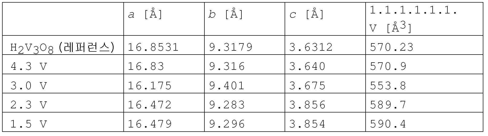
도 2에서, 상이한 Li 수율에 대한 XRD 도가 금속 Li에 대한 전위에 대응하여 도시되어 있고 표 1은 특히 a 축에 대한 Li 함량에 대해 현저한 변화를 나타내는 대응 격자 상수를 나타낸다.In FIG. 2, XRD plots for different Li yields are shown corresponding to the potential for the metal Li and Table 1 shows the corresponding lattice constants, which show a marked change in Li content, especially for the a axis.
표 1 : 상이한 선택된 전압에서 종료된 전기화학 처리 샘플들의 리트벨트 리파인먼트 (Rietveld refinement) 결과 Table 1: Rietveld refinement results of electrochemically treated samples terminated at different selected voltages
H2V3O8 캐소드 내에서 무엇이 일어나는지를 더 잘 이해하기 위해, 이 체적 일 및 그의 효과들은 더 면밀히 조사되었는데, 왜냐하면 그것들은 리튬 이온 배터리에서 각각의 캐소드에 대한 결정적으로 중요하다고 고려되었기 때문이다. 그에 의해, 모든 정전류 측정들은 먼저, 상이한 전류 밀도에 대해 각각의 측정들을 나타내는 도 3에서 볼 수 있는 바처럼 용량이 감소하기 전에 15번째와 35번째 사이클 사이에서, 재료의 비전하 또는 용량의 증대를 각각 나타냈다.To better understand what is happening within the H 2 V 3 O 8 cathode, these volumetric work and its effects have been examined more closely because they were considered critically important for each cathode in a lithium ion battery. . Thereby, all constant current measurements first show an increase in the charge or capacity of the material between the 15th and 35th cycles before the capacity decreases, as can be seen in FIG. 3 showing the respective measurements for different current densities. Respectively.
감소된 용량에도 불구하고, 결정 구조는 주로 같은 상태로 남았다 (약 35 사이클 후의 약 300 Ah/kg의 최대 용량으로부터 약 111 사이클 후 약 150 Ah/kg 의 용량에 이르는 50 A/kg에서 270 사이클까지에 대하여, 도 4 참조). 도 4에 예시된 바처럼, 2번째 및 270번째 사이클 사이에는 거의 구조적 변화가 관찰될 수 없었다. 이러한 발견은 또한 도 5에 도시된 시클로볼태그램에 의해 확인되었다.Despite the reduced capacity, the crystal structure remained largely the same (from 50 A / kg to 270 cycles, ranging from a maximum capacity of about 300 Ah / kg after about 35 cycles to a capacity of about 150 Ah / kg after about 111 cycles). For reference, see FIG. 4). As illustrated in FIG. 4, little structural change could be observed between the second and 270th cycles. This finding was also confirmed by the cyclobologram shown in FIG. 5.
따라서, 변화되었고 용량의 극적인 손실을 야기한 다른 특징들을 알아내야 했다. 그러므로, 섬유 길이의 변화들이 조사되었고 몇 사이클 후 이미 섬유들은 프래그먼트화되었는데, 이는 먼저 용량의 증대를 야기했지만, 추가의 프래그먼트화시 용량의 손실을 야기했다는 것을 알아냈다. 이러한 거동은 더 작은 섬유들의 향상된 용량으로서 해석되었지만, 전류 컬렉터와의 접촉을 위한 감소된 가능성에 연결되고, 그에 의해 용량의 손실을 야기한다.Therefore, it was necessary to identify other features that changed and caused a dramatic loss of capacity. Therefore, changes in fiber length were investigated and after a few cycles the fibers had already been fragmented, which first resulted in an increase in capacity, but found a loss of capacity upon further fragmentation. This behavior has been interpreted as an improved capacity of smaller fibers, but leads to a reduced likelihood for contact with the current collector, thereby causing a loss of capacity.
최신의 H2V3O8 캐소드들의 수명을 향상시키는 것과 같은, 캐소드 특징들을 향상시키기 위한 몇몇 출발점들이 조사되었다. 더 앞선 공동 소유의 아직 공개되지 특허 출원 (2010년 3월 10일자로 출원된 유럽 특허 출원 제10 156 075.3호) 에서, 향상된 수명을 갖는 H2V3O8 캐소드의 제조 방법이 이미 설명되어 있다. 거기에서 한편으로는 섬유들을 바인딩하기 위한 새로운 방법이 개발되었고, 모두 개별적으로 향상에 이르지만 특히 함께 사용되는 경우 캐소드 재료 코팅 및 새로운 캐소드를 형성하는 수정된 섬유 출발 물질이 개발되었다.Several starting points have been investigated for improving cathode characteristics, such as improving the lifetime of modern H 2 V 3 O 8 cathodes. In a more co-owned yet unpublished patent application (European Patent Application No. 10 156 075.3 filed March 10, 2010), a process for the preparation of H 2 V 3 O 8 cathodes with improved lifetime has already been described. . There, on the one hand, new methods for binding the fibers have been developed, all of which have been individually improved but modified fiber starting materials have been developed which, in particular when used together, form a cathode material coating and a new cathode.
이 앞서 설명되었지만 아직 공개되지 않은 바인딩 방법은 다공질, 유연성 및 전기전도성 재료를 생성하는 것을 허용하고, 여기서, 특히 H2V3O8 섬유들은, 사용하기 전에 리튬 이온들로 처리되어 바람직하게는 H2V3O8 당 0.5 내지 1.5, 더 바람직하게는 약 1 리튬을 갖는 부분적으로 리튬화된 재료를 형성하는 경우, 섬유들은 많은 사이클 동안 매우 높은 용량에서 안정한 상태로 남는 방법으로 통합된다. 많은 사이클에 걸친 그러한 재료의 안정성은 도 6으로부터 알 수 있다. 제 1 전기화학 사이클에서 달성된 용량은 400 Ah/kg 보다 현저하게 높고, 다음의 사이클들 동안 약간만 감소한다. 50 사이클들 후에, 용량은 여전히 약 400Ah/kg 이었고, 이 실험에서 용량의 손실은 활성 전극 재료 자체에 기인한 것이 아니라 오히려 전해질에 기인한 것으로 추정되었다.This previously described but not yet disclosed binding method allows for the creation of porous, flexible and electrically conductive materials, in particular where H 2 V 3 O 8 fibers are treated with lithium ions prior to use, preferably H When forming partially lithiated materials with 0.5 to 1.5, more preferably about 1 lithium per 2 V 3 O 8 , the fibers are integrated in a way that remains stable at very high capacity for many cycles. The stability of such materials over many cycles can be seen from FIG. 6. The capacity achieved in the first electrochemical cycle is significantly higher than 400 Ah / kg and only slightly decreases during the next cycles. After 50 cycles, the capacity was still about 400 Ah / kg, and in this experiment it was estimated that the loss of capacity was not due to the active electrode material itself but rather to the electrolyte.
하지만, 보다 앞선 공동 소유의 출원에 설명된 제조 방법은-비록 훨씬 향상된 생성물에 이르지만- 많은 단계들을 필요로 했다. 따라서, 본 발명자들은 프로세스를 촉진하게 하기 위한 추가의 연구를 수행하였고 본 발명자들은 제조 방법 뿐만 아니라 그에 의해 얻어질 수 있는 생성물을 향상시킬 수 있었다. 본 발명자들은 특히 전극의 매트릭스 함량을 더 감소시킬 수 있었다.
However, the manufacturing method described in the earlier co-owned application—even though much improved product—needed many steps. Thus, the inventors have carried out further studies to facilitate the process and the inventors have been able to improve not only the preparation method but also the product obtainable thereby. We were able to further reduce the matrix content of the electrodes in particular.
실시예 1 : H2V3O8 의 합성 Example 1 Synthesis of H 2 V 3 O 8
제 1 방법 :First way:
바나딜 클로라이드 펜타히드레이트와 같은 0.06 M 바나듐 (IV) 수용액 200 ㎖, 및 증류수 200 ㎖ 를 800 ㎖ Teflon® 인렛에 넣었다. 그후, 인렛을 스틸 오토클레이브로 이송시키고, 220 ℃ 로 미리 예열된 오븐 속에 배치하였다. 자기 교반기 (80 rpm) 는 용액의 균질성을 보증한다. 온도는 12 시간 동안 일정하게 유지되었다. 오븐 속에서 오토클레이브를 제거하고 주변 조건하에서 냉각시킨 후, 녹색 내지 황록색 고체 생성물을 필터링하고, 증류수로 2번 및 이소프로판올로 1번 세정하고, 3 시간 동안 120℃에서 공기중에서 건조하였다. 이런 방식으로 450 내지 550 mg 물질을 획득하였다.200 ml of an aqueous 0.06 M vanadium (IV) solution, such as vanadil chloride pentahydrate, and 200 ml of distilled water were placed in an 800 ml Teflon® inlet. The inlets were then transferred to a steel autoclave and placed in an oven preheated to 220 ° C. A magnetic stirrer (80 rpm) ensures homogeneity of the solution. The temperature was kept constant for 12 hours. After removing the autoclave in an oven and cooling under ambient conditions, the green to yellow green solid product was filtered off, washed twice with distilled water and once with isopropanol and dried in air at 120 ° C. for 3 hours. In this way, 450-550 mg material was obtained.
상기 반응에서 개시 재료로서 사용되기에 적합한 바나딜 클로라이드 용액은, 바륨 클로라이드를 갖는 바나딜 설페이트 용액 속에서 설페이트의 정량적 침전에 의해 조제되었다. 마이크로사이즈 필터 (0.22 ㎛ 포어 직경) 에 의한 필터링 이후에, 투명한 (clear) 바나딜 클로라이드 용액이 획득되었다.A vanadil chloride solution suitable for use as starting material in the reaction was prepared by quantitative precipitation of sulphate in a vanadil sulfate solution with barium chloride. After filtering by a microsize filter (0.22 μm pore diameter), a clear vanadil chloride solution was obtained.
본 발명의 산화 루트는 안전하고 빠르다. 바나듐 (IV) 은, 합성의 종료시에 일부 바나듐 (IV) 이 혼합물에 잔류하도록 반응 혼합물에서 과잉으로 사용되는 것이 바람직하다. 바나딜 용액은 산성이다 (pH ≤ 3). 열수 처리는, 220 ℃ (반응 용기의 외부에서 측정된 온도 또는 반응 혼합물 내에서 온도가 측정되는 경우에는 180 ℃) 에서 12 시간 동안 수행된다. 220 ℃ 에서 12 시간은 최소값이다. 반응 용기의 절반까지는 채워져야 한다. 응집을 방지하기 위해, 생성물은 비배위 (non-coordinating) 용매로 세정될 수도 있다.
The oxidation route of the present invention is safe and fast. Vanadium (IV) is preferably used in excess in the reaction mixture such that some vanadium (IV) remains in the mixture at the end of the synthesis. The vanadil solution is acidic (pH <3). The hydrothermal treatment is carried out for 12 hours at 220 ° C. (the temperature measured outside of the reaction vessel or 180 ° C. if the temperature is measured in the reaction mixture). 12 hours at 220 ° C. is the minimum. Up to half of the reaction vessel should be filled. To prevent aggregation, the product may be washed with a non-coordinating solvent.
제 2 방법 : 균질한 나노사이즈의 H2V3O8 를 획득하기 위한 바람직한 방법 Second Method: Preferred Method for Obtaining Homogeneous Nanosized H 2 V 3 O 8
3 g VOSO4·5H2O 를 50 ㎖ 탈이온수에 용해시켰다. 그후, 25 중량%의 암모니아 (NH4OH) 2 ㎖ 를 첨가하였다. 즉시 형성하는 치밀한 침전물을 필터링하고 회색의 습윤 고체 생성물을 수집하고, 오토클레이브의 Teflon® 용기에 넣고 400 ㎖ 증류수에 분산시켰다. 1 ㎖ 12 M HCl 의 첨가 이후에, 오토클레이브를 밀봉하고 현탁액을 220 ℃에서 48 시간 동안 열수 처리하였다. 반응의 종료시에, 녹색 내지 황록색 고체 생성물을 필터링하고, 물 및 이소프로판올로 세정하고, 100℃ 공기중에서 하룻밤 동안 건조시켰다. 750 mg H2V3O8 을 획득하였다. 바나듐 수율은 70% 이었다.
3 g VOSO 4 .5H 2 O was dissolved in 50 mL deionized water. Then 2 ml of 25% by weight ammonia (NH 4 OH) were added. The dense precipitate that formed immediately was filtered off and the gray wet solid product was collected, placed in an autoclave's Teflon® vessel and dispersed in 400 ml distilled water. After addition of 1 ml 12 M HCl, the autoclave was sealed and the suspension was hydrothermally treated at 220 ° C. for 48 hours. At the end of the reaction, the green to yellow green solid product was filtered off, washed with water and isopropanol and dried overnight in 100 ° C. air. 750 mg H 2 V 3 O 8 was obtained. The vanadium yield was 70%.
실시예Example 2a : 자기조립, 2a: self-assembly, 리튬화Lithiation 및 탄화 And carbonization
0.68 mg (0.0071 mmol) 리튬 락테이트, 0.8 mg (0.0049 mmol) 바나딜 설페이트 및 0.3 mg (0.0125mmol) 리튬 수산화물을 10 ㎖ 의 기밀하게 밀폐가능한 테스트 튜브에서의 0.5 ㎖ 증류수에 용해시켰다. 그후, (실시예 3에 따라 조제된) 1.5 ㎖ 그래핀 산화물 (GO) 용액을 첨가하고, 테스트 튜브를 조심해서 쉐이킹하여 밝은 갈색을 띤 투명한 용액을 획득하였다. 20 mg (0.0707 mmol) H2V3O8 를 그 용액에 분산시키고, 테스트 튜브를 밀봉하고, 얻어진 현탁액을 초음파 및 강한 쉐이킹 (vigorous shaking) 을 통해 균질화하였다. 일단 균질화가 완료되면, 녹색 현탁액을 함유하는 테스트 튜브를 오븐에 넣고 150 ℃에서 1.5 시간동안 유지하였다. 이러한 열수 단계 동안, GO 의 그래핀으로의 열분해, 자기조립 및 리튬화가 발생하면서, 용기 내부의 압력은 대략 3-4 bar 로 증가된다. 현탁액은, 치밀한 (암청색) 고체 부유물을 갖는 검은 액체로 변화되었다. 열수 처리의 종료시에, 전극을 나타내는 이 암청색 고체는 수집되고, 알루미늄 컬렉터 상에 놓이고, 여기서 잔류 액체는 예컨대, 티슈로 소킹함으로써 제거되는데, 전류 컬렉터 상의 고체 퇴적물에 대하여 가압된 후에 남은 티슈가 건조 상태로 남을 때까지 행해졌다. 그후, 건조는 85 ℃ 에서 10분간 건조 공기에 의해 계속되었다. 마지막 단계는 220℃ 공기중에 5분 노출에서 이루어졌고, 후속하여 아르곤 글로브 박스로 이송되었다 (적어도 1 시간 배기). 활성 전극 재료의 SEM 사진은 도 7에 나타나 있고, 통상의 방전 곡선은 도 8에 나타나 있고, 정전류 측정은 도 9에 나타나 있다.
0.68 mg (0.0071 mmol) lithium lactate, 0.8 mg (0.0049 mmol) vanadil sulfate and 0.3 mg (0.0125 mmol) lithium hydroxide were dissolved in 0.5 mL distilled water in a 10 mL hermetically sealed test tube. Then a 1.5 ml graphene oxide (GO) solution (prepared according to Example 3) was added and the test tube was carefully shaken to obtain a light brownish clear solution. 20 mg (0.0707 mmol) H 2 V 3 O 8 was dispersed in the solution, the test tube was sealed, and the obtained suspension was homogenized via ultrasonication and vigorous shaking. Once homogenization was complete, the test tube containing the green suspension was placed in an oven and kept at 150 ° C. for 1.5 hours. During this hydrothermal step, the decomposition of GO to graphene, self-assembly and lithiation occur, while the pressure inside the vessel is increased to approximately 3-4 bar. The suspension turned into a black liquid with a dense (dark blue) solid suspension. At the end of the hydrothermal treatment, this dark blue solid representing the electrode is collected and placed on an aluminum collector, where residual liquid is removed, for example, by soaking with tissue, wherein the tissue remaining after being pressed against the solid deposit on the current collector is dried. It was done until it remained. Drying was then continued by dry air at 85 ° C. for 10 minutes. The final step was made at 5 min exposure in 220 ° C. air and subsequently transferred to an argon glove box (exhaust at least 1 hour). A SEM photograph of the active electrode material is shown in FIG. 7, a typical discharge curve is shown in FIG. 8, and a constant current measurement is shown in FIG. 9.
실시예Example 2b : 자기조립, 2b: self-assembly, 리튬화Lithiation 및 탄화 And carbonization
화학물질들Chemicals
다음의 화학물질들이 사용되었다 : 20 mg H2V3O8 , 150 mg VOSO4·5H2O, 60 mg 리튬 락테이트, 5 ㎖ 그래파이트 산화물 (GO) 용액 (0.5g/ℓ), 5 ㎖ 증류수, 60 mg LiOH·H2OThe following chemicals were used: 20 mg H 2 V 3 O 8 , 150 mg VOSO 4 · 5H 2 O, 60 mg lithium lactate, 5 ml graphite oxide (GO) solution (0.5 g / l), 5 ml distilled water , 60 mg LiOHH 2 O
장비equipment
하기 장비가 필요하였다 : 페이퍼 필터 1개, 세라믹 깔때기 필터 1개, 20 ㎖ 비커 1개 및 자기 교반기 1개The following equipment was required: 1 paper filter, 1 ceramic funnel filter, 1 20 ml beaker and 1 magnetic stirrer
전극 제조Electrode manufacturing
바나딜 설페이트를 자기 교반기로 비커에서 물에 용해하였다. H2V3O8 를 첨가하고, 초음파처리 및 교반을 통해 간단히 분산시켰다. (실시예 3에 따라 조제된) GO 용액을 교반하면서 적하 첨가하였다. 혼합물을 교반하면서 30분간 방치한 후 현탁액을 냉동시켰다. 현탁액이 냉동된 상태로 유지되는 시간은 비임계이다. 완전히 냉동된 상태에 도달하자마자 가온될 수도 있다. 일단 현탁액이 실온 (RT) 으로 다시 가온되고 다시 교반 작업되면, 리튬 락테이트를 첨가하고 용해시켰다. 일단 리튬 락테이트가 완전히 용해되면, 리튬 수산화물 분말을 첨가하였다. 일단 현탁액의 컬러가 암청색으로 변하면, 생성물을 필터링하고 thf 로 린스한 후, RT 에서 건조하여 방치하였다. 그후, 전극 재료는, 필터로부터 통상 고체 디스크의 형태로 분리되고, 150℃에서 15분간 공기중에서 건조하였다. 다시 녹색이 된 전극 재료를 10분간 220℃에서 동작되는 오븐으로 이송시켰다. 냉각 후에, 뜨거운 전극 재료를 글로브 박스로 이송시키고, 여기서 전극 재료는 적어도 30분간 배기되었다. 활성 전극 재료의 SEM 사진은 도 8에 나타나 있고, 통상의 방전 곡선은 도 11에 나타나 있고, 정전류 측정이 도 12에 나타나 있고, 차동 비전하 플롯 (7번째 사이클) 은 도 13에 나타나 있고, 그리고 활성 전극 재료의 XRD 패턴은 도 14에 나타나 있다.Vanadil sulfate was dissolved in water in a beaker with a magnetic stirrer. H 2 V 3 O 8 was added and briefly dispersed via sonication and stirring. The GO solution (prepared according to Example 3) was added dropwise with stirring. The mixture was left for 30 minutes with stirring and the suspension was frozen. The time for which the suspension remains frozen is noncritical. It may warm up as soon as it reaches a completely frozen state. Once the suspension was warmed back to room temperature (RT) and stirred again, lithium lactate was added and dissolved. Once lithium lactate was completely dissolved, lithium hydroxide powder was added. Once the color of the suspension turned dark blue, the product was filtered, rinsed with thf and then dried at RT. The electrode material was then separated from the filter, usually in the form of a solid disk, and dried in air at 150 ° C. for 15 minutes. The green electrode material was transferred to an oven operated at 220 ° C. for 10 minutes. After cooling, the hot electrode material was transferred to a glove box, where the electrode material was evacuated for at least 30 minutes. An SEM image of the active electrode material is shown in FIG. 8, a typical discharge curve is shown in FIG. 11, a constant current measurement is shown in FIG. 12, a differential non-charge plot (7th cycle) is shown in FIG. 13, and The XRD pattern of the active electrode material is shown in FIG. 14.
배터리 조립Battery assembly
전극을 제조하기 위해, 한 조각의 전극 재료를 디스크에서 잘라내고, (결과의 해석을 위해) 가중시키고, 금속성 전류 컬렉터 상에 배치하였다. 그후, 전극을 먼저 폴리프로필렌 셀가드 (cellguard) 세퍼레이터로 커버한 후, 하나의 실리카 폼 세퍼레이터로 커버하고, 셀을 LP30 전해질 (EC/DMC 1:1 에서의 1M LiPF6) 로 채우고, 리튬 애노드를 내부에 배치하고, 셀을 기밀하게 밀폐하였다.
To prepare the electrodes, one piece of electrode material was cut from the disk, weighted (for interpretation of the results) and placed on a metallic current collector. The electrode is then first covered with a polypropylene cellguard separator, then with one silica foam separator, the cell is filled with LP30 electrolyte (1M LiPF6 in EC / DMC 1: 1) and the lithium anode is internally And the cell was hermetically sealed.
실시예Example 3 : 콜로이드 3: colloid GOGO 분산액의 조제 ( Preparation of Dispersion ( GOGO 용액이라고도 함) Also called solution)
실시예 3.1 : 그래파이트 산화물의 조제Example 3.1 Preparation of Graphite Oxide
Boehm 등 [8] 에 의해 변형된 Brodie 에 의해 주지된 방법에 따라 그래파이트 산화물을 조제하였다.Graphite oxide was prepared according to a method well known by Brodie modified by Boehm et al. [8].
10 g 그래파이트를 85 g 과염소산나트륨 분말과 완전히 혼합하였다. 혼합물을 아이스 염화나트륨 혼합물을 사용하여 대략 -20℃ 로 냉각시킨 후, 효율적인 교반기로 천천히 교반하였다. 그후, 60 ㎖ 발연 질산을 매우 천천히 첨가하였다. 이 점성 녹색 덩어리를 실온에서 추가 30분간 교반하였다. 혼합물을 휘젓지 않고 하룻밤 동안 방치한 후, 60 ℃에서 10 시간 동안 천천히 가열하였다. 그후, 물 2 리터를 반응 생성물에 첨가하고, 혼합물을 필터링하고, 희석된 염산으로 1번 세정하고, 매번 물 2 리터로 적어도 2번 세정하였다. 필터링 후에, 획득된 덩어리는 냉동 건조되어, 매우 솜털 같은 상아색 착색된 분말로서의 그래파이트 산화물 약 14 g 을 산출하였다.10 g graphite was thoroughly mixed with 85 g sodium perchlorate powder. The mixture was cooled to approximately −20 ° C. using an iced sodium chloride mixture and then stirred slowly with an efficient stirrer. Thereafter, 60 ml fuming nitric acid was added very slowly. This viscous green mass was stirred for an additional 30 minutes at room temperature. The mixture was left overnight without stirring and then slowly heated at 60 ° C. for 10 hours. Thereafter, 2 liters of water were added to the reaction product, the mixture was filtered, washed once with diluted hydrochloric acid, and at least twice with 2 liters of water each time. After filtering, the obtained mass was freeze-dried to yield about 14 g of graphite oxide as a very downy ivory colored powder.
그래파이트 산화물의 원소 분석에 기초하여, 화학식 C8O4H1 .7 이 획득된다. 물로서 수소의 공제 이후에, C/O 비율 2.5 를 갖는 식 C8O3 .2 이 획득된다. X선 회절 분석을 이용하면, 그래파이트에서의 3.35 Å의 평면간 거리가 건조 그래파이트 산화물에서 6.1 Å으로 확대되도록 나타날 수 있다.
Based on the elemental analysis of the graphite oxide, the formula C 8 O 4 H a 1 .7 is obtained. The after subtraction of hydrogen as water the formula having a C / O ratio 2.5 C 8 O 3 .2 is obtained. Using X-ray diffraction analysis, the interplanar distance of 3.35 kW in graphite can be shown to extend to 6.1 kW in dry graphite oxide.
실시예Example 3.2 : 콜로이드 3.2: colloid 그래핀Graphene 산화물 분산액의 조제 Preparation of Oxide Dispersion
실시예 3.1 에 기재된 바와 같이 획득된 그래파이트 산화물 100 mg 을 탈이온수 100 ㎖ 에 첨가하고, 12 시간 동안 완전히 교반한 후, 초음파 배쓰 (bath) 에 1 시간 동안 방치하였다. 이와 같이 획득된 그래파이트 산화물 (더욱 나아가 그래핀 산화물이라고도 함) 의 콜로이드 분산액을 그후에 콜로이드 그래핀 분산액으로 반응시켰다 (하기 참조).100 mg of the graphite oxide obtained as described in Example 3.1 was added to 100 ml of deionized water, stirred for 12 hours thoroughly, and then left in an ultrasonic bath for 1 hour. The colloidal dispersion of the graphite oxide (also referred to as graphene oxide) thus obtained was then reacted with the colloidal graphene dispersion (see below).
그래파이트 산화물을 물에 분산시킴으로써 획득된 콜로이드 그래핀 산화물 분산액은 육안으로 그리고 심지어 1000배 배율의 광 현미경에서도 입자가 없이 시각적으로 투명하고, pH 약 5 를 가지고 있었다. 레이저를 사용하여, 얻어진 틴들 (Tyndall) 효과는 그래파이트 산화물이 콜로이드 분산액을 야기함을 나타내었다.The colloidal graphene oxide dispersion obtained by dispersing the graphite oxide in water was visually transparent, free of particles, and visually transparent, even with a naked eye and even at 1000 times magnification light microscopy. Using a laser, the Tindall effect obtained showed that graphite oxide caused the colloidal dispersion.
이러한 분산액이 희석된 후 적합한 샘플 홀더에 적용되는 경우에, 주사력 현미경은, 콜로이드 분산액이 산화된 그래핀, 즉 그래핀 산화물의 단일층들로 이루어짐을 나타낸다.
When this dispersion is diluted and then applied to a suitable sample holder, the scanning force microscope shows that the colloidal dispersion consists of monolayers of oxidized graphene, ie graphene oxide.
실시예Example 4 : 4 : 실시예Example 2a 의 2a HH 22 VV 33 OO 88 전극에 대한 보존 시간의 효과 (전기화학 응용 이전에 Effect of retention time on electrodes (prior to electrochemical application 에이징Aging ))
조립된 셀들 (열수 방법에 의해 제조된 H2V3O8 전극) 이 30 ℃ 에서 보존 방치될 때, OCV 값들은 4일에 대략 200 mV 만큼 감소되었다. 감쇠 (전위 대 시간) 의 정확한 형상은 여전히 특징화되어야 하지만, 아마도 네거티브 곡률을 갖는 지수적 경로를 따를 것이다 (평형을 향해 감속되는 시작에서의 빠른 강하). 조립 직후에, OCV 는 3.50 V 에 있었다. 4 일 보존 후에, OCV 는 3.30 V 로 감소되었다. 3 일 보존 후에, OCV 는 3.45 V 이었다 (도 A 참조).When the assembled cells (H 2 V 3 O 8 electrodes made by the hydrothermal method) were left at 30 ° C., the OCV values were reduced by approximately 200 mV on 4 days. The exact shape of the damping (potential vs. time) still needs to be characterized, but will probably follow an exponential path with negative curvature (fast drop at the start of deceleration towards equilibrium). Immediately after assembly, the OCV was at 3.50 V. After 4 days retention, the OCV was reduced to 3.30 V. After 3 days preservation, the OCV was 3.45 V (see FIG. A).
감소된 OCV 는 전해질의 일부가 바나듐 (V) 에 의해 산화되는 자기방전에서 생긴다. 이 프로세스는 배터리의 성능에 크게 영향을 주었다. 전기화학 측정들은 향상된 동력학을 나타내었다. 제 1 충전으로부터 획득된 시간 (및 그리하여 용량) 은 연장된 보존 시간에 따라 증가되었다. 이론적 용량 (420-450 Ah/kg) 값에 가까운 것이 이러한 방식으로 내구력 있게 획득될 수 있다.
Reduced OCV results from self-discharge in which part of the electrolyte is oxidized by vanadium (V). This process greatly affected the performance of the battery. Electrochemical measurements showed improved kinetics. The time (and thus capacity) obtained from the first charge increased with extended retention time. What is close to the theoretical capacity (420-450 Ah / kg) value can be obtained durable in this way.
실시예Example 5 : 5: 실시예Example 2a 의 2a HH 22 VV 33 OO 88 전극에 대한 개선된 충전 기술 Improved Charging Technology for Electrodes
안정한 H2V3O8 전극들은 충전 및 방전 (전위 대 시간) 에 대해 비대칭으로 거동하는 특징을 가진다. 그 방전 곡선은 3개의 전기활성 영역들을 표시하는데, 충전 동안 2개의 영역들만이 관찰가능하다. 가장 낮은 전위 (2V) 에서의 탈리는 충전 곡선에서 일어나지 않는다. 그럼에도 불구하고, 애노드 및 캐소드 용량들은 동일하게 남는데, 손실 리튬이 2.7V 에서 추출되기 때문이다. 이러한 특징의 자연적 발생은 도 15 및 도 16에서 예시되고, 도 17에 나타낸 바와 같이 인위적으로 생성될 수 있다. 1.6V 와 2.7V 사이의 완전한 충전 단계는 편광 부분, 2V 에서의 짧은 플래토 (방전 동안 대략 그것의 절반), 및 2.7V 플래토에 대한 선형 영역을 제공한다. 2V와 2.7V 사이의 전기화학 활성은 방전 동안 발생된 상들 중 하나에 상관될 수 없고, 비가역적 프로세스를 트리거할 수도 있다. 2V 플래토는 바나데이트 내부의 양자들의 재배열에 대해 책임지고, 부분적 재배열은 리튬 추출이 더욱 에너지를 요구하게 하는 구조에 있어서의 무질서를 생성하기 때문에 플래토는 단축된다고 여겨진다. 실제로, 셀의 성능 저하 동안 플래토가 더욱더 단축되고 시간 경과에 따라 선형 영역으로 변환되는 것이 관찰되었다. 이러한 현상은 H2V3O8 의 아몰퍼스화 (amorphization) 로 이어진다 (도 B 참조).Stable H 2 V 3 O 8 electrodes are characterized by asymmetrical behavior with respect to charge and discharge (potential versus time). The discharge curve shows three electroactive regions, only two of which are observable during charging. Desorption at the lowest potential (2V) does not occur in the charging curve. Nevertheless, the anode and cathode capacities remain the same because the lost lithium is extracted at 2.7V. Natural occurrences of this feature are illustrated in FIGS. 15 and 16 and can be artificially generated as shown in FIG. 17. The complete charging step between 1.6V and 2.7V provides a polarization portion, a short plateau at 2V (approximately half of it during discharge), and a linear region for 2.7V plateau. The electrochemical activity between 2V and 2.7V cannot correlate to one of the phases generated during the discharge and may trigger an irreversible process. The 2V Plato is responsible for rearrangement of protons inside the vanadate, and the Plato is believed to be shortened because the partial rearrangement creates a disorder in the structure that allows the lithium extraction to require more energy. Indeed, it has been observed that the plateau becomes even shorter and transforms into a linear region over time during the degradation of the cell. This phenomenon leads to amorphization of H 2 V 3 O 8 (see FIG. B).
방전의 시작시에 순환 전압전류 (CV) 단계를 프로그래밍함으로써 2V 에서 탈리를 인위적으로 억제할 수 있었다. 이 아이디어는 2.7V에 가깝게 전극을 신속히 극성화한 후, 선택된 전류에서 정전류 충전을 진행하기 위한 것이었다. 예를 들면, 적합한 CV 단계는 2.8V까지 5mV/sec 이었다 (도 B 참조). 이러한 절차는 2V 플래토로 하여금 더 높은 전위에서 더 많은 추출의 이익으로 점차적으로 사라지게 하여 결국 2.5V 에서 여분의 플래토를 발생시켰다. 이 처리는 배터리의 보관 수명을 증가시켰다 (도 C 참조).
By programming the cyclic voltammogram (CV) step at the start of discharge, desorption at 2V could be artificially suppressed. The idea was to quickly polarize the electrode close to 2.7V and then proceed with constant current charging at the selected current. For example, a suitable CV step was 5 mV / sec up to 2.8 V (see FIG. B). This procedure caused 2V plateaus to disappear gradually with the benefit of more extraction at higher potentials, eventually generating extra plateaus at 2.5V. This treatment increased the shelf life of the battery (see Figure C).
실시예Example 6 : 6: 실시예Example 2b 의 전극의 전기화학 Electrochemistry of 2b Electrode
전극을 연구하기 위해, 2개의 정전류 단계들 및 "카운터 단계" 를 갖는 mpr 프로그램을 준비하였다. 충전은 4.2 V (C/3.5) 까지 수행되었다. 방전은 1.6V 까지 -100 A/kg에서 발생되었다. 원하는 사이클 수 및 충전 단계에 대한 레퍼런스를 부가하였다. 배터리를 플랫폼 상에 두고, OCV (3.58V) 를 메모하였다. 그후 실험을 시작하였다.To study the electrodes, an mpr program with two constant current steps and a "counter step" was prepared. Charging was performed up to 4.2 V (C / 3.5). The discharge occurred at -100 A / kg up to 1.6V. References were added to the desired number of cycles and filling steps. The battery was placed on the platform and the OCV (3.58V) was noted. Then the experiment was started.
CV 단계 대신에 완화 단계를 이용하는 경우에, 즉, 완전히 방전된 셀이 2V 약간 이상으로 완화를 야기하는 충전 이전에 15 내지 20 분간 휴지하도록 허용되는 경우에, 유사한 결과가 획득되었다.
Similar results were obtained when using the relaxation step instead of the CV step, that is, when a fully discharged cell was allowed to rest for 15 to 20 minutes before charging causing relaxation to slightly above 2V.
결론:conclusion:
전기화학적 사이클링 및 에너지 보존 용량Electrochemical Cycling and Energy Conservation Capacity
2 단계들로 충전을 실시하는 것이 유익하는 것을 발견하였다. 제 1 단계는 1.6V 와 2.8V 사이의 신속한 순환 전압전류 (CV) 단계이었다. 제 2 단계는 제 1 단계 직후에 수행되며, 4.1V까지의 정전류 단계이었다. 제 1 탈리 플래토는 2V 로부터 2.5V 로 시프트되었다. 2V 약간 이상으로 완화를 허용하기에 충분한 시간의 완전히 방전된 배터리의 보존 시간 또는 휴지 시간, 통상 약 15 내지 20 분 이후에 충전이 시작되는 경우에, 유사한 효과가 획득 가능하다.It has been found to be beneficial to carry out the filling in two steps. The first stage was a rapid cyclic voltammetry (CV) stage between 1.6V and 2.8V. The second stage was performed immediately after the first stage and was a constant current stage up to 4.1V. The first tally plateau was shifted from 2V to 2.5V. Similar effects are achievable when charging begins after the retention time or rest time of a fully discharged battery, typically about 15-20 minutes, sufficient to allow relaxation above 2V.
본 발명의 바람직한 실시형태들을 나타내고 기재하였지만, 본 발명은 여기에 한정되지 않으며 하기 청구항들의 범위 내에서 다른 방식으로 다양하게 구현 및 실시될 수도 있음을 명백하게 이해해야 한다.
While the preferred embodiments of the invention have been shown and described, it should be clearly understood that the invention is not limited thereto but may be embodied and practiced in various other ways within the scope of the following claims.
Claims (31)
제 1 충전 또는 방전 이전에, 상기 EAM은 LixH2 - xV3O8 이며,
상기 식 단위에서의 3개의 V 원자들 중 적어도 하나는 산화 상태 4+를 가지며, x는 0.1 내지 1.5이고, 바람직하게는 0.5 내지 1.5이고, 보다 바람직하게는 x는 1에 가까운 것을 특징으로 하는 전극.As an electrode for a rechargeable lithium battery comprising an electronically active material (EAM) in the form of a matrix and nanoparticulates, preferably consisting of an electronically active material (EAM) in the form of a matrix and nanoparticulates,
Prior to the first charge or discharge, the EAM is Li x H 2 - x V 3 O 8 ,
At least one of the three V atoms in the formula unit has an oxidation state of 4+, x is 0.1 to 1.5, preferably 0.5 to 1.5, more preferably x is close to 1 .
상기 매트릭스는, 내부에 통합된 그래핀 플레이크들 그리고 선택적으로 이온성 리튬 소스 및 또한 선택적으로 안정화제를 갖는 열분해 생성물로 이루어지는 것을 특징으로 하는 전극.The method of claim 1,
Wherein said matrix consists of graphene flakes integrated therein and optionally a pyrolysis product having an ionic lithium source and also optionally a stabilizer.
상기 전극에서의 상기 매트릭스의 중량비는 활성 전극의 중량에 대해서 최대 10중량%이고, 바람직하게는 5±2 중량%이고, 및/또는
아몰퍼스 탄소질 재료 대 그래핀 비율은 2:1 내지 1:1 이고, 바람직하게는 약 3 : 2 인, 전극.The method of claim 2,
The weight ratio of the matrix at the electrode is at most 10% by weight, preferably 5 ± 2% by weight, relative to the weight of the active electrode, and / or
An amorphous carbonaceous material to graphene ratio of 2: 1 to 1: 1, preferably about 3: 2.
(A) 분산액을 포함하는 전자적 활성 전구체 재료를 조제하는 단계로서, 상기 분산액은,
(i) 가용성 리튬 소스 및 수산화물 소스, 특히 리튬 수산화물,
(ii) 수용성이고, - 전자적 활성 재료와 혼합되어 - 열분해될 수 있는 적어도 부분적 유기 물질,
(iii) 전자적 활성 재료 (EAM), 및
(iv) 그래핀 산화물 (GO) 을 포함하는, 상기 전자적 활성 전구체 재료를 조제하는 단계;
(B) 액체상으로부터 고체 전자적 활성 전구체 재료를 분리하는 단계;
(C) 상기 단계 (B) 의 전자적 활성 전구체 재료를 건조시키는 단계; 및
(D) 활성 전극 재료를 산출하기 위해 상기 단계 (C) 의 전자적 활성 전구체 재료를 열분해하는 단계를 포함하는, 전극 재료 제조 방법.As a method of producing a particulate, in particular fibrous, electrode material,
(A) preparing an electronically active precursor material comprising a dispersion, wherein the dispersion is
(i) soluble lithium and hydroxide sources, in particular lithium hydroxide,
(ii) an at least partially organic material which is water soluble and which can be pyrolyzed in admixture with an electronically active material,
(iii) an electronically active material (EAM), and
(iv) preparing the electronically active precursor material comprising graphene oxide (GO);
(B) separating the solid electronically active precursor material from the liquid phase;
(C) drying the electronically active precursor material of step (B); And
(D) pyrolysing the electronically active precursor material of step (C) to yield an active electrode material.
상기 전극 재료 제조 방법은,
(E) 상기 단계 (D) 의 활성 전극 재료를 절단하여 형상화하고 상기 활성 전극 재료를 기판 상에 배치하는 추가적 단계를 포함하는, 전극 재료 제조 방법.The method of claim 4, wherein
The electrode material manufacturing method,
(E) an additional step of cutting and shaping the active electrode material of step (D) and placing the active electrode material on a substrate.
상기 전극 재료 제조 방법은,
(Ba) 상기 단계 (C) 를 실시하기 전에, 상기 단계 (B) 의 전자적 활성 전구체 재료를 기판 상에 공급하는 단계를 포함하는, 전극 재료 제조 방법.The method of claim 4, wherein
The electrode material manufacturing method,
(Ba) A method of manufacturing an electrode material, comprising the step of feeding the electronically active precursor material of step (B) onto a substrate before performing step (C).
상기 단계 (A) 는,
(Aa) 리튬 소스, 수산화물 소스, 특히 리튬 수산화물, 그리고 유기 용매 및/또는 물에 가용성이고, - 전자적 활성 재료와 혼합되어 - 열분해될 수 있는 적어도 부분적 유기 물질을 포함하는 용액을 조제하는 단계로서, 상기 용액은, 상기 유기 용매 및/또는 물에 유기 화합물, 상기 리튬 소스 및 상기 수산화물 소스를 용해시킴으로써 조제되는, 상기 용액 조제 단계,
(Ab) pH 가 8 과 10 사이에 유지되도록 하면서 그래핀 산화물의 수계 분산액/용액을 첨가하는 단계,
(Ac) 상기 단계 (Ab) 에서 조제된 분산액에 전자적 활성 재료 (EAM) 를 분산시키고 균질화하는 단계, 및
(Ad) 분산액을 포함하는 전자적 활성 전구체 재료를 야기하는 압력 강화 조건하에서 그래핀 산화물의 그래핀으로의 열분해 (thermolysis), 자기조립 및 리튬화를 위한 열수 (hydrothermal) 단계를 수행하는 단계로서, 상기 분산액은 내부에 치밀한 고체 부유물을 갖는 검은 액체의 형태로 존재하는, 상기 열수 단계를 수행하는 단계
의 서브단계들을 포함하는, 전극 재료 제조 방법.The method of claim 4, wherein
Step (A) is,
(Aa) preparing a solution comprising a lithium source, a hydroxide source, in particular a lithium hydroxide, and at least a partially organic material which is soluble in an organic solvent and / or water, and which is mixed with an electronically active material and which can be pyrolyzed, Wherein the solution is prepared by dissolving an organic compound, the lithium source and the hydroxide source in the organic solvent and / or water,
(Ab) adding an aqueous dispersion / solution of graphene oxide while maintaining the pH between 8 and 10,
(Ac) dispersing and homogenizing the electronically active material (EAM) in the dispersion prepared in step (Ab), and
Performing a hydrothermal step for thermolysis, self-assembly and lithiation of graphene oxide to graphene under pressure strengthening conditions resulting in an electronically active precursor material comprising (Ad) dispersion, wherein Performing the hydrothermal step, wherein the dispersion is in the form of a black liquid with a dense solid suspension therein.
And substeps of the electrode material manufacturing method.
상기 단계 (A) 는,
(Aα) 유기 용매 및/또는 물에 선택적으로 안정화된 EAM을 분산시키는 단계,
(Aβ) 그래핀 산화물 용액을 첨가하는 단계,
(Aγ) 상기 단계 (Aβ) 에서 획득된 분산액을 냉동시키는 단계,
(Aδ) 냉동된 분산액을 가온함으로써, 바람직하게는 실온 (RT) 으로 가온함으로써 상기 냉동된 분산액을 해동시키는 단계,
(Aε) 리튬 소스 및 수산화물 소스, 특히 리튬 수산화물, 그리고 상기 유기 용매 및/또는 물에 가용성이고, - 전자적 활성 재료와 혼합되어 - 열분해될 수 있는 적어도 부분적 유기 물질을 첨가하는 단계, 및
(Aζ) 상기 전자적 활성 전구체 재료를 포함하는 분산액이 암청색이 될때까지 대기하는 단계
의 서브단계들을 포함하는, 전극 재료 제조 방법.The method of claim 4, wherein
Step (A) is,
(Aα) dispersing the selectively stabilized EAM in an organic solvent and / or water,
(Aβ) adding a graphene oxide solution,
(Aγ) freezing the dispersion obtained in the step (Aβ),
(Aδ) thawing the frozen dispersion by warming the frozen dispersion, preferably by warming to room temperature (RT),
(Aε) adding at least a partial organic material which is soluble in a lithium source and a hydroxide source, in particular lithium hydroxide, and said organic solvent and / or water, and which is mixed with an electronically active material and capable of pyrolysis, and
(Aζ) waiting until the dispersion comprising the electronically active precursor material becomes dark blue
And substeps of the electrode material manufacturing method.
상기 단계 (C) 는,
(Cα) 먼저 유기 용매 및/또는 물의 비점 미만의 온도에서, 예컨대, 실온 (RT) 에서 상기 전자적 활성 전구체 재료를 건조시키는 단계, 및
(Cβ) 그후, 상기 유기 용매 및/또는 물의 비점 이상의 온도에서 상기 전자적 활성 전구체 재료를 건조시키는 단계
의 서브단계들을 포함하는, 전극 재료 제조 방법.The method of claim 4, wherein
Step (C) is,
(Cα) first drying the electronically active precursor material at a temperature below the boiling point of the organic solvent and / or water, such as at room temperature (RT), and
(Cβ) then drying the electronically active precursor material at a temperature above the boiling point of the organic solvent and / or water
And substeps of the electrode material manufacturing method.
상기 열분해 단계 (단계 (D)) 는, 약 150℃와 약 350℃ 사이의 온도 범위 내에서 달성되고, 바람직하게는 약 200 ℃에서 달성되는, 전극 재료 제조 방법.The method of claim 4, wherein
The pyrolysis step (step (D)) is achieved within a temperature range between about 150 ° C. and about 350 ° C., and preferably at about 200 ° C.
상기 전극 재료 제조 방법은,
(Da) 상기 단계 (D) 의 뜨거운 활성 전극 재료를 적어도 30분간 배기하고 (이 배기 시간 동안) 상기 활성 전극 재료를 냉각시키는 단계를 포함하는, 전극 재료 제조 방법.The method of claim 10,
The electrode material manufacturing method,
(Da) evacuating the hot active electrode material of step (D) for at least 30 minutes and cooling the active electrode material (during this exhaust time).
상기 전극 재료 제조 방법은 물에서 수행되는, 전극 재료 제조 방법.The method of claim 4, wherein
And the electrode material manufacturing method is performed in water.
유기 물질 포함 부분은 리튬염, 특히 리튬 락테이트 및 리튬 시트레이트와 같은 리튬 히드록시카르복실레이트, 바람직하게는, 리튬 락테이트를 포함하는 열분해 가능한 부분인, 전극 재료 제조 방법.The method of claim 4, wherein
The organic material containing portion is a pyrolysable portion comprising lithium salts, in particular lithium hydroxycarboxylates such as lithium lactate and lithium citrate, preferably lithium lactate.
상기 리튬 소스는 리튬 락테이트를 포함하고, 바람직하게는 리튬 수산화물과 리튬 락테이트로 이루어지는, 전극 재료 제조 방법.The method of claim 13,
The lithium source comprises lithium lactate, and preferably comprises lithium hydroxide and lithium lactate.
EAM의 몰에 대해서 약 5 내지 15 몰%, 바람직하게는 7 내지 13 몰%, 더욱 바람직하게는 약 10 몰%의 열분해 가능한 재료가 사용되고,
아몰퍼스 탄소질 재료 대 그래핀의 비율 약 2:1 내지 약 1:1, 바람직하게는 약 3:2 를 제공하는데 적합한 양의 그래핀 산화물이 사용되는, 전극 재료 제조 방법.The method of claim 4, wherein
About 5 to 15 mol%, preferably 7 to 13 mol%, more preferably about 10 mol%, of pyrolysable materials are used relative to the moles of EAM,
A method of making an electrode material, wherein an amount of graphene oxide is used to provide an amorphous carbonaceous material to graphene ratio of from about 2: 1 to about 1: 1, preferably about 3: 2.
나노미립자 EAM은,
LixTPO4, LixTSiO4, LixTBO3 (T=Mn, Fe), Li4V3O8 [5], Na V3O8 [6] 및 Li1 .3-yCuyV3O8 [7], LixFePO4, LixCoO2, LixMn2O4, Lix(MnuCovNiyAlz)O2 (u+v+y+z
LixC6 및 리튬 합금들로 이루어진 그룹으로부터 선택된 애노드 재료인, 전극 재료 제조 방법.The method of claim 4, wherein
Nanoparticulate EAM,
Li x TPO 4, Li x TSiO 4, Li x TBO 3 (T = Mn, Fe), Li 4 V 3 O 8 [5], Na V 3 O 8 [6] , and Li 1 .3-y Cu y V 3 O 8 [7], Li x FePO 4 , Li x CoO 2 , Li x Mn 2 O 4 , Li x (Mn u Co v Ni y Al z ) O 2 (u + v + y + z
A method of making an electrode material, the anode material selected from the group consisting of Li x C 6 and lithium alloys.
사용된 상기 캐소드 재료는 H2V3O8인, 전극 재료 제조 방법.17. The method of claim 16,
The cathode material used is H 2 V 3 O 8 , the electrode material manufacturing method.
상기 H2V3O8 는 바람직하게 부분적으로 리튬화되고,
상기 열분해 단계 (단계 (D)) 는, 온도 범위 200℃ 내지 250℃, 바람직하게는 220 ℃에서 달성되는, 전극 재료 제조 방법.The method of claim 17,
The H 2 V 3 O 8 Is preferably partially lithiated,
The pyrolysis step (step (D)) is achieved in the temperature range 200 ° C to 250 ° C, preferably 220 ° C.
상기 열수 단계 (단계 (Ad)) 는 압력하에서 수행되고,
상기 압력은 대략 3-4 bar 로 증가되는, 전극 재료 제조 방법.The method of claim 7, wherein
The hydrothermal step (step Ad) is carried out under pressure,
And the pressure is increased to approximately 3-4 bar.
기다랗지 않은 나노미립자 EAM 에서의 입자들은, 500 nm 미만의 입자 사이즈, 특히 5 내지 500 nm 범위의 평균 입자 사이즈, 바람직하게는 5 내지 400 nm 범위의 평균 입자 사이즈, 보다 바람직하게는 20 내지 300 nm 범위의 평균 입자 사이즈를 가지며,
기다란 입자들은, 200 nm 미만의 폭, 바람직하게는 약 100 nm 의 폭, 그리고 약 100 ㎛ 까지의 길이, 바람직하게는 약 10 ㎛ 의 길이를 가지는, 전극 재료 제조 방법.The method of claim 4, wherein
Particles in the elongated nanoparticulate EAM have a particle size of less than 500 nm, in particular an average particle size in the range of 5 to 500 nm, preferably an average particle size in the range of 5 to 400 nm, more preferably 20 to 300 nm. Has an average particle size in the range,
The elongated particles have a width of less than 200 nm, preferably about 100 nm, and a length up to about 100 μm, preferably about 10 μm.
전해질은, 에틸 메틸 카르보네이트 및/또는 디메틸카르보네이트와 에틸렌 카르보네이트의 혼합물에서의 LiPF6 또는 LiPF3(C2F5)3 으로부터 선택되는, 재충전가능한 배터리.The method of claim 22,
The electrolyte is selected from LiPF 6 or LiPF 3 (C 2 F 5 ) 3 in ethyl methyl carbonate and / or a mixture of dimethyl carbonate and ethylene carbonate.
상기 전극은 LixH2 - xV3O8 를 포함하는 H2V3O8 캐소드이고,
제 1 삽입 플래토 (first intercalation plateau) 는 2V로부터 2.5V로 시프트되는, 재충전가능한 배터리.The method of claim 22,
The electrode is a H 2 V 3 O 8 cathode comprising Li x H 2 - x V 3 O 8 ,
A rechargeable battery, wherein the first intercalation plateau is shifted from 2V to 2.5V.
상기 셀이 전해질로 채워지고,
상기 셀이 리튬 애노드로 완성되고 기밀하게 밀폐되는, 배터리 제조 방법.The electrode according to any one of claims 1, 2 and 3 is disposed in a cell and covered with at least one separator,
The cell is filled with electrolyte,
And the cell is completed with a lithium anode and hermetically sealed.
상기 배터리를 30 ℃ 에서 3 내지 4일에 대응하는 조건하에서 보존하는, 배터리 개선 방법.A method for improving a battery comprising the electrode according to any one of claims 1, 2 and 3,
A battery improvement method, wherein the battery is stored at 30 ° C. under conditions corresponding to 3 to 4 days.
신속한 순환 전압전류 (cyclovoltammetric) 단계가 1.6V 와 2.8V 사이에서 수행되고, 정전류 (galvanostatic) 단계가 2.8V 와 4.1V 사이에서 수행되는, 배터리 충전 방법.A method for charging a battery comprising the electrode according to any one of claims 1, 2 and 3,
A method of charging a battery, wherein a rapid cyclovoltammetric step is performed between 1.6V and 2.8V and a galvanostatic step is performed between 2.8V and 4.1V.
상기 셀이 전해질로 채워지고,
상기 셀이 리튬 애노드로 완성되고 기밀하게 밀폐되는, 배터리 제조 방법.The electrode according to claim 21 is disposed in the cell and covered with at least one separator,
The cell is filled with electrolyte,
And the cell is completed with a lithium anode and hermetically sealed.
상기 배터리를 30 ℃ 에서 3 내지 4일에 대응하는 조건하에서 보존하는, 배터리 개선 방법.A method for improving a battery comprising the electrode of claim 21,
A battery improvement method, wherein the battery is stored at 30 ° C. under conditions corresponding to 3 to 4 days.
신속한 순환 전압전류 (cyclovoltammetric) 단계가 1.6V 와 2.8V 사이에서 수행되고, 정전류 (galvanostatic) 단계가 2.8V 와 4.1V 사이에서 수행되는, 배터리 충전 방법.
A method of charging a battery comprising the electrode of claim 21,
A method of charging a battery, wherein a rapid cyclovoltammetric step is performed between 1.6V and 2.8V and a galvanostatic step is performed between 2.8V and 4.1V.
Applications Claiming Priority (4)
| Application Number | Priority Date | Filing Date | Title |
|---|---|---|---|
| EP10188609 | 2010-10-22 | ||
| EP10188609.1 | 2010-10-22 | ||
| EP10196127 | 2010-12-21 | ||
| EP10196127.4 | 2010-12-21 |
Related Child Applications (1)
| Application Number | Title | Priority Date | Filing Date |
|---|---|---|---|
| KR1020130125307A Division KR101468330B1 (en) | 2010-10-22 | 2013-10-21 | Improvement of electrode (anode and cathode) performance by composites using graphene oxide |
Publications (2)
| Publication Number | Publication Date |
|---|---|
| KR20120047782A true KR20120047782A (en) | 2012-05-14 |
| KR101468265B1 KR101468265B1 (en) | 2014-12-04 |
Family
ID=45346191
Family Applications (2)
| Application Number | Title | Priority Date | Filing Date |
|---|---|---|---|
| KR1020110108363A Active KR101468265B1 (en) | 2010-10-22 | 2011-10-21 | Improvement of electrode (anode and cathode) performance by composites using graphene oxide |
| KR1020130125307A Active KR101468330B1 (en) | 2010-10-22 | 2013-10-21 | Improvement of electrode (anode and cathode) performance by composites using graphene oxide |
Family Applications After (1)
| Application Number | Title | Priority Date | Filing Date |
|---|---|---|---|
| KR1020130125307A Active KR101468330B1 (en) | 2010-10-22 | 2013-10-21 | Improvement of electrode (anode and cathode) performance by composites using graphene oxide |
Country Status (8)
| Country | Link |
|---|---|
| US (2) | US8802295B2 (en) |
| EP (2) | EP2445049B1 (en) |
| JP (1) | JP5711095B2 (en) |
| KR (2) | KR101468265B1 (en) |
| CN (1) | CN102456869B (en) |
| AU (1) | AU2011236100A1 (en) |
| IL (1) | IL215768A0 (en) |
| TW (1) | TWI530005B (en) |
Cited By (7)
| Publication number | Priority date | Publication date | Assignee | Title |
|---|---|---|---|---|
| KR101399042B1 (en) * | 2012-09-17 | 2014-05-27 | 주식회사 예일전자 | Method for manufacturing silicon-graphene based complex composite in use of anode material for secondary battery |
| US9293770B2 (en) | 2012-04-10 | 2016-03-22 | Semiconductor Energy Laboratory Co., Ltd. | Graphene oxide, positive electrode for nonaqueous secondary battery using graphene oxide, method of manufacturing positive electrode for nonaqueous secondary battery, nonaqueous secondary battery, and electronic device |
| US9373834B2 (en) | 2011-12-16 | 2016-06-21 | Semiconductor Energy Laboratory Co., Ltd. | Method for forming positive electrode for lithium-ion secondary battery |
| US9385366B2 (en) | 2012-08-27 | 2016-07-05 | Semiconductor Energy Laboratory Co., Ltd. | Positive electrode for secondary battery, secondary battery, and method for fabricating positive electrode for secondary battery |
| KR20170049444A (en) * | 2015-10-28 | 2017-05-10 | 리나타 에이지 (리나타 에스에이) | Electro-active material of a cathod of primary battery |
| US10038177B2 (en) | 2012-06-15 | 2018-07-31 | Semiconductor Energy Laboratory Co., Ltd. | Method for manufacturing storage battery electrode, storage battery electrode, storage battery, and electronic device |
| US10243214B2 (en) | 2011-06-03 | 2019-03-26 | Semiconductor Energy Laboratory Co., Ltd. | Method of manufacturing electrode |
Families Citing this family (53)
| Publication number | Priority date | Publication date | Assignee | Title |
|---|---|---|---|---|
| US8945498B2 (en) | 2011-03-18 | 2015-02-03 | Semiconductor Energy Laboratory Co., Ltd. | Method for manufacturing lithium-containing composite oxide |
| CN103443971B (en) | 2011-03-25 | 2016-06-08 | 株式会社半导体能源研究所 | Lithium-ion secondary battery |
| US9218916B2 (en) | 2011-06-24 | 2015-12-22 | Semiconductor Energy Laboratory Co., Ltd. | Graphene, power storage device, and electric device |
| KR102100352B1 (en) | 2011-08-29 | 2020-04-13 | 가부시키가이샤 한도오따이 에네루기 켄큐쇼 | Method of manufacturing positive electrode active material for lithium ion battery |
| US9249524B2 (en) | 2011-08-31 | 2016-02-02 | Semiconductor Energy Laboratory Co., Ltd. | Manufacturing method of composite oxide and manufacturing method of power storage device |
| US9118077B2 (en) | 2011-08-31 | 2015-08-25 | Semiconductor Energy Laboratory Co., Ltd. | Manufacturing method of composite oxide and manufacturing method of power storage device |
| JP6029898B2 (en) | 2011-09-09 | 2016-11-24 | 株式会社半導体エネルギー研究所 | Method for producing positive electrode for lithium secondary battery |
| CN103858259B (en) | 2011-09-30 | 2018-03-06 | 株式会社半导体能源研究所 | Graphene, electricity storage device, and their manufacturing method |
| CN103035922B (en) | 2011-10-07 | 2019-02-19 | 株式会社半导体能源研究所 | Electrical storage device |
| US9487880B2 (en) | 2011-11-25 | 2016-11-08 | Semiconductor Energy Laboratory Co., Ltd. | Flexible substrate processing apparatus |
| EP2607319B1 (en) | 2011-12-20 | 2015-02-25 | Belenos Clean Power Holding AG | H4V3O8, a new vanadium(IV) oxide electroactive material for aqueous and non aqueous batteries |
| EP2629353A1 (en) * | 2012-02-17 | 2013-08-21 | Belenos Clean Power Holding AG | Non-aqueous secondary battery having a blended cathode active material |
| US9680272B2 (en) | 2012-02-17 | 2017-06-13 | Semiconductor Energy Laboratory Co., Ltd. | Method for forming negative electrode and method for manufacturing lithium secondary battery |
| JP5719859B2 (en) | 2012-02-29 | 2015-05-20 | 株式会社半導体エネルギー研究所 | Power storage device |
| CN108417401A (en) | 2012-07-18 | 2018-08-17 | 印制能源技术有限公司 | Diatomite energy accumulating device |
| US9548511B2 (en) | 2012-07-18 | 2017-01-17 | Nthdegree Technologies Worldwide Inc. | Diatomaceous energy storage devices |
| US10396365B2 (en) | 2012-07-18 | 2019-08-27 | Printed Energy Pty Ltd | Diatomaceous energy storage devices |
| KR20150056532A (en) * | 2012-07-20 | 2015-05-26 | 아카데미아 시니카 | Graphene-containing electrodes |
| TWI441947B (en) | 2012-07-20 | 2014-06-21 | Academia Sinica | Electrochemical graphene and electrode composite materials and lithium ion battery including the same |
| US9520598B2 (en) | 2012-10-10 | 2016-12-13 | Nthdegree Technologies Worldwide Inc. | Printed energy storage device |
| US9397341B2 (en) | 2012-10-10 | 2016-07-19 | Nthdegree Technologies Worldwide Inc. | Printed energy storage device |
| JP6159228B2 (en) | 2012-11-07 | 2017-07-05 | 株式会社半導体エネルギー研究所 | Method for producing positive electrode for non-aqueous secondary battery |
| JP5836254B2 (en) * | 2012-11-12 | 2015-12-24 | 太平洋セメント株式会社 | Conductive composite particles, positive electrode active material, and secondary battery using the same |
| EP2747175B1 (en) | 2012-12-21 | 2018-08-15 | Belenos Clean Power Holding AG | Self-assembled composite of graphene oxide and H4V3O8 |
| EP2755259A1 (en) | 2013-01-10 | 2014-07-16 | Belenos Clean Power Holding AG | Self-assembled composite of graphene oxide and H4V3O8 |
| WO2014106088A1 (en) | 2012-12-28 | 2014-07-03 | Nthdegree Technologies Worldwide Inc. | Nickel inks and oxidation resistant and conductive coatings |
| JP2014150058A (en) * | 2013-01-14 | 2014-08-21 | Semiconductor Energy Lab Co Ltd | Electronic device |
| JP6060699B2 (en) * | 2013-01-23 | 2017-01-18 | 東レ株式会社 | Composite particles of positive electrode active material and conductive carbon |
| TWI509866B (en) * | 2013-01-24 | 2015-11-21 | Univ Nat Taiwan Science Tech | Surface-modified powder |
| US9673454B2 (en) | 2013-02-18 | 2017-06-06 | Semiconductor Energy Laboratory Co., Ltd. | Sodium-ion secondary battery |
| US12261285B2 (en) * | 2019-11-07 | 2025-03-25 | Enevate Corporation | Control of furnace atmosphere for improving capacity retention of silicon-dominant anode cells |
| EP2784847B1 (en) | 2013-03-26 | 2015-09-30 | Belenos Clean Power Holding AG | Surface modified lithiated H2V3O8 |
| US9490472B2 (en) | 2013-03-28 | 2016-11-08 | Semiconductor Energy Laboratory Co., Ltd. | Method for manufacturing electrode for storage battery |
| EP3022794B1 (en) | 2013-07-17 | 2019-01-16 | Printed Energy Pty Ltd | Silver oxide batteries with separator comprising partially dissolved cellulose |
| US10394848B2 (en) | 2013-07-29 | 2019-08-27 | Amazon Technologies, Inc. | Generating a multi-column index for relational databases by interleaving data bits for selectivity |
| GB2516932B (en) | 2013-08-07 | 2018-12-26 | Nokia Technologies Oy | An apparatus and associated methods for water detection |
| US20150044560A1 (en) | 2013-08-09 | 2015-02-12 | Semiconductor Energy Laboratory Co., Ltd. | Electrode for lithium-ion secondary battery and manufacturing method thereof, and lithium-ion secondary battery |
| CN103730663B (en) * | 2013-12-16 | 2016-03-02 | 广西科技大学 | A kind of preparation method of nanometer silicon-dioxide-dopepositive positive electrode material |
| EP2905257B1 (en) | 2014-02-05 | 2018-04-04 | Belenos Clean Power Holding AG | Method of production of graphite oxide |
| US20170054143A1 (en) * | 2014-02-18 | 2017-02-23 | Yongyao Xia | A graphene/he-ncm composite for lithium ion battery, a method for preparing said composite, and an electrode material and a lithium ion battery comprising said composite |
| EP2919298B1 (en) | 2014-03-12 | 2017-08-23 | Belenos Clean Power Holding AG | Si/C composite anodes for lithium-ion batteries with a sustained high capacity per unit area |
| JP6745587B2 (en) | 2014-05-29 | 2020-08-26 | 株式会社半導体エネルギー研究所 | Electrode manufacturing method |
| CN104495781A (en) * | 2014-11-19 | 2015-04-08 | 中国科学院长春应用化学研究所 | Hydrothermal cutting method |
| KR101753126B1 (en) | 2015-08-31 | 2017-07-04 | 한국지질자원연구원 | Manufacturing method of graphene/platinum-gold nano composite and graphene/platinum-gold 3D nano composite using the same |
| CN105826547A (en) * | 2016-05-15 | 2016-08-03 | 河北工业大学 | Method for preparing graphene-doped/carbon-clad lithium titanate composite negative electrode material through three-step method |
| CN106159241A (en) * | 2016-08-31 | 2016-11-23 | 四川剑兴锂电池有限公司 | A kind of anode pole piece and the amorphous carbon lithium battery containing this positive plate |
| KR102066704B1 (en) * | 2016-09-09 | 2020-01-15 | 주식회사 엘지화학 | Method of making electrodes for lithium secondary battery and Electrodes manufactured therefrom |
| KR102565802B1 (en) * | 2016-12-20 | 2023-08-17 | 나노텍 인스트러먼츠, 인코포레이티드 | Shape adaptable cable type flexible alkali metal battery |
| PL3503268T3 (en) | 2017-12-22 | 2021-04-06 | Belenos Clean Power Holding Ag | Liquid electrolyte formulation for lithium metal secondary battery and lithium metal secondary battery comprising the same |
| CN108126712B (en) * | 2017-12-22 | 2020-11-13 | 陕西科技大学 | A kind of VOOH/VS4 micron composite powder and its preparation method and application |
| US11251430B2 (en) | 2018-03-05 | 2022-02-15 | The Research Foundation For The State University Of New York | ϵ-VOPO4 cathode for lithium ion batteries |
| EP4035219B1 (en) * | 2019-09-24 | 2024-03-20 | Talga Technologies Limited | Material and method for producing same |
| EP4167311A1 (en) * | 2021-10-15 | 2023-04-19 | Belenos Clean Power Holding AG | Active material for an electrode for a battery cell and method for manufacturing thereof |
Family Cites Families (8)
| Publication number | Priority date | Publication date | Assignee | Title |
|---|---|---|---|---|
| FR2807024B1 (en) | 2000-04-04 | 2002-05-17 | Centre Nat Rech Scient | SODIUM AND VANADIUM OXIDE, ITS USE AS AN ACTIVE SUBSTANCE OF A POSITIVE ELECTRODE |
| KR100471979B1 (en) * | 2002-05-08 | 2005-03-08 | 삼성에스디아이 주식회사 | An electrolyte for a lithium battery and a lithium battery comprising the same |
| US7566410B2 (en) * | 2006-01-11 | 2009-07-28 | Nanotek Instruments, Inc. | Highly conductive nano-scaled graphene plate nanocomposites |
| US7745047B2 (en) * | 2007-11-05 | 2010-06-29 | Nanotek Instruments, Inc. | Nano graphene platelet-base composite anode compositions for lithium ion batteries |
| US9093693B2 (en) * | 2009-01-13 | 2015-07-28 | Samsung Electronics Co., Ltd. | Process for producing nano graphene reinforced composite particles for lithium battery electrodes |
| EP2228854B1 (en) | 2009-03-12 | 2014-03-05 | Belenos Clean Power Holding AG | Nitride and carbide anode materials |
| EP2256087A1 (en) | 2009-05-26 | 2010-12-01 | Belenos Clean Power Holding AG | Stable dispersions of single and multiple graphene layers in solution |
| CN101811696B (en) * | 2010-04-28 | 2013-01-02 | 东南大学 | Graphene-supported cobaltosic oxide nano composite material and preparation method thereof |
-
2011
- 2011-10-12 EP EP11184855.2A patent/EP2445049B1/en active Active
- 2011-10-12 EP EP13185186.7A patent/EP2698854B1/en active Active
- 2011-10-18 AU AU2011236100A patent/AU2011236100A1/en not_active Abandoned
- 2011-10-18 TW TW100137740A patent/TWI530005B/en active
- 2011-10-20 US US13/277,360 patent/US8802295B2/en active Active
- 2011-10-21 KR KR1020110108363A patent/KR101468265B1/en active Active
- 2011-10-23 IL IL215768A patent/IL215768A0/en unknown
- 2011-10-24 CN CN201110325299.4A patent/CN102456869B/en active Active
- 2011-10-24 JP JP2011232595A patent/JP5711095B2/en active Active
-
2013
- 2013-10-21 KR KR1020130125307A patent/KR101468330B1/en active Active
-
2014
- 2014-01-14 US US14/154,275 patent/US9337481B2/en active Active
Cited By (10)
| Publication number | Priority date | Publication date | Assignee | Title |
|---|---|---|---|---|
| US10243214B2 (en) | 2011-06-03 | 2019-03-26 | Semiconductor Energy Laboratory Co., Ltd. | Method of manufacturing electrode |
| US9373834B2 (en) | 2011-12-16 | 2016-06-21 | Semiconductor Energy Laboratory Co., Ltd. | Method for forming positive electrode for lithium-ion secondary battery |
| US9293770B2 (en) | 2012-04-10 | 2016-03-22 | Semiconductor Energy Laboratory Co., Ltd. | Graphene oxide, positive electrode for nonaqueous secondary battery using graphene oxide, method of manufacturing positive electrode for nonaqueous secondary battery, nonaqueous secondary battery, and electronic device |
| US10038177B2 (en) | 2012-06-15 | 2018-07-31 | Semiconductor Energy Laboratory Co., Ltd. | Method for manufacturing storage battery electrode, storage battery electrode, storage battery, and electronic device |
| US10818908B2 (en) | 2012-06-15 | 2020-10-27 | Semiconductor Energy Laboratory Co., Ltd. | Method for manufacturing storage battery electrode, storage battery electrode, storage battery, and electronic device |
| US11411209B2 (en) | 2012-06-15 | 2022-08-09 | Semiconductor Energy Laboratory Co., Ltd. | Method for manufacturing storage battery electrode, storage battery electrode, storage battery, and electronic device |
| US9385366B2 (en) | 2012-08-27 | 2016-07-05 | Semiconductor Energy Laboratory Co., Ltd. | Positive electrode for secondary battery, secondary battery, and method for fabricating positive electrode for secondary battery |
| US11108038B2 (en) | 2012-08-27 | 2021-08-31 | Semiconductor Energy Laboratory Co., Ltd. | Positive electrode for secondary battery, secondary battery, and method for fabricating positive electrode for secondary battery |
| KR101399042B1 (en) * | 2012-09-17 | 2014-05-27 | 주식회사 예일전자 | Method for manufacturing silicon-graphene based complex composite in use of anode material for secondary battery |
| KR20170049444A (en) * | 2015-10-28 | 2017-05-10 | 리나타 에이지 (리나타 에스에이) | Electro-active material of a cathod of primary battery |
Also Published As
| Publication number | Publication date |
|---|---|
| EP2445049B1 (en) | 2018-06-20 |
| KR101468330B1 (en) | 2014-12-02 |
| US8802295B2 (en) | 2014-08-12 |
| IL215768A0 (en) | 2012-02-29 |
| JP5711095B2 (en) | 2015-04-30 |
| KR101468265B1 (en) | 2014-12-04 |
| EP2445049A1 (en) | 2012-04-25 |
| US20120100402A1 (en) | 2012-04-26 |
| US20140127562A1 (en) | 2014-05-08 |
| JP2012094516A (en) | 2012-05-17 |
| TWI530005B (en) | 2016-04-11 |
| CN102456869A (en) | 2012-05-16 |
| EP2698854A1 (en) | 2014-02-19 |
| EP2698854B1 (en) | 2017-02-22 |
| TW201232896A (en) | 2012-08-01 |
| CN102456869B (en) | 2015-05-13 |
| AU2011236100A1 (en) | 2012-05-10 |
| US9337481B2 (en) | 2016-05-10 |
| KR20130121799A (en) | 2013-11-06 |
Similar Documents
| Publication | Publication Date | Title |
|---|---|---|
| KR101468265B1 (en) | Improvement of electrode (anode and cathode) performance by composites using graphene oxide | |
| KR102522173B1 (en) | Anode active material coated with nitrogen-doped carbon for sodium ion secondary battery and method of preparing the same | |
| Cho et al. | Control of side reactions using LiNbO3 mixed/doped solid electrolyte for enhanced sulfide-based all-solid-state batteries | |
| Ma et al. | Facile solvothermal synthesis of anatase TiO 2 microspheres with adjustable mesoporosity for the reversible storage of lithium ions | |
| CN101420023A (en) | Electrochemical lithium ionic insertion/deinsertion electrode and production method thereof | |
| Chen et al. | Superior wide-temperature lithium storage in a porous cobalt vanadate | |
| Wang et al. | Nanostructured Li3V2 (PO4) 3/C composite as high-rate and long-life cathode material for lithium ion batteries | |
| Na et al. | Enhancing the reversible capacity and cycle stability of lithium-ion batteries with Li-compensation material Li6CoO4 | |
| KR101407606B1 (en) | Method for preparing positive active material for rechargeable lithium battery, positive active material prepared using same, and rechargeable lithium battery including same | |
| Huang et al. | V2O5 self-assembled nanosheets as high stable cathodes for Lithium-ion batteries | |
| CN111834628A (en) | A Na-doped NH4V4O10 nanosheet material and its preparation method and application | |
| US20130337335A1 (en) | Negative electrode material for a secondary battery and method for manufacturing same | |
| Wang et al. | One-dimensional SnO2 nanostructures: facile morphology tuning and lithium storage properties | |
| Kim et al. | Standing pillar arrays of C-coated hollow SnO 2 mesoscale tubules for a highly stable lithium ion storage electrode | |
| US20160079592A1 (en) | Aluminum based electroactive materials | |
| WO2012105799A2 (en) | Cathode active material for lithium secondary battery and lithium secondary battery comprising same | |
| KR20200073304A (en) | Manufacturing method of sodium metal fluorides having high surface area, lithium secondary battery and manufacturing method of the lithium secondary battery using the sodium metal fluorides | |
| Wang et al. | In situ construction of a continuous ionic conductive coating for a high-performance Li 3 VO 4 anode | |
| KR102801668B1 (en) | Sulfide type solid electrolyte, its manufacturing method, and lithium secondary battery including thereof | |
| KR102801675B1 (en) | Sulfide type solid electrolyte for improving the performance of all-solid type batteries, combined wet process with ball milling for manufacturing thereof and lithium secondary battery including thereof | |
| Mo et al. | Enhancing the reversibility of the chemical evolution of the Ni-rich LiNi 0.8 Co 0.1 Mn 0.1 O 2 cathode via a simple pre-oxidation process | |
| Dai | Effect of freeze-drying gel on properties of lithium manganese iron phosphate prepared by sol-gel method | |
| Li et al. | Facile Synthesis and Modification of KMn8O16 Nanorods for Lithium Ion Battery Applications | |
| Moulahi et al. | New composite materials-based vanadium and reduced graphene oxide as cathode for battery lithium-ion | |
| Xiao et al. | Upcycling lithium extraction by-products from spent lithium-ion batteries into high-voltage polyanionic LiMn x Fe 1− x PO 4 |
Legal Events
| Date | Code | Title | Description |
|---|---|---|---|
| A201 | Request for examination | ||
| PA0109 | Patent application |
Patent event code: PA01091R01D Comment text: Patent Application Patent event date: 20111021 |
|
| PA0201 | Request for examination | ||
| PG1501 | Laying open of application | ||
| E902 | Notification of reason for refusal | ||
| PE0902 | Notice of grounds for rejection |
Comment text: Notification of reason for refusal Patent event date: 20130419 Patent event code: PE09021S01D |
|
| A107 | Divisional application of patent | ||
| PA0107 | Divisional application |
Comment text: Divisional Application of Patent Patent event date: 20131021 Patent event code: PA01071R01D |
|
| E90F | Notification of reason for final refusal | ||
| PE0902 | Notice of grounds for rejection |
Comment text: Final Notice of Reason for Refusal Patent event date: 20140226 Patent event code: PE09021S02D |
|
| E701 | Decision to grant or registration of patent right | ||
| PE0701 | Decision of registration |
Patent event code: PE07011S01D Comment text: Decision to Grant Registration Patent event date: 20140829 |
|
| GRNT | Written decision to grant | ||
| PR0701 | Registration of establishment |
Comment text: Registration of Establishment Patent event date: 20141126 Patent event code: PR07011E01D |
|
| PR1002 | Payment of registration fee |
Payment date: 20141126 End annual number: 3 Start annual number: 1 |
|
| PG1601 | Publication of registration | ||
| FPAY | Annual fee payment |
Payment date: 20181112 Year of fee payment: 5 |
|
| PR1001 | Payment of annual fee |
Payment date: 20181112 Start annual number: 5 End annual number: 5 |
|
| PR1001 | Payment of annual fee |
Payment date: 20211026 Start annual number: 8 End annual number: 8 |
|
| PR1001 | Payment of annual fee |
Payment date: 20231023 Start annual number: 10 End annual number: 10 |
|
| PR1001 | Payment of annual fee |
Payment date: 20241029 Start annual number: 11 End annual number: 11 |