KR20120030196A - Apparatus and method for generating depth image - Google Patents
Apparatus and method for generating depth image Download PDFInfo
- Publication number
- KR20120030196A KR20120030196A KR1020100092035A KR20100092035A KR20120030196A KR 20120030196 A KR20120030196 A KR 20120030196A KR 1020100092035 A KR1020100092035 A KR 1020100092035A KR 20100092035 A KR20100092035 A KR 20100092035A KR 20120030196 A KR20120030196 A KR 20120030196A
- Authority
- KR
- South Korea
- Prior art keywords
- sequence
- depth image
- light
- intensity
- depth
- Prior art date
- Legal status (The legal status is an assumption and is not a legal conclusion. Google has not performed a legal analysis and makes no representation as to the accuracy of the status listed.)
- Granted
Links
Images


Classifications
-
- H—ELECTRICITY
- H04—ELECTRIC COMMUNICATION TECHNIQUE
- H04N—PICTORIAL COMMUNICATION, e.g. TELEVISION
- H04N13/00—Stereoscopic video systems; Multi-view video systems; Details thereof
- H04N13/20—Image signal generators
- H04N13/271—Image signal generators wherein the generated image signals comprise depth maps or disparity maps
-
- G—PHYSICS
- G01—MEASURING; TESTING
- G01S—RADIO DIRECTION-FINDING; RADIO NAVIGATION; DETERMINING DISTANCE OR VELOCITY BY USE OF RADIO WAVES; LOCATING OR PRESENCE-DETECTING BY USE OF THE REFLECTION OR RERADIATION OF RADIO WAVES; ANALOGOUS ARRANGEMENTS USING OTHER WAVES
- G01S17/00—Systems using the reflection or reradiation of electromagnetic waves other than radio waves, e.g. lidar systems
- G01S17/02—Systems using the reflection of electromagnetic waves other than radio waves
- G01S17/06—Systems determining position data of a target
- G01S17/08—Systems determining position data of a target for measuring distance only
- G01S17/32—Systems determining position data of a target for measuring distance only using transmission of continuous waves, whether amplitude-, frequency-, or phase-modulated, or unmodulated
- G01S17/36—Systems determining position data of a target for measuring distance only using transmission of continuous waves, whether amplitude-, frequency-, or phase-modulated, or unmodulated with phase comparison between the received signal and the contemporaneously transmitted signal
-
- G—PHYSICS
- G01—MEASURING; TESTING
- G01S—RADIO DIRECTION-FINDING; RADIO NAVIGATION; DETERMINING DISTANCE OR VELOCITY BY USE OF RADIO WAVES; LOCATING OR PRESENCE-DETECTING BY USE OF THE REFLECTION OR RERADIATION OF RADIO WAVES; ANALOGOUS ARRANGEMENTS USING OTHER WAVES
- G01S17/00—Systems using the reflection or reradiation of electromagnetic waves other than radio waves, e.g. lidar systems
- G01S17/88—Lidar systems specially adapted for specific applications
- G01S17/89—Lidar systems specially adapted for specific applications for mapping or imaging
- G01S17/894—3D imaging with simultaneous measurement of time-of-flight at a 2D array of receiver pixels, e.g. time-of-flight cameras or flash lidar
-
- G—PHYSICS
- G01—MEASURING; TESTING
- G01S—RADIO DIRECTION-FINDING; RADIO NAVIGATION; DETERMINING DISTANCE OR VELOCITY BY USE OF RADIO WAVES; LOCATING OR PRESENCE-DETECTING BY USE OF THE REFLECTION OR RERADIATION OF RADIO WAVES; ANALOGOUS ARRANGEMENTS USING OTHER WAVES
- G01S7/00—Details of systems according to groups G01S13/00, G01S15/00, G01S17/00
- G01S7/48—Details of systems according to groups G01S13/00, G01S15/00, G01S17/00 of systems according to group G01S17/00
- G01S7/481—Constructional features, e.g. arrangements of optical elements
- G01S7/4816—Constructional features, e.g. arrangements of optical elements of receivers alone
-
- G—PHYSICS
- G01—MEASURING; TESTING
- G01S—RADIO DIRECTION-FINDING; RADIO NAVIGATION; DETERMINING DISTANCE OR VELOCITY BY USE OF RADIO WAVES; LOCATING OR PRESENCE-DETECTING BY USE OF THE REFLECTION OR RERADIATION OF RADIO WAVES; ANALOGOUS ARRANGEMENTS USING OTHER WAVES
- G01S7/00—Details of systems according to groups G01S13/00, G01S15/00, G01S17/00
- G01S7/48—Details of systems according to groups G01S13/00, G01S15/00, G01S17/00 of systems according to group G01S17/00
- G01S7/491—Details of non-pulse systems
- G01S7/4912—Receivers
- G01S7/4915—Time delay measurement, e.g. operational details for pixel components; Phase measurement
-
- H—ELECTRICITY
- H04—ELECTRIC COMMUNICATION TECHNIQUE
- H04N—PICTORIAL COMMUNICATION, e.g. TELEVISION
- H04N13/00—Stereoscopic video systems; Multi-view video systems; Details thereof
- H04N13/10—Processing, recording or transmission of stereoscopic or multi-view image signals
- H04N13/106—Processing image signals
- H04N13/128—Adjusting depth or disparity
-
- H—ELECTRICITY
- H04—ELECTRIC COMMUNICATION TECHNIQUE
- H04N—PICTORIAL COMMUNICATION, e.g. TELEVISION
- H04N13/00—Stereoscopic video systems; Multi-view video systems; Details thereof
- H04N13/20—Image signal generators
- H04N13/204—Image signal generators using stereoscopic image cameras
- H04N13/207—Image signal generators using stereoscopic image cameras using a single 2D image sensor
-
- H—ELECTRICITY
- H04—ELECTRIC COMMUNICATION TECHNIQUE
- H04N—PICTORIAL COMMUNICATION, e.g. TELEVISION
- H04N13/00—Stereoscopic video systems; Multi-view video systems; Details thereof
- H04N13/20—Image signal generators
- H04N13/296—Synchronisation thereof; Control thereof
Landscapes
- Engineering & Computer Science (AREA)
- Physics & Mathematics (AREA)
- Computer Networks & Wireless Communication (AREA)
- General Physics & Mathematics (AREA)
- Radar, Positioning & Navigation (AREA)
- Remote Sensing (AREA)
- Electromagnetism (AREA)
- Multimedia (AREA)
- Signal Processing (AREA)
- Optical Radar Systems And Details Thereof (AREA)
- Length Measuring Devices By Optical Means (AREA)
Abstract
PN-시퀀스로 구성된 파형을 이용하여 다중 사용자 간 간섭 문제를 해결하는 뎁스 영상 생성 장치 및 방법이 제공된다. 뎁스 영상 생성 장치는, 제1 PN-시퀀스(pseudorandomㅡsequence)를 이용하여 변조된 광원의 방출에 의하여 피사체로부터 반사된 반사광을, 제1 PN-시퀀스에 비해 N개의 서로 다른 타임 쉬프트를 가지며 제1 PN-시퀀스와 동일한 제2 PN-시퀀스를 이용하여 광 변조를 수행하는 광 변조기와, 광 변조가 수행된 반사광을 감지하는 광 센서와, 감지되는 광 신호 중에서, N개의 인텐서티 영상을 샘플링하여, 샘플링된 N개의 인텐서티 영상을 이용하여 피사체에 대한 뎁스 영상을 생성하는 뎁스 영상 처리부를 포함한다. Provided are a depth image generating apparatus and method for solving an interference problem between multiple users using a waveform composed of PN-sequences. The depth image generating apparatus may include reflected light reflected from a subject by the emission of a light source modulated using a first pseudo-domesque sequence, having N different time shifts compared to the first PN-sequence, and the first PN-sequence. N optical images are sampled from an optical modulator for performing optical modulation using a second PN-sequence identical to the PN-sequence, an optical sensor for detecting reflected light subjected to optical modulation, and a detected optical signal. And a depth image processor configured to generate a depth image of the subject using the sampled N intensity images.
Description
촬상 장치 및 방법에 관한 것으로, 더욱 상세하게는 거리 정보를 생성하는 뎁스 영상 생성 장치 및 방법에 관한 것이다. The present invention relates to an imaging apparatus and method, and more particularly, to a depth image generating apparatus and method for generating distance information.
최근에 사물의 거리 정보를 촬영하는 3D 카메라 또는 LADAR(Laser Radar) 기술이 연구되고 있다. 사물의 거리 정보를 촬영하는 기술 중 하나는 빛의 왕복 시간(Time-of-Flight) 측정법으로서 촬상 장치와 피사체 간의 거리(이하, 뎁스(Depth))를 측정하는 기능을 갖는다. Recently, a 3D camera or LADAR (Laser Radar) technology for photographing distance information of an object has been studied. One technique of photographing distance information of an object is a time-of-flight measurement method of light, and has a function of measuring a distance (hereinafter, referred to as a depth) between an imaging device and a subject.
왕복 시간 측정법은 기본적으로 특정 파장의 빛을 이용하여 피사체로 투사하고, 피사체로부터 반사된 같은 파장의 빛은 특별한 변조 과정을 거쳐 포토다이오드 또는 카메라에서 측정하거나 촬영한다. 이러한 과정을 통해 얻은 측정값을 이용하여 뎁스를 추출하기 위한 특별한 프로세싱을 거치게 된다. 이러한 광 처리 과정 즉, 광원투사-피사체 반사-광변조-촬영-프로세싱의 일련의 과정에 대한 다양한 왕복 시간 측정법이 소개되고 있다. The round trip time measurement method basically uses light of a specific wavelength to project to the subject, and the light of the same wavelength reflected from the subject is measured or photographed by a photodiode or camera through a special modulation process. Using this measurement, special processing is needed to extract the depth. Various round trip time measurement methods have been introduced for this light processing process, that is, a series of processes of light source-projection reflection-light modulation-imaging-processing.
그 중에서 SLP(Shutter Light Pulse) 방법은, 촬영 대상의 특정 파장의 빛(예를 들어, 850㎚의 근적외광)을 LED(Light Emitting Diode) 또는 LD(Laser Diode)를 이용하여 피사체로 투사하고, 피사체로부터 반사된 같은 파장의 광 영상을 광 증폭기(image intensifier) 또는 특별한 변조기 소자를 이용하여 광 변조를 하고, 광 변조된 광 영상을 이미지 센서로 영상을 촬영한다. 그런 다음, 이미지 센서로 촬영하여 측정되는 값을 처리하여 결과적으로 포인트 또는 영상의 뎁스를 얻는다. Among them, the SLP (Shutter Light Pulse) method projects light of a specific wavelength (for example, near-infrared light of 850 nm) to be photographed onto a subject using a light emitting diode (LED) or a laser diode (LD), The optical image of the same wavelength reflected from the subject is optically modulated using an image intensifier or a special modulator element, and the optically modulated optical image is captured by an image sensor. Then, the value measured by the image sensor is processed to obtain a depth of a point or an image as a result.
이 과정에서, 빛의 거리에 따른 위상차 또는 빛의 왕복 시간(Time-to-Flight)을 식별하기 위해, 수십 ㎒ 내지 수백 ㎒의 초고속의 광 변조 속도가 필요하다. 이를 위한 수단으로서는 MCP(Multi-Channel Plate)를 구비한 광 증폭기(image intensifier)를 사용하거나 GaAs 계열의 고체 변조기 소자를 사용한다. 최근에는, 그 특성을 개선하기 위한 GaAs 기반의 변조기 소자 및 전기 광학(Electro-Optic) 물질을 사용하는 박형의 변조기 소자가 제시되었다. In this process, in order to identify the phase difference or the time-to-flight of light according to the distance of light, an ultra high speed optical modulation rate of several tens of MHz to several hundred MHz is required. As a means for this, an image intensifier having a multi-channel plate (MCP) is used or a GaAs-based solid state modulator device is used. Recently, GaAs-based modulator devices and thin modulator devices using electro-optic materials have been proposed to improve their properties.
한편, 뎁스 추출을 위한 광처리 과정시 광원과 광변조 소자를 펄스 구동하는 방법 또는 삼각형파(ramp 파형) 등의 특별한 파형을 이용하는 방법, 사인파를 사용하는 방법, 비선형 파형을 그대로 사용하는 방법 등이 소개가 되었다. 각각의 파형에 따라 광원과 광변조 소자의 구동 방법 및 촬영된 인텐서티(intensity) 값을 통한 뎁스 추출 계산 방법, 소위 뎁스 알고리즘이 요구된다. On the other hand, in the light processing process for extracting the depth, a method of pulse driving a light source and an optical modulator or using a special waveform such as a triangle wave, a method of using a sine wave, and a method of using a nonlinear waveform as they are introduced Became. According to each waveform, a driving method of a light source and a light modulation device, a depth extraction calculation method using a photographed intensity value, and a so-called depth algorithm are required.
그런데, 위와 같은 펄스, 삼각형파, 사인파 등 일반적으로 사용되는 파형을 3D 카메라에 적용하는 경우 대부분의 경우, 다수 사용자가 동시에 한 위치에서 촬영을 할 때, 서로 다른 카메라에서 투사된 적외선 광원이 모든 카메라의 광학계에 입사되어, 뎁스 추출 결과에 오차 요인을 작동한다. 즉, 다중 사용자의 카메라간 간섭(Multi-user interference) 문제가 발생한다. By the way, in the case of applying the commonly used waveforms such as pulse, triangle wave, sine wave to the 3D camera in most cases, when multiple users are shooting at the same position at the same time, the infrared light source projected from different cameras are all Is incident on the optical system, and an error factor is operated on the depth extraction result. That is, a problem of multi-user interference of multiple users occurs.
의사 난수 시퀀스로 구성된 파형을 이용하여 다중 사용자 간 간섭 문제를 해결하는 뎁스 영상 생성 장치 및 방법이 제공된다. Provided are a depth image generating apparatus and method for solving an interference problem between multiple users using a waveform composed of a pseudo random number sequence.
일 측면에 따른 뎁스 영상 생성 장치는, 제1 PN-시퀀스(pseudorandomㅡsequence)를 이용하여 변조된 광원의 방출에 의하여 피사체로부터 반사된 반사광을, 제1 PN-시퀀스와 동일한 시퀀스를 가지며 N개의 서로 다른 타임 쉬프트를 가지는 제2 PN-시퀀스를 이용하여 광 변조를 수행하는 광 변조기와, 광 변조가 수행된 반사광을 감지하는 광 센서와, 감지되는 광 신호 중에서, N개의 인텐서티 영상을 샘플링하여, 샘플링된 N개의 인텐서티 영상을 이용하여 피사체에 대한 뎁스 영상을 생성하는 뎁스 영상 처리부를 포함한다. According to an aspect, an apparatus for generating a depth image includes reflected light reflected from a subject by emission of a light source modulated using a first PN-sequence, having the same sequence as that of the first PN-sequence, and having N mutual values. A light modulator for performing light modulation using a second PN-sequence having a different time shift, an optical sensor for detecting reflected light on which the light modulation is performed, and N intensity images among the detected light signals are sampled, And a depth image processor configured to generate a depth image of the subject using the sampled N intensity images.
다른 측면에 따른 뎁스 영상 생성 장치는, N개의 서로 다른 타임 쉬프트를 가지는 N개의 제1 PN-시퀀스(pseudorandomㅡsequence)를 이용하여 변조된 광의 방출에 의하여 피사체로부터 반사된 반사광을, 제1 PN-시퀀스와 동일한 시퀀스를 가지며 서로 다른 타임 쉬프트를 가지는 한 개의 제2 PN-시퀀스를 이용하여 광 변조를 수행하는 광 변조기와, 광 변조가 수행된 반사광을 감지하는 광 센서와, 감지되는 광 신호 중에서, N개의 인텐서티 영상을 샘플링하여, 샘플링된 N개의 인텐서티 영상을 이용하여 피사체에 대한 뎁스 영상을 생성하는 뎁스 영상 처리부를 포함한다. According to another aspect, an apparatus for generating a depth image includes reflecting light reflected from a subject by emission of light modulated using N first PN-sequences having N different time shifts. Among the optical modulator for performing light modulation using a second PN-sequence having the same sequence as the sequence and having different time shifts, an optical sensor for detecting the reflected light on which the light modulation is performed, and a detected optical signal, And a depth image processor configured to sample the N intensity images and generate a depth image of the subject using the sampled N intensity images.
다른 측면에 따른 뎁스 영상 생성 방법은, 제1 PN-시퀀스를 이용하여 변조된 광원의 방출에 의하여 피사체로부터 반사된 반사광을, 제1 PN-시퀀스와 동일한 시퀀스를 가지며 N개의 서로 다른 타임 쉬프트를 가지는 제2 PN-시퀀스를 이용하여 광 변조를 수행하는 단계와, 광 변조가 수행된 반사광을 감지하는 단계와, 감지되는 광 신호 중에서 광 변조에 의하여 획득되는 N개의 인텐서티 영상을 샘플링하는 단계와, 샘플링된 N개의 인텐서티 영상을 이용하여 피사체에 대한 뎁스 영상을 생성하는 단계를 포함한다. According to another aspect of the present invention, a depth image generation method includes reflecting light reflected from a subject by emission of a light source modulated using a first PN-sequence, having the same sequence as the first PN-sequence, and having N different time shifts. Performing light modulation using a second PN-sequence, detecting reflected light on which light modulation has been performed, sampling N intensity images obtained by light modulation from the detected light signals, Generating a depth image of the subject using the sampled N intensity images.
일 실시예에 따르면, 기존의 뎁스 추출시 발생하는 다수의 사용자 간의 간섭 현상을 PN-시퀀스의 상호 상관이 적고, 비동기화된 동일한 시퀀스의 자기 상관이 작다는 특성에 따라 제거할 수 있다. According to an embodiment of the present disclosure, interference between a plurality of users generated during the depth extraction may be eliminated according to the characteristics that the PN-sequence has little cross correlation and the autosynchronization of the same asynchronous sequence is small.
다수의 인텐서티 영상을 촬영할 때, 셔터의 시간 지연의 간격을 조절함으로써, 뎁스 계산에 필요한 인텐서티 영상의 측정 수를 늘림으로써, 복수 개의 뎁스를 계산하고, 계산된 뎁스에 평균을 취하거나 최적의 조합을 선택 및 계산하여 잡음에 의한 오차를 감소시켜 높은 뎁스 추출 정밀도를 얻을 수 있다. When capturing multiple intensity images, increase the number of measurements of the intensity image required for depth calculation by adjusting the interval of the shutter's time delay to calculate a plurality of depths and average or calculate the optimal depth. The combination can be selected and calculated to reduce the error due to noise, resulting in high depth extraction accuracy.
다수의 인텐서티 영상 촬영시 셔터의 인텐서티 영상의 개수를 늘림으로써 그 개수에 비례하여 거리 촬영 범위를 늘릴 수 있다. 이때, 부가적인 파형 생성이나 별도의 장치가 필요하지 않고 단지 광 변조기에서 시간 지연을 주는 횟수를 늘리고 인텐서티 영상을 촬영하면 된다. When photographing a plurality of intensity images, the number of intensity images of the shutter may be increased to increase the distance photographing range in proportion to the number of intensity images. In this case, an additional waveform generation or a separate device is not required, and the optical modulator only needs to increase the number of time delays and take an intensity image.
또한, 다수의 인텐서티 영상 촬영시에, 첫 번째 인텐서티 영상의 시간 지연의 크기를 조절하여 이동하고, 그에 비례하여 촬영 범위의 중간 값을 이동시킬 수 있다. In addition, when capturing a plurality of intensity images, the size of the time delay of the first intensity image may be adjusted and moved, and the median value of the shooting range may be moved in proportion to the intensity.
또한, 기존 방법에 비하여 추가되는 연산량이 매우 작으므로 실시간을 뎁스 영상을 촬영할 수 있다. In addition, since the amount of computation added is very small compared to the existing method, it is possible to capture a depth image in real time.
또한, 기존의 뎁스 추출시에 사용하는 광원, 광변조기, 촬상 장치 등을 사용하므로 추가되는 장치로 인한 비용이 발생하지 않는다. In addition, since a light source, an optical modulator, an imaging device, or the like used in the existing depth extraction is used, no cost is incurred due to the additional device.
도 1은 의사 난수 파형을 이용한 뎁스 영상 생성 장치의 구성의 일 예를 나타내는 도면이다.
도 2a 및 도 2b는 서브 프레임별 인텐서티 영상 촬영 방법의 일 예를 나타내는 도면이다.
도 3은 뎁스 영상을 구성하는 방법의 일 예를 나타내는 도면이다.
도 4는 바이폴라 m 시퀀스의 일 예를 나타낸다.
도 5는 바이폴라 m 시퀀스의 자기 상관을 나타내는 도면이다.
도 6의 도 1의 IR 광원의 파형의 일 예를 나타내는 도면이다.
도 7은 도 1의 광 변조기의 파형의 일 예를 나타내는 도면이다.
도 8a 내지 도 8c는 광 변조기의 시간 지연을 TC로 하는 경우 측정된 인텐서티 영상을 나타내는 도면이다.
도 9a 내지 도 9d는 4개 이상의 인텐서티 영상을 촬영하는 경우, 뎁스를 계산하는 방법을 나타내는 도면이다.
도 10은 광 변조기의 시간 지연을 TC/2로 하는 경우 측정된 인텐서티 영상을 나타내는 도면이다.
도 11은 뎁스 영상 생성 방법의 일 예를 나타내는 순서도이다. 1 is a diagram illustrating an example of a configuration of a depth image generating apparatus using a pseudo random number waveform.
2A and 2B are diagrams illustrating an example of an intensity image capturing method for each subframe.
3 is a diagram illustrating an example of a method of constructing a depth image.
4 shows an example of a bipolar m sequence.
5 is a diagram illustrating autocorrelation of a bipolar m sequence.
6 is a diagram illustrating an example of a waveform of the IR light source of FIG. 1.
7 is a diagram illustrating an example of a waveform of the light modulator of FIG. 1.
8A to 8C illustrate an intensity image measured when the time delay of the optical modulator is T C.
9A to 9D are diagrams illustrating a method of calculating a depth when photographing four or more intensity images.
FIG. 10 is a diagram illustrating an intensity image measured when the time delay of the optical modulator is T C / 2.
11 is a flowchart illustrating an example of a depth image generation method.
이하, 첨부된 도면을 참조하여 본 발명의 일 실시예를 상세하게 설명한다. 본 발명을 설명함에 있어 관련된 공지 기능 또는 구성에 대한 구체적인 설명이 본 발명의 요지를 불필요하게 흐릴 수 있다고 판단되는 경우에는 그 상세한 설명을 생략할 것이다. 또한, 후술되는 용어들은 본 발명에서의 기능을 고려하여 정의된 용어들로서 이는 사용자, 운용자의 의도 또는 관례 등에 따라 달라질 수 있다. 그러므로 그 정의는 본 명세서 전반에 걸친 내용을 토대로 내려져야 할 것이다. Hereinafter, an embodiment of the present invention will be described in detail with reference to the accompanying drawings. In the following description of the present invention, if it is determined that detailed descriptions of related well-known functions or configurations may unnecessarily obscure the subject matter of the present invention, the detailed description thereof will be omitted. In addition, terms to be described below are terms defined in consideration of functions in the present invention, which may vary according to intention or custom of a user or an operator. Therefore, the definition should be based on the contents throughout this specification.
도 1은 의사 난수 파형을 이용한 뎁스 영상 생성 장치의 구성의 일 예를 나타내는 도면이다. 1 is a diagram illustrating an example of a configuration of a depth image generating apparatus using a pseudo random number waveform.
뎁스 영상 생성 장치(100)는 제어부(110), 광원 드라이버(120), IR 광원(130), 광 변조기 드라이버(140), 영상 획득부(150) 및 뎁스 영상 처리부(160)를 포함할 수 있다. The depth
뎁스 영상 생성 장치(100)는 특정 의사 난수(pseudorandom) 시퀀스(이하에서, PN-시퀀스라 함)으로 IR 광원(130)을 구동하여 투사하고, 영상 획득부(150)의 광 변조기(153)에서 IR 광원(130)에서 투사된 광과 동일한 파형으로 광변조를 수행하여 얻어진 이미지 즉, PN-시퀀스의 자기 상관(auto-correlation) 값을 사용하여 피사체(10)와의 거리 즉, 뎁스를 추출한다. PN-시퀀스는 바이너리 함수로서 2개의 값을 갖는 시퀀스이다. 통신 분야에서 활발한 활용이 있는 CDMA(Code Division Multiple Access) 기법에서 사용되는 파형중의 하나인 PN-시퀀스는 통신 기기 사용자를 구별하는데 이용되어, 다중 사용자간 간섭을 효과적으로 제거할 수 있다. The depth
제어부(110)는 뎁스 영상 생성 장치(100)의 광원 드라이버(120), 광 변조기 드라이버(140), 영상 획득부(150) 및 뎁스 영상 처리부(160)와 연결되어 뎁스 영상 생성 장치(100)의 전체 시스템을 제어한다. The
광원 드라이버(120)는 제어부(110)의 제어에 따라서 적절한 전기 신호를 출력하여 IR 광원(130)의 광을 크기 변조(Amplitude Modulation)하는 방식으로 구동한다. The
IR 광원(130)은 눈의 안전 등을 고려하여 인간의 눈에 보이지 않는 IR 대역(예를 들어, 850㎚의 근적외광)을 출력하는 소자를 사용할 수 있다. IR 광원(130)으로 LD(Laser Diode) 또는 LED(Light Emitting Diode) 등이 이용될 수 있으며, 광원의 파장 대역 및 광원의 종류는 제한되지 않는다. The
IR 광원(130)에서 출력된 광은 피사체(10)에 도달되고 피사체(10)로부터 반사되어 영상 획득부(150)의 입사 렌즈인 제1 렌즈(151)로 들어온다. 영상 획득부(150)는 제1 렌즈(151), IR 필터(152), 광 변조기(153), 제2 렌즈(154) 및 광 센서(155)를 포함할 수 있다. The light output from the
반사광은 제1 렌즈(151)를 통과하여 포커싱된다. IR 필터(152)는 포커싱된 이미지에서 사용된 파장 이외의 배경광 또는 잡음을 제거하기 위해 광원의 중심 파장에 근접한 대역으로 포커싱된 빛을 투과시킬 수 있다. IR 필터(152)를 투과한 빛은 광 변조기(153)에 도달한다. The reflected light is focused through the
광 변조기(153)는 광 변조 드라이버(140)에 의해 IR 광원(130)과 동일한 길이 및 주기를 가지는 PN-시퀀스로 구동된다. 이하에서, IR 광원(130)의 구동 파형으로 이용되는 PN-시퀀스를 제1 PN-시퀀스라고 하고, 광 변조기(153)의 구동 파형으로 이용되는 PN-시퀀스를 제2 PN-시퀀스라고 한다. 제2 PN-시퀀스는 제1 PN-시퀀스와 동일한 시퀀스를 가지지만, 제1 PN-시퀀스에 비해 N개의 서로 다른 타임 쉬프트를 가진다. 타임 쉬프트는 후술할 거리 추출 알고리즘에 따라 다양한 값을 가질 수 있다. The
즉, 제어부(110)는 광원 드라이버(120)가 제1 PN-시퀀스를 이용하여, 광원의 광원 구동 파형을 생성하도록 광원 드라이버(120)를 제어하고, 광 변조기 드라이버(140)가 제2 PN-시퀀스를 이용하여 광 변조기(153)의 광 변조 구동 파형을 생성하도록 광 변조기 드라이버(140)를 제어할 수 있다. That is, the
제2 렌즈(154)는 광 센서(155)에 캡처될 영상의 배율 조절 또는 리포커싱을 수행하도록 구성될 수 있다. 광 센서(155)는 광 변조기(153)를 통해 변조된 반사광을 감지한다. The
광 센서(155)는 CCD(charge-coupled device), 또는 CMOS(complementary metal oxide semiconductor) 등으로 구성될 수 있으나, 이에 한정되지 않는다. 광 센서(155)는 하나의 픽셀에 대응하는 광 검출 소자로 구성될 수 있다. 예를 들어, 단일 픽셀의 거리를 측정하는 경우에는, 광센서(155)로서 하나의 포토다이오드 및 적분기가 사용될 수 있다. The
광 센서(155)는 복수 개의 픽셀을 포함하는 1차원 픽셀 어레이로 구성될 수 있고, 2차원 픽셀 어레이로 구성될 수 있다. 광 센서(155)가 하나의 광 검출 소자로 구성되는 경우 광 센서(155)는 감지되는 광의 인텐서티 정보를 획득한다. 광 센서(155)가 복수 개의 픽셀로 구성되는 경우, 광 센서(155)가 얻는 픽셀당 인텐서티 정보 또는 한 프레임의 인텐서티 정보를 인턴서티 영상이라고 한다. The
반사광 1~5는 각각 투사광이 피사체(100)의 위치(P1, P2, P3, P4, P5)에서 반사된 광을 나타낸다. 예시를 위하여 위치(P1, P2, P3, P4, P5)는 뎁스 영상 생성 장치(100)로부터의 거리가 순차적으로 멀어지도록 도시되었다. 이 경우, 뎁스 영상 생성 장치(100)로부터 거리가 가까운 위치(P1)에서 반사된 빛은 상대적으로 짧은 시간(t1)만큼 지연된 후 카메라(100)의 입사 렌즈에 도달한다. 뎁스 영상 생성 장치(100)로부터 거리가 먼 위치(P5)에서 반사된 빛은 시간(t1)보다 상대적으로 큰 시간(t5)만큼 시간이 지연된 후 뎁스 영상 생성 장치(100)의 입사 렌즈에 도달한다. The reflected
제어부(110)는 광 변조기 드라이버(140)를 제어한다. 광 변조기(153)는 광 변조기 드라이버(140)에 의해 구동된다. 구동 결과, 광 변조기(153)는 반사광의 크기를 변조하는 가변 이득(gain)을 갖는 투과 필터의 역할을 한다. 광 변조기(153)는 빛의 거리에 따른 위상차 또는 빛의 왕복 시간(TOF)을 식별하기 위해서 수십 ㎒ 내지 수백 ㎒의 고속의 광변조 속도가 필요하다. 이를 위한 수단으로서, 기존에는 MCP(Multi-Channel Plate)를 구비한 광 증폭기(Image Intensifier)를 사용하거나 GaAs 계열의 고체 변조기 소자를 사용할 수 있다. 또는, 광 변조기(153)는 그 특성을 개선하기 위한 GaAs 기반의 변조기 소자 및 전기 광학 물질을 사용하는 박형의 변조기 소자를 이용할 수 있다. The
제2 PN-시퀀스가 제1 PN-시퀀스에 비해 N개의 서로 다른 타임 쉬프트를 가지도록 하기 위하여, 제어부(110)는 제2 PN-시퀀스가 제1 PN-시퀀스에 대해 소정의 시간 지연을 갖도록 생성하고, 생성된 제2 PN-시퀀스에 따라 광 변조기(153)의 구동 파형이 생성되도록 광 변조기 드라이버(140)를 제어할 수 있다. In order for the second PN-sequence to have N different time shifts compared to the first PN-sequence, the
다른 방법으로, 제어부(110)는 N개의 서로 다른 타임 쉬프트를 가지는 N개의 제1 PN-시퀀스(pseudorandomㅡsequence)를 이용하여 변조된 광의 방출에 의하여 피사체로부터 반사된 반사광을, 제1 PN-시퀀스와 동일한 시퀀스를 이용하되 서로 다른 타임 쉬프트를 가지는 한 개의 제2 PN-시퀀스를 이용하여 광 변조를 수행하도록 광원 드라이버(120) 및 광 변조기 드라이버(140)를 제어할 수 있다. 이를 위해, 제어부(110)는 제2 PN-시퀀스에 비해 소정의 선행 시간(lead time)을 가지도록 N개의 제1 PN-시퀀스를 생성하고, 생성된 제1 PN-시퀀스에 따라 광원 구동 파형이 생성되도록 광원 드라이버(120)를 제어할 수 있다. Alternatively, the
뎁스 영상 처리부(160)는 감지되는 광 신호 중에서, N개의 인텐서티 영상을 샘플링하여, 샘플링된 N개의 인텐서티 영상을 이용하여 피사체(10)에 대한 뎁스 영상을 생성한다. 뎁스 영상 처리부(160)는, 제2 PN-시퀀스의 N개의 서로 다른 타임 쉬프트에 대응하는 N개의 인텐서티 영상을 샘플링한다. 도 1을 참조하면, 제어부(110)는 각각의 영상 프레임 당 노출 시간(Exposure Time)을 적절히 선정하여 뎁스 추출에 필요한 인텐서티 영상(I1 ~ I5)을 얻도록 광 센서(155)를 제어할 수 있다. 얻어진 인텐서티 영상은 뎁스 영상 처리부(160)로 입력된다. 뎁스 영상 처리부(160)는 뎁스(Depth 1~5)를 계산하여 출력할 수 있다. The
뎁스 영상 처리부(160)는, 광 센서(155)에서 감지되는 적어도 3개의 서로 다른 인텐서티를 가지는 인텐서티 영상을 이용하여 뎁스 영상을 생성할 수 있다. 뎁스 영상 처리부(160)는, 샘플링된 인텐서티 영상을 IR 광원(130)에서 방출되어 광 센서(155)에 도달하는 빛의 왕복 시간(tTOF)을 미지수로 포함하는 함수로 모델링하고, 샘플링된 N개의 인텐서티 영상을 이용하여 빛의 왕복 시간을 계산할 수 있다. 빛의 왕복 시간을 미지수로 포함하는 함수는, 주변광 및 반사광의 반사도를 미지수로 더 포함할 수 있다. The
이를 위해, 샘플링된 N개의 인텐서티 영상을 이용하여, 복수 개의 왕복 시간이 예측되고, 그에 따라 복수 개의 뎁스가 결정되는 경우, 뎁스 영상 처리부(160)는, 복수 개의 뎁스를 평균하여 최종적인 뎁스를 결정할 수 있다. 또는, 뎁스 영상 처리부(160)는, 샘플링된 N개의 인텐서티 영상을 이용하여, 복수 개의 왕복 시간이 예측되고, 그에 따라 복수 개의 뎁스가 결정되는 경우, 복수 개의 뎁스에 대한 뎁스 추출 오차를 각각 결정하고, 뎁스 추출 오차 중 최소의 오차를 가지는 뎁스를 선택하여, 선택된 뎁스를 최종적인 뎁스로 결정할 수 있다. To this end, when a plurality of round trip times are predicted using the sampled N intensity images, and a plurality of depths are determined accordingly, the
뎁스를 계산하여 뎁스 영상을 생성하는 과정의 상세에 대하여는 도 8a 내지 도 9d를 참조하여 후술한다. Details of the process of generating the depth image by calculating the depth will be described later with reference to FIGS. 8A to 9D.
한편, 뎁스 영상의 촬영 범위를 늘리기 위하여, 제어부(110)가 광 변조기 드라이버(140)를 제어하여, 제2 PN-시퀀스의 타임 쉬프트 값의 간격을 일정하게 유지한 상태에서, 뎁스 영상 처리부(160)는 인텐서티 영상의 샘플링 횟수를 늘릴 수 있다. On the other hand, in order to increase the photographing range of the depth image, the
또한, 뎁스 영상의 정밀도를 높이기 위하여, 제어부(110)는 타임 쉬프트 값의 간격을 제1 및 제2 PN-시퀀스의 최소 정보 단위 전송 시간(TC)보다 작도록 광원 드라이버(120) 및 광 변조기 드라이버(140)를 제어하고, 뎁스 영상 처리부(160)는 타임 쉬프트 간격 단위로 인텐서티 영상을 샘플링할 수 있다. In addition, in order to increase the accuracy of the depth image, the
도 2a 및 도 2b는 서브 프레임별 인텐서티 영상 촬영 방법을 나타내는 도면이다. 2A and 2B illustrate an intensity image capturing method for each subframe.
한 장의 뎁스 영상을 얻기 위해서 3장 이상의 다수의 인텐서티 영상이 이용될 수 있다. 도 2a 및 도 2b는 N개의 인텐서티 영상을 촬영하는 방법을 시간 순으로 나타낸다. 뎁스 영상은 메인 프레임이라고 하고, 한 장의 뎁스 영상을 얻는데 이용되는 다수의 인텐서티 영상은 서브 프레임이라고 할 수 있다.Three or more intensity images may be used to obtain one depth image. 2A and 2B illustrate a method of capturing N intensity images in chronological order. The depth image is referred to as a main frame, and many of the intensity images used to obtain one depth image may be referred to as subframes.
각각의 1개의 인텐서티 영상 즉, 서브 프레임을 캡처하기 위한 광 센서(155)의 노출 시간(Tsub)은, 뎁스 영상 생성 장치(100)에서 뎁스 영상 프레임 한 장을 출력하는 시간(Tmain)의 대략 1/N이 되도록 결정할 수 있다(Tsub=1/N*Tmain). 그러나, 각 서브 프레임을 촬영하는 노출 시(Tsub)간은 특정 시간에 제약되지 않으며, 촬영 환경에 따라 임의로 적절히 설정될 수 있다. The exposure time T sub of the
도 2a를 참조하면, 서브 프레임은 광센서(155)의 노출 시간(Tsub) 동안 다음과 같이 촬영될 수 있다. Referring to FIG. 2A, the subframe may be photographed as follows during the exposure time T sub of the
제어부(110)는 광원 드라이버(120)에 제어 신호를 주어 IR 광원(130)을 구동하여, 제1 PN-시퀀스로 구성된 투사광을 구현한다. 투사광은 피사체(10)의 P1 내지 P5 지점에서 각각 반사되어 광 변조기(153)에 입사된다. 설명의 용이성을 위하여 P1 내지 P5의 5개의 지점의 광센서(155), 예를 들어, CCD의 5개의 픽셀에 각각 대응한다고 가정한다. 도 2a에 도시된 바와 같이, P1 내지 P5에서의 반사광은 각각의 카메라로부터의 거리에 따른 시간(t1~t5)만큼 지연되어 광 센서(155)에 도달된다. The
반사광 이미지는 광 변조기(153)를 통과하면서 그 크기가 광 변조 신호에 따라 변조된다. 즉, 반사광과 광 변조 신호는 곱해져서 변조된 이미지(modulated image)를 형성한다. 전술한 바와 같이, 광 변조 신호는 투사광과 동일한 PN-시퀀스를 사용하고, N개 각각의 서브 프레임 촬영시에 N개의 서로 다른 타임 쉬프트, 예를 들어, 시간 지연(td1, td2,...,tdN)을 가질 수 있다. The reflected light image passes through the
변조된 광 이미지는 후단의 광센서(155)에 도달하고, 광 센서(155)의 노출 시간(Tsub) 시간 동안 누적되어 인텐서티 영상 1 내지 인텐서티 영상으로 순차적으로 촬상될 수 있다. 이와 같이, 동일한 투사광을 사용하고, 다른 광 변조기(153)의 서로 다른 광 변조 신호의 타임 쉬프트(td1, td2,..., tdN)를 사용하여 N개의 서브 프레임을 구성할 수 있다. The modulated optical image reaches the rear
한편, 도 2b에 도시된 바와 같이, 광 변조기(153)의 광 변조 신호는 동일한 신호를 사용하고 광원 구동 신호에 서로 다른 타임 쉬프트로서 선행 시간(time lead)를 갖는 경우에도 동일한 서브 프레임을 얻을 수 있다. 이때, (tl1, tl2,...,tlN)=(td1, td2,...,tdN)이다. On the other hand, as shown in Fig. 2b, even if the light modulated signal of the
도 2a에 도시된 구동 방법은, 광 변조기(153)가 제1 PN-시퀀스와 소정 시간 시간 지연을 갖는 N개의 제2 PN-시퀀스로 구동되고, 도 2b에 도시된 구동 방법은 IR 광원(130)이 제2 PN-시퀀스에 비해 소정 시간 선행적으로 구동되는 N개의 제1 PN-시퀀스로 구동되는 점에서 상이하다. 그러나, 광 센서(155)에서 얻어지는 서브 프레임과 뎁스 영상 처리부(160)에 의한 뎁스 계산 결과는 같다. In the driving method shown in FIG. 2A, the
이하에서는, 설명의 편의를 위해, 도 2a에 도시된 바와 같이, 광 변조기(153)가 제1 PN-시퀀스와 소정 시간 타임 쉬프트(또는 시간 지연)을 갖는 N개의 제2 PN-시퀀스로 구동되는 방법을 중심으로 설명한다. Hereinafter, for convenience of explanation, as shown in FIG. 2A, the
도 3은 뎁스 영상을 생성하는 과정의 일 예를 나타내는 도면이다. 3 is a diagram illustrating an example of a process of generating a depth image.
도 3에 도시된 바와 같이, 한 장의 뎁스 영상을 얻기 위해서 N장의 다수의 인텐서티 영상이 이용될 수 있다. 뎁스 영상은 반복 계산되어 프레임 레이트(Fmain)을 갖는 실시간 동영상으로 피사체의 동작을 따라가며 출력될 수 있다. 여기에서, Fmain=1/T의 관계를 갖는다. As shown in FIG. 3, N multiple intensity images may be used to obtain one depth image. The depth image may be repeatedly calculated and output along with the operation of the subject as a real-time video having a frame rate (F main ). Here, the relationship of F main = 1 / T.
다음으로, 도 4 및 도 5를 참조하여 PN-시퀀스의 특징 및 뎁스 영상 생성 원리에 대하여 설명한다. Next, the features of the PN-sequence and the depth image generation principle will be described with reference to FIGS. 4 and 5.
도 4는 바이폴라 m-시퀀스의 일 예를 나타낸다. 4 shows an example of a bipolar m-sequence.
바이폴라 m-시퀀스(Mb(t))는 PN-시퀀스의 일종이다. 바이폴라 m-시퀀스(Mb(t))는 1과 -1의 2가지 값을 갖는 연속 함수로 구성되며, 최소 정보 단위 전송 시간 TC(chip duration)을 최소 정보 단위 송출 시간으로 갖는다. 도 4는 설명을 위하여 시퀀스의 길이(n)이 7인 경우를 예를 들어 도시하였다. Bipolar m-sequence (M b (t)) is a type of PN-sequence. The bipolar m-sequence (M b (t)) consists of a continuous function with two values of 1 and -1, and has a minimum information unit transmission time T C (chip duration) as the minimum information unit transmission time. 4 exemplarily illustrates a case where the length n of a sequence is 7 for explanation.
뎁스 영상 생성 장치(100)에 적용시에는 측정하려는 거리의 범위의 프레임 레이트를 고려하여 TC와 시퀀스 길이 n가 적절이 선정될 수 있다. 바이폴라 m-시퀀스는 주기적으로 반복되도록 하여 광원(130)과 광 변조기(153)를 구동하며, 그 주기 즉 (n*TC)를 서브 프레임 노출 시간(Tsub) 이하의 값으로서 충분히 길도록 해서, 사용자가 간의 간섭이 없도록 한다. 뎁스 영상 생성 장치(100) 적용시에 시퀀스 길이 n은 1000 이상으로 할 수 있다. When applied to the depth
도 4의 바이폴라 m-시퀀스는 아래와 같은 자기 상관을 갖는다. The bipolar m-sequence of FIG. 4 has the following autocorrelation.
[수학식 1][Equation 1]

여기에서, ![]()
![]()
도 5는 바이폴라 m-시퀀스의 자기 상관을 나타내는 도면이다. 5 shows autocorrelation of bipolar m-sequences.
바이폴라 m-시퀀스의 자기 상관은, 에서, 최대치 1을 갖고 최대치는 n*TC를 주기로 반복된다. ![]()
![]()
광원(130)과 광 변조기(153)의 구동 신호를 모두 바이폴라 m-시퀀스로 하는 경우, 변조된 인텐서티, 즉, 광 변조기(153)의 변조 후의 반사광에 대한 인텐서티는 도 5에 도시된 자기 상관과 같은 수학적 특징을 갖는다. When the driving signals of the
일 실시예에 따르면, 바이폴라 m-시퀀스에서 자기 상관이 큰 구간을 거리 추출에 활용하고, 자기 상관이 작은 구간에 서로 다른 카메라 간의 자기 상관 또는 상호 상관(cross correlation)이 배정되도록 하여, 다수의 사용자 간섭 문제를 해결할 수 있다. According to an embodiment, a bipolar m-sequence uses a large autocorrelation section for distance extraction, and assigns autocorrelation or cross correlation between different cameras to a section having low autocorrelation, thereby providing a plurality of users. Interference problem can be solved.
다음으로, 뎁스 영상 처리부(160)의 뎁스 추출 방법에 대하여 설명한다. Next, a depth extraction method of the
광원(130)과 광 변조기(153)의 파형을 PN-시퀀스(예를 들어, 바이폴라 m-시퀀스)로 구동하여, 반사파를 광 변조기(153)를 이용해 변조한 결과, 즉 자기 상관을 광센서(155)로 촬영된다. 그러면, 텝스 영상 처리부(160)는, 자기 상관과 왕복 시간(TOF) 값의 해석적 관계를 활용하여, 각 픽셀에 대한 빛의 왕복 시간(tTOF)를 추출한다. The waveforms of the
이하에서는, 단일 투사광을 사용하고, 광 변조기(153)의 광 변조 파형은 3개의 이상의 여러 가지 타임 쉬프트(여기에서, 시간 지연)을 갖도록 하는 방법을 위주로 뎁스를 계산하는 방법에 대하여 설명한다. 또한, 뎁스 영상 생성 장치(100)의 출력이 2차원 어레이로 구성된 이미지인 경우라도, 각각의 픽셀에 적용되는 뎁스 추출 방법은 동일하므로, 하나의 픽셀에 적용되는 방법을 설명한다. 단, 2차원 어레이로 구성된 이미지를 동시에 추출하는 경우, 중복 계산 및 데이터 관리, 메모리 할당 등을 효율적으로 처리하여 계산량을 줄일 수도 있다. Hereinafter, a method of calculating the depth will be described mainly using a method in which a single projection light is used and the light modulation waveform of the
다음으로, 도 6 및 도 7을 참조하여, 광원(130), 광 변조기(153), 반사광의 파형의 모델링의 일 예를 설명한다. Next, an example of modeling the waveform of the
뎁스 영상 생성 장치(100)의 IR 광원(130)은 아래의 같은 바이폴라 m-시퀀스)를 구동 파형으로 사용한다. 다양한 시퀀스, 예를 들어, 월시-코드(Walsh-code) 또는 골드-시퀀스(Gold-sequence) 등도 동일한 방법으로 거리 추출에 이용될 수 있다. 이하에서는, 바이폴라 m-시퀀스를 예를 들어 설명한다. The IR
도 6의 도 1의 IR 광원(130)의 파형의 일 예를 나타내는 도면이다. 6 is a diagram illustrating an example of a waveform of the IR
[수학식 2][Equation 2]
![]()
![]()
여기에서, ![]()
![]()
![]()
![]()
![]()
![]()
![]()
![]()
뎁스 영상 생성 장치(100)에서 촬영하는 거리의 최대 범위와 요구하는 사양의 뎁스 프레임 레이트를 고려하여 투사광을 구성하는 제1 PN-시퀀스의 최소 정보 송출 단위(TC )와 시퀀스 길이(n)이 적절히 선정될 수 있다. The minimum information transmission unit (T C ) and the sequence length (n) of the first PN-sequence constituting the projection light in consideration of the maximum range of the distance photographed by the depth
도 7은 도 1의 광 변조기(153)의 파형의 일 예를 나타내는 도면이다. 7 is a diagram illustrating an example of a waveform of the
도 7의 광 변조기의 파형은 IR 광원(130)과 동일한 파형에 적절한 시간 지연( t di )을 준 형태이다. The waveform of the optical modulator of FIG. 7 is in the form of giving a time delay t di appropriate to the same waveform as the IR
[수학식 3]&Quot; (3) "
![]()
![]()
![]()
![]()
![]()
![]()
![]()
![]()
또한, 뎁스 영상 생성 장치(100)에서, 바이폴라 m-시퀀스는 주기적으로 반복되도록 하여 광원(130)과 광 변조기(153)를 구동하며, 그 주기 즉, (n*TC)를 Tsub 이하의 값으로서 충분히 길게 하여, 사용자 간의 간섭이 없게 할 수 있다. 뎁스 영상 생성 장치(100) 적용시 시퀀스 길이 n은 1000 이상으로 한다. In addition, in the depth
IR 광원(130)에서 출사된 후, 피사체(10)로부터 반사되어 돌아오는 반사광은 수학식 2의 광원 파형을 기초로 수학식 4와 같이 나타낼 수 있다. After the light emitted from the IR
[수학식 4]&Quot; (4) "
![]()
![]()
여기에서, ![]()
![]()
![]()
![]()
![]()
![]()
![]()
![]()
즉, 반사광(![]()
![]()
![]()
![]()
![]()
![]()
![]()
![]()
![]()
![]()
![]()
![]()
수학식 4의 반사광은 수학식 3에 표현된 광 변조기(153)의 투과 이익과 곱해져서, 광센서(155)에 도달한다. 광 변조기(153)의 투과 후의 광량 즉, 변조된 광 ![]()
![]()
[수학식 5][Equation 5]
![]()
![]()
![]()
![]()
![]()
![]()
![]()
![]()
변조된 광 ![]()
![]()
![]()
![]()
![]()
![]()
[수학식 6]&Quot; (6) "

![]()
![]()
![]()
![]()
[수학식 7][Equation 7]

이때, 광센서(155)의 게인, 즉, 전압 출력 대 입력 광 에너지의 비는 개념 설명을 위해 편의상 1로 두었다. At this time, the gain of the
수학식 6에서 나타나는 바와 같이, 광센서(155)의 촬영 이미지(![]()
![]()
뎁스 영상 처리부(160)가 뎁스를 추출하는 문제는 측정된 광센서(155)의 출력 값인 ![]()
![]()
![]()
![]()
![]()
![]()
![]()
![]()
![]()
![]()
미지수가 3개인 위의 문제를 풀기 위해서는, 3개 이상의 방정식이 필요하며, 이를 위해서, 수학식 6의 인텐서티 이미지 관계식으로부터 3개 이상의 방정식을 구성할 수 있다. In order to solve the above problem with three unknowns, three or more equations are required, and for this purpose, three or more equations can be constructed from the intensity image relation of
다음으로, 인텐서티 영상을 촬영 즉, 뎁스 결정에 이용되는 인텐서티 영상을 샘플링하여 뎁스를 결정하는 과정의 일 예에 대하여 도 8a 내지 도 8c를 참조하여 상세하게 설명한다. Next, an example of a process of determining the depth by capturing the intensity image, that is, sampling the intensity image used to determine the depth will be described in detail with reference to FIGS. 8A to 8C.
도 8a 내지 도 8c는 도 1의 광 변조기(153)의 시간 지연을 TC로 하는 경우 측정된 인텐서티 영상을 나타내는 도면이다. 8A to 8C illustrate an intensity image measured when the time delay of the
도 8a 내지 도 8c에 도시된 바와 같이, 예를 들어, 광 변조기(153)의 시간 지연(tdi)을 (0, TC, 2TC)로 하여 인텐서티 영상 (![]()
![]()
도 8a는 0<tTOF<TC인 경우 광센서에서 측정된 인텐서티를 나타내는 도면이다. 0<tTOF<TC인 경우, 수학식 6을 정리하면 수학식 8과 같은 연립 방정식을 구성할 수 있다. 8A is a diagram illustrating an intensity measured by an optical sensor when 0 <t TOF <T C. In the case of 0 <t TOF <T C , the
[수학식 8][Equation 8]
![]()
![]()

![]()
![]()

![]()
![]()
![]()
![]()
수학식 8의 연립 방정식을 풀면 빛의 왕복 시간(tTOF)는 수학식 9와 같이 구해질 수 있다. Solving the system of equations (8), the round trip time t TOF of the light can be obtained as shown in (9).
[수학식 9][Equation 9]

여기에서, ![]()
![]()
![]()
![]()
![]()
![]()
따라서, 피사체와의 거리 즉, 뎁스는 수학식 10과 같이 나타낼 수 있다. Therefore, the distance to the subject, that is, the depth may be expressed as in
[수학식 10][Equation 10]

여기에서, ![]()
![]()
도 8b는 TC<tTOF<2TC인 경우의 도 1의 광센서(155)에서 측정된 인텐서티 영상을 나타내는 도면이다. 8B is a diagram illustrating an intensity image measured by the
위와 같은 방법으로 3개의 연립 방정식을 구성하고, 빛의 왕복 시간(tTOF) 및 뎁스를 계산하면 수학식 11 및 수학식 12와 같다. Comprising three simultaneous equations in the same manner as above, and calculating the round trip time (t TOF ) and the depth of light is as shown in equations (11) and (12).
[수학식 11][Equation 11]
![]()
![]()


여기에서, ![]()
![]()
![]()
![]()
[수학식 12][Equation 12]

여기에서, ![]()
![]()
![]()
![]()
도 8c는 2TC<tTOF인 조건을 광센서(155)의 측정치를 통해서 판별하는 방법과 뎁스 추출 방법을 요약하여 나타내는 도면이다.FIG. 8C is a diagram summarizing a method of determining a condition of 2T C <t TOF through the measured value of the
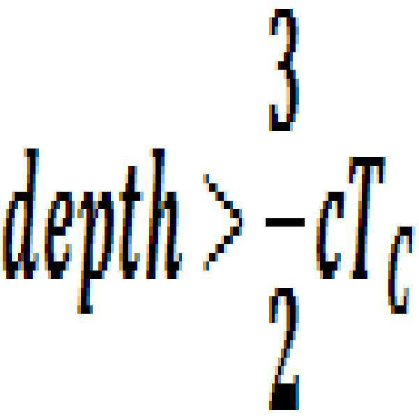
2TC<tTOF인 경우는 독립적인 측정치가 2개이므로 tTOF를 구할 수 없다. 즉, 3개의 광센서(155)의 측정치를 이용하는 경우, 최대 거리 측정 범위는 2TC*c/2=c*TC이다. When 2T C <t TOF , t TOF cannot be obtained because there are two independent measurements. That is, in the case of using the measured values of the three
이와 같이, 3개의 인텐서티 영상을 샘플링한 경우, 뎁스 영상 처리부(160)는 최소 인텐서티를 가지는 인텐서티 영상(IM)이 첫 번째 촬영된 인텐서티 영상(I1)인지 세 번째 촬영된 인텐서티 영상(I3)인지를 결정하고, 결정에 따라서 뎁스를 계산할 수 있다. 다음의 수학식 13은 3개의 인텐서티 영상을 이용하여 뎁스를 결정하는 과정을 요약하여 나타낸다. As such, when three intensity images are sampled, the
[수학식 13][Equation 13]
i)IR 광원(130)의 연속적인 선행 시간(0, TC, 2TC) 또는, 광 변조기(153)의 지연 시간(0, TC, 2TC)을 적용하여, 최소 정보 단위 송출 시간 TC의 PN 시퀀스로 광센서(155)의 인텐서티 영상 ![]()
![]()
ⅱ) 최소 인텐서티 영상(![]()
![]()
![]()
![]()
ⅲ) ![]()

![]()
![]()

![]()
![]()
![]()
![]()
![]()
이하에서는, 도 9a 내지 도 9d를 참조하여 4개 이상의 일반적인 인텐서티 영상 샘플링하여 뎁스를 계산하는 방법에 대하여 설명한다. Hereinafter, a method of calculating depths by sampling four or more general intensity images will be described with reference to FIGS. 9A to 9D.
위의 3개의 인텐서티 영상 샘플링 방법에서 추가로 광 변조기(153)에 3TC의 시간 지연을 인가하여, 4개의 인텐서티 영상을 샘플링하면, 2TC<tTOF<3TC인 경우에도, 독립적인 방정식이 3개가 되어 미지수인 tTOF를 추출해 낼 수 있다. In the above three intensity image sampling methods, if a time delay of 3T C is additionally applied to the
도 9a 내지 도 9d는 0<tTOF<TC, TC<tTOF<2TC, 2TC<tTOF<3TC, 및 3TC<tTOF의 각 구간별로 4개의 인텐서티 영상을 샘플링하고, 각 구간에서 뎁스를 추출하는 방법을 요약하여 나타내는 도면이다. 9A to 9D sample four intensity images for each section of 0 <t TOF <T C , T C <t TOF <2T C , 2T C <t TOF <3T C , and 3T C <t TOF Is a diagram summarizing a method of extracting a depth in each section.
도 9a를 참조하면, 0<tTOF<TC에서, 인텐서티 영상(![]()
![]()
![]()
![]()
![]()
![]()
![]()
![]()
[수학식 14][Equation 14]

도 9b를 참조하면, TC<tTOF<2TC에서, 인텐서티 영상(![]()
![]()
![]()
![]()
![]()
![]()
![]()
![]()
[수학식 15][Equation 15]

도 9c를 참조하면, 2TC<tTOF<3TC에서, 인텐서티 영상(![]()
![]()
![]()
![]()
![]()
![]()
![]()
![]()
[수학식 16][Equation 16]

도 9d를 참조하면, 3TC<tTOF에서, 인텐서티 영상(![]()
![]()
![]()
![]()
![]()
![]()
![]()
![]()
![]()
![]()
일 실시예에 따르면, 4개 이상의 일반적인 인텐서티 영상 샘플을 이용하는 경우, 뎁스 영상 처리부(160)는 최소 인텐서티를 가지는 인텐서티 영상(IM)이 몇 번째 영상인지 결정하고, 4개 이상의 인텐서티 중 최소 인텐서티와 다른 최상위 2개의 서로 다른 인텐서티를 가지는 2개의 영상이 몇 번째 영상들인지 결정하고, 결정에 따라서 뎁스를 계산할 수 있다. 4개 이상의 인텐서티 영상을 샘플링하여 뎁스 영상을 생성하는 방법은 아래의 수학식에서와 같이 정리될 수 있다. According to an embodiment, when using four or more general intensity image samples, the
[수학식 17][Equation 17]
1)IR 광원(130)의 연속적인 선행 시간(0, TC, 2TC) 또는, 광 변조기(153)의 지연 시간(0, TC, 2TC)을 적용하여, 최소 정보 단위 송출 시간(TC)의 PN 시퀀스로 인텐서티 영상![]()
![]()
(2) 최소 인텐서티 및 2개 최대 인텐서티(0이 아닌 연속적인 2개의 측정차)를 계산한다. (2) Calculate the minimum and two maximum intensities (two consecutive nonzero measurement differences).
![]()
![]()
![]()
![]()
(3) 뎁스를 계산한다. (3) Calculate the depth.

![]()
![]()

위에서 보는 바와 같이 N개의 인텐서티 영상 즉, 서브 프레임을 촬영하여 뎁스 영상을 추출하는 경우, 최대 촬영 가능 거리가 (N-1)cTC/2가 되어 N에 비례하여 선형 증가함을 알 수 있다. As seen above, when the N intensity images, i.e., sub-frames are taken to extract the depth image, it can be seen that the maximum recordable distance becomes (N-1) cT C / 2 and increases linearly with N. .
다음으로, 광 변조기(153)의 제2 PN-시퀀스의 시간 지연(tdi) 선정에 따른 뎁스 추출 오차 및 거리 측정이 가능한 뎁스의 길이와의 관계에 대하여 설명한다. Next, the relationship between the depth extraction error according to the time delay t di selection of the second PN-sequence of the
일 실시예에 따르면, N개의 인텐서티 영상, 예를 들어, 4개의 인텐서티 영상 ![]()
![]()
도 10은 광 변조기의 시간 지연을 TC/2로 하는 경우 인텐서티 영상을 나타내는 도면이다. 10 is a diagram illustrating an intensity image when the time delay of the optical modulator is T C / 2.
도 10에 도시된 바와 같이, 광 변조기(153)의 시간 지연을 TC 간격이 아닌, TC/2로, 즉, 절반에 해당하는 간격으로 두어 각각 (0, TC/2, TC, 3TC/2)로 하는 경우를 설명하면 아래와 같다. 이 경우, 거리 측정 구간의 시간의 길이는 2TC로서 TC의 시간 지연을 사용하는 경우보다는 짧다. As shown in Figure 10, the time delay of the
또한, 다수의 인텐서티 영상 촬영시에, 광 변조기(153)의 첫 번째 제2 PN-시퀀스의 시간 지연(td1)의 크기를 조절하여 이동하고, 나머지 제2 PN-시퀀스의 시간 지연을 그에 따라 이동시키면, 광 센서(155)에서 첫 번째로 샘플링된 인텐서티 영상부터 마지막으로 샘플링된 인텐서티 영상 사이의 시간 간격이 줄어들게 된다. 따라서, 촬영 범위의 중간 값을 이동시킬 수 있다. 이와 같은 방법으로, 선택된 촬영 범위에서 뎁스를 얻을 수 있다. In addition, when photographing multiple intensity images, the time delay t d1 of the first second PN-sequence of the
이 경우, 측정 구간이 짧아짐으로 해서, 3개의 미지수를 밝히기 위한 수학식 8을 풀기 위해, 아래와 같이 유용한 방정식 4개를 얻을 수 있다. In this case, since the measurement interval is shortened, four useful equations can be obtained as follows to solve the equation (8) for identifying three unknowns.
[수학식 18]Equation 18


![]()
![]()
여기에서, ![]()
![]()
![]()
![]()
4개의 방정식으로부터 피사체와의 거리를 포함한 3개의 미지수를 추출하므로, 광 변조기(153)의 시간 지연이 TC인 경우와 달리, 미지수에 대하여 복수 개의 해가 존재하게 된다. 일 실시예에 따르면, 복수 개의 해에 대해 최소 자승(least square) 또는 최적화된 측정치의 조합을 사용하여 최종적인 미지수 값을 결정할 수 있다. 아래는 수학식 19의 4개의 방정식 중 3개를 선택하고, 선택된 방정식에 따른 거리추출 방법의 결과를 표시한다. Since three unknowns including the distance to the subject are extracted from the four equations, unlike the case where the time delay of the
[수학식 19]&Quot; (19) "
![]()

![]()
![]()
![]()
![]()
![]()
![]()

![]()
광센서(155)의 측정치에 잡음, 신호 왜곡 등의 이유로 오차가 있는 경우, 위의 4개의 해답은 서로 다른 값을 가질 것이다. 일 실시예에 따르면, 뎁스 영상 처리부(160)는 최종적인 거리 추출을 위해서 위의 4개의 해답을 평균하여, 예를 들어, 최소 자승법을 이용하여 뎁스를 결정하거나 4개 중에 오차 특성이 가장 좋은 것을 선별할 수 있다. If there is an error in the measurement of the
일 예로서, 광센서(155)의 측정치가 표준편차 ![]()
![]()
![]()
![]()
[수학식 20]&Quot; (20) "
![]()
![]()

![]()
![]()

![]()
![]()

![]()
![]()

뎁스 영상 처리부(160)는 수학식 20을 이용해서, 오차가 가장 작은 최적의 해답을 가려낼 수 있다. The
위의 수학적 해석은, 0<tTOF<TC/2인 경우를 설명하였고, TC/2<tTOF<TC, 2TC<tTOF<3TC/2인 경우도 동일한 방법으로 계산을 하면, 거리 추출 오차 특성이 가장 좋은, 즉, 오차의 표준편차 예측치가 가장 작은 거리 추출 방법을 가려낼 수 있다. The above mathematical interpretation has explained the case where 0 <t TOF <T C / 2, and the same method is used when T C / 2 <t TOF <T C , 2T C <t TOF <3T C / 2 In this case, the distance extraction method having the best distance extraction error characteristic, that is, the smallest standard deviation prediction value of the error can be selected.
광 변조기(153)의 시간 지연 및 인텐서티 영상(서브 프레임)의 개수는 이론적인 제약이 없으므로, 하드웨어에서 허용하는 범위에서, 사용자는 기기 내부에서 원하는 목적을 달성하기 위하여 자유롭게 선정할 수 있다. 전술한 바와 같이, 광 변조기(153)의 광 변조 파형의 시간 지연(tdi)을 줄여서 사용하는 경우는 뎁스 추출을 위해 거리 연산에 활용되는 샘플링을 많이 하게 되는 경우이므로, 뎁스 정밀도를 높이는데 활용될 수 있다. Since the time delay of the
한편, 광 변조기(153)의 시간 지연(tdi)을 고정하고, 서브 프레임의 개수를 늘리는 경우는, 수학식 17에서 언급한 바와 같이 뎁스 영상 생성 장치(100)에서 거리 추출 가능 범위를 확장하는데 활용될 수 있으며 이론적으로는 이 범위의 한계가 없다. 단, 피사체(10)가 멀수록 반사광의 세기 저하 등 하드웨어의 한계에 따라 최대 측정 범위가 결정된다. 한편, 광 변조기(153)의 시간 지연(tdi)은 0에서 시작하지 않고 사용자 또는 기기가 적절히 선정된 값에서부터 순차적으로 늘리면서 적용될 수도 있다. 이 경우는, 거리 추출의 범위가 카메라로부터 근접한 0부터가 아니라, 특정 거리 이상을 측정하는 것이 되어, 원하는 거리 범위의 피사체를 선택적으로 촬영할 수 있다. On the other hand, when the time delay t di of the
일 실시예에 따르면, PN-시퀀스를 이용한 거리 추출 방법을 이용하여, PN-시퀀스의 기본 특성상 다수 사용자간의 간섭 문제를 제거할 수 있다. 즉, 서로 다른 사용자가 서로 다른 종류의 PN-시퀀스 또는 동일한 시퀀스라도 동기화가 되어 있지 않은 경우 그 상호 상관 또는 자기 상관의 값, 즉 광센서(155)에 촬영되는 값은 매우 작으므로, 타 사용자의 카메라에서 발광되는 적외선의 효과는 제거될 수 있다. According to an embodiment, the distance extraction method using the PN-sequence can be used to eliminate the interference problem between multiple users due to the basic characteristics of the PN-sequence. That is, when different users are not synchronized even with different types of PN-sequences or the same sequence, the value of the cross-correlation or auto-correlation, that is, the value captured by the
도 11은 뎁스 영상 생성 방법의 일 예를 나타내는 순서도이다. 11 is a flowchart illustrating an example of a depth image generation method.
뎁스 영상 생성 장치(100)는 제1 PN-시퀀스를 이용하여 변조된 광을 방출한다(1110). The depth
뎁스 영상 생성 장치(100)는 방출된 광에 의하여 피사체로부터 반사된 반사광을, 제1 PN-시퀀스와 동일한 시퀀스를 가지며, 제1 PN-시퀀스에 비해 N개의 서로 다른 타임 쉬프트를 가지는 제2 PN-시퀀스를 이용하여 광 변조를 수행한다(1120). N은 3 이상일 수 있다. The depth
뎁스 영상 생성 장치(100)는 동작 1110 및 1120을 다른 방법으로 수행할 수 있다. 상세하게는, 뎁스 영상 생성 장치(100)는 동작 1110에서, N개의 서로 다른 타임 쉬프트를 가지는 N개의 제1 PN-시퀀스를 이용하여 광을 변조하고, 변조된 광을 방출할 수 있다. 그런 다음, 동작 1120에서, 뎁스 영상 생성 장치(100)는 변조된 광의 방출에 의하여 피사체로부터 반사된 반사광을, 제1 PN-시퀀스와 동일한 시퀀스를 이용하며 제1 PN-시퀀스와 다른 타임 쉬프트를 가지는 한 개의 제2 PN-시퀀스를 이용하여 광 변조를 수행할 수 있다. The depth
뎁스 영상 생성 장치(100)는 광 변조가 수행된 반사광을 감지한다(1130). The depth
뎁스 영상 생성 장치(100)는 감지되는 광 신호 중에서 광 변조에 의하여 획득되는 N개의 인텐서티 영상을 샘플링한다(1140). The depth
뎁스 영상 생성 장치(100)는 샘플링된 N개의 인텐서티 영상을 이용하여 피사체에 대한 뎁스 영상을 생성한다(1150). The depth
뎁스 영상 생성 장치(100)는 3개의 인텐서티 영상이 샘플링된 경우, 최소 인텐서티를 가지는 인텐서티 영상이 첫 번째 촬영된 인텐서티 영상인지 세 번째 촬영된 인텐서티 영상인지를 결정하고, 그 결정에 따라서 뎁스를 계산할 수 있다. 또한, 뎁스 영상 생성 장치(100)는 4개 이상의 인텐서티 영상이 샘플링된 경우, 최소 인텐서티를 가지는 인텐서티 영상이 몇 번째 영상인지 결정하고, 4개 이상의 인텐서티 중 최소 인텐서티와 다른 최상위 2개의 서로 다른 인텐서티 영상이 몇 번째 영상인지 결정하고, 그 결정에 따라서 뎁스를 계산할 수 있다. When three intensity images are sampled, the depth
뎁스 영상 생성 장치(100)와 다른 뎁스 영상 생성 장치, 예를 들어, 다른 사용자의 뎁스 영상 생성 장치에서 이용하는 PN-시퀀스와 서로 다른 제1 PN-시퀀스 및 제2 PN-시퀀스를 이용할 수 있다. 또는, 뎁스 영상 생성 장치(100)는, 다른 뎁스 영상 생성 장치의 PN-시퀀스와 동일하되, 다른 뎁스 영상 생성 장치의 PN-시퀀스와 비동기화된 제1 PN-시퀀스 및 제2 PN-시퀀스를 이용할 수 있다. The PN-sequence different from the depth
본 발명의 일 양상은 컴퓨터로 읽을 수 있는 기록 매체에 컴퓨터가 읽을 수 있는 코드로서 구현될 수 있다. 상기의 프로그램을 구현하는 코드들 및 코드 세그먼트들은 당해 분야의 컴퓨터 프로그래머에 의하여 용이하게 추론될 수 있다. 컴퓨터가 읽을 수 있는 기록매체는 컴퓨터 시스템에 의하여 읽혀질 수 있는 데이터가 저장되는 모든 종류의 기록 장치를 포함한다. 컴퓨터가 읽을 수 있는 기록 매체의 예로는 ROM, RAM, CD-ROM, 자기 테이프, 플로피 디스크, 광 디스크 등을 포함한다. 또한, 컴퓨터가 읽을 수 있는 기록 매체는 네트워크로 연결된 컴퓨터 시스템에 분산되어, 분산 방식으로 컴퓨터가 읽을 수 있는 코드로 저장되고 실행될 수 있다.One aspect of the present invention may be embodied as computer readable code on a computer readable recording medium. The code and code segments implementing the above program can be easily deduced by a computer programmer in the field. Computer-readable recording media include all kinds of recording devices that store data that can be read by a computer system. Examples of the computer-readable recording medium include ROM, RAM, CD-ROM, magnetic tape, floppy disk, optical disk, and the like. The computer-readable recording medium may also be distributed over a networked computer system and stored and executed in computer readable code in a distributed manner.
이상의 설명은 본 발명의 일 실시예에 불과할 뿐, 본 발명이 속하는 기술분야에서 통상의 지식을 가진 자는 본 발명의 본질적 특성에서 벗어나지 않는 범위에서 변형된 형태로 구현할 수 있을 것이다. 따라서, 본 발명의 범위는 전술한 실시예에 한정되지 않고 특허 청구범위에 기재된 내용과 동등한 범위 내에 있는 다양한 실시 형태가 포함되도록 해석되어야 할 것이다. It will be apparent to those skilled in the art that various modifications and variations can be made in the present invention without departing from the spirit or scope of the invention. Therefore, the scope of the present invention should not be limited to the above-described embodiments, but should be construed to include various embodiments within the scope of the claims.
Claims (20)
상기 광 변조가 수행된 반사광을 감지하는 광 센서; 및
상기 광 센서에 의해 감지되는 광 신호 중에서, N개의 인텐서티 영상을 샘플링하여, 상기 샘플링된 N개의 인텐서티 영상을 이용하여 상기 피사체에 대한 뎁스 영상을 생성하는 뎁스 영상 처리부를 포함하는 뎁스 영상 생성 장치. The reflected light reflected from the subject by the light emission modulated using the first PN-sequence, the second PN-sequence having the same sequence as the first PN-sequence and having N different time shifts. An optical modulator for performing optical modulation using the optical modulator;
An optical sensor detecting the reflected light on which the light modulation is performed; And
A depth image generating apparatus including a depth image processor configured to sample N intensity images from the optical signals sensed by the optical sensor and to generate a depth image of the subject using the sampled N intensity images. .
제1 PN-시퀀스 및 상기 제2 PN-시퀀스는 최소 정보 단위 발생 시간(TC)과 시퀀스 길이가 동일한 바이폴라 m-시퀀스인 뎁스 영상 생성 장치. The method of claim 1,
And a first PN-sequence and a second PN-sequence are bipolar m-sequences having a sequence length equal to a minimum information unit generation time (T C ).
상기 PN-시퀀스는 월시 코드 또는 골드 시퀀스인 뎁스 영상 생성 장치. The method of claim 1,
And the PN-sequence is a Walsh code or a gold sequence.
상기 N은 3 이상인 뎁스 영상 생성 장치. The method of claim 1,
N is 3 or more depth image generating apparatus.
상기 뎁스 영상 처리부는, 상기 제2 PN-시퀀스의 N개의 서로 다른 타임 쉬프트에 대응하는 N개의 인텐서티 영상을 샘플링하는 뎁스 영상 생성 장치. The method of claim 1,
And the depth image processor is configured to sample N intensity images corresponding to N different time shifts of the second PN-sequence.
상기 뎁스 영상 처리부는, 상기 샘플링된 인텐서티 영상을 상기 광원에서 방출되어 상기 광 센서에 도달하는 빛의 왕복 시간(Time-Of-Flight)을 미지수로 포함하는 함수로 모델링하고, 상기 샘플링된 N개의 인텐서티 영상을 이용하여 상기 빛의 왕복 시간을 계산하는 뎁스 영상 생성 장치. The method of claim 1,
The depth image processor is configured to model the sampled intensity images as a function including a time-of-flight of light emitted from the light source and reaching the optical sensor as an unknown value, and the sampled N pieces Depth image generating device for calculating the round trip time of the light using an intensity image.
상기 빛의 왕복 시간을 미지수로 포함하는 함수는, 주변광 및 상기 반사광의 반사도를 미지수로 더 포함하는 뎁스 영상 생성 장치. The method of claim 6,
The function of including the round-trip time of the light as an unknown, Depth image generating apparatus further comprises a reflectance of the ambient light and the reflected light as an unknown.
상기 뎁스 영상 처리부는, 3개의 인텐서티 영상을 샘플링한 경우, 최소 인텐서티를 가지는 인텐서티 영상(IM)이 첫 번째 촬영된 인텐서티 영상(I1)인지 세 번째 촬영된 인텐서티 영상(I3)인지를 결정하고, 상기 결정에 따라서 뎁스를 계산하는 뎁스 영상 생성 장치. The method of claim 6,
When the depth image processor samples three intensity images, the depth image processor may determine whether the intensity image I M having the minimum intensity is the first intensity image I 1 photographed or the third intensity image I photographed. 3 ) a depth image generating apparatus for determining whether the image is determined and the depth in accordance with the determination.
상기 뎁스 영상 처리부는, 4개 이상의 인텐서티 영상을 샘플링한 경우, 최소 인텐서티를 가지는 인텐서티 영상(IM)이 몇 번째 영상인지 결정하고, 상기 4개 이상의 인텐서티 중 상기 최소 인텐서티와 다른 최상위 2개의 서로 다른 인텐서티를 가지는 2개의 영상이 몇 번째 영상들인지 결정하고, 상기 결정에 따라서 뎁스를 계산하는 뎁스 영상 생성 장치. The method of claim 6,
When the depth image processor samples four or more intensity images, the depth image processor determines a number of images of the intensity image I M having the minimum intensity and is different from the minimum intensity among the four or more intensities. And a depth image generation device for determining which of the two images has the highest two different intensities and calculates a depth according to the determination.
상기 뎁스 영상 처리부는, 상기 샘플링된 N개의 인텐서티 영상을 이용하여, 복수 개의 왕복 시간이 예측되고, 그에 따라 복수 개의 뎁스가 결정되는 경우, 상기 복수 개의 뎁스를 평균하여 최종적인 뎁스를 결정하는 뎁스 영상 생성 장치. The method of claim 6,
The depth image processor may determine a final depth by averaging the plurality of depths when a plurality of round trip times are predicted using the sampled N intensity images, and thus a plurality of depths are determined. Video generation device.
상기 뎁스 영상 처리부는, 상기 샘플링된 N개의 인텐서티 영상을 이용하여, 복수 개의 왕복 시간이 예측되고, 그에 따라 복수 개의 뎁스가 결정되는 경우, 상기 복수 개의 뎁스에 대한 뎁스 추출 오차를 각각 결정하고, 상기 뎁스 추출 오차 중 최소의 오차를 가지는 뎁스를 선택하여, 선택된 뎁스를 최종적인 뎁스로 결정하는 뎁스 영상 생성 장치. The method of claim 6,
The depth image processor may determine depth extraction errors for the plurality of depths when a plurality of round trip times are predicted using the sampled N intensity images, and thus a plurality of depths are determined. And a depth image having a minimum error among the depth extraction errors to determine the selected depth as the final depth.
피사체에 투사하는 광을 생성하는 광원;
상기 광원을 구동하는 광원 드라이버;
상기 광 변조기를 구동하는 광 변조기 드라이버; 및
상기 광원 드라이버가 상기 제1 PN-시퀀스를 이용하여, 상기 광원의 광원 구동 파형을 생성하도록 상기 광원 드라이버를 제어하고, 상기 광 변조기 드라이버가 상기 제2 PN-시퀀스를 이용하여 상기 광 변조기의 광 변조 구동 파형을 생성하도록 상기 광 변조기 드라이버를 제어하는 제어부를 더 포함하는 뎁스 영상 생성 장치. The method of claim 1,
A light source for generating light projected onto a subject;
A light source driver for driving the light source;
An optical modulator driver for driving the optical modulator; And
The light source driver controls the light source driver to generate a light source driving waveform of the light source using the first PN-sequence, and the light modulator driver modulates light of the light modulator using the second PN-sequence And a control unit for controlling the optical modulator driver to generate a driving waveform.
상기 뎁스 영상의 촬영 범위를 늘리기 위하여, 상기 제어부가 상기 타임 쉬프트 값의 간격을 일정하게 유지한 상태에서, 상기 뎁스 영상 처리부는 상기 인텐서티 영상의 샘플링 횟수를 늘리는 뎁스 영상 생성 장치. The method of claim 12,
And the depth image processor increases the number of sampling times of the intensity image while the control unit maintains a constant interval of the time shift value in order to increase the photographing range of the depth image.
상기 뎁스 영상의 정밀도를 높이기 위하여, 상기 제어부는 상기 타임 쉬프트 값의 간격을 상기 제1 및 제2 PN-시퀀스의 최소 정보 단위 전송 시간(TC)보다 작도록 상기 광원 드라이버 및 상기 광 변조기 드라이버를 제어하고, 상기 뎁스 영상 처리부는 상기 타임 쉬프트 간격 단위로 상기 인텐서티 영상을 샘플링하는 뎁스 영상 생성 장치. The method of claim 12,
In order to increase the accuracy of the depth image, the controller controls the light source driver and the optical modulator driver so that the interval between the time shift values is smaller than the minimum information unit transmission time T C of the first and second PN-sequences. And a depth image processor configured to sample the intensity image in units of the time shift interval.
상기 제1 PN-시퀀스 및 상기 제2 PN-시퀀스는 다른 뎁스 영상 생성 장치와 서로 다른 PN-시퀀스인 뎁스 영상 생성 장치. The method of claim 1,
And the first PN sequence and the second PN sequence are different PN sequences from other depth image generators.
상기 제1 PN-시퀀스 및 상기 제2 PN-시퀀스는 다른 뎁스 영상 생성 장치와 동일하되, 서로 비동기화된 PN-시퀀스인 뎁스 영상 생성 장치. The method of claim 1,
The first PN-sequence and the second PN-sequence are the same as the other depth image generating apparatus, but the PN-sequence asynchronous to each other depth image generating apparatus.
상기 광 변조가 수행된 반사광을 감지하는 광 센서; 및
상기 감지되는 광 신호 중에서, N개의 인텐서티 영상을 샘플링하여, 상기 샘플링된 N개의 인텐서티 영상을 이용하여 상기 피사체에 대한 뎁스 영상을 생성하는 뎁스 영상 처리부를 포함하는 뎁스 영상 생성 장치. Reflected light reflected from the subject by the emission of light modulated using N first PN-sequences having N different time shifts, and having different time shifts with the same sequence as the first PN-sequence. An optical modulator for performing optical modulation using one second PN-sequence having a second PN sequence;
An optical sensor detecting the reflected light on which the light modulation is performed; And
And a depth image processor configured to sample N intensity images from the detected optical signals and generate a depth image of the subject using the sampled N intensity images.
상기 뎁스 영상 처리부는, 상기 샘플링된 인텐서티 영상을 상기 광원에서 방출되어 상기 광 센서에 도달하는 빛의 왕복 시간(Time-Of-Flight)을 미지수로 포함하는 함수로 모델링하고, 상기 샘플링된 N개의 인텐서티 영상을 이용하여 상기 빛의 왕복 시간을 계산하는 뎁스 영상 생성 장치. The method of claim 17,
The depth image processor is configured to model the sampled intensity images as a function including a time-of-flight of light emitted from the light source and reaching the optical sensor as an unknown value, and the sampled N pieces Depth image generating device for calculating the round trip time of the light using an intensity image.
상기 광 변조가 수행된 반사광을 감지하는 단계;
상기 감지되는 광 신호 중에서 상기 광 변조에 의하여 획득되는 N개의 인텐서티 영상을 샘플링하는 단계; 및
상기 샘플링된 N개의 인텐서티 영상을 이용하여 상기 피사체에 대한 뎁스 영상을 생성하는 단계를 포함하는 뎁스 영상 생성 방법. Optical modulation of the reflected light reflected from the subject by the emission of the light source modulated using the first PN-sequence, using a second PN-sequence having the same sequence as the first PN-sequence and having N different time shifts Performing;
Detecting the reflected light on which the light modulation is performed;
Sampling N intensity images obtained by the light modulation among the sensed optical signals; And
Generating a depth image of the subject using the sampled N intensity images.
상기 제1 PN-시퀀스 및 상기 제2 PN-시퀀스는, 다른 뎁스 영상 생성 장치와 서로 다른 PN-시퀀스이거나 상기 다른 뎁스 영상 생성 장치와 동일하되 서로 비동기화된 PN-시퀀스인 뎁스 영상 생성 방법. 20. The method of claim 19,
The first PN sequence and the second PN-sequence are different PN-sequences from other depth image generating apparatuses or PN-sequences that are the same as the other depth image generating apparatuses but are asynchronous with each other.
Priority Applications (2)
| Application Number | Priority Date | Filing Date | Title |
|---|---|---|---|
| KR1020100092035A KR101753312B1 (en) | 2010-09-17 | 2010-09-17 | Apparatus and method for generating depth image |
| US13/090,683 US9310488B2 (en) | 2010-09-17 | 2011-04-20 | Apparatus and method for generating depth image |
Applications Claiming Priority (1)
| Application Number | Priority Date | Filing Date | Title |
|---|---|---|---|
| KR1020100092035A KR101753312B1 (en) | 2010-09-17 | 2010-09-17 | Apparatus and method for generating depth image |
Publications (2)
| Publication Number | Publication Date |
|---|---|
| KR20120030196A true KR20120030196A (en) | 2012-03-28 |
| KR101753312B1 KR101753312B1 (en) | 2017-07-03 |
Family
ID=45817417
Family Applications (1)
| Application Number | Title | Priority Date | Filing Date |
|---|---|---|---|
| KR1020100092035A Active KR101753312B1 (en) | 2010-09-17 | 2010-09-17 | Apparatus and method for generating depth image |
Country Status (2)
| Country | Link |
|---|---|
| US (1) | US9310488B2 (en) |
| KR (1) | KR101753312B1 (en) |
Cited By (5)
| Publication number | Priority date | Publication date | Assignee | Title |
|---|---|---|---|---|
| KR20140047271A (en) * | 2012-10-12 | 2014-04-22 | 삼성전자주식회사 | Depth sensor, image capturing method thereof and image processing system having the depth sensor |
| KR20180075091A (en) * | 2016-12-26 | 2018-07-04 | 연세대학교 산학협력단 | Apparatus and method for determining optical signal reflected from target in depth sensor |
| US10205933B2 (en) | 2014-08-29 | 2019-02-12 | Samsung Electronics Co., Ltd. | Depth image acquisition apparatus and method of acquiring depth information |
| US10509125B2 (en) | 2015-12-24 | 2019-12-17 | Samsung Electronics Co., Ltd. | Method and device for acquiring distance information |
| US10545237B2 (en) | 2016-08-22 | 2020-01-28 | Samsung Electronics Co., Ltd. | Method and device for acquiring distance information |
Families Citing this family (33)
| Publication number | Priority date | Publication date | Assignee | Title |
|---|---|---|---|---|
| EP2400768A3 (en) * | 2010-06-25 | 2014-12-31 | Samsung Electronics Co., Ltd. | Method, apparatus and computer-readable medium for coding and decoding depth image using color image |
| KR101722641B1 (en) * | 2010-12-23 | 2017-04-04 | 삼성전자주식회사 | 3D image acquisition apparatus and method of extractig depth information in the 3D image acquisition apparatus |
| KR101799521B1 (en) * | 2011-05-24 | 2017-11-20 | 삼성전자 주식회사 | Light modulator with photonic crystal and 3D image acquisition apparatus employing the same |
| US8736924B2 (en) | 2011-09-28 | 2014-05-27 | Truesense Imaging, Inc. | Time-delay-and-integrate image sensors having variable integration times |
| KR101854188B1 (en) | 2011-10-25 | 2018-05-08 | 삼성전자주식회사 | 3D image acquisition apparatus and method of acqiring depth information in the 3D image acquisition apparatus |
| US9060404B2 (en) * | 2012-11-20 | 2015-06-16 | RedBeard Ventures LLC | Synchronized light source for rolling shutter imagers |
| US9307600B2 (en) * | 2012-11-20 | 2016-04-05 | RedBeard Ventures LLC | Synchronized light source for rolling shutter imagers |
| US20140139632A1 (en) * | 2012-11-21 | 2014-05-22 | Lsi Corporation | Depth imaging method and apparatus with adaptive illumination of an object of interest |
| KR102040152B1 (en) | 2013-04-08 | 2019-12-05 | 삼성전자주식회사 | An 3D image apparatus and method for generating a depth image in the 3D image apparatus |
| KR102056904B1 (en) * | 2013-05-22 | 2019-12-18 | 삼성전자주식회사 | 3D image acquisition apparatus and method of driving the same |
| US9729860B2 (en) | 2013-05-24 | 2017-08-08 | Microsoft Technology Licensing, Llc | Indirect reflection suppression in depth imaging |
| JP2016524709A (en) * | 2013-06-06 | 2016-08-18 | ヘプタゴン・マイクロ・オプティクス・プライベート・リミテッドHeptagon Micro Optics Pte. Ltd. | Sensor system with active illumination |
| KR20150010230A (en) * | 2013-07-18 | 2015-01-28 | 삼성전자주식회사 | Method and apparatus for generating color image and depth image of an object using singular filter |
| US10063844B2 (en) | 2013-10-17 | 2018-08-28 | Microsoft Technology Licensing, Llc. | Determining distances by probabilistic time of flight imaging |
| KR102163728B1 (en) * | 2013-12-05 | 2020-10-08 | 삼성전자주식회사 | Camera for depth image measure and method of measuring depth image using the same |
| US12401911B2 (en) | 2014-11-07 | 2025-08-26 | Duelight Llc | Systems and methods for generating a high-dynamic range (HDR) pixel stream |
| US12401912B2 (en) | 2014-11-17 | 2025-08-26 | Duelight Llc | System and method for generating a digital image |
| US12445736B2 (en) | 2015-05-01 | 2025-10-14 | Duelight Llc | Systems and methods for generating a digital image |
| JP2018526765A (en) * | 2015-06-03 | 2018-09-13 | レッドビアード・ベンチャーズ・リミテッド・ライアビリティ・カンパニーRedbeard Ventures, Llc | Synchronous light source for rolling shutter image sensor |
| WO2017110417A1 (en) | 2015-12-21 | 2017-06-29 | 株式会社小糸製作所 | Image acquisition device for vehicles, control device, vehicle provided with image acquisition device for vehicles and control device, and image acquisition method for vehicles |
| CN108541305A (en) | 2015-12-21 | 2018-09-14 | 株式会社小糸制作所 | Vehicle image acquiring device and vehicle including the device |
| CN108431631A (en) | 2015-12-21 | 2018-08-21 | 株式会社小糸制作所 | Vehicle image acquiring device, control device, include vehicle image acquiring device or control device vehicle and vehicle image acquiring method |
| US11187805B2 (en) | 2015-12-21 | 2021-11-30 | Koito Manufacturing Co., Ltd. | Image acquiring apparatus for vehicle, control device, vehicle having image acquiring apparatus for vehicle or control device, and image acquiring method for vehicle |
| CN107818554B (en) * | 2016-09-12 | 2023-04-21 | 索尼公司 | Information processing apparatus and information processing method |
| US10627494B2 (en) * | 2016-09-16 | 2020-04-21 | Analog Devices, Inc. | Interference handling in time-of-flight depth sensing |
| CN107980102B (en) * | 2016-12-23 | 2021-07-09 | 深圳配天智能技术研究院有限公司 | A lidar scanning method and lidar |
| CN106970393B (en) * | 2017-03-14 | 2019-12-03 | 南京航空航天大学 | A 3D Imaging Method of Area Array LiDAR Based on Code Division Multiple Access |
| US11016179B2 (en) * | 2017-12-03 | 2021-05-25 | Munro Design & Technologies, Llc | Digital image processing systems for three-dimensional imaging systems with image intensifiers and methods thereof |
| US20190045169A1 (en) * | 2018-05-30 | 2019-02-07 | Intel Corporation | Maximizing efficiency of flight optical depth sensors in computing environments |
| WO2020049126A1 (en) * | 2018-09-06 | 2020-03-12 | Sony Semiconductor Solutions Corporation | Time of flight apparatus and method |
| CN111077529A (en) * | 2019-12-27 | 2020-04-28 | 广东博智林机器人有限公司 | Laser radar and robot |
| TWI899217B (en) * | 2020-04-28 | 2025-10-01 | 美商光程研創股份有限公司 | Systems and operating methods for tof imaging of a target and a light emission apparatus |
| CN115201786B (en) * | 2021-04-09 | 2025-04-04 | 深圳引望智能技术有限公司 | A laser radar synchronization control device and method |
Family Cites Families (28)
| Publication number | Priority date | Publication date | Assignee | Title |
|---|---|---|---|---|
| US5081530A (en) | 1987-06-26 | 1992-01-14 | Antonio Medina | Three dimensional camera and range finder |
| US5075863A (en) * | 1988-02-09 | 1991-12-24 | Nkk Corporation | Distance measuring method and apparatus therefor |
| JP2665231B2 (en) * | 1988-05-13 | 1997-10-22 | 浜松ホトニクス株式会社 | Optical waveform measurement device |
| US4935616A (en) | 1989-08-14 | 1990-06-19 | The United States Of America As Represented By The Department Of Energy | Range imaging laser radar |
| IL114278A (en) | 1995-06-22 | 2010-06-16 | Microsoft Internat Holdings B | Camera and method |
| AU6136096A (en) * | 1995-06-22 | 1997-01-22 | 3Dv Systems Ltd. | Telecentric 3d camera and method |
| US6088086A (en) | 1995-09-11 | 2000-07-11 | Sandia Corporation | Range determination for scannerless imaging |
| AU5876798A (en) | 1998-02-08 | 1999-08-23 | 3Dv Systems Ltd. | Large aperture optical image shutter |
| US6856355B1 (en) | 1999-11-30 | 2005-02-15 | Eastman Kodak Company | Method and apparatus for a color scannerless range image system |
| US6794628B2 (en) | 2000-01-03 | 2004-09-21 | 3Dv Systems, Ltd. | Solid state optical shutter |
| JP2004125733A (en) | 2002-10-07 | 2004-04-22 | Nippon Steel Corp | Distance measuring device and distance measuring method |
| JP2005106603A (en) | 2003-09-30 | 2005-04-21 | Tdk Corp | Pulse wave radar apparatus |
| WO2005036372A2 (en) | 2003-10-09 | 2005-04-21 | Honda Motor Co., Ltd. | Systems and methods for determining depth using shuttered light pulses |
| JP4161910B2 (en) | 2004-01-28 | 2008-10-08 | 株式会社デンソー | Distance image data generation device, generation method, and program |
| US7379100B2 (en) * | 2004-02-12 | 2008-05-27 | Canesta, Inc. | Method and system to increase dynamic range of time-of-flight (TOF) and/or imaging sensors |
| JP4553634B2 (en) | 2004-06-03 | 2010-09-29 | セイコープレシジョン株式会社 | Distance measuring device and distance measuring method |
| US7283213B2 (en) * | 2005-02-08 | 2007-10-16 | Canesta, Inc. | Method and system to correct motion blur and reduce signal transients in time-of-flight sensor systems |
| US7983548B2 (en) | 2005-10-28 | 2011-07-19 | Hewlett-Packard Development Company, L.P. | Systems and methods of generating Z-buffers in cameras |
| US8391698B2 (en) | 2005-10-28 | 2013-03-05 | Hewlett-Packard Development Company, L.P. | Systems and methods of generating Z-buffers for an image capture device of a camera |
| US7405812B1 (en) * | 2006-05-18 | 2008-07-29 | Canesta, Inc. | Method and system to avoid inter-system interference for phase-based time-of-flight systems |
| US7746450B2 (en) * | 2007-08-28 | 2010-06-29 | Science Applications International Corporation | Full-field light detection and ranging imaging system |
| KR101520029B1 (en) | 2008-12-31 | 2015-05-15 | 삼성전자주식회사 | Optical Modulator with Pixelization Patterns |
| KR101547327B1 (en) | 2009-01-15 | 2015-09-07 | 삼성전자주식회사 | Optical image modulator and optical apparatus comprising the same and methods of manufacturing and operating optical image modulator |
| KR101603778B1 (en) | 2009-01-19 | 2016-03-25 | 삼성전자주식회사 | Optical image shutter |
| KR101623960B1 (en) | 2009-06-04 | 2016-05-25 | 삼성전자주식회사 | Optoelectronic shutter, method of operating the same and optical apparatus employing the optoelectronic shutter |
| KR101638974B1 (en) | 2009-06-17 | 2016-07-13 | 삼성전자주식회사 | Optical modulator, methods of manufacturing and operating the same and optical apparatus comprising optical modulator |
| KR101706354B1 (en) | 2009-06-24 | 2017-02-13 | 삼성전자주식회사 | High speed optical modulator and method of modulating light using the same |
| KR101675112B1 (en) | 2010-01-21 | 2016-11-22 | 삼성전자주식회사 | Method of extractig depth information and optical apparatus employing the method |
-
2010
- 2010-09-17 KR KR1020100092035A patent/KR101753312B1/en active Active
-
2011
- 2011-04-20 US US13/090,683 patent/US9310488B2/en active Active
Cited By (5)
| Publication number | Priority date | Publication date | Assignee | Title |
|---|---|---|---|---|
| KR20140047271A (en) * | 2012-10-12 | 2014-04-22 | 삼성전자주식회사 | Depth sensor, image capturing method thereof and image processing system having the depth sensor |
| US10205933B2 (en) | 2014-08-29 | 2019-02-12 | Samsung Electronics Co., Ltd. | Depth image acquisition apparatus and method of acquiring depth information |
| US10509125B2 (en) | 2015-12-24 | 2019-12-17 | Samsung Electronics Co., Ltd. | Method and device for acquiring distance information |
| US10545237B2 (en) | 2016-08-22 | 2020-01-28 | Samsung Electronics Co., Ltd. | Method and device for acquiring distance information |
| KR20180075091A (en) * | 2016-12-26 | 2018-07-04 | 연세대학교 산학협력단 | Apparatus and method for determining optical signal reflected from target in depth sensor |
Also Published As
| Publication number | Publication date |
|---|---|
| US9310488B2 (en) | 2016-04-12 |
| US20120069176A1 (en) | 2012-03-22 |
| KR101753312B1 (en) | 2017-07-03 |
Similar Documents
| Publication | Publication Date | Title |
|---|---|---|
| KR101753312B1 (en) | Apparatus and method for generating depth image | |
| JP5739174B2 (en) | Distance information extraction method and optical apparatus employing the method | |
| EP2790034B1 (en) | 3D image acquisition apparatus and method of generating depth image in the 3D image acquisition apparatus | |
| US7834985B2 (en) | Surface profile measurement | |
| KR101722641B1 (en) | 3D image acquisition apparatus and method of extractig depth information in the 3D image acquisition apparatus | |
| US9894347B2 (en) | 3D image acquisition apparatus and method of driving the same | |
| KR101613133B1 (en) | Method and apparatus for processing 3-dimensional image | |
| US7379100B2 (en) | Method and system to increase dynamic range of time-of-flight (TOF) and/or imaging sensors | |
| EP3163316B1 (en) | Apparatus and method for obtaining a depth image | |
| EP2587276A1 (en) | 3D image acquisition apparatus and method of calculating depth information in the 3D image acquisition apparatus | |
| KR20170050058A (en) | Apparatus and method of sensing depth information | |
| KR102194237B1 (en) | Method and apparatus for generating depth image | |
| KR101145132B1 (en) | The three-dimensional imaging pulsed laser radar system using geiger-mode avalanche photo-diode focal plane array and auto-focusing method for the same | |
| JP2004538491A (en) | Method and apparatus for recording three-dimensional range images | |
| US9746547B2 (en) | Method and apparatus for generating depth image | |
| KR20130091194A (en) | 3d image acquisition apparatus and method of extractig depth information in the 3d image acquisition apparatus | |
| CN111025321B (en) | Variable-focus depth measuring device and measuring method | |
| US12498463B2 (en) | Time of flight apparatus and method | |
| KR20170076477A (en) | Method and device for acquiring distance information | |
| KR102389380B1 (en) | Apparatus and method of extracting depth information of the 3D image | |
| EP3069167A1 (en) | Method for illuminating an object |
Legal Events
| Date | Code | Title | Description |
|---|---|---|---|
| PA0109 | Patent application |
Patent event code: PA01091R01D Comment text: Patent Application Patent event date: 20100917 |
|
| PG1501 | Laying open of application | ||
| A201 | Request for examination | ||
| PA0201 | Request for examination |
Patent event code: PA02012R01D Patent event date: 20150707 Comment text: Request for Examination of Application Patent event code: PA02011R01I Patent event date: 20100917 Comment text: Patent Application |
|
| E902 | Notification of reason for refusal | ||
| PE0902 | Notice of grounds for rejection |
Comment text: Notification of reason for refusal Patent event date: 20160418 Patent event code: PE09021S01D |
|
| E90F | Notification of reason for final refusal | ||
| PE0902 | Notice of grounds for rejection |
Comment text: Final Notice of Reason for Refusal Patent event date: 20161006 Patent event code: PE09021S02D |
|
| E701 | Decision to grant or registration of patent right | ||
| PE0701 | Decision of registration |
Patent event code: PE07011S01D Comment text: Decision to Grant Registration Patent event date: 20170412 |
|
| GRNT | Written decision to grant | ||
| PR0701 | Registration of establishment |
Comment text: Registration of Establishment Patent event date: 20170627 Patent event code: PR07011E01D |
|
| PR1002 | Payment of registration fee |
Payment date: 20170628 End annual number: 3 Start annual number: 1 |
|
| PG1601 | Publication of registration | ||
| PR1001 | Payment of annual fee |
Payment date: 20200518 Start annual number: 4 End annual number: 4 |
|
| PR1001 | Payment of annual fee |
Payment date: 20210513 Start annual number: 5 End annual number: 5 |
|
| PR1001 | Payment of annual fee |
Payment date: 20240516 Start annual number: 8 End annual number: 8 |