KR20120014325A - Optical lenses and lighting devices - Google Patents
Optical lenses and lighting devices Download PDFInfo
- Publication number
- KR20120014325A KR20120014325A KR1020100076301A KR20100076301A KR20120014325A KR 20120014325 A KR20120014325 A KR 20120014325A KR 1020100076301 A KR1020100076301 A KR 1020100076301A KR 20100076301 A KR20100076301 A KR 20100076301A KR 20120014325 A KR20120014325 A KR 20120014325A
- Authority
- KR
- South Korea
- Prior art keywords
- optical lens
- incident
- light
- reflecting
- light source
- Prior art date
- Legal status (The legal status is an assumption and is not a legal conclusion. Google has not performed a legal analysis and makes no representation as to the accuracy of the status listed.)
- Withdrawn
Links
Images


Classifications
-
- G—PHYSICS
- G02—OPTICS
- G02B—OPTICAL ELEMENTS, SYSTEMS OR APPARATUS
- G02B19/00—Condensers, e.g. light collectors or similar non-imaging optics
- G02B19/0033—Condensers, e.g. light collectors or similar non-imaging optics characterised by the use
- G02B19/0047—Condensers, e.g. light collectors or similar non-imaging optics characterised by the use for use with a light source
- G02B19/0071—Condensers, e.g. light collectors or similar non-imaging optics characterised by the use for use with a light source adapted to illuminate a complete hemisphere or a plane extending 360 degrees around the source
-
- B—PERFORMING OPERATIONS; TRANSPORTING
- B29—WORKING OF PLASTICS; WORKING OF SUBSTANCES IN A PLASTIC STATE IN GENERAL
- B29D—PRODUCING PARTICULAR ARTICLES FROM PLASTICS OR FROM SUBSTANCES IN A PLASTIC STATE
- B29D11/00—Producing optical elements, e.g. lenses or prisms
- B29D11/00009—Production of simple or compound lenses
- B29D11/00269—Fresnel lenses
-
- F—MECHANICAL ENGINEERING; LIGHTING; HEATING; WEAPONS; BLASTING
- F21—LIGHTING
- F21K—NON-ELECTRIC LIGHT SOURCES USING LUMINESCENCE; LIGHT SOURCES USING ELECTROCHEMILUMINESCENCE; LIGHT SOURCES USING CHARGES OF COMBUSTIBLE MATERIAL; LIGHT SOURCES USING SEMICONDUCTOR DEVICES AS LIGHT-GENERATING ELEMENTS; LIGHT SOURCES NOT OTHERWISE PROVIDED FOR
- F21K9/00—Light sources using semiconductor devices as light-generating elements, e.g. using light-emitting diodes [LED] or lasers
- F21K9/60—Optical arrangements integrated in the light source, e.g. for improving the colour rendering index or the light extraction
- F21K9/68—Details of reflectors forming part of the light source
-
- F—MECHANICAL ENGINEERING; LIGHTING; HEATING; WEAPONS; BLASTING
- F21—LIGHTING
- F21K—NON-ELECTRIC LIGHT SOURCES USING LUMINESCENCE; LIGHT SOURCES USING ELECTROCHEMILUMINESCENCE; LIGHT SOURCES USING CHARGES OF COMBUSTIBLE MATERIAL; LIGHT SOURCES USING SEMICONDUCTOR DEVICES AS LIGHT-GENERATING ELEMENTS; LIGHT SOURCES NOT OTHERWISE PROVIDED FOR
- F21K9/00—Light sources using semiconductor devices as light-generating elements, e.g. using light-emitting diodes [LED] or lasers
- F21K9/60—Optical arrangements integrated in the light source, e.g. for improving the colour rendering index or the light extraction
- F21K9/69—Details of refractors forming part of the light source
-
- F—MECHANICAL ENGINEERING; LIGHTING; HEATING; WEAPONS; BLASTING
- F21—LIGHTING
- F21V—FUNCTIONAL FEATURES OR DETAILS OF LIGHTING DEVICES OR SYSTEMS THEREOF; STRUCTURAL COMBINATIONS OF LIGHTING DEVICES WITH OTHER ARTICLES, NOT OTHERWISE PROVIDED FOR
- F21V13/00—Producing particular characteristics or distribution of the light emitted by means of a combination of elements specified in two or more of main groups F21V1/00 - F21V11/00
- F21V13/02—Combinations of only two kinds of elements
- F21V13/04—Combinations of only two kinds of elements the elements being reflectors and refractors
-
- F—MECHANICAL ENGINEERING; LIGHTING; HEATING; WEAPONS; BLASTING
- F21—LIGHTING
- F21V—FUNCTIONAL FEATURES OR DETAILS OF LIGHTING DEVICES OR SYSTEMS THEREOF; STRUCTURAL COMBINATIONS OF LIGHTING DEVICES WITH OTHER ARTICLES, NOT OTHERWISE PROVIDED FOR
- F21V5/00—Refractors for light sources
- F21V5/04—Refractors for light sources of lens shape
-
- F—MECHANICAL ENGINEERING; LIGHTING; HEATING; WEAPONS; BLASTING
- F21—LIGHTING
- F21V—FUNCTIONAL FEATURES OR DETAILS OF LIGHTING DEVICES OR SYSTEMS THEREOF; STRUCTURAL COMBINATIONS OF LIGHTING DEVICES WITH OTHER ARTICLES, NOT OTHERWISE PROVIDED FOR
- F21V7/00—Reflectors for light sources
- F21V7/0091—Reflectors for light sources using total internal reflection
-
- G—PHYSICS
- G02—OPTICS
- G02B—OPTICAL ELEMENTS, SYSTEMS OR APPARATUS
- G02B19/00—Condensers, e.g. light collectors or similar non-imaging optics
- G02B19/0004—Condensers, e.g. light collectors or similar non-imaging optics characterised by the optical means employed
- G02B19/0028—Condensers, e.g. light collectors or similar non-imaging optics characterised by the optical means employed refractive and reflective surfaces, e.g. non-imaging catadioptric systems
-
- G—PHYSICS
- G02—OPTICS
- G02B—OPTICAL ELEMENTS, SYSTEMS OR APPARATUS
- G02B19/00—Condensers, e.g. light collectors or similar non-imaging optics
- G02B19/0033—Condensers, e.g. light collectors or similar non-imaging optics characterised by the use
- G02B19/0047—Condensers, e.g. light collectors or similar non-imaging optics characterised by the use for use with a light source
- G02B19/0061—Condensers, e.g. light collectors or similar non-imaging optics characterised by the use for use with a light source the light source comprising a LED
-
- G—PHYSICS
- G02—OPTICS
- G02B—OPTICAL ELEMENTS, SYSTEMS OR APPARATUS
- G02B3/00—Simple or compound lenses
- G02B3/0006—Arrays
- G02B3/0037—Arrays characterized by the distribution or form of lenses
- G02B3/0056—Arrays characterized by the distribution or form of lenses arranged along two different directions in a plane, e.g. honeycomb arrangement of lenses
-
- H—ELECTRICITY
- H10—SEMICONDUCTOR DEVICES; ELECTRIC SOLID-STATE DEVICES NOT OTHERWISE PROVIDED FOR
- H10H—INORGANIC LIGHT-EMITTING SEMICONDUCTOR DEVICES HAVING POTENTIAL BARRIERS
- H10H20/00—Individual inorganic light-emitting semiconductor devices having potential barriers, e.g. light-emitting diodes [LED]
- H10H20/80—Constructional details
- H10H20/85—Packages
- H10H20/855—Optical field-shaping means, e.g. lenses
-
- F—MECHANICAL ENGINEERING; LIGHTING; HEATING; WEAPONS; BLASTING
- F21—LIGHTING
- F21Y—INDEXING SCHEME ASSOCIATED WITH SUBCLASSES F21K, F21L, F21S and F21V, RELATING TO THE FORM OR THE KIND OF THE LIGHT SOURCES OR OF THE COLOUR OF THE LIGHT EMITTED
- F21Y2115/00—Light-generating elements of semiconductor light sources
- F21Y2115/10—Light-emitting diodes [LED]
Landscapes
- Physics & Mathematics (AREA)
- Engineering & Computer Science (AREA)
- Optics & Photonics (AREA)
- General Engineering & Computer Science (AREA)
- General Physics & Mathematics (AREA)
- Microelectronics & Electronic Packaging (AREA)
- Health & Medical Sciences (AREA)
- Manufacturing & Machinery (AREA)
- Ophthalmology & Optometry (AREA)
- Mechanical Engineering (AREA)
- Non-Portable Lighting Devices Or Systems Thereof (AREA)
Abstract
본 발명은 광학 렌즈 및 이를 이용한 조명 장치에 관한 것으로서, 본 발명의 일 측면은, 광 입사 영역으로 제공되며, 표면 중 적어도 일부 영역에 형성된 마이크로 렌즈 어레이를 구비하는 입사부, 상기 입사부와 소정 거리 이격 배치되며, 상기 입사부를 거친 광 중 적어도 일부를 반사시키는 반사부 및, 상기 입사부 및 반사부를 연결하며, 상기 반사부에 의하여 반사된 광을 투과시키는 측면부를 포함하는 광학 렌즈를 제공한다.
본 발명에서 제안하는 광학 렌즈를 사용할 경우, 광원으로부터 입사된 광이 외부로 방출되면서 광축과 이루는 각도가 커지므로, 광원의 지향각이 향상된 효과를 가져올 수 있다.The present invention relates to an optical lens and a lighting apparatus using the same, and an aspect of the present invention is provided as a light incidence region and includes an incidence portion having a microlens array formed on at least a portion of a surface thereof, and a predetermined distance from the incidence portion. The optical lens may be disposed to be spaced apart from each other to reflect at least a portion of the light passing through the incident part, and a side part connecting the incident part and the reflecting part to transmit the light reflected by the reflecting part.
In the case of using the optical lens proposed in the present invention, since the angle formed with the optical axis is increased while the light incident from the light source is emitted to the outside, the directing angle of the light source can be improved.
Description
본 발명은 광학 렌즈 및 이를 이용한 조명 장치에 관한 것으로, 특히, 지향각이 향상된 광학 렌즈를 사용함으로써 광범위한 용도의 조명으로 사용되기에 적합한 배광 곡선을 갖는 조명 장치에 관한 것이다. BACKGROUND OF THE
반도체 광원의 일 종인 발광 다이오드(LED)는 전류가 가해지면 p, n형 반도체의 접합 부분에서 전자와 정공의 재결합에 기하여, 다양한 색상의 빛을 발생시킬 수 있는 반도체 장치이다. 이러한 발광 다이오드는 필라멘트에 기초한 광원에 비해 긴 수명, 낮은 전원, 우수한 초기 구동 특성, 높은 진동 저항 등의 여러 장점을 갖기 때문에 그 수요가 지속적으로 증가하고 있다. 특히, 청색 계열의 단파장 영역의 빛을 발광할 수 있는 III족 질화물 반도체가 각광을 받고 있다.
A light emitting diode (LED), which is a kind of semiconductor light source, is a semiconductor device capable of generating light of various colors based on recombination of electrons and holes at junctions of p and n-type semiconductors when a current is applied. Such light emitting diodes have a number of advantages, such as long life, low power, excellent initial driving characteristics, and high vibration resistance, compared to filament-based light sources. In particular, group III nitride semiconductors capable of emitting light in a blue short wavelength region have been in the spotlight.
최근에는 이러한 발광 다이오드를 이용하여 백열등이나 형광등과 같은 종래의 조명 장치를 대체하기 위한 시도가 있다. 그러나, 발광 다이오드의 경우에는 빛이 모든 방향으로 균일하게 방출되기보다는 특정 방향으로만 빛이 방출되며, 통상적으로 지향각은 120° 정도의 수준이다. 이러한 배광 특성은 모든 방향으로 빛을 방출하는 백열등이나 형광등과 비교하여 큰 차이를 보이는 것으로서 광범위한 용도의 조명 장치로 사용되기에 제약이 된다. 따라서, 발광 다이오드를 이용한 조명 장치의 경우, 광 방출 방향을 제어하는 렌즈를 이용하여 발광 다이오드를 이용한 조명 장치의 적용 범위를 확대할 수 있도록 설계할 수 있는 방안이 요구된다.Recently, there is an attempt to replace a conventional lighting device such as an incandescent lamp or a fluorescent lamp using such a light emitting diode. However, in the case of a light emitting diode, light is emitted only in a specific direction, rather than uniformly emitted in all directions, and a direction angle is typically about 120 °. These light distribution characteristics show a large difference in comparison with incandescent lamps or fluorescent lamps that emit light in all directions, and thus are restricted from being used as lighting devices for a wide range of applications. Therefore, in the case of a lighting device using a light emitting diode, a method that can be designed to extend the application range of the lighting device using a light emitting diode by using a lens for controlling the light emission direction is required.
본 발명은 일 목적은 광원의 지향각을 향상시킬 수 있는 형상을 갖는 광학 렌즈를 제공하며, 나아가, 이러한 광학 렌즈를 이용하여 광범위한 용도의 조명으로 사용되기에 적합한 배광 특성을 갖는 조명 장치를 제공하는 것이다.One object of the present invention is to provide an optical lens having a shape capable of improving the directivity angle of a light source, and furthermore, to provide an illumination device having light distribution properties suitable for use in a wide range of applications using such an optical lens. will be.
상기 기술적 과제를 실현하기 위해서, 본 발명의 일 측면은,In order to realize the above technical problem, an aspect of the present invention,
광 입사 영역으로 제공되며, 표면 중 적어도 일부 영역에 형성된 마이크로 렌즈 어레이를 구비하는 입사부, 상기 입사부와 소정 거리 이격 배치되며, 상기 입사부를 거친 광 중 적어도 일부를 반사시키는 반사부 및, 상기 입사부 및 반사부를 연결하며, 상기 반사부에 의하여 반사된 광을 투과시키는 측면부를 포함하는 광학 렌즈를 제공한다.
An incidence part provided as a light incidence area and having a microlens array formed on at least a part of a surface thereof, an incidence part spaced apart from the incidence part by a predetermined distance, and a reflecting part reflecting at least a portion of light passing through the incidence part, and the incidence part It provides an optical lens comprising a side portion connecting the portion and the reflecting portion, and transmits the light reflected by the reflecting portion.
본 발명의 일 실시 예에서, 상기 마이크로 렌즈 어레이는, 입사부에 입사된 광의 적어도 일부를 굴절시키되 상기 반사부에서 전반사되는 각도로 굴절시키도록 제공될 수 있다.In one embodiment of the present invention, the micro lens array may be provided to refract at least a portion of the light incident on the incident portion at a angle totally reflected by the reflecting portion.
본 발명의 일 실시 예에서, 상기 입사부 및 반사부는 서로 평행인 평면으로 형성되도록 제공될 수 있다.In one embodiment of the present invention, the incident portion and the reflective portion may be provided to be formed in a plane parallel to each other.
본 발명의 일 실시 예에서, 상기 입사부는 반사부보다 큰 폭을 갖도록 제공될 수 있다.In one embodiment of the present invention, the incidence portion may be provided to have a larger width than the reflecting portion.
본 발명의 일 실시 예에서, 상기 입사부 및 반사부는 원형이 되도록 제공될 수 있다.In one embodiment of the present invention, the incident part and the reflecting part may be provided to be circular.
본 발명의 일 실시 예에서, 상기 측면부는 외측으로 볼록한 곡면 형상을 갖도록 제공될 수 있다.In one embodiment of the present invention, the side portion may be provided to have a curved surface convex outward.
본 발명의 일 실시 예에서, 상기 마이크로 렌즈 어레이는 상기 입사부의 하면상에 돌출된 반구형상을 갖는 마이크로렌즈로 이루어지도록 제공될 수 있다.In one embodiment of the present invention, the micro lens array may be provided to be made of a micro lens having a hemispherical shape projecting on the lower surface of the incident portion.
본 발명의 일 실시 예에서, 상기 마이크로 렌즈 어레이는 반구형, 원추형, 삼각뿔형, 사각뿔형 및 랜덤한 산란 형상의 마이크로 렌즈 중 적어도 하나를 포함하도록 제공될 수 있다.In one embodiment of the present invention, the micro lens array may be provided to include at least one of hemispherical, conical, triangular pyramid, square pyramidal and random scattering micro lenses.
본 발명의 일 실시 예에서, 폴리카보네이트 및 아크릴 중 적어도 하나로 이루어지도록 제공될 수 있다.
In one embodiment of the present invention, it may be provided to be made of at least one of polycarbonate and acrylic.
한편, 본 발명의 다른 측면은,On the other hand, another aspect of the present invention,
광원 및, 광 입사 영역으로 제공되며, 표면 중 적어도 일부 영역에 형성된 마이크로 렌즈 어레이를 구비하는 입사부, 상기 입사부와 소정 거리 이격 배치되며, 상기 마이크로 렌즈 어레이를 거친 광 중 적어도 일부를 반사시키는 반사부 및, 상기 입사부 및 반사부를 연결하며, 상기 반사부에 의하여 반사된 광을 투과시키는 측면부로 이루어지는 광학 렌즈를 포함하는 것을 특징으로 하는 조명 장치를 제공한다.
An incidence portion provided as a light source and a light incidence region and having a microlens array formed on at least a portion of a surface thereof, the incidence portion being spaced apart from the incidence portion by a predetermined distance, and reflecting at least a portion of light passing through the microlens array And an optical lens comprising a side portion connecting the incidence portion and the reflecting portion and transmitting the light reflected by the reflecting portion.
본 발명의 일 실시 예에서, 상기 마이크로 렌즈 어레이는, 입사부에 입사된 광의 적어도 일부를 굴절시키되 상기 반사부에서 전반사되는 각도로 굴절시키도록 제공될 수 있다.In one embodiment of the present invention, the micro lens array may be provided to refract at least a portion of the light incident on the incident portion at a angle totally reflected by the reflecting portion.
본 발명의 일 실시 예에서, 상기 입사부 및 반사부가 서로 평행인 평면으로 형성도록 제공될 수 있다.In one embodiment of the present invention, the incident part and the reflecting part may be provided to be formed in a plane parallel to each other.
본 발명의 일 실시 예에서, 상기 반사부가 입사부보다 큰 폭을 갖도록 제공될 수 있다.In one embodiment of the present invention, the reflector may be provided to have a larger width than the incident part.
본 발명의 일 실시 예에서, 상기 반사부 및 상기 입사부가 원형으로 제공될 수 있다.In one embodiment of the present invention, the reflecting portion and the incident portion may be provided in a circular shape.
이 경우, 상기 입사부의 폭과, 상기 광원의 폭의 비가 1.8 이상 3.2 이하 이도록 제공될 수 있다.In this case, the ratio between the width of the incident portion and the width of the light source may be provided to be 1.8 or more and 3.2 or less.
이 경우, 상기 반사부의 폭과, 상기 광원의 폭의 비가 3 이상 4.2 이하 이도록 제공될 수 있다.In this case, the ratio of the width of the reflector and the width of the light source may be provided to be 3 or more and 4.2 or less.
본 발명의 일 실시 예에서, 상기 광학 렌즈는, 상기 측면부가 외측으로 볼록한 곡면 형상이 되도록 제공될 수 있다.In one embodiment of the present invention, the optical lens may be provided such that the side portion is curved to the outside convex.
본 발명의 일 실시 예에서, 상기 반사부와 상기 입사부간의 거리와, 상기 광원의 폭의 비가 0.46 이상 0.9 이하 이도록 제공될 수 있다.In one embodiment of the present invention, the ratio of the distance between the reflecting portion and the incident portion, and the width of the light source may be provided to be 0.46 or more and 0.9 or less.
본 발명의 일 실시 예에서, 상기 마이크로 렌즈 어레이가 하면 상에 돌출된 반구 형상을 가지는 복수의 마이크로 렌즈들을 포함하도록 제공될 수 있다.In one embodiment of the present invention, the micro lens array may be provided to include a plurality of micro lenses having a hemispherical shape protruding on the lower surface.
이 경우, 상기 마이크로 렌즈 어레이는, 상기 마이크로 렌즈들 간의 간격이 일정하도록 제공될 수 있다.In this case, the micro lens array may be provided such that a distance between the micro lenses is constant.
이 경우, 상기 마이크로 렌즈들 간의 간격과 상기 광원의 폭의 비는 0.08 이하이도록 제공될 수 있다.In this case, a ratio of the distance between the micro lenses and the width of the light source may be provided to be 0.08 or less.
이 경우, 상기 복수의 마이크로 렌즈들의 반지름과 상기 복수의 마이크로 렌즈들 간의 간격의 비는 0.48 이상 0.62 이하 이도록 제공될 수 있다.In this case, a ratio of the radius of the plurality of micro lenses and the interval between the plurality of micro lenses may be provided to be 0.48 or more and 0.62 or less.
본 발명의 일 실시 예에서, 상기 광학 렌즈는, 폴리카보네이트, 아크릴 중 적어도 하나로 이루어지도록 제공될 수 있다.In one embodiment of the present invention, the optical lens may be provided to be made of at least one of polycarbonate, acrylic.
본 발명의 일 실시 예에서, 상기 마이크로 렌즈 어레이가 형성되는 영역은 광원에 대응되는 영역보다 크게 제공될 수 있다.In an embodiment of the present disclosure, an area in which the micro lens array is formed may be provided larger than an area corresponding to the light source.
본 발명의 일 실시 예에서, 상기 광원 하부에 배치된 방열 구조체를 더 포함하도록 제공될 수 있다.In one embodiment of the present invention, it may be provided to further include a heat dissipation structure disposed under the light source.
본 발명의 일 실시 예에서, 상기 광학 렌즈와 상기 방열 구조체와의 사이에 고정부를 더욱 포함하도록 제공될 수 있다.In one embodiment of the present invention, it may be provided to further include a fixing portion between the optical lens and the heat dissipation structure.
상기와 같이 이루어지는 본 발명에 따르면, 광 확산 기능을 수행하는 광학 렌즈를 배치함으로서, 발광 다이오드의 빛이 넓은 면적으로 퍼져나가 고르게 확산됨과 동시에, 우수한 광효율을 얻을 수 있다.According to the present invention made as described above, by arranging an optical lens that performs the light diffusing function, the light of the light emitting diode can be spread evenly spread over a large area, and at the same time, excellent light efficiency can be obtained.
도 1 은, 본 발명의 일 실시예에 따른 광학 렌즈의 대략적인 사시도이다.
도 2 는, 도 1의 광학 렌즈 하면에 광원이 배치된 조명 장치의 AB면을 잘라 나타낸 단면도로서, 광 경로 또한 함께 나타내고 있다.
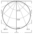
도 3 은, 도 2의 조명 장치의 배광 곡선을 시뮬레이션하여 나타낸 것이다.
도 4 는, 마이크로렌즈 어레이를 제거한 도 1의 광학 렌즈에서, 렌즈 하면에 광원이 배치된 조명 장치의 AB면을 잘라 나타낸 단면도로서, 광 경로 또한 함께 나타내고 있다.
도 5 는, 도 4의 조명 장치의 배광 곡선을 시뮬레이션하여 나타낸 것이다.
도 6 은, 본 발명에서 제안한 광학 렌즈를 사용한 조명 장치를 개략적으로 나타낸 단면도이다.
도 7 은, 본 발명의 일 실시 형태에 따른 광학 렌즈의 상기 입사부의 반지름과, 상기 광원의 폭의 비를 시뮬레이션하여 나타낸 것이다.
도 8 는, 본 발명의 일 실시 형태에 따른 광학 렌즈의 상기 반사부의 반지름과, 상기 광원의 폭의 비를 시뮬레이션하여 나타낸 것이다.
도 9 는, 본 발명의 일 실시 형태에 따른 광학 렌즈의 상기 반사부와 상기 입사부간의 거리와, 상기 광원의 폭의 비를 시뮬레이션하여 나타낸 것이다.
도 10 은, 본 발명의 일 실시 형태에 따른 광학 렌즈의 상기 마이크로 렌즈들 간의 간격과 상기 광원의 폭의 비를 시뮬레이션하여 나타낸 것이다.
도 11 는, 본 발명의 일 실시 형태에 따른 광학 렌즈의 상기 복수의 마이크로 렌즈들의 반지름과 상기 복수의 마이크로 렌즈들 간의 간격의 비를 시뮬레이션하여 나타낸 것이다.
도 12 은, 본 발명의 일 실시 형태에 따른 광학 렌즈의 단면도로서, 광학 렌즈를 이루는 각 부의 길이관계를 설명하기 위한 기호를 나타낸 것이다.
도 13 은, 본 실시 형태에 따른 조명 장치의 배광 곡선을 시뮬레이션하여 나타낸 것이다.1 is a schematic perspective view of an optical lens according to an embodiment of the present invention.
FIG. 2 is a cross-sectional view of the AB surface of the lighting apparatus in which the light source is disposed on the lower surface of the optical lens of FIG. 1, and the optical path is also shown.
FIG. 3 simulates and shows a light distribution curve of the lighting apparatus of FIG. 2.
FIG. 4 is a cross-sectional view of the optical lens of FIG. 1 from which the microlens array is removed, showing the AB plane of the lighting apparatus in which the light source is disposed on the lower surface of the lens, and also showing the optical path.
FIG. 5 simulates and shows a light distribution curve of the lighting apparatus of FIG. 4.
6 is a sectional view schematically showing a lighting device using the optical lens proposed in the present invention.
FIG. 7 simulates and shows a ratio of the radius of the incidence portion of the optical lens according to the embodiment of the present invention and the width of the light source.
FIG. 8 simulates and shows the ratio of the radius of the said reflecting part of the optical lens and the width of the said light source which concerns on one Embodiment of this invention.
9 is a diagram showing a simulation of a ratio of the distance between the reflecting portion and the incident portion of the optical lens and the width of the light source according to the embodiment of the present invention.
FIG. 10 is a diagram showing a simulation of the ratio of the interval between the micro lenses of the optical lens and the width of the light source according to one embodiment of the present invention.
FIG. 11 illustrates a ratio of a radius of the plurality of micro lenses of an optical lens and an interval between the plurality of micro lenses according to an embodiment of the present invention.
12 is a cross-sectional view of an optical lens according to an embodiment of the present invention, and shows symbols for explaining the length relationship of the portions constituting the optical lens.
13 simulates and shows a light distribution curve of the lighting apparatus according to the present embodiment.
이하, 첨부된 도면을 참조하여 본 발명의 바람직한 실시형태들을 설명한다. Hereinafter, preferred embodiments of the present invention will be described with reference to the accompanying drawings.
그러나, 본 발명의 실시형태는 여러 가지 다른 형태로 변형될 수 있으며, 본 발명의 범위가 이하 설명하는 실시 형태로 한정되는 것은 아니다. 또한, 본 발명의 실시형태는 당해 기술 분야에서 평균적인 지식을 가진 자에게 본 발명을 더욱 완전하게 설명하기 위해서 제공되는 것이다. 따라서, 도면에서의 요소들의 형상 및 크기 등은 명확한 설명을 위해 과장될 수 있으며, 도면상의 동일한 부호로 표시되는 요소는 동일한 요소이다.
However, embodiments of the present invention may be modified in various other forms, and the scope of the present invention is not limited to the embodiments described below. Further, the embodiments of the present invention are provided to more fully explain the present invention to those skilled in the art. Accordingly, the shape and size of elements in the drawings may be exaggerated for clarity, and the elements denoted by the same reference numerals in the drawings are the same elements.
도 1 은 본 발명의 일 실시예에 따른 광학 렌즈의 대략적인 사시도이다.1 is a schematic perspective view of an optical lens according to an embodiment of the present invention.
도 2 는 도 1의 광학 렌즈 하면에 광원이 배치된 조명 장치의 AB면을 잘라 나타낸 단면도로서, 광학 렌즈를 통과하여 진행하는 광 경로 또한 함께 나타내고 있다.FIG. 2 is a cross-sectional view illustrating the AB surface of the lighting apparatus in which the light source is disposed on the lower surface of the optical lens of FIG. 1, and also shows an optical path traveling through the optical lens.
우선, 도 1 및 도 2를 참조하면, 본 실시 형태에서 제공되는 광학 렌즈(10)는, 입사부(13)와, 입사부(13)와 소정 거리 이격 배치되는 반사부(11) 및, 입사부(13) 및 반사부(11)를 연결하는 측면부(12)로 형성된 기본 구조를 갖도록 제공된다. 이 경우, 상기 광학 렌즈(10)는 전체적으로 속이 꽉 찬 투명한 접시와 유사한 형상을 이루도록 제공된다. 즉, 상기 입사부(13) 및 반사부(11)는 전체적으로 원형이면서 평면 형태를 가지고, 각 원의 중심이 일치하도록 제공되며, 동시에 서로 평행하여, 렌즈의 어느 부분에서도 항상 같은 거리만큼 이격되고 이와 같이 이격된 상기 입사부(13) 및 반사부(11)는, 상기 측면부(12)를 통하여 서로 연결된다. 본 실시 형태와 같이 상기 입사부(13)의 폭(또는 지름)은 상기 반사부(11)의 폭(또는 지름)보다 작도록 형성되는 경우에는 측면부(12) 역시 반사부(11)에서 입사부(13)로 진행할수록 점점 렌즈의 중심에 모이는 형상을 가지면서, 상기 입사부(13) 및 반사부(11)를 원형으로 따라 돌면서 광학 렌즈(10) 외측으로 볼록한 곡면 형태가 되도록 제공된다.First, referring to FIG. 1 and FIG. 2, the
이와 같이 형성된 광학 렌즈(10)의 하부, 즉 입사부(13)의 하부 중심에 광원(2)이 배치된 경우에, 광원으로부터 출사된 광이 렌즈를 거쳐 최종적으로 외부로 방출되는 과정을 도 2 를 통하여 구체적으로 설명한다.In the case where the
도 2 를 참조하면, 본 실시 형태의 경우, 광원(2)은 발광 다이오드로 제공된다. 상술한 바와 같이 발광 다이오드는 통상적으로 지향각이 120° 정도의 수준에 머무는 배광 특성을 가지므로, 광원(2)에서 출사된 광은 넓게 퍼지지 못하고 대부분이 상부로 출사된다. 이때 출사된 광은 광원(2) 상부 중심에 인접하여 평행하게 배치된 광학 렌즈(10)의 입사부(13)에 도달하게 된다. 이 중 일부의 광은 상술한 마이크로 렌즈 어레이(14)에 입사하게 될 것이고, 일부의 광은 마이크로 렌즈 어레이(14)가 형성되지 않은 평면의 입사부(13)에 도달하고, 또 다른 일부의 광은 광학 렌즈(10) 방향으로 유도되지 않고 공기중으로 방산되거나, 또는 광학 렌즈(10)의 반사부(13)에서 반사, 혹은 전반사되어 방산된다. 이 경우, 최대한 많은 양의 광이 광학 렌즈(10)에 입사하는 것이 바람직하다. 이는 발광 다이오드의 특성인 좁은 지향각을 가지는 광을 광학 렌즈(10)을 통하여 분산시키고자 하는 본 실시 형태의 목적을 이루기 위하여 중요한 요소가 된다. 따라서, 본 실시 형태에서는 마이크로 렌즈 어레이(14)가, 입사부(13)에 형성되되, 광원의 폭보다 넓은 면적에 형성되도록 제공된다. 이와 같이 함으로써, 입사부(13)에서 반사, 전반사되어 광학 렌즈(10)에 입사되지 못하고 방산되는 광의 양을 최소화하여 궁극적으로는 배광 특성의 향상에 기여하게 된다.Referring to FIG. 2, in the present embodiment, the
상술한 바와 같이 마이크로 렌즈 어레이(14)에 입사된 광은, 굴절을 통하여 진행 방향이 바뀌게 된다. 이 경우, 마이크로 렌즈 어레이(14)에 입사될 때의 입사각보다, 출사될 때의 출사각이 커지는 것이 바람직한데, 이는 반사부(11)의 작용과 관계되어 설명되어야 하므로, 자세한 설명은 후술하기로 한다. 이와 같이, 마이크로 렌즈 어레이(14)는 입사된 광이 광학 렌즈(10)의 입사부(13)과 이루는 각도를 크게 하는 것이므로, 이와 같은 기능을 최대한 발휘할 수 있는 형태로 형성되는 것이 바람직하다. 빛의 굴절은 서로 굴절률이 다른 매질이 만나는 경계면에서 빛이 진행방향을 바꾸는 것으로서 각 매질의 굴절률 및 계면과 빛의 진행방향이 이루는 각도를 조절함으로써 출사된 빛을 원하는 방향으로 유도하는 것이 가능하다.As described above, the light incident on the
본 실시예에서는 마이크로 렌즈 어레이(14)를 이루는 복수의 마이크로 렌즈들은 입사부(13)에서 외부로 돌출된 반구형상을 갖는 것으로 제공된다. 이와 같이 함으로써, 마이크로 렌즈 어레이(14)에 입사된 빛의 상당수가 큰 출사각을 가지면서 출사될 수 있다. 그러나, 본 발명은 이와 같은 실시 형태에 한정되는 것이 아니며, 상기 마이크로 렌즈 어레이는 반구형, 원추형, 삼각뿔형, 사각뿔형 및 랜덤한 산란 형상 또는 이들을 혼합한 형태 등 실시 형태에 따라 다양하게 형성될 수 있다.In the present embodiment, the plurality of micro lenses of the
상술한 바와 같이, 마이크로 렌즈 어레이(14)는 입사한 빛을 큰 출사각으로 굴절시키는 역할을 수행하나, 광학 렌즈(10)의 입사부(13)에 입사한 광이 모두 위와 같이 굴절되는 것은 아니다. 즉, 광원(2)으로부터 입사부(13)에 입사한 광은 마이크로 렌즈 어레이(14)가 형성되지 않은 영역을 통해 입사하거나, 혹은 마이크로 렌즈 표면에서 반사될 수 있고, 마이크로 렌즈 어레이(14)를 통해 입사하여도 입사된 위치 및 입사각도에 따라 거의 굴절되지 않고 그대로 직진할 수 있다.As described above, the
상술한 바와 같이 입사부(13)을 통하여 입사 및 굴절된 빛 중, 극히 일부의 광은 측면부(12)로 직접 진행하여 최종적으로 출사되고, 대부분의 광은 반사부(11)로 진행한다. 반사부(11)는 도 2 에서 보듯이 공기와 평면 형태의 계면을 이루고 있으므로, 일정한 임계각을 초과하는 입사각의 광에 대하여는 전반사가 일어나게 된다. 상술한 바와 같이 입사부(13)에서의 굴절이 크게 일어나지 않고 거의 직진하여 반사부(11)에 도달한 광은 입사각이 임계각을 초과하지 않으므로 굴절하여 공기와의 계면을 통과하면서 최종 출사된다. 이 과정에서도 광들은 저마다 서로 다른 출사각을 가지면서 산란되어 출사되지만, 이것만으로는 발광 다이오드의 지향각이 향상되는 정도의 유의할만한 효과를 얻기는 어렵다. 그러나, 임계각을 초과하는 입사각의 광은 전반사를 일으켜 광학 렌즈(10)의 외부로 출사되지 못하고 측면부(12)방향으로 진행하거나, 또는 다시 입사부(13)으로 진행한다.As described above, among the light incident and refracted through the
이와 같이, 반사부(11)에서의 입사각을 크게 함으로서 광을 측면부(12)방향으로 유도할 수 있는데, 그러한 역할을 하는 것이 마이크로 렌즈 어레이(14)임은 상술한 바와 같다.As described above, the light may be directed toward the
측면부(12)로 유도된 광은 더이상 전반사하지 않고 광학 렌즈(10)외부로 출사되어야 하며, 만약 계속 전반사 혹은 반사된다면 의도하지 않게 외부로 출사되지 못하고 손실되는 빛이 생기므로, 이와 같은 경우를 방지하기 위해서는 측면부(12)에 입사되는 빛의 입사각을 작게 할 필요가 있다. 따라서 측면부(12)는 반사부(11)에서 전반사되는 빛이 최대한 수직에 가깝게 입사되도록 외측면으로 불룩하게 튀어나온 형태로 제공된다.The light guided to the
이와 달리, 다시 입사부(13)으로 진행한 광은 입사부(13)을 통해 직접 외부로 출사되거나, 입사각이 큰 경우 재차 전반사 될 수 있다. 이와 같이 전반사를 거듭하는 경우에 있어서도, 빛은 측면부(12)를 향하여 진행할 수 밖에 없으므로, 결과적으로는 측면부를 통하여 출사되고, 빛의 손실이 일어나지는 않는다.On the contrary, the light propagated to the
상술한 바와 같이 광학 렌즈(10)는, 광학 렌즈 어레이(14)를 구비한 입사부(13)을 통하여 입사된 빛이, 일부(L1)는 직접 반사부(11)을 통과하여 광학 렌즈(10) 상면으로 출사되고, 일부(L2)는 반사부(11)에서 전반사하여 측면부(12)을 통하여 측면으로 최종 출사 되며, 일부(L3)는 전반사를 거듭하여 측면부(12)혹은 입사부(13)을 통하여 출사된다. 이와 같이, 렌즈가 없는 경우 지향각이 120도 가량에 머물던 발광 다이오드의 경우에도, 상면에 본 실시예에서의 광학 렌즈(10)를 배치함으로서 측면과 후면까지도 빛을 조사하는 것이 가능해진다.As described above, in the
도 3은 도 2의 조명 장치의 배광 곡선을 시뮬레이션하여 나타낸 것이다. 도 3을 참조하면, 광원에서 출사된 빛이 본 실시 형태의 광학 렌즈(10)를 통하여 배광 특성이 향상되었음을 알 수 있다.3 illustrates a light distribution curve of the lighting apparatus of FIG. 2. Referring to FIG. 3, it can be seen that the light distribution characteristic of the light emitted from the light source is improved through the
도 4는 마이크로렌즈 어레이(14)를 제거한 도 1의 광학 렌즈에서, 렌즈 하면에 광원(4)이 배치된 조명 장치의 AB면을 잘라 나타낸 단면도이다.4 is a cross-sectional view of the optical lens of FIG. 1 from which the
도 4를 참조하면, 입사부(43)에 마이크로렌즈 어레이(14)를 형성하지 않은 점을 제외하고는 도 1 및 도 2에 도시된 광학 렌즈(10)과 동일한 형태의 광학 렌즈(40)가 도시되고 있다. 즉, 광원(4)상에 입사부(43), 측면부(42) 및 반사부(41)로 구성된 광학 렌즈(40)의 단면도로서, 광원(4)으로부터 입사된 광(L4, L5)의 경로 또한 함께 나타내고 있다. 이 경우, 마이크로 렌즈 어레이가 없는 경우 입사부(43)으로 입사되는 광 중 대부분(L4, L5)이 큰 출사각을 갖도록 굴절되지 못하여 반사부(41)에서 전반사되지 못하고 그대로 최종 출사되는 것을 알 수 있다. Referring to FIG. 4, except that the
도 5 는 도 4의 조명 장치의 배광 곡선을 시뮬레이션하여 나타낸 것이다. 도 5 를 참조하면, 본 실시 형태의 광학 렌즈(40)를 배치하여도, 마이크로렌즈 어레이(14)를 제거하면 도 3의 경우에 비하여 배광 특성이 거의 향상되지 않음을 알 수 있다.
FIG. 5 illustrates a light distribution curve of the lighting apparatus of FIG. 4. Referring to FIG. 5, even when the
상술한 바와 같이, 광학 렌즈(10)는 일부의 광은 직진하고, 일부의 광은 굴절하도록 함으로서 자연스러운 광 산란을 유도하며, 이 과정에서 얼마나 많은 양의 광을, 어느정도로 굴절시키는가는 상술한 마이크로 렌즈 어레이(14)의 형태, 형성 범위 및, 광학 렌즈 제체의 형태와 마이크로 렌즈 어레이(14)간의 간격, 직경, 높이, 광원의 폭 등 다양한 변수를 조합하여 결정할 수 있는데, 이와 관련한 실시 형태에 대하여 구체적으로 설명한다.As described above, the
도 6 은 본 발명의 일 실시 형태에 따른 광학 렌즈를 나타낸 단면도로서, 광학 렌즈를 이루는 각 부의 길이관계를 설명하기 위한 기호를 나타낸 것이다.6 is a cross-sectional view showing an optical lens according to an embodiment of the present invention, and shows symbols for explaining the length relationship of each part constituting the optical lens.
도 7 내지 도 11은 도 6에서 정의된 각 부의 길이를 달리하는 경우에 후면으로 방사되는 광효율(Back Direction Efficiency)을 시뮬레이션하여 나타낸 것이다.FIG. 7 to FIG. 11 show simulations of Back Direction Efficiency emitted to the rear surface when the lengths of the parts defined in FIG. 6 are different.
먼저 도 6을 참조하면, 광원(60)의 폭(S), 광학 렌즈(60)의 입사부(63)의 폭(D1), 반사부(61)의 폭(D2), 입사부(63)와 반사부(61)간의 거리(H)(즉, 광학 렌즈(60)의 높이), 마이크로 렌즈간의 간격(P), 반구형으로 형성된 마이크로 렌즈의 반지름(R)이 정의된 것을 알 수 있다.First, referring to FIG. 6, the width S of the
또한, 도 7 내지 도 11을 참조하면, D1/S는 약 2.5의 값을 가지는 경우 최대의 효율을 발휘하며, 바람직하게는 1.8 내지 3.2 의 범위에서 유리한 효과를 기대할 수 있다. D2/S는 약 3.5의 값을 가지는 경우 최대의 효율을 발휘하며, 바람직하게는 3 내지 4.2 의 범위에서 유리한 효과를 기대할 수 있다. H/S는 약 0.5의 값을 가지는 경우 최대의 효율을 발휘하며, 바람직하게는 0.46 내지 0.9 의 범위에서 유리한 효과를 기대할 수 있다. P/S는 약 0.03의 값을 가지는 경우 최대의 효율을 발휘하며, 바람직하게는 0.08 이하의 범위에서 유리한 효과를 기대할 수 있다. r/P는 약 0.5의 값을 가지는 경우 최대의 효율을 발휘하며, 바람직하게는 0.48 내지 0.62 의 범위에서 유리한 효과를 기대할 수 있다. 7 to 11, when D1 / S has a value of about 2.5, it exhibits maximum efficiency, and an advantageous effect can be expected in the range of 1.8 to 3.2. When D2 / S has a value of about 3.5, it exhibits maximum efficiency, and preferably an advantageous effect can be expected in the range of 3 to 4.2. H / S exhibits maximum efficiency when it has a value of about 0.5, and preferably an advantageous effect can be expected in the range of 0.46 to 0.9. P / S exhibits maximum efficiency when it has a value of about 0.03, and preferably an advantageous effect can be expected in the range of 0.08 or less. r / P exhibits maximum efficiency when it has a value of about 0.5, and preferably an advantageous effect can be expected in the range of 0.48 to 0.62.
한편, 상기 광학 렌즈(10, 40, 60)는 광 투과성이 있는 다양한 소재로 형성될 수 있으나, 바람직하게는, 폴리카보네이트 및 아크릴 중 적어도 하나로 이루어질 수 있다.Meanwhile, the
도 12는 본 발명에서 제안한 광학 렌즈를 사용한 조명 장치(100)를 개략적으로 나타낸 단면도이다. 본 실시 형태에 따른 조명 장치는 방열 구조체(150) 상에 회로 기판(140)이 배치되며, 회로 기판(140) 상에 광원(120)이 실장된다. 이 경우, 광원(120)은 복수의 발광 다이오드를 구비할 수 있다. 광원(120) 상부에는 앞선 실시 형태에서 설명한 광학 렌즈(110)가 배치되며, 광원(120)의 중심은 광학 렌즈(110)의 중심에 위치할 수 있다. 이 경우, 광원(120)에 비하여 광학 렌즈(110)의 폭이 큰 경우, 광학 렌즈(110)가 움직이지 않고 고정될 수 있도록 상기 방열 구조체와 광학 렌즈 사이에 고정부(160)를 배치할 수 있다. 또한, 방열 구조체(150)상에, 상기 광원(110) 및 광학 렌즈(110)을 둘러싸는 형태로 커버(130)를 배치할 수도 있다.12 is a schematic cross-sectional view of the
방열 구조체(150) 내부에는 광원(110)을 작동시키기 위한 구동 회로부(170)가 배치되며, 이와 연결되도록 전기 접속부(180)가 형성된다. 본 실시 형태에서 제안하는 조명 장치는 종래의 백열등과 유사한 형상을 가지며, 그 일 예를 나타낸 것일 뿐 필요에 따라 다양한 형상으로 변형될 수 있을 것이다. The driving
도 13은 본 실시 형태에 따른 조명 장치의 배광 곡선을 시뮬레이션하여 나타낸 것이다. 도 13을 참조하면, 본 실시 형태의 광학 렌즈(110)를 사용한 조명 장치(100)를 통하여 배광 특성이 향상되었음을 알 수 있다.
13 simulates and shows a light distribution curve of the lighting apparatus according to the present embodiment. Referring to FIG. 13, it can be seen that the light distribution characteristic is improved through the
이와 같이, 본 발명은 서술한 실시형태 및 첨부된 도면에 의해 한정되는 것이 아니고, 첨부된 청구범위에 의해 한정하고자 하며, 청구범위에 기재된 본 발명의 기술적 사상을 벗어나지 않는 범위 내에서 다양한 형태의 치환, 변형 및 변경이 가능하다는 점은 당 기술분야의 통상의 지식을 가지는 자에게는 자명할 것이다.As such, the present invention is not limited to the above-described embodiments and the accompanying drawings, but is intended to be limited by the appended claims, and various forms of substitution may be made without departing from the spirit of the present invention described in the claims. It will be apparent to one of ordinary skill in the art that modifications, variations and variations are possible.
10, 40, 60, 110: 광학 렌즈 11, 41, 61: 반사부
12, 42, 62: 측면부 13, 43, 63: 입사부
14, 64: 마이크로 렌즈 어레이 2, 4, 6, 120: 광원
100: 조명 장치 130: 커버
140: 회로 기판 150: 방열 구조체
160: 고정부 170: 구동 회로부
180: 전기 접속부10, 40, 60, 110:
12, 42, 62:
14, 64:
100: lighting device 130: cover
140: circuit board 150: heat dissipation structure
160: fixed portion 170: drive circuit portion
180: electrical connection
Claims (26)
상기 입사부와 소정 거리 이격 배치되며, 상기 입사부를 거친 광 중 적어도 일부를 반사시키는 반사부; 및,
상기 입사부 및 반사부를 연결하며, 상기 반사부에 의하여 반사된 광을 투과시키는 측면부;
를 포함하는 광학 렌즈.An incidence portion provided as a light incident region and having a micro lens array formed in at least a portion of a surface thereof;
A reflection part disposed to be spaced apart from the incidence part and reflecting at least a portion of the light passing through the incidence part; And,
A side part connecting the incidence part and the reflecting part and transmitting the light reflected by the reflecting part;
Optical lens comprising a.
광 입사 영역으로 제공되며, 표면 중 적어도 일부 영역에 형성된 마이크로 렌즈 어레이를 구비하는 입사부, 상기 입사부와 소정 거리 이격 배치되며, 상기 마이크로 렌즈 어레이를 거친 광 중 적어도 일부를 반사시키는 반사부 및, 상기 입사부 및 반사부를 연결하며, 상기 반사부에 의하여 반사된 광을 투과시키는 측면부로 이루어지는 광학 렌즈;
를 포함하는 것을 특징으로 하는 조명 장치.Light source; And,
An incident portion provided as a light incident region and having a micro lens array formed on at least a portion of a surface thereof, a reflecting portion disposed at a predetermined distance from the incident portion, and reflecting at least a portion of light passing through the micro lens array; An optical lens comprising a side part connecting the incidence part and the reflecting part and transmitting the light reflected by the reflecting part;
Lighting device comprising a.
Priority Applications (4)
| Application Number | Priority Date | Filing Date | Title |
|---|---|---|---|
| KR1020100076301A KR20120014325A (en) | 2010-08-09 | 2010-08-09 | Optical lenses and lighting devices |
| US13/205,345 US20120033430A1 (en) | 2010-08-09 | 2011-08-08 | Optical lens and lighting apparatus |
| EP11176977A EP2418531A1 (en) | 2010-08-09 | 2011-08-09 | Optical lens and lighting apparatus |
| CN201110230104.8A CN102374484B (en) | 2010-08-09 | 2011-08-09 | Optical lens and lighting apparatus |
Applications Claiming Priority (1)
| Application Number | Priority Date | Filing Date | Title |
|---|---|---|---|
| KR1020100076301A KR20120014325A (en) | 2010-08-09 | 2010-08-09 | Optical lenses and lighting devices |
Publications (1)
| Publication Number | Publication Date |
|---|---|
| KR20120014325A true KR20120014325A (en) | 2012-02-17 |
Family
ID=44674242
Family Applications (1)
| Application Number | Title | Priority Date | Filing Date |
|---|---|---|---|
| KR1020100076301A Withdrawn KR20120014325A (en) | 2010-08-09 | 2010-08-09 | Optical lenses and lighting devices |
Country Status (4)
| Country | Link |
|---|---|
| US (1) | US20120033430A1 (en) |
| EP (1) | EP2418531A1 (en) |
| KR (1) | KR20120014325A (en) |
| CN (1) | CN102374484B (en) |
Cited By (2)
| Publication number | Priority date | Publication date | Assignee | Title |
|---|---|---|---|---|
| CN103307549A (en) * | 2012-03-14 | 2013-09-18 | 三星电子株式会社 | Lens and bulb-type light emitting device lamp employing the lens |
| KR20160051292A (en) * | 2014-11-03 | 2016-05-11 | 엘지이노텍 주식회사 | lens,light emitting apparatus including the lens, and backlight unit including the apparatus |
Families Citing this family (9)
| Publication number | Priority date | Publication date | Assignee | Title |
|---|---|---|---|---|
| US9169017B2 (en) * | 2012-02-15 | 2015-10-27 | The Boeing Company | Aircraft interior lighting system using structured micro lens arrays |
| DE102013204868A1 (en) * | 2013-03-20 | 2014-09-25 | Osram Gmbh | Optical device for light mixing |
| JP2016526767A (en) * | 2013-07-04 | 2016-09-05 | コーニンクレッカ フィリップス エヌ ヴェKoninklijke Philips N.V. | Light emitting device |
| CN105393157B (en) * | 2013-07-10 | 2018-01-30 | 纳卢克斯株式会社 | Optical element |
| US9190563B2 (en) | 2013-11-25 | 2015-11-17 | Samsung Electronics Co., Ltd. | Nanostructure semiconductor light emitting device |
| CN106062465B (en) * | 2014-03-04 | 2018-04-17 | 三菱电机株式会社 | Light supply apparatus and lighting device |
| JP6743372B2 (en) * | 2015-11-19 | 2020-08-19 | 大日本印刷株式会社 | Light wide-angle irradiation device |
| DE102016101614A1 (en) | 2016-01-29 | 2017-08-03 | Osram Opto Semiconductors Gmbh | lighting device |
| CN109663216A (en) * | 2018-12-20 | 2019-04-23 | 广州美锐健康产业股份有限公司 | Optical dynamic therapy light-source system and optical dynamic therapy irradiator |
Family Cites Families (17)
| Publication number | Priority date | Publication date | Assignee | Title |
|---|---|---|---|---|
| DE69803297T2 (en) * | 1997-08-12 | 2002-08-22 | Breault Res Organization Inc | DOUBLE REFLECTIVE LENS |
| US7364341B2 (en) * | 1999-02-23 | 2008-04-29 | Solid State Opto Limited | Light redirecting films including non-interlockable optical elements |
| WO2002044612A2 (en) * | 2000-11-29 | 2002-06-06 | Zumtobel Staff Gmbh | Light with a transparent panel |
| JP2003158302A (en) * | 2001-11-21 | 2003-05-30 | Toyoda Gosei Co Ltd | Light emitting diode |
| US7781787B2 (en) * | 2001-11-16 | 2010-08-24 | Toyoda Gosei, Co., Ltd. | Light-emitting diode, led light, and light apparatus |
| FR2846400B1 (en) * | 2002-10-28 | 2005-10-07 | Valeo Vision | SIGNALING LIGHT COMPRISING A DEVICE FOR RECOVERING AND DISTRIBUTING THE LUMINOUS FLOW TO AN ANNULAR REFLECTOR |
| DE102004043516A1 (en) * | 2004-09-08 | 2006-03-23 | Osram Opto Semiconductors Gmbh | Laterally emitting, radiation generating component with radiation source, whose optical axis extends orthogonally to assembly surface of component |
| TWI249257B (en) * | 2004-09-24 | 2006-02-11 | Epistar Corp | Illumination apparatus |
| US7488084B2 (en) * | 2004-10-29 | 2009-02-10 | Pentair Water Pool And Spa, Inc. | Selectable beam lens for underwater light |
| JP2009534799A (en) * | 2006-04-18 | 2009-09-24 | ラミナ ライティング インコーポレーテッド | Optical device for controlled color mixing |
| ITRE20060052A1 (en) * | 2006-04-28 | 2007-10-29 | Incerti Simonini Snc | SECONDARY OPTICAL DEVICE FOR LEDS LAMPS |
| WO2008027692A2 (en) * | 2006-08-02 | 2008-03-06 | Abu-Ageel Nayef M | Led-based illumination system |
| DE102006043402B4 (en) * | 2006-09-15 | 2019-05-09 | Osram Gmbh | Lighting unit with an optical element |
| US20090050905A1 (en) * | 2007-08-20 | 2009-02-26 | Abu-Ageel Nayef M | Highly Efficient Light-Emitting Diode |
| TWI354839B (en) * | 2007-08-28 | 2011-12-21 | Chunghwa Picture Tubes Ltd | Back light module |
| CN201237152Y (en) * | 2008-07-04 | 2009-05-13 | 李继红 | Rectangular light spot forming apparatus of LED road lamp |
| KR20100076301A (en) | 2008-12-26 | 2010-07-06 | 엘지이노텍 주식회사 | Rf communication module |
-
2010
- 2010-08-09 KR KR1020100076301A patent/KR20120014325A/en not_active Withdrawn
-
2011
- 2011-08-08 US US13/205,345 patent/US20120033430A1/en not_active Abandoned
- 2011-08-09 CN CN201110230104.8A patent/CN102374484B/en active Active
- 2011-08-09 EP EP11176977A patent/EP2418531A1/en not_active Withdrawn
Cited By (2)
| Publication number | Priority date | Publication date | Assignee | Title |
|---|---|---|---|---|
| CN103307549A (en) * | 2012-03-14 | 2013-09-18 | 三星电子株式会社 | Lens and bulb-type light emitting device lamp employing the lens |
| KR20160051292A (en) * | 2014-11-03 | 2016-05-11 | 엘지이노텍 주식회사 | lens,light emitting apparatus including the lens, and backlight unit including the apparatus |
Also Published As
| Publication number | Publication date |
|---|---|
| US20120033430A1 (en) | 2012-02-09 |
| EP2418531A1 (en) | 2012-02-15 |
| CN102374484A (en) | 2012-03-14 |
| CN102374484B (en) | 2014-07-30 |
Similar Documents
| Publication | Publication Date | Title |
|---|---|---|
| KR20120014325A (en) | Optical lenses and lighting devices | |
| US20130170245A1 (en) | Lighting device | |
| JP2010192439A (en) | Light emitting device and light guide member for the same | |
| JP6096180B2 (en) | Light emitting diode light source | |
| CN105864647B (en) | Light emitting device | |
| TWI537523B (en) | Optical lens and lighting element using the same | |
| CN103672461B (en) | LED lamp | |
| JP2013505473A (en) | Lighting equipment and optical components | |
| KR101298576B1 (en) | A led lighting lens having a reflection surface and a led lighting device having thereof | |
| JP4344978B2 (en) | Interior lighting device | |
| US11421828B2 (en) | LED filament arrangement | |
| KR102071429B1 (en) | Lighting apparatus | |
| US20140355239A1 (en) | Beam shaping light emitting module | |
| JP2013118054A (en) | Linear lighting apparatus and aggregate linear lighting apparatus | |
| JP2015111523A (en) | Lighting device and optical lens | |
| JP2009117375A (en) | Indoor illuminating device | |
| TWI480489B (en) | Led light control lens and light source apparatus using the same | |
| KR101304875B1 (en) | Lighting device | |
| KR20150138886A (en) | Led lighting device | |
| JP6386808B2 (en) | Lighting device | |
| KR20130029203A (en) | Light device | |
| KR101326519B1 (en) | Lighting device | |
| CN106402671B (en) | Lens and lighting module using the same | |
| KR20140040559A (en) | Member for controlling luminous flux and lighting apparatus having the same | |
| JP4730860B1 (en) | Lighting device |
Legal Events
| Date | Code | Title | Description |
|---|---|---|---|
| PA0109 | Patent application |
Patent event code: PA01091R01D Comment text: Patent Application Patent event date: 20100809 |
|
| PG1501 | Laying open of application | ||
| N231 | Notification of change of applicant | ||
| PN2301 | Change of applicant |
Patent event date: 20120628 Comment text: Notification of Change of Applicant Patent event code: PN23011R01D |
|
| PC1203 | Withdrawal of no request for examination | ||
| WITN | Application deemed withdrawn, e.g. because no request for examination was filed or no examination fee was paid |