KR20120013767A - Image processing device - Google Patents
Image processing device Download PDFInfo
- Publication number
- KR20120013767A KR20120013767A KR1020100075979A KR20100075979A KR20120013767A KR 20120013767 A KR20120013767 A KR 20120013767A KR 1020100075979 A KR1020100075979 A KR 1020100075979A KR 20100075979 A KR20100075979 A KR 20100075979A KR 20120013767 A KR20120013767 A KR 20120013767A
- Authority
- KR
- South Korea
- Prior art keywords
- image
- parameter
- user
- situation parameter
- size
- Prior art date
- Legal status (The legal status is an assumption and is not a legal conclusion. Google has not performed a legal analysis and makes no representation as to the accuracy of the status listed.)
- Granted
Links
Images


Classifications
-
- G—PHYSICS
- G06—COMPUTING OR CALCULATING; COUNTING
- G06V—IMAGE OR VIDEO RECOGNITION OR UNDERSTANDING
- G06V20/00—Scenes; Scene-specific elements
- G06V20/50—Context or environment of the image
- G06V20/52—Surveillance or monitoring of activities, e.g. for recognising suspicious objects
- G06V20/53—Recognition of crowd images, e.g. recognition of crowd congestion
-
- G—PHYSICS
- G06—COMPUTING OR CALCULATING; COUNTING
- G06T—IMAGE DATA PROCESSING OR GENERATION, IN GENERAL
- G06T7/00—Image analysis
- G06T7/20—Analysis of motion
-
- G—PHYSICS
- G06—COMPUTING OR CALCULATING; COUNTING
- G06T—IMAGE DATA PROCESSING OR GENERATION, IN GENERAL
- G06T7/00—Image analysis
- G06T7/20—Analysis of motion
- G06T7/246—Analysis of motion using feature-based methods, e.g. the tracking of corners or segments
-
- H—ELECTRICITY
- H04—ELECTRIC COMMUNICATION TECHNIQUE
- H04N—PICTORIAL COMMUNICATION, e.g. TELEVISION
- H04N7/00—Television systems
- H04N7/18—Closed-circuit television [CCTV] systems, i.e. systems in which the video signal is not broadcast
-
- G—PHYSICS
- G06—COMPUTING OR CALCULATING; COUNTING
- G06T—IMAGE DATA PROCESSING OR GENERATION, IN GENERAL
- G06T2207/00—Indexing scheme for image analysis or image enhancement
- G06T2207/10—Image acquisition modality
- G06T2207/10016—Video; Image sequence
-
- G—PHYSICS
- G06—COMPUTING OR CALCULATING; COUNTING
- G06T—IMAGE DATA PROCESSING OR GENERATION, IN GENERAL
- G06T2207/00—Indexing scheme for image analysis or image enhancement
- G06T2207/30—Subject of image; Context of image processing
- G06T2207/30196—Human being; Person
-
- G—PHYSICS
- G06—COMPUTING OR CALCULATING; COUNTING
- G06T—IMAGE DATA PROCESSING OR GENERATION, IN GENERAL
- G06T2207/00—Indexing scheme for image analysis or image enhancement
- G06T2207/30—Subject of image; Context of image processing
- G06T2207/30232—Surveillance
Landscapes
- Engineering & Computer Science (AREA)
- Multimedia (AREA)
- Physics & Mathematics (AREA)
- General Physics & Mathematics (AREA)
- Theoretical Computer Science (AREA)
- Computer Vision & Pattern Recognition (AREA)
- Signal Processing (AREA)
- Closed-Circuit Television Systems (AREA)
- Studio Devices (AREA)
Abstract
본 발명은 영상 처리 장치에 관한 것으로, 영상으로부터 움직임을 검출하는 움직임 검출부와, 검출 결과로부터 물체를 검출하는 물체 검출부와, 영상 내의 위치에 따라서 미리 설정된 파라미터에 의하여 크기가 조절되는 적어도 하나의 기준 윤곽을 생성하는 윤곽 생성부와, 검출한 물체들 중 기준 윤곽과 크기가 일치하는 물체의 수를 계산하는 계산부를 포함하며, 파라미터는 사용자의 설정에 의하여 가변하는 적어도 하나 이상의 상황 파라미터에 의하여 조절되는 것을 특징으로 하는 영상 처리 장치를 제공한다.BACKGROUND OF THE INVENTION 1. Field of the Invention The present invention relates to an image processing apparatus, comprising: a motion detector for detecting a motion from an image, an object detector for detecting an object from a detection result, and at least one reference contour whose size is adjusted by a preset parameter according to a position in the image. And a calculation unit configured to calculate the number of objects whose size matches the reference contour among the detected objects, wherein the parameter is adjusted by at least one situation parameter variable according to a user's setting. An image processing apparatus is provided.
Description
본 발명은 영상 처리 장치에 관한 것이다.The present invention relates to an image processing apparatus.
최근 들어, 방범, 보안 등 다양한 목적으로 건물 내부나 외부, 길거리 등에 감시 카메라를 설치하는 경우가 증가하고 있다. 이러한 감시 카메라는 유선 또는 무선으로 네트워크를 통하여 메인 서버에 연결될 수 있으며, 메인 서버에서는 연결된 복수의 감시 카메라를 동시에 제어할 수도 있다.In recent years, surveillance cameras have been increasingly installed in buildings, exteriors, and streets for various purposes such as security and security. Such a surveillance camera may be connected to a main server via a wired or wireless network, and the main server may simultaneously control a plurality of connected surveillance cameras.
감시 카메라 또는 메인 서버와 같은 영상 처리 장치는 영상을 촬영 및 저장할 수 있으며, 사건이 발생한 경우 촬영한 영상을 모니터 등으로 확인하여 사건을 해결할 수 있다.An image processing apparatus such as a surveillance camera or a main server may capture and store an image, and when an event occurs, the image may be checked by using a monitor to solve the event.
본 발명의 실시 예들이 해결하고자 하는 과제는 촬영한 영상으로부터 움직이는 물체를 계수하기 위한 알고리즘을 사용자가 간편하게 사용할 수 있는 영상 처리 장치를 제공하는 것이다.An object of the present invention is to provide an image processing apparatus in which a user can easily use an algorithm for counting a moving object from a captured image.
본 발명에 따른 실시 예들의 일 측면에 의하면, 영상으로부터 움직임을 검출하는 움직임 검출부와, 검출 결과로부터 물체를 검출하는 물체 검출부와, 영상 내의 위치에 따라서 미리 설정된 파라미터에 의하여 크기가 조절되는 적어도 하나의 기준 윤곽을 생성하는 윤곽 생성부와, 검출한 물체들 중 기준 윤곽과 크기가 일치하는 물체의 수를 계산하는 계산부를 포함하며, 파라미터는 사용자의 설정에 의하여 가변하는 적어도 하나 이상의 상황 파라미터에 의하여 조절되는 것을 특징으로 하는 영상 처리 장치를 제공한다.According to an aspect of an embodiment of the present invention, a motion detection unit for detecting a motion from an image, an object detection unit for detecting an object from the detection result, and at least one of the size is adjusted by a preset parameter according to the position in the image A contour generation unit for generating a reference contour, and a calculation unit for calculating the number of objects whose size matches the reference contour among the detected objects, wherein the parameter is adjusted by at least one situation parameter variable by a user's setting It provides an image processing apparatus characterized in that the.
이러한 본 실시 예의 다른 특징에 의하면, 적어도 하나 이상의 상황 파라미터는 영상을 촬영하는 장치가 설치된 높이, 장치의 촬영 각도 중 적어도 어느 하나에 따라서 변하는 파라미터일 수 있다.According to another aspect of the present exemplary embodiment, the at least one situation parameter may be a parameter that varies according to at least one of a height in which an apparatus for photographing an image is installed and a photographing angle of the apparatus.
본 실시 예의 또 다른 특징에 의하면, 상황 파라미터를 미리 설정된 개수로 양자화시킬 수 있다.According to another feature of the present embodiment, the situation parameter may be quantized to a preset number.
본 실시 예의 또 다른 특징에 의하면, 양자화된 파라미터를 사용자가 선택할 수 있는 크기 조절 UI(User Interface)를 생성하는 UI 생성부와, 영상 및 크기 조절 UI를 디스플레이하는 디스플레이부를 더 포함할 수 있다.According to still another feature of the present embodiment, the apparatus may further include a UI generator configured to generate a scaled user interface (UI) from which the user can select quantized parameters, and a display configured to display an image and a scaled UI.
본 실시 예의 또 다른 특징에 의하면, UI 생성부는 상황 파라미터의 차원에 따라서 생성하는 크기 조절 UI를 변경할 수 있다.According to another feature of the present embodiment, the UI generator may change the size adjustment UI generated according to the dimension of the situation parameter.
본 실시 예의 또 다른 특징에 의하면, 사용자에 의하여 선택된 상황 파라미터에 따라서 영상에 기준 윤곽을 미리 설정된 개수만큼 디스플레이할 수 있다.According to another feature of the present embodiment, a preset number of reference contours may be displayed on an image according to a situation parameter selected by a user.
본 발명에 따른 실시 예들의 다른 측면에 의하면, 물체 판별을 위한 기준이 되는 적어도 하나의 기준 윤곽의 크기를 결정하는 적어도 하나의 상황 파라미터의 값을 선택하기 위한 크기 조절 UI를 생성하는 UI 생성부와, 촬영된 영상 및 크기 조절 UI를 디스플레이하는 디스플레이부를 포함하는 것을 특징으로 하는 영상 처리 장치를 제공한다.According to another aspect of embodiments of the present invention, a UI generator for generating a scaled UI for selecting a value of at least one situation parameter for determining the size of at least one reference contour as a reference for object identification; The present invention provides an image processing apparatus comprising a display unit for displaying a captured image and a size adjustment UI.
이러한 본 실시 예의 다른 특징에 의하면, UI 생성부는 상황 파라미터의 차원의 수만큼 사용자가 값을 선택할 수 있도록 크기 조절 UI를 생성할 수 있다.According to another feature of the present exemplary embodiment, the UI generator may generate a scaled UI so that the user can select a value by the number of dimensions of the situation parameter.
본 실시 예의 또 다른 특징에 의하면, 디스플레이부는 미리 설정된 개수의 기준 윤곽을 디스플레이부에 디스플레이할 수 있다.According to another feature of this embodiment, the display unit may display a predetermined number of reference contours on the display unit.
본 실시 예의 또 다른 특징에 의하면, 상황 파라미터는 기준 윤곽의 크기가 선형적으로 변하도록 양자화될 수 있다.According to another feature of this embodiment, the situation parameter may be quantized such that the size of the reference contour varies linearly.
본 발명의 실시 예들에 따른 영상 처리 장치에 의하여 촬영한 영상으로부터 움직이는 물체를 계수하기 위한 알고리즘을 사용자가 간편하게 사용할 수 있게 된다.The user may easily use an algorithm for counting a moving object from the captured image by the image processing apparatus according to the embodiments of the present invention.
도 1은 본 발명의 일 실시 예에 따른 영상 처리 장치가 사용되는 시스템을 개략적으로 나타낸 도면이다.
도 2는 본 발명의 일 실시 예에 따른 영상 처리 장치가 사용되는 감시 카메라를 나타내는 블록도이다.
도 3은 본 발명의 일 실시 예에 따른 영상 처리 장치가 사용되는 메인 서버를 나타내는 블록도이다.
도 4는 본 발명의 일 실시 예에 따른 영상 신호 처리부 또는 제어부의 구성을 나타내는 블록도이다.
도 5는 본 발명의 일 실시 예에 따른 영상 처리 장치의 디스플레이부를 나타내는 도면이다.
도 6은 본 발명의 다른 실시 예에 따른 영상 처리 장치의 디스플레이부를 나타내는 도면이다.
도 7은 본 발명의 다른 실시 예에 따른 영상 처리 장치의 디스플레이부를 나타내는 도면이다.
도 8은 본 발명의 다른 실시 예에 따른 영상 처리 장치의 디스플레이부를 나타내는 도면이다.1 is a diagram schematically illustrating a system in which an image processing apparatus according to an exemplary embodiment is used.
2 is a block diagram illustrating a surveillance camera using an image processing apparatus according to an exemplary embodiment.
3 is a block diagram illustrating a main server in which an image processing apparatus according to an exemplary embodiment is used.
4 is a block diagram illustrating a configuration of an image signal processor or a controller according to an exemplary embodiment.
5 is a diagram illustrating a display unit of an image processing apparatus according to an exemplary embodiment.
6 is a diagram illustrating a display unit of an image processing apparatus according to another exemplary embodiment.
7 is a diagram illustrating a display unit of an image processing apparatus according to another exemplary embodiment.
8 is a diagram illustrating a display unit of an image processing apparatus according to another exemplary embodiment.
이하, 본 발명에 따른 실시 예들을 첨부도면을 참조하여 상세히 설명하기로 하며, 첨부 도면을 참조하여 설명함에 있어, 동일하거나 대응하는 구성 요소는 동일한 도면번호를 부여하고 이에 대한 중복되는 설명은 생략하기로 한다.Hereinafter, embodiments according to the present invention will be described in detail with reference to the accompanying drawings, and in the following description with reference to the accompanying drawings, the same or corresponding components are given the same reference numerals and redundant description thereof will be omitted. Shall be.
하기의 설명에서는 본 발명의 실시 예에 따른 동작을 이해하는데 필요한 부분만이 설명되며 그 이외 부분의 설명은 본 발명의 요지를 흩트리지 않도록 생략될 수 있다. 또한, 이하에서 설명되는 본 명세서 및 청구범위에 사용된 용어나 단어는 통상적이거나 사전적인 의미로 한정해서 해석되어서는 아니 되며, 본 발명을 가장 적절하게 표현할 수 있도록 본 발명의 기술적 사상에 부합하는 의미와 개념으로 해석되어야 한다.In the following description, only parts necessary for understanding the operation according to the embodiment of the present invention will be described, and descriptions of other parts may be omitted so as not to distract from the gist of the present invention. In addition, terms and words used in the following description and claims should not be construed to be limited to ordinary or dictionary meanings, but are to be construed in a manner consistent with the technical idea of the present invention As well as the concept.
도 1은 본 발명의 일 실시 예에 따른 감시 카메라가 메인 서버와 네트워크를 통하여 통신하는 시스템을 나타낸 개념도이다.1 is a conceptual diagram illustrating a system in which a surveillance camera communicates with a main server through a network according to an embodiment of the present invention.
도 1을 참조하면, 복수 개의 감시 카메라들(100)이 네트워크(200)를 통해 메인 서버(300)와 데이터를 주고받고 있다. 구체적으로, 감시 카메라들(100)은 통신 채널(DCOM)을 통하여 메인 서버(300)와 통신하면서, 영상 데이터 채널(DIMA)을 통하여 라이브 뷰 동영상 데이터를 메인 서버(300)에 전달한다. 물론 복수 개의 감시 카메라가 아닌 한 개의 감시 카메라만 메인 서버와 통신할 수도 있고, 한 개의 감시 카메라 또는 복수 개의 감시 카메라들이 복수 개의 메인 서버들과 통신할 수도 있는 등 다양한 변형이 가능함은 물론이다. 여기서 통신 채널(DCOM) 및 영상 데이터 채널(DIMA)을 형성하는 네트워크(200)는 유선 또는 무선으로 데이터나 명령을 송수신할 수 있는 모든 수단이 될 수 있다. 예를 들어, 네트워크(200)는 케이블을 통하여 유선으로 감시 카메라(100)와 메인 서버(300)를 연결할 수도 있으며, 무선 랜 등을 사용하여 무선으로 감시 카메라(100)와 메인 서버(300)를 연결할 수도 있다.Referring to FIG. 1, a plurality of
도 1에서는 메인 서버(300)가 컴퓨터와 유사한 형태를 갖는 것으로 도시하고 있으나 본 실시 예에 따른 감시 카메라(100)가 도 1에 도시된 것과 같은 메인 서버(300)와만 통신할 수 있는 것은 아니며, 디스플레이 화면을 갖는 장치라면 어떠한 것이든 가능함은 물론이다. 예를 들어, 메인 서버(300)로 개인용 컴퓨터 등이 사용될 수도 있을 것이다. 메인 서버(300)는 필요에 따라 감시 카메라(100)로부터의 라이브 뷰 동영상을 저장할 수도 있다.In FIG. 1, the
도 2는 본 발명의 일 실시 예에 따른 영상 처리 장치가 사용되는 감시 카메라를 나타내는 블록도이다.2 is a block diagram illustrating a surveillance camera using an image processing apparatus according to an exemplary embodiment.
도 2를 참조하면, 본 실시 예에 따른 감시 카메라(100)는, 렌즈부(110), 촬상소자(111), 촬상소자 제어부(112), 드라이버(113), 모터(114), 사전 처리부(120), 영상 신호 처리부(121), 압축 신장부(122), CPU(130), ROM(131), RAM(132), 메모리 콘트롤러(133), 카메라 메모리(134), 카메라 조작부(140), 카메라 디스플레이부(150), 카메라 통신부(160) 등을 포함할 수 있다.2, the
렌즈부(110)는 외부의 광 정보를 촬상소자(111)에 결상시키는 광학계 시스템으로, 피사체로부터의 광을 촬상소자(111)까지 투과시킨다. 렌즈부(110)는 초점거리를 변화시키는 줌 렌즈, 초점을 조절하는 포커스 렌즈 등의 렌즈군과 투과하는 광량을 조절하는 조리개 등으로 이루어진다.The
렌즈부(110)에 포함되는 줌 렌즈, 조리개, 포커스 렌즈 등은 드라이버(113)로부터 구동신호를 인가받은 모터(114)에 의해 구동된다.The zoom lens, the iris, the focus lens, and the like included in the
촬상소자(111)는 광전변환소자의 일례로서, 렌즈부(110)를 투과하여 입사된 영상광을 촬상하여 전기신호로 변환하는 광전 변환이 가능한 복수의 소자로 구성된다. 각 소자는 입사된 빛에 따른 전기신호를 생성하여 영상신호를 생성한다. 이때, 촬상소자(11)는 촬상소자 제어부(112)로부터의 타이밍 신호에 따라서 미리 설정된 주기로 프레임 영상을 촬상하여 영상신호를 주기적으로 생성한다. 촬상소자(111)는 CCD(charge coupled device) 센서, CMOS(complementary metal oxide semiconductor) 센서 등을 적용할 수 있다. 촬상소자(111)는 광전변환 및 Analog/Digital 변환에 의하여 생성한 디지털 신호를 사전 처리부(120)로 출력한다.The
촬상소자 제어부(112)는 타이밍 신호를 생성하고, 타이밍 신호에 동기하여 상기 촬상소자(111)가 촬상하도록 제어한다.The
사전 처리부(120)는 촬상소자(111)로부터 출력된 디지털 신호에 대해 처리를 하여 영상처리가 가능하게 되는 영상신호를 생성한다. 사전 처리부(120)는, 영상신호를 영상 신호 처리부(121)로 출력한다. 또한, 사전 처리부(120)는 RAM(132)으로의 영상 데이터의 읽기 및 쓰기를 제어한다.The
영상 신호 처리부(121)는 사전 처리부(120)로부터 영상신호를 받아 WB 제어값, γ값, 윤곽 강조 제어값 등에 기초하여 영상 처리된 영상신호를 생성한다. 영상 처리된 영상신호는 압축 신장부(122)에 인가될 수 있다. 또는 영상 처리된 영상신호는 라이브 뷰 영상으로 사용될 수 있으며, RAM(132)을 거쳐서 카메라 디스플레이부(150)로 전송될 수도 있다.The
한편, 본 실시 예에 따른 영상 신호 처리부(121)는 촬상소자(110)에서 주기적으로 촬상한 프레임 영상들 내에 움직이는 물체가 있는지 여부를 판단하고, 움직이는 물체를 검출한 경우 검출한 물체의 수를 카운트한다. 상기 영상 신호 처리부(121)의 기능에 대하여는 도 4 내지 도 8에 대한 설명에서 자세히 설명하도록 한다.Meanwhile, the
압축 신장부(122)는 압축 처리 전의 영상신호를 수신하여, 예를 들면 MPEG, ACI, MOV, ASD 등의 압축 형식으로 영상신호를 압축 처리한다. 압축 신장부(122)는 압축 처리로 생성한 영상 데이터를 포함하는 영상 파일을 메모리 콘트롤러(133)로 전송한다. 또는 압축 신장부(122)는 영상 파일을 카메라 통신부(160)에 입력하고, 카메라 통신부(160)를 통하여 감시 카메라(110)를 제어하는 메인 서버(300) 등으로 전송할 수도 있다. 또한 압축 신장부(122)는 카메라 디스플레이부(150)를 구비하는 경우, 카메라 메모리(134)에 저장된 영상 파일을 추출한 후 신장 처리를 수행하여 카메라 디스플레이부(150)에서 재생될 수 있도록 한다.The
CPU(130)는, 프로그램에 의해 연산처리장치 및 제어장치로서 기능하고, 감시 카메라(100) 내에 설치된 각 구성요소의 처리를 제어한다. CPU(130)는, 예를 들면 포커스 제어나 노출 제어에 기초하여 드라이버(113)로 신호를 출력하여 모터(114)를 구동시킨다. 또한, CPU(130)는 카메라 조작부(140)로부터의 신호에 기초하여 감시 카메라(100)의 각 구성요소를 제어한다. 또, 본 실시 예에서는, CPU(130)가 하나만으로 이루어진 구성이지만, 신호계의 명령과 조작계의 명령을 별도의 CPU에서 행하는 등 복수의 CPU로 구성되어도 된다.The
ROM(read only memory, 131)은 촬영 조건 등과 관련된 사용자의 설정 데이터가 저장될 수 있다. 또한 ROM(131)은 CPU(130)에서 감시 카메라(100)를 제어하기 위하여 사용하는 알고리즘이 저장될 수 있다. 이러한 ROM(131)으로는 EEPROM(electrically erasable and programmable read only memory) 등이 사용될 수 있다.The
RAM(random access memory, 132)은 사전 처리부(120)에서 출력된 영상신호, 영상 신호 처리부(121)에서 신호 처리 과정에서 생성되는 데이터 등, 각종 데이터를 일시적으로 저장하는 부분이다. RAM(132)으로 DRAM(dynamic RAM)을 사용할 수 있다.The random access memory (RAM) 132 temporarily stores various data such as an image signal output from the
메모리 컨트롤러(133)는 카메라 메모리(134)로의 영상 데이터의 기입, 또는 상기 카메라 메모리(134)에 기록된 영상 데이터나 설정 정보 등의 독출을 제어한다. 카메라 메모리(134)는, 예를 들면 광디스크(CD, DVD, 블루레이 디스크 등), 광자기 디스크, 자기 디스크, 반도체 기억 매체 등으로서, 촬영된 영상 데이터를 기록한다. 상기 영상 데이터는 압축 신장부(122)에서 생성된 영상 파일에 포함된 것일 수 있다. 메모리 콘트롤러(133), 카메라 메모리(134)는 감시 카메라(100)로부터 착탈 가능하게 구성되어도 좋다. 그러나 메모리 콘트롤러(133) 및 카메라 메모리(134)는 감시 카메라(100)에 반드시 설치되어야 하는 것은 아니며, 감시 카메라(100)가 네트워크(200)를 통하여 메인 서버(300)에 연결된 감시 카메라 등일 경우에는 감시 카메라(100)를 제어하는 메인 서버(300) 측에 영상 데이터 등을 저장하기 위한 서버 메모리(350)가 구비될 수 있을 것이다. 이때, 영상 데이터 등은 카메라 통신부(160)에 의하여 네트워크(200)를 통하여 감시 카메라(100)로부터 메인 서버(300)로 전송될 수 있을 것이다.The
카메라 조작부(140)는, 예를 들면 감시 카메라(100)에 설치된 각종 버튼이나 레버 등을 포함하며, 사용자에 의한 조작에 기초하여 조작신호를 CPU(130) 등에 전송한다. 그러나 카메라 조작부(140)는 감시 카메라(100)에 반드시 설치되어야 하는 것은 아니며, 감시 카메라(100)가 네트워크(200)로 연결된 감시 카메라 등일 경우에는 감시 카메라(100)를 제어하는 메인 서버(300) 측에 서버 조작부(330)를 구비하고, 이를 통하여 인가되는 신호를 통하여 감시 카메라(100)의 동작을 제어할 수도 있을 것이다.The
카메라 디스플레이부(150)는 촬영된 영상이나 촬영되어 카메라 메모리(134)에 저장된 영상, 또는 압축 신장부(122)에서 신장 처리된 영상 등을 표시한다. 또한 카메라 디스플레이부(150)는 감시 카메라(100)의 제어를 위한 각종 설정 화면 등이 표시될 수 있다. 예를 들어, 본 실시 예에 따른 서버 디스플레이부(360)는 상황 파라미터를 변경하기 위한 크기 조절 UI를 표시할 수 있다. 그러나 카메라 디스플레이부(150)는 감시 카메라(100)에 반드시 설치되어야 하는 것은 아니며, 감시 카메라(100)가 네트워크(200)로 연결된 감시 카메라 등일 경우에는 감시 카메라(100)를 제어하는 메인 서버(300) 측에 서버 디스플레이부(360)를 구비하여 촬영된 영상이나 각종 설정 화면 등을 표시할 수 있을 것이다. 상황 파라미터에 대하여는 도 4에 대한 설명에서 자세히 설명하도록 한다.The
카메라 통신부(160)는 감시 카메라(100)에서 촬영된 라이브 뷰 영상이나 촬영되어 카메라 메모리(134)에 저장된 영상을 유선 또는 무선 네트워크(200)를 통하여 외부 장치, 예를 들어 메인 서버(300)로 전송한다. 또한 카메라 통신부(160)는 네트워크(200)를 통하여 메인 서버(300)로부터 전송되는 각종 명령 신호를 수신한다.The
도 3은 본 발명의 일 실시 예에 따른 영상 처리 장치가 사용되는 메인 서버를 나타내는 블록도이다.3 is a block diagram illustrating a main server in which an image processing apparatus according to an exemplary embodiment is used.
도 3을 참조하면, 본 실시 예에 따른 메인 서버(300)는 제어부(310), 서버 조작부(320), 서버 통신부(330), 서버 메모리(340), 서버 디스플레이부(350)를 포함할 수 있다.Referring to FIG. 3, the
제어부(310)는 메인 서버(300)에 구비된 각 부분의 동작을 제어한다. 또한 제어부(310)는 서버 조작부(320)로부터 조작신호를 수신하고, 수신한 조작신호에 기초하여 메인 서버(300) 또는 감시 카메라(100)를 제어하기 위한 명령 신호를 생성한다. 제어부(310)는 메인 서버(300)를 제어하기 위하여 생성된 명령 신호는 메인 서버(300) 내의 각 부분으로 전송하며, 감시 카메라(100)를 제어하기 위한 명령 신호는 서버 통신부(330)로 전송한다. The
제어부(310)는 서버 통신부(330)에서 수신한 영상을 인가받아 각종 영상 신호 처리를 수행할 수 있다. 또한 제어부(310)는 감시 카메라(100)에서 전송한 영상의 파일 포맷을 서버 디스플레이부(350)에서 재생할 수 있는 파일 포맷으로 변환할 수 있다.The
한편, 본 실시 예에 따른 제어부(310)는 수신한 영상 내에 움직이는 물체가 있는지 여부를 판단하고, 움직이는 물체를 검출한 경우 검출한 물체의 수를 카운트한다. 이러한 제어부(310)는 범용 CPU에 의하여 구현될 수 있다. 상기 제어부(310)의 기능에 대하여는 도 4 내지 도 8에 대한 설명에서 자세히 설명하도록 한다.Meanwhile, the
서버 조작부(320)는 메인 서버(300) 또는 감시 카메라(100)의 동작을 제어하기 위한 각종 버튼이나 레버 등을 포함할 수 있다. 서버 조작부(320)는 사용자의 조작에 기초하여 조작신호를 제어부(310)에 전송한다.The
서버 통신부(330)는 감시 카메라(100)에서 촬영된 라이브 뷰 영상이나 촬영되어 카메라 메모리(134)에 저장되어 있는 영상을 유선 또는 무선 네트워크(200)를 통하여 수신한다. 또한 서버 통신부(330)는 제어부(310)로부터 감시 카메라(100)를 제어하기 위한 명령 신호를 수신하여 감시 카메라(100)로 전송할 수 있다. 여기서 명령 신호는 제어부(310)가 서버 조작부(320)로부터 인가받은 조작신호에 기초하여 생성한 신호일 수 있다.The
서버 메모리(340)는 메인 서버(300)를 제어하기 위한 알고리즘이나 각종 설정 데이터가 저장될 수 있으며, 각종 데이터를 일시적으로 저장한다. 또한 서버 메모리(340)는 감시 카메라(100)에서 촬영된 영상을 수신하여 저장할 수 있다. 서버 메모리(340)로서는, 예를 들면 광디스크(CD, DVD, 블루레이 디스크 등), 광자기 디스크, 자기 디스크, 반도체 기억 매체 등을 사용할 수 있다.The
서버 디스플레이부(350)는 감시 카메라(100)에서 촬영된 라이브 뷰 영상이나 카메라 메모리(134)에 저장되었던 영상을 수신하여 표시할 수 있다. 또한 서버 디스플레이부(350)는 감시 카메라(100)의 제어를 위한 각종 설정 화면 등이 표시될 수 있다. 예를 들어, 본 실시 예에 따른 서버 디스플레이부(350)는 상황 파라미터를 변경하기 위한 크기 조절 UI를 표시할 수 있다.The
이하, 도 4 내지 도 8을 참조하여, 촬영한 영상으로부터 특정 물체를 계수(計數)하는 방법에 대하여 살펴보도록 한다.Hereinafter, a method of counting a specific object from a captured image will be described with reference to FIGS. 4 to 8.
도 4는 본 발명의 일 실시 예에 따른 영상 신호 처리부 또는 제어부의 구성을 나타내는 블록도이다.4 is a block diagram illustrating a configuration of an image signal processor or a controller according to an exemplary embodiment.
도 4를 참조하면, 본 실시 예에 따른 영상 신호 처리부(121) 또는 제어부(310) 중 적어도 어느 하나는 움직임 검출부(400), 물체 검출부(401), 윤곽 생성부(402), 계산부(403), UI 생성부(404)를 포함한다. 이하, 영상 신호 처리부(121)와 제어부(310)를 포괄하여 '신호 처리부'라고 칭하도록 한다.Referring to FIG. 4, at least one of the
움직임 검출부(400)는 입력된 영상을 사용하여 영상 내에 움직임이 있는지 여부를 검출한다. 예를 들어, 움직임 검출부(400)는 영상의 각 픽셀에 대하여 혼합 가우시안 모델(Gaussian Mixture Model)을 사용하여 색상 모델을 생성하고, 생성된 색상 모듈과 픽셀 데이터를 비교하여 움직임을 검출하는 방식으로 움직임 검출을 수행할 수 있다. 그러나 움직임 검출 알고리즘은 이에 한정되는 것은 아니며, 다양한 알고리즘이 사용될 수 있다.The
물체 검출부(401)는 영상에서 움직임이 검출된 경우, 움직임이 검출된 픽셀들에 대한 정보를 사용하여 물체를 검출한다. 예를 들어, 하나의 물체가 움직이는 경우, 상기 물체의 테두리 부분에 위치한 픽셀들에서는 움직임이 검출된다. 따라서 물체 검출부(401)는 테두리와 같이 하나의 폐루프를 형성하는 픽셀들의 집합을 하나의 물체로 판단하여 물체 검출을 수행할 수 있다. 그러나 이는 예시적인 것으로, 물체를 검출하는 알고리즘은 이에 한정되는 것은 아니며, 다양한 알고리즘이 사용될 수 있다.When a motion is detected in the image, the
윤곽 생성부(402)는 물체 검출부(401)에 의하여 검출된 물체들에 대한 픽셀정보를 수신하고, 수신한 정보를 토대로 하나의 물체로 판단되는 픽셀들을 둘러싸는 물체 윤곽을 생성한다. 물체 윤곽은 물체의 실제 실루엣을 의미하는 것은 아니며, 검출한 물체의 상하좌우의 끝에 위치한 픽셀들을 사용하여 생성한 직사각형 모양의 윤곽일 수 있다.The
또한 윤곽 생성부(402)는 영상 내의 위치에 따라서 미리 설정된 파라미터에 의하여 크기가 조절되는 적어도 하나의 기준 윤곽을 생성한다. 기준 윤곽은 물체 검출부(401)에서 검출한 물체가 특정 조건을 만족시키는지를 판단하는 윤곽으로서, 예를 들어, 검출한 물체의 윤곽 크기가 기준 윤곽의 크기와 동일하면 검출한 물체를 사람이라고 판단할 수 있다. 그러나 검출한 물체의 윤곽 크기와 기준 윤곽의 크기가 정확히 일치하여야 하는 것은 아니며, 실질적으로 동일한 경우도 포함될 수 있을 것이며, 기준 윤곽의 크기에 소정의 오차 범위 내에 물체 윤곽이 포함되면 검출된 물체가 사람이라고 판단할 수도 있을 것이다. 기준 윤곽은 영상 내의 위치에 따라서 그 크기가 상이할 수 있다.In addition, the
계산부(403)는 물체 검출부(401)에 의하여 검출된 물체들 중 기준 윤곽과 크기가 일치하는 물체의 수를 계산한다.The
여기서 기준 윤곽을 생성하는 방법에 대하여 구체적으로 살펴보도록 한다.Here, the method of generating the reference contour will be described in detail.
기준 윤곽은 이미 설명한 바와 같이 영상에서 물체가 검출되었을 때, 검출된 물체가 특정 조건을 만족시키는지 여부를 판단하는 크기의 기준을 제공하는 윤곽이다. 이러한 기준 윤곽은 영상 내의 위치에 따라서 크기가 상이하다. 영상 내의 좌표 (x,y)를 중심으로 하는 경우, 기준 윤곽의 폭(w)과 높이(h)는 각각 다음과 같이 나타내어진다.As described above, when the object is detected in the image, the reference contour is an outline that provides a reference of a size for determining whether the detected object satisfies a specific condition. These reference contours vary in size depending on their position in the image. When the coordinates (x, y) in the image are centered, the width (w) and the height (h) of the reference contour are respectively expressed as follows.
![]()
![]()
이는 영상 내의 (x,y)에 위치한 물체의 폭과 높이가 상기 수식을 만족시키면 특정 조건을 만족한다고 판단한다는 의미이다.This means that if the width and height of the object located at (x, y) in the image satisfy the above equation, it is determined that the specific condition is satisfied.
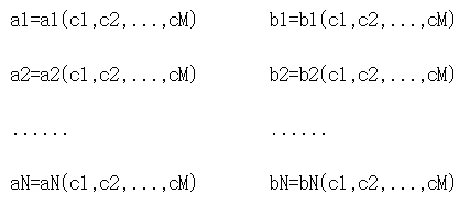
여기서, A={a1, a2, ... ,aN} 및 B={b1, b2, ... , bN}은 영상 내의 위치에 따라서 기준 윤곽의 폭(w)과 높이(h)를 결정하는 함수 f(x,y)와 g(x,y)의 파라미터들이다.Where A = {a1, a2, ..., aN} and B = {b1, b2, ..., bN} determine the width (w) and height (h) of the reference contour according to the position in the image. These are the parameters of the functions f (x, y) and g (x, y).
한편, 본 실시 예에 따른 윤곽 생성부(402)는 상기 파라미터들을 감시 카메라(100)가 설치된 상황에 맞추어 변경되는 상황 파라미터(C)의 함수로 표현한다. 즉, 파라미터 집합 A, B를 다시 M개의 독립 변수들로 이루어진 C={c1,c2,...,cM)으로 파라미터화 한다. 이는 다음과 같이 나타낼 수 있다.On the other hand, the
즉, M개의 상황 파라미터 C를 변화시킴으로써 파라미터 A, B를 변화시킬 수 있다.That is, the parameters A and B can be changed by changing the M situation parameters C.
상황 파라미터를 수학식 1에 반영하면 다음과 같이 표현할 수 있다.Reflecting the situation parameter in
![]()
![]()
![]()
![]()
여기서, 기준 윤곽의 크기에 영향을 미치는 요소에 따라서 상황 파라미터의 차원은 조절될 수 있다. 예를 들어, 감시 카메라(100)의 높이에만 기준 윤곽의 크기가 의존하는 경우, 상황 파라미터 C는 1차원 값(M=1)이 될 것이다. 따라서 파라미터 A, B는 각각 A={a1(c1),a2(c1),...,aN(c1)}, B={b1(c1),b2(c1),...,bN(c1)}와 같이 된다.Here, the dimension of the situation parameter may be adjusted according to the factors affecting the size of the reference contour. For example, if the size of the reference contour depends only on the height of the
한편, 본 실시 예에 따른 신호 처리부에서는 사용자의 편의를 위하여 상황 파라미터 C의 원소인 c1이 가질 수 있는 범위를 양자화(Qauntization)시킨다. 예를 들어, c1의 값을 1 내지 10의 값으로 양자화시킬 수 있다. 본 실시 예의 경우, c1이 높이에만 의존하는 파라미터이다. 따라서 감시 카메라(100)가 설치되는 높이의 범위를 설정하고, 설정된 범위 내에서 높이가 소정의 간격으로 변경되도록 상황 파라미터를 양자화시킨다. 이러한 양자화는 각 단계의 변경에 따라서 생성되는 기준 윤곽의 크기가 선형적으로 변하도록 수행할 수 있다. 즉, 사용자가 c1 값을 1에서 2로 변경할 때 발생하는 기준 윤곽의 크기 증가 비율이 c1값을 2에서 3 또는 3에서 4로 변경할 때 발생하는 기준 윤곽의 크기 증가 비율과 같도록 할 수 있다. 상황 파라미터를 양자화시키는 경우 양자화된 상황 파라미터의 값에 따라서 A,B의 파라미터 값을 미리 계산하여 저장해둘 수도 있을 것이다. c1을 1 부터 Q 까지의 정수로 양자화하면, 파라미터 A,B는 다음과 같이 될 것이다.On the other hand, the signal processor according to the present embodiment quantizes the range that c1 which is an element of the situation parameter C can have for the convenience of the user. For example, the value of c1 may be quantized to a value of 1 to 10. In the present embodiment, c1 is a parameter that depends only on height. Therefore, the range of the height at which the
A1={a11,a21,...,aN1}, A2={a12,a22,...,aN2},...,AQ{a1Q,a2Q,...,aNQ}A1 = {a11, a21, ..., aN1}, A2 = {a12, a22, ..., aN2}, ..., AQ {a1Q, a2Q, ..., aNQ}
B1={b11,b21,...,bN1}, B2={b12,b22,...,bN2},...,BQ{b1Q,b2Q,...,bNQ}B1 = {b11, b21, ..., bN1}, B2 = {b12, b22, ..., bN2}, ..., BQ {b1Q, b2Q, ..., bNQ}
(Aq는 c=q일 경우의 파라미터 A의 집합)(Aq is the set of parameter A when c = q)
(Bq는 b=q일 경우의 파라미터 B의 집합)(Bq is a set of parameter B when b = q)
여기서,here,
a11=a1(1), a21=a2(1), ..., aN1=aN(1)a11 = a1 (1), a21 = a2 (1), ..., aN1 = aN (1)
a12=a1(2), a22=a2(2), ..., aN2=aN(2),a12 = a1 (2), a22 = a2 (2), ..., aN2 = aN (2),
............
a1Q=a1(Q), a2Q=a2(Q), ..., aNQ=aN(Q)a1Q = a1 (Q), a2Q = a2 (Q), ..., aNQ = aN (Q)
이고,ego,
b11=b1(1), b21=b2(1), ..., bN1=bN(1)b11 = b1 (1), b21 = b2 (1), ..., bN1 = bN (1)
b12=b1(2), b22=b2(2), ..., bN2=bN(2),b12 = b1 (2), b22 = b2 (2), ..., bN2 = bN (2),
............
b1Q=b1(Q), b2Q=b2(Q), ..., bNQ=bN(Q)b1Q = b1 (Q), b2Q = b2 (Q), ..., bNQ = bN (Q)
이다.to be.
후술할 UI 생성부(404)에 의하여 생성되어 디스플레이되는 크기 조절 UI를 사용하여 사용자가 상황 파라미터의 특정 값을 선택하면, 선택한 상황 파라미터에 해당하는 파라미터 A,B의 값들을 사용하여 기준 윤곽의 폭(w) 및 높이(h)가 계산된다.When the user selects a specific value of the situation parameter by using the resizing UI generated and displayed by the
한편, 상황 파라미터 C는 1차원(M=1)으로 한정되는 것은 아니다. 예를 들어, 감시 카메라(100)의 높이 및 감시 카메라(100)가 영상을 촬영하는 각도에 기준 윤곽의 크기가 의존하는 경우, 상황 파라미터 C는 2차원 값(M=2)이 된다. 이 경우, 파라미터 A, B는 각각 A={a1(c1,c2),a2(c1,c2),...,aN(c1,c2)}, B={b1(c1,c2),b2(c1,c2),...,bN(c1,c2)}와 같이 된다. 상황 파라미터 C가 2차원(M=2)인 경우에도 각각의 상황 파라미터를 양자화시킬 수 있으며, 각각의 상황 파라미터 변화에 대하여 기준 윤곽의 크기가 선형적으로 변하도록 할 수 있을 것이다.On the other hand, the situation parameter C is not limited to one dimension (M = 1). For example, when the size of the reference contour depends on the height of the
UI 생성부(404)는 사용자가 양자화된 상황 파라미터의 값을 선택하여 기준 윤곽의 크기를 조절하기 위한 크기 조절 UI를 생성한다. 크기 조절 UI는 양자화된 적어도 하나의 상황 파라미터의 값을 사용자가 선택할 수 있도록 목록 상자(list box), 일정 간격의 눈금을 갖는 슬라이드 바(slide bar), 혹은 사용자가 직접 수치를 입력할 수 있는 편집 상자 등의 형태로 생성될 수 있다. 또한 크기 조절 UI는 상황 파리미터의 차원에 따라서 변경될 수 있을 것이다. 예를 들어, 상황 파라미터가 3차원의 값을 갖는 경우, 3가지 상황 파라미터의 값을 각각 선택할 수 있도록 크기 조절 UI를 생성할 수 있을 것이다.The
생성된 크기 조절 UI 및 기준 윤곽은 카메라 디스플레이부(150) 또는 서버 디스플레이부(350)에 촬영된 영상과 함께 표시한다. 이때, 기준 윤곽은 OSD(on screen display) 형태로 생성되어 영상과 겹쳐서 표시하며, 사용자가 영상 내에 포함되어 있는 물체, 예를 들어 사람과 비교하여 크기를 조절할 수 있도록 한다. 또한 기준 윤곽은 미리 설정된 개수만큼 디스플레이될 수 있다. 예를 들어, 영상 내에 기준 윤곽이 균등하게 분포하도록 기준 윤곽을 생성하여 디스플레이할 수 있다. 혹은 사람의 출현이 많은 부분들을 중심으로 하여 기준 윤곽이 배치되도록 기준 윤곽을 생성하여 디스플레이할 수 있다. 이때, 생성한 기준 윤곽의 개수와 디스플레이하는 기준 윤곽의 개수는 상이할 수 있다. 특정 조건을 만족하는 물체 검출하기 위하여는 영상 내의 모든 위치에 대하여 기준 윤곽을 생성하여야 하지만, 그 중 일부 기준 윤곽에 대하여만 디스플레이할 수 있기 때문이다.The generated resizing UI and the reference outline are displayed together with the captured image on the
종래에는 직사각형의 네 모서리에 해당하는 좌표값들을 하나의 세트로 하여 미리 정해진 세트의 좌표값 데이터를 수신하고, 수신한 데이터로부터 기준 윤곽을 생성하였다. 그러나 정확한 기준 윤곽을 생성하기 위하여는 입력되는 좌표값 데이터의 개수가 커야한다. 만약 입력되는 좌표값 데이터의 개수가 작은 경우에는 기준 윤곽의 크기가 부정확하게 되며, 이로 인하여 특정 조건을 만족하는 물체 판별의 정확도가 낮아지게 된다. 이는 입력되는 좌표값 데이터로부터 기준 윤곽의 폭(w)과 높이(h)를 결정하는 파라미터를 역으로 계산하게 되는데, 파라미터를 계산하는데 필요한 만큼의 좌표값 데이터를 수신하지 못하게 되기 때문이다.In the related art, coordinate data corresponding to four corners of a rectangle are set as one set to receive a predetermined set of coordinate value data, and a reference contour is generated from the received data. However, in order to generate an accurate reference contour, the number of input coordinate value data must be large. If the number of input coordinate value data is small, the size of the reference contour is inaccurate, and thus the accuracy of object discrimination that satisfies a specific condition is lowered. This calculates the parameter that determines the width (w) and height (h) of the reference contour from the input coordinate value data inversely, because it is impossible to receive as much coordinate value data as necessary to calculate the parameter.
그러나 상기와 같은 신호 처리부에 의하면 기준 윤곽을 정확하게 생성할 수 있을 뿐만 아니라, 상황 파라미터를 양자화시켜 사용자가 용이하게 기준 윤곽을 조절할 수 있게 된다. 즉, 움직이는 물체의 계수를 위한 알고리즘을 사용자가 간편하게 사용할 수 있게 된다.However, according to the signal processor as described above, not only can the reference contour be accurately generated, but the user can easily adjust the reference contour by quantizing the situation parameter. That is, a user can easily use an algorithm for counting moving objects.
이하, 크기 조절 UI 및 기준 윤곽을 디스플레이하는 방법에 대하여 도면을 참고하여 구체적으로 살펴보도록 한다.Hereinafter, a method of displaying the scaling UI and the reference outline will be described in detail with reference to the accompanying drawings.
도 5는 본 발명의 일 실시 예에 따른 영상 처리 장치의 디스플레이부를 나타내는 도면이다.5 is a diagram illustrating a display unit of an image processing apparatus according to an exemplary embodiment.
도 5를 참조하면, 카메라 디스플레이부(150) 또는 서버 디스플레이부(350)는 크기 조절 UI(500)와 촬영된 영상이 디스플레이한다. 이하, 카메라 디스플레이부(150)와 서버 디스플레이부(350)를 포괄하여 '디스플레이부'라 칭하도록 한다.Referring to FIG. 5, the
크기 조절 UI(500)는 1~10으로 양자화된 상황 파라미터를 선택할 수 있는 목록 박스 형태로 형성되어 있으며, 본 실시 예에서는 사용자가 상황 파라미터로 1을 선택하였다. 선택된 상황 파라미터에 해당하는 기준 윤곽(501)이 윤곽 생성부(402)에 의하여 생성되며, 생성된 기준 윤곽(501)은 영상에 겹쳐서 디스플레이부에 디스플레이된다. 기준 윤곽(501)은 영상 내에 미리 설정된 위치에서 생성되며, 사용자는 실시간으로 디스플레이되는 기준 윤곽(501)을 영상에 포함된 사람과 비교할 수 있다. 따라서 사용자는 현재 디스플레이되는 기준 윤곽(501)과 영상에 포함된 사람을 비교한 후, 선택한 상황 파라미터의 값을 적절히 조절하여 적절한 크기의 기준 윤곽을 생성할 수 있게 된다.The scaling
도 6은 본 발명의 다른 실시 예에 따른 영상 처리 장치의 디스플레이부를 나타내는 도면이다.6 is a diagram illustrating a display unit of an image processing apparatus according to another exemplary embodiment.
도 6을 참조하면, 사용자는 크기 조절 UI(500)를 조절하여 상황 파라미터를 1에서 5로 변경하였다. 본 실시 예에서, 상황 파라미터는 감시 카메라(100)의 높이에 의존하는 값이다. 감시 카메라(100)가 높은 위치에 설치된 경우 낮은 위치에 설치된 경우보다 촬영되는 영상은 줌 아웃한 효과가 발생하며, 결과적으로 사람의 크기도 작아진다. 따라서 사용자는 상황 파라미터를 조절하여 디스플레이되는 기준 윤곽(501)이 영상에 포함된 사람과 일치하도록 할 수 있다.Referring to FIG. 6, the user adjusted the
도 7은 본 발명의 다른 실시 예에 따른 영상 처리 장치의 디스플레이부를 나타내는 도면이다.7 is a diagram illustrating a display unit of an image processing apparatus according to another exemplary embodiment.
도 7을 참조하면, 영상에 디스플레이하는 기준 윤곽(501)의 개수가 25개로 도 5 및 도 6에서 디스플레이된 기준 윤곽(501)에 비하여 그 개수를 증가시켰다. 이와 같이, 디스플레이되는 기준 윤곽(501)의 개수를 조절할 수 있다. 도 5 내지 도 7에서는 기준 윤곽(501)의 개수를 9개 도는 25개로 설정하였으나 이에 한정되는 것은 아니며, 디스플레이하는 기준 윤곽(501)의 개수를 증가 또는 감소시킬 수 있을 것이다.Referring to FIG. 7, the number of
도 8은 본 발명의 다른 실시 예에 따른 영상 처리 장치의 디스플레이부를 나타내는 도면이다.8 is a diagram illustrating a display unit of an image processing apparatus according to another exemplary embodiment.
도 8을 참조하면, 상황 파라미터가 2차원인 경우로서, 2 개의 상황 파라미터를 사용자가 각각 선택할 수 있도록 UI 생성부(404)는 두 개의 크기 조절 UI(500, 502)를 생성하여 디스플레이할 수 있다. 예를 들어, 2 개의 상황 파라미터는 감시 카메라(100)가 설치된 높이 및 감시 카메라(100)가 영상을 촬영하는 각도일 수 있다. 사용자에 의하여 각도 및 높이에 대한 상황 파라미터의 양자화된 값이 선택되면, 촬영된 영상과 함께 미리 설정된 위치 또는 미리 설정된 개수의 기준 윤곽 (501)이 윤곽 생성부(402)에 의하여 생성되어 디스플레이된다.Referring to FIG. 8, when the situation parameter is two-dimensional, the
상기와 같이 본 발명의 실시 예들에 따른 영상 처리 장치에 의하면, 상황 파라미터를 사용하여 특정 조건을 만족시키는 물체의 검출을 위한 기준 윤곽을 생성하며, 상기 상황 파라미터를 양자화시킨 후 사용자가 UI를 통하여 용이하게 조절가능하게 하여 움직이는 물체를 계수하는 알고리즘을 사용자가 간편하게 사용할 수 있게 된다.As described above, according to the image processing apparatus according to the exemplary embodiment of the present invention, a reference contour for detecting an object that satisfies a specific condition is generated by using a situation parameter, and the user easily quantizes the situation parameter and then the user easily through the UI. This allows the user to easily use an algorithm that counts moving objects.
이상에서 언급된 본 실시 예 및 그 변형 예들에 따른 제어방법을 영상 처리 장치에서 실행시키기 위한 알고리즘 등의 프로그램은 기록매체에 저장될 수 있다. 여기서 기록매체는 반도체 기록매체(예를 들어, 플래시 메모리(Flash memory)) 등이 사용될 수 있다.Programs such as algorithms for executing the control method according to the present embodiment and its modifications mentioned above in the image processing apparatus may be stored in a recording medium. In this case, the recording medium may be a semiconductor recording medium (eg, a flash memory).
본 발명은 도면에 도시된 실시 예를 참고로 설명되었으나 이는 예시적인 것에 불과하며, 당해 기술 분야에서 통상의 지식을 가진 자라면 이로부터 다양한 변형 및 균등한 다른 실시 예가 가능하다는 점을 이해할 것이다. 따라서, 본 발명의 진정한 기술적 보호 범위는 첨부된 특허청구범위의 기술적 사상에 의하여 정해져야 할 것이다.While the present invention has been described with reference to exemplary embodiments thereof, it is to be understood that the invention is not limited to the disclosed exemplary embodiments, but, on the contrary, is intended to cover various modifications and equivalent arrangements included within the spirit and scope of the appended claims. Therefore, the true technical protection scope of the present invention will be defined by the technical spirit of the appended claims.
100 감시 카메라 200 네트워크
300 메인 서버 111 렌즈부
111 촬상소자 112 촬상소자 제어부
113 드라이버 114 모터
120 사전 처리부 121 영상 신호 처리부
122 압축 신장부 130 CPU
131 ROM 132 RAM
133 메모리 컨트롤러 134 카메라 메모리
140 카메라 조작부 150 카메라 디스플레이부
160 카메라 통신부 310 제어부
320 서버 조작부 330 서버 통신부
340 서버 메모리 350 서버 디스플레이부
400 움직임 검출부 401 물체 검출부
402 윤곽 생성부 403 계산부
404 UI 생성부100
300
111
113
131
133
140
160
320
340
400
402
404 UI generator
Claims (10)
상기 검출 결과로부터 물체를 검출하는 물체 검출부;
상기 영상 내의 위치에 따라서 미리 설정된 파라미터에 의하여 크기가 조절되는 적어도 하나의 기준 윤곽을 생성하는 윤곽 생성부; 및
상기 검출한 물체들 중 상기 기준 윤곽과 크기가 일치하는 물체의 수를 계산하는 계산부;를 포함하며,
상기 파라미터는 사용자의 설정에 의하여 가변하는 적어도 하나 이상의 상황 파라미터에 의하여 조절되는 것을 특징으로 하는 영상 처리 장치.A motion detector to detect motion from an image;
An object detector for detecting an object from the detection result;
An outline generator for generating at least one reference outline whose size is adjusted according to a preset parameter according to a position in the image; And
And a calculator configured to calculate the number of objects whose size matches the reference contour among the detected objects.
And the parameter is adjusted by at least one situation parameter that varies according to a user's setting.
상기 적어도 하나 이상의 상황 파라미터는 상기 영상을 촬영하는 장치가 설치된 높이, 상기 장치의 촬영 각도 중 적어도 어느 하나에 따라서 변하는 파라미터인 것을 특징으로 하는 영상 처리 장치.The method of claim 1,
And the at least one situation parameter is a parameter that varies according to at least one of a height at which the apparatus for photographing the image is installed and a photographing angle of the apparatus.
상기 상황 파라미터를 미리 설정된 개수로 양자화시키는 것을 특징으로 하는 영상 처리 장치.The method of claim 1,
And quantizing the situation parameter to a preset number.
상기 양자화된 파라미터를 사용자가 선택할 수 있는 크기 조절 UI(User Interface)를 생성하는 UI 생성부; 및
상기 영상 및 상기 크기 조절 UI를 디스플레이하는 디스플레이부를 더 포함하는 것을 특징으로 하는 영상 처리 장치.The method of claim 1,
A user interface (UI) generator for generating a user interface (UI) for controlling the user to select the quantized parameter; And
And a display configured to display the image and the size control UI.
상기 UI 생성부는 상기 상황 파라미터의 차원에 따라서 상기 생성하는 크기 조절 UI를 변경하는 것을 특징으로 하는 영상 처리 장치.The method of claim 4, wherein
And the UI generating unit changes the generated scaling UI according to the dimension of the situation parameter.
사용자에 의하여 선택된 상기 상황 파라미터에 따라서 상기 영상에 상기 기준 윤곽을 미리 설정된 개수만큼 디스플레이하는 것을 특징으로 하는 영상 처리 장치.The method of claim 4, wherein
And displaying a predetermined number of the reference contours on the image according to the situation parameter selected by the user.
촬영된 영상 및 상기 크기 조절 UI를 디스플레이하는 디스플레이부;를 포함하는 것을 특징으로 하는 영상 처리 장치.A UI generator configured to generate a scaling UI for selecting a value of at least one situation parameter for determining a size of at least one reference contour as a reference for object identification; And
And a display unit configured to display the captured image and the size adjustment UI.
상기 UI 생성부는 상기 상황 파라미터의 차원의 수만큼 사용자가 값을 선택할 수 있도록 상기 크기 조절 UI를 생성하는 것을 특징으로 하는 영상 처리 장치.The method of claim 7, wherein
And the UI generating unit generates the resizing UI so that a user can select a value by the number of dimensions of the situation parameter.
상기 디스플레이부는 미리 설정된 개수의 상기 기준 윤곽을 상기 디스플레이부에 디스플레이하는 것을 특징으로 하는 영상 처리 장치.The method of claim 8,
And the display unit displays a predetermined number of the reference contours on the display unit.
상기 상황 파라미터는 상기 기준 윤곽의 크기가 선형적으로 변하도록 양자화된 것을 특징으로 하는 영상 처리 장치.The method of claim 7, wherein
And the contextual parameter is quantized such that the size of the reference contour varies linearly.
Priority Applications (2)
| Application Number | Priority Date | Filing Date | Title |
|---|---|---|---|
| KR1020100075979A KR101630281B1 (en) | 2010-08-06 | 2010-08-06 | Image processing apparatus |
| US13/204,161 US8699750B2 (en) | 2010-08-06 | 2011-08-05 | Image processing apparatus |
Applications Claiming Priority (1)
| Application Number | Priority Date | Filing Date | Title |
|---|---|---|---|
| KR1020100075979A KR101630281B1 (en) | 2010-08-06 | 2010-08-06 | Image processing apparatus |
Publications (2)
| Publication Number | Publication Date |
|---|---|
| KR20120013767A true KR20120013767A (en) | 2012-02-15 |
| KR101630281B1 KR101630281B1 (en) | 2016-06-15 |
Family
ID=45556196
Family Applications (1)
| Application Number | Title | Priority Date | Filing Date |
|---|---|---|---|
| KR1020100075979A Active KR101630281B1 (en) | 2010-08-06 | 2010-08-06 | Image processing apparatus |
Country Status (2)
| Country | Link |
|---|---|
| US (1) | US8699750B2 (en) |
| KR (1) | KR101630281B1 (en) |
Cited By (1)
| Publication number | Priority date | Publication date | Assignee | Title |
|---|---|---|---|---|
| KR20180033874A (en) | 2016-09-26 | 2018-04-04 | 한화테크윈 주식회사 | Apparatus and method for processing image |
Families Citing this family (6)
| Publication number | Priority date | Publication date | Assignee | Title |
|---|---|---|---|---|
| US10425586B2 (en) * | 2013-03-14 | 2019-09-24 | Nokia Technologies Oy | Methods, apparatuses, and computer program products for improved picture taking |
| US10475221B2 (en) * | 2016-05-19 | 2019-11-12 | Canon Kabushiki Kaisha | Image processing device, image processing method and program for detected objects |
| CN106454233A (en) * | 2016-09-30 | 2017-02-22 | 北京中星微电子有限公司 | Intelligent crowd-gathering monitoring method and system |
| CN106412507A (en) * | 2016-09-30 | 2017-02-15 | 北京中星微电子有限公司 | Intelligent monitoring method and system of personnel flow |
| DE102020107016B4 (en) * | 2020-03-13 | 2024-06-20 | Mekra Lang Gmbh & Co. Kg | Method for verifying an indirect vision system and indirect vision system of a vehicle |
| US12014371B2 (en) * | 2020-06-05 | 2024-06-18 | Capital One Services, Llc | Systems and methods for fraud detection and prevention |
Citations (2)
| Publication number | Priority date | Publication date | Assignee | Title |
|---|---|---|---|---|
| US20090128549A1 (en) * | 2007-11-16 | 2009-05-21 | Sportvision, Inc. | Fading techniques for virtual viewpoint animations |
| US20090219381A1 (en) * | 2008-03-03 | 2009-09-03 | Disney Enterprises, Inc., A Delaware Corporation | System and/or method for processing three dimensional images |
Family Cites Families (13)
| Publication number | Priority date | Publication date | Assignee | Title |
|---|---|---|---|---|
| AUPQ717700A0 (en) * | 2000-04-28 | 2000-05-18 | Canon Kabushiki Kaisha | A method of annotating an image |
| KR100450579B1 (en) | 2001-11-07 | 2004-10-01 | 선인텔레콤(주) | The motion detection system and method with assigned subject recognition function |
| KR101282251B1 (en) | 2006-05-23 | 2013-07-10 | 삼성전자주식회사 | Display apparatus, image processing apparatus and control method thereof |
| EP1862969A1 (en) * | 2006-06-02 | 2007-12-05 | Eidgenössische Technische Hochschule Zürich | Method and system for generating a representation of a dynamically changing 3D scene |
| JP2008077430A (en) | 2006-09-21 | 2008-04-03 | Oki Electric Ind Co Ltd | Mobile body counting device and mobile body counting method |
| JP4263737B2 (en) * | 2006-11-09 | 2009-05-13 | トヨタ自動車株式会社 | Pedestrian detection device |
| CA2674310C (en) * | 2007-01-16 | 2016-05-24 | Thomson Licensing | System and method for reducing artifacts in images |
| US7991193B2 (en) * | 2007-07-30 | 2011-08-02 | International Business Machines Corporation | Automated learning for people counting systems |
| KR100883066B1 (en) * | 2007-08-29 | 2009-02-10 | 엘지전자 주식회사 | Apparatus and method for displaying a moving path of a subject using text |
| KR101467847B1 (en) * | 2008-01-16 | 2014-12-03 | 삼성전자주식회사 | Area Based Object Counting Device and Method |
| JP4963297B2 (en) | 2008-03-17 | 2012-06-27 | グローリー株式会社 | Person counting device and person counting method |
| US8345749B2 (en) * | 2009-08-31 | 2013-01-01 | IAD Gesellschaft für Informatik, Automatisierung und Datenverarbeitung mbH | Method and system for transcoding regions of interests in video surveillance |
| WO2012012555A1 (en) * | 2010-07-20 | 2012-01-26 | SET Corporation | Methods and systems for audience digital monitoring |
-
2010
- 2010-08-06 KR KR1020100075979A patent/KR101630281B1/en active Active
-
2011
- 2011-08-05 US US13/204,161 patent/US8699750B2/en active Active
Patent Citations (2)
| Publication number | Priority date | Publication date | Assignee | Title |
|---|---|---|---|---|
| US20090128549A1 (en) * | 2007-11-16 | 2009-05-21 | Sportvision, Inc. | Fading techniques for virtual viewpoint animations |
| US20090219381A1 (en) * | 2008-03-03 | 2009-09-03 | Disney Enterprises, Inc., A Delaware Corporation | System and/or method for processing three dimensional images |
Cited By (4)
| Publication number | Priority date | Publication date | Assignee | Title |
|---|---|---|---|---|
| KR20180033874A (en) | 2016-09-26 | 2018-04-04 | 한화테크윈 주식회사 | Apparatus and method for processing image |
| US10362308B2 (en) | 2016-09-26 | 2019-07-23 | Hanwha Techwin Co., Ltd. | Apparatus and method for processing image |
| US10574991B2 (en) | 2016-09-26 | 2020-02-25 | Hanwha Techwin Co., Ltd. | Apparatus and method for processing image |
| US11184614B2 (en) | 2016-09-26 | 2021-11-23 | Hanwha Techwin Co., Ltd. | Apparatus and method for processing image |
Also Published As
| Publication number | Publication date |
|---|---|
| KR101630281B1 (en) | 2016-06-15 |
| US8699750B2 (en) | 2014-04-15 |
| US20120033854A1 (en) | 2012-02-09 |
Similar Documents
| Publication | Publication Date | Title |
|---|---|---|
| KR101666397B1 (en) | Apparatus and method for capturing object image | |
| US8831282B2 (en) | Imaging device including a face detector | |
| KR101630281B1 (en) | Image processing apparatus | |
| KR101913837B1 (en) | Method for providing Panoramic image and imaging device thereof | |
| US10359498B2 (en) | Image pickup apparatus having function of generating simulation image,control method therefor, and storage medium | |
| KR20110102695A (en) | Digital imaging device, control method thereof, and computer readable storage medium | |
| US8295609B2 (en) | Image processing apparatus, image processing method and computer readable-medium | |
| US8798369B2 (en) | Apparatus and method for estimating the number of objects included in an image | |
| KR20150078275A (en) | Digital Photographing Apparatus And Method For Capturing a Moving Subject | |
| CN103888667B (en) | Image capturing apparatus and control method thereof | |
| CN105190229A (en) | Three-dimensional shape measurement device, three-dimensional shape measurement method, and three-dimensional shape measurement program | |
| JP6087617B2 (en) | Imaging apparatus and control method thereof | |
| US9189863B2 (en) | Method and system for detecting motion capable of removing shadow by heat | |
| JP2008301162A (en) | Imaging apparatus and imaging method | |
| KR20130060040A (en) | Method for providing user interface and image photographing apparatus thereof | |
| JP6450107B2 (en) | Image processing apparatus, image processing method, program, and storage medium | |
| US20210289119A1 (en) | Information processing apparatus, imaging apparatus, method, and storage medium | |
| KR101237975B1 (en) | Image processing apparatus | |
| JP5615012B2 (en) | White balance stable adjustment device and control method thereof, program for white balance stable adjustment | |
| JP2015132949A (en) | Image processing apparatus, image processing method, and program | |
| JP2024012828A (en) | Imaging device and its control method | |
| KR101272631B1 (en) | Apparatus for detecting a moving object and detecting method thereof | |
| KR101905813B1 (en) | Device for comparing image files | |
| JP7739903B2 (en) | Imaging device, imaging method, and program | |
| KR20120035421A (en) | Image processing apparatus and controlling method of the same |
Legal Events
| Date | Code | Title | Description |
|---|---|---|---|
| PA0109 | Patent application |
Patent event code: PA01091R01D Comment text: Patent Application Patent event date: 20100806 |
|
| PG1501 | Laying open of application | ||
| A201 | Request for examination | ||
| PA0201 | Request for examination |
Patent event code: PA02012R01D Patent event date: 20141203 Comment text: Request for Examination of Application Patent event code: PA02011R01I Patent event date: 20100806 Comment text: Patent Application |
|
| E902 | Notification of reason for refusal | ||
| PE0902 | Notice of grounds for rejection |
Comment text: Notification of reason for refusal Patent event date: 20151016 Patent event code: PE09021S01D |
|
| E701 | Decision to grant or registration of patent right | ||
| PE0701 | Decision of registration |
Patent event code: PE07011S01D Comment text: Decision to Grant Registration Patent event date: 20160421 |
|
| GRNT | Written decision to grant | ||
| PR0701 | Registration of establishment |
Comment text: Registration of Establishment Patent event date: 20160608 Patent event code: PR07011E01D |
|
| PR1002 | Payment of registration fee |
Payment date: 20160609 End annual number: 3 Start annual number: 1 |
|
| PG1601 | Publication of registration | ||
| FPAY | Annual fee payment |
Payment date: 20190527 Year of fee payment: 4 |
|
| PR1001 | Payment of annual fee |
Payment date: 20190527 Start annual number: 4 End annual number: 4 |
|
| PR1001 | Payment of annual fee |
Payment date: 20200525 Start annual number: 5 End annual number: 5 |
|
| PR1001 | Payment of annual fee |
Payment date: 20210526 Start annual number: 6 End annual number: 6 |
|
| PR1001 | Payment of annual fee |
Payment date: 20230523 Start annual number: 8 End annual number: 8 |
|
| PR1001 | Payment of annual fee |
Payment date: 20240523 Start annual number: 9 End annual number: 9 |