KR20120011846A - Reverse Displacement Asymmetric Rotary (IDAR) Engine - Google Patents
Reverse Displacement Asymmetric Rotary (IDAR) Engine Download PDFInfo
- Publication number
- KR20120011846A KR20120011846A KR1020117022853A KR20117022853A KR20120011846A KR 20120011846 A KR20120011846 A KR 20120011846A KR 1020117022853 A KR1020117022853 A KR 1020117022853A KR 20117022853 A KR20117022853 A KR 20117022853A KR 20120011846 A KR20120011846 A KR 20120011846A
- Authority
- KR
- South Korea
- Prior art keywords
- contour
- island
- engine
- port
- valve
- Prior art date
- Legal status (The legal status is an assumption and is not a legal conclusion. Google has not performed a legal analysis and makes no representation as to the accuracy of the status listed.)
- Abandoned
Links
- 238000006073 displacement reaction Methods 0.000 title claims abstract description 26
- 235000001008 Leptadenia hastata Nutrition 0.000 title 1
- 244000074209 Leptadenia hastata Species 0.000 title 1
- 238000002485 combustion reaction Methods 0.000 claims abstract description 51
- 238000000034 method Methods 0.000 claims description 32
- 238000007906 compression Methods 0.000 claims description 15
- 230000006835 compression Effects 0.000 claims description 15
- 239000000446 fuel Substances 0.000 claims description 13
- 210000002445 nipple Anatomy 0.000 claims description 7
- 229910001018 Cast iron Inorganic materials 0.000 claims description 2
- 230000008878 coupling Effects 0.000 claims 2
- 238000010168 coupling process Methods 0.000 claims 2
- 238000005859 coupling reaction Methods 0.000 claims 2
- 238000005516 engineering process Methods 0.000 description 18
- 238000013461 design Methods 0.000 description 11
- 238000004519 manufacturing process Methods 0.000 description 5
- 238000007789 sealing Methods 0.000 description 5
- 230000000694 effects Effects 0.000 description 4
- 230000008569 process Effects 0.000 description 4
- 230000008859 change Effects 0.000 description 3
- 230000007423 decrease Effects 0.000 description 3
- 238000003754 machining Methods 0.000 description 3
- 238000012546 transfer Methods 0.000 description 3
- 239000006227 byproduct Substances 0.000 description 2
- 239000000463 material Substances 0.000 description 2
- 230000007246 mechanism Effects 0.000 description 2
- 239000002184 metal Substances 0.000 description 2
- 229910052751 metal Inorganic materials 0.000 description 2
- 239000003380 propellant Substances 0.000 description 2
- 238000005086 pumping Methods 0.000 description 2
- 229920001817 Agar Polymers 0.000 description 1
- 208000034809 Product contamination Diseases 0.000 description 1
- 230000001133 acceleration Effects 0.000 description 1
- 239000008272 agar Substances 0.000 description 1
- 230000000712 assembly Effects 0.000 description 1
- 238000000429 assembly Methods 0.000 description 1
- 238000006243 chemical reaction Methods 0.000 description 1
- 239000004020 conductor Substances 0.000 description 1
- 230000003247 decreasing effect Effects 0.000 description 1
- 230000001419 dependent effect Effects 0.000 description 1
- 239000003344 environmental pollutant Substances 0.000 description 1
- 238000004880 explosion Methods 0.000 description 1
- 238000003780 insertion Methods 0.000 description 1
- 230000037431 insertion Effects 0.000 description 1
- 238000007620 mathematical function Methods 0.000 description 1
- 238000012986 modification Methods 0.000 description 1
- 230000004048 modification Effects 0.000 description 1
- 231100000719 pollutant Toxicity 0.000 description 1
- 210000000664 rectum Anatomy 0.000 description 1
- 239000003566 sealing material Substances 0.000 description 1
- 238000000926 separation method Methods 0.000 description 1
- 239000002915 spent fuel radioactive waste Substances 0.000 description 1
Images


Classifications
-
- F—MECHANICAL ENGINEERING; LIGHTING; HEATING; WEAPONS; BLASTING
- F02—COMBUSTION ENGINES; HOT-GAS OR COMBUSTION-PRODUCT ENGINE PLANTS
- F02B—INTERNAL-COMBUSTION PISTON ENGINES; COMBUSTION ENGINES IN GENERAL
- F02B53/00—Internal-combustion aspects of rotary-piston or oscillating-piston engines
- F02B53/02—Methods of operating
-
- F—MECHANICAL ENGINEERING; LIGHTING; HEATING; WEAPONS; BLASTING
- F01—MACHINES OR ENGINES IN GENERAL; ENGINE PLANTS IN GENERAL; STEAM ENGINES
- F01C—ROTARY-PISTON OR OSCILLATING-PISTON MACHINES OR ENGINES
- F01C1/00—Rotary-piston machines or engines
- F01C1/08—Rotary-piston machines or engines of intermeshing engagement type, i.e. with engagement of co- operating members similar to that of toothed gearing
- F01C1/10—Rotary-piston machines or engines of intermeshing engagement type, i.e. with engagement of co- operating members similar to that of toothed gearing of internal-axis type with the outer member having more teeth or tooth-equivalents, e.g. rollers, than the inner member
- F01C1/104—Rotary-piston machines or engines of intermeshing engagement type, i.e. with engagement of co- operating members similar to that of toothed gearing of internal-axis type with the outer member having more teeth or tooth-equivalents, e.g. rollers, than the inner member one member having simultaneously a rotational movement about its own axis and an orbital movement
-
- F—MECHANICAL ENGINEERING; LIGHTING; HEATING; WEAPONS; BLASTING
- F01—MACHINES OR ENGINES IN GENERAL; ENGINE PLANTS IN GENERAL; STEAM ENGINES
- F01C—ROTARY-PISTON OR OSCILLATING-PISTON MACHINES OR ENGINES
- F01C1/00—Rotary-piston machines or engines
- F01C1/30—Rotary-piston machines or engines having the characteristics covered by two or more groups F01C1/02, F01C1/08, F01C1/22, F01C1/24 or having the characteristics covered by one of these groups together with some other type of movement between co-operating members
- F01C1/40—Rotary-piston machines or engines having the characteristics covered by two or more groups F01C1/02, F01C1/08, F01C1/22, F01C1/24 or having the characteristics covered by one of these groups together with some other type of movement between co-operating members having the movement defined in group F01C1/08 or F01C1/22 and having a hinged member
- F01C1/46—Rotary-piston machines or engines having the characteristics covered by two or more groups F01C1/02, F01C1/08, F01C1/22, F01C1/24 or having the characteristics covered by one of these groups together with some other type of movement between co-operating members having the movement defined in group F01C1/08 or F01C1/22 and having a hinged member with vanes hinged to the outer member
-
- F—MECHANICAL ENGINEERING; LIGHTING; HEATING; WEAPONS; BLASTING
- F04—POSITIVE - DISPLACEMENT MACHINES FOR LIQUIDS; PUMPS FOR LIQUIDS OR ELASTIC FLUIDS
- F04C—ROTARY-PISTON, OR OSCILLATING-PISTON, POSITIVE-DISPLACEMENT MACHINES FOR LIQUIDS; ROTARY-PISTON, OR OSCILLATING-PISTON, POSITIVE-DISPLACEMENT PUMPS
- F04C2250/00—Geometry
- F04C2250/30—Geometry of the stator
- F04C2250/301—Geometry of the stator compression chamber profile defined by a mathematical expression or by parameters
Landscapes
- Engineering & Computer Science (AREA)
- Mechanical Engineering (AREA)
- General Engineering & Computer Science (AREA)
- Chemical & Material Sciences (AREA)
- Combustion & Propulsion (AREA)
- Cylinder Crankcases Of Internal Combustion Engines (AREA)
- Combustion Methods Of Internal-Combustion Engines (AREA)
- Output Control And Ontrol Of Special Type Engine (AREA)
- Shafts, Cranks, Connecting Bars, And Related Bearings (AREA)
Abstract
본 발명에 따르면, 챔버를 포함하는 역변위 비대칭 로터리 엔진이 제공된다. 상기 챔버는 아일랜드 외측 표면을 가진 고정식 아일랜드를 포함한다. 상기 외측 표면은 연신된 볼록한 형태를 가진다. 상기 아일랜드는 상기 아일랜드의 중심으로부터 거리가 떨어진 크랭크샤프트 포트를 포함한다. 상기 챔버는 아일랜드의 전방 표면에 결부된 전방 플레이트를 포함한다. 상기 챔버는 오목한 형태의 이동식 컨투어(contour)를 포함하는데, 상기 컨투어는 상기 아일랜드 주위로 회전하고 상기 아일랜드 외측 표면을 향해 편향된다. 상기 아일랜드 외측 표면과 상기 컨투어의 내측 표면 사이에 작동 공간이 형성된다. 상기 이동식 컨투어의 전방 표면으로부터 연장되며 상기 전방 플레이트의 가이드 에지 위로 연장되는 하나 이상의 전방 플레이트 결합 베어링이 제공된다. 상기 전방 플레이트 결합 베어링은 연소 사이클 동안 상기 가이드 에지와 결합한다.According to the present invention, there is provided a reverse displacement asymmetric rotary engine comprising a chamber. The chamber includes a stationary island having an island outer surface. The outer surface has an elongated convex shape. The island includes a crankshaft port away from the center of the island. The chamber includes a front plate attached to the front surface of the island. The chamber includes a concave movable contour, which contour rotates around the island and is deflected towards the island outer surface. An operating space is formed between the island outer surface and the inner surface of the contour. At least one front plate engaging bearing is provided that extends from the front surface of the movable contour and extends over the guide edge of the front plate. The front plate engaging bearing engages the guide edge during the combustion cycle.
Description
본 특허출원은 미국 가특허출원번호 61/211,192호를 우선권 주장하고 있으며, 상기 미국 가특허출원은 본 명세서에서 참조문헌으로서 인용된다.This patent application claims priority to US Provisional Patent Application No. 61 / 211,192, which is incorporated herein by reference.
본 발명은 챔버를 포함하는 역변위 비대칭 로터리 엔진에 관한 것이다.The present invention relates to a reverse displacement asymmetric rotary engine comprising a chamber.
발명의 명칭이 "Continuous Torque Inverse Displacement Asymmetric Rotary Engine"인 미국 특허번호 6,758,188호는 역변위 비대칭 로터리(IDAR) 엔진에 대해 기술하고 있는데, 상기 미국 특허는 본 명세서에서 참조문헌으로서 인용된다. 상기 엔진은 내부 챔버 벽, 외부 챔버 벽, 및 이동식 컨투어(contour)를 포함하는데, 이 컨투어는 하기에서 논의될 내용에 의해 정의된다.US Patent No. 6,758, 188, entitled “Continuous Torque Inverse Displacement Asymmetric Rotary Engine,” describes a reverse displacement asymmetric rotary (IDAR) engine, which is incorporated herein by reference. The engine includes an inner chamber wall, an outer chamber wall, and a movable contour, which contour is defined by the content to be discussed below.
연소 사이클(combustion cycle) 동안 외부 챔버 벽을 따르는 모든 지점에서 외부 챔버 벽의 힘 방향과 오목한 형태의 컨투어로부터 나온 힘의 방향 사이의 입사각(angle of incidence)이 0°보다는 크고 90°보다는 작은 각도가 되도록, 로터리 엔진 내에 챔버를 설계함으로써 전반적인 연소 사이클에 걸쳐 토크(torque)가 구현될 수 있다. 0° 내지 90° 사이의 입사각으로 결정되는 오목한 형태의 컨투어와 외부 챔버 벽 및 내부 챔버 벽의 형태는 미리 정해진 입사각에 대해 대수적으로(algebraically) 결정될 수 있다.At any point along the outer chamber wall during the combustion cycle, the angle of incidence between the direction of the force of the outer chamber wall and the direction of the force from the concave contour is greater than 0 ° and less than 90 °. If possible, torque can be implemented over the entire combustion cycle by designing the chamber in the rotary engine. The concave contour and the shape of the outer chamber wall and the inner chamber wall determined by the angle of incidence between 0 ° and 90 ° may be determined algebraically for a predetermined angle of incidence.
도 1에 예시되어 있는 것과 같이, S는 챔버 벽 표면을 가리키고 CS는 크랭크샤프트를 가리키며, 표면과 상호작용하고 있는(interacting) 힘 F(r)에 의해 생성된 미리 정해진 입사각(C)에 의해 생성된 토크 크기는 F(r) x 거리(D) x cos(C) x sin(C)와 같을 수 있다. 수학적으로 결정될 수 있는 것과 같이, 입사각(C)이 45°일 때 토크가 최대값이 된다. cos 45° x sin 45°는 0.5이다. 그 외의 다른 입사각, 가령, 약 20° 내지 약 70° 사이의 입사각도 적절한 크기의 토크를 생성시킬 수 있다.As illustrated in FIG. 1, S points to the chamber wall surface, CS points to the crankshaft, and is generated by a predetermined angle of incidence C generated by the force F (r) interacting with the surface. The torque magnitude may be equal to F (r) x distance (D) x cos (C) x sin (C). As can be determined mathematically, the torque is at its maximum when the incident angle C is 45 °. cos 45 ° x sin 45 ° is 0.5. Other angles of incidence, such as angles of incidence between about 20 ° and about 70 °, can also produce torque of appropriate magnitude.
도 2에 도시된 것과 같이, 지점(CS) 주위로 어떤 각도(D)로 회전할 때 반경(R)이 일정한 상태로 유지되는 경우, 반경(R)에 의해 형성된 호(arc)에 대한 접선(tangent)(C)이 지점(X 및 Z) 사이에서 일직선을 형성할 것이다. 상기 접선(C)은 호의 중심(각도(D/2))에서 반경에 대해 직각을 이룬다. 직선(X-Z)이 반경이 밀어내는 챔버의 표면을 나타내는 경우, 각도(D/2)에서, 상기 표면으로부터의 힘의 방향과 상기 반경으로부터의 힘의 반경 사이의 입사각은 0°일 것이다.As shown in FIG. 2, when the radius R remains constant when rotating at an angle D around the point CS, the tangent to the arc formed by the radius R ( tangent) (C) will form a straight line between points X and Z. The tangent line C is perpendicular to the radius at the center of the arc (angle D / 2). If the straight line X-Z represents the surface of the chamber that the radius pushes out, at angle D / 2, the angle of incidence between the direction of the force from the surface and the radius of the force from the radius will be 0 °.
이러한 관계식은 종래의 로터리 엔진 기술에서의 상태에 대해 설명하고 있는데, 연소 사이클의 시작 부분과 끝 부분에서의 입사각은 0°이다. 연소 사이클의 모든 단계 동안 토크를 구현하기 위하여, 입사각은 연소 사이클 동안 모든 지점에서 0° 내지 90° 사이일 수 있다.This relationship describes the state in conventional rotary engine technology, where the angle of incidence at the beginning and end of the combustion cycle is 0 °. To implement the torque during all stages of the combustion cycle, the angle of incidence can be between 0 ° and 90 ° at all points during the combustion cycle.
도 3은 고정 지점(CS) 주위로 어떤 각도(D)로 가변 반경(changing radius)을 회전시킴으로써 생성된 호에 대한 지점(Y 및 Z) 사이의 접선(C)을 도시하고 있다. 상기 접선(C)이 가변 반경이 밀어내는 표면일 경우, 표면으로부터의 힘의 방향과 반경으로부터의 힘의 방향 사이의 입사각은 각도(E)일 것이며, 이 각도(E)는 0° 내지 90° 사이의 특정 각도이다.3 shows a tangent C between points Y and Z for an arc created by rotating a changing radius at an angle D around a fixed point CS. If the tangent C is a surface pushed by a variable radius, the angle of incidence between the direction of the force from the surface and the direction of the force from the radius will be an angle E, which is between 0 ° and 90 °. There is a certain angle between.
도 3에서 주어진 임의의 지점에서의 가변 반경 길이는 R+dR과 같을 수 있는데, 여기서 R은 시작 반경 길이이고 dR은 0과 같거나 0보다 더 큰 가변 길이이다. 상기 R 및 dR이 각도(D)에 걸쳐 주어지면, 입사각(E)이 계산될 수 있다. 이와 반대로, 입사각(E)이 회전각(D)의 중간점(D/2)으로 주어지면, 길이(dR)가 결정될 수 있다.The variable radius length at any point given in FIG. 3 may be equal to R + dR, where R is the starting radius length and dR is the variable length equal to or greater than zero. Given R and dR over angle D, the incident angle E can be calculated. On the contrary, if the incident angle E is given as the midpoint D / 2 of the rotation angle D, the length dR can be determined.
곡선 반경이 회전 기준(rotational reference)의 고정 지점 주위로 회전할 때 상기 곡선의 반경이 곡선을 따라 모든 지점에서 표면과의 입사각을 0°보다는 크고 90°보다는 작은 각도로 만드는 곡선에 대한 수학적 방정식이 유도될 수 있다. 입사각은 상기 곡선을 따라 모든 지점에서 약 20° 내지 70° 사이일 수 있다. IDAR의 고정 내부 챔버 벽의 일부분과 이동식 컨투어의 프로파일(profile)일 수 있는 곡선을 유도하기 위해 수학방정식이 사용될 수 있다.When the radius of the curve rotates around a fixed point of rotational reference, the mathematical equation for the curve is that the radius of the curve makes the angle of incidence with the surface at any point along the curve greater than 0 ° and less than 90 °. Can be induced. The angle of incidence may be between about 20 ° and 70 ° at all points along the curve. Mathematical equations may be used to derive curves that may be part of the IDAR's fixed internal chamber walls and profiles of the mobile contours.
다시 도 3을 보면, 반경(R+dR)이 크랭크샤프트 주위로 회전할 때 입사각(E)을 유지하기 위해 반경(R)이 증가되어야 하는 크기(dR)를 계산하기 위하여 미리 정해진 입사각(E)이 사용될 수 있다. 45°의 입사각(E)에 대해, 도 3의 삼각형(XYZ)은 똑같은 길이의 레그(leg)(XY 및 XZ)를 가진다. 45°의 입사각(E)을 생성하기에 필요한 반경(R)에 대해 반경(dR)에서의 변동율(change)을 결정하기 위한 방정식은:Referring again to FIG. 3, the predetermined angle of incidence E is calculated to calculate the magnitude dR at which the radius R should be increased to maintain the angle of incidence E as the radius R + dR rotates around the crankshaft. This can be used. For an angle of incidence E of 45 °, the triangle XYZ in FIG. 3 has legs (XY and XZ) of equal length. The equation for determining the change in radius dR relative to the radius R needed to produce an angle of incidence E of 45 ° is:
dR x (cos(D/2)) = DR x sin(D/2)) + 2 x R x sin(D/2) (2)dR x (cos (D / 2)) = DR x sin (D / 2)) + 2 x R x sin (D / 2) (2)
dR x (cos(D/2) - sin(D/2)) = 2 x R x sin(D/2) (4)dR x (cos (D / 2)-sin (D / 2)) = 2 x R x sin (D / 2) (4)
dR/R = 2 x sin(D/2)/x (cos(D/2)-sin(D/2)) (6)
dR / R = 2 x sin (D / 2) / x (cos (D / 2) -sin (D / 2)) (6)
상기 방정식 (6)은 주어진 회전각(D), 가령, 예를 들어 1°에 대해, 반경(R)은 길이(dR)와 같은 특정 백분율만큼 변경되어야 하는 것을 나타내고 있다. R의 백분율은 변경되어야 하며, 특정 회전각(D)에 걸쳐 45°의 입사각(E)을 일정하게 유지하기 위해 dR/R은 일정하다. 예를 들어, 방정식 (6)을 이용하여, 회전각 1°에 걸쳐 생성되어야 하는 45°의 입사각(E)에 대해, 반경(R)은 약 1.76% 만큼 증가할 수 있다. R이 변화하는 백분율(dR)은 각각의 회전 각도에 대한 R의 초기 값에 무관하게 일정한 상태를 유지할 수 있다.Equation (6) indicates that for a given rotation angle D, for example 1 °, the radius R should be changed by a certain percentage such as the length dR. The percentage of R must be changed, and dR / R is constant to keep the angle of incidence E of 45 ° constant over a particular rotation angle D. For example, using equation (6), for an angle of incidence E of 45 ° that must be produced over 1 ° of rotation, the radius R can be increased by about 1.76%. The percentage dR at which R changes can remain constant regardless of the initial value of R for each rotation angle.
45° 이외의 각도에 대한 방정식은 방정식 (6)의 우측에 계수인자(scaling factor)(K)를 곱하여 생성될 수 있다. 상기 계수인자(K)는 입사각(E)이 45°로부터 변경될 때 레그 길이(XZ)에 비해 삼각형(XYZ)의 레그 길이(XY)에 있어서의 차이값으로서, 여기서 길이(XY 및 XZ)는 동일하다. 입사각(E)이 45°이 아닌 경우, 방정식은:Equations for angles other than 45 ° can be generated by multiplying the scaling factor K on the right side of equation (6). The coefficient factor K is a difference value in the leg length XY of the triangle XYZ compared to the leg length XZ when the incident angle E is changed from 45 °, where the lengths XY and XZ are same. If the angle of incidence (E) is not 45 °, the equation is:
dR/R = 2 x sin(D/2)/(K x cos(D/2) - sin(D/2)) (8)
dR / R = 2 x sin (D / 2) / (K x cos (D / 2)-sin (D / 2)) (8)
상기 계수인자(K)는 1/tan(E)과 동일하다. 각도(E)가 45°이면, 1/tan(45°)는 1이 되어 방정식 (6)이 된다. 각도(E)가 45°이 아니면, 계수인자(K)는 1이 아닌 특정 값을 가진다. 방정식 (8)은 미리 정해진 입사각(E)을 생성하기 위해 어떤 백분율(R)이 회전각(D)에 걸쳐 변화해야 하는지에 따라 사용될 수 있다.The counting factor K is equal to 1 / tan (E). If the angle E is 45 °, then 1 / tan (45 °) becomes 1, resulting in equation (6). If the angle E is not 45 °, the coefficient K has a specific value other than one. Equation (8) can be used depending on what percentage (R) should change over the rotation angle (D) to produce a predetermined angle of incidence (E).
일정한 입사각(E)을 이용하여 방정식 (6) 또는 (8)에 의해 생성된 곡선은 고정된 회전 지점으로부터 외부를 향해 급격하게 나선형으로 회전할 수 있다(rapidly spiral outward). 상대적으로 작은 반경 백분율로 덜 급격하게 나선형으로 회전하는 경우, 가변 입사각(E)이 사용될 수 있다. 예를 들어, 곡선의 시작 부분에서 입사각은 45°이거나 또는 45°보다 크고 90°보다 작을 수 있으며, R이 고정 지점 주위로 회전함에 따라 점차 감소할 수 있다. 예를 들어, 가변 입사각이 지속적으로 감소하는 입사각이면, 90° 내지 0° 사이 또는 70° 내지 20° 사이를 유지할 수 있다.Using a constant angle of incidence E, the curve produced by equations (6) or (8) can rapidly spiral outward from a fixed point of rotation. In the case of helical rotation less rapidly with a relatively small radius percentage, a variable angle of incidence E can be used. For example, the angle of incidence at the beginning of the curve may be 45 ° or greater than 45 ° and less than 90 ° and may gradually decrease as R rotates around the fixed point. For example, if the variable angle of incidence is a continuously decreasing angle of incidence, it may be maintained between 90 ° and 0 ° or between 70 ° and 20 °.
도 3에 대해 방정식 (2)를 보면, dR x sin(D/2) 항은 상기 방정식의 그 외의 다른 항들에 비해 매우 작은 값을 가지는 것을 볼 수 있다. dR x sin(D/2) 항이 2 x R x sin(D/2) 항으로부터 빼지거나 또는 그 대신 더해지면, 반경(R) 값은 여전히 증가할 것이나 보다 서서히 증가할 것이며, 입사각(E)은 점차 감소될 것이다. 45° 이외의 입사각에 대해, 2 x R x sin(D/2) 항으로부터 dR x sin(D/2) 항을 빼고 계수인자(K)를 곱하면 다음의 방정식을 얻을 수 있다:Looking at equation (2) for Figure 3, it can be seen that the dR x sin (D / 2) term has a very small value compared to the other terms of the equation. If the dR x sin (D / 2) term is subtracted from or instead added to the 2 x R x sin (D / 2) term, the radius (R) value will still increase but will increase more slowly, and the angle of incidence (E) Will be gradually reduced. For angles of incidence other than 45 °, subtracting the dR x sin (D / 2) term from the 2 x R x sin (D / 2) term and multiplying the coefficient factor (K) yields the following equation:
dR/R = 2 x R x sin(D/2)/(K x cos(D/2) - sin(D/2)) (10)
dR / R = 2 x R x sin (D / 2) / (K x cos (D / 2)-sin (D / 2)) (10)
45°의 시작 입사각(E)과 시작 반경 길이(R) 값이 2로, 상기 방정식 (10)을 사용하면, K 값은 1과 같을 수 있으며, 도 4에 도시된 것과 같은 곡선이 생성될 것이다.If the starting incidence angle (E) and starting radius length (R) value of 45 ° are 2, using equation (10), the K value may be equal to 1, and a curve as shown in FIG. 4 will be generated. .
도 4는 방정식 (10)에 의해 생성된 대표적인 곡선을 2개의 원 그래프와 함께 보여주고 있는데, 이 원들 중 하나는 반경이 1 단위와 같고 또 다른 하나는 반경이 2 단위와 같다. 계속, 도 4를 보면, 방정식 (10)에 따라 생성된 곡선 위에 있는 임의의 점에서, 원점(origin)으로부터 접선으로 그려진 선은 0° 회전각에서 45° 입사각을 가질 것이며, 상기 입사각은 90° 회전각에서 약 20°로 점차 감소할 것이다.4 shows a representative curve generated by equation (10) with two circle graphs, one of which has a radius equal to 1 unit and the other has a radius equal to 2 units. 4, at any point on the curve created according to equation (10), the line tangentially drawn from the origin will have a 45 ° angle of incidence at 0 ° rotation angle, which is 90 ° It will gradually decrease to about 20 ° from the angle of rotation.
도 4의 곡선의 컨투어를 가진 IDAR의 내부 챔버 벽이 생성될 수 있으며, 이에 따라 0° 회전각에서 오목한 형태의 컨투어를 가진 입사각이 45°에서 시작하여 90° 회전각에서 약 20°으로 점차 감소한다. IDAR의 외부 챔버 벽의 컨투어가 내부 챔버 벽의 컨투어의 함수일 수 있으며, 외부 챔버 벽의 힘과 오목한 형태의 컨투어로부터의 토크를 생성하는 힘의 성분 방향 사이에서의 입사각은 연소 사이클 동안 45 °로부터 약 20°로 변할 것이다.An internal chamber wall of IDAR with the contoured contour of FIG. 4 can be created, such that the angle of incidence with concave contours at 0 ° rotation angle starts at 45 ° and gradually decreases from 90 ° rotation angle to about 20 °. do. The contour of the outer chamber wall of the IDAR may be a function of the contour of the inner chamber wall, and the angle of incidence between the component direction of the force of the outer chamber wall and the force generating torque from the concave shaped contour is approximately from 45 ° during the combustion cycle. Will change to 20 °.
내부 챔버 벽 컨투어를 형성하기 위하여, 예를 들어 도 4에 도시된 곡선과 같이, 방정식 (10)에 의해 생성된 곡선이 반복되고 180° 회전하여 도 5에 도시된 것과 같이 똑같은 형태를 가진 2개의 교차 곡선(intersecting curve)을 형성할 수 있다. 도 5에서 생성된 형태는 IDAR의 오목한 형태의 컨투어가 IDAR의 챔버 내에서 회전할 수 있는 아일랜드와 IDAR의 내부 챔버 벽을 형성할 수 있다. 방정식 (10)에 의해 생성된 곡선의 원점(origin point)은 IDAR의 아일랜드 내부에 있는 크랭크샤프트 위치일 수 있다. 도 5에 도시된 것과 같이, 크랭크샤프트는 IDAR의 아일랜드 내부에서 중심이 벗어나 있을 수 있다(off-center). 도 6에 도시된 것과 같이, 내부 챔버 벽의 형태와 일치하는(mate) 오목한 형태의 컨투어가 생성될 수 있다.To form the inner chamber wall contour, for example, as shown in FIG. 4, the curve generated by equation (10) is repeated and rotated 180 ° so that two of the same shape as shown in FIG. Intersecting curves can be formed. The form created in FIG. 5 may form an inner chamber wall of the IDAR and an island where the concave shaped contour of the IDAR may rotate within the chamber of the IDAR. The origin point of the curve generated by equation (10) may be the crankshaft position inside the island of IDAR. As shown in FIG. 5, the crankshaft may be off-center inside the island of IDAR. As shown in FIG. 6, a contour of concave shape can be created that mate with the shape of the inner chamber wall.
도 6에 예시되어 있는 것과 같이, 오목한 형태의 컨투어(4)를 가진 챔버(2)가 내부 곡선(inner curve)(10)의 중심에 대해 오프셋 배열된 리테이너(retainer)(8)와 크랭크 피벗(crank pivot)(6)을 가질 수 있다. 리테이너(8)와 크랭크 피벗(6)의 위치는, 컨투어의 기하학적 중심(geometric center)과 비교하였을 때, 컨투어의 한 측면을 향해 오프셋 배열될 수 있다.As illustrated in FIG. 6, a
외부 챔버 벽(14)의 형태는 오목한 형태의 컨투어를 내부 챔버 벽 주위로 이동시킴으로써 생성될 수 있다. 외부 챔버 벽은 오목한 형태의 컨투어의 외부 곡선(outer curve) 또는 리테이너가 외부 챔버 벽을 따라 이동하는 동안 내부 챔버 벽에 대해 오목한 형태의 컨투어를 고정하도록 설계될 수 있다. 따라서, 도 6은, 챔버(2) 내에서, 컨투어 및/또는 내부 챔버 벽(16), 아일랜드(18), 크랭크샤프트(12), 외부 챔버 벽(14), 오목한 형태의 컨투어(4), 크랭크 피벗(6) 및 리테이너(8)의 위치는 방정식 (10)에 의해 생성된 곡선에 대해서 결정되는 것을 보여준다.The shape of the
도 6을 가시적으로 검사해 보면, 외부 챔버 벽(14)의 형태가 내부 챔버 벽(16)과 같은 수학적 함수로부터 유도될 수 있음을 이해할 수 있다. 외부 챔버 벽(14)은 내부 챔버 벽(16)의 일부분 이상과 같이 동일한 형태를 가질 수 있으나, 연소 사이클 동안, 크기는 상대적으로 더 크고 예를 들어, 90°와 같은 특정 각도만큼 회전되는 챔버(2) 일부분과 같은 형태를 가질 수 있다.Visually examining FIG. 6, it can be understood that the shape of the
위에서 기술된 IDAR 엔진 기술은 통상적인 내연기관 기술에 비해 많은 이점을 가진다. 이 이점들 중 IDAR 기하학적 형태가 제공하는 몇몇 이점은 상이한 크기를 가진 사이클 지속기간(cycle length)을 제공하는 것이다.The IDAR engine technology described above has many advantages over conventional internal combustion engine technology. Some of the advantages that the IDAR geometry provides are those that provide cycle lengths with different magnitudes.
예를 들어, 압축 사이클(compression cycle)은 팽창 (연소) 사이클보다 더 짧은 행정 거리에서 발생할 수 있다. 이에 따라, 동일 변위(displacement)의 피스톤 기술에 비해, 상대적으로 긴 팽창 사이클 동안 더 많은 일이 얻어질 수 있게 한다.For example, a compression cycle may occur at a shorter stroke distance than an expansion (combustion) cycle. This allows more work to be obtained during relatively long expansion cycles as compared to piston technology of equal displacement.
이와 유사하게, 배출 및 흡입 사이클은 반드시 똑같은 지속기간을 가질 필요가 없다. IDAR 엔진의 팽창 사이클은 일(work)로 전달되는 기계적 전달 함수(mechanical transfer function)를 가지는데, 이 기계적 전달 함수는 피스톤 기술의 벨 곡선 전달 함수(bell curve transfer function)에 비해 거의 연속적인 함수이다. 이는 rpm 범위에 걸쳐 아주 작게 변화하는 매우 평평한 토크 곡선으로 변경된다(translate). 이는, 사실, 팽창 사이클이 진행함에 따라 크랭크 암(crank arm)의 길이가 늘어나기(grow) 때문에 부분적으로 발생한다.Similarly, discharge and intake cycles do not necessarily have to have the same duration. The expansion cycle of the IDAR engine has a mechanical transfer function that is transferred to work, which is almost continuous compared to the bell curve transfer function of piston technology. . This translates to a very flat torque curve that changes very small over the rpm range. This actually happens in part because the length of the crank arm grows as the expansion cycle proceeds.
또한, 4개의 모든 엔진 사이클 즉 흡입, 압축, 연소 및 배출 사이클은 상이한 지속기간과 상이한 용적(volume)을 가질 수 있으며 똑같은 4-행정 순서에서 상이한 속도로 발생할 수 있다. 이는 IDAR 엔진 디자이너들이 엔진 성능을 최적화시킬 수 있게 하고 피스톤 엔진 기술보다 더 우수한 방식으로 부산물 오염을 감소시킬 수 있게 한다. In addition, all four engine cycles, that is, intake, compression, combustion and exhaust cycles, can have different durations and different volumes and can occur at different speeds in the same four-stroke sequence. This enables IDAR engine designers to optimize engine performance and reduce by-product contamination in a way that is superior to piston engine technology.
또한, 상기 4개의 모든 사이클은 샤프트가 완전히 1회 회전할 때 발생한다. IDAR 엔진 성능은 상기 엔진이 매우 높은 가속도를 가지지만 이와 동시에 유사한 변위의 긴 행정(long stroke) 디젤 엔진의 특성을 가진 토크가 발생된다는 점에서 2-사이클 엔진과 약간 비슷하다. IDAR 엔진의 기하학적 형태는, 피스톤 기술과 함께 수행된 것과 같이, 내경-행정비(bore-to-stroke ratio)에 따른 성능의 종속 범주에 형성되어서는 안 되는데, 이는 IDAR 기술이 이와 비슷하게 비교했을 때 상기 모든 범주에 걸쳐있기 때문이다.In addition, all four cycles occur when the shaft rotates one complete revolution. IDAR engine performance is slightly similar to two-cycle engines in that the engine has very high acceleration but at the same time generates torque with the characteristics of a long stroke diesel engine of similar displacement. The geometry of the IDAR engine, as performed with the piston technology, should not be formed in a subcategory of performance depending on the bore-to-stroke ratio, as the IDAR technology compares similarly. Because it spans all categories.
IDAR 엔진의 실질적인 제작에서, 복잡한 만곡부들과 평평한 표면들이 있다. 하지만, 밀봉부(seal)는 밀봉 재료의 길이 방향으로 배열되고 평평한 표면에 대해 항상 밀봉한다. 이는, 제작에서 핵심적인 수치가 엔진의 폭에 걸쳐 서로 맞은편에 있는 측면(side)들이 평행하도록 부분들을 나란하게 정렬하기 위한 기능과 상기 부분들의 표면의 평평도(flatness)이라는 것을 의미한다. 또한, 상기 부분들이 이동 경로 방향으로 비틀려지지 않으며, 서로 벗어나서 수직으로 시작하는 표면들이 연소 사이클 동안 서로에 대해 수직인 상태로 유지되는 것이 중요하다.In practical fabrication of the IDAR engine, there are complex curves and flat surfaces. However, the seals are arranged in the longitudinal direction of the sealing material and always seal against flat surfaces. This means that a key figure in the fabrication is the ability to align parts side by side so that the sides opposite each other over the width of the engine and the flatness of the surface of the parts. It is also important that the parts are not twisted in the direction of the travel path and that the surfaces starting off and perpendicular to each other remain perpendicular to each other during the combustion cycle.
사이클 지속기간, 용적 및 속도가 서로 상이할 수 있으며 피스톤 기술에서와 같이 대칭이 아니기 때문에, 흡입 및 배출 사이클 동안 포트(port)에서 흐름을 우수하게 조절하는 것이 중요하다. 이는 피스톤 엔진 성능보다 더 우수한 성능 표준이 충족될 수 있게 한다.Since the cycle duration, volume and speed can differ from one another and are not symmetrical as in piston technology, it is important to have good control of flow at the port during the intake and discharge cycles. This allows performance standards that are superior to piston engine performance to be met.
또한, IDAR 엔진이 고유의 팽창 행정(expansion stroke)을 가지기 때문에, 상기 엔진의 기하학적 형태는 오직 IDAR의 팽창 행정에 기초하여 기본적인 동력 장치(power plant) 설계를 수행할 수 있게 한다. IDAR 엔진이 외부 기기에 연결될 때, 상기 IDAR은 압축 공기(compressed air)와 같이 그 외의 다른 몇몇 추진제(propellant)에 의해 동력이 공급되는(powered) 동력 장치 또는 외연기관을 형성한다.In addition, since the IDAR engine has its own expansion stroke, the geometry of the engine allows to perform basic power plant design based only on the expansion stroke of the IDAR. When the IDAR engine is connected to an external device, the IDAR forms a power unit or external combustion engine powered by some other propellant, such as compressed air.
본 발명의 목적은 IDAR 기술을 조절하며, 성능을 개선하고, 쉽게 제작할 수 있으며 IDAR 기술을 더욱 확장하여 사용할 수 있게 하는 데 있다.An object of the present invention is to adjust IDAR technology, improve performance, make it easier to manufacture, and to extend the use of IDAR technology.
본 발명에 따르면, 챔버를 포함하는 역변위 비대칭 로터리 엔진(inverse displacement asymmetric rotary engine)이 제공된다. 상기 챔버는 아일랜드(island) 외측 표면을 가진 고정식 아일랜드를 포함한다. 상기 외측 표면은 연신된 볼록한 형태(elongated convex shape)를 가진다. 상기 아일랜드는 상기 아일랜드의 중심으로부터 거리가 떨어진 크랭크샤프트 포트(crankshaft port)를 포함한다. 상기 챔버는 상기 아일랜드의 전방 표면에 결부된(attached) 전방 플레이트(front plate)를 포함한다. 상기 챔버는 오목한 형태의 이동식 컨투어(contour)를 포함하는데, 상기 컨투어는 상기 아일랜드 주위로 회전하고 상기 아일랜드 외측 표면을 향해 편향된다(biased). 상기 아일랜드 외측 표면과 상기 컨투어의 내측 표면 사이에 작동 공간(working volume)이 형성된다. 상기 이동식 컨투어의 전방 표면으로부터 연장되며 상기 전방 플레이트의 가이드 에지(guide edge) 위로 연장되는 하나 이상의 전방 플레이트 결합 베어링이 제공된다. 상기 전방 플레이트 결합 베어링은 연소 사이클 동안 상기 가이드 에지와 결합한다.According to the invention there is provided an inverse displacement asymmetric rotary engine comprising a chamber. The chamber includes a stationary island with an island outer surface. The outer surface has an elongated convex shape. The island includes a crankshaft port away from the center of the island. The chamber includes a front plate attached to the front surface of the island. The chamber includes a concave movable contour, which contour rotates around the island and is biased toward the island outer surface. A working volume is formed between the island outer surface and the inner surface of the contour. At least one front plate engaging bearing is provided that extends from the front surface of the movable contour and extends above the guide edge of the front plate. The front plate engaging bearing engages the guide edge during the combustion cycle.
하기 도면들은 단지 본 발명의 대표적인 구체예들을 상세하게 도시하는 것이지 본 발명의 범위를 제한하려는 것으로 간주하여서는 안 된다는 것을 이해해야 할 것이다.
도 1은 로터의 힘과 벽의 힘 성분들이 직선상에 있을 때 로터의 힘 F(r)과 벽의 힘 F(s) 사이의 기하학적 관계를 도시한 도면이다.
도 2는 반경에 의해 생성된 곡선에 대한 반경의 기하학적 관계를 도시한 도면으로서, 상기 반경의 길이는 상기 반경이 피벗 지점 주위로 반시계 방향으로 점점 증가하는 일정 양만큼 회전할 때 균일한 상태를 유지한다.
도 3은 상기 반경이 피벗 지점 주위로 반시계 방향으로 점점 증가하는 양만큼 회전할 때 길이가 증가하는 반경에 의해 생성된 곡선에 대한 기하학적 관계를 도시한 도면이다.
도 4는 상기 반경이 피벗 지점 주위로 반시계 방향으로 회전할 때 길이가 일정하게 증가하는 반경에 의해 생성된 곡선 그래프이다.
도 5는 아일랜드(island)의 내부 챔버 벽과 상기 아일랜드의 크랭크샤프트의 위치의 구체예의 한 형태를 도시하는 도면으로서, 상기 형태는 도 2의 곡선과 관련이 있다.
도 6은 오목 형태의 컨투어, 크랭크 피벗, 리테이너, 크랭크샤프트 및 외부 챔버 벽을 가진 도 3의 아일랜드를 포함하는 로터리 엔진을 도식적으로 도시한 다이어그램이다.
도 7은 정렬 포스트(alignment post)들을 가진 다수의 부분들을 보여주는 엔진 챔버를 분해하여 도시한 도면이다.
도 8은 후방 플레이트 위에 있는 아일랜드를 도시한 투시도이다.
도 9는 롤러 베어링이 배열된 것을 보여주는 컨투어를 도시한 측면도이다.
도 10은 컨투어가 수축 위치에 있는 엔진 챔버를 도시한 측면도이다.
도 11은 컨투어가 팽창 위치에 있는 엔진 챔버를 도시한 측면도이다.
도 12는 컨투어가 배출 위치에 있는 엔진 챔버를 도시한 측면도이다.
도 13은 컨투어가 흡입 위치에 있는 엔진 챔버를 도시한 측면도이다.
도 14는 배럴 밸브 디자인을 도시한 투시도이다.
도 15는 로터리 밸브 디자인을 도시한 투시도이다.
도 16은 내부에 장착된 스파크플러그를 가진 컨투어를 도시한 측면도이다.
도 17은 스파크플러그와 함께 장착될 수 있는 컨투어를 도시한 투시도이다.
도 18은 페탈 밸브(petal valve) 디자인을 도시한 분해도이다.
도 19는 2개의 카운터 엔진 조립체를 도시한 분해도이다.
도 20은 대안의 후방 플레이트를 도시한 정면 입면도이다.
도 21은 정면 플레이트와 대안의 컨투어를 도시한 투시도이다.It is to be understood that the following drawings are merely illustrative of exemplary embodiments of the invention and are not to be considered as limiting the scope of the invention.
FIG. 1 shows the geometric relationship between the force F (r) of the rotor and the force F (s) of the wall when the force components of the rotor and the force components of the wall are in a straight line.
FIG. 2 shows the geometric relationship of a radius to a curve created by a radius, the length of the radius being uniform when the radius rotates by an increasing amount counterclockwise around the pivot point. Keep it.
FIG. 3 shows the geometric relationship to the curve created by the radius of increasing length as the radius rotates by an increasing amount counterclockwise around the pivot point.
4 is a curve graph created by a radius that increases in length constantly as the radius rotates counterclockwise around the pivot point.
FIG. 5 shows a form of an embodiment of the interior chamber wall of an island and the position of the crankshaft of the island, which shape relates to the curve of FIG. 2.
FIG. 6 is a diagrammatic representation of a rotary engine including the island of FIG. 3 with concave contours, crank pivots, retainers, crankshafts and outer chamber walls. FIG.
FIG. 7 is an exploded view of the engine chamber showing a number of parts with alignment posts. FIG.
8 is a perspective view of an island on the back plate.
9 is a side view showing a contour showing that the roller bearings are arranged.
10 is a side view showing the engine chamber in which the contour is in the retracted position.
11 is a side view showing the engine chamber in which the contour is in the expanded position.
12 is a side view of the engine chamber with the contour in the discharge position.
Figure 13 is a side view of the engine chamber with the contour in the intake position.
14 is a perspective view of a barrel valve design.
15 is a perspective view of a rotary valve design.
16 is a side view showing a contour with a spark plug mounted therein.
17 is a perspective view illustrating a contour that can be mounted with a spark plug.
FIG. 18 is an exploded view showing a petal valve design. FIG.
19 is an exploded view showing two counter engine assemblies.
20 is a front elevational view showing an alternative back plate.
21 is a perspective view showing the front plate and an alternative contour.
본 발명의 배경기술에서 기술한 것과 같이, IDAR 엔진(Inverse Displacement Asymmetric Rotary engine; 역변위 비대칭 로터리 엔진) 구조는 복잡한 만곡부(curve)들과 평평한 표면들을 포함한다. 밀봉 표면(sealing surface)들은 평평하고 밀봉부 길이 방향으로 배열된다. 이 IDAR 엔진은 복수의 평평한 표면 부분들이 서로 나란하게 정렬되어 전체 엔진을 형성하도록 배열된다. 이는 정면 또는 후면 중 한 표면이 평평하지 않은 경우, 전체적으로 오류(error)가 전파할(propagate) 수 있음을 의미한다. 오류가 발생하는 경우, 한 표면에 대해서 표면들을 적절하게 밀봉하는 문제점이 증가한다. 또한, 한 부분이 길면 길수록, 엔진 전체 폭에 걸쳐 전체 표면을 평평하게 하는 것이 더 더욱 어렵다.As described in the background of the present invention, the IDAR engine (Inverse Displacement Asymmetric Rotary engine) structure includes complex curves and flat surfaces. Sealing surfaces are flat and arranged in the seal longitudinal direction. This IDAR engine is arranged such that the plurality of flat surface portions are aligned side by side to each other to form the entire engine. This means that if one of the front or back surfaces is not flat, an error can propagate as a whole. If an error occurs, the problem of properly sealing the surfaces against one surface is increased. Also, the longer the portion, the more difficult it is to flatten the entire surface over the entire engine width.
상대적 평평도(relative flatness) 높이(level)를 증가시키고 모든 표면들에 걸쳐 전체 오류를 감소시키기 위하여, 각 부분의 전면과 후면 표면을 연삭하는(grind) 것이 가장 좋다. 표면 연삭(surface grinding)은 적절하게 정밀한 연삭 기계장치가 사용되면 표면에 걸쳐 1/10,000 인치 미만까지 표면 평평도 변화를 줄일 수 있다. 이는 상대적으로 넓은 영역에 정밀도를 제공한다. 따라서, 실제 엔진 챔버를 1개 대신 2개 또는 그 이상의 부분으로 형성하는 것이 가장 좋다.In order to increase the relative flatness level and reduce the overall error across all surfaces, it is best to grind the front and back surfaces of each part. Surface grinding can reduce surface flatness variations to less than 1 / 10,000 inches across the surface if a properly precise grinding mechanism is used. This provides precision over a relatively wide area. Therefore, it is best to form the actual engine chamber in two or more parts instead of one.
일반적으로, 챔버는 챔버의 후면을 형성하는 추가적인 크기와 대략 컨투어(contour)의 두께의 금속으로 만든 원형 부분이다. 그리고, 챔버는 통상 중공 구조이며(hollowed out) 컴퓨터-제어 방식의 기계장치가 공동(cavity) 내로 도달한다. 챔버가 일체형으로 제작되는 경우, 챔버는 림(rim)을 가질 것이다. 이 림은 정밀한 평평도를 위해 챔버의 후방 공동(back cavity)을 연삭하도록 연삭 휠(grinding wheel)을 사용하게 하지 않을 것이다.In general, the chamber is a circular portion made of metal of additional size and approximately contour thickness that forms the back side of the chamber. The chamber is then usually hollowed out and a computer-controlled mechanism arrives into the cavity. If the chamber is built in one piece, the chamber will have a rim. This rim will not allow the use of a grinding wheel to grind the back cavity of the chamber for precise flatness.
챔버가 다수 부분들로 구성되면, 상기 림은 일체형일 수 있으며 챔버의 후방 공동은 또 다른 부분일 수 있다. 후방 플레이트(back plate)가 개별적으로 정밀하게 연삭될 수 있고 정렬 포스트(alignment post) 또는 나사(screw)로 상기 림에 결부되어 전체 챔버를 형성한다.If the chamber consists of multiple parts, the rim may be integral and the rear cavity of the chamber may be another part. The back plate can be ground individually precisely and attached to the rim with an alignment post or screw to form the entire chamber.
밀봉 평평 표면들의 또 다른 형태는 임의의 3차원 공동 내에서 2개의 밀봉 표면들이 직각으로 만나는 것이다. 이는 코너 부분들을 밀봉하고 평평한 표면(parallel surface)들이 서로에 대해 평평할 뿐 아니라 수직 표면(perpendicular surface)들이 정확히 직각일 것을 요구하는 것을 의미한다. 여기서, 각각의 부분의 표면 연삭도 도움이 된다.Another form of sealing flat surfaces is that two sealing surfaces meet at right angles in any three-dimensional cavity. This means that the corner parts are sealed and the flat surfaces are not only flat to each other but also the perpendicular surfaces are exactly right angles. Here, the surface grinding of each part also helps.
IDAR 엔진의 목표는 다른 평평 표면들과 나란하게 정렬되는 평평 표면들이 엔진 작동 중에도 나란한 정렬상태를 유지하게 하는 것이다. 이는 어떠한 부분도 전체 사이클 동안 움직임(movement)이 비틀려져서는 안 된다는 것을 의미한다. 이 이동식 컨투어(movable contour)는 밀봉 표면들을 가지며 챔버 내에서 이동하는 부분들이다The goal of the IDAR engine is to ensure that the flat surfaces aligned side by side with the other flat surfaces remain aligned even during engine operation. This means that no part should be distorted during the entire cycle. This movable contour is parts that have sealing surfaces and move within the chamber
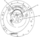
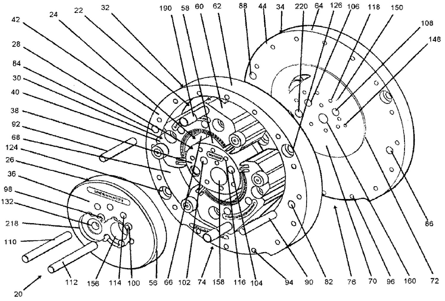
도 7-13은 개시된 구체예에 따른 IDAR(20)을 예시하고 있다. IDAR은 연소 챔버(22)와 작동 공간(working volume)(24) 즉 연료가 유입되고, 압축되고 연소되며 배출되는 공간을 가진다.7-13 illustrate an IDAR 20 in accordance with the disclosed embodiments. The IDAR has a
더 구체적으로는, IDAR(20)은 전방 플레이트(26), 아일랜드(island)(28), 컨투어(30), 림(32) 및 후방 플레이트(34)를 포함한다. 상기 IDAR 구성요소들은 각각 맞은편에 있는 전면(36-44) 및 후면(도시되어 있지 않음)을 가지며, 이에 따라 IDAR(20)에서 전방 플레이트의 후면은 아일랜드 전면(38)과 컨투어 전면(40)에 대해(against) 위치되고 후방 플레이트 전면(44)은 아일랜드 후면, 컨투어 후면 및 림 후면에 대해 위치된다More specifically,
전방 플레이트(26), 아일랜드(28), 컨투어(30), 림(32) 및 후방 플레이트(34)는 각각 외측 표면(56-64)을 가지며, 컨투어(30) 및 림(32)은 내측 표면(66, 68)을 가지며, 후방 플레이트(34)는 외측 에지(72)를 가진 제 2 후방 플레이트(70)를 포함한다. 상기 IDAR 구성요소들에 따라, IDAR 연소 챔버(22)는 림 내측 표면(68)과 아일랜드 외측 표면(58)에 의해 형성되고, 작동 공간은 컨투어 내측 표면(66)과 아일랜드 외측 표면(58)에 의해 형성된다.The
제 2 후방 플레이트 외측 에지(72)는 제 2 플레이트 내로 드릴링되어(drilled) 있는 포트(port)들 뿐 아니라 후방 플레이트의 후면 내로 드릴링된 흡입 및 배출 포트들을 덮기에(cover) 충분히 크다. 제2 후방 플레이트의 형태는 원형일 수 있다. 상기 제 2 후방 플레이트는, 전방 플레이트(26)와 후방 플레이트의 나머지 부분(remainder)과 함께, 작동 공간(24)을 둘러싸고 있지만(encapsulate) 연소 챔버(22)를 둘러싸고 있지는 않은데, 이는 밑에서 더 상세하게 논의될 것이다.The second rear plate
밑에서 더욱 상세하게 기술하고 있는 것과 같이, 아일랜드 외측 표면(58)은 본 발명의 배경기술에 기술된 방정식에 따른 형태를 가진다. 그 외의 다른 모든 외측 에지와 내측 에지들은, 림 외측 에지(62)와 후방 플레이트 외측 에지(64)를 제외하고는, 아일랜드 형태에 따른다.As described in more detail below, island
림 외측 에지(62)와 후방 플레이트 외측 에지(64)는 연소 챔버의 형태와 무관하다. 게다가, 작동 공간 내에 연료가 함유되어 있기 때문에, 림의 두께는 실질적으로 작동 공간의 형태와 무관하다. 이는, 컨투어 후면이 후방 플레이트(34) 상에서 림 후면과 실질적으로 평평하지만(flush), 컨투어 전면(38)은 작동 공간을 형성하기에 필요한 거리만큼 림 전면(42)을 지나 연장할 수 있음을 의미한다. 이에 따라, 림과 후방 플레이트는 모두 동일한 재료(stock)로 제작될 수 있으며, 예시되어 있는 것과 같이, 동일한 외측 에지 형태와 두께를 가질 수 있다.Rim
림 외측 에지(62)와 후방 플레이트 외측 에지(64)는 각각 IDAR 제작 동안 그리고 IDAR을 자동차 내에 장착할 때 IDAR을 제자리에(in place) 고정하는 것을 보조하기에 적합한 바닥 컨투어(bottom contour)(74, 76)를 포함한다. 상기 바닥 컨투어(74, 76)는 일반적으로 림과 후방 플레이트의 외측 반경에 대해 오프셋 배열(offset)된 반경을 가지고 예를 들어 둥글거나 또는 완만하게(eased) 서로 맞은편에 있는 내부 에지(78, 80)들을 가지는 것으로 기술될 수 있다.Rim
림(32)과 후방 플레이트(34)는 플레이트의 두께 방향으로 연장되는 서로 일치하는(matching) 정렬 홀(82-88)들을 가지는데, 이 정렬 홀들은 정렬 핀(90, 92)들을 수용하도록 구성된다. 상기 정렬 홀(82-88)들은 림 외측 에지(62)와 후방 플레이트 외측 에지(64)로부터 거리가 떨어져 있고 서로 약 180° 오프셋 배열된다.
정렬 핀(90, 92)들이 제자리에 있으면, 고정 볼트 또는 이와 유사한 것이 예를 들어 일련의 고정 홀(94, 96)을 통과하는데, 이 고정 홀들은 림(32)과 후방 플레이트(34)의 외측 직경 주위로 외주 방향으로(circumferentially) 거리가 떨어져 있고 플레이트의 두께 방향으로 연장한다. 도면에서, 각각의 플레이트 상에는 12개보다 많은 이러한 고정 홀들이 있다.If the alignment pins 90, 92 are in place, fastening bolts or the like pass through a series of fastening holes 94, 96, for example, which are outside the
전방 플레이트(26), 아일랜드(28) 및 후방 플레이트(34)의 두께를 통해 한 세트의 정렬 홀(98-109)들이 제공된다. A set of alignment holes 98-109 is provided through the thickness of the
전방 플레이트(26), 아일랜드(28) 및 후방 플레이트(34)가 서로 대향하도록(against) 하기 위해 제 2 정렬 핀(110, 112) 쌍이 상기 홀(98-108)을 통과하여 이동한다(run). 이 배열 동안, 컨투어(30)는 아일랜드(28)에 대향하도록(against) 위치되는데, 이는 본 명세서를 읽음으로써 이해될 것이다.The second pair of alignment pins 110, 112 run through the holes 98-108 so that the
각각의 전방 플레이트(26), 아일랜드(38) 및 후방 플레이트(34)는 두께 방향으로 연장되는 예를 들어 일치하는 고정 홀(114-118)들을 가진다. 도면에서, 이들 각각은 8개의 이러한 고정 홀들을 가진다. 이러한 홀들을 사용하여, 전방 플레이트(26), 아일랜드(38) 및 후방 플레이트(34)는 정렬 핀(110-112)들이 제공되고 난 뒤 서로 고정된다.Each
컨투어(30), 림(32), 및 후방 플레이트(34)는 각각 각각의 전면 내에 접시머리 가공된(countersunk) 복수의 홀(120-130)들을 가져서, 제작 공정에 도움이 된다. 예를 들어, 이 홀들은 플레이트들과 컨투어가 CNC 가공 테이블 위에 단단히 고정될 수 있게 한다. 전방 플레이트(26)와 아일랜드(28)는 같은 목적을 위해 각각 각각의 전면에 접시머리 가공된 하나 이상의 홀(132, 134)을 가진다.
림(32)과 후방 플레이트(34) 위에 있는 접시머리 가공 홀들은 외주 방향으로 거리가 떨어져 있으며 외측 에지(62, 64)들에 인접하게 배열된다. 컨투어(30) 내에 있는 접시머리 가공 홀들은 적절한 거리를 제공하기 위해 도시된 것과 같이 서로 거리가 떨어져 있어서, 기계가공 측면에서 적절하게 도움을 준다. 아일랜드(28)와 전방 플레이트(26) 위에 있는 접시머리 가공 홀들은 밸브 채널(valve channel)로서 사용하는 또 다른 기능을 제공하도록 배치되는데, 이는 밑에서 설명될 것이다.The countersunk holes on the
후방 플레이트(34)는 연료 흡입 포트(136)와 배출 포트(138)를 포함한다. 상기 포트(136, 138)들은 후방 플레이트 후면(44) 내에서 원형의 개구(opening)(140, 142)들에 의해 형성된다. 이 포트들의 특정 위치들은 밑에서 연소 사이클(combustion cycle)의 흡입 상(intak phase)과 배출 상(exhaust phase)을 논의하고 있는 내용으로부터 자명해질 것이다. 원형의 배출 개구(142)는 원형의 흡입 개구(140)보다 큰 직경을 가져서 팽창된 가연성 물질(expanded combustibles)들이 배출될 수 있게 한다. 원형의 흡입 개구와 배출 개구는 비슷하게 위치된 피스톤 타입의 연소 엔진(similarly situated piston type combustion engine) 내에 제공된 것과 같이 동일한 개구 영역을 가진다.The
상기 원형의 개구(140, 142)들은 각각의 아치 형태의 만곡부(arcuate curvature)(144, 146)을 통해 후방 플레이트 전면(44)으로 변환된다(transition). 상기 아치 형태의 만곡부의 목적은 각각의 개구(136, 138)로부터의 흡입 흐름 속도와 배출 흐름 속도를 최대화하는 것이다.The
복잡한 아치 형태의 성질로 인해, 밑에서 논의될 것과 같이, 아치 형태의 만곡부들은 후방 플레이트(34)보다 제 2 후방 플레이트(70) 내로 밀링가공된다(milled). 상기 제 2 후방 플레이트는 후방 플레이트 전면(44)에 용접된다. 이해할 수 있듯이, 제 2 후방 플레이트(70)는 구조적인 최소 요건으로 인해 재료의 핵심 부분(think pice of material)일 수 있다.Due to the complex arch-shaped nature, as will be discussed below, the arch-shaped bends are milled into the
또한, 후방 플레이트(34)는 압축이 발생하는 영역 내에 위치된 스파크플러그 포트(sparkplug port)(148)를 포함한다. 또한, 압축이 발생하는 영역 내에 센서 포트(150)가 위치된다.The
다시, 도 7과 도 8에 도시되어 있는 아일랜드(28)를 보면, 외부 컨투어(outer contour)가 비원형이며 연신되고(elongate) 오목한 형태의 컨투어로서 기술될 수 있을 것이다. 상기 컨투어는 앞에서 본 발명의 배경기술 부분에서 기술된 방법과 방정식을 이용하여 생성되었다. 일단, 미국, 메사추세츠주, 01742의 Concord, 300 Baker Avenue에 소재한 Dassault Systemes SolidWorks Corp.으로부터 구매가능한 가령, SolidWorks와 같은 프로그램 내에서 생성되고 나면, 컨투어 형태는 주어진 상황에 맞춰지도록 용이하게 스케일링 될 수 있다(scaled).Again, looking at
대안으로, 오프셋 크랭크샤프트 위치(offset crankshaft location)를 가진, 타원(ellipse)과 같은 타원체(oval)가 유사한 구조를 제공하여 비슷한 효과를 거둘 수 있을 것이다. 상기 타원도 SolidWorks 내에서 생성될 수 있으며, 필요 시마다 스케일링 될 수 있다. 타원은 장축(major axis)과 단축(minor axis)을 가지며, 상기 기술된 구체예들에서는, 장축은 단축보다 25% 이상 더 길다. 상기 변수의 더 큰 양은 압축에 대해 팽창의 더 큰 양을 제공한다는 사실을 이해하면, 타원의 semilatus rectum(장축 상에서 국부 에지(local edge)와 초점(focal point) 사이의 거리)는 최적화될 수 있다. 이 또한 설계 요인들에 따라 SolidWorks를 사용하여 최적화될 수 있다.Alternatively, an oval, such as an ellipse, with an offset crankshaft location may provide a similar structure to achieve a similar effect. The ellipse can also be created in SolidWorks and scaled as needed. The ellipse has a major axis and a minor axis, and in the embodiments described above, the major axis is at least 25% longer than the minor axis. Understanding that a larger amount of this variable provides a greater amount of expansion for compression, the semilatus rectum of the ellipse (the distance between the local edge and the focal point on the long axis) can be optimized. . This can also be optimized using SolidWorks based on design factors.
게다가, 전방 플레이트(26), 아일랜드(28) 및 후방 플레이트(34)는 각각 크랭크샤프트 개구(156-160)를 가진다. 아일랜드(28)에 대해, 상기 크랭크샤프트 개구(158)의 위치는 본 명세서에서 기술된 방정식을 사용할 때 본 발명의 배경기술에 제공된 것과 같이 기술될 수 있다.In addition, the
대안으로, 타원을 이용할 때, 크랭크샤프트 개구의 위치는 실질적으로 타원 장축과 단축에 의해 그려진 그래프의 제 4 분면(bottom-right quadrant)에 있다. 도면에서, 접시머리 가공 보어(countersunk bore)의 외측 직경은 타원의 장축과 단축과 접선 방향으로 접촉한다(tangentially touch)(도 10 참조). 하지만, 크랭크샤프트 보어는 필요 시마다 상기 사분면 내로 더 이동될 수 있다. 크랭크샤프트가 상기 사분면 내로 더 이동하여 배열됨에 따라, 이동식 컨투어는 압축 단계(compression stage)를 거치는 동안 더욱더 서서히 이동하여, 연소 사이클 주기(combustion cycle timing)를 변경시킨다. 이 또한, 주어진 설계 변수 하에서 SolidWorks를 사용하여 모델링하여 최적화될 수 있다.Alternatively, when using an ellipse, the position of the crankshaft opening is substantially in the bottom-right quadrant of the graph drawn by the ellipse long axis and short axis. In the figure, the outer diameter of the countersunk bore tangentially touches the major and minor axes of the ellipse (see FIG. 10). However, the crankshaft bore can be moved further into the quadrant as needed. As the crankshaft is arranged to move further into the quadrant, the movable contour moves more and more slowly during the compression stage, changing the combustion cycle timing. This can also be optimized by modeling using SolidWorks under given design parameters.
전방 플레이트 내에 있는 크랭크샤프트 개구는 전방 플레이트 전면 내로 접시머리 가공되며 이에 따라 상기 크랭크샤프트에 결부된 디스크(disk)는 상기 전방 플레이트와 평평하게 배치될 수 있는데, 이는 밑에서 논의될 것이다.The crankshaft opening in the front plate is countersunk into the front plate front so that the disk attached to the crankshaft can be arranged flat with the front plate, which will be discussed below.
도 9와 도 10은 연소 사이클의 압축 단계에 있는 컨투어(30)를 도시하고 있다. 도면에서 볼 수 있듯이, 컨투어 내측 표면(66)은 아일랜드 외측 표면(58)의 함수이다. 이는 즉 상기 컨투어(30)와 내측 표면(66)은 압축 영역(compression zone) 내에서 아일랜드의 형태와 실질적으로 동일하지만, 상기 아일랜드 주위로 자유로이 이동할 수 있도록 약간 더 크다는 의미이다. 이 공간은 작동 공간을 위해 원하는 압축율(compression ratio)을 구현하도록 조절된다. 도시되어 있는 것과 같이, 상기 컨투어는 실질적으로 서로 맞은편에 있는 외주방향 단부(162, 164)를 가진다.9 and 10 show the
연소 사이클의 상기 부분에서 작동 공간은 상사점(top dead center; 上死點) 위치에 있는 피스톤 용적과 일치한다. 스파크플러그 포트(148)는 플러그 전극(plug electrode)들을 압축 피크(compression peak) 동안 작동 공간의 중심에 위치시킨다. 센서 포트(150)는 챔버(22) 내에서 상기 컨투어 위치에 있는 연료에 노출된다.In this part of the combustion cycle the working space coincides with the piston volume in the top dead center position. The
상기 컨투어는 컨투어의 전면과 후면 위에 한 쌍의 측면 밀봉부(side seal)(166, 168)를 포함한다(오직 전면 밀봉부들만이 도시되어 있음). 상기 컨투어의 전면 위에 있는 측면 밀봉부들은 전방 플레이트(46)의 후방 표면에 대해 가압한다(press). 상기 컨투어의 후면 위에 있는 측면 밀봉부들은 후방 플레이트(34) 위에 있는 제 2 후방 플레이트(70)에 대해 가압한다.The contour includes a pair of side seals 166 and 168 over the front and back of the contour (only front seals are shown). Side seals on the front of the contour press against the rear surface of the front plate 46. Side seals on the back of the contour press against the
측면 밀봉부(166, 168)들은 2쌍의 꼭지(apex) 밀봉부 구멍(170, 172)들에 끝을 이루는데(terminate), 한 쌍의 밀봉부 구멍은 각각 서로 맞은편에 있는 컨투어(162, 164)의 외주방향 단부(circumferential end) 위에 위치된다(상기 밀봉부들은 도시되지 않음). 상기 꼭지 밀봉부는 전방 플레이트와 립(lip) 사이에서 연장되며, 이들은 아일랜드 및 후방 플레이트와 전방 플레이트의 표면과 접촉하고, 예를 들어 주조 철(cast iron)로 제조된다. 이 밀봉부들의 효과는 작동 공간 내에 연료를 밀봉하는 것이다.The side seals 166, 168 terminate at two pairs of apex seal holes 170, 172, the pair of seal holes each having a
각각의 꼭지 밀봉부 구멍 쌍에서, 외부(outboard) 밀봉부 구멍(174)은 반경 방향으로 내부(inboard) 밀봉부 구멍(176)의 외측에서 끝을 이룬다. 이 방사형 구배(radial gradient)는 아일랜드 주위로 회전하는 동안 컨투어가 걸리는(jamming) 것을 방지하는데 도움을 준다.In each tap seal hole pair, the
컨투어(30)는 상기 컨투어(30)의 전면 위에 위치된 한 쌍의 롤러 베어링(178, 180)을 포함한다. 상기 롤러 베어링(178, 180)은 서로 맞은편에 있는 컨투어 외측 표면(60) 단부에서, 측면 밀봉부들과 꼭지의 반경 방향 외부 및 서로 맞은편에 있는 컨투어(30)의 외주방향 단부(circumferential end)에 있다. 상기 베어링들은 IDAR 작동 동안에 전방 플레이트의 외측 에지(56) 주위로 구르며(roll) 외측 에지(56)가 가이드 에지(guide edge)로서 작용한다. 이에 따라 상기 움직임(motion)의 흔적(trace)은 전방 플레이트의 외측 에지(56)의 프로파일(profile)을 형성한다.
도면에 예시되어 있는 것과 같이, 컨투어 외측 표면(60)의 서로 맞은편에 있는 단부(182, 184), 및 따라서 전방 플레이트의 외측 에지(56)는 반경 방향으로 림 내측 표면(68) 내에 있다. 이에 따라 상기 단부(182, 184)는 IDAR 작동 동안에 컨투어(30)의 움직임을 교란시키지(disrupt) 않는다.As illustrated in the figure, the
컨투어 외측 표면(60)은 한 위치에서 림 내측 표면(68)과 접촉한다. 이 위치는 컨투어 외측 표면(60) 내에 있는 외부 피크(186)이다. 상기 컨투어 외부 피크(186)는 크랭크 피벗 개구(crank pivot opening)(188)의 위치이다. 본 발명의 배경기술 부분에서 기술한 것과 같이, 컨투어 외부 피크의 위치는 한 외주방향 단부(164) 방향에서 외주 방향으로 오프셋 배열되어 있는데, 가령, 예를 들어, 컨투어의 기하학적 중심(geometric center)과 비교하였을 때, 25% 만큼 오프셋 배열된다. 대안으로, SolidWorks를 사용하여, 상기 위치는, 설계 기준에 따라서, 상기 외부 피크를 아일랜드 표면을 향해 더 이동시키거나 또는 상기 아일랜드 표면으로부터 멀어지도록 더 이동시키고 컨투어의 외주방향 단부(162, 164) 중 한 단부를 향해 이동시킴으로써 최적화될 수 있다.Contour
컨투어 외부 피크를 아일랜드 표면으로부터 동일한 반경방향 공간에 유지시키고, 컨투어 외부 피크를 컨투어의 외주방향 단부 중 하나를 향해 이동시킴으로써, 상사점의 위치 및 이에 따라 연소 사이클에 대한 컨투어의 움직임 상(phasing)이 변경될 수 있다. 반면, 반경방향 공간을 줄이지만 외주방향 공간을 일정하게 유지함으로써, 감소된 효과가 발생하여, 컨투어의 모든 구성요소들을 배치시키기 위해 더 작은 공간을 가지게 된다. 컨투어 외부 피크를 아일랜드 표면으로부터 반경 방향으로 더 멀어지도록 밀어서, 토크(torque) 구현에 있어서 반드시 효과를 얻을 필요없이 림이 더 크게 될 수 있다.By keeping the contour outer peak in the same radial space from the island surface and moving the contour outer peak toward one of the circumferential ends of the contour, the position of top dead center and thus the phasing of the contour relative to the combustion cycle is achieved. can be changed. On the other hand, by reducing the radial space but keeping the circumferential space constant, a reduced effect occurs, resulting in a smaller space for placing all the components of the contour. By pushing the contour outer peak away from the island surface in the radial direction, the rim can be made larger without necessarily having an effect on torque implementation.
컨투어는 컨투어 외부 피크(186)가 림에 대해 부드럽게 구를 수 있게 하는(smooth rolling) 외부 피크 롤러(192)를 포함한다. 이에 따라, 작동 공간에 실질적으로 무관하게, 림 두께는 피크 외부 롤러(192)를 지지하기에 충분히 두껍다. 게다가, 림 내측 표면(68)의 프로파일은 꼭지 밀봉부(170, 172)들이 컨투어 내측 표면(66)에 대해 지속적으로 가압하도록 컨투어를 한 위치로 밀어내도록 구성된다.The contour includes an
이해할 수 있듯이, 전방 플레이트 외측 표면(56), 아일랜드 외측 표면(58), 컨투어 내측 표면(66), 컨투어 외측 표면(60)의 프로파일, 제 2 후방 플레이트 프로파일(흡입 및 배출 포트의 위치로 인한), 및 림 내측 표면(68)들의 프로파일들은 모두 상호 종속적이다(mutually dependent). 상기 구성요소들 중에서, 아일랜드 외측 표면(58)이 IDAR 효율성에서 가장 큰 회수율(return)을 제공하기 때문에 시작점(starting point)이다.As can be appreciated, the front plate outer surface 56, the island
도 11은 연소 사이클의 팽창 상(expansion phase)을 도시하고 있다. 상기 연소 사이클의 부분에서의 작동 공간은 하사점(bottom dead center) 위치에서의 피스톤 부피와 동일하다. 도 10과 비교해 보면, 아치 형태의 배출 개구(146)를 잘 이해할 수 있다. 팽창 사이클 동안, 배출 포트는 닫힌다. 이를 구현하기 위해, 배출 포트는 리딩 에지(leading edge)(194) 즉 컨투어(30)에 의해 제일 먼저 도달되는 에지를 가진다. 상기 에지(194)는 컨투어의 내부 에지(66)가 팽창 상이 종료될 때까지 배출 포트와 접촉하지 않도록 위치된다. 도 11에 도시되어 있는 것과 같이, 배출 포트의 리딩 에지(194)는 작동 공간 내에서는 보이지 않는다.11 shows an expansion phase of the combustion cycle. The operating space at the part of the combustion cycle is equal to the piston volume at the bottom dead center position. Compared with FIG. 10, the arched discharge opening 146 can be well understood. During the expansion cycle, the discharge port is closed. To implement this, the discharge port has a
도 12를 보면, 연소 사이클의 배출 상(exhaust phase)이 도시되어 있다. 도 10과 비교하였을 때, 배출 포트는 톱 에지(top edge)(196), 트레일링 에지(trailing edge)(198), 및 반경방향 내측 에지(200)를 가진다. 이 에지들은 배출 상의 피크에서 컨투어의 위치에서 제 2 후방 플레이트(70)에 대해 컨투어 내측 표면(66)이 돌출하는 것을 추적한다(trace). 아치 형태의 배출 프로파일(146)에서의 각도 분리부(angular separation)(202)가 배출된 가연성 물질들의 흐름을 조절하는 것에 도움을 준다. 상기 분리부(202)는 분리부 위치에서 흐름의 유선(streamline)과 나란하게 정렬된다.Referring to FIG. 12, the exhaust phase of the combustion cycle is shown. Compared with FIG. 10, the discharge port has a
도 13을 보면, 연소 사이클의 흡입 상(intake phase)이 예시되어 있다. 아치 형태의 흡입 개구(142)의 형태는 도 13을 도 10과 도 12를 비교함으로써 이해할 수 있으며 아치 형태의 배출 개구가 어떻게 얻어졌는지 이해할 수 있다.13, the intake phase of the combustion cycle is illustrated. The shape of the
도 12에 도시되어 있는 것과 같이, 아치 형태의 흡입 개구는 컨투어가 최대 배출(maximum exhaust) 위치에 있을 때 컨투어(30) 위로 돌출하지 않는 리딩 에지(204)를 가진다. 아치 형태의 흡입 개구는 컨투어가 도 13에 예시된 흡입 상을 통해 왕복운동할 때(travel) 베이스 플레이트(base plate) 위로 컨투어의 돌출에 따른 바닥 에지(bottom edge)(206)를 가진다. 흡입 개구의 톱 에지의 제 1 부분(208)이 아일랜드까지 연장되는 반면, 상기 제 1 부분보다 더 큰 제 2 부분(210)은 아일랜드까지 연장되지 않는다. 상기 더 큰 부분(210)은 압축 상(compression phase)(도시되지 않음)이 시작하는 곳에서 컨투어 내측 표면(66)을 추적한다(trace). 적절한 연료 흐름을 보조하기 위해 일련의 홀(212) 및 각도 분리부(214)도 제공된다. 상기 분리부(214)는 분리부 위치에서 흐름 유선 방향으로 연장된다.As shown in FIG. 12, the arched suction opening has a
위에서 논의된 롤러 베어링(178, 180)은 컨투어(30)가 위에서 기술한 연소 사이클 동안 측면 밀봉부(166, 168)와 꼭지 밀봉부(170, 172)가 비틀려지고(twisting) 서로 결합되는(binding-up) 것을 방지한다. 상기 베어링(178, 180)은 컨투어(30)와 밀봉부(166-172)의 비틀림 모멘트(twisting moment)를 제거한다(take off).The
하기 대안의 구체예에서, 개선된 IDAR 흡입 용적 효율이 얻어질 수 있다. 흡입 포트(136)에 대한 대안예로서, 도 10에 예시되어 있는 홀(212)의 크기와 비슷한 작은 홀(도시되지 않음)들이 아일랜드 외측 표면(58)을 통해 직각으로 드릴링될 수 있다. 상기 홀들은, 이전에 기술한 구체예에서 원형의 흡입 개구(140)가 위치된 영역에서, 접시머리 가공된 아일랜드 홀(132) 내로 드릴링될 수 있을 것이다. 후방 플레이트(34)에서 관통 홀(through hole)(220) 뿐 아니라 전방 플레이트(26) 내에 상응하는 접시머리 가공 홀(218)이 제공된다. 이 홀들은 약 (1/2) 1인치 직경을 가진다.In the following alternative embodiments, improved IDAR inhalation volume efficiency can be obtained. As an alternative to the
도 14에 도시된 것과 같이, 배럴 밸브(barrel valve)(222)가 전방 플레이트 개구(218) 내로 삽입되고 홀(132)에 의해 생성된 채널 내로 삽입되어 상대적으로 작은 흡입 홀들이 열리고 닫히는 것을 조절한다. 구체적으로, 상기 배럴 밸브는 서로 맞은편에 있는 배럴 밸브(222)의 외주방향 측면들 위에서 두 세트의 슬롯 세트(226, 228)를 가진 중공 실린더(224)를 포함한다(각 세트에는 7개의 슬롯이 예시되어 있음). 상기 슬롯들은 배럴 밸브의 세로방향 축(longitudinal axis)에 대해 수직이며 배럴 밸브 주위로 전체 밸브 외주의 약 1/4만큼 연장된다.As shown in FIG. 14, a barrel valve 222 is inserted into the front plate opening 218 and into the channel created by the
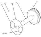
상기 밸브는 접시머리 가공된 오목부(impression)(218) 내에서 회전하고 상기 오목부 내에 배열된 기어구성식 톱 디스크(geared top disk)(230)를 포함한다. 상기 기어(230)들은 접시머리 가공된 전방 플레이트 홀(134) 내에 위치한 크랭크샤프트(도시되지 않음) 상에서 동일한 기어와 서로 맞물려 있다(intermeshed). 이렇게 맞물려 있기 때문에, 배럴 밸브(222)는 IDAR 엔진의 매 회전마다 두 배로 열리고 닫힐 수 있다.The valve includes a geared
상기 기술을 사용하여, 100%보다 더 큰 용적 효율 비율이 관측되었다.Using this technique, a volume efficiency ratio greater than 100% was observed.
대안의 흡입 형상은 원래 기술된 흡입부(136) 및 도 15에 예시되어 있는 로터리 밸브(rotary valve)(232)를 포함한다. 이 구체예는 컨투어 외측 표면(60) 내에 상대적으로 작은 홀들을 포함하지 않지만 후방 플레이트 관통 홀(220)과 접시머리 가공된 전방 플레이트 홀(218)을 더 포함한다.Alternative suction shapes include the
또한, 상기 로터리 밸브(232)는 기어구성식 톱 디스크(230), 중공 구조이거나 또는 중공 구조가 이닐 수 있는 실린더(234), 및 바닥 디스크(236)를 포함한다. 바닥 디스크(236)는 후방 플레이트의 바닥면에 대향하여(against) 배열되고 전반적으로 원형의 흡입 개구에 걸쳐 연장되기에 충분히 큰 직경을 가진다.The
바닥 디스크(236)는 상기 바닥 디스크(236) 위의 외주 방향으로 서로 맞은편에 있는 위치에서 2개의 아치 형태의 개구(238, 240)를 가진다. 이 개구들은 각각 디스크(236) 영역의 약 30% 내지 40%이다. 상기 밸브(232)를 사용하여, 흡입부(136)는 디스크 개구(238, 240)에 의해 엔진의 매 회전마다 두 배로 연리고 닫힌다.The
도 16과 도 17에 또 다른 대안의 구체예가 도시되어 있다. 이 구체예에서, 후방 플레이트(34)에서 스파크플러그 삽입 홀(148)이 불필요하다. 대신, 상기 구체예에서는, 대안의 이동식 컨투어(242)가 하나 또는 그 이상의 접시머리 가공 홀(244)을 포함하는데, 이 각각의 가공 홀(244)들은 스파크플러그(246)를 끼우기에 적합하다. 컨투어의 외측 표면(250) 내에 있는 홀(244) 내의 개구(248)가 스파크플러그에 대해 접근할 수 있게 하며, 컨투어의 내측 표면(254) 내에 있는 개구(252)는 전극(256)들이 작동 공간으로 삽입될 수 있게 한다. 안테나 선(antenna wire)(도시되지 않음)이 스파크플러그 연결부에 결부된다(attached).Another alternative embodiment is shown in FIGS. 16 and 17. In this embodiment, the spark
스파크플러그를 후방 플레이트 내의 고정 위치에 배열시켰을 때와 비교하여 보면, 상기 대안의 구체예는 매우 예측가능한 연소(burn)를 제공하며, 심지어 상이한 속도의 컨투어 움직임이 일어난다. 이는, 컨투어가 장착된 스파크플러그가 항상 연소 공정이 시작하게 하는 것을 원하는 정확한 위치에 있기 때문이다.Compared to when the sparkplugs are arranged in a fixed position in the rear plate, this alternative embodiment provides very predictable burns, even at different speeds of contour movement. This is because the spark plugs with contours are always in the exact position that they want the combustion process to start.
또한, 금속 플레이트(도시되지 않음)가 배치됨으로써 스파크 갭(spark gap)이 생성되어, 전방 플레이트(26)를 따라 연소 영역(combustion area) 가까이에서 고전압의 코일(도시되지 않음)에 연결된다. 컨투어(242)가 고전압의 플레이트 가까이에서 이동하기 때문에, 스파크가 이동 스파크플러그(248)로 튀고(jump) 스파크플러그를 통해 스파크플러그 갭으로 튀어 연소 공정이 시작된다.In addition, the placement of a metal plate (not shown) creates a spark gap, which is connected along the
또 다른 대안의 구체예에서, 도 18에 있는 분해도에 예시되어 있는 컨트롤 페탈 밸브(control petal valve)(258)를 배출 포트(138)에서 후방 플레이트의 후면 위에 추가함으로써, 배출 사이클(exhaust cycle)에 관한 펌핑 손실(pumping loss)이 개선될 수 있다. 컨투어들은 배출 사이클 동안 배출 영역 위로 통과하고, 그 뒤, 배출 포트를 주변 압력(atmospheric pressure)에 개방한 상태로 둔다. 이는, 가스가 한 움직임 방향으로는 포함되지 않기 때문에 배출부에서 펌프 마찰(pumping friction)을 증가시킨다.In yet another alternative embodiment, a
구체적으로, 페탈 밸브는 어떠한 컨투어(30)도 존재하지 않는 시간 동안 배출 포트를 밀봉하고 배출물(exhaust)이 엔진 챔버 내부로 다시 들어오는(backing up) 것을 방지한다. 이를 위해, 본 발명의 또 다른 구체예에서는, 로터리 밸브(도시되지 않음)가 사용된다.Specifically, the petal valve seals the discharge port for a time when no
또 다른 대안의 구체예에서, 컨투어는 특정 양의 배출물을 저장하고(store) 흡입 공정 동안 새로운 연료와 상기 배출물을 조합하도록 변형된다. 이는, 배출 사이클로부터 흡입 사이클로 변환되는 동안 연소 부산물(combustion byproduct)의 양과 종류를 조절하기 위해 바람직할 것이다.In another alternative embodiment, the contour is modified to store a certain amount of emissions and combine the emissions with fresh fuel during the intake process. This would be desirable to control the amount and type of combustion byproduct during conversion from the discharge cycle to the intake cycle.
내부 가스가 재순환(re-circulation)될 수 있게 하도록 변형될 수 있는 컨투어 타입은 도 17의 컨투어(242)와 유사하다. 반구체(hemispherical)인 내측 표면 개구(252)가 제공되어, 외측 컨투어 표면(250) 내에 있는 개구(248)에서 끝을 이루는 대신, 상기 내측 표면 개구(252)는 컨투어 내부에서 내부적으로 끝을 이루고 사용한 연료를 가둔다(trap). 이렇게 하여, 미리 선택된 양의 배출 가스가 새로운 연료와 다시 조합되고 위험한 오염물질들을 감소시키기 위해 연소 온도를 조절하도록 사용된다.The contour type that can be modified to allow internal gas to be re-circulated is similar to the
대안으로, 연소된 모든 연료를 배출할 수 없으며(예를 들어, 배출 영역(exit area)은 배출되는 질량 흐름(mass flow)을 수용할 수 없음) 이에 따라 흡입 동안 나머지 부분(remainder)을 새로운 연료 내로 이송하도록, 배출 포트의 크기를 축소하거나(downscaling) 또는 이동시킴으로써, 재순환(re-circulation)이 구현된다. 업계에서 공지되어 있는 것과 같이, 복잡한 캠-샤프트 타이밍(cam-shaft timing)과 추가적인 밸브를 사용하지 않고는 이를 구현하기 위해 피스톤 엔진이 사용될 수 없을 것이다.Alternatively, it is not possible to discharge all burned fuel (e.g., the exit area cannot accommodate the mass flow being discharged) and thus to remainder the fresh fuel during intake. Re-circulation is implemented by downscaling or moving the size of the discharge port to transport it into. As is known in the art, a piston engine may not be used to implement this without the use of complicated cam-shaft timing and additional valves.
도 19는 본래의 컨투어(30) 및 이와 동일한 제 2 컨투어(260)를 포함하는 2-컨투어 엔진 조립체의 분해도이다. 상기 대안의 구체예는 앞에서 이전에 기술한 구체예의 모든 형태들과 똑같다. 오직 하나의 챔버만 사용되긴 하지만, 결과적인 구조는 2 밸브 엔진 구조와 동일하다.19 is an exploded view of a two-contour engine assembly including the
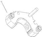
대안으로, 도 20에 예시되어 있는 후방 플레이트(262)를 사용하면, 기술된 본 발명의 IDAR 엔진은 내연기관의 기술적 범위 외의 기술을 이용할 수 있다. IDAR 기술은 이와 유사한 변위형(displacement) 피스톤 기술보다 훨씬 더 바람직한 기계적 토크 전달율을 가진다. 피스톤 기술보다 변위(displacement) 한 단위 당 일(work)의 출력(output)이 더 유용하다. 이 때문에, 오직 IDEA 팽창 사이클(스파크 유도 폭발(spark induced explosion) 없는 연소) 및 IDAR 배출 사이클만 사용하면, 지지하는 흡입 및 압축 사이클이 외부에서, 하지만 이와 연결된 장치에서 발생하지만 전체 효율을 증가시킨다. 게다가, 이 경우, 컨투어가 여전히 전체 아일랜드 주위로 이동하기 때문에, IDAR 흡입 및 압축 사이클은 동일한 챔버 내부에서 제 2 IDAR 팽창 및 배출 사이클로서 사용될 수도 있다.Alternatively, using the
기술적으로, 이 분야들은 내연기관(internal combustion engine)보다는 압축 공기 동력 장치(compressed air power plant) 또는 외연기관(external combustion engine)에 제공하기 위해 오직 IDAR 팽창 및 배출 사이클을 사용한다. 고압의 공기 또는 추진제(propellant)는 컨투어를 움직이게 하기 위해 외부의 하지만 이와 연결된 장치로부터 공급된다.Technically, these fields only use IDAR expansion and exhaust cycles to provide a compressed air power plant or an external combustion engine rather than an internal combustion engine. High pressure air or propellant is supplied from an external but connected device to move the contour.
상기 대안의 형상을 구현하기 위하여, 후방 플레이트(262)는 스파크플러그 홀(sparkplug hole)과 크기가 비슷할 수 있는 2개의 흡입 홀(264, 266)을 포함하며, 팽창 사이클을 밀어내는(force) 고압의 공기를 공급하는 튜브용 포트를 제공한다. 또한, 끝부분에서 팽창 사이클이 발생하는 2개의 배출 포트(266, 268)들이 도시되어 있다. 이 배출 포트들은 위에서 기술한 것과 같이 설계된다. 서로 맞은편에 있는 포트들은 서로 맞은편에 있는 아일랜드의 외주방향 단부들에 있으며, 챔버 내에서 컨투어가 각각 완전히 한 바퀴를 회전할 때 2회의 팽창 및 배출을 수행할 수 있다.To implement this alternative shape, the
이는, 엔진 내에서 어떠한 흡입 및 팽창도 발생하지 않기 때문에(고압의 압축 공기가 엔진 외부에서 압축되고 그 외의 수단에 의해 압축됨) 상기 2개의 사이클은 제 2 팽창 및 배출 사이클로서 2배가 되도록 사용되는 것을 의미한다. 매번 각각의 360° 회전에 대해, 컨투어는 2개의 팽창 사이클과 2개의 배출 사이클을 수행할 것이다.This is because the two cycles are used to double as the second inflation and exhaust cycles because no intake and expansion occurs in the engine (high pressure compressed air is compressed outside the engine and compressed by other means). Means that. For each 360 ° turn each time, the contour will perform two expansion cycles and two discharge cycles.
도 21은 대안의 컨투어(270)와 대안의 전방 플레이트(272)를 제공하는데, 이에 대한 이유가 이제부터 설명될 것이다. 앞에서 기술되었던 컨투어(30)에서, 서로 맞은편에 있는 상기 컨투어(30)의 외주방향 단부(162, 164)들에 있는 베어링(178, 180)들은 컨투어 전면(40)으로부터 외부 방향으로 동일한 거리만큼 돌출하고 이 베어링들은 동일한 외측 직경을 가진다. 상기 베어링(178, 180)들은 균일한 방사형 외부 프로파일(56)을 가지는 전방 플레이트 외측 에지(56) 위로 돌출한다.Figure 21 provides an
서로 맞은편에 있는 컨투어의 외주방향 단부(162, 164)들은 아일랜드 외측 표면(58) 주위로 동일한 정확한 경로(path)를 따라 이동하지 않는데, 이는 아일랜드(28)의 비대칭적 형태 때문이다. 컨투어가 아일랜드 주위로 회전할 때, 상기 단부(162, 164)들이 아일랜드의 외측 표면과 약간 오정렬(misalignment)되어 꼭지 밀봉부들은 약간의 차이를 조절하기 위해 내부 방향으로 또는 외부 방향으로 이동할 필요가 있다.The circumferential ends 162, 164 of the contours opposite each other do not travel along the same exact path around the island
서로 맞은편에 있는 컨투어의 외주방향 단부(274, 276)들에서 꼭지 밀봉부들이 원치않게 이동하는 것을 최소화시키기 위하여, 상호 고유한 특성들을 가진 베어링(278, 280)들이 제공된다. 이는, 외주 방향으로 컨투어(270)의 리딩 단부(274)에 있는 상기 베어링(278)은 컨투어(270)의 전면(282)으로부터 더 돌출하고 외주 방향으로 컨투어(270)의 트레일링 단부(276)에서 베어링(280)보다 더 큰 외측 직경을 가진다는 의미이다.In order to minimize unwanted movement of the nipple seals at the circumferential ends 274, 276 of the contour opposite one another,
상기 베어링(278, 280)들을 수용하기 위하여, 전방 플레이트 외측 에지(282)는 2개의 상이한 외부 프로파일(284, 286) 즉 외부 프로파일(284)과 내부 프로파일(286)을 가진다. 외부 프로파일(284)은 전방 플레이트 후면에 더 가까이 위치되고 내부 프로파일(286)은 전방 플레이트 전면(288)에 더 가까이 위치된다.To accommodate the
전방 플레이트 외부 프로파일(284)은 전방 플레이트 내부 프로파일(286)보다 반경 방향으로 더 크며, 외부 프로파일(284)은 트레일링 단부 베어링(280)의 경로를 추적하도록 설계된다. 반면, 내부 프로파일(286)은 리딩 단부 베어링(278)의 경로를 추적하도록 설계된다.The front plate
리딩 단부 베어링(278)과 트레일링 단부 베어링(280)의 외측 직경들은 각각의 프로파일(286, 284)들에 대향하여(against) 위치하도록 설계된다. 리딩 베어링(178)의 스템(stem)(290)은 자체적으로는 전방 플레이트(272)의 외부 프로파일(284)과 접촉하지 않고도 리딩 단부 베어링(278)을 내부 프로파일(286)에 대향하여 위치하기에 충분히 길고 좁다.The outer diameters of the leading end bearing 278 and the trailing end bearing 280 are designed to be positioned against each of the
상기 베어링(278, 280)들 중 어떤 베어링이 더 긴 스템을 가지는 지는 중요한 것이 아니라는 것을 이해할 수 있어야 한다. 상기 구체예에서, 오직 중요한 사실은, 전방 플레이트가 각각의 베어링들을 수용할 수 있는 외측 에지 프로파일을 가지며 상기 프로파일들이 각각의 베어링(278, 280)들에 의해 이동된 경로를 추적한다는 점이다. 이에 따라, 연소 사이클 동안 컨투어(270)의 위에서 언급한 원치않는 움직임이 최소화되거나 또는 방지될 것이다.It should be understood that which of the
요약하면, 위에서 기술한 구체예들은 하나 또는 그 이상의 롤러 베어링들이 이동식 컨투어의 측면을 따라 배열되기 위해 제공되며, 이에 따라 롤러 베어링들은 전방 플레이트의 외측 표면과 일정하게 접촉하여 컨투어가 고정된 아일랜드 주위로 회전할 때 챔버 영역 내에서 컨투어가 회전하게 한다.In summary, the embodiments described above are provided so that one or more roller bearings are arranged along the side of the movable contour, such that the roller bearings are in constant contact with the outer surface of the front plate and around the island on which the contour is fixed. The rotation causes the contour to rotate within the chamber area.
연소 챔버는 일렬로(in sequence) 층 구성된(layered) 다수의 부분들로서 형성되어 전체 IDAR을 형성하고, 각각의 층(layer)은 일련의 정렬 포스트(alignment post) 또는 커넥터(connector)를 통해 다른 층들과 나란하게 정렬된다.The combustion chamber is formed as a plurality of parts layered in sequence to form the entire IDAR, each layer being connected to another layer through a series of alignment posts or connectors. And are aligned side by side.
위에서 기술된 한 구체예에서, 흡입 포트는 챔버의 후방으로부터 아일랜드의 바디(body)를 통해 경로가 형성된(routed) 더 큰 개구에 연결된 아일랜드의 주변(perimeter) 내에서 일련의 작은 홀들을 통해 공급된다. 상기 구체예에서, 배럴 밸브는 챔버의 후방을 통해 배열되고 아일랜드의 바디와 연결되어 흡입 홀들을 형성하는 아일랜드를 통과하는 흡입 흐름을 조절한다.In one embodiment described above, the suction port is supplied through a series of small holes in the perimeter of the island connected to a larger opening routed from the rear of the chamber through the body of the island. . In this embodiment, the barrel valve regulates the suction flow through the island which is arranged through the rear of the chamber and connected to the body of the island to form the suction holes.
위에서 기술된 또 다른 구체예에서, 스템 부분(stem piece)에 결부된 로터리 밸브는 챔버의 후방을 통해 배열되고 아일랜드의 바디와 연결되어 흡입 오리피스(intake orifice)를 형성하는 아일랜드를 통과하는 흡입 흐름을 조절한다.In yet another embodiment described above, the rotary valve attached to the stem piece is arranged to flow through the island through the island, which is arranged through the rear of the chamber and is connected to the body of the island to form an intake orifice. Adjust.
위에서 기술된 또 다른 구체예에서, 안테나에 결부된 스파크플러그에 대한 연결지점을 가지는, 하나 또는 그 이상의 스파크플러그가 이동식 컨투어 내부에 장착된 엔진의 형상은 정지상태의 고전압 컨덕터에 대해 근위 영역(proximity area)를 통해 이동할 때 시간 스파크 에너지(timed spark energy)를 얻는다(pick up).In yet another embodiment described above, the shape of an engine with one or more sparkplugs mounted inside the movable contour, having a connection point to the sparkplugs attached to the antenna, has a proximity for stationary high voltage conductors. Pick up timed spark energy as you move through the area.
기술된 구체예들에서, 후방 플레이트와 전방 플레이트의 표면과 접촉하는 꼭지 밀봉부들이 사용된다.In the described embodiments, tap seals are used that contact the surfaces of the back plate and the front plate.
위에서 기술된 한 구체예에서, 배출 포트 위에 엔진 챔버의 후측면 상에 페탈 밸브가 장착되어 배출 포트가 열리고 닫히게 할 수 있다.In one embodiment described above, a petal valve can be mounted on the rear side of the engine chamber above the discharge port to allow the discharge port to open and close.
위에서 기술된 또 다른 구체예에서, 배출 포트 위에 엔진 챔버의 후측면 상에 로터리 밸브가 장착되어 배출 포트가 열리고 닫히게 할 수 있다.In another embodiment described above, a rotary valve may be mounted on the rear side of the engine chamber above the discharge port to allow the discharge port to open and close.
위에서 기술된 또 다른 구체예에서, 아일랜드 표면들을 향하고 있는(face) 오목한 컨투어 표면의 일부분이 제거되어 내부 가스 재순환 공정이 배출 사이클과 흡입 사이클 사이에서 직접 수행된다.In yet another embodiment described above, a portion of the concave contour surface facing the island surfaces is removed so that an internal gas recycle process is performed directly between the discharge cycle and the intake cycle.
따라서, 역변위 비대칭 로터리(IDAR) 내연기관 기술에 대한 개선예들이 도시되었다. 엔진 내부의 공차(tolerance)를 개선하고 조립 공정들을 단순화시키는 엔진 챔버 설계 개선사항들이 기술되었다. 꼭지 밀봉부와 측면 밀봉부들에 가해지는 응력(stress)을 제거하고 엔진 압축률, 기능적인 반복성(functional repeatability) 및 엔진 수명을 향상시키는 컨투어 디자인에 대한 개선사항들이 기술되었다. 각각의 사이클 성능을 증가시키기 위해, 포트 디자인, 흡입 및 배출 밸브와 이에 상응하는 밸브 디자인에 대한 개선사항들이 논의되었다.Thus, improvements to the reverse displacement asymmetric rotary (IDAR) internal combustion engine technology have been shown. Engine chamber design improvements have been described that improve the tolerances inside the engine and simplify the assembly processes. Improvements to the contour design have been described that eliminate stresses on the nipple seals and side seals and improve engine compression, functional repeatability and engine life. In order to increase the performance of each cycle, improvements in port design, inlet and outlet valves and corresponding valve designs have been discussed.
위에서 기술한 IDAR 기술의 또 다른 형태에서, 위에서 기술된 기술들을 사용하는 범위를 확장시키면, 기존의 기술들이 고압의 공기 또는 연료와 공기의 조합 공급원(source)을 IDAR 동력 장치에 제공하면서 IDAR이 동력 장치로서의 기능을 수행하도록 그 외의 다른 기술들을 사용하는 것을 포함한다. 이 경우, IDAR 기술은, 내연기관 대신 압축 공기에 의해 동력이 공급되는 것과 같이, 외연 동력 장치(external combustion power plant)로서 작용한다In another form of IDAR technology described above, extending the scope of using the technologies described above allows existing technologies to provide high pressure air or a combination source of fuel and air to the IDAR power plant while providing power. Use of other techniques to perform functions as a device. In this case, the IDAR technology acts as an external combustion power plant, as if powered by compressed air instead of an internal combustion engine.
위에서 본 발명의 몇몇 구체예들이 기술되었지만, 본 발명은 이 구체예들에만 제한되는 것이 아니라는 것을 이해해야 한다. 사실, 구체적으로 도시되거나 또는 기술되지 않았다 하더라도 당업자가 본 발명의 범위 내에서 본 발명의 원리를 이용하여 다양한 실시예들을 고안할 수 있을 것이라는 점을 이해할 수 있다. 당업자들에게는 위에서 기술된 구체예들에 대한 변형예들이 자명하지만, 첨부된 청구항들의 범위를 초과하여 본 발명을 변형하지는 않을 것이다.While some embodiments of the invention have been described above, it should be understood that the invention is not limited to these embodiments. In fact, even if not specifically illustrated or described, it will be understood by those skilled in the art that various embodiments may be devised using the principles of the invention within the scope of the invention. Modifications to the embodiments described above will be apparent to those skilled in the art, but will not modify the invention beyond the scope of the appended claims.
Claims (25)
상기 챔버는:
- 아일랜드(island) 외측 표면을 가진 고정식 아일랜드를 포함하며, 상기 외측 표면은 연신된 볼록한 형태를 가지고, 상기 아일랜드는 상기 아일랜드의 중심으로부터 거리가 떨어진 크랭크샤프트 포트(crankshaft port)를 포함하며;
- 상기 아일랜드의 전방 표면에 결부된(attached) 전방 플레이트를 포함하고;
- 오목한 형태의 이동식 컨투어(contour)를 포함하며, 상기 컨투어는 상기 아일랜드 외측 표면을 향해 편향되고(biased) 상기 컨투어는 상기 아일랜드 주위로 회전하며, 상기 아일랜드 외측 표면과 상기 컨투어의 내측 표면 사이에 작동 공간(working volume)이 형성되고; 및
- 상기 이동식 컨투어의 전방 표면으로부터 연장되며 상기 전방 플레이트의 가이드 에지(guide edge) 위로 연장되는 하나 이상의 전방 플레이트 결합 베어링을 포함하고, 상기 전방 플레이트 결합 베어링은 연소 사이클(combustion cycle) 동안 상기 가이드 에지와 결합하는 역변위 비대칭 로터리 엔진.In an inverse displacement asymmetric rotary engine comprising a chamber,
The chamber is:
A fixed island having an outer surface of the island, the outer surface having an elongated convex shape, the island comprising a crankshaft port spaced from the center of the island;
A front plate attached to the front surface of the island;
A concave movable contour, wherein the contour is biased towards the island outer surface and the contour rotates around the island and operates between the island outer surface and the inner surface of the contour A working volume is formed; And
At least one front plate engaging bearing extending from the front surface of the movable contour and extending above the guide edge of the front plate, the front plate engaging bearing being in contact with the guide edge during a combustion cycle. Combined reverse displacement asymmetric rotary engine.
상기 컨투어는 2개의 전방 플레이트 결합 베어링을 포함하는데, 상기 2개의 전방 플레이트 결합 베어링은 서로 맞은편에 있는 상기 컨투어의 외주방향 단부(circumferential end) 각각에 배열되는 것을 특징으로 하는 역변위 비대칭 로터리 엔진.The method of claim 1,
The contour includes two front plate coupling bearings, wherein the two front plate coupling bearings are arranged at each of the circumferential ends of the contour opposite each other.
- 상기 2개의 베어링들은 리딩 단부 베어링(leading end bearing)과 트레일링 단부 베어링(trailing end bearing)을 포함하며, 상기 베어링들 중 한 베어링은 다른 베어링보다 상기 이동식 컨투어의 상기 전방 표면으로부터 더 연장되고; 및
- 상기 전방 플레이트 가이드 에지는 상이한 프로파일을 가진 2개의 가이드 에지를 포함하는데, 상기 2개의 가이드 에지 중 제 1 가이드 에지는 상기 베어링들 중 하나를 고정하고(seating) 상기 가이드 에지 중 제 2 가이드 에지는 상기 베어링들 중 또 다른 베어링을 고정하는 것을 특징으로 하는 역변위 비대칭 로터리 엔진.The method of claim 2,
The two bearings comprise a leading end bearing and a trailing end bearing, wherein one of the bearings extends further from the front surface of the movable contour than the other bearings; And
The front plate guide edge comprises two guide edges with different profiles, wherein a first guide edge of the two guide edges secures one of the bearings and a second guide edge of the guide edges Reverse displacement asymmetric rotary engine, characterized in that for holding another of the bearings.
상기 챔버는, 추가로:
- 림 내측 표면을 포함하고, 상기 컨투어와 상기 고정식 아일랜드의 일부분 이상이 상기 림 내측 표면 내에 있으며;
- 상기 림 내측 표면과 결합하기 위한 베어링을 포함하고, 상기 베어링은 상기 이동식 컨투어의 외측 표면으로부터 연장되며;
상기 림 내측 표면은 상기 컨투어가 상기 아일랜드를 향하게 편향시키도록 형태가 형성되어, 상기 전방 플레이트 결합 베어링이 상기 가이드 에지와 결합하는 것을 특징으로 하는 역변위 비대칭 로터리 엔진.The method of claim 2,
The chamber further comprises:
A rim inner surface, wherein at least a portion of the contour and the stationary island are in the rim inner surface;
A bearing for engaging the inner surface of the rim, the bearing extending from an outer surface of the movable contour;
The rim inner surface is shaped to deflect the contour towards the island such that the front plate engaging bearing engages the guide edge.
- 상기 엔진은 흡입 포트(intake port)와 배출 포트(exhaust port)를 포함하는 후방 플레이트를 추가로 포함하고;
- 상기 배출 포트는, 상기 작동 공간이 상기 연소 사이클의 배출 상(exhaust phase)에 있을 때, 상기 후방 플레이트 위로 돌출된 상기 작동 공간의 돌출부(projection)에 의해 일부분 이상 형성된 아치 형태(arcuate shape)를 포함하는 것을 특징으로 하는 역변위 비대칭 로터리 엔진.The method of claim 4, wherein
The engine further comprises a rear plate comprising an intake port and an exhaust port;
The discharge port has an arcuate shape formed at least in part by a projection of the operating space projecting over the rear plate when the operating space is in the exhaust phase of the combustion cycle. Reverse displacement asymmetric rotary engine, comprising.
상기 흡입 포트는, 상기 작동 공간이 상기 연소 사이클의 흡입 상(intake phase)에 있을 때, 상기 후방 플레이트 위로 돌출된 상기 작동 공간의 돌출부에 의해 일부분 이상 형성된 아치 형태를 추가로 포함하는 것을 특징으로 하는 역변위 비대칭 로터리 엔진.The method of claim 5, wherein
The intake port further comprises an arch shape formed at least in part by a protrusion of the working space projecting over the rear plate when the working space is in the intake phase of the combustion cycle. Reverse displacement asymmetric rotary engine.
- 상기 엔진은 2개의 흡입 포트와 2개의 배출 포트를 포함하며, 상기 흡입 포트들은 서로 맞은편에 있는 상기 아일랜드의 외주방향 단부들 위에 위치되고 상기 배출 포트들은 서로 맞은편에 있는 상기 아일랜드의 다른 외주방향 단부들 위에 위치되며; 및
- 상기 챔버 내에서는 연소가 발생하지 않는 것을 특징으로 하는 역변위 비대칭 로터리 엔진.The method of claim 5, wherein
The engine comprises two intake ports and two outlet ports, the intake ports being located above the circumferential ends of the islands opposite each other and the outlet ports being the other outer periphery of the islands opposite each other; Located above the directional ends; And
Reverse displacement asymmetric rotary engine, characterized in that no combustion occurs in the chamber.
상기 아치 형태들은 유선 조절 구조(streamline control structure)를 포함하는 것을 특징으로 하는 역변위 비대칭 로터리 엔진.The method according to claim 6,
Wherein said arch forms comprise a streamline control structure.
상기 아치 형태들은 상기 후방 플레이트 위에 위치된 제 2 후방 플레이트 내로 밀링가공되는(milled) 것을 특징으로 하는 역변위 비대칭 로터리 엔진.The method according to claim 6,
The arch shapes are milled into a second rear plate located above the rear plate.
상기 이동식 컨투어는, 추가로:
- 상기 전방 플레이트 및 상기 후방 플레이트와 결합하는 측면 밀봉부를 포함하고; 및
- 상기 컨투어가 상기 아일랜드를 향해 편향될 때 상기 아일랜드 외측 표면과 결합하는 외주 방향으로 서로 맞은편에 있는 꼭지(apex) 밀봉부를 포함하는 것을 특징으로 하는 역변위 비대칭 로터리 엔진.The method according to claim 6,
The removable contour further comprises:
A side seal that engages the front plate and the back plate; And
Reverse displacement asymmetric rotary engine, characterized by apex seals opposite each other in the circumferential direction that engages the outer surface of the island when the contour is deflected towards the island.
상기 꼭지 밀봉부들은 주조 철(cast iron)인 것을 특징으로 하는 압축 공기 구동 엔진.The method of claim 8,
Compressed air driven engine, characterized in that the nipple seals are cast iron.
상기 후방 플레이트는 상기 연소 사이클의 압축 상(compression phase)이 발생하는 미리 정해진 영역에 위치된 스파크플러그 수용 포트(sparkplug receiving port)를 포함하는 것을 특징으로 하는 역변위 비대칭 로터리 엔진.The method according to claim 6,
And the rear plate comprises a sparkplug receiving port located in a predetermined area where a compression phase of the combustion cycle occurs.
상기 이동식 컨투어는 상기 컨투어 내측 표면을 통해 연장되는 스파크플러그 수용 포트를 포함하며, 스파크플러그 전극들은 상기 작동 공간 내에 삽입되는 것을 특징으로 하는 역변위 비대칭 로터리 엔진.The method of claim 4, wherein
The movable contour includes a spark plug receiving port extending through the contour inner surface, wherein the spark plug electrodes are inserted into the working space.
- 일정 두께를 가진 상기 아일랜드를 통해 밀링가공된 밸브 채널을 포함하고;
- 상기 아일랜드 외측 표면을 통해 추가로 밀링가공된, 상기 밸브 채널로부터의 하나 또는 그 이상의 개구(opening)를 포함하며; 및
- 상기 밸브 채널 내에 회전가능하게 위치된(rotatably positioned) 슬롯구성 배럴 밸브(slotted barrel valve)를 포함하고, 연료가 상기 작동 공간에 선택적으로 전달되는 것을 특징으로 하는 역변위 비대칭 로터리 엔진.The method of claim 4, wherein
A valve channel milled through said island of constant thickness;
One or more openings from the valve channel, further milled through the island outer surface; And
A slotted barrel valve rotatably positioned in the valve channel, wherein fuel is selectively delivered to the operating space.
상기 배럴 밸브는 상기 크랭크샤프트 포트 내에서 크랭크샤프트와 직접 또는 간접적으로 맞물리는 기어구성 디스크(geared disk)를 포함하며, 상기 챔버 내에서 상기 컨투어가 움직여서 상기 배럴 밸브를 회전시켜(turn) 상기 작동 공간에 연료를 선택적으로 전달하는 것을 특징으로 하는 역변위 비대칭 로터리 엔진.The method of claim 15,
The barrel valve includes a geared disk that directly or indirectly engages the crankshaft in the crankshaft port, wherein the contour moves within the chamber to turn the barrel valve to turn the operating space. Reverse displacement asymmetric rotary engine, characterized in that for selectively delivering fuel to.
상기 엔진은 일정 두께를 가진 상기 아일랜드를 통과하는 밸브 포트(valve port)와 상기 밸브 포트 내에 회전가능하게 위치된 로터리 밸브(rotary valve)를 포함하며, 상기 흡입 포트는 상기 연소 사이클 동안 선택적으로 덮이거나(covered) 덮이지 않는(uncovered) 것을 특징으로 하는 역변위 비대칭 로터리 엔진.The method according to claim 6,
The engine includes a valve port passing through the island having a predetermined thickness and a rotary valve rotatably positioned within the valve port, the intake port being selectively covered during the combustion cycle or Reverse displacement asymmetric rotary engine, characterized in that it is uncovered.
상기 로터리 밸브는 복수의 개구를 가진 디스크를 포함하며, 상기 디스크는 상기 흡입 포트 위로 연장되고 상기 후방 플레이트에 대향하여(against) 위치되는 것을 특징으로 하는 역변위 비대칭 로터리 엔진.The method of claim 17,
The rotary valve includes a disk having a plurality of openings, the disk extending over the suction port and positioned against the rear plate.
상기 로터리 밸브는 상기 크랭크샤프트 포트 내에서 크랭크샤프트와 직접 또는 간접적으로 맞물리는 기어구성 디스크를 포함하며, 상기 챔버 내에서 상기 컨투어가 움직여서 상기 로터리 밸브를 회전시켜(turn) 상기 연소 사이클 동안 상기 흡입 포트를 선택적으로 덮거나 덮지 않는 것을 특징으로 하는 역변위 비대칭 로터리 엔진.The method of claim 18,
The rotary valve includes a geared disk that engages directly or indirectly with the crankshaft in the crankshaft port, wherein the contour moves within the chamber to turn the rotary valve to turn the suction port during the combustion cycle. Reverse displacement asymmetric rotary engine, characterized in that not selectively cover.
상기 컨투어는 배출 가스를 재순환시킬 수 있게 하기 위해 재순환 포트(recirculation port)를 포함하는 것을 특징으로 하는 역변위 비대칭 로터리 엔진.The method of claim 4, wherein
The contour is a reverse displacement asymmetric rotary engine, characterized in that it comprises a recirculation port to enable the exhaust gas to be recycled.
상기 엔진은, 상기 연소 사이클이 배출 상에 있지 않은 경우, 배출 포트를 밀봉하기 위해 상기 후방 플레이트의 후면 위에 있는 상기 배출 포트에 배치된 컨트롤 밸브(control valve)를 추가로 포함하는 것을 특징으로 하는 역변위 비대칭 로터리 엔진.The method according to claim 6,
The engine further comprises a control valve disposed at the exhaust port above the rear face of the rear plate to seal the exhaust port when the combustion cycle is not on the exhaust. Displacement asymmetrical rotary engine.
상기 컨트롤 밸브는 페탈 밸브(petal valve)인 것을 특징으로 하는 역변위 비대칭 로터리 엔진.The method of claim 21,
Reverse control asymmetric rotary engine, characterized in that the control valve (petal valve).
상기 컨트롤 밸브는 로터리 밸브인 것을 특징으로 하는 역변위 비대칭 로터리 엔진.The method of claim 21,
Reverse control asymmetric rotary engine, characterized in that the control valve is a rotary valve.
상기 엔진은 복수의 이동식 컨투어를 포함하는 것을 특징으로 하는 역변위 비대칭 로터리 엔진.The method of claim 4, wherein
The engine is a reverse displacement asymmetric rotary engine, characterized in that it comprises a plurality of movable contours.
상기 후방 플레이트와 림 외측 표면은 동일한 형태를 가지는 것을 특징으로 하는 역변위 비대칭 로터리 엔진.The method according to claim 6,
And said rear plate and rim outer surface have the same shape.
Applications Claiming Priority (3)
| Application Number | Priority Date | Filing Date | Title |
|---|---|---|---|
| US21119209P | 2009-03-25 | 2009-03-25 | |
| US61/211,192 | 2009-03-25 | ||
| PCT/US2010/028754 WO2010111557A2 (en) | 2009-03-25 | 2010-03-25 | Inverse displacement asymmetric rotary (idar) engine |
Publications (1)
| Publication Number | Publication Date |
|---|---|
| KR20120011846A true KR20120011846A (en) | 2012-02-08 |
Family
ID=42781898
Family Applications (1)
| Application Number | Title | Priority Date | Filing Date |
|---|---|---|---|
| KR1020117022853A Abandoned KR20120011846A (en) | 2009-03-25 | 2010-03-25 | Reverse Displacement Asymmetric Rotary (IDAR) Engine |
Country Status (13)
| Country | Link |
|---|---|
| US (2) | US8607762B2 (en) |
| EP (1) | EP2414635B1 (en) |
| JP (1) | JP5706394B2 (en) |
| KR (1) | KR20120011846A (en) |
| CN (1) | CN102575522B (en) |
| AU (1) | AU2010229818B2 (en) |
| BR (1) | BRPI1009834A2 (en) |
| CA (1) | CA2756230C (en) |
| IL (1) | IL215238A (en) |
| MX (1) | MX2011009891A (en) |
| RU (1) | RU2578072C2 (en) |
| WO (1) | WO2010111557A2 (en) |
| ZA (1) | ZA201106710B (en) |
Families Citing this family (15)
| Publication number | Priority date | Publication date | Assignee | Title |
|---|---|---|---|---|
| CA2756230C (en) | 2009-03-25 | 2017-02-07 | Lumenium Llc | Inverse displacement asymmetric rotary (idar) engine |
| US20130224053A1 (en) * | 2011-10-03 | 2013-08-29 | Jan Hendrik Ate Wiekamp | Coaxial progressive cavity pump |
| US10184392B2 (en) | 2012-03-14 | 2019-01-22 | Lumenium Llc | Single chamber multiple independent contour rotary machine |
| IN2014DN08432A (en) * | 2012-03-14 | 2015-05-08 | Lumenium Llc | |
| US9309765B2 (en) | 2012-03-14 | 2016-04-12 | Lumenium Llc | Rotary machine |
| CN106030037B (en) * | 2013-09-18 | 2018-09-14 | 卢门纽姆公司 | Rotary |
| US12146411B2 (en) | 2015-04-13 | 2024-11-19 | Lumenium Llc | Rotary machine |
| WO2020113109A1 (en) | 2018-11-27 | 2020-06-04 | Lumenium Llc | Rotary engine with recirculating arc roller power transfer |
| US11920476B2 (en) | 2015-04-13 | 2024-03-05 | Lumenium Llc | Rotary machine |
| CN107709703B (en) | 2015-04-13 | 2021-06-04 | 卢门纽姆公司 | Single-chamber multi-independent contour rotary machine |
| WO2021232025A1 (en) | 2020-05-15 | 2021-11-18 | Lumenium Llc | Rotary machine with hub driven transmission articulating a four bar linkage |
| US10823173B2 (en) | 2015-11-18 | 2020-11-03 | Societe Des Produits Nestle S.A. | Rotary compressor arrangement with stationary shaft with inlet and outlet and a cylindrical piston rotated by a satellite element |
| TWI743126B (en) | 2016-07-08 | 2021-10-21 | 瑞士商雀巢製品股份有限公司 | Rotary compressor arrangement |
| CN110359962B (en) * | 2019-07-17 | 2021-01-05 | 顾新钿 | an air motor |
| CN113378319B (en) * | 2021-06-24 | 2022-04-12 | 宁波蓝海量子精工轴承制造有限公司 | Design method for end face grinding allowance of double-end-face asymmetric bearing ring |
Family Cites Families (54)
| Publication number | Priority date | Publication date | Assignee | Title |
|---|---|---|---|---|
| US613345A (en) | 1898-11-01 | Reversible rotary engine | ||
| US419770A (en) | 1890-01-21 | Rotary engine | ||
| US709773A (en) | 1902-03-08 | 1902-09-23 | Oliver C Jones | Rotary engine. |
| US1595496A (en) * | 1924-06-04 | 1926-08-10 | Beggs Thomas Robert | Fluid motor |
| US1972302A (en) | 1932-11-08 | 1934-09-04 | Multicycol Pump & Engine Corp | Rotary pump, compressor, or the like |
| US1983033A (en) | 1932-11-30 | 1934-12-04 | Multicycol Pump & Engine Corp | Rotary pump, compressor, or the like |
| US1986202A (en) | 1933-01-21 | 1935-01-01 | Multicycol Pump & Engine Corp | Rotary pump, compressor, and the like |
| US1983034A (en) | 1933-01-31 | 1934-12-04 | Multicycol Pump & Engine Corp | Rotary pump, compressor, engine, and the like |
| US2277225A (en) * | 1941-07-21 | 1942-03-24 | Edward H Green | Internal combustion engine |
| US2919062A (en) | 1954-10-05 | 1959-12-29 | British Internal Combust Eng | Rotary compressing, displacing or expanding machine |
| US2897798A (en) * | 1956-07-02 | 1959-08-04 | Schrougham Benton | Rotary internal combustion engine |
| US3186385A (en) * | 1960-09-20 | 1965-06-01 | Hamilton Walker Rotary Engines | Rotary internal combustion engines |
| GB930280A (en) | 1960-11-02 | 1963-07-03 | Otto Korf | A rotary piston internal combustion engine |
| US3259113A (en) * | 1961-08-16 | 1966-07-05 | Yanmar Diesel Engine Co | Rotary diesel engines |
| GB1006408A (en) * | 1961-11-20 | 1965-09-29 | Artajo Jose Ignacio Martin | Improved rotary internal combustion engine |
| AT240108B (en) * | 1962-11-22 | 1965-05-10 | Johann Ing Geiger | Rotary piston internal combustion engine |
| US3295505A (en) * | 1963-05-31 | 1967-01-03 | Jordan Alfred | Rotary piston apparatus |
| US3230938A (en) * | 1963-10-09 | 1966-01-25 | Edward J Hojnowski | Rotary internal combustion engine |
| DE1294088B (en) * | 1965-07-31 | 1969-04-30 | Nsu Motorenwerke Ag | Internal combustion engine set |
| US3302870A (en) | 1966-02-25 | 1967-02-07 | Gen Motors Corp | Rotary compressor |
| JPS5618772B1 (en) | 1969-03-28 | 1981-05-01 | ||
| US3762377A (en) * | 1972-06-21 | 1973-10-02 | Gen Motors Corp | Spark plug and rotor assembly for a rotary combustion engine |
| US3952708A (en) * | 1973-10-16 | 1976-04-27 | General Motors Corporation | Rotor mounted spark plug for rotary engine |
| US3884600A (en) * | 1973-11-08 | 1975-05-20 | Gray & Bensley Research Corp | Guidance means for a rotary engine or pump |
| US3981645A (en) | 1974-08-01 | 1976-09-21 | Hans Herzner | Displaced piston machine |
| JPS51116313A (en) * | 1975-04-03 | 1976-10-13 | Mazda Motor Corp | Reflux device of exhaust gas from rotary piston engine |
| US4095564A (en) * | 1975-11-05 | 1978-06-20 | Hochstein Peter A | Method and apparatus for igniting air-fuel mixture in an engine |
| US4055156A (en) * | 1976-03-12 | 1977-10-25 | Gundlach, S.A. | Rotary engine |
| JPS5381837A (en) * | 1976-12-27 | 1978-07-19 | Toyota Motor Corp | Rotary piston engine ignition system |
| US4144866A (en) * | 1977-11-14 | 1979-03-20 | Robert Hakner | Internal combustion rotary engine |
| DE2853930A1 (en) | 1978-12-14 | 1980-06-19 | Karl Dipl Ing Otto | Rotary piston unit compressor or engine - has multi-arc contoured piston whose centre moves in same curvature multi-arc housing along two-arc path |
| DE3236811A1 (en) | 1982-10-05 | 1984-05-17 | Markus 2000 Hamburg Pahl | Pivoted-cylinder engine |
| JPS61210228A (en) | 1985-03-14 | 1986-09-18 | Kenji Kasama | Biaxial reversing rotary engine |
| JPH0795565B2 (en) | 1986-09-05 | 1995-10-11 | 日本電気株式会社 | Static electricity protection device for complementary MIS integrated circuit |
| FR2615577B1 (en) | 1987-05-18 | 1992-12-31 | Koyo Seiko Co | POWER TRANSMISSION DEVICE FOR VEHICLE AND FOUR-DRIVE VEHICLE EQUIPPED WITH SUCH A DEVICE |
| FR2683000B1 (en) * | 1991-10-23 | 1994-02-04 | Andre Leroy | VOLUMETRIC MACHINE WITH PLANETARY MOTION AND HYPERTROCHOUIDAL GEOMETRY. |
| US5343838A (en) * | 1993-07-29 | 1994-09-06 | Gas Research Institute | Dual radius rotor for pre-mixed-charge rotary engine combustion |
| US5423298A (en) | 1993-09-14 | 1995-06-13 | Pahis; Nikolaos S. | Rotary internal combustion engine |
| US5540199A (en) | 1994-06-01 | 1996-07-30 | Penn; Jay P. | Radial vane rotary engine |
| US6129067A (en) * | 1997-11-28 | 2000-10-10 | Riley; Thomas | Rotary engine |
| US6120272A (en) | 1998-08-10 | 2000-09-19 | Gallardo; Arturo | Pump-motor for fluid with elliptical members |
| WO2002033222A1 (en) * | 2000-10-16 | 2002-04-25 | William Henry Ollis | Rotary drive mechanism |
| JP2002188454A (en) | 2000-12-15 | 2002-07-05 | Shin Yoneda | Eccentric shaft pressurized rotational engine |
| SK285000B6 (en) | 2000-12-22 | 2006-04-06 | Svetozár Hruškovič | Method for energy conversion in a rotary piston engine or machine and a rotary piston engine or machine |
| DE10292075T5 (en) * | 2001-05-26 | 2004-07-22 | Dong Hyun Kim | Rotary engine |
| TW565651B (en) | 2002-04-03 | 2003-12-11 | Jung-Kuang Chou | Rotary enginge |
| US6758188B2 (en) | 2002-07-16 | 2004-07-06 | Joseph B. Wooldridge | Continuous torque inverse displacement asymmetric rotary engine |
| FR2870883A1 (en) * | 2004-05-28 | 2005-12-02 | Vimak Soc Civ Ile | Turbomachine for use as generator, has blades rotating around respective axles parallel to rotation axle of rotor, where axles of blades are disposed in circle on rotor and positioning of blades is similar for each angular position of rotor |
| US7331315B2 (en) * | 2005-02-23 | 2008-02-19 | Eastway Fair Company Limited | Two-stroke engine with fuel injection |
| US7621255B2 (en) * | 2005-08-03 | 2009-11-24 | E3P Technologies, Inc. | Toroidal engine method and apparatus |
| US7281513B1 (en) * | 2006-02-24 | 2007-10-16 | Webb David W | Inverted Wankel |
| CA2756230C (en) | 2009-03-25 | 2017-02-07 | Lumenium Llc | Inverse displacement asymmetric rotary (idar) engine |
| KR100936347B1 (en) | 2009-05-06 | 2010-01-12 | 기덕종 | Separated rotary engine |
| US20100319652A1 (en) * | 2009-06-18 | 2010-12-23 | Rotary Engine Technologies, Inc. | Rotor housing assembly for rotary engine and related devices and methods |
-
2010
- 2010-03-25 CA CA2756230A patent/CA2756230C/en not_active Expired - Fee Related
- 2010-03-25 AU AU2010229818A patent/AU2010229818B2/en not_active Ceased
- 2010-03-25 BR BRPI1009834A patent/BRPI1009834A2/en not_active IP Right Cessation
- 2010-03-25 EP EP10722458.6A patent/EP2414635B1/en not_active Not-in-force
- 2010-03-25 US US12/732,160 patent/US8607762B2/en not_active Expired - Fee Related
- 2010-03-25 CN CN201080013906.7A patent/CN102575522B/en not_active Expired - Fee Related
- 2010-03-25 WO PCT/US2010/028754 patent/WO2010111557A2/en not_active Ceased
- 2010-03-25 RU RU2011140081/06A patent/RU2578072C2/en not_active IP Right Cessation
- 2010-03-25 MX MX2011009891A patent/MX2011009891A/en active IP Right Grant
- 2010-03-25 JP JP2012502272A patent/JP5706394B2/en not_active Expired - Fee Related
- 2010-03-25 KR KR1020117022853A patent/KR20120011846A/en not_active Abandoned
-
2011
- 2011-09-13 ZA ZA2011/06710A patent/ZA201106710B/en unknown
- 2011-09-19 IL IL215238A patent/IL215238A/en not_active IP Right Cessation
-
2013
- 2013-11-22 US US14/087,460 patent/US9714605B2/en not_active Expired - Fee Related
Also Published As
| Publication number | Publication date |
|---|---|
| BRPI1009834A2 (en) | 2016-03-15 |
| IL215238A0 (en) | 2011-12-29 |
| WO2010111557A2 (en) | 2010-09-30 |
| ZA201106710B (en) | 2012-07-25 |
| CN102575522B (en) | 2014-04-30 |
| CA2756230A1 (en) | 2010-09-30 |
| CN102575522A (en) | 2012-07-11 |
| CA2756230C (en) | 2017-02-07 |
| IL215238A (en) | 2014-04-30 |
| AU2010229818B2 (en) | 2014-10-02 |
| US9714605B2 (en) | 2017-07-25 |
| US20100242897A1 (en) | 2010-09-30 |
| JP2012522165A (en) | 2012-09-20 |
| US20140076270A1 (en) | 2014-03-20 |
| US8607762B2 (en) | 2013-12-17 |
| JP5706394B2 (en) | 2015-04-22 |
| MX2011009891A (en) | 2012-01-12 |
| RU2011140081A (en) | 2013-04-27 |
| EP2414635B1 (en) | 2013-08-14 |
| RU2578072C2 (en) | 2016-03-20 |
| EP2414635A2 (en) | 2012-02-08 |
| WO2010111557A3 (en) | 2012-05-31 |
| AU2010229818A1 (en) | 2011-10-13 |
Similar Documents
| Publication | Publication Date | Title |
|---|---|---|
| KR20120011846A (en) | Reverse Displacement Asymmetric Rotary (IDAR) Engine | |
| US7578278B2 (en) | Multilobe rotary motion asymetric compression/expansion engine | |
| US4178900A (en) | Rotary internal combustion engine | |
| US8714135B2 (en) | IDAR-ACE inverse displacement asymmetric rotating alternative core engine | |
| US5415141A (en) | Rotary engine with radially sliding vanes | |
| US3990817A (en) | Rotary combustion engine having a modified trochoid | |
| US3986483A (en) | Rotary internal combustion engine | |
| US4033300A (en) | Rotary internal combustion engine | |
| EP1009913A1 (en) | A vane type rotary engine | |
| CN106884710A (en) | A kind of sliding block coordinates cam follower explosive motor dynamical system | |
| US3952709A (en) | Orbital vane rotary machine | |
| JP2631626B2 (en) | Rotary engine | |
| CN110139975B (en) | Multi-axis rotary engine | |
| US20040231635A1 (en) | Rotary engine | |
| USRE41373E1 (en) | Rotary engine | |
| RU2418180C1 (en) | Rotary engine and cam shaft | |
| RU2310082C2 (en) | Rotary internal combustion engine | |
| US20080264379A1 (en) | Rotary Engine | |
| EP3361098A1 (en) | Rotary engine with a vane actuator | |
| US3857656A (en) | Apex seal for a rotary internal combustion engine | |
| RU2693550C1 (en) | Internal combustion rotor engine with asymmetric compression and expansion | |
| WO2000057027A1 (en) | Rotary engine with overexpanded cycle | |
| WO2012151423A2 (en) | Dual tip seals for a rotary engine |
Legal Events
| Date | Code | Title | Description |
|---|---|---|---|
| PA0105 | International application |
Patent event date: 20110929 Patent event code: PA01051R01D Comment text: International Patent Application |
|
| PG1501 | Laying open of application | ||
| PA0201 | Request for examination |
Patent event code: PA02012R01D Patent event date: 20150320 Comment text: Request for Examination of Application |
|
| PE0902 | Notice of grounds for rejection |
Comment text: Notification of reason for refusal Patent event date: 20160115 Patent event code: PE09021S01D |
|
| E701 | Decision to grant or registration of patent right | ||
| PE0701 | Decision of registration |
Patent event code: PE07011S01D Comment text: Decision to Grant Registration Patent event date: 20160516 |
|
| PC1904 | Unpaid initial registration fee |