KR20110073474A - View compositing using heuristic view merging - Google Patents
View compositing using heuristic view merging Download PDFInfo
- Publication number
- KR20110073474A KR20110073474A KR1020117006765A KR20117006765A KR20110073474A KR 20110073474 A KR20110073474 A KR 20110073474A KR 1020117006765 A KR1020117006765 A KR 1020117006765A KR 20117006765 A KR20117006765 A KR 20117006765A KR 20110073474 A KR20110073474 A KR 20110073474A
- Authority
- KR
- South Korea
- Prior art keywords
- candidate pixel
- pixel
- view
- candidate
- hole
- Prior art date
- Legal status (The legal status is an assumption and is not a legal conclusion. Google has not performed a legal analysis and makes no representation as to the accuracy of the status listed.)
- Withdrawn
Links
- 238000000034 method Methods 0.000 claims abstract description 117
- 230000008569 process Effects 0.000 claims abstract description 59
- 230000015572 biosynthetic process Effects 0.000 claims abstract description 45
- 238000003786 synthesis reaction Methods 0.000 claims abstract description 45
- 238000009826 distribution Methods 0.000 claims abstract description 27
- 238000011156 evaluation Methods 0.000 claims abstract description 21
- 238000012935 Averaging Methods 0.000 claims description 8
- 239000003550 marker Substances 0.000 claims description 8
- 230000008878 coupling Effects 0.000 claims 1
- 238000010168 coupling process Methods 0.000 claims 1
- 238000005859 coupling reaction Methods 0.000 claims 1
- 230000006870 function Effects 0.000 description 23
- 238000002156 mixing Methods 0.000 description 19
- 238000012545 processing Methods 0.000 description 16
- 238000004891 communication Methods 0.000 description 10
- 230000005540 biological transmission Effects 0.000 description 8
- 238000004422 calculation algorithm Methods 0.000 description 6
- 238000010586 diagram Methods 0.000 description 6
- 230000002093 peripheral effect Effects 0.000 description 5
- 238000009877 rendering Methods 0.000 description 5
- 238000012805 post-processing Methods 0.000 description 4
- 230000003139 buffering effect Effects 0.000 description 3
- 239000002131 composite material Substances 0.000 description 3
- 230000033001 locomotion Effects 0.000 description 3
- 230000011664 signaling Effects 0.000 description 3
- 238000012952 Resampling Methods 0.000 description 2
- 238000004364 calculation method Methods 0.000 description 2
- 239000000969 carrier Substances 0.000 description 2
- 230000000052 comparative effect Effects 0.000 description 2
- 238000012937 correction Methods 0.000 description 2
- 230000008571 general function Effects 0.000 description 2
- 238000013507 mapping Methods 0.000 description 2
- SYHGEUNFJIGTRX-UHFFFAOYSA-N methylenedioxypyrovalerone Chemical compound C=1C=C2OCOC2=CC=1C(=O)C(CCC)N1CCCC1 SYHGEUNFJIGTRX-UHFFFAOYSA-N 0.000 description 2
- 229920001690 polydopamine Polymers 0.000 description 2
- 238000001228 spectrum Methods 0.000 description 2
- 230000007704 transition Effects 0.000 description 2
- 230000000007 visual effect Effects 0.000 description 2
- 230000003044 adaptive effect Effects 0.000 description 1
- 230000002411 adverse Effects 0.000 description 1
- 238000013459 approach Methods 0.000 description 1
- 230000009286 beneficial effect Effects 0.000 description 1
- 230000001413 cellular effect Effects 0.000 description 1
- 230000008859 change Effects 0.000 description 1
- 238000006243 chemical reaction Methods 0.000 description 1
- 230000000295 complement effect Effects 0.000 description 1
- 238000001514 detection method Methods 0.000 description 1
- 230000000694 effects Effects 0.000 description 1
- 238000000605 extraction Methods 0.000 description 1
- 239000000945 filler Substances 0.000 description 1
- -1 for example Substances 0.000 description 1
- 238000007429 general method Methods 0.000 description 1
- 239000011159 matrix material Substances 0.000 description 1
- 238000012986 modification Methods 0.000 description 1
- 230000004048 modification Effects 0.000 description 1
- 230000008520 organization Effects 0.000 description 1
- 238000004088 simulation Methods 0.000 description 1
- 239000013598 vector Substances 0.000 description 1
Images


Classifications
-
- H—ELECTRICITY
- H04—ELECTRIC COMMUNICATION TECHNIQUE
- H04N—PICTORIAL COMMUNICATION, e.g. TELEVISION
- H04N13/00—Stereoscopic video systems; Multi-view video systems; Details thereof
- H04N13/10—Processing, recording or transmission of stereoscopic or multi-view image signals
- H04N13/106—Processing image signals
- H04N13/111—Transformation of image signals corresponding to virtual viewpoints, e.g. spatial image interpolation
-
- H—ELECTRICITY
- H04—ELECTRIC COMMUNICATION TECHNIQUE
- H04N—PICTORIAL COMMUNICATION, e.g. TELEVISION
- H04N13/00—Stereoscopic video systems; Multi-view video systems; Details thereof
- H04N13/10—Processing, recording or transmission of stereoscopic or multi-view image signals
- H04N13/106—Processing image signals
- H04N13/128—Adjusting depth or disparity
-
- H—ELECTRICITY
- H04—ELECTRIC COMMUNICATION TECHNIQUE
- H04N—PICTORIAL COMMUNICATION, e.g. TELEVISION
- H04N2213/00—Details of stereoscopic systems
- H04N2213/003—Aspects relating to the "2D+depth" image format
-
- H—ELECTRICITY
- H04—ELECTRIC COMMUNICATION TECHNIQUE
- H04N—PICTORIAL COMMUNICATION, e.g. TELEVISION
- H04N2213/00—Details of stereoscopic systems
- H04N2213/005—Aspects relating to the "3D+depth" image format
Landscapes
- Engineering & Computer Science (AREA)
- Multimedia (AREA)
- Signal Processing (AREA)
- Testing, Inspecting, Measuring Of Stereoscopic Televisions And Televisions (AREA)
- Image Processing (AREA)
- Processing Or Creating Images (AREA)
Abstract
본 명세서의 수개의 실시예들은 3D 비디오(3DV) 애플리케이션들을 위한 휴리스틱 뷰 병합을 사용하는 뷰 합성에 관한 것이다. 일 실시형태에 따르면, 제1의 워핑된 참조 뷰로부터의 제 1 후보 픽셀 및 제2의 워핑된 참조 뷰로부터의 제 2 후보 픽셀이, 상기 제 1 후보 픽셀 및 상기 제 2 후보 픽셀의 품질을 평가하기 위한 백워드 합성 프로세스, 상기 제 1 후보 픽셀 및 상기 제 2 후보 픽셀 주변의 홀 분포 중 적어도 하나에 근거하여 혹은 특정 주파수 이상의 상기 제 1 후보 픽셀 및 상기 제 2 후보 픽셀 주변의 에너지의 양에 근거하여, 평가된다. 상기 평가는 적어도 상기 제1의 워핑된 참조 뷰 및 상기 제2의 워핑된 참조 뷰를 신호 합성된 뷰로 병합하는 것의 일부로서 일어난다. 상기 평가에 근거하여, 단일의 합성된 뷰에서의 소정의 타겟 픽셀에 대한 결과가 결정된다. 상기 결과는 상기 소정의 타겟 픽셀에 대한 값을 결정하는 것 혹은 상기 소정의 타겟 픽셀을 홀로서 마킹하는 것일 수 있다.Several embodiments herein relate to view compositing using heuristic view merging for 3D video (3DV) applications. According to one embodiment, a first candidate pixel from a first warped reference view and a second candidate pixel from a second warped reference view evaluate the quality of the first candidate pixel and the second candidate pixel. A backward synthesis process, based on at least one of the hole distribution around the first and second candidate pixels or based on the amount of energy around the first and second candidate pixels above a certain frequency. It is evaluated. The evaluation takes place as part of merging at least the first warped reference view and the second warped reference view into a signal synthesized view. Based on the evaluation, the result for a given target pixel in a single synthesized view is determined. The result may be to determine a value for the predetermined target pixel or to mark the predetermined target pixel as a hole.

Description
관련 출원들에 대한 상호 참조Cross Reference to Related Applications
본 출원은 (1) 미국 가출원 번호 제61/192,612호(2008년 9월 19일 출원, 발명의 명칭: "View Synthesis with Boundary-Splatting and Heuristic View Merging for 3DV Applications") 및 (2) 미국 가출원 번호 제61/092,967호(2008년 8월 29일 출원, 발명의 명칭: "View Synthesis with Adaptive Splatting for 3D Video (3DV) Applications") 모두에 대해 우선권을 주장한다. 상기 미국 가출원들 모두는 사실상 그 전체가 참조로 본 명세서에 통합된다.The present application discloses (1) US Provisional Application No. 61 / 192,612 filed September 19, 2008, entitled “View Synthesis with Boundary-Splatting and Heuristic View Merging for 3DV Applications” and (2) US Provisional Application Number Priority is claimed to all 61 / 092,967 filed August 29, 2008, entitled “View Synthesis with Adaptive Splatting for 3D Video (3DV) Applications”. All of these US provisional applications are in fact incorporated herein by reference in their entirety.
코딩 시스템(coding system)들에 관한 실시예들이 설명된다. 다양한 특정 실시예들은 3D 비디오(3D Video)(3DV) 애플리케이션들을 위한 휴리스틱 뷰 병합(heuristic view merging)을 사용하는 뷰 합성(view synthesis)에 관한 것이다.
Embodiments relating to coding systems are described. Various particular embodiments relate to view synthesis using heuristic view merging for 3D Video (3DV) applications.
삼차원 비디오(3DV)는 복수 뷰 비디오(multiple view video)의 코딩된 표현 및 깊이 정보(depth information)를 포함함과 아울러 예를 들어 수신기에서의 고품질 3D 렌더링의 발생을 목표로 하는 새로운 프레임워크(framework)다. 이것은 오토-스테레오스코픽 디스플레이(auto-stereoscopic display)들, 프리-뷰 포인트 애플리케이션(free-view point application)들, 및 스테레오스코픽 디스플레이(stereoscopic display)들로 3D 시각 경험을 가능하게 한다. 부가적인 뷰들을 발생시키기 위한 또 다른 기술들을 갖는 것이 바람직하다.
Three-dimensional video (3DV) includes a coded representation and depth information of multiple view video, as well as a new framework aimed at the generation of high-
전반적 실시형태에 따르면, 제1의 워핑된 참조 뷰(warped reference view)로부터의 제 1 후보 픽셀(candidate pixel) 및 제2의 워핑된 참조 뷰로부터의 제 2 후보 픽셀이, 상기 제 1 후보 픽셀 및 상기 제 2 후보 픽셀의 품질을 평가하기 위한 백워드 합성 프로세스(backward synthesis process), 상기 제 1 후보 픽셀 및 상기 제 2 후보 픽셀 주변의 홀 분포(hole distribution) 중 적어도 하나에 근거하여 혹은 특정 주파수 이상의 상기 제 1 후보 픽셀 및 상기 제 2 후보 픽셀 주변의 에너지의 양에 근거하여, 평가된다, 상기 평가는 적어도 상기 제1의 워핑된 참조 뷰 및 상기 제2의 워핑된 참조 뷰를 신호 합성된 뷰로 병합하는 것의 일부로서 일어난다. 상기 평가에 근거하여, 단일의 합성된 뷰에서의 소정의 타겟 픽셀(target pixel)에 대한 결과가 결정된다.According to a general embodiment, a first candidate pixel from a first warped reference view and a second candidate pixel from a second warped reference view are defined by the first candidate pixel and Based on at least one of a backward synthesis process for evaluating the quality of the second candidate pixel, a hole distribution around the first candidate pixel and the second candidate pixel or above a certain frequency; The evaluation is based on the amount of energy around the first candidate pixel and the second candidate pixel, wherein the evaluation merges at least the first warped reference view and the second warped reference view into a signal synthesized view. As part of what happens. Based on the evaluation, the result for a given target pixel in a single synthesized view is determined.
하나 이상의 실시예들의 세부적 내용이, 첨부 도면 및 아래의 설명에서 제시된다. 비록 하나의 특정된 방식으로 설명되지만. 실시예들은 다양한 방식으로 구성 혹은 구현될 수 있음을 명백히 하는 바이다. 예를 들어, 실시예는 방법으로서 수행될 수 있거나, 또는 예를 들어, 연산들의 세트를 수행하도록 구성된 장치 혹은 연산들의 세트를 수행하기 위한 명령들을 저장하는 장치와 같은 그러한 장치로서 구현될 수 있거나, 또는 신호로서 구현될 수 있다. 다른 실시형태 및 특징은 첨부되는 도면과 연계하여 고려되는 다음의 상세한 설명 및 특허청구범위로부터 명백하게 될 것이다.
The details of one or more embodiments are set forth in the accompanying drawings and the description below. Although described in one specific way. It is apparent that the embodiments may be configured or implemented in various ways. For example, an embodiment may be performed as a method or may be implemented as such a device as, for example, a device configured to perform a set of operations or a device storing instructions for performing a set of operations, Or as a signal. Other embodiments and features will become apparent from the following detailed description and claims considered in conjunction with the accompanying drawings.
도 1a는 비교정된 뷰 합성의 구현을 나타낸 도면이다.
도 1b는 교정된 뷰 합성의 구현을 나타낸 도면이다.
도 2a는 뷰 합성기(view synthesizer)의 구현을 나타낸 도면이다.
도 2b는 이미지 합성기(image synthesizer)의 구현을 나타낸 도면이다.
도 3은 비디오 전송 시스템의 구현을 나타낸 도면이다.
도 4는 비디오 수신 시스템의 구현을 나타낸 도면이다.
도 5는 비디오 프로세싱 디바이스의 구현을 나타낸 도면이다.
도 6은 깊이 정보를 갖는 복수 뷰 비디오를 전송 및 수신하는 시스템의 구현을 나타낸 도면이다.
도 7은 뷰 합성 및 병합 프로세스의 구현을 나타낸 도면이다.
도 8은 깊이, 홀 분포(hole distribution), 및 카메라 파라미터들을 사용하는 병합 프로세스의 구현을 나타낸 도면이다.
도 9는 깊이, 백워드 합성 에러(backward synthesis error), 및 카메라 파라미터들을 사용하는 병합 프로세스의 구현을 나타낸 도면이다.
도 10은 깊이, 백워드 합성 에러, 및 카메라 파라미터들을 사용하는 병합 프로세스의 또 다른 구현을 나타낸 도면이다.
도 11은 고주파수 에너지를 사용하는 병합 프로세스의 구현을 나타낸 도면이다.1A is a diagram illustrating an implementation of comparative view synthesis.
1B is a diagram illustrating an implementation of calibrated view synthesis.
2A illustrates an implementation of a view synthesizer.
FIG. 2B illustrates an implementation of an image synthesizer.
3 illustrates an implementation of a video transmission system.
4 is a diagram illustrating an implementation of a video receiving system.
5 is a diagram illustrating an implementation of a video processing device.
6 illustrates an implementation of a system for transmitting and receiving multi-view video with depth information.
7 is a diagram illustrating an implementation of a view synthesis and merging process.
8 illustrates an implementation of a merging process using depth, hole distribution, and camera parameters.
9 is a diagram illustrating an implementation of a merging process using depth, backward synthesis error, and camera parameters.
10 illustrates another implementation of a merging process using depth, backward synthesis error, and camera parameters.
11 shows an implementation of a merging process using high frequency energy.
일부 3DTV 애플리케이션들은 입력 뷰들에 엄격한 제한을 둔다. 픽셀이 하나의 뷰로부터 또 다른 뷰로 어떻게 변위되었는 지가 일차원(1D) 시차(disparity)에 의해 설명될 수 있도록, 입력 뷰들은 전형적으로 잘 교정돼야만 한다.Some 3DTV applications place strict limits on input views. Input views should typically be well calibrated so that how a pixel is displaced from one view to another can be explained by one-dimensional (1D) disparity.
깊이 이미지 기반의 렌더링(Depth-Image-Based Rendering, DIBR)은 복수의 조정된 카메라들로터 캡처된 다수의 이미지 및 관련 픽셀당 깊이 정보를 사용하는 뷰 합성 기술이다. 개념적으로, 이러한 뷰 생성 방법은 두 단계 프로세스, 즉 (1) 3D 이미지 워핑(image warping)과 (2) 재구성(reconstruction) 및 리샘플링(re-sampling)으로서 이해될 수 있다. 3D 이미지 워핑에 관하여, 깊이 데이터 및 관련 카메라 파라미터들은 참조 이미지들(reference images)로부터의 픽셀들을 적절한 3D 위치에 언프로젝제트(un-project)하고 이들을 새로운 이미지 공간에 리프로젝트(re-project)하는 데 사용된다. 재구성 및 리샘플링에 관하여, 이는 합성된 뷰에서의 픽셀 값들의 결정을 포함한다.Depth-Image-Based Rendering (DIBR) is a view synthesis technique that uses multiple images captured from multiple coordinated cameras and associated per-pixel depth information. Conceptually, this view creation method can be understood as a two step process: (1) 3D image warping and (2) reconstruction and resampling. Regarding 3D image warping, depth data and related camera parameters are used to un-project pixels from reference images to an appropriate 3D location and re-project them into a new image space. Used to. With regard to reconstruction and resampling, this involves the determination of pixel values in the synthesized view.
렌더링 방법은 픽셀-기반(스플랫팅(splatting)) 혹은 메쉬(mesh)-기반(삼각법(triangular))일 수 있다. 3DV에 있어서, 픽셀당 깊이는 전형적으로, 레이저 레인지 스캐닝(laser range scanning) 혹은 컴퓨터 그래픽 모델들로부터 발생된 것이 아닌 스테레오(stereo)와 같은 패시브 컴퓨터 비전 기술(passive computer vision techniques)로 추정된다. 따라서, 3DV에서의 실시간 프로세싱에 있어서, 단지 노이즈가 있는 깊이 정보만이 주어지는 경우, 복잡하고 연산 비용이 많이 드는 메쉬 발생을 피하기 위해 픽셀-기반의 방법이 선호돼야하는 데, 왜냐하면 로버스트 3D 삼각화(robust 3D triangulation)(표면 재구성)는 어려운 기하학 문제이기 때문이다.The rendering method may be pixel-based (splatting) or mesh-based (triangular). In 3DV, the depth per pixel is typically estimated by passive computer vision techniques such as stereo, which are not generated from laser range scanning or computer graphics models. Thus, for real-time processing in 3DV, if only noisy depth information is given, pixel-based methods should be preferred to avoid complex and computationally expensive mesh generation, because robust 3D triangulation Robust 3D triangulation (surface reconstruction) is a difficult geometry problem.
기존 스플랫팅 알고리즘은 일부 매우 인상적인 결과들을 달성한다. 그러나, 이들은 고정밀 깊이로 동작하도록 설계되어 있고 저품질 깊이에 대해서는 적합하지 않을 수 있다. 추가적으로, 많은 기존 알고리즘들이 당연시하는 애스팩트(aspect)들이 존재하는바, 예를 들어 3D에서의 포인트-클라우드(point-cloud) 혹은 픽셀당 노멀 표면(per-pixel normal surface)이 있으며, 이는 3DV에서 존재하지 않는다. 이처럼, 이러한 특정 문제들에 대처하기 위해서 새로운 합성 알고리즘들이 요구된다.Existing splatting algorithms achieve some very impressive results. However, they are designed to operate at high precision depths and may not be suitable for low quality depths. In addition, there are aspects that many existing algorithms take for granted, such as point-cloud or per-pixel normal surfaces in 3D, for example in 3DV. does not exist. As such, new synthesis algorithms are required to address these specific problems.
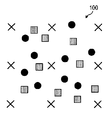
깊이 정보 및 카메라 파라미터들이 주어지면, 합성된 뷰 상으로 참조 픽셀들을 워핑하는 것은 간단하다. 가장 중요한 문제는 워핑된 참조 뷰 픽셀들로부터 타겟 뷰에서의 픽셀 값들을 어떻게 추정할 것인가 이다. 도 1a 및 도 1b는 이러한 기본적인 문제를 나타내고 있다. 도 1a는 비교정된 뷰 합성(100)을 도시한다. 도 1b는 교정된 뷰 합성(150)을 도시한다. 도 1a 및 도 1b에서, 문자 "X"는 추정돼야할 타겟 뷰에서의 픽셀을 나타내고, 원형 표시들 및 사각형 표시들은 서로 다른 참조 뷰들로부터 워핑된 픽셀들을 나타내며, 여기서 상위 형상(difference shape)들은 상위 참조 뷰(difference reference view)들을 나타낸다.Given depth information and camera parameters, warping the reference pixels onto the synthesized view is simple. The most important question is how to estimate pixel values in the target view from the warped reference view pixels. 1A and 1B illustrate this basic problem. 1A shows a
간단한 방법은 워핑된 샘플들을 목적지 뷰에서의 자신의 가장 가까운 픽셀 위치로 라운딩(rounding)시키는 것이다. 복수의 픽셀들이, 합성된 뷰에서 동일한 위치로 맵핑될 때, Z-버퍼링(Z-buffering)이 전형적인 해법인바, 즉 카메라에 가장 가까운 픽셀이 선택된다. 이러한 방식(가장 가까운 픽셀 위치 라운딩)은, 특히 오브젝트 바운더리(object boundary)들을 따라 약간 언더-샘플링(under-sampling)된 임의의 표면에서 핀홀(pinhole)들을 종종 발생시킬 수 있다. 이러한 핀홀 문제에 대처하는 가장 일반적인 방법은 참조 뷰에서의 하나의 픽셀을 타겟 뷰에서의 수개의 픽셀들로 맵핑시키는 것이다. 이러한 프로세스는 스플랫팅으로 불리운다.A simple way is to round the warped samples to their nearest pixel position in the destination view. When multiple pixels are mapped to the same location in the synthesized view, Z-buffering is a typical solution, i.e., the pixel closest to the camera is selected. This approach (closest pixel position rounding) can often generate pinholes, especially at any surface slightly under-sampled along object boundaries. The most common way to deal with this pinhole problem is to map one pixel in the reference view to several pixels in the target view. This process is called splatting.
만약 참조 픽셀이 타겟 뷰에서의 복수의 주변 타겟 픽셀들로 맵핑된다면, 대부분의 핀홀들은 제거될 수 있다. 그러나, 일부 이미지 디테일(image detail)이 손실될 것이다. 투명한 스플랫-타입의 재구성 커널(transparent splat-type reconstruction kernel)을 사용하는 경우, 핀홀 제거와 디테일의 손실 간에 동일한 상충관계(trade-off)가 일어난다. 문제는 "스플랫팅의 정도를 어떻게 제어할 것인가?"이다. 예를 들어, 각각의 워핑된 픽셀에 있어서, 이 워핑된 픽셀을 자신의 주변 타겟 픽셀들 모두에 맵핑할 것인가? 또는 단지 자신에게 가장 가까운 것에만 맵핑할 것인가? 이 문제는 여러 문헌들에서 대부분 다루어지고 있지 않다.If the reference pixel is mapped to a plurality of peripheral target pixels in the target view, most pinholes can be removed. However, some image detail will be lost. When using a transparent splat-type reconstruction kernel, the same trade-off occurs between pinhole removal and loss of detail. The question is, how do you control the degree of splatting? For example, for each warped pixel, will you map this warped pixel to all of its surrounding target pixels? Or will you only map to the one closest to you? This problem is not addressed in most of the literature.
복수의 참조 뷰들이 사용되는 경우, 일반적인 방법은 각각의 참조 뷰로부터의 합성을 개별적으로 프로세싱하고, 그 다음에 복수의 합성된 뷰들을 함께 병합하는 것이다. 문제는 이들을 어떻게 병합하는가인데, 예를 들어 어떤 특정의 가중치 부여 방식이 사용될 수 있다. 예를 들어, 서로 다른 가중치들이, 각거리(angular distance), 이미지 해상도(image resolution) 등에 근거하여, 서로 다른 참조 뷰들에 적용될 수 있다. 이러한 문제들이, 노이즈가 있는 깊이 정보에 강한 방식으로 처리돼야만 함에 주목해야 한다.If a plurality of reference views are used, the general method is to process the synthesis from each reference view separately and then merge the plurality of synthesized views together. The question is how to merge them, for example some specific weighting scheme can be used. For example, different weights may be applied to different reference views based on angular distance, image resolution, and the like. It should be noted that these problems must be addressed in a strong manner against noisy depth information.
DIBR을 사용하여, 본 명세서에서 참조 뷰들로 또한 언급되는, 캡처된 뷰들로부터 가상 뷰가 발생될 수 있다. 특히, 입력 깊이 정보가 노이즈가 있고 다른 장면 정보(scene information)(예를 들어, 장면의 3D 표면 특성)가 알려져 있지 않은 경우에, 가상 뷰의 발생을 위한 작업은 해 볼만 한 작업이다.Using DIBR, virtual views can be generated from captured views, also referred to herein as reference views. In particular, when the input depth information is noisy and other scene information (e.g., 3D surface characteristics of the scene) is not known, the work for generating the virtual view is a worthwhile operation.
가장 어려운 문제들 중 하나는 종종, 참조 뷰들에서의 샘플 픽셀들이 워핑된 이후에, 합성된 뷰에서의 각각의 픽셀의 값을 어떻게 추정할 것인 가이다. 예를 들어, 각각의 타겟 합성 픽셀에 대해, 어떤 참조 픽셀들이 사용돼야만 하는가?, 그리고 이들을 어떻게 결합할 것인가?One of the most difficult problems is how to estimate the value of each pixel in the synthesized view, often after the sample pixels in the reference views are warped. For example, for each target composite pixel, what reference pixels should be used, and how do you combine them?
적어도 일 실시예에서, 본 명세서는 3DV 애플리케이션들을 위한 바운더리-스플랫팅(boundary-splatting)을 사용하는 뷰 합성을 위한 프레임워크를 제안한다. 본원의 발명자들은, 가상 뷰의 발생을 포함하는 (예를 들어, DIBR을 사용하는) 3DV 애플리케이션들에서, 이러한 발생은, 특히 입력 깊이 정보가 노이즈가 있고 다른 장면 정보(예를 들어, 장면의 3D 표면 특성)가 알려져 있지 않은 경우에, 해 볼만 한 작업임을 주목하고 있다.In at least one embodiment, the present specification proposes a framework for view synthesis using boundary-splatting for 3DV applications. The inventors of the present application find that, in 3DV applications (eg, using DIBR) involving the generation of a virtual view, this generation is particularly true when the input depth information is noisy and other scene information (eg, 3D of the scene). Note that this is a worthwhile operation if the surface properties are not known.
본원의 발명자들은 또한, 참조 픽셀이 타겟 뷰에서의 복수의 주변 타겟 픽셀들로 맵핑되고, 대부분의 핀홀들이 제거될 수 있는 경우에, 불행하게도 일부 이미지 디테일이 손실될 수 있음을 주목하고 있다. 투명한 스플랫-타입의 재구성 커널을 사용하는 경우, 핀홀 제거와 디테일의 손실 간에 동일한 상충관계가 일어난다. 문제는 "스플랫팅의 정도를 어떻게 제어할 것인가?"이다. 예를 들어, 각각의 워핑된 픽셀에 있어서, 이 워핑된 픽셀을 자신의 주변 타겟 픽셀들 모두에 맵핑할 것인가? 혹은 단지 자신에게 가장 가까운 것에만 맵핑할 것인가?The inventors also note that if the reference pixel is mapped to a plurality of peripheral target pixels in the target view and most of the pinholes can be removed, unfortunately some image detail may be lost. When using a transparent splat-type reconstruction kernel, the same tradeoff occurs between pinhole removal and loss of detail. The question is, how do you control the degree of splatting? For example, for each warped pixel, will you map this warped pixel to all of its surrounding target pixels? Or just map to the one closest to you?
적어도 일 실시예에서, 본 명세서는 (1) 바운더리 층들 주변의 픽셀들에만 스플랫팅을 적용하는 것, 즉 약간의 깊이 불연속을 갖는 영역들에서의 픽셀들을 단지 가장 가까이 있는 이웃 픽셀에만 맵핑시키는 것과, 그리고 (2) 복수의 참조 뷰들로부터의 합성된 이미지들을 병합하는 경우 Z-버퍼와 함께 홀 분포 혹은 백워드 합성 에러를 사용하는 두 개의 새로운 휴리스틱 병합 방식을 제안한다.In at least one embodiment, the present specification relates to (1) applying splatting only to pixels around boundary layers, i.e., mapping pixels in regions with some depth discontinuity to only the nearest neighboring pixel; And (2) propose two new heuristic merging methods using hole distribution or backward synthesis error with Z-buffer when merging synthesized images from a plurality of reference views.
추가적으로, 본원의 발명자들이 주목하고 있는 것은, 참조 뷰들로부터 가상 뷰를 합성하기 위해서는 일반적으로 세 개의 단계들이 필요한데, 즉 (1) 포워드 워핑(forward warping), (2) 블렌딩(blending)(단일 뷰 합성 및 복수 뷰 병합), (3) 홀-필링(hole-filling)이 필요하다는 것이다. 적어도 일 실시예는 노이즈가 있는 깊이 정보에 의해 야기되는 문제들에 대처하기 위해 블렌딩을 개선하는 몇 가지 알고리즘들에 기여한다. 시뮬레이션은 3DV에서의 일부 기존 방식들과 비교하는 경우 월등한 품질을 보여주었다.In addition, the inventors note that generally three steps are required to synthesize a virtual view from reference views: (1) forward warping, (2) blending (single view synthesis). And merging multiple views), and (3) hole-filling. At least one embodiment contributes to several algorithms that improve blending to cope with problems caused by noisy depth information. Simulation showed superior quality when compared to some existing methods in 3DV.
참조 뷰들로부터 가상 뷰를 합성하는 것에 관한 앞서 언급된 세 개의 단계들 중 워핑 단계에 대해, 기본적으로 두 개의 옵션들은 워핑 결과들을 어떻게 프로세싱할 것인가, 즉 병합 및 블렌딩에 관해 존재하는 것으로 고려될 수 있다.For the warping phase of the three previously mentioned steps relating to compositing the virtual view from the reference views, basically two options can be considered to exist regarding how to process the warping results, ie merging and blending. .
병합에 대하여, 각각의 뷰는 완전히 워핑되어 각각의 참조에 대한 최종 워핑된 뷰가 형성될 수 있다. 그 다음에 이러한 최종 워핑된 뷰들이 "병합"되어 단일의 실제 최종 합성된 뷰가 획득될 수 있다. "병합"은 예를 들어 N개의 후보들(N개의 최종 워핑된 뷰들이 존재한다고 가정) 간의 선택을 포함하거나, 혹은 어떤 방식으로 이들을 결합하는 것을 포함한다. 물론, 타겟 픽셀 값을 결정하는데 사용되는 후보들의 수가 워핑된 뷰들의 수와 동일할 필요는 없음을 이해해야 한다. 즉, 복수의 후보들(혹은 전혀 없는 것)이 단일 뷰로부터 발생할 수 있다.For merging, each view may be fully warped to form a final warped view for each reference. These final warped views can then be "merged" to obtain a single actual final synthesized view. "Merge" includes, for example, the selection between N candidates (assuming there are N final warped views), or includes combining them in some way. Of course, it should be understood that the number of candidates used to determine the target pixel value need not be the same as the number of warped views. That is, multiple candidates (or none at all) may arise from a single view.
블렌딩에 관하여, 각각의 뷰는 여전히 워핑되지만 각각의 참조에 대해 최종 워핑된 뷰가 형성되지 않는다. 최종적인 것이 아니기 때문에, 블렌딩에 따라 더 많은 옵션들이 유지된다. 이것은 이로울 수 있는데, 왜냐하면 일부 경우에 있어 서로 다른 뷰들은 합성된 타겟 뷰의 서로 다른 부분들에 대해 최상의 정보를 제공할 수 있기 때문이다. 따라서, 블렌딩은 각각의 픽셀에서 서로 다른 뷰들로부터의 정보의 올바른 결합을 선택할 수 있도록 하는 융통성을 제공한다. 따라서, 병합은 두 단계 블렌딩의 특별한 경우로서 고려될 수 있다(여기서 각각의 뷰로부터의 후보들이 먼저 개별적으로 프로세싱되고, 그 다음에 결과들이 결합됨).Regarding blending, each view is still warped but no final warped view is formed for each reference. Since it is not final, more options are maintained depending on the blending. This can be beneficial because, in some cases, different views can provide the best information about different parts of the synthesized target view. Thus, blending provides the flexibility to select the correct combination of information from different views in each pixel. Thus, merging can be considered as a special case of two-step blending, where candidates from each view are first processed separately and then the results are combined.
다시 도 1a를 참조하면, 도 1a는 전형적인 블렌딩 동작에 대한 입력을 도시한 것으로 고려될 수 있는데, 왜냐하면 도 1a는 서로 다른 참조 뷰들로부터 워핑된 픽셀들(각각 원형 표시들 및 사각형 표시들)을 포함하고 있기 때문이다. 이와는 대조적으로, 전형적인 병합 애플리케이션에 있어서, 원형 표시들 혹은 사각형 표시들 중 단지 어느 하나만을 볼 수 있을 것으로 예측되는데, 왜냐하면 전형적으로 각각의 참조 뷰는, 개별적으로 워핑되고, 그 다음에 각각의 참조에 대해 최종 워핑된 뷰를 형성하기 위해 프로세싱되기 때문이다. 복수의 참조들에 대해 최종 워핑된 뷰들은 그 다음에 전형적인 병합 애플리케이션에서 결합된다.Referring again to FIG. 1A, FIG. 1A may be considered to show an input for a typical blending operation, because FIG. 1A includes pixels warped from different reference views (circular and rectangular representations, respectively). Because it is. In contrast, in a typical merged application, it is expected that only one of the circular representations or the square representations can be seen, since typically each reference view is warped separately, and then on each reference. Because it is processed to form the final warped view. The final warped views for the plurality of references are then combined in a typical merged application.
다시 블렌딩으로 돌아가서, 이에 관한 한 가지 가능한 옵션/고려사항으로서, 홀들 모두의 필링(filling)을 원하지 않아, 스플랫팅을 수행하지 않는 것이다. 이런 옵션들 및 다른 옵션들은, 본 발명의 원리의 사상을 유지하면서, 본 발명의 기술 분야 및 관련 기술 분야에서 통상의 기술을 가진자에 의해 쉽게 결정된다.Going back to blending, one possible option / consideration in this regard is that no filling of all of the holes is desired and no splatting is performed. These and other options are readily determined by one of ordinary skill in the art and related arts, while maintaining the spirit of the present principles.
따라서, 본 발명의 원리의 하나 이상의 실시예들은 병합에 관한 것일 수 있으며, 본 발명의 원리의 다른 실시예들은 블렌딩에 관한 것일 수 있음을 이해해야 한다. 물론, 추가적 실시예들은 병합과 블렌딩의 결합을 포함할 수 있다. 본 명세서에서 설명되는 특징 및 개념은 일반적으로 블렌딩 및 병합 양쪽 모두에 적용될 수 있는바, 비록 블렌딩 혹은 병합 중 단지 어느 하나의 맥락에서만 설명될지라도 그러하다. 본 명세서에서 제공되는 본 발명의 원리들의 가르침이 주어지는 경우, 본 발명의 기술분야 및 관련 기술분야에서 통상의 기술을 가진자는, 본 발명의 원리의 사상을 유지하면서, 병합 및/또는 블렌딩에 관한 다양한 애플리케이션들을 쉽게 고려할 수 있을 것이다.Accordingly, it should be understood that one or more embodiments of the principles of the present invention may relate to merging and that other embodiments of the principles of the present invention may relate to blending. Of course, additional embodiments may include a combination of merging and blending. The features and concepts described herein may generally be applied to both blending and merging, even if only described in the context of either blending or merging. Given the teachings of the principles of the invention provided herein, one of ordinary skill in the art and related arts will appreciate that various aspects of merging and / or blending may be made while maintaining the spirit of the principles of the invention. You can easily consider the applications.
본 발명의 원리는 일반적으로 통신 시스템에 관한 것이고, 특히 무선 시스템, 예를 들어, 지상파 방송, 셀률러, 무선-충실도(Wireless-Fidelity, Wi-Fi), 인공위성 등에 관한 것임을 이해해야 한다. 본 발명의 원리가 예를 들어, 인코더, 디코더, 전처리 프로세서(pre-processor), 후처리 프로세서(post processor), 및 수신기(이것은 앞서 나열된 것 중 하나 또는 그 이상의 것을 포함할 수 있음)로 구현될 수 있음을 또한 이해해야 한다. 예를 들어, 인코딩 목적으로 사용하기 위해 가상 이미지를 발생시킬 것이 요구되는 애플리케이션에서, 본 발명의 원리는 인코더로 구현될 수 있다. 인코더에 관한 추가적 예로서, 이러한 인코더는 가상 뷰를 합성하는데 사용될 수 있는바, 이 가상 뷰는 해당하는 가상 뷰 위치로부터 실제 픽쳐들을 인코딩하는 데 사용하기 위한 것이거나 혹은 그 가상 뷰 위치에 가까운 뷰 위치로부터 픽쳐들을 인코딩하는데 사용하기 위한 것이다. 두 개의 참조 픽쳐들을 포함하는 실시예들에서, 양쪽 모두는 가상 뷰에 대응하는 가상 픽쳐와 함께 인코딩될 수 있다. 물론, 본 명세서에서 제공되는 본 발명의 원리들의 가르침이 주어지는 경우, 본 발명의 기술분야 및 관련 기술분야에서 통상의 기술을 가진자는, 본 발명의 원리의 사상을 유지하면서, 이러한 애플리케이션 및 다양한 다른 애플리케이션을 고려할 수 있을 뿐만 아니라 앞서 설명된 애플리케이션에 대한 변형물(여기에 본 발명의 원리가 적용될 수 있음)을 고려할 수 있을 것이다.It should be understood that the principles of the present invention generally relate to communication systems, and in particular to wireless systems, such as terrestrial broadcast, cellular, wireless-fidelity (Wi-Fi), satellites, and the like. The principles of the invention may be implemented with, for example, an encoder, a decoder, a pre-processor, a post processor, and a receiver (which may include one or more of those listed above). It should also be understood that it can. For example, in applications where it is necessary to generate a virtual image for use for encoding purposes, the principles of the present invention can be implemented with an encoder. As a further example of an encoder, such an encoder can be used to synthesize a virtual view, which is for use in encoding actual pictures from a corresponding virtual view position or a view position close to that virtual view position. It is for use in encoding pictures from. In embodiments that include two reference pictures, both can be encoded with a virtual picture corresponding to the virtual view. Of course, given the teachings of the principles of the invention provided herein, one of ordinary skill in the art and related arts will appreciate that these and various other applications may be maintained while maintaining the spirit of the principles of the invention. In addition to the above, variations to the above-described application (where the principles of the present invention can be applied) may be considered.
추가적으로, 본 명세서에 하나 이상의 실시예들이 H.264/MPEG-4 AVC (AVC) 표준에 관해 설명되고 있지만, 본 발명의 원리가 오로지 이것에만 한정되는 것은 아니며, 따라서 본 명세서에서 제공되는 본 발명의 원리들의 가르침이 주어지는 경우, 본 발명의 원리의 사상을 유지하면서, 복수 뷰 비디오 코딩(Multi-view Video Coding, MVC), 현재 및 장래의 3DV 표준에 쉽게 적용될 수 있을 뿐만 아니라 다른 비디오 코딩 표준, 사양, 및/또는 권고안에 적용될 수 있음을 이해해야만 한다.Additionally, although one or more embodiments are described herein with respect to the H.264 / MPEG-4 AVC (AVC) standard, the principles of the present invention are not limited solely to this, and therefore, the present invention provided herein. Given the teachings of the principles, other video coding standards, specifications, as well as being easily applicable to Multi-view Video Coding (MVC), current and future 3DV standards, while maintaining the spirit of the principles of the present invention It should be understood that they may apply to, and / or to, recommendations.
"스플랫팅(splatting)"은 참조 뷰로부터의 하나의 워핑된 픽셀을 타겟 뷰에서의 수개의 픽셀들에 맵핑시키는 프로세스를 말하는 것임에 유의해야 한다.Note that "splatting" refers to the process of mapping one warped pixel from a reference view to several pixels in the target view.
"깊이 정보(depth information)"는 깊이에 대한 다양한 종류의 정보를 말하는 일반적인 용어임에 유의해야 한다. 일 타입의 깊이 정보는 "깊이 맵(depth map)"이고, 이는 일반적으로 픽셀당 깊이 이미지를 말한다. 다른 타입의 깊이 정보는 예를 들어, 각각의 코딩된 픽셀에 대한 것이 아닌 각각의 코딩된 블록에 대한 단일의 깊이 값을 사용하는 것을 포함한다.It should be noted that "depth information" is a general term referring to various kinds of information about depth. One type of depth information is a "depth map", which generally refers to a depth image per pixel. Another type of depth information includes, for example, using a single depth value for each coded block rather than for each coded pixel.
도 2a는 본 발명의 원리의 실시예에 따른, 본 발명의 원리가 적용될 수 있는 예시적인 뷰 합성기(200)를 나타낸다. 뷰 합성기(200)는 포워드 워퍼(forward warper)들(210-1 내지 210-K), 뷰 병합기(220) 및 홀 필러(hole filler)(230)를 포함한다. 포워드 워퍼들(210-1 내지 210-K)의 각각의 출력은 이미지 합성기들(215-1 내지 215-K)의 각각의 입력과 신호 통신으로 연결된다. 이미지 합성기들(215-1 내지 215-K)의 각각의 출력은 뷰 병합기(220)의 제1의 입력과 신호 통신으로 연결된다. 뷰 병합기(220)의 출력은 홀 필러(230)와 신호 통신으로 연결된다. 포워드 워퍼들(210-1 내지 210-K)의 제1의 각각의 입력들은, 각각의 참조 뷰 1 내지 참조 뷰 K를 수신하기 위한, 뷰 합성기(200)의 입력들로서 이용가능하다. 포워드 워퍼들(210-1 내지 210-K)의 제2의 각각의 입력들 및 이미지 합성기들(215-1 내지 215-K)의 제2의 각각의 입력들은, 뷰 1 및 타겟 뷰 깊이 맵들 및 이에 대응하는 카메라 파라미터들, 내지 뷰 K 및 타겟 뷰 깊이 맵들 및 이에 대응하는 카메라 파라미터들을 각각 수신하기 위한, 뷰 합성기(200)의 입력들로서 이용가능하다. 뷰 병합기(220)의 제2의 입력은, 모든 뷰들의 카메라 파라미터들 및 깊이 맵들을 수신하기 위한, 뷰 합성기의 입력으로서 이용가능하다. 홀 필러(230)의 제2의 입력(선택적 입력)은, 모든 뷰들의 카메라 파라미터들 및 깊이 맵들을 수신하기 위한, 뷰 합성기(200)의 입력으로서 이용가능하다. 홀 필러(230)의 출력은, 타겟 뷰를 출력하기 위한, 뷰 합성기(200)의 출력으로서 이용가능하다.2A illustrates an
도 2b는 본 발명의 원리의 실시예에 따른 본 발명의 원리가 적용될 수 있는 예시적인 이미지 합성기(250)를 나타낸다. 이미지 합성기(250)는 스플랫터(splatter)(255)를 포함하고, 스플랫터(255)는 타겟 픽셀들 계산기(target pixels evaluator)(260)의 입력과 신호 통신으로 연결되는 출력을 갖는다. 타겟 픽셀들 계산기(260)의 출력은 홀 마커(hole marker)(265)의 입력과 신호 통신으로 연결된다. 스플랫터(255)의 입력은, 참조 뷰로부터의 워핑된 픽셀들을 수신하기 위한, 이미지 합성기(250)의 입력으로서 이용가능하다. 홀 마커(265)의 출력은, 합성된 이미지를 출력하기 위한, 이미지 합성기(250)의 출력으로서 이용가능하다. 홀 마커(265)는 선택적인 것이며, 홀 마킹(hole marking)이 필요하지 않고 타겟 픽셀 계산만으로 충분한 일부 실시예에서 생략될 수 있음을 이해해야 한다.2B illustrates an
스플랫터(255)는 다양한 방식으로 구현될 수 있다. 예를 들어, 스플랫팅의 기능을 수행하는 소프트웨어 알고리즘이 범용 컴퓨터 혹은 특정 용도의 머신(예를 들어, 비디오 인코더와 같은 것)을 통해 실행될 수 있다. 스플랫팅의 일반적인 기능들은 본 발명의 기술분야에서 통상의 기술을 가진자에게 잘 알려져 있다. 이러한 구현은 본 명세서에서 설명되는 바와 같이 수정될 수 있어, 예를 들어, 워핑된 참조에서의 픽셀이 하나 이상의 깊이 바운더리들로부터 특정 거리 내에 있는지 여부를 근거로 스플랫팅 기능을 수행할 수 있다. 본 명세서에서 설명되는 구현들에 의해 수정되는 바와 같은 스플랫팅 기능들은 대안적으로, 특수 목적 집적 회로(예를 들어, 애플리케이션 특정 집적 회로(Application-Specific Integrated Circuit, ASIC)) 혹은 다른 하드웨어에서 구현될 수 있다. 구현들은 또한 소프트웨어, 하드웨어 및 펌웨어의 결합을 사용할 수 있다.The
예를 들어, 포워드 워퍼들(210), 홀 마커(265), 및 타겟 픽셀들 계산기(260)와 같은 도 2a 및 도 2b의 다른 구성요소들이 스플랫터(255)에서와 마찬가지로 구현될 수 있다. 예를 들어, 포워드 워퍼(210)의 구현들은, 범용 컴퓨터 혹은 애플리케이션 특정 디바이스 또는 애플리케이션 특정 집적 회로를 통해 워핑의 공지된 기능들을 수행하기 위해, 소프트웨어, 하드웨어 및/또는 펌웨어를 사용할 수 있다. 추가적으로, 홀 마커(265)의 구현들은 홀을 마킹하기 위해 다양한 실시예에서 설명되는 기능들을 수행하도록, 예를 들어 소프트웨어, 하드웨어 및/또는 펌웨어를 사용할 수 있고, 그리고 이러한 기능들은 예를 들어, 범용 컴퓨터 혹은 애플리케이션 특정 디바이스 또는 애플리케이션 특정 집적 회로를 통해 수행될 수 있다. 더욱이, 타겟 픽셀 계산기(260)의 구현들은, 타겟 픽셀을 계산하기 위해 다양한 실시예에서 설명되는 기능들을 수행하도록, 예를 들어 소프트웨어, 하드웨어 및/또는 펌웨어를 사용할 수 있고, 그리고 이러한 기능들은 예를 들어, 범용 컴퓨터 혹은 애플리케이션 특정 디바이스 또는 애플리케이션 특정 집적 회로를 통해 수행될 수 있다.For example, other components of FIGS. 2A and 2B, such as
더욱이, 뷰 병합기(220)는 또한, 예를 들어, 홀 마커(265) 혹은 홀 마커(265)의 변형물과 같은 그러한 홀 마커를 포함할 수 있다. 이러한 구현들에서, 뷰 병합기(220)는 또한, 예를 들어, 실시예 2 및 실시예 3 그리고 도 8 및 도 10에서 제시되어 설명되는 바와 같이, 홀들을 마킹할 수 있다.Moreover,
추가적으로, 뷰 병합기(220)는 다양한 방식으로 구현될 수 있다. 예를 들어, 뷰 병합의 기능을 수행하는 소프트웨어 알고리즘이 범용 컴퓨터 혹은 특정 용도의 머신(예를 들어, 비디오 인코더와 같은 것)을 통해 구현될 수 있다. 뷰 병합의 일반적인 기능들은 본 발명의 기술분야에서 통상의 기술을 가진자에게 잘 알려져 있다. 그러나, 이러한 구현은 본 명세서에서 설명되는 바와 같이 수정될 수 있어, 예를 들어, 본 명세서의 하나 이상의 구현들을 위해 설명된 뷰 병합 기술들을 수행할 수 있다. 본 명세서에서 설명되는 구현들에 의해 수정되는 바와 같은 뷰 병합 기능들은 대안적으로, 특수 목적 집적 회로(예를 들어, 애플리케이션 특정 집적 회로(ASIC)) 혹은 다른 하드웨어에서 구현될 수 있다. 구현들은 또한, 소프트웨어, 하드웨어 및 펌웨어의 결합을 사용할 수 있다.Additionally,
뷰 병합기(220)의 일부 구현들은, 제1의 워핑된 참조 뷰로부터의 제 1 후보 픽셀 및 제2의 워핑된 참조 뷰로부터의 제 2 후보 픽셀을, 제 1 후보 픽셀 및 제 2 후보 픽셀의 품질을 평가하기 위한 백워드 합성 프로세스, 제 1 후보 픽셀 및 제 2 후보 픽셀 주변의 홀 분포 중 적어도 하나에 근거하여 혹은 특정 주파수 이상의 제 1 후보 픽셀 및 제 2 후보 픽셀 주변의 에너지의 양에 근거하여, 평가하는 기능을 포함한다. 뷰 병합기(220)의 일부 구현들은 또한, 이러한 평가에 근거하여, 단일의 합성된 뷰에서의 소정의 타겟 픽셀에 대한 결과를 결정하는 기능을 포함한다. 이러한 기능들 모두는 예를 들어 도 10 및 본 명세서의 다른 부분에 제시되어 설명된다. 이러한 구현들은, 예를 들어, 이러한 기능들 각각을 수행하기 위한, 명령들의 단일의 세트, 혹은 명령들의 서로 다른(오버랩핑을 포함함) 세트들을 포함할 수 있고, 그리고 이러한 명령들은, 예를 들어 범용 컴퓨터, 특수 목적 머신(예를 들어, 비디오 인코더와 같은 것), 또는 애플리케이션 특정 집적 회로를 통해 구현될 수 있다. 더욱이, 이러한 기능은 소프트웨어, 하드웨어 혹은 펌웨어의 다양한 결합을 사용하여 구현될 수 있다.Some implementations of the
도 3은 본 발명의 원리의 구현에 따른 본 발명의 원리가 적용될 수 있는 예시적인 비디오 전송 시스템(300)을 나타낸다. 비디오 전송 시스템(300)은, 예를 들어 위성, 케이블, 전화선, 혹은 지상파 방송과 같은 다양한 매체들 중 어느 하나를 사용하여 신호를 전송하기 위한 헤드-엔드(head-end) 혹은 전송 시스템일 수 있다. 이러한 전송은 인터넷 혹은 어떤 다른 네트워크를 통해 제공될 수 있다.3 illustrates an example
비디오 전송 시스템(300)은 깊이를 갖는 인터-뷰 스킵 모드(inter-view skip mode)를 사용하여 인코딩된 비디오 콘텐츠를 발생시켜 전달할 수 있다. 이것은, 예를 들어 디코더를 가질 수 있는 수신기에서 깊이 정보를 합성하는데 사용될 수 있는 정보 혹은 깊이 정보를 포함하는 인코딩된 신호(들)를 발생시킴으로써 달성된다.The
비디오 전송 시스템(300)은 인코더와, 그리고 인코딩된 신호를 전송할 수 있는 송신기(320)를 포함한다. 인코더(310)는 비디오 정보를 수신하고, 깊이를 갖는 인터-뷰 스킵 모드를 사용하여 이로부터 인코딩된 신호(들)를 발생시킨다. 인코더(310)는 예를 들어, AVC 인코더일 수 있다. 인코더(310)는 서브모듈(sub-module)들을 포함할 수 있으며, 이 서브 모듈들은, 예를 들어, 다양한 정보를 수신하여 저장 혹은 전송을 위한 구조화된 포맷으로 조립하는 조립 유닛(assembly unit)을 포함할 수 있다. 다양한 정보로는, 예를 들어, 코딩된 혹은 언코딩된 비디오, 코딩된 혹은 언코딩된 깊이 정보, 및 코딩된 혹은 언코딩된 요소들(예를 들어, 모션 벡터(motion vector)들, 코딩 모드 표시자(coding mode indicator)들, 및 신택스 요소(syntax element)들과 같은 것)을 포함할 수 있다.
송신기(320)는, 예를 들어, 인코딩된 픽쳐들 및/또는 이와 관련된 정보를 나타내는 하나 이상의 비트스트림(bitstream)들을 가진 프로그램 신호를 전송하도록 구성될 수 있다. 전형적인 송신기들은, 예를 들어, 에러 정정 코딩을 제공하는 것, 신호에 데이터를 인터리브(interleave)하는 것, 신호 내의 에너지 랜덤화(randomizing)하는 것 및 신호를 하나 이상의 캐리어들 상에 변조하는 것 중 하나 이상의 기능과 같은 그러한 기능들을 수행한다. 송신기는 안테나를 포함할 수 있거나, 혹은 안테나와 인터페이스할 수 있다(미도시). 따라서, 송신기(320)의 구현은 변조기를 포함할 수 있지만, 이러한 것에만 한정되는 것은 아니다.The
도 4는 본 발명의 원리의 실시예에 따른, 본 발명의 원리가 적용될 수 있는 예시적인 비디오 수신 시스템(400)을 나타낸다. 비디오 수신 시스템(400)은, 예를 들어, 위성, 케이블, 전화선, 혹은 지상파 방송과 같은 다양한 매체들을 통해 신호들을 수신하도록 구성될 수 있다. 신호들은 인터넷 혹은 어떤 다른 네트워크를 통해 수신될 수 있다.4 illustrates an example
비디오 수신 시스템(400)은, 예를 들어, 셀폰(cell-phone), 컴퓨터, 셋탑 박스, 텔레비젼일 수 있거나 혹은 인코딩된 비디오를 수신하고 예를 들어 디코딩된 비디오를 사용자에게 디스플레이하기 위해 제공 혹은 저장용으로 제공하는 다른 디바이스일 수 있다. 따라서, 비디오 수신 시스템(400)은 그 출력을 예를 들어 텔레비젼의 스크린, 컴퓨터 모니터, (저장, 프로세싱 혹은 디스플레이를 위한) 컴퓨터, 또는 어떤 다른 저장, 프로세싱, 혹은 디스플레이 디바이스에 제공할 수 있다.The
비디오 수신 시스템(400)은 비디오 정보를 포함하는 비디오 콘텐츠를 수신 및 프로세싱할 수 있다. 비디오 수신 시스템(400)은, 예를 들어, 본 명세서의 구현들에서 설명되는 신호들과 같은 그러한 인코딩된 신호를 수신할 수 있는 수신기(410)와, 그리고 수신된 신호를 디코딩할 수 있는 디코더(420)를 포함한다.The
수신기(410)는, 예를 들어, 인코딩된 픽쳐들을 나타내는 복수의 비트스트림들을 갖는 프로그램 신호를 수신하도록 구성될 수 있다. 전형적인 수신기들은, 변조 및 인코딩된 데이터 신호를 수신하는 것, 하나 이상의 캐리어들로부터 데이터 신호를 복조하는 것, 신호 내의 에너지 역랜덤화(de-randomizing)하는 것, 신호 내의 데이터를 디인터리브(de-interleave)하는 것, 및 신호를 에러 정정 디코딩하는 것 중 하나 이상 기능과 같은 그러한 기능들을 수행한다. 수신기(410)는 안테나를 포함할 수 있거나, 혹은 안테나와 인터페이스할 수 있다(미도시). 수신기(410)의 구현은 복조기를 포함할 수 있지만, 이러한 것에만 한정되는 것은 아니다.
디코더(420)는 비디오 정보 및 깊이 정보를 포함하는 비디오 신호들을 출력한다. 디코더(420)는 예를 들어 AVC 디코더일 수 있다.The
도 5는 본 발명의 원리의 실시예에 따른, 본 발명의 원리가 적용될 수 있는 예시적인 비디오 프로세싱 디바이스(500)를 나타낸다. 비디오 프로세싱 디바이스(500)는, 예를 들어, 셋탑 박스일 수 있거나, 또는 인코딩된 비디오를 수신하고 예를 들어 디코딩된 비디오를 사용자에게 디스플레이하기 위해 혹은 저장을 위해 제공하는 다른 디바이스일 수 있다. 따라서, 비디오 프로세싱 디바이스(500)는 그 출력을 텔레비젼, 컴퓨터 모니터, 또는 컴퓨터 혹은 다른 프로세싱 디바이스에 제공할 수 있다.5 illustrates an example
비디오 프로세싱 디바이스(500)는 프런트-엔드(Front-End, FE) 디바이스(505) 및 디코더(510)를 포함한다. 프런트-엔드 디바이스(505)는, 예를 들어, 인코딩된 픽쳐들을 나타내는 복수의 비트스트림들을 갖는 프로그램 신호를 수신하도록 구성됨과 아울러 복수의 비트스트림들로부터 디코딩을 위한 하나 이상의 비트스트림들을 선택하도록 구성될 수 있다. 전형적인 수신기들은, 예를 들어, 변조 및 인코딩된 데이터 신호를 수신하는 것, 데이터 신호를 복조하는 것, 데이터 신호의 하나 이사의 인코딩들(예를 들어, 채널 코딩 및/또는 소스 코딩)을 디코딩하는 것, 및/또는 데이터 신호를 에러 정정하는 것 중 하나 이상의 기능과 같은 그러한 기능들을 수행한다. 프런트-엔드 디바이스(505)는 예를 들어, 안테나(미도시)로부터 프로그램 신호를 수신할 수 있다. 프런트-엔드 디바이스(505)는 수신된 데이터 신호를 디코더(510)에 제공한다.
디코더(510)는 데이터 신호(520)를 수신한다. 데이터 신호(520)는, 예를 들어, 하나 이상의 고급 비디오 코딩(Advanced Video Coding, AVC), 스케일링가능 비디오 코딩(Scalable Video Coding, SVC), 혹은 복수 뷰 비디오 코딩(Multi-view Video Coding, MVC) 호환가능 스트림들을 포함할 수 있다.The
AVC는, 보다 구체적으로는, 기존의 ISO/IEC(International Organization for Standardization/International Electrotechnical Commission) MPEG-4(Moving Picture Experts Group-4) 파트(Part) 10 AVC(Advanced Video Coding) 표준(standard)/ITU-T(International Telecommunication Union, Telecommunication Sector) H.264 권고안(Recommendation)(이하에서는 "H.264/MPEG-4 AVC 표준" 혹은 그 변형물, 예를 들어 "AVC 표준" 혹은 간단히 "AVC")을 말한다.More specifically, the AVC is an existing International Organization for Standardization / International Electrotechnical Commission (ISO / IEC) Moving Picture Experts Group-4 (MPEG-4) Part 10 Advanced Video Coding (AVC) standard / International Telecommunication Union (ITU-T) H.264 Recommendation (hereinafter referred to as the "H.264 / MPEG-4 AVC Standard" or a variant thereof, for example "AVC Standard" or simply "AVC") Say
MVC는, 보다 구체적으로는, AVC 표준의 복수-뷰 비디오 코딩(Multi-view Video Coding)("MVC") 확장(extension) (애넥스(Annex) H)를 말하며, 이는 H.264/MPEG-4 AVC, MVC 확장("MVC 확장" 혹은 간단히 "MVC")으로 언급된다.MVC, more specifically, refers to the Multi-view Video Coding ("MVC") extension (Annex H) of the AVC standard, which is H.264 / MPEG- 4 AVC, referred to as MVC extension ("MVC extension" or simply "MVC").
SVC는, 보다 구체적으로는, AVC 표준의 스케일링가능 비디오 코딩(Scalable Video Coding)("SVC") 확장 (애넥스 G)를 말하며, 이는 H.264/MPEG-4 AVC, SVC 확장("SVC 확장" 혹은 간단히 "SVC")으로 언급된다.SVC, more specifically, refers to Scalable Video Coding ("SVC") extension (Annex G) of the AVC standard, which is H.264 / MPEG-4 AVC, SVC extension ("SVC extension"). "Or simply" SVC ").
디코더(510)는 수신된 신호(520)의 일부 혹은 모두를 디코딩하고 디코딩된 비디오 신호를 출력으로서 제공한다. 디코딩된 비디오(530)는 선택기(550)에 제공된다. 디바이스(500)는 또한 사용자 입력(570)을 수신하는 사용자 인터페이스(560)를 포함한다. 사용자 인터페이스(560)는 사용자 입력(570)에 근거하여 픽쳐 선택 신호(580)를 선택기(550)에 제공한다. 픽쳐 선택 신호(580) 및 사용자 입력(570)은, 복수의 픽쳐들, 시퀀스들, 스케일링가능 버전들, 뷰들, 혹은 이용가능한 디코딩 데이터의 다른 선택들 중 어느 것을 사용자가 디스플레이하기 원하는지 표시한다. 선택기(550)는 선택된 픽쳐(들)를 출력(590)으로서 제공한다. 선택기(550)는, 디코딩된 비디오(530)에서의 픽쳐들 중 어느 것을 출력(590)으로서 제공하기 위해 선택할지를 결정하기 위해 픽쳐 선택 정보(580)를 사용한다.
다양한 구현들에서, 선택기(550)는 사용자 인터페이스(560)를 포함하고, 그리고 다른 구현들에서는, 개별적 인터페이스 기능이 수행됨이 없이 선택기(550)가 직접적으로 사용자 입력(570)을 수신하기 때문에 사용자 인터페이스(560)가 필요 없다. 선택기(550)는 예를 들어, 소프트웨어로 구현될 수 있거나 혹은 집적 회로로서 구현될 수 있다. 일 구현에서, 선택기(550)는 디코더(510)와 통합되고, 그리고 다른 구현에서는 디코더(510), 선택기(550), 및 사용자 인터페이스(560)가 모두 통합된다.In various implementations, the
일 애플리케이션에서, 프런트-엔드(505)는 다양한 텔레비젼 쇼들의 방송을 수신하고, 프로세싱을 위해 하나를 선택한다. 하나의 쇼의 선택은 시청을 원하는 채널의 사용자 입력에 근거한다. 프런트-엔드 디바이스(505)로의 사용자 입력이 도 5에서는 도시되지 않았지만, 프런트-엔드 디바이스(505)는 사용자 입력(570)을 수신한다. 프런트-엔드(505)는 방송을 수신하고, 그리고 방송 스펙트럼의 관련 부분을 복조하고 복조된 쇼의 임의의 외부 인코딩(outer encoding)을 디코딩함으로써, 원하는 쇼를 프로세싱한다. 프런트-엔드(505)는 디코딩된 쇼를 디코더(510)에 제공한다. 디코더(510)는 디바이스들(560 및 550)을 포함하는 통합 유닛이다. 따라서, 디코더(510)는 사용자 입력을 수신하는바, 사용자 입력은 쇼에서 시청을 원하는 뷰의 사용자에 의해 제공되는 표시이다. 디코더(510)는 선택된 뷰를 디코딩하고, 뿐만 아니라 다른 뷰들로부터 임의의 원하는 참조 픽쳐들을 디코딩하며, 그리고 디코딩된 뷰(590)를 디스플레이를 위해 텔레비젼(미도시)에 제공한다.In one application, front-
앞서의 애플리케이션을 계속 진행시키면서, 사용자는 디스플레이되는 뷰를 스위칭하여 새로운 입력을 디코더(510)에 제공하기를 원할 수 있다. 사용자로부터 "뷰 변경(view change)"을 수신한 이후, 디코더(510)는 오래된 뷰와 새로운 뷰 양쪽 모두를 디코딩할 뿐만 아니라, 오래된 뷰와 새로운 뷰 사이에 있는 임의의 뷰들도 디코딩한다. 즉, 디코더(510)는 오래된 뷰를 촬영한 카메라와 새로운 뷰를 촬영한 카메라 사이에 물리적으로 위치하고 있는 카메라들로부터 촬영된 임의의 뷰들을 디코딩한다. 프런트-엔드 디바이스(505)는 또한 오래된 뷰, 새로운 뷰, 및 그 사이에 있는 뷰들을 식별하는 정보를 수신한다. 이러한 정보는 예를 들어, 이러한 뷰들의 위치에 대한 정보를 가지고 있는 제어기(도 5에서는 미도시)에 의해 또는 디코더(510)에 의해 제공될 수 있다. 다른 구현들은 프런트-엔드 디바이스와 통합된 제어기를 갖는 프런트-엔드 디바이스를 사용할 수 있다.Continuing with the previous application, the user may wish to switch the displayed view to provide a new input to the
디코더(510)는 이러한 디코딩된 뷰들을 출력(590)으로서 제공한다. 후처리 프로세서(도 5에서는 미도시)는 오래된 뷰로부터 새로운 뷰로의 완만한 변이를 제공하기 위해 이러한 뷰들 간의 인터폴레이트(interpolate)를 수행하고, 그리고 이러한 변이를 사용자에게 디스플레이한다. 새로운 뷰로의 전이 이후에, 후처리 프로세서는 (하나 이상의 통신 링크(미도시)를 통해) 디코더(510) 및 프런트-엔드 디바이스(505)에게 단지 새로운 뷰만이 요구됨을 알려준다. 이후에, 디코더(510)는 출력(590)으로서 단지 새로운 뷰만을 제공한다.
시스템(500)은 이미지들의 시퀀스의 복수의 뷰들을 수신하고, 디스플레이를 위한 단일 뷰를 제공하고, 그리고 완만한 방식으로 다양한 뷰들 간의 스위칭을 행하는 데 사용될 수 있다. 완만한 방식은 또 다른 뷰로의 이동을 위해 뷰들 간에 인터폴레이트를 행하는 것을 포함할 수 있다. 추가적으로, 시스템(500)은 사용자가 오브젝트 혹은 장면을 회전시킬 수 있게 하거나, 또는 만약 그렇지 않다면 오브젝트 혹은 장면의 3차원 표현을 볼 수 있게 한다. 예를 들어, 오브젝트의 회전은 뷰로부터 뷰로의 이동에 대응할 수 있고, 그리고 뷰들 간의 완만한 변이를 얻기 위한 혹은 간단히 3차원 표현을 얻기 위한 뷰들 간의 인터폴레이트에 대응할 수 있다. 즉, 사용자는 인터폴레이트된 뷰를 디스플레이될 "뷰"로서 "선택"할 수 있다.
도 2a 및 도 2b의 구성요소들은 도 3 내지 도 5에서 다양한 위치에 통합될 수 있다. 예를 들어, 도 2a 및 도 2b의 하나 이상의 구성요소들은 인코더(310) 및 디코더(420)에 위치할 수 있다. 또 다른 예로서, 비디오 프로세싱 디바이스(500)의 구현들은 도 2a 및 도 2b의 하나 이상의 구성요소들을 디코더(510)에 포함할 수 있거나, 혹은 수신된 뷰들 간의 인터폴레이트 행하는 도 5의 설명에서 언급된 후처리-프로세서에 포함할 수 있다.The components of FIGS. 2A and 2B may be integrated at various locations in FIGS. 3 to 5. For example, one or more components of FIGS. 2A and 2B may be located in
본 발명의 원리의 설명 및 본 발명의 원리가 적용될 수 있는 환경을 고려하여 볼 때, 본 발명의 원리는 3D 비디오(3DV)에 유리하게 적용될 수 있음을 이해해야 한다. 3D 비디오는 복수의 뷰 비디오에 대한 코딩된 표현 및 깊이 정보를 포함함과 아울러 수신기에서의 고품질 3D 렌더링의 발생을 목표로 하는 새로운 프레임워크다. 이것은 오토-멀티스코픽 디스플레이(auto-multiscopic display)들로 3D 시각 경험을 가능하게 한다.In view of the description of the principles of the present invention and the circumstances in which the principles of the present invention may be applied, it should be understood that the principles of the present invention may be advantageously applied to 3D video (3DV). 3D video is a new framework that includes coded representations and depth information for multiple view videos as well as aims for the generation of
도 6은 본 발명의 원리의 실시예에 따른, 본 발명의 원리가 적용될 수 있는, 깊이 정보를 갖는 복수 뷰 비디오를 전송 및 수신하기 위한 예시적 시스템(600)을 나타낸다. 도 6에서, 비디오 데이터는 실선으로 표시되었고, 깊이 데이터는 파선으로 표시되었으며, 그리고 메타 데이터(meta data)는 점선으로 표시되었다. 시스템(600)은 예를 들어 프리-뷰포인트 텔레비젼 시스템(free-viewpoint television system)일 수 있지만, 이러한 것에만 한정되는 것은 아니다. 송신기 사이드(610)에서, 시스템(600)은, 각각의 복수의 소스들로부터 비디오, 깊이, 및 메타 데이터 중 하나 이상을 수신하기 위한 복수의 입력들을 갖는, 3차원(3D) 콘텐츠 생산기(content producer)(620)를 포함한다. 이러한 소스들에는 스테레오 카메라(611), 깊이 카메라(612), 복수 카메라 셋업(multi-camera setup)(613), 2차원/3차원(2D/3D) 변환 프로세스들(614)이 있지만 이러한 것에만 한정되는 것은 아니다. 하나 이상의 네트워크들(630)이 복수-뷰 비디오 코딩(Multi-view Video Coding, MVC) 및 디지털 비디오 방송(Digital Video Broadcasting, DVB)에 관한 비디오, 깊이, 및 메타 데이터 중 하나 이상을 전송하는데 사용될 수 있다.6 illustrates an
수신기 사이드(640)에서, 깊이 이미지 기반의 렌더러(depth image-based renderer)(650)가 신호를 다양한 타입의 디스플레이에 프로젝트하기 위해 깊이 이미지 기반의 렌더링을 수행한다. 본 애플리케이션의 예에는 협각 획득(narrow angle acquisition)(< 20도)과 같은 특정 제약이 부가할 수 있다. 깊이 이미지 기반의 렌더러(650)는 디스플레이 구성 정보(display configuration information) 및 사용자 환경설정(user preferences)을 수신할 수 있다. 깊이 이미지 기반의 렌더러(650)의 출력은 2D 디스플레이(661), M-뷰 3D 디스플레이(662), 및/또는 헤드-트랙킹된 스테레오 디스플레이(head-tracked stereo display)(663) 중 하나 이상에 제공될 수 있다.
At the
포워드 워핑(Forward warping ( ForwardForward WarpingWarping ))
뷰 합성을 수행함에 있어서의 제 1 단계는 포워드 워핑이고, 이것은 참조 뷰(들)에서의 각각의 픽셀에 대해 타겟 뷰에서의 그 대응하는 위치를 찾는 것을 포함한다. 3D 이미지 워핑은 컴퓨터 그래픽에서 공지되어 있다. 입력 뷰들의 교정 여부에 따라, 다른 방정식들이 사용될 수 있다.The first step in performing view synthesis is forward warping, which involves finding its corresponding location in the target view for each pixel in the reference view (s). 3D image warping is known in computer graphics. Depending on whether the input views are calibrated, other equations can be used.
(a) 비교정된 뷰(Non-rectified view)(a) Non-rectified view
만약 3D 포인트를 그 동차 좌표(homogeneous coordinates) P=[x, y, z, l]T에 의해 정의하고, 참조 이미지 평면에서의 그 원근 프로젝션(perspective projection)(즉, 2D 이미지 위치)이 p r =[u r , v r , l]T라고 하면, 다음과 같은 방정식을 얻을 수 있다.If a 3D point is defined by its homogeneous coordinates P = [ x , y , z , l ] T , its perspective projection (
![]()
![]()
여기서 w r 은 깊이 팩터(depth factor)이고, PPM r 은, 카메라 파라미터들로부터 알 수 있는 3×4의 원근 프로젝션 매트릭스(perspective projection matrix)이다. 이에 상응하여, 합성된 뷰(타겟 뷰)에 대한 방정식을 다음과 같이 얻을 수 있다.Where w r is the depth factor and PPM r is the 3 × 4 perspective projection matrix known from the camera parameters. Correspondingly, the equation for the synthesized view (target view) can be obtained as follows.
![]()
![]()
PPM r 의 12개의 원소들이 ![]()
![]()

여기서,here,
![]()
![]()
참조 뷰들에서의 각각의 픽셀의 입력 깊이 레벨이 3DV에서 8비트로 양자화됨에 유의해야 한다(즉, 256개의 레벨을 가지게 되며, 여기서 더 큰 값들은 카메라에 더 가깝게 있음을 의미함). 워핑 동안 사용되는 깊이 팩터 z는 그 입력 깊이 레벨 Y에 직접 관련되며 다음과 같은 방정식을 만족시킨다.Note that the input depth level of each pixel in the reference views is quantized to 8 bits in 3DV (ie, it will have 256 levels, meaning larger values are closer to the camera). The depth factor z used during warping is directly related to its input depth level Y and satisfies the following equation.

여기서, ![]()
![]()
![]()
![]()
P의 3D 위치가 알려져 있고, 합성된 이미지 평명 상으로 이것이 방정식 (2)에 의해 리프로젝트될 때, 타겟 뷰 p s 에서의 그 위치(즉, 워핑된 픽셀 위치)가 획득된다. When the 3D position of P is known and on the synthesized image plane it is reprojected by equation (2), its position in the target view p s (ie warped pixel position) is obtained.
(b) 교정된 뷰(Rectified view)(b) Rectified view
교정된 뷰에 있어서, 1-D 시차(1-D disparity)(전형적으로는 수평선을 따라)는 픽셀이 하나의 뷰로부터 또 다른 뷰로 어떻게 변위되는 지를 설명한다. 다음과 같은 카메라 파라미터들이 주어진다고 가정한다.In the calibrated view, 1-D disparity (typically along the horizontal line) describes how pixels are displaced from one view to another. Assume that the following camera parameters are given.
(ⅰ) ![]()
![]()
(ⅱ) ![]()
![]()
(ⅲ) ![]()
![]()
입력 뷰들이 잘 교정되었다고 고려하면, 참조 뷰에서의 픽셀 p r =[u r , v r , l]T로부터 타겟 뷰에서의 워핑된 위치 p s =[u s , v s , l]T를 계산하는데 다음과 같은 방정식이 사용될 수 있다.Considering that the input views are well calibrated, we compute the warped position p s = [ u s , v s , l ] T from the target view from the pixel p r = [ u r , v r , l ] T in the reference view. The following equation can be used.
![]()
![]()
참조 Reference 뷰들Views 및 합성된 And synthesized 뷰에서의In view 서브픽셀Subpixel 정밀( detailed( SubSub -- pixelpixel precisionprecision atat reference reference viewsviews andand synthesizedsynthesized viewview ))
합성된 뷰에서의 이미지 품질을 개선하기 위해, 참조 뷰들은 업샘플링(up-sampling)될 수 있는바, 즉 새로운 서브픽셀(sub-pixel)들이 하프픽셀 위치(half-pixel position)들에 삽입될 수 있고, 대게는 쿼터픽셀 위치(quarter-pixel position)들에 삽입되거나, 혹은 훨씬 더 세밀한 해상도로 삽입된다. 깊이 이미지가 이에 대응하여 업샘플링될 수 있다. 참조 뷰들에서의 서브픽셀들이 정수 참조 픽셀들(즉, 풀 픽셀 위치(full-pixel position)들로 워핑된 픽셀들)과 동일한 방식으로 워핑된다. 마찬가지로, 합성된 뷰에서, 새로운 타겟 픽셀들이 서브픽셀 위치들에서 삽입될 수 있다.To improve the image quality in the synthesized view, the reference views can be up-sampled, i.e. new sub-pixels can be inserted at half-pixel positions. It is usually inserted in quarter-pixel positions, or at much finer resolution. The depth image may be upsampled correspondingly. Subpixels in the reference views are warped in the same manner as integer reference pixels (ie, pixels warped at full-pixel positions). Similarly, in the synthesized view, new target pixels can be inserted at subpixel positions.
하나 이상의 구현들이 하프픽셀들 및 하프픽셀 위치들에 관해 설명되었지만, 본 발명의 원리는 또한, 본 발명의 원리의 사상을 유지하면서, 임의 크기의 서브픽셀들(및 이에 따른 대응하는 서브픽셀 위치들)에 쉽게 적용될 수도 있음을 이해해야 한다.
Although one or more implementations have been described with respect to halfpixels and halfpixel positions, the principles of the present invention also provide subpixels of arbitrary size (and corresponding subpixel positions accordingly), while maintaining the spirit of the present principles. It should be understood that it may be easily applied.
제안된 방법: 뷰 블렌딩(Suggested method: View blending ( ProposedProposed methodmethod : : ViewView blendingblending ))
뷰 워핑의 결과가 도 1a 및 도 1b에서 예시된다. 여기서 타겟 뷰에서의 픽셀 값들을 그 주변의 워핑된 참조 뷰들로부터 어떻게 추정할 것인가의 문제가 처리될 것이다. 도 7은 본 발명의 원리의 실시예에 따른, 뷰 합성 및 병합 프로세스(700)를 나타낸다. 이 프로세스(700)는 워핑 이후에 수행되고, 단일 뷰 합성을 위한 바운더리 층 스플랫팅 및 새로운 뷰 병합 방식을 포함한다. 단계(702)에서, 참조 뷰 1이 프로세스(700)에 입력된다. 단계(704)에서, 참조 뷰 2가 프로세스(700)에 입력된다. 단계(705)에서, (업샘플링으로 인해, 삽입된 서브픽셀들을 포함하는) 각각의 참조 픽셀이 워핑된다. 단계(710)에서, 바운더리가 깊이 이미지에 근거하여 검출된다. 단계(715)에서, 워핑된 픽셀이 바운더리에 가까운지 여부가 결정된다. 만약 그렇다면, 제어권은 단계(720)로 넘어간다. 만약 그렇지 않다면, 제어권은 단계(735)로 넘어간다.The result of view warping is illustrated in FIGS. 1A and 1B. Here the question of how to estimate the pixel values in the target view from the warped reference views around it will be addressed. 7 illustrates a view synthesis and merging
단계(720)에서, 워핑된 픽셀이 자신의 좌측과 우측 상에서의 가장 가까운 타겟 픽셀들로 맵핑된다.In
단계(725)에서, 복수의 픽셀들이 동일한 타겟 픽셀로 맵핑되는 경우 Z-버퍼링이 수행된다.In
단계(730)에서, 참조 1로부터 합성된 이미지가 이전 프로세싱으로부터 입력/획득된다. 단계(740)에서, 참조 뷰 1에 대해 수행된 프로세싱과 유사한 프로세싱이 참조 뷰 2에 관해 수행된다. 단계(745)에서, 참조 2로부터 합성된 이미지가 이전 프로세싱으로부터 입력/획득된다.In
단계(750)에서, 참조 1로부터 합성된 이미지와 참조 2로부터 합성된 이미지를 병합하는 뷰 병합이 수행된다.
In
실시예Example 1: One: 바운더리Boundary -층 -layer 스플랫팅Splatting (( EmbodimentEmbodiment 1: One: BoundaryBoundary -- layerlayer splattingsplatting ))
앞서 설명된 바와 같이, 핀홀들을 감소시키기 위해, 워핑된 픽셀은 복수의 이웃하는 타겟 픽셀들로 맵핑된다. 교정된 뷰의 경우, 전형적으로 좌측 및 우측에서의 타겟 픽셀들로 맵핑된다. 간결한 설명을 위해, 앞서 제안된 방법은 교정된 뷰들(도 1b)의 경우에 대해서 설명될 것이다. 예를 들어, 도 1b에서, 워핑된 픽셀 W1은 타겟 픽셀들 S1 및 S2로 맵핑된다. 그러나, 이것은, 특히 서브픽셀 정밀이 사용되는 경우에 이미지 품질에 악영향을 미칠 수 있다(즉, 고주파수 디테일들이 스플랫팅으로 인해 손실됨). 핀홀들이 대부분, 전경(foreground)과 배경(background) 간의 바운더리(즉 큰 깊이 불연속을 갖는 바운더리) 주변에서 일어나는 점에 유의하여, 단지 바운더리에 가까운 픽셀들에 대해서만 스플랫팅을 적용하는 것이 제안된다. 도 1b의 경우에, 만약 픽셀 W1이, 바운더리에 가까이 있지 않다면(예를 들어, 바운더리로부터 50 픽셀보다 더 먼 거리에 있다면), 가장 가까운 타겟 픽셀 S1로만 맵핑된다. 물론, 앞서의 50 픽셀 거리는 단지 예시적인 것이며, 따라서 본 발명의 원리의 사상을 유지하면서 본 발명의 기술분야 및 관련 기술분야에서 통상의 기술을 가진자가 용이하게 고려할 수 있는 바와 같이, 다른 픽셀 거리가 또한 사용될 수 있다.As described above, to reduce the pinholes, the warped pixel is mapped to a plurality of neighboring target pixels. In the case of a calibrated view, it is typically mapped to target pixels on the left and right sides. For the sake of brevity, the method proposed above will be described for the case of calibrated views (FIG. 1B). For example, in FIG. 1B, the warped pixel W1 is mapped to the target pixels S1 and S2 . However, this can adversely affect image quality, especially when subpixel precision is used (ie high frequency details are lost due to splatting). Note that pinholes mostly occur around the boundary between the foreground and the background (i.e. the boundary with large depth discontinuity), it is proposed to apply splatting only to pixels close to the boundary. In the case of FIG. 1B, if pixel W1 is not close to the boundary (eg, farther than 50 pixels from the boundary), it is mapped only to the nearest target pixel S1 . Of course, the foregoing 50 pixel distances are merely exemplary, so that other pixel distances may be easily considered by one of ordinary skill in the art and related arts while maintaining the spirit of the present principles. It can also be used.
여기서 "바운더리(boundary)"는 단지 깊이 연속성이 큰 이미지의 부분(들)을 말하는 것으로, 따라서 참조 뷰의 깊이 이미지로부터의 검출이 용이하다. 바운더리들로서 고려되는 이러한 픽셀들에 대해, 스플랫팅이 포워드 워핑에서 수행된다. 반면, 바운더리들로부터 훨씬 멀리 있는 픽셀들에 대한 스플랫팅은 디스에이블되는바, 이는 특히 서브픽셀 정밀이 합성된 이미지에서 사용되는 경우 많은 깊이 변화 없이 오브젝트의 안쪽에 고주파수 디테일들을 보유하는 것을 돕는다. 또 다른 실시예에서, 참조 뷰들의 깊이 이미지는 가상 위치로 포워드 워핑되고, 그 다음에, 합성된 깊이 이미지에서의 바운더리 층 추출이 행해진다. 픽셀이 바운더리 영역으로 워핑되는 경우 스플랫팅이 수행된다.“Boundary” here merely refers to the portion (s) of the image with high depth continuity, thus facilitating detection from the depth image of the reference view. For those pixels considered as boundaries, splatting is performed in forward warping. On the other hand, splatting for pixels farther away from the boundaries is disabled, which helps to retain high frequency details inside the object without much depth variation, especially when subpixel precision is used in the synthesized image. In another embodiment, the depth image of the reference views is forward warped to a virtual location, and then boundary layer extraction is performed on the synthesized depth image. Splatting is performed when the pixel is warped to the boundary area.
복수의 워핑된 픽셀들이, 합성된 뷰에서 동일한 타겟 픽셀로 맵핑될 때, 용이한 Z-버퍼링 방식(카메라에 더 가까운 픽셀을 선택하는 것)이 깊이 레벨들을 비교함으로써 적용될 수 있다. 물론, 본 발명의 원리의 사상을 유지하면서, 이들을 평균화하기 위한 임의의 다른 가중치부여 방식이 또한 사용될 수 있다.
When multiple warped pixels are mapped to the same target pixel in the synthesized view, an easy Z-buffering scheme (selecting a pixel closer to the camera) can be applied by comparing the depth levels. Of course, any other weighting scheme for averaging them may also be used, while maintaining the spirit of the present principles.
실시예Example 2( 2( EmbodimentEmbodiment 2) 2)
Z-버퍼링, 홀 분포, 및 카메라 위치들에 근거하는 병합(Z-buffering, hole distribution, and merging based on camera positions MergingMerging basedbased onon Z-buffering, Z-buffering, holehole distributiondistribution , , andand cameracamera positionspositions ))
하나 이상의 참조 뷰가 이용가능한 경우, 두 개의 뷰들의 경우에 대해 도 7에서 설명된 바와 같이, 합성된 이미지가 각각의 뷰로부터 개별적으로 발생될 때, 일반적으로 병합 프로세스가 필요하다. 문제는 이들을 어떻게 결합할 것인가?, 즉 p1(참조 뷰 1로부터의 합성된 이미지 상에서의 배열(collocate)된 픽셀) 및 p2(참조 뷰 2로부터의 합성된 이미지 상에서의 배열된 픽셀)로부터의 병합된 이미지에서 타겟 픽셀 p의 값을 어떻게 얻을 것인가?이다.If more than one reference view is available, as described in FIG. 7 for the case of two views, a merge process is generally required when the synthesized image is generated separately from each view. The problem is how to combine them?, That is, p1 a (see the view of the pixel array (collocate) on the synthesized image from a 1) and merging from (the array of pixels on the synthesized image from a reference view 2) p2 How do you get the value of the target pixel p in the image?
합성된 이미지에서의 일부 픽셀들은 블렌딩 단계 동안 전혀 값을 할당받지 못한다. 이러한 위치들은 홀들로 불리며, 이 홀들은 종종 디스어쿨루젼(dis-occlusion)들(뷰포인트(viewpoint)에서의 차이로 인해, 합성된 뷰에서의 언커버(uncover)된 참조 뷰들에서의 이전의 비가시적 장면 포인트들)에 의해 발생되거나 혹은 입력 깊이 에러로 인해 발생된다.Some pixels in the synthesized image are not assigned a value at all during the blending step. These locations are called holes, and these holes are often dis-occlusions (due to the difference in viewpoints, the previous ratio in uncovered reference views in the synthesized view). Poetic scene points) or due to input depth errors.
p1 혹은 p2가 홀인 경우, 홀이 아닌 픽셀의 픽셀 값이, 최종 병합된 이미지에서 p에 할당될 것이다. p1 및 p2가 모두 홀들이 아닐 경우 충돌이 발생한다. 만약 p1 및 p2가 모두 홀들이라면, 홀 필링 방법(hole filling method)이 사용되고, 그리고 다양한 이러한 방법들이 본 발명의 기술분야에서 공지되어 있다. 가장 간단한 방식은 다시 Z-버퍼링을 적용하는 것인바, 즉 이들의 깊이 레벨들을 비교함으로써 카메라에 더 가까운 픽셀을 선택하는 것이다. 그러나, 입력 깊이 이미지들은 노이즈가 있고, p1 및 p2가 두 개의 서로 다른 참조 뷰들(이들의 깊이 이미지들은 일관되지 않을 것임)로부터 존재하는 것이기 때문에, 단순히 Z-버퍼링을 적용하는 것은 최종 병합된 이미지 상에 많은 아티팩트(artifact)들을 발생시킬 수 있다. 이러한 경우에, p1과 p2의 다음과 같은 평균화는 아티팩트들을 감소시킬 수 있다. p1 Or if p2 is a hole, the pixel value of the non-hole pixel will be assigned to p in the final merged image. p1 A collision occurs if and p2 are not both holes. If p1 If p2 is both holes, a hole filling method is used, and various such methods are known in the art. The simplest way is to apply Z-buffering again, i.e. select pixels closer to the camera by comparing their depth levels. However, input depth images are noisy, and p1 And since p2 is from two different reference views (their depth images will not be consistent), simply applying Z-buffering can generate many artifacts on the final merged image. . In this case, the following averaging of p1 and p2 can reduce artifacts.
![]()
![]()
여기서, w1 및 w2는 뷰 가중치부여 팩터들이다. 일 구현에서, 이들은 간단히 일(1)로 설정될 수 있다. 교정된 뷰들에 있어서, 이들은 베이스라인 간격 l i (뷰 i와 합성된 뷰 간의 카메라 거리)에 근거하여 설정될 것이 권고된다(예를 들어, wi=1/l i ). 다시 말하지만, 임의의 다른 기존의 가중치부여 방식이, 하나 혹은 수개의 파라미터들을 결합하여, 적용될 수도 있다.Where w1 and w2 are view weighting factors. In one implementation, they may simply be set to one (1). For calibrated views, it is recommended that they be set based on baseline spacing l i (camera distance between view i and the synthesized view) (eg wi = 1 / l i ). Again, any other existing weighting scheme may be applied, combining one or several parameters.
도 8은, 본 발명의 원리의 실시예에 따른, 깊이, 홀 분포, 및 카메라 파라미터들을 이용하는 병합 프로세스를 나타낸다. 단계(805)에서, p1, p2(p를 갖는 동일한 이미지 위치)가 프로세스(800)에 입력된다. 단계(810)에서, |깊이(p1)-깊이(p2)| > 깊이임계치(depthThreshold) 여부가 결정된다. 만약 그렇다면, 제어권은 단계(815)로 넘어간다. 만약 그렇지 않다면, 제어권은 단계(830)로 넘어간다.8 illustrates a merging process using depth, hole distribution, and camera parameters, in accordance with an embodiment of the present principles. In
단계(815)에서, p에 대해 카메라에 더 가까운 것(p1 또는 p2)이 선택된다(즉, Z-버퍼링).In
단계(830)에서, 각각의 합성된 이미지에서의 p1 및 p2 주변에 얼마나 많은 홀들이 존재하는가의 카운트(count)가 수행된다(즉, 홀카운트1(holeCount1) 및 홀카운트2(holeCount2)를 구한다).In
단계(820)에서, |홀카운트1-홀카운트2| > 홀임계치(holeThreshold) 여부가 결정된다. 만약 그렇다면, 제어권은 단계(825)로 넘어간다. 만약 그렇지 않다면, 제어권은 단계(835)로 넘어간다.In
단계(825)에서, p에 대해 주변에 더 적은 홀들을 갖는 것(p1 또는, p2)이 선택된다.In
단계(835)에서, p1과 p2는 방정식 (6)을 사용하여 평균화된다.In
프로세스(800)에 관하여, 기본적 아이디어는, 깊이들이 많이 다를 때(예를 들어, |깊이(p1)-깊이(p2)| > 깊이임계치)는 언제나 Z-버퍼링을 적용하는 것이다. 앞서 사용된 깊이 양은 단지 예시적인 것이고 따라서, 본 발명의 원리의 사상을 유지하면서, 다른 양이 또한 사용될 수 있음을 이해해야 한다. 깊이 레벨들이 유사한 경우에는, p1 및 p2 주변의 홀 분포가 점검된다. 일 예에서, p1 및 p2 주변의 홀 픽셀들의 수가 카운트되는바, 즉 홀카운트1 및 홀카운트2가 구해진다. 만약 이들이 많이 다르다면(예를 들어, |홀카운트1-홀카운트2| > 홀임계치), 그 주변에 더 적은 홀들을 가진 것이 선택된다. 앞서 사용된 홀 카운트 양은 단지 예시적인 것이고 따라서, 본 발명의 원리의 사상을 유지하면서, 다른 양이 또한 사용될 수 있음을 이해해야 한다. 만약 그렇지 않으면, 평균화를 위해 방정식 (6)이 적용된다. 예를 들어, 이미지 크기 혹은 연산 제약들에 근거하여, 다른 근처(neighborhoods)가 홀들의 수를 카운트하기 위해 사용될 수 있음에 유의해야 한다. 홀 카운트들이 뷰 가중치부여 팩터들을 계산하기 위해 사용될 수도 있음에 또한 유의해야 한다.About the
간단히 홀을 카운트하는 것에 추가하여, 홀 위치들이 또한 고려될 수 있다. 예를 들어, 홀들이 주변에 산재되어 있는 픽셀은, 대부분의 홀들이 일 사이드(수평 카메라 정렬에서 좌측 사이드 또는 우측 사이드) 상에 위치하고 있는 픽셀과 비교하여 덜 바람직하다.In addition to simply counting holes, hole positions can also be considered. For example, a pixel with holes scattered around is less desirable compared to a pixel where most holes are located on one side (left side or right side in horizontal camera alignment).
다른 구현에서, p1 및 p2 양쪽 모두는, 만약 이들 중 어떤 것도 충분히 양호한 것으로 고려되지 않는다면, 버려질 것이다. 결과적으로, p는 홀로서 마킹될 것이고, 그 값은 홀 필링 알고리즘에 근거하여 획득된다. 예를 들어, p1 및 p2는, 만약 그 각각의 홀 카운트들이 모두, 임계치인 홀임계치2보다 크다면, 버려진다.In other implementations, p1 and p2 Both will be discarded if none of these are considered good enough. As a result, p will be marked as a hole, the value of which is obtained based on the hole filling algorithm. For example, p1 and p2 are discarded if their respective hole counts are both greater than the threshold threshold 2 .
"주변 홀(surrounding hole)들"은 일 구현에서 특정 타겟 픽셀에 대해 인접한 픽셀들만을 포함할 수 있고, 혹은 특정 타겟 픽셀로부터 사전에 결정된 수의 픽셀 거리 내에 있는 픽셀들을 포함할 수 있음을 이해해야 한다. 이러한 변형 및 다른 변형은, 본 발명의 원리의 사상을 유지하면서, 본 발명의 기술분야 및 관련 기술분야에서 통상의 기술을 가진자에 의해 용이하게 고려된다.
It should be understood that "surrounding holes" may include only pixels that are adjacent to a particular target pixel in one implementation, or may include pixels that are within a predetermined number of pixel distances from a particular target pixel. . These and other variations are readily contemplated by one of ordinary skill in the art and related arts, while maintaining the spirit of the principles of the invention.
실시예Example 3: 3: 백워드Backward 합성 에러 사용( Use composite error EmbodimentEmbodiment 3: 3: UsingUsing backwardbackward synthesissynthesis errorerror ))
실시예 2에서, 노이즈가 있는 깊이 이미지들을 병합 프로세스가 처리하기 위해, 주변 홀 분포가 Z 버퍼링과 함께 사용되었다. 여기서, 도 9에 제시된 바와 같은 뷰 병합에 도움을 주는 또 다른 방법이 제안된다. 도 9는, 본 발명의 원리의 실시예에 따른, 깊이, 백워드 합성 에러, 및 카메라 파라미터들을 사용하는 병합 프로세스를 나타낸다. 단계(902)에서, 참조 뷰 1로부터의 합성된 이미지가 프로세스(900)에 입력된다. 단계(904)에서, 참조 뷰 2로부터의 합성된 이미지가 프로세스(900)에 입력된다. 단계(903)에서, p1, p2(p를 갖는 동일한 이미지 위치)가 프로세스에 입력된다. 단계(905)에서, 참조 뷰 1이 백워드 합성되고, 재합성된 참조 뷰 1이 입력 참조 뷰 1과 비교된다. 단계(910)에서, 입력 참조 뷰와의 차이(에러) D1이 프로세스(900)에 입력된다. 단계(915)에서, D1 및 D2가 p 주변 작은 근처에서 비교되고, 이들이 유사한지 여부가 결정된다. 만약 그렇다면, 제어권은 기능 블록(930)으로 넘어간다. 만약 그렇지 않다면, 제어권은 기능 블록(935)으로 넘어간다.In Example 2, the peripheral hole distribution was used in conjunction with Z buffering for the merging process to process the noisy depth images. Here, another method is proposed to assist in merging views as shown in FIG. 9. 9 illustrates a merging process using depth, backward synthesis error, and camera parameters, in accordance with an embodiment of the principles of the present invention. In
단계(930)에서, p1과 p2는 방정식 (6)을 사용하여 평균화된다.In
단계(935)에서, p에 대해 더 적은 에러를 갖는 것(p1 또는, p2)이 선택된다.In
단계(920)에서, |깊이(p1)-깊이(p2)| > 깊이임계치 여부가 결정된다. 만약 그렇다면, 제어권은 단계(925)로 넘어간다. 만약 그렇지 않다면, 제어권은 단계(915)로 넘어간다.In
단계(925)에서, p에 대해 카메라에 더 가까운 것(p1 또는 p2)이 선택된다(즉, Z-버퍼링).In
단계(950)에서, 참조 뷰 2가 백워드 합성되고, 재합성된 참조 뷰 2가 입력 참조 뷰 2와 비교된다. 단계(955)에서, 입력 참조 뷰 와의 차이(에러) D2가 프로세스(900)에 입력된다.In
(합성된 깊이와 함께) 각각의 합성된 이미지로부터, 본래 참조 뷰가 재합성되고, 그리고 백워드 합성된 이미지와 입력 참조 뷰 간의 에러가 구해진다. 이것은 백워드 합성 에러 이미지 D로 언급될 것이다. 이 프로세스를 참조 이미지 1과 참조 이미지 2에 적용하여, D1 및 D2를 얻는다. 병합 단계 동안, p1 및 p2가 유사한 깊이를 가질 때, 만약 p1 주변 근처에서의 백워드 합성 에러 D1(예를 들어, 5×5 픽셀 범위 내에서의 에러들의 합)이 p2 주변에서 계산된 D2보다 훨씬 더 크다면, p2가 선택될 것이다. 마찬가지로 D2가 D1보다 더 크다면, p1이 선택된다. 이 아이디어는 큰 백워드 합성 에러가 큰 입력 깊이 이미지 노이즈와 밀접하게 관련되어 있다는 가정에 근거하고 있다. 만약, 에러들 D1 및 D2가 유사하다면, 방정식 (6)이 사용될 수 있다.From each synthesized image (with the combined depth), the original reference view is resynthesized, and an error between the backward synthesized image and the input reference view is obtained. This will be referred to as backward synthesis error image D. Apply this process to reference image 1 and reference image 2 to obtain D1 and D2 . During the merge phase, than p1 and when p2 that have a similar depth, if p1 backward synthesis error in the vicinity of the peripheral D1 a (e. G., The sum of the error in the 5 × 5 pixel range) is calculated from peripheral p2 D2 If it is much larger, p2 will be chosen. Likewise, if D2 is greater than D1 , p1 is selected. This idea is based on the assumption that large backward synthesis error is closely related to large input depth image noise. If the errors D1 and D2 are similar, equation (6) can be used.
실시예 2와 유사하게, 다른 구현에서, p1 및 p2 양쪽 모두는, 만약 이들 중 어떤 것도 충분히 양호하지 않다면, 버려질 것이다. 예를 들어, 도 10에 예시된 바와 같이, p1(p2)은, 만약 대응하는 백워드 합성 에러 D1(D2)가 소정의 임계치보다 크다면, 버려질 수 있다.Similar to Example 2, in other implementations, both p1 and p2 will be discarded if none of these are good enough. For example, as illustrated in FIG. 10, p1 ( p2 ) may be discarded if the corresponding backward synthesis error D1 ( D 2) is greater than a predetermined threshold.
도 10은, 본 발명의 원리의 실시예에 따른, 깊이, 백워드 합성 에러, 및 카메라 파라미터들을 사용하는 또 다른 병합 프로세스를 나타낸다. 단계(1002)에서, 참조 뷰 1로부터의 합성된 이미지가 프로세스(1000)에 입력된다. 단계(1005)에서, 참조 뷰 1이 백워드 합성되고, 재합성된 참조 뷰 1이 입력 참조 뷰 1과 비교된다. 단계(1010)에서, 입력 참조 뷰와의 차이(에러) D1이 프로세스(1000)에 입력된다.10 illustrates another merging process using depth, backward synthesis error, and camera parameters, in accordance with an embodiment of the present principles. In
단계(1004)에서, 참조 뷰 2로부터의 합성된 이미지가 프로세스(1000)에 입력된다. 단계(1050)에서, 참조 뷰 2가 백워드 합성되고, 재합성된 참조 뷰 2가 입력 참조 뷰 2와 비교된다. 단계(1055)에서, 입력 참조 뷰와의 차이(에러) D2가 프로세스(1000)에 입력된다. D1과 D2가 적어도 단계(1040) 및 단계(1040) 이후의 후속 단계들에서 사용됨에 유의해야 한다.In
단계(1003)에서, p1, p2(p를 갖는 동일한 이미지 위치)가 프로세스에 입력된다. 단계(1020)에서, |깊이(p1)-깊이(p2)| > 깊이임계치 여부가 결정된다. 만약 그렇다면, 제어권은 단계(1025)로 넘어간다. 만약 그렇지 않다면, 제어권은 단계(1040)로 넘어간다.In
단계(1025)에서, p에 대해 카메라에 더 가까운 것(p1 또는 p2)이 선택된다(즉, Z-버퍼링).In step 1025, one closer to the camera ( p 1 or p 2) is selected for p (ie, Z-buffering).
단계(1040)에서, D1 및 D2 양쪽 모두가 p 주변 작은 근처에서의 임계치보다 더 작은지 여부가 결정된다. 만약 그렇다면, 제어권은 단계(1015)로 넘어간다. 만약 그렇지 않다면, 제어권은 단계(1060)로 넘어간다.At
단계(1015)에서, D1 및 D2이 p 주변 작은 근처에서의 비교되고, 이들이 유사한지 여부가 결정된다. 만약 그렇다면, 제어권은 기능 블록(1030)으로 넘어간다. 만약 그렇지 않다면, 제어권은 기능 블록(1035)으로 넘어간다.In
단계(1030)에서, p1과 p2는 방정식 (6)을 사용하여 평균화된다.In
단계(1035)에서, p에 대해 더 적은 에러를 갖는 것(p1 또는, p2)이 선택된다.In
단계(1060)에서, D1이 p 주변 작은 근처에서의 임계치보다 더 작은지 여부가 결정된다. 만약 그렇다면, 제어권은 기능 블록(1065)으로 넘어간다. 만약 그렇지 않다면, 제어권은 단계(1070)로 넘어간다.In
단계(1065)에서, p에 대해 p1이 선택된다.In
단계(1070)에서, D2가 p 주변 작은 근처에서의 임계치보다 더 작은지 여부가 결정된다. 만약 그렇다면, 제어권은 단계(1075)로 넘어간다. 만약 그렇지 않다면, 제어권은 단계(1080)로 넘어간다.In
단계(1075)에서, p에 대해 p2가 선택된다.In
단계(1080)에서, p가 홀로서 마킹된다.
In
실시예Example 4: 고주파수 에너지 사용( 4: high frequency energy use ( EmbodimentEmbodiment 4: 4: UsingUsing highhigh frequencyfrequency energyenergy ))
이 실시예에서, 워핑된 픽셀들의 품질을 계산하기 위한 메트릭(metric)으로서 고주파수 에너지가 제안된다. 포워드 워핑 이후에 공간 움직임(spatial activity)에서의 상당량의 증가는 워핑 프로세스 동안 (예를 들어, 불량한 깊이 정보로 인해) 에러가 존재함을 표시하는 것일 것이다. 더 높은 공간 움직임은 고주파수에서의 더 많은 에너지로 해석되기 때문에, 이미지 패치(image patch)들(예를 들어, M×N 픽셀들의 블록들과 같은 것, 하지만 이러한 것에만 한정되는 것은 아님)에 관해 계산된 고주파수 에너지 정보를 사용하는 것을 제안한다. 특정 구현에서, 만약 모든 참조 뷰들로부터의 픽셀 주변에 많은 홀들이 존재하지 않는다면, 임의의 고주파수 필터를 사용하여 픽셀 주변의 블록을 프로세싱하고 고주파수에서 더 낮은 에너지를 갖는 것을 선택할 것을 제안한다. 결국에는, 만약 모두가 고주파수에서 높은 에너지를 갖는다면 어떠한 픽셀도 선택될 수 없다. 이 실시예는 실시예 3에 대한 대안적 실시예 혹은 보완적 실시예일 수 있다.In this embodiment, high frequency energy is proposed as a metric for calculating the quality of warped pixels. A significant increase in spatial activity after forward warping would be indicative of an error during the warping process (eg due to bad depth information). Since higher spatial motion is interpreted as more energy at high frequencies, it is not limited to image patches (such as, but not limited to, blocks of M × N pixels). It is proposed to use calculated high frequency energy information. In a particular implementation, if there are not many holes around a pixel from all reference views, we suggest using an arbitrary high frequency filter to process the block around the pixel and choose to have a lower energy at high frequency. After all, no pixel can be selected if all have high energy at high frequencies. This embodiment may be an alternative or complementary embodiment to Example 3.
도 11은, 본 발명의 원리의 실시예에 따른, 고주파수 에너지를 이용하는 병합 프로세스를 나타낸다. 단계(1105)에서, p1, p2(p를 갖는 동일한 이미지 위치)가 프로세스(1100)에 입력된다. 단계(1110)에서, 각각의 합성된 이미지에서의 p1 및 p2 주변의 고주파수 에너지가 계산된다(즉, hf에너지1(hfenergy1) 및 hf 에너지2(hfenergy2)를 구한다). 단계(1115)에서, |hf에너지1 - hf에너지2| > hf 에너지임계치(hfenergyThreshold) 여부가 결정된다. 만약 그렇다면, 제어권은 단계(1120)로 넘어간다. 만약 그렇지 않다면, 제어권은 단계(1125)로 넘어간다.11 illustrates a merging process using high frequency energy, in accordance with an embodiment of the principles of the present invention. At
단계(1120)에서, p에 대해 주변에 더 작은 고주파수 에너지를 갖는 것(p1 또는, p2)이 선택된다. 단계(1125)에서, p1과 p2는, 예를 들어, 방정식 (6)을 사용하여 평균화된다.In
다른 구현들에서, 합성된 이미지에서의 고주파수 에너지는, 워핑 전에, 참조 이미지의 고주파수 에너지와 비교된다. 이러한 비교에서 임의의 임계치가 사용될 수 있는바, 이 경우 임계치는 워핑 전 참조 뷰의 고주파수 에너지에 근거하는 것이다.
In other implementations, the high frequency energy in the synthesized image is compared with the high frequency energy of the reference image before warping. Any threshold may be used in this comparison, in which case the threshold is based on the high frequency energy of the reference view before warping.
후처리-프로세싱: 홀-필링(Post-Processing: Hole-Pilling PostPost -- processingprocessing : : HoleHole -- fillingfilling ))
병합된 합성 이미지에서의 일부 픽셀들은 여전히 홀들일 수 있다. 이러한 홀들을 처리하는 가장 간단한 방법은 홀들에 접하고 있는 픽셀들을 검사하고 일부를 이러한 홀들을 필링하는데 사용하는 것이다. 그러나, 임의의 기존 홀 필링 방식이 적용될 수 있다.Some pixels in the merged composite image may still be holes. The simplest way to handle these holes is to examine the pixels that are in contact with the holes and use some to fill these holes. However, any existing hole filling scheme can be applied.
따라서, 요약하면, 적어도 일 구현에서, 제안하고자 하는 바는, (1) 바운더리 층들 주변의 픽셀들에 대해서만 스플랫팅을 적용하는 것, 그리고 (2) Z 버퍼링과 함께 홀 분포 혹은 백워드 합성 에러를 사용하는 두 개의 병합 방식들이다. 휴리스틱인 이러한 방법 및 구현에 대해, 가능한 변형들이 많이 존재할 수 있다.Thus, in summary, in at least one implementation, the proposal is to (1) apply splatting only to pixels around boundary layers, and (2) hole distribution or backward synthesis error with Z buffering. There are two merge methods using. For such a method and implementation that is heuristic, there are many possible variations.
이러한 변형들의 일부는, 이들이 본 명세서에서 설명되는 다양한 실시예들과 관련되어 있기 때문에, 다음과 같다. 그러나, 본 명세서에서 제공되는 본 발명의 원리의 가르침이 주어지는 경우, 본 발명의 기술분야 및 관련 기술분야에서 통상의 기술을 가진자가, 본 발명의 원리의 사상을 유지하면서, 본 발명의 원리의 이러한 변형 및 다른 변형을 고려할 수 있음을 이해해야 한다.Some of these variations are as follows, as they relate to the various embodiments described herein. However, given the teachings of the principles of the present invention provided herein, one of ordinary skill in the art and related arts, while maintaining the spirit of the principles of the present invention, It is to be understood that variations and other variations may be considered.
실시예 1을 설명하는 동안, 사용된 예는 교정된 뷰 합성이다. 동일한 바운더리 층 스플랫팅 방식이 비교정된 뷰들에도 적용될 수 있다. 이 경우, 각각의 워핑된 픽셀은 종종 네 개의 그 이웃하는 타겟 픽셀로 맵핑된다. 실시예 1에서, 비비운더리 부분에서의 각각의 워핑된 픽셀에 대해, 이것을 단지 하나 혹은 두 개의 가장 가까운 이웃 타겟 픽셀들로 맵핑할 수 있고, 혹은 다른 이웃하는 타겟 픽셀들에 훨씬 더 작은 가중치를 부여할 수 있다.While describing Example 1, the example used is calibrated view synthesis. The same boundary layer splatting scheme can be applied to the compared views. In this case, each warped pixel is often mapped to four its neighboring target pixels. In Embodiment 1, for each warped pixel in the non-border portion, it can be mapped to only one or two nearest neighbor target pixels, or a much smaller weight to other neighboring target pixels. You can give it.
실시예 2 및 실시예 3에서, p1 및 p2 주변의 홀들의 수 혹은 p1 및 p2 주변의 백워드 합성 에러는, 병합 이미지에서의 픽셀 p에 대한 최종 값으로서 이들 중 하나를 선택하는 것을 돕는데 사용된다. 이러한 바이너리 가중치부여 방식(0 또는 1)은 비바이너리 가중치부여 방식으로 확장될 수 있다. 실시예 2의 경우에, 만약 픽셀이 그 주변에 더 많은 홀들을 갖는다면 (도 8에서와 같은 0 대신에) 더 작은 가중치가 부여될 수 있다. 실시예 3에 대해서도 마찬가지로, 만약 픽셀의 근처가 더 높은 백워드 합성 에러를 갖는다면 (도 9에서와 같은 0 대신에) 더 작은 가중치가 부여될 수 있다.In Examples 2 and 3, the number of holes around p1 and p2 or the backward synthesis error around p1 and p2 are used to help select one of them as the final value for pixel p in the merged image. . The binary weighting scheme (0 or 1) may be extended to a non-binary weighting scheme. In the case of Embodiment 2, if the pixel has more holes around it, a smaller weight may be given (instead of zero as in FIG. 8). Similarly for the third embodiment, if the vicinity of the pixel has a higher backward synthesis error, a smaller weight may be given (instead of zero as in FIG. 9).
실시예 2 및 실시예 3에서, 후보 픽셀들 p1 및 p2는, 만약 이들이 충분히 양호하지 않다면, p의 계산에 대해 완전히 버려질 수 있다. 후보 픽셀의 양호 여부를 결정하기 위해, 홀들의 수, 백워드 합성 에러 혹은 팩터들의 결합과 같은, 다른 기준이 사용될 수 있다. 이것은, 두 개 이상의 참조 뷰들이 사용될 때에도 동일하게 적용된다.In Embodiments 2 and 3, candidate pixels p1 and p2 may be completely discarded for the calculation of p if they are not good enough. Other criteria may be used to determine whether a candidate pixel is good, such as the number of holes, backward synthesis error, or combination of factors. This applies equally when two or more reference views are used.
실시예 2, 실시예 3, 및 실시예 4에서는 두 개의 참조 뷰들이 가정되었다. 홀들의 수, 합성된 이미지들 간의 백워드 합성 에러, 혹은 각각의 참조 뷰로부터의 고주파수 에너지를 비교하기 때문에, 이러한 실시예들은 임의 개수의 참조 뷰들에 대한 비교를 포함하도록 쉽게 확장될 수 있다. 이러한 경우에, 비바이너리 가중치부여 방식이 더 적합하게 사용될 수 있다.In Example 2, Example 3, and Example 4, two reference views are assumed. Since the number of holes, backward synthesis error between the synthesized images, or high frequency energy from each reference view are compared, these embodiments can be easily extended to include a comparison of any number of reference views. In such a case, a non-binary weighting scheme can be used more suitably.
실시예 2에서, 후보 픽셀의 근처에서의 홀들의 수는 블렌딩 프로세스에서의 그 사용을 결정하는데 사용된다. 홀들의 수에 추가하여, 홀들의 크기, 그 밀도, 등이 고려될 수 있다. 일반적으로, 본 발명의 원리의 사상을 유지하면서, 후보 픽셀들의 근처에서의 홀들에 근거하는 임의의 메트릭이 사용될 수 있다.In Embodiment 2, the number of holes in the vicinity of the candidate pixel is used to determine its use in the blending process. In addition to the number of holes, the size of the holes, their density, and the like can be considered. In general, any metric based on holes in the vicinity of candidate pixels may be used, while maintaining the spirit of the present principles.
실시예 2 및 실시예 3에서, 홀 카운트 및 백워드 합성 에러는 각각의 후보 픽셀의 근처에서의 깊이 맵들의 노이즈를 평가하기 위한 메트릭으로서 사용된다. 그 이론적 근거는 그 근처에서의 깊이 맵의 노이즈가 더 클수록, 후보 픽셀의 신뢰가능성은 더 작아진다는 것이다. 일반적으로, 본 발명의 원리의 사상을 유지하면서, 깊이 맵의 로컬 노이즈의 추정치를 얻기 위해 임의의 메트릭이 사용될 수 있다.In Examples 2 and 3, the hole count and backward synthesis error are used as a metric for evaluating noise of depth maps in the vicinity of each candidate pixel. The rationale is that the greater the noise in the depth map in the vicinity, the smaller the reliability of the candidate pixel. In general, any metric can be used to obtain an estimate of local noise in the depth map, while maintaining the spirit of the present principles.
이에 따라, 다양한 구현들이 설명되었다. 하나 이상의 이러한 구현들은 제1의 워핑된 참조 뷰로부터의 제 1 후보 픽셀 및 제2의 워핑된 참조 뷰로부터의 제 2 후보 픽셀을 평가한다. 이 평가는, 제 1 후보 픽셀 및 제 2 후보 픽셀의 품질을 평가하기 위한 백워드 합성 프로세스, 제 1 후보 픽셀 및 제 2 후보 픽셀 주변의 홀 분포 중 적어도 하나에 근거를 두거나 혹은 특정 주파수 이상의 제 1 후보 픽셀 및 제 2 후보 픽셀 주변의 에너지의 양에 근거를 두고 있다. 이 평가는 적어도 제1의 워핑된 참조 뷰 및 제2의 워핑된 참조 뷰를 신호 합성된 뷰로 병합하는 것의 일부로서 일어난다. 품질은, 예를 들어, 홀 분포, 고주파수 에너지 콘텐츠, 및/또는 백워드 합성된 뷰와 입력 참조 뷰 간의 에러에 근거하여 표시될 수 있다(예를 들어, 도 10, 단계(1055) 참조). 품질은 또한, (대안적으로 혹은 추가적으로) 두 개의 서로 다른 참조 뷰들에 대한 이러한 에러들의 비교, 및/또는 이러한 에러들(혹은 이러한 에러들 간의 차이)과 하나 이상의 임계치들과의 비교에 의해 표시될 수 있다. 더욱이, 다양한 구현들은 또한, 단일의 합성된 뷰에서의 소정의 타겟 픽셀에 대한 결과를 이러한 평가에 근거하여 결정한다. 이러한 결과는 예를 들어, 소정의 타겟 픽셀에 대한 값을 결정하는 것, 혹은 소정의 타겟 픽셀을 홀로서 마킹하는 것일 수 있다.Accordingly, various implementations have been described. One or more such implementations evaluate a first candidate pixel from a first warped reference view and a second candidate pixel from a second warped reference view. The evaluation is based on at least one of a backward synthesis process for evaluating the quality of the first candidate pixel and the second candidate pixel, a hole distribution around the first candidate pixel and the second candidate pixel, or a first frequency above a certain frequency. It is based on the amount of energy around the candidate pixel and the second candidate pixel. This evaluation occurs as part of merging at least the first warped reference view and the second warped reference view into a signal synthesized view. The quality may be indicated, for example, based on hole distribution, high frequency energy content, and / or errors between the backward synthesized view and the input reference view (see, eg, FIG. 10, step 1055). The quality may also be indicated by comparison of these errors (alternatively or additionally) to two different reference views, and / or comparison of these errors (or differences between these errors) with one or more thresholds. Can be. Moreover, various implementations also determine the result for a given target pixel in a single synthesized view based on this evaluation. Such a result may be, for example, determining a value for a given target pixel, or marking a given target pixel as a hole.
앞서의 설명을 고려하는 경우, 앞서의 설명은 단지 본 발명의 원리를 예시하는 것이고, 따라서 본 발명의 기술분야에서 숙련된 자들이 수많은 대안적 구성을 고안해 낼 수 있음을 이해해야 할 것이며, 이러한 구성이 비록 본 명세서에서 명시적으로 설명되고 있지 않을지라도 본 발명의 원리를 구현함과 아울러 그 사상 및 범위 내에 있는 것임을 이해해야 할 것이다. 따라서, 특정된 특징 및 실시형태를 갖는 하나 이상의 구현들이 제공된다. 그러나, 설명된 구현들의 특징 및 실시형태는 또한 다른 구현을 위해 조정될 수 있다. 따라서, 비록 본 명세서 설명된 구현들이 특정된 내용으로 설명되었지만, 이러한 설명이 이러한 구현들 혹은 내용에 대한 특징 및 개념을 한정하는 것으로 고려돼서는 안 된다.In view of the foregoing description, it will be appreciated that the foregoing description merely illustrates the principles of the invention, and that those skilled in the art will be able to devise numerous alternative configurations. Although not explicitly described herein, it is to be understood that the principles of the present invention are within its spirit and scope. Accordingly, one or more implementations are provided having specific features and embodiments. However, features and embodiments of the described implementations can also be adjusted for other implementations. Thus, although implementations described herein have been described with specific details, such descriptions should not be considered as limiting the features and concepts of such implementations or content.
본 명세서에서, 본 발명의 원리의 "일 실시예" 혹은 "실시예" 혹은 "일 구현" 혹은 "구현" 그리고 그 다른 변형들로 언급되는 것은, 실시예들과 연계되어 설명되는 특정된 특징, 구조, 특성 등이 본 발명의 원리의 적어도 일 실시예에 포함됨을 의미하는 것이다. 따라서, 본 명세서 전반에 걸쳐 다양한 곳에서 나오는 어구 "일 실시예에서" 혹은 "실시예에서" 혹은 "일 구현에서" 혹은 "구현에서" 그리고 임의의 다른 변형들로 표현된 것은 모두 반드시 동일한 실시예를 말하는 것은 아니다.In this specification, reference is made to the "one embodiment" or "embodiment" or "one implementation" or "implementation" and other variations of the principles of the invention, in particular features described in connection with the embodiments, It is intended that structures, properties, and the like be included in at least one embodiment of the principles of the invention. Thus, the appearances of the phrase “in one embodiment” or “in an embodiment” or “in an implementation” or “in an implementation” and in any other variations throughout this specification are necessarily the same embodiment. Is not to say.
다음과 같은 것, "/", "및/또는" 그리고 "중 적어도 하나" 가운데 어느 하나를 사용하는 것(예를 들어, "A/B", "A 및/또는 B" 그리고 "A와 B 중 적어도 하나")은, 단지 첫 번째 나열된 옵션(A)만을 선택하는 것, 또는 단지 두 번째 나열된 옵션(B)만을 선택하는 것, 또는 양쪽 옵션들(A 및 B) 모두를 선택하는 것을 포괄하도록 의도되었음을 이해해야 한다. 추가적 예로서, 어구 "A, B, 및/또는 C" 그리고 A, B, 및 C 중 적어도 하나"의 경우에, 이러한 어구는, 단지 첫 번째 나열된 옵션(A)만을 선택하는 것, 또는 단지 두 번째 나열된 옵션(B)만을 선택하는 것, 또는 단지 세 번째 나열된 옵션(C)만을 선택하는 것, 또는 단지 첫 번째와 두 번째 나열된 옵션들(A 및 B)만을 선택하는 것, 또는 단지 첫 번째와 세 번째 나열된 옵션들(A 및 C)만을 선택하는 것, 또는 단지 두 번째와 세 번째 나열된 옵션들(B 및 C)만을 선택하는 것(B 및 C), 또는 세 개의 옵션들(A 및 B 및 C) 모두를 선택하는 것을 포괄하도록 의도되었다. 이것은, 본 발명의 기술분야 및 관련 기술분야에서 통상의 기술을 가진자에게 용이하게 명백한 것이기 때문에, 나열되는 아이템이 많은 경우에도 확장될 수 있다.Using any of the following, "/", "and / or" and "at least one of" (eg, "A / B", "A and / or B" and "A and B" At least one ") encompasses selecting only the first listed option A, or only selecting the second listed option B, or selecting both options A and B. It should be understood that it is intended. As a further example, in the case of the phrases “A, B, and / or C” and at least one of A, B, and C ”, such phrases may be selected only by the first listed option A, or by only two Selecting only the first listed option (B), or selecting only the third listed option (C), or only selecting the first and second listed options (A and B), or just the first and the Selecting only the third listed options (A and C), or selecting only the second and third listed options (B and C) (B and C), or three options (A and B and C) It is intended to encompass selecting all, which can be extended to a large number of listed items, as will be readily apparent to one of ordinary skill in the art and related art.
구현들은 다양한 기술들을 사용하여 정보를 시그널링할 수 있다(대역내 정보(in-band information), 대역외 정보(out-of-band information), 데이터스트림 데이터(datastream data), 암시적 시그널링(implicit signaling), 및 명시적 시그널링(explicit signaling)을 포함하지만 이러한 것에만 한정되는 것은 아님). 대역내 정보 및 명시적 시그널링은, 다양한 구현들 및/또는 표준에 있어서, 슬라이스 헤더(slice header)들, SEI 메세지들, 다른 고레벨 신택스(high level syntax), 및 비-고레벨 신택스(non-high-level syntax)를 포함할 수 있다. 따라서, 비록 본 명세서에서 설명되는 구현들이 특정 내용으로 설명될 수 있지만, 이러한 설명이 이러한 구현들 혹은 내용에 대한 특징 및 개념을 한정하는 것으로 고려돼서는 안 된다.Implementations can signal information using a variety of techniques (in-band information, out-of-band information, datastream data, implicit signaling). ), And explicit signaling, but not limited to such). In-band information and explicit signaling, in various implementations and / or standards, may include slice headers, SEI messages, other high level syntax, and non-high-level syntax. level syntax). Thus, although implementations described herein may be described in specific contexts, such descriptions should not be considered as limiting the features and concepts of such implementations or content.
본 명세서에서 설명되는 구현들 및 특징들은 MPEG-4 AVC 표준, 혹은 MVC 확장을 갖는 MPEG-4 AVC 표준, 혹은 SVC 확장을 갖는 MPEG-4 AVC 표준의 맥락에서 사용될 수 있다. 그러나, 이러한 구현 및 특징은 (기존의 혹은 장래의) 또 다른 표준 및/또는 권고안의 맥락에서 사용될 수 있고, 또는 임의의 표준 및/또는 권고안을 포함하지 않는 맥락에서 사용될 수 있다.The implementations and features described herein may be used in the context of the MPEG-4 AVC Standard, or the MPEG-4 AVC Standard with the MVC Extension, or the MPEG-4 AVC Standard with the SVC Extension. However, such implementations and features may be used in the context of other standards and / or recommendations (existing or future), or may be used in the context of not including any standards and / or recommendations.
본 명세서에서 설명되는 구현들은, 예를 들어, 방법 또는 프로세스, 장치, 소프트웨어 프로그램, 데이터 스트림 또는 신호로 구현될 수 있다. 단지 단일 구현 형태의 맥락에서만 설명될지라도(예를 들어, 단지 방법으로만 설명될지라도), 설명되는 특징들의 구현은 또한, 다른 형태(예를 들어, 장치 혹은 프로그램)로도 구현될 수 있다. 장치는 예를 들어, 적절한 하드웨어, 소프트웨어, 및 펌웨어로 구현될 수 있다. 방법은 예를 들어 장치(예를 들어, 프로세서와 같은 것, 이것은, 일반적으로, 예를 들어 컴퓨터, 마이크로프로세서, 집적 회로, 혹은 프로그래밍가능 로직 디바이스를 포함하는 프로세싱 디바이스를 말함)에서 구현될 수 있다. 프로세서는 또한, 예를 들어, 컴퓨터, 셀폰, 휴대가능/개인용 정보 단말기(Portable/Personal Digital Assistant)("PDA"), 및 최종 사용자들 간의 정보의 통신을 용이하게 하는 다른 디바이스와 같은, 그러한 통신 디바이스를 포함한다.Implementations described herein may be implemented, for example, in a method or process, apparatus, software program, data stream or signal. Although only described in the context of a single implementation form (eg, described only in a method), the implementation of the described features may also be implemented in other forms (eg, an apparatus or a program). The apparatus can be implemented, for example, with appropriate hardware, software, and firmware. The method may be implemented, for example, in an apparatus (eg, such as a processor, which generally refers to a processing device that includes, for example, a computer, a microprocessor, an integrated circuit, or a programmable logic device). . The processor may also be such communications, such as, for example, a computer, a cell phone, a Portable / Personal Digital Assistant (“PDA”), and other devices that facilitate communication of information between end users. It includes a device.
본 명세서에서 설명되는 다양한 프로세스 및 특징의 구현은 다양한 다른 장비 또는 애플리케이션에서 구현될 수 있는바, 예를 들어 데이터 인코딩 및 디코딩과 관련된 장비 또는 애플리케이션에서 구현될 수 있다. 이러한 장비의 예로는, 인코더, 디코더, 디코더로부터의 출력을 프로세싱하는 후처리 프로세서, 인코더에 입력을 제공하는 전처리 프로세서, 비디오 코더, 비디오 디코더, 비디오 코덱, 웹 서버, 셋탑 박스, 랩탑, 개인용 컴퓨터, 셀폰, PDA, 및 다른 통신 디바이스가 있다. 당연히 명백해지는 바와 같이, 이러한 장비는 모바일 장비일 수 있고, 차량에 설치될 수도 있다.Implementations of the various processes and features described herein may be implemented in a variety of other equipment or applications, such as in equipment or applications related to data encoding and decoding. Examples of such equipment include encoders, decoders, post-processors that process output from decoders, pre-processors that provide inputs to encoders, video coders, video decoders, video codecs, web servers, set-top boxes, laptops, personal computers, Cell phones, PDAs, and other communication devices. As will of course become apparent, such equipment may be mobile equipment and may be installed in a vehicle.
추가적으로, 본 방법들은 프로세서에 의해 수행되는 명령들로 구현될 수 있고, 그리고 이러한 명령들 (및/또는 실행에 의해 생성되는 데이터 값들)은, 예를 들어, 집적 회로, 소프트웨어 캐리어 혹은 다른 저장 디바이스(예를 들어, 하드 디스크, 컴팩트 디스켓, 랜덤 액세스 메모리(Random Access Memory)("RAM"), 또는 판독 전용 메모리(Read-Only Memory)("ROM")와 같은 것)와 같은 프로세서 판독가능 매체에 저장될 수 있다. 이 명령들은 프로세서 판독가능 매체에 실체적으로 구현되는 애플리케이션 프로그램을 형성할 수 있다. 명령들은 예를 들어, 하드웨어, 펌웨어, 소프트웨어, 혹은 이들의 결합에 존재할 수 있다. 명령들은 예를 들어, 운영 체계, 개별 애플리케이션, 혹은 이 둘의 결합에 존재할 수 있다. 따라서, 프로세서는 예를 들어, 프로세스를 수행하도록 구성된 디바이스 및 프로세스를 수행하는 명령들이 수록된 프로세서 판독가능 매체(예를 들어, 저장 디바이스)를 포함하는 디바이스 양쪽 모두로서의 특징을 가질 수 있다. 더욱이, 프로세서 판독가능 매체는 명령에 추가하여 혹은 명령 대신에, 실행에 의해 생성되는 데이터 값들을 저장할 수 있다.In addition, the methods may be implemented with instructions executed by a processor, and such instructions (and / or data values generated by execution) may be, for example, integrated circuits, software carriers or other storage devices ( For example, a processor-readable medium such as a hard disk, a compact diskette, random access memory ("RAM"), or read-only memory ("ROM"). Can be stored. These instructions may form an application program tangibly embodied in a processor readable medium. Instructions may be, for example, in hardware, firmware, software, or a combination thereof. Instructions may exist, for example, in the operating system, in a separate application, or in a combination of both. Thus, a processor may be characterized as both, for example, a device configured to perform a process and a device including a processor readable medium (eg, a storage device) containing instructions to perform the process. Moreover, the processor readable medium may store data values generated by execution in addition to or instead of an instruction.
관련 기술분야에서 숙련된 자에게 명백해지는 바와 같이, 실시예들은, 예를 들어 저장 혹은 전송될 수 있는 정보를 운반하도록 포맷팅된 다양한 신호들을 생성할 수 있다. 이 정보는 예를 들어, 방법을 수행하기 위한 명령들을 포함할 수 있거나 혹은 앞서 설명된 실시예들 중 하나에 의해 생성된 데이터를 포함할 수 있다. 예를 들어, 신호는 블렌딩 혹은 병합된 워핑된-참조-뷰들을 데이터로서 운반하도록 포맷팅될 수 있거나 혹은 워핑된 참조 뷰들을 블렌딩 혹은 병합하기 위한 알고리즘을 운반하도록 포맷팅될 수 있다. 이러한 신호는 예를 들어, 전자기파(예를 들어, 스펙트럼의 무선 주파수 부분을 사용하는 전자기파)로서 포맷팅될 수 있거나, 혹은 기저대역 신호로서 포맷팅될 수 있다. 이러한 포맷팅은 예를 들어 데이터 스트림을 인코딩하는 것, 및 이 인코딩된 데이터 스트림으로 캐리어를 변조하는 것을 포함할 수 있다. 신호가 운반할 수 있는 정보는 예를 들어, 아날로그 정보 또는 디지털 정보일 수 있다. 이 신호는, 알려진 바와 같은, 다양한 서로 다른 유선 혹은 무선 링크들을 통해 전송될 수 있다. 이 신호는 프로세서 판독가능 매체에 저장될 수 있다.As will be apparent to those skilled in the art, embodiments may generate various signals that are formatted to carry information that may be stored or transmitted, for example. This information may include, for example, instructions for performing a method or may include data generated by one of the embodiments described above. For example, the signal may be formatted to carry blended or merged warped-reference-views as data or may be formatted to carry an algorithm for blending or merging warped reference views. Such a signal may be formatted, for example, as electromagnetic waves (eg, electromagnetic waves using the radio frequency portion of the spectrum), or may be formatted as a baseband signal. Such formatting may include, for example, encoding the data stream, and modulating the carrier with the encoded data stream. The information that the signal can carry may be analog information or digital information, for example. This signal may be transmitted over various different wired or wireless links, as known. This signal may be stored on a processor readable medium.
다수의 실시예들이 설명되었다. 그럼에도 불구하고, 다양하게 수정될 수 있음을 이해할 수 있을 것이다. 예를 들어, 서로 다른 실시예들의 구성요소들이 결합되거나, 보완되거나, 수정되거나, 혹은 제거되어 다른 실시예들이 만들어질 수 있다. 추가적으로, 통상의 기술을 가진자는, 본 명세서에서 개시되는 구조 및 프로세스가 다른 구조 및 프로세서로 대체될 수 있고, 그 결과물인 실시예들은 적어도 실질적으로 동일한 방식(들)으로 적어도 실질적으로 동일한 기능(들)을 수행하여 본 명세서에서 개시되는 실시예들과 적어도 실질적으로 동일한 결과(들)를 달성할 수 있음을 이해할 것이다. 따라서, 이러한 실시예들 및 다른 실시예들이 그 응용시 고려될 수 있고, 이들은 다음의 특허청구범위 내에 있는 것이다.Numerous embodiments have been described. Nevertheless, it will be understood that various modifications may be made. For example, components of different embodiments may be combined, supplemented, modified, or removed to make other embodiments. In addition, one of ordinary skill in the art would recognize that the structures and processes disclosed herein may be replaced with other structures and processors, and the resulting embodiments may be at least substantially the same function (s) in at least substantially the same manner (s). It will be appreciated that the following may result in at least substantially the same result (s) as the embodiments disclosed herein. Accordingly, these and other embodiments may be considered in their application, and they are within the scope of the following claims.
Claims (36)
상기 평가에 근거하여, 단일의 합성된 뷰에서의 소정의 타겟 픽셀(target pixel)에 대한 결과를 결정하는 단계(1075, 1080)를 포함하는 것을 특징으로 하는 방법.
A first candidate pixel from a first warped reference view and a second candidate pixel from a second warped reference view, the first candidate pixel and the second candidate pixel; A first synthesis process for evaluating quality, the first distribution based on at least one of a hole distribution around the first candidate pixel and the second candidate pixel or above a certain frequency; Evaluating (1010, 1055) based on the amount of energy around the candidate pixel and the second candidate pixel, wherein the evaluating step comprises at least a signal synthesized view of the first and second warped reference views. occurring as part of merging into a synthesized view; And
Based on the evaluation, determining (1075, 1080) results for a given target pixel in a single synthesized view.
상기 결과를 결정하는 단계는 상기 소정의 타겟 픽셀에 대한 값을 결정하는 단계를 포함하는 것을 특징으로 하는 방법.
The method of claim 1,
Determining the result comprises determining a value for the predetermined target pixel.
상기 결과를 결정하는 단계는 상기 소정의 타겟 픽셀이 홀이라고 결정하는 단계를 포함하는 것을 특징으로 하는 방법.
The method of claim 1,
Determining the result comprises determining that the predetermined target pixel is a hole.
상기 홀 분포는 상기 제 1 후보 픽셀 주변의 홀들의 수를 나타내는 제 1 홀 카운트(hole count) 및 상기 제 2 후보 픽셀 주변의 홀들의 수를 나타내는 제 2 홀 카운트를 포함하고,
상기 소정의 타겟 픽셀의 값을 결정하는 단계는, 상기 소정의 타겟 픽셀에 대한 값으로서, 상기 제 1 후보 픽셀 혹은 상기 제 2 후보 픽셀 중 어느 것이든 상기 제 1 홀 카운트 및 상기 제 2 홀 카운트 중에서 가장 낮은 홀 카운트 값을 갖는 것을 선택하는 단계(825)를 포함하는 것을 특징으로 하는 방법.
The method of claim 2,
The hole distribution comprises a first hole count indicating a number of holes around the first candidate pixel and a second hole count indicating a number of holes around the second candidate pixel,
The determining of the value of the predetermined target pixel may include a value for the predetermined target pixel, wherein either the first candidate pixel or the second candidate pixel is selected from the first hole count and the second hole count. Selecting (825) the one having the lowest hole count value.
상기 소정의 타겟 픽셀에 대한 값으로서, 상기 제 1 후보 픽셀 혹은 상기 제 2 후보 픽셀 중 어느 것이든 상기 가장 낮은 홀 카운트 값을 갖는 것을 선택하는 단계(825)는, 상기 제 1 홀 카운트와 상기 제 2 홀 카운트 간의 차이가 사전에 결정된 임계차(threshold difference)보다 더 클 때(820)만 수행되는 것을 특징으로 하는 방법.
The method of claim 4, wherein
Selecting (825) either the first candidate pixel or the second candidate pixel having the lowest hole count value as a value for the predetermined target pixel, wherein the first hole count and the first And only when the difference between the two hole counts is greater than the predetermined threshold difference (820).
상기 소정의 타겟 픽셀에 대한 값으로서, 상기 제 1 후보 픽셀 혹은 상기 제 2 후보 픽셀 중 어느 것이든 상기 가장 낮은 홀 카운트 값을 갖는 것을 선택하는 단계(825)는, 상기 제 1 홀 카운트와 상기 제 2 홀 카운트 간의 차이가 사전에 결정된 임계차보다 더 크고(820) 그리고 상기 제 1 후보 픽셀과 상기 제 2 후보 픽셀의 깊이 간의 차이가 사전에 결정된 임계 깊이(threshold depth)보다 크지 않을 때(810)만 수행되는 것을 특징으로 하는 방법.
The method of claim 4, wherein
Selecting (825) either the first candidate pixel or the second candidate pixel having the lowest hole count value as a value for the predetermined target pixel, wherein the first hole count and the first When the difference between the two hole counts is greater than a predetermined threshold difference (820) and the difference between the depth of the first candidate pixel and the second candidate pixel is not greater than a predetermined threshold depth (810) Only carried out.
상기 소정의 타겟 픽셀의 값을 결정하는 단계는, 상기 제 1 홀 카운트와 상기 제 2 홀 카운트 간의 차이가 상기 사전에 결정된 임계차보다 더 크지 않을 때(820), 상기 제 1 후보 픽셀과 상기 제 2 후보 픽셀의 값을 평균화하는 단계(835)를 포함하는 것을 특징으로 하는 방법.
The method of claim 4, wherein
Determining the value of the predetermined target pixel is performed when the difference between the first hole count and the second hole count is not greater than the predetermined threshold difference (820). Averaging (835) values of two candidate pixels.
상기 제 1 후보 픽셀과 상기 제 2 후보 픽셀의 값을 평균화하는 단계(835)는, 상기 제 1 홀 카운트와 상기 제 2 홀 카운트 간의 차이가 사전에 결정된 임계차보다 더 크지 않고(820) 상기 제 1 후보 픽셀과 상기 제 2 후보 픽셀의 깊이 간의 차이가 사전에 결정된 임계 깊이보다 더 크지 않을 때(810)만 수행되는 것을 특징으로 하는 방법.
The method of claim 7, wherein
Averaging (835) the value of the first candidate pixel and the second candidate pixel is such that a difference between the first hole count and the second hole count is not greater than a predetermined threshold difference (820). And only when the difference between the depth of the first candidate pixel and the second candidate pixel is not greater than a predetermined threshold depth (810).
상기 제 1 후보 픽셀과 상기 제 2 후보 픽셀의 값을 평균화하는 단계(835)는, 상기 제 1 후보 픽셀과 상기 제 2 후보 픽셀의 각각에 대한 가중치 팩터(weight factor)들을 사용하는 단계(835)를 포함하는 것을 특징으로 하는 방법.
The method of claim 7, wherein
Averaging (835) the values of the first candidate pixel and the second candidate pixel comprises using weight factors for each of the first candidate pixel and the second candidate pixel (835). Method comprising a.
상기 가중치 팩터들은, 상기 제1의 워핑된 참조 뷰와 상기 단일의 합성된 뷰 간의 차이 및 상기 제2의 워핑된 참조 뷰와 상기 단일의 합성된 뷰 간의 차이 중 적어도 하나에 근거하여 결정되는 것을 특징으로 하는 방법.
10. The method of claim 9,
Wherein the weight factors are determined based on at least one of a difference between the first warped reference view and the single synthesized view and a difference between the second warped reference view and the single synthesized view. How to.
상기 가중치 팩터들은, 상기 제 1 홀 카운트 및 상기 제 2 홀 카운트에 근거하여 결정되는 것을 특징으로 하는 방법.
The method of claim 8,
Wherein the weight factors are determined based on the first hole count and the second hole count.
상기 가중치 팩터들은, 상기 제 1 후보 픽셀 및 상기 제 2 후보 픽셀 주변의 홀들의 위치에 근거하여 결정되는 것을 특징으로 하는 방법.
The method of claim 8,
Wherein the weight factors are determined based on positions of holes around the first candidate pixel and the second candidate pixel.
상기 홀 분포는 또한 상기 제 1 후보 픽셀 및 상기 제 2 후보 픽셀 주변의 홀들의 위치에 근거하고, 그리고
상기 소정의 타겟 픽셀의 값을 결정하는 단계는, 상기 소정의 타겟 픽셀에 대한 값으로서, 상기 제 1 후보 픽셀 혹은 상기 제 2 후보 픽셀 중 어느 것이든 소정의 측면(given side)에 가장 많이 위치하고 있는 홀들을 갖는 것을 선택하는 단계를 포함하거나, 또는 상기 제 1 후보 픽셀 혹은 상기 제 2 후보 픽셀 중 어느 것이든 소정의 측면에 가장 많이 위치하고 있는 홀들을 갖는 것에 더 높은 가중치 팩터를 할당하는 단계를 포함하는 것을 특징으로 하는 방법.
The method of claim 11,
The hole distribution is also based on the position of the holes around the first candidate pixel and the second candidate pixel, and
The determining of the value of the predetermined target pixel may include a value for the predetermined target pixel, wherein either the first candidate pixel or the second candidate pixel is most located on a given side. Selecting to have holes, or assigning a higher weight factor to having holes that are most located on a given side of either the first candidate pixel or the second candidate pixel. Characterized in that the method.
상기 홀 분포는 또한 상기 제 1 후보 픽셀 및 상기 제 2 후보 픽셀 주변의 홀들의 위치를 포함하고, 그리고
상기 소정의 타겟 픽셀의 값을 결정하는 단계는, 상기 소정의 타겟 픽셀에 대한 값으로서, 상기 제 1 후보 픽셀 혹은 상기 제 2 후보 픽셀 중 어느 것이든 소정의 측면에 가장 많이 위치하고 있는 홀들을 갖는 것을 선택하는 단계를 포함하거나, 또는 상기 제 1 후보 픽셀 혹은 상기 제 2 후보 픽셀 중 어느 것이든 소정의 측면에 가장 많이 위치하고 있는 홀들을 갖는 것에 더 높은 가중치 팩터를 할당하는 단계를 포함하는 것을 특징으로 하는 방법.
The method of claim 2,
The hole distribution also includes positions of holes around the first candidate pixel and the second candidate pixel, and
The determining of the value of the predetermined target pixel may include, as a value for the predetermined target pixel, either the first candidate pixel or the second candidate pixel having holes located most at a predetermined side surface. Selecting, or assigning a higher weighting factor to those having the most located holes on either side of either the first candidate pixel or the second candidate pixel. Way.
상기 제 1 후보 픽셀 및 상기 제 2 후보 픽셀 양쪽 모두는, 상기 제 1 홀 카운트 및 상기 제 2 홀 카운트 양쪽 모두가 사전에 결정된 임계 홀 카운트 값(threshold hole count value)보다 클 때, 상기 소정의 타겟 픽셀에 대한 값을 결정할 때의 사용으로부터 폐기되는 것을 특징으로 하는 방법.
The method of claim 4, wherein
Both the first candidate pixel and the second candidate pixel are the predetermined target when both the first hole count and the second hole count are greater than a predetermined threshold hole count value. Discarding from use in determining the value for the pixel.
상기 백워드 합성 프로세스는,
재합성된 제1의 워핑된 참조 뷰 및 재합성된 제2의 워핑된 참조 뷰를 각각 제공하기 위하여 상기 제1의 참조 뷰 및 상기 제2의 참조 뷰를 재합성하는 단계(905, 950);
상기 재합성된 제1의 참조 뷰와 제 1 참조 뷰 간의 제 1 차이를 계산하는 단계(910)로서, 상기 제 1 참조 뷰로부터는 상기 제1의 워핑된 참조 뷰가 획득된, 단계(910);
상기 재합성된 제2의 참조 뷰와 제 2 참조 뷰 간의 제 2 차이를 계산하는 단계(955)로서, 상기 제 2 참조 뷰로부터는 상기 제2의 워핑된 참조 뷰가 획득된, 단계(955);
상기 제 1 후보 픽셀 주변의 이웃에 적용되는 상기 제 1 차이에 대한 제1의 합을 계산하는 단계(915); 및
상기 제 2 후보 픽셀 주변의 이웃에 적용되는 상기 제 2 차이에 대한 제2의 합을 계산하는 단계(915)를 포함하고,
상기 방법은 상기 제1의 합과 상기 제2의 합 중 적어도 하나에 근거하여 상기 소정의 타겟 픽셀에 대한 값을 결정하는 단계를 더 포함하는 것을 특징으로 하는 방법.
The method of claim 2,
The backward synthesis process,
Resynthesizing (905, 950) the first reference view and the second reference view to provide a resynthesized first warped reference view and a resynthesized second warped reference view, respectively;
Calculating (910) a first difference between the resynthesized first reference view and a first reference view, wherein the first warped reference view is obtained from the first reference view (910) ;
Calculating (955) a second difference between the resynthesized second reference view and a second reference view, wherein the second warped reference view is obtained from the second reference view (955) ;
Calculating (915) a first sum of the first differences applied to the neighbors around the first candidate pixel; And
Calculating a second sum of the second difference applied to a neighbor around the second candidate pixel (915),
The method further comprising determining a value for the predetermined target pixel based on at least one of the first sum and the second sum.
상기 제1의 합과 상기 제2의 합 중 적어도 하나에 근거하여 상기 소정의 타겟 픽셀의 값을 결정하는 단계는,
상기 소정의 타겟 픽셀에 대한 값으로서,
상기 제1의 합이 상기 제2의 합보다 더 작고(935) 상기 제1의 합과 상기 제2의 합 간의 차이가 사전에 특정된 임계차보다 더 큰(920) 경우에는 상기 제 1 후보 픽셀을 선택하고,
상기 제2의 합이 상기 제1의 합보다 더 작고(935) 상기 제1의 합과 상기 제2의 합 간의 차이가 사전에 특정된 임계차보다 더 큰(920) 경우에는 상기 제 2 후보 픽셀을 선택하는 단계; 및
상기 제1의 합과 상기 제2의 합 간의 차이가 사전에 특정된 임계차보다 더 크지 않을 때(920)에는 상기 제 1 후보 픽셀 및 상기 제 2 후보 픽셀의 값을 평균화하는 단계(930)를 포함하는 것을 특징으로 하는 방법.
The method of claim 16,
Determining a value of the predetermined target pixel based on at least one of the first sum and the second sum,
As a value for the predetermined target pixel,
The first candidate pixel if the first sum is less than the second sum (935) and the difference between the first sum and the second sum is greater than a predetermined threshold difference (920); Select it,
The second candidate pixel if the second sum is less than the first sum (935) and the difference between the first sum and the second sum is greater than a predetermined threshold difference (920); Selecting a; And
When the difference between the first sum and the second sum is not greater than a predetermined threshold difference (920), averaging (930) the values of the first candidate pixel and the second candidate pixel. Method comprising a.
상기 제 1 후보 픽셀 및 상기 제 2 후보 픽셀의 값을 평균화하는 단계(930)는 상기 제 1 후보 픽셀 및 상기 제 2 후보 픽셀 각각에 대한 가중치 팩터들을 사용하는 단계(930)를 포함하는 것을 특징으로 하는 방법.
The method of claim 17,
Averaging (930) the values of the first and second candidate pixels includes using weight factors for each of the first and second candidate pixels (930). How to.
상기 제1의 합과 상기 제2의 합 중 적어도 하나가 사전에 특정된 임계합(threshold sum)보다 더 클 때 상기 제 1 후보 픽셀 및 상기 제 2 후보 픽셀 중 적어도 하나를 폐기하는 단계(1080)를 더 포함하는 것을 특징으로 하는 방법.
The method of claim 16,
Discarding at least one of the first candidate pixel and the second candidate pixel when at least one of the first sum and the second sum is greater than a predetermined threshold sum (1080) Method further comprising a.
상기 제1의 합과 상기 제2의 합이 상기 사전에 특정된 임계합보다 더 클 때 상기 소정의 타겟 픽셀을 홀로서 마킹(marking)하는 단계(1080)를 더 포함하는 것을 특징으로 하는 방법.
The method of claim 19,
And marking (1080) the predetermined target pixel as a hole when the first sum and the second sum are greater than the pre-specified threshold sum.
상기 홀 분포는 상기 제 1 후보 픽셀 주변의 홀들의 수를 표시(830)하는 제 1 홀 카운트 및 상기 제 2 후보 픽셀 주변의 홀들의 수를 표시(830)하는 제 2 홀 카운트를 포함하고,
상기 단일의 합성된 뷰에서의 상기 소정의 타겟 픽셀에 대해 상기 제 1 후보 픽셀 및 상기 제 2 후보 픽셀을 선택하는 단계는, 상기 제 1 홀 카운트 및 상기 제 2 홀 카운트가 소정의 임계 홀 카운트보다 작을 때, 상기 제 1 후보 픽셀 혹은 상기 제 2 후보 픽셀 중 어느 것이든 상기 에너지의 양에 대해 더 낮은 값을 갖는 것을 선택하는 단계(1120)를 포함하는 것을 특징으로 하는 방법.
The method of claim 2,
The hole distribution includes a first hole count indicating 830 the number of holes around the first candidate pixel and a second hole count indicating 830 the number of holes around the second candidate pixel,
Selecting the first candidate pixel and the second candidate pixel for the predetermined target pixel in the single synthesized view may include the first hole count and the second hole count being greater than a predetermined threshold hole count. And when small, either the first candidate pixel or the second candidate pixel has a lower value for the amount of energy (1120).
상기 제 1 후보 픽셀과 상기 제 2 후보 픽셀 중 소정의 임계치보다 큰 상기 에너지의 양을 갖는 것을 폐기하는 단계를 더 포함하는 것을 특징으로 하는 방법.
The method of claim 2,
Discarding the one having the amount of energy greater than a predetermined threshold of the first candidate pixel and the second candidate pixel.
상기 단일의 합성된 뷰에서의 상기 소정의 타겟 픽셀의 값을 결정하는 단계는,
제1의 양을 획득하기 위하여 상기 제 1 후보 픽셀 주변의 상기 에너지의 양을 결정하는 단계(1110);
제2의 양을 획득하기 위하여 상기 제 2 후보 픽셀 주변의 상기 에너지의 양을 결정하는 단계(1110); 및
상기 제1의 양과 상기 제2의 양 중 적어도 하나에 근거하여, 상기 제 1 후보 픽셀과 상기 제 2 후보 픽셀 중 하나를 선택(1120)하거나, 또는 상기 제 1 후보 픽셀과 상기 제 2 후보 픽셀 중 하나를 폐기하거나, 또는 상기 제 1 후보 픽셀과 상기 제 2 후보 픽셀을 결합(1125)하는 단계를 포함하는 것을 특징으로 하는 방법.
The method of claim 2,
Determining a value of the predetermined target pixel in the single synthesized view,
Determining (1110) the amount of energy around the first candidate pixel to obtain a first amount;
Determining (1110) the amount of energy around the second candidate pixel to obtain a second amount; And
Select one of the first candidate pixel and the second candidate pixel (1120) based on at least one of the first amount and the second amount, or among the first candidate pixel and the second candidate pixel Discarding one, or combining (1125) the first candidate pixel and the second candidate pixel.
상기 홀 분포는 상기 제 1 후보 픽셀 주변의 홀들의 수를 표시하는 제 1 홀 카운트 및 상기 제 2 후보 픽셀 주변의 홀들의 수를 표시하는 제 2 홀 카운트를 포함하고,
상기 제 1 후보 픽셀과 상기 제 2 후보 픽셀 중 하나를 선택(1120)하거나, 또는 상기 제 1 후보 픽셀과 상기 제 2 후보 픽셀 중 하나를 폐기하거나, 또는 상기 제 1 후보 픽셀과 상기 제 2 후보 픽셀을 결합(1125)하는 단계는 또한 상기 제 1 홀 카운트 및 상기 제 2 홀 카운트 중 적어도 하나에 근거하는 것을 특징으로 하는 방법.
The method of claim 23, wherein
The hole distribution includes a first hole count indicating a number of holes around the first candidate pixel and a second hole count indicating a number of holes around the second candidate pixel,
Select one of the first candidate pixel and the second candidate pixel (1120), or discard one of the first candidate pixel and the second candidate pixel, or the first candidate pixel and the second candidate pixel Coupling (1125) is also based on at least one of the first hole count and the second hole count.
상기 홀 분포는 또한 상기 제 1 후보 픽셀 및 상기 제 2 후보 픽셀 주변의 홀들의 위치에 근거하고,
상기 제 1 후보 픽셀과 상기 제 2 후보 픽셀 중 하나를 선택(1120)하거나, 또는 상기 제 1 후보 픽셀과 상기 제 2 후보 픽셀 중 하나를 폐기하거나, 또는 상기 제 1 후보 픽셀과 상기 제 2 후보 픽셀을 결합(1125)하는 단계는 또한 상기 제 1 후보 픽셀 주변의 홀들의 위치 및 상기 제 2 후보 픽셀 주변의 홀들의 위치 중 적어도 하나에 근거하는 것을 특징으로 하는 방법.
25. The method of claim 24,
The hole distribution is also based on the position of the holes around the first candidate pixel and the second candidate pixel,
Select one of the first candidate pixel and the second candidate pixel (1120), or discard one of the first candidate pixel and the second candidate pixel, or the first candidate pixel and the second candidate pixel Combining 1125 is also based on at least one of the positions of the holes around the first candidate pixel and the positions of the holes around the second candidate pixel.
상기 평가에 근거하여, 단일의 합성된 뷰에서의 소정의 타겟 픽셀에 대한 결과를 결정하는 수단(220)을 포함하는 것을 특징으로 하는 장치.
A backward synthesis process for evaluating the quality of the first candidate pixel and the second candidate pixel from the first candidate pixel from the first warped reference view and the second candidate pixel from the second warped reference view. Means for evaluating based on at least one of a hole distribution around the first candidate pixel and the second candidate pixel or based on an amount of energy around the first candidate pixel and the second candidate pixel above a specific frequency ( Means (220), wherein the evaluation occurs as part of merging at least the first and second warped reference views into a signal synthesized view; And
And means (220) for determining results for a given target pixel in a single synthesized view based on the evaluation.
상기 명령들은 프로세서로 하여금 적어도,
제1의 워핑된 참조 뷰로부터의 제 1 후보 픽셀 및 제2의 워핑된 참조 뷰로부터의 제 2 후보 픽셀을, 상기 제 1 후보 픽셀 및 상기 제 2 후보 픽셀의 품질을 평가하기 위한 백워드 합성 프로세스, 상기 제 1 및 제 2 후보 픽셀 주변의 홀 분포 중 적어도 하나에 근거하여 혹은 특정 주파수 이상의 상기 제 1 후보 픽셀 및 상기 제 2 후보 픽셀 주변의 에너지의 양에 근거하여, 평가하는 단계(1010, 1055)로서, 상기 평가는 적어도 상기 제1 및 제2의 워핑된 참조 뷰를 신호 합성된 뷰로 병합하는 것의 일부로서 일어나는, 단계(1010, 1055); 및
상기 평가에 근거하여, 단일의 합성된 뷰에서의 소정의 타겟 픽셀에 대한 결과를 결정하는 단계(1075, 1080)를
수행하도록 하는 것을 특징으로 하는 프로세서 판독가능 매체.
A processor readable medium having stored thereon instructions,
The instructions cause the processor to at least:
A backward synthesis process for evaluating the quality of the first candidate pixel and the second candidate pixel from the first candidate pixel from the first warped reference view and the second candidate pixel from the second warped reference view. Evaluating (1010, 1055) based on at least one of the hole distributions around the first and second candidate pixels or based on the amount of energy around the first and second candidate pixels above a certain frequency. Wherein the evaluation occurs as part of merging at least the first and second warped reference views into a signal synthesized view (1010, 1055); And
Based on the evaluation, determining (1075, 1080) results for a given target pixel in a single synthesized view.
Processor-readable medium, characterized in that to perform.
상기 프로세서는 적어도,
제1의 워핑된 참조 뷰로부터의 제 1 후보 픽셀 및 제2의 워핑된 참조 뷰로부터의 제 2 후보 픽셀을, 상기 제 1 후보 픽셀 및 상기 제 2 후보 픽셀의 품질을 평가하기 위한 백워드 합성 프로세스, 상기 제 1 및 제 2 후보 픽셀 주변의 홀 분포 중 적어도 하나에 근거하여 혹은 특정 주파수 이상의 상기 제 1 후보 픽셀 및 상기 제 2 후보 픽셀 주변의 에너지의 양에 근거하여, 평가하는 단계(1010, 1055)로서, 상기 평가는 적어도 상기 제1 및 제2의 워핑된 참조 뷰를 신호 합성된 뷰로 병합하는 것의 일부로서 일어나는, 단계(1010, 1055); 및
상기 평가에 근거하여, 단일의 합성된 뷰에서의 소정의 타겟 픽셀에 대한 결과를 결정하는 단계(1075, 1080)를
수행하도록 구성되는 것을 특징으로 하는 장치.
An apparatus comprising a processor,
The processor at least,
A backward synthesis process for evaluating the quality of the first candidate pixel and the second candidate pixel from the first candidate pixel from the first warped reference view and the second candidate pixel from the second warped reference view. Evaluating (1010, 1055) based on at least one of the hole distributions around the first and second candidate pixels or based on the amount of energy around the first and second candidate pixels above a certain frequency. Wherein the evaluation occurs as part of merging at least the first and second warped reference views into a signal synthesized view (1010, 1055); And
Based on the evaluation, determining (1075, 1080) results for a given target pixel in a single synthesized view.
And configured to perform.
상기 뷰 병합기는,
제1의 워핑된 참조 뷰로부터의 제 1 후보 픽셀 및 제2의 워핑된 참조 뷰로부터의 제 2 후보 픽셀을, 상기 제 1 후보 픽셀 및 상기 제 2 후보 픽셀의 품질을 평가하기 위한 백워드 합성 프로세스, 상기 제 1 및 제 2 후보 픽셀 주변의 홀 분포 중 적어도 하나에 근거하여 혹은 특정 주파수 이상의 상기 제 1 후보 픽셀 및 상기 제 2 후보 픽셀 주변의 에너지의 양에 근거하여, 평가하는 단계(1010, 1055)로서, 상기 평가는 적어도 상기 제1 및 제2의 워핑된 참조 뷰를 신호 합성된 뷰로 병합하는 것의 일부로서 일어나는, 단계(1010, 1055); 및
상기 평가에 근거하여, 단일의 합성된 뷰에서의 소정의 타겟 픽셀에 대한 결과를 결정하는 단계(1075, 1080)를
수행하도록 구성되어 있는 것을 특징으로 하는 장치.
A device including a view merger 220,
The view merger,
A backward synthesis process for evaluating the quality of the first candidate pixel and the second candidate pixel from the first candidate pixel from the first warped reference view and the second candidate pixel from the second warped reference view. Evaluating (1010, 1055) based on at least one of the hole distributions around the first and second candidate pixels or based on the amount of energy around the first and second candidate pixels above a certain frequency. Wherein the evaluation occurs as part of merging at least the first and second warped reference views into a signal synthesized view (1010, 1055); And
Based on the evaluation, determining (1075, 1080) results for a given target pixel in a single synthesized view.
Device configured to perform.
상기 장치는 인코더(310)를 포함하는 것을 특징으로 하는 장치.
The method of claim 29,
The device according to claim 1, characterized in that it comprises an encoder (310).
상기 장치는 디코더(420)를 포함하는 것을 특징으로 하는 장치.
The method of claim 29,
The apparatus comprising a decoder (420).
상기 뷰 병합기는 상기 소정의 타겟 픽셀을 홀로서 마킹하기 위한 홀 마커(hole marker)를 포함하는 것을 특징으로 하는 장치.
The method of claim 29,
And the view merger comprises a hole marker for marking the predetermined target pixel as a hole.
상기 뷰 병합기는,
제1의 워핑된 참조 뷰로부터의 제 1 후보 픽셀 및 제2의 워핑된 참조 뷰로부터의 제 2 후보 픽셀을, 상기 제 1 후보 픽셀 및 상기 제 2 후보 픽셀의 품질을 평가하기 위한 백워드 합성 프로세스, 상기 제 1 및 제 2 후보 픽셀 주변의 홀 분포 중 적어도 하나에 근거하여 혹은 특정 주파수 이상의 상기 제 1 후보 픽셀 및 상기 제 2 후보 픽셀 주변의 에너지의 양에 근거하여, 평가하는 단계(1010, 1055)로서, 상기 평가는 적어도 상기 제1 및 제2의 워핑된 참조 뷰를 신호 합성된 뷰로 병합하는 것의 일부로서 일어나는, 단계(1010, 1055); 및
상기 평가에 근거하여, 단일의 합성된 뷰에서의 소정의 타겟 픽셀에 대한 결과를 결정하는 단계(1075, 1080)를 수행하도록 구성되어 있고;
상기 변조기는 상기 단일의 합성된 뷰를 포함하는 신호를 변조하기 위한 것임을 특징으로 하는 장치.
An apparatus comprising a view merger 220 and a modulator 320,
The view merger,
A backward synthesis process for evaluating the quality of the first candidate pixel and the second candidate pixel from the first candidate pixel from the first warped reference view and the second candidate pixel from the second warped reference view. Evaluating (1010, 1055) based on at least one of the hole distributions around the first and second candidate pixels or based on the amount of energy around the first and second candidate pixels above a certain frequency. Wherein the evaluation occurs as part of merging at least the first and second warped reference views into a signal synthesized view (1010, 1055); And
Based on the evaluation, it is configured to perform steps 1075 and 1080 for determining a result for a given target pixel in a single synthesized view;
And the modulator is for modulating a signal comprising the single synthesized view.
상기 장치는 인코더(310)를 포함하는 것을 특징으로 하는 장치.
The method of claim 33, wherein
The device according to claim 1, characterized in that it comprises an encoder (310).
상기 장치는 디코더(420)를 포함하는 것을 특징으로 하는 장치.
The method of claim 33, wherein
The apparatus comprising a decoder (420).
상기 복조기(420)는 적어도 제1의 워핑된 참조 뷰 및 제2의 워핑된 참조 뷰를 포함하는 신호를 복조하고;
상기 뷰 병합기(220)는,
제1의 워핑된 참조 뷰로부터의 제 1 후보 픽셀 및 제2의 워핑된 참조 뷰로부터의 제 2 후보 픽셀을, 상기 제 1 후보 픽셀 및 상기 제 2 후보 픽셀의 품질을 평가하기 위한 백워드 합성 프로세스, 상기 제 1 및 제 2 후보 픽셀 주변의 홀 분포 중 적어도 하나에 근거하여 혹은 특정 주파수 이상의 상기 제 1 후보 픽셀 및 상기 제 2 후보 픽셀 주변의 에너지의 양에 근거하여, 평가하는 단계(1010, 1055)로서, 상기 평가는 적어도 상기 제1 및 제2의 워핑된 참조 뷰를 신호 합성된 뷰로 병합하는 것의 일부로서 일어나는, 단계(1010, 1055); 및
상기 평가에 근거하여, 단일의 합성된 뷰에서의 소정의 타겟 픽셀에 대한 결과를 결정하는 단계(1075, 1080)를 수행하도록 구성되어 있는 것을 특징으로 하는 장치.An apparatus comprising a demodulator 420 and a view merger 220,
The demodulator 420 demodulates a signal comprising at least a first warped reference view and a second warped reference view;
The view merger 220,
A backward synthesis process for evaluating the quality of the first candidate pixel and the second candidate pixel from the first candidate pixel from the first warped reference view and the second candidate pixel from the second warped reference view. Evaluating (1010, 1055) based on at least one of the hole distributions around the first and second candidate pixels or based on the amount of energy around the first and second candidate pixels above a certain frequency. Wherein the evaluation occurs as part of merging at least the first and second warped reference views into a signal synthesized view (1010, 1055); And
And based on the evaluation, determining (1075, 1080) results for a given target pixel in a single synthesized view.
Applications Claiming Priority (4)
| Application Number | Priority Date | Filing Date | Title |
|---|---|---|---|
| US9296708P | 2008-08-29 | 2008-08-29 | |
| US61/092,967 | 2008-08-29 | ||
| US19261208P | 2008-09-19 | 2008-09-19 | |
| US61/192,612 | 2008-09-19 |
Publications (1)
| Publication Number | Publication Date |
|---|---|
| KR20110073474A true KR20110073474A (en) | 2011-06-29 |
Family
ID=41226021
Family Applications (2)
| Application Number | Title | Priority Date | Filing Date |
|---|---|---|---|
| KR1020117006916A Ceased KR20110063778A (en) | 2008-08-29 | 2009-08-28 | View Synthesis Using Heuristic View Blending |
| KR1020117006765A Withdrawn KR20110073474A (en) | 2008-08-29 | 2009-08-28 | View compositing using heuristic view merging |
Family Applications Before (1)
| Application Number | Title | Priority Date | Filing Date |
|---|---|---|---|
| KR1020117006916A Ceased KR20110063778A (en) | 2008-08-29 | 2009-08-28 | View Synthesis Using Heuristic View Blending |
Country Status (8)
| Country | Link |
|---|---|
| US (2) | US20110157229A1 (en) |
| EP (2) | EP2321974A1 (en) |
| JP (2) | JP2012501494A (en) |
| KR (2) | KR20110063778A (en) |
| CN (2) | CN102138334A (en) |
| BR (2) | BRPI0916882A2 (en) |
| TW (2) | TW201023618A (en) |
| WO (3) | WO2010024938A2 (en) |
Cited By (1)
| Publication number | Priority date | Publication date | Assignee | Title |
|---|---|---|---|---|
| KR20140114002A (en) * | 2012-01-18 | 2014-09-25 | 인텔 코오퍼레이션 | Intelligent computational imaging system |
Families Citing this family (58)
| Publication number | Priority date | Publication date | Assignee | Title |
|---|---|---|---|---|
| AU2008365306B2 (en) * | 2008-12-19 | 2014-02-13 | Saab Ab | System and method for mixing a scene with a virtual scenario |
| JP5249114B2 (en) * | 2009-04-03 | 2013-07-31 | Kddi株式会社 | Image generating apparatus, method and program |
| US9124874B2 (en) * | 2009-06-05 | 2015-09-01 | Qualcomm Incorporated | Encoding of three-dimensional conversion information with two-dimensional video sequence |
| WO2011033668A1 (en) * | 2009-09-18 | 2011-03-24 | 株式会社 東芝 | Parallax image creation device |
| JP2011151773A (en) * | 2009-12-21 | 2011-08-04 | Canon Inc | Video processing apparatus and control method |
| TWI434227B (en) * | 2009-12-29 | 2014-04-11 | Ind Tech Res Inst | Animation generation system and method |
| CN101895753B (en) * | 2010-07-07 | 2013-01-16 | 清华大学 | Network congestion degree based video transmission method, system and device |
| CN101895752B (en) * | 2010-07-07 | 2012-12-19 | 清华大学 | Video transmission method, system and device based on visual quality of images |
| JP5627498B2 (en) * | 2010-07-08 | 2014-11-19 | 株式会社東芝 | Stereo image generating apparatus and method |
| US8760517B2 (en) * | 2010-09-27 | 2014-06-24 | Apple Inc. | Polarized images for security |
| JP5858381B2 (en) * | 2010-12-03 | 2016-02-10 | 国立大学法人名古屋大学 | Multi-viewpoint image composition method and multi-viewpoint image composition system |
| BR112013016890A8 (en) | 2010-12-30 | 2018-01-02 | Michelin & Cie | PIEZOELECTRIC SYSTEM AND METHOD FOR DETERMINING TIRE LOAD |
| US20120262542A1 (en) * | 2011-04-15 | 2012-10-18 | Qualcomm Incorporated | Devices and methods for warping and hole filling during view synthesis |
| US8988558B2 (en) | 2011-04-26 | 2015-03-24 | Omnivision Technologies, Inc. | Image overlay in a mobile device |
| US9536312B2 (en) * | 2011-05-16 | 2017-01-03 | Microsoft Corporation | Depth reconstruction using plural depth capture units |
| EP2733945A4 (en) * | 2011-07-15 | 2014-12-17 | Lg Electronics Inc | Method and apparatus for processing a 3d service |
| WO2013022401A2 (en) * | 2011-08-10 | 2013-02-14 | Telefonaktiebolaget L M Ericsson (Publ) | Method and apparatus for creating a disocclusion map used for coding a three-dimensional video |
| CN102325259A (en) * | 2011-09-09 | 2012-01-18 | 青岛海信数字多媒体技术国家重点实验室有限公司 | Method and device for synthesizing virtual viewpoints in multi-viewpoint video |
| WO2013049388A1 (en) * | 2011-09-29 | 2013-04-04 | Dolby Laboratories Licensing Corporation | Representation and coding of multi-view images using tapestry encoding |
| FR2982448A1 (en) * | 2011-11-07 | 2013-05-10 | Thomson Licensing | STEREOSCOPIC IMAGE PROCESSING METHOD COMPRISING AN INCRUSTABLE OBJECT AND CORRESPONDING DEVICE |
| WO2013086137A1 (en) | 2011-12-06 | 2013-06-13 | 1-800 Contacts, Inc. | Systems and methods for obtaining a pupillary distance measurement using a mobile computing device |
| JP5911166B2 (en) * | 2012-01-10 | 2016-04-27 | シャープ株式会社 | Image processing apparatus, image processing method, image processing program, imaging apparatus, and image display apparatus |
| TWI478095B (en) | 2012-02-07 | 2015-03-21 | Nat Univ Chung Cheng | Check the depth of mismatch and compensation depth error of the |
| US10447990B2 (en) | 2012-02-28 | 2019-10-15 | Qualcomm Incorporated | Network abstraction layer (NAL) unit header design for three-dimensional video coding |
| KR101318552B1 (en) * | 2012-03-12 | 2013-10-16 | 가톨릭대학교 산학협력단 | Method for measuring recognition warping about 3d image |
| CN102663741B (en) * | 2012-03-22 | 2014-09-24 | 侯克杰 | Method for carrying out visual stereo perception enhancement on color digit image and system thereof |
| US9286715B2 (en) | 2012-05-23 | 2016-03-15 | Glasses.Com Inc. | Systems and methods for adjusting a virtual try-on |
| US9483853B2 (en) | 2012-05-23 | 2016-11-01 | Glasses.Com Inc. | Systems and methods to display rendered images |
| US9235929B2 (en) | 2012-05-23 | 2016-01-12 | Glasses.Com Inc. | Systems and methods for efficiently processing virtual 3-D data |
| CN103716641B (en) | 2012-09-29 | 2018-11-09 | 浙江大学 | Prognostic chart picture generation method and device |
| US9596445B2 (en) | 2012-11-30 | 2017-03-14 | Panasonic Intellectual Property Management Co., Ltd. | Different-view image generating apparatus and different-view image generating method |
| EP2765774A1 (en) | 2013-02-06 | 2014-08-13 | Koninklijke Philips N.V. | System for generating an intermediate view image |
| KR102039741B1 (en) * | 2013-02-15 | 2019-11-01 | 한국전자통신연구원 | Method and apparatus for image warping |
| WO2014145722A2 (en) * | 2013-03-15 | 2014-09-18 | Digimarc Corporation | Cooperative photography |
| CN104065972B (en) * | 2013-03-21 | 2018-09-28 | 乐金电子(中国)研究开发中心有限公司 | A kind of deepness image encoding method, device and encoder |
| WO2014163468A1 (en) * | 2013-04-05 | 2014-10-09 | 삼성전자 주식회사 | Interlayer video encoding method and apparatus for using view synthesis prediction, and video decoding method and apparatus for using same |
| US20140375663A1 (en) * | 2013-06-24 | 2014-12-25 | Alexander Pfaffe | Interleaved tiled rendering of stereoscopic scenes |
| WO2015167739A1 (en) * | 2014-04-30 | 2015-11-05 | Replay Technologies Inc. | System for and method of generating user-selectable novel views on a viewing device |
| TWI517096B (en) * | 2015-01-12 | 2016-01-11 | 國立交通大學 | Backward depth mapping method for stereoscopic image synthesis |
| CN104683788B (en) * | 2015-03-16 | 2017-01-04 | 四川虹微技术有限公司 | Gap filling method based on image re-projection |
| EP3286737A1 (en) * | 2015-04-23 | 2018-02-28 | Ostendo Technologies, Inc. | Methods for full parallax compressed light field synthesis utilizing depth information |
| KR102465969B1 (en) * | 2015-06-23 | 2022-11-10 | 삼성전자주식회사 | Apparatus and method for performing graphics pipeline |
| US9773302B2 (en) * | 2015-10-08 | 2017-09-26 | Hewlett-Packard Development Company, L.P. | Three-dimensional object model tagging |
| CN105488792B (en) * | 2015-11-26 | 2017-11-28 | 浙江科技学院 | Based on dictionary learning and machine learning without referring to stereo image quality evaluation method |
| EP3496388A1 (en) * | 2017-12-05 | 2019-06-12 | Thomson Licensing | A method and apparatus for encoding a point cloud representing three-dimensional objects |
| KR102133090B1 (en) * | 2018-08-28 | 2020-07-13 | 한국과학기술원 | Real-Time Reconstruction Method of Spherical 3D 360 Imaging and Apparatus Therefor |
| US11528461B2 (en) * | 2018-11-16 | 2022-12-13 | Electronics And Telecommunications Research Institute | Method and apparatus for generating virtual viewpoint image |
| KR102491674B1 (en) * | 2018-11-16 | 2023-01-26 | 한국전자통신연구원 | Method and apparatus for generating virtual viewpoint image |
| US11393113B2 (en) | 2019-02-28 | 2022-07-19 | Dolby Laboratories Licensing Corporation | Hole filling for depth image based rendering |
| US11670039B2 (en) | 2019-03-04 | 2023-06-06 | Dolby Laboratories Licensing Corporation | Temporal hole filling for depth image based video rendering |
| KR102192347B1 (en) * | 2019-03-12 | 2020-12-17 | 한국과학기술원 | Real-Time Reconstruction Method of Polyhedron Based 360 Imaging and Apparatus Therefor |
| WO2020200236A1 (en) * | 2019-04-01 | 2020-10-08 | Beijing Bytedance Network Technology Co., Ltd. | Using interpolation filters for history based motion vector prediction |
| US10930054B2 (en) * | 2019-06-18 | 2021-02-23 | Intel Corporation | Method and system of robust virtual view generation between camera views |
| KR102635319B1 (en) | 2019-08-20 | 2024-02-07 | 베이징 바이트댄스 네트워크 테크놀로지 컴퍼니, 리미티드 | Selective use of alternative interpolation filters in video processing |
| EP3937136A1 (en) * | 2020-07-07 | 2022-01-12 | X-Rite Europe GmbH | Visualizing the appearance of at least two materials |
| CN112291549B (en) * | 2020-09-23 | 2021-07-09 | 广西壮族自治区地图院 | Method for acquiring stereoscopic sequence frame images of raster topographic map based on DEM |
| US11570418B2 (en) | 2021-06-17 | 2023-01-31 | Creal Sa | Techniques for generating light field data by combining multiple synthesized viewpoints |
| KR20230103198A (en) * | 2021-12-31 | 2023-07-07 | 주식회사 쓰리아이 | Texturing method for generating 3D virtual model and computing device therefor |
Family Cites Families (14)
| Publication number | Priority date | Publication date | Assignee | Title |
|---|---|---|---|---|
| JP3826236B2 (en) * | 1995-05-08 | 2006-09-27 | 松下電器産業株式会社 | Intermediate image generation method, intermediate image generation device, parallax estimation method, and image transmission display device |
| JP3769850B2 (en) * | 1996-12-26 | 2006-04-26 | 松下電器産業株式会社 | Intermediate viewpoint image generation method, parallax estimation method, and image transmission method |
| EP1264281A4 (en) * | 2000-02-25 | 2007-07-11 | Univ New York State Res Found | ARRANGEMENT AND METHOD FOR PROCESSING AND PLAYING A VOLUME |
| US7079157B2 (en) * | 2000-03-17 | 2006-07-18 | Sun Microsystems, Inc. | Matching the edges of multiple overlapping screen images |
| US7085409B2 (en) * | 2000-10-18 | 2006-08-01 | Sarnoff Corporation | Method and apparatus for synthesizing new video and/or still imagery from a collection of real video and/or still imagery |
| AU2002303082A1 (en) * | 2001-01-26 | 2002-09-12 | Zaxel Systems, Inc. | Real-time virtual viewpoint in simulated reality environment |
| US6965379B2 (en) * | 2001-05-08 | 2005-11-15 | Koninklijke Philips Electronics N.V. | N-view synthesis from monocular video of certain broadcast and stored mass media content |
| US7003136B1 (en) * | 2002-04-26 | 2006-02-21 | Hewlett-Packard Development Company, L.P. | Plan-view projections of depth image data for object tracking |
| US7348963B2 (en) * | 2002-05-28 | 2008-03-25 | Reactrix Systems, Inc. | Interactive video display system |
| EP1542167A1 (en) * | 2003-12-09 | 2005-06-15 | Koninklijke Philips Electronics N.V. | Computer graphics processor and method for rendering 3D scenes on a 3D image display screen |
| US7292257B2 (en) * | 2004-06-28 | 2007-11-06 | Microsoft Corporation | Interactive viewpoint video system and process |
| US7364306B2 (en) * | 2005-06-20 | 2008-04-29 | Digital Display Innovations, Llc | Field sequential light source modulation for a digital display system |
| US8384763B2 (en) * | 2005-07-26 | 2013-02-26 | Her Majesty the Queen in right of Canada as represented by the Minster of Industry, Through the Communications Research Centre Canada | Generating a depth map from a two-dimensional source image for stereoscopic and multiview imaging |
| US7471292B2 (en) * | 2005-11-15 | 2008-12-30 | Sharp Laboratories Of America, Inc. | Virtual view specification and synthesis in free viewpoint |
-
2009
- 2009-08-28 KR KR1020117006916A patent/KR20110063778A/en not_active Ceased
- 2009-08-28 CN CN2009801340224A patent/CN102138334A/en active Pending
- 2009-08-28 KR KR1020117006765A patent/KR20110073474A/en not_active Withdrawn
- 2009-08-28 WO PCT/US2009/004924 patent/WO2010024938A2/en not_active Ceased
- 2009-08-28 JP JP2011525011A patent/JP2012501494A/en active Pending
- 2009-08-28 CN CN200980134021.XA patent/CN102138333B/en not_active Expired - Fee Related
- 2009-08-28 WO PCT/US2009/004895 patent/WO2010024919A1/en not_active Ceased
- 2009-08-28 EP EP09789234A patent/EP2321974A1/en not_active Withdrawn
- 2009-08-28 BR BRPI0916882A patent/BRPI0916882A2/en not_active IP Right Cessation
- 2009-08-28 JP JP2011525007A patent/JP5551166B2/en not_active Expired - Fee Related
- 2009-08-28 US US12/737,890 patent/US20110157229A1/en not_active Abandoned
- 2009-08-28 TW TW098129161A patent/TW201023618A/en unknown
- 2009-08-28 EP EP09806154A patent/EP2327224A2/en not_active Withdrawn
- 2009-08-28 WO PCT/US2009/004905 patent/WO2010024925A1/en not_active Ceased
- 2009-08-28 US US12/737,873 patent/US20110148858A1/en not_active Abandoned
- 2009-08-28 BR BRPI0916902A patent/BRPI0916902A2/en not_active IP Right Cessation
- 2009-08-28 TW TW098129160A patent/TWI463864B/en not_active IP Right Cessation
Cited By (2)
| Publication number | Priority date | Publication date | Assignee | Title |
|---|---|---|---|---|
| KR20140114002A (en) * | 2012-01-18 | 2014-09-25 | 인텔 코오퍼레이션 | Intelligent computational imaging system |
| US9313420B2 (en) | 2012-01-18 | 2016-04-12 | Intel Corporation | Intelligent computational imaging system |
Also Published As
| Publication number | Publication date |
|---|---|
| CN102138334A (en) | 2011-07-27 |
| WO2010024938A2 (en) | 2010-03-04 |
| JP5551166B2 (en) | 2014-07-16 |
| BRPI0916902A2 (en) | 2015-11-24 |
| JP2012501580A (en) | 2012-01-19 |
| EP2327224A2 (en) | 2011-06-01 |
| TWI463864B (en) | 2014-12-01 |
| KR20110063778A (en) | 2011-06-14 |
| WO2010024925A1 (en) | 2010-03-04 |
| CN102138333B (en) | 2014-09-24 |
| TW201023618A (en) | 2010-06-16 |
| US20110157229A1 (en) | 2011-06-30 |
| US20110148858A1 (en) | 2011-06-23 |
| JP2012501494A (en) | 2012-01-19 |
| EP2321974A1 (en) | 2011-05-18 |
| CN102138333A (en) | 2011-07-27 |
| WO2010024919A1 (en) | 2010-03-04 |
| WO2010024938A3 (en) | 2010-07-15 |
| TW201029442A (en) | 2010-08-01 |
| BRPI0916882A2 (en) | 2016-02-10 |
Similar Documents
| Publication | Publication Date | Title |
|---|---|---|
| KR20110073474A (en) | View compositing using heuristic view merging | |
| US8913105B2 (en) | Joint depth estimation | |
| US9569819B2 (en) | Coding of depth maps | |
| JP5858380B2 (en) | Virtual viewpoint image composition method and virtual viewpoint image composition system | |
| EP2761878B1 (en) | Representation and coding of multi-view images using tapestry encoding | |
| US10158838B2 (en) | Methods and arrangements for supporting view synthesis | |
| KR101415147B1 (en) | A Boundary Noise Removal and Hole Filling Method for Virtual Viewpoint Image Generation | |
| US9497435B2 (en) | Encoder, method in an encoder, decoder and method in a decoder for providing information concerning a spatial validity range | |
| Amado Assuncao et al. | Spatial error concealment for intra-coded depth maps in multiview video-plus-depth | |
| Song et al. | Down-/up-sampling based depth coding by utilizing interview correlation |
Legal Events
| Date | Code | Title | Description |
|---|---|---|---|
| PA0105 | International application |
Patent event date: 20110324 Patent event code: PA01051R01D Comment text: International Patent Application |
|
| PG1501 | Laying open of application | ||
| PC1203 | Withdrawal of no request for examination | ||
| WITN | Application deemed withdrawn, e.g. because no request for examination was filed or no examination fee was paid |