KR20110042328A - Systems and methods for anesthetizing ear tissue - Google Patents
Systems and methods for anesthetizing ear tissue Download PDFInfo
- Publication number
- KR20110042328A KR20110042328A KR1020117004163A KR20117004163A KR20110042328A KR 20110042328 A KR20110042328 A KR 20110042328A KR 1020117004163 A KR1020117004163 A KR 1020117004163A KR 20117004163 A KR20117004163 A KR 20117004163A KR 20110042328 A KR20110042328 A KR 20110042328A
- Authority
- KR
- South Korea
- Prior art keywords
- electrode
- earplug
- tube
- ear
- distal
- Prior art date
- Legal status (The legal status is an assumption and is not a legal conclusion. Google has not performed a legal analysis and makes no representation as to the accuracy of the status listed.)
- Granted
Links
Images


Classifications
-
- A—HUMAN NECESSITIES
- A61—MEDICAL OR VETERINARY SCIENCE; HYGIENE
- A61M—DEVICES FOR INTRODUCING MEDIA INTO, OR ONTO, THE BODY; DEVICES FOR TRANSDUCING BODY MEDIA OR FOR TAKING MEDIA FROM THE BODY; DEVICES FOR PRODUCING OR ENDING SLEEP OR STUPOR
- A61M31/00—Devices for introducing or retaining media, e.g. remedies, in cavities of the body
-
- A—HUMAN NECESSITIES
- A61—MEDICAL OR VETERINARY SCIENCE; HYGIENE
- A61F—FILTERS IMPLANTABLE INTO BLOOD VESSELS; PROSTHESES; DEVICES PROVIDING PATENCY TO, OR PREVENTING COLLAPSING OF, TUBULAR STRUCTURES OF THE BODY, e.g. STENTS; ORTHOPAEDIC, NURSING OR CONTRACEPTIVE DEVICES; FOMENTATION; TREATMENT OR PROTECTION OF EYES OR EARS; BANDAGES, DRESSINGS OR ABSORBENT PADS; FIRST-AID KITS
- A61F11/00—Methods or devices for treatment of the ears or hearing sense; Non-electric hearing aids; Methods or devices for enabling ear patients to achieve auditory perception through physiological senses other than hearing sense; Protective devices for the ears, carried on the body or in the hand
- A61F11/06—Protective devices for the ears
- A61F11/08—Protective devices for the ears internal, e.g. earplugs
-
- A—HUMAN NECESSITIES
- A61—MEDICAL OR VETERINARY SCIENCE; HYGIENE
- A61M—DEVICES FOR INTRODUCING MEDIA INTO, OR ONTO, THE BODY; DEVICES FOR TRANSDUCING BODY MEDIA OR FOR TAKING MEDIA FROM THE BODY; DEVICES FOR PRODUCING OR ENDING SLEEP OR STUPOR
- A61M1/00—Suction or pumping devices for medical purposes; Devices for carrying-off, for treatment of, or for carrying-over, body-liquids; Drainage systems
- A61M1/90—Negative pressure wound therapy devices, i.e. devices for applying suction to a wound to promote healing, e.g. including a vacuum dressing
- A61M1/96—Suction control thereof
- A61M1/964—Suction control thereof having venting means on or near the dressing
-
- A—HUMAN NECESSITIES
- A61—MEDICAL OR VETERINARY SCIENCE; HYGIENE
- A61N—ELECTROTHERAPY; MAGNETOTHERAPY; RADIATION THERAPY; ULTRASOUND THERAPY
- A61N1/00—Electrotherapy; Circuits therefor
- A61N1/18—Applying electric currents by contact electrodes
- A61N1/20—Applying electric currents by contact electrodes continuous direct currents
- A61N1/30—Apparatus for iontophoresis, i.e. transfer of media in ionic state by an electromotoric force into the body, or cataphoresis
- A61N1/303—Constructional details
- A61N1/306—Arrangements where at least part of the apparatus is introduced into the body
-
- A—HUMAN NECESSITIES
- A61—MEDICAL OR VETERINARY SCIENCE; HYGIENE
- A61M—DEVICES FOR INTRODUCING MEDIA INTO, OR ONTO, THE BODY; DEVICES FOR TRANSDUCING BODY MEDIA OR FOR TAKING MEDIA FROM THE BODY; DEVICES FOR PRODUCING OR ENDING SLEEP OR STUPOR
- A61M1/00—Suction or pumping devices for medical purposes; Devices for carrying-off, for treatment of, or for carrying-over, body-liquids; Drainage systems
- A61M1/90—Negative pressure wound therapy devices, i.e. devices for applying suction to a wound to promote healing, e.g. including a vacuum dressing
- A61M1/96—Suction control thereof
-
- A—HUMAN NECESSITIES
- A61—MEDICAL OR VETERINARY SCIENCE; HYGIENE
- A61M—DEVICES FOR INTRODUCING MEDIA INTO, OR ONTO, THE BODY; DEVICES FOR TRANSDUCING BODY MEDIA OR FOR TAKING MEDIA FROM THE BODY; DEVICES FOR PRODUCING OR ENDING SLEEP OR STUPOR
- A61M19/00—Local anaesthesia; Hypothermia
-
- A—HUMAN NECESSITIES
- A61—MEDICAL OR VETERINARY SCIENCE; HYGIENE
- A61M—DEVICES FOR INTRODUCING MEDIA INTO, OR ONTO, THE BODY; DEVICES FOR TRANSDUCING BODY MEDIA OR FOR TAKING MEDIA FROM THE BODY; DEVICES FOR PRODUCING OR ENDING SLEEP OR STUPOR
- A61M2205/00—General characteristics of the apparatus
- A61M2205/33—Controlling, regulating or measuring
- A61M2205/3331—Pressure; Flow
- A61M2205/3341—Pressure; Flow stabilising pressure or flow to avoid excessive variation
-
- A—HUMAN NECESSITIES
- A61—MEDICAL OR VETERINARY SCIENCE; HYGIENE
- A61M—DEVICES FOR INTRODUCING MEDIA INTO, OR ONTO, THE BODY; DEVICES FOR TRANSDUCING BODY MEDIA OR FOR TAKING MEDIA FROM THE BODY; DEVICES FOR PRODUCING OR ENDING SLEEP OR STUPOR
- A61M2210/00—Anatomical parts of the body
- A61M2210/06—Head
- A61M2210/0662—Ears
-
- A—HUMAN NECESSITIES
- A61—MEDICAL OR VETERINARY SCIENCE; HYGIENE
- A61N—ELECTROTHERAPY; MAGNETOTHERAPY; RADIATION THERAPY; ULTRASOUND THERAPY
- A61N1/00—Electrotherapy; Circuits therefor
- A61N1/02—Details
- A61N1/04—Electrodes
- A61N1/0404—Electrodes for external use
- A61N1/0408—Use-related aspects
- A61N1/0428—Specially adapted for iontophoresis, e.g. AC, DC or including drug reservoirs
- A61N1/0432—Anode and cathode
- A61N1/044—Shape of the electrode
-
- A—HUMAN NECESSITIES
- A61—MEDICAL OR VETERINARY SCIENCE; HYGIENE
- A61N—ELECTROTHERAPY; MAGNETOTHERAPY; RADIATION THERAPY; ULTRASOUND THERAPY
- A61N1/00—Electrotherapy; Circuits therefor
- A61N1/18—Applying electric currents by contact electrodes
- A61N1/32—Applying electric currents by contact electrodes alternating or intermittent currents
- A61N1/36—Applying electric currents by contact electrodes alternating or intermittent currents for stimulation
- A61N1/36014—External stimulators, e.g. with patch electrodes
- A61N1/36021—External stimulators, e.g. with patch electrodes for treatment of pain
Landscapes
- Health & Medical Sciences (AREA)
- Life Sciences & Earth Sciences (AREA)
- Public Health (AREA)
- Engineering & Computer Science (AREA)
- Biomedical Technology (AREA)
- Veterinary Medicine (AREA)
- Animal Behavior & Ethology (AREA)
- General Health & Medical Sciences (AREA)
- Heart & Thoracic Surgery (AREA)
- Vascular Medicine (AREA)
- Radiology & Medical Imaging (AREA)
- Nuclear Medicine, Radiotherapy & Molecular Imaging (AREA)
- Physics & Mathematics (AREA)
- Acoustics & Sound (AREA)
- Biophysics (AREA)
- Otolaryngology (AREA)
- Psychology (AREA)
- Anesthesiology (AREA)
- Hematology (AREA)
- Electrotherapy Devices (AREA)
Abstract
고막의 이온삼투요법적 마취에서 사용하기 위한 시스템 및 방법이 개시된다. 시스템은 일반적으로 이어플러그 및 전극 장치를 포함한다. 이어플러그는 이도 내에서 이어플러그를 밀봉하기 위한 적어도 하나의 밀봉 부재를 포함한다. 본 방법은 사람 또는 동물 대상에 대한 시스템의 사용을 포함한다.Systems and methods for use in tympanic iontophoretic anesthesia are disclosed. The system generally includes an earplug and an electrode device. The earplug includes at least one sealing member for sealing the earplug in the ear canal. The method involves the use of a system for a human or animal subject.

Description
관련 출원과의 상호 참조Cross Reference with Related Application
본 출원은 그 전체가 본 명세서에 참고로 포함된 2008년 7월 31일자로 출원된 발명의 명칭이 "귀 조직을 마취하기 위한 시스템 및 방법(SYSTEMS AND METHODS FOR ANESTHETIZING EAR TISSUE)"인 미국 가출원 제61/085,360호(대리인 관리번호: 021120-001300US)의 이익을 주장한다.This application is filed on July 31, 2008, the entirety of which is incorporated herein by reference in the United States provisional application of "SYSTEMS AND METHODS FOR ANESTHETIZING EAR TISSUE" Claims 61 / 085,360 (Agent Control Number: 021120-001300US).
본 발명은 이온삼투요법적(iontophoretic) 약물 전달 방법 및 시스템에 관한 것이다. 특히, 본 발명은 귀 조직을 마취하기 위한 신규하고 유리한 이온삼투요법적 약물 전달 방법 및 시스템에 관한 것이다.The present invention relates to methods and systems for iontophoretic drug delivery. In particular, the present invention relates to novel and advantageous methods of iontophoretic drug delivery and anesthesia for anesthetizing ear tissue.
이온삼투요법(iontophoresis)은 피부, 또는 소정의 귀 수술 시술의 경우의 고막(tympanic membrane, TM)과 같은 생체 막(biological membrane)을 가로질러 약물을 전달하기 위한 방법이다. 낮은 수준의 전류를 유사하게 대전된 약물 용액에 인가함으로써, 이온삼투요법은 약물의 이온을 반발시켜서, 이온을 피부 또는 다른 막을 가로질러 운반한다. 귀 시술에서, 만성 귀 염증을 치료하기 위해 TM을 가로질러 귀 튜브를 위치시키기 전에 TM을 마취(또는 "무감각화")하기 위해 이온삼투요법을 사용하기 위한 시도가 과거에 이루어졌다. TM 이온삼투요법의 경우, 약물 용액이 이도(ear canal) 내에 배치되고, 전류가 전극을 거쳐 용액에 인가되어서, TM을 가로질러 마취 약물을 운반한다.Iontophoresis is a method for delivering drugs across the skin or a biological membrane, such as the tympanic membrane (TM) in the case of certain ear surgery procedures. By applying a low level of current to a similarly charged drug solution, iontophoresis repels the ions of the drug, transporting the ions across the skin or other membranes. In ear procedures, attempts have been made in the past to use iontophoresis to anesthetize (or “insensitize”) TM before placing the ear tube across the TM to treat chronic ear inflammation. For TM iontotherapy, a drug solution is placed in the ear canal, and an electric current is applied to the solution via an electrode to transport the anesthetic drug across the TM.
이전의 이온삼투요법 장치 및 시스템은 제한된 성공을 이루었고, 흔히 모든 환자에게서 사용될 수는 없었다. 이전의 장치는 일반적으로 이도 내에서 약물 용액을 밀봉하지 않아서, 환자가 이온삼투요법 시술 동안에 그/그녀의 두부(head)를 비스듬히 기대고 기울일 것을 요구한다. 현재 이용가능한 이온삼투요법적 방법을 사용할 때, 환자는 이온삼투요법 시술이 TM에 적절한 마취를 제공하는 5 내지 15분 동안 이러한 비스듬히 기대고 두부를 기울인 위치에서 비교적 움직임이 없이 유지하여야 하는데, 이는 어린이에게 특히 어려울 수 있다. 또한, 현재 이용가능한 시스템을 사용할 때, 한 번에 하나의 귀를 마취하는 것만이 가능하여서, 환자의 양쪽 TM의 이온삼투요법적 마취를 비교적 길고 불편한 과정으로 만든다.Previous iontophoretic devices and systems have achieved limited success and are often not available to all patients. Previous devices typically do not seal the drug solution within the ear canal, requiring the patient to lean and tilt his / her head during iontotherapy procedures. When using currently available iontophoretic methods, patients should remain relatively stationary in this oblique and tilted head position for 5 to 15 minutes, during which the iontophoretic procedure provides adequate anesthesia to the TM, which is intended for children. This can be particularly difficult. In addition, when using currently available systems, it is only possible to anesthetize one ear at a time, making iontophoretic anesthesia of both TM of the patient a relatively long and inconvenient process.
이도 내에 유체를 유지하도록 설계된 이어플러그(earplug)를 거쳐 TM으로 이온삼투요법적 유체를 투여하기 위한 시도가 이루어졌다. 예를 들어, 도날드슨(Donaldson) 등에게 허여된 미국 특허 제5,674,196호 참조. 그러나, 도날드슨 특허에 기술되어 있는 것과 같은 이어플러그 및 다른 현재 이용가능한 이어플러그는 많은 단점을 갖는다. 예를 들어, 대부분의 이어플러그는 유체를 이도 내에 유지하기보다는 이도 외부에 유지하도록 설계된다. 현재 이용가능하며 앞서 기술된 이어플러그는 일반적으로 이도의 만곡된 해부학적 구조물에 적절하게 일치하지 않고, 따라서 적어도 일부의 (일부 경우에, 모든) 환자의 이도 내에서 양호한 시일(seal)을 형성하지 않는다. 따라서, 현재의 이어플러그는 전형적으로 유체가 귀 외부로 누출되게 하는데, 이는 이온삼투요법적 마취제 전달을 환자가 직립 위치에 있을 때 불가능하지는 않더라도 어렵게 만든다. 또한, 이온삼투요법에서 사용하기 위한 앞서 기술된 이어플러그 장치는 이온삼투요법적 약물 용액 내에서의 기포 형성과 같은 문제를 다루지 않았는데, 이러한 기포는 이온삼투요법적 전극과 용액 사이의 접촉을 방해할 수 있다.Attempts have been made to administer iontophoretic fluids to the TM via earplugs designed to hold fluid within the ear canal. See, for example, US Pat. No. 5,674,196 to Donaldson et al. However, earplugs and other currently available earplugs, such as those described in the Donaldson patent, have many disadvantages. For example, most earplugs are designed to retain fluid outside the ear canal rather than within the ear canal. The earplugs currently available and described above generally do not adequately conform to the curved anatomical structure of the ear canal and thus do not form a good seal within the ear canal of at least some (in some cases, all) patients. Do not. Thus, current earplugs typically cause fluid to leak out of the ear, which makes iontophoretic anesthetic delivery difficult, if not impossible, when the patient is in an upright position. In addition, the previously described earplug devices for use in iontophoresis did not address issues such as bubble formation in iontophoretic drug solutions, which would impede contact between the iontophoretic electrode and the solution. Can be.
따라서, 고막에 이온삼투요법 치료를 해주기 위한 개선된 장치 및 시스템을 갖는 것이 유리할 것이다. 이상적으로, 그러한 장치 및 시스템은 이온삼투요법적 마취제가 직립 위치의 환자에게 투여되게 할 것이다. 또한 이상적으로, 그러한 장치 및 시스템은 양측의 동시적 TM 이온삼투요법을 용이하게 할 것이다. 이들 목적 중 적어도 일부는 본 발명의 실시예에 의해 충족될 것이다.Thus, it would be advantageous to have an improved apparatus and system for the ionotherapy treatment of the tympanic membrane. Ideally, such devices and systems would allow iontophoretic anesthesia to be administered to a patient in an upright position. Also ideally, such devices and systems will facilitate simultaneous TM iontophoresis on both sides. At least some of these objects will be met by embodiments of the present invention.
본 발명의 일 태양에서, 환자의 귀의 고막을 마취하기 위한 이온삼투요법 시스템은 이어플러그, 적어도 하나의 가요성 밀봉 요소, 및 전극 장치를 포함할 수 있다. 이어플러그는 원위부, 근위부, 원위부와 근위부를 연결하는 튜브, 및 튜브 또는 근위부에 위치된 측부 배출구를 포함할 수 있다. 튜브는 원위부 및 근위부의 강도(stiffness)보다 작은 상대 강도를 가질 수 있는데, 더 작은 상대 강도는 튜브가 이도의 곡률에 일치하게 한다. 가요성 밀봉 요소는 이어플러그의 튜브에 결합될 수 있고, 이도 내에서 시일을 형성하도록 형상화될 수 있다. 전극은 전극 팁 및 긴 샤프트를 포함할 수 있고, 이어플러그의 튜브 내에 활주가능하게 배치될 수 있으며, 여기서 전극 팁은 원위부 내에 끼워맞춤되어 튜브 내에서 활주하도록 크기 설정된다.In one aspect of the invention, an iontophoretic system for anesthetizing the eardrum of a patient's ear may comprise an earplug, at least one flexible sealing element, and an electrode device. The earplug may include a distal portion, a proximal portion, a tube connecting the distal portion and the proximal portion, and a side outlet located at the tube or proximal portion. The tube may have a relative strength that is less than the stiffness of the distal and proximal portions, with the smaller relative strength allowing the tube to match the curvature of the ear canal. The flexible sealing element can be coupled to the tube of the earplug and can be shaped to form a seal within the ear canal. The electrode may include an electrode tip and an elongate shaft and may be slidably disposed within the tube of the earplug, wherein the electrode tip is sized to fit within the distal portion and slide within the tube.
일 실시예에서, 이어플러그는 튜브로부터의 공기 및/또는 유체의 배출을 허용하기 위해 튜브와 유체 연통하는 측부 배출구를 포함할 수 있다. 일 실시예에서, 원위부는 튜브에 비해 강성일 수 있다. 일 실시예에서, 원위부는 전진 위치에서 전극 장치의 전극 팁에 대해 밀봉하는 o-링을 포함할 수 있다. 일 실시예에서, 전극 팁의 외경은 o-링의 내경보다 더 클 수 있고, o-링은 전극 팁이 o-링 내로 통과하여 시일을 형성하게 하도록 가요성일 수 있다. 일 실시예에서, 근위부는 강성일 수 있다. 일 실시예에서, 근위부는 루어 피팅(luer fitting)을 포함할 수 있다. 일 실시예에서, 적어도 하나의 가요성 밀봉 요소는 우산 형상일 수 있는데, 이때 밀봉 요소의 개방 단부가 이어플러그의 근위 단부를 향한다. 일 실시예에서, 적어도 하나의 가요성 밀봉 요소는 원위 밀봉 요소 및 근위 밀봉 요소를 포함할 수 있고, 근위 밀봉 요소의 직경은 원위 밀봉 요소의 직경보다 더 클 수 있다. 일 실시예에서, 가요성 밀봉 요소들 각각은 우산 형상일 수 있는데, 이때 각각의 밀봉 요소의 개방 단부가 이어플러그의 근위 단부를 향한다. 일 실시예에서, 전극 장치는 유연성일 수 있다. 일 실시예에서, 전극 장치는 루멘(lumen)을 포함할 수 있다. 일 실시예에서, 시스템은 이어플러그의 근위부와 연결된 이어 후크(ear hook)를 포함할 수 있고, 이어 후크는 귀의 일부분과 맞물리고 귀 내에서의 배치 후에 이어플러그의 이탈을 방지하기 위한 만곡 부재를 포함한다. 일 실시예에서, 시스템은 사람 또는 동물 대상의 다른 귀의 고막으로의 이온삼투요법적 물질 전달에서 사용하기 위한 추가의 이어플러그 및 추가의 전극을 포함할 수 있다. 일 실시예에서, 시스템은 이어플러그 및 추가의 이어플러그가 대상의 귀 내에 있을 때, 이어플러그 및 추가의 이어플러그를 결합시키기 위한 헤드셋을 포함할 수 있다.In one embodiment, the earplug may include a side outlet in fluid communication with the tube to allow for the discharge of air and / or fluid from the tube. In one embodiment, the distal portion may be rigid relative to the tube. In one embodiment, the distal portion may include an o-ring that seals against the electrode tip of the electrode device in the forward position. In one embodiment, the outer diameter of the electrode tip may be larger than the inner diameter of the o-ring, and the o-ring may be flexible to allow the electrode tip to pass into the o-ring to form a seal. In one embodiment, the proximal portion can be rigid. In one embodiment, the proximal portion can include a luer fitting. In one embodiment, the at least one flexible sealing element may be umbrella shaped, with the open end of the sealing element facing the proximal end of the earplug. In one embodiment, the at least one flexible sealing element can include a distal sealing element and a proximal sealing element, and the diameter of the proximal sealing element can be larger than the diameter of the distal sealing element. In one embodiment, each of the flexible sealing elements may be umbrella shaped, with the open end of each sealing element facing the proximal end of the earplug. In one embodiment, the electrode device may be flexible. In one embodiment, the electrode device may comprise lumens. In one embodiment, the system may include an ear hook connected to the proximal portion of the earplug, the ear hook engaging a portion of the ear and having a curved member to prevent the earplug from detaching after placement in the ear. Include. In one embodiment, the system may include additional earplugs and additional electrodes for use in iontophoretic mass transfer to the eardrum of another ear of a human or animal subject. In one embodiment, the system may include a headset for engaging the earplugs and the additional earplugs when the earplugs and the additional earplugs are in the subject's ear.
본 발명의 일 태양에서, 사람 또는 동물 대상의 귀의 고막으로의 이온삼투요법적 물질 전달에서 사용하기 위한 시스템은 근위부 및 원위부를 갖는 긴 가요성 튜브, 이도 내에서 시일을 형성하도록 우산처럼 형상화된 제1 가요성 밀봉 요소, 이도 내에서 시일을 형성하도록 우산처럼 형상화된 제2 가요성 밀봉 요소, 밀봉 부재에 대해 원위에서 긴 튜브의 원위부 내에 위치되는 원위 강화 튜브, 튜브의 주 루멘과 유체 연통하는 측부 배출구를 포함하고 튜브의 근위부와 결합되는 루어 피팅, 및 전극 장치를 포함할 수 있다. 가요성 튜브는 관통 연장되는 주 루멘을 포함할 수 있다. 원위부는 원위부의 원위 단부에서의 내측 립(lip), 및 내측 립에 대해 근위에 있는 밀봉 부재를 포함할 수 있다. 긴 튜브는 이도의 형상에 일치하도록 구부러지기에 충분한 가요성을 가질 수 있다. 제1 가요성 밀봉 요소는 긴 튜브와 일체로 되어 긴 튜브의 외부 상에 배치되며, 긴 튜브의 최원위부로부터 소정 거리로 오프셋될 수 있다. 제2 가요성 밀봉 요소는 긴 튜브와 일체로 되어 긴 튜브의 외부 상에 배치되며, 제1 밀봉 요소에 대해 근위에 있을 수 있다. 원위 강화 튜브는 긴 튜브의 원위부가 구부러지는 것을 방지할 수 있다. 전극 장치는 긴 샤프트를 포함할 수 있다. 전극 팁은 긴 샤프트의 직경보다 더 큰 직경을 가질 수 있다. 전극 장치는, 유체가 튜브를 통해 전극 주위를 통과할 수 있는 후퇴 위치로부터 전극 팁이 내측 립과 밀봉 부재 사이에서 긴 튜브의 원위부 내에 끼워맞춤되어 유체 밀봉 시일을 형성할 수 있는 전진 위치로, 이어플러그의 튜브 루멘 내에서 이동가능할 수 있다.In one aspect of the invention, a system for use in iontophoretic mass transfer to the eardrum of an ear of a human or animal subject is an elongated flexible tube having proximal and distal portions, an article shaped like an umbrella to form a seal within the ear canal. 1 flexible sealing element, a second flexible sealing element shaped like an umbrella to form a seal within the ear canal, a distal reinforcing tube located within the distal portion of the long tube distal to the sealing member, the side in fluid communication with the main lumen of the tube Luer fittings that include outlets and engage proximal portions of the tubes, and electrode devices. The flexible tube may comprise a main lumen extending therethrough. The distal portion may include an inner lip at the distal end of the distal portion, and a sealing member proximal to the inner lip. The long tube may have sufficient flexibility to bend to match the shape of the ear canal. The first flexible sealing element is integral with the elongated tube and is disposed on the outside of the elongated tube and may be offset by a distance from the distal most of the elongated tube. The second flexible sealing element is integral with the elongated tube and is disposed on the outside of the elongated tube and may be proximal to the first sealing element. The distal reinforcement tube can prevent the distal portion of the long tube from bending. The electrode device may comprise an elongate shaft. The electrode tip may have a larger diameter than the diameter of the elongate shaft. The electrode device is from a retracted position where fluid can pass through the tube around the electrode, and from the retracted position where the electrode tip is fitted within the distal portion of the elongated tube between the inner lip and the sealing member to form a fluid sealing seal. It may be movable within the tube lumen of the plug.
본 발명의 일 태양에서, 이온삼투요법을 사용하여 환자의 귀의 고막을 마취하는 방법은 환자의 이도에 마취 약물 용액을 전달하는 단계, 마취 약물 용액으로 충전된 이도 내로 이온삼투요법 장치를 삽입하는 단계, 삽입하는 동안 및 전극이 제1 위치에 있는 동안 루멘을 통해 과잉의 마취 약물 용액을 배출시키는 단계, 전극을 제1 위치로부터 제2 위치로 이동시키는 단계, 및 제2 위치에서 전극을 활성화하는 단계를 포함할 수 있다. 이온삼투요법 장치는 루멘 내부에서 제1 위치로부터 제2 위치로 이동가능한 전극을 포함할 수 있다. 이온삼투요법 장치의 제1 위치는 이도에서 배출이 일어나게 할 수 있다. 이온삼투요법 장치의 제2 위치는 이도일 수 있다.In one aspect of the invention, a method of anesthetizing the eardrum of a patient's ear using iontophoresis comprises delivering an anesthetic drug solution to the ear canal of the patient, and inserting the iontophoretic device into the ear canal filled with the anesthetic drug solution. Draining the excess anesthetic drug solution through the lumen during insertion and while the electrode is in the first position, moving the electrode from the first position to the second position, and activating the electrode at the second position It may include. The iontophoretic device may comprise an electrode movable within the lumen from a first position to a second position. The first location of the iontophoretic device can cause discharge to occur in the ear canal. The second location of the iontophoretic device may be the ear canal.
일 실시예에서, 본 방법은 청각적 및/또는 촉각적 피드백을 사용하여 전극을 제1 위치로부터 제2 위치로 이동시키는 것을 확인하는 단계를 추가로 포함할 수 있다. 일 실시예에서, 본 방법은 대상의 제2 귀에 대해 본 방법을 반복하는 단계를 포함할 수 있다. 일 실시예에서, 대상의 두부는 이도에 약물 용액을 전달할 때는 비스듬히 기대어 기울어진 위치에 그리고 전극을 활성화할 때는 직립 위치에 위치될 수 있다. 일 실시예에서, 본 방법은 대상의 제2 귀에 대해 본 방법을 반복하는 단계, 활성화 이전 또는 활성화 동안에 대상의 두부와 결합된 헤드셋과 이어플러그를 결합시키는 단계를 포함할 수 있다. 일 실시예에서, 본 방법은 전극을 이도의 형상에 일치하도록 변형시키는 단계를 포함할 수 있다.In one embodiment, the method may further comprise confirming the movement of the electrode from the first position to the second position using auditory and / or tactile feedback. In one embodiment, the method may include repeating the method for the second ear of the subject. In one embodiment, the head of the subject may be positioned at an oblique leaning position when delivering the drug solution to the ear canal and in an upright position when activating the electrode. In one embodiment, the method may include repeating the method for the second ear of the subject, engaging the earplug with the headset coupled with the head of the subject before or during activation. In one embodiment, the method may include modifying the electrode to match the shape of the ear canal.
본 발명의 일 태양에서, 이온삼투요법을 사용하여 환자의 귀의 고막을 마취하는 방법은 환자의 이도에 마취 약물 용액을 전달하는 단계, 환자의 이도 내로 이온삼투요법 장치를 삽입하는 단계, 및 전극을 활성화하는 단계를 포함할 수 있다. 이온삼투요법 장치는 루멘 내부에서 전극을 포함할 수 있다. 이온삼투요법 장치는 마취 약물 용액을 밀봉할 수 있으며, 동시에 과잉의 마취 약물 용액을 전극을 지나 루멘 내부의 시일을 통해 배출시킨다.In one aspect of the invention, a method of anesthetizing the eardrum of a patient's ear using iontophoresis comprises delivering an anesthetic drug solution to the patient's ear canal, inserting the iontophoretic device into the patient's ear canal, and placing the electrode Activating. The iontophoretic device may include an electrode inside the lumen. The iontophoretic device may seal the anesthetic drug solution while simultaneously discharging excess anesthetic drug solution through the electrodes and through the seal inside the lumen.
일 실시예에서, 본 방법은 환자의 제2 귀에 대해 본 방법을 반복하는 단계를 포함할 수 있다. 일 실시예에서, 환자는 전달 단계 때는 비스듬한 위치에 그리고 활성화 단계 때는 직립 위치에 있을 수 있다. 일 실시예에서, 본 방법은 전극을 이도의 형상에 일치하도록 변형시키는 단계를 포함할 수 있다.In one embodiment, the method may include repeating the method for the second ear of the patient. In one embodiment, the patient may be in an oblique position during the delivery phase and in an upright position during the activation phase. In one embodiment, the method may include modifying the electrode to match the shape of the ear canal.
본 발명의 일 태양에서, 이온삼투요법을 사용하여 사람 또는 동물 대상의 귀의 고막을 마취하기 위한 키트는 이어플러그 및 제어기를 포함할 수 있다. 이어플러그는 원위부, 근위부, 및 원위부로부터 근위부로 연장되는 튜브, 튜브의 외측 표면으로부터 연장되고 근위 단부보다 원위 단부에 더 가까이 배치되는 적어도 하나의 가요성 밀봉 요소, 및 전극 장치를 포함할 수 있다. 튜브는 이어플러그의 근위부 및 원위부의 강도보다 더 작은 강도를 가질 수 있다. 전극 장치는 긴 샤프트와, 긴 샤프트의 직경보다 더 큰 직경을 갖는 전극 팁을 포함할 수 있다. 전극 장치는, 유체가 튜브를 통해 전극 주위를 통과할 수 있는 후퇴 위치로부터 전극 팁이 튜브의 내측 표면과 접촉하여 유체가 튜브를 통해 유동하는 것을 방지하는 전진 위치로, 이어플러그의 튜브 내에서 이동가능할 수 있다. 제어기는 전극 장치에 전기 접속가능할 수 있다.In one aspect of the invention, a kit for anesthetizing the eardrum of an ear of a human or animal subject using iontophoresis may comprise an earplug and a controller. The earplug may comprise a distal portion, a proximal portion, and a tube extending proximal from the distal portion, at least one flexible sealing element extending from the outer surface of the tube and disposed closer to the distal end than the proximal end, and the electrode device. The tube may have a smaller strength than that of the proximal and distal portions of the earplugs. The electrode device may comprise an elongated shaft and an electrode tip having a diameter larger than the diameter of the elongated shaft. The electrode device moves within the tube of the earplug from a retracted position where fluid can pass through the tube around the electrode and in a forward position where the electrode tip contacts the inner surface of the tube and prevents fluid from flowing through the tube. It may be possible. The controller may be electrically connectable to the electrode device.
일 실시예에서, 키트는 대상의 다른 귀를 위한 추가의 이어플러그, 및 추가의 이어플러그를 위한 추가의 전극 장치를 포함할 수 있다. 일 실시예에서, 제어기는 전극 장치 및 추가의 전극 장치에 연결될 수 있다. 일 실시예에서, 키트는 대상의 두부 상에 위치되어 전극 및 이어플러그를 유지하기 위한 헤드셋을 추가로 포함할 수 있다. 일 실시예에서, 키트는 대상의 양쪽 귀의 고막에 이온삼투요법적 마취를 제공하기에 충분한 양의 약물 용액을 포함할 수 있다. 일 실시예에서, 키트는 대상의 이도 내로 약물 용액을 전달하기 위한 약물 전달 장치를 포함할 수 있다.In one embodiment, the kit may include additional earplugs for the other ear of the subject, and additional electrode devices for the additional earplugs. In one embodiment, the controller can be connected to the electrode device and the additional electrode device. In one embodiment, the kit may further include a headset positioned on the head of the subject to hold the electrodes and earplugs. In one embodiment, the kit may comprise a sufficient amount of drug solution to provide iontophoretic anesthesia to the eardrum of both ears of the subject. In one embodiment, the kit may include a drug delivery device for delivering a drug solution into the ear canal of the subject.
다양한 태양 및 실시예의 특성 및 이점의 추가의 이해를 위해, 하기의 설명 및 첨부 도면이 참조되어야 한다. 도면들 각각은 단지 예시 및 설명의 목적으로 제공되고, 본 발명의 실시예의 범주를 제한하고자 하는 것은 아니다.For further understanding of the features and advantages of various aspects and embodiments, reference should be made to the following description and the accompanying drawings. Each of the drawings is provided for the purpose of illustration and description only, and is not intended to limit the scope of embodiments of the invention.
<도 1a>
도 1a는 외이(outer ear)의 정면도.
<도 1b>
도 1b는 외이, 중이(middle ear), 내이(inner ear)의 부분 단면도.
<도 2a 내지 도 2c>
도 2a 내지 도 2c는 본 발명의 다양한 실시예에 따른, 고막을 마취하기 위한 시스템의 단면도.
<도 2d>
도 2d는 본 발명의 일 실시예에 따른 이어플러그의 원위 단부의 사시도.
<도 2e>
도 2e는 본 발명의 일 실시예에 따른 이어플러그의 측면도.
<도 2f 및 도 2g>
도 2f 및 도 2g는 본 발명의 다양한 실시예에 따른, 고막을 마취하기 위한 시스템의 측면도.
<도 2h>
도 2h는 본 발명의 일 실시예에 따른, 사용시의 시스템을 도시하는 도면.
<도 3a 내지 도 3c>
도 3a 내지 도 3c는 본 발명의 다양한 실시예에 따른, 사용시의 고막을 마취하기 위한 시스템의 부분 단면도.
<도 4>
도 4는 본 발명의 일 실시예에 따른, 고막을 마취하기 위한 키트를 도시하는 도면.
<도 5a>
도 5a는 본 발명의 일 실시예에 따른 가요성 밀봉 요소의 정면도.
<도 5b>
도 5b는 본 발명의 일 실시예에 따른 가요성 밀봉 요소의 측면도.
<도 5c>
도 5c는 본 발명의 일 실시예에 따른 가요성 밀봉 요소의 정면도.
<도 5d>
도 5d는 본 발명의 일 실시예에 따른 가요성 밀봉 요소의 측면도.
<도 5e>
도 5e는 본 발명의 일 실시예에 따른 가요성 밀봉 요소의 사시도.
<도 5f>
도 5f는 본 발명의 일 실시예에 따른 가요성 밀봉 요소의 정면도.
<도 6a>
도 6a는 본 발명의 일 실시예에 따른, 이어 후크를 포함하는 이어플러그의 정면도.
<도 6b>
도 6b는 본 발명의 일 실시예에 따른, 이어 후크를 포함하는 이어플러그의 정면도.
<도 6c>
도 6c는 본 발명의 일 실시예에 따른, 사용시의 이어 후크를 포함하는 이어플러그의 대면도(facing view).
<도 6d>
도 6d는 본 발명의 일 실시예에 따른 통합형 이어 버드(ear bud)의 측면도.
<도 6e 및 도 6f>
도 6e 및 도 6f는 본 발명의 다양한 실시예에 따른, 사용시의 통합형 이어 버드의 대면도.
<도 7a>
도 7a는 본 발명의 일 실시예에 따른 이어플러그의 사시도.
<도 7b>
도 7b는 본 발명의 일 실시예에 따른, 이어플러그 내에서 사용하기 위한 연장 부분의 사시도.
<도 7c>
도 7c는 본 발명의 일 실시예에 따른, 이어플러그 내에서 사용하기 위한 연장 부분의 단면도.
<도 7d 내지 도 7i>
도 7d 내지 도 7i는 본 발명의 다양한 실시예에 따른, 이어플러그 내에서 사용하기 위한 연장 부분의 사시도.
<도 7j>
도 7j는 본 발명의 일 실시예에 따른, 이어플러그 내에서 사용하기 위한 연장 부분의 분해도.
<도 8a>
도 8a는 본 발명의 일 실시예에 따른 확대가능한 이어플러그의 측면도.
<도 8b>
도 8b는 본 발명의 일 실시예에 따른, 사용시의 확대가능한 이어플러그의 측면도.
<도 9a>
도 9a는 본 발명의 일 실시예에 따른 폼(foam) 플러그 장치의 단면도.
<도 9b>
도 9b는 본 발명의 일 실시예에 따른 폼 풍선 장치의 단면도.
<도 10a>
도 10a는 본 발명의 일 실시예에 따른 검경 포트(speculum port)의 단면도. <도 10b>
도 10b는 본 발명의 일 실시예에 따른 대안적인 원위 포트의 단면도.
<도 10c>
도 10c는 본 발명의 일 실시예에 따른 대안적인 원위 포트의 사시도.
<도 10d 및 도 10e>
도 10d 및 도 10e는 본 발명의 일 실시예에 따른, 사용시의 검경 포트를 도시하는 도면.
<도 10f 내지 도 10h>
도 10f 내지 도 10h는 본 발명의 일 실시예에 따른, 사용시의 검경 포트를 도시하는 도면.
<도 11 및 도 12>
도 11 및 도 12는 본 발명의 다양한 실시예에 따른, 환자의 두부에 착용되어 이온삼투요법 시스템을 지지하는 단순화된 지지 구조물을 도시하는 도면.Figure 1a
1A is a front view of the outer ear.
Figure 1b
1B is a partial cross-sectional view of the outer ear, middle ear, and inner ear.
2A to 2C.
2A-2C are cross-sectional views of a system for anesthetizing an eardrum, in accordance with various embodiments of the present invention.
Figure 2d
2D is a perspective view of the distal end of an earplug according to one embodiment of the present invention.
Figure 2e
Figure 2e is a side view of the earplug according to an embodiment of the present invention.
2F and 2G
2F and 2G are side views of a system for anesthetizing the tympanic membrane, in accordance with various embodiments of the present invention.
Figure 2h
2H illustrates a system in use, in accordance with one embodiment of the present invention.
3A to 3C.
3A-3C are partial cross-sectional views of a system for anesthetizing a tympanic membrane in use, in accordance with various embodiments of the invention.
<Figure 4>
4 illustrates a kit for anesthetizing an eardrum, in accordance with an embodiment of the present invention.
Figure 5a
5A is a front view of a flexible sealing element in accordance with one embodiment of the present invention.
Figure 5b
5B is a side view of a flexible sealing element in accordance with one embodiment of the present invention.
Figure 5c
5C is a front view of a flexible sealing element in accordance with one embodiment of the present invention.
Figure 5d
5D is a side view of a flexible sealing element in accordance with one embodiment of the present invention.
Figure 5e
5E illustrates a perspective view of a flexible sealing element in accordance with one embodiment of the present invention.
Figure 5f
5F is a front view of a flexible sealing element in accordance with one embodiment of the present invention.
Figure 6a
6A is a front view of an earplug including an ear hook, in accordance with an embodiment of the present invention.
Figure 6b
6B is a front view of an earplug including ear hooks, in accordance with an embodiment of the present invention.
Figure 6c
6C is a facing view of an earplug including ear hooks in use, in accordance with one embodiment of the present invention.
Figure 6d
6D is a side view of an integrated ear bud in accordance with an embodiment of the present invention.
6e and 6f
6E and 6F are perspective views of integrated earbuds in use, in accordance with various embodiments of the present invention.
Figure 7a
Figure 7a is a perspective view of the earplug according to an embodiment of the present invention.
Figure 7b
7B is a perspective view of an extension portion for use in an earplug, in accordance with an embodiment of the present invention.
Figure 7c
7C is a cross-sectional view of an extension portion for use in an earplug, in accordance with an embodiment of the present invention.
7D to 7I
7D-7I are perspective views of extension portions for use in earplugs, in accordance with various embodiments of the present invention.
<FIG. 7J>
7J is an exploded view of an extension portion for use in an earplug, in accordance with an embodiment of the present invention.
Figure 8a
8A is a side view of an expandable earplug in accordance with an embodiment of the present invention.
Figure 8b
8B is a side view of an expandable earplug in use, in accordance with an embodiment of the present invention.
Figure 9a
9A is a cross-sectional view of a foam plug device according to one embodiment of the present invention.
Figure 9b
Figure 9b is a cross-sectional view of the foam balloon device according to an embodiment of the present invention.
Figure 10a
10A is a cross-sectional view of a speculum port in accordance with an embodiment of the present invention. Figure 10b
10B is a cross-sectional view of an alternative distal port in accordance with one embodiment of the present invention.
Figure 10c
10C is a perspective view of an alternative distal port in accordance with an embodiment of the present invention.
10D and 10E
10D and 10E illustrate a speculum port in use, in accordance with one embodiment of the present invention.
10F to 10H
10F-10H illustrate a speculum port in use, in accordance with one embodiment of the present invention.
11 and 12
11 and 12 illustrate simplified support structures worn on the head of a patient to support an iontophoretic system, in accordance with various embodiments of the present invention.
도 1a는 외이의 도면을 도시한다. 외이는 귓바퀴(100)로서 알려진 주요 요소를 포함한다. 외이는 귀의 내부 부분으로 소리를 안내하기 위한 깔때기로서 역할한다. 귀의 주요 물리적 특징부는 귓불(lobule, 102), 이각(concha, 104), 대이륜(anthelix, 106), 이륜(helix, 108), 주상와(scapha, 110), 삼각와(triangular fossa, 112), 외이도(external acoustic meatus, 114), 이주(tragus, 116), 및 대이주(antitragus, 118)를 포함한다.1A shows a view of the outer ear. The outer ear contains the major elements known as the
도 1b는 귀의 내측 부분 및 외측 부분의 단면도를 도시한다. 귓바퀴(100)는 외이도(118) 또는 이도에 연결된 것으로 도시되어 있다. 이도(118)는 비교적 직선인 통로로서 도시되어 있지만, 흔히 더 만곡되고 구불구불한 통로이다. 이도(118)는 이어 드럼(ear drum, 122)을 포함하는 중이(120)에 연결된다. 중이(120)는 이어서 내이(124)에 연결된다. 이어 드럼(122)은 보통 고막으로 불리는 외측 부분 후방의 공기 주머니를 갖는다. 중이(120)가 감염되면, 유체가 이어 드럼(122) 내부에서 팽윤된다. 유체 팽창은 중이염이 있는 사람에게 심한 통증을 일으킨다. 중이염은 어린이들에게서 일반적이다. 통증은, 고막천자(tympanocentesis)로서 알려진 치료인, 유체의 배출을 위한 고막의 천공에 의해 경감될 수 있다. 환자는 고막천자 시술 이전에 전신 마취를 겪을 수 있지만, 이는 비용 및 건강 문제로 인해 바람직하지 않다. 바람직한 대안으로서, 고막은 이온삼투요법적 약물 전달을 사용하여 국소 마취될 수 있다. 따라서, 환자는 의식이 있는 동안 치료될 수 있다. 고막을 국소 마취하기 위한 장치 및 방법은, 그 전부가 본 명세서에 참고로 포함된, 공동 양도된 미국 특허 출원 제11/962,073호 및 제11/749,729호에 개시되어 있다.1B shows a cross-sectional view of the inner and outer portions of the ear. The
도 2a는 본 발명의 일 실시예에 따른, 고막을 마취하기 위한 이온삼투요법 시스템(200)을 도시한다. 시스템(200)은 이어플러그(202) 및 전극 장치(206)를 포함한다. 이어플러그(202)는 가요성 밀봉 요소(204), 원위부(208), 근위부(210), 및 원위부와 근위부를 연결하는 튜브(212)를 포함할 수 있다. 튜브(212)는, 굽힘에 대한 저항의 측면에서, 원위부(208) 및 근위부(210)보다 비교적 더 가요성이다. 이는 이도가 흔히 구불구불한 통로이기 때문에 특히 유리한데, 구불구불한 통로는 원위부(208) 및 근위부(210)가 구불구불한 통로의 대향 단부들에 배치될 것을 요구한다. 이어플러그(202)는 바람직하게는 구부러져서 튜브(212)를 차단함이 없이 구불구불한 통로의 형태와 정합할 것이다. 대안적으로, 이어플러그(202)는 이도의 구불구불한 통로와 정합하도록 바람직한 형상으로 미리 구부러지거나 미리 성형될 수 있다. 원하는 가요성을 달성하기 위해, 이어플러그(202)는 실리콘과 같은 가요성 중합체 재료로부터 형성될 수 있다.2A illustrates an
원위부(208)는 강성 부재(214)를 포함할 수 있다. 강성 부재(214)는 일반적으로 원통형 또는 튜브 형상일 수 있고, 전극 장치가 원위부(208)로부터 빠져나가는 것을 방지하는 내측 립(216)을 포함할 수 있다. 강성 부재(214)는 원위부(208)에 구조적 완전성을 부가하는 금속 또는 중합체로부터 구성될 수 있다. 강성 부재(214)는 튜브(212)보다 더 큰 강도를 갖는 원위부(208)를 제공하여, 원위부(208)가 구불구불한 통로를 통과할 때 형상을 유지하게 할 것이다. 강성 부재(214)는 원위부(208) 내로 접합 또는 성형될 수 있다. 대안적으로, 강성 부재(214)는 튜브(212)의 벽 두께보다 더 큰 벽 두께의 부분으로서 원위부(208)와 일체이다.
원위부(208)는 o-링(218)을 또한 포함할 수 있다. o-링(218)은 원위부(208) 내부에서 전극 장치(206)를 유체 밀봉한다. o-링은 원위부(208) 내로 접합 또는 성형될 수 있거나, 대안적으로 원위부(208)와 튜브(212) 사이에서 일체로 형성될 수 있다. o-링(218)은 대기압 부하보다 더 높은 압력 부하, 예를 들어 유체 충전된 귀 내로 시스템(200)을 삽입하는 것으로부터 발생하는 압력을 경험할 때, 유체가 통과하게 하도록 설계될 수 있다. 예를 들어, o-링(218)은 근위 방향으로 개방되는 덕빌(duck-bill) 시일로서 설계될 수 있다. 2.2 ㎝ H2O가 임계 o-링 압력해제를 위한 양호한 값임이 시험에서 밝혀졌다.
근위부(210)는 튜브(212)보다 더 강성일 수 있어, 구불구불한 통로 내로 삽입될 때 근위부(210)의 형상이 유지되도록 할 것이다. 근위부(210)는 측부 배출구(220)를 포함할 수 있다. 측부 배출구(220)는 과잉의 유체를 귀의 외부로 배출시키도록 기능하는데, 이는 근위부(208)로부터 튜브(212)를 통해 배출시킨다. 대안적으로, 측부 배출구(220)는 튜브(212) 둘레에 위치될 수 있다. 근위부(210)는, 도시된 바와 같이, 전극 장치(206)와 인터페이싱하도록 유체 밀봉 피팅(222)을 갖는 루어 피팅을 포함할 수 있다. 근위부는 튜브(212)와 인터페이싱하도록 미늘형(barbed) 부분(222)을 포함할 수 있다. 대안적으로, 근위부(210)는 튜브(212) 내로 일체로 형성될 수 있고, 성형된 강화 삽입물을 통해 또는 두꺼운 벽 섹션의 사용에 의해 강성을 유지할 수 있다.The
가요성 밀봉 요소(204)는 시스템(200)과 이도 사이의 유체 밀봉 시일을 형성하는 데 사용된다. 가요성 밀봉 요소(204)는 대체로 가요성이며, 유체 밀봉 시일을 형성하도록 변형되어 이도의 형상에 일치한다. 2개의 가요성 밀봉 요소(204)가 도시되어 있지만, 하나의 가요성 밀봉 요소만이 요구되고, 2개 초과의 가요성 밀봉 요소가 사용될 수 있다. 제1 밀봉 요소(204a)는, 도시된 바와 같이, 타원형 우산 형상이고, 튜브(212) 및 원위부(208) 내로 일체로 형성될 수 있다. 대안적으로, 가요성 밀봉 요소(204)는 형상이 피라미드형(3면형) 또는 삼각형일 수 있다. 이도가 흔히 타원형 또는 삼각형 단면을 갖는다는 것이 밝혀졌다. 제1 가요성 밀봉 요소(204a)와 시스템(200)의 최원위부 사이의 오프셋(226)이 바람직하다. 오프셋(226)은 공기 기포가 머무르는 귀 내부의 가외의 체적을 제공하여서, 공기 기포가 원위부(208)를 차단하는 것을 방지한다. 제2 밀봉 요소(204b)는, 도시된 바와 같이, 제1 밀봉 요소보다 더 크고 튜브(212) 내로 일체로 형성될 수 있다.
대안적인 실시예에서, 가요성 밀봉 요소(204)는 밀봉 요소(204)의 표면과 이도 사이의 유체 밀봉 시일을 촉진하기 위한 접착 요소를 포함할 수 있다. 예를 들어, 제1 밀봉 요소(204a) 및/또는 제2 밀봉 요소(204b)의 외부(즉, 이도 대향) 표면 상에 접착 층이 사용될 수 있다. 접착 층은 이도 내로의 삽입 이전에 제거될 수 있는, 배킹(backing) 테이프에 의해 덮일 수 있다. 다양한 접착제, 예를 들어 실온에서는 단지 약간 점착성이지만 이도에 의한 가열을 통해 삽입 후에는 극도로 점착성이 되는 온도 의존성 접착제가 사용될 수 있다. 온도 의존성 접착제는 환자의 불편함을 최소화하기 위해 귀의 복잡한 해부학적 구조물 내에서의 배치 및 재배치를 허용할 수 있다. 이어플러그(202)는 점착성을 감소시키고 이어플러그(202)의 제거를 허용하기 위해 냉습포(cool compress)에 의해 냉각될 수 있다. 접착 요소의 예는 코바텍, 인크.(CovaTec, Inc.)에 의해 제조된 이킨 코헤시브(Eakin Cohesive)(등록상표) 시일, 및 란덱 랩스, 인크.(Landec Labs, Inc.)에 의해 제조된 프레-포(Pre-Po)(등록상표) 드레이프를 포함한다. 대안적으로, 체온에서 극도로 점착성이며 체온 위의 온도로 가열될 때 약간 점착성이 되는 온도 의존성 접착제가 사용될 수 있다. 이러한 실시예에서, 점착성을 감소시키고 이어플러그(202)의 제거를 허용하기 위해 온습포(warm compress)에 의해 열이 인가될 수 있다.In an alternative embodiment, the
전극 장치(206)는 전극 팁(228), 긴 샤프트(230), 및 근위 커넥터(232)를 포함한다. 전극 팁(228)은 원위부(208)의 내부 부분과 정합하도록 원통형으로 형상화될 수 있다. 전극 팁(228)은 일반적으로 내측 립(216)과 o-링(218) 사이에서 원위부(208) 내에 시일을 형성하도록 형상화된다. 전극 팁(228)은 또한 튜브(212) 내에서 활주가능하게 배치가능하도록 크기 설정된다. 전극 팁(228)은 바람직하게는 은(99.9% 순도)으로부터 구성된다. 전극 팁(228) 상에 산화 층을 포함할 수도 있는 순수한 은 전극 팁(228)이 이온삼투요법 시술을 돕는다는 것이 밝혀졌다. 이전의 장치는 이온삼투요법 유체, 예를 들어 리도카인의 전해를 일으키는 경향을 가지며, 이어서 pH 값을 낮추고 불편함을 야기하는 스테인레스강 또는 금 전극을 이용하였다. 은 전극은 전해를 비교적 감소시키고, 따라서 불편함을 방지한다. 대안적으로, 전극 팁(228)은 스테인레스강과 같은 상이한 금속 위에 은 코팅을 포함할 수 있다.The
전극 팁(228)은 원통형 형상의 금속 질량체로서 도시되어 있지만, 대안적인 실시예에서, 전극 팁(228)은 표면적을 증가시키고 이온삼투요법을 촉진하기 위해 상이한 구성을 가질 수 있다. 예를 들어, 브러시와 유사하게 구성된 복수의 은 와이어가 사용될 수 있다. 다른 실시예에서, 엇갈리는 직경들을 갖는 복수의 동심 하이포튜브가 사용될 수 있다. 다른 실시예에서, 강철 솜(steel wool)과 유사하게 구성된 은 메시(mesh) 질량체가 사용될 수 있다. 다른 실시예에서, 비교적 큰 표면적(예를 들어, 스펀지형) 및 금 또는 은 도금 또는 침착을 갖는 성형된 중합체 매트릭스 플러그가 사용될 수 있다. 다른 실시예에서, 크기에 따라 외측 절연체와 함께 또는 외측 절연체가 없이, 금속 코팅된 직조 천(woven fabric)이 사용될 수 있다. 다른 실시예에서, 내부의 원위방향으로 노출된 허니콤을 갖는 원통형 몸체가 사용될 수 있다. 다른 실시예에서, 은 포일 코일(foil coil)이 사용될 수 있다. 다른 실시예에서, 노출된 측면을 갖도록 크기 설정된 (즉, 더 작은 직경의) 만입형(recessed) 플러그가 사용될 수 있다. 다른 실시예에서, 긴 샤프트(230)는 튜브 또는 와이어로서, 그리고 튜브(212) 내의 근위 시일을 사용하여, 전극으로서 사용될 수 있다. 다른 실시예에서, 가요성 밀봉 요소(204)의 표면 내로 통합된 복수의 꽃잎 또는 가지(예를 들어, 꽃 형상)를 갖는 질량체가 사용될 수 있다. 다른 실시예에서, 원위부(208)로부터 원위방향으로 연장되는, 절연 외측 표면 및 은 코팅된 내측 표면을 갖는, 부드러운 가요성 백(bag)이 사용될 수 있다. 다른 실시예에서, 원위부(208) 내에, 금속 코팅된 표면을 포함하는 하나 이상의 공동이 사용될 수 있다. 다른 실시예에서, 전극 팁(228)은 표면적을 증가시키기 위해 구멍 및/또는 텍스처 형성된(textured)(예를 들어, 크로스 해칭된(cross-hatched), 에칭된(etched), 샌드블라스팅된(sandblasted)) 표면을 포함할 수 있다. 다른 실시예에서, 전극 팁(228)은 다수의 금속 유형을 포함할 수 있는데, 이때 하나의 금속은 희생 애노드(sacrificial anode)(예를 들어, 아연)이다. 다른 실시예에서, 시술 전체에 걸쳐 새로운 전극 표면을 공급하도록 작동될 수 있는 컨베이어 시스템(예를 들어, 금속 코팅된 가요성 벨트)이 사용될 수 있다. 다른 실시예에서, 튜브(212)는 시술 전체에 걸쳐 새로운 전극 표면을 공급하기 위해, 회전될 때 전극의 표면을 세척하는 와이핑(wiping) 요소를 포함할 수 있다. 다른 실시예에서, 전극 팁(228)은 부식 방지를 돕기 위한 보호 코팅을 포함할 수 있다.Although
전극 팁(228)은 납땜 또는 용접에 의해 긴 샤프트(230)에 부착될 수 있다. 긴 샤프트(230)는 전극 팁(228)과 동일한 재료로부터 구성될 수 있다. 긴 샤프트(230)는 유체의 통과를 허용하기 위한 루멘을 또한 포함할 수 있다. 긴 샤프트(230)는 바람직하게는 시스템(200)을 이도 내로 삽입하기 전에 사용자가 긴 샤프트를 미리 구부리게 하도록 유연성이다. 이어플러그(202)는 또한 전극 장치(206) 이전에 배치될 수 있고, 따라서 전극 장치(206)는 미리 삽입되어 변형된 이어플러그(202)에 일치하도록 형상화될 수 있다. 근위 커넥터(232)는 근위부(210)와 유체 밀봉하도록 형상화된다. 근위 커넥터(232)는 전극 장치(206)에 에너지를 제공하도록 와이어(234)에 추가로 전기 접속된다.
도 2b는 본 발명의 일 실시예에 따른, 제1 위치에서의 이온삼투요법 시스템(200)을 도시한다. 전극 장치(206)는 전극 팁(228)이 튜브(212) 내부에서 근위 위치에 있는 상태로 도시되어 있다. 제1 위치에서, 원위부(208)는 튜브(212)와 유체 연통한다. 제1 위치에서, 유체는 화살표에 의해 도시된 바와 같이, 원위부(208)를 통해 그리고 배출구(220)를 통해 외부로 통과할 수 있다.2B shows the
도 2c는 본 발명의 일 실시예에 따른, 제2 위치에서의 이온삼투요법 시스템(200)을 도시한다. 전극 장치(206)는 전극 팁이 원위부(208) 내에서 원위 위치에 있는 상태로 도시되어 있다. 전극 장치(206)는 o-링(218)을 강제로 지나갈 수 있고, 이는 가청 '딸깍음(snap)'을 야기할 수 있다. 따라서, 전극 장치(206)는 청각적 확인과 함께 제1 위치로부터 제2 위치로 이동될 수 있다. 제2 위치에서, 개방된 원위 위치(208)는 폐쇄되고, 튜브(212)와 더 이상 유체 연통하지 않는다. 대안적인 실시예에서, o-링(218)은 이도 내부의 유체 압력이 임계치를 초과할 때 유체가 통과하게 할 수 있다.2C shows the
도 2d는 이온삼투요법 시스템(200)의 대안적인 실시예를 도시한다. 이러한 실시예에서, 오프셋 부분(226) 및 원위부(208) 각각은 내측 립(216) 후방에서 인접 배치되는 복수의 정렬된 구멍(236)을 포함한다. 4개의 구멍(236)이 도시되어 있지만, 더 많거나 더 적은 구멍이 대안적인 실시예들에서 사용될 수 있다. 구멍(236)은 많은 적합한 크기들 중 임의의 크기를 가질 수 있고, 예를 들어 일 실시예에서, 각각 약 0.64 ㎜(0.025 인치)의 직경을 가질 수 있다. 구멍(236)은 약물 용액의 포획되는 체적을 감소시킬 수 있으며, 전극 팁(228)의 더 많은 표면적이 노출되게 할 수 있는데, 이는 이어서 이온삼투요법 시술을 위한 전압 요건을 감소시킬 수 있다. 이온삼투요법 시술은 점진적으로 전극 팁(228)이 부식되게 하고, 따라서 전극 팁의 전기적 효율이 감소하므로 이온삼투요법 시스템으로부터 더 많은 전압을 인출한다. 해부용 시체 시험에서, 구멍(236)은 구멍(236)이 없는 시스템(200)과 비교하여, 10분의 기간에 걸쳐 대략 2/3만큼 전압 요구를 감소시킬 수 있음이 실험적으로 입증되었다. 따라서, 구멍(236)의 사용은 시스템 정지 및 전압 스파이크가 발생하는 것을 방지할 수 있다. 시스템 정지는 이온삼투요법 시스템이 부식된 전극 팁(228)의 전압 요구를 충족시킬 수 없고, 따라서 이온삼투요법 시술이 우발적으로 중단될 수 있는 경우이다. 전압 스파이크는 환자에게 불편함을 야기할 수 있다.2D illustrates an alternative embodiment of
도 2e는 이온삼투요법 시스템(200)의 대안적인 실시예를 도시한다. 이러한 실시예에서, 시스템(200)은 대체로 전술된 바와 같이 유지되지만, 백(238)이 시스템(200)의 원위 단부에 부착된다. 백(238)은 얇은 중합체 또는 직조 재료와 같은 유연한 물질로부터 구성될 수 있다. 백(238)은 본 명세서에 기술되는 접착 부재와 같은 외측 접착 물질을 가질 수 있다. 각질 또는 피지와 같은 유기 찌꺼기가 삽입 및/또는 이온삼투요법 과정 동안에 뜯어내질 수 있다. 찌꺼기는 시스템(200)의 전극에 들러 붙을 수 있고, 전극의 활성 표면적을 감소시킬 수 있다. 사용시, 시스템은 귀 내로 삽입될 수 있고, 백(238)은 이어 드럼(122)까지 이어지는 이도의 표면에 부착될 수 있다. 백(238)은 면봉과 같은 프로브에 의한 물리적 탐지에 의해 이도에 대항하여 확대될 수 있거나, 확대되는 폼 또는 풍선을 사용하여 팽창될 수 있다. 일부 실시예에서, 백(238)은 이중 벽 풍선일 수 있다. 백(238)은 이도와 전극 사이에 물리적 장벽을 제공함으로써 찌꺼기가 전극에 들러 붙는 것을 방지할 수 있다. 이도의 벽이 약물 용액의 흡수로부터 차단될 것이므로, 백은 또한 약물 용액의 손실을 감소시킬 수 있다.2E illustrates an alternative embodiment of
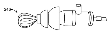
도 2f 내지 도 2h는 이온삼투요법 시스템(200)의 대안적인 실시예들을 도시한다. 이들 실시예에서, 시스템(200)은 대체로 전술된 바와 같이 유지되지만, 가요성 전극(240)이 시스템(200)의 원위 단부로부터 연장된다. 가요성 전극(240)은 절연성 측부(242), 및 노출된 금속(예를 들어, 은) 부분을 갖는 전도성 측부(244)를 포함할 수 있다. 가요성 전극(240)은 폴리이미드와 같은 가요성 중합체 재료로부터 구성되고, 금속 스트립과 함께 공압출될 수 있다. 가요성 전극(240)은 루프의 내측 부분 상에 노출된 금속 부분을 갖는 단일 루프형 밴드로서 구성될 수 있다. 대안적으로, 도 2g의 가요성 전극(246)에 의해 도시된 바와 같이, 하나 초과의 밴드가 사용될 수 있다. 가요성 전극(240)의 연장 길이는 특정 환자의 해부학적 구조물에 따라 조절될 수 있다. 사용시, 가요성 전극(240)은, 전도측(244)이 이도와 접촉하지 않으므로, 충격을 일으키지 않으면서, 도 2h에 도시된 바와 같이 이도와 접촉할 수 있다. 가요성 전극(204)은 그의 가요성 특성으로 인해 이도로부터 편향될 수 있다. 가요성 전극(240)은 더 효율적인 이온삼투요법 시술을 위한 더 큰 전극 표면적을 제공한다. 큰 전극 표면적은 또한 약물 용액 내에서의 기포 형성을 감소시킬 수 있다.2F-2H illustrate alternative embodiments of
도 3a 내지 도 3c는 본 발명의 일 실시예에 따른, 환자의 귀의 고막을 마취하기 위한 이온삼투요법 시스템(200)을 사용하는 방법을 도시한다. 환자의 귀(300)의 단면이 도시되어 있다. 환자는 초기에 치료 받는 귀가 위로 향하는 상태로 옆으로 뉘어질 수 있다. 그리고 나서, 이온삼투요법 유체(302)가 도시된 바와 같이 이도 내부로 주입된다. 그리고 나서, 충전된 이도 내로 이어플러그(304)가 삽입되어 이도 내에서 이온삼투요법 유체를 밀봉한다. 이어플러그(304)는 대체로 본 명세서의 실시예들에서 설명된 바와 같다. 이어플러그(304)는 이어플러그를 이도 내로 삽입하기 전에 이온삼투요법 유체(302)로 선택적으로 프라이밍될 수 있다.3A-3C illustrate a method of using an
도 3b에서, 삽입된 이어플러그(304) 내로 전극 장치(306)가 삽입된다. 전극 장치(306)는 유연성이며, 선택적으로 삽입 이전에 미리 구부러질 수 있다. 전극 장치(306)는 이어플러그(304) 내로 완전히 삽입될 때 가청 잡음을 만들 수 있어서, 전극 장치가 적절하게 배치된 것을 확인하기 위한 가청 신호를 사용자에게 제공한다. 전극 장치(306)가 완전히 삽입된 때, 이도 내부에서 압력이 증가할 것이고, 도시된 바와 같이 과잉의 유체(308)가 플러그의 후방으로 배출되어 나올 것이고, 유체 압력을 대기압과 즉시 균형을 이루게 한다. 이는, 심지어 약간의 압력 증가라도 감염된 귀에 큰 통증을 야기할 수 있으므로, 매우 유리하다. 전극 장치(306)가 완전히 삽입된 후에, 전극 장치는 환자를 치료하기 위해 전력을 공급받을 수 있다. 다른 귀가 또한 본 명세서에서 기술되는 바와 같이 치료될 수 있다.In FIG. 3B, the
대안적인 실시예에서, 전극 장치(306)는 이도 내로의 초기 삽입 동안에, 예를 들어 전극 팁(228)이 튜브(212) 내에 있는 제1 위치로 이어플러그(304) 내에 부분적으로 삽입될 수 있다. 이어플러그(304)가 배치된 후에, 전극 장치(306)는 제1 위치로부터 이어플러그(304) 내로의 완전한 삽입의 제2 위치(예를 들어, 작동 위치)로 이동될 수 있다.In an alternative embodiment, the
또 다른 대안적인 실시예에서, 전극 장치(306)는 이도 내로의 삽입 이전에 이어플러그(304) 내로 완전히 삽입될 수 있다. 이어플러그(304)가 이도 내로 삽입될 때, 귀 내부에서 압력이 증가할 것이고, 동시에 압력은 압력이 소정의 임계치를 초과할 때 과잉의 유체를 배출시키는 이어플러그(304) 내의 시일을 통해 완화될 것이다. 이러한 실시예는 이어플러그가 귀 내에 배치되는 동안 사용자가 전극을 이동시킬 것을 요구하지 않기 때문에 유리하다.In yet another alternative embodiment, the
도 3c는 직립 위치의 귀 및 따라서 환자를 도시한다. 장치(304)는 공기 기포(312)가 도시된 위치로 이동하게 하는 전극으로부터의 오프셋(310)을 포함한다. 오프셋(310)은 부분적이거나 비효과적인 치료를 야기하는, 공기 기포가 전극 상에 직접 또는 부분적으로 놓이는 것을 방지한다. 오프셋(310)은, 시스템(200)이 직립 위치에서 사용되게 하고, 따라서 양쪽 귀가 동시에 치료될 수 있기 때문에, 유리하다.3C shows the ear and thus the patient in an upright position.
대안적인 실시예에서, 환자는 이온삼투요법 유체(302) 또는 이어플러그(304)의 삽입 이전에 직립 위치에 있을 수 있다. 이어플러그(304)는 먼저 전극 장치(306)가 완전히 삽입된 상태로 이도 내로 삽입된다. 이러한 실시예에서, 전극 장치(306)는 이도를 충전하기 위한 별개의 루멘을 포함한다. 이온삼투요법 유체(302)가 이도를 충전하기 위해 전극 장치(306)를 통해 주입된다. 이도가 이온삼투요법 유체(302)로 충전될 때, 압력이 이도 내부에서 증가할 것이고, 동시에 압력은 이어플러그(304) 내의 시일을 통해 완화될 것이다. 따라서, 압력이 소정의 임계치를 초과할 때 과잉의 유체가 배출된다. 이러한 실시예는, 한쪽 또는 양쪽 귀가 필요하다면 동시에 그리고 또한 환자가 직립 위치에 있는 동안 충전될 수 있기 때문에, 유리하다.In alternative embodiments, the patient may be in an upright position prior to insertion of the
대안적인 실시예에서, 장치(304)가 도 3c에 도시된 바와 같이 배치된 후에 근위 밀봉 재료가 적용될 수 있다. 밀봉 재료는 부드러운 퍼티(putty) 유사 재료로부터 제조될 수 있는데, 예를 들어 골 왁스(예를 들어, 밀랍, 파라핀, 또는 아이소프로필 팔미테이트)가 사용될 수 있다. 밀봉 재료는 별개로, 또는 장치(304)에 밀봉가능하게 부착되는 부재로서, 예를 들어 근위방향으로(예를 들어, 도 2a의 측부 배출구(220)와 밀봉 부재(204b) 사이에) 위치된 디스크로서 사용될 수 있다. 밀봉 재료는 체온으로 가열될 때 형상화가능할 수 있다. 사용시, 밀봉 재료는 장치(304)가 도 3c에 도시된 바와 같이 배치된 후에, 이각 및 외이 해부학적 구조물 내로 밀려 들어가서 성형될 수 있다. 밀봉 재료는 외이의 복잡한 해부학적 구조물에 일치하여 확실한 고정을 보장할 수 있다. 밀봉 재료는 또한 약간 더 작은 크기의 장치(304)의 사용을 허용하는 유체 밀봉 시일을 제공할 수 있고, 이는 이어서 밀봉 재료가 장치(304) 대신에 1차 시일을 제공하므로, 이도 내로의 더 빠르고 외상을 덜 일으키는 장치 삽입을 허용한다.In an alternative embodiment, the proximal sealing material may be applied after the
대안적으로, 천 패치가 밀봉 재료 대신에 또는 밀봉 재료와 함께 사용될 수 있다. 천 패치는 디스크 형상을 가질 수 있으며, 근위방향으로(예를 들어, 도 2a의 측부 배출구(220)와 밀봉 부재(204b) 사이에) 위치된 디스크로서, 장치(304)에 밀봉가능하게 부착될 수 있다. 천 패치는 본 명세서에서 기술되는 온도 의존성 접착제와 같은 접착제를 포함할 수 있다. 천 패치는 대안적으로, 예를 들어 쓰리엠, 인크.(3M, Inc.)에 의해 제조된 넥스케어(Nexcare)™ 테가덤(Tegaderm)™ 트랜스패런트 드레싱(Transparent Dressing)에서 사용되는 바와 같은, 종래의 접착제를 사용할 수 있다. 사용시, 천 패치는 장치(304)가 도 3c에 도시된 바와 같이 배치된 후에, 이각 및 외이 해부학적 구조물 내로 밀려 들어가서 성형될 수 있다. 천 패치는 유체 시일을 제공하고 확실한 고정을 보장할 수 있다. 따라서, 천 패치는 또한 표준보다 더 작은 장치(304)에 사용될 수 있다.Alternatively, cloth patches may be used instead of or with the sealing material. The cloth patch may have a disk shape and may be sealably attached to the
도 4는 본 발명의 일 실시예에 따른, 이온삼투요법을 사용하여 환자의 귀의 고막을 마취하기 위한 키트(400)를 도시한다. 키트는 본 명세서에서 개시되는 장치와 실질적으로 유사한 시스템(402)을 포함한다. 각각의 시스템(402)은 이어플러그(404) 및 전극 장치(406)를 포함한다. 도시된 바와 같이, 다양한 크기의 이어플러그가 가능하다. 키트(400)는 또한 귀환 전극(410)을 포함하고 시스템(402)과 전기적으로 상용가능한 제어기(408)를 포함한다. 제어기(412)는 이온삼투요법 시술을 위해 시스템(402)에 전력을 제공한다. 상용가능한 제어기의 예가 앞서 참조로 포함되고 공동 양도된 미국 특허 출원 제11/962,063호에 나타나 있다.4 shows a
도 5a 및 도 5b는 본 발명의 일 실시예에 따른 우산형 구성의 가요성 밀봉 요소(500)의 정면도 및 측면도를 각각 도시한다. 가요성 밀봉 요소(500)는 일체형 리브(rib, 502) 또는 스포크(spoke)를 포함한다. 일체형 리브(502)는 가요성 밀봉 요소(500)의 나머지 부분(504)이 리브형 부분보다 더 얇게 되게 하고, 따라서 가요성 밀봉 요소(500)는 매우 쉽게 변형된다. 따라서, 가요성 밀봉 요소(500)를 포함하는 장치, 예를 들어 시스템(200)은 일체형 리브(502)가 없는 밀봉 요소보다 더 작은 힘으로 이도 내에서 시일을 달성할 수 있다. 대안적으로, 일체형 리브(502)는 가요성 밀봉 장치(500)의 내부 부분 상에 위치될 수 있다.5A and 5B show front and side views, respectively, of a
도 5c 및 도 5d는 본 발명의 일 실시예에 따른 가요성 밀봉 요소(506)의 정면도 및 측면도를 각각 도시한다. 가요성 밀봉 요소(506)는 절결부(508)를 포함한다. 절결부(508)는 얇은 재료 웨브를 특징으로 한다. 절결부(508)는 가요성 밀봉 요소(506)의 나머지 부분(510)보다 더 얇고, 따라서 가요성 밀봉 요소(506)는 매우 쉽게 변형된다. 따라서, 가요성 밀봉 요소(506)를 포함하는 장치, 예를 들어 시스템(200)은 절결부(508)가 없는 밀봉 요소보다 더 작은 힘으로 이도 내에서 시일을 달성할 수 있다. 대안적으로, 절결부(508)는 가요성 밀봉 장치(506)의 내부 부분 상에 위치될 수 있다.5C and 5D show front and side views, respectively, of a
도 5e 및 도 5f는 본 발명의 일 실시예에 따른 가요성 밀봉 요소(510)의 사시도 및 정면도를 각각 도시한다. 가요성 밀봉 요소(506)는 도시된 바와 같이 피라미드형 또는 삼각형 형상이다. 가요성 밀봉 요소(506)는 이도를 밀봉하기 위한 3개의 면을 포함한다. 이도는 원형 단면을 갖지 않고, 흔히 형상이 삼각형이다. 따라서, 가요성 밀봉 요소(510)는 매우 효과적으로 이도 내에 끼워맞춤되어 이도를 밀봉할 수 있다.5E and 5F show, respectively, a perspective view and a front view of a
도 6a 및 도 6b는 본 발명의 일 실시예에 따른 이어플러그(600)의 배면도 및 측면도를 각각 도시한다. 이어플러그(600)는 본 명세서에서 일반적으로 기술되는 바와 같이 튜브형 요소 및 적어도 하나의 가요성 밀봉 요소를 포함할 수 있는 본체(602)를 포함한다. 이어플러그는 또한 이어 후크(604)를 포함한다. 이전의 장치는 이어플러그를 보유하는 것을 돕기 위해 귀마개 또는 헤드폰 스타일 구성과 같은 보유 메커니즘을 사용하였다. 이들 종래 장치는 사용자(예를 들어, 작은 어린이)에게 성가심 및 불편함을 일으키는 경향이 있고, 환자에 의해 유발되는 이온삼투요법 치료 중단을 초래한다. 이어 후크(604)는 실리콘과 같은 가요성 중합체로부터 형성될 수 있고, 또한 이어플러그(600)와 일체일 수 있다. 이어 후크(604)는 또한 코어(예를 들어, 와이어) 둘레에 감긴 가요성 중합체의 골격형 구성물을 포함할 수 있다. 코어는 이어 후크(604)가 특정 귀의 프로파일과 정합하도록 형상화되게 하기 위해 유연성일 수 있다. 대안적으로, 코어는 탄성일 수 있으며, 외이로부터 이어플러그(600) 상으로 일정한 힘을 가하는 것을 도울 수 있다.6A and 6B show back and side views, respectively, of an
도 6c는 본 발명의 일 실시예에 따른, 사용시의 이어플러그(600)를 도시한다. 이어 후크(604)는 귀의 이륜각(606) 둘레에 감기도록 설계된다. 이어 후크(604)는 비교적 작은 질량을 가지고, 따라서 환자에게 과도하게 밀고 들어가는 느낌을 주지 않기 때문에, 다른 종래의 장치에 비해 유리하다.6C illustrates
도 6d는 본 발명의 일 실시예에 따른 통합형 이어 버드(608)를 도시한다. 이어 버드는 전원 및 제어 유닛을 포함하는 본체(610)를 포함한다. 제어 유닛은 도 4의 제어 유닛(412)의 기능을 가질 수 있다. 본체(610)는 이온삼투요법 시술을 시작 또는 정지시키기 위한 제어 버튼을 포함할 수 있다. 본체(610)는 하나 이상의 접착 패치를 포함할 수 있다. 이어 버드(608)는 또한 만곡된 프로파일을 갖는 유연성 브리지(612)를 포함한다. 유연성 브리지(612)는 고무와 같은 가요성 중합체로부터 구성될 수 있고, 유연성 금속 코어를 가질 수 있다. 이어플러그(614)가 유연성 브리지(612)에 피벗가능하게 연결될 수 있다. 이어플러그(614)는 일반적으로 본 명세서에서 개시되는 이어플러그의 구성을 공유할 수 있다. 케이블(616)이 본체(610)로부터 이어져서 귀환 전극(618)에 연결된다. 귀환 전극(618)은 다른 귀환 전극으로의 연결을 허용하기 위한 스냅 요소를 포함할 수 있다.6D illustrates an
도 6e는 본 발명의 일 실시예에 따른, 사용시의 통합형 이어 버드(608)를 도시한다. 본체(610)는 도시된 바와 같이 이륜 후방에 배치될 수 있고, 환자의 피부에 일시적으로 부착될 수 있다. 유연성 브리지(612)는 이륜 둘레에 감기고, 이어플러그(614)는 이도 내로 삽입된다. 통합형 이어 버드(608)는 원치 않는 이동을 방지하기 위해 그리고 또한 유체 밀봉 시일을 보장하는 것을 돕기 위한 일정한 장착력을 제공하기 위해, 이어플러그(614)를 지지한다. 유연성 브리지(612)는 더 많거나 더 적은 장착력을 제공하도록 조절될 수 있다. 이어플러그(614)는 통합형 이어 버드(608)가 각각의 귀에서 사용될 수 있도록 회전될 수 있다. 귀환 전극(618)은 제어 유닛을 위한 전기 귀환 경로를 제공하기 위해 환자의 피부의 일부분에 부착될 수 있다. 통합형 이어 버드(608)가 통합형 제어 유닛을 포함하므로, 환자는 시술 동안에 자유롭게 움직일 수 있다.6E illustrates an
도 6f는 본 발명의 일 실시예에 따른, 사용시의 통합형 이어 버드(620)를 도시한다. 통합형 이어 버드(620)는 도 6d의 이어 버드(608)와 유사하게 구성되지만, 제어 유닛(622)이 귀환 전극 패치와 함께 별개로 내장된다. 통합형 이어 버드(620)는 또한 귀의 이륜을 완전히 둘러싸는 유연성 본체(624)를 포함한다. 유연성 본체(624)는 고무와 같은 가요성 중합체로부터 구성될 수 있고, 유연성 금속 코어를 가질 수 있다. 유연성 본체(624)는 원치 않는 이동을 방지하기 위해 그리고 또한 유체 밀봉 시일을 보장하는 것을 돕기 위한 일정한 장착력을 제공하기 위해 다양한 귀의 해부학적 구조물에 맞춤되도록 조절될 수 있다.6F illustrates an
도 7a는 본 발명의 일 실시예에 따른 이어플러그(700)를 도시한다. 귀의 해부학적 구조물의 상이한 영역들은 상이한 수준의 전기 저항을 갖는다. 전류는 더 낮은 저항의 영역을 통해 우선적으로 흐른다. 예를 들어, 고막은 이도 내의 연골 영역보다 더 낮은 저항을 갖는다. 더 높은 저항 영역에 대한 원치 않는 전기 접촉을 방지하는 것이 바람직하고, 또한 환자의 편안함을 위해 전달되는 전류량을 제한하는 것이 바람직하다. 전극을 가능한 한 고막 가까이에 배치하는 것은 전체 전류 전달을 감소시키는 것을 돕기 때문에, 긍정적인 결과를 달성하는 것을 돕는다. 그러나, 이도는 구불구불한 것으로 알려져 있고, 따라서 고막 부근에 전극을 배치하는 것은 귀의 다른 영역과 접촉하지 않고서는 어렵다. 이어플러그(700)는 이러한 어려움을 해결한다.7A shows an earplug 700 in accordance with one embodiment of the present invention. Different areas of the anatomical structure of the ear have different levels of electrical resistance. The current flows preferentially through the region of lower resistance. For example, the tympanic membrane has a lower resistance than the cartilage area in the ear canal. It is desirable to prevent unwanted electrical contact to higher resistance areas, and also to limit the amount of current delivered for patient comfort. Placing the electrode as close to the eardrum as possible helps to reduce overall current transfer, thus helping to achieve positive results. However, the ear canal is known to be serpentine, and therefore placing the electrode near the eardrum is difficult without contacting other areas of the ear. Earplug 700 solves this difficulty.
이어플러그(700)는 이도 내에서 이어플러그(700)를 밀봉하기 위한 밀봉체(702)를 포함한다. 밀봉체(702)는 본 명세서에 개시된 다른 유사한 이어플러그의 구성을 포함할 수 있다. 밀봉체(702)는 이도를 충전하기 위한 루멘 및 배출구를 포함하거나 포함하지 않을 수 있다. 이어플러그(700)는 밀봉체(702) 전체에 걸쳐 연장되는 절연체(704)를 포함한다. 절연체(704)의 연장된 부분(706)은 전극(708)을 수용한다. 연장된 부분(706)은, 전극(708)을 밀봉체를 충분히 지나 그리고 사용시 고막에 더 가까이 연장시키기 때문에, 유리하다. 원위부(706)는 또한 이도의 부분들과 접촉하면서 여전히 전극(708)에 대한 절연을 제공할 수 있다.The earplug 700 includes a
도 7b 및 도 7c는 예를 들어 도 7a에 도시된 이어플러그(700)에 사용될 수 있는, 대안적인 연장된 부분(710)의 사시도 및 단면도를 각각 도시한다. 연장된 부분(710)은 내측 전극(714)에 대한 유체 접근을 제공하는 다중 슬릿(712)을 특징으로 한다. 연장된 부분(710)은 절단되고 외부 절연 장벽으로 코팅된 하이포튜브로부터 형성될 수 있다. 연장된 부분은, 필요한 부품의 양을 감소시키고, 또한 전극(714)에 대해 비교적 큰 표면적을 사용함으로써 전류 밀도를 낮추기 때문에, 유리하다. 더 낮은 전류 밀도는 환자의 편안함을 증가시키는 것으로 밝혀졌다. 대안적으로, 돔형 부분(710a)이 제거될 수 있고, 또한 도시된 것보다 더 많거나 더 적은 슬릿(712)이 사용될 수 있다.7B and 7C show, respectively, a perspective view and a cross-sectional view of an alternate
도 7d는 예를 들어 도 7a에 도시된 이어플러그(700)에 사용될 수 있는, 대안적인 연장된 부분(710)의 사시도를 도시한다. 연장된 부분(710)은 절연 부분(716a, 716b) 및 전극(718)을 포함한다. 전극(718)은 니켈 티타늄과 같은, 초탄성 합금으로부터 구성될 수 있다. 따라서, 전극(716a)이 이도의 부분들과 접촉하게 될 때, 전극(718)은 필요한 대로 쉽게 편향될 것이다. 전극(718)은 도시된 것보다 더 길 수 있고, 전극(718)을 고막 부근으로 추가로 연장시키기 위해 다수의 절연 부분(716b)들을 포함한다.FIG. 7D shows a perspective view of an alternative
도 7e는 예를 들어 도 7a에 도시된 이어플러그(700)에 사용될 수 있는, 대안적인 연장된 부분(720)의 사시도를 도시한다. 연장된 부분(720)은 도 7b 및 도 7c에 도시된 것과 유사한 하이포튜브 구성의 것이다. 연장된 부분(720)은 더 어두운 영역에 의해 도시된 내측 전극 부분(724)과의 유체 연통을 허용하는 다수의 천공된 구멍(722)을 포함한다. 연장된 부분(720)은 절단되고 천공되며, 외부 절연 장벽으로 코팅된 하이포튜브로부터 형성될 수 있다.FIG. 7E shows a perspective view of an alternate
도 7f는 예를 들어 도 7a에 도시된 이어플러그(700)에 사용될 수 있는, 대안적인 연장된 부분(726)의 사시도를 도시한다. 연장된 부분(726)은 쉽게 변형가능하지만 탄성적인 바스켓으로서 구성될 수 있다. 연장된 부분(726)이 이도의 부분들과 접촉하게 될 때, 이는 쉽게 편향될 것이다. 연장된 부분(728)은 외측 절연 재료(728) 및 내측 전도 부분(730)으로부터 구성된다. 연장된 부분(726)은 니켈 티타늄과 같은 초탄성 재료로부터 구성될 수 있고, 예를 들어 0.127 ㎜(0.005 인치) 두께 미만으로 얇은 부분의 것일 수 있다.FIG. 7F shows a perspective view of an alternate
도 7g는 예를 들어 도 7a에 도시된 이어플러그(700)에 사용될 수 있는, 대안적인 연장된 부분(732)의 사시도를 도시한다. 연장된 부분(732)은 외측 절연 부재(734) 및 복수의 전극(736)을 포함한다. 복수의 전극(736)은 절연 부재(734) 내에서 연장된다. 이러한 구성은 전도 표면적을 크게 증가시키고, 따라서 전류 밀도를 감소시키는 것을 돕기 때문에 유리하다. 이러한 구성은 또한 사용시에 고막을 향해 원위 방향으로 전류 흐름을 안내한다.FIG. 7G shows a perspective view of an alternative
도 7h는 예를 들어 도 7a에 도시된 이어플러그(700)에 사용될 수 있는, 대안적인 연장된 부분(738)의 사시도를 도시한다. 연장된 부분(738)은 도 7f에 도시된 연장된 부분과 유사하다. 그러나, 전극(742)은 도시된 바와 같이 최원위 지점까지 절연된다. 이러한 구성은 또한 사용시에 고막을 향해 원위 방향으로 전류 흐름을 안내한다.FIG. 7H shows a perspective view of an alternative
도 7i 및 도 7j는 예를 들어 도 7a에 도시된 이어플러그(700)에 사용될 수 있는, 대안적인 연장된 부분(744)의 사시도 및 분해도를 각각 도시한다. 연장된 부분(744)은 라미네이트형 구성을 추가로 포함하는, 도시된 바와 같은 코일형 구성을 포함한다. 라미네이트형 구성은 외측 절연 부재(746), 전도 부재(748), 및 내측 절연 부재(750)를 포함한다. 내측 절연 부재(750)는 전도 부재(750)를 노출시키는 개방부(752)를 포함한다. 연장된 부분(744)은 초기에 코팅된 평탄 와이어로부터 구성될 수 있고, 이는 이후에 개방부(752)를 형성하도록 일 측에서 절삭되고, 추가로 코일 형상으로 된다.7I and 7J show, respectively, a perspective view and an exploded view of an alternative
도 8a 및 도 8b는 본 발명의 일 실시예에 따른 확대가능한 이어플러그의 측면도 및 작동도를 각각 도시한다. 이어플러그(800)는 외측의 확대가능한 부분(802) 및 확대기(804)를 포함한다. 외측의 확대가능한 부분(802) 및 확대기는 도시된 바와 같이 이어플러그의 원위 단부 부근에서 내부에서 연결될 수 있다. 확대기(804)는 확대가능한 부분 내에서 활주가능하고, 도 8b에 도시된 바와 같은 제2 형태로 확대하기 위해 외측의 확대가능한 부분에 힘을 가하도록 근위방향으로 인출될 수 있다. 외측의 확대가능한 부분(802)은 부드러운 중합체, 예를 들어 실리콘으로부터 구성될 수 있다. 이러한 구성은 특정 귀의 해부학적 구조물 내에서 정밀한 끼워맞춤을 허용하고, 또한 더 깊은 위치설정을 허용하기 때문에 유리하다.8A and 8B show side and operational views, respectively, of an expandable earplug according to one embodiment of the present invention. The
도 9a는 본 발명의 일 실시예에 따른 폼 플러그 장치(900)를 도시한다. 폼 플러그 장치(900)는 전극(902) 및 전극(902)에 부착되는 천공된 튜브(904)를 포함한다. 폼 플러그(906)는 전극(902)을 둘러싼다. 폼 플러그(906)는 원통형 또는 원추형 형상을 가질 수 있고, 개방 셀형 폼으로부터 구성될 수 있다. 전극(902)은 가단성 금속(예를 들어, 은)의 중실 또는 스트랜드형(stranded) 와이어, 또는 중실 또는 천공된 튜브로부터 구성될 수 있고, 천공된 튜브(904)의 근위 단부로부터 이어지는 절연부(908)를 포함할 수 있다. 전기 커넥터(도시되지 않음)가 전극(902)의 근위 단부에 연결될 수 있다. 천공된 튜브(904)는 가요성의, 절연성 또는 전도성 재료로부터 구성될 수 있고, 일반적으로 전체에 걸쳐 천공부를 포함한다. 폼 플러그 장치(900)는 또한 본 명세서에서 기술된 바와 같이, 추가의 밀봉 요소(도시되지 않음) 및/또는 접착제를 포함할 수 있다. 사용시, 폼 플러그(906)는 압축되어, 이도 내로 삽입되고, 이어서 확대하게 되어 이도를 밀봉할 수 있다. 약물 용액은 폼 플러그 장치(900)의 삽입 이전에 또는 폼 플러그(902)의 개방 셀 특성으로 인해 이후에 이도 내로 도입될 수 있다. 폼 플러그의 다공성은 천공된 튜브(904)의 길이 전체에 걸쳐 약물 용액 접촉을 허용함으로써, 천공된 튜브(904)의 천공부들에 의해 전극 표면적을 증가시킬 수 있다. 폼 플러그의 다공성은 또한 이온삼투요법 시술 동안에 압력 증강을 방지할 수 있다.9A shows a
도 9b는 본 발명의 일 실시예에 따른 폼 풍선 장치(910)를 도시한다. 폼 풍선 장치(910)는 전극(912)을 포함한다. 전극(912)은 가단성 금속(예를 들어, 은)의 중실 또는 스트랜드형 와이어, 또는 중실 또는 천공된 튜브로부터 구성될 수 있다. 일 실시예에서, 전극(912)은 약 1.5 ㎜(0.060 인치)의 내경 및 약 1.8 ㎜(0.072 인치)의 외경을 갖는 폴리에테르 블록 아미드(예를 들어, 페백스(Pebax)(등록상표) 55D)로부터 제조될 수 있는 외측 루멘(도시되지 않음)을 포함할 수 있다. 전기 커넥터(도시되지 않음)가 전극의 근위 단부에 연결될 수 있다. 전극(912)은 또한 복수의 와이어 스트랜드를 둘러싸는 확대된 절연체를 갖는 원위 단부를 포함할 수 있다. 폼 플러그(914)가 전극(912)을 둘러싼다. 폼 플러그(914)는 개방 셀형 폼으로부터 구성될 수 있다. 80.1 g/L (5 lb/ft3)의 밀도를 가지며, 포멕스 이노베이션스, 인크.(Foamex Innovations, Inc.)에 의해 제조되는 폴리에테르 폼(EC85HDE)이 적합한 것으로 밝혀졌다. 폼 플러그는 5 내지 15 ㎜의 외경 및 2.5 ㎜의 내경을 갖는 원통형 형상을 가질 수 있다. 8.3 ㎜ 및 11 ㎜의 외경이 사용되었다. 폼 플러그는 원추형과 같은 다른 형상을 가질 수 있다. 폼 플러그는 이중 벽 풍선(916)에 의해 에워 싸인다. 이중 벽 풍선(916)은 순응성(compliant), 반-순응성(semi-compliant), 또는 비-순응성(non-compliant) 재료로부터 구성될 수 있다. 일 실시예에서, 이중 벽 풍선(916)은 형상화된 맨드릴을 누실 테크놀러지 엘엘씨(NuSil Technology LLC)에 의해 제조된 MED10-6400과 같은 실리콘으로 침지 코팅함으로써 형성될 수 있다. 그리고 나서, 이중 벽 풍선(916)은 전극(912)의 일부분에 부착되고, 이어서 부분적으로 뒤집혀서 이중 벽을 생성할 수 있다. 그리고 나서, 폼 플러그(914)가 벽들 사이의 공간 내로 삽입될 수 있다. 풍선(916)의 원위부는 쿼시나 코포레이션(Qosina Corp.)으로부터 입수가능한 T 커넥터 88207과 같은 흡입 커플러(918)에 연결될 수 있다.9B shows a
사용시, 진공이 흡입 커플러(918)에 인가될 수 있고, 이는 폼 플러그(914)가 붕괴되게 한다. 그리고 나서, 폼 풍선 장치(910)가 이도 내로 삽입될 수 있다. 일단 제위치에 있게 되면, 진공이 중단될 수 있고, 이는 폼(914)이 확대되게 한다. 폼(914) 확대는 이도 벽과 접촉하는 이중 벽 풍선(916)을 가압하여 이도 내에서 약물 용액을 유체 밀봉한다. 이중 벽 풍선을 팽창시키기 위해 양의 공기 압력이 사용되지 않으므로, 풍선 파열의 위험이 사라진다. 제거를 돕도록 폼(914)을 다시 붕괴시키기 위해 진공이 다시 인가될 수 있다.In use, a vacuum can be applied to the
도 10a는 본 발명의 일 실시예에 따른 검경 포트(1000)를 도시한다. 검경 포트(1000)는 대체로 원추형 형상을 가질 수 있다. 검경 포트(1000)는 중합체 또는 금속 합금으로부터 구성될 수 있다. 검경 포트(1000)는 비교적 가요성이거나 강성일 수 있다. 검경 포트(1000)는 원위 포트(1004)에 제거가능하게 결합되는 근위 포트(1002)를 포함할 수 있다. 근위 포트(1002)는 약간의 억지 끼워맞춤에 의해 또는 나사식 연결에 의해 원위 포트(1004)에 결합될 수 있다. 내측 플러그(1006)가 원위 포트(1004)에 제거가능하고 밀봉가능하게 결합될 수 있다. 내측 플러그(1006)는 도 2f에 도시된 바와 같은 루프형 전극으로서 구성된 전극(1008)을 포함한다. 그러나, 전극(1008)은 일반적으로 본 명세서에 개시된 전극들 중 임의의 것의 형태를 취할 수 있다. 내측 플러그(1006)는 본 명세서에 개시된 다른 밀봉 부재와 유사하게 구성된 밀봉 부재(도시되지 않음)를 포함할 수 있다. 원위 포트(1004)는 본 명세서에 개시된 접착제들 중 임의의 것의 형태를 취할 수 있는 접착 층(1010)을 포함할 수 있다. 접착 층(1010)은 또한 유연성 실리콘 퍼티, 조루술 백(ostomy bag) 접착 가스켓 재료, 확대성 폼, 각인 재료, 겔, 골 왁스, 풍선 시멘트 또는 실리콘 가스켓의 층일 수 있다.10A illustrates a
도 10b는 본 발명의 일 실시예에 따른 대안적인 원위 포트(1012)를 도시한다. 원위 포트(1012)는 원위 포트(1004)와 유사하게 구성되지만, 원위 포트(1012)는 전극 표면(1014)을 포함한다. 전극 표면(1014)은 원위 포트(1004)의 내부 표면에 결합된, 은과 같은 금속의 층일 수 있다. 내측 플러그(1016)가 원위 포트(1012)에 제거가능하고 밀봉가능하게 결합될 수 있다. 내측 플러그(1016)는 내측 플러그(1016)가 원위 포트(1004)에 결합할 때 전극 표면과 전기 접촉을 이룰 수 있는 접촉 표면(1018)을 포함할 수 있다.10B illustrates an alternative
도 10c는 본 발명의 일 실시예에 따른 대안적인 원위 포트(1020)를 도시한다. 원위 포트(1012)는 원위 포트(1004)와 유사하게 구성되지만, 원위 포트(1012)는 복수의 촉수(tentacle) 전극(1022)을 갖는 플러그에 결합된다. 촉수 전극(1022)은 고도로 가요성이며, 증가된 표면적을 제공한다. 촉수 전극(1022)은 노출된 금속의 절연성 영역 및 전도성 영역을 포함할 수 있다.10C illustrates an alternative
도 10d 및 도 10e는 본 발명의 일 실시예에 따른, 사용시의 검경 포트(1000)를 도시한다. 검경 포트(1000)는 근위 포트(1002)에 의해 취급될 수 있다. 근위 포트(1002)의 증가된 직경은 검경 포트(1000)의 손가락 조작 및 삽입을 허용한다. 검경 포트는 고막의 시각화를 제공하도록 조절될 수 있다. 원위 포트(1004) 상의 접착 층(1010)은 원위 포트(1004)와 이도 사이에서 유체 밀봉 시일 및 고정을 제공한다. 일단 검경 포트(1000)가 최적 위치에 배치되면, 근위 포트(1002)는 원위 포트(1004)로부터 분리될 수 있다. 그리고 나서, 원위 포트(1004)는 약물 용액으로 충전될 수 있고, 내측 플러그(1006)는 원위 포트(1004) 내로 삽입될 수 있다. 그리고 나서, 내측 플러그(1006)에는 이온삼투요법 시술을 완료하기 위해 전류가 공급될 수 있다.10D and 10E illustrate the
도 10f 내지 도 10h는 본 발명의 일 실시예에 따른, 사용시의 검경 포트(1000)를 도시한다. 검경 포트(1000)는 전극 표면(1014)을 갖는 대안적인 원위 포트(1012)를 포함한다. 도 10d 및 도 10e에 따르면, 원위 포트(1012)는 이미 이도 내에 배치되어 있고, 근위 포트(1002)는 제거되어 있다. 원위 포트(1012)는 약물 용액으로 충전될 수 있고, 내측 플러그(1016)는 원위 포트(1012) 내로 삽입될 수 있다. 그리고 나서, 내측 플러그(1016)에는 이온삼투요법 시술을 완료하기 위해 전류가 공급될 수 있다.10F-10H illustrate the
도 11은 본 발명의 일 실시예에 따른, 환자의 두부 상에 착용되는 단순화된 지지 구조물(1100)을 도시한다. 단순화된 지지 구조물(1100)은 환자가 일어나서 직립하고 있는 동안에 환자의 두부 상에 착용된다. 지지 구조물(1100)은 본 명세서에 기술되는 하나 이상의 시스템을 환자의 귀(E)와의 정렬 상태로 유지하도록 구성된다. 도 11에서 알 수 있는 바와 같이, 지지 구조물(1100)은 제1 귀와 맞물리는 제1 본체(1110), 제2 귀와 맞물리는 제2 본체(1110), 및 제1 본체와 제2 본체 사이에서 환자의 두부 둘레에서 연장되는 부재를 갖는 정렬 구조물을 가질 수 있다. 본 발명의 이어플러그들 중 임의의 것이 도 11에서와 같이 헤드셋을 거쳐 두부에 결합될 수 있다.11 illustrates a
도 12는 본 발명의 일 실시예에 따른, 환자의 두부 상에 착용되는 단순화된 지지 구조물(1200)을 도시한다. 지지 구조물(1200)은 안경과 유사하게 구성되고, 유사한 방식으로 착용될 수 있다. 이어플러그(1210)는 지지 구조물(1200)에 힌지식으로 연결되고, 지지 구조물(1200)에 의해 이도 내로 지렛대식으로 도입될 수 있다. 이어플러그(1210)는 본 명세서에 개시된 이어플러그들 중 임의의 것과 유사하게 구성될 수 있다. 지지 구조물(1200)은 원치 않는 이동을 방지하고 이어플러그(1210)에 대한 밀봉력을 제공할 수 있다. 지지 구조물(1200)은 다양한 크기의 환자를 위해 폭 및 길이를 조절하기 위한 조절가능한 요소를 포함할 수 있다. 지지 구조물(1200)은 환자에게 비디오 시청을 제공할 수 있는 LCD 패널과 같은 시각 패널을 포함할 수 있다. 이어플러그(1210)는 또한 환자에게 오디오를 제공하기 위한 스피커를 포함할 수 있다.12 illustrates a
본 발명은 본 발명의 본질적 특징으로부터 벗어남이 없이 다른 특정 형태로 실시될 수 있다. 이들 다른 실시예는 하기의 특허청구범위에서 기술되는 본 발명의 범주 내에 포함되도록 의도된다.The invention may be embodied in other specific forms without departing from the essential features thereof. These other embodiments are intended to be included within the scope of the invention as set forth in the claims below.
Claims (23)
이어플러그(earplug)로서,
원위부(distal portion),
근위부(proximal portion),
상기 원위부로부터 상기 근위부로 연장되는 튜브로서, 상기 이어플러그의 상기 근위부 및 상기 원위부의 강도(stiffness)보다 더 작은 강도를 갖는, 상기 튜브, 및
상기 튜브의 외측 표면으로부터 연장되고, 상기 근위 단부보다 상기 원위 단부에 더 가까이 배치되는 적어도 하나의 가요성 밀봉 요소를 포함하는, 상기 이어플러그; 및
전극 장치로서,
긴 샤프트, 및
상기 긴 샤프트의 직경보다 더 큰 직경을 갖는 전극 팁(tip)을 포함하는, 상기 전극 장치를 포함하며,
상기 전극 장치는, 유체가 상기 튜브를 통해 전극 주위를 통과할 수 있는 후퇴 위치로부터 상기 전극 팁이 상기 튜브의 내측 표면과 접촉하여 유체가 상기 튜브를 통해 유동하는 것을 방지하는 전진 위치로, 상기 이어플러그의 상기 튜브 내에서 이동가능한 시스템.A system for use in iontophoretic mass transfer to the eardrum of a human or animal subject,
As an earplug,
Distal portion,
Proximal portion,
A tube extending from the distal portion to the proximal portion, the tube having a strength less than the stiffness of the proximal portion and the distal portion of the earplug, and
The earplug, extending from an outer surface of the tube and including at least one flexible sealing element disposed closer to the distal end than the proximal end; And
As an electrode device,
Long shaft, and
Comprising an electrode tip, the electrode device having a diameter greater than the diameter of the elongated shaft,
The electrode device is a retracted position from which the fluid can pass through the tube around the electrode to a forward position where the electrode tip contacts the inner surface of the tube and prevents fluid from flowing through the tube. A system movable within the tube of a plug.
관통 연장되는 주 루멘을 포함하는, 원위부 및 근위부를 갖는 긴 가요성 튜브로서, 상기 원위부는 상기 원위부의 원위 단부에서의 내측 립(lip) 및 상기 내측 립에 대해 근위에 있는 밀봉 부재를 포함하고, 상기 긴 튜브는 이도(ear canal)의 형상에 일치하도록 구부러지기에 충분한 가요성을 갖는, 상기 긴 가요성 튜브;
상기 이도 내에서 시일을 형성하도록 우산처럼 형상화되고, 상기 긴 튜브와 일체로 되어 상기 긴 튜브의 외부 상에 배치되며, 상기 긴 튜브의 최원위부로부터 소정 거리로 오프셋된 제1 가요성 밀봉 요소;
상기 이도 내에서 시일을 형성하도록 우산처럼 형상화되고, 상기 긴 튜브와 일체로 되어 상기 긴 튜브의 외부 상에 배치되며, 상기 제1 밀봉 요소에 대해 근위에 있는 제2 가요성 밀봉 요소;
상기 밀봉 부재에 대해 원위에서 상기 긴 튜브의 상기 원위부 내에 위치되고, 상기 긴 튜브의 상기 원위부가 구부러지는 것을 방지하는 원위 강화 튜브;
상기 튜브의 상기 주 루멘과 유체 연통하는 측부 배출구를 포함하고, 상기 튜브의 상기 근위부와 결합되는 루어 피팅; 및
전극 장치로서,
긴 샤프트, 및
상기 긴 샤프트의 직경보다 더 큰 직경을 갖는 전극 팁을 포함하는, 상기 전극 장치를 포함하며,
상기 전극 장치는, 유체가 상기 튜브를 통해 전극 주위를 통과할 수 있는 후퇴 위치로부터 상기 전극 팁이 상기 내측 립과 상기 밀봉 부재 사이에서 상기 긴 튜브의 상기 원위부 내에 끼워맞춤되어 유체 밀봉 시일을 형성하는 전진 위치로, 상기 이어플러그의 상기 튜브 루멘 내에서 이동가능한 시스템.A system for use in iontophoretic mass transfer into the eardrum of a human or animal subject,
A long flexible tube having a distal and proximal portion, the main lumen extending therethrough, the distal portion comprising an inner lip at the distal end of the distal portion and a sealing member proximal to the inner lip, The elongate tube having sufficient flexibility to bend to conform to the shape of an ear canal;
A first flexible sealing element shaped like an umbrella to form a seal within the ear canal, integral with the elongated tube and disposed on the outside of the elongated tube, offset by a distance from the distal most of the elongate tube;
A second flexible sealing element shaped like an umbrella to form a seal within the ear canal, integral with the elongated tube and disposed on the exterior of the elongated tube, proximal to the first sealing element;
A distal reinforcing tube positioned in the distal portion of the elongated tube distal to the sealing member and preventing the distal portion of the elongated tube from bending;
A luer fitting including a side outlet in fluid communication with the main lumen of the tube and coupled with the proximal portion of the tube; And
As an electrode device,
Long shaft, and
Comprising an electrode tip, the electrode device having a diameter greater than the diameter of the elongated shaft,
The electrode device is such that the electrode tip fits within the distal portion of the elongated tube between the inner lip and the sealing member from a retracted position where fluid can pass through the tube around the electrode to form a fluid sealing seal. A system movable in the tube lumen of the earplug to an advanced position.
상기 대상의 이도에 마취 약물 용액을 전달하는 단계;
전극과 결합된 이온삼투요법 이어플러그를, 상기 전극이 상기 이어플러그 내의 제1 위치에 배치되는 상태로, 상기 이도 내로 삽입하는 단계로서, 상기 이어플러그의 루멘은 상기 전극이 상기 제1 위치에 배치될 때 유체를 배출시키도록 원위 개방부로부터 근위 개방부로 개방되는, 상기 이어플러그를 상기 이도 내로 삽입하는 단계;
과잉의 마취 약물 용액이 상기 이어플러그 루멘을 통해 배출되게 하는 단계;
상기 전극을 상기 이어플러그 내에서 상기 제1 위치로부터 제2 위치로 이동시켜, 상기 전극과 상기 이어플러그 루멘의 내측 벽 사이에 시일을 형성하는 단계; 및
상기 전극을 활성화하여 상기 이도 내의 상기 약물 용액에 전류를 전달하는 단계를 포함하는 방법.A method of anesthesia of the eardrum of a human or animal subject using iontophoresis,
Delivering an anesthetic drug solution to the ear canal of the subject;
Inserting an iontophoretic earplug coupled with an electrode into the ear canal, with the electrode disposed at a first position within the earplug, wherein the lumen of the earplug is disposed with the electrode at the first position Inserting the earplug into the ear canal, wherein the earplug is opened from the distal opening to the proximal opening so as to drain fluid;
Causing excess anesthetic drug solution to be discharged through the earplug lumen;
Moving the electrode from the first position to a second position within the earplug to form a seal between the electrode and an inner wall of the earplug lumen; And
Activating the electrode to deliver a current to the drug solution in the ear canal.
상기 대상의 이도에 마취 약물 용액을 전달하는 단계;
상기 대상의 이도 내로 이온삼투요법 장치를 삽입하는 단계로서, 상기 이온삼투요법 장치는 루멘을 갖는 이어플러그 및 상기 루멘 내에 배치되는 전극을 포함하고, 상기 장치를 삽입하는 단계는 상기 장치와 상기 이도 사이에 시일을 형성하여 상기 이도 내에 상기 약물 용액을 유지하며 동시에 과잉의 약물 용액을 상기 전극을 지나 상기 이어플러그 루멘을 통해 배출시키는, 상기 대상의 이도 내로 상기 이온삼투요법 장치를 삽입하는 단계; 및
상기 전극을 활성화하여 상기 약물 용액에 전류를 전달하는 단계를 포함하는 방법.A method of anesthesia of the eardrum of a human or animal subject using iontophoresis,
Delivering an anesthetic drug solution to the ear canal of the subject;
Inserting an iontophoretic device into the ear canal of the subject, the iontophoretic device comprising an earplug having a lumen and an electrode disposed within the lumen, wherein the step of inserting the device is between the device and the ear canal Inserting the iontophoretic device into the ear canal of the subject's ear canal to form a seal to maintain the drug solution in the ear canal while simultaneously discharging excess drug solution through the earplug lumen past the electrode; And
Activating the electrode to deliver a current to the drug solution.
이어플러그로서,
원위부,
근위부,
상기 원위부로부터 상기 근위부로 연장되고, 상기 이어플러그의 상기 근위부 및 상기 원위부의 강도보다 더 작은 강도를 갖는 튜브, 및
상기 튜브의 외측 표면으로부터 연장되고, 상기 근위 단부보다 상기 원위 단부에 더 가까이 배치되는 적어도 하나의 가요성 밀봉 요소를 포함하는, 상기 이어플러그; 및
전극 장치로서,
긴 샤프트, 및
상기 긴 샤프트의 직경보다 더 큰 직경을 갖는 전극 팁으로서, 상기 전극 장치는, 유체가 상기 튜브를 통해 전극 주위를 통과할 수 있는 후퇴 위치로부터 상기 전극 팁이 상기 튜브의 내측 표면과 접촉하여 유체가 상기 튜브를 통해 유동하는 것을 방지하는 전진 위치로, 상기 이어플러그의 상기 튜브 내에서 이동가능한, 상기 전극 팁을 포함하는, 상기 전극 장치; 및
상기 전극 장치에 전기 접속가능한 제어기를 포함하는 키트.A kit for anesthesia of the eardrum of a human or animal subject using iontophoresis,
As an earplug,
Distal,
Proximal,
A tube extending from the distal portion to the proximal portion and having a strength less than the strength of the proximal portion and the distal portion of the earplug, and
The earplug, extending from an outer surface of the tube and including at least one flexible sealing element disposed closer to the distal end than the proximal end; And
As an electrode device,
Long shaft, and
An electrode tip having a diameter greater than the diameter of the elongated shaft, wherein the electrode device contacts the inner surface of the tube with the electrode tip from a retracted position where fluid can pass through the tube around the electrode. The electrode device, including the electrode tip, moveable within the tube of the earplug to a forward position that prevents flow through the tube; And
And a controller electrically connectable to the electrode device.
상기 대상의 다른 귀를 위한 추가의 이어플러그; 및
상기 추가의 이어플러그를 위한 추가의 전극 장치를 추가로 포함하고, 상기 제어기는 상기 전극 장치 및 상기 추가의 전극 장치에 연결되는 키트.The method of claim 19,
Additional earplugs for the other ear of the subject; And
And further comprising an additional electrode device for the additional earplug, wherein the controller is connected to the electrode device and the additional electrode device.
Applications Claiming Priority (4)
| Application Number | Priority Date | Filing Date | Title |
|---|---|---|---|
| US8536008P | 2008-07-31 | 2008-07-31 | |
| US61/085,360 | 2008-07-31 | ||
| US12/510,217 US8452392B2 (en) | 2008-07-31 | 2009-07-27 | Systems and methods for anesthetizing ear tissue |
| US12/510,217 | 2009-07-27 |
Publications (2)
| Publication Number | Publication Date |
|---|---|
| KR20110042328A true KR20110042328A (en) | 2011-04-26 |
| KR101610139B1 KR101610139B1 (en) | 2016-04-08 |
Family
ID=41609087
Family Applications (1)
| Application Number | Title | Priority Date | Filing Date |
|---|---|---|---|
| KR1020117004163A Expired - Fee Related KR101610139B1 (en) | 2008-07-31 | 2009-07-31 | Systems and methods for anesthetizing ear tissue |
Country Status (11)
| Country | Link |
|---|---|
| US (2) | US8452392B2 (en) |
| EP (1) | EP2328653B1 (en) |
| JP (1) | JP5323935B2 (en) |
| KR (1) | KR101610139B1 (en) |
| CN (1) | CN102119041B (en) |
| AU (1) | AU2009276384B2 (en) |
| BR (1) | BRPI0916756A2 (en) |
| CA (1) | CA2732595C (en) |
| ES (1) | ES2393697T3 (en) |
| MX (1) | MX2011001100A (en) |
| WO (1) | WO2010014894A1 (en) |
Cited By (2)
| Publication number | Priority date | Publication date | Assignee | Title |
|---|---|---|---|---|
| KR200483115Y1 (en) * | 2016-12-05 | 2017-04-05 | 오호준 | Eearplug |
| KR20190109139A (en) * | 2018-03-16 | 2019-09-25 | 의료법인 성광의료재단 | Intratympanic current supply device and intratympanic current supply method using the same |
Families Citing this family (50)
| Publication number | Priority date | Publication date | Assignee | Title |
|---|---|---|---|---|
| US7351246B2 (en) * | 2004-01-20 | 2008-04-01 | Epley John M | Minimally invasive, sustained, intra-tympanic drug delivery system |
| US8052693B2 (en) | 2007-04-19 | 2011-11-08 | Acclarent, Inc. | System and method for the simultaneous automated bilateral delivery of pressure equalization tubes |
| CN101785327B (en) * | 2007-07-23 | 2013-11-20 | 艾瑟斯技术有限责任公司 | Diaacoustic sound conversion connection coupler and earbuds |
| US8391534B2 (en) | 2008-07-23 | 2013-03-05 | Asius Technologies, Llc | Inflatable ear device |
| US8192420B2 (en) | 2007-12-20 | 2012-06-05 | Acclarent, Inc. | Iontophoresis methods |
| US8774435B2 (en) | 2008-07-23 | 2014-07-08 | Asius Technologies, Llc | Audio device, system and method |
| US20110228964A1 (en) * | 2008-07-23 | 2011-09-22 | Asius Technologies, Llc | Inflatable Bubble |
| US8452392B2 (en) | 2008-07-31 | 2013-05-28 | Acclarent, Inc. | Systems and methods for anesthetizing ear tissue |
| US8840602B2 (en) * | 2008-07-31 | 2014-09-23 | Acclarent, Inc. | Systems and methods for anesthetizing ear tissue |
| AU2010256450B2 (en) * | 2009-06-05 | 2014-09-18 | Arthrocare Corporation | Systems and devices for providing therapy of an anatomical structure |
| US9272157B2 (en) | 2010-05-02 | 2016-03-01 | Nervive, Inc. | Modulating function of neural structures near the ear |
| BR112012028015A2 (en) | 2010-05-02 | 2017-03-28 | Lake Biosciences Llc | apparatus and method |
| WO2012061594A2 (en) * | 2010-11-03 | 2012-05-10 | Asius Technologies, Llc | Audio device, system and method |
| AU2011343589B2 (en) | 2010-12-16 | 2017-02-23 | Scion NeuroStim, Inc. | Systems, methods and apparatus for delivering nerve stimulation to a patient with physician oversight |
| CA2843147C (en) * | 2011-07-25 | 2020-04-14 | Acclarent, Inc. | Personalizable system and method for anesthetizing the tympanic membrane |
| US9011363B2 (en) * | 2012-04-10 | 2015-04-21 | Acclarent, Inc. | Tympanic membrane pressure equalization tube |
| US9364648B2 (en) | 2012-05-30 | 2016-06-14 | Tusker Medical, Inc. | Adhesive earplugs useful for sealing the ear canal |
| US20140119586A1 (en) * | 2012-10-25 | 2014-05-01 | Sonion A/S | Hearing aid assembly |
| US10130808B2 (en) | 2013-03-14 | 2018-11-20 | Tusker Medical, Inc. | System and method for providing iontophoresis at tympanic membrane |
| US10065047B2 (en) | 2013-05-20 | 2018-09-04 | Nervive, Inc. | Coordinating emergency treatment of cardiac dysfunction and non-cardiac neural dysfunction |
| US9039639B2 (en) | 2013-06-28 | 2015-05-26 | Gbs Ventures Llc | External ear canal pressure regulation system |
| US12396892B2 (en) | 2013-06-28 | 2025-08-26 | Nocira, Llc | External ear canal pressure regulation device |
| US10251790B2 (en) | 2013-06-28 | 2019-04-09 | Nocira, Llc | Method for external ear canal pressure regulation to alleviate disorder symptoms |
| US9516995B2 (en) | 2013-12-17 | 2016-12-13 | Biovision Technologies, Llc | Surgical device for performing a sphenopalatine ganglion block procedure |
| US10016580B2 (en) | 2013-12-17 | 2018-07-10 | Biovision Technologies, Llc | Methods for treating sinus diseases |
| US9694163B2 (en) | 2013-12-17 | 2017-07-04 | Biovision Technologies, Llc | Surgical device for performing a sphenopalatine ganglion block procedure |
| US9510743B2 (en) | 2013-12-17 | 2016-12-06 | Biovision Technologies, Llc | Stabilized surgical device for performing a sphenopalatine ganglion block procedure |
| WO2015179207A1 (en) * | 2014-05-19 | 2015-11-26 | Cain Frank J | Biomedical aural delivery systems and methods |
| CN104218165A (en) * | 2014-08-20 | 2014-12-17 | 京东方科技集团股份有限公司 | Organic light-emitting diode device and display device |
| USD772406S1 (en) | 2014-12-16 | 2016-11-22 | Biovision Technologies, Llc | Surgical device |
| US10232082B2 (en) | 2015-06-29 | 2019-03-19 | 480 Biomedical, Inc. | Implantable scaffolds for treatment of sinusitis |
| CA2986444C (en) | 2015-06-29 | 2023-10-24 | 480 Biomedical, Inc. | Implantable scaffolds for treatment of sinusitis |
| WO2017004209A1 (en) | 2015-06-29 | 2017-01-05 | 480 Biomedical, Inc. | Scaffold loading and delivery systems |
| US10016304B2 (en) * | 2015-07-16 | 2018-07-10 | Tusker Medical, Inc. | Earplug assembly for iontophoresis system |
| US10973664B2 (en) | 2015-12-30 | 2021-04-13 | Lyra Therapeutics, Inc. | Scaffold loading and delivery systems |
| CA3029401A1 (en) * | 2016-06-30 | 2018-01-04 | Safkan, Inc. | Wearable ear cleaning device |
| US10760566B2 (en) | 2016-07-22 | 2020-09-01 | Nocira, Llc | Magnetically driven pressure generator |
| EP4424293A3 (en) | 2017-02-27 | 2024-11-27 | Nocira, LLC | Ear pumps |
| US10201639B2 (en) | 2017-05-01 | 2019-02-12 | 480 Biomedical, Inc. | Drug-eluting medical implants |
| AU2019209147B2 (en) | 2018-01-16 | 2024-10-24 | Tusker Medical, Inc. | Visualization devices and methods for otologic procedures |
| AU2019209321B2 (en) | 2018-01-16 | 2024-08-22 | Tusker Medical, Inc. | Earset assembly for providing iontophoresis including valve |
| WO2019246456A1 (en) | 2018-06-22 | 2019-12-26 | Nocira, Llc | Systems and methods for treating neurological disorders |
| WO2020005910A1 (en) | 2018-06-28 | 2020-01-02 | Sandler Scientific, Llc | Sino-nasal rinse delivery device with agitation, flow-control and integrated medication management system |
| CN110575157A (en) * | 2019-09-16 | 2019-12-17 | 张仕林 | A disposable tympanic membrane electrode for electrocochlear examination |
| USD1091806S1 (en) | 2019-11-22 | 2025-09-02 | Safkan, Inc. | Ear cleaning device |
| USD1091805S1 (en) | 2019-11-22 | 2025-09-02 | Safkan, Inc. | Nozzle for ear cleaning device |
| USD1057151S1 (en) | 2019-11-22 | 2025-01-07 | Safkan, Inc. | Reservoir for ear cleaning device |
| CN111513923B (en) * | 2020-05-18 | 2022-08-12 | 黄津博 | Ear-blocking type hearing protection device |
| WO2022047234A1 (en) * | 2020-08-28 | 2022-03-03 | President And Fellows Of Harvard College | Drug combination kits and methods of drug delivery |
| EP4221652A1 (en) * | 2020-09-29 | 2023-08-09 | Smith&Nephew, Inc. | Systems and methods for delivering an anesthetizing solution into the ear canal |
Family Cites Families (134)
| Publication number | Priority date | Publication date | Assignee | Title |
|---|---|---|---|---|
| US858673A (en) | 1906-08-30 | 1907-07-02 | Charles R Roswell | Device adapted for curing deafness. |
| US1920006A (en) * | 1932-07-26 | 1933-07-25 | Edward A Arnim Jr | Prostatic catheter |
| US2458884A (en) | 1946-01-03 | 1949-01-11 | Volkmann John | Ear protector valve |
| CH538277A (en) | 1970-09-04 | 1973-06-30 | Micromedic Systems Inc | Percutaneous blood test device |
| US3897786A (en) | 1971-02-05 | 1975-08-05 | Richards Mfg Co | Disposable myringotomy apparatus |
| US3888258A (en) | 1972-11-07 | 1975-06-10 | Taichiro Akiyama | Drain for the eardrum and apparatus for introducing the same |
| US3948271A (en) | 1972-11-07 | 1976-04-06 | Taichiro Akiyama | Drain for the eardrum and apparatus for introducing the same |
| US3991755A (en) | 1973-07-27 | 1976-11-16 | Medicon, Inc. | Iontophoresis apparatus for applying local anesthetics |
| US3913584A (en) | 1974-06-28 | 1975-10-21 | Xomox Corp | Combination myringotomy scalpel, aspirator and otological vent tube inserter |
| JPS5347192A (en) | 1976-10-13 | 1978-04-27 | Matsushita Electric Industrial Co Ltd | Device for introducing fluorine ion to tooth |
| US4406282A (en) | 1981-02-20 | 1983-09-27 | Parker Bruce W | Earplug for an underwater diver |
| JPS5821431A (en) | 1981-07-29 | 1983-02-08 | Hitachi Cable Ltd | Foamed material composition prepared with fluorine- containing copolymer |
| US4473073A (en) | 1982-01-20 | 1984-09-25 | Microtek Medical Incorporated | Myringotomy tube inserter and method for inserting myringotomy tubes |
| US4601294A (en) * | 1982-01-25 | 1986-07-22 | Minnesota Mining And Manufacturing Company | Ear canal electrode |
| FR2526656A1 (en) | 1982-05-12 | 1983-11-18 | Dumas Yves | Ear syringe using recycled water - has flexible vessel collecting water from bowl shaped to fit patient's ear |
| US4468218A (en) | 1982-09-24 | 1984-08-28 | Armstrong Beverly W | Ventilation tube for the middle ear and method of implanting same |
| JPS59129815A (en) | 1983-01-18 | 1984-07-26 | Sumitomo Electric Ind Ltd | Method and device for assembling sleeve inside of photoelectric element |
| US4552137A (en) | 1983-08-16 | 1985-11-12 | Strauss Richard H | Earplugs |
| US4564009A (en) | 1983-08-24 | 1986-01-14 | Mine Safety Appliances Company | Universal ear plug |
| CA1292285C (en) | 1985-08-21 | 1991-11-19 | Paul H. Stypulkowski | External ear canal electrode to be placed proximate the tympanic membrane and method of stimulating/recording utilizing external ear canal electrode placed proximate the tympanic membrane |
| US4712537A (en) | 1986-08-13 | 1987-12-15 | Pender Daniel J | Apparatus for treating recurrent ear infections |
| SE8703694L (en) | 1987-09-25 | 1989-03-26 | Barbara Densert | MAKE AIR INTERMEDIATELY AIR INSERTABLE VENTILATION TUB |
| US5261903A (en) | 1988-04-11 | 1993-11-16 | M.D. Inc. | Composite anesthetic article and method of use |
| DK45889D0 (en) | 1989-02-01 | 1989-02-01 | Medicoteknisk Inst | PROCEDURE FOR HEARING ADJUSTMENT |
| US5135478A (en) | 1989-05-10 | 1992-08-04 | Drug Delivery Systems Inc. | Multi-signal electrical transdermal drug applicator |
| US5053040A (en) | 1989-11-09 | 1991-10-01 | Goldsmith Iii Manning M | Method of performing a myringotomy |
| US5026378A (en) | 1989-11-09 | 1991-06-25 | Goldsmith Iii Manning M | Punch myringotomy system and method |
| US4968296A (en) | 1989-12-20 | 1990-11-06 | Robert Ritch | Transscleral drainage implant device for the treatment of glaucoma |
| US5047007A (en) | 1989-12-22 | 1991-09-10 | Medtronic, Inc. | Method and apparatus for pulsed iontophoretic drug delivery |
| US5160316A (en) | 1990-09-10 | 1992-11-03 | Henley Julian L | Iontophoretic drug delivery apparatus |
| US5176654B1 (en) | 1990-12-07 | 1999-12-07 | Simeon B Schreiber | Method and apparatus for otologic administration of medicament |
| US5107861A (en) | 1990-12-10 | 1992-04-28 | Lillian Narboni | Safe ear clean button and protection with attachment device |
| US5254081A (en) | 1991-02-01 | 1993-10-19 | Empi, Inc. | Multiple site drug iontophoresis electronic device and method |
| CN2087067U (en) * | 1991-04-03 | 1991-10-23 | 胡广艾 | Therapeutic apparatus for otitis media |
| US6183469B1 (en) | 1997-08-27 | 2001-02-06 | Arthrocare Corporation | Electrosurgical systems and methods for the removal of pacemaker leads |
| US5254120A (en) | 1992-02-11 | 1993-10-19 | Cinberg James Z | Myringotomy ventilliation tube, method, applicator and kit |
| US5466239A (en) | 1992-07-28 | 1995-11-14 | Cinberg; James Z. | Myringotomy ventilation tube and associated method |
| USD352780S (en) | 1993-04-19 | 1994-11-22 | Valleylab Inc. | Combined suction, irrigation and electrosurgical handle |
| US5496329A (en) | 1993-09-08 | 1996-03-05 | Alpha Surgical, Inc. | Method and apparatus for implanting a medical ventilation tube |
| JPH0779499A (en) * | 1993-09-08 | 1995-03-20 | Sony Corp | hearing aid |
| US5421818A (en) | 1993-10-18 | 1995-06-06 | Inner Ear Medical Delivery Systems, Inc. | Multi-functional inner ear treatment and diagnostic system |
| JP2807859B2 (en) | 1993-10-21 | 1998-10-08 | 永島医科器械株式会社 | Tympanic anesthesia and treatment device |
| US5735817A (en) | 1995-05-19 | 1998-04-07 | Shantha; T. R. | Apparatus for transsphenoidal stimulation of the pituitary gland and adjoining brain structures |
| US6475138B1 (en) | 1995-07-12 | 2002-11-05 | Laser Industries Ltd. | Apparatus and method as preparation for performing a myringotomy in a child's ear without the need for anaesthesia |
| US5707383A (en) | 1995-10-05 | 1998-01-13 | Xomed Surgical Products, Inc. | Method of removing soft tissue in the middle ear |
| USD378611S (en) | 1995-10-19 | 1997-03-25 | Ethicon Endo-Surgery, Inc. | Electrosurgical instrument |
| US5643280A (en) | 1995-12-07 | 1997-07-01 | The Anspach Effort, Inc. | Integral myringotomy tube and inserter |
| US5674196A (en) | 1996-01-05 | 1997-10-07 | Donaldson; John | Device for introducing medical fluid into the human ear |
| US5893828A (en) | 1996-05-02 | 1999-04-13 | Uram; Martin | Contact laser surgical endoscope and associated myringotomy procedure |
| DE19618585A1 (en) | 1996-05-09 | 1997-11-13 | Michael Glimmann | Ear plug for tinnitus treatment |
| USD387863S (en) | 1996-07-22 | 1997-12-16 | Microvena Corporation | Medical device delivery handle |
| USD420741S (en) | 1996-08-20 | 2000-02-15 | Ethicon Endo-Surgery, Inc. | Handle for an electrosurgical instrument |
| US5910150A (en) | 1996-12-02 | 1999-06-08 | Angiotrax, Inc. | Apparatus for performing surgery |
| US6045528A (en) | 1997-06-13 | 2000-04-04 | Intraear, Inc. | Inner ear fluid transfer and diagnostic system |
| US6206888B1 (en) | 1997-10-01 | 2001-03-27 | Scimed Life Systems, Inc. | Stent delivery system using shape memory retraction |
| US6295469B1 (en) | 1997-11-14 | 2001-09-25 | Alza Corporation | Formulation for electrically assisted delivery of lidocaine and epinephrine |
| US6148821A (en) * | 1998-04-29 | 2000-11-21 | Cabot Safety Intermediate Corporation | Selective nonlinear attenuating earplug |
| US6137889A (en) | 1998-05-27 | 2000-10-24 | Insonus Medical, Inc. | Direct tympanic membrane excitation via vibrationally conductive assembly |
| US6200280B1 (en) | 1998-05-29 | 2001-03-13 | Theracardia, Inc. | Cardiac massage apparatus and method |
| USD418223S (en) | 1998-06-05 | 1999-12-28 | Eclipse Surgical Technologies, Inc. | Hand piece for surgical and biopsy procedures |
| US6440102B1 (en) | 1998-07-23 | 2002-08-27 | Durect Corporation | Fluid transfer and diagnostic system for treating the inner ear |
| US6358231B1 (en) | 1998-08-24 | 2002-03-19 | Biopolymer, Inc. | Transdermal anesthetizing solution and method and apparatus for anesthetizing the ear canal and tympanic membrane |
| EP1447057A1 (en) | 1998-09-30 | 2004-08-18 | Bard Peripheral Vascular, Inc. | Delivery mechanism for implantable stent |
| US6148232A (en) | 1998-11-09 | 2000-11-14 | Elecsys Ltd. | Transdermal drug delivery and analyte extraction |
| USD424197S (en) | 1999-02-12 | 2000-05-02 | Thermolase Corporation | Laser handpiece housing |
| US6553253B1 (en) | 1999-03-12 | 2003-04-22 | Biophoretic Therapeutic Systems, Llc | Method and system for electrokinetic delivery of a substance |
| US7127285B2 (en) | 1999-03-12 | 2006-10-24 | Transport Pharmaceuticals Inc. | Systems and methods for electrokinetic delivery of a substance |
| US6059803A (en) | 1999-06-01 | 2000-05-09 | Spilman; Daniel A. | Ear vacuum |
| US6640121B1 (en) | 1999-08-10 | 2003-10-28 | The University Of Miami | Otic microprobe for neuro-cochlear monitoring |
| USD426135S (en) | 1999-09-02 | 2000-06-06 | Shu-Chen Lee | Tool handle |
| US6245077B1 (en) | 2000-01-21 | 2001-06-12 | Exmoor Plastics Ltd. | Universal myringotomy tube/aural grommet inserter and methods |
| US6347246B1 (en) | 2000-02-03 | 2002-02-12 | Axelgaard Manufacturing Company, Ltd. | Electrotransport adhesive for iontophoresis device |
| EP1259285A1 (en) | 2000-02-18 | 2002-11-27 | University of Utah | Methods for delivering agents using alternating current |
| CN2409940Y (en) * | 2000-02-25 | 2000-12-13 | 陈向东 | Earplug type laser fibre-optical fixed support |
| USD450843S1 (en) | 2000-05-30 | 2001-11-20 | Boston Scientific Corporation | Thrombectomy handpiece |
| DE10041725B4 (en) | 2000-08-25 | 2004-04-29 | Phonak Ag | Device for electromechanical stimulation and testing of the hearing |
| US6522827B1 (en) | 2000-10-11 | 2003-02-18 | Trimedyne, Inc. | Laser devices for performing a myringotomy |
| US20020069883A1 (en) | 2000-12-08 | 2002-06-13 | Aviv Hirchenbain | Device for active regulation of pressure on outer ear |
| DK174538B1 (en) | 2001-01-26 | 2003-05-19 | Coloplast As | Cleaning device |
| US7137975B2 (en) | 2001-02-13 | 2006-11-21 | Aciont, Inc. | Method for increasing the battery life of an alternating current iontophoresis device using a barrier-modifying agent |
| US6520939B2 (en) * | 2001-02-13 | 2003-02-18 | Scimed Life Systems, Inc. | Hemostasis valve |
| US20020138091A1 (en) | 2001-03-23 | 2002-09-26 | Devonrex, Inc. | Micro-invasive nucleotomy device and method |
| US6770080B2 (en) | 2001-04-26 | 2004-08-03 | Fenestra Medical, Inc. | Mechanically registered videoscopic myringotomy/tympanostomy tube placement system |
| US6682558B2 (en) | 2001-05-10 | 2004-01-27 | 3F Therapeutics, Inc. | Delivery system for a stentless valve bioprosthesis |
| US7094228B2 (en) | 2001-07-31 | 2006-08-22 | Zars, Inc. | Methods and formulations for photodynamic therapy |
| US6648873B2 (en) | 2001-09-21 | 2003-11-18 | Durect Corp. | Aural catheter system including anchor balloon and balloon inflation device |
| US6645173B1 (en) | 2002-03-29 | 2003-11-11 | Barbara Liebowitz | Dripless eardrop applicator |
| US7563232B2 (en) | 2002-04-19 | 2009-07-21 | Pelikan Technologies, Inc. | Method and apparatus for penetrating tissue |
| US7175642B2 (en) | 2002-04-19 | 2007-02-13 | Pelikan Technologies, Inc. | Methods and apparatus for lancet actuation |
| EP2322798A1 (en) | 2002-10-09 | 2011-05-18 | Abbott Diabetes Care Inc. | Device and method for delivering medical fluids using a shape memory alloy |
| US7381210B2 (en) | 2003-03-14 | 2008-06-03 | Edwards Lifesciences Corporation | Mitral valve repair system and method for use |
| US7024010B2 (en) * | 2003-05-19 | 2006-04-04 | Adaptive Technologies, Inc. | Electronic earplug for monitoring and reducing wideband noise at the tympanic membrane |
| DK1638638T3 (en) | 2003-06-20 | 2009-11-23 | Allergan Inc | Two-way Wearing Valve |
| US7697706B2 (en) * | 2003-11-03 | 2010-04-13 | 3M Innovative Properties Company | Low sound attenuating hearing protection device |
| US7898821B2 (en) | 2003-12-10 | 2011-03-01 | Nokia Corporation | Apparatus and arrangement for shielding a light emitting diode against electrostatic discharge |
| US7351246B2 (en) | 2004-01-20 | 2008-04-01 | Epley John M | Minimally invasive, sustained, intra-tympanic drug delivery system |
| US20060177080A1 (en) * | 2005-01-25 | 2006-08-10 | Smith Richard C | Earpiece with flanged extension |
| US7677734B2 (en) | 2004-04-09 | 2010-03-16 | Arthur Wallace | Audiovisual distraction in patients undergoing surgery with regional anesthesia |
| US7654997B2 (en) | 2004-04-21 | 2010-02-02 | Acclarent, Inc. | Devices, systems and methods for diagnosing and treating sinusitus and other disorders of the ears, nose and/or throat |
| US7778434B2 (en) * | 2004-05-28 | 2010-08-17 | General Hearing Instrument, Inc. | Self forming in-the-ear hearing aid with conical stent |
| USD535027S1 (en) | 2004-10-06 | 2007-01-09 | Sherwood Services Ag | Low profile vessel sealing and cutting mechanism |
| US20080051804A1 (en) | 2005-05-05 | 2008-02-28 | Cottler Shayn P | Tube, stent and collar insertion device |
| WO2006119512A2 (en) | 2005-05-05 | 2006-11-09 | University Of Virginia Patent Foundation | Surgical tool and insertion device for tube placement |
| US8409175B2 (en) | 2005-07-20 | 2013-04-02 | Woojin Lee | Surgical instrument guide device |
| US20070078372A1 (en) | 2005-09-30 | 2007-04-05 | Vyteris, Inc. | Iontophoresis Drug Delivery Formulation Providing Acceptable Sensation and Dermal Anesthesia |
| US8518098B2 (en) | 2006-02-21 | 2013-08-27 | Cook Medical Technologies Llc | Split sheath deployment system |
| USD598543S1 (en) | 2006-06-13 | 2009-08-18 | Angiomed Gmbh & Co. Medizintechnik Kg | Handle for a medical delivery device |
| US20080011308A1 (en) | 2006-07-12 | 2008-01-17 | Thomas Walter Fleming | Reverse fitting earplug |
| BRPI0716452A2 (en) | 2006-09-05 | 2014-03-04 | Tti Ellebeau Inc | NON-DESTRUCTIVE SYSTEMS, DEVICES, AND METHODS FOR EVALUATING IONTOPHORESIS MEDICINAL PRODUCTS DEVICES |
| US20080065002A1 (en) | 2006-09-07 | 2008-03-13 | Neurosystec Corporation | Catheter for Localized Drug Delivery and/or Electrical Stimulation |
| US8027481B2 (en) | 2006-11-06 | 2011-09-27 | Terry Beard | Personal hearing control system and method |
| DE102006060927A1 (en) | 2006-12-20 | 2008-06-26 | Atmel Germany Gmbh | Signaling device for household appliance, particularly smoke detector, has time signal receiver which has receiving unit that receives electromagnetic time signal and processing unit for processing time signal |
| US8052693B2 (en) | 2007-04-19 | 2011-11-08 | Acclarent, Inc. | System and method for the simultaneous automated bilateral delivery of pressure equalization tubes |
| USD595410S1 (en) | 2007-05-07 | 2009-06-30 | Derma Dream Ltd. | Demabrasion applicator |
| GB2450931A (en) | 2007-07-13 | 2009-01-14 | Mark Andrew Palmer | Ear-muffs incorporating a pump to control pressure within the ears |
| US8192420B2 (en) | 2007-12-20 | 2012-06-05 | Acclarent, Inc. | Iontophoresis methods |
| CN101980738A (en) | 2008-02-07 | 2011-02-23 | 华盛顿大学 | Circumferential aerosol device |
| EP2252237B1 (en) | 2008-02-20 | 2020-07-22 | Preceptis Medical, Inc. | Insertion system |
| US8212618B2 (en) | 2008-03-04 | 2012-07-03 | Nec Corporation | Variable gain amplifier |
| US7942852B2 (en) * | 2008-04-23 | 2011-05-17 | Medtronic Vascular, Inc. | Aspiration catheter having an internal vacuum accumulator |
| US8452392B2 (en) | 2008-07-31 | 2013-05-28 | Acclarent, Inc. | Systems and methods for anesthetizing ear tissue |
| US8840602B2 (en) | 2008-07-31 | 2014-09-23 | Acclarent, Inc. | Systems and methods for anesthetizing ear tissue |
| US8498425B2 (en) | 2008-08-13 | 2013-07-30 | Onvocal Inc | Wearable headset with self-contained vocal feedback and vocal command |
| US20100061581A1 (en) | 2008-09-09 | 2010-03-11 | Creative Technology Ltd | Sound producing device |
| US8291911B2 (en) | 2009-05-27 | 2012-10-23 | 3M Innovative Properties Company | Earplug |
| BR112012001039A2 (en) | 2009-07-15 | 2019-09-24 | Acclarent Inc | tympanic membrane pressure equalization tube implantation system |
| USD622842S1 (en) | 2009-08-06 | 2010-08-31 | Given Imaging Ltd. | Implantable monitor delivery device handle |
| US8594356B2 (en) | 2010-04-29 | 2013-11-26 | Cochlear Limited | Bone conduction device having limited range of travel |
| CA2843147C (en) | 2011-07-25 | 2020-04-14 | Acclarent, Inc. | Personalizable system and method for anesthetizing the tympanic membrane |
| EP2816966B1 (en) | 2012-02-22 | 2023-10-25 | Veran Medical Technologies, Inc. | Steerable surgical catheter comprising a biopsy device at the distal end portion thereof |
| US9011363B2 (en) | 2012-04-10 | 2015-04-21 | Acclarent, Inc. | Tympanic membrane pressure equalization tube |
| US9364648B2 (en) | 2012-05-30 | 2016-06-14 | Tusker Medical, Inc. | Adhesive earplugs useful for sealing the ear canal |
| US9320652B2 (en) | 2013-03-14 | 2016-04-26 | Tusker Medical, Inc. | Features to improve and sense tympanic membrane apposition by tympanostomy tube delivery instrument |
| US10130808B2 (en) | 2013-03-14 | 2018-11-20 | Tusker Medical, Inc. | System and method for providing iontophoresis at tympanic membrane |
-
2009
- 2009-07-27 US US12/510,217 patent/US8452392B2/en not_active Expired - Fee Related
- 2009-07-31 KR KR1020117004163A patent/KR101610139B1/en not_active Expired - Fee Related
- 2009-07-31 ES ES09791044T patent/ES2393697T3/en active Active
- 2009-07-31 JP JP2011521352A patent/JP5323935B2/en not_active Expired - Fee Related
- 2009-07-31 AU AU2009276384A patent/AU2009276384B2/en not_active Ceased
- 2009-07-31 EP EP09791044A patent/EP2328653B1/en not_active Not-in-force
- 2009-07-31 BR BRPI0916756A patent/BRPI0916756A2/en not_active IP Right Cessation
- 2009-07-31 CA CA2732595A patent/CA2732595C/en not_active Expired - Fee Related
- 2009-07-31 WO PCT/US2009/052395 patent/WO2010014894A1/en not_active Ceased
- 2009-07-31 MX MX2011001100A patent/MX2011001100A/en active IP Right Grant
- 2009-07-31 CN CN200980130731.5A patent/CN102119041B/en not_active Expired - Fee Related
-
2013
- 2013-03-13 US US13/798,635 patent/US9713710B2/en not_active Expired - Fee Related
Cited By (2)
| Publication number | Priority date | Publication date | Assignee | Title |
|---|---|---|---|---|
| KR200483115Y1 (en) * | 2016-12-05 | 2017-04-05 | 오호준 | Eearplug |
| KR20190109139A (en) * | 2018-03-16 | 2019-09-25 | 의료법인 성광의료재단 | Intratympanic current supply device and intratympanic current supply method using the same |
Also Published As
| Publication number | Publication date |
|---|---|
| CN102119041B (en) | 2014-02-12 |
| AU2009276384B2 (en) | 2015-06-18 |
| US20130197426A1 (en) | 2013-08-01 |
| CN102119041A (en) | 2011-07-06 |
| CA2732595A1 (en) | 2010-02-04 |
| ES2393697T3 (en) | 2012-12-27 |
| US8452392B2 (en) | 2013-05-28 |
| AU2009276384A1 (en) | 2010-02-04 |
| US9713710B2 (en) | 2017-07-25 |
| EP2328653B1 (en) | 2012-08-29 |
| BRPI0916756A2 (en) | 2019-09-24 |
| JP5323935B2 (en) | 2013-10-23 |
| US20100030131A1 (en) | 2010-02-04 |
| WO2010014894A1 (en) | 2010-02-04 |
| JP2011529747A (en) | 2011-12-15 |
| CA2732595C (en) | 2017-06-13 |
| MX2011001100A (en) | 2011-03-15 |
| EP2328653A1 (en) | 2011-06-08 |
| KR101610139B1 (en) | 2016-04-08 |
Similar Documents
| Publication | Publication Date | Title |
|---|---|---|
| KR101610139B1 (en) | Systems and methods for anesthetizing ear tissue | |
| US10751531B2 (en) | Systems and methods for anesthetizing ear tissue | |
| US11045614B2 (en) | Personalizable system and method for anesthetizing the tympanic membrane | |
| RU2503469C2 (en) | Systems and methods for anesthetising of ear tissues |
Legal Events
| Date | Code | Title | Description |
|---|---|---|---|
| PA0105 | International application |
St.27 status event code: A-0-1-A10-A15-nap-PA0105 |
|
| PG1501 | Laying open of application |
St.27 status event code: A-1-1-Q10-Q12-nap-PG1501 |
|
| P11-X000 | Amendment of application requested |
St.27 status event code: A-2-2-P10-P11-nap-X000 |
|
| P13-X000 | Application amended |
St.27 status event code: A-2-2-P10-P13-nap-X000 |
|
| PA0201 | Request for examination |
St.27 status event code: A-1-2-D10-D11-exm-PA0201 |
|
| E902 | Notification of reason for refusal | ||
| PE0902 | Notice of grounds for rejection |
St.27 status event code: A-1-2-D10-D21-exm-PE0902 |
|
| E13-X000 | Pre-grant limitation requested |
St.27 status event code: A-2-3-E10-E13-lim-X000 |
|
| P11-X000 | Amendment of application requested |
St.27 status event code: A-2-2-P10-P11-nap-X000 |
|
| P13-X000 | Application amended |
St.27 status event code: A-2-2-P10-P13-nap-X000 |
|
| PE0701 | Decision of registration |
St.27 status event code: A-1-2-D10-D22-exm-PE0701 |
|
| GRNT | Written decision to grant | ||
| PR0701 | Registration of establishment |
St.27 status event code: A-2-4-F10-F11-exm-PR0701 |
|
| PR1002 | Payment of registration fee |
St.27 status event code: A-2-2-U10-U12-oth-PR1002 Fee payment year number: 1 |
|
| PG1601 | Publication of registration |
St.27 status event code: A-4-4-Q10-Q13-nap-PG1601 |
|
| R18-X000 | Changes to party contact information recorded |
St.27 status event code: A-5-5-R10-R18-oth-X000 |
|
| PN2301 | Change of applicant |
St.27 status event code: A-5-5-R10-R11-asn-PN2301 |
|
| PN2301 | Change of applicant |
St.27 status event code: A-5-5-R10-R14-asn-PN2301 |
|
| PR1001 | Payment of annual fee |
St.27 status event code: A-4-4-U10-U11-oth-PR1001 Fee payment year number: 4 |
|
| R17-X000 | Change to representative recorded |
St.27 status event code: A-5-5-R10-R17-oth-X000 |
|
| PR1001 | Payment of annual fee |
St.27 status event code: A-4-4-U10-U11-oth-PR1001 Fee payment year number: 5 |
|
| PC1903 | Unpaid annual fee |
St.27 status event code: A-4-4-U10-U13-oth-PC1903 Not in force date: 20210402 Payment event data comment text: Termination Category : DEFAULT_OF_REGISTRATION_FEE |
|
| R18-X000 | Changes to party contact information recorded |
St.27 status event code: A-5-5-R10-R18-oth-X000 |
|
| PC1903 | Unpaid annual fee |
St.27 status event code: N-4-6-H10-H13-oth-PC1903 Ip right cessation event data comment text: Termination Category : DEFAULT_OF_REGISTRATION_FEE Not in force date: 20210402 |