KR20100106568A - Discovery of electronic devices utilizing a control bus - Google Patents
Discovery of electronic devices utilizing a control bus Download PDFInfo
- Publication number
- KR20100106568A KR20100106568A KR1020107017342A KR20107017342A KR20100106568A KR 20100106568 A KR20100106568 A KR 20100106568A KR 1020107017342 A KR1020107017342 A KR 1020107017342A KR 20107017342 A KR20107017342 A KR 20107017342A KR 20100106568 A KR20100106568 A KR 20100106568A
- Authority
- KR
- South Korea
- Prior art keywords
- transmitting device
- control bus
- state
- transmitter
- receiving device
- Prior art date
- Legal status (The legal status is an assumption and is not a legal conclusion. Google has not performed a legal analysis and makes no representation as to the accuracy of the status listed.)
- Granted
Links
Images


Classifications
-
- G—PHYSICS
- G06—COMPUTING OR CALCULATING; COUNTING
- G06F—ELECTRIC DIGITAL DATA PROCESSING
- G06F3/00—Input arrangements for transferring data to be processed into a form capable of being handled by the computer; Output arrangements for transferring data from processing unit to output unit, e.g. interface arrangements
- G06F3/14—Digital output to display device ; Cooperation and interconnection of the display device with other functional units
-
- G—PHYSICS
- G09—EDUCATION; CRYPTOGRAPHY; DISPLAY; ADVERTISING; SEALS
- G09G—ARRANGEMENTS OR CIRCUITS FOR CONTROL OF INDICATING DEVICES USING STATIC MEANS TO PRESENT VARIABLE INFORMATION
- G09G5/00—Control arrangements or circuits for visual indicators common to cathode-ray tube indicators and other visual indicators
- G09G5/003—Details of a display terminal, the details relating to the control arrangement of the display terminal and to the interfaces thereto
- G09G5/006—Details of the interface to the display terminal
-
- G—PHYSICS
- G09—EDUCATION; CRYPTOGRAPHY; DISPLAY; ADVERTISING; SEALS
- G09G—ARRANGEMENTS OR CIRCUITS FOR CONTROL OF INDICATING DEVICES USING STATIC MEANS TO PRESENT VARIABLE INFORMATION
- G09G2370/00—Aspects of data communication
- G09G2370/10—Use of a protocol of communication by packets in interfaces along the display data pipeline
-
- G—PHYSICS
- G09—EDUCATION; CRYPTOGRAPHY; DISPLAY; ADVERTISING; SEALS
- G09G—ARRANGEMENTS OR CIRCUITS FOR CONTROL OF INDICATING DEVICES USING STATIC MEANS TO PRESENT VARIABLE INFORMATION
- G09G2370/00—Aspects of data communication
- G09G2370/12—Use of DVI or HDMI protocol in interfaces along the display data pipeline
Landscapes
- Engineering & Computer Science (AREA)
- Theoretical Computer Science (AREA)
- Physics & Mathematics (AREA)
- General Physics & Mathematics (AREA)
- Computer Hardware Design (AREA)
- Human Computer Interaction (AREA)
- General Engineering & Computer Science (AREA)
- Two-Way Televisions, Distribution Of Moving Picture Or The Like (AREA)
- Information Transfer Systems (AREA)
- Power Sources (AREA)
Abstract
제어 버스를 사용하는 전자 디바이스들의 발견을 개시한다. 방법의 일 실시예는 제어 버스를 포함하는 케이블에 수신 디바이스를 연결하는 단계를 포함한다. 수신 디바이스가 단절 상태이고 송신 디바이스의 신호가 제어 버스 상에서 검출되면, 수신 디바이스는 제1 유형의 송신 디바이스를 위한 상태로 전이된다. 수신 디바이스가 단절 상태와 제1 유형의 송신 디바이스를 위한 상태 중 어느 하나의 상태이고 소정의 전압 신호가 송신 디바이스로부터 수신되면, 수신 디바이스는 제2 유형의 송신 디바이스를 위한 상태로 전이된다.Disclosed discovery of electronic devices using a control bus. One embodiment of the method includes connecting the receiving device to a cable comprising a control bus. If the receiving device is in a disconnected state and a signal of the transmitting device is detected on the control bus, the receiving device transitions to a state for the first type of transmitting device. If the receiving device is in one of a disconnected state and a state for the first type of transmitting device and a predetermined voltage signal is received from the transmitting device, the receiving device transitions to a state for the second type of transmitting device.
Description
본 발명의 실시예들은 일반적으로 네트워크의 분야에 관한 것으로, 특히 제어 버스를 사용하는 전자 디바이스들의 발견을 위한 방법 및 장치에 관한 것이다.Embodiments of the present invention generally relate to the field of networks, and in particular, to a method and apparatus for the discovery of electronic devices using a control bus.
다수의 전자 디바이스들이 통신을 위해 서로 연결되는 것이 증가하고 있다. 일 예에서, 엔터테인먼트 및 멀티미디어 디바이스들이 디지털 정보를 전송하거나 공유하기 위해 상호 접속될 수 있다. 이러한 디바이스들의 연결은 일반적으로 디바이스들이 용이하게 서로 연결되어 통신할 수 있도록 허용하는 일정한 형태의 표준 버스 또는 인터페이스를 필요로 한다.An increasing number of electronic devices are connected to each other for communication. In one example, entertainment and multimedia devices may be interconnected to transmit or share digital information. The connection of such devices generally requires some form of standard bus or interface that allows the devices to easily connect and communicate with each other.
일 예에서, 고화질 멀티미디어 인터페이스(HDMITM)는 압축되지 않은 디지털 고화질 비디오 및 오디오를 관련 제어 신호들과 함께 전송하는 것을 감안한 인터페이스를 제공한다(HDMI는 HDMI 라이선싱(HDMI Licensing, LCC)의 상표이다). HDMI는 HDMI의 초기 버전뿐만 아니라 고화질 멀티미디어 인터페이스 1.3(히타치(Hitachi, Ltd.), 마츠시타(Matsushita Electric Industrial Co., Ltd.), 필립스(Philips Consumer Electronics International B.V.), 실리콘 이미지(Silicon Image, Inc.), 소니(Sony Corporation), 톰슨(Thomson Inc.), 도시바(Toshiba Corporation); 2006년 6월 22일)도 포함한다. 멀티미디어 디바이스들은 텔레비전 모니터, 케이블 및 위성 셋톱 박스, 디지털 비디오 디스크(DVD) 플레이어와 고화질 DVD와 블루레이 플레이어 등의 비디오 플레이어, 오디오 플레이어, 디지털 비디오 레코더, 및 그 밖의 유사한 디바이스들을 포함하는, 멀티미디어 데이터를 제공하거나 저장하거나 표시할 수 있는 임의의 디바이스들을 포함할 수 있다. HDMI 디바이스는 전이 최소화 차동 시그널링(TMDSTM) 기술을 이용한다. TMDS 인코딩은 TMDS 데이터 채널당 8비트를 10비트의 DC-평형 전이 최소화 시퀀스로 변환하고, 이는 다음으로 TMDS 클럭 주기당 10비트의 비율로 쌍(pair)을 가로질러 연속적으로 송신된다. HDMI 연결은 소스 디바이스와 싱크 디바이스 사이의 구성 및 상태 교환을 위한 디스플레이 데이터 채널(DDC)과, 사용자 환경에서 시청각 제품들 사이에 높은 수준의 제어 기능들을 제공하기 위한 선택적인 소비자 전자제품 제어(CEC) 프로토콜을 포함할 수 있다.In one example, the High Definition Multimedia Interface (HDMI ™ ) provides an interface that takes into account the transmission of uncompressed digital high definition video and audio along with associated control signals (HDMI is a trademark of HDMI Licensing (LCC)). . HDMI is the first version of HDMI, as well as the high-definition multimedia interface 1.3 (Hitachi, Ltd., Matsushita Electric Industrial Co., Ltd.), Philips Consumer Electronics International BV, and Silicon Image, Inc. ), Sony Corporation, Thomson Inc., Toshiba Corporation; June 22, 2006). Multimedia devices include multimedia data, including television monitors, cable and satellite set-top boxes, video players such as digital video disc (DVD) players and high definition DVD and Blu-ray players, audio players, digital video recorders, and other similar devices. It can include any device that can provide, store, or display. HDMI devices use transition minimization differential signaling (TMDS ™ ) technology. TMDS encoding converts 8 bits per TMDS data channel into a 10-bit DC-balanced transition minimization sequence, which is subsequently transmitted across the pair at a rate of 10 bits per TMDS clock period. The HDMI connection provides a display data channel (DDC) for configuration and state exchange between the source device and the sink device, and optional consumer electronics control (CEC) to provide a high level of control between audiovisual products in the user environment. Protocol may be included.
그러나, 디바이스들의 메모리 용량과 처리 능력이 증가함에 따라, 다량의 디지털 데이터를 보유 및 사용할 수 있는 전자 디바이스들의 유형도 확대되었다. 이러한 미디어 디바이스들은 이동형 또는 휴대형일 수 있다. 그러나, 모바일 디바이스는 더 작은 물리적인 크기 때문에 표준 디바이스와는 상이한 유형의 연결을 사용할 수 있다. 다양한 유형의 디바이스들이 미디어 데이터 등의 데이터를 교환할 필요가 있는 경우, 이러한 데이터를 송신하거나 수신하는 디바이스는 데이터 전송과 관계된 디바이스 또는 디바이스들의 유형을 식별하는 것이 요구될 수 있다.However, as the memory capacity and processing power of devices increase, so has the type of electronic devices capable of holding and using large amounts of digital data. Such media devices may be mobile or portable. However, mobile devices may use different types of connections than standard devices because of their smaller physical size. If various types of devices need to exchange data such as media data, the device sending or receiving such data may be required to identify the device or type of devices involved in the data transmission.
본 발명의 목적은 제어 버스를 사용하는 전자 디바이스들의 발견을 위한 방법 및 장치를 제공하는 것이다.It is an object of the present invention to provide a method and apparatus for the discovery of electronic devices using a control bus.
본 발명의 첫 번째 양상에 있어서, 방법의 일 실시예는 제어 버스를 포함하는 케이블에 수신 디바이스를 연결하는 단계를 포함한다. 수신 디바이스가 단절 상태이고 송신 디바이스의 신호가 제어 버스 상에서 검출되면, 수신 디바이스는 제1 유형의 송신 디바이스를 위한 상태로 전이된다. 수신 디바이스가 단절 상태와 제1 유형의 송신 디바이스를 위한 상태 중 어느 하나의 상태이고 소정의 전압 신호가 송신 디바이스로부터 수신되면, 수신 디바이스는 제2 유형의 송신 디바이스를 위한 상태로 전이된다.In a first aspect of the invention, one embodiment of the method comprises connecting the receiving device to a cable comprising a control bus. If the receiving device is in a disconnected state and a signal of the transmitting device is detected on the control bus, the receiving device transitions to a state for the first type of transmitting device. If the receiving device is in one of a disconnected state and a state for the first type of transmitting device and a predetermined voltage signal is received from the transmitting device, the receiving device transitions to a state for the second type of transmitting device.
본 발명의 두 번째 양상에 있어서, 방법의 일 실시예는 단일 제어 버스와 전원 버스를 포함하는 케이블에 송신 디바이스를 연결하는 단계를 포함한다. 송신 디바이스가 단절 상태이고 소정의 전압이 전원 버스 상에서 검출되면, 송신 디바이스가 보류 상태로 전이되고 제어 라인이 신호 펄스로 구동된다. 송신 디바이스가 보류 상태이고, 신호가 구동되지 않는 경우에 신호 펄스의 값이 제어 버스 상에서 검출되면, 송신 디바이스는 수신 디바이스에 의해 발견되었음을 나타내는 발견 상태로 전이된다.In a second aspect of the invention, one embodiment of the method includes connecting a transmitting device to a cable comprising a single control bus and a power bus. If the transmitting device is in a disconnected state and a predetermined voltage is detected on the power bus, the transmitting device transitions to the holding state and the control line is driven with a signal pulse. If the value of the signal pulse is detected on the control bus when the transmitting device is on hold and the signal is not driven, then the transmitting device transitions to a discovery state indicating that it has been found by the receiving device.
본 발명의 실시예들은 예를 통해 설명되지만 제한하려는 것은 아니며, 첨부 도면에서 동일한 도면 번호는 유사한 구성 요소를 지칭한다.
도 1은 전자 디바이스들 사이의 연결의 실시예의 도면이다.
도 2는 데이터 송신기와 데이터 수신기 사이의 연결의 실시예의 도면이다.
도 3은 수신 디바이스와 결합된 송신 디바이스의 실시예의 도면이다.
도 4는 디바이스 발견 프로세스에서 수신기의 상태간 전이를 도시한 도면이다.
도 5는 디바이스 발견 프로세스에서 송신기의 상태간 전이를 도시한 도면이다.
도 6과 도 7은 연결된 디바이스들을 위한 발견 프로세스의 실시예를 도시한 흐름도이다.
도 8은 제어 버스를 통해 표준 디바이스와 결합된 모바일 디바이스의 실시예의 도면이다.
도 9는 송신기와 수신기를 연결하기 위해 사용될 수 있는 케이블들의 도면이다.
도 10은 송신기 및 수신기 케이블들을 위한 케이블 신호 할당의 실시예의 도면이다.
도 11은 두 개의 모바일 디바이스 사이의 연결의 실시예의 도면이다.Embodiments of the present invention are described by way of example and not by way of limitation, like reference numerals in the accompanying drawings indicate like elements.
1 is a diagram of an embodiment of a connection between electronic devices.
2 is a diagram of an embodiment of a connection between a data transmitter and a data receiver.
3 is a diagram of an embodiment of a transmitting device in conjunction with a receiving device.
4 illustrates a transition between states of a receiver in a device discovery process.
5 is a diagram illustrating the transition between states of a transmitter in a device discovery process.
6 and 7 are flowcharts illustrating an embodiment of a discovery process for connected devices.
8 is a diagram of an embodiment of a mobile device coupled with a standard device via a control bus.
9 is a diagram of cables that may be used to connect the transmitter and the receiver.
10 is a diagram of an embodiment of cable signal assignment for transmitter and receiver cables.
11 is a diagram of an embodiment of a connection between two mobile devices.
본 발명의 실시예들은 일반적으로 제어 및 전원 버스들을 사용하는 전자 디바이스들의 발견에 관한 것이다.Embodiments of the present invention generally relate to the discovery of electronic devices using control and power buses.
본 명세서에 사용되는 바와 같이, "모바일 디바이스"는 임의의 모바일 전자 디바이스를 의미한다. "모바일 디바이스"라는 용어는 이동 전화, 스마트폰, 개인 휴대 단말기(PDA), MP3 또는 다른 포맷의 뮤직 플레이어, 디지털 카메라, 비디오 리코더, 디지털 스토리지 디바이스, 및 그 밖의 유사한 디바이스들을 포함하지만, 이에 제한되지는 않는다.As used herein, “mobile device” means any mobile electronic device. The term "mobile device" includes, but is not limited to, mobile phones, smartphones, personal digital assistants (PDAs), MP3 or other formats of music players, digital cameras, video recorders, digital storage devices, and other similar devices. Does not.
일부 실시예들에 있어서, 시스템은 모바일 디바이스를 다른 디바이스들에 연결하는 인터페이스를 제공한다. 일부 실시예들에 있어서, 모바일 디바이스는 표준 프로토콜을 사용할 수 있는 다른 디바이스들과의 연결을 허용하기 위해 변형 프로토콜을 사용한다. 일부 실시예들에 있어서, 표준 디바이스는 어떤 유형의 디바이스가 자신에게 부착되는지를 발견하기 위해 적어도 부분적으로 제어 버스를 사용하는 이중 또는 다중-모드 디바이스이다.In some embodiments, the system provides an interface for connecting the mobile device to other devices. In some embodiments, the mobile device uses a variant protocol to allow connection with other devices that may use the standard protocol. In some embodiments, a standard device is a dual or multi-mode device that uses at least partly a control bus to discover what type of device is attached to it.
특정한 실시예에 있어서, 디바이스들 사이에 전송되는 데이터는 HDMI 데이터들과 명령어들을 포함하는 멀티미디어 데이터들 및 관련 명령어들일 수 있다. 예를 들어, 고화질 비디오 데이터들 및 관련 명령어들을 포함하는 모바일 디바이스는 (예를 들어, 텔레비전 또는 모니터와 같은) 표준 HDMI 디바이스에 연결될 수 있다. 그러나, 본 발명의 실시예들은 임의의 특정한 유형의 데이터 또는 디바이스에 제한되지 않는다. 본 명세서에 사용된 바와 같이, 여기서 "HDMI-M"은 변형 프로토콜을 사용하는 모바일 디바이스를 나타내도록 사용된다. HDMI-M 디바이스는 범용 직렬 버스 온더고(USB On-The-Go; USB-OTG, 디바이스가 퍼스널 컴퓨터 또는 다른 이동형 디바이스에 연결될 수 있게 하는 이중-모드 동작을 허용하는 이동형 디바이스들을 위한 표준)를 사용하여 USB 프로토콜 데이터의 사용을 포함할 수 있다. 여기서, "HDMI-E"는 변형 프로토콜 모바일 디바이스 또는 표준 프로토콜 디바이스와 인터페이스될 수 있는 이중-모드 디바이스를 지칭하도록 사용된다.In a particular embodiment, the data transmitted between the devices may be multimedia data and related instructions, including HDMI data and instructions. For example, a mobile device that includes high definition video data and related instructions may be connected to a standard HDMI device (eg, such as a television or monitor). However, embodiments of the invention are not limited to any particular type of data or device. As used herein, "HDMI-M" is used herein to refer to a mobile device using a modification protocol. HDMI-M devices use Universal Serial Bus On-The-Go (USB-OTG, a standard for mobile devices that allows dual-mode operation that allows the device to be connected to a personal computer or other mobile device). May include the use of USB protocol data. Here, "HDMI-E" is used to refer to a dual-mode device that can interface with a modified protocol mobile device or a standard protocol device.
실시예에 있어서, 제어 버스는 어떤 종류의 소스(예를 들어, 표준 HDMI 디바이스 또는 HDMI-M 디바이스)가 이중-모드 수신기에 연결되는지를 발견하기 위한 메커니즘을 제공한다. 일부 실시예들에 있어서, 제어 버스는 단선(1비트) 양방향 제어 버스이다. 일부 실시예들에 있어서, 제어 버스는 HDMI-M 소스와 같은 소스를 위한 핫 플러그 메커니즘을 더 제공한다. 일부 실시예들에 있어서, 제어 버스는 소스 디바이스의 USB-OTG 컴패니온 물리 계층에 ID 비트를 제공하도록 사용된다. 실시예에 있어서, 송신 디바이스와 수신 디바이스 각각은 제어 버스 상에서 신호들을 검출하는 로직을 포함한다. 실시예에 있어서, 송신 디바이스와 수신 디바이스 각각은 수신되는 전원 신호들을 검출하는 로직을 더 포함한다. In an embodiment, the control bus provides a mechanism for discovering what kind of source (eg, standard HDMI device or HDMI-M device) is connected to the dual-mode receiver. In some embodiments, the control bus is a single wire (1 bit) bidirectional control bus. In some embodiments, the control bus further provides a hot plug mechanism for a source, such as an HDMI-M source. In some embodiments, the control bus is used to provide an ID bit to the USB-OTG companion physical layer of the source device. In an embodiment, each of the transmitting device and the receiving device includes logic to detect signals on a control bus. In an embodiment, each of the transmitting device and the receiving device further includes logic for detecting received power signals.
일부 실시예들에 있어서, 이중-모드 HDMI 디바이스는 상이한 케이블을 사용할 수 있는 두 개의 가능한 동작 모드에 직면할 수 있다.In some embodiments, a dual-mode HDMI device may face two possible modes of operation that may use different cables.
(1) HDMI-M 소스(데이터 제공 디바이스)는 M형(HDMI-M 디바이스로의 연결을 나타냄)-E형(이중-모드 HDMI-E 디바이스로의 연결을 나타냄) 케이블을 통해 이중-모드 싱크(데이터 수신 디바이스)에 연결될 수 있고, 각각의 경우에 HDMI 및 USB 프로토콜들이 운용될 수 있다. 일부 실시예들에 있어서, 제어 버스가 싱크 측의 발견을 개시하고, 소스 측의 핫 플러그 검출이 뒤따른다. 실시예에 있어서, 제어 버스는 또한 소스 측의 USB-OTG 물리 계층에 ID 할당을 제공하도록 사용된다.(1) HDMI-M source (data providing device) is a dual-mode sink via cable of type M (represents connection to HDMI-M device) to type E (represents connection to dual-mode HDMI-E device) (Data receiving device) and in each case HDMI and USB protocols can be operated. In some embodiments, the control bus initiates discovery on the sink side, followed by hot plug detection on the source side. In an embodiment, the control bus is also used to provide ID assignment to the USB-OTG physical layer on the source side.
(2) HDMI 소스는 표준 HDMI 케이블을 통해 이중-모드 싱크에 연결될 수 있다. 일부 실시예들에 있어서, 표준 HDMI 신호 동작들이 사용될 수 있다.(2) The HDMI source can be connected to the dual-mode sync via a standard HDMI cable. In some embodiments, standard HDMI signal operations can be used.
(3) 또한, 두 개의 HDMI-M 소스 디바이스들이 M-M형 케이블을 통해 서로 연결될 수 있다. 이 경우에, 단지 USB-OTG만이 운용 가능하다. 실시예에 있어서, M-M형 케이블은 TMDS 클럭, 데이터, 제어 버스 라인들을 연결하는 어떤 선도 물리적으로 구비하지 않는다. 실시예에 있어서, 케이블의 일단은 자신의 제어 버스 핀을 접지에 단락되게 한다. 이 경우에, 제어 버스 핀은 단지 양측의 USB-OTG 물리 계층에 ID 할당을 제공하도록 사용된다.(3) Also, two HDMI-M source devices can be connected to each other through an M-M type cable. In this case, only USB-OTG can be operated. In an embodiment, the M-M cable does not have any leading physically connecting TMDS clock, data, and control bus lines. In an embodiment, one end of the cable causes its control bus pin to be shorted to ground. In this case, the control bus pins are only used to provide ID assignment to both USB-OTG physical layers.
일부 실시예들에 있어서, HDMI-M 제어 버스는 (일 예에서, 대략 10㏀의 임피던스를 사용할 수 있는) 활성 풀-업 회로를 통해 송신기 칩 상에서 하이로 풀링된다. 또한, 제어 버스는 (일 예에서, 대략 100㏀의 임피던스를 사용할 수 있는) 매우 약한 활성 풀-다운 회로를 이용하여 수신기 칩 상에서 로우로 풀링될 수 있다. 수신기에 전원이 공급되지 않는 경우, 이러한 활성 풀-다운은 디스에이블되어야 한다(즉, 패드가 3상화되어야 한다(tristated)). In some embodiments, the HDMI-M control bus is pulled high on the transmitter chip via an active pull-up circuit (in one example, which may use an impedance of approximately 10 Hz). In addition, the control bus may be pulled low on the receiver chip using a very weak active pull-down circuit (which in one example may use an impedance of approximately 100 Hz). If there is no power to the receiver, this active pull-down must be disabled (ie, the pad must be tristated).
일부 실시예들에 있어서, 제어 버스를 위한 패드는 수신 디바이스에서 핫 플러그를 위한 패드와 통합되고, 제어 버스는 수신기 측의 HTPLG 핀에 매핑된다. 이러한 방식으로, 제어 버스는 송신기와 수신기의 동작 동안 다양한 목적을 이룰 수 있다.In some embodiments, the pad for the control bus is integrated with the pad for hot plug in the receiving device, and the control bus is mapped to the HTPLG pin on the receiver side. In this way, the control bus can serve various purposes during the operation of the transmitter and receiver.
일부 실시예들에 있어서, HDMI-M 송신기 칩은 USB PHY에 ID 출력을 제공한다. 이는 보통 저전력 상태에서도 하이로 구동되어야 한다. HDMI-M 수신기 칩은 수신기 측의 USB PHY에 ID 출력을 제공할 필요가 없다-이러한 디바이스는 항상 호스트로서 구성될 것이다.In some embodiments, the HDMI-M transmitter chip provides an ID output to the USB PHY. It should normally be driven high even in low power states. The HDMI-M receiver chip does not need to provide an ID output to the USB PHY on the receiver side-such a device will always be configured as a host.
실시예에 있어서, 모바일 송신 디바이스가 이중-모드 수신 디바이스에 연결된 경우의 발견 및 핫 플러그 순서는 다음과 같다.In an embodiment, the discovery and hot plug order when the mobile transmitting device is connected to a dual-mode receiving device is as follows.
1. 제어 버스 상에서 송신기는 풀-업 회로를 구비하고 수신기는 풀-다운 회로를 구비한다. 처음에, 송신기는 ID 핀을 하이로 구동되게 한다. 디바이스들은 양쪽 다 케이블 단절 상태이다.1. On the control bus, the transmitter has a pull-up circuit and the receiver has a pull-down circuit. Initially, the transmitter causes the ID pin to be driven high. Both devices are cable disconnected.
2. (M-E형 케이블과 같은) 케이블이 송신기와 이중-모드 수신기 사이에 연결된다. 송신기는 5V 전원 핀 상에서 수신기의 +5V 전원 신호의 존재를 검출하고 보류 상태로 전이된다. 제어 버스는 핫 플러그 핀과 공유되기 때문에 수신기에 의해 로우로 구동 중이다.2. A cable (such as an M-E cable) is connected between the transmitter and the dual-mode receiver. The transmitter detects the presence of the receiver's + 5V power signal on the 5V power pin and transitions to the hold state. The control bus is driven low by the receiver because it is shared with the hot plug pins.
3. 송신기는 보류 상태인 동안 반복적으로 제어 버스를 1㎳ 동안 하이로 펄스하고 1㎳ 동안 3상화한다. 송신기가 제어 버스를 구동하지 않는 경우, 송신기는 수신기가 제어 버스를 로우로 구동하는 것을 중지했는지 확인한다.3. The transmitter repeatedly pulses the control bus high for 1 ms and three phases for 1 ms while it is on hold. If the transmitter does not drive the control bus, the transmitter checks to see if the receiver has stopped driving the control bus low.
4. 수신기는 제어 버스 상에서 하이 값을 검출한다. 이는 수신기에게 송신기가 (HDMI-M 송신기와 같은) 모바일 송신기이고 제어 버스를 하이로 구동 중임을 알려준다. 표준 HDMI 송신기는 이 선을 하이로 구동하지 않을 것이다. 응답으로, 수신기는 자신의 핫 플러그 기능성을 디스에이블하고 제어 버스 상에서 100K 풀-다운을 인에이블한다. 수신기는 이제 모바일 디바이스 연결 상태이다.4. The receiver detects a high value on the control bus. This tells the receiver that the transmitter is a mobile transmitter (such as an HDMI-M transmitter) and that the control bus is driving high. Standard HDMI transmitters will not drive this line high. In response, the receiver disables its hot plug functionality and enables 100K pull-down on the control bus. The receiver is now connected to the mobile device.
5. 송신기가 제어 버스를 구동하지 않는 경우에 제어 버스가 로우임을 검출하면, 송신기는 발견 상태로 전이되고 제어 버스의 펄싱(pulsing)을 중지한다.5. If the transmitter does not drive the control bus and detects that the control bus is low, the transmitter transitions to the discovery state and stops pulsing of the control bus.
6. 이 시점에서, 송신기와 수신기는 모두 제어 버스를 통해 통신을 시작할 준비가 되어있다. 양측은 제어 버스 상에서 중재할 수 있다.6. At this point, both the transmitter and receiver are ready to begin communicating over the control bus. Both sides can arbitrate on the control bus.
7. 송신기는 수신기의 +5V 신호를 잃으면 케이블 단절 상태로 전이할 것이다.7. The transmitter will transition to cable disconnection if it loses the + 5V signal from the receiver.
8. 수신기는 케이블이 단절되었음을 나타내는 제어 버스 상의 긴 로우를 확인하면 케이블 단절 상태로 전이할 것이다.8. The receiver will transition to the cable disconnected state when it sees a long low on the control bus indicating that the cable is disconnected.
실시예에 있어서, 수신기가 파워 다운되면, 제어 버스 상에서 풀 다운하면 안 된다. 이에 의해 송신기의 배출 전류(1.2V에서 120㏀-약 10㎂)를 방지할 것이다.In an embodiment, once the receiver is powered down, it should not be pulled down on the control bus. This will prevent the transmitter's discharge current (120mA-about 10mA at 1.2V).
실시예에 있어서, (HDMI-M 소스 디바이스들과 같은) 두 개의 연결된 모바일 송신 디바이스들을 위한 발견 및 핫 플러그 순서는 다음과 같다.In an embodiment, the discovery and hot plug order for two connected mobile transmission devices (such as HDMI-M source devices) is as follows.
1. (M-M형 케이블과 같은) 케이블이 두 개의 송신기 사이에 연결된다.1. A cable (such as an M-M cable) is connected between the two transmitters.
2. 제어 버스가 접지에 단락되어 있는 케이블의 일 측에서, 송신기는 하이에서 로우로 신호 레벨 변화를 검출한다. 이에 의해 일시적으로 송신기 제어 버스 상태 기계를 깨우게 된다.2. On one side of the cable with the control bus shorted to ground, the transmitter detects a signal level change from high to low. This temporarily wakes up the transmitter control bus state machine.
3. 송신기는 제어 버스 상에서 일정한 로우 레벨의 존재를 검출한다. 이는 케이블의 호스트 단에 연결되었을 때만 일어난다.3. The transmitter detects the presence of a constant low level on the control bus. This only happens when connected to the host end of the cable.
4. 송신기는 자신의 ID 출력을 로우로 구동하여, USB PHY를 호스트 디바이스로서 표시한다.4. The transmitter drives its ID output low, marking the USB PHY as a host device.
5. USB PHY는 전원 버스 상으로 +5V 구동을 시작하여, 케이블의 주변 측의 송신기에 핫 플러그 신호를 제공한다.5. The USB PHY starts driving + 5V on the power bus, providing a hot plug signal to the transmitter on the periphery of the cable.
6. 주변 송신기는 계속 자신의 ID 핀을 하이로 구동한다. 이에 의해 USB PHY를 주변 디바이스로서 표시한다.6. The peripheral transmitter continues to drive its ID pin high. This displays the USB PHY as a peripheral device.
7. 주변 송신기는 제어 버스 상에서 중재 개시를 시도하고, 몇 번의 시도 후에 포기할 것이다.7. The peripheral transmitter attempts to initiate arbitration on the control bus and will give up after several attempts.
8. 호스트 및 주변 송신기들 양쪽 다 타임아웃 후에 저전력 모드로 들어간다. 송신기들은 ID 출력에서 각각의 로우 및 하이 값들을 유지한다. 8. Both the host and peripheral transmitters enter low power mode after timeout. The transmitters maintain their respective low and high values at the ID output.
실시예에 있어서, M-M형 케이블은 계속 호스트 송신기로부터 전류(1.2V에서 20㏀ 내지 GND-약 60㎂)를 끌어낸다. 이는 USB-OTG 케이블의 호스트 측의 경우와 유사하다. 실시예에 있어서, 10㏀ 풀-업 회로를 칩 상에 배치하고 칩이 0의 ID를 구동할 때마다 값을 100㏀으로 증가시켜서 전류를 감소시킬 수 있다. 이에 의해 전류를 약 12㎂까지 감소시킬 것이다.In an embodiment, the M-M cable continues to draw current (20 mA to 1.2 GND-about 60 mA at 1.2 V) from the host transmitter. This is similar to the host side of a USB-OTG cable. In an embodiment, a 10 mA pull-up circuit can be placed on the chip and the value can be increased to 100 mA each time the chip drives an ID of 0 to reduce the current. This will reduce the current to about 12 mA.
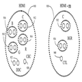
도 1은 전자 디바이스들 사이의 연결의 실시예의 도면이다. 도 1에서, 두 개의 전자 디바이스들이 케이블을 통해 연결된다. 특히, (HDMI 출력을 제공하는) HDMI 소스(102)가 케이블(106)을 통해 (HDMI 입력을 수신하는) HDMI 싱크(104)와 결합된다. HDMI 소스(102)는 비디오 데이터(122)와 오디오 데이터(124)를 수신하고 제어 및 상태 데이터(126)를 전달하는 송신기(120)를 포함한다. 마찬가지로, HDMI 싱크(104)는 비디오 데이터(132)와 오디오 데이터(134)를 제공하고 제어 및 상태 데이터(136)를 전달하는 수신기(130)를 포함한다.1 is a diagram of an embodiment of a connection between electronic devices. In FIG. 1, two electronic devices are connected via a cable. In particular, an HDMI source 102 (which provides an HDMI output) is coupled with an HDMI sink 104 (which receives an HDMI input) via a
케이블(106)은 HDMI 소스(102)로부터 HDMI 싱크(104)로의 세 개의 데이터 채널(108)(TMDS 채널 0, 1, 2)과 TMDS 클럭 채널(110)을 HDMI 싱크(104) 내에서 확장된 디스플레이 식별 데이터(EDID) ROM(138)에 결합된 DDC 채널(112)과 CEC 라인(114)과 함께 포함한다. 일부 실시예들에 있어서, 케이블(106)을 통해 운반된 채널들은 모바일 동작을 대비하여 통합된다. 특히, 데이터 채널들(108)은 단일 데이터 채널로 통합될 수 있고, DDC 채널과 CEC 채널은 단일 제어 채널로 통합될 수 있다. 일부 실시예들에 있어서, 채널들은 도 2에 제공된 바와 같이 통합된다.
도 2는 데이터 송신기와 데이터 수신기 사이의 연결의 실시예의 도면이다. 도 2에서, 두 개의 전자 디바이스들이 케이블을 통해 연결된다. 특히, HDMI-M 송신 디바이스(202)가 케이블(206)을 통해 HDMI-M 수신 디바이스(204)와 결합된다. HDMI-M 송신 디바이스(202)는 비디오 데이터(222)와 오디오 데이터(224)를 수신하고 제어 및 상태 데이터(226)를 전달하는 송신기(220)를 포함한다. 마찬가지로, HDMI-M 수신 디바이스(204)는 비디오 데이터(232)와 오디오 데이터(234)를 제공하고 제어 및 상태 데이터(236)를 전달하는 수신기(230)를 포함한다.2 is a diagram of an embodiment of a connection between a data transmitter and a data receiver. In FIG. 2, two electronic devices are connected via a cable. In particular, the HDMI-
케이블(206)은 HDMI-M 송신 디바이스(202)로부터 HDMI-M 수신 디바이스(204)로의 단일 데이터 채널(208)(TMDS 채널)과 TMDS 클럭 채널(210)을 단일 제어 버스(212)와 USB 버스(214)와 함께 포함한다. 실시예에 있어서, HDMI-M 수신 디바이스(204) 내의 EDID ROM(238)은 수신기(230)와 결합된다. 일부 실시예들에 있어서, 단일 TMDS 데이터 채널(208)은 모든 비디오 및 오디오 데이터를 운반하고, 단일 제어 버스(212)는 모든 제어 데이터를 운반한다. 일부 실시예들에 있어서, 단일 제어 버스(212)는 어떤 유형의 디바이스가 송신기(202)로서 사용되는지를 판단하기 위한 발견 프로세스에서 추가로 사용된다.The
도 3은 수신 디바이스와 결합된 송신 디바이스의 실시예의 도면이다. 도 3에서, 송신기(302)가 케이블(320)을 통해 수신기(310)에 결합된다. 도 3에서, 수신기(310)는 이중-모드 HDMI 수신 디바이스를 포함할 수 있는 표준 프로토콜 디바이스(312)일 수 있다. 일부 실시예들에 있어서, 이중-모드 HDMI 수신 디바이스는 HDMI 송신기와 HDMI-M 송신기 중 어느 하나의 송신기와 통신할 수 있을 것이다. 일부 실시예들에 있어서, 송신기(302)는 다양한 유형의 디바이스들 중 하나의 디바이스일 수 있다. 도 3에서, 송신기는 HDMI 송신 디바이스와 같은 표준 프로토콜 디바이스(304)로서 도시된 제1 유형의 송신 디바이스이거나, 또는 모바일 프로토콜 디바이스(306)로서 도시된 제2 유형의 디바이스일 수 있다. 모바일 프로토콜 디바이스(306)는 휴대형 또는 다른 이동형 미디어 디바이스와 같은 HDMI-M 송신 디바이스일 수 있다. 일부 실시예들에 있어서, 케이블(320)은 (HDMI 호환 케이블과 같은) 표준 프로토콜 디바이스들의 연결을 위한 표준 프로토콜 케이블(322)이거나, 또는 단일 제어 케이블과 전원 케이블을 포함하는 (HDMI-M 호환 케이블과 같은) 모바일 프로토콜 케이블(324)일 수 있다. 일부 실시예들에 있어서, 수신기(310)는 송신기(302)와의 연결을 발견하기 위해 케이블(320) 상에 수신된 신호들을 이용하고, 송신기는 수신기(310)와의 핫 플러그 연결 등의 연결 설정을 돕기 위해 케이블(320) 상의 신호들을 이용한다.3 is a diagram of an embodiment of a transmitting device in conjunction with a receiving device. In FIG. 3, the
도 4는 디바이스 발견 프로세스에서 수신기의 상태간 전이를 도시한 도면이다. 예에서, 수신기는 어떤 유형의 송신기가 자신에게 연결되는지를 발견하기 위해 대비할 수 있다. 수신기는 하나 이상의 제어 버스를 포함하는 케이블과 결합될 수 있다. 또한, 케이블은 전원을 전송하기 위해 하나 이상의 라인을 포함할 수 있다. 버스들의 특성은 수신기에 연결되는 송신기의 특성에 달려있다. 일부 실시예들에 있어서, 제어 버스는 어떤 유형의 송신기가 제어 버스를 통해 수신기와 결합되는지를 판단하기 위해 다중-모드 수신기를 위한 메커니즘을 제공할 수 있다. 예를 들어, 제어 버스는 HDMI 송신기(표준 프로토콜 디바이스) 또는 HDMI-M 송신기(모바일 프로토콜 디바이스)가 송신기와 연결되는지를 발견하기 위한 메커니즘을 제공할 수 있다. 일부 실시예들에 있어서, 제어 라인은 HDMI-M (모바일 디바이스) 송신기를 위한 핫 플러그 메커니즘을 더 제공한다. 일부 실시예들에 있어서, 제어 버스는 ID 비트를 USB-OTG 컴패니온 PHY에 제공하기 위해 추가로 사용될 수 있다. 일부 실시예들에 있어서, 전원 버스(VBUS)는 (HDMI 수신 디바이스로부터 HDMI-M 송신 디바이스로와 같이) 수신기로부터 모바일 송신기로 전원을 공급하고, 또한 연결을 설정하기 위해서도 사용될 수 있다. 일부 실시예들에 있어서, 송신 디바이스는 디바이스 발견에서 (5V 전원 신호와 같은) 수신기 전원 신호의 존재를 검출할 수 있다.4 illustrates a transition between states of a receiver in a device discovery process. In an example, the receiver may be prepared to find out what type of transmitter is connected to it. The receiver can be coupled with a cable containing one or more control buses. The cable may also include one or more lines for transferring power. The nature of the buses depends on the nature of the transmitter connected to the receiver. In some embodiments, the control bus may provide a mechanism for the multi-mode receiver to determine what type of transmitter is coupled with the receiver via the control bus. For example, the control bus may provide a mechanism for discovering whether an HDMI transmitter (standard protocol device) or an HDMI-M transmitter (mobile protocol device) is connected with the transmitter. In some embodiments, the control line further provides a hot plug mechanism for the HDMI-M (mobile device) transmitter. In some embodiments, the control bus can be further used to provide an ID bit to the USB-OTG companion PHY. In some embodiments, a power bus (VBUS) may be used to power the receiver from the receiver (such as from the HDMI receiving device to the HDMI-M transmitting device) and to establish a connection. In some embodiments, the transmitting device can detect the presence of a receiver power signal (such as a 5V power signal) in device discovery.
도 4에서, 이중-모드 수신기는 처음에 케이블 단절 상태(402)일 수 있고, 임의의 리셋 시에도 케이블 단절 상태로 전이된다. 수신기는 케이블 단절 상태(402)로부터 표준 HDMI 모드의 동작에 대응할 수 있는 표준 디바이스 연결 상태(406)와 HDMI-M 모드의 동작에 대응할 수 있는 모바일 디바이스 연결 상태(404)로 전이될 수 있다. 일부 실시예들에 있어서, 제어 버스가 로우이고 VBUS 상에 전원이 공급되지 않는 한 수신기는 케이블 단절 상태(402)로 남아있다. 이러한 상태에서, HDMI 수신기는 핫 플러그 검출을 위한 HDMI 사양에 제공된 바와 같이 핫 플러그(HDMI-M 케이블을 위한 제어 라인과 동일한 라인임)를 로우로 구동할 것이다. 이 상태에서, 제어 버스 풀-다운 회로는 디스에이블된다.In FIG. 4, the dual-mode receiver may initially be in a cable disconnected
일부 실시예들에 있어서, 수신기는 송신기의 +5V 전원 신호 검출 시에(408) 케이블 단절 상태(402)로부터 표준 디바이스 연결 상태(406)로 전이된다. 이러한 신호는 HDMI-M 디바이스를 위해서는 연결되지 않기 때문에, 수신기가 HDMI 송신기와 같은 표준 프로토콜 디바이스와 연결된 것을 의미한다. 이러한 상태에서, 수신기는 (1㏀당 2.4V 내지 5.3V의 전압으로) 핫 플러그 검출을 위한 HDMI 사양에 따라 핫 플러그를 로우로 구동해야만 한다. 이 상태에서, 제어 버스 풀-다운은 디스에이블되어야 한다. 또한, 수신기는 송신기의 전원 신호 검출 시에(416) 모바일 디바이스 연결 상태(404)로부터 표준 디바이스 연결 상태(406)로 전이될 것이다. 그러므로, 수신기는 송신기의 +5V 전원 신호 검출 시에 임의의 상태, 즉 케이블 단절 상태(402)와 모바일 디바이스 연결 상태(404) 중 어느 하나의 상태로부터 표준 디바이스 연결 상태(406)로 전이될 것이다.In some embodiments, the receiver transitions from a cable disconnected
일부 실시예들에 있어서, 수신기는 제어 버스 상에서 펄스(일 예에서, 100㎲ 하이, 100㎲ 로우일 수 있음)의 검출 시에(412) 케이블 단절 상태(402)로부터 모바일 디바이스 연결 상태(404)로 전이된다. 실시예에 있어서, 신호 펄스는 신호가 HDMI-M 송신기에 의해 구동 중임을 나타낸다. 실시예에 있어서, 모바일 디바이스 연결 상태(404)로의 전이 시에, 수신기는 자신의 핫 플러그 패드를 3상화하고 제어 버스 풀-다운 회로를 인에이블한다. 실시예에 있어서, 풀-다운 회로는 상대적으로 약하고 저항은 100㏀의 범위 내에 있다. 실시예에 있어서, 수신기는 제어 버스 상에서 자신의 모드 출력을 하이로 구동하고 전원 버스를 +5V로 구동한다.In some embodiments, the receiver is connected to the mobile
실시예에 있어서, 수신기는 송신기의 0V 전원 신호 검출 시에(410) 표준 디바이스 연결 상태(406)로부터 케이블 단절 상태(402)로 전이되고, 이는 케이블 단절 또는 송신기 정지 동작을 나타낸다. 실시예에 있어서, 수신기는 제어 버스가 로우 값인 (일정한 수의 사이클 이상의) 긴 기간의 검출 시에(414) 모바일 디바이스 연결 상태(404)로부터 케이블 단절 상태(402)로 전이된다. 이는 케이블이 수신기의 풀-다운 회로 또는 모바일 디바이스 중지 동작에 의해 단절되고 로우로 풀링됨을 나타낸다.In an embodiment, the receiver transitions from the standard
도 5는 디바이스 발견 프로세스에서 송신기의 상태간 전이를 도시한 도면이다. 도 5에서, 송신기는 케이블 단절 상태(502), 송신기가 수신기에 의한 발견 확인을 기다리는 경우 사용하는 보류 상태(504), 발견 후의 동작을 위한 발견 상태(506) 사이에서 전이될 수 있다. 송신기는 리셋 시에 케이블 단절 상태이고, 전원 버스가 로우인 동안은 이 상태로 머물러 있다. 이러한 상태에서, 일 예에서 10㏀ 풀-업일 수 있는 풀-업 회로가 인에이블된다. 5 is a diagram illustrating the transition between states of a transmitter in a device discovery process. In FIG. 5, the transmitter may transition between a cable disconnected
일부 실시예들에 있어서, 송신기는 VBUS 상에서 논리 '1' (+5V)의 검출 시에(508) 보류 상태(504)로 전이된다. 이 신호는 송신기가 HDMI 수신기에 연결되었으나 수신기가 (수신기의 HTPLG의 역할을 하는) CBUS 상으로 로우 신호를 여전히 구동 중이기 때문에 송신기가 수신기에 의해 아직 발견되지 않았다는 것을 의미한다. 이러한 상태에서, 송신기는 CBUS를 펄스할 것이고, 예를 들어, 신호 펄스는 대략 100㎲ 구동 하이, 100㎲ 부동(float)이다.In some embodiments, the transmitter transitions to pending state 504 upon
일부 실시예들에 있어서, 송신기는 CBUS를 구동하지 않는 동안 보류 상태(504)에서 CBUS 상의 값을 감시한다. 송신기가 하이 신호를 구동하지 않는 동안 CBUS 상에서 하이 값을 검출하면(512), 이는 수신기가 송신기의 존재를 발견하고 자신의 HTPLG 패드를 3상화했다는 것을 의미한다. 송신기는 발견 상태(506)로 전이되고 CBUS 상에서 10K 풀-업 회로를 인에이블한다. 일부 실시예들에 있어서, VBUS가 보류 상태(504)와 발견 상태(506) 중 어느 하나의 상태에서 0V로 되돌아가면(510과 516), 이는 수신기가 더 이상 연결되거나 동작되지 않음을 나타내고, 송신기는 케이블 단절 상태(502)로 도로 전이된다. 또한, 송신기가 발견 상태인 동안 긴 로우 신호가 CBUS 상에서 검출되면(514), 송신기는 보류 상태(504)로 도로 전이될 것이다.In some embodiments, the transmitter monitors the value on the CBUS in hold state 504 while not driving the CBUS. If a high value on the CBUS is detected (512) while the transmitter is not driving a high signal, this means that the receiver has detected the presence of the transmitter and three-phased its HTPLG pad. The transmitter transitions to the
도 6과 도 7은 연결된 디바이스들을 위한 발견 프로세스의 실시예를 도시한 흐름도이다. 도 6과 도 7에서, 송신기는 케이블을 통해 이중-모드 수신기에 연결된다(602 단계). 송신 디바이스는 표준 디바이스와 모바일 디바이스 중 어느 하나와 같이, 두 가지 유형의 디바이스 중 어느 하나의 디바이스일 수 있다(604 단계). 예를 들어, 송신 디바이스는 표준 HDMI 디바이스와 HDMI-M 디바이스 중 어느 하나의 디바이스일 수 있다. 디바이스가 모바일 디바이스이면(606 단계), 프로세스는 도 7에서 기술된 바와 같을 것이다. 디바이스가 표준 디바이스이면(608 단계), 송신기는 송신기 라인 상에 +5V 값을 제공할 것이고(610 단계), 송신기는 (표준 디바이스를 위한 핫 플러그 라인일 수 있는) 제어 라인 상에서 신호를 구동하지 않을 것이다(612 단계).6 and 7 are flowcharts illustrating an embodiment of a discovery process for connected devices. 6 and 7, the transmitter is connected to a dual-mode receiver via a cable (step 602). The transmitting device may be one of two types of devices, such as either a standard device or a mobile device (step 604). For example, the transmitting device may be one of a standard HDMI device and an HDMI-M device. If the device is a mobile device (step 606), the process will be as described in FIG. If the device is a standard device (step 608), the transmitter will provide a + 5V value on the transmitter line (step 610) and the transmitter will not drive a signal on the control line (which may be a hot plug line for the standard device). (Step 612).
실시예에 있어서, 수신기는 송신기로부터 신호 펄스를 수신하지 않을 것이다(614 단계). 수신기는 +5V 전원 신호를 검출하고, 따라서 송신기가 HDMI 디바이스와 같은 표준 프로토콜 디바이스임을 판단할 것이다(616 단계). 다음으로, 디바이스들은 HDMI 디바이스들 간의 표준 연결과 같은 표준 동작을 시작할 수 있다(618 단계). 이러한 표준 동작은 예를 들어 +5V 전원 신호가 손실되었음을 수신기가 판단하거나(620 단계) 또는 +5V 전원이 VBUS 상에서 손실되었음을 송신기가 판단할 때까지(622 단계) 계속되고, 이는 케이블 단절 상태를 나타낸다(624 단계).In an embodiment, the receiver will not receive signal pulses from the transmitter (step 614). The receiver detects the + 5V power signal and will therefore determine that the transmitter is a standard protocol device, such as an HDMI device (step 616). Next, the devices may begin standard operation, such as standard connection between HDMI devices (step 618). This standard operation continues, for example, until the receiver determines that the + 5V power signal has been lost (step 620) or the transmitter determines that + 5V power has been lost on the VBUS (step 622), which indicates a cable disconnection condition. (624 steps).
다음으로, 도 7은 HDMI-M 송신 디바이스와 같은 모바일 디바이스 송신기(606 단계)를 위한 프로세스를 도시한다. 실시예에 있어서, 이중-모드 수신기는 VBUS 상에서 +5V 신호를 제공한다(702 단계). 다음으로, 제어 버스는 핫 플러그 기능과의 CBUS 공유로 인해 수신기에 의해 로우로 구동된다(704 단계). 송신기는 VBUS 상에서 +5V를 검출하고, 응답으로 제어 버스 상에서 신호 펄스를 구동한다(706 단계). 수신기는 CBUS 상에서 하이 값을 검출하고 응답으로서 송신기가 모바일 디바이스임을 판단하고, 핫 플러그 기능을 단절하고 CBUS 상에서 풀-다운 회로를 인에이블한다(710 단계). 풀-다운 회로의 결과로서, 송신기는 제어 버스 상에서 펄스를 구동하지 않는 경우에 CBUS 신호가 로우임을 검출하고, 그러므로 수신기는 송신기를 발견했다고 판단하고 제어 버스 상에서 펄싱을 중지한다(712 단계). 디바이스들은 통신을 개시할 준비가 되어있고(714 단계), 송신기와 수신기는 제어 버스를 사용하여 통신한다(716 단계). 이러한 프로세스는 예를 들어 수신기의 +5V 전원 공급이 사라졌음을 송신기가 판단하거나(718 단계) 또는 제어 버스가 긴 기간 동안 로우였음을 수신기가 판단할 때까지(720 단계) 계속될 수 있고, 이는 케이블 단절 상태를 나타낸다(722 단계).Next, FIG. 7 shows a process for a mobile device transmitter (step 606), such as an HDMI-M transmitting device. In an embodiment, the dual-mode receiver provides a + 5V signal on VBUS (step 702). The control bus is then driven low by the receiver due to CBUS sharing with the hot plug function (step 704). The transmitter detects + 5V on VBUS and drives a signal pulse on the control bus in response (step 706). The receiver detects a high value on the CBUS and determines as a response that the transmitter is a mobile device, disconnects the hot plug function and enables the pull-down circuit on the CBUS (step 710). As a result of the pull-down circuit, the transmitter detects that the CBUS signal is low when it does not drive a pulse on the control bus, and therefore the receiver determines that it has found the transmitter and stops pulsing on the control bus (step 712). The devices are ready to initiate communication (step 714) and the transmitter and receiver communicate using a control bus (step 716). This process may continue, for example, until the transmitter determines that the + 5V power supply of the receiver has disappeared (step 718) or until the receiver determines that the control bus has been low for a long period (720). Indicate the cable disconnection state (step 722).
도 8은 제어 버스를 통해 표준 디바이스와 결합된 모바일 디바이스의 실시예의 도면이다. 일부 실시예들에 있어서, 송신기는 HDMI-M 송신기 보드(810)이고 수신기는 HDMI-E(이중-모드) 수신기 보드(830)이다. HDMI-M 송신기 보드(810)는 HDMI-M 송신기 칩(812)을 포함하고, HDMI-E 수신기 보드(830)는 HDMI-E 수신기 칩(832)을 포함한다. 송신기와 수신기 사이의 케이블 연결들은 핫 플러그(HTPLG) 핀(834)과 패드들을 공유하는 제어 버스(CBUS)(802)와, 수신기(830)가 전원 스위치(838)를 통해 송신기(810)에 +5V 신호를 제공하는데 사용하는 전원 버스(VBUS)(804)와, (USB PHY 주변(818)과 USB PHY 호스트(840) 사이의) USB 연결(806)을 포함한다. 일부 실시예들에 있어서, HDMI-M 송신기 칩(812)과 HDMI-E 수신기 칩(832)은 제어 버스(802) 상에서 신호들을 검출하는 로직과 VBUS(804) 또는 다른 전원 연결을 통해 송신된 전원 신호들을 검출하는 로직을 포함한다. 제어 버스(CBUS)(802) 상에서, 송신기(810)는 (1.2V 소스에 연결된 10㏀ 임피던스로서 도시된) 스위칭 가능한 풀-업 회로(814)를 구비하고, 수신기는 (접지에 연결된 100㏀ 임피던스로서 도시된) 스위칭 가능한 풀-다운 회로(836)를 구비한다. 동작 동안, 처음에 송신기는 ID 핀(817)을 하이로 구동되게 하고, 디바이스들은 양쪽 다 케이블 단절 상태이다. M-E형 케이블이 HDMI-M 송신기(810)와 다중-모드 수신기(830) 사이에 연결된다. 송신기(810)는 송신기의 파워/웨이크 인에이블(PWR/WAKE_EN) 핀 상에 공급된 수신기의 +5V 전원의 존재를 검출하고, 보류 상태로 전이된다. 이러한 상황에서, CBUS(802)는 HTPLG 핀(834)과 공유되기 때문에 수신기(830)에 의해 로우로 구동된다.8 is a diagram of an embodiment of a mobile device coupled with a standard device via a control bus. In some embodiments, the transmitter is an HDMI-
송신기(810)는 보류 상태인 동안 반복적으로 CBUS(802)를 100㎲ 동안 하이로 펄스하고 100㎲ 동안 3상화한다. 송신기(810)가 CBUS(802)를 하이로 구동하지 않는 경우, 송신기(810)는 수신기(830)가 CBUS를 로우로 구동하는 것을 중지했는지 판단하기 위해 CBUS(802)의 상태를 판단한다.
실시예에 있어서, 수신기(830)는 CBUS(802) 상에서 하이 값을 검출한다. 이는 수신기에게 송신기가 HDMI-M 송신기이고 CBUS를 하이로 구동 중임을 알려준다. 표준 HDMI 송신기는 이 선을 하이로 구동하지 않을 것이다. 응답으로, 수신기(830)는 자신의 HTPLG 기능성을 디스에이블하고 CBUS 상에서 100K 풀-다운을 인에이블한다. 수신기는 이제 HDMI-M 연결 상태이다.In an embodiment, the
송신기(810)가 CBUS를 구동하지 않는 경우에 CBUS(802)가 로우임을 검출하면, 송신기(810)는 발견 상태로 전이되고 CBUS의 펄싱을 중지한다. 이 시점에서, 송신기(810)와 수신기(830)는 모두 CBUS(802)를 통해 통신을 시작할 준비가 되어있다. 양측은 CBUS(802)의 사용에 대해 중재를 수행할 수 있다.If the
송신기(810)는 수신기의 +5V 전원 신호를 잃으면 케이블 단절 상태로 전이할 것이다. 수신기(830)는 케이블이 단절되었음을 나타내는 CBUS(802) 상의 긴 로우를 확인하면 케이블 단절 상태로 전이할 것이다. 실시예에 있어서, 수신기(830)가 파워 다운되면, CBUS(802) 상에서 풀 다운하지 않는다. 이러한 프로세스는 송신기의 배출 전류(1.2V에서 120㏀-약 10㎂)를 방지하는 것을 돕는다.The
도 9는 송신기와 수신기를 연결하기 위해 사용될 수 있는 케이블들의 도면이다. 도시된 바와 같이, HDMI 케이블(910)과 같은 표준 디바이스를 위한 케이블은 신호 타이밍을 위한 클럭 채널(912)과 다양한 데이터 채널들(이 경우에, 블루(916), 그린(918), 레드(914))을 포함할 수 있다. HDMI 케이블(910)은 (두 개의 선을 갖는) DDC 채널(922)과 (단선을 갖는) CEC 라인(920)을 더 포함할 수 있다. (케이블은 도시되지 않은 +5V 전원 신호 라인, 핫 플러그 검출, USB 데이터 채널 등의 다른 라인들을 포함할 수 있다). 모바일 디바이스를 위해, 케이블은 신호들을 통합하여 더 적은 수의 라인을 사용할 수 있다. 예를 들어, HDMI-M 케이블(930)은 단지 클럭 채널(932)을 (블루-그린-레드 라인(934)과 같은) 통합된 데이터를 위한 단일 데이터 채널과 통합된 제어 데이터를 위한 단일 제어 채널(940)과 함께 포함할 수 있다. 실시예에 있어서, 케이블들은 표준 HDMI 송신기와 HDMI-M 모바일 송신기 중 어느 하나의 송신기로부터 어떤 유형의 송신기가 자신에게 부착되는지를 발견할 수 있는 이중-모드 수신기로 신호들을 운반하는데 사용될 수 있다.9 is a diagram of cables that may be used to connect the transmitter and the receiver. As shown, a cable for a standard device, such as
도 10은 송신기 및 수신기 케이블들을 위한 케이블 신호 할당의 실시예의 도면이다. 도시된 신호 할당들이 사용될 수 있는 연결들의 일 예를 제공하지만, 본 발명의 실시예들은 임의의 특정한 핀 할당 선택에 제한되지 않는다. 도시된 바와 같이, 표준 HDMI 할당(핀 1~6)의 두 개의 데이터 채널은 HDMI-M 할당 내에 등가물이 없다. 세 번째 HDMI 데이터 채널(핀 7~9)이 HDMI-M 할당을 위한 단일 데이터 채널에 연결된다. 클럭(핀 10~12)은 불변일 수 있다. HDMI를 위한 CEC 채널(핀 13)은 HDMI-M 내에 등가물이 없다. HDMI를 위해 예약된 핀(핀 14)은 수신기로부터 송신기로 +5V 전원(VBUS)을 제공하는 핀이 될 수 있다. HDMI를 위한 DDC 채널(핀 15와 16)이 HDMI-M을 위한 USB 데이터로서 사용될 수 있다. 송신기의 +5V 전원(핀 18)은 HDMI-M 내에 등가물이 없을 수 있다. 최종적으로, HDMI의 핫 플러그 검출(핀 19)이 HDMI-M 내에 병합된 신호들을 운반하기 위한 제어 버스와 결합될 수 있다.10 is a diagram of an embodiment of cable signal assignment for transmitter and receiver cables. Although the signal assignments shown provide an example of connections that may be used, embodiments of the present invention are not limited to any particular pin assignment selection. As shown, the two data channels of the standard HDMI assignment (pins 1-6) have no equivalent within the HDMI-M assignment. The third HDMI data channel (pins 7-9) connects to a single data channel for HDMI-M assignment. The clock (pins 10-12) may be immutable. The CEC channel (pin 13) for HDMI has no equivalent in HDMI-M. The pin reserved for HDMI (pin 14) can be a pin that provides + 5V power (VBUS) from the receiver to the transmitter. DDC channels (pins 15 and 16) for HDMI can be used as USB data for HDMI-M. The transmitter's + 5V supply (pin 18) may have no equivalent in HDMI-M. Finally, hot plug detection (pin 19) of HDMI can be combined with a control bus to carry the merged signals within HDMI-M.
도 11은 두 개의 모바일 디바이스 사이의 연결의 실시예의 도면이다. 도 11에서, 제1 모바일 디바이스(1110)(제1 HDMI-M 측)는 제2 모바일 디바이스(1130)(제2 HDMI-M 측)에 연결될 수 있다. 이들은 모바일 디바이스들이기 때문에, 디바이스들 모두가 풀-업 회로(1114)(1134)를 포함한다. 디바이스들은 전원이 공급되지 않는 VBUS(1104)와 USB 연결(1106)을 통해 연결된다. 디바이스들은 전이 최소화 차동 시그널링(TMDS) 버스(1108)를 더 포함할 수 있다. USB 버스(1106)는 제1 USB PHY(1118)를 제2 USB PHY(1140)에 연결한다. 그러나, 두 개의 모바일 디바이스들의 연결은 제어 버스의 단절을 가져온다. 실시예에서, 케이블의 연결은 제2 모바일 디바이스(1130)의 USB PHY(1140)가 호스트 디바이스로서 지정되게 하고 제1 모바일 디바이스(1110)의 USB PHY(1118)가 주변 디바이스로서 지정되게 하면서, 제2 모바일 디바이스(1130)에서 제어 버스(1102)를 접지시킨다.11 is a diagram of an embodiment of a connection between two mobile devices. In FIG. 11, a first mobile device 1110 (first HDMI-M side) may be connected to a second mobile device 1130 (second HDMI-M side). Since these are mobile devices, all of the devices include pull-up circuits 1114 and 1134. The devices are connected via a
상기 설명에서, 설명의 목적으로, 본 발명의 철저한 이해를 제공하기 위해 다수의 특정 세부사항들이 제시된다. 그러나, 당해 기술분야의 숙련자들에게는 본 발명이 이러한 특정 세부사항들 중 일부가 없더라도 실시될 수 있다는 것이 자명할 것이다. 다른 예들에서, 주지의 구조들 및 디바이스들이 블록도 형태로 도시되어 있다. 도시된 컴포넌트들 사이에 중간 구조가 존재할 수 있다. 본 명세서에 설명되거나 도시된 컴포넌트들은 도시 또는 설명되지 않은 추가적인 입력들 또는 출력들을 가질 수 있다.In the foregoing description, for purposes of explanation, numerous specific details are set forth in order to provide a thorough understanding of the present invention. However, it will be apparent to those skilled in the art that the present invention may be practiced without some of these specific details. In other instances, well-known structures and devices are shown in block diagram form. There may be an intermediate structure between the components shown. Components described or illustrated herein may have additional inputs or outputs not shown or described.
본 발명의 다양한 실시예들은 다양한 프로세스들을 포함할 수 있다. 이러한 프로세스들은 하드웨어 컴포넌트에 의해 수행될 수 있거나, 또는 컴퓨터 프로그램 또는 기계-실행 가능 명령 내에 구현될 수 있고, 상기 명령으로 프로그래밍된 로직 회로들 또는 범용 또는 특별 목적 프로세서가 이 프로세스들을 수행하게 할 수 있다. 대신으로, 프로세스들은 하드웨어와 소프트웨어의 조합에 의해 수행될 수 있다.Various embodiments of the present invention may include various processes. Such processes may be performed by a hardware component or may be implemented in a computer program or machine-executable instructions and cause logic circuits or general purpose or special purpose processors programmed with the instructions to perform these processes. . Instead, the processes can be performed by a combination of hardware and software.
본 발명의 다양한 실시예들의 일부는 본 발명의 실시예들에 따른 프로세스를 수행하도록 컴퓨터(또는 다른 전자 디바이스들)를 프로그래밍하는데 이용될 수 있는 컴퓨터 프로그램 명령들이 저장된 컴퓨터-판독 가능 매체를 포함할 수 있는 컴퓨터 프로그램 제품으로서 제공될 수 있다. 기계-판독 가능 매체는 플로피 디스켓, 광 디스크, 콤팩트 디스크 판독전용 메모리(CD-ROM), 및 자기-광 디스크, 판독전용 메모리(ROM), 랜덤 액세스 메모리(RAM), 삭제 가능한 프로그램 가능 판독전용 메모리(EPROM), 전기적-삭제 가능한 프로그램 가능 판독 전용 메모리(EEPROM), 자기 또는 광학 카드, 플래시 메모리, 또는 전자 명령들을 저장하는데 적합한 다른 유형의 미디어/기계-판독가능 매체를 포함할 수 있으나 이에 제한되지 않는다. 또한, 본 발명은 컴퓨터 프로그램 제품으로서 다운로드될 수 있고, 이 프로그램은 원격 컴퓨터로부터 요청하는 컴퓨터로 전송될 수 있다.Some of the various embodiments of the present invention may include a computer-readable medium having stored thereon computer program instructions that can be used to program a computer (or other electronic devices) to perform a process in accordance with embodiments of the present invention. Can be provided as a computer program product. Machine-readable media include floppy diskettes, optical disks, compact disk read-only memory (CD-ROM), and magnetic-optical disks, read-only memory (ROM), random access memory (RAM), removable programmable read-only memory. (EPROM), electrically-erasable programmable read only memory (EEPROM), magnetic or optical cards, flash memory, or other types of media / machine-readable media suitable for storing electronic instructions. Do not. In addition, the present invention can be downloaded as a computer program product, which can be transferred from a remote computer to the requesting computer.
방법들 중 다수가 가장 기본적인 형태로 기술되었으나, 본 발명의 기본적인 범주로부터 벗어나지 않고 이러한 방법들 중 임의의 방법에 대하여 프로세스들이 추가되거나 삭제될 수 있고, 전술한 메시지들 중 임의의 메시지에 대하여 정보가 추가 또는 배제될 수 있다. 당해 기술분야의 숙련자들에게는 다수의 추가적인 변형 및 적응이 이루어질 수 있다는 것이 명백할 것이다. 특정한 실시예들이 본 발명을 제한하기 위해서가 아니라 설명하기 위해 제공된다. 본 발명의 실시예들의 범주는 앞서 제공된 특정한 예들에 의해서가 아니라 이하의 청구범위에 의해서 결정되어야 한다.Although many of the methods have been described in their most basic form, processes can be added or deleted for any of these methods without departing from the basic scope of the present invention, and information for any of the above-described messages can be obtained. May be added or excluded. It will be apparent to those skilled in the art that many further modifications and adaptations can be made. Specific embodiments are provided to illustrate but not limit the invention. The scope of embodiments of the invention should be determined by the following claims rather than by the specific examples provided above.
요소 "A"가 요소 "B"에 또는 요소 "B"와 결합된다고 기술된 경우에, 요소 A는 요소 B에 직접 결합되거나 예를 들어 요소 C를 통해 간접적으로 결합될 수 있다. 명세서 또는 청구범위에서 컴포넌트, 특징, 구조, 프로세스 또는 특성 A가 컴포넌트, 특징, 구조, 프로세스 또는 특성 B를 "초래한다"고 언급된 경우, "A"가 "B"의 적어도 부분적인 원인이지만 또한 "B"를 초래하는 것을 돕는 하나 이상의 다른 컴포넌트, 특징, 구조, 프로세스 또는 특성이 있을 수 있다는 것을 의미한다. 명세서에서 컴포넌트, 특징, 구조, 프로세스 또는 특성이 포함될 수 있다(may, might, could be included)고 나타낸 경우, 이러한 특정한 컴포넌트, 특징, 구조, 프로세스 또는 특성이 포함되도록 요구되는 것은 아니다. 명세서 또는 청구범위에서 "하나(a or an)"의 요소를 지칭하는 경우, 이는 기술된 요소들 중 단지 하나의 요소만 있다는 것을 의미하지는 않는다. In the case where element "A" is described as being coupled to element "B" or with element "B", element A may be directly bonded to element B or indirectly via eg element C. Where component, feature, structure, process or property A is referred to in the specification or claims as "derives" component, feature, structure, process or property B, "A" is at least partly a cause of "B" but also It is meant that there may be one or more other components, features, structures, processes or properties that help to bring about "B". Where a specification may indicate that a component, feature, structure, process or feature may be included, it is not required that this particular component, feature, structure, process or feature be included. When referring to an "a or an" element in the specification or claims, this does not mean that there is only one element of the elements described.
실시예는 본 발명의 구현예 또는 예이다. 본 명세서의 "실시예", "일 실시예", "일부 실시예들", 또는 "다른 실시예들"에 대한 참조는 실시예와 관련하여 기술된 특정한 특징, 구조 또는 특성이 반드시 모든 실시예들에 포함되는 것이 아니라 적어도 일부 실시예들에 포함된다는 것을 의미한다. "실시예", "일 실시예", 또는 "일부 실시예들"의 다양한 언급들 모두가 반드시 동일한 실시예들을 지칭하는 것은 아니다. 본 발명의 예시적인 실시예들에 대한 전술한 설명에서는 본 개시를 간략하게 만들고 다양한 발명의 양상들의 하나 이상의 양상의 이해를 돕기 위한 목적으로, 다양한 특징들이 단일 실시예, 도면 또는 설명에서 때때로 함께 그룹화되어 있다는 것을 이해해야 한다. 그러나, 본 개시의 이러한 방법은 청구된 발명이 각각의 청구항에서 명백하게 인용된 것보다 더욱 많은 특징들을 필요로 한다는 의도를 반영하는 것으로 해석되어서는 안 된다. 오히려, 후술하는 청구범위가 반영하는 바와 같이, 발명의 양상들은 앞서 개시된 단일 실시예의 모든 특징들보다 더 적은 수로 존재한다. 그러므로, 청구범위는 이에 의해 본 명세서에 명백하게 통합되고, 각각의 청구항은 그 자체로 본 발명의 별개의 실시예로서 존재한다.
An embodiment is an embodiment or example of the invention. References herein to “an embodiment”, “an embodiment”, “some embodiments”, or “other embodiments” are not necessarily all embodiments that have particular features, structures, or characteristics described in connection with the embodiments. It is meant to be included in at least some embodiments rather than included. All references in "an embodiment,""oneembodiment," or "some embodiments" do not necessarily all refer to the same embodiments. In the foregoing description of exemplary embodiments of the present invention, various features are sometimes grouped together in a single embodiment, figure, or description for the purpose of streamlining the disclosure and aiding in the understanding of one or more aspects of the various aspects of the invention. It must be understood. However, this method of the present disclosure should not be construed to reflect the intention that the claimed invention requires more features than are expressly recited in each claim. Rather, as the following claims reflect, inventive aspects exist in fewer numbers than all features of a single embodiment disclosed above. Therefore, the claims are hereby expressly incorporated into this specification, with each claim standing on its own as a separate embodiment of the invention.
Claims (30)
수신 디바이스가 단절 상태이고 송신 디바이스의 신호가 제어 버스 상에서 검출되면, 수신 디바이스를 제1 유형의 송신 디바이스를 위한 상태로 전이하는 단계와;
수신 디바이스가 단절 상태와 제1 유형의 송신 디바이스를 위한 상태 중 어느 하나의 상태이고 소정의 전압 신호가 송신 디바이스로부터 수신되면, 수신 디바이스를 제2 유형의 송신 디바이스를 위한 상태로 전이하는 단계를 포함하는 방법.Connecting the receiving device to a cable comprising a control bus;
If the receiving device is in a disconnected state and a signal of the transmitting device is detected on the control bus, transitioning the receiving device to a state for a first type of transmitting device;
Transitioning the receiving device to a state for a second type of transmitting device when the receiving device is in one of a disconnected state and a state for the first type of transmitting device and a predetermined voltage signal is received from the transmitting device. How to.
송신 디바이스가 단절 상태이고 소정의 전압이 전원 버스 상에서 검출되면, 송신 디바이스를 보류 상태로 전이하고 제어 라인을 제1 값의 신호 펄스로 구동하는 단계와;
송신 디바이스가 보류 상태이고, 신호 펄스가 구동되지 않는 경우에 제1 값이 제어 버스 상에서 검출되면, 송신 디바이스를 수신 디바이스에 의해 발견되었음을 나타내는 발견 상태로 전이하는 단계를 포함하는 방법.Connecting the transmitting device to a cable comprising a single control bus and a power bus;
If the transmitting device is in a disconnected state and a predetermined voltage is detected on the power bus, transitioning the transmitting device to a holding state and driving the control line with a signal pulse of a first value;
If the first value is detected on the control bus when the transmitting device is on hold and the signal pulse is not driven, transitioning the transmitting device to a discovery state indicating that the transmitting device has been found by the receiving device.
수신기와 결합되며 제어 버스 및 수신기에 의해 전원이 공급되는 전원 버스를 포함하는 케이블 인터페이스와;
케이블 인터페이스 상에서 신호들을 검출하는 로직으로서, 전원 버스 상에서 전압 값을 검출하는 제1 로직으로, 소정의 전압이 제1 로직에 의해 전원 버스 상에서 검출되면 송신기가 보류 상태로 전이되는 제1 로직과, 제어 버스 상에서 신호들을 검출하는 제2 로직으로, 송신기가 제어 버스 상에서 제1 신호 값을 주기적으로 구동하고, 송신기가 제어 버스 상에서 신호 값을 구동하지 않는 경우 제1 신호 값이 제2 로직에 의해 검출되면, 송신기가 발견 상태로 전이되는 제2 로직으로 이루어진 로직;을 포함하는 송신 디바이스.A transmitter for transmitting signals to a receiver;
A cable interface coupled to the receiver and including a control bus and a power bus powered by the receiver;
Logic for detecting signals on a cable interface, the first logic for detecting a voltage value on a power bus, the first logic to transition a transmitter to a hold state when a predetermined voltage is detected on the power bus by the first logic, and With second logic to detect signals on the bus, the transmitter periodically drives the first signal value on the control bus and if the first signal value is detected by the second logic when the transmitter does not drive the signal value on the control bus. And logic comprising second logic at which the transmitter transitions to a discovery state.
송신 디바이스와 결합되며 제어 버스를 포함하는 인터페이스와;
수신 디바이스와 결합된 송신 디바이스를 발견하는 로직으로서, 제어 버스 상에서 제1 신호를 검출하는 제1 로직으로, 제1 신호가 검출되면 수신 디바이스가 제1 유형의 송신 디바이스를 발견하게 되는 제1 로직과, 수신 디바이스로부터 전원 신호를 검출하는 제2 로직으로, 전원 신호가 검출되면 수신 디바이스가 제2 유형의 송신 디바이스를 발견하게 되는 제2 로직으로 이루어진 로직;을 포함하는 수신 디바이스.A receiver for receiving signals from a transmitting device;
An interface coupled with the transmitting device and including a control bus;
Logic for discovering a transmitting device in conjunction with a receiving device, the first logic for detecting a first signal on a control bus, the first logic detecting the first signal when the first signal is detected; And second logic for detecting a power signal from the receiving device, the logic comprising second logic that causes the receiving device to discover a second type of transmitting device when the power signal is detected.
제1 송신 디바이스에서 제어 버스 상의 일정한 로우 레벨을 검출하고 제1 송신 디바이스가 호스트 디바이스임을 판단하는 단계와;
제1 송신 디바이스의 범용 시리얼 버스(USB) PHY를 호스트 디바이스로서 표시하기 위해 USB ID 출력을 로우로 구동하는 단계와;
핫 플러그 신호를 제2 송신 디바이스에 제공하기 위해 제1 송신 디바이스에 의해 전원 버스 상에서 전원 신호를 구동하는 단계를 포함하는 방법.Connecting the first transmitting device to the second transmitting device via a cable comprising a single control bus and a power bus and shorting the control bus to ground at the first transmitting device;
Detecting a constant low level on the control bus at the first transmitting device and determining that the first transmitting device is a host device;
Driving the USB ID output low to indicate a universal serial bus (USB) PHY of the first transmitting device as a host device;
Driving a power supply signal on a power bus by the first transmission device to provide a hot plug signal to the second transmission device.
Applications Claiming Priority (3)
| Application Number | Priority Date | Filing Date | Title |
|---|---|---|---|
| US11/969,865 US7921231B2 (en) | 2008-01-04 | 2008-01-04 | Discovery of electronic devices utilizing a control bus |
| US11/969,865 | 2008-01-04 | ||
| PCT/US2008/086879 WO2009088656A1 (en) | 2008-01-04 | 2008-12-15 | Discovery of electronic devices utilizing a control bus |
Publications (2)
| Publication Number | Publication Date |
|---|---|
| KR20100106568A true KR20100106568A (en) | 2010-10-01 |
| KR101490895B1 KR101490895B1 (en) | 2015-02-06 |
Family
ID=40379564
Family Applications (1)
| Application Number | Title | Priority Date | Filing Date |
|---|---|---|---|
| KR1020107017342A Active KR101490895B1 (en) | 2008-01-04 | 2008-12-15 | Discovery of electronic devices utilizing a control bus |
Country Status (7)
| Country | Link |
|---|---|
| US (1) | US7921231B2 (en) |
| EP (1) | EP2238530B1 (en) |
| JP (1) | JP5378409B2 (en) |
| KR (1) | KR101490895B1 (en) |
| CN (1) | CN101925873B (en) |
| TW (1) | TWI393011B (en) |
| WO (1) | WO2009088656A1 (en) |
Cited By (1)
| Publication number | Priority date | Publication date | Assignee | Title |
|---|---|---|---|---|
| KR20140021829A (en) * | 2012-08-09 | 2014-02-21 | 삼성전자주식회사 | Multimedia processing system and operating method thereof |
Families Citing this family (40)
| Publication number | Priority date | Publication date | Assignee | Title |
|---|---|---|---|---|
| JP2008276067A (en) * | 2007-05-02 | 2008-11-13 | Canon Inc | Video display device and control method thereof |
| US7921231B2 (en) | 2008-01-04 | 2011-04-05 | Silicon Image, Inc. | Discovery of electronic devices utilizing a control bus |
| US8090030B2 (en) * | 2008-01-04 | 2012-01-03 | Silicon Image, Inc. | Method, apparatus and system for generating and facilitating mobile high-definition multimedia interface |
| US7856520B2 (en) * | 2008-01-04 | 2010-12-21 | Silicon Image, Inc. | Control bus for connection of electronic devices |
| US9030976B2 (en) | 2008-03-27 | 2015-05-12 | Silicon Image, Inc. | Bi-directional digital interface for video and audio (DIVA) |
| US8176214B2 (en) * | 2008-10-31 | 2012-05-08 | Silicon Image, Inc. | Transmission of alternative content over standard device connectors |
| TWI460995B (en) | 2008-12-11 | 2014-11-11 | Silicon Image Inc | Power delivery over digital interaction interface for video and audio (diiva) |
| US8674679B2 (en) | 2009-10-08 | 2014-03-18 | Qualcomm Incorporated | Power saving during a connection detection |
| CN102835091B (en) * | 2010-01-12 | 2017-07-04 | 美国莱迪思半导体公司 | Multimedia USB data transmission is through digital video and the interactive interface of audio (DiiVA) |
| US9234930B2 (en) * | 2010-02-10 | 2016-01-12 | Lattice Semiconductor Corporation | Determination of physical connectivity status of devices based on electrical measurement |
| JP5515919B2 (en) * | 2010-02-12 | 2014-06-11 | ソニー株式会社 | Method for determining digital interface of electronic device and connected external device |
| CN102792707B (en) * | 2010-03-09 | 2015-08-26 | 佳能株式会社 | Video display apparatus and control method, picture output device and control method thereof |
| EP2563018A4 (en) * | 2010-04-20 | 2013-05-01 | Sharp Kk | Output device, source apparatus, television set, system, output method, program, and recording medium |
| JP5589543B2 (en) * | 2010-05-10 | 2014-09-17 | 富士ゼロックス株式会社 | Video signal transmission apparatus and signal transmission program |
| US8650334B2 (en) * | 2010-05-19 | 2014-02-11 | Sharp Kabushiki Kaisha | Source device, sink device, system, and recording medium |
| JP5671838B2 (en) * | 2010-05-21 | 2015-02-18 | ソニー株式会社 | Data transmitting apparatus, data receiving apparatus, data transmitting method and data receiving method |
| US8601173B2 (en) | 2010-06-30 | 2013-12-03 | Silicon Image, Inc. | Detection of cable connections for electronic devices |
| US8484387B2 (en) * | 2010-06-30 | 2013-07-09 | Silicon Image, Inc. | Detection of cable connections for electronic devices |
| US8489784B2 (en) | 2010-12-31 | 2013-07-16 | Silicon Image, Inc. | Adaptive interconnection scheme for multimedia devices |
| US20130009969A1 (en) * | 2011-07-05 | 2013-01-10 | Netanel Goldberg | Methods circuits & systems for wireless transmission of a video signal from a computing platform |
| JP2013046123A (en) * | 2011-08-23 | 2013-03-04 | Sony Corp | Signal converter, signal conversion method, and terminal device |
| US8930610B2 (en) * | 2011-09-26 | 2015-01-06 | Key Digital Systems, Inc. | System and method for transmitting control signals over HDMI |
| CN103259999B (en) * | 2012-02-20 | 2016-06-15 | 联发科技(新加坡)私人有限公司 | HPD signal output control method, HDMI receiving device and system |
| EP3008720A1 (en) | 2013-06-13 | 2016-04-20 | Google, Inc. | Methods, systems, and media for managing output of an hdmi source |
| CN106980559B (en) * | 2013-10-18 | 2020-08-14 | 歌尔科技有限公司 | HDMI (high-definition multimedia interface) -based hot plug detection circuit and multimedia data transmission system |
| WO2015101397A1 (en) * | 2013-12-30 | 2015-07-09 | Arcelik Anonim Sirketi | Stabd-by power management in an imade display device having wake-on-lan function |
| EP2911425B1 (en) * | 2014-01-13 | 2016-08-31 | Industrial Technology Research Institute | Device to device discovery method for user equipment and network entity and user equipment and network entity using the same |
| GB2522921B (en) * | 2014-02-11 | 2016-10-05 | Canon Kk | Communication interface of a device and method for configuring thereof |
| WO2016000632A1 (en) * | 2014-07-03 | 2016-01-07 | U3D Limited | Adaptive control and management for electronic device |
| JP2016122873A (en) * | 2014-12-24 | 2016-07-07 | ソニー株式会社 | Communication apparatus and communication method |
| KR102513263B1 (en) * | 2015-06-04 | 2023-03-23 | 엘지전자 주식회사 | Method and apparatus for transmitting and receiving power using HDMI |
| CN106325080A (en) * | 2015-06-17 | 2017-01-11 | 派斡信息技术(上海)有限公司 | Group control method of electronic device and control machine with application of method |
| CN106325081A (en) * | 2015-06-17 | 2017-01-11 | 派斡信息技术(上海)有限公司 | Method for controlling electronic device and control machine with application of method |
| JP6485271B2 (en) * | 2015-07-31 | 2019-03-20 | ティアック株式会社 | Recording system |
| US20170171504A1 (en) * | 2015-12-14 | 2017-06-15 | Le Holdings (Beijing) Co., Ltd. | Method and apparatus for converting dedicated interface into hdmi interface |
| KR102477059B1 (en) * | 2016-06-23 | 2022-12-13 | 에스케이텔레콤 주식회사 | Apparatus and method for encoding streaming data |
| CN110618672A (en) * | 2019-10-18 | 2019-12-27 | 深圳市道通科技股份有限公司 | Interface circuit and interface communication method and device thereof |
| WO2021159526A1 (en) * | 2020-02-14 | 2021-08-19 | 华为技术有限公司 | Integrated circuit, and control method and system |
| WO2023008605A1 (en) * | 2021-07-28 | 2023-02-02 | 엘지전자 주식회사 | Image display device |
| US12028116B2 (en) * | 2022-06-24 | 2024-07-02 | Celerity Technologies Inc. | HDMI matrix switcher receiving side and receiver-side fiber connector power management |
Family Cites Families (29)
| Publication number | Priority date | Publication date | Assignee | Title |
|---|---|---|---|---|
| US5210846B1 (en) * | 1989-05-15 | 1999-06-29 | Dallas Semiconductor | One-wire bus architecture |
| JP3112274B2 (en) * | 1990-04-13 | 2000-11-27 | ソニー株式会社 | Electronics |
| US5517015A (en) * | 1990-11-19 | 1996-05-14 | Dallas Semiconductor Corporation | Communication module |
| JPH0553965A (en) * | 1991-08-26 | 1993-03-05 | Toshiba Corp | Electronic computer system |
| EP0559425B1 (en) * | 1992-03-02 | 1999-01-07 | Immuno Japan Inc. | Use of proteins belonging to the transferrin/lactoferrin family for potentiating the immune system |
| US5239732A (en) * | 1992-07-27 | 1993-08-31 | Zack Steven | Adjustable non-tying resilient securing apparatus for shoes |
| US5579299A (en) | 1994-12-16 | 1996-11-26 | Chrysler Corporation | Communications network, a dual mode data transfer system therefor |
| US5729547A (en) * | 1996-02-07 | 1998-03-17 | Dutec, Inc. | Automatic driver/receiver control for half-duplex serial networks |
| US6532506B1 (en) * | 1998-08-12 | 2003-03-11 | Intel Corporation | Communicating with devices over a bus and negotiating the transfer rate over the same |
| US6697897B1 (en) * | 1999-10-28 | 2004-02-24 | Microchip Technology Incorporated | Data communication interface between host and slave processors |
| JP2003110899A (en) * | 2001-09-27 | 2003-04-11 | Ricoh Co Ltd | Cradle device for digital camera |
| US7340509B2 (en) * | 2002-07-18 | 2008-03-04 | General Electric Company | Reconfigurable appliance control system |
| US20040221315A1 (en) | 2003-05-01 | 2004-11-04 | Genesis Microchip Inc. | Video interface arranged to provide pixel data independent of a link character clock |
| US8068485B2 (en) * | 2003-05-01 | 2011-11-29 | Genesis Microchip Inc. | Multimedia interface |
| TW200506622A (en) * | 2003-05-01 | 2005-02-16 | Genesis Microchip Inc | Method and apparatus for efficient transmission of multimedia data packets |
| US20040218599A1 (en) * | 2003-05-01 | 2004-11-04 | Genesis Microchip Inc. | Packet based video display interface and methods of use thereof |
| US8204076B2 (en) | 2003-05-01 | 2012-06-19 | Genesis Microchip Inc. | Compact packet based multimedia interface |
| SG135023A1 (en) * | 2003-05-01 | 2007-09-28 | Genesis Microchip Inc | Method of adaptively connecting a video source and a video display |
| US7187307B1 (en) * | 2003-06-12 | 2007-03-06 | Silicon Image, Inc. | Method and system for encapsulation of multiple levels of communication protocol functionality within line codes |
| DE10335904B4 (en) * | 2003-08-06 | 2018-12-13 | Robert Bosch Gmbh | Method and device for bidirectional single-wire data transmission |
| US7181557B1 (en) * | 2003-09-15 | 2007-02-20 | National Semiconductor Corporation | Single wire bus for connecting devices and methods of operating the same |
| US7634090B2 (en) | 2003-09-26 | 2009-12-15 | Genesis Microchip Inc. | Packet based high definition high-bandwidth digital content protection |
| US7729427B2 (en) * | 2004-02-24 | 2010-06-01 | Intersil Americas Inc. | Pseudo-synchronous one wire bidirectional bus interface |
| GB0416627D0 (en) * | 2004-07-26 | 2004-08-25 | Toric Ltd | Anti-jitter circuits |
| KR100662450B1 (en) * | 2005-01-14 | 2007-01-02 | 엘지전자 주식회사 | Multi-screen system and its implementation |
| GB0508576D0 (en) | 2005-04-27 | 2005-06-01 | Symbian Software Ltd | Delegating universal serial bus functionality |
| TWI296376B (en) * | 2005-10-06 | 2008-05-01 | Holtek Semiconductor Inc | Method and apparatus for detecting the type of interface to which a peripheral device is connetced |
| US20070279408A1 (en) * | 2006-06-01 | 2007-12-06 | Intersil Corporation | Method and system for data transmission and recovery |
| US7921231B2 (en) | 2008-01-04 | 2011-04-05 | Silicon Image, Inc. | Discovery of electronic devices utilizing a control bus |
-
2008
- 2008-01-04 US US11/969,865 patent/US7921231B2/en active Active
- 2008-12-15 JP JP2010541475A patent/JP5378409B2/en active Active
- 2008-12-15 CN CN2008801242208A patent/CN101925873B/en active Active
- 2008-12-15 WO PCT/US2008/086879 patent/WO2009088656A1/en not_active Ceased
- 2008-12-15 EP EP08869984.8A patent/EP2238530B1/en active Active
- 2008-12-15 KR KR1020107017342A patent/KR101490895B1/en active Active
- 2008-12-16 TW TW097149052A patent/TWI393011B/en active
Cited By (3)
| Publication number | Priority date | Publication date | Assignee | Title |
|---|---|---|---|---|
| KR20140021829A (en) * | 2012-08-09 | 2014-02-21 | 삼성전자주식회사 | Multimedia processing system and operating method thereof |
| CN107864140A (en) * | 2012-08-09 | 2018-03-30 | 三星电子株式会社 | Multimedia processing system and its operating method |
| CN107864140B (en) * | 2012-08-09 | 2021-01-26 | 三星电子株式会社 | Multimedia processing system and method of operation thereof |
Also Published As
| Publication number | Publication date |
|---|---|
| US20090177818A1 (en) | 2009-07-09 |
| EP2238530A1 (en) | 2010-10-13 |
| US7921231B2 (en) | 2011-04-05 |
| TW200931270A (en) | 2009-07-16 |
| WO2009088656A1 (en) | 2009-07-16 |
| CN101925873B (en) | 2013-03-27 |
| JP5378409B2 (en) | 2013-12-25 |
| KR101490895B1 (en) | 2015-02-06 |
| EP2238530B1 (en) | 2018-11-28 |
| TWI393011B (en) | 2013-04-11 |
| JP2011514694A (en) | 2011-05-06 |
| CN101925873A (en) | 2010-12-22 |
Similar Documents
| Publication | Publication Date | Title |
|---|---|---|
| KR101490895B1 (en) | Discovery of electronic devices utilizing a control bus | |
| KR101567989B1 (en) | Control bus for connection of electronic devices | |
| US20250021404A1 (en) | Multi-interface streaming media system | |
| KR101575322B1 (en) | Discovery of connections utilizing a control bus | |
| JP5616897B2 (en) | Transmission of alternative content with standard equipment connectors | |
| JP5683696B2 (en) | Detecting cable connections for electronic devices | |
| TWI484803B (en) | Detection of cable connections for electronic devices | |
| US20140327833A1 (en) | Sink device and power supply method | |
| CN103259999A (en) | Hot plug detection (HPD) signal output control method and high definition multimedia interface (HDMI) receiving end device and system |
Legal Events
| Date | Code | Title | Description |
|---|---|---|---|
| PA0105 | International application |
St.27 status event code: A-0-1-A10-A15-nap-PA0105 |
|
| PG1501 | Laying open of application |
St.27 status event code: A-1-1-Q10-Q12-nap-PG1501 |
|
| R18-X000 | Changes to party contact information recorded |
St.27 status event code: A-3-3-R10-R18-oth-X000 |
|
| R18-X000 | Changes to party contact information recorded |
St.27 status event code: A-3-3-R10-R18-oth-X000 |
|
| A201 | Request for examination | ||
| PA0201 | Request for examination |
St.27 status event code: A-1-2-D10-D11-exm-PA0201 |
|
| R17-X000 | Change to representative recorded |
St.27 status event code: A-3-3-R10-R17-oth-X000 |
|
| E902 | Notification of reason for refusal | ||
| PE0902 | Notice of grounds for rejection |
St.27 status event code: A-1-2-D10-D21-exm-PE0902 |
|
| E13-X000 | Pre-grant limitation requested |
St.27 status event code: A-2-3-E10-E13-lim-X000 |
|
| P11-X000 | Amendment of application requested |
St.27 status event code: A-2-2-P10-P11-nap-X000 |
|
| P13-X000 | Application amended |
St.27 status event code: A-2-2-P10-P13-nap-X000 |
|
| E701 | Decision to grant or registration of patent right | ||
| PE0701 | Decision of registration |
St.27 status event code: A-1-2-D10-D22-exm-PE0701 |
|
| GRNT | Written decision to grant | ||
| PR0701 | Registration of establishment |
St.27 status event code: A-2-4-F10-F11-exm-PR0701 |
|
| PR1002 | Payment of registration fee |
St.27 status event code: A-2-2-U10-U12-oth-PR1002 Fee payment year number: 1 |
|
| PG1601 | Publication of registration |
St.27 status event code: A-4-4-Q10-Q13-nap-PG1601 |
|
| PN2301 | Change of applicant |
St.27 status event code: A-5-5-R10-R11-asn-PN2301 |
|
| PN2301 | Change of applicant |
St.27 status event code: A-5-5-R10-R14-asn-PN2301 |
|
| FPAY | Annual fee payment |
Payment date: 20180125 Year of fee payment: 4 |
|
| PR1001 | Payment of annual fee |
St.27 status event code: A-4-4-U10-U11-oth-PR1001 Fee payment year number: 4 |
|
| FPAY | Annual fee payment |
Payment date: 20190123 Year of fee payment: 5 |
|
| PR1001 | Payment of annual fee |
St.27 status event code: A-4-4-U10-U11-oth-PR1001 Fee payment year number: 5 |
|
| PR1001 | Payment of annual fee |
St.27 status event code: A-4-4-U10-U11-oth-PR1001 Fee payment year number: 6 |
|
| PR1001 | Payment of annual fee |
St.27 status event code: A-4-4-U10-U11-oth-PR1001 Fee payment year number: 7 |
|
| R18-X000 | Changes to party contact information recorded |
St.27 status event code: A-5-5-R10-R18-oth-X000 |
|
| PR1001 | Payment of annual fee |
St.27 status event code: A-4-4-U10-U11-oth-PR1001 Fee payment year number: 8 |
|
| PN2301 | Change of applicant |
St.27 status event code: A-5-5-R10-R11-asn-PN2301 |
|
| PN2301 | Change of applicant |
St.27 status event code: A-5-5-R10-R14-asn-PN2301 |
|
| PR1001 | Payment of annual fee |
St.27 status event code: A-4-4-U10-U11-oth-PR1001 Fee payment year number: 9 |
|
| PR1001 | Payment of annual fee |
St.27 status event code: A-4-4-U10-U11-oth-PR1001 Fee payment year number: 10 |
|
| PR1001 | Payment of annual fee |
St.27 status event code: A-4-4-U10-U11-oth-PR1001 Fee payment year number: 11 |
|
| PR1001 | Payment of annual fee |
St.27 status event code: A-4-4-U10-U11-oth-PR1001 Fee payment year number: 12 |
|
| U11 | Full renewal or maintenance fee paid |
Free format text: ST27 STATUS EVENT CODE: A-4-4-U10-U11-OTH-PR1001 (AS PROVIDED BY THE NATIONAL OFFICE) Year of fee payment: 12 |