KR20100061842A - Elliptical retractor - Google Patents
Elliptical retractor Download PDFInfo
- Publication number
- KR20100061842A KR20100061842A KR1020107008696A KR20107008696A KR20100061842A KR 20100061842 A KR20100061842 A KR 20100061842A KR 1020107008696 A KR1020107008696 A KR 1020107008696A KR 20107008696 A KR20107008696 A KR 20107008696A KR 20100061842 A KR20100061842 A KR 20100061842A
- Authority
- KR
- South Korea
- Prior art keywords
- retractor
- ring
- incision
- retractor ring
- seal assembly
- Prior art date
- Legal status (The legal status is an assumption and is not a legal conclusion. Google has not performed a legal analysis and makes no representation as to the accuracy of the status listed.)
- Withdrawn
Links
- 238000000034 method Methods 0.000 claims abstract description 8
- 238000012830 laparoscopic surgical procedure Methods 0.000 claims description 5
- 238000002357 laparoscopic surgery Methods 0.000 abstract description 4
- 210000003815 abdominal wall Anatomy 0.000 description 6
- 238000001356 surgical procedure Methods 0.000 description 5
- 238000013461 design Methods 0.000 description 4
- 239000000463 material Substances 0.000 description 4
- 229920002635 polyurethane Polymers 0.000 description 4
- 239000004814 polyurethane Substances 0.000 description 4
- 230000007704 transition Effects 0.000 description 4
- 210000000683 abdominal cavity Anatomy 0.000 description 3
- 210000001519 tissue Anatomy 0.000 description 3
- 239000004698 Polyethylene Substances 0.000 description 2
- 210000001015 abdomen Anatomy 0.000 description 2
- XECAHXYUAAWDEL-UHFFFAOYSA-N acrylonitrile butadiene styrene Chemical compound C=CC=C.C=CC#N.C=CC1=CC=CC=C1 XECAHXYUAAWDEL-UHFFFAOYSA-N 0.000 description 2
- 239000004676 acrylonitrile butadiene styrene Substances 0.000 description 2
- 229920000122 acrylonitrile butadiene styrene Polymers 0.000 description 2
- 238000005520 cutting process Methods 0.000 description 2
- 238000002347 injection Methods 0.000 description 2
- 239000007924 injection Substances 0.000 description 2
- 238000003780 insertion Methods 0.000 description 2
- 230000037431 insertion Effects 0.000 description 2
- 238000004519 manufacturing process Methods 0.000 description 2
- 230000007246 mechanism Effects 0.000 description 2
- 210000000056 organ Anatomy 0.000 description 2
- 239000004417 polycarbonate Substances 0.000 description 2
- 229920000515 polycarbonate Polymers 0.000 description 2
- -1 polyethylene Polymers 0.000 description 2
- 229920000573 polyethylene Polymers 0.000 description 2
- 241000894006 Bacteria Species 0.000 description 1
- OKTJSMMVPCPJKN-UHFFFAOYSA-N Carbon Chemical compound [C] OKTJSMMVPCPJKN-UHFFFAOYSA-N 0.000 description 1
- 239000004677 Nylon Substances 0.000 description 1
- 239000004433 Thermoplastic polyurethane Substances 0.000 description 1
- 238000005299 abrasion Methods 0.000 description 1
- 238000013459 approach Methods 0.000 description 1
- 229910052799 carbon Inorganic materials 0.000 description 1
- 230000008859 change Effects 0.000 description 1
- 230000006835 compression Effects 0.000 description 1
- 238000007906 compression Methods 0.000 description 1
- 239000000356 contaminant Substances 0.000 description 1
- 238000010586 diagram Methods 0.000 description 1
- 229920001971 elastomer Polymers 0.000 description 1
- 239000000806 elastomer Substances 0.000 description 1
- 229920006258 high performance thermoplastic Polymers 0.000 description 1
- 238000005304 joining Methods 0.000 description 1
- 239000004973 liquid crystal related substance Substances 0.000 description 1
- 238000012986 modification Methods 0.000 description 1
- 230000004048 modification Effects 0.000 description 1
- 229920001778 nylon Polymers 0.000 description 1
- 210000004303 peritoneum Anatomy 0.000 description 1
- 229920000728 polyester Polymers 0.000 description 1
- 229920001296 polysiloxane Polymers 0.000 description 1
- 238000007789 sealing Methods 0.000 description 1
- 229920002803 thermoplastic polyurethane Polymers 0.000 description 1
Images


Classifications
-
- A—HUMAN NECESSITIES
- A61—MEDICAL OR VETERINARY SCIENCE; HYGIENE
- A61B—DIAGNOSIS; SURGERY; IDENTIFICATION
- A61B17/00—Surgical instruments, devices or methods
- A61B17/34—Trocars; Puncturing needles
- A61B17/3417—Details of tips or shafts, e.g. grooves, expandable, bendable; Multiple coaxial sliding cannulas, e.g. for dilating
- A61B17/3421—Cannulas
- A61B17/3423—Access ports, e.g. toroid shape introducers for instruments or hands
-
- A—HUMAN NECESSITIES
- A61—MEDICAL OR VETERINARY SCIENCE; HYGIENE
- A61B—DIAGNOSIS; SURGERY; IDENTIFICATION
- A61B17/00—Surgical instruments, devices or methods
- A61B17/02—Surgical instruments, devices or methods for holding wounds open, e.g. retractors; Tractors
Landscapes
- Health & Medical Sciences (AREA)
- Surgery (AREA)
- Life Sciences & Earth Sciences (AREA)
- Biomedical Technology (AREA)
- Nuclear Medicine, Radiotherapy & Molecular Imaging (AREA)
- Engineering & Computer Science (AREA)
- Heart & Thoracic Surgery (AREA)
- Medical Informatics (AREA)
- Molecular Biology (AREA)
- Animal Behavior & Ethology (AREA)
- General Health & Medical Sciences (AREA)
- Public Health (AREA)
- Veterinary Medicine (AREA)
- Pathology (AREA)
- Surgical Instruments (AREA)
Abstract
복강경 수술 절차에 사용하기 위한 견인기는 상부 견인기 링; 하부 견인기 링; 및 상부 견인기 링과 하부 견인기 링 사이에서 연장되어, 의료 절차 동안에 기기 또는 의사의 손이 통과할 수 있는 관형 통로를 형성하는 견인기 시스를 포함한다. 견인기 시스는 하부 견인기 링과 상부 견인기 링 사이에서 연장되는 타원형 통로를 포함한다.Retractors for use in laparoscopic surgery procedures include an upper retractor ring; Lower retractor ring; And a retractor sheath extending between the upper retractor ring and the lower retractor ring to form a tubular passageway through which the instrument or doctor's hand can pass during the medical procedure. The retractor sheath includes an elliptical passageway extending between the lower retractor ring and the upper retractor ring.
Description
본 발명은 상처 견인기(retractor)에 관한 것이다. 보다 구체적으로, 본 발명은 복강경 수술에 의한 외과적 처치에서 그리고 손 보조식(hand assisted) 복강경 수술에 의한 외과적 처치에 채용되는 시일(seal)과 함께 사용하기 위한 타원형 상처 견인기에 관한 것이다.The present invention relates to a wound retractor. More specifically, the present invention relates to an elliptical wound retractor for use with a seal employed in surgical treatment by laparoscopic surgery and in surgical treatment by hand assisted laparoscopic surgery.
복강경 수술 절차 동안에, 작업 공간의 체적을 증가시키기 위하여 복강을 팽창시키는 것이 종종 필요하다. 이는 복벽을 상승시키기에 충분한 압력으로 유지되어야 하는 주입 가스의 이용을 통해 달성된다. 주입 가스에 의해 공급되는 압력은 일반적으로 복강경 수술에 의한 외과적 처치를 위한 접근 지점에 시일 조립체를 위치시킴으로써 제어된다. 시일은 견인기의 이용을 통해 복강을 실질적으로 밀봉하는 방식으로 상처에 연결된다. 견인기는 조직을 따라 시일 조립체와 내부 벽 사이에서 연장된다.During laparoscopic surgical procedures, it is often necessary to dilate the abdominal cavity to increase the volume of the working space. This is accomplished through the use of an injection gas that must be maintained at a pressure sufficient to raise the abdominal wall. The pressure supplied by the injection gas is generally controlled by placing the seal assembly at an access point for surgical treatment by laparoscopic surgery. The seal is connected to the wound in a manner that substantially seals the abdominal cavity through the use of a retractor. The retractor extends between the seal assembly and the inner wall along the tissue.
복강을 밀봉하는 것에 더하여, 견인기는 상처에 인접한 조직에 찰과상, 박테리아 또는 다른 오염물로부터의 보호를 제공한다. 또한, 이는 기관(organ)에 대한 손상의 위험을 최소화하면서 기관이 제거되게 한다.In addition to sealing the abdominal cavity, the retractor provides protection from abrasions, bacteria or other contaminants to the tissue adjacent to the wound. It also allows the organ to be removed while minimizing the risk of damage to the organ.
외과적 처치 절차에 현재 사용되는 많은 견인기 장치는 견인을 수행하기 위하여 가요성 원통형 슬리브(원형 단면) 디자인을 사용한다. 절개부 개구 내로 배치될 때, 원통형 슬리브는 개구 내로 끼워지도록 압착될 수 있다. 일단 절개부 개구 내에 배치되면, 원통형 슬리브의 강성은 절개부가 절개부 벽의 압축력에 대항하여 얼마나 많이 개방되어 유지되는 지를 결정한다. 그러나, 슬리브가 그의 원형 단면을 유지할 정도로 극히 강성인 것이 아니라면, 이는 슬리브의 강성에 근거하여 작은 "d" (즉, 절개 방향에 수직인 절개부 개구의 폭) 및 큰 "D" (즉, 절개 방향에 평행한 절개부 개구의 폭)를 위해 상응하는 값을 갖는 타원형 형상을 형성할 것이다. 원형 형상을 달성하기 위해서는, 슬리브의 강성은 절개부 개구 내로의 슬리브의 배치를 방해할 때까지만큼만 증가될 수 있다.Many retractor devices currently used in surgical procedures use a flexible cylindrical sleeve (circular cross-section) design to perform traction. When placed into the incision opening, the cylindrical sleeve can be compressed to fit into the opening. Once placed in the incision opening, the rigidity of the cylindrical sleeve determines how much the incision remains open against the compressive force of the incision wall. However, if the sleeve is not extremely rigid enough to maintain its circular cross section, it is based on the rigidity of the sleeve, which means that a small "d" (i.e. the width of the incision opening perpendicular to the incision direction) and a large "D" (ie, the incision direction) Will form an elliptical shape with a corresponding value). To achieve a circular shape, the stiffness of the sleeve can only be increased until it interferes with the placement of the sleeve into the incision opening.
그러한 견인기의 유용성을 고려하여, 기존의 견인기를 개선하려는 것이 진행 중인 시도이다.In view of the usefulness of such a retractor, an attempt to improve an existing retractor is an ongoing attempt.
따라서, 본 발명의 목적은 복강경 수술 절차에 사용하기 위한 견인기를 제공하는 것이다. 견인기는 상부 견인기 링; 하부 견인기 링; 및 상부 견인기 링과 하부 견인기 링 사이에서 연장되어, 의료 절차 동안에 기기 또는 의사의 손이 통과할 수 있는 관형 통로를 형성하는 견인기 시스(sheath)를 포함한다. 견인기 시스는 하부 견인기 링과 상부 견인기 링 사이에서 연장되는 타원형 통로를 형성한다.It is therefore an object of the present invention to provide a retractor for use in laparoscopic surgical procedures. The retractor has an upper retractor ring; Lower retractor ring; And a retractor sheath extending between the upper retractor ring and the lower retractor ring to form a tubular passageway through which the instrument or doctor's hand can pass during the medical procedure. The retractor sheath forms an elliptical passageway extending between the lower retractor ring and the upper retractor ring.
또한, 본 발명의 목적은 상부 견인기 링이 강성인 견인기를 제공하는 것이다.It is also an object of the present invention to provide a retractor in which the upper retractor ring is rigid.
또한, 본 발명의 다른 목적은 상부 견인기 링이 원형 형상인 견인기를 제공하는 것이다.Another object of the present invention is to provide a retractor in which the upper retractor ring is circular in shape.
본 발명의 다른 목적은 하부 견인기 링이 가요성인 견인기를 제공하는 것이다.Another object of the present invention is to provide a retractor in which the lower retractor ring is flexible.
본 발명의 다른 목적은 하부 견인기 링이 타원형 형상인 견인기를 제공하는 것이다.Another object of the present invention is to provide a retractor in which the lower retractor ring is oval shaped.
본 발명의 또 다른 목적은 하부 견인기 링이 원형 형상인 견인기를 제공하는 것이다.It is another object of the present invention to provide a retractor in which the lower retractor ring is circular in shape.
본 발명의 다른 목적은 전술된 견인기를 갖는 시일 조립체를 제공하는 것이다.Another object of the present invention is to provide a seal assembly with a retractor as described above.
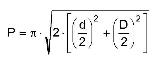
마지막으로, 본 발명의 목적은 타원형 통로를 갖는 견인기 시스를 제공하는 것으로, 여기서 타원형 통로의 둘레 길이(P)는 타원형 통로의 작은 직경(d)과 타원형 통로의 큰 직경(D)의 함수로서 하기의 수학식으로 표현된다:Finally, it is an object of the present invention to provide a retractor sheath having an elliptical passage, wherein the circumferential length (P) of the elliptical passage is as a function of the small diameter (d) of the elliptical passage and the large diameter (D) of the elliptical passage. Is expressed as:

본 발명의 다른 목적 및 이점이 본 발명의 소정 실시예들을 설명하는 첨부 도면과 관련하여 볼 때 하기의 상세한 설명으로부터 명백해질 것이다.Other objects and advantages of the invention will become apparent from the following detailed description when read in conjunction with the accompanying drawings which illustrate certain embodiments of the invention.
<도 1>
도 1은 절개부 내부에의 삽입 전의 본 발명에 따른 복강경 수술용 시일 조립체의 사시도.
<도 2>
도 2는 도 1에 도시된 복강경 수술용 시일 조립체의 평면도.
<도 3>
도 3은 본 발명에 따른 시일 캡(seal cap)의 사시도.
<도 4>
도 4는 본 발명에 따른 견인기의 사시도.
<도 5>
도 5는 도 4에 도시된 견인기의 평면도.
<도 6>
도 6은 절개부 내에 삽입되어 비틀려진 복강경 수술용 시일 조립체의 평면도.
<도 7, 도 8 및 도 9>
도 7, 도 8 및 도 9는 절개부의 잠재적인 형상들을 도시하는 개략도.<Figure 1>
1 is a perspective view of a laparoscopic surgical seal assembly according to the invention prior to insertion into an incision;
<FIG. 2>
FIG. 2 is a plan view of the laparoscopic surgical seal assembly shown in FIG. 1. FIG.
3,
3 is a perspective view of a seal cap according to the present invention;
<Figure 4>
4 is a perspective view of a retractor in accordance with the present invention;
<Figure 5>
5 is a plan view of the retractor shown in FIG. 4;
6,
6 is a plan view of a twisted laparoscopic seal assembly inserted into the incision.
7, 8, and 9
7, 8 and 9 are schematic diagrams showing potential shapes of the incision.
본 발명의 상세한 실시예가 본 명세서에 개시된다. 그러나, 개시된 실시예들이 단지 본 발명을 예시하며, 이는 다양한 형태로 실시될 수 있다는 것을 이해하여야 한다. 따라서, 본 명세서에 개시된 상세사항은 제한으로 해석되는 것이 아니라 단지 본 발명을 어떻게 제조하고/하거나 사용하는 지를 당업자에게 교시하기 위한 기초로서 해석되어야 한다.Detailed embodiments of the invention are disclosed herein. However, it should be understood that the disclosed embodiments merely illustrate the invention, which may be embodied in various forms. Accordingly, the details disclosed herein are not to be construed as limiting, but merely as a basis for teaching those skilled in the art how to make and / or use the invention.
본 발명에 따라서 그리고 도 1 내지 도 6을 참조하여, 본 발명에 따른 견인기(10)가 개시된다. 본 개시에 따르면, 견인기(10)는 손 보조식 복강경 수술 절차에 이용하기 위한 시일 조립체(12)에 고정된 상태로 도시되어 있다. 시일 조립체(12)는, 본명세서에 참고로 포함된, 2007년 3월 6일자로 출원되고 발명의 명칭이 "래칫 기구를 갖는 손 보조식 복강경 수술용 시일 조립체"(HAND ASSISTED LAPAROSCOPIC SEAL ASSEMBLY WITH A RATCHET MECHANISM)인 공동 소유의 미국 특허 출원 제11/714,267호에 개시된 것과 유사할 수 있다. 본 견인기(10)가 시일 조립체(12)와 함께 사용되는 것에 대해 개시되지만, 당업자는 견인기(10)가 체강(30)으로의 보다 큰 접근이 요구되는 곳에 단독으로 사용될 수 있음을 인식할 것이다.According to the invention and with reference to FIGS. 1 to 6, a
간단히 말해, 견인기(10)는 상부 견인기 링(14); 하부 견인기 링(16); 및 상부 견인기 링(14)과 하부 견인기 링(16) 사이에서 연장되어, 의료 절차 동안에 기기 또는 의사의 손이 통과할 수 있는 관형 통로(20)를 형성하는 견인기 시스(sheath, 18)를 포함한다. 견인기 시스(18)는 하부 견인기 링(14)과 상부 견인기 링(16) 사이에서 연장되는 타원형 통로(20)를 형성한다. 본 발명의 바람직한 실시예에 따르면, 견인기(10)는 고정 길이의 견인기이지만, 당업자는 본 발명의 개념이 본 발명의 사상으로부터 벗어남이 없이 "롤업(roll-up)" 견인기에 적용될 수 있음을 인식할 것이다.In short, the
보다 구체적으로, 견인기(10)는 상부 견인기 링(14) 및 하부 견인기 링(16)을 포함한다. 상부 견인기 링(14)은 바람직하게는 폴리카르보네이트로 구성된 강성 링 부재이고, 하부 견인기 링(16)은 바람직하게는 폴리우레탄으로 구성된 가요성 링 부재이다. 폴리카르보네이트 및 폴리우레탄이 바람직한 재료로서 각각 개시되지만, 당업자는 본 발명의 사상으로부터 벗어남이 없이 다른 재료가 채용될 수 있음을 인식할 것이다. 예를 들어, ABS(아크릴로니트릴-부타디엔-스티렌), 탄소-충전된 나일론, 및/또는 고성능 열가소성 물질, 예를 들어 벡트라(VECTRA)(액정 폴리에스테르)가 상부 견인기 링의 제조에 채용될 수 있는 반면에, 폴리에틸렌 및/또는 열가소성 폴리우레탄 탄성중합체, 예를 들어 펠레탄(Pellethane)이 하부 견인기 링의 제조에 채용될 수 있음이 고려된다.More specifically, the
상부 및 하부 견인기 링(14, 16)들은 탄성 견인기 시스(18)에 의해 연결되어, 의료 절차 동안에 기기 또는 의사의 손이 통과할 수 있는 관형 통로(20)를 형성하다. 바람직한 실시예에 따르면, 견인기 시스(18)는 폴리우레탄으로 구성된다. 폴리우레탄이 바람직한 재료로서 개시되지만, 당업자는 실리콘 및 폴리에틸렌과 같은 다른 재료가 본 발명의 사상으로부터 벗어남이 없이 채용될 수 있음을 인식할 것이다. 이하에서 보다 상세하게 논의되는 바와 같이, 견인기 시스(18)에는 견인기(10)가 상부 견인기 링(14)으로부터 하부 견인기 링(16)으로 연장되는 종방향 축에 실질적으로 수직인 평면 내에서 볼 때 실질적으로 타원형인 단면을 갖는 중앙 몸체부(44)가 형성된다.The upper and
바람직한 발명에 따르면, 상부 견인기 링(14)은 원 형상으로 형성되어, 기기 또는 의사의 손이 통과할 수 있는 공간을 최대화한다. 보다 구체적으로 그리고 본 발명의 바람직한 실시예에 따르면, 상부 견인기 링(14)은 견인기(10)가 상부 견인기 링(14)으로부터 하부 견인기 링(16)으로 연장되는 종방향 축에 실질적으로 수직인 평면 내에서 볼 때 원형 단면 형상을 갖는다.According to a preferred invention, the
전술된 바와 같이, 하부 견인기 링(16)은 가요성이다. 바람직한 실시예에 따르면, 하부 견인기 링은 원형 단면 형태로 구성되지만, 하부 견인기 링이 타원형 단면 형태로 구성될 수 있음이 고려된다. 보다 구체적으로, 하부 견인기 링(16)은 견인기(10)가 상부 견인기 링(14)으로부터 하부 견인기 링(16)으로 연장되는 종방향 축에 실질적으로 수직인 평면 내에서 볼 때 타원형 또는 원형 단면 형상을 갖는다. 그러나, 그리고 당업자가 하기의 개시에 기초하여 확실히 인식할 수 있는 바와 같이, 하부 견인기 링의 형상은 본 발명의 사상으로부터 벗어남이 없이 특정 응용에 적합하도록 변경될 수 있다.As mentioned above, the
원형 상부 견인기 링(14) 및 하부 견인기 링(16)에 대한 견인기 시스(18)의 정합성(conformance)을 향상시키기 위하여, 견인기 시스(18)는 개개의 상부 및 하부 견인기 링(14, 16)들에 인접하는 영역에서 상부 및 하부 견인기 링(14, 16)들의 형상과 일치하도록 형상화된다. 이와 같이, 견인기 시스(18)는 상부 견인기 링(14)에 인접하여 원형 형상이고 하부 견인기 링(16)에 인접하여 원형 또는 타원형이다. 이를 염두에 두어, 견인기 시스(18)는 실질적으로 원형인 단면 형상을 갖는 상부 견인기 링(14)으로부터 실질적으로 타원형인 단면 형상을 갖는 중앙 몸체부(44)까지 연장되는 상부 전이 섹션(46)을 상부 견인기 링(14)에 인접하여 포함한다. 유사하게, 견인기 시스(18)는 실질적으로 원형 또는 타원형인 단면 형상을 갖는 상부 견인기 링(16)으로부터 실질적으로 타원형인 단면 형상을 갖는 중앙 몸체부(44)까지 연장되는 하부 전이 섹션(48)을 하부 견인기 링(16)에 인접하여 포함한다.In order to improve the conformance of the
전술된 바와 같이, 견인기 시스(18)는 견인기(10)가 상부 견인기 링(14)으로부터 하부 견인기 링(16)으로 연장되는 종방향 축에 실질적으로 수직인 평면 내에서 볼 때 타원형 단면 형상을 갖는 튜브를 형성하도록 형상화된 중앙 몸체부(44)를 포함한다. 보다 구체적으로, 견인기 시스(18)의 타원형 중앙 몸체부(44)는 길이 치수(22) 및 폭 치수(24)를 포함하는데, 여기서 길이 치수(22)는 폭 치수(24)보다 크다. 그 결과, 견인기 시스(18)는, 원형 형상인 상부 견인기 링(14)으로부터 타원형 형상인 견인기 시스(18)의 중앙 몸체부(44)로 그리고 이어서 대체로 타원형 또는 원형 형상인 하부 견인기 링(16)으로 연장됨에 따라, 그 단면 형상이 변화한다. 형상의 변화는 상부 전이 섹션(46) 및 하부 전이 섹션(48)의 포함을 통해 달성된다.As described above, the
이하에서 보다 상세하게 논의되는 바와 같이, 상부 및 하부 견인기 링(14, 16)들이 복벽(26)의 대향 면들 상에 위치된 때, 견인기 시스(18)는 장력을 받아, 절개부(28)의 벽에 의해 가해지는 압력에 대항하여 중앙 몸체부(44)를 따라 그의 타원형 형상을 유지한다. 위에서 논의된 바와 같이 절개부(28)를 접근 및 시일 조립체(12)와의 공동 이용을 위한 그의 이상적인 형상으로 변형시키는 것을 돕는 것은 견인기 시스(18)의 타원형 중앙 몸체부(44)의 강성이다.As will be discussed in more detail below, when the upper and lower retractor rings 14, 16 are located on opposite sides of the
보다 구체적으로, 견인기 시스(18)의 타원형 중앙 몸체부(44)의 결과로서, 견인기 시스(18)의 중앙 몸체부(44)의 길이 치수(22)가 절개부(28)의 길이 치수에 대해 90도인 상태로 하부 견인기 링(16)이 절개부(28) 내부에 위치되고 절개부(28)가 절개부의 최대 형상으로 확대될 때, 상처 내부에서의 견인기(10)의 안정성은 최대화되어 절개부(28) 내부에서의 견인기(10)의 회전을 방지 및/또는 감소시킨다.More specifically, as a result of the elliptical
바람직한 실시예에 따르면 그리고 도 7, 도 8 및 도 9를 참조하면, 견인기 시스(18)의 중앙 몸체부(44)의 타원형은 하기를 염두에 두고 구성된다.According to a preferred embodiment and with reference to FIGS. 7, 8 and 9, the oval of the
여기서,here,
L = 초기 절개부 길이L = initial incision length
d = 절개 방향에 수직인 절개부 개구의 폭d = width of the incision opening perpendicular to the incision direction
D = 절개 방향에 평행한 절개부 개구의 폭D = width of the incision opening parallel to the incision direction
P = 절개부 개구의 둘레 길이(perimeter)P = perimeter of the incision opening
견인 성능은 일반적으로 견인기(10)가 형성할 수 있는 절개부 개구(36)의 형상으로서 정의된다. 절개부 개구(36)가 견인될 때, 이는 일반적으로 타원의 형상을 형성한다. 타원은 2개의 폭 치수 (또는 사람의 시각에 따라서는 폭 및 길이 치수), 즉 작은 "d" (절개 방향에 수직인 절개부의 치수임) 및 큰 "D" (절개 방향에 평행한 절개부의 치수임)에 의해 정의된다. 타원의 둘레 길이는 "d" 및 "D"의 함수로서 표현될 수 있다.Traction performance is generally defined as the shape of the incision opening 36 that the
초기 절개부(28) 길이는 타원의 둘레 길이를 확립시키므로 절개부(28)에 의해 형성될 수 있는 타원의 크기를 결정한다. 타원의 둘레는 초기 절개부 길이의 2배와 실질적으로 동일하다. 따라서, 절개부 길이는 작은 "d"와 큰 "D" 사이의 관계를 확립시키는 데 사용될 수 있다.The

작은 "d"가 그의 최대값("dmax")에 도달한 때, 이는 최소값("Dmin")에서의 큰 "D"와 동일하고, 타원의 둘레 길이에 대한 수학식은 원의 둘레 길이(원주)에 대한 수학식이 된다.When the small "d" reaches its maximum value "dmax", it is equal to the large "D" at the minimum value "Dmin", and the equation for the circumferential length of the ellipse is the circumferential length of the circle (circumference) Becomes an equation for.

본 발명에 따르면, 견인기(10)의 성능은 절개부 개구의 크기에 기초하여 등급이 매겨진다. 견인기(10) 성능은 절개부 개구의 형상이 원의 형상에 근접할 때, 즉 "d"가 "D"와 대략 동일할 때 최상으로 등급이 매겨진다. 이를 염두에 두어, 본 견인기(10)는 절개부 개구의 치수인 작은 "d" 및 큰 "D"가 서로 동일하게 수렴하는(작은 "d"의 최대치가 큰 "D"의 최소치와 동일한) 견인된 절개부 개구를 생성하도록 설계된다.According to the invention, the performance of the
본 견인기(10)는, 절개부 벽의 압력 하에서 압축될 때 원 형상에 접근하도록 유사하게 변형하면서 절개부(28)를 원에 접근하는 형상으로 신장시키도록 설계된 타원형 단면을 나타내는 견인기(10)를 제공함으로써, 절개부(28)를 실질적으로 원형인 형태로 신장시키는 목적을 달성한다. 따라서, 견인기 시스(18)의 타원형 단면은 실질적으로 상이한 길이 및 폭 치수를 갖는다. 견인기 시스(18)의 길이 치수(22)가 절개 방향에 수직으로 배향되고 견인기 시스(18)의 폭 치수(24)가 절개 방향을 따라 배향된 상태로 절개부 개구(36) 내에 배치될 때, 절개부(28)의 벽에 의한 견인기 시스(18)의 압축은 견인기 시스(18)의 길이 치수(22)가 감소되게 하고 견인기 시스(18)의 폭 치수(24)가 증가되게 할 것이다(도 6 참조). 당업자는 견인기 시스(18)의 치수 및 견인기 시스(18)의 강성이 이어서 최적화될 수 있어, 절개부(28)의 작은 "d"와 큰 "D"가 서로 동일하게 수렴하고 따라서 원형 형상을 갖는 절개부 개구를 형성할 것임을 확실히 인식할 것이다.The
앞서 정의된 바와 같이, 절개부 길이는 절개부 개구(36)의 둘레 길이를 확립시킨다. 알려진 둘레 길이에 의해, 작은 "d"와 큰 "D"에 대한 관계가 또한 확립될 수 있다. 따라서, 작은 "d"와 큰 "D"에 대한 제한은 전형적인 절개부 길이 크기에 좌우될 것이다. 수학식 3으로부터, 작은 "d"의 최대값("dmax") 및 큰 "D"의 최소값("Dmin")은 절개부 길이로부터 계산될 수 있다. 하기의 표는 몇몇 전형적인 절개부 길이에 기초하여 "dmax" 및 "Dmin"에 대해 계산된 값을 열거한다.As defined above, the incision length establishes the circumferential length of the

작은 "d"의 범위는 0과 "dmax" 사이일 수 있고, 큰 "D"의 범위는 "Dmin"과 절개부 길이 사이일 수 있다. 타원형 견인기(10)에 대한 초기 시작 치수는 절개부 둘레 길이(견인기(10) 둘레 길이)에 대한 목표값 및 작은 "d" 또는 큰 "D"의 시작값에 좌우될 것이다. 타원형 견인기(10) 장치를 설계하는 예가 이하에 나타나 있다.The range of small "d" may be between 0 and "dmax" and the range of large "D" may be between "Dmin" and incision length. The initial starting dimension for the
절개부 길이의 다양한 범위를 수용하기 위하여, 가능한 견인기 설계는 상기 표에서 7.0 ㎝이고 14.0 ㎝의 둘레 길이가 얻어지게 하는 공칭 절개부 길이를 목표로 정할 수 있다. 고려될 필요가 있는 다른 설계 인자는 절개부 개구 내에서의 견인기(10)의 배치가 방해받지 않도록 하는 큰 "D"의 값이다. 작은 절개부 크기에 대해 견인기(10)의 배치를 용이하게 하는 것을 돕기 위하여, 큰 "D"의 가능한 값은 상기 표에서 최소 절개부 길이를 나타내는 5.0 ㎝일 수 있다. 수학식 2를 사용하여, 작은 "d"가 계산될 수 있다. 하기의 계산은 14.0 ㎝의 견인기 둘레 길이 및 5.0 ㎝의 큰 "D"에 기초한 타원형 견인기 설계의 예를 나타낸다.In order to accommodate various ranges of incision lengths, a possible retractor design can target nominal incision lengths such that a circumferential length of 7.0 cm and 14.0 cm is obtained in the table above. Another design factor that needs to be considered is the value of large "D" so that the placement of the

실제로, 견인기(10) 및 시일 조립체(12)의 나머지 부분은, 절개부(28)를 먼저 생성하고 절개부(28) 위에 견인기(10)를 위치시킴으로써, 개인 환자의 복벽(26)에 고정된다. 이후에, 견인기(10)의 하부 견인기 링(16)은 복벽(26)이 상부 견인기 링(14)과 하부 견인기 링(16) 사이에 있는 상태로 체강(30) 내로 삽입된다. 상부 견인기 링(14)과 하부 견인기 링(16)이 절개부(28)의 외부 부분과 내부 부분 사이에서 연장됨에 따라 이들 사이의 장력이 견인기 시스(18)의 중앙 몸체부(44)에서 상당한 강성을 생성하여, 본 명세서에서 보다 상세하게 논의되는 방식으로 절개부의 견인을 최적화하는 방식으로 절개부(28)를 신장시킨다. 이어서, 시일 조립체(12)의 시일 캡(32)이 견인기(10)의 상부 견인기 링(14)에 연결된다. 본 발명의 바람직한 실시예에 따르면, 상부 견인기 링(14)에는 견인기(18)를 시일 캡(32)에 고정하기 위하여 시일 캡(32)의 측벽(42)의 리세스(recess, 40)와 결합하도록 형상화되고 치수설정된 일련의 탄성 래치 부재(latch member, 38)가 제공된다. 당업자는 견인기를 시일 캡에 고정하기 위해 다양한 기구가 이용가능함을 확실히 인식할 것이다. 그러한 결합 구조물의 예는, 본 명세서에 참고로 포함된, 2007년 4월 4일자로 출원되고 발명의 명칭이 "탈착가능한 부착 링을 갖는 손 보조식 복강경 수술용 시일 조립체"(HAND ASSISTED LAPAROSCOPIC SEAL ASSEMBLY WITH DETACHABLE ATTACHMENT RING)인 공동 소유의 미국 특허 출원 제11/730,922호에 개시되어 있다.In practice, the
보다 구체적으로, 외과적 처치 부위가 종래의 표준 병원 절차에 따라 준비되어, 피부가 청결하고 건조함을 확인한다. 이후에, 템플릿(template)이 절개 부위 위에 놓이고, 살균한 피부 마커(marker)를 사용하여 템플릿 상에 절개선이 표시된다. 당업자는 장갑 크기가 절개부(28)의 크기에 영향을 끼침을 인식할 것이다. 예를 들어, 의사의 장갑 크기가 7이면, 6.5 내지 7.0 ㎝ 절개부(28)가 보통 적절하다. 이후에, 절개부(28)는 표시된 절개선을 따라 만들어진다. 이후에, 절개부 크기는 견인기(10) 및 시일 조립체(12)의 나머지 부분을 설치하기 전에 복부 내로 외과 의사의 손을 삽입함으로써 확인된다. 절개부가 너무 작다면, 절개부의 중앙 위치를 현재의 시일 조립체(12)의 배치에 대해 유지하는 것이 요구되는 바에 따라 절개부는 각각의 단부에서 연장된다. 이후에, 견인기(10)의 하부 견인기 링(16)이 절개부(28)를 통해 삽입된다. 손가락을 사용하여, 견인기(10)의 하부 견인기 링(16)이 복막 아래에 균일하게 안착되고, 그 영역은 견인기(10)가 조직 층들 사이에서 놓이지 않게 하도록 스위핑(sweeping)된다. 견인기 시스(18), 특히 중앙 몸체부(44)의 형상의 관점에서, 길이 치수(22)가 절개부(28)의 길이에 실질적으로 평행하게 배향되도록 견인기(10)를 배향시킴으로써 삽입에 대한 최소 저항이 달성된다. 상부 견인기 링(14) 및 하부 견인기 링(16)은 복벽(26)의 대향 면들 상에 위치된다. 상부 견인기 링(14)과 하부 견인기 링(16)이 절개부(28)의 외부 부분과 내부 부분 사이에서 연장됨에 따라 이들 사이의 장력은 견인기 시스(18)에 실질적인 강성을 생성하여, 본 명세서에서 보다 상세하게 설명되는 방식으로 절개부의 견인을 최적화하는 방식으로 절개부(28)를 신장시킨다. 이어서, 견인기(10)는 90도 회전되어서, 견인기 시스(18)의 중앙 몸체부(44)의 길이 치수(22)가 절개부(28)의 길이에 수직으로 배향된다. 이러한 배향은, 상처를 그의 최대 형상으로 확대시키기 위해 절개부(28)의 작은 "d" 치수를 확대하고 견인기(10)의 안정성을 최대화시켜 절개부(28) 내부에서의 견인기(10)의 회전을 방지 또는 감소시키도록, 견인기 시스(18)의 중앙 몸체부(44)를 배향시킨다(도 6 참조).More specifically, surgical treatment sites are prepared according to conventional standard hospital procedures to confirm that the skin is clean and dry. The template is then placed over the incision site and the incision is marked on the template using sterile skin markers. Those skilled in the art will appreciate that glove size affects the size of the
이후에, 시일 캡(32)이 견인기(10)의 상부 견인기 링(14)에 부착되고, 환자의 복부가 뉴모(pneumo)를 유지하는 상태로 시일 조립체(12)가 고정되도록 조절이 이루어진다.Thereafter, a
당업자는 본 견인기의 기초가 되는 개념이 고정된 길이 또는 조절가능한 길이의 견인기에 적용될 수 있음을 확실히 인식할 것이다. 어느 경우에서도, 견인기는 안정성 및 뉴모를 유지하기 위하여 복벽 두께에 적합하여야 한다.Those skilled in the art will certainly appreciate that the concepts underlying the retractor can be applied to fixed or adjustable length retractors. In either case, the retractor should be suitable for abdominal wall thickness to maintain stability and pneumo.
바람직한 실시예가 도시되고 설명되었지만, 본 발명을 그러한 개시 내용에 의해 제한할 의도가 있는 것이 아니라, 오히려 본 발명의 사상 및 범주에 속하는 모든 변형 및 대안 구성을 포함하도록 의도된다는 것이 이해될 것이다.While the preferred embodiments have been shown and described, it will be understood that the invention is not intended to be limited by such disclosure, but rather is intended to cover all modifications and alternative arrangements falling within the spirit and scope of the invention.
Claims (20)
상부 견인기 링;
하부 견인기 링; 및
상기 상부 견인기 링과 상기 하부 견인기 링 사이에서 연장되어, 의료 절차 동안에 기기 또는 의사의 손이 통과할 수 있는 관형 통로를 형성하는 견인기 시스(sheath)를 포함하며,
상기 견인기 시스는 상기 하부 견인기 링과 상기 상부 견인기 링 사이에서 연장되는 타원형 통로를 포함하는 견인기.As a retractor for use in laparoscopic surgical procedures,
Upper retractor ring;
Lower retractor ring; And
A retractor sheath extending between the upper retractor ring and the lower retractor ring to form a tubular passageway through which the instrument or doctor's hand can pass during a medical procedure;
The retractor sheath includes an elliptical passageway extending between the lower retractor ring and the upper retractor ring.

시일 캡(seal cap); 및
상기 시일 캡에 고정되는 견인기를 포함하며,
상기 견인기는:
상부 견인기 링;
하부 견인기 링; 및
상기 상부 견인기 링과 상기 하부 견인기 링 사이에서 연장되어, 의료 절차 동안에 기기 또는 의사의 손이 통과할 수 있는 관형 통로를 형성하는 견인기 시스를 포함하고,
상기 견인기 시스는 상기 하부 견인기 링과 상기 상부 견인기 링 사이에서 연장되는 타원형 통로를 포함하는, 견인기를 갖는 시일 조립체.A seal assembly having a retractor for use in a laparoscopic surgical procedure,
Seal caps; And
A retractor secured to the seal cap,
The retractor is:
Upper retractor ring;
Lower retractor ring; And
A retractor sheath extending between the upper retractor ring and the lower retractor ring to form a tubular passageway through which the instrument or doctor's hand can pass during a medical procedure;
And the retractor sheath includes an elliptical passageway extending between the lower retractor ring and the upper retractor ring.

Applications Claiming Priority (2)
| Application Number | Priority Date | Filing Date | Title |
|---|---|---|---|
| US11/902,662 | 2007-09-24 | ||
| US11/902,662 US8308755B2 (en) | 2007-09-24 | 2007-09-24 | Elliptical retractor |
Publications (1)
| Publication Number | Publication Date |
|---|---|
| KR20100061842A true KR20100061842A (en) | 2010-06-09 |
Family
ID=40032413
Family Applications (1)
| Application Number | Title | Priority Date | Filing Date |
|---|---|---|---|
| KR1020107008696A Withdrawn KR20100061842A (en) | 2007-09-24 | 2008-09-19 | Elliptical retractor |
Country Status (8)
| Country | Link |
|---|---|
| US (1) | US8308755B2 (en) |
| EP (1) | EP2197358B1 (en) |
| JP (1) | JP5583583B2 (en) |
| KR (1) | KR20100061842A (en) |
| CN (1) | CN101808585B (en) |
| AU (1) | AU2008304677B2 (en) |
| CA (1) | CA2700482A1 (en) |
| WO (1) | WO2009042505A1 (en) |
Cited By (5)
| Publication number | Priority date | Publication date | Assignee | Title |
|---|---|---|---|---|
| KR101592975B1 (en) * | 2015-08-19 | 2016-02-12 | 위캔메디케어 주식회사 | Surgical retractor |
| WO2017047887A1 (en) * | 2015-09-16 | 2017-03-23 | 위캔메디케어 주식회사 | Traction device for surgery |
| KR20220044859A (en) * | 2014-08-15 | 2022-04-11 | 어플라이드 메디컬 리소시스 코포레이션 | Natural orifice surgery system |
| WO2023068426A1 (en) * | 2021-10-19 | 2023-04-27 | 드림팩 주식회사 | Surgical retractor for preventing leakage of intraperitoneal gas |
| KR20230117838A (en) | 2022-02-03 | 2023-08-10 | 인제대학교 산학협력단 | Surgical wound protection clip unit |
Families Citing this family (31)
| Publication number | Priority date | Publication date | Assignee | Title |
|---|---|---|---|---|
| US8273017B1 (en) | 2007-10-30 | 2012-09-25 | Ethicon Endo-Surgery, Inc. | Surgical access port with ring actuated latching mechanism |
| US8142354B1 (en) | 2007-10-30 | 2012-03-27 | Ethicon Endo-Surgery, Inc. | Laminated surgical access port |
| US8623395B2 (en) | 2010-01-29 | 2014-01-07 | Forsight Vision4, Inc. | Implantable therapeutic device |
| JP5577354B2 (en) | 2009-01-29 | 2014-08-20 | フォーサイト・ビジョン フォー・インコーポレーテッド | Treatment device |
| WO2011075573A1 (en) | 2009-12-18 | 2011-06-23 | Scion Neurostim, Llc | Devices and methods for vestibular and/or cranial nerve stimulation |
| US8480683B2 (en) * | 2009-11-24 | 2013-07-09 | Covidien Lp | Foam introduction system including modified port geometry |
| SI2600930T1 (en) | 2010-08-05 | 2021-08-31 | Forsight Vision4, Inc. | Injector apparatus for drug delivery |
| US10617557B2 (en) | 2010-08-05 | 2020-04-14 | Forsight Vision4, Inc. | Combined drug delivery methods and apparatus |
| HRP20211909T1 (en) | 2010-08-05 | 2022-03-18 | Forsight Vision4, Inc. | Apparatus to treat an eye |
| US8597180B2 (en) * | 2010-08-12 | 2013-12-03 | Covidien Lp | Expandable thoracic access port |
| CA2811753C (en) | 2010-10-01 | 2019-05-21 | Applied Medical Resources Corporation | Natural orifice surgery system |
| AU2011329656B2 (en) | 2010-11-19 | 2017-01-05 | Forsight Vision4, Inc. | Therapeutic agent formulations for implanted devices |
| CN102743199A (en) * | 2011-04-20 | 2012-10-24 | 北京航天卡迪技术开发研究所 | Cut protection retractor |
| WO2013003620A2 (en) | 2011-06-28 | 2013-01-03 | Forsight Vision4, Inc. | Diagnostic methods and apparatus |
| EP2739252A4 (en) | 2011-08-05 | 2015-08-12 | Forsight Vision4 Inc | SMALL MOLECULE ADMINISTRATION USING AN IMPLANTABLE THERAPEUTIC DEVICE |
| ES3049671T3 (en) | 2011-09-16 | 2025-12-17 | Forsight Vision4 Inc | Fluid exchange apparatus |
| CN102429689A (en) * | 2011-10-08 | 2012-05-02 | 金黑鹰 | Disposable multi-angle mono-hole converter for laparoscope |
| KR101301914B1 (en) * | 2011-11-09 | 2013-08-30 | (주)유원메디텍 | single port for surgical operation |
| WO2013116061A1 (en) | 2012-02-03 | 2013-08-08 | Forsight Vision4, Inc. | Insertion and removal methods and apparatus for therapeutic devices |
| US9968603B2 (en) | 2013-03-14 | 2018-05-15 | Forsight Vision4, Inc. | Systems for sustained intraocular delivery of low solubility compounds from a port delivery system implant |
| AU2014229033B2 (en) | 2013-03-15 | 2018-10-04 | Applied Medical Resources Corporation | Trocar surgical seal |
| AU2014241163B2 (en) | 2013-03-28 | 2018-09-27 | Forsight Vision4, Inc. | Ophthalmic implant for delivering therapeutic substances |
| ES2992100T3 (en) | 2014-07-15 | 2024-12-09 | Forsight Vision4 Inc | Ocular implant delivery device |
| CA2957548A1 (en) | 2014-08-08 | 2016-02-11 | Forsight Vision4, Inc. | Stable and soluble formulations of receptor tyrosine kinase inhibitors, and methods of preparation thereof |
| SG11201703726XA (en) | 2014-11-10 | 2017-06-29 | Forsight Vision4 Inc | Expandable drug delivery devices and method of use |
| CN105380688A (en) * | 2015-10-26 | 2016-03-09 | 北京迈迪顶峰医疗科技有限公司 | Retractor |
| USD788300S1 (en) * | 2015-10-27 | 2017-05-30 | Orthogrid Systems, Inc. | Grid positioning device |
| EP3377009B1 (en) | 2015-11-20 | 2020-10-28 | ForSight Vision4, Inc. | Porous structures for extended release drug delivery devices |
| MX2018012021A (en) | 2016-04-05 | 2019-01-24 | Forsight Vision4 Inc | Implantable ocular drug delivery devices. |
| WO2019103906A1 (en) | 2017-11-21 | 2019-05-31 | Forsight Vision4, Inc. | Fluid exchange apparatus for expandable port delivery system and methods of use |
| USD1033637S1 (en) | 2022-01-24 | 2024-07-02 | Forsight Vision4, Inc. | Fluid exchange device |
Family Cites Families (20)
| Publication number | Priority date | Publication date | Assignee | Title |
|---|---|---|---|---|
| AU977266A (en) | 1966-08-17 | 1968-02-22 | Johnson And Johnson | Wound edge protector |
| JPH0813304B2 (en) * | 1991-05-10 | 1996-02-14 | 株式会社ニッショー | Incision opening device |
| US5460170A (en) * | 1994-08-23 | 1995-10-24 | Hammerslag; Julius G. | Adjustable surgical retractor |
| US6589211B1 (en) * | 1995-04-28 | 2003-07-08 | Macleod Cathel | Modified trocar and methods of use |
| US5906577A (en) * | 1997-04-30 | 1999-05-25 | University Of Massachusetts | Device, surgical access port, and method of retracting an incision into an opening and providing a channel through the incision |
| US6440063B1 (en) * | 1997-04-30 | 2002-08-27 | University Of Massachusetts | Surgical access port and laparoscopic surgical method |
| US7559893B2 (en) * | 1998-12-01 | 2009-07-14 | Atropos Limited | Wound retractor device |
| JP3062106U (en) * | 1999-03-11 | 1999-09-28 | 株式会社八光電機製作所 | Wound edge protection device with retracting site holding function |
| IE990795A1 (en) * | 1999-07-30 | 2001-03-07 | Gaya Ltd | Hand Access Port Device |
| EP1392178A1 (en) * | 1999-10-14 | 2004-03-03 | Atropos Limited | A retractor |
| US7540839B2 (en) * | 1999-10-14 | 2009-06-02 | Atropos Limited | Wound retractor |
| US7052454B2 (en) | 2001-10-20 | 2006-05-30 | Applied Medical Resources Corporation | Sealed surgical access device |
| US6723044B2 (en) * | 2002-03-14 | 2004-04-20 | Apple Medical Corporation | Abdominal retractor |
| EP2343032B1 (en) * | 2002-06-05 | 2012-05-09 | Applied Medical Resources Corporation | Wound retractor |
| AU2004233871B2 (en) * | 2003-04-25 | 2010-02-18 | Covidien Lp | Surgical hand access apparatus |
| US20060161050A1 (en) * | 2003-10-15 | 2006-07-20 | John Butler | A surgical sealing device |
| US8857440B2 (en) * | 2004-06-22 | 2014-10-14 | DePuy Synthes Products, LLC | Devices and methods for protecting tissue at a surgical site |
| US20060229636A1 (en) * | 2005-03-04 | 2006-10-12 | Woodburn William N Sr | Expandable access device with mobility member |
| US7766824B2 (en) * | 2005-03-31 | 2010-08-03 | Tyco Healthcare Group Lp | Surgical hand access apparatus |
| US7704207B2 (en) * | 2005-10-14 | 2010-04-27 | Applied Medical Resources Corporation | Circular surgical retractor |
-
2007
- 2007-09-24 US US11/902,662 patent/US8308755B2/en active Active
-
2008
- 2008-09-19 KR KR1020107008696A patent/KR20100061842A/en not_active Withdrawn
- 2008-09-19 CA CA2700482A patent/CA2700482A1/en not_active Abandoned
- 2008-09-19 EP EP08833002.2A patent/EP2197358B1/en not_active Not-in-force
- 2008-09-19 AU AU2008304677A patent/AU2008304677B2/en not_active Ceased
- 2008-09-19 CN CN2008801084261A patent/CN101808585B/en not_active Expired - Fee Related
- 2008-09-19 WO PCT/US2008/076938 patent/WO2009042505A1/en not_active Ceased
- 2008-09-19 JP JP2010525987A patent/JP5583583B2/en active Active
Cited By (6)
| Publication number | Priority date | Publication date | Assignee | Title |
|---|---|---|---|---|
| KR20220044859A (en) * | 2014-08-15 | 2022-04-11 | 어플라이드 메디컬 리소시스 코포레이션 | Natural orifice surgery system |
| KR101592975B1 (en) * | 2015-08-19 | 2016-02-12 | 위캔메디케어 주식회사 | Surgical retractor |
| WO2017030264A1 (en) * | 2015-08-19 | 2017-02-23 | 위캔메디케어 주식회사 | Retractor for surgical operation |
| WO2017047887A1 (en) * | 2015-09-16 | 2017-03-23 | 위캔메디케어 주식회사 | Traction device for surgery |
| WO2023068426A1 (en) * | 2021-10-19 | 2023-04-27 | 드림팩 주식회사 | Surgical retractor for preventing leakage of intraperitoneal gas |
| KR20230117838A (en) | 2022-02-03 | 2023-08-10 | 인제대학교 산학협력단 | Surgical wound protection clip unit |
Also Published As
| Publication number | Publication date |
|---|---|
| EP2197358B1 (en) | 2019-01-09 |
| US20090082631A1 (en) | 2009-03-26 |
| WO2009042505A1 (en) | 2009-04-02 |
| JP5583583B2 (en) | 2014-09-03 |
| US8308755B2 (en) | 2012-11-13 |
| CN101808585A (en) | 2010-08-18 |
| JP2010540034A (en) | 2010-12-24 |
| AU2008304677A1 (en) | 2009-04-02 |
| CN101808585B (en) | 2013-06-12 |
| EP2197358A1 (en) | 2010-06-23 |
| CA2700482A1 (en) | 2009-04-02 |
| AU2008304677B2 (en) | 2013-05-23 |
Similar Documents
| Publication | Publication Date | Title |
|---|---|---|
| KR20100061842A (en) | Elliptical retractor | |
| EP1407715B1 (en) | Medical treating instrument | |
| US7766824B2 (en) | Surgical hand access apparatus | |
| EP2138118B1 (en) | Surgical access assembly | |
| US8137267B2 (en) | Retractor with flexible sleeve | |
| US20060149137A1 (en) | Easily placeable and removable wound retractor | |
| US20080021360A1 (en) | Roll-up wound protector | |
| ES2566562T3 (en) | Appropriate surgical equipment for mini-invasive surgery | |
| US20120157786A1 (en) | Surgical retractor having ring of variable durometer | |
| WO2008011356A1 (en) | Roll-up wound protector with tricuspidate ring | |
| US8231527B2 (en) | Roll-up wound protector with asymmetric ring | |
| BRPI0903942B1 (en) | SURGICAL ACCESS DEVICE | |
| BRPI0904876B1 (en) | surgical access device | |
| JP2010527640A (en) | Flexible outer cannula sheath | |
| JP4623067B2 (en) | Medical treatment tool | |
| JP4082952B2 (en) | Medical treatment tool | |
| US20200268412A1 (en) | Access assembly including flexible cannula | |
| AU2011239219B2 (en) | Surgical hand access apparatus | |
| AU2009203014A1 (en) | Surgical access port with cinching attachment mechanism |
Legal Events
| Date | Code | Title | Description |
|---|---|---|---|
| PA0105 | International application |
Patent event date: 20100421 Patent event code: PA01051R01D Comment text: International Patent Application |
|
| PG1501 | Laying open of application | ||
| PC1203 | Withdrawal of no request for examination | ||
| WITN | Application deemed withdrawn, e.g. because no request for examination was filed or no examination fee was paid |