KR20100027087A - For the ocean a generating plant in global village zero calmity tidal power generator used with in it's a level pipes seesow type - Google Patents
For the ocean a generating plant in global village zero calmity tidal power generator used with in it's a level pipes seesow type Download PDFInfo
- Publication number
- KR20100027087A KR20100027087A KR1020090117757A KR20090117757A KR20100027087A KR 20100027087 A KR20100027087 A KR 20100027087A KR 1020090117757 A KR1020090117757 A KR 1020090117757A KR 20090117757 A KR20090117757 A KR 20090117757A KR 20100027087 A KR20100027087 A KR 20100027087A
- Authority
- KR
- South Korea
- Prior art keywords
- water
- fire
- power plant
- power
- pump
- Prior art date
- Legal status (The legal status is an assumption and is not a legal conclusion. Google has not performed a legal analysis and makes no representation as to the accuracy of the status listed.)
- Ceased
Links
- XLYOFNOQVPJJNP-UHFFFAOYSA-N water Substances O XLYOFNOQVPJJNP-UHFFFAOYSA-N 0.000 claims abstract description 709
- 239000010959 steel Substances 0.000 claims abstract description 130
- 229910000831 Steel Inorganic materials 0.000 claims abstract description 128
- 238000009434 installation Methods 0.000 claims abstract description 104
- 238000010248 power generation Methods 0.000 claims abstract description 74
- 230000002265 prevention Effects 0.000 claims description 367
- 238000000034 method Methods 0.000 claims description 207
- 239000003921 oil Substances 0.000 claims description 121
- 238000010168 coupling process Methods 0.000 claims description 112
- 238000010276 construction Methods 0.000 claims description 111
- 230000008878 coupling Effects 0.000 claims description 107
- 238000005859 coupling reaction Methods 0.000 claims description 107
- XEEYBQQBJWHFJM-UHFFFAOYSA-N Iron Chemical compound [Fe] XEEYBQQBJWHFJM-UHFFFAOYSA-N 0.000 claims description 88
- 238000004519 manufacturing process Methods 0.000 claims description 77
- 238000003466 welding Methods 0.000 claims description 73
- 230000004075 alteration Effects 0.000 claims description 67
- 239000004567 concrete Substances 0.000 claims description 63
- 230000033001 locomotion Effects 0.000 claims description 59
- 238000005553 drilling Methods 0.000 claims description 57
- 238000002347 injection Methods 0.000 claims description 52
- 239000007924 injection Substances 0.000 claims description 52
- 229910052500 inorganic mineral Inorganic materials 0.000 claims description 52
- 239000011707 mineral Substances 0.000 claims description 52
- VNWKTOKETHGBQD-UHFFFAOYSA-N methane Chemical compound C VNWKTOKETHGBQD-UHFFFAOYSA-N 0.000 claims description 50
- 238000012545 processing Methods 0.000 claims description 50
- 238000009412 basement excavation Methods 0.000 claims description 42
- 229910052742 iron Inorganic materials 0.000 claims description 41
- 238000007667 floating Methods 0.000 claims description 40
- 230000032258 transport Effects 0.000 claims description 36
- 239000010779 crude oil Substances 0.000 claims description 35
- PWHULOQIROXLJO-UHFFFAOYSA-N Manganese Chemical compound [Mn] PWHULOQIROXLJO-UHFFFAOYSA-N 0.000 claims description 30
- 229910052748 manganese Inorganic materials 0.000 claims description 30
- 239000011572 manganese Substances 0.000 claims description 30
- 230000005540 biological transmission Effects 0.000 claims description 28
- 230000007246 mechanism Effects 0.000 claims description 28
- 239000003345 natural gas Substances 0.000 claims description 22
- 239000004568 cement Substances 0.000 claims description 20
- 238000005452 bending Methods 0.000 claims description 13
- 230000009189 diving Effects 0.000 claims description 11
- 238000010413 gardening Methods 0.000 claims description 11
- 239000011521 glass Substances 0.000 claims description 9
- 239000000295 fuel oil Substances 0.000 claims description 6
- 238000000605 extraction Methods 0.000 claims description 4
- 238000009313 farming Methods 0.000 claims description 3
- 235000013305 food Nutrition 0.000 claims description 3
- 238000013000 roll bending Methods 0.000 claims description 3
- 238000009415 formwork Methods 0.000 claims 1
- 239000000463 material Substances 0.000 abstract description 162
- 239000012530 fluid Substances 0.000 abstract description 128
- 229910052751 metal Inorganic materials 0.000 abstract description 61
- 239000002184 metal Substances 0.000 abstract description 61
- 238000011161 development Methods 0.000 abstract description 45
- 230000006378 damage Effects 0.000 abstract description 39
- 238000005086 pumping Methods 0.000 abstract description 38
- 239000000428 dust Substances 0.000 abstract description 31
- 238000013461 design Methods 0.000 abstract description 15
- 239000010949 copper Substances 0.000 abstract description 14
- RYGMFSIKBFXOCR-UHFFFAOYSA-N Copper Chemical compound [Cu] RYGMFSIKBFXOCR-UHFFFAOYSA-N 0.000 abstract description 13
- 229910052802 copper Inorganic materials 0.000 abstract description 13
- 238000004078 waterproofing Methods 0.000 abstract description 12
- 231100001261 hazardous Toxicity 0.000 abstract description 10
- 239000002699 waste material Substances 0.000 abstract description 3
- 238000009418 renovation Methods 0.000 abstract description 2
- 239000005871 repellent Substances 0.000 abstract description 2
- APTZNLHMIGJTEW-UHFFFAOYSA-N pyraflufen-ethyl Chemical compound C1=C(Cl)C(OCC(=O)OCC)=CC(C=2C(=C(OC(F)F)N(C)N=2)Cl)=C1F APTZNLHMIGJTEW-UHFFFAOYSA-N 0.000 abstract 1
- 239000007789 gas Substances 0.000 description 169
- 239000007788 liquid Substances 0.000 description 137
- 238000012856 packing Methods 0.000 description 97
- 230000008859 change Effects 0.000 description 70
- 239000000446 fuel Substances 0.000 description 70
- 230000006870 function Effects 0.000 description 70
- 239000007921 spray Substances 0.000 description 70
- CURLTUGMZLYLDI-UHFFFAOYSA-N Carbon dioxide Chemical compound O=C=O CURLTUGMZLYLDI-UHFFFAOYSA-N 0.000 description 51
- 238000001816 cooling Methods 0.000 description 50
- 238000010586 diagram Methods 0.000 description 48
- 239000002689 soil Substances 0.000 description 46
- 230000018109 developmental process Effects 0.000 description 44
- 230000009931 harmful effect Effects 0.000 description 44
- 238000001514 detection method Methods 0.000 description 43
- 239000000047 product Substances 0.000 description 43
- 230000009471 action Effects 0.000 description 42
- 235000010755 mineral Nutrition 0.000 description 42
- 239000012188 paraffin wax Substances 0.000 description 42
- 239000010426 asphalt Substances 0.000 description 40
- 238000004891 communication Methods 0.000 description 40
- 238000005520 cutting process Methods 0.000 description 40
- 239000007787 solid Substances 0.000 description 39
- 239000010720 hydraulic oil Substances 0.000 description 38
- 210000004907 gland Anatomy 0.000 description 35
- 239000011435 rock Substances 0.000 description 35
- 238000003860 storage Methods 0.000 description 35
- 229920001971 elastomer Polymers 0.000 description 33
- 239000002803 fossil fuel Substances 0.000 description 33
- 239000005060 rubber Substances 0.000 description 33
- 108091006146 Channels Proteins 0.000 description 31
- 238000002156 mixing Methods 0.000 description 30
- 230000005611 electricity Effects 0.000 description 29
- 239000000126 substance Substances 0.000 description 28
- VYPSYNLAJGMNEJ-UHFFFAOYSA-N Silicium dioxide Chemical compound O=[Si]=O VYPSYNLAJGMNEJ-UHFFFAOYSA-N 0.000 description 27
- 230000000694 effects Effects 0.000 description 27
- 230000005484 gravity Effects 0.000 description 27
- 230000036961 partial effect Effects 0.000 description 27
- 238000000926 separation method Methods 0.000 description 27
- 241000196324 Embryophyta Species 0.000 description 26
- 238000009360 aquaculture Methods 0.000 description 26
- 244000144974 aquaculture Species 0.000 description 26
- 239000001569 carbon dioxide Substances 0.000 description 24
- 229910002092 carbon dioxide Inorganic materials 0.000 description 24
- 239000001301 oxygen Substances 0.000 description 24
- 229910052760 oxygen Inorganic materials 0.000 description 24
- QVGXLLKOCUKJST-UHFFFAOYSA-N atomic oxygen Chemical compound [O] QVGXLLKOCUKJST-UHFFFAOYSA-N 0.000 description 23
- 238000006243 chemical reaction Methods 0.000 description 23
- 238000002485 combustion reaction Methods 0.000 description 23
- 238000005516 engineering process Methods 0.000 description 23
- 230000001681 protective effect Effects 0.000 description 23
- 239000004576 sand Substances 0.000 description 23
- 239000003981 vehicle Substances 0.000 description 23
- 241000282414 Homo sapiens Species 0.000 description 22
- 230000001276 controlling effect Effects 0.000 description 22
- 238000011068 loading method Methods 0.000 description 22
- 239000004033 plastic Substances 0.000 description 22
- 229920003023 plastic Polymers 0.000 description 22
- 230000002829 reductive effect Effects 0.000 description 22
- 230000008901 benefit Effects 0.000 description 21
- 238000007906 compression Methods 0.000 description 21
- 230000006835 compression Effects 0.000 description 21
- 238000002955 isolation Methods 0.000 description 20
- 230000008569 process Effects 0.000 description 20
- 230000007423 decrease Effects 0.000 description 18
- 239000000203 mixture Substances 0.000 description 18
- BASFCYQUMIYNBI-UHFFFAOYSA-N platinum Chemical compound [Pt] BASFCYQUMIYNBI-UHFFFAOYSA-N 0.000 description 18
- 239000003507 refrigerant Substances 0.000 description 18
- 238000012360 testing method Methods 0.000 description 18
- 238000012384 transportation and delivery Methods 0.000 description 18
- 239000000498 cooling water Substances 0.000 description 17
- 238000005304 joining Methods 0.000 description 17
- 238000010438 heat treatment Methods 0.000 description 16
- 239000000314 lubricant Substances 0.000 description 16
- 229910000906 Bronze Inorganic materials 0.000 description 15
- 239000010974 bronze Substances 0.000 description 15
- KUNSUQLRTQLHQQ-UHFFFAOYSA-N copper tin Chemical compound [Cu].[Sn] KUNSUQLRTQLHQQ-UHFFFAOYSA-N 0.000 description 15
- 239000010687 lubricating oil Substances 0.000 description 15
- 238000005461 lubrication Methods 0.000 description 15
- 239000004575 stone Substances 0.000 description 15
- 229910001018 Cast iron Inorganic materials 0.000 description 14
- 239000002585 base Substances 0.000 description 14
- 238000006073 displacement reaction Methods 0.000 description 14
- ZZUFCTLCJUWOSV-UHFFFAOYSA-N furosemide Chemical compound C1=C(Cl)C(S(=O)(=O)N)=CC(C(O)=O)=C1NCC1=CC=CO1 ZZUFCTLCJUWOSV-UHFFFAOYSA-N 0.000 description 14
- 239000013535 sea water Substances 0.000 description 14
- 239000010865 sewage Substances 0.000 description 14
- OKTJSMMVPCPJKN-UHFFFAOYSA-N Carbon Chemical compound [C] OKTJSMMVPCPJKN-UHFFFAOYSA-N 0.000 description 13
- PXHVJJICTQNCMI-UHFFFAOYSA-N Nickel Chemical compound [Ni] PXHVJJICTQNCMI-UHFFFAOYSA-N 0.000 description 13
- 230000005856 abnormality Effects 0.000 description 13
- 239000012298 atmosphere Substances 0.000 description 13
- 239000003638 chemical reducing agent Substances 0.000 description 13
- 238000005056 compaction Methods 0.000 description 13
- 239000002826 coolant Substances 0.000 description 13
- 238000012423 maintenance Methods 0.000 description 13
- 238000005259 measurement Methods 0.000 description 13
- 238000005381 potential energy Methods 0.000 description 13
- 239000000843 powder Substances 0.000 description 13
- 238000007789 sealing Methods 0.000 description 13
- 230000008093 supporting effect Effects 0.000 description 13
- 238000012546 transfer Methods 0.000 description 13
- 239000002918 waste heat Substances 0.000 description 13
- 230000000903 blocking effect Effects 0.000 description 12
- 230000001976 improved effect Effects 0.000 description 12
- 230000006872 improvement Effects 0.000 description 12
- 238000007689 inspection Methods 0.000 description 12
- 230000005855 radiation Effects 0.000 description 12
- 230000009183 running Effects 0.000 description 12
- 229920002554 vinyl polymer Polymers 0.000 description 12
- 239000002023 wood Substances 0.000 description 12
- 230000015572 biosynthetic process Effects 0.000 description 11
- 238000005755 formation reaction Methods 0.000 description 11
- 239000000123 paper Substances 0.000 description 11
- 230000002441 reversible effect Effects 0.000 description 11
- 239000002253 acid Substances 0.000 description 10
- 238000004364 calculation method Methods 0.000 description 10
- 230000007797 corrosion Effects 0.000 description 10
- 238000005260 corrosion Methods 0.000 description 10
- 239000001257 hydrogen Substances 0.000 description 10
- 229910052739 hydrogen Inorganic materials 0.000 description 10
- 238000007726 management method Methods 0.000 description 10
- 230000037452 priming Effects 0.000 description 10
- 230000010349 pulsation Effects 0.000 description 10
- 238000011144 upstream manufacturing Methods 0.000 description 10
- 125000000391 vinyl group Chemical group [H]C([*])=C([H])[H] 0.000 description 10
- 238000010792 warming Methods 0.000 description 10
- 241000251468 Actinopterygii Species 0.000 description 9
- 229920004449 Halon® Polymers 0.000 description 9
- 239000004809 Teflon Substances 0.000 description 9
- 229920006362 Teflon® Polymers 0.000 description 9
- 230000002159 abnormal effect Effects 0.000 description 9
- 238000009395 breeding Methods 0.000 description 9
- 230000001488 breeding effect Effects 0.000 description 9
- 239000003245 coal Substances 0.000 description 9
- PXBRQCKWGAHEHS-UHFFFAOYSA-N dichlorodifluoromethane Chemical compound FC(F)(Cl)Cl PXBRQCKWGAHEHS-UHFFFAOYSA-N 0.000 description 9
- 238000007599 discharging Methods 0.000 description 9
- 239000000835 fiber Substances 0.000 description 9
- 238000003754 machining Methods 0.000 description 9
- 239000012528 membrane Substances 0.000 description 9
- 231100000614 poison Toxicity 0.000 description 9
- 239000002574 poison Substances 0.000 description 9
- 238000005507 spraying Methods 0.000 description 9
- 229910001220 stainless steel Inorganic materials 0.000 description 9
- 239000010935 stainless steel Substances 0.000 description 9
- UFHFLCQGNIYNRP-UHFFFAOYSA-N Hydrogen Chemical compound [H][H] UFHFLCQGNIYNRP-UHFFFAOYSA-N 0.000 description 8
- 229910052799 carbon Inorganic materials 0.000 description 8
- 239000011248 coating agent Substances 0.000 description 8
- 238000000576 coating method Methods 0.000 description 8
- 230000007613 environmental effect Effects 0.000 description 8
- 230000012010 growth Effects 0.000 description 8
- 230000003137 locomotive effect Effects 0.000 description 8
- 229910052697 platinum Inorganic materials 0.000 description 8
- 230000004044 response Effects 0.000 description 8
- 102000010637 Aquaporins Human genes 0.000 description 7
- 206010003497 Asphyxia Diseases 0.000 description 7
- PEDCQBHIVMGVHV-UHFFFAOYSA-N Glycerine Chemical compound OCC(O)CO PEDCQBHIVMGVHV-UHFFFAOYSA-N 0.000 description 7
- 208000027418 Wounds and injury Diseases 0.000 description 7
- 230000001133 acceleration Effects 0.000 description 7
- 238000005266 casting Methods 0.000 description 7
- 239000002360 explosive Substances 0.000 description 7
- 238000003032 molecular docking Methods 0.000 description 7
- 210000002445 nipple Anatomy 0.000 description 7
- 239000003758 nuclear fuel Substances 0.000 description 7
- 239000002245 particle Substances 0.000 description 7
- 238000005192 partition Methods 0.000 description 7
- 230000001105 regulatory effect Effects 0.000 description 7
- 230000035939 shock Effects 0.000 description 7
- 239000000243 solution Substances 0.000 description 7
- 238000007514 turning Methods 0.000 description 7
- 238000004804 winding Methods 0.000 description 7
- 229920000742 Cotton Polymers 0.000 description 6
- 238000004873 anchoring Methods 0.000 description 6
- 230000033228 biological regulation Effects 0.000 description 6
- 238000004140 cleaning Methods 0.000 description 6
- 239000004744 fabric Substances 0.000 description 6
- SWQJXJOGLNCZEY-UHFFFAOYSA-N helium atom Chemical compound [He] SWQJXJOGLNCZEY-UHFFFAOYSA-N 0.000 description 6
- 244000005700 microbiome Species 0.000 description 6
- 229910052759 nickel Inorganic materials 0.000 description 6
- 238000012827 research and development Methods 0.000 description 6
- 239000007858 starting material Substances 0.000 description 6
- 241000269350 Anura Species 0.000 description 5
- 229910001369 Brass Inorganic materials 0.000 description 5
- 229910001208 Crucible steel Inorganic materials 0.000 description 5
- 239000010951 brass Substances 0.000 description 5
- 238000009933 burial Methods 0.000 description 5
- 239000004020 conductor Substances 0.000 description 5
- 230000003247 decreasing effect Effects 0.000 description 5
- 230000007547 defect Effects 0.000 description 5
- 238000005265 energy consumption Methods 0.000 description 5
- 238000005188 flotation Methods 0.000 description 5
- 238000007710 freezing Methods 0.000 description 5
- 230000008014 freezing Effects 0.000 description 5
- 239000003502 gasoline Substances 0.000 description 5
- 239000001307 helium Substances 0.000 description 5
- 229910052734 helium Inorganic materials 0.000 description 5
- 239000012535 impurity Substances 0.000 description 5
- 208000014674 injury Diseases 0.000 description 5
- 150000002739 metals Chemical class 0.000 description 5
- 238000005065 mining Methods 0.000 description 5
- 235000020004 porter Nutrition 0.000 description 5
- 238000010791 quenching Methods 0.000 description 5
- 230000000171 quenching effect Effects 0.000 description 5
- 230000009467 reduction Effects 0.000 description 5
- 230000008439 repair process Effects 0.000 description 5
- 239000013049 sediment Substances 0.000 description 5
- 239000002002 slurry Substances 0.000 description 5
- 230000007480 spreading Effects 0.000 description 5
- 238000003892 spreading Methods 0.000 description 5
- 238000003756 stirring Methods 0.000 description 5
- VZGDMQKNWNREIO-UHFFFAOYSA-N tetrachloromethane Chemical compound ClC(Cl)(Cl)Cl VZGDMQKNWNREIO-UHFFFAOYSA-N 0.000 description 5
- 239000002349 well water Substances 0.000 description 5
- 235000020681 well water Nutrition 0.000 description 5
- 208000019901 Anxiety disease Diseases 0.000 description 4
- XKRFYHLGVUSROY-UHFFFAOYSA-N Argon Chemical compound [Ar] XKRFYHLGVUSROY-UHFFFAOYSA-N 0.000 description 4
- VTYYLEPIZMXCLO-UHFFFAOYSA-L Calcium carbonate Chemical compound [Ca+2].[O-]C([O-])=O VTYYLEPIZMXCLO-UHFFFAOYSA-L 0.000 description 4
- VYZAMTAEIAYCRO-UHFFFAOYSA-N Chromium Chemical compound [Cr] VYZAMTAEIAYCRO-UHFFFAOYSA-N 0.000 description 4
- RTZKZFJDLAIYFH-UHFFFAOYSA-N Diethyl ether Chemical compound CCOCC RTZKZFJDLAIYFH-UHFFFAOYSA-N 0.000 description 4
- 208000002193 Pain Diseases 0.000 description 4
- UIIMBOGNXHQVGW-UHFFFAOYSA-M Sodium bicarbonate Chemical compound [Na+].OC([O-])=O UIIMBOGNXHQVGW-UHFFFAOYSA-M 0.000 description 4
- 238000005299 abrasion Methods 0.000 description 4
- 239000003513 alkali Substances 0.000 description 4
- 229910052782 aluminium Inorganic materials 0.000 description 4
- XAGFODPZIPBFFR-UHFFFAOYSA-N aluminium Chemical compound [Al] XAGFODPZIPBFFR-UHFFFAOYSA-N 0.000 description 4
- 230000036506 anxiety Effects 0.000 description 4
- 230000008033 biological extinction Effects 0.000 description 4
- 230000034994 death Effects 0.000 description 4
- 230000006866 deterioration Effects 0.000 description 4
- 239000006185 dispersion Substances 0.000 description 4
- 238000009826 distribution Methods 0.000 description 4
- 238000005868 electrolysis reaction Methods 0.000 description 4
- 230000003628 erosive effect Effects 0.000 description 4
- 238000002474 experimental method Methods 0.000 description 4
- 239000010439 graphite Substances 0.000 description 4
- 229910002804 graphite Inorganic materials 0.000 description 4
- -1 gravel Substances 0.000 description 4
- 239000004519 grease Substances 0.000 description 4
- 230000020169 heat generation Effects 0.000 description 4
- 238000009413 insulation Methods 0.000 description 4
- 238000003698 laser cutting Methods 0.000 description 4
- 230000001050 lubricating effect Effects 0.000 description 4
- 230000007257 malfunction Effects 0.000 description 4
- 239000002480 mineral oil Substances 0.000 description 4
- 235000010446 mineral oil Nutrition 0.000 description 4
- 230000007935 neutral effect Effects 0.000 description 4
- 230000036407 pain Effects 0.000 description 4
- 239000003208 petroleum Substances 0.000 description 4
- BWHMMNNQKKPAPP-UHFFFAOYSA-L potassium carbonate Chemical compound [K+].[K+].[O-]C([O-])=O BWHMMNNQKKPAPP-UHFFFAOYSA-L 0.000 description 4
- 238000004321 preservation Methods 0.000 description 4
- 238000003825 pressing Methods 0.000 description 4
- 239000002994 raw material Substances 0.000 description 4
- 230000000630 rising effect Effects 0.000 description 4
- 238000005096 rolling process Methods 0.000 description 4
- 238000007790 scraping Methods 0.000 description 4
- 125000006850 spacer group Chemical group 0.000 description 4
- 239000008400 supply water Substances 0.000 description 4
- 239000008399 tap water Substances 0.000 description 4
- 235000020679 tap water Nutrition 0.000 description 4
- 239000011269 tar Substances 0.000 description 4
- JFALSRSLKYAFGM-UHFFFAOYSA-N uranium(0) Chemical compound [U] JFALSRSLKYAFGM-UHFFFAOYSA-N 0.000 description 4
- 238000009423 ventilation Methods 0.000 description 4
- 238000009941 weaving Methods 0.000 description 4
- 241000380131 Ammophila arenaria Species 0.000 description 3
- 241000283690 Bos taurus Species 0.000 description 3
- 241000282693 Cercopithecidae Species 0.000 description 3
- 241000195493 Cryptophyta Species 0.000 description 3
- 229910000881 Cu alloy Inorganic materials 0.000 description 3
- 235000011511 Diospyros Nutrition 0.000 description 3
- 244000236655 Diospyros kaki Species 0.000 description 3
- 238000006424 Flood reaction Methods 0.000 description 3
- 241000282412 Homo Species 0.000 description 3
- OAICVXFJPJFONN-UHFFFAOYSA-N Phosphorus Chemical compound [P] OAICVXFJPJFONN-UHFFFAOYSA-N 0.000 description 3
- 229910001294 Reinforcing steel Inorganic materials 0.000 description 3
- ATJFFYVFTNAWJD-UHFFFAOYSA-N Tin Chemical compound [Sn] ATJFFYVFTNAWJD-UHFFFAOYSA-N 0.000 description 3
- 241000607479 Yersinia pestis Species 0.000 description 3
- 238000004378 air conditioning Methods 0.000 description 3
- HSFWRNGVRCDJHI-UHFFFAOYSA-N alpha-acetylene Natural products C#C HSFWRNGVRCDJHI-UHFFFAOYSA-N 0.000 description 3
- 238000013459 approach Methods 0.000 description 3
- 239000010425 asbestos Substances 0.000 description 3
- 230000015556 catabolic process Effects 0.000 description 3
- 239000000919 ceramic Substances 0.000 description 3
- 239000003795 chemical substances by application Substances 0.000 description 3
- 239000004927 clay Substances 0.000 description 3
- 239000010941 cobalt Substances 0.000 description 3
- 229910017052 cobalt Inorganic materials 0.000 description 3
- GUTLYIVDDKVIGB-UHFFFAOYSA-N cobalt atom Chemical compound [Co] GUTLYIVDDKVIGB-UHFFFAOYSA-N 0.000 description 3
- 238000005336 cracking Methods 0.000 description 3
- 230000000254 damaging effect Effects 0.000 description 3
- 230000003111 delayed effect Effects 0.000 description 3
- 235000020188 drinking water Nutrition 0.000 description 3
- 239000003651 drinking water Substances 0.000 description 3
- 238000001035 drying Methods 0.000 description 3
- 125000002534 ethynyl group Chemical group [H]C#C* 0.000 description 3
- 238000011049 filling Methods 0.000 description 3
- 239000006260 foam Substances 0.000 description 3
- 239000002828 fuel tank Substances 0.000 description 3
- 235000011187 glycerol Nutrition 0.000 description 3
- 238000003306 harvesting Methods 0.000 description 3
- 230000002706 hydrostatic effect Effects 0.000 description 3
- JEIPFZHSYJVQDO-UHFFFAOYSA-N iron(III) oxide Inorganic materials O=[Fe]O[Fe]=O JEIPFZHSYJVQDO-UHFFFAOYSA-N 0.000 description 3
- WPBNNNQJVZRUHP-UHFFFAOYSA-L manganese(2+);methyl n-[[2-(methoxycarbonylcarbamothioylamino)phenyl]carbamothioyl]carbamate;n-[2-(sulfidocarbothioylamino)ethyl]carbamodithioate Chemical compound [Mn+2].[S-]C(=S)NCCNC([S-])=S.COC(=O)NC(=S)NC1=CC=CC=C1NC(=S)NC(=O)OC WPBNNNQJVZRUHP-UHFFFAOYSA-L 0.000 description 3
- QSHDDOUJBYECFT-UHFFFAOYSA-N mercury Chemical compound [Hg] QSHDDOUJBYECFT-UHFFFAOYSA-N 0.000 description 3
- 229910052753 mercury Inorganic materials 0.000 description 3
- 230000036651 mood Effects 0.000 description 3
- NJPPVKZQTLUDBO-UHFFFAOYSA-N novaluron Chemical compound C1=C(Cl)C(OC(F)(F)C(OC(F)(F)F)F)=CC=C1NC(=O)NC(=O)C1=C(F)C=CC=C1F NJPPVKZQTLUDBO-UHFFFAOYSA-N 0.000 description 3
- 238000013021 overheating Methods 0.000 description 3
- 230000000704 physical effect Effects 0.000 description 3
- 238000001556 precipitation Methods 0.000 description 3
- 210000003660 reticulum Anatomy 0.000 description 3
- 229910052895 riebeckite Inorganic materials 0.000 description 3
- 150000003839 salts Chemical class 0.000 description 3
- 238000001228 spectrum Methods 0.000 description 3
- 230000003068 static effect Effects 0.000 description 3
- 239000000725 suspension Substances 0.000 description 3
- 239000000057 synthetic resin Substances 0.000 description 3
- 229920003002 synthetic resin Polymers 0.000 description 3
- 231100000331 toxic Toxicity 0.000 description 3
- 230000002588 toxic effect Effects 0.000 description 3
- 230000005641 tunneling Effects 0.000 description 3
- 230000000007 visual effect Effects 0.000 description 3
- 239000003643 water by type Substances 0.000 description 3
- 238000001363 water suppression through gradient tailored excitation Methods 0.000 description 3
- KVGZZAHHUNAVKZ-UHFFFAOYSA-N 1,4-Dioxin Chemical compound O1C=COC=C1 KVGZZAHHUNAVKZ-UHFFFAOYSA-N 0.000 description 2
- 241000191291 Abies alba Species 0.000 description 2
- IJGRMHOSHXDMSA-UHFFFAOYSA-N Atomic nitrogen Chemical compound N#N IJGRMHOSHXDMSA-UHFFFAOYSA-N 0.000 description 2
- BVKZGUZCCUSVTD-UHFFFAOYSA-M Bicarbonate Chemical compound OC([O-])=O BVKZGUZCCUSVTD-UHFFFAOYSA-M 0.000 description 2
- 241000272165 Charadriidae Species 0.000 description 2
- KZBUYRJDOAKODT-UHFFFAOYSA-N Chlorine Chemical compound ClCl KZBUYRJDOAKODT-UHFFFAOYSA-N 0.000 description 2
- LFQSCWFLJHTTHZ-UHFFFAOYSA-N Ethanol Chemical compound CCO LFQSCWFLJHTTHZ-UHFFFAOYSA-N 0.000 description 2
- 229910001335 Galvanized steel Inorganic materials 0.000 description 2
- 244000043261 Hevea brasiliensis Species 0.000 description 2
- 241000238631 Hexapoda Species 0.000 description 2
- 241001492414 Marina Species 0.000 description 2
- 240000002853 Nelumbo nucifera Species 0.000 description 2
- 235000006508 Nelumbo nucifera Nutrition 0.000 description 2
- 240000007594 Oryza sativa Species 0.000 description 2
- 235000007164 Oryza sativa Nutrition 0.000 description 2
- 241000286209 Phasianidae Species 0.000 description 2
- UIIMBOGNXHQVGW-DEQYMQKBSA-M Sodium bicarbonate-14C Chemical compound [Na+].O[14C]([O-])=O UIIMBOGNXHQVGW-DEQYMQKBSA-M 0.000 description 2
- 229910052770 Uranium Inorganic materials 0.000 description 2
- 244000071378 Viburnum opulus Species 0.000 description 2
- 235000019013 Viburnum opulus Nutrition 0.000 description 2
- 206010052428 Wound Diseases 0.000 description 2
- 238000009825 accumulation Methods 0.000 description 2
- 239000000853 adhesive Substances 0.000 description 2
- 230000001070 adhesive effect Effects 0.000 description 2
- 230000002411 adverse Effects 0.000 description 2
- 230000032683 aging Effects 0.000 description 2
- 238000003915 air pollution Methods 0.000 description 2
- 210000004381 amniotic fluid Anatomy 0.000 description 2
- 229910052786 argon Inorganic materials 0.000 description 2
- 125000004429 atom Chemical group 0.000 description 2
- 244000052616 bacterial pathogen Species 0.000 description 2
- 230000004888 barrier function Effects 0.000 description 2
- 238000009529 body temperature measurement Methods 0.000 description 2
- 238000009835 boiling Methods 0.000 description 2
- 239000000872 buffer Substances 0.000 description 2
- 238000009435 building construction Methods 0.000 description 2
- 244000309464 bull Species 0.000 description 2
- 229910000019 calcium carbonate Inorganic materials 0.000 description 2
- 238000007600 charging Methods 0.000 description 2
- 244000145845 chattering Species 0.000 description 2
- NEHMKBQYUWJMIP-UHFFFAOYSA-N chloromethane Chemical compound ClC NEHMKBQYUWJMIP-UHFFFAOYSA-N 0.000 description 2
- 229910052804 chromium Inorganic materials 0.000 description 2
- 239000011651 chromium Substances 0.000 description 2
- 210000000078 claw Anatomy 0.000 description 2
- 150000001875 compounds Chemical class 0.000 description 2
- 238000010411 cooking Methods 0.000 description 2
- 239000013078 crystal Substances 0.000 description 2
- 230000002542 deteriorative effect Effects 0.000 description 2
- 230000001079 digestive effect Effects 0.000 description 2
- 238000005485 electric heating Methods 0.000 description 2
- 238000004134 energy conservation Methods 0.000 description 2
- 238000004146 energy storage Methods 0.000 description 2
- 238000001704 evaporation Methods 0.000 description 2
- 230000008020 evaporation Effects 0.000 description 2
- 238000004880 explosion Methods 0.000 description 2
- 210000003414 extremity Anatomy 0.000 description 2
- 239000003925 fat Substances 0.000 description 2
- 235000019197 fats Nutrition 0.000 description 2
- 230000002349 favourable effect Effects 0.000 description 2
- 238000001914 filtration Methods 0.000 description 2
- 235000020280 flat white Nutrition 0.000 description 2
- 238000011010 flushing procedure Methods 0.000 description 2
- 239000002737 fuel gas Substances 0.000 description 2
- 239000008397 galvanized steel Substances 0.000 description 2
- 239000003292 glue Substances 0.000 description 2
- 238000009499 grossing Methods 0.000 description 2
- 150000003278 haem Chemical class 0.000 description 2
- 230000017525 heat dissipation Effects 0.000 description 2
- 150000002431 hydrogen Chemical class 0.000 description 2
- 230000006698 induction Effects 0.000 description 2
- 239000008235 industrial water Substances 0.000 description 2
- 238000011900 installation process Methods 0.000 description 2
- 239000012212 insulator Substances 0.000 description 2
- 235000000396 iron Nutrition 0.000 description 2
- 238000003973 irrigation Methods 0.000 description 2
- 230000002262 irrigation Effects 0.000 description 2
- JVTAAEKCZFNVCJ-UHFFFAOYSA-N lactic acid Chemical compound CC(O)C(O)=O JVTAAEKCZFNVCJ-UHFFFAOYSA-N 0.000 description 2
- 230000007774 longterm Effects 0.000 description 2
- 230000013011 mating Effects 0.000 description 2
- 238000002844 melting Methods 0.000 description 2
- 230000008018 melting Effects 0.000 description 2
- 239000007769 metal material Substances 0.000 description 2
- 229920003052 natural elastomer Polymers 0.000 description 2
- 229920001194 natural rubber Polymers 0.000 description 2
- 230000003647 oxidation Effects 0.000 description 2
- 238000007254 oxidation reaction Methods 0.000 description 2
- 230000001590 oxidative effect Effects 0.000 description 2
- 238000004806 packaging method and process Methods 0.000 description 2
- 239000003973 paint Substances 0.000 description 2
- 238000010422 painting Methods 0.000 description 2
- 239000011295 pitch Substances 0.000 description 2
- 229910052700 potassium Inorganic materials 0.000 description 2
- 229910000027 potassium carbonate Inorganic materials 0.000 description 2
- 238000002360 preparation method Methods 0.000 description 2
- 230000003449 preventive effect Effects 0.000 description 2
- 230000002035 prolonged effect Effects 0.000 description 2
- 239000008213 purified water Substances 0.000 description 2
- 238000011084 recovery Methods 0.000 description 2
- 230000002787 reinforcement Effects 0.000 description 2
- 235000009566 rice Nutrition 0.000 description 2
- 230000002000 scavenging effect Effects 0.000 description 2
- 235000014102 seafood Nutrition 0.000 description 2
- 230000001932 seasonal effect Effects 0.000 description 2
- 230000003584 silencer Effects 0.000 description 2
- 229910052709 silver Inorganic materials 0.000 description 2
- 239000004332 silver Substances 0.000 description 2
- 239000002893 slag Substances 0.000 description 2
- 229910000030 sodium bicarbonate Inorganic materials 0.000 description 2
- 235000017557 sodium bicarbonate Nutrition 0.000 description 2
- UIIMBOGNXHQVGW-UHFFFAOYSA-N sodium;hydron;carbonate Chemical compound [Na+].OC(O)=O UIIMBOGNXHQVGW-UHFFFAOYSA-N 0.000 description 2
- 239000008234 soft water Substances 0.000 description 2
- 238000005476 soldering Methods 0.000 description 2
- 239000002904 solvent Substances 0.000 description 2
- 238000001179 sorption measurement Methods 0.000 description 2
- 238000009987 spinning Methods 0.000 description 2
- 230000002269 spontaneous effect Effects 0.000 description 2
- 239000010902 straw Substances 0.000 description 2
- 230000035882 stress Effects 0.000 description 2
- 239000013589 supplement Substances 0.000 description 2
- 239000002352 surface water Substances 0.000 description 2
- 239000010936 titanium Substances 0.000 description 2
- 231100000419 toxicity Toxicity 0.000 description 2
- 230000001988 toxicity Effects 0.000 description 2
- 238000009966 trimming Methods 0.000 description 2
- 239000010723 turbine oil Substances 0.000 description 2
- RLLPVAHGXHCWKJ-IEBWSBKVSA-N (3-phenoxyphenyl)methyl (1s,3s)-3-(2,2-dichloroethenyl)-2,2-dimethylcyclopropane-1-carboxylate Chemical compound CC1(C)[C@H](C=C(Cl)Cl)[C@@H]1C(=O)OCC1=CC=CC(OC=2C=CC=CC=2)=C1 RLLPVAHGXHCWKJ-IEBWSBKVSA-N 0.000 description 1
- HGUFODBRKLSHSI-UHFFFAOYSA-N 2,3,7,8-tetrachloro-dibenzo-p-dioxin Chemical compound O1C2=CC(Cl)=C(Cl)C=C2OC2=C1C=C(Cl)C(Cl)=C2 HGUFODBRKLSHSI-UHFFFAOYSA-N 0.000 description 1
- QTBSBXVTEAMEQO-UHFFFAOYSA-M Acetate Chemical compound CC([O-])=O QTBSBXVTEAMEQO-UHFFFAOYSA-M 0.000 description 1
- 235000001674 Agaricus brunnescens Nutrition 0.000 description 1
- 229910000838 Al alloy Inorganic materials 0.000 description 1
- 241000272525 Anas platyrhynchos Species 0.000 description 1
- 241000554155 Andes Species 0.000 description 1
- 241000238017 Astacoidea Species 0.000 description 1
- 238000012935 Averaging Methods 0.000 description 1
- 241000271566 Aves Species 0.000 description 1
- 244000025254 Cannabis sativa Species 0.000 description 1
- 235000012766 Cannabis sativa ssp. sativa var. sativa Nutrition 0.000 description 1
- 235000012765 Cannabis sativa ssp. sativa var. spontanea Nutrition 0.000 description 1
- 239000004215 Carbon black (E152) Substances 0.000 description 1
- UGFAIRIUMAVXCW-UHFFFAOYSA-N Carbon monoxide Chemical compound [O+]#[C-] UGFAIRIUMAVXCW-UHFFFAOYSA-N 0.000 description 1
- 241000159846 Centrosema pascuorum Species 0.000 description 1
- 241001125222 Centurio Species 0.000 description 1
- 206010050337 Cerumen impaction Diseases 0.000 description 1
- VEXZGXHMUGYJMC-UHFFFAOYSA-M Chloride anion Chemical compound [Cl-] VEXZGXHMUGYJMC-UHFFFAOYSA-M 0.000 description 1
- ZAMOUSCENKQFHK-UHFFFAOYSA-N Chlorine atom Chemical compound [Cl] ZAMOUSCENKQFHK-UHFFFAOYSA-N 0.000 description 1
- 241000272194 Ciconiiformes Species 0.000 description 1
- VGGSQFUCUMXWEO-UHFFFAOYSA-N Ethene Chemical compound C=C VGGSQFUCUMXWEO-UHFFFAOYSA-N 0.000 description 1
- 239000005977 Ethylene Substances 0.000 description 1
- 206010016952 Food poisoning Diseases 0.000 description 1
- 208000019331 Foodborne disease Diseases 0.000 description 1
- 244000225256 Gaillardia pulchella Species 0.000 description 1
- 235000015842 Hesperis Nutrition 0.000 description 1
- MHAJPDPJQMAIIY-UHFFFAOYSA-N Hydrogen peroxide Chemical compound OO MHAJPDPJQMAIIY-UHFFFAOYSA-N 0.000 description 1
- 235000012633 Iberis amara Nutrition 0.000 description 1
- DGAQECJNVWCQMB-PUAWFVPOSA-M Ilexoside XXIX Chemical compound C[C@@H]1CC[C@@]2(CC[C@@]3(C(=CC[C@H]4[C@]3(CC[C@@H]5[C@@]4(CC[C@@H](C5(C)C)OS(=O)(=O)[O-])C)C)[C@@H]2[C@]1(C)O)C)C(=O)O[C@H]6[C@@H]([C@H]([C@@H]([C@H](O6)CO)O)O)O.[Na+] DGAQECJNVWCQMB-PUAWFVPOSA-M 0.000 description 1
- 241000023813 Isia Species 0.000 description 1
- PIWKPBJCKXDKJR-UHFFFAOYSA-N Isoflurane Chemical compound FC(F)OC(Cl)C(F)(F)F PIWKPBJCKXDKJR-UHFFFAOYSA-N 0.000 description 1
- 235000019738 Limestone Nutrition 0.000 description 1
- 241001124569 Lycaenidae Species 0.000 description 1
- 241001465754 Metazoa Species 0.000 description 1
- 229910000792 Monel Inorganic materials 0.000 description 1
- 244000131360 Morinda citrifolia Species 0.000 description 1
- 241001101720 Murgantia histrionica Species 0.000 description 1
- 241001028048 Nicola Species 0.000 description 1
- 244000061176 Nicotiana tabacum Species 0.000 description 1
- 235000002637 Nicotiana tabacum Nutrition 0.000 description 1
- 239000004677 Nylon Substances 0.000 description 1
- AIRVQKRIUOSQNR-UHFFFAOYSA-L O=[S+2]=O.[O-]S([O-])=O Chemical compound O=[S+2]=O.[O-]S([O-])=O AIRVQKRIUOSQNR-UHFFFAOYSA-L 0.000 description 1
- 206010061876 Obstruction Diseases 0.000 description 1
- 241000237502 Ostreidae Species 0.000 description 1
- 241001417527 Pempheridae Species 0.000 description 1
- 241001483078 Phyto Species 0.000 description 1
- 235000008331 Pinus X rigitaeda Nutrition 0.000 description 1
- 235000011613 Pinus brutia Nutrition 0.000 description 1
- 241000018646 Pinus brutia Species 0.000 description 1
- 208000003141 Plant Poisoning Diseases 0.000 description 1
- 241000209504 Poaceae Species 0.000 description 1
- 208000005374 Poisoning Diseases 0.000 description 1
- 241000985694 Polypodiopsida Species 0.000 description 1
- 241000576091 Portunion Species 0.000 description 1
- 241001502122 Pyrrhocoris apterus Species 0.000 description 1
- 244000088415 Raphanus sativus Species 0.000 description 1
- 235000006140 Raphanus sativus var sativus Nutrition 0.000 description 1
- 241000555745 Sciuridae Species 0.000 description 1
- 241000269400 Sirenidae Species 0.000 description 1
- 229910001128 Sn alloy Inorganic materials 0.000 description 1
- 241000251131 Sphyrna Species 0.000 description 1
- 229910000639 Spring steel Inorganic materials 0.000 description 1
- 238000007185 Stork enamine alkylation reaction Methods 0.000 description 1
- FNYLWPVRPXGIIP-UHFFFAOYSA-N Triamterene Chemical compound NC1=NC2=NC(N)=NC(N)=C2N=C1C1=CC=CC=C1 FNYLWPVRPXGIIP-UHFFFAOYSA-N 0.000 description 1
- 235000021307 Triticum Nutrition 0.000 description 1
- 244000098338 Triticum aestivum Species 0.000 description 1
- CLBRCZAHAHECKY-UHFFFAOYSA-N [Co].[Pt] Chemical compound [Co].[Pt] CLBRCZAHAHECKY-UHFFFAOYSA-N 0.000 description 1
- QRSFFHRCBYCWBS-UHFFFAOYSA-N [O].[O] Chemical compound [O].[O] QRSFFHRCBYCWBS-UHFFFAOYSA-N 0.000 description 1
- 238000010521 absorption reaction Methods 0.000 description 1
- 150000007513 acids Chemical class 0.000 description 1
- 239000002156 adsorbate Substances 0.000 description 1
- 238000013019 agitation Methods 0.000 description 1
- 229910045601 alloy Inorganic materials 0.000 description 1
- 239000000956 alloy Substances 0.000 description 1
- PNEYBMLMFCGWSK-UHFFFAOYSA-N aluminium oxide Inorganic materials [O-2].[O-2].[O-2].[Al+3].[Al+3] PNEYBMLMFCGWSK-UHFFFAOYSA-N 0.000 description 1
- 230000002547 anomalous effect Effects 0.000 description 1
- 235000015241 bacon Nutrition 0.000 description 1
- 239000011324 bead Substances 0.000 description 1
- 239000011230 binding agent Substances 0.000 description 1
- 230000000740 bleeding effect Effects 0.000 description 1
- 230000004397 blinking Effects 0.000 description 1
- 210000004369 blood Anatomy 0.000 description 1
- 210000004204 blood vessel Anatomy 0.000 description 1
- 230000037396 body weight Effects 0.000 description 1
- 235000014121 butter Nutrition 0.000 description 1
- 230000001914 calming effect Effects 0.000 description 1
- 235000009120 camo Nutrition 0.000 description 1
- 235000011089 carbon dioxide Nutrition 0.000 description 1
- 229910002091 carbon monoxide Inorganic materials 0.000 description 1
- 238000003763 carbonization Methods 0.000 description 1
- 235000013339 cereals Nutrition 0.000 description 1
- 210000002939 cerumen Anatomy 0.000 description 1
- 235000005607 chanvre indien Nutrition 0.000 description 1
- SILSDTWXNBZOGF-KUZBFYBWSA-N chembl111058 Chemical compound CCSC(C)CC1CC(O)=C(\C(CC)=N\OC\C=C\Cl)C(=O)C1 SILSDTWXNBZOGF-KUZBFYBWSA-N 0.000 description 1
- 239000000460 chlorine Substances 0.000 description 1
- 229910052801 chlorine Inorganic materials 0.000 description 1
- 230000003749 cleanliness Effects 0.000 description 1
- 230000009194 climbing Effects 0.000 description 1
- 239000000571 coke Substances 0.000 description 1
- 239000000567 combustion gas Substances 0.000 description 1
- 239000012141 concentrate Substances 0.000 description 1
- 230000009193 crawling Effects 0.000 description 1
- 230000005574 cross-species transmission Effects 0.000 description 1
- 230000001186 cumulative effect Effects 0.000 description 1
- 239000010730 cutting oil Substances 0.000 description 1
- 238000000354 decomposition reaction Methods 0.000 description 1
- 238000005034 decoration Methods 0.000 description 1
- 230000007123 defense Effects 0.000 description 1
- 238000004332 deodorization Methods 0.000 description 1
- 230000001419 dependent effect Effects 0.000 description 1
- 230000000994 depressogenic effect Effects 0.000 description 1
- 239000002274 desiccant Substances 0.000 description 1
- 230000001066 destructive effect Effects 0.000 description 1
- 238000011981 development test Methods 0.000 description 1
- 238000004512 die casting Methods 0.000 description 1
- 239000010710 diesel engine oil Substances 0.000 description 1
- 238000009792 diffusion process Methods 0.000 description 1
- 239000003085 diluting agent Substances 0.000 description 1
- 238000010790 dilution Methods 0.000 description 1
- 239000012895 dilution Substances 0.000 description 1
- 150000002013 dioxins Chemical class 0.000 description 1
- 201000010099 disease Diseases 0.000 description 1
- 208000037265 diseases, disorders, signs and symptoms Diseases 0.000 description 1
- 238000009328 dry farming Methods 0.000 description 1
- 230000009977 dual effect Effects 0.000 description 1
- 239000013013 elastic material Substances 0.000 description 1
- 230000008030 elimination Effects 0.000 description 1
- 238000003379 elimination reaction Methods 0.000 description 1
- 238000004945 emulsification Methods 0.000 description 1
- 239000000839 emulsion Substances 0.000 description 1
- 238000005538 encapsulation Methods 0.000 description 1
- 239000003623 enhancer Substances 0.000 description 1
- 230000007717 exclusion Effects 0.000 description 1
- 238000004079 fireproofing Methods 0.000 description 1
- 230000004992 fission Effects 0.000 description 1
- 239000003063 flame retardant Substances 0.000 description 1
- 230000004907 flux Effects 0.000 description 1
- 239000011888 foil Substances 0.000 description 1
- 238000013467 fragmentation Methods 0.000 description 1
- 238000006062 fragmentation reaction Methods 0.000 description 1
- 239000013505 freshwater Substances 0.000 description 1
- 235000011389 fruit/vegetable juice Nutrition 0.000 description 1
- 230000004927 fusion Effects 0.000 description 1
- 230000002496 gastric effect Effects 0.000 description 1
- 238000007429 general method Methods 0.000 description 1
- 239000003673 groundwater Substances 0.000 description 1
- 239000003721 gunpowder Substances 0.000 description 1
- JEGUKCSWCFPDGT-UHFFFAOYSA-N h2o hydrate Chemical compound O.O JEGUKCSWCFPDGT-UHFFFAOYSA-N 0.000 description 1
- 210000004247 hand Anatomy 0.000 description 1
- 239000008233 hard water Substances 0.000 description 1
- 230000012447 hatching Effects 0.000 description 1
- 238000005338 heat storage Methods 0.000 description 1
- 239000011487 hemp Substances 0.000 description 1
- 125000001145 hydrido group Chemical group *[H] 0.000 description 1
- 229930195733 hydrocarbon Natural products 0.000 description 1
- 150000002430 hydrocarbons Chemical class 0.000 description 1
- 238000009776 industrial production Methods 0.000 description 1
- 239000011261 inert gas Substances 0.000 description 1
- 230000002401 inhibitory effect Effects 0.000 description 1
- 238000003780 insertion Methods 0.000 description 1
- 230000037431 insertion Effects 0.000 description 1
- 210000000936 intestine Anatomy 0.000 description 1
- 230000009545 invasion Effects 0.000 description 1
- 238000011835 investigation Methods 0.000 description 1
- 229910001608 iron mineral Inorganic materials 0.000 description 1
- 239000010977 jade Substances 0.000 description 1
- 230000002147 killing effect Effects 0.000 description 1
- 239000004310 lactic acid Substances 0.000 description 1
- 235000014655 lactic acid Nutrition 0.000 description 1
- WABPQHHGFIMREM-UHFFFAOYSA-N lead(0) Chemical compound [Pb] WABPQHHGFIMREM-UHFFFAOYSA-N 0.000 description 1
- 239000006028 limestone Substances 0.000 description 1
- 230000000670 limiting effect Effects 0.000 description 1
- 239000004973 liquid crystal related substance Substances 0.000 description 1
- 229910001338 liquidmetal Inorganic materials 0.000 description 1
- 210000004072 lung Anatomy 0.000 description 1
- 235000012054 meals Nutrition 0.000 description 1
- 235000013372 meat Nutrition 0.000 description 1
- 239000000155 melt Substances 0.000 description 1
- FBBDOOHMGLLEGJ-UHFFFAOYSA-N methane;hydrochloride Chemical compound C.Cl FBBDOOHMGLLEGJ-UHFFFAOYSA-N 0.000 description 1
- 229940050176 methyl chloride Drugs 0.000 description 1
- 239000010445 mica Substances 0.000 description 1
- 229910052618 mica group Inorganic materials 0.000 description 1
- 239000002557 mineral fiber Substances 0.000 description 1
- 239000003595 mist Substances 0.000 description 1
- 238000000465 moulding Methods 0.000 description 1
- 239000008239 natural water Substances 0.000 description 1
- 229910001120 nichrome Inorganic materials 0.000 description 1
- 229910000623 nickel–chromium alloy Inorganic materials 0.000 description 1
- 229910052757 nitrogen Inorganic materials 0.000 description 1
- 235000017524 noni Nutrition 0.000 description 1
- 229910052755 nonmetal Inorganic materials 0.000 description 1
- 239000011824 nuclear material Substances 0.000 description 1
- 229920001778 nylon Polymers 0.000 description 1
- 238000007645 offset printing Methods 0.000 description 1
- 238000011017 operating method Methods 0.000 description 1
- 230000003287 optical effect Effects 0.000 description 1
- 230000008520 organization Effects 0.000 description 1
- 210000003101 oviduct Anatomy 0.000 description 1
- 239000007800 oxidant agent Substances 0.000 description 1
- 235000020636 oyster Nutrition 0.000 description 1
- 230000037361 pathway Effects 0.000 description 1
- 230000035515 penetration Effects 0.000 description 1
- 230000000737 periodic effect Effects 0.000 description 1
- 229910052698 phosphorus Inorganic materials 0.000 description 1
- 239000011574 phosphorus Substances 0.000 description 1
- 239000000049 pigment Substances 0.000 description 1
- 239000003123 plant toxin Substances 0.000 description 1
- 231100000572 poisoning Toxicity 0.000 description 1
- 230000000607 poisoning effect Effects 0.000 description 1
- 229910052573 porcelain Inorganic materials 0.000 description 1
- 239000011148 porous material Substances 0.000 description 1
- 238000007639 printing Methods 0.000 description 1
- 230000002250 progressing effect Effects 0.000 description 1
- 230000000750 progressive effect Effects 0.000 description 1
- 238000004080 punching Methods 0.000 description 1
- 238000003904 radioactive pollution Methods 0.000 description 1
- 230000001869 rapid Effects 0.000 description 1
- 239000011150 reinforced concrete Substances 0.000 description 1
- 230000003014 reinforcing effect Effects 0.000 description 1
- 230000002940 repellent Effects 0.000 description 1
- 229920005989 resin Polymers 0.000 description 1
- 239000011347 resin Substances 0.000 description 1
- 230000000241 respiratory effect Effects 0.000 description 1
- 230000004043 responsiveness Effects 0.000 description 1
- 230000000284 resting effect Effects 0.000 description 1
- 230000000717 retained effect Effects 0.000 description 1
- 238000012552 review Methods 0.000 description 1
- 238000009490 roller compaction Methods 0.000 description 1
- 238000010079 rubber tapping Methods 0.000 description 1
- 238000005201 scrubbing Methods 0.000 description 1
- 238000004092 self-diagnosis Methods 0.000 description 1
- 239000004065 semiconductor Substances 0.000 description 1
- 230000035945 sensitivity Effects 0.000 description 1
- 238000010008 shearing Methods 0.000 description 1
- 235000015170 shellfish Nutrition 0.000 description 1
- 238000005245 sintering Methods 0.000 description 1
- 238000004513 sizing Methods 0.000 description 1
- 239000000779 smoke Substances 0.000 description 1
- 239000011734 sodium Substances 0.000 description 1
- 229910052708 sodium Inorganic materials 0.000 description 1
- 239000003583 soil stabilizing agent Substances 0.000 description 1
- 230000006641 stabilisation Effects 0.000 description 1
- 238000011105 stabilization Methods 0.000 description 1
- 239000003381 stabilizer Substances 0.000 description 1
- 238000005728 strengthening Methods 0.000 description 1
- CCEKAJIANROZEO-UHFFFAOYSA-N sulfluramid Chemical group CCNS(=O)(=O)C(F)(F)C(F)(F)C(F)(F)C(F)(F)C(F)(F)C(F)(F)C(F)(F)C(F)(F)F CCEKAJIANROZEO-UHFFFAOYSA-N 0.000 description 1
- 229910052717 sulfur Inorganic materials 0.000 description 1
- QAOWNCQODCNURD-UHFFFAOYSA-N sulfuric acid Substances OS(O)(=O)=O QAOWNCQODCNURD-UHFFFAOYSA-N 0.000 description 1
- 230000001629 suppression Effects 0.000 description 1
- 230000001360 synchronised effect Effects 0.000 description 1
- 230000033772 system development Effects 0.000 description 1
- 229940038570 terrell Drugs 0.000 description 1
- 238000010415 tidying Methods 0.000 description 1
- 239000002341 toxic gas Substances 0.000 description 1
- 238000012549 training Methods 0.000 description 1
- 230000009466 transformation Effects 0.000 description 1
- 238000000844 transformation Methods 0.000 description 1
- 230000007704 transition Effects 0.000 description 1
- 238000013519 translation Methods 0.000 description 1
- 230000014616 translation Effects 0.000 description 1
- VXYADVIJALMOEQ-UHFFFAOYSA-K tris(lactato)aluminium Chemical compound CC(O)C(=O)O[Al](OC(=O)C(C)O)OC(=O)C(C)O VXYADVIJALMOEQ-UHFFFAOYSA-K 0.000 description 1
- 238000002604 ultrasonography Methods 0.000 description 1
- 238000009834 vaporization Methods 0.000 description 1
- 230000008016 vaporization Effects 0.000 description 1
- 230000017260 vegetative to reproductive phase transition of meristem Effects 0.000 description 1
- 230000008673 vomiting Effects 0.000 description 1
- 230000009184 walking Effects 0.000 description 1
- 239000002912 waste gas Substances 0.000 description 1
- 238000003911 water pollution Methods 0.000 description 1
- 238000005303 weighing Methods 0.000 description 1
- 210000002268 wool Anatomy 0.000 description 1
Images


Classifications
-
- F—MECHANICAL ENGINEERING; LIGHTING; HEATING; WEAPONS; BLASTING
- F03—MACHINES OR ENGINES FOR LIQUIDS; WIND, SPRING, OR WEIGHT MOTORS; PRODUCING MECHANICAL POWER OR A REACTIVE PROPULSIVE THRUST, NOT OTHERWISE PROVIDED FOR
- F03B—MACHINES OR ENGINES FOR LIQUIDS
- F03B13/00—Adaptations of machines or engines for special use; Combinations of machines or engines with driving or driven apparatus; Power stations or aggregates
- F03B13/08—Machine or engine aggregates in dams or the like; Conduits therefor, e.g. diffusors
-
- F—MECHANICAL ENGINEERING; LIGHTING; HEATING; WEAPONS; BLASTING
- F03—MACHINES OR ENGINES FOR LIQUIDS; WIND, SPRING, OR WEIGHT MOTORS; PRODUCING MECHANICAL POWER OR A REACTIVE PROPULSIVE THRUST, NOT OTHERWISE PROVIDED FOR
- F03B—MACHINES OR ENGINES FOR LIQUIDS
- F03B17/00—Other machines or engines
- F03B17/06—Other machines or engines using liquid flow with predominantly kinetic energy conversion, e.g. of swinging-flap type, "run-of-river", "ultra-low head"
-
- F—MECHANICAL ENGINEERING; LIGHTING; HEATING; WEAPONS; BLASTING
- F03—MACHINES OR ENGINES FOR LIQUIDS; WIND, SPRING, OR WEIGHT MOTORS; PRODUCING MECHANICAL POWER OR A REACTIVE PROPULSIVE THRUST, NOT OTHERWISE PROVIDED FOR
- F03D—WIND MOTORS
- F03D9/00—Adaptations of wind motors for special use; Combinations of wind motors with apparatus driven thereby; Wind motors specially adapted for installation in particular locations
- F03D9/008—Adaptations of wind motors for special use; Combinations of wind motors with apparatus driven thereby; Wind motors specially adapted for installation in particular locations the wind motor being combined with water energy converters, e.g. a water turbine
-
- F—MECHANICAL ENGINEERING; LIGHTING; HEATING; WEAPONS; BLASTING
- F05—INDEXING SCHEMES RELATING TO ENGINES OR PUMPS IN VARIOUS SUBCLASSES OF CLASSES F01-F04
- F05B—INDEXING SCHEME RELATING TO WIND, SPRING, WEIGHT, INERTIA OR LIKE MOTORS, TO MACHINES OR ENGINES FOR LIQUIDS COVERED BY SUBCLASSES F03B, F03D AND F03G
- F05B2220/00—Application
- F05B2220/30—Application in turbines
- F05B2220/32—Application in turbines in water turbines
-
- Y—GENERAL TAGGING OF NEW TECHNOLOGICAL DEVELOPMENTS; GENERAL TAGGING OF CROSS-SECTIONAL TECHNOLOGIES SPANNING OVER SEVERAL SECTIONS OF THE IPC; TECHNICAL SUBJECTS COVERED BY FORMER USPC CROSS-REFERENCE ART COLLECTIONS [XRACs] AND DIGESTS
- Y02—TECHNOLOGIES OR APPLICATIONS FOR MITIGATION OR ADAPTATION AGAINST CLIMATE CHANGE
- Y02E—REDUCTION OF GREENHOUSE GAS [GHG] EMISSIONS, RELATED TO ENERGY GENERATION, TRANSMISSION OR DISTRIBUTION
- Y02E10/00—Energy generation through renewable energy sources
- Y02E10/20—Hydro energy
-
- Y—GENERAL TAGGING OF NEW TECHNOLOGICAL DEVELOPMENTS; GENERAL TAGGING OF CROSS-SECTIONAL TECHNOLOGIES SPANNING OVER SEVERAL SECTIONS OF THE IPC; TECHNICAL SUBJECTS COVERED BY FORMER USPC CROSS-REFERENCE ART COLLECTIONS [XRACs] AND DIGESTS
- Y02—TECHNOLOGIES OR APPLICATIONS FOR MITIGATION OR ADAPTATION AGAINST CLIMATE CHANGE
- Y02E—REDUCTION OF GREENHOUSE GAS [GHG] EMISSIONS, RELATED TO ENERGY GENERATION, TRANSMISSION OR DISTRIBUTION
- Y02E10/00—Energy generation through renewable energy sources
- Y02E10/30—Energy from the sea, e.g. using wave energy or salinity gradient
-
- Y—GENERAL TAGGING OF NEW TECHNOLOGICAL DEVELOPMENTS; GENERAL TAGGING OF CROSS-SECTIONAL TECHNOLOGIES SPANNING OVER SEVERAL SECTIONS OF THE IPC; TECHNICAL SUBJECTS COVERED BY FORMER USPC CROSS-REFERENCE ART COLLECTIONS [XRACs] AND DIGESTS
- Y02—TECHNOLOGIES OR APPLICATIONS FOR MITIGATION OR ADAPTATION AGAINST CLIMATE CHANGE
- Y02E—REDUCTION OF GREENHOUSE GAS [GHG] EMISSIONS, RELATED TO ENERGY GENERATION, TRANSMISSION OR DISTRIBUTION
- Y02E10/00—Energy generation through renewable energy sources
- Y02E10/40—Solar thermal energy, e.g. solar towers
-
- Y—GENERAL TAGGING OF NEW TECHNOLOGICAL DEVELOPMENTS; GENERAL TAGGING OF CROSS-SECTIONAL TECHNOLOGIES SPANNING OVER SEVERAL SECTIONS OF THE IPC; TECHNICAL SUBJECTS COVERED BY FORMER USPC CROSS-REFERENCE ART COLLECTIONS [XRACs] AND DIGESTS
- Y02—TECHNOLOGIES OR APPLICATIONS FOR MITIGATION OR ADAPTATION AGAINST CLIMATE CHANGE
- Y02E—REDUCTION OF GREENHOUSE GAS [GHG] EMISSIONS, RELATED TO ENERGY GENERATION, TRANSMISSION OR DISTRIBUTION
- Y02E10/00—Energy generation through renewable energy sources
- Y02E10/70—Wind energy
- Y02E10/72—Wind turbines with rotation axis in wind direction
Landscapes
- Engineering & Computer Science (AREA)
- Chemical & Material Sciences (AREA)
- Combustion & Propulsion (AREA)
- Mechanical Engineering (AREA)
- General Engineering & Computer Science (AREA)
- Power Engineering (AREA)
- Life Sciences & Earth Sciences (AREA)
- Sustainable Development (AREA)
- Sustainable Energy (AREA)
- Other Liquid Machine Or Engine Such As Wave Power Use (AREA)
Abstract
본 발명은 해양에 다수의 개 발전기 몸체로 형성된 오대양 육대주 무재해 관교량 부침형 터넬독으로 연결된 바지선 본체 상단과 하단으로 다수의 개 해양발전소에는 다수의 개 발전기를 설치하고, 상기 다수의 개 발전기는 화력발전과 수력발전에 지열발전 그리고 원자력발전에 태양열발전과 파력발전에 우주발전 등에 사용되는 일체의 발전기를 설치한 후 상기한 각개의 발전 전력을 안전하게 공급 조절하게 되는 전압 및 전류 흐름을 제어하는 다수의 변전소의 변압기로 전력을 조절하는 무재해 지구촌 해양발전소의 관 레벨 시소형 풍수력 발전기에 관한 것으로, 댐 또는 취수댐 없이도 친환경 무공해 에너지를 생산할 수 있게 무동력 펌프로 양수기능의 무동력 펌프와 지오이드(평균 해수면)에 지구타원체에 따른 양수발전기능을 보장하고 유체 위치에너지와 기계에너지 발전 설비 위치를 정확히 설치 위치를 정확히 설정하게 되는 해양발전소 일체의 발전기장치에 대한 고안이다.The present invention provides a plurality of dog generators in a plurality of dog offshore power plants to the top and bottom of the barge body connected to the five oceans six-jujube accident-free pipe bridge ups and downs Tunnel dock formed by a plurality of dog generator body in the ocean, the plurality of dog generators After installing all generators used for geothermal power generation, hydroelectric power generation, nuclear power generation, solar power generation, wave power generation, space generation, etc. It is a pipe-level seesaw type wind power generator of a no-hazard global marine power plant that regulates power by transformers in substations. It is a non-powered pump that can produce eco-friendly and clean energy without dams or intake dams. To ensure the pumping power generation function according to the ellipsoid It is designed for the development of marine energy and mechanical energy plants together that exactly correctly set the installation location for the facility where the generator unit.
이러한 본 고안은 바지선 본체의 상단부 최상 위치에는 발전소 설비 안전을 보장하는 기상상태 악화상태의 천둥번개 발생시 벼락의 피해를 막기 위하여 철탑 가장 높은 곳에 끝 부위가 뾰족한 금속체의 막대기인 피뢰침이 형성된 철탑 상단부로 기상관측장비 애드벌룬 또는 비행선에 탑재 형성된 라디오존데와 기상관측장비 기상레이더에 무인카메라 일체로 상기 철탑 상단부에 설치한 후 상기 철탑 하단부에는 댐 또는 취수댐을 다단 입류 계단식으로 설치하고, 계단식 댐의 하부 측면 격벽에는 취수구에 다수의 압력수로와 조압수조의 수압관 등의 도수 설비로 유입된 유체가 프란시스수차 또는 펠톤수차의 회전체에 결합된 다수개의 친환경 무공해 에너지 생산의 풍력발전기와, 시이소형 조력발전기에 수력 부침형 수차발전기 각개로 형성된 무동력 펌프인 수격펌프의 다단 입류 계단식의 양수 기능에 방수 설비가 포함된 방수 설비 구간의 방수로와 방수구의 방수 유량을 양수 발전으로의 전환을 도모하고 개보수시 유입구에는 유량제어밸브의 설치 위치를 정확히 결정되게 한다.This design is to the upper part of the upper part of the barge body to the upper part of the tower where the lightning rod, the rod of the pointed metal body is formed at the highest part of the tower to prevent the damage of the thunderbolt in the event of a thunderstorm in bad weather condition which guarantees the safety of the power plant equipment. It is installed on the upper part of the pylon with the unmanned camera integrated in the radio zone and the weather radar weather radar formed on the meteorological observation equipment balloon or airship, and a dam or intake dam is installed at the bottom of the pylon in a multi-stage inflow step, and the lower side of the terraced dam In the bulkhead, there are a number of eco-friendly energy-generating wind turbines and seesaw type tidal generators, in which fluids flowed into the water intakes, such as a plurality of pressure channels and a pressure pipe of a pressure tank, are combined with a rotating body of Francis water or Pelton water. Non-moving copper formed by each hydraulic up and down generator In order to convert the water flow rate of the waterproofing section and the waterproofing port of the water-proofing section with the water-repellent step-up pumping function of the water hammer, which is a pump, to switch to positive power generation, the location of the flow control valve is determined accurately at the inlet during the renovation. do.
상기한 본 고안의 과제는 안전성, 유동성, 물체의 수명을 감안하여 그 표준 크기를 한국 원자력 수력발전소의 수력발전기 표준 규격 수준으로 발전소 설치 위치를 거센 풍랑 파도로부터 발전소 안전가동을 보장받기 위하여 해수면(SLL) 상단 100M 위치로 설치하고, 오대양 육대주의 육지와 해양으로 연결된 교량 부침형의 무재해 교량 부침형 터넬독 몸체의 길이는 적도 전선의 위도에 남극과 북극을 횡단하는 거리의 치수로 92,500km이고 터넬독 안전거리 보장인 1km 거리로 1개소에는 1000,000km/h 발전용량을 생산하므로 총 전체 발전소는 92,500여 개소로 구획함으로 지구촌의 각 지역으로 무공해 전력공급을 1차적으로 상기 터넬독 몸체 내부로 전력공급라인이 형성된 후 각 국의 전력공급 재개하면서 터넬독 몸체의 내부에 교통장치의 교각 및 다리와 터넬의 해상 철구조물에는 핵폭탄에서부터 재래식 전쟁물자 일체를 유엔안전보장 회원국 합의 일체로 적절하게 생산 보전하도록 유도되면서 육지에서는 어떠한 명분으로도 핵물질을 상호 각 국은 보유할 수 없게 되어 핵 보유국 다수의 국가는 전쟁과 테레를 방지하면서 자연발생적인 태풍, 지진, 해일, 산불, 황사, 홍수 가뭄조절을 사전 예방하는 장비 등에 에너지를 우선 제공한 후 우주과학 발전장비와, 심해저 광물자원 및 천연 가스에너지 자원 및 석유에너지 굴착 장비 등에 풍수력발전기의 생산 전력을 지구촌에 공급하게 되는 무재해 지구촌 해양발전소의 관 레벨 시소형에 관한 것이다.The object of the present invention described above is to take into consideration the safety, fluidity, and life of the object. The standard size is the standard level of the hydroelectric generator of the Korean nuclear power plant. Installed in the upper 100M position, the length of the body of the bridge upright and non-disruptive bridge up and down tunnel which is connected to the land and the ocean of the five oceans is 92,500km in the latitude of the equator front. The 1km distance, which guarantees a safe distance, produces 1000,000km / h of power generation capacity in one place, so the total power plants are divided into 92,500 places, so that the pollution-free power supply to each area of the global village is primarily supplied to the inside of the tunnel dog body. After the line was formed, the power supply to each station was resumed, and the bridges and bridges and the tunnels of the traffic devices were inside the tunnel dock body. In the steel structure, the nuclear bombs are used to ensure that all conventional war materials are properly produced and preserved in accordance with UN Security Council member agreements, and land cannot be held by each other for any cause on land. It provides energy to equipment that prevents typhoons, earthquakes, tsunamis, wildfires, yellow dust, and flood droughts, and prevents rain and terrestrial wastes. The present invention relates to a pipe level seesaw type of a non-hazardous global marine power plant that supplies the power of wind power generators to the global village.
Description
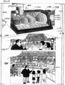
도 1은 본 발명 해양발전소 몸체 내부의 화력발전소와 발전기 구조를 도시한 사시도이다.1 is a perspective view showing a thermal power plant and a generator structure inside the marine power plant body of the present invention.
[도 1-1]은 중유를 연소시켜 발전하는 해양 화력발전 구조방식을 도시한 상세 측면도이며,[1-1] is a detailed side view showing a marine thermal power generation structure method by burning heavy oil,
[도 1-2]는 보일러의 내부와 보일러 외부의 부분적 구조 사시도 및 터빈과 발전기에 연결되는 수증기 파이프 연결구조를 부분적으로 도시한 부분적 사시도이고,1-2 is a partial perspective view of a partial structure perspective view of the inside and the outside of the boiler and a steam pipe connection structure connected to the turbine and the generator,
[도 1-3]은 중기 터빈의 구조 사시도 및 발전소 제어실 내부를 부분적 도시한 사시도이다.1-3 is a perspective view partially showing the structure of the medium-term turbine and the interior of the power plant control room.
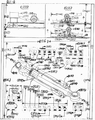
도 2는 본 발명 무재해 관교량 부침형 터넬독 몸체 내부의 수력발전소 가동에 따른 디젤 엔진과 발전기 생산전력을 각개의 압축기와 펌프로 공급하기 위한 전동기 펌프의 각개의 설치위치설정에 따른 사시도이고,Figure 2 is a perspective view of each installation position of the electric motor pump for supplying diesel engine and generator production power to the respective compressors and pumps according to the operation of the hydroelectric power plant inside the body of the non-hazardous tubular bridge submerged tunneling dock,
[도 2-1]는 수력발전소 내부의 수력발전기 몸체 내부 프란시스수차, 펠톤수차에 펌프수차 및 터어빈과 가이드베인 내부 조립모형도 및 펌프수차 내용도이며,2-1 is a Francis aberration inside a hydroelectric generator body inside a hydroelectric power plant, a pump aberration on a pelton aberration, a turbine and guide vane internal assembly model, and a pump aberration diagram.
[도 2-2]은 종래의 디젤엔진 외형도 및 전동기 모터 내부 분해조립 모형도이고,2-2 is a diagram of a conventional diesel engine outline and an internal disassembly and assembly diagram of an electric motor,
[도 2-3]은 종래의 입형다단 펌프 정단면도 및 정면도와 입형다단 시스템 개념도에 컨트롤 블록 다이아그램(Control Block Diagram)과 비에프모델(BF모델; 속도제어방식, 3PUMP 직입 기동방식의 실시예의 입형다단 펌프 운전 방식 구성도이다.2-3 is a vertical cross-sectional view of a vertical multistage pump, a front view, and a vertical multistage system conceptual view of a control block diagram and a BF model (BF model; speed control method and 3PUMP direct start operation method) Multi-stage pump operation method configuration diagram.
[도 2-4]는 종래의 입형다단 펌프의 마이크로콤퓨터를 사용하는 제어방식과 디지털 피아디 제어방식의 인버터시스템에 관제시스템의 무인카메라가 설치되어 분사노즐에서 방화수가 토출되는 인버터시스템과 관제시스템의 장비가 접목 형성된 소방센서펌프 몸체 내부 작동도이며,2-4 is an inverter system and a control system in which fireproof water is discharged from a spray nozzle by installing an unmanned camera of a control system in a control system using a microcomputer of a conventional vertical multistage pump and a digital PIA control system. The operation diagram inside the body of the fire sensor pump grafted with the equipment of
[도 2-5]은 종래 다수의 압축기인 이동용 에어콤프레샤와 고정용 콤프레샤 및 투스테이지 스큐르콤프레샤의 부분적인 사시도 및 지하매설 앙카볼트 고정용의 정단면도이고,2-5 is a partial perspective view of a conventional air compressor, a fixed compressor, and a two-stage scour compressor, which are a plurality of compressors, and a front sectional view for fixing an underground buried anchor bolt,
[도 2-6]과 [도 2-7]은 유분리탱크가 접착 형성된 기어드라이븐(Gear Driven,290)과 전동기모터와 연결되는 스큐르 압축기에 흡입밸브로 분해조립 모형도와, 아프트쿨러 내부와 에어드라이어 내부에 부착되는 흡입필터(262)와 에어드라이어(291) 내부로 부착되는 흡입필터를 도시한 사시도이다.[Figure 2-6] and [Figure 2-7] is an exploded assembly model diagram with an intake valve in the skew compressor connected to the oil drive tank (Gear Driven, 290) and the motor motor is formed, the aftercooler FIG. 7 is a perspective view illustrating a
[도 2-8]은 종래의 옥외소화전인 쌍구포탄형 지상식 소화전과 배설형 소화전의 지하식 단구소화전(179a)과, 지하식 쌍구소화전(179b)의 도로지표면(GU) 하단부(GLD) 상부 지하식 소화전 박스 쇠덥개인 맨홀을 부분적으로 도시한 정단면이며, 오토소화전(161)과 옥내 소화전상자(160) 내부의 소화기 부속품과 소화전 상자의 정면도이고, 연결송수관의 송수구(168)와 방수구(소방대전용 소화전, 169)에 소화전(채수구, 179)을 정면도와 사시도이며, 옥내 소화전 배관방식의(a) 대규모 소화전 설비와, (b) 소규모 소화전 설비를 부분적 측면을 도시한 부분 측면도이다.2-8 is a conventional outdoor fire hydrant, a double-shell shell type ground fire hydrant and an excretory fire hydrant, a ground type single fire hydrant 179a, and an underground double fire hydrant 179b. Underground fire hydrant box is a front cross-sectional view partially showing an iron manhole, the front view of the fire extinguisher accessories and fire hydrant box inside the auto fire hydrant (161) and the indoor fire hydrant box (160). A hydrant (drainer, 179) is a front view and a perspective view of a dedicated fire hydrant, 169), and a partial side view showing a partial side of (a) large-scale fire hydrant facility and (b) small-scale fire hydrant facility of indoor fire hydrant piping system.
[도 2-9]은 종래의 스프링클러 설비와 트랜처헤드의 스프링클러헤드(111) 사시도와 진동경보장치(300)의 사시도에 스프링클러 설비의 배관계통도이며,2-9 is a schematic diagram of the sprinkler installation and the perspective view of the
[도 2-10]은 종래 왕복펌프인 피스톤펌프(127)의 작동방식을 측면 도시한 부분측면도 및 플런저펌프(148)를 부분적 측면으로 플런저(253) 작동방식을 도시한 부분적 작동도이고, 회전운동펌프의 블류우트펌프(311)와 터어빈펌프(140)의 측면을 도시한 부분적 측면도이며 오수펌프(309)의 설치상태를 측면으로 도시한 운전 측면 방식도이다.2-10 is a partial side view showing the operation of the
[도 2-11]는 무재해 관교량 부침형 터넬독인 해양발전소 몸체 인근 산봉우리와 각개의 빌딩 건물 옥상에 감속기(251)와 전동기몸체(192)로 구축된 엘리베이터 기계실 타구어윈치(137)에 와이어로프(19)를 철탑(116) 상부로 구동바퀴로라(135)에 부착시킨후 케이블카아(256)에 소방센서펌프 일체의 소방방재 대책용품을 탑재시켜 1초 이내로 초기진화를 이루도록 소방방재라인을 구성시킨 산속 계곡 정상 부위와 바닷가 주변의 소방방재라인이 구축된 본 발명 사시도이다.2-11 is a wire rope
[도 2-12]은 발전소 몸체 각개의 화재유형별로 1초 이내에 초기진화를 이루게 되는 산정상 부위와 빌딩 건물 각개의 엘리베이터 기계실의 집수정펌프와 소방엘리베이터 설치 위치 정단면도이며,2-12 is a cross-sectional view of a sump pump and a fire-fighting elevator installation location of an elevator machine room of each of a mountaintop and a building building in which an initial evolution is achieved within one second for each fire type of a power plant body,
[도 2-13]은 본 발명의 와이어로프 및 분사노즐과 소방호스 설치운전 작동 방식도2-13 is a wire rope and spray nozzle and fire hose installation operation method of the present invention
[도 2-14]는 본 발명의 옥내의 화재를 1초 이내로 초기진화 및 인명구조를 간단히 이루게 되는 옥상탱크와 압력탱크에 급수장치 상수도 연결펌프소화기 설치 방식도2-14 is a diagram of a method of installing a water supply connection water pump in a rooftop tank and a pressure tank to easily achieve an initial fire and lifesaving structure within 1 second of an indoor fire of the present invention.
[도 2-15]는 본 발명의 산불예방을 간단히 이루게 되는 계단식 무동력 수격펌프(393)의 관노즐 집수정탱크 설치에 따른 탄산가스 소화기 설치 방식도.2-15 is a carbon dioxide gas extinguisher installation method according to the installation of the tubular nozzle water collection tank of the stepless non-power
[도 2-16]은 본 발명의 다중관 소방호스 및 분사노즐 조립모형도 및 조립제작 과정도.2-16 is a multi-pipe fire hose and injection nozzle assembly model and assembly manufacturing process of the present invention.
[도 2-17]은 본 발명의 조정밸브(459) 일체와 배관부속품의 수전류형의 일반형 수도꼭지(496) 구성도,2-17 is a configuration diagram of a general-
[도 2-18]은 본 발명의 요부확대 단면도.(펌프구동중의 주요문제에 있어 그에 대한 대책)2-18 is an enlarged cross-sectional view of the main part of the present invention. (Measures against major problems during pump driving)
[도 2-19]는 본 발명의 소방펌프와 에어콤프레샤에 형성되는 다수개의 밸브구성 사시도이며2-19 is a perspective view of a plurality of valves formed in the fire pump and the air compressor of the present invention;
[도 2-20]은 ,.... 각개의 밸브 작동 방식도이다2-20 is a diagram showing the operation of each valve.
[도 2-21]은 본 발명의 용적식 각개 펌프종류별 왕복펌프의 플런저펌프(148) 사시도 및 다이어후렘 펌프(144)의 작동방식과 윙펌프(327) 작동방식을 도시한 작동도이며, 로우터리 펌프(337) 내부와 외치기어펌프(326) 그외의 로우터리펌프 회전자(338)를 부분적 작동방식을 도시한 작동도이다.2-21 is a perspective view showing the operation of the
[도 2-22]은 본 발명의 터어빈펌프(140)를 도시한 사시도이며, 프라이밍(339)과 자흡식펌프(340) 사시도에 프로펠러펌프(146)의 축류펌프(341)와 혼류펌프(342) 작동도이고, 점성펌프(343) 사시도에 점성펌프와 그 임펠러 사시도에 그 펌프 작동방식을 측면 도시한 측면 작동도이다.2-22 is a perspective view showing the
[도 2-23], [도 2-24], [도 2-25], [도 2-26], [도 2-27] 각각은 본 발명의 산불발생시 1초 이내로 초기진화를 이루게 되는 집수정탱크 및 그에 대체하는 마노매턴형 레벨 균형관 노즐 설치 방식도(삼칠계단식 펌프 소화기 화재예방 방식도)[Fig. 2-23], [Fig. 2-24], [Fig. 2-25], [Fig. 2-26], and [Fig. 2-27], each of which is to achieve initial evolution within 1 second during a forest fire of the present invention. Crystal tank and agate mating type level balance pipe nozzle installation method (Sachiil stairs pump fire extinguisher fire prevention method)
[도 2-28]은 본 발명의 무동력 수격펌프에 의한 1초 이내로 각부능선별의 이중비닐텐트노즐형 방화수 공급 방식도(누구나 쉽게 A화재 초기진화와 설치 방법도)2-28 is a double vinyl tent nozzle type fireproof water supply system for each subfunctionality within 1 second by the non-powered water hammer of the present invention (Easy fire extinguishing and installation method for anyone)
[도 2-29]는 애드벌룬과 비행선의 작용방식을 도시한 것으로 대기권 내부의 태풍 및 일기예보에 따른 작동도이며 건물 내외부의 분사노즐 및 침대노즐 설치 후 1초 이내로 초기진화를 이루게 되는 종류별 화재 및 재난 예방 방식도이며,[Figure 2-29] shows the operation of the ad balloon and the airship according to the typhoon and weather forecasts in the atmosphere and the fire by type to achieve initial evolution within 1 second after the injection nozzle and bed nozzle inside and outside the building It's a disaster prevention plan,
[도 2-30]은 유공압 실린더에 부착되는 다수개의 솔레노이드밸브 작동조립을 도시한 실시예의 구성도와 검출용 스위치 일체의 구성에 따른 센서의 구성에 의한 유공압과 센서기술 적용방식 구성도.2-30 is a configuration diagram of an embodiment showing a plurality of solenoid valve operation assembly attached to the hydraulic cylinder and the configuration diagram of the application method of the hydraulic pressure and sensor technology by the configuration of the sensor according to the configuration of the switch for detection.
도 3은 본 발명 해양발전소 몸체 내부의 태양열발전소와 태양열발전기 구조를 도시한 사시도이다.Figure 3 is a perspective view showing the structure of the solar power plant and the solar generator inside the body of the marine power plant of the present invention.
[도 3-1]은 해양 태양열 발전기의 구조 및 작동방식을 측면 도시한 작동방식 측면도 및 태양열 주택구조를 부분적 도시한 사시도이고,3-1 is a perspective view partially showing an operation method side view and a solar housing structure in which a structure and an operation method of a marine solar generator are shown in a side view,
[도 3-2]는 해양 원자력발전소 외형을 도시한 사시도 및 원자력발전의 작동 방식을 측면으로 도시한 작동방식 측면도이며,3-2 is a perspective view showing the appearance of the marine nuclear power plant and the operation method side view showing the operation method of nuclear power in a side view,
[도 3-3]은 해양 지열발전소 외형을 도시한 사시도 및 지열발전의 작동방식을 측면으로 도시한 작동방식 측면도이다.3-3 is a perspective view showing the external appearance of the geothermal power plant and the operation method side view showing the operation method of the geothermal power generation side.
[도 3-4]는 해양 풍수력발전소의 외형을 도시한 사시도 및 수격작용의 무동력 수격펌프 작동방식을 측면으로 도시한 작동방식 측면도이고,3-4 is a perspective view showing the external appearance of the marine wind and hydro power plant and the operation method side view showing the operation method of the non-powered water hammer of the water hammer action,
[도 3-5]는 해양 시소형 수력발전(직류와 교류발전) 작동방식을 도시한 측면 방식도 및 실린더 내부의 시일 종류 형성을 도시한 사시도이다.3-5 is a side view showing the marine seesaw type hydroelectric power generation (direct current and alternating current power generation) operation method and a perspective view showing the formation of the seal type inside the cylinder.
도 4는 본 발명 해양발전소 몸체 내부의 조력발전을 도시한 조력발전소 사시도이다.Figure 4 is a perspective view of a tidal power plant showing tidal power generation within the body of the marine power plant of the present invention.
[도 4-1]은 파도의 힘에 의한 파력발전소의 파력발전기 구조를 도시한 사시도 및 한류와 난류를 이용하는 파력발전소 설치 위치를 도시한 정단면도이고,4-1 is a sectional view showing a wave power generator structure of a wave power plant by the force of a wave and a wave power plant installation position using the Korean wave and turbulent flow,
[도 4-2]는 변압기의 구조와 기능 및 송전철탑과 송전선의 단면을 도시한 송전선의 단면도이며,4-2 is a cross-sectional view of a transmission line showing the structure and function of a transformer and a cross section of a transmission tower and a transmission line,
[도 4-3]은 해양발전소 몸체 내부의 초고압 변전소로 생산전력을 공급하기 위한 방식을 도시한 전기 공급 방식을 도시한 사시도이고,4-3 is a perspective view showing an electricity supply method showing a method for supplying production power to an ultra-high voltage substation inside a marine power plant body,
[도 4-4]는 해양발전소에서 가정(근린생활주거지)까지의 전압의 변화과정을 측면으로 도시한 전기공급방식 측면도 및 2차 변전소 구조를 도시한 사시도이다.4-4 is a perspective view showing a side view of the electricity supply method and a secondary substation structure showing the process of changing the voltage from the marine power plant to the home (neighbor living residence).
도 5는 본 발명의 요부확대 사시도(부양식독의 본체의 지주탱크 상단의 바지선 본체(591)와 지주탱크 하단의 바지선 본체(592)를 탱크용 블럭배관(598)과 중심부 지주탱크 및 피라밋 형식 보조지지 결합분리용 포터블러그 결합용 핀 샤프 트(606)와 포터블러그용 플레이트(607)로 해상에서 부양식독 본체 구성이 도시된 상세한 조립 과정 방식 구성도)이다5 is an enlarged perspective view of the main part of the present invention (barge
[도 5-1]은 해양발전소 몸체 형성도(부양식독 본체의 배관블럭용 강재철판 밴딩방식과, 용접접합기본방식을 이중관 구조의 배관내부의 철구조물 정면 측면을 도시한 부분적 부분상세 구성도 및 오대양 육대주의 무재해 관교량 강관 제조공정도)이다5-1 is a partial partial detailed view showing the front side surface of the steel structure inside the pipe of the marine power plant body forming diagram (steel plate banding method for the piping block of the main body of the aquaculture dock, and the welding joint basic method) Manufacturing process diagram of the five pipes
[도 5-2]는 발전소 몸체 내부의 부양식독 본체의 이중관 블럭배관 연결부위 측면 단면을 부분적 상세히 도시한 부분적 부분 상세 구성도이며,5-2 is a partial partial detailed configuration diagram showing a partial cross-sectional side view of the double pipe block piping connection part of the main body of the subculture in the power plant body,
발전소 몸체 내부의 부양식독 본체의 전체 구성 방식을 설명하기 위한 이중관 구조의 지주탱크와 부양식독 본체를 결합방식을 도시한 전체 구성의 전개방식 구성도이고This is a schematic diagram of the overall configuration of the floating tank and the floating tank.
[도 5-3]은 본 발명 해양발전소 몸체의 부양식독 본체를 블럭단위 탱크별로 분해 결합을 도시한 잠수식 조절 부양식독의 블럭단위 탱크 분해 결합방식 구성도로5-3 is a block diagram of a submerged control subculture dock disassembly coupling method of the subculture dock main body of the present invention marine power plant body by block unit tank configuration diagram
[도 5-2], [도 5-3]...각각은 본 발명 구성에 의한 일실시예를 예시한 구성도이며[Fig. 5-2], [Fig. 5-3] ... each is a block diagram illustrating an embodiment according to the configuration of the present invention;
부양식독 본체를 예인선(636)과 헬리콥터(647)를 이용하여 해상과 해저에서 블럭단위 탱크 결합방식을 도시한 부양식독 건조 조립방식 구성도이고,It is a configuration diagram of the dry farming dock assembly method showing the combined tank unit in the sea and the seabed using a
[도 5-4], [도 5-5], [도 5-6]....각각은 본 발명 구성에 의한 일실시예를 예시하는 구성도이며[Fig. 5-4], [Fig. 5-5], [Fig. 5-6] .... each is a block diagram illustrating an embodiment according to the present invention configuration.
[도 5-4]는 본 발명 해양발전소 몸체의 부양식독 본체의 탱크용 블럭배관(598) 각각으로 용접연결을 하기 위하여 해상의 반잠수작업선 상단의 해상안전치공구장비 밴드지그대(621)를 이용하여 수중절단 및 수중용접 준비과정을 도시한 탱크용 블럭배관 측면 연결방식 구성도로 탱크용 블럭배관(598)과 밴드지그대(621)를 부분적 상세히 도시한 부분적 탱크용 블럭배관 단위 부분 측면 상세 결합방식 구성도이며,5-4 is a seam safety tool
[도 5-5]는 본 발명 발전소 몸체의 탱크용 블럭배관(598) 연결마디 결합 분리수단의 포터블러그 결합용 핀 샤프트(606)와 포터블러그용 플레이트(607)에 브라켓(165)을 상세히 도시한 부분적 탱크용 블럭배관 단위 연결부위 부분 측면 부분 상세 구성도로, 피라밋 형식의 외부 블럭탱크(599)의 결합 분리수단의 포터블러그 결합용 핀 샤프트(606)와 포터블러그용 플레이트(607) 그리고 러그(21) 결합방식을 상세히 도시한 외부 블럭탱크(599) 수직 수평 연결부위 부분적 부분측면 상세 구성도이며5-5 shows the details of the
[도 5-6]은 본 발명 해양발전소 몸체의 내부로 부양식독 종류별 소형의 부양식독(593)과 중형의 부양식독(594)에 대형의 부양식독(595)을 해상에서 조립 연결토록 부양식독 접속연결구 러그 힌지소켓(613)으로 우산접기, 우산펴기 형식의 유압실린더 또는 유압실린더 작키(623) 사용방식을 도시한 부양식독을 심해저 저층바닥 굴착기로 드릴머신으로 천공 후 지주탱크(교각기둥) 앙카링 방식도 및 지주탱크 하단의 바지선 본체(592) 블럭배관 연결방식을 측면 단면 정면을 부분적 상세히 도시한 바지선 본체 블럭배관 조립연결 해상조립 부분 상세 구성도이다5-6 is a subsidiary poison connection for connecting a
도 6은 본 발명의 해양발전소 몸체 내부 원유 시추선 고정형의 외형 사시도이다.Figure 6 is an external perspective view of the crude oil drilling ship fixed type inside the body of the marine power plant of the present invention.
[도 6-1]은 본 발명의 해양발전소 몸체 이동형 시추선 설치과정 정단면도이며,6-1 is a sectional front view of an installation process of a mobile drilling rig body of a marine power plant according to the present invention.
[도 6-2]은 본 발명의 해양발전소 몸체 관교량 부침형 터넬독의 교각 기초 콘크리트 고정해지 단면도.6-2 is a cross-sectional view of the pier foundation concrete anchoring of the tubular bridge submerged tunnel dock of the marine power plant body of the present invention.
도 7은 본 발명의 발전소 몸체 터넬독 내부 전동차 설치 방식 사시도 및 정단면도이다.7 is a perspective view and a front cross-sectional view of the installation method inside the power plant body tunnel dogl of the present invention.
[도 7은1]은 본 발명의 발전소 몸체 발전소 몸체 내부 망간 단괴 및 그 이외의 해양자원 천연가스 채집방식 정단면도이고,7 is a front sectional view of a manganese nodule and a marine resource natural gas collection method other than the power plant body of the power plant body of the present invention,
[도 7-2]는 본 발명의 발전소 몸체 다수개의 태풍진로 변경 방식 장비 설치 방식도.7-2 is a diagram illustrating a method of installing a plurality of typhoon furnace-type equipment of a power plant body according to the present invention.
도 8은 본 발명의 해류 흐름에 의한 풍수력발전기 발전 설비 방식 정단면도이다.8 is a front sectional view of the wind power generator power generation system according to the current flow of the present invention.
도 9는 본 발명의 바지선 본체 갑판데크 측면 사이드(동서남북 4곳)에 수개의 시이소(935) 크레인 붐대(651) 내부에 설치된 해수면 상공 10km 이상의 높이로 애드벌룬(77)과 비행선(78) 없이도 무동력의 수격작용(389)의 수격펌프(393)로 바닷물을 양수할 수 있는 방식도 및 쿨링팬(641)과 히터팬(642)에 에어콤프레샤(80)에서 생성된 다수의 개 공기로 대류의 흐름을 조절하는 시소형 붐대의 측면 작동도와 해양발전장치 설치 단면도이다.FIG. 9 shows a non-motorized vehicle without an
<도면의 주요부분에 대한 부호의 설명><Description of the code | symbol about the principal part of drawing>
(1) 무재해 지구촌 해양발전소(관교량 부침형 터넬독; tunnel Dock) 몸체(1) Body of accident-free global marine power plant (tubular ups and downs tunnel tunnel dock)
(2) 입형다단 펌프 제어반(Control Assy) 또는 제어박스, (3) 흡입 합류관(Manifold-Suction), (4) 토출 합류관(Manifold-Discharge), (5) 펌프 격리밸브인 격리밸브(Isolating Valve, Ballor Butterfly) (6) 펌프 역류방지 역지밸브(Check Valve),(2) Vertical multistage pump control panel or control box, (3) Manifold-Suction, (4) Manifold-Discharge, (5) Isolating pump isolation valve Valve, Ballor Butterfly) (6) Pump check valve
(7) 방화수 또는 발전용 물 그리고 전해수 (8) 방재 및 방제펌프 또는 입형다단 펌프(Vertical Multi-Stage Pump) (9) 노즐호스 또는 소방호스, (10) 소방관노즐(방제 및 방재 포함함), (11) 소방노즐 프레임, (12) 감지센서, (13) 갈고리, (14) 배관 또는 노즐배관, 도크선체갑판상단부(SDU), 선체갑판중심부(SDM), 도크선체갑판상단부(SDL), 기계실 바닥표면 상단부(MFGU), 기계실 바닥표면(MFG) 기계실 바닥표면 하단부(MFGL) 지표면 상단부(GLU), 지표면(GLL), 지표면 하단부(GLD), 적도 전선(EL), 북극(NP), 남극(SP), 경도(longitude; ld), 위도(latitude; lt로 약칭함), (15) 틈새, (16) 경사각도, (17) 방재수로 (18) 갈고리 훅크, (19) 와이어로프 (20) 가공홀, (21) 갈고리러그(뭉치쇠) 또는 포터블러그,(7) fire or water for power generation and electrolyzed water; (8) disaster prevention and control pumps or vertical multi-stage pumps; (9) nozzle hoses or fire hoses; (10) firefighter nozzles (including control and disaster prevention); (11) Fire nozzle frame, (12) Sensor, (13) Hook, (14) Pipe or nozzle piping, Dock hull deck top (SDU), Hull deck center (SDM), Dock hull deck (SDL), Machine room Floor Surface Top (MFGU), Machine Room Floor Surface (MFG) Machine Room Floor Surface Bottom (MFGL) Surface Top (GLU), Surface (GLL), Surface Bottom (GLD), Equatorial Front (EL), North Pole (NP), South Pole ( SP), longitude (ld), latitude (abbreviated lt), (15) clearance, (16) angle of inclination, (17) disaster channel (18) hook hook, (19) wire rope (20) ) Machining hole, (21) Hook lug or porter lug,
(22) 지그대 또는 다양한 형태의 지그("![]()
![]()
![]()
![]()
![]()
![]()
(32) 가스켓트 또는 고무패킹, (33) 노즐호스 장비거치대, 분사노즐 상단 부(A) 분사노즐 몸체(B) 분사노즐 하단부(C) (34) 집수정탱크 (35) 레듀사, (36) 고성능 수중펌프 (37) 펌프수차 (38) 토출분사수 (39) 물막 또는 커텐물막, (40) 소방정, (41) 감지노끈, (42) 바스켓, (43) 이중비닐텐트 또는 봉지, (44) 엘보 또는 티이엘보, (45) 연돌(굴뚝)(32) Gasket or rubber packing, (33) Nozzle hose equipment holder, top of injection nozzle (A) injection nozzle body (B) bottom of injection nozzle (C) (34) sump collecting tank (35) Redusa, (36) ) High performance submersible pumps (37) Pump aberrations (38) Water jets (39) Water or curtains, (40) Fire fighting boats, (41) Detection straps, (42) Baskets, (43) Double vinyl tents or bags, (44 ) Elbow or Tie elbow, (45) Stack (chimney)
도로지표면 상단부(GLU), 도로지표면(GLL), 도로지표면 하단부(GLD), (46) 동력 전원 공급장치인 전원, (47) 인버터, (48) 인버터브이오(VO;vidicon off) (49) 억세스 포인터(AP; Access Point), (50) 인터넷 망, (51) (입형다단펌프) 또는 관제서버 (52) 모니터 (53) 펌프 제어보드 또는 타구어윈치 콘트롤 박스, (54) 근거리 무선통신 안테나 (55) 근거리 무선통신장치의 무선통신제어모듈, (56) 디스플레이(LCD;liquid crystal display) (57) 전자제어장치인 에이디이씨(ADC;advanced developing countrie) (58) 스위치 입력회로, (59) 전자제어장치인 엠씨유(MCU;moduler concept. unit) (60) 전자제어장치인 디이에이씨(DAC;Development Assistance Committee)Road surface top (GLU), road surface (GLL), road surface bottom (GLD), (46) power source power supply, (47) inverter, (48) inverter off (VO) (49) Access Point (AP), (50) Internet Network, (51) (Pumped Multistage Pump) or Control Server (52) Monitor (53) Pump Control Board or Targer Winch Control Box, (54) Near Field Communication Antenna (55) Wireless communication control module for short range wireless communication device, (56) Liquid crystal display (LCD) (57) Advanced developing countrie (ADC), electronic control device (58) Switch input circuit, (59) Module concept (MCU), electronic control unit (60) Development Assistance Committee (DAC), electronic control unit
(61) 브레이크(과전류차단기), (62) 전원부, (63) 디스플레이 화면, (64) 아날로그입력, (65) 디지털 입력, (66) 각 펌프의 온오프제어를 위한 스위치인 메인 스위치버턴, (67) 보조스위치버턴 (68) 입형다단펌프 디스플레이(LCD) 입력(콤퓨터 전산망 입력), (69) 현재 압력값 또는 설정 압력값(압력설정수치) 인식명판, (70) 메모리, (71) 전선, (73) 방재물질 혼합기 믹서, (74) 터어빈수차 (75) 헝겊꺼즈, (76) 솔레노이드밸브 (77) 애드벌룬, (78) 비행선, (79) 가스통, (80) 에어콤프레샤 (81) 모바일 서비스(SMS;short messge servise) (82) 휴대용 단말 기(PDA;perseNAL digital assistant)(61) brake (overcurrent breaker), (62) power supply, (63) display screen, (64) analog input, (65) digital input, (66) main switch button for on / off control of each pump, ( 67) Auxiliary switch button (68) Vertical multistage pump display (LCD) input (computer computer network input), (69) Current pressure value or set pressure value (pressure setting value) Identification plate, (70) Memory, (71) Wire, (73) Disaster Prevention Mixer (74) Turbine Aberration (75) Cloth Tod, (76) Solenoid Valve (77) Ad Balloon, (78) Airship, (79) Gas Cylinder, (80) Air Compressor (81) Mobile Service SMS (short messge servise) 82 perseNAL digital assistant (PDA)
(83) 저압차단 밸브, (84) 비상 밸브, (85) 감압 밸브(83) low pressure shutoff valve, (84) emergency valve, (85) pressure reducing valve
(86) 제1압력체크센서, (87) 제2압력체크센서(86) 1st pressure check sensor, (87) 2nd pressure check sensor
(88) 전자제어유닛, (89) 양수관(89a) 또는 수직 하향관(89b) (90) 볼밸브 핸들(88) Electronic control unit, (89) Pumping pipe (89a) or vertical downward pipe (89b) (90) Ball valve handle
(91) 드렌처헤드, (92) 밸브 몸체 내부 디스크(91) Drencher Head, (92) Valve Body Inner Disc
(93) 비상싸이렌(93) emergency sirens
(94) 최초발화원인물질인 스파크 또는 낙뢰, (95) 전신주, (96) 변압기(94) Sparks or lightning as the first ignition source, (95) Telephone poles, (96) Transformers
(97) 레듀사 붓싱소켓,(97) Redusa Bushing Socket,
(99) 점멸경고등, (100) 파라핀노즐마개(양초), (101) 압력계(99) Flashing warning lamp, (100) Paraffin nozzle stopper (candle), (101) Pressure gauge
(102) 감지센서 바이메탈, (103) 열전대온도계 스위치(감지센서)(102) Bimetal Sensors, (103) Thermocouple Switches (Sensors)
(104) 레벨 또는 압력스위치, (105) 방유량체크용 유량계(104) Level or pressure switch, (105) Flowmeter for discharge check
(106) 동력모터제어모듈, (107) 밸브스위치작동용 추 또는 크레인 붐대 레벨유지 웨이트, 추(106) Power motor control module, (107) Valve switch operation weight or crane boom level maintenance weight, weight
(108) 과대압력 방지스위치 또는 스위치박스, (109) 에어호스, (110) 닛플(에어호스 연결장치)(108) Overpressure protection switch or switch box, (109) Air hose, (110) Nipple (air hose coupling)
(111), 스프링쿨러헤드, (112), 반사관, (113) 가용금속(퓨우즈), (114) 정지밸브 또는 수도밸브, (115) 지하매설관, (116) 철탑 또는 블럭철탑 (117) 부자, (118) 부자회로개폐기 (119) 벨, (120) 경보밸브, (121) 시험밸브, (122) 고압수도펌프, 밸브몸체중심선(VBCL or PBCL), 방화수수면하단(WLD), 방화수수면(WLL), 분 출수면(WLU), (123) 레버블럭, (124) 소화기(소화기a, 소화기b, 소화기c, 소화기D, 소화기e, 소화기f) (125) 체인 (126) 시린더 또는 실린더, (127) 피스톤 또는 피스톤펌프, (128) 소화기 고정용 핀 (129) 빗장 장금장치, (130) 인명구조용 에어튜우브 (131) 로프, (132) 컨테이너, (133) 앙카볼트, (134) 라디오존데, (135) 구동바퀴 로라(도루레), (136) 레귤레이트, (137) 에어 타구어윈치 또는 타구어윈치, (138) 에이시린더 (139) 철개망태, (140) 터어빈펌프, (141) 케이싱, (142) 베인펌프 또는 가이드베인(111), sprinkler head, (112), reflector, (113) soluble metal (fuse), (114) stop or water valve, (115) underground buried pipe, (116) pylon or block pylon (117) ) Rich, (118) rich circuit breaker (119) bell, (120) alarm valve, (121) test valve, (122) high pressure water pump, valve body center line (VBCL or PBCL), fire protection water bottom (WLD), fire water Water surface (WLL), Water jet surface (WLU), (123) Lever block, (124) Fire extinguisher (Fire extinguisher a, Fire extinguisher b, Fire extinguisher c, Fire extinguisher D, Fire extinguisher e, Fire extinguisher f) (125) Chain (126) Cylinder Or cylinder, (127) piston or piston pump, (128) fire extinguisher fixing pin (129) latching device, (130) life-saving air tube (131) rope, (132) container, (133) anchor bolt, ( 134) Radiosonde, (135) Drive wheel Laura (136), (136) Regulate, (137) Air or Winch Winch, (138) Acylinder (139) Iron Mane, (140) Turbine Pump , (141) casing, (142) vane pump or guide Person
(143) 임펠러, (144) 다이어후렘펌프, (145) 에어리시버탱크 또는 고압저장탱크, (146) 프로펠러펌프 또는 프로펠러 (147) 스큐르 또는 스큐르압축기 그리고 스큐르펌프 (148) 플런저펌프, (149) 철재빔, (150) 방재펌프 제어시스템 또는 관제시스템, (151) 오일쿨러, (152) 맨홀뚜껑, (153) 해치카버, (154) 방화문 (155) 글랜드패킹, (156) 매커니커 시일 또는 각개의 시일 (157) 제트펌프, (158) 황토 (159) 방화사 (160) 옥내소화전상자 (161) 오토소화전 (162) 호스걸이 (163) 질식가스(![]()
![]()
(177) 발화물질 파라핀테이프, (178) 비발화물질 철사, (178) 소화전(단구형 a, 쌍구형b) (180) 비닐포대, (181) 공기배관라인, (182) 아프터쿨러 (183) 리밋스위치 또는 리미트스위치 (184) 무인카메라(씨씨티비), (185) 지그대 쇄기(끝이 뾰족한 틈새결합공구) (186) 스프링, (187) 무인점화기 스파크라이터 (188) 구명정 (189) 헤드탱크(압력탱크) (190) 플렉시블고압호스 또는 유압호스, (191) 도입관(수압관)(177) ignition paraffin tape, (178) non-ignition wire, (178) fire hydrant (mono-a, twin-b), (180) plastic bag, (181) air line, (182) aftercooler (183) Limit switch or limit switch (184) Unmanned camera (CTV), (185) Jig wedge (pointed crevice fitting tool) (186) Spring, (187) Drone spark writer (188) Lifeboat (189) Head tank (Pressure tank) (190) Flexible high pressure hose or hydraulic hose, (191) Introduction pipe (hydraulic pipe)
(192) 전동기 몸체(동력모터), (193) 후드, (194) 스냅링, (195) 팬, (196) 몸체프레임, (197) 몸체전방부라켓트, (198) 샤프트, (199) 회전자조립, (200) 전바베아링, (201) 고정자조립, (202) 주물프레임(모터보호용), (203) 단자박스, (204) 인양볼터, (205) 단자박스카버 (206) 후방베아링, (207) 후방부라켓트, (208) 공극, (209) 팬카바 또는 보호카바 (210) 회전자 철심, (211) 고정자 철심, (212) 고정자권선,(192) Motor body (power motor), (193) Hood, (194) Snap ring, (195) Fan, (196) Body frame, (197) Front body racket, (198) Shaft, (199) Rotor Assembly, (200) Front bar bearing, (201) Stator assembly, (202) Casting frame (motor protection), (203) Terminal box, (204) Lifting bolt, (205) Terminal box cover (206) Rear bearing, (207) ) Rear racket, (208) air gap, (209) fan cover or protective cover (210) rotor iron core, (211) stator iron core, (212) stator winding,
(213) 수력발전기(대형발전기 또는 대형발전기 몸체)(213) Hydro generators (large generators or large generator bodies)
(214) 회전속도 검출기 에스에스지(speed signal generator; SSG로 약칭 함)(214) speed signal generator (SSG)
(215) 여자기(BRUSHLESS EXCITOR; 교류발전기이거나 동력전동기의 계자 코일에 전류를 공급하는 직류발전기를 칭함)(215) BRUSHLESS EXCITOR; refers to an alternator or a direct current generator that supplies current to the field coils of a power motor.
(216) 드러스트 고리관(THRUSTCOLLAR; 고리관 깃을 밀어 넣는 수단을 칭함)(216) THRUSTCOLLAR (means for pushing the collar tube collar)
(217) 엎퍼 가이드 베아링(UPPER GUIDE BEARING)(217) UPPER GUIDE BEARING
(218) 드러스트 베아링(THRUST BEARING)(218) THRUST BEARING
(219) 고정자 코일(STATOR COIL),(219) stator coil,
(220) 고정자 프레임(STATOR FRAME)(220) Stator frame
펌프몸체(PB), 펌프몸체수직라인(PBVL), 펌프몸체수평중심라인(PBCL)Pump Body (PB), Pump Body Vertical Line (PBVL), Pump Body Horizontal Center Line (PBCL)
(221) 스테이터어 코어(STATOR CORE)(221) status core (STATOR CORE)
(222) 로워 베아링 쿨러(LOWER BRG COOLER; 저속냉각기),(222) lower bearing cooler (LOWER BRG COOLER),
(223) 브래이크 링(BRAKE RING),(223) BRAKE RING,
(224) 브래이크 또는 잭(BRAKE & JACK)(224) BRAKE & JACK
(225) 로워 가이드 베아링(LOWER GUIDE BEARING)(225) LOWER GUIDE BEARING
(226) 엔진(발전기) (227) 터어빈베아링, (228) 런너어(Runner), (229) 프란시스수차 (230) 펠톤수차, (231) 해양 풍력발전기 (232), 탐조등, (233) 조력발전소 (234) 호칭별 노즐몸체 "호칭 100", (235) 호칭 "90", (236) 호칭 "75", (237) 호칭 "65", (238) 호칭 50, (239) 호칭 "40", (240) 호칭 "25", (241) 호칭 "100×90", (242) 호칭 "90×75" (243) 호칭 "75×65", (248) 크랭크, (249) 링크대, (250) 푸레, (251) 감속기, (252) 브이(V)밸트, (253) 플런저, (254) 고정핀 (255) 타임머, (256) 해양 케이블카아 (257) 공기밸브, (258) 안전밸브, (259) 오토 또는 오우토밸브 (260) 드레인밸브 (261) 밸트카바 (262) 흡입필터, (263) 압축기본체 (264) 펌프수차, (265) 메인밸브, (266) 산림, (267) 터어빈, (268) 플라이휠, (269) 흡입구, (270) 토출구, (271) 공운전방지장치, (272) 펌프전원, (273) 제어전원, (274) 비상운전(Sequence)회로, (275) 디씨이파워공급(DC power supply)회로, (276) 마이크로콘트롤유니트(Micro control unit), (277) 디아이피(DIP)스위치설정회로, (278) 엘이이디이 디스플레이(LED display)회로, (279) M/C 구동신호 접점출력회로, (280) 모터 과부하 신호입력회로, (281) 인버터운전 데이트 입출력회 로, (282) 압력감지회로, (283) 외부상태 입력회로, (284) 토출압력트랜스미터어(Transmitter), (285) 흡입/토출스위치 등의, (286) 베드프레임, (287) 냉각수 입구, (288) 유분리탱크, (289) 흡입밸브, (290) 기어드라이븐,(226) Engine (Generator) (227) Turbine Bearing, (228) Runner, (229) Francis Water Wheel (230) Pelton Water Wheel, (231) Offshore Wind Power Generator (232), Searchlight, (233) Tidal Power Plant (234) Nominal nozzle body "Nominal 100", (235) Nominal "90", (236) Nominal "75", (237) Nominal "65", (238) Nominal 50, (239) Nominal "40", (240) Nominal "25", (241) Nominal "100 × 90", (242) Nominal "90 × 75" (243) Nominal "75 × 65", (248) Crank, (249) Link stand, (250 ) Puree, (251) Reducer, (252) V (V) Belt, (253) Plunger, (254) Fixed Pin (255) Timer, (256) Marine Cable Car (257) Air Valve, (258) Safety Valve , (259) Auto or auto valve (260) Drain valve (261) Belt cover (262) Suction filter, (263) Compressor body (264) Pump aberration, (265) Main valve, (266) Forest, (267) Turbine, (268) Flywheel, (269) Inlet, (270) Outlet, (271) Idle Protection, (272) Pump Power, (273) Control Power, (274) Sequence Circuit, (275) DC Power Supply (DC power supply circuit, (276) Micro control unit, (277) DIP switch setting circuit, (278) LED display circuit, (279) M / C drive signal contact Output circuit, (280) Motor overload signal input circuit, (281) Inverter operation data input / output circuit, (282) Pressure sensing circuit, (283) External state input circuit, (284) Discharge pressure transmitter (285) ) (286) bed frame, (287) coolant inlet, (288) oil separation tank, (289) suction valve, (290) gear driver,
(291) 에어드라이어, (292) 불씨, (293) 불꽃, (294) 불기둥,(291) air dryer, (292) embers, (293) flame, (294) pillar of fire,
(295) 수조탱크, (296) 게이트밸브, (297) 리턴밸브, (298) 부시 또는 트로틀부시 (299) 드렌처헤드(a,b,c,d)의 종류, (300) 진동경보장치, (301) 드레인, (302) 역정지밸브, (303) 고압보울탱크, (304) 회전펌프, (305) 버터플라이밸브, (306) 중탄산 소오다, (307) 재유입구, (308) 센튜리퓨우걸펌프, (309) 오수펌프, (310) 스파이럴 케이싱, (311) 블류우트펌프, (312) 후드밸브, (313) 양수구, (314) 펌프본체, (315) 플로우트, (316) 드러스트보울, (317) 플랙스블카프링, (318) 플로우트스위치, (319) 뒷날개, (320) 퍼올림밸브, (321) 빨아올림밸브, (322) 분출수면계, (323) 실제양정 (324) 분출양정, (325) 제트펌프, (326) 기어펌프 또는 기어, (327) 윙펌프, (330) 분리실, (331) 마그넷스위치 (332) 목조건물, (333) 빌딩 또는 대형건물, (334) 밸런스 (335) 언밸런스, (336) 옥내소화용펌프 (337) 로우터리펌프, (338) 로우터리회전자, (339) 프라이밍, (340) 자흡식펌프, (341) 축류펌프, (342) 혼류펌프, (343) 점성펌프(295) tank tanks, (296) gate valves, (297) return valves, (298) bushes or throttle bushes (299) types of drencher heads (a, b, c, d), (300) vibration alarms, (301) Drain, (302) Reverse stop valve, (303) High pressure bowl tank, (304) Rotary pump, (305) Butterfly valve, (306) Sodium bicarbonate, (307) Refill inlet, (308) Centurirepu Woogal Pump, (309) Sewage Pump, (310) Spiral Casing, (311) Blowout Pump, (312) Hood Valve, (313) Pump, (314) Pump Body, (315) Float, (316) Drust Bowl, (317) Flexible Coupling, (318) Float Switch, (319) Rear Wings, (320) Lift Valve, (321) Suction Valve, (322) Ejection Level Meter, (323) Actual Head (324) Ejection Head , (325) jet pump, (326) gear pump or gear, (327) wing pump, (330) separation chamber, (331) magnet switch (332) wood conditioner, (333) building or large building, (334) balance (335) Unbalanced, (336) Indoor fire extinguishing pump (337) Rotary pump, (338) Rotor Rotor, 339 priming, 340 chair-priming pump, 341 is an axial flow pump, 342, the mixed flow pump, 343, viscous pump
(344) 표준형 글랜드패킹, (345) 글랜드, (346) 주액랜턴링부착패킹, (347) 랜턴패킹, (348) 2중 글랜드형 패킹, (349) 드로틀부시부착패킹, (350) 냉각수출구, (351) 봉수, (352) 냉각수 입구, (353) 슬리이브내면 냉각병용 워터재킷부착패킹, (354) 슬리이브의 내부 냉각실, (355) 보조글랜드, (356) 누설액의 냉각실, (357) 글랜드 패킹짜는 방법, (358) 여덟가닥짜기, (359) 봉지짜기, (360) 격자짜기, (361) 플래싱구멍, (362) O링, (363) 스톱더, (364) 중동링, (365) 밀봉 단면, (366) 시이트링, (367) 피동링, (368) 퀀칭, (369) 쿠울링, (370) 되돌림관, (371) 핸들(Handle), (372) 격벽, (373) 축방향의 드러스트 하중, (374) 임펠러 전면에 작용하는 압력, (375) 임펠러 뒷면에 작용하는 압력, (376) 밸런스호울,(344) Standard Gland Packing, (345) Gland, (346) Liquid Lantern Packing Packing, (347) Lantern Packing, (348) Double Gland Packing, (349) Throttle Bushing Packing, (350) Cooling outlet, (351) Sealed water, (352) Cooling water inlet, (353) Sealing with inner jacket for water bottle cooling bottle, (354) Internal cooling chamber of sleeve, (355) Secondary gland, (356) Cooling chamber, (357) Gland packing, (358) Eight strands, (359) Bag weaving, (360) Lattice, (361) Flashing hole, (362) O-ring, (363) Stop the, 364) Middle East Ring, (365) Sealed Section, (366) Sheet Ring, (367) Passive Ring, (368) Quenching, (369) Coiling, (370) Return Tube, (371) Handle, (372) ) Bulkhead, (373) axial thrust load, (374) pressure on the front of the impeller, (375) pressure on the back of the impeller, (376) balance hole,
(377) 흡입압력, (378) 배면압력, (378) 밸런스구멍, (380) 전면웨어링, (381) 토출압력, (382) 배면베어링 링, (384) 뒷날개, (385) 뒷날개 설치로 인한 압력분포와 임펠러, (386) 다단펌프의 임펠러 배치, (387) 수주분리, (388) 수주결합, (389) 수격작용, (390) 축봉부, (391) 매커니컬시일의 냉각방식, (392) 스트레이너, (393) 수격펌프, (394) 옥상소방운전실 또는 크레인운전실, (395) 높고 낮은 산, (396) 폴저엔코드(Pulse Encoder), (397) 스피드콤멘드(Speed Command), (398) 모터스피드 그리고 변속기, (399) 디스크 브레이크(DISC Brakes), (400) 방파제 (401) 안전그물망(로프그물) (402) 에어(공기) 압축실(Air Chamber)(377) Suction pressure, (378) Back pressure, (378) Balance hole, (380) Front wear ring, (381) Discharge pressure, (382) Back bearing ring, (384) Rear wing, (385) Pressure due to rear wing installation Distribution and impeller, (386) Impeller placement of multistage pumps, (387) water column separation, (388) water column coupling, (389) water hammering, (390) shaft, (391) mechanical seal cooling, (392) ) Strainers, (393) Water hammer pumps, (394) Rooftop fire cabs or crane cabs, (395) High and low mountains, (396) Pulse Encoder, (397) Speed Command, (398) ) Motor speed and transmission, (399) DISC Brakes, (400) Breakwater (401) Safety nets (Rope nets) (402) Air chambers
(403) 슬루우브 밸브, (404) 밸브 몸통, (405) 밸브 덮개, (406) 슬루우스 밸브, (407) 패킹누르게, (408) 패킹누르게 너트, (409) 밸브대, (410) 핸들, (411) 핸들너트, (412) 패킹, (413) 웨지 게이트 밸브, (414) 단체밸브, (415) 플렉시블 밸브, (416) 패럴렐 슬라이드 밸브, (417) 더블 디스크 게이트 밸브, (418) 스톱 밸브, (419) 플랜지형 글로우브 밸브, (420) 플랜지형 앵글 밸브, (421) 몸통, (422) 덮개(본네트), (423) 디스크, (424) 덮개붙임밸브 시이트, (425) 밸브대, (426) 밸브 누르개, (427) 핸들, (428) 덮개 끼움링, (429) 패킹누르개링, (430) 패킹 누르개, (431) 나사 끼움 형, (432) 덮개 보울트, (433) 패킹 누르개 보울트, (434) 핀, (435) 덮개 보울트용 너트, (436) 패킹 누르개 보울트용너트, (437) 핸들 너트, (438) 멈춤 나사, (439) 와셔, (440) 패킹, (441) 가스킷, (442) 밸브누르게(평면누르게(a), 원뿔누르게(b), 구면누르게(c), 스터트누르게(d)), (443) 콕(cock;1형 (444) 콕(2형), (445) 청동나사넣기 메인콕, (446) 주철플랜지형 글랜드형, (447) 청동나사넣기 글랜드콕, (448) 삼방콕, (449) 사방콕, (450) 핸들콕(403) Slew valve, (404) Valve body, (405) Valve cover, (406) Slew valve, (407) Packing press, (408) Packing press nut, (409) Valve seat, (410) Handle , (411) Handle Nut, (412) Packing, (413) Wedge Gate Valve, (414) Single Valve, (415) Flexible Valve, (416) Parallel Slide Valve, (417) Double Disc Gate Valve, (418) Stop Valve, (419) flanged glove valve, (420) flanged angle valve, (421) body, (422) cover (bonnet), (423) disc, (424) cover valve seat, (425) valve seat , (426) valve presser, (427) handle, (428) cover fitting ring, (429) packing presser ring, (430) packing presser, (431) threaded type, (432) cover bolt, (433) packing presser Bolt, (434) Pin, (435) Nut for cover bolt, (436) Packing nut Nut for bolt, (437) Handle nut, (438) Set screw, (439) Washer, (440) Packing, (441) Gasket (442) Valve press (flat press (a), cone press (b), spherical presser (c), stud presser (d), (443) cock; type 1 (444) cock (type 2), (445) bronze screw main cock, (446) cast iron plan Terrain gland type, (447) Bronze screw glandcock, (448) Sambangcock, (449) Sabangcock, (450) Handlecock
(451) 첵 밸브, (452) 스윙형 첵 밸브, (453) 리프트형 첵 밸브, (454) 첵 밸브몸통, (455), 덮게, (456) 디스크, (457) 디스크핀, (458) 플러그, (459) 조정밸브, (460) 감압밸브, (461) 파이로트 작동식 감압밸브(자력식), (462) 2차측 감지구멍, (463) 다이어프램 (464) 파이로트밸브, (465), (466) 메인밸브, (467) 메인밸브스프링, (468) 조정스프링, (469) 오우토압력조절밸브, (470) 나사형 오우토압력조절밸브(a), (471) 플랜지형 압력조절밸브(b)(451) Check valve, (452) Swing check valve, (453) Lift check valve, (454) Check valve body, (455), Cover, (456) Disc, (457) Disc pin, (458) Plug , (459) control valve, (460) pressure reducing valve, (461) pilot operated pressure reducing valve (magnetic), (462) secondary sensing hole, (463) diaphragm (464) pilot valve, (465), (466) Main valve, (467) Main valve spring, (468) Adjustment spring, (469) Auto pressure control valve, (470) Threaded auto pressure control valve (a), (471) Flange pressure control valve (b)
(472) 안전밸브, (473) 스프링식 안전밸브, (474) 리리이프식 안전밸브, (475) 증기용 포프 스프링식 안전밸브, (476) 포프식 안전밸브, (477) 온도조절밸브, (478) 오우토급수기(오우토수준조정기), (479) 오우토급수기(a), (480) 오우토수준 조정기, (481) 공기빼기밸브, (482) 오우토공기배기밸브 열동형(증기용), (483) 오우토공기배기밸브 바켓트형(온수형), (484) 냉매배관용 밸브, (485) 냉매스톱밸브, (486) 팩드밸브, (487) 팩레스밸브(벨로우즈형), (488) 팩레스 밸브(다이어프램형), (489) 팽창밸브, (490) 다이어후렘형 팽창밸브, (491) 벨로우스형 팽 창밸브, (492) 부자밸브, (493) 냉매용 압력조정밸브, (494) 전자밸브, (495) 오우토급수밸브(미도시), (496) 일반형 수도꼭지(수전), (497) 지수선, (498) 분수전, (499) 보올탭, (500) 피뢰침, (501) 나사이음형 Y형 스트레이너 외형도(a) 단면도(b), (502) U형 스트레이너, (503) V형 스트레이너, (504) 관고정금속, (505) 터언버클부지지밴드, (506) 지지밴드, (507) 로울러부지지밴드, (508) 수직관 매몰용밴드, (509) 철재안경밴드, (510) 바닥밴드, (511) 트랩 (522) 앵글형 열동식 트랩, (523) 스트레이트 열동식 트랩, (524) 버키트 트랩, (525) 상향식 버키트 트랩, (526) 하향식 버키트 트랩, (527) 플로우트 트랩, (528) 임펄스 증기 트랩 (529) 수도꼭지몸통, (530) 패킹상자, (531) 패킹누르게, (532) 꼭지대, (533) 핸들, (534) 디스크, (535) 디스크패킹, (536) 내수패킹, (537) 내노화성물건패킹, (538) 고무막 또는 테프론막(472) Relief Valves, (473) Spring Relief Valves, (474) Relief Relief Valves, (475) Steam Pope Spring Relief Valves, (476) Pope Relief Valves, (477) Temperature Control Valves, ( 478) Auto water supply (auto level regulator), (479) Auto water supply (a), (480) Auto level regulator, (481) Air bleed valve, (482) Auto air exhaust valve Thermal type (for steam) ), (483) Auto Air Exhaust Valve, Bucket Type (Hot Water Type), (484) Refrigerant Piping Valve, (485) Refrigerant Stop Valve, (486) Fed Valve, (487) Plessed Valve (Bellow Type), ( 488) valves (diaphragm type), (489) expansion valves, (490) diaphragm expansion valves, (491) bellows expansion valves, (492) rich valves, (493) refrigerant pressure regulating valves, (494) Solenoid valves, (495) Auto water supply valves (not shown), (496) General-purpose faucets (faucets), (497) Exponential lines, (498) Water fountains, (499) Bowl taps, (500) Lightning rods, (501) Outline of Threaded Type Y Strainer (a) Sectional View (b), (5 02) U type strainer, (503) V type strainer, (504) Tube fixing metal, (505) Turnbuckle support band, (506) support band, (507) Roller support band, (508) Band, (509) Steel Glasses Band, (510) Bottom Band, (511) Trap (522) Angled Thermal Trap, (523) Straight Thermal Trap, (524) Bucket Trap, (525) Bottom Up Bucket Trap, (526) Top-down Bucket Trap, (527) Float Trap, (528) Impulse Steam Trap (529) Faucet Body, (530) Packing Box, (531) Packing Press, (532) Tap, (533) Handle, ( 534) disk, (535) disk packing, (536) waterproof packing, (537) aging resistant packing, (538) rubber or Teflon film
(539) 열팽창이 큰 금속, (540) 열팽창이 작은 금속, (541) 타임머 또는 레벨스위치 (542) 하이레벨 알람(High Level Alarm), (543) 베이컴페일루어알람(Vacuum Fallure Alarm), (544) 스어멀 릴레이 알람(Thermal Relay Alarm), (545) 알람 리셋트 버턴(Alarm reset button), (546) 로워 레벨 스위치(Low Level Switch), (547) 플랩(flap;밸브의 혀), (548) 사운드캡(Sound Cap), (549) 첵노즐,(539) Metals with large thermal expansion, (540) Metals with small thermal expansion, (541) Timers or level switches (542) High Level Alarms, (543) Vacuum Fallure Alarms, (544) Thermal Relay Alarm, (545) Alarm reset button, (546) Low Level Switch, (547) flap (valve tongue), (548) Sound Cap, (549) Shock Nozzle,
(550) 루우버카버, (551) 플로이트 인셔어트 스위치, (552) 지시눈금스케일, (553) 오우버플로워 콘넥션 (554) 벤트 파이프 콘넥션, (555) 플랜지 콘넥션, (556) 이중비닐 개방형 침(바늘), (557) 솔레노이드밸브 몸체, (558) 카버, (559) 스폴(Spool), (560) 스플패킹, (561) 파이로트(안내), (562) 코일, (563) 콘넥터, (564) 메니폴드(L;PTY 8" 대유량형), (565) 매니폴드(S;M5 소유량형), (566) 나사볼트, (567) 에어호스 결속구 유니온 카플링, (568) 유니온 카플링(몸체결속), (569) 2위치싱글(Single), (570) 2위치더블(Double), (571) LL; 중앙수직형, (572) L; 수직형, (573) 수평형; M, (574) F; 피팅포함 (575) 도시기호 싱글(S;Single), (576) 더블(D; Double), (577) 에이취(H; Center Closed), (578) 아이(I; Center Pressure), (579) 제이(J; Center Exhaust), (580) 마이크로 스위치, (581) 직접 배관형, (582) 베이스 배관형, (583) 파이어 댐퍼(Fire Damper), (584) 댐퍼스핀들, (585) 닥터벤츄레이션(흡입구a, 배출구b), (586) 몽골피에의 열기구,(550) Louver Carver, (551) Float Insertion Switch, (552) Indicator Scale, (553) Overflow Connection (554) Vent Pipe Connection, (555) Flange Connection, (556) Double Vinyl Open Needle (557) Solenoid Valve Body, (558) Carver, (559) Spool, (560) Splashing, (561) Pilot (Guide), (562) Coil, (563) Connector, (564) Manifold (L; PTY 8 "Large Flow), (565) Manifold (S; M5 Low Flow), (566) Screw Bolt, (567) Air Hose Binding Union Coupling, (568) Union Couplings, (569) 2-Position Single, (570) 2-Position Double, (571) LL; Center Vertical, (572) L; Vertical, (573) Horizontal; M , (574) F; with fittings (575) City symbol Single, (576) Double, (577) H; Center Closed, (578) I (Center Pressure) ), (579) J; Center Exhaust, (580) Micro Switch, (581) Direct Piping, (582) Base Piping, (583) Fire Damper per), (584) damper pins, (585) Dr. Ventilation (intake a, outlet b), (586) hot air balloon to Mongolian pi,
(587) 블량샤르의 열기구, (588) 켈리의 열기구, (589) 증기비행선, (590) 지주탱크(교각겸용), (591) 지주탱크 상단의 바지선 본체, (592) 지주탱크 하단의 바지선 본체, (593) 소형의 해양발전소 부양식독, (594) 중형의 해양발전소 부양식독, (595) 대형의 해양발전소 부양식독, (596) 내부 블럭탱크(내부배관), (597) 고장력의 철판(High steel surface tension), (598) 블럭배관, (599) 외부 블럭탱크(지지기둥 또는 외부배관), (600) 티이롱지스틸바아 ("T"Lon'G steel bar), (601) 오링스틸바아 ("O"Ring steel bar), (602) 스카프웰딩홀 (Scarfe welding hole), (603) 러그 샤프트 결합용 볼트, (604) 러그샤프트결합분해 너트, (605) 수직격벽, (606) 포터블(portable)러그결합용 핀 샤프트, (607) 포터블러그용 플레이트(587) Hot Air's hot air balloon, (588) Kelly's hot air balloon, (589) Steamship, (590) Shore tank (pier), (591) Barge body at the top of the holding tank, (592) Barge body at the bottom of the holding tank , (593) small offshore power plant dock, (594) medium sized offshore power plant, (595) large offshore power plant offshore dock, (596) internal block tank (internal piping), (597) high tensile steel plate steel surface tension), (598) block piping, (599) external block tank (support column or external piping), (600) teelong steel bar ("T" Lon'G steel bar), (601) O-ring steel bar ( "O" Ring steel bar, (602) Scarf welding hole, (603) Lug shaft coupling bolt, (604) Lug shaft coupling disassembly nut, (605) Vertical bulkhead, (606) Portable Pin Shafts for Lug Coupling, (607)
(608) 포터블러그용 핀, (608) portable pins,
(609) 수평격벽, (610) 격벽맨홀, (611) 인공위성(609) horizontal bulkhead, (610) bulkhead manhole, (611) satellite
(612) 우주로켓, (613) 러그 힌지소켓(612) Space Rocket, (613) Lug Hinge Socket
(614) 대형플랜지(614) Large flange
(615) 대형플랜지 접속연결구 접합부위 가공, (616) 작키베드(
해수면 상단부(SLU) 해수면(SLL) 해수면 하단부(SLD)Sea Level Top (SLU) Sea Level (SLL) Sea Level Bottom (SLD)
기계식 외부(Out of Merchinery Room ; OMR)Out of Merchinery Room (OMR)
기계실 (Merchinery Room ; MR)Merchinery Room (MR)
기계실 내부(In of Merchinery Room ; IMR)In of Merchinery Room (IMR)
(616) 장공홀 (616) Jangong Hall
(617) 이중관 구조 탱크 교각 건설용 부교식 새들형틀(617) Double pipe structure tank bridge pier saddle frame for construction
(618) 가이드레일 ( Guide Rail ), (619) 헬리콥터 정류장 (![]()
![]()
(620) 유압회전실린더(로터리 실린더[랙&피니언형-NRP])(620) Hydraulic Rotary Cylinder (Rotary Cylinder [Rack & Pinion Type-NRP])
(621) 밴드지그대(621) Band Jigs
(622) 벨러스터 버터 플라이 밸브622 bellows butterfly valve
(623) 유압실린더 또는 유압 작키, (624) 유압실린더용 도어(623) Hydraulic cylinders or hydraulic actuators, (624) Doors for hydraulic cylinders
(625) 마개철판(625) Spigot
(626) 화력발전소(626) Thermal Power Plant
(627) 엔진제어모듈,(엔진제어시스템)(627) engine control module, (engine control system)
(628) 부이 깃대 고무풍선(629) 밧줄용 로프, (630) 로프매듭 갈고리 (631) 비상용의 계단 또는 스탭, (632) 승강기 또는 앨리베이트 (633) 콘베이어(628) Buoy Felt Balloon (629) Rope for rope, (630) Rope hook (631) Emergency stairs or staff, (632) Lift or elevator (633) Conveyor
(634) 선박침몰방지 공기 부양선, (635) 진공펌프, (636) 예인선(Air tug boat; 에어타구어 보트), (637) 반잠수작업선, (638) 볼라드 (639) 앙카 (640) 앙카용 체인, (641) 쿨링팬(Cooling Fan) (642) 공기보온용의 히터팬(Hit Fan), (643) 인공위성발사대 (644) 무어링타워(Mooring Tower), (645) 전기자석 마그넷, (646) 우주로켓발사대, (647) 헬리콥터, (648) 체인블럭, (649) 황토 또는 시멘트 혼합장비 믹서, (650) 애자, (651) 크레인 붐 또는 붐대, (652) 크레인 붐 걸고리(634) Anti-Sink Air Floats, (635) Vacuum Pumps, (636) Tug Boats, (637) Semi-Submersible Workboats, (638) Bollards (639) Anchors (640) Anchor Chain, (641) Cooling Fan (642) Heat Fan for Air Insulation, (643) Satellite Launcher (644) Mooring Tower, (645) Magnet Magnet, (646) Space Rocket Launcher, (647) Helicopter, (648) Chain Block, (649) Loess or Cement Mixer Mixer, (650) Insulator, (651) Crane Boom or Boom, (652) Crane Boom Hook
(653) 비 또는 구름, (654) 우물(해저저층바닥에서 생긴 수증기를 모으는 우물), (655) 직류(항상 같은 방향으로만 흐른다), (656) 교류(시소가 오르내릴 때마다 흐름의 방향이 바뀐다), (657) 안정기(전류가 근사치로 일정해지도록 하는 것), (658) 슬라이 댁(전류의 세기를 여러 가지로 바꾸는 장치), (659) 니크롬선(전류가 잘 흐르지 않는 선), (660) 전구 몸체, (661) 베이스, (662) 아르곤가스, (663) 필라멘트, (664) 유리, (665) 형광 방전관, (666) 점등관, (667) 방전, (668) 탄소막대, (669) 양극(플러스; (+)로 표시함), (670) 음극(마이너스; (-)로 표시함), (671) 건전지 또는 밧데리, (672) 원자력 발전소(해양), (673) 시이소 중심축 프레임(조력발전 설비장치 고정대), (674) 한류, (675) 난류, (676) 베링해협, (677) 추코트 반도, (678) 알래스카, (679) 파력발전소, (680) 댐, (681) 웰렌, (682) 웨일스, (683) 전류,(653) rain or clouds, (654) wells (wells that collect water vapor from the ocean floor), (655) direct current (which always flows in the same direction), (656) alternating current (the direction of flow each time the seesaw rises and falls) ), (657) ballasts (to make current constant, approximate), (658) sliced homes (devices for varying the strength of currents), (659) nichrome wires (wires where current does not flow well) , (660) bulb body, (661) base, (662) argon gas, (663) filament, (664) glass, (665) fluorescent discharge tube, (666) light tube, (667) discharge, (668) carbon rod, (669) positive electrode (plus; denoted by (+)), (670) negative electrode (minus; denoted by (-)), (671) battery or battery, (672) nuclear power plant (ocean), (673) seesaw Central axis frame (tidal power station fixture), (674) Korean Wave, (675) Turbulence, (676) Bering Strait, (677) Chukot Peninsula, (678) Alaska, (679) Wave Power Plant, (680) Dam, (681) Wellen, (682) Wales, (68 3) current,
(684) 전압, (685) 전력, (686) 출구(전원), (687) 입구(전원), (688) 감은수(전선코일) (689) 파력발전기, (690) 초고압 변전소, (691) 1차 변전소, (692) 송전소 내부 중심에 7가닥의 강철선, (693) 54가닥의 알루미늄선, (694) 연료호스, (695) 송전선 직경, (696) 오대양 육대주 횡단철도 변전소, (697) 중간 변전소, (698) 대단위 공장, (699) 중단위 공장, (700) 2차 변전소, (701) 소단위 공장, (702) 가정(태양열 주택이 포함됨), (703) 스탭 발판 걸고리, (704) 전선 균형용 케인크(초고압 전선 균형 애자),(684) Voltage, (685) Power, (686) Outlet (Power), (687) Inlet (Power), (688) Winding Water (Wire Coil) (689) Wave Generator, (690) Ultra High Voltage Substation, (691) 1 Primary substation, (692) 7-strand steel wire in the center of the transmission station, (693) 54-strand aluminum wire, (694) fuel hose, (695) transmission line diameter, (696) Odaeyang Crossroad railway substation, (697) middle Substation, (698) Large Unit, (699) Sudan Factory, (700) Secondary Substation, (701) Subunit, (702) Home (Includes Solar Housing), (703) Staff Scaffold Hook, (704) Wire Balancing kane (ultra high voltage wire balance insulator),
(705) 관교량 터넬독 관 제조공정, (706) 소구경 전기 저항 용접관 및 SRM(3/8∼8 inch O.D), (707) 원재료, (708) 언코일링, (709) 레벨링, (710) 사이드 트리밍, (711) 절단 및 대강연결, (712) 성형, (713) 용접 및 내외면 비드제거, (714) 초음파 및 와류탐상시험, (715) 용접부열처리, (716) 공냉, (717) 수냉, (718) 진원 성형, (719) 절단, (720) 평평도 시험, (721) 구조관, (722) 교정, (723) 중간적재, (724) 유도가열로, (725) 에스알엠(SRM), (726) 열간절단, (727) 면취, (728) 수압시험, (729) 초음파 또는 와류탐상시험, (730) 무게 및 길이측정, (731) 육안 및 치수검사, (732) 나사, (733) 도유, (734) 일반 배관용, (735) 아연도금, (736) 아연도강관, (737) 보일러 튜브, (738) 냉각대,(705) Tube Bridge Tunnel Dock Pipe Manufacturing Process, (706) Small Diameter Electrical Resistance Welded Pipe and SRM (3/8 to 8 inch OD), (707) Raw Materials, (708) Uncoiling, (709) Leveling, ( (710) Side trimming, (711) Cutting and coarse connection, (712) Forming, (713) Welding and internal and external bead removal, (714) Ultrasonic and Vortex Testing, (715) Weld heat treatment, (716) Air cooling, (717) ) Water cooling, (718) Round molding, (719) Cutting, (720) Flatness test, (721) Structural tubes, (722) Calibration, (723) Interlapping, (724) Induction Furnace, (725) SM (SRM), (726) Hot Cutting, (727) Chamfering, (728) Hydraulic Test, (729) Ultrasonic or Vortex Test, (730) Weight and Length Measurement, (731) Visual and Dimensional Inspection, (732) Screw , (733) Oiling, (734) General Piping, (735) Galvanized, (736) Galvanized Steel Pipe, (737) Boiler Tube, (738) Cooling Table,
(739) 중구경 케이지 성형 전기저항 용접관(8∼24 inch O,D), (740) 코일마게철판(원재료), (741) 사이드 트라밍, (742) 케이지 성형, (743) 송유관, (744) 초음파 탐상시험, (745) 진원성형, (746) 송유관(석유산업용 강관), (747) 대구경 강관(22-82 inch O.D), (748) 엣지 밀링, (749) 3롤 밴딩, (750) 포스트 밴딩, (751) 가용접, (752) 내면 용접, (753) 백가후징, (754) 외면 용접, (755) 관단 싸이징, (756) 관단면취, (757) X-선시험, (758) 냉간 익스팬딩, (759) 마킹.포장. 출하, (760) 스파이랄 용접 강관(400A∼2600A), (761) 언코일링, (762) 구조관 및 강관 말뚝, (763) 비도복 배관용, (764) 외면 브라스트 크리닝, (765), 내면 브라스트 크리닝, (766) 내면 도장, (767) 1차 도장, (768) 도장 및 도복, (769) 도복장 강관, (770) 초음파 및 X-선검사, (771) 전동차(터넬독 내부 전동차)(739) Medium-Cage Cage Formed Electrical Resistance Welded Tube (8-24 inch O, D), (740) Coil Marginal Steel Sheet (Raw Material), (741) Side Trimming, (742) Cage Forming, (743) Oil Pipe, ( 744) Ultrasonic Testing, (745) Round Shape, (746) Oil Pipe (Petroleum Pipe), (747) Large Diameter Pipe (22-82 inch OD), (748) Edge Milling, (749) 3-Roll Bending, (750) ) Post banding, (751) Weld Welding, (752) Inner Weld, (753) Bag Hugging, (754) Outer Weld, (755) Pipe End Sizing, (756) Pipe End Chamfer, (757) X-ray Test, (758) Cold Expanding, (759) Marking. Packing. Shipping, (760) Spiral Welded Steel Pipes (400A to 2600A), (761) Uncoiling, (762) Structural and Steel Pipe Piles, (763) for Uncoated Tubing, (764) Exterior Blast Cleaning, (765) , Internal blast cleaning, (766) internal coating, (767) primary coating, (768) coating and doping, (769) coating steel pipe, (770) ultrasound and X-ray inspection, (771) electric vehicle (tunnel dog) Internal electric car)
(772) 화력 발전기(터어빈), (773) 화력발전기용 전기자코일(회전하지 않는 코일), (774) 화력발전기용 회전자코일(회전하는 전자석), (775) 송전선, (776) 송전철탑, (777) 개폐시설, (778) 보일러, (779) 증기파이프, (780) 강력한 기체(고온·고압증기) 입구, (781) 중앙제어실(생산전력 제어실), (782) 트랜스포머룸(송전측정실), (783) 보일러 내부, (784) 주전자, (785) 바람개비, (786) 가스렌지, (787) 자석, (789) 탈기기, (790) 복수기(수증기를 냉각시켜 물이 되게 하는 장치, 쿨링기기), (791) 불(화력), (792) 드럼, (793) 재열기, (794) 집진기, (795) 중유탱크, (796) 중유, (797) 유조선 또는 화물선, (798) 증기기관차, (799) 태양열 발전소(태양열발전기), (800) 조력(터빈)발전기, (801) 풍차날개, (802) 태양, (803) 햇빛, (804) 거울(반사경), (805) 반사경 반사각도 조절 프레임, (806) 모여진(집합) 햇빛, (807) 증기탑, (808) 가압수형 원자력 발전기, (809) 정화장치, (810) 증기발생기, (811) 원자로, (812) 농축우라늄(우라늄 235), (813) 원자로 격납용기, (814) 가압기, (815) 지열발전기, (816) 냉각탑, (817) 소음기, (818) 기체·액체 분리기, (819) 마그마 덩어리, (820) 지열, (821) 화산,(772) Thermal power generators (turbines), (773) Thermal power generator coils (coils that do not rotate), (774) Thermal power generator coils (rotating electromagnets), (775) Transmission lines, (776) Transmission towers, (777) Switchgear, (778) Boiler, (779) Steam Pipe, (780) Powerful Gas (High Temperature & High Pressure Steam) Inlet, (781) Central Control Room (Production Power Control Room), (782) Transformer Room (Power Transmission Measurement Room) , (783) boiler interior, (784) kettle, (785) vane, (786) gas stove, (787) magnet, (789) deaerator, (790) condenser (device to cool water vapor to make water, cooling) Appliance), (791) fire, (792) drum, (793) reheater, (794) dust collector, (795) heavy oil tank, (796) heavy oil, (797) tanker or cargo ship, (798) steam locomotive , (799) Solar Power Generator, (800) Tidal Generator, (801) Windmill Wings, (802) Sun, (803) Sunlight, (804) Mirror (Reflector), (805) Reflector Reflection Angle Adjustable frame, (806) Gathered sunlight, (80 7) steam tower, (808) pressurized water nuclear generator, (809) purifier, (810) steam generator, (811) reactor, (812) uranium enriched uranium (235), (813) reactor containment vessel, (814) Pressurizer, (815) geothermal generator, (816) cooling tower, (817) silencer, (818) gas-liquid separator, (819) magma mass, (820) geothermal, (821) volcano,
(822) 로드 앤드 피스톤 시일(ROD & piston seal; UPI(a), UPH(b), (823) 피스톤 시일(OSIa, ODIb, OUIc, SPGd, SPGWe, GRf), (824) 부프 시일(Buffer seal; HBYa, HBTZb, Sealc), (825) 웨어링(Wear Ring; WRa, RYTb), (826) 스라이드 링(Slide RING), (827) 디유 부시(DU Bush), (828) 오링(O-RING), (829) 로드 시일(ISIa, IDIb, IUHc), (830) 백업 시일(Back up seal; T2/T3(a), BRT2/3(b)), (831) 로드 시일 & 백업 시일, (832) 다스트 시일(Dust seal; LBIa, DSIb, LPIYc, DWId, DKBIe, DKIf, DWIRg, LBHh, DKBi), (833) 핀 다스트 시일(pin dust seal; Vaya, DLIb,), (834) 다스트 위프 시일(Dust wiper seal), (835) 부프링(Buffer Ring), (836) 피스톤링, (837) 다스트링, (838) 물레방아(822) Rod & piston seal (ROD & piston seal; UPI (a), UPH (b), (823) Piston seal (OSIa, ODIb, OUIc, SPGd, SPGWe, GRf), (824) Buff seal ; HBYa, HBTZb, Sealc), (825) Wear Ring (WRa, RYTb), (826) Slide Ring, (827) DU Bush, (828) O-RING , 829 loaded seal (ISIa, IDIb, IUHc), (830) back up seal (back up seal; T 2 / T 3 (a),
(839) 등변산 형강(앵글 및 부등변산 형강이 포함됨), (840) 기상관측장비 레이다, (841) 원유(기름), (842) 해저광물 뜰채 바스켓, (843) 심해저 탐색 수중조명 (844) 버킷 또는 빠레트, (845) 굴착기(스큐르 드릴; 심해저층 굴착장비) (846) 앙카 대체용 쇄기 크랭크, (847) 착암기 또는 네트, (848) 엑츄레이트, (849) 해저광물 뜰채용 공기주머니, (850) 턴박클, (851) 교각(기둥)용 레벨 기초용 밑받침대, (852) 쇄기 받침목(고정용), (853) 용접기(Arc 또는 Arj 아아크 또는 아르곤)(839) isobars (including angle and isobars), (840) weather radar, (841) crude oil (oil), (842) submarine mineral gardening baskets, (843) deep sea search underwater lighting (844) Buckets or pallets, (845) excavators (scure drills; deep-sea excavation rigs) (846) anchor replacement wedge cranks, (847) rock drills or nets, (848) actuators, (849) subsea mineral garden pouches, (850) Turnbuckles, (851) Level foundation bases for piers, (852) Wedge supports (fixed), (853) Welders (Arc or Arj arc or argon)
(854) 파이프 랙, (855) 불도저, (856) 굴삭기, (857) 로더, (858) 지게차, (859) 스크레이퍼, (860) 덤프트럭, (861) 크레인 또는 기중기, (862) 모터 그레이더, (863) 롤러, (864) 노상 안전기, (865) 콘크리트 배칭 플랜트, (866) 콘크리트 피니셔, (867) 콘크리트 스프레더, (868) 콘크리트 믹서트럭, (869) 콘크리트 펌프, (870) 아스팔트 믹싱 플랜트, (871) 아스팔트 피니셔, (872) 아스팔트 살포기, (873) 골재 살포기, (874) 쇄석기 (875) 공기압축기, (876) 천공기, (877) 항타 및 항발기, (878) 사리 채취기, (879) 준설선, (880) 별도의 건설기계, (882) 파일드라이버, (883) 디젤파일해머, (884) 증기해머, (885) 유압크레인, (886) 타워크레인, (887) 크롤러 크레인, (888) 트럭크레인, (889) 머캐덤롤러, (890) 탠덤롤러, (891) 탬핑롤러, (892) 타이어롤러, (893) 트랙터, (894) 트레일러, (895) 램, (896) 리드, (897) 냉각수 냉크, (898) 파일, (899) 헬밋, (900) 연료펌프, (901) 캠, (902) 연료탱크, (903) 기동장치, (904) 붐전핀 (905) 캐드워크, (906) 어댑터, (907) 어군탐지기(소나), (908) 원유시추용 드릴링머신(로터리테이블), (909) 망간단괴, (910) 뜰채그물, (911) 흡입 채집기계, (912) 해저광물 채취로봇, (913) 잠망경, (914) 고무풍선, (915) 와이어로프 체인, (916) 르메틱 운송장비, (917) 코아드릴, (918) 비이오피이 스키드(B.O.P.Skid), (919) 고무타이어, (920) 버너붐, (921) 유해적조 미생물, (922) 무공해의 천연가스, (923) 에어노즐, (924) 광물채집 뚜레박, (925) 상승기류, (926) 하강기류, (927) 황사 미세먼지, (928) 교각(다리기둥), (929) 터넬, (930) 화학물질, (931) 세멘트, (932) 어족자원 확보용 그물, (933) 방재선 또는 방제선, (934) 원유시추선, (935) 시이소(지렛대), (936) 시추공, (937) 관교량, (938) 아노드(Inode; 전극판), (939) 냉각공기방울, (940) 비트, (941) 송풍기(854) pipe rack, (855) bulldozer, (856) excavator, (857) loader, (858) forklift, (859) scraper, (860) dump truck, (861) crane or crane, (862) motor grader, (863) roller, (864) road safety, (865) concrete batching plant, (866) concrete finisher, (867) concrete spreader, (868) concrete mixer truck, (869) concrete pump, (870) asphalt mixing plant , (871) asphalt finishers, (872) asphalt spreaders, (873) aggregate spreaders, (874) crushers, 875 air compressors, (876) perforators, (877) rudder and propellers, (878) sari harvesters, (879 ) Dredger, (880) Separate Construction Machinery, (882) Pile Driver, (883) Diesel Pile Hammer, (884) Steam Hammer, (885) Hydraulic Crane, (886) Tower Crane, (887) Crawler Crane, (888) ) Truck crane, (889) Macadam Roller, (890) Tandem Roller, (891) Tamping Roller, (892) Tire Roller, (893) Tractor, (894) Trailer, (895) Ram, (896) Lead, (897) A) cooling water cold , (898) Pile, (899) Helm, (900) Fuel Pump, (901) Cam, (902) Fuel Tank, (903) Starter, (904) Boom Front Pin (905) CAD Work, (906) Adapter , (907) fish finder (sonar), (908) oil drilling drilling machine (rotary table), (909) manganese nodules, (910) garden nets, (911) suction harvesting machines, (912) submarine mineral harvesting robots, (913) Periscope, (914) Hot Air Balloon, (915) Wire Rope Chain, (916) Lematic Transport Equipment, (917) Core Drill, (918) BOPPI, Skid (919) Rubber Tire, ( (920) Burner boom, (921) Harmful microorganisms, (922) Pollution-free natural gas, (923) Air nozzle, (924) Mineral-gathering Tobacco, (925) Updraft, (926) Downdraft, (927) Yellow dust fine Dust, (928) Pier, (929) Tunnel, (930) Chemical, (931) Cement, (932) Fish Net, (933) Disaster or Control Ship, (934) Crude Drillship, ( 935) Isoiso (Lever), (936) Borehole, (937) Tubular Bridge, (938) Inode; Electrode plate), (939) cooling air drop, (940) bit, (941) blower
본 발명은 해양 수심에 따른 조수력 해양발전소(해양 철구조물인 바지선 본 체)의 발전기 몸체의 내부에 다수의 취수 설비와 도수 설비에 발전 설비와 방수 설비로 분리되어 분해 결합이 가능하게 이루게 되는 일체의 수차발전기 홀이 형성된 고정 수차발전기 일체를 설치하고, 상기 고정 수차발전기 일체의 전방에 다수의 발전기 홀이 형성된 이동 수차발전기를 설치한 후 상기 이동 수차발전기를 회전시켜 수차발전기 홀이 수직상태와 서로 일치되는 유체의 위치에너지와 유체의 운동에너지는 저수지로부터 수차 전방의 수압관의 내수압력의 균형이 서로 일치되는 량에 따라 수차와 발전기는 분해 조립이 가능하게 기계에너지를 회전체에 발생시키게 되는 전기에너지 생산을 이루게 되는 육지의 댐수로식 발전기와 해양의 관 다공 가변형 부침조절 이중텐트 해중의 조력발전기와 물레바퀴 레벨 시소형 조수력 및 풍력발전기 등에 접목 형성된 해양발전소의 친환경 산업발전을 간단히 이루게 되는 관 레벨 시소형 풍수력 발전기 설비에 관한 것으로, 무동력 펌프인 수격 펌프의 다단 입류 계단식의 양수발전 기능을 보장하고 유체의 위치에너지와 기계에너지 발전 설비 위치를 정확히 설정하는 것이다.The present invention is integrated into a plurality of water intake and water treatment facilities in the generator body of the tidal power offshore power plant (barge body that is a marine steel structure) according to the sea depth separated into power generation equipment and waterproofing equipment to enable decomposition and coupling. The fixed aberration generator unit is formed, the aberration generator hole is formed, and the aberration generator hole is formed in front of the fixed aberration generator unit and a plurality of generator holes are formed, and then rotates the movable aberration generator, the aberration generator hole is perpendicular to each other. The potential energy of the matching fluid and the kinetic energy of the fluid depend on the balance of the internal pressure of the hydraulic pipe in front of the water tank from the reservoir, so that the aberration and the generator generate mechanical energy to the rotating body so that they can be disassembled and assembled. Onshore dam-waterway generators to produce energy and the seabed porous variable ups and downs It is a multi-stage flow-in type of water-powered water pump which is a non-powered pump. It ensures a stepped pumping function and accurately positions the potential energy and mechanical energy generation of the fluid.
이러한 본 발명은 바지선 본체의 상단부 최상 위치에는 발전소 설비 안전을 보장하는 기상상태 악화상태의 천둥 번개 발생시 벼락의 피해를 막기 위하여 철탑 가장 높은 곳에 끝 부위가 뾰족한 금속체의 막대기인 피뢰침이 형성된 철탑 상단부로 기상관측 장비 애드벌룬 또는 비행선에 탑재 형성된 라디오존데와 기상관측 장비 기상레이더에 무인카메라 일체로 상기 철탑 상단부에 설치한 후 상기 철탑 하단부에는 댐 또는 취수댐을 다단 입류 계단식으로 설치하고, 계단식 댐의 하부 측면 격벽에는 취수구의 다수의 압력 수로와 조압 수조의 수압관 등의 도수 설비로 유입 된 유체가 프란시스수차 또는 펠톤수차의 회전체에 결합된 다수개의 친환경 무공해 에너지 생산의 풍력발전기와, 시이소형 조력발전기에 수력 부침형 수차발전기 각개로 형성된 무동력 펌프인 수격펌프의 다단 입류 계단식의 양수기능에 방수 설비가 포함된 방수 설비 구간의 방수로와 방수구의 방수 유량을 양수발전으로의 전환을 도모하고 개보수시 유입구에는 유량제어밸브의 설치 위치를 정확히 결정되게 하는 지구촌의 각 지역으로 무공해 전력공급을 1차적으로 상기 조수력 해양발전소 몸체 내부의 오대양 육대주 무재해 관 교량 부침형 터넬독으로 전력 공급라인 형성되는 관 레벨 시소형 풍수력발전기란 점에서 종래의 것과는 현격한 차이가 있는 풍수력발전기이다.The present invention is to the top of the upper part of the barge body to the upper end of the bar to the lightning rod is formed of a rod of pointed metal body at the highest point of the tower in order to prevent the damage of the lightning in the event of a thunderstorm in a bad weather condition to ensure the power plant equipment safety It is installed on the upper part of the pylon with the unmanned camera integrated into the radio zone and the weather radar formed on the air balloon or airship, and the dam or intake dam is installed on the lower part of the pylon in a multi-stage inflow step. The bulkhead has a number of eco-friendly energy-free wind turbines and seesaw tidal generators, in which fluids flowing into the water supply facilities such as the multiple pressure channels of the intake and the hydraulic pipes of the pressure tank are combined with the rotors of the Francis or Pelton water wheels. Radish formed by each hydraulic up-and-down water generator The multi-stage flow-in cascade pumping function of the water pump, which is a power pump, aims to convert the water flow path in the waterproofing section and the waterproofing port of the waterproofing port into pumped power generation. It is a pipe level seesaw type wind power generator which is formed by a power supply line formed by five oceanic landlords and no-hazardous pipe bridge up and down tunnel tunnel dock inside the body of the tidal power offshore power plant. It is a wind power generator with a big difference.
이 같은 본 발명의 친환경 풍력발전기의 수차발전기를 서로 접목시켜 해저 수심이 10킬로미터 지역에서도 침몰되지 않도록 해양환경 산업발전과 지구촌의 자원고갈을 해소토록하는 해양발전 종합장치와 지구촌 무재해의 분사식 노즐 조절 전자제어펌프장치 일체를 바지선 상단, 하단으로 탑재 형성된 무재해 관 교량 부침형 터넬독 몸체의 내부로 동력전원을 공급한 후 보다 상세하게는 해양(해상, 해중, 해저, 포함 함)의 해수면에서 해저저층의 천연가스 또는 원유에너지 자원과, 해저광물 자원 망간단괴 또는 그외 광물자원을 채집 생산하고 오대양 육대주 지구촌 각각의 국가간 경제발전 협력을 돈독히 하고 지구촌 자원고갈로 인한 경제발전 저해요인을 해소하면서 육지에서 필요하는 대체에너지 자원을 보충하기 위한 무공해 친환경 에너지 자원인 풍력발전기와 조력발전기 또는 수력발전기와 조력발전기로 임무교대로 친환경 에너지 자원을 보충 생산하면서 더 나아가 태양열 에너지로 해저광 물 자원을 가공할 수 있는 철광석을 용해하는 용광로가 설치되되, 지구촌 각국으로 공급토록 하는 해상정거장 역할로서 선박 또는 항공기 정박용으로 이용되면서 오대양 육대주를 잇는 교통장치로 해상교각과 해저 터넬 건설재원을 마련하는 원천적 계기로서 해양에서 발생되는 유해적조와, 태풍 또는 허리케인과, 해일 지진 발생 전후시 풍랑파도에 따른 해안도시 소멸 방지 장치와, 거센 풍랑파도에 따라 해상선박 침몰 방지 대책과 인명구조 대책방식의 장치선박, 그외 지구촌 해양 수심 깊이에 따라 과거 역사의 이미 침몰되어 있는 보물선이거나 근래의 잠수함, 여객선, 어선, 화물선을 안전하게 해저저층 바닥까지 약 10km 해상에서 재침몰되지 않도록 인양하는 방식과, 해저광물 자원을 부양식독의 지주탱크와 보조 지지탱크 내부로 건져 올릴 수 있도록 하는 운송장치 르메틱 방식과, 해저저층 약 10km 수심깊이로 태양열과 빛을 대체하는 탐조등과 신선한 공기를 해저저층에 공급되게 하는 에어콤프레샤 또는 해상 상공의 기상관측기구 및 방재장치의 분사노즐과 닥터벤츄레이션 방재장치 일체로 탑재 가동되는 방식으로서 유류사용의 엔진모듈에서 전력사용의 동력모터 모듈시스템으로 전환하는 방식과, 자연발생적인 번개 또는 낙뢰에서 발생하는 전력 저축용의 대용량 밧데리 생산 방식으로 지구촌에 자원 고갈되는 각각의 에너지 자원 소비 대체 방식의 정립으로 인류의 고민을 해소된 후 해양발전을 이루기 위한 철구조물인데 해수면(SLL) 상단 100M 위치에 1km 거리로 발전설비가 이루어진다.By combining the aberration generators of the eco-friendly wind power generator of the present invention with each other so that the seabed does not sink in the 10 km area, the marine environment industrial development and the global exhaustion apparatus to eliminate the resource depletion of the global village, and the global disaster-free injection nozzle control electronics After supplying power to the inside of the no-hazard pipe bridge overturned tunnel body, which is formed with the control pump device installed at the top and bottom of the barge, more specifically, the bottom of the seabed in the sea (sea, sea, seabed, including) It collects and produces natural gas or crude energy resources, submarine mineral manganese nodules and other mineral resources, strengthens economic development cooperation among the nations of the Great Ocean Territory, and solves the obstacles to economic development caused by global resource depletion. Pollution-free, eco-friendly energy resources to supplement alternative energy resources In addition, wind turbines and tidal power generators, or hydroelectric generators and tidal power generators alternately produce eco-friendly energy resources, and furthermore, melting furnaces for iron ore that can process submarine mineral resources with solar energy will be installed and supplied to countries around the world. It is used as an anchorage station for ships or aircrafts, and it is a natural means of providing maritime pier and submarine tunnel construction resources as a transportation device connecting five oceanic territories. Anti-destruction device for coastal city along city wind wave, anti-ship ship sinking and life-saving device ship according to heavy wind wave and other submarines that have been sunk in the past history according to the depth of ocean depth Secure, passenger ship, fishing boat, cargo ship About 10km to the bottom of the sea floor to lift it from re-sinking, a transport device rematic method to lift the sea mineral resources into the holding tanks and auxiliary support tanks of the aquaculture dock, and about 10km to the sea floor. It is an engine module for oil use that operates as a unit equipped with a searchlight to replace solar heat and light, an air compressor to supply fresh air to the bottom of the sea, a meteorological observation device over the sea, and a spray nozzle of the disaster prevention device and a doctor ventilator. Mankind's worries with the establishment of alternative energy resource consumption methods that are depleted in the global village by the method of switching from power to the power motor module system and the production of large-capacity batteries for power saving generated by natural lightning or lightning. The steel structure to achieve marine development after the removal of The power plant is located at a distance of 1km at 100M.
상기한 발전설비에는 조수력 해양발전소 몸체는 절대 침몰되지 않으면서 해양의 중력과 부력에 따라 부양식독의 선체 내부의 이중관 구조의 탱크블럭 내부로 저장되는 방재수(바닷물)를 고압 입형 다단 펌프로 방출하면서 팬(FAN) 또는 에어콤프레샤 작동으로 공기를 탱크블럭 내부로 압축 저장되면서 잠수상태가 해지되고 바지선 본체가 부력에 의해 서서히 부상완료 후 해수면 상단부(SLU) 상단으로 태풍 또는 지구온난화 소멸방식의 관 레벨 시소형 다수개의 방재장치로 제거 또는 소멸되는 시기에는 바지선 본체가 해저저층에 잠수되도록 밸러스트 조절 밸브를 개방하게 되는데에는 입형 다단 펌프로 탱크블럭 내부로 전해수를 흡입하면서 탱크블럭 외부에는 공기를 배출시켜 해저저층 바닥으로 서서히 안전 착륙 잠수되도록 다용도로 사용되는 무재해 관 교량 부침형 터넬독의 지주탱크 상단의 바지선 본체 갑판데크 상단에는 댐수로식 취수용 집수정탱크로 조력 수력식과 동일하게 구성시키고 지주탱크 하단의 바지선 본체 보텀 하단에는 에어콤프레샤 작동으로 상기 집수정탱크가 해수면 상단부로 1000미터 더 높게 수차발전기가 구성 작동되게 콘테이너 내부용의 공기투입용 고무튜우브를 다수개로 상하 작동되도록 구성되어 대형수력발전기 다수로 구성되되, 친환경 무공해 풍차발전기로 영구적으로 지구촌 내부의 기계장치로 전력이 공급되도록 변압기와 동력전선이 다수개로 형성된다In the above power plant, the tidal power offshore power plant body is never sinked and discharges the disaster prevention water (sea water) stored in the double-pipe tank block inside the hull of the aquaculture dock according to the gravity and buoyancy of the ocean by a high pressure vertical multistage pump. While the air is compressed and stored inside the tank block by a fan or air compressor operation, the diving state is canceled and the barge body is gradually buoyed by buoyancy and afterwards, the typhoon or global warming extinction tube level is raised to the top of the sea level. The ballast control valve is opened to allow the barge body to submerge on the seabed at the time of being removed or extinguished by a plurality of seesaw type disaster prevention devices. The vertical multistage pump draws electrolyzed water into the tank block and discharges air to the outside of the tank block. Versatile to use for a safe landing dive slowly to the bottom floor The above-mentioned barge main body deck deck at the top of the holding tank of the bridge bridge submerged tunnel tunnel dock is constructed in the same way as the hydraulic power type with the catchment tank for water intake for dam channel at the top of the tank and at the bottom of the barge main body at the bottom of the holding tank by the air compressor operation. It is composed of a large number of large hydroelectric generators, which are configured to operate a plurality of rubber tubings for the air inside the container to be operated up and down by 1000 meters higher than the sea level. Multiple transformers and power cables are formed to supply power to the machinery
이렇게, 전세계 국가와 국가간 정치 경제 외교분야의 환경산업 경제발전을 돈독히 하고 미래의 재앙을 사전에 탐지하여 전세계 인류의 행복한 삶을 영구히 지속하기 위한 해양에서 발생되는 다수의 재난과 국가와 국가간의 경계선 또는 국경선을 초월하는 불특정지역의 육지의 다수의 재난을 포함하는 인위적 재난과 자연발생적 재난방지 겸용의 다목적 다기능을 포함하는 해양환경 산업발전을 이루기 위한 재난방지 겸용의 다목적 다용도 다기능이 포함된 무재해 관 교량 부침형 터넬독의 갑판데크 상단 발전설비로 전력생산 공급되되, 전세계 국가 경제 발전의 저해요인의 원천인 육상에서의 자원고갈을 해소하는 방식의 수단과 일정한 크기의 방제선을 다수의 이중관 구조의 수직탱크와 이에 걸맞은 재질의 철판으로 제작하는 이중관 구조 배관블럭을 해상에서 분리해체 결합할 수 있도록 불특정 해상의 수심깊이에 따라서 해저저층 바닥까지 장비를 설치한 후 육상에서 필요로 하는 해저광물과 에너지자원인 원유와 천연가스를 조달하기 위한 재난방지 겸용의 종합장비로 이용하고 다수의 방재노즐과 입형 다단 펌프 관제시스템의 전자제어장치와 감지센서와 기상관측장비시스템의 애드벌룬과 비행선과 에어투입용 고무튜우브와, 와이어로프와, 로프로 구비하고 상기 와이어로프와 로프는 상기 터넬독의 하중을 분산시켜 물체의 수명을 보장하고 고정 고박하기 위한 수단으로 형성된다In this way, a number of disasters and borders between nations are created in the ocean to strengthen the development of environmental industry in the political, economic, and diplomatic fields of the world and the nations, and to proactively detect future catastrophes and to continue the happy life of mankind around the world. Or a non-hazardous tube bridge with multipurpose versatile multi-functional multi-disciplinary to achieve industrial development in the marine environment, including multi-purpose multi-functional multi-purpose multi-purpose disasters involving human and natural disaster prevention, including land-based disasters that cross land borders. Vertical tank of multiple pipe structure that is supplied with electric power production by power generation equipment on deck deck of up-shelf Tunnel Dock, and method of eliminating resource depletion on land, which is a source of impediment to global economic development. And double pipe structure pipe made of steel plate The equipment is installed to the bottom of the sea floor according to the depth of the sea bottom so that it can be separated and combined at sea, and then it is a comprehensive equipment for disaster prevention to supply crude oil and natural gas, which are the minerals and energy resources needed on land. It is equipped with a plurality of disaster prevention nozzles, an electric control device of a vertical multistage pump control system, a sensing sensor, an air balloon, an air balloon, a rubber tube for air injection, a wire rope, and a rope. It is formed as a means for distributing the load of the tunnel dog to ensure the life of the object and fixed fixed
상기 종합장비 내부로 설치되는 엔진기능은 대형발전기시스템의 장비로 운영하여 전세계로 무한전력 공급하고, 해상안전 에이치브이에이시이(HVAC)시스템의 입형 다단 방재펌프 관제시스템 장비에 전력전원을 공급되면서 인근의 육상으로도 전력전원을 공급토록 하고, 해상에서 발생하는 다수의 재해 재난인 사나운 태풍과 풍랑 해일 지진을 잠재우기 위한 수단과 상기 종합장비로 불특정 국가의 대평원에서 발생하는 황사와 사막화 진행되는 지역과 폭풍 수준의 토네이드를 발생시 전후로 하는 다수의 재해 재난인 토네이드와 홍수 가뭄, 산불을 소멸제거로 하는 장치와 해저탐사 장비 일체로 구비하여 평화적인 목적으로 사용하는 다용도로 다목적의 재난방지 장치로 이권분쟁과 테러방지하기 위해서 무재해 지구촌을 이루기 위해 미사일 또는 핵개발은 본 발명 터넬독 상단 갑판데크에서 당업자 합의 일체로 통신장비 시스템과 지구대기권 외부의 우주장비탐색용 우주로켓발사대와 전세계의 스포츠 행사를 할 수 있는 해양철구조물의 해양도시 제조 설치 작동 방식을 포함으로 하는 해저저층에 적재되어 있는 철광석인 해저광물 자원과 에너지 자원인 원유와 천연가스의 매장량과 매장된 위치를 오우토(auto) 감지하여 획득성과를 모니터에 오우토 디스플레이(auto display)하도록 분사식 노즐 조절 전자제어펌프와 분사식 에어콤프레샤에 고성능 수중펌프장치 일체로 탑재 형성된 잠수식 바지선 조절 부양식독 해저자원 매장량 획득의 성과의 점수연상장치가 형성된 작동장치 일체로 지구촌에는 동력에너지가 공급된다.The engine function installed inside the comprehensive equipment operates as a large generator system equipment and supplies infinite power to the world, and supplies power power to the vertical multistage disaster prevention pump control system equipment of the marine safety HVAC system. It is a means to supply power to the land of Korea, and it is a means for calming many disaster disasters that occur at sea, such as typhoons and storm surges, and the comprehensive equipment. It is a versatile disaster prevention device that can be used for peaceful purposes by providing all kinds of disasters such as tornade, flood drought and forest fire extinction and submarine exploration equipment, which are the disaster disasters before and after storm tornadoes. Missiles or nuclear weapons to build a global disaster-free world to prevent terrorism In the present invention the tunnel deck deck deck of the present invention includes a communication equipment system and a space rocket launch pad for exploring space equipment outside the Earth's atmosphere and the marine city manufacturing installation operation method of the marine steel structure that can be used for sporting events around the world. Adjusting the spray nozzle to auto-detect the reserves and locations of the reserves and locations of iron minerals and iron and natural gas, which are iron ores loaded on the sea floor. Submerged barge control floating floating dock formed by electronic control pump and injection air compressor integrated with high performance submersible water pump is integrated with the operation device formed with a score reminder of the achievement of submarine resource reserves.
일반적으로 풍수력발전기로 형성된 해양발전소 몸체는 선박의 건조나 수리, 또는 하물을 싣고 부리기 위한 설비, 독(dock)을 칭하는 것이되되, 예인선(에어타구어 보트; Air Tugger boat) 선체 후미에 밧줄에 결속되어 끌려 다니는 무엔진 무동력 선체를 바지선이라 칭하고 상기 바지선을 해양 수심에 따라 10킬로미터 지역에서도 침몰되지 않도록 이중관 구조 형식으로 된 해양 철구조물 고장력의 금속인 철판을 산업현장에서 탱크용의 블럭배관으로 가공공정 처리과정을 거친후 지주탱크 상단의 바지선 본체의 상단과 하단에 홀수개의 또는 짝수개의 포터블러그용 플레이트를 지주탱크와 내부 지지탱크 외부 지지탱크로 구비되되, 요부위 지점에는 포터블러그 결합용 핀 샤프프와 포터블러그 핀을 구비시킨 후 탁상테이블 다리와 대동소이하게 일정한 경사각도로 선체를 펼치고 물위에 띄워서 상기 테이블 다리를 오므리도록 구성 작동하되, 블럭배관 다리 부위를 잠수할 수 있도록 블럭배관 내부로 벨레스트 버터플라이 밸브를 개방시키되, 해저층에 잠수부위부터 전해수를 채워지 면서 서서히 침하되도록 결합요부위 지점에 포터블러그용 플레이트 가공홀에 상기 결합용의 샤프트와 러그핀을 결속시키게 되되, 사면팔방의 결합요부위의 수량에 따라 점수를 산정하여 해저자원 매장량 획득하기 위한 터넬독 건조방식을 부가토록하여 높은 점수를 획득하는 게임자가 이기는 강강수월래 게임과 물에서 숨바꼭질 게임을 서로 접목시켜 부침을 조절할 수 있게 형성된 관 레벨 시소형 발전설비 장치이다In general, the body of an offshore power plant, which is formed by a wind power generator, refers to a dock, a facility for building or repairing a ship, or loading and carrying a load, and is bound to a rope at the end of a tug boat (Air Tugger boat). The no-power engine-less hull, which is being dragged, is called barge, and the steel plate, which is a metal of high strength of marine steel structure in double pipe structure type, is processed to block piping for tank at industrial sites so that the barge does not sink in 10 km area according to the sea depth. After the treatment process, the odd and even number of portable port plates on the top and bottom of the barge body at the top of the support tank are provided as the support tank and the inner support tank at the outer support tank. And portable plug pins, and then beveled to approximately the same level as the table table legs. It is configured to retract the table hull by unfolding the hull of the road and floating it on the water, but open the bellows butterfly valve inside the block pipe so that the block pipe leg can be submerged. The coupling shaft and lug pins are coupled to the plate processing hole for the port plug at the point of the coupling recess to be settled, and the tunnel dock is dried to obtain a submarine resource reserve by calculating the score according to the number of coupling recesses on all four sides. It is a pipe-level seesaw-type power generation equipment that can control ups and downs by combining a game of precipitation and a game of hide-and-seek in the water that a player who obtains a high score by adding a method.
한편, 다수의 재해 재난 소멸 제거하는 수준으로서 태풍, 유해적조, 황사로서 더 나아가서 지구온난화 현상에 따른 홍수, 가뭄, 천만년 빙설의 보존관리 기준이 아직까지 보편적으로 체계화되어 있지 않고 기준이 설정되어 있지 않다는 것이 매우 부족하여 안타까운 현실이다. 상기 다수의 재난 대책이 저속으로 미온적인 상태에서 불특정 국가 각지역에서는 인위적 재난을 포함하여 끊임없이 진행되어 전세계 인류가 이에 대한 불안과 우려와 근심은 날이 갈수록 가일층 증가 되는 추세인데 상기한 애로사항을 무재해 교량 부침형 터넬독 몸체 내부의 다수의 개 장치에 의해 상기의 애로사항이 해소되면서 무동력 펌프의 양수발전기능을 보장함으로써 이루어진다.On the other hand, as the level of eliminating a number of disasters and disasters, it is further known as typhoons, harmful tides, and yellow dust, and the preservation and management standards for floods, droughts, and ten million years of ice and snow due to global warming are not universally organized and standards have not been established. It is a pity that there is so much lack. As many of the disaster countermeasures are slow and lukewarm, unspecified countries and regions are constantly progressing, including artificial disasters, and the anxiety, concern, and anxiety about humanity around the world are increasing day by day. The above obstacles are eliminated by a number of dog devices inside the bridge submerged tunnel dock body, thereby ensuring the pumping power generation function of the non-powered pump.
이에 따라 자연발생적 재난과 인위적 재난은 전쟁과 테레와 대형산불과 대형화재와 해상해적이 출몰하여 외교적 문제를 유발하고 경제적 불안정 발생 수준의 국제사회 이슈로 인터넷 사이버 공간을 가뜩 채우고 대형참사의 현장이 불특정의 통신사로 사고 소식을 무인카메라를 통해, 또는 티브이(TV) 보도 매개체가 빠르게 전달하는 수준의 오늘날의 통신기술에 걸맞게 다수의 재난 발생전으로 하는 유비무 환의 기계 및 장치로 구비된 본 발명 특징인데, 상기 다수의 재난 발생전 후시 발생 요인들을 참고문헌을 통하여 설명하기로 한다.As a result, spontaneous disasters and artificial disasters caused wars, terrestrial fires, large fires, and maritime pirates, causing diplomatic problems, and filling the Internet cyber space with international social issues of economic instability. It is a feature of the present invention, which is equipped with a Ubi-free machine and a device that has a number of disasters in accordance with today's communication technology that the accident news through a unmanned camera or TV (TV) media is rapidly delivered. The above-mentioned causes of backsight before and after the disaster will be described by reference.
[문헌 3] 환경부소관 2004 환경백서 발간 등록번호 11-1480000-000586-10과, 기후에 관한 기상 청소관 태풍경로 1980년보와 유해적조 관한 것은 수산과학원 발행의 유해적조 미생물, 한반도 평화통일에 관한 정보내용은 국토통일원 발간 통일논총(1970.12월과 1971년 발행 분단국가의 제문제와, 1990년대 교수논문집을 참조로 하고 원유와 개스 광물자원 채집에 관한 기술문헌 (Specification of Semi Submersible Drilling Rig Page-348, 84. 06. 24. Date ; Aug. 24th. 1984)과 소방방재청 산하 소방검정공사 표준규격에 대한 것과 영문, 독일어, 스웨덴어, 중국어 일본어로된 재료선정 편람)을 참조하고, 상기 문헌의 장비를 다이나믹 테스트를 하기 위한 에이치브이에이시이(HVAC) 시스템과 종래기술 문헌에 등록되지 않은 본 발명의 엔더블유시이디이(NWCD) 시스템인 바, 상기 시스템을 서로 접목시킨 수단을 포함하는 본 발명 특징으로서 잘못된 방향으로 추진되는 국책을 쌍방 모순점을 해소하고 평화통일을 염원하는 한반도 내부에 발생되는 정치 경제 발전을 위하여 한반도 철책선 하단과 철책선 상단의 불특정 다수의 정치지도자와 환경론자, 개발론자에 엄중 경고로 하는 수준으로 반성토록하고 한반도 주위를 에워싸는 주변국가 국민과 불특정의 정치 지도자에게 극동아세아 평화공존의 방향을 제안 제시하는 수준으로 인간의 야망과 욕망을 우선순위로 잠재워야 될 필요성이 부각되면서 상기 인간의 야망과 욕망을 쓰러뜨리게 되면 무인카메라(씨씨티비; 184)를 통해 불특정 다수의 당업자(정치지도자, 환경론자, 개발론자)의 상태를 확인한 후 점수로 환산 모니터(128)에 디스플레이하게 된다는 점에 유념하면서 유체의 위치에너지와 기계에너지 발전설비 위치를 정확히 설정하여 전기에너지를 무재해 지구촌으로 공급한다.[Ref. 3] Ministry of Environment, 2004 Environmental White Paper Publication No. 11-1480000-000586-10, and Meteorological Cleaner Typhoon Pathway on Climate and the 1980 Report on Harmful Tide, information on harmful microorganisms and the peaceful unification of the Korean Peninsula. Refer to the Unification Consortium published by the Ministry of National Unification (December 1970 and 1971 for the problems of divided nations and the 1990s professor's dissertation) and the Technical Document on the Collection of Crude Oil and Gas Mineral Resources (Specification of Semi Submersible Drilling Rig). 84. 06. 24. Date; Aug. 24th. 1984) and the Fire Safety Assistance Standards of the Korea Fire Protection Agency and the Material Selection Manual in English, German, Swedish, Chinese and Japanese). The HVAC system for testing and the NWCD system of the present invention not registered in the prior art literature, combining the system with each other. As a feature of the present invention, including the Kin means, the unspecified number of political leaders and the environment at the bottom of the Korean peninsula and the top of the iron fence line for political and economic development occurring within the Korean peninsula to resolve the contradictions of both sides and hope for peaceful unification. We must put human ambitions and desires first as a level that suggests the direction of peace coexistence in the Far East Asia to the people of neighboring countries and unspecified political leaders who surround the Korean peninsula as a strict warning to the scholars and developmentists. As the necessity to become more noticeable and the human ambitions and desires are knocked down, the unmanned camera (CTV) 184 checks the state of a number of unspecified persons (political leaders, environmentalists, developmentists) and converts them into scores. The potential energy of the fluid and the machine Accurately set the location of energy generators to supply electric energy to the global village.
이 같이, 본 출원인은 국제사회의 인민이자 국민의 주민으로서 "인간 개구리라" 칭하고 불특정 다수의 정치지도자는 "멋쟁이 어린애"라 칭하고 세계 2차 대전시 후의 불특정 다수의 정치지도자를 "말썽꾸러기 장난꾸러기 어린애라" 칭하였다.As such, the applicant is a people of the international community and the inhabitants of the people, referred to as "human frogs", the unspecified political leaders as "fashionable children" and the unspecified political leaders after World War II, as "naughty naughty children." ".
황하문명 요람지 주변에 위치하는 한반도는 유구한 반만년 역사의 전통을 은근과 끈기로 명맥을 유지하는 선비의 나라이자 소위 동방예의지국으로서 약육강식의 전쟁시 전후로 시기에 걸맞게 영웅호걸이 등장하여 국난을 슬기롭게 극복하고 평화로운 시절이 오는가 가는가 할때는, 간신이 득세하여 이것이다 저것이다 무작정 무작위로 엿장사 마음대로 정리하고 이런 와중에 커다란 두개의 이념분쟁으로 또는 약육강식의 이득배분에 따라 북위 삼팔선을 반분하는 얄타회담 포츠담선언으로 이데올로기적 삼천리 강토는 장난꾸러기 말썽꾸러기 어린애의 작당에 의해 국토는 동강나게 된 사실은 삼척동자가 다아는 사실이다. 이런 시기에 멋쟁이 어린이는 다람쥐 채바퀴 돌고돌아 역사의 수레바퀴에 이름 없이 묻힌 수많은 애국지사는 다름 아닌 본 발명의 본 발명인의 조부에 조부이신 상해임시 혁명정부 수뇌부를 이끌어오신 분으로 그 자손된 자가 본 출원인인 것으로 인간 개구리는 뿌리를 갖춘 반도의 전통 혈연체인 것이다. 이쯤으로 신상발언은 생략하고 찬탁, 반탁 북세통 난리에 수뇌 저격 사건후 혁명정부 비밀문서는 소각후 소실되고 이와 같이 1910년에서 1945년 08. 10 기간의 매스컴에 보도되지 못한 비공개 사안은 소실 된 것이다 이는 모두 장난꾸러기 말썽꾸러기의 손에 쥔 방아쇠 뭉치와 탄알 때문인 것이다. 이때 장난꾸러기 말썽꾸러기 양측의 전통성과 합법성의 정당성이 성립할 명분이 없자 1950. 06. 25일 남조선인민해방이란 명분하에 엎치락 뒤치락 말썽꾸러기와 장난꾸러기 철부지어린애에서 무서운 아이로 변모하여 전쟁놀음의 동존상잔의 비극이 삼년간 지속된 후 1953. 07. 17일부로 포성이 멈추면서 또 다른 군사분계선이 육상으로 155마일 해상으로 엔엘엘(NLL) 포함하여 중앙군사 분계선 좌측 우측으로 2킬로미터로 양측 거리 합하여 4킬로미터로 이의 면적이 약 1000제곱 평방 킬로미터의 절반씩 남북한 당사국의 비무장지대로 공유하고 있는데 이의 보존관리를 국제사회 유엔군이 관리하고 있는 바이며 이의 면적은 공교롭게도 서울특별시 행정구역의 면적과 대송소이한 것이다. 상기 면적에 비무장지대라 해놓고 양측의 뷰비추렙, 대전차 지뢰는 왜 그리 많이도 설치되어 있으며 계절별로 겨울이 오면 눈밭이 되고 여름오면 홍수 가뭄에 분단의 역사가 끝날시기까지 자손대대로 참호속에서 보초를 세워야 될지 아이 돈 노 유 돈 노(I don't Know, you don't Know?) 말썽꾸러기 장난꾸러기는 알고나 있는가? 연못속이거나 연못가에 놀고 있는 개구리는 되묻고 있는 것이다. 소위 만물의 영장이라 칭하는 인간으로서 휴전선이거나 국경선이거나 상관없이 분쟁 당사국은 500제곱 평방 킬로미터씩 철의 삼각지대를 중심축으로 평강, 철원, 금화지역에는 차세대 인류의 지상낙원으로서 무재해 지구촌을 유산으로 제공토록 절반의 대지를 상호 할애하도록 하여 전쟁으로 인한 과거 불행한 역사를 과감하게 청산하되, 분단의 차단 경계선 때문에 혈연관계와 민족의 동질성을 공유하지 못하고 분단의 비극이 언제까지 지속될 것인가 궁금증을 해소시켜 주어야 될 책임 과 의무는 국제사회의 불특정 다수의 관청인 일체로 이의 책임과 의무를 다 하여야 하는 것이다. 이쯤에서 철책선 남단의 다수의 인간개구리와 철책선 북단의 인간개구리는 한라산 백록담에서 백두산 천지까지 걸어가거나 기어가거나 철없는 어린애 무심코 던지는 돌멩이에 목숨을 잃지 않는 수준의 한반도 안전보장이 되어야 진정한 평화통일이 이루어지는 것으로 이에 걸맞는 대책은 동북아세아 평화공존을 위하여 한반도 인접국가는 1910년 그 이전의 역사로 일보후퇴 이보전진하는 수준으로 역사는 일보후퇴하면서 장난꾸러기 말썽꾸러기 어린애 잘못된 사고방식을 수습정리하면서 동북아세아 불특정 다수의 주민의 삶의 질을 이보전진하는 수준인 것으로 흘러간 시간은 되돌리 수 없는 반면에 평화의 역사는 돌릴 수 있기 때문이다. 억조창생의 평화는 말로서 되는 것이 아니고 본 출원인이 미래를 내다보는 심미안으로서 조상님의 은혜속에서 저승을 몇번이나 들락날락하면서 실제 경험에 따른 대책으로서 말썽꾸러기 장난꾸러기에 의해서 이루어낸 역사를 청산하면서 오늘날 불특정 다수의 관청인은 멋쟁이 수준의 어린애로 거듭 태어나길 발원 또 발원하면서 다음과 같이 해결책을 함께 성명하는데에는 프릴 오브 차아지(Free of Charge) 방식에 의해 인류는 억조창생의 평화 연결고리 수단으로 국제사회·질서유지에 선택된다.The Korean Peninsula, located near the Yellow River Civilization Cradle, is a nation of scholars that maintains a long tradition of half a million years of history and is a so-called Eastern courtesy nation. When it comes to a peaceful and peaceful time, it's barely dominant, and that's it. That's it. The fact that the ideological Samchully River was made up by the party of the mischievous children of mischievous children is the fact that Samcheok-dong knows. At this time, the fashionable children turned around the squirrel wheels, and the numerous patriotic branches buried in the wheel of history were none other than the ones who led the grandfather of Shanghai's temporary revolutionary government to the grandfather of the inventor of the present invention. Applicant says that human frogs are traditional bloods of the peninsula with roots. At this point, after the sniper, the secret document of the revolutionary government was destroyed after the sniper sniper, the secret document that was not reported to the mass media between 1910 and 1945 08.10 was lost. It's all because of the bunch of triggers and bullets in the hands of the naughty troublemaker. At this time, there was no justification for the tradition and legitimacy of both the naughty and troubled naughty people. On the 25th of June 1950, the Korean people's liberation turned over from the troubled and mischievous children to the scary children. After three years of tragedy, the siege ceased on 17 July 1953, another
그렇기 때문에, 1940년대 이전 출생자에 한하여 비무장지대를 비무장상태로 여행의 자유를 위하여 휴전선 남단과 북단을 도보로 여행할 수 있게 다수의 인류(지구촌 인간개구리)가 목숨을 잃지 않게 여행할 수 있도록 장난꾸러기 말썽꾸러기(불특정 다수 정치지도자)는 전쟁후 시 상처를 달래주기 위하여 남단과 북단의 정치이념 및 사상에 상관없이 여행에 필요한 제반 안전보장을 국제사회의 유엔평화 협력기구에 남북한 당사국 실무자는 상기 1940년대 이전 출생자를 등록조치 할 수 있도록 배례되어야 하고, 상기와 같이 소위 만물의 영장은 철책선을 자유로이 통과하는 바람과 같이 바람보다 더 월등한 인류의 삶을 추구하기 위한 결과로서 동북아세아 평화 공존을 위한 조상의 숭고하고 거룩하신 얼과 뜻을 받들어서 전통의 계승발전을 이루기 위한 본 발명의 특징으로서 국제사회 질서에 순수하게 적응되도록 당업자 일체로 동참토록 휴전선 내부의 인마살상용 폭약은 남북한 실무자간 협의로 제거토록하고 백두산 면적 절반은 중국으로부터 반환받음으로 불행한 과거가 청산되고 물새가 노니는 동해바다 독도와 서해바다로 남해에 설치되되, 부양식독이 해양 주권 경계선이 되면서 국토와 영해를 방어하는 수단으로 전환되는 방식과 휴전선을 똘똘말거나 또는 감거나 하면 휴전원이 되면서 남북한 거주했든 조상님 일체의 혼령을 모시는 극락원을 조성하는 계기가 되며 기계문명의 보물 일체를 보관토록 강대국 틈새의 완충기 역할로 형성시킨 장비로써 평화로운 지구촌이 이루어지는 본 발명의 특징으로 연간 1,000,000개의 핵폭탄 잠재열량의 생성과 소멸되는 과정을 해양수심에 따라 설치하는 소형과 중형 그리고 대형의 해양발전소 각개로 형성된다.As a result, it is mischievous for many humans (global frogs) to travel undisarmed in the demilitarized zone and to walk the southern and northern ends of the armistice line for freedom of travel. Troublemakers (unspecified majority political leaders) provide the security of the two countries to the UN Peace and Cooperation Organization of the international community in order to heal the wounds after the war. It should be circumcised to register the former birth, and as mentioned above, the so-called warrant of all things is the ancestor for peace co-existence in Northeast Asia as a result of pursuing human life superior to the wind, such as the wind passing freely through the fence. To achieve the succession of tradition by supporting the sublime and holy ear and will As a feature of the present invention, the killing explosives inside the cease-fire line should be removed by consultation between North and South Korean practitioners, and half of the area of Mt. Baekdusan is returned from China. Noni is installed on the South Sea by Dokdo and West Sea by the East Sea, and the way the Buoyant Dock becomes a marine sovereign border and a means of defending the land and the territorial sea. It is an opportunity to create a paradise that enshrines the spirit of the world, and it is a device that forms the role of a buffer for the gap of the great power to store all the treasures of mechanical civilization. Cows that set up the process according to ocean depth It is formed of medium, medium and large marine power plants.
일반적으로, 종래기술의 부양식독(바지선 본체)은 해저수심이 10미터 이하되는 지역에서도 기상상태가 좋지 않아 강풍과 풍랑파도에 상기 바지선 선체의 선수부위, 선미부위, 선체좌측, 우측으로 균형을 상실하면서 물속으로 침몰하는 사례가 종종 발생되고, 선체 갑판데크 상부로 해상 크레인을 탑재 구성시킨 후 엔진 또는 수차발전기가 가동되면서 방제펌프장치로 전원공급되되, 예인선 후미에 와이어로프 또는 로프로 계류장치인 볼라드에 고정 결박된 후 해상방제용 선박으로 사용하고 있다는 점을 감안해서 해양발전소 계류장치는 고정형의 이중관 구조탱크 교각 건설용 부교식 새들 형틀로 해저수심이(0km 이상 또는 10km 이내의 교각을 설치한다In general, the floating dock (barge main body) of the prior art is poor in the weather conditions even in the area of the seabed depth less than 10 meters, the wind and wind waves lost the balance of the bow portion, stern portion, hull left, right side of the barge hull. While sinking into the water often occurs, the marine crane is mounted on the top of the deck deck deck, and the engine or the water generator is powered by a control pump, which is connected to the bollard mooring device by wire rope or rope at the rear of the tugboat. Considering that it is used as a marine control ship after being fixed, the mooring device for a marine power plant is a fixed type double pipe structure tank pier bridge saddle type for the construction of piers.
이와 같이, 본 발명의 해양발전소 몸체는 해저수심이 10킬로미터 이상되는 지역에서의 기상상태가 좋지 않은 상태에서도 침몰되지 않도록 해양수심 깊이에 따라 분리 결합되는 이중관 구조의 지주탱크와 보조탱크로 상단, 하단의 바지선 본체에 러그사프트와 포터블러그용 플레이트와 각개로 구비된 힌지(정첩) 결합방식을 사용하고 상기 힌지 결합방식으로 조립후에는 부양식독 갑판데크 상단으로 친환경 무공해 풍차발전기와 대형수력발전기로 전력생산된 후에는 분사식 노즐 조절 전자제어펌프 기계실과 상기 전자펌프 관제시스템의 동력모터 제어모듈장치 일체에 공급하고 원유시추 드릴링 머신과, 에어콤프레샤, 망간단괴를 생산하는 해저광물자원 탐조등, 르메틱 운송시스템의 흡입채취기계와 채취로봇에 전력전원을 먼저 공급되도록 한 후 지중선로 배선으로 육지에서 필요한 전력과 광물자원 및 에너지 자원을 공급하도록 배관 또는 호스로 르메틱 운송장치의 르메틱 방식을 사용하되, 상기 르메틱 운송장치의 고압호스 및 배관 내부는 육조우선이 형성된 유량관으로 사용하되, 종래 기술 수준의 수력발전소 설비 배경기술 문헌을 다음과 같이 설명한다As described above, the marine power plant body of the present invention is the top and bottom of the double tank structure holding tank and auxiliary tank which are separated and coupled according to the depth of the sea so that the seabed does not sink even in bad weather conditions in an area of 10 km or more. The barge main body of the barge lug and the port for the portable lug and each hinge (binding) provided by the hinge coupling method after the assembly using the hinged docking deck deck deck on the top of the eco-friendly pollution-free windmill generator and large hydro generators to produce power After supplying to the injection nozzle control electronic control pump machine room and the power motor control module unit of the electronic pump control system, the oil drilling drilling machine, air compressor, manganese nodule, sea mineral resource search lamp, After supplying power to the suction collection machine and the collecting robot, In order to supply power, mineral resources and energy resources on land with the main line wiring, the lematic method of the lematic transport device is used as a pipe or a hose. Used as a pipe, the background art of the conventional hydroelectric power plant facilities is described as follows.
상기한 발전소(육상수력발전)의 배경기술을 수력설비와 수력일반에 수력학으로 분리 구분시켜 당업자들이 본 발명을 보다 더 상세한 설명에 의해 누구나 쉽게 이해할 수 있도록 본 출원인은 해양발전소 설비방식을 종전의 기술과 대동소이한 발전설비를 접목 형성된 하표와 하도로 다음과 같이 설명한다. 먼저 수력설비의 개 요에 대하여Applicant has divided the background technology of the power plant (land hydropower) into hydropower and hydropower so that those skilled in the art can easily understand the present invention by more detailed description. The description of the power generation facility with technology and the same is as follows. First, an overview of hydraulic equipment
상기 수력설비는 유량과 낙차를 이용하는 설비이므로 항상 발전에 필요한 유량을 안전하게 취수하고, 또한 낙차 및 유량의 손실이 가능한 한 적게 되도록 건설되어야 한다. 수력 발전소에서의 수력설비를 그 기능에 따라 분류하면 취수설비, 도수설비, 발전설비 및 방수설비의 4가지로 크게 나누어지지만, 이들의 설비는 지형에 알맞게 설계하고 또 각 설비를 잘 조합시켜서 그 지점이 갖는 수력을 가장 유효하게 활용할 수 있도록 계획하지 않으면 안된다.Since the hydraulic equipment is a facility using flow rate and free fall, it should always be constructed so that the flow rate required for power generation is safely taken in, and the drop and loss of the free flow rate are as small as possible. When hydropower facilities in hydroelectric power plants are classified according to their function, they are divided into four categories: water intake, tap water, power generation, and waterproofing. However, these facilities are designed to suit the terrain, and the facilities are well combined. You must plan to make the best use of the hydraulic power you have.
각 설비에 사용하는 공작물에는 여러 가지 구조의 것이 있는데 이들을 어떻게 조합 하는가에 따라 발전소의 구성을 분류하면 하도와 같이 된다. 여기서는 수력발전설비의 개요를 수로식 발전소를 대상으로 해서 간단히 살펴보기로 한다.There are various types of workpieces used in each facility, and depending on how they are combined, the composition of the power plant can be classified as a channel. Here, the outline of the hydro power plant will be briefly examined for the hydroelectric power plant.
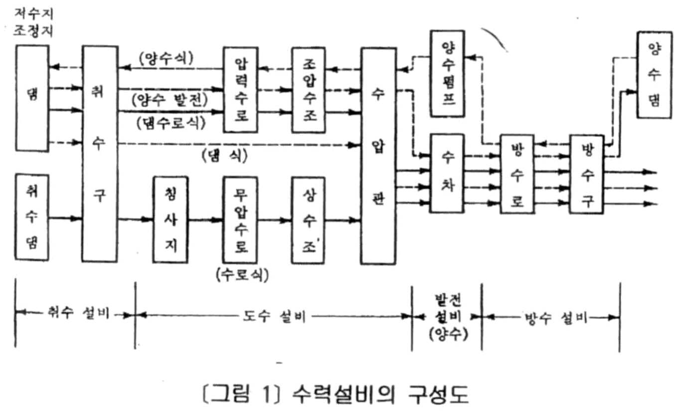
수력 발전용으로서 하전의 유수를 취수하기 위해서는 하천의 흐름에 거의 직각의 방향으로 물을 막아 주는 설비 - 이것을 취수댐이라고 부른다 - 와 그 바로 상류의 하안에 물을 취수하는 설비 - 이것을 취수구라고 부른다 -를 축조한다.In order to take in the flowing water of the electric power for hydroelectric power generation, it is a facility that blocks water in a direction substantially perpendicular to the flow of the river-this is called an intake dam-and the facility that collects water in the upstream river-this is called an intake port- Build a.
취수구로부터 취수한 물은 수로를 통하여 발전소 상부에 있는 상수조까지 유도해서 낙차를 얻는다. 이것을 다시 수압관을 거쳐 수차로 보내고 여기서 물이 갖는 위치에너지를 기계적 에너지로 변환해서 발전기로 전기 에너지를 발생한다. 사용하고 난 물은 방수로를 통해서 다시 하천에 방류하게 된다. 이 과정에서 취수구 가까이에 침사지를 만들어 유수 중의 토사를 침전시키고 있다. 또, 상수조에는 여수로를 설치해서 갑자기 부하가 줄어서 수위가 규정값을 넘었을 때 잉여수를 하천에 안전하게 방류하도록 하고 있다. 이들 가운데 취수구 직후부터 상수조 입구까지를 도수로라고 부른다.Water drawn from the inlet is led through a water channel to the water tank at the top of the power plant to obtain a drop. This is sent back through the hydraulic tube to the water wheel, where the potential energy of water is converted into mechanical energy, which generates electrical energy with a generator. The used water is discharged back to the river through the spillway. In this process, the sediment is made near the inlet to settle the sediment in the running water. In addition, by installing a water channel in the water tank, the load suddenly decreases, and when the water level exceeds the prescribed value, the surplus water is safely discharged into the river. Among them, the waterway from the inlet to the water inlet is called a channel.
도수로에는 그 전체에 압력이 걸리는 압력수로와 유수의 상부가 대기와 접하고 있는 자연유하식의 무압수로의 2가지가 있다. 상수조는 자연유하식에 사용되는 것이며, 압력수로일 경우에는 이 상수조 대신에 조압수조를 사용한다.There are two types of raceways: a pressure canal that applies pressure to the whole and a natural flow-free pressure canal where the upper part of the flow is in contact with the atmosphere. The water tank is used for the natural flow type, and in the case of a pressure channel, a pressure tank is used instead of this water tank.
한편 조정지나 저수지로부터 취수할 경우에는 이들 못 자체가 침사지의 작용을 겸하기 때문에 침사지를 설치하지 않는다. 또, 댐식 발전소에서는 저수지가 상수조의 작용을 하게 되므로 따로 상수조를 설치하지 않고 있다는 것이었다.On the other hand, when the water is taken from the control pond or reservoir, the pond itself does not have to be settled because it functions as a sink. In addition, in the dam-type power plant, the reservoir acts as a water tank, so no water tank is installed.
둘째로 발전용 댐에 있어서,Secondly, in the dam for power generation,
발전용 댐을 우선 그 용도별로 분류하면, 수로식 발전소에 사용되는 간단한 취수댐, 댐 수로식 발전소에서는 상류측의 수위를 높이는 데 사용되는 약간 큰 댐, 그리고 취수용뿐만 아니라 물을 어느 기간 동안 저장하기 위해서 골짜기나 하천을 가로 막아서 조정지라든지 저수지를 만드는 거대한 저수댐 등이 있다(댐식 발전소).Generating dams are first classified by their use, such as simple intake dams used in water-powered power plants, slightly larger dams used to raise the water level in the upstream side, and water storage as well as water storage for a period of time. There are huge reservoir dams that create reservoirs by blocking valleys or rivers (dam-type power plants).
댐을 축조할 때 주의하지 않으면 안 될 중요한 사항을 열거하면 다음과 같다. 먼저 홍수, 그 이외의 외력을 받더라도 안전하게끔 합리적으로 설계되어야 한다는 것이었고 다음의 댐 형식은 지형 및 지질을 고려해서 가장 경제적인 것으로 선정되어야 한다는 것이었으며 선정후 댐의 상류측 수위가 올라가게 됨으로써 - 곧 이것을 배수라 한다 - 입게 되는 피해를 최소한으로 줄여야 한다는 것이었고 그리고 홍수시에도 그 최대유량을 안전하게 방류해서 발전 설비 및 하류의 모든 시설 등에 위험을 미치지 않아야 한다는 것이었다.Some important points to note when constructing a dam are listed below. First, it was to be reasonably designed to be safe even under flood and other external forces.The next dam type was to be selected as the most economical in consideration of the terrain and geology. This is called drainage-to reduce the damage to a minimum and to safely discharge its maximum flow rate during flooding, so that it does not pose a danger to the power plant and all downstream equipment.
발전용 댐의 사용목적에 따른 분류에 의하면 취수댐과 저수댐이 형성된다According to the purpose of using the dam for power generation, the intake dam and the reservoir dam are formed.
먼저 취수댐에 있어,First in the intake dam,
수로식 발전소에서 취수를 목적으로 한 댐으로서 일반적으로 댐 높이와 폭은 그다지 크지 않은 편이다.Dams intended for intake in a hydroelectric power plant are generally not very tall and wide.
다음은 저수댐에 있어,Next is the reservoir dam,
댐으로 상류측 수위를 높여서 낙차를 얻음과 동시에 계절적 내지 연간을 통한 수량조절이 가능한 대규모의 것이 사용된다. 조정능력의 크기에 따라 조정지와 저수지로 나뉘어진다는 것은 앞에서 설명한 그대로이다.The dam is used to increase the water level upstream to get a free fall, and at the same time, a large-scale one can be used to control the quantity from season to year. According to the size of the adjustment capacity, it is divided into the adjustment pond and the reservoir as described above.
발전용 댐의 사용재료에 의한 분류에 의하면 콘크리트댐과 흙댐에 암석댐이 형성된다According to the classification of materials used in power generation dams, rock dams are formed in concrete dams and soil dams.
첫째로 콘크리트댐에 있어Firstly, in a concrete dam
시멘트, 모래, 자갈을 혼합, 가공한 콘크리트를 소재로 한 댐으로서 안정도가 높기 때문에 현재 가장 많이 사용되고 있다.The dam is made of mixed concrete, cement, sand and gravel and is the most used because of its high stability.
둘째로 흙댐에 있어Secondly, it's in the dirt dam
모래, 자갈, 점토 등을 적당히 혼합해서 축조하는 댐으로서 자재가 현지에서 조달될 경우 경제적이다. 이 형식의 댐은 하도에서 보는 바와 같이 콘크리트댐보다도 상류, 하류 양면의 경사를 완만하게 해서 안정을 유지할 수 있도록 설계하여야 한다.It is economical if materials are procured locally, and the dam is constructed by mixing sand, gravel, and clay properly. This type of dam should be designed to maintain stability by smoothing the slopes of both upstream and downstream sides of the concrete dam, as seen from the lower road.
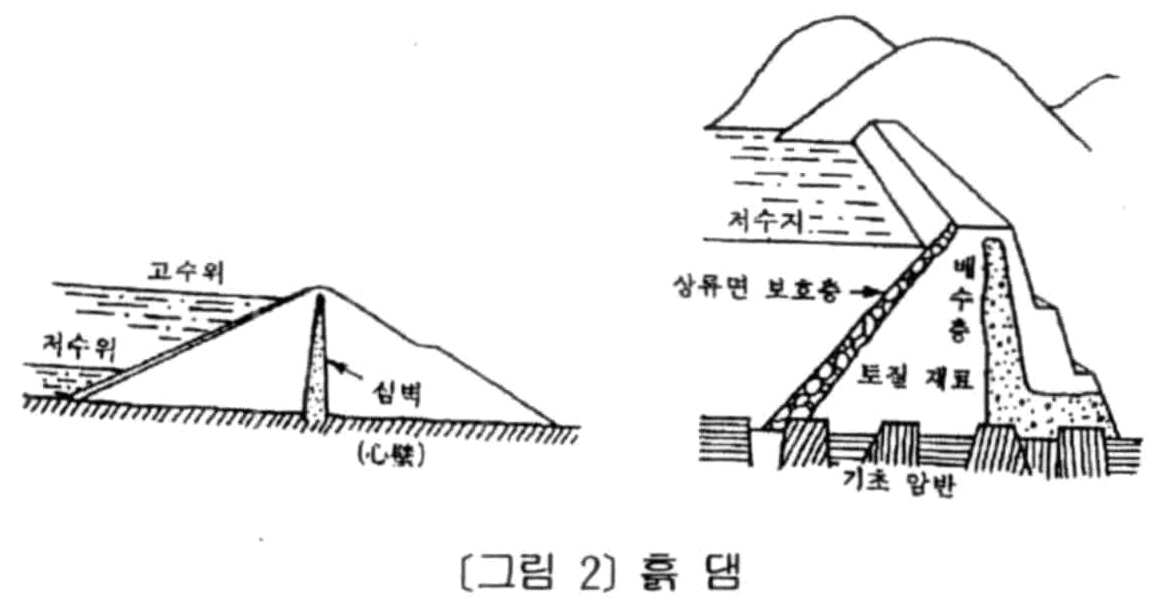
세번째 암석댐에 있어,In the third rock dam,
주로 암석을 축조재료로 한 흙댐과 마찬가지로 현지에서 이러한 암석 재료가 조달될 경우 경제적이다. 이 댐은 흙댐에 비하여 댐을 높게 할 수 있고, 또 안정도도 높지만 가체중량이 크기 때문에 기초를 튼튼히 할 필요가 있다. 이것 역시 흙댐과 마찬가지로 중력댐의 일종이다.As with soil dams mainly made of rock, these rock materials are economical if they are procured locally. Compared with the soil dam, this dam can be made to have a higher dam, and its stability is high, but the body weight is large, so the foundation needs to be strengthened. This is also a type of gravity dam, just like an earth dam.

발전용 댐의 역학적인 구조에 따른 분류에 의하면 중력댐이 형성된다According to the dynamic structure of the dam for power generation, a gravity dam is formed
상기 중력댐은 현재 가장 많이 사용되고 있는 형식으로서, 둑 본체의 자체중량으로 외력에 대하여 안정도를 유지하고 있다. 이 댐은 큰 압력이 기초부분에 걸리기 때문에 설치장소는 견고한 암반이 있는 곳이어야 한다.The gravity dam is currently the most used type, and maintains stability against external force by its own weight of the dam body. Since the dam is subjected to high pressure on the foundation, the installation site should be located with solid rock.
중력댐은 주로 콘크리트로 축조되지만 이 밖에 흙을 사용한 흙댐, 암석을 사용한 암석댐도 중력댐의 일종으로 일부 사용되고 있다. 하도는 콘크리트 중력댐의 설명도이다.Gravity dams are mainly constructed of concrete, but soil dams using soil and rock dams using rocks are partly used as gravity dams. The diagram is an explanatory diagram of a concrete gravity dam.

세째, 수 문의 종류에는Third, the kind of door
고정댐의 상부에 설치하여 갈수시에는 이것을 폐쇄해서 상류측의 수위를 높여서 취수를 용이하게 하고 홍수시에는 이것을 개방해서 방수시킴으로써 수위가 지나치게 올라가는 것을 방지함과 동시에 댐의 상류측에 퇴적된 토사를 토해 내도록 하는 기능을 지니고 있다. 이것에 사용되는 수문에는 다음과 같은 여러 종류가 있다.It is installed on the upper part of the fixed dam and closes it when water is drained to increase the water level on the upstream side to facilitate water intake. In case of flooding, it is opened and waterproofed to prevent the water level from rising too high. Has the ability to vomit. There are several types of sluices used for this:
먼저 슬루스 게이트가 사용되었고 이것은 소규모의 댐에 사용되는 가장 간단한 수문으로서 보통 직사각형의 문을 상하로 조작해서 개폐하는 구조로 되어 있다.First, a sluice gate was used, which is the simplest gate used for small dams.
다음은 롤러 게이트가 사용되었으며 상기 슬루스 게이트가 대형이 되면 문틀과 문의 접촉 부분의 마찰저항이 커지기 때문에 이 마찰을 줄이기 위하여 여기에 롤러를 사용한 것이다. 수문의 상·하 조작은 보통 와이어로프와 권상기를 사용하고 있다.Next, the roller gate is used, and when the slug gate becomes large, the frictional resistance between the contact portion of the door frame and the door increases, so that the roller is used to reduce this friction. The up and down operations of the water gate usually use wire ropes and hoisting machines.
그 다음은 롤링 게이트가 사용되었고 이에 따라 하도과 같이 강철제의 원통형 게이트를 댐의 정상에 설치하고 이 원통을 회전시키면서 수문을 개폐하는 것이다. 이것은 구조가 견고하여 유수 등의 충격에도 견딜 수 있으므로 취수댐 등에 많이 사용되고 있다.Next, a rolling gate was used, whereby a steel cylindrical gate, such as a road, was installed at the top of the dam, and the water gate was opened and closed while rotating the cylinder. It has a strong structure and can be used for water dams because it can withstand impacts such as running water.
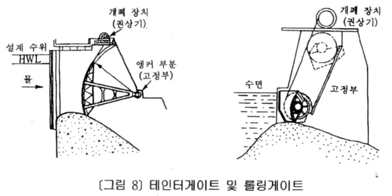
네째로 수압관로의 설치되는 데에는Fourth, the installation of the hydraulic pipe
일반적으로 상수조(또는 조압수조)로부터 발전소의 수차입구에 이르기까지의 도수관을 수압관이라고 부르며, 이 수압관을 지지하기 위한 공작물 등과 기타 반면을 총칭해서 수압관로라고 부르고 있다.In general, the water pipes from the water tank (or the pressure tank) to the water inlet of the power plant are called hydraulic pipes, and the workpieces and other parts for supporting the hydraulic pipes are collectively called hydraulic pipes.
수압관의 위치는 상수조(또는 조압수조)와 발전소와의 위치에 따라 가능한 한 최단거리의 직선을 택하여야 하며 수압관의 지름은 건설비나 손실수두를 고려하 여 관내 유속이 3~5[m/s] 정도가 되게끔 정하고 있다. 그 밖에 수압관수는 수차 1대에 1관이 기본이지만 가령 고낙차라든지 수량이 적을 경우에는 수차 2대에 1관으로 하는 경우도 있다.The position of the hydraulic pipe should be the shortest possible straight line according to the position of the water tank (or pressure tank) and the power plant. The diameter of the hydraulic pipe should be 3 ~ 5 [ m / s]. In addition, water pipes are basically one pipe per aberration, but in some cases, such as a high drop of water or a small quantity, one pipe may be used for two aberrations.
수압관에는 정수두, 서징수두, 수격작용에 의한 압력 등이 내압으로서 작용하므로 관의 두께 t[cm]는 그 부분에 걸리는 최대수압에도 충분히 견딜 수 있는 크기로 결정해 주어야 한다.Hydrostatic head, surging head, water pressure, etc. act as internal pressure in the hydraulic pipe, so the thickness t [cm] of the pipe should be determined to be sufficient to withstand the maximum hydraulic pressure applied to the part.
지금 수압관의 지름을 D[cm], 최대수압을 P[kg/㎠], 강철재료의 허용응력도(응장력)을 σ[kg/㎠], 관의 접합효율을 η[%], 부식에 대한 여유두께를 ε[cm]라고 하면 관의 두께 t[cm]는 다음 식으로 계산된다.Now, the diameter of the hydraulic pipe is D [cm], the maximum hydraulic pressure is P [kg / ㎠], the allowable stress (tension) of the steel material is σ [kg / ㎠], the pipe joint efficiency is η [%], If the allowance thickness is ε [cm], the thickness t [cm] of the tube is calculated by the following equation.
![]()
![]()
다음 수차 이후에는 방수로가 사용된다.After the next aberration, a spillway is used.
이것은 수차로부터 나오는 물을 원래의 하천에 방류하기 위한 수로로서 이것과 하천의 본류가 합류되는 곳을 방수구라고 한다.This is a waterway for discharging water from the aberration to the original river, where the water and the main stream of the river merge together.
방수로의 구조는 앞에서 설명한 수로의 그것과 대체로 같지만 하천의 흐름에 원활하게끔 가능한 한 수심이 깊은 장소를 선정하고 또한 하천의 흐름과 같은 방향으로 방류시키도록 하여야 한다는 것이었다.The structure of the spillway was generally the same as that of the waterway described above, but it was necessary to select as deep a place as possible and to discharge it in the same direction as that of the stream.
이 같이 수력발전의 원리에 대하여 다음의 하도와 하표로 수력일반을 다음과 같이 설명한다.Thus, the general principle of hydropower is explained as follows with the following diagram and the following table.
현재 지구상에 보유되어 있는 에너지자원 중 석탄과 석유 기타의 지하자원에 의한 열에너지는 장차 자원이 고갈될 운명에 있고, 최근 원자력발전의 개발에 크게 기대되고 있으나, 물 에너지는 우주가 존재하는 한 무한이라고 생각할 수 있다.Among the energy resources currently on earth, thermal energy from coal, oil, and other underground resources is destined to be depleted in the future, and it is expected to be greatly developed in nuclear power generation recently, but water energy is infinite as long as space exists. I can think of it.
우리나라에서도 최근 큰 댐을 건설하여 인공적인 저수지를 만들어 홍수의 조절과 발전, 관개 등에 많은 노력을 하고 있다.Recently, a large dam has been constructed in Korea, making artificial reservoirs, and making great efforts to control, develop, and irrigate floods.
또한 물은 압력, 위치의 에너지를 가지고 있으며, 자연계에서는 위치에너지의 형태로서 보유되는 경유가 많다. 이 위치 에너지를 운동 에너지 및 압력 에너지로, 또는 운동 에너지만으로 변화시켜 수차에 작용시키므로 기계적 에너지로 변화시킬 수 있다.In addition, water has energy of pressure and position, and in the natural world, there are many diesel oils which are held in the form of potential energy. This potential energy is changed into kinetic energy and pressure energy, or only kinetic energy to act on aberration, and thus can be changed into mechanical energy.
물의 발생동력 P kg·m/sec은 낙차를 Hm, 유량을 Q ㎥/sec, 물의 비중량을 r kg/㎥라고 하면Speaking of water generated power P kg · m / sec is the H m, the flow rate Q ㎥ / sec, the ratio by weight of water r kg / ㎥ free fall
(P = rHQ kg·m/sec)( P = rHQ kgm / sec)
이므로 수력동력은 낙차와 유량에 따라서 결정된다. 낙차는 하천이나 수원지의 상태가 결정되면 대체로 일정하고, 유량은 유역과 강우량에 관계된다는 것이었고Therefore, the hydraulic power is determined by the drop and the flow rate. The drop was generally constant when the condition of the stream or source was determined, and the flow rate was related to the basin and rainfall.
여기서 발생하는 출력은 낙차와 수량과의 곱에 비례하므로 우선 발전소 상부의 포장수력에 좌우된다. 또한, 이 때의 출력을 늘리기 위해서는 이들의 물을 1개소에 집중하도록 인공적으로 유수를 바꾸고, 또 큰 낙차를 얻을 수 있는 발전지점을 선정하여야 한다는 것이었으며The output produced here is proportional to the product of freefall and quantity, so it first depends on the pavement power at the top of the power plant. In addition, in order to increase the output at this time, it was necessary to artificially change the water flow to concentrate their water in one place, and select a power generation point that can obtain a large drop.
지금 사용수량 Q[㎥/s]의 물이 유효낙차 H[m]를 낙하해서 수차에 유입될 경우 수차에 주는 동력 P o[kW]는If the water used in Q [㎥ / s] drops in the effective drop H [m] and flows into the water wheel, the power P o [kW] is given to the water wheel.
(P o = 9.8QH[kW])( P o = 9.8 QH [kW])
로 되는데 보통 이것을 이론수력이라고 부른다.It is usually called theoretical hydraulic power.
이 이론수력은 하도에서와 같이 수차에의 입력으로 되어 수차, 발전기를 회전하게 된다. 수차출력 P t 및 발전기 출력 P g는 각각 수차효율을 η t , 발전기효율을 η g 라고 할 때,This theoretical hydraulic power is input to the aberration as in the roadway, and the aberration and the generator are rotated. When the aberration output P t and the generator output P g are respectively aberration efficiency η t and generator efficiency η g ,
(P t = 9.8QHη t [kW])( P t = 9.8 QHη t [kW])
(P g = 9.8QHη t η g [kW])( P g = 9.8 QHη t η g [kW])
로 표시된다.Is displayed.
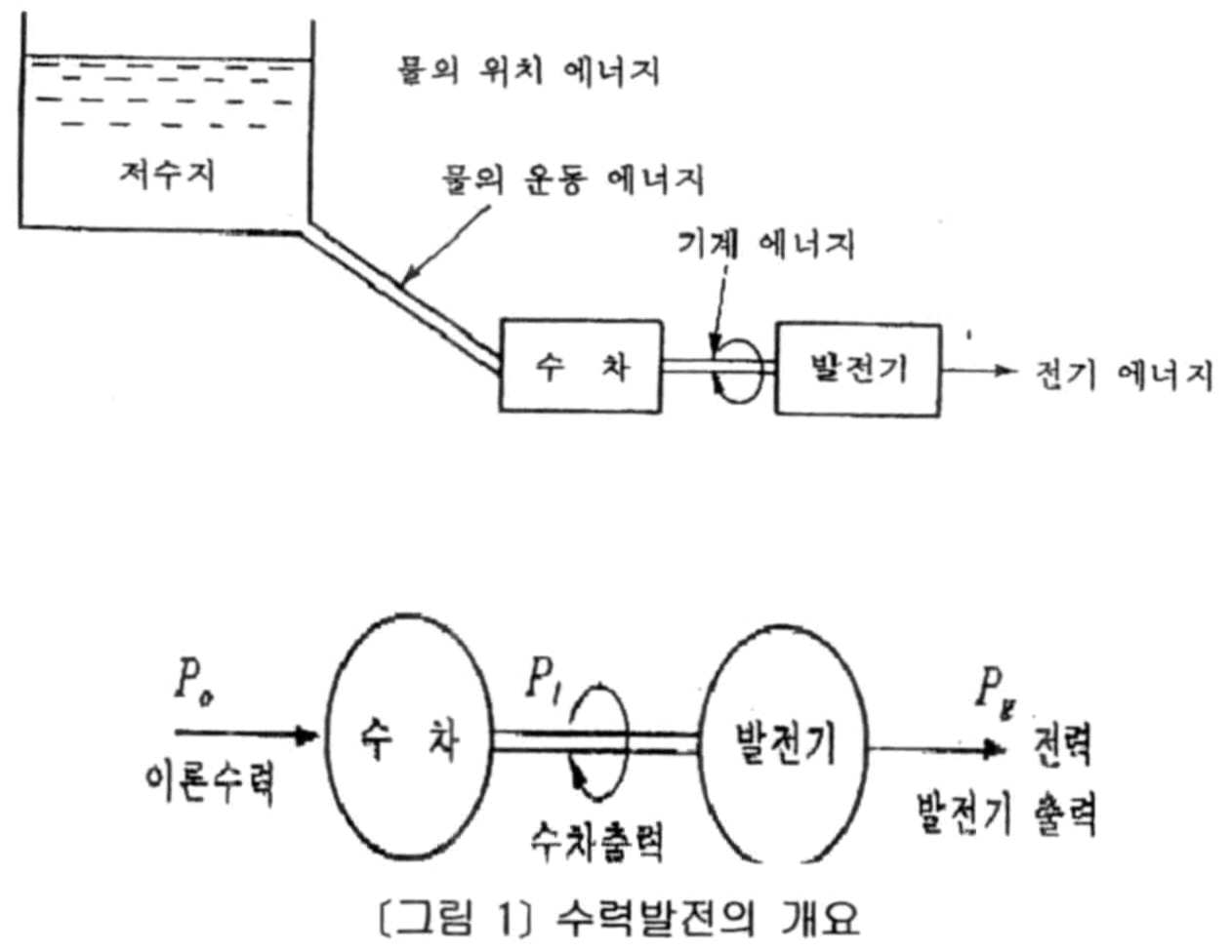
(η t ),(η g )는 수차, 발전기의 각각의 형식, 용량, 부하의 크기 등에 따라 약간 달라지지만 정격 운전시에 η t = 80 ∼ 90[%], η g = 90 ∼ 97[%] 정도의 값 을 가지며, 이 양자의 곱 η = η t η g 를 종합효율이라고 한다. 위의 식으로부터 알 수 있는 바와 같이 수력을 유효하게 사용하려면, 어떻게 하면 큰 낙차(H)를 얻고 또 사용수량(Q)을 경제적으로 얻을 수 있는가 하는 것이 문제로 된다. 하천의 하류부를 이용할 경우에는 사용수량을 크게 얻을 수 있으나 그 대신 낙차는 작아지며, 반대로 하천의 상류부에서는 큰 낙차를 얻을 수 있는 대신 사용수량은 일반적으로 감소하게 된다.( η t ) and ( η g ) vary slightly depending on the aberration, the type, capacity and load of the generator, but at rated operation η t = 80 to 90 [%], η g = 90 to 97 [% ], And the product of these two is called η = η t η g . As can be seen from the above equation, in order to effectively use hydraulic power, the question is how to obtain a large drop ( H ) and economically obtain the use quantity ( Q ). If the downstream part of the river is used, the quantity of water used can be largely obtained, but the drop is small instead. On the contrary, the quantity of water used is generally reduced in the upstream part of the stream.
[표 1] 수차 및 발전기 효율의 개략 값[Table 1] Schematic value of aberration and generator efficiency
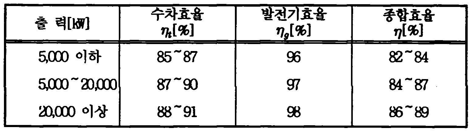
다음의 수력발전소의 종류와 설비에는 The following types and facilities of hydro power plants
수력발전소는 취수방법과 운용방법에 따라 여러 가지로 분류된다. 먼저 취수방법에 의한 분류에는 하도와 같이 댐식 발전소와 수로식 발전소에 댐수로식 발전소와 유역변경식 발전소가 형성되었고 상기 댐식 발전소는 하천을 횡단하는 댐을 축조하여 유수를 막아, 이로 인하여 생기는 낙차를 이용하는 형식이다. 큰 낙차를 이 형식으로 하려면 상당히 높은 댐을 축조하여야 하고, 또 매몰면적도 크므로 경제적인 방법이라고 할 수 없으나, 적성지형 외에도 관개용 또는 홍수조절용 저수지의 낙차를 이용하는 경우가 많으며 대개 저낙차 원동소에 사용된다. 이 댐식은 우리나라 실정에서 볼때 가장 유용한 것이며 장래에도 이 방식의 건설이 매우 중요시 된다. 이와 같이 발전, 관개, 홍수조절용 등의 목적으로 축조되는 댐을 다목적댐이라고 부른다. 또 댐식으로 하면 강우량과 사용수량사이의 불균형에 의하여 상당한 낙차변동을 피할 수 없을 때가 많으며 이와 같은 발전소를 특히 변낙차발전소라고 부르는 수도 있다.Hydroelectric power plants are classified into various types according to the method of intake and operation. First, in the classification of water intake method, dam-type power plant and watershed-changing power plant were formed in dam-type power plant and waterway-type power plant like the sewer, and the dam-type power plant constructed dams crossing rivers to prevent the flow of water, thereby using the resulting drop. to be. In order to make a large drop into this type, a considerably high dam must be constructed and the area of burial is large, which is not an economical method. However, in addition to the aptitude, there are many cases of using the drop of irrigation or flood control reservoirs. Used for This type of dam is the most useful in our country and the construction of this type is very important in the future. The dams constructed for the purpose of power generation, irrigation and flood control are called multipurpose dams. In addition, the dam type often causes unavoidable fluctuations in rainfall due to the imbalance between rainfall and the quantity used, and such a power plant may be called a variable dropping power plant.
이것은 댐에 저장되는 수량이 풍부할수록 경제적으로도 유리하고, 또 운용면에서도 바람직하므로 우리나라에서는 비교적 경사가 있고 수량이 풍부한 한강계 중·하류부에 이 형식의 발전소를 많이 건설하고 있다.(춘천, 의암, 청평, 팔당, 소양강 발전소 등)This is because the more water stored in the dam, the more economically advantageous it is and the better it is in terms of operation. Therefore, in Korea, many power plants of this type are being built in the middle and downstream of the Han River system, which is relatively inclined and rich in water. , Cheongpyeong, Paldang, Soyang River Power Plant, etc.)
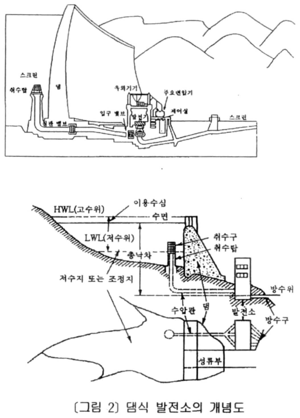
그리고 수로식 발전소는 하천주류에 댐을 축조하여 별도로 작은 구배의 수로 또는 압력수로를 만들어 하천의 급구배 또는 굴곡된 지형을 이용하여 주로 상당한 거리의 수로에 의하여 중낙차나 고낙차를 얻는 경우에 사용된다.In addition, a hydroelectric power station is used to build a small gradient channel or pressure channel separately by constructing a dam in the mainstream of the river to obtain a heavy drop or a high drop by means of a considerable distance by using a river steep grade or curved terrain.
[그림 3]은 이형식이며 물은 취수구, 침사지, 수로 또는 압력수로, 상수조 또는 조압수조, 수문, 수압관, 수차, 방수로의 순서로 흐르게 된다.[Figure 3] is heterogeneous and water flows in the order of water intake, settlement, water or pressure water, water tank or pressure tank, water gate, water pipe, water wheel and waterway.
침사지를 취수구에 가깝게 만들어 물을 일단 정지시켜, 흙, 모래, 초목 같은 침전물을 제거하여 맑은 물만을 수로에 들어가게 한다. 침사지의 칙면에는 배사로를 만들어 때때로 침전된 흙, 모래 등을 배출시킨다. 수로는 지형에 따라서 개거, 암거, 압력수로, 수로교, 사이폰 등을 사용한다. 수로의 경과지의 선정, 단면설계 등은 공사비, 운전유지비 등의 경제적 고려와 보수, 운전면에서 검토된다. 수로구배는 1/1,000 ~ 1/2,000이 보통이며 구배가 이보다 급하면 유속이 커지고 따라서 수로단면이 작아져서 건설공사비는 적게 드는 반면에 마찰손실이 커진다. 1/5,000보다 급하면 흙, 모래 등을 수차내에 옮겨와서 수차 각 부분의 마멸을 빨리한다. 수조는 수로와 수압관의 연결점에 설치하는 저수조이며 흙, 모래 등의 제거와 유량의 조절을 목적으로 한다. 수조의 출구에는 보통 제진장치가 만들어져 있으며 여분의 물을 흘러내리는 여수로가 설치되어 있다. 때로는 수조 대신에 수압관 도중에 조압수조를 설치하여 수차의 부하 변동 또는 고장이 났을 경우 급히 유수를 막을 때에 생기는 수격작용의 위험을 방지한다. 수압관은 수조 또는 조압수조부의 재료와 두께는 낙차 및 구경에 따라 다르나 철근콘크리트관, 주철관, 주강관, 리벳붙이 강관, 용접강관 등이 사용된다. 수압관은 보통 1대의 수차에 1개씩 설치하나, 가격을 저하시키기 위하여 수차입구에서 1개의 관으로부터 분기관으로 배수하여 수대의 수차에 급수시킬 때가 많다. 크기는 운반시의 제약이 있으므로 최대직경은 4m이며, 관내유속은 2~4m/sec가 보통이다. 관내의 손실수두는 전낙차의 2~5%정도에 달한다. 수압관은 상당한 길이를 가지고 있으므로 온도로 인한 길이의 변화에 대한 대책으로서 이음쇄 부분에 특히 주의가 필요하다. 방수로는 수차에서 방출되는 물을 하천에 유입시키는 수로이며, 그의 위치는 하천구배, 하상, 지형 등을 고려하여 유심이 충돌하지 않을 정도의 수심이 큰 장소를 선택해야하며, 또 유량의 증감에 따른 수위의 변동이 적은 수로단면이 요구된다.Makes the basin close to the intake and stops the water once, removing any sediment such as soil, sand, or vegetation so that only clear water enters the channel. On the surface of the settlement, it creates a drainage furnace and sometimes discharges settled soil and sand. Waterways use open water, culverts, pressure waterways, waterway bridges, and siphons, depending on the terrain. Selection of transitional sites and cross-sectional design is considered in terms of economic considerations such as construction costs and maintenance costs, maintenance, and operation. The waterway gradient is usually 1 / 1,000 to 1 / 2,000, and the steeper the gradient, the greater the flow rate, and thus the smaller the cross section of the waterway, the lower the construction cost and the greater the friction loss. If it is urgent than 1 / 5,000, soil, sand, etc. are moved in aberration, and the abrasion of each part of aberration is quickened. The water tank is a water tank installed at the connection point between the waterway and the hydraulic pipe. The purpose of the water tank is to remove soil and sand, and to control the flow rate. The exit of the tank is usually made of a dedusting device and a drainage channel is provided to drain off excess water. Occasionally, a pressure tank is installed in the middle of a hydraulic pipe instead of a water tank to prevent the risk of water hammer when the load changes or breaks in the aberration. The material and thickness of the water pipe or the water tank of the water pressure pipe vary depending on the drop and diameter, but reinforced concrete pipe, cast iron pipe, cast steel pipe, riveted steel pipe, welded steel pipe, etc. are used. Hydraulic pipes are usually installed one by one aberration, but in order to reduce the price, water pipes are often drained from one pipe to branch pipes and watered by several aberrations. As the size is restricted during transportation, the maximum diameter is 4m and the flow velocity in the pipe is usually 2 ~ 4m / sec. The head of loss in the pipe is about 2-5% of the total drop. Since the hydraulic pipe has a considerable length, special attention should be paid to the joint part as a countermeasure against the change in length due to temperature. Waterway is a channel that inflows water discharged from water wheel into the river, and its location should be selected where the depth of water is not enough to be considered in consideration of river gradient, riverbed, terrain, etc. Channel sections with less fluctuation in water level are required.
우리나라에서는 북한강 상류에 있는 화천발전소 및 대관령 고원지대에서 동해안까지 지하터널로 연결한 강릉수력발전소가 이러한 수로식 발전소의 대표 예이다.In Korea, the Hwacheon Power Plant upstream of the Bukhan River and the Gangneung Hydroelectric Power Plant, which connect the underground tunnel from the Daegwallyeong Plateau to the East Coast, are representative examples of such a hydroelectric power plant.
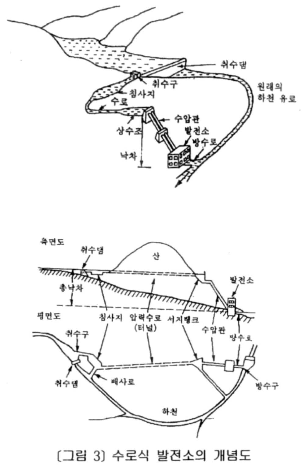
이러한 댐 수로식에는 댐과 수로를 병용하는 방식이며 상당히 급한 구배의 하천을 하도와 같이 주류에 댐을 설치함으로써 큰 낙차를 얻을 수 있어 수력개발지점으로 가장 유리한 형식이다. 지형에 따라서 수로가 압력수로를 병용하거나 또는 그중 하나를 사용하며 물의 경로는 수로식과 대체로 같다는 것이었다.The dam canal is a combination of a dam and a canal, and a large drop can be obtained by installing a dam in the mainstream, such as a river with a very steep gradient, which is the most advantageous form of hydropower development. Depending on the terrain, the channel could use either a pressure channel or one of them, and the water path would be roughly the same as the channel.

상기한 유역 변경식 발전소에 있어 어느 하천에 인접해서 다른 하천이 있고, 이 두 하천 사이에 큰 낙차를 얻을 수 있을 때 두 하천을 수로로 연결해서 그 낙차를 이용하는 발전소이다. 앞에서 소개한 강릉수력발전소와 섬진강수력발전소는 우리나라 유역변경 댐 수로식의 대표적인 예로서 강릉수력은 대관령 고원지대에서 용평쪽으로 흘러가는 남한강 수계를 댐으로 가로막아서 이 물을 멀리 동해안 강릉부근을 흐르는 강릉수계(수로터널 15.6[k/m])까지 유도해서 최고 640[m]에 달하는 낙차를 얻고 있다.In the above watershed modified power plant, there is another river adjacent to one river, and when two large rivers can be obtained between the two rivers, the two rivers are connected by waterways to use the free fall. The Gangneung Hydroelectric Power Plant and Seomjin River Hydroelectric Power Plant, introduced above, are representative examples of the waterway change dams in Korea, and Gangneung Hydropower intercepts the Namhan River system that flows from the Daegwallyeong Plateau to Yongpyeong to the dam, and the water flows near the Gangneung River. The water tunnel is 15.6 [k / m]), leading to a maximum drop of 640 [m].
발전소로부터 약21km, 섬진강 상류로부터는 82km 지점인 전북 임실군 강진면 소재의 중력식 콘크리트댐의 수자원을 정읍군 산내면에 위치한 취수구로 유입시켜 약6km의 압력수로를 이용, 도수하여 발전후 동진강에 방류함으로서 농업용수 및 광 역 상수원으로 활용하는 우리나라 최초의 유역변경식 발전소이며, 최고 162m의 유효낙차가 얻어진다.Water resources of gravity-type concrete dam located in Gangjin-myeon, Imsil-gun, Jeonbuk-gun, about 21 km from the power plant and the upper part of Seomjin River, are flowed into the intake located in Sannae-myeon, Jeongeup-gun. It is Korea's first watershed change-type power plant to be used as a water source and wide area water supply, and an effective drop of up to 162m is obtained.

다음의 운용방법에 따른 분류에는 하도와 같이 유입식 발전소와 저수지식 발전소에 조정지식 발전소와 양수식 발전소에 조력 발전소 각개로 종래에는 설치되는 것이었다. 이에 하천을 흐르고 있는 자연유량을 어떻게 조절하는가에 따라 유량의 사용법이 달라진다. 가령 홍수량을 모아 두었다가 이것을 갈수기에 방출하면 1년간을 통해서 유량이 평균화되어 안정된 유량을 얻을 수 있다. 한편 1일 단위이지만 전력의 사용량이 적은 심야 등 경부하시에 유량을 모아 두었다가 수요가 가장 많은 첨두부하시에 그 수량을 사용하면 이른바 피크(첨두시) 발전을 할 수 있다.According to the following operation method, conventionally installed as tidal power plant in inflow power plant and reservoir knowledge power plant and pumped-in power plant, respectively. The usage of the flow rate varies depending on how the natural flow rate is flowing through the stream. For example, if the flood volume is collected and discharged to the dry season, the flow rate is averaged over a year to achieve a stable flow rate. On the other hand, if the flow rate is collected at light loads, such as at night, but the daily use is low, and the quantity is used at the peak load with the highest demand, so-called peak (peak) power generation can be achieved.
이와 같이 하천유량을 어떻게 사용하는가에 따라서 수력발전소는 다음과 같이 몇 가지로 나뉘어진다.Thus, depending on how the river flow is used, hydroelectric power plants are divided into several parts as follows.
먼저 유입식 발전소는First, the incoming power plant
자연유량이 풍부한 지점에서는 발전소 소정의 최대 사용수량의 범위 내에서 하천의 자연유량을 인공적으로 아무런 조절을 가하지 않고 그대로 계속 발전에 이 용하는 발전소이다. 저수지 또는 조정지가 없는 수로식 발전소가 바로 이 방식이라고 할 수 있다.At the point where the natural flow is abundant, it is a power plant that continues to generate power without artificially adjusting the natural flow of the river within the range of the predetermined maximum use quantity of the power plant. A hydroelectric power plant without a reservoir or coordination is this way.
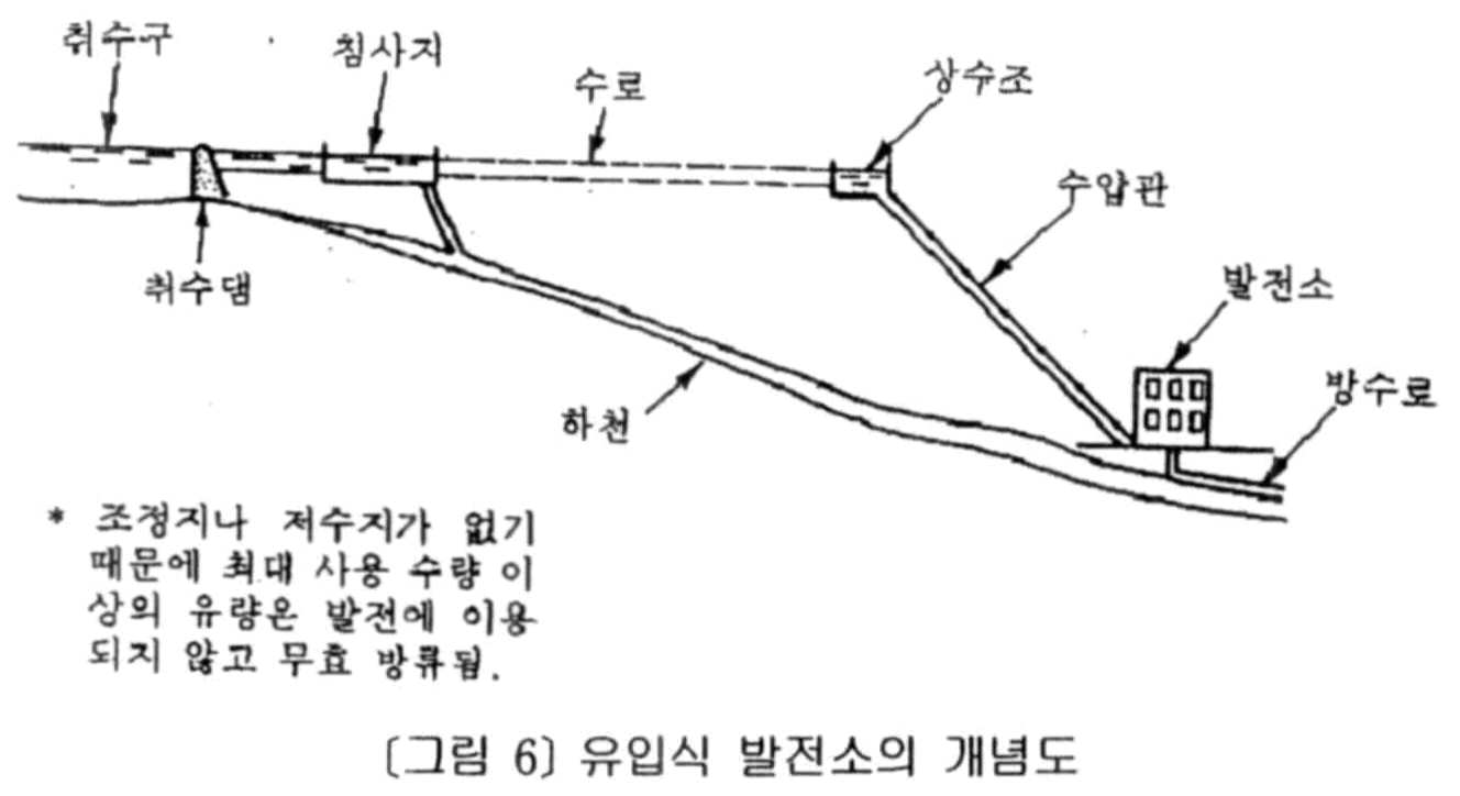
이 방식에서는 건설비가 크게 소요되지 않지만 그 대신 발생전력은 자연유량에 따라 달라지며, 또 이 자연유량도 계절에 따라 변동되기 때문에 부하변화에 응해서 원활한 전력공급을 할 수 없다는 결점이 있다.In this method, the construction cost is not very large, but instead, the generated power is dependent on the natural flow rate, and the natural flow rate also varies according to the season.
우리나라에서는 이 방식의 발전소가 없지만 러시아(시베리아)나 브라질같이 수량이 풍부한 하천에서는 자연유량을 그대로 발전에 이용하는 유입식 발전소를 건설해서 운용하고 있다.In Korea, there is no power plant of this type, but rivers with abundant water, such as Russia (Siberia) and Brazil, are building and operating inflow-type power plants that use natural flow for power generation.
다음의 저수지식 발전소는 계절적인 하천의 유량변화를 조정할 수 있는 대용량의 저수지를 가진 발전소로서, 가령 풍수기에 남는 물을 저수하였다가 갈수기에 방출해서 하천유량을 장기간(보통 1년간)에 걸쳐 유효하게 이용하는 발전소이다.The following reservoir-type power plant is a power plant with a large reservoir capable of adjusting seasonal flow rate changes. For example, the reservoir can store water left in the feng shui season and release it to the dry season to effectively discharge the river flow for a long time (usually one year). It is power plant to use.
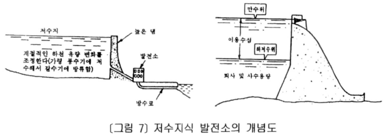
우리나라의 수계는 유량이 비교적 적기 때문에 저수지식 발전소는 귀한 편이다. 그 중에서도 북한강계의 소양강 발전소와 남한강계의 충주발전소가 다목적댐을 축조해서 저수지식 발전소를 이루고 있다. 유효 저수량을 보면 소양강댐이 약 19억[t], 충주댐이 약 18억[t]이다.Reservoir power plants are valuable because the water system in Korea has a relatively low flow rate. Among them, the Soyang River Power Plant in North Korea and the Chungju Power Plant in Namhan River have built a multipurpose dam to form a reservoir knowledge power plant. The effective reservoirs are about 1.9 billion [t] in Soyang River Dam and about 1.8 billion [t] in Chungju Dam.
그리고 조정지식 발전소에 있어 저수지를 건설할 수 없을 정도로 유량이 적은 수계에서는 수로의 도중 또는 취수구 앞(댐식일 경우)에 조정지를 설치해서 하천으로부터의 취수량과 발전에 필요한 수량과의 차를 이 조정지에 저수하거나 또는 방출함으로써 수시간 또는 수일간에 걸친 부하변동에 대응할 수 있게 하고 있다. 이 방식은 유입식 발전소와 달라서 하천의 취수량보다도 발전소 최대수량을 상당히 크게 설계할 수 있다는 이점이 있다. 또, 첨두부하를 분담하는 경우가 많아서 그러한 경우에는 이것을 특히 피크(첨두용) 발전소라 부르기도 한다.In the case of water systems where the flow rate is so small that the reservoir cannot be constructed in the power plant, the control center is installed in the middle of the waterway or in front of the water inlet (if it is a dam type), and the difference between the amount of water taken from the stream and the water required for power generation is By storing or releasing, it is possible to cope with load fluctuations over hours or days. This approach differs from the inflow plant, which allows the design of the plant's maximum volume to be considerably larger than that of the stream. In addition, the peak load is often shared, and in such a case, this is particularly called a peak power plant.

네번째 양수식 발전소는 조정지식 또는 저수지식 발전소의 일종으로서 전력수요가 적은 심야 또는 주말 등의 경부하시에 원자력발전소 등의 값싼 전력을 이용하여 펌프로 하부 저수지의 물을 상부저수지에 양수해서 저장해 두었다가 첨두부하시에 이것을 이용하는 발전소이다.The fourth pumped-type power plant is a kind of regulated or reservoir-type power plant. At low loads, such as late night or weekends, when the demand for power is low, a low-power electric power plant such as a nuclear power plant is used to pump water from the lower reservoir to the upper reservoir and store the peak load. It is a power plant that uses this in the city.
이 방식에는, 상부 저수지에 하천으로부터의 자연 유입량이 있고, 부족되는 수량만을 하부 저수지로부터 양수하는 혼합식 양수 발전소와, 상부 저수지에는 전혀 자연 유입량이 없이 양수된 수량만으로써 발전하는 순양수식 발전소의 2가지가 있다.In this method, a mixed pumped power plant which has natural inflow from the upper reservoir, and pumps only a shortage of water from the lower reservoir, and a pure pumped power plant that generates power only by pumped water without any natural inflow into the upper reservoir. There is a branch.
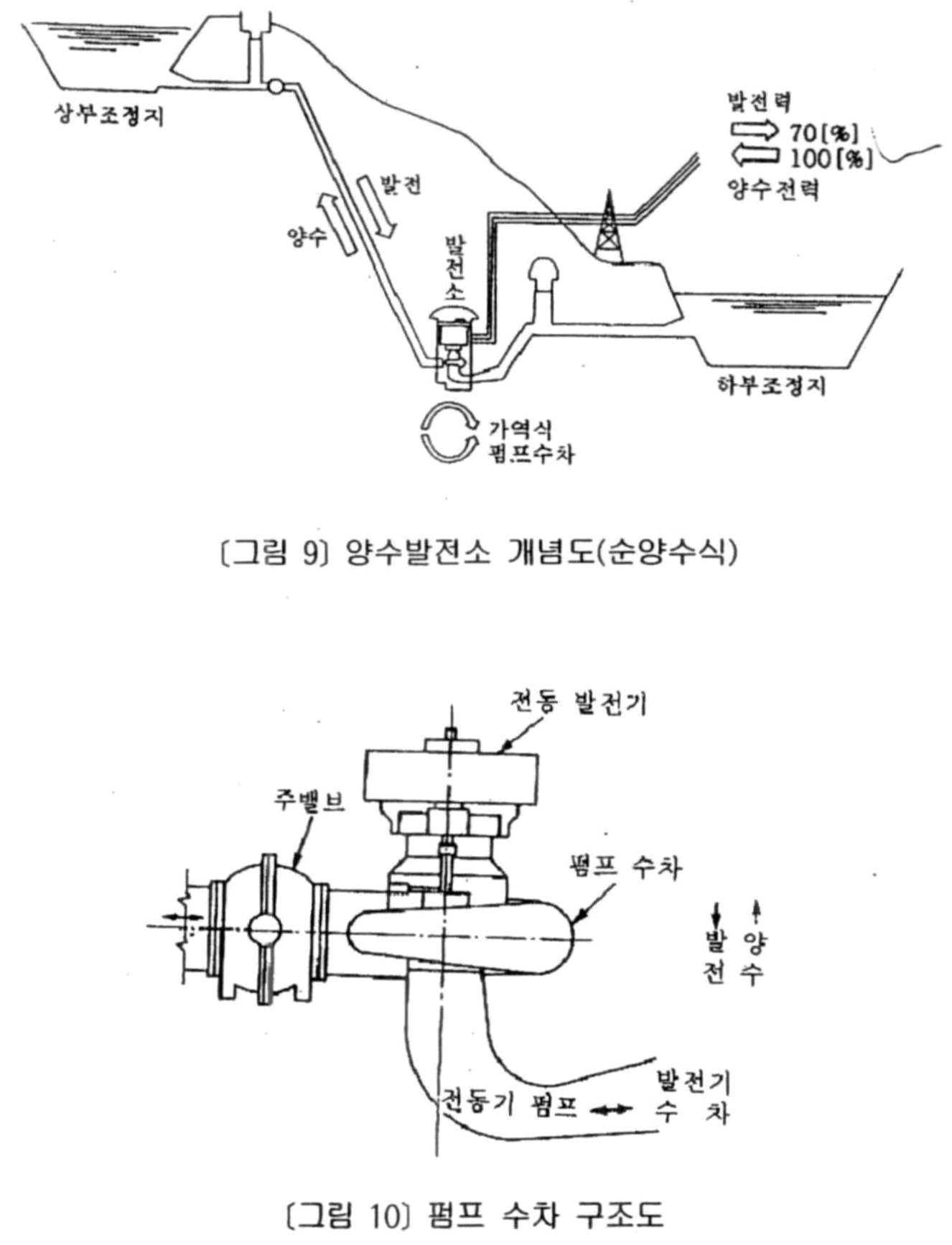
현재 우리나라의 양수 발전소는 청평(40만[kW]), 삼랑진(60만[kW]), 무주(60만[kW]), 산청(70만[kW]), 양양(100만[kW]) 등이 있는데 이들은 모두 후자의 순양수식 발전소이다.Korea's pumped power plants are Cheongpyeong (400,000 [kW]), Samrangjin (600,000 [kW]), Muju (600,000 [kW]), Sancheong (700,000 [kW]), and Yangyang (1 million [kW]). These are all latter pumped-type power plants.
종래의 조력 발전소에 있어서 상기의 조력발전은 바닷물의 간만의 차에 의한 위치 에너지를 전력으로 변환하는 발전소로서 그 설치장소는 가능한 한 간만의 차가 큰 곳이 바람직하다. 곧, 바닷물이 밀물로 밀려 왔을 때 이것을 해안에 건설된 저장지에 유도해서 저장하고, 썰물로 빠져나갈 때 저장지로부터 저장한 바닷물을 바다로 낙하시켜서 양수발전의 경우와 마찬가지로 발전기를 구동해서 발전하는 방식이다.In the conventional tidal power plant, the above tidal power generation is a power plant that converts potential energy due to tidal difference in electric power into electric power, and it is preferable that the installation place is as large as possible. In other words, when the seawater is pushed into the high tide, it is induced and stored in a reservoir built on the coast, and when the water flows out at the low tide, the seawater stored from the reservoir is dropped into the sea to generate power by driving a generator as in the case of pumping power generation. to be.
조력 발전소의 운전 예로서는 최대 13[m]의 간만차를 이용할 수 있다는 프랑스의 랭스 하구에서의 랭스 조력 발전소가 유명하다. 여기서는 최대 13[m], 평균 8.5[m]의 간만차를 이용해서 10,000[kW]× 24기의 240,000[kW]의 발전을 하고 있다. 이 발전방식의 가장 큰 문제점은 입지조건이며, 바닷물의 간만차가 최대 10[m] 정도 이상의 바다가 있고, 이 해안이 저장지의 건설에 적합하다는 조건이 충족되어야 한다.An example of the operation of tidal power plants is the Reims tidal power plant in the Reims estuary, France, where up to 13 [m] tidal cars are available. Here, the maximum of 13 [m] and the average 8.5 [m] intermittent difference is used to generate 240,000 [kW] of 10,000 [kW] × 24 units. The biggest problem of this power generation method is the location condition, and the condition that the tidal difference of seawater is up to 10 [m] or more and that the coast is suitable for the construction of the reservoir should be satisfied.
우리나라에서도 충남의 가로림만을 중심으로 한 몇 군데에서 조력발전 계획을 구상중에 있다. 가로림만은 최대 조석차 7.9[m], 조지 면적 120[㎡], 방조제 길이 2.1[km], 시설용량 40만[kW]의 발전소를 건설할 수 있는 매우 유리한 후보지로 알려지고 있다.In Korea, tidal power generation plans are being planned in several places centered on Garorim Bay, Chungnam. Garolim Bay is known as a very favorable candidate for the construction of a power plant with a maximum tidal difference of 7.9 [m], a Georgeland area of 120 [㎡], a dike length of 2.1 [km] and a capacity of 400,000 [kW].
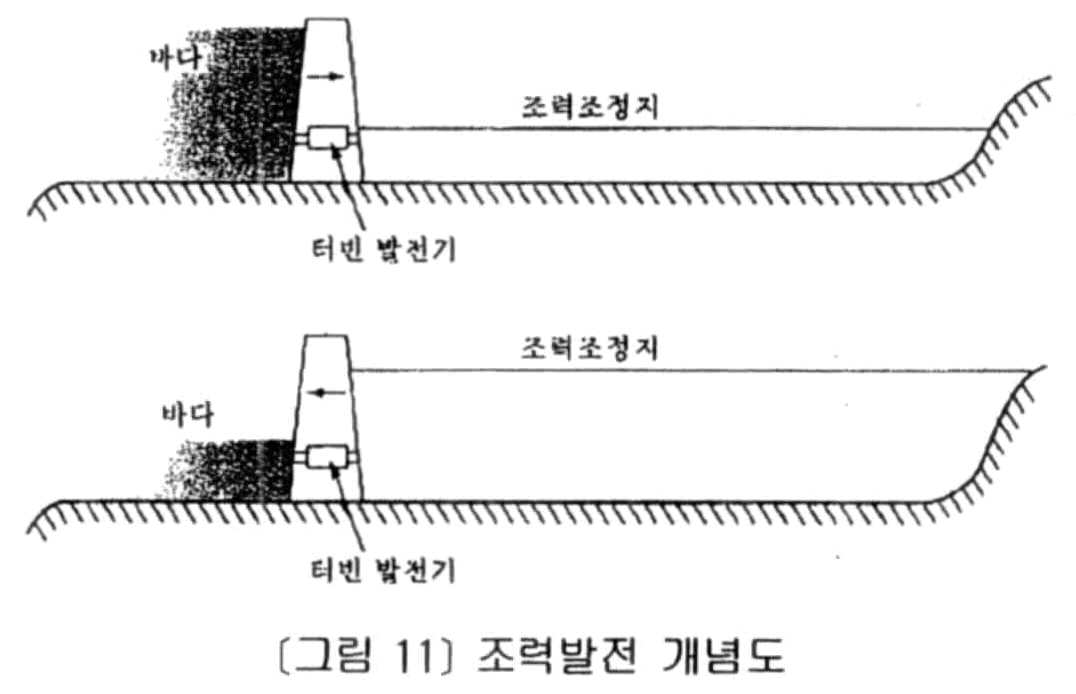
참고로 [표 2]는 세계 주요지점에서의 평균조차(간만차)를 나타낸 것이다(여기서는 평균조차 4.6[m] 이상만 수록하였음).For reference, [Table 2] shows the average (interval difference) at the world's major points (here, even the average contains more than 4.6 [m]).
[표 2] 세계 주요지점에서의 평균조차[Table 2] Even averages at major world locations

참고로 [그림 12]에 우리나라의 대부분의 수력 발전소가 집중되어 있는 한강수계에서의 각 발전소 위치도 및 종단도를 정리해서 보인다.For reference, [Figure 12] shows the location and longitudinal diagram of each power plant in the Han River, where most hydroelectric power plants in Korea are concentrated.


종래의 기술수준의 수력학에 있어서 물의 물리적 성질과 정수력학에 동수력학이 포함되어 본 발명의 해양발전소 설치 조건을 간단히 이루게 한다. 이처럼 물의 물리적 성질에 있어 물의 밀도는 대기압 아래에서는 4[℃]에서 최대로 되고 온도에 따라서 다소 변화하지만 그 변화는 아주 작기 때문에 보통 수력학상의 계산에서는 일정한 무게를 갖는 것으로 취급하여 무방하다. 즉, 물의 중량은 1[g/㎤] 또는 1[t/㎡]이라고 한다.In the prior art hydrodynamics, hydrodynamics is included in the physical properties and hydrostatics of water to simplify the installation conditions of the marine power plant of the present invention. As such, the density of water in water's physical properties is maximum at 4 [℃] under atmospheric pressure and varies slightly depending on the temperature, but the change is very small, so it is usually considered to have a constant weight in hydraulic calculations. That is, the weight of water is 1 [g / cm 3] or 1 [t / m 2].
물에 압력을 가하면 극히 작은 값이지만 체적이 감소한다. 그러나 그 체적의 변화비율, 곧 물의 압축률은 워낙 작아서 상온상압에서는 1기압의 변화에 대하여 약 5×10⁻⁵밖에 안 되므로 보통 물을 비압축성이라고 보아도 별문제가 없다.Pressurizing the water is a very small value, but the volume is reduced. However, the rate of change of the volume, that is, the compression rate of water, is so small that only about 5 × 10 −5 changes to 1 atm of normal pressure at normal temperature, so there is no problem even if water is incompressible.
운동하고 있는 액체내부에서 유속의 차가 있으면 그 상대운동에 저항하는 힘을 발생하게 된다. 이 성질은 점성 또는 내부마찰이라고 불려지며 그 정도는 점성계수로 나타내고 있다는 것이었고,If there is a difference in flow velocity inside a moving liquid, it generates a force that resists its relative motion. This property is called viscous or internal friction and the degree is expressed by the viscosity coefficient,
다음의 정수력학에 있어 하도와 같이 정지하고 있는 수면으로부터 깊이가 H[m]이고 단면적이 A[㎡]인 수주를 생각한다. 이 수주의 체적은 AH[㎥]인데 이때 물의 단위 체적당 중량을 ω[kg/㎤]라고 하면 이 수주의 전중량은 ωAH[kg]으로 된다. 따라서 수주는 그 밑바닥에서 위로 향해서 작용하는 물의 힘 ω[kg]에 지탱되어서 평형상태에 있게 된다.In the following hydrodynamics, an order with a depth of H [m] and a cross-sectional area of A [m 2] is considered from the surface of water stopped as shown below. The volume of the water column is AH [m 3]. If the weight per unit volume of water is ω [kg / cm 3], the total weight of the water column is ωAH [kg]. The order is thus in equilibrium, supported by the force ω [kg] of water acting from the bottom upwards.
즉, W=ωAH[kg]이므로 수주의 밑바닥 부분에서 물이 받는 평균의 힘 p[kg/T㎡는That is, W = ωAH [kg], so the mean force p [kg / T㎡]
![]()
![]()
로 된다. 이 p를 깊이 H[m]에서의 압력의 세기 또는 압력도(pressure intensity)라고 말하며, 전체에 작용하는 수압 P를 전압력 또는 총압이라고 해서 이것과 구별하고 있다.It becomes This p is referred to as the strength or pressure intensity of the pressure at the depth H [m], and the water pressure P acting on the whole is distinguished from this as the total pressure or total pressure.
또, 이 때의 ![]()
![]()
압력의 단위로서는 [kg/㎠]또는 [kg/㎡]를 사용한다.[Kg / cm 2] or [kg / m 2] is used as a unit of pressure.
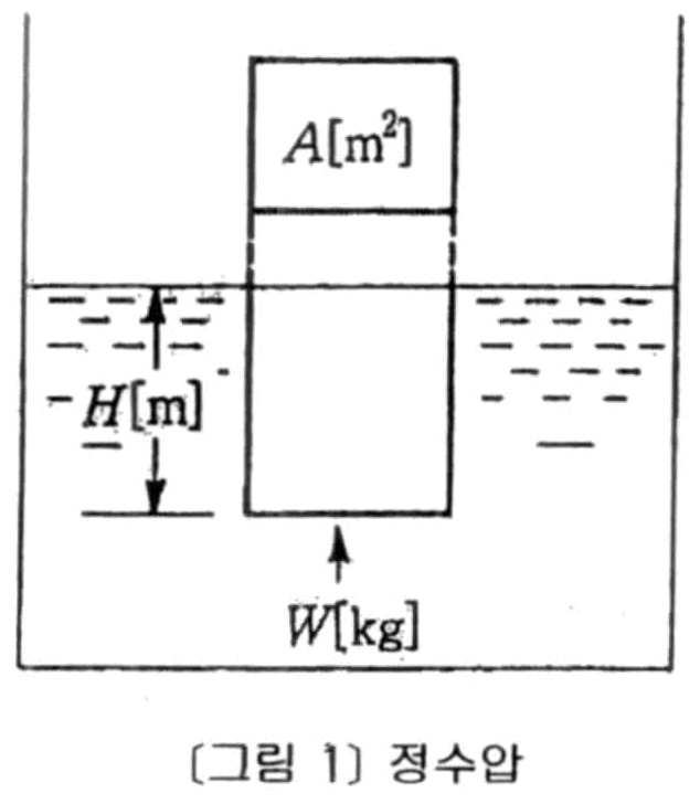
그리고 동수력학에 있어 먼저 연속의 원리에 대하여 다음과 같이 설명한다First, the principle of continuity in hydrodynamics is explained as follows.
동수력학에서는 유체(주로 물)의 운동법칙을 취급한다. 유체의 운동을 크게 나누면 유동과 와동, 그리고 파동으로 된다. 유동을 다시 나누면 유선이 정연하게 기하학적인 선으로 되어 흐트러지지 않고 흐르는 충류와 유선이 서로 엉켜서 혼란한 상태가 되어 흐르는 난류로 된다. 수력 발전소에서 사용하는 유체의 흐름은 일반적으로 난류이다.In hydrodynamics, we deal with the laws of motion of fluids (mostly water). Dividing a fluid's motion into large parts results in flows, vortices, and waves. When the flow is subdivided, the streamline becomes an orderly geometric line, and the flowing stream and the streamline are entangled with each other and become a turbulent flow. The flow of fluid used in hydro power plants is generally turbulent.
일반적으로 관로나 수로 등에 흐르는 물의 양 Q[㎥]는 유수의 단면적 A[㎡]와 평균유속 υ[m/s]와의 곱으로 표시하고 있다.In general, the quantity Q [m 3] of water flowing in a pipe or a water channel is expressed by the product of the cross-sectional area A [m 2] of the running water and the average flow rate υ [m / s].
(Q = A·υ [㎥]) 식 ②( Q = A · υ [㎥])
하도와 같이 관로 등의 고체로 둘러싸인 유수에서 2점 a, b 에서의 단면적을 각각 A 1[㎡], A 2[㎡] 평균 유속을 υ 1[m/s], υ 2[m/s]라고 하면, 단위시간에 지점 a로부터 유입되는 수량은 A 1 B 2[㎥/s], 지점 b로부터 유출되는 수량은 A 2 υ 2[㎥/s]이다.The cross-sectional areas at two points a and b in the flowing water surrounded by solids such as pipelines are respectively A 1 [m 2] and A 2 [m 2] average flow rates υ 1 [m / s] and υ 2 [m / s] In this case, the quantity of water flowing from the point a in the unit time is A 1 B 2 [

그런데 유수는 고체로 둘러싸여 있고, 또한 비압축성이므로 도중에서 물의 출입이 없는 한 지점 a로부터 유입되는 수량과 지점 b로부터 유출되는 수량은 같다. 이것을 연속의 원리라고 말하고 다음의 관계식이 성립한다.However, since the running water is surrounded by solids and is also incompressible, the quantity of water flowing in from point a and the quantity of water flowing out from point b are the same as long as there is no water in and out. This is called the principle of continuity, and the following relation holds.
(A 1 υ 1 = A 2 υ 2 = Q = 일정) 식 ③( A 1 υ 1 = A 2 υ 2 = Q = constant)
또, 이 관계로부터 유속은 유로의 단면적에 반비례해서 좁은 장소에서는 유속이 크고 넓은 장소에서는 유속이 작아진다는 것을 쉽게 알 수 있다.From this relationship, it is easy to see that the flow velocity is inversely proportional to the cross-sectional area of the flow path, and the flow velocity is large in a narrow place and decreases in a wide place.
다음의 베르누이의 정리에 대하여 다음과 같이 설명한다The following Bernoulli's theorem is explained as follows.
정지하고 있는 물은 그 내부에서는 그것에 작용하는 외력과 압력에 의해서 평형이 유지되지만 운동하고 있는 물에서는 이 2가지 힘 외에 가속도가 작용해서 결국 이 3가지 힘으로 평형을 유지하게 된다.(단, 정상류의 경우에는 가속도는 작용하지 않고 외력은 지구의 중력만으로 된다)The stationary water is equilibrated by the external forces and pressures acting on it, but in the moving water, the acceleration acts in addition to these two forces, resulting in equilibrium with these three forces. In this case, acceleration is not applied and external force is only earth's gravity.)
하도의 A점, B점에서의 물의 압력도를 각각 p 1[kg/㎡], p 2[kg/㎡]라고 하고 기준면으로부터의 높이를 각각 h 1[m], h 2[m]라고 한다. 동시에 물의 단위 체적당 중량을 ω[kg/㎥], 중력 가속도를 g=9.8[m/s2]라고 하면 에너지 보존법칙에 따라 다음 식이 성립한다.The pressures of water at point A and point B of the lower road are called p 1 [kg / m2] and p 2 [kg / m2], respectively, and the heights from the reference plane are h 1 [m] and h 2 [m], respectively. . At the same time, if the weight per unit volume of water is ω [kg / ㎥] and the gravitational acceleration is g = 9.8 [m / s 2 ], the following equation is established according to the law of energy conservation.

따라서 위 식의 관계는 일반적으로 다음과 같이 표현된다.Therefore, the above relationship is generally expressed as follows.
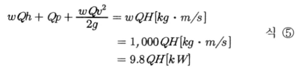
단, H : 정수Where H is an integer
즉, 식⑤는 파워(power)를 나타내고 있다. 따라서 ωQh, Qp 및 은 각각 위치파워, 압력파워 및 속도파워 또는 운동파워라고 불리어지는 것이다.That is, equation (5) represents power. Therefore, ω Qh , Qp and are called position power, pressure power and velocity power or kinetic power, respectively.
① 위치파워(ωQh) : 기준면으로부터 h의 높이에 있는 유수가 갖는 1초당의 위치 에너지로서 다음에 설명하는 위치수두와 같다.① Position power ( ωQh ): Potential energy per second of running water at the height of h from the reference plane.
② 압력파워(Qp) : 상기 유량이 갖는 1초당의 압력 에너지로서 다음에 설명하는 압력수두와 같다.(2) Pressure power ( Qp ): The pressure energy per second of the flow rate, which is the same as the pressure head described below.
③ 속도파워(![]()
![]()
그런데 위의 3가지 파워의 합계는 에너지 보존법칙에 따라 일정하므로 이것을 ωQH로 나타내는데 일반적으로 이 ωQH를 총파워 또는 총수력 (즉, 1초당의 총 에너지)이라고 한다. 곧 위의 식⑤는 완전유체가 유선에 따라 흐르고 있을 경우 위치 에너지, 압력 에너지 및 운동 에너지의 합계는 그 유수가 가지는 1초당 총에너지 ωQH와 같다는 것을 나타내고 있다.However, since the sum of the three powers is constant according to the law of energy conservation, this is expressed as ωQH . Generally, this ωQH is called total power or total hydraulic power (ie, total energy per second). Equation (5) above indicates that when a complete fluid flows along the streamline, the sum of potential energy, pressure energy, and kinetic energy is equal to the total energy ωQH per second of the flow.
이들 에너지의 합계가 일정하다는 것은 이들 각 에너지간의 상호변환이 가능하다는 것을 의미한다.If the sum of these energies is constant, it means that the mutual conversion between each of these energies is possible.
이 상호변환을 이용해서 수차가 회전함으로써 수력발전이 실행되는 것이다. 곧, 위치가 높은 곳(저수지의 취수구)에서의 위치 에너지가 위치가 낮은 곳(수차가 있는 방수구)에서의 운동 에너지로 변환되고, 그 양은 이들 양자간의 수위의 차로 표현되는 것이다.(이 수위의 차를 총낙차라고 함)Hydroelectric power generation is performed by rotating the aberration using this interconversion. In other words, the potential energy at the high position (water intake port of the reservoir) is converted into kinetic energy at the low position (waterproof port with aberration), and the amount is expressed as the difference in the water level between these two. A car is called a total drop)
지금 식②의 양변을 ωQ로 나누면 다음과 같이 된다.If we divide both sides of
![]()
![]()
이것을 베르누이의 정리(Bernouli's theorem)라고 한다.This is called Bernoulli's theorem.
윗 식에서 h를 위치수두, p/ω를 압력수두, υ 2/2g를 속도수두, H를 전수두라고 부른다.An upper head where expression h, p / ω a pressure head, referred to as the 2 υ / 2 g velocity head, transfer the two H.
베르누이의 정리를 수로의 흐름에 응용할 경우에는 실제로 물이 흐를 때 받게되는 여러 가지 손실분까지 고려해서 - 손실에 상당하는 수두를 손실수두라고 하 고 h 1로 나타낸다.- 다음과 같이 고쳐서 쓰고 있다.When Bernoulli's theorem is applied to the flow of waterways, it takes into account the various losses actually received when the water flows-the head corresponding to the loss is called the head of loss, and is represented by h 1 .
![]()
![]()
아래에 이들 각 수두를 간단히 설명해 본다.Briefly describe each of these heads below.
높은 위치에 있는 물이 떨어지면 일을 하게 되는데 이것을 위치 에너지라고 부른다.When the water in the high place falls, you work. This is called potential energy.
하도에서 임의의 기준면 (X-X')에 대해서 h a 의 높이에 있는 점 a의 물은 (X-X')에 대하여 h a 의 위치를 갖는다고 말하며, 수력학에서는 이것을 위치수두라고 부른다.The water at point a at the height of h a with respect to any reference plane ( X-X ' ) in the lower island is said to have a position of h a with respect to ( X-X' ), which hydrodynamically calls this position head.

마찬가지로 b점의 위치수두는 h b 이다. 2점 a, b의 위치수두의 차 h a - h b 는 h a 와 h b 의 수직거리로써 표시되며, a로부터 b까지의 통로의 길이와는 아무 관계가 없다. 하천의 유수 등의 에너지를 이용할 경우 이 위치수두의 차이를 특히 낙차(head)라고 부르고 있다. [그림 2-5]에 나타낸 것처럼 정지하고 있는 물 속에 단면적 A[㎡], 수심 H[m]의 수주를 가상할 경우 이 수주의 밑바닥 면에 작용하는 압 력 P[kg]는 이 수주의 무게와 같게 되어Similarly, the position head of point b is h b . Difference h a of position head of two points a, b h b is expressed as the vertical distance between h a and h b and has nothing to do with the length of the passage from a to b. When using energy such as river runoff, this difference in head is especially called head. As shown in [Figure 2-5], the pressure P [kg] acting on the bottom surface of the water column is the weight of the water column when simulating the order of cross-section A [m2] and depth H [m] in stationary water. Becomes like
(P = ωAH[kg]) 식 ⑧( P = ω AH [kg])
로 된다. 단, ω는 물의 단위 체적당의 중량[kg/㎥]이다. 여기서 압력의 세기를 p[kg/㎡]라고 한다면 식①과 같이It becomes Is the weight [kg / m 3] per unit volume of water. If the intensity of pressure is p [kg / ㎡],
![]()
![]()
으로 되는데 이것은, 즉 단위체적의 물이 갖는 압력 에너지이다. 수력학에서는 압력의 세기를This is the pressure energy of the unit volume of water. In hydraulics, the strength of pressure
![]()
![]()
상기한 수주의 높이로 나타내고 이것을 압력수두라고 부르기도 한다.It is expressed as the height of the above water column, and it is also called the pressure head.

상기와 같이 물이 흐르고 있는 경우를 생각한다. 중력의 가속도를 g[m/s2]라고 하면 단위체적의 물의 질량 m[kg]은Consider the case where water flows as described above. If the acceleration of gravity is g [m / s2], the mass m [kg] of unit volume of water is
![]()
![]()
이다. 여기서 속도 υ[m/s]로 흐르고 있는 물의 단위 체적당의 운동 에너지는to be. Where the kinetic energy per unit volume of water flowing at velocity υ [m / s]
![]()
![]()
로 되는데, 앞에서 에너지의 상호변환에서 본 바와 같이 이 단위 체적당의 운동 에너지가 단위 체적당의 위치 에너지로 바뀌었다고 보고 이것을 ωH[kg·m]라고 하면As seen in the interconversion of energy, the kinetic energy per unit volume has been converted to the potential energy per unit volume, and this is ω H [kg · m].
![]()
![]()
로부터from
![]()
![]()
가 된다. 이처럼 속도 υ로 흐르고 있는 물은 이상론 H의 높이에 해당하는 수두를 갖는다고 생각해서 이 H(=υ 2/2g)를 속도수두라고 부르고 있다.Becomes Thus, water flowing at a rate υ is to think to have the head that corresponds to the height H of yisangron termed the H (= υ 2/2 g ) the velocity head.
끝으로 토리첼리의 정리에 대하여 하도와 같이 설명한다Finally, Torichelli's theorem is explained as follows.
하도와 같이 단면적 ①을 가진 수조에서 하부의 측면에 있는 아주 작은 구멍, 즉 오리피스 ②로부터 분출하는 물의 속도 υ 2는 베르누이의 정리Velocity's velocity υ 2 is the velocity of water spouting from the
![]()
![]()
에서 P 1과 P 2는 대기압 P a 와 같고 (P 1 = P 2 = P a ) 수조의 단면적은 분출구의 단면적보다 훨씬 크기 때문에 υ 1는 무시된다. (≒0) P 1 and P 2 are equal to atmospheric pressure P a ( P 1 = P 2 = P a ), and υ 1 is ignored because the cross-sectional area of the bath is much larger than that of the jet. (≒ 0)
또, h 1 - h 2 = h인 조건을 윗 식에 대입하면,In addition, substituting the condition h 1 - h 2 = h into the above expression,

![]()
![]()
를 얻는다.Get
이 관계식을 토리첼리의 정리(Torricelli's theorem)라고 말한다. 실제는 물의 점성, 분출공에서의 마찰손실 등이 있기 때문에 실제의 분출속도 υ 2'는 υ 2보다 약간 작아져서 다음 식으로 표시된다.This relationship is called Torricelli's theorem. Actually, because of the viscosity of water and friction loss in the jet hole, the actual jet velocity υ 2 'is slightly smaller than υ 2, and is expressed by the following equation.
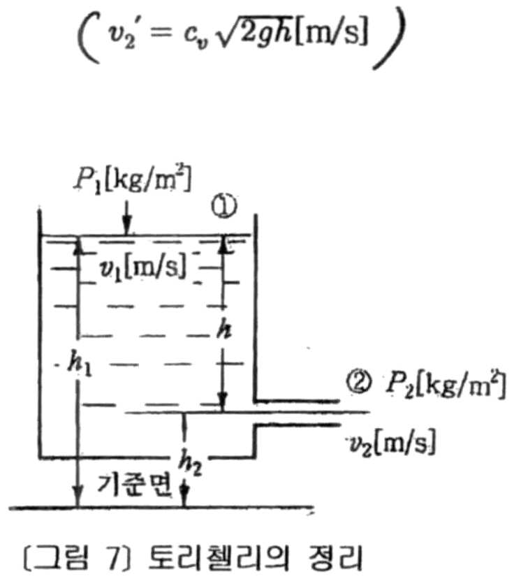
전술한 바와 같이 수력발전 종래의 기술에 있어 도수설비와 발전설비(양수)에 방수설비 등은 수력발전의 요건에는 별로 장애가 없는 반면에 취수설비인 댐(680) 또는 취수댐(680)의 설정이 매우 심각한 수준인데 상기 취수댐(680) 설정에 따른 인근 주변의 환경영향의 표출되는 제반 문제점(해결되어야 할 사항)은 다음과 같다.As described above, in the conventional technology of hydro power generation, water supply facilities and power generation facilities (pumping), waterproof facilities, etc., have no obstacles to hydroelectric power generation requirements, while the
첫째로는 적정한 발전용량을 얻기 위하여 댐의 건설에 따라 발전설비의 발전 기 제작 설치보다도 댐 건설에 따른 설치비용과 댐 건설의 소요기간이 발전설비와 상대적으로 격차가 매우 크기 때문이었고First, in order to obtain proper power generation capacity, the installation cost of dam construction and the time required for dam construction are much larger than that of power generation facilities.
둘째로 취수댐 설치 지역 인근의 환경영향(댐 설치위치 지층의 지반과 지각변동 사항을 사전에 철저히 확인 고려하지 않은 점 등의 취수댐 설치한 후에는 홍수 가뭄을 조절하는 다목적용이기 보다는 유량의 체류기간이 장기화됨에 따라 조류 내지 유해 적조 대번식이 초래하고 취수량이 많고 적음에 따라 지각변동으로 지진 또는 산사태로 중소도시가 매몰되는 사례가 속출되었으며 그 이외 지역으로는 태양열 발전으로 태양열 발전기 설치 등에 따른 산림을 훼손하는 등의 홍수 가뭄 조절 불능으로 국가 경제발전 저해요인(걸림돌 내지 애물단지)이 원자력 발전의 경우에는 구 소련의 체르노빌 원전의 사고로 방사능 오염 사고 등의 결과를 초래하여 이의 피해는 상당한 것이었다. 한편 화력발전소는 보통 전력의 수요가 많은 대도시 가까운 장소 또는 해안에 건설하게 되어 굴뚝(연돌)에서 분출하는 폐기가스로 인해 생태계의 질서가 와해되고 이런 와중에 자동차가 뿜어내는 매연 등의 분진으로 대기의 오염과 이산화탄소 배출 등의 증가에 따라 지구온난화 현상에 의해 자연재해는 심각한 수준에 도달하게 된 것으로 그에 대한 대책이 바로 본 발명인이 무재해 지구촌 해양발전소의 관 레벨 시소형 풍수력 발전기를 해양에 설치함으로써 친환경적 에너지를 무한적 생산으로 인류 고민을 해소하는 방식의 수단이다.Second, after the installation of an intake dam, such as the fact that the environmental impacts near the intake dam installation area (the ground and crustal changes of the dam installation location are not thoroughly checked beforehand), the flow rate stays rather than multipurpose for controlling the drought. As the period is prolonged, there are many cases in which small to medium cities are buried due to earthquakes or landslides due to tectonic changes due to tide and large red tide breeding. In the case of nuclear power generation, the factor of impeding the national economic development due to the inability to control the drought (such as dams) was caused by radioactive pollution accidents in the former Soviet Union's Chernobyl nuclear power plant. Thermal power plants, on the other hand, are usually located near large cities with high demand for electricity. Due to the waste gas emitted from the chimney, the order of the ecosystem is degraded, and in the midst of this, due to the increase of air pollution and carbon dioxide emissions, natural disasters caused by global warming Has reached a serious level, and the countermeasure is the method of the present inventors to solve the human anxiety by infinitely producing eco-friendly energy by installing the pipe-level see-saw wind generator of the global marine power plant in the ocean.
그렇기 때문에, 본 출원인에 의해 국내에 발명등록특허 제0546221호는 등록된 다용도 계단식 조절맨홀의 삼칠 계단식으로 차량의 통행에 따른 도로교통흐름의 방해와 작업자의 목숨을 잃을뻔한 위험을 해소토록 안전맨홀의 설치위치에서 감쪽 하는 순간 감쪽같이 도로지표면과 동일하게 레벨을 균등하게 설치한 후 맨홀뚜껑 하단부로 또다른 장치물인 발명등록특허제10-0650936호의 인수공 맨홀 빗장걸이 장금장치로서 지중선로 관계자외는 함부로 들어가지 못하도록 제작되었고 이때에 장금장치의 열쇠삽입구가 녹이 슬고 아무나 열고 인수공 맨홀에 들락날락하여 국가의 통신보안에 큰 장애가 유발되어 이점을 해소하고자 열쇠삽입구에 파라핀액체를 투입시켜 3분동안 파라핀 액체에서 3분후에는 파라핀이 고체가 되면서 열쇠삽입구에는 녹이 슬지 않을 뿐만 아니라 고체상태에서는 열쇠를 삽입할 수 없도록 장치가 되었기 때문에 원리를 모르면 열쇠전문가(가칭 금고털이 범인)도 맨홀 내부로 근접하지 못하도록 되었고, 이때에 통신선로이거나 지중선로(전기 전선 지하 매설물)에서 전기합선으로 매시껍은 유독개스와 함께 뿜어내는 질식가스로 어느지점 어디서 발화되었는지 위치 식별을 할 수도 없고 진화요원이 진화도 못할 지경에 본 발명의 전개노즐로 지중선로의 맨홀가스 노출부위 전방과 후방으로 이산화탄소와 하론가스를 방화수액과 함께 지중선로에 투입함으로 해서 초기진화를 이루어내고 다치는 사람없이 발화현장에 접근하지 않고도 이중관 구조로 형성된 상기 다용도 계단식 조절맨홀형틀과 맨홀뚜껑 유동공간 틈새로 관노즐의 설치위치로 정확하게 방재물질을 투입함으로서 국내에 출원된 출원번호 10-2009-0088090호는 관노즐이동형 소방센서펌프는 소방방재용 장비로써 종전의 소방장비의 센서와는 저온감지효율이 성냥불과 촛불정도의 감지속도로 매우 빠르게 감지하는 것으로서 종전의 것과는 현격한 차이로 상기 출원번호 명세서(342 페이지 분량)을 참조하게 되면 본 발명의 기술을 이해하는데 많은 도움이 표출되게 된다.Therefore, the invention patent registration No. 0546221 in Korea by the applicant of the three-step stairs of the multi-purpose staircase adjustment manhole registered in the safety manhole so as to eliminate the risk of obstruction of road traffic flow and loss of worker's life according to the traffic of the vehicle As soon as the periphery of the installation position, the level is set equally to the road surface like the periphery of the manhole, and the manhole latch device of the man-in-law of the invention, which is another device, is another device to the lower part of the manhole cover. In order to solve this problem, paraffin liquid was added to the key insert for 3 minutes in paraffin liquid for 3 minutes to solve this problem. Later, the paraffin becomes solid, so the key inlet will not rust. In addition, in the solid state, the device cannot be inserted so that the key expert (tentative name) is not able to come into the manhole without knowing the principle. At this time, the electric power in the communication line or underground line (electric underground underground) With the short circuit, the mash shell is a suffocating gas emitted with toxic gas, so it is not possible to identify where it is ignited and where the evolutionary agent cannot evolve. Installation of pipe nozzles with the above-mentioned multi-purpose stepped manhole frame and manhole cover flow space gap formed by double pipe structure without initial injury by injecting carbon dioxide and halon gas into underground line with fireproof solution and without injuring people. By accurately injecting disaster prevention materials Application No. 10-2009-0088090 is a pipe nozzle mobile fire sensor pump, which is a fire-fighting disaster prevention equipment that detects low-temperature sensing efficiency very quickly at the same speed as a match fire and a candle. Reference to the application number specification (342 pages) with a significant difference will be very helpful in understanding the technology of the present invention.
그리고 본 출원인이 국내에 출원되어 있는 출원번호 10-2007-0099575호는 오대양 육대주의 육지와 해양으로 연결되는 교량의 높낮이 조절되는 무재해 교량 부침형 터넬독몸체 내부에 유해적조, 대형산불에 황사와 태풍에 홍수가뭄과, 산사태로 지진해일의 영향을 받지 않도록 명확히 재해발생지 재해를 원천봉쇄차단하는 장비인데 상기 재해가 없도록 무재해 소방방재 대책용품의 관노즐이 적도적선의 위도에 남극과 북극을 횡단하는 거리의 치수는 92500km이고 상기 치수의 20배로 관노즐 몸체로 형성되어야만이 무재해 지구촌의 자연적 재해를 일소하면서 인위적 재난인 전쟁과 테레가 없는 평화로운 지구촌의 행복한 삶을 보장받기 위해서도 상기한 관노즐홀이 다공가변형으로 전개와 전폐할 수 있게 그 기능을 보장받도록 하고 있다.In addition, Korean Patent Application No. 10-2007-0099575, the applicant of which is filed in Korea, shows that there are no harmful bridges in the height of the bridges connected to the land and the ocean of the five oceans. It is a device that blocks the source of disasters clearly so that it is not affected by tsunamis due to flood drought and landslides, and the pipe nozzle of the disaster prevention measures supplies without crossing the Antarctic and Arctic at the latitude of the equator The pipe nozzle hole should be formed with a tubular nozzle body at 20 times the size of the above, and it should be formed without any accidents in order to clean up the natural disasters of the global village and ensure the happy life of a peaceful global village without human disaster and war. Its function is guaranteed to be variable and fully deployed.
이러한 본 발명의 기술수준은 상기 방제활동이란 단어는 아예 제거되는 또는 제외되는 수준으로서 눈덩이 같이 불어나는 재난피해를 아예 없애주는 것으로서 종래의 기술수준과는 현격한 차이의 재난방지시스템으로 구비되는 특징이자 본 발명의 목적으로 이루어지는데에는 종전의 건설장비 및 중기류인 건설기계를 본 발명에 형성시켜 지구촌의 경제불황과 향후 3년 이내로 국가채무상환액(1400조원)을 청산할 수 있는 정치, 경제, 문화, 과학, 환경분야의 미래 청사진이 포함되는 미래지향적인 해양발전소 몸체 내부의 제작 설치가 기술적 특징이다.The technical level of the present invention is that the word "control activity" is eliminated or eliminated as a level to eliminate the disaster damage that blows like a snowball, and is characterized by a disaster prevention system with a significant difference from the conventional technical level. It is made for the purpose of the present invention to form a conventional construction equipment and heavy machinery construction equipment in the present invention, the economic recession of the global village and political, economic, cultural, science that can settle the national debt repayment (1400 trillion won) within the next three years The technical feature is the fabrication and installation inside the body of a future-oriented offshore power plant, which includes a future blueprint for the environment.
상기한 건설기계 일체로 형성되는데에는 관교량 부침형 터넬독 몸체(1) 내부에 다수의 개 지주탱크(교각겸용, 590)와 상기 탱크(590) 상단의 바지선 본체(591)에 상기 탱크(590) 하단의 바지선 본체(592)를 조립 해체할 수 있게 되는 소형의 해양발전소 부양식독(593)과 중형의 해양발전소 부양식독(594)에 대형의 해양발전 소 부양식독(595)을 해양의 심해저 저층 바닥에 고정시키게 되는 요부위 장비이다.The construction machine is integrally formed with a plurality of dog holding tanks (piers, 590) and a
다시 말해 건설기계(Construction machinery)라 함은 건설공사를 수단으로 사용되는 모든 기계의 총칭이다. 즉 원동기(Prime mover)로부터 얻은 동력을 이용하여 굴착, 운반, 견인 등에 사용되는 건설장비 및 중기류를 말하는데 이의 장비 종류에 따라 상기한 건설기계로 본 발명이 이루지게 되는데 이의 건설기계는 하도와 하표로 상세한 설명을 다음과 같이 한다.In other words, construction machinery is a general term for all machinery used as a means of construction. That is, the construction equipment and heavy equipment used for excavation, transportation, towing, etc. using the power obtained from prime mover. The present invention is achieved by the construction machinery described above according to the type of equipment. Detailed description is as follows.
건설기계의 범위에 대하여 상세한 설명에 있어 건설기계 관리법에 의한 범위는 다음과 같었다.In the detailed description of the scope of construction machinery, the scope under the Construction Machinery Management Act was as follows.
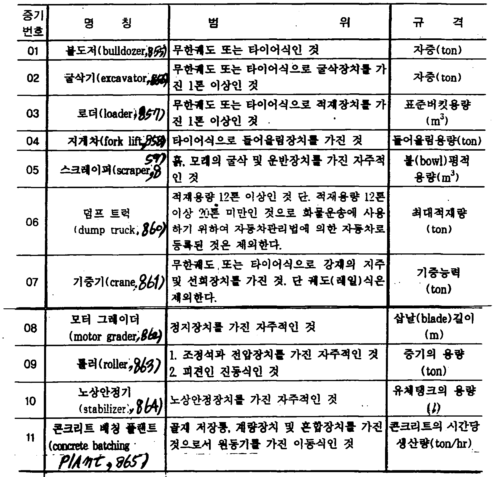

그리고 건설기계의 분류에 있어서 상세한 설명은 다음과 같다The detailed description of the classification of construction machinery is as follows.
먼저 굴착기계에 있어 불도저(855)와 스크레이퍼(859)에 엑스카베이터(856)와 루터로 분리되고 다음은 기초공사용 기계인데 파일 드라이버(882)와 디젤 파일 해머(883)에 증기해머(884)로 분리되며 그 다음의 크레인(기중기, 861)에는 유압크레인(885)과 타워크레인(886)에 크롤러크레인(887)과 트럭크레인(888)으로 분리되 었고First, in the excavation machine, the bulldozer (855) and the scraper (859) are separated into the excavator (856) and the luther. Next, the foundation machine is the pile driver (882) and the diesel pile hammer (883) and the steam hammer (884). The next crane (the crane 861) was divided into a hydraulic crane (885) and a tower crane (886) to a crawler crane (887) and truck crane (888).
네번째 적재기계에 있어 로더(857)인데 셔블 로더(857a)와 ![]()
![]()
하도와 같이 건설기계의 더욱 상세한 설명에 있어 각개의 순서별 개요와 정의는 다음과 같다In the more detailed description of the construction machinery, such as the diagram, the following is an outline and definition of each order.
먼저 트랙터(Tractor)의 전면부에 배토판(스트레이트형, 앵글형 등)을 장착하고 후면에 리퍼(Ripper), 루터(Rooter) 등 부수장치를 부착하여 흙, 암반 등을 깎아 밀어내는 토공용 건설기계이다.First of all, a construction machine for earthworks that attaches a top plate (straight type, angle type, etc.) to the front of the tractor, and attaches additional devices such as ripper and rooter to the back to cut off soil and rock to be.
즉, 건설기계의 가장 기본이 되는 토공기계로서 불(황소) + 도저(쉬게 하는 기계)의 복합용어로서 황소를 노동으로부터 해방시킬 정도로 힘이 센 밀어내는 작업을 하는 기계이다.In other words, it is the earthwork machine which is the most basic of construction machinery. It is a compound term of bull (ox) + dozer (resting machine), and it is a machine that pushes the force strong enough to free bull from labor.

용도에 있어서 하표와 같이 설명한다.It demonstrates like a table | surface in a use.
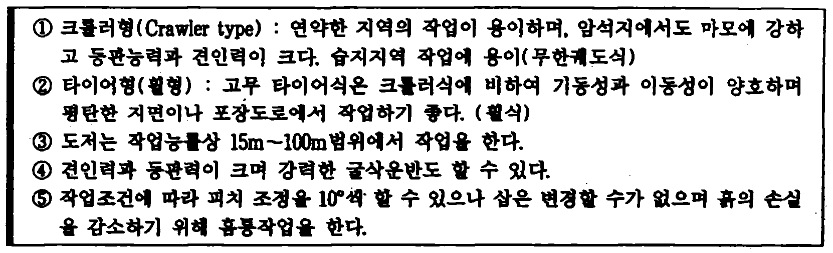
일반사항으로는 도저의 규격 표시는 자중(ton 또는 kg)으로 표시 즉 자체중량으로 표시한다.In general, the standard marking of the doser shall be expressed in its own weight (ton or kg), ie its own weight.
그리고 도저의 경제적인 작업거리는 10∼100 m이며 별도로 두 대의 도저로 삽 맞대기작업시 거리는 100m 이내로 하되 And economical working distance of dozer is 10 ~ 100m and when do shovel butt with two dozers, distance should be within 100m.
도저의 3대 작업은 하표와 같으며The three major tasks of the dozer are the same as
![]()
![]()
도저의 동력전달순서에 있어 하표와 같고Like the mark in the power transmission sequence of the dozer

도저의 작업량 산출에 있어 하도와 하표와 같이 설명한다.The calculation of the doser's workload is explained with the sewer and the sewer.
1) 시간당 작업량 : 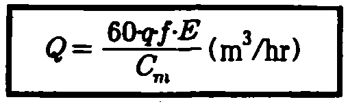
단, q : 토공판 용량(m3) f : 토량환산계수Q: Earthwork plate capacity (m 3 ) f: Soil conversion factor
E : 작업효율(%) C m : 1회 사이클시간(min) E : Work efficiency (%) C m : One cycle time (min)
① 블레이드 (토공판)용량 : ![]()
![]()
여기서. Q : 블레이드 용량(m3)here. Q : Blade Capacity (m 3 )
B : 블레이드 폭(m) B : blade width (m)
H : 블레이드 높이(m) H : blade height (m)
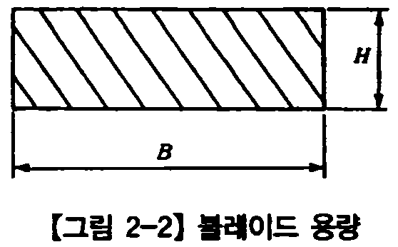
② 1회 사이클시간② One cycle time
(단. L : 작업거리(m). V 1 : 전진속도(m/min). V 2 : 후진속도(m/min). t : 기어변환시간(min))( L : Working distance (m) V 1 : Forward speed (m / min) V 2 : Reverse speed (m / min) t : Gear shift time (min))
견인력의 상세한 설명은 다음과 같다.The detailed description of the traction is as follows.
![]()
![]()
여기서,(μ : 마찰계수)Where μ is the coefficient of friction
(W : 차량 중량(kg))( W : Vehicle weight (kg))
견인마력(H)Traction horsepower (H)
단, 
도저의 분류에 있어서 하표와 하도로 설명한다We explain with mark and road in classification of dozer
첫째로 주행장치에 의한 분류(=접지압을 고려한 분류)에는 하표와 하도와 같이 무한궤도식이 사용되는 크롤러형 도저와 휠형 도저로 분리한다First, classification by traveling device (= classification considering grounding pressure) is divided into crawler type dozer and wheel type doser, which use infinitely orbital equation such as loading and loading.

무한궤도식(Crawler type) : 접지면적이 넓고, 접지압력이 적어 나쁜 지형에서도 강력한 굴착능력을 가지며, 등판능력이 좋다. 습지용 트래슈를 사용하면 접지압이 낮아서 습지작업에 아주 적합하며, 트랙이 잠길 수 있는 깊이까지는 수중작업이 용이하다.Crawler type: Wide ground area, low ground pressure, strong excavation ability in bad terrain, good climbing ability. Wetland traces are well suited for wetland operations due to low ground pressures and are easy to work underwater to the depth where the track can be locked.
타이어식(Wheel type : 차륜식) : 접지면적이 크고, 접지압력이 커서 습지, 사지에의 작업이 불가능하지만 무한궤도식보다는 기동성, 이동성이 양호하며 평탄지면이나 포장도로에서 작업하기에 효과적이다.Tire type (Wheel type): It is impossible to work on wetlands and limbs because of large ground area and large ground pressure, but it is more mobile and mobile than caterpillar type, and it is effective to work on flat ground or pavement.

둘째로 작업장치에 의한 분류에 있어 스트레이트 도저와 틸트 도저에 앵글 도저로 분리한다Secondly, the straight dozer and the tilt dozer are divided into angle dozers for sorting by the working device.
먼저 스트레이트 도저(Straight dozer)는 통상적으로 도저라 하며 삽을 변경할 수 없으며, 삽날(배토판)의 상부를 10°씩 경사지게 조작하며 직선 절토, 송토작업에 사용 블레이드(Blade)의 상·하 작동에 유압실린더를 이용하여 자체중량으 로 강력한 힘을 내어 굴착하는 기계인데 피치조정으로 전·후방 10°씩 삽의 변화각을 주어 굴토력을 조정할 수 있다.First of all, the straight dozer is generally called a doser and cannot change the shovel, and the top of the blade (top plate) is inclined by 10 ° and used for straight cutting and transfer work. It is a machine that excavates powerful force by its own weight by using hydraulic cylinder. It can adjust the oyster force by giving the angle of change of shovel by 10 ° in front and rear by pitch adjustment.
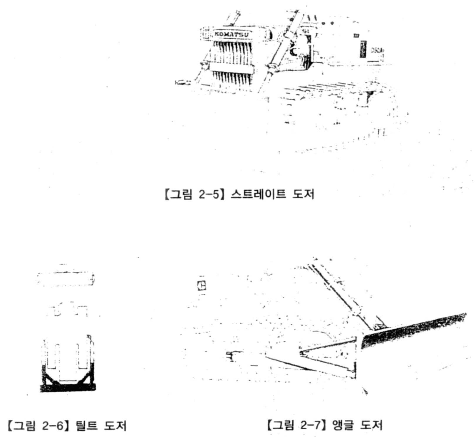
다음의 앵글 도저(Angle dozer)는The next angle dozer
삽날이 길고 낮으며, 삽날의 위치를 좌우로 필요한 각도(20°∼30°)만큼 변경하여 사용 틸트 도저와 스트레이트 도저의 역할을 할 수 있으며, 신설 도로 작업시 산허리를 깎아 한쪽으로 배토하는데 적합하고The blade is long and low, and it can act as a tilt doser and straight dozer by changing the position of the blade to the required angle (20 ° ~ 30 °) to the left and right.
용도 : 경사지 배토작업, 절토작업, 제설작업, 측면 매몰작업, 도랑매립작업, 파이프 매설작업, 굳은땅 측면 자르기작업 등이었고Use: Slope work, cutting work, snow removal work, side burial work, trench burial work, pipe laying work, hard ground side cutting work, etc.
그리고 틸트 도저(Tilt dozer)는And the tilt dozer
삽날의 각도를 수평면을 기준으로 하여 좌·우로 각각 15cm 정도 경사를 지어 작업할 수 있다.The blade can be inclined about 15cm from the left and right of the horizontal plane.
용도 : 언땅, 굳은 땅, 옆도랑 굴착, 바위돌 굴리기, V형 배수로작업 등에 이용한다Use: It is used for frozen ground, hard ground, excavation of side trench, rolling rock, and V type drainage work.
세번째로 부수장치(Attachment)에 의한 분류에 있어서는 레이크 도저와 힌지 도저에 트리 도저와 하이드릭리퍼에 푸시 도저와 티나 도저에 U 도저로 세분화 되어 있다Third, in classification by attachment, it is subdivided into rake dozer, hinge dozer, tree dozer, hydric ripper, push dozer, tina doser and U dozer.
먼저 레이크 도저Rake dozer)Lake dozer first
삽날 대신에 레이크형(쇠고랑 모양)의 부수장치를 부착한 도저이며 용도는 농지 개간 및 도로공사 시 암석 골라내기, 잡목이나 나무뿌리 뽑기, 댐건설 공사 시큰 돌 운반에 적합. 굳은 땅 파헤치기. 등에 이용된다.It is a dozer with a rake-type cracking device instead of a blade. It is suitable for picking rocks for clearing farmland and road construction, plucking lumber or tree roots, and carrying large stones for dam construction work. Dig hard ground. And the like.

트리 도저(Tree dozer)는 개간, 정지작업에 적합하고Tree dozers are suitable for clearing and grading
힌지 도저는 제토, 제설작업, 토사 운반에 적합하며Hinged dozers are suitable for earthwork, snow removal, and soil transportation.
리퍼(Ripper)에는 지반이 단단하고 견고하여 굴착이 곤란한 경우 사용되었으며 불도저의 토공판으로 굴착이 곤란한 경우나 발파가 곤란한 암석 또는 옥석류의 제거, 아스팔트 포장 파괴 등에 사용한다.Ripper is used when excavation is difficult due to hard and solid ground, and it is used when excavation is difficult due to earthwork of bulldozer, removal of rocks or stones that are difficult to blast and destruction of asphalt pavement.
푸시 도저(Push dozer)는 스크레이퍼 작업시 견인력을 주기 위해 스크레이퍼를 뒤에서 밀어주는 역할을 한다Push dozer pushes the scraper from behind to give traction when working on the scraper
그리고 터나 도저는 저압의 고무 타이어식 도저로 무한궤도식보다 고속이고, 운반 토량의 증가가 가능하다. 또한 이동이 쉽고 포장에 해를 주지 않는 것이 장점 이다.And the dozer or dozer is a low-pressure rubber tire dozer, which is faster than the caterpillar and can increase the amount of transported soil. In addition, it is easy to move and does not harm the packaging.
한편 U도저는 블레이드가 U형으로 되어 있기 때문에 옆으로 넘치는 것이 적다.U-dozers, on the other hand, are less likely to spill over to the side because their blades are U-shaped.
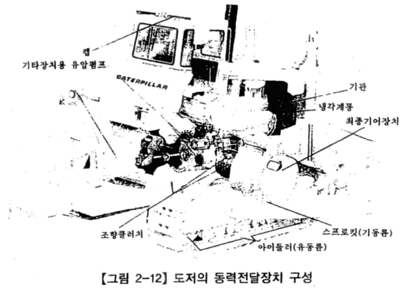
불도저의 어태치먼트에 있어In the attachment of the bulldozer
불도저는 토공장치 대신에 여러 가지 어태치먼트(Attachment : 부속장치)를 부착하여 작업할 수 있다.The bulldozer can work by attaching various attachments instead of earthworks.
먼저 스트레이트 레이크 도저(Straight rake dozer)는 스트레이트 도저에 삽 대신 레이크(rake)를 부착하여 뿌리 뽑기, 암석의 굴착 전용으로 사용하며 다음의 백호(Back hoe)는 파이프 전선의 매설구. 배수구 굴착용으로 이용되었고 다음 유압 리퍼(Hydraulic ripper)는 굳고 단단한 지반에서 블레이드(Blade)로는 굴착이 곤란한 지반이나 포장의 분쇄, 뿌리뽑기, 암석긁기 등에 사용되었으며 토잉 윈치(Towing winch)는 중량물 목재 등의 견인작업에 사용하고 스노 플라우(Snow plow)는 제설작업용으로 스킷 로더(Skit loader)는 목재, 펌프 등의 둥근 물체 적 재 운반용에 그리고 크레인 훅(Crane hook)는 중량물의 적재. 적하, 운반용으로 로크 버킷(Rock bucket)은 암석의 적재 전용되었고 셔블(Shovel)은 굴착(산이나 절벽 굴착)에 사용되는 것이었다First, the straight rake dozer is used for extracting and digging rocks by attaching a rake to the straight dozer instead of a shovel, and the back hoe is a burrow of a pipe wire. The next hydraulic ripper is used for excavation of drains, and it is used for crushing, rooting and rock scraping of hard or hard ground, which is difficult to excavate with blades. Towing winch is used for heavy wood, etc. Snow plows for snow removal, skid loaders for transporting round objects such as wood and pumps, and crane hooks for heavy loads. For loading and transporting, the rock bucket was dedicated to loading rock and shovel was used for excavation (mountain or cliff excavation).
개요summary
불도저보다 운반거리가 크며 일명 캐리올(Carry all)이라고 함Carry greater than bulldozer, also known as Carry all
대량 토공작업을 위한 기계로서 굴착, 적재, 운반, 부설, 다짐 등 5가지 작업을 일괄하여 연속작업 가능As a machine for mass earthworks, it is possible to carry out 5 types of work including excavation, loading, transportation, laying and compacting in one batch.
모터스크레이퍼는 차량식 트랙터와 스크레이터를 조합하여 자주 능력을 갖게 한 것으로 자신이 동력을 가지고 있다는 것이 다르다.A motor scraper is a combination of a vehicle tractor and a scraper that is often empowered. It differs from its own power.
용도 및 규격Usage and standard
용도Usage
많은 토량을 굴착(굴삭)운반할 수 있으며 무른 토사나 토괴로 된 평탄한 지형의 지표면을 얇게 깍는 작업. 토사. 절토. 적재. 운반. 성토작업을 할 수 있으며 주용도는 토사운반작업이다. → 밀어서는 운반하지 못한다.Able to excavate and excavate large volumes of soil, and thinly cut the surface of flat terrain of soft soil or ingots. Tosa. Cut. load. carrying. It is possible to fill the soil and its main purpose is earth and sand transportation. → cannot be transported by pushing.
규격standard
볼(Bowl)의 평적(적재)용량을 m3으로 표시Mark the floor area of the bowl in m 3
동력전달순서Power transmission sequence

다음의 스크레이퍼의 분류에 있어 상세한 설명을 하표와 하도로 설명한다In the following classification of scrapers, a detailed explanation is given by the table and the table below.
[견인식 스크레이퍼와 동력식 스크레이퍼 비교][Comparison of Towed Scraper and Motorized Scraper]
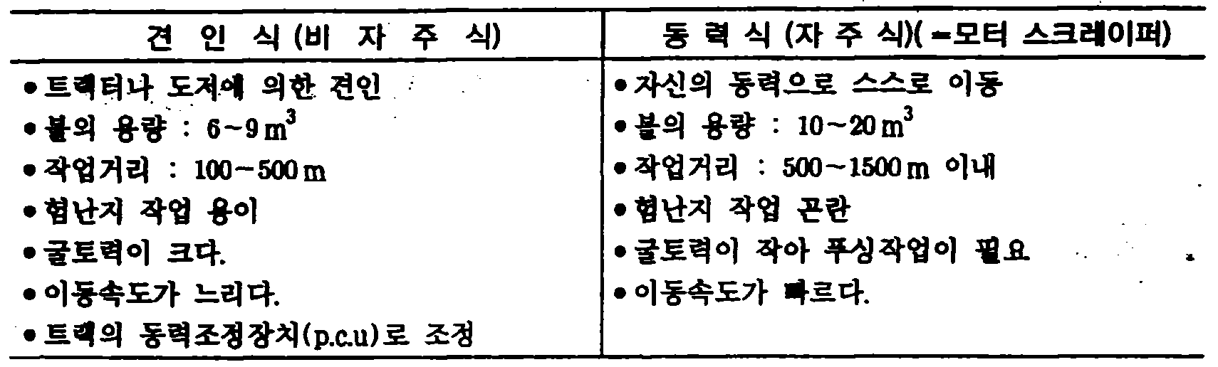
스크레이퍼의 주요 구성부분 및 역할Main Components and Roles of Scrapers
볼(Bowl)Bowl
토사를 운반하는 용기로서 스크레이퍼의 중심부를 이루며 진행방향의 아래면에 삽날(Cutting edge)을 붙여 전진하면서 조작장치로 볼을 굴삭면에 자중으로 밀어 굴삭, 적재한다.As a container for transporting soil, the center of the scraper is formed and the cutting edge is attached to the lower surface of the traveling direction, and the ball is pushed to the excavation surface by the operation device to excavate and load.
에이프런(Apron)Apron
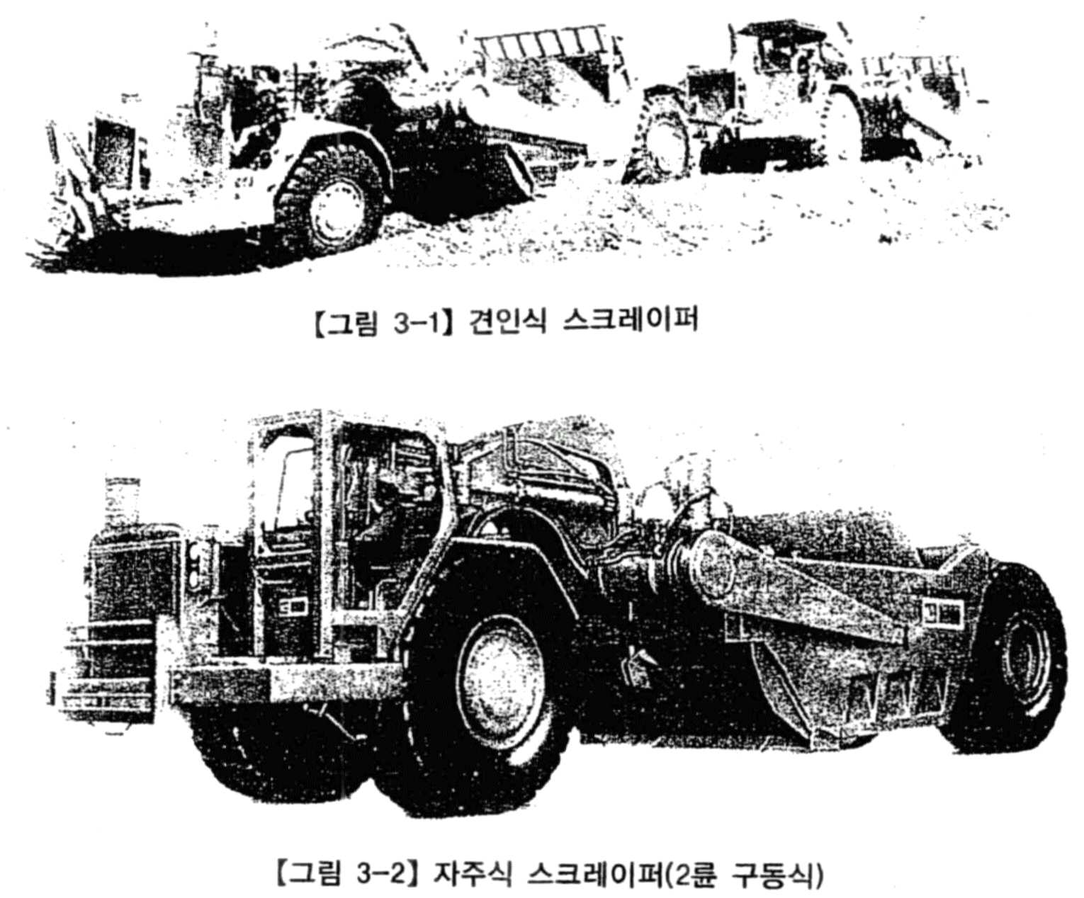
볼의 전면에 설치하며 볼의 토사가 흘러 내리지 않도록 하는 역할을 하며, 적재 및 사토시에는 위로 올리게 한다.It is installed on the front of the ball and prevents the soil from flowing down the ball.
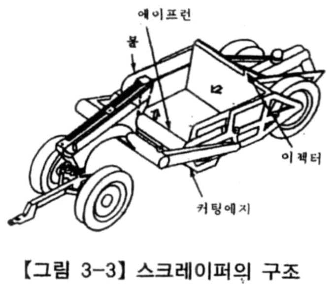
이젝터(Ejector)Ejector
일명 테일 게이트라 하며 볼의 뒷면에 위치하고 볼내의 토사를 밀어내는 역할 및 토사를 적재할 수 있도록 넓은 공간을 만드는 일The so-called tailgate is located on the back of the ball to push out the soil inside the ball and to make a large space for loading the soil.
요크(Yoke)York
볼과 트랙터를 결합해 주는 부재Member joining ball and tractor

스크레이퍼의 작업량(피견인식 스크레이퍼)Workload of Scraper (Towed Scraper)
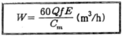
여기서, Q : 볼 1회 흙운반 적재량Where Q is the ball loading capacity
f : 토량환산계수 f : soil conversion factor
E : 스크레이퍼의 작업효율 E : Work efficiency of scraper
C m : 사이클시간 C m : Cycle time
개요summary

그레이더는 토목공사에 사용하는 것으로 주로 정지작업을 하며 균토판(삽날 : 블레이드)을 장치하여 지표를 긁어 땅을 고르는 장비Grader is used for civil works, and it is mainly for stopping work. It is a device for leveling the ground by scraping the surface by equipping a flat plate (blade: blade).
토공기계의 대패라 불리우는 장비로서 지면을 매끈하게 다듬어 끝맺음을 할 때 사용하는 장비This equipment is called the plane of earthworking machine. It is used to finish the surface smoothly.
용도 및 규격Usage and standard
용도Usage
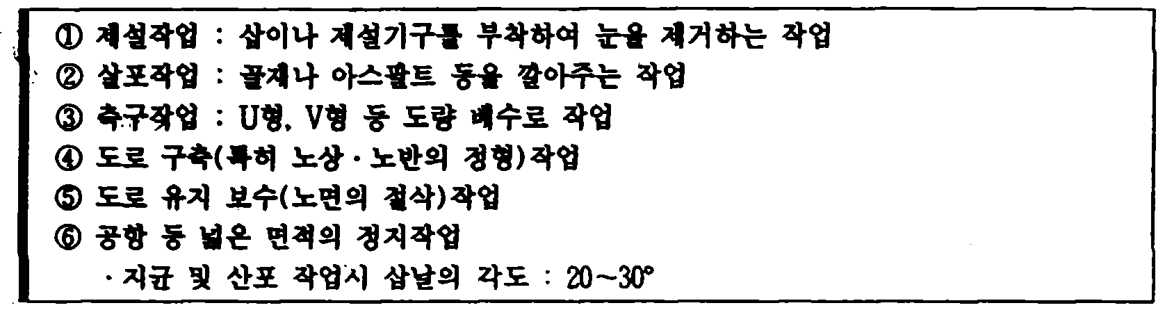
성능 표시 : 삽날(블레이드)의 길이로 표시Performance indication: Shown as the blade length
동력전달순서Power transmission sequence

·모터 그레이더의 주차 브레이크는 변속기어의 하부축을 잡아주며 외부 수축식이다.The parking grader of the motor grader holds the lower shaft of the transmission gear and is externally retractable.
·동력전달순서Power delivery sequence
![]()
![]()
블레이드의 추진각도와 절삭각도에 있어 하표와 하도를 다음과 같이 설명한다.In the propulsion angle and cutting angle of the blade, the table and the underlining will be described as follows.
추진각도Propulsion angle
그레이드 중심선과 블레이드가 이루는 각으로 단단한 땅에는 작게, 정지작업시에는 70∼90°정도로 작업The angle between the grade centerline and the blade is small for hard ground and 70-90 ° for stationary work.
절삭각도Cutting angle
절삭지면에 대하여 블레이드 절삭날이 기울어져 있는 각도Angle of inclination of the blade cutting edge with respect to the cutting surface
절삭작업시에는 작게. 정지작업시에는 크게 잡는다.Small when cutting. Hold large when stopping.
그레이더 본체와 배토판과의 각도를 조절하여 흙을 옆으로 밀어낼 때 45∼60°정도로 하고 끝마무리에서는 90°정도로 한다.Adjust the angle between the grader body and the top plate to push the soil to the side, and set it to about 45 to 60 degrees, and finish it to about 90 degrees.
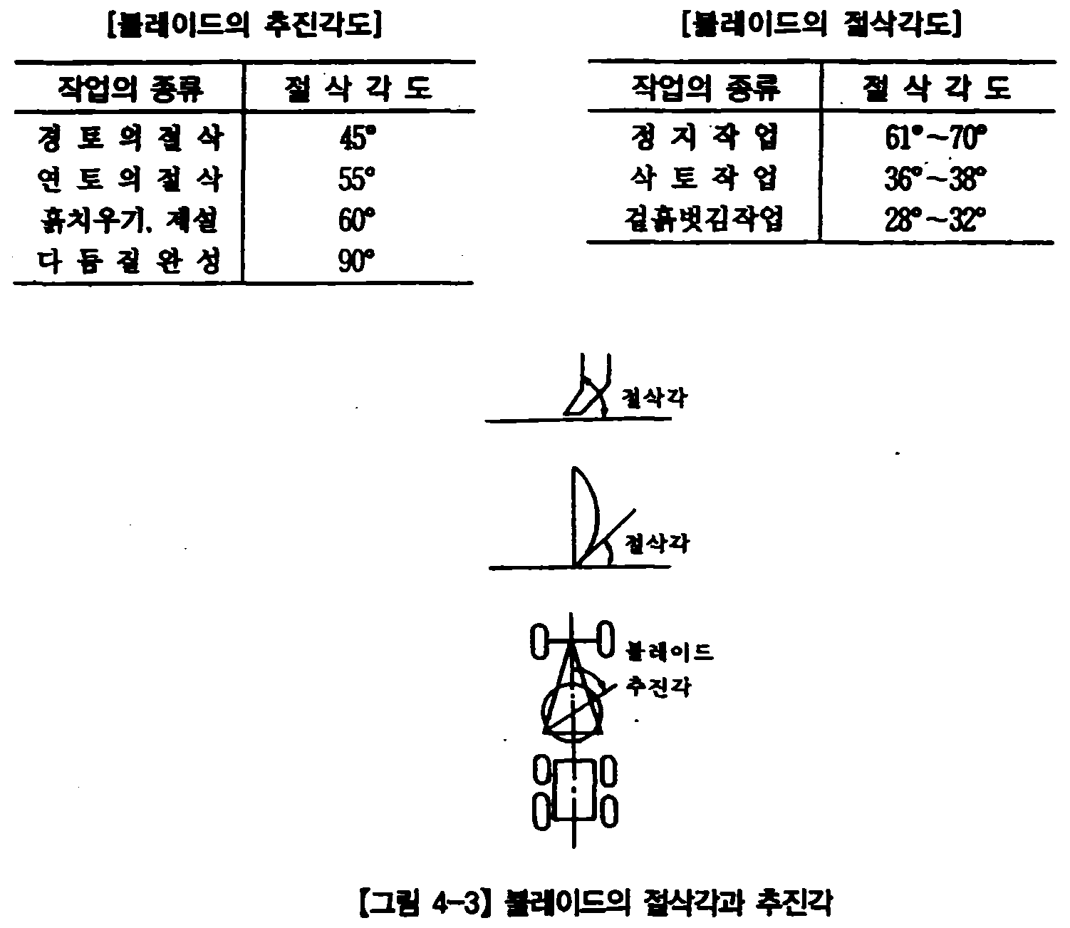
블레이드 용량Blade capacity
![]()
![]()
단. Q : 블레이드 용량(m3)only. Q : Blade Capacity (m 3 )
B : 블레이드 폭(m) B : blade width (m)
H : 블레이드 높이(m) H : blade height (m)
조향장치의 최소 회전반경Minimum turning radius of steering system
![]()
![]()
차등기구가 없는 이유Reason for no differential
작업성질상 직진성을 좋게 하여 다듬질 정밀도를 높이고, 능률을 올리기 위해서이다.This is to improve the finishing precision and improve efficiency by improving the straightness in terms of work quality.
개요summary
셔블계 굴착기는 가장 오래전부터 사용한 적재기계로서 굴착기계로 사용하는 것 외에 프런트 어태치먼트(Front attachment)를 설치하여 많은 작업을 할 수 있는 다목적기계이다.Shovel type excavator is the longest used loading machine, and it is a multipurpose machine that can do a lot of work by installing front attachment.
셔블 또는 크레인을 기본형으로 하고, 각종 부속장치의 교환에 의하여 여러 가지 굴삭작업과 크레인 작업을 하는 기계로서 상부회전체는 360°선회가 가능하다.The excavator or crane is the basic type and various excavation and crane work is performed by exchanging various accessories. The upper rotating body can rotate 360 °.
굴삭기의 구조에 대하여 다음과 같이 설명한다.The structure of an excavator is demonstrated as follows.
주요 3대 구성요소Three major components

굴삭기의 외부구조External structure of excavator
굴삭기의 분류에 있어서In classification of excavator
주행장치에 따른 분류에 의하면 크롤러형과 휠형에 트럭탑재형으로 분리한다According to the classification according to the traveling device, it is divided into crawler type and wheel type by truck-mounted type.
먼저 크롤러형은 견인력이 크고 협소한 장소에서의 작업이 용이하며, 습지, 사지, 활지의 운행이 용이하고 안정성이 아주 좋다.First, the crawler type has a high traction and easy to work in a narrow place, and the wetlands, limbs and live lands are easy to operate and have very good stability.
그리고 포장도로 운행이 곤란하고 주행속도가 3.2 km/hr로 느리다.It is difficult to drive on the pavement and slow at 3.2 km / hr.
다음의 휠형은 포장도로와 교량 등의 운행이 좋고 작업장의 이동이 용이한 형식으로 주행속도는 40 km/hr 정도이고 작업능률은 크롤러형보다 30∼35 % 높다.The following wheel type is good for pavement roads and bridges, and it is easy to move the workplace. The driving speed is about 40 km / hr and the work efficiency is 30 ~ 35% higher than the crawler type.
그리고 트럭 탑재형은 주행속도가 60 km/hr정도로 기동성은 좋으나 작업능률이 나쁘다.In addition, the truck-mounted type has a high maneuverability of about 60 km / hr, but has poor work efficiency.
조작방법에 따른 분류에 있어 수동식과 유압식에 공기식과 전기식으로 분리한다In the classification according to the operating method, separate the manual and hydraulic type by air or electric type.
크기에 의한 분류에 있어서 소형과 중형에 대형으로 분리한다Divided into small and medium and large in classification by size
그리고 소형은 철도, 트레일러 등의 수송에 임하여 둥글게 적재할 수 있는 일단의 한계로서 기체중량 20t 이하의 것을 말하며 바켓 용량 0.6 m3 이하의 셔블과 중형은 바켓용량 3 m3 크레인 조상능력 10 t 정도까지이며 대형은 중형 이상의 기체 중량의 것이 된다.And miniature railway, as one limit of which may be the occasion round loaded in transport such trailers refers to a gas weight 20t below bucket capacity 0.6 m 3 excavator, medium was bucket capacity of more than 3 m 3 crane ancestor capacity up to 10 t And large are those of medium or more gas weight.
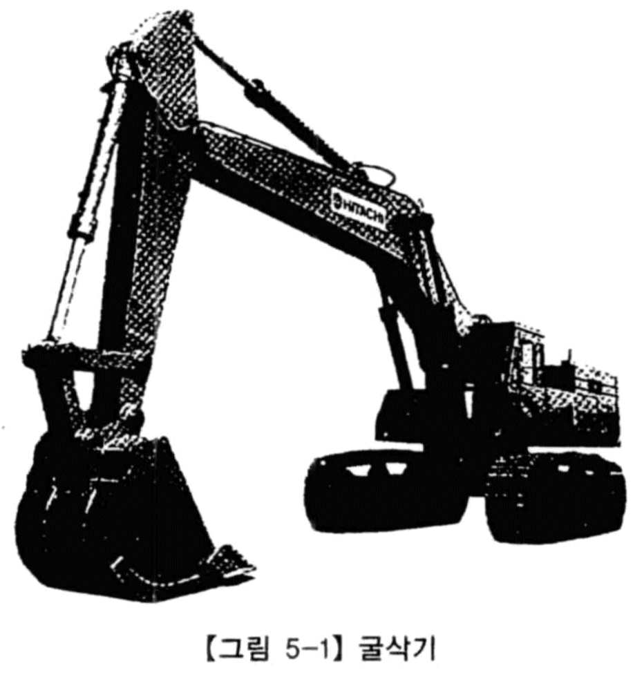
이같은 굴삭기의 성능 표시 방법은 백호, 파워셔블, 드래그 라인, 클램셸 버킷(Bucket)의 용량(m)으로 표시하고 어스 드릴은 굴착구경으로 표시하며 파일 드라이버는 해머의 중량으로 표시되고 크레인은 최대 권상하중을 (ton)으로 표시한다The performance of these excavators is represented by the capacity of the backhoe, power shovel, dragline, clamshell bucket (m), earth drill by the digging diameter, pile driver by the weight of the hammer and crane by the maximum hoisting. We display middle as (ton)
그리고 셔블, 백호, 드래그 라인, 클램셸의 작업량 산정식은 아래와 같다The formulas for calculating the shovel, backhoe, dragline and clamshell are as follows:

단. 
한편 프런트 어태치먼트(Front attachment)의 종류에 있어On the other hand, in the kind of front attachment
백 호(Back hoe)는 작업위치보다 낮은 굴착에 쓰이고 하천, 건축의 기초 굴착에 사용된다. (도랑파기) 기계보다 낮은 쪽을 굴삭한다. 기계보다 높은 곳에 있는 운반장비에 적재가 가능하다. 주로 좁은 위치를 굴삭한다. 상기 백호는 대형산 불 예방용 방재 및 방제 배관라인 설치공사에 적합하다Backhoe is used to excavate lower than the working position and to excavate foundations of rivers and constructions. (Ditch) Excavate the lower side of the machine. It can be loaded on transport equipment higher than the machine. Excavates mainly in narrow locations. The backhoe is suitable for large fire prevention disaster prevention and pipeline installation.
그리고 파워 셔블(Power shovel)은 원형으로 작업위치보다 높은 굴착에 적합하며 산. 절벽 굴착에 쓰인다. (삽)Power shovels are circular and suitable for excavation higher than the working position. Used for cliff excavation. (shovel)
![]()
![]()
또한 유압셔블의 특징(기계로프식과 비교시)에 의하면 In addition, according to the characteristics of the hydraulic excavator (compared to the mechanical rope type)
첫째는 구조가 간단하다. First, the structure is simple.
둘째는 프론트의 교환과 주행이 쉽다. Second, the front is easy to change and run.
세째로 보수 및 운전조작이 쉽다.Third, maintenance and operation is easy.
끝으로 모든 면에서 기계로프식 보다 우수하다는 것이었다Finally, it was superior to mechanical rope in every way.
그리고 드래그 라인(Drag line)의 긁어파기에는 먼저 작업반경이 크며 수중굴착에도 용이하다.는 것이었으며 다음은 지면보다 낮은 곳을 넓게 굴삭하는데 사용되었고 그 다음에는 하천의 사리채취에도 사용되며 끝으로 단단하게 다져진 토질이나 자갈채취에는 적합하지 않다.는 것이었다.In addition, the scraping line of the drag line has a large working radius and is easy to excavate underwater.Then, it is used to excavate wider areas than the ground, and then it is used to collect river streams. It is not suitable for soil or gravel mining.

한편 어스 드릴(Earth drill)은 무소음으로 대구경의 깊은 구멍을 굴착하여 현장 박기조정에 사용된다는 것이고 본 발명의 교각 설치에 적합하다Earth drill, meanwhile, is used for field drilling adjustment by excavating deep hole of large diameter without noise and is suitable for pier installation of the present invention.
다음의 크레인(Crane)은 중량물의 하역, 높은 건축공사에 쓰인다. 즉, 버킷 대신 훅(Hook)을 장치하고, 중량물을 들어올리는 기계이다.The following cranes are used for heavy lifting and high construction work. In other words, it is a machine that mounts a hook instead of a bucket and lifts a heavy object.
그리고 파일 드라이버(Pile driver)는 항타용 기구로서 콘크리트 말뚝이나 시트파일을 박는데 쓰인다. (기둥박기)로 교각 설치용에 적합하다.The pile driver is a driving mechanism used to drive concrete piles and sheet piles. It is suitable for pier installation as (pilling).
또한 클램셸(Clamshell)은 수중 굴착, 폭발작업 등 일정장소의 굴착에 적합하다. (조개장치)는 것이었고 지반 밑의 좁은 장소에서 깊게 수직굴삭에 사용되는 것이며 망간단괴 재취용에 적합하다. 자갈, 모래, 흙 등을 굴삭하여 덤프트럭에 적재하는데 많이 사용데 단단한 지반의 굴삭에는 적합하지 않다.는 것이었다.In addition, clamshell is suitable for excavation of certain places such as underwater excavation and explosion work. It is used for deep vertical excavation in narrow places under the ground and is suitable for reusing manganese nodules. It is often used to excavate gravel, sand, soil and so on dump trucks, but it is not suitable for excavation of solid ground.
끝으로 트렌처는 도랑을 파기 위하여 사용하는 기계로 적합하다 것이다.Finally a trencher is one that fits into the machine used to dig ditch.
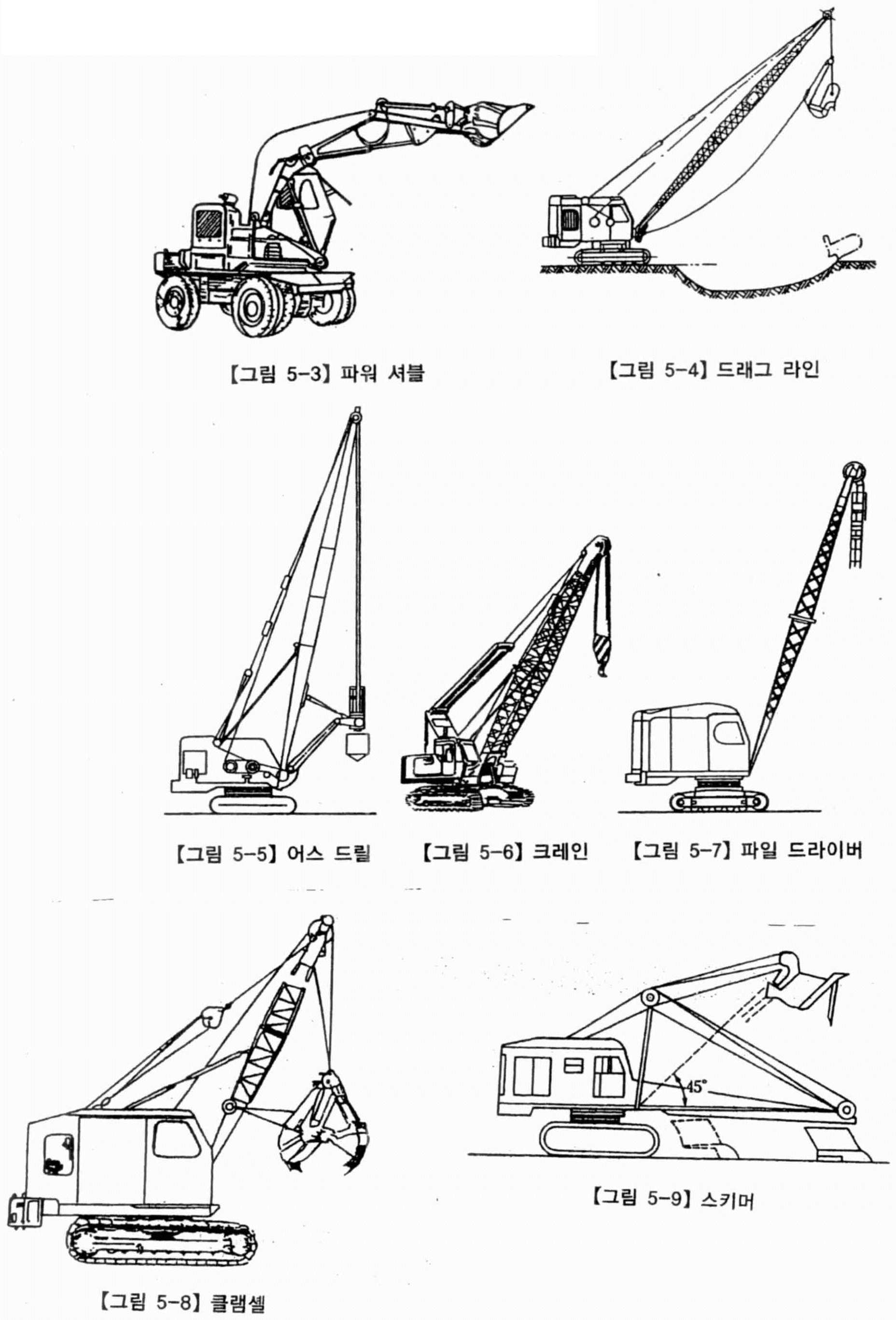
다음의 굴삭기의 작업범위로는 최대 굴삭깊이는 버킷투스의 선단을 최저위치로 내린 경우 지표면에서 버킷투스의 선단까지의 길이로서 최대 굴삭반경(=최대작업반경)은 선회할 때 그리는 원의 중심에서 버킷투스의 최대 수평거리이고 최대 덤프높이는 최대 지상고이었다The working range of the next excavator is the length from the ground surface to the tip of the bucket tooth when the tip of the bucket tooth is lowered to the lowest position, and the maximum digging radius (= maximum working radius) is the center of the circle to be drawn when turning. The maximum horizontal distance of the bucket tooth and the maximum dump height were the maximum ground clearance.
그리고 스키머(Skimmer)의 구조 및 기능에는 선회대에 달린 붐을 따라 버킷이 체인의 힘으로 이동되면서 지표를 얇게 깎는 건설장비인데 좁은 장소에서 얇은 굴착에 적당한 것이고 이의 용도에 있어서 대형기계로는 작업이 곤란한 협소한 장소에서 얇은 굴착에 사용한다는 것이었다And the skimmer's structure and function are construction equipment that cuts the surface thinly as the bucket is moved by chain force along the boom attached to the turning table, which is suitable for thin excavation in a narrow place. Was to be used for thin digging in difficult places
한편 리퍼와 루터(Ripper, Rooter)의 구조 및 기능에 있어 지반이 단단하고 견고하여 굴착이 곤란한 경우에 사용되며 대형 불도저의 뒤에 부착하여 자체의 중량으로 발톱날(2∼3개)을 이용하여 단단한 지반을 긁어 파헤치는데 적당하다는 것이었으며 이의 용도에 있어서 나무뿌리 파헤치기, 아스팔트나 콘크리트 포장 파헤치기와 암석 또는 옥석류의 제거에 굳은 땅 파헤치기에 사용되는 것이었다.On the other hand, it is used when the excavation is difficult because the ground is hard and solid in the structure and function of Ripper and Rooter.It is attached to the back of large bulldozer and it is hard to use claw blades (2 ~ 3 pieces) by its own weight. It was suitable for scraping and digging the ground, and for its purposes, it was used for digging tree roots, digging asphalt and concrete pavements, and digging hardened ground for the removal of rocks or jade.
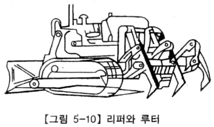
크레인(Crane ; 기중기, 861)의 개요에 따라서 기중기라 부르며 중량물의 들어올리기와 내리기, 다른 작업장치를 이용하여 파쇄작업, 폐철 수집과 건축공사 등에 많이 사용 토목건설공사에 사용되는 토사, 석재, 기자재 등의 이동, 운반을 목 적으로 차체 전면에 훅, 클램셸, 드래그 라인 등 전부장치를 설치하여 다목적으로 사용되는데에는 구조 및 명칭은 하표와 하도와 같이 설명한다According to the outline of Crane (861), it is called a crane and is used for lifting and unloading heavy materials, crushing by using other working devices, collecting waste iron, and building construction. For the purpose of moving and carrying the light, all the devices such as hooks, clamshells, and drag lines are installed on the front of the vehicle body.
기본 주요 3부 명칭

구조 및 명칭에는 훅 그 이외 하도에 기재한 바와 같다.The structure and name are as described in the hook and the other below.

규격(성능)표시방법으로는 최대 권상하중을 톤(ton)으로 표시하는데 크레인의 7가지 기본동작은 아래와 같다.In the standard (performance) marking method, the maximum hoisting load is expressed in tons. Seven basic operations of the crane are as follows.

상기 같이 크레인의 6개 전부장치(작업장치)에는 먼저 크레인(갈쿠리 : Hook)은 일반적인 기중작업, 화물의 적재 및 적하작업 등에 사용되며 클램셸(조개 : Clamshell)은 토사 적재작업, 수직 굴토작업, 오물 제거작업, 수중굴착, 호퍼작업 및 깊은 구멍파기 작업에 적합하였으며 셔블(삽 : Shovel)은 토사 굴토, 경사면의 굴토, 차량의 토사 적재, 도로의 기초공사에 적합하고 드래그 라인(긁어파기 : Drag line)은 제방 구축작업, 배수로 구축작업, 평면 굴토 및 수중작업 차량에 토사를 적재시 적합하며 트렌치호(도랑파기 : Trench hoe)는 배수로 작업, 매몰 작업, 굴토작업, 채굴작업, 송유관매설작업에 적합하였고 파일 드라이버(기둥박기 : Pile driver)는 건물 기초공사 작업시 기둥박기 작업, 교량의 교주 항타작업 등에 사용되는 것으로서 상기 6개의 크레인 해양발전소 몸체(1)를 조립하는데 주요 장비이다As described above, the first six cranes (work equipment) of the crane (cracker: hook) is used for general lifting work, loading and unloading work of cargo, and clamshell (sea clam: clamshell) is earthwork loading work, vertical excavation work, It is suitable for dirt removal work, underwater excavation, hopper work and deep hole digging. Shovel is suitable for earth excavation, excavation of slope, vehicle soil loading, road foundation work, and drag line. The line is suitable for dike construction, drainage construction, flat pit and underwater vehicles, and the trench hoe is used for drainage, burial, burial, mining, and pipeline laying. The pile driver, which is suitable, is used for the pillar laying work and the pontoon piering work of bridges when building foundation works. It is the main equipment to assemble the body (1)
그리고 붐(Boom)의 운전각도는 아래와 같다.And the driving angle of the boom is as follows.
최소 제한각은 20°(단, 백호는 최소 제한각을 제한받지 않음)에 최대 제한각은 78°이며 최대 안전각은 66°30'로서 보통 작업각도는 45∼65°이다. 그리고 크레인(기중기)작업시 물체의 무게가 무거울수록 붐(Boom)의 길이는 짧게 하고 각도는 크게 한다.The minimum limit angle is 20 ° (but the backhoe is not limited to the minimum limit angle), the maximum limit angle is 78 °, the maximum safety angle is 66 ° 30 ', and the working angle is usually 45-65 °. And the heavier the weight in crane work, the shorter the boom and the larger the angle.
크레인의 분류에는 크롤러식과 트럭식으로 구분하는데 주행장치에 의한 분류는 하표와 같다.There are two types of cranes: crawler type and truck type.

사용용도별 종류에 있어 다음과 같이 분리된다It is separated as follows according to kind by use
드래그 크레인(Drag crane)의 기능은 접지압이 크며, 연약 지반에서는 작업이 불가능하나 기동성이 좋다 것이고 용도는 고층건물의 철골 조립, 자재의 적재 운반, 항만 하역작업 등에 사용되었다The function of the drag crane is that the grounding pressure is large, and it is impossible to work on the soft ground, but the maneuverability is good. The purpose of the drag crane is used for the assembly of steel frame of high-rise buildings, the transportation of materials, and the port unloading work.
타워 크레인(Tower crane)의 구조 및 기능은 높은 탑위에 짧은 지브나 해머 헤드식 트러스를 장치한 크레인이었고The structure and function of the tower crane was a crane equipped with a short jib or hammerhead truss on a high tower.
용도 : 높이를 필요로 하는 고층빌딩이나 건축현장에 많이 사용되었으며Use: It is used in high-rise buildings or construction sites that require height.
유압 크레인(Hydraulic crane)의 구조 및 기능은 유압으로 하여 장치를 조작하는 이동 크레인으로서 붐(Boom)은 보통 5∼10m까지 신축가능하고 권상하중은 보통 3∼10ton이다는 것이고 용도는 항만 하역공사, 토목공사, 전주작업, 중량물의 권상작업 등에 사용되었고The hydraulic crane's structure and function are hydraulic cranes that operate the device. The boom is usually telescopic up to 5-10m and the lifting load is usually 3-10ton. It was used for civil engineering work, electric pole work, heavy work lifting work,
케이블 크레인(Cable crane)의 구조 및 기능은 양끝을 타워(Tower)에 굵은 케이블을 쳐서 트롤리를 달아 올리는 방식이며 용도는 댐(Dam)공사시 콘크리트나 자재 운반용으로 사용되었다The structure and function of the cable crane is to raise the trolley by putting a thick cable on the tower at both ends and it is used for concrete or material transportation during dam construction.
데릭 크레인(Derrick crane)은 본 발명 주요 구성 부위로 상기 데릭 크레인의 구조 및 기능은 철골제 마스트의 밑부분에서 비스듬히 붐(Boom)을 세워 블록을 지나 와이어 로프로 매단 중량물을 윈치로 감아올려 옮기는 기계이며 용도는 철골의 조립, 기초공사, 교량의 가설작업 등에 사용되고 종류로는 다음과 같었다.Derrick crane (Derrick crane) is a main component of the present invention, the structure and function of the derrick crane is a machine that moves the heavy weight to the winch by hoisting the wire rope through the block by booming (block) at the bottom of the steel mast Its use is used for assembly of steel frame, foundation construction, construction work of bridge, etc.
가이 데릭은 재료빔에 대해 짐을 매다는 능력이나 작업반경이 크고 조립해체가 용이하며 하역작업. 중량물의 이동. 철골 조립작업 등에 사용된다 그리고 3각 데릭은 좁은 장소나 빌딩의 옥상작업에 알맞으며 기초가 없어도 되고, 차륜에 설치한 경우는 이동이 용이하므로 파일 해머작업, 교량가설, 항만 하역 등에 사용되는 것이었다Guy derrick has the ability to load the material beams, the working radius is large, easy to disassemble and unloading. Movement of heavy objects. It is used for steel assembly work, and the triangular derrick is suitable for the roof work of a narrow place or building, and there is no need for foundation, and it is used for pile hammer work, bridge construction, port unloading, etc.
한편 트랙터 크레인(Tractor crane)은 먼저 셔블계 굴착기의 상부체에 크레인을 부착한 것으로 휠식과 크롤러식이 있다. 다음의 아웃리거는 안전성을 유지해 주고 타이어에 하중을 받는 것을 방지하여 타이어 및 스프링 등 하중으로 인하여 마모 파손되는 것을 방지해 주는 역할을 한다.On the other hand, the tractor crane (Tractor crane) is first attached to the crane of the excavator-based excavator is a wheel type and crawler type. The following outriggers maintain safety and prevent the tires from being loaded, preventing the wear and tear of tires and springs from being damaged.
또 한편 천정 주행 크레인(=문형크레인)On the other hand, ceiling running crane (= door crane)
천정에 주행 레일을 설치하여 이동하도록 한 크레인이며 보통 콘크리트 빔(Beam)의 제작 및 가공현장 등에 사용되는데 고정형은 공장, 창고 등에서 적재작업에 사용한다. 하지만 건설공사에는 사용하지 않는다. 그리고 주행형은 건설공사에 많이 사용한다It is a crane that moves by installing a traveling rail on the ceiling. It is usually used for manufacturing and processing concrete beams. The fixed type is used for loading work in factories and warehouses. However, it is not used for construction work. And the driving type is used a lot in construction work.
이같이, 체인 블록(Chain block, 648)은 보통 하역용으로서 최대 15ton까지 인력으로 끌어올릴 수 있다.As such, the chain block 648 can normally be pulled up to a maximum of 15 tonnes for unloading purposes.
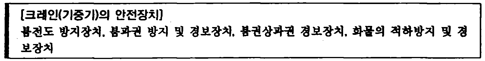
기중기의 권상, 권하 작업시의 안전장치는 브레이크와 제한스위치이다.Safety devices for hoisting and hoisting cranes are brakes and limit switches.
그 다음 해상크레인은 교량의 대형 강구조물의 운송 및 가설. 초대형 시설물의 운송 및 설치, 해상 구조물 운송 및 설치에 사용되는데 드레그 크레인과 타워 크레인에 유압 크레인과 케이블 크레인 및 클램셸 부착물을 가진 크레인이 포함된다.The offshore crane is then transported and constructed for the large steel structures of the bridge. It is used for the transportation and installation of very large facilities, and the transportation and installation of offshore structures, including hydraulic cranes, cable cranes and cranes with clamshell attachments to drag cranes and tower cranes.


로더의 개요에 있어In the outline of the loader
일명 적재기라 하며 트랙터 본체 전면에 셔블(Shovel)장치를 하여 건설공사에서 자갈, 모래, 흙 등을 퍼서 덤프(Dump)차에 적재하는 것이 주용도인 건설장비이다.The so-called loader is a construction equipment whose main purpose is to use a shovel device on the front of the tractor body and to spread gravel, sand, soil, etc. in the construction work and load it in a dump car.
첫째 규격(성능)표시방법으로는 표준 버킷(Bucket)용량을 m3로 표시한다The first standard (performance) display method is to express the standard bucket capacity in m 3 .

둘째로 로더의 분류에 있어Secondly, in the classification of loaders
먼저 주행방법에 의한 분류로서First, as a classification by driving method
크롤러형 로더(Crawler type loader)(장궤식=무한궤도식=크롤러식=셔블 로더)는 크롤러 트랙터 앞에 버킷(Bucket)을 설치하여 험악한 늪지나 모래땅에서 작업을 수행할 수 있으며 수중작업이 가능함이며 Crawler type loader (long track = crawler = crawler loader) can be installed in the rugged swamp or sandy ground by installing a bucket in front of the crawler tractor.
휠형 로더(Wheel type loader)(차륜식=타이어식=휠식 로더)는 휠형 트랙터 앞에 버킷(Bucket)을 설치한 것으로 평탄한 작업장에서 기동성이 우수하고 작업 수행능력이 크며 포장한 도로에서 작업 용이하고Wheel type loader (wheel type = wheel type loader) is a bucket installed in front of the wheel type tractor. It has excellent maneuverability in a flat work place, high performance and easy work on paved roads.
반무한 궤도식 로더는 전, 후륜의 한쪽을 무한궤도식으로 하고, 다른 한쪽에는 타이어를 장착한 것으로 무한궤도식과 차륜식의 단점을 보완한 기종이다.The semi-infinite track loader is one of the front and rear wheels in the endless track type, and the other side is equipped with tires, which complements the disadvantages of the tracked and wheeled type.
그리고 레일식 로더는 레일 위를 주행할 수 있는 장치로서 터널이나 갱내에서 적재 작업을 한다.Rail loaders are devices that can run on rails and work in tunnels or gangs.
다음의 적하방식에 의한 분류 아래와 같다Classification by the following dropping method

한편 로더의 상차 적재방법 아래와 같다.Meanwhile, the loading method of the loader is as follows.

그 이외의 로더에는Other loaders
머크 로더(Muk loader)로서 터널공사에서 많이 사용하며 굴착공사에서 폭파된 토석 등을 운반차에 적재하는데 사용되며It is a muk loader, which is used in tunnel construction, and is used to load the soils that were blown up in the excavation work in the truck.
페이 로더(Pay loader)는 덤프트럭에 토사를 적재하는데 사용하며 가급적 서 서히 운행해야 하고 무부하 운전시 버킷(Bucket)을 올려서는 안된다.는 것이었다Pay loaders are used to load the soil in dump trucks and should be run as slowly as possible and should not raise the bucket during no-load operation.
다음 레일식 슬랙 로더는 터널이나 갱도 등의 굴삭작업에서 폭파된 슬래그를 운반차에 적재하는 전용 중기이며The next rail-type slag loader is a heavy machinery dedicated to loading slag blasted in a truck by excavation work such as tunnel or tunnel.
그리고 연속식 로더에는 개더링 암 로더로 각종 터널, 택지 조성, 석회석 채굴 등에 사용되었으며 스크루 엑스카베이터는 시가지의 지하 굴삭공사, 공장 또는 배안에서의 토사 적재작업에 사용되는 것이었고, 버킷 휠 엑스카베이터가 사용되었고 다음의 벨트로더가 사용되는 것이었다The continuous loader is used as a gathering arm loader for various tunnels, site constructions, limestone mining, and the screw excavator is used for underground excavation work in the city area, earth and sand loading works in factories or ships, and bucket wheel excavators. Was used and the following belt loader was used
다음의 스키드 로더는 갱도나 터널에서 작업하기에 알맞은 적재기계로서 작업량 산정식은 아래와 같다.The following skid loader is a suitable loading machine for working in tunnels or tunnels.
![]()
![]()
여기서
한편 덤프 트럭의 종류에는 다음과 같이 리어(Rear)덤프트럭은 짐칸을 뒤쪽으로 기울게 하여 짐을 부리는 트럭으로 토목공사에서 가장 많이 사용하고 있으며 사이드(Side)덤프트럭은 짐칸을 옆쪽으로 기울게 하여 짐을 부리는 트럭이고 보텀(Bottom)덤프트럭은 지브의 밑부분이 열려서 짐을 아래로 부릴 수 있는 것으로 트레일러 덤프차에 많이 사용되고 3방 열림 덤프트럭은 3방향으로 짐을 부릴 수 있는 트럭인 것이다.Meanwhile, the following types of dump trucks are used in civil engineering as rear dump trucks that tilt the luggage compartment to the rear, while side dump trucks are used to load the luggage by tilting the luggage compartment to the side. Bottom dump trucks are used for trailer dump trucks because the bottom of the jib is open, and the three-door open dump trucks are trucks that can load in three directions.
이에 덤프 트럭의 작업량 계산식은 하표에 하도와 같다The work load formula for dump trucks is as shown below.
트럭의 소요 대수 계산 : ![]()
![]()
트럭작업량 계산 : ![]()
![]()
여기서,
이같이 덤프 트럭의 주행저항에는 회전저항과 구배저항에 구동력의 계산식이 있다. Thus, the driving resistance of the dump truck has a formula for calculating the driving force in the rolling resistance and the gradient resistance.
회전저항(Wr)은 ![]()
![]()
구배저항은(Wg)은 ![]()
![]()
구동력은(Ws)은 ![]()
![]()
여기서
다음의 덤프터(Dumptor)는 단거리 운반의 특수 비포장 도로용 트럭으로 협소한 작업장에서 작업 가능하며The following dumpers are short-haul special off-road trucks that can work in tight workplaces.
그리고 기관차는 다음과 같이 운반거리가 1 km 이상인 경우에 사용하며 터널공사 방조제의 토운공사에 이용되었고 크기는 견인력을 표시하는 자중(ton)으로 표시된다.The locomotive is used when the transport distance is more than 1 km as follows, and it was used for the puncture of tunnel construction embankment, and the size is expressed in tons indicating the traction force.
또한 트랙터 및 트레일러는 중량물이나 장착물 및 건설기계(불도저, 롤러 등)를 적재한 피견인 트레일러를 트랙터에 의하여 운반하는 기계이며 트랙터의 주행장치는 크롤러식. 반크롤러식, 차륜식으로 구분한다In addition, tractors and trailers are machines for carrying a towing trailer by a tractor with heavy loads, loads, and construction equipment (bulldozers, rollers, etc.). We classify into semi-crawler type, wheel type
또 한편 삭도(Rope way)는 산간 양쪽에 철탑을 세우고 케이블을 연결한 후 60 m 마다 운반기를 배치하여 화물을 운반하는 기계로서 지형 및 도로조건 등에 제약을 받지 않는다는 점과 고장이 적으며 비교적 장거리 운반에 용이하다는 것이었다. 그리고 댐공사 등에서 골재 및 시멘트 등의 재료운반에 사용된다.On the other hand, ropeway is a machine that transports cargo every 60m after setting up a tower and connecting cables to the mountainside, and is not restricted by terrain and road conditions. It was easy to. It is also used for transporting materials such as aggregate and cement in dam construction.
이같은 왜건(Wagon)은 모터 스크레이퍼와 비슷하나 자력으로 흙깔기를 할 수 없고 싣기기계로부터 적재한 토사를 운반하는 기계이며This wagon is similar to a motor scraper, but it is a machine that carries out the soil from the loading machine.
☞ 트랙터 드로운 왜건은 트랙터에 의해 견인되며, 앞, 뒤 끝에 차축과 바퀴를 붙인 것으로서 풀(full) 트레일러라고도 한다.Tractor Draw wagons are towed by tractors, also called full trailers, with axles and wheels at the front and rear ends.

다음은 지게차(포크리프트 : Forklift)의 개요로서 화물을 들어 올리거나 내리는 장비이며, 자동차와 공통되는 점이 많은 장비로서 창고나 부두 옥내외에서 널리 사용되는 장비. 즉, 경화물의 단거리 운반 및 적재와 적하작업에 효과적이며 규격표시는 들어 올릴 수 있는 용량을 톤(ton)으로 표시(1톤 이상 중기)하고 이에 대한 특징으로는 조종석에 설치되어 있는 틸트 레버는 마스터를 앞으로 5∼6°(전경각이라 함), 뒤로 10∼12°(후경각이라 함)기울일 수 있고 높이는 최대 4500mm, 최소 3000mm(최대 양고라함)움직일 수 있다.The following is an outline of a forklift, which lifts and unloads cargo, and has a lot in common with automobiles. In other words, it is effective for short-distance transportation, loading and unloading of cured products, and the standard mark indicates the lifting capacity in tons (medium size more than 1 ton) and the tilt lever installed in the cockpit is the master. Can be tilted forward 5-6 ° (referred to front angle), backwards 10 to 12 ° (referred to rear angle) and height can be up to 4500mm and at least 3000mm (refer to maximum lift).
최소 반경이 매우 적다. (65∼75°안쪽 바퀴의 조향각도)The minimum radius is very small. (Steering angle of wheel within 65 ~ 75 °)
유압피스톤의 압력은 110∼130 kgf/cm2가 된다.The pressure of the hydraulic piston is 110 to 130 kgf / cm 2 .
전륜 구동, 후륜 환향식으로 되어 있다.It is a front wheel drive and a rear wheel echo type.
☞ 지게차의 스티어링 장치 : 후륜환향식☞ Forklift Steering System: Rear Wheel
유압으로 작동하는 마스터 뭉치가 설치되어 있다. (유압 70∼130 kgf/cm2)Hydraulically operated master bundles are installed. (Hydraulic 70-130 kgf / cm 2 )
운행시 포크는 지상으로부터 150∼200mm 정도 올리고 운행한다.During operation, the fork is operated by raising 150 ~ 200mm from the ground.
운행거리 250m 이내가 효율적이다.The driving distance is within 250m.
앞바퀴는 직접 프레임에 설치하며 뒷바퀴는 소형에서는 현가 스프링이 없으나 대형은 현가 스프링을 사용하는 것도 있다.The front wheels are mounted directly on the frame. The rear wheels do not have suspension springs on small ones, but large suspension suspension springs are used.
그리고 조종방법에는 효율적인 운반거리의 운반거리는 250m이내 작업에 적합하며 주행중 포크의 높이는 하물을 적재하여 운반시 포크의 높이는 150∼200mm정도 올리고 주행한다는 것이고 경사지 운반은 경사지 적하물 운반시 포크부(전면부)가 윗부분으로 향하고 후진하여 서행한다는 것이었다And the control method is the efficient transporting distance is suitable for the work within 250m and the height of the fork during driving loads the load and carries the height of the

이같은 컨베이어(Conveyor, 633)의 개요로서 자재 및 콘크리트 등의 운송에 주로 사용되며 설비가 용이하고 경제적이므로 많이 사용되며 종류에 있어서 As an outline of such a conveyor (633), it is mainly used for transportation of materials and concrete, and it is frequently used because equipment is easy and economical.
대형 컨베이어는 모래, 흙, 자갈, 쇄석 등의 운송에 사용한다는 것이고Large conveyors are used to transport sand, soil, gravel, crushed stone, etc.
스크류(Screw) 컨베이어는 모래, 시멘트, 콘크리트 운반 등에 사용한다는 것이며Screw conveyor is used to transport sand, cement, concrete, etc.
벨트(Belt) 컨베이어는 흙, 쇄석, 골재 운반에 가장 널리 사용한다는 것이었고 ☞ 크기 : ton·mBelt conveyor was the most widely used for transporting soil, crushed stone and aggregate. ☞ Size: ton · m
포터블(Portable) 컨베이어는 모래자갈의 운반 및 채취에 사용한다는 것이었다.Portable conveyors were used for transporting and collecting sand gravel.
이같이 특장 운반차에는 부정지 주행차와 유니모그에 호이스팅으로 아래와 같이 설명한다As described above, the body-carrier is described as follows by hoisting to a stationary vehicle and Unimog.
부정지 주행차는 진흙, 모래, 요철 등의 악조건에서 운반작업이 가능한 차륜식 전륜 구동차인데 The unsteady driving wheel is a wheel-type front wheel drive vehicle that can be transported under adverse conditions such as mud, sand, and irregularities.
유니 모그(Uni mog)는 농업용, 토목, 제설, 도로 유지관리 등 여러 분야에 널리 사용할 수 있는 차량이고 Uni mog is a vehicle that can be widely used in many fields such as agriculture, civil engineering, snow removal, road maintenance, etc.
호이스팅은 중량물을 달아 올려 운반하는 기계이다.Hoisting is a machine for lifting and carrying heavy loads.
롤러 개요로는 전압장치를 가진 자주적인 것으로 2개 이상의 매끈한 드럼롤러를 바퀴로 하는 다짐용 기계로 전압기계라고도 하며 주로 도로, 제방, 비행장, 활주로 등의 공사의 마지막 작업으로 노면을 다져주는 건설장비이다.As a roller outline, it is independent with a voltage device. It is a compaction machine that uses two or more smooth drum rollers as a wheel. It is also called a voltage machine. to be.
상기 롤러 규격 표시에는 롤러의 중량을 톤(ton)으로 표시하며In the roller standard marking, the weight of the roller is displayed in tons.
·롤러의 규격이 8∼15톤(ton)인 경우에는 자체 중량이 8ton이고 벨러스트(부가 하중)를 7ton까지 적재한다If the size of the roller is 8 to 15 tons, the weight is 8 tons and loads up to 7 tons of ballast (additional load).
그리고 롤러의 종류에 있어 전압식에 충격식과 가압방식의 진동식으로 분리한다.And for the type of roller, voltage type is divided into shock type and pressure type vibration type.
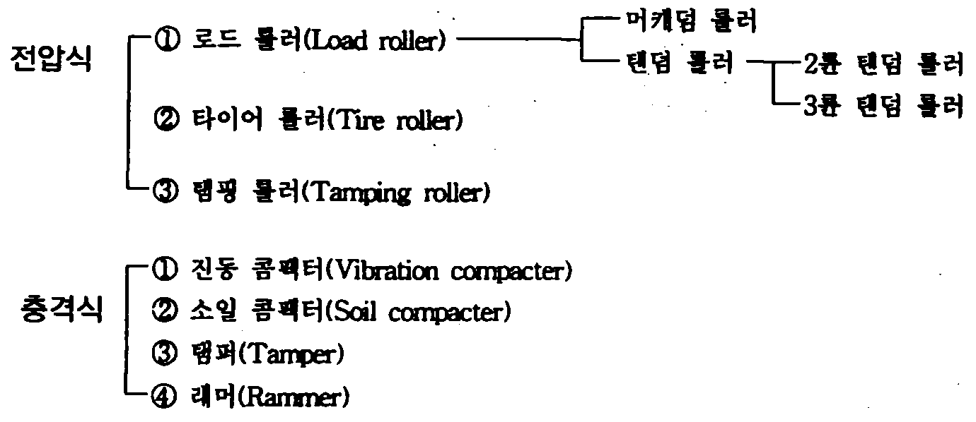
요부위 부가하중(Ballast : 중량추)은 롤러자체의 무게로 전압능력이 작을 때 부가하중을 실어서 전압능력을 높이는 것을 부가하중이라 한다. 자중의 2배 이상으로 추가시킬 수 있다. 부가하중은 철, 물, 모래 등을 이용하는데 타이어 롤러는 물탱크에 필요한 만큼 주입하고, 머캐덤, 탠덤, 탬핑롤러 등은 바퀴에 부가하중을 주입하여 전압능력을 높인다.The additional load (Ballast) is the weight of the roller itself, and when the voltage capacity is small, the additional load is loaded to increase the voltage capacity. Can be added more than twice its own weight. The additional load uses iron, water, sand, etc. Tire rollers are injected as necessary for the water tank, and the mercadom, tandem, and tamping rollers are injected with additional loads on the wheels to increase the voltage capacity.
그리고 가압방식에 의한 분류에 있어 전압식 다짐기계는 로드 롤러, 타이어 롤러, 탬핑 롤러로 분리되며 충격식 다짐기계는 래머, 탬퍼로 분리되고 진동식 다짐기계는 진동 롤러, 소일 콤팩터로 분리되었다In the classification by the pressurization method, the voltage compaction machine is divided into road roller, tire roller, and tamping roller, and the impact compaction machine is divided into rammer and tamper, and the vibration compaction machine is divided into vibratory roller and soil compactor.
다음의 롤러의 종류 및 특징에 의한 정적 압력에 의한 롤러는 롤러의 정적 자중에 의하여 노면을 다지는 것이고The roller by the static pressure by the following kinds and features of the roller is to compact the road surface by the static weight of the roller
그리고 머캐덤 롤러(Machadam roller)의 용도는 쇄석(자갈)기층, 노상, 노반, 아스팔트 포장시 초기 다짐에 적합하고 특징은 커브(Curve) 선회시 원활한 선회를 위하여 내륜의 속도를 감속시킬 수 있는 차동장치 사용하는And the use of Macadam roller is suitable for initial compaction in pavement (gravel) base, roadbed, subgrade, and asphalt pavement, and the feature is a differential device that can reduce the speed of inner ring for smooth turning during curve turning. using
☞ 차동기어로 뒤차축의 중앙부에 장착되어 커브를 돌때 양쪽바퀴를 서로 다른 속도로 주행시키는 장치이다.☞ The differential gear is installed at the center of the rear axle to drive both wheels at different speeds when turning the curve.

한편 탠덤 롤러(Tandem roller)의 용도는 찰흙, 점성토 등의 다짐에 적당하고 두꺼운 흙을 다지거나 아스팔트 포장의 끝마무리 작업에 사용되고 동력전달순서는 엔진→메인클러치→변속기→전, 후진기→차동장치→종감속장치→후륜순서로 진행되며 특징은 쇄석 다짐에는 사용할 수 없으며, 구동드럼에 중유 주입 평활한 철재 원통형륜으로 2축 탠덤과 3축 탠덤이 있다. 또한, 전·후륜의 조작을 따로 하여 다짐 폭을 넓힐 수 있다는 것이다.Tandem rollers are suitable for compacting clays and viscous soils and are used for compacting thick soil or finishing asphalt pavement. The power transmission sequence is engine → main clutch → transmission → forward and reverse → differential device. → It is a deceleration device → rear wheel sequence. Its characteristics cannot be used for compaction of crushed stone. It is a heavy-duty steel cylindrical wheel with heavy oil injection into the driving drum. It has two axis tandem and three axis tandem. In addition, the compaction width can be widened by separately operating the front and rear wheels.
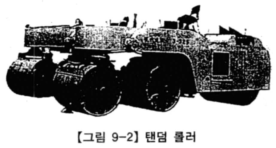
또한 탬핑 롤러(Tamping roller)의 용도는 토질이 연약한 곳을 다지는데 사용. 댐의 축대공사와 제방, 도로, 비행장 등이며 종류는 푸트 롤러, 턴 푸트 롤러, 테이프 푸트 롤러이고 특징은 강제의 원통륜에 다수의 돌기 형태의 구조물을 붙여 회전하므로서 다짐한다는 것이다Tamping rollers are also used for compacting soils with poor soil quality. Dam construction, embankment, road, airfield, etc. The types are foot rollers, turn foot rollers, tape foot rollers, and the characteristics are that they are compacted by rotating a number of protrusion-type structures on a forced cylindrical wheel.
또 한편 타이어 롤러(Tire roller)의 개요는 탠덤 롤러의 철재 바퀴 대신에 타이어를 부착한 것으로 피견인식과 자주식이 있다는 것이고 용도는 비행장 활주 로, 고속도로 아스팔트 포장시 노면을 일정한 압력으로 다지는데 사용하며 타이어의 공기압력은 1.5∼10kg/cm2이며 특징은 주행속도가 매우 크다는 것이었다.On the other hand, the outline of the tire roller is a tire attached to the tandem roller instead of the steel wheels, and there is a towing recognition and self-propelled use.It is used to compact the road surface at a certain pressure in pavement runway and highway asphalt pavement. Air pressure of 1.5 to 10kg / cm 2 and the characteristic was that the running speed is very large.

이같이 원심력에 의한 롤러는 자중에 원심력을 이용하여 노면을 다지는 것이고 In this way, the centrifugal roller compacts the road surface using centrifugal force in its own weight.
진동 롤러는 기진기로 다짐바퀴를 진동시켜 다지는 기계로 쇄석, 자갈, 흙, 아스팔트, 콘크리트 등의 다짐에 적합하며Vibration roller is a machine that vibrates compaction wheel with vibrator and is suitable for compaction of crushed stone, gravel, soil, asphalt, concrete, etc.
규격표시방법은 전장비의 중량인 것이다The standard marking method is the weight of all equipment.
이같이 충격식 다짐기계는 자유 낙하 충격을 다지기에 이용되며This impact compaction machine is used to compact free fall impact
래머(Rammer)는 소형 내연기관의 2행정 사이클기관 몸체에 다짐용 푸트를 단 것이고 탬퍼(Tamper)는 가솔린기관의 폭발력을 토크로 바꾼 후 크랭크축의 왕복운 동으로 변화시켜 스프링의 탄성체를 통해 다짐판에 전하는 구조로 되어 있으며 좁은 장소와 도로의 노견 다지기에 적합하고Rammer is a compacting foot on the body of a 2-stroke cycle engine of a small internal combustion engine. Tamper converts the explosive force of a gasoline engine to torque and changes it to a reciprocating motion of the crankshaft. It is structured to be suitable for narrowing roads and roads,
소일콤팩터(Soil compacter)는 소형가솔린엔진을 이용하여 진동을 일으키는 장치와 평판진동체가 조합된 다짐기계로서 자주식과 인력에 의한 이동식이 있다는 것이다 이처럼 중량에 비해 다짐효과가 크다는 것이고 사질토에 적합하다는 것이며 점성토에는 부적당하다는 것이었다.Soil compacter is a compaction machine that combines a vibration generating device and a plate vibrator using a small gasoline engine. It is self-propelled and movable by manpower. It was inadequate for clay.
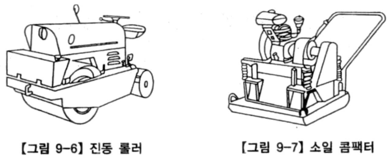
그 이의의 사항에는 롤러 다짐폭으로 1회 통과에 다져지는 폭(최대나비)에 의한The objection is due to the width (maximum butterfly) which is compacted in one pass with the roller compaction width.
선압인데 바퀴의 접지 중량을 그 바퀴의 폭으로 나눈 값(kg/cm)이다Linear pressure, the ground weight of a wheel divided by the width of the wheel (kg / cm)
그리고 소일 스태빌라이저(Soil stabilizer, 864)는 흙땜. 도로. 비행장 공사 등에 경제적인 다짐 안정공법으로 사용되며 실작업에서 각종 작업을 1개 기종으로 한번에 끝낼 수 있는 안정처리 시공기계이다. 이에 노상, 노반재료를 정확하게 현장에 투입한다는 것이며 자기 자신이 굴착하고 분쇄작업을 한다는 것이고 전체 재료를 균일하게 혼합한다는 것이었다.And the Soil Stabilizer (864) is soiled. road. It is used as an economical compaction stabilization method for aerodrome construction, etc. It is a stable construction machine that can finish various tasks in one model at a time in real work. This means that the roadbed and subgrade materials are accurately put on site, excavated and grounded by themselves, and the entire material is mixed uniformly.
다음의 콘크리트 포장기계의Of concrete pavers
·종류는 콘크리트배칭 플랜트(865)와 콘크리트 믹서의 콘크리트 믹서트 럭(868)에 콘크리트 펌프(869)와 콘크리트 피니셔(866)에 콘크리트 스프레더(867)로 분류된다Types are classified as concrete pump 869 in concrete batching plant 865 and concrete mixer rack 868 in concrete mixer as concrete spreader 867 in concrete finisher 866.

이에 상도는 콘크리트 제조기계로 콘크리트배칭 플랜트(Concrete plant, 865)의 개요는 골재 저장통, 개량장치 및 혼합장치를 가지고 있고 원동기가 달린 것으로서 각 재료를 소정의 배합률로 콘크리트를 제조 생산하는 장치이고 종류는 정치식, 가반식, 트로리식, 탑재중층식이 있으며 규격표시는 시간당 생산량을 톤으로 표시(ton/hr)하게 된다The top coat is a concrete manufacturing machine, the outline of the concrete batching plant (Concrete plant, 865) has an aggregate storage container, an improvement device and a mixing device, and is a prime mover, and is a device for producing and producing concrete at a predetermined mixing ratio. There are stationary, portable, trolley and on-floor layers, and the standard designation shows the hourly output in tons (ton / hr).
다음의 콘크리트 믹서의 하도와 같이 개요는 모래, 자갈, 시멘트, 물 등을 혼합(Mixer)하여 공사현장에서 효과적으로 작업하기 위한 기계인데 건식(Dryness type)은 시멘트 및 골재를 계량하여 투입하고, 주행도중 물을 가하여 혼합하면서 목적지(공사 현장)에 운송하며 혼합(Mixer)할 때의 구동은 유압에 의해서 이루어진다. 그리고 습식(Wetness type)은 완전히 혼합된 생콘크리트 혼합물을 교반하면서 운송하는 것으로 "에 지테이터"라고도 한다.As shown in the following concrete mixer, the outline is a machine for working effectively at the construction site by mixing sand, gravel, cement, water, etc.Dryness type is used to measure and input cement and aggregate, while driving Mixing by adding water, transporting it to the destination (construction site), and driving when mixing is performed by hydraulic pressure. Wetness type is also referred to as an "egitator" to transport a fully mixed raw concrete mixture with stirring.
규격표시는 1회 혼합할 수 있는 콘크리트 생산량(m3)으로 표시한다Specifications are expressed as the amount of concrete that can be mixed once (m 3 ).

한편 콘크리트 운반기계의 콘크리트 믹서 트럭 개요에 있어 자갈, 모래, 시멘트, 물을 혼합하여 건축공사시에 효과적으로 작업하는 기계이며 건식믹서는 시멘트나 골재를 투입하고 물을 가하여 혼합하면서 목적지에 수송하며 습식믹서는 완전히 혼합된 생콘크리트 혼합물을 교반하면서 수송하는데 규격표시는 용기내에서 1회 혼합할 수 있는 생산량(m3)으로 표시한다On the other hand, in the concrete mixer truck outline of the concrete conveying machine, it is a machine that works effectively during the construction work by mixing gravel, sand, cement and water, and the dry mixer adds cement or aggregate, adds water, mixes it, transports it to the destination, and wet mixer Transports a fully mixed raw concrete mixture with stirring. The specifications are expressed as the production capacity (m 3 ) that can be mixed once in a container.
또한 콘크리트 펌프(869)의 개요는 터널 속 교량 또는 건물속에서와 같이 제한된 공간에서 콘크리트를 운반할 때에 편리하며 펌프는 기계식과 액압식이 있다는 것이며 이동 설치가 간단하고 설치장소에 특별한 제한이 없다.는 것이고 유압 또는 유압 병용식으로 충격이나 진동이 적으며 취급이 간단하고 보수 점검이 용이하고 경제적이다는 것이었고 고층건물 및 장거리 콘크리트 이송에 사용된다는 것으로 하 도와 같이 설명한다In addition, the outline of the concrete pump 869 is convenient for transporting concrete in confined spaces, such as in a bridge or building in a tunnel, and the pump is mechanical and hydraulic, and the installation is simple and there is no particular limitation on the installation place. It is a hydraulic or hydraulic combination type, which has low impact or vibration, simple handling, easy maintenance and economical, and is used for transporting high-rise buildings and long-distance concrete.
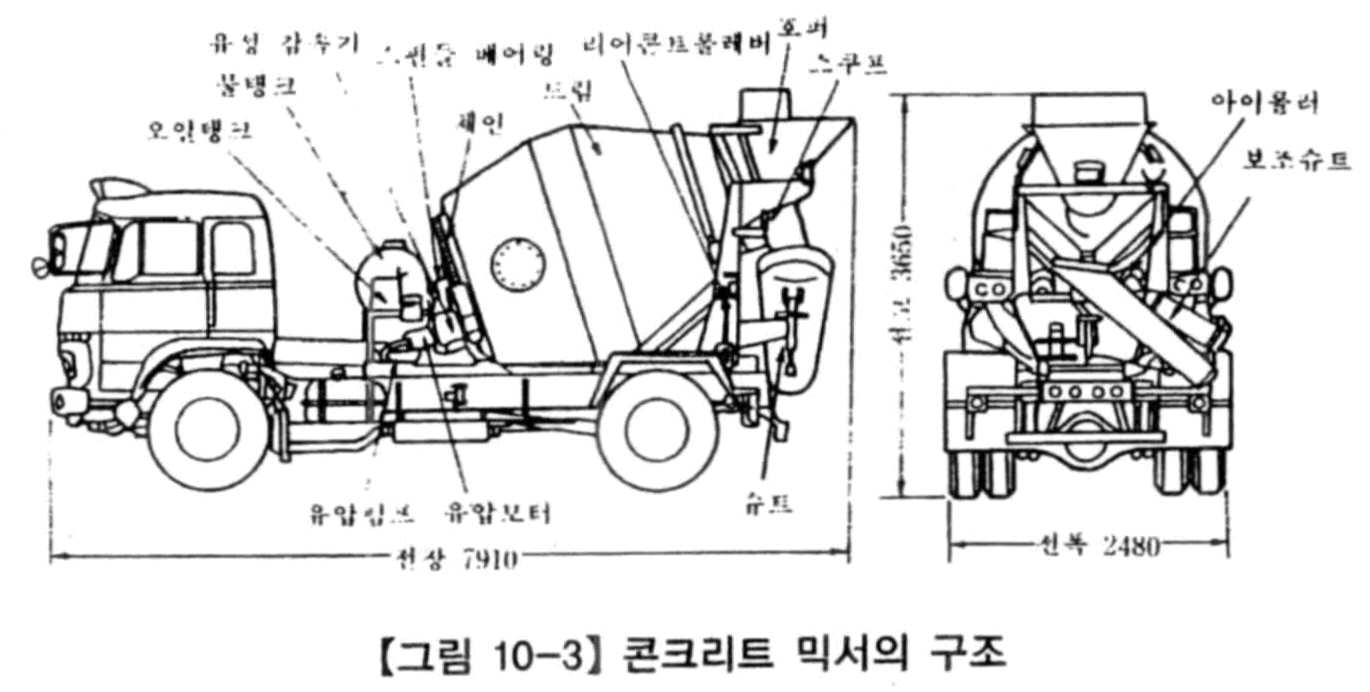
이같이 상도의 종류에는 이동식과 기계식에 액압식과 트럭 적재식인데 다이어프램식은 고층건물(100m이상)에 사용하며 규격표시는 시간당 배송능력(m3/hr)으로 표시되고 피스톤식 콘크리트 펌프의 구성요소는 콘크리트 주입 호퍼, 흡입 및 토출 밸브, 피스톤, 실린더로 형성된다Types of top coats are mobile and mechanical, hydraulic and truck-loaded. The diaphragm is used for high-rise buildings (more than 100m), and the standard designation is expressed in the hourly delivery capacity (m 3 / hr) and the components of the piston concrete pump are concrete. Is formed of injection hopper, suction and discharge valve, piston, cylinder
그리고 콘크리트 타설 기계에는 콘크리트 피니셔(Concrete finisher, 866)의 개요는 콘크리트를 포설한 다음 고르고, 다짐하는 마무리 작업기계로서 먼저, 포설기로서 포설하고, 진동기로 다지고, 그 뒤를 피니셔가 횡단방향으로 움직이면서 콘크리트 슬래브면을 마감작업을 한다는 것으로 하도와 같이 설명한다The concrete finisher (866) outlines the concrete finishing machine (Concrete finisher), which is then laid and selected, and then the compacted finishing work machine is installed first as a laying machine, compacted with a vibrator, and then the finisher moves in transverse direction. Explain as below to finish the slab surface.

상도의 용도로는 기계각부의 부하가 적다.는 것이고 구조가 간단하고 기계의 마모 및 소음이 적다.는 것으로 콘크리트 피니셔는 표면의 앞, 뒤 고르기 진동 등을 하면서 포장표면을 끝낸다.는 것이며 규격표시는 시공할 수 있는 표준폭(m)으로 표시한다The purpose of the top coat is to use less load on each part of the machine, and the structure is simple and the wear and noise of the machine is low.The concrete finisher finishes the pavement surface by vibrating the front and back of the surface. Indicates the standard width (m) that can be constructed.
콘크리트 스프레더(Concrete spreader, 867)의 개요는 포장노반에 살포 된 생콘크리트를 균일하게 부설하는 포장기계이며 용도는 콘크리트 피니셔 앞을 주행하면서 트럭믹서나 덤프트럭으로부터 콘크리트를 받아 운반하고 깔고, 다지는 기계이고 규격표시는 시공할 수 있는 표준폭(m)으로 표시되었고 종류는 블레드형, 스크루형과 박스형으로 분류한다The outline of concrete spreader (867) is a paving machine that evenly lays the raw concrete spread on the paving bed. Its purpose is to transport, lay and crush concrete from truck mixer or dump truck while driving in front of concrete finisher. Standard mark is indicated by the standard width (m) that can be applied and the types are classified into Bled type, Screw type and Box type.
그리고 아스팔트 포장기계의And of asphalt pavers
·종류는 아스팔트 믹싱 플랜트(870)에 아스팔트 피니셔(871)와 아스팔트 살포기(872)에 아스팔트 커버와 아스팔트 스프레이로 분리된다Types are separated by asphalt cover and asphalt spray on asphalt mixing plant 870 and asphalt finisher 871 and asphalt spreader 872.
아스팔트 믹싱 플랜트(870)의 개요는 골재 공급장치, 건조 가열장치, 믹서 아스팔트 공급장치를 가진 것으로 원동기를 부착한 이동식의 것은 도로포장공사뿐만 아니라 공항, 항만공사 등에 사용되는 아스팔트 혼합재를 제조하는 기계 및 그 설비이며 배기 집진장치는 건조기 드럼내에서 발생된 수증기, 먼지, 연소가스 또는 진동스크린에서 발생된 분진 등을 이용하여 원심분리 청정시키는 장치이고 규격표시는 아스팔트 혼합재(아스콘)의 시간당 생산량(ton/hr)으로 표시한다An overview of the asphalt mixing plant 870 has an aggregate feeder, a drying heater, and a mixer asphalt feeder. The mobile unit equipped with the prime mover is a machine for manufacturing asphalt mixtures used for airport paving, port construction, and the like. Exhaust dust collector is a device that centrifugally cleans by using steam generated in dryer drum, dust, combustion gas or dust generated from vibrating screen, etc., and the specification shows hourly output of asphalt mixture (ascon) (ton / hr)
이의 종류에 있어 계량, 혼합방법은 배치식과 연속식으로 형성되며 설치방법은 정치식. 가반식인데 조작방법은 전자동식과 반자동식에 수동식으로서 용도는 골재건조와 아스팔트 혼합에 아스팔트 가열 등이며 구성은 피드 호퍼와 골재건조장치 에 배기집진장치와 핫엘리베이터에 진동 스크린과 믹서와 아스팔트 캐틀에 계량장치로 형성되었다.For this type, the metering and mixing methods are formed in batch and continuous mode and the installation method is stationary. The operation method is fully automatic and semi-automatic, and is used for manual drying and asphalt mixing, asphalt heating, etc. The composition consists of feed hopper and aggregate drying device, exhaust dust collector and hot elevator, vibrating screen, mixer and asphalt cattle. It was formed with a metering device.
이같이 아스팔트 피니셔(Asphalt finisher, 871)의 개요는 정리 및 사상장치를 가진 것으로 아스팔트 혼합공장에서 자갈 모래를 160℃이상 끓여서 혼합골재를 도로상에서 일정한 규격의 두께로 깔아주는 장비이며 용도는 비행장 활주로와 고속도로의 아스팔트 포장공사에서 아스팔트 살포, 고르기, 다지기 등에서 사용되며 규격표시는 최대 포장나비(m) 및 포장능력(ton/hr)으로 표시되었고 아스팔트 피니셔(871)의 기구에 있어 스크리드는 노면에 살포된 혼합재를 매끈하게 다듬질하는 판이며 리빙 호퍼는 장비의 정면에 5톤 이상의 호퍼가 설치되어 덤프트럭으로 운반된 혼합재(아스팔트)를 저장하는 용기이고 피더는 호퍼 바닥에 설치되어 혼합재를 스프레딩 스크루로 보내는 일을 한다는 것이며 범퍼는 스크리드 전면에 설치되어 노면에 살포된 혼합재를 요구하는 두께로 포장면을 다져주는 일을 한다는 것인데 하도와 같다.Asphalt finisher (871) is an overview of the finishing and finishing device. It is a device that boils gravel sand at 160 ℃ and spreads the mixed aggregate to a certain thickness on the road in the asphalt mixing plant. It is used in asphalt spreading, picking and compacting in asphalt paving works. The standard designation is indicated by the maximum paving width (m) and paving capacity (ton / hr). The screed is applied to the surface of the asphalt finisher (871). It is a plate that smoothes the mixture, and the living hopper is a container to store the mixed material (asphalt) transported by the dump truck with 5 tons or more hopper installed on the front of the equipment, and the feeder is installed at the bottom of the hopper to send the mixture to the spreading screw. The bumper is installed on the front of the screed and requires a mixture spread on the road surface. Geotinde primer is the same as that of one that lay the pavement thickness.
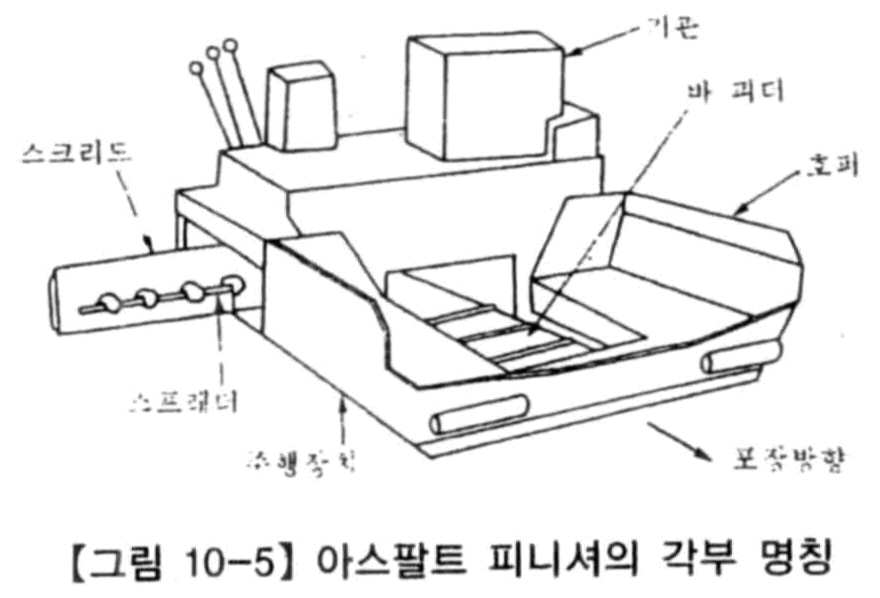
그리고 아스팔트 살포기(Asphalt distributor, 872)의 개요는 아스팔트를 끓여서 최초로 도로 표면에 뿌리는 장비. 즉, 아스팔트를 노면에 뿜게 하는 살포기인 데 종류는 자주식, 기어펌프식에 용액가압식과 탑재식으로 되었고 규격표시는 최대 살포나비(m) 및 탱크 용량(m3)으로 표시하며 하도와 같이 설명한다And the Asphalt distributor (872) outlines the first equipment to boil asphalt and spray it on the road surface. In other words, it is a spreader that sprays asphalt on the road, and the type is self-propelled, gear pump type, solution pressurized and mounted. The standard designation is expressed as the maximum spreading butterfly (m) and tank capacity (m 3 ).
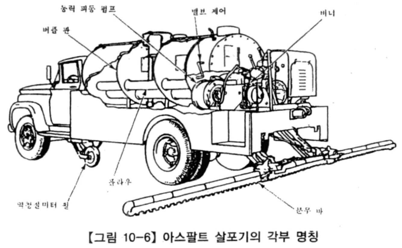
한편 아스팔트 커버는 고속도로용으로서 아스팔트 혼합재를 연속적으로 까는 건설장비이다Asphalt covers, on the other hand, are construction equipment that continuously covers asphalt mixtures for highway use.
또한 아스팔트 스프레이는 아스팔트, 아스팔트 유제와 타르 등을 오일버너에 의하여 가열용해하며 노면에 가압 살포하는 장비이다In addition, asphalt spray is a device that heat-dissolves asphalt, asphalt emulsion and tar by oil burner and pressurizes the road surface.
그리고 노상 안정기(Stabilizer)의 개요는 기체가 노상을 진행하면서 각종 작업을 하며 결합제, 물 등을 첨가 혼합하여 표면 고르기, 조여 굳힘 등을 하는 장비이고 규격 표시는 유체탱크의 용량(m3)으로 표시하며 특징으로 작업능률이 양호하고 기동성이 우수하며 스프레이어의 효율이 좋다는 것이었고 땅을 파는 깊이 조정이 용이함이고 하도와 같이 설명한다.In addition, the outline of stabilizer is a device that performs various operations while gas is in the course of the hearth, and is used to add and mix the binder and water to smooth the surface and tighten it, and the specification is indicated by the capacity of the fluid tank (m 3 ). It is characterized by good work efficiency, excellent maneuverability, good sprayer efficiency, easy digging depth adjustment, and the following description.

준설선의 개요는 물속의 흙을 파내는 작업을 하는 장비로 항만공사에서 항로. 선유장. 하천. 수로 등의 수심증가 및 수심유지를 위하여 공유 수면의 매립과 암벽, 방파제 등 축항공사의 기초공사까지 작업하는데 준설선의 분류에는 형식에 의한 분류와 능력에의 분류하여 구분한다The outline of the dredger is the equipment for digging soil in the water. Sewage. River. In order to increase the depth of waterways and maintain the depth of the water, we also work on the reclamation of shared water surface and the basic construction of the axial airlines such as rock walls and breakwaters.
형식에 의한 분류에 있어In classification by form

능력에 의한 분류에 있어 전동식과 디젤식에 증기 터빈식과 가스 터빈식으로 구분되었다.In terms of capability classification, electric and diesel type were classified into steam turbine type and gas turbine type.
그리고 준설선의 구조 및 용도에 있어 펌프(Pump) 준설선(879a)은 하도와 같다And in the structure and use of the dredger, the pump dredger 879a is the same as the sewer.
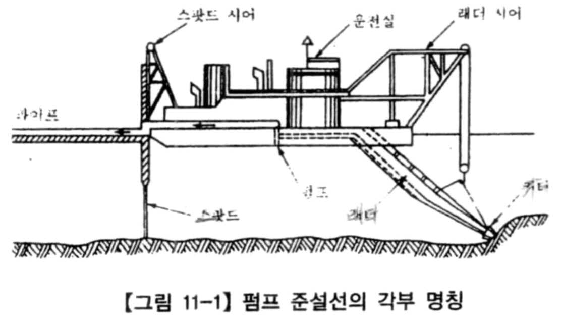
구조 및 용도는 배송관의 설치가 곤란하거나 배송거리가 장거리인 경우 저양정 펌프선을 이용하여 토사를 토운선으로 수송하거나 흙과 물을 같이 빨아 올리는 장비로 항만 준설 또는 매립공사에 사용하며, 작업 시 선체이동 범위 각도는 70∼90°이다. Its structure and use is a device that transports earth and sand to a tow vessel by using a low lift pump ship or sucks up soil and water when the delivery pipe is difficult to install or when the delivery distance is long. It is used for port dredging or reclamation work. The hull travel range angle is 70-90 °.
그리고 규격 표시는 구동엔진의 정격 출력(PS)으로 표시된다 이의 특징으로는 하표와 같다In addition, the standard mark is indicated by the rated output (PS) of the drive engine.

한편 버킷(Bucket) 준설선(879b)의 구조 및 용도는 해저의 토사를 버킷 컨베이어를 사용하여 연속적으로 토사를 퍼올리는 방식으로 준설선 토사는 토운선에 의하여 수송하며 대규모의 항로나 정박지의 준설작업에 사용하고 On the other hand, the structure and use of bucket dredger (879b) is to spread the soil from the seabed continuously using bucket conveyor, and the dredger soil is transported by the ton ship, and it is used for dredging works on large scale routes or marinas.
종류는 연속식과 단속식이 있으며 연속식을 많이 사용되며 Kinds of continuous and intermittent type are used a lot.
규격표시는 주 엔진의 연속 정격 출력(PS)으로 표시되었으며 하도와 같이 설명한다.The markings are given in terms of the continuous rated power (PS) of the main engine and are described as shown below.

상도의 특징으로 하표와 같다It is the same as a mark with the characteristic of the top coat

그리고 디퍼(Dipper)준설선(879c)의 구조 및 용도는 굴착력이 강하고 견고한 지반이나 깨어진 암석을 준설하는데 사용하며 규격표시는 버킷의 용량(m3)으로 표시하였고 이의 특징은 하표와 하도로 설명한다.And dipper (Dipper) structure and uses are used for the digging forces dredging a strong and solid ground or broken rocks and the standard display of the dredger (879c) was represented by the capacity (m 3) of the bucket counter features are described as undercoating and hapyo .

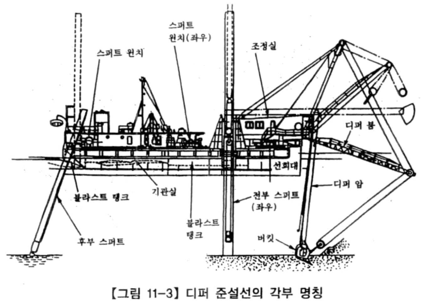
한편 그래브(Grab) 준설선(879d)의 구조 및 용도는 선박위의 클램셸을 장치하여 특수한 기중기에 의하여 준설하는 장비로서 소규모의 항로나 정박지의 준설작업에 사용되었으며 규격표시는 그래브 버킷 평적 용량(m3)으로 표시하고 이의 특징으로는 하표의 하도와 같이 설명한다.The Grab Dredger (879d), on the other hand, is a device for dredging by a special crane equipped with a clamshell on a ship. It is used for dredging operations of small routes or marinas. It is denoted by (m 3 ), and its characteristics are explained as shown in the diagram below.

다음은 기초공사용 기계(항타 및 항발기, 877) 분류하는데 디젤 파일 해머(Diesel pile hammer, 883)는 하도와 같이 설명되며 이의 개요는 2사이클 디젤엔 진의 폭발력을 이용하여 항타하는 기계로서 동일 크기의 진동해머, 증기해머보다 2배 정도 항타속도가 빠르다는 것이며The following is a classification of the basic engineering machines (Die and Erection, 877). The diesel pile hammer (883) is described as a sewer. An overview of this is a machine that uses the explosive power of a two-cycle diesel engine to drive the same size. It is about twice as fast as a vibration hammer and a steam hammer.
이의 방식은 기동장치에 의하여 램을 올렸다가 낙하시켰을 때의 분사장치가 작용, 앤빌의 오목면에 연료가 분사되어 램이 앤빌을 타격하는 순간 폭발함으로서 이 때의 폭발력과 램의 타격력이 말뚝에 전달되고 램은 반발력에 의하여 다시 위로 튀어 올라가게 되며 이때에 배기 및 흡입작용도 이루어지고 다시 낙하, 타격, 폭발을 되풀이하게 되므로 연속 항타작업이 가능하다.는 것이고 이의 구조는 실린더에 실린더 속을 오르내리는 램과 실린더 하부에 삽입된 앤빌에 연료펌프와 연료분사장치에 기동장치 등으로 구성되며, 실린더 냉각용 물 탱크 등이 장치되어 있었고In this method, the injector works when the ram is raised and dropped by the starter, and the fuel is injected into the concave surface of the anvil, which explodes the moment the ram hits the anvil. And the ram will bounce up again due to the repulsive force, and at this time, the exhaust and suction action will be performed again, and the falling, hitting and exploding will be repeated, so that the continuous driving operation is possible. The anvil inserted into the ram and the lower part of the cylinder consists of a fuel pump, a fuel injection device, a starting device, and a cylinder for cooling water.
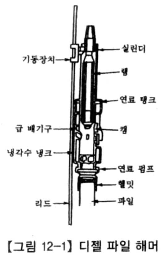
상기의 디젤파일해머(883) 몸체의 좌측에는 리드(896)에 기동장치(903)가 부착되었고, 상기 기동장치(903) 우측 상부에는 실린더(126)의 하부로 램(895)과 연료탱크(902)에 캠(901)의 하부에 연료펌프(900)와 상기 펌프(900) 하부로 헬밋(899)이 형성되었고 상기 헬밋(899) 하면에 파일(899)을 부착하여 파일작업이 진 행된다.A starter 903 is attached to a lead 896 on the left side of the body of the diesel pile hammer 883, and a ram 895 and a fuel tank (bottom) of the
이의 규격표시는 램(ram)의 중량(ton)으로 표시된다는 것이었고 이의 용도에는 나무, 콘크리트, 강관 파일을 박는데 사용되며 이의 특징은 하표와 같다Its standard designation is that it is expressed in tons of ram and its use is to put piles of wood, concrete and steel pipes.
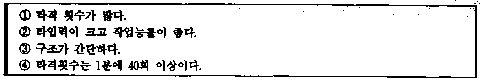
다음의 기둥해머(=기둥 파일 해머)의 이의 개요는 실린더 안에 증기 또는 압축공기를 보내 피스톤의 상하운동을 연속적으로 반복시켜 피스톤 로드 하단에 있는 램(ram)으로 기둥(Pile)을 박는 기계이며The following pillar hammer (= pillar pile hammer) is a machine that sends steam or compressed air into a cylinder and continuously puts the pillar into the ram at the bottom of the piston rod by continuously repeating the up and down movement of the piston.
기둥해머의 종류에는 증기해머에 이의 개요는 증기의 팽창에너지를 이용하여 피스톤을 동작시켜 항타하는 기계로 규격표시는 피스톤 중량(ton)으로 표시하며 이의 특징으로 구조가 복잡하고, 정비와 보수가 어려우며 유지비가 많이 든다.는 점이었고 경량이 단단하고, 밀도가 높은 흙속에 말뚝을 박을 때 사용되며 리드(Lead)에 안내되며 단동식과 복동식이 있다.는 점이다. 그리고 진동해머의 개요는 진동력에 의해 항타 또는 뽑기작업을 하며 진동수는 1분에 500회 이상이며 규격표시는 모터의 출력(kW) 및 기진력(ton)으로 표시하였고 드롭해머는 금속제 블록을 와이어 로프로 들어 올렸다가 파일의 머리에 낙하시켜 그 타격력으로 파일을 박는 것이었고 기초공사용 기계 중 원거리에서 소량시공에 있어 동일조건일 경우 설비비, 운전경비를 적게 하고자 할 때 적합하였다 이의 장비의 장단점 아래와 같다Types of column hammers are steam hammers, the outline of which is a machine that drives the pistons by using the expansion energy of steam, and the standard mark is indicated by the piston weight (ton), which is complicated in structure and difficult to maintain and repair. It is expensive to maintain, lightweight, hard, and used to drive piles in dense soil, guided to lead, single-acting and double-acting. And the outline of vibratory hammer is driven or pulled by vibrating force, the frequency is over 500 times per minute, the standard mark is indicated by motor output (kW) and vibration force (ton), and the drop hammer is a metal block wire It was lifted by rope and dropped to the head of pile to put pile with its striking force. It was suitable for reducing equipment cost and operation cost under the same conditions for small-scale construction at a long distance among basic construction machines.
첫째의 장점에는 운전 및 해머조작이 간단하다는 것이었고 설비규모가 작아 소요경비가 적게 든다.는 점이었으며 낙하높이의 조정으로 타격에너지의 증가가 가능하다.는 것이었다.The first advantage was that the operation and hammer operation were simple, the equipment size was small, the required cost was small, and the impact energy could be increased by adjusting the drop height.
둘째로 단점에 있어 파일박는 속도가 느리다는 것이었으며 파일을 파손시킬 위험이 있다.는 점이었고 이에 작업시의 진동으로 주위 건물에 피해를 주기 쉽다.는 점이었고 수중 작업이 불가능하다.는 점이었다.Secondly, the disadvantage was that the pile was slow and there was a risk of damaging the pile, and it was easy to damage surrounding buildings by vibration during work, and it was impossible to work underwater. .
한편 파일 드라이버(Pile driver, 882)는 하도와 같이 설명한다On the other hand, the file driver (Pile driver) 882 will be described as follows.
상기 파일 드라이버(882) 몸체의 리드(896) 상부에는 어댑터(906)와 붐전핀(904)에 와이어로프(19)와 도루레(135) 크레인붐(651)에 형성되었고 크레인 전면의 캐드워크(905)가 부착되었다. 상기 파일 드라이버(882)는 바지선 본체(591) 상단 갑판데크에 탑재후 갑판데크 작업위치에 장비를 고정시켜 파일(898) 작업이 진행된다The

이에 디젤해머에 증기해머와 진동해머에 드롭해머 등을 총칭하는 것으로 파일을 박을 때에는 드롭해머나 디젤해머 등을 사용하며 그 작업장치를 크레인 붐에 설치하는 장비인데 참고할 사항은 하표와 같다.This is a generic name for steam hammer and vibration hammer for diesel hammer and drop hammer for vibrating hammer. It uses drop hammer or diesel hammer to install piles, and the equipment is installed on the crane boom.

상기한 파일(898)은 심해저 저층바닥의 하부의 기초 기둥부위로 고정해지용의 별도의 앙카파일(898)을 부착시켜 교각용의 새들 형틀(617)로 콘크리트 교각을 해저 저층바닥 상부로 설치가 용이하게 작업 진행한다.The
또한 건설 공기 압축기(Air compressor, 875)는 하도와 같이 설명한다In addition, the construction air compressor (875) will be described as a channel.
이의 개요는 대기 중에 있는 공기를 흡입압축하여 압축공기를 만들며, 고압의 상태로 만들어 각종 건설공사에 다목적용으로 사용하는 기계로서 구동장치와 압축장치 및 그 밖의 부속품으로 구성되어 있다. 여기서, 구동장치는 압축기를 작동시키는 동력을 공급하는 가솔린 또는 디젤기관이다. 또한, 건설공사에는 주로 체적형 압축기가 쓰인다는 것이었고Its outline is to make compressed air by inhaling and compressing air in the atmosphere, and to make it in high pressure and to use it for various purposes in various construction works. It is composed of driving device, compression device and other accessories. Here, the drive device is a gasoline or diesel engine that supplies power to operate the compressor. In addition, the construction was mainly used for volumetric compressors
이의 용도로 채석작업은 착암기를 이용하여 바위에 구멍뚫기, 분활작업 등을 한다.는 것이었으며 점토굴착 작업은 물속에 찌든 찐득한 점토에 굳은 땅위 연암 등을 삽장치나 굴착기로 굴착한다.는 것이고 파괴작업은 브레이크로 콘크리트, 아스팔트를 파괴한다.는 점등이다For this purpose, the quarrying work is to drill holes and divide into rocks by using a rock drill. The clay excavation work is to use a shovel or excavator to excavate the ground soft rock, which is hardened in water. Destructive work destroys concrete and asphalt with brakes.
이에 콘크리트 진동작업과 벌목작업에 페인팅작업과 타이어 공기주입 및 장비세척 등이며 건설공기압축기는 대용량인 것이다.Therefore, painting works, tire inflation and equipment cleaning for concrete vibration work and lumbering work, and construction air compressor is large capacity.
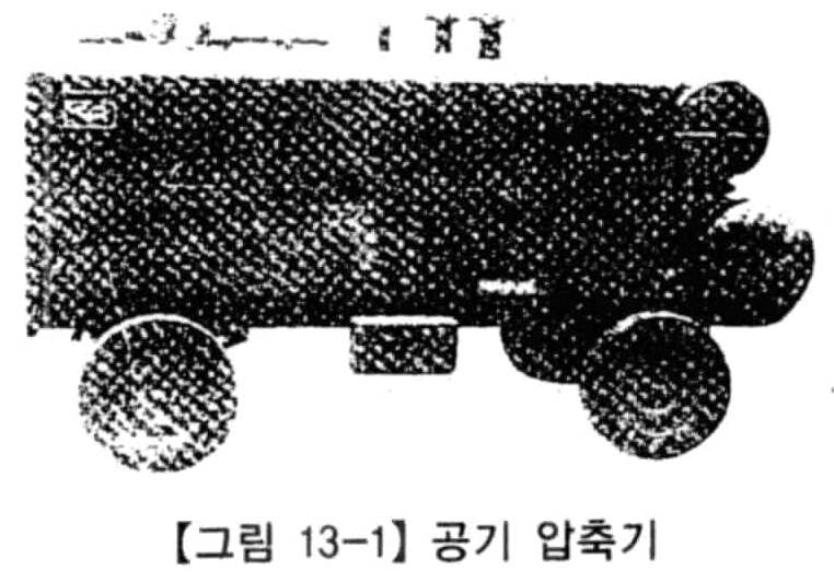
이의 종류에 있어 압축기 구별 분류하고 왕복형 압축기(피스톤식)에 베인형 압축기와 로터형 압축기에 스크루형 압축기와 원심(터보형) 압축기로 분리되며 용도별 분류에 있어 정치식은 일정한 장소에 고정시켜 사용되면, 주로 대규모 공사에 이용된다는 것이고 가반식은 압축기를 간단히 이동시켜가면서 사용할 수 있게 되어 있다는 것이다In this type, the compressor is classified and classified into reciprocating compressor (piston type), vane type compressor and rotor type compressor, screw type compressor and centrifugal type (turbo type) compressor. It is mainly used for large-scale construction. The portable type means that the compressor can be used by simply moving the compressor.
이에 압축공기 생산과정은 다음과 같이 설명한다The compressed air production process is explained as follows.
에어 크리너→저압실린더→중간냉각기→고압실린더→공기 탱크Air cleaner → low pressure cylinder → middle cooler → high pressure cylinder → air tank
이의 규격표시는 매분당 공기 토출량(m3/min)으로 표시. 즉, 실공기량으로 표시하며Its standard is expressed as air discharge volume per minute (m 3 / min). In other words, the actual air volume
·210 c·f·m은 분당 210 입방 피트 압축공기 생산(ft3/min)으로 표기한다210 c · f · m is the production of 210 cubic feet of compressed air per minute (ft 3 / min)
이에 공기 압축기의 부품에는 피스톤과 실린더와 흡입 및 배기밸브에 압력조정밸브로 이루어진다The parts of the air compressor are composed of a piston and a cylinder and a pressure regulating valve on the intake and exhaust valves.
이의 주요 부분의 기능(역할)은 하표와 같이 설명한다.The function (role) of its main part is explained as below.
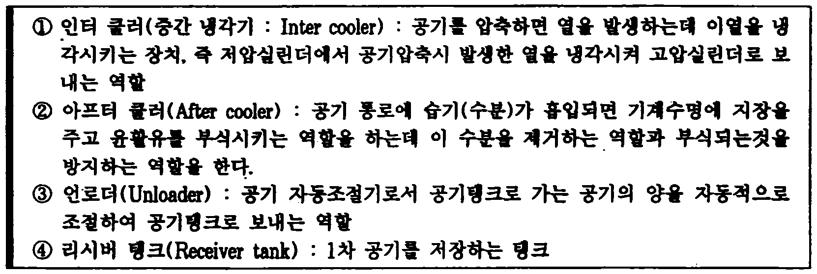
다음의 천공기(Boring equipment ; 착암기와 같다, 876)의 상세한 설명을 하도와 같다The following is a detailed description of the following boring equipment: 876;
이의 개요는 암석이나 지면에 구멍을 뚫는 기계로서 공기 압축기나 유압에 의해 작동된다는 것인데 타격식은 칼날의 충격에너지에 의하여 굴착되며, 굴착속도는 빠르나 그 깊이가 낮다는 단점이 있다. 대부분 압축공기를 이용하며, 이 압축공기로 충격용로드(rod)를 작동하게 하여 그 충격력으로 암석을 부수는 것으로서 구조가 간단하고, 취급도 쉬우며 압축공기의 조작도 쉬워서 많이 사용된다.는 점이였고 회전식은 구멍속에서 회전하는 칼날로 굴삭하며, 굴착속도는 느리나 그 깊이가 깊다.The outline of this is that it is a machine that drills a rock or the ground and is operated by air compressor or hydraulic pressure. The blow type is excavated by the impact energy of the blade, and the excavation speed is fast but its depth is low. Most of them use compressed air, and this compressed air is used to operate the rod for impact and crush the rock by its impact force so that the structure is simple, easy to handle and easy to operate the compressed air. The rotary type is excavated with a rotating blade in the hole, and the drilling speed is slow but deep.

이의 규격 표시로 크롤러식은 착암기의 중량 및 분당 공기 소비량(m3/min) 표기기재하였고 크롤러 점보식은 프랫트롤 단수와 착암기 대수(단×대)로 표시되며 이에 실드 굴진식은 사용 설비 동력(kW)으로 표시되고 터널 굴진기는 최대 굴착치수(mm)로 표시되었다As a standard mark, the crawler type is written on the rock drill weight and air consumption per minute (m 3 / min), and the crawler jumbo type is displayed on the number of units of prattrol and the number of rock drills (stage × size). Tunnel excavators are marked with maximum digging dimensions (mm)
이의 종류에 있어 싱커는 방음장치가 달린 최신형 착암기로서 암석의 구멍뚫기, 각종의 팽치커트, 갱도의 반하향 작업에 적합하다. 즉, 인력으로 조작할 수 있는 소형으로 공기의 힘으로 작동하며, 피스톤의 상·하작동으로 로드에 가격력을 전달하여 삭공하는 기계이며 드리프터는 강력한 천공기로서 넓은 절단면의 굴진작업, 채석작업, 댐굴착시의 큰 구멍을 뚫는데 적합하다. 수동 또는 자동이송장치에 의하여 적당한 추압을 비트에 주어 구멍을 뚫으며, 이 피드장치에는 체인식과 스크루식이 있다는 것이었으며 스토퍼는 수평에서 하늘을 향해 구멍을 뚫는 기계로서 절삭 수직 갱상향 채굴에 적합하다.는 것이다Sinkers are the newest rock-drilling machines with soundproofing and are suitable for rock drilling, various pinch cuts, and half-down work in tunnels. In other words, it is a small size that can be operated by manpower and operates by the force of air, and it delivers the price force to the rod by cutting the piston up and down, and the drifter is a powerful punching machine. Suitable for drilling large holes in dam excavation. Drilling was performed by means of manual or automatic transfer to the bit with appropriate thrust, which was chained and screwed, and the stopper was a machine for drilling holes horizontally to the sky. Will
그리고 브레이커는 콘크리트 도로의 파쇄 개수, 건조물 및 튼튼한 기초물 파괴 등에 사용되며 공기소비량이 적으면서 강력한 파쇄력을 갖고 있다. 주로 유압 백호 굴삭기에 부착하여 사용한다는 것이며The breaker is used for the number of crushing of concrete roads, destruction of buildings and solid foundations, and has strong crushing power with low air consumption. It is mainly attached to the hydraulic backhoe excavator
이에 록크래커는 화약을 사용할 수 없는 장소에서 암석이나 콘크리트 등을 유압으로 파쇄하는 장비이다.The rock cracker is a device that crushes rock or concrete hydraulically in places where gunpowder cannot be used.
이같이 핸드 해머는 좁은 곳에서 굴진작업과 2차 파쇄작업에 효과적이며 방음장치가 붙어 있어 사용하기 쉽다. 잭해머라고도 하며, 인력으로 이동, 조작이 가 능한 소형의 착암기로서 주로 하향으로 구멍을 뚫는데 사용한다.Like this, hand hammer is effective for excavation work and secondary crushing work in narrow place and it is easy to use because it is soundproofed. Also known as jackhammer, it is a small rock drill that can be moved and manipulated by manpower. It is mainly used to drill holes downward.
그 이외로 래그 드릴에 보링 머신과 크롤러 드릴에 왜건 드릴과 픽 해머 등이 있다.Others include lag drills, boring machines and crawler drills, wagon drills and pick hammers.
그리고 쇄석기(Crusher, 874)의 이의 개요는 도로 및 콘크리트 공사에서 골재기층 다짐용에 사용한다. 다음은 원석을 부수어서 작게 만드는 기계로서 쇄석을 만들어 공급하는 기능을 가지고 있으며 모든 쇄석 작업에 사용되며 주로 골재생산에 사용된다는 점인데 향후 이의 기계로 해저채굴광석을 1단은 선별과정을 거치게 된다And its outline of Crusher 874 is used for compacting aggregates in road and concrete construction. The following is a machine that breaks down ore and makes small stones. It has the function of making and supplying crushed stone. It is used for all crushed stone work, and mainly used for aggregate production.
이같이 쇄석기의 종류에는 1차, 2차, 3차 쇄석기로 분리시키는데 1차 쇄석기의 각부명칭의 설명은 하도와 같이 설명한다The type of crusher is divided into primary, secondary, and tertiary crushers. The description of each part name of the primary crusher will be explained as follows.
조 크러셔(Jaw crusher)는 압축력에 의하여 파쇄되는 기계로서 양측에 있는 조(Jaw) 사이에 암석이 투입되어 물려들어가면 양쪽 중 한 측은 고정되어 있고, 다른 측은 가동하여 이때의 가격압력에 파쇄되어 석재는 자기중력과 밀어내는 힘에 의하여 토출방향으로 내려오게 된다. 이와 같은 조(Jaw)는 강력한 힘으로 어떠한 경질 암석류도 파쇄할 수 있는 구조로 제작되어 있다.Jaw crusher is a machine that is crushed by the compressive force. When the rock is inserted between the jaws on both sides, the jaw crusher is fixed on one side of the jaw and the other side is operated to be crushed at the price pressure. The magnetic gravity and the pushing force come down in the discharge direction. These jaws are designed to break any hard rock with strong force.
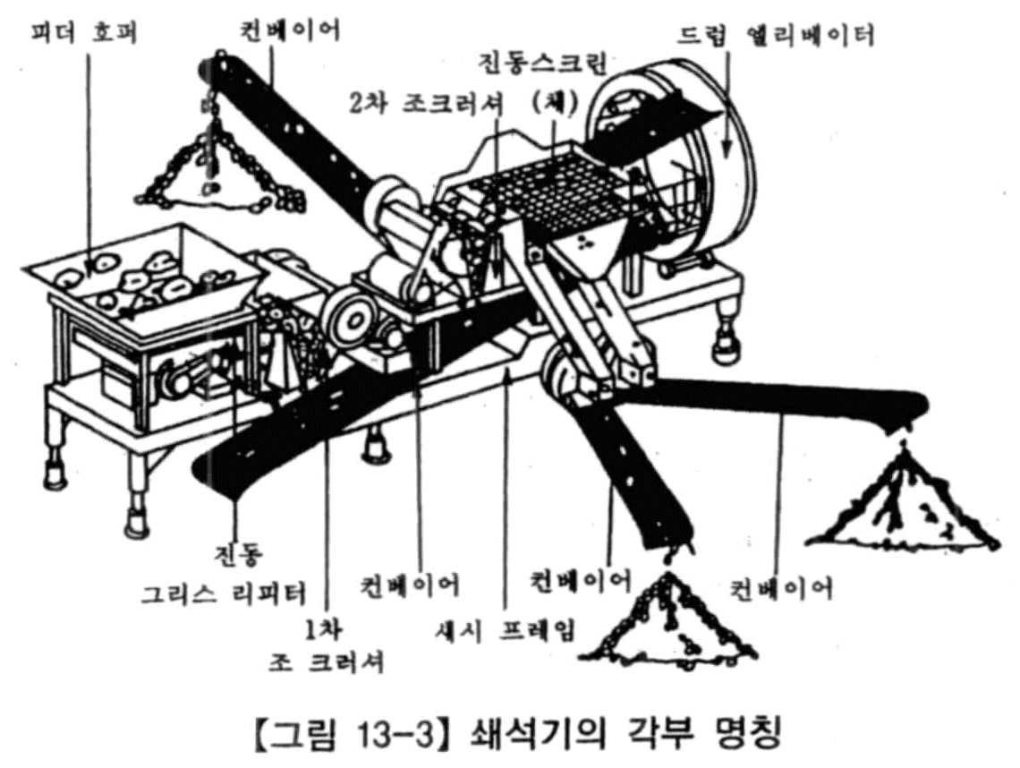
상도와 같이 자이레토리 크러셔(Gyratory crusher)는 주철 또는 강철제로서 프레임 하부 편심축과 구동기어로 구성되어 있으며, 상부에는 cone형상의 파쇄실이 있다. 파쇄부에는 연직 강제축에 경강의 파쇄헤드부가 있어 회전하면서 1차 분쇄되며, 그 다음에 최후의 파쇄실 밑으로 배출되는 크러셔이다. 이 크러셔는 조(Jaw)크러셔에 비하여 진동이 적으며 연속적인 파쇄를 할 수 있는 장점이 있으며 기계의 위쪽을 투입구로 밑쪽을 토출구로 되어 있어 원석투입호퍼를 설치하여 덤프트럭에 그대로 적재할 수 있는 장점이 있다. 압축력에 의해 파쇄된다.는 것이며Gyratory crusher (Gyratory crusher) is made of cast iron or steel, composed of the eccentric shaft and the drive gear in the lower frame, the cone-shaped crushing chamber on the top. The crushing portion has a hard steel crushing head portion in the vertical steel shaft, which is first crushed while rotating, and then is crusher discharged under the last crushing chamber. Compared to jaw crusher, this crusher has less vibration and has the advantage of being able to be continuously crushed. There is an advantage. It is broken by the compressive force
임팩트 크러셔(Impact crusher)Impact crusher
해머 크러셔(Hammer mill crusher)는 한 개의 회전축에 많은 디스크를 달고, 그 주위에는 장방형의 해머를 힌지에 매달아 급속회전을 시키면 돌은 타격하게 되어 이때의 타격력으로 파쇄되는 것이다.Hammer crusher (hammer crusher) is attached to a lot of discs on one axis of rotation, around the rectangular hammer is hung on the hinge to rotate quickly and the stone will be crushed by the impact force at this time.
이에 2차 쇄석기의 콘 크러셔(Con crusher)는 짧은 수직형 주축위에 우산 모양을 콘맨틀헤드를 달아 이의 폄심운동에 의하여 프레임에 장치한 콘커브볼 사이에 돌이 물리고, 다시 이의 하강석을 파쇄하게 된다. 이는 충격작용에 의하여 파쇄되므로 그 구조가 약간 복잡하며, 파쇄석이 그대로 흘러내리는 슬립(Slip)은 거의 없어 상대적으로 파쇄비가 매우 큰 특징이 있다. 충격력과 압축력을 이용한다. 자이레토리 크러셔에 비하여 콘이 짧고, 공급구 치수가 작으며 출구 간격 치수가 최대치수의 쇄석으로 규격품을 생산 할 수 있는 장점이 있다. 일정한 세골재의 대량생산에 적합하다.는 것이며Con crusher of the secondary crusher attaches an umbrella-shaped cone mantle head on a short vertical spindle, and the stone is sandwiched between the cone curve balls mounted on the frame by its core movement, and then the crushed stone is broken again. . The structure is slightly complicated because it is broken by the impact action, there is almost no slip (Slip) flowing crushed stone as it is characterized by a relatively large crushing ratio. Use impact and compression forces. Compared with the Zyretori crusher, the cone is shorter, the supply port size is smaller, and the exit gap dimension is the advantage that the standard product can be produced with the crushed stone of the maximum size. It is suitable for mass production of certain fine aggregates.
해머 밀 크러셔(Hammer crusher)Hammer mill crusher
더블 롤 크러셔(Double roll crusher)는 2개의 경강제롤이 별개의 수평축에 고정되어 있고, 그 간격도 자유스럽게 조절할 수 있다. 이 롤은 평행으로 설치되어 있으나 회전은 각기 반대방향으로 회전하게 하여 그 사이에 암석을 물리게 함으로서 이 롤 사이를 통과하면서 파쇄된다. 이 롤은 압축파쇄, 배출의 주기능을 가지며 포장용 골재 생산에 많이 쓰인다.The double roll crusher has two hard steel rolls fixed on separate horizontal axes, and the gap can be freely adjusted. The rolls are installed in parallel, but the rotations are rotated in opposite directions to crush the rocks between them so that they are broken while passing between them. This roll has the main function of compression crushing and discharging, and it is widely used for producing packaging aggregates.
한편 3차 쇄석기(874)의 로드 밀(Rod mill)은 5mm 이하의 잔골재를 생산하는 것이었고 볼 밀(Ball mill)은 로드밀과 볼밀은 파쇄된 돌을 다시 가는 골재로 생산하기위한 기계로서 강제의 원형 드럼 속에 짧은 환봉제의 로드를 넣고, 이 속에 가는 골재를 물과 함께 연속적으로 공급하여 드럼을 회전시키면서 타격되어 분쇄된 다음 흘러나오게 되는 것으로 비교적 입도가 균일하며, 이때의 물이 적으면 곱게 파쇄되며, 물이 많으면 입도의 거칠기 정도가 크다. 물이 있는 밀은 습식이고, 물이 없는 것은 건식이나 일반적으로 습식이 많다. 볼 밀은 로드밀의 로드 대신 강볼을 원통내에 넣고 회전하여 세골재를 얻게 한 것이 다를 뿐이다.On the other hand, the rod mill of the 3rd crusher 874 produced fine aggregates of 5 mm or less, and the ball mill was used as a machine for producing the rod mill and the ball mill as fine aggregates again. A short rod of rod is put in a circular drum, and aggregates are supplied continuously with water to be blown and pulverized while rotating the drum. The particle size is relatively uniform. If the water is large, the roughness of the particle size is large. Wheat with water is wet, dry without water, but generally wet. The ball mill differs from the one in which the steel ball is placed in the cylinder instead of the rod mill to obtain fine aggregate.
이의 규격표시는 시간당 쇄석능력을 톤(ton)으로 표시[T·P·H(ton per hour)]하는 것이다.The standard designation is to express the crushed stone capacity per hour in tons [T · P · H (ton per hour)].
상기한 바와 같이 건설기계 각개의 장비는 무재해 지구촌 해양발전소 몸체(1)의 내부로 해양에서도 바지선 본체(591) 상단에서 엔진발전기(226)의 동력전원(46)으로 관교량터넬독(1)의 완성전 시기로 한시적으로 사용할 수 있게 하는 데에는 공사중 화재와 안전에 만전을 기하기 위하여 지구촌의 무재해 소방방재 대책용품의 관노즐이동형 소방셈서펌프의 부품일체가 해양발전소 몸체(1) 내부에 형성되었기 때문에 더욱 상세한 설명을 화재유형별의 A화재, B화재에 C화재 모두를 취합하여 육지와 해상의 장소를 불문하여 재해와 이에 대한 대책을 강구토록 함에 의의가 있다고 보는 바와 같이 설명한다.As described above, the equipment of each construction machine is a disaster-free inside of the global marine power plant body (1) of the bridge bridge tunnel dock (1) as the power source 46 of the engine generator (226) from the top of the barge body (591) even in the sea. In order to make it possible to use temporarily for the time before completion, all parts of the pipe nozzle mobile fire fighting pump of the disaster prevention measures for disaster prevention in the global village are formed inside the body of the marine power plant in order to ensure the safety of fire and safety during construction. A more detailed explanation is given as if it is meaningful to combine both A fire and B fire by fire type, and to prepare disaster and countermeasures regardless of land and sea.
상기의 관노즐이동형 소방센서펌프는 해양발전소 내부에 다수의 소방방재 대책용품인 호스와 배관몸체가 탑재되는 소방관노즐 틈새와 노즐가공홀이 형성된, 발화감지센서용의 파리핀테이프와 파라핀형 관이음 노즐연결용 노즐마개를 높고 낮은 산과 산정상 아래의 각부능선별 일체와 해수욕장 인근의 높고 낮은 빌딩 건물 옥상 각개로 와이어로프형의 케이블카아식 무재해 소방방재 대책용품의 관노즐이동형 소방센서펌프를 설치한 후, 다수 화재의 종류에 속하는 건물 등의 보통화재인 목재와 산림과 종이와 이불 등의 일반 가연소물 화재가 발생되었을 때 종래에는 헬리콥터와 소방차량 등의 소방차는 싸이렌을 울리면서 화재발생지로 출발하는데 이때 교통흐름의 방해하는 노상의 주정차차량 등의 장애물과 산속의 소방헬기는 방화수를 싣어나르기 위해 왔다 갔다 하는 순간에 꺼진 불은 다시 되살아 나고 이런 저런 이유 때문에 화재현장의 소화활동은 한순간을 다투는 것으로 1초 늦어짐에 따라 큰불로 되는 긴박하고도 절박한 상황에서 물론 생명까지 잃을 수 있는 위험을 해소하고자 최초화재발생초기에 소방차량 또는 헬리콥터 출동직전에 간단히 초기진화를 이루게 되는 무재해 소방방재 대책용품의 관노즐이동형 소방센서펌프가 본 발명 해양발전소 몸체(1) 내부로 탑재형성하며 일반 선박 내부와 외부에도 형성하고 상기 펌프 몸체의 다중관노즐몸체 내부에 형성된 다수의 무재해 파라핀 노즐마개와 파라핀테이프로 밀폐된 다중관노즐틈새홀을 개방시킨 화재열감지센서파라핀이 성냥불과 촛불의 저온감지로 인해 발화물체의 주변으로 다수의 관노즐홀이 개방되어 내수압의 커텐물막으로 인명이 구제되며 1초 이내로 진화되는 만큼 본 고안의 무재해 관노즐이동형 소방센서펌프는 각개 화재에 속하는 화재의 종류에 따라 액체와 기체에 고체로 혼합된 방재물질을 최초화재발생시기의 1초 이내에 간단히 불연성가스(연소하지 않는 가스)로 연소물을 에워싸 공기(산소)의 공급을 차단하여 연소를 방지하는 질식작용과 연소물을 발화점 이하의 온도로 낮추는 냉각작용이 되었으며 호스배관 틈새로 흙탕물을 끼얹는 방식으로 발화초기에 애드벌룬과 비행선 하부의 바스켓에 구호난민을 탑승시켜 소방케이블카아로 안전지역으로 대피토록 하고 상기 애드벌룬과 비행선은 해양발전소 몸체의 물체 하중을 분산시켜 상기 발전소 몸체의 안전을 보장하고 대형산불 및 대형화재로부터 인명구조 및 초기진화를 개도영역(자국 영토 영해주권 영역)을 초월하여 소방센서펌프 소화기 설치 위치를 명확히 설정되게 하는 지구촌의 무재해 소방방재 대책용품 일체가 해양발전소 몸체 내부에도 형성된다는 점에서 종래의 것과는 현격한 차이가 있는 소방센서펌프를 지구촌 전체에 공급 함으로써 무재해 지구촌의 해양발전소 몸체(1)에도 설치된다.The above pipe nozzle moving type fire sensor pump has a fire pipe nozzle gap and a nozzle processing hole in which a number of fire protection measures are installed in the offshore power plant and a hose body and a pipe body are installed. After installing the nozzle plug for nozzle connection, install the pipe nozzle moving type fire sensor sensor of the wire rope type cable car-type accident-free fire prevention measures by the unit of each function line under the high and low mountain and the mountain top and the roof of the high and low building near the beach. In general, fires such as helicopters and fire trucks depart to the place of fire when a fire occurs, such as wood, forests, and general combustible materials such as paper and blankets, which are common fires of buildings belonging to a large number of fires. Obstacles such as roadside vehicles that obstruct the flow and firefighting helicopters in the mountains carry fire water. The fire that is turned off at the moment of going back and forth to revive is revived, and for this or that reason, the fire extinguishing activity fights for a moment, and in order to alleviate the danger of losing a life in the urgent and desperate situation that becomes a big fire as it is one second late. The pipe nozzle moving type fire sensor pump of the disaster-free fire-fighting and disaster prevention countermeasures that is to be initially extinguished immediately before the dispatch of a fire engine or helicopter at the beginning of the first fire occurrence is mounted inside the body of the
일반적으로 지구촌의 해양발전소 몸체(1)의 내부에도 다수의 플랜지(28)와 플랜지(28) 접합부위 복수개의 플랜지 틈새와 다수개의 배관몸체의 둘레면을 지그재그 대칭 대각의 일자형 가공홀(20) 틈새(15)와, 배관길이에 따라서 일직선으로 일정한 원둘레 경사각도(16)로 일직선의 틈새(15)로 설치한 후 일정량의 방재물질은 방재수로(17) 및 방재배관(89)을 경유하여 방화수가 유입되는 집수정 탱크(34)와, 상기 집수정 탱크(35) 내부로 방화수 수위감지 체크하는 체크감지센서인 보올탭(499) 지렛대에 연결되어 있는 보올탭(499) 밸브(Boll Top Valve)가 보올탭 지렛대의 작동에 따라 보올탭 밸브가 전개되면 집수정 탱크 내부로 일정량 방화수가 채워지되,In general, a plurality of flange gaps between the
단 집수정 탱크(34) 하단부 드레인 배관라인으로 방재물질 방화수가 방출하게끔 호스 또는 소방호스(9)가 구비되면서 발화물질로 가공된 감지노끈인 나일론 노끈 또는 무명실 노끈으로 도로지표면(GLL) 상단부 상단으로 호스매듭부위를 고체 파라핀 노즐마개(100) 끼워두고 감지노끈(41)으로 발화물(A화재, B화재와 C화재 일체가 포함됨) 유형에 따라 육지와 해상의 선체 내부와 건물 주변의 높고 낮은 산으로 방재호스(9) 마디 마디로 엘보 또는 티이엘보(44)와 레듀사(35)엘보 붓싱소켓 연결부속을 일정한 거리의 간격으로 호스구멍(분사노즐이라 칭하고)인 엘보 티이엘보 연결구인 양초 심지구멍 주위로 파라핀테이프(177) 발화감지센서 를 감지노끈(41)과 결속 부착하고 길게 짧게 동서남북 여러 지역에 배치토록 구비되어 원인불명의 불씨와 불꽃이 감지노끈에 인화 또는 점화되어 감지노끈이 불타면서 호스구 멍 또는 티이엘보(44) 연결구멍의 양초(100)가 녹으면서 호스구멍이 표출되어 호스 내부의 방재수는 호스 외부로 감쪽하는 순간에 토출분사수로 감쪽같이 최초 발화물질에 접근 이동후 복수개의 방사선 형상의 커텐물막과, 다수개의 일직선 또는 일자형의 커텐물막이 형성된 후 발화물질이 발화진행시 발생되는 질식가스(다이옥신)와, 화염물질을 뿜어 내기 직전에 건물내부에서는 다수의 형성된 커텐물막이 수직하강 분출되면서 상기 질식가스(163)와 화염물질을 비상통로(탈출구)로 복도, 실내와 구분되게 질식가스(163)를 격리차단토록 복도 마루바닥 또는 천정 벽체로 배관노즐이 설치되어 화재현장에서 침착하게 안전하게 인명구조가 우선되면서 거동불편자(환자, 노약자 갓난애기 이하 생략함)의 신체에 아무 이상없도록 최초 발화 초기에 소방구조요원과 소방장비 출동전에 불씨 불꽃이 진압된 후에는 실내용 미니 침대노즐로 구조요원이 인명구조와 화재진압을 동시에 이루어지도록 지구촌 내부에 발생되는 산불과 대형화재를 초기에 진화하고 인명을 구조하는 소방방재장치로 해양발전소 몸체(1) 내부로 설치한다.However, the hose or fire hose (9) is provided with the hose or fire hose (9) to discharge the fire prevention water to the drain pipe line at the bottom of the sump tank (34), and the nylon rope or the cotton thread cord which is processed into a ignition material to the top of the upper surface of the road surface (GLL). Hose knots are fitted with solid
이렇게, 입형다단펌프(8) 동력모터(192) 작동제어센서의 전자제어유닛과 전자제어밸브와 우회 방재수 라인의 흡입합류 관(3) 토출합류 관(4)의 펌프 내부 밸브 일체로 산업현장주변의 근린생활 지역의 대형 건물 옥상에는 방재물질을 살수할 수 있도록 집수정탱크 주위로 상기 탱크에 방화수가 충전되게 리미트스위치(183)와 감지노끈(41)이 함께 설치되되, 어떠한 악조건하에도 인명구출을 반드시 해낸다는 임무수행의 사명감과 책임감의 필요성이 부각되면서 화재현장에 필요한 일정한 용량의 방재물질 혼합기 믹서역할의 에어콤프레샤에 에어호스와 닛플 그리고 레듀사 붓싱소켓과 에어콤프레샤 작동제어용 차단기 스위치로 형성된 후로는 방재물질 저장탱크인 에어리시이버 고압저장탱크에 공기가 일정량의 압력 저장된 뒤 도로지표면(GLL) 상단 또는 해수면(SLL) 상단 하단의 지중선로 방재노즐과 함께 설치하고 비닐팩(43)을 지탱하기 위한 수단의 텐트고정형 프레임 가운데 부위로 발화비물질철사로 고박한 후 비닐팩(43) 모서리 부분으로 발화감지노끈(41)을 4곳과 8곳에 과발화물질 파라핀 흡착물테이프는 발화지점에 근접되도록 설치한 후 기상상태 악화시 또는 야간 방재활동 불능시 수송장비인 헬리콥터와 대체되는 애드벌룬과 비행선, 비상발전기와 에어튜우브에 와이어로프와 갈고리에 불타는 물질 프레임과 불타지 않는 프레임 그리고 고성능 수중펌프로 이 외의 인명구조와 초기 진화장비 일체로 구비되어 종전의 진화방식을 개선시켜 기상상태에 따라서 발화물질 유형별로 소방방재대책의 대형화재방지를 이루기 위하여 빌딩 건물 옥상에는 집수정탱크용과 소형의 펌프로 종전에 구비되었고 기계실에는 엘리베이터를 작동시키는 타구어윈치 감속기모터가 구축되어 있기 때문에 상기 우인치 감속기모터와 타구어윈치에 와이어로프로 형성된 집수정탱크(프라스틱물통)와 인명구조용 바스켓 또는 그물형 로프에 관노즐이동형 소방센서펌프로 구동바퀴로라와 옥내의 창문커텐로라와 동일하게 산봉우리에 건물 각개로 연결시켜 전천후 소방방재 대책용품의 무재해 관노즐이동형 소방센서펌프는 1초 이내에 각개의 화재유형에 따른 초기진화 및 인명구조를 확실히 보장하여 재해전, 재해시, 재해후 사전예방으로 그에 대한 기능의 설치위치를 명확히 설정함으로써 결정되게 하는 것이다. 이에 종래의 배경기술을 다음과 같이 설명한다.In this way, the industrial control unit of the vertical multi-stage pump (8)
이러한 종래의 소화 설비를 크게 나누면 소화기, 소화전 설비에 스프링 클러 설비와 드렌처 설비로 별도의 소화 설비와 화재 경보 설비가 된다. 상기의 설비는 소화법과 각 도시의 화재 예방조건 조례에 의하여 건축물에 대한 그 설치 기준이 규정되어 있는 것이었다. 이렇게, 화재의 초기에 있어서 간편하고 손쉽게 사용하여 불을 끄기 위해서는 소화기가 가장 적합하다. 학교, 여관, 각개의 영업소등 많은 사람이 모이는 건축물에는 설치해야 할 기준이 법령으로 정해져 있었으며 소화기의 소화 작용에는 다음과 같은 방식이 있게 된 것이었고, 해양에서의 일반선박화재를 포함하게 된 것이다.If the conventional fire extinguishing equipment is largely divided into a fire extinguisher, a fire hydrant equipment, a sprinkler equipment and a drencher equipment are separate fire extinguishing equipment and fire alarm equipment. The above-mentioned facilities were prescribed by the Fire Protection Act and the Fire Protection Condition Ordinance of each city. Thus, the extinguisher is most suitable to extinguish the fire by using simply and easily in the early stage of the fire. In buildings where many people gather, such as schools, inns, and sales offices, the standards to be installed were established by law. The fire extinguisher's fire extinguishing system was based on the following methods, including general ship fires in the ocean.
첫째; 불연성 가스(연소하지 않은 가스,164)로 연소물을 에워싸 공기(산소)의 공급을 차단하여 연소를 방지하는 질식 작용을 하는 것이었다.first; It was to suffocate the combustion product by blocking the supply of air (oxygen) by enclosing the combustion product with a non-combustible gas (non-combusted gas, 164).
둘째; 연소물을 발화점 이하의 온도로 낮추는 냉각 작용이 있으며 일반으로 이 두가지 작용이 동시에 작용하는 경우가 많은 점 이었다.second; There is a cooling action to lower the combustion products to a temperature below the ignition point, and in general, both of these actions are simultaneously performed.
호스로 물을 끼얹는 소화 방법은 주로 냉각작용인데, 일반으로 화재의 종류를 살펴보면 <표1-1>과 같다.The fire extinguishing method of pouring water with a hose is mainly a cooling function. In general, the types of fire are shown in <Table 1-1>.
(표1-1) 화 재 의 종 류(Table 1-1) Types of Fire

상기된 바와 같이 화재의 종류를 삼등분으로 화재의 유형에 따라 소화기를 설치하는데에는 소화기의 종류와 사용대상의 상세한 설명은 다음과 같이 설명한다.As described above, to install a fire extinguisher according to the type of fire by dividing the type of fire into three parts, the detailed description of the type of fire extinguisher and the object of use will be described as follows.
먼저; 산·알칼리 소화기(124a) 상세한 설명에 있어서,first; Acid alkali fire extinguisher 124a In the detailed description,
용기 속에 중탄산 소오다를 넣어 유산병을 달아 놓은 것으로 용기가 넘어지면 탈산가스가 발생하여 그 압력으로 물을 분출시켜 소화하는 것이었다.Soda bicarbonate was put in the container and a lactic acid bottle was put. When the container fell down, deoxidation gas was generated and water was ejected at that pressure to extinguish.
둘째; 포말 소화기(124b)의 상세한 설명에 있어서,second; In the detailed description of the foam fire extinguisher 124b,
중탄산 소오다와 유산 알루미늄의 용액을 혼합하여 탄산가스의 거품을 발생시켜 이것을 분출하여 소화하는 것이었다.A solution of soda bicarbonate and aluminum lactate was mixed to generate bubbles of carbon dioxide, which were then ejected and extinguished.
셋째; 염화탄소 소화기(124c)의 상세한 설명에 있어서,third; In the detailed description of the carbon chloride extinguisher 124c,
용기속에 4 염화 탄소를 분출시키면 공기보다 5배가량 무거운 불 연소성가스(164)가 발생하며, 이것이 연소물에 산소의 공급을 단절함으로써 소화하는 것이었다.Ejecting carbon tetrachloride into the vessel produces an
네째; 탄산 가스 소화기(124d)의 상세한 설명으로는,fourth; In the detailed description of the carbon dioxide gas extinguisher 124d,
용기 속의 액상 탄산 가스(174)를 분출시키면 저장 용적의 약 450배가 되어 산소의 공급을 단절시켜 소화할 수 있도록 한 것이었다.When the liquid
다섯째; 펌프 소화기(124e)의 상세한 설명에 있어서,fifth; In the detailed description of the pump fire extinguisher 124e,
물통이 달린 소형 펌프를 사용하여 방수하는 것으로서 액상 탄산 가스(124)의 압력으로 물을 방출하는 것이었다.Water was released using a small pump with a bucket, and the water was discharged at the pressure of the
여섯째; 분말 소화기(124f)의 상세한 설명에 있어서,Sixth; In the detailed description of the powder fire extinguisher 124f,
중조의 보드라운 가루를 봄베에 넣어 탄산 가스(124)의 압력으로 분출시키면 열에 의한 중조의 흡열 반응에 의하여 탄산 가스(124)가 발생하여 소화하는 것이었다.When the sodium bicarbonate powder was put into a cylinder and spouted under the pressure of the
상기 화재에 대한 소화기의 종류와 사용대상을 살펴보면 <표1-2>와 같다.Looking at the type and use of fire extinguishers for the fire is shown in Table 1-2.
<표1-2> 소화기의 종류와 사용 대상<Table 1-2> Kinds of fire extinguisher and object of use

상기한 바와 같이 적응하는 화재유형별 방재물질은 액체와 고체에 기체로 다양하게 화재유형별로 적응한 것이란 점에는 동의하게 되는 것이었다.As described above, it was agreed that the disaster prevention materials for each fire type adapted to various types of fires were liquids and solids as gases.
이에 따라서, 소화전 설비에 대한 상세한 설명에 있어서,Accordingly, in the detailed description of the fire hydrant equipment,
소화전 설비에는 옥외 소화전 설비와 옥내 소화전(179) 설비가 있으며 옥외 소화전은 학교, 아파트, 공장, 대지등의 건물밖에 설치하며 지상식과 지하식이 있고, 옥내 소화전은 소형 소화전방수구(소방대전용, 169)가 있는데 본 발명의 바지선본체(591) 상단의 발전소 내부와 터넬독 몸체 내부와 외부에도 설치한다.The fire hydrant has an outdoor fire hydrant and an indoor fire hydrant (179). The outdoor fire hydrant is installed outside buildings such as schools, apartments, factories, and grounds, and has ground and underground foods. There is a barge
이에 따라, 옥외 소화전(179) 설비의Accordingly, the
옥외 소화전(179) 설치 기준에 따른 상세한 설명을 다음과 같이 한다Detailed description according to outdoor fire hydrant (179) installation standard is as follows.
옥외 소화전 설치 기준은 건축물의 지상 면적이 내화 건축물에 있어서는 9,000㎡이상이며 이러한 건축물에는 반드시 소화전을 설치해야 하고 다음과 같은 조건을 구비해야 한다는 것이었으며,The standard for the installation of outdoor fire hydrants was that the ground area of the building was more than 9,000 m2 for fireproof buildings, and that fire hydrants must be installed on these buildings, and the following conditions must be met:
첫째로, 옥외 소화전은 건축물의 각 부분에서 1개의 호스 접속구까지의 수평거리가 40m 이하가 되게 설치하는 것이었고,First, the outdoor fire hydrant was installed so that the horizontal distance from each part of the building to one hose joint was less than 40 m.
다음의 수원은 2개의 옥외 소화전을 동시에 사용하였을 때 20분간 방수할 수 있는 수량 이상이어야 한다는 것이었으며,The next source was that when two outdoor fire hydrants were used at the same time, they should be at least water-resistant enough for 20 minutes.
세번째는 압력이 미달된 경우는 가압 송수 펌프를 설치하여 규정 방수 능력 즉 2개의 소화전을 동시에 사용하였을 때 18m 의 호스(9) 3개를 연결하여 2.5kg/㎠이상의 방수 압력과 방수량 0.35㎥/min이상이어야 한다는 것이었다.Third, if the pressure is under pressure, install a pressurized water pump and connect 3 hoses of 18m when using two fire hydrants at the same time. It should be more than min.
위와 같이 상세한 옥외 소화전의 종류에 있어서 옥외 소화전에는 지상식과 지하식이 있으며 지상식은 포탄형 소화전이다. 지상식이나 지하식 둘다 단구형(179a)과 쌍구형(179b)이 있으며 소화전의 지름은 단구형이 75mm이고 쌍구형이 100mm로 되어 있으며 호오스 접속구는 소방서 전용으로 사용하는 호스(9)의 지름과 같이 하는 것이었다.In the type of outdoor fire hydrant as described above, the outdoor fire hydrant has a ground type and an underground type, and the ground type is a shell type fire hydrant. Both ground and underground type have single-ended type (179a) and twin-type type (179b). The fire hydrant has a diameter of 75mm, a single type of 100mm, and the hose connection port has a diameter of a hose (9) used exclusively for fire departments. It was to be together.
상기한 바와 같이 옥외 소화전에는 쌍구포탄형 지상식 소화전(179)과 배설형 소화전(179)으로 설치 위치 설정한 후 기준을 확실히 하는 것이었다.As described above, the outdoor fire hydrant was set to an installation position with a double-shell shell type
위와 같이, 옥내 소화전 설비에 대한 상세한 설명에 있어서,As above, in the detailed description of the indoor fire hydrant equipment,
옥내 소화전 설비 기준에는In indoor fire hydrant facilities standard
옥내 소화전의 설치와 설치 대상물 및 설치 간격은 소방법 규정에 따라 설치한다. 동일 부지 안에 2 동 이상의 건물이 건축되어 있고 각동이 복도로 연결되어 있으면 동일 건물로 인정한다. 옥내 소화전의 설치 간격은 각 층마다 소화전을 중심으로 반지름 25m 이내에 대상물이 있어야 한다는 것이었다.Installation of indoor fire hydrants, installation targets and installation intervals shall be installed in accordance with the provisions of the Fire Services Act. If two or more buildings are built on the same site and each building is connected by a corridor, it is considered as the same building. The spacing of indoor fire hydrants was that each floor had an object within a radius of 25 m around the fire hydrant.
한편, 저수 탱크 설치에 있어서, <표1-3>을 참조토록 하였고,On the other hand, in installing a reservoir tank, it referred to <Table 1-3>,
저수탱크의 용량은 소화전 1개의 소요 방수량 130ℓ/min을 20분간 이상 방수할 수 있는 용량이어야 하며 소화전을 동시에 여는 수는 최대 5개로 하며 각층의 설치 수가 5개 미만인 때는 설치 개수가 가장 많은 층의 소화전을 동시에 열었을때 20분간 방수할 수 있는 용량이 되어야 한다는 것이었고The capacity of the water tank should be watertight for 130 minutes / min for one hydrant over 20 minutes. The maximum number of fire hydrants can be opened at the same time. When the fire hydrant was opened at the same time, it had to be waterproof enough for 20 minutes
<표1-3> 옥내 소화전의 동시 개구 소요 수량과 저수 탱크<Table 1-3> Simultaneous opening required quantity of water and water storage tank of indoor fire hydrant

또한, 소화 펌프 설치의 기준에는 <표1-4>을 참조하도록 되었으며 소화 펌프에는 일반적으로 다단 터어빈 펌프를 사용하며 펌프의 방수압력은 1.7kg/㎠이상이고 소요 방수량은 130ℓ/min 이상이어야 한다. 이때의 압력은 배관의 손실 및 호오스의 손실을 제외한 압력이며 펌프의 수는 소요 방수량 보다 15% 더 많게 규정한다는 것이었다.In addition, refer to <Table 1-4> for the standard of the fire pump installation. The multistage turbine pump is generally used for the fire pump, and the waterproof pressure of the pump should be 1.7kg / ㎠ or more and the required waterproof amount should be 130ℓ / min or more. . The pressure at this time is the pressure minus the loss of the pipe and the hose, and the number of pumps is 15% more than the required waterproof amount.
<표1-4> 소화 펌프의 크기<Table 1-4> Size of Fire Extinguishing Pump
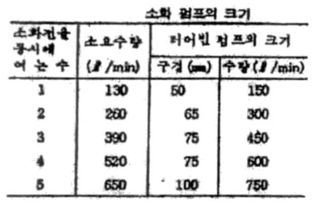
이렇게, 소화전 상자(160)의 설치규정에 있어서,Thus, in the installation regulations of the
소화전의 상자는 일반적으로 강판제이며 상자(160) 속에는 소화 밸브, 통선, 호오스(15∼30m), 호오스 걸이 등이 들어있다. 상자의 표면에는 소화전이라 쓰고 상자의 윗부분에는 붉은색의 표시등(주·야)을 설치한다는 것이었다.The box of the fire hydrant is generally made of steel and the
소화 노즐 및 소화전 상자의 표준 치수는 <표1-5> 및 <표1-6>과 동일하며 동도면에 도시한 바와 같었다.The standard dimensions of the fire extinguishing nozzle and the fire hydrant box were the same as in <Table 1-5> and <Table 1-6> and as shown in the same drawing.
<표1-5> 소 화 노 즐<Table 1-5> Fire Nozzle
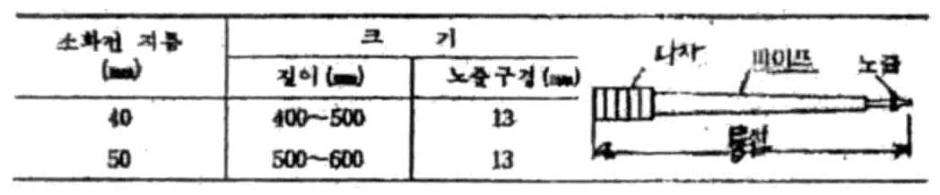
<표1-6> 소화전 상자의 표준치수(mm)<Table 1-6> Standard dimensions of fire hydrant box (mm)
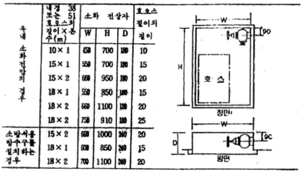
또다시, 연결 송수관에 대하여 상세한 설명을 다음과 같이 한다.Again, a detailed description of the connecting water pipes follows.
송수구(사이어미즈 코넥션)와 건물안에 설치한 방수구(169)를 연결 송수관이라 하며 설치하는 방화 대상물 및 설치 기준은 <표1-7>과 같았다.The water duct (Siame's Connection) and the waterproof pit (169) installed in the building are called water pipes, and the fire protection objects and the installation criteria are as shown in <Table 1-7>.
방수구는 <표1-7>의 1의 방화 대상물에 대해서는 3층 이상의 층계에 설치하며 지하 3층 이하에도 설치하는 것이 좋다는 것이었다.For the fire prevention object of 1 in <Table 1-7>, the waterproof opening was installed in three or more floors, and it should be installed also in three or less basement floors.
<표1-7> 연결 송수관의 설치기준<Table 1-7> Installation Standards of Consolidated Water Pipes

이처럼, 송수구(168)에 대하여 상세한 설명은 하표와 같다As such, the detailed description of the
건물의 외벽에 설치하는 것이며 소방관이 보기 쉽고 접근하기 쉬운 건물바깥벽에 설치하여 화재가 발생했을때 소방 펌프 호스를 송수구에 연결하여 방수구에 압력수를 송수하는 역활을 한다. 송수구의 지름은 63.5mm이고 암나사로 되어 있고 수직관에는 체크밸브가 있으며 송수구 가까이의 송수관구경은 100mm, 송수구의 압력은 7kg/㎠이다. 설치 높이는 지면에서 0.5∼1.0m로하고 관속의 물을 배수하기 위하여 배수관을 설치한다. 또 송수관은 폭 3m이상의 도로에 접하게 하고 보기 쉬운 위치에 표지를 붙여야 한다는 것이었고It is installed on the outer wall of the building, and it is installed on the outer wall of the building which is easy for firefighters to see and access, and when a fire breaks out, it connects the fire pump hose to the water inlet and serves to supply pressure water to the waterproof port. The diameter of the water inlet is 63.5mm, with female thread, the check valve is located in the vertical pipe, the water pipe diameter near the water inlet is 100mm, and the pressure of the water inlet is 7kg / ㎠. The installation height is 0.5 to 1.0m from the ground, and a drainage pipe is installed to drain the water in the pipe. In addition, the water pipe should be in contact with a road over 3m wide and put a sign in an easy-to-view location.
<표1-8> 소화 노출에서의 분출 수량(매분)<Table 1-8> Ejection quantity (every minute) in digestive exposure

<표1-9> 소화전 및 송수구의 설치 기준<Table 1-9> Setting standard of fire hydrant and water squirt

이처럼 다시, 방수구(169)에 대한 상세한 설명은 동도면에 도시한 바와 같은 기재와 하표와 같다.As such, again, the detailed description of the
방수구는 소방호스(65m길이)를 연결하여 방수하는 역할을 하는 것으로서 소방전용 소화전이라고도 한다는 것이었고 소방펌프에서 압송되는 압력수는 송수구와 송수관을 통하여 방수구에 도달하며 방수구에 도달한 압력수는 소방호스에 의하여 방수된다는 것이었다.The water-proof port is called a fire hydrant for connecting fire hose (65m length), and it is also called a fire hydrant for firefighting. The pressure water pumped from the fire pump reaches the water outlet through the water inlet and the water pipe, and the water pressure reached the water outlet is the fire hose. Was to be waterproof.
방수구의 지름은 63.5mm이며 방수,압력은 노즐 끝에서 3.5kg/㎠이고 방수량은 450ℓ/mm이며 노즐 끝의 지름은 19mm로 된 것이었으며,The diameter of the waterproof port was 63.5mm, waterproof and pressure was 3.5kg / ㎠ at the nozzle end, water resistance was 450ℓ / mm, and the diameter of the nozzle tip was 19mm.
방수구의 설치 위치는 건물 바닥에서 0.5∼1m의 높이에 설치하고 쉽게 찾을 수 있도록 표시를 한다는 것이었고,The installation location of the tarps was 0.5 to 1 m above the floor of the building and marked for easy access.
연결 송수관의 방수구는 옥내 소화전 상자 속에 같이 설치하거나 단독으로 설치하여도 좋다. 또한 노출을 시켜 설치하여도 좋으나 반드시 캡을 씌워야 한다.는 것이었다.The waterproofing ports of the connecting water pipes may be installed together in the indoor fire hydrant box or may be installed alone. It may also be installed exposed, but must be capped.
<표1-10 방수구 박스의 치수(mm)<Table 1-10 Dimensions of Waterproofing Box (mm)
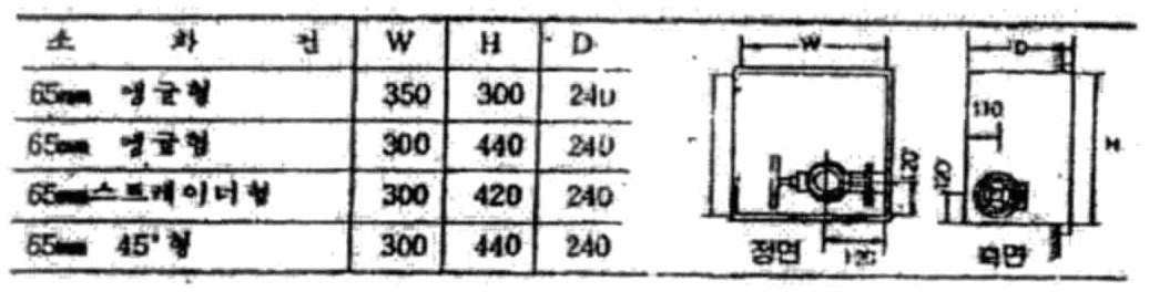
이렇게 소화전(179) 배관의 치수에 대하여About the dimensions of the hydrant pipe (179)
옥내 소화전의 배관에는 배관용강관과 수도용 아연 도금 강관을 사용하며 관을 연결할 때에는 나사 이음으로 하고 가단주철제 이음쇠를 사용한다는 것이었고,For the pipe of indoor fire hydrant, pipe pipe and water galvanized steel pipe are used.
수직관의 치수는 층수 4층 이하는50mm, 그 이상은 65mm로 한다. 옥내 소화전의 배관은 고가 탱크를 사용하는 경우에는 고가 수조 주관에 체크밸브(451)와 스톱 밸브(418)를 설치하고 고가 탱크주관에 접속한다. 또한 압력탱크를 사용하는 경우에는 체크 밸브 및 스톱 밸브를 사용하여 압력탱크(189)의 주관에 접속한다. 동도면에 도시한 바와 같이 소화전 배관 계통의 표준적인 4 가지 방식을 나타낸다는 것이었다.The dimension of the vertical pipe shall be 50mm or less for the fourth floor and 65mm for more. In the case of using an expensive tank, an indoor fire hydrant pipe is provided with a
한편 이렇게, 스프링클러 설비와 드렌처헤드에 대하여 동도면에 도시한 바와 같이 상세한 스프링클러 설비에는 동도면에 도시한 바와 같이 별도의 밸브를 갖춘 스프링클러 헤드(111)를 실내 천정에 일정한 간격으로 배열하고 이것에 급수배관을 해두면 불이 났을때 실온이 상승하면 헤드의 가용금속(113)이 녹아서(일반으로 65∼75℃에서 녹는다) 정지 밸브(114)가 오토(auto)로 탈락하여 다량의 물이 분수 산포되어 소화하게 되는 오토 산수 설비인 것이었다.On the other hand, the
그러나, 이 소화 장치는 오토식으로 물이 나오나 소화가 끝나도 오토식으로 물이 멈추지 않으므로 이 장치에는 반드시 오토 경보 장치를 설치해 둘 필요가 있게 된 것이었다.However, this fire extinguishing device is automatic, but the water does not stop automatically when the fire is finished, so it is necessary to install an auto alarm device.
상기된, 스프링클러 헤드(111)가 작동하여 물이 분출하면 경보 밸브(120)내에 물이 흐른다. 이 흐르는 물에 의하여 보조 밸브가 열리어 물의 일부는 경보 계통에 유입한다. 그 결과 압력 스위치(104) 작동에 의하여 전기 벨(119) 회로를 접속시켜 벨(119)이 울린다. 그리고 수차에도 물이 흘러 수차의 회전에 의하여 기계적으로 경보기를 울리게 되어 있다. 시험 밸브(121)는 때때로 시험할 때 사용한다는 것이었다As described above, when the
이같은, 드렌처 헤드의 종류에 대하여 상세한 설명에는 동도면에 도시한 바 와 같이 드렌처 헤드(299)를 건물의 외벽, 낭하, 지붕등에 일정한 간격으로 배열하여 이것이 배관하여 주로 인접 건물의 화재시 급수 주관의 밸브를 열어서 각 헤드에서 분사하여 수막을 만들어 화재를 방지하는 것을 목적으로 하는 방화 설비인 것이었다.As described above, the type of the drencher head is described in the same drawing, and the drencher
한편 이 같이, 별도의 소화 설비와 화재 경보장치의 별도의 소화 설비에 대하여,On the other hand, with respect to the separate fire extinguishing equipment and the separate fire extinguishing equipment of the fire alarm device,
산업 문화의 발달에 수반되는 생산 공장, 창고, 빌딩은 물론 주택에 이르기까지 휘발유, 석유 그 이외의... 약품등의 위험한 가연물이 많아지고 있다. 그러므로 지금까지의 화재와 같이 물을 끼얹는 것으로는 소화되지 않을 때가 많다. 그러므로 가연물의 종류, 건축물의 각층(단층이나 고층), 그 이외의 조건에 의하여 별도의 소화 설비를 사용하는 것이 규정되어 있다는 것이었다Dangerous combustibles such as gasoline, petroleum and other chemicals are increasing in production factories, warehouses, buildings, as well as houses accompanied by the development of industrial culture. Therefore, spraying water like a fire so far is often not digested. Therefore, it was prescribed to use a separate fire extinguishing facility depending on the type of combustibles, each floor of the building (single floor or high floor), and other conditions.
별도의 소화 설비에는 다음과 같은 것이 있다는 것이었다.There was a separate fire extinguishing facility:
첫째; 수 분무 소화 설비first; Water spray extinguishing equipment
둘째; 거품 소화 설비second; Foam fire extinguishing equipment
세째; 불 연성 가스 소화 설비(탄산가스 소화 설비)Third; Nonflammable Gas Fire Extinguishing Facility
네째; 분말 소화 설비fourth; Powder fire extinguishing equipment
다섯째; 증발성 액체 소화 설비(4 염화 탄소 소화 설비)fifth; Evaporative Liquid Fire Extinguishing Equipment
이처럼, 화재 경보 장치(300)에 있어서,In this way, in the fire alarm device 300,
소화 활동은 한순간을 다투는 것으로 1초 늦어짐에 따라 큰불로 되는 수가 많다. 화재시에는 가급적 재빨리 소화 활동에 임하기 위해서는 화재 경보기 장치의 완비가 필요하다. 그러므로 소화방법에 규정된 화재 경보 장치를 설치해야 하는 건물의 종류와 크기 등을 규정하고 있다. 수동 화재 경보 장치는 화재의 발견자가 손으로 조작하여 발화의 장소를 알리는 것이었으며,Digestive activity is a fleeting fight, and as a second late, a large fire is often. In the event of a fire, it is necessary to equip a fire alarm system in order to work as quickly as possible. Therefore, it regulates the type and size of the building where the fire alarm should be installed. The manual fire alarm system was operated by a hand of a fire detector to signal the place of ignition.
오우토(auto) 화재 경보 장치는 여관, 호텔, 사무소 아파트, 등의 화재의 발생하기 쉬운 장소 또는 발화의 초기 발견이 곤란한 장소등의 천정 또는 천정 근처의 벽면등에 오토 감지기를 설치하여 전선에 의하여 수신판과 접속하여 놓으면 발화시 실온의 상승 또는 연기 발생에 의하여 감지기가 오토식으로 작동하여 전기 부자 회로 개폐기(118)가 닫혀져 수신판의 부자(117)가 울려 동시에 표시등이 켜져서 발화와 발화 장소를 알 수 있게 한 장치인 것이었다.Auto fire alarm system is installed by the auto detector on the ceiling or wall near the ceiling of an inn, hotel, office apartment, etc. When it is connected to the plate, the sensor operates automatically by rising the room temperature or generating smoke during ignition, and the electric
오토 감지기에는 여러 종류의 것이 있으나 그 작동의 방식에 의하여 나누면 다음과 같았다.There are several types of auto detectors, but they are divided by the way of operation.
첫째; 금속의 열 팽창에 의한 변형, 용융등에 의한것first; By deformation, melting, etc., due to thermal expansion of the metal
둘째; 공기나 기타 기체의 열 팽창에 의한것second; By thermal expansion of air or other gases
세째; 액체의 열 팽창, 증발등에 의한것Third; By thermal expansion, evaporation, etc. of liquid
네째; 열전대의 열기 전력에 의한것fourth; By thermoelectric power
다섯째; 열에 의한 전기 저항의 변화를 이용한것fifth; Using change in electrical resistance due to heat
여섯째; 광전관에 의한것Sixth; By photoelectric tubes
등이 있다.Etc.
상기와 같이 종래의 소화설비의 설치기준은 엄격하고 고도한 소방제조설비는 상당한 기술임에는 상당한 것이었으나 무엇때문에 현장에는 적응이 잘 되지 않으므 로 이에 대하여 의문점을 해소토록 상세한 설명을 펼쳐가면서 진행토록 한다.As described above, the installation standards of the conventional fire extinguishing equipment were considerable, and the advanced fire fighting manufacturing equipment was a considerable technology. However, it is not well adapted to the site because of what it is, and the detailed explanation is made to solve the question.
이러한 방화수(7)인 급수의 수원과 수질에 대하여 상세한 설명에 있어서,In the detailed description of the water source and the water quality of the water supply which is such a
하천수나 호수와 같이 지표 위에 노출되어 있는 물을 지표수라 하고 우물과 같이 지하에 잠겨 있는 물을 지하수라 한다. 급수의 수원으로는 하천수와 우물 물이 많이 사용된다는 것이었다.Surface water, such as rivers and lakes, is called surface water, and submerged water, such as wells, is called groundwater. The source of water was the use of river water and well water.
이에 우물 물은 평균 온도가 16∼17℃로서 계절의 변화에 따른 수온의 차가 적어 냉방이나, 공업 용수에 적합하고 수질이 좋은 것은 음료수로 사용된다는 것이었으며,Well water has an average temperature of 16 ~ 17 ℃, and the difference in water temperature is small according to the change of season, so it is suitable for cooling or industrial water, and the water quality is good for drinking water.
하천수는 수량이 풍부하므로 정화하여 대도시의 상수도 물로 많이 사용한다. 수도물은 겨울에는 3∼8℃ 여름에는 25∼28℃로서 계절에 따라 수온의 변화가 심하기 때문에 사진 현상, 그 이외는 별도의 공업용에는 적합하지 않다는 것이었고,Since river water is abundant in quantity, it is purified and used a lot as tap water in large cities. Tap water is 3-8 ℃ in winter and 25-28 ℃ in summer, so the water temperature varies greatly depending on the season. Therefore, it is not suitable for photographic or other industrial purposes.
수질은 물에 포함되어 있는 유해물과 병균등에 따라 탁도, 색, 맛, 냄새 등이 다르므로 이를 검사하여 허용 함유량을 초과하는 경우에는 사용을 금하고 있다. 병균은 질병을 발병시키는 요인이 되며 유해물은 기준치를 초과한 광물질로서 요리와 세탁물에 나쁜 영향을 준다.는 것이었으되,Water quality has different turbidity, color, taste, and smell depending on harmful substances and germs, etc., so it is prohibited to use it when it exceeds the allowable content. Germs are the cause of disease, and pests are minerals that exceed the threshold, which adversely affects cooking and laundry.
물의 경도는 물 속에 포함된 탄산칼슘 등의 광물질의 함유량을 기준으로 표시한다. 즉 탄산 칼슘이 물 속에 100만분의 1 포함되어 있을때 이것을 1(p.p.m; part per milion)이라 한다. 음료수는 90∼110(p.p.m)이 적합하고 300(p.p.m)을 초과하여 서도 안된다. 또한 물은 경도에 따라 연수와 경수로 나뉘며 90 p.p.m 이하의 물을 연수(110 p.p.m) 이상의 물을 경수라 한다는 것이었다.The hardness of water is expressed based on the content of minerals such as calcium carbonate in water. In other words, when calcium carbonate contains one millionth of water, it is called 1 (p.p.m; part per milion). Drinking water is suitable for 90 to 110 (p.p.m) and shall not exceed 300 (p.p.m). In addition, water is divided into soft water and hard water according to hardness, and water of 90 p.p.m or less is called soft water (110 p.p.m) or more.
일반적으로 펌프(pump) 몸체(Body)에 대하여,Generally with respect to the pump body,
상기 펌프의 양수는 흡입관내를 진공하여 하여 빨아 올리는 작용과 물을 뿜어 내는 관내를 눌러서 올리는 작용에 의하여 행해진다. 빨아 올리는 작용은 진공에 의한 것이므로 대기압에 상당한 수두. 즉 표준 기압하에서는 10.33m 이상 빨아 올릴 수는 없다. 그러나 이 10.33m는 이론상의 빨아올리는 높이이며 실제로는 수중에 함유되어 있는 공기나 물 자체의 증발에 의하여 완전한 진공은 되지 못하며 또한 빨아 올리는 관 내의 저항손실 등에 의하여 이론상의 빨아 올리는 높이의 2/3정도 즉 약 7m 정도에 불과하다. 따라서 펌프의 설치 높이(빠라올림 양정)은 최저 수면에서 7m 이내의 곳이 아니면 안된다. 이 높이는 낮을수록 좋다는 겄이었고The pumping of the pump is carried out by the action of vacuuming up the suction pipe and pressing up the pipe to discharge water. Sucking action is due to the vacuum, so the head is considerable pressure. In other words, under standard pressure, it can not be sucked more than 10.33m. However, this 10.33m is the theoretical suction height, and in reality, it is not fully vacuumed by the evaporation of air or water contained in the water, and about 2/3 of the theoretical suction height due to the resistance loss in the suction pipe. That is only about 7m. Therefore, the installation height of the pump (rapid lift head) must be within 7 m of the lowest water surface. The lower this height is, the better
건축 설계에 사용되는 펌프를 대별하면 왕복동 펌프와 회전 운동 펌프(퓨갈 펌프)가 있다는 것이었다.The most common pumps used in architectural design were reciprocating pumps and rotary motion pumps (fugal pumps).
한편 다양한 펌프의 종류에 있어서,On the other hand, in various pump types,
먼저, 왕복 펌프(Veciprocating pump)의 상세한 설명을 동도면에 도시한 바와 같이, 왕복펌프 내부에는 퍼올림밸브(320)와 빨아올림밸브(321)가 형성되어 있고 수면하단부(WLD)에는 후드밸브(312)로 각개로 부착되며 시린더(126) 몸체 내부로 피스톤(127) 또는 플런저(253)가 샤프트(198)에 부착되어 있는 것이었다.First, as shown in the drawings for a detailed description of the reciprocating pump (Veciprocating pump), a
상기 왕복 펌프에는 피스톤(127) 펌프(piston pump,127) 프런저 펌프(plunger pump)에 워어싱톤 펌프(worthington pump)등이 있다. 피스톤 펌프는 송수압에 파동이 크고 수량의 조절도 곤란하여 양수량이 적어 양정이 큰 경우에 적합하다는 것이었으며The reciprocating pump includes a
플런저 펌프(148)는 플런저(253) 주위로부터의 누설이 적고 물 그외 액체용 고압 펌프에 사용되고 있으며
워싱톤 펌프는 증기 기관에 펌프가 직결되어 있어 고압 보일러의 급수 펌프 등에 적합하다는 것이었다.The Washington pump was connected directly to the steam engine, so it was suitable for feed pumps of high pressure boilers.
다음의 회전 운동 펌프에 있어서 동도면에 도시한 바와 같이 상기 회전 운동 펌프에는 센튜리 퓨우걸 펌프(308) 터어빈 펌프에 치차 펌프 등이 있다. 왕복 펌프에 비하여 다음과 같은 이점이 있으므로 일반적으로 널리 사용되고 있다는 것이며 이에 대하여 상세한 설명은 다음과 같다.As shown in the same figure in the following rotary motion pump, the rotary motion pump includes a
첫째 경량 소형이며 고속 운전에 적당하고 모우터에 직결된다. 운전 성능도 우수하다는 것이며First, it is light and compact, suitable for high speed operation and directly connected to the motor. Driving performance is excellent.
둘째 진동과 소음이 적고 장치도 간단하며 송수압에 파동이 없어 수량의 조절도 용이하다는 것이었고Second, the vibration and noise is small, the device is simple, and there is no wave in the water pressure, so it is easy to control the quantity.
센튜리 퓨우걸 펌프(centrifugl pump,308)는 주로 15m 내외의 낮은 양정의 펌프로서 사용되고 시동하는데 있어 펌프내에 프라밍하여 임펠러(143)를 회전, 원심력에 의하여 양수한다는 것이었으며The Centrifugl pump (308) is mainly used as a low lift pump of about 15m and is used to prime the pump to pump the
터어빈 펌프(Turtine pump,140)는 센튜리 퓨우걸 펌프(308)의 임펠러(143) 외축에 가이드 베인(guide uane)을 장치하고 있어 물의 흐름을 조절하여 20m이상의 높은 양수에 사용되며 현재 가장 많이 사용되고 있다는 것이며Turbine pump (Turtine pump, 140) is equipped with a guide uane on the outer shaft of the impeller (143) of the Centurie Pugirl pump (308) to control the flow of water is used for high pumping water of more than 20m and is currently used most Is that
회전운동 펌프를 시동 할 때의 조작 순서 실시예는 다음과 같다는 것이었다.The procedure of operation when starting the rotary motion pump Example was as follows.
먼저 베어링(227)에 기름을 치고 원활한 회전이 되게 한다는 것이었고The first thing is to grease the bearings (227)
다음은 펌프의 분출 밸브를 반드시 잠근다. (왕복동 펌프는 열어 놓고 시동한다)라고 했으며Next, be sure to shut off the pump's blow valve. (Return the reciprocating pump open and start it)
그 다음은 시동 전에 펌프 내부에 물을 가득히 붓는다. (프라이밍:priming,339) 이하 생략Next, fill the pump with water before starting. (Priming: priming, 339) omitted below
네번째 분출변을 잠근채 모우터의 스위치를 넣는다는 것이었다The fourth eruption was locked and the motor was switched on.
다섯번째 시동후 압력계를 보고 압력이 소정의 압력까지 오르면 분출 밸브를 서서히 연다는 것이었고After the fifth start, the pressure gauge was used to open the blowoff valve slowly
여섯번째 전류계를 보아 소정의 암페어 이상이면 분출구의 밸브를 조절 양수량을 가감한다는 것이었다.In the sixth ammeter, if the predetermined amperage or more was adjusted, the valve of the outlet port was added or decreased.
그 다음의 디이프 웰 펌프(deep well pump)의 상세한 설명으로는 상기 펌프는 깊은 우물물을 퍼 올리는데 사용하는 펌프로 다음과 같은 종류가 있다는 것이었으며 먼저 보어호울 펌프(borehole pump)는 수직형 터어빈 펌프로서 임펠러와 스트레이너는 물 속에 있고 모우터는 깡 위에 있어 이 2개를 긴 축으로 연결하여 운전한다.는 것이었으며The detailed description of the following deep well pump is that the pump is used to pump deep well water. There are the following types. The borehole pump is a vertical turbine pump. The impeller and strainer are in the water, and the motor is on the can, so the two are connected by a long shaft.
다음은 수중 모우터 펌프는 수직형 터어빈 펌프 밑에 모우터를 직결하여, 양수하며 모우터와 터어빈은 수중에서 작동한다는 것이었고 이러한 펌프는 고성능 수중펌프(36)와 대동소이하다.Next, the submersible motor pump was connected directly to the motor under the vertical turbine pump, pumped and the motor and the turbine operated in water, which is almost the same as the high
그 다음에는 제트 펌프(Jet pump, 157)는 지상에 설치한 터어빈 펌프에 연결된 흡입관과 압력관을 우물 속에 세운다. 터어빈에서 압력수의 일부를 압력관을 통하여 물 속에 있는 제트에 보내어 고속으로 벤튜리관에 분사시킨다. 이때 벤튜리관 은 압력이 낮아져 우물물을 흡입하고 흡입된 물을 압력수와 같이 흡입관으로 올라가 터어빈펌프(140)로 배출된다.Jet pumps (157) then erect the suction and pressure pipes in the wells connected to the turbine pumps installed above the ground. In the turbine, part of the pressure water is sent through a pressure tube to a jet in the water and sprayed to the venturi tube at high speed. At this time, the venturi pipe is lowered in pressure to suck the well water, and the sucked water is lifted up to the suction pipe as the pressure water and discharged to the
이 펌프의 제트는 보조 펌프의 역할을 하여 우물 물을 센튜리 퓨우걸 펌프(308)의 흡수 가능 범위(6∼7m)까지 끌어 올리므로 빨아 올리는 높이 25m까지의 디이프 웰 용에 사용할 수 있다.는 것이었다.The jet of this pump acts as an auxiliary pump and draws well water up to the absorbable range (6-7 m) of the Centurion
네번째 오수 펌프(하수 펌프, 309)에 대하여 동도면에 도시한 바와 같이 수면하단부(WLD)에는 양수구(313) 상부로 오수펌프(309)가 형성되었고 상기펌프(309) 수면부(WLL)로 플로우트(315)와 오수통 상부로 토출구(270)와 전동기(192) 몸체 하부로 플랙스블 카프링(317)과 드러스트보울(316)에 상기 보울(316) 좌측에는 플로우트 스위치(318)가 부착되었다.As shown in the same drawing for the fourth sewage pump (sewage pump 309), a
상기 오수 펌프(309)는 가옥의 오수등 오물찌거기등의 고형물이나, 유지, 천 등이 섞인 물을 배제할 때 건축 설비용으로는 지층의 오수 또는 정화조의 정화수를 공공 하수관까지 양정 할 때에 사용된다는 것이었으며 동도시된 도면에 따라 그 설치 상태를 나타낸다. 이 펌프도 회전운동 펌프에 속하나 정수 펌프와 임펠러의 구조가 다소 달라 둥글게 하여 고형물이 걸리지 않게 되어 있으며 임펠러의 수도 1 또는 2배로 하고 스파이럴 케이싱(310)도 충분히 넓게하여 고형물이 막히지 않게 되어 있다는 것이었고The
큰 고형물이 함유되어 있지 않은 오수의 경우에는 임펠러의 수가 4개 또는 6개의 것도 사용된다. 동도시된 바 있는 도면과 같이 모우터는 지상에 설치하고 펌프는 오수통 속의 수중에 잠기게 하여 오수는 분출관을 통하여 양정된다. 펌프는 플로우트로트 스위치(318)에 의하여 오토 운전 된다는 것이었다.For sewage that does not contain large solids, four or six impellers are also used. As shown in the drawing, the motor is installed on the ground and the pump is submerged in the water in the sump, so that the sewage is pumped through the discharge pipe. The pump was auto run by the
상기한 바와 같이 방화수(7)의 유동에 대한 펌프 운전에 대한 종래의 기술 설명은 생략하고 에어콤프레샤, 송풍기, 팬 등의 압축기에 대하여 살펴보는 바와 같이 상세한 설명은 다음과 같이 한다.As described above, a conventional description of the pump operation for the flow of the
상기 압축기는 기계에너지를 가스에 전달하여 그 압력과 속도를 높이는 기계이다. 압력상승이 1,000mm(Aq)미만은 팬(fan), 1,000mm(Aq)이상 1kg/㎠g 미만을 송풍기(blower : 블로우어), 1kg/㎠g 이상을 압축기(Compressor)라 한다는 것이었다.The compressor is a machine that delivers mechanical energy to the gas to increase the pressure and speed. When the pressure rise was less than 1,000 mm (Aq), a fan, a blower (blower) was less than 1 kg / cm 2g and more than 1,000 mm (Aq), and a compressor was more than 1 kg / cm 2 g.
이렇게, 압축기의 종류에는 터어보형과 용적형으로 분리 구분테는 데에는 다음과 같이 설명하되, 동도시된 도면의 실시예의 제작 수리한 것을 참조토록 하였다.Thus, the type of compressor is divided into a turbo type and a volume type, which are described as follows, but refer to the fabrication and repair of the embodiment of the drawing shown in the drawing.

먼저, 터어보 압축기에 대하여 상세한 설명을 다음과 같이 한다.First, a detailed description of the turbo compressor is as follows.
첫째로는 일반적으로 원심력을 이용하여 압력과 속도 에너지를 얻으므로 원심압축기(Centrifugal Compressor)라 한다고 칭하였든 것이며,First, it is generally called centrifugal compressor because it obtains pressure and velocity energy using centrifugal force.
둘째로 왕복동식에 비해 고속이고, 소형이며, 진동·소음·중량·설치 면적이나 마모 또는 마찰손실이 작다라는 것이었으며,Second, it was faster, smaller, and less vibration, noise, weight, installation area, abrasion or friction loss than reciprocating type.
세째로 가스압송은 연속적인 회전에 의하므로 맥동이 없다는 것이었고,Thirdly, gas pressure was due to continuous rotation, so there was no pulsation,
네째에는 대용량에 적합하며, 내부에 윤활유를 쓰지 않으므로 압송유체 중에 기름이 혼입되지 않는다고 하였으며,Fourth, it is suitable for large capacity and does not use lubricating oil inside, so no oil is mixed in the pressurized fluid.
다섯째로 원동기에 직접연결하여 감속장치가 필요없다라는 것으로서,Fifthly, it is not necessary to reduce gear by connecting directly to prime mover.
여섯째에는 왕복동식에 비해 제작비가 비싸고, 기계적 접촉부는 베어링(227) 부분 뿐이므로 안정하고 마찰이 작지만,Sixth, the manufacturing cost is higher than that of the reciprocating type, and since the mechanical contact part is only the
일곱번째는 고압은 축봉장치에 고도의 가공기술을 요한다는 것이었든 바이며,The seventh is that high pressure requires a high degree of processing technology for the shaft,
여덟번째에는 가스의 비중에 의하여 크게 영향을 받으며, 토출압력변화에 의한 용량변화가 크다는 것이었으며,Eighth, it was greatly influenced by the specific gravity of the gas, and the change in capacity due to the discharge pressure was large.
아홉번째로 용량 조정범위는 비교적 좁고(70∼100%), 어려운 편이다라고 주장하였으며,Ninthly, the capacity adjustment range was relatively narrow (70-100%) and was difficult.
열번째에는 운전 중 써어징현상에 대하여 주의해야 할 필요가 있다는 것이었다.The tenth was that you need to be careful about surges while driving.
다음의 왕복압축기에 대하여 상세한 설명은 다음과 같다.Detailed description of the following reciprocating compressor is as follows.
상기 왕복 압축기는 다음과 같이 분류하기도 한다는 것으로써, 상기 압축기는 실린더 배치에 따라 먼저 횡형의 피스톤이 수평으로 왕복운동하는 것과, 다음은 입형의 피스톤이 수직으로 왕복운동하는 것인바 이에 그 다음은 L형의 피스톤이 하나는 수직으로,하나는 수평으로 왕복운동 것이었고 다음의 그리고 V형은 피스톤 축이 V형으로 배치되어 왕복운동것에 뒤이어 W형은 피스톤 축이 W형으로 배치되어 왕 복운동것으로서 이어서 대향형은 피스톤이 양측에 서로 맞대어 배치되어저 왕복운동것이었다The reciprocating compressor may be classified as follows, in which the lateral compressor reciprocates horizontally according to the arrangement of the cylinder first, and then the vertical piston reciprocates vertically. The piston of the type will be reciprocating one vertically and one horizontally. The next and V type will be reciprocating with the piston shaft arranged in the V shape, followed by the W type with the reciprocating motion with the piston axis arranged in the W type. The opposite type was a low reciprocating motion in which the pistons were placed against each other.
첫째 압축방법에 따라서 단동형의 피스톤(127) 한쪽에서만 압축이 행해지는 것과, 복동형으로 피스톤 양쪽에서 압축이 교대로 행해지는 것이었으며According to the first compression method, compression is performed only on one side of the single-acting
둘째 압축 단수에 따라서 1단형, 2단형에 3단형 …‥, 다단형으로써,Second, the first stage, the second stage and the three stage… ‥, as a multi-stage type,
세째로 윤활 방식에 따라 강제 윤활식은 기어펌프(326) 등의 유압펌프 등으로 베어링부에 윤활하는 방식과, 비말 윤활식의 크랭크 샤프트의 회전에 의해 베어링부에 윤활유를 튀겨주는 방식의 것으로써,Third, according to the lubrication method, the forced lubrication type is a method of lubricating the bearing part with a hydraulic pump such as a
이러한 급유식 외에도 윤활유를 공급해 주지 않는 무급유식이 있다는 것이었다In addition to this type of lubrication, there was no lubrication without supplying lubricant.
그 이외에도 설치 방법에 따른 고정식과 이동이 가능한 가반식, 원동기의 동력 연결에 따라 직결식 또는 V벨트(252)·평벨트·기어 감속기(251) 등을 이용한 감속식 등으로 분류하기도 한다는 것이었으며 왕복압축기의 특징은 다음과 같았다.In addition, depending on the installation method, it can be classified into a fixed type, a portable type, a direct type, or a deceleration type using a
첫째로, 용적형으로 일정량의 정량이 압축된다는 것이었고,Firstly, a certain amount of quantitation was compressed into a volumetric form,
둘째로는 왕복운동이 단속적으로 맥동이 있다는 것이었으며,Secondly, the reciprocating motion is intermittently pulsating,
세째로 저속이며, 단단으로도 고압을 얻을 수 있다는 것으로써,Thirdly, because it is low speed and high pressure can be obtained in a single stage,
네째에는 흡입·토출밸브가 꼭 필요하고, 작동부분이 많으므로 진동·소음 및 밸브의 고장 우려가 있다고 주장하였으며,Fourth, they claimed that suction and discharge valves are essential and that there are many operating parts, which may cause vibration, noise, and valve failure.
다섯째로 외형과 중량이 크고, 설치 면적을 많이 차지하며, 견고한 기초를 필요로 한다는 것으로써,Fifth, it is large in appearance and weight, occupies a lot of installation area, and requires a solid foundation,
여섯째에는 전반적으로 효율이 높으며, 용량 조절 폭이 넓고(0∼100%), 용량조절이 용이하다는 것이었으며,Sixth, the overall efficiency was high, the capacity adjustment was wide (0-100%), and the dose adjustment was easy.
일곱번째로 기체의 비중에 크게 영향을 받지 않으며, 토출 압력 변화에 의한 용량변화가 적다는 것이었고Seventhly, it was not influenced by the specific gravity of the gas, and the change of capacity due to the discharge pressure was small.
여덟번째에는 시린더(126)에 피스톤(127)이 운동을 할 때 기밀과 마찰 저항을 줄이게 하기 위하여 유막을 형성하는 윤활유를 공급해 주어야 하므로 오일이 토출가스 중에 혼입해 들어갈 우려가 있다는 것이었다.Eighth, the lubricating oil to form an oil film should be supplied to the
세번째 회전형 압축기(Rotary Compressor)의 상세한 설명에 있어서,In the detailed description of the third rotary compressor (Rotary Compressor),
상기 용적형 압축기의 일종으로 왕복운동 대신 회전운동을 하는 피스톤이나 날개에 의해 압축이 이루어지는 것으로 이 회전운동을 하는 것의 형태에 따라 루츠형, 베인이 고정된 고정익형(Stationary blade type)과 회전하는 회전익형(Rotary blade type) 등으로 분류하기도 한다. 나사(Screw : 스크류)형 압축기도 회전형의 일종이지만 다음 별개의 항목에서 그 특징을 살펴보았다.Compression is performed by a piston or a blade that rotates instead of a reciprocating motion as a kind of the volumetric compressor. Roots, a stationary blade type with fixed vanes and a rotating rotor that rotate according to the form of the rotational motion It may be classified into a rotary blade type or the like. Screw-type compressors are also a type of rotary type, but their characteristics are discussed in the next separate section.
먼저 동작이 단순하므로 부품의 수가 적고, 간단하다는 것이었고,First, because the operation is simple, the number of parts is small and simple.
다음으로는 회전운동이므로 진동이 적다는 것이었으며,Next is the rotational movement, which means less vibration.
세번째는 케이싱 마찰부에 정밀도 및 내 마모성이 요구되며, 소음이 있으며, 간극효율을 좋게하기 위해서는 윤활을 필요로 한다는 것이었고,Third, the casing friction part requires precision and abrasion resistance, there is noise, and lubrication is required to improve the gap efficiency.
네번째는 효율이 높고, 고압축비를 얻을 수 있으며, 대용량의 것으로 제작이 가능하다는 점이었으며,Fourth, high efficiency, high compression ratio, and large capacity.
다섯번째는 압축된 토출량이 대략 일정하며 부하의 변동에 따른 토출량 증감 이 없고, 토출량은 압축비의 저하없이 회전속도에 비례한다는 것이었다.Fifth, the compressed discharge amount was approximately constant, and there was no increase or decrease in discharge amount according to the load variation, and the discharge amount was proportional to the rotational speed without lowering the compression ratio.
네번째 나사 압축기(Screw Compressor : 스크류 압축기, 147)의 상세한 설명에 있어서,In the detailed description of the fourth screw compressor (Screw Compressor) 147,
용적형 압축기의 일종으로써 대용량의 회전식 압축기로 고속(15,000r·p·m에 이른다)용의 무급유 압축기로 개발한 것인데 최근들어 상당한 관심을 모으고 있다는 것이었고It is a kind of volumetric compressor, developed as a large-capacity rotary compressor and a non-lubricating compressor for high speed (up to 15,000 r · p · m).
그 원리는 케이싱 내에 암·수 한쌍의 로우터가 맞물려 돌아가면서 연속적으로 압축을 한다. 두 로우터와 케이싱 간에는 윤활유를 사용하지 않아도 되는 특징을 갖고 있으나 간극의 누설·효율 등을 좋게하기 위해 윤활유를 사용하기도 한다. 그 주요 특징은 다음과 같다.The principle is to continuously compress a pair of male and female rotors in a casing. Lubricant does not need to be used between the two rotors and the casing, but lubricating oil is sometimes used to improve the leakage and efficiency of the gap. The main features are as follows.
먼저 용적형으로써 무급유식으로 개발되었으나 급유식도 있다는 것이었고,First of all, it was developed as a lubrication type, but there was also a lubrication type.
이에 두 로우터는 회전운동으로 진동이나 맥동이 없고 연속 송출된다는 것으로써,The two rotors are continuously transmitted without vibration or pulsation by rotational movement.
이에 따라 가볍고, 진동·발열·고장·설치면적이 작으며, 고속으로 중용량에서 대용량에 적합하다는 것이며,As a result, it is light, vibration, heat generation, failure and installation area is small, and it is suitable for medium to large capacity at high speed.
이 같이 토출압력변화에 의한 용량변화가 적고, 기체의 비중에 약간 영향을 받는다는 것이었고,As such, the capacity change due to the discharge pressure change is small, and it is slightly influenced by the specific gravity of the gas.
일반적으로 효율이 작고, 용량조정이 곤란하며 용량조정폭(70∼100%)도 작다는 것이었므로, 이같은 소음이 있으므로 소음 방지대책을 필요로 한다는 것이었다.In general, the efficiency was small, the capacity adjustment was difficult, and the capacity adjustment range (70-100%) was also small. Therefore, such noise was required, and noise prevention measures were needed.
다섯번째 그 이외의 용도에 따른 왕복식의 전용압축기(263)의 상세한 설명에 있어서,In the detailed description of the reciprocating
먼저 산소 압축기의 산소 압축기에는 윤활유를 쓸 수 없으므로 물(또는 10% 이하의 묽은 글리세린)을 윤활유로 사용하거나 무급유식의 압축기를 사용한다. 물을 윤활유로 사용할 때에는 크롬을 입힌 U형 패킹(크롬피)이나 화이버 또는 테프론 등의 피스톤링을 사용하며 누설이 되지 않게 하고 실린더에서 누설된 산소나 물이 크랭크실에 들어가지 않게 피스톤봉의 하방에는 칼라를 설치한다. 금속재료는 산화되어 녹이 스는 것을 막게 하기 위해 피스톤 봉은 불수강으로 선택하고 밸브는 포금 또는 불수강을, 피스톤·실린더·밸브 박스는 포금제를 사용한다는 것으로서,First of all, the lubricating oil cannot be used in the oxygen compressor of the oxygen compressor, so water (or less than 10% dilute glycerin) is used as the lubricating oil or an oil-free compressor is used. When using water as lubricating oil, use a chrome coated U-shaped packing (chromium) or a piston ring such as fiber or Teflon to prevent leakage and to prevent oxygen or water leaking from the cylinder from entering the crankcase. Install the collar. In order to prevent metal materials from oxidizing and rusting, the piston rod is selected as inert steel, the valve is made of gunmetal or inert steel, and the piston, cylinder, valve box is made of gunmetal.
불수강이란 스테인레스 강(강에 크롬과 니켈을 합금한 것)을 말한다는 것이었고,Invisible steel refers to stainless steel (alloyed with chromium and nickel in steel),
이의 포금에 있어서, 구리와 주석의 합금인 청동의 일종으로 그 중에서도 구리(Cu)90%와 주석(Sn)10%로 된 것을 말하는데, 강도와 연성이 크고 내식성·내마모성이 우수하며 과거에 주로 포신을 만드는 데에서 유래하여 포금(Gun metal)이라 부르게 되었다는 것이었으며,In the gun metal, it is a kind of bronze, which is an alloy of copper and tin, of which 90% copper (Cu) and 10% tin (Sn) are used. The strength and the ductility are excellent, the corrosion resistance and the wear resistance are excellent, Originated from the making of metal and was called Gun metal,
무급유 압축기는 카아본링이나 테프론링을 사용하거나 라비린스 피스톤식 또는 다이어후렘식의 압축기를 사용하여 윤활유없이 압축을 실시한다는 것이었다.The lubrication-free compressor was to perform compression without lubricating oil by using a carbon ring or Teflon ring, or by using a labyrinth piston or diaphragm type compressor.
다음으로 아세틸렌 압축기의 아세틸렌 가스는 폭발 범위가 대단히 넓은 가연성가스이며, 동이나 동합금·은·수은 등과 접촉하여 폭발성화합물질을 생성하고, 산소와 같은 조연성가스의 도움이 없이도 가압하면 자기분해 폭발을 한다. 따라서, 압축기에는 62%를 초과하는 동의 합금이나 수은마노미터 또는 은 등의 사용을 피해야 하며, 각단의 압축비는 3이하의 낮은 값으로 저속회전 (보통 100r·p·m내외)의 왕복동식 압축기를 주로 사용한다는 것이었고,Next, the acetylene gas of acetylene compressor is a flammable gas with a very wide explosive range, and forms explosive compounds by contact with copper, copper alloy, silver, mercury, etc. do. Therefore, the use of more than 62% copper alloy, mercury manometer or silver, etc. should be avoided in the compressor, and the compression ratio of each stage is lower than 3, and low speed rotation (usually around 100r · p · m) is mainly used. Use it,
상기 압축기는 충분한 냉각(보통 수중에서 작동시키고, 냉각수 온도는 20℃ 이하를 유지)을 필요로 하며 기밀한 구조로 격리된 방폭모터와 연결하고, 충전시는 온도 여하에도 불구하고 25kg/㎠ 이상으로 압력을 올리지 말아야 하며 온도 여하에도 불구하고 25kg/㎤의 압력으로 압축할 때에는 일산화탄소·질소·에틸렌·메탄 등의 희석제를 첨가하도록 되어 있다는 것이었다.The compressor requires sufficient cooling (usually operated in water and the temperature of the coolant is below 20 ° C) and is connected to the explosion-proof motor in an airtight structure and is charged at 25kg / cm2 or more despite charging temperature. The pressure was not to be raised and, despite the temperature, when compressed to a pressure of 25 kg /
상기된 압축기의 주요특성에 있어서,In the main characteristics of the compressor described above,
상기 왕복식 압축기의 흡입·토출밸브의 기능 및 구비조건으로As a function and provision condition of the suction / discharge valve of the reciprocating compressor
먼저 흡입·토출밸브의 기능에 왕복식 압축기에서는 흡입·토출밸브가 꼭 필요한데 작동여하에 따라 효율이나 압축기의 수명에 크게 영향을 준다. 내연기관처럼 버섯형태를 갖기보다는 통상링처럼 얇은 판(0.8∼4.0mm정도)의 윤형 형태를 갖고 있다. 이 윤형밸브판은 니켈·크롬의 합금강으로 가급적 가벼워야 좋다는 것이었고,First of all, the suction / discharge valve is necessary for the function of the suction / discharge valve. However, depending on the operation, it greatly affects the efficiency and the life of the compressor. Rather than having a mushroom shape like an internal combustion engine, it has a circular shape of a thin plate (about 0.8 ~ 4.0mm) like a normal ring. This valve valve is made of nickel-chromium alloy steel, which should be as light as possible.
이 밸브와 접촉하는 밸브시트는 고급주철로 만들며, 고압용은 단강제로 한다. 밸브판을 누르고 있는 스프링은 스프링 강으로 만드는데, 너무 강하면 동력의 손실이 있고 너무 약하면 밸브판이 진동하고 가스를 역류시켜 토출량을 감소시키게 된다는 것이었다The valve seat in contact with this valve is made of high-grade cast iron, and the high pressure steel is forged steel. The spring holding the valve plate is made of spring steel, if too strong, there is a loss of power, and if it is too weak, the valve plate will vibrate and back the gas to reduce the discharge rate.
그리고 밸브의 구비 조건에 있어서 이처럼 개폐가 확실하여 폐쇄나 개방이 지연되지 않고, 작동이 양호할 것이어야 하고, 이 같이 유체의 충분한 통과면적을 가지고 유체 저항이 적을 것이어야 하며 또한 파손이 적은 것일 것과, 운전중 분해하는 경우가 없을 것이어야 하는 것이었다In the condition of the valve, the opening and closing is assured so that the closing or opening is not delayed and the operation is good. The fluid resistance must be sufficient and the fluid resistance should be low and the breakage should be small. In other words, it should not be disassembled during operation.
한편 왕복 압축기의 용량 제어방법에 있어서, 이런 연속적으로 조절을 행하는 방법에는 흡입 주밸브의 폐쇄에 의한 방법과, 바이패스 밸브에 의해 흡입측으로 가스를 되돌리는 방법에 타임드 밸브에 의해 제어시키는 방법과 회전수를 변경하는 방법인 것이었다On the other hand, in the capacity control method of the reciprocating compressor, such a continuous adjustment is performed by controlling the timed valve in the method of closing the suction main valve and returning the gas to the suction side by the bypass valve and rotating the valve. Was to change the number.
또는 단계적으로 조절을 행하는 방법으로서, 이런 클리어런스 밸브에 의해 체적효율을 낮추는 방법과, 흡입밸브를 개방하여 실제의 가스흡입을 못하게 줄이는 방법(언로더 법)인 것이었다.Alternatively, the stepwise adjustment is a method of lowering the volumetric efficiency by such a clearance valve, and a method of opening the intake valve to prevent actual gas intake (unloader method).
그리고 흡입 주밸브 폐쇄는 흡입 측 주밸브의 열림을 조절하는 것으로 흡입측 압력이 떨어져 토출 온도가 올라가고, 대기압에서 흡입하는 경우는 흡입압력이 대기압 이하로 진공화하여 죠인트부에서 공기를 흡입할 위험이 있으므로 대형에서는 거의 쓰지 않고, 소형의 공기 압축기에서나 쓰인다는 것이었다.The inlet main valve is closed to control the opening of the inlet side main valve, and the inlet side pressure drops and the discharge temperature rises.In case of inhalation at atmospheric pressure, the inlet pressure is reduced to below atmospheric pressure, so there is a risk of inhaling air from the joint. Rarely used in small air compressors.
한편 바이패스는 중간 단이나 마지막 단에서 압축된 기체를 되돌려 흡입측으로 복귀시키는 방법으로 간단하게 0∼100%까지 연속적으로 조절할 수 있으나 동력 손실이 크므로 대용량의 조절은 다른 조절장치와 조합하여 미량 조절에 주로 쓰인다는 것이었고Bypass is a method of returning the compressed gas from the middle stage or the last stage and returning it to the suction side, which can be easily adjusted continuously from 0 to 100%, but because of large power loss, the large capacity can be adjusted in combination with other regulators. Is mainly used for
또한 타임드 밸브는 흡입밸브의 폐쇄시기를 스프링의 탄성에 의해 강제적으로 지연시켜 흡입한 가스를 역류시킴으로써 조절하는 것으로 마치 행정거리가 조절 되는 것과 같은 효과를 얻는데 동력 손실이 적고, 역류 시간을 자유롭게 조절 선택할 수 있는 이점이 있다는 것이었으며,In addition, the timed valve adjusts the closing time of the intake valve by forcibly delaying the spring due to the elasticity of the intake valve to reverse the intake of gas, thereby reducing the power loss and freely adjusting the backflow time. There are advantages to choose from,
이렇게 회전수 가감은 회전수를 변화시켜 용량을 조절해도 왕복식에서는 압력변화가 거의 없으나 맥동주기가 길게 된다는 것으로써In this way, even if the rotation speed is changed and the capacity is adjusted, there is almost no pressure change in the reciprocating type, but the pulsation period is long.
클리어런스 밸브는 시린더(126)의 일부에 클리어런스 박스를 설치하고 스톱밸브(301)로 시린더(126)와의 연결을 개폐 조절하여 간극 용적이 변화하고 체적효율이 가감되는 방식으로 클리어런스 박스에 폐쇄된 가스는 재 압축되어 토출가스의 온도를 상승시키므로 클리어런스 박스의 용량이 클 때에는 충분한 냉각수가 흐르도록 워터자켓을 설치하여야 한다. 동력손실이 없으나 연속적으로 조정되지 않으므로 바이패스 방식과 조합하는 예가 많다는 것이었으며,The clearance valve is installed in a part of the
마지막에는 흡입밸브 개방으로 흡입밸브를 강제적으로 개방하여 압축을 행하지 않도록 하는 것으로 수동 외에도 유압이나 공기압 등의 동력으로 조작한다. 수개 이상의 시린더 중 일부 시린더만 작동할 수 있으므로 '일부 시린더를 놀리는 방법'이라 표현하기도 하며, 일명 '언로더법'이라 한다. 동력 손실이 없고 간단한 구조이지만 단계적으로 조정이 이루어지므로 단독으로 설치하는 외에 클리어런스밸브나 바이패스 방식과 조합하여 사용하기도 한다는 것이었다.Finally, the suction valve is opened to forcibly open the suction valve so that compression is not performed. In addition to manual operation, it is operated by hydraulic or pneumatic power. Since only some of the cylinders can be operated, it is sometimes referred to as 'how to play some cylinders', also known as 'unloader method'. There is no power loss and simple structure, but it can be adjusted in stages so that it can be used in combination with a clearance valve or bypass method.
그러나 터어보 압축기의 용량제어 방법에 있어서,However, in the turbo compressor capacity control method,
첫째로 회전수의 변경에 의한 방법은 회전속도와는 다음 관계를 갖는다 것이었고First, the method of changing the rotational speed had the following relationship with the rotational speed.
(Q∝N;토출량은 속도의 1승에 비례)(Q∝N; discharge rate is proportional to 1 power of speed)
(H∝N2;압력은 속도의 2승에 비례)(H∝N 2 ; pressure is proportional to the power of speed)
(KW∝N3;동력은 속도의 3승에 비례)(KW∝N 3 ; power is proportional to three power of speed)
압축비가 큰 다단의 경우에는 이 관계가 성립되지 않지만 가장 현실적이고 경제적인 방법이다는 것이었다In the case of multiple stages with a high compression ratio, this relationship is not established but is the most realistic and economic way.
다음의 토출밸브에 의한 조정은 토출관에 설치된 밸브의 열림을 조정함으로써 압송량을 조절하는 방법으로 가장 일반적으로 사용된다는 것이었으며The following adjustment by the discharge valve is the most commonly used method of adjusting the feed rate by adjusting the opening of the valve installed in the discharge pipe.
세번째의 흡입밸브에 의한 조정은 흡입관에 설치된 밸브의 열림을 조정함으로써 압송량을 조절하는 방법으로 대기압을 흡입하는 공기압축기에 널리 사용된다. 흡입밸브로 조정하는 것이 축동력이 절약되고, 서어징 한계량도 감소한다는 것이었고,The third suction valve adjustment is widely used in an air compressor that sucks atmospheric pressure by adjusting the opening amount of the valve installed in the suction pipe. Adjusting with the intake valve saves axial force and reduces the surging limit,
일반적으로 냉동기를 다루는 안전관리자들은 터어보 압축기는 흡입 및 토출밸브가 없는 것으로 알고 있는데, 여기서 터어보 압축기는 포괄적인 의미에서 터어보 압축기를 다루었으므로 흡입. 토출측의 '댐퍼'도 흡입·토출측의 밸브와 같은 역할을 하므로 흡입·토출 밸브로 본다는 것이었다In general, safety managers working with freezers know that turbo compressors do not have intake and discharge valves, where turbo compressors are designed to cover turbo compressors in a comprehensive sense. The 'damper' on the discharge side also acts as a suction / discharge valve, so it is regarded as a suction / discharge valve.
또한 베인 콘트롤에 의한 조정은 압축기의 임펠러 입구에 방사선상으로 놓인 가이드 베인의 각도를 조정함으로써 임펠러의 각도가 바뀌고 특성 곡선을 변화시킬 수 있다. 이것은 흡입밸브에 의한 조정보다도 축동력이 절약되고, 서어징 한계량도 보다 소량까지 조절할 수 있다는 것이었고 그 이외의 바이패스에 의한 조정은 서어징 한계에서 소량영역으로 운전하는 경우에 토출관로의 도중에 바이패스 관로를 설 치하고 토출량의 일부를 흡입측에 되돌리거나 대기중에 방출시키는 방법으로 토출온도는 높아진 상태이므로 흡입측에 되돌릴 때에는 바이패스 관로에 냉각기를 설치할 필요가 있다는 것이었다In addition, the adjustment by vane control can change the angle of the impeller and change the characteristic curve by adjusting the angle of the guide vanes placed radially at the inlet of the compressor. This means that the axial force is saved compared to the adjustment by the intake valve, and the surging limit can be adjusted to a smaller amount. The adjustment by the other bypass is bypassed in the discharge line when operating from the surging limit to the small amount area. By installing the pipeline and returning part of the discharge amount to the suction side or discharging it to the atmosphere, the discharge temperature is high. Therefore, when returning to the suction side, it is necessary to install a cooler in the bypass pipeline.
이렇게, 왕복 압축기 냉각시 얻을 수 있는 효과에는 먼저 체적효율이 증가된다는 것이었고 다음은 압축효율이 증가되어 동력이 감소된다는 것이었으며 그 다음은 윤활기능이 향상되고 적당한 점도가 유지된다는 것이었고 네번째는 윤활유의 열화나 탄화를 막는다는 것으로서 종국에는 피스톤링 축수부 등 습품부품의 수명을 유지시킨다는 것이었다.Thus, the effect of cooling the reciprocating compressor is to increase the volumetric efficiency first, and then to increase the compression efficiency to decrease the power, then to improve the lubrication function and maintain the proper viscosity, and the fourth is the lubricant It is to prevent the deterioration and carbonization of oil, and ultimately to maintain the life of wet parts such as piston ring bearing part.
만일, 왕복식의 다단 압축기에서 중간 냉각기의 자켓에 냉각수량이 감소된다면 다음과 같은 현상이 생긴다는 것이었다.If the amount of cooling water is reduced in the jacket of the intermediate cooler in the reciprocating multi-stage compressor, the following phenomenon occurs.
첫째; 실린더 내의 가스온도가 상승된다는 것이었고,first; The gas temperature in the cylinder is going to rise,
둘째는; 흡입 가스량의 감소로 체적효율이 저하된다는 것이었으므로,Second is; Since the volumetric efficiency was lowered due to the reduction of the amount of intake gas,
세째는; 압축효율이 감소되어 동력이 증가된다는 것이었고,Thirdly; The compression efficiency is reduced and the power is increased.
네째는; 그 단이나 그 뒷단의 압력이 상승된다는 것이었다.Fourth is; The pressure at that stage or at the rear was increased.
이러하듯이 윤활유는 압축기 몸체 내부에서 하는 역할이 무엇인가 하는 의문점을 해소토록 다음과 같이 설명한다As such, the following explains the role of lubricating oil in the compressor body:
먼저 윤활의 목적에 있어서,First of all, for the purpose of lubrication,
첫째로 활동부에 유막을 형성하여 마찰저항을 줄이고, 운전을 원활하게 한다.First, oil film is formed on the active part to reduce the frictional resistance and smooth the operation.
둘째에는 유막을 형성하여 가스의 누설을 방지한다.Secondly, an oil film is formed to prevent gas leakage.
세째로 활동부의 마찰열을 제거하여 기계효율을 높인다.Thirdly, the frictional heat of the active part is removed to increase the mechanical efficiency.
네번째는 과열 압축을 방지하고, 기계수명을 연장시킨다는 것이었고 결국에는 방청효과를 지닌다는 것이었다.The fourth was to prevent overheating compression, to prolong the life of the machine, and eventually to have an antirust effect.
다음은 윤활유의 구비 조건에 대하여 설명한다Next, the conditions for the preparation of the lubricant will be described.
첫째; 화학적으로 안정하여 사용가스와 반응하지 않을 것이었고first; Chemically stable and would not react with the gas
둘째; 인화점이 높을 것과second; High flash point
세째; 점도가 적당하고, 항유화성이 클 것이이며 다섯째; 정제도가 높아 잔류탄소가 적을 것이어야 하며Third; The viscosity is moderate, and the anti-emulsification is large; It should be high in purity and low in residual carbon
네째; 수분 및 산 등의 불순물이 적을 것이어 하고 여섯째; 열 안정성이 좋아 쉽게 열분해하지 않을 것이어 한다는 것이었다fourth; Sixth, less impurities such as moisture and acid; Good thermal stability and would not easily pyrolyze
세번째 각 가스 전용의 윤활제에 대하여 설명한다.Third, the lubricant for each gas will be described.
먼저 공기 압축기는 양질의 광유(고급디젤 엔진유)에 있어서,First, the air compressor is a high quality mineral oil (high-grade diesel engine oil)
공기 압축기의 내부 윤활유는 재생유 이외의 것으로서 잔류탄소의 질량이 전 질량의 1% 이하로 인화점이 200℃이상되고 170℃의 온도에서 8시간 이상 교반해도 분해하지 아니하는 것, 또는 잔류탄소의 질량이 전 질량의 1%를 초과하고 1.5% 이하로 인화점이 230℃ 이상되고 170℃의 온도에서 12시간 이상 교반해도 분해하지 아니하는 것이어야 한다는 것이었으며The internal lubricating oil of the air compressor is other than regenerated oil and does not decompose when the residual carbon is 1% or less of the total mass and the flash point is 200 ° C or higher and stirred at a temperature of 170 ° C for 8 hours or longer, or the mass of residual carbon. Flash point above 230% and below 1.5% of the total mass and should not be decomposed even after stirring for 12 hours at 170 ℃
둘째로 산소 압축기는 물 또는 10% 이하의 묽은 글리세린 윤활유로 기름이나 농후한 글리세린은 사용할 수 없다. 산소는 강한 조연성 가스로 산소와 기름이 혼합하면 압축시 연소폭발하기 때문이다는 것이었으므Secondly, the oxygen compressor is water or dilute glycerin lubricating oil of 10% or less, and oil or rich glycerin cannot be used. Oxygen is a strong flammable gas because when oxygen and oil are mixed, they explode in compression.
세째 염소 압축기의 진한 황산은 염소 가스의 압축기에는 윤활제로 보통 진한 황산을 사용하는데, 진한 황산은 염소가스의 건조제 역할도 한다는 것이었다.Third, the concentrated sulfuric acid of the chlorine compressor is usually used as a lubricant in the compressor of the chlorine gas, which is also a desiccant of the chlorine gas.
네째 아세틸렌 압축기에 양질의 광유로 항 유화성이 높은 것을 사용한다는 것이었고Fourth, the acetylene compressor uses high quality mineral oil with high anti-emulsifying properties.
다섯째 수소 압축기는 양질의 광유로 점도가 높은 것을 사용한다는 것이었으므로 메틸 클로라이드(염화메탄)압축기는 화이트유로 사용한다는 것으로서 이산화황(아황산)가스 압축기는 화이트유나 정제된 용제 터어빈유 가스에 침윤되지 않고 수분이 없는 것이어야 한다고 하는 것이었다.Fifth, the hydrogen compressor used high quality mineral oil with high viscosity, so the methyl chloride (methane chloride) compressor was used as white oil. The sulfur dioxide (sulphite) gas compressor was not infiltrated with white oil or refined solvent turbine oil gas. It should have been without.
네째로 윤활유는 실험에 의하여 다음 식을 이용한다는 것이었다. 아래의 별표란을 참고한다.Fourth, the lubricant used the following equation by experiment. See the asterisk section below.

윤활유의 점검에 대하여 상세한 설명을 다음과 같이 한다.Detailed explanations on the inspection of lubricants are as follows.
첫째로 윤활유의 선택은 메이커의 도움을 받아 적당한 것을 선택한다는 것이었고Firstly, the choice of lubricant was to choose the right one with the help of the maker.
둘째 윤활유 질 변화에 대하여 통상 운전 개시후 1,000시간, 그 후는 2,000시간마다 인화점·불순물·점도·산성도(산가) 등을 분석하고 허용치에 들어있지 않으면 교체하도록 한다는 것이었으므로Second, it was to analyze the flash point, impurity, viscosity, acidity (acid value) every 1,000 hours after the start of normal operation, and then replace it if it is not within the allowable level.
세째로 베어링이나 기타 축봉부의 급유압력·급유온도·축봉용 오일의 차압이나 복귀된 오일의 온도 또는 누설 유량을 항상 점검하여 기록하고 돌연한 사고로 운전이 정지되지 않도록 관리하지 않으면 안된다는 것이었는데 상기와 같이 종래의 기술수준으로 형성된 본 발명의 기술배경을 실시예에 따라서 취사선택하도록 당업자나 본 출원인의 궁금증을 해소토록 구성에서 설명토록 하되, 압축기와 펌프에 직결되는 전동기의 특징에 대하여 상세한 설명을 한다.Thirdly, the oil supply pressure, oil temperature, oil pressure of the bearings and other oils of the shaft, the oil pressure of the oil or the temperature of the returned oil or the leakage flow rate should always be checked and recorded so that the operation cannot be stopped in case of accident. As described above in the configuration to solve the questions of those skilled in the art or the applicant to select the technical background of the present invention formed in the conventional technical level according to the embodiment, the characteristics of the motor directly connected to the compressor and the pump will be described in detail. .
이러한 동력모터제어모듈(106) 몸체의 전동기몸체(192)의 몸체프레임(196) 외벽 둘레면을 따라 상기 전동기몸체 상부로 상기 몸체를 인양하도록 오링볼트로 된 인양 볼트(204)에 상기 몸체 프레임 외벽에는 상기 볼트(204)를 끼울 수 있게 나사탭이 형성되어 있으며 전극을 연결시키는 단차박스(203)가 상기 몸체 좌측부위로 형성되어 있고 몸체프레임(196) 전방과 후방으로 전방부라켓트(197)에 상기 부라켓트(197) 반대편으로 후방 부라켓트(207) 몸체 중심부로 모터샤프트(198)가 설치되었고 상기 샤프트(198) 둘레면으로 회전자철심(210)과, 펜(195)에 회전자조립(199)의 물체가 회전자 철심(210) 양쪽에 설치되었고 상기 프레임(196) 내부로 회전자 조립물체인 동선으로 형성된 고정자철심(211)에 고정자권선(212)에 다수의 구리철사로 된 동력전극이 모터보호용 주물프레임(202) 내부로 설치한 후 회전자조립(199)용의 회전자철심(210)과, 상기 철심(210)을 고정설치하도록 회전자조립(199) 물체가 샤프트(198) 둘레면을 따라서 다수의 고정체인 키(Key) 펀치형의 고정체로 회전자 조립한 후 샤프트 양쪽에 전방 베아링(200)과, 후방 베아링(206) 을 결속시키게 되되, 모터 결합 분리용 볼트와 낫트로 결합분리시킨다 이때에 후드(193)와, 스냅링(194)에 팬(195)은 조립공정순서로 결합분리를 명확히 한 후 상기 샤프트(198)에 터어빈펌프몸체(140)로 형성된 스파이럴케이싱(141)과 가이드베인(142)에 임펠러(143)이 설치되도록 하였고 상기 샤프트에 부착되는 일체의 물체는 부분적으로 안전적으로 키 펀치형의 고정체 암수키 펀치형으로 이루도록 한 것이었다.The body frame outer wall with a
한편 종래의 소방방재 제어장치는 동도면에 도시한 바와 같이 도로지표면 상단부(GLU) 상단부에 위치하는 입형다단 펌프 기계실에는 소방센서펌프 몸체 내부의 펌프제어시스템(150)의 펌프제어반(Control Assy; 2) 후미의 기계실 바닥 상단부(GLU)로 펌프 하단부 베드 프레임(286) 상부 측면 전방에는 흡입합류 관(3)과 토출합류 관(4)으로 펌프 좌측 우측에 각각 펌프 내부 격리밸브인 격리밸브(5)와 펌프내부 역류방지용 역지밸브(6)가 조립되는 입형다단 펌프(8)로 상기 펌프(8)는 기계실 바닥 베드프레임(286)의 상부 펌프 제어박스 상단에는 제어박스 운반할 수 있게 갈고리 러그(21)와 샤클(22)을 결합시키고 볼트(24), 너트(25), 와샤(26)로 베드 프레임과 펌프제어박스(2) 및 펌프 결속 조립 연결부속으로 설치하고 상기 제어박스(2) 도어에는 힌지(정첩, 27)로 부착후 펌프 결합용의 플랜지(28)에는 카플링(29)과 배관연결부 속으로 마개플랜지 연결한 후 소방호스에 결합할 수 있도록 카플링 암나사산 몸체(30)와 카플링 수나사산 몸체(31)로 정밀 가공후 각기 연결되고 연결부위는 고무패킹(32)이 표준형 규격의 봉상식 소방관창의 소방호스에 카플링에 결합된 후 노즐호스 장비거치대(33)에 소방장비가 적재되고 소방호스 길이는 15미터로 규격화 되어 있으므로 소방호스 사용압력은 1평방 센치미터당 13킬로그램 이상과 13킬로그램의 소방호스가 카플링에 접합하여 실제로 현장에서 사용되는데 펌프작동시 100미터 수직으로 양정(상향급수식을 칭함)시에는 소방호스 내부의 내수압이 16바아인즉은 소방호스 사용압력이 1평방센치미터당 16킬로그램으로 사용압력부하가 발생되므로 1000미터를 양정시에는 160바아의 사용압력부하가 발생되므로 이때 펌프 내부 임펠러가 공회전하면서 방화수는 펌프 내부에서 흡입된 위치의 흡입구로 역류하게 되어 문제가 발생하는데 이런 어려운 기술적인 사항을 해소시킨 것이 호스마디로 연결되는 소방관노즐(10) 및 고성능 수중펌프(36)인 것이다.On the other hand, the conventional fire prevention and control device is a pump control panel (Control Assy) of the
그리고 종래에는, 도로지표면(GLL) 하단의 도로지표면하단부(GLD) 집수정탱크(34), 후방의 방재수로(17)에서 소방정(40)의 맨홀뚜껑(152)을 개방한 후 소방차가 화재현장에 소방요원이 도로에 방치물(차량) 주차로 인해 소방차 출동이 지연중 상호 유무선통신기로 교신후 소방헬기는 엔진(226) 가동으로 프로펠러(146) 작동후 현지 도착한 후에 지표면상단부(GLU) 대형건물인 빌딩(333) 상단에서 바스켓(42)을 작동시켜 방화수를 고공낙하 투하를 지표면 상단 소방차 및 소방요원과 함께 진화활동을 종전에는 진행하고 있는 것이었다,In the related art, a fire truck fires after opening the
이렇게 종래 진화방식의 방재물질 공급방식에는 소방차가 소방정(40)에 방화수(7) 충전되는 산업현장의 취수장 펌프의 방화수 공급라인의 건물 상부 벽면 소화전(179) 또는 도로지표면의 맨홀뚜껑(152)을 개방후 맨홀 내부 지하매설밸브를 개방시켜 접속구 카플링을 연결후 재충전 후로 화재진압을 진행하는데 이때 배관연결은 연결부속엘보 또는 티이엘보(44)로 연결되고 연결배관 중간 마디로 밸브로 접합 연결하여 지중매설되어 있는데 상기 밸브는 배관 파손시 비상밸브(84)로 구비되고 입형다단 펌프 제어시스템의 동력전원 공급장치 전원(46)의 공급전원(단상 220V, 60Hz, 삼상 380V, 60Hz, 사상 440V, 60Hz)이 전선(71)으로 제어반에 공급되며 입형 다단 펌프 제어방식에는 대수제어(Step제어) 속도제어(Inveter제어)로 이루어지고 펌프(8)는 입형다단펌프(8)로 펌프대수 2세트, 3세트와 4세트에 5세트와 6세트로 당업자의 주문에 따라 사양이 선택되는 것이었다.In the fire extinguishing material supply method of the conventional fire extinguishing method, a fire truck is provided with a
그러나, 소방센서펌프 몸체 의 내부에 다수의 펌프제어방식의 압력감지는 무접점 압력센서이고, 방화수액 청수(맑은물)로 펌핑수온도(0℃ 또는 70℃)에서 사용되고 흡입, 토출합류관(4) 구경은 50밀리미터, 65밀리미터, 80밀리미터, 100밀리미터, 125밀리미터, 150밀리미터, 200밀리미터, 250밀리미터의 구경으로 흡입합류관(3)과 토출합류 관(4)으로 형성되며 흡입측 손실이 많거나 배관이 길거나, 굽음이 있는 경우와 유량변화폭이 큰 경우는 펌프의 흡입구경보다 큰 배관을 사용한다. 여기서 레듀사(35)를 사용하여 펌프규격을 조절하게 되고 플랜지 결합시 고무패킹(32)을 접합부위로 결속된다However, the pressure sensor of the multiple pump control method inside the fire sensor pump body is a contactless pressure sensor, and it is used at the pumping water temperature (0 ℃ or 70 ℃) as the fireproof liquid fresh water (clear water). 4) The diameter is 50mm, 65mm, 80mm, 100mm, 125mm, 150mm, 200mm, 250mm diameter and is formed by the suction confluence tube (3) and the discharge confluence tube (4). If there are many, long pipes, bends, or large fluctuations in flow rate, use pipes larger than the suction port of the pump. Here, the pump size is controlled by using the
또한편 펌프제어시스템(150) 내부로 인버터(47), 인버터 브이오(Vividicon off, 48)에 억세서포인터(AP; Access Point, 49)와 인터넷 망(50)과 부스터 펌프 관제서버(51)와 모니터(52)에 부스터 펌프 제어보드(53)와 근거리무선통신안테나(54)에 근거리무선통신장치의 무선제어모듈(55)과 디스플레이(LCD; liquid crystrie, 56)와 전자제어장치인 에이디씨(ADC; advanced developing countrie, 57)에 스위치입력(58)과 전자제어장치인 엠씨유(59)와 전자제어장치인 디이에이 씨(DAC; Development Assistance Committee, 60)로 과전류 차단기인 브레이크(61)에 전원부(62)와 디스플레이 화면(63)에 아날로그 입력(64)과 디지털 입력(65)에 각 펌프의 온오프 제어를 위한 스위치인 메인스위치버턴(66)과 보조스위치버턴(67)에 부스터 펌프 디스플레이 입력(콤퓨터 전산망 입력, 68)과 현재 압력값 또는 설정 압력값(압력설정수치) 인식명판(69)에 메모리(70)와 펌프모터작동용의 동력전선(71)과 방재물질 액체 기체, 고체 혼합장비의 에어콤프레샤(80)에 분말소화기(124)와 스프링쿨러헤드(247)에 모바일서비스(SMS; short messge service, 81)와 휴대용 단말기(PDA; persenal digital assistant, 82)에 저압차단 밸브(83)와 비상밸브(84)에 감압밸브(85)로 제1압력체크센서(86)에 제2압력체크센서(87)와 전자제어유닛(88)과 다수의 배관라인(89)에 밸브손잡이 핸들(90)과 드렌처헤드(91)에 다수의 압축기(92)로 비상싸이렌(93)에 노즐작동용 파라핀(양초, 100)과 앨피지 개스통(79)과 레듀사 붓싱소켓(97)에 점멸경고등(99)과 일회용개스용기(101)와 감지센서 바이메탈(102)과 방수량 체크용 유량계(106)와 열전대 온도계 스위치(103)에 동력모터제어모듈(106)과 스위치 작동용 추와 감지센서용의 납덩이 추(웨이트; 무게감지용, 248)와 에어호스(109)에 닛플(에어호스 연결장치; 110)과 인명구조용 에어튜우브(130)와 레귤레이트(136)로 타구어윈치(137)와 임펠러(143)에 엔진(226)과 에어리시버 고압저장탱크(145)와 프로펠라펌프(146)에 스큐르펌프(146)와 에어노즐(151)과 맨홀뚜껑(152)에 해치카버(153)와 방화문(154)에는 자연황토(158) 또는 방재사(159)와 소화전(단구형a, 쌍구형b; 179) 그 이외의 소방방재 대책용 장비 일체로 설치위치를 조절하고 있다.In addition, the internal control pump (AP; Access Point, 49), the Internet network (50) and the booster pump control server (51) to the
여기서 종전의 산업현장 펌프기계실 내부와 외부의 방재물질 배관 내부의 방화수 이동 상태와 펌프작동의 정확한 제어작동을 재차 살펴보는 바와 같이 동도면에 도시된 바와 같이,Here, as shown in the same drawing, as shown again in the previous state of the industrial pumping machine room and the fire control water movement and the precise control operation of the pump operation inside the external disaster prevention material pipe,
마이크로 콤퓨터에 의한 제어와 인버터시스템이 접목된 것으로서 상기 펌프작동의 주요기능에 있어서,In the main function of the pump operation as a combination of the control by the microcomputer and the inverter system,
고기능의 마이크로 콤퓨터를 사용하여 작동 조절되고 급수량 증감에 따라 내장 마이크로 콤퓨터가 펌프 대수 또는 속도를 제어하고 입형다단 펌프(8)와 펌프제어반(2)에 다양한 밸브와 센서류 일체로 볼트에 너트와 와샤를 몽키 스패너로 체결되는 간편 용이한 조립인데 상기 펌프의 제어반에 밸브와 센서 일체는 자기진단기능과 과전류 과부하 보호기능이 내장되어 요일별, 시간별로 다수의 기동압력을 프로그램 운전에 의해 에너지 절감효과를 보게 된다.It is operated and controlled using a high-performance microcomputer, and the built-in microcomputer controls the number of pumps or the speed according to the increase and decrease of water supply, and various valves and sensors are integrated in the vertical multistage pump (8) and the pump control panel (2). It is easy and easy to be fastened by monkey spanner. The valve and sensor are integrated in the control panel of the pump with self-diagnosis function and over-current overload protection function. .
이렇게 마이크로 콤퓨터가 펌프를 교대 운전하여 특정 펌프로 부하집중을 방지하여 각 펌프의 수명을 균등히 하고 펌프의 기동 및 정지시 순차적으로 작동하여 시스템 및 배관을 보호하고 압력 맥동현상을 감소하고 단, 유량변화가 심한 경우 압력변동이 심하므로 토출합류관(4)에 감압밸브(85)가 설치된다.In this way, the microcomputer alternately operates the pumps to prevent load concentration with a specific pump to equalize the life of each pump and operate sequentially when the pump is started and stopped to protect the system and piping, reduce pressure pulsation, and In case of severe pressure fluctuations, the pressure reducing valve 85 is installed in the
동력모터제어모듈(106) 고장시 고장신고를 출력하고 고장나지 않은 펌프로 건너 뛰어넘어 운전함으로써 급수가 끊어지지 않고 원활하게 작동되고 온(ON), 오프(off) 선택버턴을 사용하여 펌프를 운전교대로 제어하게 되어 보수 및 예비운전으로의 활용이 용이하며 외부 비상신호의 화재발생 또는 휴대용 단말기의 신호감지시 선택된 모든 펌프가 작동되며 온도감지기능을 첨가하여 겨울철 동파 방지되는 것을 사전 예방하고 알람 및 경고의 운전상태가 표시창에 나타나며 오우토(auto) 방식과 수동 방식의 비상운전을 다양하게 운전모드를 가지고 있어 어려운 상황에 유연하게 대응하고 응답성을 높이기 위해 피아이디(Proportional integral Differential) 제어방식이 채택되어 있고 현장에 적합한 피아이디(PID) 계수를 설정되되 단, 유량 변화가 심한 곳에서는 응답속도가 저하되고 소유량 구간 및 체절운전구간에서 마이크로 콤퓨터의 내부 오우토 연산을 통하여 최적의 운전점을 유지하며 인버터 고장시 대수 제어방식으로 전환이 가능하므로 인버터(47) 고장의 경우에도 대수 제어방식으로 정상적인 운전이 가능하기 위해서는 적정 용량의 압력탱크가 절실하게 필요한 것이다.When power motor control module 106 breaks down, it outputs a fault report and skips over to the pump that is not broken so that water supply is not broken and the pump is operated by using ON / OFF selection button. As it is controlled alternately, it is easy to use for maintenance and preliminary operation, and all selected pumps are operated in case of fire occurrence of external emergency signal or signal of portable terminal, and it prevents freezing in winter by adding temperature sensing function, alarm and The operation status of the warning is displayed on the display window, and the auto and manual emergency operation has various operation modes, so that the flexible integral response method and the responsiveness of the Proportional integral differential control system are used to increase the response. Adopted and set the PID coefficient suitable for the site, but it responds in the case of severe change of flow rate As the deterioration decreases and the optimum operating point is maintained through the internal automatic operation of the microcomputer in the low flow rate section and the segment operating section, and the inverter can be switched to the logarithmic control method in case of inverter failure, In order to be able to operate, a pressure tank with the proper capacity is desperately needed.
상기 압력탱크는 헤드탱크(189)인데 100리터, 200리터, 300리터, 500리터, 750리터, 1000리터, 1500리터, 2000리터 헤드탱크(189)로 각각 구비하며 별도의 발주처의 기종 선택에 따라 주문 제작되는데 상기의 급수가압설비 입형다단 펌프(8)는 전자센서 펌프로써 화재발생시 화재열 감지신호가 펌프기계실 감지신호에 따라 작동하는데 적용범위에 있어서는 아파트 중-대단위 주거지역의 가압, 선박용과 사무용 고층빌딩과 호텔에 병원과 취수장 펌프기계실용의 산업용으로 사용범위가 상당한 것이다.The pressure tank is a head tank (189) is provided with 100 liters, 200 liters, 300 liters, 500 liters, 750 liters, 1000 liters, 1500 liters, 2000 liters head tank (189) and according to the choice of models The above water supply pressurization equipment vertical multi-stage pump (8) is an electronic sensor pump. When a fire occurs, a fire heat detection signal operates according to a pump machine room detection signal. It is of considerable use for high-rise buildings and hotels for industrial use in hospitals and intake pumping machines rooms.
상기의 산불 방지용 관노즐이동형 소방센서펌프 몸체의 입형다단 펌프(8)는 대용량 급수 가압의 상향식, 하향식의 설비로써 적용액체에는 음용수 및 생활용수, 냉각수, 소방용 스프링쿨러, 섬유질 또는 화학적 기계적으로 청수가 적용되었으며 상기 소방방재 제어장치 펌프작동 상세한 설명으로는(6대 전펌프 사용시) 시간당 580세제곱 평방미터의 최대 용량으로서 최대 양정높이는 160미터로서 펌프대수 2대 또는 6대로 구비되는 최대 사용액체 온도는 섭씨 70˚이며 펌프 최대 주위온도는 섭씨 40˚로 최대 운전압력은 16바아(bAR)로서 흡입압력값이 포함되고 최대 흡입압력은 6바아(bar)이고 모터 회전수는 분당 3500 알피엠(rpm)으로 회전동작이 진행되었고 이하 기계실 내부 또는 외부에 설치되는 고성능 수중펌프(36)의 설치기종의 설명에 있어서는 소비자의 옵션선택으로 주문사양에 따른다.The vertical
이 같이 모델기종에 따라, 전원(46)의 전압은 220볼트와, 380볼트(VOLT)가 사용되는데 전선(삼상교류, 71)과 정격출력(5.5kw, 7.5Hp)에 최대 양정 350미터에 매분당 220미터 높이에서 100리터 이상 양정이 이루어졌고 상기 펌프는 농업용수, 분수대와 공업용수에 소방용수로 사용되는 적용범위인데 한편 화염물질과 질식가스(163) 발생시 공기를 공급하는 에어콤프레샤(PISTON AIR COMPESSORS; 80)는 왕복동작의 저속형 작동이므로 피스톤(127)의 링(194)에는 메탈 등의 마모가 적고 따라서, 제품 수명이 긴 견고한 콤프레샤(80)로서 장기간 안심하고 사용된 것이다.Thus, according to the model, the voltage of the power supply 46 is 220 volts and 380 volts (VOLT) are used, and the maximum power of 350 meters per wire (three-phase AC, 71) and the rated output (5.5kw, 7.5Hp) More than 100 liters of lift was made at the height of 220 meters per minute and the pump is used for firefighting water for agricultural water, fountain and industrial water, while air compressor supplying air when flame and suffocating gas (163) is generated. 80 is a low-speed operation of the reciprocating motion, so the
이러한 방화수 액체의 펌프 동력모터 제어모듈(106)의 모터회전은 에어콤프레샤(80)의 동력모터의 회전과 동일하나 감속기(251)에 의해 저속회전으로 크랭크(248)축의 밸런스(334)에 의하여 소음과 진동이 적고 베드 프레임(기계 밑받침대로 칭함, 286)위에 압축기에 형성되는 전동기(192)와 상기 전동기 후미의 냉각기기인 아프터쿨러(182)와 인터쿨러(170)에 냉각수입구(287)와 유분리탱크(288)에 기어드라이븐(290)이 형성되고 공기탱크(에어리시이버탱크, 145)가 유니트(Unit)화 된다.The motor rotation of the pump power motor control module 106 of the fire protection liquid is the same as that of the power motor of the
상기의 전동기는 간단히 설치하고 있되, 출력(0.75kw, 1.5kw, 2.2kw, 3.7kw, 5.5kw, 7.5kw 11.0(15Hp)kw, 15.0(20Hp)kw)으로는 기종 선택하고, 전기종 실제 사용압력(7.5∼9.9kgf/㎠G)이나 발주처 주문에 따라서 투 스테이지 스큐르 콤프레샤(Two Stage Screw Compressor, 147)가 토출압력(14bar 또는 35bar)이 매분당 23.37㎥ 세제곱 평방미터에 흡입공기가 생산되는 것으로 인터쿨러(중간냉각기; Intercooler; 공기를 압축하면 열을 발생하는데 이 열을 냉각시키는 장치인 저압실린더에서 보내는 역할, 170)와 아프트쿨러(After cooler; 공기통로에 습기(수분)가 흡입되면 기계수명에 지장을 주고 윤활유를 부식시키는데 이 수분을 제거하는 역활과 부식되는 것을 방지하는 역할, 182) 없이도 압축공기의 온도가 낮게 오일쿨러(oil cooler; 압축기 본체(263)에 또는 유분리탱크(288)의 오일인 윤활유 냉각기, 151)로 통해서만 열이 분산되고 그 이외 규격은 발주처 주문시 사양 검토후 제작은 결정된다.The above motor is simply installed, but the output (0.75kw, 1.5kw, 2.2kw, 3.7kw, 5.5kw, 7.5kw 11.0 (15Hp) kw, 15.0 (20Hp) kw) can be selected as the model and the actual operating pressure (7.5 ~ 9.9kgf / ㎠G) or according to customer's order, Two Stage Screw Compressor (147) produces suction air at 23.37m3 cubic meter per minute of discharge pressure (14bar or 35bar). Intercooler (Intercooler) Compresses air and generates heat, which is sent by low pressure cylinder, a device that cools the heat, 170) and After cooler (Machine life) when moisture (moisture) is sucked into the air passage. The role of removing water and preventing corrosion by impairing and corroding lubricating oil, 182, lowers the temperature of the compressed air without the coolant (oil cooler) in the compressor body (263) or oil separation tank (288). Oil cooler, oil of 151) Heat is distributed only through the furnace, and other specifications are determined after reviewing specifications when ordering.
한편 피스톤(127)의 실제 생산되는 공기량은 매분당 138리터 또는 2518리터이고 압축기 회전수(r.p.m)는 660회전 또는 1040회전수이며 직경(Bore)×행정(Stroke)×시린더수(No, of cyl.)에는 (직경 65, 77, 90)×행정(40, 67, 89, 108, 100)×시린더수는 1, 2에 4와 6개이었고 설치용도에 따라 풍부한 기종이 조립된다. 상기된 소방방재 제어장치의 장비는 최첨단의 고도하고도 엄격하고 고도한 기술적 기능이 포함되는 동력펌프인 입형다단 펌프(8) 또는 고성능 수중펌프(36) 그리고 에어콤프레샤로 기종선택에 따라 펌프제어반, 센서류와 소방노즐에 밸브 일체로 더 나은 기능이 표출되는 반면에 종전의 대형화재 진화방식에 있어 바스켓에 탐재 운반되는 방재물질 방화수(7)는 헬리콥터에 의해서 수미상의 물을 고공 낙하하고 방화수를 운반하기 위하여 왔다 갔다하는 도중에 화재현장에서는 불씨(292)와 불꽃(293)이 잠자는 척 잠잠하다가 투하된 방화수는 수증기로 증발된 후 바람과 함께 되살아나는 현상이 해마다 되풀이 되면서 많은 사람이 재난을 당하여 이와 같은 폐단이 우실지후 우실재개와 동등한 소잃고 외양간 고치고, 빈대벼룩 잡으려다 초가삼간 다 태우고, 불난집에 부채질하고, 불을 보고 뛰어드는 불나방 같아서 본 발명의 인명구조와 초기진화방식과 정반대의 진화방식이 통제실 내부로 화재현장 사정을 무인카메라(씨씨티비; 184)가 전송함으로써 입형다단펌프 제어시스템(150)의 관제서버(51), 모니터(52)에 화재발생 전후시 장면을 디스플레이하게된 것이었다.On the other hand, the actual amount of air produced by the
이러한 종래의 소방헬기 탑재용 바스켓(42)과 봉상식 노즐 소방차에 의한 진화방식에 있어, 소방방재 제어장치는 최첨단 수송장비 소방헬기와 소방차의 엔진(226)과 소방호스(9)와 도로지표면 하단부 방재배관라인(14)과 집수정탱크(34)에 있는 방화수(7)를 입형다단 펌프(8)와 상기 펌프(8) 제어시스템(150) 일체의 장치로 설치되어 있는 취수장 펌프기계실의 공급수를 소방차 몸체의 집수정 탱크(34)로 충전한 후 소방차의 엔진(226)이 재가동됨으로 엔진펌프 작동되면서 방화수는 소방호스를 경유 소방관창 인봉상식 표준관창의 손잡이를 조절하면서 소방방재가 진행중이고 유무선통신에 의한 소방헬기는 수미상의 방화수(7)를 바스켓(42)으로 급착스럽게 방화수를 고공낙하후 방재수로(17)거나 연못 또는 강, 저수지에서 완전 진화될 시기의 수십차례 운송하므로 소방헬기 또는 소방차의 소방방재는 초기 진화에 있어 수준미달에다가 현지주민 또는 진화요원간의 유대가 멀어지고 진화요원이 소 방방재중 목숨을 잃거나 화재현장 주민 마찬가지의 입장인데 갈팡질팡, 우왕좌왕하고 설왕설래 또는 최초 화재 발화지점 발화원인을 파악하지 못하는 실정과 소방차량 운행 방해물로서 공급수를 원활하게 살포하지 못하는 실정에 의해 초기진화방식에 종종 오류를 범하게 되는 것이었다In the conventional
뿐만 아니라, 종래의 소방방재 시스템은 기상조건 악화시, 방재활동이 중단되고 주야간의 진압식별 불능시 불씨(292)와 불꽃(293)은 잠들은 척하면서 방화수(7)는 수증기로 증발되면서 바람따라 어디론가 사라진후 건물내부가 최초 발화지점이면 최초 발화지점 내부로 방재물질과 소방장비로 방화수를 투입해야 됨에도 불구하고 건물 외부에서 집중적으로 방화수를 봉상식으로 부분살포로 건물이 붕괴되고 건물내부 문화보존가치가 훼손되고 질식가스(163)를 흡입하여 사망사고로 이어져서 재난복구의 사고처리과정도 매우 번거롭고도 복잡한 과정을 거쳐야 되는데 이런 종전의 화재발생요인을 다각적으로 재검토 재분석 한후 폭넓은 과학적인 사고력에 의해서 소방차 출동의 현지도착 시간을 감안하고 발화후 시간에 따른 화재의 확산을 정체토록함으로써 대형화재를 신속하고 정확하게 좀더 빠르게 초기진화하기 위해서는 좀더 많이 연속적이고 지속적으로 방재물질인 방화수(7) 및 방화사(159)를 토출 분사하도록 한 후 인명구조를 하기 위하여 소방관창 접합부 그리고 발화감지노끈의 적절한 설치위치와 솔레노이드 밸브(76) 및 밸브작동스위치가 감지센서에 의해 작동후 비상 싸이렌이 울리면서 잠자는 청소년, 공부하는 청소년,을 비상대피토록하고 갓난애기, 지체장애 병중의 환자, 거동불능자,를 위해서 인명구조겸용 침대노즐(172)을 비상대기토록 설치위치 선정후 발생현지에 설치토록 함으로써 근린 생활주거지의 화재진압의 초기진화 및 인명구조를 하기 위한 본 발명 방재시스템은 ""주민의 자체 노력에 의해서""주민의 자체 실천에 의하여""대형화재를 축소진압함을"" 특징으로 설치위치를 결정되게 설치한후 재해시 그 즉시 다수의 밀폐된 관노즐을 개방시켜 방화수가 질식가스를 차단하면서 불씨와 불꽃을 사전제거하였기 때문으로 종래의 것과는 현격한 차이가 있는 관노즐인데다가 대형산불, 대형화재로부터 인명구조 및 초기진화를 확실하게 보장하는 소방방재 대책용 장비로써 그 기능을 보장하고 있기 때문이다.In addition, the conventional fire protection system, when weather conditions deteriorate, the disaster prevention activity is stopped, and when the day and night suppression can not be identified, the fire (292) and flame (293) pretend to fall asleep while the fire water (7) evaporated with water vapor If the inside of the building is the first point of ignition after disappearing somewhere, the fireproof water must be put into the first point of ignition by fire prevention materials and firefighting equipment. The loss of value and inhalation of suffocation gas (163) leads to death accidents, and the accident handling process of disaster recovery must go through a very cumbersome and complicated process. Considering the time of arrival of fire trucks, the spread of fire over time after ignition is to be stagnated. In order to extinguish large-scale fires quickly and accurately, the fire extinguishing (7) and fire-fighting yarns (159), which are disaster prevention materials, are injected more continuously and continuously. After the proper installation position and
한편 불씨(292), 불꽃(293)을 사전제거함으로써 화재는 영구히 종식됨을 인지하고 감지됨을 알수 있으며 화재발생시 위급한 상황에서, 속내의 상태로 혼자 현장에서 뒤쳐나오다 보니 미처 탈출못한 가족은 화재로 인한 사상자가 종종 발생되었고 이제는 근린생활주거지 인명구조겸용 침대노즐(172)이 실내와 복도에 항상 설치되어 있으므로,On the other hand, by removing the
그렇기 때문에 인명구조요원과 인명구조피요원이 함께 숨을 쉬도록 복수개와 다수의 노즐틈새(15)가 부착되었고 복수개의 노즐틈새로 상기 노즐틈새가 개방하도록 한후에 방사형의 토출분사수 커텐물막(39)이 분출할 수 있게 되어 있고 건물내부에서 이동이 간편하게 분리결합시킨 다중관 구조로 형성된 호스와 배관으로 이루어진다.Therefore, a plurality of
한편, 최초발화 감지노끈(41) 중간마디에는 파라핀 테이프(177)를 발화감지노끈(41) 중간에 끼워두고 발화되지 않는 비발화물질 철사(178)로 실내내부천정으로 조성된 후로 발화와 동시에 소방활동이 진행되는데에는 재해발생전에는 밀폐형 의 고정관노즐인 관노즐 몸체의 관노즐 호스배관 원둘레면을 따라 다수의 관노즐 홀이 형성된 설치위치로 관노즐마개가 고체의 양초로 설치되어 있다가 근접하는 불씨(292)와 불꽃(293)을 감지하면서 근접하는 화재열에 영향을 받아서 밀폐시킨 관노즐 형태가 서서히 표출되면서 호스배관 내부의 방재물질인 기체와 액체로 된 방화수와 방화사 또는 황토는 믹서기(191)에 의해 배관호스로 유입되였고, 최초발화감지센서인 바이메탈(102)과, 열전대 온도계 스위치(103)에 압력스위치(104)는 솔레노이드밸브(76)와 상기 밸브작동압력스위치(104)는 연결전선(71)으로 전개와 전폐로 이루어지는 파라핀마개 또는 파라핀종이테이프(177)가 다수의 관노즐 홀을 밀폐(전폐)에서 개방(전개)홀로 전환됨으로써 산불진화 및 대형화재현장에 근무자와 진화요원 없이도 그리고 소방차 및 헬리콥터 동원 없이도 초기진화가 이루어지는 것으로 관노즐홀이 평상시에는 밀폐되어 있다가 재해발생시, 발생후 그 즉시 현장에서 즉각 개방시켜 무재해 소방방재 대책용 장비로써 1초 이내로 산정상 부위와 대형건물 옥상의 집수정탱크(34)와 기계실 내부 타구어윈치(137) 일체로 전동기에 부착되는 감속기(251)와 와이어로프에 형성된 소방케이블카아(256)의 센서펌프로 1초 이내로 초기진화를 이루게 하여 초고압 변전소(690)와 송전선(775)에 송전철탑(776)을 보호한다.Meanwhile, a paraffin tape 177 is inserted into the middle section of the first
그렇기 때문에, 해양발전소의 관 레벨 시소형의 터넬독 몸체(1) 내부에는 소방방재장치 부속품인 철판결합용 지그대 쇄기(185)가 건물내부, 외부로 부착되는 일정한 규격의 철판(165), 갈고리(13)에 갈고리 훅크(21)와 부착용 가공홀(20)로 와이어로프(19)와 스프링(186)과 러그(21)에 지그대 또는 지그(22)와 샤클(23)에 볼트(24)와 너트(25)로 와샤(26)와 힌지(27)로 타구어윈치(137)에 레버블럭(123)과 체인(189)에 에어튜우브(188)로 대형건물 옥상의 기계실 철탑(116)과 산정상의 철탑(116)에 비상발전기(124)를 포함하여 재난방재의 방재장비로 이루어지는 육해상에서의 발생되는 재난방재시스템의 소방방재 대책용 장비로써 더 멀리, 더 빠르게 더 많이 더 높은 곳에서 방재물질을 방출할 수 있게 설치위치를 보장하고, 전개와 전폐 위치를 설정되게 결정된 장비로 지구촌의 터넬독에도 설치되는 것이다.Therefore, inside the pipe-level seesaw-type tunnel dog body of the marine power plant (1), the iron plate
이에 육상의 종래 재난방지에 사용되는 것은 재난방재물질인 방재수와, 방재사이고 상기 방재사를 대체하는 방제물질 또는 방재물질은 자연황토 또는 분말황토로서 방재물질을 수송하기 위한 수송장비인, 소방헬기, 소방차이며 이의 수송장비에 방재물질 운송도구로 바스켓(42)을 사용하고, 방재물질이 풍부한 강하천의 방재수로(17) 또는 일정량의 방재수를 보유하는 저수지 또는 연못인 집수정에 일정량의 방화수를 국가재난방지의 화재진화를 하기 위하여 매수회 이동운반하여 수송장비로 방재활동을 진행하여 이때에 초기진화가 이루어지면 천만다행인 것이고 일주일 이상 진화활동이 진행되면 재난지역으로 선포되는 것이 종래의 기술수준인 바, 이에 재난지역으로 선포되지 않는 방향의 모든 재난을 총칭하는 무재해재난방지 필요성이 부각되면서 재난방지에 대한 개발이 가일층 진행되고 있다.Thus, the conventional disaster prevention on land is used for disaster prevention material disaster prevention material, and disaster prevention material and the disaster prevention material or disaster prevention material replacing the disaster prevention material is natural loess or powder loess, which is a transportation equipment for transporting the disaster prevention material, fire helicopter , A fire truck and a
이에 따라 재해재난에 속하는 대형화재로부터 문화재를 보존하고 주민의 생명, 신체 및 재산을 보호함을 목적하는 본 발명의 재난방지시스템의 재난방지 기술을 제공하고자 하는 것으로써 종래의 소방장비, 통신장비와 수송장비의 장단점을 발본색원하고 취사 선택하여 본 발명의 몸체 내부로 다수의 재난 중, 산불화재진압 에 따른 상기된 소방장비 중 종전의 수송장비에 대체하는 애드벌룬, 비행선에 고무로 된 에어튜우브와 와이어로프에 고무호스 그 이외의 장비로 대형화재를 사전에 예방하고 취사용의 가스불의 수준 그 이상 개도영역 이탈을 방지토록 이중관 구조의 호스와 노즐몸체로 형성된 관노즐 가공홀인 것이다.Accordingly, to provide a disaster prevention technology of the disaster prevention system of the present invention for the purpose of preserving cultural property and protecting the lives, bodies and property of residents from large fires belonging to a disaster disaster. Advertisement balloon and air rope made of rubber in the airship to replace the previous transportation equipment among the above-mentioned firefighting equipments in response to wildfire during fire and fire disasters. It is a pipe nozzle processing hole formed with a hose and nozzle body of a double pipe structure to prevent large fires in advance with rubber hoses and to prevent deviations from the opening area beyond the level of gas fire for cooking.
이처럼, 소방노즐(10)은 종래의 표준형 소방관창보다 더많은 방수량을 더멀리, 더빠르게 더많이 더높은 곳에서 방재물질을 토출되는 것으로 방제 및 방재를 포함시킨 것이 분사노즐인데 방재노즐은 소형의 배관(14)과 공기(기체)와 액체를 이중복합으로 제조되는 방재호스(9)와 연결하고 고압입형다단펌프(8)의 배관후미로 연결되는 방재노즐(10)과 케이블식 탑재용 방재노즐(10), 방재호스 연결마디 연결접합부 중간에 설치되는 방재노즐(10)인데 상기된 노즐은 노즐 지지대 프레임(11)와 갈고리(13)에 훅크(18)와 와이어로프(19)에 충격완와용의 스프링(186)과, 갈고리 결합용 러그(21)와 안전핀용 샤클(23)에 볼트(24)로 너트(25)와 와샤(26)로 마개용의 철판(165)과 플랜지(28)를 조립한 후 통신수단의 단말기 휴대폰(82)과 케이블카아(256) 엔진(226)에 의해 고성능 수중펌프(36)와 고압상향식 펌프 제어장치 일체의 시스템이 포함하여 이루어지는 소방센서펌프몸체에 형성되는 장비이다.In this way, the
이에 따라 노즐 틈새(15)로 분출하는 다수의 토출분사수(38)와 다수개의 칸막이 일직선. 물막 또는 복수개의 방사선 커텐물막(39)은 대형화재의 인명구조 및 초기진화를 하기 위한 화재를 제압하는 초석이다.As a result, the plurality of
이때 한세트 단단 고압의 입형다단펌프(8)는 통상 높이 160미터 정도의 방화수를 급수하는 것으로 낮은곳에서 높은곳으로 급수하기 위한 상향식 가압급수방식 의 급수시스템인데 종래의 고압의 입형다단펌프는 각각의 펌프를 온·오프 구동제어하는 스텝구동방식에서 인버터(47)를 이용하여 가변속 구동제어하는 인버터 구동방식으로 변하는 추세이다. 이러한 고압의 입형다단펌프의 구동을 효율적으로 제어하기 위한 제어시스템이 고압의 입형다단펌프(8)는 동도면에 도시한 바와 같이 탑재되는 고압의 소방방재펌프시스템이 실제로 산업현장에서 적용되며 상기. 펌프(8)는 애드벌룬(77) 하부로 너높게 높낮이 조절 후 계단식으로 160미터 간격으로 고성능 수중펌프(36)가 다수개로 다단입류형으로 연결한다.At this time, the one-stage single-stage high-pressure vertical
이러한 기존의 고압의 입형다단펌프시스템,(고압의 입형다단펌프 + 제어시스템)에 있어서,In the existing high pressure vertical multistage pump system, (high pressure vertical multistage pump + control system),
첫째; 대부분은 오프라인상에서 독립적으로 감시되고 제어되기 때문에 근무자 또는 작업자의 접근이 어렵고 위험한 곳에서는 고압의 입형다단펌프의 운용에 대한 부담이 가중된다.first; Most of them are independently monitored and controlled off-line, which increases the burden on the operation of high pressure vertical multistage pumps in difficult and dangerous places for workers or workers.
둘째; 스위치버턴을 사용하는 관계로 시인성 및 조작성이 떨어진다.second; Visibility and operability are inferior because a switch button is used.
셋째; 여러곳에 분산되어 있을 경우에 전체를 관리하기 위한 시스템의 적용이 어렵다.third; It is difficult to apply the system to manage the whole when it is distributed in many places.
네째; 다수의 고압의 입형다단펌프(8) 제어시스템(150)을 제작하고 설치하는데 있어서 구동테스트 및 초기값 설정, 프로그램의 초기화를 위해서 각각 독립적인 작업을 하므로 시간 및 비용이 많이 소요된다.fourth; In the manufacture and installation of a large number of high-pressure vertical
상기 문제점을 해결하기 위한 몇가지 종래기술에 있어서,In some prior art for solving the above problems,
첫째; 공중전화망을 이용한 고압의 입형다단펌프 원격관제시스템 및 그 방법 에서는 공중전화망을 이용하여 제어장치의 이상발생시에 경보신호를 중앙관제서버로 전송하여 원격에서 관제하도록 하고 다수의 펌프장치를 관제하는 것을 특징으로 하는 것인 반면에 관노즐 산업현장 외부로 50미터 거리 간격으로 전신주 설치 위치와 동일한 거리의 무인카메라(184)가 야간에도 불꽃과 불기둥을 감지토록 구축하되 단, 시간별로 지속적으로 기체와 액체를 공급하므로 인해서 고가의 센서 설치 없이도 무방한 것이다.first; High pressure vertical multi-stage pump remote control system using public telephone network and its method transmit alarm signal to central control server in case of abnormality of control device using public telephone network to remotely control and control multiple pump devices On the other hand, the
둘째; 순환 급수장치의 통신수단을 갖는 모터 일체형인라인 고압상향식에서는 다수의 이웃하는 고압상향식이 유무선 통신부를 구비하여 제어시스템(150)으로 연동제어가 가능한 것을 특징으로 하되 상기한 애드벌룬(77)과 비행선(78) 내부로 핼륨(176)기체가 흡입구와 배기구로 복수개의 호스로 이루게 되어 소방센서펌프몸체(1)의 하중을 분산한다.second; In the motor-integrated in-line high-voltage up-type having a communication means of the circulation water supply device, a plurality of neighboring high-voltage up-type has a wired and wireless communication unit, the interlocking control is possible to the
세째; "가압급수운용관리시스템"에서는 인터넷망(50)을 이용하여 가압장 급수 운용설비의 운용상태를 파악하기 위한 것으로서, 인터넷망(50)을 통해 전송된 가압장의 급수운용설비에 대한 운용상태를 데이트 베이스화 하여 정보를 제공하는 관리서브시스템을 두고 원격지에서 인터넷 기능이 내장된 휴대용 무선통신단말기(82)를 이용하여 운용상태를 파악하는 것을 특징으로 하고 있다. 또한 휴대용 무선통신단말기(82)를 통해 모니터(52)로 다양한 서비스를 제공할 수 있는 것을 특징으로 하는 고압의 입형다단펌프 근거리 관제시스템인데 무선망을 통해 애드혹(Ad-hoc)이나 인프라 스트릭쳐(Infrastructure) 형태로 쉽게 네트워크 구축이 되고,Third; "Pressurized water supply management system" is to determine the operating state of the pressurized water supply operation equipment using the
이에 기계실 내부로 설치되는 고압의 입형다단펌프(8)에는 전동기 모터가 구 비되고 이의 모터에 동력전선을 설치한 후 전기공급으로 모터가 일정하게 회전하여 피스톤(127)에 의하여 왕복작동, 작동으로 대단히 높은 압력을 발생하는 전동기 모터를 고압의 입형다단펌프라 칭하고 이의 모터는 엔진모듈과 동등하며 기계치차인 펌프모듈과 결합되며 입형다단펌프 내부에는 임펠러(143) 내의 유체흐름을 균일하도록 하고, 임펠러(143)로부터 유출된 물의 마찰, 와류등으로 인한 손실을 줄여 토출 토출구로 안내하도록 제작된다.The high-pressure vertical
이에 따라 작동제어장치로 통제실과 기계실 내부로 동력전선, 감지센서용 전선과, 전자제어용의 전선배열로 구비되어 모니터(52)와 전원부(62)로 과전류차단기용 브레이크(61)와 메인스위치버턴(66)으로 이어지고 스위치버턴은 각각 "작동-온" "작동-오프"로 제어장치와 연결되는 펌프몸체의 외부로 형성된 격리밸브(5)와, 일정하게 감압되는 레귤레이터(136)에 펌프내부 역류방지 역지밸브(6)와, 저압차단밸브(83)에 비상밸브(84)와 압력체크센서 등의 각개로 전자제어장치와 다수의 밸브에 다수의 펌프로 형성된 전자제어유닛(88) 장비에는 다수의 스위치버턴으로 설치하고, 상기 유닛의 인버터브이오(48)와 고압상향식 펌프 관제 서버(51)의 입형다단펌프 제어보드(53)와 동력전원 공급장치인 전원(46)에 근거리 무선통신안테나(54)와 근거리 무선통신제어모듈(55)로서 이상의 통신수단의 휴대용 무선단말기(82) 또는 공중전화 연락망과 연결 구비하는 전자제어장치는 입형다단펌프 제어박스(2) 내부로 설치되는 것이고, 휴대용 무선통신단말기로 억세서 포인트(49)에 무선으로 신호를 전송하면 전자제어장치 모듈에서 수신하여 통제실의 내부의 "스위치 버턴-온" 하면 모니터(52)의 디스플레이 화면(63)이 통제실에서 육안으로 식별할 수 있게 설 치한 후 기계실 내부에 있는 전자제어장치에 속하는 통신장비 및 입형다단펌프 전후좌우의 격리밸브(5)와 역류방지용 역지밸브(6)에 저압차단 밸브(83)와 비상밸브(84)에 감압밸브(85) 그 외의 전자제어 기능의 솔레노이드 밸브(76)와 에어콤프레샤(80)에 분사노즐과 방재배관라인(89)에 집수정(34)으로 연결하는 유무선통신장치와 전자제어장치를 포함하여 이루어지는 방재물질인 기체와 액체의 유동을 단속하고, 일정한 내수압의 방재물질을 다수의 개 노즐틈새와 복수개의 노즐틈새 가공홀로 방화수액이 토출 분사수 또는 커텐물막형상으로 다수의 산불과 주거지 옥상에 설치된 장비로 화재시 초기진화 및 인명구조용의 소방방재대책용 장비이다.Accordingly, the operation control device is provided with a power cable, a sensor sensor wire, and an electronic control wire arrangement inside the control room and the machine room. The
또한 집수정 내부의 내벽 둘레면 저수위로 방화수량을 체크하는 감지센서(104)는 최초발화감지노끈으로 결합연결된 기계실 내부의 고압의 입형다단펌프 제어박스(2)는 방재수수위를 체크하는 전자제어용 감지센서에 전달되어 펌프작동이 정지되었다가 방재수가 일정한 수위에 도달하면 재차 작동되는 것이 특징인데 여기서 방화수수위 감지센서장치에는 감지노끈(41)에 원구형식의 보올탭(499)이 지렛대 역할의 소형의 가느다란 철사로 집수정 내벽에 부착하여 보올탭(499)이 하부로 위치변동시에는 펌프작동하고 수평으로 위치가 고정되는 시기에는 펌프작동 중지하는 것으로 기존의 볼탭(499)에 감지노끈(41)으로 결합되는 조건이고 이때에 감지노끈(41)은 동작거리는 90°또는 120°각도로 형성하되, 높은산 낮은산의 집수정탱크는 자연을 훼손하지 않는 범주의 집수정탱크를 이중관구조로된 헨스물막으로도 재해발생전에 설치한 후 높낮이 조절할 수 있게끔 에어콤프레샤(80)로 집수정탱크(34) 내부의 물을 전개와 전폐를 하도록 하여 A화재로 분리된 보통화재를 1초 이 내로 간단히 해결하는 수단을 포함시켜 누구나 실시하도록 설치한다.In addition, the
이에 상기 탱크(34) 내부에 위치하는 방수량 흡입구 전방에는 플랜지 접합부위에는 마개용철판(165)에 가공홀(20)이 일정한 치수로 흡입구 규격에 적당하게 설치되어 이물질을 걸려주는 역할로 필터역할의 여과기능을 구비하고 여과된 방재수는 흡입합류관(3)을 통과하면서 격리밸브(5)와 역지밸브(6)를 통과한다.Accordingly, in the front of the waterproof amount suction port located inside the
상기의 감지센서 일체는 방수량의 유입되는 양을 체크하는 메터기(105)와 방수량 수위를 감지하는 보올탑(104), 각개의 부분요소에 위치하는 밸브개폐작용을 하기 위한 전자제어유닛을 설치하여 이루어진다. 펌프 흡입구(269) 전방의 배관 상단으로 메터기(105), 펌프 흡입 접합부 플랜지(28) 중간으로 고압의 격리밸브가 설치되고 고압차단 격리밸브(5)는 방재수이송을 제어하는 오토매틱콘트롤 밸브인데 제어조작부로서 자력식의 조정밸브와 타력식의 조절밸브로 구분하여 제어조작부 신호에 의하여 조작되는 밸브의 총칭으로 솔레노이드 밸브(76) 또는 나비형의 버터플라이(butterfly) 밸브(305)가 방재배관라인(89)에 형성된다The detection sensor unit includes a meter 105 for checking the amount of water inflow and a
또한 감지센서로 구비되는 감지노끈(41)은 방대한 지역에 분포배치하는 방재물질 보관용의 바스켓(42) 또는 이중구조로 된 헨스의 천막텐트 또는 비닐팩(43)에 방재물질을 일정한 규격의 바스켓 비닐봉지에 보관 적재한 후 방재물질 담긴부위 상단에 감지노끈으로 결합하고 일정한 거리로 건물 또는 육상 구조물 외벽 내부로 내벽 외부로 적당한 위치로 구비하여 설치한 후 지역별로 분류되는 플랜지 접합부위 방재배관연결부위의 지역단위로 구비되는 전자제어용의 감지센서가 위치하는 타력식의 조절밸브 상단에 위치하는 전자제어용의 감지센서에 감지노끈을 연결구비하 여 이루어지며 상기 다수의 천막텐트(43) 모서리 부위로 상기 감지노끈(41)을 각기 4곳에, 8곳으로 고정시켜 상기 노끈 매듭의 설치 위치를 명확히 텐트 고정형 프레임에 매달아 고정한 것이 산정상과 하면에 설치되는 이동간편한 비닐팩(43) 수조탱크(295)로 설치한다.In addition, the
이에 화재 발생시 최초로 불씨(292)에 의해 또는 불꽃(293)에 의해서 바스켓(42) 또는 비닐팩(43)은 지표면 상단부 상단에 낙하되고 이에 따라 밸브상단의 감지센서인 제어장치가 화재감지하고 밸브가 개방되어 일정한 수압력을 방재배관에 보유하고 일정한 수압을 보유하는 방화수는 방재배관에 개방된 밸브를 통과하여 화재발생지역의 다수의 분사노즐(10)에 도달한다 이어 분사노즐 내수압의 일정한 수압에 의해 토출분사 하는데 이것이 바로 토출분사수(38)인 것이다. 이에 따라 기계실 내부의 고압의 입형다단펌프 후미하단에는 방재 배관(89)이 구비되고 배관라인 최초 출발지역인 헤드탱크(189)의 접합연결부위 비상 밸브(84) 및 수압감지조절 감압 밸브(85)에 부착되는 감지센서인 제1압력체크센서(86)가 입형다단펌프 제어박스 내부 제어보드(53)로 연결되고 펌프는 재차 가동을 하여 일정한 기준의 수압이 유지진행한후 펌프작동은 일시 중단하는 것이다. 이에 방재 배관라인(89)에는 상수도배관라인(89)과 같이 기계실 바닥표면(MFG) 일정한 거리로 수압감지조절 감압 밸브(85)로 구축한다.Accordingly, when the fire occurs, the
한편 펌프(8)의 보호카바 내부의 임펠러(143) 주위로 흡입구 주변에는 좌측, 우측부위로 압력 흡입, 토출배관(3),(4)이 결합된 것을 헤드탱크(189)라 칭하고, 상기 헤드탱크(189)는 대단히 높고 고압의 상태로 방화수 수압이 상승한다 이때 헤 드탱크는 8리터 용량, 16바아(Bar)에서 견딜수 압력으로 압축 저장되고 일정한 압력에 도달되면 헤드탱크 전방부위인 펌프 흡입구 또는 펌프 토출구 후미로 각각의 일정한 규격의 대형의 배관(14) 그리고 이에 걸맞는 배관연결부속인 엘보 또는 티이엘보(44)로 구비되는 고압력에 견디어 내는 적합한 재질로 포함하여 설치위치를 정확히 설정되게 한다.On the other hand, the pressure suction and
또한편 방재펌프 연결구 접합부위로 플랜지 연결로 하고 플랜지접합에는 패킹(32)을 플랜지(28)와 플랜지(28) 중간에 접속시킨 후 볼트, 너트에 와샤로 구비하여 이루어지는 분사노즐(10)과 소방호스(9) 연결마디로 결합분리되는 관노즐이동형과 전신주같은 관노즐고정형으로 이루어지는 기본1형과 기본2형으로 분리한다In addition, a spray nozzle (10) and a fire hose are formed by connecting a flange (32) between the flange (28) and the flange (28) between the flange (28) and the flange (28) with a washer in the bolt and nut. (9) Separate into
또한 헤드탱크(189)에 별도의 압력감지센서를 장착할 수도 있으나 고압의 헤드탱크(189)에 별도의 센서를 장착하는 고도의 기술이 필요하므로 현실성이 부족하고 비경제적인 문제가 있게되며 분사노즐(10)인 분사노즐몸체(B)는 기본1형과 기본2형으로 분리구분 제작되며 "호칭100"(234), "호칭90"(235)에 "호칭75"(236)와 "호칭 65"(237)에 "호칭 50"(238)과 "호칭 40"(239)에 "호칭 25"(240)로 표준형 소방호스접합부에 결합분리되는 노즐(10) 몸체(B)는 기본1형으로 구성된다.In addition, the
이에 급수용의 배관(14) 다음으로는 재난방지용의 방재 배관(14)으로 연결되고 이어서 분사노즐 접합부는 배관연결부속 레듀사(35)로 규격을 조절되도록 배관몸체로 형성된 표준규격의 호칭별 일곱종류 유형별로 "호칭 100×90(241),호칭 90×75(242)와 호칭 75×65(243)에 호칭 65×50(244)로 호칭 50×40(245)에 호칭 40×25"(246)의 규격 순서로 제작 후 설치가 용인하게 분사노즐 몸체를 안테나 형식 으로 연결되어 분사노즐은 일정한 길이의 배관 마디에 분사노즐 몸체의 배관(14)을 중간으로 한개씩 접합 또는 접속되는 것으로 기계실 바닥표면 배관후미로 연결되는 방재노즐(10)인 것으로 배관(14)과 배관(14)을 접합함에 있어서 플랜지(28)는 호칭별로 구분 제작되어 배관연결 레듀사(35) 다음에 방재노즐 몸체의 배관(14) 그 다음으로 배관연결 레듀사(35) 순서로 결합되되, 이에 결합분리는 역순인데 분사노즐 연결용의 볼트(24)와 너트(25)에 와샤(26)로 방재노즐플랜지(28) 원둘레 내부의 플랜지 접속 가공홀(20)에 접속하고 플랜지(28)와 플랜지(28) 중간부위에 노즐에 걸맞는 노즐 틈새(15)로 조성되는 요부위로 결합되는 상기 노즐몸체(B)는 기본2형으로 구성되어 있다.Thus, the
플랜지와 플랜지 중간부위에 와샤(26)를 0.5밀리미터 또는 5밀리미터로 조절할 수 있도록 분해결합이 용이하게 볼트 너트를 사용하고 이에 토출분사수(38)는 방사선 커텐물막(39) 또는 일직선 토출분사수는 제어장치인 밸브 및 고압의 입형다단펌프(8)의 가동에 의해서 방화수를 신속하고 정확하게 더 빨리, 더 많이 연속적이고 지속적으로 노즐틈새(15)로 토출하는 토출분사수(38)는 대형화재의 확산을 방지하고 재난방지하기 위한 사전예방의 다목적 다용도 범위에 적용되는 것이 특징으로 토출분사수 커텐물막 상부로 기상관측시스템의 관측을 하기 위한 다다익선 형식으로 다수의 비행선(78 과, 애드벌룬(77)을 지표면 상공으로 띠우고 노즐호스 내부로 에어호스(109)와 연결용 닛플(110)로 에어 콤프레샤(80)에서 생성되는 공기를 이송하는 재난방지장비의 사용방식을 포함하여 이루어지는 것을 특징으로 하는 지구촌 방재장치 장비시스템인 이중구조형식의 관 노즐몸체의 내부로 설치되어 더멀 리 더높게 방재물질을 방출할 수 있도록 설치 위치를 보장하는 관 노즐이다.The bolt nut is used to easily disassemble and adjust the
상기 된 분사노즐(10) 몸체의 배관(14) 원둘레 주위로 조성되는 노즐 틈새(15)는 일직선 형의 다수의 물막 토출분사수(38)로 불씨(292), 불꽃(293)을 신속하고 정확하게 서서히 진화되어 대형화재를 사전예방하는 지름길로서 잔불씨 진화는 방재노즐(10) 몸체의 배관길이에 따라서, 높고 낮은 산 주위의 밭두렁 논두렁 그리고 도로 및 인근주택에는 전신주 배열과 같이 배관 원둘에의 두곳에 일직선의 노즐틈새를 조성하고 이에 철판으로 제작하여 크고 작은 배관을 사용하여 작은 배관은 방재수 이송수단으로 적용하고 작은 배관 상단으로 작은 배관보다 조금더 큰 배관을 반분하여 볼트, 낫트로 일직선의 노즐 틈새(15)를 배관길이 4미터로 하여 배관부속을 접합하여 사용하고 실험한 바와같이 고압의 입형다단펌프(8)에 연결 가동하여 점검한바 두곳에서 토출분사수(38)는 분출되어 재차 틈새(15)를 조절하여 20회를 성능 테스트하였는바, 이에 대한 결론은 매우 바람직 했고, 이렇게 제작되는 것은 분사노즐틈새 길이로 구비되는 것으로 삼각형의 물막커텐인바, 설치높이에 따라서, 설치길이에 의하여, 기상 상태 악화로 눈이 많은 겨울에는 도로가 얼지 않도록 상기 소방관 노즐을 형성된 후에는 최전방 국토방위에 열심하는 국군장병 신체적 안정을 도모하고 철책선 근무지 생활환경의 삶의 질 향상을 위하고 도로지표면 주위로 안개를 제거하면서 도로전방의 시야를 넓혀서 차량운전자 안전운행을 위하여 교통차량의 원활하게 소통시키며 농사에 종사하는 농업인을 위하여 비닐하우스 농공단지의 작물을 보호육성하고 비닐하우스 파손을 사전예방하고 또한 비가 많이 오는날에는 계곡의 물을 적정하게 통제역할하는 능선별의 일정한 경사각도(91) 의 방재수로(17)와, 가뭄에는 능선별의 일정한 경사각도(91)의 방재수로 및 방재배관 주위로 집수정으로 물을 적정하게 배치보관하고 여름철에는 우박피해를 방지하고 휴양지 모래사장 위로 휴양지 해안선으로 더운날에는 더위를 식혀주고 안개가 많아서 고속도로 주변으로 시야를 가리는 지역에는 복수개의 일직선형의 노즐 틈새에서 방출하는 칸막이식 물막과 찬공기가 함께 분출되는 수단으로 안개 제거되어 교통소통을 원활하게 하며 가을철 추수기 참새 메뚜기 근접을 못하게 하여 곡식의 손실을 방지하고 봄철의 황사발생 피해 축소 대형건물 보전을 위하여 일급 철구조물인 대형의 교량관리 보존을 위해서, 이렇게 광범한 지역에 적용범위로 설치한 후 다다익선 형식으로 개도영역(주권영역) 이외로 국제사회의 무재해 지구촌을 이룩하기 위하여 또는 동북아세아의 평화공존을 이루기 위하여 휴전선인 철의 삼각지 평강, 철원, 금화 중심 경계선 중심축으로 하여 설치반경을 3000리인 1200Km 내부로 1차적으로 관노즐이동형 소방센서펌프몸체를 이루도록 국제 사회의 화해 친선 외교 역량을 발휘하여 무재해 지구촌 조성에 각국의 당업자 일체로 협력하여야 한다.The
상기된 방재노즐(10)의 방재호스(9)에 입형다단펌프(8)와 고성능수중펌프(36)에 방재배관(14), 그리고 입형다단펌프 시스템의 휴대용 무선통신단말기(82), 방재물질 수송장비와 관노즐몸체 내부의 작동제어를 위한 스위치 버턴과 기상대 일기예보에 따른 방화수 살포를 하기 위한 고압의 입형다단펌프작동용 스위치 버턴(66)과 입형다단펌프 제어보드(53) 그리고 동력전원공급장치인 전원(46)는 상기 입형다단펌프 제어박스(2) 내부로 설치하되, 동력전선(80)으로 인버터(47)와 전원부(62)로 재연결하고 과전류차단기용 브레이크(61)로 동력전선(80)이 설치한 후 각 펌프의 온오프제어를 위한 스위치 버턴으로 통제실 및 기계실 내부에 구비되되 수송장비(73) 승무원과 긴밀한 협력으로 방재장비 사용방식을 선택하고 동도면에 도시한바와 같이 입형다단펌프내부에는 고압차단용 격리밸브(5)와 역류방지의 역지밸브(6), 비상밸브(84)로 피스톤에 의해 왕복작동하여 설치되는 것과 플런저로 고압차단용의 격리밸브(5)와 역류방지 체크용의 역지밸브(6)로 설치되는 왕복펌프로서 플런저 펌프(148)는 사용하기 무난하여 본 발명에 적합하다.Disaster prevention hose (9) in the disaster prevention nozzle (10) of the above-described disaster prevention pipe (8) and disaster prevention piping (14) in the high-performance submersible pump (36), and portable wireless communication terminal (82) of the emergency multi-stage pump system, disaster prevention material Switch button for operation control of transportation equipment and pipe nozzle body,
한편 상기한바 있는 방재노즐은 방재노즐 상단 지지대 프레임(11)과 하단 지지대 프레임(11) 그리고 수직 지지대 프레임(11)으로 분리결합이 가능하게 설치되고 분사노즐 갈고리(13)와 갈고리 훅크(18) 또는 갈고리 훅크 갈고리 프레임(11)과 갈고리 훅크 결합 갈고리 가공홀(20)은 분사노즐과 노즐호스를 보호하기 위해서 형성되고 와이어로프(11)와 와이어로프 매듭 갈고리 가공홀(20)은 분사노즐과 노즐호스를 결속장착하여 보호용으로 사용되어 연결갈고리 러그(21)와 연결갈고리 러그 가공홀(20) 또는 연결갈고리 안전핀샤클(23)은 분사노즐과 노즐호스 분해결합을 위하여 사용하며 노즐호스 연결수단으로 방재장비 카플링(29) 내부와 외부로 진화장비 카플링 암나사산 몸체(30)와 방재장비 카플링 숫나사산 몸체(31)가 제작 가공되며 암나사산 내부 중간부위로 카플링 접합 고무패킹(32)이 구비된 후 화재발생 감지센서용의 파라핀마개가 노즐틈새로서 패킹(32)을 대체하는 물질로 부착되어 화재발생시 불씨와 불꽃을 제압하는데 종전의 소화설비의 제작방식을 교체하게 되면 신규한 제작기술로 인하여 갑짝스런 변화로 재원의 충당 어려운점을 감안하여 최소한 적은 비용으로 또는 환경을 훼손하지 않는 방향으로 유도하도록 기술이 진행되는 것이다.Meanwhile, the above-described disaster prevention nozzle is installed to be detachably coupled to the disaster prevention nozzle
이에, 애드벌룬(77)과 비행선(78)에는 에어호스(109)와 고압호스(190)를 사용하여 산불 및 대형화재 그 외의 기능인 산림보호의 방제용으로 황토(158)를 에어콤프레샤에서 생성되는 에어 일체로 재난방지용으로 항상 압축혼합된 찬공기, 더운 공기를 분리구분 후 에어를 공급 사용하고 와이어로프와 프레임으로 고정하는 대체방식으로 하여 기상상태에 따라 방재물질을 이중구조로 형성된 펌프소화기 몸체 내부의 장비로 조절하고 통신수단과 소방장비시스템으로 합체형성된 후 연결 작동하는 도미노 방식의 능동적이고 수동적인 방재수단을 사용한다. 또한, 방재펌프 후미의 믹서부위는 티이엘보 카플링 가스투입구로서 이산화탄소(174) 가스통(171)을 사용하되 상기 이산화탄소는 분말과 압축액상기체로서 방화수보다 15배의 빠른속도로 진화되어 초기진화의 기능을 보장하되, 단 하론가스(175)에도 가스통(171)을 구축하여 상기 가스 투입구 혼합믹서기(191)로 형성된 고압의 입형다단펌프 후미의 배관라인(89)에 구축하여 통산 포트인젝션(PORT injection) 방식을 사용하며 상기의 포트인젝션방식은 인체내부혈관에 주사로 주사액을 투입하는 방식과 대동소이하다. Therefore, the
이처럼 대형화재 불능시 적용되는 것으로 다만 종전의 산업현장에 적용되는 수준의 방식으로 일반적인 추세로서. 방재호스(9) 내부로 상기 방재호스(9)보다 가늘고 적은 에어호스를 방재호스(9) 내부로 설치한 후 연결부속과 함께 다수의 산정상과 다수의 대형건물옥상에 구축된 집수정탱크(34)와 엘리베이터 감속기(251) 모터와 연결된 후 이루어지는 본 발명의 특징이다.As such, it is applied when large fires are not available. However, it is a general trend in a level that is applied to previous industrial sites. After installing the air hose thinner and less than the disaster prevention hose (9) into the disaster prevention hose (9) inside the disaster prevention hose (9), and the sump tanks built on a number of mountaintops and a number of large building roofs with the connection parts ( 34) and the elevator reducer 251 is a feature of the present invention made after being connected to the motor.
도 2b 내지 도 2ad는 이런 수동적인 수단방식을 동원하여 대형화재 초기진화 를 이루기위한 관노즐이동형 소방센터펌프몸체의 내부에 속하는 소방장비 전체를 측면 도시한 흐름도로, 방재물질인 이산화탄소와 하론가스를 사용하는 고압의 입형다단펌프 및 통신장비를 이용하는 산업현장 내부 안전통제실, 기계실 내부 방재물질 공급하기 위한 방식이다. 상기 방재물질 이산화탄소(174)와 하론가스(175)를 대체하는 물질로 자연황토 또는 분말황토(158)로 방재수와 적정한 비율로 혼합하여 사용하되, 상기 방재물질 중 이산화탄소(174)와 하론가스(175)에 일체의 가스 및 자연황토(158)는 본 발명에 있어서 구성을 설명하기 위하여 필요한 것으로 미도시된 것이다. 상기의 자연황토(158)는 헬기에 의해서 분상산포와 액상산포로 병충해 방제를 선박과 헬리콥터로 구제장비로 사용되는 오늘날의 현실인데 이러한 방제활동은 호미로 막을 일을 가래로도 막지 못하는 현상으로 뭐니뭐니해도 재난재해는 사전예방이 가장 바람직하다.Figure 2b to Figure 2ad is a flow chart showing the entire side of the fire fighting equipment belonging to the inside of the pipe nozzle mobile fire-fighting center pump body to achieve the initial fire extinguishing by using such a manual means method, carbon dioxide and halon gas as a disaster prevention material It is a method for supplying disaster prevention materials inside safety control room and machine room in industrial sites using high pressure vertical multistage pump and communication equipment. As a material to replace the disaster prevention
뿐만 아니라, 무재해 지구촌 해양발전소의 관 레벨 시소형 풍수력발전기에서 생산되는 전력을 1단은 1차적으로 무재해 소방방재장치에 공급하게 되는 것이다.In addition, the first stage of power supply from the pipe-level seesaw type wind power generator of the no-hazard global marine power plant will be supplied to the fire-fighting disaster prevention device primarily.
이에 높고 낮은산과 계곡, 도로 논두렁 및 근린생활의 건물 각개의 위치에 설치된 소방관노즐의 배관몸체는 다단입류식의 한마디의 거리를 300mm로 하여 총 7마디로 분리결합되도록 총길이 2100mm치수로 규격화 되었고 소방호스마디로 연결되는 관노즐 한마디의 거리를 600mm로 하여 규격화된 소방호스 직경보다 2배가 큰 형태의 노즐틈새 가공홀이 복수개의 7마디와 한마디 배관몸체에 직경 5mm 이하의 홀이 70개소로 총전체홀이 498개소로 구획하므로 설치 위치는 50m 길이 간격으로 전신주 배열과 동일하게하되, 높이는 건물과 산림의 형상에 따라 높낮이 조절하게 되 었고,수송장비 애드벌룬과 무인비행선에 이중관 구조의 호스와 배관몸체를 높낮이 조절시켜 다수의 재해 재난을 소멸시키도록 방재 및 방제 겸용으로 방재물질인 공기와 이산화탄소에 하론가스 또는 공기보다 가벼운 산소 및 핼륨을 액체방화수와 고체황토분말 및 방화사인 모래가 설치된 후 소방펌프와 에어콤프레샤가 감지센서의 열감지 직후 작동되면서 관노즐 외부로 다수의 토출분사수가 방출되었고 이에 불씨와 불꽃과 불기둥을 확실하게 소멸 제거시키는 장면을 무인카메라 또는 모바일 써비스, 휴대폰 단말기로부터 전송받은 입형다단펌프관제시스템의 관제서버의 연산을 통해 모니터에 점수를 디스플레이하도록 무재해 소방방재대책용품의 장비일체로 소방센서펌프에 구성되는 관노즐이동형 소방센서펌프는 각개소의 산봉우리와 각개소의 빌딩 옥상에 에어 타구어윈치를 고정시키고 산골짜기 또는 해변도로 일체로 액체와 기체에 고체로 혼합된 방재물질을 최초화재 발생시기인 1초 이내에 간단히 불연성가스(연소하지 않는 가스)로 연소물을 에워싸 공기(산소)의 공급을 차단하여 연소를 방지하는 질식작용과 연소물을 발화점 이하의 온도로 낮추는 냉각작용이 되었으며 호스로 물을 끼얹는 냉각작용으로 초기에 진화되면서 인명이 구제되되, 계절별로 발생되는 산불 및 대형화재로부터 인명구조 및 초기진화를 확실히 보장해 주는 무재해 소방방재대책용품의 관노즐이동형 소방센서펌프를 케이블카아에 탑재시켜 무재해 지구촌 전체에 해양발전소의 생산전력으로 소방센서펌프에 전력이 공급되었다The pipe body of the firefighter nozzle installed at each location of high and low mountain, valley, road paddy field and neighboring living building was standardized to 2100mm in total length so that it could be combined into 7 pieces with the distance of one word of multi-stage flow type 300mm. The nozzle gap processing hole, which is twice the diameter of the standardized fire hose with the pipe nozzle connected to the node at 600mm, has a plurality of 7 nodes and 70 holes with a diameter of 5mm or less in the pipe body. Since it is divided into 498 places, the installation location is the same as the pole pole arrangement at 50m intervals, but the height is adjusted according to the shape of the building and the forest, and the hose and pipe body of the double pipe structure on the transportation balloon and the drone are Haron to the disaster prevention air and carbon dioxide as a disaster prevention and control combine to control and extinguish many disaster disasters Oxygen and helium, which is lighter than air or air, were installed with liquid fire water, solid ocher powder and fire sand, and the fire pump and air compressor were operated immediately after the heat detection of the detection sensor. Fire-fighting fire-fighting disaster prevention equipment to display the score on the monitor through the operation of the control server of the vertical multi-stage pump control system received from unmanned cameras, mobile services, and mobile terminals to ensure that the flames and fire pillars are extinguished. The pipe nozzle mobile fire sensor pump composed of the sensor pump fixes the air blower winch on the mountain peaks of each location and the roof of each building, and when the first fire occurs, the disaster prevention material mixed solid with liquid and gas in the valley or the seaside road. Non-combustible gas simply within one second It is a choking action that prevents combustion by enclosing the combustion products by blocking the supply of oxygen (oxygen) and a cooling action that lowers the combustion products to a temperature below the ignition point. However, it is equipped with a pipe nozzle portable fire sensor pump of a disaster-free fire-fighting countermeasure that ensures life-saving and early evolution from wildfires and large fires, which occur seasonally, on a cable car. The pump is powered
다수의 방재물질을 함께 공급하는 이중관 구조로 형성된 소방관노즐을 종전의 수자원 공사의 상수도 취수장 펌프의 수도공급 배관라인에 높고 낮은 산 아래 건물이 있는 근린생활 주거지로 방재물질을 좀더 빨리 좀더 빠르게 공급되도록 배관라인을 연장시키고 더 나아가서 잠자다가 봉변을 당하고 잠자다가 산불을 진화하지 않도록 하기 위하여, 여기에다 일기예보와 접목시켜 상수도 배관라인과 함께 공기배관을 증설시킨 관노즐몸체에 투입되는 호스와 배관과 프레임과 집수정탱크장비를 효율적으로 이용하기 위해 에어콤프레샤, 고성능 수중펌프와 입형다단펌프 전자제어장치 일체와 휴대용 무선통신단말기를 근거리 무선통신장치로 연결하여 취수장 내부로 설치되어 상기 펌프에 근접하지 않고 관제를 할수 있도록 하는 시스템과, 재난발생상황판단을 더 빨리 판단하고 더 신속한 조치로 눈덩이 같이 불어가는 재난손실을 사전에 방지하기 위한 방재방식과 방재수단으로서, 더 나아가 인터넷을 통하여 재난을 관제할수 있는 방법에 관한 것이며, 최초 화재발생현장에 진화요원이 근접하지 않고도 화재발생 전 후 시기에 소방호스연결구 암수카플링 연결마디로 배관노즐을 호스연결마디로 종전에 사용된 진화호스 사용보다 더 길게 연장시킨 무재해 소방방재대책용품의 관노즐이동형 소방센서펌프 일체로 소방방재 제어장치에 의한 인명구조와 초기진화를 신속하게 하는 이중관 구조의 에어튜우브형 집수정탱크로 이루도록 형성된다.The fireman nozzle, which has a double pipe structure that supplies a number of disaster prevention materials, is used to supply the disaster prevention material more quickly and faster to the neighborhood living area where the buildings are located under high and low mountains in the water supply pipe line of the waterworks intake pump of the previous water resources corporation. In order to prevent the fire extinguishing from sleeping while sleeping and sleeping by extending the line further, hoses, pipes, frames, and houses that are added to the pipe nozzle body, which is combined with a weather forecast and expanded with an air pipe, with water supply piping lines. In order to use the modified tank equipment efficiently, the air compressor, high performance submersible pump and vertical multi-stage pump electronic control unit and portable wireless communication terminal can be connected to the short distance wireless communication device to be installed inside the intake station to control without being close to the pump. System in case of disaster It is about disaster prevention method and disaster prevention means to judge judgment faster and prevent snowballing disaster loss in advance, and to control disaster through the Internet, and to evolve at the first fire site Pipe nozzle of fire-fighting and disaster prevention measures for fire-fighting and disaster prevention measures, which extends the pipe nozzle with the hose connection node with the fire hose connector male and female coupling joint before and after the fire. It is integrally formed to form a double pipe structure air tub type sump tank for quick life-saving and initial fire extinguishing by the fire prevention control device.
상기된 대형산불 및 대형화재는 사전예고에 의해서 발생되지 않음을 인지하고 밤낮구분없이 빈번히 발생되는 돌발사고 발생을 당황하지않고 의연히 대처토록 사전예방에 만반의 노력을 할 수 있도록 관노즐 몸체 내부의 소방방재대책용품의 막펌프(다이어후렘펌프)와 무동력펌프로 1초 이내에 산불진화가 이루도록 수격작용을 이용하여 낙차의 50배정도까지도 양수할 수 있는 수압펌프로 설정되게 위치조정 한다Recognizing that large forest fires and large fires are not generated by prior notice, and fire fighting inside the tube nozzle body so that every effort can be made to prevent accidents without embarrassing occurrence of sudden accidents that occur frequently without day or night. It is set to be set as a hydraulic pump that can pump up to 50 times of the drop by using water hammer to achieve fire extinguishing within 1 second with the membrane pump (diaphragm pump) and the non-powered pump of disaster prevention measures.
상기 종전의 대형화재는 근생생활 주거지역의 사정에 따라서, 소방차 출동이 지연되는 관계로서 작은 불씨가 확산 확대하여 불기둥이 크게되면서 대형화재로써 그 결과는 재앙을 초래하는 종래기술을 이루고 있다. 이렇게 근린생활구역의 방대한 지역 여러 곳에서 통상적으로 생산지 공장, 시장통으로 소방차의 진입에 상당한 애로사항이 발생되고 이러한 연유로 화재발생현장에는 건물하단에서 발화되여 상단으로 유독한 질식 가스 화염물질이 비상통로 일방통로 상층으로 주거지 호실에 가스가 침투하여 사전예고없이 발생되는 화재로 인하여 취침시에 발생할시에는 가스질식사고로 인하여 대형참사로 이어지는 안타까운 상황이란 점에서 이를 해소하고자 인명구조용 커텐칸막이형 물막과 일직선형의 복수개의 노즐틈새로 분출되는 다수의 물막이 대형참사를 사전방지할 수 있게 된다In the past, large fires are delayed by fire trucks, depending on the circumstances of living life, and small fires are spreading and expanding, resulting in large fires. In many areas of the neighboring living area, there is a considerable difficulty in entering a fire truck into a production site, a market, etc., and as a result, the fire occurrence site is ignited at the bottom of the building, and toxic choking gas flames are emitted to the top. In case of going to bed due to a fire that occurs without prior notice due to gas infiltrating into the upper floor of the one-way passage, it is a sad situation that leads to a large disaster due to gas suffocation accident. A large number of water jets ejected into a plurality of nozzle gaps can prevent large catastrophe.
상기한 바와같이 통상적으로 종전의 화재발생 후 소방차 출동되어 소방차 전용 소방관창으로 방화수와 방화사를 살포함에 있어서, 불기둥 중심부를 먼저 살포함으로 인하여 이러한 방식의 화재진압은 불난집에 부채질 함과 동일한 수준이었다. 본 발명의 대형화재초기진화 및 인명구조를 하기 위한 무재해펌프소화기의 장비는 종래기술과는 현격하게 구별되게 소방노즐을 표준소방관창규격에 사용되는 소방호스 호칭별 규격에 따라 사용되게 노즐몸체(B)는 기본1형과 기본2형으로 형성되도록 접합부 노즐에 정확히 표준규격화로 조성된다As described above, in the case of spraying firewater and firefighters to a fire truck dedicated to a fire truck after a fire, the fire extinguishing of this type was the same as fanning a fire house by spraying the center of the fire pillar first. . The equipment of the fire-fighting pump fire extinguisher for the initial fire extinguishing and life-saving structure of the present invention is a nozzle body (B) to be used in accordance with the specification of the fire hoses used in the standard fire extinguishing window standard to be distinguished from the prior art. ) Is exactly standardized at the junction nozzle to form a basic 1 type and a basic 2 type.
상기 된 종전의 최초발화 원인물질에는 라이터스파크, 성냥불과 촛불에(방화범의 소행에 따른 발화)와 낙석끼리 부싯돌의 마찰 또는 낙엽마찰과 번개불 등의 원인에 의하여 불꽃, 불씨와 불기둥으로 발화 후 잿더미 화염물질 발생으로 대형화재로 이어지고 이와 동시에 대형화재는 상가건물, 목조건물에 빌딩의 공공건물로 A화재의 종류에 속하는 범위의 화재진압을 1초 이내로 통신장비와 함께 불씨와 불꽃과 불기둥이 확산되지 않고 인명손상이 없도록 대형화재 발생 범위를 각 개의 발화현장에서 다수의 개 다중관노즐의 전폐위치와 개폐위치를 정확히 설정하는 것이 초기진화를 보장하며 인명구조를 보장하도록 하기 위하여 무재해 지구촌의 소방방재대책을 아래와 같이 설정된 것이다The above-mentioned first ignition causing materials include lighter sparks, matchsticks and candles (ignition of fireman's actions) and falling rocks after ignition with sparks, embers and pillars of fire due to friction of flint or falling litter and lightning. Large-scale fires lead to large-scale fires at the same time, and at the same time, large-scale fires are public buildings of malls and wooden buildings. In order to ensure the initial firefighting and life-saving, it is necessary to accurately set the total closing position and opening and closing positions of multiple multi-pipe nozzles at each ignition site so that no human injury is caused. Is set as follows:
상기한 A화재의 건물등의 보통화재는 목재(산림)과 종이에 이불(섬유)등의 일반 가연소물의 화재가 높고 낮은산과, 밭두렁 논두렁의 가시덤불, 잔디와, 잡목과 낙엽등에 인화 확대되는 사례이고 건물내부 밀폐공간 화재발생시의 대처요령을 본 발명의 구성에서 설명토록 하되 화재의 사전예방이 최선책으로서 대형건물 옥상 부위의 기계실과 산정상 부위에는 거미집형의 케이블카아로 탄산가스와 황토분말을 발화현장에 방화수와 혼합시켜 화재의 안전영역을 이탈되지 않도록 1초 이내에 불연성 가스로 연소물을 에워싸 공기의 공급을 차단토록 질식작용과 물을 끼얹고 황토뻘물을 발화체에 8겹으로 옷을 입히는(황토페인팅과) 능선별의 방재수로에 자연 늪지 조성이 형성된 일정한 간격 50m로 인명구조가 간단히 이루어지게 되었다.The fires of buildings such as A fires are high in fires of general combustible materials such as quilts (fibers) on wood (forest) and paper, and are extended to low mountains, thorny bushes of paddy fields, grasses, scrubs and fallen leaves. It is a case of explaining how to deal with fires in a confined space inside the building in the configuration of the present invention, but the precaution of fire is the best way. Mixing with fire-proof water on site, surrounded by combustibles with incombustible gas within 1 second to prevent the supply of air, so as to block the supply of air and put water on the ignition body, and to coat the loess with 8 layers The lifesaving was made simple at 50m intervals where natural swamp composition was formed in the disaster prevention waterway of painting and ridgeline.
발화요인은 다양한 것으로써 이하생략하며Ignition factors are various and are omitted below
이렇게, 발화물질에 발화를 억제하도록 방재물질과 발화물질은 적대적인 상관관계를 해지하고, 죽마지우의 교분관계로 유지하도록 전폐위치를 정확히 설정되었다.In this way, to prevent ignition of the ignition material, the disaster prevention material and the ignition material were correctly set to the closed position to terminate the hostile correlation and maintain the mating relationship of stir-fry.
상기 대형화재는 근린생활의 방대하고도 넓은 영역에서 사전예고없이 발생되는것으로 한정되고 밀폐된 공간 내부 외부에서 발생의 빈도의 다변화로 인해,The large fire is limited to occur without notice in a vast and wide area of neighborhood life and due to the diversification of the frequency of occurrence inside and outside the enclosed space,
상기 기술된바 있는 발화 원인제공물질과 이의 물질을 발화억제력으로 동원되는 방재소방장비시스템에는 다양한 관노즐홀이 다수의 산과 들로 건물내,외부로 전반적으로 위치 설치함에 인명을 구조함과 동시에 수동적인 방재 방식과 능동적인 방재 수단을 포함하여 이루도록 감지센서 겸용의 파라핀 센서형 관노즐의 파라핀 마개로 다수의 관노즐홀이 형성된 위치에 이중관 구조의 물탱크 외부로 관노즐을 설치한 것이었다The above-mentioned fire-fighting material providing system and the fire-fighting equipment system mobilized with the fire-inhibiting power as described above have various pipe nozzle holes installed in a number of mountains and furnaces. The paraffin plug of the paraffin sensor type tube nozzle combined with a sensing sensor was installed outside the double-pipe water tank at the position where a number of tube nozzle holes were formed to include a fire prevention method and an active disaster prevention means.
이러한 종래기술의 문제를 개선하기 위하여 고안된 것으로, 최초 화재발생지의 발화물질과 방재물질이 죽마지우의 밀접한 교분관계가 유지되면서 화재발생전, 후, 발생시 인터넷 관제시스템의 통신장비 일체와 입형다단펌프와 펌프전자 제어장치 및 고성능 수중펌프 또는 에어콤프레샤 및 공기저장탱크와 와이어로프에 소방 케이블카아 몸체에 형성되는 소방방재대책용품의 애드벌룬 비행선이 포함되는 설비 일체로 기체와 액체 또는 고체의 방재물질을 혼합시켜 신속하고 정확하게 배관노즐이 화재발생전에는 고체로된 노즐마개로 유지하고 화재발생시 액체로 변화되면서 배관노즐이 방사선 형식의 노즐틈새와 일직선 틈새가 칸막이식으로 형성된 틈새노즐로 방화수가 복수개의 방사선 형상 커텐물막과 다수개의 일자형 일직선 형상 커텐물막으로 분리 방출 또는 분출후 화재발생시 발생되는 죽음의 가스 다이옥신과 화염물질로부터 신체와 생명에는 아무 이상없도록 다수개의 재난에 따른 대형산불 및 대형화재로부터 1초 이내에 진화하고 인명구조를 우선 순위로 해결하고 그 후에 는 홍수와 가뭄에 대비하였고, 산사태 및 도로유실을 사전 예방에 철저히 완벽한 대책을 수립하였으며, 다수의 재난을 그때에 그 즉시 해소시키게끔 되어 있고 위기상황을 침착하게 극복함으로써 지구촌의 육상의 재난방지를 하기 위한 안전 제어장치 시설물 제조설치방식과 인명구조수단의 장비 일체로 소방방재노즐에 설치되는 파라핀 센서노즐마개로 산과 건물에 설치되어 화재방지목적 그 이외의 재난을 대비하여 지구촌에는 재해가 없도록 규격화로 형성된 무재해 소방방재대책용품의 관노즐이동형 소방센서펌프를 해양에 설치되는데에는 바지선 본체(591) 하면에 오대양 육대주에 형성된 터넬독인 블럭배관(598) 내부의 전동기(터넬독 내부 전동차, 771) 구간의 역사(정거장)에도 화재유형별 일체의 소방장비가 설치된다.It is designed to improve the problems of the prior art, and the ignition and disaster prevention materials of the first fire place are maintained in close contact with stilts, and before and after the fire, all the communication equipment of the Internet control system and the vertical multistage pump Pump electronic control unit, high performance submersible pump or air compressor, air storage tank and wire rope are mixed with gas and liquid or solid disaster prevention materials as a facility that includes balloon airship of fire protection measures formed on the body of fire fighting cable car. Quickly and accurately, the pipe nozzle is maintained with a solid nozzle cap before the fire, and when the fire is changed, it is a gap nozzle in which the pipe nozzle is formed in the form of a radial nozzle nozzle and a straight gap partitioned. And a plurality of straight line curtains Fire and extinguish within one second from large-scale fires and large-scale fires caused by a number of disasters to ensure that there are no abnormalities in the body and life from death gas dioxins and flames that occur during a fire after a separate discharge or eruption. Prepared for floods and droughts, established thorough measures to prevent landslides and road loss, and immediately resolved many disasters at that time and calmly overcome the crisis to prevent disasters on land around the globe. Paraffin sensor nozzle stoppers installed in firefighting disaster prevention nozzles are installed in the mountains and buildings to prevent fires and other disasters. Pipe nozzle of fire-free disaster prevention measures formed In order to install the pump in the sea, there is a fire extinguishing system for each fire type in the history (station) of the electric motor (tunnel-dock electric car, 771) section inside the
상기한 해양발전소 탑재용 무재해 소방방재대책용품의 관노즐이동형 소방센서펌프는 상기 소방센서펌프의 내부에는 전동기 몸체와, 상기 전동기 몸체의 수평중심라인(MBCL)에 형성된 모터중심축인 샤프트의 중심부 원둘레면 부위로 회전체인 임펠러와 상기 임펠러 외측 양면에 가이드베인 펌프에 피스톤이 부착된 것과 터어빈과 분리가능하게 조립되는 원동기 펌프인데 상기 펌프몸체에는 격리밸브와 역지밸브에 유체의 압력과 유량제어와 유량방향조절을 오우토방식으로 조절되는 유량제어감지센서와 압력감지센서에 기체와 액체 그리고 고체를 배관내부에서 유동을 단속하게 되는 센서 스위치 일체와 동력에너지를 공급하는 동력전선과 A화재에 적합한 방재물질인 방화수, 황토, 방화사, 탄산가스, 이산화탄소 하론가스 등의 불연성가스를 저장하는 고압의 탱크와 집수정탱크에 수조탱크 각 개로 밀폐형과 개방형에 유동형의 비닐팩 또는 천막텐트로 이동설치 가능하게 조립되는 관노즐이동형으로 이루어진다The pipe nozzle mobile fire sensor pump of the disaster-free fire prevention countermeasure for mounting a marine power plant has an electric motor body in the fire sensor pump and a central circumference of a shaft which is a motor center axis formed in a horizontal center line (MBCL) of the motor body. An impeller, which is a rotating body, and a piston attached to guide vane pumps on both sides of the impeller, and a prime mover pump detachably assembled with a turbine. The pump body has an isolation valve and a check valve for controlling the pressure, flow rate and flow rate of the fluid. Disaster prevention material suitable for the flow control sensor and the pressure sensor that control the direction control by the auto way and the sensor switch which controls the flow of gas, liquid, and solid inside the pipe, and the power wire and A fire that supply power energy. It is possible to store incombustible gas such as phosphorus fire water, loess, fire fire, carbon dioxide gas and carbon dioxide halon gas. Consists of a high-pressure tank and the pipe nozzle movable in the water collection tank, a water bath tank in which the assembly pieces enabling each installation See the plastic bag or tent tent of the closed type and open flow type
상기 관노즐이동형은 표준형 소방호스규격에 따라 기본1형과 기본2형으로 구분하여 플랜지접합부 소방관노즐과 카플링 접합부소방관노즐로 형성된 상기 관노즐은 소방케이블카아에 결합되는 이동형과 높은산 낮은산 산정상산맥의 지표면(GLL) 하단의 각부능선의 일정한 경사각도로 전신주와 동일하게 설치간격 50m 거리로 고정시키는 고정형 소방관노즐로 분리구분되게 되는데 이때 높고 낮은산과 산정산 산맥의 지표면 하단의 각부능선별 일체와 해수욕장 해변가 인근의 높고 낮은 빌딩건물옥상 각개소와 인근 산봉우리 정상 각개소에 소방케이블카아 작동용 철탑을 세워 조립 후 수공구에 의해 앙카볼트로 철탑을 고정시킨 후 상기 철탑 상부로 와이어로프 다수의 구동바퀴로라와 푸레를 설치하고, 상기 철탑하부로 타구어윈치를 산정상과 건물옥상 각개소로 설치한 후 상기 소방케이블카아에 탑재되는 방재물질 이송장치의 소방호스 연결마디로 연결되는 소방관노즐 배관몸체의 둘레면에 다수의 관노즐홀이 형성된 이동소방관노즐을 설치한 후 발전소의 발전기 또는 엔진 발전기로부터 생산되는 동력전원을 다수의 전선으로 연결된 변압기와 전신주의 전원공급라인을 거친 후 각 펌프전동기모터와, 각 압축기 전동기 모터에, 각 전자밸브의 센서감지로 각축압기 등의 회전동력을 전달받아 임펠러 또는 피스톤에 플런저펌프 등에 이용하여 방화수를 높은산 정상으로 역류되게 하는 방식과, 발전소의 발전기 또는 엔진발전기로부터 동력전원을 공급받지 않고도 무동력펌프에 의해 방화수를 높은산 정상으로 역류시켜 황토혼합물(흙탕물)을 쉼없이 적정한 수준으로 각개 화재의 종류에 속하는 건물 등의 보통화재인 목재와 산림과 종이에 불씨와 불꽃에 불기둥을 1초 이내로 간단히 화재현장에 근접하지 않고 초기에 진화하고 인명이 구제되는 방식으로 이루게 되는 무재해 소방방재대책용품의 관노즐이동형 소방센서펌프 소방장치에 있어서,The pipe nozzle moving type is divided into the
상기 소방센서펌프몸체의 내부에 다수의 소방정과 소화전에 집수정탱크 및 압력탱크로 형성된 다중관 호스 및 배관노즐에 에어콤프레샤를 이용하여 소방방재배관라인에 설치되는 전자열감지센서 및 유량제어밸브 일체로 마노매턴레벨호스와, 소방관노즐에 화재감지센서인 감지노끈 파라핀 노즐마개 등에 의해 1초 이내로 토출분사수와 다수의 커텐물막들이 불연성가스와 함께 연소물을 에워싸 공기의 공급을 차단하여 연소를 방지하는 질식작용과, 연소물을 발화점 이하의 온도로 낮추는 냉각작용이 소방호스배관가공홀 틈새부위로 분출되는 흙탕물을 끼얹는 상기 냉각작용 소방방식은 화재발생 초기에 애드벌룬과 비행선 하부의 바스켓에 구호난민을 탑승시켜 소방케이블카아로 안전지역으로 대피토록하고 상기 애드벌룬과 비행선은 소방센서펌프몸체의 물체의 하중을 분산시켜 상기 펌프몸체의 안전을 보장하고 대형산불 및 대형화재로부터 인명구조 및 초기진화를 개도영역을 초월하여 설치위치를 명확히 설정되게하여 1단은 침묵의 휴전선인 철의 삼각지 경계선 하나 점인 중심축을 기준(표준점)이 설정된 후 삼천리 금수강산의 동서남북으로 지름 2400km 원둘레 면적 내부로 옛 조상님의 영토와 영해로서 침묵하는 자손들의 우리 땅에 1차적으로 다다익선형의 무동력펌프에 수조탱크와 집수정탱크에 전자센서밸브와 무인카메라에 마노매턴형 소방관노즐 및 소방방재배관라인을 형성함을 특징으로 하는 무재해 소방방재대책용품의 관노즐이동형 소방센서펌프를 해양발전소(무재해 관 교량 부침형 터넬독) 몸체(1) 내부와 외부로 형성되는 것이다.An integrated electronic heat detection sensor and flow control valve installed in the fire protection pipe line using an air compressor in a multi-pipe hose and a pipe nozzle formed of a plurality of fire-fighting vessels and fire hydrants and a pressure tank in the fire sensor sensor body. Low-atomite level hose and fire-nozzle, fire-sensing sensor paraffin nozzle plug, etc., within 1 second, the discharge spray water and a large number of curtain water membranes surround the combustion products with non-combustible gas to block the air supply to prevent combustion. This cooling action fire system, in which the choking action, and the cooling action of lowering the combustion product to a temperature below the ignition point, spews muddy water that is ejected into the gap of the fire hose piping hole, is used to mount relief refugees in the basket of the ad balloon and the lower part of the ship at the beginning of the fire. To evacuate to a safe area with a fire-fighting cable car. Distributing the load on the body of the body to ensure the safety of the pump body, and the installation position is clearly set beyond the open area of life-saving and early evolution from large fires and large fires. After the reference point (standard point) of the triangular boundary line is established, it is the east-south and north-south of Mt. Geumsugang in Samcheon-ri. It has an area of 2400km in circumference. The pipe-nozzle mobile fire sensor pump of the disaster-free fire-fighting and disaster prevention countermeasures is formed in the tank and the sump tank by forming the agate-maton type fireman nozzle and the fire-fighting discharging line on the electronic sensor valve and the unmanned camera. Type Tunnel Dock) It is formed inside and outside the body (1).
이하, 본 발명의 바람직한 목적의 상세한 설명을 첨부된 도면들을 참조하여 기술토록 한다. 도면 중 종래의 형성과 동일한 형성에는 동일 부호를 적용하기로 하며 상기한 관노즐 이동형 소방센서펌프는 A화재, B화재에 C화재 유형별로 화재예방에 한정되어져서는 아니됨을 본 출원인은 강조한다.Hereinafter, with reference to the accompanying drawings a detailed description of the preferred object of the present invention. In the drawings, the same reference numerals apply to the same formation as the conventional one, and the applicant stresses that the pipe nozzle moving type fire sensor pump should not be limited to fire prevention for each fire type A and B.
이러한 소방센서펌프는 먼저 재질에서는 KSD 3507 일반 배관용 압연강재에 비닐코팅이 되었고 노즐몸체로 연결되는 연결카플링은 KSD 2331 다이 캐스팅용 알루미늄 합금지금과 열에 견디어내는 프라스틱으로된 유량관 또는 KSD 3699 열간 압연스테인레스강대로 하는데 온도 감지 감지센서는 종전의 바이메탈식 또는 부르돈관식으로부터 파라핀센서형으로 대체되어 사용되되, 디젤엔진, 소방펌프에 솔레노이드전자밸브와 그 이외의 표준화된 일반용 호스배관에 그 크기에 따른 이중관 구조형식으로 액체와 기체를 동시에 공급되도록 관노즐의 크기는 소방호스 연결호칭별 일곱종류 유형별로 "관노즐 1형 직경 200mm, 180mm, 150mm, 130mm, 100mm, 80mm, 50mm, 등의 규격순서로 제작후 관노즐 2형 직경(200×180)mm, (180×150)mm, (150×130)mm, (130×100)mm, (100×80)mm, (80×50)mm, (50×25)mm 등의 14개의 형태규격과 호스마디에 결속되는 관노즐과 다수의 일직선형의 틈새가공홀의 관노즐로 형성되어 근린생활지역 구분없이 빌딩 또는 단독주택과 도로시설보호구역 개도영역의 휴전선 근무지로는 다공가변형의 형태와 규격으로 하여 각개 화재의 분류에 속하는 건물등의 보통화재인 목재와 산림과 종이와 이불등의 일반 가연소물의 화재 및 산불 또는 근린생활지역의 대형화재로부터 초기에 진화하고 인명이 다수개의 애 드벌룬과 비행선으로 소방방재대책용품으로 구제되되, 다수의 재해재난을 소멸시키도록 휴전선 철의 삼각지대 중심경계선 하나 점을 중심부위로 하여 설치 위치 반경이 1200km 내부로 국제사회의 무재해 지구촌을 이룩하기 위하여 개도영역 이외의 광범한 지역에 다다익선형으로 설치 위치가 보장되고 동북아세아 평화공존을 이루게 되도록 무재해 지구촌의 국경선을 초월하여 1차적으로 설치 위치가 결정되도록 무재해 지구촌의 재난방지용의 소방방재대책용품 등에 합당하게 하였다.These fire sensor pumps were first coated with rolled steel for KSD 3507 pipes in general, and the couplings connected to the nozzle body were made of aluminum alloys for KSD 2331 die casting and plastic pipes that resist heat, or hot rolled KSD 3699. It is made of stainless steel, but the temperature sensing sensor is used as a paraffin sensor type instead of the conventional bimetallic or bourdon tube type, and it can be used for the solenoid solenoid valve and other standardized hose pipes for diesel engines and fire pumps. The size of the pipe nozzles is to be supplied at the same time in the double pipe structure to supply liquids and gases in the order of "7 types of pipe nozzle type 200mm, 180mm, 150mm, 130mm, 100mm, 80mm, 50mm, etc."
해양발전소 몸체의 관노즐은 도 2b 내지 도 2ad에 도시한 바와 같이 소방센서펌프몸체(소방방재대책용 장비일체를 포함된 것을 칭함)의 내부에 다수의 이중관구조로 가공되는 호스(9)와 배관(14) 몸체로 분사노즐(10) 틈새(15)와 노즐(10) 가공홀(20)이 배관(14) 몸체 한마디의 거리를 300mm로 되어 총 7마디로 볼트(24)와 너트(25)에 와샤(26)로 복수개의 8개 노즐틈새가 형성되고 배관몸체 한마디 원통형태의 배관둘레면을 따라 직경 5mm이하의 다수개의 가공홀(20)이 70개소로 총전체 가공홀 틈새는 498개소로 분사노즐몸체(B)는 다단입류식 원통형태를 가지며 분사노즐몸체 상단부(A) 배관(14)몸체에 부착된 2개의 플랜지(28)에는 일정한 경사각도(16)인 45°로 8개의 가공홀로 배관몸체인 단관에 상단부(A) 상부로 플랜지(28) 마개철판(165)이 상단부(A) 플랜지(28) 상부에 마개뚜껑 원판(165)으로 상단부(A) 플랜지와 분사노즐(10) 몸체하단부(A) 플랜지 아래에 산소와 공기에 이산화탄소(174), 하론가스(175), 핼륨(176), 연료(131), 방화수(7)가 통과되도록 마개뚜껑원판(165) 중심위치로 카플링(29) 몸체가 카플링 암나사산 몸체(30)와 카플링 수나사산 몸체(31) 내부로 소형의 소방호스의 양수관(89)과 와이어로프(19)가 형성된 관통홀(20)로 수공구 몽키스페너에 의해 분리 가능하게 조립되는 7마디의 단관으로 총 전체 길이, 2100mm의 치수로 규격화 되었으며 노즐과 연결되는 상기의 방재물질을 공급하기 위한 양수관(89)으로 형성된 와이어로프(19)는 소방호스(9)의 내부로 결속된다As shown in FIGS. 2b to 2ad, the pipe nozzle of the body of the offshore power plant includes a
연료공급 배관라인과 기체로 된 방재물질 배관라인에 액체로 된 배관라인 일체로 결속한 후, 질서정연하게 이중관 구조형식으로 관노즐의 호스와 배관몸체로 형성된 노즐을 칭하는 소방관 노즐(10)이 분사노즐몸체 하단부(C)와, 상기 몸체 하단부 상부로 분사노즐 몸체상단부(C)로 분리 가능하게 조립되는 분사노즐몸체(B)로 상기 몸체(B) 상부로 인명구조용 바스켓(가로×세로×높이; 2500mm×2500mm×2000mm로 와이어로프 또는 로프로 형성된 그물망으로 구성함, 42)이 설치되고 상기 바스켓(42) 내부에는 가스연료공급 배관라인으로부터 공급되는 연료를 공급받아 비상시 사용토록 토오치 또는 버너(173)는 애드벌룬(가로×세로×직경; 10M×10M×10M로 원구형식에 이중구조로 형성된 비닐텐트, 77) 하부로 부착되며 이때 사용되는 취사용의 가스버너(173)에는 무인점화기(187)가 설치되면서 와이어로프(19) 또는 로프(131)로 애드벌룬 외부 둘레면을 그물망과 같이 감싸고 로프(131) 마디와 함께 애드벌룬 하부로 결속된 후 애드벌룬(77) 내부로 무인카메라(184)를 탑재시키게 되는데에는 더 높은 위치에서 더 빠르게 더 먼곳의 일기상황을 관측하도록 기상관측장비인 라디오존데(134)가 탑재되며 상기 분사노즐몸체(B) 하부로 입형다단펌프 제어시스템(150)의 일체의 장비인 입형다단펌프(8)와, 방재배관라인(89), 방재수로(17) 이중관 구조의 집수정탱크(34)와, 소방정(40), 연돌개구부(45)와, 전자제 어장치 마이크로 콤퓨터 시스템과 통신장비 시스템과 배관내부 유량의 흐름을 단속하는 다수의 밸브와 에어콤프레샤(80)와, 발전기(124)와, 엔진(144)과, 닥터 벤츄레이션에 형성된 에어실린더(138)와, 에어 타우어윈치(137)와, 인명구조겸용 침대노즐(172)과, 소화전(179)과, 지그대쇄기(185)와, 에어튜우브(188)와, 헤드탱크(189)와, 고압호스(190)에 철재구조물과 펌프내부 임펠러(143) 그 이외의 발화물질과, 질식가스(163)에 불씨(292)와 불꽃(293)과 불기둥(294)이 발생되는 지역 전체를 소방센서펌프몸체라 지칭되었고 이에 무재해 지구촌 해양발전소(관 교량 부침형 터넬독) 몸체(1) 내부에 전체 인명구조 및 초기진화에 필요한 소방방재산업용품의 일체의 장비 전체가 포함되어 형성된다.After binding the liquid supply line to the fuel supply pipe line and the gaseous disaster prevention material pipe line together, the
상기 해양발전소 몸체(1) 내부로 다수의 관노즐로 사용되는 소방관 노즐(10)은 제질도 KSD 3507 또는 KSD 2331 그리고 KSD 3699인데 뚜께를 2mm 이상되게 하고 배관몸체 7마디 기본1형에서는 전신주 높이이상 수직으로 세워 설치 할 때 노즐 접합부위를 7단계로 상기 기본1형의 관노즐은 관노즐 호칭별 "호칭 100"(234), "호칭90"(235)에 "호칭75"(236)과 "호칭65"(237)에 "호칭50"(238)과 "호칭40"(239)와 "호칭25"(240)로 분리구분되어 이루어지는 소방관노즐(10)이 형성되어 산정상의 산맥을 따라 설치된 복수개의 소방방재배관라인(168)에 엘보 또는 티이엘보(44)에 상기 관노즐(10)이 부착되는데에는 상기 배관라인(직경; φ350mm의 비닐코팅의 유량관, (60)에 부착되고 "호칭 100×90"(241)과 "호칭 90×75"(242)와 "호칭 75×65"(243)과 "65×50"(244)에 "50×40"(245)와 "호칭 40×25"(246)에도 상기 기본1형과 동일하게 더 높은 위치에 소방관노즐을 형성시키게 되는 경우에 관노즐 기본2 형으로서 상기된 치수로 형성된 레듀사(35)로 분사노즐 최상위치로 복수개의 8마디 틈새(15) 가공홀(20)이 플랜지(28) 접합부 7마디에서 8마디 노즐틈새가 형성되며 안전을 위해 50m 거리 치수로 설치할 때 플랜지(28) 하단부 접합부와 연결되는 방재배관과 연결되는 부위인 티이엘보(44) 플랜지 가공홀(20) 두 곳에서 샤클(23)과 볼트(24)에 너트(25)로 임시로 이탈되지 않게 결속한 후 로프(131)로 노즐(10) 몸체 상부에 로프로 결속한 후 샤클(23) 결속위치 반대 방향 양쪽에서 끌어당겨 세운 뒤에 볼팅 작업후 고박된 로프(137)를 해체하되 단, 전신주 높이에까지 작업자는 올라가서 고박해체 않도록 지혜롭게 안전작업을 타구어윈치(137)를 사용하여 삼바리형 지그대(22)로 분사노즐(10)을 설치 할 수 있게 한다. 상기한 소방관 노즐(10)은 15m 소방호스마디에 부착되는 소방관노즐(10)이 다수개로 연결되어 1km, 2km에 3km의 길이로 1세트로 이루게 되는 장치이다.The
도 2b 내지 도 2ad는 무재해지구촌이 근린생활지역 및 산불진화방식을 대표하는 흐름도로서 동도면에 도시한 바와 같이 본 발명 전체 흐름도를 상세한 설명하기 위한 부분적 상세 측면사시 흐름도로 상기 동도면에 도시한 바와 같이 헤드탱크(189)와, 솔레노이드밸브(76)와, 방화수(7)와, 황토(158)에 방화사(159)와 고압의 입형다단펌프(8)실내부로 다수로 형성되는 감지센서(105) 일체와 펌프제어시스템(150)의 일체 동력전원공급장치인 전원(46)과 고압의 입형다단펌프 제어박스(2)와, 상기 제어박스 내부의 제어보드(53)와 관제서버(51)에 인버터(47)와 전원부(62)로 와이어로우프(19)에 펌프작동을 위한 스위치버턴(66)과 갈고리러그(21)에 방화수 저장탱크인 집수정탱크(34)와 배관접속연결 부속 레듀사(35)와 고성능 수중 펌프(36)에 바스켓(42)과 무선통신 안테나(54)와 휴대용 통신 단말기(82)에 발화물질 지역명 콤퓨터 전산망입력(68)과 방재배관 연결부속 엘보 또는 티이엘보(44)와 모니터(52)에 비닐봉지(43)와 갈고리 훅크(18)로 브레이크(61)가 설치되는 장치는 종전과 대동소이 하다.Figure 2b to 2ad is a flow chart representing a neighborhood living area and forest fire extinguishing system is a disaster-free global village as shown in the Figure of Figure 3 in a partial detailed side perspective flow chart for explaining the entire flow chart of the present invention in detail As described above, a
상기한 해양발전소 몸체(1)의 내부에 다수의 개 펌프(8) 몸체의 보호카바로서 스파이럴 케이싱(141)과 가이드베인(142)에 임펠러(143)이 설치된 전동기 몸체(192)의 샤프트(198) 중심축에 부착사용되는 펌프의 종류 및 특성과, 펌프 구동중의 주요문제에 그 대책에 관한 것과, 펌프의 기존 선정, 후 임펠러 회전수에 따른 펌프의 계산과, 펌프의 축봉장치와, 펌프의 진동에 따른 대책마련과, 기체를 압축하는 압축기 취급에 관한 순서로 명확히 무재해지구촌 해양발전소 몸체에 형성되는 소방방재대책용 장비일체로 지구촌의 무재해를 이루게 되는 제반사항을 다음과 같이 설명한다.The
이처럼 본 발명의 무재해지구촌 해양발전소 몸체(1)의 내부에 다수의 소방방재대책용품인 호스(9)와 배관몸체(14)로 이루게되는 소방관노즐(10) 틈새와 노즐가공홀(20)이 형성된, 발화감지센서용의 파라핀 테이프(177)와 파라핀형 관이음 노즐연결용 노즐마개(100)를 높고 낮은산(395)과 산정상 아래의 각부능선별 일체와 해수욕장 인근의 높고 낮은 빌딩건물(333) 옥상 각개로 와이어로프(19) 소방케이블카아(256)식 무재해 소방방재대책용품의 관노즐이동형 소방센서펌프를 설치한 후, A화재의 종류에 속하는 건물 등의 보통화재인 목조건물(332)과 산림(266)에 종이와 이불 등의 일반 가연소물 화재가 발생되었을 때 종전에는 헬리콥터와 소방차량 등 의 소방차는 싸이렌을 울리면서 화재발생지로 출발하는데 이때 교통흐름의 방해하는 노상의 주정차차량 등의 장애물과 산속의 소방헬기는 방화수를 싣어나르기 위해 왔다갔다 하는 순간에 꺼진불은 다시 되살아 나고 이런저런 이유 때문에 화재현장의 소화활동은 한순간을 다투는 것으로 1초 늦어짐에 따라 큰불로 되는 긴박하고도 절박한 상황에서 물론 생명까지 잃을 수 있는 위험을 해소하고자 최초화재발생초기에 소방차량 또는 헬리콥터 출동직전에 간단히 초기진화를 이루게 되는 무재해 소방방재 대책용품의 관노즐이동형 소방센서펌프는 1초 이내로 소화되는 소방장치이다.In this way, the gap between the
상기 센서펌프의 호스(9)와 노즐몸체(10) 내부에 형성된 다수의 무재해 파라핀 노즐마개(100)와 파라핀 테이프(177)로 밀폐된 다중관 노즐 틈새홀을 개방시킨 화재열감지센서 파라핀이 성냥불(166)과 촛불의 저온감지로 인해 발화물체에 불타오르는 불씨와 불꽃이 쉽게 대형화재로 확산되지 아니하고 인명이 구제되며 초기에 진화되는 만큼 본 발명의 무재해 관노즐이동형 소방센서펌프는 A화재에 적응하는 산알카리 소화기(124b)와 포말 소화기(124b)에 펌프 소화기(124e)의 방재물질로 최초 화재 발생시기인 1초 이내에 간단히 불연성가스(연소하지 않는 가스)로 연소물을 에워싸 공기(산소)의 공급을 차단하여 연소를 방지하는 질식작용과 연소물을 발화점 이하의 온도로 낮추는 냉각작용이 되었으며 호스로 물을 끼얹는 냉각작용으로 초기에 진화되면서 인명이 구제되되, 계절별로 발생되는 대형산불 및 대형화재로부터 인명구조 및 초기진화를 확실히 보장하게 되는 무재해 소방방재 대책용품의 관노즐이동형의 펌프 소화기(124)는 방화수(7)와 황토(158)에 방화사(159)를 믹서(호 퍼; Hopper, 73)로 집수정탱크(34) 내부로 유입시켜 펌프(막펌프, 144)와 콤프레샤(80)에 인터쿨러(170)의 소방장치로 형성한다.The fire heat detection sensor paraffin which opened the multi-pipe nozzle gap hole sealed with the several no-hazardous
발화물체(166)가 불타면서 소방관노즐몸체의 내부에 소방호스의 내수압이 보유되어 있는 방화수와 함께 다수의 소화기 내부로 저장되어 있는 불연성가스(164)가 저장되어 있다가 소화기 몸체 외부로 동시에 방출되면서 소방관노즐(10) 틈새(15)로 토출분사수(38)와 커텐물막(39)이 다수개로 불타오르는 불기둥(294)을 감쪽하는 순간에 소멸 제거시키면 화재현장주변에 전신주 높이로 설치된 무인카메라(184)로 이 장면을 전송시켜, 입형다단펌프(8) 관제시스템(150)의 펌프관제서버(51)의 정보감지기능을 통해 모니터(52)에 화재당시상황을 디스플레이 되도록 형성되는 상기 펌프(8)의 마이크로 콤퓨터 제어의 특징에는 디지털 제어방식과 인버터(47) 속도제어방식과 대수제어방식을 포함하는 장치이다.As the
상기의 소방센서펌프몸체의 내부로 다수의 개 펌프몸체의 스파이럴 케이싱(310) 내부에 임펠러(143)로 형성된 일정량의 방재물질을 흡입구로 유입되도록 임펠러(143)는 동력모터 회전중심축인 샤프터(198)에 결합되어 회전되면서 유입되는 방화수(7)의 내수압을 압축저장하는 산업현장 기계실 내부 펌프 좌측과 우측편의 헤드탱크(189)와, 일정량의 방화수(7) 이송장치의 복수개의 소방방재배관라인(168)과 일정한 규격의 산능선별의 방재수로(17)와, 상기 방재수로(17)의 일정한 경사각도(16)로 일정한 거리의 간격으로 전진배치되는 이중구조의 집수정탱크(34)와, 상기 집수정탱크(34) 내부로 방화수 수위를 감지시킨 감지센서인 보올탭(499)과, 상기 집수정탱크(34) 내부 이물질 유입을 차단시키도록 방화수(7) 흡입구(269) 마개 필터용 플랜지 마개철망(28)과, 스위치버턴-온시 전개되고 스위치버턴-오프시 전폐되는 다수의 솔레노이드 밸브(76)와, 상기 헤드탱크(189) 후미에 방재물질 이산화탄소(164) 및 하론가스(175)가 유입되도록 결속장치의 티이엘보(44)에 카플링(29)과, 방재 배관(14) 후미의 끝단부로 유도되면 공급이 차단되는 저압차단밸브(83)와, 방재물질 이산화탄소(164)와 자연황토(158)를 혼합하는 믹서(호퍼, 73) 및 동력모터 제어모듈(106)로서 이루게 되는 고압의 입형다단펌프(8)로 작동되면서 방화수는 배관연속부속 티이엘보(44)와, 레듀사(35)에 플랜지(28)와 연결되는 방재배관(14)을 통과하고 노즐호스(9)에 연결되는 다수개의 배관 원둘레 주위의 틈새(15) 가공홀(20)과 복수개의 플랜지(28) 접합부위의 틈새(15)로 이루어 형성한다.The
이처럼 방화수(7)는 490개의 원형 일자형의 토출분사수(38) 형상 또는 커텐물막(39) 형상으로 더높게 더높은 위치에서 8개의 수막들이 애드벌룬(77)과 비행선(78)의 부력에 의해 소방케이블카아(256)의 몸체하중을 분산하여 시설물의 수명을 연장하며 안전이 보장된 후에는 황토혼합물이 관노즐(10)로 분출되며서 지구촌의 산불과, 건물 내부와 외부에 대형화재를 재난발생전 후 시 사전예방되며서 1초 이내로 산불진화를 이루게되는 유체의 이동에 따른 수격펌프(393)인 무동력펌프로 낙차의 50배 정도로 양수할 수 있게끔 형성되었고 속형으로 피스톤 왕복 동작되는 에어콤프레샤(80)와, 인터쿨러(170)와 아프터쿨러(182) 없이도 오일쿨러(157)로 열이 분산되는 투스테이지 스큐르콤프레샤(80) 일체로 연결장치의 수단으로 결합분리 가능하게 흡입구(269)와 토출구(270)로 이루게 되는 에어튜우브(730)에 인명구조용 의 바스켓(42)과 인명구조겸용의 침대 노즐(172)에 방제용 황토(158) 및 방화사(159)와 에어보관용 비닐튜우브로 설치되는 재난방지수단이 포함되되, 상기의 무동력펌프(393) 내부의 압력탱크(고압보울탱크, 303)에 형성되는 공기압력으로 유체를 이동가능하게 제어작동으로 낙차의 50배로 양수할 수 있게 역지밸브(6)와 격리밸브(5)로 형성되어 산정상 부위 화재를 간단히 초기진화 이루게되는 해양발전소 몸체(1)의 내부에 다수의 전개와 전폐의 기능이 보장되는 무재해 소방방재대책용품의 관노즐이동형의 압력제어밸브와 방향제어밸브에 유량제어밸브로 분류되는 밸브의 계통연결장치로 형성된다.As described above, the
위와 같이 상기한 격리밸브(5) 전방에 설치되는 제1압력체크센서(86)와;A first
상기 감압밸브 일체로 설치되는 제2압력체크센서(87)와;A second pressure check sensor 87 integrally installed with the pressure reducing valve;
상기 격리밸브(5)를 기준으로 상기 격리밸브(5)의 전방과 후방을 연결시켜 우회하도록 설치되는 우회 방재배관라인(168)과;A bypass disaster
상기 우회 방재배관라인(168)에서 상기 격리밸브(5)와는 반대로 개폐작동하도록 설치되는 비상밸브(84)와;An emergency valve (84) installed in the bypass disaster prevention pipe line (168) so as to be opened and closed as opposed to the isolation valve (5);
상기 제1압력체크센서(86)와 상기 제2압력체크센서(87)로부터의 압력값을 체크하여 상기 비상밸브(84)의 작동을 제어하는 전자제어유닛(88)일체와;An electronic control unit (88) integrally controlling the operation of the emergency valve (84) by checking the pressure values from the first pressure check sensor (86) and the second pressure check sensor (87);
상기 입형다단펌프(8) 하단부 도로 지표면 상단의 흡입합류관(3) 플랜지(28) 연결 접합부위의 솔레노이드밸브(76)와, 펌프 기계실 상부에 있는 집수정탱크(34)에 설치되는 방화수는 방화수 수위감지센서인 보올탭(499)으로 방재수량이 감지되며, 노즐호스(9) 내부로 설치되는 에어호스(109)와, 에어호스(109) 열결마디로 분 리결합되는 암수관계의 소켓용 에어닛플(110)과, 육상건물 재난발생전후시 인명구조를 이루게되는 애드벌룬(77)과, 비행선(78)을 지표면 상단부 상단으로 띠우게 되게끔 기계실 내부 상단의 엔진발전기(226)가 가동되면서 동력전원(46)을 에어콤프레샤80 동력모터제어모듈(106)에 공급된 후 에어콤프레샤 작동으로 생성되는 에어를 에어리시이버 고압저장탱크(145) 내부로 일정한 압력의 공기가 저장되도록 재난발생전에 에어리시버고압저장탱크(145) 내부에는 일정하게 공기압이 형성된 후 재난발생시 방재공기배관라인(181) 비상밸브(84)가 전개되면서 건물 내부로 공기를 불어 넣고 건물 외부의 배관프레임에 부착된다The fire protection water installed in the
그러므로 다수개의 콘테이너 크기의 에어튜우브130에 공기가 저장되면서 동시에 인명구조를 이루도록 옥외건물 상단의 애드벌룬(77)이 지표면 상단부 상단으로 부상되면서 애드벌룬(77) 하단의 인명구조용 바스켓(42)에 재난구조원과 난민 일체로 탑승구조확인된 후 위기상황을 침착하게 극복함으로써 지구촌의 대형산불 대형화재를 사전예방하게 되는 관노즐 안전제어장치 시설물 제조설치방식과 인명구조수단의 장비일체로 소방관노즐에 설치되는 파라핀 센서노즐마개(100)로 산과 건물에 설치되어 화재방지목적 그 이외의 재난에 대비하여 지구촌에는 재해피해가 없도록 규격화로 형성된 소방정(40)과 소화전(179)에 더 길게 상수도 배관라인과 함께 연장시킨 공기배관라인(181)이 각개의 펌프와 각개의 밸브에 감지센서 스위치일체로 소방케이블카아(256)에 펌프소화기(124)를 이용하여 1초 이내로 불꽃(293)과 불기둥(294)을 간단히 소멸 제거하는 방식으로 이루어지게 되는 관노즐이동형 소방센서펌프 장치수단이 포함되는 방식이다.Therefore, as the air is stored in a plurality of container-
상기된 펌프의 종류 및 특성에 대하여 상세한 설명에 따른 바람직한 실시예에 의해 조성된 용적식 펌프 내부의 전폐위치와 전개위치를 명확히 설정된 펌프의 보장된 기능에 있어서, 일정량의 유체를 마치 삽질과 동일하게 유체를 송출하는 방식이다.In the guaranteed function of the pump, in which the total closing position and the deploying position inside the volumetric pump formed by the preferred embodiment according to the detailed description with respect to the type and characteristic of the pump described above, a certain amount of fluid is applied as if shoveling. It is a method of sending fluid.
이에 왕복펌프의 피스톤이나 플런저 등을 이용하여 정량의 액체를 빨아올려 밀어올림으로서 송출하는 것으로 다음과 같은 특징이 있다.This is characterized in that the quantitative liquid is sucked up and pumped out by using a piston or plunger of a reciprocating pump to be discharged.
첫째로 소형으로도 고압을 얻을 수 있고, 고점도의 작은 유량에 유효하다는 것이며First, high pressure can be obtained even in small size, and it is effective for small flow rate with high viscosity.
둘째로 송액 작용이 단속적이므로 맥동이 있으되, 이를 줄이게 하기 위하여 회전속도를 일정하게 하기 위한 플라이휘일(Fly wheel)을 달거나 공기실(Air Chamber : 에어 체임버, 402) 또는 고압시는 맥동방지기(Accumulator : 어큐뮤레이터)등을 부착한다는 것이고Second, there is a pulsation because the liquid feeding action is intermittent, but in order to reduce it, a flywheel or air chamber (402) or a high pressure pulsator (Accumulator) Accumulator)
셋째로 1행정(Stroke : 스트로우크)의 토출량이 일정하므로 정량을 토출하여 송출할 수 있다는 것이다.Thirdly, since the discharge amount of one stroke (Stroke) is constant, it is possible to discharge by sending a fixed quantity.
다음으로 회전수를 변화시켜도 토출압력의 변화는 원심펌프같이 심하지 않다는 것으로 반드시 흡입·토출밸브가 있어 부품이 많아지게 되며, 밸브의 고장은 치명적이다는 것이며 동력의 회전운동을 왕복운동으로 변환하기 위한 기구로 크랭크방식이나 엑센방식 등을 필요로 하게 되어 부품이 복잡해지거나 진동의 원인이 될 수 있다는 것이다.Next, even if the rotation speed is changed, the change of discharge pressure is not as severe as the centrifugal pump, and there are necessarily many parts because there are intake / discharge valves, and the failure of the valve is fatal. The crank or exen method is required as a mechanism, which can complicate parts or cause vibration.
이 같이 왕복펌프의 종류에는 다음과 같은 것이 있다.Thus, there are the following types of reciprocating pumps.
첫째로 피스톤 펌프는 피스톤에 시일라인(패킹)과 밸브가 붙어 있다는 점이고,Firstly, the piston pump has a seal line (packing) and a valve attached to the piston,
둘째로 플런저 펌프는 피스톤식 펌프와 다른 점은 시일라인이 펌프 본체에 고정되어 왕복운동을 하는 플런저에는 붙어있지 않다. 따라서, 플런저(253)형은 패킹교환이 용이하고, 대단히 높은 고압을 얻을 수 있게 된다는 사실이다.Secondly, the plunger pump is different from the piston type pump in that the seal line is fixed to the pump body and is not attached to the reciprocating plunger. Therefore, the
상기의 펌프는 대형건물 옥상위치의 기계실 내부 옥상 집수정탱크(34)에 다양한 전동기에 감속기(251) 모터(192)에 타구어윈치(137)의 와이어로프(19)에 엘리베이트(미도시)가 건물 상단과 하단을 스위치버턴으로 눌려주면 작동됨과 같이 소방방재배관라인(168) 라인의 방재수(7)를 펌프소화기 몸체내부의 장비 일체로 일기예보와 상관없이 전천후 소화활동 할 수 있게끔 황토(158)와 방화사(159)를 다이어 후렘 펌프(144)로도 산과 도로에 화재시 소방활동된다.The pump is equipped with an elevator (not shown) on the
이 같이 다이어 후렘 펌프(diaphram pump : 막펌프, 144)는 유체나 진흙탕이나 모래 등을 많이 함유한 물도 펌프질을 할 수 있는데, 고무막 또는 테프론막(538)을 상·하로 움직여 흡입·토출이 이루어진다. 그 특징으로서는 상기 펌프(144) 상면에는 크랭크(248)와 링크대(249)가 고무막(538) 상부에 형성되어 슬러리(입자)를 함유한 유체 등에도 쉽게 마모되거나 폐쇄되지 않는다는 점이 산불의 초기진화의 예방에 구성된다. 그러므로 그랜드 패킹이 없이도 완전히 누설 방지될 수 있어 화학약제나 유해한 유체에 유효하다는 점이 화재 그 이외의 재난에 대비하여 무재해 무재난의 재난방지용에 적합하다,In this way, the diaphram pump (membrane pump) 144 can pump water containing a lot of fluid, muddy or sand, and the rubber membrane or the Teflon membrane 538 moves up and down to inhale and discharge. . Its characteristic is that the
그리고 윙펌프(깃 펌프)는 핸들을 좌우로 움직여 두 개의 방에서 흡입·토출 이 각 각 이루어지도록 되어 있는 간단한 펌프로 벽 따위에 쉽게 장착할 수 있어 드럼통의 유류를 옮기거나 선박의 밑에 고인 물을 퍼내거나 할 때 많이 이용된다.The wing pump is a simple pump that moves the handle from side to side to allow suction and discharge in two rooms. The wing pump can be easily mounted on the wall to transfer oil from the drum or to hold water under the ship. It is often used to dig out.
위와 같이 종전에 설치되어 있는 장비의 이동을 원활하게 활용하기 위해서는 엘리베이터와 대동소이한 소방케이블카아(256)에 형성 탑재되는 소방센서펌프몸체(1)에는 다수의 펌프가 부착되며 상기한 타구어윈치(137)는 에어콤프레샤(80)로부터 공급되는 공기를 공급받아서 공기차단밸브를 전개(오픈)함으로써 에어를 사용하는, 에어 타구어윈치(137)가 사용되는데에는 옥상소방운전실(394)과 높고 낮은 산(395)의 철탑(116)에는 구동바퀴로라(135)에 타구어윈치 콘트롤박스(53)에 폴저엔코드(396)와 스피드콤멘드(397)를 할 수 있게 모터스피드 그리고 변속기(398)의 치차와 와이어로프를 감아돌리면서 브레이크 역할의 디스크브레이크(399)가 형성되어 유압의 시린더(126)와 공압의 시린더(126) 및 전동기 모터(192)와 스위치 일체가 형성된다.In order to smoothly use the movement of the equipment previously installed as described above, a number of pumps are attached to the fire sensor pump body (1) formed on the
또한 회전펌프(Rotary pump) 로우터리 펌프(357)는 용적식 펌프의 하나로 펌프 본체 속의 회전자가 회전할 때 본체(케이싱)와 회전자와의 사이로 유체가 밀려가 토출된다. 이 회전펌프를 원심력을 이용한 원심펌프와 혼돈하지 않도록 하되,In addition, the rotary pump rotary pump 357 is one of the volumetric pumps, and the fluid is pushed and discharged between the main body (casing) and the rotor when the rotor in the pump main body rotates. Do not confuse this rotary pump with a centrifugal pump using centrifugal force,
그 특징으로서는As a characteristic
첫째로 왕복 펌프같은 흡입·토출 밸브가 없고, 연속 토출되어 맥동이 적다.Firstly, there is no intake / discharge valve such as a reciprocating pump, and it is continuously discharged, so there is little pulsation.
둘째로 고압 토출이 가능하다는 점과,Secondly, high pressure discharge is possible,
세째로 점성이 있어 유체에 좋다.(유류, 유지류, 타르, 피치, 도료 등)는 것이다.Third, it is viscous and good for fluids (oil, oils, tars, pitches, paints, etc.).
이때, 점도가 클수록 회전수가 적고 큰 동력의 것을 선택한다. 고압의 경우는 안전밸브를 꼭 설치하고, 점도가 없는 액은 원심펌프가 좋다는 것이 감지된다At this time, the larger the viscosity, the smaller the rotational speed and the larger power one is selected. In the case of high pressure, a safety valve must be installed and a liquid with no viscosity can be detected as a centrifugal pump.
이렇게 기어펌프(gear pump)는 여러 형태의 기어를 두 개 맞물려 기어가 열릴 때 흡입, 닫힐 때 토출되도록 한 펌프인데 그 특징으로서는The gear pump is a pump that engages two gears of various types so that they are sucked when the gear is opened and discharged when the gear is opened.
첫째로 고점도액의 이송에 적합하다는 것이고Firstly, it is suitable for the transfer of high viscosity liquids.
둘째로 고압용에 적합하고, 토출압력이 바뀌어도 토출량은 크게 변하지 않는다는 점이며,Secondly, it is suitable for high pressure and the discharge amount does not change greatly even if the discharge pressure is changed.
세째로 원심펌프같이 액이 심하게 교반되지 않는다는 사실에Third, the fact that the liquid does not stir very much like a centrifugal pump
네째로 구조가 간단하고, 분해·소제나 세척이 용이하다는 것이며Fourth, the structure is simple, and it is easy to disassemble, clean, or clean.
다섯째는 입자를 함유한 액에 의해 마모가 촉진되므로 단단한 입자를 함유한 액에는 사용할 수 없다는 사실이다.Fifth, the wear is promoted by the liquid containing particles, so it cannot be used for liquids containing hard particles.
또, 평기어(스퍼어 기어)는 구조가 간단하고, 가공이 용이하고, 가격이 싸서 많이 사용되고 있으나 소음·진동이 있고, 베어링의 손상 우려가 있으며, 내구력이 약하다.In addition, spur gears (spur gears) have a simple structure, are easy to process, and are inexpensive, but are frequently used. However, spur gears have noise, vibration, bearing damage, and durability.
이에 비해 비틀림 경사를 준 헬리컬 기어나 헬리컬의 추력 (축 방향으로 밀리는 힘)을 상쇄시키기 위한 더블 헬리컬 기어는 가공이 힘들고, 가격이 비싸지만 소음이나 진동은 없다.By comparison, helical gears with torsional inclinations or double helical gears to offset helical thrust (force pushing in the axial direction) are difficult to machine and expensive, but have no noise or vibration.
기어의 형상에 따라 외치 기어펌프(External Gear Pump, 326a)와 내치 기어펌프(Internal Gear Pump, 326b)로 분류하기도 한다.According to the shape of the gear, it may be classified into an external gear pump 326a and an internal gear pump 326b.
한편 기어펌프(326)의 치형에 의한 봉입과 공동현상에 따른 참고사항은 다음 과 같이 설명한다On the other hand, reference to the sealing and cavity phenomenon by the tooth of the
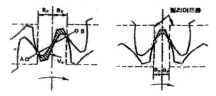
인벌류트 기어는 기어가 서로 맞물릴 때 두 점이 접촉되므로 그 사이에 들어간 액은 나갈데가 없고 심하게 압축되어 매우 높은 고압을 형성한다. 이를 봉입이라 하는데, 이로 인해 펌프 회전에 큰 장애가 되어 축동력의 증대, 베어링의 파손·소음·진동의 원인이 된다. 반대로 기어가 서로 맞물렸던 것이 열릴 때 두 점에서 접촉되어 있으면 기어의 두 점 밖에 있던 액이 들어가지 못하고 두 점 사이의 공간에서는 매우 큰 진공의 마이너스 압력을 형성하고, 한 점이라도 접촉이 떨어지면 순식간에 밖의 액이 침입하여 붕괴되면서 커다란 소음을 내며, 기포를 발생시키고 진동을 일으켜 펌프의 내구력을 현저하게 저하시킨다. 이를 공동현상이라 한다.Involute gears have two points of contact when the gears are engaged with each other, so that the liquid between them is indispensable and severely compressed to form a very high pressure. This is called encapsulation, which causes a great obstacle to the rotation of the pump, which causes an increase in axial force, damage to the bearing, noise, and vibration. On the contrary, if the gears are in contact with each other when they are opened, if they are in contact at two points, the liquid that is only two points of the gears will not enter, and the space between the two points will create a very large vacuum negative pressure. The outside liquid invades and collapses, producing a loud noise, generating bubbles and causing vibration, which significantly reduces the durability of the pump. This is called cavitation.
이들을 막기 위해서는To prevent them
첫째로 두 개의 기어를 헬리컬 기어로 만든다 것이고First, two gears are made of helical gear
둘째로 기어의 잇수를 서로 한 개 엇갈리게 한다는 점이며Secondly, the teeth of the gears are staggered one by one.
세째는 펌프의 케이싱 안쪽에 릴리이프 홈을 내어 액이 유입 또는 유출하도록 하여 고압이나 저압이 형성되지 않게 한다는 사실이다.Third, a relief groove is made inside the casing of the pump to allow the liquid to flow in or out so that no high or low pressure is formed.
그 외 편심 펌프(Vane Pump : 벤 펌프)Other eccentric pump (Vane Pump: Ben pump)
나사펌프(Screw Pump : 스크류 펌프와, 147)는 나사모양이 뱀처럼 비틀려 있어 스네이크 펌프(Snake Pump)라는 표현을 쓰기도 하는데, 교반이나 맥동이 없고, 자흡작용을 할 수 있어 화학공업의 안료·그리스·아세테이트 등의 운반이나 식품공업의 버터·어육 등의 이송에 쓰인다는 사실이다.Screw Pump (Screw Pump, 147) is a snake-shaped twisted screw, which is sometimes referred to as Snake Pump. It has no agitation or pulsation and can act as a self-acting pigment. It is used for the transportation of grease and acetate, and for the transportation of butter and fish meat in the food industry.
또 다르게 구성된 비용적식 펌프에 있어서, 동도시된 도면을 참조토록 하되,In another alternatively constructed inexpensive pump, reference may be made to the drawings in which:
임펠러나 프로펠러 등과 같은 날개를 회전시켜 원심력이나 양력 등을 얻어 연속적으로 송출하는 방식인데 먼저It is a method of continuously sending wings such as impellers and propellers to obtain centrifugal force or lift force.
원심펌프(Centrifugal Pump)는 비오는 날 받친 우산을 빙빙돌리면 원심력에 의해 빗방울은 우산 살을 따라 포물선을 그리며 비산되는 것을 볼 수 있는데 이것이 원심펌프의 작동방식이다. 이때 우산 살같은 것이 '임펠러'라 하는 것으로 임펠러의 중심에 흡입구가 있어 임펠러 회전에 의해 생긴 원심력으로 유체는 에너지를 갖게되어 바깥쪽으로 밀려나가고 중심부는 진공에 가까워지게 되면 대기의 압력이 유체를 펌프 흡입구로 밀어 올리고 역시 임펠러의 회전에 의한 원심력으로 연속적으로 토출되게 된다.Centrifugal pumps can be seen that when the umbrella is held on a rainy day, the raindrops are scattered by the centrifugal force along the flesh of the umbrella. This is how the centrifugal pump works. At this time, something like umbrella flesh is called 'impeller'. There is an inlet in the center of the impeller, and the centrifugal force created by the impeller's rotation causes the fluid to be energized and pushed outwards. It is pushed up and is continuously discharged by centrifugal force by the rotation of the impeller.
상기 펌프(8) 종류에는 터어빈 펌프(Turbine Pump, 140)로 회전하는 임펠러의 주위에 고정된 안내날개(Guide Vane : 가이드 밴 또는 디퓨서<Diffuser>라 한다)와,The pump (8) includes a guide vane (Guide Vane: referred to as a guide van or diffuser <Diffuser>) fixed around the impeller rotating with a turbine pump (Turbine Pump, 140),
"볼류트 펌프(Volute Pump)는 안내날개(Guide Vane : 가이드 밴 또는 베인, 142)가 없다. 그리고 종전에는 소방헬기와 소방차로 엔진발전기에 의해 수송장비가 동원되었지만 이제는 소방헬기와 소방차가 동원되지 않고도 A화재에 속하는 대형화재를 1초 이내로 제어할 수 있도록 열기구인 애드벌룬(77)과 비행선(78)으로 관노즐이동형 소방센서펌프몸체의 내부에 다수의 소화물질을 열기구에 탑재시켜 지속적 으로 발화물체에 공기를 차단시켜 초기진화에 인명구조를 할 수 있도록 하는데에는 공기보다 가벼운 기체인 핼륨(176)을 상기의 열기구에 주입시키도록 된 후에는 수직상승되는데 애드벌룬(77) 열기구에는 몽골피에의 열기구(586)와 블량샤르의 열기구(587)에 켈리의 열기구(588)로 구분되면서 열기구 내부로 토오치 또는 버너(175)로 불꽃(293)을 발생시켜 열기구 내부의 공기를 데워서 공기보다 가벼워지면 열기구는 상공으로 올라간다. 이 점을 감안해서 애드벌룬(77)과 비행선(78) 하부로 인명구조용 바스켓(42)과 상기 바스켓(42) 하부로 다중관노즐로 연료가스와 소방방재물질을 이송시켜 소방노즐(10)로 펌핑후 방출되어 화재는 1초 이내로 냉각작용과 질식작용이 진행되어 발화 그 이전상태로 복구되는 본 발명 바램이다."Volute pumps do not have guide vanes (guide vans or vanes, 142), and in the past, firefighting helicopters and fire trucks were mobilized by engine generators, but now fire helicopters and fire trucks are not mobilized. The hot air balloon is equipped with a number of fire extinguishing materials on the inside of the pipe nozzle moving type fire sensor sensor body so that the hot air balloon can be controlled within 1 second without a large balloon belonging to A fire without a second. It is possible to save life in the initial evolution by blocking the air in order to inject a helium (176), which is lighter than air, into the hot air balloon, and then rise vertically. The hot air balloon by dividing the hot air balloon (587) and the hot air balloon (587) of Kelly and the flame (293) torch or burner (175) inside the hot air balloon When the air inside is warmed and lighter than the air, the hot air balloon rises in the air.In view of this, the life-saving
상기 터빈 펌프의 이 안내날개는 펌프의 임펠러로부터 받은 속도에너지를 쉽게 압력에너지로 바꾸게 하기 위한 것으로 인해 구조가 복잡해지고, 부품이 많아지며, 가격이 비싸지게 된다. 최근에는 볼류트 펌프를 다단화시킨 좋은 성능의 펌프를 만들 수 있게 되어 특이한 경우 이외에는 볼류트로 쓰는 예가 더 많다.This guide vane of the turbine pump is easy to convert the velocity energy received from the pump's impeller into pressure energy, which makes the structure complicated, more parts, and more expensive. In recent years, it is possible to make a good performance pump that has a multi-stage volute pump, so there are more examples of volute except for unusual cases.
상기 다단 펌프는 임펠러의 수를 두 개 이상으로 하여 펌프의 능력을 향상시키기 위한 것을 다단 펌프라 하는데 주의할 것은 아무리 단수가 증가된다고 해도 토출 능력은 좋아지지만 흡입 양정은 증가되지 않는다고 하는 사실이다.The multi-stage pump is a multi-stage pump for improving the pump's capacity by using two or more impellers. It is noted that even if the number of stages is increased, the discharge capacity is improved but the suction head is not increased.
이는, 펌프의 흡입측이 진공화됨에 따라 대기압이 흡입관을 통해 펌프로 유체를 밀어 올리는 것이므로 대기압에 의한 액주 높이만이 흡입양정이 되기 때문이다.This is because, as the suction side of the pump is evacuated, the atmospheric pressure pushes the fluid through the suction pipe to the pump, so only the liquid column height due to the atmospheric pressure becomes the suction head.
상기된 임펠러(143)와 양수량(또는 양정)과의 관계는 세 가지로 분류하는데The relationship between the
첫째로 임펠러가 고속 회전할수록 커진다는 사실과Firstly, the impeller grows at higher speeds,
둘째로 임펠러의 회전수가 동일하면 직경이 클수록 커진다는 것으로Secondly, the larger the diameter, the larger the impeller
세째로 임펠러의 회전수가 동일하면 임펠러의 두께가 두꺼울수록 커진다는 사실이다.Thirdly, if the number of revolutions of the impeller is the same, the thicker the impeller, the larger the fact.
그러나 임펠러의 두께를 무작정 두껍게 할 수 없으므로 임펠러의 등을 맞대고 양쪽에서 흡입할 수 있는 양흡입방식을 채택한다. (이것은 캐비테이션의 방지 효과도 갖는다.)However, since the impeller cannot be thickened at random, it adopts a double suction method that can be sucked on both sides of the impeller. (This also has the effect of preventing cavitation.)
다음의 프라이밍(Priming, (339))과 자흡식 펌프(Self priming pump, 340)의 전개와 전폐에 대하여,For the following priming (339) and self-priming pump (340) development and total closure,
펌프 운전시 펌프 내에 액이 충만되지 않으면 공회전하여 펌프질을 할 수 없다. 따라서 기동시 펌프 내에 액을 충만해 주어야만 하는데 이 작업을 프라이밍(priming)이라 한다. 펌프를 정지하였다가 매회 기동시 프라이밍을 실시하는 것은 귀찮은 일이므로 최초만 프라이밍을 실시하면 다음 번에는 별도의 프라이밍이 필요없는 펌프를 자흡식펌프(340)라 한다. 그 예로 자흡식 볼류트 펌프의 작동을 보면 동도면에 도시된 바와 같으며If the pump is not filled with liquid when the pump is running, the pump cannot run idle. Therefore, the pump must be filled with liquid at start-up. This operation is called priming. Since it is troublesome to stop the pump and perform priming at every start, the priming pump is called a self-priming
상기의 증기비행선(589)은 인류의 역사상 최초의 비행선으로 증기기관을 싣고 프로펠러를 돌려서 전방으로 운행(상공)된 것이며 체펠린(LZ)129 힌텐부르그호(비행선, 78)은 전체길이 245m 내부(기체)에는 승객을 700명 승선할 수 있는 정도이기 때문에 소방관노즐과 관노즐 내부 방재물질을 탑재되도록 되어있기 때문에 다수의 비행선(78)과 애드벌룬(77)으로 불기둥(파이어휠; Fire Wheel, 294) 또는 회 오리 불기둥(294)을 사전에 제거토록 야간에도 무인소방활동이 전개됨으로 무동력펌프인 수격펌프(393)의 수격작용(398)이 진행되면서 에어콤프레샤(80)와 연결되어 화재발생시 그 즉시 1초 이내로 진화(소화)되도록 이루게되는 장치가 포함된 본 발명의 수격펌프(393)에도 마이크로 기능의 센서가 형성되지 않더라고 발전소 몸체 내부로 관노즐이동형 소방센서펌프의 무동력펌프(수격작용의 수격펌프, 393)를 계속적으로 사용할 수 있게 된다The
첫째로 최초의 프라이밍에 의해 펌프 내에서 임펠러가 잠길 정도로 액이 차있다는 사실과,Firstly, the fact that the impeller is filled in the pump by the first priming,
둘째로 운전의 개시로(A 실)의 액은 (B 실)로 이동하여 (A 실)은 진공화되어 나비형 첵크밸브가 열리고 흡입구 내의 공기가 (A 실)로 들어온다는 것이고,Secondly, the start of operation (room A) moves to room B, room A is evacuated, the butterfly check valve opens and air in the inlet enters room A,
세째로 B 실로 이동된 액은 (C 실)을 지나 재 유입구로부터 다시 임펠러로 들어가며, (A 실)의 공기는 액과 혼입되어 임펠러에 흡입되고 (B 실)을 지나 윗쪽의 공기와 액 분리실에서 분리되어 토출관으로 나간다는 사실인데,Thirdly, the liquid transferred to chamber B passes through chamber C and enters the impeller again from the inlet, and the air of chamber A is mixed with the liquid and sucked into the impeller, and then through chamber B the upper air and liquid separation chamber Is separated from the outlet into the discharge tube,
네째에는 이것을 반복하는 동안 흡입관 내의 공기는 점차 토출관(270),(14)으로 배출되어 흡입관(269),(14) 속으로 액이 흡입되기 시작한다는 사실이며,Fourthly, while repeating this, the air in the suction pipe is gradually discharged to the
다섯째는 마침내 공기가 모두 배출되면 (A·B·C)실에는 모두 액이 차서 통로가 된다. 만일 운전을 정지하게 되면 흡입관 내의 액이 수원을 향해 떨어지게 되지만 나비형 첵크밸브(6)가 닫혀 펌프 내에는 다음번 운전 기동시에 필요한 액 정도는 남기게 된다는 전개와 전폐로 형성되는 펌프내부의 장치인 것이다.Fifth, when all the air is finally discharged, the liquid is filled in the chambers (A, B, and C) to become passages. If the operation is stopped, the liquid in the suction pipe falls toward the water source, but the
그 다음의 프로펠러 펌프(Propeller Pump)는 대구경·대용량의 비교적 저양 정에 이용한다. 프로펠러 펌프에는 크게 다음 두 종류를 들 수 있는데 동도면에 도시한 바와 같이The next propeller pump is used for relatively small heads with large diameters and large capacities. There are two main types of propeller pumps, as shown in the drawing.
먼저 축류 펌프(Axial flow Pump, 342)는 프로펠러의 양력으로 축 방향에 대해 평행으로 흡입·토출된다는 것이고First, the
둘째로 혼류 펌프(Mixed flow Pump, 342)는 사류 펌프라고도 하며, 볼류트 펌프와 축류펌프(341)의 중간형으로 흡입된 유체는 축방향에 대해 평행하지만 토출되는 유체는 축방향에 비스듬한 각도를 갖고 토출된다. (즉, 볼류트 펌프와 같은 원심력과 축류펌프와 같은 양력이 동시에 작용된다.)Secondly, the
상기한 무동력펌프(393)는 각부능선의 낙차로 인한 공기압력에 의해서 낙차크기에 따라 다수개의 계단식 무동력 마노매턴 레벨형 소방호스(9)와 소방관노즐(10)에는 관노즐홀(20) 형성되며 수력발전소(267)의 헤드탱크(189)와 대송소이한 장치이다. 상기와 같은 무동력펌프는 다단계단 입류형으로 산정상 지표면 상단부(GLU) 매수 Km 이상을 양수할 수 있게 되므로 소방케이블카아(256)의 타구어윈치(137)로 상기한 헤드탱크(189)와 수조탱크(259)를 이동 설치한 후 소방방재배관라인(189)에 연결하며 해수면 하단부(SLD)와 상단부(SLU)로 발전설비(양수)로 선택되는 본 발명의 기술적 특징이다The
세번째로 점성 펌프(마찰펌프, 343)는 일명 '작은 폭포'라는 뜻의 캐스 케이드(Cascade)펌프 또는 웨스코 펌프·와류 펌프라는 이름으로 불려진다.Third, the viscous pump (friction pump) 343 is called Cascade pump or Wesco pump and vortex pump, which means 'small waterfall'.
컵의 물을 식히기 위해 숟가락으로 저었을 때 물이 따라 회전하는 것을 볼 수 있는데, 이것이 이 펌프의 원리이다. 외관으로 보았을 때 흡입구가 임펠러 중심 부에 있지 않고 임펠러의 외부에 있어 한 눈으로도 구별할 수 있다. 이 펌프의 특징에 있어서,When you stir with a spoon to cool the water in the cup, you can see the water spinning along, which is the principle of this pump. From the outside, the inlet is not at the center of the impeller, but is outside of the impeller and can be distinguished with one eye. In the characteristic of this pump,
첫째로 소형으로 볼류트 펌프보다 양수 능력이 크고, 쉽게 고압을 얻을 수 있다.Firstly, it is compact and has a greater pumping capacity than volute pumps, and high pressure can be easily obtained.
둘째로 유량은 볼류트 펌프보다 적으므로 소유량 고양정에 좋다.Secondly, the flow rate is less than that of a volute pump, which is good for low flow high lift.
세째로 간단하게 프라이밍(자흡)할 수 있고, 가정의 양수용은 이 방식이 대단히 많다.Third, it can be simply primed (self-sufficiency), and the home pumping is very much this way.
상기한 그 이외의 펌프로는In other pumps mentioned above
먼저 분사 펌프(Jet Pump : 제트펌프, 325)는 노즐을 통해 고속으로 분사된 유체에 의해 흡입된 유체가 펌프를 통해 토출된다. 그 특징으로서는First, the jet pump (Jet Pump: 325) is the fluid sucked by the fluid injected at a high speed through the nozzle is discharged through the pump. As a characteristic
첫째로 소음이 없다.Firstly there is no noise.
둘째로 공사가 간단하다.Secondly, construction is simple.
세째로 흡입양정이 크다.Third, the suction head is large.
네째로 토출된 액을 일부 되돌리므로 효율은 좋지 않다.Fourthly, since the discharged liquid is partially returned, the efficiency is not good.
다섯째는 액 중의 이물질이 있으면 마모되기 쉽다.Fifthly, if there is foreign matter in the liquid, it is easy to wear.
다음의 기포 펌프(Ail lift : 에어리프트)로 이 방식은 펌프가 없이 압축기로 압축공기를 양수관(89)의 아래쪽에서 구멍으로 분출시켜 수면을 올리는 방법이다.The following bubble pump (Ail lift: air lift) is a method of raising the water surface by ejecting the compressed air into the hole from the bottom of the pump pipe (89) without the pump.
그 다음의 수격 펌프(무동력펌프 : Hydraulic Ram ; 393)로 이 방식은 펌프나 압축기가 없이 유체의 위치에너지를 이용한 것으로 영국의(Whit Hurst)가 고안 하여 프랑스의(Montgolfier)가 배수 밸브의 개폐로 오우토 양수되도록 하였다는 사실인데 동도면에 도시한 바와 같이 수면(WLL) 아래에는 스트레이너(여과기, 392)의 흡입배관(14)를 통과하는 방화수는 제트펌프(325)의 흡입구(269) 중간지점의 배관(14) 부위로 되돌림관(370)과 노즐(10)로 형성되는데에 고수위 위치의 옹달샘 또는 계곡물을 집수정에 방화수를 가득 채워지게되면 볼탑스위치(104)가 상승하면서 감지노끈(41)에 매달려 있든 마개밸브가 오픈되면서 저수위 집수정탱크로 유입되면서 상기 저수위 집수정탱크에서는 고압이 발생된다. 상기한 소방관노즐(10)은 플렉시블 호스(190)를 사용하여 산불방지용 또는 건물 옥외 옥내로 상기 관노즐(10)을 관노즐 설치거리를 1미터 또는 3미터 거리로 다수개로 연결시켜 내부화재 발생시에 사용되는 플렉시블고압호스(190)는 와이어와 고무제에 헝겊꺼즈(75)로 유압기에 의해 형성된다The next water hammer (hydraulic pump; 393) uses the potential energy of the fluid without pumps or compressors, and was devised by the Whithurst and the French by Montgolfier to open and close the drain valve. As shown in the drawing, the fire water passing through the
사실인 즉, 높은 위치의 물을 흘려보내다가 급격히 폐쇄시킬 때 고압이 발생하는 워터 햄머(Water Hammer : 수격작용, 389)를 이용한 것으로 낙차의 50배 정도까지도 양수할 수 있도록 되었기 때문인데 상기의 수압펌프는 펌프가 없이도 수원을 확보하고 있는 경사지에서 유효하며, 다음과 같은 특징을 갖고 있다.The fact is that water hammer (389), which generates high pressure when flowing water in a high position and closes rapidly, is used to pump up to 50 times of the drop. The pump is effective on slopes that have a water source without a pump, and has the following characteristics.
첫째로 형상 낙차만 있으면 양수가 가능하므로 매우 경제적이다.Firstly, it is very economical because the pumping is possible only if the shape drop is required.
둘째는 고장이 없고, 수명이 반 영구적이며 이의 수격작용과 대동소이한 것이 마노매턴형레밸 소방관노즐의 호스로 높낮이 조절이 가능하도록 집수정탱크(34)의 구조를 개선하여 상기 탱크(34)의 밸브로 형성된 양수관(89)은 프라스틱 유량관으로 형성되며 상기 형상낙차에 의해 수력설비 뿐만 아니고 낙동강 퇴적토를 준설 하게 되는 친환경의 경제적 손실을 사전예방하는 계기로 환경개선사업에 선택할 수 있다.Second, there is no failure, the life is semi-permanent, and its water hammer action is similar to that of the
상기된 수격 펌프(393) 작동방식에 대하여 더욱 상세하게는 유체의 이동상태를 다음과 같이 설명한다.In more detail with respect to the operation of the
도2-15에 도시된 바와 같이 저수위 집수정탱크(34) 상부로 고압보울탱크(303)는 축구공 또는 뻥튀기 압력기구형으로 상기 탱크(34) 측면에는 스프링(186)식 안전밸브(473)로 형성되고 한국공업규격 KSD 4103 스테인레스주강품(HSC; KS기호, H-Steel S-Stainless C-Casting)으로 상기 탱크(303)의 재질로 제작된 후 설치되되, 상기 탱크 하부로 책 밸브(역류방지밸브; 나비형, 453) 교체하기 쉽도록 플랜지 분리 결합형(TYPE;타입)으로 샘, 계곡물이 흘러내리는 산골짜기의 일정한 경사각도(16)와 높이 낙차에 따라 산정상부의 수조탱크(295)에 방화수를 떨구지 않도록 하여 소방호스 연결마디로 파라핀 노즐마개(100)를 다수의 개 설치하여 누구나 쉽게 설치할 수 있도록 되는데 상기 탱크(303)의 부피 체적은 산의 크기에 따라 치수는 변경된다.As shown in Figure 2-15, the high-
상기의 보울탱크(303) 외측에는 (탱크수평중심선) 하단부로 반 엘보(45°각도, 44) 소켓이 양수관(89)에 부착된다Outside the
상기 유체를 도입관(191)으로 흘려보내면 유속으로 개폐밸브가 닫히고, 개폐밸브가 닫히면 급격히 압력이 상승(Water Hammer)하여 나비형 밸브가 열리며 그 압력으로 토출되어 유체를 양수하고, 압력상승이 없어지면 나비형밸브는 닫히지만 압력탱크 내의 공기압력으로 유체를 계속 양수할 수 있으며, 개폐밸브 앞의 압력이 내려가면 개폐밸브는 스프링(186) 힘으로 열려서 다시 유체는 도입관으로 흘러 들어와 위와 같은 동작을 반복하여 계속 양수할 수 있게 되는데 이의 방식으로 산불진화는 1초 이내로 상기 유체의 이동에 따라 수격펌프(393) 작동방식에 의해 이루게 된 사실로 인지한다.When the fluid flows into the
네번째의 액중펌프에 대하여 상세한 설명을 다음과 같이 한다.Detailed description of the fourth submersible pump is as follows.
별개의 항으로 액중 펌프를 구분할 필요는 없지만 최근들어 대단한 관심을 가지고, 그 이용도가 늘어가고 있으므로 따로 구분해 보았다. 이 액중펌프는 펌프자체가 액중에서 회전한다는 점이 독특하다.It is not necessary to separate the submersible pumps into separate terms, but with great interest in recent years, the use of them has been increasing, so I tried to separate them separately. This submersible pump is unique in that the pump itself rotates in the liquid.
액 속에서 작동시키기 위한 밀봉방법만 제외하면 다른 펌프와 같으며 그 종류로는 액중 캐스케이드 펌프, 액중 볼류트펌프, 액중 터어빈 펌프, 액중 혼류 펌프 등이 있다는 사실이 종전의 고성능 수중펌프(36)와 대동소이한 펌프이다.It is the same as other pumps except for the sealing method to operate in the liquid, and the fact that there are submerged cascade pump, submerged volute pump, submerged turbine pump, submerged mixed pump, etc. It is a very similar pump.
상기한 펌프 구동중의 주요문제에 있어서,In the above-mentioned main problem while driving the pump,
이런 축방향의 드러스트 하중(axial thrust, 373)인 축 추력은 원심펌프에서만 일어나는 것으로 임펠러를 회전시켰을 때 임펠러와 연결된 축(shaft : 샤프트)을 유체압력이 흡입측으로 미는 힘이 작용하는 것을 칭하고 이 때에 발전펌프 수차(264)와, 펠톤수차(230) 터어빈(267) 내부 날개에도 소수의 개 가공홀(20) 틈새(15) 노즐(10)이 형성된다. 상기 축방향 드러스트 하중(373)에는 임펠러(143) 전면에 작용하는 압력(374)과 임펠러 뒷면에 작용하는 압력(375)은 샤프트의 드러스트 하중(373)은 발전소의 발전기(213)와 동일하다.This axial shaft connected to the impeller when the axial thrust thrust load (axial thrust, 373) in the direction rotated an impeller to occur only in the centrifugal pump the fluid pressure (shaft shaft) this refers to the pushing force acting toward the suction At the time, a few opening holes 20, a
그 대책에 있어서,In that measure,
먼저 밸런스 호올(blance hole : 균형공, 376)은 임펠러 보스 측의 샤프트 가까이에 구멍을 내어 임펠러 앞뒤가 압력의 균형을 유지하도록 한다.First, a balance hole (376) makes a hole near the shaft of the impeller boss so that the impeller front and rear balance the pressure.
상기 밸런스 호올(376)에는 흡입압력(377) 부위로 전면 웨어링 링(380)에 밸런스 구멍(379)이 형성되고 배면압력(378) 부위에는 배면베어링 링(382)이 형성 구분되며 결합되어 토출압력(381)을 이루게 되는 요부위 구성으로의 본 발명 특징이다.A balance hole 379 is formed in the
다음의 밸런스 파이프(blance pipe, 균형관, 383)는 임펠러 뒷 부분의 압력이 더 높으므로 파이프로 흡입측에 연결하여 압력의 균형이 유지되도록 하게 하며The following balance pipe (blance pipe, 383) has a higher pressure at the back of the impeller, so it is connected to the suction side with a pipe so that the pressure is balanced.
그 다음의 뒷 날개 설치는 임펠러의 뒷편에 작은 날개를 만들어 임펠러와 함께 회전하여 압력의 균형을 유지하도록 한다. 그러나 이 뒷날개가 크면 드러스트가 역으로 생기는 수도 있다. 또, 이 뒷날개는 모래 등의 고형물이 임펠러 뒤의 시일 부분에 침입하지 못하게 하는 역할도 하므로 고형물이 섞인 유체에서는 이 방법을 많이 채택된다. 상기 방법의 뒷날개(384)에는 뒷날개(384) 설치로 인한 압력분포와 임펠러(385)에는 뒷날개에 의한 압력감소를 축봉절개면 우측 빗금으로 압력감소상태를 도시하였다.Subsequent rear wing installations create a small wing at the back of the impeller to rotate with the impeller to balance the pressure. However, this large rear wing may cause reverse. In addition, the rear wing also prevents solid matter such as sand from invading the seal portion behind the impeller, so this method is widely adopted in a fluid mixed with solid matter. The pressure distribution due to the rear wing 384 on the rear wing 384 of the method and the pressure reduction due to the rear wing on the
그러므로 다단펌프의 임펠러 배치(386)는 양 흡입펌프나 고압의 다단 짝 수의 임펠러 반을 반대방향으로 하여 드러스트 하중을 상쇄시킨다.Therefore, the impeller arrangement 386 of the multistage pump cancels the thrust load by opposing both suction pumps or high pressure multistage even impeller half.
이와 같이 밸런스 디스크는 다단 고압펌프의 최종단 뒤에 '밸런스 디스크'라 하는 소형의 원판날개에 고압수는 밸런스 파이프(383)로 흡입측에 되돌린다.As such, the balance disk is returned to the suction side by the
요부위의 레이디얼 하중(radial thrust : 반경 방향 하중)은 샤프트(198)의 중심이 완전하지 못하였을 때 샤프트(198)가 좌우로 진동하고, 이를 받침 축수부에 힘으로 나타내는 것을 칭한다.Radial thrust (radial load) at the recess is referred to as the
다음은 캐비테이션(Cavitation, 공동현상)에 대하여 그에 대한 대비책의 상세한 설명을 다음과 같이 한다.The following is a detailed description of the countermeasures against cavitation.
펌프의 운전 중 그 액중 온도안에서의 증기압보다 압력이 낮은 (즉, 그 온도에서의 액체가 기화되는 압력 이하로 저하하는)부분이 생기는 경우 그 부분이 기화하여 기포를 발생하거나 공동화하는 현상으로 기체의 증가에 따라 흡입능력은 점차 작아지고 결국은 흡입능력이 없어져 공전하게 되어 기계적 사고를 불러 일으킨다.During operation of the pump, if a part of the liquid has a pressure lower than the vapor pressure in the liquid temperature (ie, drops below the pressure at which the liquid is vaporized), the part vaporizes to generate bubbles or cavities. Increasingly, the suction capacity gradually decreases and eventually the suction capacity is lost, causing the engine to revolve, causing mechanical accidents.
흡입측의 저압부에서 생긴 기포는 토출측의 고압부에 들어가면 단번에 붕괴되고, 이때 고압이 생성되어 독특한 소음을 내며, 진동하게 되고, 금속이 침식하게 되며, 결국은 운전불능이 되고 만다.Bubbles generated in the low pressure part on the suction side collapse at once when entering the high pressure part on the discharge side. At this time, high pressure is generated to generate a unique noise, vibrate, metal erosion, and eventually become inoperable.
이런 침식(Erosion)은 액중의 토사나 슬러리 등에 의해 물리적으로 마멸되는 현상이며, 이에 반해 해수·산·알칼리·기타의 부식성 액에 의하거나 전위차에 의한 화학적 침해현상은 부식(Corrosion)이라 하며 침식과 부식이 중복되어 일어나는 손멸현상을 괴식이라 한다.Erosion is a phenomenon that is physically worn by soil, slurry, etc. in the liquid, whereas chemical invasion by seawater, acid, alkali, and other corrosive liquids or potential difference is called corrosion. Destruction of overlapping corrosion is called erosion.
그 대책에 있어서, 동도면에 도시한 바와 같이 한쪽 흡입임펠러(143a)를 양쪽 흡입임펠러(143b)로 형성된 후 유효흡입양정(NPSH : Net Positive Suction Head)을 계산하여 펌프의 형식, 회전수와 흡입조건 등을 결정한다.As a countermeasure, as shown in the drawing, one suction impeller 143a is formed of both suction impellers 143b, and then the net positive suction head (NPSH) is calculated to calculate the pump type, rotation speed and suction. Determine conditions, etc.
다음으로 계획된 유량이나 양정뿐아니라 예상되는 운전범위에 대한 흡입양정의 검토를 행한다. 즉, 펌프를 가급적 액면 가까이에 설치하여 흡입양정을 작게하 거나 수직축 펌프를 채택한다.Next, a review of the suction heads, as well as the planned flow and head, as well as the expected operating range, is made. In other words, install the pump as close to the liquid level as possible to reduce the suction head or adopt a vertical pump.
그 다음에는 흡입 배관은 손실이 작도록 관경을 크게 하거나 굽힘이 적게 하며, 굽힘 반지름을 크게 한다. 또, 배관은 낡은 금속보다는 새것으로, 금속제보다는 플라스틱의 염화비닐제 등으로 하는 것이 마찰저항을 줄여준다.Next, suction pipes have larger diameters or less bends, and larger bend radii for less loss. In addition, piping is newer than old metal, and plastic chloride or the like rather than metal reduces frictional resistance.
이 같이 흡입관 말단부의 여과기(스트레이너)는 액 통과 면적을 크게 잡고, 막힘이 적도록 한다.In this way, the strainer (strainer) at the end of the suction pipe has a large liquid passage area, and the blockage is reduced.
이렇게 계획 이상의 토출량, 회전수 이상으로 올리지 말고, 양수량을 감소시킬 것. 양 흡입펌프나 두대의 펌프를 병열 운전하는 것도 좋다.Do not raise more than planned discharge amount and rotation speed, but reduce pumping quantity. It is also good to run both suction pumps or two pumps in parallel.
이때 온도나 점도가 큰 액에서는 특히 주의해야 한다. 만일 캐비테이션 발생하에서 운전시킬 수 밖에 없는 경우는 스테인레스강으로 캐비테이션에 강한 재료를 쓴다.Particular attention should be paid to liquids with high temperatures or viscosities. If it can only be operated under cavitation, stainless steel is used for strong cavitation.
펌프의 수격작용(Water Hammer : 워터햄머(389))에 대하여 그에 대한 대비책을 상세한 구성에 관한 설명은 다음과 같다.Water hammer of the pump (Water Hammer (389)) is a description of the detailed configuration to prepare for the following.
펌프로 양수하던 중 정전 등으로 급격히 펌프가 멈추게 되거나, 유량 조절밸브를 급격히 폐쇄시키거나 하는 등 어떠한 원인으로 유체의 속도가 급격히 변화하게 될 때 관로 내의 액은 대단히 큰 압력변화를 갖는데, 이 현상을 수격작용이라 한다.The fluid in the pipeline has a very large pressure change when the speed of the fluid suddenly changes for some reason, such as when the pump stops suddenly or the flow control valve closes suddenly while pumping. It is called water hammer.
수격작용에 의해 큰 소음이나 진동이 발생하고, 심하면 관이 파열되기도 하는데, 대용량의 긴 관로에서 심하다.The water hammer acts as a loud noise or vibration, and in some cases, the pipe ruptures, which is severe in large, long pipelines.
그 대책에 있어서 다음의 각 펌프는 미도시한 바와 같이 다음과 같이 설명한 다.In the countermeasures, each of the following pumps is described as follows, as shown.
먼저 펌프에 플라이휘일(Fly Wheel)을 설치(즉, 회전체의 관성모우멘트를 크게)해서 펌프의 동력이 끊겨 도 급격히 회전이 떨어지지 않도록 한다.First, install a flywheel on the pump (that is, increase the moment of inertia of the rotor) so that the rotation of the pump does not drop suddenly.
그 후 배관에 공기실(Air chamber : 에어체임버)이나 원웨이-써지탱크(One way-Surge tank)를 설치하여 압력 상승시 공기가 완충역할을 하도록 하여 고압발생을 막는다.After that, install an air chamber (Air chamber) or one way surge tank in the pipe so that the air acts as a buffer when the pressure rises to prevent high pressure.
그 후로는 수격작용이 예상되는 토출관로 내의 유속은 가급적 느리게 선택하되,Afterwards, the flow rate in the discharge line is expected to be as slow as possible.
단 유속은 1 m/s정도가 좋다고 한다.However, the flow rate is said to be about 1 m / s.
그러므로 수주분리가 발생할 염려가 있는 부분에서는 공기 밸브를 설치하여 부압이 되면 오우토식으로 공기를 흡입하여 이를 방지시킨다.Therefore, in the part where there is a possibility of separation of orders, install an air valve to prevent negative pressure by inhaling air by auto-type.
상기 펌프의 수격작용(389)에 대하여 그에 대한 또 다른 대비책으로서,As another countermeasure against
운전 중의 펌프가 정전 등에 의해 동력을 상실했을 때를 예로들어 설명하면 다음과 같다.An example in which the pump loses power due to a power failure or the like will be described below.
먼저 펌프의 회전부나 임펠러 및 관로 속의 유체는 모두 펌프의 운동에 의해 운동을 계속 유지하려는 '관성'을 갖고 있다.First, the rotating part of the pump, the impeller and the fluid in the pipeline all have 'inertia' to maintain the motion by the pump movement.
둘째로 그런데, 동력이 끊기게 되면 펌프의 회전이 급속이 떨어져 양수량이나 유속은 현저하게 떨어지게 되는데, 토출관 속의 유체는 지금까지와 같은 유속으로 계속 관성에 의해 흐르고 있으므로 펌프쪽으로 일부의 유체가 끌려가 펌프의 토출구 가까운 그 중간 부분은 '수주분리'라 하는 압력저하(진공화)현상이 생기게 된 다.Secondly, when the power is cut off, the rotation of the pump drops rapidly, and the amount of water and the flow rate are remarkably decreased.Because the fluid in the discharge pipe continues to flow by the inertia at the same flow rate as before, some of the fluid is attracted to the pump. The middle part near the discharge port of the tube causes a pressure drop (vacuum) phenomenon called 'order separation'.
세째로 이윽고, 펌프는 정지하게 되고, 토출관의 유체도 정지하게 된다.Thirdly, the pump stops, and the fluid in the discharge pipe also stops.
네째로 다음에, 토출관의 액은 역류하게 되고, 둘째에서 저하된 압력이 이번에는 상승하여 충격적인 압력을 형성한다. 즉, 정지된 펌프로 역류된 물이 역회전시키려 하면 펌프의 토출측에 붙은 첵크(Check Valve : 역류방지 밸브)가 닫혀버리므로 대단한 고압이 되어버리고 만다.Fourthly, the liquid in the discharge tube is reversed, and the pressure lowered in the second rises this time to form a shocking pressure. In other words, when the water flowing back to the stationary pump tries to reverse, the check valve (check valve) on the discharge side of the pump is closed, resulting in a high pressure.
이때 둘째와 같은 저압(외부보다 낮은 이러한 압력을 부압)으로 외부로부터 붕괴되거나, 네째와 같은 고압으로 파열하게 된다. 또, 그렇게까지 되지는 않더라도 큰 소음이나 진동을 일으킨다. 상기 동도면에 동도시된 바와 같이 수격작용에 대해서 수주분리(387)와 수주결합(388)으로 분리구분되는 구성작용인 것이다.At this time, it is collapsed from the outside by the low pressure (negative pressure lower than the outside) as the second, or burst into high pressure as the fourth. Also, even if not so far, it causes loud noise or vibration. As shown in the same figure, the water hammer is divided into
이런 수주분리는 유속이 급히 저하하였을 때 입상관의 상부일 수록 압력강하가 심해져 그 곳에서의 부압이 그 액의 증기압 이하가 되어 (극단적으로 표현한다면 진공화되어)액이 분리하는 현상으로 수주분리가 일어난 경우 다음 순간에는 분리된 액이 다시 결합하므로 순간적으로 충격적인 큰 압력이 생겨 파이프를 파괴시킬 수도 있다.This order separation is a phenomenon in which when the flow rate drops rapidly, the pressure drop in the upper part of the granular conduit increases, and the negative pressure therein becomes below the vapor pressure of the liquid (vacuum in the extreme case). In the next moment, the separated liquid recombines at the next moment, creating a momentary shock that can destroy the pipe.
이 같이 토출구에는 서서히 폐쇄되는 첵크밸브(스모렌 스키 첵크밸브)를 설치하여 역류와 압력의 상승을 막는다.In this way, a check valve (smolenski check valve) that is gradually closed is provided at the discharge port to prevent backflow and an increase in pressure.
그리고 토출관로의 첵크밸브 외측에는 자동 압력조절 밸브를 설치하여 압력상승시 오우토식으로 압력이 상승된 유체를 밖으로 도피시키고, 일정 시간 후 오우토식으로 서서히 닫히도록 한다.In addition, an automatic pressure control valve is installed outside the check valve of the discharge pipe to escape the fluid whose pressure has risen by the auto-type when the pressure rises, and closes slowly by the auto-type after a certain time.
펌프의 써어징(Surging)에 대하여 상세한 설명은 다음과 같다.The detailed description of surging of the pump is as follows.
써어징 현상은 캐비테이션과 동일하게 주기적인 부하변동을 주지 않는데도 일종의 자려 진동이 발생하여 주기적으로 압력 또는 양정이나 토출량이 변동하는 현상으로 그 주기는 10∼![]()
![]()
반면에 캐비테이션은 그 주기가 600∼25.000 사이클에 이른다.Cavitation, on the other hand, has a cycle of 600 to 25.000 cycles.
이것은 펌프 자체의 특성뿐아니라 배관계 전체의 특성에 따라 일어나는 것으로 터어보 압축기에서는 가끔 문제가 되지만 펌프는 비압축성이므로 발생 가능성은 희박하다.This is caused by the characteristics of the entire piping system, as well as the characteristics of the pump itself, which is sometimes a problem for turbo compressors, but the pump is incompressible and therefore unlikely.
그러나 증발하기 쉬운 액이나 유량조절밸브가 펌프와 떨어진 곳에 설치된 경우로 보일러의 급수펌프따위에서는 주의해야 할 필요가 있다.However, if the liquid or flow control valve which is easy to evaporate is installed away from the pump, attention should be paid to the feed pump of the boiler.
참고적으로 부언한다면 써어징현상은 다음의 세 가지 조건을 갖춘 경우 일어난다고 실험 결과로 알려져 있다.For reference, surging is known to occur when the following three conditions are met.
첫째로 펌프의(H·Q: 양정, 토출량)곡선이 산 형으로 그 사용점이 그 정상(우상특성)부분일 것.First, the pump's (H · Q: lift, discharge rate) curve is in a mountainous form, and its point of use should be its normal (right-hand) characteristic.
둘째로 토출 배관 중에 수조나 공기실이 있을 것.Second, there should be a water tank or air chamber in the discharge pipe.
세째로 토출량 조절 밸브가 둘째의 공기실이나 수조의 하부(토출측)에 있을 것이되되Thirdly, the discharge amount control valve will be in the lower part (discharge side) of the second chamber or tank.
단, 이 수조나 공기실은 일부러 부착한 것 외에도 관로 중에 기체가 체류하는 부분을 포함한다.However, in addition to the water tank and the air chamber on purpose, the water tank and the air chamber include a portion where gas stays in the pipeline.
이러한 해양발전기 펌프의 선정의 명확한 설명은 다음과 같다.A clear description of the selection of such a marine generator pump follows.
먼저 사용목적에 따라 기종을 선정한다는 것인데,First of all, the model is selected according to the purpose of use.
첫째로 소용량 고양정의 점성펌프는 주거지 단독주택용으로 보장적합되어,Firstly, the small capacity high-pump viscous pump is guaranteed suitable for residential single-family housing.
둘째로 대용량 저양정의 볼류트 펌프는, 케이블카식 소방방재용 및 논 밭 방제용으로 사용적합되되,Secondly, high volume low lift volute pumps are suitable for cable car fire protection and paddy field control.
셋째로 대용량 고양정의 다단 볼류트 펌프는 산불방지용 또는 홍수 가뭄 조절용으로 합당되고,Thirdly, large-capacity multi-level volute pumps are suitable for forest fire prevention or flood drought control.
네째로 대용량 아주 낮은 양정의 혼류펌프, 축류펌프는 산의 각부능선의 소방방재 및 계절별 곤충방제용으로 적합되며Fourthly, large capacity, very low head mixed pump and axial pump are suitable for fire prevention and seasonal insect control of each ridge of mountain.
다섯째로 고압시는 플런저 펌프와 피스톤 펌프로 오대양 육대주의 관교량 공사 댐수로식 수력발전용으로 보장적합한 것이고Fifth, high pressure is guaranteed as plunger pump and piston pump for dam waterway type hydroelectric power generation for pipe bridge construction of five oceans.
여섯째로 흡입 양정 큰 경우는 액중펌프, 제트펌프와 피스톤 펌프로 오대양 육대주 연결하는 해양구조물 공사시 적합하게 선택할 수 있다.Sixth, the large suction head can be appropriately selected for the construction of offshore structures that connect the five oceans with submersible pumps, jet pumps and piston pumps.
일곱째는 별도 수액에는 화학펌프(Chemical Pump : 케미칼 펌프)를 이용하는 것인데 유해 적조 대번식 차단용에 적합한 것이다.Seventh, the separate fluid is to use a chemical pump (chemical pump) is suitable for blocking harmful red tide breeding.
상기의 다음 세부 사항을 결정에 따라서,In accordance with determining the following details above,
먼저 흡입 양정(석션헤드 : Suction Head)에 대하여 결정되는데에는First, the suction head (suction head) is determined
첫째로 수원이 무엇인가에 따라 흡입양정은 최대한 짧게(수원 가까이에 낮게 펌프를 설치) 하며 유체가 관로에서 갖는 손실인 파이프로스가 작게하기 위하여 굵은 관경으로 저항이 적도록 큰 밸브나 스트레이너를 선택하며 구부림은 적게 엘보우보다는 밴드로(그것도 구부림 반경이 큰 것으로) 매끈한 내면의 관을 선택한다.First, depending on what the source is, the suction head should be as short as possible (pump installed close to the source) and the large valve or strainer should be selected so that the resistance of the thick pipe is small so that the pipe loss, which is the loss of fluid in the pipeline, is small. Bend selects a smooth inner tube with a band rather than an elbow (which also has a larger bend radius).
둘째로 온도가 높은 유체일수록 흡입능력은 저하하므로 주의한다.Second, note that the higher the temperature, the lower the suction capacity.
실시예 구성에 따라 물은 80℃이상 될 때는 흡입할 수 없게 된다.According to the configuration of the embodiment, water cannot be inhaled when it is 80 ° C or higher.
세째로 고점도 액일수록 흡입능력은 크게 저하하므로 주의한다.Thirdly, the higher the viscosity, the lower the suction ability.
요부위 점도는 온도에 따라 크게 변화하므로 온도와 연결지어 생각한다.Since the viscosity of the recessed part varies greatly with temperature, it is considered to be connected with temperature.
네째로 무리하게 흡입을 하면 평상시의 양수량에 비해 현저하게 양수량이 감소한다.Fourth, excessive inhalation significantly reduces the amount of amniotic fluid compared to usual amniotic fluid.
먼저 펌프의 제 조건 중 흡입양정은 뭐니뭐니해도 적게 잡는 것이 제일 좋다.First of all, it is best to keep the suction head small among all the conditions of the pump.
다음은 토출 양정(데리버리 헤드 ; Delivery Head)Next is the discharge head (delivery head; Delivery Head)
그 다음은 토출량(양수량) : 단위 시간 당의 유량과,Next, discharge amount (positive amount): flow rate per unit time,
네번째 회전수 (R.P.M : Revolution per Minute) : 매분당 회전수4th revolution (R.P.M: Revolution per Minute): revolutions per minute
다섯번째 동력원에,On the fifth power source,
여섯번째 액성은 액의 비중·온도·농도·점도·유독성·폭발성·슬러리의 함유 정도 등이다The sixth liquid is the specific gravity, temperature, concentration, viscosity, toxicity, explosiveness, and degree of slurry content of the liquid.
본 발명 펌프기종 선정에 따른 펌프의 계산에 대하여 다음과 같이 설명한다The calculation of the pump according to the selection of the pump type of the present invention will be described as follows.
먼저 펌프의 구동 동력에 있어서,First, the driving power of the pump,
동력은 (![]()
![]()

일반적으로, 펌프를 구동하기 위한 원동기는 구동축동력보다 10∼15%정도 큰 것으로 설정한다.Generally, the prime mover for driving the pump is set to be about 10 to 15% larger than the drive shaft power.
다음의 전양정(토탈 헤드 : Total Head)은 실양정외에 속도수두, 관로 및 밸브의 마찰손실 수두를 더한 것으로 다음 식으로 표시된다.The following total head (total head) is the sum of speed head, pipeline and valve friction loss head in addition to the actual head.
(H=ha+hv+hf)(H = ha + hv + hf)
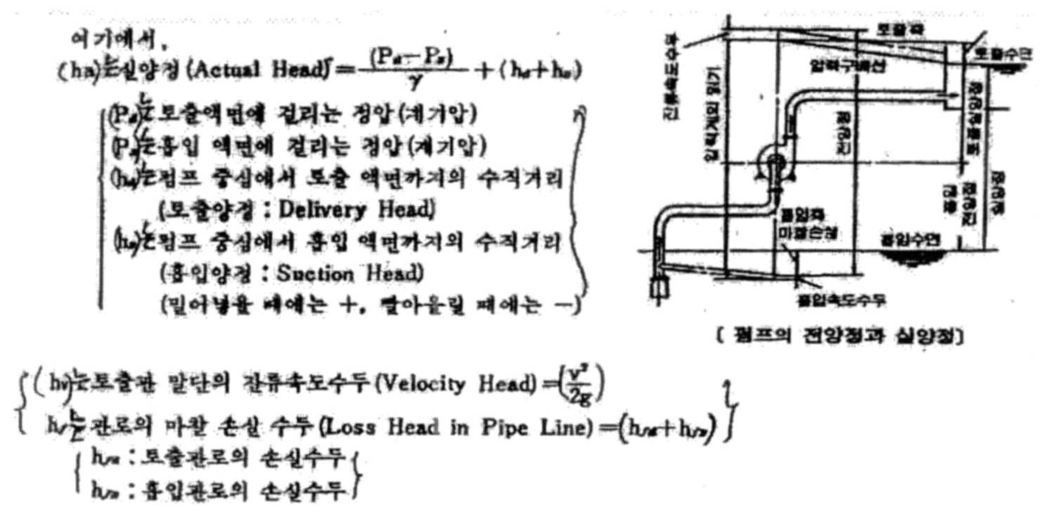
만일, 펌프의 토출구·흡입구의 구경이 같다면 양쪽에서의 속도 수두는 같은 값이므로 0이 되고, 펌프가 빨아올릴 때(흡입 정압이-)진공계를 사용한다면 다음 식으로도 된다.If the discharge port and the suction port of the pump have the same diameter, the speed heads on both sides are the same value, so that the value is zero.
전양정은 압력계의 값과 진공계의 값을 합한 것과 같다는 것이 된다.The total head is equal to the sum of the pressure gauge and the vacuum gauge.
그 다음 펌프 회전수와의 관계에 있어서Then in relation to the pump speed
먼저 토출량은 회전수와 비례하여 어느 펌프라도 토출량이 변화한다.First, the discharge amount changes in any pump in proportion to the rotational speed.
단, 왕복펌프는 회전수가 가장 적어도 액을 토출할 수 있으며, 점성 펌프는 어느 정도 회전수가 올라가지 않으면 양수할 수 없고, 원심펌프는 그 중간이다. 또, 왕복펌프는 회전수 변화에 따라 토출압력이 큰 변화없이 토출량 조절이 가능한데, 지나치게 고속으로 증가시키면 밸브의 동작이 이를 따르지 못하게 되거나 액이 미처 따라 올라오지 못해 캐비테이션이 발생할 수 있다. 대체로 표준 회전수의 10%정도 증가가 무난하며, 액의 점도나 비중이 클 때에는 그 회전수 상한치를 더 줄여야 한다.However, the reciprocating pump can discharge at least the rotational speed at least, and the viscous pump cannot pump if the rotational speed does not rise to some extent, and the centrifugal pump is in the middle. In addition, the reciprocating pump is capable of adjusting the discharge amount without a large change in the discharge pressure in accordance with the rotational speed, if the increase in excessively high speed may not be able to follow the operation of the valve or the liquid may not rise along the cavitation may occur. In general, an increase of about 10% of the standard speed is acceptable, and when the viscosity or specific gravity of the liquid is large, the upper limit of the speed should be further reduced.
다음의 양정은 원심펌프나 점성펌프는 회전수의 2승에 비례하며, 왕복펌프나 회전펌프는 회전수에 비례하여 변화하게 되지만In the next head, the centrifugal pump or the viscous pump is proportional to the power of rotation, and the reciprocating pump or the rotation pump is changed in proportion to the rotation speed.
단, 원심펌프나 점성펌프는 최소한 어느 정도의 회전수를 요구하므로 회전수를 감소할 수록 2승에 꼭 비례하지 않고 현저하게 양정이 감소한다.However, centrifugal pumps or viscous pumps require at least some degree of rotation, so the head is not necessarily proportional to the quadratic as the number of rotations decreases.
그 다음의 소요동력은 원심펌프나 점성펌프는 회전수의 3승에 비례하며, 왕복펌프나 기어펌프는 회전수의 2승에 비례하여 변화한다.The next required power is centrifugal pump or viscous pump, and the reciprocating pump or gear pump changes in proportion to the power of rotation.
만일, 회전수 토출량을 일정하게 하면 전양정의 변화에 따라 운전시의 소요동력은 증감된다.If the rotation speed discharge amount is made constant, the required power during operation increases and decreases in accordance with the change of the total head.
이렇게 일반적으로 원심펌프와 점성펌프는 회전수변화가 20% 이내일 때 다음 관계가 대체로 일정하므로 비례법칙이라 하여 편리하게 이를 이용하기도 한다.(회전수N→N')In general, centrifugal pumps and viscous pumps are conveniently used as the proportional law because the following relationship is generally constant when the rotational speed change is within 20%.
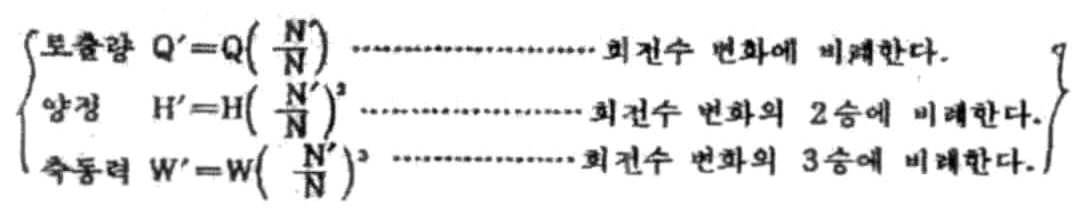
이래서 효율은 변함이 없다.Thus, the efficiency remains the same.
본 발명 펌프의 축봉장치 구성에 따른 실시예를 다음과 같이 설명한다.An embodiment according to the configuration of the shaft device of the pump of the present invention will be described as follows.
시일(Seal)은 밀봉장치의 총칭으로 운동부분의 밀봉에 사용되는 것은 패킹(Packing), 고정부분에 사용되는 것은 가스켓(Gasket)이라 일반적으로 부른다. 이 축봉장치에는 원리상으로 크게 나누었을 때 누출량을 적게하는 방법과 0으로 하는 방법이 있는데, 이들을 모두 들 수는 없으므로 다음과 같이 주로 쓰이는 것만 알아보되 단, 본 출원인이 실제 산업현장에서 개보수시 상기 패킹을 사용하여 파라핀을 녹여 사용한 바 이에 대한 것은 매우 바람직하였다.Seal is a general term for sealing device, and packing is used for sealing moving parts and gasket is used for fixing part. In principle, there are two methods for reducing the leakage amount and dividing it into 0 when it is divided in principle. However, it is impossible to mention all of them, but only the following are mainly used. It was very desirable to use paraffin to melt the packing.
먼저 글랜드 패킹(Gland Packing, 155)설치에 있어서,First, in the gland packing (155) installation,
콘벤셔널 패킹(Conventional Packing)이라고도 하며, 축봉장치로서 가장 오래전부터 사용되어 왔고, 현재도 널리쓰이는 방식인데, 글랜드 패킹(155)으로서는 액 누설을 완전히 막을 수 없으므로 액이 약간 누설해도 무방한 경우에 쓰인다.Also known as Conventional Packing, it has been used for a long time as a sealing device, and is still widely used. The gland packing 155 can not completely prevent leakage of liquid, Used.
우선 글랜드패킹의 종류에 있어,At first kind of gland packing,
첫째로 표준형 글랜드패킹은 목면이나 목면에 그리이스(grease)를 함침시킨 패킹재를 사용한 보편적인 패킹 방식인데Firstly, standard gland packing is a universal packing method using a packing material impregnated with grease on cotton or cotton.
둘째로 액을 주입한 랜턴링 부착 패킹(155)은 가장 많이 사용하는 형식으로 스터핑 박스의 중앙에 랜턴링을 설치하고 그 양쪽에 대략 같은 수의 패킹을 삽입하고 이 랜턴링에 액을 주입하도록 한 방식으로Secondly, the lantern ring packing packing 155, which is injected with the liquid, is the most commonly used type. The lantern ring is installed at the center of the stuffing box, and approximately the same number of packings are inserted at both sides to inject liquid into the lantern ring. In a way
세째는 2중 글랜드 패킹은 보통의 글랜드 패킹(155)을 2중으로 하여 고압이나 유해한 액의 누설을 줄이게 하기 위한 방식인 것인데되, 표준형 글랜드패킹(344)과 주액 랜턴링 부착패킹(346)에 2중 그랜드형 패킹(348)의 종류로 구분되어 각개의 펌프의 축봉장치로 이루게되는 펌프소화기 요부위 구성이다.Thirdly, the double gland packing is a method for reducing the leakage of high pressure or harmful liquid by double the ordinary gland packing 155, but the standard gland packing 344 and the lantern ring attach packing 346 It is divided into the type of the double gland type packing 348) is composed of a pump fire extinguisher main portion consisting of the axial rod device of each pump.
네째로 드로틀 부시(298) 부착 패킹(349)은 슬러리를 함유한 액이 패킹 내에 들어오지 않게 축봉부의 속에 드로틀 부시를 설치한 방식이며Fourth, the packing 349 with the
다섯째 워터 자켓부착 패킹(353)은 고온의 액에 있어서 패킹의 재질이 열화하거나 눌어붙는 것을 막게하기 위하여 패킹 외부에 냉각실을 설치하여 냉각수를 순환시키는 방식인데 슬리이브 내면 냉각병용 워터 재킷부착 패킹(353) 구성에는 슬리이브의 내부 냉각실(354)과 보조 글랜드(355)에 누설액의 냉각실(356)로 축봉장치 둘레면을 따라 이루게 되고 워터 재킷부착 패킹(353)의 구조에는 냉각수 출구(350)와 냉각수입구(352) 상부로 봉수(351)가 부착된다.The fifth water jacketed packing 353 is a method of circulating the cooling water by installing a cooling chamber outside the packing in order to prevent the material of the packing from deteriorating or pressing in a high temperature liquid. 353) is formed along the circumferential surface of the storage device with the cooling chamber 356 of the leakage liquid in the
다음은 글랜드 패킹 재료의 재질에 있어,Next is the material of the gland packing material,
첫째로 소프트 패킹(Soft Packing)은 비금속 재료로 제작된 패킹으로 아스베스트(asbest : 석면)·고무·목면·마 등의 섬유와 테프론(teflon)등의 합성수지 섬유를 주원료로 흑연·그리이스 등을 함침시킨 것이며Firstly, soft packing is made of non-metallic material and impregnated with graphite, grease, etc. as the main raw material of fibers such as asbestos, rubber, cotton, hemp, and synthetic resin fibers such as teflon. It was made
둘째로 세미 메탈릭 패킹(Semi Metallic Packing)은 고온·고압·고속에 사용하기 위하여 석면 등에 동·납·알루미늄 등 금속의 선이나 박판·분말 등을 혼합해 흑연·수지·유지 등을 첨가해 짜거나 성형한 것으로(즉, 섬유와 연질의 금속을 조합) 소프트에 비하여 누설이 적다는 것인데Second, semi-metallic packing is made by mixing graphite, resin, oil, etc. by mixing wire, sheet, powder, etc. of metal such as copper, lead, aluminum, etc. Molded (i.e., a combination of fiber and soft metal) and less leakage
세째로 메탈릭 패킹(Metallic Packing)은 납·주석·알루미늄 등의 선이나 박판에 광유나 윤활제를 함침시켜 성형한 것으로 대체로 스파이럴(Spiral)형태이다. 이것은 유체가 침투하지 않아 누설이 적으며, 열전달이 좋아 열을 쉽게 외부로 방출시켜 고압 유체의 패킹재로서 좋지만 내진성이 부족하고 과열 우려가 있으므로 냉각구조로 한다.Thirdly, metallic packing is formed by impregnating mineral oil or lubricant on wire or sheet such as lead, tin, aluminum, etc., and is generally in the form of spiral. It does not penetrate the fluid, so there is little leakage, and heat transfer is good, so it is easy to release heat to the outside, which is good as a packing material for high pressure fluid, but it is lacking in seismic resistance and there is a risk of overheating.
그 다음은 글랜드 패킹의 취급에 있어, 글랜드 패킹(155) 짜는 방법(357)에는 여덟가닥짜기(358)와 봉지짜기(359)에 격자짜기(360)로 취급된다Next, in the handling of the gland packing, the method of weaving the gland packing 155 (357) is treated as the lattice weaving (360) to the eight strands (358) and the bag weaving (359).
먼저 글랜드 패킹에서는 완전히 누설을 막을 수 없고, 극히 소량 새는 것이 좋은데, 그 이유는 다음과 같다.First of all, gland packing can't completely prevent leakage, and it is good to leak very small amount.
처음에는 새는 액이 축과 패킹의 윤활작용을 하여 저항을 줄여주며,Initially, the leaking fluid lubricates the shaft and packing, reducing the resistance,
두번째로 마모에 의한 발열을 줄이고,Secondly, reduce the heat generated by wear,
세번째는 축의 표면을 상하지 않게 해준다. 일단 축의 표면이 상하게 되면 아무리 새 패킹으로 교환하여도 소용이 없다.The third does not damage the surface of the shaft. Once the surface of the shaft is damaged, no matter how much it is replaced with a new packing, it is of no use.
다음은 글랜드 패킹의 재질이나 구조상 구비하여야 할 조건은 다음과 같다.The following are the conditions to be provided due to the material and structure of the gland packing.
첫째로 유체에 대하여 화학적으로 안정된 재질일 것. 상대방의 금속을 부식시키지 않을 것.First, the material should be chemically stable against the fluid. Do not corrode the opponent's metal.
둘째로 유체가 침투하지 않는 치밀한 것일 것.Secondly, the fluid should not be penetrated.
세째로 활동부 마찰에 의한 마모가 적고, 마찰계수가 작을 것.Third, the wear of the active part should be less friction and the coefficient of friction should be small.
네째로 기계에 장착이 용이할 것.Fourth, it should be easy to install on the machine.
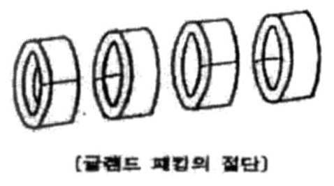
그 다음은 글랜드 패킹(155)을 끼울 때에는 둥글거나 네모난 단면형상으로 길게 짜여져 있으므로 샤프트에 둥글게 말아 하나씩 잘라 겹쳐 넣는다. 자를 때에는 비스듬히 자르고, 절단면이 일치하지 않게 넣으며, 패킹을 겹친 두께는 최소한 샤프트 직경의 2배이상, 줄 수로는 세 줄 이상 넣는 것이 좋다. 이외에도 최근에는 테프론계의 솜을 조금씩 손으로 비틀어 뜯어 넣거나 분말상태로 되어 밀어넣는 것 등도 있다.Next, when the gland packing 155 is fitted, it is woven in a round or square cross-sectional shape so that the gland packing 155 is rolled round and cut one by one. When cutting, cut at an angle, insert the cutting section unmatched, and overlap the packing with at least twice the diameter of the shaft and three or more rows. In addition, recently, Teflon-based cotton wool is twisted by hand, or powdered and pushed.
그 후로는 글랜드를 너무 조여 누설을 없애려 하면 우선 일시적으로 누설이 정지하나 마찰 때문에 기계적 동력이 증가하고, 발열과 열전도가 맞지 않아 마모를 일으키므로 다시 누설이 일어나게 된다.After that, if the gland is too tight to eliminate the leakage, the leakage stops temporarily first, but the mechanical power increases due to friction, and the leakage occurs again because the heat does not match the heat generation and the wear occurs.
다음은 매커니컬 시일(Mechanical Seal, 156)의 제작에는 동도면에 도시된 바와 같이 상기 메커니컬 시일(156)에는 플래싱구멍(361)에 O링(362)과 스프링(186)이 축봉상부 위치로 형성되고 상기 축봉 하부로 스톱터(363)에 중동링(364)과 밀봉단면(365) 좌측으로 시이트링(366)과 피동링(367)으로 형성된 후 글랜드 패킹은 원통 내면에서의 밀봉작용으로 누설을 방지하는데 반하여 메커니컬 시일은 원통 단면에서의 밀봉 작용으로 누설이 절대로 없거나 근소한 양만 누설된다. 메커니컬 시일(156)은 1885년경 이탈리아의 선등록에 의해 알려진 후 전후 급격한 발전을 보였다. 메커니컬 시일(156)은 회전축에 수직한 두 평면을 정밀하게 다듬질하고 마주 접촉시켜 한쪽을 회전시키면 이 두면 사이에는 액이 스며들 여유가 없으므로 완전히 시일할 수 있다. 이때에 두 면을 항상 일정한 힘으로 접촉시키기 위하여 스프링을 사용하거나 유체의 압력·고무 등의 탄성재료·벨로우즈·자력 등을 이용하여 접촉압력을 얻는다.Next, in the manufacture of the
메커니컬 시일 방식의 장점은The advantage of mechanical seal
첫째로 누설을 거의 완벽하게 막을 수 있다.Firstly, leakage can be almost completely prevented.
둘째로 위험한 액·귀중한 액·별도의 액에 사용할 수 있다.Secondly, it can be used for dangerous liquids, precious liquids and separate liquids.
세째로 기계적인 마찰 저항이 적어 손실 동력이 적고, 효율이 높다.Third, the mechanical frictional resistance is small, the loss power is low, the efficiency is high.
네째로 샤프트가 글랜드 패킹같이 시일작용에 관계하지 않으므로 샤프트의 마모가 없다.Fourth, there is no wear of the shaft since the shaft is not related to the sealing action like gland packing.
메커니컬 시일 방식의 단점은The disadvantage of the mechanical seal method
첫째로 다듬질이 대단히 정밀해야 하고, 재질은 엄선해야 하므로 가격이 매우 비싸진다.Firstly, the finishing must be very precise and the materials must be carefully selected, which is very expensive.
둘째로 구조가 복잡하여 교환이나 조립이 힘들다.Second, the structure is complicated, so it is difficult to exchange or assemble.
세째는 재질에 따라 각별히 주의하지 않으면 홈이나 가는 금 또는 균열이 생긴다.Third, depending on the material, if not careful, grooves, fine cracks or cracks are formed.
네째로 이물의 혼입을 절대 피해야 한다.Fourth, the mixing of foreign objects should be avoided.
다섯째로 냉각수를 통하지 않으면 곧 눌어붙는다.Fifth, if it does not pass through the coolant, it will be pressed soon.
여섯째는 글랜드 패킹처럼 도중에 클램핑을 더해줄 수 없고, 일단 교환하거 나 랩핑작업을 하여 다시 짜 맞추어야만 한다.Sixth, you can't add clamping along the way like gland packing, but you have to replace or wrap and refit.
일곱째로 펌프의 동력을 잘 연결하여 진동을 없애지 않으면 시일의 수명을 단축한다.Seventh, if the pump power is connected well, the vibration life will be shortened if the vibration is not eliminated.
단점이 대단히 많으나 현재로서는 가장 뛰어난 시일방식이다, 따라서, 단점을 잘 알아 이를 피할 수 있게 하는 것이 중요하다.There are a lot of disadvantages, but at present it is the best seal method, so it is important to be aware of the disadvantages and avoid them.
먼저 메커니컬 시일의 종류는 세트 형식에 따라 인사이드 형·아웃사이드형, 시일 형식에 따라 싱글 시일형·더블 시일형 면압 밸런스 형식에 따라 언밸런스형·밸런스형을 들 수 있다.First, the types of mechanical seals include inside and outside types depending on the set type, and unbalanced and balanced types depending on the single seal type and the double seal type surface pressure balance type depending on the seal type.
첫째로 인사이드(inside, 내장)형은 고정환이 펌프측에 있는 방식으로 일반적으로 사용되는 방식이다.First, the inside type is a commonly used method in which the fixed ring is on the pump side.
둘째로 아웃사이드(outside, 외장)형은 회전환이 펌프측에 있는 방식으로 구조재·스프링 재가 액의 내식성에 문제가 있을 때, 점성계수가 100cp를 초과하는 고점도액일 때 저 응고점의 액일 때, 스터핑박스 내부가 고 진공일 때 통상 이용된다.Second, the outside type is the way that the rotating ring is on the pump side, when the structural material and the spring material have problems of corrosion resistance of the liquid, when the liquid has a low freezing point when the viscosity is high viscosity liquid exceeding 100cp It is usually used when the inside of the box is high vacuum.
세째는 싱글 시일(single mechanical seal)형은 습동면이 하나로 밀봉된 일반적인 방식이다.Third, the single mechanical seal type is a general method in which the sliding surface is sealed in one.
네째로 더블시일(double mechanical seal)형은 습동면이 두 개인 방식으로 유독액이나 인화성이 강한 액일 때, 보온·보냉이 필요할 때, 누설되면 응고하는 액일 때, 내부가 고진공이거나 기체를 시일할 때 이용되며 고온이나 저온의 액 또는 메커니컬 시일의 단점인 슬러리를 함유한 액에 대해서도 유효하다.Fourthly, the double mechanical seal type has two sliding surfaces, which is toxic or flammable, needs warming and cold storage, leaks and solidifies, leaks when the inside is high vacuum or gas sealed. It is also effective for liquids containing hot or cold liquids or slurries that are disadvantages of mechanical seals.
다섯째는 언 밸런스(unblance)형은 펌프 내의 압력이 그대로 시일의 습동면에 걸리는 시일 방식으로 일반적으로 사용된다. 액압은 4kg/㎠이하(제품에 따라 차이가 있는데 윤활성이 좋은 액은 약 7kg/㎠ 이하, 윤활성이 나쁜 액은 2.5kg/㎠이하)가 무난하다.Fifth, the unblance type is generally used as a seal method in which the pressure in the pump is applied to the sliding surface of the seal as it is. Hydraulic pressure is less than 4kg / ㎠ (depending on the product, good lubricating liquid is about 7kg / ㎠ or less, poor lubricating liquid is less than 2.5kg / ㎠).
여섯째는 밸런스(blance)형은 펌프 내의 압력이 클 경우 시일의 습동면에 그대로 압력이 걸리지 않게 만든 방식으로 하이드로 카본이거나 내압이 4∼5kg/ ㎠이상일때, LPG. 액화가스와 같이 저비점의 액체에 쓰인다.Sixth, the balance type is made of hydrocarbon in a manner that does not apply pressure to the sliding surface of the seal when the pressure in the pump is large, or LPG when the internal pressure is 4 ~ 5kg / ㎠ or more. Used for low boiling liquids, such as liquefied gases.
이처럼 보통의 메커니컬시일에 있어서는 습동면의 회전링을 밀어 붙이는 것은 스프링인데, 여기에 액 내압이 가해지면 밀봉단면의 접촉력을 더하여 누설을 방지하게 된다. 그러나 접촉압력이 지나치게 높아지게 되면 습동면의 마모가 촉진되므로 내압이 높을 때에는 이 압력을 밸런스시켜 접촉압력을 조정하도록 설계한다.In the normal mechanical seal, it is a spring that pushes the rotary ring of the sliding surface. When the internal pressure of the liquid is applied thereto, the contact force of the sealing end surface is added to prevent leakage. However, if the contact pressure is too high, the wear of the sliding surface is promoted, so when the internal pressure is high, it is designed to balance the pressure to adjust the contact pressure.
다음의 냉각 및 윤활은 취급액의 열이나 습동면의 마찰열로 온도가 상승하면 재료가 마모·부식되거나 패킹이 눌어붙게되므로 이를 억제하기 위하여 다음과 같은 기본방식을 이용하여 냉각 및 윤활 기능을 갖도록 하는데에는 동도면에 도시한 바와 같이 매커니컬시일의 냉각방식(391)에는 축봉부(390) 상부로 퀀칭(268)과 쿠울링(367)에 플래싱 구멍(361)으로 형성되는데에는In the following cooling and lubrication, if the temperature rises due to the heat of the handling liquid or the frictional heat of the sliding surface, the material may be worn or corroded or the packing may stick. As shown in the drawing, the mechanical
첫째로 플러싱(flusing)은 가장 많이 행하는 방법으로 축봉부의 고압측 액체가 있는 곳에 외부에서 액체를 주입·추출하여 시일의 온도를 적당히 유지하는 방법으로 밀봉단면의 기화를 방지하여 윤활을 좋게하고, 불순물이 축봉부에 쌓이는 것을 막아주기도 한다.First of all, flushing is the most common method of injecting and extracting liquid from the outside of the high-pressure side of the shaft to maintain the seal temperature properly. It also prevents it from accumulating on the shaft.
둘째로 퀀칭(quenching은 축봉부의 고압측 유체가 없는 부분에는 시일의 밀봉 단면에 냉각액이 접하도록 주입시키는 방법으로 휘발성의 유체나 공기에 접하면 결정물을 만들어 마모를 촉진 시키는 유체, 유해한 유체 등을 취급할 경우 새어나온 유체를 씻어내어 희석 회수한다. 또, 밀봉단면과 공기를 격리시켜 산화를 막는 작용도 한다.Secondly, quenching is a method of injecting a coolant into the sealing end surface of the seal in the absence of the high-pressure fluid in the shaft part, and when it comes into contact with volatile fluid or air, it forms a crystal to promote abrasion and harmful fluid. In case of handling, the leaked fluid should be rinsed and dilute and recovered, and the sealing section and air will be separated to prevent oxidation.
실시예를들면(LPG)등을 취급할 경우 누설되면 곧 가스화하므로 시일면 외측에 이 냉각수를 흘려 보내어 씻어버릴 수 있게 한다.For example, when handling (LPG) or the like, it will be gasified soon after leakage, so that this cooling water can flow out to the outside of the seal surface to be washed off.
세째로 쿨링(Cooling은 시일의 밀봉 단면이 아닌 그 외주를 냉각시키는 방법으로 퀀칭보다 냉각효과는 낮으나 대기측에의 누설방지가 필요없고, 냉각수의 순도 등에 주의하지 않아도 되는 이점도 있다.Third, cooling is a method of cooling the outer circumference of the seal, not the sealing cross section, but has a lower cooling effect than quenching, but does not need to prevent leakage to the air side, and there is an advantage of not having to pay attention to the purity of the cooling water.
그 다음 메카니컬 시일의 재질에 있어서, 시일의 재질은 밀봉된 액의 종류, 온도, 압력, 이물의 존재 여부, 속도, 누설의 허용정도 등에 따라 달라지지만 일반에게 표준으로 알려진 것으로 스테인레스강과 카이본 그래파이트의 조합이다. 카아본 그래파이트는 자기 윤활성이 있고, 금속과 융착하지 않으며, 마찰이 작고, 약품에 강하다. 스테인레스 강 외에도 스테라이트·세라믹·초경합금을 덧붙이거나 열처리한 것을 쓰는데, 충분한 내식성·내마모성을 필요로 한다.The material of the mechanical seal then depends on the type of liquid sealed, the temperature, the pressure, the presence of foreign objects, the speed, and the tolerance of the leak, but is known to the public as standard for stainless steel and carbon graphite. It is a combination. Carbon graphite is self-lubricating, does not fuse with metal, has low friction and is resistant to chemicals. In addition to stainless steel, it is used to add steritic, ceramic, cemented carbide, or heat treatment, which requires sufficient corrosion resistance and wear resistance.
메카니컬 시일의 재질을 조합하는 실시예는 다음과 같다.An embodiment of combining the materials of the mechanical seal is as follows.

본 발명 구성에 의한 펌프의 진동에 따른 대비 수단에 있어서,In the contrast means according to the vibration of the pump according to the configuration of the present invention,
펌프의 진동은 대단히 많은 여러 요인이 하나 또는 여럿으로 중첩되어 있는데, 이를 대별하면 다음과 같다.The vibration of the pump is one or several overlapping a lot of factors, which are roughly as follows.
먼저 수력적 진동에 따라Based on hydraulic vibration
첫째로 캐비테이션에 의한 진동 : 600∼25,000사이클 정도의 주기가 빠른 진동과 소음을 가져온다.Firstly, vibration caused by cavitation: a cycle of about 600 to 25,000 cycles brings about rapid vibration and noise.
둘째는 써어징 현상에 의한 진동 : 캐비테이션은 토출량이 많을 때 일어나는데 반해 써어징은 토출량이 적을 때 발생할 뿐 아니라 그 주기도 10∼0.1싸이클 정도의 긴 주기를 갖는다.Second, the vibration caused by the surge phenomenon: Cavitation occurs when the discharge amount is large, while surge is not only occurred when the discharge amount is small, but also has a long cycle of about 10 to 0.1 cycles.
세째로 워터 햄머(수격작용)에 의한 진동.Thirdly, vibration by water hammer.
네째로 펌프 내 흐름의 언밸런스에 의한 진동Fourth, vibration caused by unbalance of flow in the pump
다음은 기계적 진동에 의한Next is due to mechanical vibration
첫째는 회전체의 언밸런스에 의한 진동First, vibration caused by unbalance of the rotating body
둘째로 위험속도에 의한 진동은 축의 회전속도가 그 회전체의 고유 진동수와 공진할 때 일으키는 격심한 진동을 일으키는데 이때의 회전속도를 위험속도(Crital Speed)라 한다.Secondly, the vibration caused by the dangerous speed causes severe vibration that occurs when the rotational speed of the shaft resonates with the natural frequency of the rotating body. The rotational speed is called the critical speed.
세째는 고체 마찰에 기인하는 진동은 일종의 자려 진동으로 회전축에 윤활유가 부족하거나 베어링이나 부시·링 등의 활동부가 접촉할 때 일어난다.Third, vibration caused by solid friction is a kind of self-generated vibration, which occurs when the rotating shaft lacks lubricating oil or when active parts such as bearings, bushes and rings come into contact.
네째로 베어링의 유압에 의한 진동은 회전축이 위험속도의 약 2배 이상되는 각속도로 회전할 때 베어링부의 유압 때문에 발생한 진동으로 보통속도의 펌프에서는 그리 흔하지 않으며, 베어링 압력을 높이거나 회전을 줄여 방지할 수 있다Fourth, the vibration caused by the hydraulic pressure of the bearing is a vibration caused by the hydraulic pressure of the bearing part when the rotating shaft rotates at an angular speed that is about twice the dangerous speed. It is not so common in the pump of normal speed, and it can be prevented by increasing the bearing pressure or reducing the rotation. Can
다섯째는 펌프의 고유 진동수에 의한 진동은 수직축 펌프에서 특히 문제가 된다 ,Fifth, vibration caused by the natural frequency of the pump is particularly problematic in the vertical pump.
여섯째로 센터링 불량에 의한 진동은 센터링불량에 의한 경우는 대단히 그 요인이 많고 중요하므로 운전에 신중히 검토하지 않으면 안된다.Sixth, the vibration caused by poor centering is very important and important when it is caused by poor centering.
일곱째는 원동기에 기인하는 진동에Seventh is the vibration caused by the prime mover.
여덟째로 기초가 약하기 때문에 일어나는 진동이다Eighth, it is vibration caused by weak foundation
디젤엔진(226)의 용도별 출력정의 대하여Definition of output by use of
첫째로 상용이라 함은 주전원 대체용으로 발전기에 적용되는 출력(ISO 8528 PRP 상당)을 칭하고First, commercial refers to the output (equivalent to ISO 8528 PRP) applied to the generator as a substitute for main power.
둘째로 비상용이라 함은 주전원 이상시 한시적으로 사용되는 비상 발전기에 적용되는 출력(ISO 8528 ESP 상당)을 칭하되 엔진모델이 형성되는데에는 냉각팬(195)과 시린더(126)와 푸레(250)에 브이벨트(V velt, 252)와 플라이휠(268)로 조립부착된다. 동도면에 도시한 바와 같이 상기 엔진은Secondly, the emergency refers to the output (equivalent to ISO 8528 ESP) applied to the emergency generator used for a limited time when the main power is abnormal, but the engine model is formed in the cooling
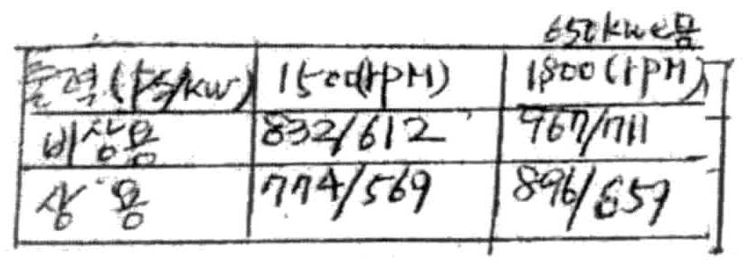
상기 표와 같이 출력허용오차는 ±5%이며 엔진(226) 제원에 대하여 명세서에 대한 설명은 우측의 엔진제원 명세서 표기와 같다.As shown in the above table, the output allowable error is ± 5%, and the description of the specification with respect to the specification of the
<엔진제원 명세서><Engine specifications list>

끝으로 압축기의 취급에 관한 주의사항에 대하여 상세한 설명을 다음과 같이 한다.Finally, a detailed description of the precautions for handling the compressor follows.
먼저 일반적인 주의사항에 있어,First of all, in general precautions,
첫째로 압축기는 항상 청결을 유지하고, 주위는 정리·정돈을 철저히 해 둔다.First, the compressor is always kept clean, and the surroundings are thoroughly cleaned and organized.
둘째로 압축기의 가동을 정리한 휴무시기로 단 기간 정지시 1 일에 1 회 정도는 잠간동안이라도 공운전을 해 본다.Secondly, it is a period in which the operation of the compressor is arranged, and if it is stopped for a short time, try to run at least once a day for a while.
그러나 장 기간 정지때, 분해 소제하여 마모·파손부 또는 윤활유는 새 것으로 교환하고 냉각수는 모두 빼내고 (Drain : 드레인), 방청 조치를 해 둔다.However, when stopped for long periods of time, disassemble and clean up, replace any worn or damaged parts or lubricants with new ones, drain all coolant (drain), and perform antirust measures.
세째로 각 축수부는 기회가 있을 때마다 점검하여 조정해 둔다.Third, each bearing department checks and adjusts each opportunity.
네째로 밸브·압력계·조정기·여과기 등은 정기점검 및 일상 점검으로 고장을 미연에 방지한다.Fourth, valves, pressure gauges, regulators, filters, etc., are prevented by regular inspections and routine inspections.
다섯째로 냉각수는 깨끗한 물을 사용하며, 냉각관은 6 월이나 1 년마다 분해하여 수증기등으로 세정하고 무게가 10%이상 감소 되어 있다면 그만큼 부식또는 마모된 것이므로 새것과 교환한다.Fifth, the cooling water uses clean water, and the cooling tube is disassembled every June or year and cleaned with steam. If the weight is reduced by more than 10%, it is corroded or worn.
여섯째로 각 부의 가스 누설에 항상 주의하고, 독성이나 가연성은 검지기로 미량이라도 알아내 적당한 조치를 취해야 한다.Sixth, always pay attention to gas leakage from each part, and take appropriate measures to find out the trace amount of toxicity and flammability with a detector.
일곱째로 오일은 메이커의 도움을 받아 적절한 것으로 선택한다.Seventh, the oil is selected with the help of the maker.
여덟째는 만일 이상이 있으면 즉시 운전을 중지하고 메이커에 통보하여 수리를 의뢰한다.Eighth, if something goes wrong, stop driving immediately and notify the manufacturer for repair.
다음은 시동시의 주의사항에 있어,The following are the instructions at the time of the start,
먼저 볼트·너트 그 외의 나사들은 잘 조여져 있는가 충분히 점검 확인한다.First, check that bolts, nuts and other screws are tight.
다음은 크랭크 케이스 등에는 규정량의 윤활유를 채우고 윤활상태를 확인한다.Next, fill the crankcase with lubricant of the specified amount and check the lubrication condition.
세번째 냉각수를 통수하고 냉각수의 순환여부를 확인해 본다.Pass through the third coolant and check the circulation of the coolant.
다음은 압력계·압력조절밸브·드레인 밸브등을 모두 열어서 압력 지시의 이상 유무를 확인한다.Next, open all the pressure gauges, pressure control valves and drain valves and check for any abnormality of the pressure indication.
그 다음은 소형 압축기는 손으로 무부하 상태에서 회전시켜 보고, 전동기가 연결 된 것은 스위치를 단속 후 손으로 넣어 보면서 실린더내에 이물질 등이 끼지 않았는가 확인해 본다.After that, the small compressor is rotated by hand with no load, and if the motor is connected, check if there is any foreign substance in the cylinder by inserting the switch by hand after intercepting the switch.
여섯번째 흡입 밸브는 닫혀 있고, 바이패스 밸브나 드레인 밸브가 열린 상태로 스위치를 넣는다.The sixth intake valve is closed, with the bypass valve or drain valve open.
다음은 정규회전이 되면 1 단에서부터 다음단으로 드레인 밸브 그리고 바이패스 밸브를 잠그며 동시에 흡입 밸브를 개방시킨다.After normal rotation, the drain valve and bypass valve are locked from the first stage to the next stage and the suction valve is opened at the same time.
끝으로 각 단의 압력·윤활유·온도·소음·진동 누설에 대하여 주의 한다.Finally, pay attention to pressure, lubricating oil, temperature, noise, and vibration leakage at each stage.
그 다음 운전 중의 주의사항에 있어,Then in the precautions while driving,
각 단의 압력·누설·진동·온도·이상소음·냉각수의 통수량이나 온도·윤활유의 온도나 압력 및 전동기의 부하 적정 여부등을 확인하며 끊임없이 주의를 기울인다.Pay close attention to the pressure, leakage, vibration, temperature, abnormal noise, coolant flow rate, temperature, lubricant temperature and pressure, and whether the motor is properly loaded.
특히 온도나 압력의 이상 상승이나 저하에 주의하며, 누설이 있다고 운전중 에 보울트를 조이거나 망치질 하는 것은 절대 피해야 한다.In particular, pay attention to abnormal rises or drops in temperature or pressure, and never tighten or hammer the bolt during operation if there is a leak.
이를 세분하면 다음과 같다.This is broken down as follows.
먼저 왕복식 압축기의 취급에 대하여First, the handling of the reciprocating compressor
첫째로 압력계의 눈금과 각단의 흡입·토출가스 온도의 이상 유무First of all, there is an abnormality in the pressure gauge reading and intake / discharge gas temperature at each stage.
둘째로 베어링 온도의 변화 및 이상 상승유무Second, bearing temperature change and abnormal rise
세째로 냉각수 온도의 변화를 주시하고, 필요시 수량을 조절한다.Third, watch for changes in coolant temperature and adjust the water volume if necessary.
네째로 실린더 주유기의 송유 상황을 주시하고 유량을 조절하거나 주유기에 기름을 보급한다.Fourthly, check the oil supply status of the cylinder oiler, adjust the flow rate or supply oil to the oiler.
다섯째로 외부 유량이나 유압의 변화 상태Fifth, change of external flow rate or hydraulic pressure
여섯째로 피스톤로드 패킹의 누설과 온도상승 여부Sixth, the leakage of piston rod packing and temperature rise
일곱째로 드레인의 색이 급히 검게 되지 않는가의 여부Seventh, whether the color of the drain does not rush to black?
여덟째로 각 부의 발생음이나 진동이 정상과 다른 점은 없는가Eighth, is there any difference in the sound or vibration of each part from normal?
아홉째로 안전 밸브·드레인 밸브 등의 밸브류 또는 플렌지 죠인트·기타 타이트면에서의 가스누설은 없는가Ninth, are there any gas leaks from valves such as safety valves and drain valves, or flange joints and other tight surfaces?
다음으로 전력의 소비량에 이상은 없는가Is there abnormality in power consumption next?
끝으로 자동장치·감시계기 작동의 이상유무Finally, abnormal operation of automatic device and watch
다음은 터어보 압축기의 취급에 대하여Next, handling of the turbo compressor
첫째로 베어링 윤활유의 급유압력이나·복귀된 기름의 온도First, the oil supply pressure of the bearing lubricant or the temperature of the returned oil
둘째로 축봉용 급유 압력이나 복귀된 기름의 온도 또는 차압이나 누설유량Secondly, the oil supply pressure for the shaft, the temperature of the returned oil or the differential pressure or leakage flow rate.
세째로 본체·베어링·증속기어등 각 부의 진동 여부Third, vibration of each part such as main body, bearing, gearbox
네째로 축수온도의 이상유무Fourthly, there is an abnormality in shaft temperature
다섯째로 냉각수 온도의 변화를 주시하고, 필요시는 수량을 조절한다.Fifthly, observe the change in the coolant temperature and adjust the water quantity if necessary.
여섯째로 배관계의 밸브 또는 후렌지 이음·기타 타이트면에서의 가스누설은 없는가Sixth, are there any gas leaks in the piping system or flange joints and other tight surfaces?
다음으로 전력 소비량의 이상은 없는가Is there abnormality of power consumption next?
끝으로 자동장치·감시계기 작동의 이상유무Finally, abnormal operation of automatic device and watch
네번째 정지시의 주의사항에 있어,In the caution at the fourth stop,
첫째로 전동기의 스위치를 끊고 흡입 밸브를 닫는다.First, switch off the motor and close the intake valve.
둘째로 압력 강하를 확인한 후 토출밸브를 닫는데, 정지할 때 까지의 이상음이나 진동발생을 관찰 한다.Second, close the discharge valve after checking the pressure drop, and observe abnormal sound or vibration until it stops.
다음은 냉각수 밸브를 닫아 냉각수의 공급을 끊고 워터자켓·(water jacket)이나 냉각관 내의 물을 전부 드레인 시킨다.Next, shut off the cooling water by closing the cooling water valve and drain all the water in the water jacket or cooling pipe.
끝으로 그 외 응축수 또는 기름을 충분히 배출시킨다.Finally, discharge enough other condensate or oil.
다섯번째 분해·점검시의 주의사항에 있어,In the fifth disassembly and inspection precautions,
첫째로 분해 점검시 기계가 작동치 않도록 동력원과 확실히 끊어놓는다.Firstly, make sure that the machine is not disconnected from the power source during overhaul.
둘째로 내부의 가스가 독성이나 가연성이라면 완전히 불활성가스로 치환한 후 검사나 점검에 들어가며 타설비나 탱크로 통하는 배관을 확실히 차단되어 있어야 한다.Second, if the gas inside is toxic or flammable, it should be completely replaced by inert gas and then inspected or inspected, and the pipes to other facilities or tanks should be shut off.
다음은 분해 작업에 들어 간다면 각단의 압력이 없음을 확인한 후라야 한다.The next step should be to make sure that there is no pressure at each stage when entering the disassembly work.
끝으로 실린더 헤드를 분해시 보울트는 마주보는 상대편의 순서대로 교대하 면서 마지막의 상대적으로 위치한 두개까지 서서히 풀어나간다.(물론 이상이 없음을 확인하고는 이 마지막 두개도 마저 푼다)Finally, when disassembling the cylinder head, the bolts alternate in the order of the opposing opponent, slowly releasing to the last two relatively positioned (unless, of course, loosen the last two).
상기한 바와 같이 각개의 원동기와 압축기에 전동기로 연결과 분리과정에 기종 선택에 대하여 소방방재대책용 장비로써 화재유형별로, 발화물질에 따라서 명확하게 전술된 바와 같이 1초인 눈깜짝 하는 순간에 발생되는 화재로 인한 그에 대한 피해는 이루 말로써 형언할 수도 없는 없기 때문에 화재는 최초 발생지 사전예방 수준이 가장 적합하게 선택되어야 한다.As described above, the fire is generated at the moment of blinking for 1 second as described above clearly according to the type of fire and the ignition material as the equipment for fire prevention measures for the selection of the model in the process of connecting and disconnecting each prime mover and the compressor with an electric motor. The damages caused by this cannot be described in words, so the fire should be selected at the most suitable level of prevention of the original place of origin.
이같이 해양발전소 몸체(1) 내부에 종전의 산불진화장비인 수송장비가 출동되지 않도록 무재해를 이루게 되는 소방방재대책용의 관노즐 몸체 내부의 다수의 관노즐의 노즐홀이 사용되는 소형의 비상용 엔진(226) 주변에는 산속의 병충해 구제장비와 구제물질인 자연황토(158)와 상기 황토(158)를 방화수(7)와 방화자(159)가 혼합된 물을 펌프질할 수 있게끔 고무제나 테프론 등의 막을 상하로 작동시켜 흡입 토출이 이루게 되는 다이어 후렘 펌프(144)인 일명 막펌프(144)의 펌프제어시스템(150)의 종전의 장비일체가 구비되어 파라핀 테이프없는 관노즐로 육상의 병충해를 소멸 또는 번식을 차단토록 구성되되, 엔진(226)의 내부가 설명하기에는 복잡하고 번거롭기 때문에 상기 엔진(226)과 대체하는 물질로 구성되되, 단 엔진구조에 대하여 도면에 제시한 후 구성토록 함. 이에 인근 산업현장 기계실에 공급 공급되는 대형수력발전기 또는 수차발전기(213) 몸체의 내부에 구성되는 작동장치의 본 발명 일실시예를 예시하는 구성도에 의해 상기 수차발전기(213) 내부 중심의 회전축(198)의 상기 회전축(198) 회전속도를 검출하는 회전속도 검출기 에스에스 지(SSG, 214)가 여자기(215) 상부에 위치하고 상기 여자기(215) 하면에는 드러스트 고리관(216)과 엎퍼가이드 베아링(217)의 상기 베아링(217) 하면에도 드러스트 베아링(218)이 형성되고 상기 회전축 둘레면에는 발전기(213) 몸체의 회전시 발생되는 열을 식혀주기 위해 팬(FAN, 195)이 장치되며 상기 팬(195) 상단부로 동력전선(71)이 고정자 코일(219)과 고정자 프레임(220)에 스테이터어 코어(221) 내면에 접속 결합되되, 상기 팬(195) 하부에는 브레이크 링(223)과 브래이크 또는 잭(224)이, 상기 잭(224) 하부로 로워가이드 베아링(225)과 상기 베아링(225) 하부로 로워베아링 쿨러(Lower BRG Cooler; 저속 브래이크 냉각기, 222)가 재차 장치되면서 상기 회전축(198) 하단부 하단에는 수차에 해당되는 터어빈(74) 베아링(227)과 가이드베인(142)에 상기 베인(142) 주위로 케이싱(141)과 런너어(RUNNER, 228) 각개로 결합 형성된 수차발전기는 도면에 도시한 바와 같이 수차에의 입력으로 되어 수차발전기를 회전하게 되되, 조정지식 또는 저수지식 발전소(양수식 발전소)의 방식에는 전력수요가 적은 심야 또는 주말의 경부하시에 원자력 발전소로부터 값싼 전력을 이용하여 펌프로 하부 저수지의 물을 상부 저수지에 양수해서 저장해 두었다가 첨두부하시에 펌프수차를 이용하는 수력발전소(267)이다As described above, a small emergency engine that uses nozzle holes of a plurality of pipe nozzles inside the body of the pipe nozzle for fire prevention and disaster prevention, in which the marine fire extinguishing equipment transport equipment does not operate in the marine
이 방식에는, 상부 저수지에 하천으로부터의 자연유입량이 있고 부족되는 수량만을 하부 저수지로부터 양수하는 혼합식 양수발전소와, 상부 저수지에는 전혀 자연유입량이 없이 양수된 수량만으로써 발전하는 순양수식 발전소(267)의 2가지가 있으되, 양수시 발전이 되도록 전동기펌프 양수시 터어빈수차가 회전축에 부착된 전동발전기에 전력생산하는데 이때, 펌프수차 옆 밸브가 오픈되어야 되는데 이 방 식, 역시 입형다단펌프 관제시스템의 전자제어장치와 대동소이하게 이루게되는 설비인데 터어빈(74) 수차 내부에도 노즐홀(20)이 형성된다 상기 가역식 펌프수차로 100퍼센트 양수전력에 70퍼센트 발전력이 표출되되, 현재 국내 양수발전소는 청평(40만[KW]), 삼량진(60만[KW]), 무주(60만[KW]), 산청(70만[KW]), 양양(100만[KW])으로 되어 있는데 이들은 모두 후자의 순양수식 발전소(267)로 상기 이들의 방식과는 달리 밑빠진 뚜레박의 뚫린 구멍자체가 분사노즐이 되며 상기 노즐홀(20)인 터어빈(17) 날개홀(20)은 축추력 균형을 유지되도록 한 후 터어빈 날개의 압력을 균형되게 하면서 수차의 회전속도가 조절된다 이에 수력발전기(213)가 프란시스수차(229)와 펠톤수차(230)로 발전에 따른 전력이 생산되는데 친환경 풍력발전기(231)로 각개 탐조등(232)와 전동기모터로 전력을 공급토록하고 해수면 하단 저층 바닥에는 조력발전기(대형의 부양식독을 연결하여 한쪽이 부상하면 또 다른쪽은 잠수하면서 부침에 따른 수차흐름을 이용하는 것과 레듀샤(35) 내부로 발전기를 구성시켜 육지의 댐수로식과 접목시켜 높이 격차로 인한 에너지 생산이 가능토록 한 조력발전기(233) 전력공급이 탐조등(232)에 동력전선으로 연결 구성되는 발전기에도 상기된 펌프가 발전기 하부로 부착되며 발전기 하부 측면에도 밸브가 전개와 전폐되면서 전력을 생산한 후에는 산불방지와 산림보호 및 인명구조용 관노즐 틈새에서 다수의 수막형태로 분출되게 되는 본 발명 해양발전소 몸체(1) 내부로 탑재 형성된 소방방재대책용 장비 일체로 무재해를 이루게 되는 전력생산용 발전 설비와 취수 설비에 도수 설치와 방수 설비 일체를 보호하게 되는 것이다In this method, a mixed pumping power plant that has a natural inflow from a river in the upper reservoir and pumps only a shortage of water from the lower reservoir, and a pure pumped power plant that generates power only from the pumped water without any natural inflow in the upper reservoir (267). There are two types of electric motors, but when the pump is pumped, the turbine aberration generates electric power to the motor generator attached to the rotating shaft. At this time, the valve next to the pump aberration must be opened. The
이렇게, 무재해 지구촌 해양발전소(터넬독) 몸체(1) 내부에는 파라핀 테이 프(177)와 파라핀 노즐마개(100)에 의해 전폐된 관노즐인 분사노즐(10)을 전개시킨 화재{(불씨(160)와 불꽃(161)에 불기둥(162)이 포함된 것을 칭함)}열 감지센서 겸용의 발화가 잘되는 발화감지노끈(41)과 함께 부착된 파라핀 노즐마개(헝겊꺼즈에 파라핀 액체로 촛불을 켜는 양초 형태의 노즐배관 또는 호스연결용 소켓 이음매를 칭함, 100) 또는 파라핀 테이프(177)가 화재로 인해 불타면서 관노즐 몸체 내부에 소방호스(표준소방관창규격으로 된 기본 1형과, 기본 2형으로 구분하여 호칭별 규격에 호스길이 15m; 사용압력 20kg/㎠로 표기·기재된 호스의 사용형식, 9)의 내수압(1㎤당 10kg미만)이 보유되어 있는 방화수(방재수 또는 방제수 칭함, 7)와 함께 다수의 소화기(산, 알칼리 소화기와, 포말 소화기에 염화탄소 소화기와 탄산가스 소화기로) 펌프 소화기에 분말 소화기로 일반화되어 사용되는데 본 발명에서는 황토(158) 및 방화사(159)로 형성된 소화기가 포함된 것을 칭함; 124) 내부로 저장된 불연성 가스(164)가 저장되어 있다는 소화기(124) 몸체 외부로 동시에 방출되면서 분사노즐(10) 틈새(15)로 490개소의 원형일직선 토출분사수(38)와 8개소의 복수 개의 커텐물막(39)으로 다수 개로 불타오르는 불꽃(293)과 불기둥(294)의 발화물체(화재의 종류의 A화재와, B화재 및 C화재 유형 분리 구분된 삼등분되어 있는 건물 등의 보통화재와, 기름화재 및 전기화재가 포함된 것을 칭함, 166)에 공기의 공급을 차단시켜 연소를 방지시키는 질식작용과 상기 발화물체(연소물, 166)를 발화점 이하의 온도로 낮추는 냉각작용이 있으며 상기 호스(9)로 물을 끼얹는 소화방법은 주로 냉각작용인 것이다.In this way, a fire in which the nozzle No. 10, which is a tube nozzle closed by a paraffin tape 177 and a
상기 냉각작용과 질식작용을 모두 포함시켜 감쪽하는 순간에 감쪽같이 잔류 된 불씨(292) 마저도 소멸 제거시키게 되는 데에 이때 1초 이내로 초기 진화를 이루도록 해양발전소 몸체(1) 내부의 화재현장 주변에 전신주 상단에 설치된 무인카메라(유무선 통신설비와 메가픽셀 실물화 상기 용줌모듈 VMD1011; 아날로그 영상출력과 디지털 영상출력과 오우토 기능의 수동형으로 OSD 제어기능에 최대 20배줌으로 프로그래시브 CMOS센서로 구성된 것을 포함시킨 것, 184)로 상기 초기 진화 장면을 전송시켜 입형다단 펌프관제시스템의 펌프제어시스템(150) 일체로 형성되는 펌프관제서버(51)의 정보감지기능을 통해 모니터(52)에 화재현장상황을 디스플레이되도록 구성되게 하는 본 발명의 특징으로 해저물체의 형상을 식별하도록 센서감지기능의 소나(어군탐지기, 907)로 형성된 후 발전설비가 이루어진다.Including both the cooling and suffocating action, the
상기된, 이중관노즐 몸체(B)의 내부로 다수의 개 펌프인 입형다단펌프(8)와, 고성능 수중펌프(36)에 펌프수차(37)와 터어빈수차(74)에 피스톤(127) 왕복의 에어콤프레샤(80)와 플런저(253) 타잎의 플런저 펌프(148)에 터어빈펌프(140)와 다이어후렘(144)과 다수의 압축기 일체는 펌프 또는 압축기 몸체인 스파이럴 케이싱(141) 내부에 가이드베인(142)인 안내날개가 볼류트 펌프(volute pump)에는 부착되지 않는데 상기 케이싱(141) 펌프 본체 내부에 임펠러(143)로 형성된 일정량의 혼합된 물질을 흡입구(168)와 토출구(169)로 각개의 개구부와 위치이동이 다르게 설정된 것을 감지되되 상기 임펠러(143)이 전동기 몸체(192)인 동력모터 회전체 중심축인 샤프트(198)에 부착된다. 상기 임펠러(143) 또는 다이어후렘 펌프(144)와 프로펠라 펌프(146)에 스큐르 펌프(147) 몸체 내부로 각각의 펌프 명칭에 따른 펌프의 축봉장치가 구성되는데 전술된 바와 같이 글랜드 패킹(155)과 매커니컬 시일(156)이 냉 각 및 윤활기능을 갖도록 퀀칭과 쿨링과 플러싱으로부터 냉각방식 그외의 기능으로 형성된다.As described above, the
이때에, 전동기몸체(192)는 후드(193)와, 스냅링(194)에 팬(195)과 상기 몸체(192)를 형성되도록 주물로 제작된 몸체 프레임(196)에는 몸체 전방 부라켓트(197)와 중심축 샤프트(198) 둘레면을 따라 회전자 조립(199) 물체와 상기 샤프트(198) 중심축 전방으로 전방 베아링(200)이 위치하고 몸체 프레임 내부로 고정자 조립(201) 물체가 형성된 후 모터 보호용인 주물프레임(202) 외부 측면에는 단자박스(203)와 상기 프레임(202) 상단부 상부 몸체 중심위치로 전동기 몸체(192)인 물체를 인양할 수 있도록 인양볼트(204)가 결속되게끔 전기 마력수에 의한 물체의 중량을 감안해서 일정한 치수의 나사탭(167)을 형성한 후에는 오링 형태의 인양볼트(204)를 상기 나사탭(167)에 부착 결속시키데 상기 단자박스(203)에도 나사탭을 4개소로 설치한 후에 단자박스카버(205)를 부착하고 상기 샤프트(198) 후방에 후방 베아링(206)과 후방 부라켓트(207)에 공극(208)과 팬 보호용의 팬카바(209)에 회전자 철심(210)과 상기 회전체에 부착되는 크랭크(248)와 상기 크랭크(248)를 연결하는 링크대(249)에 푸레(250)를 상기 샤프트 전방 부위에 고정핀홀(20)에 고정핀(가로×세로×높이 치수로 사각형태; 6mm×6mm×6mm에 길이 60mm 치수로 가공된 것, 254)을 상기 푸레(250) 중심 가공홀 내부로 고정핀홀(가로×세로×높이×길이; 3mm×3mm×3mm×80mm, 20)이 상기 샤프트 고정핀홀과 상기 푸레 고정핀홀을 고정핀 치수로 반분씩 가공을 가공시킨 뒤에는 조립시 고정핀홀과 일치시킨후 고정핀(254)을 수공구 푸레나기에 의해 각개의 베아링과 푸레는 분해 조립이 진행되며 고정자 철 심(211)과 고정자 권선(212)은 몸체 프레임 내면으로 부착되고 상기 푸레(250)없이 임펠러(143)의 고정핀(254) 가공홀(20)에 부착되도록 형성된 것이 전동기 펌프가 되며 감속기(251)와 벨트(252)로 피스톤(127) 둘레면으로 다수의 시린더(126)로 부착된 것은 압축기로 분리 구분되어 펌프와 압축기에 형성되는 소방 방재 대책용의 전동기 모터 장치이다.(이하 규격 치수는 마력에 따라 변형되므로 치수 표기는 생략함.)At this time, the
이처럼, 상기 전동기 모터 샤프트(198)의 임펠러 작동에 따라, 유입되는 방화수의 내수압이 압축저장되는 산업현장기계실 내부의 펌프 좌측과 우측편의 전방에 설치된 부스터펌프제어박스(2) 후미의 흡입합류배관(3)과 토출합류배관(4)이 고압력에 견디어 낼 수 있는 재질로 제작된 것이 메니폴더 또는 헤드탱크(189)라 칭하고 일정량의 방화수 이송수단인 방재배관([상기 헤드탱크 후미로 부터 산꼭대기 능선의 높은 산 정상에서 낮은 산으로 마노매턴형의 프라스틱 비닐코팅 재질로서 직경 350mm의 유량관으로 인력으로 운반 가능한 가볍고 수명이 긴 것으로 선택된 후에 장마철 집중강우로 계곡물이 넘치는 상황에 비상우회 배관라인(89)이 포함 구성된 것임]; 14)이 형성되며 상기 배관(14)과, 일정한 규격(가로×세로×높이의 폭×높이; 1M×1M)의 산능별로 방재수로(17)를 일정한 경사각도(16) 1˚로 빗장장금장치((![]()
![]()
뿐만 아니라, 집수정탱크(가로×세로×높이; 10M×10M×1M의 세멘트 콘크리형에 탱크뚜껑덮개가 설치된 것에 한정됨, 34)의 흡입구(269)에는 방재수로(17)와 직결되고 상기 탱크(34) 하부로 연결되는 다수 개의 방재배관라인(168)은 넘치는 계곡물을 끌어당겨서 그에 대한 범람물을 그 즉시 동해 바다, 남해 바다 서해 바다로 제주도의 천연폭포인 정방폭포와 같이 바닷가 해변으로 인공폭포로 흘러 보내게 됨으로써 해양의 유해적조 대번식을 차단소멸 제거토록 하는 계기이며 이때 논밭과 저수지역 침수지역으로는 압축기인 에어콤프레샤(80)와 다이어후렘 펌프(144)를 동시에 작동시켜 계곡물이 범람되지 않도록 형성되며 이렇게 피해복구를 함에도 불구하고 시간당 150mm 또는 300mm 강수량이 될 때에는 비닐하우스용 이중비닐(43)을 적절하게 방재수로 지역으로 설치시켜 산사태 피해를 축소토록 이중비닐(43)을 방재배관 형식으로 재설치가 되되 단, 이렇게 조치를 함에도 제방뚝이 유실되고 교량이 끊어지고 이쪽저쪽 계곡에는 피서난민이 속출될 지경에는 산 계곡에 고립된 난민을 구제하기 위하여 철개망태(139)가 계곡에 설치가 되는데 이때 철개망태(가로×세로폭길이; 3M×50M의 와이어로프(19) 그물망 형태로 형성된 것, 139) 내부로 단관 파이프 소형관이 직경 100mm, 길이 10M 이하로 계곡 바닥에 형성시킨 후 단관홀로 가재, 송사리가 통과되도록 설치한 후 설치된 소형관 상부로 비닐포대(가로×세로; 49kg들이 60mm×1M 방화사 및 황토를 저장시킨 것, 180)를 다수로 설치하고 난 후 상기 포대(180) 상부로 중형관 직경 200mm 길이 7m 이하 규격으로 재차 깔아 놓고 난 후에 또다시 상기 중형관 상부로 상기 포대 내부에는 자갈과 모래가 저장시킨 것을 깔고난 후에는 재차 상기 중형관 상부 비닐포대(180) 그 위로 대형관 직경 300mm 이상 길이 5M로 형성시키데되, 각각의 계단층 단위로 그물망 형태의 와이어로프(19)로 형성된 철개망태(139)를 덮어씌운 뒤에 끝이 뾰족한 지그대쇄기(185) 또는 오링볼트인 인양볼트(204)와 앙카볼트(133)가 설치한 후에는 매듭을 고박시키면서 급류에 힙싸여 떠내려 갈 수 없도록 설치되는 재방뚝 겸용으로 인명이 우선 구조되게끔 무재해를 이루게 되는 소방방재대책용 장비가 포함된 장비로 형성된다(이상으로 본 발명의 산불예방조건에는 산에는 소나무가 많아야 재해가 없음을 인지한다).In addition, the
한편, 상기된 지표면(Ground Level Load; 그라운드레벨로드 약칭된 것이 GLL)과 지표면 상단부(Ground Level Load on the upper; 그라운드레벨로드 언더엎퍼 약칭된 것이 GLU)와 지표면 하단부(GLL 그 뒤로 on the Down이 약칭된 것 GLD)라 약칭한 후 설명이 진행된다.Meanwhile, the above-described Ground Level Load (GLL) and Ground Level Load on the upper (GLU) and Ground Bottom Load (GLL) on the Down The abbreviation GLD) is followed by explanation.
계곡 좌측 우측으로는, 산업현장의 5000kg용 천정 크레인 와이어로프(19) 또는 로프(131)를 계곡 정상(A)지점과 (B)지점에 상기 로프(19),(131)가 계곡 하단부(C)지점과 (D)지점으로도 갈고리훅크(18)에 샤클(23)로 상기 로프(19), (131)를 구동바퀴로라(135)로 결속 후 상기 각 지점 각개의 위치에 에어 타구어원치(137)를 설치되어 케이블카 형식으로 인명구조용 바스켓(42)과 분사노즐(10)이 15m 길이의 소방호스 마디로 연결되어 산 높이 100M 단위로 방화수를 저장시키게끔 이동용 집수정탱크(이중구조로 형성된 물통; 34)와 각개의 펌프가 케이블 카아(cable car; 256) 내부로 동력전선(71)이 함께 설치된 후 상기 분사노즐 길이는 산의 길이에 따라 각개의 (A), (B), (C), (D)지점으로 복수개로 설치된 후 운전되되,On the left side of the valley, the ceiling
본 발명의 밸브장치의 구성에 따른 실시예를 다음과 같이 설명한다An embodiment according to the configuration of the valve device of the present invention will be described as follows.
증기 또는 물등의 유체·유량을 제어하는 것으로 슬루우스 밸브 (sluice valve), 스톱 밸브 (stop valve), 글로우브 밸브 (glove valve), 앵글 밸브 (angle valve), 첵 밸브 (check valve), 리듀싱 밸브 (reduching valve), 콕 (cock) 등이 사용 목적에 따라서 이용 된다.By controlling the fluid flow rate such as steam or water, sluice valve, stop valve, glove valve, angle valve, check valve, reducing Reduching valves, cocks, etc. are used depending on the intended use.
[표2-1]에 밸브의 구성을, <표2-2>에 밸브의 분류, 그리고 <표2-3>에 밸브의 (KS) 규격 일람표를 나타낸다.The configuration of the valve is shown in [Table 2-1], the classification of the valve is shown in <Table 2-2>, and the (KS) standard list of the valve is shown in <Table 2-3.
<표2-1> 밸브의 구성<Table 2-1> Structure of Valve

<표2-2> 밸브의 분류<Table 2-2> Classification of Valves

<표2-3> 밸브 KS 규격 일람표<Table 2-3> List of valve KS standards

슬루우스 밸브장치에 대하여 상세한 설명을 다음과 같이 설명한다Detailed description of the slew valve device is as follows.
상기한 밸브를 나사봉에 의하여 파이프의 횡단면과 평행하게 개폐하는 것으로 게이트 밸브(296)라고도 한다. 완전히 밸브를 열면 유체 흐름의 저항이 다른 밸브에 비하여 아주 적다. 밸브실 내에는 유체가 남지 않으며 구경은 통상 50mm 또는 1,000mm 정도이고 대형은 동력으로 조작을 한다. 그러나 값이 비싸며 밸브의 개폐 에 시간이 걸리는 결점이 있다. 그러므로 발전소(267)의 수도관, 상수도의 수도관과 같이 지름이 크고 자주 밸브를 개폐할 필요가 없을 때 사용되는데 슬로우브 밸브(403)에 형성된 각개의 부속품이 부착되는데 아래의 상기 슬로우브 밸브(403)의 명세표를 참조토록 하며 동도면에 도시한 바와 같이 상기 밸브(403)는 밸브몸통(404)에 밸브덮개(405)와 슬로우스 밸브(406)에 패킹누르게(407)와 패킹누르게 너트(408)에 밸브대(409)와 핸들(410) 및 핸들너트(411)와 패킹(412)이 부착된다.The valve is also referred to as a
슬로우브 밸브의 명세표Specification Table of Slow Valve

상기 슬루우스 밸브의 종류에는 디스크의 구조에 따라 웨지 게이트 밸브, 패럴렐 슬라이드 밸브, 더블 디스크 게이트 밸브, 제수 밸브 등이 있다.Types of the slew valves include wedge gate valves, parallel slide valves, double disc gate valves, and dilution valves, depending on the structure of the disc.
첫째로 웨지 게이트 밸브(413)의 장치구성에 있어서,First, in the device configuration of the
웨지(wedge) 게이트 밸브(413)는 단체 밸브(414)와 플렉시블 밸브(415)로 나뉜다.The
단체형은 동도면에 도시한 바와 같은 쇄기 모양의 밸브로서 쐐기의 각도는 통상 6˚ 내지 8˚이나 청동 소형 밸브는 쐐기 각도는 8˚로 정해져 있다.The unit type is a wedge-shaped valve as shown in the same drawing, and the wedge angle is usually 6 ° to 8 °, but the bronze small valve has a wedge angle of 8 °.
플렉시블 밸브(415)는 동도면에 도시한 바와 같이 중앙에 홈이 파져 있어 고온 배관 등에서 열에 의한 밸브 시이트에 미치는 영향을 플렉시블을 이용하여 흡수하게 되어 있다.As shown in the same drawing, the
둘째로 패럴렐 슬라이드 밸브(416)의 장치구성에 있어서,Secondly, in the device configuration of the
패럴렐 슬라이드 밸브는 평행한 두 개의 밸브 몸체 사이에 스프링을 삽입하여 유체의 압력에 의해 밸브가 밸브 시이트에 압착하게 되어 있다.The parallel slide valve inserts a spring between two parallel valve bodies so that the valve is pressed against the valve seat by the pressure of the fluid.
동도면에 도시한 바와 같이 밸브 몸체와 디스크 사이에 사이짬이 있어 밸브 측면의 마찰이 적고 열팽창의 영향을 받지 않아 밸브의 개폐가 용이하다.As shown in the drawing, there is a gap between the valve body and the disk, so the friction of the valve side is small and the valve is not affected by thermal expansion.
밸브 디스크와 밸브 시이트는 슬라이드하여 작동하므로 밸브시이트는 경질금속을 사용한다. 이 밸브는 수직으로 달면 고온 고압에 적합하다.Since the valve disc and the valve seat slide and operate, the valve seat uses hard metal. This valve is suitable for high temperature and high pressure when mounted vertically.
다음은 더블 디스크 게이트 밸브(417)의 장치구성에 있어서,Next, in the device configuration of the double disc gate valve 417,
쐐기형 밸브는 마찰 저항 및 열 팽창으로 인한 밸브 시이트의 변형으로 완전한 개폐가 곤란하다. 이것을 방지하기 위한 밸브 몸체를 둘로 나누어 밸브 스텝의 추력에 의해서 밸브 디스크를 넓혀 밸브 시이트에 압착시키는 밸브이다.Wedge valves are difficult to open and close completely due to deformation of the valve sheet due to frictional resistance and thermal expansion. It is a valve which divides the valve body in two and prevents this and expands a valve disc by the thrust of a valve step, and presses it to a valve seat.
웨지 케이트 밸브(413)와 패럴렐 게이트 밸브(416)의 장점을 채택한 구조로서 온도 및 압력에 의한 변형에 대한 영향을 비교적 적게 받는다.The structure adopting the advantages of the
그리고 스톱 밸브(418)의 장치구성에 있어 상세한 설명은 다음과 같다.In the device configuration of the
유체가 흐르는 방향에 따라 입구와 출구가 일직선상에 있는 것을 글로우브 밸브라 하고 또 입구와 출구가 직각인 것을 앵글 밸브라고 한다. 파이프의 연결 방법을 나사 조임 이음과 플랜지 이음 방식이 있고 재료는 소형의 중압용일 때는 청동 고온 고압용에는 단조강으로 하고 대형의 것은 주철 주강 등으로 한다. 그리고 밸브의 개폐 구면은 평면 시이트, 원뿔 시이트, 구면 시이트, 스텃(stud) 시이트가 있으며 유체의 흐름에 대하여 저항 손실이 크고 사수역에 먼지가 모이기 쉬운 결점 이 있다. 이것은 양정(lift)이 적고 밸브 개폐가 빠르면 밸브와 밸브 시이트(valve seat)의 제작이 쉬우므로 값이 싸서 밸브 종류 중에서 가장 널리 사용되고 있다.The inlet and outlet are in a straight line along the direction of fluid flow, and the inlet and outlet are at right angles. The pipe connection method is screwed joint and flanged joint. The material is for small and medium pressure, forged steel for bronze, high temperature and high pressure, and for large, cast iron cast steel. In addition, the opening and closing spheres of the valve include a flat sheet, a conical sheet, a spherical sheet, and a stud sheet, and have a high resistance loss to the flow of fluid and are easy to collect dust in the catchment area. This is the most widely used among the valve types because of the low cost (lift) and the quick opening and closing of the valve is easy to manufacture the valve and valve seat (valve seat).
밸브와 밸브 스템(stem)이 패킹 글랜드에 의해 접속되어 있는 것과 밸브와 로드가 통체로 되어 있는 것이 있다.Some valves and valve stems are connected by packing glands, and some valves and rods are cylindrical.
Y형 글로우브(419)는 글로우브 밸브와 같은 용도에 쓰이며 저항을 감소시키기 위한 목적으로 밸브통을 중심선에 대해 45˚ 내지 60˚ 경사시킨 것이다.The Y-shaped globe 419 is used for applications such as a globe valve and inclines the
앵글 밸브(420)는 글로우브 밸브(419)와 기능은 같으나 유체의 흐르는 방향을 직각으로 바꿀 때 사용한다.The
니이들 밸브는 유량 제어에 쓰이는 15∼16mm의 원뿔 모양의 침이며, 극히 유량이 적으나 고압일 때 유량을 조금씩 가감하는데 사용되되, 밸브의 명세표를 참조토록 하되, 동도면에 도시한 바와 같이 밸브몸통(421)에 덮게(본네트, 422)와 디스크(423)와 덮개붙임밸브시이트(424)에 밸브대(425)와 밸브누르개(426) 핸들(427)과 덮개끼움링(428)에 패킹누르게 링(429)과 패킹누르게(430)에 나사끼움형(431)과 덮게보울트(432)에 패킹누르개보울트(433)와 핀(434)에 덮개보울트용 너트(435)와 핸들너트(437)에 멈춤나사(438) 와셔(439)와 패킹(440)에 가스킷(441)이 부착되는 슬로우스 밸브 장치이다.Needle valve is a conical needle of 15 ~ 16mm used for flow control, and it is used to adjust the flow rate little by little at high pressure even though the flow rate is very low.Refer to the specification table of the valve. The
밸브의 명세표 (플랜지형 글로우브 밸브와 앵글 밸브)Specification Table of Valve (Flanged Glow Valve and Angle Valve)

본 발명의 콕(cock)에는 콕 1형(443)과 콕 2형(444)으로 분류되며 콕 1형(443)에는 청동나사 넣기 메인콕(445)과 주철플랜지형 글랜드형(446)에 청동나사 넣기 글랜드 콕(447)이 형성되며 상기 콕 2형(444)은 삼방콕(448)과 사방콕(449)에 핸들콕(450)으로 형성되되 단, 유체를 직선상으로 흐르게 하고 콕을 1/4 회전시키면 완전히 통로가 열리므로 개폐가 빠르다. 주철과 청동제가 많으며 작은 지름의 저압용은 배수구에 사용된다.The cock of the present invention is classified into
콕은 2 방향 콕의 한 방향 흐름과 3 방향 콕의 두 방향 흐름으로 유출시키는 것 등이 있다.The cock flows into one direction flow of the two-way cock and two direction flow of the three-way cock.
메인 콕은 (a) 동도면에 도시한 바와 같이 플러그(458)의 밑을 너트로 죄고, 글랜드 콕은 (b), (c)와 같이 패킹으로 눌러 플러그가 빠지지 않게 되어 있다.The main cock clamps the bottom of the
본 발명의 첵 밸브 (Check Valve, 451)에는 스윙형 첵 밸브(452)와 리프트형 첵 밸브(453)로 분류되어 유체의 흐름이 한쪽 방향으로 역류를 하면 오토식으로 밸브가 닫혀지게 할 때 사용하며 스윙형 (swing type)과 리프트형 (lift type)이 있 다.The
스윙형 첵 밸브(452)는 동도면에 도시한 바와 같이 핀(457)을 축으로 회전하여 개폐되므로 유수에 대한 마찰 저항이 리프트형보다 적고 수평 수직 어느 배관에도 사용할 수 있다.Since the swing
리프트형 첵 밸브(453)는 글로우브 밸브와 같은 밸브 시이트의 구조로서 동도면에 도시한 바와 같이 유체의 압력에 의해 밸브가 수직으로 올라가게 되어 있다. 밸브의 리프트는 지름의 ¼ 정도이며 흐름에 대한 마찰 저항이 크다. 2 조 이상 수평 밸브에만 사용되는데 첵 밸브(451)가 형성되는데는 몸통(454)과 덮게(455)에 디스크(456)와 디스크핀(457)과 플러그(458)가 부착된다.The lift check valve 453 has a structure of a valve sheet such as a glow valve, and as shown in the drawing, the valve rises vertically by the pressure of the fluid. The lift of the valve is about 1/4 of the diameter and the frictional resistance to flow is large. Used only for two or more horizontal valves, the
첵의 명세표표 Specification Table
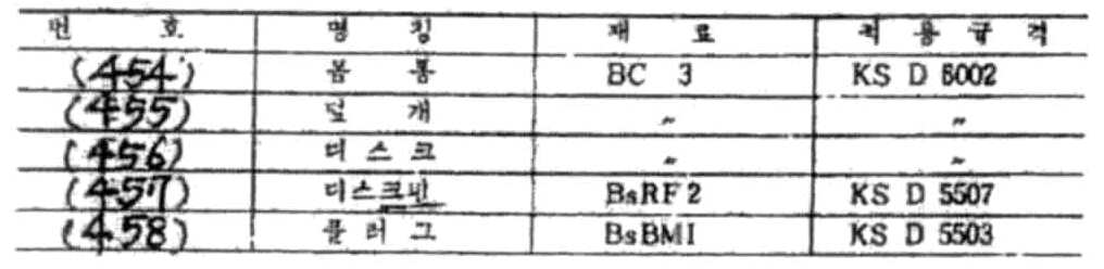
이 밖에 리프트형 첵 밸브(453) 내에 날개가 달려 충격을 완화시키는 스모렌스키형이 있다.In addition, there is a Smorensky type that lifts the wing in the lift valve valve 453 to alleviate the impact.
첵 밸브는 유체가 일정한 방향으로만 흐르게 되어 있으므로 설치 할 때 유체의 흐르는 방향에 주의하여야 하며 10A 또는 15A의 것은 청동 나사 이음형, 50A 또는 200A의 것은 주철 또는 주강 플랜지형으로 되어 있다.첵 Since the valve is intended to flow only in a certain direction, pay attention to the direction of fluid flow when installing. The 10A or 15A type is made of bronze threaded joint and the 50A or 200A type is cast iron or cast steel flanged type.
본 발명의 조정 밸브(459)에는 감압밸브(460)와 안전밸브(472)에 온도조절밸브(477)와 오우토급수기(478)에 공기빼기 밸브(481)로 분류되어 구성되는데에는 상 기 감압 밸브(460)는 고압 배관과 저압 배관의 사이에 설치하여 밸브의 리프트를 적당한 장치에 의하여 제동, 고압측의 압력의 변화와 증기 소비량 변화에 관계없이 저압측의 압력을 거의 일정하게 유지하는 밸브이다.In the
밸브의 행동은 대개 벨로스, 다이어프램(463) 또는 피스톤(127)과 같은 것으로 행한다.The action of the valve is usually done with something like bellows, diaphragm 463 or
고저압의 압력비는 2 : 1 이내로 하고 육 이것을 초과할 때에는 2 조의 감압밸브(460)를 직렬로 사용하여 2 단 감압을 하는 것이 더 좋다. 구조는 일반으로 동도면에 도시한 바와 같이 조정스프링(468), 다이어프램(463), 파이로트 밸브(464), 피스톤(127), 메인밸브(466), 등으로 구성되어 있다.When the pressure ratio of the high and low pressure is within 2: 1, and it exceeds six, it is better to perform two-stage pressure reduction using two sets of
상기한 파이로토 작동식 감압밸브(자력식, 461)에는 2차측 감지구멍(462)과 다이어프램(463)에 파이로트밸브(464)와 피스톤(127)과 메인밸브(466)에 메인밸브 스프링(467)이 부착되며 오우토압력조절밸브(469)에는 나사형(½∼1½인치) 오우토압력조절밸브(470a)와 플랜지형(2∼6인치) 압력조절밸브(471b)로 분류된다The pilot operated pressure reducing valve (magnetic) 461 has a secondary valve detecting hole 462 and a diaphragm 463, and a
이러한 안전밸브(472)에는 스프링식 안전밸브(473)와 리리이프식 안전밸브(474)에 증기용 포프스프링식 안전밸브(475)와 포프식 안전밸브(476)로 분리 구분된다.The safety valve 472 is divided into a spring-
이렇게 유체의 폐지 기구는 글로우브 밸브(419)와 같으며 글로우브 밸브(419)는 외력에 의하여 개폐를 하지만, 안전 밸브는 외력 대신에 스프링의 힘이나 밸브 스템의 중량과 지렛대의 추에 의하여 개폐된다.In this way, the fluid closing mechanism is the same as that of the glove valve 419. The glove valve 419 is opened and closed by an external force, but the safety valve is opened and closed by the spring force or the weight of the valve stem and the weight of the lever instead of the external force. do.
안전 밸브는 보일러 등 압력 용기와 그 밖에 고압 유체를 취급하는 배관에 설치하여 관 또는 용기내의 압력이 규정 한도에 달하면 내부 에너지를 오우토식으로 외부로 방출하여 용기 안의 압력을 항상 안전한 수준으로 유지하는 밸브이다.Safety valves are installed in pressure vessels, such as boilers, and other piping that handles high pressure fluids. When the pressure in a tube or vessel reaches the specified limit, the valve releases the internal energy to the outside automatically to maintain a safe level. to be.
보일러와 같은 축적 에너지가 큰 압력 용기에는 반드시 부착하게 되어 있는 안전 장치이다. 안전 밸브의 일종으로 릴리이프 밸브가 있다. 이것은 압력 유체가 흐르는 배관의 판로에 직접 연결하여 사용하는 밸브로서 관속의 압력을 일정하게 조정함과 동시에 경보의 목적에도 사용된다.It is a safety device that must be attached to a pressure vessel with a large accumulated energy such as a boiler. One type of safety valve is a relief valve. This valve is used to connect directly to the pipeline of the pipe through which the pressure fluid flows. It is also used for the purpose of alarming the pressure in the pipe constantly.
밸브의 성능은 분출 압력과 분출 정지시의 압력, 분출시의 압력차, 분출 용량의 정확도로 정해진다. 밸브가 열려 증기를 분출할 때 그 입구측 압력을 분출 압력, 밸브가 닫혀 증기의 유출이 정지 되었을 때 그 입구측 압력을 분출 정지 압력, 분출 압력과 분출 정지 압력의 차이를 분출차 압력이라 한다.The performance of the valve is determined by the accuracy of the ejection pressure, the pressure at the stop of the ejection, the pressure difference at the ejection, and the ejection capacity. When the valve is opened and the steam is ejected, the inlet pressure is the ejection pressure, and when the valve is closed and the outflow of steam is stopped, the inlet pressure is the difference between the ejection stop pressure, the ejection pressure and the ejection stop pressure.
한편 온도조절 밸브(477)로는 오우토 온도 조절밸브(477)와 동일한 구성인데 액체의 온도를 조절하기 위한 것으로 온도의 변화에 매우 민감한 밸로우즈의 작용에 의하여 개폐되어, 가열 증기 또는 냉각수의 유량을 오우토식으로 조절하는 오우토 제어밸브이다. 열 교환기나 중유 가열기 등에 사용된다.On the other hand, the temperature control valve 477 is the same configuration as the Outo temperature control valve 477, but to control the temperature of the liquid is opened and closed by the action of the bellows very sensitive to temperature changes, the flow rate of the heating steam or cooling water Oto control valve that controls Oto type. It is used for heat exchangers, heavy oil heaters and the like.
또한 오우토 급수기(479)에도 오우토수준조정기(480)가 별도로 형성되는데 오우토 급수기(479)와 상기 조정기(480)는 오우토 급수기 보일러의 수준을 그 최대 효율점에 일정하게 오우토식으로 급수하는 것으로 수위차는 언제나 풍요한때에 유도되는 것으로 이것에 의하여 보일러 급수의 부족에 의하여 일어나는 위험을 방지하는 것이다.In addition, the
또 한편 조정밸브(459)에 속하는 공기빼기밸브(481)에는 오우토공기배기밸브 열동형(증기용, 482)과 오우토공기배기, 밸브 바켓트형(온수형, 483)으로 분리되는데 상기 배기밸브(가로×세로; 53mm×56mm, 482)의 치수에 상기 밸브(가로×세로; 53mm×68mm, 483) 치수인데 상기 공기용의 공기 빼기 밸브는 열등형 또는 열동 플로우트 양용형이 있으며 온수용 공기 빼기 밸브를 플로우트식을 채용하고 있다. 동체는 청동제 벨로우스는 청동제, 플루우트는 황동제, 버키트는 청동판으로 사용하고 있다.On the other hand, the air bleed
본 발명의 냉매 배관용 밸브(484)에는 냉매스톱밸브(485)에 속하는 팩드밸브(486)와 팩레스밸브(벨로우즈형, 487)에 팩레스밸브(다이어프램형, 488)가 냉매스톱밸브(485)로 형성되고 팽창밸브(489)에는 다이어후렘형 팽창밸브(490)와 벨로우스형 팽창밸브(491)로 형성되되, 부자밸브(492)와 압력조정밸브(냉매용, 493)에 전자밸브(494)와 오우토급수밸브(미도시) 일체로 냉매배관용 밸브(484)로 형성된다.In the valve 484 for refrigerant piping according to the present invention, a packed valve (486) belonging to the refrigerant stop valve (485) and a faucet valve (diaphragm type, 488) are provided in the valveless valve (485, 489). And the
상기한 냉매스톱밸브(485)에 속하는 팩드밸브(486)와 상기 밸브(487), (488) 일체의 밸브(485)는 앞에서 설명한 글로우브 밸브와 같은 모양의 밸브와 밸브 시이트의 구조를 가지는 것으로 밸브측의 동체 관통부에서 냉매의 새는 것을 방지하기 위하여 석면 패킹 등으로 다진 그랜드 패킹형(폰넷트형)과 벨로우스에 의하여 축이 봉해진 팩레스형이나 다이어 프램으로 축이 봉해진 다이어 프램형이 있으며,벨로우스, 다이어 프램에 의하여 지름이 큰 것은 제작할 수 없다. 그랜드 형은 모든 축 덥게 (본네트, 캡) 을 가지며 최근에는 거의 팩시이트형으로 되어 있어 벨로우스, 팩레스 또는 패킹 조임물(팩킹)의 교환이나 밸브 개방시의 샘을 방지하게 끔 되어 있다.The packed
재료는 동체가 큰것은 포금제, 또는 주철제, 작은 구경의 것은 거의 포금제이며 밸브 스테라이트, 밸브 시이트는 네루넬메탈 등이 사용되고 있다.The material of the body is made of large metal or cast iron, and the small diameter of the metal is almost made of metal. The valve sterite and valve sheet are made of flannel metal.
밸브의 재질은 마모를 방지하기 위하여 밸브 시이트의 재질보다 굳은 것을 사용한다.The material of the valve is harder than the material of the valve seat to prevent wear.
그리고 팽창 밸브(489)는 다이어후렘형 팽창밸브(490)과 벨로우스형 팽창밸브(491)로 분리 구분 후 형성되는데The
상기 팽창 밸브(489)에는 수동형 팽창 밸브 접압 팽창 밸브, 열동형 팽창밸브의 3종류가 있다.The
수동형 팽창 밸브는 수동으로 냉매유로의 유효 면적을 조절함에 따라 냉매 유량을 가감하는 것이지만 오늘날에는 1 부를 제외하고는 거의 사용되지 않는다.Passive expansion valves are used to manually adjust the effective flow area of the refrigerant flow, thereby decreasing the flow rate of the refrigerant, but today they are rarely used except for one part.
정압식 팽창 밸브는 가정용 냉장고와 같은 작은 용량의 것에 사용되는 것으로 증발기 내의 압력을 일정하게 유지하여 동작한다.The constant pressure expansion valve is used for a small capacity such as a domestic refrigerator and operates by keeping a constant pressure in the evaporator.
열동형 팽창 밸브는 오늘날 더욱 널리 사용되며, 액냉매가 증발기를 나올 때 완전히 증발하여 가스화되어 있게 동작하는 기구로 되어 있으며 직접 팽창식의 증발기에 사용된다.Thermodynamic expansion valves are more widely used today, with mechanisms that operate completely to vaporize liquid refrigerant when it exits the evaporator and are used in direct inflatable evaporators.
재질은 어느 형식의 동체이든 포금제 밸브는 스테인리스제, 밸브 시이트는 모넬메탈제. 벨로우스는 인청동제이다.Material of any type of body is stainless steel, valve seat is made of Monel metal. Bellows is a phosphor bronze.
또한 부자 밸브(492)가 구성되는데에는In addition, the
상기 부자 밸브(492)의 플로우트 밸브(float valve)는 만액식 증발기에 사용 하는 밸브이며, 증발기 속의 액면을 일정하게 조절하는 저압측 부자 밸브이다. 상기 밸브는 증발기 속의 냉매 액의 양에 따라 열리고 닫히며 구조는 플로우트와 아암은 황동제 서어지 챔버(surge chamber)는 주철 또는 강판제로 되어 있다. 니이들 밸브는 스테인리스, 밸브 시이트는 황동을 사용한다. 플로우트 밸브에는 이 밖에 고압측의 냉매량을 조정하는 고압 플로우트 밸브도 있다.The float valve of the
이 같이 냉매용 압력 조정 밸브(493)의 구성에 있어Thus, in the structure of the pressure control valve 493 for refrigerant | coolants,
압력 조정 밸브(493)는 증발기 중의 부하에는 관계없이 증발기에서 증발한 냉매의 온도를 일정하게 유지하기 위하여 사용되는 것으로 증발기 중의 압력을 가지게 함에 따라 이 목적은 달성할 수 있다.The pressure regulating valve 493 is used to maintain a constant temperature of the refrigerant evaporated in the evaporator irrespective of the load in the evaporator. This purpose can be achieved by having a pressure in the evaporator.
하나의 압축기에 여러개의 증발기가 사용되며 또한 각 증발기의 증발 온도가 다를 때 유효하다.Multiple evaporators are used in one compressor and are also effective when the evaporator temperatures of each evaporator are different.
상기와 같이 전자 밸브(494)의 구성으로는As described above, the configuration of the
전자 밸브(494)는 밸브의 개폐를 전자석의 작용으로 조작하는 별도의 밸브이다.The
이것은 글로우브 밸브에 전자 코일을 부착한 것으로서 코일에 전류가 흐르면 전자석에 의하여 니이들 밸브가 달린 플런저가 위로 이동하여 밸브가 열리고 전류가 흐르지 않으면 플런저가 중력에 의해 아래로 떨어지므로써 밸브가 닫힌다. 팽창 밸브 바로 앞에 설치하여 압축기가 정지하고 있을 때는 냉매액이 증발기 속으로 유입하는 것을 방지한다.This is the attachment of the electromagnetic coil to the glow valve. When the current flows in the coil, the plunger with the needle valve is moved upward by the electromagnet, and the valve is opened. If the current does not flow, the plunger falls down due to gravity and the valve is closed. It is installed in front of the expansion valve to prevent refrigerant liquid from entering the evaporator when the compressor is stopped.
끝으로 오우토 급수 밸브(495, 미도시)에 있어Finally, in the Oto water supply valve (495, not shown)
오우토 급수 밸브는 냉동기의 콘덴서의 출구쪽(냉각수의 배출구쪽)에 취부하는 것으로 압축기의 부하의 변동에 대응하여 오우토식으로 응축기에 대한 급수량을 가감하는데 사용되며 윗부분에 다이어프램 또는 벨로우스가 설치되어 압축기의 고압 가스 압력에 의하여 밸브를 상하시키는 기구로 되어있다.Oto water supply valve is installed at the outlet side of the condenser of the refrigerator (outlet side of the cooling water) and it is used to adjust the water supply to the condenser in the auto way in response to the fluctuation of the load of the compressor, and the diaphragm or bellows is installed at the upper part It is a mechanism for raising and lowering the valve by the high pressure gas pressure of the compressor.
본 발명의 배관부속품인 수전류형의 수전인 일반형 수도꼭지(수전, 496) 내부에는 상기 꼭지(496)의 몸통(529)과 패킹상자(530)에 패킹누르게(531)와 꼭지대(532)에 핸들(533)과 디스크(534)와 디스크패킹(535)에 내수, 내식성의 패킹(536)과 내노화성 물건의 패킹(537)에 패킹받이(538)이가 분해 결합 조립된다.In the general faucet (faucet, 496), a faucet of a water current type, which is a piping accessory of the present invention, a handle is pressed on the body 529 and the
이에 급수 급탕관의 끝에 직결하여 탕과 물의 흐름을 개폐하는 장치를 수전이라 한다.The faucet is directly connected to the end of the water supply hot water supply pipe to open and close the flow of hot water and water.
수전의 재질은 일반으로 청동 주물, 황동 주물로 만들며 일반적으로 니켈 또는 크롬 도금을 하여 사용한다.Faucets are usually made of bronze or brass castings and are usually nickel or chrome plated.
일반용 수전의 구조와 부품명은 동도면에 도시한 바와 같으며 일반적으로 사용되는 건축 설비용, 수전류를 그림으로 나타내었고 상기 수도꼭지 명세표는 다음과 같다.The structure and part names of general-purpose faucets are as shown in the drawings, and generally used for building equipment, water current is shown in the figure and the faucet specification table is as follows.
일반형 수도 꼭지 명세표General Faucet Specification Table
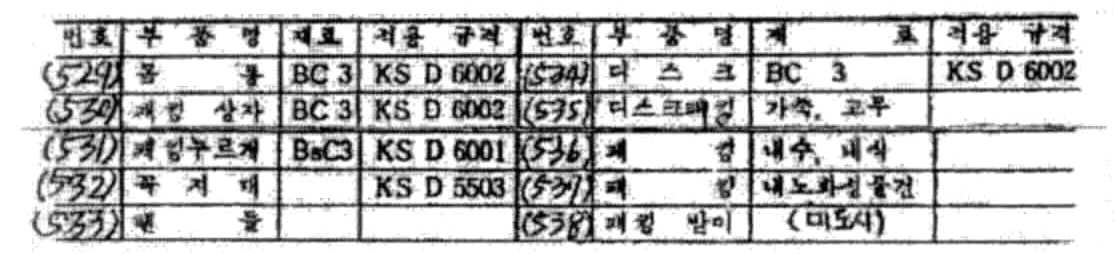
건물 내부에 형성되는 일반형 수도꼭지(496)는 다수개로 이음소켓부위로 소 방방재배관 펌프소화기로 소화활동이 진행된다The


수전류의 지수전의 형성되는 데에는 다음과 같이 설명한다Formation before the exponential of the water current is explained as follows.
지수전에는 갑 지수전과 을 지수전의 2 종류가 있다. 갑 지수전은 급수 장치의 일부 수량을 조절하거나 개폐하는데 쓰이며 일반으로 하이 탱크 급수 수직 상향관, 샤워 수직 상향관, 상층 수직 상향관의 중간에 자유롭게 개폐 할 수 있는 위치에 설치한다. 관과의 접합 방법에는 강관용 나사 이음 방식과 연관 동관용 납땜 방식 등이 있다.There are two types of exponents: A before and A before. The former is used to control or open some of the water supply equipment, and it is generally installed at the position that can open and close freely in the middle of the high tank water supply vertical pipe, the shower vertical pipe, and the vertical pipe. The joining method with a pipe | tube includes the screw joint method for steel pipes, and the soldering method for an associated copper pipe.
을 지수전은 갑 지수전 과는 달리 공도와 부지 경계 지점의 땅속 수도 분기관에 설치하여 급수 장치 전체의 통수를 제한하는데 사용되는데 지수전(497)이 표기 기재되어 있다.The exponential field is used to limit the water supply of the entire water supply system by installing it in the underground water branch at the highway and site boundary, unlike the abrupt field field.
지수전은 보통 지수전 박스로 보호되어 있으며 급수관의 누수등 특별한 경우를 제외 하고는 마음대로 개폐하지 않는다.Exponential warfare is usually protected by an exponential warfare box and is not open or closed at all times except in special cases such as water supply leaks.
구조는 동도면에 도시한 바와 같이 플러그 식으로 90˚ 회전하면 물이 흐르고 반대로 90˚ 회전하면 물의 흐름이 멎도록 되어 있다As shown in the drawing, the water flows when the plug is rotated 90 degrees, while the water flow is stopped when rotated by 90 degrees.
다음의 분수전(corporation stop; 코프레이션 스톱, 498)에 있어서On the next corporation stop (corporation stop, 498)
공도에 매설되어 있는 급수 소관에서 40mm 이하의 급수관을 분기할 때 쓰이는 수전이며 분수전의 지름은 13, 16, 20, 25mm 까지 있다. 주철관 또는 석면 시멘트관의 급수 소관에 직접 접속하거나 또는 분수 새들을 사용하여 부착한다. 분수전은 불 단수식 천공기(물을 끊지 않고 수도관에 구멍을 뚫는 기계)를 사용하여 급수 소관의 물을 멈추게 하지 않고 설치할 수 있다.A faucet used to branch water pipes less than 40mm from the water supply pipes buried in the highway. The diameters of the fountains are 13, 16, 20, and 25mm. Attach directly to the feed pipe of a cast iron pipe or asbestos cement pipe or attach using fountain saddles. Fractional fields can be installed without stopping the water in the water supply pipes by means of fire drills (machines that make holes in the water pipes without breaking them).
본 발명의 보올 탭(499)에는The bowl tab 499 of the present invention
물 탱크에 물을 공급하는 데 사용하는 부자식 밸브로서 지레 끝에 동제 또는 합성 수지제의 공이 달려 있어 물탱크 속의 물이This is a subsidiary valve used to supply water to the water tank. It has a ball made of copper or synthetic resin at the end of the lever.
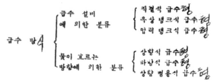
일정한 수위까지 도달하면 공의 부력에 의해 밸브가 오우토식으로 닫혀 항상 물탱크 속에 일정량의 물을 저장하게 되어 있다. 이 보올 탭은 소구경용과 대구경용이 있고 형식에 따라 단식과 복식이 있다.When the water level reaches a certain level, the valve is automatically closed by the buoyancy of the ball, which always stores a certain amount of water in the water tank. These bowl taps are available in small and large diameters, depending on the type, single and double.
본 발명의 스트레이너(392)에는 나사이음형 Y형 스트레이너(501)와 U형 스트레이너(502)에 V형 스트레이너(503)가 형성되되, 스트레이너는 증기, 물, 기름등의 배관에 사용되며 관내의 오물을 제거하는 목적으로 사용된다. 일반으로 2 B이하는 보금제 나사 조임형이고 2½B이상은 주철제 플랜지형이 사용된다.In the
스트레이너(392)는 형상에 따라 Y형, U형, V형, 등이 있다.
이렇게 Y형 스트레이너(501)는Y-
45˚ 경사진 Y형의 본체에 원통형 금속망을 넣은 것으로 유체에 대한 저항을 적게하기 위하여 유체는 망의 안쪽에서 바깥쪽으로 흐르게 되어 있으며 밑 부분에 플러그를 설치하여 불순물을 제거하게 되어 있다.A cylindrical metal net is placed in a 45 ° inclined Y-shaped main body. In order to reduce the resistance to fluid, the fluid flows from the inside of the net to the outside, and a plug is installed at the bottom to remove impurities.
금속망의 개구 면적은 호칭 지름 단면적의 약 3 배이고 망의 교환이 용이하게 되어 있다.The opening area of the metal net is about three times the nominal diameter cross-sectional area and the net is easily replaced.
한편 U형 스트레이너(502)에 있어On the other hand, in the
주철제의 본체 안에 여과망을 설치한 둥근통을 수직으로 넣은 것으로 유체는 망의 안 쪽에서 바깥 쪽으로 흐른다. 구조상 유체는 직각으로 흐름의 방향이 바뀌므로 Y형 스트레이너에 비하여 유체에 대한 저항은 크나 보수, 점검이 용이하며 주로 오일 스트레이너가 많다.In the cast iron body, a round tube with a filtering net is placed vertically. The fluid flows from inside to outside. Due to the structure, the flow direction is changed at right angles, so the resistance to the fluid is larger than that of the Y-type strainer, but it is easy to repair and inspect, and there are many oil strainers.
또한 V형 스트레이너(503)를 설치되는데에는In addition, the V-
상기 V형 스트레이너(503)는 동도면에 도시한 바와 같이 주철제의 본체 속에 금속망을 V자 모양으로 넣은 것으로 유체가 이 망을 통과하여 오물이 여과되나 구조상 유체는 스트레이너 속을 직선적으로 흐르므로 Y형이나 U형에 비해 유속에 대한 저항이 적으며 여과망의 교환이나 점검이 편리하다.The V-
배관 부속품의 트랩 (Trap ; 511)에는 앵글형 열동식트랩(522)과 스트레이트 열동식트랩(523)에 버키트트랩(524)과 상향식 버키트트랩(525)에 하향식 트랩(526) 과 플로우트트랩(527)에 임펄스 증기트랩(528)으로 상기 증기 트랩은 방열기 또는 증기관 속에 생긴 응축수 및 공기를 증기로 부터 분리하여 증기는 통과시키지 않고 응축수만 환수관으로 배출하는 장치이다. 일반적으로 증기관의 끝이나 방열기 환수구 또는 응축수가 모이는 곳에 설치한다. 증기 트랩의 종류에는 열동식 트랩, 버키트 트랩, 플로우트 트랩, 임펄스 증기 트랩(528) 등이 있고 작동 압력, 배출량 등에 따라 용도가 달라진다.The trap (511) of piping fittings includes an angle type thermal trap (522) and a straight thermal trap (523), a bucket trap (524) and a bottom bucket trap (525), a bottom trap (526) and a float trap ( 527) the
상기 열동식 트랩(523)은 사용 압력에 따라 저압용과 고압용이 있으며 형식에 따라 앵글형과 스트레이트형으로 구분할 수 있다.The thermal trap 523 has a low pressure and a high pressure according to the working pressure, and may be divided into an angle type and a straight type according to the type.
상기 트랩은 실폰 트랩이라고도 하며 벨로우즈는 인청동의 박판으로 만들어 내부에 휘발성이 높은 액체(에텔)를 채운 것으로 방열기의 출구쪽에 설치한다.The trap is also called a silpon trap, and the bellows is made of phosphor bronze and filled with highly volatile liquid (ether) inside the radiator.
벨로우즈의 주위에 증기가 오면 에텔이 증발하여 팽창하므로 벨로우즈가 늘어나 밸브를 닫는다. 드레인(301)이나 공기가 고이면 온도가 내려가 벨로우즈가 수축하여 밸브를 연다. 내압력은 낮아서 1 kg/㎠ 이하의 방열기가 파이프 끝 트랩에 사용되며 또한 공기를 통과 시키므로 에어 리터언 (air retern) 방식이나 진공 환수관 방식의 증기 배관에 사용된다.When steam comes around the bellows, the ether will evaporate and expand, closing the valve. If the drain 301 or air accumulates, the temperature drops and the bellows contract to open the valve. Since the pressure resistance is low, a radiator of less than 1 kg /
상기의 버키트 트랩의 종류에 있어서In the kind of Bucket trap mentioned above
상기 트랩은 버키트의 부력에 의해 밸브를 개폐하여 간헐적으로 응축수를 배제하는 구조로 되어 있고 버키트의 부력은 증기 압력에 의하여 조작되므로 증기관과 환수관의 압력차가 있어야 하며 압력차가 1 kg/㎠일 때 이론상 10.33m까지 응축수를 수직으로 밀어 올려 배출할 수 있으나 실제로는 8 m이하이다. 또 압력차가 충 분하지 못한 저압 증기관에서는 응축수의 배출이 완전히 이루어지지 않는다.The trap has a structure that removes condensed water intermittently by opening and closing the valve by buoyant buoyancy. Since buoyant buoyancy is operated by steam pressure, there must be a pressure difference between the steam and return pipes and the pressure difference is 1 kg / ㎠ In theory, condensate can be discharged vertically up to 10.33m but is actually less than 8m. In addition, condensate is not completely discharged from low pressure steam pipes with insufficient pressure difference.
버키트 트랩은 고압 중압의 증기관에 적합하며 환수관을 트랩보다 윗쪽에 배관할 수도 있으며 버키트의 위치에 따라 상향식과 하향식이 있다.Bucket traps are suitable for high pressure, medium pressure steam pipes, and the return pipe can be piped above the traps, depending on the location of the bucket.
먼저 상향식 버키트 트랩(525)으로는First, the bottom up bucket trap (525)
상기는 오픈 트랩(open trap)이라고도 하며 트랩에 응축수가 들어오면 처음에는 버키트 바깥쪽(A)에 괴고 버키트 (B)는 그 부력으로 떠올라 밸브 (C)를 닫는다. 응축수가 서서히 충만하여 넘쳐 버키트 속으로 흘러 들어가면 버키트가 무거워져 부력을 잃고 가라 앉아 밸브 (C)가 열린다. 밸브가 열리면 응축수는 버키트 속의 수면에 작용하는 증기의 압력에 의해서 배출된다.This is also called an open trap. When condensate enters the trap, it is initially trapped outside the bucket (A), and the bucket (B) floats with its buoyancy to close the valve (C). As the condensate slowly fills and overflows into the bucket, the bucket becomes heavy and loses buoyancy and the valve (C) opens. When the valve is opened, condensate is discharged by the pressure of the steam acting on the water surface in the bucket.
다음의 하향식 버키트 트랩(526)의 형식에 있어서,In the form of the following top down bucket trap 526,
이 형식은 버키트의 위치가 상향식에 비하여 거꾸로 놓여 있으며 트랩 아래로부터 증기 및 응축수가 들어오면 버키트는 증기로 가득차서 부력을 받아 위로 떠오르고 밸브가 닫힌다. 버키트 속의 증기는 응축수가 고임에 따라서 버키트 상부의 작은 구멍으로 배출되고 증기가 배출되면 버키트는 부력을 잃어 자중으로 하강하여 밸브가 열리고 응축수와 공기가 배출된다. 배출이 끝나면 버키트에 다시 증기가 차고 부력을 받아 밸브가 닫힌다.In this format, the position of the bucket is upside down compared to bottom-up, and when steam and condensate enter from under the trap, the bucket is filled with steam, floated up, and the valve closes. As the condensate accumulates, the steam in the bucket is discharged into a small hole in the upper part of the bucket. When the steam is discharged, the bucket loses its buoyancy and descends to its own weight, opening the valve and discharging the condensate and air. After the discharge, the bucket is again steamed and buoyant to close the valve.
그리고 플로우트 트랩(527)의 형식으로는And in the form of the float trap 527
상기 플로우트 트랩(527)은 일명 다량(多量) 트랩이라고도 하며 플로우트의 부력을 이용하여 밸브를 개폐한다. 사용 압력은 저압, 중압(4 kg/㎠ 정도)의 공기 가열기, 열 교환기 등에서 다량의 응축수를 처리할 때 사용되며 공기를 배출할 수 없으므로 필요할 때에는 열동식을 병용하여 상부 공기 배출관을 통해 온도가 낮은 공기를 배출할 수 있도록 유도한다.The float trap 527, also known as a large amount trap, opens and closes the valve by using the buoyancy of the float. The working pressure is used to treat a large amount of condensate in low pressure, medium pressure (about 4 kg / ㎠) air heaters, heat exchangers, etc.The air cannot be discharged. Induce to release air.
한편 임펄스 증기트랩 (impulse steam trap, 528)의 형성에 있어,On the other hand, in the formation of the impulse steam trap (528),
상기의 임펄스 증기 트랩(528)은 실린더 속의 온도 변화에 따라 연속적으로 밸브가 개폐하며 구조가 극히 간단하고 취급하는 드레인의 양에 비하여 소형이다. 공기를 배출할 수 있고 고압, 중압, 저압 어느 것에나 사용할 수 있으나 결점으로는 증기가 다소 새는 점이다.The
구조는 동도면에 도시한 바와 같이 원반 모양의 밸브 로드와 디스크 시이트로 구성되어 있다.The structure is composed of disc shaped valve rods and disc seats as shown in the same figure.
위와 같이 배수 트랩 (미도시) 에 있어서,As above, in the drain trap (not shown),
상기 배수 트랩은 하수관 속에서 발생한 가스가 배수관을 통해 기구 배수구에서 실내로 역류하는 것을 방지하는 수동식 방취 기구로서 재질은 주철제, 청동제 황동제 및 도기제 등이 있다.The drain trap is a manual deodorization mechanism that prevents the gas generated in the sewer pipe from flowing back to the room from the apparatus drain through the drain pipe, and the materials include cast iron, bronze brass, and ceramics.
구조는 배수 장치의 일부에 물이 고이게하고 물은 자유로이 통과하되 공기나 가스의 유통을 차단한다. 트랩 봉수의 깊이는 50∼100mm로 하고 50mm보다 낮으면 가스나 공기가 통할 염려가 있으며 100mm보다 깊이면 배수 할 때 자기 세척력이 약해져서 트랩의 바닥에 찌꺼기가 고여 막히는 원인이 된다.The structure allows water to accumulate in part of the drainage system, allowing the water to pass freely, but blocking the flow of air or gas. If the depth of trap seal is 50 ~ 100mm, if it is lower than 50mm, gas or air may pass. If it is deeper than 100mm, self-cleaning power becomes weak when draining, which causes clogging of debris on the bottom of trap.
배수 트랩은 구조상 관 트랩과 박스 트랩으로 크게 나눌 수 있다.Drain traps can be broadly divided into tubular traps and box traps .
이처럼 수직 배관 지지 금속에 있어서,In this vertical pipe support metal,
수직 파이프가 바닥을 관통하는 경우에는 바닥에 슬리이브를 넣어 파이프의 신축을 자유로이 하고 트랜스버어스 스윙을 방지하기 위해 층이 높은 도중에 지지 금속을 설치하여 둔다. 지지 간격에 관해서는 차후 시공방법에 설명하기로 한다.If the vertical pipe passes through the floor, a sleeve is placed on the floor to free the pipes to stretch and the support metal is installed during the high layer to prevent transverse swings. The supporting interval will be described later in the construction method.
이러한 고정 금속의 관고정금속(504)에는 터언버클부 지지밴드(505)와 지지밴드(506)에 로울러 지지밴드(507)와 수직관 매몰용 밴드(508)에 철재 안경밴드(509)와 바닥밴드(510) 등으로 형성된다The
이같은 관의 신축에 대하여 관의 이동을 방지하는 것이 목적이며 건물에 견고하게 취부한다. 고정 금속의 모양은 고정 장소에 적합한 모양으로 제작해야 한다.The purpose of this is to prevent the movement of the tube against the new construction of the tube and to be firmly attached to the building. The shape of the fixed metal should be shaped to fit the fixed location.
끝으로 패킹의 성질과 용도에는Finally, the nature and use of the packing
상기 패킹은 접합부로 부터의 새는 것을 방지하기 위하여 사용하는 것으로 일반적으로 가스켓트라한다. 가스켓트(32)는 두 플랜지의 사이에 끼어 그 조임너트의 조이는 힘에 의하여 압축되어 플랜지에 밀착하여 새는 것을 방지하는 것이다. 이때 가스켓트는 약간 탄성을 가지고 있어야 한다. 그 이유는 어떤 원인으로 보울트가 늘어 났을 때 가스켓트(32)에 탄성이 없으면 즉시 새기 때문이다.The packing is generally used as a gasket to prevent leakage from the joint. The
배관용 가스켓트는 선정할 때 고려해야 할 점은 다음과 같다.When selecting a gasket for piping, consider the following:
먼저 관내 물체의 물리적 성질을 고려 되어야 되며 이에 온도, 압력, 가스체와 액체의 구분, 밀도, 점도등이며First of all, the physical properties of the objects inside the pipe must be taken into account.These include temperature, pressure, gas and liquid separation, density, and viscosity.
다음은 관내 물체의 화학적 성질이 고려 되어야 되고 이 같은 화학 성분과 안정도, 부식성, 용해 능력, 휘발성, 인화성과 폭발성에Next, the chemical properties of the objects in the pipe should be considered and these chemical components and their stability, corrosiveness, solubility, volatility, flammability and explosiveness
그 다음의 기계적 성질에는The next mechanical property is
교환의 난이, 진동의 유무, 내압과 외압의 정도, 이상의 조건을 모두 검토한 후에 총합적으로 가장 적합한 가스켓트 재료를 선정해야 한다. 가스켓트 재료의 종류로서는 다음의 6 종류로 구분할 수 있다.After considering the difficulty of exchange, the presence of vibration, the degree of internal and external pressure, and the above conditions, the most appropriate gasket material should be selected as a whole. The gasket material can be classified into the following six types.
첫째는 고무류와 그 가공품이고First is rubbers and processed products
둘째는 식물 섬유 제품이며Second is plant fiber products
세번째는 동물 섬유 제품이다.Third is animal fiber products.
네번째는 광물 섬유 제품이며Fourth is mineral fiber products
다섯번째는 합성 수지 제품이고Fifth is a synthetic resin product
여섯번째는 금속 제품 등이 있으며 그 주된 것에 대하여 설명하면 다음과 같다.Sixth, there are metal products and the main ones are as follows.
상기된 고무류와 그 가공품에 있어서,In the above-mentioned rubber and its processed products,
상기 고무류는 그 탄성이 크고 약품에 침식되지 않으므로 가스켓트 재료로서 널리 사용되고 있다. 강도를 필요로 할 때에는 천(헝겊꺼즈, 75)을 섞은 고무 또는 금속망을 섞는 가스켓트가 사용된다.The rubbers are widely used as gasket materials because of their high elasticity and no erosion by chemicals. When strength is required, a gasket containing rubber or metal mesh mixed with a cloth (cloth lid) is used.
이 같이 천연고무의 선택에 있어서,In the selection of natural rubber in this way,
상기 고무의 특징은 탄성이 매우크고 흡수성이 없으며 연한 산이나 알칼리에는 잘 침식되지 않으나 내열성이 나쁘므로 100℃이상의 고온을 취급하는 배관에는 사용할 수 없다. 또 -55℃에서 경화 변질 한다. 천연 고무의 가장 큰 결점은 내유성이 나쁜 점이며 따라서 일반 냉수, 배수와 공기 배관 등에는 사용할 수 있으나, 기름, 증기, 온수와 냉매배관 등에는 사용할 수 없다. (이하 설명생략함)The feature of the rubber is that the elasticity is very large, absorptive and does not corrode well in soft acids or alkalis, but the heat resistance is bad, so it cannot be used for pipes that handle high temperatures of 100 ° C or higher. Hardening alteration at -55 ℃. The biggest drawback of natural rubber is its poor oil resistance, so it can be used for general cold water, drainage and air piping, but not for oil, steam, hot water and refrigerant piping. (Explanation below)
위와 같이 본 발명의 엘리베이터 기계실의 설치되는 압력센서와 유공압센서에 배치되는 본 구성의 1초 이내로 초기진화 및 인명구조가 이루어지게 케이블카아(256)에 탑재되는 펌프소화기 일체의 설명되지 못한 부분을 그림과 함께 상세한 구성이 진행된다.As described above, an unexplained portion of the pump fire extinguisher mounted on the
에어솔레노이드밸브(76) 제품의 사용전 주의사항에 대하여 다음과 같이 설명한다.Precautions before use of the

상기한 주의표지판에 따른In accordance with the above warning signs
유체의 사용 조건에 대하여 상세한 설명에 있어서,In the detailed description of the conditions of use of the fluid,
첫째로 필터는 5㎛ 이상의 여과정도를 가진 필터를 설치하여야 되며 이 같이 드레인이 많은 경우는 밸브를 처음 사용할 때 공압기기의 작동 불량이 될수 있으며 또한 주위환경의 오염도 되므로 드레인 관리에 충분히 유의하여하 된다First of all, the filter should be installed with a filtration accuracy of 5㎛ or more. If there are a lot of drainage, it may be a malfunction of the pneumatic equipment when the valve is used for the first time, and the surrounding environment may be polluted.
드레인 관리가 곤란한 경우 오우토 드레인 부착필터를 사용하면 편리하여If drain management is difficult, use the filter with auto drain.
콤프레샤에서 발생하는 카본 타르가 많은 경우는 밸브 내부에 다량으로 부착되어 동작불능이 되는 경우가 있으므로 카본 타르가 적게 발생되는 콤프레샤를 사용하되 오일 미스트 세퍼레이타가 사용된다.If there is a lot of carbon tar generated in the compressor, it may be attached to the inside of the valve in a large amount so that it may become inoperable. Therefore, use a compressor that generates less carbon tar, but an oil mist separator is used.
그 이외의 사용 유체의 조건에 대하여는 공압기기 메이커의 압축공기 청정화 시스템을 참작한다.For the conditions of other fluids used, refer to the compressed air cleaning system of the pneumatic equipment manufacturer.
다음은 급유에 대하여Next, about refueling
초기 윤활이 되어 있으므로 무급유로 사용하여도 무방하나 다만 꼭 급유가 필요한 경우 터빈유 1종(ISO VG32)을 사용하되 급유를 사용도중에 중단 시킬 경우 초기 윤활제의 소실로 인하여 작동 불량을 초래할 경우가 있으므로 급유는 필히 연속해야 사용된다Since it is initially lubricated, it can be used as lubrication free, but if it is necessary to use lubrication, use turbine oil class 1 (ISO VG32), but if the lubrication is stopped during use, it may cause malfunction due to loss of initial lubricant. Must be used consecutively
특히 스핀들유는 사용하지 않도록 한다.In particular, do not use spindle oil.
그 다음의 누설전압에 대하여 다음과 같이 설명한다.The next leakage voltage is explained as follows.
전원 차단시 누설전류 등에 의해 양단에 남은 누설전압의 크기는 3% 이하로 억제하여야 되며,When the power is cut off, the amount of leakage voltage left at both ends due to leakage current, etc. should be kept below 3%.
접점보호에 C-R소자를 사용할 경우 C-R 소자를 통해 흘러들어오는 누설전류에 의해 누설전압이 증가하는 경우가 있으니 주의한다.In case of using C-R element for contact protection, leakage voltage may increase due to leakage current flowing through C-R element.

특히 무접점 릴레이 에서는 보호회로가 내장되어 있는 경우가 있으므로 주의하여야 한다.In particular, care should be taken in the case of solid-state relays as they may have built-in protection circuits.
네째로 저온 사용에 대하여Fourth, about low temperature use
온도 -10℃ 까지 사용이 가능하지만 드레인(301) 수분 등의 고화 또는 동결에 유의하여야 되며Although it can be used up to -10 ℃, care should be taken to solidify or freeze moisture such as drain (301).
동결 등이 우려되는 경우는 에어 드라이어를 설치하여 사용한다.If you are concerned about freezing, install an air dryer.
다음은 순시통전에 대하여Next is Instantaneous Power
더블솔레노이드형을 순시통전에 의해 사용할 경우 통전시간을 0.1초 이상 되도록 한다.When using double solenoid type by instantaneous energization, make energizing time more than 0.1 second.
상기한 바와 같이 주의 표지판의 설명에 따른 사용전의 솔레노이드밸브의 주의사항이다.As described above, the cautions of the solenoid valve before use according to the description of the caution sign.
![]()
![]()
공압기기 선정 및 취급시 상세한 설명에 있어서,In the detailed description of the selection and handling of pneumatic equipment,
첫째는 공압기기의 올바른 선정 및 결정은 전문적인 지식과 경험을 갖춘 기능인이 설계 또는 사양을 결정후 취급하도록 하여야 되며Firstly, the proper selection and decision of the pneumatic equipment should be handled by a skilled person with professional knowledge and experience after the design or specification has been decided.
공압기기의 사용은 충분한 지식과 경험이 있는 기능인이 취급하되The use of pneumatic equipment is handled by skilled personnel with sufficient knowledge and experience.
압축공기는 잘못 취급하면 대단히 위험하기 때문에 유지 보수 등은 충분한 지식과 경험을 갖춘 기능인이 책임지고 취급한다.Compressed air is very dangerous if handled incorrectly. Maintenance and maintenance are the responsibility of a skilled worker with sufficient knowledge and experience.
그리고 안전장치 확인후 공기압 기기를 조작하여 주시고 분해시 시스템의 초기 조건 및 압축공기가 완전히 배기되었는지 확인후 분해 조립하되After checking the safety device, operate the pneumatic equipment and disassemble and assemble after confirming the initial condition of the system and whether the compressed air is completely exhausted.
압축공기가 분기되지 않는 상태에서 유지 보수시 기계장치의 오동작으로 인해 인체에 상해를 끼칠 수 있으므로 반드시 지켜야 된다.Maintenance of compressed air should not be prevented, as maintenance may cause personal injury due to malfunction of machinery.
이 같이 일반적인 사용조건이 아닌 별도의 조건이나 압축공기외 가스 및 그 외의 인체에 유해한 유체를 제어시 제작시공 문의 하신후 협의하여 공압기기를 선정 사용하되 그외 각별히 안전이 요구되는 경우에도 제작사로 문의하여 위험요소를 제거한다.In case of controlling other conditions or compressed air besides compressed air and other fluids harmful to human body, such as general use conditions, consult with the manufacturer after construction and consult and select and use pneumatic equipment. Eliminate hazards
그러므로 공압기기를 사용하기 전에는 당업자는 주문하는 사양이 맞는지 한번더 확인한 후에 배관전 배관내의 청소나 그 외의 세정을 충분히 하여 관내에 이물질 및 절삭유 그 이외의 먼지등이 들어가지 않도록 주의하되Therefore, before using the pneumatic equipment, one of ordinary skill in the art should check whether the specifications to be ordered are met again, and clean the inside of the pipe before piping so that the foreign matter, cutting oil and other dusts are not allowed to enter the pipe.
테프론 테이프를 사용하는 경우 나사의 1.5∼2산 정도 남기고 감아주면 된다.If you use Teflon tape, you can wind it with about 1.5 ~ 2 threads left.

이 같이 중간정지형 밸브를 사용하는 경우 밸브(76)와 시린더(126) 사이의 배관에 누설이 없도록 주의하고 정밀한 위치제어의 경우 공기의 물리적인 특성인 압축성 및 미세한 누설로 인하여 정밀한 중간 정지가 되지 않는 경우가 있으므로 긴 시간의 중간정지가 필요한 경우 제작사로 문의하여 애로사항을 해소하되In the case of using the intermediate stop valve as described above, be careful not to leak the pipe between the
배관시 무리한 힘으로 조이거나, 적정 토오크로 조이지 않을 경우 사용중 장치의 오동작으로 인한 인체에 손상이 올 수 있으므로 다음의 적정 토오크로 배관 설치되도록 하여야 된다.If the pipe is tightened with excessive force or if it is not tightened with the proper torque, the human body may be damaged by the malfunction of the device during use. Therefore, the pipe should be installed with the following proper torque.

이 처럼 사용환경에 대하여 더욱더 상세한 설명으로는In this more detailed description of the environment
부식성 가스, 화학약품용액, 해수, 빗물, 수증기 등이 있는 장소에의 설치 사용은 피하여 설치하되 수분, 기름 등이 일시적으로 있는 장소에 설치할 경우 보호 카바 등의 대책을 세워서 설치하고 먼지 등이 많은 경우는 밸브의 배기포트에 소음기 등을 부착하여 먼지등이 들어가지 않도록 하여야 되며 폭발성이 있는 환경에서 사용하지 않아야 되며 직사광선을 피하여 열원이 있는 환경에서 복사열을 차단하여 주도록 하여 진동 및 충격이 있는 장소에서의 사용은 피하고 사양을 반드시 감안하여 설치한다.Installation in places with corrosive gas, chemical solution, seawater, rainwater, steam, etc. Avoid using, but install in places with temporary moisture, oil, etc. The silencer should be attached to the exhaust port of the valve to prevent dust from entering and should not be used in an explosive environment. Avoid direct sunlight to block radiant heat in an environment with heat sources. Avoid use and install in consideration of specifications.
상기한 바와 같이 솔레노이드밸브(76)는 기종이 다양하게 많기 때문에 5포트 솔레노이드밸브 (5PORT SOLENOID VALVE)는 밸브몸체(557)와 카버(558)에 스폴 (SPOOL, 559)과 스폴패킹(560)에 안내 파이로트 (PILOT, 561)에 코일(562)이 2 위치 싱글(569)에서는 상기 코일(562) 좌측 부위로 부착되며, 2 위치 더블(570) 역시도 밸브몸체(557)의 좌측, 우측에 각개로 코일 좌측과 우측으로 부착되어 2 위치 싱글(569)과 2 위치 더블(570)로 표준생산제품으로 형성되는데 상기 표준생산제품 이외로 주문생산제품에는 3 위치 센터 크로지드 (Center Closed, 577)와 3 위치 센터 프레스르 (Center Pressure, 578)에 3 위치 센터 익조오스트(Center Exhaust, 579)로 다양한 구조로 상기 생산제품을 표시기호로 일반적으로 동도면에 기재된 바와 같이 싱글(S; SINGLE, 575)과 더블(D; Double, 576)은 표준생산제품으로 분리 구분되면 에이취(H; Center Closed, 577)와 아이(I; Center Pressure, 578)에 제이(J; Center Exhaust, 579)는 표시기호로 상기한 주문생산제품으로 분리구분되는데 특히 제이(579) 품목은 화재발생시 닥터벤츄레이션의 흡입구, 토출구의 환기장치의 파이어댐퍼 개페장치기구로서 시린더(126) 전방에 에어호스(109)와 연결되어 건물 또는 그이외 산업체 및 해상선박 내부에 널리 사용된다As described above, since the
한편 매니폴드 시스템의 매니폴드 형식에는 5-포터 파일로트 타잎(PORT PILOT Type; M5, V8; 인치단위)의 (DMQF 100-MOO-S) 및 (DMQF100-MOO-L)의 형식을 취하는데 다음의 명세서로 설명한다.The manifold type of the manifold system takes the form of (DMQF 100-MOO-S) and (DMQF100-MOO-L) of 5-port pilot type (PORT PILOT Type; M5, V8; inch). It demonstrates by specification of.
각개의 솔레노이드 밸브 명세서Each Solenoid Valve Specification

상기한 밸브(76)에서는 취부형식으로는 직접배관형 (581)과 베이스 배관형(밸브시이트, 582)의 취부형식으로 형성되며 동작방식으로 도시기호로 표기되었고 전원접속방식에는 중앙수직형(LL, 571)과 수직형(L, 572)에 수평형(M, 573)으로 분리되며, 입력전압에는 디시(DC, 직류 12V)와 디시(DC, 직류 24V)가 코일(562) 몸체로 스위치 온(ON)-시 개폐(밸브) 되고 스위치 오프(off)-시 전폐된다 이렇게 솔레노이드 밸브 몸체(557)에 부착되는 일체의 부속의 흡입구와 토출구에는 나사탭 및 가공홀 치수는 다음과 같이 설명한다 (거리치수 설명은 생략함)In the
아래의 각 치수의 나사탭에는 에어호스 결속구 유니온 카플링(567)과 유니온 카플링(몸체결속, 568) 암수나사산이 가공되는 일체의 가공홀(20)은 다음과 같다.The thread tabs of the respective dimensions below are integrally formed through

이렇게 펌프소화기 몸체 내부의 입형다단펌프(8)와 집수정탱크(34) 내부에는 소방방재라인의 방수구(169)와 상기 방수구(169) 하단부로 송수구(168)와 상기 송수구(168)와 방수구(169)의 중간부위로 맨홀뚜껑(152) 상부의 플로우트(315)와 상기 맨홀 하부에 플로우트(315)로 방화수위 감지센서 역할로 방화수를 집수정 내부로 일정량을 채워지게끔 상기 맨홀(152) 상하로 부착되는데에는 상기의 플로우트(315)는 탱크 외벽의 가공홀(20) 주위 네곳으로 플로우트(315)와 결합 분리되는 루우버 카버(550)와 플로이트 인셔어트 스위치(551)로 형성되도록 상기 루우버카버(550) 몸체의 사각플랜지(28)로 결합된 후 상기 탱크 외벽 가공홀(20) 끼워서 플랜지 가공홀 네곳에 결속후 너트(25)를 채운후 수공구 몽키 스패너를 사용하여 결합 분리된다. 한편 상기한 바와 같이 동도면에 도시된 바와 같이 지표면(GLL) 상부로 베드프레임(286) 상단부 집수정탱크(34) 외부에는 베드프레임(286) 상단부로 센튜리푸우걸 펌프(308) 좌측에는 정지밸브(114)와 상기 밸브(114) 좌측에는 방수 구(169) 각개는 플랜지(28)로 상기 펌프(308) 상부 티이엘보(44) 부착펌프(259)는 오토밸브(259)로 타임머 또는 레벨 스위치(541)와 하이레벨 알람(542)에 베이컴 페일루어 알람(543)과 스어멀릴레이 알람(544) 및 알람 리셋트버턴(545)과 탱크 내부 낮은 위치의 로워레밸 스위치(546)가 펌프제어보드(53) 내부와 외부로 설치된다.Thus, the vertical multi-stage pump (8) and the water collecting tank (34) inside the pump fire extinguisher body (34) and the water inlet (169) and the water inlet (168) and the water outlet (168) and the water outlet (lower end) of the fire protection line.
그리고 센튜리푸우걸 펌프(308) 몸체는 모터(192)의 중심축(198)인 샤프트(198)가 상기 펌프(308) 몸체인 케이싱(141) 내부에 임펠러(143) 날개에는 가이드베인(142)이 종전의 펌프구동 요부위와 대동소이하게 부착되며 케이싱(141) 중심선에 위치하는 샤프트(198) 둘레면에는 축봉장치의 매커니커시일(156)과 격벽(372)에 밸런스구멍(376)이 형성되어 매커니컬시일의 냉각방식(391)은 대동소이하게 축봉부(390)가 구성되는데 상기 펌프제어보드(53)의 제어박스는 입형다단펌프 제어보드(53) 기능은 대동소이 하되, 방수량 체크용 유량계(105)와 과대압력방지 스위치(108)가 방수구(169) 라인배관 상부의 정지밸브(114)의 라인배관(168)에 별도의 티이엘보(44)로 형성된 배관라인 센서로 표출되면서 인지되어 감지된다.The body of the Centurio
상기한 입형다단펌프 및 제어시스템 개념의 압력탱크(189)와 집수정탱크(34)와 제어부 인버터(47)로 상호 연결되는데 이때 제어부 인버터(47)와 집수정 탱크(34)의 연관된 라인 관계는 방화수를 흡입할 때 흡입구(269)에서는 공운전 방지장치(271)와 각 펌프의 역지밸브를 인버터(47)에서 전폐와 전개를 제어할 수 있도록 되게끔 형성된 후 상기 역지밸브(6) 선반부 일체의 각 펌프(8)와 전방의 각 밸브(5)인 격리밸브(Isolating Vavle, Ballo-2 Butterfly, 5) 전방에 설치위치가 명확하게 설정된 후에는 압력탱크(189)와 제어부 인버터(47)는 토출합류관(4) 라인에 토출압력 체크센서인 제1압력 체크센서(86)와 제2압력 체크센서(87) 일체에 과대압력 방지 스위치(108)로 일정량 방화수압을 제어하면서 토출구(270)인 분사노즐인 다수의 소방노즐(10)로 화재를 1초 이내로 각개 A화재를 냉각작용과 질식작용이 되도록 믹서기(73)에 황토(158)를 주입시켜 케이블카아(256)로 일반 화재에 속하는 대형산불과 주거지 근린생활지역의 화재 예방을 최우선으로 목적하는 소방 케이블카아(256)의 형성은 각개의 높고 낮은 산봉우리와 높낮이 차이있는 다수개의 건물 각개로 상호 와이로프로 복수개의 소방호스(9)는 안전 그물망(열십자형 또는 우물정자형의 와이어로프가 포함되는 그물망의 호스, 401) 형식의 호스(9)로 이루게 되는 구성이 기술적 특징이다.The
이 같이 컨트롤 블럭 다이아그램과 비에프 모델의 입형다단펌프 운전방식 구성에 의하면 펌프전원(272)에 제어전원(273) 각개로 분리 구분되면서 상기 제어전원(273)은 비상운전 시킨스(sequence) 회로(274)는 디시파워스프래이(DC Power Supply) 공급회로(275)의 (M/C) 구동신호 접점출력회로(279)의 출력회로 선단과 접촉된 후 펌프전원(272)의 (M/C) 스위치 접점과 인버터(47) 회로 접점과 각 펌프 비상운전되도록 접점 연결되되, 제어전원(273)의 디시 파워 공급회로(275)에 의해 마이크로 콘트롤 유니트(276)에는 디아피 스위치 설정회로(277)와 스위치 입력회로(58)가 상기 유니트(276)에 입력 설정되되, 엘이이디이 디스플레이(LED DISPLAY)회로(278)와 (M/C) 구동신호접점 출력회로(279)에는 신호를 출력하고 모터과부화 신호입력회로(280)는 상기 유니트(276)와 펌프전원(272) 선단부의 (MCCB+THR)과 (MCCB) 회로접점이 인버터(47) 회로접점과 연결되게끔 설치되며 인버터운전 데이트 입출력회로(281)는 인버터(47) 회로와 마이크로 콘트롤 유니트(276)와 상호 입력, 출력의 회로로 형성되며 토출 압력 트랜스미터어(Transmitter, 284)는 압력감지회로(282)와 연결 후 상기 회로(282)는 다시 상기 유니트(276)에 입력 설정되게 한 후에 흡입/토출 압력 스위치 등의(285)는 외부상태 입력회로(283)를 통한 후 상기 입력회로(283)는 다시 상기 마이크로 콘트롤 유니트(276)에 입력 설정된다.According to the configuration of the control block diagram and the vertical multistage pump operation method of the BF model, the control power supply 273 is divided into the control power supply 273 and the pump power supply 272, respectively, and the control power supply 273 is an emergency operation sequence ( 274 is in contact with the output circuit tip of the (M / C) drive signal
이렇게 입형다단펌프(8)는 누구나 쉽게 조작할 있게끔 정확한 구성의 기능에 따른 구성명세서는 다음과 같다.Thus, the vertical
입형다단펌프 명세서Vertical multistage pump specification
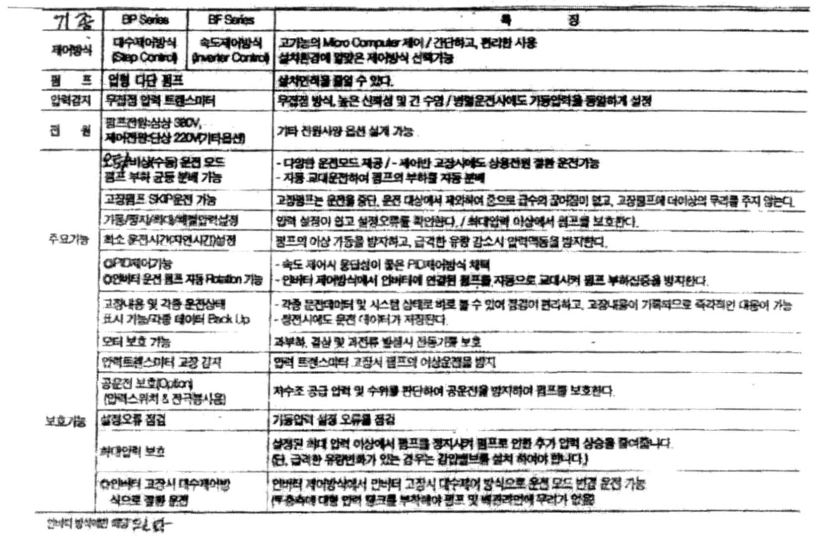
이러한 입형다단펌프시스템의 제어방식에 대하여 상세한 내용은 다음과 같다.Details of the control method of the vertical multistage pump system are as follows.
·압력제어방식 (그림1)Pressure control method (Figure 1)
시스템의 운전 범위는 모든 펌프의 가동점(Pon)에서부터 최대부하 운전펌프 의 가동 정지점 Poff1과 주펌의 운전 정지점 Poff2 사이에 형성된다. 압력제어 방식의 시스템의 Poff2의 운전정지 지점에 도달한 후 180초∼210초(CO-CR), 0∼120초(CO-ER)간의 최소운전후 완전히 정지한다. 인버터제어 방식보다 ΔP의 폭을 좁게 유지할 수는 없지만 1bar정도의 입력변화를 감지함으로 저층의 흡수가압에 주로 이용된다.The operating range of the system is formed between the starting point (Pon) of all pumps, between the operating stop point Poff1 of the maximum load operating pump and the operating stop point Poff2 of the main pump. After reaching the operation stop point of Poff2 in the pressure control system, it stops completely after the minimum operation between 180 seconds and 210 seconds (CO-CR) and 0 to 120 seconds (CO-ER). Although the width of ΔP cannot be kept narrower than the inverter control method, it is mainly used for absorbing pressure of the lower layer by detecting input change of about 1 bar.
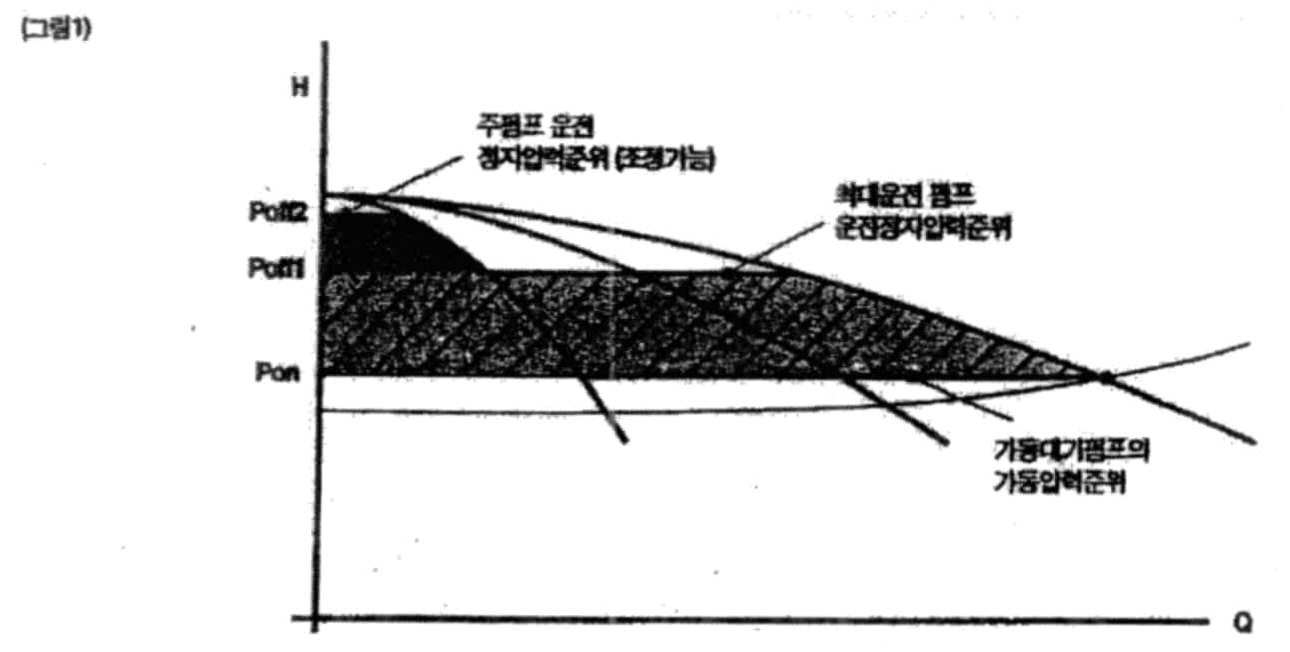
·주파수 변조제어 장식 (그림2)Frequency modulation control decoration (Figure 2)
시스템의 운전 범위는 조정수치 범위를 유지 한다.The operating range of the system is maintained within the adjustment range.
각 운전중인 펌프의 유량이 100% 도달시와 가동대기 펌프가 구동 직전의 압력이 가동점 Pon이고 개개의 최대운전 펌프가 정지 직전이 압력이 펌프 정지점 Poff가 된다.When the flow rate of each running pump reaches 100%, the pressure immediately before the movable standby pump is driven is the operating point Pon, and the pressure immediately before the respective maximum operating pump is stopped is the pump stop point Poff.
따라서 주파수 변조 방식은 △P의 폭을 좁게 유지할 수 있으며 주파수 변조기로 주펌프의 회전속도를 제어함으로서 가동 대기펌프의 가동시 또는 최대 운전펌프의 정지시 발생하는 급격한 압력의 변화를 보상하는 시스템으로 구성된다.Therefore, the frequency modulation method can keep the width of △ P narrow and control the rotational speed of the main pump with the frequency modulator to compose the system to compensate for the sudden pressure change that occurs during the operation of the standby air pump or the stop of the maximum operation pump. do.
시스템의 가동은 가동점 부근까지 압력이 낮아지면 곧바로 주펌프가 주파수 변조기제어에 의하여 서서히 가동하고 유량의 변화가 없으면 제어기에 의하여 중지 되므로 시스템헌팅 (System hunting)에 의한 압력 변동을 제거할 수 있다.As soon as the pressure of the system is lowered near the operating point, the main pump is operated slowly by the frequency modulator control and stopped by the controller if there is no change in flow rate, thereby eliminating the pressure fluctuation caused by system hunting.
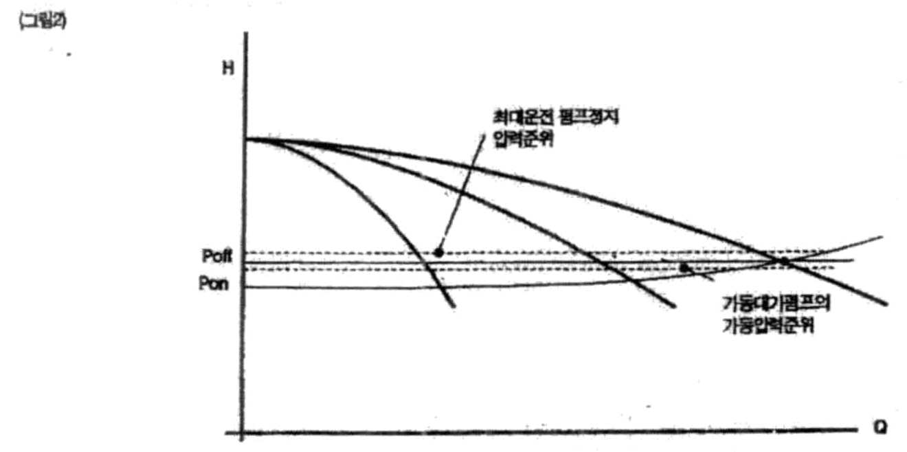
일반적으로 입형다단펌프의 주요기능의 동도면에 도시한 한 바와 같이 상세한 설명은 다음과 같다.In general, as shown in the diagram of the main function of the vertical multistage pump, the detailed description is as follows.
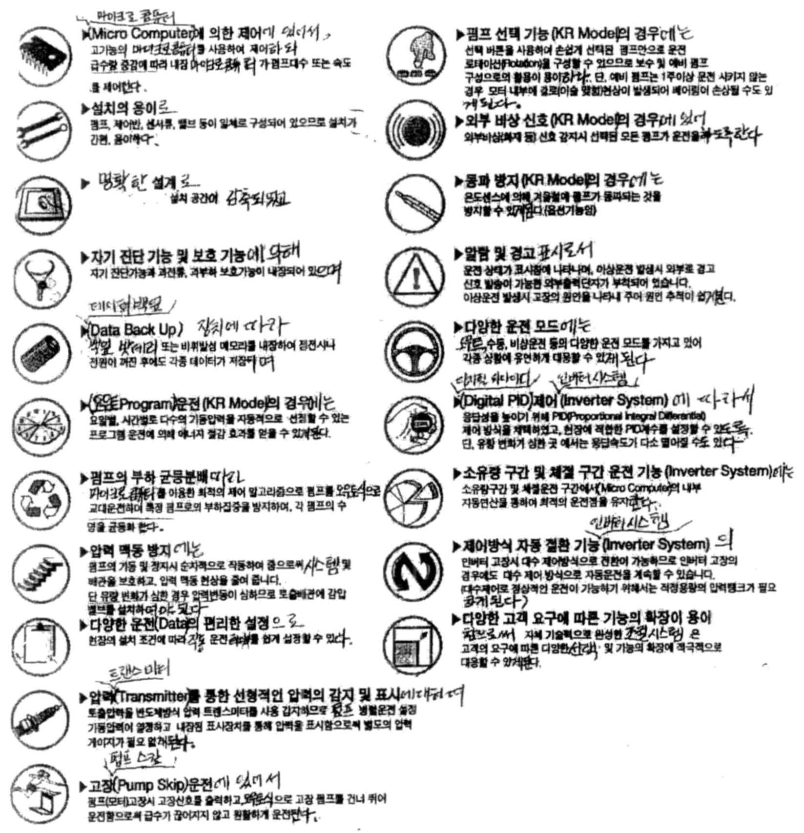
상기된 바와 같이 입형다단펌프에는 도시기호로 요부위인 관노즐 틈새형 펌프소화기 몸체 내부로 주요기능을 상세히 표기 기재함으로써 누구나 쉽게 화재발생시 화재현장 또는 펌프기계 근처에 근접않고도 펌핑을 하게 되어 잠자다가도(취침시)에도 주민의 고통을 해소시키게 되는 본 발명의 구성에 따른 결과로서 인명구조 및 사전예방에 따라 소방차 소방헬기가 화재현장 도착 전에 1초 이내로 초기진화를 이루게 되는 구성이 기술적 특징인데 종전(1960대 후반의 현대과학의 에너지와 동력의 미국의 과학총서 내용중 번역문중 에너지 변환을 다음과 같이 상세한 설명은 다음과 같다.As described above, in the vertical multistage pump, the main function is described in detail inside the body of the pipe nozzle crevice-type fire extinguisher body, which is a recessed part of the city symbol, so that anyone can easily pump in the event of a fire without being close to the fire site or the pump machine. As a result of the configuration of the present invention to relieve the pain of the inhabitants even at bedtime, the fire extinguisher fire helicopter according to the rescue of life and preventive measures to achieve the initial evolution within 1 second before the arrival of the fire scene is a technical feature. Here is a detailed description of the energy conversion in the translations of the American scientific book on energy and power in modern science in the late 1960s:
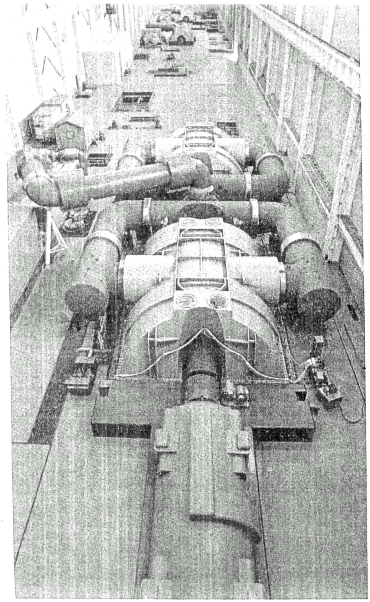
<켄터키주 파라다이스(Paradise) 부근에 있는 TVA의 파라다이스발전소 증기터빈발전기의 용량은 1,150MW이다. 1970년 2월 처음 가동했을 때에는 이것이 세계에서 가장 큰 발전소였다. 제네럴전기회사가 제작한 이 터빈은 먼저 왼쪽에 있는 직각파이프 밑의 고압 터빈으로 들어간 후 이 직각파이프를 통해 차례로 중압터빈 (뒤쪽의 뚜껑)과 저압터빈(앞쪽의 뚜껑)으로 흐른다. 고압터빈은 하나의 발전기(왼쪽의 회색상자)에 연결되어 있고, 다른 두 터빈은 같은 용량을 가진 두번째 발전기(앞쪽 상자)에 연결되어 있다. 이 시설 전체는 시간당 360만kg의 수증기에 의해 가동되며, 이 수증기는 제곱인치당 1,650kg의 압력 및 427℃로서 고압터빈에 들어간다. 하루의 석탄소비량은 10,572t으로 석탄화차 210량을 가득 채우기에 충분한 양이다. 이 시설의 순 열효율은 39.3%이다. 각 704MW인 두개의 작은 터빈발전기가 뒤쪽에 보인다.>TVA's Paradise Power Plant Steam Turbine Generator, located near Paradise, Kentucky, has a capacity of 1,150 MW. When first operated in February 1970, it was the largest power plant in the world. The turbine, manufactured by General Electric, first enters the high-pressure turbine below the right angle pipe on the left, and then flows through the right angle pipe to the medium-pressure turbine (back cover) and the low-pressure turbine (front cover). The high-pressure turbine is connected to one generator (gray box on the left), and the other two turbines are connected to a second generator (front box) of the same capacity. The entire plant is powered by 3.6 million kilograms of steam per hour, which enters a high pressure turbine at 1,650 kilograms per square inch of pressure and 427 ° C. The coal consumption per day is 10,572 tons, enough to fill 210 coal cars. The net thermal efficiency of this facility is 39.3%. Two small turbine generators, each 704 MW, are visible behind.
<가정용 난로, 증기터빈, 자동차엔진 및 전구등의 효율은 에너지의 수요를 확정시키는 데 도움이 된다. 주로 필요한 것은 지구의 열부하량을 증가시키지 않는 종류의 에너지원이다.>The efficiency of home stoves, steam turbines, automobile engines and light bulbs can help to determine the demand for energy. What is needed is a type of energy source that does not increase the global heat load.>
현대 공업사회는 수많은 상품과 써비스를 창조하는 데 필요한 에너지를 염출하는 동시에 질이 높은 에너지를 폐열로 저락시키는 복잡한 기계로 볼 수 있다. 지난해 미국은 69×1015B.t.u.를 사용하여 1,000조달러가 약간 넘는 국민총생산을 달성하였으며 이 에너지 중 95.9%를 화석연료가, 3.8%를 낙하하는 물이, 그리고 0.3%를 U235의 분열이 공급하였다. 1인당 3억4,000만B.t.u.의 소비량은 약 13t의 석탄, 또는 근래 자주 사용되는 방식을 따른다면 2,700gal의 가솔린에 함유되어 있는 에너지에 상당하는 것이다. 1900∼70년에 모든 목적에 사용된 연료가 소비된 효율은 대체로 4배정도 향상되었다고 추산할 수 있다. 이러한 효율의 향상이 없었다면 1971년의 미국경제는 이미 2025년 또는 그 무렵의 예상소비량 만큼의 에너지를 소비하고 있을 것이다.The modern industrial society can be seen as a complex machine that produces high quality energy as waste heat while releasing the energy needed to create numerous products and services. Last year, the United States achieved a gross domestic product of just over $ 1,000 trillion, using 69 × 10 15 Btu, with 95.9 percent of its energy supplied by fossil fuels, 3.8 percent by water, and 0.3 percent by U 235 fragmentation. It was. The consumption of 340 million Btu per person is equivalent to the energy contained in about 13 tons of coal, or 2,700 gallons of gasoline, according to the more commonly used methods. It can be estimated that in 1900-70, the efficiency of fuel consumption for all purposes has improved approximately four times. Without this efficiency improvement, the US economy in 1971 would already be consuming energy as expected in 2025 or so.
에너지를 유용한 열, 빛, 일로 변환시키는 효율이 계속 향상되었기 때문에 1890∼1960년에 연료소비량은 연간 2.7%의 속도로밖에 증가되지 않았으면서도 GNP는 연간 3.25%의 속도로 증가될 수 있었다. 그러나 이제는 이러한 유리한 현상이 더 이상 지속되지 않는 것으로 보인다. 1967년 이래 연료소비의 연간 증가량은 GNP의 성장보다 빨라 연료경제의 향상이 점점 어려워지고 새로운 상품과 써비스는 과거의 것보다 더 많은 에너지입력과 비용을 필요로 하고 있음을 나타내고 있다. 전력생산을 위한 핵연료 사용의 예상증가량만을 생각한다면 1980년대와 1990년대에 소비될 연료의 중요한 부분이 오늘날의 화석연료보다 낮은 효율로서 유용한 형태로 변환될 것임이 명백하다. 그 이유는 가장 효율적인 화석연료발전소의 약 40%라는 효율에 비하여 현재의 원자력발전소는 연료가 가진 에너지의 약 30%만을 전력으로 변환시키기 때문이다.Because the efficiency of converting energy into useful heat, light, and work continued to improve, GNP could increase at a rate of 3.25% per year, while fuel consumption increased at only 2.7% per year in 1890–1960. However, it seems that this favorable phenomenon no longer persists. Since 1967, the annual increase in fuel consumption has been faster than the growth of GNP, indicating that it is becoming increasingly difficult to improve the fuel economy and that new products and services require more energy inputs and costs than in the past. Considering only the expected increase in the use of nuclear fuel for power generation, it is clear that a significant portion of the fuel to be consumed in the 1980s and 1990s will be converted into a useful form with lower efficiency than today's fossil fuels. The reason is that current nuclear power plants convert only about 30% of the energy of a fuel into electricity, compared to about 40% of the most efficient fossil fuel power plants.
기술자들이 연료의 에너지를 다른 보다 유용한 형태로 변환시키는 효율을 향상시키려고 노력하는 것은 이해할 만하다. 공업에 있어서 효율의 향상은 생산가격의 절감을 의미하고, 소비자에게 있어서는 가격의 저렴을 의미하며, 모든 사람에게 대하여 대기와 수질의 오염의 감소를 의미한다. 전기사업체들은 오랫동안 다수의 사용자를 위해 에너지의 가격을 절감시킴으로써 소비를 촉진시킬 수 있음을 알고 있었다. <1W 절약>이라는 이 공익사업체의 최근의 캠페인은 기업철학의 현저한 반전을 나타낸다. 적절한 새로운 발전소 부지선정의 어려움은 소비의 절약만이 아니라 소비의 효율성의 필요성을 잘 나타낸다. 이에 부연하여 이러한 효율이 많이 향상된다 해도 지구의 화석연료와 핵연료 공급량의 수명을 연장시키는 데에는 경미한 효과밖에는 기대할 수 없음을 강조하지 않을 수 없다. 이 점에 관해서는 이 글에서 뒤에서 보다 자세히 전개하려 한다.It is understandable that technicians are trying to improve the efficiency of converting the energy of fuels into other more useful forms. In industry, increased efficiency means lower production costs, lower prices for consumers, and lower air and water pollution for all. Utilities have long known that they can boost consumption by reducing the price of energy for many users. The utility's recent campaign of <1W savings> represents a significant reversal of corporate philosophy. Difficulties in selecting a suitable new plant site well illustrate the need for efficiency as well as savings. In addition, even if such efficiency is greatly improved, it can be emphasized that only a slight effect can be expected to prolong the life of the earth's fossil fuel and nuclear fuel supply. We will discuss this in more detail later in this article.

<[그림 8-1] 변환경로는 많은 친숙한 형태의 에너지를 서로 연결한다. 검은색으로 표시한 네가지 형태는 오늘날의 중요한 에너지원인데 태양에너지의 경우에는 잠재적으로 중요한 에너지원이다. 파선은 드물거나 우연한, 또는 이론적인 유용한 변환을 나타낸다. 흰선은 중간형태에너지의 운명을 나타내고 있다. 난방에 사용되는 열에너지를 제외하고 대부분의 에너지는 기계적 에너지로 변환된다. 기계적 에너지는 직접 교통에 사용(그림 8-2 참조)되거나 발전에 사용된다. 그리고 전기에너지는 조명, 난방 및 기계적인 일에 사용된다. 2차적인 형태로서 화학에너지는 건전지와 충전기에서 볼 수 있다. 전구가 생산하는 복사에너지는 대부분 열로서 소실된다.><Figure 8-1> Conversion Paths connect many familiar forms of energy to each other. The four forms shown in black are the major energy sources of today, and in the case of solar energy they are potentially important. Dashed lines represent rare, accidental, or theoretical useful transformations. The white line represents the fate of the intermediate form energy. Except for the thermal energy used for heating, most of the energy is converted into mechanical energy. Mechanical energy is used for direct transportation (see Figure 8-2) or for generation. And electrical energy is used for lighting, heating and mechanical work. As a secondary form, chemical energy is found in batteries and chargers. Most of the radiant energy produced by light bulbs is lost as heat.
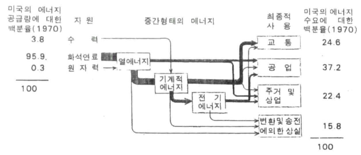
[그림 8-2] 세가지 주요한 에너지원에 대해 최종적인 용도까지의 경로를 나타냈다. 가장 직접적이고 가장 효율적인 변환은 낙하하는 물로부터 기계적인 에너지로, 이것이 다시 전기에너지로 변환되는 것이다. 화석연료와 원자핵연료에 갇혀 있는 에너지는 먼저 열에너지의 형태로서 방출된 후 기계적 에너지로 변환된 다음 원하는 경우에는 전기에너지로 변환된다. 변환 및 송전 상의 손실에는 화석연료를 윤활유의 생산에 사용하거나 석탄을 코크스로 변환시키는 것과 같은 화석연료의 여러가지 비에너지적 사용도 포함된다. 그러나 가장 큰 손실은 평균효율 32.5%로서 전력을 생산하는 데서 발생한다.Figure 8-2 shows the route to the final uses for the three major energy sources. The most direct and most efficient conversion is from falling water to mechanical energy, which in turn is converted into electrical energy. Energy trapped in fossil fuels and nuclear fuel is first released as a form of thermal energy, which is then converted into mechanical energy and then into electrical energy if desired. Conversion and transmission losses include various non-energy uses of fossil fuels, such as the use of fossil fuels in the production of lubricants or the conversion of coal into coke. The biggest loss, however, comes from generating power with an average efficiency of 32.5%.
어떤 연료에 함유된 에너지를 유용한 형태로 변환시키는 효율은 변환방법과 희망하는 최종적인 사용방법에 따라 여러가지로 달라진다. 개방된 벽난로에서 나무나 석탄을 연소시킬 때에는 그 에너지의 20% 이하만이 방안으로 방사된다. 나머지는 모두 굴뚝으로 상실된다. 한편 잘 설계된 가정의 난로는 연료가 가진 에너지의 75%를 포획하여 이를 난방에 이용할 수 있다. 난방을 위한 화석연료 변환의 평균효율은 현재 아마 50∼55%로서 금세기 벽두의 효율보다 3배가 된다. 1900년에는 미국에서 소비된 모든 연료의 반 이상이 난방에 쓰여졌으나 오늘날에는 1/3 이하가 이에 쓰여진다.The efficiency of converting the energy contained in a fuel into a useful form depends on the conversion method and the desired final use. When burning wood or coal in an open fireplace, less than 20% of its energy is emitted into the room. All others are lost to the chimney. Well-designed home stoves, on the other hand, can capture 75% of the fuel's energy and use it for heating. The average efficiency of fossil fuel conversion for heating is now perhaps 50-55%, three times the efficiency of this century's head. In 1900, more than half of all fuel consumed in the United States was spent on heating, but today less than one third is spent on it.
금세기 연료변환효율의 가장 뚜렷한 향상은 전력발전사업에 의해 이루어졌다. 1900년에는 연료가 가진 에너지의 5% 이하만이 전력으로 변환되었었다. 오늘날 평균효율은 33% 내외이다. 이러한 증가는 주로 발전기를 돌리는 터빈속으로 들어가는 증기의 온도를 상승시키고 보다 큰 규모의 발전시설의 건설로써 이루어졌다. 1910년에는 전형적인 입사수증기온도가 260℃였으나 오늘날에는 최근 시설은 574℃의 고열로 가열된 수증기를 사용한다. (니꼴라 까르노; Nicolas ![]()
![]()
증기터빈발전소의 전체적인 효율을 알기 위해서는 이 값을 연료로부터 전력에까지의 연쇄 중에 있는 다른 에너지 변환기의 효율로 곱해야 한다. 현대적인 보 일러는 연료가 가진 화학적 에너지의 약 88%를 열로 변환시킨다. 발전기는 증기터빈이 생산한 기계적 에너지의 99%까지를 전력으로 변환시킬 수 있다. 따라서 이 전체적 효율은 88×47(터빈의 효율)×99, 즉 약 41%이다.To know the overall efficiency of a steam turbine power plant, this value must be multiplied by the efficiency of other energy converters in the chain from fuel to power. Modern boilers convert about 88% of the fuel's chemical energy into heat. The generator can convert up to 99% of the mechanical energy produced by a steam turbine into electricity. The overall efficiency is therefore 88 x 47 (turbine efficiency) x 99, i.e. about 41%.
참조 (역자주 : Lord Kelvin, William Thomson, 1824-1907)See, Lord Kelvin, William Thomson, 1824-1907.
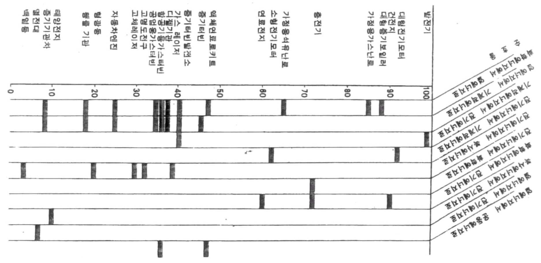
[그림 8-3] 에너지변환기의 효율은 보통의 백열등의 5% 이하로부터 대형발전기의 99%까지이다. 여기 표시한 효율은 현재의 기술로서 도달할 수 있는 대체적인 최대의 값이다. 액체연료로키트의 47%라는 수치는 쌔턴 달우주선에 사용된 액화수소엔진에 대해 계산한 것이다. 형광등과 백열등의 효율은 완전히 <평탄한> 백색광의 V당 220루멘이라는 이론값이 아니라 용납할 수 있을 정도의 백색광이 도달할 수 있는 최대효율은 W당 약 400루멘인 것으로 전제한 것이다.[Figure 8-3] The efficiency of energy converters ranges from 5% or less for ordinary incandescent lamps to 99% for large generators. The efficiency shown here is an alternative maximum that can be reached with current technology. The 47% of liquid fuel kits were calculated for the liquefied hydrogen engine used in the Saturn moonship. The efficiency of fluorescent and incandescent lamps is not a theoretical value of 220 lumens per volt of completely <flat> white light, but the maximum efficiency that white light can tolerate is assumed to be about 400 lumens per W.
원자력발전소는 현재의 원자로가 화석연료를 연소하는 보일러만큼 고온으로 될 수 없기 때문에 그 가동효율이 보다 낮다. 물을 끓이는 원자로가 생산하는 온도는 350℃ 근처로, 이것은 까르노의 식에서 T 1이 623˚K라는 것을 의미한다. 연료로 부터 전력으로까지의 완전한 순환에 있어서는 원자력발전소의 효율은 약 30%로 저하된다. 이것은 원자력발전소가 사용하는 연료가 가진 에너지의 70% 정도가 폐열로 나타나 인접한 수체나, 냉각탑을 사용하고 있을 경우에는 주위의 대기 중으로 방출된다는 것을 의미한다. 화석연료발전소에 있어서는 이렇게 낭비된 열이 연료가 가진 에너지의 60% 정도에 달한다.Nuclear power plants are less efficient because current reactors cannot be as hot as boilers burning fossil fuels. The temperature produced by the water-boiling reactor is around 350 ° C, which means that T 1 is 623 ° K in Carno's equation. In the complete cycle from fuel to power, the efficiency of a nuclear power plant is reduced to about 30%. This means that about 70% of the energy of the fuel used by nuclear power plants is generated as waste heat and is released into the surrounding atmosphere when adjacent water bodies or cooling towers are used. In a fossil fuel power plant, this waste heat accounts for about 60% of the energy of the fuel.
그러나 물이나 공기에 부하되는 실제의 폐열은 60%나 70%라는 수치가 나타내는 것보다 훨씬 크다. 같은 킬로와트 출력을 가진 발전소의 경우, 원자력발전소는 화석연료발전소보다 50% 정도 많은 폐열을 발생한다. 그 이유는 원자력발전소가 1kW/h의 전력을 생상하기 위해 화석연료발전소보다 약 1/3 많은 연료를 <연소>시켜야 하며 또 이 많은 B.t.u. 入力의 70%를 낭비하기 때문이다.However, the actual waste heat that is loaded into water or air is much larger than that indicated by 60% or 70%. For power plants with the same kilowatt output, nuclear power plants generate about 50% more waste heat than fossil fuel power plants. The reason is that nuclear power plants need to <burn> about 1/3 more fuel than fossil fuel plants in order to generate 1 kW / h of electricity. This is because 70% of the entry force is wasted.
물론 원자력발전소나 화석연료발전소가 방출한 열이 낭비되어야 한다는 열역학적 법칙은 없다. 문제는 이 많은 양의 저질에너지가 할 수 있는 유용한 일을 발견하는 것이다. 많은 용도가 제안되었지만 이 모두가 경제적 제약에 부딪치고 있다. 예를 들어 증기터빈에서 방출된 저압수증기는 난방에 사용될 수 있다. 어떤 지역사회, 특히 뉴욕시에서는 이를 실시하고 있으며, 뉴욕에서는 (컨살리데이티드 에디슨, Consolidated Edison 회사)가 많은 수증기를 공급하고 있다. 많은 화학공장과 정유소에서도 터빈에서 나오는 저압수증기를 처리과정에 필요한 수증기로 사용하고 있다.Of course, there is no thermodynamic rule that the heat emitted by nuclear or fossil fuel power plants must be wasted. The problem is to find useful things that this large amount of low-energy can do. Many uses have been proposed, but all of them face economic constraints. For example, low pressure steam released from steam turbines can be used for heating. Some communities, especially New York City, do this, and in New York (the Consolidated Edison company) they supply a lot of water vapor. Many chemical plants and refineries also use low-pressure steam from turbines as steam for the treatment process.
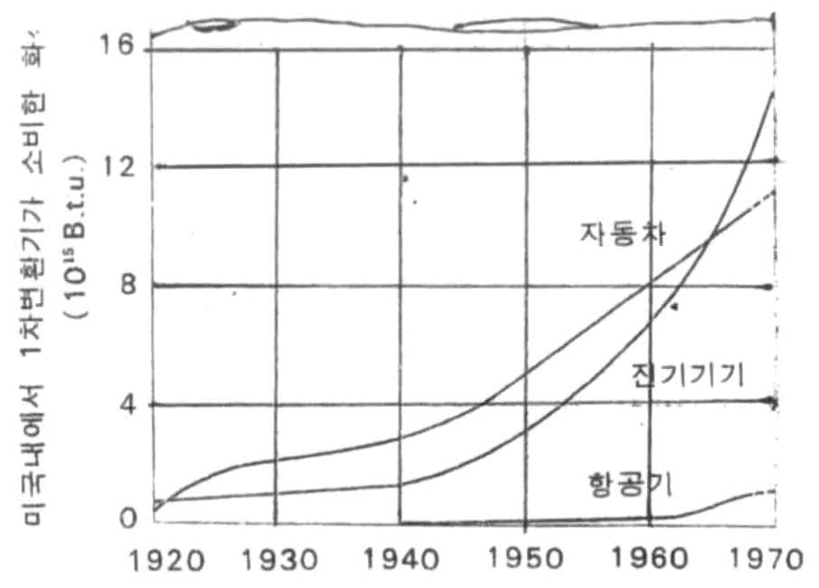
[그림 8 - 4] 가장 빠르게 증가되는 에너지소비기기 세가지는 전기기기, 자동차, 그리고 항공기이다. 현재 이 세가지는 합해서 미국에서 소비되는 모든 에너지의 약 40%를 소비한다. 최근 1940년까지만 해도 이들은 현재보다 훨씬 적어서 총 에너지소비량의 18%에 불과했었다. 항공기의 연료수요는 10년간에 3배 이상으로 증가되었다.Figure 8-4 Three of the fastest growing consumer devices are electrical equipment, automobiles, and aircraft. Today, these three add up to about 40% of all energy consumed in the United States. Until recently, by 1940, they were far less than present, accounting for only 18% of total energy consumption. The aircraft's fuel demand has more than tripled in 10 years.
발전소에서 방출되는 가열된 물이 어떤 지역에서는 어류와 패류의 성장을 촉진시키는 데 도움이 될 것이라는 제안도 있었다. 그러나 전국적으로 볼 때에는 현재 화석연료발전소에서 방출되는 폐열이나 앞으로 곧 수십개의 새로운 원자력발전소에서 방출될 폐열은 이용할 매력적인 용도는 없는 것으로 보인다. 문제는 이 폐열이 환경에 미치는 해를 제한하는 것이다.It has been suggested that heated water released from power plants may help to promote the growth of fish and shellfish in some areas. Nationwide, however, there seems to be no attractive use for waste heat from fossil-fuel power plants, or from heat from dozens of new nuclear power plants. The problem is to limit the environmental impact of this waste heat.
이상의 논의에서 가정의 난방에 전력을 사용하는 것(어떤 전기업체에서는 아직도 활발히 권장하고 있다)이 화학연료를 비효율적으로 사용하는 것임을 알 수 있다. 가정용 고급석유난로나 가스난로는 보통 발전소보다 적어도 두배의 효율을 나타낸다. 그러나 어떤 지역에서는 전력에 의한 난방의 연간 가격에 이러한 낮은 효율에도 불구하고 화석연료에 의한 직접적인 난방과 경쟁할 만하다. 이와같은 변칙 적인 경우에는 여러가지 요인이 관여한다. 전력은 온도가 높아질수록 소비량이 적어진다. 전기에 의한 난방은 보온이 좋은 새로운 건물에 설치되는 것이 보통이다. 어떤 지역에서는 천연가스를 구하기가 약간 어렵고 그 값도 비싸다. 석유의 공급도 항상 믿을 만하지는 않은 수가 있다. 화학연료가 귀해짐에 따라 그 값이 비싸질 것이며, 원자력에 의한 전력 생산은 증가될 것이다. 불행히도 우리는 연료의 비효율적인 사용에도 불구하고 우리가 가장 연료자원 중 보다 많은 부분(특히 원자핵연료)이 전력에 의한 난방에 사용되리라고 예상하지 않을 수 없다.The above discussion shows that the use of electricity for heating the home (which is still strongly recommended by some utilities) is an inefficient use of chemical fuels. Domestic high-grade oil stoves or gas stoves are usually at least twice as efficient as power plants. In some regions, however, the annual price of electric heating is comparable to direct heating by fossil fuels, despite this low efficiency. There are several factors involved in such anomalous cases. Power consumption is lower at higher temperatures. Electric heating is usually installed in new buildings with good insulation. In some areas, natural gas is a bit difficult and expensive. The supply of oil may not always be reliable. As chemical fuels become valuable, they will become expensive, and nuclear power generation will increase. Unfortunately, we cannot but expect that even in the inefficient use of fuel, more of our fuel resources (especially nuclear fuel) will be used for heating by electricity.
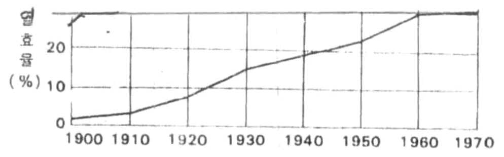
[그림 8 - 5] 미국내 화석연료 발전소의 효율은 1900년의 3.6%에서 1970년의 32.5%로 거의 10배 나 향상되었다. 이러한 향상은 증기터빈의 작동온도를 높이고 발전시설의 규모를 크게 함으로써 가능하였다.The efficiency of fossil fuel power plants in the United States has improved almost tenfold, from 3.6% in 1900 to 32.5% in 1970. This improvement was made possible by increasing the operating temperature of the steam turbine and increasing the size of the power plant.
모든 원동기 중 가장 널리 보급된 것은 피스톤기관이다. 많은 미국가정의 차고에는 동력예초기, 제설기, 체인톱 등을 포함시키지 않더라도 두개의 피스톤기관이 있다. 미국내 1억대 이상의 자동차에 있는 피스톤기관의 출력은 170억마력 이상, 또는 모든 원동기(연료를 기계적 에너지로 변환시키는 기관으로 정의된) 출력의 95% 이상인 것으로 평가된다. 이 막대한 출력이 대부분의 시간에는 사용되지 않기는 하지만 이것은 미국 내에서 소비되는 화석연료의 16% 이상을 차지한다. 모든 형태의 교통수단 - 선박의 00만t의 석탄을 소비하여 전국에너지 총 수요의 16% 에 달하였다. 에너지상담자 (존 흄, John Hume)의 추산에 따르면 철도는 1920년보다 1/6의 B.t.u.로써 54%나 많은 교통편(<운송실적>의 지수로 측정)을 제공하였다. 이와같은 효율의 향상은 전국 경제에 있어서의 철도의 역할감소와 함께 전국 총 에너지예산에서 철도가 차지하는 비율을 16%에서 약 1% 정도로 감소시켰다. 그러나 1920∼67년의 전국 총 에너지소비량에 관한 곡선을 보면 이러한 굉장한 변화의 영향은 거의 눈에 띄지 않는다.The most widespread of all prime movers is the piston engine. Many American home garages have two piston engines, even if they do not include power mowers, snow plows, and chain saws. Piston engines in more than 100 million cars in the United States are estimated to be more than 17 billion horsepower, or more than 95 percent of all prime movers (defined as engines that convert fuel into mechanical energy). Although this huge output is not used most of the time, it accounts for more than 16% of the fossil fuel consumed in the United States. All forms of transport-16 million tonnes of coal in ships, accounting for 16% of the country's total energy demand. According to an energy consultant (John Hume), railroads provided 54 per cent more traffic (measured by <transport record>) as B.t.u. This improvement in efficiency has reduced rail's role in the nation's economy and has reduced the railroad's share of the nation's total energy budget from 16% to about 1%. However, the effects of this tremendous change are hardly noticeable in the curve of the nation's total energy consumption in 1920-67.

<[그림 8 - 8] 전등의 효율은 각자가 좋다고 생각하는 빛의 질에 따라 다르다. 완전히 평탄한 백색광의 경우 이론적인 효율은 W당 220루멘이다. 스펙트럼의 중간부분의 빛을 약간 강화시킴으로써 W당 약 400루멘까지도 얻을 수 있다. 현재의 형광등은 효율이 36%라고 할 수도, 20%라고 할 수도 있다.>< [Fig. 8-8] The efficiency of the lamps depends on the quality of light that they think is good. For perfectly flat white light, the theoretical efficiency is 220 lumens per W. By slightly intensifying the light in the middle of the spectrum, up to about 400 lumens per W can be achieved. Current fluorescent lamps may be said to have an efficiency of 36% or 20%.>
전력을 가장 효율이 낮게 이용하는 중요한 용도는 아마 빛을 공급하는 일일 것이다. (제너럴 일렉트릭사, General Electric Company)는 조명이 전력 총 발전량의 약 24%, 또는 전국 총 에너지예산의 6%를 소비하는 것으로 추산하고 있다. 보통의 100W 백열전구의 필라멘트는 빛보다 훨씬 많은 열을 생산한다는 것이 잘 알려져 있다. 실제로 전력입력의 95% 이상의 적외선으로서 나타나고 5% 이하만이 가시광선으로 방출된다. 그럼에도 불구하고 이것은 1900년에 100W 전구가 방출하던 빛의 5배 이상인 것이다. 현대적인 형광등은 소비전력의 약 20%를 빛으로 변환시 킨다.The most important use of the least efficient power is probably light. General Electric Company estimates that lighting consumes about 24% of total electricity generation, or 6% of the country's total energy budget. It is well known that the filaments of a typical 100W incandescent bulb produce much more heat than light. In fact, it appears as 95% or more of infrared rays of power input and only 5% or less is emitted as visible light. Nevertheless, this is more than five times the light emitted by the 100W bulb in 1900. Modern fluorescent lamps convert about 20% of the power consumption into light.

<[그림 8 - 9] 현재 사용되고 있는 전력발전기는 낙하하는 물, 화석연료 또는 원자핵연료가 가진 에너지를 이용한다. 수력터빈발전기(1)는 잠재적인 운동에너지를 전력으로 변환시킨다. 화석연료증기터빈발전기(2)에서는 보일러가 수증기를 생산하고 이 수증기는 터빈을 돌리며 이 터빈이 발전기를 돌린다. 원자력발전소(3)에서는 U235의 분열로 에너지가 방출되어 수증기를 만들고, 이 수증기는 그후 화석연료발전소에서와 마찬가지회로를 통과한다. 현재 개발 중인 원자핵증식로(4)에서는 잉여중성자가 분열하지 못하는 U238이나 Th232원자의 피복에 포획되어 이 원자들이 분열할 수 있는 Pu239나 U238로 변환된다. 이 원자로의 열은 액체나트륨에 의해 전달된다.><Figure 8-9> Current generators use the energy of falling water, fossil fuels or atomic fuels. The
이 값은 완전한 백색광이 아니라 용납할 수 있을 정도의 백색광을 전제로 할 때의 실제적인 상한선인 와트당 400루멘(lumen)을 근거로 한 것이다. 스펙트럼이 완전히 평탄한 백색광의 경우로 한정한다면 최대이론출력은 와트당 220루멘으로 저 하된다. 인간의 눈에 가장 예민한 단파장(550nm)의 빛으로 만족할 수 있다면 이론적으로 와트당 680루멘에 달할 수 있는 것이다.This value is based on the actual upper limit of 400 lumens per watt, assuming that white light is acceptable, not fully white light. The maximum theoretical output is reduced to 220 lumens per watt, provided that the spectrum is limited to perfectly flat white light. If we can be satisfied with the shortest wavelength (550nm) of light that is most sensitive to the human eye, we can theoretically reach 680 lumens per watt.
제너럴 일렉트릭社는 현재 형광등이 전국 총 조명의 약 70%를 차지하고 있으며 그 나머지는 백열등과 고명도 전추진계, 기관차 및 항공기 - 은 전국 에너지예산의 약 25%를 소비한다.General Electric currently accounts for about 70% of the country's total lighting, while the remainder consumes about 25% of the country's energy budget for incandescent lamps, high-brightness propulsion systems, locomotives and aircraft.
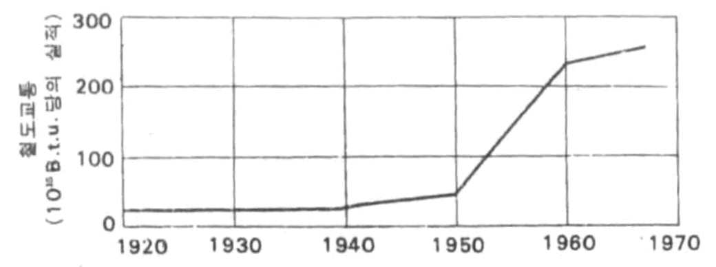
[그림 8-6] 기관차의 효율은 미국 철도에서 단위<운송실적>을 나타내는 데 필요한 에너지의 양으로써 표시할 수 있다. 1950년대의 급격한 향상은 증기기관차가 거의 완전히 디젤기관차로 대치되었음을 반영한다.The efficiency of a locomotive can be expressed as the amount of energy needed to represent a unit's track record on US railroads. Rapid improvements in the 1950s reflect the almost complete replacement of steam locomotives with diesel locomotives.
자동차기술자들은 자동차엔진의 평균효율이 지난 50년간에 대체로 22%로부터 25%로 약 10%가 향상되었다고 추산하고 있다. 그러나 연료 1gal으로 달릴 수 있는 거리는 실제로 작아졌다. 1920년부터 2차세계대전때까지는 보통 승용차는 연료 1gal당 약 21.6km을 주행하였다. 지난 25년 간에 이 평균값은 갈론당 약 20.5km로 점차 단축되었다. 이러한 감소는 자동차가 보다 무거워지고 가속이 훨씬 빠르며 속도가 빠른 강력한 엔진을 가지게 되었다는 데 기인한다. 차량이 공기 속을 시속 96km로 달리는 데에는 시속 48km로 달릴 때보다 약 8배의 에너지를 필요로 한다. 자동차의 무게를 시속 96km로 가속시키는 데 필요했던 에너지와 같은 양의 에너지 가 이 자동차를 정지시킬 때 열로서, 주로 브레이크에서 흡수되어야 한다. 따라서 엔진효율 향상의 대부분은 인간이 이 기계를 사용하는 방법으로 인해 소실된다. 승용차의 에어 컨디슈닝도 갈론당 킬로미터수를 감소시키는 원인이 되었다. 소비자들이 소형차를 더 좋아하는 기호가 변함으로써 이 킬로미터수는 곧 향상될 것이다. 그러나 기본적인 피스톤기관의 효율 더 이상 크게 향상될 수는 없다.Automotive engineers estimate that the average efficiency of a car engine has improved by about 10%, from 22% to 25% over the last 50 years. But the distance that can run with a gal of fuel is actually smaller. From 1920 to World War II, ordinary cars traveled about 21.6 km per gallon of fuel. Over the past 25 years, this average has been gradually reduced to about 20.5 km per gallon. This decrease is due to the fact that cars have a heavier engine that is heavier, much faster and faster. A vehicle running at 96 km / h in the air requires about eight times as much energy as running at 48 km / h. The same amount of energy needed to accelerate the car's weight to 96 km / h, as heat when stopping the car, must be absorbed primarily from the brakes. Therefore, much of the engine efficiency improvement is lost due to the way humans use this machine. Air conditioning in passenger cars also contributed to the reduction in kilometers per gallon. The number of kilometers will soon improve as consumers' preference for smaller cars changes. But the efficiency of a basic piston engine can no longer be significantly improved.
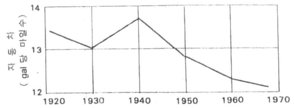
[그림 8-7] 자동차엔진의 효율은 그 중량 및 속력의 증가로 인해 완전하지는 못하지만 연료 1gal당의 마일수에 반영된다. 자동차제작자들은 1920년대의 엔진의 열효율이 약 22%였다고 말하고 있다. 오늘날에는 이것은 약 25%이다.The efficiency of a car engine is not perfect due to the increase in its weight and speed but is reflected in the number of miles per gallon of fuel. Automakers say the engine's thermal efficiency in the 1920s was about 22 percent. Today it is about 25%.
만일 2000년에 모든 차량이 중앙집배발전소에서 생산한 전력으로 충전한 충전기에 의해 가동된다 해도 미국의 전체 연료수요에는 별 변화가 없을 것이다. 발전소에서의 최초의 변환효율은 피스톤기관의 25%에 비교하여 35%가 되겠으나 전력을 송전하고 (충전기 내의)화학적 에너지로 변환시키며 이것을 다시 전력으로 변환시켜 자동차의 바퀴를 돌리게 하는 데에는 손실이 생기기 때문이다. 현재의 충전기는 그 전체적인 효율을 70%에서 75%로 향상시킬 여지가 많지 않다. 모든 승용차가 전력에 의해 가동되는 것이 모든 사람에게 유익하다고 믿는 사람은 모두 1억대의 차량을 가동하는 데 필요한 조처로서 전국 발전능력을 약 75% 증가시켜야 한다는 문제를 생각해 보아야 할 것이다.If all cars were powered by chargers charged with electricity from central cogeneration plants in 2000, there would be little change in the overall fuel demand in the United States. The initial conversion efficiency at a power plant will be 35% compared to 25% of a piston engine, but there is a loss in transmitting power, converting it into chemical energy (in the charger) and converting it back into power to turn the wheels of the car. Because. Current chargers have little room for improving their overall efficiency from 70% to 75%. Anyone who believes that all passenger cars are powered by electricity should benefit from the need to increase the nation's power generation by about 75 percent as a necessary step to run 100 million vehicles.
에너지변환의 효율의 차이에 의해 이루어진 절약을 추적하려 하는 것이 비록 그 차이가 컸다 하더라도 얼마나 어려운 일인가는 철도가 증기기관차(최고열효율 10%)에서 디젤기관차(열효율 약 35%)로 전환된 후에 어떤 일이 일어났는가를 보면 잘 알 수 있다. 1920년에 철도는 약 1억 3,5 등으로 되어 있는 것으로 추산하고 있는데, 이 고명도전등의 효율은 형광등의 효율에 비교할 만하거나 때로는 보다 효율이 높다. 이러한 분포는 전력을 빛으로 변환시키는 평균효율이 약 13%라는 것을 의미한다. 화학적(또는 핵)에너지를 가시광선으로 변환시키는 전체적인 효율을 계산하려면 이 백분율을 발전의 평균효율(33%)로 곱해야 하며, 따라서 순변환효율은 대체로 4%가 된다. 그럼에도 불구하고 형광등과 고명도전등 사용의 증가 덕택으로 전국적으로 1960∼70년에 조명에 사용된 전력소비량은 2배밖에 증가하지 않았으면서 조명의 소비는 3배로 증가될 수 있었다.How difficult it is to track the savings made by the difference in the efficiency of energy conversion, even if the difference is large, what happens after the railway is converted from a steam locomotive (10% of the highest thermal efficiency) to a diesel locomotive (about 35% of the thermal efficiency). We can see well if this happened. It is estimated that in 1920, the railway was about 133,5, etc. The efficiency of these high-conductor lamps is comparable to, or sometimes more efficient than, fluorescent lamps. This distribution means that the average efficiency of converting power to light is about 13%. To calculate the overall efficiency of converting chemical (or nuclear) energy into visible light, this percentage needs to be multiplied by the average efficiency of power generation (33%), so the net conversion efficiency is usually 4%. Nevertheless, thanks to the increase in the use of fluorescent and high-conductivity lamps, the consumption of lighting in the 1960-70 nationwide has only doubled and the consumption of lighting has tripled.

<[그림 8 - 10] 추진기계는 액체연료가 가진 에너지를 일과 교통에 쓰일 기계에너지 또는 운동에너지로 변환시킨다. 피스톤 엔진(5)에서는 압축된 연료와 공기가 전기점화로 폭발된다. 팽창된 기체는 피스톤을 밀고, 이것이 크랭크축으로 전 달된다. 디젤 엔진(6)에서는 압축만으로 연료와 공기의 혼합물을 점화시키기에 충분하다. 비행기가스 터빈(7)에서는 연소실에서 나오는 고온가스가 계속 팽창되어 터빈을 통해 흐르면서 다단계 공기압축기를 회전시킨다. 터빈에서 나오는 고온가스는 추진을 위한 운동에너지를 제공한다. 액체연료 로키트(8)는 연료 외에 산화제도 가지고 있어 공기의 공급에 의존하지 않는다. 로키트배기가스가 운동에너지를 제공한다.><Figure 8-10> The propulsion machine converts the energy of liquid fuel into mechanical energy or kinetic energy for work and transportation. In the

<[그림 8 - 11] 다양한 에너지원을 이용하기 위하여 새로운 에너지변환기들이 설계되고 있다. 연료전지(9)는 수소나 액체연료가 가진 에너지를 직접 전기로 변환시킨다. 이러한 연료의 <연소>는 다공성 전극 내에서 일어난다. 최근 제안된 태양력발전소(10)에서는 햇빛이 특수피복을 한 수광판에 도달되어 액체금속의 온도를 500℃까지 상승시킨다. 이렇게 수집된 열은 열교환기에 의해 수증기에 전달되고, 이 수증기는 종래의 발전소에서와 마찬가지로 터빈발전기를 회전시킨다. 염류 열저장기에 충분한 열을 저장하여 밤이나 구름으로 해가 가리워졌을 때라도 수증기 를 계속 발생시킬 수 있게 한다. NHD<터빈>(11)은 고온의 전기전도가스가 가진 에너지를 직접 전력으로 변환시킨다. 이 고온가스를 전기전도가 좋게 하기 위해서 불꽃 속으로 탄산칼륨과 같은 <씨>물질을 소량 뿜어 넣어야 한다. 이 가스의 대전된 입자들이 외부의 자기력에 의한 자기장을 통과할 때 전기가 발생한다. 장기적인 목표는 열핵원자로(12)로서 여기에서는 가벼운 원소의 원자핵이 무거운 원소로 융합되면서 에너지를 방출한다. 열핵반응으로 생산된 고속대전입자를 포획하여 직접 전력을 생산하도록 할 수 있다.><Figure 8-11> New energy converters are being designed to use various energy sources. The
이상 에너지변환효율의 변화를 간단히 조감함으로써 현재 개발 중인 새로운 에너지변환계의 예상되는 영향을 평가하려할 때 약간의 안목을 가질 수 있을 것이다. 많은 관심을 모아온 두가지 기기는 연료전지와 MHD(magnetohydro_dynamic)발전기이다. 연료전지는 화학적 에너지를 직접 전력으로 변환시키며 후자는 전력생산에 있어 증기터빈 및 발전기와 함께 가동되는 고온<추가>(topping)기기로서 사용될 가능성을 가지고 있다. 수소, 산화수소 또는 알코올을 50%에서 60%의 효율로 <연소>시킬 수 있는 연료전지가 개발되었다. 아폴로우주계획에 사용된 (유나이트드 에어크래프트, United Aircraft사)의 프래트 앤드 휘트니部(Pratt & Whitney division)가 제작한 수소-산소연료전지의 출력은 직류 20.5V, 2.3kW였다.By taking a brief look at the changes in the energy conversion efficiency, we may have some insight in assessing the expected impact of the new energy conversion system currently under development. Two devices that have attracted much attention are fuel cells and magnetohydro_dynamic (MHD) generators. Fuel cells convert chemical energy directly into electric power, and the latter has the potential to be used as high temperature topping equipment that works with steam turbines and generators in power generation. Fuel cells have been developed that can <burn> hydrogen, hydrogen oxide, or alcohol at an efficiency of 50% to 60%. The hydrogen-oxygen fuel cell produced by the Pratt & Whitney division of United Aircraft (United Aircraft, Inc.) used in the Apollo state plan was 20.5V DC, 2.3kW.
10년 전부터 미래의 에너지변환기로서 MHD발전기가 개발되어 왔다. 이 기계에서는 연료를 고온으로 연소시키고 탄산칼륨과 같은 <씨>물질을 뿜어 넣어 그 기상의 연소산물을 전기전도성을 가지게 한다. 이 전기전도성을 가진 가스는 자기장 속을 고속으로 통과하며 이 과정에서 직류의 흐름을 일으킨다(그림 8 - 11 참 조). 이 MHD공학이 개발될 수 있다면 45∼50% 정도의 효율을 가진 화석연료발전소의 설계가 가능해질 것이다. MHD는 매우 고온을 요하기 때문에 화석연료를 사용한 연소실로 얻을 수 있는 작용액체온도보다 훨씬 온도가 낮은 작용액체를 형성하는 원자로에는 적합하지 않다.MHD generators have been developed as energy converters of the future ten years ago. In this machine, the fuel is burned to a high temperature and a <seed> substance, such as potassium carbonate, is blown out to make the gaseous combustion product electrically conductive. This electrically conductive gas passes through the magnetic field at high speeds, causing a flow of direct current (see Figures 8-11). If this MHD engineering could be developed, it would be possible to design a fossil fuel power plant with an efficiency of 45-50%. MHD requires very high temperatures and is not suitable for reactors that form a working liquid much lower than the working liquid temperature attainable in a combustion chamber using fossil fuels.
어떤 에너지원이 바로 알맞은 시기에 개발되었다고 한다면 그것은 원자력이다. 현재 미국에는 22개의 원자력발전소가 가동되고 있다. 이 외에도 55개의 원자력발전소가 건설 중이며 40개 이상이 발주되어 있다. 올해 미국은 총 전력의 1.4%를 핵분열에 의해 생산할 것이며, 1980년에는 이 비율이 25%에 도달할 것이며, 2000년이 되면 50%가 될 것이다.If an energy source was developed at the right time, it is nuclear power. There are currently 22 nuclear power plants in operation in the United States. In addition, 55 nuclear power plants are under construction and more than 40 are ordered. This year, the United States will produce 1.4 percent of its total electricity by nuclear fission, and this figure will reach 25 percent in 1980 and 50 percent by 2000.

[그림 8 - 12] 배증곡선(왼쪽)은 시간이 지남에 따라 지수적으로 굽어진다. 이 곡선은 증가량이 일정한 크기만큼 되려면 몇번의 배증간격이 필요한가를 나타낸다. 즉 전력수요가 매 10년마다 계속 배증된다면 3번의 배증기간 후, 즉 2001년에는 전력수요가 8배로 증가될 것임을 알 수 있다. 지수적 증가곡선을 반대수 눈금에 표시하면 직선이 된다(오른쪽). 만일 A의 시기에 전력소비량을 반으로 절감시킨 후 10년 동안 그대로 유지시키다가 먼저의 증가율로 되돌아가게 한다면 일정한 크기의 수요(B)에 도달되는 데 소요되는 시간은 두번의 배증기간, 즉 20년밖에는 연장되지 않을 것이다.The doubled curve (left) bends exponentially over time. This curve shows how many times the doubling interval is needed for the increase to be a constant amount. In other words, if the demand for electricity continues to be multiplied every ten years, the demand for electricity will increase eight times after three times of multiplication. The exponential growth curve is plotted on the opposite scale and becomes a straight line (right). If at the time of A, power consumption is cut in half and kept for 10 years, then back to the rate of growth, the time required to reach a certain size of demand (B) is twice as doubled, that is, 20 years. It will not be extended outside.
출력 1,000MW의 원자력발전소는 화석연료발전소보다 10% 정도 비싸게 소요(2억5,000만달러에 비해서 2억8,000만달러)되지만 광구에서는 이미 핵연료가 화석연료보다 싸다. 몇가지 예상에 의하면 지금부터 1980년 사이에 석탄의 값은 배로 등귀할 것으로 보인다. 그 이유의 하나는 새로운 연방안전규정(federal safety regulations)으로 인하여 1인당 하루에 생산하는 석탄의 톤수는 이미 1969년에 도달되었던 20t에서 15t 이하로 감소되었다는 것이다.A 1,000-MW nuclear power plant costs 10% more than a fossil fuel power plant ($ 280 million compared to $ 250 million), but in the ore, nuclear fuel is already cheaper than fossil fuel. Some estimates show that between now and 1980, coal prices will double. One reason is that new federal safety regulations have reduced the tonnage of coal produced per person per day to less than 15 tons from 20 tons already reached in 1969.
전기산업은 그 기본부하량, 중간부하량(이것은 사람들이 오전 7시부터 자정까지 가정과 직장에서 하는 활동을 모두 더한 부하량과 대체로 일치한다) 및 최대부하량(전체 수요의 수 %에 불과한, 계절에 민감한 부하량)을 충당하는 방법을 다시 생각해야 할 새로운 시대로 접어들고 있다. 과거에 전기산업은 가장 새롭고 효율적인 시설을 기본부하량을 충당하는 데 사용하고, 오래되고 작은 시설은 매일매일의 가변적인 수요를 충당하는 데 사용하였다. 그러나 보다 새로운 시설이 출현할 미래에는 현재 기본부하량을 충당하고 있는 시설은 너무 커서 쉽게 가동시켰다 중단했다 하기가 어렵기 때문에 이들을 간헐적인 용도에 충당하도록 쉽게 격하시킬 수는 없다.The electricity industry has its base load, medium load (which is roughly equivalent to the load of people's activities at home and work from 7 am to midnight) and maximum load (seasonally sensitive load, which is only a few percent of total demand). We are entering a new era in which we need to rethink how to pay for it. In the past, the electricity industry used the newest and most efficient facilities to cover basic loads, while older and smaller facilities used to meet the variable demands of each day. However, in the future when new facilities will emerge, the facilities currently covering basic loads are so large that they cannot be easily started and shut down, so they cannot be easily downgraded to cover intermittent applications.
따라서 공업용 가스터빈을 가스터빈에서 방출되는 폐열을 사용하여 증기터빈-발전소의 조합에 필요한 저압수증기를 생산하는 발전기에 연결시킨 새로운 종류의 융통성을 가진 발전시설을 건설할 필요가 있다. (제너럴 일렉트릭사와 웨스팅하우스전기회사, Westinghouse Electric Company)에서는 현재 이러한 종류의 조합적인 계를 권장하고 있다. 가스터빈시설은 효율이 가장 높은 종래의 커다란 시설보다 약간 효율이 낮기는 하지만 한시간 이내에 최대부하량까지 도달할 수 있으며, 킬로와트당 보다 저렴한 가격으로 건설할 수 있다. 단기간의 최대수요를 충당하기 위해 전기산업은 점차 가스터빈(폐열보일러가 없을 경우 가스터빈은 수분 내에 완전가동시킬 수 있다)과 양수수력발전체계로 전환하고 있다. 후자에서는 최대수요가 아닐 때에 생산되는 전력은 높은 곳에 있는 저수지로 물을 끌어올렸다가 필요할 때 방출하여 전력을 생산할 수 있다.Therefore, there is a need to build a new type of flexible power plant that connects industrial gas turbines to generators that produce low pressure steam for the combination of steam turbines and power plants using waste heat emitted from the gas turbines. General Electric, Westinghouse Electric Company, and Co., Ltd. currently recommend this type of combination system. Although gas turbines are slightly less efficient than conventional ones with the highest efficiency, gas turbines can reach maximum loads in less than an hour and can be constructed at lower cost per kilowatt. To meet the short-term peak demand, the electric industry is gradually shifting to gas turbines (without waste heat boilers, gas turbines can be fully operational in minutes) and positive hydroelectric systems. In the latter, the power produced when it is not at maximum demand can be produced by drawing water up to a high reservoir and then releasing it as needed.
(웨스팅하우스사)는 최근에 1970∼90년에 미국의 전력산업은 1,000GW(109W), 즉 약 300GW인 현재의 시설출력보다 3배가 넘는 시설을 새로이 건설해야 할 것으로 추산한 바 있다. 이 새로운 시설출력 중 500GW, 즉 반은 기본부하량의 예상증가량을 충당하는 데 사용될 것이며, 이 500GW의 75%는 원자력에 의한 것일 것이다. 또 400GW 이상은 점점 증가되고 있는 중간부하량을 충당하는 데 사용될 것이며, 그중 상당한 부분은 가스터빈에 의해 공급될 것이다. 170GW 정도에 달할 새로운 최대수요는 10 : 7의 비율로 가스터빈과 양수저수체계에 의해서 공급될 것으로 (웨스팅하우스사)는 믿고 있다.Westinghouse recently estimated that in the 1970s and 1990s, the US electricity industry would have to rebuild more than three times the current plant output of 1,000 GW (10 9 W), or about 300 GW. Of these new plant outputs, 500 GW, or half, will be used to cover the expected increase in base load, and 75% of this 500 GW will be from nuclear power. In addition, more than 400 GW will be used to cover increasing medium loads, a significant portion of which will be supplied by gas turbines. Westinghouse believes that the new maximum demand of around 170 GW will be supplied by gas turbines and pumping water systems at a ratio of 10: 7.
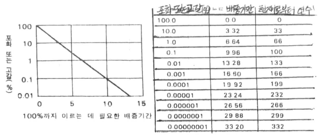
[그림 8 - 13] 한 자원의 고갈을 왼쪽에 있는 곡선에서 읽을 수 있다. 즉 만일 현재 전 세계 석유자원의 0.1%가 사용되었다 해도 배증기간이 10년이라고 한다면 모든 석유자원은 10번의 배증기간, 즉 100년 미만 이내에 고갈될 것이다. 오른쪽 표에 의하면 현재까지 사용된 자원의 추정량에 큰 차이가 있다 해도 궁극적인 고갈시기는 별로 달라지지 않음을 알 수 있다.The exhaustion of a resource can be read from the curve on the left. That is, even if 0.1% of the world's oil resources are currently used, if the doubling period is 10 years, all petroleum resources will be exhausted within 10 doubling periods, less than 100 years. The table on the right shows that even though there is a large difference in the estimated amount of resources used to date, the eventual depletion period does not change much.
이러한 예상은 전례적인 지혜라고 생각할 수 있다. 그렇다면 혁신적인 지혜는 1990년이나, 아니면 2000년의 전력발전에 어떤 영향을 미칠 새로운 무엇을 제시할 수 있겠는가? 무엇보다도 첫째로, 1980년대에는 원형적인 핵융합발전소가 건설되고, 1990년대에는 완전한 규모의 것이 건설될 것으로 믿는 낙관론자들이 있다. 그러나 어떤 의미에서는 이것은 단지 전래적인 지혜를 가속화된 시간단위로 본 것 뿐이다. 정말로 혁신적인 시도를 하려는 사람들은 왜 우리는 태양이나 바람 또는 조석으로부터 에너지를 얻을 수 있는 기술을 개발하기 시작하지 않는가 하고 묻는다.This expectation can be thought of as liturgical wisdom. How can innovative wisdom suggest something that will affect power generation in 1990 or 2000? First of all, there are optimists who believe that a prototype fusion plant will be built in the 1980s and a full-scale one in the 1990s. In a sense, however, it is merely a view of conventional wisdom in accelerated time units. Really innovative people ask why we don't start developing technologies to get energy from the sun, wind or tides.
많은 사람들이 아직도 1930대의 (패써머콰디, Passamaquoddy)계획을 기억하고 있을 것인 바, 이것이 또다시 논의되고 있으며, 이 새로운 계획은 메인(Maine)주와 캐너더 사이의 펀디만(Bay of Fundy)의 평균 5.4m인 조석을 이용하여 300MW(터빈발전기 출력의 1/3 이하)를 공급하려는 것이다. 현재 가동 중인 240MW출력의 조력발전소가 최근 랑스강 하구에 프랑스정부에 의해 시동되었는데 이곳의 조석의 차는 평균 8m이다. 미국의 적합한 만과 하구를 모두 개발한다면 얼마나 많은 조석에너지를 얻을 수 있을 것인가? 모든 추산에는 충분한 근거가 부수되어야 하겠 으나, 비교적 무난한 추산에 의하면 100GW 정도 생각된다. 그러나 전기산업은 1990년의 수요를 충당하는 데에만도 이 출력의 10배를 증가시켜야만 한다는 것을 방금 살펴본 바 있다. 조석에너지는 주요한 혁신적 에너지원이 될 자격이 없다고 결론지을 수밖에 없다.Many people still remember the 1930 (Pasamaquoddy) plan, which is being discussed again, and this new plan is the Bay of Fundy between Maine and Canarder. Will supply 300 MW (less than 1/3 of the turbine generator's output) using a tidal average of 5.4 meters. A 240 MW tidal power plant, which is currently in operation, was recently started by the French government at the mouth of the Reims Estuary. How much tidal energy will you get if you develop both the proper bays and estuaries in the United States? All estimates should be accompanied by sufficient evidence, but relatively reasonable estimates of 100 GW. But we have just seen that the electricity industry has to increase its

[그림 8 - 14] 미국 육지의 제곱피트가 태양으로부터 받아들이는 에너지는 전력수요가 매 10년마다 계속 배증된다고 할 때 대체로 100년 후의 전력생산량과 같은 양일 것이다.The energy that the square feet of the American land receives from the sun will be roughly the same as 100 years later if the demand for electricity continues to double every 10 years.
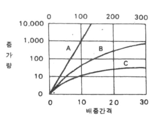
[그림 8 - 15] 세가지 증가곡선을 비교하였다. 곡선 A는 지수적 증가곡선이다. 곡선 B는 배증기간이 계속 20%씩 연장된 것이다. 곡선 C에서는 이 배증기간 동안의 증가량이 항상 일정하다.[Fig. 8-15] The three increasing curves were compared. Curve A is an exponential growth curve. Curve B is a 20% extension of the doubling period. In curve C, the increase during this doubling period is always constant.
바람은 어떠한가? 저자들이 수년전 (오클러호머 주립대)에서 행한 연구에 의하면 오클러호머시 지역에서의 풍력은 바람에 직각인 방향일 때 지면 1제곱피트당 약 18.5W이다. 이것은 오클러호머의 지면 1제곱피트에 비치는 태양에너지를 모든 계절, 모든 기후 상태하에서 하루 24시간으로 평균 한 양과 대체로 비슷하다. 프로펠러에 의해 회전되는 터빈은 60∼80%의 효율로서 풍력을 전력으로 변화시킬 수 있다. 조석에너지나 다른 형태의 수력과 마찬가지로 풍력은 생활권에 폐열을 방출하지 않는다는 커다란 이점을 가지고 있다.What is the wind like? A few years ago at the Oklahoma State University, the authors found that wind power in the Oklahoma City area is about 18.5W per square foot in the direction perpendicular to the wind. This is roughly equivalent to the average amount of solar energy occupied by one square foot of Oklahoma, 24 hours a day in all seasons and in all weather conditions. Turbines rotated by propellers can convert wind power to power with an efficiency of 60-80%. Like tidal energy and other forms of hydro, wind has the great advantage of not discharging waste heat into the living area.
풍력을 이용함에 있어서의 어려움은 에너지저장의 문제로 귀착된다. 모든 자연적인 에너지원 중 바람은 가장 가변적이다. 어느정도 일정한 출력의 발전소를 원한다면 바람이 불 때 그 에너지를 획득하여 저장하지 않으면 안된다. 그러나 불행히도 실제적인 에너지저장매체를 생산할 수 있는 기술은 개발되어 있지 않다. 충전기는 문제도 되지 않는다.Difficulties in using wind power result in energy storage problems. Of all natural energy sources, wind is the most variable. If you want a plant with a certain output, you have to get and store that energy when the wind blows. Unfortunately, no technology has been developed to produce practical energy storage media. The charger isn't a problem either.
유망한 것으로 보이는 계획의 하나는 풍력발전기가 생산하는 가변적인 전기출력을 사용하여 물을 수소와 산소로 분해시키는 것이다. 이 기체들을 고압 하에 저장하고 연료전지 내에서 다시 일정한 속도로 결합시켜 전력을 생산하도록 한다(그림 8 - 16 참조). 이 대신 이 수소를 가스터빈에서 연소시켜 재래적인 발전기를 회전시킬 수도 있다. (노드 어메리컨 락웰, North American Rockwell사)의 (라킷다인부, Rocketdyne Division)는 쌔턴(Saturn) 달우주선을 위해 그 회사가 제작한 수소를 연료로 하는 로키트엔진이 발전기에 연결되어 있는 가스터빈에 동력을 공급하는 데 있어 필요한 고온가스의 분출을 일으키는 데 사용할 수 있다고 진지하게 제안한 바 있다. 라킷다인부에서는 물로 냉각되는 가스터빈이 재래의 연료연소가스터빈보다 높은 온도에서 가동될 수 있으며, 발전소의 전체효율을 55%에 도달시킬 수 있다고 예측하고 있다. 만일 라키다인방식이 성공적인 것이라면 어떤 원천에 의한 수소라도 사용할 수 있다. 바람에 의해 가동되는 수소로 키트 가스터빈 발전소는 가장 이국적인 감각을 가진 사람까지도 기쁘게 하기에 충분할 만큼 혁신적인 것일 것이다.One plan that seems promising is the breakdown of water into hydrogen and oxygen using the variable electrical power produced by wind turbines. The gases are stored under high pressure and combined again at a constant rate in the fuel cell to produce power (see Figures 8-16). Alternatively, the hydrogen can be burned in gas turbines to rotate conventional generators. The Rocketdyne Division of North American Rockwell is a gas powered by a hydrogen fueled Rocket engine produced by the company for the Saturn Moonship. It has been seriously suggested that it can be used to generate the hot gas emissions required to power turbines. Rakitdine says the water-cooled gas turbines can run at higher temperatures than conventional fuel-burning gas turbines and can reach the plant's overall efficiency of 55 percent. If the Rakidine method is successful, hydrogen can be used from any source. With wind-powered hydrogen, the kit gas turbine power plant will be innovative enough to please even the most exotic.

<[그림 8 - 16] 에너지원으로서의 바람은 화석연료나 원자핵연료에서 나오는 에너지의 경우처럼 환경에 여분의 열부담을 주지 않기 때문에 매력적인 것이다. 태양에너지의 포획과 마찬가지로 수력이나 조석에너지외는 달리 바람은 아무 곳에서나 이용 가능하다. 그러나 불행히도 바람은 또한 변화가 너무 많다. 이것을 효과적으로 이용하기 위해서는 바람이 불 때 포획한 에너지를 저장하여 다소 간에 연속적으로 방출시킬 수 있어야 한다. 그 방법의 하나는 바람으로 생산된 전력을 사용 하여 전기분해에 의해 물을 분해시키는 것이다. 그렇게 하면 저장된 수소와 산소를 일정한 속도로 전기분해조에 공급하여 직류를 생산할 수 있다. 이 직류를 교류로 전환시켜 전선에 공급한다. 다른 곳에서 최대수요기 외에 생산된 전력을 바람이 없을 때는 언제든지 전기분해조에 공급하여 전기분해에 사용할 수 있다.><Figure 8-16> Wind as an energy source is attractive because it does not add extra heat to the environment as is the case with energy from fossil fuels or nuclear fuels. Like the capture of solar energy, the wind is available anywhere other than hydro and tidal energy. But unfortunately, the wind is also too changeable. To use this effectively, the energy captured in the wind should be able to be stored and released in some succession. One way is to decompose water by electrolysis using wind-generated power. Doing so can supply the stored hydrogen and oxygen to the electrolysis tank at a constant rate to produce direct current. This direct current is converted into alternating current and supplied to the wire. In addition to the peak demand elsewhere, when the wind is not available, the electricity can be supplied to the electrolysis tank and used for electrolysis.
이에 비해 태양에너지를 이용하는 대부분의 제안은 정말 단조로운 것으로 보인다. 최근 (애리조너대를 대산하여 그 대학 광학쎈터(Optical Science Center)의 애든 메이늘과 마조리 메이늘은 애리조너 동력국, Arizona Power Authority)에 상당히 직접적인 제안을 한 바 있다. 그들은 미국 서부 사막지역의 14%에 도달되는 햇빛을 효율적으로 수집한다면 이를 1,000GW, 즉 현재로부터 1990년 사이에 필요하게 될 에너지수요의 증가량과 대체로 비슷한 에너지로 변환시킬 수 있다고 제안하였던 것이다. 그들은 현재의 기술범위 내에서 태양에너지를 574℃의 열로서 저장하는 괴집계를 설계할 수 있으며, 이것을 전체효율 30%의 전력으로 변환시킬 수 있다고 믿고 있다.In contrast, most proposals using solar energy seem to be very monotonous. Recently, at the University of Arizona, Aden Mayer and Marjorie Mayer of the University's Optical Science Center have made a fairly direct proposal to the Arizona Power Authority. They suggested that efficiently collecting sunlight reaching 14 percent of the western desert in the United States could convert it into energy that is roughly equivalent to 1,000 GW, the increase in energy demand that will be needed between now and 1990. They believe that within the current technical scope, they can design clusters that store solar energy as heat at 574 ° C, and convert it to a power of 30% overall efficiency.
이 계획의 열쇠는 태양광선에 대한 흡수성이 크고, 스펙트럼의 적외선부분의 방출성이 작은 최근에 개발된 표면피복에 있다. 하루 24시간 동안 에너지를 계속 방출하기 위해 낮 동안에 수집된 열을 574℃의 용융염에 저항한다. 열교환기는 이 저장된 에너지를 같은 온도의 수증기에 전달시킨다. 1000MW출력의 발전소에 소요되는 열저장탱크는 용적이 약 300,000gal이 되어야 할 것이다. (메이늘일가)는 전기산업과 정부가 즉시 애리조너주 유머(Yuma) 부근에 100MW출력의 시범발전소를 설계, 건설할 것을 제안하고 있다. 이 정도의 발전소에 필요한 수광판의 넓이는 360 만m2 (1제곱마일보다 약간 넓다)가 될 것이다. 필요한 발전이 이루어진 후에는 약 11억달러, 즉 현재의 원자력발전소 시설비의 약 4배로 1,000MW 출력의 태양력발전소를 건설할 수 있을 것으로 추산하고 있다. 그들이 지적했던 바와 같이 「태양력은 운영경비에 의해서가 아니고 시설자금에 의해 구매한다는 경제적 문제점을 가지고 있다.」 그럼에도 불구하고 가동수명 40년의 태양력발전소는 kW/h당 평균 1/2쎈트의 가격으로 동력을 생산할 수 있을 것으로 그들은 추산하고 있다.The key to this plan is the recently developed surface coating which has high absorption of sunlight and low emission of the infrared part of the spectrum. The heat collected during the day resists the molten salt at 574 ° C. to continue to release energy for 24 hours a day. The heat exchanger transfers this stored energy to steam at the same temperature. The heat storage tank for a 1000 MW power plant would have to be about 300,000 gallons in volume. The Meilai Family is proposing that the electricity industry and the government immediately design and build a 100-MW pilot plant near Yuma, Arizona. The width of this level can gwangpan needed for power plants will be more than 3.6 million m 2 (slightly larger than one square mile). After the necessary power generation, it is estimated that about 1.1 billion dollars, or 4 times the current cost of nuclear power plants, will be able to build a solar power plant with 1,000 MW output. As they pointed out, “Solar power has the economic problem of purchasing not by operating expenses, but by facility funds.” Nevertheless, a 40-year solar power plant costs an average of 1/2 kWh per kW / h. They estimate that they can produce power.

<[그림 8 - 17] 아더 D. 리틀회사의 피터 글레이저는 정류궤도 상의 태양력수집기를 제안하였다. 적도상 29,000km에 위치하는 이 우주정거장은 지상의 수신소 에 대하여 고정되어 있는 셈이다. 8×8km의 수광판은 약 8.5×10⁷kW의 태양복사에너지를 받아들일 것이다. 약 18%의 효율로서 작용하는 태양전지는 이것을 1.5×10⁷kW의 전력으로 전환시키고, 또 이것은 마이크로파로 변환되어 지구로 보내진다. 지구에서는 이것이 107순kW, 즉 뉴욕시에 충분한 양의 전력으로 다시 변환된다. 수신안테나가 차지하는 넓이는 같은 출력의 석탄용 화력발전소에 필요한 넓이의 약 6배, 또는 원자력발전소에 필요한 넓이의 약 20배에 달할 것이다.>Peter Glaser of Arthur D. Little has proposed a solar collector on the orbit. This space station, located at 29,000 kilometers on the equator, is fixed to the earth's receiving station. The 8 × 8 km light receiving plate will receive about 8.5 × 10 7 kW of solar radiation. The solar cell, which acts with an efficiency of about 18%, converts it into 1.5 x 10 7 kW of power, which is then converted into microwaves and sent to Earth. On Earth, this translates into 10 7 net kW, or enough power in New York City. The receiving antenna occupies about six times the area needed for coal-fired power plants of the same output, or about 20 times the area needed for nuclear power plants.>
보다 이국적인 태양력이용계획이 (아더 D. 리틀회사, Arthur D. Little, Inc.)의 (피터 글레이저, Peter E. Glaser)에 의해 진전되었다. 그의 생각은 가벼운 태양전지판을 지구에서 3,500km 떨어진 동기궤도에 올려놓고 하루 24시간 동안 계속 햇빛을 받을 수 있게 한다는 것이다. 태양전지(개발 중에 있는)들은 복사에너지를 수집하여 15∼20%의 효율로 이를 전력으로 변환시킨다. 이 전력은 궤도 상에서 전자기적으로 85%의 효율로 마이크로파(microwave) 에너지로 변환시키는데, 이것은 오늘날에도 가능하다. 이 마이크로파는 손실이 거의 또는 전연 없이 구름을 통과할 수 있는 파장으로 선정될 것이며, 지상에 있는 적당한 안테나에 의해 수집될 것이다. 현재의 기술로는 마이크로파 에너지를 약 70%의 효율로 전력으로 변환시킬 수 있으며, 80∼85%의 효율까지 도달시킬 수 있을 것이다. (글레이저)는 현재 뉴욕시의 에너지수요량인 10,000MW(=10GW) 출력의 위성발전소는 8km2의 수광판을 필요로 할 것으로 추산하고 있다. 지상의 수신안테나는 이보다 약간 커서 9.6km2이 면 족할 것이다. 이 광속의 마이크로파에너지는 햇빛의 강도와 비교될 수 있을 정도이기 때문에 아무런 피해도 미치지 않을 것이다. 글레이저에 따르면 이러한 위성의 건설을 위한 왕복우주여행이 가능하다고 가정할 때, 이러한 계는 킬로와트당 약 500달러, 즉 원자력발전소 가격의 대략 2배가 소요될 것이다. 이 우주정거장 전체는 2,265t, 즉 발사시의 쌔턴 달로키트보다 약간 가벼운 무게일 것이다.A more exotic solar power plan was developed by Peter E. Glaser of Arthur D. Little, Inc. His idea is to place light solar panels on a synchronized orbit 3,500 kilometers from Earth, allowing them to continue to receive sunlight for 24 hours a day. Solar cells (in development) collect radiant energy and convert it to power with an efficiency of 15 to 20 percent. This power is converted electromagnetically into microwave energy at 85% efficiency on track, which is possible today. The microwave will be selected to a wavelength through which clouds can pass through little or no loss and will be collected by a suitable antenna on the ground. With current technology, microwave energy can be converted into power at an efficiency of about 70% and can reach efficiency of 80-85%. (Glaser) satellite plants in energy demand of 10,000MW (= 10GW) of the output current New York City has been estimated to be in need of gwangpan of 8km 2. The receiving antenna on the ground is slightly larger than this and will be 9.6 km 2 . The microwave energy of this beam will be harmless because it is comparable to the intensity of sunlight. According to Glazer, assuming that a round-trip space travel is possible for the construction of such a satellite, the system would cost about $ 500 per kilowatt, or roughly twice the price of a nuclear power plant. The entire station would weigh 2,265 tons, or slightly lighter than the launch of the Saturn Dalokit.
2000년의 미국의 예상 총 전력수요 2,500GW를 충당하려면 이같은 크기의 우주정거장 250개가 필요할 것이다.250 space stations of this size would be needed to meet the estimated total of 2,500 GW of power in 2000.
바람이나 지구표면에서 수집된 태양에너지를 기초로 하는 에너지계획의 큰 이점은 오늘날에 있어서 지나친 억지인 것처럼 들릴지도 모르나, 지구 상의 생태계에 열부담을 더하지 않는다는 것으로 이들은 불변(invariant)에너지계라고 말할 수 있다. 궤도 상에서 수집된 태양에너지는 3,500km 고도에서 차단한 복사에너지의 대부분이 그렇지 않았다면 지구에 도달되지 않았을 복사에너지이기 때문에 엄격한 의미에서 불변에너지계라고 할 수는 없다. 태양수광판이 태양과 지구의 가운데서 일직선 상에 있을 때 수집된 에너지만이 지구의 열부담을 증기시키지 않는다. 다른 한편, 우주공간에 있는 수광판은 화석연료발전소나 원자력발전소보다 환경에 훨씬 적은 폐열을 방출할 것이다. 지구로 향하는 마이크로파속이 가진 총 에너지 중 20%, 또는 그 이하를 제외하고는 모두 유용한 전력으로 변환된다. 물론 이 전력이 소비되면 열로 방출된다.The great advantage of energy plans based on wind or solar energy collected from the earth's surface may sound overwhelming in today's world, but it does not add heat burden to the ecosystems on Earth, which they say are invariant energy systems. Can be. Solar energy collected on orbits is not invariant in the strict sense because most of the radiation cut off at an altitude of 3,500 km is radiation that would otherwise not have reached Earth. Only the energy collected when the solar panel is in the middle of the sun and the earth does not release the earth's heat load. On the other hand, light receiving plates in space will emit much less waste heat to the environment than fossil fuel or nuclear power plants. All but 20% or less of the total energy of the microwave flux to Earth is converted into useful power. Of course, this power is dissipated as heat.
불변에너지계개발의 거시적인 중요성을 인식하려면 어떤 한 양의 지수적인 증가라는 것이 무엇을 의미하는가를 인식하지 않으면 안된다. 배증과정이라는 것은 두려운 현상이다 어떤 한 배증기간 동안의 증가량 - 그것이 에너지 소비량이든, 인구이든 또는 고속도로가 차지하는 육지넓이든 - 은 그것의 지난 과거 전체 동안의 증가량과 같은 양인 것이다. 예를 들어 다음번의 배증기에는 지금까지 지구에서 채굴되어 온 모든 화석연료량 만큼의 화석연료가 채굴될 것이다. 앞으로 10년 동안에 미국은 전기시대의 시작 이래 현재까지 생산된 전력과 같은 양의 전력을 생산할 것이다.To recognize the macro importance of invariant energy system development, one must recognize what an exponential increase in quantity means. The doubling process is a dreadful phenomenon. The increase during any doubling period – whether it is energy consumption, population or land-wide occupied by highways – is equal to the amount of growth over its past past. For example, in the next doubling, fossil fuels will be mined as much as all fossil fuels that have been mined from the earth so far. In the next decade, the United States will produce as much electricity as it has produced since the beginning of the electric age.
이러한 지수적인 증가의 곡선은 그 전체를 적당히 나타내기 위해서 보통 반대수눈금에 표시한다. 반대수눈금의 양 축에 적당한 값을 지정함으로써 어떤 알려져 있는, 또는 가상한 백분율의 위치로부터 포화, 또는 고갈에 달하는 데 필요한 배증기의 수를 나타내는 곡선을 얻을 수 있다(그림 8 - 13 왼쪽 그림 참조), 그 한 예로서, 지금까지 지구에 있는 화석연료 총 매장량의 0.1%를 채굴하였고, 이 채굴량이 매 10년마다 배증되어 왔다고 가정하자. 이러한 속도가 계속된다면 열번의 배증기간, 즉 100년 약간 미만 이내에 이 연료를 모두 채굴하게 될 것이다. 물론 총 화석연료 매장량 중 얼마나 되는 부분이 지금까지 채굴되었는지는 확실히 알지 못한다. 비교적 적게 잡아 지금까지 0.1%가 아니라 0.01%가 채굴되었다고 가정하기로 하자. 이 곡선에 의하면 이러한 경우 13.3번의 배증기간, 즉 133년 이내에 100% 모두 채굴하게 될 것이다. 다시 말해서 지금 이 순간까지 채굴된 연료의 양에 10, 1,000 또는 100,000배의 차이가 있다 해도 완전한 고갈의 시기는 그리 크게 차이가 나지 않는다. 그리하여 지금까지 지구가 가진 화석연료 총 매장량 중 100만분의 1%(0.000001%)밖에 채굴되지 않았다 해도 매 10년마다 채굴량이 배증된다고 할 때 266년이면 총 매장량이 모두 고갈될 것이다(그림 8 - 13 오른쪽 그림 참조). 여기서 실제 채굴량은 화석연료의 종류에 따라 다르며 배증기간 10년이라는 것은 단지 예로서 든 것일 뿐임을 지적해 두어야 할 것이다.This exponential increase curve is usually marked on the opposite scale to adequately represent the whole. By assigning appropriate values to both axes of the counter-scale, a curve representing the number of doublings required to reach saturation or exhaustion from any known or hypothetical percentage position can be obtained (see Figure 8-13, left). As an example, suppose that up to now, 0.1% of the total fossil fuel reserves on earth have been mined, which has been doubled every 10 years. If this rate continues, the fuel will be mined in less than ten times of doubling, a little less than 100 years. Of course, it is not clear how much of the total fossil fuel reserves have been mined so far. Let's assume that we have mined relatively less and 0.01% has been mined, not 0.1%. According to this curve, in this case, 100% will be mined within 13.3 times of doubling, 133 years. In other words, even if there is a 10, 1,000, or 100,000-fold difference in the amount of fuel mined up to this moment, the timing of complete depletion is not very different. Thus, even if only 1% (0.000001%) of the world's total fossil fuel reserves have been mined, the total reserves will be depleted by 266 if mining is doubled every 10 years (Figure 8-13). See the picture on the right). Here, it should be pointed out that the actual mining amount depends on the type of fossil fuel, and that the 10-year doubling period is merely an example.
전력수요가 매 10년마다 계속 배증된다(이것은 실제의 증가속도이다)고 할 때 미국이 몇번의 배증기간을 용납할 수 있을 것인가를 추산함에 있어 관건이 되는 요인은 아마 연료의 공급 - 핵융합이 실용적인 것이 된다면 이것은 거의 무한정하다-이 아니라 연료를 전력으로 그리고 전력을 궁극적으로 열로 변환시키는 데 따르는 환경에 대한 열의 영향일 것이다. 논의에 편하도록 화석연료발전소나 원자력발전소에 의한 폐열의 부담은 무시하고, 실제로 소비되는 전력의 열함량만에 관하여 고찰하기로 하자. 2000년이 되면 대부분의 전력은 해안에서 수마일 떨어진 곳에 위한 거대한 발전소에서 생산되어 피해를 주지 않고(적어도 어느 기간 동안은) 폐열을 주위의 바다로 방출할 수 있을 게임을 상상할 수 있기 때문이다.Given that demand for electricity continues to multiply every ten years (this is the actual rate of growth), the key factor in estimating how many times the US can tolerate is probably fuel-fueling. If it does, it's almost indefinite—not the effect of heat on the environment that comes from converting fuel to power and ultimately power to heat. For the sake of convenience, let us consider the heat content of the actual power consumed, ignoring the burden of waste heat from fossil fuel or nuclear power plants. By the year 2000, most of the power would be produced in huge power plants, miles away from the coast, and you could imagine a game that would dissipate waste heat into the surrounding sea (at least for some time) without damaging it.
1970년 미국은 1조 5,500억kW/h의 전력을 소비하였다. 이것이 열로 변환되어(실제로 그랬다) 미국 육지 전역에 균일하게 분산되었다(실제로 그렇지는 않았다)고 한다면 이 방출된 에너지는 제곱피트당 0.017W에 달한 것이다. 현재의 배증속도로서는 전력소비량이 매 33년마다 10배로 증가된다. 지금부터 99년, 즉 열번의 배증기간 후에는 방출되는 열의 양이 제곱피트당 17W, 즉 미국이 태양으로부터 받는 에너지를 하루 24시간으로 평균한 제곱피트당 18∼19W보다 약간 적은 양이 될 것이다. 이렇게 되기 전에 미리 현재의 에너지소비 양상을 바꾸거나 또는 불변에너지계에 필요한 기술을 개발해야 할 것이다.In 1970, the United States consumed 1.5 trillion kW / h. If it was converted to heat (actually) and distributed evenly (but not really) throughout the land of the United States, this emitted energy amounted to 0.017W per square foot. At the current doubled rate, power consumption increases tenfold every 33 years. 99 years from now, after ten times of doubling, the amount of heat released will be slightly less than 17W per square foot, or 18-19W per square foot, averaging the United States' energy from the
에너지의 증가양상을 상당히 뚜렷한 것 같이 보이는 방식으로 변경시키면 어떤 결과가 생길 것인가를 조사해 보자. 각 배증기간을 계속 20%씩 연장시킨 증가곡선을 생각한다(그림 8 - 14 참조). 지수적 증가곡선에서는 에너지소비량이 10배로 증가되는 데 3.32번의 배증기간, 즉 33년이 소요된다. 이 증가속도가 둔화된 곡선에서는 동일하게 10배로 증가되는 데에 5번의 배증기간, 즉 50년이 소요된다. 다시 말해서 연장되는 것은 17년에 불과하다. 소비량이 100배로 증가되는 데 대한 연장시간은 79년(즉 145년과 66년과의 차이)에 불과하다.Investigate the consequences of changing the increase in energy in a way that seems quite distinct. Consider an increase curve that continues to prolong each doubling period by 20% (see Figures 8-14). In the exponential growth curve, the energy consumption increases tenfold to 3.32 times double, or 33 years. In this slowed-down curve, it takes five doublings, or 50 years, to equally increase tenfold. In other words, it is only 17 years. The extension time for a 100-fold increase in consumption is only 79 years (ie, 145 and 66 years).
또 한가지 방식은 현재의 소비수준을 현저하게 절감시키고 일정한 기간동안 이것이 증가되지 않도록 낮은 수준으로 계속 유지시킨 후 다시 현재의 증가속도로 되돌아오게 하는 것이다. 전력소비량을 즉각 반으로 절감시키고 10년 동안 그 수준을 유지한 후 다시 현재와 같은 증가속도를 되찾게 한다면, 소비량이 100배로 증가되는 데 소요되는 시간은 단지 20년, 즉 66년에서 86년으로 연장되는 데 불과하다는 것을 쉽게 알 수 있을 것이다(그림 8 - 12 오른쪽 그림 참조).Another approach is to significantly reduce the current consumption level, keep it at a low level so that it does not increase for a period of time, and then return to the current rate of increase. If you immediately cut power consumption in half, maintain that level for 10 years, and then regain the current rate of increase, the time it takes to increase
장기적인 효과를 기대하기 위해서는 증가량이 일정한 곡선, 즉 원래의 각 배증기간마다 같은 양만큼씩만 증가하는 곡선과 같을 필요가 있다. 이러한 곡선 상에서는 전력생산량이 태양으로부터 받고 있는 복사에너지와 같은 수준까지 도달하는 데에 10년마다 배증되는 증가속도로서 예측되는 것처럼 100년이 아니라 거의 1,000년이 필요하게 될 것이다. 불변에너지계가 전력수요의 많은 부분을 공급하지 않는 한, 현재와 같은 배증속도가 앞으로 100년 더 계속될 수는 없다는 것이 거의 확실하지만 이 계가 어떻게 보일 것인가는 아직도 미래 속에 감추어진 문제인 것이다.In order to expect a long-term effect, it is necessary to have a constant curve, that is, a curve that increases only by the same amount for each original doubling period. On this curve, it will take nearly 1,000 years instead of 100 years, as predicted as the rate of increase multiplied every 10 years to reach the same level of radiation received from the sun. Unless the constant energy system supplies much of the power demand, it is almost certain that the current doubled rate cannot continue for another 100 years, but what this system will look like is still a problem hidden in the future.
상기한 바와 같이 본 발명은 불변에너지계로 전력수요 충족할 수 있게끔 오대양 육대주를 포함하는 터넬독 몸체를 해양에 설치방법과 수단을 지구촌에 제공함으로써 값싼 에너지 무공해의 친환경에너지 생산수단과 고갈되는 자원을 연장할 수 있도록 최선의 노력을 현재의 기성세대는 후손들을 위하여 동참하도록 되어야 한다As described above, the present invention provides a global village with a method and means for installing a tunnel shell body including five oceanic territories in the ocean so as to satisfy electric power demands with a constant energy system, thereby prolonging resources depleted with eco-friendly energy production means of low energy and pollution. The best efforts should be made for current generations to join in on behalf of their posterity.
이 같은 본 발명은 해양의 해저수심이 10미터 지역에서도 태풍과 너울파도에 따른 침몰되는 뗏목 또는 해상선박 일체와 해저수심이 10킬로미터 정도의 심해저 지역의 위치에서 심한 풍랑파도에도 요지부동의 자세로 해저저층에서는 댐수로식 수차발전기를 접목시켜 해수조력 또는 잠수조절 해저수심 높이 격차 작동에 의한 수차발전기로 또는 화력발전의 중기터빈의 그 이외의 발전소 일체의 발전설비를 서로 접목시켜 형성된 해양발전소 몸체는 바지선 본체 중심부위의 지주탱크와 상기 지주탱크를 지지하는 내부 지지탱크에 상기 내부 지지탱크 외측둘레면을 따라 구비되는 외부 지지탱크로 해상에서 이중관 구조의 탱크 내부의 내수압과 탱크 내부 공기 압력조절방식과 이의 수단으로 사용되는 장비일체와 지주탱크 상단의 바지선 본체 상단 갑판데크에 탑재되는 지구촌 해양환경 방재산업에 속하는 지구촌 무재해 해양환경 재난방지 제어장치와, 해양개발 장비 일체로 탑재 후 구성 작동되는 해양발전소 몸체 내부의 부양식독은 해저 수심깊이에 따라 해수면에서 분리 결합, 조립 해체되는 해양 철구조물로서 안전제조방식으로 구성시키게 되는 데에는 해저수심 10km 지역에서도 심한 풍랑 파도에도 요지부동한 교각용 레벨 기초공사를 다수의 건설기계에 의해 해저바닥에 설치한다.In the present invention, even if the seabed depth is 10 meters, the raft or the marine vessels sinking according to the typhoon and the wind wave, and the seabed depth is about 10 km, the position of the seabed in the position of the deep sea wave in the deep sea wave area At the lower level, the body of a marine power plant formed by combining a waterway generator with a dam waterway or a power generator with a seawater tidal or submerged subsea height gap operation or by combining power generation facilities of other power plants of a medium-term turbine of a thermal power plant. An external support tank provided along the outer circumferential surface of the inner support tank and the inner support tank supporting the support tank on the center and the internal pressure of the tank and the air pressure regulation method in the tank and its means at sea Barge body upper deck at the top of holding tank The global disaster-free marine environment disaster prevention control device, which belongs to the global marine marine disaster prevention industry, and the floating farm inside the body of the marine power plant, which is constructed after being integrated with marine development equipment, are separated and assembled at sea level according to the depth of the sea floor. As the steel structure to be dismantled, it is constructed by the safety manufacturing method. The pier level foundation works, which are rugged even in the 10km subsea depth and the severe wind waves, are installed on the sea floor by many construction machines.
더욱 상세하게는 이를 위한 본 발명은 발전소 몸체(1)의 지주탱크 상단의 바 지선 본체(591)와, 지주탱크 하단의 바지선 본체(529)를 분리 구분 결합하고 해양의 수심에 따라 소형의 해양발전소 부양식독(593)에 중형의 해양발전소 부양식독(594)와 대형의 해양발전소 부양식독(595)이 바지선 본체와 이중관 블럭의 지주탱크(590)와 보조탱크 각기로 수압에 견디어내는 고장력의 철판(597)과 블럭배관(598)으로 구비되는 이중관 구조의 블럭배관(598)인 부양식독 중심부 지주탱크(590)와, 상기 지주탱크(590)를 보조 지지하는 피라밋 형식의 내부 블럭탱크(596)와, 상기 내부 블럭탱크(596) 외벽으로 설치되는 외부 블럭탱크(599)와, 상기 탱크(596) 외벽과 외부 블럭탱크(599) 내부를 용접 결합되도록 티이롱지스틸바아("T"Lon'g steel Bar;600)와, 오링스틸바아("O"Ring steel bar;601)가 사용되며 상기 이중관 구조 블럭배관 용접 결함을 해소하기 위한 스카프웰딩홀(Scafe Welding Hole;602)이 구비된 후에는 부양식독 갑판데크 상단부 철탑(116)과 이중관 구조의 블록배관 결합 분리용으로 사용되는 철탑(116)의 내부 설치부품인 러그용의 샤프트(198)와, 러그용의 샤프트(198)를 고정해지 할 수 있도록 볼트(603) 나사산과, 너트(604)와, 샤프트(198)를 끼울 수 있도록 하는 포터블러그용 플레이트(607)와, 작키베드(616)와, 유압실린더작키(623)와 해상안전치공구장비 밴드지그대(621)로 블럭배관(598) 단위 또는 블럭탱크 단위로 플랜지 연결 방식으로 이루어지는 무재해 관 교량 부침형 터넬독의 제조 설치후 지구촌 무재해 해양환경 재난방지 제어장치와, 인위적 재난(전쟁억제 방지대책 및 영토 영해 분쟁해소 방식을 포함 함) 일체의 제어방식이 포함되는 해양(해상, 해중, 해저)의 개발 일체의 장비가 탑재되는 부양식독에는 풍수력발전기 일체로 에너지와 동력을 1개소의 해양발전에서는 1,000,000Kw/h 발전용량을 92,500여 개소에서 생산한다.More specifically, the present invention for this purpose separates and separates the barge
상기 해양의 해수면 하단부(SLD) 해저저층 바닥에 잠수되는 터넬독 몸체(1) 중심부 위치 상부로 구비되는 지주탱크(590)와; 상기 해저저층 부양식독 선체 보텀 내부의 일정한 거리로 선체가 해저 잠수 또는 해수면 부상을 할 수 있게 조절기능 역할의 벨러스트 버터플라이 밸브(622)와, 닥터벤츄레이션(585)과, 유압실린더 도어(684)와, 이물질 차단용 필터용 마개철판(625)과, 공기 배관라인(181)과, 비상용 엔진(226)의 장비가 선체 보텀 내부에 일체로 구비되는 선박밸런스 조절용의 흡입 토출용 전자제어용 입형다단 펌프(8)와; 상기 선체 보텀 내부에 계류장치의 에어타구어윈치(137) 주위로 고압 입형다단 펌프 제어시스템(150) 장비 일체와, 망간단괴(909)를 채집할 수 있는 뜰채 바스켓(842)과, 해저광물자원 탐색장비용 탐조등(232)과, 르메틱 운송시스템의 흡입재취기계(911)와, 해저광물 채취로봇(912)과, 방제물질 자연황토(158)를 방출토록하는 지중선로 방재노즐과, 유해적조 해저청소 노즐기구용 방제노즐을 가동하는 압축기와 원동기 전동기 일체의 장비에 에너지가 공급된다.A
상기한 에너지는 선체 보텀 외부의 각각의 모서리 부분으로 다수개의 앙카와 앙카 대체용의 계류장치 앙카볼트(133) 상기 앙카볼트(133)를 해저 저층 바닥에 고정시키게 되는 작키베드(616)가 구비되는 계류장치와; 상기 선체 보텀 하단부 일정한 거리 각각으로 유압조절식 안전제어장치 해치카버(153)와, 이중관 구조의 탱크 프레임 밑받침대 조절기구 레벨조정용 작키베드(616)와; 상기 선체 보텀 상단의 선체 갑판 상단부(SDU) 일정한 거리로 선체 정박용 볼라드(638)가 다수개로 구비되는 선체 갑판 상단부 상단의 중심위치 지주탱크의 굴착기(845)와; 상기 지주탱크 내부 상부로 원유시추용의 드릴링머신(908)과, 파이프랙(694)을 보호하기 위한 연결카버용 배관라인과, 해저 저층 굴착시 굴착후 유해가스 발생을 소멸 또는 방지토록 하는 배관라인과, 탱크 내부 안전제어장치의 전자제어식 다수개의 밸브와, 천연가스와 원유시추 장비 일체로 구비되는 중심위치 지주탱크에서 상기 지주 탱크 외부의 외벽으로 수자원확보의 어구용그물(910)과, 탱크 내부와 외부로 형성된 씨씨티비(184)와; 상기 지주탱크 외벽의 주변으로 피라밋 형식의 외부 블럭탱크(599) 각각으로 비상계단(631) 스탭과, 계류장치의 갈고리(630)와, 다양한 형태의 지그(22)와, 노즐호스 장비거치대(33)와, 누수물질 저장용 집수정 탱크(34)와, 고성능 수중펌프(33)로 구비되는 해양발전소 몸체(1)의 내부로 형성된 장비에도 에너지 파워(전력, 685)가 선공급된다The above energy is provided to each corner portion of the outer hull bottom, a plurality of anchors and mooring device anchor bolts for
그리고 이중관 블럭 단위 부양식독의 상단부 하단과 상단부 갑판데크 상단으로 천정기중기(861) 와이어로프와 갈고리 붐대로 상하 작동할 수 있는 관통홀(개방홀)로 해저광물 망간단괴(909)를 적재 이송하는 장비일체로 구비되는 해저 지층 변동에 따른 대비책으로 벤츄레이션용 안전장비 일체의 방재물질 헨스 공기주머니용 포켓(899)과 풍력 또는 수력식의 대형발전기 가동으로 육지에서 필요한 에너지를 공급하는 대형발전기 몸체(213)는 직류(655)발전과 교류(656)발전이 이루게 된다Equipment for loading and transporting submarine mineral manganese nodules (909) into the through hole (opening hole) that can be operated up and down by the overhead crane (861) wire rope and hook boom to the upper and lower deck deck deck top of the double pipe block unit. As a countermeasure against the changes in the seabed strata provided integrally, a large generator body (213) for supplying necessary energy on land through operation of a pocket (899) for the disaster prevention material hens air bag and the operation of a large generator of wind or hydraulic power. ) Is the direct current (655) and alternating current (656)
이처럼 해양발전소 몸체로 형성된 반잠수 작업선에 설치되는 잠망경(913)과, 고압호스(190)와, 고압호스 연결부속 카플링(29)과 해저선로 분사노즐(10)과 해저선로 송전선(775)으로 구비되는 기상관측장비시스템의 애드벌룬(77)과 비행선(78) 의 상기 기상관측장비 그 외의 장비로 해상의 태풍과 풍랑 파도를 이겨낼 수 있도록 재난방지와 함께 지구촌의 자원고갈을 해소토록 하는 해양발전 종합장비를 포함하는 구성에 의해 방재제어방식과, 전쟁억제방지대책 및 영토, 영해 영공분쟁 해소방식을 포함되어 어떠한 재난에서도 인명구조가 최우선 목적인 바, 심해저(수심 약 10km)에서 선체가 침몰되지 않도록 침몰방지와 함께 해양개발 하는데, 또는 차세대 인류에게 평화로운 지구촌의 지상낙원으로서 무해재 지구촌을 유산으로 물려주는데 본 발명 그에 대한 특징으로 관 레벨 시소형이란 점에서 풍수력발전 뿐만 아니고 우주발전(태양력 우주발전)을 상기한 해양광물자원(천연가스 및 원유자원과 망간단괴에 수자원 채집방식을 포함 함)을 국제사회 균등한 발전을 하기 위하여 오대양 육대주에는 전동차(시속 500km, 771)가 터넬독 내부로 물자와 인적수송을 하기 위하여 설치(터넬독)한다 점에서 종래의 기술수준과는 현격한 차이이다.As per the
본 고안의 과제는 안전성, 유동성, 물체 수명을 감안하여 그 표준 크기를 한국원자력 수력발전소의 수력발전기 표준 수준으로 발전소 설치 위치를 거센 풍랑 파도로부터 발전소 안전 가동을 보장받기 위하여 해수면(SLL) 상단100M 위치로 설치하고, 오대양 육대주의 육지와 해양으로 연결된 관 교량 부침형의 무재해 관 교량 부침형터널독, 물체의 길이는 적도전 선의 위도에 남극과 북극을 횡단하는 거리를 합산한 치수로 길이 92,500km로 설계되었고 터넬독 몸체 안전도를 위하여1km간격거리로1개소에는 1,000,000kw/h 발전 용량을 생산하므로 총전체 발전소는92,500여 개소로 구획하므로 지구촌의 각 지역으로 무공해 전력공급을 1차적으로 상기 터 넬독 몸체 내부로 전력 공급라인이 형성 된 후 각국으로 전력공급 재개하면서 터넬독 몸체의 내부에 교통장치의 교각 및 다리와 터넬의 해상철구조물에는 핵폭탄에서부터 재래식 전쟁물자 일체를 유엔안전보장 회원국 합의 일체로 적절하게 폐기 처분하도록 유도하면서 육지에서는 어떠한 명분으로도 핵 물질을 상호 각국은 보유할 수 없게하여 핵 보유국 다수의 국가는 전쟁과 테러를 방지하면서 자연 발생적인 태풍,지진, 해일, 산불, 황사, 홍수 가뭄 조절을 사전 예방하는 장비 등에 에너지를 우선 제공 한 후 우주 과학 발전장비와 심해저 광물자원과 천연가스 에너지 자원 및 석유에너지 굴착 장비 등에 풍수력발전기 생산 전력을 지구촌에 공급하게 된다The subject of the present invention is the 100M position of the sea level (SLL) in order to ensure the safety operation of the power plant from the storm waves that are strong enough to install the power plant at the standard level of the Korean nuclear power plant in consideration of safety, fluidity, and object life. The bridge bridge ups and downs of the five oceanic terrestrial lands connected to the land and the ocean.The length of the object is 92,500km, which is the latitude of the equator and the distance between the Antarctic and the Arctic. It is designed and produces 1,000,000kw / h power generation capacity at 1km distance for safety of tunnel dock body, so total power plant is divided into more than 92,500 sites, so the pollution-free power supply is primarily provided to each region of the global village. After the power supply line was formed inside, the power supply was resumed. The naval and bridge and tunnel maritime structures are required to properly dispose of all conventional war materials from nuclear bombs, in accordance with the United Nations Security Council member agreements, while on land no nuclear material can be retained by any other nation on any ground. Many countries prefer to provide energy to equipment that prevents storm and earthquakes, earthquakes, tsunamis, forest fires, yellow dust, and flood droughts, while preventing war and terrorism. Supplying the production power of wind and hydro power generators to the global village
이 100m라는 것은 거센 풍랑 파도 및 일반 해상 선박과 해양 철구조물 항해 선박 안전 통과 높이로 충돌 방지와 해양 발전소 몸체 개보수 할 때 최소 높이를 감안 한 것이고 발전기의 수명도 터넬독(바지선)의 수명 이외에 갑판 테크 개보수 시기까지 견고하게 지탱되도록 하였으며 철강의 재질인 KSD3515인 용접구조용 압연 강재로 해양발전소 몸체 전체를 이루도록 하였다.This 100m is the height of heavy wind waves and safe passages of general marine vessels and marine steel structures. The minimum height is taken into consideration when preventing collisions and renovating the body of a marine power plant. It was firmly supported until the renovation period, and the entire marine power plant body was made of rolled steel for welding structure, KSD3515, which is made of steel.
본 발명에서 제안하는 풍수력발전기는 상기 풍수력발전기는 해양에 수개의 해양발전소 몸체 내부에 수개의 터어빈과 수개의 수차들이 발전기 몸체의 샤프트 중심거리 좌측에 분리 가능하게 조립되는 수개의 발전기들로 이루어지며, 상기 발전소 몸체에는 풍수력발전기로 형성된 화력발전기와, 수력발전기에 지열발전기와 원자력발전기에 태양열발전기와 조력발전기에 우주발전기 등의 일정 간격으로 설치하고, 상기 일정 간격의 발전소의 발전기는 지주탱크를 상기 지주탱크 상단의 바지 선 본체의 갑판데크 상부로 수개의 발전기를 설치하고 상기 탱크 하단의 바지선 본체와 결합하여 수개의 소형의 해양발전소 부양식독과 중형의 해양발전소 부양식독에 대형의 해양발전소 부양식독으로 분리 가능하게 수개의 해양발전소 몸체로 이루어지고, 상기 수개의 지주탱크들은 상기 탱크 상단의 바지선 중심 내측과 외측의 블럭탱크들로 지주탱크 상단부위의 바지선 본체를 받쳐주게 하고, 상기 외부 블럭탱크 하면의 해저 저층바닥을 수개의 건설기계 등의 코아드릴과 항타 및 항발기로 굴착 후 앙카 대체용 쇄기크랭크를 저층바닥에 고정시킴으로써 해양발전소 몸체 내부에 수개의 풍수력발전기 설치가 간단히 이루어지며, 상기 수개의 발전소는 지주탱크 상단의 바지선 본체 갑판데크 상단에 설치하여 바지선 본체 하단의 해수면 하단 100M 부위로 부침형 터넬이 이중관 구조의 형태로 형성된 블럭배관 내부로 전동차가 시속 500km로 주행하게된 1개의 단위 블럭배관은 길이 1km 단위로 92,500km를 가지도록 형성된 오대양 육대주의 무재해 관 교량 부침형 터넬독을 해양발전소 몸체 내부로 형성하고 상기 관 교량 부침형 터넬 상단인 해수면(SLL) 상단 100M 높이의 해양발전소 몸체에는 수개의 발전기들로 발전용량이 1km 거리로 1000,000kw/h 전력 생산하도록 형성된 수개의 발전기들이 해양발전소 몸체 내부로 구성하고, 상기 수개의 발전기들은 92500여 개소의 발전소에 형성된 초고압 변전소의 변압기들로 생산 전력을 조절한 후 오대양 육대주 횡단철도 변전소 그 이외의 수개의 변전소와 수개의 산업체 및 가정으로 무공해 전력을 송전선이 형성된 송전철탑에 의해 전력을 공급하고 상기 전력으로 자연발생적인 재해 및 인위적 재난방지의 방재 및 방제 제어장치 등에 생산전력을 선공급 후 태양열 우주발전장비와 연결되어 망간단 괴의 철광석 채집기계와 천연가스 에너지자원 및 원유에너지 굴착장비 등의 생산장비 일체에 전력이 공급되며 상기 부양식독 전방과 후방에 형성된 수개의 건설기계로 해저수심이 10km 지점의 관 교량 터넬의 교각을 해저 저층바닥에 고정 후 수개의 센서감지장치가 부착된 이중관 구조 탱크 교각 건설용 부교식 새들형틀로 수개의 콘크리트 교각들로 해양발전소 몸체 내부로 구성하며, 수개의 포터블 러그용 플레이트 가공홀이 형성된 곳으로 간단히 지주탱크 상단의 바지선 본체와 지주탱크 하단의 바지선 본체를 관 교량 터넬의 교각과 분리 해체할 수 있게 수개의 나사탭이 형성된 포터블러그 결합용 핀 샤프트를 러그 가공홀에 끼우고 핀 샤프트 나사탭에는 러그 샤프트 결합 분해 너트가 체결된 후에는 포터블 핀을 고정홀에 끼워져 지주탱크 상단의 바지선 본체와 상기 탱크 하단의 바지선 본체로 결합된 수개의 부양식독 갑판데크 상단부위와, 상기 갑판데크의 하면과 측면의 위치에는 풍수력발전기들이 수개의 시이소 크레인 붐대에 형성된 수격펌프로 양수발전 및 방제와 방재를 이루게 된 수개의 분사노즐 및 호스펌프와 밸브에 애드벌룬과 비행선들로 형성된 방재 및 방제 제어장치 일체는 해양발전소 몸체 내부로 분리 가능하게 조립되는 관 레벨 시소형으로 결합 구성함을 특징으로 하는 무재해 지구촌 해양발전소의 관 레벨 시소형 풍수력 발전기를 기술적 요지로 하는 것이다.Wind power generator proposed in the present invention, the wind power generator is composed of several turbines and several aberrations are separably assembled to the left of the shaft center distance of the generator body in the body of several marine power plants in the ocean In the power plant body, a thermal power generator formed of a wind power generator, a hydroelectric generator, a geothermal power generator, a nuclear power generator, a solar generator, a tidal generator, and a space generator are installed at regular intervals, and the generators of the predetermined intervals are holding tanks. Install several generators on the deck deck of the barge body at the top of the holding tank, and combine with the barge body at the bottom of the tank to support the large marine power plant in several small marine power plant floating docks and the medium sized marine power plant floating farms. It consists of several marine power plant bodies that can be separated by food poisoning, Several holding tanks support the barge main body at the upper end of the holding tank with block tanks inside and outside the barge center of the tank top, and the bottom of the seabed below the outer block tank has several core drills such as construction machines and the like. After excavation with the helm and the actuator, the anchor replacement crank is fixed to the bottom floor, so that several wind and water power generators are easily installed inside the body of the marine power plant, and the several power plants are installed on the top of the barge body deck deck at the top of the holding tank. The one unit block pipe that the electric car travels at 500km per hour into the block pipe formed with the double tunnel structure with the submerged tunnel in the bottom 100M of the sea level at the bottom of the barge main body was formed to have 92,500km in 1km length. A non-hazardous tube bridge upholstery tunnel is formed inside the body of the offshore power plant. The 100m high marine power plant body on the top of the sea level (SLL) at the top of the ups and downs tunnel is composed of several generators that are configured to produce 1000,000kw / h of electricity at a distance of 1km. The several generators are transformers of ultra-high voltage substations formed at 92,500 power plants, and then control the production power, and then transmit the pollution-free electric power lines to several substations and other industries and homes. Power supply to the disaster prevention and control device for natural disasters and artificial disaster prevention, and supply the power to the solar power generation equipment and the iron ore gathering machine of manganese nodules and natural gas energy resources Electric power is supplied to all production equipment such as crude oil energy drilling equipment, The bridge bridge tunnel of 10km subsea depth is fixed to the bottom of the sea floor with several construction machines formed at the rear, and then the double bridge structure tank pier with several sensor detection devices is installed. It is composed of several portable lug plate processing holes, and the barge body at the top of the holding tank and the barge body at the bottom of the holding tank can be separated from the piers of the pipe bridge tunnel by several screws. After inserting the tabbed port plug pin shaft for lug processing hole and pin shaft screw tap lug shaft coupling disassembly nut, the portable pin is inserted in the fixing hole and the barge body on the top of the holding tank and the barge bar on the bottom of the tank. The upper part of the deck deck deck attached to the main body, and the lower and side surfaces of the deck deck There are several spray nozzles, hose pumps and valves that are formed by ad-balloons and airships in which water and wind power generators are formed with water hammer pumps formed on several seesaw crane booms, and prevent and prevent disasters. It is a technical gist of the tube level seesaw type wind power generator of a no-hazard global marine power plant, characterized in that it is composed of a pipe level seesaw type that is detachably assembled inside.
이하, 본 발명의 바람직한 실시예의 상세한 설명을 첨부된 도면들을 참조하여 기술토록 한다. 도면 중 종래의 구성과 동일한 구성에는 동일 부호를 적용하기로 한다.Hereinafter, the detailed description of the preferred embodiment of the present invention will be described with reference to the accompanying drawings. In the drawings, the same reference numerals apply to the same components as the conventional configurations.
본 발명의 주요 구성은 먼저 재질에서는 KSD 3507 일반 배관용 압연강재로는 소방방재용품의 해수면 상단과 지표면 상단에 형성되는 분사노즐장치로 사용하고 KSD 3515 용접 구조용 압연강재로 원통형태를 가지는 지주탱크와 블럭배관에 상기 지주탱크 원둘레면 외측에 설치하는 내부 블럭탱크와 외부 블럭탱크를 지지 보강하는 철판과 바지선 본체를 형성하는 KSD 3560 보일러용 압연강재에 KSD 3704 내열강재(KS 기호; HRS, H-Heat R-Resisting S-steel)로 하는데 해양발전소 크기는 1형(소형의 부양식독 지주탱크 상단부 바지선 본체; 가로×세로×높이×철판뚜께(티이), 600M×800M×40M×18mm)에 2형(중형의 부양식독 지주탱크 상단부 바지선 본체; 가로×세로×높이×철판뚜께(티이=mm), 2m×3.2km×40M×22mm)과 3형(대형의 부양식독 지주탱크 상단부 바지선 본체; 가로×세로×높이×철판뚜께, 10km×12km×40M×24mm) 등의 3개의 형태 규격에 오대양 육대주를 횡단하는 92,500km의 터넬(관 교량)의 표준 규격(가로×세로×4곳 모서리 직경×철판뚜께×제작단위 길이, 15M×15M×π15M×24mm×1km)과 관 교량의 교각 직경 5M로 표준하여 해저수심 깊이에 따라 1km당 레듀사형 접합 부위로 교각 직경을 5M에 1M씩 추가로 직경을 확대로 하여 이중관 구조 탱크 교각 건설용 부교식 새들 형틀로 다수의 개 건설기계로 교각기둥을 해수면 상단으로 300M 높이로 세워지게 한 후 해수면(SLL) 상단과 해수면 하단 100M 이내로 높이 조절하여 해상선박 안전항해와 바지선 본체와 오대양 육대주 관 교량 물체의 하중을 분산시키고 개보수할 수 있게 하여 무재해 지구촌 해양발전소의 발전기 탑재 가동용과 해양환경산업경제 발전용 등에 합당하게 하였다.The main constitution of the present invention is a rolled steel material for the KSD 3507 general pipe in the first material and the holding tank having a cylindrical shape as the rolled steel for KSD 3515 welded structure and used as a spray nozzle device formed on the sea surface top and the top surface of the fire protection equipment KSD 3704 heat-resistant steels (KS symbol; HRS, H-Heat) in rolled steel for KSD 3560 boilers to form steel plates and barge bodies supporting and reinforcing the inner block tanks installed outside the circumferential surface of the holding tank in the block piping and the outer block tanks. R-Resisting S-steel, and the size of offshore power plant is 1 type (small barbed dock holding tank top barge body; width × length × height × steel plate thickness (Ti), 600M × 800M × 40M × 18mm) Barge body of the upper part of the medium-sized docking dock holding tank; bar × width × height × steel plate thickness (Tee = mm), 2m × 3.2km × 40M × 22mm) and type 3 (large barge of the docking dock holding tank upper body; horizontal × length X height X iron Standard specification of 92,500km of tunnels (pipe bridges) crossing the five great ocean poles in three shape standards: thickness, 10km × 12km × 40M × 24mm) (width × length × 4 corner diameter × steel plate thickness × manufacturing unit length) 15M × 15M × π15M × 24mm × 1km) and the pier diameter of 5M of pipe bridges, and the duplex-structured tank pier by expanding the pier diameter by 5M by 1M to the reddish-type joint site per 1km according to the sea depth. The bridge girdle saddle for construction makes the pier columns 300m high above the sea level with a number of dog construction machines, and then adjusts the height to within 100M above the sea level (SLL) and the bottom of the sea level. Distributing and renovating the load of bridge objects makes it suitable for generator-mounted operation of marine power plants around the world and marine environment industrial economy development.
본 발명의 풍수력 발전기는 도 1 내지 도 9에 도시한 바와 같이 무재해 지구촌 해양발전소 몸체(1)인 바지선 몸체의 갑판데크 상단부위와 갑판데크 하단에 분 리 가능하게 조립되는 관 레벨 시소형으로 구성되는데에는 하도와 같이 관 교량 터넬독 몸체(1)의 관 제조공정(705)을 그림과 같다.Wind power generator of the present invention as shown in Figures 1 to 9 is composed of a pipe-level seesaw that is detachably assembled to the deck deck upper portion and the deck deck bottom portion of the barge body, which is a disaster-free global marine power plant body (1) As shown in the figure, the tube manufacturing process (705) of the tube bridge tunnel dog body (1).
관 제조공정(Manufacturing Process, 705)은 소구경 전기 저항 용접관 및 에스알에 대구경 강관(22∼82 inch O.D, 747)과 스파이럴 용접강관(400A∼2600A; A = m/m, 760) 엠(SRM 3/8∼8 inch O.D, 706)과 중구경 케이지 성형 전기 저항 용접관(8∼24 inch O.D, 739) 제조공정으로 일반산업체에서는 분리시켜 제조한다(상세한 설명을 하기 위해 도시 기호를 기재하였다)Manufacturing Process (705) consists of small diameter electric resistance welded pipes and SR large diameter steel pipes (22 to 82 inch OD, 747) and spiral welded steel pipes (400A to 2600A; A = m / m, 760). 3/8 to 8 inch OD, 706) and medium-caliber cage molded electric resistance welded tube (8 to 24 inch OD, 739) are manufactured separately by the general industry (the city symbols are shown for detailed description).
첫째는 소구경 전기저항 용접관 및 SRM(3/8∼8 inch O.D, 705)의 제조공정 과정 흐름이다.The first is the manufacturing process flow of small diameter electric resistance welded tube and SRM (3/8 to 8 inch O.D, 705).

둘째로 중구경 케이지 성형 전기 저항 용접관(8∼24 inch O.D, 739)의 제조공정 과정 흐름이고,Second is the manufacturing process flow of medium diameter cage forming electric resistance welded tube (8 ~ 24 inch O.D, 739),

세째는 대구경 강관(22∼82 inch O.D, 747)의 제조공정 과정 방식이며,Third is the manufacturing process of large diameter steel pipe (22 ~ 82 inch O.D, 747),
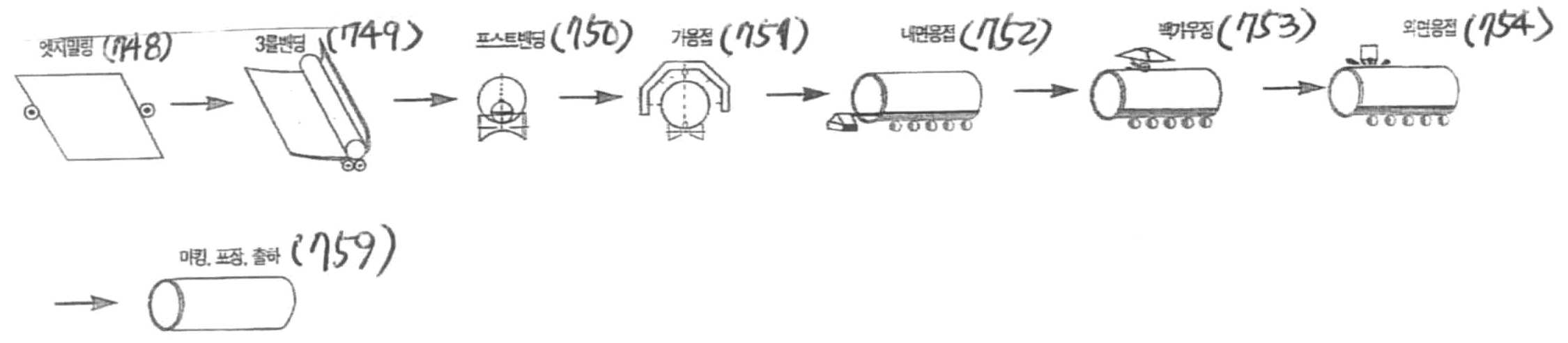
네째로 스파이랄 용접 강관(400A∼2600A, 760)의 제조공정 과정 방식이다.Fourthly, the manufacturing process of spiral welded steel pipes 400A to 2600A and 760 is performed.
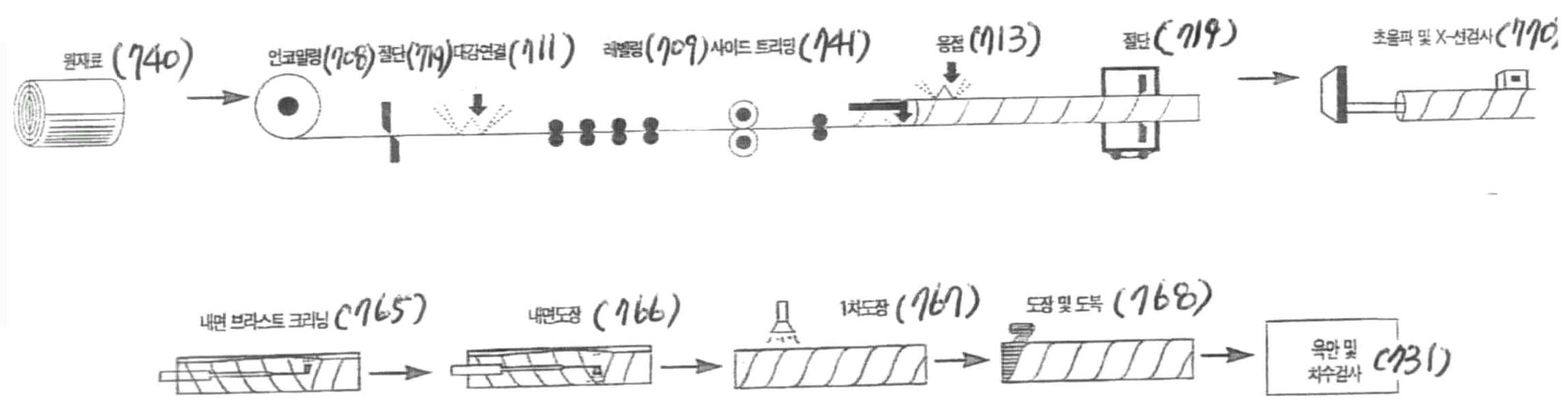
상기 해양발전소 몸체(1)는 재질도 KSD 3515로 뚜께를 24mm로 하고 고장력의 철판(597)을 일정한 치수로 용접(713)이음의 기본방식과 동일하게 용접부에 용입되는 접착금속 단면 목뚜께를 맞대기 이음용접을 하기 위하여 용접이음 홈의 형상(H형과, I형, K형, J형, V형, H형, X형, V형으로 면취, 727)을 상기 형태의 용접(713)개선면취(727)를 구비토록 블럭배관(598)을 내부배관(14) 면적과 외부배관(14) 면적에, 인장강도와 철판뚜께 치수사양을 감안해서 설계되고 수작업에 의해서 설계된 메모리(70)를 콤퓨터 전산망 입력(68)을 통해 전산제어반(수중레이져 절단기계 작동 전산제어부)에서는 선택된 치수사양에 따라 2/100이하 오차까지 허용되는 수중산소절단기와 콤퓨터 레이져 절단기에 의해 절단된 고장력의 철판(597)인 티이롱지스틸바아(600)와, 오링스틸바아(601)와, 포터블러그용 플레이트(602)와, 수평격벽(609)과, 격벽맨홀(610)과, 맨홀뚜껑(152)과, 해치카버(153)와, 블럭탱크 연결용 대형플랜지(614)와, 상기 플랜지 가공홀(615)과 그리고 상기 포터블 러그용 플레이트(607) 장공의 가공홀인 장공홀(LONG HOLE, 616)과 해상안전 조립치공구인 밴드지그대(621)와, 철판용접 결합용 브라켓(165)을 수중레이져 절단으로 용접 개선면이 각개로 제조공장에서 이루어 형성되되, 작업현장 상태를 확인하도록 관제시스템의 무인카메라(184)가 절단기와 절단상태를 전송하되, 콤퓨터 관제서버(51)의 연산을 통해 모니터(52)에 작업현장 상태를 디스플레이하도록 형성된 수중절단 및 콤퓨터레이져 절단장치와, 상기 절단장치로 제작된 용접 개선면인 다양한 용접이음 홈의 형상에 용접으로 홈을 메워주게 된다.The marine power plant body (1) is made of KSD 3515, the thickness of 24mm and the high-tensile iron plate (597) to a certain dimension welding the same as the basic method of welding (713) joints, butting the neck of the adhesive metal cross-section inserted into the weld The shape of the welded joint groove (H type, I type, K type, J type, V type, H type, X type, V type chamfered, 727) is welded 713 improved chamfering for welding. A computer network is provided with a
상기 홈을 용접후 그라인더 마무리한 후 3롤 변경(749) 기계작동 전산제어부로 크레인(861)장비로 이동후 1,000M 길이로 블럭배관(598)을 내부배관(14)과 외부 배관(14)으로 구분 밴딩 용접된 후 블럭탱크 연결용 대형플랜지(614)를 내관(내부배관을 약칭함)과 외관(외부배관을 약칭하고)마디 양쪽으로 각기 플랜지를 규격 표준화로 가용접(취부용접, 751)시키데되, 뒤이어 오링스틸바아(601)로 내관과 외관은 설계된데로 스카프웰딩홀(602)을 질서정연하게 배열 배치시킨 후 가용접(751)후 티이롱지스틸바아(600)와 수평격벽(609)에 격벽맨홀(610)과 맨홀뚜껑(152) 그리고 해치카버(153)에 부양식독 접속 연결부품 포터블 러그용 플레이트(607)와 러그 힌지 소켓(613)을 가접한 후 육안(MT)으로 1차 검사시 취부용접 불량이면 재수정 용접하고 페인트스프레이(PT)로 2차 검사시 취부용접이 불량이면 재수정 용접하되, 3차 가접시에는 취부용접사를 교체하여 본 용접사로 하여금 가접하도록 한 후 본 용접을 할 수 있도록 철저한 작업감독으로 공정을 진행하도록 하고 1000m 단위 블럭배관이 140여 개와 그 외 수미상의 배관지지대로 구비되어 조립한 후 하나 개의 부양식독이 형성되며 러그샤프트용 볼트 및 너트로 와이어로프(19)와 레버블럭(123)과 턴박클로 밧줄용 로프(629)와 블럭단위 탱크 해상조립 위치식별 공기부양식의 부이깃대 고무풍선(628)과 벨레스트 버터플라이 밸브(305)로 상기 플랜지마디로 부착시켜 연결시키게 되는 해상에서의 설치공정에 따른 선결 요건이다.After the groove is welded, the grinder is finished, and three rolls are changed (749). The machine operation control unit moves to the
상기한 블럭배관(598)은 예인선으로 이동한 후 부양식독 결합부분을 작업현장에 이송하고 난 다음에는 반잠수 작업선(637)의 밴드지그대(621)로 조립하는데 바지선 본체(591)의 지주탱크 상단과 하단으로 상단과 하단의 어느 것중 한 부위로 러그샤프트(606)를 지주탱크(590)와 내부 블럭탱크(596) 및 외부 블럭탱크(599)의 포터블 러그용 플레이트(607)에 접속(끼우도록)하되 포터블러그 핀(608)을 러그샤 프트(606)의 가공홀에 볼트너트 체결 후 핀이 이탈되지 않도록 핀(608) 결합한 후 꺾기방식으로 설치되되 지지탱크(590) 하단의 바지선 본체(591) 받침대 조절기구 작키베드(616)와 굴착기(845) 장치가 구비되어 고정시키게 되는 해양발전소 몸체(1)의 침몰방지와 부침장치 및 제조조립 후 지주탱크 바지선 본체 상단과 하단의 갑판데크 상단 하단의 탑재 형성되는 일체의 발전 설비 장치가 형성된다.The
상기 다수개의 무재해 지구촌 해양발전소(관 교량 부침형 터넬독; Tunnel Dock) 몸체(1)는 재해 해양환경 재난방지 제어장치와, 해양개발 장비일체로 탑재설치 가동되는 해양철구조물인 해상플랜트 자켓으로 부양식독의 도크 선체 갑판 상단부(SDU) 아래에 지주탱크(590)로 형성된 부양식독의 지주탱크 상단 바지선 본채(591)와 지주탱크 하단 바지선 본체(592)로 분해결합을 육상에서 부품 조립한 후 해상 이동장비로 그 부품을 이송하여 해상 설치지역의 상황을 고려하여 소형의 해양발전소 부양식독(593)과 중형의 해양발전소 부양식독(594) 그리고 대형의 해양발전소 부양식독(595)이 분리제작 설치되어 지구촌의 적도(EL) 상단의 북극(NP)과 적도하단의 남극(SP) 지역으로 또는 오대양 육대주 위도와 경도로 해양수심 깊이에 따라 국제해상안전협회의 규정에 적합하게 제작하도록 발주처(유엔안전보장이사회원국, 국제경제발전협회 그 외의 협력단체 이하 생략함)의 사양에 따라 선택할 수 있다.The plurality of disaster-free global marine power plants (Tunnel Dock) body (1) is supported by a marine plant structure, which is a marine steel structure that is installed and operated as a disaster marine environment disaster prevention control device and all of marine development equipment. Marine dock after disassembly and assembly of parts on the land by holding the upper barge main barge main body (591) and the lower barge main body (592) of the floating dock formed of the holding tank (590) under the upper deck (SDU) of the dock dock. In consideration of the situation in the offshore installation area, small parts of the offshore docks (593), medium-sized offshore docks (594), and large offshore docks (595) of the large offshore plant are separately manufactured and installed. Conforms to the regulations of the International Maritime Safety Association, depending on the depth of the ocean, to the North Pole (NP) and the South Pole (SP) region at the top of the equator or to the Great Ocean latitudes and longitudes. Client's production to be selected in accordance with the specifications of the (UN Security Director members, the International Association of economic development that must not under other partner organizations).
상기 발전소 몸체(1)의 그 부품은 해양선박 제조공장 또는 중공업분야 금속가공업분야 일체의 산업현장에서 부양식독 본체의 안전한 설계에 따른 제조공정에 따라 해양(해상용, 해저용) 철구조용 금속의 고강도 강판 또는 질긴 금속의 철판 재질로 선택되어 철판 뚜께에 따라 포오밍 또는 롤 포오밍 가공기계에 탱크용 블럭배관(598)으로 상기 철판을 포오밍 머신을 이용하여 (a)직각꺾기와, (b)V형꺾기와, (c)원형꺾기 형태의 꺾음방식으로, 앵글(형강) 굽힘방식의 프레스 브레이크식으로 로울러 굽힘방식과 세개의 굽힘 로울러로 철판의 밴딩 또는 절곡방식으로 탱크용 블럭배관(598)이 제조된 후 이음매 부위로 가용접(테크웰딩, (751))을 하게된다The parts of the power plant body (1) is a high strength of the metal for marine (offshore, seabed) steel structure according to the manufacturing process according to the safe design of the aquaculture dock body at any industrial site of the marine vessel manufacturing plant or heavy industry metal processing industry (A) right angle bending and (b) using the forming machine to form a steel plate or a tough metal sheet, and forming the steel sheet into a
상기 탱크용 블럭배관(598)이 다수개로 용접 접합된 후에는 블럭단위 배관(14) 개체별로 제작설계 고유도면번호를 배관내부 외부로 인식번호를 표기 기재토록 함으로써 다음의 제조공정인 본 용접(713)을 하게 되는데 본 용접이음의 형식 및 홈의 형상에 대하여 상세한 설명을 다음과 같이 설명하되, 선박건조시 선박침몰 방지용으로 다양한 형태의 지그("ㄱ"자, "∩", "T" 형태로 하는 지그, 22)와 쇄기(우마용의 "![]()
![]()

상기한 바와 같이 용접 이음의 기본방식에 있어서, 한개의 블럭배관(598)으로 용접이음(a)는 맞대기 이음 방식이 사용되고 그 외 철판보강에는 (b) 모서리 이음방식과, (c) 변두리 이음방식, (d) 겹치기 이음방식, (e) T 이음방식, (f) 십자 이음방식, 한쪽 덮개판 이음과 필렛이음, 양쪽 덮개판 이음방식으로 본 용접방식이 부양식독 본체에 적용되되 단, 용접 이음에는 용접 이음의 기본방식과 같은 형식이 있다. 용접부에 용입되는 접착 금속의 단면 두께를 목 두께(throat)라 하며, 겹치기 이음, 티이(T) 이음 또는 목의 방향이 모재의 면과 용접각도(45˚)를 이루는 용접을 필렛 용접(fillet weld)이라 칭하고 용접부위 면적을 각장으로 설명하되, 이 같이 용접작업을 실제로 현장에서 사용되고 있다.As described above, in the basic method of welded joint, the welded joint (a) is a butt jointed joint with one
맞대기 이음으로 판 두께가 두꺼울수록 내부까지 용착되기 어려우므로 완전히 용착시키기 위해 접합부 끝을 적정하게 깎아서 제작하되, 아래 그림 각각은 용접이음 홈의 형상으로 H형과, I형, K형, J형, V형, H형, X형, V형으로 분리 구분한 후에 철판개선 형식으로 산소절단 후 그라인더 절삭후 가접(테크웰딩)된다.Butt joints are harder to be welded to the inside as the plate thickness becomes thicker. Therefore, the ends of the joints are appropriately cut to make them completely welded. The figures below are the shape of the weld joint grooves, H, I, K, J, After dividing into V type, H type, X type, and V type, oxygen cutting is performed in the form of iron plate improvement, and then it is temporarily welded after cutting the grinder.
상기 그림은 용접 철판 결합을 위한 철판개선면 측면도로,The figure is a side view of the iron plate improved surface for welding welding plate,
홈의 형상을 도시된 바와 같이 철판개선면은 그라인더 절삭의 용접전 용접면의 녹제거 및 불순물을 제거함이며 한개의 블럭배관(598)을 다른 한 개의 블럭배관(598)을 용접이음매 작업 후 합체된 두개의 블럭배관은 또다른 두개의 배관으로 용접 연결방식으로 작업을 진행하고 내부의 배관 및 외부의 배관용접 이음매 용접 연결선은 지그재그 방식의 거리간격 격차를 일정한 간격으로 구분하여 블럭배관이 결합 연결되며 블럭배관의 양쪽 끝단 부위로 외부배관 외측으로 배관 및 밸브연결 대형플랜지(614) 한쪽 끝단 부위로 두개의 내부와 외측 대형플랜지(614) 각개로 용접 이음으로 고정 장착하고 한마디의 블럭 배관 대형플랜지의 지름길이 3미터의 외부배관의 내부로 블럭배관(598)의 마개 철판(625)이 양쪽 끝단 부위의 용접으로 블럭배관 내부를 밀폐 봉합한다As shown in the shape of the groove, the iron plate improved surface removes rust and impurities from the welded surface before welding of the grinder cutting and merges one
이렇게, 봉합마개 철판(625) 주위에는 격벽맨홀(610) 및 맨홀 뚜껑(152)과 유압식 해치카버(153)가 제작되어 해수면 상단의 현장 작업 및 작업후의 밸브 및 장비교체를 위하여 반드시 설치되어야 하는 것이며 해저 저층 깊이에 따라서 지주탱크(590) 상단의 바지선 본체(591) 상단부 하단의 이중관 구조의 블럭배관(598)인 지주탱크(590)와, 중심부 지주탱크(590)를 지지하는 보조지지대 역할을 피라밋형식의 내부 블럭탱크(596)와, 상기 블럭탱크(596) 외측 원둘레로 외부 블럭탱크(599)가 이중구조의 블럭배관 내부지지탱크와 외부지지탱크 결합용의 보강판 티이롱지스틸바(T LonG' steel BAR; 600)와 티이형식의 보강철판 또는 오링스틸바아("O"Ring steel BAR; 601)로 상기 보강판은 지주탱크와 보조지지 피라밋형식 내부와 외부의 블럭탱크에 용접결합용 재료로 사용하며 이때에 이중구조의 블럭배관 용접결함을 해소하기 위하여 스카프 웰딩 홀(Scarfe welding Hole; 602)을 상기 보강철판에 용접을 확고하게 진행할 수 있도록 설계후 수중산소 절단작업 공정이 진행된다.Thus, the partition manhole 610 and the
한편, 지주탱크 상단의 바지선 본체(591) 갑판데크와 상단부 철탑(116)의 결합방식에 있어서, 상기 결합부위로 블럭용 철탑(116) 결합용 러그핀샤프트(606)에 러그핀샤프트(606) 결합용 볼트(603)와, 너트(604)가 구비되어 부양식독(바지선 본체)과 지주탱크와 내부, 외부지지탱크 내부의 수직격벽(605)과, 중심부 지주탱크 및 내부, 외부지지탱크 블럭 결합분리용의 포터블러그 결합용 핀 샤프트(606)와, 포터블러그용 플레이트(607) 또는 포터블러그 핀(Portable Rug Pin; 608)으로 부양식독 지주탱크 및 피라밋형식의 보조지지 탱크블럭 내부의 수평격벽(609)에는 해상조립을 하기 위하여 비상통행로인 격벽맨홀(610)과, 맨홀뚜껑(152) 그리고 유압조절식 안전제어장치인 해치카버(153)와, 부양식독 본체에 구성되는 러그힌지 소켓(613)이 상기 해치카버(153) 그외의 부착물에 구성되는, 블럭탱크에 연결되는 대형플랜지(614)와 대형플랜지(614)를 결합하기 위하여 해수면(SLL)에서 탱크블럭을 수직, 수평 분해결합용 플레이트 접합부 가공홀(615)로 볼트 너트가 이중체결되도록 고강도의 볼트 및 고강도의 너트를 복수개의 접합부 가공홀(615) 한곳에 우선 고강도의 볼트 및 고강도의 너트를 부분적으로 홀수와 짝수의 포터블러그용 플레이트에 포터블러그 결합용 핀 샤프트(606)를 접속한 후 러그핀샤프트 양쪽 끝단부의 볼트 나사산 몸체에 너트를 끼운후 포터블러그핀(608)을 러그핀 가공홀에 결속하여 탱크블럭 접합 가공홀(615)에서 탱크블럭이 절대로 이탈되지 않도록 하기 위한 해양발전소 몸체의 해상안전 조립방식을 포함하는 요부위의 구성을 특징하되, 1단은 다수의 개 핀 샤프트(606) 결합지점의 한 곳 부위만 핀 샤프를 결합시킨 후 나머지 부위는 일정한 경사각도 양쪽의 가공홀(615)이 만나는 지점에서 핀 샤프트(606) 조정스프링(468)이 상기 샤프트(606)를 밀어내어 러그 가공홀 속으로 결속된다.On the other hand, in the coupling method of the barge body (591) deck deck and the upper portion of the
상기 부양식독의 해상안전 조립방식에 포함되는 보조장비와 그에 대한 보조기기 부분품인 앙카 대체용 기초공사로 건설기계 중 굴착기(845)와 항타 및 항발기(887)로 설치하는데 바람직하게는 다음과 같이 설명한다.Auxiliary equipment included in the marine safety assembling method of the aquaculture dock and the subsidiary parts of the subsidiary equipment for the anchor as a construction machine to install as an excavator (845) and a helm and a launcher 887 preferably as follows: Explain.
이중관 구조의 수직탱크 또는 바지선 본체 밑받침대 조절기구인 작키베드(616)와, 블럭배관 단위별 또는 수직 수평 힌지 접합부위의 장공의 장공홀(616)에 결속 조절되는 샤프트(606)와, 갑판데크 상단부 장비 이송용 가이드레일(618)과, 부양식독 갑판데크 상단부로 헬리콥터 정류장(619)이 구비되고 우선접기 형식의 블럭배관 또는 이중관 탱크 프레임 결합용인 해중작업을 하기 위한 잠수작업선 탑재용의 유압실린더 또는 유압실린더 작키(623)와, 이중관 구조형식의 탱크 프레임 결합분리 또는 블럭연결부위 수중절단 및 수중용접을 하기 위한 잠수작업선 탑재용의 해상안전 작업용인 블럭배관(598) 결합 치공구장비인 밴드지그대(621)로 유압실린더가 잠수작업선에 설치되며 잠수식 바지선 조절 부양식독의 해저잠수 또는 해수면 부상 조절용 제어장치인 밸러스트 버터플라이 밸브(622)와, 상기 부양식독 선체 엔진 그외 동력모터 가동 전후시 준비운동(WARMING UP)과 선체부분 결함 파손시 침몰방지 또는 침몰연장시간(선원구조에 필요한 시간)을 필요로하는 에이치브이에이시이시스템(HVAC System)의 장비인 닥터벤츄레이션(585)과, 부양식독 본체 내부 수압조절 또는 광물자원 흡입구 흡입제어 장치인 스위치버턴-온 시 도어오픈(Door Open)되고 스위치버턴-오프 시 도어클로즈(Door Close)되는 유압실린더 도어(624)와, 밸러스트 또는 펌프흡입구 이물질 유입을 차단 또는 이물질을 걸러주는 마개철판(다수의 가공홀의 타공판, 625)와, 선체 침몰방지용의 공기배관라인(181)과, 선체침몰방지 연장용인 비상용 엔진(226)이 구비되면서 블럭배관 단위로 부양식독 안전해상 조립시기에는 타선박 접근방지를 위하여 이중관 구조 탱크 위치 식별용의 공기부양식 부이깃대 고무풍선(628)이 예인선 또는 부양식독에는 결합해지 밧줄용 로프(629)와, 로프연결 매듭 갈고리(630)가 구비되고 블럭철탑(116) 내부로 비상계단 또는 스텝(631)과, 승강기 또는 앨리베이트(636)에 바지선 본체(591)의 내부 외부로 광물 또는 기계장비 운송장치용 콘베이어(633)와, 바지선 본체(592)의 밸런스 조절을 하기 위한 토출흡입진공펌프(635)와 침몰선박의 선체 인양을 하기 위한 공기 흡입 토출 방식의 공기부양선(634) 일체로 상기 부분품은 해양선박 제조공장 또는 중공업분야 산업현장에서 제조된 후 해수면(SLL) 현장이동후 안전조립 방식이 예인선(666)에 의해 형성된다.Jakki bed 616, which is a double-pipe vertical tank or barge body underlay adjustment mechanism, the shaft 606 is fastened to the long hole 616 of the long hole of each block piping unit or vertical horizontal hinge joint, and the upper deck deck A guide rail 618 for transporting the equipment and a helicopter stop 619 at the top of the floating deck deck deck are equipped with a submersible hydraulic cylinder for submerged ships for submerged work for the combination of a block pipe or a double pipe tank of a priority folding type or Band jig unit for hydraulic cylinder operation key 623 and block pipe 598 combination tool for marine safety work for submersible cutting and submerged welding of double frame structure tank frame joint separation or block connection part (621) hydraulic cylinder is installed on the submersible work vessel, the ball is a submersible barge control submarine dock or submersible submerged control device H which requires prevention of sinking or extension of sinking time (time required for source structure) in case of stray butterfly valve 622, the floating culture hull engine and other power motors before and after the operation (WARMING UP) Dr. Ventilation (585), a device of HVAC System, and a switch button-on, which is a water pressure control inside the aquaculture dock body or a mineral intake suction control device, is door-opened and is switched-off. A hydraulic cylinder door 624 that is door closed, a stopper plate that blocks or filters foreign substances from ballast or pump inlet openings (perforated plates of many processing holes, 625), and air piping lines for preventing ship sinking. And an
이에 따라, 선박 또는 이중관 구조 탱크블럭 침몰방지용의 공기부양선(634)과, 해양작업을 하기 위한 블럭탱크 결합용 밴드지그대가 탑재되는 반잠수 작업선(637)과, 선박계류장치용인 밧줄 고정해지식 또는 선체 정박용인 다수의 볼라드(638)가 지주탱크 상단 바지선 본체와 지주탱크 하단 바지선 본체 갑판데크 상부로 다수개의 볼라드(638)가 해상안전 조립전에 산업현장에서 제조하여 운반후 설치한다.Accordingly, a
상기한 바와 같이 부양식독 그에 대한 부분품 일체는 산업현장에서 제조후 일반 선박으로 조달됨을 감지하여 부양식독의 설비배치에 안전을 가하여 무재해 목표달성에 당업자는 최선을 다하여야 되며 상기 계류장치앙카(639)와, 앙카(639) 연결고리용체인(앙카체인; 640)으로 부양식독을 해저저층 바닥에 투기하여 바지선 본체를 정박토록 하기도 하며 해저수심이 대륙붕수심보다 더 깊은 상태에서는 원유시추용의 드릴링 머신으로 해저저층 바닥을 굴착한 후 앙카볼팅으로 부양식독 선체를 잠수정착을 하게 되는 방식이다. 상기 부양식독은 지주탱크(590) 상단과 하단의 바 지선 본체 결합된 1세트의 무동력선을 칭하는 것이다.As described above, all parts for the aquaculture dock are detected in the industrial field and then procured as a general ship, and the skilled person should make the best efforts to achieve the accident-free target by adding safety to the arrangement of the aquaculture dock. The mooring device anchor (639) Wo, Anchor (639) linkage chain (anca chain; 640) dumps aquaculture docks to the bottom of the sea floor to anchor the barge body. When the sea depth is deeper than the continental shelf, it is used as a drilling machine for oil drilling. After digging the bottom of the seabed, the anchored dock hulls the submerged settlement. The aquaculture dock refers to a set of non-powered lines coupled to the main body of the top line and the bottom line of the
이 같이, 부양식독 선체가 잠수조절되기 위해서는 에어저장탱크용의 에어리시이버탱크(145)와, 에이치브이에이시이시스템의 공기 액화장치 쿨링기구인 쿨링팬(645)과, 애드벌룬(77)과 비행선(78) 및 고무풍선(914) 또는 튜우브(188)를 공중으로 부상할 수 있게 하는 히터팬(HIT FAN; 642)과, 전쟁 및 해상해적, 국제외교분쟁을 유발사민하는 교전국 당사자 당업자 일체를 무재해 지구촌 대기권 외부로 추방퇴출토록하는 인공위성발사대(643)와, 상기 인공위성 및 비행선 또는 핵폭탄과 미사일을 관제하고 통제 억제하기 위한 무어링 타워(MOORING TOWER; 644)와, 상기 인공위성과 대등한 수준의 우주로켓발사대(646) 그리고 공기압축기인 에어콤프레샤(80)에 상기 에어콤프레샤(80)에서 공급받은 에어로 작동하는 에어타구어윈치(134)와, 부양식독 선체 갑판상단부(SDU)로 설치되는 크레인(861)과, 상기 크레인(861)에 포함되는 와이어로프(19)와, 와이어로프체인(915)과, 상기 에어콤프레샤 후미에서 에어리시버탱크 전후방으로 에어타구어윈치 전방에 연결되는 에어호스(109)로 구비되고 부양식독 선체 갑판 하단부(SDL)에는 전기자석 마그넷(645)과, 황토 또는 시멘트를 배관 또는 고압호스로 운송하도록 하는 르메틱(916)과, 상기 르메틱(916)의 전방에 위치하는 혼합장비 기계 믹서(73)가 구비되며 이중관 구조의 블럭배관(598) 단위로 결합할 수 있도록 레버블럭(123)이 톤수 용량별로 구비되어 블럭배관(598) 단위로 결합한 후에는 턴박클(640)로 재차 결합물체를 고박토록 하고 지주탱크 또는 보조탱크 결합부위로 볼트 낫트로 결합되도록 브라켓(165) 철판에 암수결합용 가공홀이 구비된 후 블럭배관에 용접된 후에 플랜지와 플랜지에 고 압력에 견딜수 있도록 상기 대형플랜지(614) 접합부 틈새로 가스켓트 패킹 또는 고무패킹(32)이 대형의 플랜지(614) 중간에 끼운뒤에 대형플랜지 가공홀(615)에 고강도의 볼트와 너트로 블럭배관(598) 내부와 외부로 이중관 구조인 탱크블럭 배관 플랜지와 플랜지를 접합하게 되는 것이다.As described above, in order to submerge the aquaculture dock hull, an
한편, 블럭배관(598)에는 상기 접합부위는 마개철판(625)으로 플랜지 연결부위로 반잠수 작업선(637)에 탑재가동되는 에어콤프레샤(80)에서 생성되는 압력공기를 에어호스(109)를 블럭배관 내부로 압력공기를 저장하여 블럭배관의 용접부위 결함을 탐지하고 이상유무 확인조치한 후 이상없을시에는 적정한 양의 공기를 블럭배관에 저장한 후 블럭배관이 해수면(SLL) 상단의 물위에 떠다니는 뗏목과 대등하게 표류정착시킨 후 예인선에 로프와 와이어로프(19)와, 와이어로프체인(915)을 고박결속한 후 해수면 상단의 해상안전 조립현장으로 블럭배관(598)을 이송하는 것이다On the other hand, in the
상기 해상안전 조립현장에 도착된 이중관 구조형식의 블럭배관 단위별로 연결방식을 [도 5]에 도시한 바와 같이 블럭배관 단위길이 넓이 치수는 이하 생략하며,As shown in FIG. 5, the connection method for each block piping unit of the double pipe structure type arrived at the marine safety assembly site, the dimensions of the block piping unit length are omitted below.
설명편의상 영문으로 (AB), (BC), (AC),으로 구분하고 (AB) 거리내의 구분으로는 (AR), (AQ), (AP), (AO), (AN), (AM), 거리 각각으로 설명하며,(AB), (BC), (AC), and (AB) in English for the convenience of explanation, and (AR), (AQ), (AP), (AO), (AN), and (AM) within the distance. , Each with a distance,
상기 본 발명의 대형의 해양발전소 부양식독(595)의 제작 및 설치방법에 있어서, [도 5-1]의 전개도는 [도 5-3]으로서 다음과 같이 설명한다.In the method for manufacturing and installing the large-scale offshore
상기의 블럭배관은 (AB), (BC), (AC),으로 삼각형의 맞대칭형식인 (ABC), (AB'C')는 정삼각의 (AB)(BC)(AC)의 일정한 각도인 세 변의 각도(60˚)와 일정한 경사각도(16)로 한 변과 한 변이 맞닿는 지점 세 곳으로 정확하게 제조된다The above block piping is (AB), (BC), (AC), and the triangle symmetrical form (ABC), (AB'C ') is a constant angle of (AB) (BC) (AC) of equilateral triangle. The angle of the three sides (60 °) and the constant angle of inclination (16) are precisely manufactured in three places where one side and one side meet.
상기 블럭배관의 (ABC), (AB'C')의 (AB)(BC)(AC)의 삼각형의 세변의 길이는 동일하고 접합부위의 높이가 약 10,000미터가 될때에는 (BC)의 변길이는 약 12,621미터로 형성되며 높이(AL)지점의 부양식독 중심의 수직기둥인 이중관 구조의 배관 중심부위의 기둥으로 높이(AL)지점 중심으로 (ABC),(AB'C') 맞대칭의 (A)지점의 꼭지점으로 접합되며 블럭배관 접합 수단으로 반잠수 작업선(637)과, 예인선(636)으로 근거리무선통신 장치의 휴대전화기로 업무연락하면서 작업공정이 진행한다.The lengths of the three sides of the triangles of (ABC), (AB'C ') of (AB) (BC) (AC) of the block piping are the same, and when the height of the junction is about 10,000 meters, the length of (BC) is Is approximately 12,621 meters and is a column on the center of the double pipe structure, which is a vertical column at the center of the subculture dock at the height (AL) and is centered on the height (AL) and (AB'C ') A) is joined to the vertex of the branch and the work process proceeds while contacting the
여기서, 맞대칭의 두변인 (ABC)와, (AB'C')는 경사각도(16)가 (45˚)각도로 결합되며 (AL)수직기둥의 높이의 길이를 확대하면 경사각도(16)는 확대되면서 삼각형의 피라밋드 형식의 배관 면적이 확대되는데 결합부위 치수는 일정하다.Here, the two sides (ABC) and (AB'C ') of the butt symmetry, the inclination angle (16) is combined with the (45 °) angle, and the angle of inclination (16) when the length of the height of the (AL) vertical column is enlarged As is enlarged, the triangular pyramid-type pipe area is enlarged, and the joint dimensions are constant.
이렇게, (ABC)삼각형 내의 수평구조의 배관(DE)은 (BD) 및 (CE)로 경사각도(16)가 나무가지형식으로 단관형의 플랜지 접합으로 배관 단위 블럭이 형성되여서 플랜지 접합부위에는 전자 전동 방식의 오토매틱의 밸브로 접합하고 배관(DE)은 (AB) 및 (AC)보다 배관 직경이 축소된 것이 사용되며 (BC)와, (CE) 부분에는 방제배관연결부속레듀사(35)를 사용토록 하되 단, 맞대칭의 (ABC)(AB'C')으로 결합한 후 연결하는 방식과 대형의 해양발전소 부양식독(595)을 중심으로 부양식독 네개의 변으로 (ABC),(AB'C'), 네개의 변 전체를 원둘레의 빈공간 각도(120˚)를 네등분한 각도의 빈공간을 남겨둔 채 네개의 삼각형의 블럭배관 결합수단인데 본 발명의 부양식독 결합 분리 포터블러그용 플레이트(607) 및 본 발명의 부양식독 결합분리 포터블러그 결합용 핀샤프트(606)의 러그 플레이트 철판에는 다수개의 가공홀(615)이 형성되며 맞대칭 두개의 가공홀에는 수직 수평 대칭으로 가공하며 두개의 가공홀에서 한 곳의 가공홀에 한개의 핀샤프트(606)로 한곳에 상관된 블럭배관을 결속한 후 해수면의 수평으로 블럭배관을 (ARS),(AQT),(APU),(AOV),(ANW),(AMX),(ABC) 각개변으로 부양식독이 잠수직전 부양식독 상단부 상단의 부분결합을 진행 완료 확인 후 한 곳의 가공홀에 장착된 한쪽의 배관은 먼저 잠수된 후 한쪽의 배관은 물위에 부상하면서, 수직으로 위치변동 시점으로 힌지타입으로 두개의 가공홀이 일직선을 이루면서 나머지 러그핀샤프트(606)가 조정스프링(468) 또는 유압실린더 작키(623)로 결속된다.Thus, the horizontal pipe (DE) in the (ABC) triangle is (BD) and (CE), and the angle of inclination (16) is a branched pipe joint in the form of a single pipe in the form of a tree branch. It is joined by automatic valve of type, and pipe (DE) is used with smaller pipe diameter than (AB) and (AC), and (BC) and (CE) parts are used for control pipe connection parts reducer (35). However, there are four sides (ABC) and (AB'C '), which are combined and connected in asymmetrical (ABC) (AB'C'), and in the form of aquaculture docks (595) centered on large marine power plants. ), The four sides of the circumference of the empty space angle (120˚) of the circumference of the four triangular blocks leaving the empty space of the angle divided into four parts of the present invention plate docking separation
이 순간, 예인선은 와이어로프(19) 및 예인선의 로프(629)로 수직의 블럭배관을 와이어 체인블럭(648)으로 쪼여(상호 끌어당긴다는 의미를 포함함)주는 것으로 공정순서는 질서있게 진행되어진다 이같이 배관직경에 따라서 포터블러그용 플레이트(607) 및 핀샤프트(606)의 크기와 치수 모양은 변동됨을 인지하고 감지되어야 한다At this moment, the tugboat is ordered with the
블럭배관의 잠수위치를 식별하기 위하여 콘테이너 내부용의 공기투입용 고무튜우브(188)는 로프를 이용하여 블럭배관의 한쪽 끝부위으로 고정 장착함을 엄격하게 시행 준수되되 단, 이렇게 잠수와 부상을 번복하면서 블럭배관의 조립이 완료된다.In order to identify the diving position of the block piping, the rubber tubing for air input 188 inside the container is strictly adhered to and fixedly fixed to one end of the block piping using a rope. The assembly of the block piping is completed while reversing.
상기한 바와같이 본 발명의 부양식독은 수백톤 또는 수미상의 부분적, 수만톤의 부분적인 중량의 블럭배관(598)을 부드럽게, 유연하게, 분해결합이 이루어짐을 특징으로 하는 해양재난방지 및 해양환경산업발전을 위한 유해적조 구제장비 및 종합재난방지시스템 목적을 포함하는 해상 철구조물의 작동은 중력과 부력을 이용하여 잠수조절 기능이 포함되어 조수간만차(조류변동형) 따라 물체의 하중을 분산한다.As described above, the aquaculture poison of the present invention is characterized in that the disaster prevention and marine environment, characterized in that the smooth, flexible, decomposed coupling of the
상기 부양식독의 블럭배관 결합방식에 있어서, 접합부위는 요부위로서 포테이블 러그 핀샤프트 및 러그 플레이트의 조립방식을 [도 5-5]과, [도 5-6]에 도시한 바와 같이, 해저수심에 상관없이 잠수요원(파일렛)의 투입없이도 해양발전소의 교각과 터넬이 형성된다In the block piping coupling method of the subculture dock, the joining portion is a recessed portion, as shown in Figs. 5-5 and 5-6, as shown in Figs. Piers and tunnels of offshore power plants are formed without the need for diving personnel (piles), regardless of depth.
해양발전소 몸체(1)는 바지선 본체 중심부 지주탱크(590) 외부 원둘레의 탱크용 블럭배관(598)에 수직 수평으로 일정하게 피라밋형식의 외부 블럭탱크(599)와 일정한 경사 각도로 지주탱크에는 홀수개의 러그플레이트(607)가 원둘레 네곳에 용접 부착되며 외부 블럭탱크(599) 원둘레 탱크외벽 네곳에는 짝수개의 러그용 플레이트(607)가 용접 부착되면서 상기 러그플레이트에는 탱크결합분리용 가공홀(615)이 짝수개(2곳, 4곳, 6곳, 8곳과, 한곳의 장공홀을 포함함)로 형성되고 러그플레이트 재질은 기계구조용의 철판으로 사용하고 철판 뚜께는 150밀리미터에 핀 샤프트(606)는 직경 300밀리미터로 샤프트 길이는 800밀리미터로 구비된 후 핀 샤프트(606) 양쪽 끝단 부위로 150밀리미터 단위로 수나사산을 가공후에 너트(604) 결합되며 너트가 풀리지 앉도록 러그핀(608)을 끼울수 있도록 Ø15밀리미터 관통홀 2개소를 핀 샤프트(606)에 가공된다, 이때 러그플레이트와 샤프트 또는 핀결합이 용이하도록 결합부위 가공마무리 작업이 되도록 가공한다.The offshore power plant body (1) has an odd number of holding tanks at a constant inclination angle with a pyramid type outer block tank (599), which is vertically and horizontally perpendicular to the block pipe (598) for the outer circumference of the holding tank (590) of the barge main body. The
상기 블럭배관을 연결함에 있어서, 두개의 러그용 플레이트와 한개의 러그용 플레이트의 가공홀(615)에 한개의 핀샤프트로 한곳의 홀에 결합을 하고 난후 물체가 잠수후 결합을 위하여 하단부 결합을 우선하되,In connecting the block piping, after joining one hole with one pin shaft in the
상기 [도 5-5]에 도시한 바와 같이 수직 수평 결합에 있어서 필요한 것이며, 블럭배관 크기와 형태에 따라서 가공홀은 두 곳으로 네곳으로 확대하며, 한곳 이외는 조정스프링(468)이 다수의 개 부착된다As shown in [Fig. 5-5], it is necessary for the vertical horizontal coupling, and according to the size and shape of the block piping, the processing holes are expanded to four places in two places, except for one place, a plurality of adjustment springs 468 are provided. Attached
상기의 [도 5-6]에 도시한 바와 같이 블럭배관 연결부위의 해상에서 연결을 위한 블럭배관을 정면 측면 연결 방법을 상세히 설명하기 위한 부분적 정면 측면 상세도이다.5-6 is a partial front side detailed view for explaining in detail the front side connection method of the block pipe for connection in the sea of the block pipe connection portion.
상기 수직 수평의 블럭배관 결합분리 포터블러그용 플레이트(607)는 블럭배관의 외부배관 원둘레의 삼등분의 위치로 배열하되, 블럭배관 중심부위치의 한개의 러그용 플레이트는 여섯곳의 가공홀(615)로 조성되며 또다른 블럭배관 두개의 러그용 플레이트의 다섯의 가공홀 세트는 여섯곳의 가공홀과 같고 우측배관 블럭배관의 좌측하단 한곳으로 블럭배관결합을 하기위한 접합부위 핀결합의 장공의 장공홀(616)에는 두개의 러그용 플레이트에 한세트 정밀절단 가공용접 되어서 해수면(SLL)선상으로 장공의 장공홀(616)에 블럭배관 결합분리 러그 핀샤프트(606)를 결속 결합함으로서 두개의 블럭배관은 해수면 수평으로 정면의 배관블럭과 측면의 배관블럭이 하단부 바지선 본체(592)와 피라밋 형식의 두곳의 삼각형의 배관블럭으로 힌지 방식으로 결합되어 연결된 배관블럭은 하단부 바지선의 상단으로 연결되며 하단부 바지선에 밸러스트 개구부 및 버터플라이밸브(622)를 밀폐하고 고성능수중펌프(36)의 작동으로 바지선 본체 내부의 밸레스트 탱크에 방제수가 채워지면서 해 수면 저층바닥으로 부양식독은 천천히 안착한다.The vertical and horizontal block pipe coupling separation
이때에, 피라밋 형식의 수직 및 수평의 블럭배관 연결부위 플랜지 접합부 볼트 너트 접합작업 및 용접작업 부위의 러그 플레이트 결합을 하기 위한 핀샤프트 결합을 해수면에서 해상작업을 하기 위한 반잠수 작업선(637)에 탑재되는 피라밋 형식의 블럭배관 결합분리와, 블럭연결부위 수중절단 및 수중용접을 하기 위한 안전장비 비치공구 밴드지그대(621)로 블럭배관 연결부위 연결작업을 완료후 부양식독이 잠수정지상태의 기능을 해지하고 잠수시에는 높이 1,000미터 단위의 수평형식의 배관블럭 및 블럭배관 결합부위의 러그용 플레이트 부착용 와이어로프(19) 및 레버블럭(123) 및 턴박클(640) 그리고 해저광물자원용의 탐조등(232), 해저탐사렌즈유리용의 수중조명(843), 배관연결부위 보강철판 브라켓(165) 작업으로 순서진행 후 구성하되 본 발명의 해상구조물 중심부 수직배관블럭은 직경 Ø12미터의 수직탱크 형식으로 조립구성하며 수직탱크 내부의 중심으로 원유시추를 하기 위한 원유시추용의 드릴링 머신(908)에 부착되는 코아드릴(917)로 형성하며 원유시추봉의 가동으로 발생되는 지층의 굴착토 및 지층의 유해개스를 이동하는 배관으로 해수면상단부 상단의 바지선 본체(591) 갑판데크 상단 비이.오.피이.스키드(919) 운송장비 시스템으로 운송되며 배관을 지지하는 브라켓(165) 철판 및 등변산 형강(149)으로 형성된다.At this time, the vertical and horizontal block piping connections of the pyramid type flange connection bolt nut joining work and pin shaft coupling for joining the lug plate of the welding work site to the
한편, 내부배관 주위로 교통장치수단의 해저잠수용 승강기(632) 및 에이취브이에이시이 시스템의 공기배관라인(181)으로 이어지고 해상안전을 위한 격벽맨홀(직경 998Øcm, 610) 및 해치카버(가로×세로; 800×2000, 153) 그리고 수직탱크 외부, 내부로 스쿠르 형식의 버티컬라다인 비상용의 계단(631)이 조성되되,On the other hand, it leads to the subsea submersible elevator 632 of the transportation device means and the
블럭배관 연결을 해수면 하단으로 잠수되는 부위 작업을 진행할 수 있도록 상세한 설명을 위하여 [도 5-4]는 다음과 같이 설명하되, 상기 밴드지그대(621)는 해저 저층 교량의 교각설치와 해저저층 바닥 상단으로 상기 해저저층을 굴착하지 않고 오대양 육대주를 연결시키는 해저터넬 건설을 할 수 있도록 교각다리(미도시)의 세멘트 콘크리트 작업을 할 수 있게 교각형틀로 사용되되 단, 해저터넬 교각은 이중관 구조형의 블럭배관 연결을 왕복복선화로 대형수력발전기(213)의 프란시스수차(229)와 펠톤수차(230)로 해중의 조력식 발전기인 터빈발전기(800)의 생산전력을 육지로 공급하고 이의 동력으로 해저 굴착하여 생산되는 원유와 천연개스채집 또는 해저저층에 적재되어 있는 망간단괴(909)을 채집하고 채집된 망간단괴(909)를 각국의 용광로로 운송시키는 수단으로 지그재그 대칭으로 터넬라인 고장시 우회할 수 있게 비상용 터넬라인을 형성시킨 다용도 다목적을 포함한 장비와 장치로서 무재해 지구촌의 해양재난방지와 해양환경 산업발전용 장비이며 유해적조 대번식을 방지하고 태풍의 진로를 해상상공으로 진로 변경시키며 화재를 사전예방토록 구성됨을 특징으로 하는 무재해 지구촌 해양발전소의 장치이다.5-4] will be described as follows for a detailed description so that the block pipe connection can be submerged to the bottom of the sea surface, the
동도면에 도시한 바 같이 동도면에 의하여 블럭배관(598) 단위의 연결 접합부위는 해수면 선상에서 레버블럭(123) 및 턴박클(640)로 레버블럭 손잡이를 블럭배관인 피라밋 형식의 외부지지탱크와, 지주탱크 외부에 설치되는 블럭배관 단위의 결합분리 포터블러그용 플레이트의 브라켓(165) 가공홀에 레버블럭의 갈고리를 끼워서 레버블럭 손잡이로 좌우작동하면서 양쪽의 블럭배관이 접합부위가 결합이 된 다. 이때 수중밑의 부분은 작업의 진행이 매우 어렵게 되는데 이의 애로사항을 해소하는 방법으로는 해상작업을 하기 위한 반잠수 작업선(637)으로 해결한다.As shown in the drawing, the connection joint of the
도면에 도시된 바와 같이 전해수는(#×) 괄호안의 표기된 바와 같이 식별하고 해수면 하단 부위의 해상수중 용접작업 부위는 바닷물이 침투할 수 없도록 이중관 구조 형식의 탱크프레임 결합분리와, 블럭연결부위 수중절단 및 수중용접을 하기 위한 안전장비 치공구인 밴드지그대(621) 및 장비이송용 가이드레일(618)로 설치 탑재후 사각 형식의 작업장으로 밀봉 밀폐되는 부위에는 고무패킹(32)으로 양쪽의 치공구 밴드지그대(621)에 부착되어 반잠수 작업선(637)에 설치되어 있는 가이드레일(618) 상단으로 블럭배관 연결 수중작업을 위한 유압실린더 작키(623)로 밴드지그대(621)를 양쪽에서 밀착후 접합된다.As shown in the drawing, the electrolyzed water is identified as indicated in parentheses, and the seawater welding work area at the bottom of the sea level is separated from the tank frame in the double pipe structure and the underwater cutting of the block connection part so that seawater cannot penetrate. And band jig bands on both sides with rubber packing (32) on the sealed parts in a rectangular work place after installation with
상기 반잠수 작업선(637)에 접합된 밴드지그대(621)에는 탱크 형태와 같이, 탱크 상단으로 맨홀이 조성되고 유압식 헤치카버(153) 또는 전해수토출배관 및 공기배관라인으로 조성된 후 탱크 하단에는 탱크내부에 갇힌 물을 퍼내기 위하여 소형 엔진 또는 비상용 엔진(226) 및 고성능의 윙펌프(327) 그리고 지그대 내부에 설치되는 드레인 밸브로 개방시켜 갇힌 물과 침투되는 침투수를 퍼내면서 블럭배관 연결작업인 용접작업과 플랜지 접합 볼트너트 작업을 안전작업하기 위하여 요부위 작업공정이 되되 단,The band jig stand 621 joined to the
이렇게 완료작업 후 반잠수 작업선(637)의 업무자는 작업완료 확인 후 작업부위 용접검사 및 플랜지 접합작업 검사를 마친후에 유압실린더작키(623)를 밀착후 작업자를 선실 내부로 승선시켜 유압실린더 작키 밀착을 해지한 후에 잠수하여 위 치 이동후 부상하여 기착지점에 도착하는 것이다. 이상으로 본 발명의 이중관구조의 블럭배관연결방식 설명을 끝내고 부양식독의 상, 하단 바지선 본체 결합 분리방식을 다음과 같이 설명하며,After the completion of the work, the worker of the
통상의 바지선 본체 결합분리 방식에 있어서In the normal barge body coupling separation method
해수면에서 연결하여야 되는 관계로 앞서 설명된바 있는 피라밋 형식의 이중관 구조의 블럭배관 연결 방식에 따라서 바지선 본체는 제작되며 조선중공업분야의 선박 제조 건조 방식을 따른다. 그러나 해수면 저층에 안착되는 부위는 수압에 견디어내는 철구조물이 되어야 하기때문에 이에 따라서 강재철판의 뚜께 인장강도를 참작하여 적합하고 합당한 고강도의 재질로 선택되며 돌출부 암초와 접촉사고를 감안하여 고무타이어(919)를 바지선 본체 하단부와 좌우측으로 부착하되,The barge body is manufactured according to the block piping connection method of the pyramid type double pipe structure, which is to be connected at sea level, and follows the ship construction method of shipbuilding and heavy industry. However, the part to be seated on the sea floor is to be a steel structure that withstands water pressure. Therefore, it is selected as suitable and reasonable high-strength material in consideration of the thickness tensile strength of steel sheet. ) And the left and right sides of the barge body,
방재선은 방재선 상단부의 선박계류장치의 밧줄고정용의 기둥 볼라드(638)에 밧줄을 얽혀서 연결하는데 본 발명의 부양식독은 해양의 조건에 따라서 제작 건조되고 바지선 본체 모서리 모퉁이 부분은 계란형식의 곡선으로 제작된다. 도1에 도시한 바와 같이 방제선과 방제선 연결부위 결합은 이중관 구조의 플랜지 접합으로 조성되고 100미터 단위의 연결마디로 이중관 구조 블럭배관으로 조립 연결되며 가로와 세로 각각은 6미터에 길이는 150미터로 저층바닥의 바지선 본체 상단 갑판데크 또는 지주탱크와 보조지지탱크 상단부 갑판테크 하단부위 네 곳의 모서리 부분으로 플랜지 접합 또는 러그핀샤프트로 결합 구성되고,The disaster prevention ship is connected to the
대형의 해양발전소 부양식독(515)은 조선중공업 분야의 수만큼 용량의 크레인이 하지 못하는 수송기능을 유연하고 부드럽게 거뜬히 해상에서 사십만톤 또는 수백만톤 용량의 해저자원을 해수면상단부 상단의 수백킬로의 상공으로 부상하고 10,000미터 해저 저층바닥에 잠수하면서 해수면 수평선상으로 오대양 육대주를 잇는 다리 및 교각으로 설치 공사에 적용되면서 해저 저층바닥으로 교각의 기초공사에 투입되는 콘크리트 토목공사의 근간이 이루어지고 외국간의 교역을 하기 위한 해저 터널 공사를 위한 방법 및 수단으로 적용선택됨을 특징으로 하는 해양재난 방지 및 해양환경산업발전을 위한 잠수식 바지선 조절 부양식독 전방과 후방에 형성되어 원유시추용의 굴착사용후 발생되는 유해가스는 유해가스제거용 버너붐(920)으로 불태워 버리고 평화로운 지구촌건설을 위하여 제조후 지구촌의 경도와 위도에 따라 배치 분포됨을 특징으로 하는 무재해 지구촌 해양발전소의 관 레벨 시소형 풍수력발전기는 부양식독에 형성되었다The large offshore dock farm (515) is capable of smoothly and smoothly transporting the capacity of cranes as large as those of shipbuilding and heavy industry. It is applied to the construction of bridges and piers that connect the five oceans of the six seas on the sea level horizon while floating on the sea floor and the bottom of 10,000 meters undersea. Hazardous gases generated after excavation and use for oil drilling, formed in front and rear of submerged barge control floating dock for marine disaster prevention and marine environment industry development, which is selected as a method and means for subsea tunnel construction. Burned by the burner boom (920) for removing harmful gases After construction, the pipe-level seesaw type wind power generator of a global disaster-free marine power plant is formed in aquaculture dock, which is distributed according to the global hardness and latitude.
상기 부양식독은 원유시추선 기능으로 한정되는 것이 아니고 원유시추선과 같이 되어야 한다는 원칙을 정해놓은 것이 아니며 본 발명의 부양식독은 한개체의 블럭배관을 다수개로 집합한 후 해수면 상공에서 엄격하고 질서 정연하게 공정순서에 의하여 설치함으로써 부양식독은 완성되는 것이며 원유시추공 작업후에는 시추공을 메우기 위한 황토 및 시멘트 혼합장비 기계실 내부의 믹서(73)가 구성작동한다. 이는 해상안전의 필수조건이며 침체상태의 정치와, 위기의 세계경제 또는 실업대란을 해소토록 하는 다목적 다기능을 포함하는 해상구조물인 것으로 상기 믹서(73)가 설치되는 장소를 마드 피드 룸(MUD FEED ROOM이라 칭함) 또는 마드 피드 셀리섹토룸(반죽실)이라 칭한다.The aquaculture dock is not limited to the function of a crude oil drilling ship and does not set the principle that it should be the same as a crude oil drilling ship. By installing according to the order, the aquaculture dock is completed and after the operation of the crude oil borehole, the
상기 해상구조물은 블럭단위로 하여 부품을 해수면에서 상단과 하단의 바지 선 본체와 이중관 구조의 지주탱크와 피라밋 형식의 보조지지탱크를 부분결합시켜 해양발전소 몸체(1)를 해수면 바닥까지 가라앉힌 후에 이중관 구조(수직기둥 탱크를 포함) 블럭배관을 좌우측 끝단부위 부양식독 중심부위로 합체한후 해수면(SLL)의 해상작업을 위한 반잠수 작업선(637)으로 수중으로 볼팅작업과 용접작업으로 결합된다The offshore structure is a block unit, and the parts are combined at the sea level with the barge body at the top and bottom, the holding tank of the double pipe structure and the auxiliary support tank of the pyramid type, and the marine power plant body (1) sinks to the bottom of the sea level. Structural (including vertical column tank) is combined with the left and right ends of the subculture dock center and then semi-submerged working
상기한 바와 같이 대형의 해양발전소 부양식독(595)은 선체 무게와 해수면 중력에 의하여 부력이 발생되고 발생되는 부력으로 대형의 해양발전소 부양식독(595)은 해상으로 서서히 부상하여 바지선의 웅장함이 떠오르는 태양과 동일하다 재차 설명으로는 고압의 입형다단펌프와 닥터벤츄레이션의 팬(195)이 작동되면서 맨홀(610) 및 해치카버(153)의 개방과 함께 해저에 잠수되는 벨러스터 버터플라이밸브(622) 내부의 밸브디스크 작동 개방된후 해상으로 부상된다.As described above, the large
이렇게, 부양식독의 대소경중 유형에 따라 해저의 깊이에 따라서, 한척의 장비가 해상위로 부상하면 또 다른 한척의 장비는 해저에 가라 앉으면서 강강수월래 유희와 대동소이하게 구성 작동하여 유해적조 발생조건을 사전예방하고 관 레벨 시소형 다수개의 애드벌룬(77)과 비행선(78) 하단에 메달려 있는 소방관노즐(10)에 레듀샤형 이중비닐텐트(43)로 토출분사수(38)와 커텐물막(39)을 방출하면서 물산맥을 형성하여 상승기류와 하강기류의 흐름을 체크하는 마노매턴과 유속 유량 체크용의 피토우관과 아니모매턴의 유량계 등으로 관 레벨을 이동하면서 공기의 흐름을 사전에 제어함으로써 태풍은 어디론가 사라져서 무재해 지구촌은 항구적으로 이어지고 지구촌 인위적 재난에 준하는 전쟁 테레분자 핵실험 또는 미사일 실험을 국제 사회질서에 동참하여 영토분쟁 또는 영해분쟁을 해소토록 하는 기능이 추가된다.In this way, depending on the depth of the seabed, depending on the type of flotation poison, if one piece of equipment floats up to the sea, another piece of equipment sinks to the seabed and works similarly to the precipitation of the precipitation, thus preventing harmful tidal conditions. The
대형의 해양발전소 부양식독(595)은 중력과 부력의 강한 수압에도 견딜수 있는 재질로 신중히 선택된 후 부양식독의 각 부분품 요소 요소 결합지점의 용접부위는 고도의 용접기능을 갖춘 용접사에 의해 제작함을 우선 순위로 진행하되 해양발전소의 오대양 육대주의 터넬독 몸체(1)는 우주태양광발전소로 태양빛(806)에 의해 지속적으로 전력이 생산된다.The large offshore dockside dock (595) is carefully selected to be able to withstand the strong hydraulic pressure of gravity and buoyancy, and then the welding site of each component element coupling point of the dockside dock is manufactured by a welder with high welding capability. Proceeding to the ranks, the body of the five oceans terrestrial Turnel Dock (1) of the offshore power plant is a space photovoltaic power plant is continuously produced by sunlight (806).
대형의 해양발전소 부양식독(595) 내부로 중형의 해양발전소 부양식독(594)과, 소형의 해양발전소 부양식독(593)을 포용하여 해저의 광물자원 및 수자원을 적절히 확보할수 있는 조처와 기반조성이 긴급하게 당업자(정치, 경제, 군사, 외교, 평화애호가, 산업분야종사자 이하 생략함)는 스스로 검토 확인후 상기 부양식독으로 무재해 지구촌의 평화를 이루도록 동참 노력하여야 되는 것이다.Measures and foundations for the proper acquisition of the mineral and water resources of the seabed by the inclusion of the medium-sized marine power plant's aquaculture dock (594) and the small marine power plant's aquaculture dock (593) inside the large marine power plant floating farm (595). Urgently, those skilled in the art (political, economic, military, diplomatic, peace enthusiasts, workers omitted in the field of industry) should make their own efforts to make the disaster free of global disaster with the above-mentioned poisoning poison.
여기서 부양식독은 태풍, 지진, 해일이 일기예보에 따라서 재난방지를 우선하는 장비 및 종합재난 방지시스템의 장비로서 해양환경산업발전을 위하여 해양발전소의 다수개의 발전기에서 생산전력이 변전소의 변압기(96)에 의해 전압조절이 행해진다.Here, the aquaculture dock is a equipment in which typhoons, earthquakes, and tsunamis prioritize disaster prevention and comprehensive disaster prevention system. Voltage regulation is performed by this.
상기의 해양재난방지겸용 종합구제장비와 구제물질은 유해적조 발생요인을 과학적인 사고력에 의해서 또는 발생전후의 시간간격을 감안하여 해수면상단부(SUL)상단과 해수면하단부(SLD)하단의 높낮이 별로 기체와 유체의 온도 측정장비를 활용함으로써 또는 기체 유체 압력 장비를 시기 적절하게 운용하여 유해적조 발생을 신속하고 정확하게 더 빨리, 더 많이 유해적조 발생전에 적조의 동태를 체크 함과 동시에 연속적이고 지속적으로 흡입토출되는 방재장비에 의하여 구제물질인 분말황토 및 자연 황토(158) 그리고 우뭇가사리 점액체 및 우뭇가사리 접착제 풀, 또는 참나무 목초진액을 고체화 형식의 자연 황토(158)에 자갈 형식으로 구비한 후 해수의 깊이에 따라서 해수면 저층 밑바닥까지 살포토록 방제활동을 전개함을 원칙으로 액체화 형식의 구제물질을 함께 동시에 살포토록 고압의 입형다단펌프(8)로 조성됨과 동시에 설치배치 운용토록 함으로써 유해적조는 초기에 사전제거 및 예방속도가 더 빨리 진행되는 것으로 유해적조 발생전에 적조발생예상지역으로 구제물질인 자연황토를 투입하기 위한 수단을 포함하여 유해적조발생전후시의 본 발명 지구촌 방재장치 장비시스템을 구비하여 유해적조가 소멸되는 방식과 공기압축식 에어콤프레샤 왕복형(Reciprocating Type)으로 피스톤링, 메탈의 마모가 적게 저속 작동되게하고 알맞는 회전수와, 합리적 공기회로, 그리고 크랭크(248)축의 벨런스에 의하여 저소음 진동으로 윤활유 소비량이 적으며 베드프레임(286) 위에 압축기(263)와 전동기(192)에 냉각기기 공기탱크가 유니트(UNIT)화 되어 에어호스(109)로 에어배관부품을 통하여 냉각공기로 유해적조 대번식을 사전예방되도록 냉각공기를 적조발생전 해저에 공급한다.The above-mentioned marine disaster prevention combined remedy equipment and relief materials can be applied to the gas and the height of the upper and lower sea level (SUL) and the lower sea level (SLD) by considering the factors of harmful tide by scientific thinking power or before and after occurrence. By utilizing the temperature measuring equipment of the fluid or by operating the gas fluid pressure equipment in a timely manner, it is possible to check the dynamics of red tide quickly and accurately more quickly and accurately, and to continuously and continuously inhale and discharge the red tide before Powder loess and natural loess (158) and woody slime and woody glue glue, or oak herbaceous juice, prepared by the disaster prevention equipment, are provided in the form of gravel in the natural loess (158) of the solidified type, and the sea level according to the depth of seawater. In principle, liquid liquefaction was carried out to the ground floor control activity to the bottom of the lower floor. By simultaneously constructing the material into a high pressure vertical multistage pump (8) and simultaneously installing and operating the harmful red tide, the removal and prevention speed is accelerated earlier. Including the means for injecting natural loess, the present invention is equipped with the global disaster prevention equipment equipment system before and after the occurrence of harmful tide and the piston ring, metal in the air compression type air compressor reciprocating type (Reciprocating type) Low lubricating oil consumption due to low noise and low noise due to the low speed of operation, low speed of vibration, reasonable air circuit, and balance of the
더욱 상세한 설명이 필요한 바와 같이 유해적조를 사전 제거하기 위한 방식으로는 유해적조 구제장비를 인공폭포 방식에 의한 작동수단이 과제해결수단으로 적용되는 것이다. 왜냐하면 산모의 고통과 진통후 발생되는 하혈과 같음으로 대천바다 전체를 생리대 또는 귀저기를 할 수 있는 상황이 아니므로 유해조류 대번식을 할 수 없도록 사전예방 조치가 본 발명 요부위 우선 순위의 해결방식인데 인공폭포 수는 수압(낙차)을 갖추어 있기 때문인데 분사노즐(10)에서 낙하되는 낙하방제수는 해상에서 발생되는 유해적조미생물을 방망이로 두들겨주는 역할의 제어기능이 형성되어 유해적조 번식을 차단하는 제어기능을 구비하는 제어수단이 포함된다.As more detailed explanation is required, the method of preliminary removal of the harmful tidal air is applied to the operation means by the artificial waterfall method as the problem solving means. Because the mother's pain and pain, such as bleeding that occurs after the whole of the ocean is not a situation that can be sanitary napkin or earwax, so precautionary measures to prevent the breeding of harmful algae is the solution of the priority of the main part of the present invention Because the artificial waterfall water is equipped with water pressure (dropping), the drop control water falling from the
유해적조 제거방식 그외의 오늘날 지구촌 오대양 육대주의 해양에서 발생되는 유류선박 침몰로 해양오염이 되어 해양환경보전에 애로사항이 가중되며 적조발생과 함께 재해 재난이 가중되는 현실로 국가적해결차원에서 지구촌 각국 정부는 이에 대한 지대한 관심으로 아낌없는 협력이 절실히 요청되고 종전의 방제는 해상사고에 의해서 대형화 되는 추세로서 피해는 천문학적인 수치로 정확한 피해실태를 파악할 수 없는 수준인데 본 발명의 부양식독에 탑재 구성되는 분야별 일체의 산업개발 장비의 장치는 해양재난방지겸용 구제장비와 원유시추 또는 해저개스자원과 광물자원을 채취하면서 해양재난예방을 분야별로 동시 협력과 함께 오대양 육대주를 연결하는 교량으로 르메틱(916)의 수송장치와 왕복 일직선 배열의 이중관 구조의 블럭배관(598)을 형성된 장소에는 번식이 되지 않아 자연 소멸한다.Hazardous Tide Removal System Others Today, the world's five major oceans, the sinking of oil vessels in the oceans, caused marine pollution and added difficulties to preservation of the marine environment. As a great concern for this, generous cooperation is urgently required, and the previous control is largely enlarged by marine accidents. The equipment of the industrial development equipment of Remetic (916) is a bridge that connects the five great oceanic territories with the simultaneous cooperation of marine disaster prevention and oil resource drilling or subsea gas and mineral resources while collecting marine disaster prevention. Block piping of double pipe structure in reciprocating linear arrangement with device (598) This place has not been formed and destroyed a natural breed.
뿐만 아니라, 이 분야의 종래기술을 한 단계 더 격상시키는 차원으로 발전시키는 계기가 됨으로 보다 더 나은 인류의 삶의 질을 향상시키고져 하는 것으로써, 종전에는 인위적인 재난범주에 속하는 전쟁과 테레와 국제사회 영토 영해분쟁을 유발시키는 행위와, 해상에서 안전항해를 훼방하는 해상해적 행위는 유해적조 미생물(921)과 대동소이로서 유해적조 발생후 조치를 취함으로 인해서 소형엔진 또는 소형의 발전기 그리고 방재선 또는 방제선으로 규모가 적고 영세적이어서 유해적조 발생기간이 연장되므로 인하여 재난지역으로 선포되는 안타까운 실정이므로 이에 상응하는 본 발명의 구제물질과 부양식독을 시기 적절히 현지 배치토록하여 해양환경산업발전을 가속화함과 동시에 지구촌의 한시적인 재해재난을 영구 소멸함으로써(당업자 각국의 지도층 인사로 구성되는 강대국 황새와 약소국 뱁새를 비유함) 스스로 협력하여 더 살기좋은 환경을 이루어야 되되 단, 황새가 뱁새 걸음을 비꼬면서 뱁새걸음 흉내내다 넘어져서도 안되며 뱁새가 황새걸음을 흉내내다가 뱁새의 양쪽 다리틈새로 가랑이가 손상되는 일이 없도록 국제사회 각국의 지도층 인사는 자중자애하고 육지에 분포배치되어 있는 군수물자인 탱크, 폭격기, 폭탄, 탄알, 인공위성, 미사일, 핵폭탄, 로켓폭탄 일체는 육지에서 제조 실험을 하지 않도록 국제사회 규약과 규범으로 정립되었고, 펑크난 세계 경제 위기를 극복하도록 유류사용의 자동차산업을 살리기 보다는 전력을 사용하는 친환경 무공해 에너지산업 육성으로 세계경제를 살릴수 있는 계기인데 땅짚고 헤엄치는데 불특정인이 왈가왈부한다는 것은 본 출원인에게 대단한 실례를 주게 되는 것이 된다.In addition, it is an opportunity to develop the prior art in this field to the next level to improve the quality of life of mankind. The acts that cause territorial territorial disputes, and the maritime acts that undermine the safety navigation at sea, are the same as the harmful microorganisms (921). Due to the small scale and small size, the period of occurrence of harmful tide is prolonged, so it is unfortunate to be declared as a disaster area. By permanently eradicating temporary disasters The metaphor of the powerhouse storks and the weaker nations, which consist of leaders, should be able to work together to create a more livable environment. In order not to damage the crotch due to the gap between the bridges, the leaders of the international community are self-assured and distributing munitions such as tanks, bombers, bombs, bullets, satellites, missiles, nuclear bombs, and rocket bombs on land. It was established as an international social code and norm to avoid manufacturing experiments, and it is an opportunity to save the world economy by fostering eco-friendly, pollution-free energy industry that uses electricity rather than saving the automobile industry using oil to overcome the punk global economic crisis. It is great for the applicant that an unspecified person is in a hurry. An example would be given.
본 발명은 앞서 언급된 바와 같이 이러한 종래기술의 문제를 개선하고 세계경제 불황과 차세대 인류 실업대란을 해소하고져, 우왕좌왕의 정치 경제 국제 사회질서를 바로 정립하고져 인류의 행복한 삶을 위하여 전쟁없는 무재해 지구촌의 사회번영과 좌충우돌의 일촉즉발 핵개발 실험 당사국의 당업자간에 상호대립을 완화하고 화해무드를 조성하게 되는 해양발전소 몸체(1)의 내부에는 해저수심이 10킬로미터 지역의 지역에서도 침몰되지 않는 관 레벨 시소형 풍수력 발전기 몸체 상단부와 하단부로 해양환경산업의 지구촌의 에너지 자원고갈을 해소토록 하는 해양발전 종합장치와 무재해 지구촌의 분사식 노즐조절 전자제어장치 일체를 탑재 형성되었 고 이중관 구조 형식의 탱크용의 블럭배관(598)은 바지선 본체 지주탱크와 상기 지주탱크를 지지보조하는 내부 블럭탱크 상기 내부 블럭탱크의 외부 둘레면을 따라 오링스틸바와, 티이롱지스틸바아에 결합용의 철판인 브라켓으로 상기 내부 지지탱크와 외부 지지탱크로 형성되는데에는 해양발전소의 풍수력 발전기(213)의 취수설비와 발전설비를 개선한다.The present invention, as mentioned above, improves the problems of the prior art, solves the global economic recession and the next generation unemployment crisis of human beings, and establishes the political economy and international social order of the right king. Investigation of social prosperity and left-hand cornering immediately Nuclear development test Pipe level see-saw feng shui where the seabed depth does not sink in the area of 10 km within the marine
상기 블럭배관(598)은 블럭탱크 연결용 대형플랜지를 구비하여 포터블러그 결합용 핀 샤프트(606)와 포터블러그용 플레이트(607)를 수중절단과 수중용접으로 소형의 해양발전소 부양식독, 중형의 해양발전소 부양식독, 대형의 해양발전소 부양식독으로 지주탱크 상단의 바지선 본체(591)와 지주탱크 하단의 바지선 본체(592)로 해양수심에 따라 해수면 상단부와 해수면 하단부로 상기 이중관 형식 구조의 블럭배관(598) 길이와 높이를 조절할 수 있도록 상기 부양식독 각개의 높이조절용 지주탱크 하단의 바지선 본체 받침대 조절기구인 작키베드로 부양식독 본체가 안착되도록 계류장치인 앙카(639)와 앙카볼트(133) 또는 계류장치용 작키베드(616)와 앙카 대체용 쇄기 크랭크(846)가 부착된 부양식독 본체에 형성시키되, 상기 앙카(639)와 앙카(639) 체인(125)에 대체되도록 원유시추용 드릴링 머신(908)의 코아드릴(917)로 해저저층 바닥을 굴착한 후 상기 부양식독이 안착 작업기간 중 안전정박을 위하여 앙카볼트(133)로 바지선 본체가 해저저층 바닥에서 정박되도록 계류장치로 구성되되 단, 정박해지시에는 계류장치용 작키베드(616)와 쇄기 크랭크(846)를 타구어윈치(137)와 유압기를 작동시켜 정박해지되도록 부양식독 내부의 내수압 조절 장치 일체로 형성 작동되면서 중력과 부력에 의해 잠수와 부상(물위로 뜨도 록)하는 방식이 되게끔 형성시키되, 해양(해상, 해중, 해저가 포함)의 해수면에서 해저저층의 천연가스(922) 또는 원유(841)에너지 자원을 생산하도록 원유시추용의 드릴링 머신(908)과 상기 머신(908)을 원유시추봉 연결 작동을 하기 위한 파이프 랙(854)의 상기 파이프 랙(854)에 결합 분리되는 코아드릴(917) 일체의 장비가 종래기술 수준의 장비로 형성되었고 해저광물자원을 채집하고 채집 즉시 철광석을 용해하는 용광로에 망간단괴(909)를 가공토록하고 지구촌 각국으로 철광석과 원유(841)와 천연가스(922)를 공급 수단으로 하는 해상교역물동량 창고로, 해상 정거장으로서 국제사회 경제발전 협력장치로 설립되도록 설치 형성되되, 오대양 육대주 영토 영해분쟁을 해소토록 모든 군수물자, 폭탄제조 실험을 해상 지정된 곳에 한정적으로 육지에서는 보관 못하도록 조성하되, 해저자원 매장량 획득성과에 따라 무인카메라(184)를 통해 획득점수가 많은 국가 또는 개인에게 우승확인한 후 점수환산모니터에 디스플레이(display)하는 전자펌프 제어시스템(150) 마이크로 콤퓨터가 탑재된 부양식독 장비일체로 형성시키도록 하되, 해상 블특정지역에서 출몰하는 해상해적 소탕소멸 제거방식에는 엔진 프로펠라 또는 스큐르 날개의 어느것 중 한 부분을 무선장치의 오우토(auto) 방식에 의해 스큐르(147) 날개의 형상을 가변형시켜 해적선박과 함께 해적들이 물속으로 다이빙하도록 함으로써 해상해적 행위는 종료하는데 주된 내용이며 인위적으로 산불을 내게되면 설치된 소방방재 장치에서 흙탕물이 분출되기 때문에 산불을 낼 수 없게 된다.The
이래서, 화재발생지의 발화물질과 방재물질이 죽마지우의 밀접한 교분관계가 유지되면서 화재발생전, 후, 발생시 인터넷 관제시스템의 통신장비 일체와 입형다 단 펌프와 펌프전자 제어장치 및 고성능 수중펌프 또는 에어콤프레샤 및 공기저장탱크와 와이어로프, 다수의 프레임 이동식의 수송장비(헬리콥터와 애드벌룬에 비행선을 포함되는 구성일체)로 기체와 액체 또는 고체의 방재물질을 혼합시켜 신속하고 정확하게 배관노즐이 화재발생전에는 고체로 노즐마개로 유지하고 화재발생시 액체로 변화된다.Thus, the close contact between ignition and disaster prevention materials in the fire site is maintained, and before and after the fire, all the communication equipment of the Internet control system and the vertical multi-stage pump, pump electronic controller, and high performance water pump or air Compressor and air storage tanks, wire ropes, and multiple frame mobile transportation equipment (combined with helicopters and ad balloons) that mix gas and liquid or solid disaster prevention materials to quickly and accurately It is kept in the nozzle stopper and changed to liquid in case of fire.
한편 스위치-온시 개방되고 스위치-오프시 닫히는 격리밸브(5)와, 방재수를 일정한 압력으로 감압하는 레귤레이트(136)와, 방재수가 일정압력 이하로 유도되면 공급을 차단하는 역류방지 역지밸브(61)와, 방재물질 이산화탄소(164)와 자연황토(158) 혼합기(73) 믹서 및 동력모터 제어모듈로서 이루어지는 고압 입형다단 펌프(8)가 작동되어 방재수는 차단밸브 개방으로 통과하고 노즐호스(9)에 연결되는 다수개의 배관(14) 원둘레 주위의 틈새 가공홀과, 복수개의 플랜지 접합부위의 틈새로 내수압이 형성된 방화수는 일자형의 토출분사수(38) 형상 또는 커텐물막(39) 형상으로 분출되면서 지구촌에는 산불과, 황사와, 유해적조와 폭설피해를 재난발생전후시 사전예방한다On the other hand, the isolation valve (5), which opens when the switch is turned on and closes when the switch is turned off, a regulator (136) for depressurizing the disaster prevention water at a constant pressure, and a backflow check valve (1) which shuts off the supply when the disaster prevention water is induced below a certain pressure ( 61, and the high pressure vertical
또한, 폭서와, 태풍과 지진발생전에 해일 또는 산사태의 발생에 따른 피해축소방식으로 구비되는 재난방지 에이취빔(HBeam, 149)과 산 도로절개지의 삼칠 계단식 와이어로프 그물망(안전그물망, 401)이 설치되어, 해상에서 발생되는 풍랑파도로 부터 해상선박 침몰방지를 하기 위한 해상선박 탑재용 일체로 구비되는 인명을 구조하기 위한 에어튜우브(130)와, 구명정(188)과, 인명구조용 바스켓(42)과, 인명구조겸용 침대노즐(172)에 방화사(159)와, 에어보관 비닐튜우브로 구비하는 재난방 지방식을 포함하는 가스폭발시 방화사로 구비되는 모래주머니 방벽과, 육지해상을 연결하는 해저 배관선로 일체로, 재난방지를 하기 위한 방재제어장치로 형성되고 미래의 기계문명을 꽃을 피울 수 있도록 철광석인 망간단괴(909)를 채취하도록 굴착채취 뜰채그물(910)과, 르메틱의 흡입채취기계(911)와, 해저광물 재취로봇(912)과, 뜰채 바스켓과, 탐색장비용 탐조등과 수중조명과 감지센서 일체로 해양발전소 몸체(1)의 바지선 본체(591) 상단, 하단으로 탑재 구성작용장치가 형성된다In addition, disaster prevention HBeam (149), which is provided in a way to reduce damage caused by tsunamis or landslides before storms and typhoons and earthquakes, and a three-tiered wire rope network (safety net, 401) of mountain road cutouts are installed. The
상기 격리 밸브(5) 전방에 구비되는 제1압력체크센서(86)와;A first
상기 역지 밸브(6) 일체로 구비되는 제2압력체크센서(87)와;A second pressure check sensor (87) integrally provided with the check valve (6);
상기 격리 밸브(5)를 기준으로 상기 밸브(5)의 전방과 후방을 연결하여 우회하도록 구비되는 소방방재 배관라인(168)과;Fire and disaster
상기 우회 방재 배관라인(168)에서 상기 격리 밸브(5)와는 반대로 개폐작동하도록 구비되는 비상밸브(84)와;An
상기 제1압력체크센서(86)와 상기 제2압력체크센서(86)로부터의 압력값을 체크하여 상기 비상밸브(84)의 작동을 제어하는 전자제어유닛(88) 일체와;An integrated electronic control unit (88) for controlling the operation of the emergency valve (84) by checking pressure values from the first pressure check sensor (86) and the second pressure check sensor (86);
상기 입형다단 펌프 하단부 도로 지표면 상단의 흡입합류관(3) 플랜지(28) 연결 접합부위의 솔레노이드밸브(76)와, 펌프 기계실 외부에 있는 집수정탱크(34)에 구비되는 방화수는 방화수 수위감지센서로 방재수량은 감지되며, 노즐호스(9) 내부로 구비되는 에어호스(109)와, 에어호스(109)를 연결하기 위한 암수관계의 소켓 에어닛플(110)과, 해상선박 재난발생전후시 인명구조하기 위한 애드벌룬(77)과, 비행선(78)을 해수면 상단부 상단으로 띠우기 위하여 선박갑판상단의 비상엔진발전 기(226)를 가동하면서 동력전원을 에어콤프레샤(80) 동력모터제어모듈(106)에 공급된 후 에어콤프레샤 작동으로 생성되는 에어를 에어리시이버 고압저장탱크(145) 내부로 일정한 압력의 공기가 저장되도록 재난발생전에 에어리시버고압저장탱크(145) 내부에는 일정하게 공기압이 유지되면서 재난발생시 방재용 공기배관라인(181) 비상밸브(84)가 오픈되면서 선체 내부로 공기를 불어 넣고 선체외부의 배관프레임에 부착되어 있는 다수개의 콘테이너 크기의 에어튜우브(130)에 공기가 저장되면서 동시에 인명구조를 위한 선체갑판 상단의 애드벌룬(77)이 해수면 상단부 상단으로 부상되면서 애드벌룬(77) 하단의 인명구조용 바스켓(42)에 재난선박의 선원 일체로 탑승구조확인된 후 위기상황을 침착하게 극복함으로써 지구촌의 육지와 해상의 재난방지를 하기 위한 안전제어장치 시설물 제조설치방식과 인명구조수단 일체로 분사식 노즐에 부착되는 파라핀(100)이 해상선박에 구비되어 화재방지목적 그 외 재난을 대비하여 형성되는 것을 특징으로 하는 분사식 노즐 조절 전자제어펌프를 소방방재 제어장치를 제공하게 되는데에는 관 노즐 이동형 소방방재 펌프가 해양발전소 몸체(1) 내부의 생산전력을 공급받기 때문이다.The fire protection water provided in the
1단은 앙카와 앙카체인에 대체되도록 원유시추용 드릴링 머신의 코아드릴(917)로 해저저층 바닥을 굴착한 후 상기 부양식독이 안착작업 기간 중 안전정박을 위하여 앙카볼트(133)는 영구적으로 고착되기 때문에 오대양 육대주를 횡단하는 관 교량 부침형 터넬독의 교각용에 사용되기 때문에 바지선 본체가 해저저층 바닥에서 정박되도록 계류장치로 구성되되 단, 정박해지시에는 교각기둥 하부에 부착된 작키베드와 쇄기 크랭크(846)의 지그대 쇄기(185)가 유압기로 압축해지되여 정박해 지되도록 부양식독 내부의 내수압 조절장치 일체로 형성 작동되면서 중력과 부력에 의해 잠수와 부상(물위로 뜨도록)하는 방식이 되게끔 형성시켰다.The first stage excavates the bottom of the seabed with the
이처럼, 해양(해상, 해중, 해저가 포함)의 해수면에서 해저저층의 천연가스(922) 또는 원유(841)에너지 자원을 생산하도록 원유시추용의 드릴링 머신(908)과 상기 머신(908)을 원유시추봉 연결작동을 하기 위한 파이프랙(854)의 상기 파이프랙(854)에 결합분리되는 코아드릴(917) 일체의 장비가 종래기술 수준의 장비로 구성되는데에는 밀폐된 분사노즐을 개방시킨 전자제어장치의 밸브 후미의 배관호스 및 배관라인의 배관몸체(B) 둘레면을 따라 일직선 틈새(15)와 원형 형식의 틈새(15) 가공홀(20)인 노즐직경이 5밀리미터 또는 10밀리미터로 조정되는 490개의 노즐과 플랜지 접합부 8개소의 틈새 노즐로 액체와 기체로된 방해물질을 함께 공급되도록 소방호스 마디로 연결되는 분사노즐과 소방호스(9) 내부로 형성되는 에어호스 마디에 연결구성되는 에어노즐을 볼트·너트로 분리결합하고 와샤로 플랜지 접합부 틈새노즐을 조정하도록 형성된 분사노즐몸체(B) 내부에 소방호스(9)의 내수압을 보유하고 있는 방재물질에 의해 방출된 분사노즐(10) 틈새(15)로 토출분사수(38)와 커텐물막(39)이 다수개의 불기둥을 쓰러지도록 하고, 모여드는 유해적조 미생물을 분산퇴치토록하여 조류 대번식을 억제하고, 해상상공의 찬공기 덩어리인 수직하강 기류를 해수면 10킬로미터 상공의 제트기류에 수직하강 기류를 되돌려서 태풍이 육지로 접근 못하도록 감쪽하는 순간에 감쪽같이 화재와, 유해적조와 태풍을 소멸제거시키는 장면을 구비되어 형성된 무인카메라(184)로 전송하되, 고압의 에어콤프레샤(80)와 입형다단 펌프(8)의 관제시스템(150) 관제서버(51)의 연산을 통해 모니터에 점수를 디스플레이하도록 형성되는 분사식 노즐조절용 마이크로 전자제어 펌프와, 에어호스(109)와 에어노즐(923)로 에어콤프레샤(80) 및 쿨링장치와 함께 탑재되어 형성시킨 해저수심 10킬로미터에서도 선박 또는 바지선 침몰방지와 부침장치로 형성된 잠수식 바지선 조절 부양식독 해양환경산업 발전을 위한 해양개발종합장비의 구성작용 장치에도 관 레벨 시소형 풍수력 발전기 일체로 1km 거리로 1000000kw/h 발전 용량의 발전기가 다수개로 형성되어 92,500여 개소의 해양발전소의 생산전력이 공급된다.As such, the
그렇기 때문에, 상기 해저수심 10킬로미터에서도 바지선 본체가 침몰되지 않도록 부양식독의 제조수단은 상기 관제서버(51)의 콤퓨터 전산기에 고장력의 철판(597)을 일정한 치수로 용접 이음의 기본 방식과 동일하게 용접할 수 있도록 용접 개선면을 구비되어 인장강도와 중력과 부력에 견디어 낼 수 있도록 설계된 메모리를 수중산소절단 및 수중레이져작동 전산기에 입력토록 한 후 전산제어기 작동스위치버턴-온 상태에서 수중산소 절단기 및 수중레이져 절단기에 의해 절단된 후 3롤밴딩(749) 또는 포스트밴딩(750) 기계로 밴딩 공정을 거쳐 용접(713)이음의 기본방식에 따라 가용접(751) 후 본 용접(713)으로 배관(14) 또는 블럭배관(598)이 1,000미터 표준길이 단위로 제조된 블럭배관(598)은 지주탱크(590)와, 상기 지주탱크(590) 상단의 바지선 본체(591)와, 지주탱크 하단의 바지선 본체(592)와, 지주탱크를 지지역할하는 내부 블럭탱크(596)와 상기 탱크(596) 둘레면에 따라 외부 블럭탱크 내부에 결합되는 이중관 구조 형식의 결합수단인 티이롱지스틸바아(600)와, 오링스틸바아(601)와, 상기 스틸바아 등에 수중절단된 스카프웰딩홀(602)과, 이중 관 구조 블럭의 수직격벽(605)과, 포터블 러그용 플레이트(607)와, 수평격벽(609)과, 격벽맨홀(610)과, 맨홀뚜껑(152)과, 해치카버(153)와, 대형플랜지(614)와, 이중관 구조탱크인 교각건설용 부교식 새들 형틀(617)과, 가이드레일(618)과, 반잠수 작업선(637)에 탑재되는 밴드 지그대(621)와, 블럭철탑(116)과, 이중관 구조 형식 블럭배관(598) 결합용 사프트와, 포터블러그 결합용 핀 샤프트(606)와, 포터블 러그핀(608)과, 러그 힌지소켓(613)과, 블럭배관 보조지지수단의 브라켓(165)과, 블럭배관 연결수단의 부분품 일체는 육지의 중공업 분야 산업체에도 생산전력(685)을 해양발전소 몸체(1) 내부의 다수개의 발전기와 다수개의 변압기(96) 전력 조절후 전력공급한다.Therefore, the production means of the floating farming dock is welded to the computer computer of the
1단은 예인선(에어타구어보트, 636)으로 이송전 블럭배관의 용접 결함의 이상 유무 확인 후 수정 작업 완료된 후 예인선(636)으로 해상조립 현장으로 이동시켜 반잠수 작업선(637)의 밴드지그대(621)로 수중작업으로 조립된 연결 블럭배관(598)은 탱크블럭으로 형성되어 상기 블럭배관(598)은 소형의 해양발전소 부양식독(593)과, 중형의 해양발전소(594) 부양식독과 오대양 육대주를 연결시키는 교량과 교각인 해중터넬과 함께 이중관 구조형식의 블럭배관(598)으로 이루어 구성되는데 이때 예인선(636)은 부이깃대 고무풍선(628)에 잠수위치 확인 밧줄용 로프(629)를 로프매듭 갈고리(630)로 맨나중에 잠수되는 블럭배관 부위로 상기 부이깃대 고무풍선(628)을 메달아 구성시킨뒤 상기 블럭배관(598) 외부로 부착되는 공기주입구 상태와 전자제어장치 밸브 작동상태와 에어호스(109) 및 펌프호스 상태를 점검 후 잠수와 부상기능을 점검토록 하되, 안전작업을 위해서 위치선정에 만전을 기해 반 잠수 작업선(637)은 밴드지그대(621)와 유압실린더 작키(623)로 블럭배관(598)을 연결시키면서 지주탱크 상단의 바지선 본체(591)가 해수면(SLL) 선상에 보일때까지 부양식독을 각개의 블럭배관(598)에 밸러스트 버터플라이 밸브(622)와 유압실린더용 도어(624)와 유압실린더용 해치카버(153) 각개로 예인선(636)에 연결된 토출펌프로 탱크블럭단위 내부의 물을 탱크외부로 퍼내면서 해상 화물선 선박이 정박되도록 하면서 등변산 형강(149)과 파이프로 형성된 블럭철탑(116)을 비상용의 계단(631)과 승강기 또는 앨리베이트(632)는 블럭단위별로 운송후 지주탱크 상단의 바지선 본체 상부 갑판데크에서 눕혀 조립시키면서 천정크레인 또는 기중기(861) 몸체를 형성하는데 이때 지주탱크 하단 바지선 본체(592)는 고장력의 철판(597) 갑판데크가 형성되지 않은 것이어야 해저 작업공간이 확보되기 때문인데 해수면 상단부(SLU)의 지주탱크 상단의 바지선 본체 갑판데크 상단 중심부 상단에는 철탑블럭 내부로 비상용의 계단과, 승강기 또는 앨리베이트와, 블럭단위 러그샤프트 결합용 볼트와, 러그샤프트 결합분해 너트로 블럭단위 블럭철답이 결합형성되되, 상기 비상계단(631)과 승강기 또는 앨리베이트(632)와, 함께 무어링타워 비행선 계류장 위치로 설치 구성되고 철탑 최상단에는 천둥번개 발생시 벼락의 피해를 막기 위하여 철탑(116) 가장 높은 곳에 끝이 뾰족한 금속체의 막대기인 피뢰침(500)이 형성되며 상기 피뢰침상부 최상 위치의 기상관측장비는 애드벌룬(77) 몸체의 라디오존데(134)로 통신시스템 장비로 연결하여 일기정보를 교환한다.The first stage is a tugboat (air blow boat, 636) before the transfer checks the abnormality of the welding defects of the block piping, after the corrective work is completed and moved to the sea assembly site to the
2단은 상기 기상관측장비 하부에는 파일렛이 승선하는 바스켓(42) 내부로 무인승선용 무인카메라(184)와, 상기 애드벌룬(77)이 상부로 하부로 위치 조절할 수 있도록 버너붐(920)이 설치되되, 연료공급호스(694)로 연료가스를 공급되도록 소방호스(9) 내부로 연료공급호스(694)로 설치하되 소방방재호스(9) 보호용 연결선 와이어 로프(19)와, 샤클(23)과, 러그(21)로 공기보다 가벼운 기체운송수단의 호스(694)가 방재호스(9) 내부로 접속되면서 입형다단 펌프(8)와 급수차단 밸브 후미 소방정(40)과 에어콤프레샤(80)에서 생성되는 에어리시이버 탱크(145)와 공기저장탱크 연결 각개로 연결 형성이 되되, 지주탱크 상단의 바지선 본체 블럭철탑(116) 우측으로 유해가스 버너붐(920)과, 고압저장탱크인 에어리시버탱크(145)와, 대형수력발전기 몸체(213) 내부의 각개의 수차발전기와, 운송장치시스템의 비이오피스키드(918)와, 천연가스(922) 및 원유(841)채취시 보관저장탱크와, 상기 저장탱크로부터 유해가스분리저장탱크와, 원유채취전 굴착시 유해가스 발생시의 긴급상황시 플렉시블 고압호스(190)가 부착된 집진기(794)로 긴급 복구하고 원유(841)채취 생산후 황토(158)와 세멘트(924)로 시추공간을 되메우기 위한 황토(158)와 시멘트(924)를 혼합시키는 장비인 믹서(73)와, 블럭철탑(116) 좌측으로 헬기정류장(619)과 선원 작업실, 통제실, 선원 주거지 선실 기계실이 조성되고 안전통제실 좌측으로 인공위성(611) 및 우주로켓(612)을 발사하기 위한 인공위성 발사대(643)와, 갑판데크 외벽사이드로 선박이 정박되도록 계류장치 볼라드(638)와, 상기 발사대(643) 내부로 인공위성(611) 및 우주로켓(612)이 배치 형성되면서 유해적조 대번식을 사전 예방하기 위하여 에어콤프레샤(80)와, 그물식 에어호스(109) 에어노즐(923)로 해저저층 바닥에 설치되되, 원유시추용의 드릴링머신(908)과, 상기 머신룸(908)에는 원유시추봉 연결 회전작동을 하기 위한 작은 톱니가 구르는 톱니받침의 파이프랙(854) 은 드릴머신(908)기계 선반대에 이동할 수 있도록 천정크레인(861)의 와이어로프(19)의 크레인붐(651) 샤클에 의해 운반되되 에어타구어 윈치(137)에 결속후 드릴머신(908) 선반 상단부에 길이 15미터의 파이프랙(854)은 원유시추봉 연결을 하기 위해 대기중에 있으되, 해저수심 10킬로미터 저층바닥의 지주탱크(590) 하단의 바지선 본체 중심위치 지주탱크 보텀바닥의 굴착기계실까지 원유시추봉에 결합 분리되는 코아드릴(917)로 장착 형성되는 위치의 설치장비일체로 풍수력발전기의 생산전력을 공급하게 된 것이다.The second stage is a drone
3단은 해수면 하단부(SLD) 바지선 본체(592) 외벽에는 격벽맨홀(610)과, 맨홀뚜껑(152)과, 해치카버(153)로 유압회전실린더(620) 작키(623)로 부착 형성되며 상기 맨홀(610)과 해치카버(153) 공간으로는 해저광물채취 로봇(912)과 르메틱(916)의 흡입채취계(911)와, 광물채집 뚜레박(924)과, 어족자원 뜰채 그물(910)로된 와이어로프(19) 및 로프(131)와, 심해저 탐색 장비 일체가 출입할 수 있도록 형성되었고 해저광물자원 망간단괴(909) 및 그 이외의 해저광물과 천연가스(922) 또는 원유(841)채취를 수월하게 할 수 있도록 하되 어족자원 시각적 몰이용인 탐조등(232)과, 해저탐사용 렌즈유리(반사경, 804)와, 수중조명(843) 등이 해수면 하단부 지주탱크(592)와 상기 탱크(592)하단의 바지선 몸체 외벽 둘레면에 해저(유속)에 따른 펌프수차(264)에 의해 발전할 수 있게 되는데 이때 바지선 몸체 해수면 상단의 갑판데크 상부에 발전기 몸체가 장착되도록 하게 되는데 상기 발전기 몸체 내부의 샤프트(198)는 길게 연결되며 동력전선으로 연결 형성되면서 전력을 변전소로 공급하되, 외부 블럭 배관 외벽 둘레면 해상 항해 선박충돌 피해방지용인 고무로된 에어튜우브(130)와, 선체 펑크시 원유(841)유출 방지용의 고무로된 텐트(43)에 나팔 깔대기 형식으로 된 흡착기계 전기자석 마그넷 텐트(43)의 마개철판(625) 대체장비 그외의 안전치공구 일체와 풍랑파도에도 견디어 낼 수 있게 계류장치 앙카와 앙카용체인(640)에 앙카볼트(133)와, 동력모터 작동용의 시동스위치-온시 밸브 오픈되고 시동스위치-오프시 밸브 차단되는 제1압력감지센서(86)와 제2압력감지센서(87)로 형성되었고 흡기계인 진공펌프로 펌핑되어 배관라인으로 해수면 상단의 바지선 본체 갑판데크 상단에 채집 운반되는 망간단괴(909)와, 해상해적을 접근못하도록 와이어로프(19)된 그물망(400)과, 배관노즐 프레임 일체의 탑재구성장치는 육지에서 제작된 후 예인선(636)과 선박으로 이동된 후 해수면(SLL) 선상에서 블럭배관(598) 단위의 접합부위로 반잠수 작업선(637)에 탑재된다Three stages are formed on the outer wall of the sea bottom lower part (SLD) barge
4단은 유압실린더 작키(623) 또는 유압회전실린더(620)에 부착된 밴드지그대(621)와 수공구 햄머와 렌치가 구비되어 대형플랜지 결합 볼팅 작업 진행 연결 조립후 토출펌프와 에어콤프레샤(80) 가동되면서 탱크블럭내부 공기압력 조절 또는 수압조절 후 육안의 감지수단에 의해 부양식독을 잠수와 부상을 반복하면서 탱크블럭 연결부위인 러그플레이트(607) 가공홀(615)에 포터블러그 결합용 핀샤프(606)에 끼우고 러그샤프트 결합용 볼트(603) 나사산에 러그 결합분해 너트(604)로 결속시킨 후 포터블러그 핀(608)을 볼트 나사산 끝단부위 가공홀에 끼워 핀 마디부분으로 핀(608)을 꺾어서 너트가 고정되게 결합시켜 부양식독 제조수단으로 제조완성 후 시운전 탑재구성장치 장비일체로 시동스위치 보턴-온 상태로 각개의 발전기 생산전력을 산업분야별 원유시추 사업장인 드릴링머신(908) 기계실과 철광석 채집기계실 에 고압 입형다단 펌프(8) 기계실로 생산전력을 공급하되 오대양 육대주를 연결되는 교각의 앙카링을 영구적으로 고정시키게 할 수 있게 해저 저층의 볼팅작업을 원만히 수행하기 위하여 결합 분해용 볼트(603) 나사산 중심 부위에 인양볼트(204)용의 나사탭(167)을 가공후 파라핀(100)으로 나사탭에 밀봉시켜 녹을 방지하고 인양볼트(![]()
![]()
5단은 친환경 무공해 에너지 풍차발전기와 수력발전기, 조력발전, 전력생산 을 무재해 지구촌으로 공급되되 단, 해저광물자원을 채집하고 채집 즉시 철광석을 용해하는 용광로에 망간단괴(909)를 가공토록하여 지구촌 각국으로 철광석과 원유(841)와 무공해천연가스(922)를 공급수단으로 하는 해상교역물동량 창고로 이용하며 해상정거장으로서 국제사회 경제발전 협력장치로 설립되도록 설치 조성하고 오대양 육대주 영토영해 분쟁을 해소토록 모든 군수물자, 폭탄제조 실험을 해상 지정된 곳에 한정적으로 육지에서는 보관못하도록 국제사회 평화 유지군의 관리체재로 보존되되, 해저자원 매장량 획득성과에 따라 무인카메라(184)를 통해 획득점수가 많은 국가 또는 개인에게 우승 확인한 후 점수환산모니터(52)에 디스플레이(display)하는 부양식독 장비일체로 성시키도록 하되, 해상 블특정 지역에서 출몰하는 해상해적 소탕소멸 제거방식에는 엔진 프로펠라(146) 또는 스큐르(147) 날개의 어느것 중 한 부분을 증감시킨 후 엔진작동시 오우토(auto) 방식에 의해 해적선박과 함께 해적들이 물속으로 다이빙하도록 형성되되, 화재발생지의 발화물질과 방재물질이 죽마지우의 밀접한 교분관계가 유지되면서 화재발생전, 후, 발생시 인터넷 관제시스템의 통신장비 일체와 다수개의 펌프와 펌프전자 제어장치 및 고성능 수중펌프(36) 또는 에어콤프레샤(80) 및 공기저장탱크와 와이어로프에 다수의 프레임 이동식의 수송장비(헬리콥터와 애드벌룬에 비행선을 포함되는 구성일체)로 기체와 액체 또는 고체의 방재물질을 혼합시켜 신속하고 정확하게 배관노즐이 화재발생전에는 고체로 노즐마개인 파라핀 노즐마개(100)로 유지한다.The fifth stage will be supplied to the global village without any environmentally friendly pollution-free energy windmills, hydro-generators, tidal power generation, and power generation.However, manganese nodules (909) will be processed in the smelter that collects sea mineral resources and dissolves iron ore immediately. It is used as a maritime trade traffic warehouse using iron ore, crude oil (841) and pollution-free natural gas (922) as a means of supply, and established to be established as an international social economic development cooperation system as a sea station, and to resolve all territorial disputes over the Great Ocean Territory. Logistics materials and bomb manufacturing experiments are preserved as a management system of the international peacekeeping force so that they can not be stored on land in a limited place at sea, but win the nation or individual with a high score by unmanned camera (184) according to the achievement of seabed resource reserves. After confirming that the display unit on the score conversion monitor (52) In order to remove the marine scavenging annihilation that appears in a sea-specific area, either one of the
이와 같이 화재발생시 액체로 변화되면서 배관노즐이 방사선 형식의 노즐틈새(15)와 일직선 틈새(15)가 조성되고 조성된 틈새(15)노즐로 방화수가 복수개의 방사선 형상 커텐물막(39)과 다수개의 일자형 일직선 형상 커텐물막(39)으로 분리 방출 또는 분출후 화재발생시 발생되는 죽음의 가스(163) 다이옥신과 화염물질로부터 생명에 아무 이상없도록 수직 수평의 커텐물막으로 이루어지게된 전자제어장치의 펌프, 밸브 일체로 육지와 해상에서 발생되는 산불, 황사, 폭설, 폭서, 태풍, 홍수와 가뭄, 산사태 일체의 재난방지와 함께 무재해 지구촌의 소방방재 제어장치로 형성된 분사식 노즐 조절 전자제어펌프의 소방방재 장치로 에너지 파워(전력, 685) 공급하여 부양식독 갑판데크 상단과 하단으로 형성된 해양산업 업종과 함께 오대양 육대주를 연결되는 교통장치의 교각 및 다리로 연결 구성되는 것을 특징으로 하는 무재해 지구촌 해양발전소의 관 레벨 시소형 풍수력 발전기 일체로 발전설비와 도수설비에 취수설비의 취수댐에 대체하는 바지선의 집수정 탱크와 무동력 수격펌프(393)를 설치하여 양수발전하였다.In this way, when the fire is changed to a liquid, the pipe nozzle is formed with the
동 도면에 도시한 바와 같이 도 1 내지 도 9는 일실시예를 예시하는 구성 흐름도이고, 도시한 도면 각개 도의 대표도는 해양발전장치도 ... 각각은 본 발명에 있어 일실시예를 예시하는 구성도이며, 도 7과 도 9는 .... 각각은 본 발명에 있어 기상관측장비 애드벌룬없이 다수개의 이소(935) 크레인붐대(657)에 분사식 노즐조절 무동력 수격펌프로 태풍의 수직하강 기류를 커텐물막을 분출하면서 태풍의 진로를 10km 해수면상의 제트기류로 되돌리는 장면을 감지할 수 있는 상태를 각각으로 설명하는 태풍피해 축소 및 유해적조 대번식 방제활동의 요부위 단면도이며 도 6과, 도 7a, 도 7b 그 이외의 도 ... 각각은 본 발명에 있어 친환경 무공해 에너지 풍차발전기와 수차발전기를 부양식독의 갑판데크 상단과 하단에서 철광석 채집장면 을 감지할 수 있는 상태와, 업종별 감지할 수 없는 상태를 설명하는 본 발명 부양식독 탑재 구성작용 장치의 요부 단면도이다.1 to 9 is a configuration flow diagram illustrating an embodiment, a representative view of each of the drawings shown is a marine power generation device diagram ... each illustrating an embodiment in the
본 고안은 일실시예에 따르면, 도 5의 각개 도는 해양발전소 몸체 형성도로 각개 도면에 도시한 바와 같이, 고장력의 철판(597)을 일정한 치수로 맞대기 이음 용접을 하기 위해 다양한 용접이음 홈의 형상인 용접개선면을 인장강도와 철판의 뚜께 치수사양을 감안해서 설계된 수작업을 통해 설계가 되되, 설계치수를 메모리(70)로 콤퓨터 전산망 입력(68)을 통해 수중산소절단 또는 레이져절단 전산 제어부와 접목시켜 수중절단 및 콤퓨터 절단에 의해 절단된 티이롱지스틸바아(600)와 오링스틸바아(601)의 스카프웰딩홀(scarf welding hole, 602)에 철탑(116)과, 수직격벽(605)과, 포터블러그용 플레이트(607)와, 수평격벽(609)과, 상기 격벽맨홀(610)과, 상기 격벽맨홀의 맨홀뚜껑(152)과, 해치카버(153)와, 블럭탱크용 대형플랜지(612)의 상기 대형플랜지 가공홀(615)과, 상기 포터블러그용 플레이트(607) 장공의 가공홀인 장공홀(Hole, 616)과, 해상안전 조립치공구인 밴드지그대와 동일한 이중관 구조 탱크 교각 건설용 부교식 새들형틀(617)과, 상기 밴드지그대(621)와, 철판용접 결합용 브라켓(165)의 형태로 수중 산소절단기와 수중레이져 절단기 작동에 의해 용접 개선면이 구비하되, 고장력의 철판(597)을 롤 포오밍 기계로 1,000M 표준길이 치수로 가공되는 블럭배관(598)을 내관과 외관마디 양쪽으로 대형플랜지(614)와 이중관 구조물에 탑재된 다수개의 풍수력 발전기 일체는 해양발전소의 관 레벨 시소형 발전장치According to an embodiment of the present invention, each of FIG. 5 is a marine power plant body forming road, as shown in the respective drawings, the shape of various welding joint grooves for welding butt joints of a high
상기한 발전장치 탑재용의 지주탱크(590)와 내부 블럭탱크(596)에 외부 블럭 탱크(599) 각개의 탱크 내벽과 외벽으로 포터블러그 결합용 핀 샤프트(길이×직경 ∮;800㎜×∮300㎜, 600)와 포터블러그용 플레이트(철판뚜께×가로×세로;150㎜×800×1600, 607)에 상기 핀샤프트(606)을 끼우고(접속하고) 상기 접속 핀샤프트에 가공홀(직경∮30㎜; 20)에는 포터블러그 핀(길이×![]()
![]()
1단은 다수의 물산맥으로 태풍의 상승기류(925)와 하강기류(926)를 황사미세먼지(927)와 함께 제어되도록 해수면 상단과 유해적조 미생물(921)도 마찬가지로 에어콤프레샤(80)와 입형다단 펌프(8)의 작동으로 다수의 재해를 소멸 제거시키면 무인카메라(184)가 이 장면을 전송하되, 전자펌프제어시스템 또는 관제시스템(150)의 펌프관제서버(51)의 연산을 통해 모니터(52)에 점수를 디스플레이하도록 형성된 분사식 노즐조절 전자제어펌프의 소방방재 제어장치 일체와, 미래의 기계문명을 꽃 피울수 있도록 철광석 그 외 망간단괴(909) 일체를 채집하도록 굴착채취용 샤프트(198)와, 르메틱의 흡입채집기계(911)와, 해저광물채취 로봇(912)과, 뜰채바스켓(842)과, 광물채집 뚜레박(924)과, 해저탐사 렌즈유리용 수중조명(843)과, 해저광물자원 탐색장비용 탐조등(232)과 감지센서 일체와, 전자제어장치 밸브 일체와, 원유시추용 드릴링머신(로터리테이블, (908))과, 대형 수력발전기 또는 수차발전기(213)와 프란시스수차(229)와 펠톤수차(230)와 그 외 탑재 구성 작동시킨 오대양 육대주를 연결 구성하는 교통장치의 교각다리기둥(928) 및 터넬(929)을 구비하는 구성은 종전과 대동소이하다.The first stage is a multi-product mountain range so that the rising
즉 해양발전소 몸체(1)에는 해수면(SLL) 상부로 지주탱크 상단의 바지선 본체(591)의 갑판데크 상단부 10킬로미터 정도의 상공으로 설치된 다수개의 애드벌룬(77) 하면에 파일렛이 승선하는 바스켓(42) 내부로 파일렛 없이 기상관측장비 라디오존데(134) 또는 기상관측레이다(840)와 무인카메라(184)에 상기 애드벌룬(77)이 상하로 위치 조절할 수 있도록 버너붐(920)이 연료공급호스(694)로 연료가스를 공급하되, 단 소방호스(9) 내부로 와이어로프(19)와 함께 연결 형성되면서 소방호스 연결마디로 방재노즐(10)과 함께 상기 바스켓(42) 내부로 무인점화기 스파크라이터(187)가 애드벌룬(77)과 비행성(78)의 기상관측장비 일체를 상공에 잔류되게끔 다수개의 애드벌룬 내부로 뜨거운 공기를 채워지도록 갑판데크 상단의 무어링타워(비행선 관제탑, 644)에서 연료가스를 호스 내부로 공급하면서 필요시 차단밸브(83)로 연료공급을 차단시키게 되되, 에어호스(109)와 에어호스 연결장치인 닛플(110)로 에어콤프레샤(80)와 연결 형성된 에어리시이버 탱크(145)와 소방호스 내부의 내수압이 유지되도록 입형다단 펌프(8)는 작동되면서 집수정탱크(34)외의 소방정(40)에는 기체와 액체로 된 방재물질은 내수압이 고압의 상태로 채워져 있게되되, 상기 펌프(8)와 고성능 수중펌프(36)는 소방호스(9) 중간마디로 100M 간격높이로 설치되되 관 레벨 물체의 수명을 연장하기 위하여 무동력의 수격펌프(393)를 삼칠 계단식으로 형성시켜 상승기류(925)와 하강기류(926)를 조절한다That is, a
그리고 필터(262)는 연료탱크로부터 공급되는 가스연료에 포함된 이물질들이 여과되도록 하여 순수한 연료만이 공급될 수 있도록 하되, 에어콤프레샤(80) 작동시 에어 흡입구에도 이물질 차단토록 필터(262) 마개와 오일로 된 아프터쿨러(182) 로 할 수 있도록 하며 펌프 격리밸브(5)는 스위치버턴을 온(ON)하면 개방되고 오프(off)되면 차단되도록 하는 구성이되되, 레귤레이트(136)는 상기 격리밸브(5)을 통해 유도되는 고압의 연료를 일정한 압력으로 유지되도록 감압시키게 되며, 저압차단밸브(83)에서는 지나치게 압력이 낮아지게되면 연료공급이 차단되도록 되되, 믹서(황토 또는 시멘트 혼합장비 기계, 73)는 저압차단밸브(83)를 통해 유입되는 연료 또는 해저저층의 천연가스(922) 또는 원유(841)와 화학물질(930)과 외부의 흡기계인 터어빈 펌프(140)를 통해 유도되는 엔진제어모듈(627)의 레귤레이터(136)측의 연료압력 상태를 체크하여 연료공급 상태가 비정상적이면 경고수단을 작동시키면서 연료 및 방재물질의 공급 자체가 중단되도록 하는 것이되되, 지주탱크 상단의 바지선 본체(591) 갑판데크 상단부에 무재해 지구촌에 경제에너지를 공급할 수 있게 일정량의 전력이 변전소의 전력 조절용 변압기(96)에 의해 공급된다.The
1단은 해양발전소의 친환경 무공해 에너지인 풍력발전기(231)와 수차발전기(213)는 기체에너지와 액체에너지인 운동에너지(낙차에 의한 중력)를 프로펠러(146)와 터어빈(267) 장치로 회전에 따른 회전에너지로 전환시킨 차이일 뿐인데되, 수차발전기(213)와 조력발전소(233)의 조력발전장치는 취수설비와 도수설비의 차이로 회전식과 접목된 해양발전소 몸체 하면에서도 전력생산되되, 우선적으로 부양식독 본체 분야별 산업현장 1Km 간격 거리로 오대양 육대주를 연결하는 이중관 구조 형식의 블럭배관(598) 연결로 형성된 교각다리기둥(교각다리 포함함, (928))과 터넬(이중관 구조 블럭탱크, 929) 내부로 설치되는 가이드레일(618) 상부로 전동차(771)가 운행하도록 동력전선(71)을 해중터넬(929) 송전선(775)을 통해 동력전 원이 공급되게 형성이되되 단, 지주탱크 상단 바지선 본체(591) 갑판데크 중심위치 하부에 지주탱크(590) 중심부 중앙에 스위치버턴-온(ON)시 개방하고 스위치-오프(off)시 밸브가 닫히는 상기 밸브에는 벨레스터 버터플라이 밸브(622)와 솔레노이드 밸브(76)로 구성 작용되되, 스위치버턴-온시 도어 오픈되고 스위치버턴-오프시 닫히는 유압실린더용 도어(624)는 종전의 잠수함의 안전장치와 대동소이하고 지주탱크 하부에 다수의 지지기둥인 보조 블럭탱크(599)의 바지선 본체(592)에는 해저저층으로 코아드릴(917)로 해저바닥을 굴착하고 상기 코아드릴(917) 장비교체시와 굴착후 저층바닥을 자연황토(158)로 유해가스 분출방지하기 위해 사용토록하고 원유(841) 또는 천연가스(922) 채취완료후 황토와 세멘트(931)를 믹서한 후 굴착 빈공간 틈새를 되메워주도록 하기 위한 안전장비로써 해치카버(153)에는 유압실린더 또는 유압작키(623) 설치로 구성 작용되는데, 이때 건설기계 일체의 장비로, 교각기둥(928)을 고정시키게 항타 및 항발기(877)에 의해 쇄기크랭크(846)를 고정시킨다.In the first stage, the
이 같이 해수면(SLL) 상단의 바지선본체(591) 갑판데크 상부 철탑(116) 좌측으로 인공위성발사대(643)와 우주로켓발사대(646)가 탑재되고 발사대 내부 중심 좌측우측으로 인공위성(611)과 우주로켓(612)이 탑재 형성됨에 따라서 지구촌 인위적 재난에 준하는 전쟁과, 테러와 핵실험 또는 미사일 발사로 불안을 가중토록 하는 국제사회 불안정요인(정치 경제 군사 문제가 포함되는 일체의 제반사항, 이하 생략함)과, 경기침체 세계경제위기 또는 실업대란과 자연발생적 재난을 모두 포함하여 위기경제 난국을 극복하고 실업대란을 해소토록 다목적 다기능을 포함된 방식으로 서 강대국간 약소국간의 화해무드를 조성할 목적으로 육지에서는 각 국가간 어떠한 이유와 변명없이 모든 인마살상용 무기 일체는 생산하지 않도록 하고 강대국이거나 약소국이거나 상관없이 상호간 존중되어야 되는 고유한 영토 영해를 "내것이다 네것이네"하면서 다툼없도록 하기 위하여 다툼의 국가간 국내 사정을 감안해서 우주과학의 발전과 무재해 평화로운 지구촌을 위하여 미래문명을 꽃피우는 바다에서 돛대도 없이 삿대도 없는 이중관 구조 형식의 블럭배관(598)이 92500Km의 거리치수로 형성된 터넬독 몸체(1) 갑판데크 상단의 데크선상에서 기계문화 지식 정보를 교환하면서 마음껏 미래문명을 꽃피우도록 하기 위함의 본 발명 구성을 특징으로 하는 관 교량 물체의 하중을 분산시키고, 개보수할 수 있게 하여 무재해 지구촌 해양발전소의 발전기 탑재가동용과 해양환경산업 경제발전용의 장치이다.Thus, the satellite launch pad (643) and the space rocket launch platform (646) are mounted to the left of the barge main body (591) deck deck upper steel tower (116) at the top of the sea level (SLL), and the satellite (611) and the space rocket to the left of the launch pad. As the (612) is mounted, international instability factors that aggravate global anthropogenic disasters and anxiety from terrorism, nuclear tests, or missile launches (all of which include political, economic, and military issues, are omitted below). On the land, with the aim of creating a reconciliation mood between the large powers and the weak nations in a way that includes multipurpose multifunctionality to overcome the crisis economic crisis and resolve the unemployment crisis, including both the global economic crisis or the unemployment crisis and natural disasters. Regardless of the reasons and excuses of each country, do not produce any weapons of mass destruction. In order to keep this mutually indigenous territorial territorial sea "mine is yours," and to avoid contention, the masts in the sea where future civilizations bloom for the development of space science and the disaster-free and peaceful global village, taking into account the domestic circumstances of the conflicts.
그러므로, 그물형식의 분사노즐은 열십자 형식의 방재노즐(T형엘보를 ![]()
![]()
상기 장비는 수산물 어패류 보호를 목적으로 하여 초긴급한 상황에서 적용 선택되어진다. 다시말해, 생물이 숨을 마시고 연명할수는 있는 일련의 조치이며 방제선 하단으로 유해적조 흡입집진기용의 뜰채바스켓(842)으로 유해적조발생전 유해적조 대번식 사전제거방법과 수단으로 와이어로프(19) 및 에어타구어윈치(137)와 결합 연결되어 육지와 육지 사이에서도 구성작용되어 불특정 해상해적이 귀항시 상기 뜰채바스켓(842)과 어족자원 확보용 그물(932) 또는 와이어로프로 제작된 그물을 사용하여 해적선의 통행 및 정박하는 길목에서 소형의 해양발전소 부양식독(593)과 평화유지군이 입체적 작전으로 상기 부양식독(593)이 물속에서 잠수해 있다가 해적선 통과시 바지선체 내부의 물을 퍼내면서 공기를 저층바닥의 에어호스라인에서 공급받아 상기 부양식독이 부상을 함으로써 그물에 걸린 생선과 같이 해적은 부양식독 그물 내부에서 갈팡질팡 정체되어 평화유지군에게 포획되는 장면을 무인카메라(씨씨티비, 184)로 전송받은 매스컴 보도로 전세계로 방영함으로써 향후 해적은 소멸제거되는 특징이되되, 영토분쟁을 야기하는 당업자와 군비축소에 동참 않는 당업자 일체로 우주로켓에 탑재시켜 대기권 바같으로 퇴출토록 하는 수단에 육지 내부의 테레, 전쟁시 1일 생활권으로 형성된 터넬(925)의 교통장치를 이용하여 1일 내로 전쟁을 종료한다.The equipment is selected for use in emergency situations for the purpose of protecting marine seafood. In other words, it is a series of measures for living things to breathe and life-saving, and as a gardening basket (842) for the harmful tidal suction dust collector at the bottom of the control vessel, wire rope (19) And connected to the
이처럼, 태풍을 잠재우는 대형의 해양발전소 부양식독(595) 상단부 다수개의 방재노즐(10) 및 노즐틈새(15)는 자연적인 수압으로도 북극(NP)과 남극(SP) 적도전선(EP)으로 배관 연결 됨으로써 분사노즐(10) 토출부위 낙하분사수(38) 또는 물막(39)으로 토출되는데 지주탱크 상단 바지선 본체(591) 갑판데크 측면 사이드(동서남북) 다수개의 시이소(935) 크레인붐대(등변산형강[149] 또 소형관[14]으로 형성된 붐대길이 최저 15KM 또는 최대길이 20KM 붐대, 651) 상부로는 분사노즐(10)로 방재수는 토출분사수(38)가 분출되게 해수면 상단 10km 이상 위치에서 수직하강기류(찬공기덩어리인 태풍의 씨앗, 926) 흡입할 수 있는 호퍼 닥터벤츄레이션(흡입구a, 배출구b ; 585)를 부착하고 갑판데크 하부의 붐대(651)에는 붐대 물체의 하중 균형을 이루게 크레인붐대 레벨 유지웨이트(107)로 와이어로프(19)와 가이드레일(618)에 형성시켜 조절할 수 있게 하고 붐대 최저위치에는 수격펌프(무동력펌프, 393)에 상기 펌프(393) 상부의 붐대 원둘레면을 따라 다수개의 레듀샤(35)로 형성된 도입관(191)이 형성된 후에는 양수관(89)을 설치하고 상기 양수관 둘레면을 따라 공기배관라인(181)이 닥터벤츄레이션(585) 호퍼와 연결되어 압축기 콤프레샤(80) 연결된 히터팬(642)와 쿨링팬(641)으로 생성된 공기압 공급조절로 대류의 흐름을 조절하여 지구의 온난화 방지와 태풍을 소멸 제거 내지 태풍진로를 변경시켜 지구촌의 육지로는 피해 없게 하는 것인데 이러한 해양도시 건설 또는 국가간의 교통수단의 해저 해상 통로 및 교량 건설 사업의 견인차 역할기능의 초석이되되, 현재 지구는 타원체로서 적도 부위의 섬나라 땅은 지구온난화로 인해 이대로 방치함으로써 대재앙이 도래하게 된다는 점에서 함몰되는 섬나라 땅 구재대책으로 선택할 수 있다.As such, the large number of
한편, 부양식독에 탑재 형성되는 유해적조 구제장비는 육상 해상의 해양환경 보전 대책에 의해 해양환경 보전 인식의 제고로서, 기존의 육지중심에서 해양중심적 환경관리전략 마련을 위한 중장기 종합대책인 해양환경보전 종합계획을 수립 시행함에 있어 기존의 해양오염 방지를 위한 해양수질 해양생태계 해양자원 관리 및 인프라 구축의 유해적조 사전제거 사전예방 관리에 초점을 둔 적극적인 해양보전 종합계획으로 세부실천 계획을 수립 시행 추진토록함에 기상예보에 따라서 구제장비 각각은 해양청소기 기능과 인공폭포 기능을 구비하면 비상용 엔진발전기(226)를 장착하지 않고도 무재해 지구촌이 이루어지게 되는 본 발명의 해양발전소 몸체(1) 내부의 관 레벨 시소형 풍수력발전기의 전력공급으로 적조 구제장비로 미래지향적이며 친환경적인 해양발전을 위한 연근해 간척, 매립공사에 필요로 하는 매우 주요한 총괄종합 재난방지를 목적함을 특징으로 하는 해양환경산업발전을 하기 위한 재난방지겸용 종합장비로 연근해 해양수질 해양생태계 해양환경보전을 위한 해양오염방지를 하기 위한 수단을 포함하는 다수의 해상안전구조장치 제조방식을 포함하여 본 발명은 이루어짐을 특징하되, 자연적인 조건을 최대한 활용한 장비로 유해적조 대번식 조건을 과감하게 해소토록 상기 비상용 엔진(226) 발전기에서 생산되는 이의 전력으로 에어콤프레샤(80)를 가동시켜 에어호스(109)에 의해 에어리시이버 탱 크(145)로 압축 저장하면서 쿨링팬(641)을 이용하여 에어 흡입필터(262)가 구비된 베드프레임(286) 상단 상기 탱크(145)의 냉각수 입구(287)를 경유한 뒤 아프터쿨러(182)의 밸브 개방으로 해저 바닥으로 플렉시블 고압호스(190)로 된 고압호스 연결부속 카플링(29)을 어족자원 확보용의 그물(932)과 동일하게 형성시킨 후 찬공기로 적조대번식 조건을 소멸하는 방재장치의 제어수단인데되, 상기한바 같이 태풍의 월별 평균경로 및 태풍의 이상경로 그리고 태풍의 수직 구조의 하강기류를 대기권 상공으로 되돌리는 태풍진로 변경의 그에 대한 대책으로 상세한 설명을 위하여 삽입된 하도는 다음과 같다.On the other hand, the harmful relief equipment installed on the aquaculture dock is to raise the awareness of the conservation of the marine environment by taking measures to preserve the marine environment on land and offshore. In establishing and implementing a comprehensive plan, a detailed action plan will be established and implemented as an active marine conservation comprehensive plan that focuses on preemptive management of marine water quality marine ecosystem management and infrastructure to prevent marine pollution. According to the weather forecast, the relief equipment each equipped with a marine vacuum cleaner function and an artificial waterfall function, the pipe level seesaw type inside the marine power plant body (1) of the present invention, without the
태풍의 발생지역 또는 발생예상지역의 불특정지역 해수면 상단으로 전신주(95) 배열같이 연결되는 분사노즐배관으로 닥터벤츄레이션(585) 형태의 삼각형 형식의 낙하분사수 형상 또는 방사형의 토출분사수(38)커텐물막(39)으로 조성되어서 육상에서의 록키산맥 안데스산맥과 같이 높고 낮은 산의 산불예방용 분사노즐배치와 같이 배관닥터라인이 조성되어 높고 낮은 물산과 대등하게 물산은 또 한번의 록키산맥 안데스산맥과 동일하게 물산맥을 이루어지는 것을 특징으로 하는 것으로써 여기서 태풍을 잠재우는 방재선(933)은 해저의 물속에서 분사노즐과 부이깃대 고무풍선(628)과 에어공급장치 일체로 구성되되, 지구의 온난화 현상에도 밀접한 관계가 발생됨을 인지하고 바람직한 실시예의 구성에 따라 아이러니컬한 이론과 실론으로써 소리진동주파수에 의해 적란운과 난층운이 머무는 지구촌의 육지와 해상의 재난발생지역에 상하 사면 팔방에 꽹과리, 징, 종, 북,으로 대체되는 인공폭포 낙하수 굉음으로 바람의 위력에 따라 움직임에 의해 이동하면서 비구름을 포용하는 방사선형의 밀집형과 분산형으로서 해상상공 또는 육지상공의 분사수방출을 천둥번개로 대체함이고 재차 반복 설명에는 소리진동주파수와 소리진동과 파장전달과 함께 나팔관분사수배관틈새(15)로 해수면 상공으로 굉음을 울려서 바람과 함께 사납고 거센 태풍의 발생을 사전에 차단토록하고 적란운과 난층운이 머무는 상공에는 피뢰침(500)을 애드벌룬(77)과 비행선(78)에 탑재 형성하되, 무어링타워(644) 관제탑 옥상 위의 레이다(840) 관제탑을 낙뢰와 번개로부터 선체가 보존되되, 평화로운 지구환경보전을 위하는 인류의 염원으로 이루어지는 관 교량 부침형 터넬독 몸체(1)에 탑재 형성되는 무재해 지구촌 재난방지 장치 일체로 구성 작용되는 관 레벨 시소형 방재장치이다.A drop nozzle or triangular type discharge jet (38) in the form of a doctor vent (585) with a jet nozzle connected to the top of the sea level as an array of telephone poles (95). It is composed of
토출분사노즐(10) 틈새(15)로 분출되는 분사수는 노즐형태에 따라서 자연재해를 사전 예방토록 하되 단, 유해적조발생조건을 동시에 차단하기 위한 방식인 것이며, 바람의 위력을 잠재우기 위하여 왕복 피스톤식 에어콤프레샤(80)로 형성된 압축기의 상세 설명을 돕기 위해서 상기 콤프레샤(80)는 동 도면에 도시한 바와 같이 전자제어유닛(88)에 의해 작동되는 것과, 전자제어유닛(88) 없이 감압밸브(85) 또는 안전밸브(258)에 의해 제1압력체크센서(86)와 제2압력체크센서(87)와 함께 구비되어 일정한 규격의 치수따라 모터설치용 브이벨트(252)에 모터설치용의 푸레(250)와 벨트카버(261) 그리고 에어 흡입필터(262) 아푸터쿨러(182)가 형성되고, 상기 콤프레샤에 인터쿨러(중간냉각기, 170) 탱크에는 냉각수 입구(287)로 구비되어 베드 프레임(286)의 찬넬베이스 상단으로 형성되며 상기 분사노즐(방화수노즐, 10)과 함께 에어를 생산하는 수단으로 구비되어 인명구조용 에어튜우브(130)와 플 렉시블 고압호스(190)에 고압호스 연결부속 카플링(29)을 공급수단으로 태풍의 상승기류(925)와 하강기류(926)를 황사 미세먼지(미도시, 927)와 함께 제어되도록 해수면 상단과 하단으로 방재 및 방제를 하도록 구성시킨 본 발명 특징으로서, 다시 말해 꽹과리, 징, 북, 종 으로 대체하는 인공폭포수의 굉음은 낙하분사수의 낙하지점에 토출 분사수(38) 틈새를 변경하여 연속적으로 아날로그 시계와 같이 마노매턴 계측기의 호스 내부에 공기조절 피리막이 소리를 내도록 형성된 관악기 색스폰으로 쓰나미 풍랑과 태풍을 사전 예고하여 타종토록 되어지고, 연속 타종에 동일한 수준의 인공폭포수 굉음에 따라서 쉼없이 토출낙하하는 분사수와 함께 사납고 거센 태풍도 온풍 순풍으로 전환이 되는 아니러니컬 한 조치가 되되 이러한 장면을 무인카메라(씨씨티비, 184)로 부양식독 기상관측소로 상기 장면을 전송하되 레이다(840) 기상관측센터에서는 애드벌룬(77) 하단부 파일렛이 승선하는 바스켓(42) 내부로 무인카메라(184) 및 기상관측장비 라디오존데(134) 또는 기상관측레이다(840)를 탑재 구성시키되, 파일렛 승선 인원이 탑재되지 않아야 되며 하도와 같이(그림 5) 발생지(재해)에서부터 방재선(933)의 방재장치(관 레벨(마노매턴 계측기형) 다수개로 형성되어 육지로 바람(태풍)이 유입되지 않는다.The injection water sprayed into the

상기와 같이 태풍을 잠재우는 방재선(933)의 일자형의 토출분사수(38)와 함께 태풍의 수직구조 해수면 상단 상공으로 10킬로미터 정도의 높이에서 해수면 하단부(SD) 상단의 해수면에 낙하되면서 적란운을 소멸제거되고 방재수는 북극 상단에서 적도지점의 배관라인을 통하여 이송함으로써 해상에서 펌핑없이 방재수로와 같이 자연방재가 인공폭포와 같이 이루어지고 이 같은 자연방재의 배관라인으로 취수설비에 해당되는 도입관(191)이 관 레벨 시소형의 발전용 댐인 것이다. 상기 태풍은 년간 과거 히로시마에 투하된 원폭 개수분량의 일백만개로 추산되는 열에너지 원폭 갯수량의 잠재열을 태평양 대서양으로 해수면에 잠들게 함으로써 지구촌의 인 류는 재해 재난으로부터 슬픔과 고통이 말끔히 정리되고 이렇게 발생되는 효과는 더 좋은 지구촌 환경개선이 이루어지는 것이되되, 해수면 상단 상공 10킬로미터의 제트기류로 태풍의 진로를 변경시켜 육지 해상 태풍피해를 감소토록 되어야 되기 때문인데,As described above, the cumulative cumulonimbus disappears while falling to the sea level at the top of the sea level lower part SD at a height of about 10 km above the vertical sea level top of the typhoon along with the
육안으로, 볼 수도 없고 손으로 잡히지도 않는 기체를 공기압과 공기량을 측정하는 계측기로 유량계는 피토우관과 마니모매턴과 결합시킨후 공기압을 측정하고 아니모매턴 메터기로 바로 유속과 유량을 정밀하게 측정하는 계산공식과 측정방식은 수은 액주계 대체용의 알콜홀 액주계로 1;1,000,000 mm/wg의 미세한 공기압 측정용이다. 향후 첨부하여 자세히 설명을 할 수 있음을 제안 제시토록 한다. 상기 마니모매턴(미도시) 계측형태로 부양식독은 지주탱크와 보조지지탱크 내부로 10킬로미터 수심의 공기 배관라인(181)이 형성이되되 단,With the naked eye, it is an instrument that measures the air pressure and air volume of a gas that cannot be seen or caught by hand.The flowmeter measures the air pressure after combining the pitot pipe and manimomaton, and precisely measures the flow velocity and flow rate with an animaton meter. The calculation formula and measuring method is an alcohol hole liquor system to replace mercury liquor system, and it is for measuring minute air pressure of 1,000,000 mm / wg. It is suggested to present the proposal that it can be explained in detail in the future. In the form of the Manimo Maton (not shown), the aquaculture dock is formed with an
본 출원에서는 화살표로 기체 또는 바람의 진행방향을 표기 기재토록 하였고 방재배관(14) 틈새(15)를 배관 원둘레 길이에 따라서 일직선 이중형식의 틈새를 조성하면 삼각형식의 분사커텐물막으로서 해수면상단부(SLU) 상단으로 설치되는 지구온난화 현상을 사전예방하는 커텐물막 벤츄레이션 조성에 또 한번 더 적용선택되는 사항으로 상기 커텐물막(39)은 방재 제어장치로 하는 제어수단으로서 지구온난화 주원인의 기체물질인 아황산가스와 프레온가스 그리고 이산화탄소(164) 및 죽음의 질식가스(163) 다이옥신을 해수면에 떨구어지게 하는 수단이다.In the present application, the direction of gas or wind is indicated by an arrow, and when the
해수면하단부(SLD)에는 남극과 북극을 연결되는 해저저층의 방재배관 또는 방재호스로 배관으로서 지구의 생김새 형상으로 지구모형도 경계선 위도와 경도에 일정한 거리로, 또는 일정한 규격의 치수로 고압의 입형다단 펌프(8) 없이도 방재수를 이동하는 방식이 포함된 무동력의 수격펌프(393)의 흡입구(269)는 레듀사 형식의 물보자기에 고무제 또는 테프론 막이 형성된 다이어후렘 펌프(144)와 동일하게 시소형의 입력탱크로 발전(양수)된다.The lower sea level (SLD) is an underfloor disaster prevention pipe or disaster prevention hose that connects the South Pole and the North Pole.It is a shape of the earth. (8) The
상기의 배관으로 하여 태풍을 잠재우는 방재선(933) 상단으로 십킬로미터 상공으로 해수는 낙하분사노즐로 방출되면서 해수면 상승온도를 제어하는 것으로써 해수면 상공의 높이에 따라서 기온 차이는 커져가는데 일백미터 단위 상공으로 약 일도의 섭씨 기온차이으로써 상공 칠킬로미터 정도이면 약섭씨 영하(-70℃)의 기온차이로 상공에서 낙하분사수는 낙하 도중에 액체에서 고체로 변화 과정이 되어 이는 곧 하염없이 내리는 빗물이 눈으로 변했다가 온풍을 만남으로 빗물이 되어 낙하되면서 한풍을 만나면서 눈이 되어 눈이 쌓이면서 설빙을 조성하는 계기로써 지구 온난화 현상은 사라지고 제거됨을 감지한다.With the above pipe, the seawater is discharged to the
상기와 같이, 해수면 온도 26℃ 이상되는 곳에서 태풍의 발생빈도가 높으므로, 이에 온난화 현상을 축소하는 과제 해결을 해소하는 수단과 방법으로써 제어장치로 구성되어 태풍 및 집중강우현상, 가뭄현상, 사막화현상, 지진해일피해를 사전 예방축소로 하는 방재방식의 전환이 재난발생 현지의 주민 스스로 능동적인 대처방식으로 재난발생지의 분사수로 원척적인 봉쇄로 하는 수준으로서, 이루어지는 본 발명 특징으로As described above, since the occurrence frequency of typhoons at the sea surface temperature of 26 ℃ or higher, the control device as a means and a method for solving the problem of reducing the warming phenomenon is composed of typhoons and heavy rainfall phenomenon, drought phenomenon, desertification The present invention is characterized by the fact that the transition of disaster prevention method to prevent and reduce the tsunami damage is the level of the original blockade with the injection water of the disaster occurrence area by the active residents in response to the disaster.
상기의 장비는 꽃밭에 물을 뿌려주는 물뿌리개와 같이 태풍의 눈 가장자리 원둘레지역 또는 적도전선을 따라서 태풍의 가항반원지역과, 위험반원지역을 분리 구분하면서 재난은 사전발생을 차단 또는 예방방식을 일기예보 관측시스템의 통신 장비와 유기적 협조체재로 형성된다The above equipment separates the hurricane semicircle region and the dangerous semicircle region of the typhoon along the rim of the typhoon or the equator wire, such as the watering can that sprays the flower garden, and the disaster prevents or prevents the occurrence of pre-occurrence. It is formed by communication equipment and organic cooperation system of forecast observation system.
상기 장비는 논밭에 심어논 볏짚과 같이 다다익선(많으면 많은 만큼) 지구환경은 더욱 좋아지는 그야말로 더 살기 좋은 세상을 이루기 위하여 이의 장비를 건조배치함은 억조창생의 지름길이다 이렇게 거대한 장비는 육상 해상의 환경발전에 큰 도움으로 폭설 피해도 극소화 되는 계기이다.The equipment is planted in paddy fields, like straw straw, which is a plentiful crop (as much as possible). The earth's environment is much better. The heavy snow damage is minimized with great help.
상기 태풍을 잠재우는 대책방법에 있어서 공기의 순환을 원활하게 분배하고 차단하기 위하여 필요한 장비에는 남극과 북극을 연결짓는 공기흡입 밴츄레이션을 연결함에 있어서 해수면 상단으로 돌출되게 하고 해수면 하단으로 함몰되게 곡선형식으로 프라스틱 호스배관으로 조성하고 이같이 찬공기, 더운공기는 한 곳에서 어울릴 수 있도록 해상에서 사용 적합한 재질이 선택되어야 한다. 왜냐하면 해저생물도 바람소리, 새소리를 음미하는 환경조성으로 전환되는 것이다 해상에서의 태풍을 잠재우는 장비는 원유시추선과 같이 취급되어 대등한 수준으로 선급에 등급이 등록되고 또한편 태풍을 잠재우는 방재선(933)은 공조시스템의 장비로 조성하는 것으로써 방재선 내부에 설치되는 엔진가동에 관한 내부설명은 이하 생략하되, 이에 본 출원인은 과거 원유시추선 열척을 제작으로 한척의 선박 등급을 확정하는 에이취브이에이씨이시스템의 테스트 요원으로 차출된후 원유시추선 상단 및 하단을 구석구석으로 장비를 체크하여 오십여개의 생산부서 담당자에게 결함을 지적하여 외국기술진과 국내기술진의 유대를 돈독히 한 바 있으며 이같은 경험에 따른 본 발명의 장비시스템은 이상유무를 판단 체크하되 단, 안전에 의한 안전제어수단이 구비된 분사노즐(10) 노즐호스(9) 연결마디 중간에 설치되는 분사노즐에서 방출되는 공기압 및 분사수로 태풍의 씨앗을 사전 제거하는 분사식 노즐조절 전자제어펌프를 무재해 관 교량 터넬독 몸체에 탑재 형성시키게 되는 시소형의 풍수력발전기로부터 전력을 공급받는 장비이다.In the measures to calm down the typhoon, the equipment necessary for smoothly distributing and blocking the circulation of air has a curved shape to protrude to the top of the sea level and to sink to the bottom of the sea level in connecting air intake banction connecting the North Pole and the North Pole. As a plastic hose piping, cold and hot air should be selected to be suitable for use at sea so that it can fit in one place. Because the seabed creatures are also converted to the environment that savors the sound of wind and birds. The equipment that calms the typhoon at sea is treated like a crude oil drilling ship, and the class is registered to the class at the equivalent level, and the disaster prevention line that calms the typhoon ( 933) is to create the equipment of the air conditioning system, the internal description of the operation of the engine installed inside the disaster prevention ship will be omitted below. After the team was dispatched as a testing agent, the equipment was checked at every corner of the top and bottom of the oil drilling rig to point out defects to about fifty production department managers, thereby strengthening the bond between foreign engineers and domestic engineers. The equipment system judges and checks whether there is an abnormality, but safety control means by safety Equipped spray nozzle (10) Nozzle hose (9) Mounted in the pipe bridge tunnel dock body without spray nozzle control electronic control pump to remove seeds of typhoon with air pressure and spray water discharged from the spray nozzle installed in the middle of connecting node It is a device that receives power from the seesaw type wind power generator to be formed.
상기 앞서의 유해적조 발생원인과 태풍의 발생원인에 따른 대책을 상술한 바와 같이 무엇보다 시급한 것은 발등에 불이 붙어 있는 상태로 고통받는 부분인 화재로부터의 발생과 이에 대한 원인을 규명키로 한다.As described above, the above-mentioned countermeasures according to the cause of the harmful tidal wave and the cause of the typhoon are urgently needed to identify the cause and the cause of the fire, which is a part suffering from the inflamed state of the foot.
이에 발화물질에는 미세섬유먼지 및 발화누적물질, 전선 상단부 미세발화먼지, 전선피복, 산업현장 내부로 전기용접으로 인한 불똥 및 스파르타. 산소절단으로 인한 불똥 및 스파르타, 원유 또는 화학물질, 종이류, 활성화 액체 오일, 활성화 고체 발화물질, 일회용 개스용기로 다수의 최초 발화 원인 물질인 낙뢰, 개스라이터, 구동바퀴 마찰로 발생되는 스파크 발생으로 다수의 발화물질로 재난발생되고, 해상재난에서는, 해상선박인 유조선(797)의 암초 및 파도의 마찰로 또는 선박끼리 충돌에 의한 선체외부의 펑크 및 크랙 또는 철판 부식으로 선체내부로 선체외부의 바닷물인 해수유입으로 해수표면(SLL)에서 해수면 하단부(SLD)로 침몰되면서 선체내부의 탑재물인 선박탑재용 원유 또는 화학물질(168)을 해수표면(SLL) 하단부(SLD)로 해수표면상단부(SLU)로 분출하여 재난발생되어 방제작업을 해수면에서 또는 육지바닷가에서 방제활동을 위하여 수많은 인원을 동원하고 이와 함께 오염물질 제거작업에 동원되는 흡착포, 이루 말로 표현할수 없을 지경의 종래의 기술수준인바 본 발명의 기술수준은 상기 방제활동이란 단어는 아예 제거되는 또는 제외되 는 수준으로서 눈덩이 같이 불어가는 재난피해를 아예 없애주는 것으로서 종래의 기술수준과는 현격한 차이의 재난방재시스템으로 구비하는 특징이자 본 발명의 목적으로 이루어진다. 이어서 재난방재시스템의 구비되는 선박침몰방지 및 해상오염방지를 위한 선박 탑재물 보전과 선박안전항해를 위하여 선박안전제어장치는 제어장치 부속품인 철판겹합용 지그대 쇄기(185)는 선체 내부와 외부로 부착되는 일정한 규격의 철판과 갈고리(13)에 갈고리 훅크(18) 선체부착용의 가공홀(20)과, 와이어로프(19)에 스프링(186)과 러그(21)에 선박침몰방지용의 지그대 또는 지그(22)와 샤클(23)에 볼트(24)와 너트(25)에 와샤(26)로 힌지(27)에 에어타구어윈치(137)와 레버블럭(123)과 체인(640)에 에어튜우브(130)로 구비하여 선박침몰방지용 구급장비 비상용 엔진(226) 또는 비상발전기를 포함하여 재난방재의 방재장비로 이루어지는 해상에서의 발생되는 재난방재시스템을 포함시킨 해양발전소 몸체(1) 내부에 탑재 형성된 장치이다.The ignition materials include fine fiber dust and ignition accumulation material, fine ignition dust at the upper end of the wire, wire covering, sparks and spartans due to electric welding inside the industrial site. Oxygen cutting results in sparks and spartans, crude oil or chemicals, papers, activated liquid oils, activated solid ignition materials, and disposable gas containers. A disaster occurs with the ignition material of the ship, and in a marine disaster, seawater outside the hull inside the hull due to a funnel and cracks or iron plate corrosion outside the hull caused by friction between the reefs and waves of the
이에, 육상해상의 재난방지에 사용되는 것은 재난방재물질인 방재수와, 방재사이고 상기 방재사를 대체하는 방제물질 또는 방재물질은 자연황토 또는 분말황토로서 방재물질을 수송하기 위한 수송장비인, 헬리콥터, 소방차이며 이의 수송장비에 방재물질 운송도구로 바스켓(42)을 사용하고, 방재물질이 풍부한 강하천의 방재수로 또는 일정량의 방재수를 보유하는 저수지 또는 연못인 집수정에 일정량의 방화수를 국가재난방지의 화재진화를 하기 위하여 매수회 이동운반하여 수송장비로 방재활동을 진행하여 이때에 초기진화가 이루어지면 천만다행인 것이고 일주일 이상 진화활동이 진행되면 재난지역으로 선포되는 것이 종래의 기술수준인 바, 이에 재난지역으로 선포되지 않는 방향의 모든 재난을 총칭하는 국가재난방지 필요성이 부각되면서 재난방지에 대한 개발이 가일층 진행중이다.Therefore, the disaster prevention material used for disaster prevention on land and sea, and the disaster prevention material and the disaster prevention material or disaster prevention material to replace the disaster prevention material is natural loess or powder loess, which is a transportation equipment for transporting the disaster prevention material, helicopter A fire truck and a basket (42) are used for transporting disaster prevention materials in its transportation equipment, and a certain amount of fire protection water is provided in a catchment pond, which is a reservoir or pond having a certain amount of disaster prevention water or a disaster prevention channel of a river with abundant disaster prevention materials. In order to prevent the fire extinguishing of the disaster, the transportation is carried out several times, and the disaster prevention activity is carried out by transportation equipment. At this time, it is fortunate if the initial evolution is made. The necessity of national disaster prevention, which collectively covers all disasters in a direction not declared as disaster zones, has been highlighted. This development is underway on whether heating gailcheung.
이에 따라, 재해재난에 속하는 대형화재로 국토를 보존하고 국민의 생명, 신체 및 재산을 보호함을 목적하는 본 발명의 재난방지시스템의 재난방지 기술을 제공하고자 하는 것으로 종래의 소방장비, 통신장비, 수송장비의 장단점을 발본색원하고 취사 선택할 수 있게 무재해 지구촌 해양발전소 몸체(1) 내부의 방재장치 상세한 설명을 다음과 같이 설명한다.Accordingly, to provide a disaster prevention technology of the disaster prevention system of the present invention for the purpose of preserving the land and protecting the lives, bodies and property of the people as a large fire belonging to a disaster disaster, conventional fire protection equipment, communication equipment, Disaster prevention device inside the body of the global marine
분사노즐은 종래의 표준형 분사노즐보다 더많은 방수량을 더멀리, 더빠르게 더많이 더높은 곳에서 방재물질을 토출되는 것으로 종래의 분사노즐과 현격한 차이이다. 다수개의 무동렴 펌프인 수격펌프(393)의 양정거리가 도입관(191)과 취수구와 50배 양수관(89) 양정인데 이에 분사노즐은 소형의 배관(14)으로 방재호스와 연결하고 고압 입형다단 펌프(8)의 배관후미로 연결되는 분사노즐(10)에 수송장비 탑재용 분사노즐(10)과 방재호스 연결마디 연결접합부 중간에 설치되는 분사노즐(10)인데 노즐 지지대 프레임(11)과 갈고리(13)에 훅크(18)와 와이어로프(19)에 충격완와용의 스프링(186)과 갈고리 결합용 러그(21)에 안전핀용 샤클(29)과 볼트(24)에 너트(25)와 와샤(26)에 마개용의 철망 또는 플랜지(28),를 구비하여 통신수단의 단말기 휴대폰과 수송장비 엔진에 의한 고성능 수중펌프(36), 고압 입형다단 펌프 제어장치 시스템을 포함하여 이루어진다.The spray nozzle is a drastic difference from the conventional spray nozzle by discharging the disaster prevention material from a higher, more water-resistant, faster and higher place than the conventional standard spray nozzle. The head of the water pump (393), a number of non-concentric pumps, is the head of the inlet pipe (191), the intake port and the 50 times pump pipe (89). The spray nozzle is connected to the disaster prevention hose by a small pipe (14) The
이에 따라 노즐 틈새(15)로 분출하는 토출분사수(38)는 일직선 또는 방사선 커텐물막(39)으로 대형화재 초기진화를 하기 위한 화재를 제압하는 초석인데 흙탕 물로도 1초이내로 A화재를 진압하고, B화재와 C화재는 불연성가스(164)로 제압한다Accordingly, the
이때, 고압 입형다단 펌프(8)는 통상 높이 100 미터 정도의 방화수를 급수하는 것으로 낮은곳에서 높은곳으로 급수하기 위한 상향식 가압급수방식의 급수시스템이다. 종래의 고압의 입형다단 펌프는 각각의 펌프를 온·오프 구동제어하는 스텝구동방식에서 인버터(47)를 이용하여 가변속 구동제어하는 인버터 구동방식으로 변화되는 추세이다.At this time, the high-pressure vertical
상기 장비는 수산물 어패류 보호를 목적으로 하여 초긴급한 상황에서 적용 선택되어진다. 즉 재차 설명에 있어서 생물이 숨을 마시고 연명할수는 있는 일련의 조치이며 방제선 하단으로 유해적조 흡입집진기용의 뜰채바스켓(842)으로 유해적조발생전 유해적조 대번식 사전제거방법과 수단으로 와이어로프(19) 및 에어타구어윈치(137)와 함께 적용된다.The equipment is selected for use in emergency situations for the purpose of protecting marine seafood. In other words, it is a series of measures that the creature can breathe and live in the description again, and as a gardening basket 842 for the harmful tidal suction dust collector at the bottom of the control vessel, the wire rope (pre-harm) before the harmful tidal breeding is removed. 19) and the
상기 해양발전소 몸체(1) 내부로 분리가능하게 조립되는 관레별 시소형으로 결합 구성하는 일체의 풍수력 발전기에서 생산된 전력(685)을 선공급받는 장치에 있어서, 상기 수개의 발전소 등에 형성된 초고압 변전소(690)와 1차 변전소(691)를 경유하는 변압기(96) 전압(684)조절로 대단위공장(698)인 관교량(937) 터넬(929) 부양식독 제조공정(705)에서 소구경 전기저항 용접관 및 에스.알.엠(SRM ⅜∼8INch,706)와 중구경 케이지 성형 전기저항 용접관(739)에 대구경강관(747)과 스파이랄 용접강관(760) 생산제조기기인 3롤밴딩(749)와 포스트밴딩(750)등에 원재료 고장력의 철판(597) 제조 생산공장과 철재빔(149)에 등변산형강(839) 제조공장으로 전력(685)이 선공급하여 기본1형과, 기본2형에 기본3형의 규격으로 분리하여 해중 터넬(929)인 관교량(937)은 표준규격과 상기 관교량(937)의 교각직경 5M로 표준하여 해저수심 1km당 레듀샤(35)형 접합부위로 교각직경을 5M에 1M씩 추가로 직경을 확대하여 반잠수작업선(637) 갑판데크 상부에 형성된 대형플랜지(614)의 상기 플랜지(614) 연결마디를 결합시키는 밴드 지그대(621)와 동일한 형태의 이중관 구조탱크교각 건설용 부교식 새들 형틀(617)이 1세트로 간단히 분해 결합을 이루게 상기 형틀(617) 접합부 맞대칭으로"![]()
![]()
상기 장비의 제조공정은 육상의 수력발전 및 풍력발전 장치 등인데 방재선(933) 상단으로 대형발전기 몸체(213)를 설치되어 재난방제선(933) 기능을 원활하게 하기 위한 동력을 제공하기 위함이다 방제선의 피라밋 형식의 분사노즐(10) 프레임(11)의 네곳으로 높이 삼백미터 단위로 발전을 위한 헤드탱크(189)가 설치되어 수압관(191)을 통하여 전해수(7)가 상기 대형발전기 몸체(213) 내부로 유입되어 토출함을 인지하고 감지된다.The manufacturing process of the equipment, such as onshore hydroelectric power and wind power generation equipment is to provide a power for smoothing the function of the disaster prevention line (933) by installing a
상기 발전기 내부 프란시스수차(229)로 전해수(7) 유입낙차에 의하여 회전축이 시계도는 방향으로 회전되며 발전기 내부 물의 흐름의 방향으로 높은 전력(685) 을 많이 생산되는 계기이며, 또한 해류의 속도에 의한 조력발전기(800)를 설치 가동되며 해수면 하단으로 수직 수평으로 물의 흐름을 이용하는 방법으로 설치 작동한다.The rotating shaft is rotated clockwise by the falling water of the electrolyzed
수력발전실의 전력(685)은 방제선(933) 상단 및 내부의 공급을 우선함이며 변압기(96)에 의하여 해저선로배선의 전선케이블로 육상으로 공급조치함이고 풍력에 의한 발전기는 수력발전소 스타트 가동을 위한 자동차의 건전지 또는 밧데리(671) 충전과 같음이며 또한 낮과 밤의 식별을 위한 밤하늘 등대 빛과 동일하다.The
상기 동도면에 도시된바 있는 종합재난 방지시스템의 대형의 구제장비 방재선(933)에 탑재되어 피라밋 형식의 분사노즐 프레임(11) 및 유압식 흡입채집기계(911) 그리고 해저광물 채취로봇(912)으로 함께 해저 오천미터에서 오천오백미터 지점의 해저바닥에 상기 다수개의 부양식독을 안전하게 착륙시킨후에 유압식 흡입채집기계(971)와 광물채취로봇(912) 그리고 해저광물자원 채집장비 일체로 포함하는 수중운반을 위한 전기자석 마그넷(645)의 기중기(861)와 르메틱운송장비(916) 그리고 망간단괴(909)를 운반하는 승강기(632)에 피라밋 형식의 지주탱크(590) 상단부의 바지선(591)에 설치되는 해저광물자원 재취용의 뜰채 바스켓(842) 또는 파레토(844) 등으로 수직작동형으로 형성되고 또한 해저광물을 탐색하기 위한 해저광물자원 탐색장비 및 탐조등(232)와 해저탐사 렌즈유리로 형성된 수중조명(843)으로 채취장비 일체의 분실소실을 방지하기 위한 레버블럭(123) 및 와이어로프 체인블럭(648)으로 해저잠수용 승강기(632) 및 해저굴착장비(845)를 결속 고박한 후 해저 탐사장비에 속하는 씨씨티비(184) 해저광물운반함에 해당하는 컨테이너(132) 그리 고 컨테이너박스 빗장걸이 잠금장치(129)를 해양발전소 몸체(1) 내부로 구성하고;Mounted on the large relief equipment disaster prevention line 933 of the comprehensive disaster prevention system as shown in the same diagram, the pyramid type
상기한 일체의 장치기구는 해양발전소 몸체(1)로 형성된 지주탱크 이중관구조 하부 격벽에 장착되어진 방화문(154) 및 맨홀뚜껑(152)과 해치카버(153)를 통과 되게끔 르메틱운송장비(916)에 속하는 솔레노이드밸브(76) 및 솔레노이드밸브 압력스위치(104) 그리고 솔레노이드밸브 작동스위치 연결전선(71) 등으로 해양발전소 몸체(1) 내부로 구성하며;The integrated device mechanism is a
상기의 망간단괴(909)는 태평양을 비롯한 전세계의 해저 5000미터 지점의 바다속에는 감자 같이 생긴 광물덩어리가 방치된 것을 칭한다 이것(망간단괴,909,)을 한국 동란 전후 복구비(국가외채상환금 1400조원)로 수년내로 청산 후 주민의 삶의 질을 향상하는 계기이다The manganese nodules (909) described above mean that potato-like mineral masses were left in the sea at 5,000 meters below sea level in the Pacific Ocean and other parts of the world (Manganese nodules, 909,). It is an opportunity to improve the quality of life of residents after liquidation within a few years.
상기 해저광물덩어리에는 망간, 니켈, 구리, 코발트의 금속성분의 광물이 함유되어 있는데 특히 망간의 양이 많이 때문에 망간단괴(909)라 칭하는 것이며, 또한 망간단괴는 보물 덩어리으로 칭하는 것으로 그 이외의 동력자원이 되는 원유 및 천연가스는 원유대체에너지의 실용화 이전의 물질인바 대륙붕 지역보다 더 많은 지역인 것이다.The submarine mineral mass contains minerals of metals such as manganese, nickel, copper, and cobalt. In particular, due to the high amount of manganese, the
육지의 광물자원은 금세기 안으로 바닥을 드러내고 말 것인바 거기에 비교하면 해저밑의 망간단괴(909)는 엄청난 양으로 적재되어 있는 것을 수개의 뜰채그물(910)과 뜰채 바스켓(842)등에 해저광물 뜰채 공기주머니(849)을 부착하여 바지선 본체(591)로 인양한다Onshore mineral resources will be exposed to the bottom of this century. Compared to this, manganese nodules (909) under the sea are loaded in huge quantities. Attach the
즉 다시 말해서 태평양 해양 저층바닥에 깔려있는 망간단괴의 양만도 약 17,000억톤의 분량으로 여기서 망간은 4,000억톤, 니켈은 164억톤, 구리가 88억톤, 코발트가 58억톤의 매장량이 되는 것으로 발표된 바와 같이 엄청난 매장량은 육지의 매장량과는 도무지 비교도 안될 지경으로서 지구내의 또 하나의 지구를 건설하는 자원충당의 수단인데 이의 생산과정을 해수면 상단의 갑판데크 상부의 전산망과 어군탐지기(소나)와 탐조등에 전력(685)을 공급함으로써 작업량을 산출하되 시이소 크레인이붐대에 바지선 본체의 수개의 시이소(935) 크레인(861) 붐대(651)로 신속히 인양하게 된다.In other words, the amount of manganese nodules on the bottom of the Pacific Ocean is about 170 billion tons, which is estimated to be 400 billion tons of manganese, 16.4 billion tons of nickel, 8.8 billion tons of copper, and 5.8 billion tons of cobalt. The tremendous reserves are incomparable with the reserves on land, and it is a means of replenishing resources to build another district in the earth. The production process is carried out at the top of the deck deck at the top of the sea level. The amount of work is calculated by supplying 685, and the seesaw crane quickly lifts the several pieces of the
또 한면이 보물 덩어리 속에 함유되어 있는 것은 한결같이 미래의 기계문명을 꽃피우는데 없어서는 안되는 것이기에 더욱더 인류의 시선이 집중되어 있음인데 수심에 상관없이 교각기둥을 설치하는 것과 대동소이하다.In addition, since one side is contained in the treasure mass, it is indispensable for the flowering of the future mechanical civilization, which is more and more focused on the human race.
작은것은 지름이 1cm에서 큰것은 지름이 25cm 정도로 형성되는 것으로 년간 태평양에서 16,000,000톤의 분량이 생성되고 있는 추세이다.Small ones are 1 cm in diameter and larger ones are 25 cm in diameter, with 16,000,000 tonnes being produced annually in the Pacific Ocean.
망간단괴의 생성조건으로는 약 해저 10km의 중력과 이 중력을 떠 받히는 부력의 중간지점인 5,000M에 집중적으로 망간단괴(909)는 많은 양을 적재적치되어 있기 때문에 크기 또한 앞서 설명된바와 같이 규격수준을 해상 안전 규정으로 준수하여야 됨을 감지하고 인지한다.As the conditions for generating manganese nodules, the
상기 보물을 해상으로 건져 올리는 것은 결코 쉬운것이 아니다. 그러나 본 발명의 대형의 구제장비 겸용 부양식독(595)으로 계획생산하여 지구촌의 자원고갈을 해소됨을 특징으로 하는 해양재난방지 및 해양환경산업발전을 이루게 되는 무재해 지구촌 해양발전소의 관레벨 시소형 풍수력 발전기는 우주태양광 발전소와 재접 목을할 수 있게 된다.It is never easy to bring the treasure up to sea. However, the pipe-level seesaw wind power of the disaster-free global village marine power plant to achieve marine disaster prevention and marine environmental industry development, which is planned and produced by the large-sized relief equipment combined use of the present invention (595) to solve the global resource depletion. The generator will be able to reconnect with the space solar power plant.
본 발명의 카운터 밸런스 밸브의 이용에 있어In the use of the counter balance valve of the present invention
실린더에 인장하중이 걸리거나 부하의 관성에 의한 인장하중 효과가 발생되면 실린더가 끌리게 되는데 이를 방지하기 위하여 인장하중이 걸리는 측에 압력 릴리프 밸브를 달아 저항을 주게 된다. 이러한 목적으로 사용되는 압력 릴리프 밸브를 카운터 밸런스 밸브라고 한다.When a tension load is applied to the cylinder or a tension load effect is generated due to the inertia of the load, the cylinder is attracted. To prevent this, a pressure relief valve is attached to the tension load side to prevent resistance. The pressure relief valve used for this purpose is called a counter balance valve.
카운터 밸런스 밸브를 사용하면 미터-인 속도제어시 인장하중에 대한 피스톤의 빠짐 현상을 제거할 수 있다. 즉, 인장하중의 부하가 작용하는 경우에도 로드측의 기름이 탱크로 복귀하려면 카운터 밸런스 밸브를 통과하기 위한 일정 압력이 필요하기 때문인데 실시예에 따른 실습목표와 실습순서에 시험작동과 실습장치를 정돈하게 되어 다음과 같이 정리한다.The counter balance valve eliminates the piston slippage for tension loads during meter-in speed control. That is, even when a load under tension is applied, a certain pressure is required to pass the counter balance valve to return the oil on the rod side to the tank. After tidying up, we arrange as follows.
[실시예1] 압력보상형 유량제어 밸브에 있어Example 1 In a pressure compensated flow control valve
먼저, 실습목표에는First, in practice
첫째로 압력보상형 유량제어 밸브의 구조와 용도, 기능에 대하여 설명할 수 있다.First, the structure, use, and function of the pressure compensated flow control valve can be described.
둘째는 유압 기호에 의해 회로도를 작성할 수 있다.Secondly, the schematic can be prepared by the hydraulic symbol.
다음의 실습 순서에 따른 그에 대한The following sequence of exercises
첫째는 작업 준비를 한다.First, prepare for work.
먼저 유압 회로도를 판독한다.First, read the hydraulic circuit diagram.
다음은 회로도에 표시된 유압 요소를 선정한다.Next, select the hydraulic elements shown in the circuit diagram.
그 다음에는 유압 실험 장치의 이상 유무를 확인한다.After that, check the hydraulic test equipment for abnormalities.
끝으로 초시계를 준비한다.Finally, prepare a stopwatch.
다음으로 유압 요소를 조립한다.Next, assemble the hydraulic elements.
먼저 유압 작업판 위에 유압 요소를 배치한다.First place the hydraulic element on the hydraulic working plate.
둘째로 연결 호스를 사용해 유압 요소를 연결한다.Secondly, connect the hydraulic elements using the connection hoses.
세째로 각 유압 요소의 연결부와 연결 호스의 이상 유무를 확인 점검한다.Third, check the abnormality of the connection part of each hydraulic element and the connection hose.

세번째는 시험 작동한다.The third is a test run.
먼저 유압 파워 유니트의 전원을 공급한다.First, supply power to the hydraulic power unit.
둘째는 시스템의 최대 압력을 결정하는 압력 릴리프 밸브의 설정압을 50kgf/ ㎠으로 조정한다.Secondly, the set pressure of the pressure relief valve, which determines the maximum pressure of the system, is adjusted to 50 kg f / ㎠.
세째는 무부하 상태에서 실린더의 전진 운동 완료시간이 10초가 되도록 교축 릴리프 밸브의 조정나사를 조정한다.Third, adjust the adjustment screw of the throttle relief valve so that the forward movement completion time of the cylinder is 10 seconds under no load.
네째로 전진 운동이 p1, p2, p3의 압력과 시간을 확인하여 <표 2-4>의 기록표에 기록한다.Fourth, the forward movement confirms the pressure and time of p1, p2, and p3 and records it in the recording table of <Table 2-4>.
다음은 실린더의 브레이크 레버를 이용하여 적당한 세기의 압축하중을 가한다.Next, apply a compressive load of moderate strength using the brake lever of the cylinder.
네째의 과정을 반복한다.Repeat the fourth process.
일곱째로 실린더의 브레이크 레버를 풀로 추(20 kgf)를 이용하여 인중하중을 가한다.Seventh, the brake lever of the cylinder is pulled out and the weight is applied using a weight (20 kg f ).
여덟째는 네째의 과정을 반복한다.The eighth repeats the fourth process.
다음으로 실습 장치를 정돈한다.Next, prepare the training device.
먼저 유압 파워 유니트의 전원을 차단한다.First shut off the hydraulic power unit.
압력 게이지들의 압력이 0 kgf/cm으로 된 것을 확인한다.Check that the pressure gauges have a pressure of 0 kg f / cm.
유압 배관을 제거하고 부품을 정리 정돈한다.Remove hydraulic piping and clean up parts.
그룹이 2개인 경우에 한해서 1개의 릴레이로 제어할 수 있게 된다.Only two groups can be controlled by one relay.
- 제어회로의 구성-Composition of control circuit
■ 각 그룹들은 순서대로 살아간다.■ Each group lives in order.
■ 각 그룹은 매 순간에 한 그룹만 살아간다.Each group lives in only one group at a time.
■ 마지막 그룹은 살아 있어야 한다.■ The last group must be alive.
■ 릴레이는 K1 → K2 → K3의 순서로 작동된다.■ Relay operates in the order of K1 → K2 → K3.
- 각 그룹의 릴레이가 동작되기 위하여 고려하여야 할 사항-Matters to consider for the operation of relay of each group
■ 첫 번째 K1 릴레이가 작동되기 위해서는■ For the first K1 relay to work
: K1 = [{(스타트 스위치)×(전 단계 도달 센서)×(최종 릴레이 Klast)}+(자기유지를 위한 K1)]×(인터록을 위한 ![]()
![]()
■ n 번째 릴레이가 작동되기 위해서는■ For the nth relay to work
: Kn = [(전 단계 도달 센서)×(전 단계 릴레이 Kn-1)+(자기유지를 위한 Kn)]×(인터록을 위한 ![]()
![]()
■ 마지막 릴레이가 작동되기 위해서는■ For the last relay to work
: Klast = [(전 단계 도달 센서)×(전 단계 릴레이 Klast-1)+(자기유지를 위한 Klast)+(Reset s/w)]×(인터록을 위한 ![]()
![]()
상기 각 그룹의 릴레이가 작동되기 위하여 고려하여야 할 사항을 회로도를 작성하기 위하여 간추리면 다음과 같이 된다.In order to prepare a circuit diagram, items to be considered for the operation of each group of relays are summarized as follows.
유공압과 센서기술Hydraulic pressure and sensor technology
K1={(start s/w×S3×K3)+K1}×![]()
![]()
K2={(S2×K1)+K2}×![]()
![]()
K3={(S4×K2)+K3+Reset s/w}×![]()
![]()
여기서 K : 릴레이 a접점Where K is relay a contact
![]()
![]()
× : 직렬 연결×: series connection
+ : 병렬 연결+: Parallel connection
그리고 상부(24V)라인과 하부(0V)라인 사이에 그룹 수와 같은 평행선을 긋고 릴레이 접점 K1에 첫째 그룹 라인을, K2에 두 번째 그룹라인을, K3에 세 번째 그룹라인을 연결한다.Draw a parallel line equal to the number of groups between the upper 24V line and the lower 0V line, and connect the first group line to the relay contact K1, the second group line to K2, and the third group line to K3.
위와 같은 그룹 내에서 1개 이상의 솔레노이드 밸브(76)가 설치되는 경우, 해당 그룹라인에 직접 연결하되 두 번째(같은 그룹 내)에 작동되는 솔레노이드 밸브(76)는 직전 단계에서 작동되는 센서를 직렬로 연결하여 해당 솔레노이드 밸브가 작동될 수 있도록 한다.If more than one
(A+)작동을 위한 솔레노이드 밸브의 연결Connection of solenoid valve for (A +) operation
: Y1 = K1×1그룹 라인: Y1 = K1 × 1 group line
(A-)작동을 위한 솔레노이드 밸브의 연결Connection of solenoid valve for (A-) operation
: Y2 = K2×2그룹 라인: Y2 = K2 × 2 group line
(B+)작동을 위한 솔레노이드 밸브의 연결Connection of solenoid valve for (B +) operation
: Y3 = K2×2그룹 라인×S1(직전 단계에서 작동되는 센서): Y3 = K2 × 2 group line × S1 (sensor operated in previous stage)
(B-)작동을 위한 솔레노이드 밸브의 연결Connection of solenoid valve for (B-) operation
: Y4 = K3×3그룹 라인: Y4 = K3 × 3 group line
상기한 바와 같이 방재물질을 배관라인(소방방재배관라인,168)에 연결되는 솔레노이드밸브(76)에 연결되는 유공압 기술에 대한 본 출원인의 실제 산업현장에서 점검하고 개 보수를 할 수 있도록 하여 실제의 경험에 따라 화재진압 그 이외로 산업사회의 경제발전을 이루게 되는 효과를 발생시키게 되는데 경제발전의 초석으로서 상기한 실시예는 자손대대로 이어나갈 국가만연지대계 막중지사안으로 반드시 청구범위는 본 발명의 본청에 등록되어야 된다.As described above, the disaster prevention material can be inspected and repaired at the actual industrial site of the applicant for the hydraulic pressure technology connected to the
이 같이 1초 이내로 화재를 초기에 진압하고 사전예방하는데에는 방재물질을 신속히 발화물체에 물을 끼얹는 방식과 발화물체에 산소 또는 공기를 밀폐된 공간에서는 닥터벤츄레이션(585)의 흡입공기배관라인(181) 또는 배출공기배관라인(181)의 파이어댐퍼(583)에 댐퍼스핀들(584)과 리밋스위치(183), 마이크로스위치(580)와 타임머(255)에 크랭크(248)와 링크대에 고정핀(254)과 에어시린더(126)에 유니온 카플링의 큐숀밸브와 에어호스에 솔레노이드 밸브가 구비되어 본 발명 소화활동이 이루어지게 되는 구성을 특징으로 화재열감지센서 일체와 설치위치가 명확히 설정되게 풍향과 풍속을 감안해서 방화수(7)를 황토(158)분말과 함께 연근(연뿌리)마디와 같은 형상으로 비닐봉지(43)로 포장시켜 케이블카아(256)에 항상 보관적치시켜서 높고 낮은산의 깊고 넓은 골짜기로 불특정된 지역에서 정체불명(방화거나 실화)의 화재발생시 육안으로 감지되어 케이블카아(256)소방라인의 조정으로 A화재 예방방식 및 관노즐 틈새형 펌프소화기 몸체 내부에 유공압센서기술이 적용된다In this way, in order to prevent fire early and prevent fire within 1 second, the disaster prevention material is quickly sprayed on the ignitable body and the intake air piping line of Dr. Venturation (585) in the airtight space. 181 or the damper pins 584 and the limit switch 183 to the
이러한 출입문의 개폐 여부 또는 가공물의 존재 유무를 감지하는 마이크로 스위치(580)와 리밋 스위치(183)가 작동되려면 물체와의 접촉이 필요하며 이러한 센서를 기계적 작동 방식의 접촉식 센서라 한다. 이들 스위치 사이의 서로 다른 점 은 구조와 용도면에 약간의 차이가 있다. 마이크로 스위치는 비교적 소형으로 성형품 케이스에 접점기구를 내장하고 밀봉되지 않은 구조로서 주로 계측장치나 소형기계장치의 검출기용으로 사용한다. 리밋 스위치는 견고한 다이캐스트 케이스에 마이크로 스위치를 내장한 것으로 밀봉되어 방수, 방청의 구조로 내구성이 요구되는 장소나 외력으로부터 기계적 보호가 필요한 생산 설비와 공장 오우토식 설비 등에 사용된다. 따라서 리밋 스위치(183)를 봉입형 마이크로 스위치라고도 한다.In order to operate the
이런 마이크로 스위치(580)에 있어서In this
마이크로(micro) 스위치는 리밋 스위치의 한 종류로서 리밋 스위치 중에서 아주 소형인 것을 칭한다. 마이크로 스위치는 조작 및 제어에 중요한 구성요소로서 널리 사용되며 작은 형상에도 불구하고 큰 전력을 스위칭 할 수 있는 요소이다. 마이크로 스위치는 규정된 힘으로 직접 조작하여 접점의 떨어지는 속도가 조작 속도와 관계없이 스위칭을 반복한다. 또한 특정의 동작 특성을 충실히 반복하는 높은 반복 정밀도를 가지며, 작은 힘이나 움직임에도 스위치가 동작하므로 정밀 스냅 액션(snap action) 스위치 또는 센시티브 스위치라고도 불리고 있다.A micro switch is a kind of limit switch, and is referred to as the smallest of the limit switches. Microswitches are widely used as important components for operation and control and are capable of switching large power despite their small shape. The microswitch is operated directly with the specified force so that the falling speed of the contact repeats the switching regardless of the operating speed. It is also called a precision snap action switch or a sensitive switch because it has a high repeatability that faithfully repeats certain operating characteristics and the switch operates even with a small force or movement.
한편 마이크로 스위치의 구조에 있어 하도와 같이 설명한다On the other hand, the structure of the micro switch will be described as follows.
마이크로 스위치(580)의 구조는 외력을 내부 기구에 전달하는 액추에이터부, 전기전도 스프링재를 사용한 스냅 동작 기구부, 전기회로의 개폐를 안전하게 유지하는 접점부, 회로 접속을 용이하게 하는 단자부, 형상 변화가 작고 절연 성능이 우수한 플라스틱 하우징부로 형성되어 있다. 단자는 통상 3개가 있고 COM(Common: 공통 단자), NC(Normally Close contact: b접점 단자), NO(Normally Open contact: a접점 단자) 접점으로 형성되어 있다.The structure of the

이 같은 마이크로 스위치(580)의 동작 특성에 대하여 하표와 같이 설명한다The operating characteristics of such a
마이크로 스위치(580)에서 가장 주요한 기구는 스냅 액션 기구이다. 스냅 액션이란 스위치의 접점이 액추에이터의 움직임과 관계없이, 어떤 위치에서 다른 위치로 빨리 반전하는 것을 의미한다. 사용되고 있는 스냅 액션 기구는 판 스프링 방식과 코일 스프링 방식이 있다. 고감도, 고정밀도의 특성에는 판 스프링 방식이 많이 사용된다.The primary mechanism in the
이는 사무용 기기나 가전제품과 같은 좁은 공간에서 스위칭 하고자 할 때 주로 이용된다. 마이크로 스위치의 반복 정밀도는 0.01∼0.1mm 정도이나 보다 고정밀도인 것도 있다. 또한This is mainly used when switching in a narrow space such as office equipment or home appliances. The repeating accuracy of the micro switch is about 0.01 to 0.1 mm, but may be more accurate. Also
제8장 검출용 스위치
마이크로 스위치의 스위칭 주파수는 1분에 약 60∼400회 정도의 스위칭 동작을 한다. 수명은 약 100만회 정도이나 사용 환경에 따라 차이가 있다. 마이크로 스위치의 장·단점은 다음과 같다.The switching frequency of the microswitch is about 60 to 400 switching operations per minute. The service life is about 1 million times, but it depends on the environment of use. The advantages and disadvantages of the micro switch are as follows.
먼저 장점으로는First of all,
첫째는 소형이고 대용량의 전력을 개폐할 수 있다.The first is small and can open and close a large amount of power.
그리고 정밀 스냅 액션 기구를 사용하여 반복 정밀도가 높다.In addition, the repeat accuracy is high by using a precision snap action mechanism.
세번째는 응차의 움직임이 있으므로 진동, 충격에 강하다.The third is hysteresis, so it is strong against vibration and shock.
다음은 액추에이터에 따른 기종이 다양하여 선택 범위가 넓다.Next is a wide range of choices due to the variety of actuators.
끝으로 기능 대비 경제성 높다.Lastly, it is more economical than function.
이런 단점에는This disadvantage
먼저 금속 접점을 사용하여 접점 바운스나 채터링이 있는 것도 있다.First, there are contact bounces or chattering using metal contacts.
그리고 전자 부품과 같은 고체화 소장에 비해서 수명이 짧다(응력 집중형이기 때문에).It also has a shorter lifespan (as is stress-intensive) compared to solidified intestines such as electronic components.
세번째로 동작, 복귀시에 소음이 난다(장점이 되기도 함).Third, there is noise during operation and return (which may be an advantage).
네번째는 전자회로와 같은 드라이 서킷 회로에서는 개폐 능력에 한계가 있다. 또한 구조적으로 완전 밀폐가 아니므로 사용 환경에 제약이 있다(폭발성 환경).Fourth, in dry circuit circuits such as electronic circuits, the opening and closing capability is limited. It is also structurally not completely sealed, so there is a limit to the use environment (explosive environment).
그러므로 납 단자의 기종에서 작업성에 주의(단자부는 완전 밀폐가 아니기 때문에).Therefore, pay attention to the workability in the model of lead terminal (because the terminal part is not completely sealed).
<표2-10 마이크로 스위치의 기술 자료명세서><Table 2-10 Technical Data Specification of Micro Switch>
한편 리밋 스위치(183)의 상세한 구성은 하도와 같이 설명한다On the other hand, the detailed configuration of the limit switch 183 will be described as follows.
기계식 센서의 가장 대표적인 물체 검출용 ON/OFF 센서 중의 하나가 리밋 스위치(limit switch;183)와 마이크로 스위치이다. 이들은 외부의 작용에 의해 전기적 접점이 변환되는 동작을 갖는다. 접점의 수명은 약 1000만회 정도에 이른다. 접점부의 허용 전류는 외관에 비해 상대적으로 큰 전력까지 스위칭이 가능하다. 또한 스냅 동작 기구에 의해 1∼15ms 범위의 빠른 스위칭 타임을 갖는다. 사용시 스위치의 보호 구조가 사용 장소의 환경에 적합한지 확인하여야 한다.One of the most typical object detection ON / OFF sensors for mechanical sensors is a limit switch 183 and a micro switch. They have an operation of converting electrical contacts by external action. The lifetime of the contacts is about 10 million times. The allowable current of the contact portion can switch up to a relatively large power compared to the appearance. In addition, the snap action mechanism has a fast switching time in the range of 1 to 15 ms. In use, verify that the protective structure of the switch is suitable for the environment of the place of use.

상기한 보호 회로에 있어In the above protection circuit
리밋 스위치(580)와 마이크로 스위치(183)의 접점은 유한한 수명을 갖는다. 특히, 유도 작용을 이용한 장치에 공급 중이던 전원을 차단하면 자장이 감소되고, 그 결과 전원 전압의 수배에 해당하는 압력은 물질이 인접하는 각 부분에 서로 미치는 힘의 크기를 나타내는 양이며, 단위는 면적당에 작용하는 면과 법선 방향의 힘으로 정의한다. 물질의 상태 기체, 액체, 고체 중에서 고체는 기체와 액체에서의 성질과 다르다. 고체 내에서는 압력에 따른 유동이 없으므로 힘의 방향성이 보존된다. 즉, 압력은 방향성을 지니고 있어, 한 점에서의 압력도 방향에 따라 크게 다르다. 고체와는 대조적으로 p기체, 액체와 같은 유체는 힘의 치우침에 따라 유동하므로, 압력은 방향성이 없고 어떤 점에서 어느 방향의 면에 대해서도 같은 크기의 압 력이 작용한다. 따라서 한 점에 대해 하나의 압력값이 결정된다. 이러한 유체의 등방적 성질을 발견한 파스칼(B. Pascal : 1623∼1662)의 이름을 따라 파스칼의 원리라 한다. SI 단위계에서 압력의 단위로 사용하는 파스칼 Pa(=N·m-2)는 그의 이름을 딴 것이다.The contact of the
또한 압력의 측정은 유체의 상태를 아는데 있어 온도와 함께 주요한 요소로, 이의 측정으로부터 힘이나 무게 등을 유추하게 된다. 압력을 나타내기 위한 단위에는 여러 가지가 사용되고 있으나, 압력의 종류, 범위, 측정 대상, 교정 수단 등에 따라 결정된다.In addition, the measurement of pressure is a major factor with temperature in knowing the state of the fluid, and infers the force or weight from the measurement. A variety of units are used for indicating the pressure, but are determined according to the type, range, measurement object, calibration means, and the like of the pressure.
이러한 절대 압력 센서에 의해 상세한 설명은 하도와 같이 설명한다Detailed description by such an absolute pressure sensor will be described as below.
절대 압력 센서는 기준 압력을 진공(p=OPa)으로 하는 매체의 절대 압력을 측정하는 것이다. 따라서 절대 압력 센서는 진공을 이루고 있는 공간에 게이지가 설치되어 있다. 이 게이지는 얇은 다이어프램으로 구성되어 측정하고자 하는 압력에 따라 변형이 가해진다. 진공을 이루는 공간은 절대 진공을 형성할 수 없으며 기준 압력으로 약 0.1Pa를 사용한다. 이는 대기압의 백만 분의 일 정도에 해당한다.An absolute pressure sensor measures the absolute pressure of a medium with a reference pressure of vacuum (p = OP a ). Therefore, the absolute pressure sensor has a gauge installed in the vacuum space. The gauge consists of a thin diaphragm that is strained according to the pressure to be measured. The vacuum space can never form a vacuum and uses about 0.1 P a as the reference pressure. This is equivalent to one millionth of atmospheric pressure.
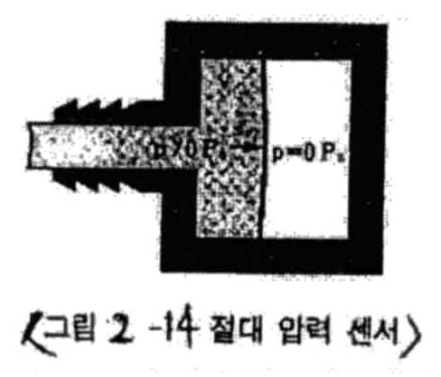
한편 상대 압력 센서에 의한 설명은 하도와 같다.On the other hand, the description by the relative pressure sensor is the same as the channel.
이런 상대 압력 센서는 Pamb로 주어지는 대기압을 기준으로 하는 차등 압력을 측정하는 것이다. 대기압이라 함은 일정한 값이 아니라 지형적, 기상적 변화에 따라 변하는 압력이다. 상대 압력 센서를 세분하면 양의 압력 센서와 음의 압력을 측정하는 진공 센서로 나눌 수 있다.This relative pressure sensor measures the differential pressure based on the atmospheric pressure given in P amb . Atmospheric pressure is not a constant value but a pressure that varies with topographic and meteorological changes. Subdividing the relative pressure sensor can be divided into a positive pressure sensor and a vacuum sensor that measures negative pressure.
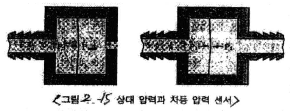
또한 차등 압력 센서에는In addition, the differential pressure sensor
차등 압력 센서는 측정 원리에서 상대 압력 센서와 크게 다르지 않다. 이는 주어진 두 압력 사이에 나타나는 차등 압력을 측정하는 것이다.Differential pressure sensors are not significantly different from relative pressure sensors in the measurement principle. This measures the differential pressure that appears between two given pressures.
이렇게 다이어프램식 압력 스위치(104)는 하도와 같이 설명한다Thus, the diaphragm

다이어프램식 압력 스위치는 스프링의 반발력에 의해 현재의 상태를 유지하급하는 압력의 차와 스프링의 장력에 의해 결정된다.The diaphragm pressure switch is determined by the tension of the spring and the difference in pressure that maintains its current state by the spring's repulsive force.
이 차등 압력 스위치는 다음의 3가지 기능으로 사용할 수 있다.This differential pressure switch can be used in three functions:
먼저 압력 스위치에는First the pressure switch
P1을 이용하여 0.25∼8bar까지 작동되는 압력 스위치로 사용.Used as a pressure switch operating from 0.25 to 8 bar using P 1 .
그리고 진공 스위치는And the vacuum switch
P2를 이용하여 -0.25∼-1bar 범위를 검출하는 진공 압력 스위치로 사용.Used as a vacuum pressure switch to detect a range of -0.25 to -1 bar using P 2 .
다음의 차등 압력 스위치는The next differential pressure switch
P1과 P2를 모두 이용하며 검출 범위는 -1∼8bar 사이에서 조절 가능하다. 스위칭 차등 압력은 스프링으로 조절하며, 히스터리시스의 영향을 고려하여 P1의 압력이 P2의 압력 보다 0.25bar 이상이 되도록 한다.Both P 1 and P 2 are used and the detection range is adjustable between -1 and 8 bar. The switching differential pressure is controlled by a spring, taking into account the effects of hysteresis so that the pressure of P 1 is 0.25 bar or more above the pressure of P 2 .
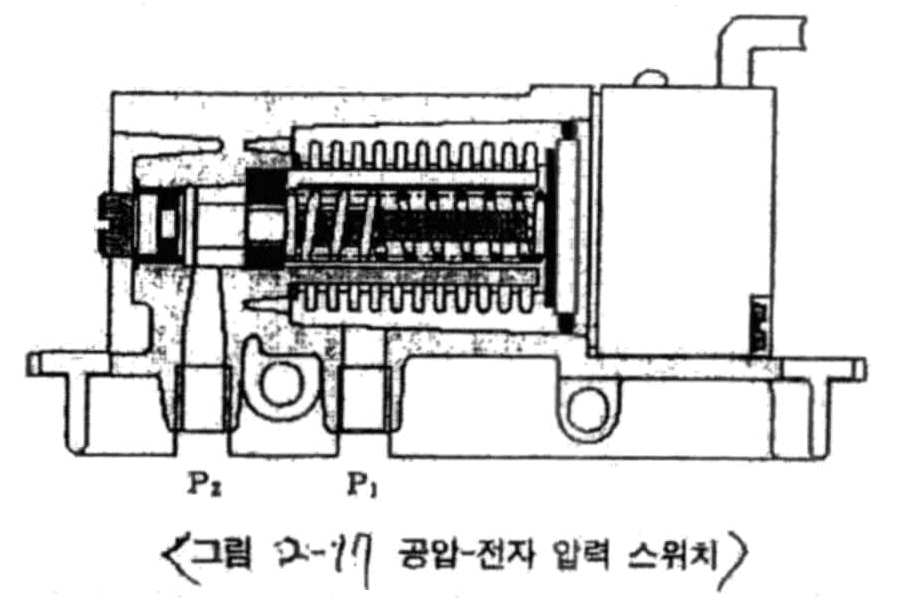
화재열 온도 감지 센서에 대하여 하표와 같이 설명한다.The fire heat temperature sensor is described as shown in the following table.
온도라는 것은 원자 또는 분자가 갖고 있는 운동 또는 진동 에너지의 크기를 나타내는 것으로 이 에너지가 열이다. 즉, 온도는 물리적 상태량의 일종이지만 이것을 직접 계측할 수는 없고, 변위, 압력, 저항, 전압, 주파수 등의 다른 물리량으로 변환하여 계측하여야 한다. 보통의 재료나 전자 소자는 온도에 따라 전기 특성이 변화하기 때문에 모두 온도 센서가 될 수 있는 것이지만, 검출 온도 영역, 정밀 도, 온도 특성, 신뢰성, 양산성, 가격 등의 면에서 사용 목적에 알맞은 것이 사용되고 있다.Temperature refers to the amount of kinetic or vibrational energy possessed by an atom or molecule, which is heat. That is, temperature is a kind of physical state quantity, but it cannot be measured directly, but it must be measured by converting it into other physical quantities such as displacement, pressure, resistance, voltage, frequency, and the like. Normal materials and electronic devices can be used as temperature sensors because electrical characteristics change with temperature, but they are suitable for the purpose of use in terms of detection temperature range, precision, temperature characteristics, reliability, mass production, and price. It is used.
온도의 계측은 온도 센서를 측정 대상물과 열적으로 접촉시켜 양자의 온도를 같게(열평형상태) 하는 접촉식 계측이 있다. 이 방법은 센서 자체가 측정 대상 온도를 견디며 소정의 동작을 해야 한다. 반면에 센서와 대상물을 접촉시키지 않고 열방사를 이용한 비접촉식 계측이 있다. 이때의 센서는 가시 또는 적외 광의 방사검출기이고 센서 자체의 온도와 측정 대상물의 온도와는 관계가 없다.The measurement of the temperature is a contact measurement in which the temperature sensor is in thermal contact with the measurement object to make the temperature of both the same (thermal equilibrium). This method requires that the sensor itself withstands the temperature to be measured and takes some action. On the other hand, there is a non-contact measurement using heat radiation without contacting the sensor and the object. The sensor at this time is a radiation detector of visible or infrared light, and is not related to the temperature of the sensor itself and the temperature of the measurement object.
<표 2-11 접촉 방식과 비접촉 방식><Table 2-11 Contact method and non-contact method>
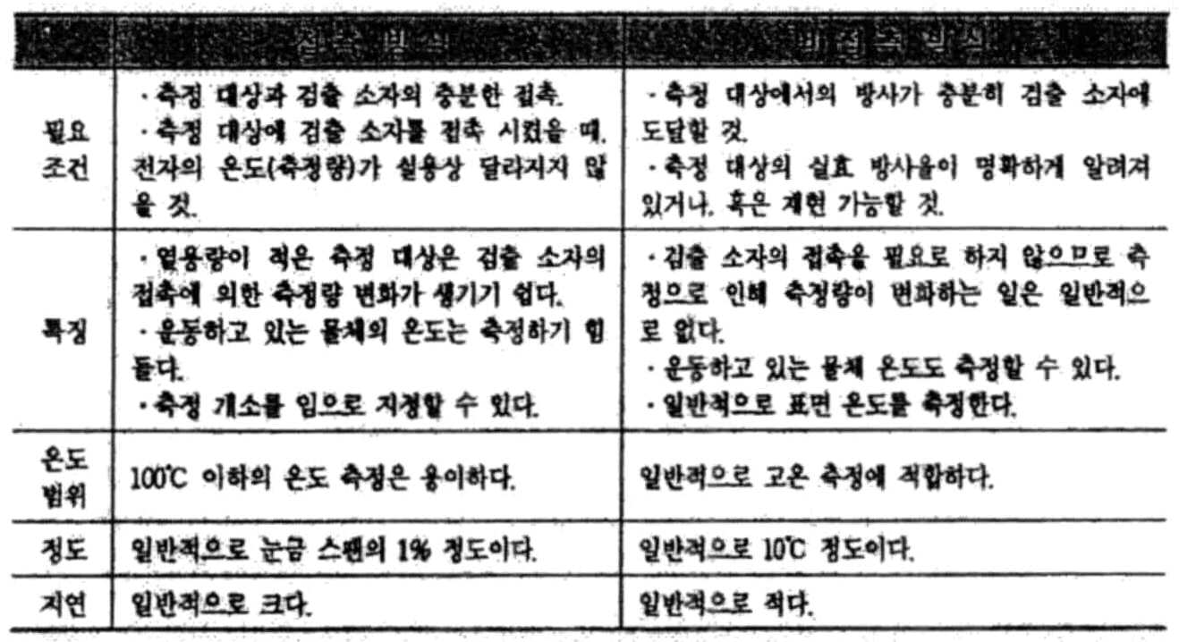
상기한 바와 같이 센서의 구성에 있어서 하도와 같이 설명한다As mentioned above, the structure of a sensor is demonstrated as follows.
온도 변화에 따라 전기저항이 크게 변화하는 반도체 감온 소자를 서미스터(thermistor)라 한다. 특히 온도에 대하여 안정적이고 온도 특성의 재현성이 좋은 것을 서미스터 온도센서로 사용된다. 사용되고 있는 대부분의 서미스터는 세라믹 서미스터로 기본 특성에 의해서 분류하면 온도가 상승함에 따라 전기저항이 지수함수적으로 감소하는 부(-)의 온도계수를 갖는 NTC(negative temperature coefficient) 서미스터, 반대로 비직선적으로 현저하게 저항이 증가하고 전체로서 정(+)의 온도계수를 갖는 PTC(positive temperature coefficient) 서미스터, 또는 NTC와 동일 특성을 갖지만 어떤 온도 경제에서 전기저항이 갑자기 감소하는 급변 서미스터 CTR(critical temperature resistor)의 3가지가 있다. 단순히 서미스터라고 부를 때는 NTC 서미스터를 가르키는 경우가 많다. PTC, CTR은 넓은 온도 범위의 온도 센서로서는 사용할 수 없으나 온도가 특정한 온도(저항이 급변하는 온도)를 초과하는가의 여부를A semiconductor thermosensitive device whose electrical resistance changes greatly with temperature changes is called a thermistor. In particular, thermistor temperature sensor is used which is stable against temperature and has good reproducibility of temperature characteristics. Most of the thermistors used are ceramic thermistors. Negative temperature coefficient (NTC) thermistors with negative temperature coefficients whose electrical resistance decreases exponentially with increasing temperature when classified by their basic characteristics, on the contrary, are non-linear. Positive temperature coefficient (PTC) thermistors with significantly increased resistance and positive temperature coefficients as a whole, or fast-changing thermistors having the same characteristics as NTC but suddenly decreasing their electrical resistance at any temperature economy. There are three ways. When called simply thermistors, they often refer to NTC thermistors. PTC and CTR cannot be used as a temperature sensor in a wide temperature range, but it is determined whether the temperature exceeds a certain temperature (temperature at which the resistance changes rapidly).

검출하는 데에 사용하면 편리하다. 예를 들면 PTC에 전류를 흘리면 발열하고 급변 온도를 초과하면 저항이 크게 되어 전류가 감소해서 발열하지 않게 되므로 전자 보온밥솥에 부착하여 내부 온도를 일정하게 유지하거나 건조기나 드라이어(drier)에 부착해서 온도 스위치를 동작시킬 수 있다.It is convenient to use to detect. For example, if a current flows through PTC, and if it exceeds the sudden change temperature, the resistance becomes large, and the current decreases so that it does not generate heat. Therefore, it is attached to an electronic thermostat and keeps the internal temperature constant or attaches to a dryer or dryer. The switch can be operated.
먼저 엔티씨(NTC) 서미스터에 있어First in NTC thermistors
부의 온도계수를 가지고 연속적으로 전기저항이 변화하는 서미스터로서, NTC라고 약칭되기도 한다. 현재 많이 사용되고 있는 것은 서미스터 정수가 2000∼5000K 정도이고, 사용할 수 있는 온도 범위는 300℃ 정도까지이다.A thermistor whose electrical resistance changes continuously with a negative temperature coefficient, sometimes abbreviated NTC. The thermistor constant is currently used about 2000-5000K, and the temperature range which can be used currently is about 300 degreeC.
서미스터는 본래 100℃ 이상의 온도에서 소결한 것이기 때문에 사용방법에 잘못이 없으면 충분히 장기간 안정된 특성을 유지한다. 그러나 모든 물질에 경년 변화가 있듯이 영구히 변화하지 않는 것은 아니다. 다음 그림 14-2에서는 100℃에서 사용한 경우의 안정도를 1로 했을 때의 상대값을 나타낸 것으로 고온이 될수록 안정도가 저하하고 있는 것을 알 수가 있다. 이것은 서미스터의 재료, 소결 조건에 따라 달라지지만 100℃ 정도의 저온에서 사용할 때는 이 원인에 의한 변화는 무시할 수 있다. 만일 저온도에서 변화가 있다면 외형의 손상으로 수분이나 용제 등이 침입한 것이라고 생각된다.The thermistor is originally sintered at a temperature of 100 ℃ or higher, so if there is no error in the method of use, it maintains stable characteristics for a long time. But not as all ages change over time. In the following figure 14-2, the relative value when the stability at 100 ° C is set to 1 is shown. As the temperature increases, the stability decreases. This depends on the material of the thermistor and the sintering conditions, but when used at a low temperature of about 100 ° C, the change caused by this cause can be ignored. If there is a change in low temperature, it is thought that water or a solvent is invaded due to damage to the appearance.
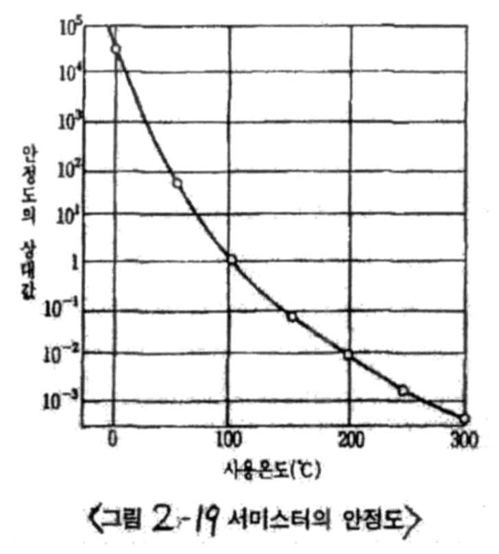
다음의 피티씨(PTC) 서미스터에 있어In the next PTC thermistor
피티씨(PTC) 서미스터는 그 구조가 간단하기 때문에 전류 제한 소자(휴즈 기능 소자), 정온도 발열체, 가전제품의 온도 센서로 사용되고 있다. 즉, 초기에 대 전류가 흐리고 그 후에 감소하여 미소 전류로 억제되는 성질을 이용 온도 상승이 빠른 발열체로 또는 회로의 과대전류 방지용, 초기에만 대전류를 필요로 하는 컬러 TV의 자기 소거용, 신뢰성이 높은 모터 기동용 무접점 스위치용 등이 있다. 사용시 소자에 인가하는 전압이 어떤 값을 넘으면 전압의 증가와 함께 전류도 증가하여 종국에는 브레이크 다운에 이르게 된다. 따라서 파괴 전압을 고려 정격 사용 전압에 대한 안전 여유를 두어야 한다.Because of its simple structure, PTC thermistors are used as current limiting devices (fuse function devices), constant temperature heating elements, and temperature sensors for home appliances. That is, a large current is initially blurred and then reduced and suppressed by a small current, so that it is possible to use a heating element having a rapid temperature rise or to prevent excessive current in a circuit, and to self-clear a color TV that requires a large current only at a high level. Motor contactless switches. In use, if the voltage applied to the device exceeds a certain value, the current increases with the increase of voltage, eventually leading to breakdown. Therefore, the breakdown voltage must be taken into consideration and safety margin should be provided for the rated working voltage.

열전대의 분류는 종류 기호, 허용차의 등급, 소선의 선지름, 보호관 바깥 지름의 길이(보호관이 있는 경우), 보호관 재질, 명칭(보호관이 있는 경우, 보호관 있는 열전대)에 따른다.The thermocouples are classified according to the type symbol, the class of tolerance, the wire diameter of the wire, the length of the outer diameter of the protective tube (if protective tube), the material of the protective tube, and the name (if any protective tube, thermocouple with protective tube).
예 ● : K클래스 1 1.00mm 열전대Example ●:
예 ● : J클래스 2 0.05mm 6 550mm 자기 보호관이 있는 열전대Example ●:
그리고 열전대의 종류에는And the kind of thermocouple
열전대를 구성하는 소선은 고온에 접촉하므로 다음의 조건을 만족하여야 한다.Since the element wire constituting the thermocouple contacts high temperature, the following conditions must be satisfied.
첫째는 열기전력이 클 것.First, the thermal power will be large.
둘째로 온도-열기전력 특성의 분산이 작을 것과,Secondly, the dispersion of temperature-thermal electromotive force characteristics is small,
세째는 열기전력 특성이 연속적이고 직선적일 것.Third, thermoelectric characteristics should be continuous and linear.
넷째는 열적, 화학적, 기계적으로 안정할 것.Fourth, be stable thermally, chemically and mechanically.
그리고 경시변화가 적을 것과,And the change over time is small,
끝으로 가공이 쉽고 가격이 저렴할 것.Finally, the processing is easy and the price is low.
현재 널리 사용되고 있는 열전대로 구성 재료에 따라 B, R, S, K, E, J, T의 7종류로 규격화되어 있다. 다음의 표 2-13은 열전대의 구성에 따른 사용온도 범위와 특징을 보여준다.Thermocouples, which are widely used today, are standardized into seven types, B, R, S, K, E, J, and T, depending on the material of construction. Table 2-13 below shows the range and characteristics of operating temperature according to the configuration of the thermocouple.
상기한 열전대 바이메탈(Bimetal, 102) 화재열 감지센서에 대하여 상세한 설명은 다음과 같다.A detailed description of the thermocouple bimetal 102 fire heat sensor is as follows.
형광등에 보면 점등전구가 끼워져 있는데 이것이 못쓰게 되어 교체 할 때 버리지 말고, 전구의 유리를 깨어 내고 성냥불을 가까이해 보면 U자 형태가 조금 펴지는 것을 쉽게 관찰할 수 있다. 성냥불을 끄면 다시 원상으로 회복 된다.In the fluorescent lamp, the light bulb is inserted, but it can not be used to replace it, and do not throw it away. If you break the glass of the bulb and close the match, you can easily observe the U-shape unfolding. If you turn off the match, you will be restored.
이것은 열팽창이 큰 금속과 작은 금속을 서로 접합하여 열팽창이 작은 쪽으로 휘기 때문이다. 이러한 것을 '바이메탈' 이라고 한다.This is because the metal with large thermal expansion and the small metal are joined to each other and the thermal expansion is bent toward the small side. This is called 'bimetal'.
전기밥솥, 전기 다리미, 가스밥솥, 가스온수기, 냉장고의 온도조절기 등이 모두 이런것을 이용한 것이다.Electric rice cookers, electric irons, rice cookers, gas water heaters, temperature controllers in refrigerators, etc. all used this.
<표 2-13 열전대 사용온도 범위와 특징><Table 2-13 Thermocouple Operating Temperature Range and Features>
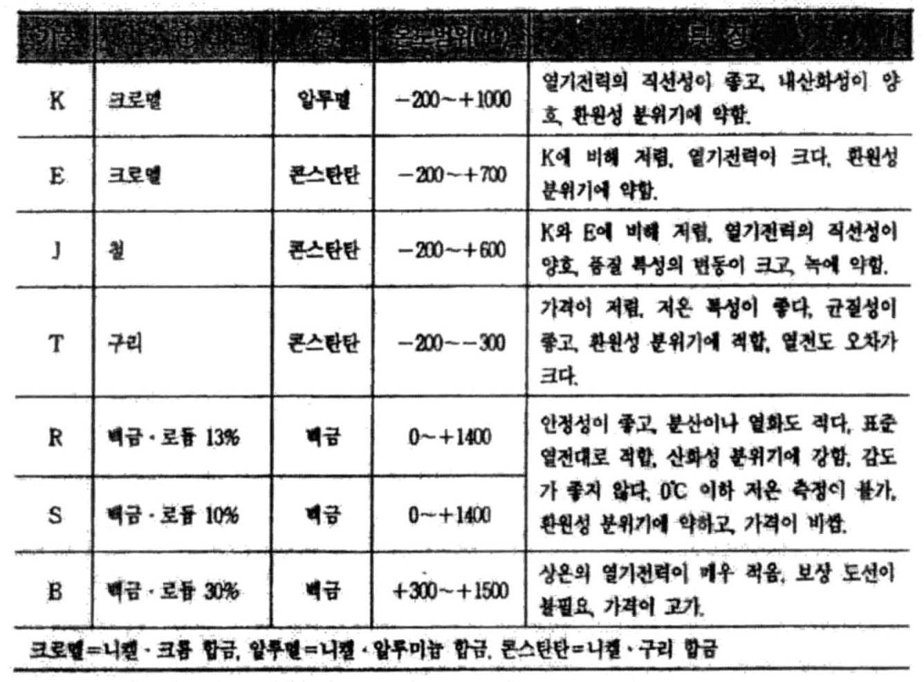

한편 열전대는 측온 접점이나 소선이 피측온물, 분위기 등에 직접 접촉하지 않도록 보호하기 위한 보호관의 사용에 따라 그림 2-23과 같은 종류가 있어 필요에 따라 선택할 수 있다.Thermocouples, on the other hand, can be selected as needed, as shown in Figure 2-23, depending on the use of a protective tube to protect the RTD or wires from direct contact with the measured temperature or atmosphere.

그림(a)는 물체 표면의 온도가 비교적 낮은 경우에 측정할 수 있고, (b)는 보호관이 있는 경우로 실험실 등에서는 소선만 사용하는 경우도 있으나 공업용에서는 기계적 강도, 내열성, 내식성 등의 목적 때문에 보호관에 넣어 사용한다. 보호관이 있는 열전대는 단자, 보호관, 열전대 소선으로 구성되어 있다. 보호관에는 스테인리스 등을 사용한 금속 보호관과 알루미늄자기 등의 비금속 보호관이 있다. 또한 고온이나 환경조건이 나쁜 곳에서도 사용하도록 (c)와 같이, 금속관(금속 시스)속에 열전대 소선을 넣고 그 주위에 절연물을 단단하게 채우고 열전대 소선간 및 금속 시스와 열전대간을 절연함과 동시에 소선을 기밀상태로 해서 부식과 열화를 방지한 시스형이 있다. 이것은 보호관이 있는 열전대에 비해 응답이 빠르고 내열성이나 내진성이 우수하며, 어느 정도의 굽힘도 가능하다. 외형 치수는 0.2∼8mm 정도의 것이 있으며 피측정체에 납땜해서 사용할 수도 있다.Figure (a) can be measured when the temperature of the surface of the object is relatively low, and (b) is a case where there is a protective tube. In the laboratory, only the wire can be used, but for industrial purposes, because of mechanical strength, heat resistance, corrosion resistance, etc. Put it in a protective tube. Thermocouples with protective tubes consist of terminals, protective tubes and thermocouple wires. The protective tube includes a metal protective tube made of stainless steel or the like and a nonmetal protective tube such as aluminum porcelain. In addition, as in (c), thermocouple wires are placed in a metal tube (metal sheath) so that the insulation is tightly filled, and between the thermocouple wires and between the metal sheath and the thermocouple as shown in (c). There is a sheath type which prevents corrosion and deterioration by keeping the airtight. It is faster in response to thermocouples with protective tubes, better in heat resistance and seismic resistance, and can be bent to some extent. The external dimensions are about 0.2 to 8 mm and can be used by soldering them to the object under test.
세번째 보상 도선에 있어서 하도와 같이 설명한다.The following description will be given for the third compensation lead wire.
열전대를 이용 온도를 측정하는 데는 열전대를 계기에 직접 접속하는 것이 이상적이나, 측정점과 계기 사이의 거리가 먼 경우 열전대 소선을 계기까지 연장하면 가격이 높아지게 된다. 따라서 열전대와 동일하거나 유사한 특성을 가진 도선을 이용한다. 이 도선을 보상 도선이라 한다. 보상 도선은 상온을 포함한 상당한 온도 범위에서 조합하여 사용하는 열전대와 거의 동일한 열기전력 특성을 가지고, 열전대와 기준 접점 사이를 이것에 의해 접속하고, 열전대의 접속 부분과 기준 접점의 온도차를 보상하기 위하여 사용하는 한 쌍의 도체에 절연을 하도록 한다. 열전대와 보상 도선의 접속은 열전대의 +각을 보상 도선의 +쪽 심선에, 열전대의 -각을 보상 도선의 -쪽 심선에 접속하여야 한다.Ideally, a thermocouple is connected directly to the instrument for temperature measurement using a thermocouple, but if the distance between the measuring point and the instrument is far, extending the thermocouple wire to the instrument will increase the price. Therefore, use conductors with the same or similar characteristics as thermocouples. This lead is called a compensating lead. Compensation wires have almost the same thermoelectric characteristics as thermocouples used in combination over a significant temperature range, including room temperature, and are used to connect the thermocouples and the reference contacts thereby, and to compensate for the temperature difference between the thermocouple connections and the reference contacts. Insulate a pair of conductors. The connection of the thermocouple and the compensating lead shall connect the + angle of the thermocouple to the + core of the compensating lead and the-angle of the thermocouple to the-core of the compensating lead.


이상으로 용어의 정의에 대하여The definition of terms above
먼저 열전대는 열기전력을 발생할 목적으로 2종류의 도체 한 끝을 전기적으로 접속한 것.First, thermocouples are electrically connected one end of two types of conductors for the purpose of generating thermoelectric power.
다음은 열전대 소선에는 열전대의 양끝이 되는 금속선 또는 합금선에Next, the thermocouple element has a metal wire or alloy wire
세째로 측온 접점은 열전대의 소선을 접합한 접점으로 온도를 측정하는 위치에 놓여진 것과, 기준 접점은 열전대와 도선, 보상 도선과 도선의 접속점을 일정한 온도(예, 빙점)로 유지하도록 한 것이어야 되고Thirdly, the RTD should be placed in the position to measure temperature with the junction of the thermocouple wires, and the reference junction should be such that the junction of the thermocouple and the lead, the compensating lead and the lead is kept at a constant temperature (eg, freezing point).
이와 같이 보호관은 측온 접점이나 소선이 피측온물, 분위기 등에 직접 접촉하지 않도록 보호하기 위하여 붙이는 관이어야 되며In this way, the protective tube should be a tube which is attached to protect the temperature-contacting point or wire from directly contacting the measured temperature or atmosphere.
이에 보상 도선은 상온을 포함한 상당한 온도 범위에서 조합하여 사용하는 열전대와 거의 동일한 열기전력 특성을 가지고, 열전대의 접속 부분과 기준 접점의 온도차를 보상하기 위하여 사용하는 한 쌍의 도체로서The compensating wire is a pair of conductors that have almost the same thermoelectric characteristics as the thermocouples used in combination in a considerable temperature range including room temperature, and are used to compensate for the temperature difference between the connection portion of the thermocouple and the reference junction.
이 같이 기준 열기전력은 기준 접점이 0일 때, 측온 접점의 온도에 대응하여 가상의 열전대(기준 열전대)가 발생하는 정해진 열기전력이어야 된다.As such, the reference thermoelectric power should be a predetermined thermoelectric power that generates a virtual thermocouple (reference thermocouple) corresponding to the temperature of the temperature measurement contact point when the reference contact point is zero.
그러므로 측온 저항체는 접촉식 온도 센서 가운데서 열전쌍이나 서미스터와 함께 널리 사용되고 있는데, 그 중 백금 측온 저항체는 가장 안정하며 온도 범위가 넓어, 높은 정확도가 요구되는 온도계측에 많이 사용된다. 일반적으로 금속은 온도에 거의 비례하여 전기저항이 증가하는 이른바 양(+)의 온도계수를 가지고 있으며, 금속의 순도가 높을수록 이 온도계수는 커진다. 측온 저항체로는 백금, 니켈, 구리 등의 순금속을 사용하며, 표준온도계나 공업계측에 널리 이용되고 있는 것은 고순도(99.999% 이상)의 백금선이다.Therefore, RTDs are widely used with thermocouples and thermistors among the contact temperature sensors. Among them, platinum RTDs are most stable and have a wide temperature range, and are widely used for thermometers requiring high accuracy. In general, metals have a so-called positive temperature coefficient which increases the electrical resistance in proportion to the temperature, and the higher the purity of the metal, the larger the temperature coefficient. Pure metals such as platinum, nickel, and copper are used as the resistance thermometer, and high purity (99.999% or more) platinum wire is widely used for standard thermometers and industrial measurements.

그림 2-25(a)는 금속 저항의 온도 변화를 0℃의 저항을 1로 했을 때의 비를 나타낸 것이다. 즉, 백금의 저항은 0℃에서 100.0Ω이고, 100℃에서 139.16Ω이므로 백금의 저항의 온도계수는 0.39%/℃가 된다. 순금속의 비저항은 매우 작기 때문에 가늘고 긴 금속선을 사용하여 저항치를 높이고, 보호관을 이용 기계적, 화학적으로 보호하는 구조를 갖추고 있다. 그림 2-26는 백금선을 마이카로 감고 보호관을 씌운 구조이다.Figure 2-25 (a) shows the ratio when the temperature change of the metal resistance is made 0 at 0 ° C. That is, since the resistance of platinum is 100.0Ω at 0 ° C and 139.16Ω at 100 ° C, the temperature coefficient of the resistance of platinum is 0.39% / ° C. Since the resistivity of pure metal is very small, it has a structure to increase resistance by using long and thin metal wires and to protect mechanically and chemically by using a protective tube. Figure 2-26 shows the structure of a platinum wire wound with a mica and covered with a protective tube.

첫째로 백금 측온 저항체에는 하표와 같이 설명한다First, explain the platinum resistance thermometer as shown below.
실용화되어 있는 센서 중에서 가장 안정하며 온도 범위가 넓으며 높은 정확도가 요구되는 온도 계측에 많이 사용된다. 단점으로는 저항 소자의 구조가 복잡하여 형상이 크고 응답이 느리며 기계적 충격이나 진동에 약하다.It is the most stable sensor in the market, and is widely used for measuring temperature that has a wide temperature range and high accuracy is required. Disadvantages include the complicated structure of the resistance element, which is large in shape, slow in response, and weak in mechanical shock or vibration.
둘째로 구리 측온 저항체에 있어Secondly, in the copper RTD
백금 다음으로 순도가 높고 저렴하며 온도 특성의 분산이 적은 안정된 소자이다. 그러나 구리는 고유저항이 작고 형상이 크며 고온에서 산화하기 쉽고 사용온도 범위가 좁다.Next to platinum, it is a stable device with high purity, low cost, and low dispersion of temperature characteristics. However, copper has a small resistivity, a large shape, easy oxidation at high temperatures, and a narrow operating temperature range.
세째로 니켈 측온 저항체에는Thirdly, the nickel resistance thermometer
백금에 비해 저렴하고 저항계수가 크다는 장점이 있으나, 340℃ 부근에서 온도계수의 변곡점이 발견된다. 또한 불순물에 의한 온도 저항값 특성이 분산되고, 호환성 있는 니켈선을 얻기가 어렵다.Compared with platinum, it is inexpensive and has a large resistance coefficient, but the inflection point of the temperature coefficient is found around 340 ° C. In addition, the temperature resistance value characteristics due to impurities are dispersed, it is difficult to obtain a compatible nickel wire.
네째로 백금-코발트 측온 저항체에 있어Fourth, in platinum-cobalt resistance
미량의 코발트 0.5%를 포함한 것으로 극저온용으로 저항값 및 저항 온도계수가 백금보다 크다.It contains a trace amount of cobalt 0.5% and the resistance value and the resistance temperature coefficient are larger than platinum for cryogenic use.
<표 2-14 측온 저항체의 종류와 특징><Table 2-14 Types and Characteristics of RTDs>

먼저 기어 펌프(326)에 있어서First, in the
기어 펌프(326) 송출압력 35∼175kgf/cm2, 용량 5∼300ℓ/min 정도의 기어 펌프(326)가 현재 제작 시판되고 있다. 기어 펌프는 구조가 간단하고 신뢰도가 높으며, 운전, 보수가 용이하고 비교적 염가이므로 널리 보급되어 있다. 기어 펌프(모우터)는 외접 기어 펌프(external gear pump)와 내접 기어 펌프(internal gear pump)로 나누어진다. 외접 기어 펌프는 사용하는 기어형에 따라 스퍼어(spur), 헬리컬(helical) 및 헬링보온(herringbone) 기어 펌프로 분류할 수 있다.Gear Pump 326 A
상기된 외접 기어 펌프(326a) 대하여 동도면에 도시한 바와 같이 상세한 설명에는As shown in the same drawing for the external gear pump 326a described above,
그림 2-27에 외접 기어 펌프(external gear pump)의 한 단면을 예시하여 놓았다.A cross section of an external gear pump is illustrated in Figure 2-27.
기어 펌프는 1조의 기어와 이것을 내장하는 기어케이스, 4개의 축수, 기어측판 등이 주요 부품이고, 부품수가 다른 펌프에 비해서 적은 것이 특징이다. 기어 펌프는 출입구에 밸브가 필요하지 않으므로 사용유의 점도가 높더라도, 오우토 밸브를 갖는 왕복펌프와는 달리, 고속운전이 가능하고, 기어의 정도, 기어형을 적절히 선정하면 공동현상이나 이상소음과 같은 장해 없이 70∼80% 정도의 펌프효율을 용이하게 얻을 수 있다. 기어 펌프는 구동기어가 변동기어를 구동시켜가면서 서로 맞물고 회전할 때 펌핑작용이 일어난다. 기어가 서로 맞물고 돌아갈 때 두 기어의 이가 접촉하는 부분은 선 접촉이므로 입구측(저압력)과 출구측(고압력)을 차단시킨다. 기어의 이가 입구측에서 서로 떼어질 때 흡입실의 용적이 한 개의 이가 점유한 용적만큼 증대되기 때문에 약간의 진공상태로 되어 유압유를 빨아올린다. 빨아올린 유압유는 기어 치곡과 케이싱 외주 사이에 끼어 송출실로 압송된다. 송출실에서 이 가 서로 맞물 때, 송출실 용적은 이가 서로 맞물 때 배제되는 용적만큼 감소되어 유압유는 송출실로부터 송출구로 압출된다.The gear pump is composed of a set of gears, a gear case containing four gears, four shafts, a gear side plate, and the number of parts is smaller than that of other pumps. Since the gear pump does not require a valve at the entrance and exit, even if the oil viscosity is high, unlike a reciprocating pump having an auto valve, high speed operation is possible. Pump efficiency of about 70 to 80% can be easily obtained without the same obstacle. The gear pump has a pumping action when the drive gear meshes and rotates while driving the variable gear. When the gears are engaged with each other and the gears are in contact with each other, the contact parts of the two gears are in line contact, so the inlet side (low pressure) and the outlet side (high pressure) are blocked. When the teeth of the gear are separated from each other at the inlet side, the suction chamber volume is increased by the volume occupied by one tooth, so that the hydraulic oil is sucked up by a slight vacuum. The sucked hydraulic oil is sandwiched between the gear teeth and the casing outer circumference and pumped into the delivery chamber. When they engage each other in the delivery chamber, the delivery chamber volume is reduced by the volume excluded when they engage each other so that the hydraulic oil is extruded from the delivery chamber to the outlet.
한편 내접 기어 펌프(326b)에 대하여 하도와 같이On the other hand, as shown below for the internal gear pump 326b.
내접 기어 펌프(internal gear pump)도 외접 기어 펌프와 비슷하게 운전된다. 내접 기어 펌프는 그림 2-28과 같이 펌프 중심을 회전 중심으로 회전하는 바깥기어, 펌프 중심으로부터 편심 되어 바깥기어와 접해서 회전하는 안기어와 초생달 모양의 스페이서(crescern-shaped spacer)로 구성되어 있다. 내측기어가 구동기어가 되어 바깥기어를 회전시키면 내외기어 치곡과 스페이서 양쪽면 사이에 유폐된 유압유는 기어의 회전과 더불어 흡입실로부터 송출실로 압송된다. 그림에는 흡입구(269)와 송출구(270)가 케이싱의 외주에 직접 뚫려 있는 것 같이 그려 놓았지만, 실제 내접 기어 펌프의 입출구는 두 기어가 맞무는 내접점과 스페이서 끝단 사이에 걸쳐 초생달을 반으로 잘라 놓은 모양으로 길쭉하게 펌프측판(end plate)에 뚫려 있다. 내측기어가 바깥기어에 내접하면서 바깥기어를 구동하면 내접점에서 송출실(고압실)과 흡입실(저압실)은 차단되고 흡입실에서 내외기어가 서로 떨어지면서 곡부용적은 점차 커진다. 이로 인하여 흡입실의 압력은 진공이 되어 유압유를 흡입한다. 흡인된 유압유는 스페이서의 양쪽면과 내외기어의 곡부 사이에 끼어 송출실로 이송된다. 송출실에서는 기어가 회전함에 따라 내외기어의 이가 서로 맞물게 되어 곡부용적이 점차 작아져 유압유가 송출구(270)로 압송된다. 내접 기어 펌프는 치형이 마모되면 외접 기어 펌프에 비하여 급속한 효율저하가 일어난다.Internal gear pumps operate similarly to external gear pumps. The internal gear pump consists of an outer gear that rotates the center of rotation of the pump as shown in Figure 2-28, an inner gear that is eccentric from the pump center and rotates in contact with the outer gear, and a crescern-shaped spacer. . When the inner gear becomes the driving gear and rotates the outer gear, the hydraulic oil that is leaked between the inner and outer gear teeth and the spacers on both sides is pumped from the suction chamber to the delivery chamber with the rotation of the gear. In the figure, the

기어 펌프는 소형, 경량이며 저렴한 것이 장점이고, 또 가혹한 운전상태(분진에 의한 오염, 유온의 상승, 과부하)에 대해서 견딜 수가 있으므로, 특히 건설기계, 산업차량, 농업기계 등에서의 유압구동에 적당하며 유온의 한계는 공작기계에 사용될 경우는 65℃ 정도까지이나, 건설기계 등에서는 80℃, 단시간이면 100℃ 정도까지 사용된다. 적당한 기름의 점도는 30∼80cst이다.The gear pump has the advantages of small size, light weight and low cost, and it can withstand harsh operating conditions (dust pollution, rise of oil temperature, overload), and is particularly suitable for hydraulic driving in construction machinery, industrial vehicles and agricultural machinery. The limit of oil temperature is up to 65 ℃ when used in machine tools, but up to 80 ℃ in construction machines and up to 100 ℃ in a short time. Suitable oils have a viscosity of 30 to 80 cst.
치형이 표준 인벌류트 치형인 기어 펌프에 대하여 이론 토출량은For gear pumps whose teeth are standard involute teeth, the theoretical discharge rate is

다음의 베인 펌프(vane pump, 142)에 있어서In the
먼저 베인 펌프의 개요에 대하여First, the outline of the vane pump
베인 펌프를 구성하는 기본요소는 흡입구, 송출구, 구동회전자, 베인, 캠링 그리고 케이싱이다. 베인은 회전자에 파 놓은 홈 안에서 유동하면서 캠링의 형상에 따라 베인과 캠링의 회전자에 둘러싸인 밀폐공간을 변화시킨다. 밀폐공간이 증가하는 동안 흡입구에서 흡입되고 회전자의 회전에 따라 전환점을 지나면서 다시 밀폐 공간이 감소되면서 토출된다. 일반산업용으로서 송출압력 1단 70kgf/cm2, 2단 140kgf/cm2, 용량 4ℓ/min∼280ℓ/min의 베인 펌프가 보통 제작 시판되고 있다. 최근에 와서는 고속고압으로서 1단 150kgf/cm2∼140kgf/cm2의 펌프가 출현되고 있다.The basic components of the vane pump are the inlet, outlet, drive rotor, vane, cam ring and casing. The vane flows in the grooves excavated in the rotor and changes the enclosed space surrounded by the vane and the rotor of the cam ring according to the shape of the cam ring. While the sealed space is increased, it is sucked by the suction port and discharged while the sealed space is reduced again as the rotor passes through the turning point. For general industry, vane pumps with discharge pressure of 1
베인 펌프는 고정용량과 가변용량형 그리고 압력평형과 불평형식으로 분류되어진다. 현재 제작되고 있는 베인 펌프는 다음과 같은 형식이 있다.Vane pumps are classified into fixed and variable displacement, pressure balanced and unbalanced. Currently manufactured vane pumps have the following types.
첫째로 평형형 베인 펌프(142a)와,First, the balanced vane pump 142a,
둘째로 불평형형 베인 펌프(142b)에Secondly, the unbalanced vane pump 142b
세째로 정용량형 베인 펌프(142a)와Thirdly, the fixed capacity vane pump 142a
네째로 가변용량형 베인 펌프(142b)인데Fourth, the variable displacement vane pump (142b)

평형형 베인 펌프와 불평형형 베인 펌프란 펌프축이 받는 축 하중이 역학적으로 평형이냐 또는 불평형이냐를 두고 구분한 경우이다. 또한 정용량형 펌프냐 가변용량형 펌프냐의 구별은 운전중 토출량을 변화시키는 기능의 여부이다. 따라서 기구학적으로 볼 때 평형형 베인 펌프는 정용량형 펌프에 해당되고 불평형형 베인 펌프는 가변용량형 펌프에 해당하게 된다.A balanced vane pump and an unbalanced vane pump are cases in which the axial load of a pump shaft is mechanically balanced or unbalanced. In addition, the distinction between the constant capacity pump and the variable capacity pump is whether or not the function of changing the discharge amount during the operation. Therefore, from the mechanical point of view, the balanced vane pump corresponds to the fixed displacement pump and the unbalanced vane pump corresponds to the variable displacement pump.
상기한 베인 펌프 그 이외의 베인 펌프에 있어서,In the vane pump other than the above-mentioned vane pump,
첫째로 2단 펌프에는Firstly, the two stage pump
1단 베인 펌프 두 개를 직렬로 연결하고 1단의 펌프 토출유를 2단째의 흡입구에 넣어 2배의 고압을 발생케 하지만 유량의 변화는 없다. 이 펌프는 2개의 베인 펌프를 사용함으로서 부하분배 밸브를 사용하여 각단의 부하가 같은 비율로 분배되게 한다.Two single stage vane pumps are connected in series and the first stage pump discharge oil is put into the inlet of the second stage to generate twice the high pressure, but there is no change in the flow rate. The pump uses two vane pumps, using load distribution valves to ensure that the loads at each stage are distributed at the same rate.
다음의 2중 펌프에는In the following double pump
대형과 중형, 또는 중형과 소형의 펌프 두 개를 1개의 몸체 내에 병렬로 연결하여 한 개의 구동축으로 회전하여 두 개의 유압원을 얻고자 할 때 사용된다.It is used when two large and medium or small and small pumps are connected in parallel in one body and rotated by one drive shaft to obtain two hydraulic sources.
그리고 복합 펌프에는And the combined pump
두 개 이상의 펌프를 동일 축으로 구동하며 릴리프 밸브, 무부하 밸브, 체크 밸브 등 회로에 필요한 밸브를 설치.Drive two or more pumps on the same axis and install valves for the circuit, such as relief valves, no-load valves, and check valves.
베인 펌프의 이론토출량Theoretical discharge of vane pump
불평형형(Q=2πDeWn) (2.12)Unbalance ( Q = 2 πDeWn ) (2.12)
평형형<Q=4πDeWn=4eWn(πD-bz)>Equilibrium < Q = 4 πDeWn = 4 eWn ( πD -bz )>
위 식에서 b는 베인의 두께, D는 캠링의 직경, e는 편심량, z는 베인의 개수, W는 베인의 폭이다.Where b is the thickness of the vane, D is the diameter of the cam ring, e is the amount of eccentricity, z is the number of vanes, and W is the width of the vanes.
한편 베인 펌프의 장·단점에 있어서On the other hand, in the advantages and disadvantages of the vane pump
먼저 베인 펌프의 장점에는Firstly, the advantages of the vane pump
첫째는 베인 펌프는 다른 펌프에 비하여 송출압력의 맥동이 적다.First, the vane pump has less pulsation of discharge pressure than other pumps.
둘째로 펌프의 구동동력에 비하여 소형이다.Secondly, it is small compared to the driving power of the pump.
세째는 베인의 선단이 마모되어도 압력저하가 생기지 않는다.Third, the pressure drop does not occur even if the vane tip is worn.
끝으로 비교적 고장이 적고 보수가 용이하다.Finally, it is relatively small and easy to repair.
또한: 베인 펌프의 단점에 있어Also: the disadvantages of vane pumps
첫째로 베인, 회전자, 캠링이 서로 접촉 활동하므로 공작정도가 놓아야 하고, 양질의 재료를 선정할 필요가 있다.Firstly, vanes, rotors and camrings are in contact with each other, so the degree of work must be set and quality materials must be selected.
둘째는 기름의 점도, 청정도 등에 세심한 주의를 요한다.The second requires careful attention to oil viscosity and cleanliness.
부품수가 많다.There are many parts.
그 다음 플런저 펌프(plunger pump, 148)에는Then the plunger pump (148)
먼저 플런저 펌프의 개요에 있어First of all, on the overview of the plunger pump,
플런저(피스톤)의 왕복운동에 의하여 펌핑작용을 하는 펌프로서 고압펌프에 적합하다. 플런저 펌프는 플런저의 왕복운동방향과 구동회전방향과의 상대관계에 따라 액셜형(axial type)과 레이디얼형(radial type)으로 크게 나누어진다. 이러한 유형의 펌프 또는 모우터를 로우터리(rotaty) 펌프(337)라고도 말한다. 크랭크식 피스톤 펌프는 피스톤의 운동으로 분류하면 일종의 레이디얼형으로 생각할 수 있으나 구조상 다른 펌프와 상당한 차이가 있으므로 하나의 독립된 형식으로 분류해서 생각한다.This pump is pumped by reciprocating motion of plunger (piston) and is suitable for high pressure pump. The plunger pump is largely divided into an axial type and a radial type according to the relative relationship between the reciprocating direction and the drive rotation direction of the plunger. This type of pump or motor is also referred to as a rotary pump 337. A crank piston pump can be thought of as a radial type when classified as a piston movement, but it is considered to be classified as an independent type because there is a considerable difference in structure from other pumps.
로우터리형 펌프는 왕복운동 부분의 질량이 극히 작던가, 또는 전혀 왕복운동 부분이 없으므로 고속운전(보통 3000∼4000rmp, 큰 것은 15,000rpm 이상)이 가 능하다. 그러므로 비교적 소형으로 고압 고성능의 펌프가 얻어진다. 다수의 플런저를 갖는 펌프를 고속 운전하므로 송출유의 맥동이 극히 적고, 진동도 적기 때문에 비교적 원활한 운전이 가능하다. 또한 기구상 가변용량형이 쉽게 얻어질 수 있다.Rotary pumps are capable of high speed operation (usually 3000 to 4000 rpm, larger than 15,000 rpm) because the mass of the reciprocating part is extremely small or there is no reciprocating part at all. Therefore, a pump of relatively high pressure and high pressure is obtained. The pump having a large number of plungers is operated at high speed, so that the pulsation of the discharge oil is extremely small and the vibration is small, so that relatively smooth operation is possible. In addition, a mechanically variable capacity type can be easily obtained.
플런저의 지름이 비교적 작고, 행정도 작으며 공작정도도 얻기 쉬우므로 높은 용적효율의 펌프를 얻을 수 있다. 그러므로 현재 시판되고 있는 플런저 펌프는 송출압력 700∼350kgf/cm2, 송출량 10∼50ℓ/min, 효율 80∼90%의 것이 보통이다.Since the diameter of the plunger is relatively small, the stroke is small, and the working accuracy is easy to obtain, a pump with high volumetric efficiency can be obtained. Therefore, currently commercially available plunger pumps have a delivery pressure of 700 to 350 kg f / cm 2 , a delivery amount of 10 to 50 l / min, and an efficiency of 80 to 90%.
또 크랭크식의 피스톤 펌프는 종래에는 저속대형의 것이 많았으나 근래에는 고속회전, 고압, 소 송출량의 것이 개발되어 소형, 고효율, 구조가 간단한 특징 때문에 일반 산업용 및 특수용도로 널리 사용되고 있다.In addition, the crank-type piston pump has a lot of low speed large conventionally, but in recent years, high speed rotation, high pressure, small discharge amount has been developed, and is widely used for general industrial and special purposes because of its small size, high efficiency, and simple structure.
다음은 액셜형 플런저 펌프(148a)에 있어서Next is the axial plunger pump 148a.
상기 펌프 구조와 특징에는The pump structure and features
플런저가 축심을 중심으로 하는 원주상에 축심과 평행하게 배열된 실린더 블록(cylinder block)에 삽입되어, 축심과 구동축과의 경각 혹은 사판 등의 기구에 의하여 왕복운동을 해서 펌핑작용을 하는 펌프로서 사축식(bent axis pump)과 사판식(swash plate pump)으로 크게 나눈다.The plunger is inserted into a cylinder block arranged parallel to the shaft core on the circumference of the shaft center, and is a pump that reciprocates by a mechanism such as an inclination between the shaft core and the drive shaft or a swash plate to pump and act as a pump. It can be divided into bent axis pump and swash plate pump.
그림 2-31는 사판식 액셜 피스톤 펌프의 단면과 구조도를 도시한 것으로 실린더 블록은 구동축과 스플라인(spline)으로 결합되어 있으며 구동축의 회전에 따라 실린더 내의 피스톤이 사판과 함께 회전하게 된다.Figure 2-31 shows the cross-sectional and structural diagram of the swash plate axial piston pump. The cylinder block is splined with the drive shaft, and the piston in the cylinder rotates with the swash plate as the drive shaft rotates.

또한 사판식은 사축식에 비하여 구조가 간단하고 부품수가 적기 때문에 소형 경량이며 가격이 저렴하고 구조상 회전중량이 축 주위에 집중되어 있으므로 고속회전에 적합하여 설치면적이 좁은 건설차량이나 하역 운반기계 등에 많이 사용되고 있다.In addition, the swash plate type is simpler in structure and has fewer parts than the small axis type, so it is compact, lightweight, inexpensive, and the rotational weight is concentrated around the axis. Therefore, the swash plate type is suitable for high speed rotation. have.
상기된 건설차량 또는 운반기계로 사용되는 시린더 또는 실린더(126) 내부에 형성되는 축봉부에는 각개의 시일(156)이 하도와 같이 부착되는데에는 상기 시린더(126) 전방의 고압(HYDRAUUC)의 펌프와 고압호스(190)와 카플링(29)과 각 밸브장치로크랭크(248)와 상기 크랭크(248)에 연결 장치로 사용되는 링크대(249)로 조립되어 상기는 중장비 건설 기계로 이용된다.Each
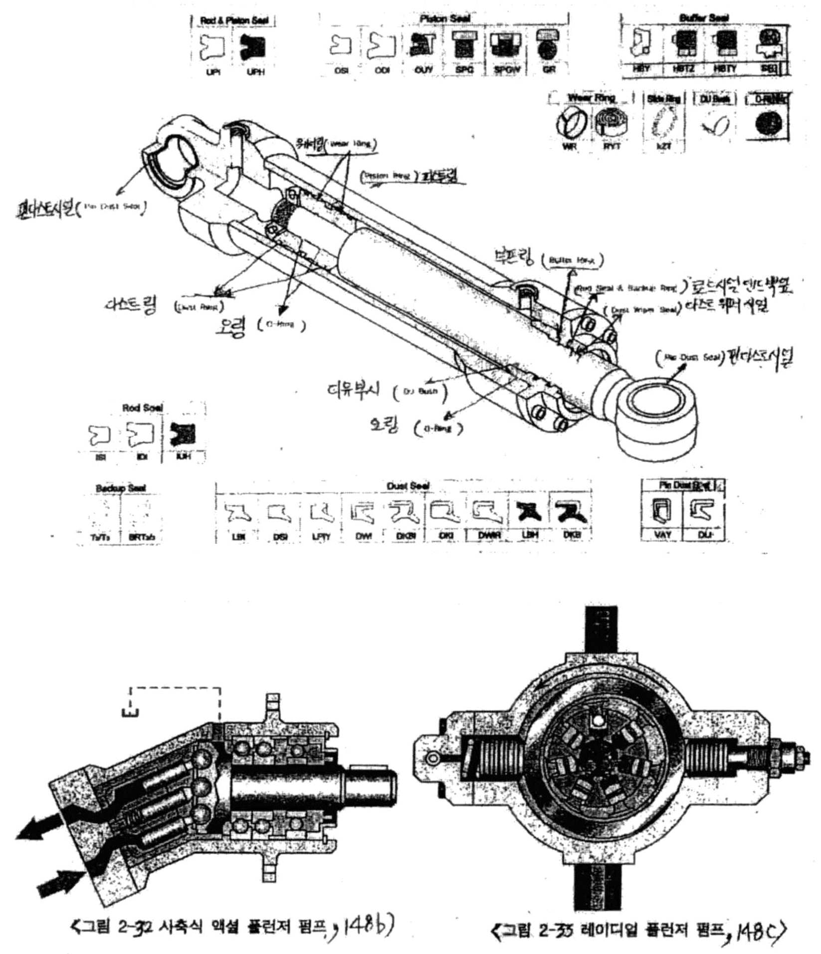
소방 방재 시스템에서는 유압 에너지는 배관을 따라 펌프에서 작동기로 전달된다. 힘, 토크, 속도, 방향 등에 대한 요구치를 만족시키기 위해 시스템을 제어해주는 적절한 유압 요소들이 필요하게 되는데 이들이 바로 밸브다.In fire protection systems, hydraulic energy is transferred from the pump to the actuator along the pipe. In order to meet the demands for force, torque, speed, direction, etc., appropriate hydraulic elements are needed to control the system. These are the valves.
이들 밸브를 기능에 따라 크게 나누면 압력제어 밸브, 방향제어 밸브, 유량제어 밸브로 나누어진다. 이들 밸브를 기능에 따라 조합하면 여러 가지 특징을 갖는 유압계통을 구성할 수 있다. 그러므로 유압제어 밸브는 유압계통을 구성하는 요 소 중 가장 다양하고 주요한 기기이다.When these valves are divided into functions, they are divided into pressure control valves, directional control valves, and flow control valves. When these valves are combined according to their functions, a hydraulic system having various characteristics can be constructed. Therefore, the hydraulic control valve is the most diverse and major component of the hydraulic system.
이러한 압력제어 밸브는 사용목적, 구조에 따라 다음과 같이 분류할 수 있다.These pressure control valves can be classified as follows according to the purpose of use and structure.
이렇게 릴리프 밸브(relief valve, 474)Like this relief valve (474)
회로의 최고압력을 한정하는 밸브로서 회로의 압력을 일정하게 유지시키는 밸브이다. 제어 압력은 밸브의 입구 P포트에서 감지된다. 이 밸브는 유압회로에서 반드시 필요로 하며 과부하에 의하여 회로가 파괴되는 것을 방지하는 안전밸브이다.It is a valve which limits the maximum pressure of a circuit and keeps the pressure of a circuit constant. Control pressure is sensed at the inlet P port of the valve. This valve is essential for the hydraulic circuit and is a safety valve to prevent the circuit from being destroyed by overload.
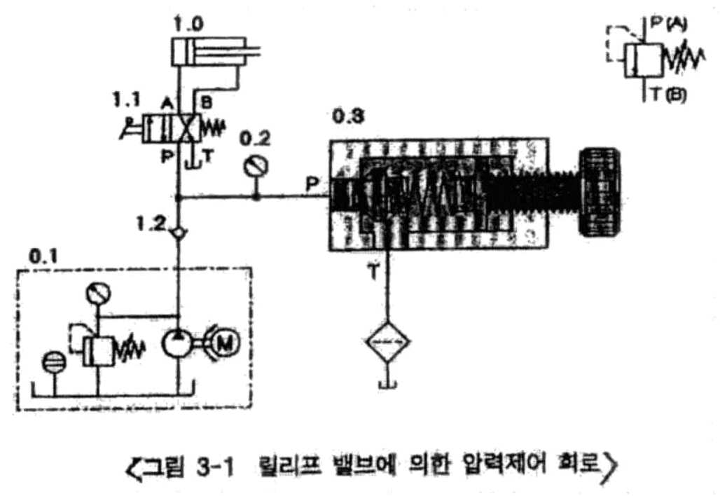
먼저 직동형 릴리프 밸브(474a)에 있어 하도와 같이First, in the direct relief valve 474a,
그림 3-2에 직동형 릴리프 밸브(474a)를 나타내었다. 스프링에 의해서 포펫트가 밸브시트에 눌려 붙어 있고, 핸들을 사용하여 스프링을 조정할 수 있도록 되어 있어 릴리프 설정압이 조정된다. 일차압이 스프링력 보다도 적을 경우는 밸브는 닫혀진 상태에서 압력유를 차단하고 있고, 일차압이 스프링력 보다 크게 될 때에 압유는 포펫트를 밀어젖히고 탱크로 유입되므로 압력의 상승을 방지한다. 포펫트를 밀어젖히고 탱크로 기름이 흐르기 시작할 때의 압력을 크랙킹압력, 밸브가 전부 열려 유압 펌프의 토출량을 전부 기름탱크로 보낼 때의 압력을 전유량시 압력이라 하며 이것이 릴리프 밸브의 설정압력이다.Figure 3-2 shows a direct relief valve 474a. The poppet is pressed against the valve seat by the spring, and the relief set pressure is adjusted because the spring can be adjusted using the handle. When the primary pressure is less than the spring force, the valve shuts off the pressure oil in the closed state. When the primary pressure becomes larger than the spring force, the pressure oil pushes the poppet up and flows into the tank to prevent an increase in pressure. The pressure when the poppet is pushed out and the oil starts to flow into the tank is the cracking pressure and the pressure when all the valves are opened to send the discharged volume of the hydraulic pump to the oil tank.

또한 전유량시 압력과 크랙킹압력의 차를 압력 오버라이드(pressure override)라고 하는데 직동형 릴리프 밸브는 압력 오버라이드가 크다. 그림에서 P포트의 압력이 설정압력에 가까워지면 포펫트가 오른쪽으로 들어올려지며 밸브시트와 포펫트 사이에 틈이 생긴다. 이 틈으로 압유가 탱크로 유출되게 되는데 이때 회로 내의 기름의 압력에너지가 속도에너지로 바뀌므로 포펫트가 열리지 않거나 압력저하가 급격히 일어나 시이트면에 격심하게 부딪친다. 이와 같은 동작을 반복하는 현상을 채터링이라고 하고, 심한 소음과 함께 밸브 시이트를 망가뜨리는 원인이 된다.In addition, the difference between the pressure at the full flow rate and the cracking pressure is called a pressure override. The direct relief valve has a large pressure override. In the figure, when the P port pressure approaches the set pressure, the poppet is lifted to the right and there is a gap between the valve seat and the poppet. This gap causes the pressurized oil to flow out into the tank. At this time, the pressure energy of the oil in the circuit is changed to the velocity energy, so that the poppet does not open or the pressure drops rapidly and hits the sheet surface violently. The phenomenon of repeating such an operation is called chattering, which causes the noise of the valve seat with severe noise.
다음은 평형 피스톤형 릴리프 밸브(474b)에 있어 하도와 같이 설명한다Next, the balance piston type relief valve 474b will be described as follows.
상기 직동형보다 구조적으로 복잡하지만, 릴리프 밸브의 기능이 확실하며 체터링 현상을 방지할 수 있어 일반 산업용 기계에서 널리 사용되고 있다. 평형 피스톤형 릴리프 밸브는 회로 내의 여분의 기름을 도피시키는 주밸브와 스프링으로 구 성되는 용량제어부, 주밸브의 작동을 컨트롤하고 압력을 조절하는 파일럿부로 되어 있다.Although structurally more complex than the direct acting type, the relief valve function is sure and can be prevented from being used for general industrial machines. The balanced piston relief valve consists of a main valve to escape excess oil in the circuit, a capacity control unit consisting of a spring, and a pilot unit to control the operation and control the pressure of the main valve.

한편 감압 밸브(pressure reducing valve, 460)에 있어서On the other hand, in the
상기 감압 밸브(460)는 분기회로 압력을 주회로 압력보다 낮추어 2차압력을 제어하는 밸브로 입구와 출구의 압력차를 같게 하는 2차압력 일정형(460a)과 출구측 압력을 입구측 압력에 대해서 소정의 비율로 감압하는 차압 일정형(460b)이 있다.The
먼저 2차압력 일정형 감압 밸브(460a)에 있어First, the secondary pressure constant pressure reducing valve (460a)
그림 3-4에 2차압력 일정형 감압 밸브의 구조를 나타내었다. 설정압력 이하에서는 포펫트 밸브는 닫힌 상태로, 스프울 양단의 압력은 같은 압력이며, 주 스프링의 작용에 의해 스프울은 하방향으로 눌려 있으며, 유입구의 압력의 저항 없이 펌프의 전유량을 유출한다. 유출구의 압력이 설정압력 이상으로 되면 포펫트 밸브가 열리고 압유는 드레인 라인으로 유출한다. 이때 초크를 통과하는 유량에 의해 스프울의 양단은 압력차를 발생시키며 스프울은 상방향으로 이동하여 유출구의 유로의 개도를 감소시켜, 출구측 압력이 설정압력으로 되도록 제어한다.The structure of the secondary pressure constant pressure reducing valve is shown in Figure 3-4. Below the set pressure, the poppet valve is closed, and the pressure at both ends of the sprue is the same pressure.The sprue is pressed downward by the action of the main spring, and the entire flow rate of the pump flows out without resistance of the inlet pressure. . If the outlet pressure is above the set pressure, the poppet valve opens and the pressurized oil flows into the drain line. At this time, both ends of the spurs generate a pressure difference by the flow rate passing through the choke, and the spurs move upward to reduce the opening degree of the flow path of the outlet port, thereby controlling the outlet pressure to be the set pressure.
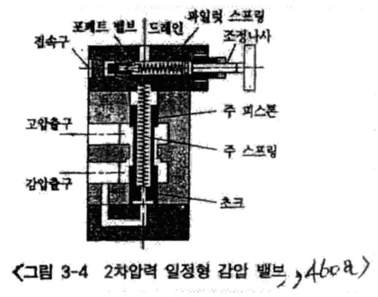
다음은 차압 일정형 감압 밸브(460b)에 있어Next is a differential pressure reducing valve (460b)
그림 3-5에 차압 일정형 감압 밸브(압력보상형)의 구조를 나타내었다. 유체의 힘을 무시한다면, 밸브에 작용하는 힘의 밸런스는 p 2×A=p 3×A+스프링의 힘으로 되고 p 2-p 3의 차이는 일정하게 유지된다.Figure 3-5 shows the structure of the differential pressure reducing valve (pressure compensation type). Neglecting the force of the fluid, the balance of forces acting on the valve becomes the force of p 2 x A = p 3 x A + spring and the difference between p 2 - p 3 remains constant.

그리고 시퀀스 밸브(sequence valve or Auto pressure control valve, 469)에는 하도와 같이 설명한다.The sequence valve or auto
2개 이상의 분기회로를 갖는 유압회로에서 그 작동순서를 회로의 압력이나 유압실린더의 운동 등으로 규제하는 오우토 밸브이다.In hydraulic circuits having two or more branch circuits, the operation order is to regulate the operation order by the pressure of the circuit, the movement of the hydraulic cylinder, or the like.
이러한 종류의 밸브는 그림 3-6과 같이 직동형 압력제어 밸브로서 조정 스프링에 의해 1차측과 2차측의 유로는 닫혀 있다. 파일럿 압력은 아래 커버의 통로를 통해서 피스톤의 하방향으로 유도되고, 스프울을 상방향으로 밀어 올리는 힘이 된다.This type of valve is a direct acting pressure control valve as shown in Figure 3-6. The primary and secondary flow paths are closed by adjustment springs. The pilot pressure is directed downward of the piston through the passage of the lower cover and becomes a force for pushing up the spring upwards.
이 힘이 스프링 힘보다 커지게 되면 유로가 열린다. 밸브의 상부 커버와 하부 커버의 조합에 따라 그림에 나타내는 것과 같은 기능을 갖는다. 또한 2차측에서 1차측으로 역류가 가능하도록 체크 밸브를 내장한 것이 있으며, 시퀀스 밸브, 카운터 밸런스 밸브, 브레이크 밸브 등으로 이용되고 있다.When this force becomes greater than the spring force, the flow path opens. The combination of the upper cover and the lower cover of the valve has the function as shown in the figure. In addition, there is a built-in check valve to allow reverse flow from the secondary side to the primary side, and is used as a sequence valve, a counter balance valve, a brake valve, and the like.

상기된 그 이외의 카운터 밸런스 밸브(counter balance valve)에는 하도와 같이 설명한다Other counter balance valves described above will be described as below.
한쪽 방향의 유동에 대해서는 설정된 배압을 부여하지만, 반대방향의 유동은 자유유동을 하는 밸브이다.The set back pressure is applied to the flow in one direction, but the flow in the opposite direction is a free flow valve.
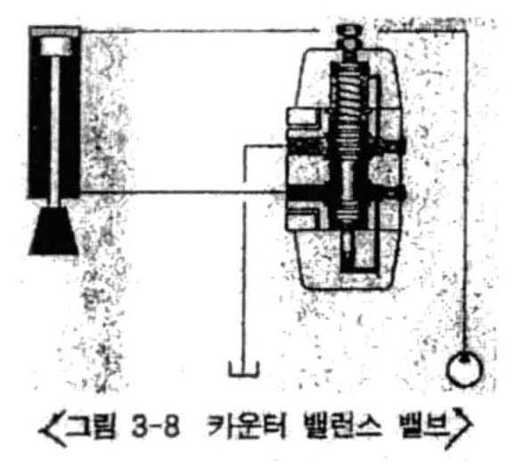
방향제어 밸브(directional control valve)는 작동유의 유동방향을 제어하고 실린더나 유압모터 등의 시동, 가속, 감속, 정지 및 현 상태를 유지하는 등을 목적으로 하여 유압의 흐름방향을 제어하기 위하여 사용하는 밸브이다.The directional control valve is used to control the flow direction of hydraulic oil and to control the flow direction of hydraulic oil for the purpose of starting, accelerating, decelerating, stopping and maintaining the current state of cylinder or hydraulic motor. Valve.
이러한 방향변환 밸브에 있어 하도와 같이 설명한다.This direction change valve is demonstrated as follows.
방향제어 밸브는 구조면에서 분류하면 볼이나 피스톤을 시트에 붙였다 떼었다 하는 포펫트(popet)형과 스풀을 축 둘레에서 회전시키는 회전 스풀형, 그리고 스풀을 축방향으로 섭동시키는 직동 스풀형이 있으며, 조작방식에 따라 분류하면 일반적인 수동작동 스프링 복귀형, 누름버튼 작동 스프링 복귀형, 핸드레버 작동형, 핸드레버 작동 위치 고정형, 페달 작동 스프링 복귀형 등이 있다. 또한 방향제어 밸브는 몇 개의 연결된 사각형으로 표시되며 중립위치에서 밸브 내의 유로의 상태, 변환 위치의 수, 접속 포트의 수, 조작방법 등을 기호로 나타내게 된다.Directional valves are divided into two types: the poppet type, in which the ball or piston is attached to the seat, the rotating spool type to rotate the spool around the axis, and the linear spool type to perturb the spool in the axial direction. According to the operation method, there are general manual actuation spring return type, push button actuation spring return type, hand lever actuation type, hand lever actuation position fixing type, pedal actuation spring return type and so on. In addition, the direction control valve is indicated by several connected rectangles and symbolically indicates the state of the flow path in the valve, the number of change positions, the number of connection ports, and the operation method at the neutral position.
먼저 2/2-way 밸브는First 2 / 2-way valve
2/2-way 밸브는 압유의 흐름을 open, shut-off 하는데 사용된다. 즉 P포트에 유입되는가 아니 되는가는 조작 레버에 따른 스프울의 위치에 따라 결정된다.The 2 / 2-way valve is used to open and shut off the flow of hydraulic oil. That is, whether or not flow into the P port is determined by the position of the spring along the control lever.
다음은 3/2-way 밸브에 있어Next up is the 3 / 2-way valve
3/2-way 밸브는 압유의 흐름을 한 방향으로 open 시키고 그리고 다른 한 방향으로는 shut-off 하도록 방향제어를 하는데 사용된다. 이 밸브는 스푸울이 중립위치에서 P포트가The 3 / 2-way valve is used to control the direction of the oil flow to open in one direction and shut off in the other direction. This valve has the spout in its neutral position

block이고 A포트에서 T포트로 open 되어 있다. 레버에 외력을 가하면 P포트와 A포트가 연결되고 레버에 작용하는 외력이 제거될 때 스프링에 의하여 스푸울이 중립위치로 되돌아온다.It is a block and is open from port A to port T. When an external force is applied to the lever, the spring is returned to the neutral position by the spring when the P and A ports are connected and the external force acting on the lever is removed.
그리고 4/2-way 밸브에 있어And on a 4 / 2-way valve
4/2-way 밸브는 압유의 양방향 흐름을 제어하는데 사용된다. 이 밸브는 상시 위치에서 P→B, A→T로 연결되어 있으며 조작력이 가해지면 P→A, B→T로 압유가 통하게 된다. 사용처로는 복동실린더의 클램프, 언클램프, 전후진에 사용된다.4 / 2-way valves are used to control the two-way flow of hydraulic oil. This valve is connected to P → B, A → T at the normal position, and the hydraulic oil flows to P → A, B → T when operating force is applied. It is used for clamping, unclamping and forward and backward of double acting cylinders.
다음의 4/3-way 밸브는 하도와 같이 설명한다.The following 4 / 3-way valve is described as the diagram below.
스풀울이 중립위치에서 P포트가 모든 포트와 완전히 차단된 경우, 모든 포트와 연결된 경우, 그리고 P포트와 T포트가 연결된 경우, 그리고 A포트와 B포트만이 연결된 경우 등이 있다.In the spool wool neutral position, the P port is completely disconnected from all ports, connected to all ports, the P and T ports connected, and only the A and B ports connected.

그리고 체크 밸브(check valve, 451)에 있어And on the
상기 밸브(451)는 압유의 흐름을 일 방향만으로 제한하는 것으로, 반대 방향의 흐름을 억제하는 밸브이다. 유압회로 중에서 압유의 압력에 의해서 작동하고 일방향만의 유로를 확보한다. 역류를 방지함으로서 액추에이터의 운동을 확실하게 한다. 인라인 체크 밸브(451a)와 앵글 체크 밸브(451b)가 있다.The

한편 유량제어 밸브의 작용과 그 특성에 대하여 하도와 같이 설명한다On the other hand, the operation and characteristics of the flow control valve will be described as follows.
압유의 유량을 변화시킴으로서 유압모터나 유압실린더의 움직이는 속도를 변화시킬 수 있다. 그 유량을 조절하는 것이 유량조절 밸브이다. 다시말해 유량조절 밸브는 유압모터나 실린더의 속도를 조절하는 밸브라고 할 수 있다. 우선 그림 3-16과 같은 모형의 유로를 초크(chock)라고 하고 그림 3-17과 같은 유로를 오리피스(orifice)라고 한다.By varying the flow rate of the hydraulic oil, the moving speed of the hydraulic motor or the hydraulic cylinder can be changed. It is a flow control valve which adjusts the flow volume. In other words, the flow control valve is a valve for controlling the speed of a hydraulic motor or a cylinder. First, the flow path of the model shown in Figure 3-16 is called a choke, and the flow path shown in Figure 3-17 is called an orifice.

오리피스는 유로의 단면적을 변화시켜 유량을 조절하는 것이고, 초크는 단면적에 비하여 유로의 길이가 길고 이 길고 가는 유로에 의해서 유량을 조절하는 것이다.The orifice is to control the flow rate by changing the cross-sectional area of the flow path, and the choke is to control the flow rate by the long and thin flow path compared to the cross-sectional area.
그러나 교축기구 일지라도 엄밀하게는 초크적으로 되든지, 또는 오리피스적으로 되든지 한다. 다시말해 면적(유량)이 커지면 오리피스적으로, 면적(유량)이 작으면 초크적으로 되는 것이다. 이와 같이 유량을 조절하는 방법이 다르나 이 다 르기에 의해 오리피스 쪽은 기름의 점도(온도)에 영향을 받지 않고, 초크 쪽은 점도의 영향을 받는 것이 된다. 따라서 유량조절 밸브는 크게 나누면 두 가지가 된다. 그 중의 하나가 단지 유량을 조이는 '교축 밸브'이다. 그런데 이 단순한 교축 밸브로서는 압력의 변동이나 점도의 변화에 대응할 수 없다. 따라서 압력보상형 유량조절 밸브와 온도보상형 유량조절 밸브가 등장한다.However, even throttling mechanisms may be strictly choked or orifice-like. In other words, when the area (flow rate) becomes large, it becomes orifice, and when the area (flow rate) is small, it becomes chalk. In this way, the flow rate adjustment method is different, but the orifice side is not affected by the viscosity (temperature) of the oil, and the choke side is affected by the viscosity. Therefore, there are two flow control valves. One of them is the 'throttling valve' which just tightens the flow rate. However, this simple throttling valve cannot cope with a change in pressure or a change in viscosity. Thus, pressure compensated flow control valves and temperature compensated flow control valves have emerged.
상기의 압력보상형 유량조절 밸브에 있어 하도와 같이 설명한다.The pressure compensation flow control valve described above will be described as follows.
일정한 단면적의 교축 통로를 지나는 유량은 교축 전후의 압력차에 따라서 유량이 변화한다. 즉, 압력의 변화는 밸브의 개폐도를 변화시키지 않아도 유량을 변화시켜 액추에이터의 속도가 변한다. 이러한 점들은 부하, 압력변동이 잦은 유압회로에서는 문제를 일으킨다. 이러한 근본적인 문제를 해결하기 위해서는 항상 일정한 유량을 흐르게 해야 하는데, 교축 전후의 압력차를 일정하게 하는 압력 보상장치가 필요하다.The flow rate passing through the throttle passage of a constant cross-sectional area changes with the pressure difference before and after the throttle. That is, the change in pressure causes the flow rate to change without changing the opening / closing degree of the valve, thereby changing the speed of the actuator. These problems cause problems in hydraulic circuits with frequent load and pressure fluctuations. In order to solve this fundamental problem, a constant flow rate must always be flowed, and a pressure compensating device is required to maintain a constant pressure difference before and after the throttle.
이와 같이 통과 유량을 일정하게 하기 위해 교축 전후의 압력을 일정하게 유지시켜 주기 위한 기구를 갖춘 밸브를 유량조정 밸브라 한다. 이런 형식의 유량제어 밸브는 자동적으로 시스템의 압력의 변화에 따라 오리피스의 크기를 조절한다. 이는 하류 압력에 비하여 상류 압력이 증가하였을 때 오리피스의 크기를 감소시키는 스프링 작용 압력보상형 스풀의 사용으로 가능하다. 밸브가 한번 설치되면 밸브의 압력 강하량을 일정한 값으로 유지하게 하며, 밸브가 거의 일정하게 되므로 유량을 일정하게 유지시킬 수 있다.As such, a valve having a mechanism for maintaining a constant pressure before and after the throttling to keep the passage flow constant is called a flow regulating valve. This type of flow control valve automatically adjusts the orifice size as the system pressure changes. This is possible with the use of a spring-loaded pressure compensated spool that reduces the size of the orifice when the upstream pressure increases compared to the downstream pressure. Once the valve is installed, the pressure drop of the valve is maintained at a constant value, and since the valve is almost constant, the flow rate can be kept constant.

상기한 그림 3-18은 압력보상형 유량제어 밸브의 단면을 보여준다. 이 밸브는 기본적으로 주 스풀과 압력보상 스풀로 구성되며, 조절 손잡이는 주 스풀의 위치를 조절하여 출구 오리피스의 크기를 조절한다. 주 스풀의 상류 압력은 파일럿 라인 A를 통해 압력보상 스풀의 왼쪽면에 작용한다. 주 스풀의 하류 압력은 파일럿 라인 B를 통하여 압력보상 스풀의 오른쪽에 작용한다. 만일 주 스풀의 상류 압력이 하류 압력에 비하여 상대적으로 너무 증가하면(즉, 압력 강하량이 너무 크면), 압력보상 스풀은 스프링의 힘에 대항하여 오른쪽으로 움직일 것이며, 이와 같은 작용은 주 스풀을 가로지르는 압력 강하량을 일정하게 하여 유량을 거의 일정하게 유지한다.Figure 3-18 above shows a cross section of a pressure compensated flow control valve. The valve basically consists of a main spool and a pressure compensating spool, and the adjustment knob adjusts the position of the main spool to adjust the size of the outlet orifice. The upstream pressure of the main spool acts on the left side of the pressure compensation spool via pilot line A. The downstream pressure of the main spool acts on the right side of the pressure compensation spool through pilot line B. If the upstream pressure of the main spool increases too much relative to the downstream pressure (i.e. the pressure drop is too large), the pressure compensation spool will move to the right against the force of the spring, which acts across the main spool. The pressure drop is made constant to keep the flow rate almost constant.
한편 온도보상형 유량조절 밸브는 하도와 같이 설명한다.On the other hand, the temperature compensation flow control valve will be described as shown below.
유압유의 온도가 상승함에 따라 점도가 떨어지므로 유압유의 온도변화는 유량제어 밸브를 통과하는 유량을 변화시키는 요인이 된다. 점도가 낮은 유압유는 점도가 높은 유압유보다 오리피스를 쉽게 흐를 수 있기 때문에, 유압유의 온도 상승은 선정된 유량제어 밸브의 유량을 증가시킨다. 따라서 온도변화에 의한 유량 변동 이 생기는 것을 최소화 시키는 기구를 채용한 온도보상 붙이의 유량조정 밸브가 있다.Since the viscosity decreases as the temperature of the hydraulic oil rises, the temperature change of the hydraulic oil becomes a factor for changing the flow rate through the flow control valve. Since the low viscosity hydraulic oil can flow through the orifice more easily than the high viscosity hydraulic oil, increasing the temperature of the hydraulic oil increases the flow rate of the selected flow control valve. Therefore, there is a flow compensation valve with temperature compensation that employs a mechanism that minimizes the flow rate fluctuation caused by temperature change.
온도보상형 유량제어 밸브는 온도 상승에 비례하여 오리피스의 크기가 조절되는 온도 감지 요소가 내장되어 있다. 그림 3-19는 체크 밸브가 달린 압력-온도보상형 유량제어 밸브의 기호이다.The temperature compensated flow control valve has a built-in temperature sensing element that adjusts the orifice in proportion to the temperature rise. Figure 3-19 shows a symbol for a pressure-temperature compensated flow control valve with a check valve.
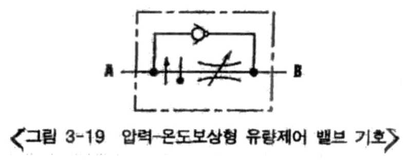
다음의 고성능수중펌프(36)는 당업자의 사양에 따라서 선택되는데는 데에는 소방방재대책용품으로 사용하기 위하여 손잡이에 안전 갈고리(13)와 훅크(18)에 와이어로프(19)를 장착할 수 있도록 별도의 설계로 플랜지(28) 타잎으로 송출구(토출구, 270)에는 송출구 규격 치수에 따라 플랜지 규격 치수로 사양 선택되며 하표와 하도와 같이설명한다.The following high-
특장점으로는As a feature
높은 기동(Torque)로 최강의 힘을 발휘하고 별도의 설계로 경량화 및 과열 방지 실현되며High torque to show the strongest power and separate design for light weight and overheating prevention
종전에는 토목, 건축공사에 터널 공사 중 또는 지하철 공사와 상·하수도 공사에 사용되고 있다.Previously, it has been used for civil engineering and building construction in tunnel construction, subway construction and water and sewage construction.
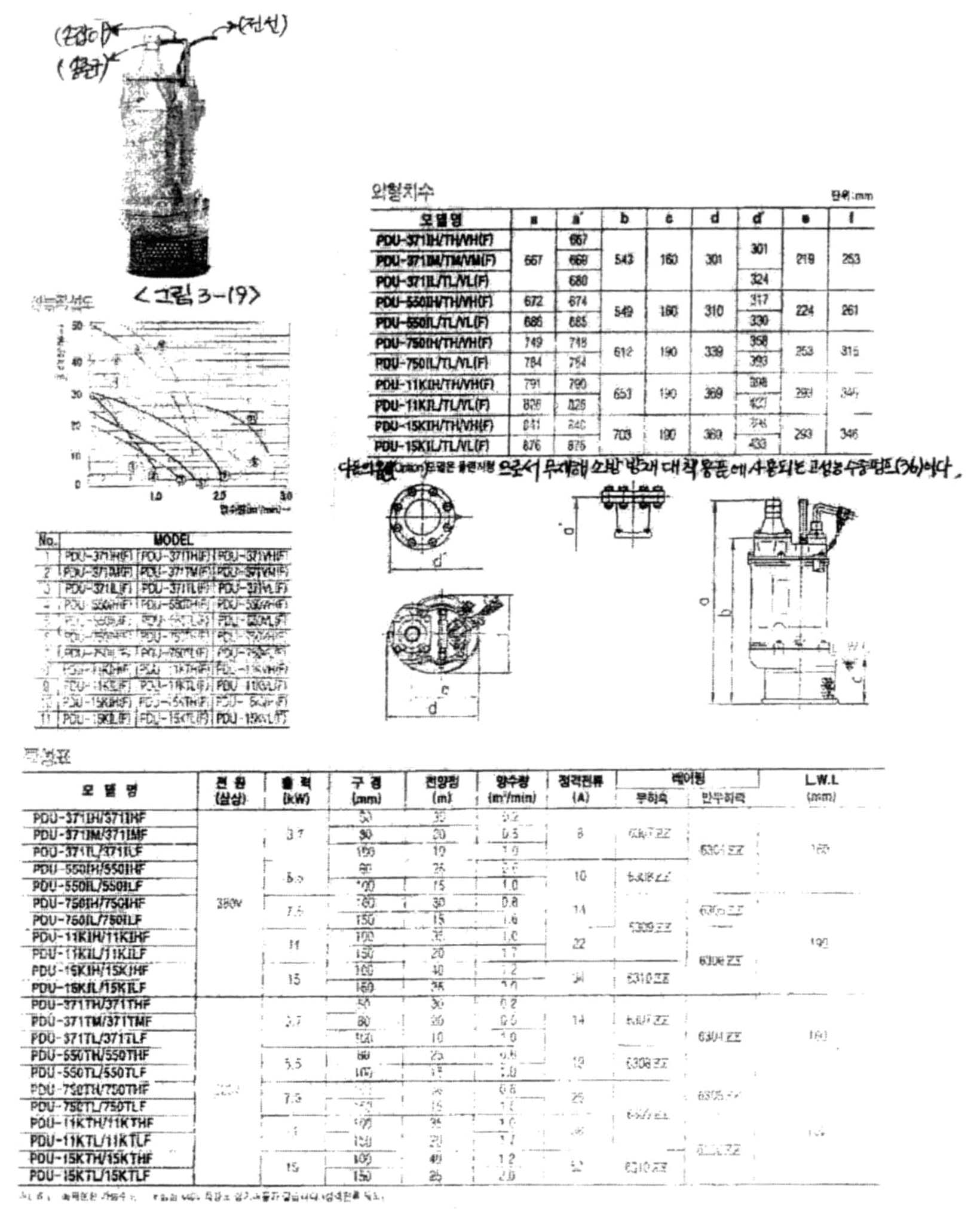
여기서, 소방센서펌프장치에 관한 상세한 구성 설명에 있어서, 대형화재 초기진화 및 인명구조를 위한 소방 방재 시스템은 근린생활 단독건물옥외, 옥내의 상수도배관(14) 수도꼭지용 급수밸브(495) 손잡이핸들(533), 중간부위연결접합부에, 엘보소켓붓싱나사부속티이엘보(44)를 부착한후 방화수방우량 체크용의 유량계(105) 부위로 방화수 제어장치 밸브로 설치구성되어야하고 상기 방화수 제어장치밸브라함 은 필요에 따라서 주택 옥내, 옥외로 발생되는 화재발생시 거주구 옥내 옥외로 구분하여 설치하고 상수도 배관(14)은 노즐호스로도 화재감지센서 감지용의 구멍난 호스(9)에 파라핀(100) 마개가 형성되어 호스 내부의 내수압에 해당되는 상수도 수압으로도 화재방지가 가능한 것이 포함하는 구성인데 여기에도 기체공급용 에어와 불연성가스(164)가 통과하면서 방화수는 발화물질이 설치배치되는 곳에는 파라핀 마개용 분사호스 노즐이 전진배치되어 불씨(292)와 불꽃(293)의 발화를 억제하고 이와동시에 최초발화 지점을 감지하는 최초발화 감지노끈(41)이 노즐몸체(B)상단으로 발화물질인 건물목재기둥 동서남북 실내 모서리와 천정바닥으로 여러곳에 부착한다.Here, in the detailed configuration description of the fire sensor pump device, the fire protection system for the initial fire extinguishing and life-saving of large-scale fire is a water supply valve (495) for the water supply pipe (14) faucet handles (outdoor, indoor buildings of neighborhood life) 533) After attaching the elbow socket bushing threaded
파라핀 테이프(177)와 발화비물질철사(176)로 형성된 후 파라핀 테이프(177)는 발화되어 이와 동시에 감지노끈(41)이 절단되며 방화수 급수제어장치밸브로 연결되는 감지센서바이메탈(102)과, 열전대 온도계 스위치(103)와, 솔레노이드밸브(76)에 조성된 솔레노이드 작동온오프스위치버턴(66)과 스위치작동후 비상싸이렌(93)이 소리내어 이에 경보장치와 함께 솔레노이드 밸브 스위치 작동용 추(107)가 작동되어 전자제어장치의 솔레노이드밸브(76)가 열림과 동시에 실내내부의 계단거치용 분사노즐(10) 그리고 벽면거치용분사노즐(10)과 천정거치용분사노즐(10)로 방화수는 신속하게 보급되어 발화지점의 불씨(292)와 불꽃(293)과 불기둥(294)을 방사선형의 틈새(15)와 일직선형의 틈새(15)로 방화수는 일직선형의 토출분사수(38) 그리고 방사형의 토출분사수커텐물막(39)으로 겹겹이 토출분사하여 불씨와 불꽃 그리고 불기둥에 부드럽게 서서히 신속 정확하게 초기진화되어 이와 동시에 소방차(402) 출동 현지 도착시간전에 불씨, 불꽃, 불기둥을 사전제거로하는 육지해상재난 발생방지를 하기 위한 지구촌 방재장치 장비시스템의 구성으로서, 토출분사수(38)와 커텐물막(39) 형상으로 일기 예보 관제시스템의 인터넷망 또는 육안으로도 식별할 수 있게 되며 집수정탱크 내부의 물수위감지로, 화재열을 온도감지센서로도 직접, 간접으로 감지하도록 구성되어 있는 본 발명은 종전의 기술과는 현격한 차이로 구분되는 구성이다After the paraffin tape 177 and the ignition
이렇게, 상기 다수의 소방방재장비는 길이 치수는 표준적으로 기재가 불가함이다 천태만상으로 건물구조가 다르기 때문에 "호칭25" "호칭40" "호칭65" 순서로 연결구 부속치수에 따라서 배관자재 및 부속을 선택하는것이 바람직하다. 또한 제어장치에 관한 본발명의 구성 설명은 첨부된 도면에 따라서 설명되어, 아래의 그림과 같이 제어장치 계통의 구성에는 실내의 화재발생시 거동불편자를 위하여 근린생활주거지 인명구조겸용 침대노즐(172)을 전진 배치하고 상기 노즐(172)는 가로×세로×높이(2000mm×600mm×800mm) 규격으로 구비하고 침대노즐상단부(A') 상단으로 인명구조겸용침대노즐(172)은 분사노즐용의 배관(14)으로 형성하고 침대상단으로 철판을 부착하며 소방침대하단부(B') 하단에는 노즐호스(9) 및 방재배관연결부속엘보(44) 그리고 분사노즐용의 배관(14)으로 연결된 분사노즐 연결플랜지(28)와, 노즐호스연결부속카플링(29)으로 분리결합하고 건물내부에 위치하는 소화전(179)에는 방호호스결합카플링으로 결속시키며 항상 영구적으로 전진배치되어 인명을 먼저 구제한후 불기둥(294)속으로In this way, the length of the fire protection equipment is not a standard length can not be described in the standard because the building structure is different from all over the place, "Nominal 25" "Nominal 40" "Nominal 65" in the order of piping materials and fittings according to the accessory dimensions It is desirable to select the parts. In addition, a description of the configuration of the present invention with respect to the control device is described in accordance with the accompanying drawings, the configuration of the control system as shown in the following picture, the living room life-saving bed nozzle (172) for the disabled in the event of a fire in the room The
상기 노즐(10)을 밀어 넣어서 많은 양의 방화수가 방출되면서 수직수평의 방 사선 형의 노즐 틈새(15)와, 일직선형의 노즐 틈새(15)에서 분출되는 다수의 개 490여개소의 분출수는 냉각작용과 8개의 분출수막은 인명구조용 수막이되도록 하고 진화장비보관 거치 장비 거치대(33)에는 일정량의 노즐호스 에어공급을 위한 에어콤프레샤(80)와, 산소구급용에어호스(109)로 산소마스크를 설치토록하고 빌딩(333) 복도 및 목조건물(166) 마루에 노출시켜서 안전소방의식을 인지하고 주지하고 상기 다수개의 수직 수평의 노즐틈새(15)는 천정에서 방바닥을 향하여 수직 하향식이 겹겹이 일직선 틈새가 형성된 후에는 벽체에는 수평틈새(15)가 방내부 중심으로 향하도록 함으로써 질식가스(163)와 발화물체(166)로부터 인명을 구조하는 방식의 노즐 틈새(15)이다A large amount of fire water is discharged by pushing the
상기 노즐이 구비되지 않은 아주 긴박한 상황으로 확산 전개될시기에는 이불을 똘똘말아서 목욕탕 욕탕내로 잠수하는 방법으로 질식가스(163)로부터 탈피하기 위하여 하수구 배관을 숨구멍으로 하여 물호스(9)를 사용토록하여 소방요원 출동과 함께 인명구조가 신속 정확하게 이루어짐을 특징으로 하는 무재해소방방재대책용품의 관노즐이동형 소방센서펌프의 인명구조수단이 포함된 장치로 구성함을 기술적 요지로서 항상 침착하게 대비하여 인명구조 방식을 안방부터 개선시키도록 하여야 되고 근린생활거주구 화재는 벽면쪽으로 발화물이 위치 배치되는 관계로 전선이 지나는 곳에는 배관의 소방관노즐(10)이 벽면거치용 천정배치용으로 건물의 수명과 함께 분사노즐은 옥내옥외로 설비되어 낡은 전선의 전선피복 위에 미세섬유질 먼지와, 발화먼지누적물질 또는 전선상단부 미세발화먼지누적물질에 화재발생시 즉시 조치되어 발화가 멈추도록 해야되고, 또한편 빈집건물에 화재가 발생되는 원인으로 는 집쥐에 의해서 전선피복을 절단하여 전기 합선과 전기누전에 의해서 화재발생되어 이때 화재열 감지센서 파라핀테이프(177)와 감지노끈(41)이 불타면서 상기 관노즐에서 분출되는 다수개의 수막이 소방방재장치로 구성된다(이하 A화재 이외의 구성 설명이라 칭함)When the diffusion is deployed in a very urgent situation where the nozzle is not provided, the
그리고, 대형산불 및 인근 근린생활 주거지 대형화재를 초기진화하고 사전예방에 필요한 것으로서 안전 통제실이다. 이곳에서는 다수의 소방케이블카아(256) 수송장비탑승 근무자를 보좌하고 진화명령을 무선으로 교신하고 소방장비배치와 전원공급실과 기계실의 장비를 관리운용하는 장소인데 일기예보에 따라서 봄철에서 다음 봄철까지 건조주의보 발생되는 상황에 따라 무동력펌프인 수격펌프(393)와 입형다단펌프(8)를 가동하여 방화수를 방재배관 후미로 설치되는 분사노즐을 통하여 토출분사토록 해야되고 또는 에어콤프레샤(80) 가동으로 방재수로(17)와 집수정 탱크(가로×세로×높이; 10M×10M×2M, 34)로 에어노즐(Spray jet type; 미도시)이 별도로 구성 작동되어 폭우로 인해서 산사태, 도로유실 계곡물범람되어 위험경보발령이 내리면 집수정의 방화수 및 방재수로의 방화수를 억제, 조절, 하도록 통제실 내부에는 인터넷망(50), 관제서버 왼쪽으로 모니터(52), 휴대용무선통신단말기(82)로 수송장비(73)내의 휴대용무선통신단말기(82)로 지상근무자와 수송장비 승무원과의 송수신 대화로 부스터 펌프제어 또는 관제시스템(150)을 운용하는 방식으로 대형산불 인근근린지역주거지 대형화재 발생시의 근무자간의 업무가 포함되는 구성인데 본 발명에서는 소방방재로 청구의 범위를 한정한다In addition, it is a safety control room as it is necessary for the early evolution and prevention of large fires and large-scale fires in neighboring residential living areas. This place is a place where many fire-fighting cable car (256) transportation equipment passengers are assisted, fire-fighting orders are communicated wirelessly, fire-fighting equipment placement, power supply room and machine room equipment management and operation are constructed from spring to next spring according to the weather forecast. In accordance with the occurrence of the warning, the hydraulic-powered
지상근무자가 공석일때는 수송장비 승무원은 방재장비보관노즐호스장비거치 대(33)에 부착된 펌프작동스위치버턴(66)이 전원부(62)로 연결되어 동력전원공급장치인 전원(46)과, 연결된후 입형다단 펌프제어박스(2) 내부에는 펌프제어시스템(150), 입형다단 펌프제어보드(53)로 연결되어 수송장비 승무원이 방재장비보관노즐호스장비거치대(33)에 보관된 소방케이블카아(256) 수송장비 탑재용 분사노즐(10)을 수송장비 갈고리 훅크(18)로 설비거치대에서 분리함과 동시에 수격펌프(393) 또는 입형다단 펌프(8)가 눈깜짝하는 순간 가동되도록하는 구성으로 종전에는 소방차로 헬기가 비상싸이렌(93)을 울리고, 도로에 통과차량의 교통흐름을 방해하는 사례등이 해소되는 효과가 발생됨을 인지한다.When the ground workers are vacant, the transport equipment crew is connected to the pump
상기 동도면에 도시한 바와 같이, 방화수(7)는 방재수로(17) 내부로 산정상 하단부(AD)와 (AE) 지점의 골짜기를 따라서 8부 능선과 5부 능선 별로 경사각도(16) 1°의 방재수로(17) 낮은 방향으로 방화수는 일정한 각도(16)를 유지하면서 능선별로 회전하여 (AD)지점과 (AE)지점으로 방화수를 환원 시키며 집수정탱크(34)는 산림자원의 많고적음에 따라서 50미터에서 100미터 구간으로 조절하고 규격에 있어서는 대,중,소 단위로 구분하고 집수정탱크(34) 내부에 방화수가 급격히 감소하게되면 그 즉시 화재발생감지기능의 방화수수위감지센서보올탭(499) 또는 플로우트(315)에 형성된 플로우트스위치(318) 또는 보올탭이 작동된 후 집수정 내부에 물이 채워지되, 물호스 또는 방화수수위 감지센서 와 드레인마개철판 또는 밸브를 설치한 후 8부 능선 상단의 꼭대기 산정상부위는 산높이에 따라서 (U)형과 (W)형의 높은산(a1)에서 낮은산(b1)(c1)부위로 소방방재 배관라인(168)을 형성 후 낮은 산(b1)(c1)의 주변 정상은 능선별로 계단식 높이 낙차에 의한 수격작용(389)의 수격펌프(393)를 계단식으로 상기 펌프(393)를 설치한다. [도2-27]과 같이 집수정탱크(34)와 방재수로(17)을 조성 한후 능선별 집수정탱크(34) 주변에 위치하는 다수개의 각 펌프로 방화수를 방재수로(17)에 머무름을 반복을 하여 방화수를 되돌려 분산시키면서 유량의 흐름을 제어할 수 있게 형성되되 상기한 방재수로(17)로 계곡의 물을 범람하지 않도록 하여 홍수조절기능이 포함하는 구성이다. 상기 구성은 화재발생과 동시에 다수의 개울, 늪지조성은 위급한 상황에서는 1초 이내에 인명이 구제되는 수단의 효과를 볼 수 있다 이에 따라 산림(266) 육성의 필요성에 따라서 당연히 산불발생전 관노즐이동형 소방센서펌프몸체(1) 내부로 이에 동반되는 환경 개선 사업을 형성하되, 도로지표면(GLL)의 사정으로 방재수로(17)와 집수정탱크(34)는 규격의 특정이 곤란하여 치수는 생략하였다, 통상 집수정탱크(34) 용적량은 700m3 적정한 부피로 세멘트 콘트리트 구조물 또는 철판으로 형성된 구조물에 대체하는 푸라스틱 재질로서 이중 비닐 또는 비닐봉지(45)로 기체와 액체로 형성된 방재물질로 산불방지장비로서 적합하게 구성한다As shown in the same drawing, the
한편 수송장비에 탑재된 분사노즐 및 노즐호스 그리고 소방케이블카(256) 수송장비엔진(226)에 의한 고성능 수중펌프(36)를 사용하여 밭두렁 논두렁으로 방화수를 방재수로와 집수정에 투입하여 화재발생전 확고한 진화 방재를 이루는 구성이다.On the other hand, by using a spray nozzle and nozzle hose mounted on the transportation equipment and a high-
여기서 늦은감이 있지만 "방재" 및 "방제"의 용어의 정의를 파악한 후 설명 을 진행토록 함인데 본 발명의 풍수력발전기가 설치된 오대양 육대주에는 무재해가 완성됨과 동시에 상기 전력(685)을 항구적으로 공급할 수 있는 펌핑과 연결된 분사장치이다Although there is a late feeling, it is necessary to proceed after the definition of the terms of "disaster prevention" and "resistance" to proceed the description. Injectors connected to pumping
일반적으로 건설기계 일체와 유압 회전실린더(620)에 유압실린더 또는 유압작키(623)와 유압실린더용 도어(잠수함 후미 또는 자동차 탑재용 선박 선체 선수 선미 중간부위에 형성된 문짝, 624) 등에는 유압실린더(623)가 많이 사용되는데, 특히 로봇의 관절 마디로 많이 사용하며 상기의 실린더(620)는 회전시에 사용하고 유압실린더(623)는 물체를 밀고 당기는데 사용 적합하다. 상기한 유압실린더 몸체는 피스톤(127)과 분해 결합을 하게 되며 상기 피스톤(127) 몸체와 상기 실린더에는 압축기능을 발휘하도록 로드앤드피스톤시일(822)에 피스톤시일(823)과 부프시일(824)에 웨어링(825)과 스라이드링(826)에 디유부시(DU Bush, 827)와 오링(O-RING, 828)과 로드시일(829)에 벡업시일(Back up seal, 830)과, 로드시일&벡업시일(831)에 다스트시일(832)과 핀다스트시일(833)에 다스트위프시일(834)과 부프링(835)에 피스톤링(836)과 다스트링(837) 등의 고무제로 피스톤(127) 둘레면과 실린더(126) 내부로 형성된다.Generally, a hydraulic cylinder or a
상기한 실린더 몸체는 유압펌프와 재결합 분리 가능하게 연결장치 부분품인 고압용배관(14)과 레듀사(35)와 엘보 또는 티이엘보(44)에 플랜지(28)를 구비하여 압력릴리이프식 안전밸브(474)와 유압호스(190)에 결합된 카플링(29)의 암수 나사산 결합 등이 있는데 유압의 개요와 유압의 용도에 유압의 특징으로 분리하여 다음과 같이 설명한다.The cylinder body is provided with a pressure relief type safety valve having a
먼저 유압의 정의에 대하여,First about the definition of hydraulic pressure,
유압(hydraulics)이란 동력을 이용한 유압 펌프에 의하여 기계적 에너지를 유체의 압력에너지로 변화시켜 유압유에 저장하게 하며 이를 제어밸브에 의해서 압력(힘의 제어), 유량(속도의 제어), 방향전환(방향의 제어)의 3가지 기본제어 요소를 목적에 따라 조합하여 유압실린더나 유압모터 등의 작동기(actuator)를 통하여 다시 기계적 에너지로 전환하는 장치 또는 방식을 의미한다.Hydraulics means that the mechanical energy is converted into the pressure energy of the fluid by a hydraulic pump using power and stored in the hydraulic oil, and the pressure (control of force), flow rate (control of speed), and direction change (direction) are controlled by a control valve. Means a device or a method of combining three basic control elements according to the purpose and converting them back into mechanical energy through an actuator such as a hydraulic cylinder or a hydraulic motor.
다음은 유압의 역사적 배경에 있어서,Next is the historical background of hydraulics,
과학의 발전에 따라 자연의 에너지를 동력으로 사용하면서 동력을 유효하게 전달하고 경제적으로 활용하기 위한 유체동력기술은 1653년에(파스칼)의 법칙이 발견되면서 개발이 시작되었다. 1850년 영국에서 산업 혁명이 일어날 무렵에 영국에서 유체동력 회사가 생겼다. 이 회사에서는 7000마력 상당의 펌프 시설을 갖추고 유압동력을 각 사용자에게 공급해 주었고 공급선은 120km 정도이고 이 동력을 이용해서 기계를 동작시키고 있는 예로서 콜리세움 극장의 회전무대, 타워브리지(Tower Bridge)의 개폐, 영국기계학회 건물 정문의 개폐 등등이었다.With the development of science, the development of fluid power technology for the effective transmission and economical use of natural energy as power was developed in 1653 when the law of Pascal was discovered. By the time of the Industrial Revolution in England in 1850, a fluid power company was established in England. The company has a pumping facility of 7,000 horsepower and supplies hydraulic power to each user. The supply line is about 120 km and the machine is operated using this power. For example, the rotating stage of the Coliseum Theatre, Tower Bridge. Opening and closing, opening and closing of the front door of the British Society of Mechanical Engineers.
1900년대에 와서는 전기가 동력화 됨으로서 유체동력의 이용이 쇠퇴하였으며 전력은 장거리 동력 전달에 있어서 유체동력 보다 우수하지만 장거리 수송이 없는 단일체 내의 동력전달에 있어서는 유체동력이 출력 대 중량의 비가 전력보다 우수하므로 1900년 후반부터 이용이 급속적으로 증가하였다.In the 1900s, the use of fluid power declined as electricity was powered, and power was superior to fluid power in long-distance power transmission, but in power transmission within a unit without long-distance transport, the fluid power was superior to the power-to-weight ratio. Since the late 1900s, usage has increased rapidly.
이러한 유압의 용도에 있어서,In the use of such a hydraulic pressure,
상기 유압은 앞으로 응용범위가 대단히 넓어지겠으나 주된 용도를 알아보면 직선 운동이나 회전운동 그리고 큰 힘이 필요한 곳이나 속도를 바꾸는 경우 등에 주로 사용한다. 유압설비는 이동식과 고정식으로 크게 나눌 수 있다.The hydraulic pressure will be very wide range of application in the future, but the main purpose is to use the linear motion or rotational motion and the place where a large force is required or when changing the speed. Hydraulic equipment can be largely divided into mobile and stationary.
먼저 이동식 유압(mobile hydraulics)에 있어,First in mobile hydraulics,
이동식 유압장비는 바퀴나 체인을 이용하여 이동이 가능한 장비이고 이동식 유압장비에서 밸브는 주로 수동으로 작동된다.Mobile hydraulics are machines that can be moved using wheels or chains. In mobile hydraulics, valves are operated manually.
첫째로 건설기계는 굴삭기와 트럭에 크레인과 불도저에 로더 등이다. 다음은 운반기계로는 자동차의 파워핸들과 토크컨버터와 청소차에 콘크리트믹서트럭과 포크 리프트 등에 사용되며 그 다음의 선박 갑판기계는 원치와 조타기로 이용되고 네째로 비행기에는 각종 비행기의 조종장치와 착륙바퀴 구동장치 등이었고 다음의 하역기계는 상하역 크레인과 승강기의 콘베어장치 등이며 농기계로도 사용한다.Firstly, construction machinery includes cranes on excavators and trucks and loaders on bulldozers. Next, as a transport machine, it is used for automobile power handles, torque converters and sweepers, concrete mixer trucks and forklifts. The next ship deck machine is used as a gear and a steering wheel. Fourth, the airplane controls and landing wheels. It was a driving device, and the following unloading machines are the conveyor devices of the upper and lower cranes and the elevators, and are also used as agricultural machines.
다음의 고정식 유압(stationary hydraulics)에 있어 하도와 같이 설명한다.The following stationary hydraulics are described as the diagram below.
상기 고정식 유압장비는 한 장소에 견고하게 설치되어 가동되는 장비를 의미하며, 주로 전기신호, 즉 솔레노이드 밸브(76)에 의하여 작동되는데The stationary hydraulic equipment refers to equipment that is firmly installed and operated in one place, and is mainly operated by an electrical signal, that is, a
상기의 공작기계는 자동조정선반에 다축드릴과 트랜스퍼머신 등이었고 철강기계로는 시어링과 권선기에 사용되었는데 그 다음 금속기계는 주조기로 사용하였고 그리고 합성수지기계에는 사출과 압출기로도 사용하며 한편 목공기계로 핫프레스와 목재 이송차로 이용되고 제본·인쇄기계에 제단기와 옵셋인쇄에 윤전기로도 이용하였고 그 이외로는 소각로와 레저시설에 로켓트와 로봇 등에 사용된 것이었다.The above machine tools were multi-axis drills and transfer machines on automatic adjusting lathes, and used for shearing and winding machines for steel machines. Then, metal machines were used as casting machines, and plastic machines were used as injection and extruders. It was used as a hot press and a wooden transport truck, as a rotary press for bookbinding and printing machines, and as a rotary press for offset printing. Others were used for rockets and robots in incinerators and leisure facilities.
상기한 유압의 특징에 있어서,In the characteristic of the above-mentioned hydraulic pressure,
먼저 유압의 장점으로는First of all, the advantages of hydraulic
상기 시스템(system)의 크기에 비해 큰 힘을 발생하며 정확한 위치제어가 가능하고 큰 부하 상태에서의 시동 가능하여 부하와 무관한 정밀한 운동에 그리고 정숙한 작동과 반전으로 뛰어난 제어(힘, 방향, 속도) 및 조절성과 뛰어난 열방출성을 감지할 수 있다는 것이다.Compared to the size of the system, it generates a large force and enables accurate position control and can be started in a large load state so that it can be controlled precisely regardless of load and excellent control (force, direction, speed) due to quiet operation and inversion. And controllability and excellent heat dissipation.
이러한 유압의 단점에 있어,On the downside of this hydraulic pressure,
폐유에 의한 주변 환경의 오염에 이물질에 민감하여 고압사용으로 인한 위험성과 온도변화에 따른 작업조건의 변화로 낮은 효율 등이다.It is sensitive to foreign matters by the pollution of the surrounding environment by waste oil, and it is low efficiency due to the change of working condition due to the change of temperature and the danger of using high pressure.
이처럼, 유압장치의 구성에 있어Thus, in the construction of the hydraulic device
상기 유압 시스템은 먼저 동력공급(power supply)과 제어(control)와 그리고 출력(output) 부분으로 나누어질 수 있다. 동력공급 부분은 시스템에 유량을 공급하며, 가장 중요한 부품은 원동기(prime mover)와 펌프(pump)이다. 원동기는 펌프를 구동하는데 필요한 기계적인 동력을 제공하는 장치이다. 산업 시스템에서는 이 장치로서 일반적으로 전동기가 사용되며, 굴삭기나 농기계와 같은 차량의 경우에 원동기는 자동차의 엔진이다. 펌프는 원동기로부터 기계적 동력을 얻어서 이를 압력을 지닌 유체의 유동으로 변환시키는 역할을 한다.The hydraulic system may first be divided into power supply, control and output parts. The powering section supplies flow to the system, the most important of which are prime movers and pumps. A prime mover is a device that provides the mechanical power needed to drive a pump. In industrial systems, this device is commonly used as an electric motor. In the case of vehicles such as excavators and agricultural machinery, the prime mover is the engine of the car. The pump takes the mechanical power from the prime mover and converts it into a flow of fluid with pressure.
상기한 유압 시스템의 출력 장치로는 액추에이터(actuator)와 부하(load)가 포함된다. 액추에이터는 유체의 동력을 기계적 동력으로 변환시켜 부하를 움직이는 역할을 한다. 액추에이터는 직선운동을 하는 실린더(선형 액추에이터)일 수도 있고, 또는 회전운동을 생성하는 유압 모터(회전 액추에이터)일 수도 있다.The output device of the hydraulic system includes an actuator and a load. The actuator converts the power of the fluid into mechanical power to move the load. The actuator may be a cylinder (linear actuator) that performs linear motion, or may be a hydraulic motor (rotating actuator) that generates a rotational motion.
이에 제어장치는 유압 시스템의 중간에 위치하고 있으며 부품으로는 방향제어 밸브, 압력제어 밸브, 그리고 유량제어 밸브가 포함된다. 예를 들면 실린더가 전진하거나 후퇴하는 것과 같이 유체 흐름의 방향제어에 의해 액추에이터의 운동 방향을 조절할 수 있다.(파스칼)의 법칙에서 서술했던 바와 같이, 유체의 압력을 제어하는 것은 출력의 힘을 조절하는 것이 된다. 또 유량을 제어하는 것은 액추에이터의 운동속도를 조절하는 것이다.The control unit is located in the middle of the hydraulic system and its components include directional valves, pressure control valves and flow control valves. For example, the direction of movement of the actuator can be adjusted by directional control of the fluid flow, such as the cylinder moving forward or backward. As described in Pascal's law, controlling the pressure of the fluid regulates the output force. It becomes. In addition, controlling the flow rate controls the movement speed of the actuator.
먼저 압력원부의 형성에 있어First, in the formation of the pressure source
필요량의 오일을 모아두는 탱크, 탱크로부터 오일을 퍼내서 회로 내로 보내는 유압 펌프와 동력원을 보호하기 위한 안전밸브 등으로 구성되고 있으나 이 부분도 장치 고유의 필요성에 맞추어 여러 종류의 기기가 사용된 펌프로 기어와 베인에 피스톤 펌프로 전동기와 탱크에 릴리프 밸브와(Shut-off) 밸브에 압력게이지와(Heat-exchange) 온도계에 휠터로 흡입라인에 압력라인과 복귀라인 등에 형성되었고,It consists of a tank that collects the required amount of oil, a hydraulic pump that pumps oil from the tank into the circuit, and a safety valve to protect the power source. Piston pumps on gears and vanes, relief valves on motors and tanks, shut-off valves and heat-exchange thermometers, filter lines on suction lines, pressure lines and return lines,
다음의 제어부는 하표와 같이 설명한다.The following control unit will be described as shown in the following table.
오일의 압력을 조절하는 압력제어밸브, 오일의 흐르는 방향을 전환하고 작동기의 작동방향을 전환하는 방향전환밸브, 작동속도를 조정하는 유량조절밸브 등이 구성요소로 되어 있는데 압력제어 밸브는 릴리프 밸브와 감압 밸브에 시퀀스 밸브와 무부하 밸브에 카운터 밸런스 밸브이며 방향제어 밸브로는 2/2와 3/2에 4/2와 4/3에 5/2-way 밸브이고 유량제어 밸브에는 오리피스와 스로틀(작동속도를 조절)로 형성한다.Pressure control valve to control the pressure of oil, direction change valve to change the flow direction of the oil and the operation direction of the actuator, flow control valve to adjust the operating speed, etc. Sequence valves for pressure reducing valves and counter-balance valves for no-load valves; for
<표 1-1 유압장치의 구성><Table 1-1 Configuration of Hydraulic System>
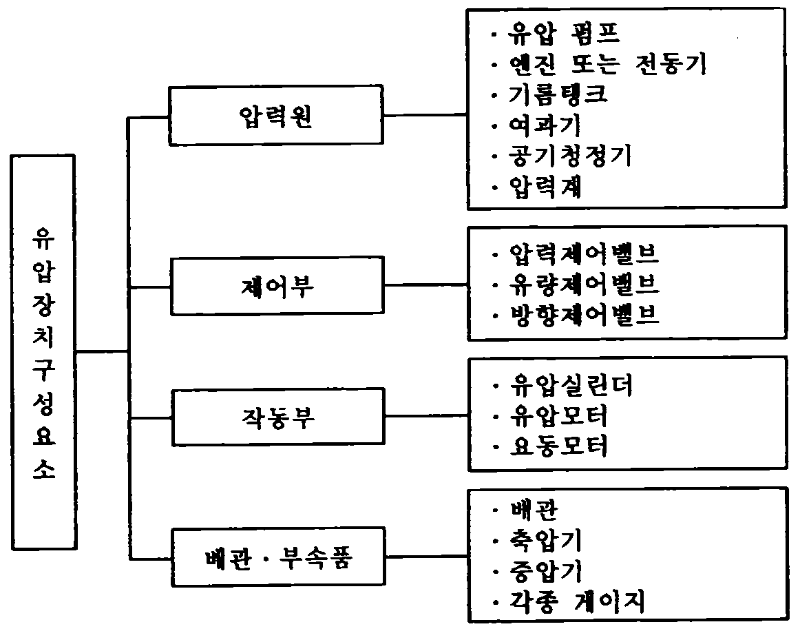
이처럼 작동부는 직선운동과 회전운동에 요동운동으로 하표와 같이 설명한다Like this, the moving part is described as the bar as the swing motion in the linear motion and the rotation motion.
{직선운동 : cylinder(직선적으로 누르거나 끌거나 한다.)}{Linear motion: cylinder (linearly press or drag)}
{회전운동 : motor(중량물을 와이어로프로 말아 올린다.)}{Rotational movement: motor (roll up the weight with wire rope)}
{요동운동 : 요동 motor(일정각을 회전)}{Swinging motion: rocking motor (rotate constant angle)}
<표 1-2 유압장치 내의 동력과 압력유><Table 1-2 Power and Pressure Oil in Hydraulic System>
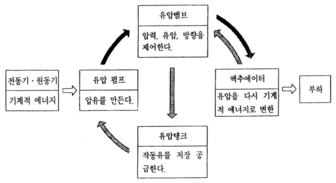
상기된 주요한 물리량과 단위의 물리량에 질량과 힘에 압력과 동력의 단위는 하표와 같이 상세한 설명을 다음과 같이 한다Units of pressure and power on mass and force on physical quantities of main physical quantities and units described above are detailed as follows:
첫째로 물리량에 있어First in physical quantities
물리량이란 물체의 특성, 즉 측정할 수 있는 상태나 과정이다. 예를 들면 속도(속력), 압력, 시간, 온도는 물리량이고 색은 물리량이 아니다.A physical quantity is a characteristic of an object, that is, a state or process that can be measured. For example, speed (speed), pressure, time, and temperature are physical quantities, and color is not physical quantity.
ㆍ길이는 Meter(m)로ㆍ The length is meter (m)
ㆍ질량은 Kilogram(kg)으로Mass is in kilograms (kg)
ㆍ시간은 Second(s)로ㆍ Time is Second (s)
ㆍ온도는 Kelvin(K) 혹은 Celsius(℃)로 표준화 되었고 유압에서 중요한 물리량 즉 힘, 면적, 유량, 량, 압력, 속도 등은 위의 기본단위에서 유도할 수 있다. SI는 kg을 질량의 단위로써 정의한다.Temperature has been standardized in Kelvin (K) or Celsius (℃), and the important physical quantities in hydraulics, such as force, area, flow rate, volume, pressure and speed, can be derived from the basic units above. SI defines kg as a unit of mass.
둘째 질량에 있어On the second mass
질량은 일반적으로 무게라는 용어와 같이 사용한다. 지구상에서 1kg의 무게를 갖고 있는 정육면체 강재는 1kg의 질량을 가진다.Mass is generally used with the term weight. A cube steel weighing 1 kg on earth has a mass of 1 kg.
세째로 힘에 있어Third, in power
질량은 중력 가속도에 관계없이 자체적인 성질을 갖고 있는 질량단위를 설명하는데 있어서, 힘의 단위는 중력 가속도와 관련되어 결정된다.Mass describes a unit of mass that has its own properties regardless of the acceleration of gravity. The unit of force is determined in relation to the acceleration of gravity.
(Newton,1643-1729)법칙에서 힘 = 질량×가속도(F=m×α), 힘 = kg×m/s2 이것을 간단하게 Newton[N]이라 한다.(Newton, 1643-1729) In the law, force = mass × acceleration ( F = m × α ), force = kg × m / s 2 This is simply called Newton [N].
1N = 1kg·m/s2 1N = 1kgm / s 2
네째로 압력에 있어Fourth, in pressure
압력이란 "물체의 단위면적에 가해지는 힘의 크기"이며 그 단위로는 지금까지 미터법 공학단위인 [kgf/cm2]나 [kgf/m2]가 주로 사용되었으나 앞으로는 SI단위인 [N/m2], 즉 Pa(Pascal이라고 읽는다)을 써야 할 것이다.Pressure is "the magnitude of force applied to the unit area of an object". As the unit, metric engineering units [kg f / cm 2 ] or [kg f / m 2 ] have been mainly used, but SI units [ N / m 2 ], ie Pa (read Pascal).
![]()
![]()
압력의 값은 일반적으로 대기압과 비교를 한다.The value of pressure is usually compared with atmospheric pressure.

먼저 대기압(atomospheric pressure)은First, atmospheric pressure
지구를 둘러싼 공기를 대기라 하고 그 대기에 의하여 누르는 압력을 대기압이라 한다.The air surrounding the earth is called the atmosphere, and the pressure pressed by the atmosphere is called atmospheric pressure.
※표준대기압※ Standard atmospheric pressure
1atm = 760mmHg(수온주 높이) = 10332kgf/m2 = 1.0332kgf/cm2 1atm = 760mmHg (Water column height) = 10332kg f / m 2 = 1.0332kg f / cm 2
= 10.332mAq(물의 높이) = 101325N/m2 = 1.01325bar= 10.332 mAq (water height) = 101325 N / m 2 = 1.01325 bar
다음의 게이지 압력(gauge pressure)은The next gauge pressure is
게이지에 의하여 측정된 압력이며 국소 대기압을 기준으로 하여 측정한 압력이다.The pressure measured by the gauge, based on the local atmospheric pressure.
그리고 절대 압력(absolute pressure)은And absolute pressure
완전진공을 기준으로 하여 측정한 압력이다.The pressure measured on the basis of full vacuum.
다섯번째 동력에 있어In fifth power
일이란 소비된 에너지의 양으로 정의되고, 가해진 힘과 힘 때문에 이동한 거리와의 곱으로 계산된다(W = F·S). 만약 어떤 물체를 40m 이동하는데 300N의 힘이 필요했다고 하자. 이 경우 한 일은 W = 300N·40m = 1200N·m[J]이다. 그러나 일이라는 개념만으로는 알 수 없는 것이 물체를 얼마나 빨리 이동하였는가 이다. 이 일은 10초 아니면 5초만에 행해졌는가? 즉 동력(power)은 에너지가 얼마나 빨리 소모되었는가를 고려하는 것이다. 한 일을 일이 행해진 시간으로 나눔으로써 동력에 대한 식을 구하게 된다.Work is defined as the amount of energy consumed and is calculated as the product of the force and the distance traveled because of the force ( W = F · S ). Let's say you need 300 N force to move an
![]()
![]()
만약 일이 N·m이고 시간이 초(s)라고 하면, 동력은 N·m/s로 될 것이다. 일반적으로 동력의 기호로는 대문자로 P를 사용하는 반면, 소문자 p는 압력의 기호로 사용된다. 위 식에서 s/t를 속도 υ로 바꾸어 넣으면 다음과 같이 된다.If that happens N · m and the time two seconds (s), power will be in N · m / s. Normally, P is used as the symbol for power, while lowercase p is used as the symbol for pressure. Replace s / t with the speed υ in the above formula:
![]()
![]()
만약 힘이 N이고 속도가 m/s라면, 동력의 단위는 N·m/s가 된다. 동력은 마력(horse power; hp)으로도 표현한다. 이 두 가지 단위 사이에서 변환 관계는 다음과 같다.If the force is N, the velocity is m / s, a unit of power is the N · m / s. Power is also expressed in horse power (hp). The conversion relationship between these two units is:
![]()
![]()
단위간의 변화 관계를 방정식에 적용했기 때문에 위 식에서 힘은 N, 속도는 m/s로 단위 사용을 제한한다. 다른 어떤 단위로도 사용하면 안 된다. 단위간의 변 환 관계를 미리 고려하여 만들어진 이러한 방정식은 편리함 때문에 산업현장에서 많이 사용된다.Since the change relation between units is applied to the equation, the force is N and the velocity is m / s. It should not be used in any other unit. These equations, which are made in advance by considering the conversion relationship between units, are frequently used in industrial fields because of their convenience.
국제단위계에서 동력은 조함단위로서 와트(Watt ; W)를 사용하고 있다. W는 크기가 작은 단위이므로 일반적으로 킬로와트(kW)로 표현한다. 적합한 변환인수(1kW = 1000W)를 식 (1.2)에 넣으면 국제단위계에서 사용하는 다음 식이 얻어진다.In the international system, power is used in units of watts (W); Since W is a small unit, it is usually expressed in kilowatts (kW). Inserting the appropriate conversion factor (1kW = 1000W) into Eq. (1.2) gives the following equation for use in international units.
![]()
![]()
위 식에서 계산한 값의 단위가 킬로와트(kW)임을 나타내기 위해 kW란 기호를 사용하였다. 식 (1.3)에서 적용되는 단위는 F(힘)는 N,υ(속도)는 m/s이다.The symbol kW is used to indicate that the unit of the value calculated in the above formula is kilowatt (kW). The unit applied in Eq. (1.3) is F (force) is N and υ (velocity) is m / s.
이처럼 유압기계에서 사용되는 간단한 유체역학의 연속방정식에 베르누이 방정식과 유체의 정역학에 파스칼의 원리와 압력전달의 원리에 유체의 유동과 마찰의 흐름을 하도와 같이 상세히 설명한다Thus, the simple equation of hydrodynamics used in hydraulic machines is explained in detail by the Bernoulli's equation and the hydrodynamics of Pascal and the principle of pressure transfer.
먼저 연속 방정식에 있어First in the continuous equation
연속 방정식은 질량 불변의 법칙을 유체의 흐름에 적용한 것으로, 폐곡선의 관로 속 유체는 도중에 생성되거나 소멸되지 않는 것을 뜻한다.The continuity equation applies the law of mass invariance to the flow of fluid, meaning that the fluid in the conduit of the closed curve is not created or destroyed on the way.
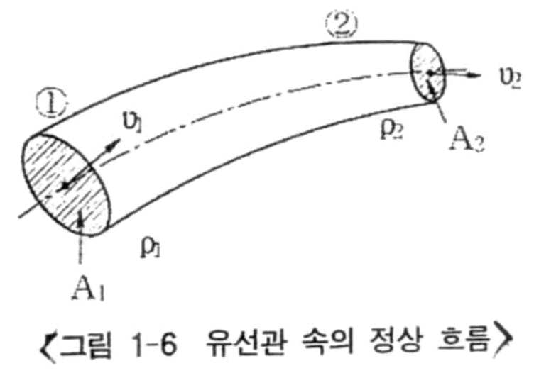
그림 1-6에 나타낸 관로 속의 흐름을 정상류(steady state flow)라 생각하고 유체는 압축성을 고려하지 않을 때, 이 관에 직교하는 임의의 단면 ①과 ②를 설정하고 그 단면에서의 평균유속을 각각 υ 1 υ 2, 단면적을 A 1 A 2, 밀도를 ρ 1 ρ 2라 한다. 이 때 단위 시간당 각 단면을 흐르는 유체의 양은 질량 불변의 법칙에 따라 같지 않으면 안 된다. 즉 질량을 m이라 하면When the flow in the pipeline shown in Fig. 1-6 is considered steady state flow and the fluid is not considered compressible, the
![]()
![]()
이 되어야 한다. 여기서 ![]()
![]()
![]()
![]()
여기서 유체가 비압축성인 경우에는 ρ = Const.이므로Where the fluid is incompressible, then ρ = Const. Because of
![]()
![]()
으로 된다. 이 Q를 유량이라 하고 관로 속을 지나는 유체의 유량은 어느 단면에 있어서나 일정하다는 것을 나타낸다. 즉 유압에서는 유량이란 "단위 시간에 이동하는 액체의 양"을 말하며 토출량으로 표현하고 있다.Becomes This Q is called the flow rate and indicates that the flow rate of the fluid passing through the pipe is constant in any cross section. In other words, in the hydraulic pressure, the flow rate refers to "amount of liquid moving in a unit time" and is expressed as a discharge amount.
유량은 통상적으로 기호 Q로 표시하고 단위는 ℓ/min. cc/sec 등으로 표시한다. 또한 유속은 "단위 시간에 이동하는 유체의 거리"를 말하는 것으로 위 식으로 부터The flow rate is usually denoted by the symbol Q and the unit is l / min. cc / sec or the like. Also, the flow rate refers to the "distance of the fluid moving in unit time".
![]()
![]()
가 되고 단위로 m/s로 표시된다.In m / s.
다음의 베르누이 방정식에 있어In the Bernoulli equation
베르누이 방정식은 비압축성 유체의 전체 에너지에 대한 관계를 설명하고 있다. 유압유는 거의 비압축성이므로 베르누이 방정식은 유압시스템에 사용할 수 있다.Bernoulli's equation describes the relationship to the total energy of an incompressible fluid. Since hydraulic oil is almost incompressible, the Bernoulli equation can be used in hydraulic systems.
유체의 에너지는 세 가지 형태로 나타낸다.The energy of a fluid is represented in three forms.
먼저 위체 에너지(높이와 주역으로 인함) = W·h First, gastric energy (due to the height and the protagonist) = W · h
다음의 압력 에너지(압력으로 인함) = W·![]()
![]()
그 다음의 운동 에너지(속도로 인함) = W·![]()
![]()
여기서, 
위의 세 가지 에너지 항의 단위는 모두 N·m이다. 만약 어떤 시스템에 외부로부터 에너지가 들어오거나 빠져나가는 경우가 없다면, 임의의 두 점에서의 에너지는 모두 같아야만 한다. 이를 식으로 나타내면 다음과 같다.The units of all three energy terms are N · m. If no energy enters or leaves the outside of a system, the energy at any two points must be the same. This is expressed as follows.
![]()
![]()
각 항에 W가 공통으로 있으므로 이를 나누면 다음 식이 얻어진다.Since W is common to each term, dividing it gives the following equation.

이것이 베르누이 방정식이다. 이는 단위 중량당 유체가 포함하는 에너지를 모두 표현하고 있다. 세 가지 에너지 중에서 한 개만이라도 증가하면 나머지 두 가지 에너지 중에서 한 가지 또는 두 가지의 에너지가 감소하여 세 가지 에너지의 합이 동일하도록 균형을 이룬다.This is the Bernoulli equation. This represents all the energy contained by the fluid per unit weight. If only one of the three energies is increased, one or two of the remaining two energies are reduced to balance the sum of the three energies equally.
네째로 유체의 정역학은 하도와 같이Fourth, the static of fluid is like
유체 정역학의 압력은 용기의 모양에 관계없이 수두에 비례한다. 따라서 유체의 비중량과 수두의 곱으로 나타낼 수 있다.The hydrostatic pressure is proportional to the head, regardless of the shape of the vessel. Therefore, it can be expressed as the product of the specific weight of the fluid and the head.
p = rh (1.6) p = rh (1.6)
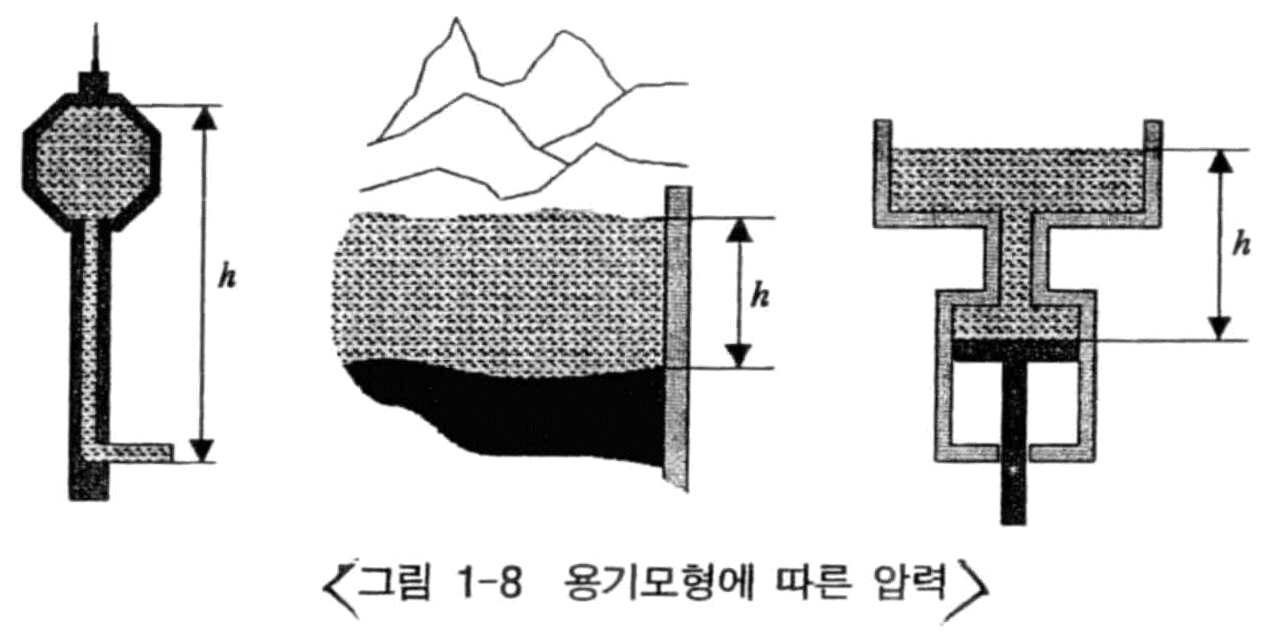
다섯째 파스칼의 원리는The fifth Pascal principle is
밀폐된 용기에서 어떤 힘(사람의 힘, 기계의 힘 또는 자중에 의한 힘)에 의하여 유체에 압력이 가했을 경우 이 유체에 가한 압력은 모든 방향에서 똑같은 크기로 다른 물체에 전달된다. 이 원리를 처음으로 밝혀낸 사람이 파스칼이라서 "파스칼의 원리"라고 하며 유공압 기기에 이 원리를 많이 사용하고 있다.When pressure is applied to a fluid by a force (human force, mechanical force, or self-weight) in a closed container, the pressure applied to the fluid is transmitted to other objects of equal magnitude in all directions. Pascal is the first person to discover this principle, which is called "Pascal's Principle."
이에 정지하고 있는 액체가 서로 맞닿아 있는 면에 미치는 압력은 맞닿아 있는 면과 수직으로 작용한다.The pressure on the surfaces of the liquids that are in contact with each other is perpendicular to the surfaces in contact with each other.
그리고 정지하고 있는 액체의 한 점에서 작용하는 압력의 크기는 모든 방향에 대하여 같다.And the magnitude of the pressure acting on one point of the liquid at rest is the same in all directions.
이처럼 밀폐된 용기 내에 정지하고 있는 액체의 일부에 가해진 압력은 모든 부분에 같은 세기로 동시에 전달된다.The pressure exerted on a portion of the liquid at rest in such a sealed container is simultaneously transmitted to all parts at the same intensity.
이를 파스칼의 원리라고 한다.This is called Pascal's principle.
그림 1-9와 같이 밀폐된 용기에 액체를 넣고 위에서 힘(F)을 가하면, 액체는 압축하여도 체적은 줄지 않는 성질이 있으므로 액체는 위에서 누르는 힘에 대항하 려는 힘이 생긴다. 이를 반력이라고 하며, 이와 같은 액체의 반력을 압력(p)이라고 한다.When the liquid is put in a closed container and the force (F) is applied from above, the volume of the liquid does not decrease even though it is compressed, so the liquid has a force to counter the pressing force from above. This reaction is called reaction force, and this reaction force of liquid is called pressure ( p ).

용기 내의 압력은 힘 F를 피스톤의 면적 A로 나눈 것이다.The pressure in the vessel is the force F divided by the area A of the piston.
![]()
![]()
그 다음의 압력 전달의 원리는The next principle of pressure transfer is
그림 1-10은 압력 전달의 원리를 설명한 것이다. 그림에서와 같이 실린더 안에 액체를 채우고 피스톤 단면적 A 1, A 2에 F 1 및 F 2의 힘이 가해졌을 때 이들 힘 때문에 액체 중에는 어떤 압력이 발생한다. 여기서 피스톤과 실린더 사이에 마찰은 없고 이 부분으로부터 누설도 없으며, 또한 전달에 의한 에너지 손실도 없다고 하면, 두 개의 실린더 내에 발생하는 압력은 다음식으로 나타낼 수 있다.Figure 1-10 illustrates the principle of pressure transfer. As shown in the figure, when the liquid is filled in the cylinder and the forces of F 1 and F 2 are applied to the piston cross sections A 1 and A 2 , these forces create some pressure in the liquid. Here, if there is no friction between the piston and the cylinder, there is no leakage from this part, and there is no energy loss due to transmission, the pressure generated in the two cylinders can be expressed by the following equation.
![]()
![]()
단, 실린더 내 액체의 높이 차에 의한 압력의 차이는 p값에 비해 매우 작으므로 무시할 수 있다. 위의 식으로부터However, the pressure difference due to the height difference of the liquid in the cylinder is very small compared to the p value and can be ignored. From the above equation
![]()
![]()
가 얻어진다. 즉 힘은 피스톤의 단면적에 비례한다. A 2에 비해 A 1이 작으므로 F1에 비해 충분히 큰 힘 F 2가 얻어진다. 유압 프레스나 수압기가 이 원리를 이용한 것이다.Is obtained. The force is proportional to the cross-sectional area of the piston. Since A 1 is smaller than A 2 , a sufficiently large force F 2 is obtained compared to F 1 . Hydraulic presses and hydraulic presses use this principle.

실시예의 유압 증강장치는Hydraulic enhancer of the embodiment
표면적이 다른 두 개의 피스톤을 로드에 의해 연결한다. 만약 압력 p 1을 피스톤 면적 A 1에 작용시키면 힘 F 1이 로드를 통하여 작은 피스톤으로 전달되고 이 힘이 단면적 A 1에 작용하므로 압력 p 2는 증압 된다.Two pistons of different surface areas are connected by a rod. If pressure p 1 is applied to the piston area A 1 , force F 1 is transmitted through the rod to the small piston and this force acts on the cross-sectional area A 1 , thereby increasing the pressure p 2 .
마찰손실을 무시하면 등식은 다음과 같다.Neglecting friction losses, the equation is

압력증강 장치에서 압력은 피스톤의 면적에 반비례한다.In pressure intensifiers the pressure is inversely proportional to the piston area.
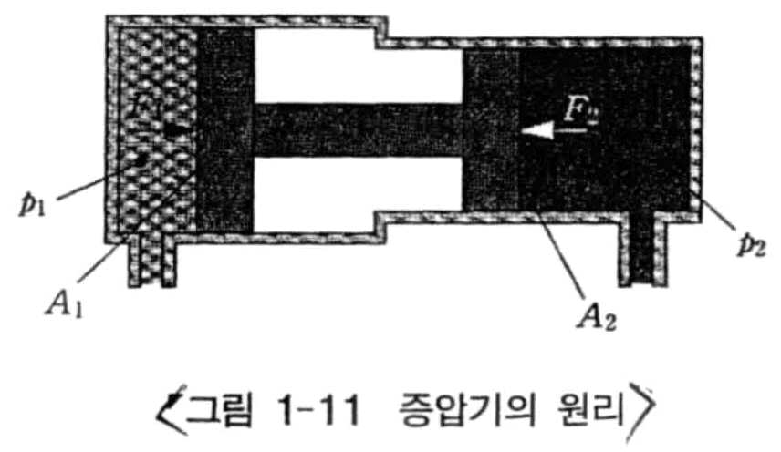
그리고 유체의 유동은And the flow of fluid
유체 유동의 모든 경계면이 고체면으로 이루어진 유동을 일반적으로 내부유동(internal flow)이라고 한다. 이러한 유동은 크게 층류유동과 난류유동으로 대별한다. 층류유동은 점성력이 관성력보다 지배적인 유동으로 레이놀즈수가 작은 즉, 속도의 크기가 작은 유동이면서 점성유동인 경우 뉴톤의 점성법칙을 잘 만족시키는 유동이며, 난류유동은 역으로 관성력이 점성력보다 지배적인 유동으로 레이놀즈수가 큰 즉, 속도의 크기가 큰 유동이다. 일반적으로 유압장치에서의 유동은 층류유동인 경우가 많다.A flow in which all interfaces of fluid flow are solid surfaces is generally referred to as internal flow. These flows are roughly divided into laminar and turbulent flows. Laminar flow is a flow in which viscous force is dominant than inertial force and has a low Reynolds number, i.e., a flow of small velocity and viscous flow that satisfies Newton's law of viscosity well. The Reynolds number is large, that is, the velocity is large. In general, the flow in a hydraulic system is often laminar flow.
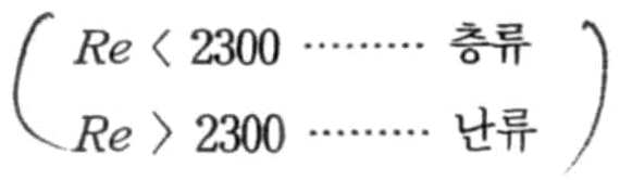
한편 마찰과 흐름은Meanwhile friction and flow
유압 에너지는 배관을 통하여 이송될 때는 손실이 따른다. 마찰은 유체 자신과 배관의 내벽에 의해 발생되고 열을 발생한다. 유압 에너지가 열에너지로 전환한다. 유압 에너지의 손실은 유압유체의 압력손실을 말한다. 유압유체는 유압설비 내의 모든 구조물에서 압력손실이 있다. 이 손실은 흐름 매체의 마찰에 의한 것이다.Hydraulic energy is lost when transferred through the pipe. Friction is generated by the fluid itself and the inner wall of the pipe and generates heat. Hydraulic energy is converted into thermal energy. The loss of hydraulic energy refers to the pressure loss of the hydraulic fluid. Hydraulic fluids lose pressure in all structures in hydraulic installations. This loss is due to the friction of the flow medium.
열에너지로 변화하는 구조물에서의 압력손실은 때때로 고의적으로 발생되는 경우가 있다. 구조물에서 열 발생을 일으키는 압력손실은 바람직하지 않다. 작동 중에 있는 모든 유압유체는 유압기기 내의 구조물에 의해 가열된다. 만약 배관 내의 유체가 화살표방향으로 작용하면 흐름의 방향으로 나타나는 압력은 점점 감소한다.Pressure loss in structures that turn into thermal energy is sometimes intentional. Pressure losses causing heat generation in the structure are undesirable. All hydraulic fluids in operation are heated by the structure in the hydraulic equipment. If the fluid in the pipe acts in the direction of the arrow, the pressure in the direction of the flow decreases.

이렇게 유압펌프는 유압펌프개요와 토출량과 압력의 관계에 펌프의 동력과 효율로 분리하여 하표와 같이 설명한다In this way, the hydraulic pump is divided into power and efficiency of the pump according to the overview of the hydraulic pump, the discharge amount and the pressure.
먼저 유압펌프 개요에 있어First, the hydraulic pump overview
원동기로부터 공급받은 기계적 에너지를 유압 에너지로 변환시켜 유압유의 유압 에너지 수준을 높임으로써 유압계통에 에너지를 가해주는 기기를 유압 펌프라 말한다.Hydraulic pump is a device that applies energy to hydraulic system by converting mechanical energy supplied from prime mover into hydraulic energy to raise hydraulic energy level of hydraulic oil.
펌프는 터보형(비용적식) 펌프(turbo pump or nonpositive displacement pump)와 용적형 펌프(positive displacement pump)로 분류한다. 비용적식 펌프란 유폐되지 않은 상태에서 에너지의 전환이 일어나는 펌프로서 원심 펌프, 사류 펌프, 축류 펌프, 분사형 펌프 등이 있으며 토출량과 압력사이에 일정한 관계가 있어 토출량이 증가하면 토출압력은 감소된다. 용적식 펌프란 펌프의 축이 한번 회전할 때마다 일정한 량을 토출하는 펌프로서 토출량이 부하압력에 관계없이 일정하고 부하압력에 따라 토출압력이 정해지므로 부하가 과대해지면 압력이 상승해서 펌프가 파괴될 위험이 있다.Pumps are classified into turbo pumps or nonpositive displacement pumps and positive displacement pumps. Cost-effective pumps are pumps in which energy is converted without being closed. There are centrifugal pumps, four-flow pumps, axial pumps, injection pumps, and the like, and there is a constant relationship between the discharge amount and the pressure. The volumetric pump is a pump that discharges a fixed amount every time the shaft of the pump rotates. The discharge amount is constant regardless of the load pressure and the discharge pressure is determined according to the load pressure. There is a danger.
유압계통은 유압 펌프가 펌프작업을 함으로써 탱크 내에 있는 저에너지의 유압유를 흡입하여 이것에 에너지를 가하고, 다시 밀폐된 작동부에 높은 에너지의 유압유를 보내어 작동부(실린더, 모우터)를 통해서 외부에 일을 하고, 유압유는 저에너지로 되어 탱크로 다시 되돌아오는 계통으로 구성된다. 펌프작업으로 유압유에 가해진 일 혹은 에너지는The hydraulic system pumps the low energy hydraulic oil in the tank, applies energy to it, and sends high energy hydraulic oil to the enclosed operating part to work externally through the operating part (cylinder, motor). The hydraulic oil becomes low energy and is composed of a system that returns to the tank again. Work or energy applied to hydraulic oil by pumping
일 = (힘)×(변위) = (압력)×(넓이)×(변위) = (압력)×(배제체적)와 같이 된다.Work = (force) x (displacement) = (pressure) x (width) x (displacement) = (pressure) x (exclusion volume).
단위시간에 가해진 일, 즉 공률 또는 동력은 ![]()
![]()
다음은 토출량과 압력의 관계에 있어 하표와 같이 설명한다.Next, the relationship between the discharge amount and the pressure will be described as shown in the following table.
<표 2-1 유압 펌프의 분류><Table 2-1 Classification of Hydraulic Pumps>
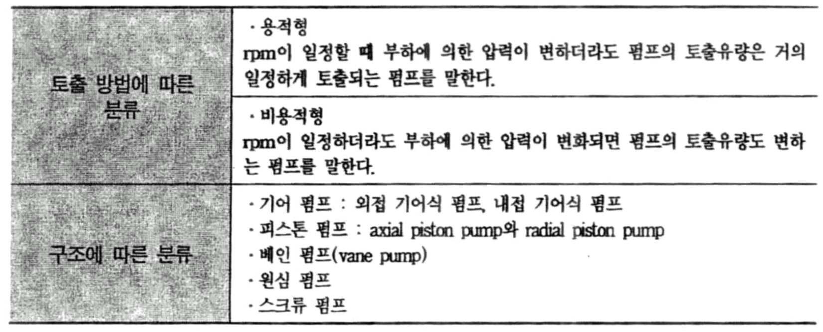
유압 펌프의 토출량은 입력축을 1회전시킬 때 토출구로부터 내보내진 작동유의 체적으로 나타난다.The discharge amount of the hydraulic pump is represented by the volume of hydraulic oil discharged from the discharge port when the input shaft is rotated once.
예를 들면 32cc/rev라면, 1회전당 토출량이 32cc라는 것이다.For example, 32 cc / rev means that the ejection amount per revolution is 32 cc.
유압 펌프에는 그 속도 이하로 구동한 경우에는 소정의 토출량을 유지할 수 없는 「최저회전속도」가 있다. 또 속도 이상으로 회전시킬 경우, 극단으로 수명이 단축되고, 파손하는 일도 있는 「최고회전속도」가 정해져 있다. 이 최저와 최고회전속도의 범위 내라면 임의의 속도로 유압 펌프를 구동할 수 있는 것이고 회전속도에 비례해서 토출구로부터 내보내진 작동유의 유량은 커진다.The hydraulic pump has a "lowest rotational speed" which cannot maintain a predetermined discharge amount when it is driven at or below that speed. Moreover, when it rotates more than speed, the "maximum rotation speed" which may shorten a lifetime and may damage is determined at the extreme. The hydraulic pump can be driven at any speed within this minimum and maximum rotational speed, and the flow rate of the hydraulic oil discharged from the discharge port increases in proportion to the rotational speed.
32cc/rev의 유압 펌프를 1500rpm(1분당 1500회전의 속도)으로 구동한 경우 토출구에서 나오는 유량은 32cc의 1500배, 즉 '48,000cc를 1분간에 흘린다.'라는 의미의 48,000cc/min(48ℓ/min)가 된다.When a 32 cc / rev hydraulic pump was driven at 1500 rpm (1,500 revolutions per minute), the flow rate from the discharge port was 1500 times 32cc, or 48,000 cc / min (48 liters), meaning `` 48,000 cc flowed in 1 minute. '' / min).
즉 1500rpm에 놓인 이 유압 펌프의 토출량은 48ℓ/min라고 표시한다.That is, the discharge amount of this hydraulic pump placed at 1500 rpm is indicated as 48 l / min.
토출구에서 압력이 5kgf/cm2 정도로 대단히 낮은 경우에는 실제로 측정한 토 출량과 계산에서 구해진 토출량(이론 토출량)이 상당한 근사치가 된다. 한편, 유압 펌프에는 토출구의 압력이 수치 이상으로 높아지면 내부 누설이 많아지고 수명도 현저히 짧아진다는 의미를 갖는 「최고사용압력」이 정해져 있다. 유압 펌프의 내부에는 금속면과 금속면의 접촉부가 여러 개 있어서 그 부분을 윤활하게 하기 위한 작동유가 필요하다. 내부 누설은 이 목적이 이용되기 때문에 뺄 수가 없다.If the pressure at the discharge port is very low, such as 5 kg f / cm 2 , the actual measured discharge amount and the calculated discharge amount (theoretical discharge amount) are approximations. On the other hand, the "maximum operating pressure" is defined in the hydraulic pump, which means that when the pressure of the discharge port becomes higher than the numerical value, the internal leakage increases and the service life is significantly shortened. Inside the hydraulic pump, there are several contacts between the metal surface and the metal surface, and hydraulic oil is required to lubricate the portion. Internal leakage cannot be subtracted because this purpose is used.
그래서 이 내부 누설은 토출구의 압력이 높아짐에 따라서(거의 비례하여) 커지고, 최고사용 압력에서는 이론 토출량의 5%에서 10%의 누설량이 된다. 이것은 최고사용압력에서 실제로 이용할 수 있는 토출량이 이론 토출량의 95%에서 90%인 것을 의미한다.Therefore, this internal leakage becomes large as the pressure of the discharge port becomes high (almost proportionally), and the leakage amount is 5% to 10% of the theoretical discharge amount at the maximum use pressure. This means that the discharge amount actually available at the maximum working pressure is 95% to 90% of the theoretical discharge amount.
어느 압력에서 실제로 이용할 수 있는 토출량이 이론 토출량의 몇 퍼센트인가를 나타내는 수치를 용적효율이라고 부른다. 통상 단순히 용적효율이라고 할 때에는 최고사용압력에서의 용적효율을 나타내는 것이 많다. 내부 누설이 이론 토출량의 5%인 경우, 바꿔 말하면 실제로 측정한 토출량이 이론 토출량의 95%인 경우(그 압력에 있어서) 용적효율은 95%라고 표시된다.The numerical value representing what percentage of the theoretical discharge amount can be actually used at a certain pressure is called volumetric efficiency. In general, when simply referred to as volumetric efficiency, the volumetric efficiency at the maximum operating pressure is often expressed. In the case where the internal leakage is 5% of the theoretical discharge amount, in other words, when the discharge amount actually measured is 95% of the theoretical discharge amount (at the pressure), the volumetric efficiency is displayed as 95%.
그리고 펌프의 동력과 효율에 있어And the power and efficiency of the pump
유압 펌프의 흡입압력을 p s[kgf/cm2], 토출압력을 p d[kgf/cm2]라고 하고, 토출유량을 R[m3/s]라 하면 펌프가 발생하는 펌프동력(유체에 유효하게 전달되는 마력) L p 는 다음과 같이 구할 수 있다.If the suction pressure of the hydraulic pump is p s [kg f / cm 2 ], the discharge pressure is p d [kg f / cm 2 ], and the discharge flow rate is R [m 3 / s], the pump power generated by the pump ( The effective horsepower delivered to the fluid) L p can be found as follows.
(L p = pQ[kgf m/s]) (2.1)( L p = pQ [kg f m / s]) (2.1)
여기서 p = p d - p s 는 펌프의 출구와 입구의 압력차이나 보통 p s 는 대기압으로 p = p d 로 생각한다.Where p = p d -p s is the pressure difference between the outlet and inlet of the pump, but p s is usually assumed to be p = p d at atmospheric pressure.
출력단위를 kW나 ps로 표시하면If the output unit is expressed in kW or ps

이다. 또 p의 단위가 kgf/cm2이고 Q의 단위가 ℓ/min일 때 펌프동력은to be. If the unit of p is kg f / cm 2 and the unit of Q is ℓ / min, the pump power
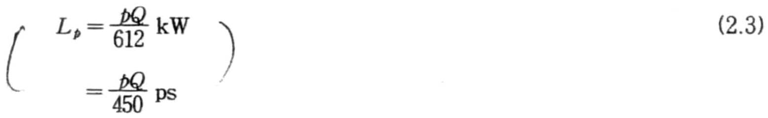
펌프 속의 누설손실이 없다고 가정하였을 때 펌프가 유압유에 준 이론동력(액체동력) L th 는Assuming that there is no leakage loss in the pump, the theoretical power (liquid power) L th
(L th = pQ th [kgf m/s]) (2.4)( L th = pQ th [kg f m / s]) (2.4)
여기서 pkgf/cm2는 펌프 토출압력이고 Q th [m3/s]는 이론 토출량이다. 원동기로부터 펌프축에 전달되는 동력(축동력)을 L s 라고 하면Where p kg f / cm 2 is the pump discharge pressure and Q th [m 3 / s] is the theoretical discharge rate. If the power (axial power) transmitted from the prime mover to the pump shaft is L s
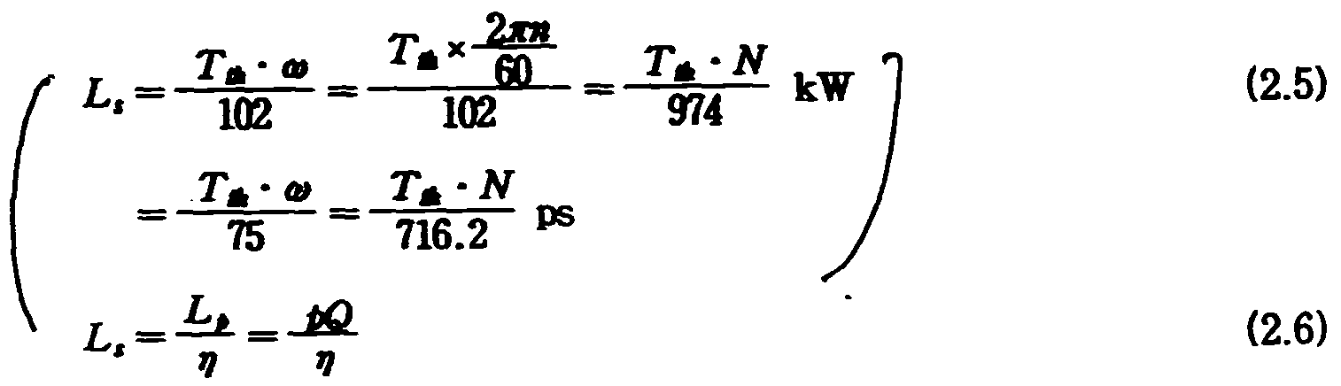
여기서 ω[l/s]는 각속도이며, T th [kgf/cm2]는 펌프를 회전시키는 데에 필요한 토크(torque)이고, N[rpm]은 회전수이다. 펌프는 원동기로부터 축을 통하여 받은 에너지의 전부를 유압유에 주는 것이 아니고 일부는 손실로 소멸되고 나머지의 에너지만 유압유가 가지고 나간다. 그러므로 펌프가 축을 통하여 받은 에너지를 얼마만큼 유용한 에너지로 전환시켰는가의 정도를 나타내는 척도로서 효율을 정의한다.Where ω [l / s] is the angular velocity, T th [kg f / cm 2 ] is the torque required to rotate the pump, and N [rpm] is the rotational speed. The pump does not give the hydraulic oil all of the energy received through the shaft from the prime mover, part of it is lost and only the remaining energy is taken out by the hydraulic oil. Therefore, efficiency is defined as a measure of how much energy the pump has converted through the shaft into useful energy.

여기서 η는 펌프의 전 효율이다.Where η is the overall efficiency of the pump.

이러한 유압 액추에이터(Actuator)는 하표와 하도로 다음과 같이 설명한다.This hydraulic actuator (Actuator) will be described as follows in the table and the road.
먼저 개요 및 분류에 있어First, in the overview and classification
유압 액추에이터는 압유에 의해 출력축의 왕복운동 혹은 회전운동을 발생시켜 기계적 일을 하는 유압기기의 총칭으로, 유압모터(축의 회전운동), 유압실린더 (축의 직선운동) 및 요동 액추에이터(축의 한정된 회전운동)의 3종류로 나눈다.Hydraulic actuator is a general term for hydraulic equipment that produces mechanical reciprocation or rotational movement of output shaft by pressure oil. Hydraulic motor (rotational movement of shaft), hydraulic cylinder (linearity of shaft) and rocking actuator (limited rotational movement of shaft) It is divided into three kinds.
<표 4-1 유압 액추에이터의 종류><Table 4-1 Types of Hydraulic Actuators>

다음은 유압모터에 있어Next is the hydraulic motor
유압모터는 압유의 에너지를 회전운동으로 전환시키는 장치이다. 원리적으로는 유압 펌프의 흡입측으로 압유를 공급하면 유압모터가 되지만 효율이 좋지 않는 등의 다소의 차이가 있다. 또한 펌프는 일정방향으로만 회전하는 것이 보통이지만 유압모터는 정역 어느 방향으로도 회전하는 것이 가능하다.Hydraulic motor is a device that converts the energy of the hydraulic oil into a rotary motion. In principle, supplying pressure oil to the suction side of the hydraulic pump results in a hydraulic motor, but there are some differences such as poor efficiency. It is also common for pumps to rotate only in certain directions, but hydraulic motors can rotate in either direction.
유압모터의 특징을 동일한 회전운동을 하는 교류 전동모터와 비교하여 보면 다음과 같다.The characteristics of the hydraulic motor are compared with those of the AC electric motor which performs the same rotational motion as follows.
■ 회전수의 무단변속, 정역회전의 변환이 대단히 간단하고 시동 정지도 대단히 쉽다.■ Stepless speed change and forward / reverse rotation are very simple and start and stop are very easy.
■ 관성이 적어 추종성이 좋고, 응답이 빠르다. 따라서 자동제어의 조작부, 서보기구의 요소 등에 적당하다.■ low inertia, good tracking, fast response. Therefore, it is suitable for operation part of automatic control, element of servo mechanism and so on.
■ 동일 마력당의 크기가 전동기에 비해 훨씬 작다.■ The size per horsepower is much smaller than the motor.
이와 같은 장점이 있지만 유압장치 자체가 전동기로 구동시키기 때문에 그 용도가 제한되고 있다.There is such an advantage, but its use is limited because the hydraulic device is driven by an electric motor.
유압모터의 형식에는 모터를 1회전 시키는데 필요한 유량이 일정한 것과 변화되는 것이 있다. 전자를 정용량형 유압모터, 후자를 가변용량형 유압모터라고 한다.There are two types of hydraulic motors in which the flow rate required for one revolution of the motor is constant. The former is called a fixed displacement hydraulic motor and the latter is called a variable displacement hydraulic motor.
먼저 기어모터(gear motor)의First of all, the gear motor
구조는 기어 펌프와 거의 같으며 공급된 압유(壓油)가 치면(齒面)에 작용하여 토크를 발생시켜 출력축을 회전시킨다. 기어는 일반적으로 평기어가 이용되며 타 모터에 비교하여 구조가 간단하고, 소형 경량이다. 그러나 구조상 가변용량형 모터로 제작하기는 곤란하고 100rpm 이하의 저속에서는 토크 출력 및 회전속도의 맥동이 커져서 사용할 수 없다는 것이 단점이다. 기어모터의 전효율은 70∼80[%] 정도이고 회전속도는 1000∼3000rpm 정도이다.The structure is almost the same as that of the gear pump, and the supplied pressure oil acts on the tooth surface to generate torque to rotate the output shaft. Gears are generally used with spur gears and are simpler in structure than other motors, and are small in size and light weight. However, due to the structure, it is difficult to manufacture a variable displacement motor, and at a low speed of less than 100 rpm, the pulsation of the torque output and the rotation speed cannot be used due to the disadvantage. The overall efficiency of the gear motor is about 70 to 80 [%] and the rotation speed is about 1000 to 3000 rpm.
그리고 베인모터(vane motor)는And the vane motor
구조면에서 베인 펌프와 동일하며 공급압력이 일정할 때 출력토크가 일정, 역전가능, 무단 변속가능, 가혹한 운전 가능, 등등의 장점이 있다.It is the same as the vane pump in structure, and when the supply pressure is constant, the output torque is constant, reversible, continuously variable, harsh driving, and so on.
최고 사용압력 70bar, 동력 5∼30ps, 회전수 200∼1800rpm 정도의 것이 많다. 최저 200rpm이라고 하는 속도 한계는 출력토크의 변동이 적다. 일반적으로 저 압이라든가 저속에서는 효율이 나쁘고, 토크의 변동이 증대되는 단점도 있다.Many have a maximum working pressure of 70 bar, a power of 5 to 30 ps, and a speed of 200 to 1800 rpm. Speed limit as low as 200rpm has little variation in output torque. In general, there is a disadvantage that the efficiency is poor at low pressure or low speed, and the torque fluctuation is increased.
세째로 피스톤 모터(piston motor)에 있어Thirdly, in the piston motor
피스톤 모터는 흔히 플런저 모터(plunger motor) 또는 회전 피스톤 모터라고도 부른다. 피스톤 펌프와 구조가 거의 같고 종류는 액셜형(axial type)과 레이디얼형(radial type)이 있다. 액셜 피스톤 모터에는 사축식과 사판식이 있다.Piston motors are also commonly referred to as plunger motors or rotary piston motors. Its structure is almost the same as the piston pump, and there are axial type and radial type. There are two types of axial piston motors: bent shaft and swash plate.

레이디얼 피스톤 모터는 몇 개 또는 10여 개의 피스톤이 축에 방사상으로 배열되어 반경방향으로 왕복운동하면서 축을 회전시키는 형식이다. 이것에는 실린더 블록의 편심 또는 편심캠을 써서 피스톤이 받는 압유에 의한 힘을 토크로 변환하는 편심식과 다엽캠을 써서 1회전에 대한 수회의 피스톤 왕복운동에 의해 토크를 발생시키는 다행정식으로 분류된다.The radial piston motor is a type in which several or ten pistons are arranged radially on the shaft to rotate the shaft while reciprocating in the radial direction. These are divided into eccentric equations for converting the force of the hydraulic pressure received by the pistons to torque using an eccentric or eccentric cam of the cylinder block, and multistroke equations for generating torque by several piston reciprocating motions per one revolution using a multileaf cam.
피스톤 모터는 피스톤 펌프와 같이 정용량형(fixed displacement type)과 가변용량형(variable displacement type)이 각 형식마다 있다.Like piston pumps, piston motors have a fixed displacement type and a variable displacement type for each type.
네째로 유압모터의 출력 및 효율에 있어Fourth, in terms of output and efficiency of hydraulic motors
모터에 유입되는 압유의 압력을 p 1[kgf/cm2], 유출되는 압유의 압력을 p 2[kgf/cm2]라 하고 공급압유의 유량을 Q[cm3/min]라고 할 때 유압모터에 유입되는 동력은 다음과 같이 계산된다.When the pressure of the pressure oil flowing into the motor is p 1 [kg f / cm 2 ], the pressure of the pressure oil flowing out is p 2 [kg f / cm 2 ], and the flow rate of the supply pressure oil is Q [cm 3 / min]. The power flowing into the hydraulic motor is calculated as follows.
![]()
![]()
출력은 토르크와 각속도에 의하여 계산된다.The output is calculated from the torque and the angular velocity.
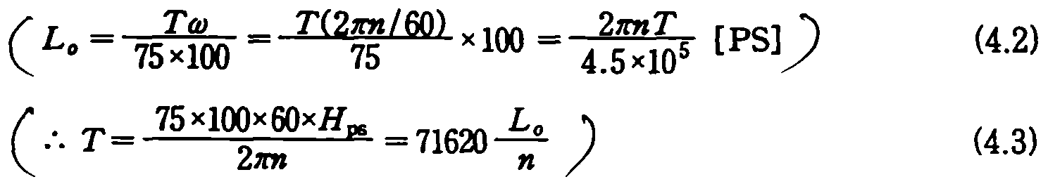
여기서 n는 모터 출력측 회전수[rpm], T는 모터 출력측에서 부하에 전달되는 토르크[kgf·m]이다. 따라서 입력과 출력의 관계에서 모터의 효율을 계산하면Where n is the motor output speed [rpm] and T is the torque [kg f · m] transmitted from the motor output to the load. Therefore, if we calculate the efficiency of the motor in the relationship between input and output,
![]()
![]()
유압모터의 크기는 1회전 당에 필요한 압유의 량 q(cm3/revolution)으로 표시한다. 따라서 모터의 내부 누설이 없다는 가정 하에서 Q = q×n o , 또 λ = 100% 즉 손실이 없는 것으로 하고 귀환기름의 압력을 0으로 보면(p 1 = p)The size of the hydraulic motor is indicated by the amount of hydraulic oil q (cm 3 / revolution) required per revolution. Therefore, assuming that there is no internal leakage of the motor, Q = q × n o , and λ = 100%, that is, no loss, and the return oil pressure is 0 ( p 1 = p )
![]()
![]()
위 식으로부터From the above equation
![]()
![]()
따라서 토르크 효율은 ![]()
![]()
위 식에서 n o는 모터 내부 누설이 없다는 가정 하에서의 회전수이며 T o는 압력 p의 압유가 발생할 수 있는 최대 토르크 또는 이론 토르크라고 한다.Where n o is the number of revolutions under the assumption that there is no leakage inside the motor and T o is the maximum torque or theoretical torque at which pressure oil p can be generated.
다섯째 유압모터의 장단점에 있어Fifth, there are advantages and disadvantages of hydraulic motors
장점으로는Advantage
전동기에 비해 쉽게 급속 정지시킬 수 있으며 광범위한 무단변속을 얻을 수 있다는 점과 소형이고 가볍고 강력한 힘을 얻을 수 있다는 것이고 내폭성이 우수하여 고속 추종성이 좋다는 것이며, 시동, 정지, 역전, 변속 등을 가변용량형 펌프나 미터링(교축 밸브의 뜻이며 유량을 개량하는 밸브)에 의해서 간단히 제어할 수 있다는 점이고 과부하에 대한 안전장치나 브레이크가 용이하며 종이나 전선 등에 쓰이는 권선기와 같은 토르크 제어 기계에 편리하다는 점 등이다.Compared to the electric motor, it can be easily stopped quickly and can obtain a wide range of continuously variable speeds, and it is possible to obtain small, light and powerful force, and it has good explosion resistance and high speed followability, and it is variable capacity type for starting, stopping, reversing and shifting. It can be easily controlled by pump or metering (meaning of throttling valve and improving flow rate), easy to protect against overload, easy to brake, and convenient for torque control machines such as winding machines used for paper or wire. .
단점에는On the downside
작동유에 먼지나 공기가 혼입되지 않도록 주의해야 한다는 것이고 작동유의 점도변화에 의해 유압모터 사용에 제약을 받는다(통상 20∼80℃)는 점이며 석유계 작동유는 인화에 약하다는 것으로 수천 시간 이내에 오버홀(over haul) 해야 한다는 점 등이다It is important to be careful not to mix dust or air in the hydraulic fluid, and to restrict the use of the hydraulic motor by changing the viscosity of the hydraulic fluid (usually 20 to 80 ℃), and petroleum hydraulic oil is weak to ignition. over haul)
여섯째 유압실린더(hydraulic cylinder, 623)는The sixth hydraulic cylinder (623)
유압동력을 단면적에 대응하는 추력과 속도의 운동으로 변환하여 직선방향으로 일을 하는 기기이다.This machine converts hydraulic power into motion of thrust and speed corresponding to the cross-sectional area and works in the straight direction.
먼저 실린더의 종류에 있어서 하도와 같이 설명한다First, the type of cylinder will be described as follows.
첫째 단동실린더(single acting cylinder)는The first single acting cylinder
한쪽방향에만 힘을 주어 일을 하며, 실린더의 귀환은 자중 또는 스프링의 힘에 의해 이루어진다.The work is applied with force in only one direction, and the return of the cylinder is made by the weight of itself or the force of the spring.
둘째 복동실린더(double acting cylinder)는The second double acting cylinder
그림 4-1과 같이 피스톤의 양쪽에 포트(port)를 설치하여 유압을 번갈아 공급하면서 양쪽 방향에 작용력을 주고 있는 실린더이다. 복동실린더의 종류는 단로드 실린더와 양측로드 실린더의 2가지 형식이 있다.As shown in Fig. 4-1, it is a cylinder that installs ports on both sides of the piston and supplies hydraulic pressure in both directions. There are two types of double acting cylinders: single rod cylinder and double rod cylinder.
다단실린더Multi-stage cylinder
텔레스코픽형 실린더(telescopic cylinder)와 디지털형 실린더(digital cylinder)가 있으며 텔레스코픽형은 실린더의 길이에 비해 긴 행정이 필요한 경우에 사용되며 디지털형 실린더는 유출입구를 적당한 조합으로 유압을 주거나 배출함으로서 로드의 위치를 정확하게 제어할 수 있다.There are telescopic cylinders and digital cylinders. Telescopic types are used when a long stroke is required compared to the length of the cylinder. Digital cylinders can be used to provide hydraulic Position can be precisely controlled.
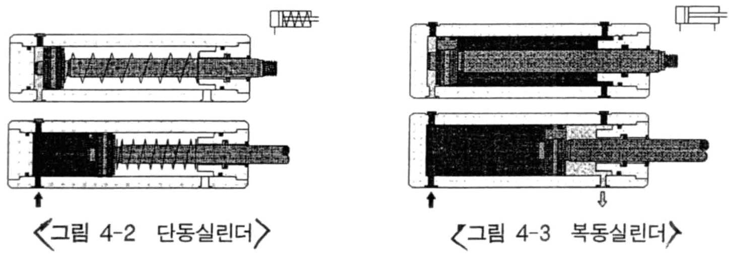
유압부속기기는 하도와 같이 설명한다.Hydraulic attachment is explained as below.
이러한 오일탱크(oil tank or oil reservoir, 795)에 있어In this oil tank or oil reservoir (795)
본래는 유압장치에 필요한 작동유의 저장을 목적으로 하나 각종 부속품을 장 착시켜 여러 가지 기능을 갖게 한다.Originally intended for the storage of hydraulic oil required for hydraulic systems, it has various functions by mounting various accessories.
탱크가 너무 작으면 유온이 상승하여 회로에서 발생한 기포가 펌프에 다시 흡입될 때까지 꺼지지 않는다. 탱크 내의 유온은 펌프의 용량, 사용압력에 따른 열발생, 기포발생의 상황 등에 의하여 결정된다. 그러므로 압유탱크의 용량은 작동 사이클 중에 유면을 적절히 유지하여 압유 중의 이물질, 공기를 분리시키면서 발생열을 방사시킬 수 있는 크기가 되어야 하고 회로 내의 압유가 전부 탱크 안에 모이더라도 넘쳐흐르지 않을 정도의 충분한 크기가 되어야 한다. 탱크의 이상적인 크기는 그 장치가 필요로 하는 매분 펌프 송출량의 2∼10배이나, 보통은 3∼6배 정도로 한다.If the tank is too small, the oil temperature rises and bubbles from the circuit do not turn off until the pump is sucked back up. The oil temperature in the tank is determined by the capacity of the pump, the heat generation according to the operating pressure, the situation of bubble generation, and the like. Therefore, the capacity of the oil tank should be large enough to keep the oil level properly during the operating cycle to separate foreign matter and air from the oil and to radiate the generated heat, and to be large enough so that the oil pressure in the circuit does not overflow even if all the oil is collected in the tank. do. The ideal size of the tank is 2 to 10 times the pump delivery volume per minute required by the device, but usually 3 to 6 times.
이물질의 혼입이 허용되지 않으므로 탱크 제작시에는 유의해서 제작하여야 한다.Since mixing of foreign matter is not allowed, be careful when manufacturing tanks.
먼저 탱크의 구조에는First, the structure of the tank
각 유압설비는 여러 가지 목적 즉, 작동유 저장, 작동유와 공기의 분리, 열분산, 펌프와 구동 모터의 지지, 제어기기를 설치하기 위한 베이스 플레이트(base plate) 등의 역할을 하는 탱크를 구비하여야 한다.Each hydraulic system should be provided with a tank for various purposes, such as storage of hydraulic oil, separation of hydraulic oil and air, heat dissipation, support of pumps and drive motors, and a base plate for the installation of controllers. .

에어 블리저(Air breather)에 있어In the air breather
각 탱크는 (Air filter)를 포함한 적정한 (Air breather)가 설치되어야 한다.Each tank must be fitted with an appropriate air breather, including an air filter.
이 Air breather는 펌프의 기름 공급과 공기의 혼입이 없는 Oil을 유지하기 위해 항상 대기압이 유체의 표면상에 작용할 수 있는 구조 이어야한다. 귀환유는 Level 을 유지하고 Zero 압력으로 Drain 한다.This air breather must be constructed so that atmospheric pressure can act on the surface of the fluid at all times in order to maintain the oil supply of the pump and oil free of air mixing. Return oil is maintained at the level and drained at zero pressure.
다음 보충구는The next supplement is
유체를 보충하는 동안 외부에서의 이물질 혼입을 방지하기 위하여 항상 Mesh strainer를 포함하여야 한다.A mesh strainer should always be included to prevent foreign matter from entering the fluid during replenishment.
드레인 플러그(Drain plug)는The drain plug
탱크(Tank)의 제일 낮은 곳에 설치하여야 한다. 유체를 교환할 시에는 (Tank)와 (Filter)를 깨끗하게 청소를 하여야 한다.It should be installed at the lowest point of tank. (Tank) and (Filter) should be cleanly cleaned when changing the fluid.
그리고 점검창은And the inspection window
유체의 (Level)은 계량봉 혹은 점검창에 의해 계속적으로 점검한다.The level of the fluid is continuously checked by dipstick or inspection window.
최소와 최대의 Level은 표시되어야 한다.Minimum and maximum levels should be displayed.
또한 격판은 탱크 내부의 셕션 체임버(Suction chamber)와 리턴 라인 체임버(Return line chamber)와의 격판이다.The diaphragm is also a diaphragm between the suction chamber and the return line chamber inside the tank.
리턴 라인 체임버(Return line chamber)의 작동유를 정지시킬 수 있으므로 귀환된 작동유 내의 이물질을 침적시킬 수 있다.The hydraulic fluid in the return line chamber can be stopped to deposit foreign matter in the returned hydraulic fluid.
다음은 필터에 있어서,Next is the filter,
유압설비에서 압유의 여과는 유압기기의 작동성과 수명에 대단히 중요하다.Filtration of pressurized oil in hydraulic installation is very important for the operability and life of hydraulic equipment.
공기 중의 먼지와 마찬가지로 금속과 Seal 입자는 설비가 작동되는 동안 압유를 오염시킨다. 여러 가지 크기의 이러한 입자는 계속해서 제거하여야만 한다. 그렇지 않으면 오염입자는 시스템의 포트(port)와 배관을 막히게 한다. 따라서 기능이 저하할 것이다. 오염은 유압 설비의 습동부 마모에 의한 것이 가장 큰 원인이다.Like dust in the air, metals and seal particles contaminate the pressurized oil during plant operation. These particles of various sizes must be removed continuously. Otherwise, contaminants can clog the ports and piping of the system. Therefore, the function will be degraded. Contamination is most likely caused by sliding of the sliding parts of hydraulic installations.
유압 필터는 라인의 흐름 상태에 따라 전량형과 분류형, 또 압력측 관로형으로서 고압용 라인필터와 귀환관로나 흡입측용으로서 저압용라인 필터가 있다. 탱크 필터는 펌프의 흡입단에 장착하는 가장 간단한 구조의 필터로서 압력강하는 펌프의 공동현상특성과 직접 관계가 있으므로 80mmHg 이하로 하는 것이 좋다. 또 여과입도는 149, 105, 74, 44μ의 각 종류가 시판되고 있고, 보통 74∼105μ 정도가 많이 사용되고 있다.The hydraulic filter has a high-pressure line filter and a low-pressure line filter for the return line or the suction side as a whole quantity type and a split type, and a pressure side pipe type according to the flow state of the line. The tank filter is the simplest filter to be mounted at the suction end of the pump. The pressure drop is directly related to the cavitation characteristics of the pump. Further filtration particle size is commercially available and each type of 149, 105, 74, 44 μ , usually being used a lot of approximately 74~105 μ.
이 스트레이너는 금속망과 세라믹자석(ceramic magnets)으로 구성되어 있다. 압유가 강한 자기장을 통과하는 동안은 저속으로 흐르게끔 구조가 되어 있어 1μ 정도의 철분까지 자석에 흡입되고, 비철 이물도 제거된다.The strainer consists of a metal mesh and ceramic magnets. While the hydraulic oil passes through the strong magnetic field, it is designed to flow at a low speed, so that up to 1 μ iron is sucked into the magnet, and non-ferrous foreign substances are also removed.
라인필터는 일종의 압력용기 내에 필터 엘레멘트(filter element)를 내장하여, 엘레멘트 세공이 막혀 규정 이상의 압력강하가 생길 때 작동하는 안전밸브를 갖는 것이 보통이다. 라인필터는 주 관로에 장치하여 전량을 여과하는 것 이외에 분류식도 있고, 또 필요한 회로에만 적당한 여과입도의 필터를 설치하는 경우도 있다. 정격압력은 35, 70, 140, 210kgf/cm2 여과입도 5, 10, 20, 44μ의 것이 시판되고 있다.The line filter usually has a filter element embedded in a pressure vessel, and has a safety valve that operates when the element pore is blocked and a pressure drop occurs. The line filter is installed in the main pipe to filter the whole quantity, and there is a classification formula, and in some cases, a filter having a suitable particle size is provided only in the required circuit. Rated pressures of 35, 70, 140 and 210 kg f / cm 2 are available on the market with 5, 10, 20 and 44 μ filtration.
여과 방법에 따라 구별에서 설명하면 다음과 같다.According to the filtration method described in the distinction is as follows.
첫째 셕션라인(Suction line) 여과에는The first suction line filtration
필터는 셕션라인(Suction line)에 설치한다. 이것은 외부의 이물질에 의해 펌프에 손상을 입히는 것을 방지하기 위한 것이다.The filter is installed in the suction line. This is to prevent the pump from being damaged by foreign matter.
필터의 막힘에 의해 캐비테이션(Cavitation)을 발생시킬 위험성이 있다.There is a risk of cavitation caused by clogging of the filter.

압력 라인(Line) 여과에 있어For pressure line filtration
필터는 외부 이물질에 의해 유압설비를 보호하기 위하여 압력 Line에 설치한다.The filter is installed in the pressure line to protect the hydraulic equipment by external debris.
리턴 라인(Return line) 여과에 있어For return line filtration
필터는 귀환유를 여과하기 위하여 리턴 라인(Return line)에 설치한다.A filter is installed on the return line to filter the return oil.
그리고 압유의 여과는And the filtration of the pressure oil
유압기기의 고압고속화에 수반하여, 기기 각 부의 정도가 요구됨에 따라 압유 청정도의 향상도 크게 요망되고 있다. 유압기기의 보수에 있어서 고장의 75%는 압유의 오염에 기인한다고 말할 수 있을 만큼, 유압의 청정도는 유압장치 전체에 걸쳐 극히 중요한 것이다.With the high pressure of the hydraulic equipment, as the degree of each part of the equipment is required, the improvement of the pressure oil cleanliness is also greatly desired. The hydraulic cleanliness is extremely important throughout the hydraulic system, so that 75% of failures in the repair of hydraulic equipment can be said to be due to contamination of the pressurized oil.
필터를 여과작용면에서 분류하면 표면식, 적층식, 다공체식, 흡착식, 자기식으로 크게 나눌 수 있다.If filters are classified in terms of filtration, they can be broadly classified into surface type, stacked type, porous body type, adsorption type, and magnetic type.
다음의 축압기(accumulator)에 있어서,In the following accumulator
축압기는 고압상태의 압유를 용기에 밀어 넣는 것으로서, 펌프로부터 공급하는 압유량 보다도 다량의 고압유가 순간적으로 구동장치 내에서 필요할 때 고압류를 보내줄 목적으로 고안되었다. 축압기를 사용하면 사용하지 않았을 때에 비하여 펌프가 소형화되고 또 전체의 장치가 소형으로 되어 설비 비용이 적당하다는 이점이 있다.The accumulator pushes the high pressure oil into the container, and is designed to send high pressure flow when a large amount of high pressure oil is instantaneously needed in the driving device than the pressure oil supplied from the pump. The use of the accumulator has the advantage that the pump is downsized and the whole apparatus is downsized as compared with the case where the accumulator is not used, and the installation cost is moderate.
먼저 용도에 있어 압축 에너지의 축척과 맥동, 충격의 제거에 액체 수송으로 분류하는데에는First of all, it is classified into liquid transport for the accumulation of compression energy, pulsation and impact.
먼저 압축 에너지의 축척에 있어First, in terms of the compression energy
축적된 압유에너지를 필요에 따라 내보냄으로써, 간헐운전에 있어서 펌프의 정전이나 고장 등의 긴급시에 동력원, 유압회로에서 누유나 온도변화에 따른 유량과 압력변화에 대한 보상용 등으로 사용된다.By storing the accumulated pressure oil energy as necessary, it is used for compensating for the flow rate and pressure change caused by leakage oil or temperature change in the power source, hydraulic circuit, etc. in an emergency such as power failure or failure of the pump in intermittent operation.
다음은 맥동, 충격의 제거로Next to the pulsation, the removal of the impact
유압 펌프가 발생하는 맥동을 흡수하고, 피크압력을 억제시켜 진동이나 소음을 방지할 목적으로 사용한다.It is used for the purpose of absorbing the pulsation generated by the hydraulic pump and suppressing the peak pressure to prevent vibration and noise.
또 밸브를 개폐할 때 발생하는 오일 해머(Oil hammering)나 서어지압(Surge pressure)의 제거, 충격압력에 의한 밸브류, 배관 계기류의 파손이나 누유를 방지할 목적으로 사용한다. 이러한 이유로 괴음제동기 서어지 흡수기 또는 충격제동기라고도 불리 운다.In addition, it is used for the purpose of removing oil hammering or surge pressure generated when opening / closing valves, preventing damages or leakage of valves and piping instruments due to impact pressure. For this reason, they are also called surge absorbers and surge absorbers.
그 다음의 액체 수송에 있어For the next liquid transport
축압기의 기체부의 기체를 피스톤과 같이 작용시키면 어큐뮬레이터는 펌프로서의 작용을 하므로 유독, 유해, 부식성의 액체를 수송시킬 수 있다.When the gas in the gas accumulator acts like a piston, the accumulator acts as a pump, thereby transporting toxic, harmful and corrosive liquids.
둘째 종류에 있어 추 부하식 축압기와 스프링 부하식 축압기로 하도와 같이 설명한다.In the second type, the load-loaded accumulator and the spring-loaded accumulator are described as underload.
먼저 추 부하식 축압기(weight loaded accumulator)에 있어First on a weight loaded accumulator
이 축압기는 피스톤과 실린더로 되어 있고, 피스톤에 사용되는 추(weight)의 무게로 오일에 에너지를 주게 되어 있다. 유압회로 내의 가압오일은 피스톤 아래쪽에 있는 오일의 실(chamber)로 밀려들어가 피스톤과 추를 들어올리고 축압기에 충전되고, 유압회로 내의 압력이 낮아지거나 오일이 더 필요하게 되면 중력에 의하여 피스톤과 추가 내려가서 오일을 유압회로로 보낸다.The accumulator consists of a piston and a cylinder, which energize oil at the weight of the weight used for the piston. Pressurized oil in the hydraulic circuit is pushed into the oil chamber under the piston to lift the piston and weight and fill the accumulator, and when the pressure in the hydraulic circuit is lowered or more oil is needed, the piston and gravity are added. Go down and send the oil to the hydraulic circuit.
이 축압기는 일정한 압력을 유지할 수 있으나 운동부분의 관성이 크고, 응답성도 좋지 않아 맥동의 흡수에는 적합하지 않고, 구조가 크고 값이 비싸서 설치를 하는데 제한을 받는 단점이 있다.This accumulator can maintain a constant pressure, but the inertia of the moving part is large, the response is not good, so it is not suitable for the absorption of pulsation, the structure is large and expensive, there is a disadvantage that is limited to the installation.
스프링 부하식 축압기(spring loaded accumulator)Spring loaded accumulator
스프링 부하에 따른 변위에 의해 생기는 힘과 유압이 평행을 이루도록 한 어큐뮬레이터의 작동은 로딩시 가압 오일이 낮아지면 스프링이 오일을 유압 회로로 밀어 낸다.The operation of the accumulator, which makes the hydraulic force parallel to the force caused by the displacement due to the spring load, causes the spring to push the oil into the hydraulic circuit when the pressurized oil drops during loading.
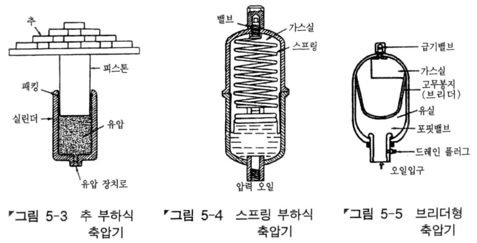
이 축압기는 예충전이나 재충전을 필요로 하지 않는 장점이 있으나, 유압회로의 용량이 크거나 고압일 경우 축압기의 부피가 너무 커지는 단점도 있어, 회로의 용량이 작거나 저압인 경우에 주로 사용된다.This accumulator has the advantage that it does not require precharging or recharging, but there is a disadvantage that the volume of the accumulator becomes too large when the capacity of the hydraulic circuit is large or high pressure, and is mainly used when the capacity of the circuit is small or low pressure. do.
상기의 그림 5-5와 같이 브리더에 불활성 가스를 주입하고 브리더의 압축과 팽창의 정도에 따라 압유를 축적하는 방법으로 단점으로는 유실에 가스가 침입할 염려가 있으나 장점으로는 대형으로도 제작이 용이하고, 맥동압 흡수가 용이하며, 빠른 응답성이다.As in Fig. 5-5, inert gas is injected into the breather and the pressure oil is accumulated according to the degree of compression and expansion of the breather. As a disadvantage, there is a possibility that gas may enter the oil chamber. Easy, easy to absorb pulsating pressure, fast response.
그 다음의 유압 작동유에 있어서,In the next hydraulic fluid,
유압 작동유는 유체에너지를 전달하기 위하여 매우 중요한 역할을 하는 것이며, 기계의 종류나 운전조건에 따라 여러 가지가 쓰이고 있다. 유압장치를 설계, 제작, 운전 관리하기 위해서도 유압기기와 더불어 유압유도 알고 있어야 하겠다.Hydraulic fluid plays a very important role in delivering fluid energy, and it is used in various ways depending on the type of machine and the operating conditions. In addition to hydraulic equipment, hydraulic oil must be known for designing, manufacturing, and managing hydraulic devices.
먼저 유압 작동유에 요구되는 성질에 있어First of all, in terms of the properties
유압장치가 그 기능을 장기적으로 충분히 발휘하기 위해서는 유압장치와 유압유가 충분히 적합해야 한다. 최근 유압장치의 고성능화에 따라 품질이 우수한 작동유가 요구되고 있다. 다음은 작동유에 요구되는 성능을 열거하였다.In order for the hydraulic system to fully function in the long term, the hydraulic system and the hydraulic oil must be sufficiently suitable. Recently, with high performance of the hydraulic system, a high quality hydraulic oil is required. The following lists the performance required for the hydraulic fluid.
첫째로 압축성은Firstly compressibility
동력을 확실하게 전달하기 위한 비압축성이고, 응답성이 양호할 것.Incompressibility to transmit power reliably and good response.
둘째로 점성은Secondly, viscosity
온도 및 압력에 의한 점도의 변화가 적고, 저온 유동성이 있으며 전단안정성이 양호할 것.Low viscosity change by temperature and pressure, low temperature fluidity and good shear stability.
세째로 윤활성은Third, lubricity
기기의 작동부에서 충분히 윤활성을 유지하고, 고체마찰을 방지할 수 있을 것.Maintain sufficient lubrication at the operating part of the machine and prevent solid friction.
네째로 안정성은Fourth, stability is
장시간 사용해도 화학적으로 안정될 것.Chemically stable even if used for a long time.
다섯째로 독성, 휘발성 등이 적을 것 등이다.Fifth, it is less toxic and less volatile.
다음은 유압에서의 점도 영향에 저점도 유압유와 고점도 유압류로 구분하는데에는 저점도 유압유는 고점도 유압유에 있어 누설이 잘된다. 그리고 내부 누설이 작다는 것과 윤활 효과가 작다는 점이며 윤활 특성이 좋다는 것이고 펌핑이 수월하다는 점에 배관저항이 크다는 점과 반응 시간이 빠르다는 것과 반응 시간이 느리고 스위칭 시간이 크다는 것인데 기포의 제거가 쉽다는 점이고 기포의 제거가 어렵다는 점 등이다.The following is the low viscosity hydraulic oil and the high viscosity hydraulic oil. The low viscosity hydraulic oil has good leakage in the high viscosity hydraulic oil. In addition, the internal leakage is small, the lubrication effect is small, the lubrication characteristics are good, the pumping is easy, the piping resistance is high, the reaction time is fast, the reaction time is slow, and the switching time is large. It is easy and it is difficult to remove bubbles.
3. 유압유의 사용법3. Usage of hydraulic oil
성능이 우수한 작동유를 사용한다고 하여도 올바르게 사용하지 않으면 유압기구의 성능을 발휘시킬 수 없다는 것인데Even if you use high-performance hydraulic fluid, you cannot show the performance of the hydraulic mechanism if you do not use it correctly.
먼저 유압유의 오염에 있어First of all, the pollution of hydraulic oil
유압기기 고장의 대부분은 먼지에 의하여 일어나고 있으며, 마찰이나 용접작업 기타 기계가 공시의 칩, 녹 등 금속입자로 이루어진 경질의 먼지와 오일의 열화나 시일재의 마모 등으로 일어나는 연질의 먼지가 있으며, 경질의 먼지는 기계의 섭동부에 홈을 내게 하여 오일누설이 이루어지고 기계의 성능이 저하되며, 연질의 먼지는 회로의 관로를 막아서(파일롯 라인 등) 작동불량이나 유량 유속 등에 영향을 주고 있다.Most of the breakdowns of hydraulic equipment are caused by dust, and there are hard dusts caused by friction, welding, and other machines made of metal particles such as chips and rust, and soft dusts caused by deterioration of oil and wear of sealing materials. The dust in the grooves in the perturbation of the machine leads to oil leakage and deterioration of the performance of the machine. The soft dust blocks the circuit of the circuit (such as the pilot line) and affects the malfunction and flow rate.
다음은 회로 중에 처음부터 들어있는 먼지인데Next is dust from the beginning of the circuit
기계가공 중이나 조립시 들어온 용접 슬래그, 칩 등이 있으며, 경질의 먼지로서 운동부에 홈을 내어 가장 위험하다.There are welding slag, chips, etc., which come in during machining or assembly, and it is the most dangerous because it is hard dust and makes a groove in the moving part.
회로 속에 발생하는 녹은 재료의 선정 잘못이나 조립 전의 보관 잘못 등으로 인하여 생기는 것이 보통이며, 온도의 변화에 따라 공기 중의 수증기가 응고(결로현상)하여 생기는 수도 있다.It is usually caused by the wrong selection of molten material in the circuit or storage error before assembling, and it may be caused by the condensation (condensation) of water vapor in the air according to the change of temperature.
다만 운전 중 회로 속에서 발생하는 먼지에 있어However, there is dust in the circuit during operation
기계의 마찰에 의하여 마찰부분이 마모하여 생기는 기계적인 것과 작동유의 산화에 의하여 생기는 화학적인 것이 있으며, 오일의 산화 생성물은 고형인 먼지와 수분과 함께 슬러지가 되는 수도 있다.Mechanical friction is caused by the friction of the machine and chemicals caused by the oxidation of the working oil. The oxidation product of the oil may become sludge together with solid dust and water.
그리고 사용 중 외부에서 들어온 먼지에는And dust from outside during use
오일 주유구의 필터불량이나 통기구의 필터 불량으로 들어오는 경우가 많으며, 또한 피스톤 로드를 통하여 들어오는 경우도 있다.In many cases, it may be caused by a poor filter at the oil inlet or a bad filter at the vent, and may also come through the piston rod.
이 같이 보충 오일 속에 들어있는 먼지는Dust in the supplementary oil like this
특히 물이 가장 많은 이물질이다. 물이 들어가면 무겁기 때문에 탱크 바닥에 모이나 유압펌프의 작동에 의하여 미세하게 분해되어 기계의 각 부분에 녹을 발생시킨다.In particular, water is the most foreign substance. Since water is heavy when it enters, it collects at the bottom of the tank and is broken down finely by the operation of the hydraulic pump, which causes rust in each part of the machine.
이처럼 유압유의 점검과 교환에 있어In the inspection and replacement of hydraulic oil
작동유의 상태를 점검하는 방법에는 눈으로 보는 방법과 시험에 의한 방법이 있으나 보통 5,000∼20,000시간 사용하면 작동유의 성질이 변하여 응고되는 경향이 생긴다.There are two methods of checking the condition of the fluid: the visual method and the test method. However, if the oil is used for 5,000 to 20,000 hours, the property of the fluid changes and it tends to solidify.
따라서 처음에는 100∼1000시간 정도에 교환을 하고 2회부터는 2000시간마다 교환하며, 흑갈색을 띄고 있으면 즉시 교환하고 비중, 점도 등도 확인하는 것이 좋다.Therefore, at first, exchange for about 100 ~ 1000 hours, and every 2 hours from 2000 times, if it is blackish brown, change it immediately and check specific gravity, viscosity, etc.
바람직한 순수 유입 제어 실습과제에 있어서,In the preferred pure water inlet control exercise,
실시예를 5회 실시하였다.The example was carried out five times.
[실시예1] 기초 실습에 있어Example 1 In basic training
먼저, 실습목표에는First, in practice
첫째로 유압 핸드 펌프를 이용하여 압력의 형성과정을 설명할 수 있다.First, the pressure formation process can be described using a hydraulic hand pump.
둘째는 압력 릴리프 밸브의 압력 설정방법을 수행할 수 있다.Secondly, the pressure setting method of the pressure relief valve can be performed.
세째로 유압 압력 릴리프 밸브의 크래킹 압력을 확인하는 작업을 할 수 있다.Thirdly, it is possible to check the cracking pressure of the hydraulic pressure relief valve.
다음의 실습순서에 따른 그에 대한According to the following practice procedure
먼저 유압 핸드 펌프 실습에 있어First, in the hydraulic hand pump exercise
첫째로 실습에 필요한 부품을 선정하여 고정판에 배치, 고정한다.First, select the parts necessary for practice and place them on the fixed plate.
둘째는 배치된 부품을 회로도와 같이 배관한다.Second, pipe the placed parts as shown in the schematic.
세째로 그림 6-1의 셧-오프 밸브 ![]()
![]()
넷째는 유압셋의 전원을 온(On)시켜 액주관 ![]()
![]()
다섯번째 셧-오프 밸브 ![]()
![]()
![]()
![]()
여섯번째 셧-오프 밸브 ![]()
![]()

일곱번째 셧-오프 밸브 ![]()
![]()
![]()
![]()
여덟번째 실습장치를 정돈 후 다섯째, 여섯째와 일곱번째의 결과에 대해 토의한다.After arranging the eighth lab, discuss the fifth, sixth, and seventh results.
다음은 유압 압력 릴리프 밸브 실습은 하도와 같다.Next, the hydraulic pressure relief valve exercise is as follows.

먼저 그림 6-2 실습에 필요한 부품을 선정하여 고정판에 배치, 고정한다.First, select the parts necessary for the exercise in Figure 6-2 and place and fix them on the fixed plate.
다음은 배치된 부품을 회로도와 같이 배관한다.Next, pipe the placed parts as shown in the schematic.
그 다음은 셧-오프 밸브 ![]()
![]()
네번째로 압력 릴리프 밸브 ![]()
![]()
다섯째는 유압셋의 전원을 온(On) 시킨다.Fifth, turn on the power of the hydraulic set (On).
여섯째로 압력 게이지 p1의 압력이 50kgf/cm2이 될 때까지 압력 릴리프 밸브의 조정나사를 시계방향으로 돌린다.Sixth, turn the pressure relief valve adjustment screw clockwise until the pressure gauge p1 has a pressure of 50 kg f / cm 2 .
다음은 유압셋의 전원을 오프(Off) 시킨 후 셧-오프 밸브 ![]()
![]()
그 다음에는 유압셋의 전원을 온(On) 시킨 후 셧-오프 밸브 ![]()
![]()
![]()
![]()
아홉째로 여덟째의 압력 릴리프 밸브의 작동압력에 대해 토의한다.Ninth, discuss the working pressure of the eighth pressure relief valve.
마지막의 압력 게이지 p1의 40kgf/cm2과 30kgf/cm2이 되도록 압력 릴리프 밸브를 재조성한 후 각 경우에 대해 (7), (8), (9) 과정을 반복하여 표 6-1을 작성한다.After re joseonghan a pressure relief valve so that 40kg f / cm 2 and a final pressure gauge p1 of 30kg f / cm 2 for each case (7), (8), Table 6-1 repeated to 9 courses Write.
<표 6-1><Table 6-1>

마지막 결과에 대해 토의한다.Discuss the final result.
그 다음의 유압 펌프의 유량-압력 특성 실습은 하도와 같다The next flow-pressure characteristic exercise for the hydraulic pump is the same as the estuary.
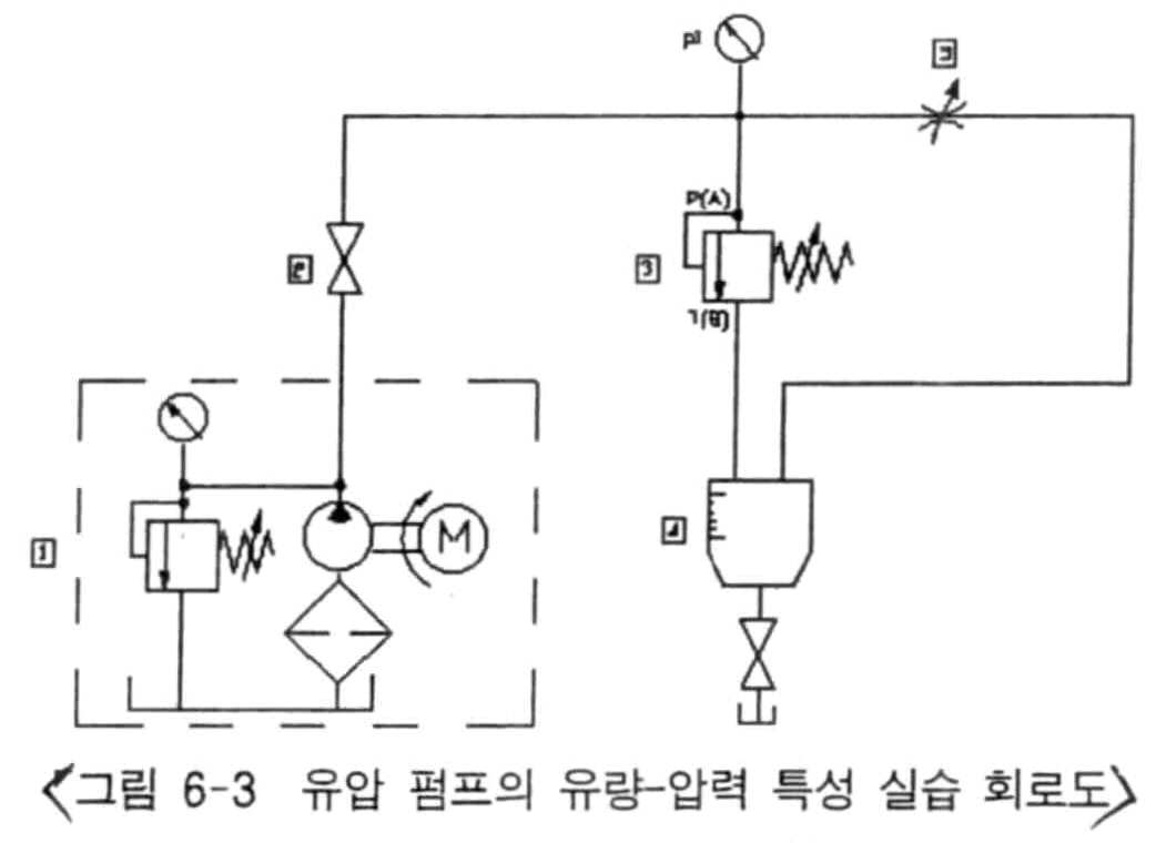
1단은 그림 6-3 실습에 필요한 부품을 선정하여 고정판에 배치, 고정한다.In the first stage, select the parts necessary for the exercise in Figure 6-3 and place and fix them on the fixed plate.
2단은 배치된 부품을 회로도와 같이 배관한다.The second stage pipes the arranged parts as shown in the circuit diagram.
3단은 셧-오프 밸브 ![]()
![]()
4단은 유량제어 밸브 ![]()
![]()
5단은 유압셋의 전원을 온(On) 시킨다.The fifth stage turns on the power of the hydraulic set.
6단은 유압 릴리프 밸브 ![]()
![]()
7단은 유량제어 밸브 ![]()
![]()
8단은 유압셋의 전원을 오프(Off) 시키고 투명 유량계의 ![]()
![]()
9단은 유압셋의 전원을 온(On) 시킨다.The 9th stage turns on the power of the hydraulic set.
10단은 초시계를 이용하여 투명 유량계 ![]()
![]()
11단은 압력 게이지 p1의 압력이 20, 30, 40kgf/cm2일 때 각각 (8), (9)의 과정을 반복한다.
12단은 결과에 대해 토의한다.
<표 6-2><Table 6-2>

네번째 유체의 흐름 실습은 하도와 같다.The fourth fluid flow practice is like a channel.

1단은 그림 6-4 실습에 필요한 부품을 선정하여 고정판에 배치, 고정한다.In the first stage, select the parts necessary for the exercise of Figure 6-4, and place and fix them on the fixed plate.
2단은 배치된 부품을 회로도와 같이 배관한다.The second stage pipes the arranged parts as shown in the circuit diagram.
3단은 셧-오프 밸브 ![]()
![]()
4단은 유압셋의 전원을 온(On) 시킨다.The fourth stage turns on the power of the hydraulic set.
5단은 유압 릴리프 밸브 ![]()
![]()
6단은 유압셋의 전원을 오프(Off) 시킨다.The sixth stage turns the power of the hydraulic set off.
7단은 회로도상의 ![]()
![]()
8단은 유압셋의 전원을 온(On) 시킨다.The 8th stage turns on the power of the hydraulic set.
9단은 오리피스 투명블록 전·후의 압력을 p1, p2 게이지로 측정하고 유체의 흐름 상태를 관찰한다.
10단은 회로도상의 ![]()
![]()
11단은 결과에 대해 토의한다.
<표 6-3><Table 6-3>

[실시예2] 유압 단동실린더의 제어에 있어Example 2 In Control of a Hydraulic Single Acting Cylinder
다음의 실습목표에 있어In the next exercise
1단은 단동실린더의 구조를 이해하여 그 기능을 설명할 수 있다.The first stage can explain the function by understanding the structure of single acting cylinder.
2단은 피스톤의 속도와 힘의 함수 관계를 이해하고 계산하여 그 값을 산출할 수 있다.The second stage can be calculated by understanding and calculating the function of the piston's speed and force.
3단은 회로도에 표시된 유압 기호를 판독하여 유압 요소를 선정 배치할 수 있다.The third stage can select and arrange a hydraulic element by reading the hydraulic symbol shown in a circuit diagram.
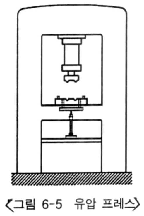
다음 실습순서에 따른 그에 대한 순서는The following is the order of the exercises
첫째는 작업 준비를 한다.First, prepare for work.
먼저 유압 회로도를 판독한다.First, read the hydraulic circuit diagram.
다음은 회로도에 표시된 유압 요소를 선정한다.Next, select the hydraulic elements shown in the circuit diagram.
그 다음은 유압 실험 장치의 이상 유무를 확인한다.Next, check whether there is an abnormality in the hydraulic test apparatus.
둘째는 유압 요소를 조립한다.Second, assemble the hydraulic elements.
먼저 유압 작업판에 유압 요소를 고정 배치한다.First, the hydraulic element is fixedly placed on the hydraulic working plate.
다음은 연결 호스를 이용하여 각 유압 요소를 연결한다.Next, connect each hydraulic element with a connection hose.
그리고 연결 요소를 점검한다.Then check the connection elements.
점검후 각 유압 요소의 연결부와 연결 호스의 이상 유무를 확인 점검한다.Check and check the connection of each hydraulic element and connecting hoses for abnormalities.
세째는 시험 작동한다.The third is a test run.
먼저 시동 스위치를 켠다.First turn on the start switch.
그리고 입력 릴리프 밸브를 이용하여 압력을 40kgf/cm2에 맞춘다.Then set the pressure to 40kg f / cm 2 using the input relief valve.
한편 단동실린더의 전·후진 운동은 3/2-way 밸브의 위치 전환에 의해 이루어지도록 한다.Meanwhile, the forward and backward movements of the single-acting cylinder are to be made by switching the position of the 3 / 2-way valve.
또한 전진 운동시 p1, p2의 압력을 확인하여 표 6-4의 기록표에 기록한다.Also, check the pressure of p1 and p2 during forward movement and record it in the record table of table 6-4.
그 다음은 실습 장치를 정돈하는데에는Next is to set up the lab.
정돈후 유압 파워 유니트의 전원을 차단한다.Turn off the hydraulic power unit after trimming.
차단후 압력 게이지의 압력이 0kgf/cm2으로 된 것을 확인한다.Check that the pressure gauge's pressure is 0kg f / cm 2 after shutdown.
확인후 유압 배관을 제거하고 부품을 정리 정돈한다.After checking, remove the hydraulic pipe and arrange the parts.

<표 6-4><Table 6-4>

[실시예3] 유압 복동실린더의 제어에 있어서Example 3 In Control of a Hydraulic Double Acting Cylinder
먼저 실습목표에 있어First, in practice
1단은 복동실린더의 구조를 이해하여 그 기능을 설명할 수 있다.The first stage can explain the function by understanding the structure of double acting cylinder.
2단은 피스톤의 전·후진 속도 차이의 원인을 설명할 수 있다.The second stage can explain the cause of the piston's forward and reverse speed differences.
3단은 회로도에 표시된 유압 기호를 판독하여 유압 요소를 선정할 수 있다.The third stage can select the hydraulic element by reading the hydraulic symbol shown in the circuit diagram.
실습순서에 따른 그에 대한According to the practice order
먼저 작업 준비를 한다.Get ready for work first.
1단은 유압 회로도를 판독한다.The first stage reads the hydraulic circuit diagram.
2단은 회로도에 표시된 유압 요소를 선정한다.
3단은 유압 실험 장치의 이상 유무를 확인한다.
4단은 초시계를 준비한다.

그리고 유압 요소를 조립한다.And assemble the hydraulic elements.
먼저 유압 작업판 위에 유압 요소를 배치한다.First place the hydraulic element on the hydraulic working plate.
다음은 연결 호스를 이용하여 유압 요소를 연결한다.Next, connect the hydraulic elements using the connection hose.
또한 연결 요소를 점검하되,Also check the connecting elements,
각 유압 요소의 연결부와 연결 호스의 이상 유무를 확인 점검한다.Check if there is any abnormality in the connection part and connecting hose of each hydraulic element.
점검후 시험 작동한다.After checking, operate the test.
작동후 시동 스위치를 온(On) 시킨다.After operation, turn on the start switch.
그리고 압력 릴리프 밸브를 이용하여 압력을 40kgf/cm2에 맞춘다.Then set the pressure to 40kg f / cm 2 using the pressure relief valve.
다음은 4/2-way 밸브를 사용하여 표 6-5를 완성한다.The following completes Table 6-5 using a 4 / 2-way valve.
완성후 각 유압 요소를 정리 정돈한다.After completion, arrange each hydraulic element.
정돈후 유압 파워 유니트의 전원을 차단한다.Turn off the hydraulic power unit after trimming.
차단후 압력 게이지의 압력이 0kgf/cm2으로 된 것을 확인한다.Check that the pressure gauge's pressure is 0kg f / cm 2 after shutdown.
확인후 유압 배관을 제거하고 부품을 정리 정돈한다.After checking, remove the hydraulic pipe and arrange the parts.
<표 6-5><Table 6-5>

[실시예4] 유압 실린더의 중간정지에 따른 대책에 있어서[Example 4] In the Countermeasure According to Intermediate Stop of the Hydraulic Cylinder
먼저 실습목표에 있어First, in practice
첫째로 파일로트 작동형 체크 밸브의 기능을 설명할 수 있다.First, the function of the pilot operated check valve can be explained.
둘째는 실린더의 중간정지 시스템을 구축할 수 있다.Second, the intermediate stop system of the cylinder can be constructed.
실습순서에 따른 그에 대한According to the practice order

실습을 준비한다.Prepare for the exercise.
먼저 그림 6-8의 실습에 필요한 부품을 선정하고 고정판에 배치, 고정한다.First, select the parts necessary for the exercise in Figure 6-8, and place and fix them on the fixed plate.
고정후 배치된 부품을 유압 호스를 사용하여 회로도와 같이 배관한다.After fixing, pipe the laid parts as shown in the circuit diagram using a hydraulic hose.
배관후 동작 시험을 한다.Perform post-pipe operation test.
시험후 유압 파워 유니트의 전원을 공급한다.After the test, supply power to the hydraulic power unit.
공급후 밸브 <2>를 작동시켜 실린더를 전진운동 시킨다.After supplying, operate valve <2> to advance cylinder.
운동후 밸브 <3>을 작동시켜 실린더를 후진운동 시킨다.After the movement, operate the valve <3> to reverse the cylinder.
다음은 20kgf의 추를 실린더 위에 올려놓는다.Next, put a weight of 20kg f on the cylinder.
그 다음은 밸브 <2>를 작동시켜 실린더를 행정의 중간위치까지 전진운동 시킨다.Next, the valve <2> is operated to move the cylinder forward to the intermediate position of the stroke.
그리고 실습 장치를 정돈한다.And prepare the training equipment.
정돈후 실린더가 완전히 후진운동하고 압력 게이지의 압력이 0kgf/cm2이 되도록 밸브 <3>을 작동시킨다.After trimming, operate the valve <3> so that the cylinder is fully retracted and the pressure gauge is 0kg f / cm 2 .
작동후 유압 파워 유니트의 전원을 차단한다.Turn off the hydraulic power unit after operation.
차단후 유압 배관을 제거하고 부품을 정리 정돈한다.After shut off, remove the hydraulic pipe and arrange the parts.

[실시예5] 유압 실린더의 속도제어에 따른[Example 5] Speed Control of a Hydraulic Cylinder
실습목표에는In practice
먼저 유압 실린더의 미터-인 속도제어 회로를 구성할 수 있다.First, the meter-in speed control circuit of the hydraulic cylinder can be configured.
다음은 유압 실린더의 미터-아웃 속도제어 회로를 구성할 수 있다.Next, the meter-out speed control circuit of the hydraulic cylinder can be configured.
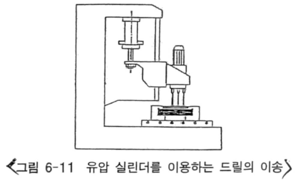
실습순서에 의해 미터-인 속도제어 실습을 준비한다.Prepare for the meter-in speed control exercise by following the practice procedure.
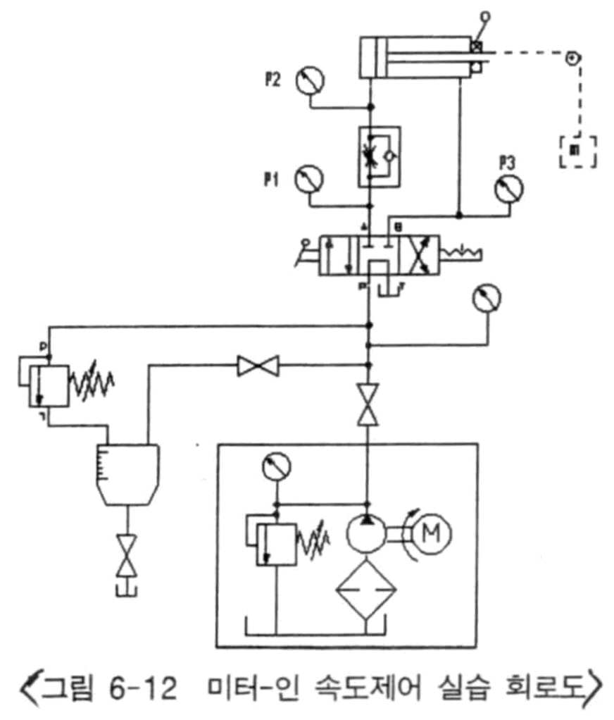
그리고 그림 6-12 미터-인 속도제어 실습에 필요한 부품을 선정하여 고정판에 배치, 고정한다.Figure 6-12 Select the parts necessary for the meter-in speed control exercise and place and fix them on the fixed plate.
고정후 배치된 부품을 유압 호스를 사용하여 회로도와 같이 배관한다.After fixing, pipe the laid parts as shown in the circuit diagram using a hydraulic hose.
그 다음 동작 시험을 한다.Then perform an operation test.
시험후 유압 파워 유니트의 전원을 공급한다.After the test, supply power to the hydraulic power unit.
공급후 시스템의 최대 압력을 결정하는 압력 릴리프 밸브의 설정압을 50kgf/cm2으로 조정한다.Adjust the set pressure of the pressure relief valve to 50 kg f / cm 2 , which determines the maximum pressure of the system after supply.
그리고 무부하 상태에서 실린더의 전진 운동 완료시간이 10초가 되도록 교축 릴리프 밸브의 조정 나사를 조정한다.Then, adjust the adjustment screw of the throttle relief valve so that the forward movement completion time of the cylinder is 10 seconds under no load.
조정후 전진 운동시 p1, p2, p3의 압력과 시간을 확인하여 표 6-6의 기록표에 기록한다.Check the pressure and time of p1, p2, p3 during forward movement after adjustment and record the result in the table of table 6-6.
기록후 실린더의 브레이크 레버를 이용하여 적당한 세기의 압축하중을 가한다.After recording, apply a compressive load of moderate strength using the brake lever of the cylinder.
한편 (4)의 과정을 반복한다.Meanwhile, the process of (4) is repeated.
반복후 실린더의 브레이크 레버를 풀고 추(20kgf)를 이용하여 인장하중을 가한다.After repeating, release the brake lever of the cylinder and apply tensile load using the weight (20kg f ).
(4)의 과정을 반복한다.Repeat the process (4).
반복후 실습 장치를 정돈한다.After the repetition, prepare the training device.
정돈후 유압 파워 유니트의 전원을 차단한다.Turn off the hydraulic power unit after trimming.
차단후 압력 게이지들의 압력이 0kgf/cm2으로 된 것으로 확인한다.After closing, check that the pressure gauges have a pressure of 0 kg f / cm 2 .
확인후 유압 배관을 제거하고 부품을 정리 정돈한다.After checking, remove the hydraulic pipe and arrange the parts.
그 다음에는 미터-아웃 속도제어 실습을 준비한다.Next, prepare for the meter-out speed control exercise.
준비한후 그림 6-13 미터-아웃 속도제어 실습에 필요한 부품을 선정하여 고정판에 고정, 배치한다.After preparing, select the parts necessary for the exercise of Figure 6-13 Meter-out speed control and fix and place them on the fixed plate.
배치후의 배치된 부품을 유압 호스를 사용하여 회로도와 같이 배관한다.After the placement, place the laid parts using hydraulic hoses as shown in the schematic.
그리고 2.와 같은 요령으로 동작 시험을 한다.And perform the operation test with the same tips as 2.
한편 3.과 같은 요령으로 실습 장치를 정돈한다.On the other hand, arrange the training device by following the same tips.

또한 카운터 밸런스 밸브 실습을 준비한다.Also prepare for counter balance valve practice.
준비후 그림 6-14의 카운터 밸런스 밸브 실습에 필요한 부품을 선정하고 고정판에 배치, 고정한다.After preparation, select the parts necessary for the practice of counter balance valve of Figure 6-14, and place and fix them on the fixed plate.
고정후 유압 호스를 사용하여 배치된 부품을 연결한다.After fixing, use the hydraulic hose to connect the placed parts.
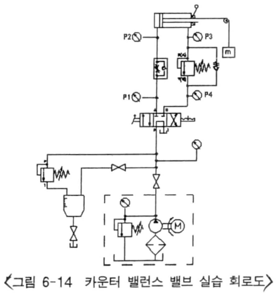
그리고 동작 시험을 한다.Then test the operation.
한편 무부하 상태에서 전진 운동시 p3의 압력이 20kgf/cm2이 되도록 압력 릴리프 밸브의 조정나사를 조정한다.On the other hand, adjust the adjustment screw of the pressure relief valve so that the pressure of p3 is 20kg f / cm 2 during the forward movement at no load.
또한 3.과 같은 요령으로 실습 장치를 정돈한다.Also, follow the same instructions as in 3. to prepare the training device.
<표 6-6><Table 6-6>
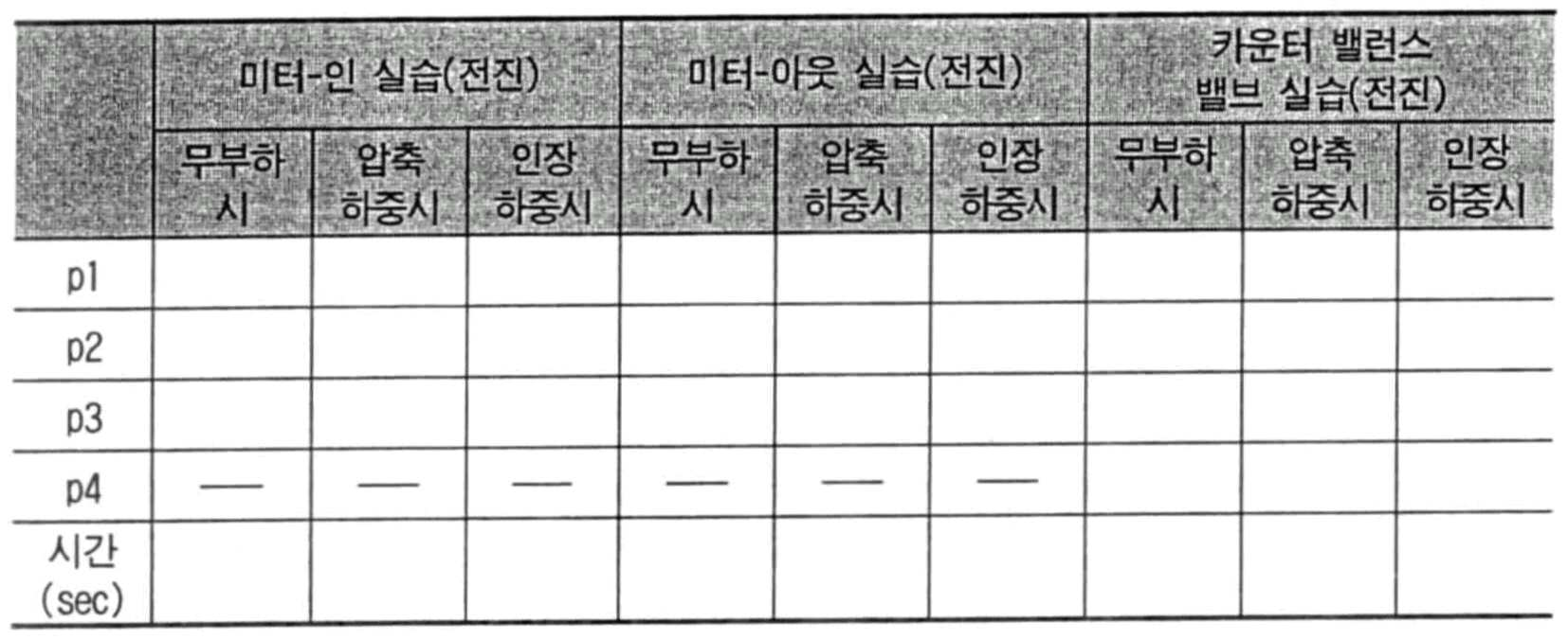
![]()
![]()
■ 미터-인 속도제어■ Meter-in speed control
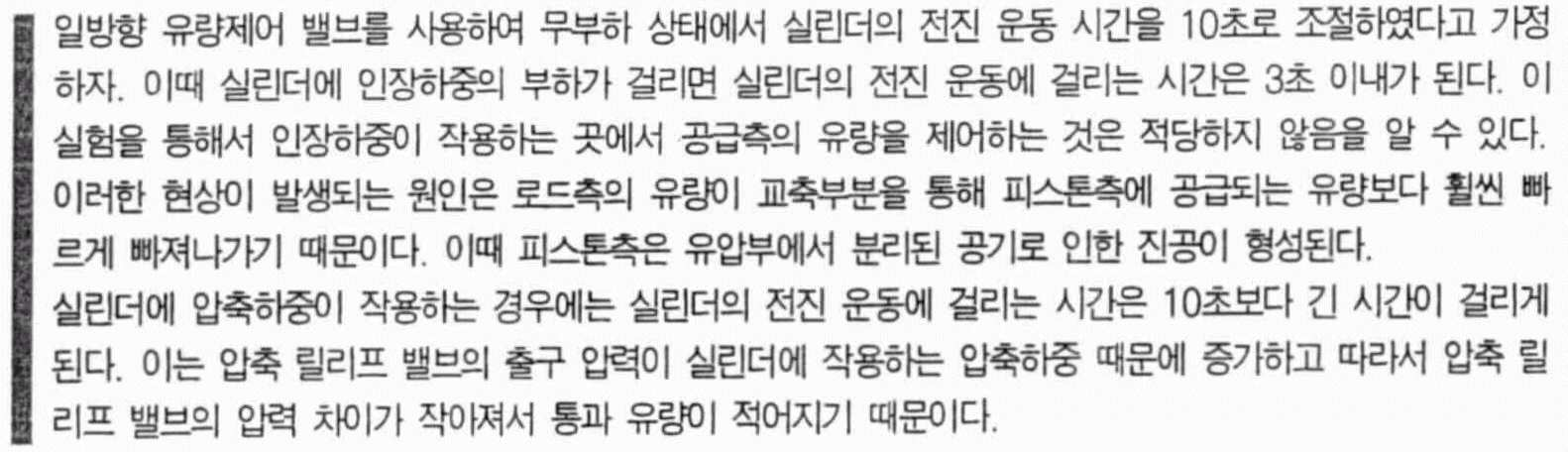
■ 미터-아웃 속도제어■ Meter-out speed control

상기한 바와 같이 수개의 해양발전소 몸체(1) 내부로 해양환경산업발전을 이루기 위하여 우주과학발전용 장비인 인공위성 발사대(643)에 우주로켓 발사대(646)가 국제사회 위계질서에 따라 해양에서 형성된 대형의 해양발전소 부양식독(595) 갑판데크상단부(SDL)에 인공위성(611)과 우주로켓(612)들이 수개로 탑재 형성되는데 상기의 장비는 국제사회 UN 평화유지군과 UN 과학 위원회원국들이 사양을 선택할 수 있다.As described above, the space
통상의 해양환경산업발전을 위한 종합 재난 방지 시스템의 수개의 해양발전소 양식 독 제조 설치에 있어 다음과 같이 요약 설명한다.The following is a summary of several marine power plant farming installations of a comprehensive disaster prevention system for the normal development of the marine environment industry.
상기 부양식독(593)에 탑재되는 종합장비는 비철재 금속의 스텐또는알루미늄과 프라스틱 재질로 조성되고 부양식독은 고장력의 철판(597)으로 배관또는블럭배관을 제조 후 예인선(636)으로 이송중 블럭배관(598) 이상 유무확인 수정된후 해상에서 이중관 구조 형식의 블럭배관(598) 연결부위 각각은분해결합장비 일체로 이루어 수개의 해양발전소 몸체(1)로 형성한다.The comprehensive equipment mounted on the
그리고, 상기 블럭배관(598)은 소형의 부양식독(593) 하단 중형의 부양식독(594) 상단부에 결합된후 중형의 부양식독하단과 대형의 부양식독(595) 상단과 각기 잠수조절 분리 결합이 해수면에서 조립형성된후 부양식독 내부로 방재수 펌핑 흡입토출 조절되면서 잠수가 진행된후 부양식독과 피라밋 형식의프레임 결합이 진행된다 상기 부양식독의 결합수단인 용접이음 방식과 플랜지 결합방식을 조절한 후 블럭배관(598) 결합분리를 하기 위한 포터블러그 플레이트(607)와 포터블러그 핀샤프트(606)는 해수면에서는 각기 핀 샤프트가 한곳으로 연결된후 응접연결선은 지그재그 대칭으로 용접 형성되면서 해상작업을 하기 위하여 피라밋 형식의 프레임결합분리와 블럭배관 연결부위 수중절단과 수중용접으로 대형플랜지(614) 결합작업을 하기 위하여 해상작업을 위한 치공구 밴드 지그대(621)는 해상작업을 위한 반잠수작업선(637) 상단으로 대형플랜지(614) 접속연결구 블럭배관(598)의 부분 결합을 위하여 밴드지그대(621)와 반잠수작업선(637)은 블럭배관 결합수단으로 구비되고 상기 블럭배관은 설치위치조절하여 유압작키(623)를 조작함으로써 수개의 블럭배관(598)이 형성된다.In addition, the
이 같은, 상기 부양식독은 해수면상단부(SUL) 상단의 부양식독(34) 상단으로 부양식독 중심부 상단에는 수개의 비상용의계단(631)블럭철탑(116) 내부의 타구어윈치(137)로 단위블럭철탑(116)을 러그 샤프트 결합용볼트(603)로 단위블럭 철탑접속 연결구 가공홀(615)에 끼우고 그 다음에는 러그 샤프트 결합너트(604)로 결속함으로써 블럭단위 블럭철탑(116)이 형성되는데 상기 블럭철탑(116) 내부 상단 주위로 비상용의계단(631)이 설치되면서 상기 비상용의계단(631)은 무어링타워(644) 비행선(78) 계류장 위치로 형성되며 비행선 계류장 하단부 하단 중심부로 파이프랙 운반용 크레인(861)에 승강기(632)로 설치 형성하는데에는 풍랑파도로부터 터넬(929)독을 보호하기 위하여 해수면(SLL) 하부로 100M 아래로 위치 조절하였고As such, the aquaculture dock is a unit block with a
이 같이, 상기 무어링타워 상단부 상단으로 방재수(7)를 급수하는 고압피스톤식 방재펌프(8) 작동중 방재호스(9)로 방재수(7)는 급수되면서 수개의 시이소(935) 크레인붐대(651) 노즐(10)과 소방호스 연결마디 중간에 설치되는 방재노즐(10) 또는 상수도 배관연결 고정식의 방재노즐(10) 각각으로 방재수는 방출되며 상기 호스와 노즐을 지지하기 위한 수단의 연결선 와이어로프(19)와 샤클(23) 또는 방재노즐 연결플랜지(28)로 부양식독 최상위치로 기상관측장비 애드벌룬(77) 또는 라디오존데(134) 하단부 하단의 파일렛이 승선하는 바스켓(42) 하단으로 방재노즐 보호용 연결선 와이어로프(19)와 공기보다 가벼운 기체운송수단의 호스가 방재호스 내부로 접합 연결 형성되었고,As such, while the high-pressure piston type
이에, 상기 고압피스톤식 방재펌프 작동으로 방재노즐 끝단부위로 방재수는 방출되며 일자형의 토출분사수(38) 또는 방사형의 토출분사수 물막커텐(39) 형상으로 토출낙하 분사되며 방재펌프작동기계실 또는 안전통제실 내부의 고압피스톤식 방재펌프시스템(150)의 휴대용무선통신단말기(82)와 방재펌프작동제어를 위한 스위치(66) 또는 방재수 살포를 위한 방제펌프작동스위치버턴(67) 상부로 동력전원 공급장치제어박스(2)가 안전통제실 또는 방재펌프작동기계실에 분포 배치 연결 형성하였고Thus, the high-pressure piston type disaster prevention pump is operated to discharge the disaster prevention water to the end of the disaster prevention nozzle and discharged in the shape of a
이에 따라, 상기 대형의 해양발전소 부양식독(595) 블럭철탑(116) 우측으로 원유시추용의 유해가스제거용 버너붐(920)과 에어리시버 탱크(145) 또는 대형발전기(213)의 발전실로 조성되며 운송시스템의 비이오피 스키드(918)와, 원유시추공 작업후 황토(158)와 세멘트(931)로 시추공을 메우기 위하여 황토(158)와 시멘트의 혼합장비 믹서는 기계실(MUD Feed M/C RooM; 머드 피드룸이라 칭하고)에 항상 대기하도록 배치되었는데 상기의 장비는 해양발전소 몸체(1) 내부에 형성된다.Accordingly, to the right side of the large offshore power plant side aquaculture dock (595)
상기 블럭철탑 좌측으로 안전통제실과 기상관측장비 관리실 또는 통제실의 상단으로 피라밋 형식의 프레임결합분리 최상위치 갑판 데크 헬기 정류장(619)이 조성되고 안전통제실 좌측으로 인공위성 발사대(643)와, 인공위성 발사대 내부의 우주로켓(612)으로 배치 형성되면서 유해적조 대변식을 방지하기 위하여 에어콤프레샤와 그물식 에어호스로 산소와 공기를 해저에 투입하여 해양환경을 보호하기 위해서 배치 형성되고 상기 부양식독 갑판데크 상단부 상단의 중심위치 블럭철탑 내부의 상단 부위로 설치되는 원유 시추봉 연결작동을 위한 파이프랙(854)은 블럭철탑 내부 에어타구어윈치(137) 또는 크레인(861)의 와이어로프(19)로 결속되어 굴착채취샤프트 하단 코아드릴(917) 상단에서 원유 시추용의 드릴링머신(908) 또는 드릴 머신룸에서 이송배치 장착 형성하고 해저광물자원망간단괴(909)를 채집하는 뜰채 바스켓(842)과, 르메틱의 흡입채취기계(911) 또는 해저광물채취로봇(912)과, 광물채집뚜레박(924)으로 조성 연결 배치 형성되며 부양식독 및 터넬독 외부에는 따개비 또는 해양생물이 서식하지 못하게 아노드(INode; 전극판, 938)를 선체 외벽으로 부착한다To the left of the block tower, a pyramid-type frame-coupling top deck
상기 부양식독 갑판데크 상단부 하단의 부양식독 보텀 하단으로 피라밋 형식의 노즐프레임의 내부배관(596) 및 외부배관(599)의 이중관 구조의 배관으로 조성되고 내부배관 중심으로 원유시추봉에 해당되는 굴착샤프트에 부착되는 코아드릴(917)로 조성하고 원유시추봉 가동후에 발생되는 굴착토와 지층의 유해가스를 이 동하는 배관으로 이의 배관을 지지하는 철판브라켓(165)은 등변산 형강(149)으로 형성되고 내부배관 또는 외부배관을 지지하는 티이롱지스틸바아(600)와 오링스틸바아(601)는 용접 접합을 할 수 있게 하는 스카프 웰딩홀(602)이 수직격벽(605)의 격벽맨홀(610)과, 방재수 통로맨홀뚜껑(152) 접합틈새와, 수평격벽(609) 용접부위로 각기 일정하게 조성후 이중관 구조의 배관에 용접 결합 구성되며 이 같이Excavation shaft corresponding to crude oil drilling rod is formed by the double pipe structure of the
상기 부양식독 노즐프레임의 외부배관 외부에는 대형의 플랜지로서 상기 플랜지 접합부위는 고강도의 볼트(603)와 고강도의 너트(604)로 플랜지 가공홀에 결합 체결되고 접합부 틈새에는 고압력의 가스켓트 또는 고무패킹(32)으로 접속되며 방재노즐프래임 연결부속 티이엘보(44) 또는 방재배관부속 엘보(44) 접합 부위로 블럭배관이 형성되고 해저광물자원 탐색장비의 탐조등(232) 또는 해저탐사 렌즈 유리와 수중조명(843)이 수직탱크 외벽으로 파라밋 형식의 방재노즐프레임 외부배관 외벽으로 일정한 간격으로 설치 형성되고 외부배관 외벽둘레면에는 방재노즐 지지대 프레임 결합분리 포터블 러그용플레이트(607)와 방재노즐 지지대 프레임 결합분리 포터블 러그(21) 핀사프트(606) 또는 핀결합을 위한 유압작키(623)로 결속되고 대형플랜지(614)는 이중으로 접속되며 블럭결합을 하기 위한 접합부위 핀결합의 장공홀(616)과 블럭결합을 하기 위한 접합부위핀(608)이 러그 플레이트의 가공제작하여 해수면으로 이동시켜 해양조립식으로 구비되어 하단의 부양식독 상단부에 연결 접합 형성되는데에는 물체의 하중을 분산시켜 물체의 수명을 연장하고 조류의 변동에 따라서 물체가 해수면에 표출될시에는 해상선박과 충돌로 대형사고가 나지 않도록 해양발전소 몸체인 부양식독 갑판에는 해수면 상부로 100M 위로 위치 조절하였 다.The outer pipe of the subcultured nozzle frame is a large flange, and the flange joint portion is fastened to the flange processing hole with a
상기 부양식독 노즐프레임의 수직탱크와 수직과 수평의 대각 또는 대칭으로 블럭단위의 러그 플레이트와 러그 핀샤프트는 해수면 선상에서 블럭배관 단위의 접합부위 연결조립 후 잠수와 부상이 반복되면서 부양식독은 공기압력조절 또는 수압조절후 펌프가동으로 해수면 상공으로 방재수(7)는 일자형의 토출분사수(38) 및 방사형의 토출분사수 물막 커텐으로 토출되어 태풍의 위력을 제압하고 지구온난화가 방지되면서 유해적조를 사전에 제어되어 대형 발전기(213)의 헤드탱크와 수압관 프란시스수차(229)와 펠톤수차(230) 그리고 해양풍력발전기(231)에 의하여 생산되는 동력을 육지로 공급하고 이의 동력으로 해저 굴착하여 원유(841)와 무공해천연가스(922)채집 또는 해저저층에 적재되어 있는 망간단괴(909)를 채집하고 해중의 해수면 하부 100지점 관 교량(937)의 교각(928)설치와 해중터널 건설을 하는 방법으로 다기능의 다목적을 포함하는 장비로서 무재해 지구촌의 해양재난방지와 해양환경 산업발전을 하기 위한 유해적조 구제장비와 종합재난 방지시스템의 장비 일체로 형성됨을 특징으로 종전의 건설기계의 크레인(861) 붐대(651)를 바지선 본체(591) 갑판데크 측면사이드에 수개의 시이소(935) 크레인붐대는 해양수심에 따른 장축으로 사용할 수 있도록 길이 20km로 제작하여 해저 저층바닥의 기초콘크리트 교각을 설치하고, 무재해를 이룰 수 있게 태풍의 진로를 제압하는 장비로서 국제사회의 기상예보 및 기상예방정책기관에서 본 발명의 장비들을 선택할 수 있다The lug plate and lug pin shaft of the block unit are vertically and horizontally symmetrical or symmetrical with the vertical tank of the subculture dock nozzle frame. Discharge water (7) is discharged into the straight discharge jet (38) and radial discharge jet spring curtain curtain over the sea level by adjusting or hydraulic pressure control to suppress the force of the typhoon and prevent global warming, It is controlled in advance to supply the power produced by the head tank, hydraulic pipe Francis aberration (229), Pelton aberration (230) and offshore wind power generator (231) of the large-scale generator (213) to the land and the bottom of the oil (841) and pollution-free natural gas (922) or manganese nodules (909) loaded on the bottom of the seabed and collected at 100 points below sea level in the sea It is a multi-purpose and multi-purpose equipment for the installation of piers (928) and the construction of underwater tunnels.The equipment for harmful relief and equipment for comprehensive disaster prevention system for marine disaster prevention and marine environment industrial development in the world The crane 861 boom 651 of the previous construction machinery, the several side of the crane boom on the side deck of the barge body (591), the crane boom 935 is used as a long axis according to the sea depth 20 km long As the equipment to install the foundation concrete pier on the bottom of the sea floor and suppress the course of the typhoon to achieve disaster-free, the equipment of the present invention can be selected from the weather forecasting and meteorological policy agencies of the international community.
상기 크레인붐대(651) 내부로 방제노즐(10)과 방제호스 연결접합부 연결마디 중간에 설치되는 방제노즐(10) 몸체와 이를 지지하는 수직지지대프레임(11)과 상단 지지대프레임 하단지지대프레임으로 분리결합 구성되고 적조발생지점에 항상 배치되어 방사선 형식의 분사노즐(10) 틈새(15)를 자유 자재로 제작설비, 설치하고 유해적조를 잠재우는 부양식독은 예인선으로 이동하여 고압피스톤식 방제펌프와 에어콤프레샤의 방제노즐로 유기적인 결합으로 해수면상단의 크레인붐대(651) 방제노즐과 방제호스(9)로 인공폭포수와 같이 일자형의 토출분사수 또는 방사형의 물막커텐(39) 형상으로 노즐외부로 방출되면서 에어콤프레샤 작동되어 유해적조 발생전에 해저저층에 신조와 공기를 함께 해저 밑층으로 그물형식의 열십자형의 분사노즐(10)로 공기와 방제수를 살포하여 유해적조발생을 사전제거 또는 사전예방방식을 포함한 장비로서 해양재난방지와 해양환경산업발전을 위한 유해적조 구제장비와 종합재난 방지시스템의 장비일체로 대형화재와 유해적조에 태풍과 황사로부터 그에 대한 피해 최대한 적게하고 기상예보에 따라 세력이 미미한 효자태풍(가뭄을 해소토록 하는 태풍 등이다.)에는 모른척하면서 그냥 지나치면 되는 것인데 뭐니 뭐니해도 자연재해와 인위적 재난은 사전예방이 바람직하다 상기한 바와 같이 너무나 내용이 많아서 천리길도 한 걸음부터 시작이 절반이라고 지루함을 달래기 위하여 미처 설명되지 못한 부분은 그림을 삽입하여 상세히 설명토록 한다.Separated into the
상기한 바와 같이 해양발전소 몸체(1) 내부에는 해저유전을 파는 원유시추선의 하반부는 물속에 가라 앉아서 부표구실을 한다는점 등의 종전의 기술수준인데 이렇게 부표역할은 원유시추선에 한정되지 않고 일반선박이 항해도중 풍랑에 의해 난파선 또는 침몰선박이 되기 때문에 해수면하단 100m 지점에는 파도의 영향이 적으므로 부양식독 자체의 하중을 분산시켜 안정되기 때문에 안전도(물체)를 감안해 서 일반선박이래도 태풍과 풍랑을 만나서 침몰되지 않으려면 태풍과 풍랑에서 잠깐 물속으로 잠수하게 되는데 이때 수개의 콘테이너(132) 크기의 고무풍선(914)은 에어압축실(402)로 선체에 부착하여 계속적으로 사용하게 된다As described above, the lower half of the oil drilling rig that sells the subsea oil field inside the body of the
상기 해양발전소 몸체(1)의 내부에 전동기몸체(192)와, 상기 전동기몸체(192)의 수평중심라인(MBCL)에 형성된 샤프트(198)의 중심부 원둘레면 부위로 임펠러(148)와 상기 임펠러(143) 외측 양면에 가이드베인(142)이 부착된 펌프와, 상기 베인(142)이 부착되지 않은 펌프에 상기 샤프터(198)에 부착되는 피스톤(127)펌프와 발전소 내부로 형성된 발전기(213) 몸체 일체로 형성된 발전소의 발전기 하부 펌프수차(264) 측면의 메인 밸브와, 프란시스수차에 펠톤수차(230) 내부의 균형노즐과 터어빈(267) 펌프(140)에 플런저펌프(198)와 고압의 피스톤펌프(127)에 프로펠러펌프(146)와 점성펌프(343)로 각 펌프 일체는 각 펌프몸체케이싱(141) 내부의 샤프터와 분리가능하게 수개의 동력모터(198)와 형성된 수개의 마이크로 콤퓨터 제어방식의 입형다단펌프(8)는 해양발전소 몸체(1) 내부에 형성되어 있고 종전의 원유시추선은 앙카(닻)으로 선체를 고정해 놓고 수심 200m 이내의 대륙붕지역에서 작업하는데 본 발명의 해저 10km에 선체를 고정시킨다는 점에서 종전의 것과는 현격한 차이이다.The
상기 입형다단펌프(8)는 내부와 외부로 형성된 수개의 격리 밸브(5)와 역지 밸브(6)에 유체의 압력과 유량제어와 유량방향조절 오우토방식의 밸브 일체와, 상기 오우토밸브제어센서와 제1압력감지센서(86)에 제2압력감지센서(87)와, 방재물질 일체를 배관내부에서 유동을 단속하게 되는 센서 스위치 일체와, 불연성가스(164) 에 탄산가스(174) 소화기(124)와 황토(158)에 방화사(159)와 핼륨가스(176)를 저장하는 가스통(171)과 수개의 집수정탱크(34)와 수개의 압력탱크(헤드탱크, 189)에 수개의 저수조탱크(295)와 고수조탱크(295) 각개로 밀폐형의 탱크 상부로는 맨홀뚜껑(153)과 해치카버(154) 각개로 수개의 탱크 맨홀에 볼트(24) 나사탭(167)에 상기 뚜껑(153) 가공홀(20)에 가스켓트(32)를 부착한 후 볼트를 수공구 몽키스패너를 이용하여 고정시키며 산봉우리 산정상 아래 각부능선의 계단식 개방형과 유동형에 수개의 수조탱크(295)는 비닐팩 또는 천막텐트(43)와 상기 텐트(43)와 함께 이동설치 가능하게 발화 감지노끈(41)에 비발화물질철사(178)로 상기 철사(178)는 비닐팩 또는 천막텐트 중심부위와 비닐팩 마디부위로 결속 후 텐트고정형 프레임에 매달아 고정시키고 텐트 모서리 부위로 상기 노끈(41)을 각기 4곳에 8곳으로 각기 형성된 상기 수개의 탱크에 대체되는 산높이 따라 각부능선으로 수개의 비닐팩 수조탱크(295)로 설치한 후 수개의 압력탱크(189)와 수개의 집수정탱크(34)의 내부와 외부로 소방방재배관라인(168)과 소방관노즐(10)의 상기 관노즐(10) 이동형은 표준형 소방호스(9) 규격에 따라 기본 1형과 기본 2형으로 구분하여 플랜지(28) 접합 소방관노즐과 카플링(29) 접합부 소방관노즐로 연결된 상기한 관노즐(10)은 소방케이블카아(256)에 수개의 이동형관노즐이 형성된 소방센서펌프몸체로 이루어 형성된 장비 등에 해양발전소 몸체(1) 내부에 수개의 발전기 생산전력(685)을 우선 공급하게 되어 관 교량(937) 터넬(929) 내부의 전동차(771)가 시속 500km로 지속적으로 운행할 수 있게 된다.The vertical multistage pump (8) includes a plurality of isolation valves (5) and check valves (6) formed inside and outside of the fluid pressure and flow rate control and flow direction control of the automatic valve system and the automatic valve control The sensor and the
상기 케이블카아(256)는 높고 낮은산(395)과 해양의 관 교량 터넬(929)과 연 결지점에 계속적으로 전력(685) 공급하게 되는데 산정상 산맥의 지표면(GLL) 하단의 각부능선별 일체와 해수욕 해변 인근의 높고 낮은 빌딩 건물 옥상 소방운전실(394) 각개소와 인근 산봉우리 정상 각개소에 상기 카아(256) 작동용 철탑(116)을 세워 조립 후 수공구에 의해 앙카볼트(133)로 철탑(116)을 고정시킨 후 상기 철탑 상부로 수개의 와이어로프(19)로 형성된 구동바퀴로라(135)와 푸레(256)를 설치하고, 상기 철탑(116) 하부로 타구위윈치(137)를 산정상 부위와 빌딩건물옥상 소방운전실(394) 각개소로 설치한 후 상기 케이블카아(256) 하부로 타구어윈치(137)는 발전소(267)의 발전기(213) 또는 엔진발전기(226)로부터 생산되는 동력전원(46)을 수개의 전선으로 연결된 변압기(96)와 전신주(95)의 전원을 공급받아 마이크로제어기능이 형성된 전동기 동력모터(192)와 수개의 압축기에 수개의 전자밸브의 센서감지로 수개의 동력모터(192) 제어모듈(106)로 이루어지고, 상기한 소방케이블카아(256)에는 와이어로프(19)에 부착되는 펌프소화기(124) 일체로 형성된 상기 비닐텐트(43)형 집수정탱크(34)에 소방호스(9) 내부의 방화수(7)의 물체의 하중을 분산시키게되는 소방관노즐(10) 홀(20)과, 인명구조용바스켓(42) 상부의 수개의 애드벌룬(77)에 비행선(78)과 로프(131)로 형성된 소방센서펌프몸체로 이루어 형성하며 오대양 육대주의 산업체 및 지구촌 각각의 주택 등에 변전소의 변압기(96)의 전압(684)이 조절된다The
상기 입형다단펌프(8)와 다이어후렘펌프(144)의 상면에는 상기 펌프(8)의 동력모터(198)가 부착되고 상기 다이어후렘펌프(막펌프, 144)는 고무막 또는 테프론막(538) 상부로 크랭크(248)와 링크대(249)로 형성된 크랭크 손잡이 핸들에 피스 톤(127)과 실린더(126)가 부착된 후 에어콤프레샤(80)로 형성된 에어리시이버 저장탱크(145)와 에어호스(109)와 닛플(110)로 형성된 공기배관라인(181)에 인터쿨러(170)와 펌프소화기(124)에 방재물질을 저장 보관하는 가스통(171)을 소방케이블카아(256)에 탑재시킨 후 해양발전소 몸체(1)의 내부로 무재해 소방방재대책용품으로 결합 형성함을 특징으로 하는 무재해 소방방재대책용품의 관노즐이동형 소방센서펌프 일체를 포함하여 무재해 지구촌 해양발전소의 관 레벨 시소형 풍수력발전기 내부에 형성된 것이다.A
상기 수개의 수력발전소(267)의 수개의 발전기(213) 또는 수개의 엔진발전기(226)로부터 동력전원(46)을 공급받지 않고도 무동력 펌프인 수격펌프(393)를 이용하여 1초 이내로 대형화재 또는 산불진화를 이루게되는 방식에 있어 아래와 같이 설명한다.Large fire or fire within 1 second using a water-powered
상기 수격펌프(393)는 동력펌프 또는 압축기없이 방화수(유체)의 위치에너지를 이용하여 높은 위치의 물을 흘러보내다가 급격히 패쇄시킬때 고압이 발생하는 워터햄머(수격작용, 389) 방식으로 상기 발전소(267)의 상면에 위치하는 도입관으로 유입된 헤드탱크(189)와 동일하게 위치에너지를 조절하게 형성된 각부능선의 헤드탱크(189) 하면에는 수개의 도입관(191)으로 계곡의 샘 하면의 설치위치 각개로 형성된 수개의 집수정탱크(34)에 도입관을 설치 후 집수정탱크(34) 상면에 형성된 고압보울탱크(303)의 하단과 집수정탱크(34) 상면 접합부의 책밸브(역류방지나비형, 453) 개보수를 간단히 할 수 있게 플랜지(28) 분리 결합형으로 이루게되는데에는 해양에서는 시이소(935) 크레인붐대(651)에 상기 수격펌프(393)는 해수면(SLL) 하부의 크레인붐대(651)에 부착시켜 해수면에서 수격작용(389)으로 해수면 상단부(SLU) 수km 상공으로 양수후 분출되면서 태풍을 잠재우게 된다The
상기 보울탱크(303) 물체의 수평 중심 하단부로 반엘보(45˚각도, 44) 소켓이 형성된 양수관(89)을 부착한 후 상기의 집수정탱크 상단 아래 도입관(191) 전면의 스프링식 안전밸브(473)로 형성된 무동력의 소방센서펌프몸체로 이루어 형성하는데 상기한 헤드탱크(189)는 해중에서는 레듀샤(35)형 벤튜리튜브식 복수개의 티이엘보(44)로 크레인붐대(651) 단진자운동에 의해 흡입구(269)를 호퍼형으로 단진자운동 속도조절에 따라 양수량이 증감된다.Spring-type safety of the front of the
상기 방화수(7)를 도입관(191)으로 흘러보내면 각부능선의 수 개의 헤드탱크(189) 흡입구(269)를 통해 저장된 후 방화수(7)가 상기 탱크(189) 토출구 도입관(191)이 설치된 아래에 형성된 집수정탱크(34)의 흡입구(269)의 상기 탱크 내부 전방에는 스프링식 안전밸브(473)는 유속에 의해 전폐(닫히고)되고 상기 안전밸브(473)가 전폐된 상기 탱크(34) 내부로 급격히 압력이 상승(워터햄머)하여 첵밸브(리프트형 첵밸브, 453)가 전개(열리며) 상기 압력으로 토출되어 방화수를 양수하고 이때 수격작용(389)에 의해 낙차의 50배 정도까지도 양수가능하게 이루어지고, 압력상승(389)이 없어지면 리프트형 첵밸브(453)는 닫히지만 고압보울탱크(303) 내부의 공기압력으로 방화수(7)를 양수할 수 있게 되며 상기 안전밸브(473) 전방의 압력이 내려가면 상기 밸브(473)는 스프링(186) 힘으로 열려서 다시 방화수(7)는 도입관(191)으로 유입되면서 상기와 같은 동작을 반복하여 양수를 계속할 수 있게 되는데에는 상기 수격작용(389)의 각부능선 계단식 수개의 수격펌 프(393) 일체로 형성된 무동력의 소방센서펌프 몸체는 해양발전소 몸체(1)의 부양식독 갑판데크 사이드 측면에 복수개의 갑판데크 측면에서 러그(21)와 샤프트(198)에 붐대로 부착된다.When the
상기 각부능선 계단식 수개의 수격펌프(393) 내부의 산정상 지표면 상단부(GLU)의 수조탱크(259) 하면에는 마노매턴 레밸형 소방호스(9)와 50m 거리로 형성된 수개의 고정형의 소방관노즐(10)몸체에는 수개의 노즐가공홀과 복수개의 틈새가공홀(20)이 설치된 배관(14) 몸체로 형성된 수개의 플랜지(28)를 분해 조립 가능하게 이루어지게 볼트(24)를 플랜지 볼트 접속홀(20)에 끼운 후 너트(25)를 볼트나사탭에 접속시켜 수공구 몽키스페너로 결속후로 상기 소방호스 15미터 단위로 파라핀노즐마개(100) 일체로 형성된 상기 수격펌프(393)는 압축기인 에어콤프레샤(80)에서 공급된 압축공기를 상기 양수관(89) 하측의 구멍으로 분출시켜 수면을 올리게되는 기포펌프(무동력펌프)에도 와이어와, 고무제에 헝겊꺼즈(75)로 부착된 유압기에 의해 형성된 플렉시블고압호스(190)를 이용하여 산정상 매수 km이상을 양수할 수 있게 되어 소방방재배관라인(168)이 형성된 소방관노즐(10) 몸체 외부로 분출된 토출분사수(38)와 거텐물막(39)이 쉼없이 낙하되어 지구촌의 육지로 1단은 휴전선 철의 삼각지 경계선 하나점을 기준으로 삼천리 금수강산의 동서남북 직경 2400km 원둘레 면적 내부로 1차적인 순위의 다다익선형 무동력 펌프와, 수조탱크에 전자센서밸브와 관제시스템의 무인카메라(184) 일체로 형성된 해양발전소 몸체(1)의 내부로 무재해 소방방재대책용품으로 결합 형성함을 특징으로 하는 무재해 소방방재대책용품의 관노즐이동형 소방센서펌프로 황토(158)를 믹싱(혼합)하여 군사적인 위계 질서 파괴행위와 국토(영토)분쟁을 야기하는 행위지역에서 산불을 내거나 범법행위로 피해가 속출할 때에는 소방관노즐(10)에서 흙탕물이 방출되면서 물총 또는 물대포로 사용되어 인위적 재난을 사전에 사전 예방하는 효과를 볼 수 있게 되기 때문으로 휴전선 철책(군사분계선)과 N.L.L라인으로 터넬(929)이 형성된다.On the lower surface of the tank tank (259) of the top surface (GLU) on the top surface of the several water hammers (393), each of the floating ridges, a fixed firefighter nozzle (10) formed at a distance of 50 m from a manomatone level fire hose (9). The
고압의 저속형 에어콤프레샤(80)와 인터쿨러(170)에 아프터쿨러(182) 없이도 오일쿨러(151)로 열이 분산되는 투스테이지 스큐르 콤프레샤(80) 일체로 형성된 흡입구(269)와 토출구(270)로 연결장치로 결합분리 가능하게 인명구조를 이루게 할 수 있는 에어튜우브(130)에 침대노즐(172)과 건물 내부 천정 칸막이 커텐물막(39)으로 형성된 해양발전소 몸체(1) 내부로 무재해 소방방재대책용품으로 결합 형성함을 특징으로 하는 무재해 소방방재대책용품의 관노즐이동형 소방센서펌프들이 무재해 지구촌을 1단은 이루게 되는데 국제사회 평화유지군과 국방정책기관의 주문사양에 따라 본 발명의 장비들로 선택할 수 있다.
본 발명의 상세한 구성은 다음의 실시예에 의해서 종전의 육지에서 생산전력을 발생하는 발전소의 발전기들을 해상의 해양발전소 몸체(1) 내부에 이동 설치되는 과정을 하도와 하표와 같이 설명한다.The detailed configuration of the present invention describes the process of moving the generators of the power plant generating production power on land by the following embodiments in the offshore marine
다음의 하도는 수동발전기이다.The next diagram is a passive generator.

다음은 하도와 같이 종전의 육지에서의 화력발전소 외형도이다.The following is an outline of the thermal power plant on land as in the past.

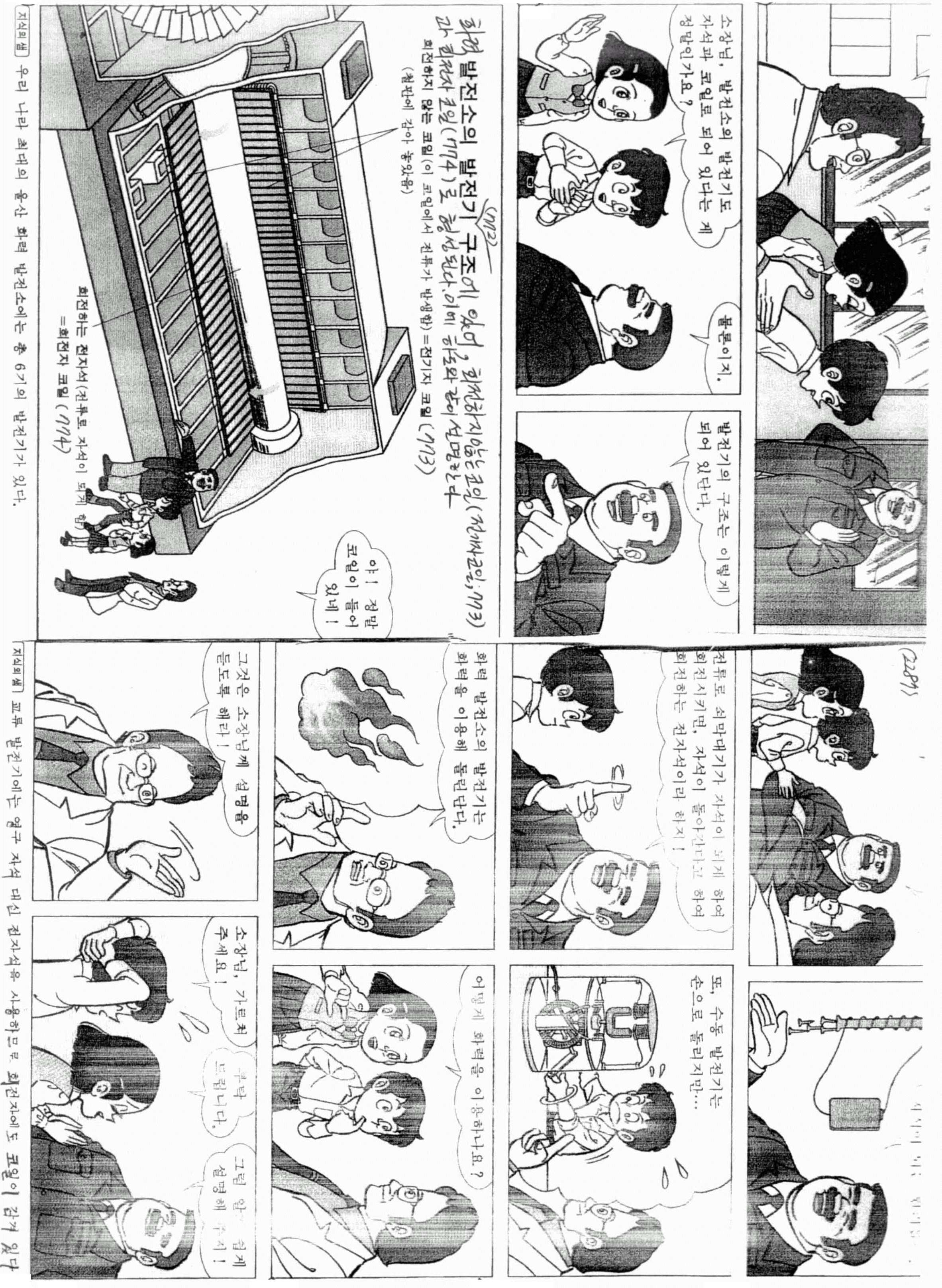
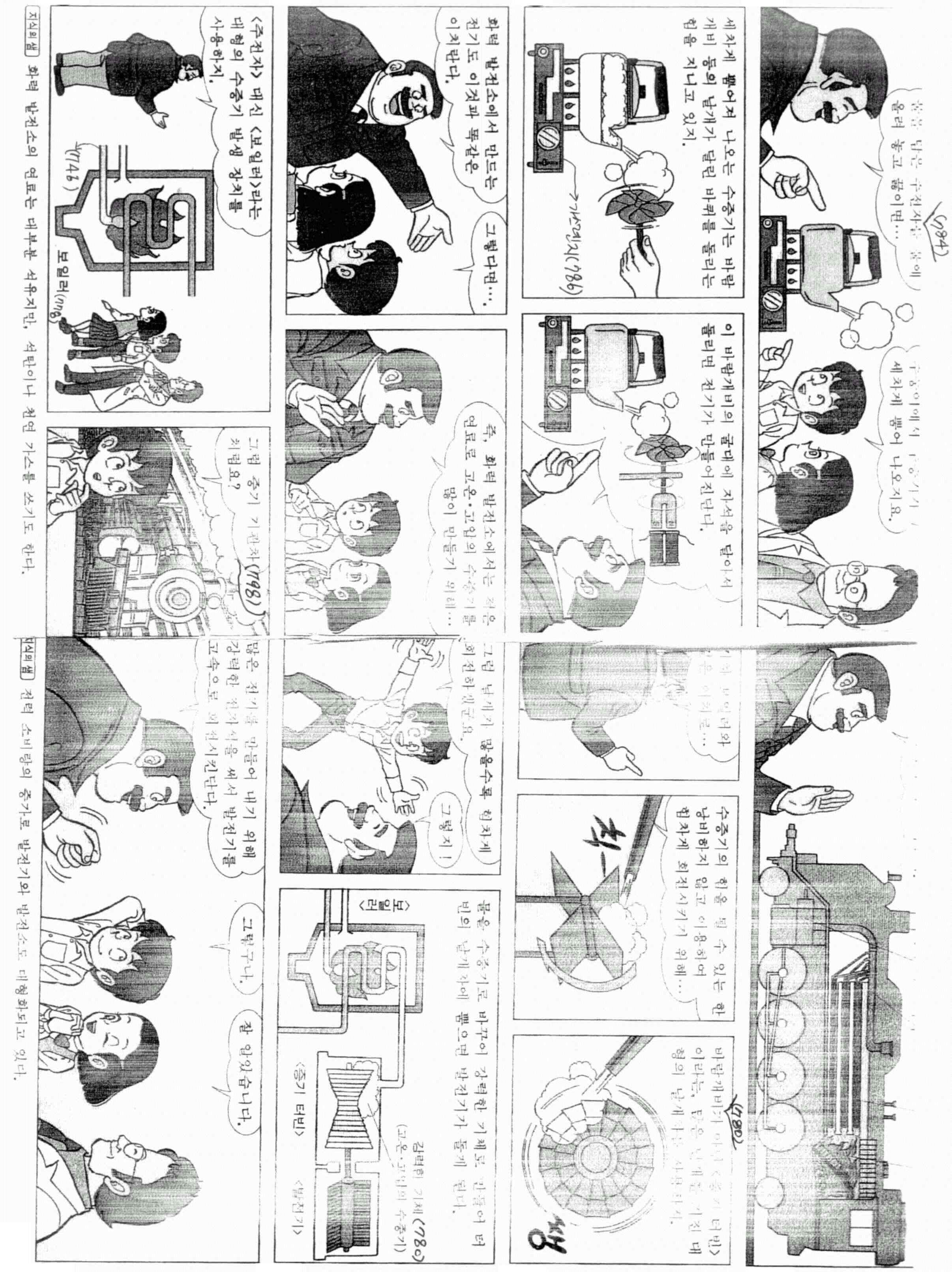
하도와 같이 해양발전소 몸체(1) 내부의 화력발전소(626) 발전장치이다.As shown below, the

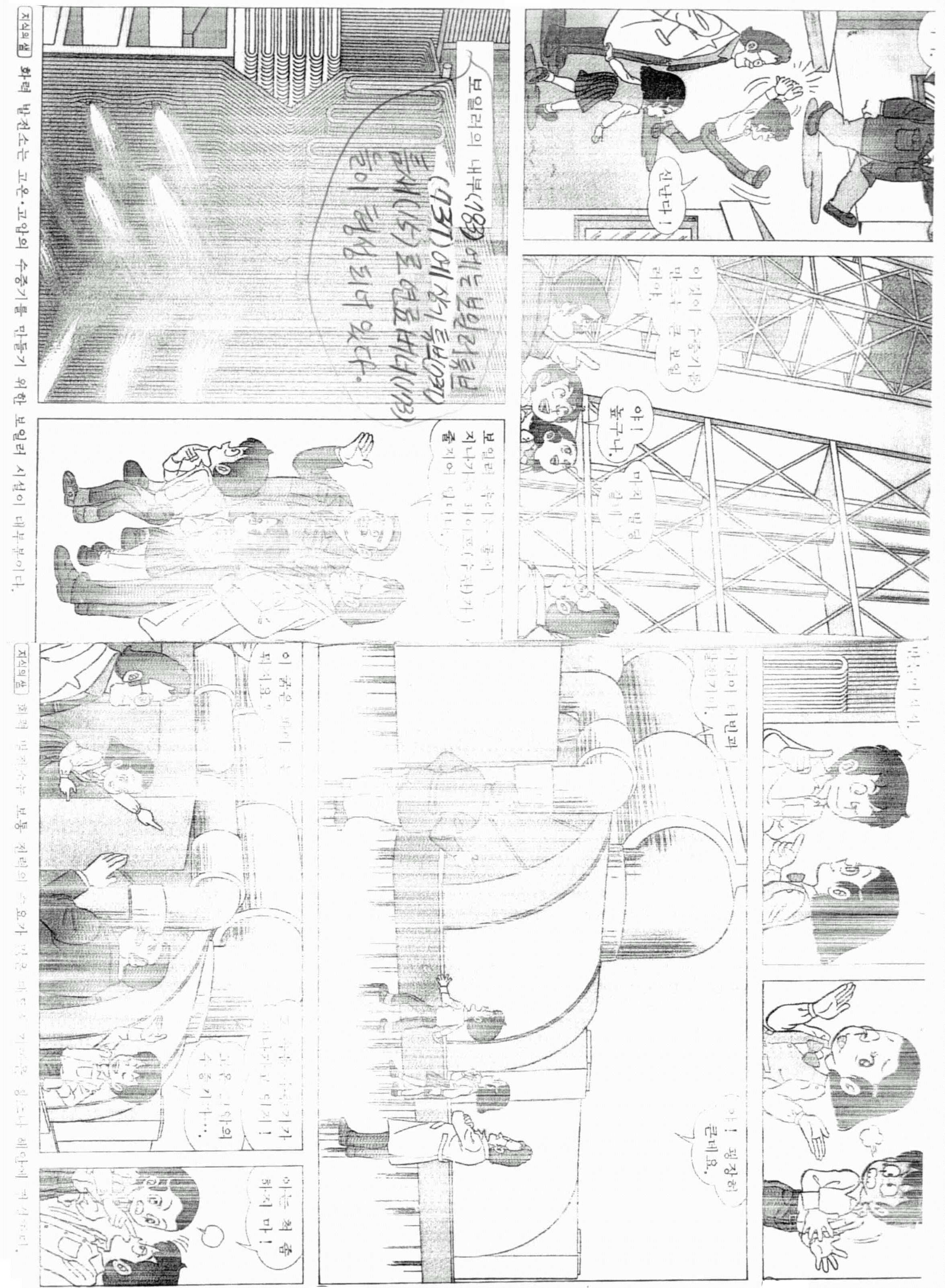
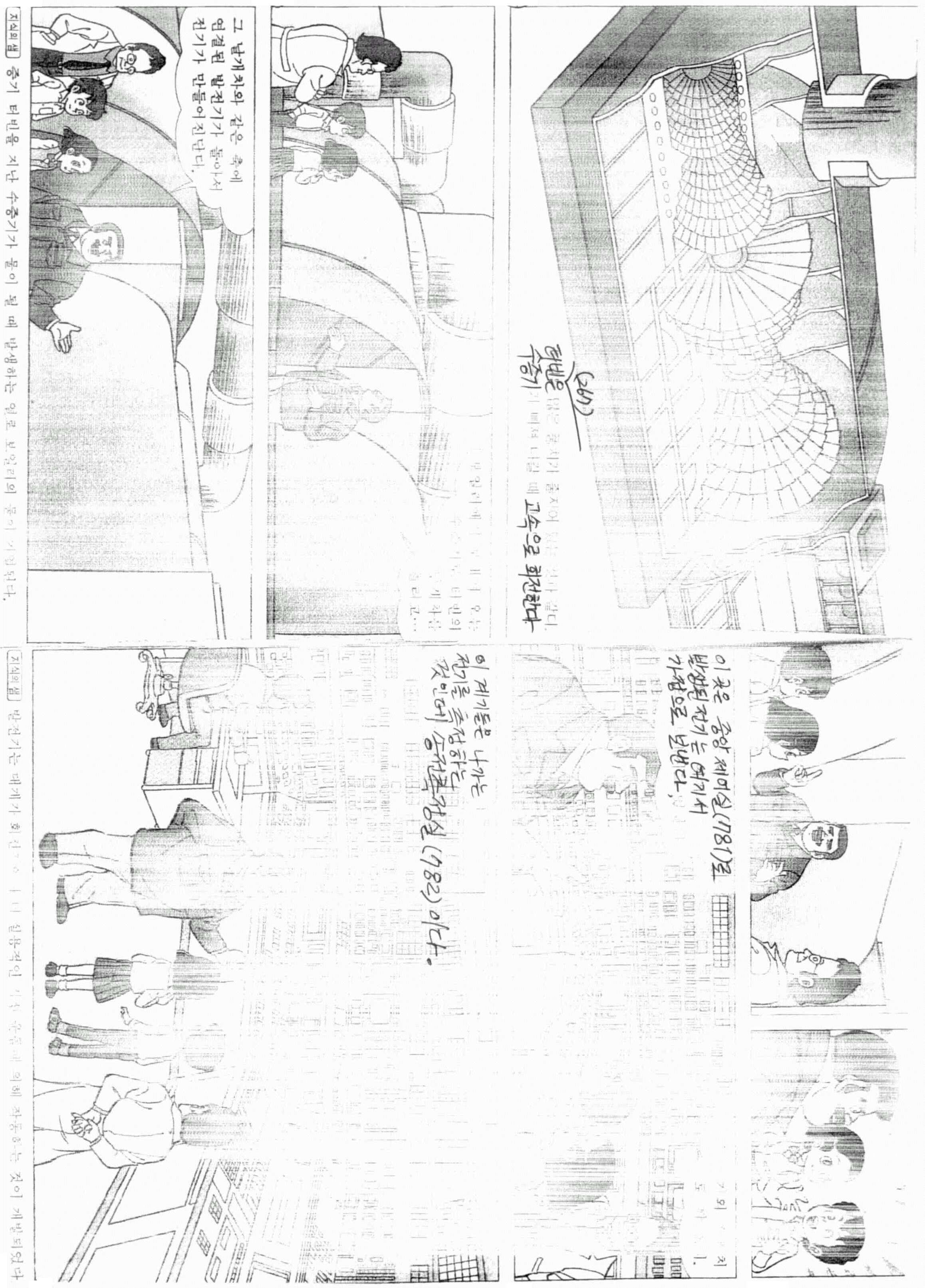

하도는 종전의 지역발전소를 해양발전소 몸체(1) 내부에 설치하게된 동기이다.Hado is the motivation to install the existing regional power plant in the marine power plant body (1).
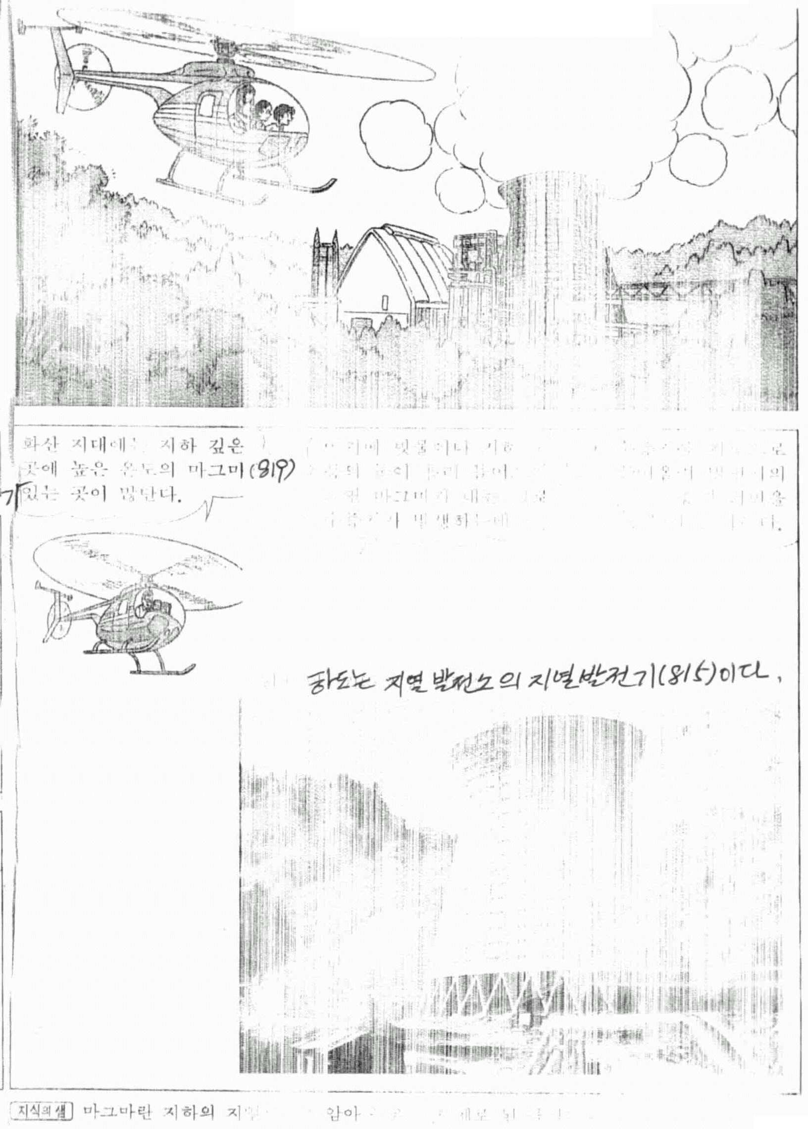
하도는 지열발전소의 발전기(815) 구조인데Hado is the structure of the generator (815) of the geothermal power plant

상도에 있어서, 터넬독 몸체(1) 하부로 즉 다시말해 수개의 우물(654)과 지열(820)이 발생하는 해저 저층바닥의 마그마 덩어리(819) 상부로 우물(854)장치를 바지선 본체(591) 하단에 수개의 앙카대체용쇄기크랭크(846)를 별도의 건설기계(880)로 설치한후 상기 바지선 본체(591) 상부로 굴뚝(연돌, 45)과 소음기(817)에 기체 액체분리기(818) 중간지점에 배관라인 수개를 연결하였고 화력발전기(792) 하면에는 수개의 복수기(790)를 설치되어 있으며 상기 복수기(790)는 냉각탑(816)의 하면의 물(7) 복수배관(뜨거운 물, 찬물)이 형성되었고 발전기(772) 생산전력(685)은 송전선(695)에 의해 수개의 변압기(96)가 형성된 초고압 변전소(690)들이 해양발전소 몸체(1) 내부에 설치하여 지구촌 내부의 대단위공장(698) 등에 각 가정(702)으로 전력을 공급하였다.In the upper coat, the barge
하도는 종전의 육지에서의 원자력발전소(672)이다.Hado is a former onshore nuclear power plant (672).
상기 발전소(672)의 원자로 격납용기(813)를 해저 저층바닥에 설치하는 것은 지열발전소의 지열발전기와 대동소이하다.The installation of the
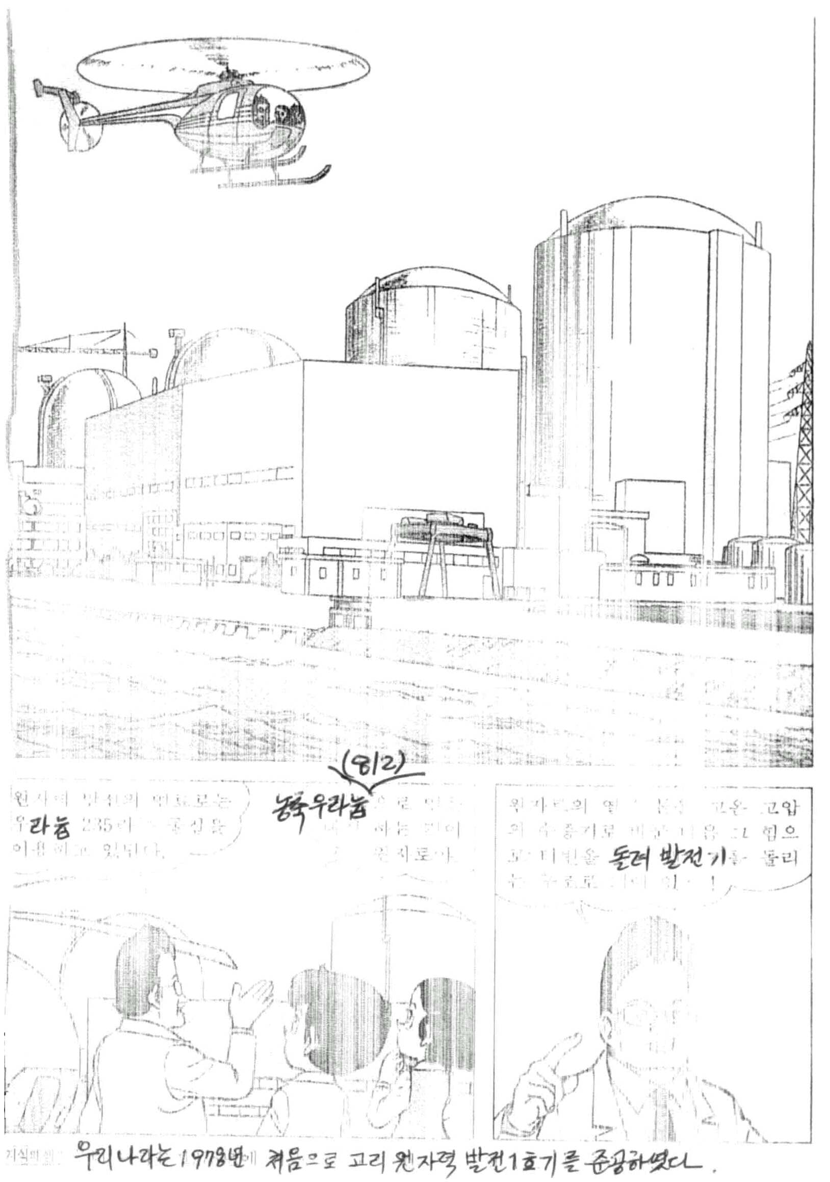
하도는 해양발전소 몸체(1)의 바지선 본체 상단에는 터어빈(267)과 발전기(772) 그 이외는 심해저 저층 바닥상부에 고정하였다.The lower road was fixed on the bottom of the bottom of the deep sea bottom, except for the

하도는 해양발전소 몸체(1) 내부에 바지선 본체(591) 상단에 형성된 태양열 발전소(799) 부분적 사시도이다.The bottom view is a partial perspective view of a
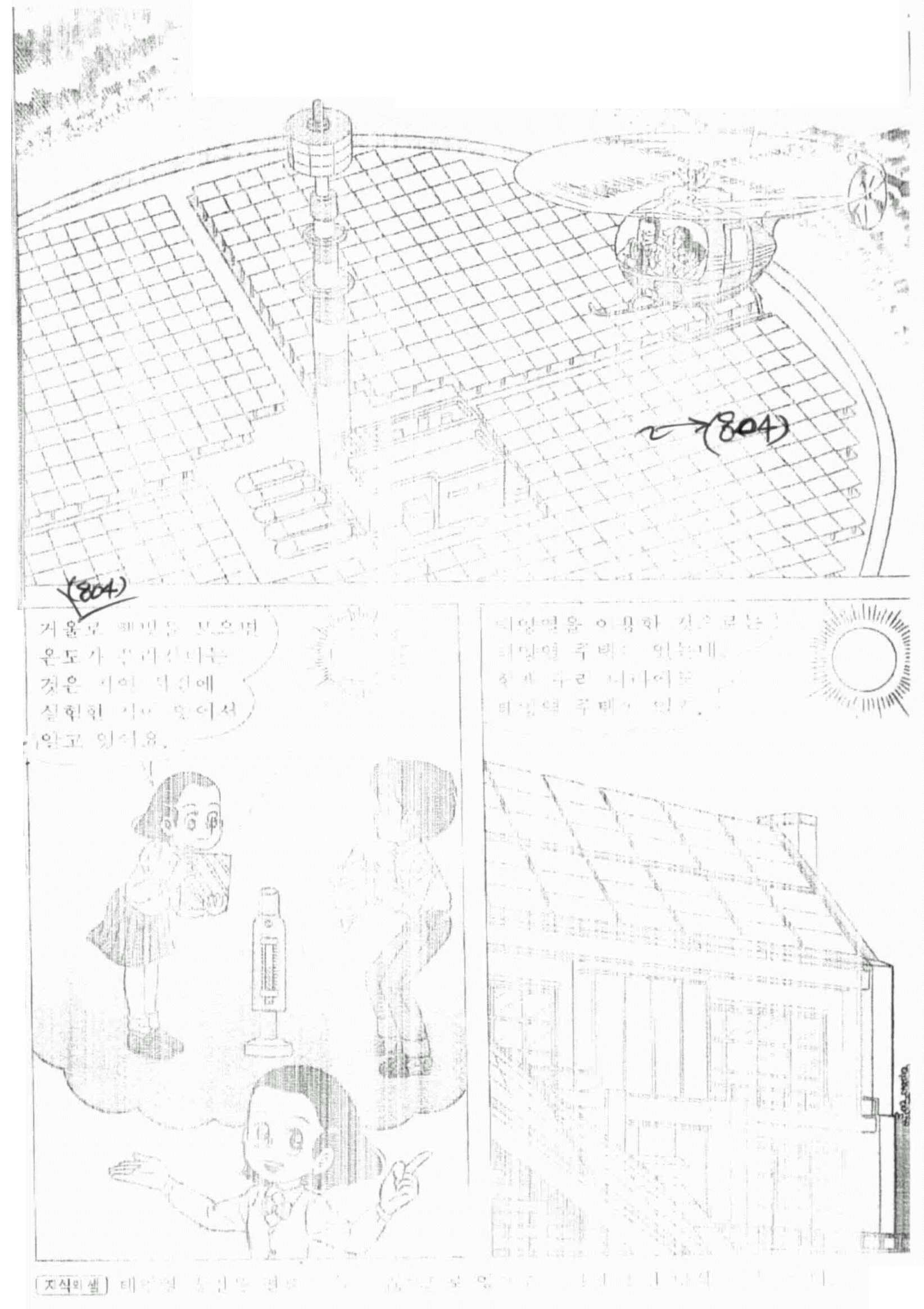
하도는 태양열발전기 구조이다.Hado is a solar generator structure.


하도는 본 발명에 있어 요부위 시이소(935)인데 1964년 본 출원인이 초등학교 4학년때 꼬마전구(661) 선 연결방식을 시험답안에 바로 기입(명확히) 기입하여 전국 초등생 중 유일하게 1명만이 맞추었다고 교육감님 이하 담임교사로부터 상품 (학용품 등 국수 5다발에 상장)을 수여받았었다.In the present invention, Hado is an essential part of the company, which is 935, and in 1964, when the applicant of the fourth grade of elementary school, the applicant writes (clearly) the small light bulb (661) wire connection method directly in the test answer. The superintendent received a prize (listed on 5 bundles of noodles including school supplies) from his or her teacher.
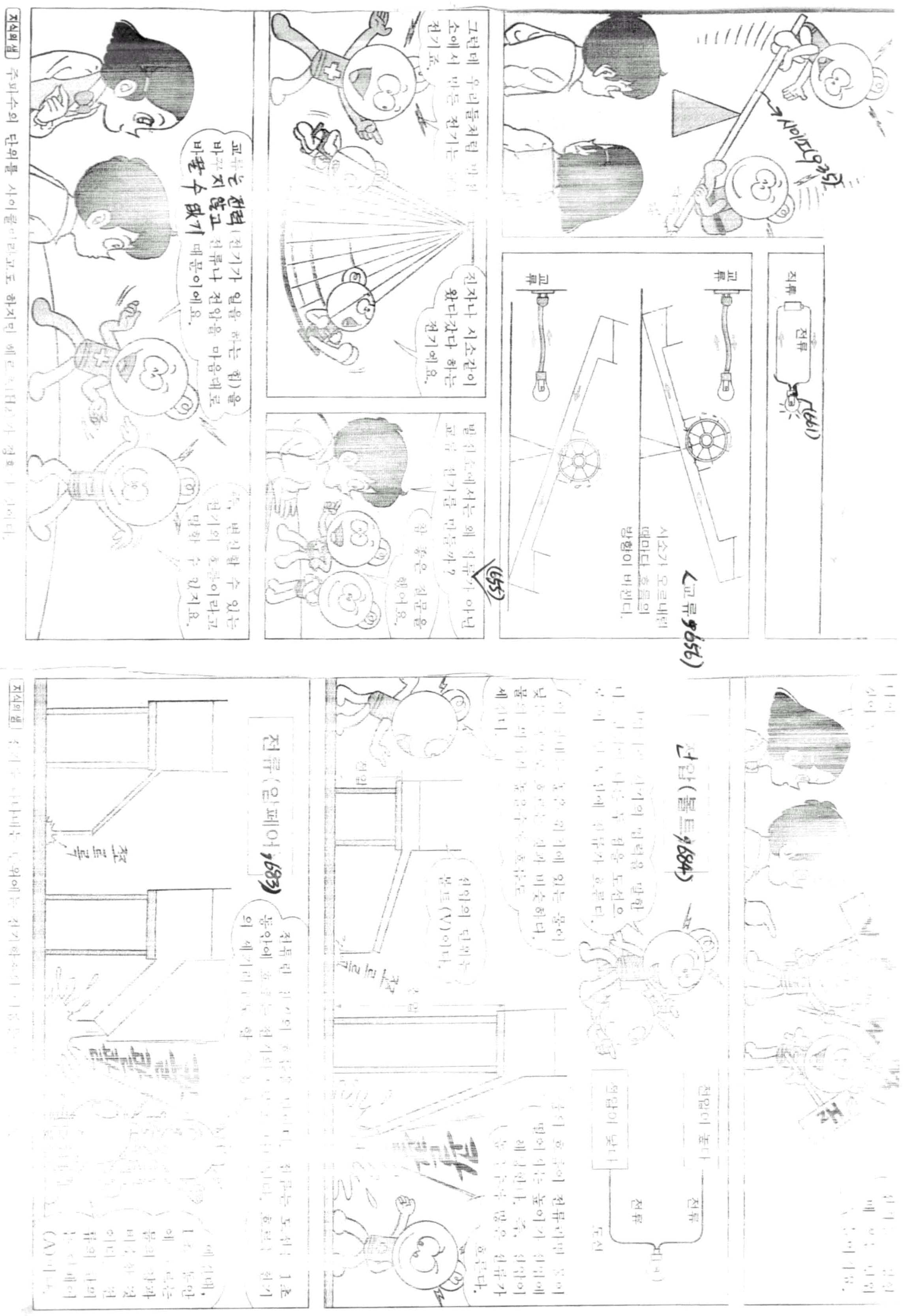

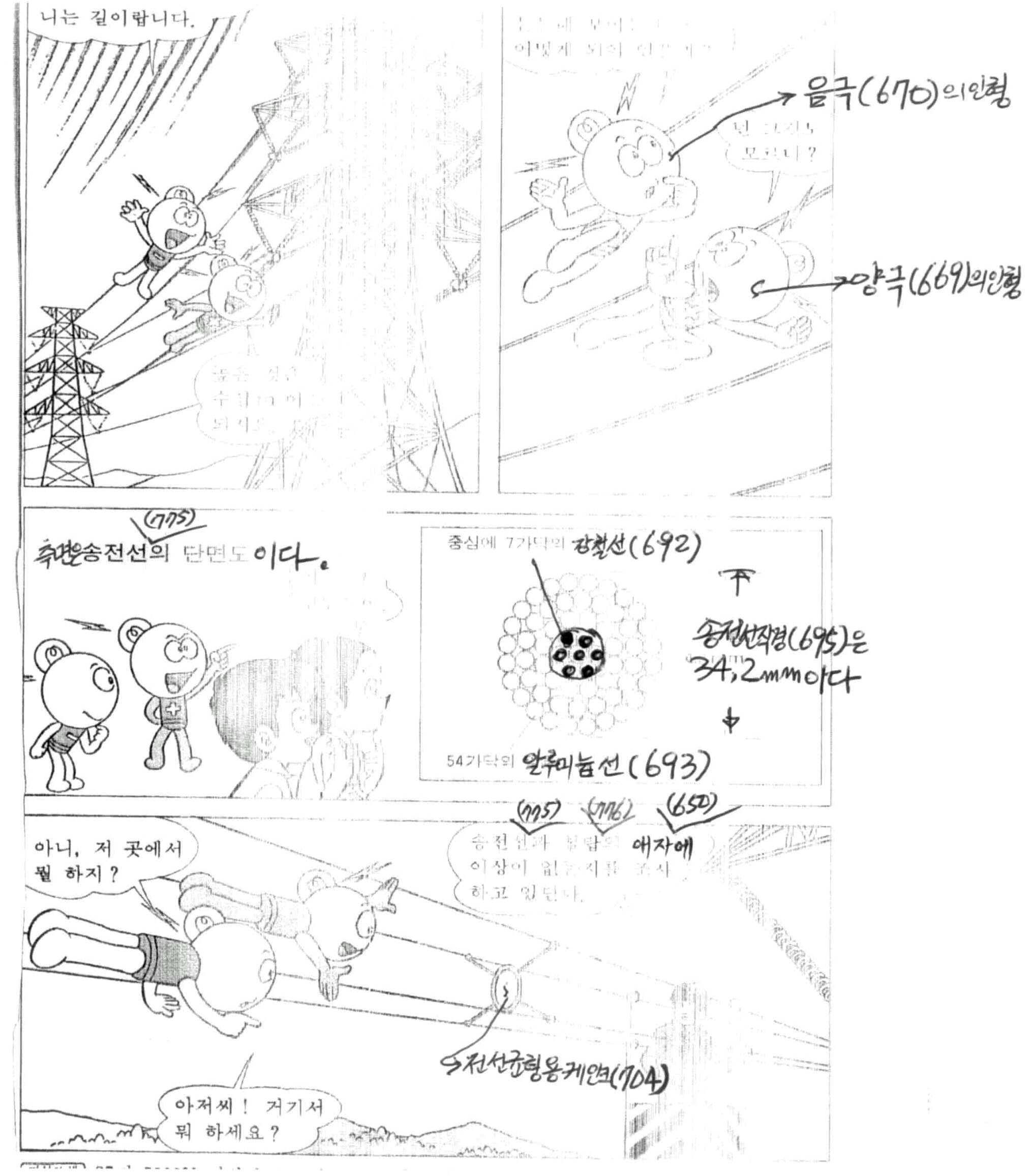
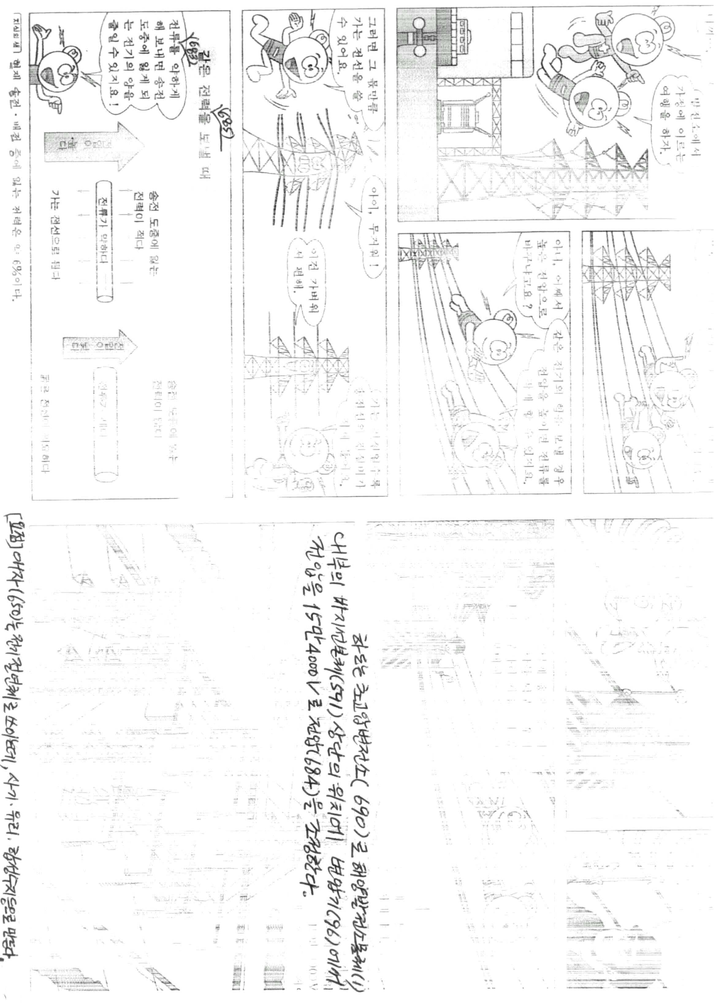
하도는 2차 변전소(700)이다The roadway is the
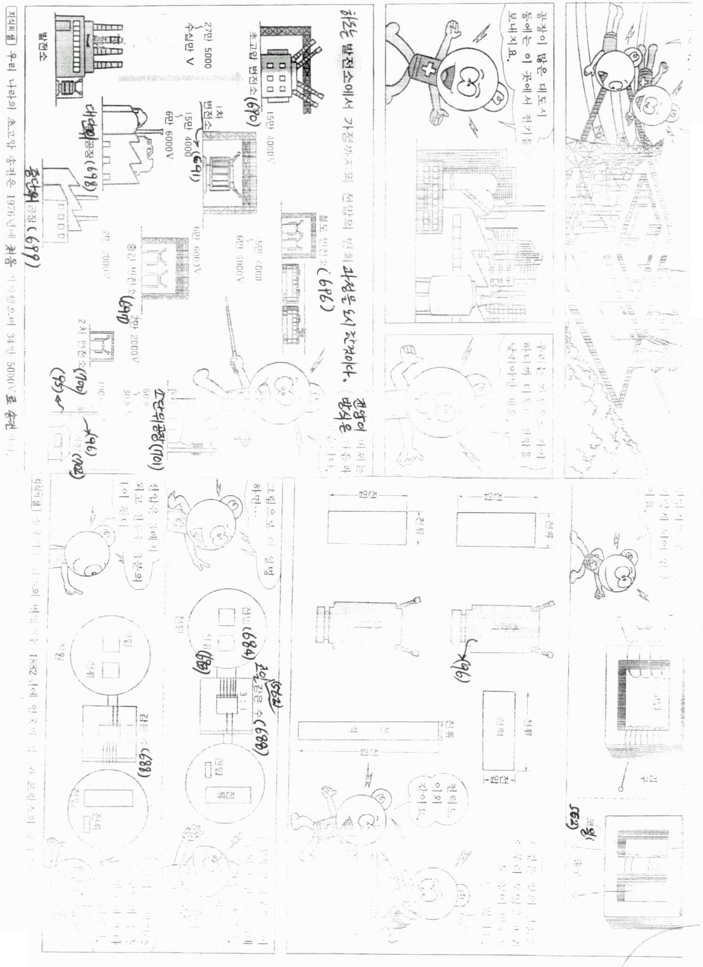
화석 연료보다는 공해를 덜 일으키는 에너지원으로는 원자력 에너지가 있다. 이 원자력 에너지는 장래의 새로운 동력원으로서 각광을 받고 있다.Nuclear energy is one of the sources of less pollution than fossil fuels. This nuclear energy is in the limelight as a future new power source.
그러나 이 원자력 에너지에도 문제가 없는 것은 아니다. 원자력 에너지의 원료가 되는 우라늄의 매장량도 한정되어 있을 뿐만 아니라, 그보다 더 골치아픈 문제는 핵 폐기물의 처분이다.But this nuclear energy is not without problems. Not only is there a limited reserve of uranium, which is a source of nuclear energy, but the more troublesome problem is the disposal of nuclear waste.
핵 폐기물에 의한 환경 오염은 우리의 하나뿐인 지구를 치명적으로 파괴시킬 수 있는 것이다.Environmental pollution from nuclear waste can fatally destroy our only planet.
그래서 오염을 일으키지 않고 에너지를 얻는 방법이 강구되기에 이르렀고, 오늘날 그 해답을 태양과 바다에서 얻고자 하는 것이다.Thus, there is a way to get energy without pollution, and today we want to get the answer from the sun and the sea.
바다에서 에너지를 얻는 방법으로는 여러 가지가 있다. 썰물과 밀물의 움직임을 이용해서 에너지를 얻는 조력 발전, 파도의 힘을 이용해서 에너지를 얻는 파력 발전, 바닷물의 온도차를 이용해서 에너지를 얻는 해수 온도차 발전 등이 그것이다. 이러한 방법들을 잘만 이용하면 우리는 바다에서 무한정한 무공해 에너지를 얻을 수 있는 것이다.There are many ways to get energy from the sea. These include tidal power generation using energy at low tide and high tide, wave power generation using energy from waves, and seawater temperature generation using energy from seawater. If we use these methods well, we can get infinite pollution-free energy from the sea.
밀물과 썰물의 힘The power of high and low tide
이미 14세기 무렵부터 유럽의 네덜란드나 영국의 일부 해안지역에서는 밀물과 썰물, 즉 조석의 힘을 이용하여 물레방아를 돌리고 있었다. 이러한 물레방아에 관해 다음과 같은 기록이 전해지고 있다.As early as the 14th century, some of the coastal regions of the Netherlands and England in Europe were turning watermills using tide and ebb, or tidal powers. The following account is given of this watermill.
'주민들은 바다를 갖가지 형태로 실생활에 이용하고 있는데, 그 한 예로 해안의 후미진 곳에 만든 물레방아가 있다. 후미진 곳에 둑을 쌓고, 두 개의 문짝이 있는 수문을 만든다. 이 문짝은 흘러드는 밀물의 힘으로 열리고, 만조 때가 지나면 썰물의 힘으로 굳게 닫힌다. 안에 갇힌 바닷물은 바다로 다시 풀려나는 대가로 물레방아를 돌리게 된다.''Residents use the sea in various forms in real life, for example, a watermill made in the back of the coast. Lay the banks in the back, and make a two-door sluice. The door opens under the power of flowing tide, and closes tightly under the ebb of high tide. The seawater trapped inside turns the watermill in exchange for being released back to the sea. '
미국의 경우에는 밀물과 썰물의 힘을 이용한 조석 제분소가 1635년에 건설되었다. 그러나 이 조석 제분소는 에너지의 발생량에 있어서는 보잘 것 없는 것이었다.In the United States, a tidal mill was constructed in 1635 using the power of high and low tide. But the tidal mill was little in terms of energy generation.
조력을 이용해 전기를 일으키는 시설은 현재 프랑스의 랑스 강 하구에 세워져 있다. 다음 페이지의 사진은 랑스 조력발전소(213)의 전경이다.A facility that uses electricity to generate electricity is now set up at the mouth of the Lance river in France. The photo on the next page is a panoramic view of the Lance tidal power plant (213).
랑스 발전소의 두드러진 특징은 흐르는 물의 에너지를 간수해서 순간적인 힘으로서 이용하는 24기의 신형 터빈이다. 바닷물이 흘러 들어오면 터빈(267)의 날개가 물의 힘에 떠밀려 회전하면서 전기를 일으킨다.The distinguishing feature of the Lance plant is the 24 new turbines that capture the energy of the flowing water and use it as an instantaneous force. When the seawater flows in, the blades of the
만조 때에는 각 터빈이 댐(680)의 일부가 되어 바닷물을 저수지 안에 가두어 버린다. 바닷물이 물러가면서 낙차가 생기면, 가 터빈의 문이 열리면서 바다로 역류하는 물의 힘으로 다시 발전이 시작된다.At high tide, each turbine becomes part of the
이 독특한 터빈(267)은 모터로서도 작용한다. 일단 전력을 공급받으면 펌프를 움직이게 하고, 바닷물의 흐름을 거들면서 전체의 출력을 높이는 것이다.This

이러한 종류의 발전기는 조석 간만의 차가 큰 곳이라면 어디든지 설치할 수 있다. 우리나라의 서해안도 간만의 차가 커서 조력 발전의 유력한 후보지로 꼽히고 있다. 상기한 바와 같이 본 발명의 조력발전기(800)는 관레벨 시소형 풍수력발전기 라는 점에서 종래의 기술과는 현격한 차이이다.This type of generator can be installed wherever the tidal car is big. The west coast of Korea is also considered as a good candidate for tidal power development due to the large gap in tidal waves. As described above, the
파력 발전소(679)의 파력발전기(689)에 있어,In the
1909년에 어떤 사람이 파랑 발전기라는 것을 발명했다고 발표하였다. 이것을 고안한 사람은, 바다를 뒤흔드는 파도를 에너지로 바꿀 수 있게 되었다고 의기양양했다.In 1909 he announced that he invented a blue generator. The person who devised this was excited to be able to convert the waves that shook the ocean into energy.
이 발전기는 물 속에 달아맨 판자로 잡은 파도의 힘을 윤전장치로 보내어 발전기를 돌리는 것이었다.The generator was to drive the generator by sending the force of the waves caught in the board to the rotational device.
그러나 전깃줄에 매달린 몇 개의 전등에 불을 켜게 했을 뿐, 결국 그것으로 끝나고 말았다. 기묘하게 생긴 그 장치들이 폭풍우에 휩쓸려 가라앉아 버리자, 세상 사람들도 그것을 잊고 말았던 것이다.But only a few lights hung on the wires turned on and eventually ended. When the oddly shaped devices were swept away by the storm, the people of the world had forgotten it.
그렇다고 이 고안이 터무니없는 것은 아니었다. 최근에 기술이 진보함에 따라, 그것은 효과적인 발전 장치의 기초가 될 수 있다는 것이 밝혀졌다.This design, however, was not absurd. As technology has advanced recently, it has been found that it can be the basis of an effective power generation device.
근래에 들어, 몇 가지 파력 발전 장치가 새로이 개발되었다. 그 가운데서도 대규모의 발전이 가능한 고안에 세상 사람들의 관심이 모아졌다.In recent years, several wave power generation devices have been newly developed. In the midst of this, the attention of the people of the world was gathered to devise the possibility of large-scale development.
이 안은 수압에 민감한 액체나 기체를 넣은 부대를 해안 가까이에 설치한 콘크리트 틀에 가득 채우는 것인데, 이 틀로 밀려오는 파도의 힘이 부대 안의 액체를 지나서 해안의 발전소로 전해진다.The inside is to fill a concrete frame installed near the shore with a bag of water-sensitive liquid or gas, and the force of the waves passing through the liquid is transmitted to the coastal power plant.
또 다른 종류의 파력 발전 장치도 선을 보이고 있다. 아래 사진에 보이는 것이 그것인데, 이 장치는 1909년의 파랑 발전기와 원리상에서 크게 다르지 않다.Another kind of wave power generator is showing its line. This is what is shown in the picture below, which is not much different in principle from the 1909 blue generator.
이 발전기는 해안에서 바다 쪽으로 10m 정도 떨어진 곳에 설치한다. 밀려오 는 파도가 3기의 수차를 세차게 돌리고, 다시 파도가 그 장치 바깥 쪽으로 밀려나가면서 다른 3기의 수차를 돌린다.The generator is installed about 10 meters from the coast towards the sea. Incoming waves bounce three aberrations, and again the waves are pushed out of the device, turning the other three aberrations.
한 차례의 파도로 일으키는 전력은 5000와트에 지나지 않지만, 외딴 섬에 깨끗하고 값싼 전력을 공급하는 데에는 충분할 정도이다.The power generated by a single wave is only 5000 watts, but enough to provide clean, cheap power to remote islands.
파도의 힘으로 전력을 대규모로 생산하려면 앞으로도 한층 더 집중적인 연구가 필요한 것이다.More power-intensive research will be needed to produce large-scale power from waves.
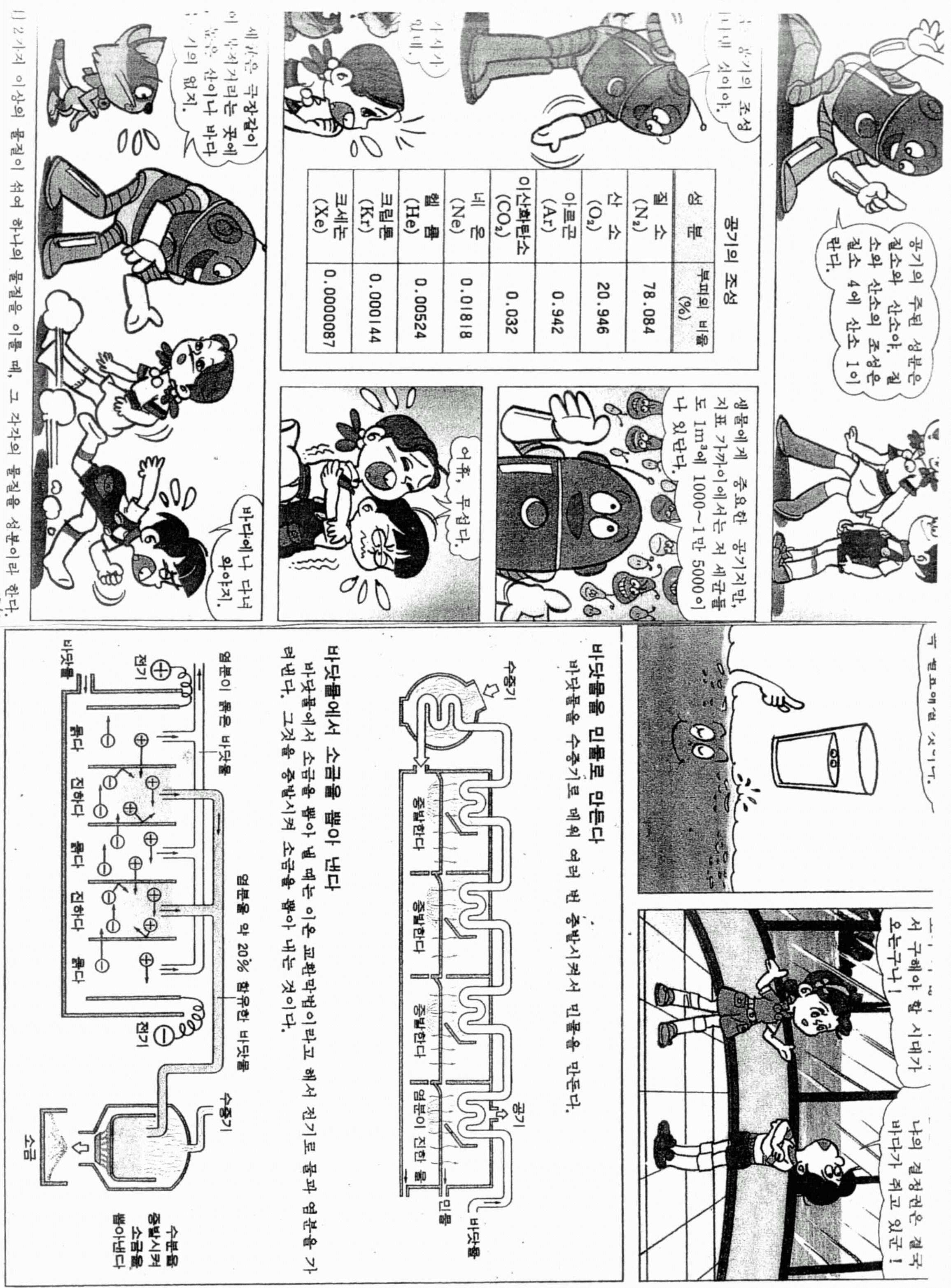
소리 전자파 이용에 있어,In the use of sound electromagnetic waves,
하도는 풍랑계급을 10단계로 분류한 것이다.Hado is divided into 10 levels.

하도는 종전의 해양에서의 광물자원 채집방식도로 본 발명에는 별도의 건설기계(880)인 시이소(935) 크레인(861) 붐대(651)를 사용하였다.Hado is a conventional method for collecting mineral resources in the ocean, and the present invention used a separate construction machine 880, a


하도는 해양발전소 몸체(1)의 내부로 수개의 닥터벤츄레이션(585) 내부로 파이어댐퍼(583) 정단면도로 에어실린더(138) 또는 액츄레이터가 설치되었었다.The lower road was provided with an
1982년 석유시추선 스메드빅 노르웨이 선적 선박 건조시 파이어댐퍼(583) 작 동불능으로 선박등급 A급으로 등급받아야 할 것인데 F등급으로 밀려 등외품의 선유시추선을 댐퍼작동용추(107)를 본 출원이 고안하여 선박안정도 F등급에서 A등급으로 국제해상안전협회에 등록유지를 하여 국위선양한 바 있다.In 1982, the oil drilling ship Smedvik Norway should be rated as ship class A due to the inability to operate the fire damper (583). As a result, ship safety was maintained at the International Maritime Safety Association from Class F to Class A, thereby improving the national level.
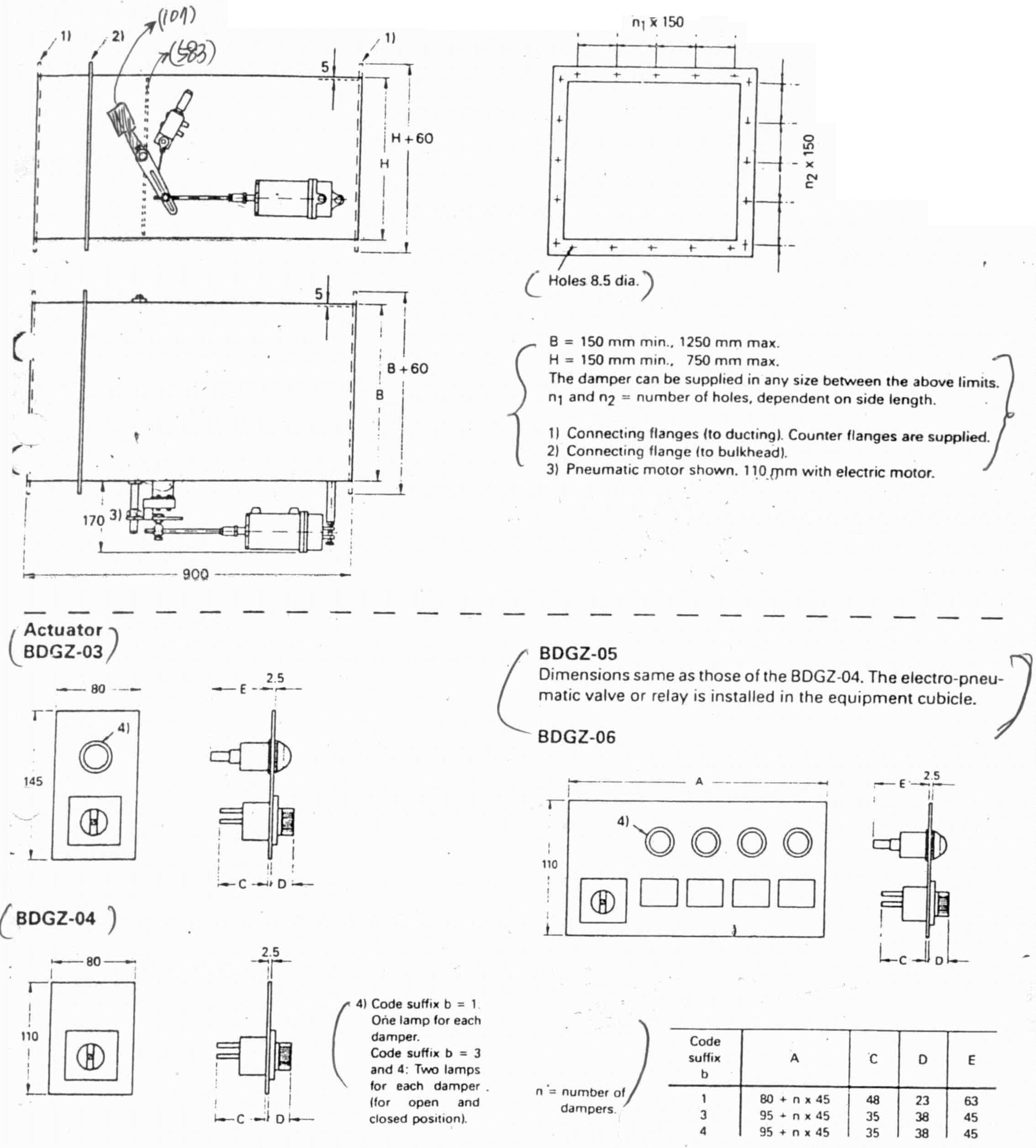
<파이어댐퍼 형식별의 무게중량표><Weight table according to fire damper model>
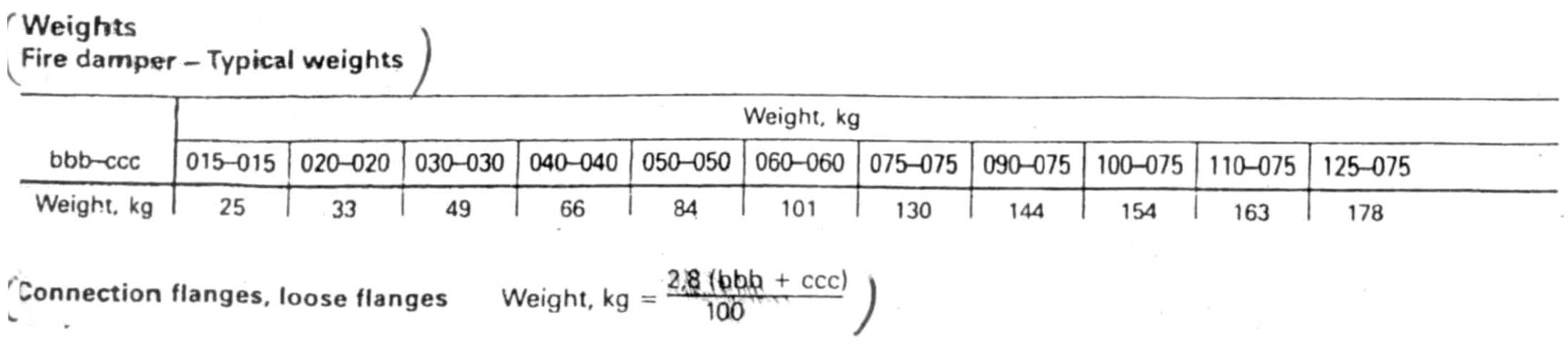
하도는 르메틱장치의 전동기 엑츄레이트(848) 설치방식도이다.The diagram is a diagram of the installation method of the motor actuator 848 of the lematic apparatus.
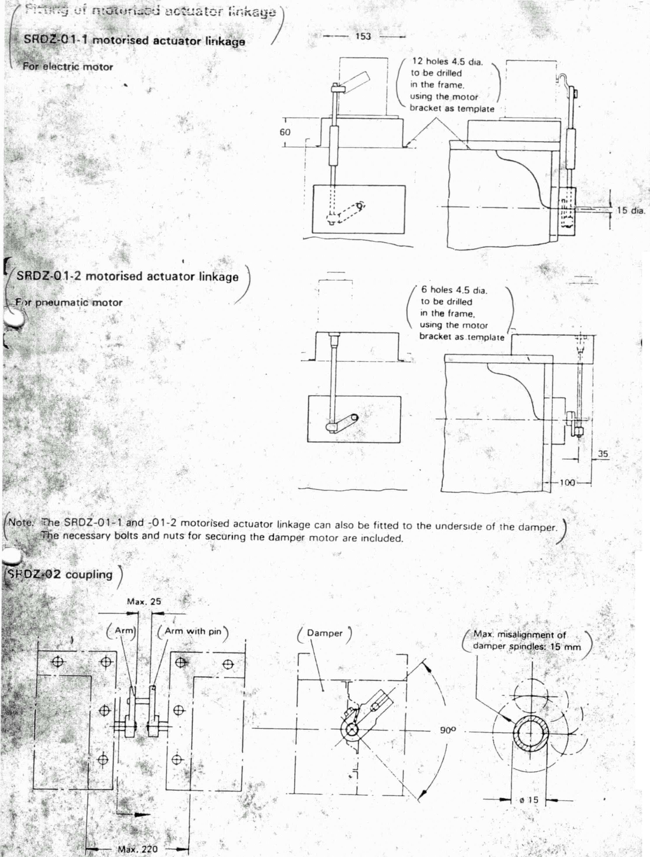
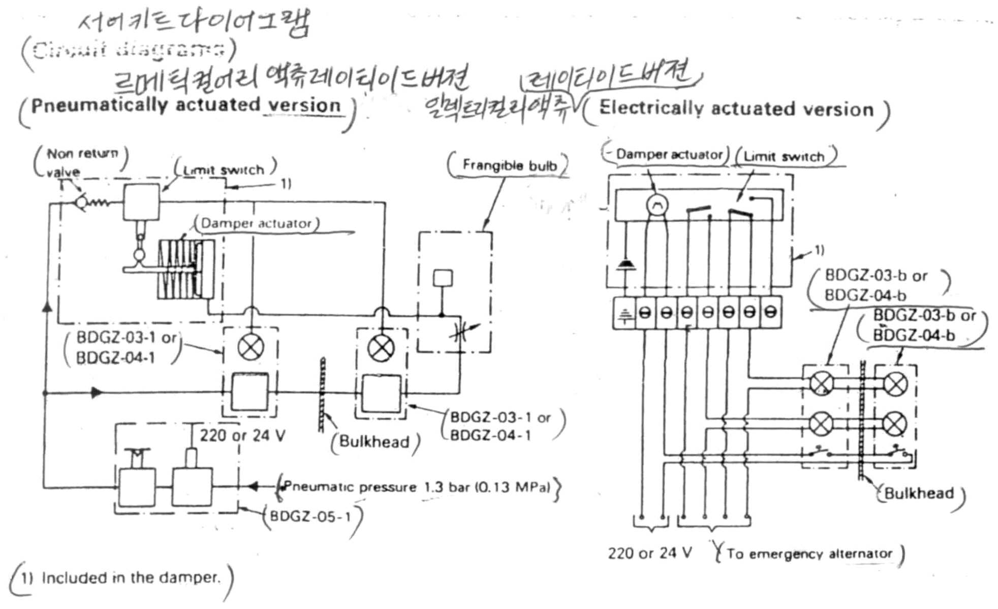

상도는 해수면 상단 대기권의 고도별 기상(기온과 공기분포)상태의 조건(태풍, 강우등의)을 해양발전소 몸체(1)의 수개의 바지선 본체(581) 사이드 측면에 설 치된 수개의 건설기계(880)인 시이소(935) 크레인(861) 붐대(651)로 대류권 높이의 구름(653)과 폭풍인 하강기류(926)를 상승기류(925)로 되돌리(진로변경)는 역할의 장비들로 형성되기전의 대기권 고도상태를 탐색한 것인데 이를 근거로 태풍, 홍수 등은 원천봉쇄 차단하는 계기이다.The top coat is constructed by several construction machines installed on the side of several barge main bodies 581 of the marine
다음은 인공위성(기상관측에 따른 것이 포함함)과 기상관측에 따른 종래의 태풍예보방식 하표와 하도로 설명한다.The following is a description of the conventional typhoon forecasting diagrams and channels for satellites (including weather observations) and meteorological observations.
중심 기압은 보통 970∼930hPa정도이며 930hPa이하이면 대단히 강한 것으로서 지상최대풍속은 50㎧이상에 달한다.The central air pressure is usually about 970 ~ 930hPa, and it is very strong below 930hPa, and the maximum land wind speed is over 50㎧.
표 6. 태풍내의 기압하강Table 6. Pressure drop in typhoons
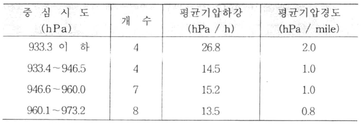
중심기압의 기록은 육상에서는 1935년 9월 3일에 미국 플로리다주의 키웨스트(Key West)의 891.7hPa이고, 다음이 1934년 9월 21일에 일본의 무로도미사기에서 관측한 912hPa이다. 해상의 기록은 필리핀 루손섬 동쪽 약 400해리 해상에서 1927년 8월 18일에 선박 "Sapaerea"호가 관측한 886.7hPa이고, 1951년 8월 23일 우리나라에 상륙한 태풍 "마지"가 최성기일 때 남양군도 해상에서 비행기로 관측한 값이 887hPa로서 두번째 기록이다.Records of central pressure are 891.7 hPa on land on September 3, 1935, in Key West, Florida, followed by 912 hPa on September 21, 1934, at Murodo Misaki, Japan. The sea record is 886.7 hPa observed by the ship "Sapaerea" on August 18, 1927, about 400 nautical miles east of Luzon Island, the Philippines, and Namyang Archipelago when the typhoon "Mage", which landed in Korea on August 23, 1951, was at its peak. Airborne observations at sea are 887 hPa, the second record.
1.7 태풍 예보법1.7 Typhoon Forecast
태풍의 진로나 이동속도를 신속하게 예상하는 것은 가장 중요한 문제이다. 그러나 현재의 진보된 기상학과 예보기술로써도 완전무결한 예보는 불가능하다. 지금까지 많은 연구자에 의하여 태풍의 이동에 관한 객관적인 예보법으로 통계적인 방법과 수치모델에 의한 역학적인 방법이 많이 쓰이고 있다.Promptly predicting the course and speed of a typhoon is the most important issue. However, even with today's advanced meteorological and forecasting techniques, flawless forecasts are impossible. Until now, many researchers have used statistical methods and dynamic methods based on numerical models as objective forecasting methods for typhoon movements.
기상청에서는 통계적인 방법으로는 PC법, Climate법, Cliper법, 그리고 유사법을 사용하고 있으며, 역학적인 방법으로는 한국 태풍모델을 기상예보용 컴퓨터로 운영하여 태풍의 예상 위치를 객관적으로 예측한다. 또, 일기도에 의한 종관적인 다음의 방법들을 참고자료로 활용하여 가장 가능성이 큰 진로를 예상하는 방법을 택하고 있다.The Korea Meteorological Administration uses the PC method, the climate method, the Cliper method, and the similar method as a statistical method. The epidemiological method uses the Korean typhoon model as a weather forecast computer to predict the expected location of the typhoon objectively. In addition, the following synoptic methods by weather map are used as a reference to predict the most likely career.
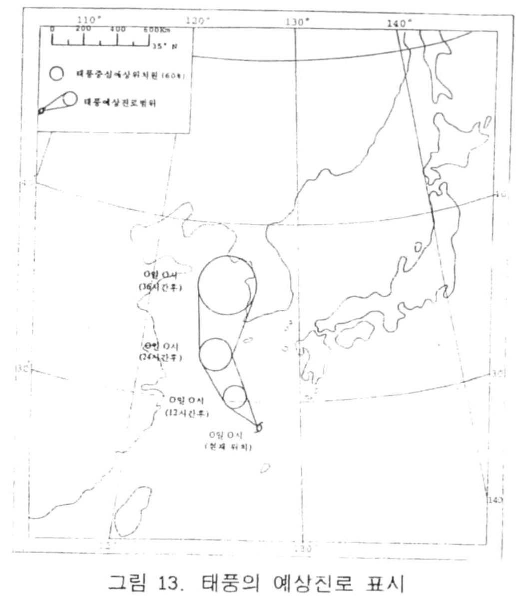
속도예상의 폭은 나타나 있지 않으나 재해방지상 지장이 없는 범위에서 가능한 한 최대속도를 가상하여 확률원의 범위를 정하고 있다. 따라서 전향점 부근에서 속도가 늦어질 때는 예상과 실제의 이동이 크게 차이가 나기 쉽다. 확률원은 태풍의 위치와 속도가 변함에 따라 수시로 변화하므로 새로운 기상자료가 입수될 때마다 수정 발표되는 새로운 태풍정보를 가지고 경계에 임하여야 한다.The range of the speed forecast is not shown, but the range of the probability source is determined by simulating the maximum speed as far as possible in the range where there is no obstacle in preventing disaster. Therefore, when the speed is slow near the turning point, the expected and actual movement tends to be significantly different. The probability source changes from time to time as the location and speed of the typhoon changes, so you should be on the lookout with new typhoon information that is revised and published each time new weather data is available.
상기한 바와 같이 종전에는 방송매개체에 의하여 전달되는데 태풍피해를 방지하는데에는 매우 미흡하고 속수무책이란점에서 본 발명은 종전과는 현격한 차이의 기술수준으로 태풍의 진로를 대류권(고도 10km 이상) 상부로 시이소(935) 크레인(861) 붐대(651)로 강우구름(653)과 찬공기 덩어리 하강기류(926)를 관 레벨 마노메턴 닥터벤츄레이션(585)과 공기실(402) 내부에서 상승기류(925)로 태풍의 씨앗을 사전제거한다는 것으로 종래기술 수준과는 현격한 차이이다.As described above, it was previously transmitted by a broadcasting medium. However, the present invention is very inadequate in preventing typhoon damage, and the present invention is a technical level of a drastic difference from the past. Siiso (935) Crane (861) Boom (651) Rainfall cloud (653) and cold air mass down stream (926) Raising airflow (925) in tube level Manometon Doctor Venturation (585) and air chamber (402) It is a significant difference from the prior art level that the seeds of the typhoon are removed in advance.
다음은 엔진식 착암기(847)에 있어,Next is the engine type rock drill 847,
용 도는 각종 콘크리트 구조물 붕괴현장에서 간편하게 엔진식 으로 콘크리트 구조물을 청공할 경우에는 착암기로도 사용하며 콘크리트 구조물을 파쇄 할 경우에는 노비,카타 등의 비트를 교체하여 브레카 용도로 사용 할 수 있는 장비이다.It can be used as a rock drill to clean concrete structures by engine type at the site of collapse of various concrete structures, and it can be used for Breca by replacing bits such as novi and kata when crushing concrete structures.
제 원은 엔지타입:75cc 1개 실린더에 2 행정Specifications are engine type:
연로탱크용량:1.1L, 중 량:15Kg Fuel Tank Capacity: 1.1L, Weight: 15Kg
동력원:휘발류, 오일 12:1 Power source: Volatile, oil 12: 1
타격력:14.3J Impact: 14.3J
파쇄능력:2.200/분당 Crushing capacity: 2.200 / min
기 타:콤퓨레샤방식의 왕복스톤형 Others: Compressor type reciprocating stone
구성에 있어 착암기(847) 본체에 수개의 타격비트(940)가 형성된다In the configuration, several blow bits 940 are formed in the main body of the rock drill 847.
1)착암기 본체1) The rock drill body
2, 3) 타격비트2, 3) blow bits
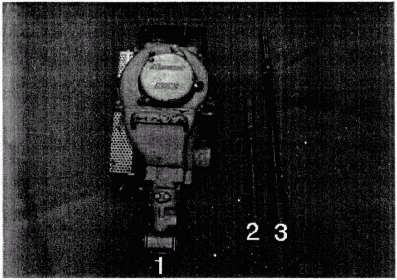
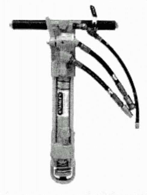
*특징 :*Characteristic :
1)최대작업직경 : ¢51mm1) Maximum working diameter: ¢ 51mm
2)작업깊이 : 2.54m2) Working Depth: 2.54m
3)회전속도 조절가능3) Adjustable speed
4)수중 발파 구멍작업, 무소음 무진동 파쇄 구멍작업4) Underwater blasting hole work, noiseless and vibration-free crushing hole work
*사양 :* Specifications:
1)Steel type :41/4"×1"hex1) Steel type: 41/4 "× 1" hex
2)회 전 수: 0∼300 RPM2) Number of revolutions: 0 ~ 300 RPM
3)무 게 : 30kg3) Weight: 30kg
4)길 이 : 66cm4) Length: 66cm
5) 폭 :46cm5) Width: 46cm
6)압 력 : 105-140 bar6) Pressure: 105-140 bar
7)유 량 : 26∼34 LPM7) Flow rate: 26 ~ 34 LPM

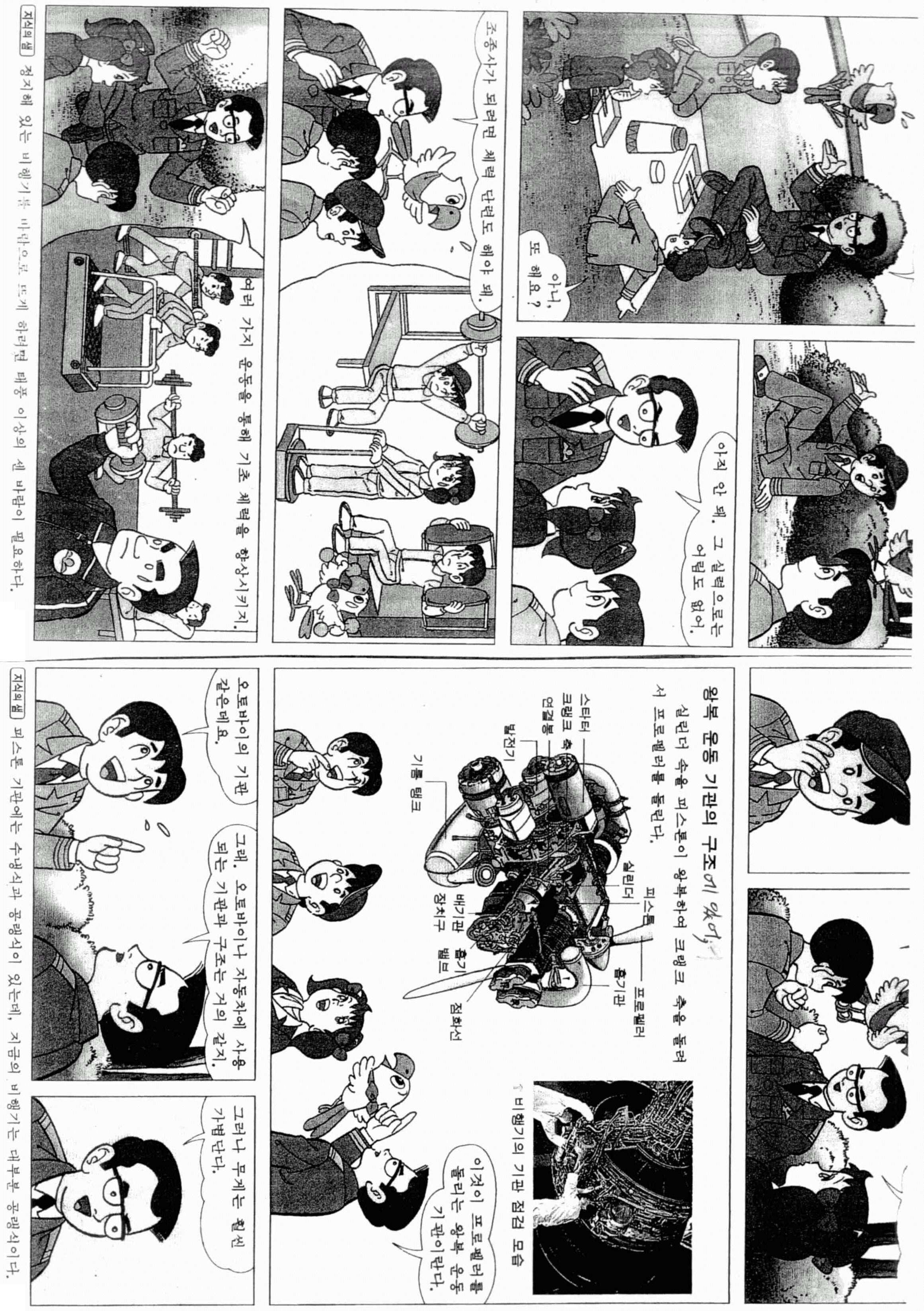
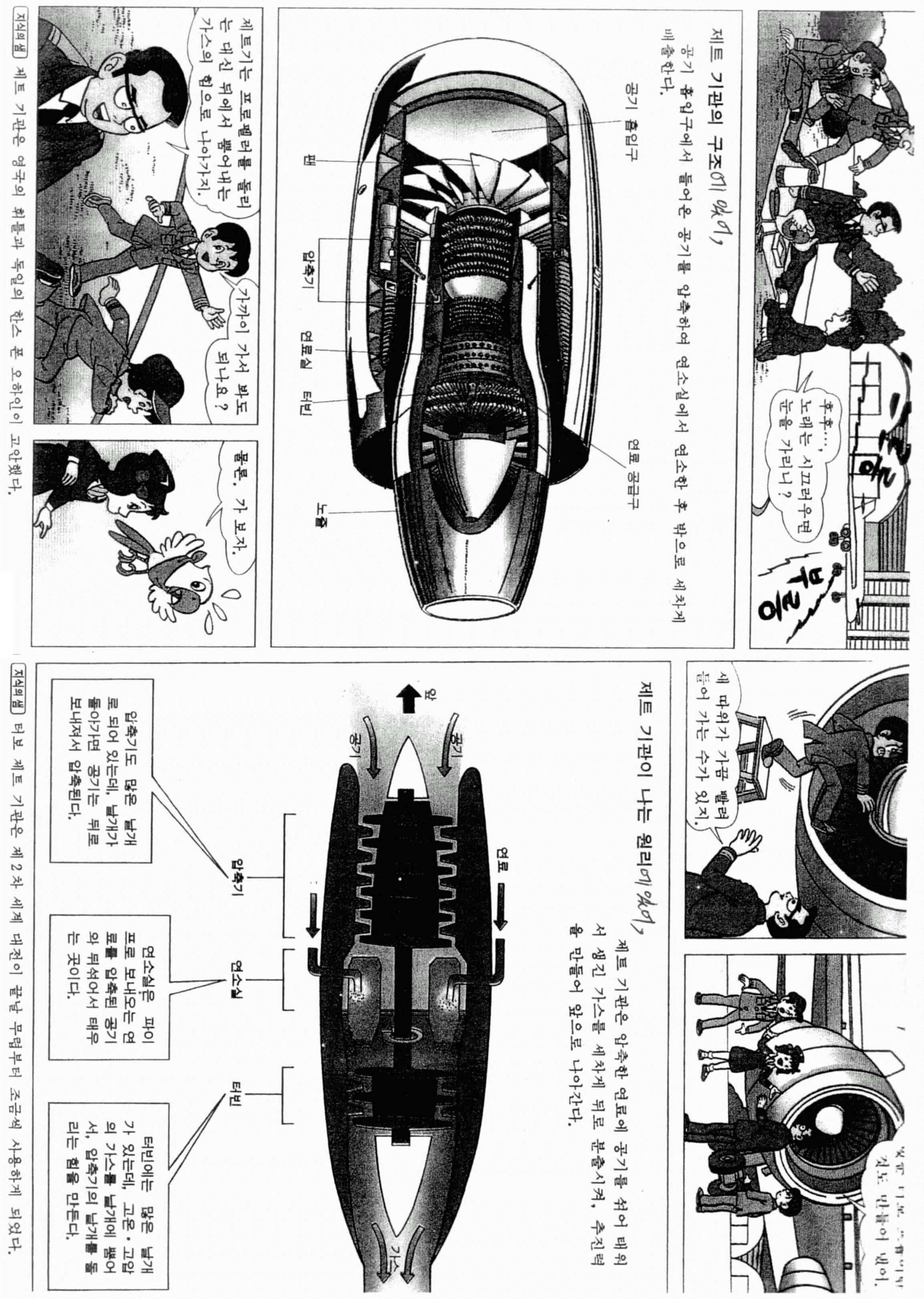

다음은 종전의 각국이 제작한 인공위성과 우주선을 쏘아올리기 위한 로켓(612)이다Next is a


하도는 미래의 인공위성에 형성된 원자력 로켓(612)이다.The underpass is a


하도와 같이 아이씨(I.C)회로에 있어,In the I.C circuit like the way,
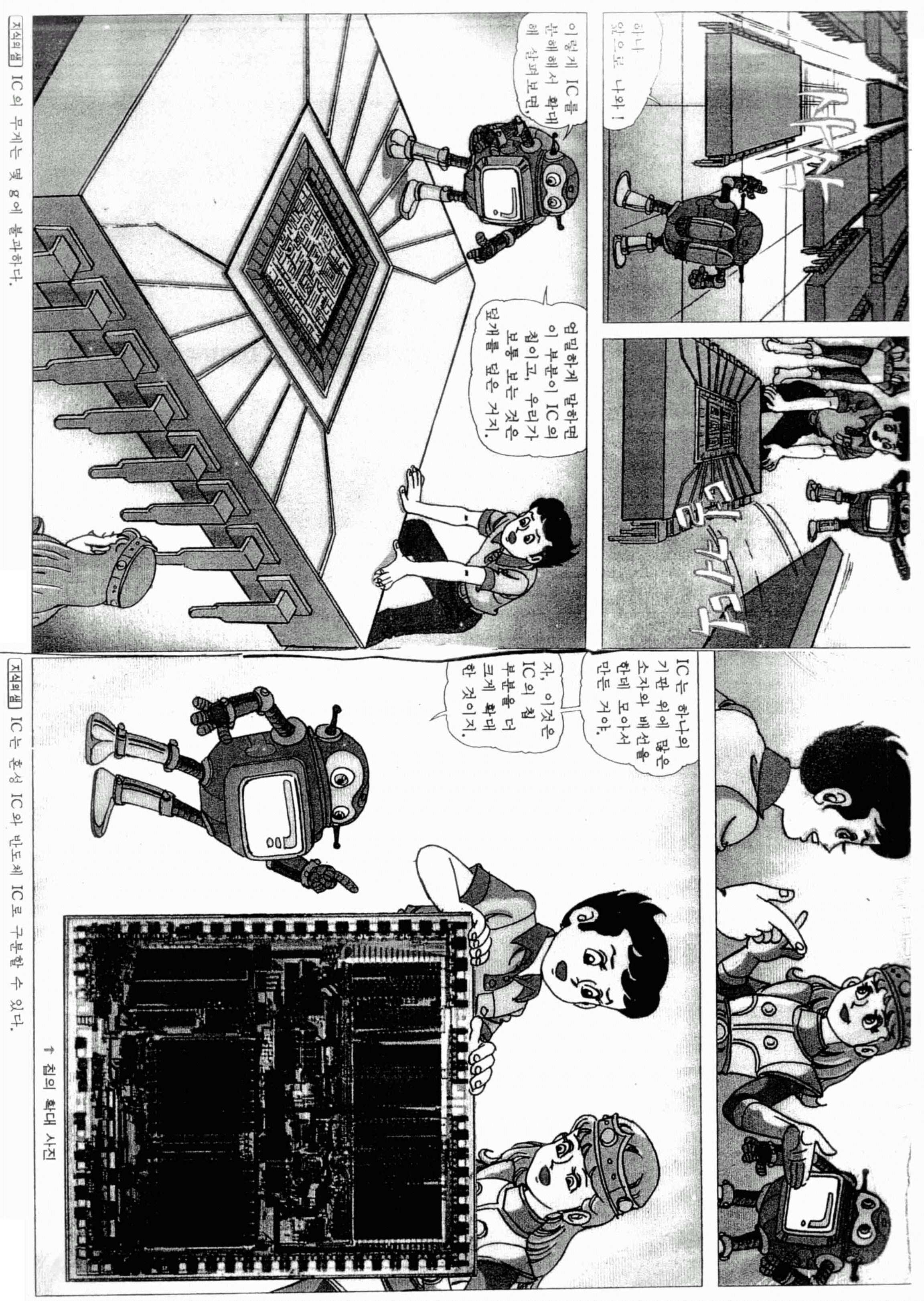

다음은 다이오드에 있어,Next up is the diode,
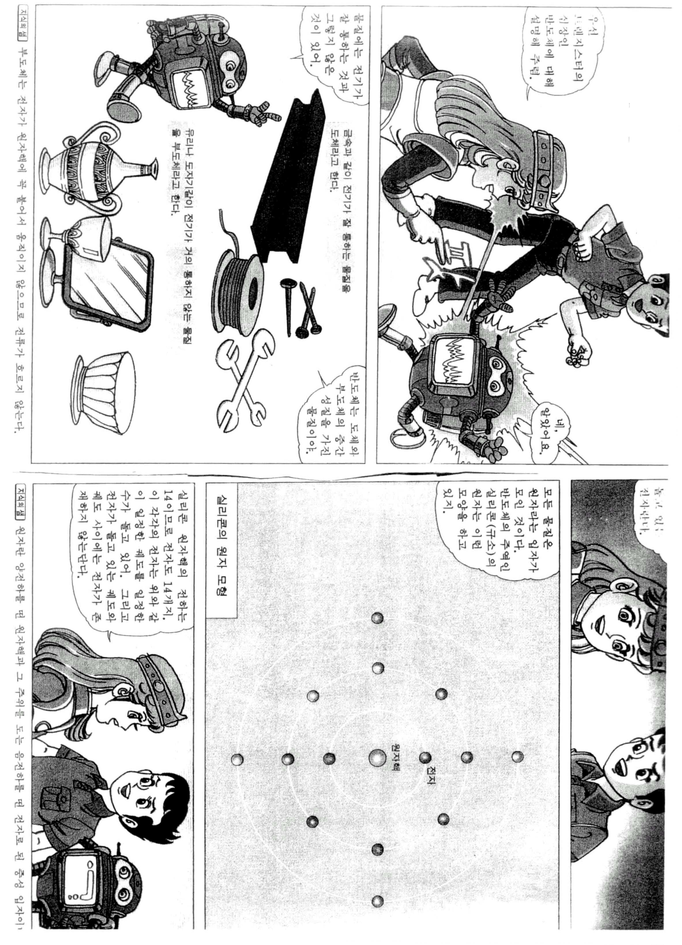
다음의 하도와 하표는 순수한 실리콘 단결정 대한 구조이다.The following diagrams and diagrams show the structure for pure silicon single crystals.

다음은 해저굴착시 폭탄외의 물질로 소음진동의 피해를 줄이는 방식인데The following is a method to reduce the damage of noise and vibration by using materials other than bombs when drilling in the seabed.

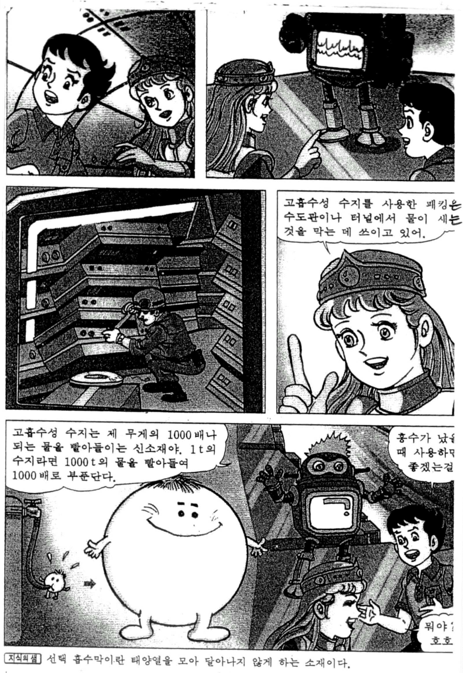
하도는 변압기(96)에 이용되는 절전형 금속에 대한 상세한 설명이다.The diagram is a detailed description of the energy saving metal used in the
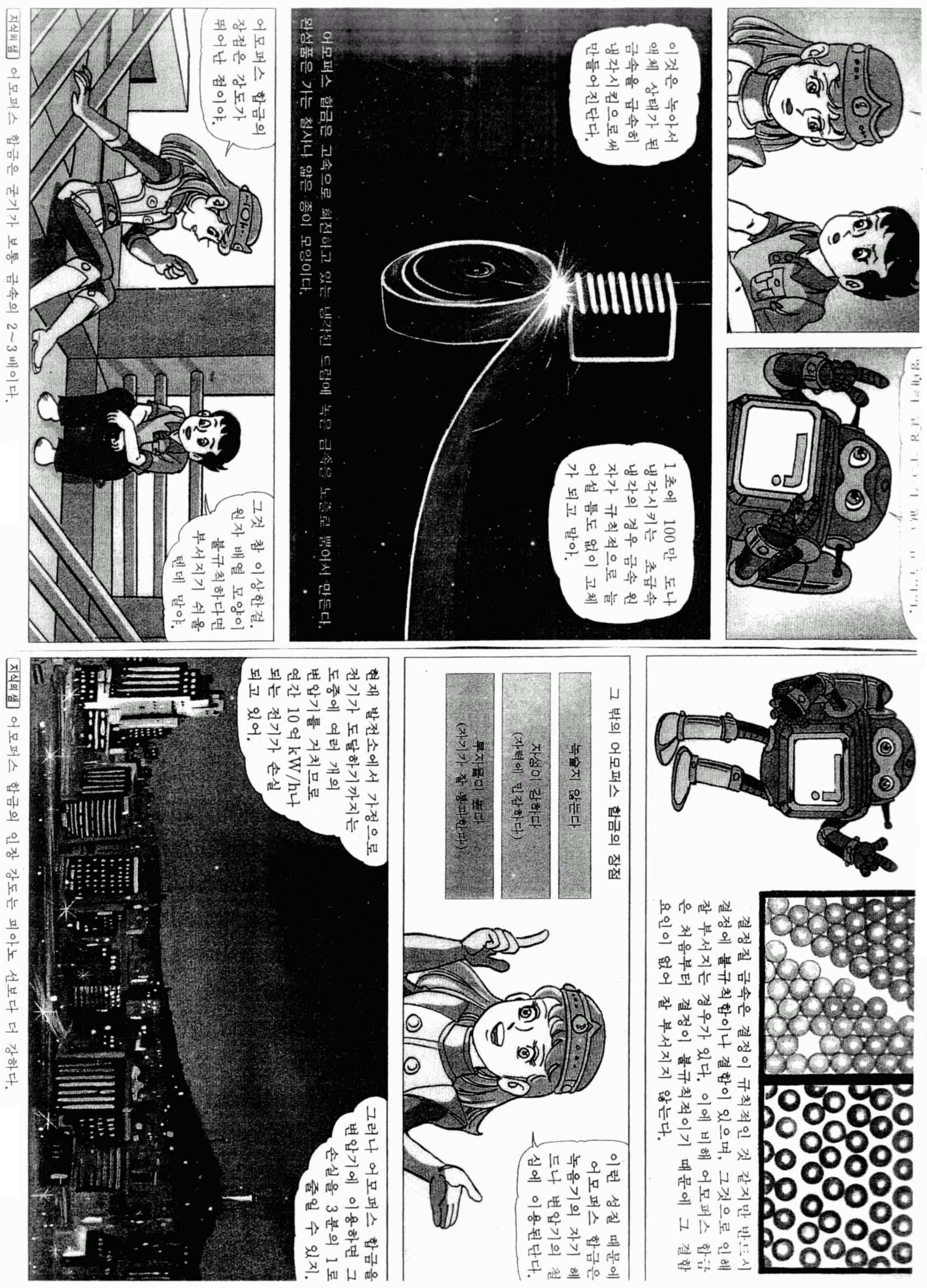

다음은 해저광물채취로봇(912)에 있어, 상기(912)은 형상기억합금으로 형성된다.Next, in the seabed mineral collection robot 912, the 912 is formed of a shape memory alloy.
신소재로된 밧데리(671)는 번개가 칠때 상기한 밧데리(671)로 전력(685)을 저장하게 되면 무재해 지구촌의 에너지 은행이 된다.The new material of the

다음은 각 산업체에 이용되는 레이져 광선에 있어,Next is the laser beam used for each industry,

초전도체에 있어, 다음과 같이 설명한다.A superconductor is demonstrated as follows.

다음의 하도는 초전도에 대한 것에 설명이다.The following diagrams explain superconductivity.

초전도 발전기에 있어, 다음과 같이 상세히 설명한다In the superconducting generator, it will be described in detail as follows.
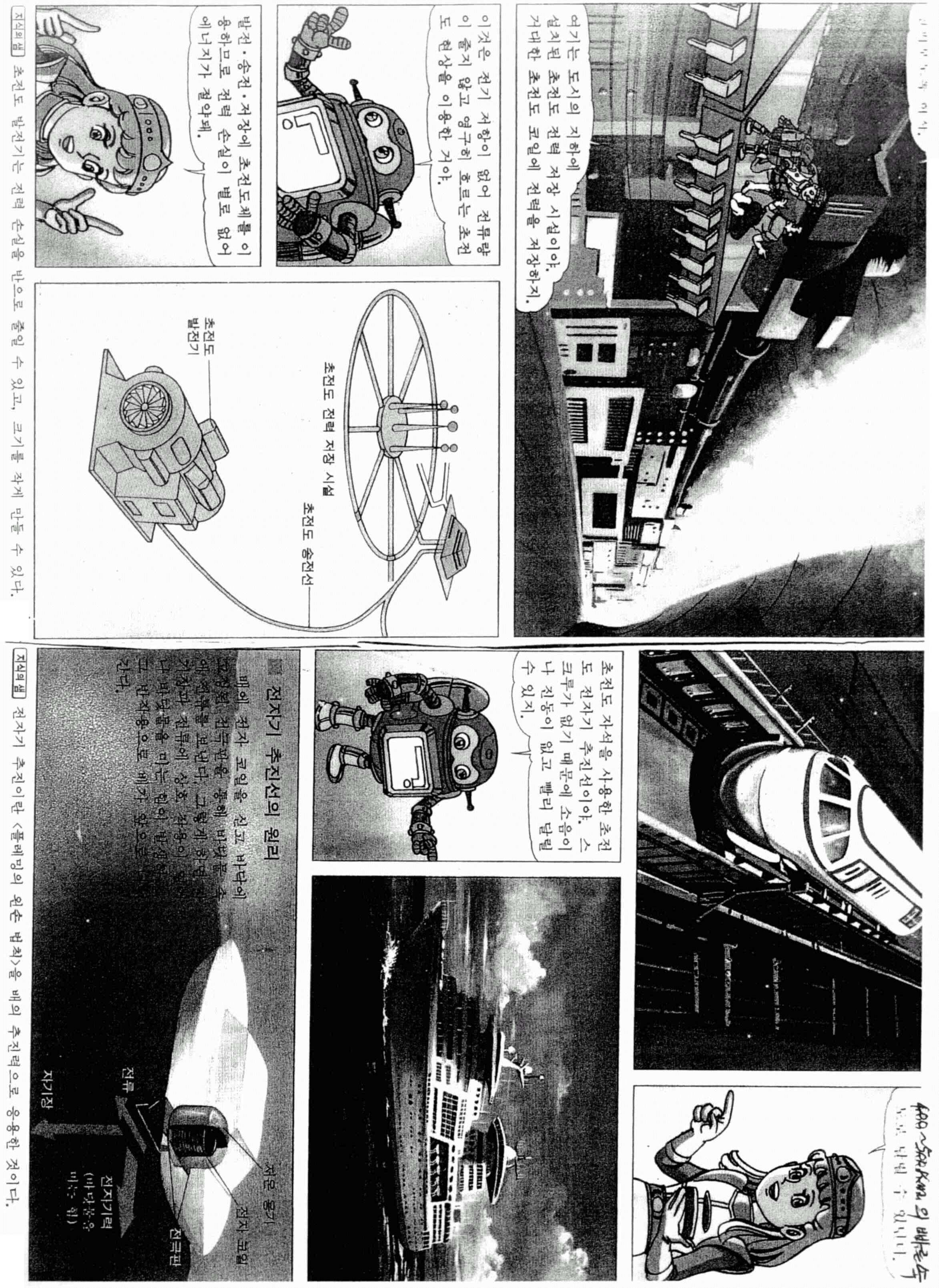


컴퓨터의 발달과 신소재에 있어, 상세한 설명을 다음과 같이 설명한다.In the development and new materials of computers, detailed descriptions will be given as follows.
첫째로 IC의 발달과 컴퓨터에 의하면Firstly according to the development of IC and computer
현재 우리 생활에는 집적 회로가 여러 방면에서 사용되고 있다. 전자 계산기·전자 시계·사진기·텔레비전 등 대부분의 전기 제품에 쓰이는 집적 회로가 그것이다. 그 밖에 비행기나 기차 예약을 비롯해 은행의 신용 카드 등 많은 분야에 쓰이고 있다.In our lives, integrated circuits are used in many ways. These are integrated circuits used in most electrical products such as electronic calculators, electronic clocks, cameras and televisions. It is also used in many areas, such as booking flights and trains, as well as bank credit cards.
집적 회로는 전기 제품이나 컴퓨터의 부품이기 때문에 겉으로 봐서는 어디에 사용되고 있는지 잘 모른다. 그러나 소형 전자 계산기나 손목 시계의 크기로 미뤄 보아 집적 회로의 크기를 대강 짐작할 수 있을 것이다.Since integrated circuits are parts of electrical appliances or computers, they don't know where they're used. However, the size of an integrated circuit can be roughly estimated by the size of a small electronic calculator or wrist watch.
집적 회로가 우리의 생활에 많이 쓰이게 된 계기는 트랜지스터의 발명이다. 1946년에 진공관을 사용한 컴퓨터가 개발되었는데, 그 기능은 오늘날의 소형 전자 계산기에도 미치지 못하는 것이었다. 진공관은 성능이 좋지 않았고 그 숫자가 1만 8000개나 되었기 때문에 자주 고장이 나서 수리하기에 바쁠 지경이었다. 트랜지스터가 나타난 후부터 컴퓨터는 보다 소형이고 성능이 좋으며, 보다 빨리 많은 일을 할 수 있게 되었다.The reason that integrated circuits have become popular in our lives is the invention of transistors. In 1946, a computer using a tube was developed, which was less than today's small electronic calculators. The tubes weren't performing well and their numbers were 18,000, so they broke down often and were busy repairing. Since the emergence of transistors, computers have become smaller, better performing, and much faster.
진공관을 사용한 컴퓨터를 제1세대, 트랜지스터를 사용한 것을 제2세대, IC를 사용한 것을 제3세대, LSI나 VLSI를 사용한 것을 제4세대라 하는데, 현재는 제4세대이다. 그리고 스스로 판단해 계산과 처리를 하는 인공 지능을 갖추게 될 컴퓨터를 제5세대라 한다.The first generation of computers using vacuum tubes, the second generation using transistors, the third generation using ICs, and the fourth generation using LSIs or VLSIs are now the fourth generation. And the fifth generation is the computer that will be equipped with artificial intelligence that judges and processes itself.
다음은 실리콘의 특징과 한계에 있어Next is the characteristics and limitations of silicon
IC의 재료로 실리콘을 사용하는 까닭은 다음과 같다.The reason for using silicon as an IC material is as follows.
첫째, 실리콘에는 매우 안정된 산화막이 존재한다. 습기 등에 의해 표면이 변해 그 성질을 변화시키는 게르마늄 트랜지스터의 문제를 해결한 것이다. 실리콘을 고온에서 구우면 표면에 산화막이 생겨 안정되고 순도가 높으며 절연성이 뛰어난 실리콘의 성질이 그대로 남아 있게 된다.First, silicon has a very stable oxide film. This solves the problem of germanium transistors in which the surface changes due to moisture and changes its properties. When the silicon is baked at a high temperature, an oxide film is formed on the surface, so that the properties of silicon that is stable, high purity and excellent in insulation are retained.
둘째, 실리콘은 한 가지 원소로 된 홀원소 반도체이다. 화합물 조성의 미소한 차이로 전기적 성질이 달라 제어가 어려운 화합물 반도체와는 달리 실리콘은 홀원소이므로 제어하기 쉽다.Second, silicon is a one-element semiconductor of one element. Unlike compound semiconductors, which are difficult to control due to different electrical properties due to a slight difference in compound composition, silicon is a hole element and therefore easy to control.
셋째, 실리콘은 고순도화가 가능하고 결함이 전혀 없는 대형 결정을 만드는 것이 가능하다.Third, silicon can be made of high purity crystals without defects.
넷째, 실리콘은 원료를 구하기 쉽다. 실리콘은 지구상에 산소 다음으로 많은 원소로 흙·돌·유리 등 어디에나 존재하고 있다.Fourth, silicon is easy to obtain raw materials. Silicon is the second most abundant element on earth, after oxygen, and exists everywhere in soil, stone, and glass.
실리콘 집적 회로의 성능은 해마다 놀라운 속도로 점점 좋아지고 있으나, 실리콘을 미세하게 가공하는 데에는 한계가 있다.The performance of silicon integrated circuits is getting better and faster every year, but there are limits to the fine processing of silicon.
특히 중요한 것은 전자가 움직이는 속도인데 이는 재료에 따라 그 정도가 다 르다. 트랜지스터를 보다 빨리 작동시키 위해서는 전자가 고속으로 움직일 수 있는 새로운 반도체가 필요하다.Of particular importance is the speed at which electrons move, depending on the material. To operate transistors faster, new semiconductors are needed that can move electrons at high speeds.
세째로, 새로운 화합물 반도체에 있어,Thirdly, in the new compound semiconductor,
트랜지스터를 고속으로 동작시키기 위한 대표적인 화합물 반도체로 갈륨·비소가 연구 중이다. 갈륨·비소를 사용하면 실리콘보다 3∼6배 빠른 속도로 열을 처리할 수 있다. 이 재료는 전자의 이동 속도가 빠르고, 실리콘에는 없는 여러 가지 성질을 지니고 있지만 아직 밝혀지지 않은 점이 많다.Gallium-arsenic is being studied as a typical compound semiconductor for operating transistors at high speed. If gallium arsenide is used, heat can be processed 3 to 6 times faster than silicon. The material has a high rate of electron movement and a number of properties not found in silicon, but it is still unknown.
이 갈륨·비소도 10여 년이 지나면 개발이 한계에 도달하게 되는데, 그 다음엔 어떻게 될까?This gallium arsenic also reaches its limit in 10 years, but what happens next?
그 시대에는 천연으로 존재하는 재료를 이용하는 것이 아니라 목적에 따라 재료를 만들게 될 것이다. 그 예로서 초격자를 들 수 있는데, 초격자란 종류가 다른 얇은 반도체 재료를 몇 층이나 겹쳐 쌓은 것이다. 이런 재료는 이제까지의 반도체 재료보다 몇 배나 빨리 전자를 이동시킬 수 있다.In those days, you will make materials according to your purpose, not using materials that exist naturally. An example is the superlattice, which is a stack of several layers of different types of thin semiconductor materials. These materials can move electrons many times faster than ever before.
물론 이런 재료는 단순히 녹여서 굳히는 방법으로는 만들지 못한다. 우주 공간 같은 진공상태에서 아주 천천히 반도체를 증착시키는 기술의 개발로 비로소 초격자를 만들 수 있게 되었다.Of course, these materials simply cannot be melted and hardened. The development of a technique that deposits semiconductors very slowly in a vacuum, such as space, makes it possible to create a superlattice.
네째로 컴퓨터는 반도체가 아니라도 제조 가능한 것인데Fourth, computers can be manufactured without semiconductors.
컴퓨터를 움직이는 심장부인 IC는 반도체가 아니라도 만들 수 있다. 실리콘이 아니라도 외부에서 신호를 입력했을 때 온(on)·오프(off) 기능만 갖추고 있으면 가능하다.ICs, the heart of the computer, can be made not even semiconductors. Even if it is not silicon, it is possible to have only on and off functions when a signal is input from the outside.
● 초전도체를 사용한 조셉슨 소자Josephson element using superconductor
니오브나 납 등을 재료로 한 조셉슨 소자는 저항이 0인 초전도 현상을 이용한 것으로, 현재의 집적 회로에 비해 훨씬 빨리, 적은 전력으로 일을 처리할 수 있다.Josephson devices made of niobium, lead, etc., use zero-resistance superconducting, which allows them to do work much faster and with less power than current integrated circuits.
● 분자 일렉트로닉스● Molecular Electronics
분자 속의 약간의 움직임에 의해 그 분자의 상태가 변하거나 생물 세포의 상태가 변하는 것을 이용하여 사람의 뇌와 닮은 컴퓨터를 만들려는 것이다.It is to create a computer that resembles the human brain by using a change in the state of a molecule or a change in the state of a living cell by a slight movement in a molecule.
다섯째 옵트 일렉트로닉스에 있어,Fifth, in Opt Electronics,
옵트 일렉트로닉스란 빛과 관계가 있는 소자를 사용한 전자 공학을 말하며, 구체적으로는 광통신이나 레이저 디스크 등을 들 수 있다.Opt electronics refers to electronics using devices related to light, and specific examples thereof include optical communication and laser disks.
현재의 전화선은 가는 구리선을 사용해서 신호를 전달하고 있는데, 광통신에서는 석영 유리로 만든 광섬유에 레이저 광선을 통과시켜 신호를 전달한다.Today's telephone lines use thin copper wires to carry signals. In optical communications, laser beams are passed through an optical fiber made of quartz glass.
옵트 일렉트로닉스의 중심은 반도체 레이저나 발광 다이오드 등의 발광 소자 이다. 그런데 실리콘으로는 발광 소자를 만들지 못하므로 실리콘 대신 화합물 반도체를 사용한다.The center of opt electronics is light emitting devices such as semiconductor lasers and light emitting diodes. However, since silicon cannot make a light emitting device, a compound semiconductor is used instead of silicon.
그 재료는 발광의 빛깔(파장)에 의존한다. 적외선의 재료로는 갈륨·비소나 인듐·인을 사용하고, 가시 구역의 경우 빨간색에는 갈륨·알루미늄·비소를, 녹색에는 갈륨·인 등을 사용한다.The material depends on the color (wavelength) of luminescence. Gallium arsenic or indium phosphorus is used as an infrared material, and gallium aluminum arsenic is used for red in the visible region, and gallium phosphorus is used for green.
끝으로 신소재의 개발에 대하여Finally, the development of new materials
앞으로는 어떻게 새로운 재료가 개발될까? 분명한 것은 단순히 재료를 합성하는 시대는 끝나가고 있다는 것이다. 옛날에는 연금술이 성했는데, 이것은 재료에 대한 전자·원자 등의 지식이 전혀 없었기 때문이다.How will new materials be developed in the future? Clearly, the age of simply synthesizing materials is coming to an end. In the past, alchemy was successful, because there was no knowledge of electrons or atoms about the material.
그렇지만 지금은 재료의 분자 구조나 성질 등에 대한 지식이 많아졌다. 이제부터는 재료의 미세한 구조, 구체적으로는 원자 크기의 구조를 제어함으로써 새로운 재료를 개발할 수 있을 것이다.However, there is now a great deal of knowledge about the molecular structure and properties of materials. From now on, new materials can be developed by controlling the fine structure of the material, specifically the atomic size structure.
렇게 되려면 반도체·금속·유기물 등의 구체적인 재료에 구애받아서는 안되며, 이러한 범주를 벗어나 원자 수준에서 재구성해야 한다. 몇천, 몇만 가지도 더 될 원자 구성 방법을 실험해 보는 가운데 놀랄 만한 신소재가 자꾸자꾸 탄생하게 될 것이다.This does not depend on specific materials such as semiconductors, metals and organics, but must reconstruct at the atomic level beyond these categories. As you experiment with how thousands and even tens of thousands of atoms are constructed, amazing new materials will continue to be born.
로타리 실린더(랙&피니언형 -NRP, 620)에 있어 하도와 하표와 같다.For rotary cylinders (rack & pinion type -NRP, 620), this is the same as the sewer and the sewer.

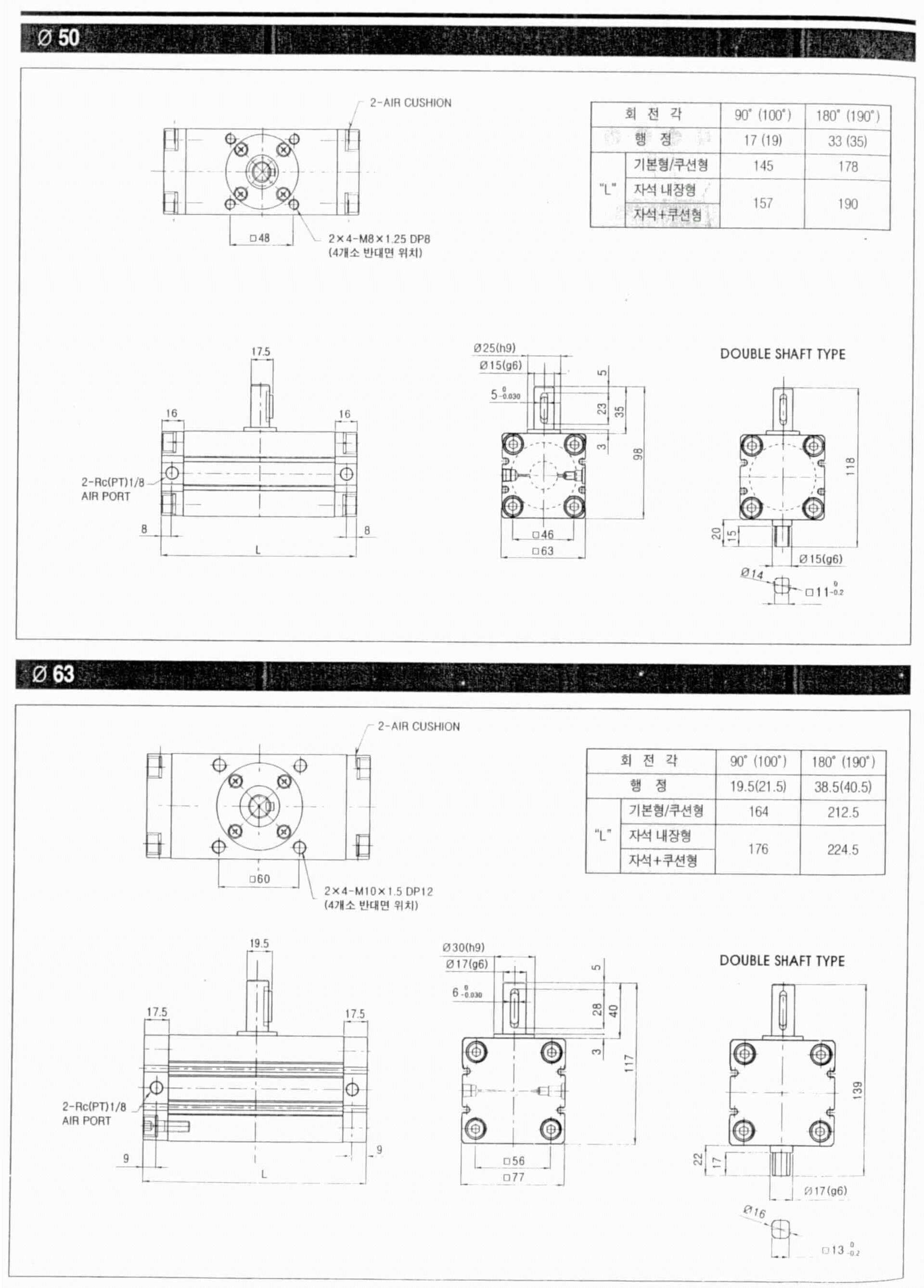
다음의 측면도는 육상에서 사용되는 굴착장비인데 스큐르드릴이 장착된 굴착기(845)이다The following is a side view of the excavation equipment used on land, the
유압실린더(623)와 굴착기(845) 에크레인(861)으로 결합분해 해지되게 되어 있다.The
상기한 유압실린더(623)와 굴착작업 후 굴착기(845)를 분해한 후에는 교각기초기둥 작업용의 볼트너트 결합해지용 복스햄머를 사용하여 너트를 쪼여서 해저 저측바닥의 기초 교각을 세워서 건설기계인데 바지선 본체(591) 갑판데크 상부에 탑재 형성되는 장비이다.After disassembling the

하도는 팬(195)의 전방에 니크롬선(659)의 전열기를 닥터벤츄레이션(585) 내부에 설치하면 뜨거운 공기를 불어 넣게 되는 것이 공기보온용의 히터팬(642)이 형성되며 차가운 공기를 팬(196) 전방 또는 후방에 설치하는 것은 쿨링팬(641)이 되는 것인데 상기한 냉각장치와 열기구는 발전장치의 엔진(226) 등에 트랜스포머룸(782)과 중앙제어실(781) 등에 사용되는 장치이다.The bottom of the
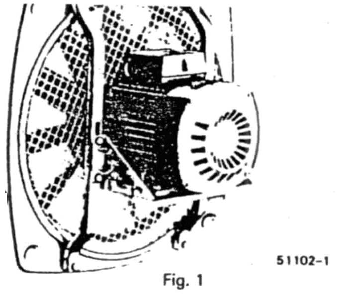

다음과 같이 하도는 팬(195)과 함께 사용되는 송풍기의 가이드베인(142)이 해양발전소 내부에 형성된다.As shown below, the
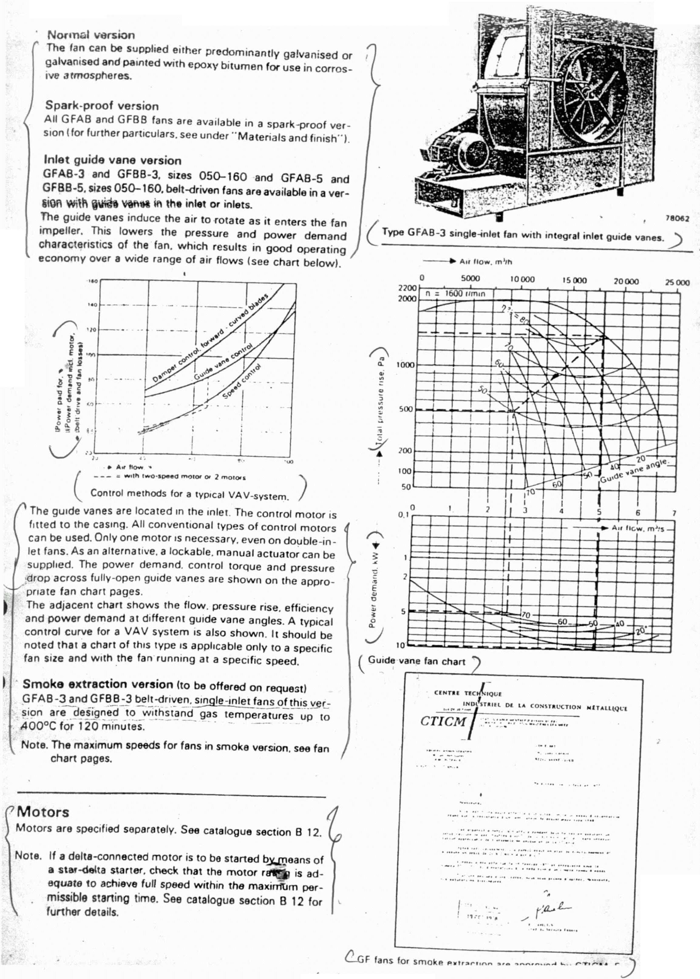
하도는 해양발전소 몸체(1) 내부에 탑재 형성된 수개의 송풍기(941) 형식이다The channel is a type of

하도는 송풍기(941) 몸체의 임펠러(143)와 샤프트(198)에 베아링(200) 등의 조립방식도이다.The bottom is an assembly method of the

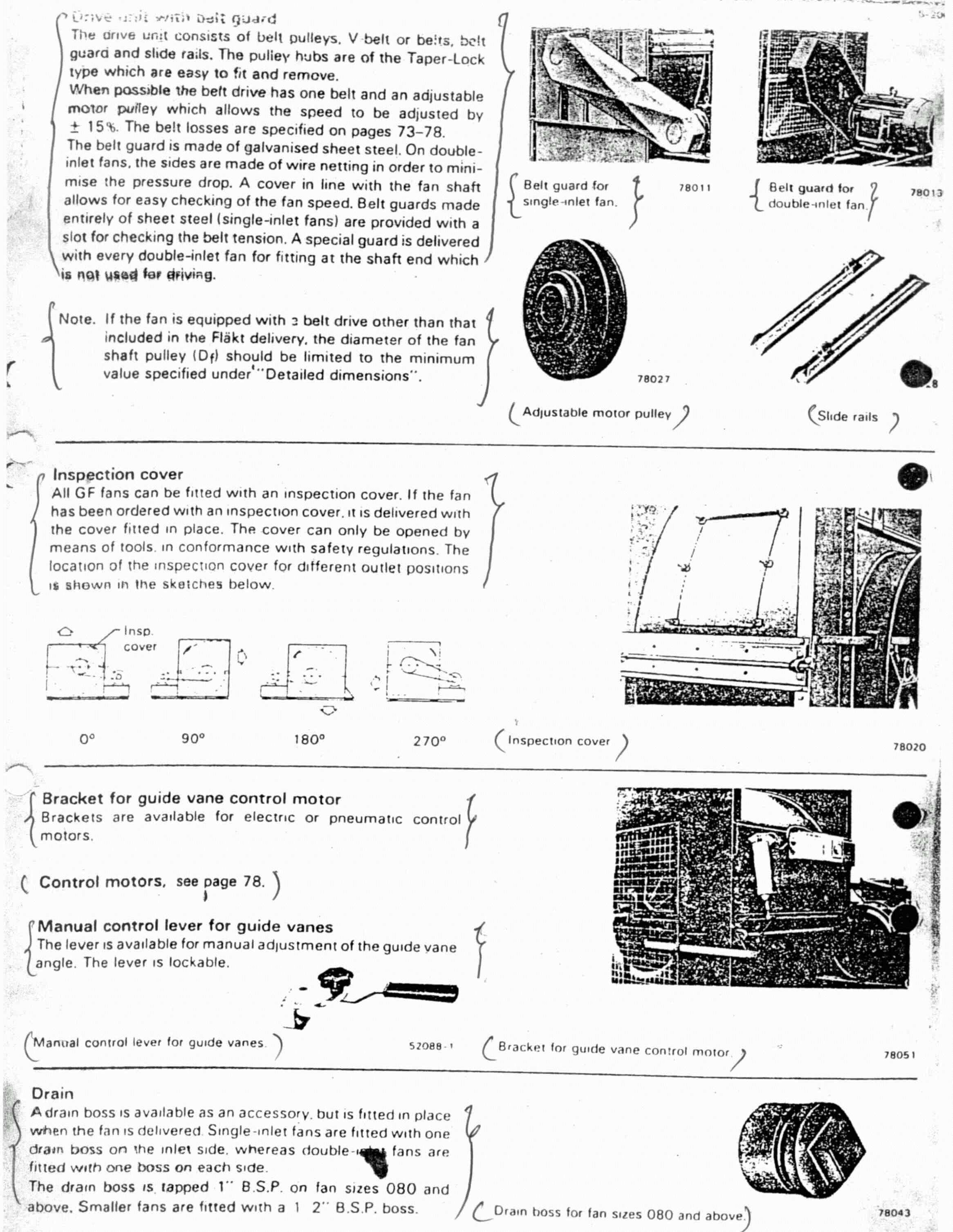
하도는 쿨링팬(641) 기종에 따른 테스트 목록이다.The lower road is a test list according to the cooling
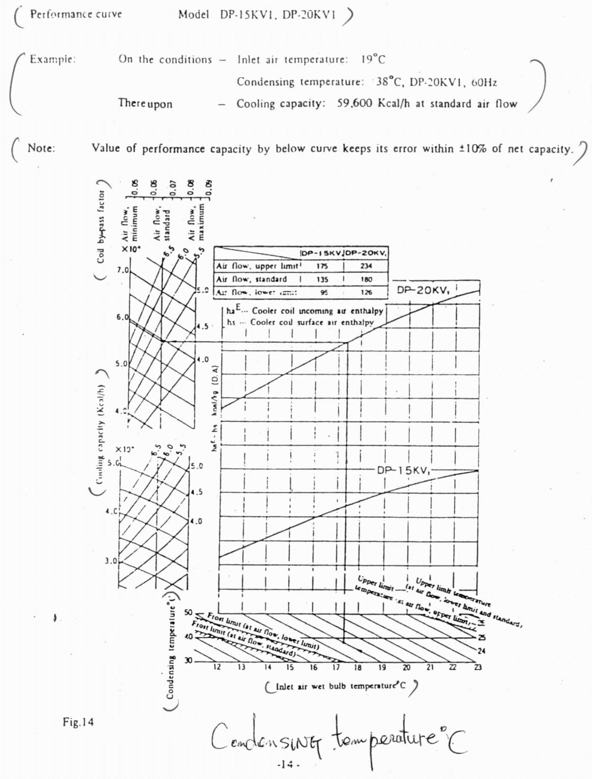

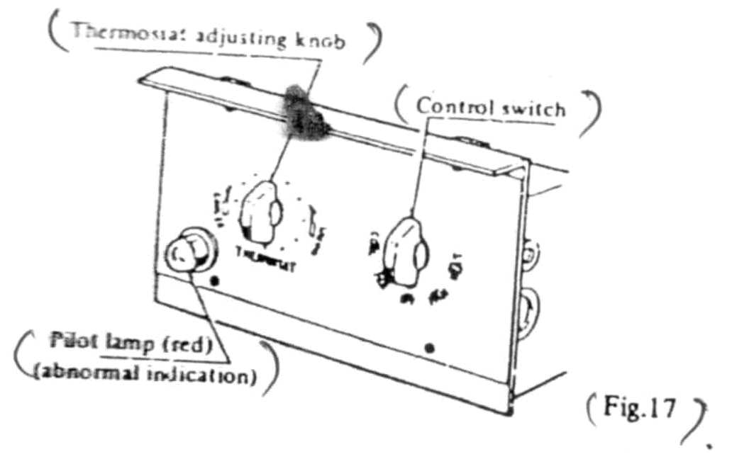
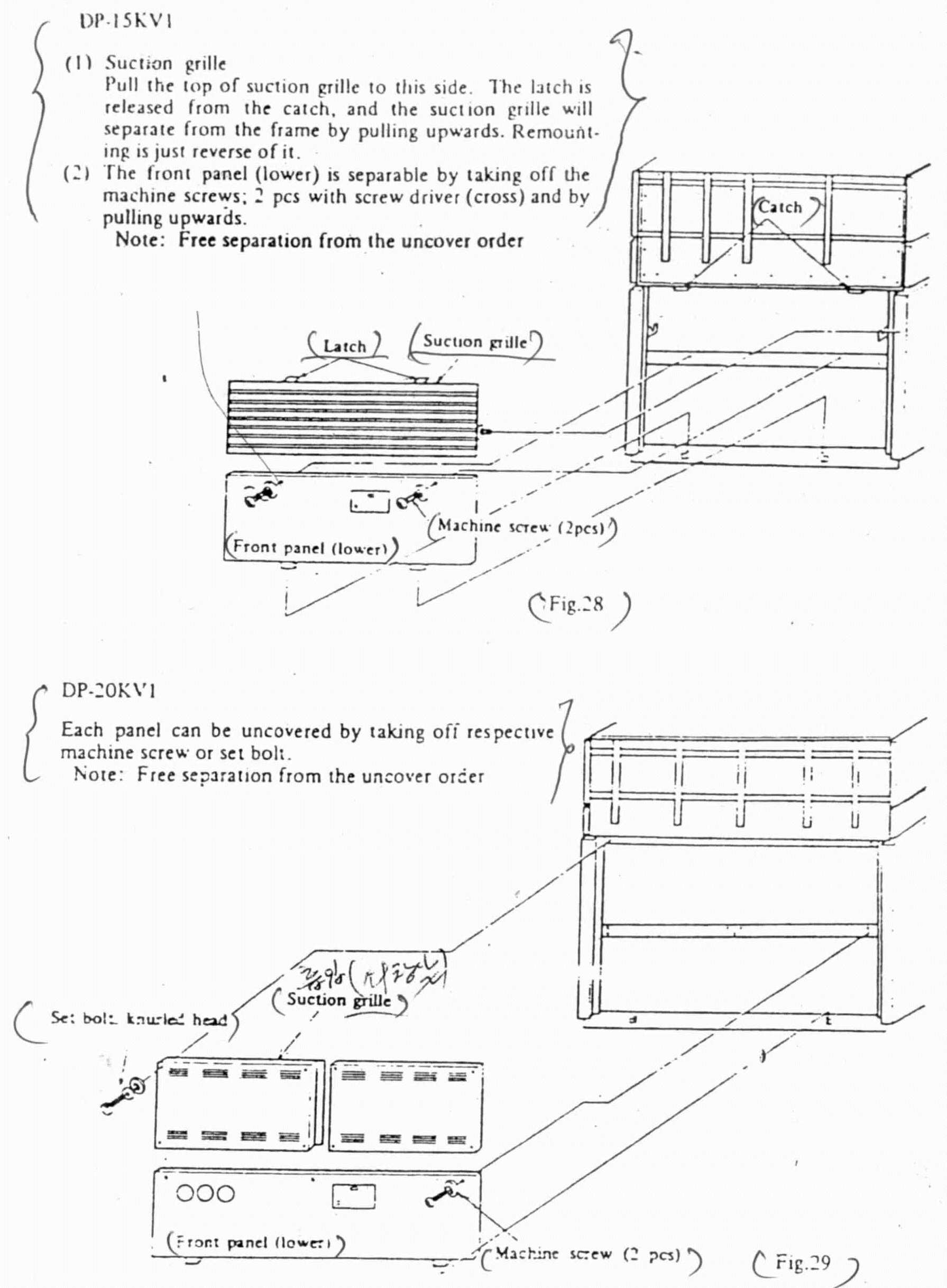
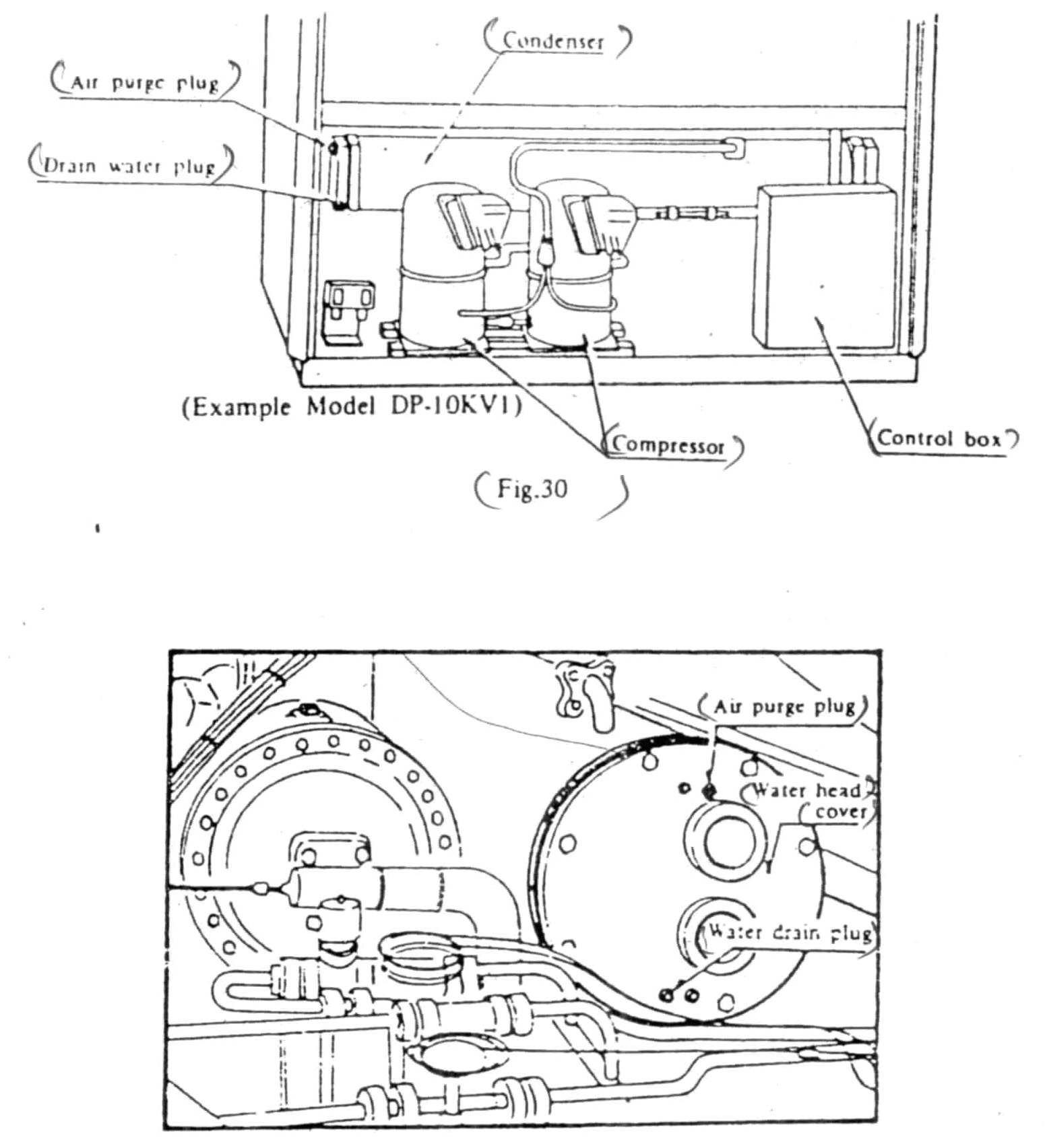


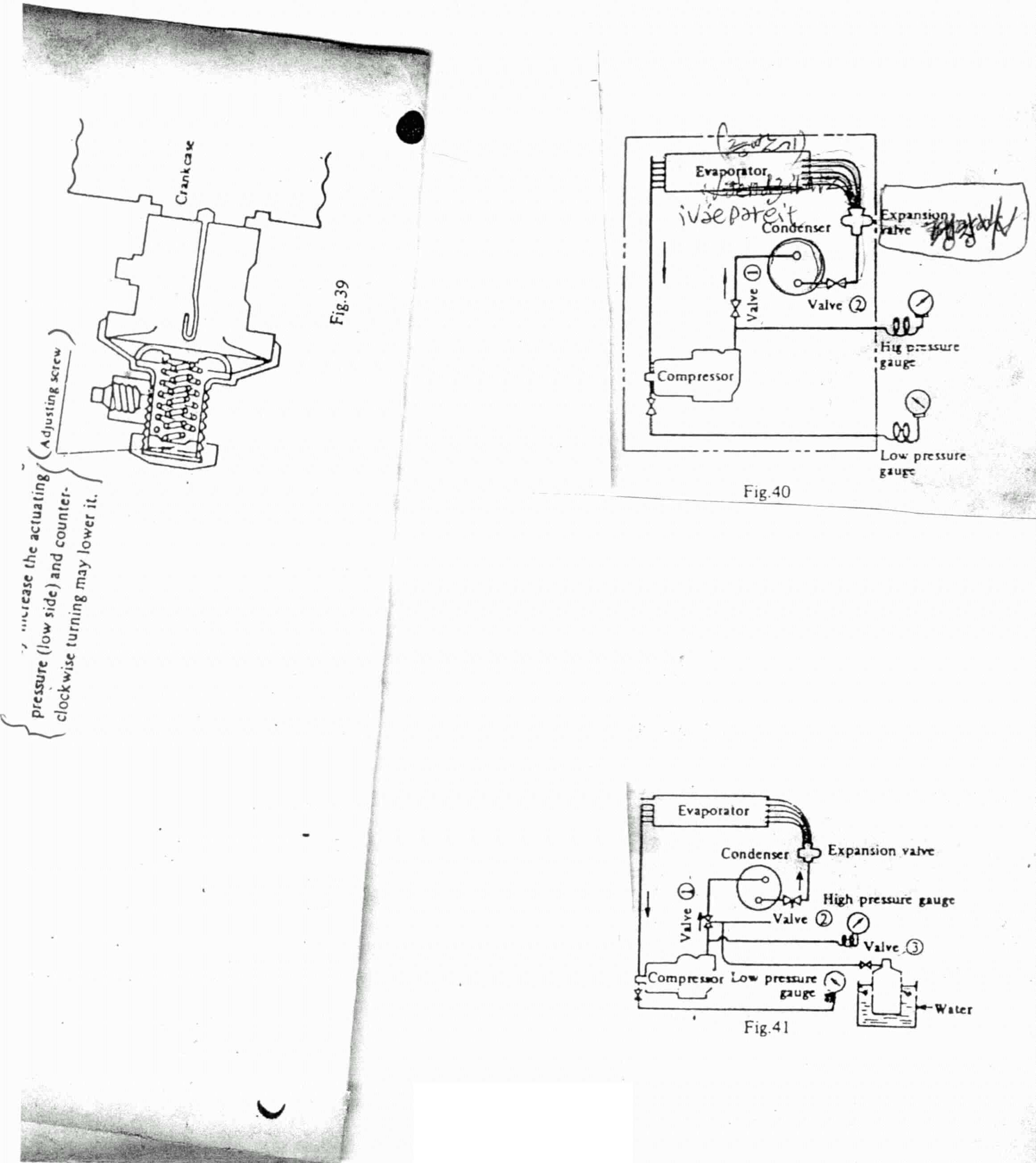


상도는 냉각기계 오우토 방식과 수동제어방식의 프레스(압력) 스위치 조작 방식 위치 설명도이다.Top coat is explanatory drawing of the position of a press (pressure) switch operation system of the cooling machine Outo system and a manual control system.

상도는 메뉴얼, 오우토 스위치 조작 방식을 도시한 것이다.Top coat shows the manual and auto switch operation method.
하도는 진공펌프(베이컴 펌프; Vaccum pump, 635)를 콘덴서 하부 게이지 메 니폴더 밸브에 연결시켜 프레온 가스를 재주입시키는 과정을 도시한 것이다.The diagram shows the process of reinjecting freon gas by connecting a vacuum pump (Vaccum pump, 635) to the condenser lower gauge manifold valve.
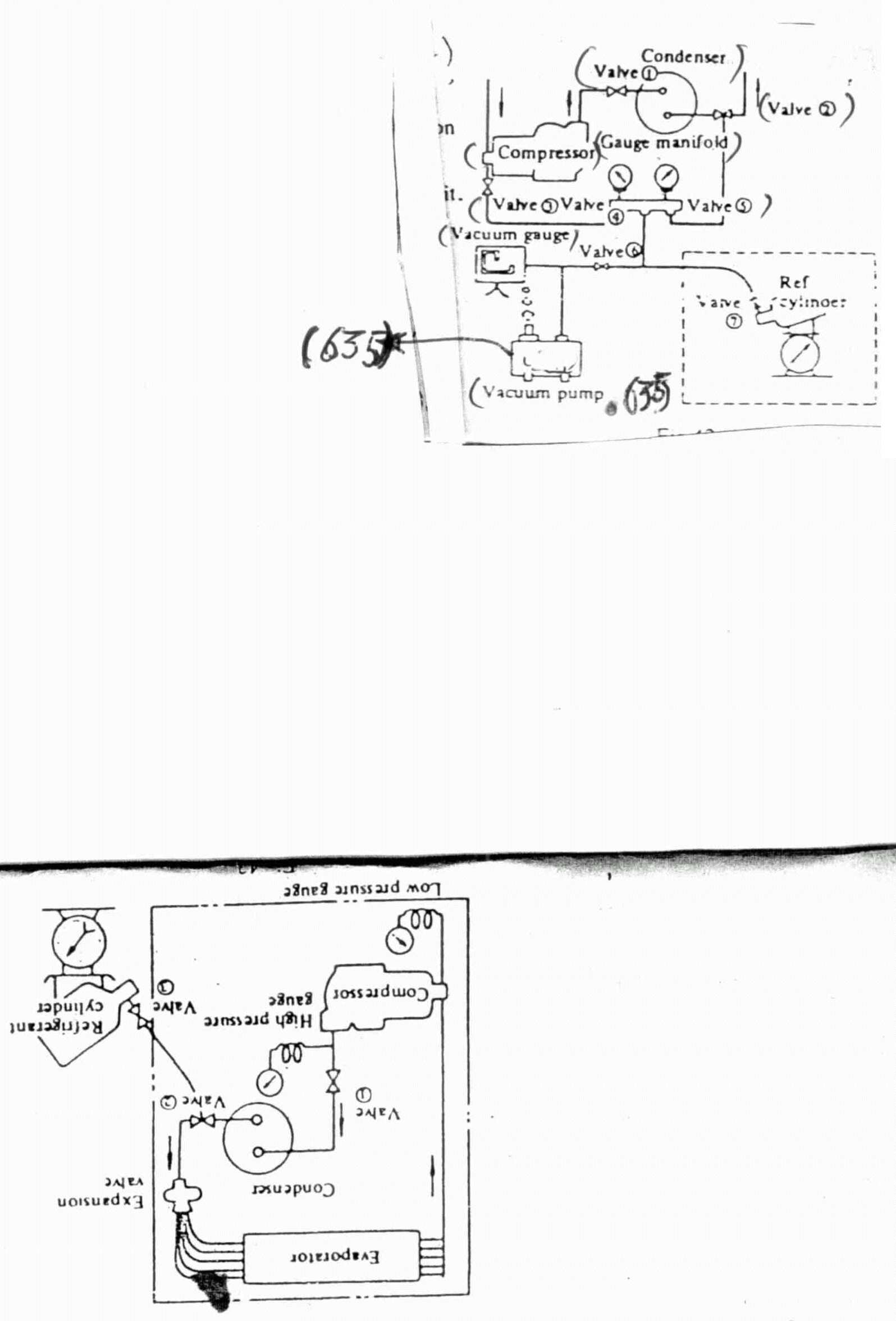
하도는 소형의 에어컨(디피이-5KV)용량의 외형 사시도와 내부 정단면도를 도시한 것이다.The bottom view shows an external perspective view and internal sectional view of a small air conditioner (DIP-5KV) capacity.
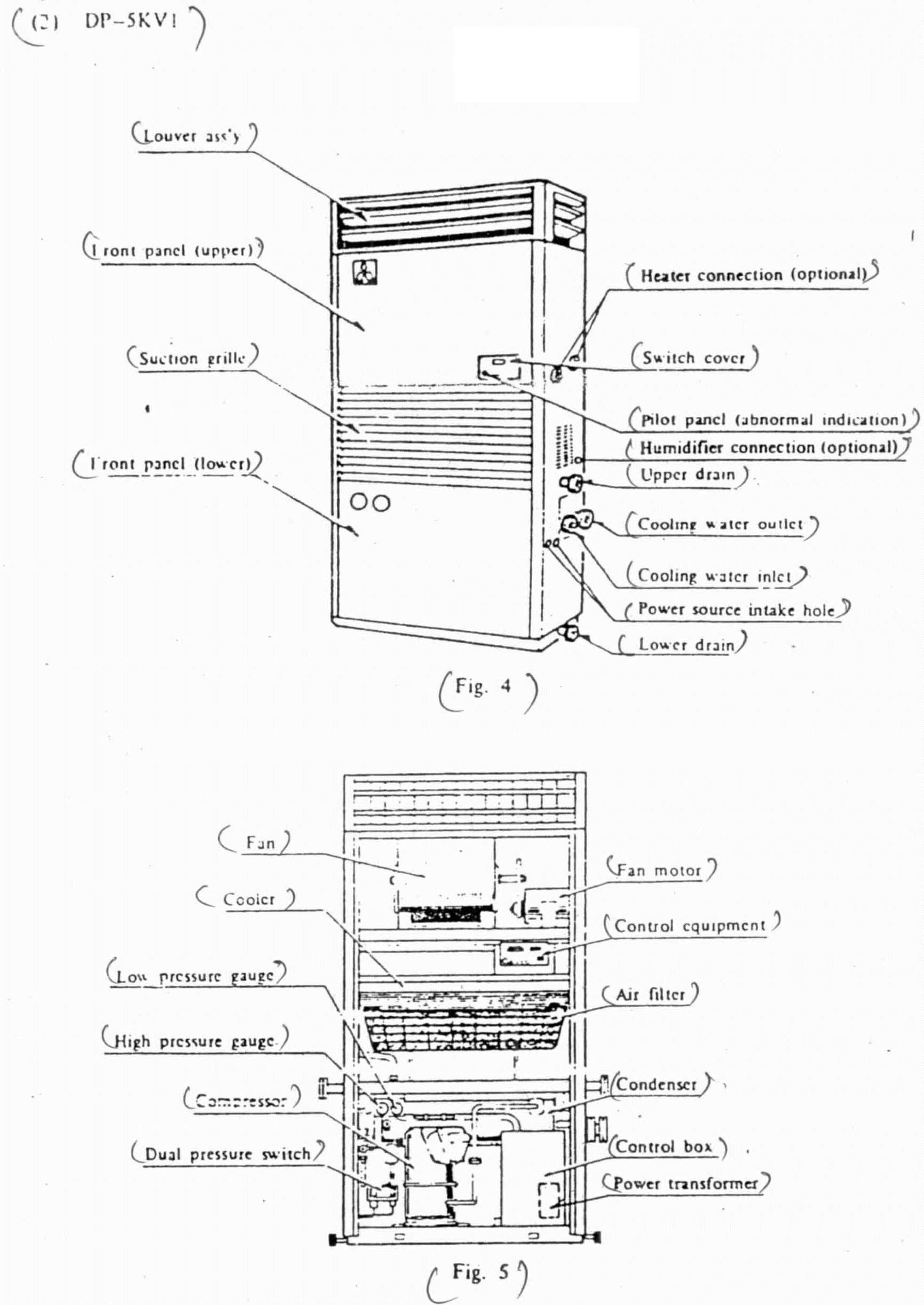
하도는 해양발전소 몸체(1) 내부에 탑재 형성되는 중형의 에어컨을 도시한 사시도 및 정단면도이다.The bottom view is a perspective view and a front sectional view showing a medium-sized air conditioner is mounted mounted inside the marine power plant body (1).
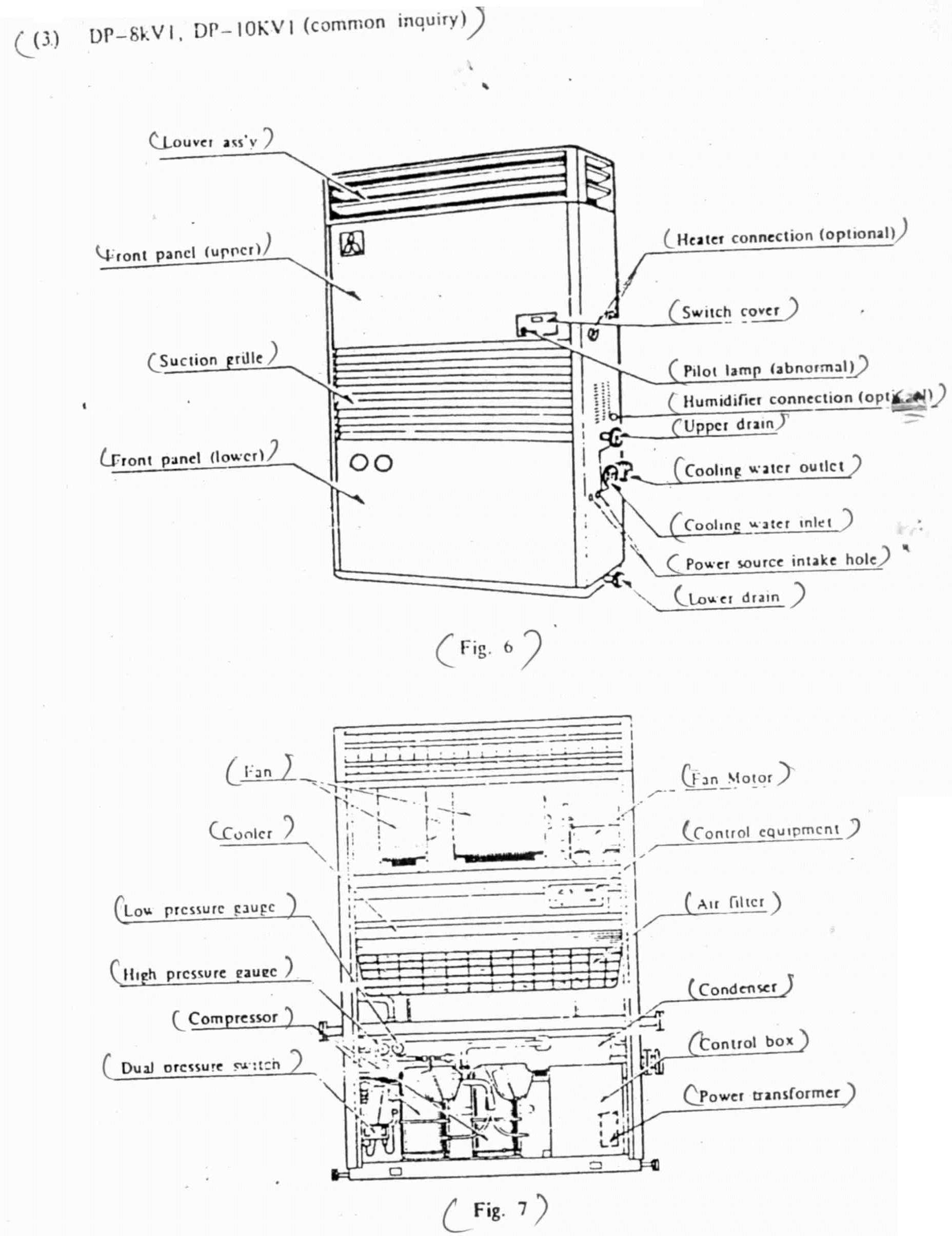
하도는 해양발전소 몸체(1) 내부에 수개의 탑재 형성된 대형의 에어컨을 도 시한 것이다.The lower road shows a large air conditioner formed of several mounted inside the marine power plant body (1).
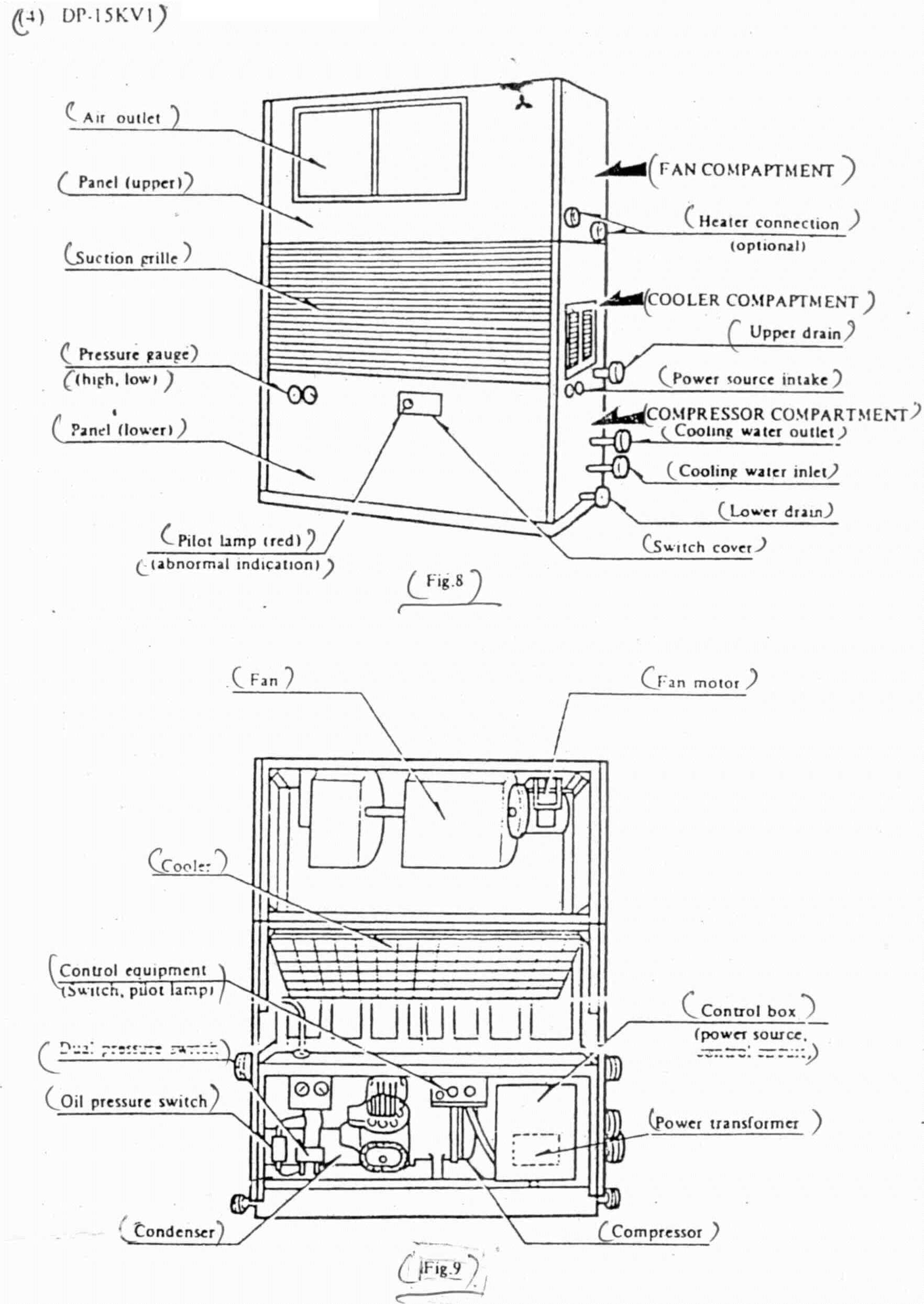
하도는 해양발전소 몸체(1)의 내부로 수개의 탑재 형성된 대용량의 에어컨을 발전소 몸체(1) 내부 공기 압축실(402)에 설치된다.The lower road is installed in the
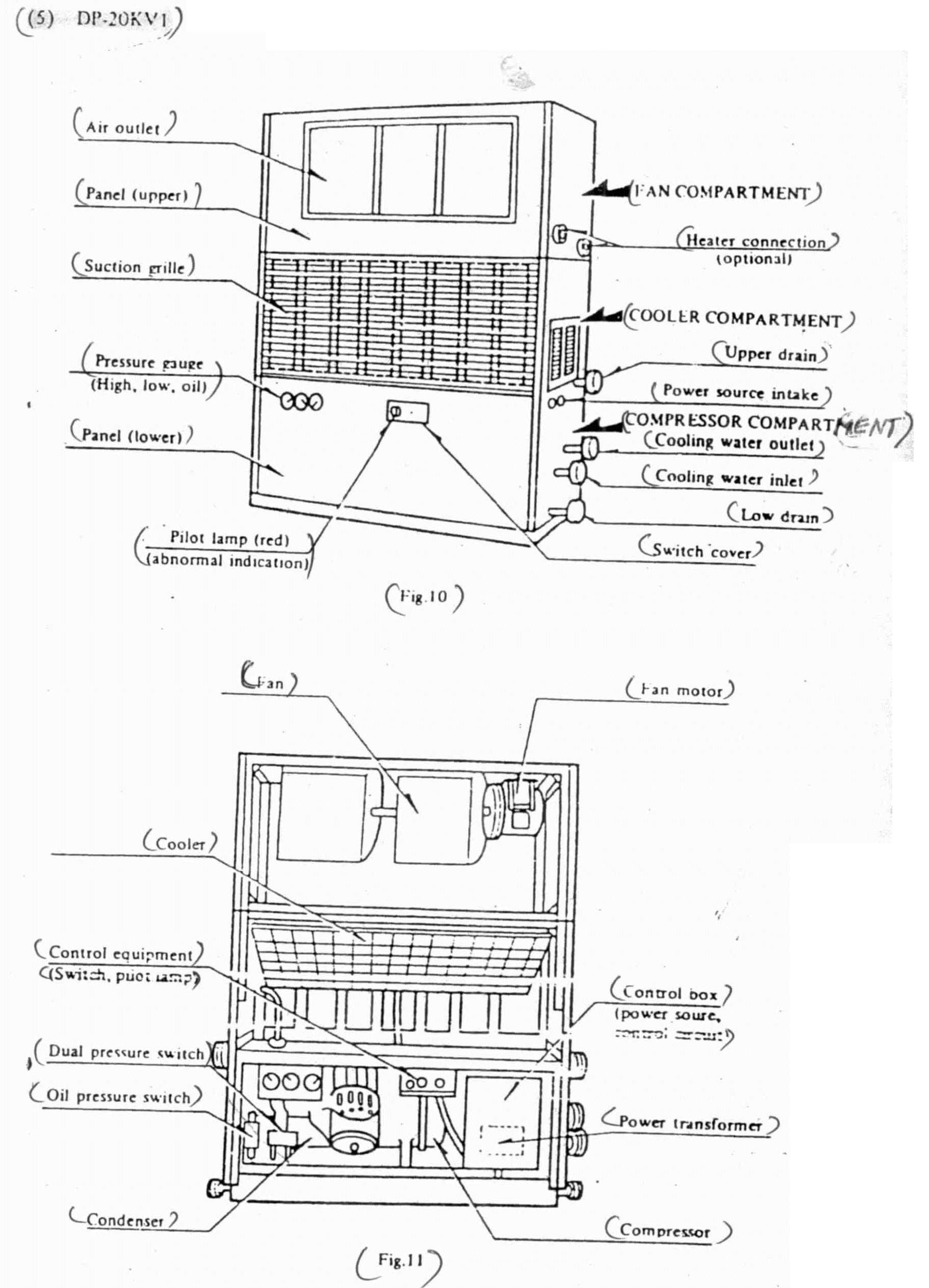
하표는 해양발전소의 화력발전기 구조 내부의 일본 보일러 규격 용접의 효율에 있어 하표와 같다.The table below is the same as the table below for the efficiency of Japanese boiler-standard welding inside the thermal power plant structure of a marine power plant.
<표 1-18 일본 보일러 규격 용접의 효율><Table 1-18 Japanese Boiler Standard Welding Efficiency>
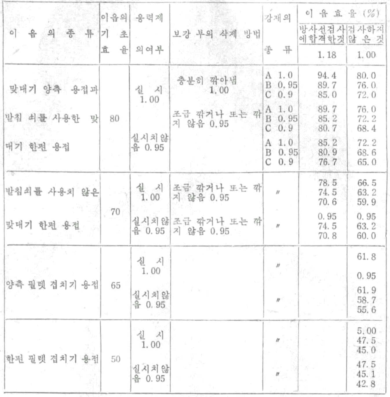
다음은 용접방식의 종류와 용접기의 선택에 대하여 하표와 하도를 다음과 같이 설명한다.The following describes the types of welding method and the selection of the welding machine as follows.
첫째로 용접방식의 종류에 있어Firstly, in the kind of welding method
용접은 2개 또는 그 이상의 개수의 금속을 국부적으로 접착시키는 방법으로서 현재 사용되고 있는 것은 약40 종류에 달하고 있다. 그 중 비교적 주요한 것 중에서 용접 기능직에 종사 하는 분에게 대해서 특히 중요하다고 생각되는 몇가지 방법을 들어보면 표 2-1과 같아 이것들은 대별하여 융접에 압접 및 납땜의 3종류로 나눌수 있다.Welding is a method of locally bonding two or more metals, and there are about 40 types currently used. Among the relatively important ones, some of the methods considered to be particularly important for those working in the welding industry are shown in Table 2-1. These can be roughly divided into three types: welding and soldering.
<표 2-1 금속의 용접법><Table 2-1 Welding Method of Metals>

융접은 달리 용융용접이라고도 하여 이어질 부분에 녹은 금속을 공급하든가 녹혀서 용접하는 방법으로서 이때 모재(용접된 재료)도 녹는 것이며 단 압력은 가해지지 않는다.Fusion welding, otherwise known as melt welding, is a method of supplying molten metal to the part to be connected or melting and welding, wherein the base material (welded material) is also melted, but no pressure is applied.
압접은 이어질 부분에 압력을 가해놓고 가스의 연소 불꽃 또는 전류에 의한 열로서 가열 하든가 혹은 가열하지 않고 단지 가열만 하고 다른 녹은 금속이 이어질 면의틈에 표면 장력의 작용으로서 흡입되고 금속분자 서로 사이에 인력이 작용하여 접합되는 것이다.The pressure contact is heated by applying pressure to the part to be connected and heating it with or without heat from the combustion flame or current of the gas. Gravitational force acts to join.
용접에 있어서 재료의 절단, 이음끝벌림(조인트)의 가공, 고우징(Gouging)등에는 각종 절단방법이 이용된다. 이들 절단 방법은 기계절단에 의하는 것외에 가스불꽃 및 아아크를 이용하는 방법이 있는데 기계절단외의 방법은 특히 용접과 관계가 깊다 이중에서도 피복금속 아아크 용접법 및 가스용접법 중에서도 산소, 아세틸렌용접법은 특히 많이 사용되는 것이니 여기에 중점을 두어 설명을 전개해 가기로 하고 서브멀지드아아크 용접법 및 불활성가스 아아크 용접은 또한 중요한 용접법이므로 타용접법에 비해서 한층 더 무게를 두고자 한다.In the welding, various cutting methods are used for cutting the material, processing the joint end (joint), gouging, and the like. These cutting methods include gas flames and arcs in addition to mechanical cutting. In addition to mechanical cutting, oxygen and acetylene welding are especially used among coated metal arc welding and gas welding. The explanation will be focused on this, and the sub-multi-arc arc welding method and the inert gas arc welding method are also important welding methods, and therefore, they will be further weighted compared to other welding methods.
둘째로 피복 아아크 용접에 따른 개설에 있어,Secondly, in the opening by covering arc welding,
피복 아아크용접이란 현재 가장 많이 사용되는 용접법이며 흔히 전기용접이라고도 많이 불리우고 있다.Covered arc welding is the most commonly used welding method and is often referred to as electric welding.
이 용접법에서는 피복제를 바른 용접봉과 용접해야 될 용접물과의 사이에 일어난 전기아아크(Arc)의 열을 이용하여 용접하는 방법이다.In this welding method, a welding method is performed by using a heat of an electric arc generated between a coated electrode and a weld to be welded.
이 용접법 원리를 표시하면 그림 2.1도와 같다. 홀더(Holder)에 물려진 피복용접봉과 피용접물(또는 모재)과의 사이에 교류 또는 직류의 전기전압을 걸어서 그 간격에 전기아아크를 일으킨다.The principle of this welding method is shown in Figure 2.1. An electric arc of alternating current or direct current is applied between the coated welding rod bited by the holder and the object to be welded (or the base metal) to generate an electric arc in the gap.
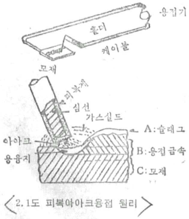
이 전기아아크의 강한 열 (온도 약 6,000℃) 에 의하여 용접봉과 모재가 녹고 용접봉은 금속증기 또는 용적은 금속이 녹아서 물방울같이 된 것으로 되어 용융지에 용착되고 거기서 녹은 모재와 합쳐져서 용접금속(Weld metal)을 만든다.The welding rod and the base material are melted by the strong heat of this electric arc (temperature about 6,000 ℃), and the welding rod becomes metal droplets or the volume is melted like water droplets, which is deposited on the molten paper and merged with the melted base material to form the weld metal. Make.
2개의 재료를 용접할 때 그 물건(모재)이 두꺼울 때는 이어지는 부분에 홈을 만들고 그 홈을용접금속으로서 채워서 접합하는 것이다. 이때 생기는 용접선을 비이드(bead) 표면은 용접의 응고에 의하여 잔 물결모양을 나타낸다.When welding two materials, when the object is thick, a groove is made in the subsequent part and the groove is filled with a welding metal and joined. The bead surface of the weld line generated at this time shows a wave shape remaining by the solidification of the weld.
용접봉은 금속심선의 겉에 피복제를 바른 것이다. 피복제는 아아크열에 의하여 분해되며 그 분해되어 생긴 가스의 역할에 의하여 아아크가 잘 꺼지지 않도록 안정하게 하고 이 발생한 가스 혹은 슬래그는 녹은 금속을 덮어줌으로써 용융금속을 외기에서 보호하여 산화, 질화를 방지하며 적당한 화학반응에 의하여 용융금속은 좋아지며, 때로는 용접금속에 필요한 다른 원소를 첨가해주기도 한다.The electrodes are coated with a coating on the core of the metal core. The coating agent is decomposed by the arc heat and stabilizes the arc so that it does not turn off due to the role of the decomposed gas. The gas or slag generated is covered with the molten metal to protect the molten metal from the outside air to prevent oxidation and nitriding. By chemical reactions, the molten metal improves, sometimes adding other elements necessary for the weld metal.
이 피복제가 없는 맨용접봉으로서 용접하면 피복제가 타서 생기는 가스가 녹은 금속을 둘러싸서 보호해주지 않으므로, 공기의 나쁜 영향을 받아서 용접된 부분은 여러져서 약해지기 때문에 현재 우리나라에서는 맨용접봉은 거의 쓰이지 않는다.When welding as a bare welding rod without this coating, the gas generated by the coating does not protect the molten metal surrounding the molten metal, and thus the welded rod is rarely used in Korea because the welded parts are weakened due to the bad influence of air.
2.1도에서 용접기로서는 교류 또는 직류의 용접전원이 사용되며. 그 이외의 용접장치로서는 용접케이블, 용접봉 홀더, 핸드실드 또는 헬멧트, 그 이외 용접공이 필요로 하는 적은 공구 등이 있다.In 2.1 degrees, welding machine of AC or DC is used as welding machine. Other welding apparatuses include welding cables, welding rod holders, hand shields or helmets, and other small tools required by the welder.
세째로 아아크의 성질에 있어,Third, in the nature of the arc,
용접봉과 모재와의 사이에 전압을 걸고 한번 접촉시켰다가 약간 떼면 푸른빛이 나는 희고 강렬한 빛을 내는 전기아아크가 발생한다. 이 아아크를 통해서 큰 전류(약50내지 400A)가 흐르는데 이 전류는 금속증기와 그 주위의 각종 기체분자가 해리하여 정전기를 띤 양이온과 부전기를 띤 전자로 나누어지고 이 양·음의 이온들이 각각 음극과 양극으로 향하여 고속으로 뛰어가고 있으므로 아아크전류가 흐르 게 되는 것이다.When a voltage is applied between the welding rod and the base metal and once slightly released, an electric arc that emits bluish white and intense light is generated. A large current (about 50 to 400A) flows through this arc, and this current is divided into electrostatic cations and negatively charged electrons by dissociation of metal vapor and various gas molecules around it. Arc current flows because it is running at high speed toward the anode and the anode.
먼저 극성 대하여First polarity
피복아아크 용접에 있어서 직류 용접전원을 이용했을 때 이것을 직류용접이라 하고 교류용접기를 사용했을 때를 교류용접이라고 한다.When a direct current welding power source is used in covering arc welding, this is called direct current welding, and when an AC welding machine is used, ac welding.
직류용접에 있어서는 용접기의 양극에 용접봉을 연결하느냐에 따라 다음 두 가지 극성으로 나눈다.In DC welding, it is divided into two polarities depending on whether the welding rod is connected to the anode of the welding machine.
정극성(Straight polarity) 용접봉을 용접기의 음극에 연결했을 때 (약호 D.C.S.P.)When a straight polarity electrode is connected to the cathode of the welder (abbreviated D.C.S.P.)
역극성(Reverse oplarity) 용접봉을 용접기의 양극에 연결했을 때(약호 D.C.R.P.)When reverse electrode is connected to the anode of the welder (abbreviated D.C.R.P.)
전기아아크용접의 초기에는 용접봉의 피복제가 잘 발달하지 못하였으므로 직류용접기가 많이 사용되었으나 그후 좋은 피복아아크 용접봉이 많이 생산되었으므로 값이 싼 교류용접기가 많이 사용되었었는데 이것은 용접기술 발전에 있어서의 괄목할만한 진보의 하나이다.In the early stage of electric arc welding, DC welding machine was used a lot because the coating material of welding rod was not well developed. However, since a good coating arc welding rod was produced, low price AC welding machine was used. This is a remarkable progress in the development of welding technology. Is one.
다음은 아아크쏠림에 대하여Next, about arc arc
용접중에 아아크가 올바른 방향으로 향하지 않고 옆으로 쏠리는 현상이 있다. 이것은 특히 용접물의 끝이나 처음부분에서 아아크가 용접물의 안쪽으로 바람에 불리는 것과 같이 쏠리는 것인데 이것에 의하여 용접이 목적하는 자리에 가서 붙지않고 용접작업을 방해한다. 이 현상을 아아크쏠림 (Arc blow) 또는 자기 쏠림이라고 한다.During welding, arc is not oriented in the right direction but tends to be sideways. This is especially true at the end or at the beginning of the weld, as arcs are blown into the weld by the wind, which prevents the welding operation from sticking to the intended position. This phenomenon is called arc blow or magnetism.
이 아아크쏠림의 현상은 피용접물의 중앙부에서는 생기지 않는다.This phenomenon of arcing does not occur at the center of the welded object.
아아크쏠림의 방지책으로서는As a preventive measure of arc arc
첫번째는 직류용접 대신 교류용접을 사용할 것First, use AC welding instead of DC welding.
둘째로 뒷판 (Backing starp) 15cm 2 정도의 모재와 같은 재료의 판을 처음과 끝에 용접선을 연장하겠끔 대어서 용접하는 방법 등을 이용할 것 등인데 첫번째 방식이 가장 유효하다.Secondly, a backing star is used to weld a plate of material such as a base material of about 15 cm 2 by extending the weld line at the beginning and the end. The first method is most effective.
그 다음은 피복아아크 용접에 있어서,Next, in the covering arc welding,
먼저 용접기에 대하여First about the welder
아아크용접기(웰더; Welder, (853))는 용접에 알맞게끔 낮은 전압으로서 큰 전류를 흐르게 할수 있도록 만들어진 것으로서 직류아아크용접기와 교류아아크용접기가 있다. 또 한대의 용접기를 한 사람이 쓰는 일인용 용접기와 두 사람 이상이 같이 쓰는 다인수형 용접기가 있는데 현재는 다인수형은 보기 드물고 대부분이 일인용이다.Arc welders (welder) (853) are designed to allow large currents to flow at low voltages, suitable for welding, including DC arc welders and AC arc welders. There is also a single welding machine used by one person and a multi-use welding machine used by two or more people. Currently, the multi-person type is rare and most of them are single-use.
첫째로 직류아아크용접기(853)에 있어First, in the DC arc welding machine (853)
직류아아크용접기에는 두 종류가 있으며 2.2도는 발전형 직류아아크 용접기인데 교류모우터(엔진)로서 직류발전기를 회전시켜서 용접용 직류를 발전시키는 방법이다. 아아크용접에서는 용접물에 따라서 적합한 용접전류로 맞추는 것이 대단히 중요한 일인데 이러한 형의 용접기에는 계기판에 이 용접전류를 조정하는 조정다이얼이 있어서 전류를 조정하게 되어 있다. 또 직류이므로 정극성과 역극성을 맞추는 절환스윗치가 있는 것과 그냥 용접 케이블을 연결하는 터어미날에 (+)(-)의 기호 혹은 Pos(+), Neg(-)로서 양극과 음극을 표시해 둔 것도 있다.There are two types of DC arc welders. 2.2 degrees is a power generation DC arc welder, which is an AC motor (engine) that rotates a DC generator to generate welding DC. In arc welding, it is very important to adjust the welding current according to the welding material. In this type of welding machine, there is an adjustment dial to adjust the welding current on the instrument panel to adjust the current. In addition, there is a switching switch that matches the positive and reverse polarity because it is a direct current, and the positive and negative poles are marked with (+) (-) sign or Pos (+), Neg (-) on the terminal connecting the welding cable. have.

또 모우터는 대체로 삼상유도전동기(시중에서는 보통 삼상모우터라고 함)가 많이 쓰이는데, 전원에 용접기를 연결할 때는 동력선 세선을 연결하는데 잘못 연결하면 모우터의 회전방향이 반대가 되는 수가 있다. 이때는 세선 중 한 줄만 다른 선과 교환해서 연결하면 회전방향이 옳으냐 틀리느냐 하는 것은 용접기에 옳은 회전방향이 표시되어 있으니 곧 알 수가 있다.In addition, motors are generally used three-phase induction motors (commonly called three-phase motors in the market). When connecting a welding machine to a power source, connecting the power line fine wires may cause the motor's rotation direction to be reversed. At this time, if only one line of thin wire is connected with other wire, the direction of rotation is right or wrong.

2.3도는 세렌정류식 직류아아크용접기이며, 이 용접기 내부에는 외부에서 들어온 교류로 세렌 정류기에 의해서 직류로 정류해서 사용하게끔 되어 있다. 이 세렌정류식 직류용접기는 최근 발달한 것으로서 회전부분이 없고 무부하 손실(용접하 지 않을 때의 전력소모)이 적으며, 조용하고 가격도 싸며 보수도 쉽다, 종래의 회전식의 결점을 많이 보충해주므로 선진국에서는 최근 갑자기 보급되고 있다. 그러나 교류용접기에 비하면 아직도 비싸며 효율도 떨어진다.2.3 degrees is a serene rectifier type DC arc welder, and inside this welder is rectified by direct current by a serene rectifier with an alternating current from outside. This serene rectifier DC welding machine has been developed recently. It has no rotating part, low load loss (power consumption when not welding), quiet, cheap and easy to repair, and it makes up for many defects of the conventional rotary type. In developed countries, it is suddenly spreading recently. However, it is still expensive and less efficient than AC welding machine.
둘째로 교류아아크용접기(853)에 있어Secondly, in the AC arc welding machine (853)
용접봉의 발달에 의하여 교류에 의해서도 좋은 아아크의 안정을 얻게 되고부터는 교류용접기의 사용이 대단히 많아졌다. 교류용접기는 일종의 변압기로서 그 구조가 비교적 간단하고 가격도 싸고, 보수도 쉬워서 널리 이용되고 있다. 또 아아크쏠림의 방지에는 효과가 좋다.With the development of welding rods, good arc stability is obtained by alternating current, and therefore, the use of alternating current welding machines has been greatly increased. AC welding machine is a kind of transformer, and its structure is relatively simple, the price is low, and the maintenance is easy, and it is widely used. In addition, it is effective to prevent arc tipping.
교류용접기에는 그 전류조정의 방법에 따라 다음 세 가지가 주로 사용되고 있다.Three kinds of AC welding machines are mainly used according to the current adjustment method.
먼저 가동철심형 교류아아크용접기(853)에 가동선륜형 교류아아크용접기(853)와 가포화 리악타형 교류아아크용접기(853)가 사용된다First, a movable wheel-type
가동철심형 교류아아크용접기의 전류조정은 2.4도의 원리도에서 보는 바와 같이 변압기의 철심 M1과 M2외에 제3의 철심 M3을 설치하고 이것을 움직일 수 있게 하여 누설자속의 통하기 쉬운 정도를 변화시켜서 용접전류의 크기를 조정한다. 이때 보통의 경우에는 2 차권선 n21, n22의 탭을 절환하여 전류의 큰 범위의 조정을 하고 세부 조정은 가동철편으로서 하는 것이 많다.As shown in the principle diagram of 2.4 degrees, the current adjustment of the movable iron core arc arc welder is provided with a third iron core M 3 in addition to the iron cores M 1 and M 2 of the transformer, which makes it possible to move and change the degree of leakage magnetic flux. Adjust the magnitude of welding current. In this case, in many cases, the taps of the secondary windings n 21 and n 22 are switched to adjust the large range of the current, and the detailed adjustment is often performed as the movable iron piece.
가동선륜형의 전류조정은 2.5도에 표시한 바와 같이 2차코일에 대해서 1차코일을 이동시켜서 누설 리악탄스의 값을 변화시키는 방법으로서 조정한다,The current adjustment of the movable wheel type is adjusted as a method of changing the leakage ricatans value by moving the primary coil relative to the secondary coil as shown in 2.5 degrees.

즉 조정핸들을 돌리면 1차권선이 올라갔다. 내려갔다 하므로 1차권선에서 같은 전류가 흐르고 있어도 2차권선에는 1차권선과 2차권선의 거리가 달라지므로 2차권선에 흐르는 용접전류의 크기는 변화하는 것이다.In other words, turning the steering wheel, the primary winding went up. Therefore, even if the same current flows in the primary winding, the distance between the primary winding and the secondary winding is different in the primary winding, so the magnitude of the welding current flowing in the secondary winding is changed.

가포화리액터형에서는 2.6도에 표시한바와 같이2차회로에 직열로 리액터를 넣고, 그것을 다른 전원(정류기 C)으로서 여자하여 그 자기회로의 포화도를 변화시켜서 실효 리악탄스를 변화시키는 방법을 취하고 있다. 이 방법은 전류조정이 용이한 외에 또 하나의 잇점으로서는 그림중의 가변저항(C)를 이용하여 용접전류를 원격조정 용접기와 멀리 떨어진 곳에서 전류를 조정하는 것)을 할 수 있다는 것이다.In the saturable reactor type, as shown in 2.6 degrees, a reactor is inserted into a secondary circuit in series, and it is excited as another power supply (rectifier C) to change the saturation of the magnetic circuit so as to change the effective reactance. . This method is easy to adjust the current, and another advantage is that the variable resistor (C) in the figure can be used to adjust the welding current away from the remote control welding machine.

세번째 용접기 사용상의 주의에 대하여On the use of the third welding machine
먼저 사용율에 있어,First of all,
용접공장에서 용접기의 2차측에 즉, 용접봉과 모재간에 아아크가 튀고 있는 시간의 비율은 대체로 40%정도인데, 그렇다면 나머지 60%의 시간은 아아크가 튀지 않고 쉬고 있는 시간이다. 용접기를 무제한으로 계속해서 쓰지 못하는 이유는 용접기의 온도 상승인데 이 온도 상승에 관계되는 1∼1.5시간 정도만 생각하면 아아크가 튀는 시간은 60%정도이다.In the welding factory, the ratio of arcing time on the secondary side of the welding machine, that is, between the electrode and the base material, is about 40%, and the remaining 60% of the time is the time when the arc is not splashing. The reason why the welding machine can not be used continuously without limit is that the temperature of the welding machine is increased, and the arc splashing time is about 60% considering only 1 to 1.5 hours related to the temperature rising.
다음에 그러면 어떤 용접기로서 작업을 할 때 실제로 어느 정도 용접기를 계속해서 사용해도 용접기에 무리가 안 가겠는가 하는 것을 한번생각해 보기로 한다. 이 사용율을 허용사용율이라고 하는데 허용사용율은 다음과 같이 표시된다. 즉Next, let's think about what kind of welding machine you will be working with. This rate of use is called the allowable rate of use, which is expressed as: In other words
![]()
![]()
여기서 정격 2차전류라 함은 용접기의 네임푸레이트에 표시되어 있으니 알 수 있고 정격사용율도 역시 사용율(Duty cycle) 몇 %로서 표시되어 있다.Here, the rated secondary current is indicated on the nameplate of the welder, and the rated use rate is also expressed as a percentage of duty cycle.
가령, 지금 정격전류 300A의 용접기로서 실지로 200A의 전류로서 용접한다고 가정하면 허용사용율은For example, suppose that now we are welding with a rated current of 300A and actually welding with a current of 200A.
![]()
![]()
단 여기서 이 용접기의 정격 사용율은 50% 였다고 한다.However, it is assumed that the rated use rate of this welding machine was 50%.
따라서 이때는 연속 사용해도 지장이 없다는 것을 알 수가 있다.Therefore, it can be seen that there is no problem even when used continuously.
다음은 용접기의 보수손질에 있어,Next is maintenance of the welding machine,
용접기는 적어도 1년에 1회 정도는 종합적으로 내부의 손질을 하고 절연저항 이나 1차무부하 전류를 측정하여 이상의 유무를 조사할 필요가 있다.The welding machine needs to be cleaned internally at least once a year, and the insulation resistance or primary no-load current should be measured and examined for abnormalities.
또 용접기를 다음과 같은 장소에서 사용할 때는 용접기를 주문할 때 미리 이것을 명기하여 특별히 제작된 것을 사용하지 않으면 좋지 못하다.In addition, when using the welding machine in the following places, it is not good to specify this in advance when ordering the welding machine and use a specially manufactured one.
먼저 옥외에서 비바람 치는 장소와 주위온도가 -10℃ 이하의 장소에 해로운 부식성 가스가 있는 장소와 수증기중 또는 습도가 많은 장소에 기름증기가 많은 장소와 폭발성 가스가 있는 장소에 이상한 진동또는 충격을 받는 장소와 먼지가 대단히 많은 장소 등인데 따라서 보통 용접기를 위와 같은 장소에서 장시간 사용해서는 안된다.First of all, it is subject to abnormal vibration or impact in places where there is a corrosive gas harmful to the place where it is outdoors in the outdoors and where the ambient temperature is below -10 ℃, and where there is a lot of oil vapor in the place where there is high humidity or explosive gas. In places where there is a lot of dust, etc., the welding machine should not be used for a long time.
세번째 용접전류와 전압의 특정에 있어,In the third welding current and voltage specification,
아아크 전류를 측정해야 될 필요성이 일어날 때는 2차회로에 전류계를 삽입하여 측정해야 한다. 시중에는 휴대용 교류전류 전압측정용의 전류계가 있으니 이것을 구입 이용할 수 있다. 이때 주의해야 될 것은 전류의 용량이 수백 암페어가 되니 용량이 큰것을 구입해야 한다. 대체로 최고 300A 눈금과 600A 눈금이 있는 것이면 사용에 지장이 없을 것이다.When the need to measure arc current arises, an ammeter must be inserted into the secondary circuit. There is an ammeter for portable AC current voltage measurement on the market. It is important to note that the current capacity will be several hundred amperes, so you must buy a larger one. In general, a maximum 300 A and 600 A scales will not interfere with use.
다음은 불활성 가스 아아크 용접(이너트 가스 아아크 용접 과탄산가스 아아크 용접)에 있어 하도와 같이 설명한다The following is described as follows in inert gas arc welding (inert gas arc welding and percarbonate gas arc welding).
첫째로 개설에 있어서,First of all,
그에 대한 원리와 장점에 있어,In principle and merit about it,
먼저 원리에 대하여First, the principle
불활성 가스 아아크용접(Inert-Gas arc welding)은 종래의 피복 아아크용접 에 가스용접으로는 용접이 곤란하였던 각종금속의 용접에 널리 사용되고 있는 중요한 용접 방법이다.Inert-Gas arc welding is an important welding method widely used for welding various metals, which was difficult to weld by gas welding in conventional arc welding.

이 용접방법으로는 2.37도와 2.38도에 나타난 바와 같이 알곤 혹은 헤리움 등의 높은 온도에서도 금속과 반응하지 않은 즉 불활성가스(이너트 가스 Inert-Gas)의 분위기 중에서 나체의 텅그스텐 봉 혹은 금속 전극과 용접하고자 하는 물건 사이에 아아크를 발생시켜 그 열로 용접하는 것이다.This welding method, as shown in 2.37 degrees and 2.38 degrees, does not react with the metal even at high temperatures such as argon or helium, i.e., a naked tungsten rod or metal electrode in an atmosphere of inert gas (Inert-Gas). Arc is generated between the objects to be welded and welded with the heat.
이것에는 그림에 나타난 바와 같이 티크용접(TIG; 2.37도)과 미그용접 (MIG;2.38도)의 두 가지 방법이 있다.There are two methods, teak welding (TIG; 2.37 degrees) and MIG welding (MIG; 2.38 degrees), as shown.
(TIG)용접은 텅그스텐 봉을 전극에 사용한 것으로 이너트 가스 텅그스텐 아아크 용접(Inert-Gas tungsten-arc welding, 머리자를 따서 TIG)이라하여 가스용접과같은 용접방법으로 용가재 (filler metal)의 용접봉(rod)을 아아크로 녹여가면서 용접한다(TIG) welding is a tungsten rod used for electrodes.Inert-gas tungsten-arc welding (Tig after head) is called welding rod of filler metal by welding method such as gas welding. Weld (rod) by melting with arc

2.39도 알미늄(Aluminum)제소형 모우터 뽀우드(Runabout)의 밑바닥을 (TIG)용접하고 있는 것으로 바른 손에 토우치(Torch)를 왼손에 나체용접봉(로우드 Rod)을 쥐고 있다.The 2.39-degree aluminum (TIG) welded bottom of a small motor about about (TIG), with a torch in the right hand and a nude rod in the left hand.
그러나 박판에서는 나체용접봉을 사용하지 않고 아아크열만으로 용접한다.However, in thin plates, arc welding is used without the use of a nude welding rod.
텅그스텐은 거의 소모하지 않으므로 (비용극식 monconsumable;비소모식)이너트 가스용접이라고도 한다.Since tungsten consumes little, it is also called inert gas welding (non-consumable).
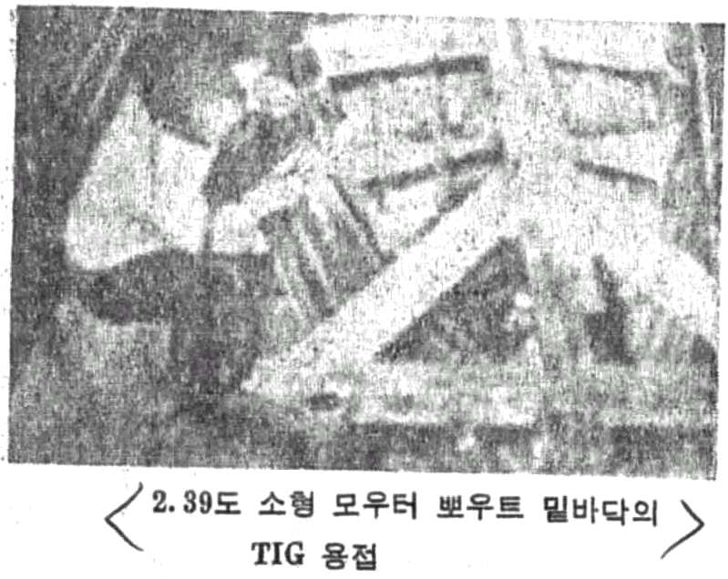
상품명으로는 헤리 아아크(Heli arc), 헤리용접(Heli weld), 알곤 아아크(Argon arc), 알곤 용접(Argou weld)등으로 부르고 있다.The trade name is called Heli arc, Heli weld, Argon arc, Argou weld and the like.
(MIG)용접은 텅그스텐 전극의 대신에 용가재의 전극선을 연속적으로(계속해서) 보내어 아아크를 발생시키는 방법으로 이너트 가스 금속 아아크용접(Inert-Gas Metal-Arc welding의 머리자를 따서 MIG) 또는 용극식 (Consumable;소모식) 이너트 가스 아아크용접이라고도 한다.(MIG) welding is a method in which the electrode wire of the filler metal is continuously (continuously) instead of the tungsten electrode to generate arc, or MIG, which is named after the head of Inert-Gas Metal-Arc welding. Also known as Consumable Inner Gas Arc Welding.
2.40도는 알미늄 합금제 탱크의 MIG용접을 하고 있는 것으로 바른손에 쥔 것이 토오치(Torch)이다.2.40 degrees is MIG welding of aluminum alloy tank. Torch is held in the right hand.
탄산가스 아아크용접(CO2 arc Welding)은 MIG용접의 이너트 가스의 대신으로 가격이 싼Co2가스를 사용하는 방식으로 최근 탄소강의 용접에 시험용으로 사용되어 장래성이 있는 용접방법으로 알려져 있다.Carbon dioxide arc welding (CO 2 arc welding) is a method of using a low-cost Co 2 gas in place of the inert gas of the MIG welding is known as a promising welding method recently used for testing the welding of carbon steel.
다음의 장점에 있어In the following advantages
이너트가스 아아크용접은 매우 우수한 용접방법으로 다음과 같은 장점을 가지고 있다.Inert gas arc welding is an excellent welding method and has the following advantages.
먼저 피복제와 후락스가 필요없다You don't need any coatings or fluxes first
일반적인 아아크용접이나 가스용접에서는 용융금속의 산화와 질화를 방지하기 위하여 피복제 혹은 후락스(flux)를 사용할 필요가 있으나 이너트가스 아아크용접에서는 이너트가스 중에서 용접하므로 그와 같은 필요가 없으며 또용접후 슬래그 혹은 잔류(사용하고 남은) 후락스를 제거하기 위해서 기계적 혹은 화학적 처리가 필요 없으므로 작업이 매우 간단하다.In general arc welding or gas welding, it is necessary to use a coating material or flux to prevent oxidation and nitriding of molten metal, but in inert gas arc welding, it is not necessary because such welding is performed in inert gas. The operation is very simple since no mechanical or chemical treatment is required to remove post slag or residual (after use) flux.
또 알미늄(Al), 마그네슘(Mg), 스테인레스강 등에서는 종래의 용접에서와 같이 잔류 후락스에 의하여 용접부가 부식될 염려는 전혀 없다.In addition, in aluminum (Al), magnesium (Mg), stainless steel, and the like, there is no fear of corrosion of the weld due to residual flax as in conventional welding.
이너트가스 아아크용접이 주로 경합금이나 스테인레스강에 사용되는 것은 이와같은 이유가 있기 때문이다.This is why inert gas arc welding is mainly used for light alloys or stainless steels.
다음은 전 자세의 용접이 쉬우며 능률이 좋다Next is easy welding and efficient
일반적으로 이너트가스 아아크용접의 아아크는 매우 안전하며 띰불꽃 튀김(spatter)이 적으며 조작이 비교적 쉽다.In general, the arc of the inert gas arc welding is very safe, there is little spatter and relatively easy to operate.
전 자세로 용접이 되며 더우기 열의 집중과 용접능률이 좋으므로 얇은 판에 사용하면 용접 속도가 빠르며 용접후의 변형이 적은 잇점이 있다.It is welded in all postures, moreover, heat concentration and welding efficiency are good, so when used in thin plates, the welding speed is fast and deformation after welding is small.
또 열전도(열을 옮기는 능률)가 좋은 동합금이나 경합금의 용접에 매우 유리하다.In addition, it is very advantageous for welding copper alloys and light alloys having good thermal conductivity (heat transfer efficiency).
써브멀지드 아아크용접(submerged-Arc Welding)인 때와는 달리 아아크나 용융지를 직접 보며, 용접할 수 있으므로 여러모로 유리하다.Unlike in submerged-arc welding, it is advantageous in many ways because it can directly see and weld the arc or melted paper.
세번째 용접된 물건의 품질이 우수하다The quality of the third welded object is excellent
이너트가스 아아크 용착부는 다른 아아크용접 혹은 가스용접의 용착부에 비하여 연성(늘어나는 성질), 강도(세기), 기밀성(금속 조진이 치밀한 것), 그리고 내식성(잘 부식되지 않는 성질)이 일반적으로 우수하다,Inner gas arc welding is generally superior in ductility (stretching), strength (strength), airtightness (dense metal coarsening), and corrosion resistance (not corrosive) compared to other arc welding or gas welding. Do,
이너트가스 아아크용접의 결점이라면 시설비가 다소 비싼 것과 이너트가스가 다소 비싼 것이지만 용접 작업비가 도리어 싸게드는 경우가 많으므로 오늘날에는 매우 많이 사용되어 알미늄합금, 마그네슘합금, 스테인레스강, 닉켈합금, 동합금, 탄소강과 저합금강의 용접, 그리고 표면 경화에 사용되어 특히 티탄합금, 질코늄합금 등 높은 온도에서 대기중의 산소나 질소에 접촉, 해를 받기 쉬운 금속의 용접에는 이너트가스 아아크용접만이 사용되는 것이다.The drawbacks of inert gas arc welding are that the cost of the facility is somewhat higher and the cost of the inner gas is somewhat higher. However, the welding work costs are often cheaper, so it is very widely used today. It is used for welding carbon steel and low alloy steel and surface hardening.Inner gas arc welding is only used for welding metals that are susceptible to contact with oxygen or nitrogen in the atmosphere at high temperatures such as titanium alloys and zirconia alloys. will be.
더우기 (TIG)용접은 일반적으로 판의 두께 0.6∼3mm의 얇은 판에 (MIG)용접은 약 3mm이상의 두꺼운 판에 적합하다.Moreover, TIG welding is generally suitable for thin plates with a thickness of 0.6 to 3 mm and MIG welding for thick plates of more than about 3 mm.
즉 (MIG)용접은 (TIG)용접보다 능률이 좋다.In other words, (MIG) welding is more efficient than (TIG) welding.
그에 대한 종류에 있어In kind about him
이너트가스 아아크용접과 이에 관련된 용접 방법을 크게 나누면 대략 다음과 같은 종류가 있다.Inner gas arc welding and related welding methods can be roughly classified into the following types.
TIG용접에는 아아크를 발생시키는 전극부분 즉 토오치(Torch)와 용접봉을 용접공이 손으로 조작하는 수동식(Manual), 그 대신에 기계를 사용하여 자동적으로 조작하는 전자동식(automatic), 용접봉의 공급은 모우터 (morter)로하고 토오치만을 손으로 조작하는 반자동식(Semiautomatic)등의 세 종류가 있다For TIG welding, the electrode part that generates arc, such as the torch and manual electrode operated by the welder by hand, instead of the automatic operation using the machine automatically, the supply of the electrode There are three types, such as semiautomatic, which is operated by a motor and only the torch is operated by hand.

또 연속적으로 긴 용접을 하는 대신 점과 같이 용접을 하는 아아크 스폿트 용접(arc spot welding)이 있으며 또 아아크 절단용에도 특이한 (TIG)토오치가 사용되고 있으며 이것들에 대해서는 순차적으로 다음에 설명한다.In addition, there is arc spot welding, in which spot welding is performed instead of continuous long welding, and a special (TIG) torch is also used for arc cutting.
더우기 (TIG)용접으로원자 수소 아아크용접(atomic hydrogen arc welding)과 같이 두 개의 텅그스텐 전극봉(tungsten rod) 사이에 아아크를 발생시켜 열원으로 하는 쌍극 아아크법(twin arc method)도 사용되고 있다.In addition, a twin arc method is also used in which a arc is generated between two tungsten rods as a heat source, such as atomic hydrogen arc welding.
(2) 불활성 가스 텅그스텐 아아크(TIG)용접(2) Inert gas tungsten arc (TIG) welding
1) 특 징1) Features
TIG용접에서는 교류 혹은 직류가 사용되며, 그 극성이 용접결과에 미치는 영향은 매우 크므로 이것에 대하여 다음에 설명하고자 한다.In TIG welding, alternating current or direct current is used. The influence of the polarity on the welding result is very large.
① 직류용접(D.C Welding)① D.C Welding
직류용접에 있어서 아아크 중을 흐르는 전자 (electron)와 이온(ion)의 흐름은 2.41도에 나타난 바와 같다.In direct current welding, the flow of electrons and ions flowing in the arc is shown in 2.41 degrees.
정극성에서는 금속 증기와 이너트가스의 이온은 전극에 향하고 전자는 모재를 강하게 충격하므로 용입은 집중적으로 깊게 된다.In the positive polarity, the ions of the metal vapor and the inert gas are directed to the electrode, and the electrons strongly impact the base metal, so the penetration is concentrated deeply.
전극은 속도가 느린 가스 이온의 충돌로서는 과히 발열(열을 일으키는 것)하지 않으므로 지름이 적어도 큰 전류를 흘릴 수 있다. (이하 설명 생략함)The electrode does not generate heat (generates heat) excessively due to the slow collision of gas ions, so that at least a large current can flow. (Omit description below)
대형화재이거나 태풍과, 해일 또는 지진의 유형별의 재난을 방지함을 방재라 일컬어 말함이며, 뱃속에 가득한 기생충,을 없애고, 모기 파리 벌레등 구충제를 살포하여 해충을 박멸함과 유해적조를 박멸하는 도구수단을 방제라 말함이며 본 발명에서는 "방재"와 "방제"를 확실하게 구분해서 분리 구분토록 한다. 상기 방재는 재 난발생전의 활동을 칭하고 방제는 재난발생후 재난복구시 활동을 칭하는 것이다.It is a large fire or a disaster that prevents disasters of each type of typhoon, tsunami or earthquake. It is a tool that eliminates the parasites in the stomach and sprays insect repellents such as mosquitoes, insects and insects to eradicate pests. Means are referred to as control, and in the present invention, "disaster prevention" and "control" are clearly distinguished and separated. The disaster prevention refers to the activity before the occurrence of disaster and the control refers to the activity at the time of disaster recovery after the occurrence of the disaster.
이상에서 설명한 본 발명은 전술한 실시예 및 첨부된 도면에 의해 한정되는 것이 아니고 본 발명의 기술적 사상을 벗어나지 않는 범위내에서 장비선택과 기술용어들이 단어는 다르지만 최종적으로 하는 역할은 같아서 비용이 적게들고 효율이 증가되는 방법으로 재충전하는 계기로서 본 발명이 속하는 기술분야에서 통상의 지식을 가진자에게 있어 명백할 것이며 대형산불과 근린생활구역의 대형화재를 분리구분지어서 재출원함을 다짐하면서 이세상의 모든 재난 재해 예방으로 재해로인한 고통과 슬픔을 제거하고 희망찬 내일을 기원하면서 종전의 수송장비에서 케이블카아로 전환되는 과정으로서 봉상식 관창은 각 탱크 청소기로 사용되고 근무자는 케이블카아로 소방방재를 이루게 된 무재해 지구촌 해양발전소 몸체(1) 발전기 생산전력(685)으로 수개의 관 레벨 시이소(935)형 크레인(861) 붐대(65)의 장치들을 지속적으로 사용할 수 있게 하는 것이다.The present invention described above is not limited to the above-described embodiments and the accompanying drawings, and equipment selection and technical terms are different in terms of words but ultimately lower in cost without departing from the technical spirit of the present invention. It is obvious to those of ordinary skill in the art to recharge in a way of increasing efficiency, and all the disasters of the world while vowing to redistribute large fires and large fires in neighboring living areas. Disaster prevention eliminates the pain and sorrows caused by disasters and hopes for a hopeful tomorrow, and is a process that transforms the cable car into a cable car. Body (1) with generator production power (685) Of tubes seesaw level to 935-
이와 같이, 본 발명의 상세한 설명에서는 구체적인 실시예에 관해 설명하였으나, 이는 본 발명의 범주에서 벗어나지 않는 한도내에서 여러가지 변형이 가능함은 물론이거니와 도면에서 방재물질과 발화물질의 방재는 종전에 개발된 기술분야는 본 구성을 설명을 하기 위함인데 본 출원은 산업재해로 상세불명의 만성질환으로 재활장비를 배부에 장착하여 생명의 노끈마감 그 순간이나마 지구촌이 무재해로서 만년지대계로 계승발전 그에 대한 순간을 만끽하고져 하는 것으로 무재해 지구촌 해양발전소의 관 레벨 시소형 풍수력발전기를 구성하였다.As described above, in the detailed description of the present invention has been described with respect to specific embodiments, which can be modified in various ways without departing from the scope of the present invention, as well as the disaster prevention material and the disaster prevention of the ignition material in the drawings is a technique that has been developed before The field is intended to explain this configuration, but this application is equipped with rehabilitation equipment on the back of a chronic disease, which is unspecified due to industrial accidents. In this regard, it constituted a pipe-level seesaw type wind power generator of a global disaster-free marine power plant.
그러므로 본 발명의 실질적인 범위는 상술된 실시예에 의해 한정되어져서는 안되며, 후술하는 청구범위 뿐만 아니라 청구범위와 균등한 구성에 의해 정해져야함은 물론이거니와 지구촌에는 재해가 없도록 소화활동은 한순간을 다투는 것으로 1초 늦어짐에 따라서 큰불로 확산되기 때문에 1초 이내로 해양발전소 몸체(1) 내부에 형성된 관노즐이동형 소방센서펌프로 작은불일때에 그 즉시 발화물체(연소물)을 불연성 가스 또는 황토혼합물을 사용하여 1초 이내로 연소물을 에워싸 산소(공기)공급을 차단하여 질식작용과 냉각작용으로 사전예방 소화하는 것과 동일하게 해양발전소 몸체(1) 내부에 형성된 관 교량(937) 시이소(935) 크레인(861) 붐대(651) 수개로 재해 일체를 소멸 제거하는 것이 바람직하다Therefore, the practical scope of the present invention should not be limited by the above-described embodiments, and should be defined by the claims and equivalent configurations as well as the claims described below. As it is spread by a large fire as it is delayed, it is a pipe-nozzle mobile type fire sensor pump formed inside the body of the marine power plant within 1 second.In case of a small fire, the ignitable body (combustibles) is immediately replaced with a nonflammable gas or an ocher mixture. The
이상과 같이 구성되는 본 발명은 무재해 지구촌 해양발전소 몸체(1) 내부에는 종전의 화재감지수단인 스프링쿨라 헤드(111)가 건물 또는 산불방지용으로 높고 낮은산(395)에 화재감지수단으로 종전에 구성되어 현재 설치된 곳도 있고 없는 곳이 많아 스프링쿨러 헤드(111)는 화재감지수단 그 자체일뿐 그외의 효과를 기대할 수 없기 때문으로 신규한 감지수단 즉, 화재발생시 불씨(292)와 불꽃(293)제거겸용의 화재열 감지센서인 감지노끈(41)과 파라핀이 부착된 분사식 소방관노즐(10)에 불씨(292)와 불꽃(293)이 접근이 되면서 화재발생전에는 배관 또는 물호스로서 배관구경(분출수 관로) 또는 호스구경(분출수 가공틈새 및 홀) 그 자체가 노즐로서 배관 또는 호스 내부 정체된 수압상태로 상수도 꼭지수도물로 초기진화되면서 수도물 공급중단시 샘, 계곡의 물을 음용수로 이용하는 장치로서 주민의 삶을 향상시키게 되는 계기로써 감지수단이며 화재가 발생되지 않으면 발화물질과 방재물질은 평 온을 유지하는 것으로서 화재발생과 동시에 발화물체(촛불(166) 또는 성냥불(166))로도 저온감지가 빠른 고체 파라핀 노즐마개(100)가 발화물체의 불꽃(293)인 화재열에 의해 녹으면서 노즐마개로 밀폐된 노즐이 개방되면서 소방호스(9)와 소방관노즐몸체(B) 내부에 마이크로펌프8와 수격펌프(393) 또는 에어콤프레샤(80)와 고성능엔진 수중펌프(36) 작동으로 압축 저장된 방재물질인 기체, 액체, 고체로된 혼합물질이 불씨에 의해 불꽃으로 불기둥으로 확산되지 않도록 화재발생시 그 즉시 감지하여 일직선 노즐틈새(15) 또는 방사선 노즐틈새(15)와, 삼각형 노즐틈새(15)에 원형형식의 노즐틈새(15)로 수직 수평의 노즐틈새(15)에서 방출되는 토출분사수(38)와 커텐물막(39)은 화재발생시 죽음의 질식가스(163)와 발화물체(166)로부터 인명(목숨)이 구제되고 건물파손 방지와 함께 흉년드는 세상에는 쌀이되어 구제하고 모진 질병 돌적에는 약풀되어 치료되게끔 수개의 바지선 본체(1)의 사이드 측면에 탑재 형성 크레인(861) 붐대(붐대길이 최대 20km, 651) 내부에 부착된 무동력펌프(393)와 막펌프(다이어후렘펌프, 144)로도 방재 및 방제효과를 기대할 수 있게 하여 해저수심 10km 지점의 관 교량(937) 터넬(929)에 교각(928)을 설치할 수 있게 수개의 건설기계가 형성되는 효과가 기대된다.The present invention constituted as described above is a
본 발명 무재해 지구촌 해양발전소 몸체(1)의 갑판데크 상단에 탑재 형성된 소방방재대책용품의 관노즐이동형 소방센서펌프는 소방케이블카아(256)의 타구어윈치(137)로 형성된 운전 조작에 의해 발전소몸체(1)내부의 대형산불과 대형화재(A화재, B, C화재) 일체로 인명구조 및 초기진화 후 황사발생방지와 폭설, 태풍, 폭서, 홍수와 가뭄, 산사태 방지와 1초 이내로 대형산불과 대형화재를 사전예방하고 황토 혼합물인 흙탕물로 소방방재와 벌레곤충의 대번식을 차단하는 소방방제 및 소방방재 제어장치로서 지구촌의 무재해 지구촌 해양발전소 몸체(1)의 내부에 해양산업발전용품 신소재 건설기계 일체와 소방방재대책용품으로 탑재하게 되는 무재해 지구촌 해양발전소의 관 레벨 시소형 풍수력발전기를 구성시키는 효과를 볼 수 있다.The pipe nozzle moving type fire sensor pump of the fire prevention measures prepared on the deck deck of the present invention without a disaster global marine power plant body (1) is the power plant body by the operation operation formed by the
Claims (3)
Priority Applications (1)
| Application Number | Priority Date | Filing Date | Title |
|---|---|---|---|
| KR1020090117757A KR20100027087A (en) | 2009-11-30 | 2009-11-30 | For the ocean a generating plant in global village zero calmity tidal power generator used with in it's a level pipes seesow type |
Applications Claiming Priority (1)
| Application Number | Priority Date | Filing Date | Title |
|---|---|---|---|
| KR1020090117757A KR20100027087A (en) | 2009-11-30 | 2009-11-30 | For the ocean a generating plant in global village zero calmity tidal power generator used with in it's a level pipes seesow type |
Publications (1)
| Publication Number | Publication Date |
|---|---|
| KR20100027087A true KR20100027087A (en) | 2010-03-10 |
Family
ID=42178232
Family Applications (1)
| Application Number | Title | Priority Date | Filing Date |
|---|---|---|---|
| KR1020090117757A Ceased KR20100027087A (en) | 2009-11-30 | 2009-11-30 | For the ocean a generating plant in global village zero calmity tidal power generator used with in it's a level pipes seesow type |
Country Status (1)
| Country | Link |
|---|---|
| KR (1) | KR20100027087A (en) |
Cited By (38)
| Publication number | Priority date | Publication date | Assignee | Title |
|---|---|---|---|---|
| KR20160009275A (en) | 2014-07-16 | 2016-01-26 | 지앤지 주식회사 | Multifunctional barge |
| KR20160061931A (en) | 2016-05-13 | 2016-06-01 | 이우성 | Reactor equipment of distribution input device for the treatment of nuclear waste in the ocean nuclear power plant with a block tank dust collector of the dual structure |
| KR20160079738A (en) * | 2016-06-17 | 2016-07-06 | 이우성 | Public water landfill construction machinery of distribution input apparatus and the public land of the landfill body |
| KR20160093580A (en) * | 2016-07-19 | 2016-08-08 | 이우성 | Public water landfill of fisheries development apparatus even the ocean with a tunnel of traffic equipment |
| KR20160101884A (en) * | 2016-08-08 | 2016-08-26 | 이우성 | Marine products cultivation marine products and public water landfill construction machinery of seafood processing equipment |
| KR20160118166A (en) | 2016-09-21 | 2016-10-11 | 이우성 | Mold to produce the currency and the currency of the anti-counter feit control of free trade distribution for the international community commerce |
| KR20160132349A (en) | 2016-10-31 | 2016-11-18 | 이우성 | Manufacturing of the ship corresponding to the ship and the par Bull jet capital of lifesaving entanglement preventing |
| KR20170001964A (en) | 2015-06-29 | 2017-01-06 | 이우성 | Adjusting the distribution chute flood flood regulation machinery equipment |
| KR20170008875A (en) | 2017-01-04 | 2017-01-24 | 이우성 | Pressurized water nuclear reactor for nuclear disposal |
| KR20170012495A (en) | 2017-01-13 | 2017-02-02 | 이우성 | Reactor facility of fast breeder reactor for the treatment of nuclear waste |
| KR20170012880A (en) | 2017-01-16 | 2017-02-03 | 이우성 | Gas cooling reactor facilities for the treatment of nuclear waste |
| KR20170015393A (en) | 2017-01-19 | 2017-02-08 | 이우성 | Nuclear reactor facilities for new type conversion for the treatment of nuclear waste |
| KR20170015945A (en) | 2017-01-23 | 2017-02-10 | 이우성 | Multipurpose high temperature gas furnace reactor equipment for the treatment of nuclear waste |
| KR20170018860A (en) | 2017-01-31 | 2017-02-20 | 이우성 | Boiling water nuclear reactor facility for treatment of nuclear waste |
| CN108869155A (en) * | 2018-08-01 | 2018-11-23 | 柏转 | The siphon drainage high-efficiency turbine generating equipment of waste water can be handled |
| CN109006060A (en) * | 2018-10-10 | 2018-12-18 | 云南涵乾农业科技有限公司 | A kind of fertigation intelligent control photovoltaic green-house |
| KR20190089483A (en) | 2018-01-23 | 2019-07-31 | 이우성 | Treatment of nuclear waste exclusively for ocean won Pressurized water double structure nuclear reactor equipment |
| CN110566448A (en) * | 2019-07-22 | 2019-12-13 | 浙江亚特电器有限公司 | oil quantity adjustable oil pump structure for chain saw and chain saw |
| CN111505585A (en) * | 2019-12-10 | 2020-08-07 | 南京恩瑞特实业有限公司 | Novel vehicle-mounted radar flip mechanism |
| CN112198508A (en) * | 2020-10-29 | 2021-01-08 | 中国人民武装警察部队工程大学 | A Radar Target Imaging and Recognition Method Based on Support Set Constraints |
| CN112629224A (en) * | 2021-01-29 | 2021-04-09 | 黑龙江赫尔特生物质能源发展有限公司 | Device capable of continuously drying rod-shaped biomass bales with different shapes and sizes |
| CN113459522A (en) * | 2020-03-30 | 2021-10-01 | 金华市胜昌科技股份有限公司 | Ear belt mechanism on mask |
| US11180263B2 (en) | 2020-04-06 | 2021-11-23 | Workhorse Group Inc. | Flying vehicle systems and methods |
| CN113989061A (en) * | 2021-11-15 | 2022-01-28 | 内蒙古沃付国际物联网有限公司 | Intelligent water supply method and system applied to livestock |
| CN114091368A (en) * | 2021-10-28 | 2022-02-25 | 西安理工大学 | Method for identifying cavitation state of axial flow turbine |
| CN114132474A (en) * | 2021-11-26 | 2022-03-04 | 江苏海事职业技术学院 | Ship power cabin cooling system for cooling by seawater series flow |
| CN115349591A (en) * | 2021-05-17 | 2022-11-18 | 宜昌九鼎牧业有限公司 | Pig feed raw material silo with cooling and dehumidifying functions and method |
| CN115463990A (en) * | 2022-09-19 | 2022-12-13 | 西北有色金属研究院 | Preparation method of high-quality micron-sized TA2 foil for aerospace engineering |
| CN115506402A (en) * | 2022-09-23 | 2022-12-23 | 上海电器科学研究所(集团)有限公司 | An emergency flood control system for underground pipe gallery |
| CN115929281A (en) * | 2022-12-30 | 2023-04-07 | 中国海洋石油集团有限公司 | Water curtain drilling layout method for underground water-sealed caverns |
| CN116242415A (en) * | 2022-12-16 | 2023-06-09 | 国网宁夏电力有限公司超高压公司 | Method, medium and system for monitoring breathing of oil pillow in oil-filled equipment |
| CN116594308A (en) * | 2023-06-20 | 2023-08-15 | 聊城大学 | Robust asynchronous control method for time-delay turbine regulation system with pulse perturbation |
| CN116628610A (en) * | 2023-05-23 | 2023-08-22 | 湖北清江水电开发有限责任公司 | Hydraulic generator brake air brake abrasion analysis system |
| CN117313239A (en) * | 2023-09-25 | 2023-12-29 | 江苏天兵航天科技有限公司 | A method and device for determining parameters of all-weather rocket kerosene storage tanks in a shooting range environment |
| CN119390252A (en) * | 2024-12-13 | 2025-02-07 | 三峡环境科技有限公司 | Rotating tower multi-stage tidal flow artificial wetland system and sewage treatment method |
| CN119419956A (en) * | 2024-11-04 | 2025-02-11 | 世拓能源技术有限公司 | How the power generation system works |
| US12379024B1 (en) | 2024-05-02 | 2025-08-05 | Ford Global Technologies, Llc | Vent device |
| CN120427082A (en) * | 2025-05-23 | 2025-08-05 | 江苏省太湖地区水利工程管理处 | Water level early warning device for water conservancy projects |
-
2009
- 2009-11-30 KR KR1020090117757A patent/KR20100027087A/en not_active Ceased
Cited By (55)
| Publication number | Priority date | Publication date | Assignee | Title |
|---|---|---|---|---|
| KR20160009275A (en) | 2014-07-16 | 2016-01-26 | 지앤지 주식회사 | Multifunctional barge |
| KR20170001964A (en) | 2015-06-29 | 2017-01-06 | 이우성 | Adjusting the distribution chute flood flood regulation machinery equipment |
| KR20160061931A (en) | 2016-05-13 | 2016-06-01 | 이우성 | Reactor equipment of distribution input device for the treatment of nuclear waste in the ocean nuclear power plant with a block tank dust collector of the dual structure |
| KR20160079738A (en) * | 2016-06-17 | 2016-07-06 | 이우성 | Public water landfill construction machinery of distribution input apparatus and the public land of the landfill body |
| KR20160093580A (en) * | 2016-07-19 | 2016-08-08 | 이우성 | Public water landfill of fisheries development apparatus even the ocean with a tunnel of traffic equipment |
| KR20160101884A (en) * | 2016-08-08 | 2016-08-26 | 이우성 | Marine products cultivation marine products and public water landfill construction machinery of seafood processing equipment |
| KR20160118166A (en) | 2016-09-21 | 2016-10-11 | 이우성 | Mold to produce the currency and the currency of the anti-counter feit control of free trade distribution for the international community commerce |
| KR20160132349A (en) | 2016-10-31 | 2016-11-18 | 이우성 | Manufacturing of the ship corresponding to the ship and the par Bull jet capital of lifesaving entanglement preventing |
| KR20170008875A (en) | 2017-01-04 | 2017-01-24 | 이우성 | Pressurized water nuclear reactor for nuclear disposal |
| KR20170012495A (en) | 2017-01-13 | 2017-02-02 | 이우성 | Reactor facility of fast breeder reactor for the treatment of nuclear waste |
| KR20170012880A (en) | 2017-01-16 | 2017-02-03 | 이우성 | Gas cooling reactor facilities for the treatment of nuclear waste |
| KR20170015393A (en) | 2017-01-19 | 2017-02-08 | 이우성 | Nuclear reactor facilities for new type conversion for the treatment of nuclear waste |
| KR20170015945A (en) | 2017-01-23 | 2017-02-10 | 이우성 | Multipurpose high temperature gas furnace reactor equipment for the treatment of nuclear waste |
| KR20170018860A (en) | 2017-01-31 | 2017-02-20 | 이우성 | Boiling water nuclear reactor facility for treatment of nuclear waste |
| KR20190089483A (en) | 2018-01-23 | 2019-07-31 | 이우성 | Treatment of nuclear waste exclusively for ocean won Pressurized water double structure nuclear reactor equipment |
| CN108869155A (en) * | 2018-08-01 | 2018-11-23 | 柏转 | The siphon drainage high-efficiency turbine generating equipment of waste water can be handled |
| CN109006060A (en) * | 2018-10-10 | 2018-12-18 | 云南涵乾农业科技有限公司 | A kind of fertigation intelligent control photovoltaic green-house |
| CN110566448A (en) * | 2019-07-22 | 2019-12-13 | 浙江亚特电器有限公司 | oil quantity adjustable oil pump structure for chain saw and chain saw |
| CN110566448B (en) * | 2019-07-22 | 2024-05-07 | 浙江亚特电器股份有限公司 | Oil pump structure with adjustable oil quantity for chain saw and chain saw |
| CN111505585A (en) * | 2019-12-10 | 2020-08-07 | 南京恩瑞特实业有限公司 | Novel vehicle-mounted radar flip mechanism |
| CN113459522A (en) * | 2020-03-30 | 2021-10-01 | 金华市胜昌科技股份有限公司 | Ear belt mechanism on mask |
| US11407527B2 (en) | 2020-04-06 | 2022-08-09 | Workhorse Group Inc. | Flying vehicle systems and methods |
| US11787563B2 (en) | 2020-04-06 | 2023-10-17 | Workhorse Group Inc. | Unmanned aerial vehicle including equipment mounted in recessed seat of apex support structure |
| US12037137B2 (en) | 2020-04-06 | 2024-07-16 | Workhorse Group Inc. | Flying vehicle systems and methods |
| US11254446B2 (en) | 2020-04-06 | 2022-02-22 | Workhorse Group Inc. | Flying vehicle systems and methods |
| US11787564B2 (en) | 2020-04-06 | 2023-10-17 | Workhorse Group Inc. | Carriage lock mechanism for an unmanned aerial vehicle |
| US12030668B2 (en) | 2020-04-06 | 2024-07-09 | Workhorse Group Inc. | Flying vehicle systems and methods |
| US11332264B2 (en) | 2020-04-06 | 2022-05-17 | Workhorse Group Inc. | Flying vehicle systems and methods |
| US11370561B2 (en) | 2020-04-06 | 2022-06-28 | Workhouse Group Inc. | Flying vehicle systems and methods |
| US11383859B1 (en) | 2020-04-06 | 2022-07-12 | Workhorse Group Inc. | Flying vehicle systems and methods |
| US11180263B2 (en) | 2020-04-06 | 2021-11-23 | Workhorse Group Inc. | Flying vehicle systems and methods |
| US11472572B2 (en) | 2020-04-06 | 2022-10-18 | Workhorse Group Inc. | Flying vehicle systems and methods |
| US11485518B2 (en) * | 2020-04-06 | 2022-11-01 | Workhorse Group Inc. | Flying vehicle systems and methods |
| US11498701B2 (en) | 2020-04-06 | 2022-11-15 | Workhorse Group Inc. | Flying vehicle systems and methods |
| US11820533B2 (en) | 2020-04-06 | 2023-11-21 | Workhorse Group Inc. | Flying vehicle systems and methods |
| US11603219B2 (en) | 2020-04-06 | 2023-03-14 | Workhorse Group Inc | Flying vehicle systems and methods |
| CN112198508A (en) * | 2020-10-29 | 2021-01-08 | 中国人民武装警察部队工程大学 | A Radar Target Imaging and Recognition Method Based on Support Set Constraints |
| CN112629224A (en) * | 2021-01-29 | 2021-04-09 | 黑龙江赫尔特生物质能源发展有限公司 | Device capable of continuously drying rod-shaped biomass bales with different shapes and sizes |
| CN115349591B (en) * | 2021-05-17 | 2024-01-02 | 宜昌九鼎牧业有限公司 | Pig feed raw material silo with cooling and dehumidifying functions and method |
| CN115349591A (en) * | 2021-05-17 | 2022-11-18 | 宜昌九鼎牧业有限公司 | Pig feed raw material silo with cooling and dehumidifying functions and method |
| CN114091368A (en) * | 2021-10-28 | 2022-02-25 | 西安理工大学 | Method for identifying cavitation state of axial flow turbine |
| CN113989061A (en) * | 2021-11-15 | 2022-01-28 | 内蒙古沃付国际物联网有限公司 | Intelligent water supply method and system applied to livestock |
| CN114132474B (en) * | 2021-11-26 | 2023-10-10 | 江苏海事职业技术学院 | Ship power cabin cooling system using seawater flow for cooling |
| CN114132474A (en) * | 2021-11-26 | 2022-03-04 | 江苏海事职业技术学院 | Ship power cabin cooling system for cooling by seawater series flow |
| CN115463990A (en) * | 2022-09-19 | 2022-12-13 | 西北有色金属研究院 | Preparation method of high-quality micron-sized TA2 foil for aerospace engineering |
| CN115506402A (en) * | 2022-09-23 | 2022-12-23 | 上海电器科学研究所(集团)有限公司 | An emergency flood control system for underground pipe gallery |
| CN116242415A (en) * | 2022-12-16 | 2023-06-09 | 国网宁夏电力有限公司超高压公司 | Method, medium and system for monitoring breathing of oil pillow in oil-filled equipment |
| CN115929281A (en) * | 2022-12-30 | 2023-04-07 | 中国海洋石油集团有限公司 | Water curtain drilling layout method for underground water-sealed caverns |
| CN116628610A (en) * | 2023-05-23 | 2023-08-22 | 湖北清江水电开发有限责任公司 | Hydraulic generator brake air brake abrasion analysis system |
| CN116594308A (en) * | 2023-06-20 | 2023-08-15 | 聊城大学 | Robust asynchronous control method for time-delay turbine regulation system with pulse perturbation |
| CN117313239A (en) * | 2023-09-25 | 2023-12-29 | 江苏天兵航天科技有限公司 | A method and device for determining parameters of all-weather rocket kerosene storage tanks in a shooting range environment |
| US12379024B1 (en) | 2024-05-02 | 2025-08-05 | Ford Global Technologies, Llc | Vent device |
| CN119419956A (en) * | 2024-11-04 | 2025-02-11 | 世拓能源技术有限公司 | How the power generation system works |
| CN119390252A (en) * | 2024-12-13 | 2025-02-07 | 三峡环境科技有限公司 | Rotating tower multi-stage tidal flow artificial wetland system and sewage treatment method |
| CN120427082A (en) * | 2025-05-23 | 2025-08-05 | 江苏省太湖地区水利工程管理处 | Water level early warning device for water conservancy projects |
Similar Documents
| Publication | Publication Date | Title |
|---|---|---|
| KR20100027087A (en) | For the ocean a generating plant in global village zero calmity tidal power generator used with in it's a level pipes seesow type | |
| KR101570665B1 (en) | Flood disaster control system | |
| KR101799861B1 (en) | Flood damage adjustment distribution input device | |
| KR20150138126A (en) | Nuclear Waste double block structure, the dust collector tank boiling water reactor nuclear power plant equipment for nuclear power plants | |
| KR20140094482A (en) | Global nuclear power reactors of different types of body hydroelectric plants operating nuclear power plant reactor shield alternative nuclear waste disposal facility for nuclear reactor radiation leak precipitator control dual structure of the main body of the block distribution feeder tank | |
| KR20120066690A (en) | Ocean tunnel traffic equipment system using buoyancying of duplication structure of block pipes | |
| KR102733651B1 (en) | Underground Water Flood Control Equipment | |
| KR20150138127A (en) | Nuclear waste disposal in the nuclear power plant facilities dual structure for pressurized water reactor nuclear power plant | |
| KR20090115096A (en) | Nozzle movement type fire-fighting sensor pump of disaster prevention fire prevention measure goods | |
| CN104295448A (en) | All-weather clean energy comprehensive electricity generating and energy saving method and facility manufacturing method thereof | |
| KR20140094481A (en) | Peace retained reclamation construction machinery processing unit which is equipped with | |
| KR20150138129A (en) | Nuclear Waste Nuclear Power Plant reactors equipped with dual structure for high-speed growth of nuclear power plants | |
| KR20150138128A (en) | The dual structure of a nuclear waste disposal facility for nuclear power plant nuclear power plant multi-purpose high-temperature gas reactors | |
| KR20180017061A (en) | Distribution input device for marine products | |
| KR20180083280A (en) | Dispensing device of aquaculture farm with construction machinery | |
| KR20170081589A (en) | Typhoon Disaster Discharge Distribution Input Device | |
| KR20160093580A (en) | Public water landfill of fisheries development apparatus even the ocean with a tunnel of traffic equipment | |
| KR20200099259A (en) | Tsunami disaster prevention dispensing device | |
| KR20070106596A (en) | Harmful relief equipment and comprehensive disaster prevention system for marine disaster prevention and marine environment industry development. | |
| KR20150138130A (en) | The dual structure of a nuclear waste disposal facility for nuclear power plants switch to the new nuclear power plant reactors | |
| KR20180019134A (en) | Dual-structure fast reactor breeder reactor facility for ocean won private nuclear waste treatment | |
| KR20170043487A (en) | Marine steel works with metal smelting furnaces and construction machinery | |
| KR20160132349A (en) | Manufacturing of the ship corresponding to the ship and the par Bull jet capital of lifesaving entanglement preventing | |
| JP6829688B2 (en) | A system that collects energy from moving mass | |
| KR20150138131A (en) | The dual structure of the gas cooled reactor nuclear waste disposal facility for nuclear power plant nuclear power plant |
Legal Events
| Date | Code | Title | Description |
|---|---|---|---|
| A201 | Request for examination | ||
| PA0109 | Patent application |
Patent event code: PA01091R01D Comment text: Patent Application Patent event date: 20091130 |
|
| PA0201 | Request for examination | ||
| PG1501 | Laying open of application | ||
| E902 | Notification of reason for refusal | ||
| PE0902 | Notice of grounds for rejection |
Comment text: Notification of reason for refusal Patent event date: 20110731 Patent event code: PE09021S01D |
|
| E601 | Decision to refuse application | ||
| PE0601 | Decision on rejection of patent |
Patent event date: 20120329 Comment text: Decision to Refuse Application Patent event code: PE06012S01D Patent event date: 20110731 Comment text: Notification of reason for refusal Patent event code: PE06011S01I |