KR20100015018A - Suction adapter for syringe - Google Patents
Suction adapter for syringe Download PDFInfo
- Publication number
- KR20100015018A KR20100015018A KR1020080075898A KR20080075898A KR20100015018A KR 20100015018 A KR20100015018 A KR 20100015018A KR 1020080075898 A KR1020080075898 A KR 1020080075898A KR 20080075898 A KR20080075898 A KR 20080075898A KR 20100015018 A KR20100015018 A KR 20100015018A
- Authority
- KR
- South Korea
- Prior art keywords
- needle
- syringe
- suction adapter
- space portion
- space
- Prior art date
- Legal status (The legal status is an assumption and is not a legal conclusion. Google has not performed a legal analysis and makes no representation as to the accuracy of the status listed.)
- Ceased
Links
- 238000002347 injection Methods 0.000 claims description 37
- 239000007924 injection Substances 0.000 claims description 37
- 239000007788 liquid Substances 0.000 claims description 13
- 238000000034 method Methods 0.000 claims description 9
- 210000003491 skin Anatomy 0.000 description 29
- 239000000243 solution Substances 0.000 description 10
- 239000002537 cosmetic Substances 0.000 description 3
- 238000005192 partition Methods 0.000 description 3
- 238000010586 diagram Methods 0.000 description 2
- 230000002500 effect on skin Effects 0.000 description 2
- 210000002615 epidermis Anatomy 0.000 description 2
- 239000000945 filler Substances 0.000 description 2
- 239000003053 toxin Substances 0.000 description 2
- 231100000765 toxin Toxicity 0.000 description 2
- 108700012359 toxins Proteins 0.000 description 2
- 230000000694 effects Effects 0.000 description 1
- 230000002708 enhancing effect Effects 0.000 description 1
- 238000012856 packing Methods 0.000 description 1
- 229910052710 silicon Inorganic materials 0.000 description 1
- 239000010703 silicon Substances 0.000 description 1
- 239000004575 stone Substances 0.000 description 1
Images


Classifications
-
- A—HUMAN NECESSITIES
- A61—MEDICAL OR VETERINARY SCIENCE; HYGIENE
- A61M—DEVICES FOR INTRODUCING MEDIA INTO, OR ONTO, THE BODY; DEVICES FOR TRANSDUCING BODY MEDIA OR FOR TAKING MEDIA FROM THE BODY; DEVICES FOR PRODUCING OR ENDING SLEEP OR STUPOR
- A61M5/00—Devices for bringing media into the body in a subcutaneous, intra-vascular or intramuscular way; Accessories therefor, e.g. filling or cleaning devices, arm-rests
- A61M5/42—Devices for bringing media into the body in a subcutaneous, intra-vascular or intramuscular way; Accessories therefor, e.g. filling or cleaning devices, arm-rests having means for desensitising skin, for protruding skin to facilitate piercing, or for locating point where body is to be pierced
- A61M5/425—Protruding skin to facilitate piercing, e.g. vacuum cylinders, vein immobilising means
-
- A—HUMAN NECESSITIES
- A61—MEDICAL OR VETERINARY SCIENCE; HYGIENE
- A61M—DEVICES FOR INTRODUCING MEDIA INTO, OR ONTO, THE BODY; DEVICES FOR TRANSDUCING BODY MEDIA OR FOR TAKING MEDIA FROM THE BODY; DEVICES FOR PRODUCING OR ENDING SLEEP OR STUPOR
- A61M5/00—Devices for bringing media into the body in a subcutaneous, intra-vascular or intramuscular way; Accessories therefor, e.g. filling or cleaning devices, arm-rests
- A61M5/178—Syringes
- A61M5/31—Details
- A61M5/32—Needles; Details of needles pertaining to their connection with syringe or hub; Accessories for bringing the needle into, or holding the needle on, the body; Devices for protection of needles
- A61M5/3287—Accessories for bringing the needle into the body; Automatic needle insertion
-
- A—HUMAN NECESSITIES
- A61—MEDICAL OR VETERINARY SCIENCE; HYGIENE
- A61M—DEVICES FOR INTRODUCING MEDIA INTO, OR ONTO, THE BODY; DEVICES FOR TRANSDUCING BODY MEDIA OR FOR TAKING MEDIA FROM THE BODY; DEVICES FOR PRODUCING OR ENDING SLEEP OR STUPOR
- A61M5/00—Devices for bringing media into the body in a subcutaneous, intra-vascular or intramuscular way; Accessories therefor, e.g. filling or cleaning devices, arm-rests
- A61M5/178—Syringes
- A61M5/31—Details
- A61M5/32—Needles; Details of needles pertaining to their connection with syringe or hub; Accessories for bringing the needle into, or holding the needle on, the body; Devices for protection of needles
- A61M5/3295—Multiple needle devices, e.g. a plurality of needles arranged coaxially or in parallel
- A61M5/3298—Needles arranged in parallel
Landscapes
- Health & Medical Sciences (AREA)
- Vascular Medicine (AREA)
- Dermatology (AREA)
- Engineering & Computer Science (AREA)
- Anesthesiology (AREA)
- Biomedical Technology (AREA)
- Heart & Thoracic Surgery (AREA)
- Hematology (AREA)
- Life Sciences & Earth Sciences (AREA)
- Animal Behavior & Ethology (AREA)
- General Health & Medical Sciences (AREA)
- Public Health (AREA)
- Veterinary Medicine (AREA)
- Infusion, Injection, And Reservoir Apparatuses (AREA)
Abstract
본 발명은 주사기의 니들과 니들허브에 장착되는 주사기용 석션어댑터에 관한 것이다. 본 발명에 따른 주사기용 석션어댑터는, 니들과 니들허브로 이루어진 주사기바늘에 결합되고 주사될 피부부위에 음압(陰壓)을 가할 수 있도록 공기흡입기에 연결하여 사용하는 것으로, 니들허브가 수용되는 제1공간부와, 니들허브에 결합되는 니들이 돌출될 수 있도록 제1공간부에 연통되는 관통공 및 상면이 개방된 제2공간부; 및 제2공간부와 연통되어 상기 공기흡입기와 연결되는 공기흡입기 연결부를 포함하여 이루어진다. The present invention relates to a suction adapter for a syringe mounted to a needle of a syringe and a needle hub. The suction adapter for a syringe according to the present invention is coupled to a syringe needle made of a needle and a needle hub, and is used by being connected to an air inhaler so that a negative pressure can be applied to the skin portion to be injected. A second space portion having a through hole and an upper surface communicating with the first space portion so that the first space portion and the needle coupled to the needle hub protrude; And an air intake connecting part connected to the second space part and connected to the air intake.
Description
본 발명의 주사기의 니들과 니들허브에 장착되는 주사기용 석션어댑터에 관한 것으로서, 보다 상세하게는 피부의 굴곡에 주사할 때 음압(陰壓)을 이용하여 피부를 니들 방향으로 상승시킴으로써 원하는 피부깊이에 주사액을 삽입시키기 위한 주사기용 석션어댑터에 관한 것이다.The present invention relates to a suction adapter for a syringe mounted to a needle and a needle hub of the syringe of the present invention, and more specifically, to a desired skin depth by raising the skin in the direction of the needle by using negative pressure when injected into the curve of the skin. A suction adapter for a syringe for inserting an injection solution.
일반적인 주사기는 노즐이 형성되는 실린더와 실린더의 내부에 장착되는 피스톤, 피스톤의 선단에 결합 되는 패킹으로 구성된다. A common syringe consists of a cylinder in which a nozzle is formed, a piston mounted inside the cylinder, and a packing coupled to the tip of the piston.
실린더의 내부에는 주사액이 저장되고, 노즐 방향으로 주사액을 가압하는 피스톤에 의해 주사액은 실린더의 노즐을 통해 주사기 밖으로 분출되며, 주사액을 인체 등에 주입하기 위해서는 주사기의 노즐에 니들(needle)과 니들허브로 이루어지는 주사기바늘을 결합시키게 된다. The injection liquid is stored inside the cylinder, and the injection liquid is ejected out of the syringe through the nozzle of the cylinder by pressurizing the injection liquid in the direction of the nozzle.In order to inject the injection liquid into the human body, a needle and a needle hub are inserted into the nozzle of the syringe. The needle is made to combine.
주사기를 이용하여 주사액을 인체에 직접 투여하는 방법은 종래부터 환자의 치료에 광범위하게 사용된 방법이었으나, 최근에는 미용 및 성형 분야에까지 확장되어 필러 및 톡신과 같은 주사액을 이용하는 주사 시술 방법이 사용되고 있다. The method of directly administering the injection solution to the human body using a syringe has been widely used in the treatment of patients in the past, but recently, the injection procedure method using injection solutions such as fillers and toxins has been extended to the cosmetic and cosmetic fields.
이러한, 주사기를 사용함에 있어 주사액이 삽입되는 위치 및 깊이는 피시술자의 상태, 주사액의 종류 및 피시술자의 상태에 따라 상이한데 이러한 미용 및 성형분야의 주사 시술방법은 주사기를 이용하여 주사액을 피부의 진피층과 지방층 사이에 주입하는 것으로, 정확한 깊이로 주사액을 주입하지 않으면 주사액의 효과가 감소되므로 숙련된 기술과 고도의 집중력을 필요로 하게 된다. 뿐만 아니라 피스톤을 가압하여 주사액을 주입하는 단계에서 해당 부위의 피부층이 눌리게 되므로 그 부위의 피부층이 상대적으로 얇아지게 되어 원하는 깊이에 주사액을 주입하기 어렵다. 이에 주사하고자 하는 부위의 피부를 손으로 집어 올려 니들을 삽입시키고 있으나 수회에 걸쳐 주사액을 투입하는 경우에는 매번 피부를 손으로 집어올리는데 어려움이 있다. 또한 니들이 복수 개 구비된 멀티니들을 이용하여 주사하는 경우 주사 면적이 넓으므로 손으로 주사부위의 피부를 집어 올릴 수 없는 문제가 있다. 또한 주사부위가 평편하지 않고 굴곡 면인 경우가 대부분이므로 굴곡면을 따라 일정한 깊이에 주사액을 주입하는 것에 어려움이 많다.In the use of the syringe, the position and depth at which the injection solution is inserted vary depending on the condition of the subject, the type of the injection solution, and the condition of the subject. Injecting between the fat layers, if the injection is not injected to the correct depth reduces the effectiveness of the injection will require skill and high concentration. In addition, in the step of injecting the injection by pressing the piston, the skin layer of the corresponding site is pressed, so that the skin layer of the site becomes relatively thin, and it is difficult to inject the injection solution to the desired depth. To this end, the skin of the part to be injected is picked up by hand, but when the injection liquid is added several times, it is difficult to pick up the skin by hand every time. In addition, when the needle is injected using a plurality of needles provided with a plurality of injection area is wide, there is a problem that can not pick up the skin of the injection site by hand. In addition, since the injection site is not flat but most of the curved surface it is difficult to inject the injection solution at a constant depth along the curved surface.
본 발명은 상기한 종래 기술의 문제점을 해결하기 위한 것으로서, 손으로 피부층을 집어 올리는 것을 대체하기 위하여 공기흡입기를 이용하여 피시술자의 피부를 주사장치 방향으로 상승시켜 주사액을 주입시키고자 하는 피부의 일정한 깊이에 주사할 수 있는 주사기용 석션어댑터를 제공하는 것이다. The present invention is to solve the above problems of the prior art, in order to replace the lifting of the skin layer by hand by using an air inhaler to raise the skin of the subject in the direction of the injection device to a certain depth of the skin to inject the injection It is to provide a suction adapter for a syringe that can be injected into.
본 발명에 따른 주사기용 석션어댑터는 니들과 니들허브로 이루어진 주사기바늘에 결합 되고 주사될 피부부위에 음압(陰壓)을 가할 수 있도록 공기흡입기에 연결하여 사용하는 주사기용 석션어댑터로, 하부에는 니들허브가 수용되는 제1공간부가 구비되고, 상부에는 개방된 제2공간부를 구비하고, 상기 니들허브에 체결된 니들이 상부로 돌출될 수 있도록 제1공간부와 제2공간부로 관통공이 형성되고, 상기 제2공간부에 연통되어 공기흡입기와 연결되는 공기흡입기 연결부를 포함하여 이루어진다. The suction adapter for a syringe according to the present invention is a suction adapter for a syringe which is connected to an air inhaler so that a negative pressure is applied to a skin portion to be injected and coupled to a syringe needle made of a needle and a needle hub. A first space is provided to accommodate the hub, an open second space is provided at an upper portion, and a through hole is formed in the first space and the second space so that the needle fastened to the needle hub can protrude upward. It comprises an air intake connecting portion connected to the air intake in communication with the second space.
여기서, 제1공간부는 니들허브에 대응되는 형상으로 형성된다. Here, the first space portion is formed in a shape corresponding to the needle hub.
또한, 상기 관통공을 지나 돌출되는 니들에 대응되도록 제2공간부로 돌출부가 구비된다. 또한 상기 관통공은 상기 니들허브에 체결되는 니들의 숫자와 위치에 대응되어 일 이상 형성되는 것을 특징으로 한다. 그리고, 상기 돌출부는 주사액이 공기흡입기의 음압에 의해 상기 제2공간부로 유출되지 않도록 제2공간부 상면의 높 이에 대응되는 높이를 갖는다.In addition, a protrusion is provided as a second space part so as to correspond to a needle protruding through the through hole. In addition, the through-hole is characterized in that formed at least one corresponding to the number and position of the needle fastened to the needle hub. The protrusion has a height corresponding to the height of the upper surface of the second space part so that the injection liquid does not flow out into the second space part by the negative pressure of the air inhaler.
또한, 제2공간부의 외측 상면에는 외부의 공기가 제2공간부로 들어오지 않도록 피부와 밀착 정도를 높이기 위한 밀착부재를 포함한다.In addition, the outer upper surface of the second space portion includes an adhesion member for enhancing the degree of close contact with the skin so that outside air does not enter the second space portion.
상기와 같이 구성된 본 발명에 의한 주사기용 석션어댑터에 의해 주사하고자 하는 부위에 석션어댑터에 밀착고정시키고 제2공간부의 공기를 공기흡입기로 흡입시킴으로써 주사장치 방향으로 피부층을 상승시켜 주사액을 주입함으로써 피부의 원하는 깊이에 주사액을 주입할 수 있는 효과를 얻을 수 있다. The suction adapter for syringe according to the present invention configured as described above is fixed to the suction adapter in close contact with the suction adapter and the air is sucked by the air inhaler in the second space to raise the skin layer in the direction of the injection device to inject the injection solution. The effect of injecting the injection liquid at a desired depth can be obtained.
이하, 본 발명에 따른 주사기용 석션 어댑터의 바람직한 실시예를 첨부된 도면을 참조하여 설명한다. 이 과정에서 도면에 도시된 선들의 두께나 구성요소의 크기 등은 설명의 명료성과 편의상 과장되게 도시되어 있을 수 있다. Hereinafter, a preferred embodiment of a suction adapter for a syringe according to the present invention will be described with reference to the accompanying drawings. In this process, the thickness of the lines or the size of the components shown in the drawings may be exaggerated for clarity and convenience of description.
또한, 하기 실시예는 본 발명의 권리범위를 한정하는 것이 아니라 본 발명의 청구범위에 제시된 구성요소의 예시적인 사항에 불과하며, 본 발명의 명세서 전반에 걸친 기술사상에 포함되고 청구범위의 구성요소에서 균등물로서 치환 가능한 구성요소를 포함하는 실시예는 본 발명의 권리범위에 포함될 수 있다.In addition, the following examples are not intended to limit the scope of the invention, but merely illustrative of the components set forth in the claims of the present invention, which are included in the technical spirit throughout the specification of the present invention and components of the claims Embodiments including a substitutable component as an equivalent in may be included in the scope of the present invention.
도 1은 본 발명의 일실시예에 의한 주사기용 석션어댑터, 니들과 주사기를 도시한 사시도이고, 도 2는 도 1에 도시된 주사기용 석션어댑터의 단면도이며, 도 3은 도 1에 도시된 주사기용 석션어댑터의 사용상태도이고, 도 4는 도 1에 도시된 주사기용 석션어댑터를 이용하여 피부에 주사하는 상태를 도시한 개략도이다.1 is a perspective view showing a suction adapter, a needle and a syringe for a syringe according to an embodiment of the present invention, Figure 2 is a cross-sectional view of the suction adapter for the syringe shown in Figure 1, Figure 3 is a syringe shown in Figure 1 4 is a schematic view showing a state of injecting into the skin using the suction adapter for the syringe shown in FIG.
또한, 도 5a는 본 발명의 다른 실시예에 따른 주사기용 석션어댑터를 도시한 사시도이며, 도 5b는 도 5a에 도시된 주사기용 석션어댑터의 단면도이고, 도 6a는 본 발명의 또 다른 실시예에 따른 주사기용 석션어댑터를 도시한 사시도이며, 도 6b는 도 6a에 도시된 주사기용 석션어댑터(1)의 단면도이다..In addition, Figure 5a is a perspective view showing a suction adapter for a syringe according to another embodiment of the present invention, Figure 5b is a cross-sectional view of the suction adapter for the syringe shown in Figure 5a, Figure 6a is another embodiment of the present invention Fig. 6B is a perspective view showing a suction adapter for a syringe according to the present invention, and Fig. 6B is a sectional view of the
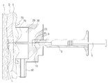
도 1을 참조하면 주사기용 석션어댑터(1)는 니들(8)과 니들허브(7)로 이루어진 주사기바늘(9)에 결합 되고 주사될 피부부위에 음압(陰壓)을 가할 수 있도록 공기흡입기에 연결된다. 주사기용 석션어댑터(1)는 니들허브가 수용되는 제1공간부(10)와 제1공간부의 상부에 위치하면서 공기흡입기와 연통되는 공기흡입연결부(50)가 형성된 제2공간부(30)로 구성되고 제1공간부(10)와 제2공간부(30)는 관통공(23)에 의해 연통되며 관통공(23)은 니들이 통과하기 위한 구멍으로 니들에 대응되게 형성된다. 또한 관통공(23)을 통해 제2공간부로 돌출되는 니들(8)을 감싸기 위해 관통공(23)이 연장형성되도록 돌출부(60)가 추가로 구비될 수 있으며 돌출부(60)의 관통공(23)에는 니들(8) 지나게 된다. 또한 제2공간부의 상부면에는 그에 대응되는 밀착부재(70)가 추가로 구비될 수 있으며 돌출부(60)에도 밀착부재(70)가 별도로 추가 형성될 수 있다. Referring to FIG. 1, a
도 2를 통해 본 발명에 따른 주사기용 석션어댑터를 상세하게 설명한다. 도 2에 도시된 바와 같이 본 발명에 따른 주사기용 석션어댑터(1)는 니들허브(7)가 수용되는 제1공간부(10)와 니들허브(7)에 결합 되는 니들(8)이 돌출될 수 있도록 상기 제1공간부(10)에 연통 되고 상면이 개방된 제2공간부(30)로 관통공(23)이 형성되고, 상기 제2공간부에 연통되어 공기흡입기(도면 미도시)와 연결되는 공기흡입기연결부(50)를 포함하여 이루어진다. The suction adapter for a syringe according to the present invention will be described in detail with reference to FIG. 2. As shown in FIG. 2, the
제1공간부(10)는 주사기용 석션어댑터(1)의 하부에 형성되어 니들허브(7)가 수용되는 부분으로 저면이 개방되고 니들허브에 대응되는 형상으로 구성된다. 한편, 제1공간부(10)의 상부에는 제2공간부(30)와 분리시키는 격벽(20)이 형성된다. The
또한, 격벽(20)에는 니들허브(7)가 제1공간부(10)에 결합 된 경우 니들허브(7)에 결합된 니들(8)이 격벽(20)을 관통하여 제2공간부(30)에 위치하도록 니들허브에 결합 된 니들(8)의 위치에 대응되는 위치에 관통공(23)이 형성된다. In addition, in the
제1공간부(10)의 상부에 형성되는 제2공간부(30)는 관통공(23)을 통해 제1공간부(10)와 연통되며, 제2공간부(30)의 공기를 흡입시켜 제2공간부(30)에 음압(陰壓)을 형성하기 위하여 공기흡입기(도면 미도시)와 연결되는 공기흡입기연결부(50)가 형성된다. The
공기흡입기연결부(50)는 제2공간부(30)와 연통되는 중공부가 형성된 실린더 형상으로 형성되어 공기흡입기와 연결관(도면 미도시)을 매개로 연결된다. The
제1공간부(10)를 구체적으로 살펴보면 제1공간부(10)는 니들허브(7)가 삽입 될 수 있도록 니들허브(7)에 대응되는 형상으로 형성된다. 따라서 제1공간부(10)는 니들허브(7)의 형상에 따라 다양하게 형성될 수 있다. 즉, 도 2에 도시된 실시예는 하나의 니들과 결합되는 원통형의 니들허브가 사용되므로 제1공간부는 측면이 원통형으로 형성되나, 후술할 도 5a 내지 도 6b에 도시된 주사기용 석션어댑터의 경우 상면이 직각사각형 형상 또는 정사각형 형상으로 되고 복수개의 니들이 구비된 멀티니들의 니들허브에 대응되는 형상으로 형성된다. 또한, 관통공(23)은 제1공간부(10)에 설치되는 니들허브(7)에 결합되는 니들(8)의 숫자와 위치에 따라 대응되게 형성된다. Looking at the
도 3을 참조하여 주사기용 석션어댑터(1)에 니들이 결합 된 상태를 살펴보면 다음과 같다. 니들허브(7)는 노즐(4)과 연결되는 입구(7a)와 니들(8)과 연통되는 출구(7b)로 구성되며, 니들허브(7)의 입구(7a)는 주사기 실린더의 노즐(4)과 연결되어 실린더의 노즐(4)로부터 유입되는 주사액(L)을 니들허브의 출구(7b)로 이동시킨다. 이때, 니들허브의 출구에는 니들(8)이 결합된다. Looking at the needle coupled to the suction adapter (1) for the syringe with reference to FIG. The
한편, 공기흡입기에 의해 발생 된 음압에 의해 니들(8)로부터 주사액(L)이 유출되지 않도록 관통공(23)을 지나 돌출되는 니들(8)에 대응되도록 제2공간부(30)부로 돌출부(60)가 형성된다. 돌출부(60)의 내부는 관통공(23)이 연장 형성되므로 니들(8)이 돌출부(60)의 관통공(23)에 위치하게 된다. 따라서 니들(23)을 돌출부(60)가 둘러싸는 형상이 된다.On the other hand, the protruding portion (2) to the
돌출부(60)는 니들허브(7)에 결합 되는 니들(8)의 개수에 대응되어 형성되므 로, 제2공간부(30)에 하나만 형성되나, 도 5a 내지 도 6b에 따르면 니들이 복수 개 구비된 멀티니들의 경우 복수개의 니들에 대응하여 복수의 돌출부가 형성된다. Since the
돌출부(60)의 상부면은 제2공간부(30)의 상면의 높이에 대응되어 형성되는 것이 바람직하다.이는 제2공간부(30)의 상부 면이 피부에 맞닿아 피부와 밀착될 때 돌출부(60)의 상부면 또한 피부와 맞닿게 되므로 돌출부(60) 내에 설치된 니들(8)은 공기흡입기에 의해 발생 되는 음압의 영향을 받지 않게 되어 주사액이 불필요하게 유출되는 것을 막을 수 있다. The upper surface of the
도 4는 본 발명에 따른 주사기용 석션어댑터(1)를 이용하여 피부에 주사하는 상태를 도시한 개략도이다. 피시술자의 피부에 주사기용 석션어댑터(1)의 상면을 밀착시키고 공기흡입기를 가동시켜 제2공간부(30)에 음압을 가하며, 이러한 음압에 의해 발생 되는 압력차에 의해 피시술자의 피부를 주사장치 방향으로 상승 된다. 상승 된 피부에 주사기 피스톤(5) 및 실린더(3)를 피시술자 피부 방향으로 가압하여 주사액(L)을 주입시키게 된다. 이때 돌출부(60)의 상부면 방향으로 돌출 되는 니들(8)의 길이는 주입되는 주사액의 종류 및 피부의 두께에 따라 상이하게 형성되나, 필러 또는 톡신과 같은 미용 주사액을 주입하는 경우에는 표피층(E)을 뚫고 진피층(D)과 지방층(F)의 경계부위에 니들(8)의 단부가 위치하는 것이 효과적이다. 따라서 삽입하고자하는 깊이에 대응되도록 니들(8)의 노출부를 형성하기 위해 돌출부(60) 및 제2공간부의 높이를 형성하는 조절할 수 있다. 예를 들어 돌출부(60)의 밖으로 노출되는 니들(8)의 길이가 3㎜가 되도록 하기 위해 니들의 끝 단높이 기준 으로 3㎜ 낮은 높이로 주사기용 석션어댑터(1)의 제2공간부 상부 면 및 돌출부의 끝단 높이를 결정할 수 있다. Figure 4 is a schematic diagram showing a state of injection into the skin using the suction adapter (1) for the syringe according to the present invention. The upper surface of the suction adapter (1) for the syringe is in close contact with the skin of the subject and a negative pressure is applied to the
또한, 석션어댑터(1)의 상부면 즉 제2공간부(30)의 상면에는 추가로 밀착부재(70)가 더 구성될 수 있다. 석션어댑터를 밀착시켜 공기 흡입하는 경우, 피부의 굴곡면으로 인해 밀착 정도가 낮은 경우 외부로부터 제2공간부(30)로 공기가 유입되는 것을 방지하기 위해 실리콘, 고무 등으로 이루어지고 제2공간부(30)의 상부면에 대응되는 고리 형상의 밀착부재(70)가 설치된다. In addition, the
도 5a 내지 도 6b은 본 발명의 다른 실시예에 따른 주사기용 석션어댑터를 도시한 사시도 및 단면도로, 니들(8)의 개수에 따라 니들허브(7)의 형상을 달리하여 제작된 경우, 그 형상에 대응되도록 주사기용 석션어댑터(1)의 제1공간부(10) 및 제2공간부(30)의 형상을 변경할 수도 있다. 즉, 니들이 복수 개 형성되는 멀티니들에 있어서 니들허브에 본 발명에 따른 주사기용 석션어댑터를 장착하여 사용할 수 있다. 멀티 니들 즉 니들이 복수개되는 주사바늘의 경우 비교적 1회 주사 면적이 넓으므로 해당 부위의 피부를 손으로 집어 올려 주사하는 것은 어렵다. 따라서 이런 경우에 본 발명에 따른 주사기용 석션어댑터가 유용하다. 5A to 6B are perspective views and cross-sectional views showing a suction adapter for a syringe according to another embodiment of the present invention. When the
도 5a는 3×2로 구성된 멀티니들용 석션어댑터가 도시되어 있다. 즉, 가로 방향으로 니들이 3개, 세로 방향으로 니들이 2개 위치한 멀티니들에 장착하여 사용되는 주사기용 석션어댑터(1) 이다. 도5b는 그 단면도로 니들허브가 장착되는 제1관통부(10)의 상부로 니들에 대응하는 위치에 관통공(23)이 다수 개 형성되어 있 다. 한편, 제2공간부(20)의 상단부 및 돌출부(60)의 끝단은 노출되는 니들의 길이에 대응되도록 연장 형성되어 있다. 즉, 주사액이 들어가는 피부층의 깊이에 니들이 들어갈 수 있도록 해당 깊이 만큼 니들이 노출되는 것이 필요하다. 따라서 니들의 노출 길이 조절을 위해 니들의 노출분을 제외한 니들의 길이에 대응되도록 제2공간부 및 돌출부의 높이를 결정하여 형성할 수 있다. FIG. 5A shows a suction adapter for multi-needle composed of 3 × 2. That is, it is a suction adapter (1) for a syringe used to be mounted on the multi-needle three needles in the horizontal direction, two needles in the longitudinal direction. 5B is a cross-sectional view, in which a plurality of through-
도 6a 및 도 6b는 6×6으로 구성된 멀티니들용 석선어댑터가 도시되어 있다. 도 6b의 멀티 니들은 니들의 노출길이 조절용 조절구(7c)가 추가로 구비된 것으로 니들허브 선단에 위치하는 조절구가 제1공간부에 연결되는 구성도 가능하다. 또한 조절구가 장착된 니들은 돌출구를 통해 외부로 노출되게 된다. 6A and 6B illustrate a stone needle adapter for multi-needle composed of 6 × 6. The multi-needle of FIG. 6B is further provided with an
도 1은 본 발명의 일실시예에 의한 주사기용 석션어댑터, 니들과 주사기를 도시한 사시도. 1 is a perspective view showing a suction adapter, a needle and a syringe for a syringe according to an embodiment of the present invention.
도 2는 도 1에 도시된 주사기용 석션어댑터의 단면도.Figure 2 is a cross-sectional view of the suction adapter for the syringe shown in FIG.
도 3은 도 1에 도시된 주사기용 석션어댑터에 니들이 결합된 상태를 도시한 단면도.3 is a cross-sectional view showing a needle coupled to the suction adapter for the syringe shown in FIG.
도 4는 도 1에 도시된 주사기용 석션어댑터를 이용하여 피부에 주사하는 상태를 도시한 개략도.Figure 4 is a schematic diagram showing a state injecting into the skin using the suction adapter for the syringe shown in FIG.
도 5a는 본 발명의 다른 실시예에 따른 주사기용 석션어댑터의 사시도. Figure 5a is a perspective view of a suction adapter for a syringe according to another embodiment of the present invention.
도 5b는 도 5a에 도시된 주사기용 석션어댑터의 단면도.5B is a cross-sectional view of the suction adapter for the syringe shown in FIG. 5A.
도 6a는 본 발명의 또 다른 실시예에 따른 주사기용 석션어댑터의 사시도.Figure 6a is a perspective view of a suction adapter for a syringe according to another embodiment of the present invention.
도 6b는 도 6a에 도시된 주사기용 석션어댑터의 단면도. 6B is a cross-sectional view of the suction adapter for the syringe shown in FIG. 6A.
<도면의 주요부분에 관한 부호의 설명><Explanation of symbols on main parts of the drawings>
1; 주사기용 석션어댑터 3; 주사기 실린더One;
4; 노즐 5; 피스톤4;
6; 주사기 7; 니들허브6;
7a; 입구 7b; 출구7a;
8; 니들 9; 주사기바늘8;
10; 제1공간부 20; 격벽10; A
23; 관통공 30; 제2공간부23; Through
50; 공기흡입기연결부50; Air intake connection
60; 돌출부 70; 밀착부재60;
E; 표피층 D; 진피층E; Epidermal layer D; Dermal layer
F; 지방층 L; 주사액F; Fat layer L; Injection
Claims (6)
Priority Applications (2)
| Application Number | Priority Date | Filing Date | Title |
|---|---|---|---|
| KR1020080075898A KR20100015018A (en) | 2008-08-04 | 2008-08-04 | Suction adapter for syringe |
| PCT/KR2008/005112 WO2010016635A1 (en) | 2008-08-04 | 2008-09-01 | Suction adapter for syringe |
Applications Claiming Priority (1)
| Application Number | Priority Date | Filing Date | Title |
|---|---|---|---|
| KR1020080075898A KR20100015018A (en) | 2008-08-04 | 2008-08-04 | Suction adapter for syringe |
Publications (1)
| Publication Number | Publication Date |
|---|---|
| KR20100015018A true KR20100015018A (en) | 2010-02-12 |
Family
ID=41663838
Family Applications (1)
| Application Number | Title | Priority Date | Filing Date |
|---|---|---|---|
| KR1020080075898A Ceased KR20100015018A (en) | 2008-08-04 | 2008-08-04 | Suction adapter for syringe |
Country Status (2)
| Country | Link |
|---|---|
| KR (1) | KR20100015018A (en) |
| WO (1) | WO2010016635A1 (en) |
Cited By (9)
| Publication number | Priority date | Publication date | Assignee | Title |
|---|---|---|---|---|
| WO2012057425A1 (en) * | 2010-10-28 | 2012-05-03 | (주)엠툴즈 | Module for use in skin surgery |
| KR101305539B1 (en) * | 2012-02-16 | 2013-09-06 | (주)메가메디칼 | gun for injection of a liquid medicine |
| WO2013180422A1 (en) * | 2012-05-31 | 2013-12-05 | 주식회사 파나시 | Multi-needle assembly with easily adjustable needle-exposed length |
| KR101383744B1 (en) * | 2012-05-14 | 2014-04-08 | 주식회사 파나시 | A multi-needle assembly having stopper |
| WO2014189161A1 (en) * | 2013-05-23 | 2014-11-27 | 주식회사 파나시 | Multi-needle assembly having stopper |
| KR101703305B1 (en) | 2016-05-24 | 2017-02-06 | 송미희 | Cosmetic surgery using syringe pump and suture thread |
| KR20180007365A (en) * | 2016-07-12 | 2018-01-23 | 주식회사 로보맥스 | Injection needle module |
| KR102117711B1 (en) | 2020-03-17 | 2020-06-09 | (주)엠플러스일렉트로닉스 | Rf radio frequency generator |
| KR20210144273A (en) * | 2020-05-22 | 2021-11-30 | 주식회사 노바메디 | Injection needle apparatus |
Families Citing this family (10)
| Publication number | Priority date | Publication date | Assignee | Title |
|---|---|---|---|---|
| KR101372403B1 (en) * | 2012-06-21 | 2014-03-25 | 주식회사 파나시 | Pressure Sensitive Automatic Injection System |
| GB2514444A (en) * | 2013-03-15 | 2014-11-26 | Elekta Ab | Injection applicator and alignment device and related methods of use |
| EP2965779A1 (en) * | 2014-07-07 | 2016-01-13 | MT Derm GmbH | Application module for a handheld device for repeated application of an application element to a human or an animal skin and hand-held device |
| CN104524669A (en) * | 2015-01-14 | 2015-04-22 | 李洪湘 | Multi-syringe-needle adsorption injection needle |
| CN104922769B (en) * | 2015-06-23 | 2017-09-15 | 中国人民解放军第四军医大学 | The vacuum injector of controllable depth of needle |
| EP3380174A4 (en) * | 2015-11-28 | 2019-04-24 | Biopreme Medical Technologies, Inc. | Negative pressure injection device |
| JP3207783U (en) * | 2016-09-20 | 2016-12-01 | 南部化成株式会社 | Needle |
| JP7324453B2 (en) * | 2019-05-14 | 2023-08-10 | 学校法人 関西大学 | Puncture aids and puncture devices |
| WO2021046680A1 (en) * | 2019-09-09 | 2021-03-18 | 郝云玲 | Injection device |
| CA3182308A1 (en) * | 2020-06-22 | 2021-12-30 | Tianqi HANG | Adapter and injection syringe |
Family Cites Families (4)
| Publication number | Priority date | Publication date | Assignee | Title |
|---|---|---|---|---|
| US4600403A (en) * | 1974-11-19 | 1986-07-15 | Wolfgang Wagner | Suction injector II |
| US4299219A (en) * | 1979-12-17 | 1981-11-10 | Norris Jr George P | Intravenous needle insertion device |
| US7279001B2 (en) * | 1998-11-06 | 2007-10-09 | Neomend, Inc. | Systems, methods, and compositions for achieving closure of vascular puncture sites |
| AU2002346399A1 (en) * | 2001-11-14 | 2003-05-26 | Medical Instill Technologies, Inc. | Intradermal delivery device and method |
-
2008
- 2008-08-04 KR KR1020080075898A patent/KR20100015018A/en not_active Ceased
- 2008-09-01 WO PCT/KR2008/005112 patent/WO2010016635A1/en not_active Ceased
Cited By (12)
| Publication number | Priority date | Publication date | Assignee | Title |
|---|---|---|---|---|
| WO2012057425A1 (en) * | 2010-10-28 | 2012-05-03 | (주)엠툴즈 | Module for use in skin surgery |
| EP3403687A1 (en) * | 2010-10-28 | 2018-11-21 | Panace Co., Ltd. | Module for use in skin surgery |
| KR101305539B1 (en) * | 2012-02-16 | 2013-09-06 | (주)메가메디칼 | gun for injection of a liquid medicine |
| KR101383744B1 (en) * | 2012-05-14 | 2014-04-08 | 주식회사 파나시 | A multi-needle assembly having stopper |
| WO2013180422A1 (en) * | 2012-05-31 | 2013-12-05 | 주식회사 파나시 | Multi-needle assembly with easily adjustable needle-exposed length |
| KR101398516B1 (en) * | 2012-05-31 | 2014-05-27 | 주식회사 파나시 | A multi-needle assembly with readily adjustable structure |
| US9468748B2 (en) | 2012-05-31 | 2016-10-18 | Panace Co., Ltd. | Multi-needle assembly with readily adjustable structure |
| WO2014189161A1 (en) * | 2013-05-23 | 2014-11-27 | 주식회사 파나시 | Multi-needle assembly having stopper |
| KR101703305B1 (en) | 2016-05-24 | 2017-02-06 | 송미희 | Cosmetic surgery using syringe pump and suture thread |
| KR20180007365A (en) * | 2016-07-12 | 2018-01-23 | 주식회사 로보맥스 | Injection needle module |
| KR102117711B1 (en) | 2020-03-17 | 2020-06-09 | (주)엠플러스일렉트로닉스 | Rf radio frequency generator |
| KR20210144273A (en) * | 2020-05-22 | 2021-11-30 | 주식회사 노바메디 | Injection needle apparatus |
Also Published As
| Publication number | Publication date |
|---|---|
| WO2010016635A1 (en) | 2010-02-11 |
Similar Documents
| Publication | Publication Date | Title |
|---|---|---|
| KR20100015018A (en) | Suction adapter for syringe | |
| KR101508067B1 (en) | Multi-needle assembly for skin beauty and medical treatment | |
| DE60230884D1 (en) | Injection device for applying a subcutaneous infusion arrangement | |
| CN101715353B (en) | Cannula and delivery device | |
| KR100902133B1 (en) | Multi-needle | |
| US20130245555A1 (en) | Sprinkler Cannula | |
| CN102470220B (en) | Injection needle assembly and drug injection device | |
| KR101713938B1 (en) | Needle unit for medication injection device | |
| WO2004004800A3 (en) | Infusion device and method thereof | |
| ITMI980009A1 (en) | DEVICE FOR CHECKING THE PENETRATION DEPTH OF A PARTICULAR NEEDLE APPLICABLE TO A SYRINGE FOR INJECTIONS | |
| ATE494024T1 (en) | DISPOSABLE INFUSION DEVICE | |
| NO20083257L (en) | injecting device | |
| CA2640626A1 (en) | Template system for multi-reservoir implantable pump | |
| CN109069726A (en) | Chemical fluid injection device | |
| CA2553454A1 (en) | Device for subcutaneous infusion of fluids | |
| CN104524669A (en) | Multi-syringe-needle adsorption injection needle | |
| KR102305286B1 (en) | Apparatus and method for skin treatment | |
| CN204684445U (en) | Operation on skin device pin unit | |
| KR102226112B1 (en) | Skin treatment handpiece and skin treatment system with suction type needle module | |
| KR20180090167A (en) | Needle assembly in using disposable syringe | |
| KR102655388B1 (en) | Multi-needle module for skin treatment | |
| KR20200126845A (en) | In-line filler injection device | |
| KR102767504B1 (en) | RF Needle Handpiece Tip for Refrigerant Injection | |
| KR20170057553A (en) | Apparatus for skin aesthetic of the skin device | |
| CN222917965U (en) | Negative pressure microneedle drug delivery device |
Legal Events
| Date | Code | Title | Description |
|---|---|---|---|
| A201 | Request for examination | ||
| PA0109 | Patent application |
Patent event code: PA01091R01D Comment text: Patent Application Patent event date: 20080804 |
|
| PA0201 | Request for examination | ||
| A302 | Request for accelerated examination | ||
| PA0302 | Request for accelerated examination |
Patent event date: 20091109 Patent event code: PA03022R01D Comment text: Request for Accelerated Examination Patent event date: 20080804 Patent event code: PA03021R01I Comment text: Patent Application |
|
| E902 | Notification of reason for refusal | ||
| PE0902 | Notice of grounds for rejection |
Comment text: Notification of reason for refusal Patent event date: 20091218 Patent event code: PE09021S01D |
|
| PG1501 | Laying open of application | ||
| E601 | Decision to refuse application | ||
| PE0601 | Decision on rejection of patent |
Patent event date: 20100402 Comment text: Decision to Refuse Application Patent event code: PE06012S01D Patent event date: 20091218 Comment text: Notification of reason for refusal Patent event code: PE06011S01I |
|
| J201 | Request for trial against refusal decision | ||
| PJ0201 | Trial against decision of rejection |
Patent event date: 20100506 Comment text: Request for Trial against Decision on Refusal Patent event code: PJ02012R01D Patent event date: 20100402 Comment text: Decision to Refuse Application Patent event code: PJ02011S01I Appeal kind category: Appeal against decision to decline refusal Appeal identifier: 2010101003368 Request date: 20100506 |
|
| J501 | Disposition of invalidation of trial | ||
| PJ0501 | Disposition of invalidation of trial |
Appeal kind category: Appeal against decision to decline refusal Request date: 20100506 Appeal identifier: 2010101003368 |