KR20090120205A - Flash memory device and its operation method - Google Patents
Flash memory device and its operation method Download PDFInfo
- Publication number
- KR20090120205A KR20090120205A KR1020080046129A KR20080046129A KR20090120205A KR 20090120205 A KR20090120205 A KR 20090120205A KR 1020080046129 A KR1020080046129 A KR 1020080046129A KR 20080046129 A KR20080046129 A KR 20080046129A KR 20090120205 A KR20090120205 A KR 20090120205A
- Authority
- KR
- South Korea
- Prior art keywords
- string
- program
- voltage
- ground select
- select transistor
- Prior art date
- Legal status (The legal status is an assumption and is not a legal conclusion. Google has not performed a legal analysis and makes no representation as to the accuracy of the status listed.)
- Ceased
Links
Images


Classifications
-
- G—PHYSICS
- G11—INFORMATION STORAGE
- G11C—STATIC STORES
- G11C16/00—Erasable programmable read-only memories
- G11C16/02—Erasable programmable read-only memories electrically programmable
- G11C16/06—Auxiliary circuits, e.g. for writing into memory
- G11C16/34—Determination of programming status, e.g. threshold voltage, overprogramming or underprogramming, retention
-
- G—PHYSICS
- G11—INFORMATION STORAGE
- G11C—STATIC STORES
- G11C16/00—Erasable programmable read-only memories
- G11C16/02—Erasable programmable read-only memories electrically programmable
- G11C16/06—Auxiliary circuits, e.g. for writing into memory
- G11C16/10—Programming or data input circuits
-
- G—PHYSICS
- G11—INFORMATION STORAGE
- G11C—STATIC STORES
- G11C16/00—Erasable programmable read-only memories
- G11C16/02—Erasable programmable read-only memories electrically programmable
- G11C16/04—Erasable programmable read-only memories electrically programmable using variable threshold transistors, e.g. FAMOS
- G11C16/0483—Erasable programmable read-only memories electrically programmable using variable threshold transistors, e.g. FAMOS comprising cells having several storage transistors connected in series
-
- G—PHYSICS
- G11—INFORMATION STORAGE
- G11C—STATIC STORES
- G11C16/00—Erasable programmable read-only memories
- G11C16/02—Erasable programmable read-only memories electrically programmable
- G11C16/06—Auxiliary circuits, e.g. for writing into memory
- G11C16/34—Determination of programming status, e.g. threshold voltage, overprogramming or underprogramming, retention
- G11C16/3436—Arrangements for verifying correct programming or erasure
- G11C16/3454—Arrangements for verifying correct programming or for detecting overprogrammed cells
Landscapes
- Engineering & Computer Science (AREA)
- Microelectronics & Electronic Packaging (AREA)
- Read Only Memory (AREA)
- Semiconductor Memories (AREA)
- Non-Volatile Memory (AREA)
Abstract
Description
본 발명은 메모리 장치에 관한 것으로, 좀 더 구체적으로는 플래시 메모리 장치에 관한 것이다.The present invention relates to a memory device, and more particularly to a flash memory device.
반도체 메모리는, 일반적으로, 위성에서 소비자 전자 기술까지의 범위에 속하는 마이크로프로세서를 기반으로 한 응용 및 컴퓨터과 같은 디지털 로직 설계의 가장 필수적인 마이크로 전자 소자이다. 그러므로, 높은 집적도 및 빠른 속도를 위한 축소 (scaling)를 통해 얻어지는 프로세스 향상 및 기술 개발을 포함한 반도체 메모리의 제조 기술의 진보는 다른 디지털 로직 계열의 성능 기준을 확립하는 데 도움이 된다.Semiconductor memories are generally the most essential microelectronic devices of digital logic designs, such as computers and applications based on microprocessors, which range from satellite to consumer electronics technology. Therefore, advances in the manufacturing technology of semiconductor memories, including process improvement and technology development, achieved through scaling for high integration and high speed, help to establish performance criteria for other digital logic families.
반도체 메모리 장치는 크게 휘발성 반도체 메모리 장치와 불 휘발성 반도체 메모리 장치로 나뉘어진다. 휘발성 반도체 메모리 장치에 있어서, 로직 정보는 스태틱 랜덤 액세스 메모리의 경우 쌍안정 플립-플롭의 로직 상태를 설정함으로써 또는 다이나믹 랜덤 액세스 메모리의 경우 커패시터의 충전을 통해 저장된다. 휘발성 반도체 메모리 장치의 경우, 전원이 인가되는 동안 데이터가 저장되고 읽혀지며, 전원이 차단될 때 데이터는 소실된다.The semiconductor memory device is largely divided into a volatile semiconductor memory device and a nonvolatile semiconductor memory device. In a volatile semiconductor memory device, logic information is stored by setting a logic state of a bistable flip-flop in the case of static random access memory or through charging of a capacitor in the case of dynamic random access memory. In the case of a volatile semiconductor memory device, data is stored and read while power is applied, and data is lost when power is cut off.
MROM, PROM, PRAM, EPROM, EEPROM 등과 같은 불 휘발성 반도체 메모리 장치는 전원이 차단되어도 데이터를 저장할 수 있다. 불 휘발성 메모리 데이터 저장 상태는 사용되는 제조 기술에 따라 영구적이거나 재프로그램 가능하다. 불 휘발성 반도체 메모리 장치는 컴퓨터, 항공 전자 공학, 통신, 그리고 소비자 전자 기술 산업과 같은 넓은 범위의 응용에서 프로그램 및 마이크로코드의 저장을 위해서 사용된다. 단일 칩에서 휘발성 및 불 휘발성 메모리 저장 모드들의 조합이 빠르고 재프로그램 가능한 불 휘발성 메모리를 요구하는 시스템에서 불 휘발성 RAM (nvRAM)과 같은 장치들에서 또한 사용 가능하다. 게다가, 응용 지향 업무를 위한 성능을 최적화시키기 위해 몇몇 추가적인 로직 회로를 포함하는 특정 메모리 구조가 개발되어 오고 있다.Nonvolatile semiconductor memory devices such as MROM, PROM, PRAM, EPROM, and EEPROM can store data even when the power supply is cut off. The nonvolatile memory data storage state is either permanent or reprogrammable, depending on the manufacturing technique used. Nonvolatile semiconductor memory devices are used for the storage of programs and microcode in a wide range of applications such as the computer, avionics, telecommunications, and consumer electronics industries. The combination of volatile and nonvolatile memory storage modes on a single chip is also available in devices such as nonvolatile RAM (nvRAM) in systems that require fast and reprogrammable nonvolatile memory. In addition, specific memory structures have been developed that include some additional logic circuitry to optimize performance for application-oriented tasks.
불 휘발성 반도체 메모리 장치에 있어서, MROM, PROM 및 EPROM은 시스템 자체적으로 소거 및 쓰기가 자유롭지 않아서 일반 사용자들이 기억 내용을 새롭게 하기가 용이하지 않다. 이에 반해 EEPROM은 전기적으로 소거 및 쓰기가 가능하므로 계속적인 갱신이 필요한 시스템 프로그래밍(system programming)이나 보조 기억 장치로의 응용이 확대되고 있다.In the nonvolatile semiconductor memory device, the MROM, PROM and EPROM are not free to erase and write in the system itself, so that it is not easy for ordinary users to update the storage contents. On the other hand, since EEPROMs can be electrically erased and written, applications to system programming or auxiliary storage devices requiring continuous updating are expanding.
불 휘발성 메모리 장치의 일예로서, 플래시 메모리 장치는 복수의 메모리 영역들이 한번의 프로그램 동작으로 소거 또는 프로그램되는 일종의 EEPROM이다. 일반적인 EEPROM은 단지 하나의 메모리 영역이 한 번에 소거 또는 프로그램 가능하게 하며, 이는 플래시 메모리 장치를 사용하는 시스템들이 동시에 다른 메모리 영역들 에 대해 읽고 쓸 때 보다 빠르고 효과적인 속도로 플래시 메모리 장치가 동작할 수 있음을 의미한다. 플래시 메모리 및 EEPROM의 모든 형태는 데이터를 저장하는 데 사용되는 전하 저장 수단을 둘러싸고 있는 절연막의 마멸로 인해서 특정 수의 소거 동작들 후에 마멸된다.As an example of a nonvolatile memory device, a flash memory device is a kind of EEPROM in which a plurality of memory areas are erased or programmed in one program operation. Typical EEPROMs allow only one memory area to be erased or programmable at a time, which allows a flash memory device to operate at a faster and more efficient speed when systems using the flash memory device read and write to other memory areas at the same time. It means that there is. All forms of flash memory and EEPROM are worn out after a certain number of erase operations due to the wear of the insulating film surrounding the charge storage means used to store the data.
플래시 메모리 장치는 실리콘 칩에 저장된 정보를 유지하는 데 전원을 필요로 하지 않는 방법으로 실리콘 칩 상에 정보를 저장한다. 이는 만약 칩에 공급되는 전원이 차단되면 전원의 소모없이 정보가 유지됨을 의미한다. 추가로, 플래시 메모리 장치는 물리적인 충격 저항성 및 빠른 읽기 접근 시간을 제공한다. 이러한 특징들때문에, 플래시 메모리 장치는 배터리에 의해서 전원을 공급받는 장치들의 저장 장치로서 일반적으로 사용되고 있다. 플래시 메모리 장치는 각 저장 소자에 사용되는 로직 게이트의 형태에 따라 2가지 종류 즉, NOR 플래시 메모리 장치와 NAND 플래시 메모리 장치로 이루어진다.Flash memory devices store information on the silicon chip in a manner that does not require a power source to maintain the information stored on the silicon chip. This means that if the power to the chip is interrupted, the information is maintained without consuming power. In addition, flash memory devices provide physical shock resistance and fast read access times. Because of these features, flash memory devices are commonly used as storage devices for devices powered by batteries. There are two types of flash memory devices, NOR flash memory devices and NAND flash memory devices, depending on the type of logic gate used for each storage element.
플래시 메모리 장치는 셀이라 불리는 트랜지스터들의 어레이에 정보를 저장하며, 각 셀은 1-비트 정보를 저장한다. 멀티-레벨 셀 장치라 불리는 보다 새로운 플래시 메모리 장치들은 셀의 플로팅 게이트 상에 놓인 전하량을 가변시킴으로써 셀 당 1 비트보다 많이 저장할 수 있다.Flash memory devices store information in an array of transistors called cells, with each cell storing one-bit information. Newer flash memory devices, called multi-level cell devices, can store more than one bit per cell by varying the amount of charge placed on the floating gate of the cell.
본 발명의 목적은 프로그램 루프들을 통해 각 스트링에 속하는 선택 트랜지스터들을 프로그램하는 스킴을 제공하는 것이다.It is an object of the present invention to provide a scheme for programming select transistors belonging to each string through program loops.
본 발명의 일 특징은 각각이 스트링 선택 트랜지스터, 접지 선택 트랜지스터, 그리고 상기 선택 트랜지스터들 사이에 직렬 연결된 메모리 셀들을 갖는 복수의 스트링들을 포함하는 메모리 셀 어레이와; 그리고 상기 스트링 및 접지 선택 트랜지스터들 중 적어도 하나는 서로 전기적으로 분리된 플로팅 게이트 및 제어 게이트를 가지며; 프로그램 실행 구간과 검증 구간을 각각 갖는 프로그램 루프들을 통해 상기 스트링 및 접지 선택 트랜지스터들 중 적어도 하나를 소정의 문턱 전압으로 프로그램하도록 구성된 읽기/쓰기 회로를 포함하는 플래시 메모리 장치를 제공하는 것이다.One aspect of the invention is a memory cell array comprising a plurality of strings each having a string select transistor, a ground select transistor, and memory cells connected in series between the select transistors; And at least one of the string and ground select transistors has a floating gate and a control gate electrically isolated from each other; The present invention provides a flash memory device including a read / write circuit configured to program at least one of the string and ground select transistors to a predetermined threshold voltage through program loops each having a program execution period and a verification period.
예시적인 실시예에 있어서, 상기 각 프로그램 루프의 검증 구간 동안, 상기 각 스트링의 스트링 또는 접지 선택 트랜지스터가 상기 소정의 문턱 전압으로 프로그램되었는 지의 여부가 상기 읽기/쓰기 회로를 통해 판별된다.In an exemplary embodiment, during the verification period of each program loop, whether the string or the ground select transistor of each string is programmed to the predetermined threshold voltage is determined by the read / write circuit.
예시적인 실시예에 있어서, 상기 각 스트링의 스트링 또는 접지 선택 트랜지스터가 상기 소정의 문턱 전압으로 프로그램된 것으로 판별되면, 상기 각 스트링의 스트링 또는 접지 선택 트랜지스터는 다음의 프로그램 루프의 프로그램 실행 구간 동안 상기 읽기/쓰기 회로를 통해 프로그램 금지된다.In an exemplary embodiment, if it is determined that the string or ground select transistor of each string is programmed to the predetermined threshold voltage, the string or ground select transistor of each string is read during the program execution interval of the next program loop. Programming is prohibited via the write / write circuit.
예시적인 실시예에 있어서, 상기 각 스트링의 스트링 및 접지 선택 트랜지스터들 중 적어도 하나를 프로그램하기 이전에 상기 각 스트링에 속하는 메모리 셀들은 프로그램된다.In an exemplary embodiment, memory cells belonging to each string are programmed prior to programming at least one of the string and ground select transistors of each string.
예시적인 실시예에 있어서, 상기 각 스트링에 속하는 메모리 셀들이 프로그 램되기 이전에, 상기 각 스트링의 스트링 및 접지 선택 트랜지스터들 중 적어도 하나는 메모리 셀들과 함께 동시에 소거된다.In an exemplary embodiment, at least one of the string and ground select transistors of each string is erased simultaneously with the memory cells before the memory cells belonging to each string are programmed.
예시적인 실시예에 있어서, 상기 각 스트링의 스트링 선택 트랜지스터는 상기 각 스트링의 프로그램된 메모리 셀들을 턴-오프 상태로 유지시키고, 상기 스트링 선택 트랜지스터의 제어 게이트에 프로그램 전압을 인가하고, 대응하는 비트 라인에 소정 전압을 인가함으로써 프로그램 금지된다.In an exemplary embodiment, the string select transistor of each string maintains the programmed memory cells of each string turned off, applies a program voltage to a control gate of the string select transistor, and corresponds to a corresponding bit line. The program is prohibited by applying a predetermined voltage to the.
예시적인 실시예에 있어서, 상기 소정 전압은 전원 전압과 상기 전원 전압보다 높은 고전압 중 어느 하나이다.In an exemplary embodiment, the predetermined voltage is one of a power supply voltage and a high voltage higher than the power supply voltage.
예시적인 실시예에 있어서, 상기 각 스트링의 스트링 선택 트랜지스터는 상기 각 스트링의 프로그램된 메모리 셀들을 턴-오프 상태로 유지시키고, 상기 스트링 선택 트랜지스터의 제어 게이트에 프로그램 전압을 인가하고, 대응하는 비트 라인을 플로팅시킴으로써 프로그램 금지된다.In an exemplary embodiment, the string select transistor of each string maintains the programmed memory cells of each string turned off, applies a program voltage to a control gate of the string select transistor, and corresponds to a corresponding bit line. Program is prohibited by plotting
예시적인 실시예에 있어서, 상기 각 스트링의 접지 선택 트랜지스터는 상기 각 스트링의 프로그램된 메모리 셀들 및 상기 각 스트링의 스트링 선택 트랜지스터를 턴-온 상태로 유지시키고, 상기 접지 선택 트랜지스터의 제어 게이트에 프로그램 전압을 인가하고, 대응하는 비트 라인에 소정 전압을 인가하며, 공통 소오스 라인을 플로팅 상태로 유지시킴으로써 프로그램 금지된다.In an exemplary embodiment, the ground select transistor of each string maintains the programmed memory cells of each string and the string select transistor of each string turned on, and a program voltage to a control gate of the ground select transistor. Program is prohibited by applying a predetermined voltage, applying a predetermined voltage to a corresponding bit line, and keeping the common source line in a floating state.
예시적인 실시예에 있어서, 상기 소정 전압은 전원 전압과 상기 전원 전압보다 높은 고전압 중 어느 하나이다.In an exemplary embodiment, the predetermined voltage is one of a power supply voltage and a high voltage higher than the power supply voltage.
예시적인 실시예에 있어서, 상기 각 스트링의 접지 선택 트랜지스터는 상기 각 스트링의 프로그램된 메모리 셀들 및 상기 각 스트링의 스트링 선택 트랜지스터를 턴-온 상태로 유지시키고, 대응하는 비트 라인을 플로팅시킴으로써 프로그램 금지된다.In an exemplary embodiment, the ground select transistor of each string is program inhibited by keeping the programmed memory cells of each string and the string select transistor of each string turned on and plotting a corresponding bit line. .
예시적인 실시예에 있어서, 상기 각 프로그램 루프의 검증 구간 동안, 상기 각 스트링의 스트링 선택 트랜지스터에 검증 전압이 인가되고, 상기 각 스트링의 접지 선택 트랜지스터에 접지 전압 및 읽기 전압 중 어느 하나가 인가되고, 상기 각 스트링의 메모리 셀들에는 상기 읽기 전압이 인가되고, 공통 소오스 라인은 접지된다.In an exemplary embodiment, a verify voltage is applied to a string select transistor of each string and one of a ground voltage and a read voltage is applied to a ground select transistor of each string during the verify period of each program loop. The read voltage is applied to the memory cells of each string, and the common source line is grounded.
예시적인 실시예에 있어서, 상기 각 프로그램 루프의 검증 구간 동안, 상기 각 스트링의 접지 선택 트랜지스터에 검증 전압이 인가되고, 상기 각 스트링의 스트링 선택 트랜지스터에 접지 전압 및 읽기 전압 중 어느 하나가 인가되고, 상기 각 스트링의 메모리 셀들에는 상기 읽기 전압이 인가되며, 공통 소오스 라인은 접지된다.In an exemplary embodiment, during the verification period of each program loop, a verify voltage is applied to the ground select transistor of each string, and either one of the ground voltage and the read voltage is applied to the string select transistor of each string. The read voltage is applied to the memory cells of each string, and the common source line is grounded.
본 발명의 다른 특징은 각각이 스트링 선택 트랜지스터, 접지 선택 트랜지스터, 그리고 상기 선택 트랜지스터들 사이에 직렬 연결된 메모리 셀들을 갖는 복수의 스트링들을 포함하는 메모리 셀 어레이와; 그리고 상기 스트링 및 접지 선택 트랜지스터들 각각은 서로 전기적으로 분리된 플로팅 게이트 및 제어 게이트를 가지며; 프로그램 실행 구간과 검증 구간을 각각 갖는 프로그램 루프들을 통해 상기 복수의 스트링들 각각에 속하는 스트링 및 접지 선택 트랜지스터들을 소정의 문턱 전압으로 프로그램하도록 구성된 읽기/쓰기 회로를 포함하는 플래시 메모리 장치를 제공하는 것이다.Another feature of the invention is a memory cell array comprising a plurality of strings each having a string select transistor, a ground select transistor, and memory cells connected in series between the select transistors; And each of the string and ground select transistors has a floating gate and a control gate electrically isolated from each other; The present invention provides a flash memory device including a read / write circuit configured to program strings and ground select transistors belonging to the plurality of strings to predetermined threshold voltages through program loops each having a program execution period and a verification period.
예시적인 실시예에 있어서, 상기 각 프로그램 루프의 검증 구간 동안, 상기 각 스트링의 스트링/접지 선택 트랜지스터가 상기 소정의 문턱 전압으로 프로그램되었는 지의 여부가 상기 읽기/쓰기 회로를 통해 판별된다.In an exemplary embodiment, during the verification period of each program loop, whether the string / ground select transistor of each string is programmed to the predetermined threshold voltage is determined by the read / write circuit.
예시적인 실시예에 있어서, 상기 각 스트링의 스트링/접지 선택 트랜지스터가 상기 소정의 문턱 전압으로 프로그램된 것으로 판별되면, 상기 각 스트링의 스트링/접지 선택 트랜지스터는 다음의 프로그램 루프의 프로그램 실행 구간 동안 상기 읽기/쓰기 회로를 통해 프로그램 금지된다.In an exemplary embodiment, if it is determined that the string / ground select transistor of each string is programmed to the predetermined threshold voltage, the string / ground select transistor of each string is read during the program execution interval of the next program loop. Programming is prohibited via the write / write circuit.
예시적인 실시예에 있어서, 상기 각 스트링의 스트링/접지 선택 트랜지스터의 채널 길이(Lgsl/Lssl)와 상기 각 스트링의 각 메모리 셀의 채널 길이(Lcell)는 (Lgsl/Lssl≥Lcell)의 관계를 갖는다.In an exemplary embodiment, the channel length Lgsl / Lssl of each string / ground select transistor of each string and the channel length Lcell of each memory cell of each string have a relationship of (Lgsl / Lssl ≧ Lcell). .
본 발명의 다른 특징은 복수의 스트링들 각각에 속하는 메모리 셀들 및 스트링 및 접지 선택 트랜지스터들을 소거하는 단계와; 상기 복수의 스트링들 각각에 속하는 스트링 및 접지 선택 트랜지스터들 중 적어도 하나는 서로 전기적으로 분리된 플로팅 게이트 및 제어 게이트를 가지며; 상기 복수의 스트링들 각각에 속하는 메모리 셀들을 프로그램하는 단계와; 그리고 프로그램 실행 구간과 검증 구간을 각각 갖는 프로그램 루프들을 통해 상기 복수의 스트링들 각각에 속하는 스트링 및 접지 선택 트랜지스터들 중 적어도 하나를 프로그램하는 단계를 포함하는 플래시 메모리 장치의 동작 방법을 제공하는 것이다.Another aspect of the present invention provides a method for processing a memory device comprising: erasing memory cells and string and ground select transistors belonging to each of a plurality of strings; At least one of a string and a ground select transistor belonging to each of said plurality of strings has a floating gate and a control gate electrically isolated from each other; Programming memory cells belonging to each of the plurality of strings; And programming at least one of a string and a ground select transistor belonging to each of the plurality of strings through program loops having a program execution section and a verify section, respectively.
예시적인 실시예에 있어서, 상기 각 프로그램 루프의 검증 구간 동안 상기 각 스트링의 스트링 및 접지 선택 트랜지스터들 중 어느 하나가 소정의 문턱 전압으로 프로그램된 것으로 판별되면, 상기 각 스트링의 스트링 그리고 접지 선택 트랜지스터들 중 적어도 하나는 다음의 프로그램 루프의 프로그램 실행 구간 동안 프로그램 금지된다.In an exemplary embodiment, if it is determined that any one of the string and ground select transistors of each string is programmed to a predetermined threshold voltage during the verification period of each program loop, the string and ground select transistors of each string At least one of the program is prohibited during the program execution interval of the next program loop.
예시적인 실시예에 있어서, 상기 각 스트링의 스트링 또는 접지 선택 트랜지스터를 프로그램하기 이전에 상기 각 스트링에 속하는 메모리 셀들은 프로그램되며; 그리고 상기 각 스트링에 속하는 메모리 셀들이 프로그램되기 이전에, 상기 각 스트링의 스트링 및 접지 선택 트랜지스터들 중 적어도 하나는 메모리 셀들과 함께 동시에 소거된다.In an exemplary embodiment, memory cells belonging to each string are programmed prior to programming the string or ground select transistor of each string; And before memory cells belonging to each string are programmed, at least one of the string and ground select transistors of each string is simultaneously erased together with the memory cells.
본 발명에 의하면, 각 스트링에 속하는 선택 트랜지스터들을 프로그램함으로써 장치 축소화에 따른 누설을 방지하는 것이 가능하다.According to the present invention, it is possible to prevent leakage due to device downsizing by programming the select transistors belonging to each string.
앞의 일반적인 설명 및 다음의 상세한 설명 모두 예시적이라는 것이 이해되어야 하며, 청구된 발명의 부가적인 설명이 제공되는 것으로 여겨져야 한다.It is to be understood that both the foregoing general description and the following detailed description are exemplary, and that additional explanations of the claimed invention are provided.
참조 부호들이 본 발명의 바람직한 실시 예들에 상세히 표시되어 있으며, 그것의 예들이 참조 도면들에 표시되어 있다. 가능한 어떤 경우에도, 동일한 참조 번호들이 동일한 또는 유사한 부분을 참조하기 위해서 설명 및 도면들에 사용된다.Reference numerals are shown in detail in preferred embodiments of the invention, examples of which are shown in the reference figures. In any case, like reference numerals are used in the description and the drawings to refer to the same or like parts.
아래에서, 반도체 메모리 장치로서 플래시 메모리 장치가 본 발명의 특징 및 기능을 설명하기 위한 한 예로서 사용된다. 하지만, 이 기술 분야에 정통한 사람은 여기에 기재된 내용에 따라 본 발명의 다른 이점들 및 성능을 쉽게 이해할 수 있을 것이다. 본 발명은 다른 실시 예들을 통해 또한, 구현되거나 적용될 수 있을 것이다. 게다가, 상세한 설명은 본 발명의 범위, 기술적 사상 그리고 다른 목적으로부터 상당히 벗어나지 않고 관점 및 응용에 따라 수정되거나 변경될 수 있다.In the following, a flash memory device as a semiconductor memory device is used as an example for explaining the features and functions of the present invention. However, one of ordinary skill in the art will readily appreciate the other advantages and performances of the present invention in accordance with the teachings herein. The present invention may be implemented or applied through other embodiments as well. In addition, the detailed description may be modified or changed according to aspects and applications without departing from the scope, technical spirit and other objects of the present invention.
도 1은 본 발명에 따른 플래시 메모리 장치를 개략적으로 보여주는 블록도이고, 도 2는 예시적인 실시예에 따른 메모리 블록을 보여주는 블록도이며, 도 3은 도 2의 점선 112-113을 따라 절단된 스트링의 단면을 보여주는 단면도이다.1 is a block diagram schematically showing a flash memory device according to the present invention, FIG. 2 is a block diagram showing a memory block according to an exemplary embodiment, and FIG. 3 is a string cut along the dashed lines 112-113 of FIG. 2. A cross section showing the cross section of the.
먼저 도 1을 참조하면, 본 발명에 따른 플래시 메모리 장치(100)는 메모리 셀 어레이(110), 행 선택 회로(120), 레지스터 블록(130), 제어 로직(140), 전압 발생 회로(150), 그리고 입출력 인터페이스(160)를 포함할 것이다. 메모리 셀 어레이(110)는 행들(또는, 워드 라인들)과 열들(또는, 비트 라인들)로 배열된 메모리 셀들을 포함할 것이다. 메모리 셀들은 메모리 블록들을 구성하고, 메모리 블록은 소거 단위를 구성할 것이다. 메모리 셀들 각각은 전하 저장 수단(charge storing means)을 포함하는 트랜지스터로 구성될 것이다. 예를 들면, 메모리 셀들 각각은 플로팅 게이트 트랜지스터 또는 전하 트랩 플래시 트랜지스터로 구성될 것이다.First, referring to FIG. 1, a
예시적인 실시예에 따른 메모리 블록을 보여주는 도 2를 참조하면, 메모리 블록(MB)은 복수의 스트링들(또는, 낸드 스트링들이라 불림)(111)을 포함할 것이다. 스트링들(111)은 대응하는 비트 라인들(BL0∼BLj-1)에 각각 연결될 것이다. 비록 도면에는 도시되지 않았지만, 메모리 셀 어레이(110)를 구성하는 메모리 블록들은 비트 라인들(BL0∼BLj-1)을 공유할 것이다. 메모리 블록들이 멀티-레이어 구조 즉, 3차원 어레이 구조(3D array structure)를 갖도록 구성될 경우, 비트 라인들은 계층적인 비트 라인 구조를 갖도록 각 레이어에 배열될 수 있다. 계층적인 비트 라인 구조에 있어서, 각 레이어에 배열된 비트 라인 세그먼트들은 대응하는 스위치들을 통해 전기적으로 연결될 수 있다. 예시적인 멀티-레이어 구조를 갖는 메모리 장치는 대한민국특허공개번호 제2008-0009989호에 "3차원 어레이 구조를 갖는 반도체 메모리 장치"라는 제목으로 게재되어 있으며, 이 출원의 레퍼런스로 포함된다.Referring to FIG. 2, which shows a memory block according to an exemplary embodiment, the memory block MB may include a plurality of strings (or NAND strings) 111. The
각 스트링(111)은 제 1 선택 트랜지스터로서 스트링 선택 트랜지스터(SST), 제 2 선택 트랜지스터로서 접지 선택 트랜지스터(GST), 그리고 선택 트랜지스터들(SST, GST) 사이에 직렬 연결된 메모리 셀들(또는, 메모리 셀 트랜지스터들)(MC0∼MCi-1)을 포함할 것이다. 메모리 셀들 각각은 전하 저장 수단으로서 플로팅 게이트를 갖는 플로팅 게이트 트랜지스터(floating gate transistor)로 구성될 것이다. 마찬가지로, 스트링 선택 트랜지스터(SST) 및 접지 선택 트랜지스터(GST) 각각은 전하 저장 수단으로서 플로팅 게이트를 갖는 플로팅 게이트 트랜지스터로 구성될 것이다. 특히, 선택 트랜지스터들(SST, GST) 각각의 제어 게이트 및 플로팅 게이트는 잘 알려진 버팅 컨택(butting contact)을 통해 전기적으로 연결되지 않을 것이다. 점선(112-113)을 따라 절단된 스트링 단면을 보여주는 도 3에 도시된 바와 같이, 선택 트랜지스터들(SST, GST) 각각의 제어 게이트와 플로팅 게이트는 메모리 셀 트랜지스터와 같이 전기적으로 서로 분리되어 있다. 이는 선택 트랜지스터들(SST, GST) 각각이 문턱 전압을 조절할 수 있도록 프로그램 및 소거될 수 있음을 의미한다.Each
다시 도 1을 참조하면, 행 선택 회로(120)는 제어 로직(140)의 제어에 응답하여 동작할 것이다. 행 선택 회로(120)는 메모리 블록을 선택하고, 선택된 메모리 블록의 행들을 요구되는 동작에 필요한 워드 라인 전압들(예를 들면, 읽기 동작, 패스 전압, 프로그램 전압, 벌크 전압, 등)로 구동할 것이다. 특히, 행 선택 회로(120)는 스트링 선택 트랜지스터들(SST) 및 접지 선택 트랜지스터들(GST)을 프로그램하기 위해서 제어 로직(140)의 제어에 따라 각 메모리 블록의 스트링 선택 라인(SSL)과 접지 선택 라인(GSL)을 프로그램 전압과 읽기 전압과 같은 워드 라인 전압으로 구동하도록 구성될 것이다. 게다가, 행 선택 회로(120)는 제어 로직(140)의 제어에 따라 모든 메모리 블록들을 동시에 선택하고 선택된 메모리 블록들의 워드 라인들을 프로그램 전압으로 구동하도록 구성될 것이다. 이는 이후 상세히 설명될 것이다.Referring back to FIG. 1, the row
레지스터 블록(130)은 메모리 셀 어레이(110)에 저장될 데이터를 임시 저장하도록 그리고 메모리 셀 어레이(110)로부터 데이터를 읽도록 구성될 것이다. 메모리 셀 어레이(110)에 저장될 데이터는 입출력 인터페이스(160)를 통해 외부 장치(200)로부터 제공될 것이다. 메모리 셀 어레이(110)로부터 읽혀진 데이터는 입출력 인터페이스(160)를 통해 외부 장치(200)로 출력될 것이다. 전압 발생 회로(150)는 제어 로직(140)의 제어에 응답하여 요구되는 동작에 필요한 워드 라인 전압들을 발생할 것이다. 입출력 인터페이스(160)는 제어 로직(140)의 제어에 응답하여 레지스터 블록(130)과 외부 장치(200) 사이의 데이터 전송 경로를 제공할 것이다.The
도 1에 도시된 외부 장치(200)는 플래시 메모리 장치(100)의 전반적인 동작 을 제어하기 위한 제어기로, 메모리 제어기, 테스트 제어기, 호스트 컴퓨터, 등을 포함할 것이다.The
이상의 설명으로부터 알 수 있듯이, 문턱 전압을 조정할 수 있도록 스트링 및 접지 선택 트랜지스터들(SST, GST)을 구현함으로써 장치 축소화(device scaling-down)로 인한 선택 트랜지스터들의 누설 특성을 향상시키는 것이 가능하다.As can be seen from the above description, it is possible to improve the leakage characteristics of the select transistors due to device scaling-down by implementing the string and ground select transistors SST and GST to adjust the threshold voltage.
도 4는 본 발명에 따른 플래시 메모리 장치의 동작 방법을 설명하기 위한 흐름도이고, 도 5는 본 발명에 따른 플래시 메모리 장치의 소거 동작시 바이어스 조건을 보여주는 도면이며, 도 6은 본 발명에 따른 플래시 메모리 장치의 프로그램 동작시 바이어스 조건을 보여주는 도면이다. 이하, 본 발명에 따른 플래시 메모리 장치의 동작 방법이 참조 도면들에 의거하여 상세히 설명될 것이다.4 is a flowchart illustrating a method of operating a flash memory device according to the present invention, FIG. 5 is a view illustrating a bias condition during an erase operation of the flash memory device according to the present invention, and FIG. 6 is a flash memory according to the present invention. A diagram showing bias conditions during program operation of the device. Hereinafter, a method of operating a flash memory device according to the present invention will be described in detail with reference to the accompanying drawings.
먼저, 외부 장치(200)로부터 소거 동작이 요청될 때, 메모리 셀 어레이(110)의 모든 메모리 블록들은 제어 로직(140)의 제어하에 동시에 소거될 것이다(S100). 각 메모리 블록의 스트링 및 접지 선택 트랜지스터들(SST, GST)은 메모리 셀들과 함께 동시에 소거될 것이다. 이를 위해서, 도 5에 도시된 바와 같이, 스트링 선택 라인(SSL), 접지 선택 라인(GSL), 그리고 워드 라인들(WL0∼WLi-1)은 제어 로직(140)의 제어에 따라 행 선택 회로(120)를 통해 접지 전압으로 구동될 것이다. 이때, P웰(또는, 포켓 P웰)은 소거 전압(Vers)으로 구동되며, 비트 라인(BL)은 플로팅 상태로 유지될 것이다. 이러한 바이어스 조건은 모든 메모리 블록들에 동일하게 적용될 것이다. 따라서, 모든 메모리 블록들 즉, 메모리 셀 어레이(110)에 포함 된 메모리 셀들과 스트링 및 접지 선택 트랜지스터들(SST, GST)이 동시에 소거될 것이다.First, when an erase operation is requested from the
그 다음에, 외부 장치(200)의 요청에 따라 메모리 셀 어레이(110)에 속한 모든 메모리 셀들이 0V의 전압보다 높은 문턱 전압을 갖도록 프로그램될 것이다(S110). 메모리 셀들을 프로그램하기 위해서 외부 장치(200)에서 레지스터 블록(130)으로 입출력 인터페이스(160)를 통해 프로그램 데이터 비트들이 전달될 것이다. 즉, '0' 데이터 비트들이 레지스터 블록(130)에 로드될 것이다. 프로그램 동작은 다양한 방식들을 통해 수행될 수 있다. 예를 들면, 제어 로직(140)은 단일의 프로그램 펄스 즉, 프로그램 전압(Vpgm)이 모든 메모리 블록들의 워드 라인들(WL0∼WLi-1)에 인가되도록 그리고 비트 라인들(BL0∼BLj-1)이 레지스터 블록(130)에 로드된 데이터 비트들에 따라 접지 전압(0V)으로 구동되도록 행 선택 회로(120) 및 레지스터 블록(130)을 제어할 것이다. 이때, 스트링 및 접지 선택 라인들(SSL, GSL)은 제어 로직(140)의 제어하에 행 선택 회로(120)를 통해 접지 전압으로 구동될 것이다. 왜냐하면 스트링 및 접지 선택 트랜지스터들(SST, GST)이 이전의 소거 동작을 통해 0V의 전압보다 낮은 문턱 전압을 갖도록 소거되었기 때문이다. 이에 반해서, 스트링 및 접지 선택 라인들(SSL, GSL)은 제어 로직(140)의 제어하에 행 선택 회로(120)를 통해 읽기 전압(Vread)으로 구동될 수 있다.Next, at the request of the
동시에 모든 메모리 블록들의 메모리 셀들을 프로그램할 때 프로그램 전압(Vpgm)이 또는 펌프에 사용되는 전원 전압이 외부 장치(200)로부터 공급될 수 있다. 동시 프로그램 방식과 달리, 하나의 메모리 블록을 선택하고 선택된 메모리 블 록의 모든 메모리 셀들을 동시에 프로그램하는 방식이 사용될 수 있다. 이러한 경우, 메모리 블록이 선택될 때마다 프로그램 데이터가 외부 장치(200)에서 레지스터 블록(130)으로 전송될 것이다. 또는, 각 메모리 블록의 워드 라인들에 대해서 순차적으로 프로그램 동작이 수행될 수 있다. 앞서 설명된 동시 프로그램 방식과 마찬가지로, 검증 동작없이 단일의 프로그램 펄스를 사용하여 프로그램 동작이 수행될 것이다.At the same time, when programming the memory cells of all the memory blocks, the program voltage Vpgm or the power supply voltage used for the pump may be supplied from the
마지막으로 메모리 블록들 각각에 속한 스트링 및 접지 선택 트랜지스터들(SST, GST)이 외부 장치(200)의 요청에 따라 0V의 전압보다 높은 문턱 전압을 갖도록 프로그램될 것이다(S120). 본 발명의 경우, 스트링 및 접지 선택 트랜지스터들(SST, GST)은 단일 프로그램 펄스를 이용하지 않고 검증 동작을 포함하는 ISPP 방식을 이용하여 프로그램될 것이다. 다시 말해서, 스트링 및 접지 선택 트랜지스터들(SST, GST)은 복수의 프로그램 루프들을 통해 프로그램될 것이다. 잘 알려진 바와 같이, 프로그램 루프들 각각은 프로그램 실행 구간과 검증 구간을 포함할 것이다. 이는 이후 상세히 설명될 것이다.Finally, the string and ground select transistors SST and GST belonging to each of the memory blocks may be programmed to have a threshold voltage higher than a voltage of 0V at the request of the external device 200 (S120). In the case of the present invention, the string and ground select transistors SST and GST will be programmed using an ISPP scheme that includes a verify operation without using a single program pulse. In other words, the string and ground select transistors SST and GST will be programmed through a plurality of program loops. As is well known, each of the program loops will include a program execution interval and a verify interval. This will be explained in detail later.
예시적인 실시예에 있어서, 행 선택 회로(120), 레지스터 블록(130), 제어 로직(140), 전압 발생 회로(150), 그리고 입출력 인터페이스(160)는 프로그램 실행 구간과 검증 구간을 각각 갖는 프로그램 루프들을 통해 스트링 및 접지 선택 트랜지스터들 중 적어도 하나를 소정의 문턱 전압으로 프로그램하도록 구성된 읽기/쓰기 회로를 구성할 것이다.In an exemplary embodiment, the
이후, 설명의 편의상, 스트링 선택 트랜지스터들을 프로그램하는 동작이 설 명되고, 그 다음에 접지 선택 트랜지스터들을 프로그램하는 동작이 설명될 것이다. 하지만, 접지 선택 트랜지스터들을 프로그램 동작이 스트링 선택 트랜지스터들을 프로그램 동작이전에 수행될 수 있음은 자명하다.Hereinafter, for convenience of explanation, the operation of programming the string select transistors will be described, and then the operation of programming the ground select transistors will be described. However, it is apparent that the program operation of the ground select transistors may be performed prior to the program operation of the string select transistors.
도 7은 스트링 선택 트랜지스터들을 프로그램 방법을 개략적으로 보여주는 흐름도이고, 도 8은 프로그램 동작시 바이어스 조건을 보여주는 도면이다. 도 9는 검증 동작시 바이어스 조건을 보여주는 도면이고, 도 10은 검증 동작시 검증 전압을 보여주는 도면이다.7 is a flowchart schematically illustrating a method of programming string select transistors, and FIG. 8 is a diagram illustrating a bias condition in a program operation. 9 is a diagram illustrating a bias condition during a verify operation, and FIG. 10 is a diagram showing a verify voltage during a verify operation.
먼저 외부 장치(200)는 메모리 셀 어레이(110)의 메모리 블록 수를 나타내는 'BN'을 '0'으로 설정할 것이다(S200). 그 다음에 외부 장치(200)는 플래시 메모리 장치(100)로 데이터를 전송할 것이다(S210). 이때, 메모리 블록을 선택하기 위한 어드레스가 데이터와 함께 플래시 메모리 장치(100)로 전송될 것이다. 플래시 메모리 장치(100)로 전송된 데이터는 입출력 인터페이스(160)를 통해 레지스터 블록(130)에 임시 저장될 것이다. 레지스터 블록(130)은 각 메모리 블록에 속한 스트링 선택 트랜지스터들(SST)에 각각 대응하는 레지스터들을 포함할 것이다. 이 실시예에 있어서, 각 레지스터에는 '0'의 데이터가 저장될 것이다. 이는 선택된 메모리 블록에 속한 스트링 선택 트랜지스터들(SST) 모두가 프로그램됨을 의미한다.First, the
일단 레지스터 블록(130)에 데이터가 로드되면, 선택된 메모리 블록의 스트링 선택 트랜지스터들(SST)은 0V의 전압보다 높은 문턱 전압을 갖도록 제어 로직(140)의 제어하에 프로그램될 것이다(S220). 좀 더 구체적으로 설명하면, 선택된 메모리 블록의 워드 라인들(WL0∼WLi-1)은 제어 로직(140)의 제어하에 행 선택 회 로(120)를 통해 접지 전압으로 구동될 것이다. 이와 동시에, 접지 선택 라인(GSL) 및 스트링 선택 라인(SSL)은 제어 로직(140)의 제어하에 행 선택 회로(120)를 통해 접지 전압과 프로그램 전압(Vpgm)으로 각각 구동될 것이다. 각 비트 라인(BL)은 대응하는 레지스터에 저장된 데이터 즉, '0'의 데이터에 따라 접지 전압으로 구동될 것이다. 각 스트링 선택 트랜지스터(SST)의 문턱 전압은 이러한 바이어스 조건에 의해서 증가될 것이다.Once data is loaded into the
스트링 선택 트랜지스터들(SST)을 프로그램한 후, 스트링 선택 트랜지스터들(SST)이 요구되는 문턱 전압을 갖도록 프로그램되었는 지의 여부가 판별될 것이다(S230). 이를 위해서, 제어 로직(140)의 제어에 따라, 행 선택 회로(120)는 워드 라인들(WL0∼WLi-1)을 읽기 전압(Vread)으로, 스트링 선택 라인(SSL)을 검증 전압(VVFY)으로, 그리고 접지 선택 라인(GSL)을 접지 전압 또는 읽기 전압(Vread)으로 각각 구동할 것이다. 이때, 공통 소오스 라인(CSL)은 접지 전압으로 구동될 것이다. 도 10에 도시된 검증 전압(VVFY)이 다양하게 결정될 수 있음은 이 분야의 통상적인 지식을 습득한 자에게 자명하다. 예를 들면, 검증 전압(VVFY)은 스트링 선택 트랜지스터(SST)의 요구되는 문턱 전압에 의거하여 결정될 수 있다. 만약 스트링 선택 트랜지스터(SST)의 문턱 전압이 검증 전압(VVFY)보다 낮으면, 비트 라인(BL)의 전압은 접지 전압으로 낮아질 것이다. 이에 반해서, 스트링 선택 트랜지스터(SST)의 문턱 전압이 검증 전압(VVFY)보다 높은 경우, 비트 라인(BL)의 전압은 전원 전압 을 향해 높아질 것이다. 비트 라인의 전압은 레지스터를 통해 래치될 것이다. 레지스터 블록(130)에 속한 레지스터들에 각각 래치된 데이터 비트들이 모두 '1'의 데이터 비트들일 때 프로그램 동작이 패스될 것이다. 만약 적어도 하나의 데이터 비트가 '0'의 데이터 비트일 때 프로그램 동작은 페일될 것이다. 전자의 경우, 절차는 다음 단계(S240)로 진행할 것이다. 후자의 경우, 절차는 프로그램 단계(S220)로 진행할 것이다. 프로그램 패스/페일은 제어 로직(140)을 통해 판별될 것이다.After programming the string select transistors SST, it may be determined whether the string select transistors SST are programmed to have the required threshold voltage (S230). To this end, under the control of the
본 발명의 예시적인 실시예에 있어서, 프로그램 패스/페일을 판별하는 방식은 다양하게 구현될 수 있으며, 본 발명이 프로그램 패스/페일을 판별하는 방식에 국한되지 않음은 이 분야의 통상적인 지식을 습득한 자들에게 자명하다.In an exemplary embodiment of the present invention, a method of determining a program pass / fail may be implemented in various ways, and the present invention is not limited to the method of determining a program pass / fail to acquire general knowledge in the art. Self-evident to one.
만약 프로그램 동작이 페일로 판별되면, 요구되는 문턱 전압을 갖도록 프로그램되지 않은 스트링 선택 트랜지스터(SST)에 대해서만 프로그램 동작이 다음의 프로그램 루프에서 수행될 것이다. 이때, 요구되는 문턱 전압을 갖도록 프로그램된 스트링 선택 트랜지스터(SST)에 대해서는 프로그램 동작이 금지될 것이다. 즉, 그러한 스트링 선택 트랜지스터(SST)는 프로그램 동작 동안 프로그램 금지될 것이다. 비록 도면에는 도시되지 않았지만, 이 분야의 통상적인 지식을 습득한 자에게 잘 알려진 바와 같이, 프로그램 전압은 프로그램 루프의 증가시 정해진 증가분만큼 증가될 것이다. 이는 스트링 선택 트랜지스터들(SST)을 프로그램하는 데 ISPP 스킴이 적용됨을 의미한다. 스트링 선택 트랜지스터를 프로그램 금지시키는 방법은 다양하게 구현될 수 있으며, 이는 이후 상세히 설명될 것이다.If the program operation is determined to fail, then the program operation will be performed in the next program loop only for the string select transistor SST that is not programmed to have the required threshold voltage. In this case, the program operation may be prohibited for the string select transistor SST programmed to have the required threshold voltage. That is, such string select transistor SST will be program inhibited during the program operation. Although not shown in the figures, as is well known to those of ordinary skill in the art, the program voltage will increase by a predetermined increment upon increase of the program loop. This means that the ISPP scheme is applied to program the string select transistors SST. Various methods of program inhibiting the string select transistor may be implemented, which will be described in detail later.
만약 프로그램 동작이 패스로 판별되면, 절차는 S240 단계로 진행되며, 이 단계에서 외부 장치(200)는 모든 메모리 블록들에 속한 스트링 선택 트랜지스터들에 대한 프로그램 동작이 완료되었는 지의 여부를 판별할 것이다. 만약 그렇다면, 메모리 셀 어레이(110)에 속하는 스트링 선택 트랜지스터들(SST)을 프로그램하는 과정이 종료될 것이다. 만약 그렇지 않으면, S250 단계에서 메모리 블록 수를 나타내는 'BN' 값이 '1'만큼 증가되고, 절차는 S210 단계로 진행될 것이다. 이후, 앞서 설명된 절차는 모든 메모리 블록들이 선택될 때까지 또는 각 메모리 블록에 속한 스트링 선택 트랜지스터들(SST)이 프로그램될 때까지 반복될 것이다.If the program operation is determined to be a pass, the procedure proceeds to step S240, in which the
본 발명의 경우, 스트링 선택 트랜지스터들을 프로그램하고자 할 때, 스트링 선택 트랜지스터들이 원하는 문턱 전압을 갖는 지의 여부를 판별하기 위한 검증 동작이 수행될 것이다. 검증 동작 동안, 원하는 문턱 전압을 갖도록 프로그램된 스트링 선택 트랜지스터는 다음의 프로그램 루프에서 프로그램 금지되는 반면에, 원하는 문턱 전압을 갖도록 프로그램되지 않은 스트링 선택 트랜지스터는 다음의 프로그램 루프에서 프로그램될 것이다.In the case of the present invention, when trying to program the string select transistors, a verify operation for determining whether the string select transistors have a desired threshold voltage will be performed. During the verify operation, the string select transistor programmed to have the desired threshold voltage will be programmed inhibited in the next program loop, while the string select transistor that is not programmed to have the desired threshold voltage will be programmed in the next program loop.
도 11은 본 발명에 따른 스트링 선택 트랜지스터의 프로그램 금지 방법을 설명하기 위한 도면이고, 도 12는 프로그램 루프 반복시 문턱 전압의 변화를 보여주는 그래프이다.FIG. 11 is a diagram illustrating a program prohibition method of a string select transistor according to an exemplary embodiment of the present invention, and FIG. 12 is a graph showing a change of a threshold voltage when a program loop is repeated.
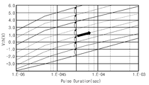
이전 프로그램 루프에서 요구되는 문턱 전압을 갖도록 프로그램된 스트링 선택 트랜지스터(SST)를 프로그램 금지시키기 위해서, 본 발명에 따르면, 스트링 선택 라인(SSL)에 프로그램 전압(Vpgm)이 인가되고, 프로그램 금지된 스트링 선택 트랜지스터(SST)의 드레인 즉, 비트 라인(BL)은 소정 전압(V1)으로 구동될 것이다. 여기서, 소정 전압(V1)은 접지 전압보다 높다. 예를 들면, 소정 전압(V1)은 레지스터 구조의 변경없이 비트 라인(BL)을 구동할 수 있을 정도의 전압(예를 들면, 전원 전압)일 것이다. 이러한 바이어스 조건에 따르면, 도 12에 도시된 바와 같이, 스트링 선택 트랜지스터(SST)의 문턱 전압은 프로그램 루프 반복시 프로그램 전압(Vpgm)의 증가분(△V)만큼 증가되는 것이 아니라 화살표 방향을 따라 즉, 소정 기울기를 갖고 증가될 것이다. 이러한 프로그램 금지 스킴에 의하면, 스트링 선택 트랜지스터(SST)의 문턱 전압은 프로그램 루프 반복시 증가분(△V)내에서 변화될 것이다. 이는 본 발명의 프로그램 금지 스킴에 따라 프로그램되는 스트링 선택 트랜지스터들(SST)의 문턱 전압들의 분포가 넓어지지 않음을 의미한다.According to the present invention, a program voltage Vpgm is applied to a string select line SSL, and a program inhibited string selection is performed to program-prohibit a string select transistor SST programmed to have a threshold voltage required in a previous program loop. The drain of the transistor SST, that is, the bit line BL, is driven to the predetermined voltage V1. Here, the predetermined voltage V1 is higher than the ground voltage. For example, the predetermined voltage V1 may be a voltage (for example, a power supply voltage) that is sufficient to drive the bit line BL without changing the register structure. According to such a bias condition, as shown in FIG. 12, the threshold voltage of the string select transistor SST is not increased by an increment ΔV of the program voltage Vpgm during program loop repetition, ie, in the direction of the arrow. It will be increased with a certain slope. According to this program prohibition scheme, the threshold voltage of the string select transistor SST will change within an increment DELTA V upon program loop iteration. This means that the distribution of threshold voltages of the string select transistors SST programmed according to the program prohibition scheme of the present invention is not widened.
본 발명에 있어서, 도 11 및 도 12를 참조하여 설명된 프로그램 금지 스킴이 이 분야에 잘 알려진 부스팅 스킴을 이용하는 것이 아님에 주의해야 할 것이다. 다른 프로그램 금지 스킴은 레지스터 구조의 변경을 통해 비트 라인을 강제로 F-N 터널링을 방지하기에 충분한 전압(예를 들면, 5V∼6V)으로 구동하는 것이다. 예를 들면, 검증 동작이 수행된 이후에 '1'의 데이터를 저장한 레지스터는 전원 전압 대신 F-N 터널링을 방지하기에 충분한 전압으로 비트 라인을 구동하도록 구현될 것이다. 또 다른 프로그램 스킴은, 도 13에 도시된 바와 같이, 프로그램 금지될 스트링 선택 트랜지스터(SST)에 대응하는 비트 라인을 플로팅시키는 것이다. 비트 라인을 플로팅시키는 것은 앞서 언급된 3차원 어레이 구조 및 미국특허공개번호 제2007-0252201호에 게재된 예시적인 구조에 적합할 것이다.It should be noted that in the present invention, the program inhibiting scheme described with reference to FIGS. 11 and 12 does not use a boosting scheme well known in the art. Another program inhibit scheme is to drive the bit line with a voltage (e.g., 5V to 6V) sufficient to prevent F-N tunneling by changing the register structure. For example, a register that stores data of '1' after the verify operation is performed may be implemented to drive the bit line with a voltage sufficient to prevent F-N tunneling instead of the supply voltage. Another program scheme is to plot the bit line corresponding to the string select transistor SST to be program inhibited, as shown in FIG. Plotting the bit lines would be suitable for the aforementioned three-dimensional array structure and the exemplary structure disclosed in US Patent Publication No. 2007-0252201.
상술한 프로그램 금지 스킴을 이용함으로써 스트링 선택 트랜지스터들(SST) 을 원하는 문턱 전압 분포 내에서 분포되도록 프로그램하는 것이 가능하다.By using the program prohibition scheme described above, it is possible to program the string select transistors SST to be distributed within a desired threshold voltage distribution.
도 14는 본 발명의 실시예에 따른 접지 선택 트랜지스터들을 프로그램 방법을 설명하기 위한 흐름도이고, 도 15는 프로그램 동작시 바이어스 조건을 보여주는 도면이며. 도 16은 검증 동작시 바이어스 조건을 보여주는 도면이다. 이하, 본 발명에 따른 접지 선택 트랜지스터들을 프로그램하는 방법이 참조 도면들에 의거하여 상세히 설명될 것이다.14 is a flowchart illustrating a method of programming ground select transistors according to an exemplary embodiment of the present invention, and FIG. 15 is a diagram illustrating a bias condition during a program operation. 16 illustrates a bias condition in a verify operation. Hereinafter, a method of programming the ground select transistors according to the present invention will be described in detail with reference to the drawings.
먼저 외부 장치(200)는 메모리 셀 어레이(110)의 메모리 블록 수를 나타내는 'BN'을 '0'으로 설정할 것이다(S300). 그 다음에 외부 장치(200)는 플래시 메모리 장치(100)로 데이터를 전송할 것이다(S310). 이때, 메모리 블록을 선택하기 위한 어드레스가 데이터와 함께 플래시 메모리 장치(100)로 전송될 것이다. 플래시 메모리 장치(100)로 전송된 데이터는 입출력 인터페이스(160)를 통해 레지스터 블록(130)에 임시 저장될 것이다. 레지스터 블록(130)은 각 메모리 블록에 속한 접지/스트링 선택 트랜지스터들에 각각 대응하는 레지스터들을 포함할 것이다. 이 실시예에 있어서, 각 레지스터에는 '0'의 데이터가 저장될 것이다. 이는 선택된 메모리 블록에 속한 접지 선택 트랜지스터들 모두가 프로그램됨을 의미한다.First, the
일단 레지스터 블록(130)에 데이터가 로드되면, 선택된 메모리 블록의 접지 선택 트랜지스터들(GST)은 0V의 전압보다 높은 문턱 전압을 갖도록 제어 로직(140)의 제어하에 프로그램될 것이다(S320). 좀 더 구체적으로 설명하면, 선택된 메모리 블록의 워드 라인들(WL0∼WLi-1) 및 스트링 선택 라인(SSL)은 제어 로직(140)의 제어하에 행 선택 회로(120)를 통해 읽기 전압(Vread)으로 구동될 것이다. 이와 동시 에, 접지 선택 라인(GSL)은 제어 로직(140)의 제어하에 행 선택 회로(120)를 통해 프로그램 전압(Vpgm)으로 구동될 것이다. 각 비트 라인(BL)은 대응하는 레지스터에 저장된 데이터 즉, '0'의 데이터에 따라 접지 전압으로 구동될 것이다. 각 접지 선택 트랜지스터(GST)의 문턱 전압은 이러한 바이어스 조건에 의해서 증가될 것이다.Once data is loaded into the
접지 선택 트랜지스터들(GST)을 프로그램한 후, 접지 선택 트랜지스터들(GST)이 요구되는 문턱 전압을 갖도록 프로그램되었는 지의 여부가 판별될 것이다(S330). 이를 위해서, 제어 로직(140)의 제어에 따라, 행 선택 회로(120)는 스트링 선택 라인(SSL) 및 워드 라인들(WL0∼WLi-1)을 읽기 전압(Vread)으로 그리고 접지 선택 라인(GSL)을 검증 전압(VVFY)으로 각각 구동할 것이다. 이때, 공통 소오스 라인(CSL)은 접지 전압으로 구동될 것이다. 만약 접지 선택 트랜지스터(GST)의 문턱 전압이 검증 전압(VVFY)보다 낮으면, 비트 라인(BL)의 전압은 접지 전압으로 낮아질 것이다. 이에 반해서, 접지 선택 트랜지스터(GST)의 문턱 전압이 검증 전압(VVFY)보다 높은 경우, 비트 라인(BL)의 전압은 전원 전압을 향해 높아질 것이다. 비트 라인의 전압은 레지스터를 통해 래치될 것이다. 레지스터 블록(130)에 속한 레지스터들에 각각 래치된 데이터 비트들이 모두 '1'의 데이터 비트들일 때 프로그램 동작이 패스될 것이다. 만약 적어도 하나의 데이터 비트가 '0'의 데이터 비트일 때 프로그램 동작은 페일될 것이다. 전자의 경우, 절차는 다음 단계(S340)로 진행할 것이다. 후자의 경우, 절차는 프로그램 단계(S320)로 진행할 것이다.After programming the ground select transistors GST, it may be determined whether the ground select transistors GST are programmed to have the required threshold voltage (S330). To this end, under the control of the
만약 프로그램 동작이 페일로 판별되면, 요구되는 문턱 전압을 갖도록 프로 그램되지 않은 접지 선택 트랜지스터에 대해서만 프로그램 동작이 다음의 프로그램 루프에서 수행될 것이다. 이때, 요구되는 문턱 전압을 갖도록 프로그램된 접지 선택 트랜지스터에 대해서는 프로그램 동작이 금지될 것이다. 즉, 그러한 접지 선택 트랜지스터는 프로그램 동작 동안 프로그램 금지될 것이다. 비록 도면에는 도시되지 않았지만, 이 분야의 통상적인 지식을 습득한 자에게 잘 알려진 바와 같이, 프로그램 전압은 프로그램 루프의 증가시 정해진 증가분만큼 증가될 것이다. 이는 접지 선택 트랜지스터들(GST)을 프로그램하는 데 ISPP 스킴이 적용됨을 의미한다. 접지 선택 트랜지스터(GST)를 프로그램 금지시키는 방법은 다양하게 구현될 수 있으며, 앞서 설명된 프로그램 금지 스킴들 중 어느 하나를 사용하여 접지 선택 트랜지스터를 프로그램 금지시키는 것이 가능하다.If the program operation is determined to fail, then the program operation will be performed in the next program loop only for ground select transistors that are not programmed to have the required threshold voltage. At this time, the program operation may be prohibited for the ground select transistor programmed to have the required threshold voltage. That is, such a ground select transistor will be program inhibited during the program operation. Although not shown in the figures, as is well known to those of ordinary skill in the art, the program voltage will increase by a predetermined increment upon increase of the program loop. This means that the ISPP scheme is applied to program the ground select transistors GST. The program banning of the ground select transistor GST may be implemented in various ways, and it is possible to program ban the ground select transistor using any of the program inhibit schemes described above.
예를 들면, 도 17에 도시된 바와 같이, 이전 프로그램 루프에서 요구되는 문턱 전압을 갖도록 프로그램된 접지 선택 트랜지스터를 프로그램 금지시키기 위해서, 본 발명에 따르면, 접지 선택 라인(GSL)에 프로그램 전압(Vpgm)이 인가되고, 비트 라인(BL)은 소정 전압(V1)으로 구동되며, 스트링 선택 라인(SSL) 및 워드 라인들(WL0∼WLi-1)은 읽기 전압(Vread)으로 구동될 것이다. 이때, 공통 소오스 라인(CSL)은 플로팅 상태로 유지될 것이다. 이러한 바이어스 조건에 따르면, 도 12를 참조하여 설명된 바와 같이, 접지 선택 트랜지스터(GST)의 문턱 전압은 프로그램 루프 반복시 프로그램 전압(Vpgm)의 증가분(△V)만큼 증가되는 것이 아니라 화살표 방향을 따라 즉, 소정 기울기를 갖고 증가될 것이다. 이러한 프로그램 금지 스킴에 의하면, 접지 선택 트랜지스터(GST)의 문턱 전압은 프로그램 루프 반복시 증가분 (△V)내에서 변화될 것이다.For example, as shown in FIG. 17, in order to program inhibit a ground select transistor programmed to have a threshold voltage required in a previous program loop, in accordance with the present invention, a program voltage Vpgm at a ground select line GSL. The bit line BL is driven to the predetermined voltage V1, and the string select line SSL and the word lines WL0 to WLi-1 are driven to the read voltage Vread. In this case, the common source line CSL may be maintained in a floating state. According to such a bias condition, as described with reference to FIG. 12, the threshold voltage of the ground select transistor GST is not increased by an increment ΔV of the program voltage Vpgm during the program loop iteration, but along the direction of the arrow. That is, it will be increased with a predetermined slope. According to this program prohibition scheme, the threshold voltage of the ground select transistor GST will change within an increment DELTA V upon program loop iteration.
만약 프로그램 동작이 패스로 판별되면, 절차는 S340 단계로 진행되며, 이 단계에서 외부 장치(200)는 모든 메모리 블록들에 속한 접지 선택 트랜지스터들(GST)에 대한 프로그램 동작이 완료되었는 지의 여부를 판별할 것이다. 만약 그렇다면, 메모리 셀 어레이(110)에 속하는 접지 선택 트랜지스터들(GST)을 프로그램하는 과정이 종료될 것이다. 만약 그렇지 않으면, S350 단계에서 메모리 블록 수를 나타내는 'BN' 값이 '1'만큼 증가되고, 절차는 S310 단계로 진행될 것이다. 이후, 앞서 설명된 절차는 모든 메모리 블록들이 선택될 때까지 반복될 것이다.If the program operation is determined to be a pass, the procedure proceeds to step S340, in which the
앞서 설명된 것과 달리, 본 발명의 경우, 검증 동작 없이 즉, 프로그램 금지 스킴을 사용하지 않고 접지 선택 트랜지스터들을 프로그램하는 것이 가능하다. 이는 이하 상세히 설명될 것이다.Contrary to what has been described above, in the case of the present invention, it is possible to program the ground select transistors without a verify operation, i.e. without using a program inhibit scheme. This will be explained in detail below.
도 18은 본 발명의 다른 실시예에 따른 접지 선택 트랜지스터의 프로그램 방법을 설명하기 위한 흐름도이고, 도 19는 프로그램 방법에 따른 바이어스 조건을 보여주는 도면이다. 이하, 본 발명에 따른 접지 선택 트랜지스터의 프로그램 방법이 참조 도면들에 의거하여 상세히 설명될 것이다.18 is a flowchart illustrating a program method of a ground select transistor according to another exemplary embodiment of the present invention, and FIG. 19 is a diagram illustrating a bias condition according to a program method. Hereinafter, a program method of a ground select transistor according to the present invention will be described in detail with reference to the accompanying drawings.
먼저 외부 장치(200)는 메모리 셀 어레이(110)의 메모리 블록 수를 나타내는 'BN'을 '0'으로 설정할 것이다(S400). 그 다음에, 외부 장치(200)는 선택된 메모리 블록의 접지 선택 트랜지스터들(GST)에 대한 프로그램 동작을 플래시 메모리 장치(100)에 요청할 것이다. 외부 장치(200)의 요청에 따라, 선택된 메모리 블록의 접지 선택 트랜지스터들(GST)은 0V의 전압보다 높은 문턱 전압을 갖도록 제어 로 직(140)의 제어하에 프로그램될 것이다(S410).First, the
좀 더 구체적으로 설명하면, 도 19에 도시된 바와 같이, 선택된 메모리 블록의 워드 라인들(WL0∼WLi-1) 및 스트링 선택 라인(SSL)은 제어 로직(140)의 제어하에 행 선택 회로(120)를 통해 접지 전압으로 구동될 것이다. 워드 라인들(WL0∼WLi-1) 및 스트링 선택 라인(SSL)이 접지 전압으로 구동됨에 따라, 스트링 선택 트랜지스터(SST) 및 메모리 셀들(MC0∼MCi-1)은 턴 오프될 것이다. 이와 동시에, 접지 선택 라인(GSL)은 제어 로직(140)의 제어하에 행 선택 회로(120)를 통해 프로그램 전압(Vpgm)으로 구동되며, 공통 소오스 라인(CSL)은 접지 전압으로 구동될 것이다. 프로그램 전압(Vpgm)이 접지 선택 라인(GSL)에 인가되는 시간은 ISPP 스킴을 이용한 것과 다르게 설정될 것이다. 본 발명의 경우, 검증 동작(또는, 프로그램 금지 스킴)을 필요로 하는 ISPP 스킴을 통해 접지 선택 트랜지스터들(GST)을 프로그램하는 것이 아니라, 단일의 프로그램 펄스를 통해 접지 선택 트랜지스터들(GST)이 소정 문턱 전압을 갖도록 프로그램될 것이다.More specifically, as shown in FIG. 19, the word lines WL0 to WLi-1 and the string select line SSL of the selected memory block are controlled by the row
단일의 프로그램 펄스를 이용하여 선택된 메모리 블록의 접지 선택 트랜지스터들(GST)이 프로그램된 후, 외부 장치(200)는 모든 메모리 블록들에 대한 프로그램 동작이 완료되었는 지의 여부를 판별할 것이다(S420). 만약 그렇지 않으면, 절차는 S430 단계로 진행하며, 이 단계에서 메모리 블록 수를 나타내는 'BN' 값이 '1'만큼 증가될 것이다. 이후, 절차는 S410 단계로 진행할 것이다. 앞서 설명된 과정은 모든 메모리 블록들에 대한 반복될 것이다.After the ground selection transistors GST of the selected memory block are programmed using a single program pulse, the
도 20은 본 발명의 다른 예시적인 실시예들에 따른 스트링 구조를 보여주는 블록도이고, 도 21은 도 20의 점선 114-115을 따라 절단된 스트링의 단면을 보여주는 단면도이다.20 is a block diagram illustrating a string structure according to another exemplary embodiment of the present invention, and FIG. 21 is a cross-sectional view illustrating a cross section of the string cut along the dotted lines 114-115 of FIG. 20.
도 20을 참조하면, 각 스트링(111')은 제 1 선택 트랜지스터로서 스트링 선택 트랜지스터(SST), 제 2 선택 트랜지스터로서 접지 선택 트랜지스터(GST), 그리고 선택 트랜지스터들(SST, GST) 사이에 직렬 연결된 메모리 셀들(또는, 메모리 셀 트랜지스터들)(MC0∼MCi-1)을 포함할 것이다. 메모리 셀들 각각은 전하 저장 수단으로서 플로팅 게이트를 갖는 플로팅 게이트 트랜지스터(floating gate transistor)로 구성될 것이다. 마찬가지로, 스트링 선택 트랜지스터(SST) 및 접지 선택 트랜지스터(GST) 각각은 전하 저장 수단으로서 플로팅 게이트를 갖는 플로팅 게이트 트랜지스터로 구성될 것이다. 특히, 도 21에 도시된 바와같이, 스트링 선택 트랜지스터(SST)의 제어 게이트 및 플로팅 게이트는 잘 알려진 버팅 컨택(butting contact)을 통해 전기적으로 연결되지 않을 것이다. 즉, 스트링 선택 트랜지스터(SST)의 제어 게이트와 플로팅 게이트는 메모리 셀 트랜지스터와 같이 전기적으로 서로 분리되어 있다. 이에 반해서, 도 21에 도시된 바와같이, 접지 선택 트랜지스터(GST)의 제어 게이트 및 플로팅 게이트는 잘 알려진 버팅 컨택(butting contact)을 통해 전기적으로 연결될 것이다.Referring to FIG. 20, each
이 실시예에 있어서, 스트링 선택 트랜지스터들(SST)은 원하는 문턱 전압을 갖도록 앞서 언급된 프로그램 방식들을 통해 프로그램되며, 그것에 대한 설명은 그러므로 생략될 것이다. 이 분야의 통상적인 지식을 습득한 자들에게 잘 알려진 바와 같이, 각 메모리 블록을 소거할 때 접지 선택 트랜지스터에 연결된 접지 선택 라인(GSL)은 플로팅 상태로 유지될 것이다.In this embodiment, the string select transistors SST are programmed through the aforementioned programming schemes to have a desired threshold voltage, and a description thereof will therefore be omitted. As is well known to those skilled in the art, the ground select line GSL connected to the ground select transistor will remain floating when erasing each memory block.
도 22은 본 발명의 다른 예시적인 실시예들에 따른 스트링 구조를 보여주는 블록도이고, 도 23은 도 22의 점선 116-117을 따라 절단된 스트링의 단면을 보여주는 단면도이다.FIG. 22 is a block diagram illustrating a string structure according to another exemplary embodiment of the present invention, and FIG. 23 is a cross-sectional view illustrating a string cut along the dotted lines 116-117 of FIG. 22.
도 22를 참조하면, 각 스트링(111")은 제 1 선택 트랜지스터로서 스트링 선택 트랜지스터(SST), 제 2 선택 트랜지스터로서 접지 선택 트랜지스터(GST), 그리고 선택 트랜지스터들(SST, GST) 사이에 직렬 연결된 메모리 셀들(또는, 메모리 셀 트랜지스터들)(MC0∼MCi-1)을 포함할 것이다. 메모리 셀들 각각은 전하 저장 수단으로서 플로팅 게이트를 갖는 플로팅 게이트 트랜지스터(floating gate transistor)로 구성될 것이다. 마찬가지로, 스트링 선택 트랜지스터(SST) 및 접지 선택 트랜지스터(GST) 각각은 전하 저장 수단으로서 플로팅 게이트를 갖는 플로팅 게이트 트랜지스터로 구성될 것이다. 특히, 도 23에 도시된 바와같이, 접지 선택 트랜지스터(GST)의 제어 게이트 및 플로팅 게이트는 잘 알려진 버팅 컨택(butting contact)을 통해 전기적으로 연결되지 않을 것이다. 즉, 접지 선택 트랜지스터(GST)의 제어 게이트와 플로팅 게이트는 메모리 셀 트랜지스터와 같이 전기적으로 서로 분리되어 있다. 이에 반해서, 도 23에 도시된 바와같이, 스트링 선택 트랜지스터(SST)의 제어 게이트 및 플로팅 게이트는 잘 알려진 버팅 컨택(butting contact)을 통해 전기적으로 연결될 것이다.Referring to FIG. 22, each
이 실시예에 있어서, 접지 선택 트랜지스터들(GST)은 요구되는 문턱 전압을 갖도록 앞서 언급된 프로그램 방식들을 통해 프로그램되며, 그것에 대한 설명은 그 러므로 생략될 것이다. 이 분야의 통상적인 지식을 습득한 자들에게 잘 알려진 바와 같이, 각 메모리 블록을 소거할 때 스트링 선택 트랜지스터에 연결된 스트링 선택 라인(SSL)은 플로팅 상태로 유지될 것이다.In this embodiment, the ground select transistors GST are programmed through the aforementioned programming schemes to have the required threshold voltage, and a description thereof will therefore be omitted. As is well known to those skilled in the art, the string select line SSL connected to the string select transistor will remain floating when erasing each memory block.
예시적인 실시예에 있어서, 스트링/접지 선택 트랜지스터들이 프로그램됨에 따라, 정상적인 읽기 동작 동안 선택 라인에는 전원 전압 대신에 읽기 전압 또는 그 보다 높은 전압이 인가될 것이다.In an exemplary embodiment, as the string / ground select transistors are programmed, a read voltage or higher voltage will be applied to the select line during the normal read operation instead of the supply voltage.
본 발명의 예시적인 실시예에 있어서, 선택 트랜지스터의 채널 길이(Lgsl/Lssl)와 플로팅 게이트를 갖는 메모리 셀 트랜지스터의 채널 길이(Lcell)은 (Lgsl/Lssl≥Lcell)과 같은 관계를 갖도록 정의될 것이다. 본 발명의 다른 예시적인 실시예에 따른 스트링 구조 및 스트링 단면을 보여주는 도 24에 도시된 바와 같이, 각 스트링에 속하는 스트링 및 접지 선택 트랜지스터들 각각은 2개 또는 그 보다 많은 선택 트랜지스터들로 구성될 수 있다. 이 경우, 각 스트링에 속하는 스트링/접지 선택 트랜지스터들 모두 프로그램 가능하도록 각 스트링을 구현되거나, 각 스트링에 속하는 스트링/접지 선택 트랜지스터들 중 어느 하나가 프로그램 가능하도록 각 스트링을 구현될 수 있다. 선택 트랜지스터 구조가 여기에 개시된 것에 국한되지 않음은 이 분야의 통상적인 지식을 습득한 자들에게 자명하다.In an exemplary embodiment of the present invention, the channel length Lgsl / Lssl of the selection transistor and the channel length Lcell of the memory cell transistor having the floating gate will be defined to have a relationship such as (Lgsl / Lssl ≧ Lcell). . As shown in FIG. 24 showing a string structure and a string cross section according to another exemplary embodiment of the present invention, each of the string and ground select transistors belonging to each string may be composed of two or more select transistors. have. In this case, each string may be embodied so that all string / ground select transistors belonging to each string may be programmed, or each string may be embodied so that any one of the string / ground select transistors belonging to each string is programmable. It is apparent to those skilled in the art that the selection transistor structure is not limited to that disclosed herein.
도 25a 내지 도 25c는 본 발명의 다른 예시적인 실시예에 따른 스트링 구조를 보여주는 도면들이다. 도 25a에 도시된 바와 같이, 각 스트링은 2개의 스트링 선택 트랜지스터들(SST), 복수의 메모리 셀들(MC0∼MCi-1), 그리고 하나의 접지 선택 트랜지스터(GST)로 구성될 수 있다. 이 경우, 스트링 선택 트랜지스터들(SST) 각각은 프로그램 가능하도록 구성되는 반면에, 접지 선택 트랜지스터(GST)는 스위치로서 기능하도록 구성될 것이다. 이에 반해서, 도 25b에 도시된 바와 같이, 각 스트링은 하나의 스트링 선택 트랜지스터(SST), 복수의 메모리 셀들(MC0∼MCi-1), 그리고 2개의 접지 선택 트랜지스터들(GST)로 구성될 수 있다. 이 경우, 접지 선택 트랜지스터들(GST) 각각은 프로그램 가능하도록 구성되는 반면에, 스트링 선택 트랜지스터(SST)는 스위치로서 기능하도록 구성될 것이다. 또는, 도 25c에 도시된 바와 같이, 2개의 스트링 선택 트랜지스터들(SST), 복수의 메모리 셀들(MC0∼MCi-1), 그리고 2개의 접지 선택 트랜지스터들(GST)로 구성될 수 있다. 이 경우, 접지 선택 트랜지스터들(GST) 각각은 스위치로서 기능하도록 구성될 수 있다. 접지 선택 트랜지스터들의 채널들 및 그것 사이의 공간은 하나의 스트링 선택 트랜지스터 또는 하나의 접지 선택 트랜지스터(도 22에 도시된 접지 선택 트랜지스터를 나타냄)의 채널에 대응할 것이다.25A to 25C are diagrams illustrating a string structure according to another exemplary embodiment of the present invention. As shown in FIG. 25A, each string may include two string select transistors SST, a plurality of memory cells MC0 to MCi-1, and one ground select transistor GST. In this case, each of the string select transistors SST is configured to be programmable while the ground select transistor GST will be configured to function as a switch. In contrast, as illustrated in FIG. 25B, each string may include one string select transistor SST, a plurality of memory cells MC0 to MCi-1, and two ground select transistors GST. . In this case, each of the ground select transistors GST is configured to be programmable, while the string select transistor SST will be configured to function as a switch. Alternatively, as shown in FIG. 25C, two string select transistors SST, a plurality of memory cells MC0 to MCi-1, and two ground select transistors GST may be formed. In this case, each of the ground select transistors GST may be configured to function as a switch. The channels of the ground select transistors and the space therebetween will correspond to the channel of one string select transistor or one ground select transistor (representing the ground select transistor shown in FIG. 22).
본 발명의 예시적인 실시예에 있어서, 선택 트랜지스터들의 프로그래밍은 시장에 출하되기 이전에 행해질 것이다. 예를 들면, 플래시 메모리 장치 즉, 메모리 칩이 패키지되기 이전에 또는 패키지된 후 선택 트랜지스터들을 프로그램하는 것이 가능하다. 또는, 외부 장치로서 메모리 제어기를 통해 시장에 출하되기 이전에 선택 트랜지스터들을 프로그램하는 것이 가능하다. 하지만, 그러한 프로그램 동작이 잘 알려진 제품 시방서에 규정되지 않음에 유의해야 할 것이다. 이에 반해서, 그러한 프로그램 동작이 잘 알려진 제품 시방서에 규정될 수도 있다. 스트링 및 접지 선택 트랜지스터들의 프로그램 동작을 플래시 메모리 장치에 지시하는 것은 다양하 게 구현될 수 있다. 미리 설정된 테스트 모드 하에서 테스트 장치 또는 메모리 제어기와 같은 외부 장치(200)의 정해진 스케쥴에 따라 그러한 동작들이 자동적으로 수행될 수 있다. 하지만, 본 발명의 동작 방법이 여기에 개시된 것에 국한되지 않음은 이 분야의 통상적인 지식을 습득한 자들에게 자명하다.In an exemplary embodiment of the invention, programming of the select transistors will be done prior to shipping to the market. For example, it is possible to program the selection transistors before or after the flash memory device, ie, the memory chip is packaged. Alternatively, it is possible to program the selection transistors prior to shipping to the market via a memory controller as an external device. However, it should be noted that such program behavior is not specified in well-known product specifications. In contrast, such program behavior may be specified in well-known product specifications. Instructing the flash memory device of the program operation of the string and ground select transistors may be variously implemented. Such operations may be automatically performed according to a predetermined schedule of the
본 발명의 예시적인 실시예에 있어서, 선택 트랜지스터들에 대한 프로그램 과정이 종료된 후, 각 메모리 블록의 메모리 셀들은 소거될 것이다. 이때, 프로그램된 선택 트랜지스터들은 소거되지 않는다. 이는 소거 동작 동안 선택 트랜지스터에 연결된 선택 라인을 플로팅 상태로 유지시킴으로써 달성될 것이다.In an exemplary embodiment of the present invention, after the programming process for the select transistors is finished, the memory cells of each memory block will be erased. At this time, the programmed select transistors are not erased. This will be accomplished by keeping the select line connected to the select transistor floating during the erase operation.
본 발명의 예시적인 실시예에 있어서, 스트링 선택 라인(SSL)과 접지 선택 라인(GSL)의 구동 전압이 동작 모드에 따라 읽기 전압 또는 접지 전압으로 설정되었다. 하지만, 스트링 선택 라인(SSL)과 접지 선택 라인(GSL)의 구동 전압이 여기에 개시된 것에 국한되지 않음은 이 분야의 통상적인 지식을 습득한 자들에게 자명하다. 예를 들면, 스트링 선택 라인(SSL)과 접지 선택 라인(GSL)의 구동 전압이 동작 모드에 따라 읽기 전압으로, 읽기 전압보다 낮고 접지 전압보다 높게, 또는 읽기 전압보다 높게 설정될 수 있다.In an exemplary embodiment of the present invention, the driving voltages of the string select line SSL and the ground select line GSL are set to the read voltage or the ground voltage according to the operation mode. However, it is apparent to those skilled in the art that the driving voltages of the string select line SSL and the ground select line GSL are not limited to those disclosed herein. For example, the driving voltages of the string select line SSL and the ground select line GSL may be set as read voltages, which are lower than the read voltage, higher than the ground voltage, or higher than the read voltage, depending on the operation mode.
플래시 메모리 장치는 전력이 차단되어도 저장된 데이터를 유지할 수 있는 불 휘발성 메모리 장치이다. 셀룰러 폰, PDA 디지털 카메라, 포터블 게임 콘솔, 그리고 MP3P와 같은 모바일 장치들의 사용 증가에 따라, 플래시 메모리 장치는 데이터 스토리지 뿐만 아니라 코드 스토리지로서 보다 널리 사용된다. 플래시 메모리 장치는, 또한, HDTV, DVD, 라우터, 그리고 GPS와 같은 홈 어플리케이션에 사용될 수 있다. 본 발명에 따른 메모리 시스템을 포함한 컴퓨팅 시스템이 도 26에 개략적으로 도시되어 있다. 본 발명에 따른 컴퓨팅 시스템은 버스(2001)에 전기적으로 연결된 마이크로프로세서(2100), 사용자 인터페이스(2200), 베이스밴드 칩셋(baseband chipset)과 같은 모뎀(2300), 메모리 제어기(2400), 그리고 플래시 메모리 장치(2500)를 포함한다. 메모리 제어기(2400)는 도 1에 도시된 외부 장치에 대응하며, 플래시 메모리 장치(2500)는 도 1에 도시된 것과 실질적으로 동일하게 구성될 것이다. 플래시 메모리 장치(2500)에는 마이크로프로세서(2100)에 의해서 처리된/처리될 N-비트 데이터(N은 1 또는 그 보다 큰 정수)가 메모리 제어기(2400)를 통해 저장될 것이다. 본 발명에 따른 컴퓨팅 시스템이 모바일 장치인 경우, 컴퓨팅 시스템의 동작 전압을 공급하기 위한 배터리(2600)가 추가적으로 제공될 것이다. 비록 도면에는 도시되지 않았지만, 본 발명에 따른 컴퓨팅 시스템에는 응용 칩셋(application chipset), 카메라 이미지 프로세서(Camera Image Processor: CIS), 모바일 디램, 등이 더 제공될 수 있음은 이 분야의 통상적인 지식을 습득한 자들에게 자명하다. 메모리 제어기(2400)와 플래시 메모리 장치(2500)는, 예를 들면, 데이터를 저장하는 데 불 휘발성 메모리를 사용하는 SSD(Solid State Drive/Disk)를 구성할 수 있다. 또는, 메모리 제어기(2400)와 플래시 메모리 장치(2500)는 데이터를 저장하는 데 불 휘발성 메모리를 메모리 카드를 구성할 수 있다.Flash memory devices are nonvolatile memory devices capable of retaining stored data even when power is cut off. With the growing use of mobile devices such as cellular phones, PDA digital cameras, portable game consoles, and MP3Ps, flash memory devices are becoming more widely used as code storage as well as data storage. Flash memory devices can also be used for home applications such as HDTV, DVD, routers, and GPS. A computing system including the memory system according to the present invention is schematically illustrated in FIG. The computing system according to the present invention includes a
본 발명에 따른 플래시 메모리 장치 그리고/또는 메모리 제어기는 다양한 형태들의 패키지를 이용하여 실장될 수 있다. 예를 들면, 본 발명에 따른 플래시 메모리 장치 그리고/또는 메모리 제어기는 PoP(Package on Package), Ball grid arrays(BGAs), Chip scale packages(CSPs), Plastic Leaded Chip Carrier(PLCC), Plastic Dual In-Line Package(PDIP), Die in Waffle Pack, Die in Wafer Form, Chip On Board(COB), Ceramic Dual In-Line Package(CERDIP), Plastic Metric Quad Flat Pack(MQFP), Thin Quad Flatpack(TQFP), Small Outline(SOIC), Shrink Small Outline Package(SSOP), Thin Small Outline(TSOP), Thin Quad Flatpack(TQFP), System In Package(SIP), Multi Chip Package(MCP), Wafer-level Fabricated Package(WFP), Wafer-Level Processed Stack Package(WSP), 등과 같은 패키지들을 이용하여 실장될 수 있다.The flash memory device and / or the memory controller according to the present invention may be mounted using various types of packages. For example, the flash memory device and / or the memory controller according to the present invention may be a package on package (PoP), ball grid arrays (BGAs), chip scale packages (CSPs), plastic leaded chip carrier (PLCC), plastic dual in- Line Package (PDIP), Die in Waffle Pack, Die in Wafer Form, Chip On Board (COB), Ceramic Dual In-Line Package (CERDIP), Plastic Metric Quad Flat Pack (MQFP), Thin Quad Flatpack (TQFP), Small Outline (SOIC), Shrink Small Outline Package (SSOP), Thin Small Outline (TSOP), Thin Quad Flatpack (TQFP), System In Package (SIP), Multi Chip Package (MCP), Wafer-level Fabricated Package (WFP), It can be implemented using packages such as Wafer-Level Processed Stack Package (WSP), or the like.
본 발명의 범위 또는 기술적 사상을 벗어나지 않고 본 발명의 구조가 다양하게 수정되거나 변경될 수 있음은 이 분야에 숙련된 자들에게 자명하다. 상술한 내용을 고려하여 볼 때, 만약 본 발명의 수정 및 변경이 아래의 청구항들 및 동등물의 범주 내에 속한다면, 본 발명이 이 발명의 변경 및 수정을 포함하는 것으로 여겨진다.It will be apparent to those skilled in the art that the structure of the present invention may be variously modified or changed without departing from the scope or spirit of the present invention. In view of the foregoing, it is believed that the present invention includes modifications and variations of this invention provided they come within the scope of the following claims and their equivalents.
도 1은 본 발명에 따른 플래시 메모리 장치를 개략적으로 보여주는 블록도이다.1 is a block diagram schematically illustrating a flash memory device according to the present invention.
도 2는 예시적인 실시예에 따른 메모리 블록을 보여주는 블록도이다.2 is a block diagram illustrating a memory block according to an exemplary embodiment.
도 3은 도 2의 점선 112-113을 따라 절단된 스트링의 단면을 보여주는 단면도이다.3 is a cross-sectional view illustrating a cross section of a string cut along the dotted lines 112-113 of FIG. 2.
도 4는 본 발명에 따른 플래시 메모리 장치의 동작 방법을 설명하기 위한 흐름도이다.4 is a flowchart illustrating a method of operating a flash memory device according to the present invention.
도 5는 본 발명에 따른 플래시 메모리 장치의 소거 동작시 바이어스 조건을 보여주는 도면이다.5 illustrates a bias condition during an erase operation of a flash memory device according to the present invention.
도 6은 본 발명에 따른 플래시 메모리 장치의 프로그램 동작시 바이어스 조건을 보여주는 도면이다.6 illustrates a bias condition during a program operation of a flash memory device according to the present invention.
도 7은 스트링 선택 트랜지스터들을 프로그램 방법을 개략적으로 보여주는 흐름도이다.7 is a flowchart schematically illustrating a method of programming string select transistors.
도 8은 프로그램 동작시 바이어스 조건을 보여주는 도면이다.8 illustrates a bias condition during a program operation.
도 9는 검증 동작시 바이어스 조건을 보여주는 도면이다.9 illustrates a bias condition in a verify operation.
도 10은 검증 동작시 검증 전압을 보여주는 도면이다.10 is a diagram illustrating a verify voltage during a verify operation.
도 11은 본 발명에 따른 스트링 선택 트랜지스터의 프로그램 금지 방법을 설명하기 위한 도면이다.11 is a view for explaining a program inhibiting method of a string select transistor according to the present invention.
도 12는 프로그램 루프 반복시 문턱 전압의 변화를 보여주는 그래프이다.12 is a graph showing a change in threshold voltage during program loop repetition.
도 13은 본 발명의 다른 실시예에 따른 스트링 선택 트랜지스터의 프로그램 금지 방법을 설명하기 위한 도면이다.FIG. 13 is a diagram for describing a program inhibiting method of a string select transistor according to another exemplary embodiment of the present invention.
도 14는 본 발명의 실시예에 따른 접지 선택 트랜지스터들을 프로그램 방법을 설명하기 위한 흐름도이다.14 is a flowchart illustrating a method of programming ground select transistors according to an exemplary embodiment of the present invention.
도 15는 프로그램 동작시 바이어스 조건을 보여주는 도면이다.15 illustrates a bias condition during a program operation.
도 16은 검증 동작시 바이어스 조건을 보여주는 도면이다.16 illustrates a bias condition in a verify operation.
도 17은 본 발명에 따른 접지 선택 트랜지스터의 프로그램 금지 방법을 설명하기 위한 도면이다.17 is a diagram illustrating a program prohibition method of a ground select transistor according to the present invention.
도 18은 본 발명의 다른 실시예에 따른 접지 선택 트랜지스터의 프로그램 방법을 설명하기 위한 흐름도이다.18 is a flowchart illustrating a program method of a ground select transistor according to another exemplary embodiment of the present invention.
도 19는 프로그램 방법에 따른 바이어스 조건을 보여주는 도면이다.19 illustrates a bias condition according to a program method.
도 20은 본 발명의 다른 예시적인 실시예들에 따른 스트링 구조를 보여주는 블록도이다.20 is a block diagram illustrating a string structure according to other exemplary embodiments of the present invention.
도 21은 도 20의 점선 114-115을 따라 절단된 스트링의 단면을 보여주는 단면도이다.FIG. 21 is a cross-sectional view illustrating a string cut along a dotted line 114-115 of FIG. 20.
도 22은 본 발명의 다른 예시적인 실시예들에 따른 스트링 구조를 보여주는 블록도이다.Fig. 22 is a block diagram showing a string structure according to other exemplary embodiments of the present invention.
도 23은 도 22의 점선 116-117을 따라 절단된 스트링의 단면을 보여주는 단면도이다.FIG. 23 is a cross-sectional view illustrating a string cut along a dotted line 116-117 of FIG. 22.
도 24는 본 발명의 다른 예시적인 실시예에 따른 스트링 구조 및 스트링 단 면을 보여주는 도면이다.24 is a diagram showing a string structure and a string cross section according to another exemplary embodiment of the present invention.
도 25a 내지 도 25c는 본 발명의 다른 예시적인 실시예에 따른 스트링 구조를 보여주는 도면이다.25A-25C illustrate a string structure in accordance with another exemplary embodiment of the present invention.
도 26은 본 발명에 따른 메모리 시스템을 포함한 컴퓨팅 시스템을 개략적으로 보여주는 블록도이다.26 is a block diagram schematically illustrating a computing system including a memory system according to the present disclosure.
Claims (20)
Priority Applications (7)
| Application Number | Priority Date | Filing Date | Title |
|---|---|---|---|
| KR1020080046129A KR20090120205A (en) | 2008-05-19 | 2008-05-19 | Flash memory device and its operation method |
| US12/424,135 US8243518B2 (en) | 2008-05-19 | 2009-04-15 | NAND flash memory device and method of making same |
| DE200910021715 DE102009021715A1 (en) | 2008-05-19 | 2009-05-18 | Flash memory device e.g. flash memory card, for use in computer system e.g. personal computer, has floating gate type memory transistor as selection transistor of memory block's NAND cell unit for storing random data in memory blocks |
| CNA2009102030829A CN101587747A (en) | 2008-05-19 | 2009-05-19 | Nand flash memory device and method of making same |
| TW098116559A TW200951964A (en) | 2008-05-19 | 2009-05-19 | NAND flash memory device and method of making same |
| US13/553,242 US8654585B2 (en) | 2008-05-19 | 2012-07-19 | NAND flash memory device and method of making same |
| US15/047,077 USRE47169E1 (en) | 2008-05-19 | 2016-02-18 | NAND flash memory device and method of making same |
Applications Claiming Priority (1)
| Application Number | Priority Date | Filing Date | Title |
|---|---|---|---|
| KR1020080046129A KR20090120205A (en) | 2008-05-19 | 2008-05-19 | Flash memory device and its operation method |
Publications (1)
| Publication Number | Publication Date |
|---|---|
| KR20090120205A true KR20090120205A (en) | 2009-11-24 |
Family
ID=41317247
Family Applications (1)
| Application Number | Title | Priority Date | Filing Date |
|---|---|---|---|
| KR1020080046129A Ceased KR20090120205A (en) | 2008-05-19 | 2008-05-19 | Flash memory device and its operation method |
Country Status (4)
| Country | Link |
|---|---|
| US (3) | US8243518B2 (en) |
| KR (1) | KR20090120205A (en) |
| CN (1) | CN101587747A (en) |
| TW (1) | TW200951964A (en) |
Cited By (2)
| Publication number | Priority date | Publication date | Assignee | Title |
|---|---|---|---|---|
| WO2019103445A1 (en) * | 2017-11-22 | 2019-05-31 | 서울대학교산학협력단 | Flash memory device for protecting data by programing selection transistor of cell string, and data storage device comprising same |
| WO2019107608A1 (en) * | 2017-11-29 | 2019-06-06 | 주식회사 더볼터 | Method and system for counting data set |
Families Citing this family (82)
| Publication number | Priority date | Publication date | Assignee | Title |
|---|---|---|---|---|
| CA2596506C (en) * | 2005-02-09 | 2021-04-06 | Avi Biopharma, Inc. | Antisense composition and method for treating muscle atrophy |
| US9391079B2 (en) | 2007-11-29 | 2016-07-12 | Zeno Semiconductor, Inc. | Compact semiconductor memory device having reduced number of contacts, methods of operating and methods of making |
| US9601493B2 (en) | 2006-11-29 | 2017-03-21 | Zeno Semiconductor, Inc | Compact semiconductor memory device having reduced number of contacts, methods of operating and methods of making |
| US8547756B2 (en) | 2010-10-04 | 2013-10-01 | Zeno Semiconductor, Inc. | Semiconductor memory device having an electrically floating body transistor |
| US8514622B2 (en) | 2007-11-29 | 2013-08-20 | Zeno Semiconductor, Inc. | Compact semiconductor memory device having reduced number of contacts, methods of operating and methods of making |
| US8295087B2 (en) * | 2008-06-16 | 2012-10-23 | Aplus Flash Technology, Inc. | Row-decoder and select gate decoder structures suitable for flashed-based EEPROM operating below +/− 10v BVDS |
| KR101076880B1 (en) * | 2008-09-24 | 2011-10-25 | 주식회사 하이닉스반도체 | Method for programming NAND type flash memory |
| US8692310B2 (en) | 2009-02-09 | 2014-04-08 | Spansion Llc | Gate fringing effect based channel formation for semiconductor device |
| KR101658479B1 (en) | 2010-02-09 | 2016-09-21 | 삼성전자주식회사 | Nonvolatile memory device, operating method thereof and memory system including the same |
| KR101691092B1 (en) | 2010-08-26 | 2016-12-30 | 삼성전자주식회사 | Nonvolatile memory device, operating method thereof and memory system including the same |
| US9324440B2 (en) | 2010-02-09 | 2016-04-26 | Samsung Electronics Co., Ltd. | Nonvolatile memory devices, operating methods thereof and memory systems including the same |
| KR101691088B1 (en) | 2010-02-17 | 2016-12-29 | 삼성전자주식회사 | Nonvolatile memory device, operating method thereof and memory system including the same |
| US9378831B2 (en) | 2010-02-09 | 2016-06-28 | Samsung Electronics Co., Ltd. | Nonvolatile memory devices, operating methods thereof and memory systems including the same |
| US8908431B2 (en) | 2010-02-17 | 2014-12-09 | Samsung Electronics Co., Ltd. | Control method of nonvolatile memory device |
| JP5788183B2 (en) * | 2010-02-17 | 2015-09-30 | 三星電子株式会社Samsung Electronics Co.,Ltd. | Nonvolatile memory device, method of operating the same, and memory system including the same |
| US8228735B2 (en) * | 2010-02-17 | 2012-07-24 | Micron Technology, Inc. | Memory array having memory cells coupled between a programmable drain select gate and a non-programmable source select gate |
| US8923060B2 (en) | 2010-02-17 | 2014-12-30 | Samsung Electronics Co., Ltd. | Nonvolatile memory devices and operating methods thereof |
| JP2011170956A (en) | 2010-02-18 | 2011-09-01 | Samsung Electronics Co Ltd | Nonvolatile memory device, programming method thereof and memory system including the same |
| KR20110098119A (en) * | 2010-02-26 | 2011-09-01 | 삼성전자주식회사 | Cell strings in a memory cell array |
| US10461084B2 (en) | 2010-03-02 | 2019-10-29 | Zeno Semiconductor, Inc. | Compact semiconductor memory device having reduced number of contacts, methods of operating and methods of making |
| US9922981B2 (en) | 2010-03-02 | 2018-03-20 | Zeno Semiconductor, Inc. | Compact semiconductor memory device having reduced number of contacts, methods of operating and methods of making |
| US8792282B2 (en) | 2010-03-04 | 2014-07-29 | Samsung Electronics Co., Ltd. | Nonvolatile memory devices, memory systems and computing systems |
| US8553466B2 (en) | 2010-03-04 | 2013-10-08 | Samsung Electronics Co., Ltd. | Non-volatile memory device, erasing method thereof, and memory system including the same |
| KR101662821B1 (en) | 2010-06-16 | 2016-10-05 | 삼성전자주식회사 | Multi-page program method, non-volatile memory device usign the same, and data storage system including the same |
| KR20120001405A (en) * | 2010-06-29 | 2012-01-04 | 삼성전자주식회사 | Memory system and its wear leveling method |
| KR101742790B1 (en) | 2010-11-16 | 2017-06-01 | 삼성전자주식회사 | Nonvolatile memory device, erasing method thereof and memoryb system including the same |
| US9136005B2 (en) | 2010-11-16 | 2015-09-15 | Samsung Electronics Co., Ltd. | Erasing methods of three-dimensional nonvolatile memory devices with cell strings and dummy word lines |
| JP2012203972A (en) * | 2011-03-28 | 2012-10-22 | Toshiba Corp | Control method of nonvolatile semiconductor storage device |
| KR101762828B1 (en) | 2011-04-05 | 2017-07-31 | 삼성전자주식회사 | Nonvolatile memory device and operating method of nonvolatile memory device |
| KR20130005463A (en) * | 2011-07-06 | 2013-01-16 | 삼성전자주식회사 | Method of forming micropattern, method of damascene metallization, and semiconductor device and semiconductor memory device fabricated using the same |
| JP2013058276A (en) * | 2011-09-07 | 2013-03-28 | Toshiba Corp | Semiconductor memory device |
| US20130083472A1 (en) * | 2011-09-30 | 2013-04-04 | Igt | Ruggedized data storage and communication apparatus and method |
| US9111619B2 (en) | 2011-10-17 | 2015-08-18 | Samsung Electronics Co., Ltd. | Semiconductor memory devices and methods of manufacturing the same |
| US9159374B2 (en) * | 2011-11-02 | 2015-10-13 | Novachips Canada Inc. | Flash memory module and memory subsystem |
| KR101857529B1 (en) | 2011-11-08 | 2018-05-15 | 삼성전자주식회사 | Nonvolatile memory device and driving method thereof |
| US8755227B2 (en) * | 2012-01-30 | 2014-06-17 | Phison Electronics Corp. | NAND flash memory unit, NAND flash memory array, and methods for operating them |
| KR101903440B1 (en) | 2012-02-21 | 2018-10-02 | 삼성전자주식회사 | Nonvolatile memory device and threshold adjusting method of ground selection transistor thereof |
| US8976594B2 (en) | 2012-05-15 | 2015-03-10 | Micron Technology, Inc. | Memory read apparatus and methods |
| US8867271B2 (en) | 2012-05-30 | 2014-10-21 | Sandisk Technologies Inc. | Threshold voltage adjustment for a select gate transistor in a stacked non-volatile memory device |
| JP2013254537A (en) | 2012-06-06 | 2013-12-19 | Toshiba Corp | Semiconductor memory and controller |
| US9064577B2 (en) | 2012-12-06 | 2015-06-23 | Micron Technology, Inc. | Apparatuses and methods to control body potential in memory operations |
| US8861282B2 (en) | 2013-01-11 | 2014-10-14 | Sandisk Technologies Inc. | Method and apparatus for program and erase of select gate transistors |
| US9029922B2 (en) | 2013-03-09 | 2015-05-12 | Zeno Semiconductor, Inc. | Memory device comprising electrically floating body transistor |
| US8797800B1 (en) | 2013-04-02 | 2014-08-05 | Sandisk Technologies Inc. | Select gate materials having different work functions in non-volatile memory |
| US9123425B2 (en) | 2013-04-02 | 2015-09-01 | Sandisk Technologies Inc. | Adjusting control gate overdrive of select gate transistors during programming of non-volatile memory |
| US9275723B2 (en) | 2013-04-10 | 2016-03-01 | Zeno Semiconductor, Inc. | Scalable floating body memory cell for memory compilers and method of using floating body memories with memory compilers |
| US9558108B2 (en) * | 2013-04-15 | 2017-01-31 | Macronix International Co., Ltd. | Half block management for flash storage devices |
| US9368625B2 (en) | 2013-05-01 | 2016-06-14 | Zeno Semiconductor, Inc. | NAND string utilizing floating body memory cell |
| US9183940B2 (en) | 2013-05-21 | 2015-11-10 | Aplus Flash Technology, Inc. | Low disturbance, power-consumption, and latency in NAND read and program-verify operations |
| US9263137B2 (en) | 2013-06-27 | 2016-02-16 | Aplus Flash Technology, Inc. | NAND array architecture for multiple simutaneous program and read |
| TW201503768A (en) * | 2013-07-05 | 2015-01-16 | Phison Electronics Corp | Pad structure and printed circuit board and memory storage device using the same |
| WO2015013689A2 (en) | 2013-07-25 | 2015-01-29 | Aplus Flash Technology, Inc. | Nand array hiarchical bl structures for multiple-wl and all -bl simultaneous erase, erase-verify, program, program-verify, and read operations |
| US9293205B2 (en) | 2013-09-14 | 2016-03-22 | Aplus Flash Technology, Inc | Multi-task concurrent/pipeline NAND operations on all planes |
| KR102242022B1 (en) | 2013-09-16 | 2021-04-21 | 삼성전자주식회사 | Nonvolatile memory device and program method using thereof |
| KR102154620B1 (en) * | 2013-12-19 | 2020-09-10 | 삼성전자주식회사 | Erase methof of nonvolatile memory device and storage device having the same |
| US9613704B2 (en) | 2013-12-25 | 2017-04-04 | Aplus Flash Technology, Inc | 2D/3D NAND memory array with bit-line hierarchical structure for multi-page concurrent SLC/MLC program and program-verify |
| US9659636B2 (en) | 2014-07-22 | 2017-05-23 | Peter Wung Lee | NAND memory array with BL-hierarchical structure for concurrent all-BL, all-threshold-state program, and alternative-WL program, odd/even read and verify operations |
| US9324437B2 (en) * | 2014-07-30 | 2016-04-26 | Macronix International Co., Ltd. | Systems and methods for trimming control transistors for 3D NAND flash |
| KR20160029506A (en) * | 2014-09-05 | 2016-03-15 | 에스케이하이닉스 주식회사 | Semiconductor memory device including 3-dimensional memory cell array and operating method thereof |
| US9418751B1 (en) * | 2015-01-23 | 2016-08-16 | Sandisk Technologies Llc | Pre-program detection of threshold voltages of select gate transistors in a memory device |
| KR20160139991A (en) * | 2015-05-29 | 2016-12-07 | 에스케이하이닉스 주식회사 | Semiconductor device and operating method thereof |
| KR102302433B1 (en) * | 2015-06-10 | 2021-09-16 | 삼성전자주식회사 | Nonvolatile memory device and erasing method thereof |
| KR102294848B1 (en) | 2015-06-30 | 2021-08-31 | 삼성전자주식회사 | Storage device including nonvolatile memory device and controller |
| JP6470146B2 (en) * | 2015-08-27 | 2019-02-13 | 東芝メモリ株式会社 | Semiconductor memory device |
| US9715938B2 (en) | 2015-09-21 | 2017-07-25 | Sandisk Technologies Llc | Non-volatile memory with supplemental select gates |
| US9792999B2 (en) | 2015-10-30 | 2017-10-17 | SK Hynix Inc. | Adaptive scheme for incremental step pulse programming of flash memory |
| JP2017111847A (en) * | 2015-12-17 | 2017-06-22 | 株式会社東芝 | Semiconductor memory device |
| US9466369B1 (en) * | 2015-12-21 | 2016-10-11 | Sandisk Technologies Llc | Word line-dependent ramping of pass voltage and program voltage for three-dimensional memory |
| US9779819B1 (en) | 2016-06-24 | 2017-10-03 | Micron Technology, Inc. | Connecting memory cells to a data line sequentially while applying a program voltage to the memory cells |
| KR102650333B1 (en) * | 2016-08-10 | 2024-03-25 | 삼성전자주식회사 | Nonvolatile memory device and storage device including nonvolatile memory device |
| US10176880B1 (en) | 2017-07-01 | 2019-01-08 | Intel Corporation | Selective body reset operation for three dimensional (3D) NAND memory |
| US10366766B2 (en) | 2017-12-12 | 2019-07-30 | Western Digital Technologies, Inc. | Power shaping and peak power reduction by data transfer throttling |
| CN109935250B (en) * | 2017-12-15 | 2021-03-12 | 旺宏电子股份有限公司 | Memory device and operation method thereof |
| US10734070B2 (en) * | 2018-06-26 | 2020-08-04 | Sandisk Technologies Llc | Programming selection devices in non-volatile memory strings |
| KR102461751B1 (en) * | 2018-07-31 | 2022-11-02 | 에스케이하이닉스 주식회사 | Memory device and operating method thereof |
| US10942799B1 (en) | 2019-09-06 | 2021-03-09 | Intel Corporation | Defective bit line management in connection with a memory access |
| KR102834551B1 (en) | 2020-12-15 | 2025-07-14 | 삼성전자주식회사 | memory card |
| CN115881199A (en) | 2021-09-27 | 2023-03-31 | 三星电子株式会社 | Memory device and programming method thereof |
| KR20230055270A (en) | 2021-10-18 | 2023-04-25 | 삼성전자주식회사 | Non-volatile Memory Device |
| KR20230066834A (en) | 2021-11-08 | 2023-05-16 | 삼성전자주식회사 | Nonvolatile memory and storage device including the same |
| KR20240048176A (en) * | 2022-10-06 | 2024-04-15 | 에스케이하이닉스 주식회사 | Nonvolatile memory device including selection transistors and operation method thereof |
| KR20240109125A (en) * | 2023-01-03 | 2024-07-10 | 삼성전자주식회사 | Memory device precharging common source line and operating method of the same |
Family Cites Families (27)
| Publication number | Priority date | Publication date | Assignee | Title |
|---|---|---|---|---|
| KR0172441B1 (en) | 1995-09-19 | 1999-03-30 | 김광호 | Programming method of non-volatile semiconductor memory |
| US5991202A (en) | 1998-09-24 | 1999-11-23 | Advanced Micro Devices, Inc. | Method for reducing program disturb during self-boosting in a NAND flash memory |
| JP4128737B2 (en) | 2000-11-14 | 2008-07-30 | 株式会社東芝 | Semiconductor device and method for manufacturing semiconductor memory device |
| JP3957985B2 (en) | 2001-03-06 | 2007-08-15 | 株式会社東芝 | Nonvolatile semiconductor memory device |
| US20060180851A1 (en) | 2001-06-28 | 2006-08-17 | Samsung Electronics Co., Ltd. | Non-volatile memory devices and methods of operating the same |
| DE10228768A1 (en) | 2001-06-28 | 2003-01-16 | Samsung Electronics Co Ltd | Non-volatile floating trap storage device comprises a semiconductor substrate, a tunnel insulation layer on the substrate, a charge storage layer, a barrier insulation layer, and a gate electrode |
| US7253467B2 (en) | 2001-06-28 | 2007-08-07 | Samsung Electronics Co., Ltd. | Non-volatile semiconductor memory devices |
| US7177197B2 (en) * | 2001-09-17 | 2007-02-13 | Sandisk Corporation | Latched programming of memory and method |
| KR100502412B1 (en) * | 2002-10-23 | 2005-07-19 | 삼성전자주식회사 | Non-volatile semiconductor memory device and program method thereof |
| JP2005085428A (en) * | 2003-09-11 | 2005-03-31 | Renesas Technology Corp | Nonvolatile semiconductor memory device |
| US6977842B2 (en) * | 2003-09-16 | 2005-12-20 | Micron Technology, Inc. | Boosted substrate/tub programming for flash memories |
| KR100540928B1 (en) * | 2003-11-05 | 2006-01-11 | 김연찬 | Construction method of anchor bolt and anchor bolt |
| KR100562506B1 (en) * | 2003-12-01 | 2006-03-21 | 삼성전자주식회사 | Flash memory device and its program method |
| KR100632942B1 (en) * | 2004-05-17 | 2006-10-12 | 삼성전자주식회사 | How to Program a Nonvolatile Memory Device |
| US7173859B2 (en) | 2004-11-16 | 2007-02-06 | Sandisk Corporation | Faster programming of higher level states in multi-level cell flash memory |
| US7092290B2 (en) | 2004-11-16 | 2006-08-15 | Sandisk Corporation | High speed programming system with reduced over programming |
| US6980471B1 (en) * | 2004-12-23 | 2005-12-27 | Sandisk Corporation | Substrate electron injection techniques for programming non-volatile charge storage memory cells |
| US7177191B2 (en) * | 2004-12-30 | 2007-02-13 | Sandisk 3D Llc | Integrated circuit including memory array incorporating multiple types of NAND string structures |
| KR100673229B1 (en) | 2005-07-04 | 2007-01-22 | 주식회사 하이닉스반도체 | NAND flash memory device and manufacturing method thereof |
| KR20070050173A (en) | 2005-11-10 | 2007-05-15 | 주식회사 하이닉스반도체 | Manufacturing Method of Semiconductor Device |
| US7489546B2 (en) * | 2005-12-20 | 2009-02-10 | Micron Technology, Inc. | NAND architecture memory devices and operation |
| US7554854B2 (en) * | 2006-03-31 | 2009-06-30 | Semiconductor Energy Laboratory Co., Ltd. | Method for deleting data from NAND type nonvolatile memory |
| EP1850347A1 (en) * | 2006-04-28 | 2007-10-31 | Deutsche Thomson-Brandt Gmbh | Method and device for writing to a flash memory |
| KR20090010481A (en) * | 2007-07-23 | 2009-01-30 | 삼성전자주식회사 | NAND flash memory device, and its programming method to program optional transistors |
| KR101358752B1 (en) * | 2007-08-06 | 2014-02-06 | 삼성전자주식회사 | Nonvolatile memory device, memory system having its, and programming method thereof |
| KR100894784B1 (en) * | 2007-09-10 | 2009-04-24 | 주식회사 하이닉스반도체 | Program method of flash memory device |
| US8335108B2 (en) * | 2008-11-14 | 2012-12-18 | Aplus Flash Technology, Inc. | Bit line gate transistor structure for a multilevel, dual-sided nonvolatile memory cell NAND flash array |
-
2008
- 2008-05-19 KR KR1020080046129A patent/KR20090120205A/en not_active Ceased
-
2009
- 2009-04-15 US US12/424,135 patent/US8243518B2/en not_active Expired - Fee Related
- 2009-05-19 CN CNA2009102030829A patent/CN101587747A/en active Pending
- 2009-05-19 TW TW098116559A patent/TW200951964A/en unknown
-
2012
- 2012-07-19 US US13/553,242 patent/US8654585B2/en not_active Ceased
-
2016
- 2016-02-18 US US15/047,077 patent/USRE47169E1/en active Active
Cited By (4)
| Publication number | Priority date | Publication date | Assignee | Title |
|---|---|---|---|---|
| WO2019103445A1 (en) * | 2017-11-22 | 2019-05-31 | 서울대학교산학협력단 | Flash memory device for protecting data by programing selection transistor of cell string, and data storage device comprising same |
| US11222701B2 (en) | 2017-11-22 | 2022-01-11 | Seoul National University R&Db Foundation | Flash memory device for protecting data by programing selection transistor of cell string, and data storage device comprising same |
| WO2019107608A1 (en) * | 2017-11-29 | 2019-06-06 | 주식회사 더볼터 | Method and system for counting data set |
| KR20190062987A (en) * | 2017-11-29 | 2019-06-07 | 주식회사 더볼터 | Method and system for counting data set |
Also Published As
| Publication number | Publication date |
|---|---|
| US20120281475A1 (en) | 2012-11-08 |
| CN101587747A (en) | 2009-11-25 |
| TW200951964A (en) | 2009-12-16 |
| US20090287879A1 (en) | 2009-11-19 |
| USRE47169E1 (en) | 2018-12-18 |
| US8243518B2 (en) | 2012-08-14 |
| US8654585B2 (en) | 2014-02-18 |
Similar Documents
| Publication | Publication Date | Title |
|---|---|---|
| KR20090120205A (en) | Flash memory device and its operation method | |
| KR100890016B1 (en) | Nonvolatile memory device, memory system comprising it and its programming method | |
| KR101575851B1 (en) | Nonvolatile memory device and its programming method | |
| KR101321472B1 (en) | Nonvolatile memory device and promgramming method thereof | |
| KR101401558B1 (en) | Flash memory device, program and erase methods thereof, and memory system and computer system including the same | |
| KR100830575B1 (en) | Flash memory device and its multi-block erase method | |
| KR100634458B1 (en) | Flash memory device that performs multi-bit and single-bit program operations with a single page buffer structure | |
| US10573378B2 (en) | Methods of programming memory devices | |
| KR101358752B1 (en) | Nonvolatile memory device, memory system having its, and programming method thereof | |
| KR101434401B1 (en) | Integrated circuit memory device | |
| CN101677020B (en) | Flash memory device and systems and reading methods thereof | |
| KR101616099B1 (en) | Flash memory device and program method thereof | |
| US8625357B2 (en) | Local self-boosting method of flash memory device and program method using the same | |
| KR101662276B1 (en) | Non-volatile memory device and program and read methods thereof | |
| KR20080103786A (en) | Flash memory device, its erase and program methods, and a memory system including the same | |
| KR100672984B1 (en) | Flash memory device can reduce program time | |
| JP2008059745A (en) | Flash memory device and memory system | |
| KR20080088789A (en) | Flash memory device with improved performance | |
| KR20090069888A (en) | Flash memory device and its read operation method | |
| KR20150123057A (en) | Memory System and Method of Operating the Memory System | |
| CN114520017A (en) | Non-volatile memory device and method of programming non-volatile memory device | |
| KR100845530B1 (en) | Flash memory device and its operation method | |
| KR20110114020A (en) | Programming method of multi-bit memory and data storage system using the same | |
| KR101561270B1 (en) | Flash memory device and its channel precharge and programming methods | |
| KR20090126073A (en) | Nonvolatile Memory Device and Its Driving Method |
Legal Events
| Date | Code | Title | Description |
|---|---|---|---|
| PA0109 | Patent application |
Patent event code: PA01091R01D Comment text: Patent Application Patent event date: 20080519 |
|
| PG1501 | Laying open of application | ||
| A201 | Request for examination | ||
| PA0201 | Request for examination |
Patent event code: PA02012R01D Patent event date: 20130415 Comment text: Request for Examination of Application Patent event code: PA02011R01I Patent event date: 20080519 Comment text: Patent Application |
|
| E902 | Notification of reason for refusal | ||
| PE0902 | Notice of grounds for rejection |
Comment text: Notification of reason for refusal Patent event date: 20140226 Patent event code: PE09021S01D |
|
| E601 | Decision to refuse application | ||
| PE0601 | Decision on rejection of patent |
Patent event date: 20140430 Comment text: Decision to Refuse Application Patent event code: PE06012S01D Patent event date: 20140226 Comment text: Notification of reason for refusal Patent event code: PE06011S01I |