KR20090116729A - Cutting tools using one or more machined tool tips with diffractive features in continuous or interrupted cutting high speed tool servos - Google Patents
Cutting tools using one or more machined tool tips with diffractive features in continuous or interrupted cutting high speed tool servos Download PDFInfo
- Publication number
- KR20090116729A KR20090116729A KR1020097016266A KR20097016266A KR20090116729A KR 20090116729 A KR20090116729 A KR 20090116729A KR 1020097016266 A KR1020097016266 A KR 1020097016266A KR 20097016266 A KR20097016266 A KR 20097016266A KR 20090116729 A KR20090116729 A KR 20090116729A
- Authority
- KR
- South Korea
- Prior art keywords
- workpiece
- tool
- tool tip
- cutting
- actuator
- Prior art date
- Legal status (The legal status is an assumption and is not a legal conclusion. Google has not performed a legal analysis and makes no representation as to the accuracy of the status listed.)
- Granted
Links
Images


Classifications
-
- B—PERFORMING OPERATIONS; TRANSPORTING
- B23—MACHINE TOOLS; METAL-WORKING NOT OTHERWISE PROVIDED FOR
- B23B—TURNING; BORING
- B23B27/00—Tools for turning or boring machines; Tools of a similar kind in general; Accessories therefor
- B23B27/14—Cutting tools of which the bits or tips or cutting inserts are of special material
- B23B27/18—Cutting tools of which the bits or tips or cutting inserts are of special material with cutting bits or tips or cutting inserts rigidly mounted, e.g. by brazing
- B23B27/20—Cutting tools of which the bits or tips or cutting inserts are of special material with cutting bits or tips or cutting inserts rigidly mounted, e.g. by brazing with diamond bits or cutting inserts
-
- G—PHYSICS
- G02—OPTICS
- G02B—OPTICAL ELEMENTS, SYSTEMS OR APPARATUS
- G02B6/00—Light guides; Structural details of arrangements comprising light guides and other optical elements, e.g. couplings
- G02B6/10—Light guides; Structural details of arrangements comprising light guides and other optical elements, e.g. couplings of the optical waveguide type
- G02B6/12—Light guides; Structural details of arrangements comprising light guides and other optical elements, e.g. couplings of the optical waveguide type of the integrated circuit kind
-
- B—PERFORMING OPERATIONS; TRANSPORTING
- B23—MACHINE TOOLS; METAL-WORKING NOT OTHERWISE PROVIDED FOR
- B23B—TURNING; BORING
- B23B27/00—Tools for turning or boring machines; Tools of a similar kind in general; Accessories therefor
-
- B—PERFORMING OPERATIONS; TRANSPORTING
- B23—MACHINE TOOLS; METAL-WORKING NOT OTHERWISE PROVIDED FOR
- B23B—TURNING; BORING
- B23B29/00—Holders for non-rotary cutting tools; Boring bars or boring heads; Accessories for tool holders
- B23B29/04—Tool holders for a single cutting tool
- B23B29/12—Special arrangements on tool holders
- B23B29/125—Vibratory toolholders
-
- B—PERFORMING OPERATIONS; TRANSPORTING
- B23—MACHINE TOOLS; METAL-WORKING NOT OTHERWISE PROVIDED FOR
- B23Q—DETAILS, COMPONENTS, OR ACCESSORIES FOR MACHINE TOOLS, e.g. ARRANGEMENTS FOR COPYING OR CONTROLLING; MACHINE TOOLS IN GENERAL CHARACTERISED BY THE CONSTRUCTION OF PARTICULAR DETAILS OR COMPONENTS; COMBINATIONS OR ASSOCIATIONS OF METAL-WORKING MACHINES, NOT DIRECTED TO A PARTICULAR RESULT
- B23Q15/00—Automatic control or regulation of feed movement, cutting velocity or position of tool or work
- B23Q15/007—Automatic control or regulation of feed movement, cutting velocity or position of tool or work while the tool acts upon the workpiece
- B23Q15/013—Control or regulation of feed movement
-
- B—PERFORMING OPERATIONS; TRANSPORTING
- B26—HAND CUTTING TOOLS; CUTTING; SEVERING
- B26D—CUTTING; DETAILS COMMON TO MACHINES FOR PERFORATING, PUNCHING, CUTTING-OUT, STAMPING-OUT OR SEVERING
- B26D3/00—Cutting work characterised by the nature of the cut made; Apparatus therefor
-
- B—PERFORMING OPERATIONS; TRANSPORTING
- B23—MACHINE TOOLS; METAL-WORKING NOT OTHERWISE PROVIDED FOR
- B23B—TURNING; BORING
- B23B2200/00—Details of cutting inserts
- B23B2200/20—Top or side views of the cutting edge
- B23B2200/204—Top or side views of the cutting edge with discontinuous cutting edge
-
- B—PERFORMING OPERATIONS; TRANSPORTING
- B23—MACHINE TOOLS; METAL-WORKING NOT OTHERWISE PROVIDED FOR
- B23B—TURNING; BORING
- B23B2260/00—Details of constructional elements
- B23B2260/108—Piezoelectric elements
-
- B—PERFORMING OPERATIONS; TRANSPORTING
- B26—HAND CUTTING TOOLS; CUTTING; SEVERING
- B26D—CUTTING; DETAILS COMMON TO MACHINES FOR PERFORATING, PUNCHING, CUTTING-OUT, STAMPING-OUT OR SEVERING
- B26D3/00—Cutting work characterised by the nature of the cut made; Apparatus therefor
- B26D3/10—Making cuts of other than simple rectilinear form
-
- Y—GENERAL TAGGING OF NEW TECHNOLOGICAL DEVELOPMENTS; GENERAL TAGGING OF CROSS-SECTIONAL TECHNOLOGIES SPANNING OVER SEVERAL SECTIONS OF THE IPC; TECHNICAL SUBJECTS COVERED BY FORMER USPC CROSS-REFERENCE ART COLLECTIONS [XRACs] AND DIGESTS
- Y10—TECHNICAL SUBJECTS COVERED BY FORMER USPC
- Y10T—TECHNICAL SUBJECTS COVERED BY FORMER US CLASSIFICATION
- Y10T407/00—Cutters, for shaping
- Y10T407/14—Cutters, for shaping with means to apply fluid to cutting tool
-
- Y—GENERAL TAGGING OF NEW TECHNOLOGICAL DEVELOPMENTS; GENERAL TAGGING OF CROSS-SECTIONAL TECHNOLOGIES SPANNING OVER SEVERAL SECTIONS OF THE IPC; TECHNICAL SUBJECTS COVERED BY FORMER USPC CROSS-REFERENCE ART COLLECTIONS [XRACs] AND DIGESTS
- Y10—TECHNICAL SUBJECTS COVERED BY FORMER USPC
- Y10T—TECHNICAL SUBJECTS COVERED BY FORMER US CLASSIFICATION
- Y10T407/00—Cutters, for shaping
- Y10T407/22—Cutters, for shaping including holder having seat for inserted tool
- Y10T407/2212—Cutters, for shaping including holder having seat for inserted tool with tool ejector
-
- Y—GENERAL TAGGING OF NEW TECHNOLOGICAL DEVELOPMENTS; GENERAL TAGGING OF CROSS-SECTIONAL TECHNOLOGIES SPANNING OVER SEVERAL SECTIONS OF THE IPC; TECHNICAL SUBJECTS COVERED BY FORMER USPC CROSS-REFERENCE ART COLLECTIONS [XRACs] AND DIGESTS
- Y10—TECHNICAL SUBJECTS COVERED BY FORMER USPC
- Y10T—TECHNICAL SUBJECTS COVERED BY FORMER US CLASSIFICATION
- Y10T428/00—Stock material or miscellaneous articles
- Y10T428/24—Structurally defined web or sheet [e.g., overall dimension, etc.]
- Y10T428/24479—Structurally defined web or sheet [e.g., overall dimension, etc.] including variation in thickness
-
- Y—GENERAL TAGGING OF NEW TECHNOLOGICAL DEVELOPMENTS; GENERAL TAGGING OF CROSS-SECTIONAL TECHNOLOGIES SPANNING OVER SEVERAL SECTIONS OF THE IPC; TECHNICAL SUBJECTS COVERED BY FORMER USPC CROSS-REFERENCE ART COLLECTIONS [XRACs] AND DIGESTS
- Y10—TECHNICAL SUBJECTS COVERED BY FORMER USPC
- Y10T—TECHNICAL SUBJECTS COVERED BY FORMER US CLASSIFICATION
- Y10T82/00—Turning
- Y10T82/25—Lathe
- Y10T82/2502—Lathe with program control
-
- Y—GENERAL TAGGING OF NEW TECHNOLOGICAL DEVELOPMENTS; GENERAL TAGGING OF CROSS-SECTIONAL TECHNOLOGIES SPANNING OVER SEVERAL SECTIONS OF THE IPC; TECHNICAL SUBJECTS COVERED BY FORMER USPC CROSS-REFERENCE ART COLLECTIONS [XRACs] AND DIGESTS
- Y10—TECHNICAL SUBJECTS COVERED BY FORMER USPC
- Y10T—TECHNICAL SUBJECTS COVERED BY FORMER US CLASSIFICATION
- Y10T82/00—Turning
- Y10T82/25—Lathe
- Y10T82/2512—Lathe having facing tool fed transverse to work
-
- Y—GENERAL TAGGING OF NEW TECHNOLOGICAL DEVELOPMENTS; GENERAL TAGGING OF CROSS-SECTIONAL TECHNOLOGIES SPANNING OVER SEVERAL SECTIONS OF THE IPC; TECHNICAL SUBJECTS COVERED BY FORMER USPC CROSS-REFERENCE ART COLLECTIONS [XRACs] AND DIGESTS
- Y10—TECHNICAL SUBJECTS COVERED BY FORMER USPC
- Y10T—TECHNICAL SUBJECTS COVERED BY FORMER US CLASSIFICATION
- Y10T82/00—Turning
- Y10T82/25—Lathe
- Y10T82/2583—Tool and work rest
Landscapes
- Engineering & Computer Science (AREA)
- Mechanical Engineering (AREA)
- Physics & Mathematics (AREA)
- Life Sciences & Earth Sciences (AREA)
- General Physics & Mathematics (AREA)
- Optics & Photonics (AREA)
- Microelectronics & Electronic Packaging (AREA)
- Forests & Forestry (AREA)
- Micromachines (AREA)
- Moulds For Moulding Plastics Or The Like (AREA)
- Milling Processes (AREA)
- Turning (AREA)
- Milling, Broaching, Filing, Reaming, And Others (AREA)
Abstract
절삭 공구 조립체는 절삭될 공작물을 따라 측방향으로 이동할 수 있는 공구대와, 적어도 하나의 기계가공된 공구 팁 및 가능하게는 다른 공구 팁을 갖는 액추에이터를 구비한다. 액추에이터는 공작물 내에 연속적인 또는 불연속적인 회절 특징부를 형성하기 위해 공작물 내외로 x-방향으로의 공구 팁 이동의 제어를 제공한다. 기계가공된 공작물은 렌즈릿을 갖는 광학 필름과 같은 회절 특징부를 구비하는 물품을 제조하는 데 사용될 수 있다.The cutting tool assembly includes an actuator having a tool post that can move laterally along the workpiece to be cut, and an actuator having at least one machined tool tip and possibly another tool tip. The actuator provides control of tool tip movement in the x-direction in and out of the workpiece to form continuous or discontinuous diffractive features in the workpiece. Machined workpieces can be used to make articles having diffractive features, such as optical films with lenslets.
절삭 공구, 공작물, 공구 팁, 액추에이터, 회절 특징부 Cutting tools, workpieces, tool tips, actuators, diffractive features
Description
기계가공 기술은 미세복제 공구와 같은 아주 다양한 공작물을 생성하는 데 사용될 수 있다. 미세복제 공구는 통상적으로 미세복제 구조체의 형성을 위해 압출 공정, 사출 성형 공정, 엠보싱 공정, 주조 공정 등에 사용된다. 미세복제 구조체는 광학 필름, 연마 필름, 접착 필름, 자가 정합 프로파일(self-mating profile)을 갖는 기계식 체결구, 또는 대략 1000 마이크로미터 미만의 치수와 같은 비교적 작은 치수의 미세복제 특징부를 구비한 임의의 성형 혹은 압출 부품을 포함할 수 있다.Machining techniques can be used to create a wide variety of workpieces, such as microreplication tools. Microreplication tools are commonly used in extrusion processes, injection molding processes, embossing processes, casting processes and the like for the formation of microreplication structures. The microreplicated structure can be any one having microreplicated features of relatively small dimensions, such as optical films, abrasive films, adhesive films, mechanical fasteners with a self-mating profile, or dimensions less than approximately 1000 micrometers. It may include molded or extruded parts.
미세 구조체는 또한 여러 가지 다른 방법들에 의해 형성될 수 있다. 예를 들어, 마스터 공구(master tool)의 구조체가 마스터 공구로부터 주조 및 경화 공정에 의해서 중합체 재료의 벨트 또는 웨브와 같은 다른 매체에 전사되어 제조 공구를 형성할 수 있으며; 이어서 이러한 제조 공구는 미세복제 구조체를 형성하는 데 사용된다. 전기 주조(electroforming)와 같은 다른 방법들이 마스터 공구를 복제하는 데 사용될 수 있다. 광 지향 필름의 제조를 위한 다른 대안적인 방법은 투명 재료를 직접 절삭하거나 기계가공하여 적절한 구조체를 형성하는 것이다. 다른 기술로는 화학적 에칭, 비드 블래스팅(bead blasting) 또는 다른 확률적 표면 개질(stochastic surface modification) 기술이 있다.The microstructures can also be formed by various other methods. For example, the structure of a master tool can be transferred from the master tool to other media such as belts or webs of polymeric material by casting and curing processes to form a manufacturing tool; This manufacturing tool is then used to form the microreplicated structure. Other methods, such as electroforming, can be used to duplicate the master tool. Another alternative method for the production of light directing films is to directly cut or machine the transparent material to form a suitable structure. Other techniques include chemical etching, bead blasting or other stochastic surface modification techniques.
본 발명에 따른 제1 절삭 공구 조립체는 공구대(tool post)와, 공구대에 부착되고 제어기와 전기 통신하도록 구성된 액추에이터를 포함한다. 적어도 하나의 회절 특징부(diffractive feature)를 갖는 공구 팁은 액추에이터에 부착되고 절삭될 공작물에 대해 이동하도록 장착되며, 액추에이터는 공작물 내외로 x-방향으로의 공구 팁의 이동을 제공한다. 공구 팁은 공작물의 절삭 동안에 공작물과 불연속적으로 접촉하고, 상기 절삭 중의 적어도 일부 동안에 공구 팁 상의 회절 특징부는 공작물과 접촉한다.The first cutting tool assembly according to the invention comprises a tool post and an actuator attached to the tool post and configured to be in electrical communication with the controller. A tool tip having at least one diffractive feature is attached to the actuator and mounted to move relative to the workpiece to be cut, the actuator providing movement of the tool tip in and out of the workpiece in the x-direction. The tool tip is in discontinuous contact with the workpiece during cutting of the workpiece, and the diffractive features on the tool tip contact the workpiece during at least some of the cutting.
본 발명에 따른 제2 절삭 공구 조립체는 공구대와, 공구대에 부착되고 제어기와 전기 통신하도록 구성된 액추에이터를 포함한다. 적어도 하나의 회절 특징부를 갖는 공구 팁은 액추에이터에 부착되고 절삭될 공작물에 대해 이동하도록 장착되며, 액추에이터는 공작물 내외로 x-방향으로의 공구 팁의 이동을 제공한다. 공구 팁은 공작물의 절삭 동안에 공작물과 연속적으로 접촉하고, 상기 절삭 중의 적어도 일부 동안에 공구 팁 상의 회절 특징부는 공작물과 접촉한다.The second cutting tool assembly according to the invention comprises a tool post and an actuator attached to the tool post and configured to be in electrical communication with the controller. A tool tip having at least one diffractive feature is attached to the actuator and mounted to move relative to the workpiece to be cut, the actuator providing movement of the tool tip in and out of the workpiece in the x-direction. The tool tip is in continuous contact with the workpiece during cutting of the workpiece, and the diffractive features on the tool tip contact the workpiece during at least some of the cutting.
제1 및 제2 조립체는 대안적으로 서로 근접하여 위치되고 공작물을 동시에 절삭하는 다수의 공구 팁을 포함할 수 있다. 다수의 공구 팁은 각각 선택적으로 적어도 하나의 회절 특징부를 가질 수 있다.The first and second assemblies may alternatively comprise a plurality of tool tips located in close proximity to one another and simultaneously cutting the workpiece. The plurality of tool tips may each optionally have at least one diffractive feature.
첨부 도면은 본 명세서에 포함되고 본 명세서의 일부를 구성하며, 상세한 설명과 더불어 본 발명의 이점 및 원리를 설명한다. 도면에서,The accompanying drawings are incorporated in and constitute a part of this specification, and together with the description serve to explain the advantages and principles of the invention. In the drawing,
도 1은 공작물에 미세 구조체를 형성하는 절삭 공구 시스템의 도면.1 is a view of a cutting tool system for forming a microstructure on a workpiece.
도 2는 절삭 공구에 대한 좌표계를 도시한 도면.2 shows a coordinate system for a cutting tool.
도 3은 절삭 공구에 사용되는 예시적인 PZT 스택의 도면.3 is an illustration of an exemplary PZT stack used in a cutting tool.
도 4A는 공구 팁 캐리어(tool tip carrier)의 사시도.4A is a perspective view of a tool tip carrier.
도 4B는 공구 팁을 보유하기 위한 공구 팁 캐리어의 정면도.4B is a front view of a tool tip carrier for holding a tool tip.
도 4C는 공구 팁 캐리어의 측면도.4C is a side view of the tool tip carrier.
도 4D는 공구 팁 캐리어의 평면도.4D is a top view of a tool tip carrier.
도 5A는 공구 팁의 사시도.5A is a perspective view of a tool tip.
도 5B는 공구 팁의 정면도.5B is a front view of the tool tip.
도 5C는 공구 팁의 저면도.5C is a bottom view of the tool tip.
도 5D는 공구 팁의 측면도.5D is a side view of the tool tip.
도 6A는 단속 절삭 FTS 액추에이터(interrupted cut FTS actuator)의 평단면도.FIG. 6A is a top sectional view of an interrupted cut FTS actuator. FIG.
도 6B는 액추에이터에 PZT 스택을 배치시킨 상태를 도시한 정단면도.Fig. 6B is a front sectional view showing a state where a PZT stack is placed on an actuator.
도 6C는 액추에이터의 정면도.6C is a front view of the actuator.
도 6D는 액추에이터의 배면도.6D is a back view of the actuator.
도 6E는 액추에이터의 평면도.6E is a top view of the actuator.
도 6F 및 도 6G는 액추에이터의 측면도.6F and 6G are side views of the actuator.
도 6H는 액추에이터의 사시도.6H is a perspective view of the actuator.
도 7A는 공작물 내외로의 진입각(taper-in angle)과 이탈각(taper-out angle)이 실질적으로 동일한 단속 절삭을 도시한 도면.FIG. 7A shows an intermittent cut with substantially the same tap-in and tap-out angles into and out of the workpiece. FIG.
도 7B는 공작물 내부로의 진입각이 외부로의 이탈각보다 작은 단속 절삭을 도시한 도면.7B shows an interrupted cut in which the entry angle into the inside of the workpiece is smaller than the departure angle to the outside.
도 7C는 공작물 내부로의 진입각이 외부로의 이탈각보다 큰 단속 절삭을 도시한 도면.FIG. 7C shows an interrupted cut where the angle of entry into the workpiece is greater than the angle of departure to the outside.
도 8은 단속 절삭 FTS 액추에이터를 갖는 절삭 공구 시스템을 사용하여 형성될 수 있는 미세 구조체를 개념적으로 도시한 도면.8 conceptually illustrates a microstructure that may be formed using a cutting tool system with an intermittent cutting FTS actuator.
도 9A는 기계가공된 공구 팁의 사시도.9A is a perspective view of a machined tool tip.
도 9B는 기계가공된 공구 팁의 정면도.9B is a front view of a machined tool tip.
도 9C는 기계가공된 공구 팁의 저면도.9C is a bottom view of a machined tool tip.
도 9D는 기계가공된 공구 팁의 측면도.9D is a side view of a machined tool tip.
도 10A는 기계가공된 공구 팁 및 기계가공되지 않은 공구 팁을 갖는 다중-팁 공구의 측면도.10A is a side view of a multi-tip tool having a machined tool tip and an unmachined tool tip.
도 10B는 다수의 기계가공된 공구 팁을 갖는 다중-팁 공구의 측면도.10B is a side view of a multi-tip tool with a number of machined tool tips.
도 11A 및 도 11B는 각각 적어도 하나의 기계가공된 공구 팁을 갖는 FTS 액추에이터를 구비하는 절삭 공구 시스템을 사용하여 형성될 수 있는 미세 구조체를 개념적으로 도시하는 측면도 및 사시도.11A and 11B are side and perspective views conceptually illustrating microstructures that may be formed using a cutting tool system having an FTS actuator having at least one machined tool tip, respectively.
도 12A 및 도 12B는 각각 적어도 하나의 기계가공된 공구 팁을 갖는 단속 절삭 FTS 액추에이터를 구비하는 절삭 공구 시스템을 사용하여 형성될 수 있는 미세 구조체를 개념적으로 도시하는 측면도 및 사시도.12A and 12B are side and perspective views conceptually illustrating microstructures that may be formed using a cutting tool system having an interrupted cutting FTS actuator having at least one machined tool tip, respectively.
도 13은 양 면 상에 회절 특징부를 구비하는 공구 팁의 측면도.13 is a side view of a tool tip with diffractive features on both sides;
도 14는 한 면 상에 회절 특징부를 구비하는 공구 팁의 측면도.14 is a side view of a tool tip with diffractive features on one side;
도 15는 단차형 높이 변동(step height variation)을 사용하는 회절 특징부를 구비하는 공구 팁의 측면도.FIG. 15 is a side view of a tool tip with diffractive features using step height variation. FIG.
도 16은 90°면인 측면들을 따라 회절 특징부를 구비하는 공구 팁의 측면도.16 is a side view of a tool tip having diffractive features along sides that are 90 ° planes.
도 17은 평탄형 팁을 따라 회절 특징부를 구비하는 공구 팁의 측면도.17 is a side view of a tool tip with diffractive features along a flat tip.
도 18은 곡면형 팁을 따라 회절 특징부를 구비하는 공구 팁의 측면도.18 is a side view of a tool tip with diffractive features along a curved tip.
도 19는 단차들로 형성된 회절 특징부를 구비하는 공구 팁의 측면도.19 is a side view of a tool tip with diffractive features formed in steps.
도 20은 렌즈 형상을 갖는 회절 특징부를 구비하는 공구 팁의 측면도.20 is a side view of a tool tip with diffractive features having a lens shape.
도 21은 곡면형 면을 따라 회절 특징부를 구비하는 공구 팁의 측면도.21 is a side view of a tool tip with diffractive features along a curved face;
도 22는 다수의 선형 면을 따라 회절 특징부를 구비하는 공구 팁의 측면도.22 is a side view of a tool tip with diffractive features along a number of linear faces.
도 23A는 이온 밀링(ion milling) 전의 공구 팁의 측면도.FIG. 23A is a side view of a tool tip before ion milling. FIG.
도 23B는 팁 상의 동일한 평면 내에 회절 특징부들을 형성하기 위해 이온 밀링을 사용한 후의 도 23A의 공구 팁의 측면도.FIG. 23B is a side view of the tool tip of FIG. 23A after using ion milling to form diffractive features in the same plane on the tip. FIG.
도 24A는 이온 밀링 전의 공구 팁의 측면도.24A is a side view of a tool tip before ion milling.
도 24B는 팁 상의 상이한 평면 내에 회절 특징부들을 형성하기 위해 이온 밀링을 사용한 후의 도 24A의 공구 팁의 측면도.24B is a side view of the tool tip of FIG. 24A after using ion milling to form diffractive features in different planes on the tip.
절삭 공구 시스템Cutting tool system
마치 완전히 설명된 것처럼 본 명세서에 참고로 포함되어 있는 국제 출원 공개 WO 00/48037호에 일반적인 다이아몬드 선삭 기술이 기재되어 있다. 광학 필름 또는 기타 필름의 제조 방법에 사용되는 장치는 고속 서보 공구(fast servo tool)를 포함할 수 있다. 국제 출원 공개 WO 00/48037호에 개시된 바와 같이, 고속 공구 서보(fast tool servo, FTS)는 고상 압전 장치(solid state piezoelectric(PZT) device)로서, PZT 스택으로 불리며, 이는 PZT 스택에 부착된 절삭 공구의 위치를 신속하게 조절한다. FTS는 절삭 공구가 추가로 후술되는 바와 같은 좌표계 내에서 여러 방향으로 매우 정밀하면서도 고속으로 이동할 수 있도록 한다.General diamond turning techniques are described in International Application Publication No. WO 00/48037, which is incorporated herein by reference as if fully described. The apparatus used in the manufacturing method of the optical film or other film may include a fast servo tool. As disclosed in WO 00/48037, fast tool servo (FTS) is a solid state piezoelectric (PZT) device, called a PZT stack, which is a cutting attached to the PZT stack. Quickly adjust the position of the tool. The FTS allows the cutting tool to move very precisely and at high speed in several directions within the coordinate system as described further below.
도 1은 공작물에 미세 구조체를 형성하는 절삭 공구 시스템(10)의 도면이다. 미세 구조체는, 물품의 표면 상에 형성되거나 물품의 표면 내로 만입되거나 물품의 표면으로부터 돌출되는 임의의 유형, 형상 및 치수의 구조체를 포함할 수 있다. 예를 들어, 본 명세서에 기술된 액추에이터 및 시스템을 사용하여 형성된 미세 구조체는 1000 마이크로미터의 피치, 100 마이크로미터의 피치, 1 마이크로미터의 피치, 또는 심지어 약 200 나노미터(㎚)의 광파장 이하의 피치(sub-optical wavelength pitch)를 가질 수 있다. 대안적으로, 다른 실시예들에서, 미세 구조체에 대한 피치는 미세 구조체의 절삭 방법과는 무관하게 1000 마이크로미터 초과일 수 있다. 이들 치수는 단지 예시적인 목적으로 제공되고, 본 명세서에 기술된 액추에이터 및 시스템을 사용하여 형성된 미세 구조체는 그 시스템을 사용하여 가공 될 수 있는 범위 내에서 임의의 치수를 가질 수 있다.1 is a diagram of a
시스템(10)은 컴퓨터(12)에 의해 제어된다. 컴퓨터(12)는 예를 들어 하기의 구성요소들을 갖는다: 하나 이상의 애플리케이션(16)을 저장하는 메모리(14); 정보의 비휘발성 저장을 제공하는 보조 저장 장치(18); 정보 또는 명령을 수신하는 입력 장치(20); 메모리(14) 또는 보조 저장 장치(18)에 저장되거나 다른 소스로부터 수신된 애플리케이션을 실행하는 프로세서(22); 정보의 시각적 표시를 출력하는 표시 장치(24); 및 음성 정보용 스피커 또는 정보의 하드카피용 프린터와 같이 정보를 다른 형태로 출력하는 출력 장치(26).
공작물(54)의 절삭은 공구 팁(44)에 의해 수행된다. 액추에이터(38)는, 컴퓨터(12)에 의해 제어되는 전기 모터와 같은 구동 유닛 및 인코더(56)에 의해 공작물(54)이 회전될 때, 공구 팁(44)의 이동을 제어한다. 이러한 예에서, 공작물(54)은 롤 형태로 도시되어 있지만, 이는 평면 형태로 구현될 수 있다. 임의의 기계가공가능한 재료가 사용될 수 있으며, 예를 들어 공작물은 알루미늄, 니켈, 구리, 황동, 강 또는 플라스틱(예컨대, 아크릴)으로 구현될 수 있다. 사용되는 특정 재료는 예를 들어 기계가공된 공작물을 사용하여 제조된 다양한 필름과 같은 특정의 요구되는 응용에 좌우될 수 있다. 액추에이터(38)와 이하에 기술되는 액추에이터는 예를 들어 스테인레스강 또는 기타 재료로 구현될 수 있다.Cutting of the
액추에이터(38)는 공구대(36)에 제거가능하게 연결되며, 이러한 공구대는 이어서 트랙(track)(32) 상에 위치된다. 공구대(36)와 액추에이터(38)는 화살표(40, 42)로 도시한 바와 같이 x-방향 및 z-방향 둘 모두로 이동하도록 트랙(32) 상에 구 성된다. 컴퓨터(12)는 하나 이상의 증폭기(30)를 통해 공구대(36)와 액추에이터(38)에 전기 접속된다. 제어기로서 기능할 때, 컴퓨터(12)는 공작물(54)의 기계가공을 위해 트랙(32)을 따른 공구대(36)의 이동과 액추에이터(38)를 통한 공구 팁(44)의 이동을 제어한다. 액추에이터가 다수의 PZT 스택들을 구비하면, 액추에이터는 그 스택들에 부착된 공구 팁의 이동을 독립적으로 제어하는 데 사용되는 각각의 PZT 스택을 독립적으로 제어하기 위해서 별개의 증폭기들을 사용할 수 있다. 컴퓨터(12)는 추가로 후술되는 바와 같이 공작물(54)에 여러 가지 미세 구조체들을 기계가공하기 위해서 액추에이터(38)에 파형들을 제공하도록 함수 발생기(28)를 사용할 수 있다.Actuator 38 is removably connected to
공작물(54)의 기계가공은 다양한 구성요소들의 조화된 이동에 의해 달성된다. 특히, 시스템은 c-방향(53)으로의 공작물의 이동과 x-방향, y-방향 및 z-방향 중 하나 이상의 방향으로의 공구 팁(44)의 이동과 함께, 컴퓨터(12)의 제어 하에서, 공구대(36)의 이동을 통해 액추에이터(38)의 이동을 조화시켜 제어할 수 있는데, 이들 좌표는 이하에서 설명된다. 시스템은 전형적으로 공구대(36)를 일정한 속도로 z-방향으로 이동시키지만, 가변 속도가 사용될 수도 있다. 공구대(36)의 이동과 공구 팁(44)의 이동은 전형적으로 c-방향으로의 공작물(54)의 이동(선(53)으로 나타낸 바와 같은 회전 이동)과 동시에 행해진다. 이들 이동들 모두는 예를 들어 컴퓨터(12)에서 소프트웨어, 펌웨어 또는 조합으로 구현된 수치 제어기(numerical controller, NC) 또는 수치 제어 기술을 사용하여 제어될 수 있다.Machining of the
공작물의 절삭은 연속 및 불연속 절삭 운동을 포함할 수 있다. 롤 형태의 공작물의 경우, 절삭은 롤 주위로 또는 롤을 중심으로 하는 개별 원들 또는 (때로는 나사 절삭(thread cutting)으로 불리는) 나선형(helix-type) 절삭을 포함할 수 있다. 평면 형태의 공작물의 경우, 절삭은 공작물 상에 또는 공작물을 중심으로 하는 개별 원들 또는 소용돌이형(spiral-type) 절삭을 포함할 수 있다. 또한, X자형 절삭이 사용될 수 있으며, 이는 다이아몬드 공구 팁이 공작물 내외로 횡단할 수 있지만 공구대의 전체 운동은 직선 운동인 거의 직선형의 절삭 방식을 포함한다. 또한, 절삭은 이러한 유형의 운동들의 조합을 포함할 수 있다.Cutting of the workpiece can include continuous and discontinuous cutting motion. In the case of a roll-shaped workpiece, the cutting may include individual circles about or around the roll or helix-type cutting (sometimes called thread cutting). In the case of planar workpieces, the cutting may comprise individual circles or spiral-type cuttings on or about the workpiece. In addition, an X-shaped cut may be used, which includes an almost straight cutting scheme in which the overall motion of the tool post is linear but the diamond tool tip may traverse in and out of the workpiece. Cutting may also include a combination of these types of motions.
기계가공된 후에, 공작물(54)은 다양한 응용들에 사용되는 해당 미세 구조체를 구비한 필름을 제조하는 데 사용될 수 있다. 이들 필름의 예로는 광학 필름, 마찰 제어 필름, 및 미세 체결구 또는 기타 기계적인 미세구조화된 구성요소들을 포함할 수 있다. 이들 필름은 전형적으로 점성 상태의 중합체 재료를 공작물에 도포하여 적어도 부분적으로 경화시키고 이어서 제거하는 코팅 공정을 이용하여 제조된다. 경화된 중합체 재료는 전형적으로 공작물의 구조체에 실질적으로 상반되는 구조체를 구비하게 되는, 필름을 위한 실질적으로 투명한 기재를 형성한다. 예를 들어, 공작물의 만입부(indentation)는 생성된 필름에서 돌출부로 된다. 기계가공된 후, 공작물(54)은 공구의 개별 요소들 또는 미세 구조체들에 대응하는 개별 요소들 또는 미세 구조체들을 갖는 다른 물품을 제조하는 데 또한 사용될 수 있다.After being machined, the
냉각 유체(46)는 라인(48, 50)을 통해 공구대(36)와 액추에이터(38)의 온도를 제어하는 데 사용된다. 온도 제어 유닛(52)은 냉각 유체가 공구대(36)와 액추에이터(38)를 통해 순환될 때 냉각 유체의 실질적으로 일정한 온도를 유지시킬 수 있다. 온도 제어 유닛(52)은 유체의 온도 제어를 제공하는 임의의 장치로 구현될 수 있다. 냉각 유체는 오일 제품, 예를 들어 저점도 오일로 구현될 수 있다. 온도 제어 유닛(52)과 냉각 유체(46)용 저장조는 유체를 공구대(36)와 액추에이터(38)를 통해 순환시키는 펌프를 포함할 수 있으며, 이들은 또한 유체를 실질적으로 일정한 온도에서 유지하도록 유체로부터 열을 제거하는 냉동 시스템을 전형적으로 포함한다. 유체를 순환시키고 유체의 온도 제어를 제공하기 위한 냉동 및 펌프 시스템은 당업계에 공지되어 있다. 소정 실시예들에서, 냉각 유체는 또한 공작물에서 기계가공되는 재료의 실질적으로 일정한 표면 온도를 유지하기 위해 공작물(54)에 인가될 수 있다.Cooling
도 2는 시스템(10)과 같은 절삭 공구에 대한 좌표계를 도시한 도면이다. 좌표계는 공작물(64)에 대한 공구 팁(62)의 이동으로서 도시되어 있다. 공구 팁(62)은 공구 팁(44)에 대응할 수 있으며, 전형적으로 액추에이터에 부착되는 캐리어(60)에 부착된다. 본 예시적인 실시예에서, 좌표계는 x-방향(66), y-방향(68) 및 z-방향(70)을 포함한다. x-방향(66)은 공작물(64)에 실질적으로 수직한 방향으로의 이동을 지칭한다. y-방향(68)은 공작물(64)의 회전축에 실질적으로 수직한 방향으로와 같이 공작물(64)을 가로질러 횡단하는 방향으로의 이동을 지칭한다. z-방향(70)은 공작물(64)의 회전축에 실질적으로 평행한 방향으로와 같이 공작물(64)을 따른 측방향으로의 이동을 지칭한다. 공작물의 회전은 도 1 및 도 2에 도시된 화살표(53)에 의해 나타낸 바와 같이 c-방향으로 지칭된다. 공작물이 롤 형태와는 대조적으로 평면 형태로 구현되면, y-방향 및 z-방향은 x-방향에 실질적 으로 수직한 방향들로 공작물을 가로지르는 상호 직교 방향들로의 이동을 지칭한다. 평면 형태의 공작물은 예컨대 회전 디스크 또는 평면 재료의 임의의 다른 형상을 포함할 수 있다.2 shows a coordinate system for a cutting tool such as
시스템(10)은 고정밀도의 고속 기계가공에 사용될 수 있다. 이러한 유형의 기계가공은 공작물 재료 및 구성요소들의 조화된 속도와 같은 다양한 파라미터들을 고려하여야 한다. 전형적으로, 예를 들어 공작물 재료의 열 안정성 및 특성과 더불어 기계가공될 금속의 주어진 체적에 대한 비에너지(specific energy)를 고려하여야 한다. 기계가공에 관한 절삭 파라미터는 이하의 참조 문헌에 기재되어 있고, 이들 문헌의 모두는 마치 완전히 설명된 것처럼 본 명세서에 참고로 포함되어 있다: 문헌[Machining Data Handbook, Library of Congress Catalog Card No. 66-60051, Second Edition (1972)]; 문헌[Edward Trent and Paul Wright, Metal Cutting, Fourth Edition, Butterworth-Heinemann, ISBN 0-7506-7069-X (2000)]; 문헌[Zhang Jin-Hua, Theory and Technique of Precision Cutting, Pergamon Press, ISBN 0-08-035891-8 (1991)]; 및 문헌[M. K. Krueger et al., New Technology in Metalworking Fluids and Grinding Wheels Achieves Tenfold Improvement in Grinding Performance, Coolant/Lubricants for Metal Cutting and Grinding Conference, Chicago, Illinois, U.S.A., June 7, 2000].
PZTPZT 스택, 공구 팁 Stack, tool tips 캐리어carrier 및 공구 팁 And tool tips
도 3은 절삭 공구에 사용되는 예시적인 PZT 스택(72)의 도면이다. PZT 스택은 이에 연결된 공구 팁의 이동을 제공하는 데 사용되며, 당업계에 공지된 PZT 효 과에 따라 작동된다. PZT 효과에 따르면, 소정 유형의 재료에 인가된 전기장은 하나의 축을 따른 재료의 팽창과 다른 축을 따른 수축을 야기한다. PZT 스택은 전형적으로, 케이싱(84) 내에 내장되고 기부 판(base plate, 86) 상에 장착되는 복수의 재료들(74, 76, 78)을 포함한다. 본 예시적인 실시예에서의 재료들은 PZT 효과를 받는 세라믹 재료로 구현된다. 단지 예시적인 목적으로 3개의 디스크(74, 76, 78)가 도시되어 있으며, 예를 들어 특정 실시예의 요건에 근거하여 임의의 개수의 디스크들 또는 다른 재료들과 임의의 유형의 형상의 디스크들 또는 다른 재료들이 사용될 수 있다. 기둥(post)(88)이 디스크에 부착되어 케이싱(84)으로부터 돌출한다. 디스크는 예를 들어 티탄산바륨, 지르콘산납 또는 티탄산납 재료 - 혼합된, 가압된, 상기 물질 기재의, 그리고 소결된 것 - 와 같은 임의의 PZT 재료로 구현될 수 있다. 또한, 디스크는 예컨대 자왜 재료(magnetostrictive material)로 구현될 수 있다.3 is a diagram of an
라인(80, 82)으로 나타낸 바와 같이, 디스크(74, 76, 78)에 대한 전기 접속은 기둥(88)의 이동을 제공하기 위하여 디스크들에 전기장을 제공한다. PZT 효과로 인해, 그리고 인가된 전기장의 유형에 근거하여, 수 마이크로미터 내의 이동과 같은 기둥(88)의 정밀하면서도 작은 이동이 달성될 수 있다. 또한, 기둥(88)을 구비한 PZT 스택(72)의 단부는 PZT 스택의 예비 하중 인가(preloading)를 제공하는 하나 이상의 접시 스프링 와셔(Belleville washer)에 맞닿아 장착될 수 있다. 접시 스프링 와셔는 기둥(88) 및 이에 부착된 공구 팁의 이동을 허용하도록 약간의 가요성을 갖는다.As shown by
도 4A 내지 도 4D는 후술되는 바와 같이 액추에이터에 의한 제어를 위해 PZT 스택의 기둥(88)에 장착될 예시적인 공구 팁 캐리어(90)의 도면이다. 도 4A는 공구 팁 캐리어(90)의 사시도이다. 도 4B는 공구 팁 캐리어(90)의 정면도이다. 도 4C는 공구 팁 캐리어(90)의 측면도이다. 도 4D는 공구 팁 캐리어(90)의 평면도이다.4A-4D are illustrations of an exemplary
도 4A 내지 도 4D에 도시된 바와 같이, 공구 팁 캐리어(90)는, 평평한 후방 표면(92), 테이퍼진 전방 표면(94), 및 각진 또는 테이퍼진 측면들을 구비한 돌출하는 표면(98)을 포함한다. 개구(96)는 PZT 스택의 기둥 상으로의 공구 팁 캐리어(90)의 장착을 제공한다. 테이퍼진 표면(98)은 공작물의 기계가공을 위한 공구 팁의 장착에 사용될 것이다. 본 예시적인 실시예에서, 공구 팁 캐리어(90)는 PZT 스택에 장착된 때 보다 큰 표면적의 접촉을 제공함으로써 그 장착 안정성을 향상시키기 위한 평평한 표면을 포함하며, 공구 팁 캐리어의 질량을 줄이기 위하여 테이퍼진 전방 표면을 포함한다. 공구 팁 캐리어(90)는 접착제, 경납땜, 연납땜, 볼트와 같은 체결구의 사용에 의해 또는 다른 방식으로 PZT 스택의 기둥(88)에 장착될 것이다.As shown in FIGS. 4A-4D, the
예를 들어 특정 실시예의 요건에 근거하여 공구 팁 캐리어의 다른 형상이 가능하다. "공구 팁 캐리어"라는 용어는 공작물을 기계가공하기 위해 공구 팁을 보유하는 데 사용되는 임의의 유형의 구조체를 포함하고자 한다. 공구 팁 캐리어(90)는 예를 들어 하기의 재료들 중 하나 이상의 재료로 구현될 수 있다: 초경합금(sintered carbide), 질화규소, 탄화규소, 강, 티타늄, 다이아몬드, 또는 합성 다이아몬드 재료. 공구 팁 캐리어(90)용 재료는 바람직하게는 강성이고 질량이 낮다.Other shapes of the tool tip carrier are possible, for example, based on the requirements of a particular embodiment. The term “tool tip carrier” is intended to include any type of structure used to hold a tool tip for machining a workpiece. The
도 5A 내지 도 5D는 접착제, 경납땜, 연납땜의 사용에 의해 또는 다른 방식으로 공구 팁 캐리어(90)의 표면(98)에 고정될 예시적인 공구 팁(100)의 도면이다. 도 5A는 공구 팁(100)의 사시도이다. 도 5B는 공구 팁(100)의 정면도이다. 도 5C는 공구 팁(100)의 저면도이다. 도 5D는 공구 팁(100)의 측면도이다. 도 5A 내지 도 5D에 도시된 바와 같이, 공구 팁(100)은 측면(104), 테이퍼지고 각진 전방 표면(106), 및 공구 팁 캐리어(90)의 표면(98)에 공구 팁을 고정하는 하부 표면(102)을 포함한다. 공구 팁(100)의 전방 부분(105)은 액추에이터의 제어 하에서 공작물을 기계가공하는 데 사용된다. 공구 팁(100)은 예를 들어 다이아몬드 슬래브(diamond slab)로 구현될 수 있다.5A-5D are illustrations of
단속 절삭 FTS 액추에이터Intermittent Cutting FTS Actuator
단속 절삭 FTS 액추에이터는 절삭 동안 공구 팁이 공작물과 불연속적으로 접촉할 때 소형 미세 구조체들을 형성하여 접해 있지 않은 미세 구조체들을 생성시키는 데 사용될 수 있다. 이러한 특징부들은 필름 도광체(film light guide), 미세 유체 구조체(micro-fluidic structure), 분할 접착제(segmented adhesive), 연마 용품(abrasive article), 광 확산기, 고콘트라스트 광학 스크린, 광 방향전환 필름, 반사 방지 구조체, 광 혼합 구조체, 및 장식 필름을 제조하는 데 사용될 수 있다.Intermittent cutting FTS actuators can be used to form non-contact microstructures by forming small microstructures when the tool tip discontinuously contacts the workpiece during cutting. These features include film light guides, micro-fluidic structures, segmented adhesives, abrasive articles, light diffusers, high contrast optical screens, light redirecting films, It can be used to make antireflective structures, light mixing structures, and decorative films.
액추에이터는 다른 이점들을 제공할 수 있다. 예를 들어, 특징부는 육안으 로 볼 수 없을 만큼 작게 형성될 수 있다. 이러한 유형의 특징부는 예컨대 액정 디스플레이에서 확산기 시트가 광 추출 특징부를 가릴 필요성을 저감시킨다. 다른 이점은 추출 특징부가 선형 또는 원형으로 형성될 수 있다는 점이다. 선형의 경우에, 이들 특징부는 예컨대 종래의 냉음극 형광 램프(CCFL) 광원과 함께 사용될 수 있다. 원형의 경우에, 특징부는 통상 LED가 위치하는 곳에 중심점이 위치하는 원호 상에 형성될 수 있다. 또 다른 이점은 모든 특징부가 연속 홈에서와 같이 하나의 라인을 따라 배치될 필요가 없는 프로그래밍 및 구조 배치에 관한 것이다. 광 추출 특징부의 면적 밀도는 특징부들을 따른 간격, 특징부들에 직교하는 간격, 및 깊이를 조정함으로써 확정적으로 조절될 수 있다. 더욱이, 광 추출 각도는 절삭면의 각도 및 반각(half angle)을 선택함으로써 우선적으로 얻어질 수 있다.The actuator can provide other advantages. For example, the feature may be formed so small that it cannot be seen with the naked eye. This type of feature reduces the need for the diffuser sheet to mask light extraction features, for example in liquid crystal displays. Another advantage is that the extraction features can be formed linear or circular. In the linear case, these features can be used, for example, with conventional cold cathode fluorescent lamp (CCFL) light sources. In the case of a circle, features may be formed on arcs where the center point is located, typically where the LED is located. Another advantage relates to programming and structure placement where all features do not have to be placed along one line as in a continuous groove. The area density of the light extraction features can be firmly adjusted by adjusting the spacing along the features, the spacing orthogonal to the features, and the depth. Moreover, the light extraction angle can be obtained preferentially by selecting the angle and half angle of the cutting surface.
특징부의 깊이는 예컨대 0 내지 35 마이크로미터, 더 전형적으로는 0 내지 15 마이크로미터의 범위일 수 있다. 롤 공작물의 경우, 임의의 개별 특징부의 길이는 c 축을 따른 회전 공작물의 분당 회전수(RPM)와 FTS의 응답 시간 및 FTS에 대한 파형 입력에 의해 제어된다. 특징부 길이는 예컨대 1 내지 200 마이크로미터로 제어될 수 있다. 나선형 절삭의 경우, 홈들에 직교하는 간격(피치)은 또한 1 내지 1000 마이크로미터로 프로그램될 수 있다. 이하에서 설명되는 바와 같이, 특징부의 형성을 위한 공구 팁은 재료 내외로 진입 및 이탈되어 구조체를 생성할 것이며, 이 구조체의 형상은 RPM, FTS의 응답 시간 및 FTS에 대한 파장 입력, 스핀들 인코더의 분해능, 및 다이아몬드 공구 팁의 여유각(clearance angle)(예컨대, 최대 45도)에 의해 제어된다. 여유각은 공구 팁의 경사각(rake angle)을 포함할 수 있다. 특징부는 예컨대 대칭형, 비대칭형, 실질적으로 반구형(hemispherical), 프리즘형, 및 반타원형(semi-ellipsoidal)과 같은 다양한 유형의 3차원 형상을 가질 수 있다.The depth of the features can be, for example, in the range of 0 to 35 micrometers, more typically 0 to 15 micrometers. For roll workpieces, the length of any individual feature is controlled by the revolutions per minute (RPM) of the rotating workpiece along the c axis and the response time of the FTS and the waveform input for the FTS. The feature length can be controlled, for example, from 1 to 200 micrometers. In the case of helical cutting, the spacing (pitch) orthogonal to the grooves can also be programmed from 1 to 1000 micrometers. As described below, the tool tip for the formation of the features will enter and exit the material to create the structure, the shape of the structure being RPM, the response time of the FTS and the wavelength input for the FTS, the resolution of the spindle encoder. , And the clearance angle (eg, up to 45 degrees) of the diamond tool tip. The clearance angle may comprise the rake angle of the tool tip. The features may have various types of three-dimensional shapes such as, for example, symmetrical, asymmetrical, substantially hemispherical, prismatic, and semi-ellipsoidal.
도 6A 내지 도 6H는 단속 절삭 미세복제 시스템 및 방법을 구현하는 데 사용되는 하나의 예시적인 액추에이터(110)의 도면들이다. "액추에이터"라는 용어는 공구 팁을 공작물의 기계가공에 사용하기 위해 실질적으로 x-방향으로의 이동을 제공하는 임의의 유형의 액추에이터 또는 다른 장치를 지칭한다. 도 6A는 액추에이터(110)의 평단면도이다. 도 6B는 PZT 스택을 액추에이터(110)에 배치시킨 상태를 도시한 정단면도이다. 도 6C는 액추에이터(110)의 정면도이다. 도 6D는 액추에이터(110)의 배면도이다. 도 6E는 액추에이터(110)의 평면도이다. 도 6F 및 도 6G는 액추에이터(110)의 측면도이다. 도 6H는 액추에이터(110)의 사시도이다. 도 6C 내지 도 6H에서 액추에이터(110)에 대한 일부 상세는 명료함을 위해 생략하였다.6A-6H are diagrams of one
도 6A 내지 도 6H에 도시된 바와 같이, 액추에이터(110)는 x-방향의 PZT 스택(118)을 유지할 수 있는 본체(112)를 포함한다. PZT 스택(118)은 화살표(138)로 도시된 바와 같이 공구 팁을 x-방향으로 이동시키는 데 사용하기 위해서 공구 팁(135)을 갖는 공구 팁 캐리어(136)에 부착된다. PZT 스택(118)은 도 3에 도시된 예시적인 PZT 스택(72)으로 구현될 수 있다. 캐리어(136) 상의 공구 팁(135)은 도 4A 내지 도 4D에 도시된 공구 팁 캐리어 및 도 5A 내지 도 5D에 도시된 공구 팁으로 구현될 수 있다. 본체(112)는 또한 컴퓨터(12)의 제어 하에서 공작물(54)을 기계가공하기 위해 볼트를 통해서와 같이 공구대(36)로의 제거가능한 장착에 사용되 는 2개의 개구(114, 115)를 포함한다.As shown in FIGS. 6A-6H, the
PZT 스택(118)은 공구 팁(135)의 정밀 제어된 이동을 위해 요구되는 안정성을 위해 본체(112)에 고정되게 장착된다. 이러한 예에서는 공구 팁(135) 상의 다이아몬드가 수직면과 45도의 오프셋을 갖는 다이아몬드이지만, 다른 유형의 다이아몬드가 사용될 수도 있다. 예를 들어, 공구 팁은 V자형(대칭 또는 비대칭), 둥근 노우즈형(round-nosed), 평탄형 또는 곡면형 면을 갖는 공구일 수 있다. 불연속적(접해 있지 않은) 특징부들이 다이아몬드 선삭기 상에서 절삭되기 때문에, 이들은 선형 또는 원형일 수 있다. 더욱이, 특징부들은 연속적이지 않기 때문에, 이들이 하나의 라인 또는 원을 따라 위치될 필요도 없다. 이들은 의사 무작위(pseudorandomness)적으로 산재될 수 있다.The
PZT 스택(118)은 레일(120, 122)과 같은 레일에 의해 본체(112)에 고정된다. PZT 스택(118)은 바람직하게는 레일을 따라 활주시킴으로써 본체(112)로부터 제거될 수 있으며, 볼트 또는 다른 체결구들에 의해 본체(112) 내에서 정위치로 고정될 수 있다. PZT 스택(118)은 컴퓨터(12)로부터 신호를 수신하는 전기 접속부(130)를 포함한다. PZT 스택(118)의 단부 캡은 PZT 스택의 온도 제어 유지를 위해 오일과 같은 냉각 유체를 저장조(46)로부터 받아 이를 PZT 스택 주위로 순환시키고 포트(132)를 통해 오일을 저장조(46)로 다시 복귀시키는 포트(128)를 포함한다. 본체(112)는 냉각 유체를 PZT 스택(118) 주위로 향하게 하는 적절한 채널을 포함할 수 있으며, 냉각 유체는 온도 제어 유닛(52)의 펌프 또는 다른 장치에 의해 순환될 수 있다.The
도 6B는 PZT 스택(118)을 본체(112)에 배치한 상태를 도시한 정단면도이며, 여기서 PZT 스택(118)의 단부 캡은 도시되어 있지 않다. 본체(112)는 PZT 스택을 정위치로 고정되게 보유하기 위해 PZT 스택을 위한 각각의 개구 내의 복수의 레일을 포함할 수 있다. 예를 들어, PZT 스택(118)은 본체(112)에 장착된 때 PZT 스택을 정위치로 고정되게 보유하기 위하여 레일(120, 122, 142, 144)에 의해 둘러싸인다. PZT 스택(118)에 부착된 단부 캡은 PZT 스택을 레일들(120, 122, 142, 144) 중 하나 이상의 레일에 고정시키는 볼트 또는 다른 체결구를 수용할 수 있으며, 단부 캡은 또한 냉각 유체를 PZT 스택 주위로 순환시키는 데 사용되는, 본체(112)에서의 PZT 스택(118)의 밀봉을 제공할 수 있다. PZT 스택(118)은 그에 대한 예비 하중 인가를 위해 스택과 공구 팁 캐리어(136) 사이에 위치되는 하나 이상의 접시 스프링 와셔를 포함할 수 있다.FIG. 6B is a front sectional view showing a state in which the
도 7A 내지 도 7C는 전술한 예시적인 액추에이터 및 시스템을 사용하는 공작물의 단속 절삭 기계가공에 대해서 도시하고 있다. 특히, 도 7A 내지 도 7C는 공구 팁의 가변적인 진입각 및 이탈각의 사용에 대해서 도시하고 있으며, 이러한 각도들은 예컨대 전술한 파라미터들을 사용하여 제어될 수 있다. 도 7A 내지 도 7C의 각각은 가변적인 진입각 및 이탈각으로 공작물이 절삭되는 전후에 공작물의 예들을 도시하고 있다. 진입각은 λIN으로 지칭되며, 이탈각은 λOUT으로 지칭된다. 진입각 및 이탈각이라는 용어들은 각각 기계가공 중에 공구 팁이 공작물로 진입하는 각도 및 공작물로부터 이탈하는 각도를 의미한다. 진입각 및 이탈각은 공구 팁 이 공작물을 통해 이동될 때 공구 팁의 각도와 반드시 일치하는 것은 아니며, 오히려 공구 팁이 공작물과 접촉하는 각도 및 공작물로부터 이탈하는 각도를 말한다. 도 7A 내지 도 7C에서, 공구 팁과 공작물은 예컨대 전술한 시스템 및 구성 요소들로 구현될 수 있다.7A-7C illustrate intermittent cutting machining of a workpiece using the exemplary actuators and systems described above. In particular, FIGS. 7A-7C illustrate the use of variable entry and exit angles of the tool tip, which angles can be controlled, for example, using the parameters described above. Each of FIGS. 7A-7C shows examples of a workpiece before and after the workpiece is cut at varying entry and exit angles. The entry angle is referred to as λ IN , and the departure angle is referred to as λ OUT . The terms entering angle and leaving angle refer to the angle at which the tool tip enters and exits the workpiece during machining, respectively. The entry and exit angles do not necessarily coincide with the angle of the tool tip when the tool tip is moved through the workpiece, but rather the angle at which the tool tip contacts the workpiece and the angle away from the workpiece. In FIGS. 7A-7C, the tool tip and the workpiece can be implemented with, for example, the systems and components described above.
도 7A는 공작물(153) 내외로의 진입각 및 이탈각이 실질적으로 동일한 단속 절삭(150)을 도시하는 도면이다. 도 7A에 도시된 바와 같이, 공작물(153) 내부로의 공구 팁(151)의 진입각(152)은 이탈각(154)과 실질적으로 동일하다(λIN ≒ λOUT). 공구 팁(151)이 공작물(153) 내에 있는 지속 기간(duration)은 생성된 미세 구조체의 길이 L(156)을 결정한다. 실질적으로 동일한 진입각 및 이탈각을 사용하면, 공구 팁에 의해 공작물로부터 재료를 제거함으로써 생성되는 실질적으로 대칭의 미세 구조체(158)가 형성된다. 간격 D(162)만큼 분리된 미세 구조체(160)와 같은 추가 미세 구조체를 형성하기 위해 이러한 공정은 반복될 수 있다.FIG. 7A shows an interrupted
도 7B는 공작물(167) 내부로의 진입각이 공작물 외부로의 이탈각보다 작은 단속 절삭을 도시하는 도면이다. 도 7B에 도시된 바와 같이, 공작물(167) 내부로의 공구 팁(165)의 진입각(166)은 이탈각(168)보다 작다(λIN < λOUT). 공구 팁(165)의 공작물(167) 내의 체류 시간(dwell time)은 생성된 미세 구조체의 길이(170)를 결정한다. 이탈각보다 작은 진입각을 사용하면, 공구 팁에 의해 공작물로부터 재료를 제거함으로써 생성되는, 예컨대 미세 구조체(172)와 같은 비대칭 미세 구조체가 형성된다. 간격(176)만큼 분리된 미세 구조체(174)와 같은 추가 미세 구조체를 형성하기 위해 이러한 공정은 반복될 수 있다.FIG. 7B shows an intermittent cut in which the entry angle into the
도 7C는 공작물(181) 내부로의 진입각이 공작물 외부로의 이탈각보다 큰 단속 절삭을 도시하는 도면이다. 도 7C에 도시된 바와 같이, 공작물(181) 내부로의 공구 팁(179)의 진입각(180)은 이탈각(182)보다 크다(λIN > λOUT). 공구 팁(179)의 공작물(181) 내의 체류 시간은 생성된 미세 구조체의 길이(184)를 결정한다. 이탈각보다 큰 진입각을 사용하면, 공구 팁에 의해 공작물로부터 재료를 제거함으로써 생성되는, 예컨대 미세 구조체(186)와 같은 비대칭 미세 구조체가 형성된다. 간격(190)만큼 분리된 미세 구조체(188)와 같은 추가 미세 구조체를 형성하기 위해 이러한 공정은 반복될 수 있다.FIG. 7C shows an intermittent cut in which the entry angle into the
도 7A 내지 도 7C에서, 진입각 및 이탈각에 대한 점선(152, 154, 166, 168, 180, 182)은 공구 팁이 공작물로 진입하는 각도 및 공구 팁이 공작물로부터 이탈하는 각도의 예를 개념적으로 설명하기 위한 것이다. 공작물의 절삭 중에, 공구 팁은 예컨대 직선 경로, 곡선 경로, 직선 운동 및 곡선 운동의 조합을 포함하는 경로, 또는 특정 함수에 의해 정의되는 경로와 같은 임의의 특정 유형의 경로로 이동될 수 있다. 공구 팁의 경로는 공작물의 절삭을 완료하기 위한 총 시간과 같은 절삭 파라미터를 최적화하도록 선택될 수 있다.7A-7C, the dashed
도 8은 단속 절삭 FTS 액추에이터를 갖는 절삭 공구 시스템을 사용하여 기계가공된 공작물을 제조하고 기계가공된 공작물을 사용하여 구조화된 필름을 제조함으로써 형성될 수 있는 필름 내의 미세 구조체를 개념적으로 도시한 도면이다. 도 8에 도시된 바와 같이, 물품(200)은 상부 표면(202) 및 하부 표면(204)을 포함한다. 상부 표면(202)은 구조체(206, 208, 210)와 같은 단속 절삭된 돌출 미세 구조체를 포함하며, 이러한 미세 구조체는 전술한 액추에이터 및 시스템을 사용하여 공작물을 기계가공하고 이어서 이러한 기계가공된 공작물을 사용하여 코팅 기술을 이용하여 필름 또는 물품을 제조함으로써 형성될 수 있다. 이러한 예에서, 각각의 미세 구조체는 길이(L)를 가지며, 순차적으로 절삭된 미세 구조체들은 간격(D)에 의해 분리되고, 인접한 미세 구조체들은 피치(P)에 의해 분리된다. 이들 파라미터들의 구현예들이 상기에 제공되어 있다.8 conceptually illustrates a microstructure in a film that may be formed by making a machined workpiece using a cutting tool system with an intermittent cutting FTS actuator and manufacturing a structured film using the machined workpiece. . As shown in FIG. 8, the
기계가공된 공구 팁Machined Tool Tip
도 9A 내지 도 9D는 접착제, 경납땜, 연납땜의 사용에 의해 또는 다른 방식으로와 같이 공구 팁 캐리어(90)의 표면(98)에 고정될 예시적인 기계가공된 공구 팁(220)의 도면이다. 도 9A는 공구 팁(220)의 사시도이다. 도 9B는 공구 팁(220)의 정면도이다. 도 9C는 공구 팁(220)의 저면도이다. 도 9D는 공구 팁(220)의 측면도이다. 도 9A 내지 도 9D에 도시된 바와 같이, 공구 팁(220)은 측면(224), 테이퍼지고 각진 전방 표면(226), 및 공구 팁 캐리어(90)의 표면(98)에 공구 팁을 고정하는 하부 표면(222)을 포함한다. 공구 팁(220)의 전방 부분(225)은 예를 들어 전술한 시스템을 사용함으로써 액추에이터의 제어 하에 공작물을 기계가공하는 데 사용된다. 공구 팁(220)은 역시 전방 부분(225)에 미세 구조체(예를 들어, 홈)(221, 223)를 가지므로 기계가공되며, 미세 구조체(221, 223)는 또한 공작물의 기계가공에 사용된다. 기계가공된 공구 팁의 미세 구조체는 전술한 예시적인 형상 들 및 치수들 중 하나 이상을 가질 수 있다.9A-9D are illustrations of exemplary machined
공구 팁(220)은 예를 들어 다이아몬드 슬래브로 구현될 수 있다. 미세 구조체(221, 223)뿐만 아니라 기계가공된 공구 팁 상의 다른 미세 구조체는 바람직하게는 이온 밀링(ion milling)을 통해 형성될 수 있다. 공구 팁 상에 미세 구조체를 형성하는 다른 기술에는 미세 방전 가공(micro electrical discharge machining), 연삭, 래핑(lapping), 어블레이션(ablation), 또는 공구 팁에 스크래치 또는 특징부를 부여하는 다른 방법이 포함된다. 대안적으로, 다이아몬드는 전통적인 방식으로 래핑되고 함께 정밀하게 접합되어 미세구조화된 특징부를 갖는 거시적 공구 조립체를 제조할 수 있다. 단지 하나의 미세 구조체만이 설명의 목적만으로 공구 팁의 각각의 측면에 도시되어 있는데, 공구 팁은 임의의 개수의 미세 구조체와, 미세 구조체들의 임의의 형상, 치수 및 구성을 가질 수 있다. 만입 미세 구조체의 대안으로서, 기계가공된 공구 팁은 돌출 미세 구조체, 또는 만입 미세 구조체와 돌출 미세 구조체의 조합을 가질 수 있다.
공작물의 기계가공을 위해 공구 팁 캐리어, 예를 들어 캐리어(90)에 하나 초과의 공구 팁을 장착하는 것이 가능하다. 이들 실시예에서, 다수의 공구 팁이 공작물을 기계가공하여 평행한 미세구조화된 홈들 또는 다른 특징부들과 같은 미세 구조체들을 그 내부에 본질적으로 동시에 형성한다. 도 10A는 기계가공된 공구 팁 및 기계가공되지 않은 공구 팁을 갖는 예시적인 다중-팁 공구(230)의 측면도이다. "기계가공되지 않은" 공구 팁이라는 용어는 일단 기계가공을 통해 생성되고 나면 공구 팁에 미세 구조체를 형성하기 위해 사용되는 추가적인 기계가공을 받지 않는 공구 팁을 지칭한다. 다중-팁 공구(230)는 기계가공되지 않은 공구 팁(234)과, 미세 구조체(238)를 갖는 기계가공된 공구 팁(236)을 갖는다. 공구 팁(234, 236)은 공구 팁 캐리어(90)의 표면(98)과 같은 기부(232)에 장착되고, 이들은 예컨대 접착제, 경납땜, 연납땜을 사용하여 또는 다른 방식으로 장착될 수 있다. 공구 팁들(234, 236) 사이의 거리(240)는 그 내부에 기계가공된 추가의 미세 구조체를 갖는 공구 팁(236)에 대응하는 미세 구조체를 갖는 다중-팁 공구(230)로 기계가공된 대응하는 미세 구조체의 피치를 결정한다.It is possible to mount more than one tool tip on a tool tip carrier, for
도 10B는 다수의 기계가공된 공구 팁을 갖는 다중-팁 공구(242)의 측면도이다. 다중-팁 공구(242)는 미세 구조체(248)를 갖는 기계가공된 공구 팁(246)과 미세 구조체(252)를 갖는 다른 기계가공된 공구 팁(250)을 갖는다. 공구 팁(246, 250)은 공구 팁 캐리어(90)의 표면(98)과 같은 기부(244)에 장착되고, 이들은 예컨대 접착제, 경납땜, 연납땜을 사용하여 또는 다른 방식으로 장착될 수 있다. 공구 팁들(246, 250) 사이의 거리(254)는 미세 구조체(248, 252) 각각과 대응하여 그 내부에 기계가공된 추가의 미세 구조체를 각각 갖는 공구 팁(246, 250)에 대응하는 미세 구조체를 갖는 다중-팁 공구(242)로 기계가공된 대응하는 미세 구조체의 피치를 결정한다.10B is a side view of a
도 10A 및 도 10B에는, 단지 2개의 공구 팁만이 설명의 목적만으로 도시되었는데, 다중-팁 공구는 임의의 개수의 공구 팁을 가질 수 있다. 다수의 공구 팁은 기계가공될 때 동일한 또는 상이한 미세 구조체를 가질 수 있고, 이들 개별 미세 구조체는 전술한 예시적인 형상들 및 치수들 중 하나 이상을 가질 수 있다. 다중- 팁 공구의 공구 팁들 사이의 거리(피치(240, 254))는 1000 마이크로미터의 피치, 100 마이크로미터의 피치, 1 마이크로미터의 피치, 또는 심지어 약 200 ㎚의 광파장 이하의 피치(sub-optical wavelength pitch)를 포함할 수 있다. 대안적으로, 다른 실시예에서, 다중-팁 공구의 공구 팁들 사이의 피치는 1000 마이크로미터 초과일 수 있다. 2개 초과의 공구 팁을 갖는 다중-팁 공구에서, 인접한 공구 팁들 사이의 피치는 동일하거나 상이할 수 있다. 이들 치수는 단지 예시적인 목적으로 제공되고, 본 명세서에 기술된 액추에이터 및 시스템을 사용하여 형성된 미세 구조체는 그 시스템을 사용하여 가공될 수 있는 범위 내에서 임의의 치수를 가질 수 있다.10A and 10B, only two tool tips are shown for illustrative purposes only, where a multi-tip tool may have any number of tool tips. Multiple tool tips may have the same or different microstructures when machined, and these individual microstructures may have one or more of the example shapes and dimensions described above. The distance between the tool tips of a multi-tip tool (
공작물(54)은 기계가공된 공구 팁들 또는 다중-팁 공구들 중 임의의 것을 사용하여 기계가공될 수 있고, 기계가공된 공작물은 전술한 바와 같이 필름을 제조하는 데 사용될 수 있다. 공작물은 예를 들어 전술한 시스템 및 공정을 사용하여 연속 절삭 또는 단속 절삭으로 기계가공될 수 있다. 도 11A 및 도 11B는 각각 적어도 하나의 기계가공된 공구 팁을 갖는 FTS 액추에이터를 구비하는 절삭 공구 시스템을 사용하여 형성될 수 있는 미세 구조체를 개념적으로 도시하는 측면도 및 사시도이다. 도 11A 및 도 11B에 도시된 바와 같이, 공작물(260)은 대응하는 기계가공된 공구 팁 내의 미세 구조체에 의해 생성된 것과 같은 기계가공된 미세 구조체(263, 264)(예를 들어, 릿지)를 그 내부에 갖는 연속적인 기계가공된 미세 구조체(262)(예를 들어, 홈)를 갖는다.
도 12A 및 도 12B는 각각 적어도 하나의 기계가공된 공구 팁을 갖는 단속 절 삭 FTS 액추에이터를 구비하는 절삭 공구 시스템을 사용하여 형성될 수 있는 미세 구조체를 개념적으로 도시하는 측면도 및 사시도이다. 도 12A 및 도 12B에 도시된 바와 같이, 공작물(270)은 대응하는 기계가공된 공구 팁 내의 미세 구조체에 의해 생성된 것과 같은 기계가공된 미세 구조체(273, 274)(예를 들어, 릿지)를 그 내부에 갖는 불연속적인(단속 절삭) 기계가공된 미세 구조체(272)(예를 들어, 다른 기계가공된 특징부와 연속적이지 않는 특징부)를 갖는다. 하나 이상의 기계가공된 공구 팁을 사용하는 단속 절삭은 도 7A 내지 도 7C에 도시되고 전술된 바와 같이 공작물 내외로의 공구 팁의 진입각 및 이탈각을 변경시킬 수 있다.12A and 12B are side and perspective views conceptually illustrating microstructures that may be formed using a cutting tool system having an intermittent cutting FTS actuator having at least one machined tool tip, respectively. As shown in FIGS. 12A and 12B, the
공작물(260, 270)은 이어서 전술한 바와 같이 코팅 기술에 사용되어 공작물(260, 270) 내의 미세 구조체에 대응하는 대향 미세 구조체를 갖는 필름 또는 다른 물품을 제조할 수 있다.
회절 특징부를 구비하는 기계가공된 공구 팁Machined tool tip with diffractive features
도 13 내지 도 22는 회절 특징부를 구비하는 예시적인 기계가공된 공구 팁의 도면이며, 이들 공구 팁은 접착제, 경납땜, 연납땜의 사용에 의해 또는 다른 방식으로와 같이 공구 팁 캐리어(90)의 표면(98)에 고정될 것이다. 도 23A, 도 23B, 도 24A, 및 도 24B는 공구 팁 내에 회절 특징부를 형성하기 위해 공구 팁을 가공하는 방법을 도시하는 도면이다. 도 13 내지 도 22의 공구 팁 상에 도시된 특징부는 축척대로 도시된 것은 아니다. 오히려, 도 13 내지 도 22에 도시된 공구 팁은 회절을 제공하기 위한 특징부들의 형상 및 구성의 예를 도시하고자 하는 것이며, 이 특징부들은 예컨대 특징부로부터 요구되는 회절의 양에 따라 임의의 치수 및 간격 을 가질 수 있다. 회절 특징부를 제외하고는, 도 13 내지 도 22에 도시된 공구 팁들은, 예컨대 선택적으로 테이퍼진 전방 부분(105)을 가진, 2개의 면인 전방 표면(106)을 갖는 공구 팁(100)과 동일한 일반적으로 형상 및 구성을 가질 수 있다.13-22 are diagrams of exemplary machined tool tips having diffractive features, which tool tips of the
몇몇 실시예에서, 회절 특징부는 광의 회절을 형성하는 필름 또는 물품 내의 특징부, 또는 필름 또는 물품을 제조하기 위해 사용될 때 필름 또는 물품 내의 회절 특징부를 형성하는 공구 내의 특징부를 지칭한다. 전술한 바와 같이, 회절 특징부를 구비하는 필름 또는 물품은 대응하는 회절 특징부를 구비하는 기계가공된 공구로부터 제조된다. 회절 특징부는 기계가공된 공구로부터 제조되는 필름 또는 물품에서의 회절의 원하는 양을 얻기 위해 조정될 수 있다. 특히, 회절 특징부들 사이의 간격과 함께 회절 특징부들의 크기와 형상은 특정 응용에 대해 요구되는 광의 회절의 양 또는 정도를 위해 설계될 수 있다. 예를 들어, 특징부들 사이의 간격이 감소됨에 따라, 특징부들은 광의 회절을 증가시키게 된다. 그러므로, 더욱 멀리 이격된 특징부들은 더 적은 회절을 형성하며, 함께 더욱 근접하게 이격된 특징부들은 더 많은 회절을 형성한다. 소정 실시예에서, 예컨대 홈과 같은 회절 특징부들은 10 마이크로미터, 5 마이크로미터, 1 마이크로미터 내에서, 또는 특정 광파장에 근접한 거리 내에서 이격될 수 있다. 일 실시예에서, 회절 특징부들은 실질적으로 삼각형의 단면 형상을 가지며 그들 사이에 650 ㎚의 간격을 갖는 다수의 특징부들을 포함한다. 예를 들어, 일 실시예는 각각 대략 650 ㎚로 이격된 28개의 그러한 특징부들을 포함한다.In some embodiments, diffractive features refer to features in a film or article that form diffraction of light, or features in a tool that form diffractive features in the film or article when used to make the film or article. As noted above, a film or article having diffractive features is made from a machined tool having corresponding diffractive features. Diffractive features can be adjusted to obtain a desired amount of diffraction in a film or article made from a machined tool. In particular, the size and shape of the diffractive features together with the spacing between the diffractive features can be designed for the amount or degree of diffraction of light required for a particular application. For example, as the spacing between features decreases, the features increase the diffraction of the light. Therefore, features that are spaced further apart form less diffraction, and features that are more closely spaced together form more diffraction. In certain embodiments, diffractive features, such as grooves, for example, may be spaced within 10 micrometers, 5 micrometers, 1 micrometer, or within distances close to a particular wavelength of light. In one embodiment, the diffractive features have a substantially triangular cross sectional shape and include a number of features with a spacing of 650 nm between them. For example, one embodiment includes 28 such features, each spaced approximately 650 nm.
다른 실시예에서, 회절 특징부는 광학 응용에 대해 설명되는 범위 내의 또는 대략 그 범위의 치수를 갖는 특징부, 및 비-광학 응용, 예컨대 소수성, 미세유체 모세관 작용, 마찰 제어 필름, 미세 체결구, 또는 다른 기계적 미세구조화된 구성요소를 위한 필름 또는 물품에 사용되는 것과 같은 특징부를 지칭한다.In other embodiments, the diffractive features include features having dimensions within or about the range described for optical applications, and non-optical applications such as hydrophobic, microfluidic capillary action, friction control films, micro fasteners, or It refers to features such as those used in films or articles for other mechanical microstructured components.
소정 실시예에서, 본 명세서에 설명된 바와 같은 기계가공된 공구로부터 제조되는 필름은 이들이 그러한 공구로부터 제조되었음을 나타내는 특정한 표시를 가질 것이다. 특히, 몇몇 실시예에서, 다중-팁 공구(예컨대, 공구(230, 242))는 공구(공작물(54)) 둘레로 일회 이상 통과하는 연속 절삭에 사용된다. 공구 상의 팁들에 의해 형성되는 회절 특징부들 또는 홈들 사이의 거리(예컨대, 거리(240, 254))는 팁들이 공구 기부(예컨대, 기부(232, 244))에 의해 일정한 이격 거리로 유지되기 때문에 실질적으로 일정하다. 공구는 선형 모터에 의해 z-방향으로 대략 일정한 속도로 공작물의 면을 따라 이동된다. 그러나, 속도는 정확하게 일정하지는 않은데, 그 이유는 선형 모터가 때로는 서보 시스템 내의 노이즈로 인해 공칭 속도를 약간 초과하는 속도에서 공구를 약간 후방으로 또는 전방으로 이동시키기 때문이다. 이러한 속도 변동은 홈들 사이의 거리의 우발적인 변동으로 이어진다. 하나의 특정한 응용에서의 전형적인 변동은 대략 ± 0.2 마이크로미터였다. 이전에 절삭된 특징부에 인접하여 일정한 거리에서 공구 팁을 반복적으로 정렬하는 것은 어려울 수 있으며, 많은 응용에 있어서 요구되지 않는다. 따라서, 이러한 방식으로 절삭되는 공구로부터 제조된 필름은 다중-팁 공구 상의 팁들 사이의 거리(예컨대, 거리(240, 254))에 대응하는 실질적으로 일정한 거리를 갖는 회절 특징부들 또는 홈들의 반복 세트를 가질 것이며, 이는 z-방향으로의 공구의 속도의 작은 변 동으로부터 유래하는 회절 특징부들 또는 홈들의 세트들 사이의 무작위적으로 반복되는 가변 거리를 가질 것이다.In certain embodiments, films made from machined tools as described herein will have specific indications that they are made from such tools. In particular, in some embodiments, multi-tip tools (eg,
도 13 내지 도 22, 도 23A, 도 23B, 도 24A, 및 도 24B에 도시된 공구는 예컨대 다이아몬드 슬래브로 구현될 수 있다. 공구 팁 상의 회절 특징부는 바람직하게는 이온 밀링을 통해 형성될 수 있다. 공구 팁 상에 회절 특징부를 형성하는 다른 기술에는 미세 방전 가공, 연삭, 래핑, 어블레이션, 또는 공구 팁에 스크래치 또는 특징부를 부여하는 다른 방법이 포함된다. 대안적으로, 다이아몬드는 전통적인 방식으로 래핑되고 함께 정밀하게 접합되어 회절 특징부를 갖는 거시적 공구 조립체를 제조할 수 있다. 만입 회절 특징부의 대안으로서, 기계가공된 공구 팁은 돌출 회절 특징부, 또는 만입 회절 특징부와 돌출 회절 특징부의 조합을 가질 수 있다.The tools shown in FIGS. 13-22, 23A, 23B, 24A, and 24B may be implemented with diamond slabs, for example. The diffractive features on the tool tip can preferably be formed through ion milling. Other techniques for forming diffractive features on tool tips include microdischarge machining, grinding, lapping, ablation, or other methods of applying scratches or features to tool tips. Alternatively, the diamond can be wrapped in a traditional manner and precisely bonded together to produce the macroscopic tool assembly with diffractive features. As an alternative to the indented diffractive features, the machined tool tip may have a protruding diffractive feature, or a combination of the indented diffractive feature and the protruding diffractive feature.
공작물(54)은 도 13 내지 도 22, 도 23B 및 도 24B에 도시된 예시적인 공구 팁들 중 임의의 것을 사용하여 기계가공될 수 있고, 기계가공된 공작물은 전술한 바와 같이 필름을 제조하는 데 사용될 수 있다. 공작물은, 예컨대 공작물에 회절 특징부를 기계가공하기 위해 전술한 시스템 및 공정을 사용하여 연속 절삭 또는 단속 절삭으로 기계가공될 수 있다. 기계가공된 공작물 또는 공구는 그 후 대응하는 회절 특징부를 갖는, 전술한 바와 같은 필름을 제공하는 데 사용될 수 있다. 이들 필름은 독특한 회절 및 굴절 광학 파워(diffractive and refractive optical power)를 갖도록 제조될 수 있다. 향상 필름(enhancement film)에서의 이들 독특한 회절 및 굴절 광학 형태의 예시적인 목적은 광을 단순히 공구의 팁 상의 반경으 로 입력하는 것보다 많은 다목적성을 갖고서 중앙 시야 구역으로부터 이동시키는 것에 대한 더 많은 선택 사양을 제공하는 것이다.
마스터 공구는 전술한 바와 같이 이온 밀링된 다이아몬드에 의한 플런지(plunge) 또는 나사 절삭을 통해 달성될 수 있다. 플런지 및 나사 절삭은 본 명세서에 참고로 포함된 미국 특허 제7,140,812호 및 제6,707,611호에 설명되어 있다. 이들 공구 팁으로 기계가공된 마스터 공구로부터 제조되는 필름에서, 특징부는 필름의 모든 홈 상에 존재할 필요는 없다. 예를 들어, 다중-개시(multi-start) 나사 또는 플런지 절삭은 종래의 다이아몬드 및 이온 밀링된 다이아몬드 둘 모두로 절삭되는 홈들을 배치하는 데 사용될 수 있다. 이온 밀링된 회절 특징부는 전형적인 대칭 프리즘 각도, 예컨대 90°의 2개의 면 중 단지 하나의 면 상에 존재할 수 있다. 이러한 유형의 공구 팁은 휘도 프로파일의 더 정교한 광학적 조정을 가능하게 한다. 이온 밀링된 회절 특징부는 BEF와 같은 광학 필름에서 더 평활한 컷오프(cut-off) 또는 휘도 프로파일을 용이하게 한다. 이온 밀링된 특징부는 또한 다수의 공구 팁이 사용될 때 광학 필름에 대한 절삭 시간 감소를 용이하게 할 수 있다.The master tool can be achieved through plunge or thread cutting with ion milled diamonds as described above. Plunge and thread cutting are described in US Pat. Nos. 7,140,812 and 6,707,611, which are incorporated herein by reference. In films made from master tools machined with these tool tips, the features need not be present on every groove of the film. For example, multi-start screw or plunge cutting can be used to place grooves that are cut with both conventional diamond and ion milled diamond. Ion milled diffractive features may be present on only one of two faces of a typical symmetric prism angle, such as 90 °. This type of tool tip allows for more precise optical adjustment of the luminance profile. Ion milled diffractive features facilitate smoother cut-off or luminance profiles in optical films such as BEF. Ion milled features can also facilitate cutting time reduction for optical films when multiple tool tips are used.
도 13은 양 면 상에 회절 특징부(302, 304)를 구비하는 공구 팁(300)의 측면도이다. 회절 특징부(302, 304)는 이러한 예에서 V자형 홈 또는 노치로 도시되어 있다. 회절 특징부들 사이의 격자 간격(grating spacing)(303)은 의미 있는 또는 중요한 다양한 특성들을 생성하도록 일정하거나 변동될 수 있다. 예를 들어, 격자 간격을 변동시킴으로써, 일정한 격자 간격과 비교할 때 대응하는 광학 필름 내에서 의 발산 프로파일을 평활하게 할 수 있다. 이러한 간격은 또한 파장 의존성에 도움이 될 수 있고 컬러 효과를 개선할 수 있다. 이온 밀링된 격자의 형상은 V자 형상을 가질 필요는 없지만, 음의 드래프트각(draft angle)은 전형적으로 회피되어야 한다. 격자 홈 또는 노치의 폭 및 깊이는 통상 1 마이크로미터 미만일 것이지만, 1 마이크로미터를 초과할 수 있다. 노치 또는 홈을 생성하기 위해 이용될 수 있는 많은 형상이 존재한다. 가시광 응용의 경우, 격자 홈들 사이의 거리(303)는 통상 0.5 마이크로미터 내지 10 마이크로미터의 간격 범위일 것이지만, 다른 범위가 설계 목표를 충족시키기 위해 사용될 수 있다.13 is a side view of
다이아몬드 공구가 이러한 설계를 사용하여 형성되었고, 이때 회절 특징부(302, 304)가 5 마이크로미터로 이격되고(거리(303)) 각각의 회절 특징부가 홈을 가로질러 1 마이크로미터의 폭을 갖는다. 이러한 경우, 회절 홈은 굴절 영역으로부터 멀어지는 광의 제어된 산란을 제공하여 필름 샘플 내에서 대략 31°에서 컷오프되는 최대값으로 투과시키는 것으로 나타났다. 이러한 필름의 회절 특징부는 측각기(goniometer)에 의한 광도 측정을 사용할 때 휘도 프로파일을 평활하게 넓히는 것으로 나타났다. 휘도 프로파일은 격자 간격을 더 크게 하고 홈 또는 특징부의 개수를 감소시킴으로써 조정될 수 있다. 대안적으로, 격자 간격을 감소시키고 홈 또는 특징부의 개수를 증가시키는 것이 또한 프로파일을 정교하게 조정하는 데 사용될 수 있다.Diamond tools were formed using this design, where diffractive features 302 and 304 are spaced 5 micrometers apart (distance 303) and each diffractive feature has a width of 1 micrometer across the groove. In this case, the diffractive grooves have been shown to provide controlled scattering of light away from the refraction area to transmit to a maximum value that is cut off at approximately 31 ° in the film sample. The diffractive features of such films have been shown to smoothly broaden the luminance profile when using photometric measurements with a goniometer. The luminance profile can be adjusted by making the grating spacing larger and reducing the number of grooves or features. Alternatively, reducing the grating spacing and increasing the number of grooves or features can also be used to fine tune the profile.
이하 도 14 내지 도 22에 대해 설명된 이온 밀링된 다이아몬드 형태의 예는 휘도 프로파일을 조정하기 위한 다른 실시예를 도시한다.The example of the ion milled diamond shape described below with respect to FIGS. 14-22 illustrates another embodiment for adjusting the luminance profile.
도 14는 일 면 상에 회절 특징부(308)를 구비하고 다른 면(310) 상에는 특징부가 없는 공구 팁(306)의 측면도이다. 회절 특징부(308)는 V자형 홈 또는 노치를 포함할 수 있으며, 일정하거나 변동가능한 격자 간격을 가질 수 있다.14 is a side view of a
도 15는 특징부들 간에서 일정하거나 변동할 수 있는 단차형 높이 변동(313)을 사용하는 회절 특징부(314)를 구비하는 공구 팁(312)의 측면도이다.FIG. 15 is a side view of a
도 16은 90°(318) 면인 측면들(317, 319)을 따라 회절 특징부(320, 322)를 구비하는 공구 팁(316)의 측면도이다. 회절 특징부(320, 322)는 설계에 적절한 대로 또는 필요에 따라 팁에 근접하거나 (팁으로부터 멀리) 밸리(valley)에 근접할 수 있다. 또한, 회절 특징부(320, 322)는 90°면인 벽들을 따라 임의로 위치될 수 있다.FIG. 16 is a side view of a
도 17은 평탄형 팁(325)을 따라 회절 특징부(324)를 구비하는 공구 팁(323)의 측면도이다. 일례에서, 공구 팁 상에서의 이러한 유형의 회절 특징부 구성은 1 마이크로미터로 이격된 11개의 V자형 홈(324)을 가진 10 마이크로미터 폭(325)을 갖는 다이아몬드로부터 제조되었다.17 is a side view of
도 18은 곡면형 팁(327)을 따라 회절 특징부(328)를 구비하는 공구 팁(326)의 측면도이다.18 is a side view of tool tip 326 with diffractive features 328 along curved tip 327.
도 19는 예를 들어 90°면들을 따라 높이(333)를 갖는 단차들로 형성된 회절 특징부(332)를 구비하는 공구 팁(330)의 측면도이다.19 is a side view of
도 20은 공구 팁의 실질적으로 평탄한 부분을 따라 렌즈 형상을 갖는 회절 특징부(336)를 구비하는 공구 팁(334)의 측면도이다.20 is a side view of a
도 21은 면들을 따라 인접한 오목한 부분과 볼록한 부분으로부터 형성된 곡면형 면(340)을 따라 회절 특징부를 구비하는 공구 팁(338)의 측면도이다.21 is a side view of a
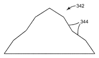
도 22는 면들을 따라 인접한 각을 이루는 평탄한 부분들로부터 형성된 다수의 선형 면(344)을 따라 회절 특징부를 구비하는 공구 팁(342)의 측면도이다.22 is a side view of a
도 23A 및 도 23B는 회절 특징부를 생성하기 위해 공구 팁을 이온 밀링하는 방법을 도시한다. 도 23A는 이온 밀링 전의 공구 팁(350)의 측면도이다. 공구 팁(350)은 예컨대 다이아몬드 슬래브로 구현될 수 있으며, 면(352, 354) 및 평탄형 팁(356)을 갖는다. 도 23B는 팁 상의 동일한 평면 내에 회절 특징부들을 형성하기 위해 이온 밀링을 사용한 후의 공구 팁(350)의 측면도이다. 특히, 그의 중앙 지점에서의 평탄형 팁(356)의 이온 밀링은 밸리(358)를 형성하여, 실질적으로 동일한 평면(364) 내에 놓이는 첨단을 갖는 2개의 회절 특징부(360, 362)를 생성한다.23A and 23B illustrate a method of ion milling a tool tip to produce diffractive features. 23A is a side view of
도 24A 및 도 24B는 회절 특징부를 생성하기 위해 공구 팁을 이온 밀링하는 다른 방법을 도시한다. 도 24A는 이온 밀링 전의 공구 팁(370)의 측면도이다. 공구 팁(370)은 예컨대 다이아몬드 슬래브로 구현될 수 있으며, 면(372, 374) 및 평탄형 팁(376)을 갖는다. 도 24B는 팁 상의 상이한 평면 내에 회절 특징부들을 형성하기 위해 이온 밀링을 사용한 후의 도 24A의 공구 팁의 측면도이다. 특히, 중앙을 벗어난 지점에서의 평탄형 팁(376)의 이온 밀링은 밸리(378)를 형성하여, 평면(386) 내에 놓이는 첨단을 갖는 제1 회절 특징부(380) 및 평면(386)과 상이한 평면(384) 내에 놓이는 첨단을 갖는 제2 회절 특징부(382)를 생성한다. 도 23B 및 도 24B에 도시된 회절 특징부를 형성하기 위한 공정은 공구 팁 상에 수개의 회절 특징부를 형성하도록 반복될 수 있으며, 도 23B 및 도 24B에 도시된 특징부는 축척대로 도시된 것이 아니고, 오히려 이들은 공구 팁 상에 회절 특징부를 형성하기 위한 공정을 예시하고자 하는 것이다.24A and 24B illustrate another method of ion milling a tool tip to produce diffractive features. 24A is a side view of
필름과 같은 미세복제된 물품을 제조하기 위해 전술된 바와 같이 회절 특징부를 구비한 공구 팁을 사용하는 것은 많은 유리하거나 바람직한 특징들을 제공할 수 있다. 예를 들어, 이들은 광 지향, 컷오프각의 감소, 도광체를 위한 광의 추출, 또는 단속 절삭 렌즈릿(lenslet) 상의 무지개 효과와 같은 기존의 특징에 대한 장식 효과를 위한 광 관리 응용에 사용될 수 있다. 또한, 더 큰 미세 구조체 상의 회절 특징부가 광을 방향전환하기 위한 추가 자유도를 제공한다.Using a tool tip with diffractive features as described above to make a microreplicated article such as a film can provide many advantageous or desirable features. For example, they can be used in light management applications for decorative effects on existing features such as light directing, reduction of cutoff angles, extraction of light for light guides, or rainbow effects on intermittent cutting lenslets. In addition, diffractive features on the larger microstructures provide additional degrees of freedom for redirecting light.
전술한 공구 팁은 거시-규모(1 마이크로미터 이상의 치수) 및 나노-규모(1 마이크로미터 미만의 치수)로 특징부를 형성하는 데 사용될 수 있으며, 특징부는 연속 또는 단속 절삭 모드로 하나 이상의 공구 팁을 사용하여 형성될 수 있다. 또한, 공구 팁을 사용하는 절삭은 공구 내로 x-방향, y-방향 또는 z-방향으로, 또는 이들 방향들의 조합으로 달성될 수 있다. 예를 들어, 특징부는 다수의 액추에이터에 의해 공구 팁을 사용하여 절삭될 수 있다. 공구를 절삭하기 위해 다수의 액추에이터를 사용하는 시스템은 모두 본 명세서에 참고로 포함된, 모두 2005년 11월 15일자로 출원된 미국 특허 출원 제11/274723호, 제11/273875호, 제11/273981호, 및 제11/273884호에 설명되어 있다. 대안적으로, 회절 특징부는 액추에이터의 사용 없이 공구 내에 절삭될 수 있는데, 이는 예컨대 저주파수 서보를 사용하여 공구의 표면 내의 실질적으로 일정한 또는 일정하지 않은 깊이에서 보유되는 공구 팁 (들)에 의한 연속 절삭을 포함할 수 있다.The tool tips described above can be used to form features in macro-scale (dimensions greater than 1 micrometer) and nano-scale (dimensions less than 1 micrometer) features that can be used to create one or more tool tips in continuous or interrupted cutting mode. Can be formed using. In addition, cutting using the tool tip can be accomplished into the tool in the x-direction, y-direction or z-direction, or a combination of these directions. For example, the feature can be cut using a tool tip by a number of actuators. Systems using multiple actuators to cut a tool are all US patent applications 11/274723, 11/273875, 11/11, filed November 15, 2005, all of which are incorporated herein by reference. 273981, and 11/273884. Alternatively, the diffractive features can be cut into the tool without the use of an actuator, for example using low frequency servo to allow continuous cutting by the tool tip (s) held at a substantially constant or non-definite depth within the surface of the tool. It may include.
본 발명이 예시적인 실시예와 관련하여 설명되었지만, 많은 변형예들이 당업자에게 용이하게 명백하게 될 것이며, 본 출원이 본 발명의 임의의 개작 또는 변형을 포괄하고자 한다는 것을 이해할 것이다. 예를 들어, 본 발명의 범주로부터 벗어남이 없이 공구대, 액추에이터 및 공구 팁을 위한 여러 가지 유형의 재료들과 이들 구성요소들의 여러 가지 유형의 구성들이 사용될 수 있다. 본 발명은 청구의 범위와 그 균등물에 의해서만 한정되어야 한다.Although the present invention has been described in connection with exemplary embodiments, it will be understood that many variations will be readily apparent to those skilled in the art, and that the present application is intended to cover any adaptations or variations of the present invention. For example, different types of materials and different types of configurations of these components can be used for tool posts, actuators and tool tips without departing from the scope of the present invention. It is intended that this invention be limited only by the claims and the equivalents thereof.
Claims (24)
Applications Claiming Priority (3)
| Application Number | Priority Date | Filing Date | Title |
|---|---|---|---|
| US11/620,093 | 2007-01-05 | ||
| US11/620,093 US7628100B2 (en) | 2007-01-05 | 2007-01-05 | Cutting tool using one or more machined tool tips with diffractive features in a continuous or interrupted cut fast tool servo |
| PCT/US2007/088575 WO2008085704A1 (en) | 2007-01-05 | 2007-12-21 | Cutting tool using one or more machined tool tips with diffractive features in a continuous or interrupted cut fast tool servo |
Related Child Applications (1)
| Application Number | Title | Priority Date | Filing Date |
|---|---|---|---|
| KR1020147008286A Division KR101515336B1 (en) | 2007-01-05 | 2007-12-21 | Optical film having a set of diffractive features randomly repeating at variable distances |
Publications (2)
| Publication Number | Publication Date |
|---|---|
| KR20090116729A true KR20090116729A (en) | 2009-11-11 |
| KR101432340B1 KR101432340B1 (en) | 2014-08-20 |
Family
ID=39594432
Family Applications (2)
| Application Number | Title | Priority Date | Filing Date |
|---|---|---|---|
| KR1020097016266A Expired - Fee Related KR101432340B1 (en) | 2007-01-05 | 2007-12-21 | Cutting tool using one or more machined tool tips with diffractive features in a continuous or interrupted cut fast tool servo |
| KR1020147008286A Expired - Fee Related KR101515336B1 (en) | 2007-01-05 | 2007-12-21 | Optical film having a set of diffractive features randomly repeating at variable distances |
Family Applications After (1)
| Application Number | Title | Priority Date | Filing Date |
|---|---|---|---|
| KR1020147008286A Expired - Fee Related KR101515336B1 (en) | 2007-01-05 | 2007-12-21 | Optical film having a set of diffractive features randomly repeating at variable distances |
Country Status (7)
| Country | Link |
|---|---|
| US (2) | US7628100B2 (en) |
| EP (1) | EP2121241B1 (en) |
| JP (1) | JP5497452B2 (en) |
| KR (2) | KR101432340B1 (en) |
| CN (1) | CN101573208B (en) |
| TW (2) | TWI462796B (en) |
| WO (1) | WO2008085704A1 (en) |
Families Citing this family (10)
| Publication number | Priority date | Publication date | Assignee | Title |
|---|---|---|---|---|
| US7669508B2 (en) * | 2007-10-29 | 2010-03-02 | 3M Innovative Properties Company | Cutting tool using one or more machined tool tips with diffractive features |
| CN101430394B (en) * | 2007-11-05 | 2011-03-23 | 鸿富锦精密工业(深圳)有限公司 | Diffraction optical element |
| US20090147361A1 (en) * | 2007-12-07 | 2009-06-11 | 3M Innovative Properties Company | Microreplicated films having diffractive features on macro-scale features |
| WO2009124107A1 (en) | 2008-04-02 | 2009-10-08 | 3M Innovative Properties Company | Light directing film and method for making the same |
| CN102078967B (en) * | 2010-12-30 | 2012-08-22 | 吉林大学 | Hybrid frequency-driven three-dimensional ellipse turning method |
| TWI453107B (en) * | 2011-07-11 | 2014-09-21 | Benq Materials Corp | Manufacturing method of roller used for manufacturing patterned retardation film |
| CN103567466B (en) | 2012-07-20 | 2016-03-09 | 鸿准精密模具(昆山)有限公司 | lathe control system |
| DE102014110772A1 (en) * | 2014-07-11 | 2016-01-14 | Helmholtz-Zentrum Berlin für Materialien und Energie Gesellschaft mit beschränkter Haftung | Apparatus and method for producing optical grating and optical grating |
| CN105698662A (en) * | 2014-11-28 | 2016-06-22 | 常州维能达精机有限公司 | Manufacturing equipment of coiled electric grid scale and manufacturing process thereof |
| CN110325883B (en) | 2017-02-14 | 2024-01-09 | 3M创新有限公司 | Safety articles containing groups of microstructures produced by end milling |
Family Cites Families (101)
| Publication number | Priority date | Publication date | Assignee | Title |
|---|---|---|---|---|
| US2404222A (en) | 1944-05-23 | 1946-07-16 | Ralph D Doner | Diffraction grating tool |
| US2738730A (en) * | 1952-07-01 | 1956-03-20 | Fairchild Camera Instr Co | Method for forming engraved image-reproducing plates |
| US3293727A (en) * | 1961-04-12 | 1966-12-27 | Bilt Rite Tool & Machine Co | Cutting tool |
| US3417959A (en) | 1966-11-14 | 1968-12-24 | Minnesota Mining & Mfg | Die for forming retro-reflective article |
| US4012843A (en) | 1973-04-25 | 1977-03-22 | Hitachi, Ltd. | Concave diffraction grating and a manufacturing method thereof |
| US4035590A (en) * | 1975-06-30 | 1977-07-12 | Rca Corporation | Apparatus for electromechanical recording of short wavelength modulation in a metal master |
| US4417489A (en) * | 1979-12-21 | 1983-11-29 | Liu Chunghorng R | Method and apparatus for machining a workpiece by varying the tool geometry |
| US4488840A (en) * | 1982-07-08 | 1984-12-18 | Pollington Bernard M | Rotary cutting tool |
| JPS63180401A (en) | 1987-01-19 | 1988-07-25 | Mitsui Eng & Shipbuild Co Ltd | Cutting tool having active vibration isolating function |
| US5007709A (en) | 1987-12-28 | 1991-04-16 | Matsushita Electric Industrial Co., Ltd. | Diffraction grating and manufacturing method thereof |
| JP2615392B2 (en) * | 1988-03-31 | 1997-05-28 | 工業技術院長 | Tool fine table |
| AU634010B2 (en) | 1989-11-28 | 1993-02-11 | Toyo Seikan Kaisha Ltd. | Metallic container equipped with hologram or diffraction grating |
| US5239736A (en) * | 1991-11-12 | 1993-08-31 | Acuson Corporation | Method for making piezoelectric composites |
| US5291812A (en) * | 1992-05-22 | 1994-03-08 | General Motors Corporation | Turning apparatus with improved chip handling |
| US5663802A (en) * | 1993-02-25 | 1997-09-02 | Ohio Electronic Engravers, Inc. | Method and apparatus for engraving using multiple engraving heads |
| JPH07114015A (en) * | 1993-10-19 | 1995-05-02 | Olympus Optical Co Ltd | Liquid crystal display device |
| US5467675A (en) * | 1993-11-15 | 1995-11-21 | North Carolina State University | Apparatus and method for forming a workpiece surface into a non-rotationally symmetric shape |
| US5600455A (en) * | 1994-08-31 | 1997-02-04 | Enplas Corporation | Prismatic member with coarsened portions or triangular prismatic and semi-circular prismatic members arranged on a flat light emitting surface |
| KR960029797U (en) * | 1995-02-23 | 1996-09-17 | 정종규 | Branch installation support |
| JPH08292111A (en) * | 1995-04-24 | 1996-11-05 | Mitsubishi Electric Corp | Belt tension measuring device |
| US20040135273A1 (en) * | 1995-06-27 | 2004-07-15 | Parker Jeffery R. | Methods of making a pattern of optical element shapes on a roll for use in making optical elements on or in substrates |
| US5801889A (en) * | 1995-08-16 | 1998-09-01 | Eastman Kodak Company | Technique to eliminate scattered light in diffractive optical elements |
| JP3727094B2 (en) * | 1996-01-12 | 2005-12-14 | 株式会社きもと | Backlight for LCD |
| DE19602079C1 (en) * | 1996-01-20 | 1997-05-15 | Karlsruhe Forschzent | Manufacture of a self-focusing micro spectrometer reflection grid |
| JPH09275689A (en) | 1996-04-01 | 1997-10-21 | Seiko Seiki Co Ltd | Ultra-precise positioning device |
| GB2314452A (en) | 1996-06-17 | 1997-12-24 | Rank Taylor Hobson Ltd | Electromechanical actuator |
| KR100211930B1 (en) | 1996-07-23 | 1999-08-02 | 김덕중 | Micro cutting device |
| US6040653A (en) * | 1996-10-17 | 2000-03-21 | Kinetic Ceramics, Inc. | Piezoelectric positioner |
| US5719339A (en) * | 1996-11-26 | 1998-02-17 | The University Of Dayton | Magnetostrictive, mass isolated, non-resonant, high frequency/low frequency mechanical test system |
| US5877432A (en) * | 1996-11-26 | 1999-03-02 | The University Of Dayton | Magnetostrictive actuator |
| JPH10328902A (en) * | 1997-05-26 | 1998-12-15 | Sony Corp | Spiral groove forming device |
| CN1105637C (en) * | 1997-07-02 | 2003-04-16 | 美国3M公司 | Cube corner sheeting mold and its mfg. method |
| US6253442B1 (en) * | 1997-07-02 | 2001-07-03 | 3M Innovative Properties Company | Retroreflective cube corner sheeting mold and method for making the same |
| US6237452B1 (en) * | 1997-12-29 | 2001-05-29 | Massachusetts Institute Of Technology | Precision high speed turning machine |
| AU752774B2 (en) * | 1998-02-18 | 2002-09-26 | Minnesota Mining And Manufacturing Company | Optical film |
| US6170367B1 (en) * | 1998-09-09 | 2001-01-09 | John R. Keller | Single-point flexure toric contact lens forming machine and method |
| SE515157C2 (en) | 1998-10-22 | 2001-06-18 | Ingvar Claesson | Method and apparatus for controlling turning operation |
| US6322236B1 (en) * | 1999-02-09 | 2001-11-27 | 3M Innovative Properties Company | Optical film with defect-reducing surface and method for making same |
| US20050024849A1 (en) * | 1999-02-23 | 2005-02-03 | Parker Jeffery R. | Methods of cutting or forming cavities in a substrate for use in making optical films, components or wave guides |
| US6752505B2 (en) * | 1999-02-23 | 2004-06-22 | Solid State Opto Limited | Light redirecting films and film systems |
| JP2002542048A (en) | 1999-02-25 | 2002-12-10 | マイクロ オプティックス デザイン コーポレーション | Method and apparatus for creating the ultimate surface on an ophthalmic lens |
| JP2000280104A (en) * | 1999-03-26 | 2000-10-10 | Ngk Spark Plug Co Ltd | Form insert for plunge cutting |
| JP2001018108A (en) | 1999-07-05 | 2001-01-23 | Canon Inc | Method of processing diffractive optical grating element shape and method of processing die for shaping diffractive optical grating element shape |
| US6665027B1 (en) * | 1999-07-23 | 2003-12-16 | Bae Systems Information And Electronic System Integration Inc | Color liquid crystal display having diffractive color separation microlenses |
| US6487017B1 (en) * | 1999-07-23 | 2002-11-26 | Bae Systems Information And Electronic Systems Integration, Inc | Trimodal microlens |
| US6618106B1 (en) * | 1999-07-23 | 2003-09-09 | Bae Systems Information And Electronics Systems Integration, Inc | Sunlight viewable color liquid crystal display using diffractive color separation microlenses |
| US6845212B2 (en) * | 1999-10-08 | 2005-01-18 | 3M Innovative Properties Company | Optical element having programmed optical structures |
| US6356391B1 (en) * | 1999-10-08 | 2002-03-12 | 3M Innovative Properties Company | Optical film with variable angle prisms |
| US6253422B1 (en) * | 1999-10-26 | 2001-07-03 | Jgb Enterprises, Inc. | Distributed force hose clamp |
| US6570710B1 (en) * | 1999-11-12 | 2003-05-27 | Reflexite Corporation | Subwavelength optical microstructure light collimating films |
| JP4398044B2 (en) * | 2000-02-03 | 2010-01-13 | 東芝機械株式会社 | Numerical control device and control method for machine tool |
| US6650666B2 (en) | 2000-02-09 | 2003-11-18 | Cymer, Inc. | Laser wavelength control unit with piezoelectric driver |
| US6581286B2 (en) * | 2000-04-05 | 2003-06-24 | 3M Innovative Properties Company | Method of making tool to produce optical film |
| JP2002062417A (en) * | 2000-06-07 | 2002-02-28 | Canon Inc | Diffractive optical element, optical system and optical apparatus having the diffractive optical element, method for manufacturing diffractive optical element, mold for manufacturing diffractive optical element |
| CA2313830A1 (en) | 2000-07-13 | 2002-01-13 | Micro Optics Design Corporation | Single point diamond turning lathe with vibration cancelling feature |
| AU2001276905A1 (en) * | 2000-07-14 | 2002-01-30 | Metabolix, Inc. | Polyurethanes obtained from hydroxyalkanoates and isocyanates |
| DE60020837T2 (en) | 2000-08-03 | 2006-05-04 | La Termoplastic F.B.M. S.R.L., Arsago Seprio | Two-piece handle for a cooking appliance, especially for a lid |
| JP2002098820A (en) | 2000-09-21 | 2002-04-05 | Nippon Sheet Glass Co Ltd | Reflection type diffraction grating |
| US6771435B2 (en) | 2000-10-02 | 2004-08-03 | Konica Corporation | Optical element, metal die, and cutting tool |
| GB2367522B (en) * | 2000-10-07 | 2004-04-28 | Federal Mogul Bradford Ltd | Engine piston and manufacture thereof |
| KR200219135Y1 (en) | 2000-10-28 | 2001-04-02 | 이세기 | The bite for producing bacteria supporting medium |
| WO2002037168A2 (en) | 2000-11-01 | 2002-05-10 | Dac International, Inc. | Method and system for producing progressive addition spectacle lenses |
| US6590208B2 (en) | 2001-01-19 | 2003-07-08 | Veeco Instruments Inc. | Balanced momentum probe holder |
| US6879087B2 (en) | 2002-02-06 | 2005-04-12 | Viking Technologies, L.C. | Apparatus for moving a pair of opposing surfaces in response to an electrical activation |
| US20030035231A1 (en) * | 2001-08-03 | 2003-02-20 | Epstein Kenneth A. | Optical film having microreplicated structures; and methods |
| JP4213897B2 (en) * | 2001-08-07 | 2009-01-21 | 株式会社日立製作所 | Method of manufacturing transfer pattern of microlens array |
| US20030108710A1 (en) * | 2001-12-07 | 2003-06-12 | General Electric Company | Articles bearing patterned microstructures and method of making |
| WO2003086688A1 (en) | 2002-04-15 | 2003-10-23 | Oren, Elimelech | Method and apparatus for vibrating cutting tool |
| US7364314B2 (en) * | 2002-05-15 | 2008-04-29 | Reflexite Corporation | Optical structures |
| US6862141B2 (en) * | 2002-05-20 | 2005-03-01 | General Electric Company | Optical substrate and method of making |
| US7140812B2 (en) * | 2002-05-29 | 2006-11-28 | 3M Innovative Properties Company | Diamond tool with a multi-tipped diamond |
| US7275468B2 (en) * | 2002-05-29 | 2007-10-02 | Massachusetts Institute Of Technology | Rotary fast tool servo system and methods |
| US6739575B2 (en) | 2002-06-06 | 2004-05-25 | Caterpillar Inc | Piezoelectric valve system |
| JP2004098230A (en) | 2002-09-10 | 2004-04-02 | Canon Inc | Processing device, processing method and displacement detection unit |
| US20040045419A1 (en) * | 2002-09-10 | 2004-03-11 | Bryan William J. | Multi-diamond cutting tool assembly for creating microreplication tools |
| US6811274B2 (en) * | 2002-12-04 | 2004-11-02 | General Electric Company | Polarization sensitive optical substrate |
| US7125131B2 (en) * | 2002-12-06 | 2006-10-24 | General Electric Company | Brightness enhancement film with improved view angle |
| US6909482B2 (en) * | 2002-12-11 | 2005-06-21 | General Electric Company | Display substrate with reflective color filters |
| US6952627B2 (en) * | 2002-12-18 | 2005-10-04 | General Electric Company | Method and apparatus for fabricating light management substrates |
| KR20040061658A (en) * | 2002-12-31 | 2004-07-07 | 삼성전자주식회사 | Hybrid achromatic optical lens and manufacturing method thereof |
| US6844950B2 (en) * | 2003-01-07 | 2005-01-18 | General Electric Company | Microstructure-bearing articles of high refractive index |
| JP2004264347A (en) * | 2003-02-06 | 2004-09-24 | Sumitomo Electric Ind Ltd | Diffractive optical component and laser processing device using the same |
| KR100514991B1 (en) | 2003-05-10 | 2005-09-15 | 고등기술연구원연구조합 | A vibration cutting machine |
| US7257877B2 (en) * | 2003-06-30 | 2007-08-21 | Nidec Sankyo Corporation | Grating forming method and manufacturing method for master member for manufacturing molding die |
| SE0302706L (en) * | 2003-10-14 | 2005-01-25 | Skf Ab | A method for achieving improved roller contact surfaces |
| US7616084B2 (en) * | 2003-10-31 | 2009-11-10 | Massachusetts Institute Of Technology | Variable reluctance fast positioning system and methods |
| US7072092B2 (en) * | 2003-12-31 | 2006-07-04 | General Electric Company | Optical substrate with modulated structure |
| JP2005279862A (en) * | 2004-03-30 | 2005-10-13 | Towa Corp | Cutting method and cutting device |
| EP1742762B1 (en) * | 2004-04-23 | 2008-12-03 | Schott AG | Device for the production of microstructures |
| US7107694B2 (en) * | 2004-06-29 | 2006-09-19 | Hysitron, Incorporated | Method for observation of microstructural surface features in heterogeneous materials |
| US7145282B2 (en) | 2004-07-15 | 2006-12-05 | Delphi Technologies, Inc. | Actuator |
| US7212345B2 (en) * | 2004-09-13 | 2007-05-01 | Eastman Kodak Company | Randomized patterns of individual optical elements |
| US8656815B2 (en) * | 2004-12-06 | 2014-02-25 | Konica Minolta Opto, Inc. | Transfer optical surface machining method, optical device producing mold and optical device |
| JP2006235553A (en) | 2005-02-22 | 2006-09-07 | Tamotsu Azuma | Method for processing and manufacturing sheet illuminator |
| US7531219B2 (en) * | 2005-07-21 | 2009-05-12 | Hi-Tex, Inc. | Treated textile fabric |
| JP4887025B2 (en) * | 2005-10-27 | 2012-02-29 | パナソニック株式会社 | Mold manufacturing method and optical element manufacturing method |
| US7290471B2 (en) * | 2005-11-15 | 2007-11-06 | 3M Innovative Properties Company | Cutting tool having variable rotation about a y-direction transversely across a work piece for making microstructures |
| US7293487B2 (en) * | 2005-11-15 | 2007-11-13 | 3M Innovative Properties Company | Cutting tool having variable and independent movement in an x-direction and a z-direction into and laterally along a work piece for making microstructures |
| US7328638B2 (en) * | 2005-12-27 | 2008-02-12 | 3M Innovative Properties Company | Cutting tool using interrupted cut fast tool servo |
| US7788998B2 (en) * | 2006-03-13 | 2010-09-07 | Panasonic Corporation | Precision machining system and methods |
| US7677146B2 (en) * | 2006-05-10 | 2010-03-16 | 3M Innovative Properties Company | Cutting tool using one or more machined tool tips in a continuous or interrupted cut fast tool servo |
-
2007
- 2007-01-05 US US11/620,093 patent/US7628100B2/en active Active
- 2007-12-21 KR KR1020097016266A patent/KR101432340B1/en not_active Expired - Fee Related
- 2007-12-21 EP EP07869755.4A patent/EP2121241B1/en not_active Not-in-force
- 2007-12-21 JP JP2009544883A patent/JP5497452B2/en not_active Expired - Fee Related
- 2007-12-21 WO PCT/US2007/088575 patent/WO2008085704A1/en not_active Ceased
- 2007-12-21 KR KR1020147008286A patent/KR101515336B1/en not_active Expired - Fee Related
- 2007-12-21 CN CN2007800491092A patent/CN101573208B/en not_active Expired - Fee Related
-
2008
- 2008-01-04 TW TW097100447A patent/TWI462796B/en not_active IP Right Cessation
- 2008-01-04 TW TW103116635A patent/TWI556903B/en not_active IP Right Cessation
-
2009
- 2009-05-06 US US12/436,156 patent/US7852570B2/en active Active
Also Published As
| Publication number | Publication date |
|---|---|
| TW200911447A (en) | 2009-03-16 |
| JP2010515586A (en) | 2010-05-13 |
| EP2121241B1 (en) | 2019-05-22 |
| EP2121241A1 (en) | 2009-11-25 |
| KR101432340B1 (en) | 2014-08-20 |
| CN101573208A (en) | 2009-11-04 |
| US20090220745A1 (en) | 2009-09-03 |
| CN101573208B (en) | 2012-07-18 |
| US7852570B2 (en) | 2010-12-14 |
| KR20140051460A (en) | 2014-04-30 |
| EP2121241A4 (en) | 2017-07-05 |
| KR101515336B1 (en) | 2015-04-24 |
| TW201505753A (en) | 2015-02-16 |
| US7628100B2 (en) | 2009-12-08 |
| TWI556903B (en) | 2016-11-11 |
| TWI462796B (en) | 2014-12-01 |
| JP5497452B2 (en) | 2014-05-21 |
| US20080166190A1 (en) | 2008-07-10 |
| WO2008085704A1 (en) | 2008-07-17 |
Similar Documents
| Publication | Publication Date | Title |
|---|---|---|
| JP5296550B2 (en) | Cutting tools that use intermittent cutting high-speed tool servos | |
| JP6470330B2 (en) | Cutting tool using one or more machined tool tips with diffractive mechanisms | |
| KR20100102137A (en) | Microreplicated films having diffractive features on macro-scale features | |
| KR101432340B1 (en) | Cutting tool using one or more machined tool tips with diffractive features in a continuous or interrupted cut fast tool servo | |
| KR101391499B1 (en) | Cutting tool assembly using one or more machined tool tips of continuous or interrupted cutting high speed tool servos |
Legal Events
| Date | Code | Title | Description |
|---|---|---|---|
| PA0105 | International application |
St.27 status event code: A-0-1-A10-A15-nap-PA0105 |
|
| PG1501 | Laying open of application |
St.27 status event code: A-1-1-Q10-Q12-nap-PG1501 |
|
| A201 | Request for examination | ||
| E13-X000 | Pre-grant limitation requested |
St.27 status event code: A-2-3-E10-E13-lim-X000 |
|
| P11-X000 | Amendment of application requested |
St.27 status event code: A-2-2-P10-P11-nap-X000 |
|
| P13-X000 | Application amended |
St.27 status event code: A-2-2-P10-P13-nap-X000 |
|
| PA0201 | Request for examination |
St.27 status event code: A-1-2-D10-D11-exm-PA0201 |
|
| E902 | Notification of reason for refusal | ||
| PE0902 | Notice of grounds for rejection |
St.27 status event code: A-1-2-D10-D21-exm-PE0902 |
|
| A107 | Divisional application of patent | ||
| E13-X000 | Pre-grant limitation requested |
St.27 status event code: A-2-3-E10-E13-lim-X000 |
|
| P11-X000 | Amendment of application requested |
St.27 status event code: A-2-2-P10-P11-nap-X000 |
|
| P13-X000 | Application amended |
St.27 status event code: A-2-2-P10-P13-nap-X000 |
|
| PA0104 | Divisional application for international application |
St.27 status event code: A-0-1-A10-A18-div-PA0104 St.27 status event code: A-0-1-A10-A16-div-PA0104 |
|
| E701 | Decision to grant or registration of patent right | ||
| PE0701 | Decision of registration |
St.27 status event code: A-1-2-D10-D22-exm-PE0701 |
|
| GRNT | Written decision to grant | ||
| PR0701 | Registration of establishment |
St.27 status event code: A-2-4-F10-F11-exm-PR0701 |
|
| PR1002 | Payment of registration fee |
St.27 status event code: A-2-2-U10-U12-oth-PR1002 Fee payment year number: 1 |
|
| PG1601 | Publication of registration |
St.27 status event code: A-4-4-Q10-Q13-nap-PG1601 |
|
| FPAY | Annual fee payment |
Payment date: 20170719 Year of fee payment: 4 |
|
| PR1001 | Payment of annual fee |
St.27 status event code: A-4-4-U10-U11-oth-PR1001 Fee payment year number: 4 |
|
| FPAY | Annual fee payment |
Payment date: 20180718 Year of fee payment: 5 |
|
| PR1001 | Payment of annual fee |
St.27 status event code: A-4-4-U10-U11-oth-PR1001 Fee payment year number: 5 |
|
| FPAY | Annual fee payment |
Payment date: 20190718 Year of fee payment: 6 |
|
| PR1001 | Payment of annual fee |
St.27 status event code: A-4-4-U10-U11-oth-PR1001 Fee payment year number: 6 |
|
| PR1001 | Payment of annual fee |
St.27 status event code: A-4-4-U10-U11-oth-PR1001 Fee payment year number: 7 |
|
| PC1903 | Unpaid annual fee |
St.27 status event code: A-4-4-U10-U13-oth-PC1903 Not in force date: 20210814 Payment event data comment text: Termination Category : DEFAULT_OF_REGISTRATION_FEE |
|
| PC1903 | Unpaid annual fee |
St.27 status event code: N-4-6-H10-H13-oth-PC1903 Ip right cessation event data comment text: Termination Category : DEFAULT_OF_REGISTRATION_FEE Not in force date: 20210814 |