KR20090030084A - Microfluidic Device - Google Patents
Microfluidic Device Download PDFInfo
- Publication number
- KR20090030084A KR20090030084A KR1020070095412A KR20070095412A KR20090030084A KR 20090030084 A KR20090030084 A KR 20090030084A KR 1020070095412 A KR1020070095412 A KR 1020070095412A KR 20070095412 A KR20070095412 A KR 20070095412A KR 20090030084 A KR20090030084 A KR 20090030084A
- Authority
- KR
- South Korea
- Prior art keywords
- microfluidic device
- substrate
- adhesive tape
- chamber
- pcr
- Prior art date
- Legal status (The legal status is an assumption and is not a legal conclusion. Google has not performed a legal analysis and makes no representation as to the accuracy of the status listed.)
- Withdrawn
Links
Images


Classifications
-
- G—PHYSICS
- G01—MEASURING; TESTING
- G01N—INVESTIGATING OR ANALYSING MATERIALS BY DETERMINING THEIR CHEMICAL OR PHYSICAL PROPERTIES
- G01N35/00—Automatic analysis not limited to methods or materials provided for in any single one of groups G01N1/00 - G01N33/00; Handling materials therefor
-
- B—PERFORMING OPERATIONS; TRANSPORTING
- B01—PHYSICAL OR CHEMICAL PROCESSES OR APPARATUS IN GENERAL
- B01L—CHEMICAL OR PHYSICAL LABORATORY APPARATUS FOR GENERAL USE
- B01L3/00—Containers or dishes for laboratory use, e.g. laboratory glassware; Droppers
- B01L3/50—Containers for the purpose of retaining a material to be analysed, e.g. test tubes
- B01L3/502—Containers for the purpose of retaining a material to be analysed, e.g. test tubes with fluid transport, e.g. in multi-compartment structures
- B01L3/5027—Containers for the purpose of retaining a material to be analysed, e.g. test tubes with fluid transport, e.g. in multi-compartment structures by integrated microfluidic structures, i.e. dimensions of channels and chambers are such that surface tension forces are important, e.g. lab-on-a-chip
- B01L3/502707—Containers for the purpose of retaining a material to be analysed, e.g. test tubes with fluid transport, e.g. in multi-compartment structures by integrated microfluidic structures, i.e. dimensions of channels and chambers are such that surface tension forces are important, e.g. lab-on-a-chip characterised by the manufacture of the container or its components
-
- B—PERFORMING OPERATIONS; TRANSPORTING
- B01—PHYSICAL OR CHEMICAL PROCESSES OR APPARATUS IN GENERAL
- B01L—CHEMICAL OR PHYSICAL LABORATORY APPARATUS FOR GENERAL USE
- B01L7/00—Heating or cooling apparatus; Heat insulating devices
- B01L7/52—Heating or cooling apparatus; Heat insulating devices with provision for submitting samples to a predetermined sequence of different temperatures, e.g. for treating nucleic acid samples
-
- G—PHYSICS
- G01—MEASURING; TESTING
- G01N—INVESTIGATING OR ANALYSING MATERIALS BY DETERMINING THEIR CHEMICAL OR PHYSICAL PROPERTIES
- G01N33/00—Investigating or analysing materials by specific methods not covered by groups G01N1/00 - G01N31/00
-
- G—PHYSICS
- G01—MEASURING; TESTING
- G01N—INVESTIGATING OR ANALYSING MATERIALS BY DETERMINING THEIR CHEMICAL OR PHYSICAL PROPERTIES
- G01N33/00—Investigating or analysing materials by specific methods not covered by groups G01N1/00 - G01N31/00
- G01N33/48—Biological material, e.g. blood, urine; Haemocytometers
-
- B—PERFORMING OPERATIONS; TRANSPORTING
- B01—PHYSICAL OR CHEMICAL PROCESSES OR APPARATUS IN GENERAL
- B01L—CHEMICAL OR PHYSICAL LABORATORY APPARATUS FOR GENERAL USE
- B01L2200/00—Solutions for specific problems relating to chemical or physical laboratory apparatus
- B01L2200/12—Specific details about manufacturing devices
-
- B—PERFORMING OPERATIONS; TRANSPORTING
- B01—PHYSICAL OR CHEMICAL PROCESSES OR APPARATUS IN GENERAL
- B01L—CHEMICAL OR PHYSICAL LABORATORY APPARATUS FOR GENERAL USE
- B01L2300/00—Additional constructional details
- B01L2300/08—Geometry, shape and general structure
- B01L2300/0848—Specific forms of parts of containers
- B01L2300/0851—Bottom walls
-
- B—PERFORMING OPERATIONS; TRANSPORTING
- B01—PHYSICAL OR CHEMICAL PROCESSES OR APPARATUS IN GENERAL
- B01L—CHEMICAL OR PHYSICAL LABORATORY APPARATUS FOR GENERAL USE
- B01L2300/00—Additional constructional details
- B01L2300/16—Surface properties and coatings
-
- B—PERFORMING OPERATIONS; TRANSPORTING
- B01—PHYSICAL OR CHEMICAL PROCESSES OR APPARATUS IN GENERAL
- B01L—CHEMICAL OR PHYSICAL LABORATORY APPARATUS FOR GENERAL USE
- B01L2300/00—Additional constructional details
- B01L2300/18—Means for temperature control
- B01L2300/1805—Conductive heating, heat from thermostatted solids is conducted to receptacles, e.g. heating plates, blocks
- B01L2300/1827—Conductive heating, heat from thermostatted solids is conducted to receptacles, e.g. heating plates, blocks using resistive heater
Landscapes
- Chemical & Material Sciences (AREA)
- Health & Medical Sciences (AREA)
- Life Sciences & Earth Sciences (AREA)
- General Health & Medical Sciences (AREA)
- Analytical Chemistry (AREA)
- Biochemistry (AREA)
- Clinical Laboratory Science (AREA)
- Chemical Kinetics & Catalysis (AREA)
- Hematology (AREA)
- General Physics & Mathematics (AREA)
- Molecular Biology (AREA)
- Engineering & Computer Science (AREA)
- Pathology (AREA)
- Immunology (AREA)
- Physics & Mathematics (AREA)
- Food Science & Technology (AREA)
- Medicinal Chemistry (AREA)
- Dispersion Chemistry (AREA)
- Biomedical Technology (AREA)
- Urology & Nephrology (AREA)
- Physical Or Chemical Processes And Apparatus (AREA)
- Apparatus Associated With Microorganisms And Enzymes (AREA)
Abstract
본 발명은, 기판; 상기 기판의 저면에 음각(陰刻)된 그루브(groove)에 의해 형성된, 유체가 수용될 수 있는 챔버(chamber); 및, 상기 기판의 저면에 부착되는 점착 테이프;를 구비하고, 상기 점착 테이프는 폴리머 필름과, 상기 폴리머 필름 상에 도포된 실리콘 수지(silicone) 계열의 점착제를 구비하는 것을 특징으로 하는 미세유동장치를 제공한다. The present invention, a substrate; A chamber in which fluid can be received, formed by grooves engraved in the bottom of the substrate; And a pressure-sensitive adhesive tape attached to a bottom surface of the substrate, wherein the pressure-sensitive adhesive tape comprises a polymer film and a silicone resin-based pressure-sensitive adhesive applied onto the polymer film. to provide.
Description
본 발명은 미세유체공학(microfluidics)에 관한 것으로, 보다 상세하게는 소량의 생화학 유체를 이용하여 생화학 반응을 수행하고, 그 결과를 검출할 수 있는 미세유동장치에 관한 것이다. The present invention relates to microfluidics, and more particularly, to a microfluidic device capable of performing a biochemical reaction using a small amount of biochemical fluid and detecting the result.
미세유체공학 분야에서 혈액, 소변 등의 생화학 유체를 이용하여 생화학 반응을 수행하며, 그 반응 결과를 검출하는 등의 생화학 유체를 이용한 다양한 기능들을 수행할 수 있는 미세유동장치에 대한 연구가 활발히 진행되고 있다. 상기 미세유동장치는 예컨대, 랩온어칩(lab-on-a-chip)이라고 불리우는 칩(chip) 형태의 소자를 포함할 수도 있고, 랩온어디스크(lab-on-a-disk)라고 불리우는 회전 가능한 디스크(disk) 형태의 소자를 포함할 수도 있다. 상기 미세유동장치에는 유체가 수용되는 챔버(chamber)와 상기 챔버에 연결된 채널(channel)이 구비된다. In the field of microfluidics, researches on microfluidic devices that can perform various biochemical reactions using biochemical fluids such as blood and urine, and detect the result of the reaction are being actively conducted. have. The microfluidic device may comprise, for example, a chip-like device called a lab-on-a-chip, and may be rotatable, called a lab-on-a-disk. It may also include a device in the form of a disk. The microfluidic device is provided with a chamber (chamber) for receiving the fluid and a channel connected to the chamber.
도 1은 종래의 PCR(polymerase chain reaction)용 미세유동장치의 일 예를 도시한 단면도이다.1 is a cross-sectional view showing an example of a conventional microfluidic device for polymerase chain reaction (PCR).
도 1을 참조하면, 종래의 미세유동장치(10)는 서로 접착된 하판(11) 및 상판(15)과, 내부에 형성된 챔버(20)를 구비한다. 상기 미세유동장치(10)는 챔버(20) 에 수용된 생화학 유체를 이용하여 PCR(polymerase chain reaction)을 수행하는데 사용되는 미세유동장치로서, 소위 "PCR 칩(chip)" 이라고도 불리운다. PCR 수행을 위해서는 상기 미세유동장치(10)에 수용된 생화학 유체를 정확한 주기에 따라 가열해 주어야 하므로, PCR 수행 과정은 "써멀 사이클링(thermal cycling) 과정" 이라고도 불리운다. 상기 미세유동장치(10)를 이용한 PCR 과정은 튜브에 생화학 유체를 주입하고 PCR을 수행하는 전통적인 PCR 과정에 비하여 빠른 시간 내에 PCR을 끝낼 수 있기 때문에 상기 미세유동장치(10)의 이용이 증대되고 있다. Referring to FIG. 1, the conventional
상기 미세유동장치(10)의 하판(11)은 빠르고 정확한 주기에 따른 열전도가 가능하도록 열전도도가 우수한 실리콘(Si)으로 이루어진다. 또한, 형광 검출법에 의해 상기 챔버(20)에 수용된 생화학 유체에서 일어나고 있는 PCR 결과를 검출할 수 있도록 상기 미세유동장치(10)의 상판(15)은 투명한 글래스(glass)로 이루어진다. 상기 형광 검출법은 생화학 반응의 진행 정도에 따라 생화학 유체에서 발광(發光)하는 형광 신호를 검출하여 생화학 반응의 진행 정도를 실시간으로 파악할 수 있는 검출 방법이다. 그런데, 상술한 바와 같이 상기 종래의 미세유동장치(10)는 실리콘(Si)으로 이루어진 하판(11)과 글래스(glass)로 이루어진 상판을 사용하여야 하므로, 제조 비용이 증대된다는 문제점이 있다.The
본 발명은 상기한 문제점을 해결하기 위한 것으로, 제조 비용이 절감됨과 동시에 빠르고 정확한 열전도가 가능한 미세유동장치를 제공하는 것을 목적으로 한다. The present invention has been made to solve the above problems, and an object of the present invention is to provide a microfluidic device capable of fast and accurate thermal conductivity while reducing manufacturing costs.
상기한 목적을 달성하기 위하여 본 발명은, 기판; 상기 기판의 저면에 음각(陰刻)된 그루브(groove)에 의해 형성된, 유체가 수용될 수 있는 챔버(chamber); 및, 상기 기판의 저면에 부착되는 점착 테이프;를 구비하고, 상기 점착 테이프는 폴리머 필름과, 상기 폴리머 필름 상에 도포된 실리콘 수지(silicone) 계열의 점착제를 구비하는 것을 특징으로 하는 미세유동장치를 제공한다. The present invention to achieve the above object, the substrate; A chamber in which fluid can be received, formed by grooves engraved in the bottom of the substrate; And a pressure-sensitive adhesive tape attached to a bottom surface of the substrate, wherein the pressure-sensitive adhesive tape comprises a polymer film and a silicone resin-based pressure-sensitive adhesive applied onto the polymer film. to provide.
바람직하게는, 상기 미세유동장치는 상기 기판의 저면에 음각된, 상기 챔버와 연결되는 채널(channel)을 더 구비할 수 있다. Preferably, the microfluidic device may further include a channel connected to the chamber engraved on the bottom surface of the substrate.
바람직하게는, 상기 미세유동장치는 상기 채널에 연결되고 상기 기판의 상면으로 개방된, 유체를 주입하기 위한 인렛홀(inlet hole) 또는, 유체 주입시 챔버 내부의 공기를 외부로 배출시키기 위한 아웃렛홀(outlet hole)을 더 구비할 수 있다. Preferably, the microfluidic device is an inlet hole for injecting a fluid, which is connected to the channel and opened to an upper surface of the substrate, or an outlet hole for discharging air inside the chamber to the outside when the fluid is injected. (outlet hole) may be further provided.
바람직하게는, 상기 기판은 폴리머로 이루어질 수 있다. Preferably, the substrate may be made of a polymer.
바람직하게는, 상기 폴리머는 PDMS(polydimethylsiloxane), PP(polypropylene), PC(polycarbonate), PE(polyethylene), PET(polyethylene terephthalate), PMMA(polymethylmethacrylate (acrylic)), COC(cyclic olefin copolymer), 실리콘 수지(silicone) 및, 우레탄 수지(urethane resin)로 이루어진 그룹 가운데 선택된 어느 하나일 수 있다. Preferably, the polymer is PDMS (polydimethylsiloxane), PP (polypropylene), PC (polycarbonate), PE (polyethylene), PET (polyethylene terephthalate), PMMA (polymethylmethacrylate (acrylic)), COC (cyclic olefin copolymer), silicone resin (silicone) and urethane resin (urethane resin) may be any one selected from the group consisting of.
바람직하게는, 상기 점착 테이프의 폴리머 필름은 PP(polypropylene), PC(polycarbonate), PE(polyethylene), PET(polyethylene terephthalate), PMMA(polymethylmethacrylate (acrylic)) 및, COC(cyclic olefin copolymer)로 이루어진 그룹 가운데 선택된 어느 하나로 이루어질 수 있다. Preferably, the polymer film of the adhesive tape is a group consisting of polypropylene (PP), polycarbonate (PC), polyethylene (PE), polyethylene terephthalate (PET), polymethylmethacrylate (acrylic), PMMA, and cyclic olefin copolymer (COC). It may be made of any one selected.
바람직하게는, 상기 점착 테이프의 두께는 30 내지 100 ㎛ 일 수 있다. Preferably, the thickness of the adhesive tape may be 30 to 100 ㎛.
바람직하게는, 상기 미세유동장치는 생화학 유체의 PCR(polymerase chain reaction)에 사용되는 것일 수 있다. Preferably, the microfluidic device may be used for polymerase chain reaction (PCR) of biochemical fluids.
바람직하게는, 상기 기판은 PCR 반응을 광학적 방법을 통하여 실시간으로 검출할 수 있도록 투명할 수 있다. Preferably, the substrate may be transparent to detect the PCR reaction in real time through an optical method.
본 발명의 미세유동장치는 생화학 반응에 사용되는 미세유동장치를 제조함에 있어 고가(高價)의 실리콘 웨이퍼(Si wafer)를 사용하지 않고, 폴리머 기반의 미세유동장치를 제조할 수 있어 제조비용이 절감된다. The microfluidic device of the present invention can manufacture a polymer-based microfluidic device without using an expensive silicon wafer in manufacturing a microfluidic device used for biochemical reactions, thereby reducing manufacturing costs. do.
이하, 첨부된 도면을 참조하여 본 발명의 바람직한 실시예에 따른 미세유동장치를 상세하게 설명한다. Hereinafter, with reference to the accompanying drawings will be described in detail a microfluidic device according to a preferred embodiment of the present invention.
도 2는 본 발명의 바람직한 실시예에 따른 미세유동장치를 도시한 사시도이 고, 도 3은 도 2의 A-A'를 따라 절개하여 도시한 단면도이며, 도 4는 도 3의 B를 확대하여 도시한 단면도이다.Figure 2 is a perspective view showing a microfluidic device according to a preferred embodiment of the present invention, Figure 3 is a cross-sectional view taken along the line AA 'of Figure 2, Figure 4 is an enlarged view of B of FIG. One cross section.
도 2 및 도 3을 참조하면, 본 발명의 바람직한 실시예에 따른 미세유동장치(100)는 기판(101)과, 상기 기판(101)의 저면에 음각(陰刻)된 그루브(groove)에 의해 형성된 챔버(chamber, 105) 및 채널(channel, 106)과, 상기 기판(101)의 저면에 부착되는 점착 테이프(110)를 구비한다. 상기 미세유동장치(100)는 PCR 반응(Polymerase Chain Reaction)을 수행할 수 있게 고안된 것으로, 바람직하게는 상기 기판(101)은 실리콘(Si)이나 유리(glass)보다 저렴하고 가공이 용이한 폴리머(polymer)로 이루어질 수 있다. 상기 기판(101)의 소재로 사용되는 폴리머는 PDMS(polydimethylsiloxane), PP(polypropylene), PC(polycarbonate), PE(polyethylene), PET(polyethylene terephthalate), PMMA(polymethylmethacrylate (acrylic)), COC(cyclic olefin copolymer), 실리콘 수지(silicone) 또는, 우레탄 수지(urethane resin)일 수 있다. 또한, 상기 기판(101)은 PCR 반응을 광학적 방법을 통하여 실시간으로 검출할 수 있도록 투명하다. 2 and 3, the
상기 기판(101)에 형성된 챔버(105) 및 채널(106)은 편평한 기판의 저면을 기계 가공하여 형성할 수도 있고, 상기 챔버(105) 및 채널(106)에 대응되는 구조물을 구비한 기판(101) 형성용 몰드(mold, 미도시)에 유동 상태의 수지(resin)를 주입하고 경화하여 형성할 수도 있다. 상기 챔버(105)는 생화학 유체의 PCR 반응(polymerase chain reaction)이 유도되고, 그 반응 결과를 형광 검출할 수 있는 장소이며, 상기 채널(106)은 상기 챔버(105)와 연결되어 있다.The
상기 기판(101)에는 상기 채널(106)과 연결되며, 기판(101)의 상면으로 개방된 인렛홀(inlet hole, 107) 및 아웃렛홀(outlet hole, 108)이 형성되어 있다. 상기 인렛홀(107)은 미세유동장치(100) 내부로 생화학 유체를 주입하기 위한 것이고, 상기 아웃렛홀(108)은 유체 주입시 챔버(105) 내부의 공기를 외부로 배출시키기 위한 것이다. 상기 인렛홀(107) 및 아웃렛홀(108)은 기판(101)을 기계 가공하여 형성할 수 있다. An
상기 점착 테이프(110)는 상기 기판(101)의 저면을 덮어 상기 챔버(105), 채널(106), 인렛홀(107) 및, 아웃렛홀(108)이 상기 기판(101)의 저면 측으로 개방되지 않도록 한다. 이에 따라 인렛홀(107)을 통해 미세유동장치(100) 내부로 주입된 생화학 유체(미도시)는 아래로 흘러내리지 않고 채널(106)과 챔버(105)에 수용될 수 있다. The
도 4를 참조하면, 상기 점착 테이프(110)는 폴리머 필름(111)과, 상기 폴리머 필름(111) 상에 도포된 실리콘 수지(silicone) 계열의 점착제(112)를 구비한다. 상기 폴리머 필름(111)은 플렉서블(flexible)하며, PP(polypropylene), PC(polycarbonate), PE(polyethylene), PET(polyethylene terephthalate), PMMA(polymethylmethacrylate (acrylic)) 또는, COC(cyclic olefin copolymer)로 이루어질 수 있다. Referring to FIG. 4, the
상기 점착제(112)가 생화학 유체에 포함된 물질과 반응을 야기하거나 생화학 유체에 포함된 물질을 점착시키면, 만족할 만한 생화학 반응이 일어나지 않거나 생 화학 반응의 결과를 측정하기 어렵게 된다. 따라서, 상기 점착제(112)는 생화학 유체에 포함된 물질들과의 반응성이 거의 없는 실리콘 수지 계열 물질로 이루어진다. When the pressure-
도 3을 다시 참조하면, 종래 기술에 대한 설명에서 상술한 바와 같이, PCR 수행 과정은 "써멀 사이클링(thermal cycling) 과정" 이라고도 불리며, 빠르고 정확한 주기에 따른 열전도가 가능하도록 종래에는 마이크로 히터(30, 도 3 참조)와 접촉되는 하판(11, 도 1 참조)은 실리콘(Si)으로 이루어진다. 상기 실리콘(Si)은 열전도도 k 가 157 W/m/K 로서, 폴리머에 비해 매우 높다. 따라서, 본 발명 미세유동장치(100)의 점착 테이프(110)의 두께(D2)를 종래의 실리콘 하판(11)의 저면에서 챔버(20) 바닥까지의 두께(D1, 도 1 참조)와 동일하게 설정하면 PCR에 사용되는 미세유동장치를 만들 수 없다. 결론적으로, 상기 두께(D1)보다 훨씬 얇은, 점착 테이프(110)의 적절한 두께(D2)가 존재한다. Referring back to Figure 3, as described above in the description of the prior art, the PCR performing process is also referred to as a "thermal cycling (thermal cycling) process", and the conventional micro-heater (30, The lower plate 11 (refer to FIG. 1) in contact with FIG. 3 is made of silicon (Si). The silicon (Si) has a thermal conductivity k of 157 W / m / K, which is much higher than that of the polymer. Therefore, the thickness D2 of the
정상 상태가 아닌 과도 상태의 열전도 방정식(transient heat conduction equation)을 무차원화(non-dimensionalization)하여 나타내면 하기의 수학식 1과 같으며, 하기 수학식 1에서 무차원 계수는 수학식 2와 같이 정의된다. Non-dimensionalization of a transient heat conduction equation in a transient state other than a steady state is shown in Equation 1 below, and the non-dimensional coefficient in Equation 1 is defined as Equation 2 below. .
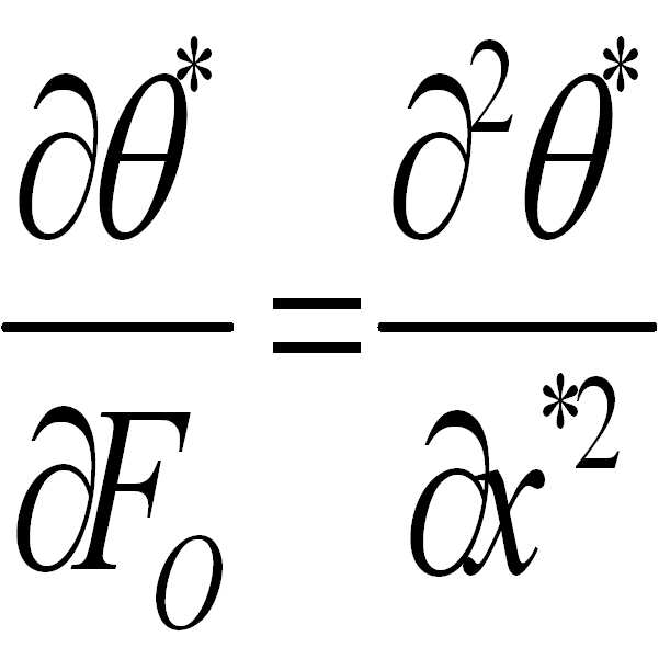
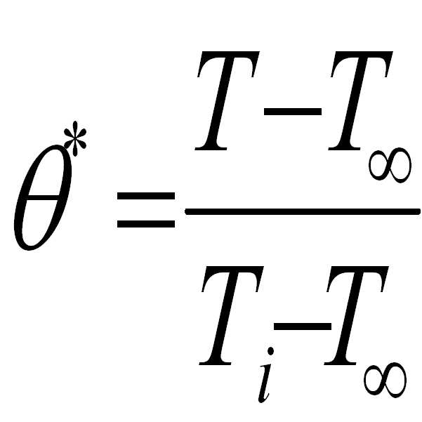
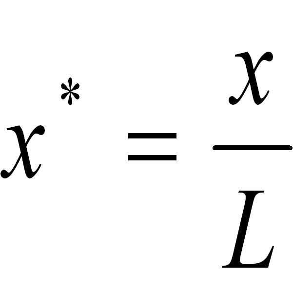
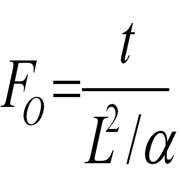
여기서, L2/α 는 열전도 시간 스케일(conduction time scale)이다. 상기 L은 히터(heater)와 접촉하는 열전도체의 두께이고, α는 열확산도(thermal duffusivity)이다. 상기 열전도 시간 스케일은 하기의 수학식 3으로 정의된다. Where L 2 / α is the conduction time scale. L is the thickness of the thermal conductor in contact with the heater, and α is the thermal duffusivity. The thermal conduction time scale is defined by Equation 3 below.
![]()
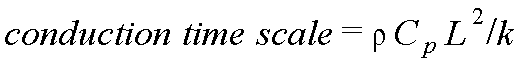
![]()
여기서, k는 히터와 접촉하는 열전도체의 열전도도(thermal conductivity)이고, ρ는 상기 열전도체의 밀도(density)이고, Cp 는 상기 열전도체의 비열(specific heat)이다. Where k is the thermal conductivity of the thermal conductor in contact with the heater, ρ is the density of the thermal conductor, and C p is the specific heat of the thermal conductor.
실리콘(Si)으로 이루어진 종래 미세유동장치(10, 도 1 참조)의 하판(11)의 열전도 시간 스케일과 본 발명 미세유동장치(100)의 점착 테이프(110)의 열전도 시간 스케일이 크게 차이나지 않도록 상기 점착 테이프(110)의 두께(D2)를 설정해 주면, 열전도도 k 의 큰 차이에 불구하고 PCR 에 사용 가능한 본 발명의 미세유동장치(100)를 제조할 수 있다. The heat conduction time scale of the
본 발명의 발명자는 상기 수학식 3을 적용하여 점착 테이프(110)의 폴리머 필름(111, 도 4 참조)의 소재로 통상적으로 사용되는 COC(cyclic olefin copolymer)의 두께에 따른 열전도 시간 스케일을 계산해 보았다. COC의 열전도도 k는 0.135 W/m/K 이고, 밀도 ρ는 1020 kg/m3 이고, 비열 Cp은 1000 J/kg/K 이다. 그러므로, 점착 테이프(110)의 두께(D2)를 10 ㎛ 에서 100 ㎛ 까지 변경하였을 때, 열전도 시간 스케일은 0.756 msec 에서 18.9 msec 까지 변경되었다. The inventor of the present invention tried to calculate the thermal conduction time scale according to the thickness of the COC (cyclic olefin copolymer) commonly used as a material of the polymer film 111 (see FIG. 4) of the
한편, 종래의 미세유동장치(10, 도 1 참조)에서 하판(11)의 챔버(20) 아래의 두께(D1)는 350 ㎛ 이고, 열전도도 k는 157 W/m/K 이고, 밀도 ρ는 2329 kg/m3 이고, 비열 Cp은 700 J/kg/K 이므로, 열전도 시간 스케일은 1.27 msec 이다. Meanwhile, in the conventional microfluidic device 10 (see FIG. 1), the thickness D1 under the
비교해보면, 본 발명 미세유동장치(100)의 점착 테이프(110)의 두께(D2)가 10 ㎛ 정도일 때에는 종래 미세유동장치(10, 도 1 참조)에 비해 열전도 시간 스케일이 양호하나 물리적 강도가 너무 약하여 생화학 반응시의 고온·고압의 조건을 견딜 수 없으며, 매우 주의 깊은 취급을 필요로 한다. 실험을 통하여 점착 테이프(110)의 두께(D2)가 30 ㎛ 이상이면 PCR 등의 생화학 반응 시의 조건을 견딜 수 있는 물리적 강도를 갖는 것으로 파악되었다. 한편, 상기 점착 테이프(110)의 두께(D2)가 100 ㎛ 보다 두꺼우면 열전도 시간 스케일이 너무 커서 종래의 미세유동장치(10, 도 1 참조)와 대등한 시간 내에 PCR을 완료할 수 없다. 따라서, 상기 점착 테이프(110)의 두께는 30 ㎛ 내지 100 ㎛ 인 것이 바람직하다. In comparison, when the thickness D2 of the
본 발명 미세유동장치(100)의 챔버(105)에서 일어나는 PCR 반응은 상기 챔 버(105)에 수용된 생화학 유체에서 발광되는 형광 신호를 검출하여 실시간으로 분석할 수 있다. 이와 같이 형광 신호를 검출하여 생화학 반응을 분석하는 방법을 소위 형광 검출법이라고 한다. PCR 반응의 분석에 사용되는 형광 검출법은, PCR 반응으로 생성된 이중나선(double stranded) DNA에 결합(binding)했을 때 형광을 방출하는 SYBR Green I 등의 염료(dye)를 이용하는 방법, DNA 시퀀스(sequence)를 프로브(probe)로 하고 이 프로브 양 끝의 형광단(fluorophore)과 발광억제단(quencher) 사이의 결합이 절단되면서 형광이 나오는 현상을 이용하는 방법 등 다양한 방법이 개발되어 있다. PCR 반응의 형광 검출법은 본 발명이 속하는 기술분야의 당업자에게 알려진 지식으로서 상세한 설명은 생략한다. 본 발명의 발명자는 상기 형광 검출법을 통하여 종래의 미세유동장치(10, 도 1 참조)와 점착 테이프(110)의 두께(D2)가 70 ㎛ 인 본 발명의 미세유동장치(100)에 대해 PCR 반응을 분석해 본 결과 유사한 분석 결과를 얻을 수 있었으며, 이를 통하여 본 발명의 미세유동장치(100)가 PCR 반응 분석에 적용 가능함을 검증하였다. The PCR reaction occurring in the
본 발명은 도면에 도시된 실시예를 참고로 설명되었으나 이는 예시적인 것에 불과하며, 당해 분야에서 통상의 지식을 가진 자라면 이로부터 다양한 변형 및 균등한 타 실시예가 가능함을 이해할 수 있을 것이다. 따라서 본 발명의 진정한 보호범위는 첨부된 특허청구범위에 의해서만 정해져야 할 것이다. Although the present invention has been described with reference to the embodiments shown in the drawings, this is merely exemplary, and it will be understood by those skilled in the art that various modifications and equivalent other embodiments are possible. Therefore, the true scope of protection of the present invention should be defined only by the appended claims.
도 1은 종래의 PCR(polymerase chain reaction)용 미세유동장치의 일 예를 도시한 단면도이다.1 is a cross-sectional view showing an example of a conventional microfluidic device for polymerase chain reaction (PCR).
도 2는 본 발명의 바람직한 실시예에 따른 미세유동장치를 도시한 사시도이다. 2 is a perspective view showing a microfluidic device according to a preferred embodiment of the present invention.
도 3은 도 2의 A-A'를 따라 절개하여 도시한 단면도이다. 3 is a cross-sectional view taken along the line AA ′ of FIG. 2.
도 4는 도 3의 B를 확대하여 도시한 단면도이다.4 is an enlarged cross-sectional view of B of FIG. 3.
<도면의 주요부분에 대한 부호의 설명><Description of the symbols for the main parts of the drawings>
30 ...마이크로 히터 100 ...미세유동장치30 ...
101 ...기판 105 ...챔버101 ...
106 ...채널 107 ...인렛홀 106 ...
108 ...아웃렛홀 110 ...점착 테이프108 ...
111 ... 폴리머 필름 112 ...점착제 111 ...
Claims (9)
Priority Applications (2)
| Application Number | Priority Date | Filing Date | Title |
|---|---|---|---|
| KR1020070095412A KR20090030084A (en) | 2007-09-19 | 2007-09-19 | Microfluidic Device |
| US12/056,311 US20090074623A1 (en) | 2007-09-19 | 2008-03-27 | Microfluidic device |
Applications Claiming Priority (1)
| Application Number | Priority Date | Filing Date | Title |
|---|---|---|---|
| KR1020070095412A KR20090030084A (en) | 2007-09-19 | 2007-09-19 | Microfluidic Device |
Publications (1)
| Publication Number | Publication Date |
|---|---|
| KR20090030084A true KR20090030084A (en) | 2009-03-24 |
Family
ID=40454676
Family Applications (1)
| Application Number | Title | Priority Date | Filing Date |
|---|---|---|---|
| KR1020070095412A Withdrawn KR20090030084A (en) | 2007-09-19 | 2007-09-19 | Microfluidic Device |
Country Status (2)
| Country | Link |
|---|---|
| US (1) | US20090074623A1 (en) |
| KR (1) | KR20090030084A (en) |
Cited By (1)
| Publication number | Priority date | Publication date | Assignee | Title |
|---|---|---|---|---|
| KR101141248B1 (en) * | 2009-10-22 | 2012-05-04 | 전남대학교산학협력단 | Microfluidic device for air bubble removal and fluid injection/removal |
Families Citing this family (27)
| Publication number | Priority date | Publication date | Assignee | Title |
|---|---|---|---|---|
| US8715446B2 (en) * | 2004-10-13 | 2014-05-06 | Rheonix, Inc. | Latent solvent-based microfluidic apparatus, methods, and applications |
| DE102008001969A1 (en) * | 2008-05-26 | 2009-12-03 | Hilti Aktiengesellschaft | Hand-operated electrically driven tacker |
| KR101793128B1 (en) | 2008-07-16 | 2017-11-02 | 칠드런'즈 메디컬 센터 코포레이션 | Organ mimic device with microchannels and methods of use and manufacturing thereof |
| WO2011014674A2 (en) * | 2009-07-29 | 2011-02-03 | Cornell University | Microfluidic device for pharmacokinetic-pharmacodynamic study of drugs and uses thereof |
| US20110143378A1 (en) * | 2009-11-12 | 2011-06-16 | CyVek LLC. | Microfluidic method and apparatus for high performance biological assays |
| US9700889B2 (en) | 2009-11-23 | 2017-07-11 | Cyvek, Inc. | Methods and systems for manufacture of microarray assay systems, conducting microfluidic assays, and monitoring and scanning to obtain microfluidic assay results |
| US9651568B2 (en) | 2009-11-23 | 2017-05-16 | Cyvek, Inc. | Methods and systems for epi-fluorescent monitoring and scanning for microfluidic assays |
| US9500645B2 (en) | 2009-11-23 | 2016-11-22 | Cyvek, Inc. | Micro-tube particles for microfluidic assays and methods of manufacture |
| ES2649559T3 (en) | 2009-11-23 | 2018-01-12 | Cyvek, Inc. | Method and apparatus for testing |
| US9759718B2 (en) | 2009-11-23 | 2017-09-12 | Cyvek, Inc. | PDMS membrane-confined nucleic acid and antibody/antigen-functionalized microlength tube capture elements, and systems employing them, and methods of their use |
| WO2013134742A2 (en) | 2012-03-08 | 2013-09-12 | Cyvek, Inc | Micro-tube particles for microfluidic assays and methods of manufacture |
| US10065403B2 (en) | 2009-11-23 | 2018-09-04 | Cyvek, Inc. | Microfluidic assay assemblies and methods of manufacture |
| US9855735B2 (en) | 2009-11-23 | 2018-01-02 | Cyvek, Inc. | Portable microfluidic assay devices and methods of manufacture and use |
| KR101737121B1 (en) | 2010-12-21 | 2017-05-17 | 엘지전자 주식회사 | Microfluidic system |
| KR102117921B1 (en) | 2011-02-28 | 2020-06-03 | 프레지던트 앤드 펠로우즈 오브 하바드 칼리지 | Cell culture system |
| WO2012129455A2 (en) | 2011-03-22 | 2012-09-27 | Cyvek, Inc | Microfluidic devices and methods of manufacture and use |
| JP5797926B2 (en) * | 2011-04-21 | 2015-10-21 | 株式会社エンプラス | Fluid handling apparatus, manufacturing method thereof, and fluid handling system |
| US9725687B2 (en) | 2011-12-09 | 2017-08-08 | President And Fellows Of Harvard College | Integrated human organ-on-chip microphysiological systems |
| JP2014097485A (en) * | 2012-10-18 | 2014-05-29 | Enplas Corp | Liquid handling apparatus |
| EP3024582A4 (en) | 2013-07-22 | 2017-03-08 | President and Fellows of Harvard College | Microfluidic cartridge assembly |
| CA2944220C (en) | 2013-12-20 | 2024-01-02 | President And Fellows Of Harvard College | Organomimetic devices and methods of use and manufacturing thereof |
| GB2538012A (en) | 2013-12-20 | 2016-11-02 | Harvard College | Low shear microfluidic devices and methods of use and manufacturing thereof |
| WO2016010861A1 (en) | 2014-07-14 | 2016-01-21 | President And Fellows Of Harvard College | Systems and methods for improved performance of fluidic and microfluidic systems |
| US10202569B2 (en) | 2015-07-24 | 2019-02-12 | President And Fellows Of Harvard College | Radial microfluidic devices and methods of use |
| US10228367B2 (en) | 2015-12-01 | 2019-03-12 | ProteinSimple | Segmented multi-use automated assay cartridge |
| CA3036378A1 (en) | 2016-09-13 | 2018-03-22 | President And Fellows Of Harvard College | Methods relating to intestinal organ-on-a-chip |
| US20220399796A1 (en) * | 2021-06-14 | 2022-12-15 | International Business Machines Corporation | Device for actuating a physical object by magnetically driven fluid flow |
Family Cites Families (5)
| Publication number | Priority date | Publication date | Assignee | Title |
|---|---|---|---|---|
| US6561208B1 (en) * | 2000-04-14 | 2003-05-13 | Nanostream, Inc. | Fluidic impedances in microfluidic system |
| US7027683B2 (en) * | 2000-08-15 | 2006-04-11 | Nanostream, Inc. | Optical devices with fluidic systems |
| US6418968B1 (en) * | 2001-04-20 | 2002-07-16 | Nanostream, Inc. | Porous microfluidic valves |
| US7198759B2 (en) * | 2002-07-26 | 2007-04-03 | Applera Corporation | Microfluidic devices, methods, and systems |
| US20080233011A1 (en) * | 2007-03-23 | 2008-09-25 | 3M Innovative Properties Company | Microfluidic devices |
-
2007
- 2007-09-19 KR KR1020070095412A patent/KR20090030084A/en not_active Withdrawn
-
2008
- 2008-03-27 US US12/056,311 patent/US20090074623A1/en not_active Abandoned
Cited By (1)
| Publication number | Priority date | Publication date | Assignee | Title |
|---|---|---|---|---|
| KR101141248B1 (en) * | 2009-10-22 | 2012-05-04 | 전남대학교산학협력단 | Microfluidic device for air bubble removal and fluid injection/removal |
Also Published As
| Publication number | Publication date |
|---|---|
| US20090074623A1 (en) | 2009-03-19 |
Similar Documents
| Publication | Publication Date | Title |
|---|---|---|
| KR20090030084A (en) | Microfluidic Device | |
| KR20090074397A (en) | Microfluidic device and its manufacturing method | |
| US7410617B2 (en) | Sample handling plate | |
| US9480982B2 (en) | Reactor for the quantitative analysis of nucleic acids | |
| CN103831140B (en) | A kind of micro-fluidic chip of multiple determination | |
| US20140038193A1 (en) | Microfluidic pcr device | |
| US20090220948A1 (en) | Methods and Device for Transmitting, Enclosing and Analysing Fluid Samples | |
| US20030138969A1 (en) | Closed substrate platforms suitable for analysis of biomolecules | |
| US20240165612A1 (en) | Microfluidic reaction vessel array with patterned films | |
| KR101513273B1 (en) | A rotary type PCR machine and a PCR chip | |
| US9539571B2 (en) | Method to increase detection efficiency of real time PCR microarray by quartz material | |
| JP5077953B2 (en) | Microchip | |
| JP2009042103A (en) | Substrate, reaction processing apparatus using the same, and reaction control method | |
| US20090291025A1 (en) | Microchip And Method Of Using The Same | |
| JP2006513421A (en) | Sample processing apparatus having a process chamber with a bypass slot | |
| KR101321912B1 (en) | Elastic valve and microfluidic device with the same | |
| WO2006098435A1 (en) | Detecting chip and method of detecting substance using the same | |
| CN101855018A (en) | Apparatus and methods for thermally isolating chambers for assay cards | |
| EP3368685B1 (en) | Fluidic card for analysis of biochips | |
| US11648563B2 (en) | Method and system for heating and temperature measurement using patterned thin films | |
| KR102431519B1 (en) | Cell chip wih concentration gradients including nano structure, manufacturing method thereof and apparatus for image analysis using the same | |
| JP6017793B2 (en) | Microchip | |
| TWI579564B (en) | Microfluidic transmission and detection of the wafer structure of biological samples | |
| JP4917765B2 (en) | PCR reaction vessel | |
| JP2017138137A (en) | PCR microchip and nucleic acid amplification apparatus |
Legal Events
| Date | Code | Title | Description |
|---|---|---|---|
| PA0109 | Patent application |
Patent event code: PA01091R01D Comment text: Patent Application Patent event date: 20070919 |
|
| PG1501 | Laying open of application | ||
| PC1203 | Withdrawal of no request for examination | ||
| WITN | Application deemed withdrawn, e.g. because no request for examination was filed or no examination fee was paid |