KR20080105870A - Red phosphorescent compound and organic electroluminescent device using same - Google Patents
Red phosphorescent compound and organic electroluminescent device using same Download PDFInfo
- Publication number
- KR20080105870A KR20080105870A KR1020070054000A KR20070054000A KR20080105870A KR 20080105870 A KR20080105870 A KR 20080105870A KR 1020070054000 A KR1020070054000 A KR 1020070054000A KR 20070054000 A KR20070054000 A KR 20070054000A KR 20080105870 A KR20080105870 A KR 20080105870A
- Authority
- KR
- South Korea
- Prior art keywords
- light emitting
- group
- red phosphorescent
- phosphorescent compound
- organic light
- Prior art date
- Legal status (The legal status is an assumption and is not a legal conclusion. Google has not performed a legal analysis and makes no representation as to the accuracy of the status listed.)
- Ceased
Links
Images


Classifications
-
- C—CHEMISTRY; METALLURGY
- C09—DYES; PAINTS; POLISHES; NATURAL RESINS; ADHESIVES; COMPOSITIONS NOT OTHERWISE PROVIDED FOR; APPLICATIONS OF MATERIALS NOT OTHERWISE PROVIDED FOR
- C09K—MATERIALS FOR MISCELLANEOUS APPLICATIONS, NOT PROVIDED FOR ELSEWHERE
- C09K11/00—Luminescent, e.g. electroluminescent, chemiluminescent materials
- C09K11/06—Luminescent, e.g. electroluminescent, chemiluminescent materials containing organic luminescent materials
-
- H—ELECTRICITY
- H10—SEMICONDUCTOR DEVICES; ELECTRIC SOLID-STATE DEVICES NOT OTHERWISE PROVIDED FOR
- H10K—ORGANIC ELECTRIC SOLID-STATE DEVICES
- H10K50/00—Organic light-emitting devices
- H10K50/10—OLEDs or polymer light-emitting diodes [PLED]
- H10K50/11—OLEDs or polymer light-emitting diodes [PLED] characterised by the electroluminescent [EL] layers
- H10K50/12—OLEDs or polymer light-emitting diodes [PLED] characterised by the electroluminescent [EL] layers comprising dopants
-
- H—ELECTRICITY
- H10—SEMICONDUCTOR DEVICES; ELECTRIC SOLID-STATE DEVICES NOT OTHERWISE PROVIDED FOR
- H10K—ORGANIC ELECTRIC SOLID-STATE DEVICES
- H10K85/00—Organic materials used in the body or electrodes of devices covered by this subclass
- H10K85/30—Coordination compounds
- H10K85/341—Transition metal complexes, e.g. Ru(II)polypyridine complexes
- H10K85/342—Transition metal complexes, e.g. Ru(II)polypyridine complexes comprising iridium
-
- C—CHEMISTRY; METALLURGY
- C07—ORGANIC CHEMISTRY
- C07F—ACYCLIC, CARBOCYCLIC OR HETEROCYCLIC COMPOUNDS CONTAINING ELEMENTS OTHER THAN CARBON, HYDROGEN, HALOGEN, OXYGEN, NITROGEN, SULFUR, SELENIUM OR TELLURIUM
- C07F15/00—Compounds containing elements of Groups 8, 9, 10 or 18 of the Periodic Table
- C07F15/0006—Compounds containing elements of Groups 8, 9, 10 or 18 of the Periodic Table compounds of the platinum group
- C07F15/0033—Iridium compounds
-
- C—CHEMISTRY; METALLURGY
- C09—DYES; PAINTS; POLISHES; NATURAL RESINS; ADHESIVES; COMPOSITIONS NOT OTHERWISE PROVIDED FOR; APPLICATIONS OF MATERIALS NOT OTHERWISE PROVIDED FOR
- C09K—MATERIALS FOR MISCELLANEOUS APPLICATIONS, NOT PROVIDED FOR ELSEWHERE
- C09K2211/00—Chemical nature of organic luminescent or tenebrescent compounds
- C09K2211/18—Metal complexes
- C09K2211/185—Metal complexes of the platinum group, i.e. Os, Ir, Pt, Ru, Rh or Pd
Landscapes
- Chemical & Material Sciences (AREA)
- Engineering & Computer Science (AREA)
- Materials Engineering (AREA)
- Organic Chemistry (AREA)
- Physics & Mathematics (AREA)
- Optics & Photonics (AREA)
- Crystallography & Structural Chemistry (AREA)
- Inorganic Chemistry (AREA)
- Electroluminescent Light Sources (AREA)
Abstract
적색 인광 화합물 및 이를 이용한 유기 전계 발광 소자에 관한 것으로, 하기 화학식 1로 표시되는 화합물을 발광층으로 사용한다.It relates to a red phosphorescent compound and an organic electroluminescent device using the same, using a compound represented by the following formula (1) as a light emitting layer.
[화학식1][Formula 1]

(상기 화학식에서 

Description
도 1은 일반적인 유기전계발광소자의 색순도가 높아질수록 시감도가 저하되는 것을 보여주는 그래프1 is a graph showing that the visibility decreases as the color purity of a conventional organic light emitting display device increases
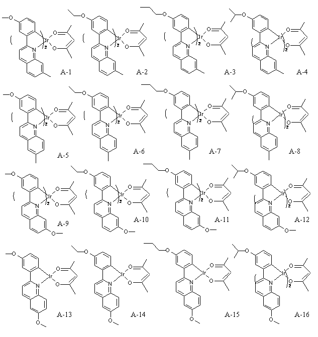
도 2는 본 발명의 실시예에서 사용되는 화합물들의 구조식을 보여주는 그래프Figure 2 is a graph showing the structural formula of the compounds used in the examples of the present invention
본 발명은 적색 인광 화합물 및 이를 이용한 유기 전계 발광 소자에 관한 것이다.The present invention relates to a red phosphorescent compound and an organic electroluminescent device using the same.
일반적으로, 유기 전계 발광 소자는 전자 주입을 위한 음극과 정공 주입을 위한 양극 사이에 형성된 유기막에 전하를 주입하면 전자와 정공이 쌍을 이룬 후 소멸하면서 빛을 내는 소자이다.In general, when an electric charge is injected into an organic film formed between a cathode for electron injection and an anode for hole injection, the organic electroluminescent device emits light while pairing with electrons and holes.
플라스틱 같은 휠 수 있는(flexible) 투명 기판 위에도 소자를 형성할 수 있을 뿐 아니라, 플라즈마 디스플레이 패널(Plasma Display Panel)이나 무기 EL 디스플레이에 비해 낮은 전압에서 (약 10V 이하) 구동이 가능하고, 또한 전력 소모가 비교적 적으며, 색감이 뛰어나다는 장점이 있다.Not only can the device be formed on a flexible transparent substrate such as plastic, but it can also be driven at a lower voltage (about 10V or less) than plasma display panels or inorganic EL displays, and it also consumes power. Is relatively small, and the color is excellent.
또한, 유기 전계 발광 소자는 녹색, 청색, 적색의 3가지 색을 나타낼 수가 있어 차세대 풀 컬러 디스플레이(full color display) 소자로 많은 사람들의 많은 관심의 대상이 되고 있다.In addition, the organic electroluminescent device can display three colors of green, blue, and red, and thus, has become a subject of much interest as a next generation full color display device.
여기서, 유기 EL 소자를 제작하는 과정을 간단히 살펴보면 다음과 같다.Here, the process of manufacturing the organic EL device will be briefly described as follows.
먼저, 투명기판 위에 양극(anode)을 형성한다.First, an anode is formed on a transparent substrate.
여기서, 양극 물질로는 흔히 ITO (indium tin oxide)가 사용된다. Here, indium tin oxide (ITO) is often used as the anode material.
이어, 양극(2) 위에 정공주입층(HIL:hole injecting layer)을 형성한다.Next, a hole injecting layer (HIL) is formed on the anode 2.
여기서, 정공주입층은 주로 구리 프탈로시안(copper phthalocyanine(CuPc))을 사용하고, 약 10 ~ 30nm 두께로 형성한다.Here, the hole injection layer is mainly formed of copper phthalocyanine (CuPc), and is formed to a thickness of about 10 ~ 30nm.
다음, 정공주입층 위에 정공수송층(HTL: hole transport layer)을 형성한다.Next, a hole transport layer (HTL) is formed on the hole injection layer.
여기서, 정공수송층은 4,4'-비스[N-(1-나프틸)-N-페닐아미노]-바이페닐(4,4'-bis[N-(1-naphthyl)-N-phenylamino]-biphenyl(NPB))을 사용하고, 약 30 ~ 60nm 두께로 형성한다.Here, the hole transport layer is 4,4'-bis [N- (1-naphthyl) -N-phenylamino] -biphenyl (4,4'-bis [N- (1-naphthyl) -N-phenylamino]- biphenyl (NPB)) is used to form a thickness of about 30 ~ 60nm.
그리고, 정공수송층 위에 유기발광층(organic emitting layer)을 형성한다.In addition, an organic light emitting layer is formed on the hole transport layer.
이때, 필요에 따라 도펀트(dopant)를 첨가한다.At this time, a dopant is added as needed.
인광 적색 발광의 경우, 흔히 유기발광층은 4,4'-N,N'-디카바졸-바이페닐(4,4'-N,N'-dicarbazole-biphenyl(CBP))을 두께 약 30 ~ 60nm 정도로 형성하고, 도펀트(dopant)로는 이리듐 콤플렉스(Iridium complex)를 많이 사용한다.In the case of phosphorescent red light emission, the organic light emitting layer often has 4,4'-N, N'-dicarbazole-biphenyl (4,4'-N, N'-dicarbazole-biphenyl (CBP)) in a thickness of about 30 to 60 nm. The iridium complex is used a lot as the dopant.
이어, 유기발광층 위에 전자수송층(ETL: electron transport layer) 및 전자 주입층(EIL: electron injecting layer)을 연속적으로 형성하거나, 또는 전자주입 수송층을 형성한다.Subsequently, an electron transport layer (ETL) and an electron injecting layer (EIL) are continuously formed on the organic light emitting layer, or an electron injection transport layer is formed.
여기서, 전자수송층은 트리스(8-하이드록시-퀴놀레이트)알루미늄(tris(8-hydroxy-quinolate)aluminum(Alq3))을 주로 많이 사용한다.Here, the electron transport layer mainly uses tris (8-hydroxy-quinolate) aluminum (Alq3).
다음, 전자주입층 위에 음극(cathode)을 형성하고, 그 위에 보호막을 형성한다.Next, a cathode is formed on the electron injection layer, and a protective film is formed thereon.
이와 같이 형성된 소자는 발광층의 형성 방식에 따라 청색, 녹색, 적색의 발광 소자를 각각 구현 할 수가 있다.The devices formed as described above may implement blue, green, and red light emitting devices, respectively, according to a method of forming the light emitting layer.
소자의 발광층에서는 양쪽 전극에서부터 주입된 전자와 정공의 재결합에 의해 여기자가 형성된다.In the light emitting layer of the device, excitons are formed by recombination of electrons and holes injected from both electrodes.
여기자는 일중항과 삼중항의 비율이 1:3 으로 존재하며, 형광의 경우 일중항 여기자만 이용되고, 인광의 경우 일중항과 삼중항을 모두 사용하여 보다 뛰어난 발광효율을 얻을 수 있다.The excitons have a ratio of 1: 3 to singlet and triplet, and in the case of fluorescence, only singlet excitons are used, and in the case of phosphorescence, both singlet and triplet can be used to obtain more excellent luminous efficiency.
이와 같이 인광 재료는 형광재료에 비해 매우 높은 양자효율을 가질 수 있으므로, 유기 전계 발광 소자의 효율을 높이는 중요한 방법으로 많이 연구되고 있다.As such, the phosphorescent material may have a very high quantum efficiency compared to the fluorescent material, and thus, much research has been conducted as an important method for increasing the efficiency of the organic EL device.
외부발광효율(ηle : luminance efficiency)은 다음과 같은 식으로 표현될 수 있다.External luminance efficiency (η le ) can be expressed as follows.
ηle = k ·ηint ·ηout η le = k η int η out
여기서, k는 색감에 따른 사람 눈의 민감도, ηint는 내부양자효율(internal quantum efficiency), ηout는 광학출력효율(outcoupling efficiency)이다.Where k is the sensitivity of the human eye according to color, η int is the internal quantum efficiency, and η out is the outcoupling efficiency.
높은 외부발광효율 얻기 위해서는 내부양자효율이 우수해야 하지만, 높은 순도의 적색(CIE 색좌표 X값이 큼)의 경우, 도 1에서 나타난 것과 같이, 시감도가 떨어지는 문제가 있으므로, 같은 내부양자효율로는 같은 외부양자효율을 얻기가 어려운 문제가 있다.The internal quantum efficiency should be excellent in order to obtain a high external light emission efficiency, but in the case of high purity red (the CIE color coordinate X value is large), as shown in FIG. It is difficult to obtain external quantum efficiency.
이에 따라, 색순도(CIE 색순도 X = 0.65이상)가 높으면서도 높은 발광효율 및 긴 발광수명의 특징을 가지는 적색 인광화합물의 개발이 요구되고 있다.Accordingly, there is a demand for the development of a red phosphorescent compound having high color purity (CIE color purity X = 0.65 or more) while having high light emission efficiency and long light emission life.
본 발명의 목적은 이러한 문제들을 해결하기 위한 것으로, 발광층의 도펀트로 사용되는 화학식 1을 합성하여 색순도를 높이고, 높은 발광효율 및 긴 발광수명을 가질 수 있는 적색 인광 화합물 및 이를 이용한 유기 전계 발광 소자를 제공하는데 있다.SUMMARY OF THE INVENTION An object of the present invention is to solve the above problems, by synthesizing the general formula (1) used as the dopant of the light emitting layer to increase the color purity, red phosphorescent compound that can have a high luminous efficiency and long emission life and an organic electroluminescent device using the same To provide.
본 발명에 따른 적색 인광 화합물은 하기 화학식 1로 표시되는 적색 인광 화합물일 수 있다.The red phosphorescent compound according to the present invention may be a red phosphorescent compound represented by Formula 1 below.
[화학식1][Formula 1]

(상기 화학식에서 

여기서, R1은 C1 내지 C6의 알킬기 및 아릴기로 이루어진 그룹으로부터 선택되고, R2 및 R3는 각각 독립적으로 수소, C1 내지 C6의 알킬기, C1 내지 C4의 알콕시기로부터 선택되며, R2 및 R3 중 적어도 하나는 C1 내지 C6의 알킬기이거나 또는 C1 내지 C4의 알콕시기일 수 있다.Wherein R 1 is selected from the group consisting of C1 to C6 alkyl and aryl groups, R2 and R3 are each independently selected from hydrogen, C1 to C6 alkyl group, C1 to C4 alkoxy group, and at least one of R2 and R3 is It may be an alkyl group of C1 to C6 or an alkoxy group of C1 to C4.
그리고, 본 발명에 따른 유기전계발광소자는 양극과 음극 사이에 발광층을 포함하여 이루어질 수 있고, 화학식 1의 화합물을 발광층의 도펀트로 사용할 수 있다.The organic light emitting device according to the present invention may include a light emitting layer between an anode and a cathode, and the compound of Formula 1 may be used as a dopant of the light emitting layer.
여기서, 발광층은 Al, Zn 금속 착물 및 카바졸 유도체 중 어느 하나를 호스트로 사용할 수 있다.Here, the light emitting layer may use any one of Al, Zn metal complex and carbazole derivatives as a host.
본 발명의 다른 목적, 특징 및 잇점들은 첨부한 도면을 참조한 실시예들의 상세한 설명을 통해 명백해질 것이다.Other objects, features and advantages of the present invention will become apparent from the following detailed description of embodiments taken in conjunction with the accompanying drawings.
이하, 첨부도면을 참조하여 본 발명의 바람직한 실시예를 상세히 설명한다.Hereinafter, exemplary embodiments of the present invention will be described in detail with reference to the accompanying drawings.
본 발명은 페닐기에는 전자를 잘 주는 알콕시기를 치환하여 색순도를 높이고, 퀴놀린기에서는 질소를 포함하지 않은 페닐기에 알킬, 알콕시기를 치환하여 높 은 발광효율 및 긴 발광수명을 가질 수 있는 적색 인광 화합물을 개발하였다.The present invention develops a red phosphorescent compound which can have a high luminous efficiency and a long luminous lifetime by substituting an alkoxy group which gives a good electron to the phenyl group and improving the color purity, and replacing an alkyl or alkoxy group with a phenyl group which does not contain nitrogen in the quinoline group. It was.
본 발명은 하기 화학식 1로 표시되는 적색 인광 화합물을 제공한다.The present invention provides a red phosphorescent compound represented by the following formula (1).
[화학식1][Formula 1]

여기서, 화학식 1의 

그리고, R1은 C1 내지 C6의 알킬기 및 아릴기로 이루어진 그룹으로부터 선택되고, R2 및 R3는 각각 독립적으로 수소, C1 내지 C6의 알킬기, C1 내지 C4의 알콕시기로부터 선택되며, R2 및 R3 중 적어도 하나는 C1 내지 C6의 알킬기이거나 또는 C1 내지 C4의 알콕시기일 수 있다.And R1 is selected from the group consisting of C1 to C6 alkyl groups and aryl groups, R2 and R3 are each independently selected from hydrogen, C1 to C6 alkyl groups, C1 to C4 alkoxy groups, and at least one of R2 and R3 is It may be an alkyl group of C1 to C6 or an alkoxy group of C1 to C4.
이때, C1 내지 C6의 알킬기는 메틸, 에틸, n-프로필, i-프로필, n-부틸, i-부틸 및 t-부틸로 이루어진 그룹으로부터 선택되고, C1 내지 C6의 아릴기는 페닐로 이루어진 그룹으로부터 선택되며, C1 내지 C4의 알콕시기는 메톡시, 에톡시, n-프로톡시, i-프로톡시, n-부톡시, i-부톡시 및 t-부톡시로 이루어진 그룹으로부터 선 택될 수 있다.Wherein the alkyl group of C1 to C6 is selected from the group consisting of methyl, ethyl, n-propyl, i-propyl, n-butyl, i-butyl and t-butyl, and the aryl groups of C1 to C6 are selected from the group consisting of phenyl And the alkoxy group of C1 to C4 may be selected from the group consisting of methoxy, ethoxy, n-propoxy, i-propoxy, n-butoxy, i-butoxy and t-butoxy.
그리고, 화학식 1의 


또한, 화학식 1의

로부터 선택된 어느 한 화합물일 수도 있다.It may be any compound selected from.
그리고, 화학식 1의 화합물은 하기 화합물들, And, the compound of Formula 1 is the following compounds,

로부터 선택된 어느 한 화합물일 수 있다.It may be any compound selected from.
한편, 본 발명에 따른 유기전계발광소자는 양극과 음극 사이에 발광층을 포함하는 구조로 이루어지고, 상기 화학식 1의 화합물을 발광층의 도펀트로 사용할 수 있다.On the other hand, the organic light emitting device according to the invention is made of a structure including a light emitting layer between the anode and the cathode, the compound of Formula 1 can be used as a dopant of the light emitting layer.
여기서, 발광층은 Al, Zn 금속 착물 및 카바졸 유도체 중 어느 하나를 호스 트로 사용할 수 있다.Here, the light emitting layer may be any one of Al, Zn metal complex and carbazole derivatives as a host.
이때, Al, Zn 금속착물의 리간드는 퀴놀닐, 바이페닐닐, 아이소퀴놀닐, 페닐닐, 메틸퀴놀닐, 메틸퀴놀닐, 다이메틸퀴놀닐, 다이메틸아이소퀴놀닐기 중 어느 하나로 이루어지고, 카바졸 유도체는 CBP로 이루어지는 것이 바람직하다.At this time, the ligand of the Al, Zn metal complex is made of any one of the quinolyl, biphenylyl, isoquinolyl, phenylyl, methylquinolyl, methylquinolyl, dimethylquinolyl, dimethylisoquinolyl group, carbazole It is preferable that a derivative consists of CBP.
그리고, 본 발명에서, 발광층의 도펀트 사용량은 약 0.1 중량% - 50 중량%인 것이 바람직하다.In the present invention, the amount of dopant used in the light emitting layer is preferably about 0.1% by weight to 50% by weight.
이하에서, 본 발명에 따른 유기전계발광소자에 사용되는 적색 인광 화합물들 중 일부 화합물에 대한 합성 방법을 설명하기로 한다.Hereinafter, a synthesis method for some of the red phosphorescent compounds used in the organic light emitting device according to the present invention will be described.
합성예Synthesis Example
(1)2-(3-메톡시페닐)-6-메틸퀴놀린(2-(3-methoxyphenyl)-6-methylquinoline)의 합성방법(1) Synthesis method of 2- (3-methoxyphenyl) -6-methylquinoline (2- (3-methoxyphenyl) -6-methylquinoline)

건조된 2구 둥근 바닥 플라스크(two-neck-r.b.f)에 3-메톡시페닐붕산(3- methoxyphenyl boronic acid)(13mmol), 2-클로로-6-메틸퀴놀린(2-chloro-6-methylquinoline)(10mmol), 테트라키스(트라이페닐포스핀)팔라듐(tetrakis(triphenylphosphine)palladium)(0)(0.5mmol)과 포타시움 카보네이트(Potassium carbonate)(15g)를, THF(30mL)와 물(H2O)(10mL)에 녹인 후, 약 100 ℃의 욕조(bath)에서 약 24시간 교반을 시킨다.3-methoxyphenyl boronic acid (13 mmol), 2-chloro-6-methylquinoline (2-chloro-6-methylquinoline) in a dried two-neck round bottom flask (two-neck-rbf) 10 mmol), tetrakis (triphenylphosphine) palladium (0) (0.5 mmol), Potassium carbonate (15 g), THF (30 mL) and water (H2O) (10 mL) After dissolving in, it is stirred for about 24 hours in a bath of about 100 ℃.
이어, 반응이 종료가 되면, THF와 톨루엔(Toluene)을 제거한 후, 다이클로로메테인(Dichloromethane)과 물을 사용하여 추출한 다음, 감압 증류하여 실리카 겔 컬럼(lica gel columm)하고, 용매를 감압 증류한다.Subsequently, when the reaction is completed, the THF and toluene are removed, and extracted with dichloromethane and water, followed by distillation under reduced pressure, and a silica gel column (lica gel columm), and the solvent is distilled under reduced pressure. do.
그리고, 다이클로로메테인(Dichloromethane)과 석유 에테르(petroleum ether)를 사용하여 재결정을 하고 여과(filter)를 하면, 2-(3-메톡시페닐)-6-메틸퀴놀린(2-(3-methoxyphenyl)-6-methylquinoline)의 고체(solid) 2.2g을 얻을 수 있었다.In addition, when recrystallized with dichloromethane and petroleum ether and filtered, 2- (3-methoxyphenyl) -6-methylquinoline (2- (3-methoxyphenyl) ) -6-methylquinoline) solid 2.2g was obtained.
(2) 클로로-가교 다이머 착물(Chloro-bridged dimer complex)의 합성방법(2) Synthesis method of chloro-bridged dimer complex
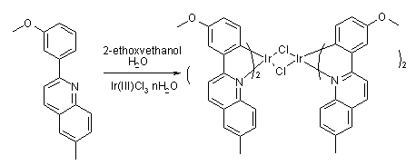
이리듐 클로라이드(Iridium Chloride)(5mmol)와 2-(3-메톡시페닐)-6-메틸퀴놀린(2-(3-methoxyphenyl)-6-methylquinoline)(10mmol)을 2-에톡시에탄올(ethoxyethanol) : 증류수(distilled H2O)가 3:1로 혼합된 용액(30ml)에 넣고, 약 24시간 동안 환류시킨다.Iridium Chloride (5mmol) and 2- (3-methoxyphenyl) -6-methylquinoline (2- (3-methoxyphenyl) -6-methylquinoline) (10mmol) as 2-ethoxyethanol: Distilled H 2 O was added to a solution (30 ml) mixed 3: 1 and refluxed for about 24 hours.
이어, 물을 첨가하여 형성된 고체를 여과한 후, 메탄올과 석유 에테르(ptroleum ether)로 세척하여 클로로 가교 다이머 착물(chloro bridged dimer complex)를 얻을 수 있었다.Subsequently, the solid formed by adding water was filtered and then washed with methanol and petroleum ether to obtain a chloro bridged dimer complex.
(3) 이리듐(III) (2-(3-메톡시페닐)-6-메틸퀴놀린-N,C2')(2,4-펜테인다이오네이트-O,O) (Iridium(III) (2-(3-methoxyphenyl)-6-methylquinoline-N,C2') (2,4-pentanedionate-O,O)) (A-5)의 합성방법(3) Iridium (III) (2- (3-methoxyphenyl) -6-methylquinoline-N, C 2 ' ) (2,4-pentanedionate-O, O) (Iridium (III) (2 Synthesis method of-(3-methoxyphenyl) -6-methylquinoline-N, C2 ') (2,4-pentanedionate-O, O)) (A-5)

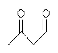
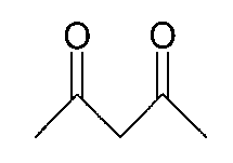
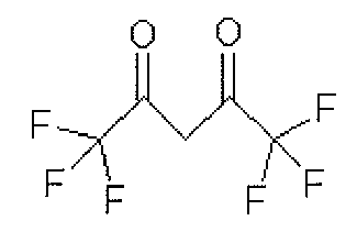
클로로-가교 다이머 착물(Chloro-bridged dimer complex)(1mmol), 2,4-펜테인다이온(2,4-pentanedion)(3mmol)과, Na2CO3(6mmol)을 2-에톡시에탄올(2- ethoxyethanol)(30ml)에 넣고, 약 24시간 동안 환류시킨다.Chloro-bridged dimer complex (1 mmol), 2,4-pentanedion (3 mmol), and Na2CO3 (6 mmol) with 2-ethoxyethanol ) (30 ml) and reflux for about 24 hours.
그리고, 이를 상온으로 식힌 후, 증류수를 첨가하여 여과한 다음, 고체를 얻었다.Then, after cooling to room temperature, distilled water was added and filtered to obtain a solid.
이어, 형성된 고체를 다이클로로메테인(dichloromethane)에 녹인 후, 실리카 겔(silica gel)을 이용하여 여과하였고, 다이클로로메테인(dichloromethane)을 감압 제거 후, 메탄올과 석유 에테르(petroleum ether)로 세척하여 화합물을 얻을 수 있다.Subsequently, the formed solid was dissolved in dichloromethane, filtered using silica gel, and dichloromethane was removed under reduced pressure, followed by washing with methanol and petroleum ether. The compound can be obtained.
실시예Example
실시예 1Example 1
ITO 유리(glass) 기판의 발광 면적이 3mm X 3mm 크기가 되도록 패터닝(patterning)한 후 세정하였다.The light emitting area of the ITO glass substrate was patterned to be 3 mm × 3 mm in size, and then washed.
이어, 기판을 진공 챔버에 장착한 후, 기본 압력(base pressure)이 1 X 10⁻⁶ torr가 되도록 한다.Subsequently, after mounting the substrate in a vacuum chamber, the base pressure is 1 × 10 −6 torr.
다음, 유기물을 ITO 유리 기판 위에 CuPC(200Å), NPD(400Å), BAlq + A-5 (7%)(200Å), Alq3(300Å), LiF(5Å), Al(1000Å)의 순서로 성막하였다. Next, an organic material was formed on an ITO glass substrate in the order of CuPC (200 Pa), NPD (400 Pa), BAlq + A-5 (7%) (200 Pa), Alq3 (300 Pa), LiF (5 Pa), Al (1000 Pa). .
상기와 같이 제작된 소자는 약 0.9mA에서 약 934cd/m2(5.7V)를 나타내었으며, 이때 CIE x = 0.691, y = 0.306를 나타내었다.The device fabricated as described above exhibited about 934 cd / m 2 (5.7 V) at about 0.9 mA, with CIE x = 0.691 and y = 0.306.
또한, 수명(초기휘도의 반)은 약 2000cd/m2에서 약 6500 시간이었다.In addition, the lifetime (half the initial luminance) was about 6500 hours at about 2000 cd / m 2 .
실시예 2Example 2
ITO 유리(glass) 기판의 발광 면적이 3mm X 3mm 크기가 되도록 패터닝(patterning)한 후 세정하였다.The light emitting area of the ITO glass substrate was patterned to be 3 mm × 3 mm in size, and then washed.
이어, 기판을 진공 챔버에 장착한 후, 기본 압력(base pressure)이 약 1 X 10⁻⁶ torr가 되도록 한다.Subsequently, after mounting the substrate in a vacuum chamber, the base pressure is about 1 × 10 −6 torr.
다음, 유기물을 ITO 유리 기판 위에 CuPC(200Å), NPD(400Å), BAlq + A-6 (7%)(200Å), Alq3(300Å), LiF(5Å), Al(1000Å)의 순서로 성막하였다.Next, an organic material was formed on an ITO glass substrate in the order of CuPC (200 kPa), NPD (400 kPa), BAlq + A-6 (7%) (200 kPa), Alq3 (300 kPa), LiF (5 kPa), Al (1000 kPa). .
상기와 같이 제작된 소자는 약 0.9mA에서 약 920cd/m2(5.9V)를 나타내었으며, 이때 CIE x = 0.692, y = 0.304를 나타내었다.The device manufactured as described above exhibited about 920 cd / m 2 (5.9 V) at about 0.9 mA, where CIE x = 0.692 and y = 0.304.
또한, 수명(초기휘도의 반)은 약 2000cd/m2에서 약 6000 시간이었다.In addition, the lifetime (half the initial luminance) was about 6000 hours at about 2000 cd / m 2 .
실시예 3Example 3
ITO 유리(glass) 기판의 발광 면적이 3mm X 3mm 크기가 되도록 패터닝(patterning)한 후 세정하였다.The light emitting area of the ITO glass substrate was patterned to be 3 mm × 3 mm in size, and then washed.
이어, 기판을 진공 챔버에 장착한 후, 기본 압력(base pressure)이 1 X 10⁻⁶ torr가 되도록 한다.Subsequently, after mounting the substrate in a vacuum chamber, the base pressure is 1 × 10 −6 torr.
다음, 유기물을 ITO 유리 기판 위에 CuPC(200Å), NPD(400Å), Balq + A-8 (7%)(200Å), Alq3(300Å), LiF(5Å), Al(1000Å)의 순서로 성막하였다. Next, an organic material was formed on an ITO glass substrate in the following order: CuPC (200 kPa), NPD (400 kPa), Balq + A-8 (7%) (200 kPa), Alq3 (300 kPa), LiF (5 kPa), Al (1000 kPa). .
상기와 같이 제작된 소자는 약 0.9mA에서 약 896cd/m2(6.0V)를 나타내었으며, 이때 CIE x = 0.690, y = 0.301를 나타내었다.The device fabricated as described above exhibited about 896 cd / m 2 (6.0 V) at about 0.9 mA, where CIE x = 0.690, y = 0.301.
또한, 수명(초기휘도의 반)은 약 2000cd/m2에서 약 6000 시간이었다.In addition, the lifetime (half the initial luminance) was about 6000 hours at about 2000 cd / m 2 .
실시예 4Example 4
ITO 유리(glass) 기판의 발광 면적이 3mm X 3mm 크기가 되도록 패터닝(patterning)한 후 세정하였다.The light emitting area of the ITO glass substrate was patterned to be 3 mm × 3 mm in size, and then washed.
이어, 기판을 진공 챔버에 장착한 후, 기본 압력(base pressure)이 1 X 10⁻⁶ torr가 되도록 한다.Subsequently, after mounting the substrate in a vacuum chamber, the base pressure is 1 × 10 −6 torr.
다음, 유기물을 ITO 유리 기판 위에 CuPC(200Å), NPD(400Å), Balq + A-13 (7%)(200Å), Alq3(300Å), LiF(5Å), Al(1000Å)의 순서로 성막하였다. Next, an organic material was formed on an ITO glass substrate in the order of CuPC (200 kPa), NPD (400 kPa), Balq + A-13 (7%) (200 kPa), Alq3 (300 kPa), LiF (5 kPa), Al (1000 kPa). .
상기와 같이 제작된 소자는 약 0.9mA에서 약 941cd/m2(5.1V)를 나타내었으며, 이때 CIE x = 0.694, y = 0.303를 나타내었다.The device manufactured as described above exhibited about 941 cd / m 2 (5.1 V) at about 0.9 mA, where CIE x = 0.694 and y = 0.303.
또한, 수명(초기휘도의 반)은 약 2000cd/m2에서 약 4500 시간이었다.In addition, the lifetime (half the initial luminance) was about 4500 hours at about 2000 cd / m 2 .
비교예Comparative example
비교예 1Comparative Example 1
ITO 유리(glass) 기판의 발광 면적이 3mm X 3mm 크기가 되도록 패터닝(patterning)한 후 세정하였다.The light emitting area of the ITO glass substrate was patterned to be 3 mm × 3 mm in size, and then washed.
이어, 기판을 진공 챔버에 장착한 후, 기본 압력(base pressure)이 1 X 10⁻⁶ torr가 되도록 한다.Subsequently, after mounting the substrate in a vacuum chamber, the base pressure is 1 × 10 −6 torr.
다음, 유기물을 ITO 유리 기판 위에 CuPC(200Å), NPD(400Å), BAlq + RD1(7%)(200Å), Alq3(300Å), LiF(5Å), Al(1000Å)의 순서로 성막하였다. Next, an organic material was formed on an ITO glass substrate in the following order: CuPC (200 kPa), NPD (400 kPa), BAlq + RD1 (7%) (200 kPa), Alq3 (300 kPa), LiF (5 kPa), Al (1000 kPa).
상기와 같이 제작된 소자는 약 0.9mA에서 약 780cd/m2(7.5V)를 나타내었으며, 이때 CIE x = 0.659, y = 0.329를 나타내었다.The device manufactured as described above exhibited about 780 cd / m 2 (7.5 V) at about 0.9 mA, where CIE x = 0.659 and y = 0.329.
또한, 수명(초기휘도의 반)은 약 2000cd/m2에서 약 2500 시간이었다.In addition, the lifetime (half of the initial luminance) was about 2500 hours at about 2000 cd / m 2 .
비교예 2Comparative Example 2
ITO 유리(glass) 기판의 발광 면적이 3mm X 3mm 크기가 되도록 패터닝(patterning)한 후 세정하였다.The light emitting area of the ITO glass substrate was patterned to be 3 mm × 3 mm in size, and then washed.
이어, 기판을 진공 챔버에 장착한 후, 기본 압력(base pressure)이 1 X 10⁻⁶ torr가 되도록 한다.Subsequently, after mounting the substrate in a vacuum chamber, the base pressure is 1 × 10 −6 torr.
다음, 유기물을 ITO 유리 기판 위에 CuPC(200Å), NPD(400Å), BAlq + RD2(7%)(200Å), Alq3(300Å), LiF(5Å) , Al(1000Å)의 순서로 성막하였다. Next, an organic material was formed on an ITO glass substrate in the order of CuPC (200 kPa), NPD (400 kPa), BAlq + RD2 (7%) (200 kPa), Alq3 (300 kPa), LiF (5 kPa), Al (1000 kPa).
상기와 같이 제작된 소자는 약 0.9mA에서 약 1173cd/m2(6.0V)를 나타내었으며, 이때 CIE x = 0.606, y = 0.375를 나타내었다.The device manufactured as described above exhibited about 1173 cd / m 2 (6.0 V) at about 0.9 mA, wherein CIE x = 0.606, y = 0.375.
또한, 수명(초기휘도의 반)은 약 2000cd/m2에서 약 4000 시간이었다.In addition, the lifetime (half the initial luminance) was about 4000 hours at about 2000 cd / m 2 .
상기 실시예와 비교예에 따라, 제작된 유기전계발광소자의 효율 특성, 색좌표, 휘도특성, 수명특성을 정리하여 표 1에 나타내었다.According to the above Examples and Comparative Examples, the efficiency characteristics, color coordinates, luminance characteristics, and lifetime characteristics of the fabricated organic light emitting display device are summarized in Table 1 below.
이와 같이, 본 발명의 유기전계발광소자는 구동전압을 적어도 약 6V 이하로 하고, 휘도는 적어도 약 890cd/m2 이상이며, 수명은 약 4500 시간 이상일 수 있다.As described above, the organic light emitting diode of the present invention may have a driving voltage of at least about 6V or less, a luminance of at least about 890 cd / m 2 or more, and a lifetime of about 4500 hours or more.
본 발명에 따른 적색 인광 화합물을 화학식 1과 같은 구조식을 갖는 화합물로 제작하고, 이 화합물을 유기전계발광소자의 발광층에 사용함으로써, 고색순도, 고휘도, 장수명인 유기전계발광소자를 얻을 수 있는 효과가 있다.By producing a red phosphorescent compound according to the present invention to a compound having the structure of formula (1), and using the compound in the light emitting layer of the organic light emitting device, there is an effect of obtaining an organic electroluminescent device of high color purity, high brightness, long life have.
이상 설명한 내용을 통해 당업자라면 본 발명의 기술 사상을 일탈하지 아니하는 범위에서 다양한 변경 및 수정이 가능함을 알 수 있을 것이다. 따라서, 본 발명의 기술적 범위는 실시예에 기재된 내용으로 한정되는 것이 아니라 특허 청구의 범위에 의하여 정해져야 한다.Those skilled in the art will appreciate that various changes and modifications can be made without departing from the spirit of the present invention. Therefore, the technical scope of the present invention should not be limited to the contents described in the embodiments, but should be defined by the claims.
Claims (11)


Priority Applications (1)
| Application Number | Priority Date | Filing Date | Title |
|---|---|---|---|
| KR1020070054000A KR20080105870A (en) | 2007-06-01 | 2007-06-01 | Red phosphorescent compound and organic electroluminescent device using same |
Applications Claiming Priority (1)
| Application Number | Priority Date | Filing Date | Title |
|---|---|---|---|
| KR1020070054000A KR20080105870A (en) | 2007-06-01 | 2007-06-01 | Red phosphorescent compound and organic electroluminescent device using same |
Publications (1)
| Publication Number | Publication Date |
|---|---|
| KR20080105870A true KR20080105870A (en) | 2008-12-04 |
Family
ID=40367081
Family Applications (1)
| Application Number | Title | Priority Date | Filing Date |
|---|---|---|---|
| KR1020070054000A Ceased KR20080105870A (en) | 2007-06-01 | 2007-06-01 | Red phosphorescent compound and organic electroluminescent device using same |
Country Status (1)
| Country | Link |
|---|---|
| KR (1) | KR20080105870A (en) |
Cited By (3)
| Publication number | Priority date | Publication date | Assignee | Title |
|---|---|---|---|---|
| US8269317B2 (en) | 2010-11-11 | 2012-09-18 | Universal Display Corporation | Phosphorescent materials |
| KR20140060974A (en) * | 2012-11-13 | 2014-05-21 | 엘지디스플레이 주식회사 | Phosphorescent material and organic light emitting diode device using the same |
| US10749118B2 (en) | 2014-06-26 | 2020-08-18 | Samsung Display Co., Ltd. | Heterocyclic compound and organic light-emitting device including the same |
-
2007
- 2007-06-01 KR KR1020070054000A patent/KR20080105870A/en not_active Ceased
Cited By (7)
| Publication number | Priority date | Publication date | Assignee | Title |
|---|---|---|---|---|
| US8269317B2 (en) | 2010-11-11 | 2012-09-18 | Universal Display Corporation | Phosphorescent materials |
| JP2013543864A (en) * | 2010-11-11 | 2013-12-09 | ユニバーサル ディスプレイ コーポレイション | Phosphorescent substance |
| JP2016225646A (en) * | 2010-11-11 | 2016-12-28 | ユニバーサル ディスプレイ コーポレイション | Phosphorescence substance |
| KR20180063384A (en) * | 2010-11-11 | 2018-06-11 | 유니버셜 디스플레이 코포레이션 | Phosphorescent materials |
| KR20200099208A (en) * | 2010-11-11 | 2020-08-21 | 유니버셜 디스플레이 코포레이션 | Phosphorescent materials |
| KR20140060974A (en) * | 2012-11-13 | 2014-05-21 | 엘지디스플레이 주식회사 | Phosphorescent material and organic light emitting diode device using the same |
| US10749118B2 (en) | 2014-06-26 | 2020-08-18 | Samsung Display Co., Ltd. | Heterocyclic compound and organic light-emitting device including the same |
Similar Documents
| Publication | Publication Date | Title |
|---|---|---|
| KR100803125B1 (en) | Red phosphorescent compound and organic light emitting device using the same | |
| KR100662378B1 (en) | Red phosphorescent compound and organic light emitting device using the same | |
| KR100797469B1 (en) | Red phosphorescent compound and organic light emitting device using the same | |
| KR101281750B1 (en) | Red color phosphorescent material and Organic electroluminescent device using the same | |
| KR101348699B1 (en) | Red color phosphorescent material and Organic electroluminescent device using the same | |
| KR20070097139A (en) | Red phosphorescent compound and organic light emitting device using the same | |
| KR20110077350A (en) | Red phosphorescent compound, organic electroluminescent device using same and manufacturing method thereof | |
| KR20110077173A (en) | Red phosphorescent compound, organic electroluminescent device using same and manufacturing method thereof | |
| KR101348698B1 (en) | Red color phosphorescent material and Organic electroluminescent device using the same | |
| KR20090032250A (en) | Red phosphorescent compound and organic electroluminescent device using same | |
| KR102028503B1 (en) | Phosphorescent material and organic light emitting diode device using the same | |
| KR20120036560A (en) | Red color phosphorescent host material and organic electroluminescent display device using the same | |
| KR20080105870A (en) | Red phosphorescent compound and organic electroluminescent device using same | |
| KR101630317B1 (en) | Red phosphorescence compound and Organic Electroluminescence Device using the same | |
| KR101519860B1 (en) | Green color phosphorescent material and Organic electroluminescent device using the same | |
| KR101493218B1 (en) | Red phosphorescent compound and organic electroluminescent device using the same | |
| KR20070105080A (en) | Red phosphorescent compound and organic light emitting device using the same | |
| KR100662379B1 (en) | Red phosphorescent compound and organic light emitting device using the same | |
| KR20120052062A (en) | Red color phosphorescent host material and organic electroluminescent display device using the same | |
| KR100662377B1 (en) | Red phosphorescent compound and organic light emitting device using the same | |
| KR100662430B1 (en) | Red phosphorescent compound and organic light emitting device using the same | |
| KR100747572B1 (en) | Red phosphorescent compound and organic light emitting device using the same | |
| KR100662381B1 (en) | Red phosphorescent compound and organic light emitting device using the same | |
| KR100662380B1 (en) | Red phosphorescent compound and organic light emitting device using the same | |
| KR20070105079A (en) | Red phosphorescent compound and organic light emitting device using the same |
Legal Events
| Date | Code | Title | Description |
|---|---|---|---|
| PA0109 | Patent application |
Patent event code: PA01091R01D Comment text: Patent Application Patent event date: 20070601 |
|
| N231 | Notification of change of applicant | ||
| PN2301 | Change of applicant |
Patent event date: 20080122 Comment text: Notification of Change of Applicant Patent event code: PN23011R01D |
|
| PG1501 | Laying open of application | ||
| A201 | Request for examination | ||
| PA0201 | Request for examination |
Patent event code: PA02012R01D Patent event date: 20120531 Comment text: Request for Examination of Application Patent event code: PA02011R01I Patent event date: 20070601 Comment text: Patent Application |
|
| E902 | Notification of reason for refusal | ||
| PE0902 | Notice of grounds for rejection |
Comment text: Notification of reason for refusal Patent event date: 20131126 Patent event code: PE09021S01D |
|
| E601 | Decision to refuse application | ||
| PE0601 | Decision on rejection of patent |
Patent event date: 20140520 Comment text: Decision to Refuse Application Patent event code: PE06012S01D Patent event date: 20131126 Comment text: Notification of reason for refusal Patent event code: PE06011S01I |
|
| J201 | Request for trial against refusal decision | ||
| PJ0201 | Trial against decision of rejection |
Patent event date: 20140618 Comment text: Request for Trial against Decision on Refusal Patent event code: PJ02012R01D Patent event date: 20140520 Comment text: Decision to Refuse Application Patent event code: PJ02011S01I Appeal kind category: Appeal against decision to decline refusal Appeal identifier: 2014101003685 Request date: 20140618 |
|
| J301 | Trial decision |
Free format text: TRIAL DECISION FOR APPEAL AGAINST DECISION TO DECLINE REFUSAL REQUESTED 20140618 Effective date: 20150515 Free format text: TRIAL NUMBER: 2014101003685; TRIAL DECISION FOR APPEAL AGAINST DECISION TO DECLINE REFUSAL REQUESTED 20140618 Effective date: 20150515 |
|
| PJ1301 | Trial decision |
Patent event code: PJ13011S01D Patent event date: 20150515 Comment text: Trial Decision on Objection to Decision on Refusal Appeal kind category: Appeal against decision to decline refusal Request date: 20140618 Decision date: 20150515 Appeal identifier: 2014101003685 |