KR20080013725A - Distortion-free location tracking method and system using redundant measurements - Google Patents
Distortion-free location tracking method and system using redundant measurements Download PDFInfo
- Publication number
- KR20080013725A KR20080013725A KR1020070074009A KR20070074009A KR20080013725A KR 20080013725 A KR20080013725 A KR 20080013725A KR 1020070074009 A KR1020070074009 A KR 1020070074009A KR 20070074009 A KR20070074009 A KR 20070074009A KR 20080013725 A KR20080013725 A KR 20080013725A
- Authority
- KR
- South Korea
- Prior art keywords
- magnetic field
- distortion
- measurements
- coordinates
- strength
- Prior art date
- Legal status (The legal status is an assumption and is not a legal conclusion. Google has not performed a legal analysis and makes no representation as to the accuracy of the status listed.)
- Withdrawn
Links
- 238000005259 measurement Methods 0.000 title claims abstract description 137
- 238000000034 method Methods 0.000 title claims abstract description 121
- 230000005291 magnetic effect Effects 0.000 claims abstract description 393
- 230000004044 response Effects 0.000 claims abstract description 38
- 230000006870 function Effects 0.000 claims description 84
- 238000012937 correction Methods 0.000 claims description 44
- 230000004048 modification Effects 0.000 claims description 30
- 238000012986 modification Methods 0.000 claims description 30
- 230000008569 process Effects 0.000 claims description 22
- 210000000056 organ Anatomy 0.000 claims description 16
- 230000000694 effects Effects 0.000 claims description 9
- 229910052751 metal Inorganic materials 0.000 claims description 9
- 230000006978 adaptation Effects 0.000 claims description 7
- 230000005298 paramagnetic effect Effects 0.000 claims description 7
- 239000000463 material Substances 0.000 claims description 6
- 239000003302 ferromagnetic material Substances 0.000 claims description 3
- 239000007769 metal material Substances 0.000 claims description 3
- 239000002907 paramagnetic material Substances 0.000 claims description 3
- 239000011159 matrix material Substances 0.000 description 29
- 239000013598 vector Substances 0.000 description 24
- 230000008859 change Effects 0.000 description 6
- 239000002184 metal Substances 0.000 description 6
- 230000005294 ferromagnetic effect Effects 0.000 description 5
- 230000003071 parasitic effect Effects 0.000 description 5
- 239000000523 sample Substances 0.000 description 5
- 230000036039 immunity Effects 0.000 description 3
- 230000000747 cardiac effect Effects 0.000 description 2
- 238000000354 decomposition reaction Methods 0.000 description 2
- 238000002594 fluoroscopy Methods 0.000 description 2
- 239000007943 implant Substances 0.000 description 2
- 230000033001 locomotion Effects 0.000 description 2
- 238000002595 magnetic resonance imaging Methods 0.000 description 2
- 238000004519 manufacturing process Methods 0.000 description 2
- 230000000399 orthopedic effect Effects 0.000 description 2
- 230000009467 reduction Effects 0.000 description 2
- 238000001356 surgical procedure Methods 0.000 description 2
- 238000002679 ablation Methods 0.000 description 1
- 239000003086 colorant Substances 0.000 description 1
- 230000007423 decrease Effects 0.000 description 1
- 230000001419 dependent effect Effects 0.000 description 1
- 238000002405 diagnostic procedure Methods 0.000 description 1
- 238000001727 in vivo Methods 0.000 description 1
- 238000013507 mapping Methods 0.000 description 1
- 230000007246 mechanism Effects 0.000 description 1
- 239000000203 mixture Substances 0.000 description 1
- 230000001151 other effect Effects 0.000 description 1
- 230000003252 repetitive effect Effects 0.000 description 1
- 229910052709 silver Inorganic materials 0.000 description 1
- 239000004332 silver Substances 0.000 description 1
- 238000006467 substitution reaction Methods 0.000 description 1
- 230000033912 thigmotaxis Effects 0.000 description 1
- 230000036962 time dependent Effects 0.000 description 1
- 230000007704 transition Effects 0.000 description 1
Images


Classifications
-
- G—PHYSICS
- G01—MEASURING; TESTING
- G01V—GEOPHYSICS; GRAVITATIONAL MEASUREMENTS; DETECTING MASSES OR OBJECTS; TAGS
- G01V3/00—Electric or magnetic prospecting or detecting; Measuring magnetic field characteristics of the earth, e.g. declination, deviation
- G01V3/08—Electric or magnetic prospecting or detecting; Measuring magnetic field characteristics of the earth, e.g. declination, deviation operating with magnetic or electric fields produced or modified by objects or geological structures or by detecting devices
- G01V3/081—Electric or magnetic prospecting or detecting; Measuring magnetic field characteristics of the earth, e.g. declination, deviation operating with magnetic or electric fields produced or modified by objects or geological structures or by detecting devices the magnetic field is produced by the objects or geological structures
-
- A—HUMAN NECESSITIES
- A61—MEDICAL OR VETERINARY SCIENCE; HYGIENE
- A61B—DIAGNOSIS; SURGERY; IDENTIFICATION
- A61B17/00—Surgical instruments, devices or methods
-
- A—HUMAN NECESSITIES
- A61—MEDICAL OR VETERINARY SCIENCE; HYGIENE
- A61B—DIAGNOSIS; SURGERY; IDENTIFICATION
- A61B34/00—Computer-aided surgery; Manipulators or robots specially adapted for use in surgery
- A61B34/20—Surgical navigation systems; Devices for tracking or guiding surgical instruments, e.g. for frameless stereotaxis
-
- A—HUMAN NECESSITIES
- A61—MEDICAL OR VETERINARY SCIENCE; HYGIENE
- A61B—DIAGNOSIS; SURGERY; IDENTIFICATION
- A61B5/00—Measuring for diagnostic purposes; Identification of persons
- A61B5/06—Devices, other than using radiation, for detecting or locating foreign bodies ; Determining position of diagnostic devices within or on the body of the patient
- A61B5/061—Determining position of a probe within the body employing means separate from the probe, e.g. sensing internal probe position employing impedance electrodes on the surface of the body
- A61B5/062—Determining position of a probe within the body employing means separate from the probe, e.g. sensing internal probe position employing impedance electrodes on the surface of the body using magnetic field
-
- G—PHYSICS
- G01—MEASURING; TESTING
- G01D—MEASURING NOT SPECIALLY ADAPTED FOR A SPECIFIC VARIABLE; ARRANGEMENTS FOR MEASURING TWO OR MORE VARIABLES NOT COVERED IN A SINGLE OTHER SUBCLASS; TARIFF METERING APPARATUS; MEASURING OR TESTING NOT OTHERWISE PROVIDED FOR
- G01D5/00—Mechanical means for transferring the output of a sensing member; Means for converting the output of a sensing member to another variable where the form or nature of the sensing member does not constrain the means for converting; Transducers not specially adapted for a specific variable
- G01D5/12—Mechanical means for transferring the output of a sensing member; Means for converting the output of a sensing member to another variable where the form or nature of the sensing member does not constrain the means for converting; Transducers not specially adapted for a specific variable using electric or magnetic means
- G01D5/14—Mechanical means for transferring the output of a sensing member; Means for converting the output of a sensing member to another variable where the form or nature of the sensing member does not constrain the means for converting; Transducers not specially adapted for a specific variable using electric or magnetic means influencing the magnitude of a current or voltage
- G01D5/20—Mechanical means for transferring the output of a sensing member; Means for converting the output of a sensing member to another variable where the form or nature of the sensing member does not constrain the means for converting; Transducers not specially adapted for a specific variable using electric or magnetic means influencing the magnitude of a current or voltage by varying inductance, e.g. by a movable armature
- G01D5/204—Mechanical means for transferring the output of a sensing member; Means for converting the output of a sensing member to another variable where the form or nature of the sensing member does not constrain the means for converting; Transducers not specially adapted for a specific variable using electric or magnetic means influencing the magnitude of a current or voltage by varying inductance, e.g. by a movable armature by influencing the mutual induction between two or more coils
- G01D5/2086—Mechanical means for transferring the output of a sensing member; Means for converting the output of a sensing member to another variable where the form or nature of the sensing member does not constrain the means for converting; Transducers not specially adapted for a specific variable using electric or magnetic means influencing the magnitude of a current or voltage by varying inductance, e.g. by a movable armature by influencing the mutual induction between two or more coils by movement of two or more coils with respect to two or more other coils
-
- G—PHYSICS
- G01—MEASURING; TESTING
- G01R—MEASURING ELECTRIC VARIABLES; MEASURING MAGNETIC VARIABLES
- G01R33/00—Arrangements or instruments for measuring magnetic variables
- G01R33/02—Measuring direction or magnitude of magnetic fields or magnetic flux
- G01R33/025—Compensating stray fields
-
- H—ELECTRICITY
- H02—GENERATION; CONVERSION OR DISTRIBUTION OF ELECTRIC POWER
- H02N—ELECTRIC MACHINES NOT OTHERWISE PROVIDED FOR
- H02N15/00—Holding or levitation devices using magnetic attraction or repulsion, not otherwise provided for
-
- A—HUMAN NECESSITIES
- A61—MEDICAL OR VETERINARY SCIENCE; HYGIENE
- A61B—DIAGNOSIS; SURGERY; IDENTIFICATION
- A61B17/00—Surgical instruments, devices or methods
- A61B2017/00681—Aspects not otherwise provided for
- A61B2017/00725—Calibration or performance testing
-
- A—HUMAN NECESSITIES
- A61—MEDICAL OR VETERINARY SCIENCE; HYGIENE
- A61B—DIAGNOSIS; SURGERY; IDENTIFICATION
- A61B34/00—Computer-aided surgery; Manipulators or robots specially adapted for use in surgery
- A61B34/10—Computer-aided planning, simulation or modelling of surgical operations
- A61B2034/101—Computer-aided simulation of surgical operations
- A61B2034/105—Modelling of the patient, e.g. for ligaments or bones
-
- A—HUMAN NECESSITIES
- A61—MEDICAL OR VETERINARY SCIENCE; HYGIENE
- A61B—DIAGNOSIS; SURGERY; IDENTIFICATION
- A61B34/00—Computer-aided surgery; Manipulators or robots specially adapted for use in surgery
- A61B34/20—Surgical navigation systems; Devices for tracking or guiding surgical instruments, e.g. for frameless stereotaxis
- A61B2034/2046—Tracking techniques
- A61B2034/2051—Electromagnetic tracking systems
-
- A—HUMAN NECESSITIES
- A61—MEDICAL OR VETERINARY SCIENCE; HYGIENE
- A61B—DIAGNOSIS; SURGERY; IDENTIFICATION
- A61B34/00—Computer-aided surgery; Manipulators or robots specially adapted for use in surgery
- A61B34/20—Surgical navigation systems; Devices for tracking or guiding surgical instruments, e.g. for frameless stereotaxis
- A61B2034/2072—Reference field transducer attached to an instrument or patient
-
- A—HUMAN NECESSITIES
- A61—MEDICAL OR VETERINARY SCIENCE; HYGIENE
- A61B—DIAGNOSIS; SURGERY; IDENTIFICATION
- A61B90/00—Instruments, implements or accessories specially adapted for surgery or diagnosis and not covered by any of the groups A61B1/00 - A61B50/00, e.g. for luxation treatment or for protecting wound edges
- A61B90/08—Accessories or related features not otherwise provided for
- A61B2090/0818—Redundant systems, e.g. using two independent measuring systems and comparing the signals
Landscapes
- Life Sciences & Earth Sciences (AREA)
- Engineering & Computer Science (AREA)
- Health & Medical Sciences (AREA)
- Physics & Mathematics (AREA)
- Surgery (AREA)
- General Physics & Mathematics (AREA)
- Remote Sensing (AREA)
- Medical Informatics (AREA)
- Biomedical Technology (AREA)
- Animal Behavior & Ethology (AREA)
- General Health & Medical Sciences (AREA)
- Public Health (AREA)
- Veterinary Medicine (AREA)
- Molecular Biology (AREA)
- Heart & Thoracic Surgery (AREA)
- Nuclear Medicine, Radiotherapy & Molecular Imaging (AREA)
- Condensed Matter Physics & Semiconductors (AREA)
- Biophysics (AREA)
- Environmental & Geological Engineering (AREA)
- Geology (AREA)
- General Life Sciences & Earth Sciences (AREA)
- Pathology (AREA)
- Geophysics (AREA)
- Electromagnetism (AREA)
- Robotics (AREA)
- Human Computer Interaction (AREA)
- Chemical & Material Sciences (AREA)
- Combustion & Propulsion (AREA)
- Measurement Of Length, Angles, Or The Like Using Electric Or Magnetic Means (AREA)
- Endoscopes (AREA)
Abstract
물체 위치를 추적하는 본 발명의 방법은 2개 이상의 자기장 생성기에 의해 생성된 자기장의 강도를 측정하기 위해 물체와 연관된 자기장 센서를 사용하는 것을 포함하며, 하나 이상의 자기장 강도의 측정은 왜곡을 받게 된다. 물체의 회전-불변(rotation-invariant) 위치 좌표값들이 측정된 자기장 강도에 반응하여 계산된다. 물체의 수정된 위치 좌표값들이 측정된 자기장 강도의 왜곡에 반응하여 각각의 측정된 자기장 강도를 수정된 위치 좌표값들로 수정하기 위해 좌표를 수정하는 함수를 회전-불변 위치 좌표값들에 적용해 결정된다.The method of the present invention for tracking the position of an object involves using a magnetic field sensor associated with the object to measure the strength of the magnetic field generated by the two or more magnetic field generators, where the measurement of the one or more magnetic field intensities is subject to distortion. The rotation-invariant position coordinates of the object are calculated in response to the measured magnetic field strength. Apply a function that modifies the coordinates to rotation-invariant position coordinates to modify each measured magnetic field strength to modified position coordinates in response to the distortion of the measured magnetic field intensities of the object. Is determined.
Description
본 발명은 일반적으로 자기 위치 추적 시스템(magnetic position tracking system)들에 대한 것이고, 상세하게는 자기장을 왜곡하는 물체들이 존재할 때 정확한 위치 측정들을 수행하는 방법들 및 시스템들에 대한 것이다.The present invention generally relates to magnetic position tracking systems, and in particular to methods and systems for performing accurate position measurements when there are objects that distort the magnetic field.
의료 시술에 관련한 물체들의 좌표들을 추적하기 위한 다양한 방법들과 시스템들이 당업계에 공지되어 있다. 이들 시스템 중 일부는 자기자기장 측정들을 사용한다. 예를 들어, 그 내용들이 본원에 참고문헌으로서 포함되는, 미국 특허 제 5,391,199호 및 제 5,443,489호는 체내 프로브의 좌표들이 하나 이상의 자기장 변환기(field transducer)를 사용하여 결정되는 시스템들을 설명한다. 이러한 시스템들은 의료용 프로브 또는 카테터에 관한 위치 정보를 생성하는데 사용된다. 코일과 같은 센서가 프로브에 배치되어 외부에서 가해지는 자기장들에 반응하여 신호들을 생성한다. 자기장들은 알려진 상호-이격된 위치들에서 외부 기준 프레임(reference frame)에 고정된, 방사기 코일(radiator coil)들과 같은 자기장 변환기들에 의해 생성된다.Various methods and systems are known in the art for tracking the coordinates of objects related to a medical procedure. Some of these systems use magnetic field measurements. For example, US Pat. Nos. 5,391,199 and 5,443,489, the contents of which are incorporated herein by reference, describe systems in which the coordinates of an in vivo probe are determined using one or more field transducers. Such systems are used to generate location information about a medical probe or catheter. A sensor, such as a coil, is placed on the probe to generate signals in response to externally applied magnetic fields. Magnetic fields are generated by magnetic field transducers, such as radiator coils, fixed to an external reference frame at known mutually-spaced locations.
자기 위치 추적과 관련한 부가적인 방법들 및 시스템들이 예를 들어, PCT 특허 공보 WO 96/05768, 미국 특허 제 6,690,963호, 제 6,239,724호, 제 6,618,612호, 및 제 6,332,089호와, 미국 특허출원 공보 제 2002/0065455 A1호, 제 2003/0120150 A1호, 제 2004/0068178 A1호에서 설명되며, 이들의 내용은 모두 본원에 참고문헌으로서 포함된다. 이들 공보는 상이한 의료 시술들에서 사용되는 심장 카테터들, 정형외과 이식물들 및 의료용 도구들과 같은 체내 물체들의 위치를 추적하는 방법들 및 시스템들을 설명한다. Additional methods and systems relating to magnetic location tracking are described, for example, in PCT Patent Publication WO 96/05768, US Pat. Nos. 6,690,963, 6,239,724, 6,618,612, and 6,332,089, and US Patent Application Publication 2002. / 0065455 A1, 2003/0120150 A1, 2004/0068178 A1, all of which are incorporated herein by reference. These publications describe methods and systems for tracking the location of objects in the body, such as cardiac catheters, orthopedic implants, and medical instruments used in different medical procedures.
자기 위치 추적 시스템의 자기장 내에 금속, 상자성(paramagnetic) 또는 강자성 물체들이 존재하면 시스템의 측정값들을 종종 왜곡한다는 것이 당업계에 공지되어 있다. 이러한 왜곡은 시스템의 자기장에 의해 이러한 물체들에 유도되는 와전류들 및 다른 효과들에 의해 종종 발생한다.It is known in the art that the presence of metal, paramagnetic or ferromagnetic objects in the magnetic field of a magnetic positioning system often distorts the measurements of the system. Such distortion is often caused by eddy currents and other effects induced by these objects by the magnetic field of the system.
이러한 간섭이 존재할 때 위치 추적을 수행하기 위한 다양한 방법들 및 시스템들이 당업계에 설명되어 있다. 예를 들어, 그 내용이 본원에 참고문헌으로서 포함되는 미국 특허 제 6,147,480호는 추적되는 물체에 유도되는 신호들이 기생 신호 성분(parasitic signal component)들을 발생시킬 수 있는 어떠한 물품도 없는 상태에서 먼저 검출되는 방법을 설명한다. 신호들의 기준선 위상(baseline phase)들이 측정된다. 기생 자기장들을 생성하는 물품이 추적되는 물체 근처에 도입되면, 기생 성분들로 인해 유도된 신호들의 위상 변화가 검출된다. 측정된 위상 변화들은 물체 위치가 부정확할 수 있음을 나타내는데 사용된다. 위상 변화들은 기생 신호 성분들의 적어도 일부분을 제거하기 위해 신호들을 분석하는데에도 사용된다. Various methods and systems for performing location tracking in the presence of such interference have been described in the art. For example, US Pat. No. 6,147,480, the contents of which are incorporated herein by reference, discloses that signals directed to an object being tracked are first detected in the absence of any article capable of generating parasitic signal components. Explain how. Baseline phases of the signals are measured. When an article generating parasitic magnetic fields is introduced near the tracked object, the phase change of the signals induced by the parasitic components is detected. The measured phase changes are used to indicate that the object position may be incorrect. Phase changes are also used to analyze the signals to remove at least some of the parasitic signal components.
본 발명의 실시예들은 중복 측정을 사용하는 금속, 상자성 및/또는 강자성 물체들(집합적으로 자기장 왜곡 물체들로 부름)의 존재시 자기 위치 추적 측정을 수행하는 개선된 방법들 및 시스템들을 제공한다. Embodiments of the present invention provide improved methods and systems for performing magnetic position tracking measurements in the presence of metal, paramagnetic and / or ferromagnetic objects (collectively called magnetic field distortion objects) using redundant measurements. .
이 시스템은 추적되는 물체 근처에서 자기장들을 생성하는 2개 이상의 자기장 생성기를 포함한다. 자기장들은 물체에 관련한 위치 센서에 의해 감지되고 물체의 위치[위치 및 배향(orientation)] 좌표값들을 계산하는데 사용되는 위치 신호들로 변환된다. 시스템은 중복 자기장 강도 측정을 수행하고 자기장을 왜곡하는 물체들이 존재함으로 인한 측정 오류들을 감소시키기 위해 중복 정보를 사용한다. The system includes two or more magnetic field generators that generate magnetic fields near the object being tracked. The magnetic fields are sensed by a position sensor relative to the object and converted into position signals used to calculate the position (position and orientation) coordinate values of the object. The system uses redundant information to perform redundant magnetic field strength measurements and reduce measurement errors due to the presence of objects that distort the magnetic field.
중복 측정(redundant measurement)들은 상이한 자기장 생성기들에 의해 생성되고 위치 센서에서 자기장 센서들에 의해 감지되는 자기장의 강도 측정들을 포함한다. 본원에 설명한 예시적인 일 실시예에서, 9개의 자기장 생성기들과 3개의 자기장 감지 코일들이 사용되어 27개의 상이한 자기장 강도 측정값을 얻는다. 27개의 측정값들은 추적되는 물체의 6개의 위치 및 배향 좌표들을 계산하는데 사용되므로, 상당한 양의 중복 정보를 포함한다. Redundant measurements include strength measurements of a magnetic field generated by different magnetic field generators and sensed by magnetic field sensors at a position sensor. In one exemplary embodiment described herein, nine magnetic field generators and three magnetic field sensing coils are used to obtain 27 different magnetic field strength measurements. The 27 measurements are used to calculate the six positional and orientation coordinates of the object being tracked and therefore contain a significant amount of overlapping information.
몇몇 실시예들에서, 회전-불변 좌표 수정 함수(rotation-invariant coordinate correcting function)가 측정된 자기장 강도에 적용되어 추적되는 물체의 왜곡 수정 위치 좌표를 만든다. 하기에 보이는 바와 같이, 좌표 수정 함수는 수 정된 위치 좌표의 왜곡 수준을 감소시키기 위해 중복 위치 정보를 사용한다.In some embodiments, a rotation-invariant coordinate correcting function is applied to the measured magnetic field strength to produce distortion correction position coordinates of the tracked object. As shown below, the coordinate correction function uses duplicate position information to reduce the distortion level of the modified position coordinates.
좌표 수정 함수는 각각의 측정된 자기장 강도에 존재하는 개개의 레벨의 왜곡에 반응하여 수정된 위치 좌표들에 대한 측정된 자기장 강도의 상대적 기여도(relative contribution)를 수정하는 것으로 볼 수 있다. 공개된 클러스터링(clustering) 과정은 상이한 위치들에 대해 상이한 좌표 수정 함수들을 정의하여 좌표 수정 함수의 정밀도를 추가로 개선한다.The coordinate correction function can be viewed as modifying the relative contribution of the measured magnetic field strength to the modified position coordinates in response to the individual levels of distortion present in each measured magnetic field strength. The disclosed clustering process further defines the different coordinate modification functions for different positions to further improve the precision of the coordinate modification function.
몇몇 실시예들에서, 추적되는 물체의 배향 좌표들은 위치 계산 후에 계산된다. 다른 공개된 방법들은 왜곡이 존재할 때 배향 계산의 정밀도를 개선하고, 위치 센서의 자기장 센서들의 비-동심성(non-concentricity; 중심 어긋남)을 보상한다.In some embodiments, the orientation coordinates of the tracked object are calculated after the position calculation. Other published methods improve the accuracy of the orientation calculation when distortion is present and compensate for the non-concentricity of the magnetic field sensors of the position sensor.
몇몇 실시예들에서, 중복 자기장 강도 측정들이 사용되어 상당한 왜곡에 기여하는 위치 센서의 자기장 생성기들 및/또는 자기장 감지 부재들과 같은 하나 이상의 시스템 요소들을 확인하는데 사용된다. 이들 시스템 요소와 관련한 자기장 측정값들은 위치 계산을 수행할 때 무시된다. 몇몇 실시예들에서, 왜곡 기여 요소들은 비활성화될 수 있다. In some embodiments, redundant magnetic field strength measurements are used to identify one or more system elements, such as magnetic field generators and / or magnetic field sensing members of the position sensor, which contribute to significant distortion. Magnetic field measurements relating to these system elements are ignored when performing position calculations. In some embodiments, the distortion contributing elements can be deactivated.
그러므로, 본 발명의 일 실시예에 따라: Therefore, according to one embodiment of the present invention:
2개 이상의 자기장 생성기들에 의해 생성된 자기장의 강도를 측정하기 위해 물체에 관련한 자기장 센서를 사용하며, 하나 이상의 자기장 강도의 측정은 왜곡을 받게 되고;Use a magnetic field sensor relative to the object to measure the strength of the magnetic field generated by the two or more magnetic field generators, the measurement of the one or more magnetic field intensities being distorted;
측정된 자기장 강도에 반응하여 물체의 회전-불변 위치 좌표값들을 계산하고;Calculate rotation-invariant position coordinate values of the object in response to the measured magnetic field strength;
측정된 자기장 강도의 왜곡에 반응하여 수정된 위치 좌표값들로 각각의 측정된 자기장 강도의 상대적 기여도를 수정하기 위해 좌표 수정 함수를 회전-불변 위치 좌표값들에 적용하여 물체의 수정된 위치 좌표값들을 결정하는 것을 포함하는 물체 위치 추적 방법이 제공된다. In order to modify the relative contribution of each measured magnetic field strength to the modified position coordinate values in response to the distortion of the measured magnetic field strength, a coordinate correcting function is applied to the rotation-invariant position coordinate values to modify the position coordinates of the object. An object location tracking method is provided that includes determining them.
몇몇 실시예들에서, 이 방법은 환자의 장기에 물체를 삽입하는 것을 포함하고, 물체의 수정된 위치 좌표값들을 결정하는 것은 장기 내측의 물체의 위치를 추적하는 것을 포함한다.In some embodiments, the method includes inserting an object into the organ of the patient, and determining the modified position coordinate values of the object comprises tracking the position of the object inside the organ.
일 실시예에서, 왜곡은 자기장들 중 적어도 일부에 노출되는 자기장을 왜곡하는 물체에 의해 발생하며, 이 물체는 금속, 상자성 및 강자성 재료들로 구성되는 그룹으로부터 선택되는 하나 이상의 재료를 포함한다.In one embodiment, the distortion is caused by an object that distorts the magnetic field exposed to at least some of the magnetic fields, the object comprising one or more materials selected from the group consisting of metal, paramagnetic and ferromagnetic materials.
공개된 일 실시예에서, 이 방법은 2개 이상의 자기장 생성기들에 관해 각각의 알려진 좌표들에서 자기장의 보정 측정(calibration measurements)을 수행하고, 보정 측정에 반응하여 좌표 수정 함수를 유도하는 것을 포함한다. 다른 실시예에서, 왜곡은 이동가능한 자기장 왜곡 물체에 의해 발생하고, 보정 측정을 수행하는 것은 자기장 왜곡 물체의 상이한 위치들에서 이 측정을 수행하는 것을 포함한다. 부가적으로 또는 다르게는, 좌표 수정 함수를 유도하는 것은 알려진 좌표들에서 보정 측정의 신뢰도(dependence)에 적합화 과정(fitting process)을 적용하는 것을 포함한다. In one published embodiment, the method includes performing calibration measurements of the magnetic field at respective known coordinates with respect to two or more magnetic field generators, and deriving a coordinate correction function in response to the calibration measurement. . In another embodiment, the distortion is caused by the movable magnetic field distortion object, and performing the correction measurement includes performing this measurement at different locations of the magnetic field distortion object. Additionally or alternatively, deriving a coordinate correction function includes applying a fitting process to the dependence of a calibration measurement at known coordinates.
또 다른 실시예에서, 좌표 수정 함수를 적용하는 것은 회전-불변 위치 좌표들 중 적어도 일부의 지수(exponent)들을 포함하는 계수들을 갖는 다항식 함수를 적용하는 것을 포함한다. In yet another embodiment, applying the coordinate modification function includes applying a polynomial function having coefficients including exponents of at least some of the rotation-invariant position coordinates.
또 다른 실시예에서, 좌표 수정 함수를 적용하는 것은 측정된 자기장 강도에 반응하여 왜곡 기여 요소를 확인하고, 좌표 수정 함수를 생성하는 것을 포함하여 왜곡 기여 요소에 관련한 측정된 자기장 강도를 무시한다. In another embodiment, applying the coordinate correction function identifies the distortion contributing elements in response to the measured magnetic field intensities and ignores the measured magnetic field intensities associated with the distortion contributing elements, including generating the coordinate correction function.
몇몇 실시예들에서, 자기장 센서는 하나 이상의 자기장 감지 요소를 포함하고, 왜곡 기여 요소를 확인하는 것은 자기장 생성기들과 자기장 감지 요소들 중 하나 이상이 왜곡에 기여하는 것을 결정하는 것을 포함한다. In some embodiments, the magnetic field sensor includes one or more magnetic field sensing elements, and identifying the distortion contributing element includes determining that one or more of the magnetic field generators and the magnetic field sensing elements contribute to distortion.
일 실시예에서, 이 방법은 물체의 각도 배향 좌표들을 계산하는 것을 포함한다. In one embodiment, the method includes calculating angular orientation coordinates of the object.
다른 실시예에서, 자기장 센서는 둘 이상의 자기장 생성기에 관련한 작업 체적 내에서 사용되고, 수정된 위치 좌표들을 결정하는 것은:In another embodiment, the magnetic field sensor is used within a working volume relative to two or more magnetic field generators, and determining modified position coordinates is:
작업 체적을 2개 이상의 클러스터로 분할하고;Dividing the working volume into two or more clusters;
둘 이상의 클러스터 각각에 대해 각각의 두 개 이상의 클러스터 좌표 수정 함수를 정의하고;Define at least two cluster coordinate modification functions for each of the at least two clusters;
회전-불변 위치 좌표가 속하는 클러스터에 반응하여 클러스터 좌표 수정 함수들 중 하나를 각각의 회전-불변 위치 좌표에 적용하는 것을 포함한다.And applying one of the cluster coordinate modification functions to each rotation-invariant position coordinate in response to the cluster to which the rotation-invariant position coordinate belongs.
클러스터 좌표 수정 함수들을 적용하는 것은 인접한 클러스터들 간의 전이를 원활하게 하기 위해 가중 함수를 적용하는 것을 포함한다. Applying the cluster coordinate modification functions includes applying a weighting function to facilitate the transition between adjacent clusters.
또 다른 실시예에서, 이 방법은 비-동심성 위치들을 갖는 2개 이상의 자기장 센서들을 사용하여 자기장 강도를 측정하고, 수정된 위치 좌표들의 비동심성 위치 들에 의해 발생하는 부정확함을 보상하는 것을 포함한다.In yet another embodiment, the method includes measuring magnetic field strength using two or more magnetic field sensors with non-concentric positions, and compensating for inaccuracies caused by the non-concentric positions of the modified position coordinates. do.
본 발명의 일 실시예에 따라, 물체의 위치 추적 방법이 제공되고, 이 방법은 According to one embodiment of the invention, there is provided a method for tracking the position of an object, the method
중복 위치 정보를 제공하기 위해 2개 이상의 자기장 생성기에 의해 생성되는 자기장의 강도의 측정을 수행하기 위해 물체에 연계된 자기장 센서를 사용하고, 자기장 강도 측정의 적어도 일부는 왜곡을 받게 되고;Use a magnetic field sensor associated with the object to perform a measurement of the strength of the magnetic field generated by the two or more magnetic field generators to provide redundant location information, at least a portion of the magnetic field strength measurement being distorted;
위치 좌표들에의 왜곡의 영향을 감소시키기 위해 중복 위치 정보를 사용하는 좌표 수정 함수를 측정값들에 적용하여 둘 이상의 자기장 생성기에 관한 물체의 위치 좌표들을 결정하는 것을 포함한다.Determining a positional coordinate of the object with respect to the two or more magnetic field generators by applying a coordinate correction function that uses redundant positional information to reduce the effect of distortion on the positional coordinates.
본 발명의 일 실시예에 따라 물체 위치 추적 방법도 역시 제공되고, 이 방법은In accordance with an embodiment of the present invention, an object location tracking method is also provided, which method
둘 이상의 자기장 생성기에 의해 생성되는 자기장의 강도를 측정하기 위해 물체에 관련한 하나 이상의 자기장 감지 요소를 포함하는 자기장 센서를 사용하며, 하나 이상의 자기장 강도의 측정이 왜곡을 받게 되고;Use a magnetic field sensor that includes one or more magnetic field sensing elements associated with the object to measure the strength of the magnetic field generated by the two or more magnetic field generators, the measurement of the one or more magnetic field intensities being distorted;
둘 이상의 자기장 생성기와 하나 이상의 자기장 감지 요소로 구성된 그룹으로부터 선택되는, 하나 이상의 왜곡 기여 시스템 요소를 측정된 자기장 강도에 반응하여 확인하고;Identify one or more distortion contributing system elements, selected from the group consisting of two or more magnetic field generators and one or more magnetic field sensing elements, in response to the measured magnetic field intensities;
왜곡 기여 시스템 요소에 관련한 자기장 측정값들을 무시하면서 측정된 자기장 강도에 반응하여 둘 이상의 자기장 생성기에 대한 물체의 위치를 판정하는 것을 포함한다. Determining the position of the object relative to the two or more magnetic field generators in response to the measured magnetic field intensities while ignoring the magnetic field measurements relating to the distortion contributing system elements.
일 실시예에서, 본 발명의 방법은 환자의 장기에 물체를 삽입하는 것을 포함 하고, 물체의 위치를 결정하는 것은 장기 내측의 물체의 위치를 추적하는 것을 포함한다. 다른 실시예에서, 2개 이상의 자기장 생성기들이 물체에 연계되고, 자기장 센서가 장기 외부에 위치된다. 또 다른 실시예에서, 왜곡 기여 시스템 요소를 확인하는 것은 왜곡 기여 시스템 요소의 확인(identity)과 왜곡의 특징 방향으로 구성되는 그룹으로부터 선택되는 연역적 표시(a-priori indication)를 수용하는 것을 포함한다. In one embodiment, the method of the present invention comprises inserting an object into the organ of the patient, and determining the position of the object comprises tracking the position of the object inside the organ. In another embodiment, two or more magnetic field generators are associated with the object and the magnetic field sensor is located outside the organ. In yet another embodiment, identifying the distortion contributing system element comprises accepting an a-priori indication selected from the group consisting of the identity of the distortion contributing system element and the characteristic direction of the distortion.
또 다른 실시예에서, 왜곡 기여 시스템 요소를 확인하는 것은 왜곡 기여 시스템 요소에 관련한 자기장 측정값들에서 왜곡의 존재를 감지하는 것을 포함한다. 일 실시예에서, 왜곡 기여 시스템 요소는 자기장 생성기들 중 하나와 자기장 감지 요소들 중 하나의 한 쌍을 포함한다. 다른 실시예에서, 왜곡 기여 시스템 요소에 관련한 자기장 측정값들을 무시하는 것은 왜곡 기여 시스템 요소를 비활성화시키는 것을 포함한다.In yet another embodiment, identifying the distortion contributing system element comprises detecting the presence of distortion in magnetic field measurements related to the distortion contributing system element. In one embodiment, the distortion contributing system element comprises one of the magnetic field generators and a pair of one of the magnetic field sensing elements. In another embodiment, ignoring the magnetic field measurements related to the distortion contributing system element includes deactivating the distortion contributing system element.
본 발명의 일 실시예에 따라:According to one embodiment of the invention:
물체의 근처에서 개개의 자기장들을 생성하도록 배치되는, 2개 이상의 자기장 생성기들;Two or more magnetic field generators, arranged to generate individual magnetic fields in the vicinity of the object;
자기장의 강도를 측정하도록 배치되며, 자기장 강도 중 하나 이상의 측정값이 왜곡을 받는, 물체에 연계된 자기장 센서;A magnetic field sensor associated with the object, arranged to measure the strength of the magnetic field, wherein one or more measurements of the magnetic field strength are distorted;
측정된 자기장 강도에 반응하여 물체의 회전-불변 위치 좌표들을 계산하고, 측정된 자기장 강도의 왜곡에 반응하여 수정된 위치 좌표들에 대한 각각의 측정된 자기장 강도의 상대적 기여도를 수정하기 위해 좌표 수정 함수를 회전-불변 위치 좌표들에 적용하여 물체의 수정된 위치 좌표들을 결정하도록 배치되는 프로세서를 포함하는, 물체 위치 추적 시스템이 추가로 제공된다. Coordinate correction functions to calculate the rotation-invariant position coordinates of the object in response to the measured magnetic field intensities, and to modify the relative contribution of each measured magnetic field intensity to the modified position coordinates in response to the distortion of the measured magnetic field intensities. Is further provided, comprising a processor disposed to apply modified rotation-invariant position coordinates to determine modified position coordinates of the object.
본 발명의 일 실시예에 따라:According to one embodiment of the invention:
물체의 근처에서 개개의 자기장들을 생성하도록 배치되는, 2개 이상의 자기장 생성기들;Two or more magnetic field generators, arranged to generate individual magnetic fields in the vicinity of the object;
중복 위치 정보를 제공하도록 자기장의 강도 측정을 수행하도록 배치되며, 자기장 강도 측정값들 중 적어도 일부가 왜곡을 받는, 물체에 연계된 자기장 센서;A magnetic field sensor associated with the object, the magnetic field sensor being arranged to perform strength measurement of the magnetic field to provide redundant location information, wherein at least some of the magnetic field strength measurements are distorted;
위치 좌표들에의 왜곡의 영향을 감소시키기 위해 중복 위치 정보를 사용하는 좌표 수정 함수를 측정값들에 적용하여 2개 이상의 자기장 생성기들에 관해 물체의 위치 좌표들을 판정하도록 배치되는 프로세서를 포함하는, 물체 위치 추적 시스템이 부가적으로 제공된다. A processor arranged to determine the position coordinates of the object with respect to the two or more magnetic field generators by applying a coordinate modification function that uses the overlapping position information to the measurements to reduce the effect of distortion on the position coordinates, An object position tracking system is additionally provided.
본 발명의 일 실시예에 따라: According to one embodiment of the invention:
물체의 근처에서 개개의 자기장들을 생성하도록 배치되는, 2개 이상의 자기장 생성기들;Two or more magnetic field generators, arranged to generate individual magnetic fields in the vicinity of the object;
자기장의 강도를 측정하도록 배치되는, 하나 이상의 자기장 감지 요소를 포함하며, 하나 이상의 자기장 강도의 측정값이 왜곡을 받는, 물체에 연계된 자기장 센서;A magnetic field sensor associated with the object, the magnetic field sensor comprising one or more magnetic field sensing elements arranged to measure the strength of the magnetic field, wherein the measurement of the one or more magnetic field intensities is distorted;
하나 이상의 자기장 감지 요소와 둘 이상의 자기장 생성기로 구성되는 그룹으로부터 선택되는, 왜곡 기여 시스템 요소를 측정된 자기장 강도에 반응하여 확인하고, 왜곡 기여 시스템 요소에 관련한 자기장 측정값들을 무시하면서 둘 이상의 자기장 생성기들에 관한 물체의 위치를 측정하도록 배치되는 프로세서를 포함하는, 물체 위치 추적 시스템이 또한 제공된다.Two or more magnetic field generators, selected from the group consisting of one or more magnetic field sensing elements and two or more magnetic field generators, in response to the measured magnetic field intensities and ignoring the magnetic field measurements associated with the distortion contributing system elements. An object positioning system is also provided, comprising a processor arranged to measure a position of an object relative to.
본 발명의 일 실시예에 따라, 물체 위치 추적 시스템에 사용되는 컴퓨터 소프트웨어 제품이 추가로 제공되며, 이 제품은 컴퓨터 판독가능한 매체를 포함하고, 이 매체에 프로그램 명령들이 저장되고, 이 명령들은 컴퓨터에 의해 판독될 때 컴퓨터가 둘 이상의 자기장 생성기들을 제어하게 하여 물체 근처에 자기장들을 생성하여서, 물체에 관련한 자기장 센서에 의해 수행되는 자기장의 강도의 측정값들을 수용하고, 자기장 강도의 하나 이상의 측정값은 왜곡을 받아서, 측정된 자기장 강도에 반응하여 물체의 회전-불변 위치 좌표값들을 계산하고, 측정된 자기장 강도의 왜곡에 반응하여 수정된 위치 좌표들에 대한 각각의 측정된 자기장 강도의 상대적 기여도를 조정하도록 좌표 수정 함수를 회전-불변 위치 좌표들에 적용함으로써 물체의 수정된 위치 좌표들을 결정한다.According to one embodiment of the invention, there is further provided a computer software product for use in an object positioning system, the product comprising a computer readable medium, on which program instructions are stored, the instructions being stored on a computer Generate magnetic fields near the object by causing the computer to control two or more magnetic field generators, when read by, to receive measurements of the strength of the magnetic field performed by the magnetic field sensor in relation to the object, and one or more measurements of the magnetic field strength are distorted To calculate the rotation-invariant position coordinate values of the object in response to the measured magnetic field strength, and to adjust the relative contribution of each measured magnetic field strength to the corrected position coordinates in response to the distortion of the measured magnetic field strength. Modified position of the object by applying a coordinate modification function to rotation-invariant position coordinates It determines the table.
본 발명의 일 실시예에 따라, 물체 위치 추적 시스템에 사용되는 컴퓨터 소프트웨어 제품이 또한 제공되며, 이 제품은 컴퓨터 판독가능한 매체를 포함하고, 이 매체에 프로그램 명령들이 저장되고, 이 명령들은 컴퓨터에 의해서 판독될 때 컴퓨터가 둘 이상의 자기장 생성기들을 제어하게 하여 물체 근처에 자기장들을 생성하여서, 물체에 관련한 자기장 센서에 의해 수행되는 자기장의 강도의 측정값들을 수용하고, 측정값들은 중복 위치 정보를 포함하고, 측정값들 중 적어도 일부가 왜곡을 받게 되고, 위치 좌표들에서의 왜곡의 영향을 감소시키기 위해 중복 위치 정보를 사용하는 좌표 수정 함수를 측정값들에 적용함으로써 둘 이상의 자기장 생 성기들에 대한 물체의 위치 좌표들을 결정한다.According to one embodiment of the invention, there is also provided a computer software product for use in an object positioning system, the product comprising a computer readable medium, on which program instructions are stored, the instructions being borne by a computer When read, the computer controls the two or more magnetic field generators to generate magnetic fields near the object to receive measurements of the strength of the magnetic field performed by the magnetic field sensor in relation to the object, the measurements comprising redundant position information, At least some of the measurements are subject to distortion, and by applying a coordinate correction function to the measurements using overlapping position information to reduce the effect of distortion on the position coordinates, Determine position coordinates.
본 발명의 일 실시예에 따라, 물체 위치 추적 시스템에 사용되는 컴퓨터 소프트웨어 제품이 부가적으로 제공되며, 이 제품은 컴퓨터 판독가능한 매체를 포함하고, 이 매체에 프로그램 명령들이 저장되고, 이 명령들은 컴퓨터에 의해서 판독될 때 컴퓨터가 둘 이상의 자기장 생성기들을 제어하게 하여 물체 근처에 자기장들을 생성하여서, 물체에 연계되고 하나 이상의 자기장 감지 요소들을 포함하는, 자기장 센서에 의해 수행되는 자기장의 강도의 측정값들을 수용하고, 자기장 강도 중 하나 이상의 측정값은 왜곡을 받아서, 둘 이상의 자기장 생성기들과 하나 이상의 자기장 감지 요소들로 구성되는 그룹으로부터 선택되는, 왜곡 기여 시스템 요소를 측정된 자기장 강도에 반응하여 확인하고, 왜곡 기여 시스템 요소에 관련한 자기장 측정값들을 무시하면서 둘 이상의 자기장 생성기들에 관한 물체의 위치를 결정한다.According to one embodiment of the invention, there is additionally provided a computer software product for use in an object tracking system, the product comprising a computer readable medium, on which program instructions are stored, the instructions being a computer Allow the computer to control two or more magnetic field generators when read by to generate magnetic fields near the object to accommodate measurements of the strength of the magnetic field performed by the magnetic field sensor, which is associated with the object and includes one or more magnetic field sensing elements. One or more measurements of the magnetic field strength are distorted to identify, in response to the measured magnetic field intensities, a distortion contributing system element selected from the group consisting of two or more magnetic field generators and one or more magnetic field sensing elements, and Ignore magnetic field measurements relating to contributing system elements Books to determine the location of objects on the two or more magnetic field generators.
본 발명은 도면들을 함께 참조하여, 하기의 실시예들의 상세한 설명으로부터 보다 완전히 이해될 것이다.The invention will be more fully understood from the following detailed description with reference to the drawings.
본 발명의 실시예들은 중복 측정을 사용하는 금속, 상자성 및/또는 강자성 물체들(집합적으로 자기장 왜곡 물체들로 부름)의 존재시 자기 위치 추적 측정을 수행하는 개선된 방법들 및 시스템들을 제공한다. Embodiments of the present invention provide improved methods and systems for performing magnetic position tracking measurements in the presence of metal, paramagnetic and / or ferromagnetic objects (collectively called magnetic field distortion objects) using redundant measurements. .
시스템 설명System description
도 1은 본 발명의 일 실시예에 따라, 체내 물체들의 위치 추적 및 조종을 위한 시스템(20)의 개략 예시도이다. 시스템(20)은 환자의 심장(28)과 같은, 장기에 삽입되는, 심장 카테터(24)와 같은, 체내 물체를 추적 및 조종한다. 또한, 시스템(20)은 카테터(24)의 위치(즉, 위치 및 배향)를 측정, 추적 및 표시한다. 몇몇 실시예에서, 카테터 위치는 심장 또는 그 일부분의 3차원 모델과 정합된다. 심장에 관한 카테터 위치가 디스플레이(30) 상에서 의사에게 표시된다. 의사는 수술 중에 카테터를 조종하고 그 위치를 보기 위해 조작자 콘솔(31; operator console)을 사용한다.1 is a schematic illustration of a
시스템(20)은 카테터의 이동(navigation) 및 조향(steering)이 시스템에 의해 자동적으로 또는 반-자동적으로 수행되고 의사에 의해 수작업에 의하지 않는 다양한 심장내 외과 및 진단 절차를 수행하는데 사용될 수 있다. 시스템(20)의 카테터 조향 기능들은 예를 들어, (미국 미주리주 세인트 루이스 소재의) 스테레오택시스 인코포레이티드(Stereotaxis, Inc.)에 의해 제조된 나이오비(Niobe®) 마그네틱 내비게이션 시스템을 사용하여 수행될 수 있다. 이 시스템에 관한 세부사항은 www.stereotaxis.com에서 입수가능하다. 자기적 카테터 이동 방법은 예를 들어, 미국 특허 제 5,654,864호 및 6,755,816호에도 설명되어 있으며, 이들의 내용은 본원에 참고문헌으로서 포함된다.The
시스템(20)은 카테터를 포함하는 작업 체적 내에 조종 자기장(steering field)으로 본원에서 언급되는 자기장을 적용하여 카테터(24)를 배치, 배향, 및 조종한다. 내부 자석이 카테터(24)의 원위 팁(distal tip)에 장착되어 있다[카테 터(24)는 하기의 도 3에서 상세히 도시되어 있다]. 조종 자기장은 내부 자석을 조종하여(즉, 회전 및 이동시켜), 카테터(24)의 원위 팁을 조종한다.
조종 자기장은 전형적으로 환자의 어느 한 측면 상에 배치되는, 한 쌍의 외부 자석(36)들에 의해 생성된다. 몇몇 실시예들에서, 자석(36)들은 콘솔(31)에 의해 생성되는 적절한 조종 제어 신호들에 반응하여 조종 자기장을 생성하는 전자석(electro-magnet)들을 포함한다. 몇몇 실시예들에서, 조종 자기장이 회전되거나 또는 다르게는 물리적으로 운동하는(예를 들어, 회전하는) 외부 자석(36)들 또는 그 부분들에 의해 제어된다. 작업 체적에 매우 밀접한 자석(36)들과 같은, 그 위치가 시간에 걸쳐 변할 수 있는 큰 금속 물체들을 가짐으로 인해 발생하는 난점들이 하기에 논의된다. The steering magnetic field is generated by a pair of
시스템(20)은 의료 절차 중에 카테터(24)의 위치 및 배향을 측정 및 추적한다. 이를 위해, 시스템은 위치 패드(40; location pad)를 포함한다.
도 2는 본 발명의 일 실시예에 따른, 위치 패드(40)의 개략적인 예시도이다. 위치 패드(40)는 자기장 생성 코일(44)들과 같은, 자기장 생성기들을 포함한다. 코일(44)들은 작업 체적의 근처에서 고정되고, 알려진 위치들 및 배향들에 배치된다. 도 1 및 도 2의 예시적 구성에서, 위치 패드(40)는 환자가 눕는 침상 아래에 수평으로 배치된다. 이 예의 패드(40)는 삼각형 형상을 갖고 3개의 3중-코일(42; tri-coil)을 포함한다. 각각의 3중-코일(42)은 3개의 자기장 생성 코일(44)들을 포함한다. 그러므로, 본 예에서, 위치 패드(40)는 총 9개의 자기장 생성 코일들을 포함한다. 각각의 3중-코일(42)의 3개의 코일(44)들은 상호-직각인 평면들에서 배향되어 있다. 대안적인 실시예들에서, 위치 패드(40)는 임의의 적합한 기하학적 구성으로 배치된 임의의 개수의 자기장 생성기들을 포함할 수 있다. 2 is a schematic illustration of a
도 1을 참조하면, 콘솔(31)은 신호 생성기(46)를 포함하고, 이는 코일(44)들을 구동하는 구동 신호들을 생성한다. 도 1 및 도 2에 도시된 실시예들에서, 9개의 구동 신호들이 생성된다. 각각의 코일(44)은 이를 구동하는 개개의 구동 신호에 반응하여, 추적 자기장(tracking field)으로 언급되는, 자기장을 생성한다. 추적 자기장들은 교류(AC) 장들을 포함한다. 전형적으로, 신호 생성기(46)에 의해 생성되는 구동 신호들의 주파수들(그리고 결과적으로 개개의 추적 자기장들의 주파수들)은 수백 Hz 내지 수 kHz의 범위이지만, 다른 주파수 범위들도 사용될 수 있다. Referring to FIG. 1, the
카테터(24)의 원위 팁으로 설치되는 위치 센서는 코일(44)들에 의해 생성되는 추적 자기장들을 감지하고 개개의 위치 신호들을 생성하고, 이들은 자기장 생성 코일들에 대한 센서의 위치 및 배향을 나타낸다. 위치 신호들은 전형적으로 카테터(24)를 통해 콘솔로 연장하는 케이블을 따라, 콘솔(31)에 보내진다. 콘솔(31)은 추적 프로세서(48)를 포함하며, 이는 위치 신호들에 반응하여 카테터(24)의 위치 및 배향을 계산한다. 프로세서(48)는 디스플레이(30)를 사용하여 의사에게, 전형적으로 6차원 좌표로서 표현되는, 카테터의 위치 및 배향을 표시한다.Position sensors installed with the distal tip of the
프로세서(48)는 신호 생성기(46)의 작동도 제어 및 관리한다. 몇몇 실시예들에서, 자기장 생성 코일(44)들은 이 자기장들을 구별하기 위해, 상이한 주파수들을 갖는 구동 신호들에 의해 구동된다. 대안적으로, 자기장 생성 코일들은 위치 센서가 임의의 주어진 시간에 단일 코일(44)로부터 발생하는 추적 자기장을 측정하도록 순차적으로 구동될 수 있다. 이들 실시예에서, 프로세서(48)는 각각의 코일(44)을 번갈아 작동시키고 적절한 자기장 생성 코일과 카테터로부터 수신된 위치 신호들을 연계시킨다. The
전형적으로, 추적 프로세서(48)는 범용 컴퓨터를 사용하여 제공되며, 이는 본원에서 설명하는 기능들을 실시하기 위해 소프트웨어로 프로그래밍되어 있다. 소프트웨어는 예를 들어, 네트워크에 걸쳐 전자적 형태로 컴퓨터에 다운로드되거나, 또는 대안적으로 CD-ROM과 같은 유형의 매체로 컴퓨터에 공급될 수 있다. 추적 프로세서는 콘솔(31)의 다른 계산 기능들과 통합될 수 있다. Typically, tracking
도 3은 본 발명의 일 실시예에 따른, 카테터(24)의 원위 팁의 개략 예시도이다. 카테터(24)는 상술한 바와 같이, 위치 센서(52)와 내부 자석(32)을 포함한다. 카테터(24)는 국지적인 전위들을 감지하기 위한 전극들 및 삭마 전극(ablation electrode)들과 같은, 하나 이상의 전극(56)을 포함할 수도 있다. 위치 센서(52)는 자기장 감지 코일(60)들과 같은 자기장 감지 요소들을 포함한다. 몇몇 실시예들에서, 위치 센서(52)는 3개의 상호-직각인 평면들에서 배향된 3개의 자기장 감지 코일(60)들을 포함한다. 각각의 코일(60)들은 AC 추적 자기장의 3개의 직각 성분 중 하나를 감지하고 감지된 성분에 반응하여 개개의 위치 신호를 생성한다. 센서(52)와 전극(56)들은 전형적으로 카테터를 통해 연장하는 케이블(64)들을 통해 콘솔(31)에 연결된다.3 is a schematic illustration of the distal tip of the
AC 자기장 내에 배치되는 금속, 상자성, 및 강자성 물체들(본원에서 집합적으로 자기장 왜곡 물체들로 언급함)은 그 근처의 장을 왜곡시킴이 당업계에 공지되 어 있다. 예를 들어, 금속 물체가 AC 자기장을 받을 때, 와전류들이 물체에 유도되고, 이는 결국 AC 자기장을 왜곡시키는 기생 자기장(parasitic magnetic field)들을 생성한다. 강자성 물체들은 자속(field line)들의 밀도 및 배향을 당기고 변화시켜 자기장을 왜곡시킨다. Metal, paramagnetic, and ferromagnetic objects (collectively referred to herein as magnetic field distortion objects) disposed in an AC magnetic field are known in the art to distort nearby fields. For example, when a metal object receives an AC magnetic field, eddy currents are induced in the object, which in turn creates parasitic magnetic fields that distort the AC magnetic field. Ferromagnetic objects distort the magnetic field by pulling and changing the density and orientation of the field lines.
자기 위치 추적 시스템에 관련하여, 자기장 왜곡 물체가 위치 센서(52) 근처에 있을 때에는, 센서(52)에 의해 감지되는 추적 자기장이 왜곡되어, 위치 측정이 잘못되게 한다. 왜곡의 정도(severity)는 존재하는 자기장 왜곡 재료의 추적 자기장이 자기장 왜곡 물체에 부딪히는 각도의 양에 따라, 및/또는 자기장 생성 코일들 및 위치센서에 근접하는 정도에 일반적으로 의존한다. 도 1의 시스템에서, 예를 들어, 외부 자석(36)들은 전형적으로 큰 질량의 자기장 왜곡 재료를 포함하고 작업 체적에 밀접하게 배치된다. 이와 같이, 외부 자석(36)들은 위치 센서에 의해 감지되는 추적 자기장을 크게 왜곡시킬 수 있다.With respect to the magnetic positioning system, when the magnetic field distortion object is near the
후술하는 방법들 및 시스템들은 추적 자기장에 심각한 왜곡이 존재할 때 정확한 위치 추적 측정을 수행하는 것에 주로 관련한 것이다. 도 1의 카테터 조종 시스템은 순수하게 예시적인 것으로서 설명되며, 여기서 위치 추적 시스템의 작업 체적 내에 또는 근처에 위치하는 물체들은 추적 자기장에 심각한 시간에 따라 변하는 왜곡을 일으킨다. 그러나, 본 발명의 실시예들은 자기적 조종 응용예들에 어떠한 방식으로도 한정되지 않는다. 본원에서 설명하는 방법들 및 시스템들은 이러한 왜곡 효과들을 감소시키기 위해 임의의 다른 적절한 위치 추적 응용예에 사용될 수 있다. 예를 들어, 본원에서 설명하는 방법들 및 시스템들은 자기 공명 영상(MRI) 장치와 C-암 형광투시경(C-arm fluoroscope)들과 같은 물체에 의해 발생하는 자기장 왜곡 효과들을 감소시키는데 사용될 수 있다.The methods and systems described below relate primarily to making accurate position tracking measurements when there is severe distortion in the tracking magnetic field. The catheter steering system of FIG. 1 is described as purely exemplary, where objects located in or near the working volume of the position tracking system cause significant time-dependent distortion in the tracking magnetic field. However, embodiments of the present invention are not limited in any way to magnetic steering applications. The methods and systems described herein may be used in any other suitable location tracking application to reduce such distortion effects. For example, the methods and systems described herein can be used to reduce magnetic field distortion effects caused by objects such as magnetic resonance imaging (MRI) devices and C-arm fluoroscopes.
대안적인 실시예들에서, 시스템(20)은 의료용 및 외과용 도구와 기기들에 커플링되는 위치 센서들을 추적하기 위해 및 카테터들, 내시경들 및 정형외과 이식물들과 같은 다양한 타입의 체내 물체들을 추적하는데 사용될 수 있다. In alternative embodiments, the
중복 측정 정보를 사용하는 왜곡 감소 방법Distortion reduction method using redundant measurement information
상술한 바와 같이, 시스템(20)은 9개 각각의 추적 자기장들을 생성하는 9개의 자기장 생성 코일(44)들을 포함한다. 각각의 이들 장은 3개의 자기장 감지 코일(60)에 의해 감지된다. 그러므로, 시스템은 카테터(24)의 6개의 위치 및 배향을 계산하기 위해 총 27개의 자기장 투사 측정(field projection measurement)을 수행한다. 27개의 측정값은 충분한 양의 중복 정보를 포함하는 것이 명백하다. 이 중복 정보는 외부 자석(36)들과 같은, 자기장 왜곡 물체들에 의해 발생되는 왜곡들에 대한 시스템의 내성(immunity)을 개선하는데 사용될 수 있다.As described above, the
27개의 측정값들은 27-차원의 벡터 공간의 벡터들로서 보일 수 있다. 이 벡터 공간의 각각의 차원은 한 쌍의 자기장 생성 코일(44), 자기장 감지 코일(60)에 상응한다. 측정값들의 중복 때문에, 자기장 왜곡들에 대해 변하지 않거나 또는 거의 변하지 않는 이 벡터 공간의 보다 낮은 차원(dimensionality)의 하위-공간을 종종 결정할 수 있다. 하기의 도 4에서 설명되는 위치 추적 방법은 자기장 측정값들에 존재하는 중복 정보를 사용하여 이러한 자기장 왜곡들이 존재할 때 위치 측정의 정밀도를 개선한다.The 27 measurements can be seen as vectors of 27-dimensional vector space. Each dimension of this vector space corresponds to a pair of magnetic field generating coils 44, magnetic field sensing coils 60. Because of the overlap of the measurements, it is often possible to determine the lower-dimensionality of the lower dimensionality of this vector space that does not change or hardly changes with respect to magnetic field distortions. The position tracking method described in FIG. 4 below uses redundant information present in the magnetic field measurements to improve the precision of the position measurement when such magnetic field distortions are present.
대체로, 이 방법은 각각 3개의 3중-코일(42)들에 대한 위치 센서(52)의 위치를 정의하는 3개의 위치 벡터들을 먼저 계산한다. 이들 위치 벡터는 위치 센서의 각도 배향에 대해 변하지 않고 회전 불변량(rotation invariant)들로서 불린다. 위치 벡터들은 배향이-변하지 않는데 왜냐하면, 하기에 보이는 바와 같이, 이들은 측정된 자기장 강도에 근거하여 계산되고 자기장 감지 코일들에의 자기장 강도의 투사에 근거하지 않기 때문이다. In general, the method first calculates three position vectors that define the position of the
위치 벡터들(회전 불변량들)은 좌표 수정 함수들에 의해 수정되며, 이는 자기장 왜곡 내성을 개선하기 위해 중복 측정 정보를 사용한다. 그 다음에, 위치 센서의 배향 좌표들이 계산되어 센서의 6차원 위치 및 배향 좌표를 완성한다. 몇몇 실시예들에서, 도 4의 방법은 보정 및 클러스터링 단계들, 및 위치 센서(52)의 코일(60)의 비-동심성에 대해 보상하는 과정을 또한 포함한다. Position vectors (rotation invariants) are modified by coordinate correction functions, which use redundant measurement information to improve magnetic field distortion immunity. The orientation coordinates of the position sensor are then calculated to complete the six-dimensional position and orientation coordinates of the sensor. In some embodiments, the method of FIG. 4 also includes calibration and clustering steps and compensating for the non-concentricity of the
비록 도 4의 방법이 3중-코일(42)들에서 3개의 상호-직각인 그룹들로 배치되는 9개의 자기장 생성 코일들을 포함하는 위치 패드와, 3개의 상호-직각인 자기장 감지 코일들을 포함하는 위치 센서를 언급하지만, 이 구성은 순수하게 개념적 명확성을 위해 선택된 예시적인 구성이다. 대안적인 실시예들에서, 위치 패드(40)와 위치 센서(52)는 임의의 적절한 기하학적 구성으로 배치되는 임의의 개수의 코일(44)들 및 코일(60)들을 포함할 수 있다. Although the method of FIG. 4 includes a location pad comprising nine magnetic field generating coils arranged in three mutually perpendicular groups in the triple-
도 4는 본 발명의 일 실시예에 따른, 자기장 왜곡의 존재시 위치 추적하는 방법을 개략적으로 예시하는 순서도이다. 이 방법은 보정 단계(100)에서 위치 패 드(40)에 의해 생성되는 추적 자기장들을 맵핑(mapping)하고 보정하여 시작된다.4 is a flow chart schematically illustrating a method for tracking position in the presence of magnetic field distortion, in accordance with an embodiment of the present invention. The method begins by mapping and correcting the tracking magnetic fields generated by the
전형적으로, 단계(100)의 보정 과정은 위치 패드(40)의 제조 중에 수행되고, 보정 결과값들이 위치 패드에 커플링되는 적절한 메모리 장치에 저장된다. 이 목적을 위해 사용될 수 있는 보정 기구(setup)와 몇몇 연관된 보정 절차들이 예를 들어, 미국 특허 제 6,335,617호에 설명되어 있고, 그 내용은 본원에 참고문헌으로서 포함된다.Typically, the calibration process of step 100 is performed during manufacture of the
보정 과정에서, 위치 센서(52)와 유사한 보정 센서는 패드(40) 주변의 3차원 작업 체적의 여러 위치들을 통해 스캐닝된다(scanned). 보정 센서의 각각의 위치에서, 패드(40)의 9개의 자기장 생성 코일(44)들 각각은 개개의 추적 자기장을 생성하도록 구동되고, 보정 센서의 3개의 자기장 감지 코일(60)들은 이 추적 자기장을 측정한다. 각각의 위치에 관련하여 감지된 자기장 강도가 기록된다.In the calibration process, a calibration sensor similar to the
몇몇 실시예들에서, 보정 과정은 보정 센서의 각각의 위치에서 여러 번의 자기장 측정을 수행하는 것을 포함한다. 전형적으로, 이들 측정의 일부가 자유-공간 측정들을 포함한다(즉, 작업 체적 및 그 부근에 자기장 왜곡 물체들이 없을 때 측정함). 다른 측정들은 이들이 시스템 작동 중에 취하리라고 예상되는 동일한 위치들에서, 자기장 왜곡 물체들의 존재시 수행된다. 예를 들어, 자기장 왜곡 물체들이 카테터(24)를 조종하기 위해 물리적으로 이동되는 외부 자석(36)들을 포함하면, 자석들이 그 전체 예상 운동 범위를 통해 이동되면서 자기장 측정들이 수행된다. 보정시 포함될 수 있는 다른 자기장 왜곡 물체들에는 예를 들어, 환자를 비추는 형광투시경, 및 환자가 눕는 침상이 포함된다.In some embodiments, the calibration process includes performing multiple magnetic field measurements at each location of the calibration sensor. Typically, some of these measurements include free-space measurements (ie, measurements when there are no magnetic field distortion objects in and around the working volume). Other measurements are performed in the presence of magnetic field distortion objects at the same locations where they are expected to be taken during system operation. For example, if magnetic field distortion objects include
보정 기구(calibration setup)는 자기장 측정들을 수행하고 보정 센서의 관련한 알려진 위치들과 함께 측정 결과들을 기록한다. 몇몇 실시예들에서, 보정 절차는 패드(40) 주변의 작업 체적에 걸쳐 보정 센서를 이동시키는 로봇 또는 다른 자동 보정 기구에 의해 실시된다. A calibration setup performs magnetic field measurements and records the measurement results along with the associated known positions of the calibration sensor. In some embodiments, the calibration procedure is performed by a robot or other automatic calibration mechanism that moves the calibration sensor over the working volume around
몇몇 실시예들에서, 제조되는 모든 패드(40)는 본원에서 설명되는 보정 절차를 사용하여 보정된다. 대안적으로, 패드(40)들의 제조 과정이 충분히 반복적일 때, 전체 보정 절차가 하나의 위치 패드 또는 패드들의 하나의 샘플에만 수행되고 그 결과값들이 나머지 패드들을 보정하는데 사용될 수 있다. 또한 다르게는, 패드들 중의 하나의 샘플이 전체 보정 절차를 받을 수 있다. 나머지 패드들에 대해, 자유-공간 측정값과 왜곡된 측정값들 간의 자기장 강도 차이들을 나타내는 차이값들만이 기록된다. In some embodiments, all
몇몇 경우에, 자기장 왜곡 물체들의 재료 조성, 기계적 구조 및/또는 위치가 알려져 있다. 이러한 경우들에, 이들 물체에 의해 발생하는 간섭이 모델링될 수 있고, 이 모델은 보정 측정값들의 일부로서 사용되었다. 몇몇 경우들에서, 여러 개의 자기장 왜곡 물체들이 존재하면, 보정 측정들은 각각의 물체에 대해 개별적으로 수행되었다. 그 다음에, 개개의 보정 측정들이 조합될 수 있다. 추가로 부가적으로 또는 대안적으로, 임의의 다른 적절한 보정 측정값 세트를 얻는 방법이 사용될 수 있다.In some cases, the material composition, mechanical structure and / or location of the magnetic field distortion objects is known. In these cases, the interference caused by these objects can be modeled and this model was used as part of the calibration measurements. In some cases, if there were several magnetic field distortion objects, correction measurements were performed for each object individually. Then, individual calibration measurements can be combined. Additionally or alternatively, a method of obtaining any other suitable set of calibration measurements can be used.
보정 센서의 알려진 위치와 각각 연계되는, 다중 자기장 투사 측정값들이 3개의 회전-불변 좌표 수정 함수들을 유도하는데 사용된다. 수정 함수들은 이후에 정상적인 시스템 작동 중에 적용된다. 이 함수들은 위치 센서(52)에 의해 측정된 원본(raw) 자기장 측정값들의 세트를 입력값으로서 받는다. 이들 원본 측정값은 자기장 왜곡 물체들이 존재하여 왜곡될 수 있다. 3개의 함수들은 위치 패드(40)에 관한 위치 센서(52)의 3개의 각각의 수정된 위치 좌표를 생성한다. 몇몇 실시예들에서, 코일(44)들에 의해 생성된 추적 자기장들이 이상적인 쌍극자 자기장(dipole field)들로부터 편향되는 사실로 인한 오류들에 대해 및 자기장 왜곡 물체들로부터의 왜곡에 대해 보상한다. 그러나, 추적 자기장들을 쌍극자 자기장들로서 모델링하는 것은 강제적이지는 않다. Multiple magnetic field projection measurements, each associated with a known position of the calibration sensor, are used to derive three rotation-invariant coordinate correction functions. Modification functions are then applied during normal system operation. These functions take as input the set of raw magnetic field measurements measured by the
몇몇 실시예들에서, 좌표 수정 함수들은 적합화(fitting) 과정을 사용하여 결정된다. 적합화 과정은 상기 보정 단계(100) 중에 측정된 위치 좌표들을 보정 센서의 알려진 위치 좌표들에 가장 잘 맞추는 함수들을 결정한다. 예를 들어, 다항식 회귀 방법들과 같은, 당업계에 공지된 임의의 적절한 적합화 방법이 이를 위해 사용될 수 있다. In some embodiments, coordinate modification functions are determined using a fitting process. The adaptation process determines the functions that best fit the position coordinates measured during the calibration step 100 to known position coordinates of the calibration sensor. For example, any suitable adaptation method known in the art, such as polynomial regression methods, can be used for this.
그러므로, 적합화 과정은 원본 측정값들에 포함된 왜곡 수준에 반응하여 수정된 위치 좌표에 대한 각각의 원본 위치 좌표의 상대적인 기여도를 좌표 수정 함수들이 효과적으로 수정하게 한다. 낮은 왜곡 함량을 갖는 원본 위치 좌표들은 적합화 과정에 의해 강조되거나 또는 더 많은 가중치가 주어지기 쉽다. 높은 왜곡 함량을 갖는 원본 위치 좌표들은 더 적은 가중치가 주어지거나 또는 심지어 무시되기 쉽다. Therefore, the adaptation process allows the coordinate modification functions to effectively modify the relative contribution of each original position coordinate to the modified position coordinate in response to the distortion level contained in the original measurements. Original position coordinates with low distortion content are likely to be emphasized or weighted more by the adaptation process. Original position coordinates with high distortion content are less likely to be weighted or even ignored.
그러므로 좌표 수정 함수들은 원본 자기장 측정값들을 왜곡에 대해 가능한 한 불변하는 하위-공간으로 변형시키는 것으로 보일 수 있다. 적합화 과정이 다량의 보정 측정값들을 고려하기 때문에, 하위-공간이 상이한 자기장 왜곡 물체 기하학적 배열(geometry)들로 인해 발생되는 왜곡에 대해 변하지 않는다. Therefore, the coordinate correction functions may appear to transform the original magnetic field measurements into a sub-space that is as invariant as possible for distortion. Since the adaptation process takes into account a large amount of correction measurements, the sub-space does not change with respect to the distortion caused by different magnetic field distortion object geometries.
몇몇 실시예들에서, 좌표 수정 함수는 상당한 양의 왜곡을 계산에 기여하는 하나 이상의 왜곡 기여 시스템 요소들에 관련한 자기장 측정값들을 무시할 수 있다. 왜곡 기여 요소들은 자기장 생성 코일(44)들, 자기장 감지 코일(60)들 및/또는 코일(44), 코일(60)의 쌍들을 포함할 수 있다. 이들 실시예에서, 함수는 예를 들어, 좌표 수정 함수의 적절한 계수들을 0으로 설정하거나 또는 다르게는 이들 요소에 둔감하게 함수를 형성하여, 왜곡 기여 요소들에 관한 측정값들을 무시할 수 있다. 몇몇 실시예들에서, 왜곡 기여 요소들은 꺼지거나(switch-off) 또는 다르게는 비활성화될 수 있다.In some embodiments, the coordinate correction function may ignore magnetic field measurements related to one or more distortion contributing system elements that contribute a significant amount of distortion to the calculation. The distortion contributing elements can include magnetic field generating coils 44, magnetic field sensing coils 60 and / or
원본 위치 좌표들은 r tc 로 표기되는 3개의 벡터들로 표현되며, tc=1...3은 측정에 사용되는 3중-코일(42)의 인덱스(index)를 나타낸다. 벡터 r tc 는 3중-코일 tc에 의해 생성되는 추적 자기장들에 반응하여 계산될 때, 위치 센서의 위치 좌표들을 나타내는 3개의 위치 좌표들{x tc , y tc , z tc }을 포함한다. 규약(convention)에 의해, r tc 는 위치 패드(40)의 기준계에 대해 표현된다. 이상적인 쌍극자 자기장을 가정하여, 측정된 자기장 강도에 근거한, r tc 를 계산하는 예시적인 수학적 절차가 후술하는 단계(102)에서 주어진다.The original position coordinates are represented by three vectors, denoted by r tc , where tc = 1 ... 3 represents the index of the triple-
몇몇 실시예들에서, 3개의 좌표 수정 함수들은 다항식 함수들을 포함한다. 하기의 설명에서, 각각의 함수는 어떠한 교차-항(cross-term)들도 포함하지 않는 위치 좌표들의 3차 다항식을 포함한다(즉, 다항식은 x, x2, x3, y, y2, y3, z, z2, z3항들을 포함할 수 있지만, 예를 들어, xy2, xyz 또는 y2z 항들을 포함하지 않는다). 그러므로, 좌표 수정 함수들에 대한 입력은 In으로 표기되는 28-차원의 벡터로서 표현될 수 있으며, 이는 In some embodiments, the three coordinate modification functions include polynomial functions. In the following description, each function comprises a cubic polynomial of position coordinates that does not include any cross-terms (ie, the polynomial is x, x 2 , x 3 , y, y 2 , y 3 , z, z 2 , z 3 terms, but, for example, do not include xy 2 , xyz or y 2 z terms). Therefore, the input to the coordinate modification functions can be represented as a 28-dimensional vector denoted as In , which is
In={1, r1, r2, r3, r1 2, r2 2, r3 2, r1 3, r2 3, r3 3 } In = (1, r 1 , r 2 , r 3 , r 1 2 , r 2 2 , r 3 2 , r 1 3 , r 2 3 , r 3 3 }
={1, x1, y1, z1, x2, y2, z2, x3, y3, z3, x1 2, y1 2, z1 2, x2 2, y2 2, z2 2, x3 2, y3 2, z3 2, x1 3, y1 3, z1 3, x2 3, y2 3, z2 3, x3 3, y3 3, z3 3}으로서 정의된다. 여기서, 첫 번째 “1”항은 오프셋으로서 역할한다. 3개의 좌표 수정 함수들은 = (1, x 1 , y 1 , z 1 , x 2 , y 2 , z 2 , x 3 , y 3 , z 3 , x 1 2 , y 1 2 , z 1 2 , x 2 2 , y 2 2 , z 2 2 , x 3 2 , y 3 2 , z 3 2 , x 1 3 , y 1 3 , z 1 3 , x 2 3 , y 2 3 , z 2 3 , x 3 3 , y 3 3 , z 3 3 }. Here, the first "1" term serves as an offset. Three coordinate modification functions
[수학식 1][Equation 1]

의 형태를 갖는다. Has the form of.
여기서, xcor, ycor 및 zcor는 각각 위치 패드(40)에 대한 위치 센서(52)의 왜 곡-수정된 x, y 및 z 위치 좌표들을 표기한다. 계수들 α1...α28, β1...β28 및 γ1...γ28은 다항식 함수들의 계수들을 표기한다. 본 예에서, 상술한 적합화 과정은 다항식 계수들의 값들을 적합화하는 것을 포함한다. Here, x cor , y cor and z cor denote the distortion-corrected x, y and z position coordinates of the
3개의 세트들의 계수들이 Three sets of coefficients
[수학식 2] [Equation 2]

로서 정의되는, L coeff 로 표기되는 계수 행렬로 배열될 수 있다. Can be arranged in a coefficient matrix, denoted L coeff .
이 표현을 사용하여, 위치 센서의 수정된 위치 좌표들이 Using this representation, the modified position coordinates of the position sensor
[수학식 3][Equation 3]
![]()
![]()
에 의해 주어진다. Is given by
좌표 수정 함수들의 효과를 보다 명확히 하기 위해, 보정 센서의 특정한 위치를 고려한다. 단계(100)의 보정 과정 중에, 여러 번의 자기장 강도 측정들이, 시스템의 정상적 작동 중에 발생할 것으로 기대될 때, 상이한 자기장 왜곡 물체들로부터의 왜곡의 존재시 및 자유 공간 모두에서 이 특정 위치에서 수행된다. 좌표 수정 함수들은 이들 여러 번의 측정값을 단일의 수정된 값으로 대체하며, 이는 보정 센서의 알려진 위치 좌표에 가장 잘 맞는다.To clarify the effect of the coordinate correction functions, consider the specific position of the calibration sensor. During the calibration process of step 100, when several magnetic field strength measurements are expected to occur during normal operation of the system, both in the presence of distortions from different magnetic field distortion objects and in free space are performed at this particular location. Coordinate correction functions replace these multiple measurements with a single modified value, which best fits the known position coordinates of the calibration sensor.
좌표 수정 함수들은 왜곡 내성을 개선하기 위해 27개의 원본 위치 측정값들에 포함된 중복 정보를 효과적으로 사용한다. 예를 들어, 자기장 강도가 거리에 따라(1/r3에 비례하여) 급속히 저하되므로, 자기장 왜곡 물체로부터 멀리 떨어져 있는 3중-코일(42)을 사용하여 수행된 측정들은 전형적으로 보다 적은 왜곡을 포함하는 측정값들을 생성한다. 이러한 경우들에, 적합화 과정은 전형적으로 좌표 수정 함수들의 계수들 αi, βi, γi를 계산할 때 이 보다 적은 왜곡의 3중-코일과 연계된 측정값들에 보다 높은 가중치를 준다. Coordinate correction functions effectively use duplicate information contained in the 27 original position measurements to improve distortion tolerance. For example, since the magnetic field strength decreases rapidly with distance (in proportion to 1 / r 3 ), measurements performed using a triple-
다른 예로서, 많은 경우들에서, 자기장 왜곡은 자기장이 자기장을 왜곡하는 물체에 부딪히는 각도에 매우 민감하다. 각각의 3중-코일(42)의 3개의 자기장 생성 코일(44)들이 상호-직각이기 때문에, 그 추적 자기장이 왜곡을 적게 생성하거나 또는 전혀 생성하지 않는 하나 이상의 코일(44)이 전형적으로 존재한다. 또한, αi, βi, γi를 계산하는데 사용되는 적합화 과정은 이러한 보다 낮은 왜곡의 코일(44)에 연계된 측정값들에 보다 높은 가중치를 부여한다.As another example, in many cases, magnetic field distortion is very sensitive to the angle at which the magnetic field strikes an object that distorts the magnetic field. Since the three magnetic field generating coils 44 of each tri-coil 42 are mutually orthogonal, there is typically one or
요약하면, 보정 단계(100)는 위치 패드(40) 주변의 작업 체적을 맵핑한 다음에, 나중에 측정된 원본 위치 좌표들을 위치 센서(52)의 왜곡-수정된 위치 좌표들로 변환하는 좌표 수정 함수들에 의해 편향되는 것을 포함한다.In summary, the calibration step 100 maps the working volume around the
하기의 단계들(102-110)은 위치 추적 측정값들이 요구될 때마다, 시스템(20)의 정상적 작동 중에 추적 프로세서(48)에 의해 실시된다. 프로세서(48)는 불변값 계산 단계(102)에서 회전-불변 위치 좌표들 r tc (원본 위치 좌표들로도 불림)를 계산한다. 상술한 바와 같이, 하기의 계산은 코일(44)들에 의해 생성되는 추적 자기장들이 이상적인 쌍극자 자기장들임을 가정한다. The following steps 102-110 are performed by the tracking
인덱스 tc=1...3을 갖는 각각의 3중-코일(42)에 대해, 프로세서(48)는 For each triple-
[수학식 4][Equation 4]
![]()
![]()
로 정의되는, MtM으로 표기되는 자기장 강도 행렬을 계산한다 Compute the field strength matrix, expressed in MtM ,
여기서 U tc 는 위치 센서(52)의 3개의 자기장 감지 코일(60)들에 의해 측정될 때, 3중-코일 tc의 3개의 자기장 생성 코일(44)들에 의해 생성되는 추적 자기장의 강도를 포함하는 3 대 3(3-by-3) 행렬이다. 각각의 행렬 요소(U tc )ij는 센서(52)의 i번째 자기장 감지 코일(60)에 의해 감지될 때, 3중-코일 tc의 j번째 자기장 생성 코일(44)에 의해 생성되는 자기장 강도를 표기한다. 행렬 M tc 는 3중-코일 tc의 자기 모멘트 역행렬(inverse of magnetic moment matrix)을 포함하는 3 대 3 행렬이다. 연산자 () t 는 행렬 치환을 표기한다. Where U tc is the intensity of the tracking magnetic field generated by the three magnetic field generating coils 44 of the triple-coil tc , as measured by the three magnetic field sensing coils 60 of the
프로세서(48)는 이제 ![]()
![]()
![]()
![]()
![]()
![]()
벡터 r tc 의 방향은 가장 큰 고유값(eigenvalue)에 상응하는 행렬 MtM의 고유 벡터의 방향에 의해 접근된다. 이 고유벡터를 결정하기 위해, 프로세서(48)는 당업계에 공지된 바와 같이 단일 값 분해(SVD) 과정을 행렬 MtM에 적용한다:The direction of the vector r tc is approached by the direction of the eigenvector of the matrix MtM corresponding to the largest eigenvalue. To determine this eigenvector,
[수학식 5] [Equation 5]
![]()
![]()
여기서 u는 고유벡터들을 표기하고 w는 행렬 MtM의 고유값들을 표기한다. Where u denotes the eigenvectors and w denotes the eigenvalues of the matrix MtM .
u(1)을 가장 큰 고유값에 상응하는 고유벡터로 표기하자. 불명확함을 해결하기 위해, u(1)의 z-축 성분(규약에 의해, 고유벡터의 3차 성분)이 필요하다면 벡터 u(1)의 대칭 이미지(mirror image)를 선택하여 양수(positive)가 되게 한다. 달리 말해, ![]()
![]()
[수학식 6][Equation 6]
![]()
![]()
에 의해 추정되고, 여기서 c tc 는 위치 패드(40)의 좌표계에서 3중-코일 tc의 위치 좌표 벡터를 나타낸다.Estimated by, where c tc represents the position coordinate vector of the triple-coil tc in the coordinate system of the
추적 프로세서(48)는 전형적으로 패드(40)의 3개의 3중-코일(42)들 모두에 대해 단계(102)의 과정을 반복한다. 단계(102)의 출력은 3중-코일(42)들에 관한 위치 센서(52)의 원본 위치 좌표들을 주는, 3개의 벡터 r tc (tc=1..3)이다. 상술한 바와 같이, 원본 위치 좌표들은 수정되지 않았고 자기장 왜곡 물체들로 인한 왜곡을 포함할 수 있다.The tracking
프로세서(48)는 이제 수정된 좌표 계산 단계(104)에서 센서(52)의 왜곡-수정된 위치 좌표들을 계산한다. 프로세서(48)는 이를 위해 상술한 보정 단계(100)에서 계산된 좌표 수정 함수들을 사용한다. 함수들이 3차 다항식을 포함하는 상술한 예시적인 실시예에서, 3개의 좌표 수정 함수들은 상술한 수학식 2에서 정의된 바와 같이, 행렬 L coeff 의 항으로 표현된다. 이 실시예에서, 센서(52)의 왜곡-수정된 위치 좌표들을 나타내는 벡터 r cor 은 The
[수학식 7] [Equation 7]
![]()
![]()
에 의해 주어진다.Is given by
여기서 In은 상술한 바와 같이, 원본 위치 좌표들의 입력 벡터 및 이들의 지수(exponent)들을 나타낸다. 대안적인 실시예들에서, 벡터 r cor 은 측정된 원본 위치 좌표들에 좌표 수정 함수들을 적용하여 계산된다. Where In represents the input vector of the original position coordinates and their exponents, as described above. In alternative embodiments, the vector r cor is calculated by applying coordinate modification functions to the measured original position coordinates.
몇몇 실시예들에서, 추적 프로세서(48)는 클러스터링 단계(10)에서 위치 측정값들에 클러스터링 과정을 적용한다. 좌표 수정 함수들의 정밀도는 클러스터들로서 불리는 둘 이상의 하위-체적들로 작업 체적을 분할하고 각각의 클러스터에 상이한 좌표 수정 함수들을 정의하여 종종 개선될 수 있다. In some embodiments, the tracking
N을 클러스터들의 개수라 하자. 좌표 수정 함수들이 예를 들어, 행렬 L coeff 의 항으로 표현되는 실시예들에서, 프로세서(48)는 각각의 클러스터 c(c=1...N)에 대 해 상술한 보정 단계(100)에서 L coeff -c 로 표기되는 클러스터 계수 행렬을 계산한다. 상기 단계(104)에서, 프로세서(48)는 각각의 원본 위치 좌표 측정값이 속하는 클러스터를 결정하고, 적절한 클러스터 계수 행렬을 적용하여 왜곡-수정된 위치 좌표들을 생성한다. Let N be the number of clusters. In embodiments in which the coordinate modification functions are represented, for example, in terms of the matrix L coeff , the
몇몇 실시예들에서, 인접한 클러스터들 간의 전환은 가중 함수를 사용하여 원활해진다. 이들 실시예에서, 전형적으로 클러스터의 중심에 위치하는, p c 로 표기되는 기본형(prototype) 좌표가 각각의 클러스터 c에 대해 정의된다. 프로세서(48)는 클러스터의 기본형 좌표 p c 로부터 원형 좌표 r의 거리에 의해 가중치-부여된(weighted), 각각의 클러스터의 좌표 수정 함수들을 사용하여 계산되는 수정된 위치 좌표들을 합산하여 r w 로 표기되는 가중치-부여된 수정된 좌표를 계산한다:In some embodiments, switching between adjacent clusters is smoothed using a weighting function. In these embodiments, prototype coordinates, denoted p c , typically located at the center of the cluster are defined for each cluster c. The
[수학식 8][Equation 8]

가중 함수 f(r- p c )는The weighting function f (r- p c ) is
[수학식 9][Equation 9]

로서 정의되고, 여기서 a와 t는 가중 함수를 적절히 형성하는데 사용되는 상수들이다. Where a and t are constants used to properly form the weighting function.
몇몇 실시예들에서, 프로세서(48)는 처리되는 원본 위치 좌표가 상기 단계(100)에서 맵핑된 작업 체적 내에 정말로 위치함을 검증한다. 이 유효성 확인(validity check)은 사용되는 좌표 수정 함수들이 문제가 되는 좌표에 대해 정말로 유효한가를 보장하기 위해 때때로 바람직하다. 몇몇 실시예들에서, 원본 위치 좌표가 맵핑된 작업 체적 바깥에 있음이 발견되면, 프로세서(48)는 상이한 컬러 또는 아이콘을 사용하여 좌표를 표시하거나 또는 경고 메시지를 표현하는 등에 의해, 상황을 의사에게 통지한다. 몇몇 실시예들에서, 원본 좌표는 수정을 적용하지 않고 표시된다. 대안적으로, 측정값이 폐기된다. In some embodiments, the
예를 들어, 몇몇 실시예들에서, 프로세서(48)는 보정 단계(100) 중에 V로 표기되는 유효성 행렬을 생성한다. 행렬 V는 3차원 비트(bit) 행렬을 포함하고, 이 행렬의 각각의 비트는 d로 표기되는 분해능(resolution)을 갖는 작업 체적의 3차원 화소(voxel; 즉 단위 체적, 하나의 화소의 3차원 등가물)에 상응한다. 상응하는 3차원 화소 좌표가 맵핑된 작업 체적 내에 있으면 행렬 V의 각각의 비트가 설정되고, 그렇지 않으면 이 비트는 리셋된다. For example, in some embodiments,
메모리 공간을 보존하기 위해, 행렬 V는 32-비트 워드(words)의 2차원 배열로서 표현될 수 있다. 배열의 두 개의 인덱스들은 3차원 화소의 x 및 y 좌표들에 상응하고, 인덱스된 32-비트 워드의 각각의 비트는 3차원 화소의 z-축 좌표에 상응한다. 하기의 가상-코드(pseudo-code)는 좌표 x,y,z가 유효한 작업 체적 내에 위치하는지 여부를 검증하기 위해 행렬 V를 인덱스하는 예시적인 방법을 보인다:To conserve memory space, the matrix V can be represented as a two dimensional array of 32-bit words. The two indices of the array correspond to the x and y coordinates of the three-dimensional pixel, and each bit of the indexed 32-bit word corresponds to the z-axis coordinate of the three-dimensional pixel. The following pseudo-code shows an exemplary method of indexing the matrix V to verify whether the coordinates x, y, z are within a valid working volume:

여기서 round [x]는 x에 가장 가까운 정수를 나타내고, x 0 , y 0 , z 0 은 맵핑된 작업 체적의 가장자리 좌표들을 나타낸다. xInx , yInx , zInx는 행렬 V에 대한 인덱스들을 나타낸다. MinX , MaxX , MinY , MaxY , MinZ , MaxZ는 x, y 및 z 좌표들의 범위 한계들을 각각 나타낸다. 추출된 유효 비트가 설정되면, 프로세서(48)는 좌표 x,y,z가 맵핑된 작업 체적 내에 위치함을 결론짓고, 그 역도 성립한다. Where round [x] represents the integer closest to x and x 0 , y 0 , z 0 represent the edge coordinates of the mapped working volume. xInx, yInx, zInx represents the index for the matrix V. MinX , MaxX , MinY , MaxY , MinZ , MaxZ represent the range limits of x, y and z coordinates, respectively. Once the extracted valid bits are set, the
몇몇 실시예들에서, 둘 이상의 유효성 행렬들이 정의될 수 있다. 예를 들어, 작업 체적의 경계, 또는 주변이 개별적으로 맵핑될 수 있고 제 2 유효성 행렬을 사용하여 정의될 수 있다. In some embodiments, two or more validity matrices can be defined. For example, the boundary, or perimeter, of the working volume may be mapped individually and may be defined using a second validity matrix.
이 단계에서, 프로세서(48)는 전형적으로 3-차원 좌표로 표현되는, 위치 센서(52)의 왜곡-수정된 위치 좌표를 계산했다. 위치 센서의 6차원 좌표를 완성하기 위해, 프로세서(48)는 이제 배향 계산 단계(108)에서 위치 센서의 각도 배향 좌표들을 계산한다. At this stage, the
몇몇 실시예들에서, 배향 좌표들은 관계식 In some embodiments, the orientation coordinates are relational
![]()
![]()
여기서 M tc 는 상술한 모멘트 역 행렬을 나타내고, R은 위치 패드(40)의 좌표 계에 대한 센서(52)의 각도 배향을 나타내는 회전 행렬을 나타내고, B tc 는 센서(52)의 코일(60)들에서 측정된 자기장을 나타낸다.Where M tc represents the moment inverse matrix described above, R represents the rotation matrix representing the angular orientation of the
행렬 R은 Matrix R is
[수학식 10][Equation 10]
![]()
![]()
에 의해 추정될 수 있다.Can be estimated by
여기서 

B tc 의 측정값들은 자기장 왜곡 물체들로부터의 왜곡을 포함할 수 있고, 이는 결국 행렬 R의 추정 정밀도에 영향을 줄 수 있다. 추정 정밀도는 R에 대칭 분해 과정을 적용하여 개선될 수 있다. 예를 들어, ![]()
![]()
[수학식 11] [Equation 11]

여기서 u1 2, u2 2 및 u3 2는 R 2 의 고유값들을 나타낸다. S를:Where u 1 2 , u 2 2 and u 3 2 represent the eigenvalues of R 2 . S:
[수학식 12][Equation 12]
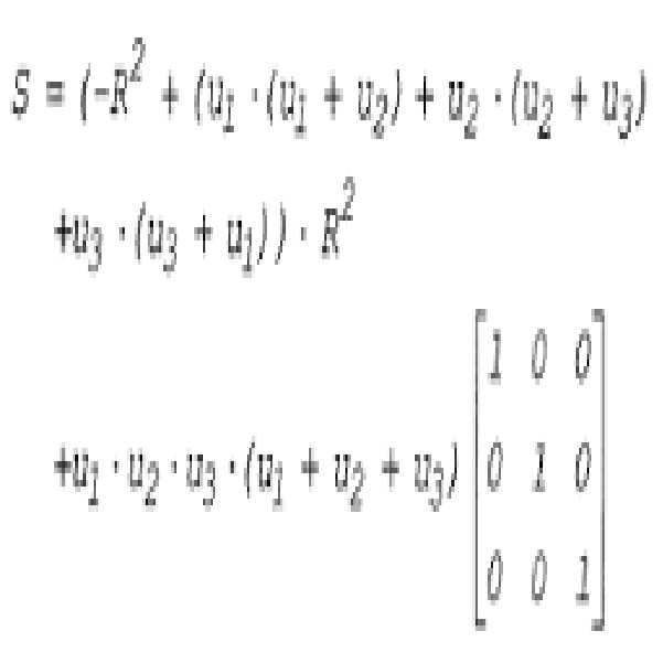
로서 정의한다.It is defined as.
프로세서(48)는
[수학식 13] [Equation 13]
![]()
![]()
에 의해 주어지는, ![]()
![]()
왜곡-수정된 위치 및 배향 좌표들을 계산했으면, 프로세서(48)는 이제 위치 센서(52)의 전체 6-차원 좌표들을 갖는다. Once the distortion-corrected position and orientation coordinates have been calculated, the
지금까지 위치 센서(52)의 자기장 감지 코일(60)들이 동심관계라고, 즉 동일한 위치 좌표들을 갖는다고 가정했다. 그러나, 몇몇 경우들에서, 센서(52)는 코일(60)들이 동심적이지 않게 구성된다. 이 비-동심성은 왜곡-수정된 좌표들에 부가적인 부정확성을 개입시킨다. 몇몇 실시예들에서, 추적 프로세서(48)는 비-동심성 보상 단계(110)에서, 자기장 감지 코일들의 비-동심성에 의해 발생하는 부정확성들을 보상한다.So far it has been assumed that the magnetic field sensing coils 60 of the
예를 들어, 프로세서(48)는 이러한 부정확성들을 보상하기 위해 반복적인 보상 과정을 적용할 수 있다. 3중-코일 tc의 코일 co에 의해 생성되고 비-동심적인 위치 센서(52)에 의해 측정되는, ME tc , co 로 표기되는 추적 자기장을 고려한다. 벡터 ![]()
![]()
![]()
![]()
![]()
![]()
[수학식 14][Equation 14]

에 의해 주어진다. Is given by
여기서 장 벡터의 두 번째 라인은 기준 코일에 상응한다. ![]()
![]()
프로세서(48)는 상기 단계들(104-108)을 반복(iteratively repeating)하여 ME tc,co 의 추정을 개선한다. 각각의 반복 단계 i+1에서, 측정된 자기장은
[수학식 15][Equation 15]
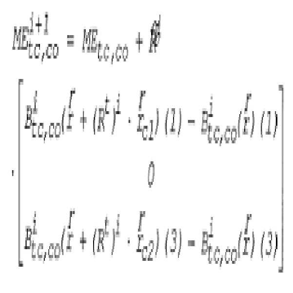
에 의해 주어진다.Is given by
몇몇 실시예들에서, 프로세서(48)는 예정된 회수의 반복 단계들을 수행한다. 대안적으로, 수렴 임계값 th가 정의되고, 반복 단계는 In some embodiments,
[수학식 16][Equation 16]
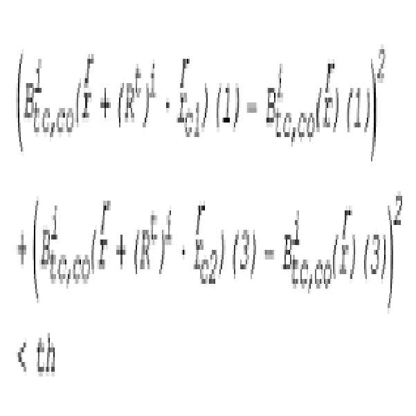
까지 반복된다. Is repeated.
방향 선택을 사용하는 왜곡 감소 방법Distortion reduction method using direction selection
상술한 바와 같이, 몇몇 경우들에서 특정한 자기장 강도 측정에 개입되는 왜곡은 왜곡을 일으키는 자기장 왜곡 물체, 사용되는 자기장 감지 코일, 사용되는 자기장 생성 코일의 상호 위치 및/또는 배향에 매우 의존한다. 그러므로, 중복 자기장 측정들이 상이한 위치들 및 배향들을 갖는 상호 자기장 생성 코일(44)들과 자기장 감지 코일(60)들을 사용하여 수행될 때, 왜곡에 지배적으로 기여하는 것인 하나 이상의 코일(44) 및/또는 코일(60)을 종종 확인할 수 있다. 이러한 왜곡 기여 시스템 요소들에 관련한 측정값들을 폐기하면 위치 계산시 왜곡의 총량을 크게 감소시킬 수 있다. As mentioned above, in some cases the distortion involved in a particular magnetic field strength measurement is highly dependent on the mutual position and / or orientation of the magnetic field distortion object causing the distortion, the magnetic field sensing coil used, and the magnetic field generating coil used. Therefore, when the redundant magnetic field measurements are performed using mutual magnetic field generating coils 44 and magnetic field sensing coils 60 with different positions and orientations, one or
도 5는 본 발명의 다른 실시예에 따른, 왜곡 기여 요소들을 인식하고 제거하는 것에 근거한, 자기장 왜곡 존재시 위치 추적하는 방법을 개략적으로 예시하는 순서도이다. 도 5의 방법은 환자의 몸 안의 카테터(24)의 단일 위치에서, 단일 위치 추적 계산에 대한 것이다. 물론, 이 방법은 위치 추적 시스템의 작업 체적에 걸 쳐 분포된 다중 위치들에 적용될 수 있다.5 is a flow chart schematically illustrating a method of location tracking in the presence of magnetic field distortion, based on recognizing and eliminating distortion contributing elements, in accordance with another embodiment of the present invention. The method of FIG. 5 is for a single position tracking calculation at a single position of the
이 방법은 시스템(20)이 측정 단계(120)에서 중복 자기장 측정들을 수행하여 시작된다. 전형적으로, 여러 번의 자기장 강도 측정이 상이한 쌍의 자기장 생성 코일(44), 자기장 감지 코일(60)을 사용하여 이루어진다. 상술한 바와 같이, 도 1 및 도 2의 예시적인 시스템 구성은 총 27개의 코일 쌍을 포함하여, 최대 27개의 중복 자기장 측정들이 된다.The method begins with the
이제 추적 프로세서(48)는 확인 단계(122)에서, 중복 자기장 측정값들로부터 하나 이상의 왜곡 기여 측정값을 확인한다. 왜곡 기여 측정값들은 높은 레벨의 왜곡을 특징으로 갖는다. 몇몇 실시예들에서, 프로세서(48)는 중복 자기장 측정값들에서 왜곡 레벨을 자동적으로 검출 및 정량화할 수 있다. 이를 위해, 예를 들어, 상기 미국 특허 제 6,147,480호에서 설명된 방법들과 같은, 임의의 적합한 방법이 사용될 수 있다. 왜곡 기여 측정값들을 사용하여, 프로세서(48)는 하나 이상의 왜곡 기여 시스템 요소들을 확인하고, 이는 왜곡 기여 측정값들에 관련한 자기장 생성 코일(44)들, 자기장 감지 코일(60)들 및/또는 코일(44), 코일(60)의 쌍들을 포함할 수 있다.
부가적으로 또는 대안적으로, 왜곡의 특징 방향이 연역적으로 프로세서(48)에 지시될 수 있다. 몇몇 경우들에서, 알려진 왜곡 방향은 코일(44)들 및/또는 코일(60)들 중 어느 것이 특히 왜곡되기 쉬운지, 즉 왜곡 기여 요소를 포함하기 쉬운지를 프로세서에 나타낸다. 또한, 대안적으로, 왜곡 기여 측정값들을 생성하는(또는 생성하기 쉬운) 특정한 코일(44), 코일(60) 및/또는 코일(44), 코일(60)의 쌍을 확인하는 것은 프로세서에 연역적으로 나타내질 수 있다. Additionally or alternatively, the feature direction of the distortion can be deduced in the
추적 프로세서(48)는 위치 계산 단계(124)에서, 왜곡 기여 요소들에 관련한 측정값들을 폐기하면서 위치 센서(52)의 (그리고 카테터(24)의) 위치 좌표들을 계산한다. 몇몇 실시예들에서, 왜곡 기여 요소에 관련한 측정값들은 위치 계산으로부터 무시되거나 또는 폐기된다. 대안적으로, 특정한 왜곡 기여 요소는 꺼지거나 또는 다르게는 비활성화될 수 있다.The tracking
프로세서(48)는 도 5의 방법과 연계하여 센서(52)의 (그리고 카테터(24)의) 위치를 계산하기 위해, 상기 도 4의 방법 및 상술한 문헌들 중 일부에 설명된 방법들과 같은, 임의의 적절한 위치 추적 방법을 사용할 수 있다.The
몇몇 실시예들에서, 상기 도 5에 도시된 방법은 추적 자기장들이 카테터(24)에 의해 생성되고 외부에 위치하는 위치 센서들에 의해 감지되는 시스템 구성들에서 유사하게 사용될 수 있다. 이들 실시예에서, 신호 생성기(46)가 추적 자기장들을 만들기 위해 카테터(24) 내의 자기장 생성기들을 구동하는 구동 신호들을 생성한다. 외부의 위치 센서들이 추적 자기장들을 감지한다. 그 다음에, 감지된 자기장들이 카테터(24)의 왜곡이-없는 위치를 판정하기 위해, 적절한 방법에 따라 사용된다. In some embodiments, the method shown in FIG. 5 may similarly be used in system configurations in which tracking magnetic fields are generated by the
본원에 설명한 실시예들이 주로 의학적 위치 추적 및 조종 시스템들의 왜곡 내성을 개선하는 것을 언급하지만, 이러한 방법들 및 시스템들은 수술실 테이블, 형광투시경 장비, MRI 장비 및/또는 임의의 다른 자기장 왜곡 물체에 의해 발생하는 왜곡을 감소하는 것과 같은, 부가적인 응용예들에 사용될 수 있다. Although the embodiments described herein primarily refer to improving the distortion immunity of medical positioning and steering systems, these methods and systems are generated by operating room tables, fluoroscopy equipment, MRI equipment and / or any other magnetic field distortion objects. It can be used in additional applications, such as to reduce distortion.
그러므로 상술한 실시예들이 예로서 인용되었고, 본 발명이 상기에 상세히 설명 및 도시한 것에 한정되지 않음이 이해될 것이다. 오히려, 본 발명의 범위는 상술한 다양한 특징들의 조합 및 하위-조합들, 및 종래기술에 공개되지 않았고 당업자가 상술한 설명을 읽어 떠오를 수 있는 변형 및 수정들 모두를 포함한다.Therefore, the above-described embodiments have been cited as an example, and it will be understood that the present invention is not limited to the details described and illustrated above. Rather, the scope of the present invention includes all combinations and sub-combinations of the various features described above, as well as variations and modifications that are not disclosed in the prior art and may be read by those skilled in the art.
도 1은 본 발명의 일 실시예에 따른 체내 물체들의 위치 추적 및 조종(steering)을 위한 시스템의 개략 예시도.1 is a schematic illustration of a system for tracking and steering of objects in the body in accordance with an embodiment of the present invention.
도 2는 본 발명의 일 실시예에 따른 위치 패드의 개략 예시도.2 is a schematic illustration of a location pad in accordance with one embodiment of the present invention.
도 3은 본 발명의 일 실시예에 따른 카테터의 개략 예시도.3 is a schematic illustration of a catheter in accordance with one embodiment of the present invention.
도 4는 본 발명의 일 실시예에 따른 자기장 왜곡이 존재할 때의 위치 추적 방법을 개략적으로 예시하는 순서도.4 is a flow chart schematically illustrating a location tracking method in the presence of magnetic field distortion in accordance with an embodiment of the present invention.
도 5는 본 발명의 다른 실시예에 따른 자기장 왜곡이 존재할 때의 위치 추적 방법을 개략적으로 예시하는 순서도.5 is a flow chart schematically illustrating a location tracking method when there is a magnetic field distortion according to another embodiment of the present invention.
Claims (45)
Applications Claiming Priority (2)
| Application Number | Priority Date | Filing Date | Title |
|---|---|---|---|
| US11/462,733 | 2006-08-07 | ||
| US11/462,733 US8082020B2 (en) | 2006-08-07 | 2006-08-07 | Distortion-immune position tracking using redundant magnetic field measurements |
Publications (1)
| Publication Number | Publication Date |
|---|---|
| KR20080013725A true KR20080013725A (en) | 2008-02-13 |
Family
ID=38566957
Family Applications (1)
| Application Number | Title | Priority Date | Filing Date |
|---|---|---|---|
| KR1020070074009A Withdrawn KR20080013725A (en) | 2006-08-07 | 2007-07-24 | Distortion-free location tracking method and system using redundant measurements |
Country Status (10)
| Country | Link |
|---|---|
| US (3) | US8082020B2 (en) |
| EP (3) | EP2259008B1 (en) |
| JP (1) | JP5191704B2 (en) |
| KR (1) | KR20080013725A (en) |
| CN (2) | CN102210611B (en) |
| AU (1) | AU2007203658B2 (en) |
| BR (1) | BRPI0703316A (en) |
| CA (1) | CA2596404C (en) |
| IL (1) | IL185005A (en) |
| MX (1) | MX2007009491A (en) |
Cited By (2)
| Publication number | Priority date | Publication date | Assignee | Title |
|---|---|---|---|---|
| WO2010077008A3 (en) * | 2008-12-31 | 2010-10-07 | 주식회사 사이버메드 | Method for calibrating an instrument for a medical navigation system |
| KR20200126246A (en) * | 2019-04-29 | 2020-11-06 | (주)레벨소프트 | Detecting apparatus and method for navigated surgical tool |
Families Citing this family (79)
| Publication number | Priority date | Publication date | Assignee | Title |
|---|---|---|---|---|
| US11331150B2 (en) | 1999-10-28 | 2022-05-17 | Medtronic Navigation, Inc. | Method and apparatus for surgical navigation |
| US8784336B2 (en) | 2005-08-24 | 2014-07-22 | C. R. Bard, Inc. | Stylet apparatuses and methods of manufacture |
| AU2008329807B2 (en) | 2007-11-26 | 2014-02-27 | C. R. Bard, Inc. | Integrated system for intravascular placement of a catheter |
| US9649048B2 (en) | 2007-11-26 | 2017-05-16 | C. R. Bard, Inc. | Systems and methods for breaching a sterile field for intravascular placement of a catheter |
| US8781555B2 (en) | 2007-11-26 | 2014-07-15 | C. R. Bard, Inc. | System for placement of a catheter including a signal-generating stylet |
| US12440238B2 (en) | 2007-11-26 | 2025-10-14 | C. R. Bard, Inc. | Apparatus for use with needle insertion guidance system |
| US10751509B2 (en) | 2007-11-26 | 2020-08-25 | C. R. Bard, Inc. | Iconic representations for guidance of an indwelling medical device |
| US9521961B2 (en) | 2007-11-26 | 2016-12-20 | C. R. Bard, Inc. | Systems and methods for guiding a medical instrument |
| US10524691B2 (en) | 2007-11-26 | 2020-01-07 | C. R. Bard, Inc. | Needle assembly including an aligned magnetic element |
| US10449330B2 (en) | 2007-11-26 | 2019-10-22 | C. R. Bard, Inc. | Magnetic element-equipped needle assemblies |
| WO2010022370A1 (en) | 2008-08-22 | 2010-02-25 | C.R. Bard, Inc. | Catheter assembly including ecg sensor and magnetic assemblies |
| CN101836862B (en) * | 2009-03-16 | 2014-03-26 | 上海微创医疗器械(集团)有限公司 | Three-dimensional mapping method of human chamber inner wall and equipment and system thereof |
| GB0905298D0 (en) * | 2009-03-27 | 2009-05-13 | Qinetiq Ltd | Apparatus and method for ferromagnetic object detector |
| FR2946154B1 (en) | 2009-05-26 | 2011-07-01 | Commissariat Energie Atomique | DETECTION METHOD AND DETECTOR DETECTOR, METHOD AND SYSTEM FOR LOCALIZATION USING THE SAME. |
| US9532724B2 (en) | 2009-06-12 | 2017-01-03 | Bard Access Systems, Inc. | Apparatus and method for catheter navigation using endovascular energy mapping |
| EP2464407A4 (en) | 2009-08-10 | 2014-04-02 | Bard Access Systems Inc | Devices and methods for endovascular electrography |
| FR2954522B1 (en) | 2009-12-22 | 2012-03-09 | Commissariat Energie Atomique | METHOD AND DEVICE FOR IDENTIFYING A SUBASSEMBLY OF MEASUREMENTS, METHOD AND SYSTEM FOR LOCATING AN OBJECT, RECORDING MEDIUM FOR THESE METHODS |
| JP2013518676A (en) | 2010-02-02 | 2013-05-23 | シー・アール・バード・インコーポレーテッド | Apparatus and method for locating catheter navigation and tip |
| DE102010002145A1 (en) * | 2010-02-19 | 2011-08-25 | Carstens Medizinelektronik GmbH, 37120 | Coil arrangement for e.g. aligning hall sensor in measuring space to detect tongue movement of test person during speaking, has satellite coils whose direction vectors run at pitch angle, where angle data allows preset angle error in plane |
| US8842893B2 (en) | 2010-04-30 | 2014-09-23 | Medtronic Navigation, Inc. | Method and apparatus for image-based navigation |
| WO2011150376A1 (en) | 2010-05-28 | 2011-12-01 | C.R. Bard, Inc. | Apparatus for use with needle insertion guidance system |
| EP3165156B1 (en) * | 2010-11-18 | 2020-03-04 | Teleflex Medical Devices S.à.r.l. | Medical device locating system |
| US9044244B2 (en) * | 2010-12-10 | 2015-06-02 | Biosense Webster (Israel), Ltd. | System and method for detection of metal disturbance based on mutual inductance measurement |
| US9211094B2 (en) | 2010-12-10 | 2015-12-15 | Biosense Webster (Israel), Ltd. | System and method for detection of metal disturbance based on contact force measurement |
| US10307205B2 (en) * | 2010-12-10 | 2019-06-04 | Biosense Webster (Israel) Ltd. | System and method for detection of metal disturbance based on orthogonal field components |
| US9113807B2 (en) * | 2010-12-29 | 2015-08-25 | St. Jude Medical, Atrial Fibrillation Division, Inc. | Dynamic adaptive respiration compensation with automatic gain control |
| EP2665415A1 (en) * | 2011-01-20 | 2013-11-27 | Enav Medical Ltd. | System and method to estimate location and orientation of an object |
| US10588543B2 (en) * | 2012-05-23 | 2020-03-17 | Biosense Webster (Israel), Ltd. | Position sensing using electric dipole fields |
| US8818486B2 (en) * | 2012-07-12 | 2014-08-26 | Biosense Webster (Israel) Ltd. | Position and orientation algorithm for a single axis sensor |
| RU2503026C1 (en) * | 2012-10-10 | 2013-12-27 | Закрытое акционерное общество "МЕРА" | Method to calibrate magnetometers |
| US9002437B2 (en) | 2012-12-27 | 2015-04-07 | General Electric Company | Method and system for position orientation correction in navigation |
| US8958913B2 (en) * | 2013-02-02 | 2015-02-17 | Perfint Healthcare Private Limited | Electronic docking system and method for robotic positioning system |
| US9854991B2 (en) | 2013-03-15 | 2018-01-02 | Medtronic Navigation, Inc. | Integrated navigation array |
| US9717442B2 (en) * | 2013-03-15 | 2017-08-01 | Medtronic Navigation, Inc. | Method and system for navigating an instrument |
| US9480415B2 (en) * | 2013-04-26 | 2016-11-01 | Medtronic Navigation, Inc. | Electromagnetic coil apparatuses for surgical navigation and corresponding methods |
| CN105358054B (en) * | 2013-07-09 | 2018-05-15 | 株式会社日立制作所 | Device, magnetic field adjustment support method, MRI device and magnet arrangement are supported in magnetic field adjustment |
| US9474466B2 (en) * | 2013-12-23 | 2016-10-25 | Biosense Webster (Israel) Ltd. | Low-profile location pad for magnetic-based intra-body probe tracking system |
| WO2015120256A2 (en) | 2014-02-06 | 2015-08-13 | C.R. Bard, Inc. | Systems and methods for guidance and placement of an intravascular device |
| US10973584B2 (en) | 2015-01-19 | 2021-04-13 | Bard Access Systems, Inc. | Device and method for vascular access |
| CA2919901A1 (en) | 2015-02-04 | 2016-08-04 | Hossein Sadjadi | Methods and apparatus for improved electromagnetic tracking and localization |
| US11096605B2 (en) | 2015-03-31 | 2021-08-24 | Medtronic Navigation, Inc. | Modular coil assembly |
| WO2016205915A1 (en) * | 2015-06-22 | 2016-12-29 | Synaptive Medical (Barbados) Inc. | System and method for mapping navigation space to patient space in a medical procedure |
| US10349890B2 (en) | 2015-06-26 | 2019-07-16 | C. R. Bard, Inc. | Connector interface for ECG-based catheter positioning system |
| US11109774B2 (en) * | 2015-07-06 | 2021-09-07 | Biosense Webster (Israel) Ltd. | Flat location pad using nonconcentric coils |
| CN105437230B (en) * | 2015-12-09 | 2017-08-08 | 珠海格力电器股份有限公司 | Industrial robot tool coordinate calibration device and method |
| JP6666454B2 (en) | 2016-01-26 | 2020-03-13 | セント・ジュード・メディカル・インターナショナル・ホールディング・エスエーアールエルSt. Jude Medical International Holding S.a,r.l. | Detection and correction of magnetic field distortion in magnetic localization systems |
| US11000207B2 (en) | 2016-01-29 | 2021-05-11 | C. R. Bard, Inc. | Multiple coil system for tracking a medical device |
| GB2547916A (en) * | 2016-03-02 | 2017-09-06 | Cook Medical Technologies Llc | Magnetic guidance system particularly for neurological device |
| EP3791785B1 (en) * | 2016-05-03 | 2023-01-04 | St. Jude Medical International Holding S.à r.l. | Magnetic field distortion detection and correction in a magnetic localization system |
| US11832889B2 (en) | 2017-06-28 | 2023-12-05 | Auris Health, Inc. | Electromagnetic field generator alignment |
| CN110913788B (en) | 2017-06-28 | 2024-03-12 | 奥瑞斯健康公司 | Electromagnetic distortion detection |
| FR3069068B1 (en) * | 2017-07-17 | 2019-08-23 | Sysnav | METHOD FOR LOCATING A EVOLVING OBJECT IN A MAGNETIC FIELD GENERATED BY A SET OF AT LEAST THREE MAGNETIC GENERATORS |
| US11529193B2 (en) | 2017-08-10 | 2022-12-20 | Northern Digital Inc. | Tracking a sensor that includes a ferrofluid |
| US10779892B2 (en) * | 2017-08-10 | 2020-09-22 | Northern Digital Inc. | Tracking a cylindrical opening |
| CN109975878B (en) * | 2017-12-27 | 2020-11-24 | 四川锦江电子科技有限公司 | Device and method for detecting the falling off of excitation electrode sheet on body surface of three-dimensional mapping system |
| US10952797B2 (en) | 2018-01-02 | 2021-03-23 | Biosense Webster (Israel) Ltd. | Tracking a rigid tool in a patient body |
| US11129518B2 (en) * | 2018-05-05 | 2021-09-28 | Ankon Medical Technologies (Shanghai) Co., Ltd. | Portable system and method for position and orientation of remote objects |
| US11806083B2 (en) * | 2018-05-14 | 2023-11-07 | Biosense Webster (Israel) Ltd. | Correcting map shifting of a position tracking system including repositioning the imaging system and the patient in response to detecting magnetic interference |
| CN112867443B (en) | 2018-10-16 | 2024-04-26 | 巴德阿克塞斯系统股份有限公司 | Safety equipment connection system and method for establishing electrical connection |
| US10973588B2 (en) * | 2018-10-24 | 2021-04-13 | Biosense Webster (Israel) Ltd. | On-the-fly calibration for catheter location and orientation |
| EP3871034B1 (en) * | 2018-10-26 | 2025-08-27 | Magic Leap, Inc. | Ambient electromagnetic distortion correction for electromagnetic tracking |
| FR3089780B1 (en) * | 2018-12-12 | 2022-07-22 | Quantum Surgical | Automatic registration of a robot arm for a medical intervention |
| DK180214B1 (en) * | 2019-01-15 | 2020-08-20 | Amfitech Aps | Calibration Method and Device for Carrying it Out |
| DE102020109121A1 (en) * | 2019-04-02 | 2020-10-08 | Ascension Technology Corporation | Correction of distortions |
| US20200333409A1 (en) * | 2019-04-19 | 2020-10-22 | St. Jude Medical, Cardiology Division, Inc. | Magnetic reference sensor with reduced sensitivity to magnetic distortions |
| US11547495B2 (en) | 2019-04-26 | 2023-01-10 | Globus Medical, Inc. | System and method for reducing interference in positional sensors for robotic surgery |
| WO2021044297A1 (en) | 2019-09-03 | 2021-03-11 | Auris Health, Inc. | Electromagnetic distortion detection and compensation |
| CN110559082B (en) * | 2019-09-10 | 2020-07-31 | 深圳市精锋医疗科技有限公司 | Surgical robot and control method and control device for mechanical arm of surgical robot |
| US12196857B1 (en) * | 2019-10-10 | 2025-01-14 | Alken Inc. | Electromagnetic tracking with self learning |
| US11457835B2 (en) * | 2019-11-13 | 2022-10-04 | California Institute Of Technology | Electromagnet gradient coil apparatus for micro-device localization |
| EP4030983B1 (en) | 2019-12-03 | 2025-08-13 | Boston Scientific Scimed, Inc. | Medical system comprising a medical imaging device with a light source and means to move a sensor based on the detection of light by the sensor |
| CN111494010B (en) * | 2020-04-28 | 2022-03-29 | 绍兴梅奥心磁医疗科技有限公司 | Magnetic navigation system |
| US12076131B2 (en) * | 2020-05-05 | 2024-09-03 | Biosense Webster (Israel) Ltd. | Catheter shape and position detection using flexible magnetic sensor |
| US12231189B2 (en) | 2020-05-07 | 2025-02-18 | Cascodium Llc | Devices, systems and methods using a common frame of reference to provide a consistent magnetic field orientation for magnetic coupling |
| US11797127B1 (en) | 2021-11-16 | 2023-10-24 | Alken Inc. | Hybrid tracking with auto-correction |
| EP4201361A1 (en) * | 2021-12-27 | 2023-06-28 | MinMaxMedical | Real-time electromagnetic localization system |
| CN114179093B (en) * | 2021-12-31 | 2024-06-11 | 信通院车联网创新中心(成都)有限公司 | A substation inspection robot system and obstacle avoidance method thereof |
| CN114487968B (en) * | 2022-01-28 | 2025-06-27 | 上海安翰医疗技术有限公司 | A magnetic ball calibration method and a magnetic ball calibration device |
| JP2024000613A (en) * | 2022-06-21 | 2024-01-09 | 旭化成エレクトロニクス株式会社 | Estimation device, estimation method, and program |
Family Cites Families (27)
| Publication number | Priority date | Publication date | Assignee | Title |
|---|---|---|---|---|
| US5391199A (en) * | 1993-07-20 | 1995-02-21 | Biosense, Inc. | Apparatus and method for treating cardiac arrhythmias |
| US5654864A (en) * | 1994-07-25 | 1997-08-05 | University Of Virginia Patent Foundation | Control method for magnetic stereotaxis system |
| CA2607769C (en) | 1994-08-19 | 2012-04-24 | Biosense, Inc. | Medical diagnosis, treatment and imaging systems |
| US6690963B2 (en) * | 1995-01-24 | 2004-02-10 | Biosense, Inc. | System for determining the location and orientation of an invasive medical instrument |
| IL125761A (en) * | 1996-02-15 | 2005-05-17 | Biosense Inc | Independently positionable transducers for location system |
| JP4166277B2 (en) * | 1996-02-15 | 2008-10-15 | バイオセンス・ウェブスター・インコーポレイテッド | Medical method and apparatus using in-vivo probe |
| ES2279540T3 (en) * | 1996-05-06 | 2007-08-16 | Biosense Webster, Inc. | CALIBRATION OF RADIANT ELEMENT. |
| US6147480A (en) * | 1997-10-23 | 2000-11-14 | Biosense, Inc. | Detection of metal disturbance |
| US6239724B1 (en) * | 1997-12-30 | 2001-05-29 | Remon Medical Technologies, Ltd. | System and method for telemetrically providing intrabody spatial position |
| US6373240B1 (en) * | 1998-10-15 | 2002-04-16 | Biosense, Inc. | Metal immune system for tracking spatial coordinates of an object in the presence of a perturbed energy field |
| US6702804B1 (en) * | 1999-10-04 | 2004-03-09 | Stereotaxis, Inc. | Method for safely and efficiently navigating magnetic devices in the body |
| US6493573B1 (en) * | 1999-10-28 | 2002-12-10 | Winchester Development Associates | Method and system for navigating a catheter probe in the presence of field-influencing objects |
| US6172499B1 (en) * | 1999-10-29 | 2001-01-09 | Ascension Technology Corporation | Eddy current error-reduced AC magnetic position measurement system |
| US6400139B1 (en) * | 1999-11-01 | 2002-06-04 | Polhemus Inc. | Methods and apparatus for electromagnetic position and orientation tracking with distortion compensation |
| FR2807831B1 (en) * | 2000-04-14 | 2002-07-12 | Thomson Csf Sextant | MAGNETIC DEVICE FOR DETERMINING THE ORIENTATION, INSENSITIVE TO INDUCED DISTURBANCES, CORRESPONDING METHOD |
| US7729742B2 (en) * | 2001-12-21 | 2010-06-01 | Biosense, Inc. | Wireless position sensor |
| US20040068178A1 (en) * | 2002-09-17 | 2004-04-08 | Assaf Govari | High-gradient recursive locating system |
| US7945309B2 (en) * | 2002-11-22 | 2011-05-17 | Biosense, Inc. | Dynamic metal immunity |
| US7783441B2 (en) | 2003-04-17 | 2010-08-24 | Northern Digital Inc. | Eddy current detection and compensation |
| US7433728B2 (en) * | 2003-05-29 | 2008-10-07 | Biosense, Inc. | Dynamic metal immunity by hysteresis |
| US7321228B2 (en) * | 2003-07-31 | 2008-01-22 | Biosense Webster, Inc. | Detection of metal disturbance in a magnetic tracking system |
| US20050107687A1 (en) * | 2003-11-14 | 2005-05-19 | Anderson Peter T. | System and method for distortion reduction in an electromagnetic tracker |
| JP4639199B2 (en) | 2004-02-18 | 2011-02-23 | コーニンクレッカ フィリップス エレクトロニクス エヌ ヴィ | Measured value correction of magnetic positioning device |
| US7292948B2 (en) * | 2004-04-30 | 2007-11-06 | Alken Inc. | Magnetic position and orientation measurement system with eddy current distortion compensation |
| US7805269B2 (en) * | 2004-11-12 | 2010-09-28 | Philips Electronics Ltd | Device and method for ensuring the accuracy of a tracking device in a volume |
| IL165314A (en) | 2004-11-21 | 2009-08-03 | Elbit Ltd | Electromagnetic tracker |
| US20060170417A1 (en) * | 2005-02-02 | 2006-08-03 | Rodgers Allan G | Distributed array magnetic tracking |
-
2006
- 2006-08-07 US US11/462,733 patent/US8082020B2/en active Active
-
2007
- 2007-07-24 KR KR1020070074009A patent/KR20080013725A/en not_active Withdrawn
- 2007-08-02 IL IL185005A patent/IL185005A/en active IP Right Grant
- 2007-08-06 EP EP10175644.3A patent/EP2259008B1/en active Active
- 2007-08-06 MX MX2007009491A patent/MX2007009491A/en not_active Application Discontinuation
- 2007-08-06 EP EP10175624.5A patent/EP2256454B1/en active Active
- 2007-08-06 EP EP07253087.6A patent/EP1887309B1/en active Active
- 2007-08-06 JP JP2007204431A patent/JP5191704B2/en active Active
- 2007-08-06 AU AU2007203658A patent/AU2007203658B2/en not_active Ceased
- 2007-08-07 CN CN201110125796.XA patent/CN102210611B/en active Active
- 2007-08-07 BR BRPI0703316-8A patent/BRPI0703316A/en not_active Application Discontinuation
- 2007-08-07 CN CN2007101399856A patent/CN101120877B/en active Active
- 2007-08-07 CA CA2596404A patent/CA2596404C/en not_active Expired - Fee Related
-
2011
- 2011-06-20 US US13/164,093 patent/US8536859B2/en active Active
- 2011-06-20 US US13/164,141 patent/US8280189B2/en active Active
Cited By (2)
| Publication number | Priority date | Publication date | Assignee | Title |
|---|---|---|---|---|
| WO2010077008A3 (en) * | 2008-12-31 | 2010-10-07 | 주식회사 사이버메드 | Method for calibrating an instrument for a medical navigation system |
| KR20200126246A (en) * | 2019-04-29 | 2020-11-06 | (주)레벨소프트 | Detecting apparatus and method for navigated surgical tool |
Also Published As
| Publication number | Publication date |
|---|---|
| AU2007203658A1 (en) | 2008-02-21 |
| IL185005A0 (en) | 2008-01-06 |
| EP2256454B1 (en) | 2017-05-03 |
| US8082020B2 (en) | 2011-12-20 |
| EP2259008B1 (en) | 2016-04-20 |
| JP5191704B2 (en) | 2013-05-08 |
| US8536859B2 (en) | 2013-09-17 |
| IL185005A (en) | 2013-05-30 |
| CN101120877A (en) | 2008-02-13 |
| BRPI0703316A (en) | 2008-04-08 |
| CA2596404C (en) | 2013-10-22 |
| JP2008062040A (en) | 2008-03-21 |
| EP2256454A1 (en) | 2010-12-01 |
| US20080033282A1 (en) | 2008-02-07 |
| US8280189B2 (en) | 2012-10-02 |
| CN102210611B (en) | 2015-04-01 |
| EP1887309A1 (en) | 2008-02-13 |
| EP2259008A1 (en) | 2010-12-08 |
| CN101120877B (en) | 2011-10-26 |
| CA2596404A1 (en) | 2008-02-07 |
| US20110251815A1 (en) | 2011-10-13 |
| CN102210611A (en) | 2011-10-12 |
| AU2007203658B2 (en) | 2012-10-11 |
| MX2007009491A (en) | 2009-01-26 |
| EP1887309B1 (en) | 2016-07-06 |
| US20110251814A1 (en) | 2011-10-13 |
Similar Documents
| Publication | Publication Date | Title |
|---|---|---|
| KR20080013725A (en) | Distortion-free location tracking method and system using redundant measurements | |
| CA2598135C (en) | Distortion-immune position tracking using frequency extrapolation | |
| JP5642369B2 (en) | Current localization tracker | |
| US9265442B2 (en) | Method of calibrating combined field location and MRI tracking | |
| EP2005208A1 (en) | System for local error compensation in electromagnetic tracking systems | |
| AU2012216419B2 (en) | Distortion-immune position tracking using redundant measurements | |
| HK1114663A (en) | Distortion-immune position tracking using redundant measurements |
Legal Events
| Date | Code | Title | Description |
|---|---|---|---|
| PA0109 | Patent application |
Patent event code: PA01091R01D Comment text: Patent Application Patent event date: 20070724 |
|
| PG1501 | Laying open of application | ||
| PC1203 | Withdrawal of no request for examination | ||
| WITN | Application deemed withdrawn, e.g. because no request for examination was filed or no examination fee was paid |