KR20070085721A - Encoding and Decoding Multichannel Audio Signals - Google Patents
Encoding and Decoding Multichannel Audio Signals Download PDFInfo
- Publication number
- KR20070085721A KR20070085721A KR1020077012575A KR20077012575A KR20070085721A KR 20070085721 A KR20070085721 A KR 20070085721A KR 1020077012575 A KR1020077012575 A KR 1020077012575A KR 20077012575 A KR20077012575 A KR 20077012575A KR 20070085721 A KR20070085721 A KR 20070085721A
- Authority
- KR
- South Korea
- Prior art keywords
- signal
- signals
- residual
- unit
- units
- Prior art date
- Legal status (The legal status is an assumption and is not a legal conclusion. Google has not performed a legal analysis and makes no representation as to the accuracy of the status listed.)
- Granted
Links
Images


Classifications
-
- G—PHYSICS
- G10—MUSICAL INSTRUMENTS; ACOUSTICS
- G10L—SPEECH ANALYSIS TECHNIQUES OR SPEECH SYNTHESIS; SPEECH RECOGNITION; SPEECH OR VOICE PROCESSING TECHNIQUES; SPEECH OR AUDIO CODING OR DECODING
- G10L19/00—Speech or audio signals analysis-synthesis techniques for redundancy reduction, e.g. in vocoders; Coding or decoding of speech or audio signals, using source filter models or psychoacoustic analysis
- G10L19/008—Multichannel audio signal coding or decoding using interchannel correlation to reduce redundancy, e.g. joint-stereo, intensity-coding or matrixing
-
- H—ELECTRICITY
- H04—ELECTRIC COMMUNICATION TECHNIQUE
- H04S—STEREOPHONIC SYSTEMS
- H04S3/00—Systems employing more than two channels, e.g. quadraphonic
-
- G—PHYSICS
- G10—MUSICAL INSTRUMENTS; ACOUSTICS
- G10L—SPEECH ANALYSIS TECHNIQUES OR SPEECH SYNTHESIS; SPEECH RECOGNITION; SPEECH OR VOICE PROCESSING TECHNIQUES; SPEECH OR AUDIO CODING OR DECODING
- G10L21/00—Speech or voice signal processing techniques to produce another audible or non-audible signal, e.g. visual or tactile, in order to modify its quality or its intelligibility
- G10L21/02—Speech enhancement, e.g. noise reduction or echo cancellation
- G10L21/0272—Voice signal separating
- G10L21/028—Voice signal separating using properties of sound source
Landscapes
- Engineering & Computer Science (AREA)
- Physics & Mathematics (AREA)
- Signal Processing (AREA)
- Acoustics & Sound (AREA)
- Mathematical Physics (AREA)
- Computational Linguistics (AREA)
- Health & Medical Sciences (AREA)
- Audiology, Speech & Language Pathology (AREA)
- Human Computer Interaction (AREA)
- Multimedia (AREA)
- Compression, Expansion, Code Conversion, And Decoders (AREA)
- Stereophonic System (AREA)
Abstract
제 1 수(M)의 입력 오디오 채널들을 제 2의 보다 작은 수(N)의 출력 오디오 채널들로 변환하는 인코딩 장치(1)는 제 1 신호(Lf; Rf; Co) 및 제 2 신호(Lr; Rr; Le)를 제 3 신호(L; R; C) 및 제 4 신호(Ls; Rs; Cs)로 변환하는 적어도 하나의 변환 유닛(12)을 포함한다. 제 3 주요 신호는 제 1 및 제 2 신호들의 신호 에너지 대부분을 포함하는 반면에, 제 4 잔여 신호는 신호 에너지의 나머지를 포함한다. 인코딩 장치는 제 3 신호(L; R; C)를 사용하여 출력 신호를 생성하고 제 4 신호(Ls, Rs; Cs)를 출력하도록 구성된다. 제 1 수(N)의 입력 오디오 채널들을 제 2의보다 큰 수(M)의 출력 오디오 채널들로 변환하는 디코딩 장치(2)는 제 1 신호(L; R; C) 및 제 2 신호(Ld; Rd; Ld)를 제 3 신호(Lf; Rf; Co) 및 제 4 신호(Lr; Rr; Le)로 변환하는 적어도 하나의 변환 유닛(24)을 포함한다. 제 1 주요 신호는 제 3 및 제 4 신호들의 신호 에너지 대부분을 포함하는 반면에, 제 2 잔여 신호는 신호 에너지의 나머지를 포함한다. 인코딩 장치는 적어도 하나의 제 2 신호(Ld,; Rd; Cd)를 수신하도록 구성된다.The encoding device 1 for converting the first number M of input audio channels into a second smaller number N of output audio channels comprises a first signal Lf (Rf; Co) and a second signal (Lr). At least one conversion unit (12) for converting Rr; Le into a third signal (L; R; C) and a fourth signal (Ls; Rs; Cs). The third main signal contains most of the signal energy of the first and second signals, while the fourth residual signal contains the remainder of the signal energy. The encoding device is configured to generate an output signal using the third signal (L; R; C) and output the fourth signal (Ls, Rs; Cs). The decoding device 2 for converting the first number N of input audio channels into a second greater number M of output audio channels comprises a first signal L; R; C and a second signal Ld. At least one conversion unit 24 for converting Rd; Ld into a third signal Lf; Rf; Co and a fourth signal Lr; Rr; Le. The first main signal contains most of the signal energy of the third and fourth signals, while the second residual signal contains the remainder of the signal energy. The encoding device is configured to receive at least one second signal Ld; Rd; Cd.
Description
본 발명은 다중채널 인코딩 및 디코딩에 관한 것이다. 특히, 본 발명은 다수의 오디오 채널들을 보다 작은 수의 오디오 채널로 변환하는 장치 및 방법(인코딩), 그리고 다수의 오디오 채널들을 더 많은 다수의 오디오 채널들로 변환하는 장치 및 방법(디코딩)에 관한 것이다.The present invention relates to multichannel encoding and decoding. In particular, the present invention relates to an apparatus and method (encoding) for converting multiple audio channels to a smaller number of audio channels, and to an apparatus and method (decoding) for converting multiple audio channels to more multiple audio channels. will be.
다중채널을 사용하는 오디오 시스템들은 잘 알려져 있다. 종래의 스테레오 시스템들이 단지 두 개의 오디오 채널만을 사용하는 반면에, 현대의 5.1 시스템들은 6개의 채널, 좌측 전방(lf), 좌측 후방(lr), 우측 전방(rf), 우측 후방(rr), 중심(co) 및 낮은 주파수 효과(lfe 또는 le)를 사용한다. 보다 많은 수의 채널들은 오디오 데이터량의 증가가 저장 및/또는 전송되도록 한다. 이러한 데이터의 증가는 코딩에 의하여 데이터량을 감소시키기 위한 노력을 초래하였다. Audio systems using multiple channels are well known. While conventional stereo systems use only two audio channels, modern 5.1 systems have six channels, left front (lf), left rear (lr), right front (rf), right rear (rr), center (co) and low frequency effects (lfe or le) are used. Larger numbers of channels allow an increase in the amount of audio data to be stored and / or transmitted. This increase in data has led to efforts to reduce the amount of data by coding.
이들 코딩 기술들 중 하나는 1992년, 미국 샌프란시스코, the International Conference on Acoustics and Speech Signal Processing(ICASSP)의 회보로, J.D.Johnston and A.J.Ferreira에 의한 문헌, "Sum-difference stereo transform coding", pp.II 569-572 에 기술된 중간/측면(M/S) 코딩 또는 합/차 코딩으로서 알 려져 있다. 중간/측면 코딩은 전형적으로 한 쌍의 스테레오 신호들을 인코딩하기 위하여 사용된다. 제 1 (예컨대, 좌측) 신호 l[n] 및 제 2 (예컨대, 우측) 신호 r[n]로 구성된 M/S 코딩 및 오디오 신호는 합 신호 m[n] 및 차(또는 잔류) 신호 s[n]로서 코딩된다.One of these coding techniques is a newsletter from the International Conference on Acoustics and Speech Signal Processing (ICASSP), San Francisco, USA, 1992, published by JD Johnston and AJ Ferreira, "Sum-difference stereo transform coding", pp.II. It is known as intermediate / side (M / S) coding or sum / difference coding described in 569-572. Mid / side coding is typically used to encode a pair of stereo signals. The M / S coding and audio signal consisting of the first (e.g., left) signal l [n] and the second (e.g., right) signal r [n] is sum signal m [n] and difference (or residual) signal s [ n].
m[n] = r[n] + l[n]m [n] = r [n] + l [n]
s[n] = r[n] - l[n] 식(1)s [n] = r [n]-l [n] Equation (1)
(거의) 동일한 신호들 l[n] 및 r[n]에 대하여 이는 대응하는 차 신호 s[n]가 제로(zero)에 근접할 때 큰 코딩 이득을 제공하는 반면에, 합 신호는 실제적으로 모든 신호 에너지를 포함한다. 그러므로, 이러한 상황에서, 합 및 차 신호들을 코딩하는데 요구된 비트율은 단지 신호 채널을 코딩하는데 필요한 비트율에 근접한다. For (almost) identical signals l [n] and r [n] this provides a large coding gain when the corresponding difference signal s [n] is close to zero, while the sum signal is practically all Contains signal energy. Therefore, in this situation, the bit rate required to code the sum and difference signals is only close to the bit rate needed to code the signal channel.
선택적으로, 식(1)의 중간/측면 코딩 프로세스는 회전 매트릭스에 의하여 기술될 수 있다.Optionally, the middle / side coding process of equation (1) can be described by a rotation matrix.

여기서, 좌측 및 우측 신호는 π/4 의 각도로 회전되었다. 합 신호는 라인 l=r상에 좌측 및 우측 샘플들의 사영(projection)으로서 해석될 수 있는 반면에, 차 (또는 잔여) 신호는 라인 l=-r상에 좌측 및 우측 샘플들의 사영으로서 해석될 수 있다.Here, the left and right signals were rotated at an angle of π / 4. The sum signal can be interpreted as the projection of the left and right samples on line l = r, while the difference (or residual) signal can be interpreted as the projection of the left and right samples on line l = -r. have.
이러한 기술은 π/4 와 다른 회전 각도들을 허용함으로써 일반화될 수 있다. 입력 신호들의 넓은 클래스에 대하여 잔여 신호의 신호 전력을 최소화하기 위하여(즉, 코딩 이득을 최대화하기 위하여), 회전 각도는 또한 신호에 종속될 수 있다. 이하의 단위 회전은 한 쌍의 채널들에 적용될 수 있다.This technique can be generalized by allowing rotation angles other than π / 4. In order to minimize the signal power of the residual signal (ie to maximize the coding gain) for a wide class of input signals, the angle of rotation can also be dependent on the signal. The following unit rotation can be applied to a pair of channels.

여기서 m'[n] 및 s'[n]은 주요 및 잔여 신호를 각각 나타내며, 각도 α는 잔여 신호의 전력을 최소화하도록 선택되고 따라서 주요 신호의 전력을 최대화한다. 이러한 일반화된 회전 기술은 종종 주성분분석(Principal Component Analysis; PCA)로서 언급된다. Where m '[n] and s' [n] represent the main and residual signals, respectively, and the angle a is chosen to minimize the power of the residual signal and thus maximizes the power of the primary signal. This generalized rotation technique is often referred to as Principal Component Analysis (PCA).
식(3)의 회전이 잔여 신호의 전력을 최소화하기 때문에, 잔여 신호는 특히 보다 높은 주파수에서 지각적 관련 정보를 거의 포함하지 않도록 고려된다. 이러한 이유로, 종래의 인코딩 시스템들은 식(3)의 회전으로 그리고 유사한 변환들로 생성된 잔여 신호들을 폐기한다.Since the rotation of equation (3) minimizes the power of the residual signal, the residual signal is considered to contain little perceptually relevant information, especially at higher frequencies. For this reason, conventional encoding systems discard residual signals generated with the rotation of equation (3) and with similar transforms.
비록 앞서 언급된 기술들이 주로 스테레오 신호들을 목적으로 할지라도, 이것들은 저장 및/또는 전송되는 주요 신호 및 폐기되는 잔여 신호에 대하여 한 쌍의 신호들을 반복적으로 감소시킴으로써 5.1 신호들과 같은, 다중채널들을 가진 오디오 신호들에 적용될 수 있다.Although the aforementioned techniques are primarily aimed at stereo signals, they can reduce multiple channels, such as 5.1 signals, by repeatedly reducing the pair of signals with respect to the primary signal being stored and / or transmitted and the residual signal being discarded. It can be applied to the audio signals having.
잔여 신호들의 폐기는 데이터 감소를 야기한다. 그러나, 본 발명은 잔여 신호가 비교적 대량의 정보를 포함할 때 단지 유효 데이터 감소만이 달성된다는 것을 실현한다. 이러한 경우에 잔여 신호를 폐기하는 것은 필연적으로 오디오 신호의 바람직하지 않은 지각 왜곡이 발생한다.Discarding residual signals causes data reduction. However, the present invention realizes that only valid data reduction is achieved when the residual signal contains a relatively large amount of information. In this case discarding the residual signal necessarily results in undesirable perceptual distortion of the audio signal.
디코딩 장치들에 있어서, 앞서 논의된 기술들은 인코딩된 신호들로부터 원시 신호들을 재구성하기 위하여 사용된다. 만일 M/S 인코딩이 사용되면, 예컨대 주요 신호 및 잔여 신호 모두는 역회전에 의하여 원시 신호 쌍을 재생하도록 요구된다. 종래의 디코딩 장치들에 있어서, 잔여 신호들은 수신되지 않으며, 따라서 합성 잔여 신호는 역상관기(decorrelator)를 사용하여 각각의 주요 신호로부터 유도된다. 비록 이것은 원시 신호가 근사될 지라도, 합성 잔여 신호의 파형은 전형적으로 실제 잔여 신호들의 파형과 상이하다. 결과로서, 디코딩된 신호들 및 원시 신호들간의 불일치가 존재할 것이다.In decoding devices, the techniques discussed above are used to reconstruct the raw signals from the encoded signals. If M / S encoding is used, for example, both the main signal and the residual signal are required to reproduce the original signal pair by reverse rotation. In conventional decoding devices, the residual signals are not received, and thus the composite residual signal is derived from each main signal using a decorrelator. Although this is an approximation of the raw signal, the waveform of the composite residual signal is typically different from the waveform of the actual residual signals. As a result, there will be a mismatch between the decoded signals and the raw signals.
본 발명의 목적은 종래 기술의 이들 및 다른 문제점들을 해결하고 신호 품질을 개선한 인코딩 장치 및 디코딩 장치를 제공하는 데 있다. It is an object of the present invention to provide an encoding device and a decoding device which solve these and other problems of the prior art and improve the signal quality.
따라서, 본 발명은 제 1 수의 입력 오디오 채널들을 제 2 수의 출력 오디오 채널들로 변환하는 인코딩 장치로서, 여기서 제 1 수는 제 2 수보다 크고, 상기 장티는, 제 1 신호 및 제 2 신호를 제 3 신호 및 제 4 신호로 각각 변환하는 적어도 두 개의 변환 유닛들을 포함하며, 상기 제 3 신호는 상기 제 1 및 제 2 신호의 신호 에너지 대부분을 포함하고, 상기 제 4 신호는 상기 신호 에너지의 나머지를 포함하며; 상기 인코딩 장치는 상기 제 3 신호들을 사용하여 출력 신호를 생성하도록 구성되고, 상기 인코딩 장치는 제 4 신호를 출력하도록 또한 구성되는, 인코딩 장치를 제공한다.Accordingly, the present invention provides an encoding apparatus for converting a first number of input audio channels into a second number of output audio channels, where the first number is greater than the second number and the typhoon is the first signal and the second signal. And at least two conversion units for converting a into a third signal and a fourth signal, respectively, wherein the third signal comprises most of the signal energy of the first and second signals, and the fourth signal is of the signal energy. Including the rest; The encoding apparatus provides an encoding apparatus, wherein the encoding apparatus is configured to generate an output signal using the third signals, and wherein the encoding apparatus is further configured to output a fourth signal.
적어도 하나의 제 4 신호를 출력함으로써, 즉 앞서 언급된 잔여 신호를 폐기하는 대신에 잔여 신호를 출력함으로써, 원시 신호의 보다 양호한 재구성이 디코더에 의하여 생성될 수 있다.By outputting at least one fourth signal, that is, by outputting the residual signal instead of discarding the aforementioned residual signal, a better reconstruction of the original signal can be produced by the decoder.
만일 인코딩 장치가 두 개 이상의 변환 유닛들을 포함하면, 제 4 신호는 바람직하게는 비록 이것이 필수적이지 않고 선택된 변환 유닛들의 제 4 신호가 디코더에서 신호 품질을 강화하기 위하여 사용될 수 있을지라도 각각의 변환 유닛에 대한 출력이다. 변환 유닛들은 병렬 또는 직렬(캐스캐이드)로 배열될 수 있으며 변환 유닛들은 두 개 이상의 채널, 예컨대 3개의 채널을 가질 수 있다는 것에 유의해야 한다.If the encoding device comprises two or more transform units, the fourth signal is preferably assigned to each transform unit even though this is not essential and the fourth signal of the selected transform units can be used to enhance the signal quality at the decoder. Is the output. It should be noted that the conversion units can be arranged in parallel or in series (cascade) and the conversion units can have two or more channels, for example three channels.
비록 전체 제 4 신호를, 즉 제 1 및 제 2 신호들의 전체 기간 동안 출력하는 것이 가능할지라도, 제 4 신호가 출력되는 시간 세그먼트들을 선택하는 것이 바람직하다. 특히, 관련 시간 세그먼트(예컨대, 시간 프레임들)를 지각적으로 선택함으로써, 제 4 신호(들)을 전송 또는 저장하는데 필요한 전송 또는 저장 용량은 종래기술에 비하여 유효 신호 품질 개선을 제공하면서 감소된다. 예컨대, 단지 5kHz보다 낮은 주파수를 포함하는 시간 세그먼트들은 주파수 종속 선택을 사용하여 선택될 수 있다.Although it is possible to output the entire fourth signal, ie for the entire period of the first and second signals, it is preferable to select the time segments for which the fourth signal is output. In particular, by perceptually selecting the relevant time segment (eg, time frames), the transmission or storage capacity required to transmit or store the fourth signal (s) is reduced while providing effective signal quality improvement over the prior art. For example, time segments containing frequencies lower than 5 kHz may be selected using frequency dependent selection.
다른 바람직한 실시예에 있어서, 시간 세그먼트들 또는 신호 부분들의 선택은 제 4 (즉, 잔여) 신호들의 관련 부분들을 실제로 지각적으로 전달(passing)하고, 제 4 신호들의 덜 관련된 부분들을 지각적으로 감쇠시키며, 제 4 신호들의 최소 관련 부분들을 억제함으로써 달성된다. 즉, 신호 부분들(또는 프레임들)은 적어도 3개의 그룹으로 분할되는데, 지각적으로 가장 관련된 신호 부분들은 감쇠없이 거의 전달되며, 지각적으로 덜 관련된 신호는 전달되지만 감쇠되며, 지각적으로 최소로 관련된 신호는 억제된다. 이러한 방식에서, 상이한 관련성을 각각 가진 신호 부분들 간의 보다 스무스한 전이가 달성되며 이에 따라 보다 높은 신호 품질이 달성된다.In another preferred embodiment, the selection of time segments or signal portions actually perceptually passes relevant portions of the fourth (ie residual) signals and perceptually attenuates the less relevant portions of the fourth signals. And suppressing the least relevant portions of the fourth signals. That is, the signal parts (or frames) are divided into at least three groups, where the most perceptually relevant signal parts are transmitted almost without attenuation, and the less perceptually related signals are transmitted but attenuated and perceptually minimal. Associated signals are suppressed. In this way, smoother transitions between signal portions each having a different relationship are achieved and thus higher signal quality is achieved.
지각적 관련성은 특정 시간 세그먼트 동안 변환 유닛의 제 4 신호 및 제 3 신호의 비, 예컨대 전력비에 종속적인 가중(즉, 이득 또는 감쇠) 값을 제공하는 가중 함수를 사용함으로써 다수의 방식들로 결정될 수 있다.Perceptual relevance can be determined in a number of ways by using a weighting function that provides a weighting (ie, gain or attenuation) value dependent on the ratio of the fourth and third signals of the transform unit, such as power ratio, during a particular time segment. have.
각각의 채널들의 시간 및/또는 주파수 세그먼트들의 선택 대신에 또는 이 선택에 부가하여, 제 4 신호가 출력되는 채널들이 또한 선택될 수 있다. 만일 적어도 두 개의 변환 유닛들이 캐스캐이드로 배열되면, 바람직하며 인코딩 장치의 출력 단자에 가장 근접한 변환 유닛은 제 4 신호를 출력하도록 선택되는 반면에, 하나 이상의 변환 유닛들의 제 4 신호(신호 처리 방향에서)는 폐기될 수 있다. 다시 말해서, 변환 유닛들 다운스트림(신호 처리 방향으로)은 그들 각각의 제 4 신호를 출력하기 위하여 다른 변환 유닛들 전에 선택된다. 본 발명자들은 인코딩 장치의 마지막 스테이지들에 있는, 출력 단자에 가장 근접하게 생성된 제 4 신호들이 전형적으로 디코딩 장치의 제 1 스테이지에서 사용되고 따라서 디코딩된 신호의 품질에 대한 가장 큰 관련성을 가진다는 것을 인식하였다. 이러한 이유로, 이들 제 4 신호들은 적은 관련성을 가진 변환 유닛들의 제 4 신호들이 폐기되는 동안, 특히 이용가능한 전송 용량이 모든 제 4 신호들을 전송할 수 없을 때 전송되는 것이 바람직하다.Instead of or in addition to the selection of the time and / or frequency segments of the respective channels, the channels on which the fourth signal is output can also be selected. If at least two transform units are arranged in a cascade, then the transform unit closest to the output terminal of the encoding device is selected to output a fourth signal, while the fourth signal (in the signal processing direction of the one or more transform units) is selected. ) May be discarded. In other words, the transform units downstream (in the signal processing direction) are selected before the other transform units to output their respective fourth signal. We recognize that the fourth signals generated closest to the output terminal, at the last stages of the encoding device, are typically used at the first stage of the decoding device and thus have the greatest relevance for the quality of the decoded signal. It was. For this reason, these fourth signals are preferably transmitted while the fourth signals of the less relevant transformation units are discarded, especially when the available transmission capacity cannot transmit all the fourth signals.
변환 유닛들의 이러한 선택은 일시적이거나 또는 영구적일 수 있다. 만일 일시적인 경우에, 모든 변환 유닛들에는 이용가능한 전송 용량 또는 다른 인자들에 따라 각각의 제 4 신호를 전달하거나 또는 차단할 수 있는 선택 유닛이 제공될 수 있다. 만일 영구적이면, 통상적으로 장치의 출력 단자로부터 더 멀리 떨어진 특정 변환 유닛들의 선택 유닛들은 생략될 수 있다.This selection of conversion units can be temporary or permanent. In the temporary case, all conversion units may be provided with a selection unit capable of carrying or blocking each fourth signal depending on the available transmission capacity or other factors. If permanent, the selection units of certain conversion units which are usually further away from the output terminal of the device can be omitted.
본 발명은 또한 앞서 정의된 인코딩 장치를 사용하여 인코딩되는 디코딩 오디오 신호들에 대한 디코딩 장치를 제공한다. 따라서, 제 1 수의 입력 오디오 채널들을 제 2 수의 출력 오디오 채널들로 변환하는 디코딩 장치로서, 여기서 제 1 수는 제 2 수보다 작고, 상기 장치는 제 1 신호 및 제 2 신호를 제 3 신호 및 제 4 신호로 변환하는 적어도 두 개의 변환 유닛들을 포함하며, 상기 제 1 신호는 상기 제 3 및 제 4 신호의 신호 에너지 대부분을 포함하고, 상기 제 2 신호는 상기 신호 에너지의 나머지를 포함하며; 합성 제 2 신호를 생성하기 위하여 제 1 신호를 역상관하는 적어도 하나의 역상관 유닛을 포함하고; 상기 디코딩 장치는 적어도 하나의 추가 제 2 신호를 수신하도록 구성되는, 디코딩 장치를 제공한다.The invention also provides a decoding device for decoded audio signals which are encoded using the encoding device defined above. Thus, a decoding device for converting a first number of input audio channels into a second number of output audio channels, where the first number is less than the second number and the device converts the first signal and the second signal to a third signal. And at least two conversion units for converting to a fourth signal, wherein the first signal comprises most of the signal energy of the third and fourth signals, and the second signal comprises the remainder of the signal energy; At least one decorrelating unit for decorrelating the first signal to produce a composite second signal; The decoding apparatus provides a decoding apparatus, configured to receive at least one additional second signal.
추가 제 2 신호(즉, 인코딩 장치에서 제 4 신호로써 언급된 잔여 신호)를 수신함으로서, 디코딩된 오디오 신호의 개선된 품질은 디코딩 장치에서 생성된 임의의 합성 잔여 신호가 통상적으로 원시 잔여 신호와 동일하지 않을 때 달성될 수 있다.By receiving an additional second signal (i.e., the residual signal referred to as the fourth signal in the encoding apparatus), the improved quality of the decoded audio signal is such that any composite residual signal produced in the decoding apparatus is typically equal to the raw residual signal. Can be achieved when not.
바람직한 실시예에 있어서, 수신된 제 2 신호는 유도된 합성 제 2 신호와 결합되어 변환 유닛에 공급된 제 2 신호가 두 개의 신호들의 결합이도록 한다. 이는 또한 잔여 신호가 전송되지 않는 시간 세그먼트들 동안 합성 잔여 신호가 항상 이용가능한 장점을 가진다. 잔여 신호가 실제로 전송되는 시간 세그먼트들 동안, 변환 유닛에 의하여 사용된 잔여 신호는 전송된 잔여 신호 및 합성 잔여 신호의 결합이며, 따라서 단지 부분적으로 잔여 신호를 구성할 것이다.In a preferred embodiment, the received second signal is combined with the derived composite second signal such that the second signal supplied to the conversion unit is a combination of two signals. This also has the advantage that the composite residual signal is always available during time segments in which no residual signal is transmitted. During the time segments in which the residual signal is actually transmitted, the residual signal used by the conversion unit is a combination of the transmitted residual signal and the composite residual signal, and thus will only partially constitute the residual signal.
바람직한 실시예에 있어서, 디코딩 장치에는 합성 잔여 신호들을 감쇠하기 위하여 수신된 잔여 신호에 의하여 제어되는 감쇠 유닛들이 제공된다. 이는 선택된 및 비선택된 잔여 신호들 사이의 보다 스무스한 전이들을 가능하게 하며 임의의 스위칭 아티팩트들(artifacts)을 방지한다. 특히, 이는 각각의 합성 잔여 신호의 진폭이 대응하는 수신 잔여 신호에 의하여 제어되도록 한다. 따라서, 합성 잔여 신호 및 실제 전송된 잔여 신호의 훨씬 개선된 혼합이 이루어진다.In a preferred embodiment, the decoding apparatus is provided with attenuation units controlled by the received residual signal to attenuate the composite residual signals. This allows for smoother transitions between selected and unselected residual signals and prevents any switching artifacts. In particular, this allows the amplitude of each composite residual signal to be controlled by the corresponding received residual signal. Thus, a much improved mixing of the composite residual signal and the actual transmitted residual signal is achieved.
앞에서는 M/S 및 PCA 인코딩에 대하여 참조하였다. 선택적으로 또는 부가적으로, 진폭-관련 인코딩 기술이 사용될 수 있다.Earlier, reference was made to M / S and PCA encoding. Alternatively or additionally, amplitude-related encoding techniques may be used.
본 발명은 공간 오디오 코딩, 즉 단지 두 개의 채널들을 포함하는 스테레오 코딩과 대조적으로 두 개 이상의 채널들을 포함하는 오디오 코딩과 관련된다. The invention relates to spatial audio coding, ie audio coding comprising two or more channels as opposed to stereo coding comprising only two channels.
본 발명은 제 1 수의 입력 오디오 채널들을 제 2 수의 출력 오디오 채널들로 변환하는 방법으로서, 여기서 제 1 수는 제 2 수보다 크고, 그 방법은, 제 1 신호 및 제 2 신호를 제 3 신호 및 제 4 신호로 변환하는 적어도 두 개의 단계를 포함하며, 상기 제 3 신호는 상기 제 1 및 제 2 신호의 대부분의 신호 에너지를 포함하고, 상기 제 4 신호는 상기 신호 에너지의 나머지를 포함하며; 상기 제 3 신호들을 사용하여 출력 신호를 생성하는 단계; 및 제 4 신호를 출력하는 추가 단계를 포함하는, 변환 방법을 제공한다.The present invention provides a method of converting a first number of input audio channels into a second number of output audio channels, wherein the first number is greater than the second number, the method further comprising: converting the first signal and the second signal to a third signal; Converting into a signal and a fourth signal, wherein the third signal comprises most of the signal energy of the first and second signals, and the fourth signal comprises the remainder of the signal energy; ; Generating an output signal using the third signals; And a further step of outputting a fourth signal.
본 발명은 여전히 제 1 수의 입력 오디오 채널들을 제 2 수의 출력 오디오 채널들로 변환하는 방법으로서, 여기서 제 1 수는 제 2 수보다 작고, 상기 방법은, 제 1 신호 및 제 2 신호를 제 3 신호 및 제 4 신호로 변환하는 적어도 두 개의 단계를 포함하며, 상기 제 1 신호는 상기 제 3 및 제 4 신호의 대부분의 신호 에너지를 포함하고, 상기 제 2 신호는 상기 신호 에너지의 나머지를 포함하며; 상기 제 1 신호로부터 제 2 신호들을 유도하는 단계; 및 부가 제 2 신호를 수신하는 추가 단계를 포함하는, 변환 방법을 제공한다.The present invention still provides a method of converting a first number of input audio channels into a second number of output audio channels, wherein the first number is less than the second number, the method further comprising: At least two steps of converting into a third signal and a fourth signal, wherein the first signal comprises most of the signal energy of the third and fourth signals, and the second signal comprises the remainder of the signal energy. To; Deriving second signals from the first signal; And an additional step of receiving an additional second signal.
본 방법은 유도된 합성 제 2 신호를 생성하기 위하여 제 1 신호를 역상관하는 단계를 더 포함할 수 있다. 바람직하게, 본 방법은 합성 제 2 신호를 감쇠시키는 단계를 더 포함하며, 상기 감쇠 단계는 대응하는 수신된 제 2 신호에 의하여 제어된다. 유리하게, 본 방법은 합성 제 2 신호 및 수신된 제 2 신호를 결합하는 단계 및 상기 변환 단계에서 상기 결합 신호를 사용하는 단계를 더 포함한다.The method may further comprise decorreferring the first signal to produce an induced synthesized second signal. Advantageously, the method further comprises attenuating the composite second signal, said attenuation being controlled by a corresponding received second signal. Advantageously, the method further comprises combining the synthesized second signal and the received second signal and using the combined signal in the transforming step.
본 발명은 앞서 정의된 인코딩 및/또는 디코딩 방법을 수행하는 컴퓨터 프로그램 제품을 부가적으로 제공한다. 컴퓨터 프로그램 제품은 CD 또는 DVD와 같은 데이터 캐리어 상에 저장된 컴퓨터 실행가능한 명령들의 세트를 포함할 수 있다. 프로그래밍 가능한 컴퓨터가 앞서 정의된 방법들을 수행하도록 하는 컴퓨터 실행가능한 명령들의 세트는 예컨대 인터넷을 통해 원격 서버로부터 다운로드하기 위하여 또한 이용가능할 수 있다.The present invention additionally provides a computer program product for performing the encoding and / or decoding methods defined above. The computer program product may include a set of computer executable instructions stored on a data carrier such as a CD or DVD. A set of computer executable instructions that allow a programmable computer to perform the methods defined above may also be available for download from a remote server, for example, via the Internet.
본 발명은 또한 첨부 도면들에 기술된 전형적인 실시예들과 관련하여 이하에서 설명될 것이다.The invention will also be described below in connection with the exemplary embodiments described in the accompanying drawings.
도 1 은 본 발명에 따른 인코딩 장치의 부분을 개략적으로 도시한다. 1 schematically shows a part of an encoding device according to the invention.
도 2 는 본 발명에 따른 디코딩 장치의 부분을 개략적으로 도시한다. 2 schematically shows a part of a decoding apparatus according to the invention.
도 3 은 종래 기술에 따른 신호 선택 기능을 개략적으로 도시한다. 3 schematically illustrates a signal selection function according to the prior art.
도 4 는 본 발명에 따른 제 1 신호 선택 기능을 개략적으로 도시한다. 4 schematically shows a first signal selection function according to the invention.
도 5는 본 발명에 따른 제 2 신호 선택 기능을 개략적으로 도시한다. 5 schematically illustrates a second signal selection function according to the present invention.
도 6은 종래 기술에 따른 인코딩 장치의 제 1 실시예를 개략적으로 도시한다. 6 schematically shows a first embodiment of an encoding apparatus according to the prior art.
도 7은 종래 기술에 따른 전형적인 디코딩 장치의 제 1 실시예를 도시한 개략도.7 is a schematic diagram showing a first embodiment of an exemplary decoding device according to the prior art.
도 8은 본 발명에 따른 인코딩 장치의 제 1 실시예를 개략적으로 도시한다. .8 schematically shows a first embodiment of an encoding apparatus according to the invention. .
도 9는 본 발명에 따른 디코딩 장치의 제 1 실시예를 개략적으로 도시한다. 9 schematically shows a first embodiment of a decoding apparatus according to the present invention.
도 10은 종래 기술에 따른 인코딩 장치의 제 2 실시예를 개략적으로 도시한다. 10 schematically shows a second embodiment of an encoding apparatus according to the prior art.
도 11은 종래 기술에 따른 디코딩 장치의 제 2 실시예를 개략적으로 도시한다. 11 schematically shows a second embodiment of a decoding apparatus according to the prior art.
도 12는 본 발명에 따른 인코딩 장치의 제 2 실시예를 개략적으로 도시한다. 12 schematically shows a second embodiment of an encoding device according to the invention.
도 13은 본 발명에 따른 디코딩 장치의 제 2 실시예를 개략적으로 도시한다. 13 schematically shows a second embodiment of a decoding apparatus according to the present invention.
도 1에 단순히 비제한적인 예로서 도시된 본 발명의 장치(10)는 2 대 1 변환 유닛(12)과 선택 및 감쇠(S&A) 유닛(15)을 포함한다. 변환 유닛(12)은 신호들의 제 1 쌍을 신호들의 제 2 쌍으로 변환하도록 구성된 종래의 변환 유닛일 수 있으며, 제 2 쌍은 대부분의 신호 에너지를 포함하는 주요 신호 및 나머지 신호 에너지를 포함하는 잔여 신호를 포함한다. 신호들(즉, 주요 신호 및 잔여 신호)의 제 2 쌍은 신호 회전 또는 유사한 기술들을 사용하여, 예컨대 전술한 식(3)을 사용하여 제 1 쌍으로부터 유도될 수 있다.The
도 1의 예에서, 변환 유닛(12)은 좌측 신호[k] 및 우측 신호 r[k]를 수신하며, 이들 신호는 스테레오 신호를 함께 구성한다. 인덱스 k는 주파수 대역 또는 빈(bin)을 나타내며, 신호들 l[k] 및 r[k]는 바람직하게는 단시간 푸리에 변환(STFT) 또는 유사한 변환을 사용하여 시간 신호들 l[n] 및 r[n]으로부터 유도된다. 따라서, 신호들 l[k] 및 r[k]는 시간 프레임과 같은 시간 세그먼트의 주파수 구성요소들을 나타낸다.In the example of FIG. 1, the
종래 기술의 구조들에서, 주요 신호 m[k]는 잔여 신호 s[k]가 폐기되는 동안 코딩에 사용되며, 변환 유닛(12)은 변환과 연관된 파라미터들(Pars)의 세트 및 주요 신호 m[k]를 생성한다. 2004년 7월 5일에 출원된 유럽특허 출원번호 EP 04 103168.3(PHNL 04 0762)는 잔여 신호(s[k])의 부분이 사용되는 인코더 구조를 개시 하고 있다. 특히, 상기 이전 특허 출원의 구조에서 무관련 부분들을 지각적으로 폐기하면서 잔여 신호의 관련 부분들을 지각적으로 선택하는 선택기가 사용된다. 따라서, 몇몇 부분들(시간 프레임들의 주파수 표현일 수 있음)은 선택되거나 또는 폐기된다. 유럽특허 출원번호 EP 04 103168.3은 스테레오 인코더 및 디코더에서 잔여 신호의 부분들의 선택을 개시하고 있으며, 본 명세서에 참조문헌으로서 그 전체 콘텐트들이 통합된다. 그러나, 5.1 구조와 같은 다중채널 인코딩 및 디코딩에서 잔여 신호의 부분들의 선택은 개시되어 있지 않다.In the prior art structures, the main signal m [k] is used for coding while the residual signal s [k] is discarded, and the
앞서 언급된 유럽특허출원에 따른 선택은 가중 함수 W'를 도시한 도 3에 개략적으로 도시된다. 잔여 신호의 부분들에 할당된 가중치 w는 잔여 신호 s[k]의 전력 및 주요 신호의 전력 비, 즉 m:z=P(s[k])/P(m[k])일 수 있는 관련성 인자 z, 또는 특히 주요 신호와 비교하여 잔여 신호의 (상대적인) 지각적 관련성을 나타내는 임의의 다른 인자에 따른다. 잔여 신호의 상대 전력이 특정 임계값 z0을 초과할때, 가중 인자 w는 1이며, 이는 잔여 신호 부분이 완전히 인코딩되어 전송되는 것을 의미한다. 잔여 신호의 상대 전력이 임계값 z0보다 작을 때, 가중 인자 w는 0과 동일하며 잔여 신호의 관련 부분은 폐기된다.The selection according to the aforementioned European patent application is schematically shown in FIG. 3, which shows the weighting function W '. The weight w assigned to the portions of the residual signal is the relation that the power ratio of the residual signal s [k] and the power of the primary signal, i.e. m: z = P (s [k]) / P (m [k]) Factor z, or in particular any other factor that indicates the (relative) perceptual relevance of the residual signal compared to the main signal. When the relative power of the residual signal exceeds a certain threshold z 0 , the weighting factor w is 1, which means that the residual signal portion is fully encoded and transmitted. When the relative power of the residual signal is less than the threshold z 0 , the weighting factor w is equal to zero and the relevant portion of the residual signal is discarded.
본 발명자들은 이러한 선택이 너무 개략적이어서 가청 스위칭 아티팩트들을 유발한다는 것을 인식하였다. 특히, 디코딩된 신호들의 품질은 전송된 데이터의 양을 현저하게 증가시키지 않고 개선될 수 있다. 따라서, 본 발명은 관련 및 비관련 부분들 사이만을 구별하는 잔여 신호의 (부분들)의 선택을 제공할 뿐만 아니라, 덜 관련된 부분들, 즉 (가장) 관련된 부분들만큼 관련되지 않으나 비관련되지 않은 부분들을 식별한다.The inventors have recognized that this selection is so schematic that it causes audible switching artifacts. In particular, the quality of the decoded signals can be improved without significantly increasing the amount of data transmitted. Thus, the present invention not only provides for the selection of (parts) of the residual signal that distinguishes between relevant and unrelated parts, but also is less as relevant but not as relevant as (most) related parts. Identifies parts.
본 발명에 따른 가중 함수 W의 예들은 도 4 및 도 5에 개략적으로 도시되어 있다. 도 4의 예에서, 가중 인자 W는 두 개의 임계값들 z0 및 z1을 가진다. 만일 z가 z0보다 작으면, 가중 인자 w는 제로이다. 만일 z가 z0보다 크지만 z1보다 작으면, 가중 인자 w는 0.5(0.25 또는 0.67과 같은 다른 값들이 사용될 수 있다는 것이 이해되어야 한다)와 동일하다(본 예에서). 만일 z가 z1 보다 크면, w는 1과 동일하다. 따라서, 도 4의 예에서, 3개의 개별적인 가중 인자 값들이 사용된다.Examples of weighting functions W according to the invention are shown schematically in FIGS. 4 and 5. In the example of FIG. 4, the weighting factor W has two thresholds z 0 and
도 5의 예에서, 가중 인자 w는 0(z=z0에서)으로부터 0.5(z=z1에서)를 통해 1.0(z=1에서)으로 점진적으로 증가한다. 결과적으로, 단지 가장 관련있는 신호 부분(z=z0)만이 1과 동일한 가중 인자를 가지며, z0보다 큰 관련성 인자 z를 가진 모든 신호 부분들은 비제로 가중 인자 w를 가진다. 도 5의 예에서, 이론적으로 무한 수의 개별 가중 인자값들이 사용된다. 가중 함수 W의 점진적 증가는 상이한 감쇠 레벨들사이에서 스무스한 스위칭을 야기한다.In the example of FIG. 5, the weighting factor w gradually increases from 0 (at z = z 0 ) to 1.0 (at z = z1) to 1.0 (at z = 1). As a result, only the most relevant signal portion (z = z 0 ) has a weighting factor equal to 1, and all signal portions with a relevance factor z greater than z 0 have a nonzero weighting factor w. In the example of FIG. 5, in theory an infinite number of individual weighting factor values are used. The gradual increase in weighting function W causes smooth switching between different attenuation levels.
물론, 도 4 및 도 5에 기술된 함수들과 다른 함수들이 사용될 수 있다. 일반적으로, 가중 함수는 원시 신호 쌍 l[k], r[k]의 재구성에 큰 공헌을 하지 않는 잔여 신호의 부분들이 제거되고, 중간 관련성을 갖는 잔여 신호의 부분들은 감쇠되며, 매우 중요한 부분들은 실제로 감쇠되지 않고 통과되는 특성들을 가질 것이다. Of course, other functions than those described in FIGS. 4 and 5 can be used. In general, the weighting function removes parts of the residual signal that do not contribute significantly to the reconstruction of the raw signal pairs l [k], r [k], parts of the residual signal with intermediate relevance are attenuated, and very important parts It will actually have the properties passed without attenuation.
전력 비 대신에 대역폭과 같은 다른 기준이 사용될 수 있다는 것에 유의해야 한다. 예컨대, 신호 전력과 무관하게 특정 임계 주파수보다 낮은 주파수를 가진 신호 부분들을 선택하는 것이 결정될 수 있다. Note that other criteria such as bandwidth may be used instead of the power ratio. For example, it may be determined to select signal portions having a frequency lower than a particular threshold frequency regardless of the signal power.
도 1에 도시된 본 발명에 따른 선택 및 감쇠(S&A) 유닛(15)은 신호 부분들을 선택할 뿐만 아니라 임의의 선택된 신호 부분들을 감쇠한다. 잔여 신호 s[k]에 부가하여, 선택 및 감쇠 유닛(15)은 주요 신호 m[k]를 수신한다. 도시된 실시예에 있어서, 선택 및 감쇠 유닛(15)은 또한 2-1 변환 유닛(12)에 의하여 생성된 신호 파라미터들(Pars) 및 원시 신호 쌍(l[k] 및 r[k])을 수신한다. 선택 및 감쇠 유닛(15)에 원시 신호 쌍을 공급하는 것은, 주요 신호 및 잔여 신호의 상대 전력들(또는 다른 특징들)에 부가하거나 또는 대신에 선택 및 감쇠 결정시 원시 신호 쌍의 상대 전력들(또는 다른 특징들)을 포함하는 가능성이 제공된다. 선택 및 감쇠 유닛(15)에 신호 파라미터들을 공급하는 것은, 추가 신호 특징이 선택 및 감쇠 프로세스에서 사용되도록 허용한다. The selection and attenuation (S & A)
선택 및 감쇠 유닛(15)은 주요 신호 m[k]와 함께 인코딩될 수 있는 가중된 잔여 신호 ws[k]를 출력한다. 가중된 잔여 신호 ws[k]가 원시 잔여 신호 s[k]보다 적은 정보를 포함하고 따라서 코딩된 신호 쌍의 전송에 요구된 비트율을 감소시킨다는 것을 이해할 것이다. 다른 한편으로, 가중된 잔여 신호 ws[k]의 포함은, 잔여 신호가 폐기되는 종래의 구조와 비교하여 신호 품질을 현저하게 개선한다. 선택 및 감쇠 유닛(15)은 도 4 및 도 5에 도시된 가중 함수 W, 또는 잔여 신호 s[k]를 선택하여 적절한 경우에 감쇠하는 임의의 등가 도구를 사용한다.The selection and
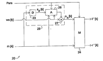
디코딩 장치에서 사용하는 본 발명에 따른 구조가 도 2에 개략적으로 도시되 어 있다. 단순히 전형적인 구조(20)는 혼합 유닛(24) 및 가중 유닛(29)을 포함한다. 구조(20)는 주요 신호 m[k], 가중된 잔여 신호 ws[k] 및 신호 파라미터들(Pars)을 수신한다. 주요 신호 m[k]는 잔여 신호가 전송되지 않는 종래기술의 구조들에서 수행되는 바와 같이, 합성 잔여 신호 sd[k]를 유도하기 위하여 역상관기(D)(23)에 공급된다. 이러한 합성 잔여 신호 sd[k]는 가중된 잔여 신호 ws[k]의 제어하에서 감쇠되는 감쇠기(26)에 공급된다. 신호 파라미터들은 또한 합성 잔여 신호의 감쇠를 부가적으로 제어하기 위하여 감쇠기(26)에 공급될 수 있다. 결과적인 감쇠된 합성 잔여 신호 및 가중된 잔여 신호는 본 실시예에서 가산기에 의하여 구성되는 결합 유닛들(27)에 결합된다. 결과적인 결합된 잔여 신호 sh[k]는 혼합 유닛(24)의 입력에 공급된다. 주요 신호 m[k]는 혼합 유닛(24)의 다른 입력에 공급되는 반면, 신호 파라미터들(예컨대 IID 및 ICC를 포함함)은 예컨대 상기 식(3)에서 언급된 신호 회전 또는 임의의 다른 적절한 기술에 의하여 신호 쌍 m[k], sh[k]을 신호 쌍 1'[k], r'[k]으로 변환하기 위하여 혼합 유닛(24)의 제어 입력에 공급된다.The structure according to the invention for use in a decoding apparatus is schematically illustrated in FIG. Simply
따라서, 본 발명의 구조(20)에서, 혼합 유닛(24)에 공급된 잔여 신호 sh[k]는 (디코딩된) 잔여 신호 ws[k] 및 합성 잔여 신호의 감쇠된 버전의 조합이다. 만일 (전송된) 잔여 신호 ws[k]가 이용가능하지 않으면, 역상관된 신호 sd[k]는 실제로 감쇠 없이 사용된다. 만일 잔여 신호 ws[k]가 이용가능하면, 역상관된 신호 sd[k]는 그에 따라 감쇠된다.Thus, in the
본 발명에 따른 인코딩 및 디코딩 장치들은 도 8, 도 9, 도 12 및 도 13을 참조하여 이하에 기술될 것이다. 그러나, 먼저, 종래 기술에 따른 인코딩 장치 및 디코딩 장치는 도 6 및 도 7을 참조하여 논의될 것이다.Encoding and decoding apparatuses according to the present invention will be described below with reference to FIGS. 8, 9, 12 and 13. However, first, the encoding apparatus and the decoding apparatus according to the prior art will be discussed with reference to FIGS. 6 and 7.
종래기술의 인코딩 장치(1')는 소위 5.1 신호와 같은 6개의 채널 오디오 입력 신호를 두 개의 채널 오디오 출력 신호로 인코딩하도록 설계된다. 도시된 예에서, 입력 채널들은 lf(좌측 정면), lr(좌측 후방), rf(우측 정면), rr(우측 후방), co(중심) 및 le(저주파수 효과)이다. 이들 모든 신호들은 디지털 시간 신호들인 것으로 가정되며, lf[n], lr[n] 등으로 기록될 수 있으며, 여기서 n은 샘플 수이다. The prior
오디오 입력 신호들은 예컨대 FFT(고속 푸리에 변환)을 사용하여 주파수 영역으로 변환되는 시간 세그먼트들로 신호들을 분할하는 세그먼트 및 변환(T) 유닛(11)에 입력된다. 시간 신호들이 분할되는 시간 세그먼트들은 종래 잘 알려진 바와 같이 바람직하게는 부분적으로 중첩된다.The audio input signals are input to a segment and transform (T)
세그먼트 및 변환 유닛들(11)은 시간 세그먼트들의 주파수 영역 표현이며 Lf[k], Lr[k] 등으로서 기록될 수 있는 변환된 신호들 Lf, Lr, Rf, Rr, Co 및 Le를 생성하며, 여기서 k는 주파수 인덱스이다. 이들 변환된 신호들은 신호 파라미터들(예컨대, PS1)의 연관된 세트를 생성하면서 입력 신호들(예컨대, Lf 및 Lr)의 각각의 쌍을 주요 신호(예컨대, L) 및 잔여 신호로 변환하는 2 대 1 변환기들(12)에 공급된다. 이러한 변환은 전형적으로 주요 신호가 신호 에너지의 대부분을 포함하는데 반해 잔여 신호가 신호 에너지의 나머지를 포함하도록 신호들의 회전을 포함한다. Segment and transform
도 6의 종래기술 장치에 있어서, 잔여 신호는 주요 신호가 3 대 2 변환 유닛(13)에 공급되는 동안 폐기된다. 도시될 수 있는 바와 같이, 각각의 2 대 1 변환 유닛(12)은 주요 신호(L, R, 및 C) 및 연관된 파라미터 세트(PS1, PS2, 및 PS3)를 각각 생성한다. 파라미터 세트는 회전 각도 α, 인터-채널 강도 차 파라미터 IID 및/또는 인터-채널 상관 파라미터 ICC와 같은, 유닛(12)에 의하여 수행되는 변환과 관련한 파라미터들을 포함한다.In the prior art device of FIG. 6, the residual signal is discarded while the main signal is supplied to the three-to-two
3 대 2 변환 유닛(13)은 연관된 파라미터 세트(PS4)를 생성하면서 3개의 입력 신호들(L, R, 및 C)을 두 개의 출력 신호들(L0, R0)로 변환한다. 입력 신호들(L, R)은 앞서 정의된 제 1 및 제 2 신호로 각각 식별될 수 있는 반면에, 신호들(L0, C0)은 앞서 정의된 제 3 및 제 4 신호로 각각 식별될 수 있다는 것에 유의해야 한다. The three-to-two
(변환 영역) 신호(L0, R0)는 시간-영역 신호들(l0 및 r0 )을 출력하는 역변환(T-1) 및 중첩-및-가산(OLA) 유닛(14)에 공급된다. 역변환은 유닛들(11)의 변환의 대응부이며 전형적으로 역 FFT이다. 중첩-및-가산 연산은 유닛(11)의 세그먼트 연산의 역이며, 부분적으로 중첩하는 시간 프레임들을 가산한다.The (conversion region) signal L 0 , R 0 is supplied to an inverse transform T- 1 and an overlap-and-addition (OLA)
따라서, 종래기술의 인코더(1')는 6개의 입력 오디오(시간) 신호들을 두 개 의 출력 오디오(시간) 신호들 + 파라미터들의 4개의 세트로 변환한다. 각각의 변환 유닛(12 또는 13)에서, 출력 신호는 신호들 및 필요한 전송율의 수를 감소시키기 위하여 폐기된다.Thus, the
종래 기술에 따른 호환가능한 디코딩 장치는 도 7에 도시되어 있다. 두 개의 오디오 입력 채널들을 6개의 오디오 출력 채널들로 변환하도록 구성된, 디코딩 장치(2')는 입력(시간) 신호들(l0 및 r0 )을 분할 및 변환하는 세그먼트 및 변환(T) 유닛(21)을 포함한다. 인코딩 장치에서처럼, 단기간 푸리에 변환(STFT)이 사용될 수 있다. 결과적인(변환 영역) 신호들 L0 및 R0은 (제 4) 파라미터 세트(PS4)(도 6과 비교)가 또한 공급되는 2 대 3 변환 유닛(22)에 공급된다. 2 대 3 변환 유닛(22)은 역상관(D) 유닛(23) 및 혼합(M) 유닛(24)에 각각 공급되는 3개의 신호들(L, R, 및 C)로 두 개의 신호들(L0, R0)을 변환한다. 역상관 유닛들(23)은 신호들(L, R, 및 C)의 역상관된 버전들(Ld, Rd, 및 Cd)을 생성한다. 이들 역상관된 신호들은 인코딩 장치에서 폐기되는 신호들을 효율적으로 대체하는 합성 잔여 신호들로서의 역할을 한다.A compatible decoding device according to the prior art is shown in FIG. A
3개의 혼합 유닛들(24) 각각은 (상향) 혼합 연산을 제어하는 각각의 파라미터 세트(PS1, PS2, 및 PS3)를 수신한다. 만일 PCA(주성분분석)이 사용되면, 신호 회전은 신호 파라미터 세트들에 포함된 각도 α로 수행된다. 다른 적절한 파라미터들은 예컨대 앞서 언급된 IID 및 ICC이다. 이들 파라미터들의 모두가 필요치 않으며, 각도 α는 다음을 사용하여 파라미터들(IID 및 ICC)로부터 유도될 수 있다. Each of the three mixing

및 And
![]()
![]()
혼합 유닛들(24)에 의하여 생성된 신호들은 각각 신호 쌍들(Lf 및 Lr, Rf 및 Rr, 및 Co 및 Le)이다. 이들 신호들은 역 FFT와 같은 적절한 역변환을 수행하는 역변환 및 중첩-및-가산 유닛들(25)에 의하여 역 변환되며(T-1) 그 후 시간 신호 쌍(lf 및 lr, rf 및 rr, 및 co 및 le)을 재구성한다. 따라서, 종래기술의 디코더(2')는 오디오 입력 신호들(l0, r0)의 쌍을 6개의 오디오 출력 신호들로 변환한다.The signals generated by the mixing
알려진 디코딩 장치(2')의 단점은 출력 신호 품질이 필수적으로 제한된다는 점이다. 더욱이, 이용가능한 전송 용량의 임의의 증가는 출력 신호 품질의 대응 증가를 야기하지 않는다. 이는 주로 혼합 유닛들(24)에 의하여 사용된 잔여 신호들이 합성적인, 즉 주요 신호들로부터 유도된다는 사실 때문이다. 본 발명은 도 1 내지 5를 참조하여 이미 기술된 바와 같이 잔여 신호의 선택된 부분들을 또한 전송함으로써 이들 문제점들을 해결한다. A disadvantage of the known decoding device 2 'is that the output signal quality is necessarily limited. Moreover, any increase in the available transmission capacity does not cause a corresponding increase in output signal quality. This is mainly due to the fact that the residual signals used by the mixing
도 8에 기술된 본 발명에 따른 인코딩 장치(1)는 3개의 2 대 1 유닛들(12) 및 단일 3 대 2 유닛(13)에 의하여 생성된 잔여 신호들의 조절을 제외하고 도 6에 도시된 종래 기술의 인코딩 장치(1')와 유사하다. 종래기술의 장치에 있어서, 유 닛(12)의 신호 처리(전형적으로 신호 회전) 연산들에 의하여 생성된 잔여 신호들은 폐기되며 "2 대 1" 유닛들을 참조한다. 그러나, 본 발명의 장치에 있어서, 이들 잔여 신호들은 폐기되지 않지만 유닛들(12)에 의하여 출력되며, 이어서 선택 및 감쇠 유닛들(15)에 의하여 처리된다. 이는 2 대 1 유닛(12)과 선택 및 감쇠 유닛(15)을 포함하는, 도 1의 구조(10)에 대응한다. 따라서, 세그먼트 및 변환 유닛(11)에 의하여 생성된 변환된 입력 신호들(Lf 및 Lr과 같은) 및 유닛(12)에 의하여 생성된 신호 파라미터들(도 8의 PS1 .. PS3 로 표시됨)은 또한 선택 및 감쇠 유닛(15)에 공급될 수 있다는 것을 이해해야 한다.The
각각의 선택 및 감쇠 유닛(15)은 인코더 장치(1)에 의하여 출력되는 각각의 잔여 신호(Ls, Rs, 및 Cs)를 생성한다. 당업자는 이들 잔여 신호들뿐만 아니라 파라미터 세트들(PS1 , ..., PS4)이 인코딩 장치에 의하여 출력되기 전에 적절하게 인코딩 및/또는 양자화될 수 있다는 것을 이해해야 한다.Each selection and
3 대 2 유닛(1)에 의하여 생성된 추가 잔여 채널(E0)은 또한 선택적으로 출력될 수 있다. 이러한 잔여 채널(E0)은 도 6을 참조하여 언급된 잔여 채널(C0)의 예측 에러를 나타낸다. 예측 에러는 차례로 L0 및 R0의 선형 조합일 수 있는, 잔여 채널(C0) 및 그 예측의 차이와 동일하다. 추가 잔여 채널(E0)은 비록 이것이 확실히 가능할지라도 선택 및 감쇠 연산(유닛들(5))에 영향을 받지 않는 것이 바람직하다. 도시된 실시예에서, 역변환(T-1)과 중첩-및-가산 유닛(14)은 규칙적 출력(시 간) 신호들(l0, r0)외에 잔여(시간) 신호(e0)를 출력한다.The additional residual channel E 0 generated by the three to two
추가 잔여 채널들은 추가 전송 용량(비트 버짓)이 이용가능한 경우에 사용될 수 있다. 따라서, 추가 전송 용량은 모든 추가 잔여 채널들에 걸쳐 분배될 수 있다. 일부 분배 선호도들이 언급될 수 있다.Additional residual channels may be used when additional transmission capacity (bit budget) is available. Thus, the additional transmission capacity can be distributed over all additional residual channels. Some distribution preferences may be mentioned.
- 추가 채널들은 좌측 오디오 채널 블록들 및 우측 오디오 채널 블록들(블록은 예컨대 채널과 연관된 다수의 유닛들이다)에 대칭적으로 할당되며;Additional channels are symmetrically assigned to left audio channel blocks and right audio channel blocks (block is for example a number of units associated with the channel);
- 추가 채널들은 우선 인코딩 장치의 출력에 가장 근접한 블록들에 할당되며;Additional channels are first assigned to the blocks closest to the output of the encoding device;
- 이용가능한 전송 용량은 가능한 많은 추가 채널들에 분배된다.The available transmission capacity is distributed over as many additional channels as possible.
더욱이, 추가 채널들의 대역폭은 예컨대 2 kHz에 제한될 수 있다.Moreover, the bandwidth of the additional channels may be limited to 2 kHz, for example.
본 발명에 따른 전형적인 호환가능한 디코딩 장치가 도 9에 도시된다. 본 발명의 디코딩 장치(2)는 유닛들(26, 27), 추가 잔여 채널들(Ls, Rs, 및 Cs)의 사용 및 추가 잔여 채널(e0)의 선택적 사용을 제외하고 도 7의 종래기술의 디코딩 장치(2')와 유사하다. An exemplary compatible decoding device according to the invention is shown in FIG. The
도 9에 도시된 바와 같이, 도 9의 디코딩 장치(2)는 3개의 가중 유닛(도 2의 29)을 포함하며, 각각의 가중 유닛은 역상관 유닛(23), 감쇠 유닛(26) 및 결합 유닛(27)을 포함한다. 이들 가중 유닛들의 각각은 각각의 파라미터 세트(PS1, PS2, 및 PS3)와 함께 각각의 잔여 신호(Ls, Rs, 및 Cs)를 수신한다. 역상관 유닛(23), 제어된 감쇠 유닛(26) 및 결합 유닛(27)을 각각 포함하는 가중 유닛들(29)은 합성 잔여 신호들 및 전송된 잔여 신호들의 가중을 제공함으로써 디코딩된 신호들(lf, lr,...,le)의 품질을 현저하게 개선한다. As shown in FIG. 9, the
디코딩 장치(2)는 도 8의 인코딩 장치(1) 및 잔여 신호들을 생성하는 다른 인코딩 장치들로 인코딩된 신호들을 디코딩할 수 있다는 것을 이해해야 한다. 다시 말해서, 이들 잔여 신호들은 비록 그러한 가중이 유리할지라도 도 1에 기술된 바와 같은 구조(10)로 가중되는 것은 필요치 않다. 따라서, 디코딩 장치(2)는 종래기술의 인코딩 장치들, 예컨대 도 6의 종래기술의 인코딩 장치에 의하여 인코딩된 신호들을 디코딩할 수 있다.It should be understood that the
본 발명의 디코딩 장치(2)의 실시예들은 감쇠 유닛들(26)이 생략되고 채널들(L, R, 및 C)의 역상관 버전들이 결합 유닛들(27)에 직접 공급되는 것에 직면할 수 있다. 여전히 본 발명의 범위 내에 있는 이러한 실시예들에 있어서, 추가 잔여 채널들(Ls, Rs, 및 Cs)의 사용은 여전히 도 7에 도시된 종래기술의 디코더(2')와 비교하여 개선된 신호 품질을 제공한다. 그러나, 감쇠 유닛(26)을 제공함으로써, 추가 잔여 채널들(Ls, Rs, 및 Cs)에 대하여 보다 양호한 수행이 이루어진다.Embodiments of the
선택적인 추가 잔여 채널(e0)은 제 3 채널로서 2 대 3 유닛(22)에서 사용될 수 있으며 이에 따라 두 개의 입력 채널들 대신에 3개의 입력 채널들을 제공한다. 이는 예컨대 잔여 채널(C0)의 예측을 조절함으로써 (변화된) 입력 채널(L0, R0) 및 파라미터 세트(PS4)로부터 신호들(L, R, 및 C)을 유도할 때 신호 품질을 개선한다.An optional additional residual channel e 0 can be used in the two to three
종래기술의 6 대 1 인코딩 장치(1')가 도 10에 도시된다. 이러한 인코딩 장 치는 3개의 세그먼트 및 변환 유닛들(11), 5개의 2 대 1 유닛들(12, 13a, 및 13b), 및 역변환 및 중첩-및-가산 유닛(14)을 포함한다. 도 6의 종래기술의 인코딩 장치(1')와 비교할 때, 제 1 스테이지들(유닛들 11, 12)은 동일한 반면에 도 6의 3 대 2 유닛(13)은 단일 신호(M) 및 두 개의 파라미터 세트들(PS4, PS5)을 함께 생성하는 두 개의 2 대 1 유닛들(13a, 13b)로 대체된다는 것을 알 수 있다. 단일 (변환 영역) 신호(M)는 역변환되며, 바람직하게는 저장 및/또는 전송될 수 있는 신호 오디오 출력(시간) 신호(m)를 생성하기 위하여 중첩-및-가산 연산이 바람직하게 적용된다.6 to 1
대응하는 종래기술의 1 대 6 디코딩 장치는 도 11에 도시된다. 도 11의 디코딩 장치(2')는 5개의 상향 혼합(M) 유닛들(22a, 22b, 및 24)을 사용하여 단일 오디오 입력(시간) 신호(m)를 6개의 오디오 출력(시간) 신호들로 디코딩한다. 도 7의 종래기술의 2 대 6 디코딩 장치와 비교할 때, 2 대 3 (상향 혼합) 유닛(22)은 단일 입력 신호(m)를 3개의 중간 신호들(L, R, C)로 변환하기 위하여 각각의 파라미터 세트(PS5, PS4)를 각각 수신하는 상향 혼합 유닛들(22a, 22b)로 대체된다는 것을 알 수 있다. A corresponding prior art one to six decoding device is shown in FIG. 11. The decoding device 2 'of FIG. 11 uses a single upstream mixed (M)
도 10의 종래기술의 인코딩 장치(1')는 본 발명에 따라 도 12의 본 발명의 6 대 1 인코딩 장치(1)를 생성하도록 수정될 수 있다. 도 12의 단순히 전형적인 실시예에 있어서, 선택 및 감쇠(S&A) 유닛들(15, 16a, 및 16b)은 추가 잔여 채널들(Ls, Rs, Cs, LRs, 및 Ms)를 생성하도록 추가되었다. 따라서, 도 12의 인코딩 장치(1)는 출력 신호(m)에 부가하여, 5개의 파라미터 세트들(PS1 ,...,PS5) 및 5개 의 잔여 채널들(Ls, Rs, Cs, LRs 및 Ms)를 생성하며, 잔여 채널들은 바람직하게 가중된다.The prior
앞서 지시된 바와 같이, 선택 및 감쇠 유닛(15)은 생략될 수 있으며 이에 따라 가중되지 않은 추가 채널들(Ls, Rs, 및 Cs)을 제공한다. 일부 실시예들에 있어서, 선택 및 감쇠 유닛들(16a, 16b)은 생략될 수 있다. 그러나, 모든 S&A 유닛들(15, 16a, 16b)은 도 12에 기술된 바와 같이 제공되는 것이 바람직하다. As indicated above, the selection and
예컨대 전송 용량이 불충분할 때 5개의 이용가능 잔여 채널들로부터 잔여 채널들을 선택하는 것이 또한 가능하다. 이 경우에, 인코딩 장치(1)의 출력 단자에 가장 근접한, 즉 변환 유닛(14)에 가장 근접한 잔여 채널들을 선택 및 전송하는 것이 바람직하다. 이들 잔여 채널들은 대응하는 디코딩 장치에 사용될 5개의 채널들이며, 따라서 디코딩 프로세스 및 디코딩된 신호의 품질에 가장 큰 영향을 미친다. 도 12의 예에서, 2 대 1 유닛(13b)에 의하여 생성된 잔여 채널 Ms가 먼저 선택되고, 그 후 2 대 1 유닛(13a)에 의하여 생성된 잔여 채널(LRs)이 선택된다. 단지 더 많은 전송용량이 이용가능할 때, 잔여 채널들(Ls, Rs, 및/또는 Cs)이 선택될 것이다.For example, it is also possible to select the remaining channels from the five available residual channels when the transmission capacity is insufficient. In this case, it is preferable to select and transmit the remaining channels closest to the output terminal of the
호환가능한 1 대 6 디코더는 도 13에 도시된다. 도 13의 단순히 전형적인 실시예에 있어서, 단일 오디오 입력(시간) 채널(m)은 5개의 파라미터 세트들(PS1 ,...,PS5) 및 5개의 잔여 채널(MS, LRs, Ls, Rs, 및 Cs)을 사용하여 6개의 오디오 출력(시간) 채널들로 변환된다. 잔여 채널들의 각각은 도 2에 기술된 바와 같은 구조(20)를 사용하여 처리되며, 각각의 구조는 역상관 유닛(23 (또는 23a/b)), 감 쇠 유닛(26)(또는 26a/b)), 결합 유닛(27) 및 상향 혼합 유닛(22a, 22b, 또는 24)을 포함한다. 감쇠 유닛들 및 결합 유닛들은 잔여 채널들이 합성 잔여 채널들의 진폭을 제어하고 수신된 잔여 채널들 및 합성 잔여 채널들의 적절한 혼합을 제공하도록 한다. 따라서, 기술된 예에서, 각각의 변환 유닛은 대응하는 제 2 신호를 수신하도록 구성된다. 그러나, 이는 필수적인 것이 아니며, 단지 선택된 수의 변환 유닛들(24)만이, 예컨대 변환 유닛들(22a, 22b)만이 제 2 신호를 수신하도록 구성될 수 있다. Compatible 1 to 6 decoders are shown in FIG. 13. In the simple exemplary embodiment of FIG. 13, a single audio input (time) channel m is composed of five parameter sets PS1,..., PS5 and five residual channels MS, LRs, Ls, Rs, and Is converted to six audio output (time) channels. Each of the remaining channels is processed using a
본 발명은 인코딩시에 잔여 신호가 적어도 3개의 카테고리, 즉 지각적으로 관련된 카테고리, 덜 관련된 카테고리 및 무관련 카테고리로 재분할될 수 있으며, 이에 따라 잔여 신호가 감쇠될 수 있는 통찰에 기초한다. 본 발명은 디코딩시에 디코딩된 잔여 신호가 재구성된 잔여 신호를 생성하기 위하여 합성 잔여 신호의 감쇠를 제어하도록 사용될 수 있다는 통찰에 기초한다.The present invention is based on the insight that the residual signal can be subdivided into at least three categories, i.e. perceptually related categories, less related categories and unrelated categories at the time of encoding, whereby the residual signal can be attenuated. The invention is based on the insight that, upon decoding, the decoded residual signal can be used to control the attenuation of the composite residual signal to produce a reconstructed residual signal.
본 발명은 인터넷 라디오, 인터넷 스트리밍, 전자 음악 배급(EMD), 고체상태(예컨대, MP3 또는 AAC) 오디오 플레이어, 소비자 오디오 시스템, 전문가 오디오 시스템 등과 같은 오디오 코딩을 포함하는 응용에서 이용될 수 있다. The present invention can be used in applications including audio coding such as Internet radio, internet streaming, electronic music distribution (EMD), solid state (eg, MP3 or AAC) audio players, consumer audio systems, expert audio systems, and the like.
본 명세서에서 사용된 일부 용어들은 본 발명의 범위를 제한하는 것으로 해석되지 않아야 한다. 특히, 용어 "포함한다"는 상세히 언급되지 않은 임의의 엘리먼트들을 배제하는 것을 의미하지 않는다. 단일(회로) 엘리먼트들은 다중(회로) 엘리먼트들 또는 이들의 균등물들로 대체될 수 있다.Some terms used herein should not be construed as limiting the scope of the invention. In particular, the term “comprising” does not mean excluding any elements not mentioned in detail. Single (circuit) elements may be replaced with multiple (circuit) elements or their equivalents.
본 발명이 앞서 기술된 실시예들에 제한되지 않고 첨부된 청구항들에 의하여 정의된 본 발명의 범위로부터 벗어나지 않고 많은 수정들 및 추가들이 이루어질 수 있다는 것을 당업자는 이해해야 한다. Those skilled in the art should understand that the present invention is not limited to the above described embodiments and that many modifications and additions can be made without departing from the scope of the invention as defined by the appended claims.
Claims (20)
Applications Claiming Priority (7)
| Application Number | Priority Date | Filing Date | Title |
|---|---|---|---|
| EP04105527 | 2004-11-04 | ||
| EP04105527.8 | 2004-11-04 | ||
| EP05103079 | 2005-04-18 | ||
| EP05103079.9 | 2005-04-18 | ||
| EP05103443 | 2005-04-27 | ||
| EP05103443.7 | 2005-04-27 | ||
| PCT/IB2005/053550 WO2006048817A1 (en) | 2004-11-04 | 2005-10-31 | Encoding and decoding of multi-channel audio signals |
Publications (2)
| Publication Number | Publication Date |
|---|---|
| KR20070085721A true KR20070085721A (en) | 2007-08-27 |
| KR101183859B1 KR101183859B1 (en) | 2012-09-19 |
Family
ID=35478388
Family Applications (1)
| Application Number | Title | Priority Date | Filing Date |
|---|---|---|---|
| KR1020077012575A Expired - Lifetime KR101183859B1 (en) | 2004-11-04 | 2005-10-31 | Encoding and decoding of multi-channel audio signals |
Country Status (9)
| Country | Link |
|---|---|
| US (1) | US7809580B2 (en) |
| EP (1) | EP1810279B1 (en) |
| JP (1) | JP5238256B2 (en) |
| KR (1) | KR101183859B1 (en) |
| CN (1) | CN101053017B (en) |
| BR (1) | BRPI0517987B1 (en) |
| MX (1) | MX2007005262A (en) |
| RU (1) | RU2407068C2 (en) |
| WO (1) | WO2006048817A1 (en) |
Families Citing this family (33)
| Publication number | Priority date | Publication date | Assignee | Title |
|---|---|---|---|---|
| EP1769491B1 (en) * | 2004-07-14 | 2009-09-30 | Koninklijke Philips Electronics N.V. | Audio channel conversion |
| CN101116136B (en) * | 2005-02-10 | 2011-05-18 | 皇家飞利浦电子股份有限公司 | Sound synthesis |
| KR101218776B1 (en) | 2006-01-11 | 2013-01-18 | 삼성전자주식회사 | Method of generating multi-channel signal from down-mixed signal and computer-readable medium |
| WO2007104882A1 (en) * | 2006-03-15 | 2007-09-20 | France Telecom | Device and method for encoding by principal component analysis a multichannel audio signal |
| KR101464977B1 (en) * | 2007-10-01 | 2014-11-25 | 삼성전자주식회사 | Memory management method, and method and apparatus for decoding multi-channel data |
| US20100228554A1 (en) * | 2007-10-22 | 2010-09-09 | Electronics And Telecommunications Research Institute | Multi-object audio encoding and decoding method and apparatus thereof |
| KR101441897B1 (en) | 2008-01-31 | 2014-09-23 | 삼성전자주식회사 | Method and apparatus for encoding residual signals and method and apparatus for decoding residual signals |
| KR101428487B1 (en) * | 2008-07-11 | 2014-08-08 | 삼성전자주식회사 | Multi-channel encoding and decoding method and apparatus |
| KR101271972B1 (en) | 2008-12-11 | 2013-06-10 | 프라운호퍼-게젤샤프트 추르 푀르데룽 데어 안제반텐 포르슝 에 파우 | Apparatus for generating a multi-channel audio signal |
| RU2449307C2 (en) * | 2009-04-02 | 2012-04-27 | ОАО "Научно-производственное объединение "ЛЭМЗ" | Method of surveillance pulse doppler radar of targets on background of reflections from earth surface |
| FR2954640B1 (en) * | 2009-12-23 | 2012-01-20 | Arkamys | METHOD FOR OPTIMIZING STEREO RECEPTION FOR ANALOG RADIO AND ANALOG RADIO RECEIVER |
| KR20140037118A (en) * | 2011-06-07 | 2014-03-26 | 삼성전자주식회사 | Method of processing audio signal, audio encoding apparatus, audio decoding apparatus and terminal employing the same |
| JP5737077B2 (en) | 2011-08-30 | 2015-06-17 | 富士通株式会社 | Audio encoding apparatus, audio encoding method, and audio encoding computer program |
| US9098576B1 (en) | 2011-10-17 | 2015-08-04 | Google Inc. | Ensemble interest point detection for audio matching |
| US8805560B1 (en) | 2011-10-18 | 2014-08-12 | Google Inc. | Noise based interest point density pruning |
| US8831763B1 (en) | 2011-10-18 | 2014-09-09 | Google Inc. | Intelligent interest point pruning for audio matching |
| US8886543B1 (en) | 2011-11-15 | 2014-11-11 | Google Inc. | Frequency ratio fingerprint characterization for audio matching |
| JP5998467B2 (en) * | 2011-12-14 | 2016-09-28 | 富士通株式会社 | Decoding device, decoding method, and decoding program |
| US9268845B1 (en) | 2012-03-08 | 2016-02-23 | Google Inc. | Audio matching using time alignment, frequency alignment, and interest point overlap to filter false positives |
| US9471673B1 (en) | 2012-03-12 | 2016-10-18 | Google Inc. | Audio matching using time-frequency onsets |
| US9087124B1 (en) | 2012-03-26 | 2015-07-21 | Google Inc. | Adaptive weighting of popular reference content in audio matching |
| US9148738B1 (en) | 2012-03-30 | 2015-09-29 | Google Inc. | Using local gradients for pitch resistant audio matching |
| JP5949270B2 (en) | 2012-07-24 | 2016-07-06 | 富士通株式会社 | Audio decoding apparatus, audio decoding method, and audio decoding computer program |
| US9848272B2 (en) * | 2013-10-21 | 2017-12-19 | Dolby International Ab | Decorrelator structure for parametric reconstruction of audio signals |
| KR101453733B1 (en) | 2014-04-07 | 2014-10-22 | 삼성전자주식회사 | Apparatus for processing audio signal |
| CN105632505B (en) * | 2014-11-28 | 2019-12-20 | 北京天籁传音数字技术有限公司 | Encoding and decoding method and device for Principal Component Analysis (PCA) mapping model |
| EP3246923A1 (en) * | 2016-05-20 | 2017-11-22 | Fraunhofer-Gesellschaft zur Förderung der angewandten Forschung e.V. | Apparatus and method for processing a multichannel audio signal |
| US10839814B2 (en) * | 2017-10-05 | 2020-11-17 | Qualcomm Incorporated | Encoding or decoding of audio signals |
| US10580420B2 (en) | 2017-10-05 | 2020-03-03 | Qualcomm Incorporated | Encoding or decoding of audio signals |
| US10535357B2 (en) * | 2017-10-05 | 2020-01-14 | Qualcomm Incorporated | Encoding or decoding of audio signals |
| CN110556117B (en) | 2018-05-31 | 2022-04-22 | 华为技术有限公司 | Coding method and device for stereo signal |
| CN110556116B (en) * | 2018-05-31 | 2021-10-22 | 华为技术有限公司 | Method and apparatus for computing downmix signal and residual signal |
| WO2021232376A1 (en) | 2020-05-21 | 2021-11-25 | 华为技术有限公司 | Audio data transmission method, and related device |
Family Cites Families (15)
| Publication number | Priority date | Publication date | Assignee | Title |
|---|---|---|---|---|
| NL9100173A (en) * | 1991-02-01 | 1992-09-01 | Philips Nv | SUBBAND CODING DEVICE, AND A TRANSMITTER EQUIPPED WITH THE CODING DEVICE. |
| ES2149235T3 (en) * | 1993-01-22 | 2000-11-01 | Koninkl Philips Electronics Nv | DIGITAL TRANSMISSION IN 3 CHANNELS OF STEREOPHONIC SIGNALS LEFT AND RIGHT AND A CENTRAL SIGNAL. |
| JP4610087B2 (en) * | 1999-04-07 | 2011-01-12 | ドルビー・ラボラトリーズ・ライセンシング・コーポレーション | Matrix improvement to lossless encoding / decoding |
| US6539357B1 (en) * | 1999-04-29 | 2003-03-25 | Agere Systems Inc. | Technique for parametric coding of a signal containing information |
| RU2161868C1 (en) * | 2000-05-12 | 2001-01-10 | Федеральное государственное унитарное предприятие Научно-исследовательский институт радио Государственного комитета РФ по связи и информатизации | Method for broadcast relaying of stereophonic signal |
| JP4618873B2 (en) | 2000-11-24 | 2011-01-26 | パナソニック株式会社 | Audio signal encoding method, audio signal encoding device, music distribution method, and music distribution system |
| ES2403178T3 (en) * | 2002-04-10 | 2013-05-16 | Koninklijke Philips Electronics N.V. | Stereo signal coding |
| BRPI0308691A2 (en) * | 2002-04-10 | 2016-11-16 | Koninkl Philips Electronics Nv | methods for encoding a multiple channel signal and for decoding multiple channel signal information, arrangements for encoding and decoding a multiple channel signal, data signal, computer readable medium, and device for communicating a multiple channel signal. |
| US20040086130A1 (en) * | 2002-05-03 | 2004-05-06 | Eid Bradley F. | Multi-channel sound processing systems |
| ATE377339T1 (en) * | 2002-07-12 | 2007-11-15 | Koninkl Philips Electronics Nv | AUDIO ENCODING |
| EP1523863A1 (en) * | 2002-07-16 | 2005-04-20 | Koninklijke Philips Electronics N.V. | Audio coding |
| US7394903B2 (en) * | 2004-01-20 | 2008-07-01 | Fraunhofer-Gesellschaft Zur Forderung Der Angewandten Forschung E.V. | Apparatus and method for constructing a multi-channel output signal or for generating a downmix signal |
| EP3561810B1 (en) * | 2004-04-05 | 2023-03-29 | Koninklijke Philips N.V. | Method of encoding left and right audio input signals, corresponding encoder, decoder and computer program product |
| US7391870B2 (en) * | 2004-07-09 | 2008-06-24 | Fraunhofer-Gesellschaft Zur Foerderung Der Angewandten Forschung E V | Apparatus and method for generating a multi-channel output signal |
| KR101315077B1 (en) * | 2005-03-30 | 2013-10-08 | 코닌클리케 필립스 일렉트로닉스 엔.브이. | Scalable multi-channel audio coding |
-
2005
- 2005-10-31 WO PCT/IB2005/053550 patent/WO2006048817A1/en not_active Ceased
- 2005-10-31 MX MX2007005262A patent/MX2007005262A/en active IP Right Grant
- 2005-10-31 JP JP2007539673A patent/JP5238256B2/en not_active Expired - Lifetime
- 2005-10-31 BR BRPI0517987-4A patent/BRPI0517987B1/en active IP Right Grant
- 2005-10-31 KR KR1020077012575A patent/KR101183859B1/en not_active Expired - Lifetime
- 2005-10-31 RU RU2007120528/09A patent/RU2407068C2/en active
- 2005-10-31 CN CN2005800379093A patent/CN101053017B/en not_active Expired - Lifetime
- 2005-10-31 EP EP05797453.7A patent/EP1810279B1/en not_active Expired - Lifetime
- 2005-10-31 US US11/718,241 patent/US7809580B2/en active Active
Also Published As
| Publication number | Publication date |
|---|---|
| RU2407068C2 (en) | 2010-12-20 |
| MX2007005262A (en) | 2007-07-09 |
| JP2008519307A (en) | 2008-06-05 |
| CN101053017A (en) | 2007-10-10 |
| CN101053017B (en) | 2012-10-10 |
| US20090055194A1 (en) | 2009-02-26 |
| RU2007120528A (en) | 2008-12-10 |
| WO2006048817A1 (en) | 2006-05-11 |
| EP1810279A1 (en) | 2007-07-25 |
| EP1810279B1 (en) | 2013-12-11 |
| US7809580B2 (en) | 2010-10-05 |
| BRPI0517987A8 (en) | 2018-07-31 |
| BRPI0517987B1 (en) | 2021-04-27 |
| BRPI0517987A (en) | 2008-10-21 |
| KR101183859B1 (en) | 2012-09-19 |
| JP5238256B2 (en) | 2013-07-17 |
Similar Documents
| Publication | Publication Date | Title |
|---|---|---|
| KR101183859B1 (en) | Encoding and decoding of multi-channel audio signals | |
| AU2006233504B2 (en) | Apparatus and method for generating multi-channel synthesizer control signal and apparatus and method for multi-channel synthesizing | |
| JP5645951B2 (en) | An apparatus for providing an upmix signal based on a downmix signal representation, an apparatus for providing a bitstream representing a multichannel audio signal, a method, a computer program, and a multi-channel audio signal using linear combination parameters Bitstream | |
| US8843378B2 (en) | Multi-channel synthesizer and method for generating a multi-channel output signal | |
| KR100924577B1 (en) | Parametric Joint-Coding of Audio Sources | |
| RU2625444C2 (en) | Audio processing system | |
| US7693721B2 (en) | Hybrid multi-channel/cue coding/decoding of audio signals | |
| JP5883561B2 (en) | Speech encoder using upmix | |
| JP4664371B2 (en) | Individual channel time envelope shaping for binaural cue coding method etc. | |
| US7292901B2 (en) | Hybrid multi-channel/cue coding/decoding of audio signals | |
| JP4664431B2 (en) | Apparatus and method for generating an ambience signal | |
| RU2607266C2 (en) | Apparatus, method and computer program for providing adjusted parameters for provision of upmix signal representation on basis of a downmix signal representation and parametric side information associated with downmix signal representation, using an average value | |
| JP2008519306A (en) | Encode and decode signal pairs | |
| TWI897026B (en) | Encoder and encoding method for discontinuous transmission of parametrically coded independent streams with metadata | |
| TWI897027B (en) | Decoder and decoding method for discontinuous transmission of parametrically coded independent streams with metadata | |
| RU2804032C1 (en) | Audio signal processing device for stereo signal encoding into bitstream signal and method for bitstream signal decoding into stereo signal implemented by using audio signal processing device | |
| AU2018200340A1 (en) | Advanced stereo coding based on a combination of adaptively selectable left/right or mid/side stereo coding and of parametric stereo coding | |
| HK1095195B (en) | Apparatus and method for generating multi-channel synthesizer control signal and apparatus and method for multi-channel synthesizing |
Legal Events
| Date | Code | Title | Description |
|---|---|---|---|
| PA0105 | International application |
St.27 status event code: A-0-1-A10-A15-nap-PA0105 |
|
| PG1501 | Laying open of application |
St.27 status event code: A-1-1-Q10-Q12-nap-PG1501 |
|
| R17-X000 | Change to representative recorded |
St.27 status event code: A-3-3-R10-R17-oth-X000 |
|
| A201 | Request for examination | ||
| E13-X000 | Pre-grant limitation requested |
St.27 status event code: A-2-3-E10-E13-lim-X000 |
|
| P11-X000 | Amendment of application requested |
St.27 status event code: A-2-2-P10-P11-nap-X000 |
|
| P13-X000 | Application amended |
St.27 status event code: A-2-2-P10-P13-nap-X000 |
|
| PA0201 | Request for examination |
St.27 status event code: A-1-2-D10-D11-exm-PA0201 |
|
| E902 | Notification of reason for refusal | ||
| PE0902 | Notice of grounds for rejection |
St.27 status event code: A-1-2-D10-D21-exm-PE0902 |
|
| T11-X000 | Administrative time limit extension requested |
St.27 status event code: U-3-3-T10-T11-oth-X000 |
|
| E13-X000 | Pre-grant limitation requested |
St.27 status event code: A-2-3-E10-E13-lim-X000 |
|
| P11-X000 | Amendment of application requested |
St.27 status event code: A-2-2-P10-P11-nap-X000 |
|
| P13-X000 | Application amended |
St.27 status event code: A-2-2-P10-P13-nap-X000 |
|
| E701 | Decision to grant or registration of patent right | ||
| PE0701 | Decision of registration |
St.27 status event code: A-1-2-D10-D22-exm-PE0701 |
|
| GRNT | Written decision to grant | ||
| PR0701 | Registration of establishment |
St.27 status event code: A-2-4-F10-F11-exm-PR0701 |
|
| PR1002 | Payment of registration fee |
St.27 status event code: A-2-2-U10-U12-oth-PR1002 Fee payment year number: 1 |
|
| PG1601 | Publication of registration |
St.27 status event code: A-4-4-Q10-Q13-nap-PG1601 |
|
| P22-X000 | Classification modified |
St.27 status event code: A-4-4-P10-P22-nap-X000 |
|
| R18-X000 | Changes to party contact information recorded |
St.27 status event code: A-5-5-R10-R18-oth-X000 |
|
| PN2301 | Change of applicant |
St.27 status event code: A-5-5-R10-R13-asn-PN2301 St.27 status event code: A-5-5-R10-R11-asn-PN2301 |
|
| FPAY | Annual fee payment |
Payment date: 20150902 Year of fee payment: 4 |
|
| PR1001 | Payment of annual fee |
St.27 status event code: A-4-4-U10-U11-oth-PR1001 Fee payment year number: 4 |
|
| FPAY | Annual fee payment |
Payment date: 20160909 Year of fee payment: 5 |
|
| PR1001 | Payment of annual fee |
St.27 status event code: A-4-4-U10-U11-oth-PR1001 Fee payment year number: 5 |
|
| FPAY | Annual fee payment |
Payment date: 20170831 Year of fee payment: 6 |
|
| PR1001 | Payment of annual fee |
St.27 status event code: A-4-4-U10-U11-oth-PR1001 Fee payment year number: 6 |
|
| FPAY | Annual fee payment |
Payment date: 20180830 Year of fee payment: 7 |
|
| PR1001 | Payment of annual fee |
St.27 status event code: A-4-4-U10-U11-oth-PR1001 Fee payment year number: 7 |
|
| FPAY | Annual fee payment |
Payment date: 20190903 Year of fee payment: 8 |
|
| PR1001 | Payment of annual fee |
St.27 status event code: A-4-4-U10-U11-oth-PR1001 Fee payment year number: 8 |
|
| PR1001 | Payment of annual fee |
St.27 status event code: A-4-4-U10-U11-oth-PR1001 Fee payment year number: 9 |
|
| R18-X000 | Changes to party contact information recorded |
St.27 status event code: A-5-5-R10-R18-oth-X000 |
|
| PR1001 | Payment of annual fee |
St.27 status event code: A-4-4-U10-U11-oth-PR1001 Fee payment year number: 10 |
|
| PR1001 | Payment of annual fee |
St.27 status event code: A-4-4-U10-U11-oth-PR1001 Fee payment year number: 11 |
|
| PR1001 | Payment of annual fee |
St.27 status event code: A-4-4-U10-U11-oth-PR1001 Fee payment year number: 12 |
|
| R18-X000 | Changes to party contact information recorded |
St.27 status event code: A-5-5-R10-R18-oth-X000 |
|
| R18-X000 | Changes to party contact information recorded |
St.27 status event code: A-5-5-R10-R18-oth-X000 |
|
| PR1001 | Payment of annual fee |
St.27 status event code: A-4-4-U10-U11-oth-PR1001 Fee payment year number: 13 |
|
| PR1001 | Payment of annual fee |
St.27 status event code: A-4-4-U10-U11-oth-PR1001 Fee payment year number: 14 |
|
| U11 | Full renewal or maintenance fee paid |
Free format text: ST27 STATUS EVENT CODE: A-4-4-U10-U11-OTH-PR1001 (AS PROVIDED BY THE NATIONAL OFFICE) Year of fee payment: 14 |