KR20070035529A - Ophthalmic implants and methods of manufacturing the same and methods of using the same - Google Patents
Ophthalmic implants and methods of manufacturing the same and methods of using the same Download PDFInfo
- Publication number
- KR20070035529A KR20070035529A KR1020067027941A KR20067027941A KR20070035529A KR 20070035529 A KR20070035529 A KR 20070035529A KR 1020067027941 A KR1020067027941 A KR 1020067027941A KR 20067027941 A KR20067027941 A KR 20067027941A KR 20070035529 A KR20070035529 A KR 20070035529A
- Authority
- KR
- South Korea
- Prior art keywords
- foot
- ophthalmic implant
- implant
- incision
- section
- Prior art date
- Legal status (The legal status is an assumption and is not a legal conclusion. Google has not performed a legal analysis and makes no representation as to the accuracy of the status listed.)
- Withdrawn
Links
- 239000007943 implant Substances 0.000 title claims abstract description 131
- 238000000034 method Methods 0.000 title claims description 61
- 238000004519 manufacturing process Methods 0.000 title description 3
- 210000003128 head Anatomy 0.000 claims description 50
- 239000000463 material Substances 0.000 claims description 48
- 239000011148 porous material Substances 0.000 claims description 34
- 239000000835 fiber Substances 0.000 claims description 29
- 239000000017 hydrogel Substances 0.000 claims description 28
- 239000004599 antimicrobial Substances 0.000 claims description 19
- 239000012530 fluid Substances 0.000 claims description 19
- 230000001580 bacterial effect Effects 0.000 claims description 15
- 229920001296 polysiloxane Polymers 0.000 claims description 15
- RTAQQCXQSZGOHL-UHFFFAOYSA-N Titanium Chemical compound [Ti] RTAQQCXQSZGOHL-UHFFFAOYSA-N 0.000 claims description 12
- 239000003242 anti bacterial agent Substances 0.000 claims description 12
- 238000003780 insertion Methods 0.000 claims description 12
- 230000037431 insertion Effects 0.000 claims description 12
- 241000894006 Bacteria Species 0.000 claims description 11
- 239000000919 ceramic Substances 0.000 claims description 10
- 230000000845 anti-microbial effect Effects 0.000 claims description 9
- 239000010936 titanium Substances 0.000 claims description 9
- 239000012528 membrane Substances 0.000 claims description 8
- 229910052709 silver Inorganic materials 0.000 claims description 8
- 239000004332 silver Substances 0.000 claims description 8
- BQCADISMDOOEFD-UHFFFAOYSA-N Silver Chemical compound [Ag] BQCADISMDOOEFD-UHFFFAOYSA-N 0.000 claims description 7
- 230000008569 process Effects 0.000 claims description 7
- 229940088710 antibiotic agent Drugs 0.000 claims description 6
- 230000003115 biocidal effect Effects 0.000 claims description 6
- 239000012510 hollow fiber Substances 0.000 claims description 6
- 229910052751 metal Inorganic materials 0.000 claims description 6
- 239000002184 metal Substances 0.000 claims description 6
- 239000000203 mixture Substances 0.000 claims description 6
- 238000012546 transfer Methods 0.000 claims description 6
- WOBHKFSMXKNTIM-UHFFFAOYSA-N Hydroxyethyl methacrylate Chemical compound CC(=C)C(=O)OCCO WOBHKFSMXKNTIM-UHFFFAOYSA-N 0.000 claims description 5
- -1 atomic powders Chemical class 0.000 claims description 5
- 150000001875 compounds Chemical class 0.000 claims description 5
- 229920003229 poly(methyl methacrylate) Polymers 0.000 claims description 5
- 108090000623 proteins and genes Proteins 0.000 claims description 5
- 102000004169 proteins and genes Human genes 0.000 claims description 5
- 239000000853 adhesive Substances 0.000 claims description 4
- 230000001070 adhesive effect Effects 0.000 claims description 4
- 210000002159 anterior chamber Anatomy 0.000 claims description 4
- 239000002246 antineoplastic agent Substances 0.000 claims description 4
- 239000003795 chemical substances by application Substances 0.000 claims description 4
- 239000004090 neuroprotective agent Substances 0.000 claims description 4
- 229910001220 stainless steel Inorganic materials 0.000 claims description 4
- 239000010935 stainless steel Substances 0.000 claims description 4
- KIUKXJAPPMFGSW-DNGZLQJQSA-N (2S,3S,4S,5R,6R)-6-[(2S,3R,4R,5S,6R)-3-Acetamido-2-[(2S,3S,4R,5R,6R)-6-[(2R,3R,4R,5S,6R)-3-acetamido-2,5-dihydroxy-6-(hydroxymethyl)oxan-4-yl]oxy-2-carboxy-4,5-dihydroxyoxan-3-yl]oxy-5-hydroxy-6-(hydroxymethyl)oxan-4-yl]oxy-3,4,5-trihydroxyoxane-2-carboxylic acid Chemical compound CC(=O)N[C@H]1[C@H](O)O[C@H](CO)[C@@H](O)[C@@H]1O[C@H]1[C@H](O)[C@@H](O)[C@H](O[C@H]2[C@@H]([C@@H](O[C@H]3[C@@H]([C@@H](O)[C@H](O)[C@H](O3)C(O)=O)O)[C@H](O)[C@@H](CO)O2)NC(C)=O)[C@@H](C(O)=O)O1 KIUKXJAPPMFGSW-DNGZLQJQSA-N 0.000 claims description 3
- XNCOSPRUTUOJCJ-UHFFFAOYSA-N Biguanide Chemical compound NC(N)=NC(N)=N XNCOSPRUTUOJCJ-UHFFFAOYSA-N 0.000 claims description 3
- 229940123208 Biguanide Drugs 0.000 claims description 3
- 235000014653 Carica parviflora Nutrition 0.000 claims description 3
- 241000243321 Cnidaria Species 0.000 claims description 3
- 239000002260 anti-inflammatory agent Substances 0.000 claims description 3
- 229940121363 anti-inflammatory agent Drugs 0.000 claims description 3
- 239000000030 antiglaucoma agent Substances 0.000 claims description 3
- 229920002118 antimicrobial polymer Polymers 0.000 claims description 3
- 239000003443 antiviral agent Substances 0.000 claims description 3
- 239000003246 corticosteroid Substances 0.000 claims description 3
- 229920002674 hyaluronan Polymers 0.000 claims description 3
- 229960003160 hyaluronic acid Drugs 0.000 claims description 3
- 230000028993 immune response Effects 0.000 claims description 3
- 239000007924 injection Substances 0.000 claims description 3
- 238000002347 injection Methods 0.000 claims description 3
- 150000002484 inorganic compounds Chemical class 0.000 claims description 3
- 229910010272 inorganic material Inorganic materials 0.000 claims description 3
- 150000002736 metal compounds Chemical class 0.000 claims description 3
- 239000000178 monomer Substances 0.000 claims description 3
- 150000002894 organic compounds Chemical class 0.000 claims description 3
- 239000004926 polymethyl methacrylate Substances 0.000 claims description 3
- 150000003431 steroids Chemical class 0.000 claims description 3
- 239000000126 substance Substances 0.000 claims description 3
- 239000003106 tissue adhesive Substances 0.000 claims description 3
- NIXOWILDQLNWCW-UHFFFAOYSA-M Acrylate Chemical compound [O-]C(=O)C=C NIXOWILDQLNWCW-UHFFFAOYSA-M 0.000 claims description 2
- GHXZTYHSJHQHIJ-UHFFFAOYSA-N Chlorhexidine Chemical compound C=1C=C(Cl)C=CC=1NC(N)=NC(N)=NCCCCCCN=C(N)N=C(N)NC1=CC=C(Cl)C=C1 GHXZTYHSJHQHIJ-UHFFFAOYSA-N 0.000 claims description 2
- 102100026735 Coagulation factor VIII Human genes 0.000 claims description 2
- 239000004971 Cross linker Substances 0.000 claims description 2
- 102000009123 Fibrin Human genes 0.000 claims description 2
- 108010073385 Fibrin Proteins 0.000 claims description 2
- BWGVNKXGVNDBDI-UHFFFAOYSA-N Fibrin monomer Chemical compound CNC(=O)CNC(=O)CN BWGVNKXGVNDBDI-UHFFFAOYSA-N 0.000 claims description 2
- 101000911390 Homo sapiens Coagulation factor VIII Proteins 0.000 claims description 2
- CERQOIWHTDAKMF-UHFFFAOYSA-N Methacrylic acid Chemical compound CC(=C)C(O)=O CERQOIWHTDAKMF-UHFFFAOYSA-N 0.000 claims description 2
- 102000004142 Trypsin Human genes 0.000 claims description 2
- 108090000631 Trypsin Proteins 0.000 claims description 2
- 229920006397 acrylic thermoplastic Polymers 0.000 claims description 2
- 125000000217 alkyl group Chemical group 0.000 claims description 2
- 230000000964 angiostatic effect Effects 0.000 claims description 2
- 238000005266 casting Methods 0.000 claims description 2
- 229960003260 chlorhexidine Drugs 0.000 claims description 2
- 229960001334 corticosteroids Drugs 0.000 claims description 2
- 238000005336 cracking Methods 0.000 claims description 2
- 210000000981 epithelium Anatomy 0.000 claims description 2
- 229950003499 fibrin Drugs 0.000 claims description 2
- 239000003292 glue Substances 0.000 claims description 2
- 238000013007 heat curing Methods 0.000 claims description 2
- 229910044991 metal oxide Inorganic materials 0.000 claims description 2
- 150000004706 metal oxides Chemical class 0.000 claims description 2
- 239000003607 modifier Substances 0.000 claims description 2
- 150000003242 quaternary ammonium salts Chemical class 0.000 claims description 2
- 230000002829 reductive effect Effects 0.000 claims description 2
- ISXSCDLOGDJUNJ-UHFFFAOYSA-N tert-butyl prop-2-enoate Chemical compound CC(C)(C)OC(=O)C=C ISXSCDLOGDJUNJ-UHFFFAOYSA-N 0.000 claims description 2
- 229960003500 triclosan Drugs 0.000 claims description 2
- 229960001322 trypsin Drugs 0.000 claims description 2
- 239000012588 trypsin Substances 0.000 claims description 2
- 238000012545 processing Methods 0.000 claims 5
- 238000001723 curing Methods 0.000 claims 3
- 229940044192 2-hydroxyethyl methacrylate Drugs 0.000 claims 2
- 238000004891 communication Methods 0.000 claims 2
- 238000005498 polishing Methods 0.000 claims 2
- 229910001200 Ferrotitanium Inorganic materials 0.000 claims 1
- XEFQLINVKFYRCS-UHFFFAOYSA-N Triclosan Chemical compound OC1=CC(Cl)=CC=C1OC1=CC=C(Cl)C=C1Cl XEFQLINVKFYRCS-UHFFFAOYSA-N 0.000 claims 1
- 150000001252 acrylic acid derivatives Chemical class 0.000 claims 1
- NIXOWILDQLNWCW-UHFFFAOYSA-N acrylic acid group Chemical group C(C=C)(=O)O NIXOWILDQLNWCW-UHFFFAOYSA-N 0.000 claims 1
- 230000001194 anti-hemostatic effect Effects 0.000 claims 1
- 230000003750 conditioning effect Effects 0.000 claims 1
- 230000002439 hemostatic effect Effects 0.000 claims 1
- 239000011159 matrix material Substances 0.000 claims 1
- 230000000813 microbial effect Effects 0.000 claims 1
- 229920000193 polymethacrylate Polymers 0.000 claims 1
- 239000000843 powder Substances 0.000 claims 1
- 229920001059 synthetic polymer Polymers 0.000 claims 1
- 239000003814 drug Substances 0.000 abstract description 29
- 210000001742 aqueous humor Anatomy 0.000 abstract description 7
- 244000005700 microbiome Species 0.000 abstract description 5
- 210000004087 cornea Anatomy 0.000 description 25
- 229940079593 drug Drugs 0.000 description 25
- 230000004410 intraocular pressure Effects 0.000 description 15
- 238000002513 implantation Methods 0.000 description 14
- 229960005475 antiinfective agent Drugs 0.000 description 12
- 210000003786 sclera Anatomy 0.000 description 12
- 210000001519 tissue Anatomy 0.000 description 11
- 230000035515 penetration Effects 0.000 description 10
- 239000011521 glass Substances 0.000 description 9
- 208000010412 Glaucoma Diseases 0.000 description 8
- 230000008901 benefit Effects 0.000 description 8
- 229910052719 titanium Inorganic materials 0.000 description 8
- 230000001413 cellular effect Effects 0.000 description 7
- 238000000576 coating method Methods 0.000 description 7
- 238000001802 infusion Methods 0.000 description 7
- 238000001914 filtration Methods 0.000 description 6
- 230000007246 mechanism Effects 0.000 description 6
- 230000037361 pathway Effects 0.000 description 6
- XLYOFNOQVPJJNP-UHFFFAOYSA-N water Substances O XLYOFNOQVPJJNP-UHFFFAOYSA-N 0.000 description 6
- 230000002924 anti-infective effect Effects 0.000 description 5
- 239000011248 coating agent Substances 0.000 description 5
- 210000000744 eyelid Anatomy 0.000 description 5
- 230000036571 hydration Effects 0.000 description 5
- 238000006703 hydration reaction Methods 0.000 description 5
- 239000004033 plastic Substances 0.000 description 5
- 229920003023 plastic Polymers 0.000 description 5
- 208000027418 Wounds and injury Diseases 0.000 description 4
- 230000009471 action Effects 0.000 description 4
- 239000000470 constituent Substances 0.000 description 4
- 230000001965 increasing effect Effects 0.000 description 4
- 208000015181 infectious disease Diseases 0.000 description 4
- 230000007774 longterm Effects 0.000 description 4
- 230000000149 penetrating effect Effects 0.000 description 4
- 206010052428 Wound Diseases 0.000 description 3
- 230000004888 barrier function Effects 0.000 description 3
- 210000004027 cell Anatomy 0.000 description 3
- 239000006196 drop Substances 0.000 description 3
- 238000012377 drug delivery Methods 0.000 description 3
- 230000006870 function Effects 0.000 description 3
- 238000009434 installation Methods 0.000 description 3
- 230000000670 limiting effect Effects 0.000 description 3
- 210000001328 optic nerve Anatomy 0.000 description 3
- 238000002054 transplantation Methods 0.000 description 3
- RWHRFHQRVDUPIK-UHFFFAOYSA-N 50867-57-7 Chemical compound CC(=C)C(O)=O.CC(=C)C(O)=O RWHRFHQRVDUPIK-UHFFFAOYSA-N 0.000 description 2
- XUIMIQQOPSSXEZ-UHFFFAOYSA-N Silicon Chemical compound [Si] XUIMIQQOPSSXEZ-UHFFFAOYSA-N 0.000 description 2
- 239000011230 binding agent Substances 0.000 description 2
- 238000006243 chemical reaction Methods 0.000 description 2
- 238000010276 construction Methods 0.000 description 2
- 229920001577 copolymer Polymers 0.000 description 2
- 230000006378 damage Effects 0.000 description 2
- 230000008021 deposition Effects 0.000 description 2
- 238000009792 diffusion process Methods 0.000 description 2
- 230000000694 effects Effects 0.000 description 2
- 208000014674 injury Diseases 0.000 description 2
- 229920003145 methacrylic acid copolymer Polymers 0.000 description 2
- 229940117841 methacrylic acid copolymer Drugs 0.000 description 2
- 239000002245 particle Substances 0.000 description 2
- BASFCYQUMIYNBI-UHFFFAOYSA-N platinum Chemical compound [Pt] BASFCYQUMIYNBI-UHFFFAOYSA-N 0.000 description 2
- 239000010703 silicon Substances 0.000 description 2
- 229910052710 silicon Inorganic materials 0.000 description 2
- 229940100890 silver compound Drugs 0.000 description 2
- 150000003379 silver compounds Chemical class 0.000 description 2
- 239000007787 solid Substances 0.000 description 2
- 230000003746 surface roughness Effects 0.000 description 2
- 239000003894 surgical glue Substances 0.000 description 2
- 238000001356 surgical procedure Methods 0.000 description 2
- 230000001225 therapeutic effect Effects 0.000 description 2
- PBJBVIHLBRYRQC-UHFFFAOYSA-N 1-o-[2-(diethylamino)ethyl] 3-o-ethyl 2-methyl-2-phenylpropanedioate Chemical compound CCN(CC)CCOC(=O)C(C)(C(=O)OCC)C1=CC=CC=C1 PBJBVIHLBRYRQC-UHFFFAOYSA-N 0.000 description 1
- 108010027529 Bio-glue Proteins 0.000 description 1
- 201000004569 Blindness Diseases 0.000 description 1
- OKTJSMMVPCPJKN-UHFFFAOYSA-N Carbon Chemical compound [C] OKTJSMMVPCPJKN-UHFFFAOYSA-N 0.000 description 1
- 208000002177 Cataract Diseases 0.000 description 1
- RYGMFSIKBFXOCR-UHFFFAOYSA-N Copper Chemical compound [Cu] RYGMFSIKBFXOCR-UHFFFAOYSA-N 0.000 description 1
- 241000195493 Cryptophyta Species 0.000 description 1
- 229920001651 Cyanoacrylate Polymers 0.000 description 1
- DORPKYRPJIIARM-UHFFFAOYSA-N Decaffeoylacteoside Natural products OC1C(O)C(O)C(C)OC1OC1C(O)C(OCCC=2C=C(O)C(O)=CC=2)OC(CO)C1O DORPKYRPJIIARM-UHFFFAOYSA-N 0.000 description 1
- 206010061218 Inflammation Diseases 0.000 description 1
- 229920000106 Liquid crystal polymer Polymers 0.000 description 1
- 239000004977 Liquid-crystal polymers (LCPs) Substances 0.000 description 1
- 206010029113 Neovascularisation Diseases 0.000 description 1
- 241001417935 Platycephalidae Species 0.000 description 1
- 239000004743 Polypropylene Substances 0.000 description 1
- 208000031074 Reinjury Diseases 0.000 description 1
- DORPKYRPJIIARM-GYAWPQPFSA-N Verbasoside Chemical compound O[C@@H]1[C@H](O)[C@@H](O)[C@H](C)O[C@H]1O[C@@H]1[C@@H](O)[C@H](OCCC=2C=C(O)C(O)=CC=2)O[C@H](CO)[C@H]1O DORPKYRPJIIARM-GYAWPQPFSA-N 0.000 description 1
- HCHKCACWOHOZIP-UHFFFAOYSA-N Zinc Chemical compound [Zn] HCHKCACWOHOZIP-UHFFFAOYSA-N 0.000 description 1
- 230000002730 additional effect Effects 0.000 description 1
- PNEYBMLMFCGWSK-UHFFFAOYSA-N aluminium oxide Inorganic materials [O-2].[O-2].[O-2].[Al+3].[Al+3] PNEYBMLMFCGWSK-UHFFFAOYSA-N 0.000 description 1
- 230000000844 anti-bacterial effect Effects 0.000 description 1
- 230000001384 anti-glaucoma Effects 0.000 description 1
- 239000007864 aqueous solution Substances 0.000 description 1
- QVGXLLKOCUKJST-UHFFFAOYSA-N atomic oxygen Chemical compound [O] QVGXLLKOCUKJST-UHFFFAOYSA-N 0.000 description 1
- 230000000975 bioactive effect Effects 0.000 description 1
- 239000003139 biocide Substances 0.000 description 1
- 239000000560 biocompatible material Substances 0.000 description 1
- 230000005540 biological transmission Effects 0.000 description 1
- 230000015572 biosynthetic process Effects 0.000 description 1
- 230000000740 bleeding effect Effects 0.000 description 1
- 208000002352 blister Diseases 0.000 description 1
- 230000037237 body shape Effects 0.000 description 1
- 230000036760 body temperature Effects 0.000 description 1
- 239000004566 building material Substances 0.000 description 1
- QXJJQWWVWRCVQT-UHFFFAOYSA-K calcium;sodium;phosphate Chemical compound [Na+].[Ca+2].[O-]P([O-])([O-])=O QXJJQWWVWRCVQT-UHFFFAOYSA-K 0.000 description 1
- 229910052799 carbon Inorganic materials 0.000 description 1
- 230000021164 cell adhesion Effects 0.000 description 1
- 239000001913 cellulose Substances 0.000 description 1
- 229920002678 cellulose Polymers 0.000 description 1
- 238000005524 ceramic coating Methods 0.000 description 1
- 230000008859 change Effects 0.000 description 1
- 229910052802 copper Inorganic materials 0.000 description 1
- 239000010949 copper Substances 0.000 description 1
- 238000012937 correction Methods 0.000 description 1
- 239000002537 cosmetic Substances 0.000 description 1
- 230000008878 coupling Effects 0.000 description 1
- 238000010168 coupling process Methods 0.000 description 1
- 238000005859 coupling reaction Methods 0.000 description 1
- NLCKLZIHJQEMCU-UHFFFAOYSA-N cyano prop-2-enoate Chemical class C=CC(=O)OC#N NLCKLZIHJQEMCU-UHFFFAOYSA-N 0.000 description 1
- 230000037416 cystogenesis Effects 0.000 description 1
- 230000007850 degeneration Effects 0.000 description 1
- 230000001419 dependent effect Effects 0.000 description 1
- 238000007599 discharging Methods 0.000 description 1
- 238000005516 engineering process Methods 0.000 description 1
- 238000001125 extrusion Methods 0.000 description 1
- 239000003889 eye drop Substances 0.000 description 1
- 229940012356 eye drops Drugs 0.000 description 1
- 230000009969 flowable effect Effects 0.000 description 1
- ZZUFCTLCJUWOSV-UHFFFAOYSA-N furosemide Chemical compound C1=C(Cl)C(S(=O)(=O)N)=CC(C(O)=O)=C1NCC1=CC=CO1 ZZUFCTLCJUWOSV-UHFFFAOYSA-N 0.000 description 1
- 239000000499 gel Substances 0.000 description 1
- 239000003365 glass fiber Substances 0.000 description 1
- 229910052588 hydroxylapatite Inorganic materials 0.000 description 1
- 238000005470 impregnation Methods 0.000 description 1
- 238000007373 indentation Methods 0.000 description 1
- 230000001939 inductive effect Effects 0.000 description 1
- 230000008595 infiltration Effects 0.000 description 1
- 238000001764 infiltration Methods 0.000 description 1
- 230000004054 inflammatory process Effects 0.000 description 1
- 230000002401 inhibitory effect Effects 0.000 description 1
- 238000001746 injection moulding Methods 0.000 description 1
- 230000003834 intracellular effect Effects 0.000 description 1
- 150000002500 ions Chemical class 0.000 description 1
- 230000001788 irregular Effects 0.000 description 1
- 230000007794 irritation Effects 0.000 description 1
- 238000005304 joining Methods 0.000 description 1
- 230000002147 killing effect Effects 0.000 description 1
- 210000000850 labyrinthine fluid Anatomy 0.000 description 1
- 150000002632 lipids Chemical class 0.000 description 1
- 150000002739 metals Chemical class 0.000 description 1
- 239000004005 microsphere Substances 0.000 description 1
- 238000012986 modification Methods 0.000 description 1
- 230000004048 modification Effects 0.000 description 1
- 230000000399 orthopedic effect Effects 0.000 description 1
- 229910052760 oxygen Inorganic materials 0.000 description 1
- 239000001301 oxygen Substances 0.000 description 1
- 238000004806 packaging method and process Methods 0.000 description 1
- XYJRXVWERLGGKC-UHFFFAOYSA-D pentacalcium;hydroxide;triphosphate Chemical compound [OH-].[Ca+2].[Ca+2].[Ca+2].[Ca+2].[Ca+2].[O-]P([O-])([O-])=O.[O-]P([O-])([O-])=O.[O-]P([O-])([O-])=O XYJRXVWERLGGKC-UHFFFAOYSA-D 0.000 description 1
- 230000035699 permeability Effects 0.000 description 1
- 238000000206 photolithography Methods 0.000 description 1
- 238000007747 plating Methods 0.000 description 1
- 229910052697 platinum Inorganic materials 0.000 description 1
- 229920000642 polymer Polymers 0.000 description 1
- 229920001155 polypropylene Polymers 0.000 description 1
- 238000001556 precipitation Methods 0.000 description 1
- 238000003825 pressing Methods 0.000 description 1
- 230000001737 promoting effect Effects 0.000 description 1
- 230000002285 radioactive effect Effects 0.000 description 1
- 230000004044 response Effects 0.000 description 1
- 150000003839 salts Chemical class 0.000 description 1
- 230000037390 scarring Effects 0.000 description 1
- 239000004065 semiconductor Substances 0.000 description 1
- DTPQZKZONQKKSU-UHFFFAOYSA-N silver azanide silver Chemical compound [NH2-].[Ag].[Ag].[Ag+] DTPQZKZONQKKSU-UHFFFAOYSA-N 0.000 description 1
- 238000005245 sintering Methods 0.000 description 1
- NTHWMYGWWRZVTN-UHFFFAOYSA-N sodium silicate Chemical compound [Na+].[Na+].[O-][Si]([O-])=O NTHWMYGWWRZVTN-UHFFFAOYSA-N 0.000 description 1
- 239000007779 soft material Substances 0.000 description 1
- 239000000243 solution Substances 0.000 description 1
- 230000000638 stimulation Effects 0.000 description 1
- 238000013268 sustained release Methods 0.000 description 1
- 239000012730 sustained-release form Substances 0.000 description 1
- 208000024891 symptom Diseases 0.000 description 1
- 229940124597 therapeutic agent Drugs 0.000 description 1
- 238000002560 therapeutic procedure Methods 0.000 description 1
- 231100000331 toxic Toxicity 0.000 description 1
- 230000002588 toxic effect Effects 0.000 description 1
- 210000001585 trabecular meshwork Anatomy 0.000 description 1
- 230000007704 transition Effects 0.000 description 1
- 230000008733 trauma Effects 0.000 description 1
- 238000007740 vapor deposition Methods 0.000 description 1
- 238000012795 verification Methods 0.000 description 1
- 238000004078 waterproofing Methods 0.000 description 1
- 238000003466 welding Methods 0.000 description 1
- 229910052725 zinc Inorganic materials 0.000 description 1
- 239000011701 zinc Substances 0.000 description 1
Images


Classifications
-
- A—HUMAN NECESSITIES
- A61—MEDICAL OR VETERINARY SCIENCE; HYGIENE
- A61F—FILTERS IMPLANTABLE INTO BLOOD VESSELS; PROSTHESES; DEVICES PROVIDING PATENCY TO, OR PREVENTING COLLAPSING OF, TUBULAR STRUCTURES OF THE BODY, e.g. STENTS; ORTHOPAEDIC, NURSING OR CONTRACEPTIVE DEVICES; FOMENTATION; TREATMENT OR PROTECTION OF EYES OR EARS; BANDAGES, DRESSINGS OR ABSORBENT PADS; FIRST-AID KITS
- A61F9/00—Methods or devices for treatment of the eyes; Devices for putting in contact-lenses; Devices to correct squinting; Apparatus to guide the blind; Protective devices for the eyes, carried on the body or in the hand
- A61F9/0008—Introducing ophthalmic products into the ocular cavity or retaining products therein
- A61F9/0017—Introducing ophthalmic products into the ocular cavity or retaining products therein implantable in, or in contact with, the eye, e.g. ocular inserts
-
- A—HUMAN NECESSITIES
- A61—MEDICAL OR VETERINARY SCIENCE; HYGIENE
- A61F—FILTERS IMPLANTABLE INTO BLOOD VESSELS; PROSTHESES; DEVICES PROVIDING PATENCY TO, OR PREVENTING COLLAPSING OF, TUBULAR STRUCTURES OF THE BODY, e.g. STENTS; ORTHOPAEDIC, NURSING OR CONTRACEPTIVE DEVICES; FOMENTATION; TREATMENT OR PROTECTION OF EYES OR EARS; BANDAGES, DRESSINGS OR ABSORBENT PADS; FIRST-AID KITS
- A61F9/00—Methods or devices for treatment of the eyes; Devices for putting in contact-lenses; Devices to correct squinting; Apparatus to guide the blind; Protective devices for the eyes, carried on the body or in the hand
- A61F9/007—Methods or devices for eye surgery
- A61F9/00781—Apparatus for modifying intraocular pressure, e.g. for glaucoma treatment
-
- A—HUMAN NECESSITIES
- A61—MEDICAL OR VETERINARY SCIENCE; HYGIENE
- A61M—DEVICES FOR INTRODUCING MEDIA INTO, OR ONTO, THE BODY; DEVICES FOR TRANSDUCING BODY MEDIA OR FOR TAKING MEDIA FROM THE BODY; DEVICES FOR PRODUCING OR ENDING SLEEP OR STUPOR
- A61M27/00—Drainage appliance for wounds or the like, i.e. wound drains, implanted drains
-
- A—HUMAN NECESSITIES
- A61—MEDICAL OR VETERINARY SCIENCE; HYGIENE
- A61F—FILTERS IMPLANTABLE INTO BLOOD VESSELS; PROSTHESES; DEVICES PROVIDING PATENCY TO, OR PREVENTING COLLAPSING OF, TUBULAR STRUCTURES OF THE BODY, e.g. STENTS; ORTHOPAEDIC, NURSING OR CONTRACEPTIVE DEVICES; FOMENTATION; TREATMENT OR PROTECTION OF EYES OR EARS; BANDAGES, DRESSINGS OR ABSORBENT PADS; FIRST-AID KITS
- A61F2210/00—Particular material properties of prostheses classified in groups A61F2/00 - A61F2/26 or A61F2/82 or A61F9/00 or A61F11/00 or subgroups thereof
- A61F2210/0061—Particular material properties of prostheses classified in groups A61F2/00 - A61F2/26 or A61F2/82 or A61F9/00 or A61F11/00 or subgroups thereof swellable
-
- A—HUMAN NECESSITIES
- A61—MEDICAL OR VETERINARY SCIENCE; HYGIENE
- A61F—FILTERS IMPLANTABLE INTO BLOOD VESSELS; PROSTHESES; DEVICES PROVIDING PATENCY TO, OR PREVENTING COLLAPSING OF, TUBULAR STRUCTURES OF THE BODY, e.g. STENTS; ORTHOPAEDIC, NURSING OR CONTRACEPTIVE DEVICES; FOMENTATION; TREATMENT OR PROTECTION OF EYES OR EARS; BANDAGES, DRESSINGS OR ABSORBENT PADS; FIRST-AID KITS
- A61F2250/00—Special features of prostheses classified in groups A61F2/00 - A61F2/26 or A61F2/82 or A61F9/00 or A61F11/00 or subgroups thereof
- A61F2250/0058—Additional features; Implant or prostheses properties not otherwise provided for
- A61F2250/0067—Means for introducing or releasing pharmaceutical products into the body
-
- A—HUMAN NECESSITIES
- A61—MEDICAL OR VETERINARY SCIENCE; HYGIENE
- A61F—FILTERS IMPLANTABLE INTO BLOOD VESSELS; PROSTHESES; DEVICES PROVIDING PATENCY TO, OR PREVENTING COLLAPSING OF, TUBULAR STRUCTURES OF THE BODY, e.g. STENTS; ORTHOPAEDIC, NURSING OR CONTRACEPTIVE DEVICES; FOMENTATION; TREATMENT OR PROTECTION OF EYES OR EARS; BANDAGES, DRESSINGS OR ABSORBENT PADS; FIRST-AID KITS
- A61F2250/00—Special features of prostheses classified in groups A61F2/00 - A61F2/26 or A61F2/82 or A61F9/00 or A61F11/00 or subgroups thereof
- A61F2250/0058—Additional features; Implant or prostheses properties not otherwise provided for
- A61F2250/0085—Identification means; Administration of patients
- A61F2250/0087—Identification means; Administration of patients colour-coded
Landscapes
- Health & Medical Sciences (AREA)
- Life Sciences & Earth Sciences (AREA)
- General Health & Medical Sciences (AREA)
- Veterinary Medicine (AREA)
- Engineering & Computer Science (AREA)
- Biomedical Technology (AREA)
- Heart & Thoracic Surgery (AREA)
- Ophthalmology & Optometry (AREA)
- Public Health (AREA)
- Animal Behavior & Ethology (AREA)
- Vascular Medicine (AREA)
- Nuclear Medicine, Radiotherapy & Molecular Imaging (AREA)
- Surgery (AREA)
- Otolaryngology (AREA)
- Anesthesiology (AREA)
- Hematology (AREA)
- Prostheses (AREA)
Abstract
안방수(aqueous humor)를 배출하기 위하여 및/또는 약제를 도입하기 위하여 눈의 전방 도는 후방 중 어느 하나에 삽입할 수 있는 안과용 임플란트 장치 (10)가 제공된다. 상기 임플란트는 전방으로부터의 안방수액의 유속을 조절하거나 후방으로 약제를 도입하며, 이와 동시에 눈으로의 미생물의 인입을 최소화하는 채널부를 구비한 실질적으로 실린더형의 본체를 포함할 수 있다.An ophthalmic implant device 10 is provided that can be inserted into either the anterior or posterior of the eye to drain the aqueous humor and / or to introduce a medicament. The implant may comprise a substantially cylindrical body having a channel portion that regulates the flow rate of the intraocular fluid from the front or introduces the medicament back, while at the same time minimizing the introduction of microorganisms into the eye.
임플란트, 션트 Implants, Shunts
Description
본 출원은 2002년 12월 27일 출원된 미국 특허 출원 제10/182,833호의 부분-계속 출원으로, 이는 2001년 1월 5일 출원된 국제 출원 PCT/US01/00350호의 국내 단계이며, 이는 000년 1월 12일 출원된 미국 가출원 제60/175,658호의 우선권을 주장하고, 각 출원의 전체 내용은 본원에서 참조로서 통합된다. 국제 출원 PCT/US01/00350호는 PCT 21조 (2)항에 따라 영어로 공개되었다.This application is the partial-continuation of US patent application Ser. No. 10 / 182,833, filed December 27, 2002, which is the domestic stage of international application PCT / US01 / 00350, filed January 5, 2001, which is year 1 000. Claims priority of US Provisional Application No. 60 / 175,658, filed May 12, the entire contents of each application are hereby incorporated by reference. International application PCT / US01 / 00350 has been published in English in accordance with PCT Article 21 (2).
본 발명은 안과용 임플란트에 관한 것이며, 더욱 상세하게는 안압(intraocular pressure)을 낮추도록 눈의 각막에 관통되어 사용하며, 또한 눈의 후방(posterior chamber)으로 약물을 도입하도록 공막(sclera)에 관통되어 사용하기 위한, 여과된 및/또는 흐름 제한적 안과용 임플란트에 관한 것이다. 그럼으로써, 본 발명의 구현예는 경각막(transcorneal) 및 경공막(transscleral) 적용 모두를 위하여 사용될 수 있다.FIELD OF THE INVENTION The present invention relates to ophthalmic implants and, more particularly, penetrates the cornea of the eye to lower intraocular pressure, and also penetrates the sclera to introduce the drug into the posterior chamber of the eye. And filtered and / or flow restrictive ophthalmic implants for use. As such, embodiments of the present invention can be used for both transcorneal and transscleral applications.
시신경 세포 퇴화함에 의하여 야기된 상태인 녹내장(glaucoma)은 현재 전 세계에서 예방가능한 실명의 두 번째로 많은 원인이다. 녹내장의 주요한 증상은 높은 안압 또는 "IOP(intraocular pressure)"이며, 이는 섬유주(trabecular meshwork)가 눈 안으로부터 안방수액(aqueous humor fluid)을 충분히 배출해내지 못하기 때문에 야기된다. 따라서, 통상적인 녹내장 치료법은 시신경을 보호하고 약물의 사용 또는 섬유주절제술(Trabeculectomy) 및 임플란트의 사용과 같은 수술방법을 포함하는 수술이나 약물 치료와 같은 것을 사용하는 다양한 방법을 사용하여 낮은 IOP를 유도함으로써 시신경을 보호하는 것에 목표를 두고 있다.Glaucoma, a condition caused by optic nerve cell degeneration, is now the second most common cause of preventable blindness worldwide. The main symptom of glaucoma is high intraocular pressure or "intraocular pressure", which is caused by the inability of the trabecular meshwork to adequately drain the aqueous humor fluid from the eye. Thus, conventional glaucoma therapies can be achieved by inducing low IOP by using a variety of methods, such as surgery or drug treatment, which protect the optic nerve and involve surgical methods such as the use of drugs or trabeculectomy and the use of implants. The aim is to protect the optic nerve.
섬유주절제술(trabeculectomy)은 어떠한 장치나 임플란트가 사용되지 않는 매우 침습성(invasive)인 수술 방법이다. 통상적으로, 수술 방법은 외과적으로 채널을 형성하여 정맥동(sinus venosus)을 개방시킴으로써 섬유주에 구멍을 내거나 그를 재성형하도록 이루어진다. 통상적으로 사용되는 다른 수술 방법은, 눈 내부에 배치되며 통상적으로 매우 큰, 스템(stem) 또는 션트(shunt)와 같은 임플란트를 사용하는 것을 포함한다. 상기 장치는 다수의 외과적으로 침습적인 과정 도중에 이식되며, 안방수액이 전방(anterior chamber)으로부터 공막을 통과하여 공막 위의 결막 소포(conjunctive bleb)로 흐르도록 함으로써 내부 안압을 낮추는 역할을 한다. 이러한 방법은 의사에게 상당한 노동력이 소요되는 작업이며, 반흔(scaring) 및 낭종(cyst)의 형성으로 인하여 종종 실패로 돌아간다.Trabeculectomy is a very invasive surgical method in which no device or implant is used. Typically, surgical methods are made to puncture or reshape the trabecular column by surgically forming a channel to open the sinus venosus. Other surgical methods commonly used include the use of implants, such as stems or shunts, placed inside the eye and typically very large. The device is implanted during a number of surgically invasive processes and serves to lower internal intraocular pressure by allowing intraocular fluid to flow from the anterior chamber into the conjunctive bleb above the sclera. This method is a labor intensive task for doctors and often fails due to scarring and cyst formation.
상기 방법에 관련된 다른 문제는 종종 약물 전달을 포함한다. 현재 눈으로의 약물 전달의 효율적이며 유효한 경로는 없다. 눈에 대한 대부분의 약물은 각막을 통해 눈으로 스며드는 안약 방울의 형태로 적용된다. 방울(drop)은 약물을 전달하는 매우 비효율적인 방법으로 상당수의 약물은 눈 내부에 도달하지 못한다. 또다른 치료 방법은 주입(injection)을 포함한다. 약물은 눈으로 직접 주입되나, 이러한 방법은 종종 외상치료용이며 눈은 통상적으로는 정기적으로 주입될 필요가 있다.Other problems related to the method often include drug delivery. There is currently no efficient and effective route of drug delivery to the eye. Most drugs for the eye are applied in the form of drops of eye drops that penetrate the eye through the cornea. Drops are a very inefficient way of delivering drugs, and many drugs don't reach inside the eye. Another method of treatment includes injection. Drugs are injected directly into the eye, but this method is often for trauma and the eye usually needs to be injected regularly.
방울 및 주입과 관련된 상기 문제에 대한 한가지 해결 방안은 경각막 션트(transcornea shunt)의 사용을 포함한다. 경각막 션트는 또한 안방수액을 눈의 전방으로부터 우회(shunt)시킴으로서 눈의 내부에서 안압을 감소시키기 위한 효과적인 수단으로서 개발되어 왔다. 경각막 션트는 각막을 관통하여 안방수액을 배출해내기 위하여 제공된 첫 번째 장치로서, 이는 다른 외과적 방법보다 외과적 장치 이식을 덜 침습적(invasive)이며 더욱 신속하게 한다. 추가적인 션트 적용에 대한 상세한 설명은 "Systems 및 Methods For Reducing INtraocular Pressure" 로 명명되어 2005년 1월 5일 출원된 국제 특허 출원 PCT/US01/00350호에 기재되어 있으며, 이는 2001년 7월 19일 국제 공개 번호 WO 01/50943호로 공개되었으며, 그 전문은 본원에서 인용에 의하여 통합되어 있다.One solution to this problem with drops and infusions involves the use of transcornea shunts. Corneal shunts have also been developed as an effective means to reduce intraocular pressure inside the eye by shunting the sap from the front of the eye. The corneal shunt is the first device provided for draining intraocular fluid through the cornea, which makes surgical device implantation less invasive and faster than other surgical methods. A detailed description of the application of additional shunts is described in international patent application PCT / US01 / 00350, filed Jan. 5, 2005, entitled "Systems and Methods For Reducing INtraocular Pressure", which was issued on July 19, 2001. Published under publication number WO 01/50943, which is hereby incorporated by reference in its entirety.
그러나, 상기 출원 PCT/US01/00350에 언급되어 있듯이, 기존의 션트는 많은 문제점을 당면하고 있다. 션트 사용과 관련된 첫 번째 문제점은 수성 유출의 조절이다. 이러한 문제는 전형적으로 유체의 유출을 생리적으로 제한하기 충분한 상처의 치료가 있기 전까지는 유체의 배출속도가 상당히 임플란트의 기계적 특성에 의존하기 때문이다. 안방수(aqueous humor) 유출에 대한 생리적이며 기계적인 저항의 효과적인 균형은 임플란트-계 배출 과정에 대하여 문제로 남아있다. 종래의 장치는 그러한 방수(aqueous) 배출을 제한하기 위하여 다양한 기구를 사용한다. 그러나, 이러한 각각의 기구는 상처 치료가 이루어지기만 하면 부담(liability)이 된다. 임플란트 내의 제한적인 요소는 상처 치료에 의하여 수행되는 제한(restriction)과 함께 조합되어, 안방수 유출 속도를 비-치료적(non-therapeutic) 수준까지 비정상적으로 감소시킬 것이다.However, as mentioned in the application PCT / US01 / 00350, existing shunts face many problems. The first problem associated with the use of shunts is the control of aqueous runoff. This problem is typically due to the fluid's discharge rate being significantly dependent on the implant's mechanical properties until there is sufficient wound treatment to physiologically limit the outflow of the fluid. Effective balance of physiological and mechanical resistance to aqueous humor outflow remains a problem for implant-based ejection processes. Conventional devices use a variety of mechanisms to limit such aqueous emissions. However, each of these instruments is liable as long as the wound is treated. Restrictive elements in the implant, in combination with the restrictions performed by wound treatment, will abnormally reduce the rate of bleeding outflow to non-therapeutic levels.
종래의 션트 사용과 연관된 두 번째 문제는 안구 내의 전염의 가능성이다. 불행하게도, 임플란트의 존재는 박테리아가 전방(anterior chamber)으로 도입될 수 있는 도관(conduit)을 제공함으로써 안구내 전염을 야기한다. 특정의 배출(drain) 장치는 전방으로의 감염의 전파를 억제하는 역할을 하는 필터, 밸브, 또는 다른 도관 시스템을 도입하나, 이러한 기구는 한계가 있다. 미생물의 통과를 억제하는데 효과적인 경우라 하더라도, 그러한 기구는 유효한 배출을 손상시키는 유체 유출에 대한 수압 효과(hydraulic effects)를 가지고 있다.The second problem associated with conventional shunt use is the possibility of transmission within the eye. Unfortunately, the presence of the implant causes intraocular infection by providing a conduit through which bacteria can be introduced into the anterior chamber. Certain drain devices introduce filters, valves, or other conduit systems that serve to inhibit the spread of infection to the front, but such mechanisms are limited. Although effective in inhibiting the passage of microorganisms, such devices have hydraulic effects on fluid outflows that impair effective discharge.
최종적으로, 종래 장치는 국부 조직 내성(local tissue tolerance)의 문제를 발생시키는바, 이는 임플란트가 이물질로서 국부적인 염증 또는 방출(extrusion)을 만연시켜서, 조직 반응을 일으킬 수 있기 때문이다. 이는 환자에게 있어서, 지각가능하거나 불편할 수 있으며, 임플란트의 존재에 대한 이러한 반응 때문에 그 치료적 용도가 부적절할 수 있다.Finally, conventional devices create a problem of local tissue tolerance because the implant can prevail local inflammation or extrusion as a foreign material, causing a tissue reaction. This may be perceptible or uncomfortable for the patient, and its therapeutic use may be inappropriate because of this response to the presence of the implant.
따라서, 미생물의 인입(ingress)을 제한하면서 전방 배출(anterior chamber drainage)을 조절하는 경강막 션트 또는 임플란트에 대한 요구가 존재한다. 또한, 통상적으로 반복적인 주입에 연관되어 눈에 대해 반복적인 상처가 발생하지 않도록 약물이 연장된 기간에 걸쳐 각막을 통과하여 눈으로 전달되도록 하며, 또한 눈으로의 연속적인 주입을 가능하게 하는 장치 및 방법에 대한 요구가 존재한다.Thus, there is a need for transmembrane shunts or implants that control anterior chamber drainage while limiting the ingress of microorganisms. In addition, a device that allows the drug to pass through the cornea and into the eye over an extended period of time so as not to cause repeated injuries to the eye, typically associated with repeated infusion, and also to enable continuous infusion into the eye and There is a need for a method.
따라서, 본 발명의 목적은 제어된 방법으로 눈의 전방으로부터 안방수액을 배출함으로써 IOP를 낮추기 위하여 사용될 수 있는 장치 및 방법을 제공하는 것이다.It is therefore an object of the present invention to provide an apparatus and method that can be used to lower IOP by draining the intraocular fluid from the front of the eye in a controlled manner.
본 발명의 다른 목적은 약물과 같은 물질을 눈의 후방(posterior chamber)으로 전달하기 위하여 사용될 수 있는 장치 및 방법을 제공하는 것이다.Another object of the present invention is to provide an apparatus and method that can be used to deliver a substance, such as a drug, to the posterior chamber of the eye.
본 발명의 또 다른 목적은 다양한 적용에 적절한 크기, 모양, 조성을 가지며, 임플란트에 의한 적절한 반응을 형성할 수 있도록 하나 이상의 필터, 밸브 또는 제한장치(restrictor)를 포함하는 임플란트로서 사용될 수 있는 장치 및 방법을 제공하는 것이다.It is another object of the present invention to provide an apparatus and method having an appropriate size, shape and composition for a variety of applications and that can be used as an implant comprising one or more filters, valves or restrictors to form a suitable reaction by the implant. To provide.
이러한 목적 및 다른 목적은 안방수를 배출하기 위하여 눈의 투명한 각막을 통과하여 전방으로 삽입가능한, 또는 유사하게 눈의 후방으로 약물을 도입하기 위하여 공막을 통과하여 삽입가능한 임플란트를 제공함으로써 실질적으로 달성된다. 상기 임플란트는 전방으로부터 투명 각막(clear corneal)의 외부표면으로 안방수의 배출을 허용하거나 눈의 후방으로의 물질 방출을 허용하는 하나 이상의 채널을 구비하는 실질적으로 원주형인 임플란트를 포함한다. 상기 임플란트는 투명 각막 또는 공막의 외부 표면에 기대어 놓인 헤드(head), 각막 또는 공막의 내부 표면에 기대어 놓인 푸트(foot), 및 안방수의 유속(flow rate)을 조절하고 미생물의 인입을 최소화할 수 있도록 본체 채널(body channel) 내부에 보류될 수 있는 하나 이상의 연장된 필터 멤버(filter member)를 더 포함할 수 있다.These and other objects are substantially achieved by providing an implant that can be inserted forward through the clear cornea of the eye to drain the aqueous fluid, or similarly through the sclera to introduce the drug into the back of the eye. . The implant includes a substantially cylindrical implant having one or more channels that allow the release of intraocular water from the front to the outer surface of the clear corneal or allow the release of material into the back of the eye. The implant can control the flow rate of the head, which rests against the outer surface of the clear cornea or sclera, the foot that rests against the inner surface of the cornea or sclera, and intraocular water and minimize the introduction of microorganisms. It may further include one or more extended filter members that can be held inside the body channel to enable.
상술한 목적 및 다른 목적 및 장점은 후술하는 도면 및 상세한 설명을 고려하면 명확해질 것이다. 본 발명의 바람직한 구현예는 첨부된 도면에 도시되며, 도면에 있어서 동일한 참조 부호는 동일한 요소를 나타낸다:The above and other objects and advantages will be apparent in view of the drawings and detailed description below. Preferred embodiments of the invention are shown in the accompanying drawings, wherein like reference numerals designate like elements:
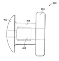
도 1은 본 발명의 일 구현예에 따른 임플란트의 확대된 투시도이다;1 is an enlarged perspective view of an implant according to one embodiment of the present invention;
도 2는 본 발명의 일 구현예에 다른 임플란트의 확대된 단면도이다:2 is an enlarged cross-sectional view of an implant according to one embodiment of the present invention:
도 3은 도 2의 임플란트에 대한 또 다른 확대된 단면도이다:3 is another enlarged cross-sectional view of the implant of FIG. 2:
도 4 내지 15는 본 발명의 일 구현예에 따른 수개의 임플란트에 대한 확대된 단면도이다;4-15 are enlarged cross-sectional views of several implants in accordance with one embodiment of the present invention;
도 16 내지 19는 본 발명의 일 구현예에 따른 임플란트가 장치된 예에 대한 확대된 단면이다. 16-19 are enlarged cross-sections of examples with implants in accordance with one embodiment of the present invention.
도 20 내지 22는 본 발명의 일 구현예에 따른 수개의 임플란트에 대한 확대된 단면도이다; 20-22 are enlarged cross-sectional views of several implants in accordance with one embodiment of the present invention;
도 23 내지 24는 본 발명의 일 구현예에 따른 수개의 임플란드가 장치된 예에 대한 확대된 단면이다;Figures 23 to 24 are enlarged cross sections of an example in which several implants are mounted according to one embodiment of the invention;
도 25 내지 28은 본 발명의 일 구현예에 따른 임플란트의 확대된 투시도이다;25-28 are enlarged perspective views of an implant according to one embodiment of the present invention;
도 29 내지 36은 본 발명의 일 구현예에 따른 수개의 임플란트에 대한 확대된 단면이다;29-36 are enlarged cross sections of several implants according to one embodiment of the present invention;
도 37a 및 37b는 본 발명의 일 구현예에 따른 모세관 필터(capillary filter) 대한 확대된 단면이다;37A and 37B are enlarged cross sections of a capillary filter in accordance with one embodiment of the present invention;
도 37c 및 37d는 도 37a의 필터에 제공된 것과 같은 중공 섬유(hollow fiber) 성분의 예에 대한 확대된 단면이다;37C and 37D are enlarged cross sections of examples of hollow fiber components such as those provided in the filter of FIG. 37A;
도 38 내지 42는 본 발명의 일 구현예에 따른 모세관 필터의 수개의 추가적인 예에 대한 확대된 단면도이다;38-42 are enlarged cross-sectional views of several additional examples of capillary filters according to one embodiment of the present invention;
도 43 내지 45는 본 발명의 일 구현예에 따른, 도 1 내지 42의 특징을 포함할 수 있는 임플란트에 대한 확대된 도면이다.43-45 are enlarged views of implants that may include the features of FIGS. 1-42, in accordance with one embodiment of the present invention.
도면에 있어서, 동일한 참조 부호는 동일한 구조를 지칭한다는 것은 인지될 것이다.In the drawings, it will be appreciated that like reference numerals refer to like structures.
경각막 션트 또는 임플란트(이하 "션트"라고 한다)는 여러 목적을 수행하도록, 예컨데 눈의 전방으로부터 각막을 통과하여 테라필룸(terafilum)으로 안방수액을 우회시킴으로써 눈의 안압(IOP)을 감소시키기 위하여 개발되어 왔다. 그렇게 하기 위하여, 션트는 작은 절개부를 관통하여 눈의 각막으로, 실제 각막의 내부 및 외부 표면 사이에 삽입되어야 한다. 또 다른 적용에 있어서, 션트는 공막을 관통하여 눈의 후방으로 물질을 도입하기 위하여 삽입될 수 있다.Corneal shunts or implants (hereinafter referred to as "shunts") serve several purposes, such as to reduce the intraocular pressure (IOP) of the eye by bypassing the sap into the terafilum through the cornea from the front of the eye. Has been developed. To do so, the shunt must be inserted through the small incision into the cornea of the eye, between the inner and outer surfaces of the actual cornea. In another application, the shunt may be inserted to introduce material into the back of the eye through the sclera.
도 1에 도시된 바와 같이, 본 발명의 일 구현예에 따른 션트의 확대된 투시도를 볼 수 있다. 대표적인 구현예에 있어서, 션트는 약 0.5 mm의 외경을 지니며 약 1 밀리미터 길이일 수 있다. 상기 도면에 있어서 션트가 원주형 구조로서 도시되지만, 관 모양의 다른 도관의 형태도 가능하다는 점은 인지된다. 예를 들면, 션트는 이하 더욱 상세하게 설명하는 바와 같이 타원형 또는 부정형 형태를 띨 수 있 다.As shown in FIG. 1, an enlarged perspective view of a shunt according to one embodiment of the present invention can be seen. In an exemplary embodiment, the shunt has an outer diameter of about 0.5 mm and may be about 1 millimeter long. Although the shunt is shown as a columnar structure in this figure, it is recognized that other tubular conduits may also be formed. For example, the shunt may be elliptical or indefinite as described in more detail below.
도 1은 치수에 있어서 경각막 위치에 적용되는 션트 (10)을 도시한다. 헤드 (12)는 션트가 각막 내부에 위치하는 경우 각막의 외부 또는 상피 표면에 위치한다. 상기 도면에 도시되는 바와 같이, 헤드 (12)는 장치에서 각막으로 연속적인 변이 표면을 제공할 있도록 돔-형태일 수 있다. 이러한 모양은 또한 환자 눈꺼풀에 의하여 잘 허용될 수도 있다. 상기 모양이 특히 유리하게 보이나, 다른 헤드 모양이 동일한 장점을 제공하도록 디자인될 수 있다. 예를 들면, 둥글게 된 모서리 가지며 최소한으로 돌출된 평평한 헤드가 동등하게 잘 허용될 수 있다. 헤드 (12)의 아랫면(도시되지 않음)은 장치가 그 위에 위치하는 각막 표면의 모양에 바람직하게 부합하도록 평평하거나 곡면일 수 있다. 헤드 (12), 본체 (14) 및 푸트 (16)는 모두 하나의 유니트(unit)로서 통합되어 형성되거나, 헤드 또는 푸트가 본체와 통합되어 형성될 수 있다.1 shows a
도 2 및 3에 도시되는 바와 같이 본 발명의 일 구현예에서, 션트 (100)은, 각각, 헤드 (102) 및 푸트 (104) 본체를 포함하는 원격(distal) 또는 근접(proximal) 말단부(end)를 가지고 있으며, 그 사이에 본체 (106)가 확장되어 있는 것으로 도시된다. 개구부 (108)는 유체 전달을 허용하기 위하여 원위 단부 또는 근위 단부 사이에 제공된다. 개구부는 협소부(narrow portion) (110)을 포함하는데, 그 사이에 얇은 층을 이루는 플랩(flap)이 펼쳐 있으며, 이는 도 3의 단면도에서 더욱 명확하게 도시된다. 고형 부재(solid member) (112)는 협소부 (110)을 덮고 있으며, 개구부의 원격 방향으로부터 최소의 압력이 적용될 때까지 플랩이 밀폐 된 위치를 유지하게 하는 실질적으로 반원(semi-circular) 모양을 가지는 플랩 (114)를 포함한다. 이어서, 플랩은 개방되어 개구부의 원격 말단부로부터 근접 말단부까지의 흐름을 조절한다.In one embodiment of the invention, as shown in FIGS. 2 and 3, the
본 명세서에서, "근접(proximal)"이란 용어는 임의의 장치상에서 장치와 연결되어 사용되는 환자로부터 가장 먼 위치를 지칭한다. 이와는 반대 의미로, "원격(distal)"라는 용어는 장치상에서 장치가 연결되어 사용되는 환자로부터 가장 가까운 위치를 지칭한다.As used herein, the term "proximal" refers to the location furthest from the patient used in connection with the device on any device. In the opposite sense, the term "distal" refers to the location closest to the patient on which the device is connected and used.
플랩 (114)은 플랩이 쉽게 개방되도록 히드로젤(hydrogel)과 같은 재료로 구성된다. 플랩 원주는 오직 한 방향으로 개방되도록 윤곽(contouring)됨으로써, 개구부의 근접 말단부로부터 원격 말단부로의 역류를 방지한다. 상세하게는, 플랩 (114)는 개구부 (108)의 내부 원주 주위의 유사한 표면과 정합하는 테이퍼링된 또는 경사진(tappered or sloped) 외부 원주(outer circumference)를 구비하도록 몰딩(molding)될 수 있다. 도 2의 단면도에 더욱 명확하게 도시된, 경사를 갖는 표면은 플랩 개구부를 단일 방향으로 제한하며 미생물의 개구부 (108)로의 인입을 방지한다.The
개구부는 또한 필터 (118)이 위치할 수 있는 광폭부(wider portion) (116)을 포함한다. 필터는 당해 기술분야의 숙련자에게 공지된 바와 같은 임의 수의 필터를 포함하거나 이하 더욱 상세하게 설명하는 바와 같이 개선된 필터를 포함할 수 있다.The opening also includes a
도 2에 도시된 구현예에 있어서, 플랩 (114) 및 필터 (118)은 모두 눈 표면 의 외부 및 내부 사이에 유체 션트를 형성한다. 필터 및 션트 본체는 본 발명의 다양한 구현예에 따라서 여러 가지 방식으로 형성될 수 있다. 예를 들면, 필터 (118)은 션트(즉, 필터 본체는 실질적으로 고형이며 실질적인 션트로서 역할을 한다). 또 다른 구현예에서, 션트의 헤드에 제공된 개구부는 필터로서 역할을 한다(즉 특정 밸브 기구를 취한다).In the embodiment shown in FIG. 2,
도 4의 션트 (120)에 도시된 바와 같이, 개구부 또는 일방향 밸브(one-way valve) (122)는, 각각, 개구부 (124)의 협소부(126) 또는 광폭부 (128) 사이에 제공된다. 도 4에 도시된 구현예에 있어서, 어떠한 필터도 제공되지 않으며 밸브 (122)가 원격 말단부로부터 근접 말단부로의 흐름을 제어하며, 개구부 내의 역류를 방지한다. 도 2 및 도 3에 도시된 플랩 (114)의 경우와 같이, 일방향 밸브 (122)는 개구부 (124)의 내부 원주 주위의 유사한 표면과 정합하는 테이퍼링된 또는 경사진 표면일 수 있다.As shown in
하기 기술하는 본 발명의 구현예에 있어서, 도 2의 필터 (118)과 같은 필터는 요구되는 특정 과제에 따라 세라믹, 산호(coral), 스테인레스강, 티타늄, 실리콘(silicone) 또는 PHEM(즉, 폴리 2-히드록시에틸메타크릴레이트), 및 임의 수의 고분자 재료로 이루어질 수 있다. 스테인레스강 이외에, 더욱 견실한 필터를 제공할 수 있는 임의의 금속이 사용될 수 있다. 금속, 또는 은, 백금과 같이 일정 정도 박테리아에 내성인 유사 재료도 사용될 수 있다. 장치, 필터 또는 조합물은 코팅재, 함침재 또는 건축재와 같은 다수의 그러한 항미생물제(antimicrobial agent)에 통합될 수 있고, 구리, 아연 또는 은(즉, 기상 증착 은도금; vapor deposition silver plating)과 같은 이온성 금속 화합물; PHMB(polyhexamethyl biguanide) 및 액정 고분자(liquid crystal polymers)와 같은 항균성 고분자(즉, 손실 염법(loss salt method)을 통하여 비가용 침전되는); 알킬 트립신, 비구아니드(biguanide), 트리클로산(triclosan) 유기 화합물 및 CHG(클로로헥시딘: chlorhexidine)과 같은 유기 화합물; 4차 암모늄염 및 금속 산화물과 같이 주입된 박테리아를 불허하는 물질 및 무기 화합물을 포함한다.In an embodiment of the invention described below, a filter, such as
기포가 필터를 막을 가능성이 더 작기 때문에, 필터는 친수성을 증가시키고 유속을 증진시키도록 더 산화될 수 있는 티타늄으로 구성될 수 있다. 또 다른 필터 재료는 유리가 용해하고 치환가능한 항균제를 포함하는 가용성/불용성 유리를 포함한다. 비가용성 유리 재료의 예는 유리 섬유 또는 입자로 만들어진 유리 프릿(frit)일 것이다.Since bubbles are less likely to clog the filter, the filter may be composed of titanium, which can be further oxidized to increase hydrophilicity and enhance flow rate. Another filter material includes soluble / insoluble glass in which the glass dissolves and includes a replaceable antimicrobial agent. An example of an insoluble glass material would be a glass frit made of glass fiber or particles.
그러한 필터는 항균 물질과 함께 진공 플레이트되는(vacuum plated) 유리 구체(glass sphere)로 구성될 수도 있다. 그러한 구체는 보다 큰 개구부 안에서 움직이도록 허용되거나, 접착된 구체로 구성된 필터로서 제공될 수 있으며, 또한 그러한 가용성 유리 구체에 지속 방출형으로 함침되는(time release impregnated ) 은 이온을 더 포함할 수 있다. 다수의 3.5 마이크로 구체는 셀룰로오스 바인더와 같은 물질로 고정된다면 0.5 미크론 홀을 제공한다.Such a filter may be composed of glass spheres that are vacuum plated with antimicrobial material. Such spheres may be provided as filters that are allowed to move in larger openings, or consist of bonded spheres, and may further include silver ions that are time release impregnated on such soluble glass spheres. Many 3.5 microspheres provide 0.5 micron holes if fixed with a material such as a cellulose binder.
필터는 도 5에 도시된 바와 같이 개구부 (134)의 원격 및 근접 말단부 사이의 흐름을 효과적으로 제어하기 위하여 사용되는 홀(hole)을 관통하는 다수를 포함하는 유리 모세관 제한장치(132) 흐름 제한장치(flow restrictor)로서 구성될 수 있다. 흐름을 제어할 뿐만 아니라, 홀을 관통하는 다수는 박테리아 침투를 방지하기 위하여 사용될 수 있다. 도 6의 션트 (140)에 도시된 바와 같은 모세관 제한장치 구성 (142)은 개구부의 근접 말단부에 위치한 헤드 또는 캡(cap) (145)에 통합될 수도 있다. 그러한 구현예에 있어서, 개구부를 덮는 캡부(cap portion)는 흐름을 제어하고 박테리아 침투를 방지하기 위하여 홀 섹션(hole section) (142)이 제공될 수도 있으며, 필터(즉, (118) 및 (132))는 생략될 수 있다. 섹션 (142)의 홀 모두에 있어서 각각은, 복수로서 또는 단수로서 제공되거나, 둘러싸는 튜브 안이 항미생물제로 둘러싸일 수 있으며, 또한 매우 매끄러운 표면이 더 제공될 수 있다.The filter includes a
도 7에 도시된 본 발명의 또 다른 구현예에 있어서, 션트 (150)의 개구부 (154)를 덮는 캡부 (155)는 흐름을 제어하고(즉, 제어된 확산) 박테리아 침투를 방지하기 위하여 다공성 히드로젤 멤브레인과 같은 멤브레인 (152)으로 구성될 수 있으며, 필터(즉 (118) 및 (132))는 생략될 수도 있다. 히드로젤이 제공되어 표피(epithelium)가 캡부 (155) 위에서 성장할 수 있으며, 그 결과로서 멤브레인 (152)이 생성된다. 표피 멤브레인은 유체가 확산하는 것을 허용하며 박테리아 침투를 방지할 수 있다.In another embodiment of the present invention shown in FIG. 7, the
필터, 멤브레인 또는 모세관 캡부가 사용되는 상기 기술한 각 구현예에 있어서, 다수의 성분은 조합되어 사용될 수 있다. 도 8의 션트 (160)에 도시된 바와 같이, 다양한 기공 크기 및 구성을 가지는 둘 이상의 독립된 필터 또는 스크린을 포함하는 적층된(stacked) 필터 (162)가 조합되어 사용될 수 있다. 적층된 필터의 선택 및 조합은 흐름을 제어하고 박테리아 침투를 최적화하기 위하여 사용될 수 있 다. 예를 들면, 적층된 필터 (162)는 천공(drill)되고 적층된 플레이트, 튜브 안의 유리 디스크, 실리콘 적층, 또는 은 플레이트, 섬유 또는 스크린 하나 이상으로 구성될 수 있으며, 여기서 각각은 다양한 직경의 관통 홀(through hole) 또는 증가된 유속을 제공하는 슬롯형 개구부(slotted openings)이 제공될 수 있다. 적층의 간격 및 위치는 바이오트랩(biotrap), 다중 챔버, 왜곡된 경로(tortuous paths, 즉 코일 경로), 튜브 또는 채널을 형성하도록 이용될 수 있다. 또한, 플레이트는 양각 또는 음각 플레이트, 또는 벌집 배열과 같이 더욱 독특한 구조를 가지는 플레이트의 음각 층으로 이루어질 수 있다. 유사한 방식으로, 플레이트는 반도체 그리드(grid) 또는 편광장치(polarizer)를 형성하도록 배열될 수 있는 재료로 구성될 수도 있다.In each of the embodiments described above where a filter, membrane or capillary cap portion is used, multiple components can be used in combination. As shown in
션트 본체 자체는 임의 수의 재료들로 구성될 수 있으며, 안과용 히드로젤(ocular hydrogel) (즉, 폴리 히드록시에틸 메타크릴레이트-메타크릴산 공중합체(polyHEMA-MAA), polyHEMA, 공중합체류 및 다른 팽창 재료(expansion material)의 히드로젤), 실리콘, PMMA(즉, 폴리메틸메타크릴레이트), 히알루론산(hylauronic acid), 실리콘/히드로젤 조합물(composition), 실리콘 아크릴의 조합물(silicone acrylic combination) 및 플루오로실리콘 아클릴레이트 등을 포함하는 임의 수의 재료들로 구성될 수 있으나 그들에 국한되지 않는다. 그러한 실리콘 재료는 높은 강도를 가지고 있으며 더욱 높은 정도의 유용한 산소 투과도를 포함하고 높은 정도의 단백질 및 지질 증착 저항성(protein 및 lipid deposition resistance)을 나타낸다. 또한 실리콘/히드로젤 조합물과 같은 실리콘 조합물의 사용은 또한 각각의 장점을 조합한다.The shunt body itself may consist of any number of materials, including ocular hydrogels (ie, polyhydroxyethyl methacrylate-methacrylic acid copolymer (polyHEMA-MAA), polyHEMA, copolymers and Hydrogels of other expansion materials), silicones, PMMA (ie polymethylmethacrylate), hyaluronic acid, silicone / hydrogel compositions, silicone acrylics combination) and fluorosilicone acrylate, and the like, but are not limited thereto. Such silicone materials have high strength, contain a higher degree of useful oxygen permeability and exhibit a high degree of protein and lipid deposition resistance. In addition, the use of silicone combinations, such as silicone / hydrogel combinations, also combines the advantages of each.
션트 본체의 구성 재료는 상기 재료로부터 선택될 수 있으며, 본 발명의 구현예에 따라서 임의 수의 방식으로 가공될 수 있다. 예를 들면, 션트 본체 (170)은 도 9에 도시된 바와 같이 필터가 필요하지 않은 다공성 방식으로 구성될 수 있다. 션트 본체 자체인 다공성 재료는 필터 및/또는 유체 전달 수단으로서의 역할을 하며, 재료의 선택은, 가능한 기공 크기에 근거하여, 효과적으로 특정 적용에 대하여 효과적인 필터로서 기능을 하는 션트 본체를 구성하도록 이용될 수 있다. 또 다른 션트 구성 재료는 션트의 외부에 적용되는 물질층을 포함하도록 선택될 수 있다. 은 질화물과 같은 이러한 물질은 신혈관형성(neovascularization) 및 단백질 침착을 최소화하거나 항균제로서 역할을 하기 위하여 사용될 수 있다. 션트 본체에는 또한 코팅 물질 및/또는 외과용 접착제(surgical adhesive), 예컨데, 조지아주 케네소에 위치한 Cryolife사로부터 입수가능한 Bioglue®, 피브린계 아교(fibrin-based glue), 마린 접착성 단백질(marine adhesive protein, 즉, 조류(algae)), 및 시아노아크릴레이트와 같은 합성 고분자 접착제가 제공될 수 있다.The constituent material of the shunt body can be selected from the above materials and can be processed in any number of ways in accordance with embodiments of the present invention. For example, the
상기 임의의 재료는 표면 거칠기 또는 재질감이 2 이상의 레벨인 션트 본체를 형성하도록 다양하게 조합되어 사용될 수 있다. 예를 들면, 도 10에 도시된 바와 같이, 션트 (180)의 근접 말단부 (185)는 각막 및 눈꺼풀 상의 편안함을 위하여 매끄러운 표면을 포함하도록 구성될 수 있으며, 한편 원격 및 말단부 사이에 확장되는 션트 본체 (181)은 강한 세포 부착을 위하여 거친 표면을 갖도록 구성될 수 있다. 2 레벨 이상의 표면 거칠기를 갖는 것 이외에, 각 구현예는 실질적으로 원 형, 타원형, 또는 도 11 및 12에 도시된 것처럼 별과 같은 부정형의 원격 및 근접 말단부 사이에 확장된 션트 본체를 포함할 수도 있다. 션트 (190)의 별 모양의 단면과 같이 부정형 단면은 션트가 눈에 더욱 잘 확보되는 것을 가능하게 한다. 또한 다양한 모양의 션트 본체 단면은 X자형, O자형, T자형 절개와 같이 다수의 절개 패턴의 사용을 허용한다. 일단 구성 재료가 선택되면, 다수의 션트 본체 모양은 본 발명의 구현예를 효과적으로 수행하도록 사용될 수 있다.Any of the above materials can be used in various combinations to form a shunt body having a surface roughness or texture of two or more levels. For example, as shown in FIG. 10, the proximal
위에서 언급한 바와 같이, 원격 및 근접 말단부 사이에 확장된 션트 본체는 실질적으로 원형, 타원형 또는 부정형일 수 있다. 도 13에 도시된 바와 같이, 션트 (200)은 각각이 특정 적용을 위하여 역할을 수행하는 부정형의 원격 또는 근접 말단부 (207) 및 (205)를 갖도록 구성될 수 있다. 예를 들면, 도 13에 도시된 바와 같이, 션트 캡부 (205)는 마티니 유리잔 모양을 갖도록 구성된다. 이러한 마티니 유리잔 및 이와 유사한 모양 및 유사한 모양은 션트 분출을 방지하기 위하여 효과적으로 사용될 수 있으며, 각각은 이물질 자극을 최소화하기 때문에 일반적으로 눈에 더욱 편안하다. 또한, 그러한 모양은 초기 이식 후의 최소 누출을 나타낸다. 그렇게 장치를 구성함에 있어서, 션트의 캡, 또는 근접 말단부는 매끄러운 마감질을 제공하기 위하여 오버몰딩(overmolding)될 수 있다. As mentioned above, the shunt body that extends between the remote and proximal distal ends may be substantially circular, elliptical or indefinite. As shown in FIG. 13, the
본 발명의 일 구현예에 따른 또 다른 모양은 도 14 및 15에 도시되어 있다. 션트 (210)은 원격 및 근접 말단부를 포함하며, 그 중 원격 말단부 (217)은 이식 도중, 및 이식 후에 변형된다. 이러한 경우에 있어서, 삽입된 원격 말단부 (217)는 변형될 수 있으며, 또는 도 14와 같이 더 작은 모양으로 축소하기 때문에, 이 식(installation)은 더욱 작은 절개부를 필요로 한다. 도 15에 도시된 바와 같이, 성공적으로 내부 표면에 도달한 후, 원격 말단부 (217)은 수화작용(hydration)으로 또는 체온에 노출되어 더욱 커다란 크기로 확장한다. 그러한 구조는 더욱 용이한 이식을 가능하게 한다.Another shape according to one embodiment of the invention is shown in FIGS. 14 and 15.
모양은 도 16에 도시되는 바와 같이 삽입 부분과 동형으로 될 수도 있다. 당해 기술분야의 숙련자에게 공지된 바와 같이, 션트 이식은 공막 각막 접합부에서 이루어질 수 있다. 그러한 이식 부위에서, 션트 (222)의 원격 및 근접 말단부는 그들 사이에 확장된 션트 본체에 대하여 각을 이루도록 구성될 수 있다. 도 16에서 도시된 구현예의 상대적인 각은 투명 각막과 같은 특정 부위 위치를 위하여, 각각, 도 17 및 18의 션트 (226) 및 (228)에 도시된 바와 같이 더 변형될 수 있다. 그러한 설치 적용에 있어서 션트를 적소에 고정할 수 있는 능력에 대하여 고려할 수도 있다. 구체적으로 가장자리(limbus) (예를 들면, 공막에 의하여 겹쳐지는 각막의 가장자리)에 션트를 배치하는 것은 도 19에 도시된 바와 같이 적소의 션트의 원격 말단부 또는 푸트를 고정하도록 기능 할 수 있다.The shape may be homogeneous with the insertion portion as shown in FIG. As is known to those skilled in the art, shunt grafts can be made at the sclera corneal junction. At such an implant site, the distant and proximal ends of the
위에서 언급한 바와 같이, 션트 본체에는 외과용 접착제와 같은 코팅 물질이 제공될 수 있다. 이식 도중에 외과 접착제를 사용하는 것은 밀봉을 확보하게 하며 및/또는 션트의 배치를 확실하게 한다. 외과용 접착제의 더욱 효과적인 사용은 바늘땀(stitch) 이식 과정과 함께 사용되는 경우에 제공된다. 예를 들면, 통상적으로 이식 과정은 션트의 원격 말단부 또는 푸트가 그 안으로 위치하는 약 1.5 내지 1.6 mm 절개부의 형성을 필요로 한다. 대안의 방법에 있어서, 상기 과정은 션트가 확실 히 위치되기 위하여 절개 및 봉합을 필요로 할 수 있다.As mentioned above, the shunt body may be provided with a coating material, such as a surgical adhesive. Using surgical adhesives during implantation ensures a seal and / or ensures placement of the shunt. More effective use of surgical adhesives is provided when used in conjunction with stitch stitch procedures. For example, the implantation process typically requires the formation of an about 1.5-1.6 mm incision in which the distant distal end or foot of the shunt is located. In an alternative method, the procedure may require incisions and sutures in order for the shunt to be securely located.
상기 구현예에서 제공된 필터에는 도 20의 션트 (240)에 도시된 바와 같이 마이크로-기계식 펌프 (242)와 같은 임의 수의 마이크로 장치가 추가로 제공될 수도 있다. 그러한 기술 및 장치는 위에서 기술한 필터, 밸브 및 제한장치를 대체하도록 사용될 수도 있다.The filter provided in this embodiment may further be provided with any number of micro devices, such as
위에서 기술한 각 구현예에서 필터, 제한장치 및/또는 마이크로-장치는 영구적이거나, 제거가능하거나 및/또는 대체가능할 수 있다. 따라서, 사용자는 필터가 막혔다면 필터를 교환함으로써 전체 션트를 교체할 필요가 없도록, 제거가능하며 및 대체가능한 필터를 구비한 션트를 사용하는 옵션을 가질 수 있다. 예를 들면, 도 21에 도시된 바와 같이, 션트 (250)의 필터 (252)는 단순히 개구부로부터 밀어서 교체될 수 있다. 그러한 교체는 필터가 막힌 경우, 또는 정기적인 시기마다 성능 레벨을 유지하기 위하여 일어날 수 있다. 교체는 또한 사용자가 유속 또는 션트의 흐름 특성을 바꾸기를 희망하는 경우에도 일어날 수 있다. 눈에 약제를 도입하기 위하여 필터가 사용되는 경우에도 교체가 일어날 수도 있다.In each of the embodiments described above, the filters, restrictors and / or micro-devices may be permanent, removable and / or replaceable. Thus, the user may have the option of using a shunt with a removable and replaceable filter so that if the filter is clogged there is no need to replace the entire shunt by replacing the filter. For example, as shown in FIG. 21, the
위에서 상술한 교체가능한 필터는 다수의 방법으로 용이한 교체, 설치 및 확인에 적합한 방식으로 구성될 수 있다. 도 22에 도시되는 바와 같이, 션트 (260)의 헤드 (265)에서 개구부는 개구부 (364)에서 구멍 윗 쪽이 넓혀진 진입부를 갖도록 구성될 수 있으며, 이는 필터가 의도되지 않은 거리만큼 개구부 안으로 이동하는 것을 방지하며 션트의 근접 말단부로부터 더욱 용이한 제거 및 교체를 가능하게 한다.The replaceable filter described above can be configured in a manner suitable for easy replacement, installation and verification in a number of ways. As shown in FIG. 22, the opening in the
더욱 용이한 삽입을 가능하게 하는 본 발명의 또 다른 구현예에 있어서, 션트는 외부 펌프와 같은 장치와 함께 사용하기 위하여 커플링 기구(coupling mechanism)를 포함한다. 도 23에 도시된 구현예에 있어서, 션트 (272)는 팽창될 수 있도록 구성된다. 일단 눈 (274)의 작은 절개부에 위치되면, 외부 펌프 (276)은 이식 후 션트 (272)가 팽창하도록 위하여 사용될 수 있다. 따라서, 션트는 확장 이전에 더욱 크기가 작아도 가능하며, 그럼으로써 더욱 용이한 이식을 위하여 더 작은 절개부를 필요로 할 수 있다. 또한 팽창된 션트 (274)는 더욱 누출 갭(leak gap)을 효과적으로 채운다. 도 24에 도시된 바와 같이, 상술한 션트 (282)는 절개부를 관통하여 각막 (284)로 션트를 견인하기 위하여 봉합 (286)을 사용하여 이식될 수 있다. 또 다른 이식 기술은 적절한 이식 위치로 션트를 발사(shooting)하는 것을 포함한다. 션트의 구성은 수정체 유화 장치(phacoemulsification machine)와 같은 임의 수의 장치를 사용하는 제거 기술 이외에, 그러한 기술을 사용하여 이식을 가능하게 하도록 채택될 수 있다.In another embodiment of the present invention that allows for easier insertion, the shunt includes a coupling mechanism for use with a device such as an external pump. In the embodiment shown in FIG. 23, the
또 다른 구현예에 있어서, 도 25 내지 28에 도시된 바와 같이, 션트 (290)는 직선형 근접부 (297)를 갖도록 구성될 수 있다. 직선형 근접부 (297)는 위에서 상술한 구현예의 원형 근접부를 대체한다. 이는 전형적으로 선형의 절개부로의 삽입을 더욱 용이하게 한다. 삽입시 션트 (290)는 절개 축에 대하여 수직이며 그럼으로써 션트 (290)를 고정시키는 직선형 근접부 (297)를 교체하기 위하여 실질적으로 90도로 회전한다.In another embodiment, as shown in FIGS. 25-28, the
각막 이식 과정 또는 백내장 수술(cataract surgery) 후 IOP를 저하시킬 수 있는 방법과 같이 임의 수의 목적에 채택가능한 션트를 구성하도록, 위에서 상술한 다양한 구현예가 사용될 수 있다. 이는 또한 수의(veterinary) 또는 화장 용도를 위하여 사용될 수도 있다. 션트 본체는 또한 본질적으로 눈을 위한 카테터(catheter)로서 사용될 수도 있다. 도 29에 도시된 바와 같이, 션트 개구부 (304)의 근접 말단부 (305)는 덮이거나, 밀봉되거나 또는 약물의 투입 또는 주입을 위한 각막내 부분을 형성하기 위하여 슬릿(slit)이 제공될 수 있다.The various embodiments described above can be used to construct shunts that are acceptable for any number of purposes, such as methods that can lower IOP after corneal transplantation or cataract surgery. It may also be used for veterinary or cosmetic use. The shunt body may also be used essentially as a catheter for the eye. As shown in FIG. 29, the proximal
션트의 근접 말단부 또는 헤드는 션트의 종류를 나타내기 위한 색 또는 모양과 같은 수단이 제공될 수 있다. 션트의 원격 말단부 또는 푸트가 전방에 올바르게 위치된 경우 더욱 명확히 나타나는 지시 색(indicator color)과 같은 유사한 수단이 제공될 수도 있다.The proximal end or head of the shunt may be provided with means such as color or shape to indicate the type of shunt. Similar means may be provided, such as an indicator color that appears more clearly when the remote end or foot of the shunt is correctly positioned forward.
위에서 언급한 바와 같이, 본 발명의 구현예는 안압을 낮추기 위한 경각막 임플란드 장치로서 또는 눈의 후방에 약제를 도입하기 위한 경공막 장치로서 제공될 수 있다. 예를 들면, 도 30, 31 및 32에 도시된 바와 같이, 임플란트 장치 또는 션트 (310)는 약물을 흡수하는 히드로젤 재료로 제조되거나, 세라믹 또는 티타늄과 같은 다공성 재료로 제조될 수 있다. 이는 또한 약물을 함유하는 다공성 재료 (312)를 둘러싸는 히드로젤 재료의 포장(casing)일 수도 있으며, 여기서 히드로젤 또는 다공성 재료 (3112)는 제어된 속도(즉, 제어된 확산)로 눈의 후방으로 약물을 방출한다. 장치 (310)은, 실질적으로 위에서 기술한 바와 같은, 플랜지(flange) (317)에 의하여 각막 또는 공막에 고정되며, 또한 장치의 외부에 코팅에 의하여 고정된다. 이러한 코팅은 세포상 부착을 유도하기 다공성이거나 화학적으로 변형될 수도 있다. 눈으로 방출될 수 있는 치료제(therapeutic agents) 또는 지속-방출형 약물은 면역 반응 조절제(immune response modifiers), 신경보호제(neuroprotectants), 코르티코스테로이드(corticosteroids), 지혈 스테로이드(angiostatic steroid), 항녹내장제(anti-glaucoma agents), 항지혈성 화합물(angiogentic compounds), 항생제(antibiotics), 방사능제(radioactive agents), 항균제(anti-bacterial agent), 항바이러스제, 항암제, 막힘-방지 물질(anti-clogging agent) 및 항염증제(anti-inflammatory agent)를 포함하는 임의 수의 물질을 포함한다.As mentioned above, embodiments of the present invention may be provided as a corneal implant device for lowering intraocular pressure or as a transmucosal device for introducing a medicament into the back of the eye. For example, as shown in FIGS. 30, 31 and 32, the implant device or shunt 310 may be made of a hydrogel material that absorbs the drug, or may be made of a porous material such as ceramic or titanium. It may also be a casing of hydrogel material surrounding the drug containing
도 30 및 31에 도시된 본 발명의 구현예는 다공성 재료 (312)를 둘러싼 히드로젤 재료 포장을 구비한 장치의 예를 도시하는데, 여기서 히드로젤 또는 다공성 재료는 약물을 제어된 속도록 눈의 후방으로 방출한다. 상기 장치는 공막을 관통하여 이식되었으며, 약물은 서서히 눈으로 전달되며, 영구적인 또는 단기간의 임플란트로서 제공될 수 있다. 도 30에 도시된 바와 같이, 임플란트는 그 사이에 션트 본체 (311)가 확장된 원격 및 근접 말단부, 각각, (317) 및 (315)를 포함할 수 있으며, 개구부는 약물을 함유하는 다공성 필터 (312)를 포함한다. 원격 및 근접 말단부 사이에 확장된 션트 본체 (311)의 외부 표면은 세포상 부착 또는 성장을 유도하기 위하여 다공성 또는 화학적으로 배합된(formlated) 외층(external layer) 또는 코팅을 포함할 수 있다. 션트 본체 (311)의 외부 표면은 다공성 층 또는 티타늄 및/또는 세라믹 코팅이 제공될 수 있으며, 여기서 요구되는 또는 부가적인 임의의 약물 기공(pore) 안에 저장된다. 션트 (310)의 나머지는 히드로젤 포장으로서 구성될 수 있다.The embodiment of the present invention shown in FIGS. 30 and 31 shows an example of a device having a hydrogel material package surrounding the
션트 (310)의 근접 말단부 또는 헤드는 흡수된 약물을 함유하는 다공성 또는 비다공성 히드로젤로 구성될 수도 있다. 도 32에 도시된 본 발명의 또 다른 구현예에 있어서, 전체 션트 (320)은 다공성 또는 비다공성 히드로젤로 구성될 수 있으며, 필터 없이 제공될 수 있다.The proximal distal end or head of the
위에서 기술한 본 발명의 구현예는 임의 수치의 연장된 기간에 걸쳐 눈에 약물을 전달하기 위하여 사용될 수 있는 장기간의 임플란트로서 일차적으로 제공된다. 이와 같이, 상기 구현예는 반복되는 주입으로 야기되는 눈에 상처를 야기하지 않으며, 또한 눈으로 완만하며 지속적인 주입(infusion)을 가능하게 한다. 그러한 장기간 임플란트에 대한 상세한 기술은 미국 특허 출원 제10/182,833호(발명의 명칭: Systems 및 Methods For Reducing Intraocular Pressure), 및 미국 특허 제5,807,302호(발명의 명칭: Treatment For Glaucoma)에 언급되어 있으며, 각각의 전문은 본원에서 인용에 의하여 통합된다.Embodiments of the invention described above are primarily provided as long-term implants that can be used to deliver drugs to the eye over any number of extended periods of time. As such, the embodiments do not cause injury to the eye caused by repeated infusions, but also allow for gentle and continuous infusion into the eye. Details of such long-term implants are mentioned in US Patent Application No. 10 / 182,833 (Systems and Methods For Reducing Intraocular Pressure), and US Patent 5,807,302 (Treatment For Glaucoma), Each full text is hereby incorporated by reference.
도 33에 도시된 본 발명의 또 다른 구현예에서, 션트 (330)은 항생제 및 항감염제(anti-infective agent)를 포함하는 다공성 흐름 조절 장치로서 구성될 수 있다. 상기 각 구현예에 대하여 기술한 바와 같이, 장치는 적용 및 션트 위치에 따라 안압을 낮추거나 후방으로 물질을 도입하기 위하여 전방으로부터 눈물막(tear film)으로 안방수의 방향을 변경시킨다. 이는 각막 또는 공막 중 어느 하나를 관통하도록 배치되어, 일 말단부가 각막, 가장자리 또는 공막의 표면상에 있고, 다른 말단부는 전방 또는 후방 안에 위치할 수 있다.In another embodiment of the present invention shown in FIG. 33, the
도 34에 도시된 바와 같이, 션트 (340)은 안방수를 제어된 속도로 배출하기 위하여 요구되는 바람직한 흐름 저항을 제공하기 위하여 또한 다공성 필터 구조를 포함할 수도 있다. 다공성 필터 구조 안의 항감염제 또는 항생제는 눈의 외부로부터 필터 (342)를 통과하여 전방으로의 박테리아 침투를 방지한다. 조직과 접촉하는 션트 본체 외부 표면 (341)은 세포상 내부성장(ingrowth)을 촉진하고 눈에 장치를 고정하는 것을 돕도록 다공성 또는 해면(spongy) 조직을 구비할 수 있다. 다공성 여과 장치 (342)는 박테리아 침투를 방지하고 감염의 위험을 감소시키는 구조에 있어서 항생제 또는 항감염제를 제공할 수 있다. 다공성 여과 장치 구조는 또한 박테리아 침투를 더욱 방지하기 위하여 왜곡된 경로를 제공할 수도 있다. 또한 개구부 또는 채널 (344)의 근접 말단부에 위치한, 협소해진 개구부 (346)는 박테리아 침투에 대한 장벽(barrier)을 제공할 수도 있다.As shown in FIG. 34, the
기존의 장치는 박테리아 방지를 위한 션트에 있어서 통상적으로 기공 크기가 0.20 미크론인 필터를 통합한다. 그러나 0.20 미크론 필터는 장치를 통과하는 흐름을 실질적으로 제한하여 바람직한 유속에 도달하기 위하여 요구되는 필터 면적의 크기가 현실적이지 않을 정도이다. 만약 항생제 또는 항감염제가 더욱 커다란 기공 크기를 갖는 구조에 사용된다면, 필요한 흐름 저항은 더욱 작은 장치에서도 얻어질 수 있다. 이와 같이, 그러한 물질이 사용되는 경우, 션트는 그러한 박테리아 방지 기구와 같은 기구를 포함하는 임의의 기존 장치보다 작을 수 있다. 또한, 기공 크기가 0.2 미크론 보다 큰 다공성 구조는 박테리아 방지를 위한 수단으로서 0.2 미크론 필터를 사용하는 장치보다 막힐 가능성이 더 작다. 작은 장치는 또한 자극 및 거부 문제를 야기할 가능성이 더 작으며, 시야를 교란하거나 외부적으로 주목되지 않고 더욱 용이하게 배치될 수 있다.Existing devices incorporate filters having a pore size of typically 0.20 micron for shunts for bacterial protection. The 0.20 micron filter, however, substantially limits the flow through the device so that the size of the filter area required to reach the desired flow rate is not realistic. If antibiotics or anti-infectives are used in structures with larger pore sizes, the required flow resistance can be obtained even in smaller devices. As such, when such a material is used, the shunt may be smaller than any existing device that includes a device such as a anti-bacterial device. In addition, porous structures with pore sizes greater than 0.2 micron are less likely to be clogged than devices that use 0.2 micron filters as a means to prevent bacteria. Small devices are also less likely to cause stimulation and rejection problems and can be more easily deployed without disturbing the field of view or externally paying attention.
조직과 접촉하는 곳의 영역에서 장치의 기공 특성은 또한 세포상 내부성장을 허용하는 장점을 갖고 있으며, 이는 조직이 장치에 부착하는 데 도움을 주며 장치가 눈에 더욱 확실하게 배치되는 것을 가능하게 한다. 이는 상기 장치가 이식된 후에 바람직하지 않은 방출을 방지하는데 도움을 준다.The pore nature of the device in the area where it is in contact with tissue also has the advantage of allowing cellular internal growth, which helps the tissue attach to the device and allows the device to be placed more reliably in the eye. . This helps to prevent undesirable release after the device is implanted.
당해 기술분야의 숙련자에게 공지된 것처럼, 그러한 장치에서 유속은 기공 크기와 직접적으로 관련된다. 위에서 언급하였듯이, 기존의 필터 장치는 박테리아가 전방으로 침투하는 것을 물리적으로 방지하기 위하여 직경 약 0.2 미크론의 기공 크기를 갖는 필터를 구비하였다. 이러한 기공 크기를 갖는 필터는 흐름을 과도하게 제한함으로써, 요구되는 유속에 도달하기 위하여 필요한, 요구되는 필터 면적을 너무 크게 한다. 이는 작용 장치가 바람직한 것보다 더욱 크게 되는 결과를 가져온다. 그러나, 만약 항생제 또는 항감염제가 추가된다면, 커다란 기공 크기를 갖는 필터는 유사한 도는 우수한 박테리아 장벽를 갖도록 사용될 수 있으며, 바람직한 흐름 제한이 더욱 작은 장치에서도 얻어질 수 있다.As is known to those skilled in the art, the flow rate in such devices is directly related to the pore size. As mentioned above, the existing filter device was equipped with a filter having a pore size of about 0.2 micron in diameter to physically prevent bacteria from penetrating forward. Filters having such pore sizes excessively restrict flow, thereby making the required filter area too large, necessary to reach the required flow rate. This results in the mechanism being larger than desired. However, if antibiotics or anti-infective agents are added, filters with large pore sizes can be used to have similar or superior bacterial barriers, and desirable flow restrictions can be obtained even with smaller devices.
또한 전방으로부터 눈물관(tear duct)으로 유체를 우회시킴으로써 녹내장을 치료하는 기존의 필터 장치는 통상적으로 조직이 장치에 부착하는데 도움을 주기 위하여 세포상 내부성장을 촉진하는 수단을 구비하고 있지 않다. 위에서 기술한 구현예의 외면상의 다공성 특성은 세포가 장치에 부착하는데 도움을 주는, 세포상 내부성장을 촉진하는 장점을 갖고 있으며, 장치는 적소에 더욱 확실히 고정될 수 있 다.In addition, conventional filter devices that treat glaucoma by bypassing fluid from the anterior to the tear duct typically do not have means to promote cellular internal growth to help tissue attach to the device. The outer porous nature of the embodiments described above has the advantage of promoting cellular internal growth, which helps cells adhere to the device, and the device can be more securely fixed in place.
전방으로부터 눈물막으로 안방수를 배출하는 션트의 일부 개념은 또한 밸브 기구를 포함하나, 다수는 일방향 밸브만을 구비하고 있다. 그러한 밸브는 박테리아가 밸브를 통과하여 침투되는 것을 모두 방지하지는 못할 수 있으므로, 감염의 위험성이 높다. 따라서 상기 구현예의 여과 장치는, 전방에 진입하기 전에 박테리아를 죽이는 항감염제가 필터 (342) 전체에 함유된 왜곡된 경로를 제공함으로써 이러한 문제를 해결한다.Some concepts of the shunt for draining the water into the tear film from the front also include valve mechanisms, but many have only one-way valves. Such valves may not prevent bacteria from penetrating through the valve, thus increasing the risk of infection. The filtration device of this embodiment thus solves this problem by providing a distorted pathway in which the anti-infective agent killing bacteria before entering the front is contained throughout the
도 34 내지 36에 도시된 구현예는, 각각, (342), (352) 및 (362)의 다공성 금속, 세라믹 또는 플라스틱 실린더형 필터를 포함하며, 각각은 외경이 약 0.001 내지 약 0.03 인치 범위이며, 길이가 약 0.020 내지 약 0.030 인치 사이이다. 기공 크기는 재료, 표면적 및 두께에 따라 직경이 약 0.20 내지 약 15 미크론이다. 다공성 필터 (342), (352) 및 (362) 각각은 그 구조 안에 코팅된 항감염제 또는 항감염성 화합물을 함유하며, 이는 은 화합물, 항생제 또는 다른 다양한 범위의 항감염제일 수 있으며, 이는 생체적합성이다. 또한 필터 두께는 연장된 기간 동안 박테리아가 침투하는 것을 방지할 수 있는 물질 코팅 또는 화합물을 함유하는 왜곡된 경로를 제공한다.The embodiments shown in FIGS. 34-36 include porous metal, ceramic, or plastic cylindrical filters of 342, 352, and 362, respectively, each having an outer diameter ranging from about 0.001 to about 0.03 inches. , Between about 0.020 and about 0.030 inches in length. Pore sizes range from about 0.20 to about 15 microns in diameter, depending on the material, surface area, and thickness. Each of the
도 34 및 35에 있어서, 실린더형 필터 (342) 및 (352) 각각은 실리콘 또는 히드로젤 튜브 또는 채널 (344) 및 (354) 각각에 밀폐되어 있으며, 이들은 각각 근접 말단부 (345) 및 (355) 각각에, 콘택트 렌즈와 같이 눈의 표면과 같은 모양이지만 안방수가 관통하여 흐를 수 있는 개구부 (346) 및 (356) 각각을 구비한, 매끄러 운 곡선 플랜지를 포함한다. 원격 말단부 (347) 및 (357) 각각은 장치를 고정하며 방출을 방지하는 플랜지를 구비한다. 외면의 튜브 (341) 및 (351) 각각은 조직을 항감염제의 독성 효과로부터 보호하며, 연질 재료(soft material)로 제조되어 있다. 상기 구현예와 같이, 튜브의 일부는 세포상 내부성장이 일어날 수 있도록 해면 조직(spongy texture)를 포함하는 조직(tissue)과 접촉하고 있다. 또한 도 35에 도시된 바와 같이, 밸브 (353)은 항감염제를 더 통합하는 다공성 필터 구조 (352)를 통과하는 유속을 제어하도록 제공될 수도 있다. 밸브의 또 다른 구현예는, 당해 기술분야의 숙련자에게 공지된 바와 같이, '포핏형(poppit-type)' 밸브, '분출형(blow-off type)' 밸브, 사용자 활성(user activated) 밸브, VernatyTM형 밸브, 오리주둥이형(duck-bill) 밸브, 우산형 밸브, 압력 크래킹(pressure cracking) 밸브 및 돔오버(dome-over) 밸브를 포함할 수 있다.34 and 35, the
또한 위에서 기술한 바와 같이, 완전히 다공성인 세리믹부(360)는 도 36에 도시된 바와 같은 함침된 바이오사이드(biocide)를 구비하도록 구성될 수 있다. 세라믹은 알루미나 또는 히드록시아피타이트와 같이, 생체 비활성(bioinert), 생체 활성(bioactive) 및/또는 생체적합성 재료일 수 있다. 사용되는 항감염제는 또한 은 화합물 같이 필요한 특성에서 또는 눈 천연의 항감염제의 증가된 농도에서 생체 비활성일 수도 있다.As also described above, the fully porous
션트 (360)의 모양은 위에서 기술한 것과 유사한 모양일 수 있으며, 또한 기계식 나사와 같은 조직 내부에 고정하기 위하여, 도 36에 도시된 바와 같이 일련의 기계적 결합 나사부(mechanical engagement thread) (369)을 포함할 수도 있다. 또 다른 결합 기술은 조직 내부에의 고정을 위하여 디텐트(detent), 압입(indentation) 또는 탭(도시되지 않음)과 같은 다수의 돌출부(protrusion)를 사용할 수 있다.The shape of the
완전히 다공성인 세라믹부는 약 0.2 미크론의 기공을 갖도록 구성될 수 있다. 이러한 구현예에 있어서, 밸브 채널 및/또는 별개의 필터 구조를 요구하지 않으며 단일의 통합 장치(single, intergral device)에서 기공 크기로 인해, 장치는 흐름 저항을 제어하며, 외부 생체적합성 구조를 제공하고, 또한 박테리아 침투를 방지할 수 있다. 또한 세라믹부의 구조는 더욱 큰 유속을 위하여 더욱 커다란 기공 크기를 갖으며 또한 표면에 분무된 또는 증착된(deposited) 매우 얇은 층(예를 들면, 약 0.2 미크론)을 갖도록 제조될 수도 있다. 또한 완전히 다공성인 티타늄부가 소결 방법을 사용하여 함침된 바이오사이드를 갖도록 상기 모형으로 구성될 수도 있다.The fully porous ceramic portion can be configured to have pores of about 0.2 microns. In this embodiment, the device does not require a valve channel and / or a separate filter structure and because of the pore size in a single, intergral device, the device controls the flow resistance and provides an external biocompatible structure. It can also prevent bacterial penetration. The structure of the ceramic portion may also be made to have a larger pore size for greater flow rates and to have a very thin layer (eg about 0.2 micron) sprayed or deposited on the surface. It is also possible to construct the model such that the fully porous titanium part has a bioside impregnated using the sintering method.
상기 구현예에 있어서, 션트, 임플란트, 또는 그 내부의 필터는 기공 크기 및 유속 사이의 관계에 근거하여 구성된다. 기공 크기가 클수록, 장치에서의 유속은 더 증가한다. 이는 녹내장 여과 장치의 흐름을 효과적으로 제어할 수 있는 매우 작은 장치를 제조하는 것을 가능하게 한다. 추가적인 효과는 박테리아를 죽여 그들의 침투를 방지할 수 있는 항감염제의 사용을 포함한다. 항감염제는 다공성 재료에 의하여 형성되는 왜곡된 경로 구조와 함께 통합되어 사용될 수 있다. 또한 다공성 구조의 사용은 사람 몸에 이식되는 경우 세포 내부성장을 가능하게 하며 장치 표면 에의 세포 부착을 촉진한다.In this embodiment, the shunt, implant, or filter therein is configured based on the relationship between pore size and flow rate. The larger the pore size, the higher the flow rate in the device. This makes it possible to manufacture very small devices that can effectively control the flow of the glaucoma filtration device. Additional effects include the use of anti-infective agents that can kill bacteria and prevent their penetration. Anti-infective agents can be used in combination with the distorted pathway structure formed by the porous material. The use of a porous structure also allows for intracellular growth when implanted in the human body and promotes cell adhesion to the device surface.
상기 장치는 약물 전달 장치로서 사용될 수도 있다. 상세하게는, 상기 구현예는 다공성 필터 또는 본체 재료 안에 경시적으로(over time) 용해하여 눈으로 방출되는 약물을 포함할 수 있다. 또 다른 적용에 있어서, 장치는 눈으로 약물을 주입하기 위한 기구(즉 카테터)로서 사용될 수다. 이는 임시적인 임플란트 또는 안과의 카테터(catheter)일 수 있다. 관련된 재료는 미국 특허 제5,807,302호(발명의 명칭: Treatment of Glaucoma), 미국 특허 제3,788,327호(발명의 명칭: Surgicai Implant Device), 미국 특허 제4,886,488호(발명의 명칭: Glaucoma Drainage the Lacrimal System 및 Method), 미국 특허 제5,743,868호(발명의 명칭: Corneal pressure-Regulating Implant Device) 및 미국 특허 제6,007,510호(발명의 명칭: implantable Devices 및 Methods for Controlling the Flow of Fluids Within the Body)에 개시되어 있으며, 각각의 전문은 본원에서 인용에 의하여 통합된다.The device may be used as a drug delivery device. Specifically, the embodiment may include a drug that dissolves over time in the porous filter or body material and is released into the eye. In another application, the device can be used as an instrument (ie catheter) for injecting drugs into the eye. It may be a temporary implant or an ophthalmic catheter. Related materials include U.S. Patent 5,807,302 (Treatment of Glaucoma), U.S. Patent 3,788,327 (Surgicai Implant Device), U.S. Patent 4,886,488 (Inventory: Glaucoma Drainage the Lacrimal System and Method ), US Pat. No. 5,743,868 (named Corneal pressure-Regulating Implant Device) and US Pat. No. 6,007,510 (name: Inventable Devices and Methods for Controlling the Flow of Fluids Within the Body), respectively. The entirety of is incorporated herein by reference.
상기 장치에 있어서 다공성 본체 또는 필터의 또 다른 구현예에서, 중공(hollow) 또는 모세관 작용 마이크로-장치가 도 37 내지 42에 도시된 바와 같이 제공될 수 있다. 도 37 내지 42의 유동성 마이크로-장치는 위에서 기술한 압력 방출 삽입 장치, 임플란트 또는 션트의 부품이 되도록 디자인되었으며, 눈의 상승된 압력을 방출하기 위한 체크 밸브로서 역할을 할 수 있다.In another embodiment of the porous body or filter in the device, a hollow or capillary action micro-device can be provided as shown in FIGS. 37-42. The flowable micro-devices of FIGS. 37-42 are designed to be part of the pressure relief insert, implant or shunt described above, and can serve as a check valve to release the elevated pressure of the eye.
도 37a 내지 37d에 도시된 바와 같이, 중공 또는 모세관 작용 마이크로-장치 (370)는 임플란트 또는 션트의 채널 안에 플라스틱 실린더 (375)으로 둘러싸인 하나 이상의 중공의 다공성 섬유 (373)를 고정하는 포팅된(potted) 베이스 (371)로 구성된 연장된 다공성 필터로 이루어질 수 있다. 상기 섬유는 제1 말단부 (379)에서 밀폐 또는 밀봉될 수 있으며, 제2 말단부에서 베이스 (371) 내부에 개방되어 유체 전달 개구부에 고정되어 있다. 섬유 (371)의 길이에 걸쳐, 다공성 벽은 실질적으로 중공인 중심(hollow center)을 둘러싸고 있으며, 플라스틱 실린더 내부에 션트의 축을 따라서 확장된다. 다공성 섬유는 마이크로-장치 (370)을 위하여 매우 커다란 여과 영역을 생성하며, 그리고 비제한적인 흐름이 베이스 (371) 내부의, 둘러싸는 플라스틱 실린더 (375), 중공 섬유 중심 및 전달 개구부를 통하여 제공된다. 따라서 섬유 구성은 섬유 길이를 따라서 제한적인 다공성 개구부를 통하여 최대 흐름을 제공한다.As shown in FIGS. 37A-37D, a hollow or capillary action micro-device 370 is potted to secure one or more hollow
중공의 다공성 섬유 기술의 사용은 위에서 기술한 임플란트 본체에 삽입되는 경우 효과적인 여과 영역을 증가시키기 위하여 사용될 수 있다. 방수는 션트 채널로 이동하며 또한 베이스 (371)의 개방 말단부를 관통하여 실질적으로 중공인 섬유 (373) 중심으로 이동한다. 상기 섬유는 반대편의 말단부 (379)가 밀폐되었기 때문에, 상기 방수는 섬유 (373)을 회피하기 위하여 섬유의 다공성층을 관통하여 이동하도록 강제된다. 이어서 방수는 플라스틱 실린더 (375)에 진입하여 그 후로 션트 채널을 지나 눈의 표면으로 방출된다. 도 37c 및 37d에 더욱 상세하게 도시된 바와 같이, 중공 섬유 필터 (373)은 제1 말단부 (379)가 밀폐된, 실질적으로 실린더형 요소를 제공한다. 수성 물질이 섬유 (373)의 반대편의 개방된 말단부를 통하여 실질적으로 중공 섬유에 진입함에 따라, 이는 섬유 본체의 다공성 재료를 관통하여 방출되어야 한다. 섬유의 (373)의 이러한 기공은 섬유 본체에 걸쳐 균일하게 분포 할 수 있으며, 또는 섬유의 중심으로부터 방사상 외부로 측정할 때 작은 것부터 큰 것으로 기울기 기공 크기(gradient pore size)를 갖도록 제공될 수도 있다.The use of hollow porous fiber technology can be used to increase the effective filtration area when inserted into the implant body described above. The waterproofing moves to the shunt channel and also through the open distal end of the base 371 to the substantially
포팅된 베이스 (371)은 직경이 약 0.020 인치인 실질적으로 원형 디스크로 구성될 수 있으며, 도 37 a 및 37b에 도시된 바와 같이 베이스의 반대편에 고정되어 이로부터 확장된 중공의 다공성 섬유 (373)과 함께 연결되는 하나 이상의 개구부를 포함한다. 섬유 (373)의 길이, 내경 및 다공성 벽 배열(즉, 기공 크기 및 기울기)은 적용에 요구되는 바람직한 필터/제한 결과를 달성하도록 배열될 수 있다. 또한, 구성 재료는 바람직한 결과를 달성하는데 도움을 주기 위하여 위에서 기술한 것과 같은 재료들을 포함할 수 있다. 이하에서 더욱 상세하게 기술하는 바와 같이, 중공 또는 모세관 작용 마이크로-장치는 또한 실질적으로 동일한 결과를 달성하기 위하여 접합된(bonded) 2개의 단편 부재(piece member)로서 수행될 수도 있다.The
도 38 및 39에 도시된 바와 같이, 다른 중공 또는 모세관 작용 마이크로-장치는 서로 접합된 둘 이상의 별개의 부분(part) (372) 및 (374)로 구성될 수 있다. 당해 기술분야의 숙련자에게 공지된 바와 같이, 접합은 약 800 nm 내지1000 nm 이상 범위의 레이저 용접 기술을 사용하여 수행될 수 있다. 장치의 하나 이상의 부분에서, 모세관 용기 (376)의 미로(maze)는 이식되거나 삽입(embeded)된다. 모세관 용기 치수 및 그들의 기하구조(geometry) 눈의 압력을 경감하기 위하여 요구되는 파라미터를 충족하도록 계산되며 제조된다.As shown in FIGS. 38 and 39, other hollow or capillary action micro-devices may be comprised of two or more
도 40에 도시된 바와 같이, 모세관 용기부 (376)는 전체 길이에 확장된 직선의 프로파일을 갖도록 구성될 수 있으며, 약 0.001 mm의 직경을 갖도록 형성된다. 도 41에 모세관부의 다른 변형예가 도시되는데, 여기서 모세관 용기(377) 용기부 전체 길이에 확장된 실질적으로 사인파(sinusoidal wave) 모양을 갖는 것으로 나타나며, 약 0.001 mm의 직경을 갖도록 형성된다. 도 40 및 41에 있어서, 모세관부는 수직축(도시되지 않음)을 따라서 확장된 부분을 더 갖도록 구성될 수 있으며, 여기서 모세관부의 상당한 부분은 저장소(reservoir)를 제공하도록 사용될 수 있다. 도 42에 도시된 모세관부의 다른 변형예에 있어서, 모세관 용기부 (378)은 저장소 부분을 통과하여 확장된 직선의 프로파일을 갖는다. 그러나, 대향하는 말단부 근처에 모세관 용기는 직경이 작아지거나, 하나 또는 양 말단부에 확대된 원뿔형 입구(orifice)를 갖도록 구성됨으로써, 장치에서의 저항을 제어할 수 있다.As shown in FIG. 40, the
각각의 부분 (372), (374), (376) 및 (378)은 정밀한 서브-미크론 치수(dimension)를 갖는 모세관부의 구성을 허용하는, 포토리소그래피(photolithography)와 같은 기술에서 제공되는 마스터(master)를 사용하여 몰딩될 수 있다. 그러한 장치는 높은 수준의 재현성 및 신뢰성을 제공한다.Each
또 다른 구현예는 모세관 입구 내부에 배치된 심지부(wick member) (도시되지 않음)를 갖는 모세관부를 포함한다. 그러한 구현예에 있어서, 모세관 작용 심지는 탄소, 유리, 폴리프로필렌 섬유, 금속의 은 또는 주름진 섬유 다발(crimped fiber bundle)과 같은 임의 수의 재료를 사용하여 구성될 수 있다.Yet another embodiment includes a capillary portion having a wick member (not shown) disposed inside the capillary inlet. In such embodiments, capillary wicks can be constructed using any number of materials, such as carbon, glass, polypropylene fibers, silver or crimped fiber bundles of metal.
도 43 및 45는 상기 각각의 특성 또는 특징이 제공될 수 있는 본 발명의 다른 구현예를 도시한다. 도시된 션트 (400)은 헤드 (402), 푸트 (404) 및 대항하는 말단부 사이에 유체 전달을 위하여 그 사이에 채널 (408)을 구비한 본체 (406)를 제공한다. 장치는 위에서 언급한 임의 수의 구성 재료를 사용하여 구성될 수 있으며, 위에서 상세하게 기술된 임의의 개선된 기술을 통합하는 필터 및/또는 밸브 어셈블리 (410)을 포함한다.43 and 45 illustrate another embodiment of the invention in which each of the above characteristics or features may be provided. The illustrated
션트 (400)의 바람직한 구현예는 고분자의 히드로젤 하우징 (406)으로 구성되며, 티타늄 흐름-제한 필터 (410)을 포함할 수 있다. 션트 하우징 (406)은 길이가 약 1.5 mm이며, 각각의 말단에서 플랜지 (402) 및 (404)를 갖는 실린더형 중심부를 구비한다. 근접 또는 외부 플랜지 또는 헤드 (402)는 직경이 약 1.4 mm이며, 눈꺼플에 덜 인지될 수 있도록 반 구형의 프로파일을 갖는다. 원격 또는 내부 플랜지 또는 푸트 (404)는 션트 (400)을 각막 내부에 고정한다. 이하 더욱 상세하게 기술되듯이, 도시된 구현예의 제1 및 제2 변형예에 있어서, 2개의 서로 다른 중심부 길이(예를 들면, 탈수된 상태에서 0.76 mm 및 0.91 mm)가 다양한 각막 두께를 수용하기 위하여 제공될 수 있다.A preferred embodiment of the
션트 하우징 (406)은 별개의 수화된 및 탈수된 상태를 갖도록, 안과의 히드로젤(즉, 폴리 히드록시에틸 메타크릴레이트-메타크릴산 공중합체(polyHEMA-MAA) polyHEMA, 공중합체 및 다른 확장 재료의 히드로젤)로 구성될 수 있다. 예를 들면, 수화된 상태의 물 함량은 약 40 내지 45%이다. 1차 재료, polyHEMA는 일반적으로 소프트 콘택트 렌즈와 같은 시력 교정 장치에서 사용되며, 탈수된 상태에서 경성(rigid)이다. 수화된 경우, 상기 재료는 약 20%(즉, 상세하게는 약 10% 내지 약 50% 범위) 팽창하며, 연성이며 유연(pliable)하다. 이러한 특성은, 이하 기술되는 제조 단계에 의하여 제공되는 바와 같이, 경성의 장점을 이용하기 위하여 션트 (400)이 탈수된 상태에서 이식되는 것을 허용하며, 이식 후 일단 위치에서 수화된 상태로 변화되면 이는 연성이며 유연(compliant)하게 된다.The
션트 (400)은 HEMA, 메타크릴산 및 디메타크릴레이트 가교결합제를 포함하는 단량체 혼합물을 히드로젤 로드(rod)를 형성하기 위하여 실리콘 몰드 및 열-경화 혼합물에 캐스팅(casting)함으로서 제조될 수 있다. 이어서 로드는 디몰딩(demolding)되어 상승된 온도 조건하에 두게 된다. 최종적으로 로드는 이하 더욱 상세하게 기술되는 션트 포장 기하구조로 가공된다.
예시적인 구현예와 함께 사용되는 것으로 도시되는 필터/제한장치부는, 전방으로부터 눈물막으로의 제어된 이동(passage)를 허용하는 소결된 티타늄 제한장치 (410)이다. 티타늄은 정형외과 장치(orthopedic devices), 맥박 조정기, 동맥 스텐트(arterial stent) 및 인공 심장과 같은 이식가능한 장치에서 오랜 기간의의 안정성을 갖고 있다. 예시적인 제한장치 (410)은 미세하게 등급된(graded) 티타늄 분말을 몰드 안에서 가압(pressing)하고 열을 적용하여 각각의 입자를 서로 소결함으로써 제조되며, 그 결과, IOP를 효과적으로 감소시키기 위하여 적절한 수준까지 유속을 제한하는 수천의 불규칙하게 뒤얽힌(random labyrinthine) 유체 경로를 가지는 다공성 구조가 생성된다. 그러한 과정은 금속 주입 몰딩(metal injection molding) 단계를 포함할 수 있으며, 상기 단계에서는 일련의 또는 일도수(a graduation)의 기공 크기를 형성하기 위하여, 티타늄 분말 또는 세라믹과 같은 라운드 재료(round material)와 함께 결합제가 포함된다.The filter / limiter portion, shown to be used with an exemplary embodiment, is a
제한장치 (410)의 제2 기능은 박테리아 인입을 방지하는데 도움을 주는 것이 다. 또한 눈으로부터 방수액의 유출을 제한하는 동일한 뒤얽힌 유체 경로는 박테리아 인입을 저지하는 장벽으로서 역할을 하기 위하여 의도된다. 상기 구현예에 사용되는 것으로 도시된 티타늄 제한장치에 대하여, 10 mm Hg에서 약 1 내지 6 ㎕/분 범위의 유속이 제공된다. 또 다른 유속이 위에서 기술한 제한장치/밸브 배열을 사용하여 제공될 수 있다.The second function of the
션트 (400)는 수화된 상태에서 전형적으로 각막에서 약 1.6 mm 절개부로 이식된다. 1.6 mm 절개부는 상부 가장자리(superior limbus)로부터 약 1 내지 2 mm를 형성한다. 플랜지 길이까지 션트 플랜지는 그 위치에 이식되도록 디자인되며, 이는 션트 (400)이 상부 눈꺼풀로 덮이는 것을 확보하며, 환자의 시야에 영향을 주지 않는다. 환자간의 각막 두께의 다양성은 크기를 고려하여 서로 다른 크기의 션트를 제공하여야 한다. 상세하게는, 션트는 둘 이상의 서로 다른 중심부 길이(예를 들면 플랜지에서 플랜지까지의 길이)는 상부 가장자리로부터 1 내지 2 mm의 위치에서 다양한 각막 두께를 수용하기 위하여 약 0.5 mm 내지 약 1.0 mm 범위(예를 들면, 탈수된 상태에서 0.76 내지 0.91 mm 범위)이다. 이는 각막내에서 우수한 적합을 확실하게 하며, 얇은 각막에 있어서 여분의 션트 길이가 홍채와 충돌하지 않는 것을 확실하게 한다.The
푸트 (404) 크기는 장치가 이식된 상태에서 방출이 최소화되도록 제공된다. 푸트 크기는 션트가 탈수된 상태에서 절개부로 이식되어 수화 후에 절개를 밀봉되는 것을 가능하게 하면서도, 장기간 장치의 방출을 최소화하도록 한다. 푸트 (404) 직경은 이러한 목적을 달성하기 위하여 푸트가 수화된 상태에서 하우징 (406)의 중 심의 샤프트보다 약 0.031 인치 크다. 수화된 및 탈수된 치수는 서로에 대하여 및 절개부 크기(이하 더욱 상세하게 기술된다)에 관하여, 방출을 방지하고 누출을 방지하며 침입을 방지하기 위하여 션트를 위한 다수의 최적화된 치수 비율을 생성하기 위하여 신중하게 준비된다.The
탈수된 상태에서, 헤드 (402)는 직경이 약 0.047 인치이고, 푸트 (404)는 직경이 약 0.057 인치이며, 그 사이에 확장된 본체는 직경이 약 0.029인치이다. 이식 후, 션트 (400)는 수화된 상태의 치수 대비 약 20% 팽창하며, 이러한 수화는 1.6 mm 절개부를 밀봉한다. 션트 푸트 (404) 치수는 탈수된 상태에서 약 0.057 인치로부터, 방출 및 누출을 방지하기 위한 수화된 상태에서 0.065인치로 변화한다. 헤드 (404)는 침입을 방지하기 위하여 약 0.055 인치 증가하며, 그 사이의 본체는 또한 누출을 방지하기 위하여 직경이 약 0.034 인치 확장된다.In the dehydrated state, the
1.6 mm 절개부가 준비되는 본 출원의 실시예에 있어서, 션트의 바람직한 구현예는 푸트 직경/ 본체 직경의 비(즉, 최적화된 치수비)가 수화된 상태에서 약 1.3 내지 약 3.0을 포함하며, 바람직한 값은 약 1.91이다. 이러한 션트 구현예의 값을 수립하기 위하여, 푸트 (404)는 수화된 상태에서 본체 직경보다 약 0.016 인치 더 큰 직경을 갖도록 구성된다.In embodiments of the present application where a 1.6 mm incision is prepared, preferred embodiments of the shunt include from about 1.3 to about 3.0 with the ratio of foot diameter / body diameter (ie, optimized dimension ratio) hydrated, The value is about 1.91. To establish the value of this shunt embodiment, the
위에서 언급한 것처럼, 본 출원의 실시예에 있어서 1.6 mm(0.063 인치) 절개부가 준비된다. 따라서, 다른 최적화된 치수비가 절개부 크기 및 수화된 상태 및 탈수된 상태에서 푸트 크기 사이에 수립될 수 있다. 션트의 바람직한 구현예는 절개부 크기/푸트 직경의 비(즉 최적화된 치수비)가 수화된 상태에서 약 1.0 내지 약 1.3 사이를 포함하며, 바람직한 값은 0.063/0.057= 1.10이다.As mentioned above, in an embodiment of the present application a 1.6 mm (0.063 inch) incision is prepared. Thus, other optimized dimension ratios can be established between the incision size and the foot size in the hydrated and dehydrated states. Preferred embodiments of the shunt include between about 1.0 and about 1.3 with a ratio of incision size / foot diameter (ie, optimized dimensional ratio) hydrated, with a preferred value of 0.063 / 0.057 = 1.10.
또한 션트의 바람직한 구현예는 절개부 크기/푸트 직경의 비가 수화된 상태에서(즉, 이식후) 약 0.75 및 약 1.0 사이를 포함할 수 있으며, 바람직한 값은 0.063/0.065 = 0.97이다. 그렇게 함에 있어서, 푸트 직경은 방출 및 누출을 방지하기 위하여 수화된 후 절개부보다 더 크다.Preferred embodiments of the shunt may also include between about 0.75 and about 1.0 with a ratio of incision size / foot diameter hydrated (ie, after implantation), with a preferred value of 0.063 / 0.065 = 0.97. In doing so, the foot diameter is larger than the incision after hydration to prevent release and leakage.
션트의 바람직한 구현예는 절개부 크기/본체 직경의 비가 수화된 상태에서(즉 이식후) 약 1.25 내지 약 2.0 사이를 포함하며, 바람직한 값은 0.063/0.034 =1.85이다. 그렇게 함에 있어서, 수환된 후 본체 직경의 증가는 누출을 방지하는 데 도움이 된다. 본체 직경 증가의 또 다른 효과는 절개부를 밀봉하거나 션트를 고정하기 위하여 요구되는 임의의 봉합의 제거로서, 이는 과정을 더욱 신속하게 한다.Preferred embodiments of the shunt include between about 1.25 and about 2.0, with the ratio of the incision size / body diameter hydrated (ie after implantation), with a preferred value of 0.063 / 0.034 = 1.85. In doing so, an increase in body diameter after receiving helps to prevent leakage. Another effect of increasing the body diameter is the removal of any sutures required to seal the incision or secure the shunt, which makes the process faster.
탈수된 상태의 경성 장치로부터 수화된 상태의 유순한 연성 장치로의 재료 특성의 변화는 수많은 장점을 제공한다. 장치가 탈수된 상태에서 딱딱(hard)하고 경성일 때, 이식 과정은 더욱 용이하며 션트에 손상을 주거나 필터를 제거시킬 가능성은 더 적다. 션트가 수화된 상태에서, 재료는 연성이며 유순하다. 수화작용에 따라 연성이며 유연해지는 장치의 특성은 환자에게 편안함을 확보하게 하며, 매우 민감한 각막 및 눈꺼풀에 대한 스트레스를 최소화한다.Changes in material properties from the dehydrated hard devices to the hydrated soft devices provide numerous advantages. When the device is hard and hard in the dehydrated state, the implantation process is easier and less likely to damage the shunt or remove the filter. With the shunt hydrated, the material is soft and docile. The characteristics of the device, which become soft and flexible with hydration, ensure patient comfort and minimize stress on highly sensitive corneas and eyelids.
이상 본 발명에 대한 매우 적은 예시적인 구현예가 기재되었지만, 당해 기술분야의 숙련자는 본 발명의 신규의 교시 및 장점으로부터 크게 벗어나지 않은 채 예시적인 구현예에 있어서 많은 변형예가 가능하다는 점을 용이하게 인지할 것이 다. 따라서, 모든 변형은 이하 청구범위에 의하여 한정되는 본 발명의 범위 안에 포함된다.While very few exemplary embodiments of the invention have been described above, those skilled in the art will readily appreciate that many variations on the exemplary embodiments are possible without departing significantly from the novel teachings and advantages of the invention. will be. Accordingly, all modifications are intended to be included within the scope of this invention as defined by the following claims.
Claims (79)
Priority Applications (1)
| Application Number | Priority Date | Filing Date | Title |
|---|---|---|---|
| KR1020067027941A KR20070035529A (en) | 2004-06-01 | 2005-05-24 | Ophthalmic implants and methods of manufacturing the same and methods of using the same |
Applications Claiming Priority (2)
| Application Number | Priority Date | Filing Date | Title |
|---|---|---|---|
| US10/857,452 | 2004-06-01 | ||
| KR1020067027941A KR20070035529A (en) | 2004-06-01 | 2005-05-24 | Ophthalmic implants and methods of manufacturing the same and methods of using the same |
Publications (1)
| Publication Number | Publication Date |
|---|---|
| KR20070035529A true KR20070035529A (en) | 2007-03-30 |
Family
ID=43656625
Family Applications (1)
| Application Number | Title | Priority Date | Filing Date |
|---|---|---|---|
| KR1020067027941A Withdrawn KR20070035529A (en) | 2004-06-01 | 2005-05-24 | Ophthalmic implants and methods of manufacturing the same and methods of using the same |
Country Status (1)
| Country | Link |
|---|---|
| KR (1) | KR20070035529A (en) |
Cited By (3)
| Publication number | Priority date | Publication date | Assignee | Title |
|---|---|---|---|---|
| KR101709873B1 (en) * | 2015-11-13 | 2017-02-23 | 동국대학교 경주캠퍼스 산학협력단 | Korean Glaucoma Drainage Device |
| WO2017131356A1 (en) * | 2016-01-28 | 2017-08-03 | 동국대학교 산학협력단 | Device for injecting drug in eyeball, having residual drug prevention capability and recharging function |
| WO2024010310A1 (en) | 2022-07-05 | 2024-01-11 | 서울대학교산학협력단 | Shunt for fibrous encapsulation in glaucoma patients |
-
2005
- 2005-05-24 KR KR1020067027941A patent/KR20070035529A/en not_active Withdrawn
Cited By (4)
| Publication number | Priority date | Publication date | Assignee | Title |
|---|---|---|---|---|
| KR101709873B1 (en) * | 2015-11-13 | 2017-02-23 | 동국대학교 경주캠퍼스 산학협력단 | Korean Glaucoma Drainage Device |
| WO2017131356A1 (en) * | 2016-01-28 | 2017-08-03 | 동국대학교 산학협력단 | Device for injecting drug in eyeball, having residual drug prevention capability and recharging function |
| WO2024010310A1 (en) | 2022-07-05 | 2024-01-11 | 서울대학교산학협력단 | Shunt for fibrous encapsulation in glaucoma patients |
| KR20240005440A (en) | 2022-07-05 | 2024-01-12 | 서울대학교산학협력단 | Shunt for fibrous encapsulation in glaucoma patients |
Similar Documents
| Publication | Publication Date | Title |
|---|---|---|
| US20080161741A1 (en) | Ocular implant and methods for making and using same | |
| US11723804B2 (en) | Device and method for reducing intraocular pressure | |
| CN100408118C (en) | Systems and methods for reducing intraocular pressure | |
| US20100241046A1 (en) | Apparatus, methods and devices for treatment of ocular disorders | |
| AU2010266013B2 (en) | Fiber matrix for maintaining space in soft tissues | |
| US6595945B2 (en) | Glaucoma treatment device and method | |
| AU2023200840B2 (en) | Drug therapy delivery systems and methods | |
| US20190000673A1 (en) | Ocular implants for reduction of intraocular pressure and methods for implanting same | |
| EP0228185A1 (en) | Tissue-implantable fluid-dissipating device | |
| JP2018525107A (en) | Apparatus and method for reducing intraocular pressure | |
| KR20070035529A (en) | Ophthalmic implants and methods of manufacturing the same and methods of using the same | |
| KR20240010642A (en) | Implant device for eye disease applied with matrix for drug delivery | |
| CA1284076C (en) | Tissue-implantable fluid conducting device |
Legal Events
| Date | Code | Title | Description |
|---|---|---|---|
| PA0105 | International application |
Patent event date: 20061229 Patent event code: PA01051R01D Comment text: International Patent Application |
|
| PG1501 | Laying open of application | ||
| PC1203 | Withdrawal of no request for examination | ||
| WITN | Application deemed withdrawn, e.g. because no request for examination was filed or no examination fee was paid |