KR20070021266A - METHODS OF REGENERATING A NOx ABSORBENT - Google Patents
METHODS OF REGENERATING A NOx ABSORBENT Download PDFInfo
- Publication number
- KR20070021266A KR20070021266A KR1020067026663A KR20067026663A KR20070021266A KR 20070021266 A KR20070021266 A KR 20070021266A KR 1020067026663 A KR1020067026663 A KR 1020067026663A KR 20067026663 A KR20067026663 A KR 20067026663A KR 20070021266 A KR20070021266 A KR 20070021266A
- Authority
- KR
- South Korea
- Prior art keywords
- reducing agent
- absorbent
- carrier
- exhaust
- catalyst
- Prior art date
- Legal status (The legal status is an assumption and is not a legal conclusion. Google has not performed a legal analysis and makes no representation as to the accuracy of the status listed.)
- Withdrawn
Links
Images


Classifications
-
- F—MECHANICAL ENGINEERING; LIGHTING; HEATING; WEAPONS; BLASTING
- F01—MACHINES OR ENGINES IN GENERAL; ENGINE PLANTS IN GENERAL; STEAM ENGINES
- F01N—GAS-FLOW SILENCERS OR EXHAUST APPARATUS FOR MACHINES OR ENGINES IN GENERAL; GAS-FLOW SILENCERS OR EXHAUST APPARATUS FOR INTERNAL-COMBUSTION ENGINES
- F01N3/00—Exhaust or silencing apparatus having means for purifying, rendering innocuous, or otherwise treating exhaust
- F01N3/02—Exhaust or silencing apparatus having means for purifying, rendering innocuous, or otherwise treating exhaust for cooling, or for removing solid constituents of, exhaust
- F01N3/021—Exhaust or silencing apparatus having means for purifying, rendering innocuous, or otherwise treating exhaust for cooling, or for removing solid constituents of, exhaust by means of filters
- F01N3/023—Exhaust or silencing apparatus having means for purifying, rendering innocuous, or otherwise treating exhaust for cooling, or for removing solid constituents of, exhaust by means of filters using means for regenerating the filters, e.g. by burning trapped particles
-
- F—MECHANICAL ENGINEERING; LIGHTING; HEATING; WEAPONS; BLASTING
- F01—MACHINES OR ENGINES IN GENERAL; ENGINE PLANTS IN GENERAL; STEAM ENGINES
- F01N—GAS-FLOW SILENCERS OR EXHAUST APPARATUS FOR MACHINES OR ENGINES IN GENERAL; GAS-FLOW SILENCERS OR EXHAUST APPARATUS FOR INTERNAL-COMBUSTION ENGINES
- F01N3/00—Exhaust or silencing apparatus having means for purifying, rendering innocuous, or otherwise treating exhaust
- F01N3/02—Exhaust or silencing apparatus having means for purifying, rendering innocuous, or otherwise treating exhaust for cooling, or for removing solid constituents of, exhaust
- F01N3/021—Exhaust or silencing apparatus having means for purifying, rendering innocuous, or otherwise treating exhaust for cooling, or for removing solid constituents of, exhaust by means of filters
- F01N3/033—Exhaust or silencing apparatus having means for purifying, rendering innocuous, or otherwise treating exhaust for cooling, or for removing solid constituents of, exhaust by means of filters in combination with other devices
- F01N3/035—Exhaust or silencing apparatus having means for purifying, rendering innocuous, or otherwise treating exhaust for cooling, or for removing solid constituents of, exhaust by means of filters in combination with other devices with catalytic reactors
-
- F—MECHANICAL ENGINEERING; LIGHTING; HEATING; WEAPONS; BLASTING
- F01—MACHINES OR ENGINES IN GENERAL; ENGINE PLANTS IN GENERAL; STEAM ENGINES
- F01N—GAS-FLOW SILENCERS OR EXHAUST APPARATUS FOR MACHINES OR ENGINES IN GENERAL; GAS-FLOW SILENCERS OR EXHAUST APPARATUS FOR INTERNAL-COMBUSTION ENGINES
- F01N3/00—Exhaust or silencing apparatus having means for purifying, rendering innocuous, or otherwise treating exhaust
- F01N3/08—Exhaust or silencing apparatus having means for purifying, rendering innocuous, or otherwise treating exhaust for rendering innocuous
- F01N3/10—Exhaust or silencing apparatus having means for purifying, rendering innocuous, or otherwise treating exhaust for rendering innocuous by thermal or catalytic conversion of noxious components of exhaust
- F01N3/24—Exhaust or silencing apparatus having means for purifying, rendering innocuous, or otherwise treating exhaust for rendering innocuous by thermal or catalytic conversion of noxious components of exhaust characterised by constructional aspects of converting apparatus
- F01N3/36—Arrangements for supply of additional fuel
-
- F—MECHANICAL ENGINEERING; LIGHTING; HEATING; WEAPONS; BLASTING
- F01—MACHINES OR ENGINES IN GENERAL; ENGINE PLANTS IN GENERAL; STEAM ENGINES
- F01N—GAS-FLOW SILENCERS OR EXHAUST APPARATUS FOR MACHINES OR ENGINES IN GENERAL; GAS-FLOW SILENCERS OR EXHAUST APPARATUS FOR INTERNAL-COMBUSTION ENGINES
- F01N9/00—Electrical control of exhaust gas treating apparatus
- F01N9/002—Electrical control of exhaust gas treating apparatus of filter regeneration
-
- B—PERFORMING OPERATIONS; TRANSPORTING
- B01—PHYSICAL OR CHEMICAL PROCESSES OR APPARATUS IN GENERAL
- B01D—SEPARATION
- B01D2255/00—Catalysts
- B01D2255/10—Noble metals or compounds thereof
- B01D2255/102—Platinum group metals
-
- B—PERFORMING OPERATIONS; TRANSPORTING
- B01—PHYSICAL OR CHEMICAL PROCESSES OR APPARATUS IN GENERAL
- B01D—SEPARATION
- B01D2255/00—Catalysts
- B01D2255/20—Metals or compounds thereof
- B01D2255/202—Alkali metals
-
- F—MECHANICAL ENGINEERING; LIGHTING; HEATING; WEAPONS; BLASTING
- F01—MACHINES OR ENGINES IN GENERAL; ENGINE PLANTS IN GENERAL; STEAM ENGINES
- F01N—GAS-FLOW SILENCERS OR EXHAUST APPARATUS FOR MACHINES OR ENGINES IN GENERAL; GAS-FLOW SILENCERS OR EXHAUST APPARATUS FOR INTERNAL-COMBUSTION ENGINES
- F01N2610/00—Adding substances to exhaust gases
- F01N2610/14—Arrangements for the supply of substances, e.g. conduits
- F01N2610/1453—Sprayers or atomisers; Arrangement thereof in the exhaust apparatus
Landscapes
- Engineering & Computer Science (AREA)
- Chemical & Material Sciences (AREA)
- Combustion & Propulsion (AREA)
- Mechanical Engineering (AREA)
- General Engineering & Computer Science (AREA)
- Chemical Kinetics & Catalysis (AREA)
- Health & Medical Sciences (AREA)
- Toxicology (AREA)
- Exhaust Gas After Treatment (AREA)
Abstract
린번 내연기관(12)용 배기 시스템(40)은, 단일 모노리스 담체(42) 상에 배치된 적어도 하나의 NOX-흡수제; 적어도 하나의 담체의 상류에서 액체 환원제 액적을 배기가스로 분사하기 위한 분사장치를 포함하는 수단(20); 및 작동시에, NOX-흡수제를 재생하여 관련된 배기 표준을 만족하도록 하기 위하여 환원제의 분사를 제어하기 위한 수단;을 포함하고, 액체 환원제 액적이 NOX-흡수제와 접촉하여 국소적인 NOX의 환원을 발생시키도록 구성되어 있다.
배기 시스템, 모노리스, 담체, 배기가스, 환원제, 흡수제, 촉매
The exhaust system 40 for the lean burn internal combustion engine 12 comprises at least one NO x -absorbent disposed on a single monolithic carrier 42; Means (20) comprising an injector for injecting liquid reducing agent droplets into the exhaust gas upstream of the at least one carrier; And in operation, NO X - means for controlling the injection of reducing agent in order to satisfy the emission standards related to playing the absorbent; includes, the liquid reducing agent droplets NO X - into contact with the absorbent reduction of the localized NO X It is configured to generate.
Exhaust system, monolith, carrier, exhaust gas, reducing agent, absorbent, catalyst
Description
본 발명은 질소산화물(NOX)용 흡수제를 포함하는 디젤엔진 등의 린번 내연기관용 배기시스템에 관한 것이다. 특히, 본 발명은 NOX-흡수제를 재생하는 방법에 관한 것이다. The present invention relates to an exhaust system for a lean burn internal combustion engine such as a diesel engine containing an absorbent for nitrogen oxides (NO X ). In particular, the present invention relates to a method for regenerating a NO x -absorbent.
희박(lean) 배기가스로부터 질소산화물(NOX)을 흡수하고, 저장된 NOX를 산소가 적게 함유된 대기 중으로 방출하여 질소분자(N2)로 환원하는 장치를 포함하는 차량용 린번 내연기관용 배기장치에 대해서는 EP 0560991 등에 공지되어 있다. 일반적으로 NOX-흡수제는 일산화질소(NO)를 이산화질소(NO2)로 산화시키기 위한 촉매, 예컨대 백금(Pt)과 관련되어 있고, 선택적으로 탄화수소 등의 적절한 환원제를 이용하여 NOX를 N2로 환원시키기 위한 로듐 등의 촉매와도 관련되어 있다. 상기 NOX-흡수제를 포함하는 촉매 및 NO 산화 촉매 및 선택적인 NOX 환원 촉매는 린 NOX-트랩(lean NOX-trap), 또는 단순히 NOX-트랩이라고 불리기도 한다. A vehicle for absorbing nitrogen oxides (NO X ) from lean exhaust gases, releasing stored NO X into the atmosphere containing less oxygen and reducing them to nitrogen molecules (N 2 ). This is known from EP 0560991 and the like. In general, NO X -absorbents are associated with a catalyst for oxidizing nitrogen monoxide (NO) to nitrogen dioxide (NO 2 ), such as platinum (Pt), and optionally NO x to N 2 with an appropriate reducing agent such as hydrocarbons. It is also associated with a catalyst such as rhodium for reduction. The NO X-catalyst and the NO oxidation catalyst and the NO X selective reducing catalyst comprising the NO X absorbent is lean - also known as the trap-trap (lean NO X -trap), or simply the NO X.
일반적인 NOX-트랩 제제에서 NOX-흡수제는 포타슘 및/또는 세슘 등의 알칼리 금속의 화합물; 바륨 또는 스트론튬 등의 알칼리토금속의 화합물; 및/또는 일반적으로 란탄 및/또는 이트륨 등의 희토금속의 화합물을 포함할 수 있다. 상기 제제용 린 엔진 작동 중에 NOX-저장용으로 일반적으로 제공되는 메커니즘에 따르면, 제 1 단계에서 NO는 Pt상의 활성 산화 자리에서 산소와 반응하여 NO2를 형성한다. 제 2 단계에서 무기 질산염의 형태로 저장 물질에 의해 NO2의 흡수가 일어난다. In general NO X -trap formulations, the NO X -absorbents are compounds of alkali metals such as potassium and / or cesium; Alkaline earth metal compounds such as barium or strontium; And / or compounds of rare earth metals, such as lanthanum and / or yttrium in general. According to the mechanism generally provided for NO X -storage during the formulation lean engine operation, in the first step NO reacts with oxygen at the active oxidation site on Pt to form NO 2 . In the second stage the absorption of NO 2 takes place by the storage material in the form of inorganic nitrates.
엔진이 간헐적으로 농축(enrich)상태에서 구동되거나, 배기가스의 온도가 증가된 상태에 있을 때, 질산염 종은 열역학적으로 불안정하게 되어 분해되고, NO 또는 NO2를 생성한다. 농축상태에서, 이러한 NOX는 일산화탄소, 수소 및 탄화수소에 의하여 N2로 환원되며, 이러한 환원반응은 환원 촉매와 함께 일어날 수 있다. When the engine is run intermittently in an enriched state, or when the temperature of the exhaust gas is increased, the nitrate species become thermodynamically unstable and decompose and produce NO or NO 2 . In concentrated state, such NO X is reduced to N 2 by carbon monoxide, hydrogen and hydrocarbons, and this reduction reaction can take place with a reduction catalyst.
무기 NOX-저장 구성성분은 일반적으로 산화물로서 존재하지만, CO2 및 H2O를 포함하는 배기가스 또는 공기가 존재하는 데에서는 탄산염의 형태 또는 수산화물의 형태일 수도 있음은 당연하다. 또한, 본 출원인이 출원한 WO 00/21647에는 NOX-특정 반응물이 NOX-트랩을 재생하는데 사용될 수 있다는 것이 설명되어 있다. Inorganic NO x -storage components are generally present as oxides, although it is obvious that in the presence of exhaust gases or air comprising CO 2 and H 2 O, they may be in the form of carbonates or in the form of hydroxides. In addition, WO 00/21647, filed by the present applicant, the NO X - it is described that the same may be used to regenerate the trap-specific reaction NO X.
EP-B-0341832에는 디젤 배기가스에서 입자상물질(PM)을 연소시키기 위한 과정이 설명되어 있다. 상기 방법은 배기가스에서의 NO를 촉매에 의해 NO2로 산화시키고, 배기가스로부터의 PM을 정화하고, NO2에서의 여과된 입자상물질을 400℃까지 연소시키는 단계를 포함한다. 이러한 시스템은 Johnson Matthey사에 의해 공급되 고 CRT®로서 상품화되어 있다. EP-B-0341832 describes a process for the combustion of particulate matter (PM) in diesel exhaust. The method includes oxidizing NO in exhaust gas to NO 2 by a catalyst, purifying PM from exhaust gas, and combusting the filtered particulate matter in NO 2 to 400 ° C. This system is supplied by Johnson Matthey and commercialized as CRT ® .
EP 0758713A에는 디젤엔진용 배기시스템에 관하여 기재되어 있다. 상기 시스템은 EP-B-0341832에 기재되어 있는 CRT®시스템; 필터에 수집된 탄소와 NO2를 반응시키기 위하여 배기가스의 온도를 간헐적으로 상승시키기 위한 히터; 및 배기가스에서 NO를 제거하기 위한 CRT®필터의 하류의 NOX-흡수제 또는 린 NOX 촉매;를 포함한다. 하나 이상의 엔진 실린더의 배기행정 동안에 탄화수소 연료를 배기가스로 주입함으로써, 또는 엔진과 산화 촉매 사이의 배기가스 도관 내부로 탄화수소 연료를 분사함으로써, NOX-흡수제가 재생되거나, 린 NOX 촉매 상에서 NO를 환원시키기 위한 환원제가 공급된다. EP 0758713A describes an exhaust system for a diesel engine. The system comprises a CRT ® system described in EP-B-0341832. A heater for intermittently raising the temperature of the exhaust gas to react the carbon collected in the filter with NO 2 ; And downstream of the CRT ® filter for removing NO from the exhaust gas NO X - absorbent or lean NO X It includes a catalyst. By injecting hydrocarbon fuel into the exhaust gas during the exhaust stroke of one or more engine cylinders, or by injecting the hydrocarbon fuel into the exhaust gas conduit between the engine and the oxidation catalyst, the NO X -absorber is regenerated, or NO is absorbed on the lean NO X catalyst. A reducing agent for reducing is supplied.
NOX-흡수제의 상류의 배기가스에 환원제를 분사하는 것은 배기가스의 산소집중을 감소시키기 위한 것, 즉 배기가스 조성물을 농축시키기 위한 것(과잉(rich)(람다<1)될 필요는 없다)이다. 그러나, 탄화수소 환원제를 NOX-흡수제의 최상류의 배기가스에 분사함으로써, 액체 탄화수소 환원제의 액적이 증발한다. 또한, 완전한 가스 흐름에서, 일정 정도의 과잉이 일어나기 전에 단지 여분의 산소 전부를 (연소를 통하여) 제거하기 위해서 일정 정도의 환원제가 필요하다. 환원제가 디젤 등의 탄화수소 연료일 경우에 이러한 방법은 연료 효율성에 있어서 비용이 많이 든다. Injecting a reducing agent into the exhaust gas upstream of the NO x -absorbent is intended to reduce the oxygen concentration of the exhaust gas, i.e. to concentrate the exhaust gas composition (it does not need to be rich (lambda <1)). to be. However, by injecting the hydrocarbon reducing agent into the exhaust gas of the most upstream of the NO x -absorbent, the droplets of the liquid hydrocarbon reducing agent evaporate. Also, in a complete gas flow, some amount of reducing agent is needed to remove (through combustion) all of the excess oxygen only before some degree of excess occurs. When the reducing agent is a hydrocarbon fuel such as diesel, this method is expensive in fuel efficiency.
본 출원인은, NOX-흡수제를 보유하고 있는 담체 모노리스의 상류 표면 근처에 크기가 제어된 환원제 액적을 제공하여, 분사된 유체 환원제, 즉 탄화수소 연료의 기화를 의도적으로 제한함으로써, 환원제의 액체 액적이 NOX-흡수제에 접촉할 수 있다는 것을 발견하였다. 이에 따라, 주변요소가 현저하게 감소되고, 이는 부근에 저장되어 있는 질산염을 감소시킬 수 있다. 따라서, 이러한 구성은 NOX-흡수제 재생과 관련된 환원제의 소비를 현저하게 감소시킬 수 있다. The Applicant has provided a size controlled reducing agent droplet near the upstream surface of the carrier monolith with the NO x -absorbent, intentionally limiting the vaporization of the injected fluid reducing agent, ie hydrocarbon fuel, thereby reducing the liquid droplet of the reducing agent. It has been found that NO x -absorbers can be contacted. Thus, the peripheral element is significantly reduced, which can reduce the nitrate stored in the vicinity. Therefore, this configuration NO X - it is possible to significantly reduce the consumption of reducing agents associated with the absorbent regeneration.
본 발명의 제 1 양태에 따르면, 단일 모노리스 담체 상에 배치된 적어도 하나의 NOX-흡수제; 적어도 하나의 담체의 상류에서 액체 환원제 액적을 배기가스로 분사하기 위한 분사장치를 포함하는 수단; 및 작동시에, NOX-흡수제를 재생하여 관련된 배기 표준을 만족하도록 하기 위하여 환원제의 분사를 제어하기 위한 수단;을 포함하는 린번 내연기관용 배기 시스템이 제공된다. 본 배기 시스템은 액체 환원제 액적이 NOX-흡수제와 접촉하여 제한적인 NOX의 환원을 발생시키도록 구성되어 있다.According to a first aspect of the invention, there is provided an article of manufacture comprising: at least one NO X -absorbent disposed on a single monolithic carrier; Means for injecting liquid reducing agent droplets into the exhaust gas upstream of the at least one carrier; And, in operation, means for controlling the injection of the reducing agent to regenerate the NO X -absorbent to meet the relevant exhaust standard. The exhaust system have liquid reducing agent solution NO X - is configured to generate a limited reduction of NO X in contact with the absorbent.
내연기관의 배기 시스템에서 환원제 액적의 크기를 제어하는 기술은 당업자에게 잘 알려져 있으며, 본 목적을 위하여 적절한 장비들이 선택될 수 있다. 고려되는 파라미터에는, 디젤기관에서 커먼레일(common-rail) 연료 분사장치를 사용할 수 있는 분사장치 헤드에 환원제를 전달하고, 기관 속도 및/또는 시스템 내에서 배기가스의 GHSV(Gas hourly space velocity)에 따라 압력을 조절하기 위한 적절한 압력의 선택이 포함된다. 분사장치 헤드 설계는 동종 기술분야에서 잘 알려져 있으며, 정전도장(electrostatic spray) 기술을 사용하거나 가정용 보일러용 연료 버너의 기술 특성을 채택할 수 있다. 어떠한 구성이 선택되든지, 본 발명의 우선적인 특징은 환원제가 액체 환원제 액적의 형태로 NOX-흡수제에 접촉한다는 것이다. Techniques for controlling the size of reducing agent droplets in the exhaust system of internal combustion engines are well known to those skilled in the art, and suitable equipment can be selected for this purpose. The parameters considered include the delivery of a reducing agent to the injector head, which can use a common-rail fuel injector in a diesel engine, and the engine speed and / or gas hourly space velocity (GHSV) of the exhaust gases within the system. Accordingly the selection of an appropriate pressure for adjusting the pressure. Injector head designs are well known in the art and can employ electrostatic spray technology or adopt the technical characteristics of fuel burners for domestic boilers. Whatever configuration is chosen, the primary feature of the present invention is that the reducing agent contacts the NO x -absorbent in the form of liquid reducing agent droplets.
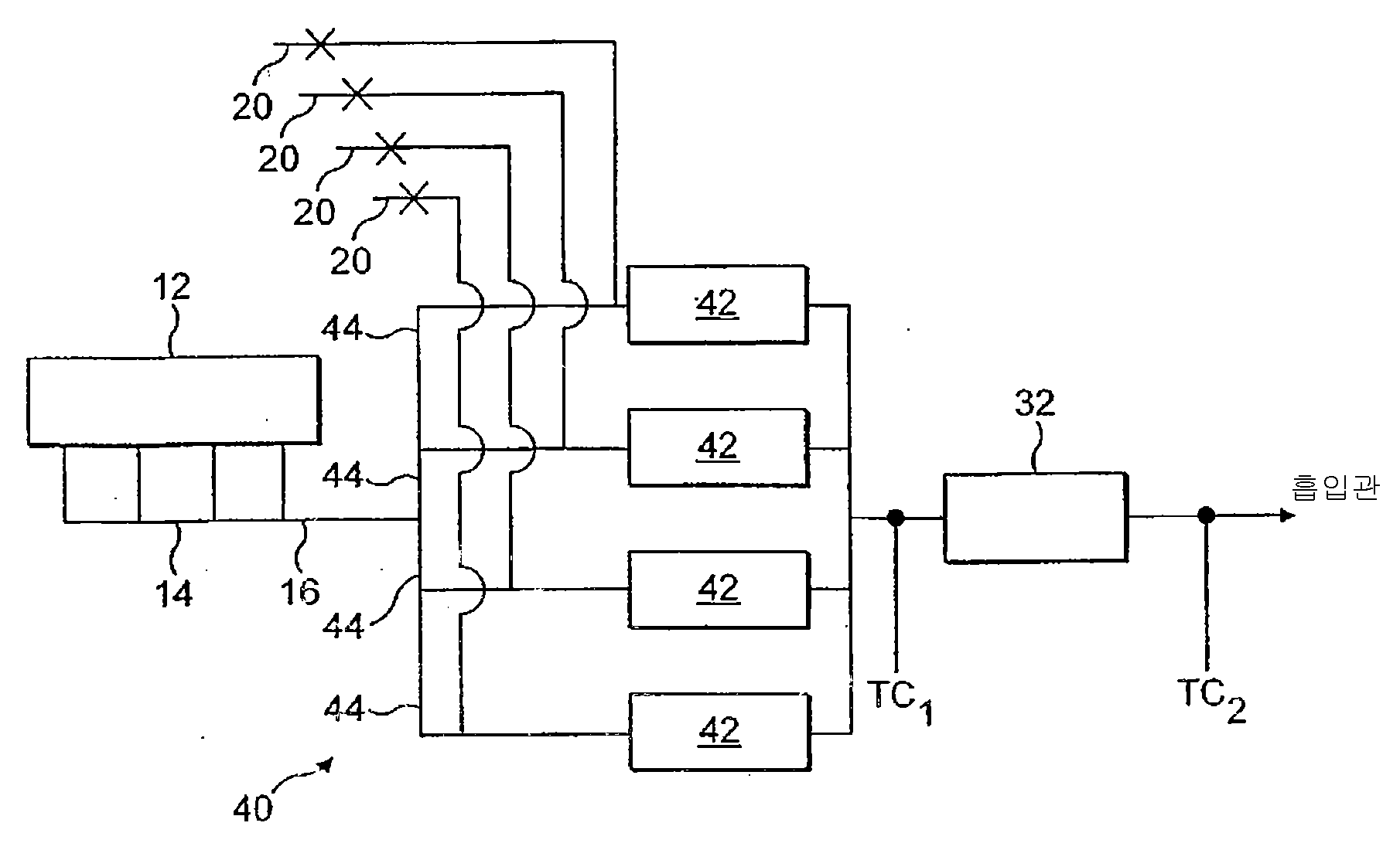
도 1에 도시된 제 1 실시예에서, 배기 시스템은, 평행하게 배열된 단일 모노리스 담체(42)(각각의 담체는 환원제 분사장치(20)와 관련되어 있다) 상에 배치된 복수의 NOX-흡수제; 및 작동시에, 복수의 NOX-흡수제가 배기가스 흐름에 일렬인 상태를 유지하면서, 평행한 담체의 적어도 하나를 액체 환원제 액적과 연속적으로 접촉시키기 위한 수단;을 포함한다. 각각의 NOX-트랩 상의 GHSV는 각 라인의 상대적인 배압에 의존하지만, 일반적으로 시스템은 각 라인에서 그 구성이 동일하도록 만들어질 것이며, 이 경우에 GHSV는 각 라인에서 실질적으로 동일할 것이다. 어떤 재생 기술에서, 시스템에서의 NOX-흡수제에서 NOX-흡수제 재생은 연속하여 이루어진다. 즉, 시스템 내에서의 모든 NOX-트랩을 빠져나오는 배기가스가 혼합될 경우에 그 조성물은 희박(즉, 람다 > 1)하도록, 어떠한 순간에서든 적어도 하나의 라인은 환원제가 분사되지 않는다. In the first embodiment shown in FIG. 1, the exhaust system comprises a plurality of NO x − disposed on a single monolithic carrier 42 (each carrier associated with a reducing agent injector 20) arranged in parallel. Absorbents; And in operation, means for continuously contacting at least one of the parallel carriers with the liquid reducing agent droplets while maintaining the plurality of NO X -absorbers in line with the exhaust stream. The GHSV on each NO X -trap depends on the relative back pressure of each line, but in general the system will be made such that the configuration is the same in each line, in which case the GHSV will be substantially the same in each line. In which reproduction technology, NO X in the system - in the NO X absorbent-absorbent regeneration is performed in series. That is, at any moment at least one line is not sprayed with a reducing agent such that the composition is lean (ie, lambda> 1) when the exhaust gases exiting all NO x -traps in the system are mixed.
도 2A 및 도 2B에 도시된 제 2 실시예에서, 적어도 하나의 담체의 상류 단은 유체 흐름 방향으로 적어도 두 개의 구역으로 나누어지고, 배기 시스템은, 작동시에, 적어도 하나의 담체가 전체적으로 배기가스 흐름에 일렬인 상태를 유지하면서, 적어도 두 개의 구역의 일부를 액체 환원제 액적과 연속적으로 접촉시키기 위한 수단을 포함하고 있다. 본 실시예의 장점은, 상기 배기 시스템을 포함하는 차량에 상기 시스템을 수용하기 위한 공간이, NOX-흡수제를 각각 포함하는 복수의 담체 모노리스를 포함하는 시스템의 경우보다, 더 적게 든다는데 있다. In the second embodiment shown in FIGS. 2A and 2B, the upstream end of the at least one carrier is divided into at least two zones in the fluid flow direction and the exhaust system, in operation, comprises at least one carrier as a whole exhaust gas. And means for continuously contacting at least a portion of the at least two zones with the liquid reducing agent droplets while maintaining in line with the flow. An advantage of this embodiment is that the space for accommodating the system in a vehicle comprising the exhaust system takes less space than in the case of a system comprising a plurality of carrier monoliths each comprising a NO X -absorbent.
도 3에 도시된 상기 제 2 실시예의 일 구성에서, 적어도 두 개의 구역의 일부를 액체 환원제 액적과 연속적으로 접촉시키기 위한 상기 수단은 담체의 상류 단에 배치되어 있는 플랩 밸브를 포함하고 있다. 플랩 밸브의 상류에 있는 단일의 분사장치는, 분사된 환원제의 대부분이 플랩 밸브의 작동에 의하여 특정 구역을 향하도록 하는 상태로 사용될 수 있다. 선택적으로, 플랩 밸브에 의하여 나누어진 각각의 구역은 그 자체의 분사장치와 관련될 수 있다. 환원제를 수용하는 상기 구역에서의 환원된 배기가스 흐름은 NOX 흡수제 재생을 촉진할 수 있으며, 플랩 밸브 작동에 의하여 영향을 받을 수 있다. In one configuration of the second embodiment shown in FIG. 3, the means for continuously contacting at least a portion of the two zones with the liquid reducing agent droplets comprises a flap valve disposed at an upstream end of the carrier. A single injector upstream of the flap valve may be used with most of the injected reducing agent directed to a particular zone by the operation of the flap valve. Optionally, each zone divided by the flap valve can be associated with its own injector. The reduced exhaust gas flow in the zone for receiving the reducing agent is to facilitate the playback NO X absorbent, it can be influenced by the flap valve.
제 1 또는 제 2 실시예의 배기 시스템은, 탄화수소 환원제가 대기로 불필요하게 빠져나가는 것을 막기 위하여 환원제 분사를 포지티브 피드백에 의해 제어하기 위한 수단을 포함할 수 있다. 제어 수단은, 각각의 NOX-흡수제 담체의 하류에 배치되어 있는 환원제를 산화시키기 위한 산화 촉매; 산화 촉매를 가로지르는 온도차(ΔT)를 측정하기 위한 수단; 작동시에, 액체 환원제 액적의 분사를 제어하기 위한 수단;을 포함하고 있다. 상기 환원제 액적 분사 제어수단은 ΔT를 소정의 범위 내로 유지하기 위하여 환원제 분사율을 제어하고, 배기 시스템은 산화 촉매 상의 배기가스 조성물이 희박하게 되도록 구성되어 있다. The exhaust system of the first or second embodiment may comprise means for controlling the reducing agent injection by positive feedback to prevent the hydrocarbon reducing agent from unnecessarily exiting into the atmosphere. The control means includes an oxidation catalyst for oxidizing a reducing agent disposed downstream of each NO x -absorbent carrier; Means for measuring a temperature difference ΔT across the oxidation catalyst; In operation, means for controlling the injection of the liquid reducing agent droplets. The reducing agent droplet injection control means controls the reducing agent injection rate in order to maintain ΔT within a predetermined range, and the exhaust system is configured such that the exhaust gas composition on the oxidation catalyst is lean.
환원제 분사를 제어하기 위한 수단을 포함하는 배기 시스템의 일 실시예에서, 환원제 분사율이 ΔT가 지나치게 클 경우에 감소된다. In one embodiment of the exhaust system comprising means for controlling the reducing agent injection, the reducing agent injection rate is reduced when ΔT is too large.
본 발명에서 사용되는 NOX-흡수제는, 적어도 하나의 알칼리금속, 알칼리토금속 또는 희토금속, 또는 이들 중 두 가지 이상의 혼합물을 포함할 수 있다. 적절한 알칼리금속은 포타슘 및 세슘으로 구성된 군으로부터 선택될 수 있다. 효과가 좋은 알칼리토금속은 마그네슘, 칼슘, 스트론튬 및 바륨으로 구성된 군으로부터 선택될 수 있다. 희토금속은 란탄 및 이트륨 중 하나 또는 양자 모두가 될 수 있다. The NO X -absorbent used in the present invention may include at least one alkali metal, alkaline earth metal or rare earth metal, or a mixture of two or more thereof. Suitable alkali metals can be selected from the group consisting of potassium and cesium. Alkaline earth metals with good effect can be selected from the group consisting of magnesium, calcium, strontium and barium. The rare earth metal can be one or both of lanthanum and yttrium.
실시예에서, NOX-흡수제는 일산화질소를 산화시키기 위한 촉매, 선택적으로는 백금 등의 백금족 금속을 포함할 수 있고, 또한, NOX-흡수제는 NOX를 N2로 환원시키기 위한 촉매, 예컨대 로듐을 더 포함할 수 있다. In an embodiment, the NO X -absorber may comprise a catalyst for oxidizing nitrogen monoxide, optionally a platinum group metal such as platinum, and the NO X -absorber may also be a catalyst for reducing NO X to N 2 , such as It may further comprise rhodium.
특정 실시예에서, 구동시에, NOX 환원 촉매가 활성화된 경우에만, 제어 수단이 환원제를 분사한다. In a particular embodiment, the sphere at the same time, the control means injects the reducing agent only when the NO X reduction catalyst is active.
다른 설명이 없는 한, 본 발명에서 사용되는 촉매는 금속이나 세라믹이나 탄화규소 물질, 예컨대 근청석으로 만들어진 담체 모노리스의 고 표면 영역 상에 코팅이 되어 있다. 공통적인 구성은 유체가 통과하는 벌집 모양의 모노리스 구조인데, 평방 인치 당 셀수(cpsi)로써 100-600 cpsi 정도이며, 예컨대 300-400 cpsi이다(15.5-93.0 cells cm-2, 예컨대 46.5-62.0 cells cm-2).Unless otherwise stated, the catalysts used in the present invention are coated on the high surface area of the carrier monolith made of metal or ceramic or silicon carbide material such as cordierite. A common configuration is a honeycomb monolithic structure through which fluids pass, ranging from 100-600 cpsi in cells per square inch (cpsi), for example 300-400 cpsi (15.5-93.0 cells cm -2 , for example 46.5-62.0 cells). cm -2 ).
입자 역학에 의하여, 액체 환원제 액적은 종래 유체가 통과가능한 세라믹 또는 금속 모노리스 담체를 통하여, 모노리스 담체의 벽에 유지되어 있는 NOX-흡수제에는 영향을 미치지 않고서, 통과할 수 있다. 환원제가 NOX-흡수제와 접촉할 가능성을 높이기 위하여, 일 실시예에서는 세라믹 또는 금속 폼을 포함하는 폼 담체가 사용된다. 대안적으로는, EP-A-1057519 또는 WO 03/038248에 개시되어 있는 것과 같은, 내연 배플을 포함하는 금속 부분 필터 담체(metallic partial filter substrates)를 사용할 수도 있다. 다른 실시예에 따르면, NOX-흡수제는 종래의 세라믹 벽 유동 필터를 포함하며, 여기서 종래 구동되는 압력 강하는 환원제 액적이 저장된 NOX와의 접촉을 보장하여야 한다. 후자의 실시예에서, PM의 효율적인 정화는 그 자체로는 중요하지 않으며, 따라서 다공성 필터가 사용될 수 있지만, JP-B-2722987(JP-A-06-159037)에 기재된 바와 같이 결합된 NOX 및 PM 제어가 바람직할 것이다. 즉, 필터는, 그을음 연소 촉매/NO 산화 촉매, 즉 Pt; 산화바륨 등의 NOX-흡수제; 및 선택적으로 NOX 환원제 촉매, 예컨대 로듐;을 포함한다. By particle dynamics, liquid reducing agent droplets can pass through a ceramic or metal monolithic carrier through which a conventional fluid can pass, without affecting the NO X -absorbent held on the wall of the monolithic carrier. In order to increase the likelihood of the reducing agent contacting the NO X -absorbent, in one embodiment a foam carrier comprising a ceramic or metal foam is used. Alternatively, metallic partial filter substrates comprising internal combustion baffles, such as those disclosed in EP-A-1057519 or WO 03/038248, may be used. According to another embodiment, the NO X -absorber comprises a conventional ceramic wall flow filter, where the conventionally driven pressure drop must ensure contact with the NO X stored in the reducing agent droplets. In the latter embodiment, efficient purification of the PM is not important on its own, so that a porous filter can be used, but combined NO X and as described in JP-B-2722987 (JP-A-06-159037). PM control would be preferred. That is, the filter may be a soot combustion catalyst / NO oxidation catalyst, ie Pt; NO x -absorbers such as barium oxide; And optionally a NO X reducing agent catalyst such as rhodium.
다른 실시예에서, 각각의 NOX-흡수제 담체 모노리스는 입사상 필터(particulate filter)를 포함한다. In another embodiment, each NO X -absorbent carrier monolith comprises a particulate filter.
산화 촉매가 종래의 유체통과가능한 모노리스에 코팅되고 환원제 분사장치 및 NOX-흡수제 담체 사이에 배치되는 경우에, 입자 역학에 따라 장점으로 작용할 수 있다. 모노리스의 셀 밀도 및 개방된 전방 영역에 따라, 환원제 액적이 실질적인 산화 없이 산화 촉매를 통하여 통과할 수 있으며, NOX-흡수제에서 저장된 NOX를 환원시키기 위하여 사용이 가능할 수 있다. 기화된 탄화수소 환원제, 즉 기체상태의 탄화수소는 산화 촉매 상에서 더 잘 산화될 것이다. When the oxidation catalyst is coated on a conventional fluid passable monolith and disposed between a reducing agent injector and a NO X -absorbent carrier, it can serve as an advantage depending on the particle dynamics. Depending on the cell density and the open front region of the monolith, have a reducing agent solution may be passed through the oxidation catalyst without substantial oxidation, NO X - may be possible to use in order to reduce the NO X stored in the absorbent. Vaporized hydrocarbon reducing agents, ie gaseous hydrocarbons, will be better oxidized on the oxidation catalyst.
개별 구성에서, 본 명세서에 기재되어 있는 환원제를 전달하기 위한 NOX 환원 촉매 및 시스템은, 전술한 EP-B-0341832에 기재되어 있는 구성의 하류에 배치되어 있다. In a separate configuration, the NO x reduction catalyst and system for delivering the reducing agent described herein are disposed downstream of the configuration described in EP-B-0341832.
본 발명의 제 2 양태에 따르면, 본 발명에 따른 배기 시스템을 포함하는 차량이 제공된다. According to a second aspect of the invention, there is provided a vehicle comprising an exhaust system according to the invention.
내연기관은 가솔린 직접 분사 엔진과 같은 린번 가솔린 엔진 또는 디젤 엔진일 수 있다. 디젤 엔진은 관련 법률에 따라 구분된 경량 엔진 또는 중량 엔진일 수 있다. The internal combustion engine may be a lean burn gasoline engine such as a gasoline direct injection engine or a diesel engine. Diesel engines may be light engines or heavy engines classified according to applicable law.
본 발명의 제 3 양태에 따르면, 린번 내연기관의 배기 시스템에서 단일 모노리스 담체 상에 배치되어 있는 NOX-흡수제를 재생하는 방법이 제공된다. 상기 방법은, NOX-흡수제를 액체 환원제 액적과 접촉시켜 제한적인 NOX의 환원을 발생시키는 단계를 포함하고 있다. According to a third aspect of the invention, there is provided a method for regenerating a NO x -absorbent disposed on a single monolithic carrier in an exhaust system of a lean burn internal combustion engine. The method, NO X - the absorbent liquid brought into contact with the enemy reducing agent solution also includes the step of generating the reduction of NO X restrictive.
일 실시예에 따라서, 배기 시스템은 평행하게 배열된 단일 모노리스 담체(42) 상에 배치된 복수의 NOX-흡수제를 포함하고, 상기 방법은, 복수의 NOX-흡수제가 배기가스 흐름에 일렬인 상태를 유지하면서, 평행한 담체의 적어도 하나를 액체 환원제 액적과 연속적으로 접촉시키는 단계를 포함하고 있다. According to one embodiment, the exhaust system comprises a plurality of NO x -absorbers disposed on a single
다른 실시예에서, 상기 방법은, 담체가 전체적으로 배기가스 흐름에 일렬인 상태를 유지하면서, 하나의 담체의 일부를 액체 환원제 액적과 연속적으로 접촉시키는 단계를 포함하고 있다. 하나의 담체의 일부가 환원제와 접촉되는 것은 환원된 배기가스 흐름에서 발생할 수 있다. In another embodiment, the method includes the step of continuously contacting a portion of one carrier with a liquid reducing agent droplet while maintaining the carrier in line with the exhaust stream as a whole. Contact of a portion of one carrier with a reducing agent can occur in a reduced exhaust gas stream.
개별 실시예에서, 상기 방법은, NOX-흡수제 담체의 하류에 배치된 산화 촉매 상에서 환원제를 산화시키는 단계; 산화 촉매의 입구 및 출구 온도 사이의 차이(ΔT)를 측정하는 단계; 및 ΔT가 소정의 범위 내에서 유지되도록 환원제 첨가율을 조절하는 단계;를 제공한다. In a separate embodiment, the method comprises oxidizing a reducing agent on an oxidation catalyst disposed downstream of the NO X -absorbent carrier; Measuring the difference ΔT between the inlet and outlet temperatures of the oxidation catalyst; And adjusting the reducing agent addition rate so that ΔT is maintained within a predetermined range.
바람직하게는, NOX-흡수제는 NOX를 N2로 환원시키기 위한 촉매를 포함하고, 상기 방법은, NOX 환원의 촉매작용을 하기 위하여 NOX 환원 촉매가 활성화된 경우에만 각각의 NOX-흡수제 담체를 액체 환원제 액적과 접촉시키는 단계를 포함하고 있다. Preferably, NO X-absorbing agent the method comprising: a catalyst for the reduction of NO X to N 2 is, only the respective NO X when the NO X reduction catalyst active to catalyze the NO X reduction - Contacting the absorbent carrier with the liquid reducing agent droplets.
도 1은 본 발명에 따른 배기 시스템의 일 실시예를 나타내는 개요도이다. 1 is a schematic diagram showing an embodiment of an exhaust system according to the present invention.
도 2A는 담체의 상류 단에서 다중의 환원제 분사장치의 분사 구역 및 분사 지점을 표시하는 단일 담체 모노리스를 포함하는 NOX-트랩의 정면도를 나타내는 본 발명에 따른 배기 시스템의 다른 실시예를 나타내는 개요도이다. 2A is a schematic diagram showing another embodiment of an exhaust system according to the present invention showing a front view of a NO X -trap comprising a single carrier monolith indicating the injection zones and injection points of multiple reducing agent injectors at an upstream end of the carrier; .
도 2B는 도 2A에 도시되어 있는 단일 담체 모노리스의 개략적인 측면도이다. FIG. 2B is a schematic side view of the single carrier monolith shown in FIG. 2A.
도 3은 디젤엔진의 배기가스의 처리에 사용되는 그을음 연소 리액터와 함께 NOX-트랩을 포함하는, 본 발명에 따른 다른 배기 시스템에 관한 실시예를 나타내는 개략적인 단면도이다 FIG. 3 is a schematic cross-sectional view showing an embodiment of another exhaust system according to the invention, comprising a NO X -trap with a soot combustion reactor used for the treatment of the exhaust gas of a diesel engine.
도 4는 본 발명의 배기 시스템이 작동하는 실시예를 나타내는 개요도이다. 4 is a schematic diagram showing an embodiment in which the exhaust system of the present invention operates.
도 5는 도 4의 실시예에서 상류의 공기/연료비(AFR)를 도로 속도의 함수로서 나타내는 그래프이다. FIG. 5 is a graph showing the upstream air / fuel ratio (AFR) as a function of road speed in the embodiment of FIG. 4.
도 6은 도 4의 실시예에 대하여 아이들 상태에서 NOX 측정을 나타내는 그래프이다. FIG. 6 is a graph illustrating NO x measurement in an idle state with respect to the embodiment of FIG. 4. FIG.
도 7은 도 6에 도시된 자취에 대하여 아이들 상태에서 상응하는 시스템 온도를 나타내는 그래프이다. FIG. 7 is a graph showing the corresponding system temperature in the idle state for the trace shown in FIG. 6.
도 8은 도 4의 실시예에 대하여 40mph에서의 NOX 측정을 나타내는 그래프이다. FIG. 8 is a graph showing NO x measurements at 40 mph for the example of FIG. 4. FIG.
도 9는 도 8에 도시된 자취에 대하여 40mph에서의 상응하는 온도 측정을 나타내는 그래프이다. FIG. 9 is a graph showing the corresponding temperature measurement at 40 mph for the trace shown in FIG. 8.
도 10은 도 4의 시스템에 대하여 NOX 변환을 도로 속도의 함수로서 나타내는 그래프이다. FIG. 10 is a graph showing NO x conversion as a function of road speed for the system of FIG. 4.
이하, 본 발명에 대한 깊은 이해를 위해서, 첨부된 도면을 참조하여 본 발명의 실시예를 설명한다. Hereinafter, embodiments of the present invention will be described with reference to the accompanying drawings for a deep understanding of the present invention.
본 발명에 따른 배기시스템(40)이 도 1에 도시되어 있다. 참조번호 12는 디젤엔진을 나타내고, 14는 배기 매니폴드, 16은 배기라인, 42는 다중의 NOX-트랩 촉매를 나타낸다. 다중의 NOX-트랩 촉매는, 담체 모노리스(substrate monolith) 상의 알루미나 중간층(washcoat) 위에 유지되고 평행한 배기라인(44)에 배열되어 있는 Pt/Rh 및 BaO를 포함한다. 각각의 배기라인은, NOX-트랩 촉매(42)의 상류의 배기라인(16)으로 다량의 디젤연료를 분사하기 위한 분사장치를 포함하는 각각의 환원제 공급수단(20)을 가지고 있다. 산화 촉매(32)(예컨대, 감마 알루미나 중간층에 유지되는 1 wt%의 백금)는 배기라인(44)의 하류 합류지점의 하류에 위치한다. 열전대(TC1)는 TC1로의 입구에서 배기가스의 온도를 검출하고, 제 2 열전대(TC2)는 산화 촉매(32)의 하류에 위치하여 TC2로의 출구에서 배기가스의 온도를 검출한다. TC1 및 TC2는 검출된 온도를 엔진 제어 유닛(ECU, 도면에 미도시)의 프로세서에 중계한다. An
작동시에, 시스템은 가스가 산화 촉매(32) 상에서 항상 희박(lean)하게 되도록 하는 방식으로 작동된다. 예를 들어, 어느 때나 적어도 하나의 라인은 환원제가 분사되지 않도록 하고 있고, 따라서 전체 NOX-트랩(42) 출구 가스 흐름이 혼합될 때, 혼합된 가스는 하류의 산화 촉매(32) 상을 통과하기 전에 전체적으로 희박하다. NOX-트랩 촉매가 NOX 환원의 촉매반응을 일으키기 위한 활성개시온도(light-off temperature) 아래에 있는 일정한 임계 배기가스 온도 아래에서, 환원제는 분사되지 않는다. 상기 온도 위에서, 환원제의 양이 증가함에 따라 환원될 배기가스에서의 NOX의 양이 증가한다. 약간의 초과한 환원제 슬립(slip)이 산화 촉매(32) 상에서 산화되고, 그 결과 발생되는 발열은 촉매를 지나면서 온도 상승을 야기한다. 이러한 온도 상승은 TC2 및 TC1에서 검출된 온도의 차이, 즉 ΔT = TC2 - TC1로 측정된다. 측정된 ΔT를 최적의 NOX 제거에 실질적으로 상응하는 소정의 값으로 유지하기 위하여 환원제의 첨가 비율을 조정하는 것이 제어 전략이다. 환원제의 흐름은 ΔT가 지나치게 작으면 증가되고, ΔT가 최적의 효율적인 NOX 변환을 위하여 요구되는 것보다 크면 감소된다. In operation, the system is operated in such a way that the gas is always lean on the
다른 실시예가 도 2A 및 도 2B에 도시되어 있다. 도 1의 실시예에서의 복수의 평행한 NOX-트랩(42)은 하나의 단일 NOX-트랩(42A)로 교체되고, 3 개의 환원제 공급수단(20)이 NOX-트랩 담체 모노리스의 상류 단에 동일 간격으로 배치되어 담체 모노리스의 전면에서 병치된 구역(45) 상으로 환원제 스프레이를 배향한다. 병치된 구역(45)의 중심은 분사점(46)에 의해 한정된다. 이러한 구성은, 두 개 이상의 환원제 분사장치를 구비한 더 큰 하나의 단일 NOX-트랩 담체 모노리스를 사용한다는 점을 제외하고는, 도 1에 도시한 실시예의 경우와 비교할 때 전체적으로 동일한 효 과를 나타낸다. 분사장치는 순차적인 방식으로 작동될 수 있으므로, 어느 때에나 NOX-트랩의 일부분만이 재생되게 되고, 상기 일부분으로부터의 출구가스는 재생되지 않은 다른 부분으로부터의 배기가스와 혼합되어, 촉매(32) 상에서의 산화를 위한 전체적으로 희박한 가스 흐름을 제공하게 된다. Another embodiment is shown in FIGS. 2A and 2B. The plurality of parallel NO x -
도 3은 또 다른 실시예를 도시하고 있다. 배기가스 후처리 시스템(80)은 그을음 연소 리액터(120)을 포함하고 있다. 그을음 연소 리액터(120)의 입구는 디젤 엔진(도면에 미도시)의 배기 매니폴드에 연결되어 있다. 리액터(120)는 그 상류 부분에, 알루미나 기반의 중간층 및 Pt를 보유하고 있는 세라믹 벌집으로 구성되어 있는 산화 촉매(122)를 포함하고 있다. 리액터(120)의 하류 부분에는 벽 유동 필터(124)를 포함하고 있는데, 벽 유동 필터는 필터급의 세라믹 벌집으로 구성되어 있다. 그 통로는 입구 단에서 선택적으로 플러그(plug)되거나 언플러그(unplug)될 수 있으며, 출구 단에서 선택적으로 플러그될 수 있다. 입구 단에서 플러그된 통로는 출구 단에서 언플러그되며, 그 역도 성립한다. 하류 필터 상에서 PM의 연소를 위하여 NO를 NO2로 산화시키기 위한 산화 촉매의 구성은 EP-B-0341832에 기재되어 있으며, 그러한 구성은 CRT®로서 알려져 있다. 리액터(120)의 출구 단으로부터, 플리넘(126)은 NOX-트랩 용기(130)의 입구에서 플랩 밸브(128X, Y, Z)의 작동 챔버로서 계속된다. 용기(130)는, 산화바륨 및 금속 Pt 및 Rh를 포함하는 알루미나 중간층을 보유하고 있는 유체통과가능한 세라믹 벌집 모노리스 담체로 구성되어 있는 NOX-트랩(131X, Y)을 포함한다. 플랩 밸브(128X, Y, Z)는, 리액터(130)의 표면을 가로질러 직경방향으로 뻗어 있으며 NOX-트랩(131)의 표면에 가스가 통하지 않도록 밀봉되어 있다. 밸브(128)의 리액터(130)의 각 측면의 각각의 구역(X, Y)에는 환원제 분사장치(132X, Y)가 구비되어 있다. 도시된 바와 같은 완성된 리액터(130)에서, 밸브(128)는 중심위치(Z)에 있다. 밸브 위치(X, Y)가 삽입화로서 도시되어 있다. 리액터(130)에는, 대기 또는 이후의 처리를 향하여 안내하는 출구(134)가 형성되어 있다. 바람직하게는, 도 1에 도시되어 있는 구성에서, 리액터(130)의 두 개로 구분된 반쪽에서의 유량은 순 희박 조성물을 제공하도록 제어되고, 혼합물은 산화 촉매를 거쳐 통과된다. 3 shows another embodiment. The
시스템의 정상 작동 중에, 증기(H2O(g)), 질소분자(N2), 산소(O2), 이산화탄소(CO2), 불연소(unburned) 탄화수소(HC), 일산화탄소(CO), 질소산화물(NOX) 및 입사상물질(PM)을 포함하는 배기가스는 예컨대 300℃에서 촉매(122)와 접촉하여, NO가 NO2로 산화되고, HC 및 CO의 일부가 증기 및 CO2로 산화된다. 그 후, 필터(124)로 들어가서, 대부분의 PM이 수집되고 촉매(122)에서 형성된 NO2와 반응함으로써 연소되고, O2와 반응하여 연소될 수도 있다. PM이 제거된 가스는 다음 세 가지 모드 중 하나에서 처리된다:During normal operation of the system, steam (H 2 O (g)), nitrogen molecules (N 2 ), oxygen (O 2 ), carbon dioxide (CO 2 ), unburned hydrocarbons (HC), carbon monoxide (CO), Exhaust gases comprising nitrogen oxides (NO X ) and incident phase materials (PM) are in contact with
128Z: NOX-트랩 구역(130X, 130Y) 모두 NOX를 흡수한다.128Z: Both the NO X -trap zones 130X, 130Y absorb NO X.
128X: 구역(131X)이 플리넘(126)을 떠난 가스의 극히 일부 및 132X에서의 디 젤 연료 분사를 수용한다. 이는 재생을 거치게 되고, 유출액은 구역(130Y)의 것과 재결합된다. 구역(131Y)는 가스의 대부분을 수용하고, NOX를 흡수하며, 134에서 유출액을 대기로 통과시킨다. 128X:
128Y: 구역(131Y)는 128X에서 설명한 과정을 수행한다. 128Y:
엔진 처리 시스템(도면에 미도시)은 NOX-트랩(131Y)이 NOX를 흡수할 수 있는 빈 용적을 가질 경우에 구역(X)에서 구역(Y)으로 변경되고, 그 역의 경우도 성립한다. Engine treatment system (not shown in the figure) is NO X - is changed to a trap (131Y) empty case have a volume in the zone (X) zone (Y) in that is absorbs NO X, also holds for the station do.
(실시예)(Example)
이하의 실시예는 단지 예시에 불과하다. The following examples are merely illustrative.
6리터 터보차저 엔진에 적합하고 European Stage 1 배기제한을 만족하는 타입의 엔진 터보(52)를 포함하는 단층 버스의 배기 시스템(50)(도 4 참조)이, 배기가스를 세 개의 평행 레그(56) 중 하나로 전환시키기 위한 삼원(3-way) 스플리터(54)를 포함하도록 변형되어 있다. 각각의 레그에서 배기가스는 동일한 속도로 흐른다. 각각의 레그(56)는 NOX-트랩(62)이 후속하는 산화 촉매(60)을 포함하는 챔버(58)를 포함한다. 가스 흐름은 NOX-트랩의 하류에서 합쳐지고, 배기가스가 곧바로 대기 중으로 통과하기 전에 NOX-트랩에서 나오는 불연소 탄화수소(HC)를 제거하기 위하여 총 배기가스 흐름이 "클린 업(clean up)" 산화 촉매(64)를 거쳐 통과된다. 연료 솔레노이드(68)를 포함하는 연료 분사장치(66)는 각각의 산화 촉매(60) 앞에 배치되어 있고, NOX 센서(69)는 배기 스플리터(54) 앞에 배치되어 있으며, 결합된 NOX/공기 연료비 센서(70)는 NOX-트랩 뒤에 배치되어 있으며, 온도를 측정하는 열전대(T1, T2, T3, T4)는 산화 촉매(60)의 전후 및 리액터 출구에 배치되어 있다. 산화 촉매(60) 및 NOX-트랩(62)은 각각 400셀 in-2 (62셀 cm-2) 및 0.06in (0.15mm) 벽 두께로 세라믹 유체통과 모노리스 상에 코팅되어 있다. 산화 촉매(60)는 직경이 5.66in(144mm)이고 길이가 3in(76mm)이며, 체적은 75.5in3(1.24리터)이다. NOX-트랩(62)의 직경은 산화 촉매(60)의 직경과 동일하지만 길이가 6in(152mm)이다. "클린 업" 촉매(64)는 10.5in(267mm)의 직경, 3in(76mm)의 길이, 260in3(4.26리터)의 체적을 가지고 있다. A single-floor bus exhaust system 50 (see FIG. 4) comprising an
본 실시예에서 설명하고 있는 실험은 배기 스플리트 중 하나의 레그 만을 사용하여 수행된다. 본 차량은 50ppm의 황을 포함하는 디젤 연료를 사용하여 구동되고, 작동 시간 동안 10, 20, 30 및 40 mph의 일정한 아이들 속도에서 구동된다. 연료는 도 5에 도시된 바와 같이 결정된 분사 중 공연비로 각각의 지점에서 분사된다. 시간 및 지속시간의 조합(2초 분사, 레그 당 1분 당 한번)은, 배기가스 온도(동적 온도 윈도우 내에서 NOX-트랩을 유지하기 위한 온도) 및 NOX 변환 사이의 최적의 조합을 달성하도록 경험적으로 선택된다. 동시에, 온도 프로파일과 함께 시스템의 사전 및 사후의 NOX-배출이 측정된다. The experiment described in this embodiment is performed using only one leg of the exhaust split. The vehicle is driven using diesel fuel containing 50 ppm of sulfur and is driven at constant idling speeds of 10, 20, 30 and 40 mph during operation. Fuel is injected at each point with the air-fuel ratio during the injection determined as shown in FIG. The combination of time and duration (two-second injection, once per minute per leg) determines the exhaust gas temperature (temperature to maintain the NO X -trap within the dynamic temperature window) and NO X. Empirically selected to achieve the best combination between transforms. At the same time, the NO x -emissions before and after the system together with the temperature profile are measured.
도 5에서, 구형파는 분사장치 뒤와 촉매의 전면 앞에서 이상적인 공기/연료비를 나타낸다. 배기가스는 정상적으로는 희박상태이지만, 분사 중에 순간적으로 과잉(rich)되게 된다. 도로 속도의 함수로서 산출된 '과잉' 공기/연료비(분사된 연료 체적, 배기 화학량론 및 배기 유량에 기초한다)가 곡선으로 표현된다. 화학량적인 공기/연료비가 14.7:1이라면, 분사장치는 약 6mph보다 빠른 속도에서 완전한 과잉 혼합을 생성할 수 없다는 것이 발견되었다. 이하 도면에서 사용되는 측정된 공기/연료비는 후-NOX-트랩 센서로부터 취해진다. 촉매 시스템 내부에서의 화학적 운동 및 흡수 때문에, 윤곽이 뚜렷한 구형파가 이루어지지 않는다. In FIG. 5, the square wave represents the ideal air / fuel ratio behind the injector and in front of the catalyst. The exhaust gas is normally lean, but momentarily becomes rich during injection. The 'excess' air / fuel ratio (based on injected fuel volume, exhaust stoichiometry and exhaust flow rate), calculated as a function of road speed, is represented by the curve. If the stoichiometric air / fuel ratio is 14.7: 1, it has been found that the injector cannot produce complete excess mixing at speeds faster than about 6 mph. The measured air / fuel ratio used in the figures below is taken from the post-NO X -trap sensor. Because of the chemical motion and absorption inside the catalyst system, no contoured square wave is achieved.
도 6은 엔진으로부터의 NOX 배기(ppm), 및 NOX-트랩 후에 측정된 공연비와 함께 아이들 상태 동안에 NOX-트랩 후의 NOX 배기(ppm)를 나타낸다. 도 7은 같은 시간 동안에 온도 자취를 나타낸다. 도 6에서, 아이들 시간이 시작되는 순간 연료가 분사되면, 공연비는 도 5에서의 예상으로부터 예견되는 바와 같이 희박상태에서 과잉상태로 떨어지는 것을 관찰할 수 있으며, 초기 NOX 돌파 후에는 양호한 NOX 변환이 관찰된다. 시간에 따라, 공연비는 분사 작동 전체에서 희박한 상태를 유지하지만, 양호한 NOX 변환이 계속 유지된다. 산화 촉매를 걸쳐 발생되는 발열(T2)은 NOX-트랩의 온도가 220-550℃의 작동 윈도우 사이에서 유지될 수 있도록 한다. 또한, 발열(T3)은 NOX-트랩을 가로질러 기록되는데, 이들 중 일부는 산화 촉매로부터 반응하지 않은 기체 환원제가 연소됨에 따라 발생된다. 이러한 결과는, 엔진 아이 들 상태에서 시간이 경과함에 따라 NOX-트랩의 표면에서 반응하는 불연소된 연료 액적의 연소로부터 상기 발열 중 일부가 발생한다는 것을 의미한다고 해석된다. 이것은, 시스템 입구 온도가 떨어져서 유입되는 연료를 기화시키기에 불충분하기 때문이고, 또한, 일련의 침전, 기화 및 이에 따른 연료 액적의 순차적인 산화를 표시하면서, 후방 센서로 측정된 공기/연료비 피크(spike)가 정확하게 표시되지 않고 더욱 둥글게 되기 때문이다. 이렇게 야기된 일부의 과잉 역시 관찰되는 NOX-트랩 작동 효율을 유지하는 역할을 한다. 6 is NO x from the engine. Exhaust (ppm), and NO X - During the idle state with the air-fuel ratio measured after the NO X trap - trap after the NO X Exhaust (ppm). 7 shows temperature traces during the same time. In FIG. 6, once fuel is injected at the start of idle time, the air-fuel ratio can be observed to fall from lean to excess as predicted from the expectation in FIG. 5, with good NO X conversion after initial NO X breakthrough. This is observed. Over time, the air-fuel ratio remains sparse throughout the injection operation, but good NO X conversion remains. The exotherm T2 generated over the oxidation catalyst allows the temperature of the NO X -trap to be maintained between operating windows of 220-550 ° C. In addition, the exotherm T3 is recorded across the NO x -trap, some of which are generated as the unreacted gas reducing agent is burned from the oxidation catalyst. These results are interpreted to mean that some of the exotherm arises from the combustion of unburned fuel droplets that react on the surface of the NO X -trap over time in the engine idle state. This is because the system inlet temperature is insufficient to vaporize the incoming fuel, and also the air / fuel ratio peak measured by the rear sensor, indicating a series of settling, vaporization and thus sequential oxidation of the fuel droplets. ) Is not displayed correctly and becomes rounder. Some of the excess thus caused also serves to maintain the observed NO x -trap operating efficiency.
40mph의 일정한 속도로 유지되는 버스로 시험한 결과가 도 8 및 도 9에 도시되어 있다. 여기서 배기 유량은 더 높지만, 아이들 상태에서 동일한 분사 유량이 사용되며, 배기는 분사 시간(도 5 참조) 전체에서 희박한 상태에 있을 것이 요구된다. 그러나, 연료가 처음으로 분사될 때 돌파 피크(breakthrough spike)와는 별도로, 아이들 상태에서만큼 효율적이지는 않지만 NOX가 남은 작동시간에 걸쳐 감소된다. 발열(T2) 위의 발열(T3)은 때때로 아이들 상태의 경우보다 낮지만, 배기가스의 증가된 유량의 열용량 때문에, 이는 매우 중요하다. 그러므로, 발열 반응이 여전히 일어나고 있으며, 또한 이와 같은 현상은 불연소 연료 액적의 일부가 산화 촉매를 통하여 운반되어 NOX-트랩 상에서 연소되기 때문이라고 생각된다. 산화 촉매의 높은 입구 온도에도 불구하고 연료 액적이 지속될 것이라고 예상되는데, 이는 NOX-트랩을 거쳐 측정된 현저한 발열 및 명백하게 희박한 상태에서 관찰된 트랩 재 생에 의해 나타나는 바와 같이, 더 많은 배기 유량이 산화 촉매를 통하여 액적을 운반할 것이기 때문이다. Results of testing with a bus maintained at a constant speed of 40 mph are shown in FIGS. 8 and 9. The exhaust flow rate is higher here, but the same injection flow rate is used in the idle state, and the exhaust is required to be in a lean state throughout the injection time (see FIG. 5). However, apart from the breakthrough spike when the fuel is first injected, NO X is reduced over the remaining operating time, although not as efficient as in the idle state. The exotherm T3 above the exothermic T2 is sometimes lower than in the idle state, but because of the increased heat capacity of the exhaust gas, this is very important. Therefore, an exothermic reaction is still taking place, and it is also believed that this phenomenon is because some of the unburned fuel droplets are carried through the oxidation catalyst and burned on the NO X -trap. It is expected that fuel droplets will persist despite the high inlet temperature of the oxidation catalyst, as more exhaust flow rates are oxidized, as indicated by the marked exotherm measured through the NO X -trap and the trap regeneration observed in the apparently sparse state. This is because the droplets will be transported through the catalyst.
도 10은 시스템에 대하여 산출된 평균 NOX 변환 효율의 경향을 속도의 함수로 나타낸 것이다. 도 5는 약 6mph 위에서 과잉 배기가스 상태가 발생하지는 않으며, 넓은 속도 범위에 걸쳐 희박상태에서 양호한 NOX 변환을 얻을 수 있음을 나타낸다. 이것은 아이들 상태로부터 30mph의 범위(도시형 버스에서 가장 일반적인 작동 범위에 해당한다)에서 특히 적절하다. FIG. 10 shows the trend in average NO x conversion efficiency calculated for the system as a function of speed. FIG. 5 shows that excess exhaust gas does not occur above about 6 mph, and a good NO X conversion can be obtained in lean state over a wide speed range. This is particularly relevant in the range of 30 mph from idle (which is the most common operating range for urban buses).
Claims (26)
Priority Applications (1)
| Application Number | Priority Date | Filing Date | Title |
|---|---|---|---|
| KR1020067026663A KR20070021266A (en) | 2004-06-18 | 2005-06-16 | METHODS OF REGENERATING A NOx ABSORBENT |
Applications Claiming Priority (3)
| Application Number | Priority Date | Filing Date | Title |
|---|---|---|---|
| GBPCT/GB2004/002643 | 2004-06-18 | ||
| GB0428291.9 | 2004-12-24 | ||
| KR1020067026663A KR20070021266A (en) | 2004-06-18 | 2005-06-16 | METHODS OF REGENERATING A NOx ABSORBENT |
Publications (1)
| Publication Number | Publication Date |
|---|---|
| KR20070021266A true KR20070021266A (en) | 2007-02-22 |
Family
ID=43653382
Family Applications (1)
| Application Number | Title | Priority Date | Filing Date |
|---|---|---|---|
| KR1020067026663A Withdrawn KR20070021266A (en) | 2004-06-18 | 2005-06-16 | METHODS OF REGENERATING A NOx ABSORBENT |
Country Status (1)
| Country | Link |
|---|---|
| KR (1) | KR20070021266A (en) |
Cited By (2)
| Publication number | Priority date | Publication date | Assignee | Title |
|---|---|---|---|---|
| KR101416410B1 (en) * | 2012-12-31 | 2014-07-08 | 기아자동차 주식회사 | Urea injection control system for vehicle and method thereof |
| KR101525302B1 (en) * | 2013-05-29 | 2015-06-02 | 두산엔진주식회사 | Selective catalytic reuction system and method of regenerating catalyst for selective catalytic reuction |
-
2005
- 2005-06-16 KR KR1020067026663A patent/KR20070021266A/en not_active Withdrawn
Cited By (2)
| Publication number | Priority date | Publication date | Assignee | Title |
|---|---|---|---|---|
| KR101416410B1 (en) * | 2012-12-31 | 2014-07-08 | 기아자동차 주식회사 | Urea injection control system for vehicle and method thereof |
| KR101525302B1 (en) * | 2013-05-29 | 2015-06-02 | 두산엔진주식회사 | Selective catalytic reuction system and method of regenerating catalyst for selective catalytic reuction |
Similar Documents
| Publication | Publication Date | Title |
|---|---|---|
| KR101060125B1 (en) | Exhaust system for lean burn IC engines | |
| US7240483B2 (en) | Pre-combustors for internal combustion engines and systems and methods therefor | |
| US7735313B2 (en) | Method of raising temperature in exhaust-gas purifier and exhaust-gas purification system | |
| KR20050115274A (en) | Exhaust system for lean burn ic engine including particulate filter and nox absorbent | |
| JP4263711B2 (en) | Exhaust gas purification device for internal combustion engine | |
| KR20070084469A (en) | Exhaust Systems Including Exothermic Producing Catalysts | |
| KR20010075708A (en) | STAGED REDUCTANT INJECTION FOR IMPROVED NOx REDUCTION | |
| KR20060069355A (en) | Methods of controlling reductant addition | |
| EP2222388A1 (en) | Denox of diesel engine exhaust gases using a temperature-controlled precatalyst for providing no2 in accordance with the requirements | |
| JP2002021544A (en) | Method for removing nitrogen oxides and carbon black particles from lean exhaust gas of an internal combustion engine and exhaust gas purification apparatus | |
| KR20140105568A (en) | Automotive catalytic aftertreatment system | |
| JP4270224B2 (en) | Exhaust gas purification device for internal combustion engine | |
| US20060179822A1 (en) | Systems and methods for reducing emissions of internal combustion engines using a fuel processor bypass | |
| WO2003037507A1 (en) | Exhaust line for an internal combustion engine | |
| KR20070021266A (en) | METHODS OF REGENERATING A NOx ABSORBENT | |
| US20080261801A1 (en) | Methods of Regenerating a Nox Absorbent | |
| CN101014756A (en) | Methods of regenerating a nox absorbent | |
| KR101091633B1 (en) | Denitrification catalyst and exhaust system using the same | |
| JP2006207549A (en) | Method for raising temperature of exhaust gas purification device and exhaust gas purification system | |
| JP4162238B2 (en) | Exhaust purification member regeneration method and exhaust purification member regeneration device | |
| JP2008502844A (en) | NOx absorbent recycling method | |
| JP4877574B2 (en) | Exhaust gas purification device for internal combustion engine | |
| HK1108013A (en) | Methods of regenerating a nox absorbent | |
| MXPA06014739A (en) | Reductant addition in exhaust system comprising nox. | |
| KR20070020138A (en) | Reductant Addition in Exhaust Systems Containing NOX-Absorbers |
Legal Events
| Date | Code | Title | Description |
|---|---|---|---|
| PA0105 | International application |
Patent event date: 20061218 Patent event code: PA01051R01D Comment text: International Patent Application |
|
| PG1501 | Laying open of application | ||
| PC1203 | Withdrawal of no request for examination | ||
| WITN | Application deemed withdrawn, e.g. because no request for examination was filed or no examination fee was paid |