KR20060048624A - Context Recognition Method and Device Using Optical Information - Google Patents
Context Recognition Method and Device Using Optical Information Download PDFInfo
- Publication number
- KR20060048624A KR20060048624A KR1020050056324A KR20050056324A KR20060048624A KR 20060048624 A KR20060048624 A KR 20060048624A KR 1020050056324 A KR1020050056324 A KR 1020050056324A KR 20050056324 A KR20050056324 A KR 20050056324A KR 20060048624 A KR20060048624 A KR 20060048624A
- Authority
- KR
- South Korea
- Prior art keywords
- optical information
- difference
- matching
- stored
- situation
- Prior art date
- Legal status (The legal status is an assumption and is not a legal conclusion. Google has not performed a legal analysis and makes no representation as to the accuracy of the status listed.)
- Abandoned
Links
Images


Classifications
-
- G—PHYSICS
- G06—COMPUTING OR CALCULATING; COUNTING
- G06T—IMAGE DATA PROCESSING OR GENERATION, IN GENERAL
- G06T7/00—Image analysis
-
- G—PHYSICS
- G06—COMPUTING OR CALCULATING; COUNTING
- G06V—IMAGE OR VIDEO RECOGNITION OR UNDERSTANDING
- G06V40/00—Recognition of biometric, human-related or animal-related patterns in image or video data
- G06V40/20—Movements or behaviour, e.g. gesture recognition
-
- G—PHYSICS
- G06—COMPUTING OR CALCULATING; COUNTING
- G06F—ELECTRIC DIGITAL DATA PROCESSING
- G06F18/00—Pattern recognition
- G06F18/20—Analysing
- G06F18/29—Graphical models, e.g. Bayesian networks
- G06F18/295—Markov models or related models, e.g. semi-Markov models; Markov random fields; Networks embedding Markov models
-
- G—PHYSICS
- G06—COMPUTING OR CALCULATING; COUNTING
- G06V—IMAGE OR VIDEO RECOGNITION OR UNDERSTANDING
- G06V10/00—Arrangements for image or video recognition or understanding
- G06V10/10—Image acquisition
-
- G—PHYSICS
- G06—COMPUTING OR CALCULATING; COUNTING
- G06V—IMAGE OR VIDEO RECOGNITION OR UNDERSTANDING
- G06V10/00—Arrangements for image or video recognition or understanding
- G06V10/70—Arrangements for image or video recognition or understanding using pattern recognition or machine learning
- G06V10/84—Arrangements for image or video recognition or understanding using pattern recognition or machine learning using probabilistic graphical models from image or video features, e.g. Markov models or Bayesian networks
- G06V10/85—Markov-related models; Markov random fields
-
- G—PHYSICS
- G06—COMPUTING OR CALCULATING; COUNTING
- G06V—IMAGE OR VIDEO RECOGNITION OR UNDERSTANDING
- G06V20/00—Scenes; Scene-specific elements
Landscapes
- Engineering & Computer Science (AREA)
- Theoretical Computer Science (AREA)
- Physics & Mathematics (AREA)
- General Physics & Mathematics (AREA)
- Computer Vision & Pattern Recognition (AREA)
- Multimedia (AREA)
- Software Systems (AREA)
- Health & Medical Sciences (AREA)
- Data Mining & Analysis (AREA)
- Artificial Intelligence (AREA)
- Evolutionary Computation (AREA)
- General Health & Medical Sciences (AREA)
- Psychiatry (AREA)
- Life Sciences & Earth Sciences (AREA)
- Medical Informatics (AREA)
- Databases & Information Systems (AREA)
- Social Psychology (AREA)
- Human Computer Interaction (AREA)
- Computing Systems (AREA)
- Probability & Statistics with Applications (AREA)
- Bioinformatics & Cheminformatics (AREA)
- Bioinformatics & Computational Biology (AREA)
- Evolutionary Biology (AREA)
- General Engineering & Computer Science (AREA)
- Image Analysis (AREA)
- Optical Recording Or Reproduction (AREA)
- Signal Processing For Digital Recording And Reproducing (AREA)
Abstract
상황 인식 장치는 광학 정보를 취득하는 광학 정보 취득부와, 복수의 광학 정보를 저장하는 기억부와, 상기 기억부에 저장되어 있는 복수의 광학 정보와 상기 광학 정보 취득부에 의해 새로 취득된 광학 정보와의 매칭을 행하는 처리부와, 상기 매칭의 결과를 출력하는 출력부를 구비한다. 상기 기억부는, 또한 상기 복수의 광학 정보의 변화를 수치화한 확률 모델을 저장한다.The situation recognition device includes an optical information acquisition unit for acquiring optical information, a storage unit for storing a plurality of optical information, a plurality of optical information stored in the storage unit, and optical information newly acquired by the optical information acquisition unit. And a processing unit for matching with each other, and an output unit for outputting the result of the matching. The storage section also stores a probability model that numerically quantifies changes in the plurality of optical information.
은닉 마르코프 모델, 웨어러블 컴퓨팅, 비터비 알고리즘, 랜드마크 Hidden Markov Models, Wearable Computing, Viterbi Algorithms, Landmarks
Description
도 1은 본 발명의 일 실시 형태에 따른 상황 인식 장치의 구성을 도시하는 블록도.BRIEF DESCRIPTION OF THE DRAWINGS Fig. 1 is a block diagram showing the configuration of a situation recognition device according to an embodiment of the present invention.
도 2는 본 발명의 일 실시 형태에 따른 광학 정보 취득부의 구성의 일례를 도시하는 블록도.2 is a block diagram illustrating an example of a configuration of an optical information acquisition unit according to an embodiment of the present invention.
도 3(a)는 본 발명의 일 실시 형태에 따른 광학 정보 취득부의 구성의 일례를 도시하는 설명도. 3A is an explanatory diagram showing an example of the configuration of an optical information acquisition unit according to an embodiment of the present invention.
도 3(b)는 본 발명의 일 실시 형태에 따른 광학 정보 취득부의 구성의 다른 예를 도시하는 설명도.3B is an explanatory diagram showing another example of the configuration of the optical information acquisition unit according to the embodiment of the present invention.
도 4는 본 발명의 일 실시 형태에 따른 처리부 및 기억부의 구성의 일례를 도시하는 블록도.4 is a block diagram showing an example of the configuration of a processing unit and a storage unit according to an embodiment of the present invention.
도 5는 본 발명의 일 실시 형태에 따른 은닉 마르코프 모델의 일례를 도시하는 설명도. 5 is an explanatory diagram showing an example of a hidden Markov model according to one embodiment of the present invention;
도 6은 본 발명의 일 실시 형태에 따른 매칭 처리의 일례를 도시하는 플로우차트.6 is a flowchart showing an example of a matching process according to one embodiment of the present invention.
도 7은 본 발명의 일 실시 형태에 따른 매칭 처리에서 사용되는 변화 검출을 위한 임계치의 시간 변화를 나타내는 그래프. 7 is a graph showing a time change of a threshold for change detection used in a matching process according to an embodiment of the present invention.
도 8은 본 발명의 일 실시 형태에 따른 측정된 화상 데이터의 구성의 일례를 도시하는 설명도.8 is an explanatory diagram showing an example of the configuration of measured image data according to an embodiment of the present invention;
도 9는 본 발명의 일 실시 형태에 따른 HMM 생성 처리의 일례를 도시하는 플로우차트.9 is a flowchart showing an example of an HMM generating process according to an embodiment of the present invention.
도 10은 본 발명의 일 실시 형태에 따른 랜드마크를 이용한 매칭 처리를 설명하기 위한 설명도.10 is an explanatory diagram for explaining a matching process using a landmark according to an embodiment of the present invention.
도 11은 본 발명의 일 실시 형태에 따른 랜드마크 매치를 이용한 매칭 처리를 설명하기 위한 비터비 트렐리스선도.Fig. 11 is a Viterbi trellis diagram for explaining a matching process using landmark matching according to an embodiment of the present invention.
도 12(a)는 본 발명의 일 실시 형태에 따른 매칭 처리를 실현하는 프로그램의 일례를 도시하는 의사 코드. 12A is a pseudo code showing an example of a program for realizing matching processing according to one embodiment of the present invention.
도 12(b)는 본 발명의 일 실시 형태에 따른 랜드마크를 검출하는 프로그램의 일례를 도시하는 의사 코드.Fig. 12B is a pseudo code showing an example of a program for detecting a landmark according to one embodiment of the present invention.
도 13은 본 발명의 일 실시 형태에 따른 매칭 처리를 모식적으로 도시하는 설명도.It is explanatory drawing which shows typically the matching process which concerns on one Embodiment of this invention.
도 14는 본 발명의 일 실시 형태의 적용 방법의 일례를 모식적으로 도시하는 설명도.It is explanatory drawing which shows typically an example of the application method of one Embodiment of this invention.
도 15(a)는 본 발명의 일 실시 형태의 적용 방법의 일례를 모식적으로 도시하는 설명도. 15 (a) is an explanatory diagram schematically showing an example of an application method of an embodiment of the present invention.
도 15(b)는 본 발명의 일 실시 형태의 적용 방법의 다른 예를 모식적으로 도 시하는 설명도. 15B is an explanatory diagram schematically showing another example of the application method of the embodiment of the present invention.
도 15(c)는 본 발명의 일 실시 형태의 적용 방법의 다른 예를 모식적으로 도시하는 설명도.15 (c) is an explanatory diagram schematically showing another example of the application method of the embodiment of the present invention.
<도면의 주요부분에 대한 부호의 설명><Description of Symbols for Main Parts of Drawings>
10 광학 정보 취득부10 Optical Information Acquisition Unit
20 처리부20 processing units
30 기억부30 memory
40 유저 인터페이스부40 User Interface
101 광센서101 Light Sensor
102 멀티플렉서102 multiplexer
201 코딩 처리부201 coding processor
202 거리 벡터 산출부202 distance vector calculator
203 거리 벡터 기억부203 distance vector memory
204 매칭 처리부204 matching processing unit
205 HMM 생성부205 HMM generator
301 광학 정보 기억부301 optical information storage
302 HMM 기억부302 HMM memory
[비특허 문헌1] Thrun, S., D. Fox, et al.(2001). "Robust Monte Carlo localization for mobile robots." Artificial Intelligence 128(1-2):99-141.[Non-Patent Document 1] Thrun, S., D. Fox, et al. (2001). "Robust Monte Carlo localization for mobile robots." Artificial Intelligence 128 (1-2): 99-141.
[비특허 문헌2] Betke, M. and L. Gurvits(1997). "Mobile Robot Localization Using Landmarks." IEEE Transactions on Robotics and Automation 13(2):251-261. [Non-Patent Document 2] Betke, M. and L. Gurvits (1997). "Mobile Robot Localization Using Landmarks." IEEE Transactions on Robotics and Automation 13 (2): 251-261.
[비특허 문헌3] Jogan, M. and A. Leonardis(2000). "Robust localization using panoramic view-based recognition." 15th International Conference on Pattern Recognition 4:136-139. [Non-Patent Document 3] Jogan, M. and A. Leonardis (2000). "Robust localization using panoramic view-based recognition." 15th International Conference on Pattern Recognition 4: 136-139.
[비특허 문헌4] Pajdla, T. and V. Hlavac(1999). "Zero-Phase Representation of Panoramic Images for Image-based Localization." 8th International Conference on Computer Analysis of Images and Patterns:550-557.[Non-Patent Document 4] Pajdla, T. and V. Hlavac (1999). "Zero-Phase Representation of Panoramic Images for Image-based Localization." 8th International Conference on Computer Analysis of Images and Patterns: 550-557.
[비특허 문헌5] Starner, T., D. Kirsh, et al.(1997). "The Locust Swarm: An Environmentally-powered, Network-less Location and Messaging System." International Symposium on Wearable Computers, Cambridge MA.[Non-Patent Document 5] Starner, T., D. Kirsh, et al. (1997). "The Locust Swarm: An Environmentally-powered, Network-less Location and Messaging System." International Symposium on Wearable Computers, Cambridge MA.
[비특허 문헌6] Aoki, H., B. Schiele, et al.(1999). "Realtime Personal Positioning System for Wearable Computers." International Symposium on Wearable Computers '99.[Non-Patent Document 6] Aoki, H., B. Schiele, et al. (1999). "Realtime Personal Positioning System for Wearable Computers." International Symposium on Wearable Computers '99.
[비특허 문헌7] Rungsarityotin, W. and T. Starner(2000). "Finding location using omnidirectional video on a wearable computing platform." Proceedings of IEEE International Symposium on Wearable Computing(ISWC 2000), Atlanta, GA.[Non-Patent Document 7] Rungsarityotin, W. and T. Starner (2000). "Finding location using omnidirectional video on a wearable computing platform." Proceedings of IEEE International Symposium on Wearable Computing (ISWC 2000), Atlanta, GA.
[특허 문헌1] U. S. Patent No. 4,737,794, "Method and apparatus for determining remote object orientation and position".[Patent Document 1] U. S. Patent No. 4,737,794, "Method and apparatus for determining remote object orientation and position".
[특허 문헌2] U. S. Patent No. 6,680,702, "Radio frequency resonant tags with conducting patterns connected via a dielectric film"[Patent Document 2] U. S. Patent No. 6,680,702, "Radio frequency resonant tags with conducting patterns connected via a dielectric film"
[특허 문헌3] U. S. Patent No. 6,073,044, "Method for determining the location in physical space of a point of fiducial marker that is selectively detachable to a base"[Patent Document 3] U. S. Patent No. 6,073,044, "Method for determining the location in physical space of a point of fiducial marker that is selectively detachable to a base"
본 발명은, 상황을 인식하는 방법 및 장치, 시스템, 컴퓨터 프로그램, 기록 매체에 관한 것으로, 특히, 광학적인 정보를 이용하여 현재와 과거의 상황을 비교함으로써 상황을 인식하는 상황 인식 방법 및 장치, 시스템, 컴퓨터 프로그램, 기록 매체에 관한 것이다. The present invention relates to a method and apparatus for recognizing a situation, a system, a computer program, a recording medium, and more particularly, to a situation recognizing method and apparatus for recognizing a situation by comparing current and past situations using optical information. , Computer programs, and recording media.
로봇 공학의 기술 분야에서는, 예를 들면, 하기의 비특허 문헌2~4에 예시되어 있는 바와 같이, 시야각 360°의 파라볼릭 비디오 카메라와 화상 기록 기술을 조합하여, 로봇의 위치 측정을 행하는 경우가 있다. 이들 기술에서는, 취득한 화상 또는 화상군과, 소위 이미지 아틀라스(image atlas)라고 하는 참조 화상 데이터베이스 공간에서의 특정한 위치를 대응시키기 위한 상세한 교정 처리가 행해진다.In the technical field of robotics, for example, as illustrated in the following
상기 대응을 위해 행해지는 화상 간의 매칭 처리는, 국소적이고 고해상도의 화상을 이용하여 행해진다. 이 때문에, 이미지 아틀라스에는 지도 공간 중의 모든 점에 관한 정보가 포함되고, 또한 각 점에서의 정보가 센서 방향에 의존하지 않는 형태로 표현될 필요가 있다.The matching process between the images performed for the above correspondence is performed using a local, high resolution image. For this reason, the image atlas needs to contain information about all the points in the map space, and the information at each point needs to be expressed in a form that does not depend on the sensor direction.
또한, 웨어러블 컴퓨팅의 기술 분야에서는, 적절한 타이밍에서 행동을 트리거하기 위한 콘텍스트 인식(context awareness)이나, 유사한 상황에서 유저나 다른 사람이 행한 것을 상기하거나, 반복해서 일어나고 있는 상황이나 새로 일어난 상황을 특정하는, 소위 에피소드 기억(episodic memory)을 실현하기 위한 방법으로서, In addition, in the technical field of wearable computing, context awareness for triggering an action at an appropriate timing, reminding of what the user or other person has done in a similar situation, or specifying a recurring or newly occurring situation As a method for realizing so-called episodic memory,
센서나 그 밖의 여러 가지 수단을 이용하여 현재의 상황과 과거의 상황과의 매칭을 취하는 기술이 제안되어 있다.Techniques for matching current and past situations using sensors or other means have been proposed.
여기서, "장소"에 관한 정보는 콘텍스트상, 매우 유익하다. 즉, 유저의 위치만이라도 인식할 수 있으면, 그 인식 결과와 과거의 상황에 관한 정보를 더불어 이용하여, 현재의 상황을 특정하는 것도 가능하게 된다. Here, the information about the "place" is very advantageous in context. In other words, if only the position of the user can be recognized, it is also possible to specify the current situation by using the recognition result and information on the past situation.
상기한 방법 중에서 시각적인 정보를 사용하지 않는 기술로서는, 예를 들면 하기가 있다. As a technique which does not use visual information among the said methods, the following is mentioned, for example.
·무선 주파수 태그(RF 태그: 특허 문헌2)Radio Frequency Tag (RF Tag: Patent Document 2)
·적외선 태그(IR 태그: 비특허 문헌5)Infrared tag (IR tag: non-patent literature 5)
·환경 내의 기준 마커(특허 문헌3)Reference marker in the environment (Patent Document 3)
·전세계 측위 시스템(GPS)Global Positioning System (GPS)
·초음파 비콘Ultrasonic Beacon
·퍼스널 휴대 전화 시스템(PHS)Personal cell phone system (PHS)
·802.11 무선 네트워크802.11 wireless network
로봇 공학의 기술 분야에서는, 레이저 범위 파인더를 이용하여 상황 인식을 하는 기술이 있다(비특허 문헌1). 비특허 문헌1에 개시되어 있는 시스템에서는, 로봇의 측위를 행하기 위해 레이저 범위 파인더를 이용하여, 과거로부터 현재까지의 측정 결과와 현재의 측정 결과의 콘텍스트에 기초하여, 현재의 위치 추정을 행하고 있다.In the technical field of robotics, there is a technique for performing situation recognition using a laser range finder (Non-Patent Document 1). In the system disclosed in
이것은, 상기 종래의 시스템을 탑재하는 로봇이 동일한 위치에 머물러 있는 경우, 레이저 범위 파인더가 취득 가능한 주위의 환경에 대한 측정 결과는 한정되어 있고, 치밀한 정보가 아니기 때문이다. 즉, 레이저 범위 파인더의 기기 특성상의 제약으로부터, 동일 장소에서의 측정 결과만으로는 장소의 식별이 어렵고, 보다 상세한 식별을 행하기 위해서는, 더욱 추가적 정보가 필요하게 된다. 추가적 정보는, 통상적으로, 상기 종래의 시스템이 취득한 과거의 측정 결과나 위치 추정 결과로부터 도출된다. 또한, 상기한 바와 같은 레이저 범위 파인더는, 옥내 환경에만 유효하다. This is because, when the robot mounted with the conventional system remains at the same position, the measurement result of the surrounding environment that the laser range finder can acquire is limited and is not dense information. That is, due to the limitations in the device characteristics of the laser range finder, it is difficult to identify the place only by the measurement result at the same place, and further information is required to perform more detailed identification. The additional information is usually derived from past measurement results or position estimation results obtained by the conventional system. In addition, the laser range finder as described above is effective only in an indoor environment.
따라서, 옥내 환경뿐만 아니라, 그 이외의 환경에서도 유효한 상황 인식 방법 및 장치를 제공하는 것이 바람직하다.Therefore, it is desirable to provide a situation recognition method and apparatus effective not only in indoor environments but also in other environments.
또한, 상기한 바와 같은 로봇의 상황 인식 방법에서는, 로봇 자신이 소정의 동작을 실행하는 것이 필요해지는 경우가 있다. 예를 들면, 로봇이 구비하고 있는 협시야각의 레이저 범위 파인더를 이용하여 신뢰성이 높은 깊이 측정을 실시하기 위해, 해당 로봇의 움직임을 제어하고, 그 중심축의 주위를 복수회 회전시키는 경 우가 있다. 또한, 다른 예로서는, 로봇 자신이 구비하는 지도 데이터베이스를 향상시키기 위해, 지도가 없는 지역이나 정확한 지도가 작성되어 있지 않은 지역을 미리 탐험시키는 경우도 있다.In addition, in the above situation recognition method of the robot, it may be necessary for the robot itself to perform a predetermined operation. For example, in order to perform highly reliable depth measurement by using the narrow viewing angle laser range finder which a robot is equipped, there exists a case where the movement of the robot is controlled and it rotates around the central axis several times. As another example, in order to improve the map database provided by the robot itself, there may be a case where an area without a map or an area where an accurate map is not prepared is previously explored.
그러나, 상기한 바와 같은 로봇 자신의 동작, 즉 시스템이 탑재되는 플랫폼에 규정의 동작을 행하게 하지 않고, 해당 시스템의 이동에 수반하여 수동적으로 취득되는 측정 결과만을 이용하여 상황 인식을 하는 것이 바람직하다.However, it is preferable to perform situation recognition using only the measurement result acquired manually along with the movement of the system, without causing the robot itself to operate as described above, that is, the prescribed operation on the platform on which the system is mounted.
한편, 상기한 웨어러블 컴퓨팅에 관한 기술에서는, 실시를 위한 환경, 예를 들면, 궤도상의 통신 위성이나 유저가 있는 공간에 배치된 무선 중계기 등을, 미리 정비해 둘 필요가 있다. 그러나, 상기한 바와 같은 환경 정비는 대부분의 경우 비싸고, 정비 그 자체가 곤란한 경우도 있다. 예를 들면, GPS는 옥내에서는 기능하지 않고, 상기 기준 마커의 시스템을 실제로 이용하기 위해서는 매우 많은 기준 마커가 필요하게 된다.On the other hand, in the above-described technology related to wearable computing, it is necessary to maintain in advance an environment for implementation, for example, a wireless satellite arranged in an orbital communication satellite or a user's space. However, the above-mentioned environmental maintenance is expensive in most cases, and the maintenance itself may be difficult. For example, GPS does not function indoors, and very many reference markers are needed to actually use the system of the reference markers.
또한, 이들 종래의 시스템에서는, 위치에 관한 정보가 얻어질 뿐이며, 해당 위치에서의 상황이나 그 변화에 대해서는, (노이즈가 문제로 되는 경우를 제외하고 )어떠한 정보도 초래되지 않는다. 예를 들면, 상기 802.11에 의한 측위 시스템에서는, 해당 시스템에 의해 특정한 장소가 회의실인 것을 전달할 수 있지만, 회의실에 사람이 많이 있는지 또는 조명이 어둡게 되어 있는지 등에 대해서는, 전혀 전달할 수 없다.In addition, in these conventional systems, only information on the position is obtained, and no information is generated (except when noise is a problem) about the situation and the change in the position. For example, in the above-described 802.11 positioning system, it is possible to transmit that a specific place is a conference room by the system, but it cannot communicate at all whether there are many people in the conference room or if the lighting is dim.
이 때문에, 상황을 보다 상세하게 인식하기 위해서는, 광학적인 상황 인식도 더불어 행하는 것이 바람직하다.For this reason, in order to recognize a situation in more detail, it is preferable to perform optical situation recognition also.
또한, 상기 웨어러블 컴퓨팅의 기술 분야에서는, 위치 결정을 하기 위해 카메라를 포함하는 시스템이 이용되는 경우가 있다(비특허 문헌6, 7). 비특허 문헌6에 개시된 기술에서는, 거칠고 낮은 해상도의 광학적 특징을 화상 매칭 처리로의 입력으로서 이용하고 있다. 그러나, 비특허 문헌6에 기재된 기술에서는, 광시야각 센서를 이용하고 있지 않고, 또한 매칭 처리에서 참조되는 데이터베이스에는 수작업으로 선택 및 분할된 비디오 클립을 저장하고 있다.In addition, in the technical field of the wearable computing, a system including a camera is sometimes used for positioning (
시스템의 편리성을 고려하면, 상기한 바와 같이 수작업에 크게 의존하는 데이터베이스의 구축 방법은 바람직한 것이 아니며, 시스템을 이용함에 따라 기록되는 데이터가 자연스럽게 증가해 가는 것이 보다 바람직하다.In view of the convenience of the system, as described above, a method of constructing a database that relies heavily on manual operation is not preferable, and it is more preferable that the recorded data naturally increase with the use of the system.
또한, 비특허 문헌6에 기재된 기술에서는, 협시야각 센서의 사용에 기인하는 지향성의 영향을 적게 하기 위해서 히스토그램을 이용하고 있다. 그러나, 상기 히스토그램이 사용된 경우, 거의 모든 공간적인 정보를 잃게 된다. 이 때문에, 예를 들면, 임의의 장소에 존재하고, 그 장소의 식별을 용이하게 하는 특징 요소까지 삭제하게 될 가능성이 있다.In addition, in the technique described in the
매칭 처리를 실행할 때에 상기한 바와 같은 광학적인 특징적 요소를 활용하는 것이 바람직하다.It is desirable to utilize the optical characteristic elements as described above when performing the matching process.
비특허 문헌7에 개시된 기술에서는, 광시야각 카메라로 촬상된 화상 간의 유사성을 이용하고 있다. 그러나, 비특허 문헌7의 기술에서는, 화상 간의 유사성을 최대화하기 위해 촬상된 화상의 방향성에 관한 정보를 제거하고 있다. 이와 같은 계산 처리는 매우 부하가 크다. 방향성에 관한 식별 능력을 희생하여 학습용 비디 오의 데이터베이스의 효과의 최대화를 목표로 하는 것이 타당한 경우도 있다. 그러나, 실용상은, 학습을 위한 사례를 얼마나 충실하게 하는가는 문제가 아니며, 유사한 위치나 상황을 얼마나 정확하게 식별하는지가 중요한 것은 분명하다. 실제의 시스템이 완성되면, 새로운 학습용 사례를 취득하는 것은 용이하다.In the technique disclosed in
또한, 비특허 문헌7에서는, 압축 처리에 의해 연속 동작 및 위치 패턴을 추측하려고 하고 있다. 이 압축 처리는 비터비 알고리즘의 연속적 아날로그에 대한 몬테카를로 해석이다. 여기에서의 정밀도는 모델을 전파해 가는 샘플 수에 의존하기 때문에, 비터비 처리에 비교하여 계산 부하가 매우 크다.In addition,
또한, 비특허 문헌7의 기술에서는, 단순히 기록된 과거의 비디오의 데이터베이스와 현재의 순간을 매칭시키는 것이 아니라, 유저의 움직임 벡터를 추정하고 있다. 이 때문에, 상기와 같은 계산 부하의 크기는 당연히 예상된다. 이 때문에, 비특허 문헌7의 기술에서는, 화상 데이터베이스의 크기를 억제하는 것이 요구된다. 바꾸어 말하면, 유저의 위치를 어느 정도 알고 있는 것이 전제 조건으로 되어 있다. 그러나, 움직임 벡터를 고정밀도로 검출할 필요가 없는 경우, 즉 현시점의 상황을 개략적으로 인식하는 경우에, 이와 같은 전제 조건은 바람직한 것이 아니다. In addition, the technique of the
본 발명은 상기한 점을 감안하여 이루어진 것이다.This invention is made | formed in view of the point mentioned above.
또한 본원 발명자는, 본 발명의 적용 대상인 시스템(예를 들면 로봇이나 유저에게 장착된 웨어러블 컴퓨터 등)이 공간 중을 이동하는 경우에 습관적으로 거쳐가는 경로에는 소정의 패턴이 존재하는 것에 주목했다. 즉, 보다 효과적인 상황 인식을 행하기 위해서는, 단순한 시간적인 순간을 비교하는 것이 아니라, 임의의 기간 중의 이력 또는 콘텍스트를 고려한 매칭을 행하는 것이 바람직하다. 또한, 공간 중의 임의의 특정한 "장소"에 대하여 근접하는 또는 멀어져 가는 루트가 복수 존재하는 상황에서도 유효하게 동작하는 시스템을 제공할 수 있는 것이 바람직하다. Furthermore, the inventor of the present application has noted that a predetermined pattern exists in a path habitually passed when a system (for example, a wearable computer mounted on a robot or a user) to which the present invention is applied moves in a space. In other words, in order to perform more effective situation recognition, it is preferable not to compare simple temporal moments, but to match in consideration of the history or the context during an arbitrary period. It is also desirable to be able to provide a system that works effectively even in the presence of a plurality of adjacent or away routes for any particular "place" in space.
본 발명의 일 실시 형태에 따르면, 광학 정보를 이용하여 현재의 상황을 인식하는 상황 인식 장치가 제공된다. 본 상황 인식 장치는, 광학 정보를 취득하는 광학 정보 취득부와, 복수의 광학 정보를 저장하는 기억부와, 상기 기억부에 저장되어 있는 복수의 광학 정보와 상기 광학 정보 취득부에 의해 새로 취득된 광학 정보와의 매칭을 행하는 처리부와, 상기 매칭의 결과를 제시하는 출력부를 구비한다. 상기 기억부는, 상기 복수의 광학 정보의 변화를 수치화한 확률 모델을 더욱 저장한다. 상기 처리부는, 상기 저장되어 있는 복수의 광학 정보 각각과 상기 새로 취득된 광학 정보와의 차이를 각각 구하고, 해당 차이를 나타내는 값을 산출하는 차이 산출부와, 상기 산출된 차이를 나타내는 값을 복수개, 시간적으로 새로운 순으로 저장하는 차이 기억부와, 상기 저장된 복수의 차이를 나타내는 값의 시계열과 상기 모델을 이용하여 매칭을 행하는 매칭 처리부를 구비하는 것을 특징으로 한다.According to one embodiment of the present invention, a situation recognition apparatus for recognizing a current situation using optical information is provided. The present situation recognition device includes an optical information acquisition unit for acquiring optical information, a storage unit for storing a plurality of optical information, a plurality of optical information stored in the storage unit, and newly acquired by the optical information acquisition unit. And a processing unit for matching with the optical information, and an output unit for presenting the result of the matching. The storage section further stores a probabilistic model in which changes in the plurality of optical information are digitized. The processing unit obtains a difference between each of the plurality of stored optical information and the newly acquired optical information, calculates a value representing the difference, a plurality of values indicating the calculated difference, And a matching processing section for performing matching using the time series of the values representing the plurality of stored differences and the model.
상기 모델에서는, 각 상태가 상기 저장되어 있는 복수의 광학 정보 각각에 대응하고, 상태 간의 천이 파라미터가 미리 정해진 값으로 설정되어 있는 구성으로 해도 무방하다. 또한, 상기 처리부는, 상기 모델을, 상기 기억부에 저장되어 있는 복수의 광학 정보에 기초하여 생성하는 모델 생성부를 더욱 구비하고 있는 구성으 로 해도 무방하다. 상기 모델로서는, 예를 들면 은닉 마르코프 모델을 이용해도 무방하다.In the model, each state corresponds to each of the plurality of stored optical information, and the transition parameter between states may be set to a predetermined value. The processing unit may further include a model generating unit that generates the model based on a plurality of optical information stored in the storage unit. As said model, you may use a hidden Markov model, for example.
또한, 상기 실시 형태의 상황 인식 장치에서, 상기 처리부가 상기 매칭에 이용되는 광학 정보의 데이터량을 압축하기 위한 코딩 처리부를 더욱 구비하는 구성으로 해도 무방하다. 또한, 상기 코딩 처리부가, 금회 취득된 광학 정보와 해당 코딩 처리부를 마지막으로 통과한 광학 정보와의 차이를 나타내는 값이 미리 정한 임계치보다도 큰 경우, 해당 금회 취득된 광학 정보를 출력하는 구성으로 해도 무방하다.In the situation recognition apparatus of the above embodiment, the processing unit may further include a coding processing unit for compressing the data amount of the optical information used for the matching. Moreover, when the value which shows the difference between the optical information acquired this time and the optical information which passed through this coding processing part lastly is larger than a predetermined threshold, it is good also as a structure which outputs this optical information acquired this time. Do.
또한, 상기 실시 형태의 상황 인식 장치에서, 상기 매칭 처리부에서는, 비터비 알고리즘을 이용하여, 상기 저장된 복수의 광학 정보를 상기 복수의 차이를 나타내는 값의 시계열과 매칭시키는 최적 상태 열을 결정하는 구성으로 해도 무방하다. 여기서, 상기 최적 상태 열의 결정은, 비터비 트렐리스선도 상을 가장 현재에 가까운 상태로부터 시간적으로 역방향으로 패스를 늘림으로써 실행되는 구성으로 해도 무방하다. 또한, 상기 매칭 처리에서는, 비터비 트렐리스선도 상을 전파하는 실질적으로 모든 패스(대략 모든 패스)가 통과하는 하나의 상태가 존재하는 경우, 해당 상태를 랜드마크로서 검출하고, 해당 랜드마크를 이용하여 해당 매칭 처리에서 사용하는 상기 복수의 차이를 나타내는 값의 시계열의 길이를 설정하는 구성으로 해도 무방하다. 또한, 상기 "대략 모든 패스"인지의 여부를 판단하기 위해, 패스의 수에 관해 미리 정한 임계치를 설정하고, 해당 패스에 관한 임계치를 이용하여 판단하는 구성으로 해도 무방하다.Further, in the situation recognition apparatus of the above embodiment, the matching processing unit is configured to determine an optimal state sequence for matching the stored plurality of optical information with a time series of values representing the plurality of differences by using a Viterbi algorithm. You can do it. The determination of the optimum state column may be performed by increasing the path in the reverse direction in time from the state closest to the Viterbi trellis diagram. Further, in the matching process, when there is a state through which substantially all the paths (approximately all paths) propagating on the Viterbi trellis diagram exist, the state is detected as a landmark, and the landmark is detected. The length of the time series of the values representing the plurality of differences used in the matching processing may be set. In addition, in order to determine whether or not it is the "approximately all path | pass", it is good also as a structure which sets the predetermined threshold value about the number of path | passes, and makes a judgment using the threshold value regarding the said path | pass.
또한, 상기 실시 형태의 상황 인식 장치에서, 상기 매칭 처리부에서는, 상기 저장되어 있는 복수의 광학 정보 중 어느 하나와, 미리 정한 임계치보다도 높은 확실성으로 매칭하고 있는 광학 정보를, 상기 복수의 차이를 나타내는 값에 대응하는 복수의 광학 정보 중에서 찾아낸 경우, 이것을 랜드마크로서 검출하고, 해당 랜드마크를 이용하여 상기 복수의 차이를 나타내는 값의 시계열의 길이를 설정하는 구성으로 해도 무방하다.Further, in the situation recognition device of the above embodiment, the matching processing unit is a value representing the plurality of differences between the optical information matching any one of the stored optical information with a certainty higher than a predetermined threshold. When it finds out from the several optical information corresponding to, it is good also as a structure which detects this as a landmark and sets the length of the time series of the value which shows the said some difference using this landmark.
또한, 상기 실시 형태의 상황 인식 장치에서, 상기 기억부에 저장되어 있는 복수의 광학 정보 중 적어도 일부는, 대응하는 상황을 나타내기 위한 라벨 부착이 되어 있는 구성으로 해도 무방하다. 또한, 상기 기억부에 저장되어 있는 복수의 광학 정보 중 적어도 일부는, 대응하는 상황을 나타내기 위한 라벨 부착이 되어 있지 않은 구성으로 해도 무방하다. 여기서, 상기 출력부는, 상기 새로 취득된 광학 정보와 상기 라벨 부착되어 있지 않은 광학 정보가 매칭된 경우, 상기 라벨 부착되어 있지 않은 광학 정보와 시간적으로 가까운 1 또는 복수의 라벨 부착되어 있는 광학 정보에 대응하는 라벨이 나타내는 정보를 이용하여, 해당 매칭 결과를 유저에게 제시하는 구성으로 하는 것이 보다 바람직하다. 또한, 상기 처리부가, 상기 라벨 부착되어 있지 않은 광학 정보와 시간적으로 가까운 1 또는 복수의 라벨 부착되어 있는 광학 정보에 대응하는 라벨이 나타내는 정보를 이용하여, 해당 라벨 부착되어 있지 않은 광학 정보를 라벨 부착하는 구성으로 해도 무방하다.In addition, in the situation recognition apparatus of the said embodiment, at least one part of the some optical information stored in the said memory | storage part may be set as the structure with labeling for showing the corresponding situation. In addition, at least one part of the some optical information stored in the said storage part may be set as the structure which is not affixed in order to show the corresponding situation. Here, when the newly acquired optical information and the unlabeled optical information match, the output unit corresponds to one or a plurality of labeled optical information close in time to the unlabeled optical information. It is more preferable to set it as the structure which shows the said matching result to a user using the information which the label to say shows. Further, the processing unit labels the unlabeled optical information by using the information indicated by a label corresponding to one or a plurality of labeled optical information that are close in time to the unlabeled optical information. It is good also as a structure to make.
또한, 상기 실시 형태의 상황 인식 장치에서, 상기 광학 정보 취득부는 복수의 광센서를 구비하고 있어도 무방하다. 또한, 상기 광학 정보 취득부는, 상기 복 수의 광센서의 각각에 집광하기 위한 집광 수단을 더욱 구비하는 구성으로 해도 무방하다.In the situation recognition device of the above embodiment, the optical information acquisition unit may include a plurality of optical sensors. The optical information acquiring unit may further include condensing means for condensing on the plurality of optical sensors.
본 발명의 다른 실시 형태에 따르면, 상황 인식부를 구비하고, 해당 상황 인식부로부터 출력된 인식 결과를 이용하여 미리 정한 처리를 실행하는 처리 실행부를 구비하는 시스템이 제공된다. 본 시스템에서는, 상황 인식부로서 상기한 실시 형태에 따른 상황 인식 장치를 이용하는 것을 특징으로 한다. 본 시스템으로서는, 예를 들면 웨어러블 컴퓨터나 로봇 등이 있다.According to another embodiment of the present invention, there is provided a system including a situation recognizing unit and a processing execution unit for executing a predetermined process by using a recognition result output from the situation recognizing unit. In this system, the situation recognition device according to the above-described embodiment is used as the situation recognition unit. As this system, a wearable computer, a robot, etc. are mentioned, for example.
본 발명의 다른 실시 형태에 따르면, 미리 저장되어 있는 복수의 광학 정보와 새로 취득된 광학 정보와의 매칭 처리를 행함으로써 현재의 상황을 인식하는 방법, 해당 방법을 컴퓨터에 실행시키는 컴퓨터 프로그램, 해당 컴퓨터 프로그램을 기록한 기록 매체, 및/또는 해당 컴퓨터 프로그램을 송신하기 위해 코드화된 신호가 제공된다. 여기서, 상기 상황 인식 방법에서는, 상기 저장되어 있는 복수의 광학 정보의 변화를 수치화한 확률 모델을 생성하고, 상기 저장되어 있는 복수의 광학 정보 각각과 상기 새로 취득된 광학 정보와의 차이를 각각 구하고, 해당 구한 차이를 나타내는 값을 산출하고, 상기 산출된 차이를 나타내는 값을 복수개, 시간적으로 새로운 순으로 배열한 차이를 나타내는 값의 시계열을 설정하고, 상기 차이를 나타내는 값의 시계열과 상기 모델을 이용하여 매칭을 행하는 것을 특징으로 한다.According to another embodiment of the present invention, a method of recognizing a current situation by performing matching processing between a plurality of previously stored optical information and newly acquired optical information, a computer program for causing the computer to execute the method, and the computer A recording medium recording a program, and / or a coded signal for transmitting the computer program is provided. Here, in the situation recognition method, a probability model that quantifies the change of the stored plurality of optical information is generated, and the difference between each of the stored plurality of optical information and the newly acquired optical information is obtained, respectively. Calculating a value representing the obtained difference, setting a time series of values representing a difference in which a plurality of values representing the calculated difference are arranged in a new order in time, and using the time series of the value representing the difference and the model It is characterized by matching.
본 발명에 따르면, 광학적인 정보를 이용하여 과거와 현재의 상황을 매칭할 때에, 단순한 시간적인 순간을 비교하는 것이 아니라, 임의의 기간 중의 이력을 고 려한 매칭을 행함으로써, 현재의 상황을 인식하는 장치, 방법, 컴퓨터 프로그램, 기록 매체, 및/또는 이들을 구비한 시스템을 제공할 수 있다. According to the present invention, when matching the past and the present situation using optical information, the present situation is recognized by performing matching in consideration of the history in any period, rather than simply comparing the temporal moments. An apparatus, a method, a computer program, a recording medium, and / or a system having the same can be provided.
이하, 도면을 참조하여 본 발명의 실시 형태를 상세히 설명한다. EMBODIMENT OF THE INVENTION Hereinafter, embodiment of this invention is described in detail with reference to drawings.
본 발명의 일 실시 형태에 따르면, 순차적으로 취득된 광학 정보의 시계열에 따른 콘텍스트를 고려한 후에, 현재의 상황과 과거의 상황을 관련지을 수 있는 상황 인식 장치(1)가 제공된다. According to one embodiment of the present invention, after considering the context according to the time series of optical information obtained sequentially, the
본 실시 형태의 상황 인식 장치(1)는, 예를 들면 도 1에 도시하는 바와 같이, 광학적인 정보를 취득하여 출력하는 광학 정보 취득부(10)와, 해당 출력에 대하여 미리 정한 처리를 실시하여 상황 인식을 행하는 처리부(20)와, 해당 처리에 필요한 정보를 기록하는 기억부(30)와, 해당 상황 인식의 결과를 유저에게 제시함과 함께 유저의 조작 입력을 접수하는 유저 인터페이스부(40)를 구비하고 있다. 본 장치(1)의 처리부(20), 기억부(30) 및 유저 인터페이스부(40)는, 예를 들면, CPU, 메모리, 맨-머신 인터페이스를 구비한 컴퓨터 시스템에서, 상황 인식을 위한 미리 정한 처리를 실현하기 위한 소프트웨어를 실행시킴으로써 실현할 수 있다.The
광학 정보 취득부(10)는, 그 배치 방향에 크게 의존하지 않고 외부 환경에 관한 광학적인 정보를 추출한다. 광학 정보 취득부(10)는, 예를 들면 도 2에 도시하는 바와 같이, 복수의 광센서(1O1-1~1O1-n)와, 해당 복수의 광센서(1O1-1~1O1-n)로부터의 출력을 합성하여 출력하는 멀티플렉서(102)를 구비하고 있다. 복수의 광센서(101~101-n)는, 예를 들면, 2차원 또는 3차원적으로 배치한다. 2차원적으로 배치하는 경우에는 미리 정한 매트릭스 형상 또는 격자 형상으로 배치하고, 3차원 적으로 배치하는 경우에는 벌룬 형상 또는 구체를 구성하도록 배치하는 것이 적합하다. 또한, 각 광 센서 간의 간격은 각광 센서의 시야각에 부합하여 결정해도 무방하다.The optical
복수의 광센서(101~101-n)에는, 집광을 위한 수단, 예를 들면 집광 렌즈, 핀 홀, 슬릿 등이 마련되어 있는 것이 보다 바람직하다. 또한, 보다 넓은 시야각을 커버하기 위해 복수의 광센서(101~101-n) 전체에서 단일의 광시야각 렌즈 또는 어안 렌즈를 공유하거나, 또는 각각이 집속 렌즈 등을 구비하는 구성으로 해도 무방하다. 이들 복수의 광센서는 본 장치(1)의 주위, 혹은 본 장치(1)를 운반하는 유저 또는 플랫폼상에 배치되고, 외부 환경의 광학적 상황을 보다 효율적으로 취득할 수 있는 구성을 구비하고 있는 것이 바람직하다.As for the some photosensor 101-101-n, it is more preferable that the means for condensing, for example, a condensing lens, a pinhole, a slit, etc. are provided. In addition, a single wide viewing angle lens or a fisheye lens may be shared by all of the plurality of
각 광센서(101-1 내지 101-n)는, 예를 들면, 단일색 또는 복수색(예를 들면 RGB)의 광을 검출하는 포토다이오드로 구성된다. 또한, 복수의 광센서(101-1 내지 101-n) 대신에, 2차원적인 광학 정보인 화상을 취득하는 CCD 등의 촬상 장치를 이용하거나, 또는 시야각이 매우 넓은 예를 들면 전방위 카메라를 이용해도 무방하다. 또한, 본 장치(1) 전체를 휴대 가능하게 하거나(도 3(a)), 또는 자주 기능을 마련하는(도 3(b)) 구성으로 해도 무방하다. 또한, 유저(50)가 본 장치(1)를 휴대하는 도 3(a)의 경우, 광학 정보 취득부(10)로서 기능하는 광학 정보 취득부(110r 및 110f)를 유저의 몸의 앞뒤에 배치하고 있다. 또한, 도 3(b)의 경우, 카메라(121)와 전방향을 카메라로 방사하기 위한 미러(122)를 구비한 전방위 카메라를, 자주식의 플랫폼에 탑재하고 있다.Each of the photosensors 101-1 to 101-n includes a photodiode for detecting light of a single color or a plurality of colors (for example, RGB). Instead of the plurality of optical sensors 101-1 to 101-n, an imaging device such as a CCD for acquiring an image which is two-dimensional optical information may be used, or an omnidirectional camera having a very wide viewing angle may be used. It's okay. In addition, it is good also as a structure which makes the whole this
또한, 본 발명에서는 콘텍스트를 이용한 매칭 처리을 행하고 있기 때문에 높은 해상도의 정보를 필요로 하지 않는다. 이 때문에, 통상의 촬상 장치를 이용하여 광학 정보를 취득하는 경우에는, 보다 낮은 해상도(예를 들면 매칭 처리에서 최저한 필요로 되는 해상도)로 변환한 후, 이하에 설명하는 본 실시 형태의 처리에 이용하는 구성으로 하는 것이 보다 바람직하다.In the present invention, since the matching process using the context is performed, high resolution information is not required. For this reason, when acquiring optical information using a normal imaging device, after converting to a lower resolution (e.g., the minimum required resolution in a matching process), the process of this embodiment described below is carried out. It is more preferable to set it as the structure to be used.
또한, 본 실시 형태의 광학 정보 취득부(10)에서는 복수의 광센서(101-1~101-n)로부터의 출력을 합성하여 멀티플렉서(102)로부터 출력하고 있지만, 대신에, 광센서 간의 차분치를 이용하거나, 기준화 등을 하여 검출한 광의 상대치를 이용하는 구성으로 해도 무방하다.In addition, although the optical
처리부(20)는, 광학 정보 취득부(10)로부터 출력된 광학 정보의 입력을 받아, 해당 광학 정보의 시계열에서의 콘텍스트를 고려한 매칭 처리를 행하고, 해당 매칭 처리의 결과를 유저 인터페이스부(40)로 출력한다. 처리부(20)는, 예를 들면 도 4에 도시하는 바와 같이, 코딩 처리부(201)와, 거리 벡터 산출부(202)와, 거리 벡터 기억부(203)와, 매칭 처리부(204)와, 은닉 마르코프 모델(HMM) 생성부(205)를 구비하고 있다. 또한, 기억부(30)는, 광학 정보 기억부(301)와 HMM 기억부(302)를 구비하고 있다.The
본 실시 형태에서, 거리 벡터 산출부(202), 거리 벡터 기억부(203)는 각각, 상기 과제를 해결하기 위한 수단 란에 기재한, 차이 산출부, 차이 기억부에 상당하는 구성 요소이다. 즉, 본 실시 형태에서는 복수의 광학 정보의 차이를 나타내는 값의 일례로서, 이하에 상세 설명되는 거리 벡터가 이용된다. 물론, 본 실시 형태 에서 사용할 수 있는 "차이를 나타내는 값"은, 이하의 거리 벡터에 한정되는 것이 아니며, 본 실시 형태에서 대상으로 되는 복수의 광학 정보의 차이를 나타낼 수 있는 값이면 임의의 형태의 수치적 표현을 이용할 수 있다. In the present embodiment, the distance
또한, 본 실시 형태에서는, 상기 과제를 해결하기 위한 수단 란에 기재한, 복수의 광학 정보의 변화를 수치화한 확률 모델로서, 해당 복수의 광학 정보를 각 상태에 대응시킨 은닉 마르코프 모델을 이용하고 있다. 여기서 은닉 마르코프 모델은, 임의의 기호(본 예에서는 광학 정보)의 출현 확률이 직전의 기호에만 의존한다고 하는 마르코프 과정에 따라 천이하는 내부 상태, 및, 각 상태에서의 기호의 출현 확률 분포로 구성되는 확률 모델이다. 또한, 본 실시 형태에서 이용할 수 있는 확률 모델은, 은닉 마르코프 모델에 한정되는 것이 아니며, 본 실시 형태에서 대상으로 하는 복수의 광학 정보가 변화 또는 천이해 가는 상황을 수치화할 수 있는 것이면, 임의의 모델을 사용할 수 있다.In addition, in this embodiment, the hidden Markov model which made the said some optical information correspond to each state is used as the probability model which numerically changed the change of some optical information described in the means column for solving the said subject. . The hidden Markov model is composed of an internal state transitioning according to the Markov process that the probability of occurrence of an arbitrary symbol (in this example, optical information) depends only on the immediately preceding symbol, and the probability distribution of the symbol in each state. Probabilistic model. In addition, the probabilistic model which can be used by this embodiment is not limited to a hidden Markov model, Any model as long as it can quantify the situation where the several optical information made into object in this embodiment changes or transitions. Can be used.
코딩 처리부(201)는, 본 실시 형태의 매칭 처리에, 보다 적합한 효과적인 데이터베이스의 구축을 도모하기 위해, 새로운 정보를 제공하지 않는 광학 정보나 상황 인식에는 불필요 또는 리던던시라고 생각되는 광학 정보를 생략하고 데이터량을 압축하는 등의 코딩 처리를 행한다. 코딩 처리부(201)로부터 출력된 광학 정보는, 광학 정보 기억부(301)에 저장됨과 함께, 거리 벡터 산출부(202)로 보내진다. 거리 벡터 산출부(202)에서는, 코딩 처리부(201)로부터 출력된 광학 정보를 특징짓기 위한 특징 벡터가 구해진다. 본 실시 형태에서는, 특징 벡터로서, 기억부(30)에 저장되어 있는 복수의 광학 정보 각각과의 거리를 구하고, 해당 구해진 각 거리를 벡터 요소로 하는 거리 벡터가 산출된다. 거리 벡터 기억부(203)는, 미리 정한 개수의 거리 벡터를 코딩 처리부(201)로부터 출력된 순으로 저장한다. 이 저장된 순서는, 광학 정보가 취득된 시간적인 순서에 대응하고 있다. 즉, 거리 벡터 기억부(203)에 저장되어 있는 내용은, 거리 벡터의 시계열을 나타내는 것이며, 과거의 상황과 매칭하려고 하는 현재의 상황에 이르기까지의 시간적 콘텍스트를 나타내고 있다. 이하, 본 명세서에서는, 기억부(30)에 저장되어 있는 광학 정보에 대응하는 과거의 시기를 원과거, 거리 벡터 기억부(203)에 저장되어 있는, 현재의 상황 및 현재에 이르기까지의 시기를 근과거("near past")라고 한다.The
매칭 처리부(204)는, 예를 들면 과거의 광학 정보군으로부터 생성된 HMM과 비터비 알고리즘을 이용하여, 거리 벡터의 시계열인 근과거의 계열과 최적으로 매칭하고 있는 과거의 계열을 검출한다. 본 실시 형태에서의 매칭 처리에 대해서는 도 6을 참조하여 후술한다.The matching
코딩 처리부(201)로부터 출력된 광학 정보는 광학 정보 기억부(301)에 저장되고, 소정의 주기 또는 외부로부터의 지시에 의해, 본 실시 형태의 매칭 처리에서 사용되는 HMM의 생성 처리를 위해 판독된다. HMM 생성부(205)는, HMM(λ)을 생성하고, HMM 기억부(302)에 저장한다. HMM 기억부(302)에는, 예를 들면 도 5에 도시하는 바와 같이, 과거의 M개의 화상(1~M)이 각 상태에 각각 대응하도록 구성된 HMM(λ)이 저장된다. 본 실시 형태에서의 HMM의 생성 방법에 대해서는 도 9를 참조하여 후술한다.The optical information output from the
본 장치(1)의 동작에 대해 설명한다.The operation of the
본 실시 형태의 장치(1)는, 본 발명의 일 실시 형태에 따른 광학적인 상황의 매칭 처리를 실시한다. 본 실시 형태의 매칭 처리에서 고려되는 "유사성"이란, 2개의 상황 사이에서의 광학적(또는 시각적)인 유사성과, 시간적인 콘텍스트에서의 유사성을 포함하고 있다. 여기서, 시간적인 콘텍스트란, 예를 들면, 광학 정보의 시계열 패턴에 대응하는 것으로, 어떠한 과거의 상황(광학 정보)의 계열에 의해 현재의 상황에 도달했는지를 의미하고 있다.The
이하에서는, 본 실시 형태에 의한 상황 인식 방법을 위치 인식에 적용한 예를 들어 설명한다. The following describes an example in which the situation recognition method according to the present embodiment is applied to position recognition.
상기 광센서(101-1 내지 101-n)가, 예를 들면 인간, 로봇, 자동차 등의 모바일 플랫폼에 장착 또는 탑재되어 있는 어플리케이션에서는, 광학적 상황과 위치와의 상관은 매우 높다. 이와 같은 경우, 위치 인식은, 예를 들면 이하의 순서(1)~(3)에 따라 행해진다. 또한, 이하의 예에서는 광학 정보로서 화상 정보를 이용하는 것으로 한다.In applications where the optical sensors 101-1 to 101-n are mounted or mounted on mobile platforms such as humans, robots, and automobiles, for example, the correlation between the optical situation and the position is very high. In such a case, position recognition is performed according to the following procedures (1)-(3), for example. In the following example, image information is used as optical information.
(1) 과거의 상황에 대응하여 이미 취득된 화상 정보에 대하여, 위치 정보의 라벨 부착을 한다. 또한, 본 처리는 한 번만 실행하면 되지만, 새로운 상황에도 대응할 수 있도록 정기적으로 갱신을 행하는 구성으로 해도 무방하다. 본 처리는, 예를 들면 새로운 화상이 저장된 단계에서 유저에게 통지하고, 위치 정보의 라벨 부착을 재촉하는 구성으로 해도 무방하다. 또한, GPS 등, 위치 정보를 출력 가능한 측위 장치로부터의 출력이 이용 가능한 경우에는, 해당 위치 정보를 이용하여 자동적으로 라벨 부착하는 구성으로 해도 무방하다. 또한, 미리 라벨 부착된 화상 정보를, 통신이나 기록 매체를 통하여, 미리 외부로부터 취득해 두는 구성으로 해도 무방하다.(1) Label the positional information with respect to the image information already acquired corresponding to the past situation. In addition, although this process only needs to be performed once, it is good also as a structure which updates regularly so that a new situation may be handled. This process may be, for example, a configuration in which the user is notified at the stage where a new image is stored and prompts labeling of the positional information. In addition, when the output from the positioning device which can output position information, such as GPS, is available, it is good also as a structure which automatically attaches a label using this position information. In addition, it is good also as a structure which acquires the image information previously label | labeled previously from the outside via a communication or a recording medium.
(2) 본 실시 형태의 상황 인식 방법을 이용하여, 과거의 상황 중에서 현재의 상황에 가장 유사한 상황과, 해당 유사(매칭)의 확실성(confidence of match)을 결정한다.(2) Using the situation recognition method of the present embodiment, a situation most similar to the present situation among the past situations and a certainty of matching (matching) are determined.
(3) 매칭의 확실성이 미리 정한 값보다도 높은 경우, 해당하는 과거의 상황에 대응하는 화상 정보에 라벨 부착되어 있는 위치 정보가 나타내는 위치가, 현재의 상황에 대응하는 위치라고 판단한다.(3) When the certainty of the matching is higher than a predetermined value, it is determined that the position indicated by the position information labeled on the image information corresponding to the past situation is a position corresponding to the current situation.
상기 (2)로 행해지는 본 실시 형태의 매칭 처리는, 예를 들면, 도 6의 플로우차트에 도시하는 순서에 따라 진행된다. The matching process of this embodiment performed by said (2) advances according to the procedure shown to the flowchart of FIG. 6, for example.
처음에, 단계 1101에서, 현시점에서의 광학 정보로서 화상 정보가 취득된다. 본 예에서는, 주위 환경의 상황을 가능한 한 충실하게 파악함과 함께 매칭 처리의 계산 부하의 증가를 억제하기 위한 하나의 수단으로서, 저해상도이기는 하지만 비교적 시야각이 넓고 사이즈가 작은 화상 정보의 입력을 접수하는 것을 상정하고 있다. 또한, 웨어러블 컴퓨팅의 분야에 본 실시 형태를 적용하는 경우, 상기 도 3(a)에 도시하는 바와 같이, 유저의 몸의 앞뒤에 각각 카메라를 부착하고, 앞뒤의 화상 정보를 취득하는 구성으로 해도 무방하다.First, in
본 예의 광학 정보 취득부(10)에서는, 상기 CCD 컬러 카메라가 디지털 카메라이어도 무방하고, 또한 광센서의 어레이어도 무방하지만, 그 측정 결과가 각 픽 셀마다의 RGB의 정보가 연속 배치된 값, 예를 들면 (Ri, Gi, Bi)로서 기록되는 RGB 팩 형식(RGB packed format)을 이용하는 것이 바람직하다. 이와 같은 구성에 따르면, 후술하는 계산 처리에서의 부하의 경감이 가능하게 된다. In the optical
또한, 광학 정보 취득부(10)는, 예를 들면, CCD 컬러 카메라의 앞에 초광각 렌즈(어안 렌즈) 또는 파라볼릭 미러를 부착하고, 필터링이나 세선화 처리를 행하여, 원하는 해상도의 화상을 취득함으로써 실현해도 무방하다. 이와 같은 구성에 따르면, 취득된 화상 중의 상세한 특징의 구별이 안 되게 되지만, 센서의 배치 방향에 의존하지 않고 광학적인 환경에 대한 개략 특징을 추출하는 것이 가능하게 된다.In addition, the optical
본 명세서의 이하의 설명에서는, 1이 센서 번호(화상의 경우에는 픽셀 위치에 대응), c가 색채널 번호(통상 1, 2, 3은 각각 적색, 녹색, 청색을 나타낸다), i가 새로운 측정이 행해질 때마다 인크리먼트되는 측정 번호라고 하면, 단일의 측정 결과는 xi(1, c)로 표현된다. 또한, 광학 정보 취득부(10)에서 사용되는 센서가 화상 정보를 취득하는 촬상 장치인 경우에는, 상기 센서 번호는 픽셀 위치에 대응한다. 또한 ti는 i번째의 측정을 행했을 때의 시간(예를 들면, 초)을 나타낸다.In the following description of this specification, 1 is a sensor number (corresponding to a pixel position in the case of an image), c is a color channel number (usually 1, 2, and 3 respectively represents red, green, and blue), and i is a new measurement. If the measurement number is incremented each time this is performed, a single measurement result is represented by x i (1, c). In addition, when the sensor used by the optical
본 단계 1101에서의 측정은 미리 정한 주기로 정기적으로 행해진다. 여기에서의 측정 주기는, 광학적인 환경의 구조가 변화하는 속도 또는 상정되는 속도에 부합하여 결정된다. 예를 들면, 본 실시 형태의 장치(1)가 차량 탑재 시스템에 적용된 경우, 유저가 본 시스템을 장착하는 웨어러블 시스템에 비교하여, 보다 짧은 주기로 화상 정보를 취득하는 것이 바람직하다. 예를 들면, 본원 발명자의 실험 결과에 따르면, 본 장치(1)를 유저가 착용하여 걷는 웨어러블 시스템에서는, 5Hz 또는 같은 정도의 촬상 주기가 적합함을 알 수 있었다.The measurement in this
단계 1101에서 취득된 복수의 측정 결과는, 본 장치(1)의 처리부(20)로 보내지고, 전용 하드웨어에서 또는 범용 정보 처리 유닛에 미리 정한 소프트웨어를 실행시킴으로써, 처리가 실행된다. The plurality of measurement results obtained in
다음으로, 단계 1103에서는, 코딩 처리부(201)에 의해, 취득된 화상의 코딩 처리가 행해진다. 본 처리에서는, 금회 취득된 화상과 전회 마지막으로 본 단계 1103을 통과한 화상과의 비교가 행해지고, 이들 2개의 화상 사이에서 미리 정한 임계치 이상의 변화가 있었던 경우에 한해 그 화상을 출력하는 처리가 실행된다. 본 처리에 따르면, 유용한 화상 정보를 잃어버리지 않고, 실질적으로 화상 정보의 압축을 실현할 수 있다. 즉, 본 처리에 따르면, 새로운 정보를 초래하지 않는 용장한 화상이 취득을 방지할 수 있기 때문에, 광학 정보 기억부(301)에 저장할 화상의 데이터량의 증가를 억제하는 것이 가능하게 된다. 또한, 본 처리에 따르면, 매칭 처리에서 이용 가능한 과거에 관한 정보를 효율적으로 다수 포함하는, 보다 큰 HMM을 작성하는 것이 가능하게 된다. Next, in
또한 본 처리의 압축 효과에 의해, 본 장치(1)에서의 계산 부하를 감소시킴과 함께, 후술하는 단계 1109의 처리에서 사용되는 은닉 마르코프 모델(HMM)의 모델 기능을 향상시키는 것이 가능하게 된다.In addition, the compression effect of the present process makes it possible to reduce the computational load in the
코딩 처리부(201)는, 예를 들면, 금회 취득된 화상 Z와 전회 마지막으로 출 력된 화상 xi 사이의 비 유사도 및 시간 간격에 기초하여, 변화의 유무를 판단한다. 상기 비 유사도 및 시간 간격 중 어느 한쪽이 충분히 큰 경우, 예를 들면 미리 정한 임계치보다도 큰 경우(단계 1103에서 Y)에는, 그 화상은 이후의 처리에의 입력으로 된다.The
상기 비 유사도를 사용하는 이유는, 동일 또는 거의 동일한 화상이 길게 이어지는 것을 방지하기 때문이다. 또한, 시간 간격을 이용하는 이유는, 취득 화상을 나타내는 신호에 변화가 일어난 경우, 그 변화에 적응하여 비 유사도의 평가 기준을 조정하기 때문이다. The reason for using the dissimilarity is that the same or almost the same image is prevented from being long. The reason why the time interval is used is that, when a change occurs in the signal representing the acquired image, the evaluation criteria of the similarity are adjusted in accordance with the change.
단계 1103에서는 하기의 수 1을 이용하여 화상 변화를 검출한다. In

여기서, Dmax는 D(xi-1, Z)의 최대치, ρ는 xi-1 및 Z의 접수에 필요한 퍼센티지 변화이다. 함수 D는 후술하는 수학식 3으로 정의된다. 또한, Z는 금회 취득된 화상, xi-1은 코딩 처리부(201)로부터 마지막으로 출력된 화상이다. β는 적응 속도를 조정하기 위한 팩터이다. 본원 발명자의 실험 결과에 따르면, 일반적인 조건에서는 △τ=5초, ρ=0.05로 설정되는 것이 바람직하다는 것을 알 수 있었다. 이것은, 현재의 측정 화상을 접수할지의 여부를 판단하기 위해 필요한 변화는, 처음 에 5% 필요하지만, 5초 후에는 2.5%로 된다는 의미이다.Where D max is the maximum value of D (x i-1 , Z), and ρ is the percentage change required for accepting x i-1 and Z. The function D is defined by the following equation (3). In addition, Z is the image acquired this time, x i-1 is the image last output from the
상기의 결과로서 얻어지는 변화 검출을 위한 적응 곡선을 도 7에 도시한다. 코팅 처리부(201)로부터 출력된 마지막의 화상의 접수로부터의 경과 시간이 증가함에 따라, 새로운 화상 정보가 접수되기 위해 필요한 변화의 임계치는 지수 함수적으로 감소하고, 최종적으로는 센서의 잠재적 잡음에 의해서도 측정 화상의 접수가 행해진다. 이와 같은 구성에 따르면, 본 처리에서의 최소 처리 레이트를 보증할 수 있다. 또한 상기 구성에 따르면, 광학 정보 기억부(301)에 저장되어 있는 과거의 측정 결과군(이하, 화상 아카이브라 한다) 및 그것에 기초하여 생성된 HMM에서, 환경에 변화가 전혀 없거나 또는 너무 없는 오랜 기간(뜸한 상태였다고 해도)을 나타낼 수 있을 뿐만 아니라, 빽빽하게 변화가 일어나고 있는 기간에 대해서도 마찬가지로 나타내는 것이 가능하게 된다.7 shows an adaptation curve for change detection obtained as a result of the above. As the elapsed time from the reception of the last image output from the
또한, 상기 코팅 처리부(201)에서는 비 유사성 및 시간을 고려한 처리를 행하는 것을 예로서 설명했지만, 본 발명에서 이용 가능한 코딩 처리는 이에 한정되는 것이 아니다. 본 발명에서는, 광학 정보를 압축하는 것이 가능한 것이면 임의의 코딩 처리, 예를 들면, JPEG 코딩, 런랭스 코딩 등을 이용하는 것이 가능하다.In addition, although the
코딩 처리부(201)로부터 출력된 화상은, 광학 정보 기억부(301)에 보존됨과 함께, 도 6의 단계 1105에서, 그 특징량이 산출된다. 본 예에서는, 상기 특징량으로서, 금회 상기 코딩 처리부(201)로부터 출력된 측정 화상과 화상 아카이브에 기록되어 있는 모든 과거 화상 각각과의 차이를 벡터 요소로 한 거리 벡터를 산출한다. 본 실시 형태에서는, 이와 같은 차이를 검출함으로써, 후술하는 매칭 처리의 실시 전에, 해당 측정 화상과 과거 화상 각각과의 광학적인 유사성을 평가하는 것이 가능하게 된다.The image output from the
또한, 본 실시 형태에서는 계산 속도 향상을 위해, 본 단계의 단계에서 화상 아카이브에 기록되어 있는 과거의 화상 계열이, 후술하는 처리에 의해 용이하게 액세스 가능한 장소에 연속해서 저장되어 있는 구성으로 한다.In addition, in this embodiment, in order to improve a calculation speed, it is set as the structure which the past image series recorded in the image archive at the step of this step is stored continuously in the place easily accessible by the process mentioned later.
본 단계에서, 코딩 처리부(201)로부터 출력된 화상과 화상 아카이브의 각 과거 화상과의 차이를 나타내는 거리 벡터는 하기의 수학식 2에 의해 얻어진다. 여기서, 화상 아카이브에 포함되어 있는 화상군을 {x1, …, xM}으로 한다. 이들 과거의 화상군은, 예를 들면, 코딩 처리부(201)로부터 출력된 측정 화상을 단순히 연속해서 나열하여 구성해도 무방하다. 이와 같이 코딩된 화상과 저장되어 있는 각 화상과의 거리를 계산함으로써, 하기의 수학식 2로 정의된 M차원의 거리 벡터가 얻어진다.In this step, the distance vector representing the difference between the picture output from the

수학식 2에서, D(x, y)는 화상 정보 취득을 위해 사용된 센서의 측정 공간에서의, 임의의 종류의 왜곡(distortion)을 포함한 측정의 결과를 나타내고 있지만, 2개의 화상 x, y간의 차이를 나타낼 수 있는 것이면, 임의의 함수를 이용할 수 있으며, 계량(metric)을 위한 엄밀한 요건을 충족할 필요는 없다. 본 실시 형태에서 는 이하의 L1 계량을 이용하고 있다. 여기서, HW는 센서 번호에서의 높이 방향 및 폭 방향의 최대치이다.In

xi(1, c) 중 어느 하나의 요소가 높은 상관성을 나타내거나 또는 넓은 분산을 나타내는 경우(즉 xi의 공분산 행렬이 단위 행렬과 크게 서로 다른 경우), 실제의 운용에서는, 주지의 PCA법(Principle Components Analysis: 주성분 분석법)의 순서에 따라, 센서의 측정 결과를 해당 센서의 고유 공간에 투영하는 것이 보다 바람직하다. If any element of x i (1, c) exhibits high correlation or wide variance (ie, the covariance matrix of x i is significantly different from the identity matrix), in practice, the known PCA method According to the order of (Principle Components Analysis), it is more preferable to project the measurement result of a sensor to the inherent space of the sensor.
PCA법에 따르면, 상기한 바와 같은 왜곡 계산에서, 센서의 측정 결과 중의 단일 요소 또는 요소 그룹이 과대한 영향을 미치는 것을 방지할 수 있다. 이와 같은 경우, 수학식 3의 왜곡 측정은 이하와 같이 된다.According to the PCA method, in the distortion calculation as described above, it is possible to prevent the single element or the group of elements in the measurement result of the sensor from being excessively affected. In such a case, the distortion measurement of the expression (3) is as follows.

수학식 4에서, Λ는 고유 벡터에 기초하는 투영 행렬이고, 센서의 측정 결과를 "백색화" 하는 것이다. 또한, Λ는 전형적인 센서의 측정 결과를 학습함으로써 취득할 수 있는 것이다.In
단계 1107에서는, 상기 단계 1105에서 산출된 거리 벡터 di가 거리 벡터 기억부(203)에 저장된다. 거리 벡터 기억부(203)는, 예를 들면 FIFO 버퍼로 구성되지만, 산출된 거리 벡터를 시간적으로 새로운 순으로 미리 정한 개수만큼 저장할 수 있고, 후술하는 계산 처리 중의 액세스가 용이하면, 임의의 구성의 기억 수단을 이용할 수 있다. 본 예에서는 FIFO 버퍼에는 항상, 시간적으로 새로운 순으로 얻어진 N개의 거리 벡터가 저장되어 있다. 이들 N개의 거리 벡터는, 다음의 단계 1109에서 행해지는 처리에서 사용된다. FIFO 버퍼의 내용은, 근과거(본 실시 형태에서는 최근의 N개의 화상)와 원과거(본 실시 형태에서는 화상 아카이브에 저장되어 있는 M개의 화상)의 거리를 나타내는 행렬 H를 나타내고 있다. 또한, 본 실시 형태의 근과거 및 원과거의 화상은, 예를 들면 도 8에 도시하는 바와 같은 시계열적 관계에 있는 것으로 한다. In
다음으로, 단계 1109에서는, 매칭 처리부(204)는, 거리 벡터 기억부(203)에 저장되어 있는 행렬 H로 표현된 근과거와, HMM 기억부(302)에 저장되어 있는 은닉 마르코프 모델(HMM)λ로 표현된 원과거와의 매칭을 행한다. Next, in
HMM(λ)은, 예를 들면 도 9의 플로우차트에 도시하는 순서에 따라, 화상 아카이브의 콘텐츠로부터 직접 구축되어 있다. 즉, 상기 도 6의 단계 1101, 1103과 마찬가지로, 새로운 화상이 취득되면(단계 1001), 그 이전에 코딩 처리부(201)로부터 출력된 화상과의 비교가 행해지고, 변화의 유무가 상기 수학식 1에 의해 판단된다(단계 1003). 변화가 있다고 판단된 화상은 화상 아카이브에 저장된다(단계 1005). 단계 1007에서, HMM 생성부(201)는, 화상 아카이브의 콘텐츠가 변화할 때마다, HMM(λ)을 재구축하고, HMM 기억부(302)에 저장한다.The HMM λ is built directly from the contents of the image archive, for example, in the order shown in the flowchart of FIG. That is, similarly to the
HMM을 생성할 때, HMM의 파라미터는, 대부분의 경우, 부분적으로 라벨 부착된 데이터로부터 기대치 최대화법(Expectation-Maximization) 등을 이용하여 추정된다. 이에 반해, 본 실시 형태에서는, HMM의 각 상태를 직접 단일의 화상에 대응시킴과 함께, 그 천이 파라미터로서 미리 정한 값을 설정한다. 여기서, 통상과 같이 학습을 행하지 않고 천이 파라미터에 미리 정한 것을 사용하는 이유는 다음과 같다. HMM의 각 상태에 대응하는 화상(광학 정보)은 시간적 경과에 따라 순차적으로 취득된 것이다. 여기서, 시간적 경과란, 상기 단계 1103 때문에 연속적이지 않은 기간도 포함하는 경우도 있다. 또한, 상기 수학식 1을 이용하여, 화상 변화 및 시간 경과도 고려된 변화 검출을 행하고 있다. 이 때문에, 시간적으로 먼 상태로의 천이가 일어날 가능성은 작거나 또는 제로라고 생각되기 때문이다. 이 결과, 본 실시 형태에서는, 천이 파라미터의 최적화 처리를 행할 필요가 없기 때문에, 계산 비용을 대폭 삭감하는 것이 가능하게 된다.When generating an HMM, the parameters of the HMM are, in most cases, estimated from partially labeled data using Expectation-Maximization or the like. In contrast, in the present embodiment, each state of the HMM is directly associated with a single image, and a predetermined value is set as the transition parameter. Here, the reason why the predetermined thing is used for the transition parameter without learning as usual is as follows. Images (optical information) corresponding to the states of the HMM are acquired sequentially over time. In this case, the temporal passage may include a non-contiguous period due to the
HMM의 천이 파라미터는, 예를 들면 이하의 수학식 5로 표현되는 바와 같이, 2개의 화상 간의 시간적인 거리에 대한, 옷자락부를 잘라낸 형상을 구비하여 평균치를 제로값으로 한 가우스 분포(zero-mean truncated Gaussian: 이하, 트렁케이트 가우스 분포라 한다)에 기초하여 산출한다.The transition parameter of the HMM is, for example, a Gaussian distribution with a mean value of zero and a shape in which a hem is cut out with respect to a temporal distance between two images, as expressed by
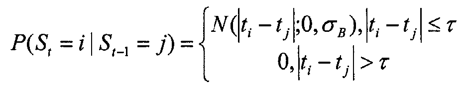
본 실시 형태의 HMM에서, 시간적으로 가까운 상태 사이에서만 천이가 허용되고, 시간적으로 떨어져 있는 2개의 화상 사이에서 천이를 행하는 것은 매우 비용이 들게 된다.In the HMM of this embodiment, transitions are allowed only between states that are close in time, and it is very expensive to make a transition between two images that are spaced apart in time.
도 6의 단계 1109로 되돌아간다. 본 단계에서는, 예를 들면 비터비 알고리즘을 이용하여, 상기 거리 벡터의 행렬 H로 표현되고 있는 근과거의 N개의 화상과 원과거의 화상을 매칭시키는 최적 상태 계열(optimal state sequence)이 결정된다. 행렬 H는 이하의 상태 신뢰치(state belief)의 계산에 사용된다. Return to step 1109 of FIG. In this step, for example, by using a Viterbi algorithm, an optimal state sequence for matching the N past images represented by the matrix H of the distance vector with the original past images is determined. The matrix H is used to calculate the state beliefs below.
![]()
![]()
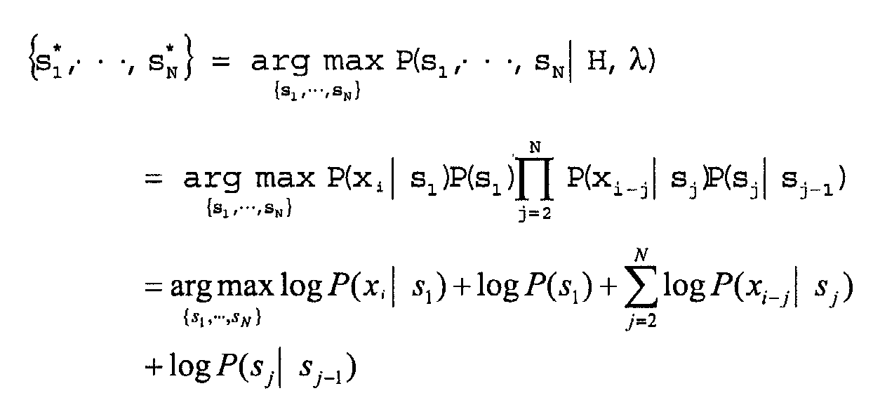
비터비 알고리즘은 이하와 같은 최대화 문제에 대한 해답을 제공한다. 여기서, si는 i번째의 화상 xi에 대응하는 상태이고, sj*는 최적화된 상태를 나타내고 있다. 본 실시 형태에서는, 상기 최대화 문제의 해답을 얻기 위해 비터비 알고리즘이라고 하는 동적 계획법을 적용한다. The Viterbi algorithm provides the answer to the following maximization problem. Here, s i is a state corresponding to the i-th image x i , and s j * represents an optimized state. In this embodiment, a dynamic programming method called a Viterbi algorithm is applied to obtain the solution of the maximization problem.

단계 1111에서는, 상기 매칭의 결과 얻어지는 최종 상태 sM*(이하, 콘텍스트 매치라고 한다)의 값을 출력한다. 본 실시 형태의 경우, 매칭의 결과 얻어진 과거의 유사 계열 중 시간적으로 가장 새로운 상태 sM*에 대응하는 화상 xSM, 또는 해당 화상에 대응하는 위치/상황이 인식 결과로서 출력된다.In
여기서, 본 실시 형태에서 이용하는 비터비 알고리즘에 대해 설명한다. 비터비 알고리즘은, 제공된 HMM과 쌍을 이루는 화상 간의 거리 H에 따라, 2개의 화상군 {x1, …, xM}와 {xi-N, …, xj} 사이에서 1대 1의 최적 대응 관계(best match)를 제공한다. 여기서, M이나 N이 큰 경우, 상기 비터비 알고리즘은 근사할 수 있다. 가장 흔히 행해지는 근사 방법은, 비터비 빔 검색법(Viterbi beam search)이다. 비터비 빔 검색법에 따르면, 최적 대응 관계를 구할 수는 없지만, 허용 가능한 정도로 매칭하고 있는 대응 관계를 발견할 수 있다. 또한, 본 실시 형태에서는, 상기 2개의 화상군의 1대 1의 대응 관계를 결정할 수 있는 처리이면, 비터비 알고리즘 대신에, 임의의 처리를 이용할 수 있다. 여기서 임의의 처리란, 시간적인 연속성을 유지한 상태에서, {xi-N, …, xi}에 포함되어 있는 각 화상과 해당 화상에 대응하는 {x1, …, xM}의 화상과의 거리를 최소화하는 것이다. 본 실시 형태의 비터비 알고리즘에서는, 상기 시간 연속성을 HMM의 천이 행렬에 의해 유지하고 있다.Here, the Viterbi algorithm used in the present embodiment will be described. The Viterbi algorithm calculates two groups of images {x 1 ,... , x M } and {x iN ,... , x j } gives a one-to-one best match. Here, when M or N is large, the Viterbi algorithm may be approximated. The most common approximation method is the Viterbi beam search. According to the Viterbi beam search method, an optimum correspondence cannot be found, but a correspondence matched to an acceptable level can be found. In the present embodiment, any processing can be used instead of the Viterbi algorithm as long as the processing can determine the one-to-one correspondence of the two groups of images. In this case, the arbitrary processing means that {x iN ,... , x i } for each picture and {x 1 ,... , x M } to minimize the distance to the image. In the Viterbi algorithm of the present embodiment, the time continuity is maintained by the HMM transition matrix.
표준적인 비터비 알고리즘의 실시에서는, 그 확률 계산은 직접적으로 행해지지 않는다. 이것은, 비터비 알고리즘에서, 확률을 순차적으로 승산해 가면 컴퓨터 의 계산 능력을 초과하게 되는 경우가 있기 때문이다. 이 때문에 실용에 있어서는, 이하와 같이, 모든 확률에 대하여 자연대수를 취함으로써, 비터비 알고리즘의 수학식을 "대수 확률"로 표현하도록 고쳐 쓰고 있다. 이 결과, 모든 승산이 가산으로 되지만, 최적화는 동일하게 실현된다.In the implementation of the standard Viterbi algorithm, the probability calculation is not done directly. This is because in the Viterbi algorithm, multiplying the probabilities sequentially may exceed the computing power of the computer. For this reason, in practical use, the logarithm of the Viterbi algorithm is expressed as "log probability" by taking a natural logarithm for all probabilities as follows. As a result, all multiplications are added, but optimization is similarly realized.
비터비 알고리즘의 처리의 구체적인 예에 대해서는 후술한다. A specific example of the processing of the Viterbi algorithm will be described later.
그런데, 상기한 매칭 처리에서, 근과거의 화상 계열에서의 순서가, 원과거에서의 화상 계열의 순서와 크게 서로 다른 경우가 있다. 이와 같이 기본적으로 서로 다른 이벤트(상이한 상황에서의 화상)를 포함하는 2개의 화상 계열을 매칭하려고 한 경우, 매칭의 확실성이 낮아지면 문제가 없다. 이와 같은 경우에는, 예를 들면 낮은 확실성이 얻어졌다는 것을 나타내거나 또는 " 매칭 화상 검출 실패" 등의 메시지를 출력하면 된다.By the way, in the above-mentioned matching process, the order in the past image series may differ greatly from the order of the image series in the past. As described above, when two image sequences including basically different events (images in different situations) are attempted to be matched, there is no problem when the certainty of the matching becomes low. In such a case, for example, it may be indicated that low certainty has been obtained or a message such as "Failed to detect matched image" may be output.
그러나 최악의 경우, 반대로 매칭의 확실성이 높아져서, 잘못된 결과가 유도되는 경우가 있다. 이와 같은 최악의 결과는, 시각적인 유사성이 있긴 하지만 물리적으로는 장소가 떨어져 있거나 또는 상황이 서로 다른 경우에 발생하기 쉽다.In the worst case, on the contrary, the certainty of the match is increased, leading to a wrong result. This worst result is likely to occur when there are visual similarities but physically distant or in different situations.
또한, 잘못된 매칭이 행해지는 경우로서는, 원과거의 화상 계열(트레이닝 예)과, 근과거의 화상 계열(테스트 예)에서 볼 수 있듯이, 상황의 순서에 관한 미스매치가 존재하는 경우이다(도 10 참조). 이와 같은 미스매치를 감소시키기 위해, 본 실시 형태에서는, 랜드마크라는 개념을 이용하고 있다. 예를 들면, 비교되고 있는 2개의 화상이 매칭하고 있는 정도가 높고, 랜드마크(특징적인 기준)로서 인식할 수 있는 화상 또는 광학 정보인지의 여부를 고려하여 매칭 처리를 행한다. 또한, 본 실시 형태에서는, 랜드마크를 이용함으로써, 매칭에 사용할 근과거의 화상 계열의 길이를 인테리전트하게 결정함으로써, 매칭 처리의 효율화 및 고속화를 도모하고 있다.In addition, a case where incorrect matching is performed is a case where mismatches regarding the order of situations exist as shown in the past image series (training example) and the recent past image series (test example). Reference). In order to reduce such mismatch, in this embodiment, the concept of a landmark is used. For example, the matching process is performed in consideration of whether or not the two images being compared are highly matched and whether they are images or optical information that can be recognized as landmarks (characteristic criteria). Further, in the present embodiment, by using the landmark, the length of the recent image series to be used for matching is determined intelligently, thereby making the matching process more efficient and faster.
도 10의 예에서, 점선(910, 940)으로 표현된 경로는 트레이닝 예이고, 일점 쇄선(920)의 경로는 테스트 예이다. 화상 아카이브에는, 방 A(902)로부터 방 B(903)를 향해 복도(901)를 진행해 가는 경우와, 도어(902d-2, 903d-2)를 통과하여 방 A(902)로부터 방 C(904)로 진행해 가는, 2개의 트레이닝 예의 경로를 따라 얻어진 화상만이 포함되어 있는 것으로 한다. 한편, 테스트 예의 경로(920)는, 복도(901)로부터 스타트하고, 그 후 도어(902d-1)를 통과하여 방 A(902)의 안으로 들어가고, 도어(902d-2)를 통과하여 방 B(903)로 이동, 그 후 도어(903d-1)를 통과하여 복도(901)로 되돌아오는 것이다.In the example of FIG. 10, the path represented by dashed
여기서, 테스트 예의 경로(920)의 전체와 트레이닝 예의 경로(910 또는 940)를, 랜드마크를 사용하지 않는 종래의 방법으로 매칭하려고 하면, 화상의 순서가 서로 다르기 때문에 미스매치가 일어나기 쉽고, 올바른 결과가 얻어지는지의 여부 는 불분명하다. 또한, 매칭되었다고 해도, 그 확실성은 낮은 것으로 될 가능성이 높다.Here, when the entirety of the
이와 같은 문제점에 대한 해결책으로서, 본원 발명자는, 광학 화상을 시간 경과에 따라 차례로 취득해 가는 경우, 많은 경로에서, 랜드마크로서 기능 가능한 지점이 존재하고 있다는 것에 주목했다. 예를 들면, 도 10의 예에서는 점(930~933)으로 표현된 지점에 랜드마크(예를 들면 특색이 있는 도어)가 존재하는 경우, 근과거의 화상 계열로서 해당 랜드마크까지의 화상 계열을 사용함으로써, 보다 정밀도가 높은 결과가 얻어지는 것이 판명되었다. 예를 들면, 테스트 예의 경로(920) 중에서 방 B(903)에 들어간 상황(위치(950))에서, 지금까지 취득된 모든 데이터를 사용하여 통상의 매칭 처리를 행한 경우, 트레이닝 예의 경로(910)에 있는지 경로(940)에 있는지를 판단할 수 없다. 이에 반해, 랜드마크를 사용한 매칭 처리에서는, 테스트 예의 경로로서 마지막의 랜드마크(932)까지의 화상 계열만을 이용한다. 이 때문에, 현시점에서는 트레이닝 예의 경로(940)에 따른 위치에 있는 것이 바르게 인식된다. 또한, 화상 계열의 길이를 랜드마크까지로 하는 대신에, 랜드마크의 위치에 부합하여, 매칭 처리에 이용하는 근과거의 화상 계열의 길이를 설정하는 구성으로 해도 무방하다.As a solution to such a problem, the inventors have noted that, in the case of acquiring an optical image one after another over time, there exist a point capable of functioning as a landmark in many paths. For example, in the example of FIG. 10, when a landmark (for example, a door having a feature) exists at a point represented by the
본 실시 형태에 따르면, 상기 랜드마크를 이용함으로써, 매칭 처리에서 사용할 근과거의 화상 계열로서, 해당 근과거의 화상 계열의 이력을 어느 지점까지 거슬러 올라가야 할지를 결정할 수 있다. 이 결과, 상기된 바와 같은 화상의 순서가 서로 다른 경우라도, 보다 정확하게 매칭 처리가 행해진다.According to this embodiment, by using the landmark, it is possible to determine to which point the history of the image series of the recent past should be raised as the image series of the recent past to be used in the matching process. As a result, even when the order of the images as described above is different from each other, matching processing is performed more accurately.
본 실시 형태에서는 비터비 알고리즘을 이용하고 있기 때문에, 상기 랜드마크의 검출을 용이하게 행할 수 있다. 통상의 비터비 알고리즘의 경우, 전방향(시간의 순방향)으로 비터비 트렐리스선도 상에서 패스를 늘리고, 상태 스코어를 전파(propagate)해 간다. 이에 반해, 본 실시 형태에서는, 시간을 반대로 하여 후방향으로, 현재 위치로부터 과거를 향해 패스를 늘려 가는 구성으로 하고 있다. Since the Viterbi algorithm is used in this embodiment, the landmark can be detected easily. In the conventional Viterbi algorithm, the path is increased on the Viterbi trellis diagram in all directions (forward direction of time) to propagate the state score. On the other hand, in this embodiment, it is set as the structure which extends a path toward the past from a present position to the past, reverse time.
본 실시 형태에 따른 랜드마크의 검출 및 그것을 이용한 매칭 처리를 도 11 및 도 12를 이용하여 설명한다. 도 11은, 본 실시 형태의 매칭 처리에서 이용되는 비터비 트렐리리스선도의 일례로서, 종방향은 원과거 화상 x1~xM, 횡방향은 근과거 화상 xi~xi-N에 대응한다. 매칭 처리는 현재 위치(71)로부터 개시되고, 랜드마크 매치(70)이 검출될 때까지, 상태 스코어를 시간적으로 역방향으로 전파해 간다. 또한, 각 단계에서는, 상기 수학식 5에서 미리 설정된 천이 파라미터에 따라, 제로가 아닌 천이 확률을 갖는 K개의 상태만이 고려된다.The detection of the landmark and the matching process using the same according to the present embodiment will be described with reference to FIGS. 11 and 12. Fig. 11 is an example of the Viterbi trellis diagram used in the matching process of the present embodiment, in which the longitudinal direction corresponds to the past past image x 1 to x M , and the lateral direction corresponds to the near past image x i to x iN . The matching process starts from the
도 12(a)에 랜드마크 매치의 검출을 이용한, 비터비 알고리즘에 의한 매칭 처리의 일례를 나타내는 의사 코드를 도시한다. 본 예의 의사 코드에서는, 이하의 대수 확률(1og-probability)로 표현된 비터비식을 참조하여 설명한다.Fig. 12A shows a pseudo code showing an example of a matching process by the Viterbi algorithm using detection of a landmark match. In the pseudo code of this example, the following description will be made with reference to the Viterbi equation expressed by the following logarithmic probability (1og-probability).
![]()
![]()

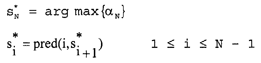
도 12(a)에 도시하는 의사 코드에서, 단계 1~3은 초기화 처리, 특히 alpha 변수의 초기화이다. 단계 4~12는 귀납 처리이다. 여기서, alpha(prev, j)는 αi(j), alpha(now, j)는 αi+1(j), temp(k)는 αi(k)+Bjk이다. 또한, 단계 13~16은 종료 처리이다.In the pseudo code shown in Fig. 12A, steps 1 to 3 are initialization processing, in particular, initialization of the alpha variable.
본 예의 의사 코드와 표준 비터비 수학식과의 차이는, 이하와 같다.The difference between the pseudo code of this example and the standard Viterbi equation is as follows.
1. 시간이 진행하는 방향이 반대이다. 1. The direction of time is reversed.
2. 단계 10의 랜드마크 검출은, 귀납 루프를 빠른 시기에 정지시킨다. 이 랜드마크 검출 처리에 사용되는 Is-Landmark-Present(i, pred, threshold)에 대해서는, 도 12(b)를 이용하여 설명한다. 2. The landmark detection in
3. 본 예의 의사 코드에서는, alpha 행렬의 금회와 전회의 컬럼만이 유지되어 있다.3. The pseudo code in this example holds only the current and previous columns of the alpha matrix.
본 실시 형태에서는, 랜드마크 매치가 검출된 경우, 이 시점까지 발견된 최적의 패스를 현재 위치까지 되돌아감으로써 해를 얻는다. 또한, 본 실시 형태에서는, 비터비 트렐리스선도에서 최적의 패스를 포함하는 모든 패스, 또는, 실질적으로 모든 패스가 동일한 상태를 통과한 경우, 그 시점에서 랜드마크 매치가 검출되었다고 정의한다. 또한, "실질적으로 모든 패스"란, 어플리케이션에 부합하여 본 처리에 요구되는 오차 범위의 안에서 "모든 패스"라고 동등하게 판단할 수 있는 상태를 의미하고 있다. 또한, 낮은 매칭 정밀도라도 허용되는 상태에서는, 다른 어느 상태보다도 매우 많은 패스가 통과한 상태가 발견된 경우에 대해, 랜드마크 매치가 검출되었다고 판단하는 구성으로 해도 무방하다.In the present embodiment, when a landmark match is detected, a solution is obtained by returning the optimal path found up to this point to the current position. In the present embodiment, when all the paths including the optimal paths or substantially all the paths pass through the same state in the Viterbi trellis diagram, it is defined that a landmark match is detected at that time. In addition, "substantially all paths" means the state which can be judged equally as "all paths" within the error range required for this process according to an application. Further, in a state where even a low matching accuracy is allowed, the configuration may be determined to determine that a landmark match has been detected in a case where a state in which more passes have been passed than in any other state is found.
또한, 비터비 트렐리스선도에서 전방향으로 패스를 늘려 랜드마크에 도달했다고 해도 큰 이익은 없다. 왜냐하면, 여전히 패스는 임의로 분산할 가능성이 있고, 비터비 트렐리스선도의 마지막에 어떠한 해가 얻어질지는 불명하기 때문이다. 이에 반해, 본 실시 형태에서는 시간적으로 역방향으로 패스를 늘리고 있다. 이 때문에, 랜드마크 매치가 검출된 시점에, 비터비 트렐리스선도 상에서는 그 이상 패스를 늘리는 필요는 없어진다. 이것은, 비터비 트렐리스선도 상의 개시점에 관한 해는 변하지 않기 때문이다.In addition, even if the path is reached in all directions on the Viterbi trellis map, it is not a big profit. This is because the path may still be randomly distributed and it is not known what solution is obtained at the end of the Viterbi trellis diagram. In contrast, in the present embodiment, the path is increased in the reverse direction in time. For this reason, it is not necessary to extend the path further on the Viterbi trellis diagram when the landmark match is detected. This is because the solution regarding the starting point on the Viterbi trellis diagram does not change.
상기 랜드마크를 이용함으로써, 화상 아카이브에 화상으로서 기록되어 있는 과거의 상황에, 유저의 현재의 상황과 정밀도 좋게 매칭할 수 있는 상황이 원래 존재하지 않는 경우라 하더라도, 화상 아카이브에는 기록되어 있지 않은 현재의 상황에 대한 다른 어프로치 방법을 자동적으로 특정하는 것이 가능하게 된다.By using the landmark, the present situation that is not recorded in the image archive, even if the situation that can be accurately matched with the current situation of the user does not exist originally in the past situation recorded as the image in the image archive. It is possible to automatically specify different approaches to the situation.
모든 천이 확률이 제로가 아닌 경우에는, 상기한 랜드마크 매치의 검출을 이용한 매칭 처리는 문제없이 실현할 수 있다. 그러나, 본 실시 형태에서는 실용성을 고려하여, 소정의 폭을 가지고 그것을 초과한 영역에서는 천이 확률을 제로로 하는 트렁케이트 가우스 분포(truncated Gaussian)를 사용하고 있다. 이 때문에, 모든 상태로부터 다른 모든 상태로의 액세스가 가능하게는 되어 있지 않다. 그래서 본 실시 형태에서는, 매칭의 정도의 판단에 임계치를 마련하고, 해당 임계치를 이용하여 랜드마크 매치의 검출을 행하고 있다.If all the transition probabilities are not zero, the matching process using the above-described landmark match detection can be realized without a problem. However, in the present embodiment, in consideration of practicality, a truncated Gaussian with a transition probability of zero is used in a region having a predetermined width and exceeding it. For this reason, access from all states to all other states is not possible. Therefore, in this embodiment, a threshold value is provided for the determination of the degree of matching, and a landmark match is detected using this threshold value.
예를 들면, 본 실시 형태에서는, 도 12(b)에 도시하는 처리에 의해, 천이 확률이 제로인 경우라 하더라도 랜드마크의 존재의 유무를 검출하고 있다. 도 12(b)의 처리에서는, 단계 1에서 카운트를 초기화하고, 단계 2~3에서, 각 상태를 통과하는 패스의 수를 카운트하고, 최대의 카운트값이 임계치(threshold)보다 큰지의 여부가 판단된다.For example, in this embodiment, even if the transition probability is zero, the presence or absence of a landmark is detected by the process shown in FIG.12 (b). In the process of Fig. 12B, the count is initialized in
천이 확률이 모두 제로가 아닌 경우에는, 상기 threshold를 M-1로 설정할 수 있다. 이와 같은 설정에 따르면, 모든 패스가 동일 상태를 통과하여 천이한 경우에 한해 랜드마크가 검출된다. 천이 확률이 제로인 경우를 포함하여, 상기한 상황이 적용되지 않는 경우에는, 하나의 상태를 많은 패스 또는 실질적으로 모든 패스가 통과하도록 M-1보다도 낮은, 예를 들면 0.5×M을 상기 threshold로서 설정해도 무방하다.When the transition probabilities are not all zero, the threshold may be set to M-1. According to this setting, the landmark is detected only when all the passes have passed through the same state. In the case where the above situation does not apply, including when the transition probability is zero, one state may be set as the threshold, for example, 0.5 × M lower than M-1 such that many passes or substantially all passes pass. It is okay.
실용에 있어서는, 상기 매칭 처리에서 사용하는 비터비 트렐리스선도가 매우 커지는 경우가 있다. 이와 같은 경우, 계산 처리가 복잡함(비터비 알고리즘의 경 우, 시간적으로는 O(NM2)가 무한대로 커지는 것을 막기 위해, 패스의 프루닝(pruning)이 필요하게 된다. 여기서 M은 화상 아카이브에 포함되는 화상의 계수, N은 근과거 시계열에 포함되는 화상의 계수를 나타낸다. 이 때문에, 많은 바리에이션을 나타내는 복잡한 환경에서는, 상기 복잡함은 매우 큰 것으로 된다.In practical use, the Viterbi trellis diagram used in the matching process may be very large. In such a case, the computational processing is complicated (in the Viterbi algorithm, in order to prevent O (NM 2 ) from growing indefinitely, pruning of the path is required, where M is stored in the image archive. The coefficient of the included image, N, represents the coefficient of the image included in the recent past time series, and therefore, the complexity is very large in a complicated environment showing a lot of variations.
본 실시 형태에서는, 상기 계산 처리의 복잡함을 감소시키기 위해 여러 가지 수단을 강구하고 있다. 그 하나는, 상기한 코딩 처리부(201)에 의한 코딩 처리이다. 본 처리에서는, 화상의 변화를 검출함으로써 화상의 용장성을 제외하고, 실질적으로 화상 아카이브에 저장될 화상의 정보량을 손상시키지 않고, 그 데이터량을 압축하고 있다. 또한 본 실시 형태에서는, 천이 함수로서 트렁케이트 가우스 분포(truncated Gaussian)를 사용하고 있고, 제로의 확률의 천이를 통과하는 패스에 대해서는 계산을 하지 않는다. 이들의 수단을 강구함으로써, 비터비 알고리즘의 계산 처리의 실제의 비용은 O(NKM)으로 된다. 여기서, K는 은닉 마르코프 모델 λ의 각 상태로부터 나오는 경우의 확률이 제로가 아닌 천이의 수(상수)이다. 따라서, 본 실시 형태의 비터비 알고리즘의 계산 처리의 복잡함은, 시간에서, 화상 아카이브의 크기에 대하여 선형으로 된다.In this embodiment, various means are devised to reduce the complexity of the calculation process. One of them is coding processing by the above-described
또한, k 근방법(k-NN)에서 이용되는 본 구조의 데이터를 이용한 최적화 처리를 행함으로써, 상기 복잡함을 대수 시간에서, 거의 화상 아카이브의 크기 M까지 감소시킬 수 있다.Further, by performing the optimization process using the data of the present structure used in the k near method k-NN, the above complexity can be reduced in logarithmic time to almost the size M of the image archive.
상기 최적화 처리는, 예를 들면, 매칭의 정도가 높아질 것으로 기대되는, 화 상 아카이브의 서브세트(예를 들면 크기 L)를 설정함으로써 실현된다. 이와 같은 처리는 K 근방법이 원래 목표로 한 것이다. 그 후, 화상 아카이브 전체에 대하여 비터비 알고리즘을 실행하는 대신에, 상기 크기 L의 서브세트에 대해서만 비터비 알고리즘을 실행한다. 이와 같은 처리에 따르면, 상기 복잡함은 O(NKL21ogM)으로 된다.The optimization process is realized, for example, by setting a subset (eg, size L) of the image archive, in which the degree of matching is expected to be high. Such treatment is originally aimed at the K-based method. Thereafter, instead of executing the Viterbi algorithm for the entire image archive, the Viterbi algorithm is executed only for the subset of size L. According to such a process, the complexity is O (NKL 2 1ogM).
여기서, 서브세트는, {xi-N, …, xi}에 포함되어 있는 각 화상에 대하여 가장 가까운, 화상 아카이브 {x1, …, xM} 내의 L개로 이루어진다. 또한, 해당 가장 가까운 L개의 화상은 L1 계량에 의해 결정된다. 서브세트는 각 화상 xi에 의해 서로 다르다. 보다 구체적으로는, 상기 화상 아카이브에 포함되는 모든 화상을 각 화상 xi마다 고려하는 대신에, 해당 화상 xi에 가장 가까운 L개의 화상만을 고려한다. 이 때문에, 행렬 H의 모든 컬럼을 계산하지 않고, HMM에서의 모든 상태가 고려되지 않는다.Here, the subset is {x iN ,... , the image archive {x 1 ,... closest to each image contained in, x i }. , x M }. In addition, the closest L images are determined by L1 metering. The subset is different for each picture x i . More specifically, instead of considering every picture included in the picture archive for each picture x i , only L pictures closest to the picture x i are considered. For this reason, all the columns of the matrix H are not calculated and all states in the HMM are not taken into account.
화상 xi에 대하여 {x1, …, xM} 중에서 가장 가까운 L개의 화상을 결정하는 방법으로서는, 예를 들면, 임의의 표준 k 근방법(k=L)을 이용할 수 있다.For image x i {x 1 ,... , x M }, as the method for determining the nearest L images, for example, any standard k root method (k = L) can be used.
또한, 대수 확률 공간에서 비터비 계산이 행해진 경우, 16 비트의 정수를 이용하여 모든 계산이 가능하게 된다. 여기서는, 취득된 센서 데이터가 정수의 형식으로 표현되어 있는 경우를 가정하고 있지만, 통상의 촬상 및 아날로그 디지털 변환으로 화상 데이터가 얻어지는 경우에는 이것에 상당한다.In addition, when Viterbi calculation is performed in a logarithmic probability space, all calculations are possible by using an integer of 16 bits. It is assumed here that the acquired sensor data is expressed in the form of an integer, but this corresponds to the case where image data is obtained by normal imaging and analog-to-digital conversion.
그다지 크지 않은 화상 아카이브를 이용하는 경우에는, 상기한 바와 같은 최적화 처리를 실행함으로써, 소위 원칩 컴퓨터 등의 저가격의 내장형 하드웨어에 의해서도 리얼타임에서의 처리가 가능하게 된다. 또한, 상기 알고리즘의 트렐리스 구조는 FPGA(Field Programmable GateArray)에서의 실시에 최적이다.In the case of using a very small image archive, the above-described optimization processing enables real-time processing even by low-cost embedded hardware such as one-chip computers. In addition, the trellis structure of the algorithm is optimal for implementation in a field programmable gate array (FPGA).
상기한 실시 형태의 매칭 처리에서는, 화상의 시계열 패턴을 이용하여 콘텍스트 매치를 행하고 있다. 이 때문에, 고해상도의 화상 데이터는 필요로 하지 않는다. 즉, 본 실시 형태의 장치는, 광학 정보 취득부(10)에서 사용되는 센서의 해상도가 높은 것일 필요는 없다. 이 결과, 본 실시 형태에서는, 얼굴이나 문자 그 자체를 인식하지 않기 때문에, 유저나 그 주위의 환경의 프라이버시를 침해하지 않고 상황 인식을 행하는 것이 가능하다. 본 실시 형태의 장치는, 통상의 해상도의 화상을 필요로 하는 종래의 장치에 비교하여, 보다 낮은 해상도의 화상 데이터를 이용한 경우라 하더라도 효율적으로 상황 인식을 할 수 있다는 유리한 효과를 발휘한다.In the matching process of the above embodiment, context matching is performed using the time series pattern of the image. For this reason, high resolution image data is not required. That is, the apparatus of this embodiment does not need to be a high resolution of the sensor used by the optical
이상 설명한 바와 같이, 상기한 실시 형태에 따르면, 화상 등의 광학 정보를 이용한 기억 기능을 구비한 시스템이 제공된다. 상기한 실시 형태에 따르면, 예를 들면 로봇, 웨어러블 컴퓨터, 환경 감시 시스템과 같은 각종 정보 처리 시스템에서, 다음과 같은 기능을 실현할 수 있다.As described above, according to the above embodiment, a system having a storage function using optical information such as an image is provided. According to the embodiment described above, the following functions can be realized in various information processing systems such as, for example, a robot, a wearable computer, and an environment monitoring system.
(1.1) 기억 상기(RECALL): 현재의 상황과 과거의 상황을 매칭시킴으로써, 과거의 상황에서의 콘텍스트를 자동적으로 불러 들인다. 예를 들면, 도 13에 도시하는 바와 같이, 현재로부터 마지막의 랜드마크까지의 근과거의 화상 계열(1200)과 화상 아카이브에 저장되어 있는 원과거(1210)를 매칭하여, 근과거(1200)와 매칭의 정도가 높은 유사 계열(1211)을 산출한다. 또한, 원과거(1210)에서, 예를 들면 도 14에 도시하는 바와 같이, 화상에 상황을 나타내는 라벨 부착이 이루어진 경우에는, 매칭의 결과 발견된 유사 계열(1211) 중에서 현재의 상황과 대응하는 시점(1220)이 특정된다. 이 결과, 현재의 상황(본 예에서는 역 안)과 마찬가지의 상황에 관한 기억 상기가 가능하게 된다. (1.1) Memory Recall: By matching the present situation with the past situation, the context in the past situation is automatically called. For example, as shown in FIG. 13, the past past 1210 stored in the image archive is matched with the past
(1. 2) 저스트인 타임 정보 제공(JIT): 상황을 인식하고, 해당 인식한 상황에서 필요한 정보를 제공한다. 본 기능에서는, 예를 들면, 인식된 위치에 기초하는 태그 부착을 이용한다.(1. 2) Just-in-time information provision (JIT): Recognizes a situation and provides the information necessary for that recognized situation. In this function, for example, tagging based on the recognized position is used.
(1.3) 이상 검출(ANAMALY DETECTION): 상기한 기억 상기와는 반대의 것으로, 과거의 상황과의 매칭이 성공하지 않은 경우, 본 장치가 지금까지 직면한 적이 없는 새로운 상황에 있을 확률이 매우 높다고 판단한다(도 15(b)). 본 기능을 이용함으로써, 통상과는 서로 다른 상황을 검출하여 기록 장치 등을 기동시키는 것이 가능하게 된다.(1.3) ANAMALY DETECTION: In contrast to the above-mentioned memory, if the matching with the past situation is not successful, it is very likely that the device is in a new situation that has not been faced so far. (FIG. 15 (b)). By using this function, it is possible to detect a situation different from the ordinary and to activate the recording apparatus or the like.
(1. 4) 예기(PREDICTION): 과거에서 상황 A의 다음에 상황 B가 일어나고 있고, 현 상황이 상황 A에 해당한다고 인식된 경우, 다음에 상황 B가 일어날 것을 예기하는 것이 가능하게 된다(도 15(a)). 본 기능은, 가이던스 장치 등의 장래 예상에 기초하여 동작하는 장치에 적용하여, 유저의 의도나 다음의 행동을 예상함으로써, 타이밍 좋게 적절한 서비스를 제공하는 것을 가능하게 한다.(1.4) PREDICTION: If situation B is occurring after situation A in the past and it is recognized that the current situation corresponds to situation A, it is possible to anticipate that situation B will occur next (FIG. 4). 15 (a)). This function can be applied to a device that operates based on future expectations, such as a guidance device, so that it is possible to provide an appropriate service in a timely manner by anticipating the user's intention or the next action.
(1. 5) 비교: 예를 들면 벽에 걸려 있는 그림이 변하는 등, 과거와 현재의 상황을 비교하여 변화한 점을 검출한다(도 15(c)).(1.5) Comparison: For example, a picture hanging on a wall is changed, and a change point is detected by comparing the present situation with the past (Fig. 15 (c)).
또한, 본 발명에서 상기 기능을 실현하기 위해, 화상 아카이브에 저장되어 있는 모든 데이터에 라벨 부착을 할 필요는 없고, 본 발명에서는, 예를 들면 메뉴얼에 의한 라벨 부착이 되어 있지 않은 데이터에 대해서도, 본 발명을 이용하는 유저나 어플리케이션의 경우에 특정한 값을 가질 수 있다. 즉, 라벨 부착되어 있지 않은 데이터라 하더라도, 그 밖의 라벨 부착되어 있는 데이터와의 상대적인 시간적 관계가 일의적으로 정의될 수 있기 때문이다.In addition, in order to realize the above functions in the present invention, it is not necessary to label all the data stored in the image archive, and in the present invention, for the data which is not labeled by manual, for example, It may have a specific value in the case of a user or an application using the invention. That is, even if the data is not labeled, the relative temporal relationship with other labeled data can be defined uniquely.
예를 들면, 상기 (1. 1)의 "기억 상기" 기능에서, 도 14에 도시하는 바와 같이 "집"과 "역" 사이에 있는 상황과 근과거(현재)의 상황이 매칭된 경우, 현재의 상황은 "집과 역 사이"라고 인식할 수 있다. 물론, "집"이나 "역" 등, 메뉴얼로 라벨 부착된 후, 본 발명의 시스템 측에서, 라벨 부착되어 있지 않은 화상 데이터에 대하여, 예를 들면 "집과 역 사이" 등과 같이 미리 자동적으로 라벨 부착을 하는 구성으로 해도 무방하다.For example, in the " memory reminder " function of (1.1) above, when the situation between the "home" and the "station" and the situation in the past (current) match, as shown in FIG. The situation can be recognized as "between the house and the station." Of course, after being manually labeled, such as "house" or "station", the system side of the present invention automatically labels the unlabeled image data in advance, such as "between house and station", for example. It is good also as a structure which attaches.
보다 구체적으로는, 라벨 부착되어 있지 않은 상황과 현재의 상황이 매칭된 경우, 화상 아카이브에 저장되어 있는 상황 중 해당 매칭된 상황과 시간적으로 가까운 1 또는 복수의 상황에 라벨 부착된 정보를 이용하여, 해당 매칭 결과를 유저에 대하여 제시하는 경우에 표시 또는 통지할 메시지를 생성하는 구성으로 해도 무방하다.More specifically, when the unlabeled situation and the current situation are matched, by using information labeled in one or a plurality of situations stored in the image archive that are close in time to the matched situation, The present invention may be configured to generate a message to be displayed or notified when the matching result is presented to the user.
또한, 상기 1 또는 복수의 상황에 라벨 부착된 정보를 이용하여 새로 생성한 정보를, 해당 매칭된 상황에 대하여 라벨 부착하는 구성으로 해도 무방하다.Further, the information newly generated by using the information labeled in one or a plurality of situations may be configured to label the matched situation.
또한, 상기 (1. 4)의 "예기" 기능에서는, 현재의 상황과 과거의 상황을 매칭하고, 그 시점으로부터 앞을 예기하는 구성이기 때문에, 예기를 하지 않는 과거의 상황에 대응하는 화상 데이터, 예를 들면 도 15(a)에서의 예기한 미래(1230)보다도 전의 데이터에 대한 라벨 부착은 필요로 하지 않는다. 또한, 도 15(b), 도 15(c)에 도시하는 바와 같은 "이상 검출"이나 "비교" 기능에서는 라벨 부착은 필요하지 않다.In addition, in the " expected " function of (1.4) above, since the present situation and the past situation are matched and the future is expected from the viewpoint, the image data corresponding to the past situation that is not anticipated, For example, labeling for data before the expected future 1230 in FIG. 15A is not required. Note that labeling is not necessary in the " abnormality detection " and " compare " functions as shown in Figs. 15B and 15C.
상기한 실시 형태가, 유저의 환경을 촬상하도록 배치된 광학 센서를 구비한 웨어러블 컴퓨터에 적용된 것인 경우, 이하와 같은 이용 방법이 있다.When said embodiment is applied to the wearable computer provided with the optical sensor arrange | positioned so as to image the environment of a user, there exist the following usage methods.
(2. 1) 메타-태그 부착(META-TAGGING): 전화에 의한 회화, 수신한 텍스트 메시지, 촬영된 사진 등의 다른 형태의 기록 정보에 대한, 해당 상황에 관련되는 정보의 태그 부착.(2.1) META-TAGGING: The tagging of information relevant to the situation to other forms of recorded information, such as conversations by phone, received text messages, photographs taken, etc.
(2. 2) 상황 인식: 소프트웨어 에이전트를 위한 상황 인식(위치 인식도 포함한다). (2. 2) Situational Awareness: Situational awareness (including location awareness) for software agents.
(2. 3) 이상 검지: 위험할 가능성이 높은 상황이나 특별한 행동을 필요로 하는 상황(예를 들면, 구급이나 범죄)의 인식.(2. 3) Anomaly detection: Recognition of situations that are likely to be dangerous or require special actions (eg, first aid or crime).
(2. 4) 예기: 예를 들면, 과거에 유저가 레스토랑을 나온 후에 택시를 불렀던 경우, 이것에 대응한 서비스를 행하는 등, 과거의 이벤트에 기초하는 다음의 유저의 상황의 예기.(2.4) Anticipation: For example, when the user called a taxi after leaving the restaurant in the past, the anticipation of the situation of the next user based on the past event, such as performing a service corresponding to this.
상기한 실시 형태가 로봇의 환경을 촬상하도록 배치된 광학 센서를 구비한 로봇에 적용된 것인 경우, 이하와 같은 이용 방법이 있다. When the above embodiment is applied to a robot having an optical sensor arranged to image the environment of the robot, there are the following usage methods.
(3. 1) 로봇용 화상 메모리 기능: 분석적인 계획의 서포트, 및 소정의 행동을 완료하려고 하는 경우에, 그 행동을 성공하지 못하게 유도할 가능성이 있는 상황을 불쾌하게 느끼는 것과 같은 감정 기능의 서포트.(3.1) Image memory function for robots: Support for analytical planning, and support for emotional functions such as feeling unpleasant in situations that may lead to unsuccessful action when attempting to complete a predetermined action. .
(3. 2) 예기: 소정의 상황에서 특정한 행동을 한 경우, 다음의 상황이 어떻게 될지를 예기하기 위한 확률 룰을 모델화함으로써 실현하는 로봇의 행동 예기(예를 들면 내비게이션과 같이, 자신의 행동의 결과를 예측함으로써, 원하는 상황으로 자신을 유도해 간다).(3. 2) Anticipation: When a particular action is performed in a given situation, the behavior of the robot (for example, navigation), which is realized by modeling probabilistic rules to predict what will happen next. By predicting the outcome, you guide yourself to the situation you want).
상기한 실시 형태는, 이동 기능을 갖지 않는 장치, 시큐러티 모니터 장치, 환자 모니터 장치, 또는 공간이나 대상물을 시각적으로 모니터하는 그 밖의 임의의 장치에 대하여도 적용할 수 있다. 이와 같은 경우에는, 주로 모니터링 처리가 행해져 있기 때문에, 예를 들면 상기한 이상 검출 기능이 도움이 된다. 또한, 예를 들면 환자가 취침 중에 발작을 일으킨 경우에 간호사에게 통지하는 등, 검출한 상황에 부합하여 다른 시스템을 기동하기 위해 본 실시 형태를 이용하는 것도 가능하다. The above embodiment can be applied to a device that does not have a moving function, a security monitor device, a patient monitor device, or any other device for visually monitoring a space or an object. In such a case, since the monitoring process is mainly performed, for example, the above-described abnormality detection function is helpful. It is also possible to use the present embodiment to start another system in accordance with the detected situation, for example, to notify the nurse when the patient has had a seizure while sleeping.
또한, 상기한 본 발명의 실시 형태에 따른 장치는, 또한 통신부를 구비하는 구성으로 해도 무방하다. 통신부는, 예를 들면, 유선 및/또는 무선으로 외부 장치와 통신을 행하고, 상기한 본 발명의 실시 형태의 화상 아카이브와 동등한 형태를 구비한 복수의 광학 정보 계열 및/또는 그것에 기초하여 생성된 은닉 마르코프 모델을 판독하고, 매칭 처리에서 사용하는 구성으로 해도 무방하다.The apparatus according to the embodiment of the present invention described above may further be configured to include a communication unit. The communication unit communicates with an external device by wire and / or wireless, for example, and includes a plurality of optical information series having a form equivalent to the image archive of the above-described embodiment of the present invention and / or a concealment generated based thereon. It is good also as a structure which reads a Markov model and uses it in a matching process.
또한, 상기한 본 발명의 실시 형태에 따른 장치를 이용하는 대신에, 연산 처 리 유닛, 메모리, 유저 인터페이스를 포함하는 범용 컴퓨터 시스템에, 상기한 바와 같은 광학 정보 취득부를 접속하고, 본 실시 형태에 의한 상황 인식을 실현하기 위한 처리를 해당 범용의 컴퓨터가 행하도록 하기 위한 컴퓨터 프로그램을 제공해도 무방하다. 컴퓨터 프로그램은, 통신으로 직접 또는 네트워크를 통하여 각 컴퓨터 시스템에 송신해도 무방하고, 또는, 기록 매체에 저장해서 배부하는 구성으로 해도 무방하다.Instead of using the apparatus according to the embodiment of the present invention described above, the optical information acquisition unit as described above is connected to a general-purpose computer system including a calculation processing unit, a memory, and a user interface, A computer program for causing the general purpose computer to perform a process for realizing the situation recognition may be provided. The computer program may be transmitted to each computer system directly or through a network by communication, or may be configured to be stored and distributed in a recording medium.
또한, 상기한 본 발명의 실시 형태에 따른 장치를 이용하는 대신에, 본 발명을 모바일형의 전자 기기에 적용하여 상황 인식 처리를 실행시키고, 그 결과를 해당 전자 기기의 본래의 용도로 이용하는 구성으로 해도 무방하다. 본 발명이 적용 가능한 전자 기기로서는, 예를 들면 휴대 전화, PDA, CD나 DVD 등의 기억 매체를 재생하는 휴대형 기억 매체 재생 장치, 디지털 카메라나 캠코더 등의 촬상 장치가 있다. Further, instead of using the apparatus according to the embodiment of the present invention described above, the present invention may be applied to a mobile type electronic device to execute a situation recognition process and use the result for the original use of the electronic device. It's okay. Examples of the electronic apparatus to which the present invention is applicable include a portable storage medium reproducing apparatus for reproducing a storage medium such as a mobile phone, a PDA, a CD or a DVD, and an imaging apparatus such as a digital camera or a camcorder.
본 발명은, 2004년 6월 29일자 및 2005년 1월 4일자로 일본 특허청에 출원된 일본 특허 출원 JP2004-191308호 및 JP2005-000115호에 관련된 서브젝트 매러를 포함하고 있고, 그 내용 전체가 참고로서 포함되어 있다.The present invention includes a subject mirror related to Japanese Patent Application Nos. JP2004-191308 and JP2005-000115, filed on June 29, 2004 and January 4, 2005, the contents of which are incorporated by reference in their entirety. Included.
당업자는, 첨부된 특허 청구범위의 범위 내에 있는 한, 다양한 수정, 조합, 부조합 및 변경이 설계 요건이나 다른 요인에 따라서 발생할 수 있다는 것을 이해할 것이다.Those skilled in the art will understand that various modifications, combinations, subcombinations and changes may occur depending on design requirements or other factors, as long as they are within the scope of the appended claims.
본 발명에 따르면, 광학적인 정보를 이용하여 과거와 현재의 상황을 매칭할 때에, 단순한 시간적인 순간을 비교하는 것이 아니라, 임의의 기간 중의 이력을 고려한 매칭을 행함으로써, 현재의 상황을 인식하는 장치, 방법, 컴퓨터 프로그램, 기록 매체, 및/또는 이들을 구비한 시스템을 제공할 수 있다. According to the present invention, an apparatus for recognizing the current situation by performing matching in consideration of the history in an arbitrary period, rather than simply comparing the temporal moments when matching the past and the present situation using optical information. , A method, a computer program, a recording medium, and / or a system having the same.
Claims (21)
Applications Claiming Priority (4)
| Application Number | Priority Date | Filing Date | Title |
|---|---|---|---|
| JPJP-P-2004-00191308 | 2004-06-29 | ||
| JP2004191308 | 2004-06-29 | ||
| JPJP-P-2005-00000115 | 2005-01-04 | ||
| JP2005000115A JP4321455B2 (en) | 2004-06-29 | 2005-01-04 | Situation recognition device and system |
Publications (1)
| Publication Number | Publication Date |
|---|---|
| KR20060048624A true KR20060048624A (en) | 2006-05-18 |
Family
ID=35094218
Family Applications (1)
| Application Number | Title | Priority Date | Filing Date |
|---|---|---|---|
| KR1020050056324A Abandoned KR20060048624A (en) | 2004-06-29 | 2005-06-28 | Context Recognition Method and Device Using Optical Information |
Country Status (4)
| Country | Link |
|---|---|
| US (1) | US7421092B2 (en) |
| EP (1) | EP1612719A3 (en) |
| JP (1) | JP4321455B2 (en) |
| KR (1) | KR20060048624A (en) |
Families Citing this family (30)
| Publication number | Priority date | Publication date | Assignee | Title |
|---|---|---|---|---|
| US7876845B2 (en) | 2005-06-22 | 2011-01-25 | Eices Research, Inc. | Wireless communications systems and/or methods providing low interference, high privacy and/or cognitive flexibility |
| USRE47633E1 (en) | 2005-06-22 | 2019-10-01 | Odyssey Wireless Inc. | Systems/methods of conducting a financial transaction using a smartphone |
| US8670493B2 (en) | 2005-06-22 | 2014-03-11 | Eices Research, Inc. | Systems and/or methods of increased privacy wireless communications |
| US8233554B2 (en) | 2010-03-29 | 2012-07-31 | Eices Research, Inc. | Increased capacity communications for OFDM-based wireless communications systems/methods/devices |
| US8050337B2 (en) * | 2005-06-22 | 2011-11-01 | Eices Research, Inc. | Systems, methods, devices, and/or computer program products for providing communications devoid of cyclostationary features |
| EP2050544B1 (en) * | 2005-09-30 | 2011-08-31 | iRobot Corporation | Robot system with wireless communication by TCP/IP transmissions |
| US7623725B2 (en) * | 2005-10-14 | 2009-11-24 | Hewlett-Packard Development Company, L.P. | Method and system for denoising pairs of mutually interfering signals |
| US7647198B2 (en) * | 2006-05-05 | 2010-01-12 | Accenture Global Services Gmbh | Action recognition and interpretation using a precision positioning system |
| US7542668B2 (en) * | 2006-06-30 | 2009-06-02 | Opt Corporation | Photographic device |
| JP4993678B2 (en) * | 2006-10-04 | 2012-08-08 | 一般財団法人電力中央研究所 | Interactive moving image monitoring method, interactive moving image monitoring apparatus, and interactive moving image monitoring program |
| KR20090043088A (en) * | 2007-10-29 | 2009-05-06 | 삼성전자주식회사 | Image-based Robot Fault Self-diagnosis Apparatus and Method |
| US8803966B2 (en) * | 2008-04-24 | 2014-08-12 | GM Global Technology Operations LLC | Clear path detection using an example-based approach |
| US8890951B2 (en) * | 2008-04-24 | 2014-11-18 | GM Global Technology Operations LLC | Clear path detection with patch smoothing approach |
| US9374746B1 (en) | 2008-07-07 | 2016-06-21 | Odyssey Wireless, Inc. | Systems/methods of spatial multiplexing |
| JP2010287028A (en) * | 2009-06-11 | 2010-12-24 | Sony Corp | Information processing apparatus, information processing method, and program |
| TWI407280B (en) * | 2009-08-20 | 2013-09-01 | Nat Univ Tsing Hua | Automatic searching system and method |
| JP5748484B2 (en) * | 2010-01-20 | 2015-07-15 | キヤノン株式会社 | Displacement detection device and error correction method for displacement detection device scale |
| US9806790B2 (en) | 2010-03-29 | 2017-10-31 | Odyssey Wireless, Inc. | Systems/methods of spectrally efficient communications |
| JP5714298B2 (en) * | 2010-10-29 | 2015-05-07 | 株式会社キーエンス | Image processing apparatus, image processing method, and image processing program |
| US8660322B2 (en) | 2011-08-25 | 2014-02-25 | King Saud University | Passive continuous authentication method |
| US8489585B2 (en) * | 2011-12-20 | 2013-07-16 | Xerox Corporation | Efficient document processing system and method |
| US20130243077A1 (en) * | 2012-03-13 | 2013-09-19 | Canon Kabushiki Kaisha | Method and apparatus for processing moving image information, and method and apparatus for identifying moving image pattern |
| WO2014020547A1 (en) * | 2012-07-31 | 2014-02-06 | Indoorgo Navigation Systems Ltd. | Navigation method and device |
| US8948517B2 (en) * | 2013-03-01 | 2015-02-03 | Adobe Systems Incorporated | Landmark localization via visual search |
| JP6631618B2 (en) * | 2015-03-18 | 2020-01-15 | 日本電気株式会社 | Image monitoring apparatus and image monitoring method |
| US11107009B2 (en) | 2015-06-15 | 2021-08-31 | International Business Machines Corporation | Managing user transportation needs without user intervention |
| US10984498B2 (en) | 2015-06-15 | 2021-04-20 | International Business Machines Corporation | Managing transportation deployment using customer activity |
| US11854187B2 (en) | 2020-10-13 | 2023-12-26 | Mitsubishi Electric Corporation | Model generation device, abnormality determination device, abnormality determination system, model generation method, and recording medium |
| DE102022105009A1 (en) | 2021-03-25 | 2022-09-29 | Sony Group Corporation | INFORMATION PROCESSING CIRCUIT AND INFORMATION PROCESSING PROCEDURES |
| CN114913407B (en) * | 2022-04-25 | 2025-04-11 | 四川省自贡运输机械集团股份有限公司 | A belt conveyor inspection robot positioning method and system |
Family Cites Families (6)
| Publication number | Priority date | Publication date | Assignee | Title |
|---|---|---|---|---|
| US3663807A (en) * | 1966-08-24 | 1972-05-16 | Us Navy | Statistical correlating device |
| US4737794A (en) | 1985-12-09 | 1988-04-12 | Mcdonnell Douglas Corporation | Method and apparatus for determining remote object orientation and position |
| US5730130A (en) | 1993-02-12 | 1998-03-24 | Johnson & Johnson Professional, Inc. | Localization cap for fiducial markers |
| US6680702B2 (en) | 2002-01-11 | 2004-01-20 | Sca Packaging N.V. | Radio frequency resonant tags with conducting patterns connected via a dielectric film |
| JP4075599B2 (en) | 2002-12-13 | 2008-04-16 | セイコーエプソン株式会社 | Weight measuring device and coating device |
| JP3823252B2 (en) | 2003-06-13 | 2006-09-20 | 由美子 伊東 | Container for animal and plant breeding and breeding observation |
-
2005
- 2005-01-04 JP JP2005000115A patent/JP4321455B2/en not_active Expired - Fee Related
- 2005-06-22 EP EP05253868.3A patent/EP1612719A3/en not_active Withdrawn
- 2005-06-28 US US11/168,667 patent/US7421092B2/en not_active Expired - Fee Related
- 2005-06-28 KR KR1020050056324A patent/KR20060048624A/en not_active Abandoned
Also Published As
| Publication number | Publication date |
|---|---|
| JP2006048629A (en) | 2006-02-16 |
| US7421092B2 (en) | 2008-09-02 |
| EP1612719A3 (en) | 2016-01-06 |
| JP4321455B2 (en) | 2009-08-26 |
| EP1612719A2 (en) | 2006-01-04 |
| US20060088187A1 (en) | 2006-04-27 |
Similar Documents
| Publication | Publication Date | Title |
|---|---|---|
| KR20060048624A (en) | Context Recognition Method and Device Using Optical Information | |
| US10210391B1 (en) | Method and system for detecting actions in videos using contour sequences | |
| US11257223B2 (en) | Systems and methods for user detection, identification, and localization within a defined space | |
| US11735018B2 (en) | Security system with face recognition | |
| US8989438B2 (en) | Mobile body track identification system | |
| WO2017049612A1 (en) | Smart tracking video recorder | |
| JP5355446B2 (en) | Moving object tracking system and moving object tracking method | |
| WO2003092291A1 (en) | Object detection device, object detection server, and object detection method | |
| ES3035913T3 (en) | Smart sensor measurement system | |
| CN113674321A (en) | A cloud-based method for multi-target tracking under surveillance video | |
| KR20230055387A (en) | AR navigation terminal, system and computer-readable program for generating indoor map based on deep learning | |
| WO2025019450A1 (en) | Knowledge-driven scene priors for semantic audio-visual embodied navigation | |
| US20240244312A1 (en) | Image shooting control apparatus and control method thereof, image capturing apparatus, and storage medium | |
| US10816974B2 (en) | Proactive acquisition of data for maintenance of appearance model by mobile robot | |
| Kumrai et al. | Automated construction of Wi-Fi-based indoor logical location predictor using crowd-sourced photos with Wi-Fi signals | |
| CN100377168C (en) | Method and device for situation recognition using optical information | |
| Kerdjidj et al. | Exploring 2D representation and transfer learning techniques for people identification in indoor localization | |
| CN116824641B (en) | Gesture classification method, device, equipment and computer storage medium | |
| CN109000634B (en) | Navigation object traveling route reminding method and system | |
| CN111695404A (en) | Pedestrian falling detection method and device, electronic equipment and storage medium | |
| US20250054339A1 (en) | Action localization apparatus, control method, and non-transitory computer-readable storage medium | |
| CN117793530A (en) | A target tracking and monitoring method and related devices based on 5G camera | |
| JP2022018808A (en) | Information processing device, information processing method, and program | |
| CN120279258B (en) | Method, device and equipment for remote sensing identification and drift prediction of distressed targets on water | |
| US20250371725A1 (en) | Camera-agnostic depth estimation via training a 360-degree-image-based depth model |
Legal Events
| Date | Code | Title | Description |
|---|---|---|---|
| PA0109 | Patent application |
Patent event code: PA01091R01D Comment text: Patent Application Patent event date: 20050628 |
|
| PG1501 | Laying open of application | ||
| A201 | Request for examination | ||
| PA0201 | Request for examination |
Patent event code: PA02012R01D Patent event date: 20100623 Comment text: Request for Examination of Application Patent event code: PA02011R01I Patent event date: 20050628 Comment text: Patent Application |
|
| PE0902 | Notice of grounds for rejection |
Comment text: Notification of reason for refusal Patent event date: 20120120 Patent event code: PE09021S01D |
|
| E601 | Decision to refuse application | ||
| PE0601 | Decision on rejection of patent |
Patent event date: 20120426 Comment text: Decision to Refuse Application Patent event code: PE06012S01D Patent event date: 20120120 Comment text: Notification of reason for refusal Patent event code: PE06011S01I |
|
| J201 | Request for trial against refusal decision | ||
| PJ0201 | Trial against decision of rejection |
Patent event date: 20120529 Comment text: Request for Trial against Decision on Refusal Patent event code: PJ02012R01D Patent event date: 20120426 Comment text: Decision to Refuse Application Patent event code: PJ02011S01I Appeal kind category: Appeal against decision to decline refusal Decision date: 20130613 Appeal identifier: 2012101005098 Request date: 20120529 |
|
| J301 | Trial decision |
Free format text: TRIAL DECISION FOR APPEAL AGAINST DECISION TO DECLINE REFUSAL REQUESTED 20120529 Effective date: 20130613 |
|
| PJ1301 | Trial decision |
Patent event code: PJ13011S01D Patent event date: 20130613 Comment text: Trial Decision on Objection to Decision on Refusal Appeal kind category: Appeal against decision to decline refusal Request date: 20120529 Decision date: 20130613 Appeal identifier: 2012101005098 |
|
| PS0901 | Examination by remand of revocation | ||
| PS0701 | Decision of registration after remand of revocation |
Patent event date: 20130712 Patent event code: PS07012S01D Comment text: Decision to Grant Registration Patent event date: 20130617 Patent event code: PS07011S01I Comment text: Notice of Trial Decision (Remand of Revocation) |
|
| PC1904 | Unpaid initial registration fee |