KR20060013673A - Method for producing electricity using temperature swing reforming and solid oxide fuel cell - Google Patents
Method for producing electricity using temperature swing reforming and solid oxide fuel cell Download PDFInfo
- Publication number
- KR20060013673A KR20060013673A KR1020057022274A KR20057022274A KR20060013673A KR 20060013673 A KR20060013673 A KR 20060013673A KR 1020057022274 A KR1020057022274 A KR 1020057022274A KR 20057022274 A KR20057022274 A KR 20057022274A KR 20060013673 A KR20060013673 A KR 20060013673A
- Authority
- KR
- South Korea
- Prior art keywords
- reforming
- zone
- temperature
- fuel cell
- gas
- Prior art date
- Legal status (The legal status is an assumption and is not a legal conclusion. Google has not performed a legal analysis and makes no representation as to the accuracy of the status listed.)
- Granted
Links
Images


Classifications
-
- H—ELECTRICITY
- H01—ELECTRIC ELEMENTS
- H01M—PROCESSES OR MEANS, e.g. BATTERIES, FOR THE DIRECT CONVERSION OF CHEMICAL ENERGY INTO ELECTRICAL ENERGY
- H01M8/00—Fuel cells; Manufacture thereof
- H01M8/06—Combination of fuel cells with means for production of reactants or for treatment of residues
- H01M8/0606—Combination of fuel cells with means for production of reactants or for treatment of residues with means for production of gaseous reactants
- H01M8/0612—Combination of fuel cells with means for production of reactants or for treatment of residues with means for production of gaseous reactants from carbon-containing material
- H01M8/0637—Direct internal reforming at the anode of the fuel cell
-
- C—CHEMISTRY; METALLURGY
- C01—INORGANIC CHEMISTRY
- C01B—NON-METALLIC ELEMENTS; COMPOUNDS THEREOF; METALLOIDS OR COMPOUNDS THEREOF NOT COVERED BY SUBCLASS C01C
- C01B3/00—Hydrogen; Gaseous mixtures containing hydrogen; Separation of hydrogen from mixtures containing it; Purification of hydrogen
- C01B3/02—Production of hydrogen or of gaseous mixtures containing a substantial proportion of hydrogen
- C01B3/32—Production of hydrogen or of gaseous mixtures containing a substantial proportion of hydrogen by reaction of gaseous or liquid organic compounds with gasifying agents, e.g. water, carbon dioxide, air
- C01B3/34—Production of hydrogen or of gaseous mixtures containing a substantial proportion of hydrogen by reaction of gaseous or liquid organic compounds with gasifying agents, e.g. water, carbon dioxide, air by reaction of hydrocarbons with gasifying agents
- C01B3/38—Production of hydrogen or of gaseous mixtures containing a substantial proportion of hydrogen by reaction of gaseous or liquid organic compounds with gasifying agents, e.g. water, carbon dioxide, air by reaction of hydrocarbons with gasifying agents using catalysts
-
- B—PERFORMING OPERATIONS; TRANSPORTING
- B01—PHYSICAL OR CHEMICAL PROCESSES OR APPARATUS IN GENERAL
- B01J—CHEMICAL OR PHYSICAL PROCESSES, e.g. CATALYSIS OR COLLOID CHEMISTRY; THEIR RELEVANT APPARATUS
- B01J19/00—Chemical, physical or physico-chemical processes in general; Their relevant apparatus
- B01J19/24—Stationary reactors without moving elements inside
- B01J19/248—Reactors comprising multiple separated flow channels
- B01J19/2485—Monolithic reactors
-
- C—CHEMISTRY; METALLURGY
- C01—INORGANIC CHEMISTRY
- C01B—NON-METALLIC ELEMENTS; COMPOUNDS THEREOF; METALLOIDS OR COMPOUNDS THEREOF NOT COVERED BY SUBCLASS C01C
- C01B3/00—Hydrogen; Gaseous mixtures containing hydrogen; Separation of hydrogen from mixtures containing it; Purification of hydrogen
- C01B3/02—Production of hydrogen or of gaseous mixtures containing a substantial proportion of hydrogen
- C01B3/06—Production of hydrogen or of gaseous mixtures containing a substantial proportion of hydrogen by reaction of inorganic compounds containing electro-positively bound hydrogen, e.g. water, acids, bases, ammonia, with inorganic reducing agents
- C01B3/12—Production of hydrogen or of gaseous mixtures containing a substantial proportion of hydrogen by reaction of inorganic compounds containing electro-positively bound hydrogen, e.g. water, acids, bases, ammonia, with inorganic reducing agents by reaction of water vapour with carbon monoxide
- C01B3/14—Handling of heat and steam
-
- C—CHEMISTRY; METALLURGY
- C01—INORGANIC CHEMISTRY
- C01B—NON-METALLIC ELEMENTS; COMPOUNDS THEREOF; METALLOIDS OR COMPOUNDS THEREOF NOT COVERED BY SUBCLASS C01C
- C01B3/00—Hydrogen; Gaseous mixtures containing hydrogen; Separation of hydrogen from mixtures containing it; Purification of hydrogen
- C01B3/02—Production of hydrogen or of gaseous mixtures containing a substantial proportion of hydrogen
- C01B3/22—Production of hydrogen or of gaseous mixtures containing a substantial proportion of hydrogen by decomposition of gaseous or liquid organic compounds
- C01B3/24—Production of hydrogen or of gaseous mixtures containing a substantial proportion of hydrogen by decomposition of gaseous or liquid organic compounds of hydrocarbons
- C01B3/26—Production of hydrogen or of gaseous mixtures containing a substantial proportion of hydrogen by decomposition of gaseous or liquid organic compounds of hydrocarbons using catalysts
-
- C—CHEMISTRY; METALLURGY
- C01—INORGANIC CHEMISTRY
- C01B—NON-METALLIC ELEMENTS; COMPOUNDS THEREOF; METALLOIDS OR COMPOUNDS THEREOF NOT COVERED BY SUBCLASS C01C
- C01B3/00—Hydrogen; Gaseous mixtures containing hydrogen; Separation of hydrogen from mixtures containing it; Purification of hydrogen
- C01B3/02—Production of hydrogen or of gaseous mixtures containing a substantial proportion of hydrogen
- C01B3/32—Production of hydrogen or of gaseous mixtures containing a substantial proportion of hydrogen by reaction of gaseous or liquid organic compounds with gasifying agents, e.g. water, carbon dioxide, air
- C01B3/34—Production of hydrogen or of gaseous mixtures containing a substantial proportion of hydrogen by reaction of gaseous or liquid organic compounds with gasifying agents, e.g. water, carbon dioxide, air by reaction of hydrocarbons with gasifying agents
- C01B3/46—Production of hydrogen or of gaseous mixtures containing a substantial proportion of hydrogen by reaction of gaseous or liquid organic compounds with gasifying agents, e.g. water, carbon dioxide, air by reaction of hydrocarbons with gasifying agents using discontinuously preheated non-moving solid materials, e.g. blast and run
-
- H—ELECTRICITY
- H01—ELECTRIC ELEMENTS
- H01M—PROCESSES OR MEANS, e.g. BATTERIES, FOR THE DIRECT CONVERSION OF CHEMICAL ENERGY INTO ELECTRICAL ENERGY
- H01M8/00—Fuel cells; Manufacture thereof
- H01M8/04—Auxiliary arrangements, e.g. for control of pressure or for circulation of fluids
- H01M8/04082—Arrangements for control of reactant parameters, e.g. pressure or concentration
- H01M8/04089—Arrangements for control of reactant parameters, e.g. pressure or concentration of gaseous reactants
- H01M8/04097—Arrangements for control of reactant parameters, e.g. pressure or concentration of gaseous reactants with recycling of the reactants
-
- H—ELECTRICITY
- H01—ELECTRIC ELEMENTS
- H01M—PROCESSES OR MEANS, e.g. BATTERIES, FOR THE DIRECT CONVERSION OF CHEMICAL ENERGY INTO ELECTRICAL ENERGY
- H01M8/00—Fuel cells; Manufacture thereof
- H01M8/06—Combination of fuel cells with means for production of reactants or for treatment of residues
- H01M8/0606—Combination of fuel cells with means for production of reactants or for treatment of residues with means for production of gaseous reactants
- H01M8/0612—Combination of fuel cells with means for production of reactants or for treatment of residues with means for production of gaseous reactants from carbon-containing material
- H01M8/0618—Reforming processes, e.g. autothermal, partial oxidation or steam reforming
-
- C—CHEMISTRY; METALLURGY
- C01—INORGANIC CHEMISTRY
- C01B—NON-METALLIC ELEMENTS; COMPOUNDS THEREOF; METALLOIDS OR COMPOUNDS THEREOF NOT COVERED BY SUBCLASS C01C
- C01B2203/00—Integrated processes for the production of hydrogen or synthesis gas
- C01B2203/02—Processes for making hydrogen or synthesis gas
- C01B2203/0205—Processes for making hydrogen or synthesis gas containing a reforming step
- C01B2203/0227—Processes for making hydrogen or synthesis gas containing a reforming step containing a catalytic reforming step
- C01B2203/0233—Processes for making hydrogen or synthesis gas containing a reforming step containing a catalytic reforming step the reforming step being a steam reforming step
-
- C—CHEMISTRY; METALLURGY
- C01—INORGANIC CHEMISTRY
- C01B—NON-METALLIC ELEMENTS; COMPOUNDS THEREOF; METALLOIDS OR COMPOUNDS THEREOF NOT COVERED BY SUBCLASS C01C
- C01B2203/00—Integrated processes for the production of hydrogen or synthesis gas
- C01B2203/06—Integration with other chemical processes
- C01B2203/066—Integration with other chemical processes with fuel cells
-
- C—CHEMISTRY; METALLURGY
- C01—INORGANIC CHEMISTRY
- C01B—NON-METALLIC ELEMENTS; COMPOUNDS THEREOF; METALLOIDS OR COMPOUNDS THEREOF NOT COVERED BY SUBCLASS C01C
- C01B2203/00—Integrated processes for the production of hydrogen or synthesis gas
- C01B2203/08—Methods of heating or cooling
- C01B2203/0805—Methods of heating the process for making hydrogen or synthesis gas
- C01B2203/0811—Methods of heating the process for making hydrogen or synthesis gas by combustion of fuel
- C01B2203/0822—Methods of heating the process for making hydrogen or synthesis gas by combustion of fuel the fuel containing hydrogen
-
- C—CHEMISTRY; METALLURGY
- C01—INORGANIC CHEMISTRY
- C01B—NON-METALLIC ELEMENTS; COMPOUNDS THEREOF; METALLOIDS OR COMPOUNDS THEREOF NOT COVERED BY SUBCLASS C01C
- C01B2203/00—Integrated processes for the production of hydrogen or synthesis gas
- C01B2203/08—Methods of heating or cooling
- C01B2203/0805—Methods of heating the process for making hydrogen or synthesis gas
- C01B2203/0811—Methods of heating the process for making hydrogen or synthesis gas by combustion of fuel
- C01B2203/0827—Methods of heating the process for making hydrogen or synthesis gas by combustion of fuel at least part of the fuel being a recycle stream
-
- C—CHEMISTRY; METALLURGY
- C01—INORGANIC CHEMISTRY
- C01B—NON-METALLIC ELEMENTS; COMPOUNDS THEREOF; METALLOIDS OR COMPOUNDS THEREOF NOT COVERED BY SUBCLASS C01C
- C01B2203/00—Integrated processes for the production of hydrogen or synthesis gas
- C01B2203/10—Catalysts for performing the hydrogen forming reactions
- C01B2203/1005—Arrangement or shape of catalyst
- C01B2203/1011—Packed bed of catalytic structures, e.g. particles, packing elements
-
- C—CHEMISTRY; METALLURGY
- C01—INORGANIC CHEMISTRY
- C01B—NON-METALLIC ELEMENTS; COMPOUNDS THEREOF; METALLOIDS OR COMPOUNDS THEREOF NOT COVERED BY SUBCLASS C01C
- C01B2203/00—Integrated processes for the production of hydrogen or synthesis gas
- C01B2203/10—Catalysts for performing the hydrogen forming reactions
- C01B2203/1005—Arrangement or shape of catalyst
- C01B2203/1023—Catalysts in the form of a monolith or honeycomb
-
- C—CHEMISTRY; METALLURGY
- C01—INORGANIC CHEMISTRY
- C01B—NON-METALLIC ELEMENTS; COMPOUNDS THEREOF; METALLOIDS OR COMPOUNDS THEREOF NOT COVERED BY SUBCLASS C01C
- C01B2203/00—Integrated processes for the production of hydrogen or synthesis gas
- C01B2203/14—Details of the flowsheet
- C01B2203/141—At least two reforming, decomposition or partial oxidation steps in parallel
-
- C—CHEMISTRY; METALLURGY
- C01—INORGANIC CHEMISTRY
- C01B—NON-METALLIC ELEMENTS; COMPOUNDS THEREOF; METALLOIDS OR COMPOUNDS THEREOF NOT COVERED BY SUBCLASS C01C
- C01B2203/00—Integrated processes for the production of hydrogen or synthesis gas
- C01B2203/14—Details of the flowsheet
- C01B2203/148—Details of the flowsheet involving a recycle stream to the feed of the process for making hydrogen or synthesis gas
-
- C—CHEMISTRY; METALLURGY
- C01—INORGANIC CHEMISTRY
- C01B—NON-METALLIC ELEMENTS; COMPOUNDS THEREOF; METALLOIDS OR COMPOUNDS THEREOF NOT COVERED BY SUBCLASS C01C
- C01B2203/00—Integrated processes for the production of hydrogen or synthesis gas
- C01B2203/16—Controlling the process
- C01B2203/1614—Controlling the temperature
-
- C—CHEMISTRY; METALLURGY
- C01—INORGANIC CHEMISTRY
- C01B—NON-METALLIC ELEMENTS; COMPOUNDS THEREOF; METALLOIDS OR COMPOUNDS THEREOF NOT COVERED BY SUBCLASS C01C
- C01B2203/00—Integrated processes for the production of hydrogen or synthesis gas
- C01B2203/16—Controlling the process
- C01B2203/1642—Controlling the product
- C01B2203/1671—Controlling the composition of the product
-
- H—ELECTRICITY
- H01—ELECTRIC ELEMENTS
- H01M—PROCESSES OR MEANS, e.g. BATTERIES, FOR THE DIRECT CONVERSION OF CHEMICAL ENERGY INTO ELECTRICAL ENERGY
- H01M8/00—Fuel cells; Manufacture thereof
- H01M8/10—Fuel cells with solid electrolytes
- H01M8/12—Fuel cells with solid electrolytes operating at high temperature, e.g. with stabilised ZrO2 electrolyte
- H01M2008/1293—Fuel cells with solid oxide electrolytes
-
- Y—GENERAL TAGGING OF NEW TECHNOLOGICAL DEVELOPMENTS; GENERAL TAGGING OF CROSS-SECTIONAL TECHNOLOGIES SPANNING OVER SEVERAL SECTIONS OF THE IPC; TECHNICAL SUBJECTS COVERED BY FORMER USPC CROSS-REFERENCE ART COLLECTIONS [XRACs] AND DIGESTS
- Y02—TECHNOLOGIES OR APPLICATIONS FOR MITIGATION OR ADAPTATION AGAINST CLIMATE CHANGE
- Y02E—REDUCTION OF GREENHOUSE GAS [GHG] EMISSIONS, RELATED TO ENERGY GENERATION, TRANSMISSION OR DISTRIBUTION
- Y02E60/00—Enabling technologies; Technologies with a potential or indirect contribution to GHG emissions mitigation
- Y02E60/30—Hydrogen technology
- Y02E60/50—Fuel cells
-
- Y—GENERAL TAGGING OF NEW TECHNOLOGICAL DEVELOPMENTS; GENERAL TAGGING OF CROSS-SECTIONAL TECHNOLOGIES SPANNING OVER SEVERAL SECTIONS OF THE IPC; TECHNICAL SUBJECTS COVERED BY FORMER USPC CROSS-REFERENCE ART COLLECTIONS [XRACs] AND DIGESTS
- Y02—TECHNOLOGIES OR APPLICATIONS FOR MITIGATION OR ADAPTATION AGAINST CLIMATE CHANGE
- Y02P—CLIMATE CHANGE MITIGATION TECHNOLOGIES IN THE PRODUCTION OR PROCESSING OF GOODS
- Y02P20/00—Technologies relating to chemical industry
- Y02P20/10—Process efficiency
Landscapes
- Chemical & Material Sciences (AREA)
- Chemical Kinetics & Catalysis (AREA)
- Organic Chemistry (AREA)
- Engineering & Computer Science (AREA)
- Life Sciences & Earth Sciences (AREA)
- Sustainable Development (AREA)
- Combustion & Propulsion (AREA)
- Inorganic Chemistry (AREA)
- General Health & Medical Sciences (AREA)
- Health & Medical Sciences (AREA)
- Manufacturing & Machinery (AREA)
- Sustainable Energy (AREA)
- Electrochemistry (AREA)
- General Chemical & Material Sciences (AREA)
- Hydrogen, Water And Hydrids (AREA)
- Fuel Cell (AREA)
- Inert Electrodes (AREA)
Abstract
본 발명은 연료 전지로부터 에너지를 생산하는 방법에서 개선점을 제공한다. 온도 스윙 개질으로 언급되는 순환식 개질 방법은 고체 산화물 연료 전지 용도에서 사용하기 위한 수소 함유 합성 기체를 제조하는 효율적인 수단을 제공한다. 한 양태에서, 온도 스윙 개질 방법에서 먼저 제조되는 합성 기체의 최소한 일부를 공기를 이용하여 연소시켜 온도 스윙 개질 방법의 재생 단계를 위한 열을 제공한다. TSR에서 생산되는 합성 가스(syngas)는 고체 산화물 연료 전지 용도에서 사용하기에 특히 적합하다. The present invention provides an improvement in the method of producing energy from a fuel cell. The cyclic reforming process, referred to as temperature swing reforming, provides an efficient means for producing hydrogen containing synthesis gas for use in solid oxide fuel cell applications. In one embodiment, at least a portion of the syngas produced first in the temperature swing reforming method is combusted with air to provide heat for the regeneration step of the temperature swing reforming method. Syngas produced in TSRs is particularly suitable for use in solid oxide fuel cell applications.
Description
본 발명은 탄화수소 연료로부터 수소를 제조하는 방법이 개선된 방법, 및 연료 전지에서의 이의 용도에 관한 것이다. 보다 구체적으로, 본 발명은 순환식 개질 방법에서 생산되는 합성 기체가 고체 산화물 연료 전지(solid oxide fuel cell; SOFC)와 통합되어 여기에 사용되는 공정안에 관한 것이다. 본원에서 순환식 개질 방법은 "온도 스윙 개질" 또는 약자로 "TSR"로서 언급된다. 온도 스윙 개질에서, 합성 기체 생산의 개질 단계 다음에는 재생 단계가 있다. TSR에 의해 생성된 수소 스트림은 온도 전도성이어서 그 유형의 연료 전지에 의해 효율적으로 사용되는 SOFC에서 사용되기에 특히 적합하다. 바람직한 양태에서 TSR은 SOFC와 물리적으로 통합되어 시스템의 전반적인 효율을 증가시킨다. 본 발명은 "내장형(on board)" 비히클 용도(예를 들면 자동차, 트럭, 버스 등)와 배전 시스템과 같은 한정된 공간 용도에 특히 유용한, 탄화수소 연료를 갖는 연료 전지 시스템으로부터 에너지를 생성하는 효율적인 방법을 제공한다. The present invention relates to an improved process for producing hydrogen from hydrocarbon fuels and to their use in fuel cells. More specifically, the present invention relates to a process wherein the synthesis gas produced in the cyclic reforming process is integrated with and used with a solid oxide fuel cell (SOFC). The cyclic reforming method is referred to herein as "temperature swing reforming" or abbreviation "TSR". In temperature swing reforming, there is a regeneration step following the reforming step of the synthesis gas production. The hydrogen stream produced by the TSR is particularly suitable for use in SOFCs that are temperature conductive and are thus efficiently used by fuel cells of that type. In a preferred embodiment, the TSR is physically integrated with the SOFC to increase the overall efficiency of the system. The present invention provides an efficient method for generating energy from fuel cell systems with hydrocarbon fuels, which is particularly useful for "on board" vehicle applications (e.g. automobiles, trucks, buses, etc.) and limited space applications such as power distribution systems. to provide.
고체 산화물 연료 전지는 배전 생성 및 비히클 용도를 포함하는 다양한 동력 용도에 유망하다. 현재의 SOFC 시스템은 1000℃정도의 높은 온도를 견딜 수 있어 중합체 전해질 또는 직접 알콜 연료 전지 시스템에 비해 상당히 더 높은 온도에서 조작할 수 있다. 또한, SOFC는 특히 탄화수소 공급원으로부터 제조되는 경우, 종종 수소 연료에 동반되는 "오염" 기체를 상당히 더 잘 견딜 수 있다. 본 발명은 온도 스윙 개질을 고체 산화물 연료 전지와 통합시켜 공통의 탄화수소 연료로 연료를 보급받을 수 있는 효율적인 전력 생성 방법을 제공한다. Solid oxide fuel cells are promising for a variety of power applications, including distribution generation and vehicle applications. Current SOFC systems can withstand temperatures as high as 1000 ° C. and can operate at significantly higher temperatures than polymer electrolyte or direct alcohol fuel cell systems. In addition, SOFCs can tolerate "polluting" gases that are often accompanied by hydrogen fuels significantly better, especially when produced from hydrocarbon sources. The present invention integrates a temperature swing reforming with a solid oxide fuel cell to provide an efficient power generation method that can be refueled with a common hydrocarbon fuel.
종래의 합성 기체 생성 방법은 증기 개질, 기상 부분적 산화 및 자가열 개질을 포함한다. 이들 방법 각각은 비교하였을 때 장점과 단점이 있다. Conventional synthesis gas production methods include steam reforming, gas phase partial oxidation and self heating reforming. Each of these methods has advantages and disadvantages when compared.
증기 개질 방법에서는, 증기를 탄화수소 함유 공급물과 반응시켜 수소가 풍부한 합성 기체를 생성한다. 메탄에 대해 예시된, 일반적인 화학양론은 하기 반응식 1과 같다:In a steam reforming process, steam is reacted with a hydrocarbon-containing feed to produce a hydrogen rich synthesis gas. Typical stoichiometry, illustrated for methane, is shown in Scheme 1:
전형적으로, 평형 상태를 오른쪽으로 몰고 가기 위해 과량의 증기를 사용한다. 수소 제조에 적용되는 바와 같이, 과다한 증기는 또한 수증기 이동 반응을 증가시키는 것으로 작용된다:Typically, excess steam is used to drive the equilibrium to the right. As applied to hydrogen production, excess steam also serves to increase the steam transfer reaction:
반응의 높은 흡열성 때문에, 증기 개질은 전형적으로 개질 촉매가 튜브에 팩킹되어 있는 큰 노에서 수행된다. 튜브는 생성된 합성 기체의 높은 압력을 견디면서도 1000℃에 달하는 온도에서 열을 전달해야만 한다. 스탠포드 조사 기관 국제 보고서(Stanford Research Institute International Report) No. 212(1994)에 기술된 바와 같이 증기 개질 공정 효율(이는 생성된 수소의 연소열을 개질 공급물 및 노 연료의 연소열로 나눈 값으로 정의된다)은 대략 74%이고, 공간 속도(시간당 C1-등가 공급물의 표준 입방 피트/촉매 베드의 ft3로 정의된다)는 1000hr-1이다. 불운하게도, 증기 개질 노는 매우 큰 부피의 공간을 차지하고, 튜브 부피보다 상당히 더 크다. 이런 특징과 비교적 낮은 효율이 조합되어 연료 전지와 같은 포인트-오브-유즈(point-of-use) 연료 용도에서의 유용성을 상당히 제한하고, 내장형 자동차 용도 또는 배전 용도에는 실시할 수 없을 것처럼 보인다. Because of the high endothermic nature of the reaction, steam reforming is typically carried out in large furnaces where the reforming catalyst is packed in tubes. The tube must transfer heat at temperatures up to 1000 ° C. while withstanding the high pressure of the resulting synthesis gas. Stanford Research Institute International Report No. As described in 212 (1994), the steam reforming process efficiency (which is defined as the heat of combustion of the produced hydrogen divided by the heat of combustion of the reformate feed and the furnace fuel) is approximately 74% and the space velocity (C 1 -equivalent per hour). The standard cubic feet / catalyst bed defined as ft 3 of the feed) is 1000hr −1 . Unfortunately, steam reforming furnaces occupy a very large volume of space and are considerably larger than the tube volume. The combination of this feature and relatively low efficiency significantly limits its usefulness in point-of-use fuel applications such as fuel cells, and does not seem feasible for interior automotive applications or power distribution applications.
세더퀴스트(Sederquist)(미국 특허 제 4,200,682 호, 제 4,240,805 호, 제 4,293,315 호, 제 4,642,272 호 및 제 4,816,353 호)는 사이클의 연소와 개질 단계 사이의 순환에 의해 개질 열이 베드 내부에 제공되는 증기 개질 공정을 개시한다. 세더퀴스트가 언급한 바와 같이, 개질 베드내부에서의 고품질의 열 회수는 약 97%의 이론적 효율을 생성한다. 그러나, 이들 특허는 (C1-등가물로서) 약 100hr-1의 공간 속도를 이용하는, 매우 낮은 생산성으로 작동되는 방법을 개시하고 있다. 세더퀴스트의 낮은 공간 속도의 한가지 결론은 이 생성된 높은 열 손실이 높은 효율을 달성하는 능력을 방해한다는 것이다. 본 발명은 이 문제점을 해결한다. Cederquist (US Pat. Nos. 4,200,682, 4,240,805, 4,293,315, 4,642,272 and 4,816,353) is a vapor in which reforming heat is provided inside a bed by circulation between the combustion and reforming steps of the cycle. Start the reforming process. As Cederquist mentions, high quality heat recovery inside the modified bed produces a theoretical efficiency of about 97%. However, these patents disclose methods that operate at very low productivity, using a space velocity of about 100 hr −1 (as C 1 -equivalent). One conclusion of Cedarquist's low space velocity is that this generated high heat loss interferes with its ability to achieve high efficiency. The present invention solves this problem.
본 발명자들은 매우 효율적인 발전 시스템을 생성하는, 고체 산화물 연료 전지와 통합된 탄화수소 함유 연료로부터 수소를 제조하는 방법을 발견하였다. The inventors have discovered a method for producing hydrogen from a hydrocarbon containing fuel integrated with a solid oxide fuel cell, which produces a very efficient power generation system.
발명의 요약Summary of the Invention
본 발명은 탄화수소 함유 합성 기체로 연료를 보급받는 연료전지로부터 전기를 생성하는 방법에 개선점을 제공한다. 온도 스윙 개질이라 불리는 순환식 개질 방법은 연료 전지 용도를 위한 수소 함유 합성 기체를 생성하는 효율적인 수단을 제공한다. 온도 스윙 개질은 고체 산화물 연료 전지와 통합되어 종래의 연료 가공자/연료 전지 시스템에 비해 열 및 물질 효율을 달성한다. 한 양태에서, 온도 스윙 개질 방법은 SOFC와 물리적으로 통합된다. 통합된 디자인으로 인해 높은 시스템 효율이 생성된다. 이후에서는 특정한 양태를 자세히 설명한다. The present invention provides an improvement in the method of generating electricity from a fuel cell that is refueled with a hydrocarbon-containing synthesis gas. Cyclic reforming methods, called temperature swing reforming, provide an efficient means of generating hydrogen-containing synthesis gas for fuel cell applications. Temperature swing reforming is integrated with solid oxide fuel cells to achieve thermal and material efficiency over conventional fuel processor / fuel cell systems. In one aspect, the temperature swing reforming method is physically integrated with the SOFC. The integrated design produces high system efficiency. Hereinafter, specific aspects are described in detail.
이후에 더욱 상세히 설명될, 온도 스윙 개질 방법은 일반적으로 다음과 같이 기술된다:The temperature swing reforming method, described in greater detail below, is generally described as follows:
a) 개질 온도로 가열되는 증기 개질 촉매 및 베드 팩킹 물질을 함유하는 제 1 대역의 제 1 말단을 통해 탄화수소 및 증기를 포함하는 공급 스트림을 약 500hr-1 초과의 공간 속도로 도입하여 H2, CO 및 CO2를 함유하는 합성 기체 스트림을 생성하는 단계; a) a feed stream comprising hydrocarbon and steam is introduced at a space velocity of greater than about 500 hr −1 through a first end of the first zone containing the steam reforming catalyst and bed packing material heated to the reforming temperature, thereby providing H 2 , CO And producing a synthesis gas stream containing CO 2 ;
b) 단계 a)의 생성물의 적어도 일부를 제 2 대역의 제 1 말단을 통해 베드 팩킹 물질을 함유하는 제 2 대역으로 통과시키고, 합성 기체 스트림에서 나온 열을 팩킹 물질로 전달하는 단계; b) passing at least a portion of the product of step a) through a first end of the second zone to a second zone containing bed packing material and transferring heat from the synthesis gas stream to the packing material;
c) 제 2 대역의 제 2 말단을 통해 상기 제 2 대역으로부터 실질적으로 모든 생성물을 회수하는 단계;c) recovering substantially all of the product from the second zone through the second end of the second zone;
d) 산소 함유 기체를 상기 제 2 대역의 제 2 말단에 도입하는 단계;d) introducing an oxygen containing gas at the second end of the second zone;
e) 산소 함유 기체를 연료와 접촉시키고, 상기 기체와 연료를 상기 대역 내부에서 연소시켜, 상기 제 1 대역을 개질 온도로 재가열하여 제 1 대역의 제 1 말단을 통해 배출되는 연통 기체를 생성하는 단계. e) contacting an oxygen containing gas with a fuel and combusting the gas and fuel inside the zone, reheating the first zone to a reforming temperature to produce a communicating gas discharged through the first end of the first zone. .
공급물 스트림 공간 속도(즉, 약 500hr-1 초과)는 전체 베드 면적에 근거한다. 온도 스윙 개질 방법은 고온 연료 전지, 전형적으로 고형 산화물 연료 전지에 연료를 공급하는데 사용되는 수소 함유 합성 기체를 효율적으로 생성한다. The feed stream space velocity (ie, greater than about 500 hr −1 ) is based on the total bed area. The temperature swing reforming method efficiently produces hydrogen containing syngas used to fuel high temperature fuel cells, typically solid oxide fuel cells.
고형 산화물 연료 전지(SOFC)는 통상적으로, 이온 전도성 세라믹 산화물을 일반적으로 포함하는 전해질을 이용하여 고형 상태 물질로부터 제조된다. 다른 연료 전지에서처럼, SOFC는 3가지 성분, 즉, 캐쏘드, 애노드 및 이들 사이에 낀 전해질로 구성된다. SOFC의 애노드는 산소 또는 수소 이온을 전도하지만, 가장 흔하게는 산소 이온을 전도할 수 있는 고체이다. 공기에서 나온 산소가 분해된 후 캐쏘드에서 O=로 환원된다. 이들 이온은 전해질을 통해 애노드로 이동되고, 애노드에서 이곳으로 배달되어온 연료와 반응한다. 연료(예를 들면 수소)는 산소 이온에 의해 산화되고 전자를 외부 회로로 방출하여 전기를 생성한다. 그런 다음, 전자는 캐쏘드로 다시 돌아와서 발전 주기를 계속한다. 개별적인 전지는 일렬로 함께 적층되어 더 높은 전압을 생성할 수 있고, 각각의 전지는 전형적으로 0.5 내지 1.2V를 생성한다. 수소 연료 보급받는 산화물 이온 전도 연료 전지의 단순한 반응은 다음과 같이 표현될 수 있다:Solid oxide fuel cells (SOFCs) are typically made from solid state materials using electrolytes generally comprising ion conductive ceramic oxides. As in other fuel cells, an SOFC consists of three components: a cathode, an anode, and an electrolyte sandwiched between them. The anode of the SOFC conducts oxygen or hydrogen ions, but most often it is a solid capable of conducting oxygen ions. Oxygen from the air is decomposed and then reduced to O = in the cathode. These ions are transported to the anode through the electrolyte and react with the fuel delivered from the anode to it. Fuel (eg hydrogen) is oxidized by oxygen ions and releases electrons to an external circuit to produce electricity. The electron then returns to the cathode and continues the development cycle. Individual cells can be stacked together in a row to produce higher voltages, with each cell typically producing 0.5 to 1.2V. The simple reaction of a hydrogen-fueled oxide ion conducting fuel cell can be expressed as:
캐쏘드: 1/2 O2 + 2e- --> O= Cathode: 1/2 O 2 + 2e - - > O =
애노드: H2 + O= --> H2O + 2e- Anode: H 2 + O = -> H 2 O + 2e -
전체: 1/2 O2 + H2 --> H2OTotal: 1/2 O 2 + H 2- > H 2 O
산화물 이온은 1.4Å 차수로 비교적 커서, 고형 전해질중에서의 효율적인 분산을 위해 충분한 열 에너지를 요구한다. 산화물 이온 SOFC는 전형적으로 600℃ 이상의 온도, 가장 전형적으로는 7000 내지 1000℃의 온도에서 작동한다. 본 발명은 산화물 이온 전도 SOFC와 통합된 TSR에 관한 것이다. Oxide ions are relatively large on the order of 1.4 kV, requiring sufficient thermal energy for efficient dispersion in the solid electrolyte. Oxide ion SOFCs typically operate at temperatures above 600 ° C., most typically between 7000 and 1000 ° C. The present invention relates to TSR integrated with oxide ion conducting SOFCs.
본 발명의 예시적인 양태는 이후의 상세한 설명에서 개시된다. Exemplary aspects of the invention are disclosed in the detailed description that follows.
도 1a 및 1b는 온도 스윙 개질의 개질 및 재생 단계의 도식도이다. 1A and 1B are schematic diagrams of the reforming and regeneration steps of a temperature swing reforming.
도 2는 이중 베드, 밸브를 갖는 시스템을 이용하는 온도 스윙 개질의 도식도이다. 2 is a schematic of a temperature swing modification using a system with a double bed, valve.
도 3은 고형 산화물 연료 전지 용도를 위해 온도 스윙 개질을 이용하는 공정 디자인의 도식도이다. 3 is a schematic of a process design using temperature swing reforming for solid oxide fuel cell applications.
도 4는 고형 산화물 연료 전지 용도를 위해 온도 스윙 개질을 이용하는 다른 공정 디자인의 도식도이다. 4 is a schematic of another process design utilizing temperature swing reforming for solid oxide fuel cell applications.
도 5는 공동 생성 수단을 포함하는 고체 산화물 연료 전지 용도를 위해 온도 스윙 개질을 이용하는 공정 디자인의 도식도이다. 5 is a schematic diagram of a process design using temperature swing reforming for solid oxide fuel cell applications including cavity generation means.
온도 스윙 개질의 기본적인 2단계 주기가 도 1에 도시되어 있다. 이제 도 1a 및 1b를 설명하자면, 소위 스윙 베드 개질기로도 불리는 제 1 대역 또는 개질 대역(1), 및 소위 합성 기체 열 회복기(7)로도 물리는 제 2 대역 또는 재회복 대역이 도시되어 있다. 2가지 대역 모두의 베드는 팩킹 물질을 포함할 것이고, 개질 대역(1) 베드는 증기 개질용 촉매를 포함할 것이다. 비록 별개의 개질 및 회복 대역으로 도시되었지만, 온도 스윙 개질 장치가 단일 반응기를 포함할 수 있고, 추가로 장치가 고체 산화물 연료 전지 장치와 물리적으로 통합될 수 있음을 인식해야 한다. A basic two step cycle of temperature swing reforming is shown in FIG. 1. Referring now to FIGS. 1A and 1B, there is shown a first zone or reforming zone 1, also referred to as a swing bed reformer, and a second zone or regeneration zone, also referred to as a so-called synthesis gas heat recovery 7. The beds in both zones will contain packing material, and the reforming zone (1) bed will contain a catalyst for steam reforming. Although shown as separate reforming and recovery zones, it should be appreciated that the temperature swing reforming apparatus may comprise a single reactor, and further that the apparatus may be physically integrated with the solid oxide fuel cell apparatus.
도 1a에 도시된 바와 같이, 주기의 제 1 단계의 시작, 소위 개질 단계에서, 개질 대역(1)은 약 100℃ 내지 약 1600℃의 범위의 승온이고, 회복기 대역(7)은 개질 대역(1)의 온도보다 낮다. 탄화수소 함유 공급물은 도관(15)을 통해 증기와 함께 개질 대역(1)의 제 1 말단(3)으로 도입된다. 탄화수소는 메탄, 석유 기체, 석유 증류물, 케로센, 제트 연료, 연료유, 난방유, 디젤 연료, 가스 오일 및 가솔린을 포함하는, 흡열 증기 개질 반응될 수 있는 임의의 물질일 수 있다. 공급 물질은 또한 메탄올, 에탄올 등과 같은 알콜을 포함할 수 있다. 바람직하게는 탄화수소는 기체 물질이거나, 개질 대역(1)에 도입되는 순간 신속하게 증발되는 물질이다. 바람직하게는, (존재할 수 있는 CO 또는 CO2 종 중의 탄소가 아닌 탄화수소중의 탄소만을 고려하여) 증기는 약 1 내지 약 3의 탄소에 대한 증기의 비를 생성하는 양으로 탄화수소에 비례하여 존재할 것이다. As shown in FIG. 1A, at the beginning of the first stage of the cycle, the so-called reforming stage, the reforming zone 1 is at an elevated temperature in the range of about 100 ° C. to about 1600 ° C., and the recoverer zone 7 is the reforming zone 1. Lower than the temperature of). The hydrocarbon-containing feed is introduced into the first end 3 of the reforming zone 1 with steam through conduit 15. The hydrocarbon may be any material capable of endothermic steam reforming, including methane, petroleum gas, petroleum distillate, kerosene, jet fuel, fuel oil, heating oil, diesel fuel, gas oil and gasoline. The feed material may also include alcohols such as methanol, ethanol and the like. Preferably the hydrocarbon is a gaseous material or a material which evaporates rapidly at the moment it is introduced into the reforming zone 1. Preferably, the vapor will be present in proportion to the hydrocarbon in an amount that produces a ratio of steam to carbon of about 1 to about 3 (only considering carbon in the hydrocarbon, not carbon in the CO or CO 2 species that may be present). .
이 공급 스트림은 베드에서 가열되어(즉 베드로부터 열을 취하고), 촉매 상에서 합성 가스로 전환된다. 이 단계가 진행됨에 따라, 온도 프로파일(23)이 시스템의 열 전달성에 근거하여 생성된다. 이 온도 프로파일은 전형적으로 100 내지 700℃의 범위인 개질 입구의 더 낮은 온도로부터 약 800℃ 내지 약 1600℃의 범위인 개질 베드 온도까지의 구배를 포함한다. 본원에 개시된 바와 같이 베드가 적절한 열 전달 능력을 갖도록 디자인된 경우, 이 프로파일은 비교적 날카로운 온도 구배를 갖고, 단계가 진행됨에 따라 이 구배는 개질 대역을 가로질러 이동할 것이다. This feed stream is heated in the bed (ie taking heat from the bed) and converted to synthesis gas over the catalyst. As this step proceeds, a temperature profile 23 is generated based on the heat transfer of the system. This temperature profile typically includes a gradient from the lower temperature of the reforming inlet in the range of 100 to 700 ° C to the reforming bed temperature in the range of about 800 ° C to about 1600 ° C. If the bed is designed to have adequate heat transfer capacity as disclosed herein, this profile will have a relatively sharp temperature gradient, which will move across the reforming zone as the step progresses.
합성 기체는 승온에서 제 2 말단(5)을 통해 개질 베드(1)에서 나가고, 회복 대역(7)을 통과하여, 제 1 말단(11)을 통해 들어오고, 제 2 말단(9)으로 나간다. 회복 대역(7)은 초기에는 개질 대역(1)보다 더 낮은 온도이다. 합성 기체가 회복 대역(7)을 통과함에 따라, 합성 기체는 실질적으로 제 2 말단(9)에서 대역의 온도에 도달하는 온도로 냉각되고, 이는 도관(19)을 통해 주기의 제 2 단계동안 도입되는 재생 공급물과 대략 동일한 온도이다(즉, 약 200℃ 내지 약 1000℃의 범위, 바람직하게는 약 400℃ 내지 약 600℃의 범위의 온도이다). 합성 기체가 회복 대역(7)에서 냉각됨에 따라, 온도 구배(24)가 생성되고, 이 단계동안 회복 대역(7)을 통해 이동한다. The synthesis gas exits the reformed bed 1 through the
단계사이의 지점에서, 온도 구배는 개질 대역(1)과 회복 대역(7)을 실질적으로 가로질러 움직인다. 대역은, 상기 개질 단계동안 필적할만한 시간에 구배가 둘 모두를 횡단하도록 하는 크기이다. 이제, 각각의 대역의 출구 근처에서 나가는 온도 구배를 제외하고는, 회복 대역(7)은 고온이고, 개질 대역(1)은 저온이다. 입구 말단(3) 근처의 개질 대역(1)의 온도는 이제 도관(15)을 통해 들어오는 탄화수소 공급물의 온도에 근접한 온도로 냉각된다(즉, 약 100℃ 내지 약 700℃, 바람직하게는 약 200℃ 내지 약 600℃, 가장 바람직하게는 약 300℃ 내지 약 500℃의 범위의 온도). At the point between the stages, the temperature gradient moves substantially across the reforming zone 1 and the recovery zone 7. The zone is sized such that the gradient traverses both at comparable times during the modification step. Now, except for the temperature gradient exiting near the exit of each zone, the recovery zone 7 is hot and the reformed zone 1 is cold. The temperature of the reforming zone 1 near the inlet end 3 is now cooled to a temperature close to the temperature of the hydrocarbon feed coming in through the conduit 15 (ie about 100 ° C. to about 700 ° C., preferably about 200 ° C.). To about 600 ° C., most preferably about 300 ° C. to about 500 ° C.).
온도 스윙 개질을 실시하는데 있어, 개질 단계의 끝을 결정하기 위한 다른 수단이 있다. 개질 단계가 끝으로 갈수록, 개질 대역의 말단(5)에서의 온도가 낮아지고, 결과적으로 개질 성능이 허용가능한 전환 효율 아래로 악화된다. 본원에서 이용되는 개질 성능은 공급 탄화수소가 H2, CO 및 CO2라는 합성 기체 성분으로 전환되는 효율을 의미한다. 본원에서 사용되는 용어 전환율은 공급 탄화수소 종 중의 탄소가 CO 및 CO2의 합성 기체 종으로 전환되는 %로서 계산된다. 본원에서 사용되는 용어 전환되지 않은 생성물 탄화수소는 H2, CO 및 CO2라는 합성 기체 성분이 아닌 생성물 탄화수소 종을 의미한다. 이는 전형적으로 공급물 탄화수소 및 공급 탄화수소의 크랙킹 산물 뿐만 아니라 생성물 메탄을 포함한다. 개질 성능이 허용가능한 한계 미만의 수준으로 악화되었을 때 개질 단계가 끝난다. 실제로, 전반적인 개질 및 합성 기체 이용 공정의 최적화는 개질 전환의 바람직한, 시간-평균적인 수준을 나타낼 것이다. 개질 전환의 이 시간-평균적인 수준은 전형적으로 80% 보다 크고, 바람직하게는 90% 보다 크고, 가장 바람직하게는 95% 보다 크다. In carrying out the temperature swing reforming, there are other means for determining the end of the reforming step. At the end of the reforming step, the temperature at the
개질 단계가 끝나는 시점 및 따라서 개질 단계 기간이 (a) 각각의 개질 단계 동안 개질기의 시간에 따라 변화되는 성능에 대한 반응으로서, 또는 (b) 전반적인(시간-평균화된) 성능 또는 시스템에 근거하여 선택되거나, 또는 (c) 일정한 개질 단계 경과로서 고정되거나, 또는 이의 조합으로서 선택될 수 있다. 양태 (a)에서, 조작의 하나 이상의 특징을 모니터링하고, 이는 개질 성능과 상호관련되어 있다. 이 특징은 CH4, H2 또는 CO와 같은 조성이거나, 다르게는 온도, 예를 들면 개질 베드의 말단(5)에서의 온도일 수 있다. 본 발명의 한 양태에서는, 개질의 말단(5)에서의 온도가 약 700℃ 내지 약 1200℃의 미리 선택된 온도로 감소되었을 때 개질 단계가 종료된다. 양태 (b)에서, 개질 단계 기간은 전반적인(시간 평균화된) 성능 또는 시스템을 반영하는 측정된 특징에 근거하여 조절된다. 이는 CH4, H2 또는 CO와 같은 평균 생성물 조성일 수 있다. 본 발명의 다른 양태에서, 개질 단계 기간은 미리 결정된 목표 CH4 양을 달성하기 위해 단계 기간을 줄이거나 늘리기 위해 당 분야에 공지된 조절 전략을 이용하여 생성물중의 CH4의 시간 평균적인 농도에 근거하여 조절된다. 이 양태의 바람직한 다른 양태에서, 목표 CH4 양은 탄화수소 공급 탄소의 약 1 내지 약 15%를 나타내는 양으로 설정된다. 경우 (c)에서, 개질 단계 기간은 작동의 공간 속도에 허용가능하도록 미리 결정된 값에서 고정된 길이이다. 본 발명의 한 양태에서, 개질 단계 기간은 약 0.1초 내지 약 60초, 바람직하게는 약 1.0 내지 30초의 기간으로 고정된다. Selection at the end of the reforming phase and thus the reforming phase duration (a) in response to the performance of the reformer changing over time during each reforming phase, or (b) based on overall (time-averaged) performance or system Or (c) fixed as the course of a certain modification step, or a combination thereof. In aspect (a), one or more features of the operation are monitored, which correlates with reforming performance. This feature may be a composition such as CH 4 , H 2 or CO or alternatively a temperature, for example the temperature at the
합성 기체가 회복 대역(7)의 제 2 말단(9)에서 출구 도관(17)을 통해 수집된 후, 또한 재생 단계라 불리는 순환의 제 2 단계가 시작된다. 도 1b에 예시된 재생 단계는 회복 베드(7)에서 재생 베드(1)로 열을 전달한다. 이러는 동안 온도 구배(25) 및 (26)가 개질동안 구배(23) 및 (24)와 유사하지만 반대 방향으로 베드를 가로질러 이동한다. 바람직한 양태에서, 산소 함유 기체 및 연료는 도관(19)을 통해 회복 대역(7)의 제 2 말단(9)으로 도입된다. 이 혼합물은 회복 대역(7)을 가로질러 유동하고, 2가지 대역(1) 및 (7)의 실질적인 계면(13)에서 연소된다. 연소는 바람직하게는 회복 대역(7)과 개질 대역(1)의 계면(13)에 가까운 영역에서 일어난다. 본 발명에서 용어 "가까운 영역"은 재생 단계 연소가 다음의 2가지 목표를 달성하는 TSR 베드의 영역을 의미한다: (a) 개질 대역의 말단(5)이 재생 단계의 끝에 800℃ 이상, 바람직하게는 1000℃ 이상의 온도가 되도록 가열되고 (b) 회복 대역이 후속적인 개질 단계에서 합성 기체가 갖고 있는 열을 수용하는 기능을 수행할 수 있기에 충분한 정도로 냉각될 것. 본원에 개시된 특정한 재생 양태에 따라, 계면에 인접한 영역은 회복 대역(7)의 부피의 0 내지 약 50%를 포함할 수 있고, 개질 대역(1)의 부피의 0 내지 약 50%를 포함할 수 있다. 본 발명의 바람직한 양태에서는, 재생 단계 연소의 90% 이상이 계면에 가까운 영역에서 일어나고, 이 영역의 부피는 회복 대역(7)의 부피의 약 20% 미만, 및 개질 대역(1)의 부피의 약 20% 미만을 포함한다. After the synthesis gas has been collected via the
연소 위치는 2가지 대역(13)의 계면에서, 또는 실질적으로 이의 계면에서 연료와 같은 연소 성분중 하나를 도입함으로써 고정될 수 있지만, 다른 성분, 예를 들면 산소 함유 기체는 회복 대역(7)의 제 1 말단(9)에 도입될 수 있다. 다르게는, 연료 및 산소-함유 기체(19) 스트림을 회복 대역(7)의 열린 말단(9)에서 혼합시키고, 대역을 통해 이동시키고, 대역(13)의 계면에서 연소시킬 수 있다. 이 양태에서 연소 위치는 온도, 시간, 유체 역학 및 촉매의 조합에 의해 조절된다. 연료와 산소는 통상적으로 연소되기까지 시간 의존적인 자기점화 시간을 요구한다. 한 양태에서, 재생의 제 1 아단계에서 비-연소성 혼합물의 유동은, 혼합물이 대역의 계면에 도달할때까지 대역이 점화되기에 충분하도록 뜨겁지는 않도록 회복 대역(7)에서의 온도 프로파일을 고정시킬 것이다. The combustion location can be fixed by introducing one of the combustion components, such as fuel, at the interface of the two
개질 대역에서 촉매의 존재는 또한 그 위치에서 연소를 개시하기 위해 사용될 수 있고, 연소 과정을 더욱 안정화시키고 상기 개시된 계면에 가까운 영역으로 연소를 한정하기 위해 개질 및 회복 대역사이의 공간이 추가되고 고안될 수 있다. 또다른 양태에서는, 연소 위치가 회복 대역의 기계적 디자인에 의해 고정된다. 이 디자인에서는, 연료 및 산소 함유 기체가 개별적인 채널(도시되지 않음)으로 이동되고, 이는 공급물이 대역(13)의 계면에서 조합될 때까지 연소를 방지한다. 이 위치에서, 불꽃 받침(도시되지 않음) 또는 개질 대역의 촉매가 연소를 개시하는데 이용될 수 있다. The presence of the catalyst in the reforming zone may also be used to initiate combustion at that location, and the space between the reforming and recovery zones may be added and devised to further stabilize the combustion process and limit combustion to the region close to the disclosed interface. Can be. In another embodiment, the combustion position is fixed by the mechanical design of the recovery zone. In this design, the fuel and oxygen containing gas are moved to separate channels (not shown), which prevent combustion until the feed is combined at the interface of the
연료 및 산소 함유 기체의 연소는 연통 기체가 그 대역을 지나감에 따라 개질 대역(1)을 가열시키는 뜨거운 연통 기체를 생성한다. 그런 다음 연통 기체는 도관(27)을 통해 개질 대역(3)의 제 1 말단을 통해 빠져나간다. 산소 함유 기체/연료 혼합물의 조성은 개질 대역의 바람직한 온도를 제공하도록 조절된다. 조성, 및 따라서, 온도는 혼합물의 연소성 부분과 비-연소성 부분의 비율을 이용하여 조절된다. 예를 들면, 연소 온도를 감소시키기 위해 비-연소성 기체, 예를 들면 H2O, CO2 및 N2를 혼합물에 첨가할 수 있다. 바람직한 양태에서, 비-연소성 기체가 혼합물의 한 성분으로서 증기, 연통 기체 또는 산소-결핍된 공기를 이용하여 수득된다. 뜨거운 연통 기체가 개질기 내부의 온도 구배에 도달하면, 구배가 베드를 추가로 가로질러 이동한다. 연통 기체의 출구 온도는 실질적으로 입구 말단(3) 근처의 개질 대역(1)의 온도와 실질적으로 동일할 것이다. 재생 단계의 시작에서, 이 출구 온도는 선행하는 개질 단계의 개질 공급물의 입구 온도와 실질적으로 동일할 것이다. 재생 단계가 진행됨에 따라, 이 출구 온도는 서서히 증가한 후, 온도 구배가 말단(3)에 도달함에 따라 신속하게 증가하여 이 단계의 끝에서는 개질 공급물의 온도보다 50 내지 500℃ 높을 수 있다. Combustion of the fuel and oxygen containing gas produces a hot communication gas that heats the reforming zone 1 as the communication gas passes through that zone. The communicating gas then exits through the
개질 대역은 이제, 다시 한번, 촉매 개질에 적합한 개질 온도이다. The reforming zone is now, once again, a reforming temperature suitable for catalytic reforming.
압력 스윙 개질을 실시하는데 있어, 재생 단계의 끝을 결정하기 위한 다른 수단이 있다. 개질 단계를 수행할 수 있도록 충분한 열이 개질 베드로 공급되거나 운반될 때 재생 단계가 끝난다. 재생 단계가 끝나는 시점, 그리고 따라서, 재생 단계의 기간은 (a) 각각의 재생 단계 동안의 PSR의 시간에 따라 변화되는 성능에 반응하거나, (b) 전반적인(시간 평균적인) 성능 또는 시스템에 근거하여 선택되거나, (c) 일정한 재생 단계 기간으로 고정될 수 있다. 양태 (a)에서, 조작의 일부 특성은 재생 성능과 연관되도록 모니터링된다. 이 특징은 O2, CH4, H2 또는 CO와 같은 조성일 수 있거나, 개질 베드의 말단(3)에서의 온도와 같은 온도일 수 있다. 본 발명의 한 양태에서, 개질 베드의 말단(3)에서의 온도가 약 200 내지 약 800℃사이의 미리 선택된 온도로 증가되면 재생 단계가 끝난다. 양태 (b)에서는, 재생 단계 기간이 시스템의 전반적인(시간 평균된) 성능을 반영하는 측정된 특징을 기준으로 조절된다. 이 특징은 CH4, H2 또는 CO와 같은 평균 생성물 조성이거나, 일부 다른 시스템 측정치일 수 있다. 본 발명의 한 양태에서, 재생 단계 기간은, 목표 CH4 양을 달성하는 기간을 단축시키거나 연장시키는 당 분야에 공지된 조절 전략을 이용하여 생성물중의 CH4의 시간 평균된 농도에 근거하여 조절된다. 바람직한 양태에서, 목표 CH4 양은 탄화수소 공급 탄소의 약 1 내지 약 15%를 나타내는 양으로 설정된다. 양태 (c)에서, 재생 단계 기간은, 조작의 공간 속도에 허용가능하도록 미리 결정된 값에서 고정된 길이를 갖는다. 본 발명의 한 양태에서, 재생 단계 기간은 약 0.1초 내지 약 60초, 바람직하게는 1.0 내지 30초의 기간으로 고정된다. 이들 모든 경우에서, 특히 양태 (c)에서, 상기 양태 (b)에서 기간의 조절에 대해 개시한 바와 유사한 방식으로 단계동안에 베드에 추가되는 열의 양을 증가시키거나 감소시키도록 재생 유동 속도를 조절하는 것 또한 바람직하다. 본 발명의 추가의 양태에서, 재생 단계 기간은 약 1초 내지 약 60초로 고정되고, 재생 유속은, 개질 생성물중의 CH4의 시간 평균 농도가 탄화수소 공급 탄소의 약 1 내지 약 15%를 나타내는 양으로 설정되도록 시간에 걸쳐 조절된다. In performing pressure swing reforming, there are other means for determining the end of the regeneration phase. The regeneration step ends when enough heat is supplied or delivered to the reforming bed to carry out the reforming step. The end of the regeneration phase, and therefore the duration of the regeneration phase, may be either (a) in response to performance varying with the time of the PSR during each regeneration phase, or (b) based on the overall (time average) performance or system. Or (c) fixed to a constant regeneration phase period. In aspect (a), some characteristics of the operation are monitored to be associated with playback performance. This feature can be a composition such as O 2 , CH 4 , H 2 or CO, or it can be the same temperature as the temperature at the end 3 of the modified bed. In one aspect of the invention, the regeneration step ends when the temperature at the end 3 of the modified bed is increased to a preselected temperature between about 200 and about 800 ° C. In aspect (b), the regeneration phase duration is adjusted based on the measured characteristic reflecting the overall (time averaged) performance of the system. This feature may be an average product composition such as CH 4 , H 2 or CO, or some other system measurement. In one aspect of the invention, the regeneration phase duration is controlled based on the time averaged concentration of CH 4 in the product using control strategies known in the art to shorten or prolong the period to achieve the target CH 4 amount. do. In a preferred embodiment, the target CH 4 amount is set to an amount that represents about 1 to about 15% of the hydrocarbon feed carbon. In aspect (c), the reproducing step period has a fixed length at a predetermined value to be acceptable for the spatial velocity of the operation. In one aspect of the invention, the regeneration step period is fixed to a period of about 0.1 seconds to about 60 seconds, preferably 1.0 to 30 seconds. In all these cases, in particular embodiment (c), regenerative flow rate is adjusted to increase or decrease the amount of heat added to the bed during the step in a similar manner as described for the adjustment of the period in embodiment (b) above. It is also preferable. In a further aspect of the invention, the regeneration step duration is fixed from about 1 second to about 60 seconds, and the regeneration flow rate is such that the time average concentration of CH 4 in the reforming product represents about 1 to about 15% of the hydrocarbon feed carbon. It is adjusted over time to be set.
시스템의 공간 속도는 전형적으로 공급물의 표준 부피 기체 유속을 촉매 베드의 총 부피로 나눈 시간 기준으로 표현되며, 기체 시간 공간 속도 또는 "GHSV"로 언급된다. 공간 속도는 또한 공급물의 탄화수소 성분의 측면으로 정의될 수 있다. 이렇게 정의됨에 따라, 메탄 공급물에 대한 GHSV는 메탄의 표준 시간 부피 기체 유속을 베드 부피로 나눈 것일 것이다. 본원에서 사용되는 용어 공간 속도(C1GHSV로 약칭된다)는 C1 기준으로 위치된 임의의 탄화수소 공급물의 공간 속도를 의미한다. 따라서, 탄화수소 공급 속도는 탄소 공급물의 몰 비로서 계산되고, 표준 부피 속도는 탄소가 기체 종인 것처럼 계산된다. 예를 들면 1.0L 베드로 1,000NL/시간의 기체 유속으로 유동되는 7.0의 평균 탄소 수를 갖는 가솔린 공급물은 7,000의 공간 속도를 갖는 것으로 말해진다. 이 정의는 개질 단계 동안의 공급물 유동에 근거하고, 여기서, 베드 부피는 개질 및 회복 대역중의 모든 촉매 및 열 전달 고형물을 포함한다. The space velocity of the system is typically expressed on a time basis divided by the standard volume gas flow rate of the feed by the total volume of the catalyst bed, referred to as the gas time space velocity or "GHSV." Space velocity can also be defined in terms of the hydrocarbon component of the feed. As so defined, the GHSV for the methane feed will be the standard time volume gas flow rate of methane divided by bed volume. As used herein, the term space velocity (abbreviated as C 1 GHSV) refers to the space velocity of any hydrocarbon feed located on a C 1 basis. Thus, the hydrocarbon feed rate is calculated as the molar ratio of carbon feed and the standard volume rate is calculated as if carbon is the gas species. For example, a gasoline feed with an average carbon number of 7.0 flowing at a gas flow rate of 1,000 NL / hour in a 1.0 L bed is said to have a space velocity of 7,000. This definition is based on the feed flow during the reforming step, where the bed volume includes all catalyst and heat transfer solids in the reforming and recovery zones.
온도 스윙 개질에서, 공간 속도 C1GHSV는 전형적으로 약 500 내지 약 150,000, 바람직하게는 약 1,000 내지 약 100,000, 가장 바람직하게는 약 2,000 내지 약 50,000의 범위일 것이다. In temperature swing modification, the space velocity C 1 GHSV will typically range from about 500 to about 150,000, preferably from about 1,000 to about 100,000, most preferably from about 2,000 to about 50,000.
바람직한 양태에서, 온도 스윙 개질은 약 0.1 내지 약 500℃, 보다 바람직하게는 약 0.5 내지 40℃의 열 전달 변수, △THT를 특징으로 하는, 적절한 열 전달 속도를 제공하는 베드 팩킹 및 공간 속도 조건하에서 수행된다. 변수 △THT는 베드의 부피 열 전달 계수, hv에 대한 개질에 필요한 베드-평균 부피 열 전달 속도, H의 비이다. 개질에 필요한 부피 열 전달 속도는 공간 속도와 개질 열(C1 부피당 열 기준)의 곱으로 계산된다. 예를 들면 H= 4.9cal/cc/s = 2.2cal/cc*8000hr-1/3600s/hr(여기서, 2.2cal/cc는 메탄의 표준 부피당 메탄의 개질 열이고, 8000은 메탄의 C1GHSV이다). 개질 및 재생 단계의 기간이 유사한 경우, H의 값은 2가지 단계에서 유사할 것이다. 베드의 부피 열 전달 계수, hv의 측정은 당분야에 공지되어 있으며, 전형적으로 면적 기준 계수(예를 들면 cal/cm2s℃)와 열전달을 위한 비표면적(av, 예를 들면 cm2/cm3; 이는 종종 팩킹의 습윤된 면적으로 언급된다)의 곱으로 계산된다. In a preferred embodiment, the temperature swing modification is characterized by a heat transfer variable, ΔT HT of about 0.1 to about 500 ° C., more preferably about 0.5 to 40 ° C., bed packing and space velocity conditions to provide a suitable heat transfer rate. Is carried out under. The variables ΔT HT are the bed's volume heat transfer coefficient, the bed-average volume heat transfer rate required for modification to h v , the ratio of H. The volumetric heat transfer rate required for reforming is calculated as the product of the space velocity and the reforming heat (based on heat per volume of C 1 ). For example, H = 4.9 cal / cc / s = 2.2 cal / cc * 8000 hr -1 / 3600 s / hr (where 2.2 cal / cc is methane reforming heat per standard volume of methane and 8000 is C 1 GHSV of methane) ). If the durations of the reforming and regeneration steps are similar, the value of H will be similar in the two steps. Determination of the volumetric heat transfer coefficient, h v , of the bed is known in the art, and typically the area reference coefficient (eg cal / cm 2 s ° C.) and the specific surface area for heat transfer (a v , eg cm 2). / cm 3, which is often referred to as the wetted area of the packing).
TSR은 전형적으로 약 0 내지 약 20 기압의 범위의 압력에서 수행된다. TSR의 순환식 조작으로 인해 개질 사이클과 재생 사이클 사이에서 일시적인 차이, 바람직하게는 일시적인 단리가 생성된다. 이는 재생 단계와는 다른 압력에서 개질 단계를 조작할 수 있게 한다. 바람직한 양태에서, 개질 단계는 약 0 내지 약 5 기압의 범위의 압력이 바람직하고, 재생 단계는 약 0 내지 약 4 기압의 범위의 압력에서 수행되는 것이 바람직하다. 재생 단계보다 더 높은 압력에서 개질 단계를 수행하는 것이 또한 바람직하고, 이때 두 단계의 압력 차이는 바람직하게는 5 기압 미만이고, 보다 바람직하게는 1 기압 미만이다. 예를 들면 연료 전지 TSR 시스템이 터빈 또는 다른 이런 동력 생성 수단과 커플링될 때, 더 높은 압력의 이용이 유리할 수 있다. TSR is typically performed at a pressure in the range of about 0 to about 20 atmospheres. The cyclical operation of the TSR creates a temporary difference, preferably a temporary isolation, between the reforming and regeneration cycles. This makes it possible to operate the reforming step at a different pressure than the regeneration step. In a preferred embodiment, the reforming step is preferably at a pressure in the range of about 0 to about 5 atmospheres, and the regenerating step is preferably performed at a pressure in the range of about 0 to about 4 atmospheres. It is also preferred to carry out the reforming step at a higher pressure than the regeneration step, wherein the pressure difference between the two steps is preferably less than 5 atmospheres, more preferably less than 1 atmosphere. For example, when the fuel cell TSR system is coupled with a turbine or other such power generating means, the use of higher pressures may be advantageous.
높은 공간 속도를 가능하도록 열 전달 특징을 갖는 베드 팩킹 물질이 선택된다. 베드 팩킹이 열 전달 계수(h)를 특징으로하고, 열 전달 표면적(종종 습윤 면적, av로 언급된다)을 특징으로 한다는 것은 당 분야에 공지되어 있다. 기체 및 고체 성질에 근거한, 이들 변수의 상호 관계는 잘 알려져 있다. 이들 두 변수의 곱은 베드 부피 기준의 베드의 열 전달 계수이다:Bed packing materials with heat transfer characteristics are selected to enable high space velocities. It is known in the art that bed packing is characterized by a heat transfer coefficient h and a heat transfer surface area (often referred to as wet area, a v ). Based on gas and solid properties, the interrelationship of these variables is well known. The product of these two variables is the bed's heat transfer coefficient based on bed volume:
부피 열 전달 계수:Volume heat transfer coefficient:

열 전달 계수는 유속 및 조성을 포함하는 기체의 다양한 성질에 민감하다. 기체중의 수소가 매우 높은 열 전도성을 갖기 때문에 계수는 전형적으로 개질동안 더 높다. 팩킹의 특징적인 크기를 감소시킴으로써 계수는 전형적으로 증가된다(예를 들면 1/8" 비드는 1/2" 비드보다 더 높은 hv를 가질 것이다). Heat transfer coefficients are sensitive to various properties of the gas, including flow rate and composition. The coefficient is typically higher during reforming because hydrogen in the gas has very high thermal conductivity. By decreasing the characteristic size of the packing, the coefficient is typically increased (eg 1/8 "beads will have a higher h v than 1/2" beads).
탄화수소의 개질 열을 측정하는 것은 잘 공지되어 있고, 탄화수소 기체의 표준 부피당 열 유니트에 근거하여 표현될 수 있다. 이 TSR 시스템의 열 전달 요구사항은 개질의 부피 열과 공급물의 GHSV의 곱으로서 표현될 수 있다.Measuring the reforming heat of hydrocarbons is well known and can be expressed based on heat units per standard volume of hydrocarbon gas. The heat transfer requirements of this TSR system can be expressed as the product of the volume heat of the reforming and the GHSV of the feed.
시스템의 부피 열 전달 요구사항은 다음과 같이 표현된다:The volumetric heat transfer requirements of the system are expressed as follows:

이 식에서, GHSV 및 △HREF는 실질적으로 동일한 유니트의 공급물 양을 갖는다. 따라서, GHSV의 유니트가 L 베드당 C1의 NL/hr이면, △HREF의 유니트는 C1의 NL당 반응열이다. In this equation, GHSV and ΔH REF have a feed amount of substantially the same unit. Thus, if the unit of GHSV is NL / hr of C 1 per L bed, then the unit of ΔH REF is the heat of reaction per NL of C 1 .
열 전달 델타-온도 △THT는 또한 본원에 개시된 바와 같은 TSR 시스템을 특징짓는 것으로 본원에서 사용된다. △THT는 부피 열 전달 계수에 대한 부피 열 전달 요구조건의 비로서 본원에서 정의된다. Heat transfer delta-temperature ΔT HT is also used herein to characterize a TSR system as disclosed herein. ΔT HT is defined herein as the ratio of volume heat transfer requirements to volume heat transfer coefficients.
특징적인 열 전달 △THT = H/hv Characteristic heat transfer ΔT HT = H / h v
이 특징적인 △THT는 열 전달의 공급과 수요 사이의 균형을 개시한다. 본원에서 사용되는 △THT는 전형적인 재생 조건에 근거한 열 전달 계수를 이용하여 계산되었다. 특징적인 △THT는 본 발명을 위한 디자인 변수이다. 팩킹 또는 공간 속도는 본 발명의 특징적인 △THT 요구조건을 만족시키기 위해 선택된다. This characteristic ΔT HT initiates a balance between supply and demand of heat transfer. As used herein, ΔT HT was calculated using heat transfer coefficients based on typical regeneration conditions. Characteristic ΔT HT is a design variable for the present invention. Packing or space velocity is chosen to meet the characteristic ΔT HT requirements of the present invention.
본 발명을 위한 △THT는 약 0.1 내지 약 500℃이다. 보다 바람직하게는, 특징적인 △THT는 약 0.5 내지 40℃ 사이이다. 예를 들면, 팩킹이 10 BTU/ft3s℉의 열 전달 계수를 갖는다면, 248BTU/scf의 메탄 개질 열이 주어진 경우 40℃의 특징적인 △THT에서 수득가능한 C1GHSV는 약 1.5X10⁴hr-1이다. 입자 팩킹, 포움 및 벌집형 모노리쓰(monolith)를 포함하는 당 분야에 현재 알려진 주어진 베드-팩킹 물질이 주어진 경우, 본 발명은 약 100,000hr-1이하의 공간 속도에서 고효율로 조작될 수 있다. ΔT HT for the present invention is from about 0.1 to about 500 ° C. More preferably, the characteristic ΔT HT is between about 0.5 to 40 ° C. For example, if the packing has a heat transfer coefficient of 10 BTU / ft 3 s ° F., given a methane reforming heat of 248 BTU / scf, the C 1 GHSV obtainable at the characteristic ΔT HT of 40 ° C. is about 1.5 × 10 4. hr -1 . Given the given bed-packing materials currently known in the art, including particle packing, foams and honeycomb monoliths, the present invention can be operated with high efficiency at space velocities of about 100,000 hr −1 or less.
바람직한 양태에서, 베드 팩킹 물질은 여러 특징을 가질 것이다. 고온(예를 들면 1000℃ 이상)과 저온(예를 들면 600℃ 이하) 사이를 반복적으로 순환할 수 있는 능력을 갖고, 높은 습윤 면적(예를 들면 6cm-1 이상) 및 부피 열 전달 계수(예를 들면 0.02cal/cm3s℃ 이상, 바람직하게는 0.05cal/cm3s℃ 이상, 가장 바람직하게는 0.10cal/cm3s℃ 이상)를 제공하고, 유동에 대해 낮은 저항(즉 낮은 압력 강하)을 갖고, 재생동안 직면하는 가장 높은 온도와 일치하는 작동 온도를 갖고, 열 쇼크에 대해 높은 내성을 가질 것이다. 또한, 물질이 높은 벌크 열 용량(예를 들면 0.10cal/cm3·℃ 이상, 바람직하게는 0.20cal/cm3·℃)을 갖는 것이 바람직하다. 또한, 베드 팩킹 물질이 개질 베드의 개질 촉매를 위해 충분한 지지체를 제공할 것이다. 이런 요구조건들은 베드 팩킹 물질의 형태, 크기 및 조성을 제어함으로써 만족된다. In a preferred embodiment, the bed packing material will have several features. It has the ability to repeatedly cycle between high temperature (eg 1000 ° C. or higher) and low temperature (eg 600 ° C. or lower), high wet area (eg 6 cm −1 or more) and volume heat transfer coefficient (eg For example, at least 0.02 cal / cm 3 s ° C., preferably at least 0.05 cal / cm 3 s ° C., most preferably at least 0.10 cal / cm 3 s ° C., and provides a low resistance to flow (ie low pressure drop). ), Have an operating temperature that matches the highest temperature encountered during regeneration, and will have high resistance to thermal shock. It is also desirable for the material to have a high bulk heat capacity (eg 0.10 cal / cm 3 · ° C. or higher, preferably 0.20 cal / cm 3 · ° C.). In addition, the bed packing material will provide sufficient support for the reforming catalyst of the reforming bed. These requirements are satisfied by controlling the shape, size and composition of the bed packing material.
베드 팩킹 물질의 형태 및 크기는 베드 열 전달 능 및 유동 저항에 영향을 미친다. 이는 팩킹 형태 및 크기가 유체와 고형물 사이의 열, 매스 및 모멘텀 전달에 대한 주요 저항인 유체 경계 층에서의 혼란 및 크기를 포함하는, 유체가 팩킹을 통해 흐르는 방식에 영향을 미치기 때문이다. 또한 물질의 크기 또한 베드의 열 충격 저항성에 영향을 미치는데, 이는 더 큰 구조체가 전형적으로 열 충격을 받기가 더 쉽기 때문이다. 베드 공극 부피와의 관계를 통해 형태가 베드 열 용량에 영향을 미친다. 본 발명의 이런 양태를 달성하기에 유리한 팩킹 형태의 디자인은 당 분야에 알려져 있다. The shape and size of the bed packing material affects bed heat transfer capacity and flow resistance. This is because the packing shape and size affects how the fluid flows through the packing, including the size and confusion in the fluid boundary layer, which is the main resistance to heat, mass, and momentum transfer between the fluid and the solids. The size of the material also affects the thermal shock resistance of the bed, since larger structures are typically more susceptible to thermal shock. The shape affects the bed heat capacity through its relationship with the bed pore volume. Packing form designs which are advantageous for achieving this aspect of the invention are known in the art.
적합한 팩킹 물질의 예는 벌집 모노리쓰 및 벽-흐름 모노리쓰를 포함하고, 이는 압력 강화를 최소화하는 직선 채널을 갖고, 더 큰 반응기 길이를 가능하게 한다. 본 발명에 바람직한 벌집형 모노리쓰는 약 100채널/in2 내지 약 3200채널/in2(15 내지 500채널/cm2)의 범위의 채널 밀도를 가질 것이다. 다른 양태에서, 포움 모노리쓰 및 팩킹된 베드와 같은 보다 구불구불한 팩킹을 사용할 수 있다. 본 발명에 바람직한 포움 모노리쓰는 약 10 ppi(인치당 포어) 내지 약 100ppi(즉, 4 내지 40포어/cm)의 범위의 공극 밀도를 가질 것이다. 본 발명에 바람직한 팩킹된 베드는 약 180ft-1 내지 약 3000ft-1(즉, 6 내지 100cm-1)의 범위의 습윤된 표면적을 갖는 팩킹을 가질 것이다. Examples of suitable packing materials include honeycomb monoliths and wall-flow monoliths, which have straight channels that minimize pressure buildup and enable larger reactor lengths. Honeycomb monoliths preferred in the present invention will have a channel density in the range of about 100 channels / in 2 to about 3200 channels / in 2 (15 to 500 channels / cm 2 ). In other embodiments, more twisting packing such as foam monoliths and packed beds can be used. Preferred foam monoliths in the present invention will have a pore density in the range of about 10 ppi (pore per inch) to about 100 ppi (ie, 4-40 pore / cm). Preferred packed beds for the present invention will have packing with wetted surface area in the range of about -1 to about 180ft 3000ft -1 (that is, 6 to 100cm -1).
베드 팩킹 물질의 조성은 작동 온도 및 열 쇼크 저항에 대해 선택된다. 열 쇼크 저항은 일반적으로 낮은 열 팽창 계수를 갖는 물질의 경우가 가장 큰데, 이는 순환에 의해 온도가 변화하는 경우 성분에 압력을 가하는 것이 온도-유도된 크기 변화이기 때문이다. 연소 온도와 열 쇼크에 저항하는 세라믹 물질이 바람직하다. 근청석 물질(마그네슘 알루미늄 실리케이트)이 매우 낮은 열 팽창 계수로 인해 바람직하다. 추가의 바람직한 구축 물질은 알루미늄 실리케이트 클레이, 예를 들면 카올린, 알루미나와 혼합된 알루미늄 실리케이트 클레이 또는 실리카 및 선택적으로 제올라이트와 혼합된 알루미나 및 알루미늄 실리케이트 클레이를 포함한다. 다른 적합한 구축 물질은 멀라이트, 알루미나, 실리카-알루미나, 지르코니아, 및 일반적으로 1000℃ 이상에서 안정한 임의의 무기 산화물 물질 또는 다른 물질을 포함한다. 물질은 단독으로 또는 조합되어 사용될 수 있고, 예를 들면 희토류 첨가제를 사용함으로써 안정화된 구조를 가질 수 있다. 재생 대역의 베드 팩킹 물질은 개질 대역의 팩킹 물질과 동일하거나 상이할 수 있다. The composition of the bed packing material is selected for operating temperature and heat shock resistance. Thermal shock resistance is generally the greatest for materials with low coefficients of thermal expansion, because pressure-pressing components when temperature changes by circulation is a temperature-induced magnitude change. Ceramic materials that are resistant to combustion temperatures and thermal shock are preferred. Cordierite material (magnesium aluminum silicate) is preferred because of its very low coefficient of thermal expansion. Further preferred building materials include aluminum silicate clays, such as aluminum silicate clays mixed with kaolin, alumina or silica and optionally alumina and aluminum silicate clays mixed with zeolite. Other suitable building materials include mullite, alumina, silica-alumina, zirconia, and any inorganic oxide material or other material that is generally stable above 1000 ° C. The materials may be used alone or in combination and may have a structure stabilized, for example by using rare earth additives. The bed packing material of the regeneration zone may be the same or different from the packing material of the reforming zone.
개질 및 회복 대역 내부의 베드의 배열은 당 분야에 공지된 많은 형태를 취할 수 있다. 허용가능한 비열은 수평 베드, 수직 베드, 방사상 베드 및 고리 모양 베드를 포함한다. 팩킹은 디자인이 모노리틱하거나 미립자일 수 있다. 미립자 팩킹은 본 발명의 일부 단계동안 유동화될 수 있다. 바람직한 양태에서, 베드 팩킹은 고정된 배열로 유지된다. The arrangement of the beds inside the modification and recovery zones can take many forms known in the art. Acceptable specific heats include horizontal beds, vertical beds, radial beds and annular beds. The packing can be monolithic or particulate in design. Particulate packing may be fluidized during some steps of the present invention. In a preferred embodiment, the bed packing is maintained in a fixed arrangement.
적합한 개질 촉매는 귀금속 성분, 전이 금속 성분, 제 8족 성분, 또한 Ag, Ce, Cu, La, Mo, Mg, Sn, Ti, Y 및 Zn 또는 이의 조합, 및 또한 촉매 성능을 안정화시키고/시키거나 개선시키기 위해 첨가되는 다른 금속 및 비-금속 물질을 포함한다. 상기 본원에 이용되는 용어 "성분"은 금속 또는 이의 금속 산화물에 관한 것이다. 바람직한 촉매 시스템은 Ni, NiO, Rh, Pt 및 이의 조합을 포함한다. 이들 물질은 당 분야에 잘 공지된 촉매 지지체상에 퇴적되거나 이에 코팅된다. Suitable reforming catalysts include noble metal components, transition metal components, Group 8 components, and also Ag, Ce, Cu, La, Mo, Mg, Sn, Ti, Y and Zn or combinations thereof, and also stabilize and / or catalyst performance. Other metals and non-metallic materials that are added to improve. As used herein, the term “component” relates to a metal or metal oxide thereof. Preferred catalyst systems include Ni, NiO, Rh, Pt and combinations thereof. These materials are deposited on or coated on catalyst supports well known in the art.
도 2는 순환식 개질 및 재생 과정을 도식적으로 예시하는 온도 스윙 개질의 한 양태이다. 이 양태에서는, 한 시스템이 개질되는 동안 다른 것이 재생되는 식으로 2가지의 온도 스윙 개질 베드 시스템이 동시에 사용된다. 여러 개의 베드의 이용은 각각의 베드의 순환식 조작에도 불구하고, 개질된 생성물의 실질적으로 연속적인 유동을 제공할 수 있다. 도 2에서는, 제 1 베드(220)가 재생 단계에 사용되고, 제 2 베드(230)는 개질 단계에 사용된다. 각각의 베드(220 및 230)는 개질 및 회복 대역 둘 모두를 포함한다. 이 양태에서는, 여러 세트의 밸브를 이용하여 베드로 들어가고 베드에서 나오는 다양한 스트림을 조절한다. 제 1 세트의 밸브(257 및 259)는 베드로의 탄화수소 공급 및 증기 공급의 유동을 조절하고, 제 2 세트의 밸브(252 및 254)는 회복 대역을 나가는 개질 단계의 생성물의 유동을 조절한다. 밸브의 제 3 세트(251 및 253)는 베드로 가는 산소-함유 기체/연료 및 선택적인 비-연소 기체의 유동을 조절하고, 제 4 세트의 밸브(256 및 258)는 개질 대역을 나가는 연통 기체의 유동을 조절한다. 2 is an aspect of temperature swing reforming that schematically illustrates a cyclic reforming and regeneration process. In this embodiment, two temperature swing modifying bed systems are used simultaneously, such that the other is regenerated while the system is being modified. The use of several beds can provide a substantially continuous flow of modified product, despite the cyclical manipulation of each bed. In FIG. 2, the
조작 중에서, 밸브(251), (254), (256) 및 (259)가 열리면, 밸브(252), (253), (257) 및 (258)은 닫힌다. 이들 밸브 상태에서는, 산소 함유 기체 및 연료(219)가 밸브(251)를 통해 베드(220)로 들어오고, 연통 기체(227)가 밸브(256)를 통해 베드(220)를 떠난다. 동시에, 탄화수소 및 증기 공급물(215)이 밸브(259)를 통해 제 2 베드(230)로 들어오고, 개질 생성물(217)이 밸브(254)를 통해 이 베드(230)를 떠난다. 이 단계의 끝에서는, 이제 밸브(252), (253), (257) 및 (259)가 열리고, 밸브(251), (254), (256) 및 (257)이 닫히고, 주기가 역전되고, 제 1 베드(220)는 공급물을 개질하고, 제 2 베드(230)는 열을 재생시킨다. During operation, when the
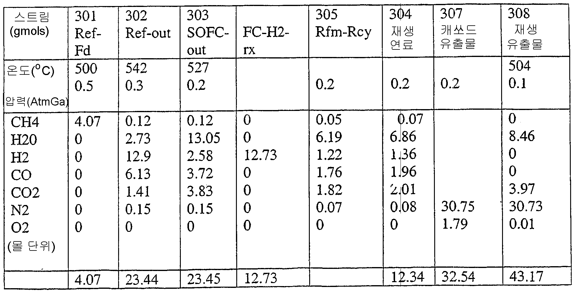
도 3은 수소 연료를 고체 산화물 연료 전지에 공급하는, 상기 개시된 온도 스윙 개질 공정을 도식적으로 예시한다. TSR 유니트(300)는 단일 베드, 또는 바람직하게는 여러 개의 베드를 포함할 수 있다. 여러 개의 베드의 선택적인 양태에서, 밸브와 유동 조절은 유니트(300) 내에 포함되어 있지만, 이 도면에는 도시되어 있지 않다. 이들의 형태 및 기능은 도 2에 대해서 상기 개시된 바와 같다. 도 3을 설명하자면, 탄화수소 함유 공급물(301), 예를 들면 가솔린 및 증기(305)는 TSR 반응기(300)의 개질 대역으로 공급된다. 탄화수소 함유 공급 기체 및 증기를 이전에 개시한 온도 스윙 개질 공정을 이용하여 합성 기체로 전환시킨다. 합성 기체(302)는 일반적으로 CO, CO2, H2, H2O 및 잔류 탄화수소 기체를 포함한다. TSR에 의해 생성된 합성 기체의 온도는 약 200℃ 내지 약 800℃의 범위, 바람직하게는 약 300℃ 내지 약 600℃의 범위이다. TSR에 의해 생성된 합성 기체의 출구 압력은 약 0 기압 게이지 내지 약 25 기압, 바람직하게는 약 0 기압 내지 약 5 기압 게이지 압력의 범위이다. 3 diagrammatically illustrates the disclosed temperature swing reforming process for supplying hydrogen fuel to a solid oxide fuel cell. The
수소 함유 합성기체(302)를 연료 전지 애노드에 공급한다. 바람직한 양태에서, SOFC, 및 특히 전지의 애노드 영역을 승온, 전형적으로는 약 600℃ 내지 약 1200℃에서 조작한다. 합성 기체(302)는 연료의 수소 함량을 추가로 풍부하게 하기 위해 SOFC의 애노드 영역에서 CO 및 잔류 탄화수소를 추가로 개질시킨다. 수소가 풍부한 합성 기체를 연료 전지 애노드에 공급하고, 여기서 이의 수소 함량은 본원에 개시된 바와 같은 전기를 생성하기 위한 전기화학적 반응을 위한 연료로서 작용한다. 용어 "수소가 풍부한"은 추가의 수소 함량을 갖는 합성 기체를 의미하고, 이는 이 양태에서는 SOFC의 애노드 영역에서 일어나는 증기 및 CO, CO2 잔류 탄화수소 또는 이의 혼합물의 추가의 개질에 의해 생성된다. 전형적으로 공기로서 공급되는 산소 함유 기체(306)는 SOFC(310)의 캐쏘드에 공급된다. 수소가 풍부한 합성 기체는 SOFC 전기화학적 반응에 "연료를 보급한다". SOFC 산소 이온은 밀집된 전해질을 가로질러 이동하여 애노드에서 양성자와 조합된다. 음전하를 띤 산소 이온이 수소와 조합하여 H2O를 생성함에 따라, 애노드의 산소 이온은 전자를 공급하고, 이는 외부 부하를 통해 전자가 결핍된 캐쏘드로 돌아간다. 애노드로부터의 유출물(303)은 연료 전지가 소비하지 않은 임의의 잔류 수소와 함께, 반응에서 생성된 CO, CO2, 물(또는 증기)을 포함한다. 바람직한 양태에서, 이 유출물 스트림의 잔류 연료 내용물은 본원에서 상기 개시한 TSR의 재생 공정의 연료를 보급하는데 이용된다. 따라서, 유출물 스트림(303)은 적어도 2개의 스트림(304) 및 (305)로 분할되고, 여기서 스트림(304)은 상기 개시된 바와 같은 TSR 재생 단계의 연소 단계를 달성하기에 충분한 연료를 포함하고, 스트림(305)은 TSR 방법에 개질 스트림을 공급하기에 충분한 물 함량을 포함한다. Hydrogen-containing
바람직한 양태에서, 캐쏘드 유출물(307)은 TSR 재생 공정을 위해 이용되고, 캐쏘드로 도입된 공기는 SOFC 캐쏘드의 산소 필요조건을 공급하기에 충분하고, 상기 개시된 바와 같은 TSR을 위한 재생 주기에서 산화체로서 작용한다. 전형적으로 산소 함유 공급물(306)은 SOFC 캐쏘드에서 약 1.2 내지 2.0, 바람직하게는 1.2 내지 1.5의 산소 화학양론을 갖는 기체를 포함한다(즉, 약 20% 내지 100%의 과량의 산소가 캐쏘드에 공급된다). In a preferred embodiment, the
물리적으로 분리된 것으로 예시되었지만, 바람직한 양태에서, TSR(300) 및 SOFC(310)는 물리적으로 통합된 장치를 구성한다. 통합된 장치의 이점은 개선된 열 통합, 액체 물 수집 및 저장 수단의 감소 또는 제거, 및 SOFC의 적합한 조작 온도까지의 빠른 초기 가열을 포함한다. 물리적으로 통합된 시스템에서, TSR 반응기 및 SOFC로부터의 투입양과 생산량은 이들 스트림중에서 열 교환이 아닌 다른 방법을 사용하지 않는 것과 직접적으로 커플링된다. TSR을 위한 산소 공급원은 캐쏘드 배출 기체(스트림 307)에 의해 운송된다. TSR 개질 유출물은 추가의 가공없이 SOFC 애노드에 의해 직접적으로 이용된다. 애노드 유출물(303)은 개질기로부터의 스트림(305)의 공급원으로서 그리고 TSR 재생 단계를 위한 연료(304)의 공급원으로써 직접 사용된다. 2가지 공정이 이렇게 통합되는 경우 선택적인 열 교환이 아닌 중간 단계가 필요하지 않다. 이는 물 축합, 물 기체 이동, 수소 분리 또는 일산화탄소 제거와 같은 다른 공정의 복잡성을 피한다. 도 3은 직접 커플링된 TSR-SOFC의 하나의 이런 양태를 예시하고, 여기에는 선택적인 열 교환이 나타나 있지 않다. 공정의 물리적인 통합으로 인해 동일한 단열 시스템 내부에 위치하고, 보조 파이프, 절연 및 다른 성분의 크기를 최소화시킨 유니트가 생성되었다. 이 양태에서는, TSR 방법이 SOFC와 대략 동일한 압력에서 수행된다. Although illustrated as physically separate, in a preferred embodiment,
실시예 1Example 1
하기 실시예는 본 발명의 양태를 더 잘 예시하기 위해 포함되어 있다. 일정양의 메탄을 도 3에 도시된 통합된 TSR/SOFC 시스템으로의 공급물로서 이용하였다. 도시된 결과는 약 8000C1 GHSV 및 3초 TSR 순환 시간에서 메탄을 공급한 경우에 대한 것이다. 개질 측면으로의 증기/탄소 비는 약 1.5이다. 연료 전지 적층체에서의 수소 이용도는 약 0.8이고, CO 이용도는 약 0.39이다. 전형적인 조작에서, 수소 이용도 및 H2와 CO의 상대적인 반응 속도/이용도는 연료 전지 유형 막 화학, 온도 및 다른 전지 변수에 따라 다양할 것이다. 스트림(303)이 (305)로 약 53%, (104)로 약 47%로 분할된다. 중요한 조작 및 공정 변수는 하기 표 1에서 확인된 바와 같다. The following examples are included to better illustrate aspects of the present invention. An amount of methane was used as feed to the integrated TSR / SOFC system shown in FIG. The results shown are for the case where methane was fed at about 8000C 1 GHSV and 3 sec TSR cycle time. The vapor / carbon ratio to the reforming side is about 1.5. The hydrogen utilization in the fuel cell stack is about 0.8 and the CO utilization is about 0.39. In a typical operation, hydrogen utilization and the relative reaction rate / availability of H 2 and CO will vary depending on the fuel cell type membrane chemistry, temperature and other cell parameters.
일부 연료 전지 조작 조건 하에서는, 애노드 유출물 스트림의 물 함량이 TSR 또는 다른 시스템 개질 요구조건의 물 필요량을 만족시키기에는 불충분할 수 있다. 점선(305)으로 도시되는 바와 같이 추가의 "보충" 물(309)이 첨가될 수 있지만, 본 발명의 바람직한 양태에서는, 선택적인 응축기 또는 물 저장소(311)를 이용하여 TSR 재생 유출물(308)로부터 나오는 물을 수집하고 저장한다. 이 물은 필요에 따라 연료(301)와 애노드 유출물 잔류 연료(305)와 함께 TSR 개질기 주기로 주입될 수 있다. Under some fuel cell operating conditions, the water content of the anode effluent stream may be insufficient to meet the water requirements of TSR or other system reforming requirements. Additional "supplement"
본 발명의 다른 양태는 도 4에 도시되어 있다. 이 도면에 도시된 양태는 SOFC 애노드 유출물이 상기 본원에 개시된 바와 같은 TSR를 위한 재생을 효율적으로 공급하기에 적절한 연료를 함유하지 않는 경우 유리할 수 있다. 이 양태에서, TSR 개질 유출물(402)은 SOFC의 애노드로 수소가 풍부한 연료 기체(404)를 보급하는 것과 TSR 재생을 위해 충분한 양의 연료(403)를 공급하는 것으로 나누어진다. 잔류 CO, CO2, 생성된 물, 및 SOFC에 의해 소비되지 않은 임의의 잔류 연료를 포함하는 애노드 배기물(405)은 상기 개시된 바와 같은 TSR의 개질 단계로의 공급물로서 개질 대역으로 돌아간다. Another aspect of the invention is shown in FIG. 4. The aspect shown in this figure may be advantageous if the SOFC anode effluent does not contain a fuel suitable for efficiently supplying regeneration for the TSR as disclosed herein above. In this embodiment, the
도 3에 대해 개시한 바와 같이, 전형적으로 공기로서 공급되는 산소 함유 기체(406)는 SOFC의 캐쏘드로 공급된다. 바람직한 양태에서, 캐쏘드 유출물(407)은 TSR 재생 공정을 위해 이용되고, 캐쏘드로 도입되는 산소 함유 공급물(406)은 SOFC 캐쏘드의 산소 요구조건을 공급하기에 충분하고, TSR 재생 주기에서 산화체로서 작용한다. As disclosed for FIG. 3, oxygen-containing
도 3에 예시된 양태에 대해 개시된 바와 같이, 물 축합 수단 및 저장소(411)를 선택적으로 사용하여 TSR 재생 유출물(408)로부터 생성된 물을 포획하거나 저장하고, TSR(409)의 물(스트림) 요구조건을 공급 또는 보충한다. As disclosed for the embodiment illustrated in FIG. 3, water condensation means and
본 발명의 다른 양태는 도 5에 도시되어 있고, 이는 도 3에 예시되고 이후에 개시된 TSR 연료 전지 시스템을 추가의 동력 생성 수단, 전형적으로 터빈과 조합하여 이용한다. 도면을 설명하자면, TSR(500) 개질 단계에는 탄화수소(501) 및 증기(505)를 함유하는 스트림이 공급되고; 개질 유출물(507)은 SOFC(510) 애노드로 공급되고; SOFC 캐쏘드에는 공기(506)가 공급되고; SOFC 캐쏘드 유출물(502)은 TSR 재생 단계로 공급되고; SOFC 애노드 유출물(503)은 재생 연료(504)를 위해 사용되고, 이들 모두는 이전에 도 3에 대해 개시된 바와 같다. 이 양태에서, 추가의 전력이 TSR-SOFC 시스템의 폐기열로부터 생성된다. SOFC 폐기열을 이용하여 증기(505)가 생성된다. 도 5에 도시된 바와 같은 한 양태에서, 폐기 열은 증기 보일러(527, 528) 각각 중의 애노드 및 캐쏘드 유출물을 냉각시킴으로써 수집되고, 결과적으로 공정 증기(505)를 생성한다. (도시되지 않은) 다른 양태는 열을 SOFC에서 직접 수집할 수 있다. 압축기(515)와 팽창기(516)의 조합을 이용하여 공기(514)를 캐쏘드 공급물(506)로 가압하고, 재생기 유출물(508)로부터 전력(518)을 생성하고, 이에 따라 이는 감압되어 연통 기체(517)가 된다. 개질에 필요한 것 이상의 추가의 증기(505)가 재생기 유출물(508)에 추가되어 팽창기 동력을 증가시킬 수 있다. Another aspect of the invention is shown in FIG. 5, which utilizes the TSR fuel cell system illustrated in FIG. 3 and described later in combination with additional power generating means, typically a turbine. To illustrate, the
Claims (23)
Applications Claiming Priority (5)
| Application Number | Priority Date | Filing Date | Title |
|---|---|---|---|
| US47286403P | 2003-05-23 | 2003-05-23 | |
| US60/472,864 | 2003-05-23 | ||
| US10/848,095 | 2004-05-18 | ||
| US10/848,095 US7503948B2 (en) | 2003-05-23 | 2004-05-18 | Solid oxide fuel cell systems having temperature swing reforming |
| PCT/US2004/016232 WO2004106226A1 (en) | 2003-05-23 | 2004-05-21 | Method for producing electricity using temperature swing reforming and solid oxide fuel cell |
Publications (2)
| Publication Number | Publication Date |
|---|---|
| KR20060013673A true KR20060013673A (en) | 2006-02-13 |
| KR101128168B1 KR101128168B1 (en) | 2012-03-23 |
Family
ID=33457404
Family Applications (1)
| Application Number | Title | Priority Date | Filing Date |
|---|---|---|---|
| KR1020057022274A Expired - Fee Related KR101128168B1 (en) | 2003-05-23 | 2004-05-21 | Method for producing electricity using temperature swing reforming and solid oxide fuel cell |
Country Status (10)
| Country | Link |
|---|---|
| US (1) | US7503948B2 (en) |
| EP (1) | EP1636132B1 (en) |
| JP (1) | JP4714691B2 (en) |
| KR (1) | KR101128168B1 (en) |
| AT (1) | ATE544728T1 (en) |
| AU (1) | AU2004243287B2 (en) |
| CA (1) | CA2524437C (en) |
| DK (1) | DK1636132T3 (en) |
| ES (1) | ES2381789T3 (en) |
| WO (1) | WO2004106226A1 (en) |
Families Citing this family (88)
| Publication number | Priority date | Publication date | Assignee | Title |
|---|---|---|---|---|
| US7914764B2 (en) * | 2003-02-28 | 2011-03-29 | Exxonmobil Research And Engineering Company | Hydrogen manufacture using pressure swing reforming |
| US7306871B2 (en) | 2004-03-04 | 2007-12-11 | Delphi Technologies, Inc. | Hybrid power generating system combining a fuel cell and a gas turbine |
| DE102004059647B4 (en) * | 2004-12-10 | 2008-01-31 | Webasto Ag | Process for regenerating a reformer |
| US7875402B2 (en) * | 2005-02-23 | 2011-01-25 | Exxonmobil Research And Engineering Company | Proton conducting solid oxide fuel cell systems having temperature swing reforming |
| JP4664709B2 (en) * | 2005-03-08 | 2011-04-06 | トヨタ自動車株式会社 | Hydrogen generator and fuel cell system |
| JP4656985B2 (en) * | 2005-04-05 | 2011-03-23 | トヨタ自動車株式会社 | Hydrogen generator and fuel cell system |
| US7389638B2 (en) * | 2005-07-12 | 2008-06-24 | Exxonmobil Research And Engineering Company | Sulfur oxide/nitrogen oxide trap system and method for the protection of nitrogen oxide storage reduction catalyst from sulfur poisoning |
| US8507404B2 (en) * | 2005-07-12 | 2013-08-13 | Exxonmobil Research And Engineering Company | Regenerable sulfur traps for on-board vehicle applications |
| US7799314B2 (en) * | 2005-09-09 | 2010-09-21 | Exxonmobil Research And Engineering Company | Hydrogen production and use in an internal combustion engine system |
| US7846401B2 (en) * | 2005-12-23 | 2010-12-07 | Exxonmobil Research And Engineering Company | Controlled combustion for regenerative reactors |
| DE112006003993A5 (en) * | 2006-06-12 | 2009-06-10 | Enerday Gmbh | Process for regenerating a reformer |
| DE102006057357A1 (en) * | 2006-12-04 | 2008-06-05 | J. Eberspächer GmbH & Co. KG | Fuel cell system operating method for motor vehicle, involves conveying oxidizer opposite to flow direction through reformer, where flow direction is present for generating anode gases and/or electric current during normal operation |
| US7815873B2 (en) * | 2006-12-15 | 2010-10-19 | Exxonmobil Research And Engineering Company | Controlled combustion for regenerative reactors with mixer/flow distributor |
| EA016546B1 (en) * | 2007-05-18 | 2012-05-30 | Эксонмобил Рисерч Энд Инджиниринг Компани | Process for removing a target gas from a mixture of gases by thermal swing adsorption |
| CN100547124C (en) * | 2007-10-31 | 2009-10-07 | 中国科学院上海光学精密机械研究所 | Growth method of carbon-doped sapphire crystal |
| CA2934542C (en) | 2008-03-28 | 2018-11-06 | Exxonmobil Upstream Research Company | Low emission power generation and hydrocarbon recovery systems and methods |
| CN101981162B (en) | 2008-03-28 | 2014-07-02 | 埃克森美孚上游研究公司 | Low emission power generation and hydrocarbon recovery systems and methods |
| AU2009303735B2 (en) | 2008-10-14 | 2014-06-26 | Exxonmobil Upstream Research Company | Methods and systems for controlling the products of combustion |
| US8450552B2 (en) * | 2009-05-18 | 2013-05-28 | Exxonmobil Chemical Patents Inc. | Pyrolysis reactor materials and methods |
| MY171001A (en) | 2009-06-05 | 2019-09-23 | Exxonmobil Upstream Res Co | Combustor systems and combustion burners for combusting a fuel |
| DE102009031774B4 (en) * | 2009-06-30 | 2012-02-02 | Fraunhofer-Gesellschaft zur Förderung der angewandten Forschung e.V. | High-temperature fuel cell system |
| MX341477B (en) | 2009-11-12 | 2016-08-22 | Exxonmobil Upstream Res Company * | Low emission power generation and hydrocarbon recovery systems and methods. |
| US7818969B1 (en) | 2009-12-18 | 2010-10-26 | Energyield, Llc | Enhanced efficiency turbine |
| AU2011271635B2 (en) | 2010-07-02 | 2015-10-08 | Exxonmobil Upstream Research Company | Stoichiometric combustion of enriched air with exhaust gas recirculation |
| CN102971508B (en) | 2010-07-02 | 2016-06-01 | 埃克森美孚上游研究公司 | CO2 separation system and method for separating CO2 |
| AU2011271633B2 (en) | 2010-07-02 | 2015-06-11 | Exxonmobil Upstream Research Company | Low emission triple-cycle power generation systems and methods |
| MY156099A (en) | 2010-07-02 | 2016-01-15 | Exxonmobil Upstream Res Co | Systems and methods for controlling combustion of a fuel |
| SG186156A1 (en) | 2010-07-02 | 2013-01-30 | Exxonmobil Upstream Res Co | Stoichiometric combustion with exhaust gas recirculation and direct contact cooler |
| JP6193759B2 (en) | 2010-08-06 | 2017-09-06 | エクソンモービル アップストリーム リサーチ カンパニー | Stoichiometric combustion optimization system and method |
| US9399950B2 (en) | 2010-08-06 | 2016-07-26 | Exxonmobil Upstream Research Company | Systems and methods for exhaust gas extraction |
| TWI593872B (en) | 2011-03-22 | 2017-08-01 | 艾克頌美孚上游研究公司 | Integrated system and method of generating power |
| TWI564474B (en) | 2011-03-22 | 2017-01-01 | 艾克頌美孚上游研究公司 | Integrated systems for controlling stoichiometric combustion in turbine systems and methods of generating power using the same |
| TWI563165B (en) | 2011-03-22 | 2016-12-21 | Exxonmobil Upstream Res Co | Power generation system and method for generating power |
| TWI563166B (en) | 2011-03-22 | 2016-12-21 | Exxonmobil Upstream Res Co | Integrated generation systems and methods for generating power |
| CN104428490B (en) | 2011-12-20 | 2018-06-05 | 埃克森美孚上游研究公司 | The coal bed methane production of raising |
| US9353682B2 (en) | 2012-04-12 | 2016-05-31 | General Electric Company | Methods, systems and apparatus relating to combustion turbine power plants with exhaust gas recirculation |
| US10273880B2 (en) | 2012-04-26 | 2019-04-30 | General Electric Company | System and method of recirculating exhaust gas for use in a plurality of flow paths in a gas turbine engine |
| US9784185B2 (en) | 2012-04-26 | 2017-10-10 | General Electric Company | System and method for cooling a gas turbine with an exhaust gas provided by the gas turbine |
| US9611756B2 (en) | 2012-11-02 | 2017-04-04 | General Electric Company | System and method for protecting components in a gas turbine engine with exhaust gas recirculation |
| US10107495B2 (en) | 2012-11-02 | 2018-10-23 | General Electric Company | Gas turbine combustor control system for stoichiometric combustion in the presence of a diluent |
| US9631815B2 (en) | 2012-12-28 | 2017-04-25 | General Electric Company | System and method for a turbine combustor |
| US9708977B2 (en) | 2012-12-28 | 2017-07-18 | General Electric Company | System and method for reheat in gas turbine with exhaust gas recirculation |
| US9803865B2 (en) | 2012-12-28 | 2017-10-31 | General Electric Company | System and method for a turbine combustor |
| US10100741B2 (en) | 2012-11-02 | 2018-10-16 | General Electric Company | System and method for diffusion combustion with oxidant-diluent mixing in a stoichiometric exhaust gas recirculation gas turbine system |
| US9869279B2 (en) | 2012-11-02 | 2018-01-16 | General Electric Company | System and method for a multi-wall turbine combustor |
| US10215412B2 (en) | 2012-11-02 | 2019-02-26 | General Electric Company | System and method for load control with diffusion combustion in a stoichiometric exhaust gas recirculation gas turbine system |
| US9574496B2 (en) | 2012-12-28 | 2017-02-21 | General Electric Company | System and method for a turbine combustor |
| US9599070B2 (en) | 2012-11-02 | 2017-03-21 | General Electric Company | System and method for oxidant compression in a stoichiometric exhaust gas recirculation gas turbine system |
| US10208677B2 (en) | 2012-12-31 | 2019-02-19 | General Electric Company | Gas turbine load control system |
| US9581081B2 (en) | 2013-01-13 | 2017-02-28 | General Electric Company | System and method for protecting components in a gas turbine engine with exhaust gas recirculation |
| US9512759B2 (en) | 2013-02-06 | 2016-12-06 | General Electric Company | System and method for catalyst heat utilization for gas turbine with exhaust gas recirculation |
| US9938861B2 (en) | 2013-02-21 | 2018-04-10 | Exxonmobil Upstream Research Company | Fuel combusting method |
| TW201502356A (en) | 2013-02-21 | 2015-01-16 | Exxonmobil Upstream Res Co | Reducing oxygen in a gas turbine exhaust |
| RU2637609C2 (en) | 2013-02-28 | 2017-12-05 | Эксонмобил Апстрим Рисерч Компани | System and method for turbine combustion chamber |
| US9618261B2 (en) | 2013-03-08 | 2017-04-11 | Exxonmobil Upstream Research Company | Power generation and LNG production |
| US20140250945A1 (en) | 2013-03-08 | 2014-09-11 | Richard A. Huntington | Carbon Dioxide Recovery |
| CA2902479C (en) | 2013-03-08 | 2017-11-07 | Exxonmobil Upstream Research Company | Power generation and methane recovery from methane hydrates |
| TW201500635A (en) | 2013-03-08 | 2015-01-01 | Exxonmobil Upstream Res Co | Processing exhaust for use in enhanced oil recovery |
| US9835089B2 (en) | 2013-06-28 | 2017-12-05 | General Electric Company | System and method for a fuel nozzle |
| US9617914B2 (en) | 2013-06-28 | 2017-04-11 | General Electric Company | Systems and methods for monitoring gas turbine systems having exhaust gas recirculation |
| TWI654368B (en) | 2013-06-28 | 2019-03-21 | 美商艾克頌美孚上游研究公司 | System, method and media for controlling exhaust gas flow in an exhaust gas recirculation gas turbine system |
| US9631542B2 (en) | 2013-06-28 | 2017-04-25 | General Electric Company | System and method for exhausting combustion gases from gas turbine engines |
| US9903588B2 (en) | 2013-07-30 | 2018-02-27 | General Electric Company | System and method for barrier in passage of combustor of gas turbine engine with exhaust gas recirculation |
| US9587510B2 (en) | 2013-07-30 | 2017-03-07 | General Electric Company | System and method for a gas turbine engine sensor |
| US9951658B2 (en) | 2013-07-31 | 2018-04-24 | General Electric Company | System and method for an oxidant heating system |
| US10030588B2 (en) | 2013-12-04 | 2018-07-24 | General Electric Company | Gas turbine combustor diagnostic system and method |
| US9752458B2 (en) | 2013-12-04 | 2017-09-05 | General Electric Company | System and method for a gas turbine engine |
| US10227920B2 (en) | 2014-01-15 | 2019-03-12 | General Electric Company | Gas turbine oxidant separation system |
| US9863267B2 (en) | 2014-01-21 | 2018-01-09 | General Electric Company | System and method of control for a gas turbine engine |
| US9915200B2 (en) | 2014-01-21 | 2018-03-13 | General Electric Company | System and method for controlling the combustion process in a gas turbine operating with exhaust gas recirculation |
| US10079564B2 (en) | 2014-01-27 | 2018-09-18 | General Electric Company | System and method for a stoichiometric exhaust gas recirculation gas turbine system |
| US10047633B2 (en) | 2014-05-16 | 2018-08-14 | General Electric Company | Bearing housing |
| US10655542B2 (en) | 2014-06-30 | 2020-05-19 | General Electric Company | Method and system for startup of gas turbine system drive trains with exhaust gas recirculation |
| US10060359B2 (en) | 2014-06-30 | 2018-08-28 | General Electric Company | Method and system for combustion control for gas turbine system with exhaust gas recirculation |
| US9885290B2 (en) | 2014-06-30 | 2018-02-06 | General Electric Company | Erosion suppression system and method in an exhaust gas recirculation gas turbine system |
| US9819192B2 (en) | 2014-07-29 | 2017-11-14 | General Electric Company | Solid oxide fuel cell-based power generation and delivery system and method of operating the same |
| US9696787B2 (en) * | 2014-12-10 | 2017-07-04 | Qualcomm Innovation Center, Inc. | Dynamic control of processors to reduce thermal and power costs |
| US9869247B2 (en) | 2014-12-31 | 2018-01-16 | General Electric Company | Systems and methods of estimating a combustion equivalence ratio in a gas turbine with exhaust gas recirculation |
| US9819292B2 (en) | 2014-12-31 | 2017-11-14 | General Electric Company | Systems and methods to respond to grid overfrequency events for a stoichiometric exhaust recirculation gas turbine |
| US10788212B2 (en) | 2015-01-12 | 2020-09-29 | General Electric Company | System and method for an oxidant passageway in a gas turbine system with exhaust gas recirculation |
| US10094566B2 (en) | 2015-02-04 | 2018-10-09 | General Electric Company | Systems and methods for high volumetric oxidant flow in gas turbine engine with exhaust gas recirculation |
| US10253690B2 (en) | 2015-02-04 | 2019-04-09 | General Electric Company | Turbine system with exhaust gas recirculation, separation and extraction |
| US10316746B2 (en) | 2015-02-04 | 2019-06-11 | General Electric Company | Turbine system with exhaust gas recirculation, separation and extraction |
| US10267270B2 (en) | 2015-02-06 | 2019-04-23 | General Electric Company | Systems and methods for carbon black production with a gas turbine engine having exhaust gas recirculation |
| US10145269B2 (en) | 2015-03-04 | 2018-12-04 | General Electric Company | System and method for cooling discharge flow |
| US10480792B2 (en) | 2015-03-06 | 2019-11-19 | General Electric Company | Fuel staging in a gas turbine engine |
| WO2017087188A1 (en) * | 2015-11-18 | 2017-05-26 | Exxonmobil Research And Engineering Company | Heat-resistant hydrocarbon reforming catalyst based on rhodium on a lanthanum-stabilised theta-alumina |
| AU2020252380B2 (en) * | 2019-04-05 | 2025-06-26 | Exxonmobil Research And Engineering Company | Oxycombustion with CO2 capture in reverse flow reactors |
Family Cites Families (13)
| Publication number | Priority date | Publication date | Assignee | Title |
|---|---|---|---|---|
| US2556835A (en) * | 1945-12-29 | 1951-06-12 | Standard Oil Dev Co | Process for producing gas mixtures |
| US2845335A (en) * | 1952-03-20 | 1958-07-29 | Koppers Co Inc | Regenerative processes and apparatus |
| US4240805A (en) * | 1979-03-16 | 1980-12-23 | United Technologies Corporation | Process for producing hydrogen containing gas |
| US6083636A (en) * | 1994-08-08 | 2000-07-04 | Ztek Corporation | Fuel cell stacks for ultra-high efficiency power systems |
| JPH1186893A (en) * | 1997-09-04 | 1999-03-30 | Aisin Seiki Co Ltd | Fuel cell system |
| US6113874A (en) * | 1998-04-29 | 2000-09-05 | Praxair Technology, Inc. | Thermochemical regenerative heat recovery process |
| US6576203B2 (en) * | 1998-06-29 | 2003-06-10 | Ngk Insulators, Ltd. | Reformer |
| AU2197500A (en) | 1998-12-23 | 2000-07-31 | International Fuel Cells, Llc | A hydrocarbon fueled power plant employing a proton exchange membrane (pem) fuelcell |
| AUPQ223499A0 (en) * | 1999-08-16 | 1999-09-09 | Ceramic Fuel Cells Limited | Fuel cell system |
| US6210157B1 (en) * | 2000-04-07 | 2001-04-03 | Praxair Technology, Inc. | Fuel reformer combustion process |
| US6767530B2 (en) * | 2001-12-14 | 2004-07-27 | Praxair Technology, Inc. | Method for producing hydrogen |
| US7491250B2 (en) | 2002-06-25 | 2009-02-17 | Exxonmobil Research And Engineering Company | Pressure swing reforming |
| US7217303B2 (en) * | 2003-02-28 | 2007-05-15 | Exxonmobil Research And Engineering Company | Pressure swing reforming for fuel cell systems |
-
2004
- 2004-05-18 US US10/848,095 patent/US7503948B2/en not_active Expired - Fee Related
- 2004-05-21 JP JP2006533342A patent/JP4714691B2/en not_active Expired - Lifetime
- 2004-05-21 CA CA2524437A patent/CA2524437C/en not_active Expired - Fee Related
- 2004-05-21 KR KR1020057022274A patent/KR101128168B1/en not_active Expired - Fee Related
- 2004-05-21 AT AT04753118T patent/ATE544728T1/en active
- 2004-05-21 EP EP04753118A patent/EP1636132B1/en not_active Expired - Lifetime
- 2004-05-21 DK DK04753118.1T patent/DK1636132T3/en active
- 2004-05-21 WO PCT/US2004/016232 patent/WO2004106226A1/en not_active Ceased
- 2004-05-21 ES ES04753118T patent/ES2381789T3/en not_active Expired - Lifetime
- 2004-05-21 AU AU2004243287A patent/AU2004243287B2/en not_active Ceased
Also Published As
| Publication number | Publication date |
|---|---|
| CA2524437C (en) | 2012-06-12 |
| US7503948B2 (en) | 2009-03-17 |
| AU2004243287B2 (en) | 2009-04-23 |
| JP2007502771A (en) | 2007-02-15 |
| ATE544728T1 (en) | 2012-02-15 |
| KR101128168B1 (en) | 2012-03-23 |
| CA2524437A1 (en) | 2004-12-09 |
| WO2004106226A1 (en) | 2004-12-09 |
| ES2381789T3 (en) | 2012-05-31 |
| JP4714691B2 (en) | 2011-06-29 |
| EP1636132A1 (en) | 2006-03-22 |
| EP1636132B1 (en) | 2012-02-08 |
| AU2004243287A1 (en) | 2004-12-09 |
| US20040241505A1 (en) | 2004-12-02 |
| DK1636132T3 (en) | 2012-05-21 |
Similar Documents
| Publication | Publication Date | Title |
|---|---|---|
| KR101128168B1 (en) | Method for producing electricity using temperature swing reforming and solid oxide fuel cell | |
| US7875402B2 (en) | Proton conducting solid oxide fuel cell systems having temperature swing reforming | |
| CN101119925B (en) | fuel cell fuel processor with hydrogen buffering | |
| CN1863730B (en) | Pressure swing reforming for fuel cell systems | |
| WO2007032839A1 (en) | Hydrogen production and use in an internal combustion engine system | |
| CN100540459C (en) | Method for generating electricity using temperature swing reforming and solid oxide fuel cells | |
| MXPA05012062A (en) | Method for producing electricity using temperature swing reforming and solid oxide fuel cell |
Legal Events
| Date | Code | Title | Description |
|---|---|---|---|
| PA0105 | International application |
St.27 status event code: A-0-1-A10-A15-nap-PA0105 |
|
| PG1501 | Laying open of application |
St.27 status event code: A-1-1-Q10-Q12-nap-PG1501 |
|
| P11-X000 | Amendment of application requested |
St.27 status event code: A-2-2-P10-P11-nap-X000 |
|
| P13-X000 | Application amended |
St.27 status event code: A-2-2-P10-P13-nap-X000 |
|
| A201 | Request for examination | ||
| P11-X000 | Amendment of application requested |
St.27 status event code: A-2-2-P10-P11-nap-X000 |
|
| P13-X000 | Application amended |
St.27 status event code: A-2-2-P10-P13-nap-X000 |
|
| PA0201 | Request for examination |
St.27 status event code: A-1-2-D10-D11-exm-PA0201 |
|
| R17-X000 | Change to representative recorded |
St.27 status event code: A-3-3-R10-R17-oth-X000 |
|
| E902 | Notification of reason for refusal | ||
| PE0902 | Notice of grounds for rejection |
St.27 status event code: A-1-2-D10-D21-exm-PE0902 |
|
| T11-X000 | Administrative time limit extension requested |
St.27 status event code: U-3-3-T10-T11-oth-X000 |
|
| T11-X000 | Administrative time limit extension requested |
St.27 status event code: U-3-3-T10-T11-oth-X000 |
|
| T11-X000 | Administrative time limit extension requested |
St.27 status event code: U-3-3-T10-T11-oth-X000 |
|
| P11-X000 | Amendment of application requested |
St.27 status event code: A-2-2-P10-P11-nap-X000 |
|
| P13-X000 | Application amended |
St.27 status event code: A-2-2-P10-P13-nap-X000 |
|
| E701 | Decision to grant or registration of patent right | ||
| PE0701 | Decision of registration |
St.27 status event code: A-1-2-D10-D22-exm-PE0701 |
|
| GRNT | Written decision to grant | ||
| PR0701 | Registration of establishment |
St.27 status event code: A-2-4-F10-F11-exm-PR0701 |
|
| PR1002 | Payment of registration fee |
St.27 status event code: A-2-2-U10-U12-oth-PR1002 Fee payment year number: 1 |
|
| PG1601 | Publication of registration |
St.27 status event code: A-4-4-Q10-Q13-nap-PG1601 |
|
| FPAY | Annual fee payment |
Payment date: 20150227 Year of fee payment: 4 |
|
| PR1001 | Payment of annual fee |
St.27 status event code: A-4-4-U10-U11-oth-PR1001 Fee payment year number: 4 |
|
| FPAY | Annual fee payment |
Payment date: 20151230 Year of fee payment: 5 |
|
| PR1001 | Payment of annual fee |
St.27 status event code: A-4-4-U10-U11-oth-PR1001 Fee payment year number: 5 |
|
| FPAY | Annual fee payment |
Payment date: 20161229 Year of fee payment: 6 |
|
| PR1001 | Payment of annual fee |
St.27 status event code: A-4-4-U10-U11-oth-PR1001 Fee payment year number: 6 |
|
| FPAY | Annual fee payment |
Payment date: 20171228 Year of fee payment: 7 |
|
| PR1001 | Payment of annual fee |
St.27 status event code: A-4-4-U10-U11-oth-PR1001 Fee payment year number: 7 |
|
| FPAY | Annual fee payment |
Payment date: 20181227 Year of fee payment: 8 |
|
| PR1001 | Payment of annual fee |
St.27 status event code: A-4-4-U10-U11-oth-PR1001 Fee payment year number: 8 |
|
| PR1001 | Payment of annual fee |
St.27 status event code: A-4-4-U10-U11-oth-PR1001 Fee payment year number: 9 |
|
| PC1903 | Unpaid annual fee |
St.27 status event code: A-4-4-U10-U13-oth-PC1903 Not in force date: 20210313 Payment event data comment text: Termination Category : DEFAULT_OF_REGISTRATION_FEE |
|
| PC1903 | Unpaid annual fee |
St.27 status event code: N-4-6-H10-H13-oth-PC1903 Ip right cessation event data comment text: Termination Category : DEFAULT_OF_REGISTRATION_FEE Not in force date: 20210313 |
|
| R18-X000 | Changes to party contact information recorded |
St.27 status event code: A-5-5-R10-R18-oth-X000 |