KR200494560Y1 - Structure for Installing Inverter - Google Patents
Structure for Installing Inverter Download PDFInfo
- Publication number
- KR200494560Y1 KR200494560Y1 KR2020190004430U KR20190004430U KR200494560Y1 KR 200494560 Y1 KR200494560 Y1 KR 200494560Y1 KR 2020190004430 U KR2020190004430 U KR 2020190004430U KR 20190004430 U KR20190004430 U KR 20190004430U KR 200494560 Y1 KR200494560 Y1 KR 200494560Y1
- Authority
- KR
- South Korea
- Prior art keywords
- inverter
- coupled
- enclosure
- bracket
- option
- Prior art date
- Legal status (The legal status is an assumption and is not a legal conclusion. Google has not performed a legal analysis and makes no representation as to the accuracy of the status listed.)
- Active
Links
Images


Classifications
-
- H—ELECTRICITY
- H05—ELECTRIC TECHNIQUES NOT OTHERWISE PROVIDED FOR
- H05K—PRINTED CIRCUITS; CASINGS OR CONSTRUCTIONAL DETAILS OF ELECTRIC APPARATUS; MANUFACTURE OF ASSEMBLAGES OF ELECTRICAL COMPONENTS
- H05K7/00—Constructional details common to different types of electric apparatus
- H05K7/14—Mounting supporting structure in casing or on frame or rack
- H05K7/1422—Printed circuit boards receptacles, e.g. stacked structures, electronic circuit modules or box like frames
- H05K7/1427—Housings
- H05K7/1432—Housings specially adapted for power drive units or power converters
-
- H—ELECTRICITY
- H02—GENERATION; CONVERSION OR DISTRIBUTION OF ELECTRIC POWER
- H02M—APPARATUS FOR CONVERSION BETWEEN AC AND AC, BETWEEN AC AND DC, OR BETWEEN DC AND DC, AND FOR USE WITH MAINS OR SIMILAR POWER SUPPLY SYSTEMS; CONVERSION OF DC OR AC INPUT POWER INTO SURGE OUTPUT POWER; CONTROL OR REGULATION THEREOF
- H02M7/00—Conversion of AC power input into DC power output; Conversion of DC power input into AC power output
- H02M7/42—Conversion of DC power input into AC power output without possibility of reversal
- H02M7/44—Conversion of DC power input into AC power output without possibility of reversal by static converters
-
- H—ELECTRICITY
- H05—ELECTRIC TECHNIQUES NOT OTHERWISE PROVIDED FOR
- H05K—PRINTED CIRCUITS; CASINGS OR CONSTRUCTIONAL DETAILS OF ELECTRIC APPARATUS; MANUFACTURE OF ASSEMBLAGES OF ELECTRICAL COMPONENTS
- H05K7/00—Constructional details common to different types of electric apparatus
- H05K7/14—Mounting supporting structure in casing or on frame or rack
- H05K7/1401—Mounting supporting structure in casing or on frame or rack comprising clamping or extracting means
-
- H—ELECTRICITY
- H05—ELECTRIC TECHNIQUES NOT OTHERWISE PROVIDED FOR
- H05K—PRINTED CIRCUITS; CASINGS OR CONSTRUCTIONAL DETAILS OF ELECTRIC APPARATUS; MANUFACTURE OF ASSEMBLAGES OF ELECTRICAL COMPONENTS
- H05K9/00—Screening of apparatus or components against electric or magnetic fields
- H05K9/0064—Earth or grounding circuit
-
- H—ELECTRICITY
- H02—GENERATION; CONVERSION OR DISTRIBUTION OF ELECTRIC POWER
- H02M—APPARATUS FOR CONVERSION BETWEEN AC AND AC, BETWEEN AC AND DC, OR BETWEEN DC AND DC, AND FOR USE WITH MAINS OR SIMILAR POWER SUPPLY SYSTEMS; CONVERSION OF DC OR AC INPUT POWER INTO SURGE OUTPUT POWER; CONTROL OR REGULATION THEREOF
- H02M7/00—Conversion of AC power input into DC power output; Conversion of DC power input into AC power output
- H02M7/003—Constructional details, e.g. physical layout, assembly, wiring or busbar connections
Landscapes
- Engineering & Computer Science (AREA)
- Microelectronics & Electronic Packaging (AREA)
- Power Engineering (AREA)
- Inverter Devices (AREA)
Abstract
본 고안은 조립 편의성 및 내구성이 강화되며 인버터의 구조를 간소화 시킬 수 있는 인버터 장착 구조체에 관한 것으로서, 본 고안의 일 형태에 따르면, 외함 또는 벽면에 고정되며, 내부에 인버터를 수용하여 상기 인버터가 결합되는 인버터 수용공간을 형성하는 브라켓 및 상기 브라켓의 외측에 결합되는 옵션케이스를 포함하는 인버터 장착 구조체가 제공된다.The present invention relates to an inverter mounting structure that has enhanced assembly convenience and durability and can simplify the structure of the inverter. There is provided an inverter mounting structure including a bracket that forms an inverter accommodating space and an optional case coupled to the outside of the bracket.
Description
본 발명은 인버터 장착 구조체에 관한 것으로서, 보다 상세하게는, 조립 편의성 및 내구성이 강화되며 인버터의 구조를 간소화 시킬 수 있는 인버터 장착구조에 관한 것이다.The present invention relates to an inverter mounting structure, and more particularly, to an inverter mounting structure capable of enhancing assembly convenience and durability and simplifying the structure of an inverter.
전동기의 사용범위가 확대 되면서 또한 인버터의 사용도 증대되고 있다. 이러한 인버터는 벽면이나 외함등에 결합되어 사용되는데, 상기 인버터에는 필요에 따라 여러 가지 장치들이 옵션으로 장착될 수 있다.As the range of use of electric motors expands, the use of inverters is also increasing. Such an inverter is used by being coupled to a wall or an enclosure, and various devices may be optionally mounted to the inverter as necessary.
이러한 추가 장착물들은 옵션부라 칭하게 되는데, 이러한 옵션부는 예를 들어 상기 인버터에 전기적으로 연결되는 케이블 등을 고정하여, 케이블 자체의 하중이나 여타 다른 외력에 의해 케이블 등이 탈거되거나 끊어지지 않도록 고정하는 케이블 고정 케이스 등이 있다.These additional attachments are referred to as optional parts. These optional parts fix cables electrically connected to the inverter, for example, so that the cables are not detached or broken by the load of the cable itself or other external forces. cases, etc.
도 1 내지 도 3은 종래의 인버터 및 상기 인버터에 장착되는 옵션부를 도시한 도면이다.1 to 3 are views illustrating a conventional inverter and an option unit mounted on the inverter.
종래의 인버터(10)는 도 1 및 도 2 도시된 바와 같이, 일측에 방열을 위한 히트싱크(20)가 구비되며, 또한 외측의 어느 일면에 케이블 고정 케이스 등의 옵션부(30)가 장착되는 구조로 이루어진다.As shown in FIGS. 1 and 2, the
즉, 상기 인버터(10)는 상기 히트싱크(20)가 외함이나 벽면에 결합되어 장착되며, 상기 히트싱크(20)를 통해 접지가 이루어질 수 있다.That is, in the
그리고, 옵션부(30)는 상기 인버터(10)에 복수개소 체결되어 결합될 수 있다.In addition, the
이 때, 상기 옵션부(30)는 도 3에 도시된 바와 같이, 그 일부가 연장된 형태의 금속편(32)이 상기 인버터(10)의 내측으로 삽입되어 결합되며, 접지를 유지하기 위하여 삽입된 곳이 인버터(10) 내부의 접지패스(12)와 전기적으로 연결되도록 형성된다.At this time, as shown in FIG. 3 , in the
또한, 이러한 접지패스(12)는 금속제로 이루어진 히트싱크(20)와도 전기적으로 연결되도록 이루어져, 상기 히트싱크(20)가 외함이나 벽면에 접촉됨으로써 접지가 이루어지도록 형성될 수 있다.In addition, the
이러한 종래의 인버터(10)에 장착되는 옵션부(30)의 장착구조는 다음과 같은 문제점이 있다.The mounting structure of the
첫째, 상기 옵션부(30)가 인버터(10)에 결합되므로, 옵션부(30)에 작용되는 하중이 인버터(10)에 작용되므로 인버터(10)의 강성이 높게 제작되어야 하는데, 때문에 인버터(10) 제작비용 및 무게가 증가하게 되는 문제점이 있다.First, since the
둘째, 인버터(10)에 부착된 히트싱크(20)가 외함 또는 벽면에 결합되는 구조로서, 히트싱크(20)가 본연의 방열의 역할 외에도 인버터(10)를 고정시키는 역할을 담당하게 되어 하중을 견디게 제작해야 하므로 그 강성이 크도록 제작해야 하므로 제작 비용 및 무게가 증가하게 되는 문제점이 있다.Second, as a structure in which the
셋째, 옵션부(30)가 인버터(10)와 결합하므로 접지를 위해서 인버터(10) 내부에 접지패스(12)를 형성해야 하며, 이러한 접지패스(12)는 히트싱크(20) 및 옵션부(30)와의 결합을 위해 외부로 노출되도록 제작해야 하는데, 이렇게 인버터(10) 내부에 접지패스를 형성해야 해 인버터(10)의 설계 및 제작이 어려워지는 문제점이 있으며, 특정한 설치조건에서는 이러한 외부로 노출된 접지패스(12)가 불리하게 작용될 수도 있는 문제점이 있다.Third, since the
본 고안은 상기와 같은 문제점을 해결하기 위한 것으로서, 본 고안은 설치가 간단하면서도, 구조가 강건하며, 인버터의 제작 및 설계를 간단화 시킬 수 있는 인버터 장착 구조체를 제공하는 것이 과제이다.The present invention is to solve the above problems, and the present invention is to provide an inverter mounting structure that is easy to install, has a strong structure, and can simplify the manufacture and design of an inverter.
본 고안의 과제들은 이상에서 언급한 과제들로 제한되지 않으며, 언급되지 않는 또 다른 과제들은 아래의 기재로부터 당업자에게 명확하게 이해될 수 있을 것이다.The tasks of the present invention are not limited to the tasks mentioned above, and other tasks not mentioned will be clearly understood by those skilled in the art from the following description.
상기한 과제를 해결하기 위하여, 본 고안의 일 형태에 따르면, 외함 또는 벽면에 고정되며, 내부에 인버터를 수용하여 상기 인버터가 결합되는 인버터 수용공간을 형성하는 브라켓 및 상기 브라켓의 외측에 결합되는 옵션케이스를 포함하는 인버터 장착 구조체가 제공된다.In order to solve the above problems, according to one aspect of the present invention, a bracket fixed to an enclosure or a wall surface, accommodating an inverter therein to form an inverter accommodating space to which the inverter is coupled, and an option coupled to the outside of the bracket An inverter mounting structure including a case is provided.
상기 브라켓은, 외함 또는 벽면과 마주보도록 형성되며, 인버터가 결합되는 제1면, 상기 제1면으로부터 외함 또는 벽면에 수직한 방향으로 연장되어 상기 인버터 수용공간의 측면을 이루도록 상기 제1면의 양 측면에서 서로 마주보도록 평행하게 형성되는 제2면 및 상기 제1면으로부터 외함 또는 벽면을 향하여 절곡 연장되어, 외함 또는 벽면에 고정되는 고정홀이 형성된 고정부를 포함하며, 상기 각 제2면의 일측단부는 서로 마주보는 방향으로 절곡되어 플랜지부를 형성할 수 있다.The bracket is formed to face an enclosure or a wall surface, and a first surface to which an inverter is coupled, the amount of the first surface extending from the first surface in a direction perpendicular to the enclosure or wall surface to form a side surface of the inverter accommodating space A second surface formed in parallel to face each other from the side and a fixing portion extending bent from the first surface toward the enclosure or wall surface, the fixing part having a fixing hole fixed to the enclosure or the wall surface is formed, one side of each of the second surfaces The ends may be bent in a direction facing each other to form a flange portion.
상기 옵션케이스는 상기 플랜지부에 결합되어 장착될 수 있다.The option case may be mounted by being coupled to the flange portion.
상기 옵션케이스는, 상기 인버터의 접지단자에 장착된 접지선이 전기적으로 결합되는 접지부가 구비될 수 있다.The option case may include a grounding portion to which a grounding wire mounted on a grounding terminal of the inverter is electrically coupled.
상기 브라켓 및 옵션케이스는 상기 인버터의 접지를 위해 전도성 재질로 형성될 수 있다.The bracket and the option case may be formed of a conductive material for grounding the inverter.
상기 제2면은 상기 인버터의 측면 중 일부를 노출시키도록 형성되며, 적어도 하나 이상의 통기공이 형성될 수 있다.The second surface is formed to expose a portion of the side surface of the inverter, and at least one vent hole may be formed.
상기 옵션케이스는, 상기 인버터에 전기적으로 연결되는 케이블이 결합되는 통공이 복수개 형성될 수 있다.The option case may have a plurality of through holes through which a cable electrically connected to the inverter is coupled.
본 고안의 인버터 장착 구조체에 따르면 다음과 같은 효과가 있다.According to the inverter mounting structure of the present invention, there are the following effects.
종래에는 인버터와 옵션케이스와 접촉하는 부분 및 상기 인버터와 외함이 접촉하는 부분에 모두 접지를 위한 금속구조를 배치하는 접지패스를 형성하는 설계를 해야 했으나, 본 고안의 인버터 장착 구조체에 따르면 일반적으로 모든 인버터가 가지고 있는 접지단자를 통해 접지를 할 수 있어 별도의 접지패스를 형성할 필요가 없으므로 설계가 간단해지고, 제조단가가 절감되는 효과가 있다.In the prior art, it was necessary to design a ground path for arranging a metal structure for grounding in both the part in contact with the inverter and the option case and the part in contact with the inverter and the enclosure, but according to the inverter mounting structure of the present invention, generally all Since it is possible to ground through the grounding terminal of the inverter, there is no need to form a separate grounding path, thereby simplifying the design and reducing the manufacturing cost.
본 고안의 효과들은 이상에서 언급한 효과들로 제한되지 않으며, 언급되지 않은 또 다른 효과들은 청구범위의 기재로부터 당업자에게 명확하게 이해될 수 있을 것이다.Effects of the present invention are not limited to the effects mentioned above, and other effects not mentioned will be clearly understood by those skilled in the art from the description of the claims.
아래에서 설명하는 본 출원의 바람직한 실시예의 상세한 설명뿐만 아니라 위에서 설명한 요약은 첨부된 도면과 관련해서 읽을 때에 더 잘 이해될 수 있을 것이다. 본 고안을 예시하기 위한 목적으로 도면에는 바람직한 실시예들이 도시되어 있다. 그러나, 본 출원은 도시된 정확한 배치와 수단에 한정되는 것이 아님을 이해해야 한다.
도 1은 벽면에 고정된 종래의 인버터를 도시한 도면;
도 2는 도 1의 인버터에 결합된 옵션케이스를 도시한 도면;
도 3은 옵션케이스와 인버터의 결합부의를 도시한 도면으로서, 상기 옵션케이스가 인버터의 접지패스와 전기적으로 연결된 모습을 도시한 도면;
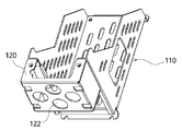
도 4는 본 고안의 일 실시예에 따른 인버터 장착 구조체를 도시한 도면;
도 5는 도 4의 브라켓을 도시한 도면;
도 6은 도 4의 브라켓에 결합된 옵션케이스를 도시한 도면;
도 7은 접지부에 접지선이 결합된 모습을 도시한 도면 이다.The summary set forth above as well as the detailed description of the preferred embodiments of the present application set forth below may be better understood when read in conjunction with the accompanying drawings. Preferred embodiments are shown in the drawings for the purpose of illustrating the present invention. It should be understood, however, that the present application is not limited to the precise arrangements and instrumentalities shown.
1 is a view showing a conventional inverter fixed to a wall;
Figure 2 is a view showing an option case coupled to the inverter of Figure 1;
FIG. 3 is a view showing a coupling part between an option case and an inverter, wherein the option case is electrically connected to a ground path of the inverter;
4 is a view showing an inverter mounting structure according to an embodiment of the present invention;
Figure 5 is a view showing the bracket of Figure 4;
Figure 6 is a view showing an option case coupled to the bracket of Figure 4;
7 is a view showing a state in which a ground wire is coupled to a grounding part.
이하 본 고안의 목적이 구체적으로 실현될 수 있는 본 고안의 바람직한 실시예를 첨부된 도면을 참조하여 설명한다. 본 실시예를 설명함에 있어서, 동일 구성에 대해서는 동일 명칭 및 동일 부호가 사용되며 이에 따른 부가적인 설명은 생략하기로 한다.Hereinafter, preferred embodiments of the present invention in which the object of the present invention can be specifically realized will be described with reference to the accompanying drawings. In describing the present embodiment, the same names and the same reference numerals are used for the same components, and an additional description thereof will be omitted.
이하, 본 고안의 인버터 장착 구조체의 일 실시예에 대해서 설명하기로 한다.Hereinafter, an embodiment of the inverter mounting structure of the present invention will be described.
본 실시예에 따른 인버터 장착 구조체는 도 4 내지 도 6에 도시된 바와 같이, 브라켓(110)과 옵션케이스(120)를 포함할 수 있다.The inverter mounting structure according to the present embodiment may include a
상기 브라켓(110)은 외함 또는 벽면에 고정되며, 내부에 인버터(100)가 결합되어 상기 인버터(100)를 수용하는 인버터 수용공간을 형성할 수 있다. 이 때, 상기 외함 및 벽면은 지면과 접지가 이루어진 상태일 수 있다.The
또한, 상기 옵션케이스(120)는 상기 인버터(100)에 부가적으로 붙는 각종 옵션장치가 수용되거나 장착되기 위한 케이스로서, 상기 브라켓(110)의 외측에 결합될 수 있다. In addition, the
본 실시예에서는 상기 옵션케이스(120)로서, 상기 인버터(100)에 전력 또는 신호를 송수신할 수 있도록 전기적으로 연결되는 케이블(40) 등을 고정하여, 케이블(40) 자체의 하중이나 여타 다른 외력에 의해 케이블(40)이 탈거되거나 끊어지지 않도록 고정하는 케이블 고정 케이스가 적용되는 것을 예로 들어 설명하기로 한다. In this embodiment, as the
이를 위해, 상기 옵션케이스(120)에는 상기 인버터(100)에 전기적으로 연결되는 케이블(40)이 결합되어 고정되는 통공(122)이 복수개 형성될 수 있다. 상기 통공(122)에는 케이블(40)을 고정시킬 수 있는 케이블 고정너트 등이 결합되어 상기 케이블(40)을 상기 옵션케이스(120)에 고정시킬 수 있다. 즉, 상기 케이블(40)이 상기 옵션케이스(120)에 고정되므로, 케이블(40)에 가해지는 하중이나 외력이 상기 인버터와 케이블(40)이 결속된 부분이 아닌 상기 옵션케이스(120)에 작용될 수 있어 케이블 고정력이 강화될 수 있다.To this end, a plurality of through
물론, 상기 옵션케이스(120)는 이에 한정되지 아니하며, 여타 다른 기능과 목적의 옵션케이스(120)가 장착될 수도 있을 것이다. Of course, the
즉, 상기 옵션케이스(120)가 인버터(100)가 아닌 브라켓(110)에 고정되므로 상기 옵션케이스(120)에 가해지는 하중이 인버터(100)가 아닌 브라켓(110)으로 직접 전달될 수 있어 상기 인버터(100)에 가해지는 힘을 줄일 수 있다. 따라서, 인버터(100)를 과도하게 강하게 제작할 필요가 없으며, 특히 히트싱크의 경우에는 하중이 가해지지 않는 만큼 간소화가 가능하여 보다 경량화 할 수 있다.That is, since the
상기 브라켓(110)은 제1면(111)과 제2면(112) 및 고정부(113)와 플렌지부(114)를 포함할 수 있다.The
상기 제1면(111)은 상기 브라켓(110)이 고정되는 외함 또는 벽면과 마주보도록 형성되며, 인버터(100)가 결합될 수 있다. 이 때, 상기 제1면(111)은 평면을 이룰 수 있으나 반드시 이에 한정된 것은 아니다. 상기 제1면(111)에는 상기 인버터(100)가 결합되기 위한 나사홀 등이 하나 이상 형성될 수 있다.The
상기 제2면(112)은 상기 제1면(111)의 양 측면으로부터 상기 외함 또는 벽면에 수직한 방향으로 연장되어 상기 제1면(111)과 함께 상기 인버터(100)가 수용되는 인버터 수용공간을 이루도록 형성될 수 있다. 상기 제2면(112)은 한 쌍이 서로 마주보도록 평행하게 연장 형성될 수 있다.The
이 때, 상기 제2면(112)은 상기 인버터(100)의 측면을 모두 덮지 않고 적어도 일부는 노출시키도록 구비될 수 있다. 이는, 상기 인버터(100)를 인버터 수용공간에 넣거나 탈거시킬 때 상기 인버터(100)를 용이하게 파지하기 위함이다.In this case, the
한편, 상기 고정부(113)는 상기 제1면(111)의 테두리로부터 외함 또는 벽면을 향하여 절곡 연장되어 상기 외함 또는 벽면에 고정되도록 고정홀(115)이 형성될 수 있다. 물론, 필요에 따라 상기 고정부(113)는 상기 제1면(111)의 테두리로부터 절곡 연장되지 아니하고 평면으로 연장될 수도 있을 것이며, 상기 고정홀(115)은 그 테두리에 형성될 수 있을 것이다. On the other hand, the fixing
또한, 상기 고정홀(115)을 통해 상기 브라켓(110)을 고정하는 고정수단은 나사 또는 볼트 등이 사용될 수 있으나 반드시 이에 한정된 것은 아니며 리벳 등의 여타 다른 고정수단도 가능할 것이다.In addition, the fixing means for fixing the
즉, 인버터(100)는 상기 제1면(111)에 고정되며, 상기 제1면(111)에 형성된 고정부(113)에 의해 상기 인버터(100)가 고정된 제1면(111)이 외함 또는 벽면에 고정되는 것이다.That is, the
이 때, 상기 제1면(111) 및 제2면(112)에는 방열을 위한 통기공(116)이 복수개 형성될 수 있다.In this case, a plurality of
또한, 제1면(111)과 마주보는 면은 개구될 수 있다. 일반적으로 상기 인버터의 제1면(111)과 마주보는 면과 대향된 면에는 여러 가지 조작 스위치 또는 I/O패널 덮개 등이 구비되는 바, 이들과의 간섭을 피하기 위하여 해당 면은 개구될 수 있다.Also, a surface facing the
또한, 상기 제2면(112)의 일측단부는 서로 마주보는 방향으로 절곡되어 플렌지부(114)를 형성할 수 있으며, 상기 옵션케이스(120)는 상기 플렌지부(114)에 결합되어 상기 브라켓(110)과 고정될 수 있다. 즉 상기 옵션케이스(120)는 상기 플렌지부(114)에 나사 또는 볼트와 너트 등의 고정수단으로서 체결될 수 있다.In addition, one end of the
한편, 상기 브라켓(110) 및 옵션 케이스(120)는 상기 인버터(100) 및 옵션케이스(120)에 장착되는 케이블의 접지를 위해 금속 등의 전도성 재질로 형성될 수 있다.Meanwhile, the
또한, 도 7에 도시된 바와 같이, 상기 인버터(100)의 접지를 위하여, 상기 옵션케이스(120)에는 접지부(130)가 구비될 수 있다. 상기 접지부(130)에는 상기 인버터의 접지단자에 연결된 접지선(132)이 결합될 수 있다. 이 때, 상기 접지선(132)과 접지부(130)의 결합은 도전성 볼트 등을 이용할 수 있다.In addition, as shown in FIG. 7 , a
따라서, 상기 인버터(100)의 접지단자에 연결된 접지선(132)이 상기 옵션케이스(120)의 접지부(130)에 연결되고, 상기 옵션케이스(120)는 외함 또는 벽면과 전기적으로 직접 연접된 브라켓(110)과 접촉되어 있으므로, 상기 인버터(100) 내에 별도의 접지패스(12)를 형성하거나 접지패스(12)를 외부에 노출시키지 않아도 상기 인버터(100)와 상기 옵션케이스(120)의 접지가 이루어질 수 있다.Accordingly, the
즉, 인버터(100)는 그 내부에 필수적으로 접지단자를 구비하고 있으므로, 본 실시예에서는 필수적으로 구비된 접지단자를 활용하여 접지를 함으로써 별도로 접지패스(12)를 형성할 필요가 없어질 수 있는 것이다.That is, since the
따라서, 인버터(100)의 설계를 보다 단순화 할 수 있어 설계 및 제작이 용이해질 수 있다. 또한 그에 따라 인버터(100)의 제작에 소요되는 부품의 가짓수가 줄어들 수 있어 부품비는 물론 공수가 줄어들을 수 있어 제조단가가 저렴해지는 효과를 기대할 수 있다.Accordingly, the design of the
이상과 같이 본 고안에 따른 바람직한 실시예를 살펴보았으며, 앞서 설명된 실시예 이외에도 본 고안이 그 취지나 범주에서 벗어남이 없이 다른 특정 형태로 구체화 될 수 있다는 사실은 해당 기술에 통상의 지식을 가진 이들에게는 자명한 것이다. 그러므로, 상술된 실시예는 제한적인 것이 아니라 예시적인 것으로 여겨져야 하고, 이에 따라 본 고안은 상술한 설명에 한정되지 않고 첨부된 청구항의 범주 및 그 동등 범위 내에서 변경될 수도 있다.As described above, preferred embodiments according to the present invention have been reviewed, and the fact that the present invention can be embodied in other specific forms without departing from the spirit or scope of the present invention in addition to the above-described embodiments is a fact having ordinary skill in the art. It is obvious to them. Therefore, the above-described embodiments are to be regarded as illustrative rather than restrictive, and accordingly, the present invention is not limited to the above description and may be modified within the scope of the appended claims and their equivalents.
100: 인버터 110: 브라켓
111: 제1면 112: 제2면
113: 고정부 114: 플렌지부
115: 고정홀 116: 통기공
120: 옵션 케이스 122: 통공
130: 접지부 132: 접지선100: inverter 110: bracket
111: first side 112: second side
113: fixing part 114: flange part
115: fixing hole 116: ventilation hole
120: optional case 122: through hole
130: ground 132: ground wire
Claims (7)
상기 브라켓의 외측에 결합되는 옵션케이스;
를 포함하며,
상기 브라켓은,
외함 또는 벽면과 마주보도록 형성되며, 인버터가 결합되는 제1면;
상기 제1면으로부터 외함 또는 벽면에 수직한 방향으로 연장되어 상기 인버터 수용공간의 측면을 이루도록 상기 제1면의 양 측면에서 서로 마주보도록 평행하게 형성되는 제2면;
상기 제1면으로부터 외함 또는 벽면을 향하여 절곡 연장되어, 외함 또는 벽면에 고정되는 고정홀이 형성된 고정부;
를 포함하며,
상기 각 제2면의 일측단부는 서로 마주보는 방향으로 절곡되어 플랜지부를 형성하는 인버터 장착 구조체.
a bracket fixed to an enclosure or a wall and accommodating an inverter therein to form an inverter accommodating space to which the inverter is coupled;
an option case coupled to the outside of the bracket;
includes,
The bracket is
a first surface formed to face an enclosure or a wall and to which an inverter is coupled;
a second surface extending from the first surface in a direction perpendicular to the enclosure or wall surface and formed in parallel to face each other on both sides of the first surface to form a side surface of the inverter accommodating space;
a fixing part having a fixing hole that is bent and extended from the first surface toward the enclosure or the wall and is fixed to the enclosure or the wall;
includes,
One end of each of the second surfaces is bent in a direction facing each other to form a flange portion.
상기 옵션케이스는 상기 플랜지부에 결합되어 장착되는 인버터 장착 구조체.According to claim 1,
The option case is an inverter mounting structure coupled to the flange portion.
상기 옵션케이스는,
상기 인버터의 접지단자에 장착된 접지선이 전기적으로 결합되는 접지부가 구비되는 인버터 장착 구조체.According to claim 1,
The option case is
Inverter mounting structure provided with a ground to which a ground wire mounted to the ground terminal of the inverter is electrically coupled.
상기 브라켓 및 옵션케이스는 상기 인버터의 접지를 위해 전도성 재질로 형성되는 인버터 장착 구조체.5. The method of claim 4,
The bracket and the option case are an inverter mounting structure formed of a conductive material for grounding the inverter.
상기 제2면은 상기 인버터의 측면 중 일부를 노출시키도록 형성되며, 적어도 하나 이상의 통기공이 형성되는 인버터 장착 구조체.According to claim 1,
The second surface is formed to expose a portion of the side surface of the inverter, the inverter mounting structure in which at least one vent hole is formed.
상기 옵션케이스는,
상기 인버터에 전기적으로 연결되는 케이블이 결합되는 통공이 복수개 형성되는 인버터 장착 구조체.According to claim 1,
The option case is
Inverter mounting structure in which a plurality of through-holes through which a cable electrically connected to the inverter is coupled is formed.
Priority Applications (5)
| Application Number | Priority Date | Filing Date | Title |
|---|---|---|---|
| KR2020190004430U KR200494560Y1 (en) | 2019-11-01 | 2019-11-01 | Structure for Installing Inverter |
| US17/773,656 US12317463B2 (en) | 2019-11-01 | 2020-04-01 | Inverter mounting structure |
| CN202080075106.1A CN114600359A (en) | 2019-11-01 | 2020-04-01 | Inverter mounting structure |
| PCT/KR2020/004454 WO2021085763A1 (en) | 2019-11-01 | 2020-04-01 | Inverter mounting structure |
| EP20883062.0A EP4054068A4 (en) | 2019-11-01 | 2020-04-01 | Inverter mounting structure |
Applications Claiming Priority (1)
| Application Number | Priority Date | Filing Date | Title |
|---|---|---|---|
| KR2020190004430U KR200494560Y1 (en) | 2019-11-01 | 2019-11-01 | Structure for Installing Inverter |
Publications (2)
| Publication Number | Publication Date |
|---|---|
| KR20210001017U KR20210001017U (en) | 2021-05-11 |
| KR200494560Y1 true KR200494560Y1 (en) | 2021-11-03 |
Family
ID=75715248
Family Applications (1)
| Application Number | Title | Priority Date | Filing Date |
|---|---|---|---|
| KR2020190004430U Active KR200494560Y1 (en) | 2019-11-01 | 2019-11-01 | Structure for Installing Inverter |
Country Status (5)
| Country | Link |
|---|---|
| US (1) | US12317463B2 (en) |
| EP (1) | EP4054068A4 (en) |
| KR (1) | KR200494560Y1 (en) |
| CN (1) | CN114600359A (en) |
| WO (1) | WO2021085763A1 (en) |
Citations (1)
| Publication number | Priority date | Publication date | Assignee | Title |
|---|---|---|---|---|
| US20170311475A1 (en) * | 2016-04-20 | 2017-10-26 | Solarcity Corporation | Flat roof inverter rack |
Family Cites Families (29)
| Publication number | Priority date | Publication date | Assignee | Title |
|---|---|---|---|---|
| DE29823843U1 (en) * | 1998-03-18 | 1999-12-30 | Rittal-Werk Rudolf Loh GmbH & Co. KG, 35745 Herborn | Wall-mounted installation housing |
| US6479746B2 (en) * | 2001-03-06 | 2002-11-12 | Rally Manufacturing, Inc. | Power inverter with collapsing mounting tabs |
| US7297008B2 (en) * | 2003-05-30 | 2007-11-20 | Alcatel Usa Sourcing, L.P. | Cam and lever ejector assembly |
| JP4231769B2 (en) | 2003-11-14 | 2009-03-04 | 株式会社日立産機システム | Filter device and power conversion device to which the filter device is connected |
| JP2007020238A (en) * | 2005-07-05 | 2007-01-25 | Diamond Electric Mfg Co Ltd | Inverter unit for automobile |
| US7607877B1 (en) * | 2008-02-21 | 2009-10-27 | Cisco Technology, Inc. | Clinch for a circuit card ejector |
| JP5511232B2 (en) * | 2009-06-18 | 2014-06-04 | 三菱重工業株式会社 | Inverter module and inverter-integrated electric compressor using the same |
| EP2299582B1 (en) | 2009-09-18 | 2015-03-11 | SMA Solar Technology AG | Inverter with a housing and electric and electronic components assembled within same |
| JP5614087B2 (en) * | 2010-04-30 | 2014-10-29 | 株式会社ノーリツ | Electrical housing mounting method and electrical housing device |
| US8416563B2 (en) * | 2011-01-14 | 2013-04-09 | Chicony Power Technology Co., Ltd. | Swapping apparatus of electronic device |
| JP5821387B2 (en) * | 2011-08-09 | 2015-11-24 | スズキ株式会社 | Vehicle inverter mounting structure |
| JP2013055807A (en) | 2011-09-05 | 2013-03-21 | Toshiba Schneider Inverter Corp | Inverter device |
| US8611103B2 (en) * | 2011-10-27 | 2013-12-17 | Cisco Technology, Inc. | Latching injector/ejector |
| US8435057B1 (en) * | 2011-11-22 | 2013-05-07 | Cisco Technology, Inc. | Dual-cam ejector assembly |
| KR200481602Y1 (en) | 2012-03-19 | 2016-10-19 | 엘에스산전 주식회사 | Solar power invertor with sealing means |
| US8605434B2 (en) * | 2012-05-01 | 2013-12-10 | Adlink Technology Inc. | Wall-mounting structure for wall-mounted electronic device |
| US9241430B2 (en) | 2013-03-15 | 2016-01-19 | Eaton Corporation | Power pole isolated heat pipe inverter assembly |
| CN105339859B (en) * | 2013-06-28 | 2019-04-09 | 慧与发展有限责任合伙企业 | rod unit |
| CN203522502U (en) | 2013-09-23 | 2014-04-02 | 希望森兰科技股份有限公司 | Converter combined cabinet |
| CN103841789B (en) * | 2014-02-17 | 2016-08-24 | 华为技术有限公司 | Single-plate component, communication system and Ejector handle and unlocking method thereof |
| JP2016013966A (en) | 2014-06-11 | 2016-01-28 | 三菱マテリアル株式会社 | Method for stabilizing chlorosilane polymers |
| JP6536256B2 (en) * | 2014-11-12 | 2019-07-03 | 日本電産株式会社 | motor |
| US10349553B2 (en) * | 2016-03-22 | 2019-07-09 | Commscope Technologies Llc | Adjustable rack for electronics cabinet |
| US10058006B2 (en) * | 2016-12-07 | 2018-08-21 | Dell Products L.P. | Lever release mechanism for information handling system chassis sled |
| CN206640915U (en) * | 2016-12-08 | 2017-11-14 | 索斯科公司 | Computer module and the displacer bolt assemblies for being configured to be fixed on plate in framework |
| US10932383B2 (en) * | 2017-09-06 | 2021-02-23 | Facebook, Inc. | Device sled extension limit latch |
| KR102075415B1 (en) | 2018-01-29 | 2020-02-11 | 엘에스산전 주식회사 | Device for driving motor |
| KR102052636B1 (en) * | 2018-02-07 | 2019-12-05 | 주식회사 에이디티 | Inverter apparatus having cable and terminal protection structure |
| DE102018115123A1 (en) * | 2018-03-20 | 2019-09-26 | Günther Spelsberg GmbH & Co. KG | Wall charging station for charging an electric vehicle |
-
2019
- 2019-11-01 KR KR2020190004430U patent/KR200494560Y1/en active Active
-
2020
- 2020-04-01 US US17/773,656 patent/US12317463B2/en active Active
- 2020-04-01 WO PCT/KR2020/004454 patent/WO2021085763A1/en not_active Ceased
- 2020-04-01 EP EP20883062.0A patent/EP4054068A4/en active Pending
- 2020-04-01 CN CN202080075106.1A patent/CN114600359A/en active Pending
Patent Citations (1)
| Publication number | Priority date | Publication date | Assignee | Title |
|---|---|---|---|---|
| US20170311475A1 (en) * | 2016-04-20 | 2017-10-26 | Solarcity Corporation | Flat roof inverter rack |
Non-Patent Citations (1)
| Title |
|---|
| ABB사 Drives ACS550 메뉴얼(2014.7.4.)* |
Also Published As
| Publication number | Publication date |
|---|---|
| US20220416680A1 (en) | 2022-12-29 |
| KR20210001017U (en) | 2021-05-11 |
| WO2021085763A1 (en) | 2021-05-06 |
| EP4054068A1 (en) | 2022-09-07 |
| EP4054068A4 (en) | 2023-12-06 |
| US12317463B2 (en) | 2025-05-27 |
| CN114600359A (en) | 2022-06-07 |
Similar Documents
| Publication | Publication Date | Title |
|---|---|---|
| JP6278243B2 (en) | Power storage unit | |
| JP5811986B2 (en) | Electrical junction box | |
| JP3094152B2 (en) | Electrical junction box | |
| US10880989B2 (en) | Electrical junction box | |
| JP5723861B2 (en) | Shield structure of electronic equipment | |
| JP6245379B2 (en) | Motor and motor manufacturing method | |
| KR200494560Y1 (en) | Structure for Installing Inverter | |
| JP5252793B2 (en) | Electrical component unit | |
| JP2006287100A (en) | Capacitor module | |
| JP7395329B2 (en) | power converter | |
| JP2006271132A (en) | Electric junction box fixing structure for automobiles | |
| JP2017199630A (en) | Bus bar and electric connection box | |
| JP2001223489A (en) | Electronic control device for vehicle | |
| JP2902210B2 (en) | Electric equipment shield plate structure | |
| WO2019244491A1 (en) | Electric power converter | |
| JPWO2014109032A1 (en) | Electronics | |
| JP4543330B2 (en) | Electrical junction box | |
| JP3131393B2 (en) | Electrical junction box | |
| CN120642199A (en) | Power conversion device | |
| JPH08170611A (en) | Case loading fixture | |
| KR102426876B1 (en) | An assembly structure for earth | |
| WO2024111361A1 (en) | Power conversion device | |
| JP2007159321A (en) | Electrical junction box | |
| JP2017189046A (en) | Inverter integrated motor | |
| JP2021005607A (en) | Storage box for electric device |
Legal Events
| Date | Code | Title | Description |
|---|---|---|---|
| UA0108 | Application for utility model registration |
St.27 status event code: A-0-1-A10-A12-nap-UA0108 |
|
| UA0201 | Request for examination |
St.27 status event code: A-1-2-D10-D11-exm-UA0201 |
|
| UN2301 | Change of applicant |
St.27 status event code: A-3-3-R10-R13-asn-UN2301 St.27 status event code: A-3-3-R10-R11-asn-UN2301 |
|
| E902 | Notification of reason for refusal | ||
| UE0902 | Notice of grounds for rejection |
St.27 status event code: A-1-2-D10-D21-exm-UE0902 |
|
| UG1501 | Laying open of application |
St.27 status event code: A-1-1-Q10-Q12-nap-UG1501 |
|
| E13-X000 | Pre-grant limitation requested |
St.27 status event code: A-2-3-E10-E13-lim-X000 |
|
| P11-X000 | Amendment of application requested |
St.27 status event code: A-2-2-P10-P11-nap-X000 |
|
| P13-X000 | Application amended |
St.27 status event code: A-2-2-P10-P13-nap-X000 |
|
| E701 | Decision to grant or registration of patent right | ||
| UE0701 | Decision of registration |
St.27 status event code: A-1-2-D10-D22-exm-UE0701 |
|
| REGI | Registration of establishment | ||
| UR0701 | Registration of establishment |
St.27 status event code: A-2-4-F10-F11-exm-UR0701 |
|
| UR1002 | Payment of registration fee |
St.27 status event code: A-2-2-U10-U11-oth-UR1002 Fee payment year number: 1 |
|
| UG1601 | Publication of registration |
St.27 status event code: A-4-4-Q10-Q13-nap-UG1601 |
|
| R18-X000 | Changes to party contact information recorded |
St.27 status event code: A-5-5-R10-R18-oth-X000 |
|
| UN2301 | Change of applicant |
St.27 status event code: A-5-5-R10-R13-asn-UN2301 St.27 status event code: A-5-5-R10-R11-asn-UN2301 |
|
| P22-X000 | Classification modified |
St.27 status event code: A-4-4-P10-P22-nap-X000 |
|
| UR1001 | Payment of annual fee |
St.27 status event code: A-4-4-U10-U11-oth-UR1001 Fee payment year number: 4 |
|
| U11 | Full renewal or maintenance fee paid |
Free format text: ST27 STATUS EVENT CODE: A-4-4-U10-U11-OTH-UR1001 (AS PROVIDED BY THE NATIONAL OFFICE) Year of fee payment: 5 |
|
| UR1001 | Payment of annual fee |
St.27 status event code: A-4-4-U10-U11-oth-UR1001 Fee payment year number: 5 |