KR102828393B1 - Refrigerator - Google Patents
Refrigerator Download PDFInfo
- Publication number
- KR102828393B1 KR102828393B1 KR1020160172026A KR20160172026A KR102828393B1 KR 102828393 B1 KR102828393 B1 KR 102828393B1 KR 1020160172026 A KR1020160172026 A KR 1020160172026A KR 20160172026 A KR20160172026 A KR 20160172026A KR 102828393 B1 KR102828393 B1 KR 102828393B1
- Authority
- KR
- South Korea
- Prior art keywords
- bracket
- panel
- door
- adjusting member
- coupling
- Prior art date
- Legal status (The legal status is an assumption and is not a legal conclusion. Google has not performed a legal analysis and makes no representation as to the accuracy of the status listed.)
- Active
Links
Images


Classifications
-
- F—MECHANICAL ENGINEERING; LIGHTING; HEATING; WEAPONS; BLASTING
- F25—REFRIGERATION OR COOLING; COMBINED HEATING AND REFRIGERATION SYSTEMS; HEAT PUMP SYSTEMS; MANUFACTURE OR STORAGE OF ICE; LIQUEFACTION SOLIDIFICATION OF GASES
- F25D—REFRIGERATORS; COLD ROOMS; ICE-BOXES; COOLING OR FREEZING APPARATUS NOT OTHERWISE PROVIDED FOR
- F25D23/00—General constructional features
- F25D23/02—Doors; Covers
- F25D23/028—Details
-
- A—HUMAN NECESSITIES
- A47—FURNITURE; DOMESTIC ARTICLES OR APPLIANCES; COFFEE MILLS; SPICE MILLS; SUCTION CLEANERS IN GENERAL
- A47F—SPECIAL FURNITURE, FITTINGS, OR ACCESSORIES FOR SHOPS, STOREHOUSES, BARS, RESTAURANTS OR THE LIKE; PAYING COUNTERS
- A47F3/00—Show cases or show cabinets
- A47F3/04—Show cases or show cabinets air-conditioned, refrigerated
- A47F3/0404—Cases or cabinets of the closed type
- A47F3/0426—Details
- A47F3/043—Doors, covers
-
- E—FIXED CONSTRUCTIONS
- E06—DOORS, WINDOWS, SHUTTERS, OR ROLLER BLINDS IN GENERAL; LADDERS
- E06B—FIXED OR MOVABLE CLOSURES FOR OPENINGS IN BUILDINGS, VEHICLES, FENCES OR LIKE ENCLOSURES IN GENERAL, e.g. DOORS, WINDOWS, BLINDS, GATES
- E06B1/00—Border constructions of openings in walls, floors, or ceilings; Frames to be rigidly mounted in such openings
-
- E—FIXED CONSTRUCTIONS
- E06—DOORS, WINDOWS, SHUTTERS, OR ROLLER BLINDS IN GENERAL; LADDERS
- E06B—FIXED OR MOVABLE CLOSURES FOR OPENINGS IN BUILDINGS, VEHICLES, FENCES OR LIKE ENCLOSURES IN GENERAL, e.g. DOORS, WINDOWS, BLINDS, GATES
- E06B3/00—Window sashes, door leaves, or like elements for closing wall or like openings; Layout of fixed or moving closures, e.g. windows in wall or like openings; Features of rigidly-mounted outer frames relating to the mounting of wing frames
- E06B3/32—Arrangements of wings characterised by the manner of movement; Arrangements of movable wings in openings; Features of wings or frames relating solely to the manner of movement of the wing
- E06B3/34—Arrangements of wings characterised by the manner of movement; Arrangements of movable wings in openings; Features of wings or frames relating solely to the manner of movement of the wing with only one kind of movement
- E06B3/36—Arrangements of wings characterised by the manner of movement; Arrangements of movable wings in openings; Features of wings or frames relating solely to the manner of movement of the wing with only one kind of movement with a single vertical axis of rotation at one side of the opening, or swinging through the opening
-
- E—FIXED CONSTRUCTIONS
- E06—DOORS, WINDOWS, SHUTTERS, OR ROLLER BLINDS IN GENERAL; LADDERS
- E06B—FIXED OR MOVABLE CLOSURES FOR OPENINGS IN BUILDINGS, VEHICLES, FENCES OR LIKE ENCLOSURES IN GENERAL, e.g. DOORS, WINDOWS, BLINDS, GATES
- E06B5/00—Doors, windows, or like closures for special purposes; Border constructions therefor
- E06B5/006—Doors, windows, or like closures for special purposes; Border constructions therefor for furniture
-
- F—MECHANICAL ENGINEERING; LIGHTING; HEATING; WEAPONS; BLASTING
- F16—ENGINEERING ELEMENTS AND UNITS; GENERAL MEASURES FOR PRODUCING AND MAINTAINING EFFECTIVE FUNCTIONING OF MACHINES OR INSTALLATIONS; THERMAL INSULATION IN GENERAL
- F16B—DEVICES FOR FASTENING OR SECURING CONSTRUCTIONAL ELEMENTS OR MACHINE PARTS TOGETHER, e.g. NAILS, BOLTS, CIRCLIPS, CLAMPS, CLIPS OR WEDGES; JOINTS OR JOINTING
- F16B5/00—Joining sheets or plates, e.g. panels, to one another or to strips or bars parallel to them
- F16B5/02—Joining sheets or plates, e.g. panels, to one another or to strips or bars parallel to them by means of fastening members using screw-thread
-
- F—MECHANICAL ENGINEERING; LIGHTING; HEATING; WEAPONS; BLASTING
- F25—REFRIGERATION OR COOLING; COMBINED HEATING AND REFRIGERATION SYSTEMS; HEAT PUMP SYSTEMS; MANUFACTURE OR STORAGE OF ICE; LIQUEFACTION SOLIDIFICATION OF GASES
- F25D—REFRIGERATORS; COLD ROOMS; ICE-BOXES; COOLING OR FREEZING APPARATUS NOT OTHERWISE PROVIDED FOR
- F25D23/00—General constructional features
- F25D23/02—Doors; Covers
- F25D23/04—Doors; Covers with special compartments, e.g. butter conditioners
-
- F—MECHANICAL ENGINEERING; LIGHTING; HEATING; WEAPONS; BLASTING
- F25—REFRIGERATION OR COOLING; COMBINED HEATING AND REFRIGERATION SYSTEMS; HEAT PUMP SYSTEMS; MANUFACTURE OR STORAGE OF ICE; LIQUEFACTION SOLIDIFICATION OF GASES
- F25D—REFRIGERATORS; COLD ROOMS; ICE-BOXES; COOLING OR FREEZING APPARATUS NOT OTHERWISE PROVIDED FOR
- F25D23/00—General constructional features
- F25D23/10—Arrangements for mounting in particular locations, e.g. for built-in type, for corner type
-
- E—FIXED CONSTRUCTIONS
- E05—LOCKS; KEYS; WINDOW OR DOOR FITTINGS; SAFES
- E05Y—INDEXING SCHEME ASSOCIATED WITH SUBCLASSES E05D AND E05F, RELATING TO CONSTRUCTION ELEMENTS, ELECTRIC CONTROL, POWER SUPPLY, POWER SIGNAL OR TRANSMISSION, USER INTERFACES, MOUNTING OR COUPLING, DETAILS, ACCESSORIES, AUXILIARY OPERATIONS NOT OTHERWISE PROVIDED FOR, APPLICATION THEREOF
- E05Y2900/00—Application of doors, windows, wings or fittings thereof
- E05Y2900/30—Application of doors, windows, wings or fittings thereof for domestic appliances
- E05Y2900/31—Application of doors, windows, wings or fittings thereof for domestic appliances for refrigerators
-
- F—MECHANICAL ENGINEERING; LIGHTING; HEATING; WEAPONS; BLASTING
- F25—REFRIGERATION OR COOLING; COMBINED HEATING AND REFRIGERATION SYSTEMS; HEAT PUMP SYSTEMS; MANUFACTURE OR STORAGE OF ICE; LIQUEFACTION SOLIDIFICATION OF GASES
- F25D—REFRIGERATORS; COLD ROOMS; ICE-BOXES; COOLING OR FREEZING APPARATUS NOT OTHERWISE PROVIDED FOR
- F25D11/00—Self-contained movable devices, e.g. domestic refrigerators
-
- F—MECHANICAL ENGINEERING; LIGHTING; HEATING; WEAPONS; BLASTING
- F25—REFRIGERATION OR COOLING; COMBINED HEATING AND REFRIGERATION SYSTEMS; HEAT PUMP SYSTEMS; MANUFACTURE OR STORAGE OF ICE; LIQUEFACTION SOLIDIFICATION OF GASES
- F25D—REFRIGERATORS; COLD ROOMS; ICE-BOXES; COOLING OR FREEZING APPARATUS NOT OTHERWISE PROVIDED FOR
- F25D2400/00—General features of, or devices for refrigerators, cold rooms, ice-boxes, or for cooling or freezing apparatus not covered by any other subclass
- F25D2400/18—Aesthetic features
Landscapes
- Engineering & Computer Science (AREA)
- General Engineering & Computer Science (AREA)
- Physics & Mathematics (AREA)
- Thermal Sciences (AREA)
- Mechanical Engineering (AREA)
- Chemical & Material Sciences (AREA)
- Combustion & Propulsion (AREA)
- Civil Engineering (AREA)
- Structural Engineering (AREA)
- Refrigerator Housings (AREA)
Abstract
본 발명에 의한 냉장고는 도어 전방에 마련되는 패널의 상하 방향과 전후 방향뿐만 아니라 좌우 방향의 위치 조절이 가능한 결합 유닛을 포함하여, 1개의 결합 유닛 구성으로 사용자가 용이하게 3-way 방향에 대한 패널의 위치를 용이하게 조절할 수 있다.
이에 따라 패널의 좌우 방향의 위치를 조절하기 위한 추가적인 구성이 불필요하고 사용자가 직접 좌우 방향의 위치를 조절하지 않고 하나의 결합 유닛을 통해 3-way 방향으로 미세한 위치를 용이하게 조절할 수 있다. The refrigerator according to the present invention includes a coupling unit capable of adjusting the position of a panel provided in the front of a door in the up-down and front-back directions as well as the left-right directions, so that a user can easily adjust the position of the panel in three directions with a single coupling unit configuration.
Accordingly, additional configuration for adjusting the left-right position of the panel is unnecessary, and the user can easily adjust the fine position in three directions through a single combination unit without having to directly adjust the left-right position.
Description
본 발명은 냉장고에 관한 것으로, 보다 상세하게는 도어 패널 조정장치가 장착된 냉장고에 관한 것이다.The present invention relates to a refrigerator, and more particularly, to a refrigerator equipped with a door panel adjustment device.
일반적으로 냉장고는 식품을 보관하는 저장실과, 저장실에 냉기를 공급하는 냉기 공급 장치를 구비하여, 식품을 신선하게 보관할 수 있는 가전기기이다.In general, a refrigerator is a home appliance that has a storage room for storing food and a cold air supply device that supplies cold air to the storage room, so that the food can be kept fresh.
최근 냉장고의 경우, 냉장고가 배치되는 장소에 주위의 가구 또는 기기들과 조화를 이루며 공간을 효과적으로 활용하기 위해 빌트인(built-in) 타입으로 마련되는 경우가 있다.Recently, refrigerators are often built-in to effectively utilize space and harmonize with the surrounding furniture or devices.
빌트인 타입 냉장고는 경우 냉장고의 본체가 수용된 상태에서 주위의 가고 또는 기기들과 조화를 이루기 위하여 도어 전방에 별도의 패널을 포함할 수 있다.Built-in type refrigerators may include a separate panel on the front of the door to harmonize with the surrounding furniture or appliances while the main body of the refrigerator is housed therein.
이 때, 빌트인 타입 냉장고의 도어에 패널을 설치하는 데에 있어서 패널의 단차를 조절하기가 어려워 문제가 될 수 있다.At this time, it may be difficult to adjust the step of the panel when installing it on the door of a built-in type refrigerator, which can be a problem.
본 발명의 일 측면은 패널의 단차 조절이 용이한 패널 조정장치를 포함하는 냉장고를 제공한다.One aspect of the present invention provides a refrigerator including a panel adjustment device that facilitates adjustment of panel steps.
본 발명의 사상에 따른 냉장고는 캐비닛과 상기 캐비닛의 전방을 개방하는 도어와 상기 도어의 전면에 배치되는 패널과 상기 패널을 상기 도어와 결합시키는 결합 유닛을 포함하고, 상기 결합 유닛은, 상기 패널의 좌우 방향 위치를 조절하도록 마련되는 제 1조절부와, 상기 패널의 상하 방향 위치를 조절하도록 마련되는 제 2조절부와, 상기 패널의 전후 방향 위치를 조절하도록 마련되는 제 3조절부를 포함한다.A refrigerator according to the invention comprises a cabinet, a door opening the front of the cabinet, a panel arranged on the front of the door, and a coupling unit coupling the panel to the door, wherein the coupling unit comprises a first adjusting unit provided to adjust a left-right position of the panel, a second adjusting unit provided to adjust a vertical position of the panel, and a third adjusting unit provided to adjust a front-back position of the panel.
또한 상기 결합 유닛은 상기 도어의 단부에 결합되는 베이스 브래킷과 상기 패널의 후면에 결합되는 결합 브래킷을 더 포함하고, 상기 제 1조절부는, 상기 베이스 브래킷에서 상측으로 연장되고 상기 패널의 좌우 방향으로 평행하는 면을 가지는 제 1도어 브래킷과, 상기 결합 브래킷의 후방으로 연장되고 상기 제 1도어 브래킷과 마주하게 배치되는 제 1패널 브래킷과, 상기 패널의 좌우 방향으로 상기 제 1도어 브래킷을 관통하여 상기 제 1패널 브래킷을 상기 패널의 좌우 방향으로 가압하는 제 1조절부재를 포함한다.In addition, the coupling unit further includes a base bracket coupled to an end of the door and a coupling bracket coupled to a rear side of the panel, and the first adjusting member includes a first door bracket extending upward from the base bracket and having a surface parallel to the left-right direction of the panel, a first panel bracket extending rearward of the coupling bracket and positioned to face the first door bracket, and a first adjusting member penetrating the first door bracket in the left-right direction of the panel and pressing the first panel bracket in the left-right direction of the panel.
또한 상기 제 2조절부는, 상기 결합 브래킷의 후방으로 연장되고 상기 베이스 브래킷에 대해 평행하게 배치되는 제 2패널 브래킷과, 상기 제 2패널 브래킷이 상기 패널의 상하 방향으로 안착되는 안착부를 포함하는 제 2조절부재와, 상기 제 2조절부재가 상기 패널의 상하 방향으로 스크류 결합되도록 상기 베이스 브래킷에 배치되는 결합 홀을 포함한다.In addition, the second adjusting member includes a second panel bracket extending rearwardly from the coupling bracket and arranged parallel to the base bracket, a second adjusting member including a mounting member on which the second panel bracket is mounted in the upper and lower direction of the panel, and a coupling hole arranged in the base bracket such that the second adjusting member is screw-coupled in the upper and lower direction of the panel.
또한 상기 제 3조절부는, 상기 베이스 브래킷에서 상측으로 연장되고 상기 결합 브래킷과 마주하게 배치되는 제 2도어 브래킷과, 상기 제 2도어 브래킷을 관통하여 상기 결합 브래킷과 결합되는 제 3조절부재를 포함하고, 상기 제 3조절부재는 상기 결합 브래킷과 스크류 결합되는 결합 스크류와 상기 결합 브래킷을 가압하는 가압 스크류를 포함한다.In addition, the third adjusting member includes a second door bracket extending upward from the base bracket and positioned to face the coupling bracket, and a third adjusting member penetrating the second door bracket and coupled with the coupling bracket, and the third adjusting member includes a coupling screw screw-connected to the coupling bracket and a pressurizing screw pressurizing the coupling bracket.
또한 상기 제 1도어 브래킷은 상기 제 1조절부재가 관통되는 제 1관통홀을 포함하고, 상기 제 1조절부재는 상기 제 1조절부재의 일단에 마련되는 제 1회전부와, 상기 회전부에서 연장되고 상기 제 1관통홀을 관통하는 제 1나사부와, 상기 제 1조절부재의 타단에 마련되고 상기 제 1도어 브래킷과 접하는 단부를 포함한다.In addition, the first door bracket includes a first through-hole through which the first adjusting member passes, and the first adjusting member includes a first rotating portion provided at one end of the first adjusting member, a first screw portion extending from the rotating portion and passing through the first through-hole, and an end portion provided at the other end of the first adjusting member and coming into contact with the first door bracket.
또한 상기 제 1조절부재는 상기 제 1회전부가 일 방향으로 회전 시 상기 단부가 일측으로 전진되어 상기 제 1도어 브래킷을 일측으로 이동시키고, 상기 제 1회전부가 반대 방향으로 회전 시 상기 단부가 상기 일측에 대해 후퇴되어 상기 제 1도어 브래킷을 반대측으로 이동시킨다.In addition, when the first rotating member rotates in one direction, the end portion of the first adjusting member advances to one side to move the first door bracket to one side, and when the first rotating member rotates in the opposite direction, the end portion retreats relative to the one side to move the first door bracket to the opposite side.
또한 상기 베이스 브래킷과 상기 제 1도어 브래킷은 일체로 형성된다.Additionally, the base bracket and the first door bracket are formed integrally.
또한 상기 제 1패널 브래킷은 상기 제 2패널 브래킷의 일측에서 하측으로 연장되도록 마련된다.Additionally, the first panel bracket is arranged to extend downward from one side of the second panel bracket.
또한 상기 결합 브래킷과 상기 제 1패널 브래킷과 상기 제2패널 브래킷은 일체로 형성된다.Additionally, the above-mentioned joining bracket, the above-mentioned first panel bracket, and the above-mentioned second panel bracket are formed integrally.
또한 상기 제 2조절부재는 상기 제 2조절부재의 일단과 상기 안착부 사이에 마련되는 제 2회전부와. 상기 안착부에서부터 상기 제 2조절부재의 타단까지 연장되는 제 2나사부를 더 포함하고, 상기 제 2패널 브래킷은 상기 회전부가 관통되는 제 2관통홀과 상기 안착부에 접하는 안착면을 포함한다.In addition, the second adjusting member further includes a second rotating member provided between one end of the second adjusting member and the fixing member, and a second screw member extending from the fixing member to the other end of the second adjusting member, and the second panel bracket includes a second through hole through which the rotating member passes and a fixing surface in contact with the fixing member.
또한 상기 제 2조절부재는 상기 제 2회전부가 일 방향으로 회전 시 상기 안착부가 하측으로 이동되어 상기 제 2도어 브래킷을 하측으로 이동시키고, 상기 제 2회전부가 반대 방향으로 회전 시 상기 안착부가 상측으로 이동되어 상기 제 2도어 브래킷을 상측으로 이동시킨다.In addition, the second adjusting member moves the fixing member downward when the second rotating member rotates in one direction, thereby moving the second door bracket downward, and moves the fixing member upward when the second rotating member rotates in the opposite direction, thereby moving the second door bracket upward.
또한 상기 결합 유닛은 상기 제 1조절부와 상기 제 2조절부와 상기 제 3조절부가 관통되는 관통 부재를 더 포함하고, 상기 제 1조절부는 상기 패널의 좌우 방향으로 상기 관통 부재를 관통하는 제 1조절부재를 포함하고, 상기 제 2조절부는 상기 패널의 상하 방향으로 상기 관통 부재를 관통하는 제 2조절부재를 포함하고, 상기 제 3조절부는 상기 패널의 전후 방향으로 상기 관통 부재를 관통하는 데 3조절부재를 포함한다.In addition, the coupling unit further includes a penetration member through which the first adjusting portion, the second adjusting portion, and the third adjusting portion penetrate, the first adjusting portion includes a first adjusting portion penetrating the penetration member in the left-right direction of the panel, the second adjusting portion includes a second adjusting portion penetrating the penetration member in the up-down direction of the panel, and the third adjusting portion includes a third adjusting portion penetrating the penetration member in the front-back direction of the panel.
또한 상기 결합 유닛은 상기 도어의 단부에 결합되는 베이스 브래킷과 상기 베이스 브래킷에서 상측으로 연장되고 상기 관통 부재의 좌우측에 각각 배치되는 한 쌍의 제 1도어 브래킷을 더 포함하고, 상기 제 1조절부재는 상기 제 1조절부재의 일단에 마련되고 상기 한 쌍의 제 1도어 브래킷 중 하나에 지지되는 회전부와 상기 관통 부재를 관통하는 나사부와 상기 제 1조절부재의 타단에 마련되고 상기 한 쌍의 제 1도 브래킷 중 다른 하나에 지지되는 지지부를 포함한다.In addition, the coupling unit further includes a base bracket coupled to an end of the door, and a pair of first door brackets extending upward from the base bracket and respectively disposed on the left and right sides of the through-hole member, and the first adjusting member includes a rotating member provided at one end of the first adjusting member and supported by one of the pair of first door brackets, a screw member penetrating the through-hole member, and a supporting member provided at the other end of the first adjusting member and supported by the other of the pair of first door brackets.
또한 상기 결합 유닛은 상기 패널의 후면에 결합되는 결합 브래킷과 상기 결합 브래킷에서 후방측으로 연장되고 상기 베이스 브래킷과 평행하게 마련되는 연장부를 더 포함하고, 상기 제 2조절부재는 상기 연장부가 상기 패널의 상하 방향으로 안착되는 안착부와 상기 패널의 상하 방향으로 상기 관통 부재를 관통하여 상기 베이스 브래킷과 스크류 결합되도록 마련되는 나사부를 포함한다.In addition, the coupling unit further includes a coupling bracket coupled to the rear of the panel and an extension portion extending rearward from the coupling bracket and provided parallel to the base bracket, and the second adjusting member includes a mounting portion on which the extension portion is mounted in the upper and lower direction of the panel and a screw portion provided to penetrate the penetration member in the upper and lower direction of the panel and be screw-coupled with the base bracket.
또한 상기 결합 유닛은 상기 패널의 후면에 결합되는 결합 브래킷과 상기 베이스 브래킷에서 상측으로 연장되고 상기 관통 부재의 후방 측에 배치되는 제 2도어 브래킷을 더 포함하고, 상기 제 3조절부재는 상기 패널의 전후 방향으로 상기 제 2도어 브래킷과 상기 관통 부재를 관통하여 상기 결합 브래킷과 스크류 결합된다.In addition, the above-described coupling unit further includes a coupling bracket coupled to the rear surface of the panel and a second door bracket extending upward from the base bracket and positioned on the rear surface of the penetration member, and the third adjusting member is screw-coupled to the coupling bracket by penetrating the second door bracket and the penetration member in the front-rear direction of the panel.
본 발명의 사상에 따른 냉장고는 캐비닛과 상기 캐비닛의 전방을 개방하는 도어와 상기 도어의 전면에 배치되는 패널과 상기 패널의 후면에 배치되는 패널 결합 브래킷과 상기 도어의 단부에 배치되는 베이스 브래킷과 상기 베이스 브래킷에서 상측으로 연장되고 결합부재에 의해 상기 패널의 전후 방향으로 상기 패널 결합 브래킷과 결합되는 도어 결합 브래킷과 상기 베이스 브래킷에서 상측으로 연장되고 상기 패널의 좌우 방향으로 평행하는 면을 가지는 도어 조절 브래킷과 상기 도어 결합 브래킷의 후방으로 연장되고 상기 도어 조절 브래킷과 마주하게 배치되는 패널 조절 브래킷과 상기 패널의 좌우 방향 위치를 조절하도록 상기 도어 조절 브래킷을 관통하여 상기 패널 조절 브래킷과 접하는 조절부재를 포함한다.A refrigerator according to the invention comprises: a cabinet; a door opening the front of the cabinet; a panel disposed on the front of the door; a panel coupling bracket disposed on the rear of the panel; a base bracket disposed on an end of the door; a door coupling bracket extending upward from the base bracket and coupled to the panel coupling bracket in the front-back direction of the panel by a coupling member; a door adjusting bracket extending upward from the base bracket and having a surface parallel to the left-right direction of the panel; a panel adjusting bracket extending rearward of the door coupling bracket and disposed facing the door adjusting bracket; and an adjusting member penetrating the door adjusting bracket and coming into contact with the panel adjusting bracket so as to adjust the left-right position of the panel.
또한 상기 패널 결합 브래킷은 상기 패널 결합 브래킷의 하방으로 연장되고 상기 베이스 브래킷에 대해 평행하게 배치되는 연장 브래킷이 안착되고 상기 연장 브래킷을 상하 방향으로 이동 가능하도록 상기 베이스 브래킷과 상기 패널의 상하방향으로 스크류 결합되는 높이 조절부재를 더 포함한다.In addition, the panel joining bracket further includes a height adjusting member that is screw-connected in the vertical direction of the base bracket and the panel so that an extension bracket is installed thereon, which extends downwardly from the panel joining bracket and is arranged parallel to the base bracket, and the extension bracket can be moved vertically.
또한 상기 패널 조절 브래킷은 상기 연장 브래킷의 일측에서 하측으로 연장되게 마련된다.Additionally, the panel adjustment bracket is provided to extend downward from one side of the extension bracket.
또한 상기 패널의 전후 방향 위치를 조절하도록 상기 도어 결합 브래킷을 관통하고 상기 패널 결합 브래킷과 접하는 전후방 조절부재를 더 포함한다.In addition, it further includes a front-rear adjusting member that penetrates the door joining bracket and comes into contact with the panel joining bracket to adjust the front-rear position of the panel.
또한 상기 조절부재는 상기 조절부재가 일 방향으로 회전 시 일측으로 전진되어 상기 패널 조절 브래킷을 일측으로 이동시키고, 상기 조절부재가 반대 방향으로 회전 시 상기 일측에 대해 후퇴되어 상기 패널 조절 브래킷을 반대측으로 이동시킨다.In addition, the adjusting member advances to one side when the adjusting member rotates in one direction to move the panel adjusting bracket to one side, and retreats to the one side when the adjusting member rotates in the opposite direction to move the panel adjusting bracket to the opposite side.
본 발명의 냉장고는 패널을 상하방향 전후방향 및 좌우방향으로 3-way 위치조절이 가능한 조절장치를 포함하여 하나의 구성으로 사용자가 용이하게 도어 전면의 패널의 위치를 조절할 수 있다.The refrigerator of the present invention includes a control device capable of adjusting the position of the panel in three directions in the up-down, forward-backward, and left-right directions, so that a user can easily adjust the position of the panel on the front of the door with one configuration.
도 1은 본 발명의 일 실시예에 따른 냉장고와 패널 및 냉장고가 수용되는 수용부의 분해 사시도.
도 2는 본 발명의 일 실시예에 따른 냉장고의 도어가 개방된 상태의 사시도.
도 3은 본 발명의 일 실시예에 따른 결합 냉장고의 유닛의 분해 사시도.
도 4a는 본 발명의 일 실시예에 따른 냉장고의 좌우방향 조절부에 의해 패널이 일측으로 위치가 조절된 상태의 단면도.
도 4b는 본 발명의 일 실시예에 따른 냉장고의 좌우방향 조절부에 의해 패널이 타측으로 위치가 조절된 상태의 단면도.
도 5a는 본 발명의 일 실시예에 따른 냉장고의 상하방향 조절부에 의해 패널이 상측으로 위치가 조절된 상태의 단면도.
도 5b는 본 발명의 일 실시예에 따른 냉장고의 상하방향 조절부에 의해 패널이 하측으로 위치가 조절된 상태의 단면도.
도 6a는 본 발명의 일 실시예에 따른 냉장고의 전후방향 조절부에 의해 패널이 전방측으로 위치가 조절된 상태의 단면도.
도 6b는 본 발명의 일 실시예에 따른 냉장고의 전후방향 조절부에 의해 패널이 후방측으로 위치가 조절된 상태의 단면도.
도 7은 본 발명의 다른 일 실시예에 따른 냉장고의 결합 유닛의 분해 사시도.
도 8은 본 발명의 다른 일 실시예에 따른 냉장고의 결합 유닛에 패널이 결합된 상태의 배면도.
도 9는 본 발명의 다른 일 실시예에 따른 냉장고의 결합 유닛에 패널이 결합된 상태의 사시도.FIG. 1 is an exploded perspective view of a refrigerator and a panel and a receiving portion in which the refrigerator is received according to one embodiment of the present invention.
Figure 2 is a perspective view of a refrigerator with its door open according to one embodiment of the present invention.
FIG. 3 is an exploded perspective view of a unit of a combined refrigerator according to one embodiment of the present invention.
FIG. 4a is a cross-sectional view of a state in which a panel is positioned to one side by a left-right direction adjustment unit of a refrigerator according to one embodiment of the present invention.
FIG. 4b is a cross-sectional view of a state in which a panel is positioned to the other side by a left-right direction adjustment unit of a refrigerator according to one embodiment of the present invention.
FIG. 5a is a cross-sectional view of a state in which a panel is positioned upward by a vertical adjustment unit of a refrigerator according to one embodiment of the present invention.
FIG. 5b is a cross-sectional view of a state in which a panel is positioned downward by a vertical adjustment unit of a refrigerator according to one embodiment of the present invention.
FIG. 6a is a cross-sectional view of a state in which a panel is positioned forward by a forward-backward adjustment unit of a refrigerator according to one embodiment of the present invention.
FIG. 6b is a cross-sectional view of a state in which the panel is positioned rearward by a forward/backward adjustment unit of a refrigerator according to one embodiment of the present invention.
FIG. 7 is an exploded perspective view of a combination unit of a refrigerator according to another embodiment of the present invention.
FIG. 8 is a rear view of a panel coupled to a coupling unit of a refrigerator according to another embodiment of the present invention.
FIG. 9 is a perspective view of a panel coupled to a coupling unit of a refrigerator according to another embodiment of the present invention.
본 명세서에 기재된 실시예와 도면에 도시된 구성은 개시된 발명의 바람직한 일 예에 불과할 뿐이며, 본 출원의 출원시점에 있어서 본 명세서의 실시예와 도면을 대체할 수 있는 다양한 변형 예들이 있을 수 있다.The embodiments described in this specification and the configurations illustrated in the drawings are merely preferred examples of the disclosed invention, and there may be various modified examples that can replace the embodiments and drawings of this specification at the time of filing of the present application.
또한, 본 명세서의 각 도면에서 제시된 동일한 참조번호 또는 부호는 실질적으로 동일한 기능을 수행하는 부품 또는 구성요소를 나타낸다.Additionally, the same reference numbers or symbols presented in each drawing of this specification represent parts or components that perform substantially the same function.
또한, 본 명세서에서 사용한 용어는 실시예를 설명하기 위해 사용된 것으로, 개시된 발명을 제한 및/또는 한정하려는 의도가 아니다. 단수의 표현은 문맥상 명백하게 다르게 뜻하지 않는 한, 복수의 표현을 포함한다. 본 명세서에서, "포함하다" 또는 "가지다"등의 용어는 명세서상에 기재된 특징, 숫자, 단계, 동작, 구성요소, 부품 또는 이들을 조합한 것이 존재함을 지정하려는 것이지, 하나 또는 그 이상의 다른 특징들이나 숫자, 단계, 동작, 구성요소, 부품 또는 이들을 조합한 것들의 존재 또는 부가 가능성을 미리 배제하지 않는다.In addition, the terminology used in this specification is used for the purpose of describing embodiments, and is not intended to limit and/or restrict the disclosed invention. The singular expression includes the plural expression unless the context clearly indicates otherwise. In this specification, the terms "comprises" or "has" and the like are intended to specify that a feature, number, step, operation, component, part, or combination thereof described in the specification is present, but do not exclude in advance the possibility of the presence or addition of one or more other features, numbers, steps, operations, components, parts, or combinations thereof.
또한, 본 명세서에서 사용한 "제1", "제2" 등과 같이 서수를 포함하는 용어는 다양한 구성요소들을 설명하는데 사용될 수 있지만, 상기 구성요소들은 상기 용어들에 의해 한정되지는 않으며, 상기 용어들은 하나의 구성요소를 다른 구성요소로부터 구별하는 목적으로만 사용된다. 예를 들어, 본 발명의 권리 범위를 벗어나지 않으면서 제1 구성요소는 제2 구성요소로 명명될 수 있고, 유사하게 제2 구성요소도 제1 구성요소로 명명될 수 있다. "및/또는" 이라는 용어는 복수의 관련된 기재된 항목들의 조합 또는 복수의 관련된 기재된 항목들 중의 어느 항목을 포함한다.Also, terms including ordinal numbers such as "first", "second", etc. used herein may be used to describe various components, but the components are not limited by the terms, and the terms are used only for the purpose of distinguishing one component from another. For example, without departing from the scope of the present invention, the first component may be referred to as the second component, and similarly, the second component may also be referred to as the first component. The term "and/or" includes any combination of a plurality of related listed items or any item among a plurality of related listed items.
이하에서는 본 발명에 따른 실시예를 첨부된 도면을 참조하여 상세히 설명한다. Hereinafter, embodiments according to the present invention will be described in detail with reference to the attached drawings.
본 명세서에서 사용하는 '상측', '상방', '하측', '하방'은 도 1에 도시된 본 발명의 일 실시예에 따른 냉장고의 상하방향, 즉 도 1에서 냉장고의 위쪽에 해당하는 측이 상측 그 아래를 하측으로 기재한다.As used herein, the terms “upper side,” “upper side,” “lower side,” and “lower” refer to the upper and lower direction of the refrigerator according to one embodiment of the present invention illustrated in FIG. 1, that is, the side corresponding to the upper side of the refrigerator in FIG. 1 is described as upper, and the side below it as lower.
또한 본 명세서에서 사용하는 '전방', '후방'은 도 1에 도시된 본 발명의 일 실시예에 따른 냉장고의 개구 및 도어가 배치된 방향을 전방, 그 반대편을 후방으로 기재한다.In addition, the terms 'front' and 'rear' used in this specification describe the direction in which the opening and door of the refrigerator according to one embodiment of the present invention illustrated in FIG. 1 are arranged as front, and the opposite direction as rear.
일반적으로 냉장고는 식품을 보관하는 저장실과, 저장실에 냉기를 공급하는 냉기 공급 장치를 구비하여, 식품을 신선하게 보관할 수 있는 가전기기이다. 냉장고는 저장실과 도어의 형태에 따라 그 종류가 구분될 수 있다.In general, a refrigerator is a home appliance that has a storage room for storing food and a cold air supply device that supplies cold air to the storage room, so that the food can be kept fresh. Refrigerators can be classified by type according to the shape of the storage room and door.
저장실이 수평격벽에 의해 상하로 구획되어 상측에 냉동실이 형성되고 하측에 냉장실이 형성되는TMP(Top Mounted Freezer)형 냉장고와, 상측에 냉장실이 형성되고 하측에 냉동실이 형성되는 BMF(Bottom Mounted Freezer)형 냉장고가 있다.There are TMP (Top Mounted Freezer) type refrigerators, in which the storage room is divided vertically by horizontal bulkheads, with a freezer room formed on the top and a refrigerator room formed on the bottom, and BMF (Bottom Mounted Freezer) type refrigerators, in which the refrigerator room is formed on the top and a freezer room formed on the bottom.
또한, 저장실이 수직격벽에 의해 좌우로 구획되고 일측에 냉동실이 형성되며 타측에 냉장실이 형성되는 SBS(Side By Side)형 냉장고가 있으며, 저장실이 수평격벽에 의해 상하로 구획되고 상측에 냉장실이 형성되고 하측에 냉동실이 형성되되 상측의 냉장실은 한 쌍의 도어에 의해 개폐되는 FDR(French Door Refrigerator)형 냉장고가 있다.In addition, there is a SBS (Side By Side) type refrigerator in which the storage room is divided left and right by vertical bulkheads, with a freezer formed on one side and a refrigerator formed on the other side, and there is an FDR (French Door Refrigerator) type refrigerator in which the storage room is divided up and down by horizontal bulkheads, with a refrigerator formed on the upper side and a freezer formed on the lower side, but the upper refrigerator is opened and closed by a pair of doors.
본 실시예에서의 냉장고는 1개의 저장실을 가진 냉장고에 대해서 설명한다. 그러나 설명의 편의상 1개의 저장실을 가진 냉장고에 대해서 설명하나, 이에 한정되지 않고 SBS형 냉장고, FDR형 냉장고 등에도 적용될 수 있다.In this embodiment, a refrigerator having one storage compartment is described. However, for convenience of explanation, a refrigerator having one storage compartment is described, but the present invention is not limited thereto and can be applied to SBS-type refrigerators, FDR-type refrigerators, etc.
도 1은 본 발명의 일 실시예에 따른 냉장고와 패널 및 냉장고가 배치되는 캐비닛의 분해 사시도이고, 도 2는 본 발명의 일 실시예에 따른 냉장고의 도어가 개방된 상태의 사시도.FIG. 1 is an exploded perspective view of a refrigerator and a cabinet in which the panel and refrigerator are arranged according to one embodiment of the present invention, and FIG. 2 is a perspective view of a refrigerator with its door open according to one embodiment of the present invention.
냉장고(1)는 캐비닛(10)과, 캐비닛(10) 내부에 형성되는 저장실(20)과, 저장실(20)을 개폐하는 도어(30)와, 저장실(20)에 냉기를 공급하는 냉기공급장치(미도시)를 포함한다.A refrigerator (1) includes a cabinet (10), a storage room (20) formed inside the cabinet (10), a door (30) for opening and closing the storage room (20), and a cold air supply device (not shown) for supplying cold air to the storage room (20).
캐비닛(10)는 저장실(20)을 형성하는 내상과, 내상의 외측에 결합되어 외관을 형성하는 외상과, 내상과 외상 사이에 발포되어 저장실(20)을 단열시키는 단열재를 포함하여 구성될 수 있다.The cabinet (10) may be configured to include an inner case forming a storage room (20), an outer case joined to the outer side of the inner case to form an exterior, and an insulating material foamed between the inner case and the outer case to insulate the storage room (20).
냉기공급장치는 냉매를 압축하고, 응축하고, 팽창시키고, 증발시키는 냉각순환 사이클을 이용하여 냉기를 생성할 수 있다.A refrigeration unit can produce cold air by using a refrigeration cycle that compresses, condenses, expands, and evaporates a refrigerant.
본 발명의 일 실시예에 의한 냉장고(1)는 빌트인(Built-in)형 냉장고일 수 있다. 이에 따라 냉장고(1)가 수용되는 수용부(50)에 냉장고(1)가 마련될 수 있다. 수용부(50)의 측부에는 가구 또는 다른 가전기기가 배치되는 측면부(F)가 형성될 수 있다.A refrigerator (1) according to one embodiment of the present invention may be a built-in refrigerator. Accordingly, a refrigerator (1) may be provided in a receiving portion (50) in which the refrigerator (1) is received. A side portion (F) on which furniture or other home appliances are placed may be formed on the side of the receiving portion (50).
냉장고(1)는 도어(30)의 전방에 배치되고 측면부(F)와 조화를 이룰 수 있는 패널(40)을 포함할 수 있다. 패널(40)은 수용부(50)의 개구와 대응되는 크기로 마련될 수 있다. 또한 패널(40)은 측면부(F)와 조화를 이루도록 측면부(F)와 대응되는 컬러 또는 재질로 형성될 수 있다.The refrigerator (1) may include a panel (40) that is arranged in front of the door (30) and may be in harmony with the side portion (F). The panel (40) may be provided in a size corresponding to the opening of the receiving portion (50). In addition, the panel (40) may be formed in a color or material corresponding to the side portion (F) so as to be in harmony with the side portion (F).
패널(40)은 결합 유닛(100)에 의해 도어(30)에 결합되어 도어(30)와 함께 회전될 수 있다. 이하에서는 결합 유닛(100)에 대해 자세히 설명한다.The panel (40) is coupled to the door (30) by the coupling unit (100) and can rotate together with the door (30). The coupling unit (100) will be described in detail below.
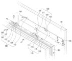
도 3은 본 발명의 일 실시예에 따른 결합 냉장고의 유닛의 분해 사시도이다.FIG. 3 is an exploded perspective view of a unit of a combined refrigerator according to one embodiment of the present invention.
종래의 결합 유닛의 경우 패널이 도어에 결합되도록 형성되면서 도어에 결합된 패널의 위치를 조절하기 위한 조절부를 포함하였다. 조절부는 나사 등을 통해 패널의 전후 방향과 상하 방향으로 패널을 미세하여 이동시켜 패널의 위치를 조절할 수 있었다. 다만, 패널의 좌우 방향으로의 미세한 이동이 불가능하여 사용자는 직접 패널의 좌우 방향으로 이동시켜 패널의 위치를 조정하거나 별도의 추가적인 결합 장치를 구비하여 패널의 좌우 방향을 조절할 수 있다.In the case of a conventional coupling unit, when a panel is formed to be coupled to a door, an adjustment part for adjusting the position of the panel coupled to the door is included. The adjustment part can adjust the position of the panel by moving the panel slightly forward and backward and up and down using screws or the like. However, since minute movement of the panel in the left-right direction is not possible, the user can adjust the position of the panel by directly moving the panel in the left-right direction or adjust the left-right direction of the panel by providing a separate additional coupling device.
다만 본 발명의 일 실시예에 따른 결합 유닛(100)은 하나의 구성을 통해 패널(40)의 전후 방향, 상하 방향 및 좌우 방향을 미세하게 이동시킬 수 있다. 즉, 추가적인 구성 없이 하나의 결합 유닛(100)으로 3-way 방향으로 패널을 미세하게 이동시킬 수 있다.However, the coupling unit (100) according to one embodiment of the present invention can move the panel (40) in the forward/backward direction, up/down direction, and left/right direction finely through one configuration. That is, the panel can be moved finely in the three-way direction with one coupling unit (100) without additional configuration.
즉, 결합 유닛(100)은 패널(40)을 좌우 방향으로 이동시키는 제 1조절부(또는 좌우 방향 조절부, 110)와 제 2조절부(또는 상하 방향 조절부, 120) 및 제 3조절부(또는 전후 방향 조절부, 130)을 포함할 수 있다.That is, the coupling unit (100) may include a first control unit (or left-right direction control unit, 110) for moving the panel (40) in the left-right direction, a second control unit (or up-down direction control unit, 120), and a third control unit (or front-back direction control unit, 130).
결합 유닛(100)은 3개의 조절부(110,120,130)를 포함하여 사용자가 3방향으로 패널(40)의 위치를 용이하게 조절할 수 있다. 패널(40)의 위치가 조정된 후 부가적인 결합 수단에 의해 패널(40)은 도어(30)에 완전 결합될 수 있다.The coupling unit (100) includes three adjustment parts (110, 120, 130) so that the user can easily adjust the position of the panel (40) in three directions. After the position of the panel (40) is adjusted, the panel (40) can be completely coupled to the door (30) by an additional coupling means.
도 3에 도시된 바와 같이 결합 유닛(100)은 도어(30)의 상단 측에 한 쌍으로 마련될 수 있다. 한 쌍의 결합 유닛(100)은 서로 대칭으로 마련되는 바 한 쌍의 결합 유닛(100) 중 하나의 결합 유닛(도1을 기준으로 좌측에 마련되는 결합 유닛)에 대해 설명하고 중복되는 설명은 생략한다.As shown in Fig. 3, the coupling units (100) may be provided as a pair on the upper side of the door (30). The pair of coupling units (100) are provided symmetrically to each other, so one coupling unit (the coupling unit provided on the left side based on Fig. 1) among the pair of coupling units (100) will be described, and redundant descriptions will be omitted.
결합 유닛(100)은 패널(40)의 후면에 배치되고 도어(30) 측에 결합되는 결합 브래킷(또는 패널 결합 브래킷, 140)을 포함할 수 있다. 또한 결합 유닛(100)은 도어(30)의 상단에 마련되고 결합 브래킷(140)과 결합되는 구성이 연장되는 베이스 브래킷(150)을 포함할 수 있다.The coupling unit (100) may include a coupling bracket (or panel coupling bracket, 140) that is arranged on the rear side of the panel (40) and coupled to the door (30) side. In addition, the coupling unit (100) may include a base bracket (150) that is provided on the top of the door (30) and has an extended configuration coupled to the coupling bracket (140).
결합 브래킷(140)과 베이스 브래킷(150)에서 3개의 조절부(110,120,130)을 이루는 구성이 연장되어 패널(40)이 3-way 방향으로 위치 조절이 가능할 수 있다. 이에 따라 최소한의 구성 만으로 패널(40)을 3방향으로 사용자가 용이하게 위치를 조정할 수 있다.The configuration of three adjusting parts (110, 120, 130) from the joint bracket (140) and the base bracket (150) is extended so that the panel (40) can be positionally adjusted in three directions. Accordingly, the user can easily adjust the position of the panel (40) in three directions with only a minimal configuration.
제 1조절부(110)는 베이스 브래킷(150)에서 상측으로 연장되고 패널(40)의 좌우 방향으로 평행하는 면을 가지는 제 1도어 브래킷(또는 도어 조절 브래킷, 111)과 결합 브래킷(140)의 후방으로 연장되고 제 1도어 브래킷(111)과 마주하게 배치되는 제 1패널 브래킷(또는 패널 조절 브래킷, 112)과 패널(40)의 좌우 방향으로 제 1도어 브래킷(111)을 관통하여 제 1패널 브래킷(112)을 패널(40)의 좌우 방향으로 가압하는 제 1조절부재(115)를 포함할 수 있다.The first adjusting member (110) may include a first door bracket (or door adjusting bracket, 111) extending upward from the base bracket (150) and having a surface parallel to the left-right direction of the panel (40), a first panel bracket (or panel adjusting bracket, 112) extending rearward of the joining bracket (140) and positioned to face the first door bracket (111), and a first adjusting member (115) penetrating the first door bracket (111) in the left-right direction of the panel (40) to press the first panel bracket (112) in the left-right direction of the panel (40).
제 1조절부재(115)는 제 1도어 브래킷(111)에 마련되는 제 1관통홀(113)을 관통하여 제 1도어 브래킷(111)에 고정되고 제 1패널 브래킷(112)과 접하게 배치되어 패널(40)의 위치를 좌우 방향으로 조정할 수 있는데 이에 대하여는 자세하게 후술한다.The first adjusting member (115) is fixed to the first door bracket (111) by penetrating the first through hole (113) provided in the first door bracket (111) and is arranged in contact with the first panel bracket (112) so that the position of the panel (40) can be adjusted in the left-right direction, which will be described in detail later.
제 2조절부(120)는 결합 브래킷(140) 후방으로 연장되고 베이스 브래킷(150)에 대해 평행하게 배치되는 제 2패널 브래킷(또는 연장 브래킷, 122)과 제 2패널 브래킷(122)이 패널(40)의 상하 방향으로 안착되는 안착부를 포함하는 제 2조절부재(또는 높이 조절부재, 125)와 제2조절부재(125)가 패널(40)의 상하 방향으로 스크류 결합되도록 베이스 브래킷(150)에 마련되는 결합 홀(121)을 포함할 수 있다.The second adjustment member (120) may include a second panel bracket (or extension bracket, 122) that extends rearwardly from the coupling bracket (140) and is arranged parallel to the base bracket (150), a second adjustment member (or height adjustment member, 125) that includes a mounting portion on which the second panel bracket (122) is mounted in the upper and lower direction of the panel (40), and a coupling hole (121) provided in the base bracket (150) so that the second adjustment member (125) is screw-coupled in the upper and lower direction of the panel (40).
제 2패널 브래킷(122)은 제 2조절부재(125)의 적어도 일부가 관통하는 제 2관통홀(123)을 포함하고, 제 2조절부재(125)는 제 2관통홀(123)에 적어도 일부가 관통되고 상하 방향 이동에 의해 패널(40)의 위치를 상하 방향으로 조정할 수 있는데 이에 대하여는 자세하게 후술한다.The second panel bracket (122) includes a second through hole (123) through which at least a portion of the second adjusting member (125) passes, and the second adjusting member (125) has at least a portion of the second through hole (123) passing through and can adjust the position of the panel (40) in the vertical direction by moving in the vertical direction, which will be described in detail later.
제 3조절부(130)는 베이스 브래킷(150)의 상측에서 연장되고 결합 브래킷(140)과 마주하게 배치되는 제 2도어 브래킷(또는 도어 결합 브래킷, 131)과 제 2도어 브래킷(131)을 관통하여 결합 브래킷(140)과 결합되는 제 3조절부재(또는 전후방 조절부재 또는 결합부재, 135)를 포함할 수 있다.The third adjusting member (130) may include a second door bracket (or door combining bracket, 131) that extends from the upper side of the base bracket (150) and is positioned to face the combining bracket (140), and a third adjusting member (or front/rear adjusting member or combining member, 135) that penetrates the second door bracket (131) and is combined with the combining bracket (140).
제 3조절부재(135)는 결합 브래킷(140)과 스크류 결합되는 결합 스크류(136)과 결합 브래킷(140)을 가압하는 가압 스크류(137)를 포함할 수 있다. 제 2도어 브래킷(131)에는 결합 스크류(136)가 관통되는 제 3관통홀(133)을 포함할 수 있다. The third adjusting member (135) may include a coupling screw (136) that is screw-connected to the coupling bracket (140) and a pressurizing screw (137) that pressurizes the coupling bracket (140). The second door bracket (131) may include a third through-hole (133) through which the coupling screw (136) passes.
결합 스크류(136)와 가압 스크류(137)의 결합에 의해 패널(40)의 위치를 전후 방향으로 조정할 수 있는데 이에 대하여는 자세하게 후술한다.The position of the panel (40) can be adjusted in the forward and backward direction by combining the coupling screw (136) and the pressure screw (137), which will be described in detail later.
이하에서는 제 1조절부(110)에 대하여 자세하게 설명한다. 도 4a는 본 발명의 일 실시예에 따른 냉장고의 좌우방향 조절부에 의해 패널이 일측으로 위치가 조절된 상태의 단면도이고, 도 4b는 본 발명의 일 실시예에 따른 냉장고의 좌우방향 조절부에 의해 패널이 타측으로 위치가 조절된 상태의 단면도이다.Hereinafter, the first control unit (110) will be described in detail. Fig. 4a is a cross-sectional view of a state in which a panel is positioned to one side by a left-right control unit of a refrigerator according to one embodiment of the present invention, and Fig. 4b is a cross-sectional view of a state in which a panel is positioned to the other side by a left-right control unit of a refrigerator according to one embodiment of the present invention.
상술한 바와 같이 제 1조절부(110)는 패널(40)의 위치를 좌우 방향으로 조절할 수 있다. As described above, the first adjusting unit (110) can adjust the position of the panel (40) in the left and right directions.
자세하게는 제 1도어 브래킷(111)과 제 1패널 브래킷(112)이 마주하게 배치될 수 있다. 도어(30)의 중심을 중심으로 제1패널 브래킷(112)이 제 1도어 브래킷(112)보다 내측에 배치되게 마련될 수 있다.In detail, the first door bracket (111) and the first panel bracket (112) may be arranged to face each other. The first panel bracket (112) may be arranged to be located further inward than the first door bracket (112) with respect to the center of the door (30).
제 1조절부재(115)는 도어(30)의 중심을 기준으로 외측에서 내측 방향으로 제 1도어 브래킷(111)을 관통하여 제 1패널 브래킷(112)을 접하게 마련될 수 있다.The first adjusting member (115) may be provided to penetrate the first door bracket (111) from the outside to the inside with respect to the center of the door (30) and contact the first panel bracket (112).
제 1도어 브래킷(111)에는 제 1조절부재(115)가 관통되는 제1관통홀(113)을 포함할 수 있다. 제 1조절부재(115)는 사용자에 의해 회전되는 제 1회전부(115a)와 제 1관통홀(113)이 관통되는 제 1나사부(115b)와 제 1패널 브래킷(112)과 접하는 단부를 포함할 수 있다.The first door bracket (111) may include a first through hole (113) through which the first adjusting member (115) passes. The first adjusting member (115) may include a first rotating portion (115a) that is rotated by the user, a first screw portion (115b) through which the first through hole (113) passes, and an end that comes into contact with the first panel bracket (112).
제 1나사부(115b)는 제 1관통홀(113)을 관통하면서 제1관통홀(1130과 나사 결합될 수 있다. The first screw portion (115b) can be screw-connected to the first through hole (1130) while penetrating the first through hole (113).
도 4a에 도시된 바와 같이 사용자가 제 1회전부(115a)를 일 방향으로 회전시키면 제 1나사부(115b)가 회전되어 제 1도어 브래킷(111)에서 제 1패널 브래킷(112) 방향으로 이동되고 이에 따라 단부(115c)가 제 1패널 브래킷(112)을 도어(30)의 중심 측으로 가압할 수 있다.As shown in Fig. 4a, when a user rotates the first rotating part (115a) in one direction, the first screw part (115b) rotates and moves from the first door bracket (111) toward the first panel bracket (112), and accordingly, the end part (115c) can press the first panel bracket (112) toward the center of the door (30).
제 1패널 브래킷(112)은 결합 브래킷(140)에서 연장된 구성으로 제 1패널 브래킷(112)이 이동됨에 따라 결합 브래킷(140)이 연동되어 이동되고 결합 브래킷(140)에 결합되어 있는 패널(40)도 제 1패널 브래킷(112)의 이동에 연동되에 제 1패널 브래킷(112)이 이동되는 방향으로 이동될 수 있다.The first panel bracket (112) is configured to extend from the coupling bracket (140), so that as the first panel bracket (112) moves, the coupling bracket (140) moves in conjunction with it, and the panel (40) coupled to the coupling bracket (140) can also move in the direction in which the first panel bracket (112) moves in conjunction with the movement of the first panel bracket (112).
즉, 패널(40)은 제 1조절부재(115)가 제 1패널 브래킷(112)을 오른쪽 방향으로 가압하면서 도어(30)에 대해 오른쪽 방향으로 이동될 수 있다.That is, the panel (40) can be moved to the right with respect to the door (30) while the first adjusting member (115) presses the first panel bracket (112) to the right.
제 1조절부재(115)가 제 1패널 브래킷(112)을 일측으로 가압함에 따라 결합 브래킷(140)에서 연장된 제 2패널 브래킷(122)도 일측으로 이동될 수 있다. 이에 따라 제 2패널 브래킷(122)에 마련되는 제 2관통홀(123)이 이동되면서 제2조절장치(125)와 충돌될 수 있는데, 이를 방지하기 위하여 제 2관통홀(123)은 제 2관통홀(123)에 삽입된 제 2조절부재(125)의 일부의 직경보다 크게 마련될 수 있다.As the first adjusting member (115) presses the first panel bracket (112) to one side, the second panel bracket (122) extended from the joining bracket (140) may also move to one side. Accordingly, the second through hole (123) provided in the second panel bracket (122) may move and collide with the second adjusting device (125). To prevent this, the second through hole (123) may be provided to have a diameter larger than a portion of the second adjusting member (125) inserted into the second through hole (123).
따라서 제 2관통홀(123) 내에서 제 2조절부재(125)의 일부가 소정거리 이동될 수 있고 이에 따라 패널(40)이 일측으로 이동되어도 제 2조절부재(125)에 제한을 받지 않고 제 2관통홀(123)도 이에 연동되어 이동될 수 있다.Accordingly, a part of the second adjusting member (125) can be moved a predetermined distance within the second through hole (123), and accordingly, even if the panel (40) is moved to one side, the second through hole (123) can also be moved in conjunction with it without being restricted by the second adjusting member (125).
제 1조절부재(115)가 제 1패널 브래킷(112)을 일측으로 가압함에 따라 결합 브래킷(140)에 결합된 결합 스크류(136)도 일측으로 이동될 수 있다. 이에 따라 결합 스크류(136)가 관통되는 제 2도어 브래킷(131) 상에 위치하는 제 3관통홀(133)이 결합 스크류(136)가 이동되면서 충돌될 수 있는데, 이를 방지하기 위하여 제 3관통홀(133)은 제 3관통홀(133)에 삽입된 결합 스크류(136) 의 직경보다 크게 마련될 수 있다.As the first adjusting member (115) presses the first panel bracket (112) to one side, the coupling screw (136) coupled to the coupling bracket (140) may also move to one side. Accordingly, the third through hole (133) located on the second door bracket (131) through which the coupling screw (136) passes may collide as the coupling screw (136) moves. To prevent this, the third through hole (133) may be provided to have a diameter larger than that of the coupling screw (136) inserted into the third through hole (133).
따라서 제 3관통홀(133) 내에서 결합 스크류(136)가 소정거리 이동될 수 있고 이에 따라 패널(40)이 일측으로 이동되어도 제 3관통홀(133)에 제한을 받지 않고 결합 스크류(136)도 이에 연동되어 이동될 수 있다.Accordingly, the coupling screw (136) can be moved a predetermined distance within the third through hole (133), and accordingly, even if the panel (40) is moved to one side, the coupling screw (136) can also be moved in conjunction with it without being restricted by the third through hole (133).
도 4b에 도시된 바와 같이 사용자가 제 1회전부(115a)를 반대 방향으로 회전시키면 제 1나사부(115b)가 반대로 회전되어 제 1패널 브래킷(112)에서 제 1도어 브래킷(111) 방향으로 이동되고 이에 따라 제 1패널 브래킷(112)을 가압하고 있던 단부(115c)와 제 1패널 브래킷(112)가 이격될 수 있다.As shown in Fig. 4b, when the user rotates the first rotating part (115a) in the opposite direction, the first screw part (115b) rotates in the opposite direction and moves from the first panel bracket (112) toward the first door bracket (111), and accordingly, the end part (115c) that was pressing the first panel bracket (112) and the first panel bracket (112) can be separated.
이에 따라 제 1패널 브래킷(112)은 일측으로 이동되지 않게 되며, 한 쌍의 결합 유닛(100) 중 우측에 배치되는 결합 유닛(100)의 제 1조절부(110)에 의해 타측으로 제 1조절부재(115)가 제 1패널 브래킷(112)을 가압하여 패널(40)이 타측으로 이동될 수 있다.Accordingly, the first panel bracket (112) is prevented from moving to one side, and the first adjusting member (115) of the coupling unit (100) positioned on the right side of the pair of coupling units (100) presses the first panel bracket (112) to the other side, so that the panel (40) can move to the other side.
이 때, 도 4b와 같이 한 쌍의 결합 유닛(100) 중 좌측에 배치되는 결합 유닛(100)의 제 1조절부재(115)가 도어(30)의 중심에 대해 후퇴되게 마련될 수 있어서, 패널(40)의 타측으로 가압이 발생하여도 제한 없이 패널(40)이 타측으로 이동될 수 있다.At this time, as shown in Fig. 4b, the first adjusting member (115) of the coupling unit (100) positioned on the left side of the pair of coupling units (100) can be arranged to be retracted with respect to the center of the door (30), so that even if pressure is applied to the other side of the panel (40), the panel (40) can be moved to the other side without restriction.
패널(40)의 타측으로 이동되어도 제 2조절부재(125)와 결합 스크류(136)는 각각 제 2관통홀(123)과 제 3관통홀(133) 내부에서 소정의 거리 이동이 가능한 바 패널(40)의 이동을 제한하지 않을 수 있다.Even if the panel (40) is moved to the other side, the second adjusting member (125) and the coupling screw (136) can move a predetermined distance inside the second through hole (123) and the third through hole (133), respectively, so that the movement of the panel (40) may not be restricted.
이하에서는 제 2조절부(120)에 대하여 자세히 설명한다. 도 5a는 본 발명의 일 실시예에 따른 냉장고의 상하방향 조절부에 의해 패널이 상측으로 위치가 조절된 상태의 단면도이고, 도 5b는 본 발명의 일 실시예에 따른 냉장고의 상하방향 조절부에 의해 패널이 하측으로 위치가 조절된 상태의 단면도이다.Hereinafter, the second control unit (120) will be described in detail. Fig. 5a is a cross-sectional view showing a state in which a panel is positioned upward by a vertical control unit of a refrigerator according to one embodiment of the present invention, and Fig. 5b is a cross-sectional view showing a state in which a panel is positioned downward by a vertical control unit of a refrigerator according to one embodiment of the present invention.
상술한 바와 같이 제 2조절부(120)는 패널(40)의 상하 방향으로 위치를 조절할 수 있다.As described above, the second adjusting unit (120) can adjust the position in the upper and lower direction of the panel (40).
자세하게는 제 2조절부(120)는 결합 브래킷(140)에서 후방으로 연장되고 베이스 브래킷(150)과 상하 방향으로 평행하게 배치되는 제 2패널 브래킷(122)을 포함할 수 있다. 제 2패널 브래킷(122)은 베이스 브래킷(150)에 상하 방향으로 스크류 결합되는 제 2조절부재(125)에 안착되어 제 2조절부재(125)의 상하 방향 이동에 따라 상하 방향으로 이동되어 패널(40)의 상하 방향 위치를 조절할 수 있다.In detail, the second adjusting member (120) may include a second panel bracket (122) that extends rearwardly from the coupling bracket (140) and is arranged vertically parallel to the base bracket (150). The second panel bracket (122) is mounted on a second adjusting member (125) that is vertically screw-coupled to the base bracket (150) and moves vertically according to the vertical movement of the second adjusting member (125), thereby adjusting the vertical position of the panel (40).
제 2패널 브래킷(122)은 제 2조절부재(125)가 관통되는 제2관통홀(123)을 포함할 수 있다. 제 2조절부재(125)는 제 2관통홀(123)에 관통되고 사용자에 의해 회전 가능한 제 2회전부(125a)와 제 2패널 브래킷(122)이 상하 방향으로 안착되는 안착부(125b)와 베이스 브래킷(150) 상에 마련되는 결합 홀(121)에 상하 방향으로 스크류 결합되는 제 2나사부(125c)를 포함할 수 있다.The second panel bracket (122) may include a second through hole (123) through which the second adjusting member (125) passes. The second adjusting member (125) may include a second rotating member (125a) that passes through the second through hole (123) and is rotatable by the user, a mounting member (125b) on which the second panel bracket (122) is mounted in the vertical direction, and a second screw member (125c) that is screw-coupled in the vertical direction to a mounting hole (121) provided on the base bracket (150).
제 2조절부재(125)는 제 2나사부(125c)의 일단이 결합 홀(121)에 스크류 결합되어 베이스 브래킷(150)에 수직하게 결합될 수 있으며, 제 2나사부(125c)의 타단 측에 마련되고 베이스 브래킷(150)과 평행한 방향으로 면을 가지도록 연장되는 안착부(125b)가 베이스 브래킷(150)과 평행하게 고정되도록 마련될 수 있다.The second adjusting member (125) can be vertically connected to the base bracket (150) by screwing one end of the second screw portion (125c) into the connecting hole (121), and a fixing portion (125b) provided on the other end of the second screw portion (125c) and extending to have a surface in a direction parallel to the base bracket (150) can be provided to be fixed parallel to the base bracket (150).
제 2조절부재(125)는 안착부(125b)에서 상하 방향으로 연장되고 제 2관통홀(123)에 관통될 수 있는 제 2회전부(125a)를 더 포함할 수 있다.The second adjusting member (125) may further include a second rotating member (125a) that extends vertically from the mounting member (125b) and can penetrate the second through hole (123).
제 2패널 브래킷(122)은 제 2관통홀(123)에 의해 제 2회전부(125a)가 관통되고 안착부(125b)의 상면과 접하게 배치될 수 있다. 즉, 제 2패널 브래킷(122)의 하면은 제 2회전부(125a)를 관통하여 안착부(125b)와 접하게 배치되어 제 2조절부재(125)에 안착될 수 있다.The second panel bracket (122) can be positioned so that the second rotating portion (125a) passes through the second through hole (123) and comes into contact with the upper surface of the fixing portion (125b). That is, the lower surface of the second panel bracket (122) can be positioned so as to pass through the second rotating portion (125a) and come into contact with the fixing portion (125b) and be fixed to the second adjusting member (125).
이 상태에서 제 2조절부재(125)의 제 2회전부(125a)를 일측으로 회전시킬 경우, 결합되어있는 제 2나사부(125c)와 결합 홀(121)의 나사 결합이 일정 부분 해제되면서 제 2나사부(125c)가 상방향으로 상승하게 되어 이에 따라 제 2패널 브래킷(123)이 상측으로 상승할 수 있다.In this state, when the second rotation part (125a) of the second adjusting member (125) is rotated to one side, the screw connection between the second screw part (125c) and the coupling hole (121) is partially released, causing the second screw part (125c) to rise upward, thereby allowing the second panel bracket (123) to rise upward.
제 2패널 브래킷(123)은 결합 브래킷(140)의 후방에서 연장되는 구성인 바 제 2패널 브래킷(123)의 상승으로 결합 브래킷(140)이 상승하게 되며, 이에 따라 패널(40)의 위치가 상승하게 된다.The second panel bracket (123) is configured to extend from the rear of the joining bracket (140), and as the second panel bracket (123) rises, the joining bracket (140) rises, and accordingly, the position of the panel (40) rises.
안착부(125b)는 패널(40)이 좌우 방향 또는 전후 방향으로 이동되어도 계속 제 2패널 브래킷(123)을 지지하고 있어야 하는 바 제 2관통홀(123)보다 크게 마련될 수 있다. 따라서 상술한 바와 같이 제 2조절부재(125)의 일부인 제 2회전부(125a)가 제 2관통홀(123)의 내부에서 소정 거리 이동하여도 안착부(125b)는 제 2패널 브래킷(123)을 안정적으로 지지할 수 있다.The fixing portion (125b) must continue to support the second panel bracket (123) even when the panel (40) moves left-right or forward-backward, and thus can be provided to be larger than the second through hole (123). Accordingly, even when the second rotating portion (125a), which is part of the second adjusting member (125), moves a predetermined distance inside the second through hole (123), as described above, the fixing portion (125b) can stably support the second panel bracket (123).
또한 상술한 바와 같이 제 3관통홀(133)은 결합 스크류(136)이 제 3관통홀(133) 내부에서 소정의 거리 이동 가능하게 마련되는 바 제 2패널 브래킷(123)의 상승으로 결합 스크류(136)가 연동되어 상승되어도 제 3관통홀(133)의 제한을 받지 않고 이동될 수 있다.In addition, as described above, the third through hole (133) is provided so that the coupling screw (136) can move a predetermined distance inside the third through hole (133), so that even if the coupling screw (136) rises in conjunction with the rise of the second panel bracket (123), it can move without being restricted by the third through hole (133).
도 5b에 도시된 바와 같이 제 2조절부재(125)의 제 2회전부(125a)를 반대측으로 회전시킬 경우, 결합되어있는 제 2나사부(125c)와 결합 홀(121)의 나사 결합이 더 강해 짐에 따라 제 2나사부(125c)가 하강하게 되어 이에 따라 제 2패널 브래킷(123)이 하측으로 하강할 수 있다.As shown in Fig. 5b, when the second rotating part (125a) of the second adjusting member (125) is rotated to the opposite side, the screw connection between the coupled second screw part (125c) and the coupling hole (121) becomes stronger, causing the second screw part (125c) to descend, thereby allowing the second panel bracket (123) to descend downward.
종래의 상하 방향을 조절하는 상하 방향 조절부는 볼트와 같은 나사부재에 패널측 결합 브래킷이 배치되고 나사부재의 상하 방향으로 한 쌍의 너트를 연결하여 패널 측 브래킷을 결합시키고 한 쌍의 너트를 각각 회전시켜 상하 방향으로 이동하게 하여 패널 측 브래킷의 상하 방향을 조절하여 패널의 상하 방향 위치를 조절하였다.The conventional up-and-down direction adjusting part, which adjusts the up-and-down direction, has a panel-side joining bracket arranged on a screw member such as a bolt, a pair of nuts connected in the up-and-down direction of the screw member to connect the panel-side bracket, and each pair of nuts is rotated to move in the up-and-down direction to adjust the up-and-down direction of the panel-side bracket, thereby adjusting the up-and-down position of the panel.
다만 상술한 바와 같이 본 발명의 일 실시예에 의한 상하 방향 조절부(또는 제 2조절부, 120)는 제 2조절부재(125) 1개의 구성을 통해 제 2패널 브래킷(122)을 안착시켜 사용자가 용이하게 패널(40)의 상하 방향의 위치를 조절할 수 있게 할 수 있다.However, as described above, the vertical direction adjustment unit (or second adjustment unit, 120) according to one embodiment of the present invention can allow a user to easily adjust the vertical position of the panel (40) by fixing the second panel bracket (122) through the configuration of one second adjustment member (125).
제 2조절부(120)의 제 2패널 브래킷(122)과 제 1조절부(110)의 제 1패널 브래킷(110)은 결합 브래킷(140)과 일체로 형성될 수 있다.(도 4a참고) 자세하게는 결합 브래킷(140)의 하방으로 베이스 브래킷(150)과 평행하게 제 2패널 브래킷(122)이 연장되고 제 2패널 브래킷(122)의 일측에서 하측으로 패널(40)의 좌우 방향으로 평행한 제 1패널 브래킷(112)이 연장될 수 있다.The second panel bracket (122) of the second adjusting member (120) and the first panel bracket (110) of the first adjusting member (110) may be formed integrally with the joining bracket (140). (See FIG. 4a) In detail, the second panel bracket (122) may be extended downwardly from the joining bracket (140) in parallel with the base bracket (150), and the first panel bracket (112) may be extended downwardly from one side of the second panel bracket (122) in a parallel left-right direction of the panel (40).
이에 따라 결합 브래킷(140)과 제 1패널 브래킷(112)과 제 2패널 브래킷(122)은 하나의 구성으로 형성될 수 있으며, 하나의 구성을 통해 패널(40)을 상하 방향 및 좌우 방향으로 조절할 수 있다.Accordingly, the joining bracket (140), the first panel bracket (112), and the second panel bracket (122) can be formed as one configuration, and the panel (40) can be adjusted in the up-down direction and left-right direction through one configuration.
이하에서는 제 3조절부(130)에 대하여 자세히 설명한다. 도 6a는 본 발명의 일 실시예에 따른 냉장고의 전후방향 조절부에 의해 패널이 전방측으로 위치가 조절된 상태의 단면도이고, 도 6b는 본 발명의 일 실시예에 따른 냉장고의 전후방향 조절부에 의해 패널이 후방측으로 위치가 조절된 상태의 단면도이다.Hereinafter, the third control unit (130) will be described in detail. Fig. 6a is a cross-sectional view showing a state in which the panel is positioned forward by the forward-backward control unit of a refrigerator according to one embodiment of the present invention, and Fig. 6b is a cross-sectional view showing a state in which the panel is positioned rearward by the forward-backward control unit of a refrigerator according to one embodiment of the present invention.
상술한 바와 같이 제 3조절부(130)는 패널(40)의 전후 방향으로 위치를 조절할 수 있다.As described above, the third adjusting unit (130) can adjust the position in the forward and backward direction of the panel (40).
자세하게는 제 3조절부(120)는 베이스 브래킷(150)에서 상측으로 연장되고 결합 브래킷(140)과 전후 방향으로 평행하게 배치되는 제 2도어 브래킷(132)을 포함할 수 있다. 결합 브래킷(140)은 제 2도어 브래킷(132)과 대응되는 위치에 마련되는 결합부(132)를 포함할 수 있다.(도 3참고)In detail, the third adjusting member (120) may include a second door bracket (132) that extends upward from the base bracket (150) and is arranged parallel to the coupling bracket (140) in the forward and backward direction. The coupling bracket (140) may include a coupling portion (132) that is provided at a position corresponding to the second door bracket (132). (See FIG. 3)
제 2도어 브래킷(132)에는 패널(40)의 후방에서 전방측으로 제 3조절부재(135)가 관통되도록 마련되는 제 3관통홀(133)과 제 4관통홀(134)이 마련될 수 있다.A third through hole (133) and a fourth through hole (134) may be provided in the second door bracket (132) to allow a third adjusting member (135) to pass through from the rear to the front of the panel (40).
결합 스크류(136)는 제 3관통홀(133)을 관통하여 결합부(132)와 스크류 결합될 수 있다. 또한 조절 스크류(137)는 제4관통홀(134)을 관통하여 결합부(132)와 접하게 마련될 수 있다.The coupling screw (136) can be screw-coupled with the coupling portion (132) by passing through the third through hole (133). In addition, the adjusting screw (137) can be provided to pass through the fourth through hole (134) and come into contact with the coupling portion (132).
결합 스크류(136)는 결합부(132)와 스크류 결합되어 패널(40)이 이동 시 패널(40)에 연동되어 같이 이동될 수 있다. 상술한 바와 같이 제 3관통홀(136)은 결합 스크류(136)의 직경보다 크게 마련되어 패널(40)과 함께 결합 스크류(136)가 이동되어도 제 3관통홀(133)에 의해 제한되지 않는다.The coupling screw (136) is screw-coupled with the coupling portion (132) so that it can move together with the panel (40) when the panel (40) moves. As described above, the third through hole (136) is provided to be larger than the diameter of the coupling screw (136), so that even if the coupling screw (136) moves together with the panel (40), it is not restricted by the third through hole (133).
도 6a에 도시된 바와 같이 결합 스크류(136)가 결합부(132)와 결합된 상태에서 조절 스크류(137)를 일 방향으로 회전시킬 경우, 제 4관통홀(134)을 관통한 조절 스크류(137)가 패널(40)의 전방 방향으로 전진하여 접해있는 결합부(132)를 패널(40)의 전방으로 가압하게 된다. 이에 따라 패널(40)은 전방으로 이동될 수 있다.As shown in Fig. 6a, when the adjusting screw (137) is rotated in one direction while the coupling screw (136) is coupled with the coupling portion (132), the adjusting screw (137) that has penetrated the fourth through hole (134) moves forward in the forward direction of the panel (40) to press the coupling portion (132) that is in contact with it toward the front of the panel (40). Accordingly, the panel (40) can be moved forward.
패널(40)이 전방으로 이동될 시 결합 브래킷(140)의 후방으로 연장되는 제 2패널 브래킷(122)도 전방으로 이동되는데, 이 때 제 2패널 브래킷(122)을 관통하는 제 2조절부재(125)와 제 2패널 브래킷(122)이 충돌되지 않도록 제 2관통홀(123)은 제 2관통홀(123)에 삽입된 제 2회전부(125a)의 반경보다 크게 마련되어 제 2회전부(125a)가 제 2패널 브래킷(122)의 이동을 제한하지 않게 마련될 수 있다.When the panel (40) moves forward, the second panel bracket (122) extending to the rear of the coupling bracket (140) also moves forward. At this time, to prevent the second panel bracket (122) and the second adjusting member (125) penetrating the second panel bracket (122) from colliding, the second through hole (123) may be provided with a radius larger than that of the second rotating member (125a) inserted into the second through hole (123) so that the second rotating member (125a) does not restrict the movement of the second panel bracket (122).
도 6b에 도시된 바와 같이 조절 스크류(137)를 반대 방향으로 회전시킬 경우, 제 4관통홀(134)을 관통한 조절 스크류(137)가 패널(40)의 후방 방향으로 후퇴하여 전방으로의 결합부(132)에 대한 가압이 종료될 수 있다.As shown in Fig. 6b, when the adjustment screw (137) is rotated in the opposite direction, the adjustment screw (137) that has penetrated the fourth through hole (134) can retreat toward the rear of the panel (40) so that the pressure applied to the forward joint (132) can be terminated.
이 때, 결합 스크류(136)를 회전시켜 결합 스크류(136)와 결합부(132)의 스크류 결합을 느슨하게 할 경우 스크류가 풀리는 방향으로 패널(40)이 후측으로 후퇴될 수 있다. 이에 따라, 패널(40)은 후방으로 이동될 수 있다.At this time, if the coupling screw (136) is rotated to loosen the screw connection between the coupling screw (136) and the coupling portion (132), the panel (40) can be moved rearward in the direction in which the screw is released. Accordingly, the panel (40) can be moved rearward.
제 3조절부(120)의 제 2도어 브래킷(131)과 제 1조절부(110)의 제 1도어 브래킷(111)은 베이스 브래킷(150)과 일체로 형성될 수 있다. 자세하게는 베이스 브래킷(150)의 상방으로 각각 결합 브래킷(140)과 평행하게 제 2도어 브래킷(131)이 연장되고 패널(40)의 좌우 방향으로 평행하게 제 1도어 브래킷(111)이 연장될 수 있다.The second door bracket (131) of the third adjusting unit (120) and the first door bracket (111) of the first adjusting unit (110) may be formed integrally with the base bracket (150). Specifically, the second door bracket (131) may be extended parallel to the connecting bracket (140) above the base bracket (150), and the first door bracket (111) may be extended parallel to the left and right directions of the panel (40).
이에 따라 베이스 브래킷(150)과 제 1도어 브래킷(111)과 제 2도어 브래킷(131)은 하나의 구성으로 형성될 수 있으며, 하나의 구성을 통해 패널(40)을 전후 방향 및 좌우 방향으로 조절할 수 있다.Accordingly, the base bracket (150), the first door bracket (111), and the second door bracket (131) can be formed as a single configuration, and the panel (40) can be adjusted in the forward/backward direction and left/right direction through a single configuration.
결합 유닛(100)은 상술한 바와 같이 도어(30)의 상단부에 마련될 수 있으나 추가적으로 대칭되게 도어(30)의 하단부에도 마련될 수 있다. 또한 결합 유닛(100)이 도어(30)의 하단부에 배치되지 않는 경우 도면에 도시되지는 않았으나, 도어(30)의 하단부에서 패널(40)을 지지하는 별도의 지지부재가 배치되어 도어(30)의 하단부에서 패널(40)을 지지할 수 있다.The coupling unit (100) may be provided at the upper end of the door (30) as described above, but may additionally be provided symmetrically at the lower end of the door (30). In addition, if the coupling unit (100) is not provided at the lower end of the door (30), a separate support member that supports the panel (40) at the lower end of the door (30) may be provided, although not shown in the drawing, to support the panel (40) at the lower end of the door (30).
이하에서는 본 발명의 다른 일 실시예에 따른 냉장고(1)의 결합 유닛(100')에 대하여 설명한다. 이하에서 설명하는 결합 유닛(100') 이 외의 구성은 상술한 본 발명의 일 실시예에 따른 냉장고(1)의 구성과 동일한 바 중복되는 설명을 생략한다.Below, a combination unit (100') of a refrigerator (1) according to another embodiment of the present invention will be described. The configuration other than the combination unit (100') described below is the same as the configuration of the refrigerator (1) according to the above-described embodiment of the present invention, so redundant descriptions are omitted.
도 7은 본 발명의 다른 일 실시예에 따른 냉장고의 결합 유닛의 분해 사시도이고, 도 8은 본 발명의 다른 일 실시예에 따른 냉장고의 결합 유닛에 패널이 결합된 상태의 배면도이고, 도 9는 본 발명의 다른 일 실시예에 따른 냉장고의 결합 유닛에 패널이 결합된 상태의 사시도이다.FIG. 7 is an exploded perspective view of a coupling unit of a refrigerator according to another embodiment of the present invention, FIG. 8 is a rear view of a panel coupled to a coupling unit of a refrigerator according to another embodiment of the present invention, and FIG. 9 is a perspective view of a panel coupled to a coupling unit of a refrigerator according to another embodiment of the present invention.
도 7 및 도 8에 도시된 바와 같이 결합 유닛(100')은 도어(30)의 상단부에 한 쌍으로 마련될 수 있다. 한 쌍의 결합 유닛(100')은 대칭되게 마련되는 바 이하에서는 한 쌍의 결합 유닛(100') 중 하나의 결합 유닛(100')에 대하여만 설명한다.As shown in FIGS. 7 and 8, the coupling units (100') may be provided as a pair at the upper portion of the door (30). The pair of coupling units (100') are provided symmetrically, and only one coupling unit (100') of the pair of coupling units (100') will be described below.
결합 유닛(100')은 도어(30)의 후면에 결합되는 결합 브래킷(140')와 도어(30)의 상단에 결합되는 베이스 브래킷(150')을 포함할 수 있다. 또한 결합 유닛(100')은 패널(40)을 좌우 방향으로 이동시키는 제 1조절부(110')와 패널(40)을 상하 방향으로 이동시키는 제 2조절부(120')와 패널(40)을 전후 방향으로 이동시키는 제 3조절부(130')를 포함할 수 있다.The coupling unit (100') may include a coupling bracket (140') coupled to the rear of the door (30) and a base bracket (150') coupled to the top of the door (30). In addition, the coupling unit (100') may include a first adjusting unit (110') that moves the panel (40) left-right, a second adjusting unit (120') that moves the panel (40) up-down, and a third adjusting unit (130') that moves the panel (40) forward-backward.
또한 결합 유닛(100')는 3개의 조절부(110',120',130')가 관통하고 3개의 조절부(110',120',130')에 의해 패널(40)의 좌우 방향, 상하 방향 및 전후 방향으로 이동 가능하게 마련되는 관통부재(170')를 포함할 수 있다.In addition, the coupling unit (100') may include a penetrating member (170') through which three adjusting members (110', 120', 130') pass and which is provided to enable movement in the left-right, up-down, and front-back directions of the panel (40) by the three adjusting members (110', 120', 130').
도 7 및 도9에 도시된 바와 같이 제 1조절부(110')는 베이스 브래킷(150')에서 상측으로 패널(40)의 좌우 방향으로 향하는 면을 포함하도록 연장되는 한 쌍의 제 1도어 브래킷(111')를 포함할 수 있다. As shown in FIGS. 7 and 9, the first adjusting member (110') may include a pair of first door brackets (111') extending upward from the base bracket (150') to include a surface facing left and right of the panel (40).
한 쌍의 제 1도어 브래킷(111')은 관통부재(170')의 양측에 각각 배치될 수 있다. 한 쌍의 제 1도어 브래킷(111')은 각각 패널(40)의 전후 방향으로 장변을 가지는 장공 형태의 제 1관통홀(113')을 포함할 수 있다.A pair of first door brackets (111') may be arranged on each side of the through-hole member (170'). Each of the pair of first door brackets (111') may include a first through-hole (113') in the form of an elongated hole having a long side in the front-rear direction of the panel (40).
제 1조절부(110')는 한 쌍의 제 1도어 브래킷(111')에 각각 마련되는 제 1관통홀(113')에 일단측과 타단측이 지지되고 패널(40)의 좌우 방향으로 관통부재(170')를 관통하는 제 1조절부재(115')를 포함할 수 있다.The first adjusting member (110') may include a first adjusting member (115') that is supported at one end and the other end by a first through hole (113') provided in each of a pair of first door brackets (111') and penetrates a through member (170') in the left-right direction of the panel (40).
제 1조절부재(115')의 일단측에는 사용자에 의해 일방향 또는 반대방향으로 회전될 수 있는 제 1회전부가 마련될 수 있다. 사용자가 제 1회전부를 일방향으로 회전시킬 경우 제 1조절부재(115')는 회전을 통해 관통부재(170')를 일측으로 이동시킬 수 있고, 제 1회전부를 반대 방향으로 회전시킬 경우 제 1조절부재(115')는 역회전을 통해 관통부재(170')를 반대측으로 이동시킬 수 있다.A first rotating member (115') that can be rotated in one direction or the opposite direction by a user may be provided at one end of the first adjusting member (115'). When a user rotates the first rotating member in one direction, the first adjusting member (115') can move the penetrating member (170') to one side through rotation, and when the user rotates the first rotating member in the opposite direction, the first adjusting member (115') can move the penetrating member (170') to the opposite side through reverse rotation.
제 2조절부(120')는 결합 브래킷(140')의 후방으로 연장되고 베이스 브래킷(150')과 상하 방향으로 평행하게 배치되는 패널 브래킷(122')과 관통부재(170')의 상측에 마련되는 제 2관통홀에 상하 방향으로 스크류 결합되고 패널 브래킷(122')이 안착되는 안착부를 포함하는 제 2조절부재(125')를 포함할 수 있다.The second adjusting member (120') may include a panel bracket (122') that extends rearwardly from the coupling bracket (140') and is arranged vertically parallel to the base bracket (150'), and a second adjusting member (125') that is vertically screw-coupled to a second through-hole provided on the upper side of the through-member (170') and includes a mounting member on which the panel bracket (122') is mounted.
제 2조절부재(125')의 일부는 패널 브래킷(122')을 관통하고 안착부가 관통된 패널 브래킷(122')의 하면을 지지하여 패널 브래킷(122')을 패널(40)의 상하 방향으로 지지할 수 있다.A part of the second adjusting member (125') can penetrate the panel bracket (122') and support the lower surface of the panel bracket (122') through which the fixing member is penetrated, thereby supporting the panel bracket (122') in the upper and lower direction of the panel (40).
제 2조절부재(125')의 일단측에는 사용자에 의해 일방향 또는 반대방향으로 회전될 수 있는 제 2회전부가 마련될 수 있다. 사용자가 제 2회전부를 일방향으로 회전시킬 경우 제 2조절부재(125')는 회전을 통해 관통부재(170')와의 스크류 결합이 더 강하게 체결되어 하측으로 이동되고 이에 따라 제 2조절부재(125')에 안착된 패널 브래킷(122')이 하측으로 이동될 수 있고, 제 2회전부를 반대 방향으로 회전시킬 경우 제 2조절부재(125')는 역회전을 통해 관통부재(170')와의 스크류 결합이 느슨해져 상측으로 이동되고 이에 따랄 제 2조절부재(125')에 안착된 패널 브래킷(122')이 상측으로 이동될 수 있다.A second rotating member (125') may be provided at one end thereof, which may be rotated in one or the opposite direction by the user. When the user rotates the second rotating member in one direction, the second rotating member (125') is rotated so that the screw connection with the penetrating member (170') is more strongly fastened and moves downward, and accordingly, the panel bracket (122') mounted on the second adjusting member (125') may move downward. When the second rotating member is rotated in the opposite direction, the second adjusting member (125') is rotated so that the screw connection with the penetrating member (170') is loosened and moves upward, and accordingly, the panel bracket (122') mounted on the second adjusting member (125') may move upward.
제 3조절부(130')는 베이스 브래킷(150')에서 상측으로 결합 브래킷(140')과 평행하게 배치되도록 연장되는 제 2도어 브래킷(131')를 포함할 수 있다.The third adjusting member (130') may include a second door bracket (131') that extends upward from the base bracket (150') and parallel to the joining bracket (140').
제 3조절부(130')는 제 2도어 브래킷(131')에 마련되는 제 3관통홀(133')에 지지되는 일단측과 관통부재(170')를 관통하여 결합 브래킷(140')에 스크류 결합되는 제 3조절부재(135')를 포함할 수 있다. 제 3관통홀(133')은 좌우 방향으로 장변을 가지는 장공 형태의 관통홀로 마련될 수 있다.The third adjusting member (130') may include a third adjusting member (135') that is supported at one end by a third through hole (133') provided in the second door bracket (131') and is screw-connected to the joining bracket (140') by penetrating the through member (170'). The third through hole (133') may be provided as a through hole in the form of an elongated hole having a long side in the left-right direction.
제 3조절부재(135')의 제 3관통홀(133')에 지지되는 일단측에는 사용자에 의해 일방향 또는 반대방향으로 회전될 수 있는 제 3회전부가 마련될 수 있다. 사용자가 제 3회전부를 일방향으로 회전시킬 경우 제 3조절부재(135')는 회전을 통해 관통부재(170')를 전방으로 이동시킬 수 있고, 제 3회전부를 반대 방향으로 회전시킬 경우 제 3조절부재(135')는 역회전을 통해 관통부재(170')를 후방측으로 이동시킬 수 있다.A third rotating member (135') that can be rotated in one direction or the opposite direction by a user can be provided at one end supported by the third through hole (133') of the third adjusting member (135'). When the user rotates the third rotating member in one direction, the third adjusting member (135') can move the through member (170') forward through rotation, and when the user rotates the third rotating member in the opposite direction, the third adjusting member (135') can move the through member (170') rearward through reverse rotation.
이하에서는 결합 유닛(100')에 의해 패널(40)이 도어(30)에 결합되는 방법에 대하여 설명한다.Below, a method of joining a panel (40) to a door (30) by a joining unit (100') is described.
패널(40)의 하면에 결합된 결합 브래킷(140')에서 후방으로 연장된 패널 브래킷(125')은 상하 방향으로 제 2조절부재(125')에 안착될 수 있다.A panel bracket (125') extending rearwardly from a joining bracket (140') coupled to the lower surface of the panel (40) can be mounted on a second adjusting member (125') in an up-down direction.
이 후, 제 2조절부재(125')의 제 2회전부를 일방향 또는 반대 방향으로 회전 시켜 패널(40)의 상하 방향 위치를 조절할 수 있다.After this, the second rotating part of the second adjusting member (125') can be rotated in one or the opposite direction to adjust the vertical position of the panel (40).
제 2조절부재(125')에 의해 패널(40)의 상하 방향이 조정된 후, 제 1회전부를 일 방향으로 또는 반대 방향으로 회전시켜 제 1조절부재(115')가 관통부재(170')를 좌우 방향으로 이동시킬 수 있다.After the up-down direction of the panel (40) is adjusted by the second adjusting member (125'), the first rotating member can be rotated in one direction or the opposite direction to cause the first adjusting member (115') to move the penetrating member (170') in the left-right direction.
관통부재(170')의 상측에는 상술한 바와 같이 제 2조절부재(125')가 배치되며, 패널 브래킷(122')이 제 2조절부재(125')에 안착되는 바, 관통부재(170')이 이동 될 시 관통부재(170')와 연동되어 제 2조절부재(125')가 좌우 방향으로 이동되고 이에 따라 패널 브래킷(122')도 연동되어 이동될 수 있다. 패널 브래킷(122')과 일체로 형성되는 결합 브래킷(140')과 결합된 패널(40)은 패널 브래킷(122')의 이동으로 연동되어 좌우 방향으로 이동되어 위치가 조정될 수 있다.As described above, a second adjusting member (125') is arranged on the upper side of the penetrating member (170'), and a panel bracket (122') is secured to the second adjusting member (125'). When the penetrating member (170') is moved, the second adjusting member (125') moves left and right in conjunction with the penetrating member (170'), and accordingly, the panel bracket (122') can also move in conjunction. A panel (40) coupled with a joining bracket (140') formed integrally with the panel bracket (122') can be adjusted in position by moving left and right in conjunction with the movement of the panel bracket (122').
관통 부재(170')의 좌우 방향 이동 시 관통부재(170')를 관통하는 제 3조절부재(135')가 관통부재(170')와 연동되어 좌우 방향으로 이동될 수 있는데, 이 때 제 3조절부재(135')가 관통되는 제 3관통홀(133')이 제 3조절부재(135')의 좌우 방향 이동을 제한할 수 있다.When the penetrating member (170') moves in the left-right direction, the third adjusting member (135') penetrating the penetrating member (170') can move in the left-right direction in conjunction with the penetrating member (170'). At this time, the third through hole (133') through which the third adjusting member (135') penetrates can limit the left-right movement of the third adjusting member (135').
이를 방지하기 위하여 상술한 바와 같이 제 3관통홀(133')은 좌우 방향으로 장변을 가지는 장공 형태로 마련되어 제 3조절부재(135')가 좌우 방향으로 이동되어도 이를 제한하지 않고 제3조절부재(135')가 제 3관통홀(133') 내부에서 소정 거리 이동될 수 있다.To prevent this, as described above, the third through hole (133') is provided in the form of a long hole having long sides in the left-right direction, so that even if the third adjusting member (135') moves in the left-right direction, it is not restricted and the third adjusting member (135') can move a predetermined distance inside the third through hole (133').
제 1조절부재(115')에 의해 패널(40)의 좌우 방향이 조정된 후, 제 3회전부를 일 방향으로 또는 반대 방향으로 회전시켜 제 3조절부재(135')가 관통부재(170')를 전후 방향으로 이동시킬 수 있다.After the left-right direction of the panel (40) is adjusted by the first adjusting member (115'), the third rotating member can be rotated in one direction or the opposite direction to cause the third adjusting member (135') to move the penetrating member (170') in the forward-backward direction.
관통부재(170')는 전후 방향으로 이동하면서 결합 브래킷(140')을 전후 방향으로 가압하여 패널(40)을 전후 방향으로 이동시킬 수 있다.The penetrating member (170') can move forward and backward and press the joining bracket (140') in the forward and backward direction to move the panel (40) in the forward and backward direction.
관통 부재(170')의 전후 방향 이동 시 관통부재(170')를 관통하는 제 1조절부재(115')가 관통부재(170')와 연동되어 전후 방향으로 이동될 수 있는데, 이 때 제 1조절부재(115')가 관통되는 제 1관통홀(113')이 제 1조절부재(115')의 전후 방향 이동을 제한할 수 있다.When the penetrating member (170') moves in the forward/backward direction, the first adjusting member (115') penetrating the penetrating member (170') can move in the forward/backward direction in conjunction with the penetrating member (170'). At this time, the first through hole (113') through which the first adjusting member (115') penetrates can limit the forward/backward movement of the first adjusting member (115').
이를 방지하기 위하여 상술한 바와 같이 제 1관통홀(113')은 전후 방향으로 장변을 가지는 장공 형태로 마련되어 제 1조절부재(115')가 전후 방향으로 이동되어도 이를 제한하지 않고 제1조절부재(115')가 제 1관통홀(113') 내부에서 소정 거리 이동될 수 있다.To prevent this, as described above, the first through hole (113') is provided in the form of a long hole having a long side in the forward-backward direction, so that even if the first adjusting member (115') moves in the forward-backward direction, it is not restricted and the first adjusting member (115') can move a predetermined distance inside the first through hole (113').
관통부재(170')의 이동으로 패널(40)의 상하 방향, 좌우 방향 및 전후 방향으로의 위치가 조정된 후 제 3조절부재(135')를 일 방향으로 회전시켜 결합 브래킷(140')과 스크류 결합되게 할 수 있다. 이에 의해 제 3조절부재(135')는 패널(40)의 위치가 조절된 후 최종적으로 결합 브래킷(140')와 결합되어 패널(40)이 도어(30)에 지지될 수 있게 할 수 있다.After the position of the panel (40) in the up-down, left-right, and front-back directions is adjusted by moving the penetrating member (170'), the third adjusting member (135') can be rotated in one direction to be screw-connected to the coupling bracket (140'). As a result, the third adjusting member (135') can be finally connected to the coupling bracket (140') after the position of the panel (40) is adjusted, so that the panel (40) can be supported on the door (30).
이상에서는 특정의 실시예에 대하여 도시하고 설명하였다. 그러나, 상기한 실시예에만 한정되지 않으며, 발명이 속하는 기술분야에서 통상의 지식을 가진 자라면 이하의 청구범위에 기재된 발명의 기술적 사상의 요지를 벗어남이 없이 얼마든지 다양하게 변경 실시할 수 있을 것이다.The above has been illustrated and described with respect to specific embodiments. However, it is not limited to the above embodiments, and those skilled in the art to which the invention pertains can make various modifications and implementations without departing from the gist of the technical idea of the invention described in the claims below.
1 : 냉장고 10 : 캐비닛
20 : 저장실 30 : 도어
40 : 패널 50 : 수용부
100 : 결합 유닛 110 : 제 1조절부
111 : 제 1도어 브래킷 112 : 제 1패널 브래킷
113 : 제 1관통홀 115 : 제1조절부재
120 : 제 2조절부 121 : 결합 홀
122 : 제 2패널 브래킷 123 : 제 2관통홀
125 : 제 2조절부재 130 : 제 3조절부
131 : 제 2도어 브래킷 132 : 결합부
133 : 제 3관통홀 134 : 제 4관통홀
135 : 제 3조절부재 136 : 결합 스크류
137 : 조절 스크류 1: Refrigerator 10: Cabinet
20 : Storage room 30 : Door
40 : Panel 50 : Reception area
100: Combination unit 110: First control unit
111: 1st door bracket 112: 1st panel bracket
113: First through hole 115: First adjusting member
120: Second control section 121: Combination hole
122: 2nd panel bracket 123: 2nd through hole
125: Second control member 130: Third control member
131: 2nd door bracket 132: Joint
133: 3rd penetration hole 134: 4th penetration hole
135: Third adjusting member 136: Coupling screw
137 : Adjusting screw
Claims (20)
상기 캐비닛의 전방을 개방하는 도어;
상기 도어의 전면에 배치되는 패널;
상기 패널을 상기 도어와 결합시키는 결합 유닛;을 포함하고,
상기 결합 유닛은,
상기 패널의 좌우 방향 위치를 조절하도록 마련되는 제 1조절부와,
상기 패널의 상하 방향 위치를 조절하도록 마련되는 제 2조절부와,
상기 패널의 전후 방향 위치를 조절하도록 마련되는 제 3조절부를 포함하는 냉장고.cabinet;
A door opening the front of the above cabinet;
A panel placed on the front of the above door;
A coupling unit for coupling the above panel to the above door is included;
The above combination unit is,
A first adjusting unit provided to adjust the left and right position of the above panel,
A second adjusting unit provided to adjust the vertical position of the above panel,
A refrigerator including a third adjusting unit configured to adjust the forward/backward position of the panel.
상기 결합 유닛은 상기 도어의 단부에 결합되는 베이스 브래킷과 상기 패널의 후면에 결합되는 결합 브래킷을 더 포함하고,
상기 제 1조절부는,
상기 베이스 브래킷에서 상측으로 연장되고 상기 패널의 좌우 방향으로 평행하는 면을 가지는 제 1도어 브래킷과, 상기 결합 브래킷의 후방으로 연장되고 상기 제 1도어 브래킷과 마주하게 배치되는 제 1패널 브래킷과, 상기 패널의 좌우 방향으로 상기 제 1도어 브래킷을 관통하여 상기 제 1패널 브래킷을 상기 패널의 좌우 방향으로 가압하는 제 1조절부재를 포함하는 냉장고.In paragraph 1,
The above coupling unit further includes a base bracket coupled to an end of the door and a coupling bracket coupled to a rear side of the panel,
The above first control unit,
A refrigerator comprising: a first door bracket extending upward from the base bracket and having a surface parallel to the left-right direction of the panel; a first panel bracket extending rearward of the coupling bracket and positioned to face the first door bracket; and a first adjusting member penetrating the first door bracket in the left-right direction of the panel and pressurizing the first panel bracket in the left-right direction of the panel.
상기 제 2조절부는,
상기 결합 브래킷의 후방으로 연장되고 상기 베이스 브래킷에 대해 평행하게 배치되는 제 2패널 브래킷과, 상기 제 2패널 브래킷이 상기 패널의 상하 방향으로 안착되는 안착부를 포함하는 제 2조절부재와, 상기 제 2조절부재가 상기 패널의 상하 방향으로 스크류 결합되도록 상기 베이스 브래킷에 배치되는 결합 홀을 포함하는 냉장고.In the second paragraph,
The above second control unit,
A refrigerator comprising a second panel bracket extending rearwardly from the above-described coupling bracket and arranged parallel to the above-described base bracket, a second adjusting member including a fixing portion on which the second panel bracket is fixed in the upper and lower direction of the panel, and a coupling hole arranged in the base bracket such that the second adjusting member is screw-coupled in the upper and lower direction of the panel.
상기 제 3조절부는,
상기 베이스 브래킷에서 상측으로 연장되고 상기 결합 브래킷과 마주하게 배치되는 제 2도어 브래킷과, 상기 제 2도어 브래킷을 관통하여 상기 결합 브래킷과 결합되는 제 3조절부재를 포함하고,
상기 제 3조절부재는 상기 결합 브래킷과 스크류 결합되는 결합 스크류와 상기 결합 브래킷을 가압하는 가압 스크류를 포함하는 냉장고.In the third paragraph,
The third control unit above,
A second door bracket extending upward from the base bracket and positioned facing the joining bracket, and a third adjusting member penetrating the second door bracket and joined to the joining bracket,
A refrigerator wherein the third adjusting member includes a coupling screw that is screw-connected to the coupling bracket and a pressurizing screw that pressurizes the coupling bracket.
상기 제 1도어 브래킷은 상기 제 1조절부재가 관통되는 제 1관통홀을 포함하고,
상기 제 1조절부재는 상기 제 1조절부재의 일단에 마련되는 제 1회전부와, 상기 제 1회전부에서 연장되고 상기 제 1관통홀을 관통하는 제 1나사부와, 상기 제 1조절부재의 타단에 마련되고 상기 제 1도어 브래킷과 접하는 단부를 포함하는 냉장고.In the second paragraph,
The above first door bracket includes a first through hole through which the first adjusting member passes,
A refrigerator in which the first adjusting member includes a first rotating portion provided at one end of the first adjusting member, a first screw portion extending from the first rotating portion and penetrating the first through hole, and an end portion provided at the other end of the first adjusting member and in contact with the first door bracket.
상기 제 1조절부재는 상기 제 1회전부가 일 방향으로 회전 시 상기 단부가 일측으로 전진되어 상기 제 1도어 브래킷을 일측으로 이동시키고,
상기 제 1회전부가 반대 방향으로 회전 시 상기 단부가 상기 일측에 대해 후퇴되어 상기 제 1도어 브래킷을 반대측으로 이동시키는 냉장고.In paragraph 5,
The above first adjusting member moves the first door bracket to one side by advancing the end portion to one side when the first rotating portion rotates in one direction.
A refrigerator in which, when the first rotating part rotates in the opposite direction, the end part retreats relative to the one side and moves the first door bracket to the opposite side.
상기 베이스 브래킷과 상기 제 1도어 브래킷은 일체로 형성되는 냉장고.In the second paragraph,
A refrigerator wherein the above base bracket and the above first door bracket are formed integrally.
상기 제 1패널 브래킷은 상기 제 2패널 브래킷의 일측에서 하측으로 연장되도록 마련되는 냉장고.In the third paragraph,
A refrigerator in which the first panel bracket is arranged to extend downward from one side of the second panel bracket.
상기 결합 브래킷과 상기 제 1패널 브래킷과 상기 제 2패널 브래킷은 일체로 형성되는 냉장고.In Article 8,
A refrigerator wherein the above-mentioned joining bracket, the first panel bracket, and the second panel bracket are formed integrally.
상기 제 2조절부재는 상기 제 2조절부재의 일단과 상기 안착부 사이에 마련되는 제 2회전부와. 상기 안착부에서부터 상기 제 2조절부재의 타단까지 연장되는 제 2나사부를 더 포함하고,
상기 제 2패널 브래킷은 상기 제 2회전부가 관통되는 제 2관통홀과 상기 안착부에 접하는 안착면을 포함하는 냉장고.In paragraph 4,
The second adjusting member further includes a second rotating member provided between one end of the second adjusting member and the fixing member, and a second screw member extending from the fixing member to the other end of the second adjusting member.
A refrigerator in which the second panel bracket includes a second through hole through which the second rotating part passes and a mounting surface that contacts the mounting part.
상기 제 2조절부재는 상기 제 2회전부가 일 방향으로 회전 시 상기 안착부가 하측으로 이동되어 상기 제 2도어 브래킷을 하측으로 이동시키고,
상기 제 2회전부가 반대 방향으로 회전 시 상기 안착부가 상측으로 이동되어 상기 제 2도어 브래킷을 상측으로 이동시키는 냉장고.In Article 10,
The above second adjusting member moves the second door bracket downward when the second rotating member rotates in one direction, thereby moving the fixing member downward.
A refrigerator in which the second rotating part rotates in the opposite direction so that the fixing part moves upward and the second door bracket moves upward.
상기 결합 유닛은 상기 제 1조절부와 상기 제 2조절부와 상기 제 3조절부가 관통되는 관통 부재를 더 포함하고,
상기 제 1조절부는 상기 패널의 좌우 방향으로 상기 관통 부재를 관통하는 제 1조절부재를 포함하고,
상기 제 2조절부는 상기 패널의 상하 방향으로 상기 관통 부재를 관통하는 제 2조절부재를 포함하고,
상기 제 3조절부는 상기 패널의 전후 방향으로 상기 관통 부재를 관통하는 제 3조절부재를 포함하는 냉장고.In paragraph 1,
The above coupling unit further includes a penetrating member through which the first regulating part, the second regulating part and the third regulating part penetrate,
The above first adjusting member includes a first adjusting member penetrating the penetration member in the left-right direction of the panel,
The second adjusting member includes a second adjusting member that penetrates the penetrating member in the upper and lower direction of the panel,
A refrigerator wherein the third regulating member includes a third regulating member penetrating the penetration member in the front-rear direction of the panel.
상기 결합 유닛은 상기 도어의 단부에 결합되는 베이스 브래킷과 상기 베이스 브래킷에서 상측으로 연장되고 상기 관통 부재의 좌우측에 각각 배치되는 한 쌍의 제 1도어 브래킷을 더 포함하고,
상기 제 1조절부재는 상기 제 1조절부재의 일단에 마련되고 상기 한 쌍의 제 1도어 브래킷 중 하나에 지지되는 회전부와 상기 관통 부재를 관통하는 나사부와 상기 제 1조절부재의 타단에 마련되고 상기 한 쌍의 제 1도 브래킷 중 다른 하나에 지지되는 지지부를 포함하는 냉장고. In Article 12,
The above coupling unit further includes a base bracket coupled to an end of the door and a pair of first door brackets extending upward from the base bracket and respectively positioned on the left and right sides of the penetration member,
A refrigerator wherein the first adjusting member includes a rotating member provided at one end of the first adjusting member and supported by one of the pair of first door brackets, a screw member penetrating the penetrating member, and a supporting member provided at the other end of the first adjusting member and supported by the other of the pair of first door brackets.
상기 결합 유닛은 상기 패널의 후면에 결합되는 결합 브래킷과 상기 결합 브래킷에서 후방측으로 연장되고 상기 베이스 브래킷과 평행하게 마련되는 연장부를 더 포함하고,
상기 제 2조절부재는 상기 연장부가 상기 패널의 상하 방향으로 안착되는 안착부와 상기 패널의 상하 방향으로 상기 관통 부재를 관통하여 상기 베이스 브래킷과 스크류 결합되도록 마련되는 나사부를 포함하는 냉장고.In Article 13,
The above coupling unit further includes a coupling bracket coupled to the rear of the panel and an extension portion extending rearward from the coupling bracket and provided parallel to the base bracket.
A refrigerator in which the second adjusting member includes a mounting portion for mounting the extension portion in the vertical direction of the panel and a screw portion for penetrating the penetration member in the vertical direction of the panel to be screw-connected with the base bracket.
상기 결합 유닛은 상기 패널의 후면에 결합되는 결합 브래킷과 상기 베이스 브래킷에서 상측으로 연장되고 상기 관통 부재의 후방 측에 배치되는 제 2도어 브래킷을 더 포함하고,
상기 제 3조절부재는 상기 패널의 전후 방향으로 상기 제 2도어 브래킷과 상기 관통 부재를 관통하여 상기 결합 브래킷과 스크류 결합되는 냉장고.In Article 13,
The above coupling unit further includes a coupling bracket coupled to the rear of the panel and a second door bracket extending upward from the base bracket and positioned on the rear side of the penetration member,
A refrigerator in which the third adjusting member is screw-connected to the joining bracket by penetrating the second door bracket and the penetrating member in the front-back direction of the panel.
상기 캐비닛의 전방을 개방하는 도어;
상기 도어의 전면에 배치되는 패널;
상기 패널의 후면에 배치되는 패널 결합 브래킷;
상기 도어의 단부에 배치되는 베이스 브래킷;
상기 베이스 브래킷에서 상측으로 연장되고 결합부재에 의해 상기 패널의 전후 방향으로 상기 패널 결합 브래킷과 결합되는 도어 결합 브래킷;
상기 베이스 브래킷에서 상측으로 연장되고 상기 패널의 좌우 방향으로 평행하는 면을 가지는 도어 조절 브래킷;
상기 도어 결합 브래킷의 후방으로 연장되고 상기 도어 조절 브래킷과 마주하게 배치되는 패널 조절 브래킷;
상기 패널의 좌우 방향 위치를 조절하도록 상기 도어 조절 브래킷을 관통하여 상기 패널 조절 브래킷과 접하는 조절부재;를 포함하는 냉장고.cabinet;
A door opening the front of the above cabinet;
A panel placed on the front of the above door;
A panel joining bracket positioned on the rear of the above panel;
A base bracket positioned at the end of the above door;
A door coupling bracket extending upward from the base bracket and coupled to the panel coupling bracket in the front-back direction of the panel by a coupling member;
A door adjustment bracket extending upward from the base bracket and having a surface parallel to the left and right directions of the panel;
A panel adjustment bracket extending rearwardly from the door coupling bracket and positioned facing the door adjustment bracket;
A refrigerator including an adjusting member penetrating the door adjusting bracket and coming into contact with the panel adjusting bracket to adjust the left-right position of the panel.
상기 패널 결합 브래킷은 상기 패널 결합 브래킷의 하방으로 연장되고 상기 베이스 브래킷에 대해 평행하게 배치되는 연장 브래킷이 안착되고 상기 연장 브래킷을 상하 방향으로 이동 가능하도록 상기 베이스 브래킷과 상기 패널의 상하방향으로 스크류 결합되는 높이 조절부재를 더 포함하는 냉장고.In Article 16,
A refrigerator wherein the panel joining bracket further includes a height adjusting member that is screw-connected in the vertical direction of the base bracket and the panel so that an extension bracket is installed thereon, the extension bracket extending downwardly from the panel joining bracket and arranged parallel to the base bracket, and the extension bracket can be moved vertically.
상기 패널 조절 브래킷은 상기 연장 브래킷의 일측에서 하측으로 연장되게 마련되는 냉장고.In Article 17,
A refrigerator in which the above panel adjustment bracket is provided to extend downward from one side of the above extension bracket.
상기 패널의 전후 방향 위치를 조절하도록 상기 도어 결합 브래킷을 관통하고 상기 패널 결합 브래킷과 접하는 전후방 조절부재를 더 포함하는 냉장고.In Article 17,
A refrigerator further comprising a front-rear adjusting member penetrating the door joining bracket and in contact with the panel joining bracket to adjust the front-rear position of the panel.
상기 조절부재는 상기 조절부재가 일 방향으로 회전 시 일측으로 전진되어 상기 패널 조절 브래킷을 일측으로 이동시키고,
상기 조절부재가 반대 방향으로 회전 시 상기 일측에 대해 후퇴되어 상기 패널 조절 브래킷을 반대측으로 이동시키는 냉장고.In Article 16,
The above adjustment member moves forward to one side when the above adjustment member rotates in one direction, thereby moving the panel adjustment bracket to one side.
A refrigerator in which the above adjustment member is rotated in the opposite direction so as to retreat to one side and move the panel adjustment bracket to the opposite side.
Priority Applications (2)
| Application Number | Priority Date | Filing Date | Title |
|---|---|---|---|
| KR1020160172026A KR102828393B1 (en) | 2016-12-15 | 2016-12-15 | Refrigerator |
| US15/841,232 US10330370B2 (en) | 2016-12-15 | 2017-12-13 | Refrigerator |
Applications Claiming Priority (1)
| Application Number | Priority Date | Filing Date | Title |
|---|---|---|---|
| KR1020160172026A KR102828393B1 (en) | 2016-12-15 | 2016-12-15 | Refrigerator |
Publications (2)
| Publication Number | Publication Date |
|---|---|
| KR20180069637A KR20180069637A (en) | 2018-06-25 |
| KR102828393B1 true KR102828393B1 (en) | 2025-07-02 |
Family
ID=62562331
Family Applications (1)
| Application Number | Title | Priority Date | Filing Date |
|---|---|---|---|
| KR1020160172026A Active KR102828393B1 (en) | 2016-12-15 | 2016-12-15 | Refrigerator |
Country Status (2)
| Country | Link |
|---|---|
| US (1) | US10330370B2 (en) |
| KR (1) | KR102828393B1 (en) |
Families Citing this family (54)
| Publication number | Priority date | Publication date | Assignee | Title |
|---|---|---|---|---|
| CN110382808B (en) * | 2017-03-16 | 2021-08-17 | 世嘉智尼工业株式会社 | Hinge |
| DE102018107419A1 (en) * | 2018-03-28 | 2019-10-02 | Bulthaup Gmbh & Co. Kg | furniture board |
| USD901560S1 (en) * | 2018-07-09 | 2020-11-10 | Samsung Electronics Co., Ltd. | Refrigerator |
| USD915474S1 (en) * | 2019-01-25 | 2021-04-06 | Lg Electronics Inc. | Refrigerator |
| US11332966B2 (en) | 2019-03-08 | 2022-05-17 | Volvo Car Corporation | Adjustable hinge assembly for automobile tailgate |
| USD924278S1 (en) * | 2019-03-14 | 2021-07-06 | Lg Electronics Inc. | Refrigerator |
| USD931346S1 (en) * | 2019-03-14 | 2021-09-21 | Lg Electronics Inc. | Wall-mounted refrigerator |
| USD921704S1 (en) * | 2019-04-11 | 2021-06-08 | Lg Electronics Inc. | Door-mounted refrigerator |
| USD921705S1 (en) * | 2019-04-11 | 2021-06-08 | Lg Electronics Inc. | Wall-mounted refrigerator |
| USD921707S1 (en) * | 2019-04-11 | 2021-06-08 | Lg Electronics Inc. | Wall-mounted refrigerator |
| USD921706S1 (en) * | 2019-04-11 | 2021-06-08 | Lg Electronics Inc. | Door-mounted refrigerator |
| USD922455S1 (en) * | 2019-04-11 | 2021-06-15 | Lg Electronics Inc. | Door-mounted refrigerator |
| USD919677S1 (en) * | 2019-04-11 | 2021-05-18 | Lg Electronics Inc. | Door mounted refrigerator |
| USD928206S1 (en) * | 2019-04-11 | 2021-08-17 | Lg Electronics Inc. | Door-mounted refrigerator |
| USD921708S1 (en) * | 2019-04-11 | 2021-06-08 | Lg Electronics Inc. | Door-mounted refrigerator |
| USD921709S1 (en) * | 2019-04-11 | 2021-06-08 | Lg Electronics Inc. | Wall-mounted refrigerator |
| KR102312667B1 (en) | 2019-04-15 | 2021-10-15 | 삼성전자주식회사 | Refrigerator |
| WO2020213861A1 (en) | 2019-04-15 | 2020-10-22 | Samsung Electronics Co., Ltd. | Refrigerator |
| PL3799616T3 (en) | 2019-08-20 | 2023-10-09 | Samsung Electronics Co., Ltd. | Refrigerator |
| USD947256S1 (en) * | 2019-10-02 | 2022-03-29 | Lg Electronics Inc. | Door for entryway with refrigerator and delivery storage box |
| USD952905S1 (en) * | 2019-10-02 | 2022-05-24 | Lg Electronics Inc. | Door for entryway with refrigerator and delivery storage box |
| JP1716286S (en) * | 2019-10-02 | 2022-05-31 | Door with refrigerator and delivery storage box | |
| JP1723621S (en) * | 2019-10-02 | 2022-08-30 | Door with refrigerator and delivery storage box | |
| JP1723623S (en) * | 2019-10-02 | 2022-08-30 | Refrigerator and door with delivery storage box | |
| JP1716287S (en) * | 2019-10-02 | 2022-05-31 | Door with refrigerator and delivery storage box | |
| USD943646S1 (en) * | 2019-10-02 | 2022-02-15 | Lg Electronics Inc. | Panel for doorway |
| USD951311S1 (en) * | 2019-10-02 | 2022-05-10 | Lg Electronics Inc. | Door with refrigerator and delivery storage box |
| JP1731461S (en) * | 2019-10-02 | 2022-12-06 | Door with refrigerator and delivery storage box | |
| JP1720838S (en) * | 2019-10-02 | 2022-07-27 | Refrigerator and door with delivery storage box | |
| USD963003S1 (en) * | 2019-11-21 | 2022-09-06 | Lg Electronics Inc. | Door with refrigerator and delivery storage box |
| USD963006S1 (en) * | 2019-11-21 | 2022-09-06 | Lg Electronics Inc. | Door with refrigerator and delivery storage box |
| EP4113042A4 (en) | 2020-02-26 | 2024-04-03 | LG Electronics, Inc. | REFRIGERATOR |
| US12259176B2 (en) | 2020-02-26 | 2025-03-25 | Lg Electronics Inc. | Refrigerator |
| CN111481001B (en) * | 2020-03-18 | 2022-04-05 | 合肥美的电冰箱有限公司 | Shelving and storage cabinets |
| KR20210125379A (en) | 2020-04-08 | 2021-10-18 | 삼성전자주식회사 | Refrigerator |
| AU2021204021B2 (en) | 2020-06-17 | 2023-06-29 | Lg Electronics Inc. | Refrigerator |
| AU2021204016B2 (en) | 2020-06-17 | 2023-04-06 | Lg Electronics Inc. | Refrigerator |
| CN113865236B (en) * | 2020-06-30 | 2023-02-17 | 青岛海尔电冰箱有限公司 | Refrigerator doors with replaceable fronts |
| CN113865235B (en) * | 2020-06-30 | 2023-02-17 | 青岛海尔电冰箱有限公司 | Refrigerator doors with replaceable fronts |
| CN113865231B (en) * | 2020-06-30 | 2023-07-14 | 青岛海尔电冰箱有限公司 | Refrigerator doors with replaceable fronts |
| KR20220020727A (en) * | 2020-08-12 | 2022-02-21 | 엘지전자 주식회사 | A refrigerator |
| USD965649S1 (en) * | 2020-09-18 | 2022-10-04 | Lg Electronics Inc. | Panel for refrigerator |
| USD963007S1 (en) * | 2020-09-18 | 2022-09-06 | Lg Electronics Inc. | Panel for refrigerator |
| WO2022067604A1 (en) * | 2020-09-30 | 2022-04-07 | 周连惠 | Compressed air comprehensive utilization system |
| WO2022108097A1 (en) * | 2020-11-18 | 2022-05-27 | 삼성전자주식회사 | Refrigerator |
| US11434678B2 (en) * | 2021-01-29 | 2022-09-06 | Volvo Car Corporation | Adjustable vehicle hinge |
| JP2023092341A (en) * | 2021-12-21 | 2023-07-03 | 三星電子株式会社 | Door position adjustment mechanism and refrigerator |
| CN116659150A (en) * | 2022-02-18 | 2023-08-29 | 青岛海尔电冰箱有限公司 | refrigerator |
| CN116659151B (en) * | 2022-02-18 | 2026-01-30 | 青岛海尔电冰箱有限公司 | refrigerator |
| US12042047B1 (en) | 2022-07-19 | 2024-07-23 | Jeffrey Toner | Adjustable mounting bracket for drawer faces |
| WO2024054667A1 (en) * | 2022-09-09 | 2024-03-14 | 3B Industries, Inc. | Multiple axis adjustable pivot bearing assembly comprising a pivot mount block |
| CN220852760U (en) * | 2023-09-28 | 2024-04-26 | 合肥美的电冰箱有限公司 | Refrigerating apparatus |
| TWI852857B (en) * | 2023-12-08 | 2024-08-11 | 富世達股份有限公司 | Swivel lift hinge |
| USD1068867S1 (en) * | 2024-02-05 | 2025-04-01 | Tdk Doors Inc. | Refrigerated door hinge |
Citations (1)
| Publication number | Priority date | Publication date | Assignee | Title |
|---|---|---|---|---|
| US20040222725A1 (en) | 2003-05-10 | 2004-11-11 | Samsung Electronics Co., Ltd. | Built-in storage device |
Family Cites Families (21)
| Publication number | Priority date | Publication date | Assignee | Title |
|---|---|---|---|---|
| US2184532A (en) * | 1939-01-06 | 1939-12-26 | American Car & Foundry Co | Adjustable pivot member for swinging doors |
| DE2342113C3 (en) * | 1973-08-21 | 1981-04-23 | Paul Hettich & Co, 4983 Kirchlengern | Furniture hinge with adjustable hinge arm |
| DE4334761A1 (en) * | 1993-10-12 | 1995-04-13 | Bosch Siemens Hausgeraete | Household appliance for installation in a furniture niche in a kitchenette or the like |
| IT1293574B1 (en) * | 1997-07-07 | 1999-03-08 | Oreste Lanzani | DEVICE FOR CONNECTION AND REGULATION OF THE SPATIAL ARRANGEMENT OF TWO PANELS |
| ITMC20010011U1 (en) * | 2001-03-09 | 2002-09-09 | Compagnucci Spa | BRACKET FOR DOOR SUPPORT EQUIPPED WITH REGISTRATION MECHANISM |
| KR100526823B1 (en) | 2003-03-19 | 2005-11-08 | 삼성전자주식회사 | Door assembly of built-in storage |
| KR100512728B1 (en) | 2003-03-20 | 2005-09-07 | 삼성전자주식회사 | Door assembly of built-in storage |
| KR101233204B1 (en) | 2006-10-18 | 2013-02-15 | 엘지전자 주식회사 | A height controling apparatus for refrigerator door |
| KR101437984B1 (en) | 2008-03-07 | 2014-09-05 | 엘지전자 주식회사 | Level control of refrigerator |
| KR20100019616A (en) * | 2008-08-11 | 2010-02-19 | 삼성전자주식회사 | Refrigerator |
| US20170198507A1 (en) * | 2008-10-29 | 2017-07-13 | Steven Humble | Adjustable pivot set |
| US9605457B2 (en) * | 2008-10-29 | 2017-03-28 | Steven Humble | Three-dimensionally adjustable pivot device |
| CN101915041B (en) | 2010-07-07 | 2013-07-03 | 合肥美的荣事达电冰箱有限公司 | Height adjustment mechanism and refrigerator with same |
| EP2638341B1 (en) | 2010-11-09 | 2015-03-18 | Arçelik Anonim Sirketi | A refrigerator the door height of which is adjusted |
| US8651590B2 (en) * | 2011-05-10 | 2014-02-18 | General Electric Company | Leveling assembly for appliance doors |
| CN105050452B (en) * | 2012-06-05 | 2017-08-08 | 阿塞里克股份有限公司 | Built-in household electrical appliance including decorating panel |
| KR101461432B1 (en) | 2013-03-13 | 2014-11-13 | 주식회사 일양오피오 | Refrigeration, freezers panel assembly device and panel assembly method |
| KR20150000102A (en) | 2013-06-24 | 2015-01-02 | 주식회사 대유위니아 | Apparatus for adjusting door of refrigerator |
| USD756423S1 (en) | 2014-06-05 | 2016-05-17 | Whirlpool S.A. | High adjustment device for refrigerator door |
| KR102213124B1 (en) | 2014-08-14 | 2021-02-05 | 주식회사 위니아딤채 | Pannel assembling device for refrigerator door |
| US9752817B2 (en) * | 2015-12-18 | 2017-09-05 | Whirlpool Corporation | Door/drawer panel adjustment mechanism for an appliance |
-
2016
- 2016-12-15 KR KR1020160172026A patent/KR102828393B1/en active Active
-
2017
- 2017-12-13 US US15/841,232 patent/US10330370B2/en active Active
Patent Citations (1)
| Publication number | Priority date | Publication date | Assignee | Title |
|---|---|---|---|---|
| US20040222725A1 (en) | 2003-05-10 | 2004-11-11 | Samsung Electronics Co., Ltd. | Built-in storage device |
Also Published As
| Publication number | Publication date |
|---|---|
| US20180172337A1 (en) | 2018-06-21 |
| US10330370B2 (en) | 2019-06-25 |
| KR20180069637A (en) | 2018-06-25 |
Similar Documents
| Publication | Publication Date | Title |
|---|---|---|
| KR102828393B1 (en) | Refrigerator | |
| US9353985B2 (en) | Refrigerator | |
| KR100512734B1 (en) | Built-in storage | |
| KR100735100B1 (en) | refrigerator | |
| JP4283683B2 (en) | Drawer-type refrigerator drawer door device | |
| US9869112B2 (en) | Refrigerator | |
| EP2225510B1 (en) | Refrigerator | |
| US20090007385A1 (en) | Mounting structure of a door-handle for refrigerator | |
| KR100953978B1 (en) | Refrigerator TV Mounting Structure | |
| EP3489600B1 (en) | Refrigerator | |
| EP3722713B1 (en) | Refrigerator | |
| CN106839635B (en) | Article-holder structure and there is its refrigerator | |
| CN106705546A (en) | Refrigerator | |
| KR20230156486A (en) | Refrigerator | |
| CN102007355B (en) | Household appliance comprising an outer wall connected by way of fastening means | |
| KR101052781B1 (en) | Refrigerator | |
| KR100767856B1 (en) | Refrigerator | |
| KR200429027Y1 (en) | Guide rail mounting structure of furniture storage tray | |
| CN112781295B (en) | refrigerator | |
| WO2017133783A1 (en) | Adjustable hinge assembly for use in a refrigerator | |
| US10674819B2 (en) | Slide rail mechanism and adjusting for slide rail | |
| WO2017059916A1 (en) | Adjustable hinge assembly for use in a refrigerator | |
| CN102797396A (en) | Hinge assembly for refrigeration equipment and refrigeration equipment with same | |
| KR20040082724A (en) | Door assembly of built-in storage | |
| KR20190038977A (en) | Refrigerator |
Legal Events
| Date | Code | Title | Description |
|---|---|---|---|
| PA0109 | Patent application |
Patent event code: PA01091R01D Comment text: Patent Application Patent event date: 20161215 |
|
| PG1501 | Laying open of application | ||
| A201 | Request for examination | ||
| PA0201 | Request for examination |
Patent event code: PA02012R01D Patent event date: 20211208 Comment text: Request for Examination of Application Patent event code: PA02011R01I Patent event date: 20161215 Comment text: Patent Application |
|
| E902 | Notification of reason for refusal | ||
| PE0902 | Notice of grounds for rejection |
Comment text: Notification of reason for refusal Patent event date: 20231030 Patent event code: PE09021S01D |
|
| E90F | Notification of reason for final refusal | ||
| PE0902 | Notice of grounds for rejection |
Comment text: Final Notice of Reason for Refusal Patent event date: 20240730 Patent event code: PE09021S02D |
|
| E701 | Decision to grant or registration of patent right | ||
| PE0701 | Decision of registration |
Patent event code: PE07011S01D Comment text: Decision to Grant Registration Patent event date: 20250428 |
|
| PG1601 | Publication of registration |