KR102815292B1 - Low profile multi-agent injection system and method - Google Patents
Low profile multi-agent injection system and method Download PDFInfo
- Publication number
- KR102815292B1 KR102815292B1 KR1020207037669A KR20207037669A KR102815292B1 KR 102815292 B1 KR102815292 B1 KR 102815292B1 KR 1020207037669 A KR1020207037669 A KR 1020207037669A KR 20207037669 A KR20207037669 A KR 20207037669A KR 102815292 B1 KR102815292 B1 KR 102815292B1
- Authority
- KR
- South Korea
- Prior art keywords
- fluid
- delete delete
- fluid delivery
- injection system
- members
- Prior art date
- Legal status (The legal status is an assumption and is not a legal conclusion. Google has not performed a legal analysis and makes no representation as to the accuracy of the status listed.)
- Active
Links
Images


Classifications
-
- A—HUMAN NECESSITIES
- A61—MEDICAL OR VETERINARY SCIENCE; HYGIENE
- A61M—DEVICES FOR INTRODUCING MEDIA INTO, OR ONTO, THE BODY; DEVICES FOR TRANSDUCING BODY MEDIA OR FOR TAKING MEDIA FROM THE BODY; DEVICES FOR PRODUCING OR ENDING SLEEP OR STUPOR
- A61M5/00—Devices for bringing media into the body in a subcutaneous, intra-vascular or intramuscular way; Accessories therefor, e.g. filling or cleaning devices, arm-rests
- A61M5/178—Syringes
- A61M5/1782—Devices aiding filling of syringes in situ
-
- A—HUMAN NECESSITIES
- A61—MEDICAL OR VETERINARY SCIENCE; HYGIENE
- A61M—DEVICES FOR INTRODUCING MEDIA INTO, OR ONTO, THE BODY; DEVICES FOR TRANSDUCING BODY MEDIA OR FOR TAKING MEDIA FROM THE BODY; DEVICES FOR PRODUCING OR ENDING SLEEP OR STUPOR
- A61M5/00—Devices for bringing media into the body in a subcutaneous, intra-vascular or intramuscular way; Accessories therefor, e.g. filling or cleaning devices, arm-rests
- A61M5/178—Syringes
- A61M5/19—Syringes having more than one chamber, e.g. including a manifold coupling two parallelly aligned syringes through separate channels to a common discharge assembly
-
- A—HUMAN NECESSITIES
- A61—MEDICAL OR VETERINARY SCIENCE; HYGIENE
- A61M—DEVICES FOR INTRODUCING MEDIA INTO, OR ONTO, THE BODY; DEVICES FOR TRANSDUCING BODY MEDIA OR FOR TAKING MEDIA FROM THE BODY; DEVICES FOR PRODUCING OR ENDING SLEEP OR STUPOR
- A61M5/00—Devices for bringing media into the body in a subcutaneous, intra-vascular or intramuscular way; Accessories therefor, e.g. filling or cleaning devices, arm-rests
- A61M5/178—Syringes
- A61M5/20—Automatic syringes, e.g. with automatically actuated piston rod, with automatic needle injection, filling automatically
- A61M5/2033—Spring-loaded one-shot injectors with or without automatic needle insertion
-
- A—HUMAN NECESSITIES
- A61—MEDICAL OR VETERINARY SCIENCE; HYGIENE
- A61M—DEVICES FOR INTRODUCING MEDIA INTO, OR ONTO, THE BODY; DEVICES FOR TRANSDUCING BODY MEDIA OR FOR TAKING MEDIA FROM THE BODY; DEVICES FOR PRODUCING OR ENDING SLEEP OR STUPOR
- A61M5/00—Devices for bringing media into the body in a subcutaneous, intra-vascular or intramuscular way; Accessories therefor, e.g. filling or cleaning devices, arm-rests
- A61M5/178—Syringes
- A61M5/20—Automatic syringes, e.g. with automatically actuated piston rod, with automatic needle injection, filling automatically
- A61M5/2066—Automatic syringes, e.g. with automatically actuated piston rod, with automatic needle injection, filling automatically comprising means for injection of two or more media, e.g. by mixing
-
- A—HUMAN NECESSITIES
- A61—MEDICAL OR VETERINARY SCIENCE; HYGIENE
- A61M—DEVICES FOR INTRODUCING MEDIA INTO, OR ONTO, THE BODY; DEVICES FOR TRANSDUCING BODY MEDIA OR FOR TAKING MEDIA FROM THE BODY; DEVICES FOR PRODUCING OR ENDING SLEEP OR STUPOR
- A61M5/00—Devices for bringing media into the body in a subcutaneous, intra-vascular or intramuscular way; Accessories therefor, e.g. filling or cleaning devices, arm-rests
- A61M5/178—Syringes
- A61M5/31—Details
- A61M5/315—Pistons; Piston-rods; Guiding, blocking or restricting the movement of the rod or piston; Appliances on the rod for facilitating dosing ; Dosing mechanisms
- A61M5/31525—Dosing
- A61M5/31531—Microsyringes, e.g. having piston bore diameter close or equal to needle shaft diameter
-
- A—HUMAN NECESSITIES
- A61—MEDICAL OR VETERINARY SCIENCE; HYGIENE
- A61M—DEVICES FOR INTRODUCING MEDIA INTO, OR ONTO, THE BODY; DEVICES FOR TRANSDUCING BODY MEDIA OR FOR TAKING MEDIA FROM THE BODY; DEVICES FOR PRODUCING OR ENDING SLEEP OR STUPOR
- A61M5/00—Devices for bringing media into the body in a subcutaneous, intra-vascular or intramuscular way; Accessories therefor, e.g. filling or cleaning devices, arm-rests
- A61M5/178—Syringes
- A61M5/31—Details
- A61M5/315—Pistons; Piston-rods; Guiding, blocking or restricting the movement of the rod or piston; Appliances on the rod for facilitating dosing ; Dosing mechanisms
- A61M5/31565—Administration mechanisms, i.e. constructional features, modes of administering a dose
- A61M5/31576—Constructional features or modes of drive mechanisms for piston rods
- A61M5/31578—Constructional features or modes of drive mechanisms for piston rods based on axial translation, i.e. components directly operatively associated and axially moved with plunger rod
- A61M5/31581—Constructional features or modes of drive mechanisms for piston rods based on axial translation, i.e. components directly operatively associated and axially moved with plunger rod performed by rotationally moving or pivoting actuator operated by user, e.g. an injection lever or handle
-
- A—HUMAN NECESSITIES
- A61—MEDICAL OR VETERINARY SCIENCE; HYGIENE
- A61M—DEVICES FOR INTRODUCING MEDIA INTO, OR ONTO, THE BODY; DEVICES FOR TRANSDUCING BODY MEDIA OR FOR TAKING MEDIA FROM THE BODY; DEVICES FOR PRODUCING OR ENDING SLEEP OR STUPOR
- A61M5/00—Devices for bringing media into the body in a subcutaneous, intra-vascular or intramuscular way; Accessories therefor, e.g. filling or cleaning devices, arm-rests
- A61M5/178—Syringes
- A61M5/31—Details
- A61M5/315—Pistons; Piston-rods; Guiding, blocking or restricting the movement of the rod or piston; Appliances on the rod for facilitating dosing ; Dosing mechanisms
- A61M5/31596—Pistons; Piston-rods; Guiding, blocking or restricting the movement of the rod or piston; Appliances on the rod for facilitating dosing ; Dosing mechanisms comprising means for injection of two or more media, e.g. by mixing
-
- A—HUMAN NECESSITIES
- A61—MEDICAL OR VETERINARY SCIENCE; HYGIENE
- A61M—DEVICES FOR INTRODUCING MEDIA INTO, OR ONTO, THE BODY; DEVICES FOR TRANSDUCING BODY MEDIA OR FOR TAKING MEDIA FROM THE BODY; DEVICES FOR PRODUCING OR ENDING SLEEP OR STUPOR
- A61M5/00—Devices for bringing media into the body in a subcutaneous, intra-vascular or intramuscular way; Accessories therefor, e.g. filling or cleaning devices, arm-rests
- A61M5/178—Syringes
- A61M5/31—Details
- A61M5/32—Needles; Details of needles pertaining to their connection with syringe or hub; Accessories for bringing the needle into, or holding the needle on, the body; Devices for protection of needles
- A61M5/3205—Apparatus for removing or disposing of used needles or syringes, e.g. containers; Means for protection against accidental injuries from used needles
- A61M5/321—Means for protection against accidental injuries by used needles
- A61M5/322—Retractable needles, i.e. disconnected from and withdrawn into the syringe barrel by the piston
-
- A—HUMAN NECESSITIES
- A61—MEDICAL OR VETERINARY SCIENCE; HYGIENE
- A61M—DEVICES FOR INTRODUCING MEDIA INTO, OR ONTO, THE BODY; DEVICES FOR TRANSDUCING BODY MEDIA OR FOR TAKING MEDIA FROM THE BODY; DEVICES FOR PRODUCING OR ENDING SLEEP OR STUPOR
- A61M5/00—Devices for bringing media into the body in a subcutaneous, intra-vascular or intramuscular way; Accessories therefor, e.g. filling or cleaning devices, arm-rests
- A61M5/178—Syringes
- A61M5/31—Details
- A61M5/32—Needles; Details of needles pertaining to their connection with syringe or hub; Accessories for bringing the needle into, or holding the needle on, the body; Devices for protection of needles
- A61M5/3294—Needles; Details of needles pertaining to their connection with syringe or hub; Accessories for bringing the needle into, or holding the needle on, the body; Devices for protection of needles comprising means for injection of two or more media, e.g. by mixing
-
- A—HUMAN NECESSITIES
- A61—MEDICAL OR VETERINARY SCIENCE; HYGIENE
- A61M—DEVICES FOR INTRODUCING MEDIA INTO, OR ONTO, THE BODY; DEVICES FOR TRANSDUCING BODY MEDIA OR FOR TAKING MEDIA FROM THE BODY; DEVICES FOR PRODUCING OR ENDING SLEEP OR STUPOR
- A61M5/00—Devices for bringing media into the body in a subcutaneous, intra-vascular or intramuscular way; Accessories therefor, e.g. filling or cleaning devices, arm-rests
- A61M5/178—Syringes
- A61M5/31—Details
- A61M5/32—Needles; Details of needles pertaining to their connection with syringe or hub; Accessories for bringing the needle into, or holding the needle on, the body; Devices for protection of needles
- A61M5/3295—Multiple needle devices, e.g. a plurality of needles arranged coaxially or in parallel
- A61M5/3298—Needles arranged in parallel
-
- A—HUMAN NECESSITIES
- A61—MEDICAL OR VETERINARY SCIENCE; HYGIENE
- A61M—DEVICES FOR INTRODUCING MEDIA INTO, OR ONTO, THE BODY; DEVICES FOR TRANSDUCING BODY MEDIA OR FOR TAKING MEDIA FROM THE BODY; DEVICES FOR PRODUCING OR ENDING SLEEP OR STUPOR
- A61M5/00—Devices for bringing media into the body in a subcutaneous, intra-vascular or intramuscular way; Accessories therefor, e.g. filling or cleaning devices, arm-rests
- A61M5/002—Packages specially adapted therefor, e.g. for syringes or needles, kits for diabetics
- A61M2005/005—Magazines with multiple ampoules directly inserted into an injection or infusion device, e.g. revolver-like magazines containing ampoules with or without needles
-
- A—HUMAN NECESSITIES
- A61—MEDICAL OR VETERINARY SCIENCE; HYGIENE
- A61M—DEVICES FOR INTRODUCING MEDIA INTO, OR ONTO, THE BODY; DEVICES FOR TRANSDUCING BODY MEDIA OR FOR TAKING MEDIA FROM THE BODY; DEVICES FOR PRODUCING OR ENDING SLEEP OR STUPOR
- A61M5/00—Devices for bringing media into the body in a subcutaneous, intra-vascular or intramuscular way; Accessories therefor, e.g. filling or cleaning devices, arm-rests
- A61M5/178—Syringes
- A61M5/20—Automatic syringes, e.g. with automatically actuated piston rod, with automatic needle injection, filling automatically
- A61M2005/2026—Semi-automatic, e.g. user activated piston is assisted by additional source of energy
-
- A—HUMAN NECESSITIES
- A61—MEDICAL OR VETERINARY SCIENCE; HYGIENE
- A61M—DEVICES FOR INTRODUCING MEDIA INTO, OR ONTO, THE BODY; DEVICES FOR TRANSDUCING BODY MEDIA OR FOR TAKING MEDIA FROM THE BODY; DEVICES FOR PRODUCING OR ENDING SLEEP OR STUPOR
- A61M5/00—Devices for bringing media into the body in a subcutaneous, intra-vascular or intramuscular way; Accessories therefor, e.g. filling or cleaning devices, arm-rests
- A61M5/178—Syringes
- A61M5/20—Automatic syringes, e.g. with automatically actuated piston rod, with automatic needle injection, filling automatically
- A61M2005/206—With automatic needle insertion
-
- A—HUMAN NECESSITIES
- A61—MEDICAL OR VETERINARY SCIENCE; HYGIENE
- A61M—DEVICES FOR INTRODUCING MEDIA INTO, OR ONTO, THE BODY; DEVICES FOR TRANSDUCING BODY MEDIA OR FOR TAKING MEDIA FROM THE BODY; DEVICES FOR PRODUCING OR ENDING SLEEP OR STUPOR
- A61M5/00—Devices for bringing media into the body in a subcutaneous, intra-vascular or intramuscular way; Accessories therefor, e.g. filling or cleaning devices, arm-rests
- A61M5/178—Syringes
- A61M5/24—Ampoule syringes, i.e. syringes with needle for use in combination with replaceable ampoules or carpules, e.g. automatic
- A61M2005/2403—Ampoule inserted into the ampoule holder
- A61M2005/2414—Ampoule inserted into the ampoule holder from the side
-
- A—HUMAN NECESSITIES
- A61—MEDICAL OR VETERINARY SCIENCE; HYGIENE
- A61M—DEVICES FOR INTRODUCING MEDIA INTO, OR ONTO, THE BODY; DEVICES FOR TRANSDUCING BODY MEDIA OR FOR TAKING MEDIA FROM THE BODY; DEVICES FOR PRODUCING OR ENDING SLEEP OR STUPOR
- A61M5/00—Devices for bringing media into the body in a subcutaneous, intra-vascular or intramuscular way; Accessories therefor, e.g. filling or cleaning devices, arm-rests
- A61M5/178—Syringes
- A61M5/31—Details
- A61M5/315—Pistons; Piston-rods; Guiding, blocking or restricting the movement of the rod or piston; Appliances on the rod for facilitating dosing ; Dosing mechanisms
- A61M5/31565—Administration mechanisms, i.e. constructional features, modes of administering a dose
- A61M5/31576—Constructional features or modes of drive mechanisms for piston rods
- A61M2005/31588—Constructional features or modes of drive mechanisms for piston rods electrically driven
-
- A—HUMAN NECESSITIES
- A61—MEDICAL OR VETERINARY SCIENCE; HYGIENE
- A61M—DEVICES FOR INTRODUCING MEDIA INTO, OR ONTO, THE BODY; DEVICES FOR TRANSDUCING BODY MEDIA OR FOR TAKING MEDIA FROM THE BODY; DEVICES FOR PRODUCING OR ENDING SLEEP OR STUPOR
- A61M5/00—Devices for bringing media into the body in a subcutaneous, intra-vascular or intramuscular way; Accessories therefor, e.g. filling or cleaning devices, arm-rests
- A61M5/178—Syringes
- A61M5/31—Details
- A61M5/32—Needles; Details of needles pertaining to their connection with syringe or hub; Accessories for bringing the needle into, or holding the needle on, the body; Devices for protection of needles
- A61M5/34—Constructions for connecting the needle, e.g. to syringe nozzle or needle hub
- A61M2005/341—Constructions for connecting the needle, e.g. to syringe nozzle or needle hub angularly adjustable or angled away from the axis of the injector
-
- A—HUMAN NECESSITIES
- A61—MEDICAL OR VETERINARY SCIENCE; HYGIENE
- A61M—DEVICES FOR INTRODUCING MEDIA INTO, OR ONTO, THE BODY; DEVICES FOR TRANSDUCING BODY MEDIA OR FOR TAKING MEDIA FROM THE BODY; DEVICES FOR PRODUCING OR ENDING SLEEP OR STUPOR
- A61M5/00—Devices for bringing media into the body in a subcutaneous, intra-vascular or intramuscular way; Accessories therefor, e.g. filling or cleaning devices, arm-rests
- A61M5/178—Syringes
- A61M5/31—Details
- A61M5/32—Needles; Details of needles pertaining to their connection with syringe or hub; Accessories for bringing the needle into, or holding the needle on, the body; Devices for protection of needles
- A61M5/34—Constructions for connecting the needle, e.g. to syringe nozzle or needle hub
- A61M2005/342—Off-center needles, i.e. needle connections not being coaxial with the longitudinal symmetry axis of syringe barrel
-
- A—HUMAN NECESSITIES
- A61—MEDICAL OR VETERINARY SCIENCE; HYGIENE
- A61M—DEVICES FOR INTRODUCING MEDIA INTO, OR ONTO, THE BODY; DEVICES FOR TRANSDUCING BODY MEDIA OR FOR TAKING MEDIA FROM THE BODY; DEVICES FOR PRODUCING OR ENDING SLEEP OR STUPOR
- A61M5/00—Devices for bringing media into the body in a subcutaneous, intra-vascular or intramuscular way; Accessories therefor, e.g. filling or cleaning devices, arm-rests
- A61M5/46—Devices for bringing media into the body in a subcutaneous, intra-vascular or intramuscular way; Accessories therefor, e.g. filling or cleaning devices, arm-rests having means for controlling depth of insertion
Landscapes
- Health & Medical Sciences (AREA)
- Engineering & Computer Science (AREA)
- Hematology (AREA)
- Anesthesiology (AREA)
- Biomedical Technology (AREA)
- Heart & Thoracic Surgery (AREA)
- Vascular Medicine (AREA)
- Life Sciences & Earth Sciences (AREA)
- Animal Behavior & Ethology (AREA)
- General Health & Medical Sciences (AREA)
- Public Health (AREA)
- Veterinary Medicine (AREA)
- Environmental & Geological Engineering (AREA)
- Infusion, Injection, And Reservoir Apparatuses (AREA)
Abstract
세장형 부재, 복수의 유체 전달 부재, 및 복수의 유체 저장소를 포함하는, 신체 내의 종양 내로 유체를 주입하기 위한 로우 프로파일(low-profile) 유체 주입 시스템 및 방법이 제공된다. 복수의 유체 저장소 각각은 각각의 유체 전달 부재가 다른 모든 유체 전달 부재에 대해 유체적으로 독립적이도록 단일 유체 전달 부재의 단일 유체 전달 루멘에 유체 결합될 수 있다. 복수의 유체 전달 부재는 시스템이 환자의 신체 내에 위치될 때 세장형 부재의 원위 단부 밖으로 종양 내로 연장되도록 구성될 수 있다. 유체 전달 기구는 복수의 유체 저장소로부터 복수의 유체 전달 부재로 유체를 전달하고 유체를 종양 내로 주입하기 위해 복수의 유체 저장소에 작동 가능하게 결합될 수 있다.A low-profile fluid injection system and method for injecting fluid into a tumor within a body is provided, comprising an elongated member, a plurality of fluid delivery members, and a plurality of fluid reservoirs. Each of the plurality of fluid reservoirs can be fluidly coupled to a single fluid delivery lumen of a single fluid delivery member such that each fluid delivery member is fluidically independent of all other fluid delivery members. The plurality of fluid delivery members can be configured to extend into the tumor beyond a distal end of the elongated member when the system is positioned within the body of a patient. A fluid delivery mechanism can be operatively coupled to the plurality of fluid reservoirs to deliver fluid from the plurality of fluid reservoirs to the plurality of fluid delivery members and to inject the fluid into the tumor.
Description
상호 참조Cross-reference
본 출원은 2018년 6월 1일에 출원된 미국 가출원 번호 62/679,589의 이익을 주장하며, 이 미국 가출원은 모든 목적을 위해 참조에 의해 그 전체 내용이 여기에 포함된다.This application claims the benefit of U.S. Provisional Application No. 62/679,589, filed June 1, 2018, which is incorporated herein by reference in its entirety for all purposes.
암 약물 개발의 근본적인 문제는 전-임상 암 모델에서의 항종양 효능이 환자에서의 효능 또는 환자 결과로 전환(translate)되지 않을 수 있다는 것이다. 많은 경우에, 약물은 임상 질환을 정확하게 표현하지 못하는 전-임상 시험관 내 또는 생체 내 시스템에서 테스트될 수 있다. 예를 들어, 시험관 내 세포 배양 기반 시스템은 종종 예를 들어 미세 환경 조건 또는 종양의 세포 이질성의 변화의 영향을 고려할 수 없는 정적인, 균질한 테스트 조건을 제공한다. 생체 내 동물 모델 기반 시스템은 임상으로의 다소 더 나은 전환을 제공할 수 있지만, 그러나 임상적 인간 종양과 비교하여 종양 미세 환경(특히 유전적, 분자적, 면역학적, 및 세포적 차이), 다양한 성장 조건, 및 다양한 다른 요인의 차이로 인해 예측 유용성이 저해되는 경우가 종종 있다.A fundamental problem in cancer drug development is that antitumor efficacy in preclinical cancer models may not translate to efficacy or patient outcomes in patients. In many cases, drugs may be tested in preclinical in vitro or in vivo systems that do not accurately represent the clinical disease. For example, in vitro cell culture-based systems often provide static, homogeneous testing conditions that cannot account for, for example, the influence of changes in the microenvironmental conditions or cellular heterogeneity of the tumor. In vivo animal model-based systems may provide somewhat better translation to the clinic, but their predictive utility is often hampered by differences in the tumor microenvironment (particularly genetic, molecular, immunological, and cellular differences), diverse growth conditions, and a variety of other factors compared to clinical human tumors.
따라서, 임상 종양에서의 효능에 대한 약물 후보 테스트를 위한 개선된 방법, 시스템 및 장치를 제공하는 것이 바람직할 것이다. 이러한 시스템의 제안된 실시예는 살아있는 피험자의 성장하는 종양에서 약물 후보의 동시 평가를 위해 임상 종양의 별개의 매핑된 위치에 하나 이상의 약물 후보의 인시투(in situ) 주입을 제공할 수 있다. 약물의 효과는 주입이 수행된 종양 조직의 절제 또는 생검 후 공간적으로 정의된 종양 반응으로서 관찰될 수 있다. 이러한 방식으로, 복수의 약물 후보의 효능을 임상적 세팅에서 직접 평가할 수 있으며, 이는 전신 약물 전달에 대한 치료 반응의 개선된 예측으로 이어질 수 있다.Accordingly, it would be desirable to provide improved methods, systems and devices for testing drug candidates for efficacy in clinical tumors. Proposed embodiments of such systems can provide for in situ injection of one or more drug candidates at distinct mapped locations in a clinical tumor for simultaneous evaluation of the drug candidates in a growing tumor of a living subject. The effect of the drug can be observed as a spatially defined tumor response following resection or biopsy of the tumor tissue into which the injection was performed. In this manner, the efficacy of multiple drug candidates can be directly evaluated in a clinical setting, which can lead to improved prediction of therapeutic responses to systemic drug delivery.
더욱이, 약물 후보 테스트를 위한 개선된 방법, 시스템 및 장치가 최소 침습 방식으로 피하 종양에 도달할 수 있다면 바람직할 것이다. 이러한 시스템의 제안된 실시예는 예를 들어 생검 기구, 복강경 장비, 혈관내 카테터 등과 같은 기존의 비-침습적 또는 최소 침습적 외과적 접근 장치 또는 도입기와 호환될 수 있다. 대안적으로 또는 조합하여, 이러한 시스템의 실시예는 관심 종양 부위에 대한 접근을 제공하기 위해 자체의 도입기를 포함할 수 있다. 본 명세서에 설명된 시스템은 덜 접근 가능하고 그리고/또는 신체 내부의 더 깊숙한 곳에 위치된 종양 및/또는 표재성 종양에 접근하도록 구성될 수 있다.Moreover, it would be desirable if improved methods, systems and devices for testing drug candidates could reach subcutaneous tumors in a minimally invasive manner. Proposed embodiments of such systems may be compatible with existing non-invasive or minimally invasive surgical access devices or introducers, such as, for example, biopsy instruments, laparoscopic instruments, intravascular catheters, and the like. Alternatively or in combination, embodiments of such systems may include their own introducers to provide access to the tumor site of interest. The systems described herein may be configured to access tumors that are less accessible and/or located deeper within the body and/or superficial tumors.
약물 후보 테스트를 위한 개선된 방법, 시스템 및 장치가 약물 후보의 단순화된 로딩을 허용한다면 또한 바람직할 것이다. 이러한 시스템의 제안된 실시예는 예를 들어 내부에 하나 이상의 약물 후보를 수용하는 하나 이상의 카트리지를 포함할 수 있다. 각 카트리지는 약물 후보가 미리 로딩될 수 있고, 카트리지로부터 관심 종양 부위로 약물 후보를 전달하는 전달 시스템 내로 삽입되도록 구성될 수 있다.It would also be desirable if improved methods, systems and devices for drug candidate testing allowed for simplified loading of drug candidates. Proposed embodiments of such systems may include, for example, one or more cartridges containing one or more drug candidates therein. Each cartridge may be preloaded with a drug candidate and configured to be inserted into a delivery system that delivers the drug candidate from the cartridge to a tumor site of interest.
이들 목적 중 적어도 일부는 아래에 설명된 예시적인 실시예에 의해 충족된다. 이러한 모든 양태들 또는 장점들이 반드시 임의의 특정 실시예에 의해 달성되는 것은 아니다. 따라서, 다양한 실시예는, 본 명세서에서 교시되거나 또는 제안될 수도 있는 다른 양태들 또는 장점들을 반드시 달성하는 것은 아니고, 본 명세서에서 교시된 하나의 장점 또는 장점 그룹을 달성하거나 또는 최적화하는 방식으로 수행될 수 있다.At least some of these objectives are met by the exemplary embodiments described below. Not all of these aspects or advantages are necessarily achieved by any particular embodiment. Accordingly, various embodiments may be implemented in a manner that achieves or optimizes one advantage or group of advantages taught herein without necessarily achieving other aspects or advantages that may be taught or suggested herein.
본 개시 내용은 일반적으로 의료 장치, 시스템 및 방법에 관한 것으로서, 특히 하나 이상의 유체, 예를 들어 하나 이상의 약물 후보 또는 조합을 조직 내로 주입하는데 사용되는 방법 및 장치에 관한 것이다.The present disclosure relates generally to medical devices, systems and methods, and more particularly to methods and devices used to inject one or more fluids, such as one or more drug candidates or combinations, into a tissue.
본 개시의 일 양태는 유체 주입 시스템을 제공한다. 일부 실시예에서, 유체 주입 시스템은 근위 단부 및 원위 단부를 갖는 세장형 부재(elongate member)를 포함한다. 일부 실시예에서, 세장형 부재는 내부에 루멘을 한정하는 내벽을 포함한다. 일부 실시예에서, 유체 주입 시스템은 복수의 유체 전달 부재를 포함한다. 일부 경우에, 복수의 유체 전달 부재는 세장형 부재의 루멘 내에 배치된다. 일부 경우에, 복수의 유체 전달 부재는 후퇴된 구성 및 연장된 구성을 갖는다. 일부 실시예에서, 복수의 유체 전달 부재는 연장된 구성에서 세장형 부재의 원위 단부 밖으로 연장되도록 구성된다. 일부 실시예에서, 복수의 유체 전달 부재 각각은 원위 단부, 근위 단부, 원위 단부의 출구 포트, 및 내부에 유체 전달 루멘을 한정하는 내벽을 포함한다. 일부 실시예에서, 유체 전달 루멘은 출구 포트에 유체 결합된다. 일부 실시예에서, 각각의 유체 전달 루멘은 복수의 유체 전달 부재의 다른 모든 유체 전달 루멘의 다른 모든 유체 전달 루멘에 대해 유체적으로 독립적이다. 일부 실시예에서, 유체 주입 시스템은 복수의 유체 전달 채널을 포함한다. 일부 실시예에서, 복수의 유체 전달 채널 각각은 복수의 유체 전달 부재의 하나 이상의 유체 전달 루멘에 유체 결합된다. 일부 실시예에서, 유체 전달 기구가 복수의 유체 전달 채널에 작동 가능하게 결합되고, 여기서 유체 전달 기구의 작동은 유체가 복수의 유체 전달 채널로부터 복수의 유체 전달 부재로 그리고 출구 포트 밖으로 통과하게 한다.An aspect of the present disclosure provides a fluid injection system. In some embodiments, the fluid injection system includes an elongate member having a proximal end and a distal end. In some embodiments, the elongate member includes an inner wall defining a lumen therein. In some embodiments, the fluid injection system includes a plurality of fluid transfer members. In some cases, the plurality of fluid transfer members are disposed within the lumen of the elongate member. In some cases, the plurality of fluid transfer members have a retracted configuration and an extended configuration. In some embodiments, the plurality of fluid transfer members are configured to extend out of the distal end of the elongate member in the extended configuration. In some embodiments, each of the plurality of fluid transfer members includes a distal end, a proximal end, an outlet port at the distal end, and an inner wall defining a fluid transfer lumen therein. In some embodiments, the fluid transfer lumen is fluidly coupled to the outlet port. In some embodiments, each fluid transfer lumen is fluidly independent of all other fluid transfer lumens of the plurality of fluid transfer members. In some embodiments, the fluid injection system includes a plurality of fluid transfer channels. In some embodiments, each of the plurality of fluid transfer channels is fluidly coupled to one or more fluid transfer lumens of the plurality of fluid transfer members. In some embodiments, a fluid transfer mechanism is operably coupled to the plurality of fluid transfer channels, wherein operation of the fluid transfer mechanism causes fluid to pass from the plurality of fluid transfer channels into the plurality of fluid transfer members and out of the outlet ports.
일부 실시예에서, 유체 전달 기구의 작동은 유체의 전달이 연장된 구성으로부터 후퇴된 구성으로의 유체 전달 부재의 후퇴에 수반되도록 복수의 유체 전달 부재에 작동 가능하게 결합된다. 일부 실시예에서, 유체 전달 기구는 유체 전달 로드(fluid delivery rod)를 포함한다. 일부 실시예에서, 복수의 유체 전달 부재는 유체 전달 부재로부터의 유체 전달과 동시에 연장된 구성으로부터 후퇴된 구성으로 후퇴하도록 구성된다. 일부 실시예에서, 복수의 유체 전달 부재는 후퇴된 구성에서 세장형 부재의 루멘 내에 완전히 둘러싸이도록 구성된다.In some embodiments, operation of the fluid delivery mechanism is operably coupled to the plurality of fluid delivery members such that delivery of fluid is accompanied by retraction of the fluid delivery members from an extended configuration to a retracted configuration. In some embodiments, the fluid delivery mechanism comprises a fluid delivery rod. In some embodiments, the plurality of fluid delivery members are configured to retract from the extended configuration to the retracted configuration concurrently with delivery of fluid from the fluid delivery members. In some embodiments, the plurality of fluid delivery members are configured to be completely enclosed within a lumen of the elongated member in the retracted configuration.
일부 실시예에서, 세장형 부재는 시스(sheath), 하이포 튜브 샤프트(a hypotube shaft) 또는 바늘을 포함한다. 일부 실시예에서, 세장형 부재는 금속을 포함한다. 일부 실시예에서, 세장형 부재는 가요성 재료를 포함한다. 일부 실시예에서, 세장형 부재는 강성 재료를 포함한다. 일부 실시예에서, 세장형 부재는 약 4 cm 내지 약 250 cm 범위의 길이를 갖는다. 일부 실시예에서, 세장형 부재는 약 4 cm 내지 약 20 cm 범위의 길이를 갖는다. 일부 실시예에서, 세장형 부재는 약 4 cm 내지 약 20 cm 범위의 길이를 갖는다. 일부 실시예에서, 세장형 부재는 약 100 cm 내지 약 250 cm 범위의 길이를 갖는다. 일부 실시예에서, 세장형 부재는 약 0.9 mm 내지 약 3.5 mm 범위의 외경을 갖는다. 일부 실시예에서, 세장형 부재는 약 2 mm 내지 약 4 mm 범위의 외경을 갖는다. 일부 실시예에서, 세장형 부재는 약 3 프렌치(French) 내지 약 10 프렌치 범위의 외경을 갖는다. 일부 실시예에서, 세장형 부재는 통상적인 생검 접근 바늘, 통상적인 내시경, 또는 통상적인 혈관 접근 시스의 작업 채널 내에 맞는 크기의 외경을 갖는다. 일부 실시예에서, 세장형 부재는 약 10 내지 약 20 범위의 게이지 번호를 갖는 바늘을 포함한다.In some embodiments, the elongated member comprises a sheath, a hypotube shaft, or a needle. In some embodiments, the elongated member comprises metal. In some embodiments, the elongated member comprises a flexible material. In some embodiments, the elongated member comprises a rigid material. In some embodiments, the elongated member has a length in the range of about 4 cm to about 250 cm. In some embodiments, the elongated member has a length in the range of about 4 cm to about 20 cm. In some embodiments, the elongated member has a length in the range of about 4 cm to about 20 cm. In some embodiments, the elongated member has a length in the range of about 100 cm to about 250 cm. In some embodiments, the elongated member has an outer diameter in the range of about 0.9 mm to about 3.5 mm. In some embodiments, the elongated member has an outer diameter in the range of about 2 mm to about 4 mm. In some embodiments, the elongated member has an outer diameter in the range of about 3 French to about 10 French. In some embodiments, the elongated member has an outer diameter sized to fit within the working channel of a conventional biopsy access needle, a conventional endoscope, or a conventional vascular access sheath. In some embodiments, the elongated member comprises a needle having a gauge number in the range of about 10 to about 20.
일부 실시예에서, 복수의 유체 전달 부재는 적어도 2 개의 유체 전달 부재를 포함한다. 일부 실시예에서, 복수의 유체 전달 부재는 2 내지 20 개의 유체 전달 부재를 포함한다. 일부 실시예에서, 복수의 유체 전달 부재는 복수의 바늘 또는 튜브를 포함한다. 일부 실시예에서, 복수의 유체 전달 부재는 복수의 연필 끝 바늘, 끝이 무딘 바늘 또는 끝이 비스듬한 바늘을 포함한다. 일부 실시예에서, 복수의 유체 전달 부재는 금속 또는 플라스틱을 포함한다. 일부 실시예에서, 복수의 유체 전달 부재는 형상 기억 합금을 포함한다. 일부 실시예에서, 복수의 유체 전달 부재는 가요성 재료를 포함한다. 일부 실시예에서, 복수의 유체 전달 부재는 강성 재료를 포함한다. 일부 실시예에서, 복수의 유체 전달 부재 각각은 약 0.05 mm 내지 약 0.50 mm 범위의 외경을 갖는다. 일부 실시예에서, 복수의 유체 전달 부재 각각은 약 0.25 mm의 외경을 갖는다. 일부 실시예에서, 복수의 유체 전달 부재 각각은 게이지 번호가 약 28 내지 약 33인 바늘이다. 일부 실시예에서, 복수의 유체 전달 부재 각각은 게이지 번호가 약 31인 바늘이다. 일부 실시예에서, 복수의 유체 전달 부재의 각각의 유체 전달 루멘은 약 0.1 μl 내지 약 10 μl 범위의 부피를 갖는다. 일부 실시예에서, 복수의 유체 전달 부재 각각은 세장형 부재의 원위 단부로부터 세장형 부재의 근위 단부까지 연장되는 길이를 갖는다. 일부 실시예에서, 복수의 유체 전달 부재 각각은 약 4 cm 내지 약 250 cm 범위의 길이를 갖는다. 일부 실시예에서, 복수의 유체 전달 부재 각각은 약 5 mm 내지 약 40 mm 범위의 연장된 구성에서 세장형 부재의 원위 단부 밖으로 연장되는 길이를 갖는다. 일부 실시예에서, 복수의 유체 전달 부재 각각은 유체 전달 루멘에 유체적으로 결합된 적어도 하나의 추가 출구 포트를 포함한다. 일부 실시예에서, 연장된 구성에서, 복수의 유체 전달 부재 각각은 세장형 부재의 종축으로부터 멀어지게 각을 이룬다. 일부 실시예에서, 복수의 유체 전달 부재 각각은 약 10 ° 내지 약 90 ° 범위의 각도로 세장형 부재의 종축으로부터 멀어지게 각을 이룬다.In some embodiments, the plurality of fluid transfer members comprises at least two fluid transfer members. In some embodiments, the plurality of fluid transfer members comprises from 2 to 20 fluid transfer members. In some embodiments, the plurality of fluid transfer members comprises a plurality of needles or tubes. In some embodiments, the plurality of fluid transfer members comprises a plurality of pencil tip needles, blunt tip needles, or beveled tip needles. In some embodiments, the plurality of fluid transfer members comprises metal or plastic. In some embodiments, the plurality of fluid transfer members comprises a shape memory alloy. In some embodiments, the plurality of fluid transfer members comprises a flexible material. In some embodiments, the plurality of fluid transfer members comprises a rigid material. In some embodiments, each of the plurality of fluid transfer members has an outer diameter in the range of about 0.05 mm to about 0.50 mm. In some embodiments, each of the plurality of fluid transfer members has an outer diameter of about 0.25 mm. In some embodiments, each of the plurality of fluid transfer members is a needle having a gauge number of about 28 to about 33. In some embodiments, each of the plurality of fluid transfer members is a needle having a gauge number of about 31. In some embodiments, each of the fluid transfer lumens of the plurality of fluid transfer members has a volume in the range of about 0.1 μl to about 10 μl. In some embodiments, each of the plurality of fluid transfer members has a length extending from a distal end of the elongated member to a proximal end of the elongated member. In some embodiments, each of the plurality of fluid transfer members has a length in the range of about 4 cm to about 250 cm. In some embodiments, each of the plurality of fluid transfer members has a length extending beyond the distal end of the elongated member in an extended configuration in the range of about 5 mm to about 40 mm. In some embodiments, each of the plurality of fluid transfer members includes at least one additional outlet port fluidly coupled to the fluid transfer lumen. In some embodiments, in the extended configuration, each of the plurality of fluid transfer members is angled away from a longitudinal axis of the elongated member. In some embodiments, each of the plurality of fluid transfer members is angled away from a longitudinal axis of the elongated member at an angle in the range of about 10° to about 90°.
일부 실시예에서, 세장형 부재의 원위 단부는 연장된 구성에서 세장형 부재의 종축으로부터 멀어지게 각을 이루도록 복수의 유체 전달 부재를 안내하도록 위치된 앵글링 요소(angling elements)를 포함한다. 일부 실시예에서, 연장된 구성에서, 복수의 유체 전달 부재 각각은 복수의 유체 전달 부재 각각의 원위 단부들 사이의 거리가 약 1 mm 내지 약 10 mm의 범위에 있도록 세장형 부재의 종축으로부터 멀어지게 각을 이룬다.In some embodiments, the distal end of the elongated member comprises angling elements positioned to guide the plurality of fluid transfer members so as to be angled away from the longitudinal axis of the elongated member in the extended configuration. In some embodiments, in the extended configuration, each of the plurality of fluid transfer members is angled away from the longitudinal axis of the elongated member such that the distance between the distal ends of each of the plurality of fluid transfer members is in a range of about 1 mm to about 10 mm.
일부 실시예에서, 시스템은 세장형 부재의 근위 단부에 인접한 핸들을 추가로 포함한다.In some embodiments, the system additionally includes a handle adjacent the proximal end of the elongated member.
일부 실시예에서, 시스템은 세장형 부재의 근위 단부에 인접하고 복수의 유체 전달 부재에 작동 가능하게 결합된 액추에이터를 추가로 포함하고, 여기서 액추에이터의 작동은 복수의 유체 전달 부재를 후퇴된 구성으로부터 확장된 구성으로 또는 확장된 구성으로부터 후퇴된 구성으로 이동시킨다. 일부 실시예에서, 액추에이터는 약 0.1 mm/s 내지 약 10 mm/s 범위의 속도로 복수의 유체 전달 부재를 확장된 구성으로부터 후퇴된 구성으로 후퇴시키도록 구성된다. 일부 실시예에서, 액추에이터는 기계적 액추에이터 또는 전기 기계적 액추에이터를 포함한다. 일부 실시예에서, 액추에이터는 수동으로 작동된다. 일부 실시예에서, 액추에이터는 자동으로 작동된다.In some embodiments, the system further comprises an actuator adjacent the proximal end of the elongated member and operably coupled to the plurality of fluid transfer members, wherein operation of the actuator moves the plurality of fluid transfer members from a retracted configuration to an extended configuration or from the extended configuration to the retracted configuration. In some embodiments, the actuator is configured to retract the plurality of fluid transfer members from the extended configuration to the retracted configuration at a speed in a range of about 0.1 mm/s to about 10 mm/s. In some embodiments, the actuator comprises a mechanical actuator or an electromechanical actuator. In some embodiments, the actuator is manually operated. In some embodiments, the actuator is automatically operated.
일부 실시예에서, 유체 전달 기구는 액추에이터에 의해 작동된다. 일부 실시예에서, 유체 전달 기구는 기계적 액추에이터 또는 전기 기계적 액추에이터를 포함한다. 일부 실시예에서, 유체 전달 기구는 플런저 또는 펌프 중 하나 이상을 포함한다. 일부 실시예에서, 유체 전달 기구는 수동으로 작동된다. 일부 실시예에서, 유체 전달 기구는 자동으로 작동된다. 일부 실시예에서, 유체 전달 기구는 유체가 약 0.1 μl/s 내지 약 10 μl/s 범위의 유량으로 출구 포트 밖으로 전달되게 하도록 구성된다.In some embodiments, the fluid delivery mechanism is actuated by an actuator. In some embodiments, the fluid delivery mechanism comprises a mechanical actuator or an electromechanical actuator. In some embodiments, the fluid delivery mechanism comprises one or more of a plunger or a pump. In some embodiments, the fluid delivery mechanism is manually actuated. In some embodiments, the fluid delivery mechanism is automatically actuated. In some embodiments, the fluid delivery mechanism is configured to cause fluid to be delivered out of the outlet port at a flow rate ranging from about 0.1 μl/s to about 10 μl/s.
일부 실시예에서, 시스템은 피부 표면 아래 약 1 cm 내지 약 300 cm의 유체 전달을 위해 구성된다. 일부 실시예에서, 시스템은 피부 표면 아래 약 1 cm 내지 약 30 cm의 유체 전달을 위해 구성된다. 일부 실시예에서, 시스템은 피부 표면 아래 약 4 cm 내지 약 20 cm의 유체 전달을 위해 구성된다. 일부 실시예에서, 시스템은 피부 표면 아래 약 100 cm 내지 약 250 cm의 유체 전달을 위해 구성된다.In some embodiments, the system is configured for fluid delivery from about 1 cm to about 300 cm below the skin surface. In some embodiments, the system is configured for fluid delivery from about 1 cm to about 30 cm below the skin surface. In some embodiments, the system is configured for fluid delivery from about 4 cm to about 20 cm below the skin surface. In some embodiments, the system is configured for fluid delivery from about 100 cm to about 250 cm below the skin surface.
일부 실시예에서, 복수의 유체 전달 채널은 복수의 유체 전달 부재의 유체 전달 루멘을 포함한다. 일부 실시예에서, 복수의 유체 전달 부재의 유체 전달 루멘은 복수의 유체 전달 채널이다. 일부 실시예에서, 유체 전달 기구는 복수의 유체 전달 기구를 포함하고, 복수의 유체 전달 기구 각각은 복수의 유체 전달 채널의 단일 유체 전달 채널에 작동 가능하게 결합된다.In some embodiments, the plurality of fluid transfer channels comprises fluid transfer lumens of the plurality of fluid transfer members. In some embodiments, the fluid transfer lumens of the plurality of fluid transfer members are the plurality of fluid transfer channels. In some embodiments, the fluid transfer mechanism comprises a plurality of fluid transfer mechanisms, each of the plurality of fluid transfer mechanisms being operably coupled to a single fluid transfer channel of the plurality of fluid transfer channels.
일부 실시예에서, 시스템은 사용 중 유체 주입 시스템의 수술기주위의(peri operative) 이미징을 위한 이미징 시스템을 추가로 포함한다.In some embodiments, the system further includes an imaging system for perioperative imaging of the fluid infusion system during use.
일부 실시예에서, 시스템은 유체 전달 루멘 중 하나 이상 또는 복수의 유체 전달 채널 중 하나 이상에 유체 결합된 하나 이상의 카트리지를 추가로 포함한다. 일부 실시예에서, 복수의 유체 전달 채널 각각은 약 10 μl 내지 약 500 μl 범위의 부피를 갖는다.In some embodiments, the system further comprises one or more cartridges fluidly coupled to one or more of the fluid delivery lumens or one or more of the plurality of fluid delivery channels. In some embodiments, each of the plurality of fluid delivery channels has a volume in the range of about 10 μl to about 500 μl.
일부 실시예에서, 시스템은 형광 추적 마이크로스피어(fluorescent tracking microspheres)(FTM)의 집단을 추가로 포함한다. 일부 실시예에서, 형광 추적 마이크로스피어는 5 마이크로미터 내지 10 마이크로미터의 직경을 갖는다. 일부 실시예에서, 형광 추적 마이크로스피어는 폴리스티렌을 포함한다. 일부 실시예에서, 시스템은 형광 추적 마이크로스피어(FTM)의 복수의 집단을 추가로 포함한다.In some embodiments, the system further comprises a population of fluorescent tracking microspheres (FTM). In some embodiments, the fluorescent tracking microspheres have a diameter of from 5 micrometers to 10 micrometers. In some embodiments, the fluorescent tracking microspheres comprise polystyrene. In some embodiments, the system further comprises a plurality of populations of fluorescent tracking microspheres (FTM).
일부 실시예에서, 시스템은 부피 선택기를 추가로 포함한다. 일부 실시예에서, 시스템은 복수의 카트리지를 추가로 포함한다.In some embodiments, the system further comprises a volume selector. In some embodiments, the system further comprises a plurality of cartridges.
본 개시의 일 양태는 환자의 신체 내의 종양 내로 유체를 주입하는 방법을 제공하며, 상기 방법은 유체 주입 시스템을 제공하는 단계 - 유체 주입 시스템은 근위 단부 및 원위 단부를 갖는 세장형 부재, 세장형 부재의 루멘 내에 배치된 복수의 유체 전달 부재, 및 복수의 유체 전달 채널을 포함하고, 복수의 유체 전달 채널 각각은 복수의 유체 전달 부재 각각의 단일 유체 전달 루멘에 유체 결합됨 - ; 복수의 유체 전달 부재가 후퇴된 상태에서 세장형 부재의 원위 단부를 신체 내로 삽입하는 단계; 복수의 유체 전달 부재가 후퇴된 상태에서 세장형 부재의 원위 단부를 종양에 매우 근접하게 위치시키는 단계; 복수의 유체 전달 부재를 세장형 부재의 원위 단부로부터 종양 내로 연장시키는 단계; 및 복수의 유체 전달 부재로부터 종양 내로 복수의 유체를 주입하는 단계를 포함하고, 복수의 유체 전달 부재 각각은 복수의 유체 전달 부재의 다른 모든 유체 전달 부재로부터 유체적으로 독립적이다.One aspect of the present disclosure provides a method of injecting a fluid into a tumor within the body of a patient, the method comprising: providing a fluid injection system, wherein the fluid injection system comprises an elongated member having a proximal end and a distal end, a plurality of fluid delivery members disposed within a lumen of the elongated member, and a plurality of fluid delivery channels, each of the plurality of fluid delivery channels being fluidly coupled to a single fluid delivery lumen of a respective one of the plurality of fluid delivery members; inserting the distal end of the elongated member into the body with the plurality of fluid delivery members retracted; positioning the distal end of the elongated member in close proximity to the tumor with the plurality of fluid delivery members retracted; extending the plurality of fluid delivery members from the distal ends of the elongated member into the tumor; and injecting a plurality of fluids into the tumor from the plurality of fluid delivery members, wherein each of the plurality of fluid delivery members is fluidically independent of every other fluid delivery member of the plurality of fluid delivery members.
일부 실시예에서, 방법은 복수의 유체 전달 부재를 종양으로부터 세장형 부재의 원위 단부로 후퇴시키는 단계를 추가로 포함한다. 일부 실시예에서, 복수의 유체 전달 부재를 후퇴시키는 단계는 복수의 유체를 주입하는 단계에 부수적으로 발생한다. 일부 실시예에서, 복수의 유체 전달 부재를 후퇴시키는 단계는 복수의 유체 전달 부재가 세장형 부재의 루멘 내에 완전히 둘러싸이도록 복수의 유체 전달 부재를 후퇴시키는 단계를 포함한다. 일부 실시예에서, 복수의 유체 전달 부재를 후퇴시키는 단계는 약 0.1 mm/s 내지 약 10 mm/s 범위의 속도로 복수의 유체 전달 부재를 후퇴시키는 단계를 포함한다.In some embodiments, the method further comprises retracting the plurality of fluid delivery members from the tumor to a distal end of the elongated member. In some embodiments, the step of retracting the plurality of fluid delivery members occurs incidental to the step of injecting the plurality of fluids. In some embodiments, the step of retracting the plurality of fluid delivery members comprises retracting the plurality of fluid delivery members such that the plurality of fluid delivery members are completely enclosed within a lumen of the elongated member. In some embodiments, the step of retracting the plurality of fluid delivery members comprises retracting the plurality of fluid delivery members at a rate in a range of about 0.1 mm/s to about 10 mm/s.
일부 실시예에서, 방법은 복수의 유체 전달 부재가 후퇴된 상태에서 세장형 부재의 원위 단부를 신체로부터 제거하는 단계를 추가로 포함한다. 일부 실시예에서, 방법은 분석을 위해 종양의 적어도 일부를 절제하는 단계를 추가로 포함한다. 일부 실시예에서, 방법은 세장형 부재의 원위 단부를 신체 내로 삽입하기 전에 복수의 유체를 복수의 유체 전달 채널 내로 로딩하는 단계를 추가로 포함한다. 일부 실시예에서, 방법은 수술기주위에 유체 주입 시스템을 이미징하는 단계를 추가로 포함한다.In some embodiments, the method further comprises removing the distal end of the elongated member from the body while the plurality of fluid delivery members are retracted. In some embodiments, the method further comprises resecting at least a portion of the tumor for analysis. In some embodiments, the method further comprises loading the plurality of fluids into the plurality of fluid delivery channels prior to inserting the distal end of the elongated member into the body. In some embodiments, the method further comprises imaging the fluid injection system around the surgical instrument.
일부 실시예에서, 세장형 부재는 시스, 하이포 튜브 샤프트, 또는 바늘을 포함한다. 일부 실시예에서, 세장형 부재는 금속을 포함한다. 일부 실시예에서, 세장형 부재는 가요성 재료를 포함한다. 일부 실시예에서, 세장형 부재는 강성 재료를 포함한다. 일부 실시예에서, 세장형 부재는 약 0.9 mm 내지 약 3.5 mm 범위의 외경을 갖는다. 일부 실시예에서, 세장형 부재는 약 10 내지 약 20 범위의 게이지 번호를 갖는 바늘을 포함한다.In some embodiments, the elongated member comprises a sheath, a hypo tube shaft, or a needle. In some embodiments, the elongated member comprises a metal. In some embodiments, the elongated member comprises a flexible material. In some embodiments, the elongated member comprises a rigid material. In some embodiments, the elongated member has an outer diameter in the range of about 0.9 mm to about 3.5 mm. In some embodiments, the elongated member comprises a needle having a gauge number in the range of about 10 to about 20.
일부 실시예에서, 세장형 부재의 원위 단부를 신체 내로 삽입하는 단계는 세장형 부재의 원위 단부를 신체 내에 미리 위치된 통상적인 생검 접근 바늘, 통상적인 내시경, 또는 통상적인 혈관 접근 시스의 작업 채널 내로 삽입하는 단계를 포함한다.In some embodiments, the step of inserting the distal end of the elongated member into the body comprises inserting the distal end of the elongated member into the working channel of a conventional biopsy access needle, a conventional endoscope, or a conventional vascular access sheath previously positioned within the body.
일부 실시예에서, 복수의 유체 전달 부재는 적어도 2 개의 유체 전달 부재를 포함한다. 일부 실시예에서, 복수의 유체 전달 부재는 2 내지 20 개의 유체 전달 부재를 포함한다. 일부 실시예에서, 복수의 유체 전달 부재는 복수의 바늘 또는 튜브를 포함한다. 일부 실시예에서, 복수의 유체 전달 부재는 금속 또는 플라스틱을 포함한다. 일부 실시예에서, 복수의 유체 전달 부재는 형상 기억 합금을 포함한다. 일부 실시예에서, 복수의 유체 전달 부재는 가요성 재료를 포함한다. 일부 실시예에서, 복수의 유체 전달 부재는 강성 재료를 포함한다. 일부 실시예에서, 복수의 유체 전달 부재 각각은 약 0.05 mm 내지 약 0.50 mm의 외경을 갖는다. 일부 실시예에서, 복수의 유체 전달 부재 각각은 게이지 번호가 약 28 내지 약 33인 바늘이다.In some embodiments, the plurality of fluid transfer members comprises at least two fluid transfer members. In some embodiments, the plurality of fluid transfer members comprises from 2 to 20 fluid transfer members. In some embodiments, the plurality of fluid transfer members comprises a plurality of needles or tubes. In some embodiments, the plurality of fluid transfer members comprise a metal or a plastic. In some embodiments, the plurality of fluid transfer members comprise a shape memory alloy. In some embodiments, the plurality of fluid transfer members comprise a flexible material. In some embodiments, the plurality of fluid transfer members comprise a rigid material. In some embodiments, each of the plurality of fluid transfer members has an outer diameter of from about 0.05 mm to about 0.50 mm. In some embodiments, each of the plurality of fluid transfer members is a needle having a gauge number of from about 28 to about 33.
일부 실시예에서, 복수의 유체를 주입하는 단계는 약 0.1 μl/s 내지 약 10 μl/s 범위의 유량으로 복수의 유체를 주입하는 단계를 포함한다. 일부 실시예에서, 복수의 유체를 주입하는 단계는 복수의 유체 전달 부재 각각으로부터 복수의 유체 각각의 약 10 μl 내지 약 500 μl 범위의 부피를 주입하는 단계를 포함한다.In some embodiments, the step of injecting the plurality of fluids comprises injecting the plurality of fluids at a flow rate ranging from about 0.1 μl/s to about 10 μl/s. In some embodiments, the step of injecting the plurality of fluids comprises injecting a volume ranging from about 10 μl to about 500 μl of each of the plurality of fluid delivery members.
일부 실시예에서, 복수의 유체 전달 부재 각각은 세장형 부재의 원위 단부로부터 세장형 부재의 근위 단부까지 연장되는 길이를 갖는다. 일부 실시예에서, 복수의 유체 전달 부재 각각은 약 4 cm 내지 약 250 cm 범위의 길이를 갖는다.In some embodiments, each of the plurality of fluid transfer members has a length extending from a distal end of the elongated member to a proximal end of the elongated member. In some embodiments, each of the plurality of fluid transfer members has a length in a range from about 4 cm to about 250 cm.
일부 실시예에서, 복수의 유체 전달 부재를 연장시키는 단계는 세장형 부재의 원위 단부 밖으로 종양 내로의 복수의 유체 전달 부재 각각의 약 5 mm 내지 약 40 mm 범위의 길이를 연장시키는 단계를 포함한다. 일부 실시예에서, 복수의 유체 전달 부재를 연장시키는 단계는 복수의 유체 전달 부재가 세장형 부재의 종축으로부터 멀어지게 각을 이루도록 세장형 부재의 원위 단부로부터 복수의 유체 전달 부재를 연장시키는 단계를 포함한다.In some embodiments, the step of extending the plurality of fluid delivery members comprises extending each of the plurality of fluid delivery members into the tumor a length ranging from about 5 mm to about 40 mm beyond the distal end of the elongated member. In some embodiments, the step of extending the plurality of fluid delivery members comprises extending the plurality of fluid delivery members from the distal end of the elongated member such that the plurality of fluid delivery members are angled away from the longitudinal axis of the elongated member.
일부 실시예에서, 세장형 부재의 원위 단부는 연장된 구성에서 세장형 부재의 종축으로부터 멀어지게 각을 이루도록 복수의 유체 전달 부재를 안내하도록 위치된 앵글링 요소를 포함한다.In some embodiments, the distal end of the elongated member includes an angling element positioned to guide the plurality of fluid transfer members so as to be angled away from the longitudinal axis of the elongated member in an extended configuration.
일부 실시예에서, 복수의 유체를 주입하는 단계는 종양에 복수의 별개의 유체 컬럼(columns)을 생성하는 단계를 포함한다.In some embodiments, the step of injecting multiple fluids comprises creating multiple distinct columns of fluids in the tumor.
일부 실시예에서, 방법에 사용되는 유체 주입 시스템은 그 위에 유체 전달 기구를 갖는 핸들을 추가로 포함하고, 유체 전달 기구는 복수의 유체 전달 채널에 작동 가능하게 결합되고, 복수의 유체를 주입하는 단계는 유체 전달 기구를 작동시키는 단계를 포함한다. 일부 실시예에서, 유체 전달 기구는 유체 전달 기구를 수동으로 작동시키는 것을 포함한다. 일부 실시예에서, 유체 전달 기구를 작동시키는 단계는 유체 전달 기구를 자동으로 작동시키는 단계를 포함한다. 일부 실시예에서, 유체 전달 기구는 기계적 액추에이터 또는 전기 기계적 액추에이터를 포함한다. 일부 실시예에서, 유체 전달 기구는 플런저 또는 펌프 중 하나 이상을 포함한다. 일부 실시예에서, 유체 주입 시스템은 세장형 부재의 근위 단부에 인접하고 복수의 유체 전달 부재에 작동 가능하게 결합된 액추에이터를 추가로 포함한다. 일부 실시예에서, 복수의 유체 전달 부재를 연장되는 단계는 액추에이터를 작동시키는 단계를 포함한다.In some embodiments, the fluid injection system used in the method further comprises a handle having a fluid delivery mechanism thereon, the fluid delivery mechanism being operably coupled to the plurality of fluid delivery channels, and wherein the step of injecting the plurality of fluids comprises actuating the fluid delivery mechanism. In some embodiments, the fluid delivery mechanism comprises manually actuating the fluid delivery mechanism. In some embodiments, the step of actuating the fluid delivery mechanism comprises automatically actuating the fluid delivery mechanism. In some embodiments, the fluid delivery mechanism comprises a mechanical actuator or an electromechanical actuator. In some embodiments, the fluid delivery mechanism comprises one or more of a plunger or a pump. In some embodiments, the fluid injection system further comprises an actuator adjacent a proximal end of the elongated member and operably coupled to the plurality of fluid delivery members. In some embodiments, the step of extending the plurality of fluid delivery members comprises actuating the actuator.
일부 실시예에서, 액추에이터를 작동시키는 단계는 액추에이터를 수동으로 작동시키는 단계를 포함한다. 일부 실시예에서, 복수의 유체를 주입하는 단계는 액추에이터를 작동시키는 단계를 포함한다. 일부 실시예에서, 액추에이터를 작동시키는 단계는 액추에이터를 자동으로 작동시키는 단계를 포함한다. 일부 실시예에서, 액추에이터는 기계적 액추에이터 또는 전기 기계적 액추에이터를 포함한다. 일부 실시예에서, 액추에이터는 썸휠 또는 전기 액추에이터 중 하나 이상을 포함한다. 일부 실시예에서, 복수의 유체를 주입하는 단계는 피부 표면 아래 약 0.2 cm 내지 약 20 cm에 복수의 유체를 주입하는 단계를 포함한다. 일부 실시예에서, 복수의 유체를 주입하는 단계는 피부 표면 아래 약 1 cm 내지 약 30 cm에 복수의 유체를 주입하는 단계를 포함한다. 일부 실시예에서, 복수의 유체를 주입하는 단계는 피부 표면 아래 약 4 cm 내지 약 20 cm에 복수의 유체를 주입하는 단계를 포함한다. 일부 실시예에서, 복수의 유체를 주입하는 단계는 피부 표면 아래 약 100 cm 내지 약 250 cm에 복수의 유체를 주입하는 단계를 포함한다. 일부 실시예에서, 복수의 유체는 하나 이상의 치료제를 포함한다. 일부 실시예에서, 복수의 유체를 주입하는 단계는 복수의 유체 전달 부재 각각으로부터 종양 내로 다른 유체를 주입하는 단계를 포함한다. 일부 실시예에서, 복수의 유체를 주입하는 단계는 복수의 유체 전달 부재 각각으로부터 종양 내로 동일한 유체를 주입하는 단계를 포함한다. 일부 실시예에서, 종양은 환자의 피부, 유방, 뇌, 전립선, 결장, 직장, 신장, 췌장, 폐, 간, 심장, 위, 장, 난소, 고환, 자궁 경부, 림프절, 갑상선, 식도, 머리 또는 목, 눈, 뼈, 또는 방광에 위치된다. 일부 실시예에서, 복수의 유체는 형광 추적 마이크로스피어(FTM)의 집단을 포함한다. 일부 실시예에서, 복수의 유체는 형광 추적 마이크로스피어의 복수의 집단을 포함한다.In some embodiments, the step of actuating the actuator comprises manually actuating the actuator. In some embodiments, the step of injecting the plurality of fluids comprises actuating the actuator. In some embodiments, the step of actuating the actuator comprises automatically actuating the actuator. In some embodiments, the actuator comprises a mechanical actuator or an electromechanical actuator. In some embodiments, the actuator comprises one or more of a thumbwheel or an electric actuator. In some embodiments, the step of injecting the plurality of fluids comprises injecting the plurality of fluids about 0.2 cm to about 20 cm below the skin surface. In some embodiments, the step of injecting the plurality of fluids comprises injecting the plurality of fluids about 1 cm to about 30 cm below the skin surface. In some embodiments, the step of injecting the plurality of fluids comprises injecting the plurality of fluids about 4 cm to about 20 cm below the skin surface. In some embodiments, the step of injecting the plurality of fluids comprises injecting the plurality of fluids about 100 cm to about 250 cm below the skin surface. In some embodiments, the plurality of fluids comprise one or more therapeutic agents. In some embodiments, the step of injecting the plurality of fluids comprises injecting a different fluid from each of the plurality of fluid delivery members into the tumor. In some embodiments, the step of injecting the plurality of fluids comprises injecting the same fluid from each of the plurality of fluid delivery members into the tumor. In some embodiments, the tumor is located in the skin, breast, brain, prostate, colon, rectum, kidney, pancreas, lung, liver, heart, stomach, intestine, ovary, testis, cervix, lymph node, thyroid, esophagus, head or neck, eye, bone, or bladder of the patient. In some embodiments, the plurality of fluids comprise a population of fluorescent tracer microspheres (FTM). In some embodiments, the plurality of fluids comprise a plurality of populations of fluorescent tracer microspheres.
참조에 의한 통합Integration by reference
본 명세서에서 언급된 모든 간행물, 특허, 및 특허 출원은 각각의 개별 간행물, 특허, 또는 특허 출원이 참조로 통합되는 것으로 구체적이고 개별적으로 표시된 것과 동일한 정도로 본 출원에 참조로 통합된다.All publications, patents, and patent applications mentioned in this specification are incorporated by reference into this application to the same extent as if each individual publication, patent, or patent application was specifically and individually indicated to be incorporated by reference.
본 발명의 새로운 특징은 첨부된 청구 범위에서 구체적으로 설명된다. 본 발명의 원리가 이용되는 예시적인 실시예를 설명하는 다음의 상세한 설명 및 첨부 도면을 참조하여 본 발명의 특징 및 장점에 대한 더 나은 이해를 얻을 수 있다.
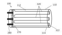
도 1은 실시예들에 따른 로우 프로파일 유체 주입 시스템의 개략도를 도시한다.
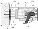
도 2는 실시예들에 따른 연장된 전달 부재를 갖는 로우 프로파일 유체 주입 시스템의 개략도를 도시한다.
도 3은 실시예들에 따른 로우 프로파일 유체 주입 시스템의 개략도를 도시한다.
도 4a는 실시예들에 따른 로우 프로파일 유체 주입 시스템 및 카트리지의 일부의 개략도를 도시한다.
도 4b는 실시예들에 따른 카트리지를 갖는 로우 프로파일 유체 주입 시스템의 로딩을 도시하는 개략도를 도시한다.
도 5a는 실시예들에 따른 로우 프로파일 유체 주입 시스템의 개략도를 도시한다.
도 5b는 실시예들에 따른 전달 부재가 연장되어 있는 로우 프로파일 유체 주입 시스템의 개략도를 도시한다.
도 5c는 실시예들에 따른 도 5b에 도시된 로우 프로파일 유체 주입 시스템의 일부의 개략도를 도시한다.
도 6a는 실시예들에 따른 로우 프로파일 유체 주입 시스템의 개략도를 도시한다.
도 6b는 실시예에 따른 도 6a에 도시된 로우 프로파일 유체 주입 시스템의 일부를 도시한다.
도 7은 실시예들에 따른 로우 프로파일 유체 주입 시스템의 내부 기구의 이미지를 도시한다.
도 8은 실시예들에 따른 로우 프로파일 유체 주입 시스템의 개략도를 도시한다.
도 9는 실시예들에 따른 로우 프로파일 유체 주입 시스템의 세장형 부재의 단면도를 도시한다.
도 10a는 실시예들에 따른 연장되지 않은 구성의 유체 전달 부재를 갖는 로우 프로파일 유체 주입 시스템의 개략도를 도시한다.
도 10b는 실시예들에 따른 연장된 구성의 유체 전달 부재를 갖는 도 10a의 시스템을 도시한다.
도 11a는 실시예들에 따른 연장되지 않은 구성의 유체 전달 부재를 갖는 예시적인 세장형 부재를 도시한다.
도 11b는 실시예들에 따른 연장된 구성의 유체 전달 부재를 갖는 예시적인 세장형 부재를 도시한다.
도 12a는 실시예들에 따른 연장되지 않은 구성의 유체 전달 부재를 갖는 예시적인 세장형 부재의 원위 단부를 도시한다.
도 12b는 실시예들에 따른 연장된 구성의 유체 전달 부재를 갖는 예시적인 세장형 부재의 원위 단부를 도시한다.
도 13a는 실시예들에 따른 시스템의 종축에 수직인 단면으로 도시된 로우 프로파일 유체 주입 시스템에 의한 주입 후 표적 조직의 다이어그램을 도시한다.
도 13b는 실시예들에 따른 로우 프로파일 유체 주입 시스템에 의한 주입 후 표적 조직의 주입 컬럼의 사시도를 도시한다.
도 13c는 실시예들에 따른 로우 프로파일 유체 주입 시스템에 의한 주입 후 표적 조직의 주입 컬럼의 사시도를 도시한다.
도 14는 실시예들에 따른 표적 조직 내부로 연장된 유체 전달 부재를 갖는 로우 프로파일 유체 주입 시스템의 개략도를 도시한다.
도 15a는 실시예들에 따른 시뮬레이션된 표적 조직 내부의 연장되지 않은 구성에 있는 유체 전달 부재를 갖는 예시적인 로우 프로파일 유체 주입 시스템을 도시한다.
도 15b는 실시예들에 따른 시뮬레이션된 표적 조직 내로 연장된 유체 전달 부재를 갖는 도 15a의 예시적인 시스템을 도시한다.
도 15c는 실시예들에 따른 시뮬레이션된 표적 조직 내로의 유체 주입 및 유체 전달 부재의 동시 후퇴 동안 도 15a의 시스템을 도시한다.
도 16a는 실시예들에 따른 연장되지 않은 구성의 유체 전달 부재를 사용한 유체 주입 이전의 로우 프로파일 유체 주입 시스템의 개략도를 도시한다.
도 16b는 실시예들에 따른 연장된 구성의 유체 전달 부재를 사용한 유체 주입 이전의 로우 프로파일 유체 주입 시스템의 개략도를 도시한다.
도 16c는 실시예들에 따른 연장되지 않은 구성의 유체 전달 부재를 사용한 유체 주입 후 로우 프로파일 유체 주입 시스템의 개략도를 도시한다.
도 16d는 실시예들에 따른 연장된 구성의 유체 전달 부재를 사용한 유체 주입 이전의 로우 프로파일 유체 주입 시스템의 개략도를 도시한다.
도 16e는 실시예들에 따른 유체 전달 부재의 동시 유체 주입 및 후퇴 후 도 16d의 시스템을 도시한다.
도 17은 실시예들에 따른 유체 주입 시스템을 사용하여 피험자의 신체 내의 종양 내로 유체를 주입하는 방법의 예시적인 단계를 도시한다.
도 18a는 실시예들에 따른 부피 선택기를 포함하는 로우 프로파일 유체 주입 시스템의 이미지를 도시한다.
도 18b는 실시예들에 따른 부피 선택기의 이미지를 도시한다.
도 19a는 실시예들에 따른 팁 캡을 포함하는 로우 프로파일 유체 주입 시스템의 개략도를 도시한다.
도 19b는 실시예들에 따른 팁 캡의 개략도를 도시한다.
도 20a는 실시예들에 따른 카트리지를 도시한다.
도 20b는 실시예들에 따른 카트리지를 도시한다.
도 21a 내지 도 21d는 실시예들에 따른 표적 조직에서 하나 이상의 제제를 전달하고 검출하기 위한 방법을 도시한다.The novel features of the present invention are set forth with particularity in the appended claims. A better understanding of the features and advantages of the present invention can be obtained by reference to the following detailed description and the accompanying drawings, which illustrate exemplary embodiments in which the principles of the invention are utilized.
Figure 1 illustrates a schematic diagram of a low profile fluid injection system according to embodiments.
FIG. 2 illustrates a schematic diagram of a low profile fluid injection system having an extended delivery member according to embodiments.
Figure 3 illustrates a schematic diagram of a low profile fluid injection system according to embodiments.
FIG. 4a illustrates a schematic diagram of a portion of a low profile fluid injection system and cartridge according to embodiments.
FIG. 4b illustrates a schematic diagram showing loading of a low profile fluid injection system having cartridges according to embodiments.
FIG. 5a illustrates a schematic diagram of a low profile fluid injection system according to embodiments.
FIG. 5b illustrates a schematic diagram of a low profile fluid injection system having an extended delivery member according to embodiments.
FIG. 5c illustrates a schematic diagram of a portion of the low profile fluid injection system illustrated in FIG. 5b according to embodiments.
FIG. 6a illustrates a schematic diagram of a low profile fluid injection system according to embodiments.
FIG. 6b illustrates a portion of the low profile fluid injection system illustrated in FIG. 6a according to an embodiment.
Figure 7 illustrates an image of the internal mechanisms of a low profile fluid injection system according to embodiments.
Figure 8 illustrates a schematic diagram of a low profile fluid injection system according to embodiments.
FIG. 9 illustrates a cross-sectional view of an elongated member of a low profile fluid injection system according to embodiments.
FIG. 10a illustrates a schematic diagram of a low profile fluid injection system having a fluid delivery member of an unextended configuration according to embodiments.
FIG. 10b illustrates the system of FIG. 10a having an extended configuration fluid delivery member according to embodiments.
FIG. 11a illustrates an exemplary elongated member having a fluid transfer member of an unextended configuration according to embodiments.
FIG. 11b illustrates an exemplary elongated member having an extended configuration fluid transfer member according to embodiments.
FIG. 12a illustrates a distal end of an exemplary elongated member having a fluid transfer member of an unextended configuration according to embodiments.
FIG. 12b illustrates the distal end of an exemplary elongated member having an extended configuration fluid transfer member according to embodiments.
FIG. 13a illustrates a diagram of a target tissue after injection by a low profile fluid injection system, depicted in a cross-section perpendicular to the longitudinal axis of the system according to embodiments.
FIG. 13b illustrates a perspective view of an injection column of a target tissue after injection by a low profile fluid injection system according to embodiments.
Figure 13c illustrates a perspective view of an injection column of a target tissue after injection by a low profile fluid injection system according to embodiments.
FIG. 14 illustrates a schematic diagram of a low profile fluid injection system having a fluid delivery member extending into a target tissue according to embodiments.
FIG. 15a illustrates an exemplary low profile fluid injection system having a fluid delivery member in an unextended configuration within a simulated target tissue according to embodiments.
FIG. 15b illustrates the exemplary system of FIG. 15a with a fluid delivery member extending into a simulated target tissue according to embodiments.
Figure 15c illustrates the system of Figure 15a during simultaneous injection of fluid into a simulated target tissue and retraction of the fluid delivery member according to embodiments.
FIG. 16a illustrates a schematic diagram of a low profile fluid injection system prior to fluid injection using a fluid delivery member of an unextended configuration according to embodiments.
FIG. 16b illustrates a schematic diagram of a low profile fluid injection system prior to fluid injection using an extended configuration fluid delivery member according to embodiments.
FIG. 16c illustrates a schematic diagram of a low profile fluid injection system after fluid injection using a fluid delivery member of an unextended configuration according to embodiments.
FIG. 16d illustrates a schematic diagram of a low profile fluid injection system prior to fluid injection using an extended configuration fluid delivery member according to embodiments.
FIG. 16e illustrates the system of FIG. 16d after simultaneous fluid injection and retraction of the fluid delivery member according to embodiments.
FIG. 17 illustrates exemplary steps of a method for injecting fluid into a tumor within a subject's body using a fluid injection system according to embodiments.
FIG. 18a illustrates an image of a low profile fluid injection system including a volume selector according to embodiments.
Figure 18b illustrates an image of a volume selector according to embodiments.
FIG. 19a illustrates a schematic diagram of a low profile fluid injection system including a tip cap according to embodiments.
Figure 19b illustrates a schematic diagram of a tip cap according to embodiments.
FIG. 20a illustrates a cartridge according to embodiments.
Figure 20b illustrates a cartridge according to embodiments.
FIGS. 21A through 21D illustrate methods for delivering and detecting one or more agents in a target tissue according to embodiments.
다음의 상세한 설명에서는, 그 일부를 형성하는 첨부 도면을 참조하도록 한다. 도면에서 유사한 기호는 문맥에서 달리 지시하지 않는 한 일반적으로 유사한 구성 요소를 나타낸다. 상세한 설명, 도면 및 청구 범위에 설명된 예시적인 실시예는 제한하는 것을 의미하지 않는다. 여기에 제시된 주제의 범위를 벗어나지 않고 다른 실시예가 이용될 수 있고, 다른 변경이 이루어질 수 있다. 본 명세서에 일반적으로 설명되고 도면에 예시되어 있는 본 개시의 양태들은 매우 다양한 상이한 구성으로 배열, 치환, 조합, 분리 및 설계될 수 있으며, 이들 모두는 여기서 명시적으로 고려된다는 것을 쉽게 이해할 수 있을 것이다.In the following detailed description, reference is made to the accompanying drawings, which form a part hereof. In the drawings, similar symbols generally represent similar elements unless the context dictates otherwise. The exemplary embodiments described in the detailed description, drawings, and claims are not meant to be limiting. Other embodiments may be utilized and other changes may be made without departing from the scope of the subject matter presented herein. It will be readily appreciated that the aspects of the present disclosure generally described herein and illustrated in the drawings may be arranged, substituted, combined, separated, and designed in a wide variety of different configurations, all of which are expressly contemplated herein.
특정 실시예들 및 예들이 아래에 개시되어 있지만, 본 발명의 주제는 구체적으로 개시된 실시예를 넘어 다른 대안적인 실시예 및/또는 사용, 그리고 그 수정 및 등가물로 확장된다. 따라서, 여기에 첨부된 청구항의 범위는 아래에 설명된 임의의 특정 실시예에 의해 제한되지 않는다. 예를 들어, 본 명세서에 개시된 임의의 방법 또는 프로세스에서, 방법 또는 프로세스의 작용 또는 동작은 임의의 적절한 시퀀스로 수행될 수 있으며, 반드시 임의의 특정 개시된 시퀀스로 제한되는 것은 아니다. 특정 실시예들을 이해하는데 도움이 될 수 있는 방식으로, 다양한 동작들이 복수의 개별 동작들로서 차례로 설명될 수 있지만, 그러나, 설명의 순서는 이러한 동작들이 순서 의존적이라는 것을 암시하는 것으로 해석되어서는 안 된다. 추가적으로, 여기에 설명된 구조, 시스템 및/또는 장치는 통합된 구성 요소 또는 별도의 구성 요소로 구현될 수 있다.While specific embodiments and examples are disclosed below, the subject matter of the present invention extends beyond the specifically disclosed embodiments to other alternative embodiments and/or uses, and modifications and equivalents thereof. Accordingly, the scope of the claims appended hereto is not limited by any specific embodiments described below. For example, in any method or process disclosed herein, the acts or operations of the method or process may be performed in any suitable sequence and are not necessarily limited to any specific disclosed sequence. In a manner that may be helpful in understanding certain embodiments, various operations may be described sequentially as multiple discrete operations; however, the order of description should not be construed to imply that such operations are order dependent. Additionally, the structures, systems, and/or devices described herein may be implemented as integrated components or separate components.
다양한 실시예를 비교하기 위해, 이들 실시예의 특정 양태 및 장점이 설명된다. 그러한 모든 양태 또는 장점이 반드시 임의의 특정 실시예에 의해 달성되는 것은 아니다. 따라서, 예를 들어, 다양한 실시예는 본 명세서에서 또한 교시되거나 또는 제안될 수 있는 다른 양태 또는 장점을 반드시 달성하지 않고 본 명세서에서 교시된 바와 같은 하나의 장점 또는 장점의 그룹을 달성하거나 또는 최적화하는 방식으로 수행될 수 있다.In order to compare the various embodiments, certain aspects and advantages of these embodiments are described. Not all such aspects or advantages are necessarily achieved by any particular embodiment. Thus, for example, various embodiments may be performed in a manner that achieves or optimizes one advantage or group of advantages as taught herein without necessarily achieving other aspects or advantages that may also be taught or suggested herein.
본 개시 내용은 로우 프로파일 유체 주입 장치 및 그 사용 시스템 및 방법을 설명한다. 본 명세서에 개시된 로우 프로파일 유체 주입 장치 및 시스템은 예를 들어 진단 및/또는 치료 응용 분야에서 기존 장치, 시스템 및 방법에 비해 장점을 제공할 수 있다. 일부 경우에, 본 명세서에 개시된 로우 프로파일 유체 주입 시스템(예를 들어, 시스템(100))은 인시투에서 암으로의 약물 전달을 위해 사용된다. 당업자는 본 명세서에 개시된 장치, 시스템 및 방법이 복수의 해부학적 영역 및 복수의 수술 절차에서 사용될 수 있다는 것을 이해할 것이다. 또한, 당업자는 본 명세서에 개시된 유체 주입 시스템의 삽입 및/또는 본 명세서에 개시된 바와 같은 하나 이상의 제제의 전달이 의사(예를 들어 내과 의사) 또는 비-의사 의료 전문가(예를 들어 사혈 전문 의사, 임상 기술자, 간호사, 개업 간호사, 또는 내과 의사 보조원)와 같은 피하 주사의 숙련자가 수행할 수 있다는 것을 이해할 것이다. 장치는 예를 들어 전임상, 생체 외, 또는 시험관 내 약물 테스트에 사용될 수 있다. 방법들은 인간 조직 또는 조직 샘플, 또는 동물 조직 또는 조직 샘플에서 수행될 수 있다.The present disclosure describes a low profile fluid infusion device and systems and methods for using the same. The low profile fluid infusion devices and systems disclosed herein may provide advantages over existing devices, systems and methods, for example, in diagnostic and/or therapeutic applications. In some instances, the low profile fluid infusion system disclosed herein (e.g., system (100)) is used for drug delivery to a cancer in situ. Those skilled in the art will appreciate that the devices, systems and methods disclosed herein may be used in a number of anatomical regions and in a number of surgical procedures. Additionally, those skilled in the art will appreciate that insertion of the fluid infusion system disclosed herein and/or delivery of one or more agents as disclosed herein may be performed by a skilled practitioner of subcutaneous injection, such as a physician (e.g., an internist) or a non-physician healthcare professional (e.g., a phlebotomist, a clinical technologist, a nurse practitioner, a nurse practitioner, or a physician assistant). The devices may be used, for example, in preclinical, ex vivo, or in vitro drug testing. The methods can be performed on human tissue or tissue samples, or on animal tissue or tissue samples.
도 1은 액추에이터(250) 및 세장형 부재(110)를 포함하는 로우 프로파일 유체 주입 시스템(100)을 도시한다. 당업자에 의해 이해되는 바와 같이, 본 명세서에 개시된 로우 프로파일 유체 주입 시스템의 치수 및 구조는 표적 조직으로의 하나 이상의 유체(예를 들어, 치료제 및/또는 진단제를 포함할 수 있음)의 최소 침습적 전달을 허용한다. 여기에 개시된 바와 같이, 하나 이상의 유체가 (예를 들어, 하나 이상의 카트리지(432) 내의) 챔버(400)에 로딩되고 세장형 부재(110) 내에 수용된 하나 이상의 유체 전달 부재(320)를 통해 표적 조직(예를 들어, 종양 조직 또는 그 일부)으로 전달될 수 있다. 세장형 부재(110)는 세장형 부재(110)의 근위 단부(113)에서 유체 주입 시스템(100)의 하우징에 연결될 수 있다. 일부 경우에, 세장형 부재(110)의 근위 단부(113)는 원위 커플링(190)을 포함할 수 있다. 원위 커플링(190)은 부착 인터페이스(예를 들어, 클립 또는 루어 락 커넥터)일 수 있다. 일부 경우에, 동축 시스는 세장형 부재(110) 위로 슬라이딩되어, 원위 커플링(190)에 결합될 수 있다.FIG. 1 illustrates a low profile fluid injection system (100) including an actuator (250) and an elongated member (110). As will be appreciated by those skilled in the art, the dimensions and configuration of the low profile fluid injection system disclosed herein allow for minimally invasive delivery of one or more fluids (e.g., which may include therapeutic and/or diagnostic agents) to a target tissue. As disclosed herein, one or more fluids may be loaded into a chamber (400) (e.g., within one or more cartridges (432)) and delivered to a target tissue (e.g., tumor tissue or a portion thereof) via one or more fluid delivery members (320) contained within the elongated member (110). The elongated member (110) may be connected to a housing of the fluid injection system (100) at a proximal end (113) of the elongated member (110). In some cases, the proximal end (113) of the elongated member (110) may include a distal coupling (190). The distal coupling (190) may be an attachment interface (e.g., a clip or a Luer lock connector). In some cases, the coaxial sheath may be slid over the elongated member (110) and coupled to the distal coupling (190).
액추에이터(250)는 (핸드 그립(170)(또는 핸들)을 포함하는 윤곽이 있는 외벽을 포함할 수 있는) 유체 주입 시스템(100)의 하우징 내에서 주사기 본체(260) 및 유체 전달 부재(320)를 구동하기 위한 다양한 수단 중 하나일 수 있다. 많은 경우에, 액추에이터(250)는 액추에이터 스트럿(254)에 연결된 레버 아암을 포함하며, 이는 주사기 로드(257)를 통해 유체 주입 시스템(100)의 하우징 내부에서 주사기 본체(260)를 구동한다. 다양한 실시예에서, 액추에이터(250)는 수동으로 작동될 수 있다(예를 들어, 액추에이터(250)를 유체 주입 시스템(100)의 하우징에 압착함으로써). 일부 경우에, 액추에이터(250)는 기계화된 액추에이터를 포함할 수 있으며, 여기서 주사기 본체(260)의 작동에 사용되는 일부 또는 모든 힘은 전기 기계 기구에 의해 제공될 수 있다. 액추에이터(250)의 작동은 하나 이상의 유체 전달 부재가 세장형 부재(110)의 원위 단부(114)로부터 (예를 들어, 표적 종양 조직과 같은 피험자의 조직 내로) 연장되게 할 수 있다.The actuator (250) may be any one of a variety of means for actuating the syringe body (260) and the fluid delivery member (320) within the housing of the fluid injection system (100) (which may include a contoured outer wall including a hand grip (170) (or handle). In many cases, the actuator (250) includes a lever arm connected to an actuator strut (254) that acts to actuate the syringe body (260) within the housing of the fluid injection system (100) via a syringe rod (257). In various embodiments, the actuator (250) may be manually actuated (e.g., by squeezing the actuator (250) against the housing of the fluid injection system (100)). In some cases, the actuator (250) may comprise a mechanized actuator, wherein some or all of the force used to actuate the syringe body (260) may be provided by an electromechanical mechanism. Actuation of the actuator (250) may cause one or more fluid delivery members to extend from the distal end (114) of the elongated member (110) (e.g., into a tissue of a subject, such as a target tumor tissue).
도 2는 액추에이터(250)의 레버 아암이 맞물린(예를 들어, 눌려진) 로우 프로파일 유체 주입 시스템(100)을 도시한다. 액추에이터(250)를 맞물리게 하면(예를 들어, 누르면) 하나 이상의 유체 전달 부재가 세장형 부재(110)의 원위 단부(114)를 통해 세장형 부재(110) 밖으로 연장되게 할 수 있다. 유체 전달 부재(들)(320)는 유체 주입 시스템(100)의 종축으로부터 멀리 편향될 수 있다(예를 들어, 벌어질 수 있음). 세장형 부재(110)의 원위 단부(114)로부터 연장될 때 벌어지는 복수의 유체 전달 부재(320)의 대표적인 예가 도 2에 도시되어 있다. 일부 경우에, 세장형 부재의 원위 단부(114)는 액추에이터(250)가 맞물릴 때(예를 들어, 주사기 본체(260)가 유체 주입 시스템(100)의 하우징 내에서 원위로 작동될 때) 하나 이상의 유체 전달 부재(320)가 유체 주입 시스템(100)의 종축으로부터 멀리 편향되게 할 수 있는 하나 이상의 앵글링 요소(115)(예를 들어, 벌림 기구)를 포함할 수 있다. 앵글링 요소(115)는 유체 전달 부재(320)가 통과할 수 있는 각진 채널(들)을 포함할 수 있는 하나 이상의 가이드를 포함할 수 있다. 앵글링 요소(115)의 대표적인 예가 도 12a 및 도 12b에 도시되어 있다. 일부 실시예에서, 하나 이상의 유체 전달 부재(들)(320)는 액추에이터(250)가 맞물릴 때 유체 주입 시스템(100)의 종축과 일렬로 연장될 수 있다. 액추에이터(250)가 맞물릴 때 유체 전달 부재(320)가 유체 주입 시스템(100)의 종축과 일렬로 연장되는 일부 경우에, 세장형 부재(110)의 원위 단부(114)는 각지지 않은 (예를 들어, 유체 전달 부재(320)가 통과할 수 있는) 가이드 요소를 포함한다.FIG. 2 illustrates a low profile fluid injection system (100) with a lever arm of an actuator (250) engaged (e.g., depressed). Engaging (e.g., depressed) the actuator (250) may cause one or more fluid delivery members to extend out of the elongated member (110) through the distal end (114) of the elongated member (110). The fluid delivery member(s) (320) may be deflected (e.g., splayed) away from the longitudinal axis of the fluid injection system (100). A representative example of a plurality of fluid delivery members (320) splaying as they extend from the distal end (114) of the elongated member (110) is illustrated in FIG. 2. In some cases, the distal end (114) of the elongated member may include one or more angling elements (115) (e.g., a spreader mechanism) that may cause one or more of the fluid delivery members (320) to deflect away from the longitudinal axis of the fluid injection system (100) when the actuator (250) is engaged (e.g., when the syringe body (260) is actuated distally within the housing of the fluid injection system (100). The angling elements (115) may include one or more guides that may include angled channel(s) through which the fluid delivery members (320) may pass. Representative examples of angling elements (115) are illustrated in FIGS. 12A and 12B . In some embodiments, the one or more fluid delivery members(s) (320) may extend in alignment with the longitudinal axis of the fluid injection system (100) when the actuator (250) is engaged. In some cases where the fluid delivery member (320) extends in alignment with the longitudinal axis of the fluid injection system (100) when the actuator (250) is engaged, the distal end (114) of the elongated member (110) includes a non-angular guide element (e.g., through which the fluid delivery member (320) can pass).
일부 경우에, 원위 단부(114)는 조직을 관통(예를 들어, 천공)하도록 형상화된다. 예를 들어, 원위 단부(114)는 예를 들어 피부 또는 섬유 조직을 관통하기 위해 뾰족하거나 또는 날카로운 단부를 가질 수 있다. 많은 경우에, 원위 단부(114)는 총알 형상의 또는 둥근 단부를 가질 수 있다. 원위 단부(114)의 이러한 총알 형상의 또는 둥근 단부는 피부 또는 섬유 조직을 관통하기에 충분할 수 있다; 그러나, 총알 형상의 또는 둥근 원위 단부(114)는 내부 장기와 같은 다른 조직의 손상(예를 들어, 천공)을 방지할 수 있으므로, 조직 또는 피험자 내부의 조직을 통해 세장형 부재를 전진시키는데 유리할 수 있다. 일부 경우에, 앵글링 요소(115)와 같은 가이드 요소는 조직 내로 또는 조직을 통한 세장형 부재(110)의 관통을 돕기 위해 형상화될 수 있다.In some cases, the distal end (114) is shaped to penetrate (e.g., puncture) tissue. For example, the distal end (114) may have a pointed or sharp end, for example, to penetrate skin or fibrous tissue. In many cases, the distal end (114) may have a bullet-shaped or rounded end. Such a bullet-shaped or rounded end of the distal end (114) may be sufficient to penetrate skin or fibrous tissue; however, the bullet-shaped or rounded distal end (114) may be advantageous in advancing the elongated member through tissue or tissue within a subject, as it may prevent damage to (e.g., puncture) other tissues, such as internal organs. In some cases, a guide element, such as an angling element (115), may be shaped to assist in penetrating the elongated member (110) into or through tissue.
일부 경우에, 액추에이터(250)의 레버 아암은 예를 들어 액추에이터(250)와 완전히 맞물림으로써, 유체 주입 시스템(100)의 하우징의 레버 아암 리세스(172)와 정합하여(예를 들어, 접촉하여) 배치될 수 있다. 레버 아암 리세스(172)는 액추에이터(250)가 유체 주입 시스템(100)의 하우징의 표면과 더 같은 높이의 위치로 눌려지게 할 수 있으며, 이는 유체 주입 시스템(100)의 사용자가 사용 중에 유체 주입 시스템(100)에 대한 안정된 제어를 유지하는 것을 도울 수 있다. 레버 아암 리세스(172)의 대표적인 예가 도 1에 도시되어 있다.In some cases, the lever arm of the actuator (250) may be positioned to mate with (e.g., contact) a lever arm recess (172) of the housing of the fluid injection system (100), for example, by fully engaging the actuator (250). The lever arm recess (172) may cause the actuator (250) to be pressed into a position that is more flush with the surface of the housing of the fluid injection system (100), which may assist a user of the fluid injection system (100) in maintaining stable control over the fluid injection system (100) during use. A representative example of a lever arm recess (172) is illustrated in FIG. 1.
도 3은 로우 프로파일 유체 주입 시스템(100)의 단면 이미지를 도시한다. 로우 프로파일 유체 주입 시스템(100)의 액추에이터(250)는 액추에이터 커플링(252)을 포함할 수 있다. 액추에이터 커플링(252)은 액추에이터 스트럿(254)에 결합될 수 있다(예를 들어, 회전 가능하게 결합될 수 있고, 예를 들어, 여기서 액추에이터 커플링(252)은 힌지 조인트임). 액추에이터 스트럿(254)은 스트럿 커플링(256)에 결합될 수 있다(예를 들어, 회전 가능하게 결합될 수 있고, 예를 들어, 여기서 스트럿 커플링(256)은 힌지 조인트임). 스트럿 커플링(256)은 주사기 로드(257) 및/또는 주사기 본체(260)에 결합될 수 있다. 일부 경우에, 스트럿 커플링은 예를 들어 주사기 로드(257) 및/또는 주사기 본체(260)에 고정적으로 부착되고, 여기서 스트럿 커플링(256)과 주사기 로드(257), 주사기 본체(260), 또는 주사기 로드(257)와 주사기 본체(260) 모두 사이의 회전 또는 병진은 허용되지 않는다.FIG. 3 illustrates a cross-sectional image of a low profile fluid injection system (100). An actuator (250) of the low profile fluid injection system (100) may include an actuator coupling (252). The actuator coupling (252) may be coupled to an actuator strut (254) (e.g., rotatably coupled, for example, where the actuator coupling (252) is a hinge joint). The actuator strut (254) may be coupled to a strut coupling (256) (e.g., rotatably coupled, for example, where the strut coupling (256) is a hinge joint). The strut coupling (256) may be coupled to a syringe rod (257) and/or a syringe body (260). In some cases, the strut coupling is fixedly attached to, for example, the syringe rod (257) and/or the syringe body (260), wherein no rotation or translation is permitted between the strut coupling (256) and the syringe rod (257), the syringe body (260), or both the syringe rod (257) and the syringe body (260).
액추에이터(250)를 맞물리게 하면(예를 들어, 액추에이터(250)의 레버 아암을 누르면) 스트럿(254)이 (예를 들어, 일부 경우에는, 주사기 로드(257)를 통해) 주사기 본체(260)에 힘을 가하게 할 수 있고, 이는 주사기 본체(260)가 유체 주입 시스템(100)의 내부 부분을 통해(예를 들어, 주사기 본체 샤프트(268)를 통해), 예를 들어 유체 주입 시스템(100)의 종축을 따라 원위 방향으로 슬라이딩 가능하게 병진하게 할 수 있다(예를 들어, 도 5a, 도 5b 및 도 5c 참조). 일부 경우에, 액추에이터(250)를 맞물림 해제시키면(예를 들어, 액추에이터(250)의 레버 아암을 해제시키면) 주사기 본체가 유체 주입 시스템(100)의 종축을 따라 근위 방향으로 병진하게 할 수 있다(예를 들어, 도 6a 및 도 6b 참조). 일부 경우에, 액추에이터(250)를 맞물리게 하면 주사기 로드(257)가 유체 주입 시스템(100)의 내부 부분(예를 들어, 주사기 로드 샤프트(520))을 통해, 예를 들어 유체 주입 시스템(100)의 종축을 따라 원위 방향으로 슬라이딩 가능하게 병진하게 할 수 있다. 일부 경우에, 액추에이터(250)를 맞물림 해제시키면(예를 들어, 액추에이터(250)의 레버 아암을 해제시키면) 주사기 로드(257)가 유체 주입 시스템(100)의 내부 부분을 통해, 예를 들어 유체 주입 시스템(100)의 종축을 따라 근위 방향으로 완전히 또는 부분적으로 병진하게 할 수 있다. 액추에이터(250)의 레버 아암은 액추에이터 힌지(251)에 의해 유체 주입 시스템(100)의 하우징에 결합(예를 들어, 회전 가능하게 결합)될 수 있다. 일부 경우에, 액추에이터(250)의 작동은 액추에이터(250)의 레버 아암이 액추에이터 힌지(251) 주위를 회전하게 한다.Engaging the actuator (250) (e.g., by depressing the lever arm of the actuator (250)) may cause the strut (254) to apply force to the syringe body (260) (e.g., via the syringe rod (257) in some cases), which may cause the syringe body (260) to slidably translate distally through an internal portion of the fluid injection system (100) (e.g., via the syringe body shaft (268)), for example, along the longitudinal axis of the fluid injection system (100) (see, e.g., FIGS. 5A, 5B, and 5C). In some cases, disengaging the actuator (250) (e.g., releasing the lever arm of the actuator (250)) may cause the syringe body to translate proximally along the longitudinal axis of the fluid injection system (100) (e.g., see FIGS. 6A and 6B ). In some cases, engaging the actuator (250) may cause the syringe rod (257) to slidably translate distally along the longitudinal axis of the fluid injection system (100) through an internal portion of the fluid injection system (100) (e.g., the syringe rod shaft (520)). In some cases, disengaging the actuator (250) (e.g., releasing the lever arm of the actuator (250)) may cause the syringe rod (257) to be translated fully or partially proximally through the interior of the fluid injection system (100), for example along the longitudinal axis of the fluid injection system (100). The lever arm of the actuator (250) may be coupled (e.g., rotatably coupled) to the housing of the fluid injection system (100) by an actuator hinge (251). In some cases, actuation of the actuator (250) causes the lever arm of the actuator (250) to rotate about the actuator hinge (251).
일부 경우에, 유체 주입 시스템(100)의 하우징은 (예를 들어, 액추에이터(250)의 작동 동안) 액추에이터 스트럿(254)이 종축을 따라 이동하게 하는 스트럿 채널(255)을 포함할 수 있다. 유체 주입 시스템(100)의 하우징은 액추에이터 결합 컷아웃(253)을 포함할 수 있다. 일부 경우에, 액추에이터 커플링 컷아웃(253)은 액추에이터 커플링(242)을 수용하기 위해 유체 주입 시스템(100)의 하우징에 형성되고 위치된다(예를 들어, 액추에이터(250)의 레버 아암이 눌려짐). 일부 경우에, 액추에이터 커플링 컷아웃(253)은 액추에이터 커플링(252)이 유체 주입 시스템(100)의 하우징의 최대 반경 내에서 이동할 수 있게 할 수 있다(예를 들어, 이는 액추에이터(250)가 유체 주입 시스템(100)의 하우징의 외부 표면과 동일 평면에 있거나 또는 접촉하는 지점까지 눌리게 할 수 있음).In some cases, the housing of the fluid injection system (100) may include a strut channel (255) that allows the actuator strut (254) to move along the longitudinal axis (e.g., during operation of the actuator (250)). The housing of the fluid injection system (100) may include an actuator coupling cutout (253). In some cases, the actuator coupling cutout (253) is formed and positioned in the housing of the fluid injection system (100) to receive an actuator coupling (242) (e.g., when a lever arm of the actuator (250) is depressed). In some cases, the actuator coupling cutout (253) may allow the actuator coupling (252) to move within a maximum radius of the housing of the fluid injection system (100) (e.g., it may cause the actuator (250) to be pressed to a point where it is flush with or in contact with an outer surface of the housing of the fluid injection system (100)).
하나 이상의 유체 전달 부재가 주사기 본체(260)에 결합될 수 있다. 주사기 본체 샤프트(268)를 통한 주사기 본체(260)의 병진은 하나 이상의 유체 전달 부재(320)가 세장형 부재(110)를 통해 원위로 병진하게 할 수 있다. 일부 경우에, 주사기 본체(260) 및/또는 하나 이상의 유체 전달 부재(320)가 유체 주입의 종축을 따라 원위 또는 근위 방향으로 병진하는 거리는 액추에이터(250)가 맞물리거나(예를 들어, 눌려지거나) 또는 맞물림 해제되는(예를 들어, 해제되는) 정도에 의존할 수 있다. 일부 경우에, 액추에이터(250)를 맞물리게 하면 하나 이상의 유체 전달 부재(320)가 세장형 부재(110)의 원위 단부(114)로부터 원위로 연장되게 한다.One or more fluid delivery members may be coupled to the syringe body (260). Translation of the syringe body (260) via the syringe body shaft (268) may cause one or more fluid delivery members (320) to be translated distally through the elongated member (110). In some cases, the distance that the syringe body (260) and/or one or more fluid delivery members (320) translate distally or proximally along the longitudinal axis of the fluid injection may depend on the extent to which the actuator (250) is engaged (e.g., depressed) or disengaged (e.g., disengaged). In some cases, engaging the actuator (250) causes one or more fluid delivery members (320) to extend distally from the distal end (114) of the elongated member (110).
주사기 본체 스프링(264)은 유체 주입 시스템(100)의 종축을 따라 주사기 본체(260)의 원위 병진을 저지하는데 사용될 수 있다. 일부 경우에, 주사기 본체 스프링(264)은 주사기 본체 샤프트(268)의 원위 단부(269)와 주사기 본체(260)의 숄더(266) 사이에 배치된다. 액추에이터(250)의 작동(예를 들어, 액추에이터(250)의 레버 아암을 누름으로써 액추에이터(250)와 맞물림)은 (예를 들어, 주사기 본체 숄더(266)가 주사기 본체 샤프트(268)의 원위 단부(269)에 더 가까워지도록 주사기 본체(260)를 병진시킴으로써) 주사기 본체 스프링(264)의 압축을 유발할 수 있다. 액추에이터(250)를 맞물림 해제시키면(예를 들어, 액추에이터(250)의 레버 아암을 해제시키면) 주사기 본체 스프링이 연장되게 할 수 있고, 주사기 본체(260)가 유체 주입 시스템(100)의 종축을 따라 근위로 병진하게 할 수 있다. 주사기 로드(257)는 액추에이터(250)가 맞물리지 않을 때 주사기 본체(260)와 함께 근위로 병진할 수 있다. 주사기 로드(257)의 근위 병진 및/또는 주사기 본체(260)의 근위 병진은 (예를 들어 스트럿 커플링(256) 및 액추에이터 커플링(252)을 통해) 액추에이터 스트럿(254)이 액추에이터(250)에 힘을 가하게 할 수 있고, 예를 들어 (예를 들어,도 3에 도시된 바와 같이) 액추에이터(250)가 맞물리지 않을 때, 액추에이터(250)가 맞물리지 않은(예를 들어, 눌리지 않은) 구성을 취하게 한다.A syringe body spring (264) may be used to resist distal translation of the syringe body (260) along the longitudinal axis of the fluid injection system (100). In some cases, the syringe body spring (264) is positioned between a distal end (269) of the syringe body shaft (268) and a shoulder (266) of the syringe body (260). Actuation of the actuator (250) (e.g., by engaging the actuator (250) by depressing a lever arm of the actuator (250)) may cause compression of the syringe body spring (264) (e.g., by translating the syringe body (260) such that the syringe body shoulder (266) moves closer to the distal end (269) of the syringe body shaft (268). Disengaging the actuator (250) (e.g., disengaging the lever arm of the actuator (250)) may cause the syringe body spring to extend, causing the syringe body (260) to translate proximally along the longitudinal axis of the fluid injection system (100). The syringe rod (257) may translate proximally with the syringe body (260) when the actuator (250) is not engaged. Proximal translation of the syringe rod (257) and/or proximal translation of the syringe body (260) may cause the actuator strut (254) to apply force to the actuator (250) (e.g., via the strut coupling (256) and the actuator coupling (252)), for example, causing the actuator (250) to assume an unengaged (e.g., uncompressed) configuration when the actuator (250) is not engaged (e.g., as illustrated in FIG. 3 ).
주사기 본체 스프링(264)은 액추에이터(250)가 맞물리지 않을 때(예를 들어, 액추에이터(250)가 맞물리지 않은 구성에 있을 때) 압축 상태로 유지될 수 있다. 예를 들어, 주사기 본체 스프링(264)은 주사기 본체 샤프트(268)의 원위 단부와 주사기 본체(260) 사이에서 압축 상태로 유지될 수 있다. 일부 경우에, 주사기 본체(260)는 주사기 본체 스프링(264)에 의해 주사기 샤프트 숄더(267)에 대해 바이어스된다. 일부 경우에, 주사기 본체 샤프트(268) 및 주사기 로드 샤프트(520)는 유체 주입 시스템(100)의 내부 공간에 연결된다. 일부 경우에, 주사기 샤프트 숄더(267)는 주사기 로드 샤프트(520)의 원위 단부 및 주사기 본체 샤프트(260)의 근위 단부를 나타낸다. 주사기 본체 스프링(264)의 길이 및/또는 스프링 상수는 액추에이터(250)를 작동시키기 위해 원하는 힘이 요구되도록 설계되거나 또는 선택될 수 있다. 예를 들어, 주사기 본체 스프링(264)은 액추에이터(250)를 작동시키는데 과도한 힘이 필요하지 않도록 길이 및/또는 스프링 상수를 갖도록 선택될 수 있고, 그렇지 않으면 사용 중에 장치의 위치 및/또는 배향에 대한 사용자의 제어를 감소시키거나 또는 액추에이터(250)의 불완전한 작동을 초래할 수 있다. 특정 실시예에서, 액추에이터(250)가 자체 중량으로 작동하지 않도록 또는 우연히 부딪히는 경우, 유체 전달 부재(들)(320)의 의도하지 않은 연장 및/또는 유체 전달 부재(들)(320)로부터의 유체의 발현을 초래할 수 있는 길이 및/또는 스프링 상수를 갖도록 주사기 본체 스프링(264)을 선택하는 것이 유용하다.The syringe body spring (264) may be maintained in a compressed state when the actuator (250) is not engaged (e.g., when the actuator (250) is in a non-engaged configuration). For example, the syringe body spring (264) may be maintained in a compressed state between the distal end of the syringe body shaft (268) and the syringe body (260). In some cases, the syringe body (260) is biased against the syringe shaft shoulder (267) by the syringe body spring (264). In some cases, the syringe body shaft (268) and the syringe load shaft (520) are connected to the interior space of the fluid injection system (100). In some cases, the syringe shaft shoulder (267) represents the distal end of the syringe load shaft (520) and the proximal end of the syringe body shaft (260). The length and/or spring constant of the syringe body spring (264) may be designed or selected such that a desired force is required to actuate the actuator (250). For example, the syringe body spring (264) may be selected to have a length and/or spring constant such that excessive force is not required to actuate the actuator (250), which could otherwise reduce the user's control over the position and/or orientation of the device during use or result in incomplete actuation of the actuator (250). In certain embodiments, it is useful to select the syringe body spring (264) to have a length and/or spring constant such that the actuator (250) does not actuate under its own weight or, if accidentally struck, could result in unintended extension of the fluid delivery member(s) (320) and/or release of fluid from the fluid delivery member(s) (320).
로우 프로파일 유체 주입 시스템(100)은 하나 이상의 유체 전달 부재(320)를 포함할 수 있다. 유체 전달 부재(들)(320)는 유체가 통과하여 흐를 수 있는 채널을 포함할 수 있다. 많은 경우에, 유체 주입 시스템(100)은 복수의 유체 전달 부재(320)를 포함한다. 예를 들면, 유체 주입 시스템(100)은 2, 3, 4, 5, 6, 7, 8, 9, 10, 10 내지 20, 20 내지 30, 30 내지 40, 40 내지 50, 또는 50 개 초과의 유체 전달 부재(320)를 포함할 수 있다. 유체 주입 시스템(100)을 포함하는 유체 전달 부재(320)의 개수를 증가시킴으로써, 더 많은 표적 조직 부위에 유체가 주입될 수 있다. 유체 주입 시스템(100)은 잘 제어된 패턴(예를 들어, 하나 이상의 컬럼 형상의 유체 주입을 포함할 수 있는 패턴)으로 표적 조직에 유체를 주입할 수 있다. 일부 경우에, 복수의 유체 전달 부재(320)를 포함하는 유체 주입 시스템(100)은 복수의 상이한 유체가 표적 조직의 하나 이상의 부분에 주입되게 할 것이다(예를 들어, 각 주입의 효과가 비교될 수 있도록, 예를 들어 생체 외, 인시투, 생체 내, 또는 시험관 내).The low profile fluid injection system (100) can include one or more fluid delivery members (320). The fluid delivery member(s) (320) can include channels through which fluid can flow. In many cases, the fluid injection system (100) includes a plurality of fluid delivery members (320). For example, the fluid injection system (100) can include 2, 3, 4, 5, 6, 7, 8, 9, 10, 10 to 20, 20 to 30, 30 to 40, 40 to 50, or more than 50 fluid delivery members (320). By increasing the number of fluid delivery members (320) that comprise the fluid injection system (100), fluid can be injected into more target tissue sites. The fluid injection system (100) can inject fluid into a target tissue in a well-controlled pattern (e.g., a pattern that can include one or more columnar fluid injections). In some cases, the fluid injection system (100) comprising a plurality of fluid delivery members (320) will allow a plurality of different fluids to be injected into one or more portions of the target tissue (e.g., so that the effects of each injection can be compared, e.g., ex vivo, in situ, in vivo, or in vitro).
유체 전달 부재(들)(320)는 유체 공급원(예를 들어, 카트리지(432))으로부터 표적 조직(예를 들어, 유체 전달 부재(들)(320)의 원위 단부에 인접하거나 또는 그 부근에 있는 표적 조직의 주입 부위)으로의 유체 경로(예를 들어, 연속 유체 경로 또는 밸브형 유체 경로)의 일부를 포함할 수 있다. 일부 경우에, 유체 전달 부재(320)의 근위 단부(327)는 유체 전달 부재(320)의 원위 단부(328)보다 유체 주입 시스템(100)의 종축으로부터 더 큰 반경 방향 거리에 있다. 유체 전달 부재(320)는 하나 이상의 굴곡부를 포함할 수 있으며, 이는 (예를 들어, 세장형 부재(110)를 조직 내로 또는 조직을 통해 전진시키는데 사용되는 접근 경로의 크기를 감소시키기 위해) 세장형 부재의 직경을 최소화하는데 유리할 수 있다. 일부 경우에, 유체 전달 부재(320) 내의 굴곡부의 개수 및/또는 각도는 유체 전달 부재(320)의 근위 단부가 유체 주입 시스템(100)의 종축으로부터 위치되는 반경에 의존한다. 일부 경우에, 유체 전달 부재(320)의 근위 단부가 유체 주입 시스템(100)의 종축으로부터 위치되는 반경은 다음 중 하나 이상의 두께 및/또는 직경에 의존한다: 주사기 본체(260), 주사기 본체 스프링(264), 주사기 본체 샤프트(268), 주사기 로드 샤프트(520), 또는 카트리지(432). 특정 실시예에서, 주사기 본체(260), 주사기 본체 스프링(264), 주사기 본체 샤프트(268), 주사기 로드 샤프트(520), 또는 카트리지(432) 중 하나 이상의 두께 및/또는 직경은 유체 주입 시스템(100)의 전체 직경을 감소시키거나 또는 유체 전달 부재(320)의 굴곡부의 개수 또는 각도를 감소시키기 위해 최소화될 수 있다. 일부 경우에, 유체 전달 부재(320)의 근위 단부가 유체 주입 시스템(100)의 종축으로부터 위치되는 반경은 유체 전달 채널(270)의 경로(예를 들어, 주사기 본체(260)를 통한 유체 전달 채널(270)의 경로)에 따라 달라진다.The fluid delivery member(s) (320) can comprise a portion of a fluid path (e.g., a continuous fluid path or a valved fluid path) from a fluid source (e.g., a cartridge (432)) to a target tissue (e.g., an injection site in the target tissue adjacent to or near the distal end of the fluid delivery member(s) (320)). In some cases, the proximal end (327) of the fluid delivery member (320) is a greater radial distance from the longitudinal axis of the fluid injection system (100) than the distal end (328) of the fluid delivery member (320). The fluid delivery member (320) can include one or more bends, which may advantageously minimize a diameter of the elongated member (e.g., to reduce the size of the access path used to advance the elongated member (110) into or through a tissue). In some cases, the number and/or angle of bends within the fluid delivery member (320) depends on the radius at which the proximal end of the fluid delivery member (320) is positioned from the longitudinal axis of the fluid injection system (100). In some cases, the radius at which the proximal end of the fluid delivery member (320) is positioned from the longitudinal axis of the fluid injection system (100) depends on the thickness and/or diameter of one or more of the following: the syringe body (260), the syringe body spring (264), the syringe body shaft (268), the syringe load shaft (520), or the cartridge (432). In certain embodiments, the thickness and/or diameter of one or more of the syringe body (260), the syringe body spring (264), the syringe body shaft (268), the syringe load shaft (520), or the cartridge (432) can be minimized to reduce the overall diameter of the fluid injection system (100) or to reduce the number or angle of bends in the fluid delivery member (320). In some cases, the radius at which the proximal end of the fluid delivery member (320) is positioned from the longitudinal axis of the fluid injection system (100) depends on the path of the fluid delivery channel (270) (e.g., the path of the fluid delivery channel (270) through the syringe body (260).
일부 경우에, 하나 이상의 유체 전달 부재(320)가 예를 들어 유체 전달 부재(320)의 근위 단부(327)에서 주사기 본체(260)에 결합된다. 일부 경우에, 하나 이상의 유체 전달 부재(320)는 하나 이상의 유체 전달 채널(270)과 유체 연통한다. 예를 들어, 유체 전달 부재(320)의 근위 단부(327)는 예를 들어 전달 채널 인터페이스(290)에서 유체 전달 채널(270)과 유체 연통할 수 있다.In some cases, one or more fluid delivery members (320) are coupled to the syringe body (260), for example at a proximal end (327) of the fluid delivery members (320). In some cases, the one or more fluid delivery members (320) are in fluid communication with one or more fluid delivery channels (270). For example, the proximal end (327) of the fluid delivery member (320) can be in fluid communication with the fluid delivery channel (270), for example at a delivery channel interface (290).
유체 전달 채널(270)은 유체 공급원(예를 들어, 카트리지(432))과 유체 전달 부재(320)를 연결하는 유체 경로일 수 있다. 유체 전달 채널(270)은 주사기 본체(260), 카트리지 접합부(410), 또는 카트리지 인터페이스(420) 중 하나 이상의 일부를 포함할 수 있다. 로우 프로파일 유체 주입 시스템(100)은 복수의 유체 전달 채널(270)을 포함할 수 있다. 예를 들어, 로우 프로파일 유체 주입 시스템은 유체 전달 부재(320) 및/또는 카트리지 챔버(400)와 동일한 개수의 유체 전달 채널(270)을 포함할 수 있다. 일부 경우에, 로우 프로파일 유체 주입 시스템은 유체 공급원(예를 들어, 카트리지(432))을 표적 조직에 연결하는 유체적으로 독립적인 복수의 경로를 포함할 수 있다. 예를 들면, 유체적으로 독립적인 경로는 유체 공급원, 유체 전달 채널(270) 및 유체 전달 부재(320)를 포함할 수 있으며, 여기서 유체적으로 독립적인 경로는 (예를 들어, 유체 전달 채널(270) 및/또는 다른 유체 공급원과 유체 연통하는 유체 전달 부재(320)를 통해) 다른 유체 공급원과 유체 연통하지 않는다. 일부 실시예에서, 유체 주입 시스템(100)은 1, 2, 3, 4, 5, 6, 7, 8, 9, 10, 10 내지 20, 20 내지 50, 또는 50 개 초과의 독립적인 유체 경로를 포함한다. 일부 경우에, 유체 주입 시스템(100)에 유체적으로 독립적인 복수의 경로를 포함하면 복수의 진단제 및/또는 복수의 치료제의 독립적인 치료 및/또는 후속 독립적인 분석이 가능하다.A fluid delivery channel (270) can be a fluidic pathway connecting a fluid supply source (e.g., a cartridge (432)) and a fluid delivery member (320). The fluid delivery channel (270) can include a portion of one or more of a syringe body (260), a cartridge abutment (410), or a cartridge interface (420). The low profile fluid injection system (100) can include a plurality of fluid delivery channels (270). For example, the low profile fluid injection system can include the same number of fluid delivery channels (270) as the fluid delivery member (320) and/or the cartridge chamber (400). In some cases, the low profile fluid injection system can include a plurality of fluidically independent pathways connecting a fluid supply source (e.g., a cartridge (432)) to a target tissue. For example, a fluidically independent pathway can include a fluid supply, a fluid delivery channel (270), and a fluid delivery member (320), wherein the fluidically independent pathway is not in fluid communication with another fluid supply (e.g., via the fluid delivery channel (270) and/or the fluid delivery member (320) in fluid communication with another fluid supply). In some embodiments, the fluid infusion system (100) includes 1, 2, 3, 4, 5, 6, 7, 8, 9, 10, 10 to 20, 20 to 50, or more than 50 independent fluidic pathways. In some cases, including multiple fluidically independent pathways in the fluid infusion system (100) allows for independent treatment and/or subsequent independent analysis of multiple diagnostic agents and/or multiple therapeutic agents.
일부 경우에, 유체 전달 채널(270) 또는 그 일부는 유체 저장소로서 기능할 수 있다. 예를 들어, 유체 전달 채널(270)의 적어도 일부는 유체 주입 시스템(100)을 사용하여 표적 조직 또는 그의 일부로 전달될 유체를 포함할 수 있다. 일부 경우에, 유체 전달 채널(270)은 유체 주입 시스템(100)이 유체를 표적 조직 또는 그 일부에 주입하기 위해 사용되기 전에 유체로 프라이밍된다. 여기에 추가로 개시되는 바와 같이, 유체 공급원(예를 들어, 카트리지(432)) 내의 유체(480)는 유체 전달 채널(270)과 유체 연통하는 동안 압력 하에 배치될 수 있으며, 이는 유체(480)가 유체 공급원으로부터 유체 전달 채널(270) 내로 흐르게 할 수 있다.In some cases, the fluid delivery channel (270) or a portion thereof may function as a fluid reservoir. For example, at least a portion of the fluid delivery channel (270) may contain a fluid to be delivered to the target tissue or a portion thereof using the fluid injection system (100). In some cases, the fluid delivery channel (270) is primed with a fluid before the fluid injection system (100) is used to inject the fluid into the target tissue or a portion thereof. As further disclosed herein, a fluid (480) within a fluid supply (e.g., a cartridge (432)) may be placed under pressure while in fluid communication with the fluid delivery channel (270), which may cause the fluid (480) to flow from the fluid supply into the fluid delivery channel (270).
도 4a 및 도 4b는 유체 주입 시스템(100)에 카트리지(432)를 로딩하는 대표적인 예를 도시한다. 카트리지(432) 내에 포함된 하나 이상의 유체는 카트리지 플런저(440)를 카트리지 인터페이스(420)와 맞물리게 함으로써 유체 전달 채널(270)과 유체 연통하도록 배치될 수 있다. 일부 경우에, (예를 들어, 카트리지(432)가 카트리지 접합부(410)에 의해 카트리지 리테이너(430)의 립에 대해 바이어스된 결과) 카트리지(432)가 카트리지 리테이너(430)에 로딩될 때 카트리지(432)의 하나 이상의 유체가 가압될 수 있다. 일부 경우에, 카트리지(432)를 유체 주입 시스템(100)으로 로딩하는 동안 카트리지(432)의 유체를 가압하면 유체가 유체 전달 채널(270)을 채우거나 또는 부분적으로 채울 수 있다.Figures 4a and 4b illustrate representative examples of loading a cartridge (432) into the fluid injection system (100). One or more fluids contained within the cartridge (432) may be placed into fluid communication with the fluid delivery channel (270) by engaging the cartridge plunger (440) with the cartridge interface (420). In some cases, one or more fluids in the cartridge (432) may be pressurized when the cartridge (432) is loaded into the cartridge retainer (430) (e.g., as a result of the cartridge (432) being biased against the lips of the cartridge retainer (430) by the cartridge abutment (410). In some cases, pressurizing the fluid in the cartridge (432) while loading the cartridge (432) into the fluid injection system (100) may cause the fluid to fill or partially fill the fluid delivery channel (270).
많은 경우에, 유체 전달 기구(280)(예를 들어, 유체 전달 로드(280))는 유체 전달 채널(270)의 적어도 일부로부터 유체 전달 부재(320)의 원위 단부(114)를 향해 유체를 구동하는데 사용된다. 유체 전달 기구(280)는 하나 이상의 유체 전달 로드를 포함할 수 있다. 유체 전달 로드(280)는 유체 전달 채널(270)의 적어도 일부 내에 슬라이딩 가능하게 배치될 수 있다. 일부 경우에, 유체 전달 로드(280)는 유체 전달 채널(270)의 적어도 일부 아래로 유체 전달 로드(280)의 병진(예를 들어, 유체 주입 시스템(100)에 대한 원위 방향으로의 병진)이 유체 전달 채널(270)의 적어도 일부 내부의 압력을 증가시키도록 크기가 설정되고, 이는 예를 들어 액추에이터(250)가 작동된 후에 유체 전달 부재(320)의 원위 단부로부터 유체의 발현을 유발할 수 있다. 도 3에 도시된 바와 같이, 유체 전달 로드(280)는 유체 전달 채널(270)의 굴곡부에서 유체 전달 채널(270) 내로 도입될 수 있다. 예를 들어, 세장형 부재의 원위 단부(284)는 유체 전달 채널(270)의 굴곡부에 또는 이에 인접하게 위치될 수 있다. 또한, 유체 전달 채널(270)은 3 방향 접합부(예를 들어, T 접합부)를 포함할 수 있는 것이 고려되고, 여기서 유체 전달 로드는 3 방향 접합부에 인접하여 그 하류(예를 들어, 원위)에서 유체 전달 채널(270)의 일부와 일렬로 3 방향 접합부의 아암에 안착된다.In many cases, a fluid delivery mechanism (280) (e.g., a fluid delivery rod (280)) is used to drive fluid from at least a portion of a fluid delivery channel (270) toward a distal end (114) of a fluid delivery member (320). The fluid delivery mechanism (280) can include one or more fluid delivery rods. The fluid delivery rod (280) can be slidably positioned within at least a portion of the fluid delivery channel (270). In some cases, the fluid delivery rod (280) is sized such that translation of the fluid delivery rod (280) down at least a portion of the fluid delivery channel (270) (e.g., translation distally relative to the fluid injection system (100)) increases a pressure within at least a portion of the fluid delivery channel (270), which can cause fluid to be expressed from the distal end of the fluid delivery member (320), for example, after the actuator (250) is actuated. As illustrated in FIG. 3, the fluid delivery rod (280) may be introduced into the fluid delivery channel (270) at a bend in the fluid delivery channel (270). For example, the distal end (284) of the elongated member may be positioned at or adjacent the bend in the fluid delivery channel (270). Additionally, it is contemplated that the fluid delivery channel (270) may include a three-way junction (e.g., a T-junction), wherein the fluid delivery rod is seated on an arm of the three-way junction in alignment with a portion of the fluid delivery channel (270) adjacent to and downstream (e.g., distal) of the three-way junction.
유체 전달 채널(270)은 퍼지 채널(purge channel)(271)과 유체 연통할 수 있다. 퍼지 채널(271)은 유체 주입 시스템(100) 외부의 공기와 유체 연통할 수 있다. 일부 경우에, 퍼지 채널(271)은 시스템(100)의 구성 요소(예를 들어, 주사기 본체(260))를 통한 및/또는 시스템(100)의 2 개 이상의 구성 요소 사이의(예를 들어, 주사기 본체(260)와 시스템(100)의 하우징 사이의) 채널 및/또는 갭을 포함한다. 일부 경우에, 유체 주입 시스템(100)의 채널, 저장소, 또는 카트리지에 존재하는 공기(또는 다른 가스)는 퍼지 채널(271)을 통해 배출될 수 있다. 과잉 가스 또는 압력이 퍼지 채널(271)을 통해 방출될 수 있으므로, 예를 들어 로딩 또는 주입 동안, 퍼지 채널(271)이 유용할 수 있다. The fluid delivery channel (270) can be in fluid communication with a purge channel (271). The purge channel (271) can be in fluid communication with air outside the fluid injection system (100). In some cases, the purge channel (271) comprises a channel and/or a gap through a component of the system (100) (e.g., the syringe body (260)) and/or between two or more components of the system (100) (e.g., between the syringe body (260) and the housing of the system (100)). In some cases, air (or other gas) present in a channel, reservoir, or cartridge of the fluid injection system (100) can be vented through the purge channel (271). The purge channel (271) can be useful, for example, during loading or injection, since excess gas or pressure can be released through the purge channel (271).
유체 주입 시스템(100)은 잠금 조립체(500)를 포함할 수 있다. 잠금 조립체(500)는 주사기 로드(257)에 결합(예를 들어, 슬라이딩 가능하게 결합)될 수 있다. 일부 경우에, 주사기 로드(257)는 주사기 로드(257)에 견고하게 결합된다. 일부 경우에, 주사기 로드(257)는 잠금 조립체(500)의 구멍 또는 채널(예를 들어, 잠금 조립체(500)의 구멍 또는 채널)을 통과할 수 있다.The fluid injection system (100) may include a locking assembly (500). The locking assembly (500) may be coupled (e.g., slidably coupled) to a syringe rod (257). In some cases, the syringe rod (257) is rigidly coupled to the syringe rod (257). In some cases, the syringe rod (257) may pass through a hole or channel in the locking assembly (500) (e.g., a hole or channel in the locking assembly (500)).
잠금 조립체(500)는 하나 이상의 잠금 핀(501)을 포함할 수 있다. 잠금 조립체(500)는 1, 2, 3, 4, 5, 6, 7, 8, 9, 10 또는 10 개 초과의 잠금 핀(501)을 포함할 수 있다. 잠금 조립체의 하나 이상의 잠금 핀(501)은 잠금 조립체(500)의 원주 방향 측면에 위치될 수 있다. 예를 들어, 하나 이상의 잠금 핀(501)은 잠금 조립체(500)의 원주 방향 측면으로부터 돌출될 수 있다. 잠금 조립체(500)는 하나 이상의 스프링을 포함할 수 있다. 일부 경우에, 잠금 조립체(500)의 하나 이상의 잠금 핀(501)은 잠금 조립체(500)의 하나 이상의 스프링에 결합될 수 있다. 일부 경우에, 잠금 조립체(500)의 하나 이상의 스프링은 잠금 조립체(500)로부터 외향으로(예를 들어, 반경 방향 외향으로) 잠금 조립체(500)의 하나 이상의 잠금 핀(501)을 바이어스시키도록 구성될 수 있다. 잠금 핀(501)은 주사기 로드 샤프트(520)를 따라 종 방향 위치에 잠금 조립체(500)를 고정하도록 구성될 수 있다. 일부 경우에, 잠금 조립체(500)의 하나 이상의 잠금 핀(501)은 주사기 로드 샤프트(520)의 내부 표면에 대해 외향으로 바이어스될 수 있다. 일부 경우에, 하나 이상의 잠금 핀(501)은 주시기 로드 샤프트(520)의 종 방향 위치에 잠금 조립체를 고정하기 위해 (예를 들어, 잠금 조립체(500)의 스프링에 의해 주사기 로드 샤프트(520)의 내부 표면에 대해 바이어스된 결과) 주사기 로드 샤프트(520)의 하나 이상의 잠금 정지부(560)로 연장될 수 있다. 일부 경우에, 액추에이터(250)가 맞물리기 전에 하나 이상의 잠금 핀(501)이 주사기 로드 샤프트(520)의 내부 표면에 대해 바이어스되고, 액추에이터(250)가 맞물릴될 때, 501의 하나 이상의 잠금 핀은 주사기 로드 샤프트(520)의 하나 이상의 내부 표면을 따라 종 방향으로 슬라이딩된다. 주사기 로드 샤프트(520)가 (예를 들어, 주사기 로드 샤프트(520)의 내부 표면을 따라) 하나 이상의 잠금 정지부(560)를 포함하는 경우, 하나 이상의 잠금 핀(501)은 (예를 들어, 잠금 조립체(500)의 하나 이상의 스프링을 사용하여 액추에이터(250)와 맞물리고 그리고/또는 주사기 로드 샤프트(520)에 대해 잠금 핀(501)을 바이어싱한 결과) 하나 이상의 잠금 정지부(560)로 적어도 부분적으로 연장되도록 구성될 수 있다. 일부 경우에, 잠금 조립체(500)는 하나 이상의 잠금 핀(501)이 하나 이상의 잠금 정지부(560)로 적어도 부분적으로 연장될 때 종 방향으로(예를 들어, 원위 방향으로, 근위 방향으로, 또는 원위 및 근위 방향으로) 병진하는 것이 방지된다.The lock assembly (500) can include one or more locking pins (501). The locking assembly (500) can include 1, 2, 3, 4, 5, 6, 7, 8, 9, 10, or more than 10 locking pins (501). The one or more locking pins (501) of the locking assembly can be positioned on a circumferential side of the locking assembly (500). For example, the one or more locking pins (501) can protrude from the circumferential side of the locking assembly (500). The locking assembly (500) can include one or more springs. In some cases, the one or more locking pins (501) of the locking assembly (500) can be coupled to one or more springs of the locking assembly (500). In some cases, one or more springs of the locking assembly (500) may be configured to bias one or more locking pins (501) of the locking assembly (500) outwardly (e.g., radially outwardly) from the locking assembly (500). The locking pins (501) may be configured to secure the locking assembly (500) in a longitudinal position along the syringe load shaft (520). In some cases, one or more locking pins (501) of the locking assembly (500) may be biased outwardly with respect to an interior surface of the syringe load shaft (520). In some cases, one or more locking pins (501) may extend to one or more locking stops (560) of the syringe load shaft (520) to secure the locking assembly in a longitudinal position along the syringe load shaft (520) (e.g., as a result of being biased with respect to the interior surface of the syringe load shaft (520) by the springs of the locking assembly (500). In some cases, prior to engaging the actuator (250), one or more of the locking pins (501) are biased against an interior surface of the syringe load shaft (520), and when the actuator (250) is engaged, the one or more of the locking pins of 501 slide longitudinally along one or more of the interior surfaces of the syringe load shaft (520). If the syringe load shaft (520) includes one or more locking stops (560) (e.g., along the interior surface of the syringe load shaft (520)), the one or more of the locking pins (501) may be configured to extend at least partially into the one or more locking stops (560) (e.g., as a result of engaging the actuator (250) using one or more springs of the locking assembly (500) and/or biasing the locking pins (501) against the syringe load shaft (520). In some cases, the locking assembly (500) is prevented from translating longitudinally (e.g., distally, proximally, or both distally and proximally) when one or more of the locking pins (501) extend at least partially into one or more of the locking stops (560).
유체 주입 시스템(100)이 다중 사용 시스템인 실시예와 같은 일부 경우에서, 하나 이상의 잠금 핀(501)은 주사기 로드 샤프트(520)(예를 들어, 하나 이상의 잠금 정지부(560))의 측면과 해제 가능하게 맞물리도록 구성된다. 일부 경우에, 하나 이상의 잠금 핀이 쐐기 형상일 수 있다. 예를 들어, 잠금 핀은 유체 주입 시스템(100)의 원위 단부를 향하는 각진 표면 또는 경사진 표면을 가질 수 있다. 일부 경우에, 하나 이상의 잠금 정지부(560)로부터 하나 이상의 잠금 핀(501)을 맞물림 해제하기 위해, 로드 또는 스틱과 같은 하나 이상의 부재가 (예를 들어, 유체 주입 시스템(100)의 근위 단부에 있는 하나 이상의 구멍, 포트 또는 채널을 통해) 유체 주입 시스템(100)에 도입될 수 있다. 하나 이상의 잠금 정지부(560)로부터 하나 이상의 잠금 핀(501)을 맞물림 해제하도록 구성된 부재는 뾰족하거나 또는 쐐기 형상의 원위 단부를 가질 수 있다. 일부 경우에, (예를 들어, 시스템(100)의 근위 단부에 있는 하나 이상의 접근 구멍, 포트 또는 채널을 통해) 하나 이상의 맞물린 잠금 핀(501)에 대해 하나 이상의 부재를 강제하면 (예를 들어, 잠금 조립체(500)의 하나 이상의 스프링을 압축함으로써) 하나 이상의 잠금 핀(501)을 잠금 조립체(500)의 본체로 다시 강제할 수 있다. 하나 이상의 잠금 정지부(560)로부터 하나 이상의 잠금 핀(501)을 맞물림 해제하면 잠금 조립체(500)와 같은 시스템(100)의 하나 이상의 구성 요소가 (예를 들어, 주사기 로드 스프링(510)에 의해 잠금 조립체(500)에 직접 또는 간접적으로 인가된 힘의 결과로) 액추에이터(250)가 해제될 때 근위 방향으로 종 방향으로 이동할 수 있다. 도 7은 잠금 조립체(500), 잠금 핀(501) 및 주사기 로드 스프링(510)을 포함하는 유체 주입 시스템(100)의 내부 기구의 이미지를 도시한다.In some instances, such as embodiments where the fluid injection system (100) is a multi-use system, one or more locking pins (501) are configured to releasably engage a side of the syringe load shaft (520) (e.g., one or more locking stops (560)). In some instances, the one or more locking pins may be wedge-shaped. For example, the locking pins may have an angled or tapered surface facing the distal end of the fluid injection system (100). In some instances, one or more members, such as a rod or stick, may be introduced into the fluid injection system (100) (e.g., through one or more holes, ports or channels in the proximal end of the fluid injection system (100)) to disengage the one or more locking pins (501) from the one or more locking stops (560). The member configured to disengage the one or more locking pins (501) from the one or more locking stops (560) may have a pointed or wedge-shaped distal end. In some cases, forcing one or more members against one or more engaged locking pins (501) (e.g., via one or more access holes, ports or channels in the proximal end of the system (100)) (e.g., by compressing one or more springs of the locking assembly (500)) may force one or more of the locking pins (501) back into the body of the locking assembly (500). Disengaging one or more of the locking pins (501) from one or more of the locking stops (560) may cause one or more components of the system (100), such as the locking assembly (500), to move longitudinally in the proximal direction when the actuator (250) is disengaged (e.g., as a result of force applied directly or indirectly to the locking assembly (500) by the syringe rod spring (510). FIG. 7 illustrates an image of the internal mechanism of the fluid injection system (100) including a locking assembly (500), a locking pin (501), and a syringe load spring (510).
유체 주입 시스템(100)은 주사기 로드 고정구(258)(예를 들어, 주사기 로드 핀)를 포함할 수 있다. 주사기 로드 고정구(258)는 주사기 로드(257)에 결합(예를 들어, 견고하게 결합)될 수 있다. 많은 경우에, 주사기 로드 고정구(258)는 (예를 들어, 유체 주입 시스템(100)의 종축에 대해) 잠금 조립체(500)의 근위에 있는 주사기 로드(257)의 종 방향 위치에서 주사기 로드(257)에 결합된다. 일부 양태에서, 주사기 로드 고정구(258)는 (예를 들어, 주사기 로드 스프링(510)에 의해 가해지는 힘으로 인해) 잠금 조립체가 주사기 로드(257)의 근위 단부에서 슬라이딩 오프되는 것을 방지한다. 일부 양태에서, 주사기 로드 고정구(258)는 주사기 로드(257)가 (예를 들어, 유체 주입 시스템(100)의 종축에 대해 근위 방향으로) 잠금 조립체(500)를 통해 슬라이딩되는 것을 방해하지 않는다.The fluid injection system (100) may include a syringe load retainer (258) (e.g., a syringe load pin). The syringe load retainer (258) may be coupled (e.g., rigidly coupled) to the syringe rod (257). In many cases, the syringe load retainer (258) is coupled to the syringe rod (257) at a longitudinal location of the syringe rod (257) proximal to the locking assembly (500) (e.g., with respect to the longitudinal axis of the fluid injection system (100)). In some embodiments, the syringe rod retainer (258) prevents the locking assembly from sliding off the proximal end of the syringe rod (257) (e.g., due to force exerted by a syringe rod spring (510). In some embodiments, the syringe rod retainer (258) does not prevent the syringe rod (257) from sliding through the locking assembly (500) (e.g., proximally with respect to the longitudinal axis of the fluid injection system (100)).
유체 주입 시스템(100)은 하나 이상의 잠금 정지부(560)를 포함할 수 있다. 잠금 정지부(560)는 주사기 로드 샤프트(520)에 고정적으로 부착될 수 있다. 많은 경우에, 잠금 정지부(560)는 유체 주입 시스템(100)의 종축을 따라 상이한 위치에서 주사기 로드 샤프트(520)에 부착(예를 들어, 고정적으로 부착)된다. 많은 경우에, 복수의 잠금 정지부(560)가 주사기 로드 샤프트(520)의 내주 주위의 복수의 위치에서 주사기 로드 샤프트(520)에 부착된다. 일부 경우에, 하나 이상의 잠금 정지부는 주사기 로드 샤프트(520) 주위에 연속적인 나선형 형상을 포함할 수 있다.The fluid injection system (100) may include one or more locking stops (560). The locking stops (560) may be fixedly attached to the syringe load shaft (520). In many cases, the locking stops (560) are attached (e.g., fixedly attached) to the syringe load shaft (520) at different locations along the longitudinal axis of the fluid injection system (100). In many cases, a plurality of locking stops (560) are attached to the syringe load shaft (520) at a plurality of locations around the inner periphery of the syringe load shaft (520). In some cases, the one or more locking stops may comprise a continuous helical shape around the syringe load shaft (520).
일부 경우에, (예를 들어, 액추에이터(250)가 맞물릴 때) 주사기 로드(257)가 유체 주입 시스템의 종축에 대해 원위 방향으로 병진될 때 잠금 조립체는 전방으로(예를 들어, 유체 주입 시스템(100)의 종축에 대해 원위 방향으로) 병진한다. 일부 경우에, 잠금 조립체(500)는 잠금 조립체가 유체 주입 시스템(100)의 종축에 대해 원위 방향으로 병진할 때 잠금 정지부(560)를 통과할 수 있다. 많은 경우에, 잠금 조립체(500)는 (예를 들어, 액추에이터(250)가 맞물린 후 맞물림 해제될 때) 잠금 조립체가 유체 주입 시스템(100)의 종축에 대해 근위 방향으로 병진할 때 하나 이상의 잠금 정지부(560)를 통과할 수 없다.In some cases, the locking assembly translates forward (e.g., distally with respect to the longitudinal axis of the fluid injection system) when the syringe rod (257) is translated distally with respect to the longitudinal axis of the fluid injection system (e.g., when the actuator (250) is engaged). In some cases, the locking assembly (500) can pass through the locking stops (560) when the locking assembly is translated distally with respect to the longitudinal axis of the fluid injection system (100). In many cases, the locking assembly (500) cannot pass through one or more of the locking stops (560) when the locking assembly is translated proximally with respect to the longitudinal axis of the fluid injection system (100) (e.g., when the actuator (250) is engaged and then disengaged).
일부 경우에, 부피 선택기(530)의 작동(예를 들어, 부피 선택기 다이얼(530)의 회전)은 주사기 로드 샤프트(520) 및 부착된 잠금 정지부(560)가 유체 주입 시스템(100)의 하우징 내에서 회전하게 할 수 있다. 일부 경우에, 유체 주입 시스템(100)의 종축에 대해 근위 방향으로 병진할 때 잠금 조립체(500)가 잠금 정지부를 통과할 수 없도록 잠금 정지부(560)를 제 위치로 회전시킴으로써 주입 부피가 선택된다.In some cases, actuation of the volume selector (530) (e.g., rotation of the volume selector dial (530)) may cause the syringe load shaft (520) and attached locking stop (560) to rotate within the housing of the fluid injection system (100). In some cases, an injection volume is selected by rotating the locking stop (560) into position such that the locking assembly (500) cannot pass through the locking stop when translated proximally with respect to the longitudinal axis of the fluid injection system (100).
유체 전달 기구(280)(예를 들어, 하나 이상의 유체 전달 로드(280))는 잠금 조립체(500)에 결합될 수 있다. 일부 경우에, 하나 이상의 유체 전달 로드(280)가 잠금 조립체(500)에 견고하게 부착된다. 많은 경우에, 하나 이상의 유체 전달 로드(280)는 하나 이상의 유체 전달 로드(280)의 근위 단부(282)에서 잠금 조립체(500)에 결합된다. 많은 경우에, 잠금 조립체가 (예를 들어, 유체 주입 시스템(100)의 종축에 대해) 유체 주입 시스템(100)의 하우징 내에서 근위로 병진하는 것이 방지될 때, 유체 전달 로드는 또한 (예를 들어, 액추에이터(250)가 맞물린 후 맞물림 해제될 때) 유체 주입 시스템(100)의 종축에 대해 근위 방향으로 더 이상 병진하는 것이 방지된다.A fluid delivery mechanism (280) (e.g., one or more fluid delivery rods (280)) may be coupled to the locking assembly (500). In some cases, the one or more fluid delivery rods (280) are rigidly attached to the locking assembly (500). In many cases, the one or more fluid delivery rods (280) are coupled to the locking assembly (500) at a proximal end (282) of the one or more fluid delivery rods (280). In many cases, when the locking assembly is prevented from translating proximally within the housing of the fluid injection system (100) (e.g., with respect to the longitudinal axis of the fluid injection system (100)), the fluid delivery rod is also prevented from further proximally translating with respect to the longitudinal axis of the fluid injection system (100) (e.g., when the actuator (250) is engaged and then disengaged).
유체 주입 시스템(100)은 주사기 로드 스프링(510)을 포함할 수 있다. 일부 경우에, 주사기 로드 스프링(510)(예를 들어, 주사기 로드 스프링(510)의 근위 단부)은 주사기 로드 고정구(258)(예를 들어, 주사기 로드 핀)에 대해 바이어스될 수 있다. 일부 경우에, 주사기 로드 스프링(510)은 주사기 본체(260) 및/또는 스트럿 커플링(256)의 근위 부분에 대해 바이어스될 수 있다. 일부 경우에, 주사기 로드 스프링(510)은 주사기 로드 고정구(258)와 주사기 본체(260) 및 스트럿 커플링(256) 중 하나 또는 둘 모두 사이에 압축되어 배치된다.The fluid injection system (100) may include a syringe load spring (510). In some cases, the syringe load spring (510) (e.g., a proximal end of the syringe load spring (510)) may be biased against a syringe load fixture (258) (e.g., a syringe load pin). In some cases, the syringe load spring (510) may be biased against a proximal portion of the syringe body (260) and/or the strut coupling (256). In some cases, the syringe load spring (510) is positioned in compression between the syringe load fixture (258) and one or both of the syringe body (260) and the strut coupling (256).
일부 경우에, 주사기 로드 스프링(510)의 스프링 상수는 주사기 본체 스프링(264)의 스프링 상수보다 작다. 일부 경우에, 주사기 본체(260)에 작용하는 원위 방향 힘(예를 들어, 주사기 로드 스프링(510)에 의해 공급됨)보다 큰 주사기 본체(260)에 작용하는 근위 방향 힘(예를 들어, 주사기 본체 스프링(264)에 의해 공급됨)은 예를 들어 주사기 본체(260)에 작용하는 불균형 힘의 결과로서, 주사기 본체(260)가 유체 주입 시스템(100)의 종축에 대해 근위 방향으로 병진하게 할 것이다. 잠금 조립체(500) 또는 그 일부(예를 들어, 하나 이상의 잠금 핀(501))가 잠금 정지부(560)에 접촉된(예를 들어, 맞물린) 다양한 경우와 같은 일부 경우에, 주사기 로드 스프링(510)보다 더 큰 스프링 상수를 갖는 주사기 본체 스프링(264)은 유체 전달 로드(들)(280) 및 잠금 조립체(500)가 제 위치에 유지되는 동안 주사기 본체(260) 및 주사기 로드(257)가 근위로 병진하게 할 것이다. 일부 경우에, 이것은 유체 전달 로드(들) 위로 유체 전달 채널(들)(270)을 강제할 수 있고, 유체 전달 채널(들)(270)의 적어도 일부로부터 유체 전달 부재(들)(320)를 통해 표적 조직으로의 유체의 추진을 발생시킬 수 있다.In some cases, the spring constant of the syringe load spring (510) is less than the spring constant of the syringe body spring (264). In some cases, a proximal force (e.g., supplied by the syringe body spring (264)) acting on the syringe body (260) that is greater than a distal force (e.g., supplied by the syringe load spring (510)) acting on the syringe body (260) will cause the syringe body (260) to translate proximally with respect to the longitudinal axis of the fluid injection system (100), for example as a result of the unbalanced force acting on the syringe body (260). In some cases, such as when the locking assembly (500) or a portion thereof (e.g., one or more locking pins (501)) is in contact with (e.g., engaged with) the locking stop (560), the syringe body spring (264) having a spring constant greater than the syringe rod spring (510) will cause the syringe body (260) and syringe rod (257) to translate proximally while the fluid delivery rod(s) (280) and locking assembly (500) are held in place. In some cases, this may force the fluid delivery channel(s) (270) over the fluid delivery rod(s), thereby propelling fluid from at least a portion of the fluid delivery channel(s) (270) through the fluid delivery member(s) (320) and into the target tissue.
조직에 전달되는 유체의 양은 하나 이상의 유체 전달 부재(320)가 세장형 부재(110)의 원위 단부(114)로부터 연장되는 거리 및/또는 액추에이터(250)가 맞물리는(예를 들어 눌려지는) 정도와 관련될 수 있다. 많은 경우에, 조직으로 전달되는 유체의 양은 하나 이상의 유체 전달 부재(320)가 세장형 부재(110)의 원위 단부(114)로부터 연장되는 거리와 직접적으로 관련되며, 이는 액추에이터(250)가 맞물리는 정도에 적접적으로 의존할 수 있다. 예를 들어, 일부 경우에, 액추에이터(250)는 주사기 로드 샤프트(520)의 원위 단부에 더 가깝게 위치된 잠금 정지부(560)와 잠금 핀(501)을 맞물리게 하도록 더 눌러질 수 있다. 많은 경우에, 액추에이터(250)를 누르는 동작은 또한 세장형 부재(110)의 원위 단부(114)로부터 더 먼 거리만큼 유체 전달 부재(320)를 연장시킨다. 더 많이 눌린 액추에이터(250)를 해제하는 것은 또한, (예를 들어, 주사기 본체 스프링(264)에 의해 시스템(100)의 하우징의 원위 단부의 내부 부분 및 주사기 본체(260)에 대해 가해지는 힘으로 인해) 주사기 본체(260)가 시스템(100)의 하우징 내에서 근위로 이동할 때, 유체 전달 기구(280)(예를 들어, 유체 전달 로드(280))가 유체 전달 채널(270)로부터 더 많은 양의 유체를 밀어 내게 할 수 있다.The amount of fluid delivered to the tissue may be related to the distance that one or more fluid delivery members (320) extend from the distal end (114) of the elongated member (110) and/or the degree to which the actuator (250) is engaged (e.g., depressed). In many cases, the amount of fluid delivered to the tissue is directly related to the distance that one or more fluid delivery members (320) extend from the distal end (114) of the elongated member (110), which may in turn be directly dependent on the degree to which the actuator (250) is engaged. For example, in some cases, the actuator (250) may be further depressed to engage the locking stop (560) and the locking pin (501) located closer to the distal end of the syringe load shaft (520). In many cases, the act of compressing the actuator (250) also extends the fluid delivery member (320) a greater distance from the distal end (114) of the elongated member (110). Releasing the further compressed actuator (250) may also cause the fluid delivery mechanism (280) (e.g., the fluid delivery rod (280)) to force a greater amount of fluid from the fluid delivery channel (270) as the syringe body (260) moves proximally within the housing of the system (100) (e.g., due to force exerted against the interior portion of the distal end of the housing of the system (100) and the syringe body (260) by the syringe body spring (264).
세장형 부재Long-legged absence
시스템(100)은 그 내벽에 의해 한정된 루멘(112)을 포함하는 세장형 부재(110)를 포함할 수 있다. 루멘(112)은 세장형 부재(110)의 종축을 따라 또는 이에 대해 평행하게 근위 단부(113)로부터 원위 단부(114)까지 세장형 부재(110)의 전체 길이에 걸쳐 연장될 수 있다. 세장형 부재(110)는 중공 튜브를 포함할 수 있다. 예를 들어, 세장형 부재(110)는 시스, 하이포 튜브 샤프트, 바늘 등을 포함할 수 있다. 대안적으로, 루멘(112)은 당업자가 원하는 세장형 부재(110)의 종축에 대한 임의의 구성으로, 당업자가 원하는 그 임의의 길이를 따라 연장될 수 있다. 루멘(112)의 원위 단부는 도시된 바와 같이 세장형 부재(110)의 원위 단부(114)에 대응할 수 있다.The system (100) can include an elongated member (110) having a lumen (112) defined by an inner wall thereof. The lumen (112) can extend the entire length of the elongated member (110) from a proximal end (113) to a distal end (114) along or parallel to the longitudinal axis of the elongated member (110). The elongated member (110) can include a hollow tube. For example, the elongated member (110) can include a sheath, a hypo tube shaft, a needle, or the like. Alternatively, the lumen (112) can extend along any length of the longitudinal axis of the elongated member (110) desired by one skilled in the art in any configuration. The distal end of the lumen (112) can correspond to the distal end (114) of the elongated member (110), as illustrated.
세장형 부재(110)는 금속을 포함할 수 있다. 세장형 부재(110)는 스테인리스강, 니티놀, 중재적 도입기(예를 들어, HDPE, Pebax 등) 등에 사용되는 전통적인 열가소성 수지, 또는 이들의 임의의 조합을 포함할 수 있다.The elongated member (110) may comprise metal. The elongated member (110) may comprise stainless steel, nitinol, a traditional thermoplastic resin used in interventional introduction (e.g., HDPE, Pebax, etc.), or any combination thereof.
세장형 부재(110)는 강성 재료를 포함할 수 있다. 대안적으로 또는 조합하여, 세장형 부재(110)는 가요성 재료를 포함할 수 있다.The elongated member (110) may comprise a rigid material. Alternatively or in combination, the elongated member (110) may comprise a flexible material.
도 8은 핸드헬드 로우 프로파일 유체 주입 시스템(100)의 개략도를 도시한다. 시스템(100)은 본 명세서에 설명된 바와 같이 세장형 부재(110) 내에 배치된 복수의 유체 전달 부재(320)를 포함할 수 있다. 복수의 유체 전달 부재(320) 각각은 이를 통한 유체 전달 루멘 및 본 명세서에 설명된 바와 같이 그 원위 단부에 적어도 하나의 출구 포트(322)를 포함할 수 있다. 각각의 유체 전달 루멘은 본 명세서에 설명된 다른 모든 유체 전달 루멘에 대해 유체적으로 독립적일 수 있다. 복수의 유체 전달 부재(320)는 여기에 설명된 바와 같이 후퇴된 구성 및 연장된 구성을 가질 수 있다. 시스템(100)은 본 명세서에 설명된 바와 같이 유체 전달 루멘에 유체적으로 결합된 하나 이상의 유체 전달 채널(270)을 포함할 수 있다. 일부 실시예에서, 각각의 유체 전달 채널(270)은 복수의 유체 전달 부재(320)의 단일 유체 전달 루멘에 유체 결합될 수 있다. 예를 들어, 시스템(100)은 도시된 바와 같이 3 개의 유체 전달 부재(320)를 포함하며 유체 전달 부재(320)에 유체적으로 결합된 3 개의 유체 전달 채널(270)을 가질 수 있어, 유체 전달 부재(320) 및 유체 전달 채널(270) 각각이 다른 모든 유체 전달 부재(320) 및 유체 전달 채널(270)에 대해 유체적으로 독립적이다. 시스템(100)은 본 명세서에 설명된 바와 같이 하나 이상의 유체 전달 채널(280)을 포함할 수 있다. 예를 들면, 시스템(100)은 도시된 바와 같이 3 개의 유체 전달 로드(280)를 포함할 수 있으며, 각각의 유체 전달 로드(280)는 3 개의 유체 전달 채널(예를 들어, 유체 저장소)의 단일 유체 전달 채널(예를 들어, 유체 저장소)에 작동 가능하게 결합된다. 3 개의 유체 전달 로드(280)는 본 명세서에 설명된 바와 같이 동시에 또는 서로 독립적으로 작동되도록 구성될 수 있다. 유체 전달 로드(들)(280)의 작동은 유체가 복수의 유체 전달 채널(270)로부터 복수의 유체 전달 부재(320)로 그리고 출구 포트(322) 밖으로 관심 조직 내로 전달되게 할 수 있다. 시스템(100)은 본 명세서에 설명된 바와 같이 복수의 유체 전달 부재(320)를 연장 또는 후퇴시키기 위해, 세장형 부재(110)의 근위 단부에 인접하고 복수의 유체 전달 부재(320) 및/또는 이동 가능한 본체(160)에 작동 가능하게 결합된 액추에이터(250)를 포함할 수 있다. 유체 전달 로드(280)는 본 명세서에 설명된 바와 같이 유체 전달 부재(320)의 동시 유체 전달 및 후퇴를 허용하도록 액추에이터(250)에 의해 작동될 수 있다.FIG. 8 illustrates a schematic diagram of a handheld low profile fluid injection system (100). The system (100) may include a plurality of fluid delivery members (320) disposed within an elongated member (110) as described herein. Each of the plurality of fluid delivery members (320) may include a fluid delivery lumen therethrough and at least one outlet port (322) at a distal end thereof as described herein. Each fluid delivery lumen may be fluidically independent of all other fluid delivery lumens described herein. The plurality of fluid delivery members (320) may have retracted and extended configurations as described herein. The system (100) may include one or more fluid delivery channels (270) fluidly coupled to the fluid delivery lumens as described herein. In some embodiments, each fluid delivery channel (270) may be fluidly coupled to a single fluid delivery lumen of the plurality of fluid delivery members (320). For example, the system (100) may include three fluid transfer members (320) as illustrated and may have three fluid transfer channels (270) fluidly coupled to the fluid transfer members (320), such that each of the fluid transfer members (320) and the fluid transfer channels (270) are fluidly independent of all other fluid transfer members (320) and fluid transfer channels (270). The system (100) may include one or more fluid transfer channels (280) as described herein. For example, the system (100) may include three fluid transfer rods (280) as illustrated, each of the fluid transfer rods (280) being operably coupled to a single fluid transfer channel (e.g., a fluid reservoir) of the three fluid transfer channels. The three fluid transfer rods (280) may be configured to operate simultaneously or independently of one another as described herein. Actuation of the fluid delivery rod(s) (280) can cause fluid to be delivered from the plurality of fluid delivery channels (270) to the plurality of fluid delivery members (320) and out the outlet ports (322) into the tissue of interest. The system (100) can include an actuator (250) adjacent the proximal end of the elongated member (110) and operably coupled to the plurality of fluid delivery members (320) and/or the movable body (160) to extend or retract the plurality of fluid delivery members (320) as described herein. The fluid delivery rod (280) can be actuated by the actuator (250) to allow simultaneous fluid delivery and retraction of the fluid delivery members (320) as described herein.
시스템(100)의 하우징은 세장형 부재(110)의 근위 단부에 인접한 핸들(170)(예를 들어, 그립)을 포함할 수 있다. 일부 실시예에서, 유체 전달 채널(270)은 도시된 바와 같이 핸들(170)에 위치될 수 있다. 일부 실시예에서, 유체 전달 채널(270)은 핸들(170) 또는 세장형 부재(110) 내에 슬라이딩 가능하게 배치된 주사기 본체(260) 내에 위치되거나 또는 이에 결합될 수 있다.The housing of the system (100) may include a handle (170) (e.g., a grip) adjacent the proximal end of the elongated member (110). In some embodiments, a fluid delivery channel (270) may be positioned in the handle (170), as shown. In some embodiments, the fluid delivery channel (270) may be positioned within or coupled to a syringe body (260) that is slidably positioned within the handle (170) or the elongated member (110).
대안적으로 또는 조합하여, 유체 전달 채널(270)은 핸들(170)의 외부, 예를 들어 튜빙을 통해 핸들(170) 및/또는 유체 전달 부재(320)의 근위 단부에 유체적으로 결합된 외부 유체 백에 위치될 수 있다.Alternatively or in combination, the fluid delivery channel (270) may be located external to the handle (170), for example in an external fluid bag fluidly coupled to the proximal end of the handle (170) and/or the fluid delivery member (320) via tubing.
도 9는 로우 프로파일 유체 주입 시스템(100)의 세장형 부재(110)의 단면도를 도시한다. 복수의 유체 전달 부재(320)는 본 명세서에 설명된 바와 같이 세장형 부재(110)의 루멘(112) 내에 배치될 수 있다. 세장형 부재(110)는 본 명세서에 설명된 바와 같이 저-침습 또는 최소 침습 주입 시스템으로서 사용하기 위한 크기의 외경(116)을 가질 수 있다. 루멘(112)을 한정하는 세장형 부재(110)의 내경(118)은 내부에 배치될 수 있는 유체 전달 부재(320)의 크기 및/또는 개수를 결정할 수 있다. 예를 들어, 세장형 부재(110)는 1.27 mm의 외경(116) 및 0.84 mm의 내경(118)을 갖는 18G 튜브일 수 있다. 0.26 mm의 외경(324)을 갖는 7 개의 31G 바늘이 18G 튜브의 루멘(112) 내에 맞을 수 있다. 복수의 유체 전달 부재(320)는 본 명세서에 설명된 바와 같이 유체 전달을 제공하도록 크기가 정해진 내경(326)을 가질 수 있다. 세장형 부재(110)의 크기 및/또는 유체 전달 부재(320)의 크기는 원하는 프로파일 및/또는 유체 전달 부재(320)의 개수를 시스템에 제공하기 위해 원하는 대로 조정될 수 있다.FIG. 9 illustrates a cross-sectional view of an elongated member (110) of a low profile fluid injection system (100). A plurality of fluid delivery members (320) can be positioned within a lumen (112) of the elongated member (110) as described herein. The elongated member (110) can have an outer diameter (116) sized for use as a low-invasive or minimally invasive injection system as described herein. An inner diameter (118) of the elongated member (110) defining the lumen (112) can determine the size and/or number of fluid delivery members (320) that can be positioned therein. For example, the elongated member (110) can be an 18G tube having an outer diameter (116) of 1.27 mm and an inner diameter (118) of 0.84 mm. Seven 31G needles having an outer diameter (324) of 0.26 mm can fit within the lumen (112) of the 18G tubing. A plurality of fluid delivery members (320) can have an inner diameter (326) sized to provide fluid delivery as described herein. The size of the elongated members (110) and/or the size of the fluid delivery members (320) can be adjusted as desired to provide a desired profile and/or number of fluid delivery members (320) for the system.
일부 실시예에서, 세장형 부재(110)는 게이지 번호가 약 10 내지 약 20인 바늘, 시스 또는 튜브를 포함할 수 있다. 세장형 부재(110)는 예를 들어, 10, 11, 12, 13, 14, 15, 16, 17, 18, 19 또는 20의 게이지 번호 중 임의의 2 개에 의해 한정된 범위의 외경(116)을 가질 수 있다. 세장형 부재(110)는 예를 들어 10, 11, 12, 13, 14, 15, 16, 17, 18, 19 또는 20의 게이지 번호를 가질 수 있다.In some embodiments, the elongated member (110) can comprise a needle, sheath or tube having a gauge number of about 10 to about 20. The elongated member (110) can have an outer diameter (116) defined by any two of the gauge numbers of, for example, 10, 11, 12, 13, 14, 15, 16, 17, 18, 19 or 20. The elongated member (110) can have a gauge number of, for example, 10, 11, 12, 13, 14, 15, 16, 17, 18, 19 or 20.
세장형 부재(110)는 약 0.9 mm 내지 약 3.5 mm의 외경(116)을 가질 수 있다. 세장형 부재(110)는 약 2 mm 내지 약 4 mm의 외경(116)을 가질 수 있다. 세장형 부재(110)는 다음 값 중 임의의 두 값에 의해 한정된 범위의 외경(116)을 가질 수 있다: 0.5 mm, 0.6 mm, 0.7 mm, 0.8 mm, 0.9 mm, 1 mm, 1.1 mm, 1.2 mm, 1.3 mm, 1.4 mm, 1.5 mm, 1.6 mm, 1.7 mm, 1.8 mm, 1.9 mm, 2 mm, 2.1 mm , 2.2 mm, 2.3 mm, 2.4 mm, 2.5 mm, 2.6 mm, 2.7 mm, 2.8 mm, 2.9 mm, 3 mm, 3.1 mm, 3.2 mm, 3.3 mm, 3.4 mm, 3.5 mm, 3.6 mm, 3.7 mm, 3.8 mm, 3.9 mm 또는 4 mm.The elongated member (110) can have an outer diameter (116) of about 0.9 mm to about 3.5 mm. The elongated member (110) can have an outer diameter (116) of about 2 mm to about 4 mm. The elongated member (110) can have an outer diameter (116) within a range defined by any two of the following values: 0.5 mm, 0.6 mm, 0.7 mm, 0.8 mm, 0.9 mm, 1 mm, 1.1 mm, 1.2 mm, 1.3 mm, 1.4 mm, 1.5 mm, 1.6 mm, 1.7 mm, 1.8 mm, 1.9 mm, 2 mm, 2.1 mm, 2.2 mm, 2.3 mm, 2.4 mm, 2.5 mm, 2.6 mm, 2.7 mm, 2.8 mm, 2.9 mm, 3 mm, 3.1 mm, 3.2 mm, 3.3 mm, 3.4 mm, 3.5 mm, 3.6 mm, 3.7 mm, 3.8 mm, 3.9 mm or 4 mm.
세장형 부재(110)는 약 3 프렌치 내지 약 10 프렌치의 외경(116)을 가질 수 있다. 세장형 부재(110)는 예를 들어 3 프렌치, 4 프렌치, 5 프렌치, 6 프렌치, 7 프렌치, 8 프렌치, 9 프렌치 또는 10 프렌치 값 중 임의의 두 개의 값에 의해 한정된 범위의 외경(116)을 가질 수 있다. 세장형 부재(110)는 예를 들어 약 3 프렌치, 약 4 프렌치, 약 5 프렌치, 약 6 프렌치, 약 7 프렌치, 약 8 프렌치, 약 9 프렌치, 또는 약 10 프렌치의 외경(116)을 가질 수 있다.The elongated member (110) can have an outside diameter (116) of from about 3 French to about 10 French. The elongated member (110) can have an outside diameter (116) in a range defined by any two of, for example, 3 French, 4 French, 5 French, 6 French, 7 French, 8 French, 9 French, or 10 French values. The elongated member (110) can have an outside diameter (116) of, for example, about 3 French, about 4 French, about 5 French, about 6 French, about 7 French, about 8 French, about 9 French, or about 10 French.
세장형 부재(110)는 본 명세서에 설명된 바와 같이 종래의 생검 접근 바늘, 종래의 내시경, 종래의 복강경 시스템, 종래의 혈관 접근 시스 등의 작업 채널 내에 맞는 크기의 외경(116)을 가질 수 있다.The elongated member (110) may have an outer diameter (116) sized to fit within the working channel of a conventional biopsy access needle, a conventional endoscope, a conventional laparoscopic system, a conventional vascular access sheath, and the like, as described herein.
세장형 부재(110)는 약 4 cm 내지 약 250 cm의 종 방향 길이를 가질 수 있다. 예를 들어, 세장형 부재(110)는 1 cm, 2 cm, 3 cm, 4 cm, 5 cm, 6 cm, 7 cm, 8 cm, 9 cm, 10 cm, 11 cm, 12 cm, 13 cm, 14 cm, 15 cm, 16 cm, 17 cm, 18 cm , 19 cm, 20 cm, 1 cm 내지 20 cm, 4 cm 내지 20 cm, 5 cm 내지 15 cm, 7 cm 내지 13 cm, 또는 9 cm 내지 11 cm의 길이를 가질 수 있다. 대안적으로, 세장형 부재(110)는 약 100 cm 내지 약 250 cm의 길이를 가질 수 있다. 세장형 부재(110)는 예를 들어 다음 값 중 임의의 두 개의 값에 의해 한정되는 범위의 길이를 가질 수 있다: 4 cm, 5 cm, 6 cm, 7 cm, 8 cm, 9 cm, 10 cm, 11 cm, 12 cm, 13 cm, 14 cm, 15 cm, 16 cm, 17 cm, 18 cm, 19 cm, 20 cm, 25 cm, 30 cm, 35 cm, 40 cm, 45 cm, 50 cm, 75 cm, 100 cm, 125 cm, 150 cm, 175 cm, 200 cm, 225 cm, 250 cm, 275 cm 또는 300 cm.The elongated member (110) can have a longitudinal length of from about 4 cm to about 250 cm. For example, the elongated member (110) can have a length of 1 cm, 2 cm, 3 cm, 4 cm, 5 cm, 6 cm, 7 cm, 8 cm, 9 cm, 10 cm, 11 cm, 12 cm, 13 cm, 14 cm, 15 cm, 16 cm, 17 cm, 18 cm, 19 cm, 20 cm, 1 cm to 20 cm, 4 cm to 20 cm, 5 cm to 15 cm, 7 cm to 13 cm, or 9 cm to 11 cm. Alternatively, the elongated member (110) can have a length of from about 100 cm to about 250 cm. The elongated member (110) can have a length in a range defined by any two of the following values, for example: 4 cm, 5 cm, 6 cm, 7 cm, 8 cm, 9 cm, 10 cm, 11 cm, 12 cm, 13 cm, 14 cm, 15 cm, 16 cm, 17 cm, 18 cm, 19 cm, 20 cm, 25 cm, 30 cm, 35 cm, 40 cm, 45 cm, 50 cm, 75 cm, 100 cm, 125 cm, 150 cm, 175 cm, 200 cm, 225 cm, 250 cm, 275 cm or 300 cm.
시스템(100)은 환자 접근 지점(예를 들어, 입, 피부 표면, 직장 등)로부터 약 1 cm 내지 약 300 cm 떨어진 곳에 유체 전달을 위해 구성될 수 있다. 일부 실시예에서, 시스템은 피부 표면 아래 약 1 cm 내지 약 30 cm의 유체 전달을 위해 구성될 수 있다. 예를 들어, 시스템은 피부 표면 아래 약 1 cm 내지 약 4 cm 또는 피부 표면 아래 약 4 cm 내지 약 20 cm의 유체 전달을 위해 구성될 수 있다. 대안적으로, 시스템은 피부 표면 아래 약 20 cm 내지 약 40 cm의 유체 전달을 위해 구성될 수 있다. 대안적으로, 시스템은 피부 표면 아래 또는 신체 내로의 진입 지점(예를 들어, 입)으로부터 약 100 cm 내지 약 250 cm의 유체 전달을 위해 구성될 수 있다.The system (100) can be configured for fluid delivery from about 1 cm to about 300 cm from a patient access point (e.g., the mouth, skin surface, rectum, etc.). In some embodiments, the system can be configured for fluid delivery from about 1 cm to about 30 cm below the skin surface. For example, the system can be configured for fluid delivery from about 1 cm to about 4 cm below the skin surface or from about 4 cm to about 20 cm below the skin surface. Alternatively, the system can be configured for fluid delivery from about 20 cm to about 40 cm below the skin surface. Alternatively, the system can be configured for fluid delivery from about 100 cm to about 250 cm below the skin surface or from an entry point into the body (e.g., the mouth).
특정 적용 분야에 사용되는 세장형 부재(110)의 길이는 관심 조직 부위의 위치에 따라 달라질 수 있다. 예를 들어, 더 긴 세장형 부재(110)를 갖는 시스템(100)은 하나 이상의 제제를 피험자 또는 조직의 내부의 더 깊은 곳에 위치된 표적 조직으로 전달하는데 사용될 수 있다.The length of the elongated member (110) used for a particular application may vary depending on the location of the tissue site of interest. For example, a system (100) having a longer elongated member (110) may be used to deliver one or more agents to a target tissue located deeper within the subject or tissue.
유체 전달 부재Absence of fluid transmission
하나 이상의 유체 전달 부재(320)가 세장형 부재(110)의 루멘(112) 내에 배치될 수 있다. 예를 들어, 4 개의 유체 전달 부재(320)는 도시된 바와 같이 세장형 부재(110)에 의해 피복될 수 있다. 원하는 임의의 개수의 유체 전달 부재(320)가 본 명세서에 설명된 바와 같이 세장형 부재(110)의 루멘(112)에 수용될 수 있다. 유체 전달 부재(320) 각각은 원위 단부, 근위 단부, 내부에 유체 전달 루멘을 한정하는 내벽, 및 루멘에 유체적으로 결합되는 그 원위 단부의 출구 포트(322)를 포함할 수 있다. 각각의 유체 전달 루멘은 다른 모든 유체 전달 루멘에 대해 유체적으로 독립적일 수 있다. 하나 이상의 유체 전달 부재(320)는 복수의 바늘 또는 튜브를 포함할 수 있다. 예를 들어, 유체 전달 부재(320) 중 하나 이상은 복수의 연필 끝 바늘, 끝이 무딘 바늘, 또는 끝이 비스듬한 바늘을 포함할 수 있다.One or more fluid transfer members (320) may be positioned within a lumen (112) of an elongated member (110). For example, four fluid transfer members (320) may be covered by the elongated member (110) as illustrated. Any desired number of fluid transfer members (320) may be accommodated within a lumen (112) of an elongated member (110) as described herein. Each of the fluid transfer members (320) may include a distal end, a proximal end, an interior wall defining a fluid transfer lumen therein, and an outlet port (322) at its distal end that is fluidically coupled to the lumen. Each fluid transfer lumen may be fluidically independent of all other fluid transfer lumens. One or more of the fluid transfer members (320) may include a plurality of needles or tubes. For example, one or more of the fluid delivery elements (320) may include a plurality of pencil tip needles, blunt tip needles, or beveled tip needles.
일부 실시예에서, 각각의 유체 전달 부재(320)는 여기에 설명된 바와 같이 원위 단부에서 단일 출구 포트(322)를 포함할 수 있다. 일부 실시예에서, 복수의 유체 전달 부재(320) 중 일부 또는 전부는 예를 들어 그 전체 내용이 여기에 참조로 포함되는 PCT/US2008/073212에 설명된 바와 같이 유체 전달 루멘에 유체적으로 결합되는 그 노출된 길이를 따라 적어도 하나의 추가 출구 포트(322)를 포함할 수 있다.In some embodiments, each fluid delivery member (320) may include a single outlet port (322) at its distal end as described herein. In some embodiments, some or all of the plurality of fluid delivery members (320) may include at least one additional outlet port (322) along their exposed length that is fluidically coupled to the fluid delivery lumen as described, for example, in PCT/US2008/073212, the entire contents of which are incorporated herein by reference.
유체 전달 부재(들)(320)는 후퇴된 구성 및 연장된 구성을 가질 수 있다. 유체 전달 부재(320)는 시스템(100)이 환자의 신체 내로(예를 들어, 피부 또는 입(701)을 통해) 삽입되고 종양 부위(702)에 매우 근접하게 위치되는 동안 후퇴된 구성으로 유지될 수 있다. 유체 전달 부재(320)는 치료제를 종양 조직(702)에 전달하기 위해 도시된 바와 같이 세장형 부재(110)의 원위 단부(114) 밖으로 종양(702) 내로 연장된 구성으로 연장될 수 있다. 유체 전달 부재(120)는 환자로부터 시스템(100)을 제거하기 위해 후퇴된 구성으로 복귀될 수 있다.The fluid delivery member(s) (320) can have a retracted configuration and an extended configuration. The fluid delivery member (320) can be maintained in a retracted configuration while the system (100) is inserted into the patient's body (e.g., through the skin or mouth (701)) and positioned in close proximity to the tumor site (702). The fluid delivery member (320) can be extended in a configuration extending out of the distal end (114) of the elongated member (110) into the tumor (702) as shown to deliver the therapeutic agent to the tumor tissue (702). The fluid delivery member (120) can be returned to the retracted configuration to remove the system (100) from the patient.
복수의 유체 전달 부재(320)는 금속 또는 플라스틱 중 하나 이상을 포함할 수 있다. 복수의 유체 전달 부재(320)는 형상 기억 합금을 포함할 수 있다. 복수의 유체 전달 부재(320)는 스테인리스강, 니티놀, 중재적 도입기(예를 들어, HDPE, Pebax 등) 등에 사용되는 전통적인 열가소성 수지, 또는 이들의 임의의 조합을 포함할 수 있다.The plurality of fluid transfer members (320) can comprise one or more of metals or plastics. The plurality of fluid transfer members (320) can comprise a shape memory alloy. The plurality of fluid transfer members (320) can comprise stainless steel, nitinol, traditional thermoplastics used in interventional introducers (e.g., HDPE, Pebax, etc.), or any combination thereof.
복수의 유체 전달 부재(320)는 가요성 재료를 포함할 수 있다. 대안적으로 또는 조합하여, 복수의 유체 전달 부재(320)는 강성 재료를 포함한다.The plurality of fluid transfer members (320) may comprise a flexible material. Alternatively or in combination, the plurality of fluid transfer members (320) comprise a rigid material.
일부 실시예에서, 유체 전달 부재(320)는 약 28 내지 약 33 범위의 게이지 번호를 갖는 바늘, 시스 또는 튜브를 포함할 수 있다. 하나 이상의 유체 전달 부재(320)는 25 게이지 바늘일 수 있다. 일부 경우에, 유체 전달 부재(120)는 20 게이지, 21 게이지, 22 게이지, 23 게이지, 24 게이지, 26 게이지, 27 게이지, 28 게이지, 29 게이지, 30 게이지, 31 게이지, 32 게이지, 또는 33 게이지 바늘을 포함할 수 있다. 유체 전달 부재(320)는 예를 들어 28, 29, 30, 31, 32 또는 33 게이지 번호 중 임의의 2 개에 의해 한정된 범위의 외경(324)을 가질 수 있다. 하나 이상의 유체 전달 부재는 예를 들어 28, 29, 30, 31, 32 또는 33의 게이지 번호를 가질 수 있다.In some embodiments, the fluid delivery member (320) can comprise a needle, sheath or tube having a gauge number in the range of about 28 to about 33. One or more of the fluid delivery members (320) can be a 25 gauge needle. In some cases, the fluid delivery member (120) can comprise a 20 gauge, 21 gauge, 22 gauge, 23 gauge, 24 gauge, 26 gauge, 27 gauge, 28 gauge, 29 gauge, 30 gauge, 31 gauge, 32 gauge, or 33 gauge needle. The fluid delivery member (320) can have an outer diameter (324) in a range defined by any two of the gauge numbers 28, 29, 30, 31, 32 or 33, for example. One or more of the fluid delivery members can have a gauge number of 28, 29, 30, 31, 32 or 33, for example.
유체 전달 부재(320)는 약 0.05 mm 내지 약 0.5 mm 범위의 외경(324)을 가질 수 있다. 유체 전달 부재(320)는 다음 값 중 임의의 두 개의 값에 의해 한정되는 범위의 외경(324)을 가질 수 있다: 0.05 mm, 0.06 mm, 0.07 mm, 0.08 mm, 0.09 mm, 0.1 mm, 0.15 mm, 0.2 mm, 0.25 mm, 0.3 mm, 0.35 mm, 0.4 mm, 0.45 mm 또는 0.5 mm. 유체 전달 부재(120) 중 하나 이상은 약 0.05 mm, 약 0.06 mm, 약 0.07 mm, 약 0.08 mm, 약 0.09 mm, 약 0.1 mm, 약 0.15 mm, 약 0.2 mm, 약 0.25 mm, 약 0.3 mm, 약 0.35 mm, 약 0.4 mm, 약 0.45 mm, 또는 약 0.5 mm의 외경(124)을 가질 수 있다.The fluid delivery member (320) can have an outer diameter (324) in the range of from about 0.05 mm to about 0.5 mm. The fluid delivery member (320) can have an outer diameter (324) in a range defined by any two of the following values: 0.05 mm, 0.06 mm, 0.07 mm, 0.08 mm, 0.09 mm, 0.1 mm, 0.15 mm, 0.2 mm, 0.25 mm, 0.3 mm, 0.35 mm, 0.4 mm, 0.45 mm, or 0.5 mm. One or more of the fluid transfer members (120) can have an outer diameter (124) of about 0.05 mm, about 0.06 mm, about 0.07 mm, about 0.08 mm, about 0.09 mm, about 0.1 mm, about 0.15 mm, about 0.2 mm, about 0.25 mm, about 0.3 mm, about 0.35 mm, about 0.4 mm, about 0.45 mm, or about 0.5 mm.
시스템(100)은 세장형 부재(110)의 루멘(112) 내에 배치된 하나 이상의 유체 전달 부재(320)를 포함할 수 있다. 시스템(100)은 예를 들어 복수의 유체 전달 부재(320)를 포함할 수 있다. 복수의 유체 전달 부재(320)는 적어도 2 개의 유체 전달 부재(320)를 포함할 수 있다. 복수의 유체 전달 부재(320)는 2 내지 20 개의 유체 전달 부재(320)를 포함할 수 있다. 복수의 유체 전달 부재(320)는 2, 3, 4, 5, 6, 7, 8, 9, 10, 11, 12, 13, 14, 15, 16, 17, 18, 19 또는 20의 값들 중 임의의 두 개의 값에 의해 한정되는 범위의 개수의 유체 전달 부재(320)를 포함할 수 있다.The system (100) can include one or more fluid transfer members (320) disposed within a lumen (112) of an elongated member (110). The system (100) can include, for example, a plurality of fluid transfer members (320). The plurality of fluid transfer members (320) can include at least two fluid transfer members (320). The plurality of fluid transfer members (320) can include from 2 to 20 fluid transfer members (320). The plurality of fluid transfer members (320) can include a number of fluid transfer members (320) defined by any two of the
도 10a는 후퇴된 구성의 유체 전달 부재(320)를 갖는 로우 프로파일 유체 주입 시스템(100)의 개략도를 도시한다. 도 10b는 연장된 구성의 유체 전달 부재(320)를 갖는 시스템(100)을 도시한다. 시스템(100)은 본 명세서에 설명된 바와 같이 세장형 부재(110) 내에 배치된 복수의 유체 전달 부재(320)를 포함할 수 있다. 복수의 유체 전달 부재(320) 각각은 본 명세서에 설명된 바와 같이 그 원위 단부에 유체 전달 루멘 및 적어도 하나의 출구 포트(322)를 포함할 수 있다. 각각의 유체 전달 루멘은 본 명세서에 설명된 바와 같이 다른 모든 유체 전달 루멘에 대해 유체적으로 독립적일 수 있다. 복수의 유체 전달 부재(320)는 여기에 설명된 바와 같이 후퇴된 구성 및 연장된 구성을 가질 수 있다.FIG. 10A illustrates a schematic diagram of a low profile fluid injection system (100) having a fluid delivery member (320) in a retracted configuration. FIG. 10B illustrates a system (100) having a fluid delivery member (320) in an extended configuration. The system (100) can include a plurality of fluid delivery members (320) disposed within an elongated member (110) as described herein. Each of the plurality of fluid delivery members (320) can include a fluid delivery lumen and at least one outlet port (322) at its distal end as described herein. Each fluid delivery lumen can be fluidically independent of all other fluid delivery lumens as described herein. The plurality of fluid delivery members (320) can have retracted and extended configurations as described herein.
유체 전달 부재(320)는 후퇴된 구성에서 세장형 부재(110)의 루멘(112) 내에 완전히 둘러싸이도록 구성될 수 있다. 일부 예에서, 복수의 유체 전달 부재(320) 각각은 세장형 부재(110)의 원위 단부(114)로부터 세장형 부재(110)의 근위 단부까지 연장될 수 있다. 예를 들어, 복수의 유체 전달 부재(320) 각각의 길이는 세장형 부재(110)의 길이와 실질적으로 유사할 수 있다.The fluid transfer member (320) can be configured to be completely enclosed within the lumen (112) of the elongated member (110) in a retracted configuration. In some examples, each of the plurality of fluid transfer members (320) can extend from a distal end (114) of the elongated member (110) to a proximal end of the elongated member (110). For example, the length of each of the plurality of fluid transfer members (320) can be substantially similar to the length of the elongated member (110).
복수의 유체 전달 부재(320) 각각은 약 4 cm 내지 약 250 cm 범위의 길이를 가질 수 있다. 예를 들어, 복수의 유체 전달 부재(320) 각각은 약 4 cm 내지 약 20 cm 범위의 길이를 가질 수 있다. 대안적으로, 복수의 유체 전달 부재(320) 각각은 약 100 cm 내지 약 250 cm 범위의 길이를 가질 수 있다. 복수의 유체 전달 부재(320) 각각은 예를 들어 다음 값 중 임의의 두 개의 값에 의해 한정되는 범위의 길이를 가질 수 있다: 4 cm, 5 cm, 6 cm, 7 cm, 8 cm, 9 cm, 10 cm, 11 cm, 12 cm, 13 cm, 14 cm, 15 cm, 16 cm, 17 cm, 18 cm, 19 cm, 20 cm , 25 cm, 30 cm, 35 cm, 40 cm, 45 cm, 50 cm, 75 cm, 100 cm, 125 cm, 150 cm, 175 cm, 200 cm, 225 cm, 250 cm, 275 cm 또는 300 cm.Each of the plurality of fluid delivery members (320) can have a length in the range of about 4 cm to about 250 cm. For example, each of the plurality of fluid delivery members (320) can have a length in the range of about 4 cm to about 20 cm. Alternatively, each of the plurality of fluid delivery members (320) can have a length in the range of about 100 cm to about 250 cm. Each of the plurality of fluid transfer members (320) can have a length in a range defined by any two of the following values, for example: 4 cm, 5 cm, 6 cm, 7 cm, 8 cm, 9 cm, 10 cm, 11 cm, 12 cm, 13 cm, 14 cm, 15 cm, 16 cm, 17 cm, 18 cm, 19 cm, 20 cm, 25 cm, 30 cm, 35 cm, 40 cm, 45 cm, 50 cm, 75 cm, 100 cm, 125 cm, 150 cm, 175 cm, 200 cm, 225 cm, 250 cm, 275 cm or 300 cm.
유체 전달 부재(320)의 길이는 세장형 부재(110)의 길이 및/또는 관심 조직 부위의 위치에 따라 조정될 수 있다.The length of the fluid delivery member (320) can be adjusted depending on the length of the elongated member (110) and/or the location of the tissue site of interest.
유체 전달 부재(320)는 본 명세서에 설명된 바와 같이 세장형 부재(110)의 원위 단부(114) 밖으로 연장된 구성으로 연장될 수 있다. 연장된 구성에서, 복수의 유체 전달 부재(320) 각각은 세장형 부재(110)의 종축(111)으로부터 멀어지게 각을 이룰 수 있다.The fluid transfer member (320) may be configured to extend beyond the distal end (114) of the elongated member (110) as described herein. In the extended configuration, each of the plurality of fluid transfer members (320) may be angled away from the longitudinal axis (111) of the elongated member (110).
일부 실시예에서, 세장형 부재(110)의 원위 단부(114)는 연장된 구성에서 세장형 부재(110)의 종축(111)으로부터 멀어지게 각을 이루도록 복수의 유체 전달 부재(320)를 안내하도록 위치된 하나 이상의 앵글링 요소(115)(예를 들어, 벌림 기구)를 포함할 수 있다. 앵글링 요소 또는 벌림 기구는 예를 들어 복수의 유체 전달 부재(320)를 원하는 연장된 구성으로 우선적으로 안내하는 세장형 부재(110) 내의 하나 이상의 채널 또는 가이드를 포함할 수 있다.In some embodiments, the distal end (114) of the elongate member (110) may include one or more angling elements (115) (e.g., a spreader mechanism) positioned to guide the plurality of fluid delivery members (320) so as to angle away from the longitudinal axis (111) of the elongate member (110) in an extended configuration. The angling elements or spreader mechanism may include, for example, one or more channels or guides within the elongate member (110) that preferentially guide the plurality of fluid delivery members (320) into a desired extended configuration.
대안적으로 또는 조합하여, 복수의 유체 전달 부재(320) 각각의 적어도 원위 단부는 형상 기억 재료 또는 압축 가능한 재료를 포함할 수 있어, 세장형 부재(110)의 원위 단부(114)로부터 복수의 유체 전달 부재(320)가 연장되면 복수의 유체 전달 부재(320) 각각의 원위의 노출된 단부가 분리 패턴으로 자가 확장된다.Alternatively or in combination, at least the distal end of each of the plurality of fluid transfer members (320) may comprise a shape memory material or a compressible material such that when the plurality of fluid transfer members (320) extend from the distal end (114) of the elongated member (110), the distal exposed end of each of the plurality of fluid transfer members (320) self-expands in a separation pattern.
연장된 구성에서, 복수의 유체 전달 부재(320) 각각은 세장형 부재(110)의 종축(111)으로부터 비스듬한 각도로 멀어지게 각을 이룰 수 있다. 복수의 유체 전달 부재(320) 각각은 약 10 ° 내지 약 90 ° 범위의 각도(329)(예를 들어, 벌림 각도)로 세장형 부재(110)의 종축(111)으로부터 멀어지게 각을 이룰 수 있다. 복수의 유체 전달 부재(320) 중 하나 이상은 다음 값 중 임의의 두 개의 값에 의해 한정되는 범위의 각도(329)로 세장형 부재(110)의 종축(111)으로부터 멀어지게 각을 이룰 수 있다: 10 °, 15 °, 20 °, 25 °, 30 °, 35 °, 40 °, 45 °, 50 °, 55 °, 60 °, 65 °, 70 °, 75 °, 80 °, 85 ° 또는 90 °. 예를 들어, 복수의 유체 전달 부재(120) 중 하나 이상은 (예를 들어, 세장형 부재(110)의 원위 단부(114)로부터 생물학적 조직 외부로 연장될 때 또는 생물학적 조직 내부로 연장될 때) 10 ° 내지 45 °, 15 ° 내지 30 °, 또는 20 ° 내지 25 °의 각도(329)로 세장형 부재(110)의 종축(111)으로부터 멀어지게 각을 이룰 수 있다.In an extended configuration, each of the plurality of fluid transfer members (320) can be angled away from the longitudinal axis (111) of the elongated member (110) at an angle oblique to the longitudinal axis (111). Each of the plurality of fluid transfer members (320) can be angled away from the longitudinal axis (111) of the elongated member (110) at an angle (329) (e.g., a splay angle) in the range of about 10° to about 90°. One or more of the plurality of fluid transfer members (320) can be angled away from the longitudinal axis (111) of the elongated member (110) at an angle (329) defined by any two of the following values: 10°, 15°, 20°, 25°, 30°, 35°, 40°, 45°, 50°, 55°, 60°, 65°, 70°, 75°, 80°, 85°, or 90°. For example, one or more of the plurality of fluid delivery members (120) can be angled away from the longitudinal axis (111) of the elongate member (110) at an angle (329) of from 10° to 45°, from 15° to 30°, or from 20° to 25° (e.g., when extending externally from the distal end (114) of the elongate member (110) or when extending internally into the biological tissue).
연장된 구성에서, 복수의 유체 전달 부재(320) 각각은 세장형 부재(110)의 종축(111)으로부터 멀어지게 각을 이룰 수 있어, 복수의 유체 전달 부재(320) 각각의 원위 단부들 사이의 거리(321)가 약 1 mm 내지 약 10 mm의 범위에 있게 된다. 복수의 유체 전달 부재(320) 각각은 세장형 부재(110)의 종축(111)으로부터 멀어지게 각을 이룰 수 있어, 복수의 유체 전달 부재(320) 각각의 원위 단부들 사이의 거리(321)가 다음 값 중 임의의 두 개의 값에 의해 한정되는 범위 내에 있게 된다: 1 mm, 2 mm, 3 mm, 4, mm, 5 mm, 6 mm, 7 mm, 8 mm, 9 mm 또는 10 mm.In an extended configuration, each of the plurality of fluid transfer members (320) can be angled away from the longitudinal axis (111) of the elongated member (110) such that the distance (321) between the distal ends of each of the plurality of fluid transfer members (320) is in a range from about 1 mm to about 10 mm. Each of the plurality of fluid transfer members (320) can be angled away from the longitudinal axis (111) of the elongated member (110) such that the distance (321) between the distal ends of each of the plurality of fluid transfer members (320) is in a range defined by any two of the following values: 1 mm, 2 mm, 3 mm, 4, mm, 5 mm, 6 mm, 7 mm, 8 mm, 9 mm, or 10 mm.
연장된 구성에서, 복수의 유체 전달 부재(320) 각각은 세장형 부재(110)의 원위 단부(114) 밖으로 연장되는 길이(323)를 가질 수 있다. 연장된 구성에서 세장형 부재(110)의 원위 단부(114) 밖으로 연장되는 복수의 유체 전달 부재(320) 각각의 길이(323)는 약 1 mm 내지 약 50 mm의 범위, 예를 들어 약 5 mm 내지 약 40 mm의 범위일 수 있다. 연장된 구성에서 세장형 부재(110)의 원위 단부(114) 밖으로 연장되는 복수의 유체 전달 부재(320) 각각의 길이(323)는 다음 값 중 임의의 두 개의 값에 의해 한정되는 범위에 있을 수 있다: 1 mm, 2 mm, 3 mm, 4 mm, 5 mm, 10 mm, 15 mm, 20 mm, 25 mm, 30 mm, 35 mm, 40 mm, 45 mm 또는 50 mm.In the extended configuration, each of the plurality of fluid transfer members (320) can have a length (323) that extends beyond the distal end (114) of the elongated member (110). The length (323) of each of the plurality of fluid transfer members (320) that extends beyond the distal end (114) of the elongated member (110) in the extended configuration can be in a range from about 1 mm to about 50 mm, for example, in a range from about 5 mm to about 40 mm. In an extended configuration, the length (323) of each of the plurality of fluid transfer members (320) extending beyond the distal end (114) of the elongated member (110) can be in a range defined by any two of the following values: 1 mm, 2 mm, 3 mm, 4 mm, 5 mm, 10 mm, 15 mm, 20 mm, 25 mm, 30 mm, 35 mm, 40 mm, 45 mm or 50 mm.
유체 전달 채널Fluid transfer channel
시스템(100)은 유체 전달 루멘에 유체적으로 결합된 하나 이상의 유체 전달 채널(270)(예를 들어, 유체 저장소)을 포함할 수 있다. 일부 실시예에서, 각각의 유체 전달 채널(270)은 복수의 유체 전달 부재(320)의 단일 유체 전달 루멘에 유체 결합된다. 예를 들어, 시스템(100)은 도시된 바와 같이 3 개의 유체 전달 부재(320)를 포함하며 유체 전달 부재(320)에 유체적으로 결합된 3 개의 유체 전달 채널(270)을 가질 수 있어, 유체 전달 부재(320) 및 유체 전달 채널(270) 각각이 다른 모든 유체 전달 부재(320) 및 유체 전달 채널(270)에 대해 유체적으로 독립적이다. 대안적으로, 하나 이상의 유체 채널(270) 또는 그 일부는 각각 하나 초과의 유체 전달 부재(320)에 유체 결합될 수 있다. 예를 들어, 하나의 유체 전달 채널(270)은 2 개의 유체 전달 부재(320)에 유체 결합될 수 있다. 대안적으로 또는 조합하여, 하나 이상의 유체 전달 부재(320)는 예를 들어 유체 전달 부재(320)에서 유체의 혼합이 요구되는 경우, 하나 초과의 유체 전달 채널(270)에 유체 결합될 수 있다. 예를 들어, 하나의 유체 전달 부재(320)는 주입 중에 유체 전달 부재(320)에서 함께 2 개의 상이한 유체를 혼합하기 위해 2 개의 유체 전달 채널(270)에 유체 결합될 수 있다.The system (100) may include one or more fluid delivery channels (270) (e.g., fluid reservoirs) fluidly coupled to the fluid delivery lumens. In some embodiments, each fluid delivery channel (270) is fluidly coupled to a single fluid delivery lumen of a plurality of fluid delivery members (320). For example, the system (100) may include three fluid delivery members (320), as illustrated, and may have three fluid delivery channels (270) fluidly coupled to the fluid delivery members (320), such that each of the fluid delivery members (320) and the fluid delivery channels (270) are fluidly independent of all of the other fluid delivery members (320) and the fluid delivery channels (270). Alternatively, one or more of the fluid channels (270), or portions thereof, may be fluidly coupled to more than one fluid delivery member (320). For example, one fluid delivery channel (270) may be fluidly coupled to two fluid delivery members (320). Alternatively or in combination, one or more of the fluid delivery members (320) may be fluidly coupled to more than one fluid delivery channel (270), for example, where mixing of fluids is desired within the fluid delivery member (320). For example, one fluid delivery member (320) may be fluidly coupled to two fluid delivery channels (270) to mix two different fluids together within the fluid delivery member (320) during injection.
일부 실시예에서, 유체 전달 채널(들)(270)은 세장형 부재(110)의 원위 단부(114)를 신체 내로 삽입하기 전에 유체(들)로 로딩될 수 있다. 대안적으로 또는 조합하여, 유체 전달 채널(들)(270)은 세장형 부재(110)의 원위 단부(114)를 신체 내로 삽입하는 동안 또는 삽입한 후에 유체(들)로 로딩될 수 있다.In some embodiments, the fluid delivery channel(s) (270) can be loaded with fluid(s) prior to insertion of the distal end (114) of the elongated member (110) into the body. Alternatively or in combination, the fluid delivery channel(s) (270) can be loaded with fluid(s) during or after insertion of the distal end (114) of the elongated member (110) into the body.
일부 실시예에서, 유체 전달 채널(270)은 유체 전달 부재(320)의 근위 단부에 직접 결합될 수 있다.In some embodiments, the fluid delivery channel (270) may be directly coupled to the proximal end of the fluid delivery member (320).
일부 실시예에서, 유체 전달 채널(270)은 유체 전달 부재(320)의 근위 단부에 직접 결합되지는 않지만, 유체적으로 결합될 수 있다.In some embodiments, the fluid delivery channel (270) may be fluidically coupled to, but not directly coupled to, the proximal end of the fluid delivery member (320).
일부 실시예에서, 복수의 유체 전달 채널(270)은 복수의 유체 전달 부재(320)의 유체 전달 루멘을 포함할 수 있다. 예를 들어, 복수의 유체 전달 채널(270)은 복수의 유체 전달 부재(320)의 유체 전달 루멘에 직접 개방적으로 결합될 수 있어, 유체를 복수의 유체 전달 채널(270) 내로 로딩하면 또한 유체를 유체 전달 루멘으로 로딩(또는 프라이밍)하게 된다. 일부 실시예에서, 복수의 유체 전달 부재(320)의 유체 전달 루멘은 복수의 유체 전달 채널(270)일 수 있다. 즉, 복수의 유체 전달 채널(270)은 복수의 유체 전달 부재(320)의 유체 전달 루멘으로 구성될 수 있고, 유체는 유체 전달 루멘으로 직접 로딩될 수 있다.In some embodiments, the plurality of fluid transfer channels (270) can comprise fluid transfer lumens of the plurality of fluid transfer members (320). For example, the plurality of fluid transfer channels (270) can be directly openly coupled to the fluid transfer lumens of the plurality of fluid transfer members (320), such that loading a fluid into the plurality of fluid transfer channels (270) also loads (or primes) the fluid into the fluid transfer lumens. In some embodiments, the fluid transfer lumens of the plurality of fluid transfer members (320) can be the plurality of fluid transfer channels (270). That is, the plurality of fluid transfer channels (270) can be configured as fluid transfer lumens of the plurality of fluid transfer members (320), and fluid can be loaded directly into the fluid transfer lumens.
일부 실시예에서, 복수의 유체 전달 채널(270)은 본 명세서에 설명된 바와 같이 복수의 카트리지를 포함할 수 있다.In some embodiments, the plurality of fluid delivery channels (270) may include a plurality of cartridges as described herein.
복수의 유체 전달 채널(270) 각각은 약 10 μl 내지 약 500 μl 범위의 부피를 가질 수 있다(즉, 내부에 유체의 부피를 유지할 수 있다). 복수의 유체 전달 채널(270) 각각은 예를 들어 다음 값 중 임의의 두 개의 값에 의해 한정되는 범위의 부피를 가질 수 있다: 10 μl, 20 μl, 30 μl, 40 μl, 50 μl, 60 μl, 70 μl, 80 μl, 90 μl, 100 μl, 125 μl, 150 μl, 175 μl, 200 μl, 225 μl, 250 μl, 275 μl , 300 μl, 325 μl, 350 μl, 375 μl, 400 μl, 425 μl, 450 μl, 475 μl, 또는 500 μl.Each of the plurality of fluid delivery channels (270) can have a volume ranging from about 10 μl to about 500 μl (i.e., can maintain a volume of fluid therein). Each of the plurality of fluid delivery channels (270) can have a volume in a range defined by any two of the following values, for example: 10 μl, 20 μl, 30 μl, 40 μl, 50 μl, 60 μl, 70 μl, 80 μl, 90 μl, 100 μl, 125 μl, 150 μl, 175 μl, 200 μl, 225 μl, 250 μl, 275 μl, 300 μl, 325 μl, 350 μl, 375 μl, 400 μl, 425 μl, 450 μl, 475 μl, or 500 μl.
각 유체 전달 채널(270)의 부피는 그에 유체적으로 결합된 각 유체 전달 부재 루멘의 부피를 포함할 수 있으며, 이는 유체가 사용 전에 전체 유체 경로에서 "프라이밍"될 때 세장형 부재(110)의 길이에 따라 변할 수 있다.The volume of each fluid delivery channel (270) can include the volume of each fluid delivery member lumen fluidically coupled thereto, which can vary along the length of the elongated member (110) as fluid is "primed" throughout the fluid path prior to use.
일부 실시예에서, 시스템(100)은 하나 이상의 유체 전달 루멘 또는 복수의 유체 전달 채널(270) 중 하나 이상에 유체 결합된 하나 이상의 라벨 저장소(예를 들어, 하나 이상의 카트리지(432))를 포함할 수 있다. 예를 들어, 각 유체 전달 부재(320)(예를 들어, 각 유체 전달 부재(320)의 각 유체 전달 루멘) 또는 유체 전달 채널(270)은 내부에 라벨링 제제를 유지하고 있는 라벨 저장소(예를 들어, 카트리지(432))에 유체 결합될 수 있다. 일부 예에서, 각각의 카트리지(432)(예를 들어, 각각의 라벨 저장소)는 다른 모든 카트리지(432)(예를 들어, 라벨 저장소)에 대해 유동적으로 독립적일 수 있다. 시스템(100)은 유체 전달 채널(270) 또는 연결된 유체 전달 루멘 중 하나 이상에서 라벨링 제제와 치료제를 혼합하도록 구성될 수 있어, 조직 내로 주입된 유체는 동일한 주입 컬럼에 라벨링 제제 및 치료제를 모두 포함한다. 일부 예에서, 혼합은 치료제의 주입 전에 발생할 수 있다. 일부 예에서, 혼합은 치료제의 주입 동안 발생할 수 있다.In some embodiments, the system (100) can include one or more label reservoirs (e.g., one or more cartridges (432)) fluidly coupled to one or more fluid delivery lumens or one or more of the plurality of fluid delivery channels (270). For example, each fluid delivery member (320) (e.g., each fluid delivery lumen of each fluid delivery member (320)) or fluid delivery channel (270) can be fluidly coupled to a label reservoir (e.g., a cartridge (432)) that holds a labeling agent therein. In some examples, each cartridge (432) (e.g., each label reservoir) can be fluidically independent of all other cartridges (432) (e.g., label reservoirs). The system (100) can be configured to mix the labeling agent and the therapeutic agent in one or more of the fluid delivery channels (270) or connected fluid delivery lumens, such that the fluid injected into the tissue includes both the labeling agent and the therapeutic agent in the same injection column. In some examples, the mixing can occur prior to injection of the therapeutic agent. In some instances, mixing may occur during infusion of the therapeutic agent.
도 11a는 후퇴된 구성의 3 개의 유체 전달 부재(320)를 갖는 3 개의 예시적인 프로토타입 로우 프로파일 유체 주입 시스템(100)을 도시한다. 도 11b는 연장된 구성의 유체 전달 부재(320)를 갖는 시스템(100)을 도시한다. 유체 주입 시스템(100)은 척도를 위해 다임 옆에 도시되어 있다. 3 개의 시스템(100)은 게이지 번호가 18, 16 및 14(도 12a 및 도 12b에서 각각 왼쪽에서 오른쪽으로)를 갖는 로우 프로파일 세장형 부재(110)를 사용하여 형성되었다. 후퇴된 구성에서, 3 개의 유체 전달 부재(320)는 각 시스템(100)의 세장형 부재(110) 내에 완전히 둘러싸여 있었다. 연장된 구성에서, 3 개의 유체 전달 부재(320)는 여기에 설명된 바와 같이 각각의 시스템(100)의 세장형 부재(110)의 종축(111)으로부터 멀어지는 각도로 세장형 부재(110)의 원위 단부(114)로부터 벌어진다.FIG. 11a illustrates three exemplary prototype low profile fluid injection systems (100) having three fluid delivery members (320) in a retracted configuration. FIG. 11b illustrates a system (100) having fluid delivery members (320) in an extended configuration. The fluid injection systems (100) are shown next to a dime for scale. The three systems (100) were formed using low profile elongated members (110) having gauge numbers 18, 16, and 14 (from left to right in FIGS. 12a and 12b, respectively). In the retracted configuration, the three fluid delivery members (320) were completely enclosed within the elongated members (110) of each system (100). In the extended configuration, the three fluid transfer members (320) are angled away from the distal end (114) of the elongated member (110) at an angle away from the longitudinal axis (111) of the elongated member (110) of each system (100) as described herein.
도 12a는 후퇴된 구성의 3 개의 유체 전달 부재(320)를 갖는 예시적인 로우 프로파일 유체 주입 시스템(100) 프로토타입을 도시한다. 도 12b는 연장된 구성의 유체 전달 부재(320)를 갖는 시스템(100)을 도시한다. 유체 주입 시스템(100)은 척도를 위해 다임 옆에 도시되어 있다. 후퇴된 구성에서, 3 개의 유체 전달 부재(320)는 세장형 부재(110) 내에 완전히 둘러싸여 있었다. 연장된 구성에서, 3 개의 유체 전달 부재(320)는 본 명세서에 설명된 바와 같이 세장형 부재(110)의 종축(111)으로부터 멀어지는 각도로 세장형 부재(110)의 원위 단부(114)로부터 벌어진다.FIG. 12a illustrates an exemplary low profile fluid injection system (100) prototype having three fluid delivery members (320) in a retracted configuration. FIG. 12b illustrates a system (100) having fluid delivery members (320) in an extended configuration. The fluid injection system (100) is shown next to a dime for scale. In the retracted configuration, the three fluid delivery members (320) are completely enclosed within the elongated member (110). In the extended configuration, the three fluid delivery members (320) are angled away from the distal end (114) of the elongated member (110) at an angle away from the longitudinal axis (111) of the elongated member (110) as described herein.
도 13a는 로우 프로파일 유체 주입 시스템(100)으로 주입한 후 피하 종양 조직(702)의 평면도의 다이어그램을 도시한다. 도 13b는 로우 프로파일 유체 주입 시스템(100)을 사용하여 주입한 후에 생성된 주입 컬럼(704)의 사시도를 도시한다. 시스템(100)은 별개의 매핑된 위치(즉, 주입 부위)(703)에서 하나 이상의 제제(예를 들어 약물)를 조직 내로 주입하도록 구성될 수 있어, 사용자가 주입 부위(703)에서 약물에 대한 공간적으로 정의된 종양 반응을 관찰할 수 있다. 제제(들)는 도 13b에 도시된 바와 같이 조직의 z-축을 통해 균일한 컬럼과 같은 트랙(704)으로 조직 내로 주입될 수 있다. 일부 경우에, 제제(들)는 서로 평행한 컬럼으로 조직 내로 주입될 수 있다. 일부 경우에, 제제(들)는 서로 평행하지 않은 컬럼(예를 들어, 도 13c에 도시된 바와 같이)으로 조직 내로 주입될 수 있다. 예를 들면, 하나 이상의 제제는 (예를 들어 유체 전달 부재가 연장된(예를 들어, 벌어진) 구성에 있는 경우) 하나 이상의 유체 전달 부재와 일렬로 배향된 컬럼으로 조직 내로 주입될 수 있다. 약물 후보의 식별을 돕고 그리고/또는 성공적인 약물 전달을 확인하기 위해 하나 이상의 제제는 본 명세서에 설명된 바와 같이 라벨과 함께 종양 내로 주입될 수 있다.FIG. 13A illustrates a plan view diagram of a subcutaneous tumor tissue (702) following injection with a low profile fluid injection system (100). FIG. 13B illustrates a perspective view of an injection column (704) created following injection using the low profile fluid injection system (100). The system (100) can be configured to inject one or more agents (e.g., drugs) into the tissue at distinct mapped locations (i.e., injection sites) (703), such that a user can observe spatially defined tumor responses to the drugs at the injection sites (703). The agent(s) can be injected into the tissue in tracks (704) such as uniform columns through the z-axis of the tissue, as illustrated in FIG. 13B . In some cases, the agent(s) can be injected into the tissue in columns that are parallel to one another. In some cases, the agent(s) can be injected into the tissue in columns that are not parallel to one another (e.g., as illustrated in FIG. 13C ). For example, one or more agents can be injected into the tissue as a column oriented in a parallel arrangement with one or more fluid delivery elements (e.g., where the fluid delivery elements are in an extended (e.g., flared) configuration). To aid in the identification of drug candidates and/or to confirm successful drug delivery, one or more agents can be injected into the tumor together with a label as described herein.
시스템(100)은 조직 내에 복수의 주입 컬럼(704)을 형성하기 위해 복수의 주입 부위(703)에서 복수의 유체를 주입하도록 구성될 수 있다. 일부 실시예에서, 각각의 유체 전달 부재(320)는 상이한 유체/제제를 주사할 수 있어서, 종양에 주입되는 별개의 제제/유체의 개수는 유체 전달 부재(320)/주입 부위(703)의 개수와 동일하다. 다른 실시예에서, 하나 이상의 유체 전달 부재(320)는 동일한 유체/제제를 주입할 수 있으므로, 종양 내로 주입되는 별개의 제제/유체의 개수는 유체 전달 부재(320)/주입 부위(703)의 개수보다 적다. 대안적으로 또는 조합하여, 하나 이상의 유체 전달 부재(320)는 동일한 활성 성분을 갖지만 상이한 농도로 유체/제제를 주입할 수 있다.The system (100) can be configured to inject multiple fluids at multiple injection sites (703) to form multiple injection columns (704) within the tissue. In some embodiments, each fluid delivery member (320) can inject a different fluid/formulation, such that the number of distinct formulations/fluids injected into the tumor is equal to the number of fluid delivery members (320)/injection sites (703). In other embodiments, one or more fluid delivery members (320) can inject the same fluid/formulation, such that the number of distinct formulations/fluids injected into the tumor is less than the number of fluid delivery members (320)/injection sites (703). Alternatively or in combination, one or more fluid delivery members (320) can inject fluids/formulations having the same active ingredient but at different concentrations.
약물은 절제 및 분석 전에 미리 결정된 기간 동안, 예를 들어 약 24 시간 내지 약 72 시간 동안 종양(702)에 남겨질 수 있다. 그 시간 동안, 약물은 주입 컬럼(704)을 바로 에워싸는 조직 내로 확산될 수 있다. 시스템(100)에 의해 생성된 주입 컬럼(704)은 당업자가 원하는 대로 교차 오염을 방지하거나 또는 약물이 조직 내에서 혼합되도록 하는 방식으로 이격될 수 있다.The drug may be left in the tumor (702) for a predetermined period of time prior to excision and analysis, for example, about 24 hours to about 72 hours. During that time, the drug may diffuse into the tissue immediately surrounding the infusion column (704). The infusion columns (704) generated by the system (100) may be spaced in a manner that prevents cross-contamination or allows the drug to mix within the tissue, as desired by those skilled in the art.
조직(702)은 약물의 치료 효능 및/또는 독성의 분석을 위해 절제될 수 있다. 약물의 치료 효능을 평가하는 것은 예를 들어 세포 독성, 저산소증, 혈관 신생, 면역 반응, 표적 생화학적 또는 유전적 경로의 조절 장애 등, 또는 이들의 임의의 조합의 알려진 마커에 대해 조직(702)을 분석하는 것을 포함할 수 있다.The tissue (702) may be excised for analysis of therapeutic efficacy and/or toxicity of the drug. Assessing therapeutic efficacy of the drug may include analyzing the tissue (702) for known markers of, for example, cytotoxicity, hypoxia, angiogenesis, immune response, dysregulation of target biochemical or genetic pathways, or any combination thereof.
조직(702)은 약물에 대한 종양 반응의 일관성을 평가하기 위해 복수의 종양 깊이에서 샘플링될 수 있으며, 이는 공간적으로 다양한 미세 환경을 갖는 매우 이질적인 종양 유형에 특히 유용할 수 있다. 절제된 조직은 예를 들어 주입 컬럼을 따라 미리 결정된 간격으로 복수의 연속 섹션으로 절단될 수 있고, 당업자에게 공지된 임의의 공지된 조직학적, 조직 화학적, 면역 조직학적, 면역 조직 화학적, 조직 병리학적, 현미경적, 세포학적, 생화학적, 약리학적, 분자 생물학적, 면역 화학적, 이미징, 또는 다른 분석 기술, 또는 이들의 조합에 의해 분석된다.The tissue (702) can be sampled at multiple tumor depths to assess the consistency of tumor response to a drug, which may be particularly useful for highly heterogeneous tumor types with spatially diverse microenvironments. The resected tissue can be sectioned into multiple serial sections, for example, at predetermined intervals along the injection column, and analyzed by any known histological, histochemical, immunohistological, immunohistochemical, histopathological, microscopic, cytological, biochemical, pharmacological, molecular biological, immunochemical, imaging, or other analytical technique, or a combination thereof, known to those skilled in the art.
도 14는 로우 프로파일 유체 주입 시스템(100)의 개략도를 도시한다. 시스템(100)은 하나 이상의 제제, 예를 들어 치료제 또는 약물을 피부(701) 또는 다른 접근 지점(예를 들어, 입)을 통해 내부 표적 조직(702), 예를 들어 피하 종양으로 전달하는데 사용될 수 있다.Figure 14 illustrates a schematic diagram of a low profile fluid infusion system (100). The system (100) can be used to deliver one or more agents, such as therapeutic agents or drugs, through the skin (701) or other access point (e.g., the mouth) to an internal target tissue (702), such as a subcutaneous tumor.
도 15a는 시뮬레이션된 종양 조직(702a)에 인접한 연장되지 않은(예를 들어, 후퇴된) 구성의 앵글링 요소 및 3 개의 유체 전달 부재(320)를 포함하는 예시적인 로우 프로파일 유체 주입 시스템(100)의 원위 단부를 도시한다. 시뮬레이션된 종양 조직(702a)은 시험관 내부에 적색 식용 색소로 염색된 0.55 % 아가로스 겔을 포함했다. 세장형 부재(110)의 원위 단부(114)는 시뮬레이션된 종양 조직(702a)에 인접하게 위치되었다. 그 후 3 개의 유체 전달 부재(320)를 시뮬레이션된 종양 조직(702a)으로 연장시켰다. 도 도 15b에 도시된 바와 같이, 유체 전달 부재(320)는 비스듬한 각도로 시뮬레이션된 종양 조직 내로 성공적으로 연장되었다. 본 명세서에 개시된 바와 같이, 액추에이터(250)는 도 15b에 도시된 바와 같이 유체 전달 부재(320)가 연장된 구성을 취하게 하도록 맞물릴 수 있다. 도 15c는 시뮬레이션된 종양 조직(702a) 내로의 유체 주입 및 이와 동시에 유체 전달 부재(320)의 후퇴 동안의 시스템(100)을 도시한다. 유체 전달 부재(320)는 0.75 mm/s의 속도로 후퇴되었고, 50 % 녹색 식용 색소를 포함하는 각 유체의 1 마이크로 리터가 시뮬레이션된 종양 조직(702a) 내로 주입되었다. 동시 주입 및 후퇴는 시뮬레이션된 종양 조직(702a) 내에 명확한 주입 컬럼(702)을 발생시켰다.FIG. 15a illustrates the distal end of an exemplary low profile fluid injection system (100) including an angling element in an unextended (e.g., retracted) configuration adjacent to simulated tumor tissue (702a) and three fluid delivery members (320). The simulated tumor tissue (702a) comprised a 0.55% agarose gel dyed with red food coloring within the test tube. The distal end (114) of the elongated member (110) was positioned adjacent to the simulated tumor tissue (702a). The three fluid delivery members (320) were then extended into the simulated tumor tissue (702a). As illustrated in FIG. 15b , the fluid delivery members (320) were successfully extended into the simulated tumor tissue at an oblique angle. As disclosed herein, the actuator (250) can be engaged to cause the fluid delivery member (320) to assume an extended configuration, as illustrated in FIG. 15b. FIG. 15c illustrates the system (100) during injection of fluid into simulated tumor tissue (702a) and simultaneous retraction of the fluid delivery member (320). The fluid delivery member (320) was retracted at a rate of 0.75 mm/s and 1 microliter of each fluid containing 50% green food coloring was injected into the simulated tumor tissue (702a). The simultaneous injection and retraction generated a distinct injection column (702) within the simulated tumor tissue (702a).
유체 전달 기구Fluid transfer mechanism
시스템(100)은 하나 이상의 유체 전달 기구(280)를 포함할 수 있다. 많은 경우에, 유체 전달 기구는 유체 전달 로드(280)를 포함할 수 있다. 유체 전달 기구는 복수의 유체 전달 로드(280)를 포함할 수 있다. 유체 전달 로드(들)(280)의 작동은 유체가 복수의 유체 전달 채널(270)로부터 복수의 유체 전달 부재(320)로 그리고 출구 포트(322) 밖으로 관심 조직 내로 전달되게 할 수 있다.The system (100) may include one or more fluid delivery mechanisms (280). In many cases, the fluid delivery mechanisms may include a fluid delivery rod (280). The fluid delivery mechanisms may include a plurality of fluid delivery rods (280). Actuation of the fluid delivery rod(s) (280) may cause fluid to be delivered from the plurality of fluid delivery channels (270) to the plurality of fluid delivery members (320) and out of the outlet ports (322) into the tissue of interest.
일부 실시예에서, 유체 전달 기구(280)는 복수의 유체 전달 채널(270) 각각에 작동 가능하게 결합된 단일 유체 전달 로드(280)를 포함할 수 있어, 유체 전달 로드(280)의 작동은 유체가 복수의 유체 전달 부재(320) 각각으로부터 동시에 전달되게 한다.In some embodiments, the fluid delivery mechanism (280) may include a single fluid delivery rod (280) operably coupled to each of the plurality of fluid delivery channels (270), such that operation of the fluid delivery rod (280) causes fluid to be delivered simultaneously from each of the plurality of fluid delivery members (320).
대안적으로, 유체 전달 기구(280)는 복수의 유체 전달 로드를 포함할 수 있다. 일부 실시예에서, 복수의 유체 전달 로드(280) 각각은 복수의 유체 전달 채널(270)(예를 들어, 유체 저장소)의 단일 유체 전달 채널(270)(예를 들어, 유체 저장소)에 작동 가능하게 결합될 수 있다. 일부 실시예에서, 복수의 유체 전달 로드(280)는 복수의 유체 전달 부재(320) 각각이 다른 모든 유체 전달 부재(320)와 독립적으로 유체를 전달할 수 있도록 서로 독립적으로 기능할 수 있다. 일부 실시예에서, 복수의 유체 전달 로드(280) 각각은 복수의 유체 전달 채널(예를 들어, 유체 저장소) 중 하나 초과의 유체 전달 채널(270)(예를 들어, 하나의 유체 저장소)에 작동 가능하게 결합될 수 있다.Alternatively, the fluid delivery mechanism (280) may include a plurality of fluid delivery rods. In some embodiments, each of the plurality of fluid delivery rods (280) may be operatively coupled to a single fluid delivery channel (270) (e.g., a fluid reservoir) of the plurality of fluid delivery channels (270). In some embodiments, the plurality of fluid delivery rods (280) may be capable of functioning independently of one another such that each of the plurality of fluid delivery members (320) may be capable of delivering fluid independently of all of the other fluid delivery members (320). In some embodiments, each of the plurality of fluid delivery rods (280) may be operatively coupled to more than one fluid delivery channel (270) (e.g., a single fluid reservoir) of the plurality of fluid delivery channels (e.g., fluid reservoirs).
유체 전달 기구(280)는 기계적 액추에이터 또는 전기 기계적 액추에이터를 포함할 수 있다. 일부 실시예에서, 유체 전달 로드(280)는 플런저 또는 펌프 중 하나 이상을 포함할 수 있다. 일부 실시예에서, 유체 전달 로드(280)는 개스킷(예를 들어, 고무 개스킷 또는 플라스틱 개스킷)을 포함한다. 예를 들어, 유체 전달 로드(280)는 그 원위 단부에 개스킷을 포함할 수 있으며, 이는 유체 전달 채널의 내부 측면(예를 들어, 내벽 표면)과 수밀 접합부를 형성하도록 구성될 수 있다. 일부 경우에, 유체 전달 로드(280)는 개스킷을 포함하지 않는다. 많은 실시예에서, 유체 전달 로드(280)는 유체 채널(예를 들어, 유체 전달 채널) 또는 저장소를 통해 슬라이딩되도록 구성된다. 유체 채널 또는 저장소 내에서 유체 전달 로드(280)를 이동시키는 것(예를 들어, 유체 전달 채널 또는 저장소를 통해 유체 전달 로드(280)을 슬라이딩시키는 것)은 유체 전달 채널 또는 저장소 내의 유체가 이동하게 할 수 있다. 예를 들어, 유체 전달 채널 또는 저장소에 대해 원위로 유체 전달 로드(280)를 이동시키면 유체 전달 채널 또는 저장소 내의 유체가 유체 전달 채널 또는 저장소 내에서 원위로 이동하게 할 수 있다. 일부 경우에, 유체 전달 채널 또는 저장소를 유체 전달 로드(280)에 대해 근위로 이동시키면 유체 전달 채널 또는 저장소 내의 유체가 유체 전달 채널 또는 저장소에 대해 원위로 이동하게 할 수 있다. 유체 전달 로드(280)의 직경은, 유체 전달 채널(270) 또는 저장소에 있는 유체가 유체 전달 로드(280)가 유체 전달 채널(270) 또는 저장소에 대해 이동될 때 이동되도록, 유체 전달 채널(270) 또는 저장소의 내경에 대해 크기가 설정될 수 있다.The fluid delivery mechanism (280) may include a mechanical actuator or an electromechanical actuator. In some embodiments, the fluid delivery rod (280) may include one or more of a plunger or a pump. In some embodiments, the fluid delivery rod (280) includes a gasket (e.g., a rubber gasket or a plastic gasket). For example, the fluid delivery rod (280) may include a gasket at its distal end, which may be configured to form a watertight joint with an interior side (e.g., an inner wall surface) of the fluid delivery channel. In some cases, the fluid delivery rod (280) does not include a gasket. In many embodiments, the fluid delivery rod (280) is configured to slide through a fluid channel (e.g., a fluid delivery channel) or a reservoir. Moving the fluid delivery rod (280) within the fluid channel or reservoir (e.g., sliding the fluid delivery rod (280) through the fluid delivery channel or reservoir) may cause fluid to move within the fluid delivery channel or reservoir. For example, moving the fluid delivery rod (280) distally relative to the fluid delivery channel or reservoir may cause fluid within the fluid delivery channel or reservoir to move distally within the fluid delivery channel or reservoir. In some cases, moving the fluid delivery channel or reservoir proximally relative to the fluid delivery rod (280) may cause fluid within the fluid delivery channel or reservoir to move distally relative to the fluid delivery channel or reservoir. The diameter of the fluid delivery rod (280) may be sized relative to the inner diameter of the fluid delivery channel (270) or reservoir such that fluid within the fluid delivery channel (270) or reservoir moves when the fluid delivery rod (280) is moved relative to the fluid delivery channel (270) or reservoir.
유체 전달 로드(280)는 수동으로 작동될 수 있다. 대안적으로 또는 조합하여, 유체 전달 로드(280)는 예를 들어 본 명세서에 설명되는 바와 같이 컴퓨터 프로그램에 의해 자동으로 작동될 수 있다.The fluid delivery load (280) may be manually operated. Alternatively or in combination, the fluid delivery load (280) may be automatically operated by a computer program, for example as described herein.
도 16a는 연장되지 않은 구성에서 유체 전달 부재(320)를 사용한 유체 주입 이전의 로우 프로파일 유체 주입 시스템(100)의 개략도를 도시한다. 일부 경우에, 액추에이터(250)는 하나 이상의 유체 전달 부재(320)를 조직(702) 내로 연장하도록 맞물릴 수 있다(예를 들어, 도 16b에 도시된 바와 같음). 일부 경우에, 액추에이터(250)가 맞물리는 정도는 유체 전달 부재(320)가 조직(702) 내로 연장되는 거리를 결정한다. 유체 전달 부재(320)는 도 16c에 도시된 바와 같이 유체 주입 시스템 내로(예를 들어, 세장형 부재(110) 내로) 후퇴할 수 있다. 일부 경우에, 유체 전달 부재(320)의 후퇴는 (예를 들어 시스템(100) 내부의 스프링의 작용으로 인해) 수동적이거나, 또는 (예를 들어, 액추에이터(250)를 그 초기 위치로 다시 당기는 결과로서) 능동적이다.FIG. 16a illustrates a schematic of a low profile fluid injection system (100) prior to fluid injection using a fluid delivery member (320) in an unextended configuration. In some cases, an actuator (250) may be engaged to extend one or more of the fluid delivery members (320) into the tissue (702) (e.g., as illustrated in FIG. 16b ). In some cases, the degree to which the actuator (250) is engaged determines the distance that the fluid delivery member (320) extends into the tissue (702). The fluid delivery member (320) may be retracted into the fluid injection system (e.g., into the elongated member (110)) as illustrated in FIG. 16c. In some cases, the retraction of the fluid delivery member (320) is passive (e.g., due to the action of a spring within the system (100)) or active (e.g., as a result of pulling the actuator (250) back to its initial position).
도 16d는 연장된 구성에서 유체 전달 부재(320)를 사용한 유체 주입 이전의 로우 프로파일 유체 주입 시스템(100)의 개략도를 도시한다. 도 16e는 유체 전달 부재(320)의 동시 유체 주입 및 후퇴 후의 시스템(100)을 도시한다. 시스템(100)은 본 명세서에 설명된 바와 같이 세장형 부재(110) 내에 배치된 복수의 유체 전달 부재(320)를 포함할 수 있다. 복수의 유체 전달 부재(320) 각각은 본 명세서에 설명된 바와 같이 이를 통한 유체 전달 루멘 및 그 원위 단부의 적어도 하나의 출구 포트(322)를 포함할 수 있다. 각각의 유체 전달 루멘은 본 명세서에 설명된 바와 같이 다른 모든 유체 전달 루멘에 대해 유체적으로 독립적일 수 있다. 복수의 유체 전달 부재(320)는 여기에 설명된 바와 같이 후퇴된 구성 및 연장된 구성을 가질 수 있다. 시스템(100)은 본 명세서에 설명된 바와 같이 유체 전달 루멘에 유체적으로 결합된 하나 이상의 유체 전달 채널(270)을 포함할 수 있다. 일부 실시예에서, 각각의 유체 전달 채널(270)은 복수의 유체 전달 부재(120)의 단일 유체 전달 루멘에 유체 결합될 수 있다. 예를 들어, 시스템(100)은 도시된 바와 같이 3 개의 유체 전달 부재(320)를 포함하며 유체 전달 부재(320)에 유체적으로 결합된 3 개의 유체 전달 채널(270)을 가질 수 있어, 유체 전달 부재(320) 및 유체 전달 채널(270) 각각이 다른 모든 유체 전달 부재(320) 및 유체 전달 채널(270)에 대해 유체적으로 독립적일 수 있다. 시스템(100)은 본 명세서에 설명된 바와 같이 하나 이상의 유체 전달 로드(280)를 포함할 수 있다. 예를 들어, 시스템(100)은 도시된 바와 같이 3 개의 유체 전달 로드(280)를 포함할 수 있고, 각각의 유체 전달 로드(280)는 3 개의 유체 전달 채널(270)(예를 들어, 유체 저장소)의 단일 유체 전달 채널(270)(예를 들어, 유체 저장소(130))에 작동 가능하게 결합된다. 3 개의 유체 전달 로드(280)는 본 명세서에 설명된 바와 같이 동시에 또는 서로 독립적으로 작동되도록 구성될 수 있다. 유체 전달 로드(280)의 작동은 유체가 복수의 유체 전달 채널(270)로부터 복수의 유체 전달 부재(320)로 그리고 출구 포트(322) 밖으로 관심 조직 내로 전달되게 할 수 있다.FIG. 16d illustrates a schematic diagram of a low profile fluid injection system (100) prior to fluid injection using a fluid delivery member (320) in an extended configuration. FIG. 16e illustrates the system (100) after simultaneous fluid injection and retraction of the fluid delivery member (320). The system (100) can include a plurality of fluid delivery members (320) disposed within an elongated member (110) as described herein. Each of the plurality of fluid delivery members (320) can include a fluid delivery lumen therethrough and at least one outlet port (322) at a distal end thereof as described herein. Each fluid delivery lumen can be fluidically independent of all other fluid delivery lumens as described herein. The plurality of fluid delivery members (320) can have a retracted configuration and an extended configuration as described herein. The system (100) may include one or more fluid transfer channels (270) fluidly coupled to a fluid transfer lumen as described herein. In some embodiments, each fluid transfer channel (270) may be fluidly coupled to a single fluid transfer lumen of a plurality of fluid transfer members (120). For example, the system (100) may include three fluid transfer members (320) as illustrated and may have three fluid transfer channels (270) fluidly coupled to the fluid transfer members (320), such that each of the fluid transfer members (320) and the fluid transfer channels (270) may be fluidly independent of all of the other fluid transfer members (320) and the fluid transfer channels (270). The system (100) may include one or more fluid transfer rods (280) as described herein. For example, the system (100) may include three fluid delivery rods (280), as illustrated, each fluid delivery rod (280) operably coupled to a single fluid delivery channel (270) (e.g., a fluid reservoir (130)) of three fluid delivery channels (270). The three fluid delivery rods (280) may be configured to operate simultaneously or independently of one another as described herein. Operation of the fluid delivery rods (280) may cause fluid to be delivered from the plurality of fluid delivery channels (270) to the plurality of fluid delivery members (320) and out of the outlet ports (322) into the tissue of interest.
액추에이터Actuator
시스템(100)은 본 명세서에 설명된 바와 같이 세장형 부재(110)의 근위 단부에 인접하고 복수의 유체 전달 부재(320)에 작동 가능하게 결합된 액추에이터(250)(예를 들어, 확장 액추에이터(250)) 및/또는 여기에 작동 가능하게 결합된 주사기 본체(260)를 포함할 수 있다. 액추에이터(250)는 액추에이터가 맞물리지 않을 때 유체 주입 시스템(100)의 종축(101)에 대해 각도(259)로 유지될 수 있다. 특정 실시예에서, 액추에이터 각도(259)는 10 도 내지 180 도, 10 도 내지 90 도, 30 도 내지 90 도, 30 도 내지 60 도, 또는 30 도 내지 45 도일 수 있다. 일부 경우에, 액추에이터 각도(259)는 액추에이터 힌지(251) 주위의 각도일 수 있다. 일부 경우에, 액추에이터 각도(259)는 유체 주입 시스템(100)의 종축(101)에 평행한 평면에 대해 측정될 수 있다. 예를 들어, 액추에이터 각도(259)는 액추에이터 힌지(251)를 통과하는 종축(101)에 평행한 평면에 대해 측정될 수 있다.The system (100) can include an actuator (250) (e.g., an extending actuator (250)) operably coupled to a plurality of fluid delivery members (320) adjacent the proximal end of the elongated member (110) as described herein and/or a syringe body (260) operably coupled thereto. The actuator (250) can be maintained at an angle (259) relative to the longitudinal axis (101) of the fluid injection system (100) when the actuator is not engaged. In certain embodiments, the actuator angle (259) can be between 10 degrees and 180 degrees, between 10 degrees and 90 degrees, between 30 degrees and 90 degrees, between 30 degrees and 60 degrees, or between 30 degrees and 45 degrees. In some cases, the actuator angle (259) may be an angle about the actuator hinge (251). In some cases, the actuator angle (259) may be measured with respect to a plane parallel to the longitudinal axis (101) of the fluid injection system (100). For example, the actuator angle (259) may be measured with respect to a plane parallel to the longitudinal axis (101) passing through the actuator hinge (251).
액추에이터(250)의 작동은 복수의 유체 전달 부재(320)를 후퇴된 구성으로부터 확장된 구성으로 또는 확장된 구성으로부터 후퇴된 구성으로 이동시킬 수 있다. 액추에이터(250)는 기계적 액추에이터 또는 전기 기계적 액추에이터를 포함할 수 있다.Operation of the actuator (250) can move the plurality of fluid transfer members (320) from a retracted configuration to an extended configuration or from an extended configuration to a retracted configuration. The actuator (250) can include a mechanical actuator or an electromechanical actuator.
액추에이터(250)는 수동으로 작동될 수 있다. 대안적으로 또는 조합하여, 액추에이터(250)는 예를 들어 본 명세서에 설명되는 바와 같이 컴퓨터 프로그램에 의해 자동으로 작동될 수 있다.The actuator (250) may be manually operated. Alternatively or in combination, the actuator (250) may be automatically operated by a computer program, for example as described herein.
일부 실시예에서, 유체 전달 로드(280)는 여기에 설명된 바와 같이 유체 전달 부재(320)의 동시 유체 전달 및 후퇴를 허용하도록 액추에이터(250)에 의해 작동될 수 있다. 대안적으로 또는 조합하여, 유체 전달 로드(들)(280)는 액추에이터(250)에 대해 독립적으로 작동될 수 있다.In some embodiments, the fluid delivery rod (280) may be actuated by the actuator (250) to allow simultaneous fluid delivery and retraction of the fluid delivery member (320) as described herein. Alternatively or in combination, the fluid delivery rod(s) (280) may be actuated independently of the actuator (250).
유체 전달 로드(들)(280)의 작동은 시스템(100)의 복수의 유체 전달 부재(320) 및/또는 주사기 본체(260)에 작동 가능하게 결합될 수 있어, 유체의 전달은 연장된 구성으로부터 후퇴된 구성으로의 유체 전달 부재(320)의 후퇴에 수반될 수 있다. 복수의 유체 전달 부재(320)는 유체 전달 부재(320)로부터의 유체 전달과 동시에 연장된 구성으로부터 후퇴된 구성으로 후퇴하도록 구성될 수 있다. 유체 전달 부재(320)의 동시 유체 전달 및 후퇴는 (도 9에 도시된 바와 같이) 관심 조직에서 깨끗한 주입 컬럼(704)의 형성을 도울 수 있다.The operation of the fluid delivery rod(s) (280) can be operatively coupled to a plurality of fluid delivery members (320) and/or syringe bodies (260) of the system (100), such that the delivery of fluid can be accompanied by retraction of the fluid delivery members (320) from an extended configuration to a retracted configuration. The plurality of fluid delivery members (320) can be configured to retract from the extended configuration to the retracted configuration simultaneously with the delivery of fluid from the fluid delivery members (320). The simultaneous fluid delivery and retraction of the fluid delivery members (320) can assist in the formation of a clean injection column (704) in the tissue of interest (as illustrated in FIG. 9 ).
유체 전달 부재(320)의 동시 유체 전달 및 후퇴는 유체 전달 채널(270) 및 유체 전달 부재(320)를 시스템(100)의 본체 내의 고정된 유체 전달 로드(들)(280)를 향해 "당김"에 의해 달성될 수 있다. 유체 전달 채널(270)은 예를 들어 세장형 부재(110) 또는 핸들 등 내부에 슬라이딩 가능하게 배치된 시스템(100)의 주사기 본체(260)에 작동 가능하게 결합되거나 또는 그 내부에 위치될 수 있다. 연장된 구성(도 16d에 도시됨)으로부터 후퇴된 구성(도 9에 도시됨)으로 유체 전달 부재(320)의 후퇴는, 고정된 유체 전달 로드(들)(280)와 맞물리게 하고 유체가 유체 전달 채널(270)로부터 유체 전달 부재(320)의 원위 단부로 그리고 출구 포트(322) 밖으로 흐르게 하기 위해, 주사기 본체(260) 및 내부에 위치된 유체 전달 채널(270)을 원위 위치로부터 근위 위치까지 후퇴시키는 것을 포함할 수 있다. 이러한 작용 기구는 유체 전달 로드(들)가 시스템의 본체에 위치된 고정된 유체 전달 저장소(예를 들어, 유체 전달 채널(270))로 "밀어 넣어지는" 전통적인 플런저-주사기형 기구와 대조될 수 있다.Simultaneous fluid delivery and retraction of the fluid delivery member (320) can be accomplished by "pulling" the fluid delivery channel (270) and the fluid delivery member (320) toward fixed fluid delivery rod(s) (280) within the body of the system (100). The fluid delivery channel (270) can be operably coupled to or positioned within the syringe body (260) of the system (100), such as an elongated member (110) or a handle, slidably disposed therein. Retraction of the fluid delivery member (320) from an extended configuration (as illustrated in FIG. 16d) to a retracted configuration (as illustrated in FIG. 9) may include retracting the syringe body (260) and the fluid delivery channels (270) positioned therein from a distal position to a proximal position to engage the fixed fluid delivery rod(s) (280) and cause fluid to flow from the fluid delivery channels (270) to the distal end of the fluid delivery member (320) and out the outlet port (322). This mechanism of action may be contrasted with traditional plunger-syringe style mechanisms in which the fluid delivery rod(s) are "pushed" into fixed fluid delivery reservoirs (e.g., fluid delivery channels (270)) positioned in the body of the system.
유체 전달 부재(320)의 동시 유체 전달 또는 후퇴는 전기 기계적 수단에 의해 달성될 수 있다. 예를 들어, 조정된 기어는 유체 전달 부재(320)를 후퇴시킬 수 있는 반면, 마이크로 펌프는 유체 전달 부재(320)로부터 유체를 주입할 수 있다.Simultaneous fluid delivery or retraction of the fluid delivery member (320) can be achieved by electromechanical means. For example, a geared device can retract the fluid delivery member (320), while a micropump can inject fluid from the fluid delivery member (320).
액추에이터(250)는 동일한 속도로 복수의 유체 전달 부재(320)를 확장된 구성으로부터 후퇴된 구성으로 후퇴시키도록 구성될 수 있다. 대안적으로, 액추에이터(250)는 예를 들어 상이한 점도 또는 유량의 유체에 대해 면적당 동일한 유체 전달 부피를 유지하기 위해 상이한 속도로 복수의 유체 전달 부재(320) 중 하나 이상을 후퇴시키도록 구성될 수 있다.The actuator (250) may be configured to retract the plurality of fluid delivery members (320) from an extended configuration to a retracted configuration at the same rate. Alternatively, the actuator (250) may be configured to retract one or more of the plurality of fluid delivery members (320) at different rates to maintain the same fluid delivery volume per area for fluids of different viscosities or flow rates, for example.
유체 전달 부재(320)는 본 명세서에 설명된 바와 같이 주입 컬럼(704)을 생성하기에 충분한 속도로 후퇴될 수 있다.The fluid delivery member (320) can be retracted at a rate sufficient to create an injection column (704) as described herein.
유체 전달 부재(320)는 약 0.1 mm/s 내지 약 10 mm/s 범위의 속도로 후퇴될 수 있다. 예를 들어 속도는 다음 값 중 두 개의 값에 의해 한정된 범위에 있을 수 있다: 약 0.1 mm/s, 약 0.2 mm/s, 약 0.3 mm/s, 약 0.5 mm/s, 약 1 mm/s, 약 2 mm/s, 약 3 mm/s, 약 4 mm/s, 약 5 mm/s, 약 6 mm/s, 약 7 mm/s, 약 8 mm/s, 약 9 mm/s 또는 약 10 mm/s.The fluid delivery member (320) can be retracted at a speed ranging from about 0.1 mm/s to about 10 mm/s. For example, the speed can be in a range defined by two of the following values: about 0.1 mm/s, about 0.2 mm/s, about 0.3 mm/s, about 0.5 mm/s, about 1 mm/s, about 2 mm/s, about 3 mm/s, about 4 mm/s, about 5 mm/s, about 6 mm/s, about 7 mm/s, about 8 mm/s, about 9 mm/s, or about 10 mm/s.
각각의 유체 전달 채널(270)은 동일한 부피의 유체를 유지할 수 있다. 대안적으로, 하나 이상의 유체 전달 채널(270)은 상이한 부피의 유체를 유지할 수 있다.Each fluid delivery channel (270) can hold the same volume of fluid. Alternatively, one or more fluid delivery channels (270) can hold different volumes of fluid.
복수의 유체 채널(270) 각각은 약 10 μl 내지 약 500 μl 범위의 부피를 가질 수 있다. 예를 들어, 유체 채널(270)의 부피는 다음 값 중 임의의 두 개의 값에 의해 한정되는 범위에 있을 수 있다: 약 10 μl, 약 20 μl, 약 30 μl, 약 40 μl, 약 50 μl, 약 75 μl, 약 100 μl, 약 150 μl, 약 200 μl, 약 250 μl, 약 300 μl, 약 350 μl, 약 400 μl, 약 450 μl, 또는 약 500 μl.Each of the plurality of fluid channels (270) can have a volume ranging from about 10 μl to about 500 μl. For example, the volume of the fluid channels (270) can be in a range defined by any two of the following values: about 10 μl, about 20 μl, about 30 μl, about 40 μl, about 50 μl, about 75 μl, about 100 μl, about 150 μl, about 200 μl, about 250 μl, about 300 μl, about 350 μl, about 400 μl, about 450 μl, or about 500 μl.
복수의 유체 전달 부재(320)의 각각의 유체 전달 루멘은 동일한 부피의 유체를 유지할 수 있다. 대안적으로, 복수의 유체 전달 부재(320)의 하나 이상의 유체 전달 루멘은 상이한 부피의 유체를 유지할 수 있다.Each fluid transfer lumen of the plurality of fluid transfer members (320) can hold the same volume of fluid. Alternatively, one or more fluid transfer lumens of the plurality of fluid transfer members (320) can hold different volumes of fluid.
복수의 유체 전달 부재(320)의 각각의 유체 전달 루멘은 약 0.1 μl 내지 약 10 μl 범위의 부피를 가질 수 있다. 예를 들어, 유체 전달 부재 루멘의 부피는 다음 값 중 임의의 2 개의 값에 의해 한정되는 범위에 있을 수 있다: 약 0.1 μl, 약 0.2 μl, 약 0.3 μl, 약 0.5 μl, 약 1 μl, 약 2 μl, 약 3 μl, 약 4 μl, 약 5 μl/s, 약 6 μl, 약 7 μl, 약 8 μl, 약 9 μl, 또는 약 10 μl.Each of the fluid delivery lumens of the plurality of fluid delivery members (320) can have a volume in the range of about 0.1 μl to about 10 μl. For example, the volume of the fluid delivery member lumen can be in a range defined by any two of the following values: about 0.1 μl, about 0.2 μl, about 0.3 μl, about 0.5 μl, about 1 μl, about 2 μl, about 3 μl, about 4 μl, about 5 μl/s, about 6 μl, about 7 μl, about 8 μl, about 9 μl, or about 10 μl.
각각의 유체 전달 루멘의 부피는 그 대응하는 유체 전달 부재(320)의 길이에 의존할 수 있으며, 이는 세장형 튜브(110)의 길이 및 관심 조직 부위의 위치에 따라 달라질 수 있다.The volume of each fluid delivery lumen can depend on the length of its corresponding fluid delivery member (320), which can vary depending on the length of the elongated tube (110) and the location of the tissue site of interest.
유체 전달 로드(280)는 조직(702)에 대한 최소 전단력 생성 및 기계 화학적 손상의 유도로 본 명세서에 설명된 바와 같이 주입 컬럼(704)을 생성하기에 충분한 유량으로 유체가 출구 포트(322) 밖으로 전달되게 하도록 구성될 수 있다.The fluid delivery rod (280) can be configured to deliver fluid out of the outlet port (322) at a flow rate sufficient to create an injection column (704) as described herein, with minimal shear force generation and induction of mechanical and chemical damage to the tissue (702).
유체 전달 로드(280)는 유체가 약 0.1 μl/s 내지 약 10 μl/s 범위의 유량으로 출구 포트(322) 밖으로 전달되게 하도록 구성될 수 있다. 예를 들어, 유량은 다음 값 중 임의의 두 개의 값에 의해 한정된 범위에 있을 수 있다: 약 0.1 μl/s, 약 0.2 μl/s, 약 0.3 μl/s, 약 0.5 μl/s, 약 1 μl/s, 약 2 μl/s, 약 3 μl/s, 약 4 μl/s, 약 5 μl/s, 약 6 μl/s, 약 7 μl/s, 약 8 μl/s, 약 9 μl/s, 또는 약 10 μl/s.The fluid delivery rod (280) can be configured to cause fluid to be delivered out of the outlet port (322) at a flow rate ranging from about 0.1 μl/s to about 10 μl/s. For example, the flow rate can be in a range defined by any two of the following values: about 0.1 μl/s, about 0.2 μl/s, about 0.3 μl/s, about 0.5 μl/s, about 1 μl/s, about 2 μl/s, about 3 μl/s, about 4 μl/s, about 5 μl/s, about 6 μl/s, about 7 μl/s, about 8 μl/s, about 9 μl/s, or about 10 μl/s.
부피 선택기Volume selector
도 18a 및 도 18b는 부피 선택기(530)를 포함하는 유체 주입 시스템(100)을 도시한다. 많은 경우에, 부피 선택기(530)는 표적 조직 내로 주입되는 유체의 부피를 제어하기 위해 사용된다. 부피 선택기(530)는 유체 주입 시스템(100)의 근위 단부에 배치될 수 있다. 부피 선택기(530)는 부피 조정 나사(540)에 결합(예를 들어, 견고하게 결합)될 수 있다. 부피 조정 나사(540)는 주사기 로드 샤프트(520)에 결합될 수 있다. 일부 경우에, 작동(예를 들어, 회전) 부피 선택기(530)는 주사기 로드 샤프트(520)를 작동시킬 수 있다(예를 들어, 유체 주입 시스템(100)의 종축(101)에 대해 주사기 로드 샤프트(520)를 회전시킬 수 있다). 일부 경우에, 부피 선택기(530)는 다이얼을 포함한다. 일부 경우에, 부피 선택기(530)는 다이얼을 선택된 부피 위치로 회전시킴으로써 표적 조직 내로 주입될 부피를 설정하는데 사용될 수 있다. 일부 경우에, 부피 선택기(530)는 복수의 개별 부피로부터 주입될 부피를 선택하는데 사용될 수 있다. 일부 경우에, 부피 선택기를 사용하여 연속적인 부피 범위로부터 부피를 선택할 수 있다. 일부 실시예에서, 부피 선택기(530)는 1 마이크로 리터 내지 1.5 마이크로 리터, 1.5 마이크로 리터 내지 2.0 마이크로 리터, 2.0 마이크로 리터 내지 2.5 마이크로 리터, 2.5 마이크로 리터 내지 3.0 마이크로 리터, 3.0 마이크로 리터 내지 3.5 마이크로 리터, 3.5 마이크로 리터 내지 4.0 마이크로 리터, 4.0 마이크로 리터 내지 4.5 마이크로 리터, 4.5 마이크로 리터 내지 5.0 마이크로 리터, 5.0 마이크로 리터 내지 5.5 마이크로 리터, 5.5 마이크로 리터 내지 6.0 마이크로 리터, 6.0 마이크로 리터 내지 6.5 마이크로 리터, 6.5 마이크로 리터 내지 7.0 마이크로 리터, 7.0 마이크로 리터 내지 7.5 마이크로 리터, 7.5 마이크로 리터 내지 8.0 마이크로 리터, 8.0 마이크로 리터 내지 8.5 마이크로 리터, 8.5 마이크로 리터 내지 9.0 마이크로 리터, 9.0 마이크로 리터 내지 9.5 마이크로 리터, 9.5 마이크로 리터 내지 10.0 마이크로 리터, 10.0 마이크로 리터 내지 50.0 마이크로 리터, 50.0 마이크로 리터 내지 100.0 마이크로 리터, 100.0 마이크로 리터 내지 500.0 마이크로 리터, 또는 500.0 마이크로 리터 초과의 주입을 위한 부피를 설정하는데 사용될 수 있다. 일부 경우에, 부피 선택기(530)를 작동시키면 유체 주입 시스템(100)의 하나 이상의 잠금 정지부를 작동시킬 수 있다. 일부 경우에, 유체 주입 시스템(100)의 하나 이상의 잠금 정지부를 작동시키는 것은 주사기 로드 샤프트(520)를 회전시키는 것을 포함할 수 있다(예를 들어, 여기서 주사기 로드 샤프트(520)를 회전시키는 것은 잠금 조립체(500)와 맞물리는 위치로 하나 이상의 잠금 정지부(560)를 회전시키는 것을 포함한다). 본 명세서에 개시된 바와 같이, 선택된 부피는 액추에이터(250)가 맞물릴 때 하나 이상의 유체 전달 부재(320)가 세장형 부재(110)의 원위 단부(114)로부터 연장되는 거리와 관련될 수 있다. 예를 들어, 부피 선택기(530)를 사용하여 전달을 위해 더 큰 부피를 선택하면 액추에이터(250)가 맞물릴 때 하나 이상의 유체 전달 부재(320)가 세장형 부재(110)의 원위 단부(114)로부터 연장되는 거리를 증가시킬 수 있다. 부피 선택기(530)는 하나 이상의 부피 설정 표시기(550)를 포함할 수 있다. 부피 설정 표시기(550)는 하나 이상의 시각적 및/또는 촉각적 특징을 포함할 수 있다. 일부 경우에, 하나 이상의 시각적 및/또는 촉각적 특징은 가능한 주입 부피 설정에 관한 정보를 포함할 수 있다.FIGS. 18A and 18B illustrate a fluid injection system (100) that includes a volume selector (530). In many cases, the volume selector (530) is used to control the volume of fluid injected into a target tissue. The volume selector (530) can be positioned at the proximal end of the fluid injection system (100). The volume selector (530) can be coupled (e.g., rigidly coupled) to a volume adjustment screw (540). The volume adjustment screw (540) can be coupled to a syringe load shaft (520). In some cases, the actuating (e.g., rotating) volume selector (530) can actuate the syringe load shaft (520) (e.g., rotate the syringe load shaft (520) about the longitudinal axis (101) of the fluid injection system (100). In some cases, the volume selector (530) includes a dial. In some cases, the volume selector (530) can be used to set the volume to be injected into the target tissue by rotating the dial to a selected volume position. In some cases, the volume selector (530) can be used to select a volume to be injected from a plurality of individual volumes. In some cases, the volume selector can be used to select a volume from a continuous range of volumes. In some embodiments, the volume selector (530) is configured to select a volume of from 1 microliter to 1.5 microliters, from 1.5 microliters to 2.0 microliters, from 2.0 microliters to 2.5 microliters, from 2.5 microliters to 3.0 microliters, from 3.0 microliters to 3.5 microliters, from 3.5 microliters to 4.0 microliters, from 4.0 microliters to 4.5 microliters, from 4.5 microliters to 5.0 microliters, from 5.0 microliters to 5.5 microliters, from 5.5 microliters to 6.0 microliters, from 6.0 microliters to 6.5 microliters, from 6.5 microliters to 7.0 microliters, from 7.0 microliters to 7.5 microliters, from 7.5 microliters to 8.0 microliters, from 8.0 microliters to can be used to set a volume for injection of 8.5 microliters, 8.5 microliters to 9.0 microliters, 9.0 microliters to 9.5 microliters, 9.5 microliters to 10.0 microliters, 10.0 microliters to 50.0 microliters, 50.0 microliters to 100.0 microliters, 100.0 microliters to 500.0 microliters, or greater than 500.0 microliters. In some cases, actuating the volume selector (530) may actuate one or more lock stops of the fluid injection system (100). In some cases, actuating one or more of the locking stops of the fluid injection system (100) may include rotating the syringe load shaft (520) (e.g., wherein rotating the syringe load shaft (520) includes rotating one or more of the locking stops (560) into a position where they engage the locking assembly (500). As disclosed herein, the selected volume may be related to the distance that one or more of the fluid delivery members (320) extend from the distal end (114) of the elongated member (110) when the actuator (250) is engaged. For example, using the volume selector (530) to select a larger volume for delivery may increase the distance that one or more of the fluid delivery members (320) extend from the distal end (114) of the elongated member (110) when the actuator (250) is engaged. The volume selector (530) may include one or more volume setting indicators (550). The volume setting indicators (550) may include one or more visual and/or tactile features. In some cases, the one or more visual and/or tactile features may include information regarding possible injection volume settings.
원위 캡Distal cap
도 19a 및 도 19b로 이동하면, 유체 주입 시스템(100)은 원위 캡(600)을 포함할 수 있다. 원위 캡은 유체 주입 시스템(100)에 포함된 유체(예를 들어, 제제)의 우발적 누출을 방지하는데 유용할 수 있다. 표적 조직으로 전달되는 하나 이상의 유체는 비-표적 조직(예를 들어, 피험자의 피부 또는 방관자의 피부)과 접촉할 수 있는 경우 위험할 수 있다. 일부 경우에, 원위 캡(600)은 유체 주입 시스템(100)의 하나 이상의 유체가 비-표적 조직과 우발적으로 접촉하는 것을 방지할 수 있다. 원위 캡(600)은 하나 이상의 캡 저장소(620)를 포함할 수 있다. 일부 경우에, 원위 캡(600)의 캡 저장소(620)는 하나 이상의 유체 전달 부재(320)의 원위 단부(들)(328)로부터 유체를 수집하는데 유용할 수 있다. 원위 캡(600)은 또한 시스템(100)의 하나 이상의 채널, 애퍼처(예를 들어 개구), 또는 저장소가 막혀 유체 흐름을 손상시키는지 여부를 결정하는데 도움이 될 수 있고, 유체 주입 시스템(100)의 하나 이상의 채널 및/또는 저장소가 (예를 들어 불완전하게 채워지는 것을 방지하기 위해) 완전히 채워지도록 보장하는데 도움이 될 수 있다. 예를 들면, 유체 주입 시스템(100)의 하나 이상의 유체 전달 부재(320)는 유체 주입 시스템(100)의 하나 이상의 채널 및/또는 저장소를 채우기 위해 원위 캡(600)의 하나 이상의 인서트 저장소(630)에 수용된 하나 이상의 제제를 포함하는 유체에 담궈질 수 있다. 원위 캡(600)으로부터 유체 주입 시스템(100)을 로딩하는 것은 또한 조직으로 전달될(예를 들어, 주입될) 액체 및/또는 고체 제제의 부피를 감소시키는데 유용할 수 있다.Moving to FIGS. 19A and 19B , the fluid injection system (100) can include a distal cap (600). The distal cap can be useful for preventing accidental leakage of a fluid (e.g., a formulation) contained in the fluid injection system (100). One or more fluids delivered to a target tissue can be hazardous if they come into contact with non-target tissue (e.g., the subject's skin or a bystander's skin). In some cases, the distal cap (600) can prevent one or more fluids of the fluid injection system (100) from accidentally coming into contact with non-target tissue. The distal cap (600) can include one or more cap reservoirs (620). In some cases, the cap reservoirs (620) of the distal cap (600) can be useful for collecting fluid from the distal ends (328) of one or more fluid delivery members (320). The distal cap (600) may also be useful in determining whether one or more of the channels, apertures (e.g., openings), or reservoirs of the system (100) are clogged, thereby impairing fluid flow, and may be useful in ensuring that one or more of the channels and/or reservoirs of the fluid infusion system (100) are completely filled (e.g., to prevent incomplete filling). For example, one or more of the fluid delivery members (320) of the fluid infusion system (100) may be immersed in a fluid comprising one or more formulations contained in one or more insert reservoirs (630) of the distal cap (600) to fill one or more of the channels and/or reservoirs of the fluid infusion system (100). Loading the fluid infusion system (100) from the distal cap (600) may also be useful in reducing the volume of liquid and/or solid formulations to be delivered (e.g., infused) into a tissue.
원위 캡(600)은 캡 인서트(610)를 포함할 수 있다. 캡 인서트(610)는 하나 이상의 캡 저장소(620)를 포함할 수 있다. 일부 경우에, 캡 인서트(610)는 1, 2, 3, 4, 5, 6, 7, 8, 9, 10, 10 내지 20, 20 내지 30, 30 내지 40, 40 내지 50, 또는 50 개 초과의 캡 저장소(620)를 포함한다. 캡 인서트(610)의 캡 저장소(620)는 0.1 마이크로 리터 내지 10 마이크로 리터, 10 마이크로 리터 내지 20 마이크로 리터, 20 마이크로 리터 내지 50 마이크로 리터, 50 마이크로 리터 내지 100 마이크로 리터, 100 마이크로 리터 내지 200 마이크로 리터, 200 마이크로 리터 내지 500 마이크로 리터, 500 마이크로 리터 내지 1000 마이크로 리터, 또는 1000 마이크로 리터 초과의 유체 용량을 가질 수 있다.The distal cap (600) can include a cap insert (610). The cap insert (610) can include one or more cap reservoirs (620). In some cases, the cap insert (610) includes 1, 2, 3, 4, 5, 6, 7, 8, 9, 10, 10 to 20, 20 to 30, 30 to 40, 40 to 50, or more than 50 cap reservoirs (620). The cap reservoir (620) of the cap insert (610) can have a fluid capacity of from 0.1 microliter to 10 microliters, from 10 microliters to 20 microliters, from 20 microliters to 50 microliters, from 50 microliters to 100 microliters, from 100 microliters to 200 microliters, from 200 microliters to 500 microliters, from 500 microliters to 1000 microliters, or greater than 1000 microliters.
원위 캡(600)은 인서트 리시버(630)를 포함할 수 있다. 다양한 실시예에서, 캡 인서트(610) 및 인서트 리시버는 예를 들어, 캡 인서트(610) 및 인서트 리시버(630)가 각각 세장형 부재(110)의 원위 단부(114) 상에 안착되는 동안 캡 인서트가 인서트 리시버(630) 내부에 끼워질 수 있도록 구성된다. 일부 경우에, 인서트 리시버(630)의 원위 부분의 내경은 캡 인서트(610)의 원위 부분의 외경(650)과 동일하다. 일부 경우에, 인서트 리시버(630)의 원위 부분의 내경은 캡 인서트(610)의 원위 부분의 외경(650)보다 0.1 mm 내지 0.2 mm, 0.2 mm 내지 0.5 mm, 0.5 mm 내지 1.0 mm, 1.0 mm 내지 5.0 mm, 또는 5.0 mm 초과 더 크다. 인서트 리시버(630)의 원위 단부는 0.5 mm 내지 1.0 mm, 1.0 mm 내지 2.0 mm, 2.0 mm 내지 3.0 mm, 3.0 mm 내지 4.0 mm, 4.0 mm 내지 5.0 mm, 5.0 mm 내지 6.0 mm, 6.0 mm 내지 7.0 mm 또는 7.0 mm 초과의 외경(670)을 가질 수 있다.The distal cap (600) may include an insert receiver (630). In various embodiments, the cap insert (610) and the insert receiver are configured such that the cap insert can fit within the insert receiver (630) while the cap insert (610) and the insert receiver (630) are each seated on a distal end (114) of the elongated member (110), for example. In some cases, the inner diameter of the distal portion of the insert receiver (630) is the same as the outer diameter (650) of the distal portion of the cap insert (610). In some cases, the inner diameter of the distal portion of the insert receiver (630) is 0.1 mm to 0.2 mm, 0.2 mm to 0.5 mm, 0.5 mm to 1.0 mm, 1.0 mm to 5.0 mm, or more than 5.0 mm larger than the outer diameter (650) of the distal portion of the cap insert (610). The distal end of the insert receiver (630) can have an outer diameter (670) of 0.5 mm to 1.0 mm, 1.0 mm to 2.0 mm, 2.0 mm to 3.0 mm, 3.0 mm to 4.0 mm, 4.0 mm to 5.0 mm, 5.0 mm to 6.0 mm, 6.0 mm to 7.0 mm, or more than 7.0 mm.
인서트 리시버(630)는 하나 이상의 리시버 노치(640)를 포함할 수 있다. 리시버 노치(640)는 예를 들어 인서트 리시버(630)의 원위 에지 상에 위치된 인서트 리시버(630)의 컷아웃 특징일 수 있다. 일부 경우에, 리시버 노치(640)는 인서트 리시버(630)로부터 캡 인서트(610)를 제거하는데 유용할 수 있다. 예를 들면, 인서트 리시버(630)의 원위 단부와 동일한 높이의 원위 단부를 갖는 캡 인서트(610)는, 리시버 노치(640)에 의해 생성된 공간에서 캡 인서트(610)를 접촉시키고 캡 인서트(610)를 인서트 리시버(630) 밖으로 안내함으로써 인서트 리시버(630)로부터 제거될 수 있다. 일부 경우에, 캡 인서트(610)는 (예를 들어, 사용된 캡 인서트가 다른 캡 인서트로 교체되는 경우) 원위 단부(114)로부터 인서트 리시버(630)를 제거하지 않고 세장형 부재(110)의 원위 단부(114)로부터 제거될 수 있다.The insert receiver (630) may include one or more receiver notches (640). The receiver notches (640) may be, for example, cutout features of the insert receiver (630) positioned on a distal edge of the insert receiver (630). In some cases, the receiver notches (640) may be useful for removing a cap insert (610) from the insert receiver (630). For example, a cap insert (610) having a distal end that is flush with a distal end of the insert receiver (630) may be removed from the insert receiver (630) by contacting the cap insert (610) in the space created by the receiver notches (640) and guiding the cap insert (610) out of the insert receiver (630). In some cases, the cap insert (610) can be removed from the distal end (114) of the elongated member (110) without removing the insert receiver (630) from the distal end (114) (e.g., when a used cap insert is being replaced with a different cap insert).
원위 캡은 근위 단부(602) 및 원위 단부(604)를 포함할 수 있다. 일부 경우에, 원위 캡(600)의 근위 단부(602)는 세장형 부재(100)의 원위 단부(114)를 수용하도록 형상화된다. 원위 캡(600)의 근위 단부(602)는 세장형 부재(110)의 원위 단부(114)의 외경과 동일하거나 또는 이보다 약간 더 큰 내경(660)을 가질 수 있다. 일부 경우에, 세장형 부재(110)의 원위 단부(114)는 세장형 부재(110)의 원위 단부 상에 원위 캡을 유지하도록 구성된 구조적 특징을 갖는다. 예를 들어, 세장형 부재의 원위 단부(114)는 원위 캡(600)의 근위 단부(602) 상의 립 또는 체결 기구와 정합하도록 형상화된 압입부를 포함할 수 있다.The distal cap may include a proximal end (602) and a distal end (604). In some cases, the proximal end (602) of the distal cap (600) is shaped to receive the distal end (114) of the elongated member (100). The proximal end (602) of the distal cap (600) may have an inner diameter (660) that is equal to or slightly larger than the outer diameter of the distal end (114) of the elongated member (110). In some cases, the distal end (114) of the elongated member (110) has a structural feature configured to retain the distal cap on the distal end of the elongated member (110). For example, the distal end (114) of the elongated member may include a recess shaped to mate with a lip or engaging mechanism on the proximal end (602) of the distal cap (600).
원위 캡(600)은 유체 주입 시스템(100)의 적어도 일부를 하나 이상의 제제를 포함하는 하나 이상의 유체로 채우기 위해(예를 들어, 로딩하기 위해) 사용될 수 있다.The distal cap (600) can be used to fill (e.g., load) at least a portion of the fluid injection system (100) with one or more fluids comprising one or more formulations.
카트리지Cartridge
도 20a 및 도 20b로 이동하면, 로우 프로파일 유체 주입 시스템(100)은 카트리지(432)를 포함할 수 있다. 카트리지(132)는 유체 주입 시스템(100)으로부터 제거될 수 있다. 카트리지(432)는 카트리지 쉘(470)을 포함할 수 있다. 일부 경우에, 카트리지(132)는 일회용이다. 일부 경우에, 카트리지(432)는 재사용 가능하다. 카트리지(432) 또는 그 하나 이상의 부분은 오토클레이브 가능할 수 있다. 제거 가능한 및/또는 재사용 가능한 카트리지(432)를 포함하는 유체 주입 시스템(100)은 개선된 다용도성을 가질 수 있다. 예를 들어, 유체 주입 시스템(100)과 함께 사용되는 하나 이상의 카트리지(432)가 미리 준비될 수 있다. 일부 경우에, 하나 이상의 카트리지(432)는 원격으로 준비될 수 있고, 이들이 사용될 위치로 운반되거나 또는 배송될 수 있다. 하나 이상의 카트리지(432)를 포함하는 로우 프로파일 유체 주입 시스템(100)은 또한 (예를 들어, 유체 주입 시스템에서 사용되는 하나 이상의 카트리지(432)를 치환 및/또는 재배열함으로써) 제 1 주입 구성으로부터 제 2 주입 구성으로 용이하게 재구성될 수 있다.Moving to FIGS. 20A and 20B , the low profile fluid injection system (100) can include a cartridge (432). The cartridge (132) can be removed from the fluid injection system (100). The cartridge (432) can include a cartridge shell (470). In some cases, the cartridge (132) is disposable. In some cases, the cartridge (432) is reusable. The cartridge (432) or one or more portions thereof can be autoclavable. A fluid injection system (100) including removable and/or reusable cartridges (432) can have improved versatility. For example, one or more cartridges (432) for use with the fluid injection system (100) can be prepared in advance. In some cases, the one or more cartridges (432) can be prepared remotely and transported or shipped to the location where they will be used. A low profile fluid injection system (100) including one or more cartridges (432) can also be readily reconfigured from a first injection configuration to a second injection configuration (e.g., by replacing and/or rearranging one or more cartridges (432) used in the fluid injection system).
카트리지(들)(432)는 챔버(400) 내로 삽입되거나 또는 로딩되기 전에 유체(들)로 완전히 또는 부분적으로 채워질 수 있다. 카트리지(432)는 카트리지(432)가 장치(100)의 챔버 내로 로딩되기 전에 기술자 또는 약사에 의해 미리 채워질 수 있다. 일부 경우에, 미리 채워진 카트리지(432)는 저장, 배송 또는 냉동될 수 있다. 대안적으로 또는 조합하여, 카트리지(들)(432)는 챔버(400) 내로 삽입되거나 또는 로딩된 후에 유체(들)로 로딩될 수 있다. 예를 들어, 카트리지(들)(432)는 챔버(400) 내로 삽입되기 전에 형광 라벨로 로딩될 수 있고, 이어서 챔버(400) 내로 삽입된 후 약물 화합물로 로딩될 수 있다.The cartridge(s) (432) may be completely or partially filled with the fluid(s) prior to being inserted into or loaded into the chamber (400). The cartridge(s) (432) may be pre-filled by a technician or pharmacist prior to being loaded into the chamber of the device (100). In some cases, the pre-filled cartridge(s) (432) may be stored, shipped, or frozen. Alternatively or in combination, the cartridge(s) (432) may be loaded with the fluid(s) after being inserted into or loaded into the chamber (400). For example, the cartridge(s) (432) may be loaded with a fluorescent label prior to being inserted into the chamber (400), and then loaded with a drug compound after being inserted into the chamber (400).
카트리지에는 하나 이상의 제제(예를 들어, 하나 이상의 치료제, 하나 이상의 표시기, 및/또는 하나 이상의 완충제 또는 부형제)가 미리 로딩될 수 있다. 일부 실시예에서, 카트리지(들)(432)에는 하나 이상의 표시기(예를 들어, 라벨)가 미리 로딩될 수 있다. 대안적으로 또는 조합하여, 카트리지(들)(432)에는 하나 이상의 치료 화합물이 미리 로딩될 수 있다.The cartridges can be preloaded with one or more agents (e.g., one or more therapeutic agents, one or more indicators, and/or one or more buffers or excipients). In some embodiments, the cartridge(s) (432) can be preloaded with one or more indicators (e.g., labels). Alternatively or in combination, the cartridge(s) (432) can be preloaded with one or more therapeutic compounds.
카트리지(432)는 카트리지 스토퍼(450)를 포함할 수 있다. 카트리지 스토퍼(450)는 바이알을 캡핑하는데 유용한 하나 이상의 다양한 재료를 포함할 수 있다. 카트리지 스토퍼는 중합체 또는 공중합체를 포함할 수 있다. 카트리지 스토퍼(450)는 천연 고무 또는 합성 고무(예를 들어, 부틸 고무)를 포함할 수 있다. 일부 경우에, 카트리지 스토퍼(450)는 자가 치유 재료(예를 들어, 천공된 후 수밀 밀봉을 유지할 수 있는 재료)를 포함한다. 일부 경우에, 카트리지(432)는 카트리지 스토퍼(450)를 통해 하나 이상의 유체(예를 들어, 하나 이상의 제제)를 주입함으로써 로딩될 수 있다.The cartridge (432) can include a cartridge stopper (450). The cartridge stopper (450) can include one or more different materials useful for capping a vial. The cartridge stopper can include a polymer or a copolymer. The cartridge stopper (450) can include natural rubber or a synthetic rubber (e.g., butyl rubber). In some cases, the cartridge stopper (450) includes a self-healing material (e.g., a material that can maintain a watertight seal after being punctured). In some cases, the cartridge (432) can be loaded by injecting one or more fluids (e.g., one or more formulations) through the cartridge stopper (450).
일부 경우에, 카트리지(432)는 스토퍼 시일(460)을 추가로 포함한다. 일부 경우에, 스토퍼 시일(460)은 카트리지(432)의 단부(예를 들어, 근위 단부(432b))에서 제 위치에 카트리지 스토퍼(450)를 유지하고 그리고/또는 (예를 들어, 카트리지(432)의 단부에 있는 카트리지 스토퍼에 압축력을 가함으로써) 카트리지(432)의 단부에서 수밀 밀봉을 유지하는 것을 돕도록 구성된다. 스토퍼 시일(460)은 금속, 중합체, 공중합체, 또는 세라믹 재료를 포함할 수 있다. 일부 경우에, 스토퍼 시일(460)은 크림프 시일이다.In some cases, the cartridge (432) additionally includes a stopper seal (460). In some cases, the stopper seal (460) is configured to maintain the cartridge stopper (450) in place at an end (e.g., the proximal end (432b)) of the cartridge (432) and/or to assist in maintaining a watertight seal at the end of the cartridge (432) (e.g., by applying compressive force to the cartridge stopper at the end of the cartridge (432). The stopper seal (460) can comprise a metal, polymer, copolymer, or ceramic material. In some cases, the stopper seal (460) is a crimp seal.
카트리지(432)는 카트리지 플런저(440)를 포함할 수 있다. 일부 경우에, 카트리지 플런저(440)는 카트리지(432) 내부의 종 방향 위치에 슬라이딩 가능하게 삽입되거나 또는 위치된다. 예를 들어, 카트리지 플런저는 카트리지(432)의 근위 단부(432b)보다 카트리지(432)의 원위 단부(432a)에 더 가까운 카트리지(432) 내부의 종 방향 위치에 위치될 수 있다. 일부 경우에, 카트리지 플런저(440)는 예를 들어 카트리지 스토퍼(450)를 통해 하나 이상의 유체를 주입함으로써, 카트리지(432)에 하나 이상의 유체(예를 들어, 하나 이상의 제제)가 로딩될 때 카트리지(432)의 종축 아래로 원위 방향으로 병진된다. 카트리지 플런저(440)는 플런저 인터페이스(442)를 포함할 수 있다. 일부 경우에, 플런저 인터페이스(442)는 바늘에 의해 천공될 수 있는 재료(예를 들어, 자가 치유 재료)를 포함할 수 있다. 일부 경우에, 플런저 인터페이스(442)는 카트리지(432)의 내용물을 전달 채널 인터페이스(290)와 맞물리도록 구성된 포트와 같은 유체 전달 채널(270)과 유체 연통하도록 배치하도록 구성된 기구를 포함할 수 있다.The cartridge (432) may include a cartridge plunger (440). In some cases, the cartridge plunger (440) is slidably inserted or positioned in a longitudinal position within the cartridge (432). For example, the cartridge plunger may be positioned in a longitudinal position within the cartridge (432) closer to the distal end (432a) of the cartridge (432) than to the proximal end (432b) of the cartridge (432). In some cases, the cartridge plunger (440) is translated distally down the longitudinal axis of the cartridge (432) when the cartridge (432) is loaded with one or more fluids (e.g., one or more formulations), for example, by introducing one or more fluids through the cartridge stopper (450). The cartridge plunger (440) may include a plunger interface (442). In some cases, the plunger interface (442) may include a material that is pierceable by a needle (e.g., a self-healing material). In some cases, the plunger interface (442) may include a mechanism configured to place the contents of the cartridge (432) in fluid communication with a fluid delivery channel (270), such as a port configured to engage the delivery channel interface (290).
카트리지(432)는 일정 부피의 유체(480)를 유지하도록 구성된 하나 이상의 카트리지 저장소를 포함할 수 있다. 일부 경우에, 카트리지(432)는 복수의 카트리지 저장소를 포함한다. 일부 경우에, 카트리지(432)의 복수의 카트리지 저장소 중 2 개 이상의 카트리지 저장소는 서로 유체 연통할 수 있다. 예를 들어, (예를 들어, 카트리지(432)가 유체 주입 시스템(100)의 챔버(400) 내로 로딩될 때) 카트리지 플런저(440)에 가해진 압력은 카트리지(432)의 2 개의 이상의 카트리지 저장소의 내용물이 혼합되게 할 수 있다.The cartridge (432) may include one or more cartridge reservoirs configured to hold a volume of fluid (480). In some cases, the cartridge (432) includes a plurality of cartridge reservoirs. In some cases, two or more of the plurality of cartridge reservoirs of the cartridge (432) may be in fluid communication with one another. For example, pressure applied to the cartridge plunger (440) (e.g., when the cartridge (432) is loaded into the chamber (400) of the fluid injection system (100) may cause the contents of the two or more cartridge reservoirs of the cartridge (432) to mix.
본 명세서에 개시된 다양한 카트리지(432)는 (예를 들어, 카트리지 플런저(440)를 슬라이딩 가능하게 삽입함으로써) 일정 부피의 유체(480)를 유지하도록 구성될 수 있다. 카트리지(432)는 카트리지 플런저(440)의 위치를 변경함으로써 특정 부피의 유체를 유지하도록 구성될 수 있다. 일부 경우에, 카트리지(432)는 1 마이크로 리터 내지 500 마이크로 리터, 10 마이크로 리터 내지 500 마이크로 리터, 100 마이크로 리터 내지 500 마이크로 리터, 200 마이크로 리터 내지 500 마이크로 리터, 300 마이크로 리터 내지 500 마이크로 리터, 1 마이크로 리터 내지 250 마이크로 리터, 1 마이크로 리터 내지 100 마이크로 리터, 1 마이크로 리터 내지 50 마이크로 리터, 1 마이크로 리터 내지 40 마이크로 리터, 1 마이크로 리터 내지 30 마이크로 리터, 1 마이크로 리터 내지 20 마이크로 리터, 1 마이크로 리터 내지 10 마이크로 리터, 1 마이크로 리터 내지 9 마이크로 리터, 1.25 마이크로 리터 내지 9 마이크로 리터, 2 마이크로 리터 내지 8 마이크로 리터, 3 마이크로 리터 내지 7 마이크로 리터, 3.75 마이크로 리터 내지 6.5 마이크로 리터, 4 마이크로 리터 내지 6 마이크로 리터, 또는 0.1 마이크로 리터 내지 1 마이크로 리터의 부피를 유지하도록 구성된다. 카트리지(432)의 부피는 다음 값 중 임의의 두 개의 값에 의해 한정되는 범위일 수 있다: 약 1 μl, 약 2 μl, 약 3 μl, 약 4 μl, 약 5 μl, 약 6 μl, 약 7 μl, 약 8 μl, 약 9 μl, 또는 약 10 μl. 유체 주입 시스템(100)의 복수의 카트리지(432) 각각은 동일한 부피의 유체를 유지할 수 있다. 대안적으로, 복수의 카트리지(432) 중 하나 이상은 상이한 부피의 유체를 유지할 수 있다.The various cartridges (432) disclosed herein can be configured to hold a volume of fluid (480) (e.g., by slidably inserting a cartridge plunger (440). The cartridge (432) can be configured to hold a specific volume of fluid by changing the position of the cartridge plunger (440). In some cases, the cartridge (432) has a volume of 1 microliter to 500 microliters, 10 microliters to 500 microliters, 100 microliters to 500 microliters, 200 microliters to 500 microliters, 300 microliters to 500 microliters, 1 microliter to 250 microliters, 1 microliter to 100 microliters, 1 microliter to 50 microliters, 1 microliter to 40 microliters, 1 microliter to 30 microliters, 1 microliter to 20 microliters, 1 microliter to 10 microliters, 1 microliter to 9 microliters, 1.25 microliter to 9 microliters, 2 microliter to 8 microliters, 3 microliter to 7 microliters, 3.75 microliter to configured to hold a volume of about 6.5 microliters, about 4 microliters to 6 microliters, or about 0.1 microliter to 1 microliter. The volume of the cartridge (432) can be a range defined by any two of the following values: about 1 μl, about 2 μl, about 3 μl, about 4 μl, about 5 μl, about 6 μl, about 7 μl, about 8 μl, about 9 μl, or about 10 μl. Each of the plurality of cartridges (432) of the fluid injection system (100) can hold the same volume of fluid. Alternatively, one or more of the plurality of cartridges (432) can hold different volumes of fluid.
카트리지(432)는 2.0 mm 내지 3.0 mm, 3.0 mm 내지 4.0 mm, 4.0 mm 내지 5.0 mm, 5.0 mm T 6.0 mm, 6.0 mm 내지 7.0 mm, 7.0 mm 내지 8.0 mm, 8.0 mm 내지 9.0 mm, 9.0 mm 내지 10.0 mm 또는 10.0 mm 초과의 외경을 가질 수 있다. 카트리지(432)는 1.0 mm 미만, 1.0 mm 내지 2.0 mm, 2.0 mm 내지 3.0 mm, 3.0 mm 내지 4.0 mm, 4.0 mm 내지 5.0 mm, 5.0 mm 내지 6.0 mm, 6.0 mm 내지 7.0 mm, 7.0 mm 내지 8.0 mm, 8.0 mm 내지 9.0 mm, 9.0 mm 내지 10.0 mm, 또는 10.0 mm 초과의 내경을 가질 수 있다.The cartridge (432) can have an outer diameter of 2.0 mm to 3.0 mm, 3.0 mm to 4.0 mm, 4.0 mm to 5.0 mm, 5.0 mm to 6.0 mm, 6.0 mm to 7.0 mm, 7.0 mm to 8.0 mm, 8.0 mm to 9.0 mm, 9.0 mm to 10.0 mm or greater than 10.0 mm. The cartridge (432) can have an inside diameter of less than 1.0 mm, from 1.0 mm to 2.0 mm, from 2.0 mm to 3.0 mm, from 3.0 mm to 4.0 mm, from 4.0 mm to 5.0 mm, from 5.0 mm to 6.0 mm, from 6.0 mm to 7.0 mm, from 7.0 mm to 8.0 mm, from 8.0 mm to 9.0 mm, from 9.0 mm to 10.0 mm, or greater than 10.0 mm.
카트리지(432)는 유체 주입 시스템(100)의 하우징에서 대응하는 형상의 리세스 또는 챔버(400) 내로 삽입되도록 구성될 수 있다. 일부 경우에, 카트리지(432)는 유체 주입 시스템(100)의 챔버(400) 내로 로딩된 후 카트리지 리테이너(430)에 의해 제 위치에 유지될 수 있다. 카트리지 리테이너(430)는 (예를 들어, 유체 주입 시스템(100)의 사용 동안) 카트리지(432)를 제 위치에 유지하기 위한 다양한 구조적 요소를 포함할 수 있다. 예를 들어, 카트리지 리테이너(430)는 챔버(400)에 대해 및/또는 카트리지 접합부(410)에 대해 카트리지(432)를 바이어스시키기 위한 스프링 기구를 포함할 수 있다. 많은 경우에, 카트리지 리테이너(430)는 챔버(400) 내의 제 위치에 카트리지(432)를 유지하기 위한 클립을 포함한다. 카트리지 리테이너(430)는 카트리지(432)가 카트리지 접합부(410)에 대해 가압될 때 카트리지(432)의 근위 단부(432b) 위에 끼워지는 형상의 립을 포함할 수 있다. 립을 포함하는 카트리지 리테이너(430)의 대표적인 예가 도 4b에 도시되어 있다.The cartridge (432) may be configured to be inserted into a correspondingly shaped recess or chamber (400) in the housing of the fluid injection system (100). In some cases, the cartridge (432) may be held in place by the cartridge retainer (430) after being loaded into the chamber (400) of the fluid injection system (100). The cartridge retainer (430) may include various structural elements to hold the cartridge (432) in place (e.g., during use of the fluid injection system (100)). For example, the cartridge retainer (430) may include a spring mechanism to bias the cartridge (432) relative to the chamber (400) and/or relative to the cartridge abutment (410). In many cases, the cartridge retainer (430) includes a clip to hold the cartridge (432) in place within the chamber (400). The cartridge retainer (430) may include a lip shaped to fit over the proximal end (432b) of the cartridge (432) when the cartridge (432) is pressed against the cartridge joint (410). A representative example of a cartridge retainer (430) including a lip is illustrated in FIG. 4b.
일부 경우에, (예를 들어, 카트리지 리테이너(430)와 카트리지(432)를 맞물리게 함으로써) 챔버(400) 내에 카트리지(432)를 위치시키면 카트리지 접합부(410)가 카트리지 플런저(440)에 압축력을 가하게 할 수 있다. 일부 경우에, (예를 들어, 카트리지 접합부(410)에 의해) 카트리지 플런저(440)에 가해진 힘은 카트리지(432) 내부의 유체(480)의 가압을 유발할 수 있다. 일부 경우에, 카트리지(432) 내부의 유체(480)를 가압하면 유체(480)가 카트리지(432)로부터 (예를 들어, 카트리지 인터페이스(420)를 통해) 유체 전달 채널(270)로 흐르게 할 수 있다. 일부 실시예에서, 카트리지(들)(432)는 (예를 들어, 카트리지(432)가 카트리지 리테이너(430)와 맞물릴 때) 유체 전달 부재(320)의 근위 단부에 직접 결합될 수 있다.In some cases, positioning a cartridge (432) within the chamber (400) (e.g., by engaging the cartridge retainer (430) and the cartridge (432)) may cause the cartridge abutment (410) to apply compressive force to the cartridge plunger (440). In some cases, the force applied to the cartridge plunger (440) (e.g., by the cartridge abutment (410)) may cause pressurization of a fluid (480) within the cartridge (432). In some cases, pressurizing the fluid (480) within the cartridge (432) may cause the fluid (480) to flow from the cartridge (432) into the fluid delivery channel (270) (e.g., through the cartridge interface (420)). In some embodiments, the cartridge(s) (432) may be directly coupled to the proximal end of the fluid delivery member (320) (e.g., when the cartridge (432) engages the cartridge retainer (430).
일부 실시예에서, 카트리지(들)(432)는 세장형 부재(110)의 원위 단부(114)를 신체 내로 삽입하기 전에 유체(들)로 로딩될 수 있다. 대안적으로 또는 조합하여, 카트리지(들)(432)는 세장형 부재(110)의 원위 단부(114)를 신체 내로 삽입하는 동안 또는 삽입한 후에 유체(들)로 로딩될 수 있다.In some embodiments, the cartridge(s) (432) can be loaded with the fluid(s) prior to insertion of the distal end (114) of the elongated member (110) into the body. Alternatively or in combination, the cartridge(s) (432) can be loaded with the fluid(s) during or after insertion of the distal end (114) of the elongated member (110) into the body.
일부 실시예에서, 카트리지(들)(432)는 세장형 부재(110)의 원위 단부(114)를 신체 내로 삽입하기 전에 시스템(100) 내로 로딩될 수 있다. 대안적으로 또는 조합하여, 카트리지(들)(432)는 세장형 부재(110)의 원위 단부(114)를 신체 내로 삽입하는 동안 또는 삽입한 후에 시스템(100) 내로 로딩될 수 있다.In some embodiments, the cartridge(s) (432) may be loaded into the system (100) prior to insertion of the distal end (114) of the elongated member (110) into the body. Alternatively or in combination, the cartridge(s) (432) may be loaded into the system (100) during or after insertion of the distal end (114) of the elongated member (110) into the body.
일부 실시예에서, 카트리지(432) 중 하나 이상은 본 명세서에 설명된 바와 같은 라벨 저장소를 포함할 수 있다. 하나 이상의 카트리지(432)는 예를 들어 라벨링 제제를 내부에 유지할 수 있다. 하나 이상의 카트리지(432)는 조직 내로 주입된 유체가 동일한 주입 컬럼에서 라벨링 제제 및 치료제를 모두 포함하도록 라벨링 제제 및 치료제를 내부에 혼합하도록 구성될 수 있다. 일부 예에서, 혼합은 치료제의 주입 전에 발생할 수 있다. 일부 예에서, 혼합은 치료제의 주입 동안 발생할 수 있다.In some embodiments, one or more of the cartridges (432) may include a label reservoir as described herein. One or more of the cartridges (432) may, for example, hold a labeling agent therein. One or more of the cartridges (432) may be configured to mix the labeling agent and the therapeutic agent therein such that the fluid injected into the tissue includes both the labeling agent and the therapeutic agent in the same injection column. In some examples, the mixing may occur prior to the injection of the therapeutic agent. In some examples, the mixing may occur during the injection of the therapeutic agent.
제제Preparation
카트리지(432)의 유체(480)는 하나 이상의 제제를 포함할 수 있다. 유체(480)의 하나 이상의 제제는 치료제일 수 있다. 예를 들어, 유체(480)는 항종양의 약물과 같은 하나 이상의 약물을 포함할 수 있다. 일부 경우에, 유체(480)는 복수의 제제를 포함한다. 일부 경우에, 유체(480)는 복수의 치료제를 포함한다. 많은 경우에, 유체 주입 시스템(100)의 2 개의 카트리지(432)는 상이한 제제 또는 상이한 제제 조합을 포함한다.The fluid (480) of the cartridge (432) can contain one or more agents. The one or more agents of the fluid (480) can be a therapeutic agent. For example, the fluid (480) can contain one or more drugs, such as an anti-tumor drug. In some cases, the fluid (480) contains multiple agents. In some cases, the fluid (480) contains multiple therapeutic agents. In many cases, the two cartridges (432) of the fluid delivery system (100) contain different agents or different combinations of agents.
일부 경우에, 유체(480)의 하나 이상의 제제는 진단제일 수 있다. 예를 들어, 유체(480)는 지시약(indicator agent)을 포함할 수 있다. 지시약은 형광 염료, 발색 염료, 또는 신탁 마커를 포함할 수 있다.In some cases, one or more of the agents of the fluid (480) may be a diagnostic agent. For example, the fluid (480) may include an indicator agent. The indicator agent may include a fluorescent dye, a chromogenic dye, or a fiducial marker.
유체(480)의 하나 이상의 제제는 형광 추적 분자를 포함할 수 있다. 형광 추적 분자는 (예를 들어, 유체 주입 시스템(100)을 사용하여) 표적 조직에 주입된 유체(480)에 의해 접촉된 표적 조직의 영역(들)을 추적하는데 도움이 될 수 있다. 중요하게는, 유체 주입 시스템(100)에서 형광 추적 분자의 사용은 예를 들어, 제 2 시점 동안 또는 표적 조직의 체외 배향 후에 표적 조직의 상대적 위치 및/또는 배향을 결정하는데 도움이 될 수 있다.One or more formulations of the fluid (480) may include a fluorescent tracer molecule. The fluorescent tracer molecule may be helpful in tracking the region(s) of the target tissue contacted by the fluid (480) injected into the target tissue (e.g., using the fluid injection system (100)). Importantly, the use of the fluorescent tracer molecule in the fluid injection system (100) may be helpful in determining the relative position and/or orientation of the target tissue, for example, during a second time point or following ex vivo orientation of the target tissue.
형광 추적 분자는 마이크로 입자일 수 있다. 형광 추적 분자는 형광 추적 마이크로스피어(FTM)일 수 있다. 예를 들어, 형광 추적 분자는 중합체 마이크로스피어일 수 있다. 형광 추적 분자는 폴리스티렌을 포함할 수 있다. 일부 경우에, 폴리스티렌은 데이터 수집 및 분석 단계 동안 성능 장점을 제공할 수 있다. 예를 들어, 폴리스티렌은, 조직학적 과정에서 일반적으로 사용되고 다양한 다른 재료를 포함하는 표시기 분자로부터 특정 중합체 및/또는 침출 염료에 악영향을 미칠 수 있는, 자일렌과 같은, 주입된 조직의 이미징 및 분석 중에 사용될 수 있는 유독한 화학 물질에 내성이 있다. 일부 경우에, 조직 처리는 지방족 탄화수소(예를 들어, Clear-Rite™ 3)로 수행되어 FTM 입자의 염료 보유력을 향상시킬 수 있다. 가교제를 사용하여 FTM 입자의 화학적 내열성을 향상시킬 수 있다. 예를 들어, FTM 입자는 DVB-가교된 폴리스티렌을 포함할 수 있다. DVB 가교제는 FTM 입자 형성 동안 0.1 % 내지 5 %의 농도로 사용될 수 있다. 일부 경우에, 형광 추적 마이크로스피어(FTM)는 벤조구아나민 포름알데히드 수지를 포함할 수 있다. 일부 경우에, 형광 추적 마이크로스피어는 일반적인 절편(sectioning) 관행을 사용하여 마이크로스피어가 절편될 수 있게 하는 장점을 제공할 수 있다. 이러한 상황에서, 마이크로스피어가 절편 과정 중에 이들이 주입되는 조직을 가로질러 드래그될(dragged) 가능성이 적어, 이로 인해 조직이 찢어지고 그리고/또는 서로에 대해 또는 조직에 대해 입자가 변위될 수 있다.The fluorescent tracer molecule may be a microparticle. The fluorescent tracer molecule may be a fluorescent tracer microsphere (FTM). For example, the fluorescent tracer molecule may be a polymeric microsphere. The fluorescent tracer molecule may comprise polystyrene. In some cases, polystyrene may provide performance advantages during the data collection and analysis steps. For example, polystyrene is resistant to toxic chemicals that may be used during imaging and analysis of the injected tissue, such as xylene, which is commonly used in histological procedures and may adversely affect certain polymers and/or leach dyes from the marker molecule, including various other materials. In some cases, the tissue processing may be performed with an aliphatic hydrocarbon (e.g., Clear-Rite™ 3) to enhance the dye retention of the FTM particles. A crosslinker may be used to enhance the chemical resistance of the FTM particles. For example, the FTM particles may comprise DVB-crosslinked polystyrene. The DVB crosslinker may be used at a concentration of 0.1% to 5% during the formation of the FTM particles. In some cases, the fluorescent tracer microspheres (FTM) may comprise a benzoguanamine formaldehyde resin. In some cases, the fluorescent tracer microspheres may offer the advantage of allowing the microspheres to be sectioned using common sectioning practices. In such situations, the microspheres are less likely to be dragged across the tissue into which they are injected during the sectioning process, which may result in tissue tearing and/or displacement of the particles relative to each other or the tissue.
형광 추적 마이크로스피어(FTM)를 포함하는 유체 주입 시스템(100)의 장점은 하나 이상의 제제 및/또는 조직에 전달되는 유체를 정밀하게 추적할 수 있고 그리고 조직을 손상시키거나 또는 FTM의 밝기에 심각한 부정적인 영향을 주지 않고 하나 이상의 FTM을 포함하는 조직을 처리할 수 있는 능력을 포함한다. 추가적으로, FTM이 비교적 적은 양의 염료로 제형화된 경우에도, FTM은 조직에서 뛰어난 밝기 및 가시성을 유지한다.Advantages of a fluid delivery system (100) comprising fluorescent tracer microspheres (FTMs) include the ability to precisely track one or more agents and/or fluids delivered to a tissue and the ability to process tissues comprising one or more FTMs without damaging the tissue or significantly adversely affecting the brightness of the FTMs. Additionally, even when the FTMs are formulated with relatively small amounts of dye, the FTMs maintain excellent brightness and visibility in the tissues.
FTM은 여기에 개시된 시스템(100)과 같은 유체 주입 시스템을 사용하여 조직(702) 내의 복수의 부위(703)로 전달될 수 있고, 여기서 하나 이상의 FTM이 조직의 절제 전에 조직(702)에서 검출된다(예를 들어, 도 21a 내지 도 21d에 도시된 바와 같음). (예를 들어 핸드헬드 장치의 형태의) 가시광원 또는 자외선 광원과 같은 방사선원(800)을 사용함으로써, 주사된 조직이 이동되었거나 또는 주입 부위가 치유된 경우에도, 조직에서 하나 이상의 주입 부위(703)의 위치, 배향, 및/또는 하나 이상의 경계를 결정할 수 있다. 많은 경우에, 이러한 상황에서 FTM을 사용하는 것은 이미징 방법(예를 들어, 형광 투시, 초음파, 또는 컴퓨터 단층 촬영)과 함께 금속 기준 임플란트를 사용하는 것 및 문신을 사용하는 것보다 우수한데, 왜냐하면 적어도 FTM은 핸드헬드 방사선원을 사용하여 용이하게 이미징될 수 있고, FTM에는 특수 검출기가 필요하지 않고(예를 들어, 이들은 이미징될 때 시각적으로 식별될 수 있는 경우가 많음), FTM은 (예를 들어 조직의 절제 후) 추적 입자의 전달 후 조직에서 수행되는 분석(예를 들어, 면역 조직 화학, 항체 사용이 있는 또는 항체 사용이 없는 형광 이미징, 또는 인시투 혼성화)과 호환되기 때문이다. 따라서, FTM 입자를 사용하면 예를 들어 크고 값 비싼 이미징 장비에 대한 필요성을 감소시키거나 또는 제거할 수 있는데, 왜냐하면 FTM 입자는 핸드헬드 UV 광과 같은 더 작은(예를 들어, 핸드헬드) 방사선원을 사용하여 빠르고 직관적으로 이미징 및 평가될 수 있기 때문이다. 주입 부위의 조명 및 검출에 사용되는 광 및 필터는 컴팩트하고 핸드헬드형일 수 있어서, 생검 및 절제 과정에서 종양 내에 배치된 금속 기준 마커를 검출하기 위해 수술 환경에서 사용되는 대형 형광 투시 장비에 비해 빠르고 경제적으로 검출이 이루어질 수 있다.FTMs can be delivered to multiple sites (703) within a tissue (702) using a fluidic injection system, such as the system (100) disclosed herein, wherein one or more FTMs are detected in the tissue (702) prior to ablation of the tissue (e.g., as illustrated in FIGS. 21A-21D ). By using a radiation source (800), such as a visible light source or an ultraviolet light source (e.g., in the form of a handheld device), the location, orientation, and/or one or more boundaries of the one or more injection sites (703) within the tissue can be determined, even if the injected tissue has moved or the injection site has healed. In many cases, the use of FTM in these situations is superior to the use of metallic reference implants and tattoos in conjunction with imaging modalities (e.g., fluoroscopy, ultrasound, or computed tomography), because at least FTM can be readily imaged using handheld radioactive sources, FTM does not require special detectors (e.g., they are often visually identifiable when imaged), and FTM is compatible with analyses performed on tissue after delivery of tracer particles (e.g., following excision of the tissue) (e.g., immunohistochemistry, fluorescence imaging with or without antibodies, or in situ hybridization). Thus, the use of FTM particles can, for example, reduce or eliminate the need for large and expensive imaging equipment, because FTM particles can be imaged and evaluated quickly and intuitively using smaller (e.g., handheld) radioactive sources, such as handheld UV lights. The lights and filters used to illuminate and detect the injection site can be compact and handheld, allowing for rapid and economical detection compared to large fluoroscopic equipment used in surgical settings to detect metallic fiducial markers placed within tumors during biopsy and resection procedures.
FTM과 함께 사용될 수 있는 주사 장치, 시스템 및 방법의 다른 예는 미국 특허 번호 US 8,349,554, US 8,657,786, US 8,834,428, US 8,475,412, US 8,672,887, US 8,926,567, US 9,205,201, 및 US 9,205,202에 개시된 것들을 포함하고, 이들은 모든 목적을 위해 전체적으로 여기에 통합된다. 본 명세서에 개시된 FTM을 사용하는 방법은 또한 미국 특허 번호 US 8,349,554, US 8,657,786, US 8,834,428, US 8,475,412, US 8,672,887, US 8,926,567, US 9,205,201, 및 US 9,205,202에 개시된 것들과 같은 다른 장치, 시스템, 및 방법에 적용될 수도 있고, 이들은 모든 목적을 위해 전체적으로 여기에 통합된다.Other examples of injection devices, systems and methods that can be used with FTM include those disclosed in U.S. Patent Nos. US 8,349,554, US 8,657,786, US 8,834,428, US 8,475,412, US 8,672,887, US 8,926,567, US 9,205,201, and US 9,205,202, which are incorporated herein in their entireties for all purposes. The methods of using FTM disclosed herein may also be applied to other devices, systems, and methods, such as those disclosed in U.S. Patent Nos. US 8,349,554, US 8,657,786, US 8,834,428, US 8,475,412, US 8,672,887, US 8,926,567, US 9,205,201, and US 9,205,202, which are incorporated herein in their entireties for all purposes.
조직에 전달되는 형광 추적 마이크로스피어(FTM)의 크기를 제어하는 것이 유리할 수 있다. 예를 들어, 직경이 100 나노 미터보다 큰 입자는 주입 후 움직임에 저항하는데, 이는 국소 유체 압력의 변화, 확산, 및/또는 조직의 변형 때문일 수 있다. 직경이 5 마이크로미터 이하인 입자는 주입된 조직의 세포에 의해 식균될 가능성이 적을 수 있다. 형광 추적 분자는 0.1 마이크로미터 내지 1.0 마이크로미터, 1.0 마이크로미터 내지 5.0 마이크로미터, 5.0 마이크로미터 내지 10.0 마이크로미터, 4.0 마이크로미터 내지 11.0 마이크로미터, 4.0 마이크로미터 내지 12.0 마이크로미터, 또는 1.0 마이크로미터 내지 20.0 마이크로미터일 수 있다. 많은 경우에, 조직으로 전달될 복수의 FTM 입자(예를 들어 카트리지 또는 원위 캡 내에 로딩되거나 또는 시스템(100)의 유체 전달 채널 또는 저장소 내에 위치됨)는 0.1 % 내지 1.0 %, 1.0 % 내지 2.0 %, 2.0 % 내지 3.0 %, 3.0 % 내지 4.0 %, 4.0 % 내지 5.0 %, 또는 5.0 % 내지 10.0 %의 C.V. 범위 내의 직경을 가질 수 있다. 일부 경우에, 제 1 카트리지(432) 또는 유체 전달 채널(270)은 제 1 직경을 갖는 FTM 집단을 포함할 수 있고, 제 2 카트리지 또는 유체 전달 채널(270)은 제 2 직경을 갖는 제 2 FTM 집단을 포함할 수 있다. 일부 경우에, 제 1 FTM 집단을 갖는 조직에 전달된 하나 이상의 제제의 제 1 세트는 제 1 및 제 2 FTM 집단의 상대적 또는 절대적 크기(예를 들어, 직경) 및/또는 신호(예를 들어, 방출된 형광 파장)에 의해 제 2 FTM 집단을 갖는 조직에 전달된 하나 이상의 제제의 제 2 세트와 구별될 수 있다. 따라서, 구별하기 위해 검출기의 더 적은 형광 이미징 채널을 필요로 할 수 있는 상대적으로 적은 개수의 형광 염료를 사용하여 많은 뚜렷하게 식별 가능한 FTM 집단을 생성할 수 있다. 예를 들어, 2 개의 직경의 FTM 입자 및 2 개의 다른 염료를 사용하여, (예를 들어, 임의의 염료를 단독으로 사용하거나 또는 2 개의 염료를 함께 사용하여) 고유하게 식별 가능한 6 개의 FTM 입자 집단을 생성할 수 있다. 형광 추적 마이크로스피어(예를 들어, 5.0 마이크로미터 내지 10.0 마이크로미터의 크기)는 표적 조직 내로 주입된 유체와 함께 이동하기에 충분히 작고, 이들이 식균될 가능성이 없을 정도로 충분히 작으며, 조직 분석 및, 해당되는 경우, 처리 중에 국부적으로 유지될 가능성이 있을 만큼 충분히 크다.It may be advantageous to control the size of the fluorescent tracer microspheres (FTMs) delivered to the tissue. For example, particles larger than 100 nanometers in diameter may resist movement after injection, which may be due to changes in local fluid pressure, diffusion, and/or deformation of the tissue. Particles smaller than 5 micrometers in diameter may be less likely to be phagocytosed by cells of the injected tissue. The fluorescent tracer molecule can be between 0.1 micrometer and 1.0 micrometer, between 1.0 micrometer and 5.0 micrometer, between 5.0 micrometer and 10.0 micrometer, between 4.0 micrometer and 11.0 micrometer, between 4.0 micrometer and 12.0 micrometer, or between 1.0 micrometer and 20.0 micrometer. In many cases, the plurality of FTM particles to be delivered to the tissue (e.g., loaded within a cartridge or distal cap or positioned within a fluid delivery channel or reservoir of the system (100)) can have a diameter within a C.V. range of from 0.1 % to 1.0 %, from 1.0 % to 2.0 %, from 2.0 % to 3.0 %, from 3.0 % to 4.0 %, from 4.0 % to 5.0 %, or from 5.0 % to 10.0 %. In some cases, a first cartridge (432) or fluid delivery channel (270) can include a population of FTMs having a first diameter, and a second cartridge or fluid delivery channel (270) can include a second population of FTMs having a second diameter. In some cases, a first set of one or more agents delivered to a tissue having a first FTM population can be distinguished from a second set of one or more agents delivered to a tissue having a second FTM population by the relative or absolute sizes (e.g., diameters) and/or signals (e.g., wavelengths of emitted fluorescence) of the first and second FTM populations. Thus, a relatively small number of fluorescent dyes can be used to generate many distinctly identifiable FTM populations, which may require fewer fluorescence imaging channels of a detector to distinguish. For example, using two diameters of FTM particles and two different dyes (e.g., using any dye alone or using the two dyes together), one can generate six uniquely identifiable FTM particle populations. Fluorescent tracer microspheres (e.g., 5.0 micrometers to 10.0 micrometers in size) are small enough to travel with the injected fluid into the target tissue, small enough that they are unlikely to be phagocytosed, and large enough that they are likely to remain localized during tissue analysis and, if applicable, processing.
형광 추적 마이크로스피어(FTM)는 염료를 포함할 수 있다. 예를 들어, FTM 입자는 하나 이상의 염료로 염색된 중합체 마이크로스피어를 포함할 수 있다. 형광 추적 분자는 유기 염료를 포함할 수 있다. 형광 추적 분자의 유기 염료는 형광 유기 염료일 수 있다. 일부 경우에, 수성 UV 염료와 같은 수성 염료를 FTM 입자에 사용할 수 있지만, 그러나, 유기 염료는, 수성 환경에서 미세 입자 밖으로 침출되는 경향이 적기 때문에, 많은 응용 분야에서 우수하다. FTM은 비드 당 0.1 % 내지 0.4 %, 0.01 % 내지 1 %, 또는 0.1 % 내지 5 %(중량 % 내지 중량) 중량 함량 범위의 염료(예를 들어, 형광 염료)를 포함하도록 제형화될 수 있다. 일부 경우에, 형광 추적 분자는 450 nm에서 495 nm 또는 300 nm에서 600 nm의 여기 파장을 가질 수 있다. FTM과 함께 사용될 수 있는(예를 들어 FTM 입자에 통합될 수 있는) 염료는 나일 레드(Nile Red), 옐로우 160, BODIPY 염료, 루시퍼 옐로우(Lucifer yellow), 크산텐 유도체(예를 들어, 플루오레세인(fluorescein), 플루오레세인 이소티오시아네이트(fluorescein isothiocyanate)(FITC), 로다민(rhodamine), 테트라메틸로다민(tetramethylrhodamine)(TRITC), 오레곤 그린(Oregon green), 에오신(eosin), 텍사스 레드(Texas red)), 시아닌 유도체(예를 들어, Cy2, Cy3, Cy3B, Cy3.5, Cy5, Cy5.5, Cy7, 시아닌 인도카보시아닌(cyanine indocarbocyanine), 옥사카보시아닌, 티아카보시아닌, 메로시아닌), 스쿠아레인 유도체, 스쿠아레인 로탁산 유도체, 나프탈렌 유도체, 쿠마린 유도체, 옥사디아졸 유도체(예를 들어, 피리딜록사졸, 니트로벤족사디아졸, 벤족사디아졸), 안트라센 유도체, 피렌 유도체(예를 들어, 캐스케이드 블루), 옥사진 유도체(예를 들어, 나일 레드, 나일 블루, 크레실 바이올렛, 옥사진 170), 아크리딘 유도체, 아릴메틴 유도체, 또는 테트라피롤 유도체를 포함할 수 있다. 일부 경우에, 유체 주입 시스템(100)을 포함하는 각 카트리지(432)는 상이한 검출 파장 또는 검출 파장 범위를 가질 수 있다. FTM 입자의 염료는 (예를 들어, 가시광 램프 또는 UV 광과 같은 방사선원에 의한 여기 시에) 검출 가능한 신호를 생성할 수 있다. 일부 경우에, 하나 이상의 검출기를 사용하여 FTM 입자로부터의 신호를 검출할 수 있다. 일부 경우에, FTM 입자로부터의 신호가 (예를 들어, 외과 의사, 기술자, 간호사, 조직학자, 연구원, 또는 다른 과학자에 의해) 시각적으로 평가된다. FTM 입자로부터의(예를 들어 FTM 입자의 염료로부터의) 신호는 350 nm 내지 750 nm, 400 nm 내지 600 nm, 450 nm 내지 550 nm, 400 nm 내지 500 nm, 500 nm 내지 600 nm, 750 nm 초과, 또는 350 nm 미만일 수 있다.Fluorescent tracer microspheres (FTM) can include a dye. For example, the FTM particles can include polymeric microspheres that are dyed with one or more dyes. The fluorescent tracer molecule can include an organic dye. The organic dye of the fluorescent tracer molecule can be a fluorescent organic dye. In some cases, aqueous dyes, such as aqueous UV dyes, can be used in the FTM particles; however, organic dyes are superior for many applications because they are less prone to leaching out of the microparticles in aqueous environments. The FTM can be formulated to include a dye (e.g., a fluorescent dye) in a weight content range of from 0.1% to 0.4%, from 0.01% to 1%, or from 0.1% to 5% (wt % to wt) per bead. In some cases, the fluorescent tracer molecule can have an excitation wavelength of from 450 nm to 495 nm or from 300 nm to 600 nm. Dyes that can be used with FTM (e.g., incorporated into FTM particles) include Nile Red,
많은 경우에, 유체 주입 시스템(100)은 상이한 염료 또는 염료들의 조합을 포함하는 FTM 입자로 로딩될 수 있다. 예를 들어, 제 1 유체 전달 부재는 제 2 유체 전달 부재에 로딩되거나 또는 이를 사용하여 전달되는 FTM 입자의 제 2 집단과는 상이한 세트의 하나 이상의 염료를 포함하는 제 1 FTM 집단을 전달하도록 사용되고 그리고/또는 이것으로 로딩될 수 있다. 따라서, 제 1 유체 전달 부재로부터 조직으로 전달되는 하나 이상의 제제의 제 1 세트는 제 2 전달 부재로부터 조직으로 전달되는 하나 이상의 제제의 제 2 세트와 구별될 수 있다.In many cases, the fluid delivery system (100) may be loaded with FTM particles comprising a different dye or combination of dyes. For example, a first fluid delivery member may be used to deliver and/or loaded with a first FTM population comprising a different set of one or more dyes than a second population of FTM particles loaded into or delivered using a second fluid delivery member. Thus, a first set of one or more agents delivered to a tissue from the first fluid delivery member may be distinguishable from a second set of one or more agents delivered to a tissue from the second delivery member.
형광 추적 마이크로스피어의 강렬한 밝기로 인해, FTM은 0.1 % 내지 5 %, 5 % 내지 10 %, 10 %, 10 % 내지 20 %, 20 % 내지 30 %, 30 % 내지 40 %, 40 % 내지 50 %, 또는 50 % 초과의 농도로 조직에 전달하기 위해 약물에 첨가될 수 있다. 일부 경우에, FTM(예를 들어, 폴리스티렌 FTM)은 35 밀리그램/밀리리터(mg/ml) 내지 45 mg/ml, 25 mg/ml 내지 50 mg/ml, 15 mg/ml 내지 60 mg/ml, 10 mg/ml 내지 65 mg/ml, 0.01 mg/ml 내지 1 mg/ml, 1 mg/ml 내지 10 mg/ml, 또는 60 mg/ml 초과로 조직에 전달될 유체로 (예를 들어, 하나 이상의 제제와 함께) 제형화될 수 있다. 일부 경우에, 10 mg/ml 내지 50 mg/ml 범위의 전달을 위해 유체에 FTM을 제형화하면 FTM 입자의 최상의 밝기 및 밀도를 제공한다.Because of the intense brightness of fluorescent tracer microspheres, FTMs can be added to drugs for delivery to tissues at concentrations of 0.1% to 5%, 5% to 10%, 10%, 10% to 20%, 20% to 30%, 30% to 40%, 40% to 50%, or greater than 50%. In some cases, FTMs (e.g., polystyrene FTMs) can be formulated into a fluid (e.g., together with one or more agents) to be delivered to tissues at 35 milligrams per milliliter (mg/ml) to 45 mg/ml, 25 mg/ml to 50 mg/ml, 15 mg/ml to 60 mg/ml, 10 mg/ml to 65 mg/ml, 0.01 mg/ml to 1 mg/ml, 1 mg/ml to 10 mg/ml, or greater than 60 mg/ml. In some cases, formulating FTM in a fluid for delivery in the range of 10 mg/ml to 50 mg/ml provides the best brightness and density of FTM particles.
유체 주입 시스템(100)의 하나 이상의 제제는 이식 가능한 제제일 수 있다. 예를 들어, 시스템(100)을 포함하거나 또는 시스템(100)을 사용하여 조직으로 전달되는 하나 이상의 제제는 물질의 제어 방출을 위해 구성된 임플란트와 같은 이식 가능한 제제일 수 있다. 이식 가능한 제제는 펠릿, 분말, 슬러리, 또는 마이크로 장치를 포함할 수 있다. 일부 경우에, 이식 가능한 제제는 주입 가능한 마이크로 펌프를 포함할 수 있다. 일부 경우에, 이식 가능한 제제는 분해 가능한 중합체 매트릭스와 같은 분해 가능한 매트릭스를 포함할 수 있다. 이식 가능한 제제는 주입 동안 및/또는 주입 후에 하나 이상의 제제(예를 들어, 약물)를 조직 내로 전달(예를 들어, 방출)하도록 구성될 수 있다. 일부 경우에, 하나의 제제가 이식 가능한 제제에 의해 조직에 전달될 수 있다. 일부 경우에, 복수의 제제가 이식 가능한 제제에 의해 조직에 전달될 수 있다. 시스템(100)에 의해 전달되는 이식 가능한 제제는 생체 흡수성 재료를 포함할 수 있다.One or more of the formulations of the fluid infusion system (100) may be an implantable formulation. For example, one or more of the formulations that comprise the system (100) or are delivered to a tissue using the system (100) may be an implantable formulation, such as an implant configured for controlled release of a substance. The implantable formulation may include a pellet, a powder, a slurry, or a microdevice. In some cases, the implantable formulation may include an injectable micropump. In some cases, the implantable formulation may include a degradable matrix, such as a degradable polymer matrix. The implantable formulation may be configured to deliver (e.g., release) one or more formulations (e.g., drugs) into a tissue during and/or after the infusion. In some cases, a single formulation may be delivered to a tissue by the implantable formulation. In some cases, multiple formulations may be delivered to a tissue by the implantable formulation. The implantable formulation delivered by the system (100) may include a bioabsorbable material.
이식 가능한 제제(예를 들어, 분해 가능한 중합체 입자 또는 마이크로 펌프)는 일정한 속도 또는 가변 속도로 하나 이상의 제제를 조직 내로 방출하도록 구성될 수 있다. 일부 경우에, 이식 가능한 제제에 의해 조직 내로 하나 이상의 제제가 방출되는 속도는 시간이 지남에 따라 증가할 수 있다. 일부 경우에, 이식 가능한 제제에 의해 조직 내로 하나 이상의 제제가 방출되는 속도는 시간이 지남에 따라 감소할 수 있다. 일부 경우에, 이식 가능한 제제에 의해 조직 내로 하나 이상의 제제가 방출되는 속도는 증가 및 감소할 수 있다. 일부 경우에, 이식 가능한 제제에 의해 조직 내로 제제가 방출되는 속도의 제어는 분해 가능한 입자가 이식 가능한 제제 내의 상이한 위치들에 더 많은 또는 더 적은 양의 제제를 갖도록 설계함으로써 및/또는 이식 가능한 제제의 조성을 선택함으로써(예를 들어, 이식 가능한 제제의 다양한 부분을 포함하는 하나 이상의 중합체 또는 공중합체의 유형 또는 비율을 선택함으로써) 및/또는 이식 가능한 제제를 통해 전달될 제제의 다양한 분포에 의해 달성될 수 있다. 이식 가능한 제제의 사용은 하나 이상의 제제에 대한 조직의 노출을 제어하는데 유리할 수 있다.Implantable formulations (e.g., degradable polymer particles or micropumps) can be configured to release one or more agents into a tissue at a constant or variable rate. In some cases, the rate at which the implantable formulation releases one or more agents into the tissue can increase over time. In some cases, the rate at which the implantable formulation releases one or more agents into the tissue can decrease over time. In some cases, the rate at which the implantable formulation releases one or more agents into the tissue can increase and decrease. In some cases, control of the rate at which the implantable formulation releases an agent into the tissue can be achieved by designing the degradable particles to have greater or lesser amounts of agent at different locations within the implantable formulation and/or by selecting the composition of the implantable formulation (e.g., by selecting the types or ratios of one or more polymers or copolymers comprising different portions of the implantable formulation) and/or by varying the distribution of the agent to be delivered through the implantable formulation. The use of implantable formulations can be advantageous in controlling the exposure of a tissue to one or more agents.
일부 경우에, 이식 가능한 제제는 예를 들어 조직의 위치를 표시하기 위한 기준 마커일 수 있다. 예를 들어, 이식 가능한 제제는 주입 위치를 표시하기 위해 하나 이상의 유체 전달 부재(320)를 통해 피험자의 조직으로 전달될 수 있는 하나 이상의 펠릿 또는 알약 형상의 임플란트를 포함할 수 있다. 일부 경우에, 기준 마커를 포함하는 이식 가능한 제제는 금속 또는 금속 합금을 포함할 수 있다. 일부 경우에, 기준 마커를 포함하는 이식 가능한 제제는 전자기장에 의해 및/또는 방사선원 또는 육안 검사를 사용하여 검출될 수 있다.In some cases, the implantable formulation may be a fiducial marker, for example, to indicate a location in a tissue. For example, the implantable formulation may include one or more pellet or pill-shaped implants that can be delivered into a tissue of a subject via one or more fluid delivery members (320) to indicate an injection location. In some cases, the implantable formulation comprising a fiducial marker may include a metal or a metal alloy. In some cases, the implantable formulation comprising a fiducial marker may be detected by an electromagnetic field and/or using a radioactive source or visual inspection.
응용Application
본 명세서에 설명된 장치, 시스템 및 방법은 치료 또는 비-치료 목적을 위해 고체 조직에 임의의 제제를 전달하는데 사용될 수 있다.The devices, systems and methods described herein can be used to deliver any agent to solid tissue for therapeutic or non-therapeutic purposes.
본 명세서에 설명된 장치, 시스템 및 방법은 전-임상 약물 개발 및 테스트 및/또는 임상 약물 개발 및 테스트에 사용될 수 있다.The devices, systems and methods described herein can be used in pre-clinical drug development and testing and/or clinical drug development and testing.
본 명세서에 설명된 장치, 시스템 및 방법은 개인화된 의학 응용 분야에 사용될 수 있으며, 예를 들어 개별 환자의 종양 치료를 위한 가장 효과적인 치료제, 또는 제제의 조합을 결정하기 위해 사용될 수 있다.The devices, systems, and methods described herein may be used in personalized medicine applications, for example, to determine the most effective therapeutic agent, or combination of agents, for treating a tumor in an individual patient.
본 명세서에 설명된 장치, 시스템 및 방법은 신체 내의 표적 부위에 접근하여 하나 이상의 유체를 전달하는데 사용될 수 있다. 표적 부위는 예를 들어 환자 접근 지점(예를 들어 입, 피부 표면, 직장 등)으로부터 약 1 cm 내지 약 300 cm 떨어진 위치에 있을 수 있다. 표적 부위는 예를 들어 피부 표면 아래 약 1 cm 내지 약 30 cm의 위치에 있을 수 있다. 예를 들어 표적 부위는 피부 표면 아래 1 cm, 2 cm, 3 cm, 4 cm, 5 cm, 6 cm, 7 cm, 8 cm, 9 cm, 10 cm, 11 cm, 12 cm, 13 cm, 14 cm, 15 cm, 16 cm, 17 cm, 18 cm, 19 cm, 20 cm, 1 cm 내지 20 cm, 5 cm 내지 15 cm, 7 cm 내지 13 cm, 또는 9 cm 내지 11 cm의 위치에 있을 수 있다. 표적 부위는 예를 들어 피부 표면 아래 약 4 cm 내지 약 20 cm의 위치에 있을 수 있다. 표적 부위는 예를 들어 환자 접근 부위로부터 약 100 cm 내지 약 250 cm 떨어진 위치에 있을 수 있다.The devices, systems, and methods described herein can be used to access a target site within the body and deliver one or more fluids. The target site can be, for example, located from about 1 cm to about 300 cm from a patient access point (e.g., the mouth, the skin surface, the rectum, etc.). The target site can be, for example, located from about 1 cm to about 30 cm below the skin surface. For example, the target site can be located 1 cm, 2 cm, 3 cm, 4 cm, 5 cm, 6 cm, 7 cm, 8 cm, 9 cm, 10 cm, 11 cm, 12 cm, 13 cm, 14 cm, 15 cm, 16 cm, 17 cm, 18 cm, 19 cm, 20 cm, 1 cm to 20 cm, 5 cm to 15 cm, 7 cm to 13 cm, or 9 cm to 11 cm below the skin surface. The target site can be, for example, located from about 4 cm to about 20 cm below the skin surface. The target site can be, for example, located from about 100 cm to about 250 cm from the patient access site.
표적 부위는 예를 들어 경피적으로 접근할 수 있는 표면 표적 부위일 수 있으며, 예를 들어 인간 환자에서 약 0.2 cm 내지 약 4 cm 깊이의 위치에 있을 수 있다.The target site can be, for example, a superficial target site that is percutaneously accessible, and can be, for example, located at a depth of about 0.2 cm to about 4 cm in a human patient.
표적 부위는 예를 들어 경피적으로 접근할 수 있는 중간 표적 부위일 수 있으며, 예를 들어 인간 환자에서 약 4 cm 내지 약 20 cm 깊이의 위치에 있을 수 있다.The target site may be, for example, a percutaneously accessible intermediate target site, for example, located at a depth of about 4 cm to about 20 cm in a human patient.
표적 부위는 예를 들어 내시경에 의해 또는 중재적으로 접근할 수 있는 더 깊은 표적 부위일 수 있으며, 예를 들어, 인간 환자에서 진입 지점(예를 들어, 입으로부터 위까지)으로부터 약 100 cm 내지 약 250 cm 깊이의 위치에 있을 수 있다.The target site may be a deeper target site, for example accessible endoscopically or interventionally, and may be located, for example, at a depth of about 100 cm to about 250 cm from the point of entry (e.g., from the mouth to the stomach) in a human patient.
일부 예에서, 표적 부위는 종양일 수 있다. 종양은 환자의 신체 내의 어느 곳에나 위치될 수 있다. 종양은 예를 들어 환자의 피부, 유방, 뇌, 전립선, 결장, 직장, 신장, 췌장, 폐, 간, 심장, 위, 내장, 난소, 고환, 자궁 경부, 림프절, 갑상선, 식도, 머리 또는 목, 눈, 뼈, 또는 방광에 위치될 수 있다. 종양은 고형 종양이 발견되는 신체 내의 임의의 위치에 위치될 수 있다.In some instances, the target site may be a tumor. The tumor may be located anywhere within the patient's body. The tumor may be located, for example, in the patient's skin, breast, brain, prostate, colon, rectum, kidney, pancreas, lung, liver, heart, stomach, intestines, ovaries, testicles, cervix, lymph nodes, thyroid, esophagus, head or neck, eyes, bones, or bladder. The tumor may be located anywhere within the body where solid tumors are found.
본 명세서에 설명된 장치, 시스템 및 방법으로 치료될 수 있는 종양은 위 암종, 식도암, 결장암으로 인한 간 전이, 유두 신장 암종, 두부 및 경부 암, 갑상선암, 난소암, 자궁 경부암, 림프종, 피부암(예를 들어 흑색종, 등), 췌장암, 전립선암, 고환암, 신세포 암종, 유방암, 결장 직장암, 뇌암(예를 들어, 수모세포종, 교모세포종 등), 폐암(예를 들어, 중피종, 소세포 폐암, 비소 세포 폐암 등), 간암(예를 들어, 간세포 암종 등), 방광암, 횡문근 육종, 및 골육종을 포함하지만 이에 제한되지는 않는다.Tumors that can be treated with the devices, systems, and methods described herein include, but are not limited to, gastric cancer, esophageal cancer, liver metastases from colon cancer, papillary renal carcinoma, head and neck cancer, thyroid cancer, ovarian cancer, cervical cancer, lymphoma, skin cancer (e.g., melanoma, etc.), pancreatic cancer, prostate cancer, testicular cancer, renal cell carcinoma, breast cancer, colorectal cancer, brain cancer (e.g., medulloblastoma, glioblastoma, etc.), lung cancer (e.g., mesothelioma, small cell lung cancer, non-small cell lung cancer, etc.), liver cancer (e.g., hepatocellular carcinoma, etc.), bladder cancer, rhabdomyosarcoma, and osteosarcoma.
본 명세서에 설명된 장치, 시스템 및 방법은 관심 조직에 하나 이상의 치료제를 전달하는데 사용될 수 있다. 치료제(들)는 액체 형태로 전달될 수 있다. 암 치료를 위한 예시적인 치료제는 일반적인 화학 요법, 비스포스포네이트(bisphosphonates), 호르몬 요법, 항체, 면역 요법(예를 들어 CAR T-세포, NK 세포 등), 스테로이드, 혈관 신생 억제제, 프로테아좀/프로테아제 억제제, 티로신 키나제 억제제, 인터페론, 인터루킨 등, 및 이들의 임의의 조합을 포함하지만 이에 제한되지는 않는다.The devices, systems and methods described herein can be used to deliver one or more therapeutic agents to a tissue of interest. The therapeutic agent(s) can be delivered in a liquid form. Exemplary therapeutic agents for treating cancer include, but are not limited to, conventional chemotherapy, bisphosphonates, hormonal therapy, antibodies, immunotherapies (e.g., CAR T-cells, NK cells, etc.), steroids, angiogenesis inhibitors, proteasome/protease inhibitors, tyrosine kinase inhibitors, interferons, interleukins, and the like, and any combination thereof.
본 명세서에 설명된 장치, 시스템 및 방법은 하나 이상의 라벨(본 명세서에서 태그 또는 프로브라고도 함)을 전달하는데 사용될 수 있다. 라벨(들)은 다른 제제, 예를 들어 치료제와 함께 또는 단일 제제로서 전달될 수 있다. 라벨(들)은 다른 제제, 예를 들어 치료제에 접합되거나, 또는 용액 내 다른 제제와 함께(결합되지 않음) 전달될 수 있다. 라벨(들)은 본 명세서에 설명되고 당업자에게 공지된 통상적인 이미징 기술을 사용하여 주입 부위 또는 컬럼의 검출을 도울 수 있다. 예시적인 라벨은 형광 라벨, 방사성 라벨, 가스 크로마토그래피/질량 분광법(GCMS) 태그, 화학적-불활성 가시 주입 추적 염료(ITD) 등 및 이들의 조합을 포함하지만 이에 제한되지는 않는다.The devices, systems, and methods described herein can be used to deliver one or more labels (also referred to herein as tags or probes). The label(s) can be delivered together with another agent, such as a therapeutic agent, or as a single agent. The label(s) can be conjugated to another agent, such as a therapeutic agent, or can be delivered together (not combined) with another agent in a solution. The label(s) can aid in detection of the injection site or column using conventional imaging techniques described herein and known to those of skill in the art. Exemplary labels include, but are not limited to, fluorescent labels, radioactive labels, gas chromatography/mass spectrometry (GCMS) tags, chemically-inert visible injectable tracer dyes (ITDs), and the like, and combinations thereof.
방법method
도 17은 본 명세서에 기재된 바와 같은 유체 주입 시스템(100)을 사용하여 환자의 신체 내의 종양 내로 유체를 주입하는 방법(1700)을 도시한다. 이 방법은 여기에 설명된 시스템 및 장치 중 하나 이상을 사용할 수 있다.FIG. 17 illustrates a method (1700) of injecting fluid into a tumor within a patient's body using a fluid injection system (100) as described herein. The method may utilize one or more of the systems and devices described herein.
단계(1701)에서, 유체 주입 시스템이 제공될 수 있다. 유체 주입 시스템은 본 명세서에 설명된 임의의 유체 주입 시스템(100)일 수 있다. 유체 주입 시스템은 예를 들어 세장형 부재, 내부에 배치된 복수의 유체 전달 부재, 및 복수의 유체 전달 부재에 유체적으로 결합된 복수의 유체 저장소(예를 들어, 유체 전달 채널)를 포함할 수 있다. 복수의 유체 저장소(예를 들어, 유체 전달 채널) 각각은 단일 유체 전달 부재에 결합될 수 있으며, 유체 전달 부재 각각은 다른 모든 유체 전달 부재로부터 유체적으로 독립적이다.At step (1701), a fluid injection system can be provided. The fluid injection system can be any of the fluid injection systems (100) described herein. The fluid injection system can include, for example, an elongated member, a plurality of fluid delivery members disposed therein, and a plurality of fluid reservoirs (e.g., fluid delivery channels) fluidly coupled to the plurality of fluid delivery members. Each of the plurality of fluid reservoirs (e.g., fluid delivery channels) can be coupled to a single fluid delivery member, and each of the fluid delivery members is fluidly independent of all other fluid delivery members.
(예를 들어, 단계(1701)에서와 같이) 유체 주입 시스템(100)을 제공하는 단계는 본 명세서에 개시된 것들과 같은 카트리지(432)를 제공하는 단계를 포함할 수 있다. 카트리지(432)는 유체 주입 시스템(100)에 로딩될 수 있다. 예를 들어, 카트리지(432)는 유체 주입 시스템(100)에 로딩될 수 있다. 많은 경우에, 카트리지(432)는 유체 주입 시스템(100)의 챔버(400)에 로딩된다. 카트리지(432)를 유체 주입 시스템(100)으로 로딩하는 단계는 카트리지(432)의 원위 단부(432a)가 카트리지(432)의 근위 단부(432b)보다 세장형 부재(110)의 원위 단부(114)에 더 가깝게 배향된 상태에서 챔버(400) 아래로 카트리지(432)를 슬라이딩시키는 단계를 포함할 수 있다. 카트리지(432)를 로딩하는 단계는 카트리지 플런저(440)와 카트리지 접합부(410)를 접촉시키는 단계를 포함할 수 있다. 일부 경우에, 유체 주입 시스템(100)으로 카트리지(432)를 로딩하는 단계는 카트리지(432) 또는 그 일부(예를 들어, 카트리지 플런저(440) 또는 플런저 인터페이스(442))를 카트리지 인터페이스(420)와 맞물리게 하는 단계를 포함한다. 카트리지(432) 또는 그 일부를 카트리지 인터페이스(420)와 맞물리게 하는 단계는 카트리지(432)를 카트리지 인터페이스(420)와 해제 가능하게 맞물리게 하는 단계를 포함할 수 있다. 예를 들어, 카트리지(432) 또는 그 일부(예를 들어, 카트리지 플런저(440) 또는 플런저 인터페이스(442))는 카트리지 인터페이스(420)(예를 들어, 여기서 카트리지 인터페이스(420)는 바늘 또는 뾰족한 채널을 포함함)에 의해 천공되거나 또는 카트리지 인터페이스(420)의 나사산에 나사 고정될 수 있다. 카트리지 인터페이스(420)와 카트리지(432) 또는 그 일부를 맞물리게 하는 단계는 (예를 들어, 카트리지 인터페이스(420) 및/또는 카트리지 접합부(410)를 통과할 수 있는 전달 채널(270)을 통해) 카트리지(432)에 포함된 유체(480)와 하나 이상의 유체 전달 부재(320) 사이에 유체 연결을 확립하는 단계를 포함할 수 있다. 카트리지(432)를 시스템(100)으로 로딩하는 대표적인 예가 도 4a 및 도 4b에 도시되어 있다.The step of providing a fluid injection system (100) (e.g., as in step (1701)) may include providing a cartridge (432) such as those disclosed herein. The cartridge (432) may be loaded into the fluid injection system (100). For example, the cartridge (432) may be loaded into the fluid injection system (100). In many cases, the cartridge (432) is loaded into a chamber (400) of the fluid injection system (100). The step of loading the cartridge (432) into the fluid injection system (100) may include sliding the cartridge (432) down the chamber (400) with the distal end (432a) of the cartridge (432) oriented closer to the distal end (114) of the elongated member (110) than the proximal end (432b) of the cartridge (432). The step of loading the cartridge (432) may include contacting the cartridge plunger (440) and the cartridge abutment (410). In some cases, the step of loading the cartridge (432) into the fluid injection system (100) may include engaging the cartridge (432) or a portion thereof (e.g., the cartridge plunger (440) or the plunger interface (442)) with the cartridge interface (420). The step of engaging the cartridge (432) or a portion thereof with the cartridge interface (420) may include releasably engaging the cartridge (432) with the cartridge interface (420). For example, the cartridge (432) or a portion thereof (e.g., the cartridge plunger (440) or plunger interface (442)) may be perforated by the cartridge interface (420) (e.g., wherein the cartridge interface (420) comprises a needle or pointed channel) or may be threaded into the threads of the cartridge interface (420). Engaging the cartridge interface (420) and the cartridge (432) or a portion thereof may include establishing a fluid connection between a fluid (480) contained in the cartridge (432) and one or more fluid delivery members (320) (e.g., via delivery channels (270) that may pass through the cartridge interface (420) and/or the cartridge abutment (410). Representative examples of loading a cartridge (432) into the system (100) are illustrated in FIGS. 4A and 4B .
단계(1702)에서, 유체 주입 시스템(100)의 적어도 일부(예를 들어, 세장형 부재(110) 또는 이의 일부)는 조직(예를 들어, 피험자의 신체의 일부를 포함할 수 있음) 내로 삽입될 수 있다. 세장형 부재(100)의 치수(예를 들어, 본 명세서에 개시된 바와 같음)는 덜 침습적인 개입이 금해지는 적용 분야(예를 들어, 종양이 수술 불가능하고 그리고/또는 전신적 개입이 급성 면역 반응과 같은 유해한 영향을 유발할 수 있는 경우)에서 유체 주입 시스템(100)의 사용을 허용한다. (예를 들어, 시스템(100)의 세장형 부재(110)에서 후퇴된) 확장되지 않은 구성의 하나 이상의 유체 전달 부재(320)로 삽입이 발생할 수 있다. 일부 경우에, 예를 들어, (예를 들어, 피험자의 신체의 다른 삽입 지점에서) 시스템(100)의 다중 사용을 허용하기 위해, 유체 주입 시스템(100)의 적어도 일부를 조직 내로 삽입하기 전에 일회용 또는 오토클레이브 가능한 동축 시스가 세장형 부재(110) 주위에 위치될 수 있다. 일부 경우에, 동축 시스는 원위 커플링(190)에 동축 시스의 적어도 일부를 결합함으로써 유체 주입 시스템(100)에 고정될 수 있다.At step (1702), at least a portion of the fluid injection system (100) (e.g., the elongated member (110) or a portion thereof) can be inserted into a tissue (e.g., which may comprise a portion of the subject's body). The dimensions of the elongated member (100) (e.g., as disclosed herein) allow for use of the fluid injection system (100) in applications where less invasive interventions are contraindicated (e.g., where the tumor is inoperable and/or where systemic interventions may induce deleterious effects, such as an acute immune response). Insertion can occur with one or more fluid delivery members (320) in an unexpanded configuration (e.g., retracted from the elongated member (110) of the system (100). In some cases, for example, to allow for multiple uses of the system (100) (e.g., at different insertion points in the subject's body), a disposable or autoclavable coaxial sheath may be positioned around the elongated member (110) prior to insertion of at least a portion of the fluid injection system (100) into a tissue. In some cases, the coaxial sheath may be secured to the fluid injection system (100) by coupling at least a portion of the coaxial sheath to a distal coupling (190).
단계(1703)에서, 유체 주입 시스템의 원위 단부는 표적 조직(예를 들어, 환자의 신체 내의 종양 또는 이의 일부)에 또는 그 근처에 위치될 수 있다. 시스템은 예를 들어 세장형 부재(110)가 예를 들어 관심 표적 조직에 접촉하는 것과 같이 매우 근접하도록 위치될 수 있다. 시스템을 위치시키는 단계는 예를 들어 초음파 또는 형광 투시 이미징 시스템을 사용하여 이미징 시스템의 안내 하에 시스템을 위치시키는 단계를 포함할 수 있다.At step (1703), the distal end of the fluid injection system can be positioned at or near the target tissue (e.g., a tumor or a portion thereof within the patient's body). The system can be positioned so that, for example, the elongated member (110) is in close proximity to the target tissue of interest, for example. Positioning the system can include positioning the system under the guidance of an imaging system, for example, using an ultrasound or fluoroscopic imaging system.
단계(1704)에서, 하나 이상의 유체 전달 부재(320)는 세장형 부재(110)의 원위 단부(114)로부터 표적 조직(예를 들어, 종양 조직)으로 연장될 수 있다. 유체 전달 부재(320)의 연장은 기계적 액추에이터 및/또는 전기 기계적 액추에이터를 포함할 수 있는 액추에이터(250)에 의해 작동될 수 있다. 액추에이터는 예를 들어 썸휠, 레벨, 전기 액추에이터 등을 포함할 수 있다. 액추에이터의 작동은 자동 또는 수동일 수 있다. 복수의 유체 전달 부재는 미리 결정된 패턴 또는 곡률로 세장형 부재의 원위 단부 밖으로 연장되도록 구성될 수 있다. 유체 전달 부재는 세장형 부재(110)의 종축(111)으로부터 멀어지게 각을 이루도록 구성될 수 있다. 유체 전달 부재는 예를 들어 종축에 대해 하나 이상의 비스듬한 각도로 세장형 부재의 종축(111)으로부터 멀어지게 각을 이루도록 구성될 수 있다.In step (1704), one or more fluid delivery members (320) can be extended from a distal end (114) of the elongated member (110) into a target tissue (e.g., tumor tissue). Extension of the fluid delivery members (320) can be actuated by an actuator (250), which can include a mechanical actuator and/or an electromechanical actuator. The actuator can include, for example, a thumbwheel, a level, an electric actuator, etc. Actuation of the actuator can be automatic or manual. The plurality of fluid delivery members can be configured to extend out of the distal end of the elongated member in a predetermined pattern or curvature. The fluid delivery members can be configured to be angled away from the longitudinal axis (111) of the elongated member (110). The fluid transfer member may be configured to be angled away from the longitudinal axis (111) of the elongated member, for example, at one or more oblique angles with respect to the longitudinal axis.
단계(1705)에서, 유체 전달 부재를 통해 종양 내로 유체가 주입될 수 있다. 본 명세서에 개시된 바와 같이, 유체 전달 부재를 통해 표적 종양 조직 내로 유체를 주입하는 단계는 액추에이터(250)를 맞물림 해제하는 단계를 포함할 수 있다. 일부 경우에, 종양 조직 내로 유체를 주입하는 단계(예를 들어, 단계(1705))는 또한 유체 전달 부재를 세장형 부재로 다시 후퇴시키는 단계(예를 들어, 단계(1706))를 포함할 수 있다. 예를 들어, 유체 주입 시스템(100)의 일부 실시예는 동시에 이루어지는 유체의 주입 및 유체 전달 부재의 인출을 허용할 수 있다.At step (1705), fluid can be injected into the tumor through the fluid delivery member. As disclosed herein, the step of injecting fluid into the target tumor tissue through the fluid delivery member can include disengaging the actuator (250). In some cases, the step of injecting fluid into the tumor tissue (e.g., step (1705)) can also include retracting the fluid delivery member back into the elongated member (e.g., step (1706)). For example, some embodiments of the fluid injection system (100) can allow for simultaneous injection of fluid and withdrawal of the fluid delivery member.
단계(1706)에서, 유체 전달 부재는 종양으로부터 세장형 부재로 후퇴될 수 있다. 본 명세서에 개시된 바와 같이, 유체 전달 부재는 액추에이터(250)가 맞물림 해제될 때 (예를 들어, 연장되지 않은 구성으로) 후퇴될 수 있다.At step (1706), the fluid delivery member can be retracted from the tumor into an elongated member. As disclosed herein, the fluid delivery member can be retracted (e.g., in an unextended configuration) when the actuator (250) is disengaged.
단계(1707)에서, 유체 주입 시스템은 환자의 신체로부터 제거될 수 있다.At step (1707), the fluid injection system can be removed from the patient's body.
단계(1708)에서, 분석을 위해 종양이 절제될 수 있다. 종양은 유체 주입 후 즉시 절제될 수 있다. 종양은 유체 주입 후 4 시간 이내에, 예를 들어 4 내지 24 시간, 4 내지 48 시간, 6 내지 24 시간, 또는 4 내지 8 시간 이내에 절제될 수 있다. 종양은 유체 주입 후 며칠 이내에, 예를 들어 약 1 일 내지 약 7 일 이내에 절제될 수 있다. 종양 조직은 본 명세서에 설명된 바와 같이 분석될 수 있다. 예를 들어, 종양 조직은 종양에 대한 하나 이상의 치료제 또는 제제의 조합의 효능을 결정하기 위해 분석될 수 있다.At step (1708), the tumor can be resected for analysis. The tumor can be resected immediately after the fluid injection. The tumor can be resected within 4 hours after the fluid injection, for example, within 4 to 24 hours, 4 to 48 hours, 6 to 24 hours, or 4 to 8 hours. The tumor can be resected within several days after the fluid injection, for example, within about 1 day to about 7 days. The tumor tissue can be analyzed as described herein. For example, the tumor tissue can be analyzed to determine the efficacy of one or more therapeutic agents or combinations of agents against the tumor.
상기 단계들은 실시예들에 따른 유체 주입 시스템을 사용하여 환자의 신체 내의 종양 내로 유체를 주입하는 방법(1700)을 나타내지만, 교시에 기초한 많은 변형예들이 본 명세서에 설명된다. 단계들은 다른 순서로 완료될 수 있다. 단계들이 추가되거나 또는 삭제될 수 있다. 일부 단계는 하위 단계를 포함할 수 있다. 원하는 절차에 유익하거나 또는 필요한 만큼 많은 단계들이 반복될 수 있다.While the above steps illustrate a method (1700) of injecting fluid into a tumor within a patient's body using a fluid injection system according to embodiments, many variations based on the teachings herein are described. The steps may be completed in a different order. Steps may be added or deleted. Some steps may include substeps. As many steps may be repeated as is beneficial or necessary for the desired procedure.
예를 들어, 일부 실시예에서, 단계(1705 및 1706)는 선택적으로 유체가 종양 내로 주입되는 동안 유체 전달 부재가 세장형 부재 내로 천천히 후퇴되도록 동시에 발생할 수 있다. 동시의 주입 및 후퇴는 예를 들어 도 15a 내지 도 15c에 도시되고 그리고 본 명세서에 설명된 바와 같이 주입 컬럼의 형성을 도울 수 있다. For example, in some embodiments, steps (1705 and 1706) may optionally occur simultaneously such that the fluid delivery member is slowly retracted into the elongated member while the fluid is injected into the tumor. The simultaneous injection and retraction may assist in the formation of an injection column, for example, as illustrated in FIGS. 15A-15C and described herein.
일부 실시예에서, 방법(1700)의 단계들 중 하나 이상이 생체 외 또는 시험관 내 조직으로의 유체 주입을 위해 사용될 수 있다. 이러한 실시예에서, 단계들(1702, 1707 및 1708)은 본 명세서에 개시된 방법의 특정 실시예에서 선택적일 수 있다.In some embodiments, one or more of the steps of the method (1700) may be used for fluid injection into an ex vivo or in vitro tissue. In such embodiments, steps (1702, 1707, and 1708) may be optional in certain embodiments of the methods disclosed herein.
도 21a 내지 도 21d로 이동하면, 본 명세서에 개시된 방법은 주입된 조직의 임의의 절제 또는 외식(explanting) 전에 조직에 전달된(예를 들어, 주입된) 하나 이상의 제제를 검출 및/또는 평가하는 단계를 포함할 수 있다. 본 명세서에 개시된 방법은 (예를 들어,도 21a에 도시된 바와 같이) 종양을 포함하는 표적 조직과 같은 피험자의 조직일 수 있는 조직(702) 내로 적어도 하나의 유체 전달 부재(320)를 삽입하는 것을 포함하는 단계를 포함할 수 있다. 본 명세서에 개시된 방법은 (예를 들어, 도 21b에 도시된 바와 같이) 하나 이상의 제제를 조직(702) 내로 전달(예를 들어, 주입)하는 것을 포함하는 단계를 포함할 수 있다. 선택적으로, 본 명세서에 개시된 방법은, 예를 들어 (예를 들어, 도 21c에 도시된 바와 같이) 조직(702)에 전달된 하나 이상의 제제가 조직을 통해 확산 또는 유동하도록 허용하고 그리고/또는 하나 이상의 제제가 조직(702)에 영향을 미칠 수 있도록 시간이 흐르도록 허용하는 단계를 포함할 수 있다. 방사선원(800)는 (예를 들어, 도 21d에 도시된 바와 같이) 조직(702)에 전달된 하나 이상의 제제를 (예를 들어, 조명을 통해) 검출하기 위해 사용될 수 있다. 예를 들어, 하나 이상의 제제가 조직에 전달되는 하나 이상의 부위의 정확한 위치(703)는 방사선 장치(800)를 사용하여 빠르고 정확하게 결정될 수 있다. 일부 경우에, 조직(702)에 전달되는 하나 이상의 제제를 검출할 수 있는 능력은 예를 들어, 조직(702)을 이미징함으로써 결정된 하나 이상의 제제의 분포에 기초하여, (예를 들어, 분석을 위해) 어떤 조직(들) 또는 조직의 일부(들)를 절제해야 할지를 결정하는데 도움이 될 수 있다. 조직(702)에 전달된 하나 이상의 제제(예를 들어, 자기 태그를 포함하는 제제)를 검출 및/또는 평가하기 위해 방사선원(702)에 추가로 또는 방사선원(702) 대신에 자기 검출기가 사용될 수 있지만, 당업자라면 방사선원은 제제의 공간 분포를 보다 정밀하게 결정할 수 있으며 (예를 들어 착색제 및/또는 형광제와 같은) 자기적이 아닌 제제와 함께 사용될 수 있다는 것을 이해할 것이다.Moving to FIGS. 21A-21D , the methods disclosed herein can include a step of detecting and/or evaluating one or more agents delivered (e.g., injected) into the tissue prior to any resection or explanting of the injected tissue. The methods disclosed herein can include a step comprising inserting at least one fluid delivery member (320) into a tissue (702), which can be a tissue of a subject, such as a target tissue comprising a tumor (e.g., as illustrated in FIG. 21A ). The methods disclosed herein can include a step comprising delivering (e.g., injecting) one or more agents into the tissue (702) (e.g., as illustrated in FIG. 21B ). Optionally, the methods disclosed herein can include allowing one or more agents delivered to the tissue (702) to diffuse or flow through the tissue and/or allowing time for the one or more agents to affect the tissue (702), for example (as illustrated in FIG. 21C ). The radiation source (800) can be used to detect (e.g., via illumination) the one or more agents delivered to the tissue (702) (e.g., as illustrated in FIG. 21D ). For example, the precise location (703) of one or more sites where the one or more agents are delivered to the tissue can be rapidly and accurately determined using the radiation device (800). In some cases, the ability to detect one or more agents delivered to the tissue (702) can aid in determining which tissue(s) or portion(s) of the tissue to excise (e.g., for analysis) based on the distribution of the one or more agents determined by imaging the tissue (702). A magnetic detector may be used in addition to or instead of a radiation source (702) to detect and/or evaluate one or more agents (e.g., agents comprising magnetic tags) delivered to the tissue (702), although those skilled in the art will appreciate that a radiation source may more precisely determine the spatial distribution of the agent and may be used with non-magnetic agents (e.g., colorants and/or fluorescent agents).
방사선원(800)은 자외선(UV) 광원, 가시광원, 적외선 조명기, 또는 간섭성 광원을 포함할 수 있다. 방사선원(800)는 핸드헬드 방사선원 또는 더 큰 방사선원의 핸드헬드 방출기일 수 있으며, 이는 절제 또는 외식 절차 전에 또는 그 동안에 제제(예를 들어, FTM 입자)의 검출 및/또는 평가를 허용할 수 있다. 일부 경우에, 카메라 또는 형광등 검출기와 같은 검출기를 사용하여 조직(702)에 전달되는 하나 이상의 제제의 신호를 검출할 수 있다. 많은 경우에, 조직( 및, 선택적으로, 방사선원(800))으로 전달되는 하나 이상의 제제는 하나 이상의 제제로부터의 신호가 육안으로 볼 수 있도록 선택될 것이다. 예를 들어, FTM 입자는 (예를 들어, 본 명세서에 개시된 바와 같이) 피험자로부터 조직을 절제하거나 또는 외식하기 전에 방사선원(800)를 사용하여 검출될 수 있다.The radiation source (800) may include an ultraviolet (UV) light source, a visible light source, an infrared illuminator, or an coherent light source. The radiation source (800) may be a handheld radiation source or a handheld emitter of a larger radiation source that may allow for detection and/or evaluation of the agent (e.g., FTM particles) prior to or during an excision or explant procedure. In some cases, a detector, such as a camera or a fluorescent detector, may be used to detect a signal from one or more agents delivered to the tissue (702). In many cases, the one or more agents delivered to the tissue (and, optionally, the radiation source (800)) will be selected such that a signal from the one or more agents is visible to the naked eye. For example, FTM particles may be detected using the radiation source (800) prior to excising or explanting tissue from a subject (e.g., as disclosed herein).
도 21a 내지 도 21d에 도시된 단계들은 본 명세서에 개시된 방법에 포함될 수 있는 단계들의 대표적인 예이다. 본 명세서에 개시된 일부 방법은 도 21a 내지 도 21d에 도시된 모든 단계를 포함하는 것은 아니며, 본 명세서에 개시된 일부 방법은 도 21a 내지 도 21d에 도시되지 않은 추가 단계를 포함할 수 있다. 예를 들어, 본 명세서에 개시된 방법은 조직(702)(예를 들어, 하나 이상의 형광 입자)에서 하나 이상의 제제를 검출하는 단계를 포함할 수 있다.The steps illustrated in FIGS. 21A-21D are representative examples of steps that may be included in the methods disclosed herein. Some methods disclosed herein may not include all of the steps illustrated in FIGS. 21A-21D , and some methods disclosed herein may include additional steps not illustrated in FIGS. 21A-21D . For example, a method disclosed herein may include a step of detecting one or more agents in a tissue (702) (e.g., one or more fluorescent particles).
시스템System
일부 실시예에서, 시스템(100)은 핸드헬드 시스템이다. 대안적으로 또는 조합하여, 시스템(100)은 예를 들어 본 명세서에 설명된 바와 같이 컴퓨터 판독 가능 프로그램으로부터의 명령어를 사용하여 로봇 제어 및 작동을 위해 구성될 수 있다.In some embodiments, the system (100) is a handheld system. Alternatively or in combination, the system (100) may be configured for robotic control and operation using instructions from a computer readable program, for example as described herein.
일부 실시예에서, 시스템(100)은 종양 조직 또는 이의 일부와 같은 관심 조직 부위에 접근하는데 사용하기 위한 독립형 접근 장치로서 구성될 수 있다. 피험자의 피부를 천공하고 그리고/또는 내부 조직(예를 들어 암 조직과 같은 표적 조직)을 관통하도록 구성된 세장형 부재(110)를 포함하는 유체 주입 시스템(100)은 독립형 접근 장치로서 구성될 수 있는 본 명세서에 개시된 유체 주입 시스템(100)의 다양한 실시예 중 하나이다. 일부 경우에, 독립형 접근 장치로 구성된 시스템은 둥글거나 또는 뾰족한 팁을 포함할 수 있으며, 이는 생물학적 조직을 뚫거나 또는 분리하는데 유용할 수 있다. 일부 경우에, 독립형 접근 장치로 구성된 시스템은 조직 내에서, 조직을 통해, 또는 조직 주위에서 주입용 바늘(예를 들어, 하나 이상의 유체 전달 부재(320))을 조작하거나 또는 지향시키는데 유용할 수 있는 강성 세장형 부재를 포함할 수 있다.In some embodiments, the system (100) may be configured as a standalone access device for use in accessing a tissue site of interest, such as tumor tissue or a portion thereof. A fluid injection system (100) comprising an elongated member (110) configured to puncture the skin of a subject and/or penetrate internal tissue (e.g., a target tissue, such as cancer tissue) is one embodiment of a fluid injection system (100) disclosed herein that may be configured as a standalone access device. In some cases, a system configured as a standalone access device may include a rounded or pointed tip, which may be useful for puncturing or separating biological tissue. In some cases, a system configured as a standalone access device may include a rigid elongated member that may be useful for manipulating or directing an injection needle (e.g., one or more fluid delivery members (320)) within, through, or around a tissue.
일부 실시예에서, 시스템(100)은 당업자에게 공지된 종래의 비-침습적 또는 최소 침습적 외과적 접근 장치 및 도입기와 함께 사용되도록 구성될 수 있다. 예를 들어, 세장형 부재(110)는 통상적인 생검 접근 바늘, 통상적인 내시경, 통상적인 복강경 시스템, 통상적인 혈관 접근 시스 등의 작업 채널 내에 맞는 크기의 외경을 가질 수 있다. 시스템(100)은 관심 조직에 도달하기 위해 종래의 접근 장치의 작업 루멘 내로 삽입될 수 있다. 기존의 접근 장치 및 바늘과 함께 사용되는 본 명세서에 개시된 유체 주입 시스템(100)의 다용도성은 본 명세서에 설명된 기술 및 분석을 수행함에 있어 의사가 유체 주입 시스템(100)의 사용에 익숙해지기 위해 필요로 하는 훈련을 제한한다.In some embodiments, the system (100) may be configured for use with conventional non-invasive or minimally invasive surgical access devices and introducers known to those of skill in the art. For example, the elongated member (110) may have an outer diameter sized to fit within the working lumen of a conventional biopsy access needle, a conventional endoscope, a conventional laparoscopic system, a conventional vascular access sheath, and the like. The system (100) may be inserted into the working lumen of a conventional access device to reach the tissue of interest. The versatility of the fluid infusion system (100) disclosed herein for use with conventional access devices and needles limits the training required for a physician to become familiar with the use of the fluid infusion system (100) in performing the techniques and analyses described herein.
대안적으로 또는 조합하여, 시스템(100)은 관심 종양 부위에 대한 접근을 제공하기 위해 자체의 도입기를 추가로 포함할 수 있다. 예를 들어, 시스템(100)은 조직을 천공하거나 또는 관통하기 위한 도입기 시스를 포함할 수 있다. 시스템(100)의 도입기는 시스템(100)의 축(예를 들어, 종축) 또는 세장형 부재(110)와 같은 시스템(100)의 구성 요소의 축(예를 들어, 종축)과 동축일 수 있다. 일부 경우에, 시스템(100)의 도입기는 시스템(100)의 하우징 및/또는 시스템(100)의 세장형 부재(110)와 같은 시스템(100)의 다른 구성 요소와 분리되어 있다. 도입기를 사용하여 (예를 들어, 도입기를 피험자의 조직 내로 삽입함으로써) 표적 조직으로의 경로를 생성할 수 있다. 일부 경우에, 세장형 부재(110)와 같은 시스템(100)의 다른 구성 요소가 표적 조직 및/또는 임의의 개재 조직 내로 삽입되기 전에 도입기가 표적 조직으로의 경로를 생성하는데 사용된다. 일부 경우에, 도입기는 시스템(100)의 원위 커플링(190)에 결합될 수 있다(예를 들어, 원위 커플링(190)은 루어 락 커플링 구성 요소를 포함한다).Alternatively or in combination, the system (100) may further include its own introducer to provide access to a tumor site of interest. For example, the system (100) may include an introducer sheath for puncturing or penetrating tissue. The introducer of the system (100) may be coaxial with the axis (e.g., longitudinal axis) of the system (100) or with the axis (e.g., longitudinal axis) of a component of the system (100), such as the elongated member (110). In some cases, the introducer of the system (100) is separate from the housing of the system (100) and/or other components of the system (100), such as the elongated member (110) of the system (100). The introducer can be used to create a path to a target tissue (e.g., by inserting the introducer into a tissue of a subject). In some cases, the introducer is used to create a path into the target tissue before other components of the system (100), such as the elongated member (110), are inserted into the target tissue and/or any intervening tissue. In some cases, the introducer can be coupled to a distal coupling (190) of the system (100) (e.g., the distal coupling (190) comprises a Luer lock coupling component).
본 명세서에 설명된 장치, 시스템 및 방법은 사용 중인 유체 주입 시스템의 수술기주위의 이미징을 위한 이미징 시스템과 함께 사용될 수 있다. 수술기주위의 이미징은 환자에게 시스템(100)을 삽입하기 전에, 종양에 인접한 곳에 시스템(100)을 삽입하여 위치시키는 동안, 유체 전달 동안, 환자로부터 주입 시스템(100)을 후퇴 및 제거시키는 동안, 및/또는 시스템(100)의 제거 후에 종양을 이미징하는 단계를 포함할 수 있다. 이미징 시스템은 당업자에게 알려진 임의의 이미징 시스템일 수 있다. 예를 들면, 이미징 시스템은 초음파 이미징 시스템, 초음파 생체 현미경(UBM) 시스템, X-선 이미징 시스템, 형광 이미징 시스템, OCT(Optical Coherence Tomography) 이미징 시스템, 자기 공명(MR) 이미징 시스템, 또는 당업자에게 알려진 임의의 다른 이미징 시스템일 수 있다.The devices, systems, and methods described herein can be used in conjunction with an imaging system for perioperative imaging of a fluid infusion system in use. Perioperative imaging can include imaging a tumor prior to insertion of the system (100) into a patient, while inserting and positioning the system (100) adjacent to a tumor, during fluid delivery, while withdrawing and removing the infusion system (100) from the patient, and/or after removal of the system (100). The imaging system can be any imaging system known to those skilled in the art. For example, the imaging system can be an ultrasound imaging system, an ultrasound biomicroscopy (UBM) system, an X-ray imaging system, a fluorescence imaging system, an optical coherence tomography (OCT) imaging system, a magnetic resonance (MR) imaging system, or any other imaging system known to those skilled in the art.
본 명세서에 개시된 시스템 또는 방법은 컴퓨터 또는 그 사용을 포함할 수 있다. 예를 들어, 방법(1700)의 하나 이상의 단계(또는 본 명세서에 개시되거나 또는 반드시 암시되는 다른 방법 단계)는 컴퓨터를 포함하는 완전 또는 부분 자동화 시스템에 의해 수행될 수 있다. 일부 경우에, 유체 주입 시스템(100)은 컴퓨터를 포함한다. 일부 경우에, 유체 주입 시스템(100) 이미징 시스템은 (예를 들어, 시스템의 삽입, 배치 및/또는 작동을 돕기 위해) 이미징 시스템을 포함한다. 컴퓨터는 프로세서(예를 들어, 제어기)를 포함할 수 있다. 컴퓨터는 실행될 때 시스템의 하나 이상의 구성 요소가 본 명세서에 개시된 방법의 하나 이상의 단계들을 수행하게 할 수 있는 명령어를 포함할 수 있는 비-일시적 컴퓨터 판독 가능 메모리를 포함할 수 있다. 일부 경우에, 시스템의 작동은 하나 이상의 사용자 입력에 전적으로 또는 부분적으로 의존한다.The systems or methods disclosed herein may include a computer or its use. For example, one or more steps of the method (1700) (or other method steps disclosed or implied herein) may be performed by a fully or partially automated system that includes a computer. In some cases, the fluid injection system (100) includes a computer. In some cases, the fluid injection system (100) includes an imaging system (e.g., to assist in inserting, positioning, and/or operating the system). The computer may include a processor (e.g., a controller). The computer may include non-transitory computer-readable memory that may include instructions that, when executed, cause one or more components of the system to perform one or more steps of the methods disclosed herein. In some cases, the operation of the system is wholly or partially dependent on one or more user inputs.
본 발명의 바람직한 실시예가 본 명세서에 도시되고 설명되었지만, 이러한 실시예는 단지 예로서 제공된다는 것이 당업자에게 명백할 것이다. 이제 본 발명을 벗어나지 않고 다양한 변형, 변경 및 치환이 당업자에게 발생할 것이다. 본 명세서에 설명된 본 발명의 실시예에 대한 다양한 대안이 본 발명을 실시하는데 사용될 수 있다는 것을 이해해야 한다. 다음의 청구 범위는 본 발명의 범위를 정의하고, 이러한 청구 범위 내의 방법 및 구조 및 그 균등물이 이에 의해 커버되도록 의도된다.While preferred embodiments of the present invention have been illustrated and described herein, it will be apparent to those skilled in the art that such embodiments are provided by way of example only. Various modifications, changes, and substitutions will now occur to those skilled in the art without departing from the invention. It should be understood that various alternatives to the embodiments of the invention described herein may be employed in practicing the invention. It is intended that the following claims define the scope of the invention and that methods and structures within the scope of such claims and their equivalents be covered thereby.
Claims (120)
근위 단부 및 원위 단부를 가지며, 내부에 루멘(lumen)을 한정하는 내벽을 포함하는 세장형 부재(elongate member) - 상기 세장형 부재의 원위 단부는 조직을 관통하도록 구성됨;
상기 세장형 부재의 상기 루멘 내에 배치되고, 후퇴된 구성 및 연장된 구성을 갖는 복수의 유체 전달 부재 - 상기 복수의 유체 전달 부재는 상기 연장된 구성에서 상기 세장형 부재의 상기 원위 단부 밖으로 연장되도록 구성되고, 상기 복수의 유체 전달 부재 각각은 상기 연장된 구성에서 상기 세장형 부재의 원위 단부로부터 연장되는 5 mm 내지 40 mm 범위의 길이를 가지며, 상기 복수의 유체 전달 부재 각각은 원위 단부, 근위 단부, 상기 원위 단부의 출구 포트, 및 내부에 유체 전달 루멘을 한정하는 내벽을 포함하고, 상기 유체 전달 루멘은 상기 출구 포트에 유체 결합되며, 상기 유체 전달 루멘 각각은 상기 복수의 유체 전달 부재의 다른 모든(every other) 유체 전달 루멘에 대해 유체적으로 독립적임 - ;
복수의 유체 전달 채널 - 상기 복수의 유체 전달 채널 각각은 상기 복수의 유체 전달 부재의 하나 이상의 유체 전달 루멘에 유체 결합됨 - ; 및
상기 복수의 유체 전달 채널에 작동 가능하게 결합된 액추에이터를 포함하는 유체 전달 기구 - 상기 액추에이터를 맞물리게 하는 것은 유체가 상기 복수의 유체 전달 부재가 세장형 부재의 원위 단부 밖으로 연장되게 하고, 상기 액추에이터를 맞물림 해제하는 것은 출구 포트로부터의 유체 전달과 동시에 상기 복수의 유체 전달 부재가 연장된 구성에서 후퇴된 구성으로 후퇴되게 함 -
를 포함하는, 유체 주입 시스템.As a fluid injection system:
An elongate member having a proximal end and a distal end and including an inner wall defining a lumen therein, the distal end of the elongate member being configured to penetrate tissue;
A plurality of fluid transfer members disposed within said lumen of said elongated member, said plurality of fluid transfer members having a retracted configuration and an extended configuration, said plurality of fluid transfer members being configured to extend out of said distal end of said elongated member in said extended configuration, each of said plurality of fluid transfer members having a length in the range of 5 mm to 40 mm extending from the distal end of said elongated member in said extended configuration, each of said plurality of fluid transfer members including a distal end, a proximal end, an outlet port at said distal end, and an inner wall defining a fluid transfer lumen therein, said fluid transfer lumen being fluidly coupled to said outlet port, each of said fluid transfer lumens being fluidly independent of every other fluid transfer lumen of said plurality of fluid transfer members;
a plurality of fluid transfer channels, each of said plurality of fluid transfer channels being fluidly coupled to one or more fluid transfer lumens of said plurality of fluid transfer members; and
A fluid transfer mechanism comprising an actuator operably coupled to said plurality of fluid transfer channels, wherein engaging said actuator causes fluid to extend out of a distal end of said plurality of fluid transfer members, and disengaging said actuator causes the plurality of fluid transfer members to retract from an extended configuration to a retracted configuration simultaneously with fluid transfer from an outlet port.
A fluid injection system comprising:
상기 유체 전달 기구는 복수 개의 유체 전달 채널 중의 유체 전달 채널의 적어도 일부 내에 배치되는 유체 전달 로드를 포함하고, 상기 유체 전달 로드는 상기 유체 전달 채널의 적어도 일부로부터 유체를 구동하도록 구성되는 것인, 유체 주입 시스템.In paragraph 1,
A fluid injection system, wherein the fluid delivery mechanism comprises a fluid delivery rod disposed within at least a portion of a fluid delivery channel among a plurality of fluid delivery channels, the fluid delivery rod being configured to drive fluid from at least a portion of the fluid delivery channel.
상기 세장형 부재는 4 cm 내지 20 cm 범위의 길이를 갖는 것인, 유체 주입 시스템.In paragraph 1,
A fluid injection system, wherein the elongated member has a length ranging from 4 cm to 20 cm.
상기 세장형 부재의 원위 단부는 상기 연장된 구성에서 상기 세장형 부재의 종축으로부터 멀어지게 각을 이루도록 상기 복수의 유체 전달 부재를 안내하도록 위치된 앵글링 요소(angling elements)를 포함하는 것인, 유체 주입 시스템.In paragraph 1,
A fluid injection system, wherein the distal end of the elongated member includes angling elements positioned to guide the plurality of fluid delivery members so as to be angled away from the longitudinal axis of the elongated member in the extended configuration.
상기 복수의 유체 전달 부재 각각은 10 ° 내지 90 ° 범위의 각도로 상기 세장형 부재의 상기 종축으로부터 멀어지게 각을 이루는 것인, 유체 주입 시스템.In paragraph 5,
A fluid injection system, wherein each of said plurality of fluid delivery members is angled away from the longitudinal axis of said elongated member at an angle ranging from 10° to 90°.
상기 연장된 구성에서, 상기 복수의 유체 전달 부재 각각은 상기 복수의 유체 전달 부재 각각의 원위 단부들 사이의 거리가 1 mm 내지 10 mm의 범위에 있도록 상기 세장형 부재의 종축으로부터 멀어지게 각을 이루는 것인, 유체 주입 시스템.In paragraph 1,
A fluid injection system, wherein in the extended configuration, each of the plurality of fluid delivery members is angled away from the longitudinal axis of the elongated member such that the distance between the distal ends of each of the plurality of fluid delivery members is in the range of 1 mm to 10 mm.
상기 복수의 유체 전달 부재는 가요성 재료를 포함하는 것인, 유체 주입 시스템.In paragraph 1,
A fluid injection system, wherein the plurality of fluid delivery members comprise a flexible material.
상기 세장형 부재의 상기 근위 단부에 인접하고 상기 복수의 유체 전달 부재에 작동 가능하게 결합된 액추에이터를 추가로 포함하고, 상기 액추에이터의 작동은 상기 복수의 유체 전달 부재를 상기 후퇴된 구성으로부터 상기 연장된 구성으로 이동시키고, 선택적으로
상기 액추에이터를 맞물림 해제하는 것은 상기 복수의 유체 전달 부재를 상기 연장된 구성에서 상기 후퇴된 구성으로 이동시키는 것인, 유체 주입 시스템.In paragraph 1,
further comprising an actuator adjacent said proximal end of said elongated member and operably coupled to said plurality of fluid transfer members, wherein operation of said actuator moves said plurality of fluid transfer members from said retracted configuration to said extended configuration, and optionally
A fluid injection system wherein disengaging said actuator moves said plurality of fluid delivery members from said extended configuration to said retracted configuration.
상기 유체 주입 시스템은 피부 표면 아래 4 cm 내지 20 cm의 유체 전달을 위해 구성되는 것인, 유체 주입 시스템.In paragraph 1,
A fluid injection system, wherein the fluid injection system is configured for delivering fluid 4 cm to 20 cm below the skin surface.
상기 유체 전달 루멘 중 하나 이상 또는 상기 복수의 유체 전달 채널 중 하나 이상에 유체 결합된 하나 이상의 카트리지를 추가로 포함하는 것인, 유체 주입 시스템.In paragraph 1,
A fluid injection system further comprising one or more cartridges fluidly coupled to one or more of said fluid delivery lumens or one or more of said plurality of fluid delivery channels.
상기 하나 이상의 카트리지에는 하나 이상의 제제(agent)가 미리 로딩되고, 상기 하나 이상의 카트리지는 유체 주입 시스템으로부터 제거 가능한 것인, 유체 주입 시스템.In Article 11,
A fluid injection system, wherein one or more cartridges are preloaded with one or more agents, and wherein the one or more cartridges are removable from the fluid injection system.
하나 이상의 제제를 포함하는 유체를 추가로 포함하고, 상기 하나 이상의 제제는 형광 추적 분자를 포함하는 것인, 유체 주입 시스템.In paragraph 1,
A fluid injection system further comprising a fluid comprising one or more agents, wherein the one or more agents comprise a fluorescent tracer molecule.
형광 추적 마이크로스피어(fluorescent tracking microspheres)(FTM)의 집단을 추가로 포함하는 것인, 유체 주입 시스템.In Article 13,
A fluid injection system further comprising a population of fluorescent tracking microspheres (FTM).
상기 형광 추적 마이크로스피어는 5 마이크로미터 내지 10 마이크로미터의 직경을 갖는 것인, 유체 주입 시스템.In Article 14,
A fluid injection system, wherein the fluorescent tracking microspheres have a diameter of 5 micrometers to 10 micrometers.
상기 형광 추적 마이크로스피어는 폴리스티렌을 포함하는 것인, 유체 주입 시스템.In Article 14,
A fluid injection system, wherein the fluorescent tracking microspheres comprise polystyrene.
부피 선택기를 추가로 포함하는 것인, 유체 주입 시스템.In paragraph 1,
A fluid injection system further comprising a volume selector.
상기 세장형 부재는 0.9 mm 내지 3.5 mm 범위의 외경을 갖는 것인, 유체 주입 시스템.In paragraph 1,
A fluid injection system, wherein the above-mentioned elongated member has an outer diameter in the range of 0.9 mm to 3.5 mm.
원위 캡을 추가로 포함하고, 상기 원위 캡은 하나 이상의 캡 저장소를 포함하는 것인, 유체 주입 시스템.In paragraph 1,
A fluid injection system further comprising a distal cap, wherein the distal cap comprises one or more cap reservoirs.
상기 원위 캡의 근위 단부가 상기 세장형 부재의 원위 단부를 수용하도록 형상화되는 것인, 유체 주입 시스템.In Article 19,
A fluid injection system, wherein the proximal end of the distal cap is shaped to receive the distal end of the elongated member.
Applications Claiming Priority (3)
| Application Number | Priority Date | Filing Date | Title |
|---|---|---|---|
| US201862679589P | 2018-06-01 | 2018-06-01 | |
| US62/679,589 | 2018-06-01 | ||
| PCT/US2019/034912 WO2019232378A1 (en) | 2018-06-01 | 2019-05-31 | Low-profile multi-agent injection system and methods |
Publications (2)
| Publication Number | Publication Date |
|---|---|
| KR20210042048A KR20210042048A (en) | 2021-04-16 |
| KR102815292B1 true KR102815292B1 (en) | 2025-05-30 |
Family
ID=68696780
Family Applications (1)
| Application Number | Title | Priority Date | Filing Date |
|---|---|---|---|
| KR1020207037669A Active KR102815292B1 (en) | 2018-06-01 | 2019-05-31 | Low profile multi-agent injection system and method |
Country Status (9)
| Country | Link |
|---|---|
| US (1) | US20210228806A1 (en) |
| EP (1) | EP3801702A4 (en) |
| JP (2) | JP2021525595A (en) |
| KR (1) | KR102815292B1 (en) |
| CN (1) | CN112566682B (en) |
| AU (1) | AU2019277668B2 (en) |
| CA (1) | CA3101828A1 (en) |
| IL (1) | IL279094B2 (en) |
| WO (1) | WO2019232378A1 (en) |
Families Citing this family (14)
| Publication number | Priority date | Publication date | Assignee | Title |
|---|---|---|---|---|
| US10869592B2 (en) | 2015-02-23 | 2020-12-22 | Uroviu Corp. | Handheld surgical endoscope |
| US11832797B2 (en) | 2016-09-25 | 2023-12-05 | Micronvision Corp. | Endoscopic fluorescence imaging |
| US11684248B2 (en) | 2017-09-25 | 2023-06-27 | Micronvision Corp. | Endoscopy/stereo colposcopy medical instrument |
| US11980342B2 (en) * | 2020-11-12 | 2024-05-14 | Micronvision Corp. | Minimally invasive endoscope |
| US12268358B2 (en) | 2019-12-05 | 2025-04-08 | Uroviu Corp. | Portable endoscope with side-mountable disposable portion |
| US11771304B1 (en) | 2020-11-12 | 2023-10-03 | Micronvision Corp. | Minimally invasive endoscope |
| WO2019235942A1 (en) * | 2018-06-06 | 2019-12-12 | Simcro Limited | Improvements in, or relating to, applicators |
| EP3986507B1 (en) * | 2019-06-21 | 2025-11-19 | Preci Health SA | Medical injection system |
| WO2021016626A1 (en) | 2019-07-25 | 2021-01-28 | Uroviu Corp. | Disposable endoscopy cannula with integrated grasper |
| EP3771460B1 (en) * | 2019-08-01 | 2022-10-12 | SCHOTT Schweiz AG | Container assembly with dead end container and dead end container |
| US11332013B2 (en) * | 2019-08-29 | 2022-05-17 | Caterpillar Paving Products Inc. | Mounting structure for operator interface of a machine |
| CN115515417A (en) * | 2020-01-29 | 2022-12-23 | 英薇艾欧科学国际有限公司 | Injection system, injection tool and method thereof |
| JP7695265B2 (en) | 2020-04-14 | 2025-06-18 | ブルーロック セラピューティクス エルピー | Delivery Device for Therapeutic Substances - Patent application |
| CA3182467A1 (en) * | 2020-06-11 | 2021-12-16 | Aescula Tech, Inc. | Device for controlled injection across a variety of material properties |
Citations (5)
| Publication number | Priority date | Publication date | Assignee | Title |
|---|---|---|---|---|
| US20020010439A1 (en) | 1999-01-06 | 2002-01-24 | Eric C. Miller | Tissue mapping injection device |
| JP2005501573A (en) * | 2000-12-01 | 2005-01-20 | ネフロス セラピューティクス, インコーポレイテッド | Intravascular drug delivery device and use thereof |
| JP2010536475A (en) * | 2007-08-22 | 2010-12-02 | カーディアック ペースメイカーズ, インコーポレイテッド | System and apparatus for photoablation |
| US20120071832A1 (en) * | 2009-06-05 | 2012-03-22 | Cook Medical Technologies Llc | Access sheath and needle assembly for delivering therapeutic material |
| JP2015533522A (en) * | 2012-08-08 | 2015-11-26 | プレサージュ バイオサイエンシズ,インコーポレイテッド | Extrusion methods and devices for drug delivery |
Family Cites Families (13)
| Publication number | Priority date | Publication date | Assignee | Title |
|---|---|---|---|---|
| US6919067B2 (en) * | 1991-09-13 | 2005-07-19 | Syngenix Limited | Compositions comprising a tissue glue and therapeutic agents |
| KR100246044B1 (en) * | 1998-02-20 | 2000-03-15 | 성재갑 | Administration device |
| US6353762B1 (en) * | 1999-04-30 | 2002-03-05 | Medtronic, Inc. | Techniques for selective activation of neurons in the brain, spinal cord parenchyma or peripheral nerve |
| EP1370186B1 (en) * | 2001-02-28 | 2006-01-18 | Rex Medical, L.P. | Apparatus for delivering ablation fluid to treat neoplasms |
| US7087040B2 (en) * | 2001-02-28 | 2006-08-08 | Rex Medical, L.P. | Apparatus for delivering ablation fluid to treat lesions |
| US20050137575A1 (en) * | 2003-12-18 | 2005-06-23 | Duke University | Minimally invasive injection devices and methods |
| CA2633678C (en) * | 2005-12-28 | 2013-08-13 | Ams Research Corporation | Devices, systems, and related methods for delivery of fluid to tissue |
| EP2346550A1 (en) * | 2008-07-31 | 2011-07-27 | Regents of the University of Minnesota | Thermochemical ablation system using heat from delivery of electrophiles |
| JP5701219B2 (en) * | 2008-12-05 | 2015-04-15 | エーエムエス リサーチ コーポレイション | Devices, systems, and related methods for delivery of fluids to tissue |
| EP2862587A1 (en) * | 2013-10-15 | 2015-04-22 | Becton Dickinson France | Tip cap assembly for closing an injection system |
| TWI689326B (en) * | 2014-08-06 | 2020-04-01 | 加拿大商複製細胞生命科學公司 | Injection device |
| US10383957B2 (en) * | 2015-01-06 | 2019-08-20 | Anthony H. de Haas | Near-infrared fluorescent surgical dye markers |
| US20180153528A1 (en) * | 2015-06-04 | 2018-06-07 | University Of Florida Research Foundation, Inc. | Coaxial biopsy needles |
-
2019
- 2019-05-31 IL IL279094A patent/IL279094B2/en unknown
- 2019-05-31 EP EP19811975.2A patent/EP3801702A4/en active Pending
- 2019-05-31 US US17/059,994 patent/US20210228806A1/en active Pending
- 2019-05-31 JP JP2020566916A patent/JP2021525595A/en active Pending
- 2019-05-31 CN CN201980051257.0A patent/CN112566682B/en active Active
- 2019-05-31 KR KR1020207037669A patent/KR102815292B1/en active Active
- 2019-05-31 CA CA3101828A patent/CA3101828A1/en active Pending
- 2019-05-31 WO PCT/US2019/034912 patent/WO2019232378A1/en not_active Ceased
- 2019-05-31 AU AU2019277668A patent/AU2019277668B2/en active Active
-
2024
- 2024-06-18 JP JP2024097990A patent/JP2024114735A/en active Pending
Patent Citations (5)
| Publication number | Priority date | Publication date | Assignee | Title |
|---|---|---|---|---|
| US20020010439A1 (en) | 1999-01-06 | 2002-01-24 | Eric C. Miller | Tissue mapping injection device |
| JP2005501573A (en) * | 2000-12-01 | 2005-01-20 | ネフロス セラピューティクス, インコーポレイテッド | Intravascular drug delivery device and use thereof |
| JP2010536475A (en) * | 2007-08-22 | 2010-12-02 | カーディアック ペースメイカーズ, インコーポレイテッド | System and apparatus for photoablation |
| US20120071832A1 (en) * | 2009-06-05 | 2012-03-22 | Cook Medical Technologies Llc | Access sheath and needle assembly for delivering therapeutic material |
| JP2015533522A (en) * | 2012-08-08 | 2015-11-26 | プレサージュ バイオサイエンシズ,インコーポレイテッド | Extrusion methods and devices for drug delivery |
Also Published As
| Publication number | Publication date |
|---|---|
| CN112566682A (en) | 2021-03-26 |
| JP2021525595A (en) | 2021-09-27 |
| US20210228806A1 (en) | 2021-07-29 |
| CA3101828A1 (en) | 2019-12-05 |
| WO2019232378A1 (en) | 2019-12-05 |
| JP2024114735A (en) | 2024-08-23 |
| EP3801702A1 (en) | 2021-04-14 |
| IL279094B2 (en) | 2025-07-01 |
| IL279094B1 (en) | 2025-03-01 |
| EP3801702A4 (en) | 2022-03-09 |
| AU2019277668B2 (en) | 2025-03-20 |
| CN112566682B (en) | 2023-04-04 |
| KR20210042048A (en) | 2021-04-16 |
| IL279094A (en) | 2021-01-31 |
| AU2019277668A1 (en) | 2021-01-07 |
Similar Documents
| Publication | Publication Date | Title |
|---|---|---|
| KR102815292B1 (en) | Low profile multi-agent injection system and method | |
| US10695039B2 (en) | Biotissue sampling apparatus | |
| JP6271602B2 (en) | Device for delivering one or more drugs to a tumor | |
| JP7223829B2 (en) | Apparatus for staining 3D biopsy tissue | |
| US10478157B2 (en) | Methods for drug delivery | |
| US20140228661A1 (en) | Biopsy method and gun set devices | |
| US20070038181A1 (en) | Method, system and device for delivering a substance to tissue | |
| CN101243332A (en) | Tissue Intervention Using Nuclear Emission Image Guidance | |
| KR20140006918A (en) | Multifunction aspiration biopsy device and methods of use | |
| CN113260396A (en) | Infusion needle for treatment | |
| CN121001765A (en) | Apparatus and systems for combining and/or delivering injectable materials, and methods for combining injectable materials. | |
| EP3887685B1 (en) | Drug delivery and biomarker access devices | |
| Castellani et al. | EUS Standard Devices | |
| US20160206296A1 (en) | Biopsy Syringe Device |
Legal Events
| Date | Code | Title | Description |
|---|---|---|---|
| PA0105 | International application |
Patent event date: 20201228 Patent event code: PA01051R01D Comment text: International Patent Application |
|
| PG1501 | Laying open of application | ||
| A201 | Request for examination | ||
| PA0201 | Request for examination |
Patent event code: PA02012R01D Patent event date: 20220530 Comment text: Request for Examination of Application |
|
| E902 | Notification of reason for refusal | ||
| PE0902 | Notice of grounds for rejection |
Comment text: Notification of reason for refusal Patent event date: 20240614 Patent event code: PE09021S01D |
|
| E701 | Decision to grant or registration of patent right | ||
| PE0701 | Decision of registration |
Patent event code: PE07011S01D Comment text: Decision to Grant Registration Patent event date: 20250326 |
|
| GRNT | Written decision to grant | ||
| PR0701 | Registration of establishment |
Comment text: Registration of Establishment Patent event date: 20250527 Patent event code: PR07011E01D |
|
| PR1002 | Payment of registration fee |
Payment date: 20250527 End annual number: 3 Start annual number: 1 |
|
| PG1601 | Publication of registration |