KR102811524B1 - Pressure control device of semiconductor process chamber - Google Patents
Pressure control device of semiconductor process chamber Download PDFInfo
- Publication number
- KR102811524B1 KR102811524B1 KR1020230181895A KR20230181895A KR102811524B1 KR 102811524 B1 KR102811524 B1 KR 102811524B1 KR 1020230181895 A KR1020230181895 A KR 1020230181895A KR 20230181895 A KR20230181895 A KR 20230181895A KR 102811524 B1 KR102811524 B1 KR 102811524B1
- Authority
- KR
- South Korea
- Prior art keywords
- chamber
- pressure
- pumping duct
- sectional area
- control valve
- Prior art date
- Legal status (The legal status is an assumption and is not a legal conclusion. Google has not performed a legal analysis and makes no representation as to the accuracy of the status listed.)
- Active
Links
Images


Classifications
-
- H—ELECTRICITY
- H01—ELECTRIC ELEMENTS
- H01L—SEMICONDUCTOR DEVICES NOT COVERED BY CLASS H10
- H01L21/00—Processes or apparatus adapted for the manufacture or treatment of semiconductor or solid state devices or of parts thereof
- H01L21/67—Apparatus specially adapted for handling semiconductor or electric solid state devices during manufacture or treatment thereof; Apparatus specially adapted for handling wafers during manufacture or treatment of semiconductor or electric solid state devices or components ; Apparatus not specifically provided for elsewhere
- H01L21/67005—Apparatus not specifically provided for elsewhere
- H01L21/67011—Apparatus for manufacture or treatment
- H01L21/67017—Apparatus for fluid treatment
-
- H10P72/0402—
-
- H—ELECTRICITY
- H01—ELECTRIC ELEMENTS
- H01L—SEMICONDUCTOR DEVICES NOT COVERED BY CLASS H10
- H01L21/00—Processes or apparatus adapted for the manufacture or treatment of semiconductor or solid state devices or of parts thereof
- H01L21/67—Apparatus specially adapted for handling semiconductor or electric solid state devices during manufacture or treatment thereof; Apparatus specially adapted for handling wafers during manufacture or treatment of semiconductor or electric solid state devices or components ; Apparatus not specifically provided for elsewhere
- H01L21/67005—Apparatus not specifically provided for elsewhere
- H01L21/67011—Apparatus for manufacture or treatment
- H01L21/67155—Apparatus for manufacturing or treating in a plurality of work-stations
- H01L21/6719—Apparatus for manufacturing or treating in a plurality of work-stations characterized by the construction of the processing chambers, e.g. modular processing chambers
-
- H—ELECTRICITY
- H01—ELECTRIC ELEMENTS
- H01L—SEMICONDUCTOR DEVICES NOT COVERED BY CLASS H10
- H01L21/00—Processes or apparatus adapted for the manufacture or treatment of semiconductor or solid state devices or of parts thereof
- H01L21/67—Apparatus specially adapted for handling semiconductor or electric solid state devices during manufacture or treatment thereof; Apparatus specially adapted for handling wafers during manufacture or treatment of semiconductor or electric solid state devices or components ; Apparatus not specifically provided for elsewhere
- H01L21/67005—Apparatus not specifically provided for elsewhere
- H01L21/67242—Apparatus for monitoring, sorting or marking
- H01L21/67253—Process monitoring, e.g. flow or thickness monitoring
-
- H10P72/0604—
Landscapes
- Engineering & Computer Science (AREA)
- Physics & Mathematics (AREA)
- Condensed Matter Physics & Semiconductors (AREA)
- General Physics & Mathematics (AREA)
- Manufacturing & Machinery (AREA)
- Computer Hardware Design (AREA)
- Microelectronics & Electronic Packaging (AREA)
- Power Engineering (AREA)
- Compressors, Vaccum Pumps And Other Relevant Systems (AREA)
Abstract
본 발명은 반도체 프로세스 챔버의 압력 조절 장치에 관한 것으로, 동일한 규격의 제1챔버와 제2챔버가 형성된 챔버바디; 상기 챔버바디의 하면 중앙에 설치되고, 상기 제1챔버와 제2챔버에 각각의 배출홀을 매개로 연통된 펌핑덕트; 상기 펌핑덕트의 배출구에 일측 단부가 연결된 배기관로; 상기 배기관로의 타측 단부에 연결된 드라이펌프; 및 상기 펌핑덕트의 내부에 설치되어 상기 제1챔버의 배출 유로 단면적과 상기 제2챔버의 배출 유로 단면적을 조절하는 조절밸브;를 포함한다.
따라서 제1챔버와 제2챔버의 압력을 동일하게 형성하여 제1챔버와 제2챔버의 프로세스 데이터를 동일하게 함으로써 제1챔버와 제2챔버에서 가공되는 웨이퍼를 동일한 품질로 가공할 수 있다.The present invention relates to a pressure control device for a semiconductor process chamber, comprising: a chamber body formed with a first chamber and a second chamber of the same specification; a pumping duct installed at the center of the lower surface of the chamber body and connected to the first chamber and the second chamber through respective discharge holes; an exhaust pipe having one end connected to an exhaust port of the pumping duct; a dry pump connected to the other end of the exhaust pipe; and a control valve installed inside the pumping duct to control a cross-sectional area of an exhaust path of the first chamber and a cross-sectional area of an exhaust path of the second chamber.
Therefore, by making the pressures of the first chamber and the second chamber identical and making the process data of the first chamber and the second chamber identical, the wafers processed in the first chamber and the second chamber can be processed with the same quality.
Description
본 발명은 반도체 프로세스 챔버의 압력 조절 장치에 관한 것으로, 보다 상세하게는 트윈 챔버 타입의 프로세스 챔버에서 양쪽 챔버의 압력을 동일하게 조절할 수 있도록 된 반도체 프로세스 챔버의 압력 조절 장치 에 관한 것이다.The present invention relates to a pressure control device for a semiconductor process chamber, and more specifically, to a pressure control device for a semiconductor process chamber capable of controlling the pressure of both chambers in a twin chamber type process chamber to be the same.
반도체 생산을 위한 웨이퍼 가공 설비는 외부에 대해 밀폐된 챔버의 내부에 진공 및 플라즈마를 형성하고 증착, 식각 등의 다양한 공정을 수행한다. 이와 같이 반도체 가공 공정이 수행되는 챔버를 보통 프로세스 챔버(Process chamber)로 지칭한다.Wafer processing equipment for semiconductor production forms vacuum and plasma inside a chamber sealed from the outside and performs various processes such as deposition and etching. The chamber where semiconductor processing is performed in this way is usually referred to as a process chamber.
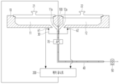
상기 프로세스 챔버는 웨이퍼 가공 처리 수를 증가시키기 위해, 도 1에 도시된 바와 같이, 하나의 챔버바디(10)에 2개의 챔버(11,12)가 형성된 트윈 챔버가 널리 사용되고 있다. 편의상 상기 2개의 챔버를 각각 제1챔버(11)와 제2챔버(12)로 구분하여 지칭하기로 한다.In order to increase the number of wafer processing processes, the above process chamber is widely used as a twin chamber in which two chambers (11, 12) are formed in one chamber body (10), as shown in Fig. 1. For convenience, the two chambers will be referred to as the first chamber (11) and the second chamber (12), respectively.
한편, 위에 설명한 바와 같이 웨이퍼 가공은 진공 분위기에서 이루어지는데, 챔버(11,12)의 내부에 진공을 형성하기 위해 챔버바디(10)에는 펌핑덕트(30)가 설치되고, 펌핑덕트(30)에는 배기관로(40)를 매개로 드라이펌프(50)가 연결된다. 상기 제1챔버(11)와 제2챔버(12)는 각각에 형성된 배출홀(11a,12a)을 통해 펌핑덕트(30)에 연통되어 있다. 도면부호 21,22는 각각 제1챔버(11)와 제2챔버(12)의 상부 개구부를 막아주는 제1리드(21)와 제2리드(22)이다.Meanwhile, as described above, wafer processing is performed in a vacuum atmosphere. In order to form a vacuum inside the chamber (11, 12), a pumping duct (30) is installed in the chamber body (10), and a dry pump (50) is connected to the pumping duct (30) via an exhaust pipe (40). The first chamber (11) and the second chamber (12) are connected to the pumping duct (30) through exhaust holes (11a, 12a) formed therein, respectively.
따라서 상기 드라이펌프(50)를 작동시켜 제1챔버(11)와 제2챔버(12) 내부의 공기를 외부로 배출함으로써 제1챔버(11)와 제2챔버(12)를 진공 상태로 만들 수 있다.Therefore, by operating the above dry pump (50) to discharge the air inside the first chamber (11) and the second chamber (12) to the outside, the first chamber (11) and the second chamber (12) can be made into a vacuum state.
또한, 상기 펌핑덕트(30) 하류의 상기 배기관로(40)에 APC(Auto Pressure Controller)(70)가 설치되며, 상기 APC의 작동에 의해 제1챔버(11)와 제2챔버(12)의 압력이 원하는 설정 압력으로 조절될 수 있다.In addition, an APC (Auto Pressure Controller) (70) is installed in the exhaust pipe (40) downstream of the pumping duct (30), and the pressure of the first chamber (11) and the second chamber (12) can be adjusted to a desired set pressure by the operation of the APC.
그런데, 상기와 같이 종래 기술에 따른 반도체 프로세스 챔버의 압력 조절 장치는 하나의 APC(70)에 의해 제1챔버(11)와 제2챔버(12)의 압력을 동시에 조절하고 있다. 따라서 챔버의 가공 오차 및 가스 공급량 차이에 따라서 상기 제1챔버(11)와 제2챔버(12)의 사이에 압력차가 발생하는 문제점이 있었다.However, as described above, the pressure control device of the semiconductor process chamber according to the prior art simultaneously controls the pressure of the first chamber (11) and the second chamber (12) by one APC (70). Therefore, there was a problem that a pressure difference occurred between the first chamber (11) and the second chamber (12) depending on the processing error of the chamber and the difference in the gas supply amount.
이와 같이 양쪽 챔버(11,12)의 압력이 동일하게 형성되지 않으면 양쪽 챔버(11,12)의 프로세스 데이터(Process Data)에 차이가 발생하게 된다. 즉, 양쪽 챔버(11,12)의 공정이 동일한 조건에서 실시되지 않게 되고, 그 결과 양쪽 챔버(11,12)에서 동시에 가공된 웨이퍼의 품질이 균일하지 않은 문제점이 있었다.In this way, if the pressures of both chambers (11, 12) are not formed equally, a difference occurs in the process data of both chambers (11, 12). That is, the processes of both chambers (11, 12) are not performed under the same conditions, and as a result, there is a problem that the quality of wafers processed simultaneously in both chambers (11, 12) is not uniform.
종래의 기술은 발명자가 본 발명의 도출을 위해 보유하고 있었거나, 본 발명의 도출 과정에서 습득한 기술 정보로서, 반드시 본 발명의 출원 전에 일반 공중에게 공개된 공지 기술이라 할 수는 없을 것이다.The prior art is technical information that the inventor possessed for the purpose of deriving the present invention or acquired in the process of deriving the present invention, and cannot necessarily be said to be a publicly known technology disclosed to the general public prior to the application for the present invention.
전술한 문제점을 해소함에 있어, 본 발명의 목적은 양쪽 챔버의 압력을 동일하게 형성하여 양쪽 챔버의 프로세스 데이터를 동일하게 함으로써 양쪽 챔버의 웨이퍼를 동일한 품질로 가공할 수 있도록 된 반도체 프로세스 챔버의 압력 조절 장치를 제공함에 있다.In order to solve the above-mentioned problem, the purpose of the present invention is to provide a pressure control device for a semiconductor process chamber that enables wafers in both chambers to be processed with the same quality by forming the pressures in both chambers to be the same and making the process data in both chambers the same.
본 발명이 해결하고자 하는 과제는 이상에서 언급한 것에 한정되지 않으며, 언급되지 아니한 다른 해결하고자 하는 과제는 이하의 기재로부터 본 발명이 속하는 기술분야에서 통상의 기술을 가지는 사람에 의하여 명확하게 이해될 수 있을 것이다.The problems to be solved by the present invention are not limited to those mentioned above, and other problems to be solved that are not mentioned can be clearly understood by a person having ordinary skill in the technical field to which the present invention belongs from the description below.
본 발명의 실시예에 따른 반도체 프로세스 챔버의 압력 조절 장치는, 동일한 규격의 제1챔버와 제2챔버가 형성된 챔버바디; 상기 챔버바디의 하면 중앙에 설치되고, 상기 제1챔버와 제2챔버에 각각의 배출홀을 매개로 연통된 펌핑덕트; 상기 펌핑덕트의 배출구에 일측 단부가 연결된 배기관로; 상기 배기관로의 타측 단부에 연결된 드라이펌프; 및 상기 펌핑덕트의 내부에 설치되어 상기 제1챔버의 배출 유로 단면적과 상기 제2챔버의 배출 유로 단면적을 조절하는 조절밸브;를 포함한다.A pressure control device for a semiconductor process chamber according to an embodiment of the present invention comprises: a chamber body formed with a first chamber and a second chamber having the same specifications; a pumping duct installed at the center of a lower surface of the chamber body and connected to the first chamber and the second chamber via respective discharge holes; an exhaust pipe having one end connected to an exhaust port of the pumping duct; a dry pump connected to the other end of the exhaust pipe; and a control valve installed inside the pumping duct to control a cross-sectional area of an exhaust path of the first chamber and a cross-sectional area of an exhaust path of the second chamber.
또한, 상기 조절밸브는 상기 펌핑덕트의 내부 중앙에 회동 가능하게 설치되고, 하단부가 상기 펌핑덕트의 배출구 입구에 배치되어 회동 방향에 따라 상기 제1챔버의 배출 유로 단면적과 상기 제2챔버의 배출 유로 단면적을 증감 조절할 수 있도록 된 것을 특징으로 한다.In addition, the control valve is rotatably installed in the center of the inside of the pumping duct, and the lower end is arranged at the discharge inlet of the pumping duct so as to increase or decrease the discharge path cross-sectional area of the first chamber and the discharge path cross-sectional area of the second chamber depending on the rotation direction.
또한, 상기 조절밸브는 수동 조작 밸브로서 그 조작레버가 상기 펌핑덕트의 외측부에 마련된 것을 특징으로 한다.In addition, the control valve is characterized by being a manually operated valve in which the operating lever is provided on the outside of the pumping duct.
또한, 상기 조절밸브는 회동 작동을 위한 액츄에이터를 구비하고, 상기 액츄에이터는 제어유니트에 의해 작동 제어되어 상기 제어유니트에 의해 상기 조절밸브가 작동 제어될 수 있도록 된 것을 특징으로 한다.In addition, the control valve is characterized in that it has an actuator for rotational operation, and the actuator is operated and controlled by a control unit so that the control valve can be operated and controlled by the control unit.
또한, 상기 제어유니트는 상기 펌핑덕트의 양측부에 설치되어 상기 제1챔버의 진공압을 측정하는 제1압력센서와 상기 제2챔버의 진공압을 측정하는 제2압력센서로부터 각각 압력 측정값을 전달받고, 상기 제1압력센서의 측정값과 상기 제2압력센서의 측정값을 비교하며, 측정된 진공압의 크기가 큰 쪽으로 상기 조절밸브를 회동시키는 것을 특징으로 한다.In addition, the control unit is characterized in that it receives pressure measurement values from a first pressure sensor installed on both sides of the pumping duct to measure the vacuum pressure of the first chamber and a second pressure sensor to measure the vacuum pressure of the second chamber, compares the measurement value of the first pressure sensor with the measurement value of the second pressure sensor, and rotates the control valve toward a side with a larger measured vacuum pressure.
또한, 상기 배기관로는 APC(Auto Pressure Controller)를 구비하는 것을 특징으로 한다.In addition, the exhaust pipe is characterized by being equipped with an APC (Auto Pressure Controller).
또한, 상기 드라이펌프는 후단에 미세 입자를 포집하는 스크러버가 설치된 것을 특징으로 한다.In addition, the dry pump is characterized by having a scrubber installed at the rear end to capture fine particles.
상술한 바와 같이, 본 발명에 의한 반도체 프로세스 챔버의 압력 조절 장치는 양쪽 챔버의 압력을 동일하게 형성하여 양쪽 챔버의 프로세스 데이터를 동일하게 함으로써 양쪽 챔버의 웨이퍼를 동일한 품질로 가공할 수 있다.As described above, the pressure control device of the semiconductor process chamber according to the present invention forms the pressure of both chambers to be the same, thereby making the process data of both chambers the same, thereby enabling wafers of both chambers to be processed with the same quality.
본 발명의 효과는 이상에서 언급한 것에 한정되지 않으며, 언급되지 아니한 다른 효과는 이하의 기재로부터 본 발명이 속하는 기술분야에서 통상의 기술을 가지는 사람에 의하여 명확하게 이해될 수 있을 것이다.The effects of the present invention are not limited to those mentioned above, and other effects not mentioned can be clearly understood by a person having ordinary skill in the art to which the present invention belongs from the following description.
도 1은 종래 기술에 따른 반도체 프로세스 챔버의 압력 조절 장치의 구성도이다.
도 2는 본 발명에 따른 반도체 프로세스 챔버의 압력 조절 장치의 구성도이다.
도 3은 본 발명에 따른 반도체 프로세스 챔버의 압력 조절 장치의 작동 상태도이다.Figure 1 is a configuration diagram of a pressure control device for a semiconductor process chamber according to conventional technology.
Figure 2 is a configuration diagram of a pressure control device of a semiconductor process chamber according to the present invention.
Figure 3 is an operational state diagram of a pressure control device of a semiconductor process chamber according to the present invention.
본 발명에 있어 첨부된 도면은 종래 기술과의 차별성 및 명료성, 그리고 기술 파악의 편의를 위해 과장된 표현으로 도시되어 있을 수 있다. 또한, 후술되는 용어들은 본 발명에서의 기능을 고려하여 정의된 용어로서, 사용자, 운용자의 의도 또는 관례에 따라 달라질 수 있으므로, 이러한 용어들에 대한 정의는 본 명세서 전반에 걸친 기술적 내용을 토대로 내려져야 할 것이다. 한편, 실시예는 본 발명의 청구범위에 제시된 구성요소의 예시적 사항에 불과하고, 본 발명의 권리범위를 한정하는 것이 아니며, 권리범위는 본 발명의 명세서 전반에 걸친 기술적 사상을 토대로 해석되어야 한다.In the present invention, the attached drawings may be illustrated with exaggerated expressions for the purpose of differentiation and clarity from the prior art, and for the convenience of understanding the technology. In addition, the terms described below are terms defined in consideration of the functions in the present invention, and may vary depending on the intention or custom of the user or operator, so the definitions of these terms should be made based on the technical contents throughout the specification. Meanwhile, the embodiments are merely exemplary matters of the components presented in the claims of the present invention, and do not limit the scope of the rights of the present invention, and the scope of the rights should be interpreted based on the technical ideas throughout the specification of the present invention.
명세서 전체에서, 어떤 구성이 어떤 구성을 "포함"한다고 할 때, 이는 특별히 반대되는 기재가 없는 한, 그 외 다른 구성을 제외하는 것이 아니라 다른 구성들을 더 포함할 수도 있음을 의미한다.Throughout the specification, whenever a configuration is said to "include" another configuration, this does not mean that it excludes other configurations, but rather that it may include other configurations, unless otherwise specifically stated.
또한, 어떤 구성이 다른 구성에 "연결", "접속" 또는 "결합"되어 있다고 할 때, 이는 '직접적으로 연결', '직접적으로 접속' 또는 '직접적으로 결합'되어 있는 경우 만이 아니라, '그 중간에 다른 구성을 개재한 채로 연결', '그 중간에 다른 구성을 개재한 채로 접속' 또는 '그 중간에 다른 구성을 개재한 채로 결합'되는 경우도 있을 수 있음을 의미한다. 반면에, 어떤 구성이 다른 구성에 "직접 연결", "직접 접속" 또는 "직접 결합"되어 있다고 할 때는, 중간에 다른 구성이 존재하지 않는 것으로 이해되어야 할 것이다.Furthermore, when it is said that a configuration is "connected", "connected" or "coupled" to another configuration, this means not only that it is "directly connected", "directly connected" or "directly coupled", but also that it may be "connected with another configuration in between", "connected with another configuration in between" or "coupled with another configuration in between". On the other hand, when it is said that a configuration is "directly connected", "directly connected" or "directly coupled" to another configuration, it should be understood that there is no other configuration in between.
또한, "전", "후", "상", "하", "좌", "우", "일 단", "타 단", "양 단" 등과 같은 방향성 용어가 사용될 때 이는 개시된 도면들의 배향과 관련하여 예시적으로 사용되는 것이므로 제한적으로 해석되어서는 안 되고, "제 1", "제 2"등의 용어가 사용될 때 이는 각 구성을 구별하기 위한 용어로서 제한적으로 해석되어는 안 된다.Also, when directional terms such as “front”, “back”, “upper”, “lower”, “left”, “right”, “one end”, “the other end”, “both ends”, etc. are used, they are used illustratively with respect to the orientation of the disclosed drawings and should not be construed limitingly, and when terms such as “first”, “second”, etc. are used, they are used as terms to distinguish each configuration and should not be construed limitingly.
본 발명의 실시예의 특징을 보다 명확히 설명하기 위하여, 이하의 실시예가 속하는 기술분야에서 통상의 지식을 가지는 사람에게 널리 알려져 있는 사항들에 관해서 자세한 설명은 생략하기로 한다. 그리고, 도면에서 실시예의 설명과 관계없는 부분에 대한 자세한 설명은 생략하기로 한다.In order to more clearly explain the features of the embodiments of the present invention, detailed descriptions of matters that are widely known to those of ordinary skill in the art to which the embodiments belong will be omitted. In addition, detailed descriptions of parts in the drawings that are not related to the explanation of the embodiments will be omitted.
이하, 첨부된 도면을 참조하여 본 발명의 실시예에 대하여 상세히 설명한다.Hereinafter, embodiments of the present invention will be described in detail with reference to the attached drawings.
도 2는 본 발명에 따른 반도체 프로세스 챔버의 압력 조절 장치의 구성도이고, 도 3은 본 발명에 따른 반도체 프로세스 챔버의 압력 조절 장치의 작동 상태도이다.FIG. 2 is a configuration diagram of a pressure control device for a semiconductor process chamber according to the present invention, and FIG. 3 is an operation status diagram of a pressure control device for a semiconductor process chamber according to the present invention.
도 2 내지 도 3을 참조하면, 본 발명의 실시예에 따른 반도체 프로세스 챔버의 압력 조절 장치는, 챔버바디(10), 펌핑덕트(30), 배기관로(40), 드라이펌프(50), APC(70) 및 조절밸브(100)를 포함한다.Referring to FIGS. 2 and 3, a pressure control device of a semiconductor process chamber according to an embodiment of the present invention includes a chamber body (10), a pumping duct (30), an exhaust pipe (40), a dry pump (50), an APC (70), and a control valve (100).
또한, 본 발명의 실시예에 따른 반도체 프로세스 챔버의 압력 조절 장치는 상기 조절밸브(100)의 작동을 제어하는 제어유니트(200)를 더 포함할 수 있다.In addition, the pressure control device of the semiconductor process chamber according to the embodiment of the present invention may further include a control unit (200) that controls the operation of the control valve (100).
상기 챔버바디(10)는 웨이퍼에 대한 반도체 공정이 실시되는 프로세서 챔버의 챔버바디이다. 본 발명의 적용 대상이 되는 프로세스 챔버는 트윈 챔버(twin chamber) 타입의 챔버로서 내부의 좌측 부분에 제1챔버(11)가 형성되고, 우측 부분에 제2챔버(12)가 형성된다. 상기 제1챔버(11)와 제2챔버(12)는 동일한 형상 및 크기로 형성된다.The chamber body (10) above is a chamber body of a processor chamber in which a semiconductor process for a wafer is performed. The process chamber to which the present invention is applied is a twin chamber type chamber in which a first chamber (11) is formed on the left side of the interior and a second chamber (12) is formed on the right side. The first chamber (11) and the second chamber (12) are formed in the same shape and size.
상기 챔버바디(10)는 제1챔버(11)와 제2챔버(12)에 형성되는 진공압에 견딜 수 있는 강성을 확보하기 위하여 두껍고 고중량의 알루미늄 또는 스테인리스스틸 재질로 이루어진다.The above chamber body (10) is made of thick and heavy aluminum or stainless steel material to secure rigidity that can withstand the vacuum pressure formed in the first chamber (11) and the second chamber (12).
상기 제1챔버(11)와 제2챔버(12)는 각각의 상부에 제1리드(21)와 제2리드(22)가 구비되어 개폐 가능하다.The first chamber (11) and second chamber (12) above are provided with a first lead (21) and a second lead (22) on the upper part of each, and can be opened and closed.
상기 제1챔버(11)와 제2챔버(12)의 인접 부분 즉, 제1챔버(11)와 제2챔버(12)를 구분하는 격벽의 양쪽 하측 부분에는 제1챔버(11)를 상기 펌핑덕트(30)와 연통시키는 제1배출홀(11a)과 제2챔버(12)를 상기 펌핑덕트(30)와 연통시키는 제2배출홀(12a)이 형성된다.A first discharge hole (11a) that connects the first chamber (11) to the pumping duct (30) and a second discharge hole (12a) that connects the second chamber (12) to the pumping duct (30) are formed on the lower sides of both sides of the partition wall that separates the first chamber (11) and the second chamber (12) at the adjacent portions of the first chamber (11) and the second chamber (12).
상기 펌핑덕트(30)는 상기 챔버바디(10)의 하면에 설치되는 대략 원통형의 부품으로서 상기 제1챔버(11) 및 상기 제2챔버(12)와 상기 배기관로(40)를 연결한다. 또한, 본 발명에 있어서 상기 펌핑덕트(30)는 상기 조절밸브(100)의 설치 장소를 제공한다.The above pumping duct (30) is a roughly cylindrical component installed on the lower surface of the chamber body (10) and connects the first chamber (11) and the second chamber (12) with the exhaust pipe (40). In addition, in the present invention, the pumping duct (30) provides an installation location for the control valve (100).
상기 펌핑덕트(30)는 상기 챔버바디(10)의 하면 중앙에 설치되되 상기 제1챔버(11)와 제2챔버(12) 양측 모두에 걸쳐지는 범위에 설치된다. 따라서 제1챔버(11)의 제1배출홀(11a)과 제2챔버(12)의 제2배출홀(12a)이 모두 펌핑덕트(30)의 내부 공간으로 연통된다.The above pumping duct (30) is installed in the center of the lower surface of the chamber body (10), but is installed in a range that spans both the first chamber (11) and the second chamber (12). Therefore, the first discharge hole (11a) of the first chamber (11) and the second discharge hole (12a) of the second chamber (12) are both connected to the internal space of the pumping duct (30).
따라서 상기 제1챔버(11)와 제2챔버(12) 내부의 공기(또는 가스)는 상기 제1배출홀(11a)과 제2배출홀(12a)을 통해 펌핑덕트(30)로 배출되고, 이어 펌핑덕트(30)의 하면에 연결된 상기 배기관로(40)를 통해 상기 드라이펌프(50)쪽으로 펌핑된다.Therefore, the air (or gas) inside the first chamber (11) and the second chamber (12) is discharged to the pumping duct (30) through the first discharge hole (11a) and the second discharge hole (12a), and then pumped toward the dry pump (50) through the exhaust pipe (40) connected to the lower surface of the pumping duct (30).
상기 배기관로(40)는 상기 펌핑덕트(30)와 상기 드라이펌프(50)를 연결하는 유로로서, 고압호스 또는 파이프 등으로 이루어진다. 상기 배기관로(40)는 일측 단부가 상기 펌핑덕트(30)의 하면 중앙에 형성된 배출구에 연결되고 타측 단부가 상기 드라이펌프(50)의 흡입구에 연결된다. 즉, 상기 배기관로(40)는 상기 펌핑덕트(30)의 배출구와 상기 드라이펌프(50)의 흡입구를 연결한다.The above exhaust pipe (40) is a conduit connecting the pumping duct (30) and the dry pump (50), and is made of a high-pressure hose or pipe, etc. One end of the exhaust pipe (40) is connected to an exhaust port formed in the center of the lower surface of the pumping duct (30), and the other end is connected to an intake port of the dry pump (50). That is, the exhaust pipe (40) connects the exhaust port of the pumping duct (30) and the intake port of the dry pump (50).
상기 드라이펌프(50)가 작동되면 제1챔버(11)와 제2챔버(12) 내부의 공기는 상기 펌핑덕트(30), 상기 배기관로(40), 상기 드라이펌프(50)를 순차적으로 통과하여 배출된다.When the above dry pump (50) operates, the air inside the first chamber (11) and the second chamber (12) is discharged sequentially through the pumping duct (30), the exhaust pipe (40), and the dry pump (50).
상기 드라이펌프(50)는 보통 저진공(760 ~ 1 Torr)을 만들 때 사용되는 펌프로서 밀폐를 위해 오일 또는 액체를 사용하지 않기 때문에 건식펌프, 드라이펌프로 불리운다. 물이나 오일이 역류하거나 확산되지 않으므로 깨끗한 진공 상태를 만들 수 있으며, 물이나 오일의 보충 및 교환 등 정기 유지보수가 필요 없어 취급이 매우 용이한 장점을 가진다.The above dry pump (50) is a pump that is usually used to create a low vacuum (760 to 1 Torr) and is called a dry pump or dry pump because it does not use oil or liquid for sealing. Since water or oil does not flow back or diffuse, it can create a clean vacuum state and has the advantage of being very easy to handle because it does not require regular maintenance such as replenishment and replacement of water or oil.
도시하지 않았으나 상기 드라이펌프(50)의 후방에는 배출 공기에 포함된 미세 입자를 포집하기 위한 스크러버(Scrubber)가 설치될 수 있다.Although not shown, a scrubber may be installed at the rear of the dry pump (50) to capture fine particles contained in the exhaust air.
상기 APC(70)는 Auto Pressure Controller로서 상기 챔버(11,12)의 압력을 다운 스트림(Down stream) 방식으로 제어하는 장치이다. 상기 APC(70)는 상기 배기관로(40)의 전단부에 설치되며 배기관로(40)의 유로 개도를 조절하는 밸브를 포함한다. 따라서 상기 밸브의 개도를 자동으로 조절하여 상기 챔버(제1챔버(11) 및 제2챔버(12))의 압력을 설정 압력으로 제어한다.The above APC (70) is an Auto Pressure Controller that controls the pressure of the chambers (11, 12) in a downstream manner. The APC (70) is installed at the front end of the exhaust pipe (40) and includes a valve that controls the opening of the exhaust pipe (40). Accordingly, the opening of the valve is automatically controlled to control the pressure of the chambers (the first chamber (11) and the second chamber (12)) to a set pressure.
상기 조절밸브(100)는 상기 제1챔버(11)와 제2챔버(12)의 압력을 서로 동일하게 조절해주는 밸브이다.The above control valve (100) is a valve that adjusts the pressure of the first chamber (11) and the second chamber (12) to be the same.
상기 조절밸브(100)는 상기 펌핑덕트(30)의 내부에 설치되어 상기 펌핑덕트(30)의 배출구를 통한 상기 제1챔버(11)의 배출 유로 단면적과 상기 제2챔버(12)의 배출 유로 단면적을 조절한다. 보다 정확하게는 상기 펌핑덕트(30) 내부의 제1챔버(11)측 공간의 배출 유로 단면적과 제2챔버(12)측 공간의 배출 유로 단면적을 조절한다.The above control valve (100) is installed inside the pumping duct (30) to control the discharge path cross-sectional area of the first chamber (11) and the discharge path cross-sectional area of the second chamber (12) through the discharge port of the pumping duct (30). More precisely, it controls the discharge path cross-sectional area of the space on the first chamber (11) side and the discharge path cross-sectional area of the space on the second chamber (12) side inside the pumping duct (30).
상기 조절밸브(100)는 수동인 경우 조작부(조작레버)가 펌핑덕트(30)의 외측부에 마련되어 사용자가 좌우로 회동 조작할 수 있도록 되어 있다.If the above control valve (100) is manual, the operating part (operating lever) is provided on the outside of the pumping duct (30) so that the user can rotate it left and right.
상기 조절밸브(100)는 상기 펌핑덕트(30)의 내부 중앙에 설치되며, 특히 좌우 회동 각도를 조절함으로써 상기 제1챔버(11)측 공간의 배출 유로 단면적과 상기 제2챔버(12)측 공간의 배출 유로 단면적을 증감 조절한다.The above control valve (100) is installed in the center of the inside of the pumping duct (30), and in particular, by adjusting the left and right rotation angles, it increases or decreases the cross-sectional area of the discharge path in the space on the first chamber (11) side and the cross-sectional area of the discharge path in the space on the second chamber (12) side.
예를 들어 상기 조절밸브(100)는 상기 펌핑덕트(30)의 내부 공간을 제1챔버(11)에 연결된 제1챔버(11)측 공간과 제2챔버(12)에 연결된 제2챔버(12)측 공간으로 양분하고, 그 하단부가 상기 펌핑덕트(30)의 배출구 즉, 배기관로(40) 입구의 중간 부분에 배치되어 있다.For example, the above control valve (100) divides the internal space of the pumping duct (30) into a first chamber (11) side space connected to the first chamber (11) and a second chamber (12) side space connected to the second chamber (12), and the lower part thereof is arranged in the middle of the outlet of the pumping duct (30), i.e., the inlet of the exhaust pipe (40).
따라서 상기 조절밸브(100)가 조작되지 않은 상태에서 펌핑덕트(30)의 배출구는 제1챔버(11)측과 제2챔버(12)측에 동일한 배출 유로 단면적을 제공한다.Therefore, when the above control valve (100) is not operated, the discharge port of the pumping duct (30) provides the same discharge path cross-sectional area to the first chamber (11) side and the second chamber (12) side.
이와 같은 상태에서 상기 드라이펌프(50)가 작동되어 제1챔버(11)와 제2챔버(12)에 진공을 형성할 때 이상적인 경우에는 상기 조절밸브(100)를 조작하지 않아도 제1챔버(11)와 제2챔버(12)의 압력은 동일하게 형성된다.In this state, when the dry pump (50) operates to form a vacuum in the first chamber (11) and the second chamber (12), in an ideal case, the pressures in the first chamber (11) and the second chamber (12) are formed to be the same even without operating the control valve (100).
그러나 위에 설명한 바와 같이, 제1챔버(11)와 제2챔버(12)의 가공 오차나 가스 공급량 차이에 의해 제1챔버(11)와 제2챔버(12)의 압력은 미세하게 차이가 발생하게 된다.However, as explained above, the pressures of the first chamber (11) and the second chamber (12) differ slightly due to processing errors or differences in gas supply amounts between the first chamber (11) and the second chamber (12).
이때 상기 조절밸브(100)를 진공압이 큰 챔버 쪽으로 회동 조작함으로써 해당 챔버의 배출 유로 단면적은 감소시키고 반대쪽(진공압이 작은 쪽) 챔버의 배출 유로 단면적은 증가시킴으로써 진공압이 큰 쪽 챔버의 압력값은 감소시키고 진공압이 작은 쪽 챔버의 압력값은 증가시킬 수 있다.At this time, by rotating the control valve (100) toward the chamber with a high vacuum pressure, the cross-sectional area of the discharge path of the chamber is reduced and the cross-sectional area of the discharge path of the chamber on the opposite side (the side with a low vacuum pressure) is increased, thereby reducing the pressure value of the chamber on the side with a high vacuum pressure and increasing the pressure value of the chamber on the side with a low vacuum pressure.
예를 들어, 펌핑덕트(30)의 내부 공간 중 제1챔버(11)측 공간의 진공압이 1Torr이고 제2챔버(12)측 공간의 진공압이 2Torr인 경우, 상기 조절밸브(100)를 도 3과 같이 진공압이 큰 쪽인 제2챔버(12)쪽 방향으로 조작하면 해당 공간의 배출 유로 단면적이 감소하여 진공압이 감소되고, 반대로 진공압이 작은 쪽인 제1챔버(11)쪽 공간의 배출 유로 단면적이 증가하여 진공압이 증가된다. 따라서 제1챔버(11)쪽 공간과 제2챔버(12)쪽 공간의 진공압이 모두 예를 들어 1.5Torr로 동일하게 조절될 수 있다.For example, if the vacuum pressure of the space on the side of the first chamber (11) in the internal space of the pumping duct (30) is 1 Torr and the vacuum pressure of the space on the side of the second chamber (12) is 2 Torr, when the control valve (100) is operated in the direction of the second chamber (12) with a higher vacuum pressure as shown in FIG. 3, the cross-sectional area of the discharge path of the space decreases, thereby reducing the vacuum pressure, and conversely, the cross-sectional area of the discharge path of the space on the side of the first chamber (11) with a lower vacuum pressure increases, thereby increasing the vacuum pressure. Accordingly, the vacuum pressures of both the space on the side of the first chamber (11) and the space on the side of the second chamber (12) can be adjusted to be the same, for example, 1.5 Torr.
한편, 상기 제어유니트(200)는 상기 조절밸브(100)를 자동 제어하는 전자제어유니트(Electronic control unit)이다.Meanwhile, the above control unit (200) is an electronic control unit that automatically controls the above control valve (100).
상기 제어유니트(200)에 의한 상기 조절밸브(100)의 자동 제어를 위해, 상기 펌핑덕트(30)의 양 측부에는 상기 제1챔버(11)측 공간의 진공압(제1챔버의 진공압과 동일함)을 측정하는 제1압력센서(61)와, 상기 제2챔버(12)측 공간의 진공압(제2챔버의 진공압과 동일함)을 측정하는 제2압력센서(62)가 각각 설치된다.In order to automatically control the control valve (100) by the control unit (200), a first pressure sensor (61) for measuring the vacuum pressure of the space on the first chamber (11) side (same as the vacuum pressure of the first chamber) and a second pressure sensor (62) for measuring the vacuum pressure of the space on the second chamber (12) side (same as the vacuum pressure of the second chamber) are installed on both sides of the pumping duct (30).
상기 제1압력센서(61)와 제2압력센서(62)의 측정값은 상기 제어유니트(200)로 전달된다.The measurement values of the first pressure sensor (61) and the second pressure sensor (62) are transmitted to the control unit (200).
상기 제어유니트(200)는 상기 조절밸브(100)를 작동시키는 액츄에이터(미도시됨)에 연결되어 상기 액츄에이터의 작동을 제어함으로써 상기 조절밸브(100)의 회동 방향 및 회동량을 조절할 수 있다. 따라서 상기 제어유니트(200)는 사용자가 조절밸브(100)를 수동 조작할 때와 동일하게 양쪽 챔버에 연결된 공간의 배출 유로 단면적을 증감 조절할 수 있다.The above control unit (200) is connected to an actuator (not shown) that operates the control valve (100) and controls the operation of the actuator, thereby controlling the rotation direction and rotation amount of the control valve (100). Accordingly, the control unit (200) can increase or decrease the cross-sectional area of the discharge path of the space connected to both chambers in the same way as when a user manually operates the control valve (100).
따라서 상기 제어유니트(200)는 상기 제1압력센서(61)와 제2압력센서(62)에서 측정되어 전달된 펌핑덕트(30) 내부의 양측 진공압 크기를 비교하고 즉, 제1챔버(11)와 제2챔버(12)의 진공압 크기를 비교하고, 진공압이 큰 쪽으로 상기 조절밸브(100)를 회동 조작함으로써 상기 제1챔버(11)와 제2챔버(12)의 진공압을 동일한 값으로 조절할 수 있다.Accordingly, the control unit (200) compares the vacuum pressure sizes on both sides inside the pumping duct (30) measured and transmitted by the first pressure sensor (61) and the second pressure sensor (62), i.e., compares the vacuum pressure sizes of the first chamber (11) and the second chamber (12), and rotates the control valve (100) toward the side with the larger vacuum pressure, thereby controlling the vacuum pressures of the first chamber (11) and the second chamber (12) to the same value.
상기와 같이, 본 발명에 따르면 펌핑덕트(30)의 내부에 조절밸브(100)가 설치되어 제1챔버(11)와 제2챔버(12)의 배출 유로 단면적을 조절할 수 있게 됨으로써 상기 제1챔버(11)와 제2챔버(12)에 가공 오차 등의 원인에 의해 압력차가 발생하는 경우에도 상기 조절밸브(100)를 조절하여 제1챔버(11)와 제2챔버(12)의 진공압을 동일한 상태로 조절할 수 있게 된다.As described above, according to the present invention, since a control valve (100) is installed inside the pumping duct (30) to control the cross-sectional area of the discharge path of the first chamber (11) and the second chamber (12), even when a pressure difference occurs between the first chamber (11) and the second chamber (12) due to a processing error or the like, the vacuum pressure of the first chamber (11) and the second chamber (12) can be controlled to the same state by controlling the control valve (100).
따라서, 트윈 챔버 타입의 프로세스 챔버에서 제1챔버(11)와 제2챔버(12)의 압력 조건이 동일한 상태에서 웨이퍼 가공 공정이 실시될 수 있다. 즉, 제1챔버(11)와 제2챔버(12)의 프로세스 데이터가 동일해지고, 제1챔버(11)와 제2챔버(12)에서 가공된 웨이퍼의 품질이 균일해질 수 있다.Therefore, the wafer processing process can be performed in a twin chamber type process chamber with the pressure conditions of the first chamber (11) and the second chamber (12) being the same. That is, the process data of the first chamber (11) and the second chamber (12) become the same, and the quality of the wafers processed in the first chamber (11) and the second chamber (12) can become uniform.
이상에서와 같이, 본 발명에 의한 반도체 프로세스 챔버의 압력 조절 장치 는 제1챔버(11)와 제2챔버(12)의 압력을 동일하게 형성하여 제1챔버(11)와 제2챔버(12)의 프로세스 데이터를 동일하게 함으로써 제1챔버(11)와 제2챔버(12)에서 가공되는 웨이퍼를 동일한 품질로 가공할 수 있다.As described above, the pressure control device of the semiconductor process chamber according to the present invention forms the pressure of the first chamber (11) and the second chamber (12) to be the same, thereby making the process data of the first chamber (11) and the second chamber (12) the same, thereby enabling the wafers processed in the first chamber (11) and the second chamber (12) to be processed with the same quality.
상술한 바와 같이, 본 발명은 도면에 도시된 실시예를 참고로 하여 설명되었으나 이는 예시적인 것에 불과하며, 당해 기술이 속하는 분야에서 통상의 지식을 기초로 다양한 변형 및 균등한 다른 실시예가 가능하다는 점을 이해해야 한다. 따라서 본 발명의 진정한 기술적 보호범위는 이하 기술할 청구범위에 의하며, 상술한 발명의 구체적 내용을 토대로 정해져야 할 것이다.As described above, the present invention has been described with reference to the embodiments shown in the drawings, but this is merely exemplary, and it should be understood that various modifications and equivalent other embodiments are possible based on common knowledge in the field to which the technology pertains. Therefore, the true technical protection scope of the present invention is determined by the claims described below and should be determined based on the specific contents of the invention described above.
본 발명은 반도체 프로세스 챔버의 압력 조절 장치에 관한 것으로, 트윈 챔버 타입의 반응 용기를 이용하여 진공 및 플라즈마 공정을 수행하는 산업 분야에 이용 가능하다.The present invention relates to a pressure control device for a semiconductor process chamber, and can be used in industrial fields that perform vacuum and plasma processes using a twin chamber type reaction vessel.
10: 챔버바디 11: 제1챔버
11a: 제1배출홀 12: 제2챔버
12a: 제2배출홀 21: 제1리드
22: 제2리드 30: 펌핑덕트
40: 배기관로 50: 드라이펌프
61: 제1압력센서 62: 제2압력센서
100: 조절밸브 200: 제어유니트10: Chamber body 11: First chamber
11a: 1st discharge hole 12: 2nd chamber
12a: 2nd discharge hole 21: 1st lead
22: Second lead 30: Pumping duct
40: Exhaust pipe 50: Dry pump
61: First pressure sensor 62: Second pressure sensor
100: Control valve 200: Control unit
Claims (7)
상기 챔버바디의 하면 중앙에 설치되고, 상기 제1챔버와 제2챔버에 각각의 배출홀을 매개로 연통된 펌핑덕트;
상기 펌핑덕트의 배출구에 일측 단부가 연결된 배기관로;
상기 배기관로의 타측 단부에 연결된 드라이펌프;
상기 배기관로에 설치되고, 상기 배기관로의 유로 개도를 조절하는 밸브를 구비하여 상기 제1챔버와 상기 제2챔버의 압력을 설정 압력으로 제어하는 APC(Auto Pressure Controller); 및
상기 펌핑덕트의 내부에 설치되어 상기 제1챔버의 배출 유로 단면적과 상기 제2챔버의 배출 유로 단면적을 조절하는 조절밸브;를 포함하고,
상기 조절밸브는
상기 펌핑덕트의 내부 중앙에 회동 가능하게 설치되고, 하단부가 상기 펌핑덕트의 배출구 입구의 중간 부분에 배치되어 상기 하단부의 회동 방향에 따라 상기 제1챔버의 배출 유로 단면적과 상기 제2챔버의 배출 유로 단면적을 증감 조절할 수 있고,
상기 조절밸브는
회동 작동을 위한 액츄에이터를 구비하고, 상기 액츄에이터는 제어유니트에 의해 작동 제어되어 상기 제어유니트에 의해 상기 조절밸브가 작동 제어되며,
상기 제어유니트는
상기 펌핑덕트의 양측부에 설치되어 상기 제1챔버의 진공압을 측정하는 제1압력센서와 상기 제2챔버의 진공압을 측정하는 제2압력센서로부터 각각 압력 측정값을 전달받고,
상기 제1압력센서의 측정값과 상기 제2압력센서의 측정값을 비교하며,
측정된 진공압의 크기가 큰 쪽으로 상기 조절밸브의 하단부를 회동시켜서 진공압이 큰 쪽의 배출 유로 단면적을 감소시키고, 진공압이 작은 쪽의 배출 유로 단면적을 증가시킴으로써 상기 제1챔버와 상기 제2챔버의 진공압을 동일하게 만드는 것
을 특징으로 하는 반도체 프로세스 챔버의 압력 조절 장치.
A chamber body formed with a first chamber and a second chamber of the same specification;
A pumping duct installed at the center of the lower surface of the chamber body and connected to the first chamber and the second chamber through respective discharge holes;
An exhaust pipe having one end connected to the discharge port of the above pumping duct;
A dry pump connected to the other end of the above exhaust pipe;
An APC (Auto Pressure Controller) installed in the exhaust pipe and having a valve for controlling the opening of the exhaust pipe to control the pressure of the first chamber and the second chamber to a set pressure; and
It includes a control valve installed inside the pumping duct to control the discharge path cross-sectional area of the first chamber and the discharge path cross-sectional area of the second chamber;
The above control valve
It is rotatably installed in the center of the inside of the above pumping duct, and the lower part is arranged in the middle part of the discharge inlet of the above pumping duct, so that the discharge path cross-sectional area of the first chamber and the discharge path cross-sectional area of the second chamber can be increased or decreased according to the rotation direction of the lower part.
The above control valve
An actuator for rotary operation is provided, and the actuator is operated and controlled by a control unit, and the control valve is operated and controlled by the control unit.
The above control unit
Pressure measurement values are received from a first pressure sensor installed on both sides of the pumping duct to measure the vacuum pressure of the first chamber and a second pressure sensor to measure the vacuum pressure of the second chamber, respectively.
The measurement value of the first pressure sensor is compared with the measurement value of the second pressure sensor,
Rotating the lower part of the control valve toward the side with a larger measured vacuum pressure to reduce the cross-sectional area of the discharge path on the side with a larger vacuum pressure and increase the cross-sectional area of the discharge path on the side with a smaller vacuum pressure, thereby making the vacuum pressures of the first chamber and the second chamber the same.
A pressure control device for a semiconductor process chamber characterized by:
후단에 미세 입자를 포집하는 스크러버가 설치된 것을 특징으로 하는 반도체 프로세스 챔버의 압력 조절 장치.
In claim 1, the dry pump
A pressure control device for a semiconductor process chamber, characterized in that a scrubber for capturing fine particles is installed at the rear end.
Priority Applications (2)
| Application Number | Priority Date | Filing Date | Title |
|---|---|---|---|
| KR1020230181895A KR102811524B1 (en) | 2023-12-14 | 2023-12-14 | Pressure control device of semiconductor process chamber |
| CN202410638011.6A CN120164810A (en) | 2023-12-14 | 2024-05-22 | Semiconductor process chamber pressure regulating device |
Applications Claiming Priority (1)
| Application Number | Priority Date | Filing Date | Title |
|---|---|---|---|
| KR1020230181895A KR102811524B1 (en) | 2023-12-14 | 2023-12-14 | Pressure control device of semiconductor process chamber |
Publications (1)
| Publication Number | Publication Date |
|---|---|
| KR102811524B1 true KR102811524B1 (en) | 2025-05-26 |
Family
ID=95936106
Family Applications (1)
| Application Number | Title | Priority Date | Filing Date |
|---|---|---|---|
| KR1020230181895A Active KR102811524B1 (en) | 2023-12-14 | 2023-12-14 | Pressure control device of semiconductor process chamber |
Country Status (2)
| Country | Link |
|---|---|
| KR (1) | KR102811524B1 (en) |
| CN (1) | CN120164810A (en) |
Citations (4)
| Publication number | Priority date | Publication date | Assignee | Title |
|---|---|---|---|---|
| JPH1120689A (en) * | 1997-07-08 | 1999-01-26 | Hitachi Ltd | Ventilation equipment for railway vehicles |
| KR20070055158A (en) | 2005-11-25 | 2007-05-30 | 삼성전자주식회사 | Semiconductor Manufacturing Equipment with Pressure Gauge |
| KR20180103012A (en) * | 2017-03-08 | 2018-09-18 | 어플라이드 머티어리얼스, 인코포레이티드 | Plasma chamber with tandem processing regions |
| KR20210117943A (en) * | 2020-03-19 | 2021-09-29 | 도쿄엘렉트론가부시키가이샤 | Substrate transporting method and substrate processing apparatus |
-
2023
- 2023-12-14 KR KR1020230181895A patent/KR102811524B1/en active Active
-
2024
- 2024-05-22 CN CN202410638011.6A patent/CN120164810A/en active Pending
Patent Citations (4)
| Publication number | Priority date | Publication date | Assignee | Title |
|---|---|---|---|---|
| JPH1120689A (en) * | 1997-07-08 | 1999-01-26 | Hitachi Ltd | Ventilation equipment for railway vehicles |
| KR20070055158A (en) | 2005-11-25 | 2007-05-30 | 삼성전자주식회사 | Semiconductor Manufacturing Equipment with Pressure Gauge |
| KR20180103012A (en) * | 2017-03-08 | 2018-09-18 | 어플라이드 머티어리얼스, 인코포레이티드 | Plasma chamber with tandem processing regions |
| KR20210117943A (en) * | 2020-03-19 | 2021-09-29 | 도쿄엘렉트론가부시키가이샤 | Substrate transporting method and substrate processing apparatus |
Also Published As
| Publication number | Publication date |
|---|---|
| CN120164810A (en) | 2025-06-17 |
Similar Documents
| Publication | Publication Date | Title |
|---|---|---|
| CN101282836B (en) | Wide range pressure control using turbo pump | |
| JP4335469B2 (en) | Method and apparatus for adjusting gas circulation rate of vacuum exhaust device | |
| US5611863A (en) | Semiconductor processing apparatus and cleaning method thereof | |
| US8968472B2 (en) | Valve and processing apparatus provided with the same | |
| US20040173312A1 (en) | Vacuum exhaust apparatus and drive method of vacuum apparatus | |
| US20050167398A1 (en) | Vacuum processing apparatus and control method therefor | |
| CN100593230C (en) | O-ringless tandem throttle valve for a plasma reactor chamber | |
| KR102811524B1 (en) | Pressure control device of semiconductor process chamber | |
| US20100163181A1 (en) | Vacuum processing apparatus | |
| KR101620053B1 (en) | Substrate processing device | |
| JP2008205183A (en) | Vacuum processing equipment | |
| CN219873400U (en) | Semiconductor processing apparatus with remote plasma source | |
| US20200109470A1 (en) | Vacuum evacuation system | |
| WO2019015452A1 (en) | Gaseous corrosion cavity capable of adjusting internal and external pressure difference and gaseous corrosion method by using gaseous corrosion cavity | |
| CN115274504A (en) | Gas delivery box of semiconductor equipment and semiconductor equipment | |
| CN119220954B (en) | Chamber structure and deposition equipment | |
| CN112992741A (en) | Semiconductor processing apparatus and exhaust method | |
| JP2806770B2 (en) | Vacuum valve | |
| KR20240015983A (en) | Sensor-integrated vacuum valve for pressure control and vacuum system having the same | |
| CN222861619U (en) | Transmission chamber pressure control device and thin film deposition equipment | |
| JP2002257040A (en) | Vacuum exhaust device | |
| KR20100073338A (en) | Vacuum pump system for semiconductor process chamber | |
| KR20250178938A (en) | Apparatus for treating substrate | |
| CN222250974U (en) | Chemical vapor deposition apparatus | |
| KR200177265Y1 (en) | Multi-chamber pressure control structure |
Legal Events
| Date | Code | Title | Description |
|---|---|---|---|
| PA0109 | Patent application |
St.27 status event code: A-0-1-A10-A12-nap-PA0109 |
|
| PA0201 | Request for examination |
St.27 status event code: A-1-2-D10-D11-exm-PA0201 |
|
| PE0902 | Notice of grounds for rejection |
St.27 status event code: A-1-2-D10-D21-exm-PE0902 |
|
| E13-X000 | Pre-grant limitation requested |
St.27 status event code: A-2-3-E10-E13-lim-X000 |
|
| P11-X000 | Amendment of application requested |
St.27 status event code: A-2-2-P10-P11-nap-X000 |
|
| P13-X000 | Application amended |
St.27 status event code: A-2-2-P10-P13-nap-X000 |
|
| E701 | Decision to grant or registration of patent right | ||
| PE0701 | Decision of registration |
St.27 status event code: A-1-2-D10-D22-exm-PE0701 |
|
| GRNT | Written decision to grant | ||
| PR0701 | Registration of establishment |
St.27 status event code: A-2-4-F10-F11-exm-PR0701 |
|
| PR1002 | Payment of registration fee |
St.27 status event code: A-2-2-U10-U11-oth-PR1002 Fee payment year number: 1 |
|
| PG1601 | Publication of registration |
St.27 status event code: A-4-4-Q10-Q13-nap-PG1601 |
|
| P22-X000 | Classification modified |
St.27 status event code: A-4-4-P10-P22-nap-X000 |