KR102807668B1 - Image Display Apparatus and Operating Method for the same - Google Patents
Image Display Apparatus and Operating Method for the same Download PDFInfo
- Publication number
- KR102807668B1 KR102807668B1 KR1020160106179A KR20160106179A KR102807668B1 KR 102807668 B1 KR102807668 B1 KR 102807668B1 KR 1020160106179 A KR1020160106179 A KR 1020160106179A KR 20160106179 A KR20160106179 A KR 20160106179A KR 102807668 B1 KR102807668 B1 KR 102807668B1
- Authority
- KR
- South Korea
- Prior art keywords
- image
- display device
- image display
- external
- video
- Prior art date
- Legal status (The legal status is an assumption and is not a legal conclusion. Google has not performed a legal analysis and makes no representation as to the accuracy of the status listed.)
- Active
Links
Images


Classifications
-
- H—ELECTRICITY
- H04—ELECTRIC COMMUNICATION TECHNIQUE
- H04N—PICTORIAL COMMUNICATION, e.g. TELEVISION
- H04N13/00—Stereoscopic video systems; Multi-view video systems; Details thereof
- H04N13/30—Image reproducers
- H04N13/356—Image reproducers having separate monoscopic and stereoscopic modes
- H04N13/359—Switching between monoscopic and stereoscopic modes
-
- G—PHYSICS
- G02—OPTICS
- G02B—OPTICAL ELEMENTS, SYSTEMS OR APPARATUS
- G02B27/00—Optical systems or apparatus not provided for by any of the groups G02B1/00 - G02B26/00, G02B30/00
- G02B27/01—Head-up displays
- G02B27/017—Head mounted
- G02B27/0172—Head mounted characterised by optical features
-
- G—PHYSICS
- G02—OPTICS
- G02B—OPTICAL ELEMENTS, SYSTEMS OR APPARATUS
- G02B27/00—Optical systems or apparatus not provided for by any of the groups G02B1/00 - G02B26/00, G02B30/00
- G02B27/01—Head-up displays
- G02B27/0101—Head-up displays characterised by optical features
-
- G—PHYSICS
- G02—OPTICS
- G02B—OPTICAL ELEMENTS, SYSTEMS OR APPARATUS
- G02B27/00—Optical systems or apparatus not provided for by any of the groups G02B1/00 - G02B26/00, G02B30/00
- G02B27/01—Head-up displays
- G02B27/017—Head mounted
-
- G—PHYSICS
- G02—OPTICS
- G02B—OPTICAL ELEMENTS, SYSTEMS OR APPARATUS
- G02B27/00—Optical systems or apparatus not provided for by any of the groups G02B1/00 - G02B26/00, G02B30/00
- G02B27/01—Head-up displays
- G02B27/0179—Display position adjusting means not related to the information to be displayed
-
- G—PHYSICS
- G06—COMPUTING OR CALCULATING; COUNTING
- G06F—ELECTRIC DIGITAL DATA PROCESSING
- G06F1/00—Details not covered by groups G06F3/00 - G06F13/00 and G06F21/00
- G06F1/16—Constructional details or arrangements
- G06F1/1613—Constructional details or arrangements for portable computers
- G06F1/163—Wearable computers, e.g. on a belt
-
- G—PHYSICS
- G06—COMPUTING OR CALCULATING; COUNTING
- G06F—ELECTRIC DIGITAL DATA PROCESSING
- G06F1/00—Details not covered by groups G06F3/00 - G06F13/00 and G06F21/00
- G06F1/16—Constructional details or arrangements
- G06F1/1613—Constructional details or arrangements for portable computers
- G06F1/1633—Constructional details or arrangements of portable computers not specific to the type of enclosures covered by groups G06F1/1615 - G06F1/1626
- G06F1/1684—Constructional details or arrangements related to integrated I/O peripherals not covered by groups G06F1/1635 - G06F1/1675
- G06F1/1686—Constructional details or arrangements related to integrated I/O peripherals not covered by groups G06F1/1635 - G06F1/1675 the I/O peripheral being an integrated camera
-
- G—PHYSICS
- G06—COMPUTING OR CALCULATING; COUNTING
- G06F—ELECTRIC DIGITAL DATA PROCESSING
- G06F1/00—Details not covered by groups G06F3/00 - G06F13/00 and G06F21/00
- G06F1/16—Constructional details or arrangements
- G06F1/1613—Constructional details or arrangements for portable computers
- G06F1/1633—Constructional details or arrangements of portable computers not specific to the type of enclosures covered by groups G06F1/1615 - G06F1/1626
- G06F1/1684—Constructional details or arrangements related to integrated I/O peripherals not covered by groups G06F1/1635 - G06F1/1675
- G06F1/1694—Constructional details or arrangements related to integrated I/O peripherals not covered by groups G06F1/1635 - G06F1/1675 the I/O peripheral being a single or a set of motion sensors for pointer control or gesture input obtained by sensing movements of the portable computer
-
- G—PHYSICS
- G06—COMPUTING OR CALCULATING; COUNTING
- G06F—ELECTRIC DIGITAL DATA PROCESSING
- G06F3/00—Input arrangements for transferring data to be processed into a form capable of being handled by the computer; Output arrangements for transferring data from processing unit to output unit, e.g. interface arrangements
- G06F3/01—Input arrangements or combined input and output arrangements for interaction between user and computer
- G06F3/011—Arrangements for interaction with the human body, e.g. for user immersion in virtual reality
- G06F3/012—Head tracking input arrangements
-
- G—PHYSICS
- G06—COMPUTING OR CALCULATING; COUNTING
- G06F—ELECTRIC DIGITAL DATA PROCESSING
- G06F3/00—Input arrangements for transferring data to be processed into a form capable of being handled by the computer; Output arrangements for transferring data from processing unit to output unit, e.g. interface arrangements
- G06F3/01—Input arrangements or combined input and output arrangements for interaction between user and computer
- G06F3/017—Gesture based interaction, e.g. based on a set of recognized hand gestures
-
- G—PHYSICS
- G06—COMPUTING OR CALCULATING; COUNTING
- G06F—ELECTRIC DIGITAL DATA PROCESSING
- G06F3/00—Input arrangements for transferring data to be processed into a form capable of being handled by the computer; Output arrangements for transferring data from processing unit to output unit, e.g. interface arrangements
- G06F3/01—Input arrangements or combined input and output arrangements for interaction between user and computer
- G06F3/03—Arrangements for converting the position or the displacement of a member into a coded form
- G06F3/0304—Detection arrangements using opto-electronic means
-
- G—PHYSICS
- G06—COMPUTING OR CALCULATING; COUNTING
- G06F—ELECTRIC DIGITAL DATA PROCESSING
- G06F3/00—Input arrangements for transferring data to be processed into a form capable of being handled by the computer; Output arrangements for transferring data from processing unit to output unit, e.g. interface arrangements
- G06F3/01—Input arrangements or combined input and output arrangements for interaction between user and computer
- G06F3/03—Arrangements for converting the position or the displacement of a member into a coded form
- G06F3/041—Digitisers, e.g. for touch screens or touch pads, characterised by the transducing means
- G06F3/0414—Digitisers, e.g. for touch screens or touch pads, characterised by the transducing means using force sensing means to determine a position
-
- G—PHYSICS
- G06—COMPUTING OR CALCULATING; COUNTING
- G06F—ELECTRIC DIGITAL DATA PROCESSING
- G06F3/00—Input arrangements for transferring data to be processed into a form capable of being handled by the computer; Output arrangements for transferring data from processing unit to output unit, e.g. interface arrangements
- G06F3/16—Sound input; Sound output
- G06F3/167—Audio in a user interface, e.g. using voice commands for navigating, audio feedback
-
- G—PHYSICS
- G10—MUSICAL INSTRUMENTS; ACOUSTICS
- G10L—SPEECH ANALYSIS TECHNIQUES OR SPEECH SYNTHESIS; SPEECH RECOGNITION; SPEECH OR VOICE PROCESSING TECHNIQUES; SPEECH OR AUDIO CODING OR DECODING
- G10L15/00—Speech recognition
- G10L15/22—Procedures used during a speech recognition process, e.g. man-machine dialogue
-
- H—ELECTRICITY
- H04—ELECTRIC COMMUNICATION TECHNIQUE
- H04N—PICTORIAL COMMUNICATION, e.g. TELEVISION
- H04N13/00—Stereoscopic video systems; Multi-view video systems; Details thereof
- H04N13/30—Image reproducers
- H04N13/332—Displays for viewing with the aid of special glasses or head-mounted displays [HMD]
- H04N13/344—Displays for viewing with the aid of special glasses or head-mounted displays [HMD] with head-mounted left-right displays
-
- H—ELECTRICITY
- H04—ELECTRIC COMMUNICATION TECHNIQUE
- H04N—PICTORIAL COMMUNICATION, e.g. TELEVISION
- H04N23/00—Cameras or camera modules comprising electronic image sensors; Control thereof
- H04N23/60—Control of cameras or camera modules
- H04N23/63—Control of cameras or camera modules by using electronic viewfinders
-
- H—ELECTRICITY
- H04—ELECTRIC COMMUNICATION TECHNIQUE
- H04N—PICTORIAL COMMUNICATION, e.g. TELEVISION
- H04N5/00—Details of television systems
- H04N5/222—Studio circuitry; Studio devices; Studio equipment
- H04N5/262—Studio circuits, e.g. for mixing, switching-over, change of character of image, other special effects ; Cameras specially adapted for the electronic generation of special effects
- H04N5/2625—Studio circuits, e.g. for mixing, switching-over, change of character of image, other special effects ; Cameras specially adapted for the electronic generation of special effects for obtaining an image which is composed of images from a temporal image sequence, e.g. for a stroboscopic effect
-
- H—ELECTRICITY
- H04—ELECTRIC COMMUNICATION TECHNIQUE
- H04N—PICTORIAL COMMUNICATION, e.g. TELEVISION
- H04N5/00—Details of television systems
- H04N5/222—Studio circuitry; Studio devices; Studio equipment
- H04N5/262—Studio circuits, e.g. for mixing, switching-over, change of character of image, other special effects ; Cameras specially adapted for the electronic generation of special effects
- H04N5/265—Mixing
-
- G—PHYSICS
- G02—OPTICS
- G02B—OPTICAL ELEMENTS, SYSTEMS OR APPARATUS
- G02B27/00—Optical systems or apparatus not provided for by any of the groups G02B1/00 - G02B26/00, G02B30/00
- G02B27/01—Head-up displays
- G02B27/0101—Head-up displays characterised by optical features
- G02B2027/0118—Head-up displays characterised by optical features comprising devices for improving the contrast of the display / brillance control visibility
-
- G—PHYSICS
- G02—OPTICS
- G02B—OPTICAL ELEMENTS, SYSTEMS OR APPARATUS
- G02B27/00—Optical systems or apparatus not provided for by any of the groups G02B1/00 - G02B26/00, G02B30/00
- G02B27/01—Head-up displays
- G02B27/0101—Head-up displays characterised by optical features
- G02B2027/0132—Head-up displays characterised by optical features comprising binocular systems
-
- G—PHYSICS
- G02—OPTICS
- G02B—OPTICAL ELEMENTS, SYSTEMS OR APPARATUS
- G02B27/00—Optical systems or apparatus not provided for by any of the groups G02B1/00 - G02B26/00, G02B30/00
- G02B27/01—Head-up displays
- G02B27/0101—Head-up displays characterised by optical features
- G02B2027/0138—Head-up displays characterised by optical features comprising image capture systems, e.g. camera
-
- G—PHYSICS
- G02—OPTICS
- G02B—OPTICAL ELEMENTS, SYSTEMS OR APPARATUS
- G02B27/00—Optical systems or apparatus not provided for by any of the groups G02B1/00 - G02B26/00, G02B30/00
- G02B27/01—Head-up displays
- G02B27/0101—Head-up displays characterised by optical features
- G02B2027/014—Head-up displays characterised by optical features comprising information/image processing systems
-
- G—PHYSICS
- G02—OPTICS
- G02B—OPTICAL ELEMENTS, SYSTEMS OR APPARATUS
- G02B27/00—Optical systems or apparatus not provided for by any of the groups G02B1/00 - G02B26/00, G02B30/00
- G02B27/01—Head-up displays
- G02B27/0179—Display position adjusting means not related to the information to be displayed
- G02B2027/0187—Display position adjusting means not related to the information to be displayed slaved to motion of at least a part of the body of the user, e.g. head, eye
-
- H—ELECTRICITY
- H04—ELECTRIC COMMUNICATION TECHNIQUE
- H04N—PICTORIAL COMMUNICATION, e.g. TELEVISION
- H04N2213/00—Details of stereoscopic systems
- H04N2213/007—Aspects relating to detection of stereoscopic image format, e.g. for adaptation to the display format
-
- H—ELECTRICITY
- H04—ELECTRIC COMMUNICATION TECHNIQUE
- H04N—PICTORIAL COMMUNICATION, e.g. TELEVISION
- H04N23/00—Cameras or camera modules comprising electronic image sensors; Control thereof
- H04N23/60—Control of cameras or camera modules
- H04N23/698—Control of cameras or camera modules for achieving an enlarged field of view, e.g. panoramic image capture
Landscapes
- Engineering & Computer Science (AREA)
- Theoretical Computer Science (AREA)
- Physics & Mathematics (AREA)
- General Engineering & Computer Science (AREA)
- General Physics & Mathematics (AREA)
- Human Computer Interaction (AREA)
- Computer Hardware Design (AREA)
- Multimedia (AREA)
- Signal Processing (AREA)
- Optics & Photonics (AREA)
- Health & Medical Sciences (AREA)
- Audiology, Speech & Language Pathology (AREA)
- General Health & Medical Sciences (AREA)
- Computational Linguistics (AREA)
- Acoustics & Sound (AREA)
- Controls And Circuits For Display Device (AREA)
- User Interface Of Digital Computer (AREA)
Abstract
영상 표시 장치에 가해지는 힘을 센싱하는 센서, 하나 이상의 인스트럭션을 저장하는 메모리, 및 메모리에 저장된 하나 이상의 인스트럭션을 실행함으로써, 디스플레이를 통해 360 도 영상을 표시하는 가상 현실 모드로 동작 중, 센서에 의해 영상 표시 장치에 가해지는 힘이 센싱된 것에 응답하여 촬상 장치를 활성화하고, 촬상 장치에 의해 촬영된 외부 영상을 표시하도록 디스플레이를 제어하는 프로세서를 포함하는 영상 표시 장치가 개시된다. A video display device is disclosed, which includes a sensor for sensing a force applied to the video display device, a memory for storing one or more instructions, and a processor for operating in a virtual reality mode for displaying a 360-degree image through the display by executing one or more instructions stored in the memory, and for activating an imaging device in response to sensing a force applied to the video display device by the sensor and controlling the display to display an external image captured by the imaging device.
Description
영상 표시 장치 및 그 영상 표시 장치의 동작 방법에 관한 것으로, 더욱 자세하게는 360 도 영상 및 외부 영상을 표시하는 영상 표시 장치 및 그 동작 방법에 관한 것이다. The present invention relates to a video display device and an operating method thereof, and more particularly, to a video display device that displays a 360-degree video and an external video and an operating method thereof.
영상 표시 장치는 사용자가 시청할 수 있는 영상을 표시하는 기능을 갖춘 장치이다. 사용자는 영상 표시 장치를 통하여 다양한 비디오 콘텐트를 시청할 수 있다. A video display device is a device that has the function of displaying video for a user to view. A user can view various video contents through the video display device.
근래에 영상 표시 장치는 웨어러블 형태로 구현되어, 사용자 움직임에 따라 서로 다른 화각의 영상을 표시할 수 있다. 이와 같이, 360 도 영상을 재생하는 영상 표시 장치는 사용자로 하여금 가상 현실 세계를 경험하게 할 수는 있으나, 사용자를 외부 상황과 단절시켜 외부 위험을 인지하기 어렵게 할 수 있다.Recently, video display devices have been implemented in a wearable form, and can display images with different angles according to the user's movements. In this way, video display devices that play 360-degree images can allow users to experience a virtual reality world, but they can disconnect users from the external situation, making it difficult to recognize external dangers.
다양한 실시예들은, 영상 표시 장치에 가해지는 힘이 센싱된 것에 응답하여, 동작 모드를 전환하는 영상 표시 장치 및 그 영상 표시 장치의 동작 방법을 제공할 수 있다. Various embodiments may provide a video display device and a method of operating the video display device that switches an operating mode in response to a sensed force applied to the video display device.
상술한 과제를 해결하기 위한 기술적 수단으로서, 개시된 실시예의 제1 측면은, 촬상 장치; 디스플레이; 영상 표시 장치에 가해지는 힘을 센싱하는 센서; 하나 이상의 인스트럭션을 저장하는 메모리; 및 메모리에 저장된 하나 이상의 인스트럭션을 실행하는 프로세서를 포함하고, 프로세서는 하나 이상의 인스트럭션을 실행함으로써, 디스플레이를 통해 360 도 영상을 표시하는 가상 현실 모드로 동작 중, 센서에 의해 영상 표시 장치에 가해지는 힘이 센싱된 것에 응답하여 촬상 장치를 활성화하고, 촬상 장치에 의해 촬영된 외부 영상을 표시하도록 디스플레이를 제어하는, 영상 표시 장치를 제공한다. As a technical means for solving the above-described problem, a first aspect of the disclosed embodiment comprises: an image capturing device; a display; a sensor for sensing a force applied to the image display device; a memory for storing one or more instructions; and a processor for executing one or more instructions stored in the memory, wherein the processor executes the one or more instructions, thereby activating the image capturing device in response to sensing a force applied to the image display device by the sensor during operation in a virtual reality mode for displaying a 360-degree image through the display, and controlling the display to display an external image captured by the image capturing device.
또한, 프로세서는 하나 이상의 인스트럭션을 실행함으로써, 디스플레이를 통해 외부 영상을 표시하는 라이브-뷰 모드로 동작 중, 센서에 의해 영상 표시 장치에 가해지는 힘이 센싱된 것에 응답하여 가상 현실 모드로 전환할 수 있다. Additionally, the processor may be configured to switch to a virtual reality mode in response to a force sensed by a sensor on the image display device while operating in a live-view mode displaying an external image through the display by executing one or more instructions.
또한, 센서는, 영상 표시 장치에 가해지는 제1 히트(hit)를 센싱하고, 제1 히트가 센싱된 후 기 결정된 시간 내에 영상 표시 장치에 가해지는 제2 히트를 센싱함으로써, 힘을 센싱할 수 있다.Additionally, the sensor can sense force by sensing a first hit applied to the image display device and sensing a second hit applied to the image display device within a predetermined time after the first hit is sensed.
또한, 프로세서는 하나 이상의 인스트럭션을 실행함으로써, 센서에 의해 영상 표시 장치에 가해지는 힘이 센싱된 것에 응답하여, 음성 인식 기능을 활성화하여 사용자의 음성을 수신하고, 사용자의 음성에 응답하여 촬상 장치를 활성화할 수 있다.Additionally, the processor may activate a voice recognition function to receive a user's voice and activate the imaging device in response to the user's voice, by executing one or more instructions in response to the sensed force applied to the image display device by the sensor.
또한, 센서는, 영상 표시 장치의 움직임 속도를 측정하며, 프로세서는 하나 이상의 인스트럭션을 실행함으로써, 센서에 의해 측정된 움직임 속도의 변화를 임계값과 비교하여, 영상 표시 장치에 힘이 가해졌는지 여부를 판단할 수 있다. Additionally, the sensor measures the speed of movement of the image display device, and the processor can determine whether force is applied to the image display device by comparing a change in the speed of movement measured by the sensor with a threshold value by executing one or more instructions.
또한, 프로세서는 하나 이상의 인스트럭션을 실행함으로써, 외부 영상에 포함된 적어도 하나의 객체와 관련된 이미지 또는 동영상을 외부 영상에 추가하고, 이미지가 추가된 외부 영상을 표시하도록 디스플레이를 제어할 수 있다. Additionally, the processor may add an image or video related to at least one object included in the external image to the external image by executing one or more instructions, and control the display to display the external image with the image added.
또한, 프로세서는 하나 이상의 인스트럭션을 실행함으로써, 360도 영상 및 외부 영상 각각을 좌안 영상 및 우안 영상으로 구분하며, 디스플레이의 화면을 제1 서브 화면 및 제2 서브 화면으로 구분하고, 360도 영상의 좌안 영상 및 외부 영상의 좌안 영상을 제1 서브 화면에 표시하고, 360도 영상의 우안 영상 및 외부 영상의 우안 영상을 제2 서브 화면에 표시하도록 디스플레이를 제어할 수 있다. In addition, the processor may control the display to divide the 360-degree image and the external image into a left-eye image and a right-eye image, respectively, by executing one or more instructions, divide the screen of the display into a first sub-screen and a second sub-screen, and display the left-eye image of the 360-degree image and the left-eye image of the external image on the first sub-screen, and display the right-eye image of the 360-degree image and the right-eye image of the external image on the second sub-screen.
또한, 프로세서는 하나 이상의 인스트럭션을 실행함으로써, 360도 영상의 밝기에 기초하여, 외부 영상의 밝기를 조정하여 표시하도록 디스플레이를 제어할 수 있다. Additionally, the processor can control the display to adjust the brightness of the external image based on the brightness of the 360-degree image by executing one or more instructions.
또한, 조정된 외부 영상의 밝기는, 기 결정된 시간 간격으로 외부 영상의 본래 밝기에 가까워지도록 점차적으로 조정될 수 있다. Additionally, the brightness of the adjusted external image can be gradually adjusted to approach the original brightness of the external image at predetermined time intervals.
또한, 프로세서는 하나 이상의 인스트럭션을 실행함으로써, 360 도 영상을 구(sphere)에 맵핑하여 구 형식의 360도 영상을 생성하고, 영상 표시 장치의 움직임에 기초하여 구 형식의 360도 영상 중 일부 영역을 추출하며, 추출된 일부 영역을 표시하도록 디스플레이를 제어할 수 있다. Additionally, the processor may execute one or more instructions to map a 360-degree image onto a sphere to generate a spherical 360-degree image, extract a portion of the spherical 360-degree image based on movement of the image display device, and control the display to display the extracted portion of the image.
또한, 영상 표시 장치는, 추출된 일부 영역을 와핑(warping)하는 그래픽 프로세서(GPU: graphic processing unit);를 더 포함하며, 프로세서는 하나 이상의 인스트럭션을 실행함으로써, 그래픽 프로세서에 의해 와핑(warping)된 일부 영역을 표시하도록 디스플레이를 제어할 수 있다. In addition, the video display device further includes a graphic processing unit (GPU) that warps the extracted portion of the region, and the processor can control the display to display the portion of the region warped by the graphic processing unit by executing one or more instructions.
개시된 실시예의 제2 측면은, 360 도 영상을 표시하는 가상 현실 모드로 동작 중 영상 표시 장치에 가해지는 힘을 센싱하는 단계; 영상 표시 장치에 가해지는 힘이 센싱된 것에 응답하여, 촬상 장치를 활성화하는 단계; 및 촬상 장치에 의해 촬영된 외부 영상을 표시하는 단계;를 포함하는 영상 표시 장치의 동작 방법을 제공한다. A second aspect of the disclosed embodiment provides a method of operating an image display device, comprising: a step of sensing a force applied to the image display device while the image display device is operating in a virtual reality mode displaying a 360-degree image; a step of activating an imaging device in response to the sensed force applied to the image display device; and a step of displaying an external image captured by the imaging device.
개시된 실시예의 제3 측면은, 상기 제2 측면의 방법을 구현하기 위한 프로그램이 기록된 컴퓨터로 판독 가능한 기록 매체를 제공한다. A third aspect of the disclosed embodiment provides a computer-readable recording medium having recorded thereon a program for implementing the method of the second aspect.
실시예들에 의하면, 영상 표시 장치에서 라이브 뷰 모드와 가상 현실 모드 사이의 전환을 간편하고 편리하게 조작할 수 있다. According to embodiments, the switching between the live view mode and the virtual reality mode can be easily and conveniently operated on the video display device.
도 1은 일 실시예에 따른 영상 표시 장치를 설명하기 위한 개요도이다.
도 2는 일 실시예에 따른 영상 표시 장치의 구성을 도시한 도면이다.
도 3a 및 도 3b는 일 실시예에 따른 영상 표시 장치를 도시한 도면이다.
도 4는 다른 실시예에 따른 영상 표시 장치를 도시한 도면이다.
도 5는 제어부의 구성을 상세히 도시한 도면이다.
도 6은 가상 현실 모드에서 그래픽 처리부의 동작을 설명하기 위한 도면이다.
도 7은 라이브-뷰 모드에서 제어부의 동작을 설명하기 위한 도면이다.
도 8은 라이브-뷰 모드에서 제어부의 동작을 설명하는 다른 도면이다.
도 9는 일 실시예에 따른 센싱부가 영상 표시 장치에 가해지는 힘을 센싱하는 일례이다.
도 10은 일 실시예에 따른 영상 표시 장치에 가해지는 힘이 센싱된 것에 응답하여, 제어부가 동작 모드를 전환하는 일례이다.
도 11은 일 실시예에 따라 제어부가 동작 모드를 전환하는 동작을 설명하기 위한 도면이다.
도 12는 일 실시예에 따라 제어부가 동작 모드를 전환하는 동작을 설명하기 위한 다른 도면이다.
도 13은 일 실시예에 따라 제어부가 외부 영상의 밝기를 조정하여 표시하도록 디스플레이부를 제어하는 일례이다.
도 14는 일 실시예에 따른 영상 표시 장치의 구성을 상세히 도시한 도면이다.
도 15는 일 실시예에 따른 영상 표시 장치의 동작 방법을 설명하는 흐름도이다.
도 16은 영상 표시 장치가 동작 모드를 전환하는 방법을 설명하는 흐름도이다.
도 17은 영상 표시 장치가 동작 모드를 전환하는 다른 방법을 설명하는 흐름도이다.
도 18은 영상 표시 장치의 동작 모드가 전환됨에 따라, 영상 표시 장치가 화면에 표시되는 영상의 밝기를 조정하는 방법을 설명하는 흐름도이다.FIG. 1 is a schematic diagram illustrating an image display device according to one embodiment.
FIG. 2 is a diagram illustrating a configuration of an image display device according to one embodiment.
FIGS. 3A and 3B are diagrams illustrating an image display device according to one embodiment.
FIG. 4 is a drawing illustrating an image display device according to another embodiment.
Figure 5 is a drawing showing the configuration of the control unit in detail.
Figure 6 is a drawing for explaining the operation of the graphics processing unit in virtual reality mode.
Figure 7 is a drawing for explaining the operation of the control unit in live-view mode.
Figure 8 is another drawing illustrating the operation of the control unit in live-view mode.
FIG. 9 is an example of a sensing unit according to one embodiment sensing force applied to an image display device.
FIG. 10 is an example of a control unit switching an operation mode in response to sensing a force applied to a video display device according to one embodiment.
FIG. 11 is a drawing for explaining an operation of a control unit switching an operation mode according to one embodiment.
FIG. 12 is another drawing for explaining an operation of a control unit switching an operation mode according to one embodiment.
FIG. 13 is an example of controlling a display unit to adjust the brightness of an external image and display it according to one embodiment.
FIG. 14 is a drawing illustrating in detail the configuration of an image display device according to one embodiment.
Figure 15 is a flowchart explaining an operating method of an image display device according to one embodiment.
Figure 16 is a flowchart illustrating how a video display device switches operating modes.
Figure 17 is a flowchart illustrating another method for a video display device to switch operating modes.
FIG. 18 is a flowchart illustrating a method for adjusting the brightness of an image displayed on a screen of a video display device as the operation mode of the video display device is switched.
본 명세서에서 사용되는 용어에 대해 간략히 설명하고, 본 발명에 대해 구체적으로 설명하기로 한다. The terms used in this specification will be briefly explained, and the present invention will be described in detail.
본 발명에서 사용되는 용어는 본 발명에서의 기능을 고려하면서 가능한 현재 널리 사용되는 일반적인 용어들을 선택하였으나, 이는 당 분야에 종사하는 기술자의 의도 또는 판례, 새로운 기술의 출현 등에 따라 달라질 수 있다. 또한, 특정한 경우는 출원인이 임의로 선정한 용어도 있으며, 이 경우 해당되는 발명의 설명 부분에서 상세히 그 의미를 기재할 것이다. 따라서 본 발명에서 사용되는 용어는 단순한 용어의 명칭이 아닌, 그 용어가 가지는 의미와 본 발명의 전반에 걸친 내용을 토대로 정의되어야 한다. The terms used in the present invention are selected from the most widely used general terms possible while considering the functions of the present invention, but they may vary depending on the intention of engineers working in the field, precedents, the emergence of new technologies, etc. In addition, in certain cases, there are terms arbitrarily selected by the applicant, and in this case, the meanings thereof will be described in detail in the description of the relevant invention. Therefore, the terms used in the present invention should be defined based on the meanings of the terms and the overall contents of the present invention, rather than simply the names of the terms.
제1, 제2 등과 같이 서수를 포함하는 용어는 다양한 구성 요소들을 설명하는데 사용될 수 있지만, 구성 요소들은 용어들에 의해 한정되지는 않는다. 용어들은 하나의 구성요소를 다른 구성요소로부터 구별하는 목적으로만 사용된다. 예를 들어, 본 발명의 권리 범위를 벗어나지 않으면서 제1 구성요소는 제2 구성요소로 명명될 수 있고, 유사하게 제2 구성요소도 제1 구성요소로 명명될 수 있다. 및/또는 이라는 용어는 복수의 관련된 항목들의 조합 또는 복수의 관련된 항목들 중의 어느 하나의 항목을 포함한다.Terms including ordinal numbers such as first, second, etc. may be used to describe various components, but the components are not limited by the terms. The terms are only used to distinguish one component from another. For example, without departing from the scope of the present invention, the first component may be referred to as the second component, and similarly, the second component may also be referred to as the first component. The term and/or includes a combination of a plurality of related items or any one of a plurality of related items.
명세서 전체에서 어떤 부분이 어떤 구성요소를 "포함"한다고 할 때, 이는 특별히 반대되는 기재가 없는 한 다른 구성요소를 제외하는 것이 아니라 다른 구성요소를 더 포함할 수 있음을 의미한다. 또한, 명세서에서 사용되는 "부"라는 용어는 소프트웨어, FPGA 또는 ASIC과 같은 하드웨어 구성요소를 의미하며, "부"는 어떤 역할들을 수행한다. 그렇지만 "부"는 소프트웨어 또는 하드웨어에 한정되는 의미는 아니다. "부"는 어드레싱할 수 있는 저장 매체에 있도록 구성될 수도 있고 하나 또는 그 이상의 프로세서들을 재생시키도록 구성될 수도 있다. 따라서, 일 예로서 "부"는 소프트웨어 구성요소들, 객체지향 소프트웨어 구성요소들, 클래스 구성요소들 및 태스크 구성요소들과 같은 구성요소들과, 프로세스들, 함수들, 속성들, 프로시저들, 서브루틴들, 프로그램 코드의 세그먼트들, 드라이버들, 펌웨어, 마이크로 코드, 회로, 데이터, 데이터베이스, 데이터 구조들, 테이블들, 어레이들 및 변수들을 포함한다. 구성요소들과 "부"들 안에서 제공되는 기능은 더 작은 수의 구성요소들 및 "부"들로 결합되거나 추가적인 구성요소들과 "부"들로 더 분리될 수 있다.When a part of the specification is said to "include" a component, unless otherwise specifically stated, this does not exclude other components, but rather may include other components. Also, the term "part" as used in the specification means a software, hardware component such as an FPGA or an ASIC, and the "part" performs certain functions. However, the "part" is not limited to software or hardware. The "part" may be configured to reside on an addressable storage medium or may be configured to execute one or more processors. Thus, by way of example, the "part" may include components such as software components, object-oriented software components, class components, and task components, processes, functions, attributes, procedures, subroutines, segments of program code, drivers, firmware, microcode, circuitry, data, databases, data structures, tables, arrays, and variables. The functionality provided in the components and "parts" may be combined into a smaller number of components and "parts" or further separated into additional components and "parts."
아래에서는 첨부한 도면을 참고하여 본 발명의 실시예에 대하여 본 발명이 속하는 기술 분야에서 통상의 지식을 가진 자가 용이하게 실시할 수 있도록 상세히 설명한다. 그러나 본 발명은 여러 가지 상이한 형태로 구현될 수 있으며 여기에서 설명하는 실시예에 한정되지 않는다. 그리고 도면에서 본 발명을 명확하게 설명하기 위해서 설명과 관계없는 부분은 생략하였으며, 명세서 전체를 통하여 유사한 부분에 대해서는 유사한 도면 부호를 붙였다.Hereinafter, with reference to the attached drawings, embodiments of the present invention will be described in detail so that those skilled in the art can easily practice the present invention. However, the present invention may be implemented in various different forms and is not limited to the embodiments described herein. In addition, in order to clearly describe the present invention in the drawings, parts that are not related to the description are omitted, and similar parts are assigned similar drawing reference numerals throughout the specification.
도 1은 일 실시예에 따른 영상 표시 장치(10)를 설명하기 위한 개요도이다. Figure 1 is a schematic diagram for explaining an image display device (10) according to one embodiment.
도 1을 참조하면, 일 실시예에 따른 영상 표시 장치(10)는 360도 영상(1)을 표시하는 가상 현실 모드로 동작할 수 있다. 360도 영상(1)은, 360도의 화각(angle of view)을 가지는 영상일 수 있다. 예를 들어, 360도 영상(1)은, 적어도 하나의 카메라를 이용하여 360도 방향으로 촬영된 적어도 하나의 영상들을 연결하여 생성된 영상일 수 있다. 또한, 360도 영상(1)은 3차원 영상일 수 있다. Referring to FIG. 1, an image display device (10) according to one embodiment may operate in a virtual reality mode that displays a 360-degree image (1). The 360-degree image (1) may be an image having a 360-degree angle of view. For example, the 360-degree image (1) may be an image created by connecting at least one image captured in a 360-degree direction using at least one camera. In addition, the 360-degree image (1) may be a three-dimensional image.
일 실시예에 따른 영상 표시 장치(10)는 사용자 움직임에 따라 360도 영상(1) 중 일부 영상을 추출하여 표시할 수 있다. 예를 들어, 영상 표시 장치(10)는 사용자가 착용할 수 있는 HMD(head mounted display) 장치일 수 있으며, 360도 영상(1) 중에서 사용자가 바라보는 방향에 대응하는 일부 영상을 추출하여 표시할 수 있다.An image display device (10) according to one embodiment can extract and display a portion of a 360-degree image (1) according to a user's movement. For example, the image display device (10) can be an HMD (head mounted display) device that a user can wear, and can extract and display a portion of an image corresponding to a direction in which the user is looking from a 360-degree image (1).
한편, 영상 표시 장치(10)는 휴대폰, 스마트폰(smart phone), 태블릿 PC, 디지털 카메라, 캠코더, 노트북 컴퓨터, 데스크탑, 전자책 단말기, 디지털 방송용 단말기, PDA(Personal Digital Assistants), PMP(Portable Multimedia Player) 등과 같은 다양한 휴대용 장치일 수 있다. 이 경우, 영상 표시 장치(10)는 헤드셋(headset) 장치와 결합되어, 사용자의 몸에 착용될 수 있다. Meanwhile, the image display device (10) may be a variety of portable devices such as a mobile phone, a smart phone, a tablet PC, a digital camera, a camcorder, a notebook computer, a desktop, an e-book reader, a digital broadcasting terminal, a PDA (Personal Digital Assistants), a PMP (Portable Multimedia Player), etc. In this case, the image display device (10) may be combined with a headset device and worn on the user's body.
일 실시예에 따라 영상 표시 장치(10)는 촬상 장치에 의해 촬영된 외부 영상(3)을 표시하는 라이브-뷰 모드로 동작할 수 있다. 외부 영상(3)은, 예를 들어, 실시간(real-time) 영상 또는 라이브-뷰(live-view) 영상일 수 있다. 또한, 영상 표시 장치(10)는 라이브-뷰 모드에서, 외부 영상(3)에 포함된 적어도 하나의 객체에 관련된 이미지를 외부 영상(3)에 추가하여 표시함으로써, 증강 현실 영상(augmented reality image)을 제공할 수 있다. According to one embodiment, the image display device (10) can operate in a live-view mode to display an external image (3) captured by an imaging device. The external image (3) can be, for example, a real-time image or a live-view image. In addition, the image display device (10) can provide an augmented reality image by adding an image related to at least one object included in the external image (3) to the external image (3) and displaying the image in the live-view mode.
한편, 영상 표시 장치(10)가 360도 영상(1)을 표시하는 가상 현실 모드로 동작하는 동안, 영상 표시 장치(10)의 사용자는 외부 상황을 인지할 수 없다. 따라서, 외부로부터의 갑작스러운 충격이나 외부 상황의 변화가 감지되는 경우, 사용자는 영상 표시 장치(10)의 가상 현실 모드를 즉각적으로 라이브-뷰 모드로 전환할 필요가 있다. 이하에서는 일 실시예에 따른 영상 표시 장치(10)가 동작 모드를 즉각적으로 전환하는 동작에 대하여 상세히 설명한다. Meanwhile, while the image display device (10) operates in a virtual reality mode displaying a 360-degree image (1), the user of the image display device (10) cannot recognize the external situation. Therefore, when a sudden impact from the outside or a change in the external situation is detected, the user needs to immediately switch the virtual reality mode of the image display device (10) to the live-view mode. Hereinafter, an operation of the image display device (10) according to one embodiment to immediately switch the operation mode will be described in detail.
도 2는 일 실시예에 따른 영상 표시 장치(10)의 구성을 도시한 도면이다. FIG. 2 is a drawing illustrating the configuration of an image display device (10) according to one embodiment.
도 2를 참조하면, 영상 표시 장치(10)는 디스플레이부(11), 센싱부(sensor)(12), 촬상 장치(14), 제어부 (14) 및 메모리(15)를 포함한다. Referring to FIG. 2, the image display device (10) includes a display unit (11), a sensing unit (12), an imaging device (14), a control unit (14), and a memory (15).
디스플레이부(11)는 제어부(13)에서 처리된 영상 신호를 입력받아 디스플레이 영역에 출력한다. 디스플레이부(11)는 PDP, LCD, OLED, 플렉서블 디스플레이(flexible display), 투명 디스플레이 등으로 구현될 수 있으며, 3차원 디스플레이(3D display)로 구현될 수도 있다. 그러나, 이에 제한되지 않으며, 기술 발전에 따른 새로운 형태로 구현될 수도 있다. The display unit (11) receives the image signal processed by the control unit (13) and outputs it to the display area. The display unit (11) can be implemented as a PDP, LCD, OLED, flexible display, transparent display, etc., and can also be implemented as a 3D display. However, it is not limited thereto, and can also be implemented in a new form according to technological advancement.
일 실시예에 따른 디스플레이부(11)는 제어부(13)의 제어에 의해, 360 도 영상 중 일부 영역을 출력할 수 있다. 또한, 디스플레이부(11)는 제어부(13)의 제어에 의해, 촬상 장치(14)에 의해 촬영된 외부 영상을 출력할 수도 있다. According to one embodiment, the display unit (11) can output a portion of a 360-degree image under the control of the control unit (13). In addition, the display unit (11) can output an external image captured by the imaging device (14) under the control of the control unit (13).
센싱부(12)는 영상 표시 장치(10)에 가해지는 힘을 센싱한다. 센싱부(12)는 가속도 센서(Acceleration sensor)(미도시), 자이로스코프 센서(gyroscope sensor)(미도시), 위치 센서(예컨대, GPS)(미도시) 중 적어도 하나로 구현될 수 있다.The sensing unit (12) senses the force applied to the image display device (10). The sensing unit (12) may be implemented with at least one of an acceleration sensor (not shown), a gyroscope sensor (not shown), and a position sensor (e.g., GPS) (not shown).
일 실시예에 따라 센싱부(12)는 적어도 하나의 센서에 의해 센싱되는 값을 임계값과 비교함으로써, 영상 표시 장치(10)에 가해지는 힘을 센싱할 수 있다.According to one embodiment, the sensing unit (12) can sense a force applied to the image display device (10) by comparing a value sensed by at least one sensor with a threshold value.
예를 들어, 센싱부(12)는 가속도 센서를 이용하여 영상 표시 장치(10)의 움직임 속도에 대한 정보를 센싱할 수 있다. 센싱부(12)는 가속도 센서에 의해 센싱된 움직임 속도가 제1 임계값 이상으로 변동된 것에 응답하여, 영상 표시 장치(10)에 힘이 가해진 것으로 판단할 수 있다. For example, the sensing unit (12) can sense information about the movement speed of the image display device (10) using an acceleration sensor. The sensing unit (12) can determine that force has been applied to the image display device (10) in response to the movement speed sensed by the acceleration sensor changing beyond a first threshold value.
또는, 센싱부(12)는 자이로스코프 센서를 이용하여 영상 표시 장치(10)의 방위에 대한 정보를 센싱할 수 있다. 이 경우, 센싱부(12)는 자이로스코프 센서에 의해 센싱된 방위가 제2 임계값 이상으로 변동된 것에 응답하여, 영상 표시 장치(10)에 힘이 가해진 것으로 판단할 수 있다. 한편, 센싱부(12)는 영상 표시 장치(10)에 가해지는 힘이 센싱되었음을 제어부(13)로 알릴 수 있다. Alternatively, the sensing unit (12) may sense information about the orientation of the image display device (10) using a gyroscope sensor. In this case, the sensing unit (12) may determine that force has been applied to the image display device (10) in response to the orientation sensed by the gyroscope sensor changing by a second threshold value or more. Meanwhile, the sensing unit (12) may notify the control unit (13) that force applied to the image display device (10) has been sensed.
일 실시예에 따라 센싱부(12)는 영상 표시 장치(10)의 움직임 속도 정보, 방위 정보 등을 센싱하여, 센싱된 값을 제어부(13)로 제공할 수 있다. 이 경우, 제어부(13)가 센싱부(12)로부터 제공된 값을 임계값과 비교함으로써, 영상 표시 장치(10)에 힘이 가해졌는지 여부를 판단할 수 있다.According to one embodiment, the sensing unit (12) can sense movement speed information, direction information, etc. of the image display device (10) and provide the sensed values to the control unit (13). In this case, the control unit (13) can determine whether force is applied to the image display device (10) by comparing the values provided from the sensing unit (12) with a threshold value.
제어부(13)는 하나 이상의 프로세서를 구비하여, 메모리(15)에 저장된 하나 이상의 인스트럭션(instruction)을 실행함으로써, 영상 표시 장치(10)의 전반적인 동작을 제어할 수 있다.The control unit (13) is equipped with one or more processors and can control the overall operation of the image display device (10) by executing one or more instructions stored in the memory (15).
일 실시예에 따라 제어부(13)는 다양한 동작 모드로 동작할 수 있다. 예를 들어, 제어부(13)는 가상 현실 모드(virtual reality mode) 또는 라이브-뷰 모드(live-view mode)로 동작할 수 있다. 가상 현실 모드에서, 제어부(13)는 메모리(15)에 저장된 360도 영상에 대응하는 영상 신호를 처리하여 디스플레이부(11)로 입력할 수 있다. 또한, 라이브-뷰 모드에서, 제어부(13)는 촬상 장치(14)를 활성화하여, 촬상 장치(14)에 의해 촬영된 외부 영상에 대응하는 영상 신호를 처리하여 디스플레이부(11)로 입력할 수 있다. 또한, 라이브-뷰 모드에서, 제어부(13)는 외부 영상에 적어도 하나의 이미지 또는 동영상을 추가함으로써 증강 현실 영상을 생성하고, 증강 현실 영상에 대응하는 영상 신호를 처리하여 디스플레이부(11)로 입력할 수도 있다. 가상 현실 모드 또는 라이브-뷰 모드에서의 제어부(13)의 동작은, 도 5 내지 도 8을 참조하여 후술한다. According to one embodiment, the control unit (13) may operate in various operation modes. For example, the control unit (13) may operate in a virtual reality mode or a live-view mode. In the virtual reality mode, the control unit (13) may process an image signal corresponding to a 360-degree image stored in the memory (15) and input the image signal to the display unit (11). In addition, in the live-view mode, the control unit (13) may activate the imaging device (14) to process an image signal corresponding to an external image captured by the imaging device (14) and input the image signal to the display unit (11). In addition, in the live-view mode, the control unit (13) may generate an augmented reality image by adding at least one image or video to an external image, and may process an image signal corresponding to the augmented reality image and input the image signal to the display unit (11). The operation of the control unit (13) in the virtual reality mode or the live-view mode will be described later with reference to FIGS. 5 to 8.
일 실시예에 따라 제어부(13)는 가상 현실 모드로 동작 중, 센싱부(12)로부터 입력받은 값에 응답하여 동작 모드를 라이브-뷰 모드로 전환할 수 있다. 또한, 제어부(13)는 라이브-뷰 모드로 동작 중, 영상 표시 장치(10)에 가해지는 힘이 센싱된 것에 응답하여, 라이브-뷰 모드를 가상 현실 모드로 전환할 수 있다.According to one embodiment, the control unit (13) may, while operating in the virtual reality mode, switch the operating mode to the live-view mode in response to a value input from the sensing unit (12). In addition, the control unit (13) may, while operating in the live-view mode, switch the live-view mode to the virtual reality mode in response to a sensed force applied to the image display device (10).
예를 들어, 제어부(13)는, 센싱부(12)에 의해 영상 표시 장치(10)에 연속하여 가해지는 힘을 센싱된 것에 응답하여, 동작 모드를 전환할 수 있다. 즉, 사용자는 영상 표시 장치(10)를 연속하여 두들김으로써, 동작 모드를 용이하게 전환할 수 있다. For example, the control unit (13) can switch the operation mode in response to sensing the force continuously applied to the image display device (10) by the sensing unit (12). That is, the user can easily switch the operation mode by continuously tapping the image display device (10).
또는, 제어부(13)는 영상 표시 장치(10)에 가해지는 힘의 세기에 기초하여, 동작 모드를 전환할 수도 있다. 예를 들어, 제어부(13)는 영상 표시 장치(10)에 가해지는 힘의 세기가 제3 임계값 이상인 것에 응답하여, 동작 모드를 전환할 수 있다. 여기서, 영상 표시 장치(10)에 가해지는 힘의 세기는, 센싱부(12)에 의해 측정된 영상 표시 장치(10)의 움직임 속도의 변동 정도 또는 방위의 변화 정도 등에 의해 결정될 수 있다. 이에 따라, 제어부(13)는 영상 표시 장치(10)에 소정 세기 이상의 충격이 가해지면, 가상 현실 모드를 라이브-뷰 모드로 전환함으로써, 사용자가 즉각적으로 외부 상황을 인지할 수 있도록 할 수 있다. Alternatively, the control unit (13) may switch the operation mode based on the intensity of the force applied to the image display device (10). For example, the control unit (13) may switch the operation mode in response to the intensity of the force applied to the image display device (10) being greater than or equal to a third threshold value. Here, the intensity of the force applied to the image display device (10) may be determined by the degree of change in the movement speed or the degree of change in the direction of the image display device (10) measured by the sensing unit (12). Accordingly, the control unit (13) may switch the virtual reality mode to the live-view mode when an impact greater than or equal to a predetermined intensity is applied to the image display device (10), thereby allowing the user to immediately recognize the external situation.
촬상 장치(14)는 렌즈(lens)(미도시) 및 적어도 하나의 이미지 센서(미도시)로 구현될 수 있다. 촬상 장치(14)는 렌즈의 시야 범위(field of view)를 촬영하여 획득된 화상 데이터를 제어부(13)로 제공할 수 있다. 제어부(13)는 촬상 장치(14)로부터 입력받은 화상 데이터로부터 외부 영상을 생성할 수 있다.The imaging device (14) may be implemented with a lens (not shown) and at least one image sensor (not shown). The imaging device (14) may capture a field of view of the lens and provide the acquired image data to the control unit (13). The control unit (13) may generate an external image from the image data received from the imaging device (14).
일 실시예에 따라 촬상 장치(14)는, 제어부(13)에 의해, 라이브-뷰 모드가 동작됨에 따라 활성화될 수 있다. 또한, 촬상 장치(14)는 제어부(13)의 제어에 의해, 가상 현실 모드가 동작됨에 따라 비활성화될 수 있다. According to one embodiment, the imaging device (14) may be activated by the control unit (13) when the live-view mode is operated. Additionally, the imaging device (14) may be deactivated by the control of the control unit (13) when the virtual reality mode is operated.
메모리(15)는 제어부(13)와 연결되어 제어부(13)에 다양한 명령어들을 제공할 수 있다. 또한, 메모리(15)는 제어부(13)에 처리되는 정보를 일시적 또는 지속적으로 저장할 수 있다.The memory (15) is connected to the control unit (13) and can provide various commands to the control unit (13). In addition, the memory (15) can temporarily or continuously store information processed by the control unit (13).
일 실시예에 따라 메모리(15)는 360도 영상을 저장할 수 있다. 또한, 메모리(15)는 촬상 장치(14)로부터 촬영된 외부 영상 및/또는 외부 영상에 추가되는 이미지 또는 동영상 등을 저장할 수 있다. According to one embodiment, the memory (15) can store a 360-degree image. In addition, the memory (15) can store an external image captured from the imaging device (14) and/or an image or video added to the external image.
한편, 메모리(15)는 플래시 메모리 타입(flash memory type), 하드디스크 타입(hard disk type), 멀티미디어 카드 마이크로 타입(multimedia card micro type), 카드 타입의 메모리(예를 들어 SD 또는 XD 메모리 등), 자기 메모리, 자기 디스크, 광디스크 등과 같은 다양한 타입으로 구현될 수 있으나, 이에 제한되는 것은 아니며, 기술이 발전됨에 따른 새로운 형태로 구현될 수 있다. Meanwhile, the memory (15) may be implemented in various types such as a flash memory type, a hard disk type, a multimedia card micro type, a card type memory (e.g., an SD or XD memory, etc.), a magnetic memory, a magnetic disk, an optical disk, etc., but is not limited thereto, and may be implemented in a new form as technology advances.
한편, 위 설명에서는, 제어부(13)가 라이브-뷰 모드에서 증강 현실 영상을 표시하는 것으로 설명하였으나, 제어부(13)는 외부 영상을 표시하는 라이브-뷰 모드와 증강 현실 영상을 표시하는 증강 현실 모드를 구분하여 동작할 수도 있다. 이 경우, 제어부(13)는 가상 현실 모드 동작 중 영상 표시 장치(10)에 가해지는 힘이 센싱됨에 따라, 라이브-뷰 모드(또는, 증강 현실 모드)로 전환하여 동작하고, 라이브-뷰 모드 동작 중 영상 표시 장치(10)에 가해지는 힘이 센싱됨에 따라 증강 현실 모드(또는, 라이브-뷰 모드)로 전환하여 동작할 수 있다. Meanwhile, in the above description, the control unit (13) is described as displaying an augmented reality image in the live-view mode, but the control unit (13) may also operate by distinguishing between the live-view mode for displaying an external image and the augmented reality mode for displaying an augmented reality image. In this case, the control unit (13) may operate by switching to the live-view mode (or augmented reality mode) as the force applied to the image display device (10) during the virtual reality mode operation is sensed, and may operate by switching to the augmented reality mode (or live-view mode) as the force applied to the image display device (10) during the live-view mode operation is sensed.
한편, 영상 표시 장치(10)는, 도 1에서 전술한 바와 같이, 사용자에게 착용되거나 분리될 수 있다. 영상 표시 장치(10)가 사용자로부터 분리된 경우, 제어부(13)는, 가상 현실 모드로 동작 중, 센싱부(12)에 의해 영상 표시 장치(10)에 가해지는 힘이 센싱되더라도, 동작 모드를 전환하지 않을 수 있다. Meanwhile, the image display device (10) may be worn by the user or separated from the user, as described above in Fig. 1. When the image display device (10) is separated from the user, the control unit (13) may not switch the operation mode even if force applied to the image display device (10) by the sensing unit (12) is sensed while operating in the virtual reality mode.
또한, 일 실시예에 따라 제어부(13)는 영상 표시 장치(10)가 가상 현실 모드 및 라이브-뷰 모드(실시예에 따라, 증강 현실 모드 포함) 이외에 다른 동작 모드에서는, 영상 표시 장치(10)에 힘이 가해지더라도 동작 모드를 전환하지 않을 수 있다. 예를 들어, 영상 표시 장치(10)는 영상 표시 장치(10)의 환경을 설정하는 환경 설정 모드로 동작 중, 영상 표시 장치(10)에 가해지는 힘을 센싱하는 경우라도, 동작 모드를 전환하지 않을 수 있다. In addition, according to one embodiment, the control unit (13) may not switch the operation mode even if force is applied to the image display device (10) in an operation mode other than the virtual reality mode and the live-view mode (including the augmented reality mode according to an embodiment). For example, the image display device (10) may not switch the operation mode even if force applied to the image display device (10) is sensed while the image display device (10) is operating in an environment setting mode that sets an environment of the image display device (10).
도 3a 및 도 3b는 일 실시예에 따른 영상 표시 장치를 도시한 도면이다. 도 3a 및 도 3b의 영상 표시 장치(10a)는 도 1의 영상 표시 장치(10)의 일례이다. FIGS. 3A and 3B are diagrams illustrating an image display device according to one embodiment. The image display device (10a) of FIGS. 3A and 3B is an example of the image display device (10) of FIG. 1.
도 3a를 참조하면, 영상 표시 장치(10a)는 HMD(head mounted display) 장치일 수 있다. 이 경우, 디스플레이부(11)는 영상 표시 장치(10a)의 내부에 위치할 수 있다. 또한, 영상 표시 장치(10a)는 접안 렌즈(30a, 30b)를 더 포함할 수 있다. 따라서, 사용자는 접안 렌즈(30a, 30b)를 통해 디스플레이부(11)에 표시된 영상(예를 들어, 360도 영상, 외부 영상, 증강 현실 영상 등)을 볼 수 있다. Referring to FIG. 3a, the image display device (10a) may be a head mounted display (HMD) device. In this case, the display unit (11) may be located inside the image display device (10a). In addition, the image display device (10a) may further include an eyepiece lens (30a, 30b). Accordingly, a user may view an image (e.g., a 360-degree image, an external image, an augmented reality image, etc.) displayed on the display unit (11) through the eyepiece lens (30a, 30b).
이때, 제어부(13)는 3차원 영상을 표시하기 위해, 영상을 좌안 영상과 우안 영상으로 구분할 수 있다.At this time, the control unit (13) can divide the image into a left-eye image and a right-eye image to display a three-dimensional image.
일 실시예에 따라 제어부(13)는 화면을 제1 서브 화면(33) 및 제2 서브 화면(35)으로 구분하여, 좌안 영상을 제1 서브 화면(33)에 표시하고 우안 영상을 제2 서브 화면(35)에 표시하도록 디스플레이부(11)를 제어할 수 있다.According to one embodiment, the control unit (13) can control the display unit (11) to divide the screen into a first sub-screen (33) and a second sub-screen (35), and display the left-eye image on the first sub-screen (33) and the right-eye image on the second sub-screen (35).
한편, 도 3b에서와 같이, 디스플레이부(11)가 복수의 디스플레이(11a 및 11b)를 포함하는 경우, 영상 표시 장치(10a)는 각 디스플레이(11a, 11b)를 접안 렌즈(30a, 30b)와 일직선 상에 위치시킬 수 있다. 제어부(13)는 좌안 영상을 제1 접안 렌즈(30a)와 일직선상에 위치하는 제1 디스플레이(11a)에 표시하고, 우안 영상을 제2 접안 렌즈(30b)와 일직선상에 위치하는 제2 디스플레이(11b)에 표시하도록 디스플레이부(11)를 제어할 수 있다. Meanwhile, as in Fig. 3b, when the display unit (11) includes a plurality of displays (11a and 11b), the image display device (10a) can position each display (11a, 11b) in a straight line with the eyepiece lenses (30a, 30b). The control unit (13) can control the display unit (11) to display the left-eye image on the first display (11a) positioned in a straight line with the first eyepiece lens (30a), and to display the right-eye image on the second display (11b) positioned in a straight line with the second eyepiece lens (30b).
한편, 도 3a 및 도 3b에서는 영상 표시 장치(10a)가 사용자의 머리에 착용되는 벨트 형태(또는, 헬멧 형태)로 구현된 것으로 도시하였으나, 이에 제한되지 않는다. 예를 들어, 영상 표시 장치(10a)는 안경 형태로 구현될 수도 있다.Meanwhile, in FIGS. 3a and 3b, the image display device (10a) is illustrated as being implemented in a belt shape (or helmet shape) worn on the user's head, but is not limited thereto. For example, the image display device (10a) may also be implemented in the form of glasses.
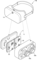
도 4는 다른 실시예에 따른 영상 표시 장치(10b)를 도시한 도면이다. 도 4의 영상 표시 장치(10b)는 도 1의 영상 표시 장치(10)의 일례이다.Fig. 4 is a drawing illustrating an image display device (10b) according to another embodiment. The image display device (10b) of Fig. 4 is an example of the image display device (10) of Fig. 1.
도 4를 참조하면, 영상 표시 장치(10b)는 헤드셋(40)과 결합될 수 있는 휴대용 장치일 수 있다. 이 경우, 영상 표시 장치(10b)는 디스플레이부(11)가 헤드셋의 본체와 마주보도록 결합되어, 헤드셋(40)을 착용한 사용자가 헤드셋(40)의 렌즈를 통해 디스플레이부(11)에 표시된 영상(예를 들어, 360도 영상, 증강 현실 영상 등)을 보도록 할 수 있다. Referring to FIG. 4, the image display device (10b) may be a portable device that can be combined with a headset (40). In this case, the image display device (10b) is combined so that the display unit (11) faces the main body of the headset, so that a user wearing the headset (40) can view an image (e.g., a 360-degree image, an augmented reality image, etc.) displayed on the display unit (11) through the lens of the headset (40).
일 실시예에 따라 제어부(13)는 영상을 좌안 영상 및 우안 영상으로 구분하고, 화면을 제1 서브 화면(43) 및 제2 서브 화면(45)으로 구분하여, 좌안 영상이 제1 서브 화면(43)에 표시되고, 우안 영상이 제2 서브 화면(45)에 표시되도록 디스플레이부(11)를 제어할 수 있다. According to one embodiment, the control unit (13) can divide the image into a left-eye image and a right-eye image, divide the screen into a first sub-screen (43) and a second sub-screen (45), and control the display unit (11) so that the left-eye image is displayed on the first sub-screen (43) and the right-eye image is displayed on the second sub-screen (45).
한편, 사용자가 헤드셋(40)을 두들기는 경우라도, 영상 표시 장치(10b)의 센싱부(12)는 헤드셋(40)을 통해 영상 표시 장치(10b)로 전달되는 힘을 센싱할 수 있다. Meanwhile, even if the user taps the headset (40), the sensing unit (12) of the image display device (10b) can sense the force transmitted to the image display device (10b) through the headset (40).
도 5는 제어부(13)의 구성을 상세히 도시한 도면이다.Figure 5 is a drawing showing in detail the configuration of the control unit (13).
도 5를 참조하면, 제어부(13)는 프로세서(51), 비디오 처리부(52) 및 그래픽 처리부(53)를 포함할 수 있다. Referring to FIG. 5, the control unit (13) may include a processor (51), a video processing unit (52), and a graphics processing unit (53).
프로세서(51)는 비디오 처리부(52)와 그래픽 처리부(53)를 제어하기 위한 동작을 수행할 수 있다. The processor (51) can perform operations to control the video processing unit (52) and the graphics processing unit (53).
비디오 처리부(52)는 영상 표시 장치(10)에 저장된 비디오 데이터 및/또는 외부로부터 수신된 비디오 데이터에 대한 처리를 수행할 수 있다. 비디오 처리부(52)는 비디오 데이터에 대한 디코딩을 수행하는 비디오 디코더(미도시)를 포함할 수 있다. 또한, 비디오 처리부(52)는 스케일링, 노이즈 필터링, 프레임 레이트 변환, 해상도 변환 등과 같은 다양한 이미지 처리를 수행할 수 있다.The video processing unit (52) can perform processing on video data stored in the video display device (10) and/or video data received from the outside. The video processing unit (52) can include a video decoder (not shown) that performs decoding on the video data. In addition, the video processing unit (52) can perform various image processing such as scaling, noise filtering, frame rate conversion, and resolution conversion.
일 실시예에 따라, 비디오 처리부(52)는 가상 현실 모드 동작 중, 평면 형태의 360도 영상을 획득하여, 평면 형태의 360도 영상에 대한 디코딩을 수행할 수 있다. According to one embodiment, the video processing unit (52) may acquire a 360-degree image in a flat shape during operation in a virtual reality mode and perform decoding on the 360-degree image in a flat shape.
그래픽 처리부(graphic processing unit)(53)는 연산부(미도시) 및 렌더링부(미도시)를 이용하여, 아이콘, 이미지, 텍스트 등과 같은 다양한 객체를 포함하는 화면을 생성할 수 있다. 연산부는 화면의 레이아웃에 따라 각 객체들이 표시될 좌표값, 형태, 크기, 컬러 등과 같은 속성값을 연산할 수 있다. 렌더링부는, 연산부에 의해 연산된 속성값에 기초하여 객체를 포함하는 다양한 레이아웃의 화면을 생성할 수 있다. 렌더링부에서 생성된 화면은 디스플레이부(11)의 디스플레이 영역에 출력될 수 있다.The graphic processing unit (53) can generate a screen including various objects such as icons, images, and texts by using a calculation unit (not shown) and a rendering unit (not shown). The calculation unit can calculate attribute values such as coordinate values, shape, size, and color for each object to be displayed according to the layout of the screen. The rendering unit can generate a screen including various layouts of objects based on the attribute values calculated by the calculation unit. The screen generated by the rendering unit can be output to the display area of the display unit (11).
일 실시예에 따라 그래픽 처리부(53)는 가상 현실 모드 동작 중, 비디오 처리부(52)에 의해 디코딩된 360도 영상을 와핑(warping)할 수 있다. 도 6에서는 그래픽 처리부(53)가 360도 영상을 와핑하는 동작을 설명한다. According to one embodiment, the graphics processing unit (53) may warp a 360-degree image decoded by the video processing unit (52) during virtual reality mode operation. FIG. 6 describes an operation of the graphics processing unit (53) warping a 360-degree image.
도 6은 가상 현실 모드에서 그래픽 처리부(53)의 동작을 설명하기 위한 도면이다. Figure 6 is a drawing for explaining the operation of the graphics processing unit (53) in virtual reality mode.
도 6을 참조하면, 그래픽 처리부(53)는 가상 현실 모드 동작 중, 비디오 처리부(51)에 의해 디코딩된 360도 영상(60)을 와핑(warping)하여 디스플레이부(11)의 디스플레이 영역에 표시할 수 있다. Referring to FIG. 6, the graphic processing unit (53) can warp a 360-degree image (60) decoded by the video processing unit (51) during virtual reality mode operation and display it on the display area of the display unit (11).
구체적으로, 그래픽 처리부(53)는 디코딩된 360도 영상(60)을 구 형태의 360도 영상(61)으로 변환할 수 있다. 예를 들어, 그래픽 처리부(53)는 평면 형태의 360도 영상(60)을 구(sphere)에 맵핑하고, 맵핑된 영상들의 접점들을 연결(스티칭(stiching))하여, 구 형태의 360도 영상(61)을 생성할 수 있다.Specifically, the graphic processing unit (53) can convert the decoded 360-degree image (60) into a spherical 360-degree image (61). For example, the graphic processing unit (53) can map a flat 360-degree image (60) to a sphere and connect (stitch) the contact points of the mapped images to generate a spherical 360-degree image (61).
또한, 그래픽 처리부(53)는 구 형태의 360도 영상(61) 중에서 사용자에 의해 선택된 일부 영역(62)을 추출하고, 디스플레이 해상도에 따라 스케일링된 영상(63)을 디스플레이부(11)의 디스플레이 영역에 표시할 수 있다. In addition, the graphic processing unit (53) can extract a portion (62) selected by the user from a 360-degree image (61) in a spherical shape and display the image (63) scaled according to the display resolution on the display area of the display unit (11).
일 실시예에 따라 그래픽 처리부(53)는 화면을 제1 서브 화면 및 제2 서브 화면으로 구분하고, 제1 서브 화면의 레이아웃 속성값 및 제2 서브 화면의 레이아웃 속성값을 연산할 수 있다. 예를 들어, 그래픽 처리부(53)는 사이드 바이 사이드 (side by side) 기법, 탑-바텀(top-bottom) 기법, 화면을 제1 및 제2 서브 화면으로 구분할 수 있다. 그러나, 이에 제한되는 것은 아니며, 그래픽 처리부(53)는 라인 인터리브드(line interleaved) 기법, 체커 보드(checker board) 기법 등에 따라, 화면을 두 개 이상의 서브 화면으로 구분할 수도 있다. According to one embodiment, the graphic processing unit (53) may divide the screen into a first sub-screen and a second sub-screen, and calculate the layout property values of the first sub-screen and the layout property values of the second sub-screen. For example, the graphic processing unit (53) may divide the screen into the first and second sub-screens using a side-by-side technique, a top-bottom technique, etc. However, the present invention is not limited thereto, and the graphic processing unit (53) may divide the screen into two or more sub-screens using a line interleaved technique, a checker board technique, etc.
그래픽 처리부(53)는 연산된 속성값에 기초하여, 스케일링된 영상(63)을 좌안 영상(64) 및 우안 영상(65)으로 구분하여, 좌안 영상(63)을 제1 서브 화면에 표시하고, 우안 영상(65)을 제2 서브 화면에 표시할 수 있다. The graphic processing unit (53) can divide the scaled image (63) into a left-eye image (64) and a right-eye image (65) based on the calculated attribute values, and display the left-eye image (63) on a first sub-screen and the right-eye image (65) on a second sub-screen.
한편, 360도 영상(60)이 좌안 전용 영상인 경우, 그래픽 처리부(53)는 우안 전용 360도 영상을 획득하여 전술한 동작을 반복함으로써, 우안 영상을 생성할 수 있다. Meanwhile, if the 360-degree image (60) is a left-eye-only image, the graphic processing unit (53) can obtain a right-eye-only 360-degree image and repeat the above-described operation to generate a right-eye image.
일 실시예에 따라 그래픽 처리부(53)는 센싱부(12)로부터 입력받는 값에 따라, 구 형태의 360도 영상(61) 내에서 일부 영역(62)의 위치를 이동시킬 수 있다. 예를 들어, 센싱부(12)는 영상 표시 장치(10)의 움직임 속도 정보, 방위 정보 등을 센싱하여 제어부(13)로 제공할 수 있다. 그래픽 처리부(53)는 센싱부(12)로부터 입력받은 값에 기초하여, 위치가 이동된 일부 영역을 디스플레이부(11)로 입력할 수 있다. According to one embodiment, the graphic processing unit (53) can move the position of a portion (62) within a spherical 360-degree image (61) based on a value input from the sensing unit (12). For example, the sensing unit (12) can sense movement speed information, direction information, etc. of the image display device (10) and provide the information to the control unit (13). The graphic processing unit (53) can input the portion of the moved position to the display unit (11) based on the value input from the sensing unit (12).
도 7은 라이브-뷰 모드에서 제어부(13)의 동작을 설명하기 위한 도면이다. Figure 7 is a drawing for explaining the operation of the control unit (13) in live-view mode.
도 7을 참조하면, 제어부(13)는 라이브-뷰 모드에서, 촬상 장치(14)로부터 획득된 외부 영상(70)을 그대로 표시하거나, 외부 영상(70)에 적어도 하나의 이미지 또는 동영상 등을 추가하여 증강 현실 영상(72)을 표시하도록 디스플레이부(11)를 제어할 수 있다. Referring to FIG. 7, the control unit (13) can control the display unit (11) to display an external image (70) acquired from the imaging device (14) in the live-view mode as is, or to display an augmented reality image (72) by adding at least one image or video to the external image (70).
일 실시예에 따라 제어부(13)는 외부 영상(70)에 외부 영상(70)과 관련된 이미지(71)를 획득할 수 있다. 여기서, 외부 영상(70)과 관련된 이미지(또는, 동영상)(71)는, 외부 영상(70)에 포함된 객체를 나타내는 텍스트, 아이콘, 애니메이션 등 적어도 하나를 포함할 수 있다. 또한, 외부 영상(70)과 관련된 이미지(71)는, 외부 서버와 통신하는 통신부(미도시)를 통해 제어부(13)로 제공될 수 있다. 또는, 식별된 객체에 관련된 이미지(71)는, 메모리(15)에 저장되어 제어부(13)로 제공될 수 있다.According to one embodiment, the control unit (13) may obtain an image (71) related to the external image (70) from the external image (70). Here, the image (or video) (71) related to the external image (70) may include at least one of text, icon, animation, etc. representing an object included in the external image (70). In addition, the image (71) related to the external image (70) may be provided to the control unit (13) through a communication unit (not shown) that communicates with an external server. Alternatively, the image (71) related to the identified object may be stored in the memory (15) and provided to the control unit (13).
구체적으로, 제어부(13)는 외부 영상(70)에 포함된 적어도 하나의 객체를 식별하고, 식별된 객체와 관련된 이미지(71)를 획득할 수 있다. 예를 들어, 제어부(13)는 외부 영상(70) 내에 엣지(edge) 성분을 추출하여, 외부 영상(70)에 포함된 객체들을 식별할 수 있다. 또한, 제어부(13)는 식별된 객체에 관련된 이미지(71)를 외부 영상(70)에 추가하여 증강 현실 영상(72)을 생성할 수 있다. Specifically, the control unit (13) can identify at least one object included in the external image (70) and obtain an image (71) related to the identified object. For example, the control unit (13) can extract an edge component within the external image (70) to identify objects included in the external image (70). In addition, the control unit (13) can add an image (71) related to the identified object to the external image (70) to generate an augmented reality image (72).
일 실시예에 따라 제어부(13)는 증강 현실 영상(72)에 대응하는 영상 신호를 처리하여 디스플레이부(11)의 디스플레이 영역에 표시되도록 제어할 수 있다. 예를 들어, 그래픽 처리부(53)는 이미지(71)의 디스플레이 속성값(예를 들어, 좌표값, 형태, 크기 등)을 연산하고, 연산된 속성값에 기초하여 외부 영상(70) 및 이미지(71)를 중첩하여 출력되도록 디스플레이부(11)를 제어할 수 있다. According to one embodiment, the control unit (13) may process an image signal corresponding to an augmented reality image (72) and control it to be displayed on the display area of the display unit (11). For example, the graphic processing unit (53) may calculate display property values (e.g., coordinate values, shape, size, etc.) of the image (71) and control the display unit (11) to output an external image (70) and an image (71) by overlapping them based on the calculated property values.
일 실시예에 따라 제어부(13)는 3차원 증강 현실 영상(72)을 제공하기 위하여, 증강 현실 영상(72)을 좌안 영상 및 우안 영상으로 구분하고, 사이드 바이 사이드 기법, 탑-바텀 기법 등에 따라 구분된 화면에 각 영상이 표시되도록 디스플레이부(11)를 제어할 수 있다. According to one embodiment, the control unit (13) may control the display unit (11) to provide a three-dimensional augmented reality image (72), divide the augmented reality image (72) into a left-eye image and a right-eye image, and display each image on a screen divided according to a side-by-side technique, a top-bottom technique, etc.
도 8은 라이브-뷰 모드에서 제어부(13)의 동작을 설명하는 다른 도면이다. Fig. 8 is another drawing explaining the operation of the control unit (13) in live-view mode.
도 8을 참조하면, 센싱부(12)는 사용자의 눈을 트래킹하는 적외선 센서(미도시)를 더 포함할 수 있다. 라이브-뷰 모드에서, 제어부(13)는 적외선 센서에 의해 센싱된 값을 입력받아, 사용자의 시선 방향을 결정할 수 있다. 또한, 제어부(13)는 외부 영상(80) 내에서 사용자의 시선 방향에 대응하는 객체를 식별하고, 외부 영상(80)에 식별된 객체에 관련된 이미지(81)를 외부 영상(80)에 추가하여, 증강 현실 영상(82)을 생성할 수 있다.Referring to FIG. 8, the sensing unit (12) may further include an infrared sensor (not shown) that tracks the user's eyes. In the live-view mode, the control unit (13) may receive a value sensed by the infrared sensor and determine the user's gaze direction. In addition, the control unit (13) may identify an object corresponding to the user's gaze direction in the external image (80), and add an image (81) related to the object identified in the external image (80) to the external image (80) to generate an augmented reality image (82).
일 실시예에 따라 제어부(13)는 증강 현실 영상(82)에 대응하는 영상 신호를 처리하여 디스플레이부(11)의 디스플레이 영역에 표시되도록 제어할 수 있다.According to one embodiment, the control unit (13) can process an image signal corresponding to an augmented reality image (82) and control it to be displayed in the display area of the display unit (11).
한편, 도 7 및 도 8에서는, 라이브 뷰 모드에서, 제어부(13)가 비디오 시스루(video see-through) 기법에 따라 촬영된 외부 영상(70)을 이용하여 증강 현실 영상(72)을 생성 및/또는 표시하는 것으로 설명하였으나, 이에 제한되지 않는다. 예를 들어, 디스플레이부(11)가 투명 디스플레이로 구현된 경우, 제어부(13)는 옵티컬 시스루 기법(optical see-through)에 따라, 외부 상황과 관련된 이미지 또는 동영상을 투명 디스플레이에 표시할 수 있다. 따라서, 사용자는 육안으로 외부 상황과 함께, 투명 디스플레이에 표시되는 이미지 또는 동영상을 중첩하여 볼 수 있다.Meanwhile, in FIGS. 7 and 8, it has been described that in the live view mode, the control unit (13) generates and/or displays an augmented reality image (72) using an external image (70) captured according to a video see-through technique, but is not limited thereto. For example, if the display unit (11) is implemented as a transparent display, the control unit (13) can display an image or video related to an external situation on the transparent display according to an optical see-through technique. Accordingly, the user can view the image or video displayed on the transparent display together with the external situation with the naked eye.
도 9는 일 실시예에 따른 센싱부(12)가 영상 표시 장치(10)에 가해지는 힘을 센싱하는 일례이다. FIG. 9 is an example of a sensing unit (12) according to one embodiment sensing force applied to an image display device (10).
도 9를 참조하면, 센싱부(12)는 가속도 센서를 이용하여, x, y 및 z 축을 기준으로 영상 표시 장치(10)의 움직임 속도를 센싱할 수 있다. Referring to FIG. 9, the sensing unit (12) can sense the movement speed of the image display device (10) based on the x, y, and z axes using an acceleration sensor.
일 실시예에 따라 센싱부(12)는 x, y, z축 중 적어도 하나에 대응하는 움직임 속도 변화가 임계값을 초과하면, 영상 표시 장치(10)에 힘이 가해진 것으로 판단할 수 있다. 예를 들어, 센싱부(12)는, 도 9의 91에 도시된 바와 같이, z 축에 대응하는 움직임 속도 변화가 임계값을 초과하면, 영상 표시 장치(10)에 힘이 가해진 것으로 판단할 수 있다. According to one embodiment, the sensing unit (12) may determine that force is applied to the image display device (10) if a change in movement speed corresponding to at least one of the x, y, and z axes exceeds a threshold value. For example, as illustrated in 91 of FIG. 9, the sensing unit (12) may determine that force is applied to the image display device (10) if a change in movement speed corresponding to the z axis exceeds a threshold value.
도 10은 일 실시예에 따른 영상 표시 장치(10)에 가해지는 힘이 센싱된 것에 응답하여, 제어부(13)가 동작 모드를 전환하는 일례이다. FIG. 10 is an example of a control unit (13) switching an operation mode in response to sensing a force applied to a video display device (10) according to one embodiment.
도 10을 참조하면, 센싱부(12)는 영상 표시 장치(10)에 가해지는 제1 히트(hit)(1001)를 센싱한 후, 기 결정된 시간 내에 영상 표시 장치(10)에 가해지는 제2 히트(1002)가 센싱된 것에 응답하여, 영상 표시 장치(10)에 힘이 가해졌다는 제어 신호를 제어부(13)로 입력할 수 있다. 여기서, 히트(hit)는, 짧은 시간 동안(예를 들어, 0.3초 등) 영상 표시 장치에 가해지는 힘일 수 있다. Referring to FIG. 10, the sensing unit (12) senses a first hit (1001) applied to the image display device (10), and then, in response to sensing a second hit (1002) applied to the image display device (10) within a predetermined time, can input a control signal indicating that force has been applied to the image display device (10) to the control unit (13). Here, the hit may be a force applied to the image display device for a short period of time (e.g., 0.3 seconds).
따라서, 영상 표시 장치(10)를 착용한 사용자는 영상 표시 장치(10)(또는, 헤드셋(40))을 연속하여 두들김으로써, 센싱부(12)가 영상 표시 장치(10)에 가해지는 힘을 센싱하도록 할 수 있다. Accordingly, a user wearing a video display device (10) can continuously tap the video display device (10) (or headset (40)) to enable the sensing unit (12) to sense the force applied to the video display device (10).
한편, 사용자는 영상 표시 장치(10)의 특정 영역을 두들길 필요는 없으며, 영상 표시 장치(10) 또는 헤드셋(40)의 임의 영역(예를 들어, 도 10에 도시된 화살표가 가리키는 영역)을 두들김으로써, 영상 표시 장치(10)에 힘을 가할 수 있다. Meanwhile, the user does not need to tap a specific area of the image display device (10), but can apply force to the image display device (10) by tapping any area of the image display device (10) or the headset (40) (for example, the area indicated by the arrow shown in FIG. 10).
일 실시예에 따라 제어부(13)는 가상 현실 모드로 동작 중 영상 표시 장치(10)에 힘이 가해진 것에 응답하여, 라이브-뷰 모드로 전환할 수 있다. 또는, 제어부(13)는 라이브-뷰 모드로 동작 중 영상 표시 장치(10)에 힘이 가해진 것에 응답하여, 가상 현실 모드로 전환할 수 있다. In one embodiment, the control unit (13) may switch to the live-view mode in response to a force being applied to the image display device (10) while operating in the virtual reality mode. Alternatively, the control unit (13) may switch to the virtual reality mode in response to a force being applied to the image display device (10) while operating in the live-view mode.
도 11은 일 실시예에 따라 제어부(13)가 동작 모드를 전환하는 동작을 설명하기 위한 도면이다. Fig. 11 is a drawing for explaining an operation of a control unit (13) switching an operation mode according to one embodiment.
도 11을 참조하면, 제어부(13)는 디스플레이부(11), 센싱부(12) 및 촬상 장치(14)를 제어하여, 동작 모드를 전환할 수 있다. Referring to Fig. 11, the control unit (13) can control the display unit (11), the sensing unit (12), and the imaging device (14) to switch the operation mode.
예를 들어, 제어부(13)는 가상 현실 모드 동작 중 디스플레이부(11)를 제어하여, 360도 영상(1101)을 표시할 수 있다. 이에 대해서는, 도 5및 6을 참조하여 자세히 설명하였으므로 동일한 설명은 생략한다. For example, the control unit (13) can control the display unit (11) during virtual reality mode operation to display a 360-degree image (1101). Since this has been described in detail with reference to FIGS. 5 and 6, the same description will be omitted.
제어부(13)는 센싱부(12)로부터 영상 표시 장치(10)에 힘이 가해졌음이 센싱되었다는 신호가 입력되면, 촬상 장치(14)를 활성화할 수 있다. 또는, 제어부(13)는 센싱부(12)에 의해 센싱되는 센서값을 일정 시간 간격으로 입력받고, 영상 표시 장치(10)에 힘이 가해졌는지 여부를 판단할 수도 있다. 이 경우, 제어부(13)는 센서값과 임계값을 비교하여 영상 표시 장치(10)에 힘이 가해졌다고 판단된 경우, 촬상 장치(14)를 활성화할 수 있다. The control unit (13) can activate the imaging device (14) when a signal is input from the sensing unit (12) that force has been applied to the image display device (10). Alternatively, the control unit (13) can receive the sensor value sensed by the sensing unit (12) at a predetermined time interval and determine whether force has been applied to the image display device (10). In this case, the control unit (13) can compare the sensor value with a threshold value and activate the imaging device (14) when it is determined that force has been applied to the image display device (10).
한편, 제어부(13)는 촬상 장치(14)가 활성화됨에 따라, 360도 영상(1101)에 대응하는 영상 신호 처리를 중단하고, 촬상 장치(14)에 의해 촬영된 외부 영상(1102)에 대응하는 영상 신호를 처리함으로써, 라이브-뷰 모드로 동작할 수 있다. Meanwhile, the control unit (13) can operate in a live-view mode by stopping image signal processing corresponding to a 360-degree image (1101) and processing an image signal corresponding to an external image (1102) captured by the image capturing device (14) as the image capturing device (14) is activated.
또한, 제어부(13)는 외부 영상(1102)에 관련된 이미지를, 외부 영상(1102)에 추가하여 증강 현실 영상(1103)을 생성하고, 디스플레이부(11)를 통해 증강 현실 영상(1103)을 표시할 수 있다. 이에 대해서는, 도 7 및 도 8을 참조하여 설명하였으므로, 자세한 설명은 생략한다. In addition, the control unit (13) can add an image related to an external image (1102) to the external image (1102) to create an augmented reality image (1103) and display the augmented reality image (1103) through the display unit (11). Since this has been described with reference to FIGS. 7 and 8, a detailed description thereof will be omitted.
도 12는 일 실시예에 따라 제어부(13)가 동작 모드를 전환하는 동작을 설명하기 위한 다른 도면이다. FIG. 12 is another drawing for explaining an operation of a control unit (13) switching an operation mode according to one embodiment.
도 12를 참조하면, 영상 표시 장치(10)는 마이크로폰(16)을 더 포함할 수 있다. 제어부(13)는 센싱부(12)에 의해 영상 표시 장치(10)에 힘이 가해졌음이 센싱된 것에 응답하여, 음성 인식 기능을 활성화함으로써 마이크로폰(16)을 온(on) 시킬 수 있다. 한편, 이 경우, 센싱부(12)는 도 9에 도시된 바와 같이, 영상 표시 장치(10)에 가해지는 제1 히트(91)가 센싱된 것에 응답하여, 영상 표시 장치(10)에 힘이 가해진 것으로 제어부(13)에 알릴 수 있다. Referring to FIG. 12, the image display device (10) may further include a microphone (16). The control unit (13) may activate a voice recognition function in response to sensing that force has been applied to the image display device (10) by the sensing unit (12), thereby turning on the microphone (16). Meanwhile, in this case, the sensing unit (12) may notify the control unit (13) that force has been applied to the image display device (10) in response to sensing that a first hit (91) applied to the image display device (10) has been applied, as illustrated in FIG. 9.
일 실시예에 따른 제어부(13)는 마이크로폰(16)을 통해 수신된 사용자 음성을 분석하여, 가상 현실 모드를 라이브-뷰 모드로 전환할 수 있다. 따라서, 디스플레이부(11)는, 제어부(13)의 제어에 의해, 360도 영상(1201)의 표시를 중단하고 외부 영상(1202) 또는 증강 현실 영상(1203)을 표시할 수 있다. According to one embodiment, the control unit (13) can analyze the user's voice received through the microphone (16) and switch the virtual reality mode to the live-view mode. Accordingly, the display unit (11) can stop displaying the 360-degree image (1201) and display an external image (1202) or an augmented reality image (1203) under the control of the control unit (13).
한편, 제어부(13)는 라이브-뷰 모드로 동작 중 영상 표시 장치(10)에 가해지는 힘이 센싱된 것에 응답하여, 가상 현실 모드로 전환할 수도 있다. 이 경우, 제어부(13)는 촬상 장치(14)를 비활성화하고, 이전에 재생했던 360도 영상(1201)에 대응하는 영상 신호를 처리하여 표시하도록 디스플레이부(11)를 제어할 수 있다. Meanwhile, the control unit (13) may switch to the virtual reality mode in response to sensing a force applied to the image display device (10) while operating in the live-view mode. In this case, the control unit (13) may deactivate the imaging device (14) and control the display unit (11) to process and display an image signal corresponding to a previously played 360-degree image (1201).
도 13은 일 실시예에 따라 제어부(13)가 외부 영상의 밝기를 조정하여 표시하도록 디스플레이부(11)를 제어하는 일례이다. FIG. 13 is an example of a control unit (13) controlling a display unit (11) to adjust the brightness of an external image and display it according to one embodiment.
도 13을 참조하면, 일 실시예에 따라 제어부(13)는 동작 모드가 전환되는 경우, 동작 모드가 전환되기 이전에 표시되던 제1 영상(1301)과 동작 모드가 전환된 이후에 표시될 제2 영상(1302)의 밝기를 비교할 수 있다. 만약, 제1 영상(1301)의 밝기와 제2 영상(1302)의 밝기 차이가 임계값 이상이면, 제어부(13)는 제2 영상(1302)의 밝기를 제1 영상(1301)의 밝기에 대응하도록 조정하여 표시하도록 디스플레이부(11)를 제어할 수 있다. Referring to FIG. 13, according to one embodiment, when the operation mode is switched, the control unit (13) can compare the brightness of a first image (1301) displayed before the operation mode is switched and a second image (1302) to be displayed after the operation mode is switched. If the difference in brightness between the first image (1301) and the second image (1302) is greater than or equal to a threshold value, the control unit (13) can control the display unit (11) to adjust the brightness of the second image (1302) to correspond to the brightness of the first image (1301) and display it.
이후, 제어부(13)는, 기 결정된 시간 간격으로, 밝기가 조정된 제1 영상(1303)을 본래 밝기에 가까워지도록 점차적으로 조정하여 표시할 수 있다.Thereafter, the control unit (13) can gradually adjust the first image (1303) with adjusted brightness to get closer to the original brightness at predetermined time intervals and display it.
예를 들어, 제어부(13)는 제1 시간 간격(1303) 동안 제1 영상(1301)의 밝기를 -60%로 조정하여 표시하고, 제2 시간 간격(1304) 동안 제1 영상(1301)의 밝기를 -30%로 조정하여 표시하고, 제3 시간 간격(1305) 이후부터는 제1 영상(1301)의 본래 밝기로 조정하여 표시하도록 디스플레이부(11)를 제어할 수 있다. For example, the control unit (13) can control the display unit (11) to adjust the brightness of the first image (1301) to -60% for the first time interval (1303) and display it, adjust the brightness of the first image (1301) to -30% for the second time interval (1304) and display it, and adjust the brightness of the first image (1301) to the original brightness for displaying it after the third time interval (1305).
도 14는 일 실시예에 따른 영상 표시 장치의 구성을 상세히 도시한 도면이다. FIG. 14 is a drawing illustrating in detail the configuration of an image display device according to one embodiment.
도 14에 도시된 바와 같이, 일 실시예에 따른 영상 표시 장치(1000)는, 출력부(1100), 센싱부(1200), 제어부(1300), A/V 입력부(1600) 및 메모리(1700) 이외에 통신부(1500), 비디오 처리부(1800) 및 그래픽 처리부(1850)를 포함할 수 있다. As illustrated in FIG. 14, a video display device (1000) according to one embodiment may include, in addition to an output unit (1100), a sensing unit (1200), a control unit (1300), an A/V input unit (1600), and a memory (1700), a communication unit (1500), a video processing unit (1800), and a graphic processing unit (1850).
출력부(1100), 센싱부(1200) 및 제어부(1300)에 대하여, 도 2에서 설명한 내용과 동일한 내용은 도 14에서 생략한다. 또한, 비디오 처리부(1800) 및 그래픽 처리부(1850)에 대하여, 도 5에서 설명한 내용과 동일한 내용은 도 14에서 생략한다. 한편, 도 5 에서는, 비디오 처리부(1800) 및 그래픽 처리부(1850)가 제어부(1300)에 포함되는 것으로 설명하였으나, 실시예에 따라 비디오 처리부(1800) 및/또는 그래픽 처리부(1850)는 제어부(1300)의 외부에 위치하는 구성요소일 수 있다.Regarding the output unit (1100), the sensing unit (1200), and the control unit (1300), the same content as described in FIG. 2 is omitted in FIG. 14. In addition, regarding the video processing unit (1800) and the graphic processing unit (1850), the same content as described in FIG. 5 is omitted in FIG. 14. Meanwhile, in FIG. 5, the video processing unit (1800) and the graphic processing unit (1850) are described as being included in the control unit (1300), but depending on the embodiment, the video processing unit (1800) and/or the graphic processing unit (1850) may be components located outside the control unit (1300).
출력부(1100)는 오디오 신호 또는 비디오 신호(즉, 영상 신호) 또는 진동 신호를 출력할 수 있으며, 출력부(1100)는 디스플레이부(1110) 및 음향 출력부(1120)를 포함할 수 있다.The output unit (1100) can output an audio signal or a video signal (i.e., an image signal) or a vibration signal, and the output unit (1100) can include a display unit (1110) and an audio output unit (1120).
일 실시예에 따라 디스플레이부(1110)는 제어부(1300)의 제어에 의해, 360도 영상 또는 외부 영상 또는 증강 현실 영상에 대응하는 영상 신호를 출력할 수 있다. According to one embodiment, the display unit (1110) can output an image signal corresponding to a 360-degree image, an external image, or an augmented reality image under the control of the control unit (1300).
한편, 디스플레이부(1110)와 터치패드가 레이어 구조를 이루어 터치 스크린으로 구성되는 경우, 디스플레이부(1110)는 출력 장치 이외에 입력 장치로도 사용될 수 있다. Meanwhile, when the display unit (1110) and the touchpad form a layer structure to form a touch screen, the display unit (1110) can be used as an input device in addition to an output device.
음향 출력부(1120)는 통신부(1500)로부터 수신되거나 메모리(1700)에 저장된 오디오 데이터를 출력한다. 또한, 음향 출력부(1120)는 영상 표시 장치(1000)에서 수행되는 기능(예를 들어, 호신호 수신음, 메시지 수신음, 알림음)과 관련된 음향 신호를 출력한다.The audio output unit (1120) outputs audio data received from the communication unit (1500) or stored in the memory (1700). In addition, the audio output unit (1120) outputs audio signals related to functions performed in the video display device (1000) (e.g., call signal reception sound, message reception sound, notification sound).
센싱부(1200)는 영상 표시 장치(1000)의 상태 또는 영상 표시 장치(1000) 주변의 상태를 센싱하고, 센싱된 정보를 제어부(1300)로 전달할 수 있다. 센싱부(1200)는 도 2에서 설명한 가속도 센서(1220), 자이로스코프 센서(1250) 및 근접 센서(1280) 이외에 지자기 센서(1210), 온/습도 센서(1230), 적외선 센서(1240), 위치 센서(1260), 기압 센서(1270), RGB 센서(1290) 중 적어도 하나를 더 포함하도록 구현될 수 있다.The sensing unit (1200) can sense the status of the image display device (1000) or the status around the image display device (1000) and transmit the sensed information to the control unit (1300). The sensing unit (1200) can be implemented to further include at least one of a geomagnetic sensor (1210), a temperature/humidity sensor (1230), an infrared sensor (1240), a position sensor (1260), a barometric pressure sensor (1270), and an RGB sensor (1290) in addition to the acceleration sensor (1220), the gyroscope sensor (1250), and the proximity sensor (1280) described in FIG. 2.
제어부(1300)는 하나 이상의 프로세서(processor)를 구비하여 영상 표시 장치(1000)의 전반적인 동작을 제어한다. 제어부(1300)는 영상 표시 장치(1000)의 내부 구성 요소들 사이의 신호 흐름을 제어하고, 데이터를 처리하는 기능을 수행한다. 제어부(1300)는 사용자의 입력이 있거나 기 설정된 조건을 만족하는 경우, 메모리(1700)에 저장된 OS(operating system) 및 다양한 애플리케이션을 실행할 수 있다. The control unit (1300) has one or more processors to control the overall operation of the image display device (1000). The control unit (1300) controls the signal flow between internal components of the image display device (1000) and performs a function of processing data. When there is a user input or a preset condition is satisfied, the control unit (1300) can execute an OS (operating system) stored in the memory (1700) and various applications.
일 실시예에 따라 제어부(1300)는 다양한 동작 모드를 실행할 수 있으며, 센싱부(1200)로부터 입력받는 센서값에 따라 동작 모드를 전환할 수 있다. According to one embodiment, the control unit (1300) can execute various operation modes and switch the operation mode according to the sensor value input from the sensing unit (1200).
사용자 입력부(1400)는 영상 표시 장치(1000)를 제어하기 위한 사용자의 입력을 수신할 수 있다. 예를 들어, 사용자 입력부(1400)에는 키 패드(key pad), 돔 스위치 (dome switch), 터치 패드(접촉식 정전 용량 방식, 압력식 저항막 방식, 적외선 감지 방식, 표면 초음파 전도 방식, 적분식 장력 측정 방식, 피에조 효과 방식 등), 조그 휠, 조그 스위치 등이 있을 수 있으나 이에 한정되는 것은 아니다.The user input unit (1400) can receive a user's input for controlling the video display device (1000). For example, the user input unit (1400) may include, but is not limited to, a key pad, a dome switch, a touch pad (contact electrostatic capacitance type, pressure resistive film type, infrared detection type, surface ultrasonic conduction type, integral tension measurement type, piezo effect type, etc.), a jog wheel, a jog switch, etc.
통신부(1500)는 외부와 통신을 하게하는 하나 이상의 구성요소를 포함할 수 있다. 예를 들어, 통신부(1500)는, 근거리 통신부(1510), 이동 통신부(1520) 및 방송 수신부(1530) 중 적어도 하나를 포함할 수 있다.The communication unit (1500) may include one or more components that enable communication with the outside. For example, the communication unit (1500) may include at least one of a short-range communication unit (1510), a mobile communication unit (1520), and a broadcast receiving unit (1530).
근거리 통신부(short-range wireless communication unit)(1110)는 블루투스, BLE(Bluetooth Low Energy), 근거리 무선 통신(Near Field Communication), WLAN(와이파이), 지그비(Zigbee), 적외선(IrDA, infrared Data Association) 통신, WFD(Wi-Fi Direct) 통신, UWB(ultra wideband) 통신, Ant+ 통신 등을 수행하기 위한 적어도 하나의 구성 요소를 포함할 수 있으나, 이에 한정되는 것은 아니며, 기술이 발전됨에 따른 새로운 구성 요소를 더 포함할 수 있다. The short-range wireless communication unit (1110) may include at least one component for performing Bluetooth, BLE (Bluetooth Low Energy), near field communication, WLAN (Wi-Fi), Zigbee, infrared (IrDA, infrared Data Association) communication, WFD (Wi-Fi Direct) communication, UWB (ultra wideband) communication, Ant+ communication, etc., but is not limited thereto, and may further include new components as technology advances.
이동 통신부(1520)는 이동 통신망 상에서 기지국, 외부의 단말, 서버 중 적어도 하나와 무선 신호를 송수신한다. The mobile communication unit (1520) transmits and receives wireless signals with at least one of a base station, an external terminal, and a server on a mobile communication network.
방송 수신부(1530)는 방송 채널을 통하여 외부로부터 방송 신호 및/또는 방송 관련된 정보를 수신한다. 방송 채널은 위성 채널, 지상파 채널을 포함할 수 있다.The broadcast receiving unit (1530) receives broadcast signals and/or broadcast-related information from the outside through a broadcast channel. The broadcast channel may include a satellite channel or a terrestrial channel.
A/V 입력부(1600)는 오디오 신호 또는 비디오 신호 입력을 위한 것으로, 이에는 카메라(1610) 및 마이크로폰(1620) 등이 포함될 수 있다. 카메라(1610)는 화상통화 모드 또는 라이브-뷰 모드에서 이미지 센서를 통해 정지영상 또는 동영상 등의 화상 프레임을 얻을 수 있다. 이미지 센서를 통해 캡쳐된 이미지는 제어부(1300) 또는 그래픽 처리부(1850)를 통해 처리될 수 있다. 카메라(1610)는 단말기의 구성 태양에 따라 2개 이상이 구비될 수도 있다. 한편, 카메라(1610)는 도 2의 촬상 장치(14)에 대응될 수 있다. The A/V input unit (1600) is for inputting audio signals or video signals, and may include a camera (1610) and a microphone (1620). The camera (1610) can obtain image frames, such as still images or moving images, through an image sensor in a video call mode or a live-view mode. An image captured through the image sensor can be processed through a control unit (1300) or a graphic processing unit (1850). Two or more cameras (1610) may be provided depending on the configuration of the terminal. Meanwhile, the camera (1610) may correspond to the imaging device (14) of FIG. 2.
마이크로폰(1620)은 외부의 음향 신호를 입력 받아 전기적인 음성 데이터로 처리한다. 또한, 마이크로폰(1620)은 외부의 음향 신호를 입력 받는 과정에서 발생 되는 잡음(noise)을 제거하기 위한 다양한 잡음 제거 알고리즘을 이용할 수 있다.The microphone (1620) receives an external acoustic signal and processes it into electrical voice data. In addition, the microphone (1620) can use various noise removal algorithms to remove noise generated in the process of receiving an external acoustic signal.
메모리(1700)는 제어부(1300)의 처리 및 제어를 위한 프로그램을 저장할 수 있고, 영상 표시 장치(1000)로 입력되거나 영상 표시 장치(1000)로부터 출력되는 데이터를 저장할 수도 있다.The memory (1700) can store a program for processing and controlling the control unit (1300), and can also store data input to or output from the image display device (1000).
메모리(1700)에 저장된 프로그램들은 그 기능에 따라 복수 개의 모듈들로 분류할 수 있는데, 예를 들어, UI 모듈(1710), 터치 스크린 모듈(1720), 가상 현실 동작 모듈(1730), 라이브-뷰 동작 모듈(1740) 등으로 분류될 수 있다.Programs stored in the memory (1700) can be classified into multiple modules according to their functions, for example, a UI module (1710), a touch screen module (1720), a virtual reality operation module (1730), a live-view operation module (1740), etc.
UI 모듈(1710)은 애플리케이션 별로 영상 표시 장치(1000)와 연동되는 특화된 UI, GUI 등을 제공할 수 있다. 터치 스크린 모듈(1720)은 사용자의 터치 스크린 상의 터치 제스처를 감지하고, 터치 제스처에 관한 정보를 제어부(1300)로 전달할 수 있다. 한편, 터치 스크린 모듈(1720)은 컨트롤러를 포함하는 별도의 하드웨어로 구성될 수도 있다.The UI module (1710) can provide specialized UI, GUI, etc. that are linked with the video display device (1000) for each application. The touch screen module (1720) can detect a user's touch gesture on the touch screen and transmit information about the touch gesture to the control unit (1300). Meanwhile, the touch screen module (1720) can also be configured as separate hardware including a controller.
가상 현실 동작 모듈(1730)은 제어부(1300)가 가상 현실 모드로 동작하기 위한 적어도 하나의 명령어(즉, 인스트럭션(instruction))들을 제공할 수 있다. 예를 들어, 가상 현실 동작 모듈(1730)은 카메라(1610)를 비활성화하고, 360도 영상에 대응하는 영상 처리를 수행하는 명령어들을 포함할 수 있다. The virtual reality operation module (1730) may provide at least one command (i.e., instruction) for the control unit (1300) to operate in a virtual reality mode. For example, the virtual reality operation module (1730) may include commands for deactivating the camera (1610) and performing image processing corresponding to a 360-degree image.
라이브-뷰 동작 모듈(1740)은 제어부(1300)가 라이브-뷰 모드로 동작하기 위한 적어도 하나의 명령어들을 제공할 수 있다. 예를 들어, 라이브-뷰 동작 모듈(1740)은 카메라(1610)를 활성화하고, 카메라(1610)에 의해 촬영된 외부 영상에 대응하는 영상 처리를 수행하는 명령어들을 포함할 수 있다. 또한, 라이브-뷰 동작 모듈(1740)은 외부 영상에 관련된 이미지 또는 동영상을 획득하여 외부 영상에 추가하는 명령어들을 포함할 수 있다. The live-view operation module (1740) may provide at least one command for the control unit (1300) to operate in a live-view mode. For example, the live-view operation module (1740) may include commands for activating the camera (1610) and performing image processing corresponding to an external image captured by the camera (1610). In addition, the live-view operation module (1740) may include commands for acquiring an image or video related to the external image and adding it to the external image.
비디오 처리부(1800)는 비디오 데이터에 대한 디코딩, 스케일링, 노이즈 필터링 등과 같은 다양한 이미지 처리를 수행한다. 그래픽 처리부(1850)는 영상 신호를 렌더링하여 디스플레이부(1110)의 디스플레이 영역에 출력될 화면을 생성한다. The video processing unit (1800) performs various image processing such as decoding, scaling, and noise filtering on video data. The graphic processing unit (1850) renders a video signal to generate a screen to be output to the display area of the display unit (1110).
도 15 내지 도 18은 실시예에 따른 영상 표시 장치(10)의 동작 방법을 설명하는 흐름도이다. 도 15 내지 도 18 에 도시된 영상 표시 장치(10)의 동작 방법은, 앞서 설명된 도 1 내지 도 17 등에서 설명된 실시예와 관련된다. 따라서, 이하 생략된 내용이라 할지라도, 도 1 내지 도 17 등에서 앞서 설명된 내용들은, 도 15 내지 도 18 의 영상 표시 장치(10)의 동작 방법에도 적용될 수 있다. FIGS. 15 to 18 are flowcharts explaining an operating method of an image display device (10) according to an embodiment. The operating method of the image display device (10) illustrated in FIGS. 15 to 18 is related to the embodiment explained in FIGS. 1 to 17, etc. described above. Therefore, even if the content is omitted below, the content explained in FIGS. 1 to 17, etc. described above can also be applied to the operating method of the image display device (10) of FIGS. 15 to 18.
도 15는 일 실시예에 따른 영상 표시 장치(10)의 동작 방법을 설명하는 흐름도이다. Figure 15 is a flowchart explaining an operation method of an image display device (10) according to one embodiment.
도 15를 참조하면, s1510 에서, 영상 표시 장치(10)는 360도 영상을 표시하는 가상 현실 모드로 동작 중 영상 표시 장치에 가해지는 힘을 센싱한다.Referring to FIG. 15, in s1510, the image display device (10) senses a force applied to the image display device while operating in a virtual reality mode displaying a 360-degree image.
일 실시예에 따라 영상 표시 장치(10)는 가상 현실 모드로 동작할 수 있다. 가상 현실 모드에서, 영상 표시 장치(10)는 360도 영상에 대응하는 영상 신호를 처리하여 화면에 표시할 수 있다. 예를 들어, 영상 표시 장치(10)는 평면 형태의 360도 영상을 획득하여 구(sphere)에 맵핍함으로써, 구 형태의 360도 영상을 생성하고, 구 형태의 360도 영상 중 일부 영역을 추출하여 화면에 표시할 수 있다.According to one embodiment, the image display device (10) can operate in a virtual reality mode. In the virtual reality mode, the image display device (10) can process an image signal corresponding to a 360-degree image and display it on a screen. For example, the image display device (10) can obtain a 360-degree image in a flat shape and map it onto a sphere, thereby generating a spherical 360-degree image, and can extract a portion of the spherical 360-degree image and display it on a screen.
한편, 영상 표시 장치(10)는 사용자의 움직임이 센싱된 것에 응답하여, 구 형태의 360도 영상 중 화면에 표시되는 일부 영역의 위치를 이동시킬 수 있다. Meanwhile, the video display device (10) can move the position of a portion of a 360-degree spherical image displayed on the screen in response to the sensed movement of the user.
일 실시예에 따라 영상 표시 장치(10)는 영상 표시 장치(10)의 움직임 속도에 대한 정보 및/또는 방위에 대한 정보를 센싱함으로써, 영상 표시 장치(10)에 힘이 가해졌는지 여부를 판단할 수 있다.According to one embodiment, the image display device (10) can determine whether force is applied to the image display device (10) by sensing information about the movement speed and/or information about the direction of the image display device (10).
예를 들어, 영상 표시 장치(10)의 움직임 속도를 센싱하고, 센싱된 값의 변화가 임계값을 초과하면, 영상 표시 장치(10)에 힘이 가해진 것으로 판단할 수 있다. 또는, 영상 표시 장치(10)는 영상 표시 장치(10)의 방위 정보를 센싱하고, 센싱된 값의 변화가 임계값을 초과하면, 영상 표시 장치(10)에 힘이 가해진 것으로 판단할 수 있다. For example, the movement speed of the image display device (10) may be sensed, and if a change in the sensed value exceeds a threshold value, it may be determined that force has been applied to the image display device (10). Alternatively, the image display device (10) may sense orientation information of the image display device (10), and if a change in the sensed value exceeds a threshold value, it may be determined that force has been applied to the image display device (10).
s1520 에서, 영상 표시 장치(10)는 영상 표시 장치(10)에 가해지는 힘이 센싱된 것에 응답하여, 촬상 장치를 활성화한다. In s1520, the image display device (10) activates the imaging device in response to sensing a force applied to the image display device (10).
일 실시예에 따라 영상 표시 장치(10)는 영상 표시 장치(10)에 가해지는 힘이 센싱된 것에 응답하여, 가상 현실 모드를 라이브-뷰 모드로 전환할 수 있다. 영상 표시 장치(10)는 동작 모드가 라이브-뷰 모드로 전환됨에 따라, 영상 표시 장치(10)는 촬상 장치를 활성화할 수 있다. In one embodiment, the image display device (10) can switch the virtual reality mode to the live-view mode in response to sensing a force applied to the image display device (10). As the operation mode of the image display device (10) switches to the live-view mode, the image display device (10) can activate the imaging device.
s1530 에서, 영상 표시 장치(10)는 촬상 장치에 의해 촬영된 외부 영상을 표시한다. In s1530, the image display device (10) displays an external image captured by an imaging device.
일 실시예에 따라 영상 표시 장치(10)는 라이브-뷰 모드로 전환됨에 따라, 촬상 장치에 의해 촬영된 외부 영상에 대응하는 영상 신호를 처리하여 화면에 표시할 수 있다.According to one embodiment, the image display device (10) may process an image signal corresponding to an external image captured by an imaging device and display it on the screen when switching to a live-view mode.
또한, 영상 표시 장치(10)는 외부 영상에, 외부 영상과 관련된 이미지 또는 동영상을 추가하여 증강 현실 영상을 생성할 수 있다. 영상 표시 장치(10)는 증강 현실 영상에 대응하는 영상 신호를 처리하여 화면에 표시할 수 있다. In addition, the image display device (10) can create an augmented reality image by adding an image or video related to the external image to the external image. The image display device (10) can process an image signal corresponding to the augmented reality image and display it on the screen.
일 실시예에 따라 영상 표시 장치(10)는 라이브-뷰 모드 동작 중 영상 표시 장치(10)에 가해지는 힘이 센싱되는 경우, 가상 현실 모드로 다시 전환할 수 있다. 이 경우, 영상 표시 장치(10)는 촬상 장치를 비활성화하고, 이전에 재생됐던 360도 영상을 이어서 재생할 수 있다. According to one embodiment, the image display device (10) may switch back to the virtual reality mode when a force applied to the image display device (10) is sensed during live-view mode operation. In this case, the image display device (10) may deactivate the imaging device and continue playing the previously played 360-degree image.
한편, 영상 표시 장치(10)는 동작 모드가 전환되면, 이전 모드에서 화면에 표시되던 영상의 밝기에 기초하여, 전환되는 모드에서 화면에 표시될 영상의 밝기를 조정할 수 있다. Meanwhile, when the operation mode of the image display device (10) is switched, the brightness of the image to be displayed on the screen in the switched mode can be adjusted based on the brightness of the image displayed on the screen in the previous mode.
또한, 위 설명에서는, 영상 표시 장치(10)가 라이브-뷰 모드에서 증강 현실 영상을 표시하는 것으로 설명하였으나, 영상 표시 장치(10)는 외부 영상을 표시하는 라이브-뷰 모드와 증강 현실 영상을 표시하는 증강 현실 모드를 개별적으로 동작할 수 있다. 이 경우, 영상 표시 장치(10)는 라이브-뷰 모드로 동작 중 영상 표시 장치(10)에 가해지는 힘을 센싱된 것에 응답하여, 증강 현실 모드로 전환할 수 있다. In addition, in the above description, the image display device (10) is described as displaying an augmented reality image in a live-view mode, but the image display device (10) can operate separately in a live-view mode for displaying an external image and an augmented reality mode for displaying an augmented reality image. In this case, the image display device (10) can switch to the augmented reality mode in response to sensing a force applied to the image display device (10) while operating in the live-view mode.
도 16은 영상 표시 장치(10)가 동작 모드를 전환하는 방법을 설명하는 흐름도이다. Figure 16 is a flowchart explaining how the video display device (10) switches the operation mode.
도 16을 참조하면, s1610 에서, 영상 표시 장치(10)는 영상 표시 장치(10)에 가해지는 제1 히트(hit) 및 제2 히트를 센싱할 수 있다. 여기서, 히트(hit)는, 짧은 시간 동안(예를 들어, 0.3초 등) 영상 표시 장치에 가해지는 힘일 수 있다. 예를 들어, 사용자가 영상 표시 장치(10)를 가볍게 두들기는 경우, 영상 표시 장치(10)는 히트를 센싱할 수 있다. Referring to FIG. 16, in s1610, the image display device (10) can sense a first hit and a second hit applied to the image display device (10). Here, the hit may be a force applied to the image display device for a short period of time (e.g., 0.3 seconds, etc.). For example, when a user lightly taps the image display device (10), the image display device (10) can sense the hit.
일 실시예에 따라 영상 표시 장치(10)는 영상 표시 장치(10)의 움직임 속도의 변화 및/또는 방위 변화를 센싱하여, 제1 및 제2 히트가 발생되었는지 여부를 판단할 수 있다. 또한, 영상 표시 장치(10)는 제1 및 제2 히트가 발생되면, 영상 표시 장치(10)에 힘이 가해졌다고 판단하여, 동작 모드를 전환할 수 있다.According to one embodiment, the image display device (10) can sense a change in the movement speed and/or a change in the direction of the image display device (10) to determine whether the first and second hits have occurred. In addition, when the first and second hits occur, the image display device (10) can determine that force has been applied to the image display device (10) and switch the operation mode.
s1620 단계에서, 영상 표시 장치(10)는 현재 동작 모드가 가상 현실 모드인지 여부를 판단할 수 있다. 현재 동작 모드가 가상 현실 모드이면, 영상 표시 장치(10)는 s1630 단계로 이동하여, 가상 현실 모드를 라이브-뷰 모드로 동작 모드를 전환하고, 외부 영상을 표시할 수 있다. At step s1620, the image display device (10) can determine whether the current operation mode is a virtual reality mode. If the current operation mode is a virtual reality mode, the image display device (10) can move to step s1630 to switch the operation mode from the virtual reality mode to the live-view mode and display an external image.
일 실시예에 따라 영상 표시 장치(10)는 외부 영상 및/또는 외부 영상에 관련된 이미지 또는 동영상을 표시할 수 있다. According to one embodiment, the image display device (10) can display an external image and/or an image or video related to the external image.
만약, 현재 동작 모드가 가상 현실 모드가 아니면, s1640 단계에서, 영상 표시 장치(10)는 현재 동작 모드가 라이브-뷰 모드인지 여부를 판단할 수 있다. 현재 동작 모드가 라이브-뷰 모드이면, 영상 표시 장치(10)는 s1650 단계로 이동하여, 라이브-뷰 모드를 가상 현실 모드로 전환하고, 360도 영상을 표시할 수 있다. If the current operation mode is not the virtual reality mode, at step s1640, the image display device (10) can determine whether the current operation mode is the live-view mode. If the current operation mode is the live-view mode, the image display device (10) can move to step s1650 to switch the live-view mode to the virtual reality mode and display a 360-degree image.
만약, 현재 동작 모드가 가상 현실 모드 및 라이브-뷰 모드가 아니면, 영상 표시 장치(10)는 영상 표시 장치(10)에 가해지는 힘이 센싱된 경우라도, 동작 모드를 전환하지 않을 수 있다.If the current operating mode is not a virtual reality mode or a live-view mode, the image display device (10) may not switch the operating mode even if a force applied to the image display device (10) is sensed.
또한, 일 실시예에 따라 영상 표시 장치(10)는 영상 표시 장치(10)가 사용자에 착용된 상태가 아닌 경우, 영상 표시 장치(10)에 힘이 가해지더라도, 동작 모드를 전환하지 않을 수 있다. Additionally, according to one embodiment, the image display device (10) may not switch the operation mode even if force is applied to the image display device (10) when the image display device (10) is not worn by the user.
한편, 도 16에서는 영상 표시 장치(10)에 가해지는 힘이 센싱된 후, 영상 표시 장치(10)의 동작 모드를 판단하는 것으로 설명하였으나, 이에 제한되지 않는다. 예를 들어, 영상 표시 장치(10)는 가상 현실 모드 또는 라이브-뷰 모드에서만, 영상 표시 장치(10)에 힘이 가해지는지 여부를 판단할 수도 있다. 따라서, 영상 표시 장치(10)가 현재 동작 모드를 판단하는 s1620 및 s1640 동작은 생략될 수 있다. Meanwhile, in Fig. 16, it is described that the operation mode of the image display device (10) is determined after the force applied to the image display device (10) is sensed, but it is not limited thereto. For example, the image display device (10) may determine whether force is applied to the image display device (10) only in the virtual reality mode or the live-view mode. Accordingly, the operations s1620 and s1640 in which the image display device (10) determines the current operation mode may be omitted.
도 17은 영상 표시 장치(10)가 동작 모드를 전환하는 다른 방법을 설명하는 흐름도이다. Figure 17 is a flowchart illustrating another method for a video display device (10) to switch operating modes.
도 17을 참조하면, s1710 에서, 영상 표시 장치(10)는 가상 현실 모드로 동작 중 영상 표시 장치(10)에 가해지는 히트(hit)를 센싱할 수 있다.Referring to FIG. 17, in s1710, the image display device (10) can sense a hit applied to the image display device (10) while operating in a virtual reality mode.
s1720 에서, 영상 표시 장치(10)는 히트(hit)가 센싱됨에 따라, 음성 인식 기능을 활성화하여 사용자 음성을 수신할 수 있다. In s1720, the video display device (10) can receive a user's voice by activating a voice recognition function when a hit is sensed.
s1730 에서, 영상 표시 장치(10)는 사용자 음성에 응답하여, 가상 현실 모드를 라이브-뷰 모드로 전환할 수 있다. 따라서, 영상 표시 장치(10)는 화면에 표시 중이던 360도 영상을, 촬상 장치에 의해 촬영된 외부 영상으로 전환할 수 있다. In s1730, the image display device (10) can switch the virtual reality mode to the live-view mode in response to the user's voice. Accordingly, the image display device (10) can switch the 360-degree image displayed on the screen to an external image captured by the imaging device.
또는, 다른 실시예에 따라 영상 표시 장치(10)는 사용자 음성에 응답하여, 다른 동작을 수행할 수도 있다. 예를 들어, 영상 표시 장치(10)는 동작 모드를 전환하지 않고, 사용자 음성에 응답하여, 가상 현실 모드의 메인 메뉴 화면을 표시하거나, 360도 영상을 제어(예를 들어, 앞으로 감기, 뒤로 감기, 반복 재생 등)할 수도 있다. Alternatively, according to another embodiment, the video display device (10) may perform another operation in response to the user's voice. For example, the video display device (10) may display a main menu screen of a virtual reality mode or control a 360-degree video (e.g., fast forward, fast backward, repeat play, etc.) in response to the user's voice without switching the operation mode.
도 18은 영상 표시 장치(10)의 동작 모드가 전환됨에 따라, 영상 표시 장치(10)의 화면에 표시되는 영상의 밝기를 조정하는 방법을 설명하는 흐름도이다. FIG. 18 is a flowchart explaining a method of adjusting the brightness of an image displayed on the screen of an image display device (10) as the operation mode of the image display device (10) is switched.
도 18을 참조하면, s1810 에서, 영상 표시 장치(10)는 가상 현실 모드가 라이브-뷰 모드로 전환됨에 따라, 360도 가상 현실 영상의 밝기에 기초하여, 외부 영상의 밝기를 조정할 수 있다. 이는, 사용자에게 노출되는 영상의 밝기가 갑자기 밝아지거나 어두워지는 것을 방지하기 위함일 수 있다. Referring to FIG. 18, in s1810, the image display device (10) can adjust the brightness of the external image based on the brightness of the 360-degree virtual reality image as the virtual reality mode is switched to the live-view mode. This may be to prevent the brightness of the image exposed to the user from suddenly becoming brighter or darker.
일 실시예에 따라 영상 표시 장치(10)는 360도 가상 현실 영상의 밝기에 대응하여, 외부 영상의 밝기를 조정할 수 있다. According to one embodiment, the image display device (10) can adjust the brightness of an external image in response to the brightness of a 360-degree virtual reality image.
s1820 에서, 영상 표시 장치(10)는 기 결정된 시간 간격으로, 외부 영상의 밝기를 점차적으로 조정함으로써, 외부 영상의 본래 밝기로 변경하여 표시할 수 있다. In s1820, the image display device (10) can display the image by gradually adjusting the brightness of the external image at predetermined time intervals, thereby changing the brightness to the original brightness of the external image.
한편, 상술한 본 발명의 실시예들은 컴퓨터에서 실행될 수 있는 프로그램으로 작성가능하고, 컴퓨터로 읽을 수 있는 기록매체를 이용하여 상기 프로그램을 동작시키는 범용 디지털 컴퓨터에서 구현될 수 있다.Meanwhile, the embodiments of the present invention described above can be written as a program that can be executed on a computer, and can be implemented in a general-purpose digital computer that operates the program using a computer-readable recording medium.
상기 컴퓨터로 읽을 수 있는 기록매체는 마그네틱 저장매체(예를 들면, 롬, 플로피 디스크, 하드디스크 등), 광학적 판독 매체(예를 들면, 시디롬, 디브이디 등) 및 캐리어 웨이브(예를 들면, 인터넷을 통한 전송)와 같은 저장매체를 포함한다. The computer-readable storage medium includes a magnetic storage medium (e.g., ROM, floppy disk, hard disk, etc.), an optical readable medium (e.g., CD-ROM, DVD, etc.), and a carrier wave storage medium (e.g., transmission via the Internet).
이상과 첨부된 도면을 참조하여 본 발명의 실시예를 설명하였지만, 본 발명이 속하는 기술분야에서 통상의 지식을 가진 자는 본 발명이 그 기술적 사상이나 필수적인 특징을 변경하지 않고서 다른 구체적인 형태로 실시될 수 있다는 것을 이해할 수 있을 것이다. 그러므로 이상에서 기술한 실시예들은 모든 면에서 예시적인 것이며 한정적이 아닌 것으로 이해해야만 한다.Although the embodiments of the present invention have been described with reference to the above and the attached drawings, those skilled in the art to which the present invention pertains will understand that the present invention can be implemented in other specific forms without changing the technical idea or essential characteristics thereof. Therefore, it should be understood that the embodiments described above are exemplary in all respects and not restrictive.
Claims (20)
촬상 장치;
디스플레이;
상기 영상 표시 장치에 터치 또는 탭이 이루어질 때 상기 영상 표시 장치에 가해지는 외부 힘을 센싱하는 센서;
하나 이상의 인스트럭션을 저장하는 메모리; 및
상기 메모리에 저장된 상기 하나 이상의 인스트럭션을 실행하는 프로세서를 포함하고, 상기 프로세서는 상기 하나 이상의 인스트럭션을 실행함으로써,
가상 현실 모드에서 360도 영상의 일부를 표시하도록 상기 디스플레이를 제어하고,
상기 영상 표시 장치가 가상 현실 모드로 동작하는 동안 임계 외부 힘 보다 큰 상기 외부 힘이 센싱됨에 따라 상기 촬상 장치를 활성화하고,
상기 가상 현실 모드로 동작하는 동안 표시된 360도 영상에 대응하는 영상 신호 처리를 중단하고 상기 촬상 장치에 의해 촬영된 외부 영상에 대응하는 영상 신호를 처리함으로써, 상기 영상 표시 장치의 동작 모드를 상기 가상 현실 모드에서 상기 촬상 장치에 의해 촬영된 상기 외부 영상을 표시하는 라이브-뷰 모드로 전환하는, 영상 표시 장치.
In a video display device,
imaging device;
display;
A sensor that senses an external force applied to the image display device when a touch or tap is made on the image display device;
Memory that stores one or more instructions; and
A processor comprising: a processor for executing one or more instructions stored in the memory; wherein the processor executes the one or more instructions,
Control the display to display a portion of a 360-degree image in virtual reality mode;
Activating the imaging device when the external force greater than the threshold external force is sensed while the image display device is operating in virtual reality mode;
An image display device that switches the operation mode of the image display device to a live-view mode that displays the external image captured by the image capturing device in the virtual reality mode by stopping image signal processing corresponding to the 360-degree image displayed while operating in the virtual reality mode and processing an image signal corresponding to an external image captured by the image capturing device.
상기 프로세서는 상기 하나 이상의 인스트럭션을 실행함으로써,
상기 디스플레이를 통해 상기 외부 영상을 표시하는 라이브-뷰 모드로 동작 중, 상기 센서에 의해 상기 영상 표시 장치에 가해지는, 상기 임계 외부 힘 보다 큰 힘이 센싱된 것에 응답하여 상기 가상 현실 모드로 전환하는, 영상 표시 장치.
In paragraph 1,
The above processor executes one or more of the above instructions,
An image display device, which operates in a live-view mode for displaying an external image through the display, switches to the virtual reality mode in response to a force greater than the threshold external force being sensed to be applied to the image display device by the sensor.
상기 센서는, 상기 터치 또는 상기 탭이 상기 영상 표시 장치에 이루어질 때, 상기 영상 표시 장치의 움직임 속도에 기반하여 상기 영상 표시 장치에 가해지는 상기 임계 외부 힘의 강도를 센싱하도록 구성되는 가속도 센서를 포함하고,
상기 터치 또는 상기 탭은 제1 히트 및 상기 제1히트에 후속하여 일어나는 제2히트를 포함하고,
상기 프로세서는 상기 하나 이상의 인스트럭션을 실행함으로써,
상기 제1히트가 일어나는 제1시점과 상기 제2히트가 일어나는 제2시점 사이의 시차를 결정하고, 상기 시차가 미리 설정된 시간 구간 내에 있음에 따라 상기 가상 현실 모드를 상기 라이브-뷰 모드로 전환하는, 영상 표시 장치.
In paragraph 1,
The above sensor includes an acceleration sensor configured to sense the intensity of the threshold external force applied to the image display device based on the movement speed of the image display device when the touch or the tap is made to the image display device,
The above touch or the above tap comprises a first hit and a second hit that occurs subsequent to the first hit,
The above processor executes one or more of the above instructions,
An image display device that determines a time difference between a first point in time when the first hit occurs and a second point in time when the second hit occurs, and switches the virtual reality mode to the live-view mode depending on whether the time difference is within a preset time interval.
상기 프로세서는 상기 하나 이상의 인스트럭션을 실행함으로써,
상기 센서에 의해 상기 영상 표시 장치에 가해지는 상기 외부 힘이 센싱된 것에 응답하여, 음성 인식 기능을 활성화하여 사용자의 음성을 수신하고, 상기 사용자의 음성에 응답하여 상기 촬상 장치를 활성화하는, 영상 표시 장치.
In paragraph 1,
The above processor executes one or more of the above instructions,
A video display device, which receives a user's voice by activating a voice recognition function in response to the external force applied to the video display device being sensed by the sensor, and activates the imaging device in response to the user's voice.
상기 센서는, 상기 영상 표시 장치의 움직임 속도를 측정하며,
상기 프로세서는 상기 하나 이상의 인스트럭션을 실행함으로써,
상기 센서에 의해 측정된 상기 움직임 속도의 변화를 임계값과 비교하여, 상기 영상 표시 장치에 상기 외부 힘이 가해졌는지 여부를 판단하는, 영상 표시 장치.
In paragraph 1,
The above sensor measures the movement speed of the image display device,
The above processor executes one or more of the above instructions,
An image display device that compares a change in the movement speed measured by the sensor with a threshold value to determine whether an external force has been applied to the image display device.
상기 프로세서는 상기 하나 이상의 인스트럭션을 실행함으로써,
상기 외부 영상에 포함된 적어도 하나의 객체와 관련된 이미지 또는 동영상을 상기 외부 영상에 추가하고, 상기 이미지가 추가된 외부 영상을 표시하도록 상기 디스플레이를 제어하는, 영상 표시 장치. In paragraph 1,
The above processor executes one or more of the above instructions,
An image display device that adds an image or video related to at least one object included in the external image to the external image and controls the display to display the external image to which the image has been added.
상기 프로세서는 상기 하나 이상의 인스트럭션을 실행함으로써,
상기 360도 영상 및 상기 외부 영상 각각을 좌안 영상 및 우안 영상으로 구분하며,
상기 디스플레이의 화면을 제1 서브 화면 및 제2 서브 화면으로 구분하고, 상기 360도 영상의 좌안 영상 및 상기 외부 영상의 좌안 영상을 제1 서브 화면에 표시하고, 상기 360도 영상의 우안 영상 및 상기 외부 영상의 우안 영상을 상기 제2 서브 화면에 표시하도록 상기 디스플레이를 제어하는, 영상 표시 장치. In paragraph 1,
The above processor executes one or more of the above instructions,
The above 360-degree video and the above external video are each divided into left-eye video and right-eye video,
An image display device that divides the screen of the display into a first sub-screen and a second sub-screen, and controls the display to display the left-eye image of the 360-degree image and the left-eye image of the external image on the first sub-screen, and to display the right-eye image of the 360-degree image and the right-eye image of the external image on the second sub-screen.
상기 프로세서는 상기 하나 이상의 인스트럭션을 실행함으로써,
상기 360도 영상의 밝기에 기초하여, 상기 외부 영상의 밝기를 조정하여 표시하도록 상기 디스플레이를 제어하는, 영상 표시 장치. In paragraph 1,
The above processor executes one or more of the above instructions,
An image display device that controls the display to adjust and display the brightness of the external image based on the brightness of the 360-degree image.
상기 조정된 외부 영상의 밝기는, 기 결정된 시간 간격으로 상기 외부 영상의 본래 밝기에 가까워지도록 점차적으로 조정되는, 영상 표시 장치.In Article 8,
An image display device in which the brightness of the adjusted external image is gradually adjusted at predetermined time intervals to become closer to the original brightness of the external image.
상기 프로세서는 상기 하나 이상의 인스트럭션을 실행함으로써,
상기 360도 영상을 구(sphere)에 맵핑하여 구 형식의 360도 영상을 생성하고, 상기 영상 표시 장치의 움직임에 기초하여 상기 구 형식의 360도 영상 중 일부 영역을 추출하며, 상기 추출된 일부 영역을 표시하도록 상기 디스플레이를 제어하는, 영상 표시 장치. In paragraph 1,
The above processor executes one or more of the above instructions,
An image display device that generates a spherical 360-degree image by mapping the 360-degree image to a sphere, extracts a portion of the spherical 360-degree image based on movement of the image display device, and controls the display to display the extracted portion of the image.
상기 영상 표시 장치는,
상기 추출된 일부 영역을 와핑(warping)하는 그래픽 프로세서(GPU: graphic processing unit);를 더 포함하며,
상기 프로세서는 상기 하나 이상의 인스트럭션을 실행함으로써,
상기 그래픽 프로세서에 의해 와핑(warping)된 일부 영역을 표시하도록 상기 디스플레이를 제어하는, 영상 표시 장치. In Article 10,
The above video display device,
It further includes a graphic processing unit (GPU) for warping the extracted portion of the above-mentioned area;
The above processor executes one or more of the above instructions,
A display device that controls the display to display a portion of the area warped by the graphics processor.
가상 현실 모드에서 360도 영상을 표시하는 단계;
상기 영상 표시 장치에 터치 또는 탭이 이루어질 때 상기 영상 표시 장치에 가해지는 힘을 센싱하는 단계;
상기 영상 표시 장치가 가상 현실 모드로 동작하는 동안 임계 외부 힘 보다 큰 상기 외부 힘이 센싱됨에 따라 촬상 장치를 활성화하는 단계;
상기 촬상 장치에 의해 외부 영상을 촬영하는 단계; 및
상기 가상 현실 모드로 동작하는 동안 표시된 상기 360도 영상에 대응하는 영상 신호 처리를 중단하고 상기 촬상 장치에 의해 촬영된 상기 외부 영상에 대응하는 영상 신호를 처리함으로써, 상기 영상 표시 장치의 동작 모드를 상기 가상 현실 모드에서 상기 촬상 장치에 의해 촬영된 상기 외부 영상을 표시하는 라이브-뷰 모드로 전환하는 단계를 포함하는, 동작 방법.
In a method of operating a video display device,
Steps to display 360-degree images in virtual reality mode;
A step of sensing force applied to the image display device when a touch or tap is made on the image display device;
A step of activating the imaging device when an external force greater than a threshold external force is sensed while the image display device is operating in a virtual reality mode;
A step of capturing an external image by the above-mentioned imaging device; and
An operating method comprising the step of switching the operation mode of the image display device to a live-view mode that displays the external image captured by the imaging device in the virtual reality mode by stopping processing of an image signal corresponding to the 360-degree image displayed while operating in the virtual reality mode and processing an image signal corresponding to the external image captured by the imaging device.
상기 외부 영상을 표시하는 라이브-뷰 모드로 동작 중, 상기 영상 표시 장치에 가해지는 힘을 센싱하는 단계; 및
상기 영상 표시 장치에 가해지는, 상기 임계 외부 힘이 센싱된 것에 응답하여, 상기 가상 현실 모드로 전환하는 단계;를 더 포함하는, 동작 방법.
In Article 12,
A step of sensing a force applied to the image display device while operating in a live-view mode displaying the external image; and
An operating method further comprising: a step of switching to the virtual reality mode in response to sensing the threshold external force applied to the image display device;
상기 영상 표시 장치에 가해지는 외부 힘을 센싱하는 단계는,
상기 터치 또는 상기 탭이 상기 영상 표시 장치에 이루어질 때, 상기 영상 표시 장치의 움직임 속도에 기반하여 상기 영상 표시 장치에 가해지는 상기 임계 외부 힘의 강도를 센싱하는 단계를 포함하고,
상기 터치 또는 상기 탭은 제1 히트 및 상기 제1히트에 후속하여 일어나는 제2히트를 포함하고,
상기 가상 현실 모드를 상기 라이브-뷰 모드로 전환하는 단계는,
상기 제1히트가 일어나는 제1시점과 상기 제2히트가 일어나는 제2시점 사이의 시차를 결정하고, 상기 시차가 미리 설정된 시간 구간 내에 있음에 따라 상기 가상 현실 모드를 상기 라이브-뷰 모드로 전환하는 단계를 포함하는, 동작 방법.
In Article 12,
The step of sensing an external force applied to the above video display device is:
A step of sensing the intensity of the threshold external force applied to the image display device based on the movement speed of the image display device when the touch or tap is made to the image display device,
The above touch or the above tap comprises a first hit and a second hit that occurs subsequent to the first hit,
The step of switching the above virtual reality mode to the above live-view mode is:
An operating method comprising the step of determining a time difference between a first time point at which the first hit occurs and a second time point at which the second hit occurs, and switching the virtual reality mode to the live-view mode based on the time difference being within a preset time interval.
상기 촬상 장치를 활성화하는 단계는,
상기 영상 표시 장치에 가해지는 상기 외부 힘이 센싱된 것에 응답하여, 음성 인식 기능을 활성화하는 단계;
상기 영상 표시 장치의 사용자의 음성을 수신하는 단계; 및
상기 사용자의 음성에 응답하여, 상기 촬상 장치를 활성화하는 단계;를 포함하는, 동작 방법.
In Article 12,
The step of activating the above imaging device is:
A step of activating a voice recognition function in response to sensing the external force applied to the video display device;
A step of receiving a voice of a user of the above video display device; and
A method of operation, comprising: a step of activating the imaging device in response to the user's voice.
상기 영상 표시 장치에 가해지는 상기 외부 힘을 센싱하는 단계는,
상기 영상 표시 장치의 움직임 속도를 측정하는 단계; 및
상기 측정된 움직임 속도의 변화와 임계값을 비교하여, 상기 영상 표시 장치에 상기 외부 힘이 가해졌는지 여부를 판단하는 단계;를 포함하는, 동작 방법.
In Article 12,
The step of sensing the external force applied to the above video display device is,
a step of measuring the movement speed of the above video display device; and
An operating method, comprising: a step of comparing the change in the measured movement speed with a threshold value to determine whether the external force has been applied to the image display device;
상기 외부 영상을 표시하는 단계는,
상기 외부 영상에 포함된 적어도 하나의 객체와 관련된 이미지를 상기 외부 영상에 추가하는 단계; 및
상기 이미지가 추가된 외부 영상을 표시하는 단계;를 포함하는, 동작 방법. In Article 12,
The step of displaying the above external image is:
A step of adding an image related to at least one object included in said external image to said external image; and
A method of operation, comprising: a step of displaying an external video to which the image is added;
상기 외부 영상을 표시하는 단계는,
상기 360도 영상의 밝기에 기초하여, 상기 외부 영상의 밝기를 조정하여 표시하는 단계; 및
상기 외부 영상의 본래 밝기에 가까워지도록 상기 외부 영상의 밝기를 점차적으로 조정하여 표시하는 단계;를 포함하는, 동작 방법.In Article 12,
The step of displaying the above external image is:
A step of adjusting and displaying the brightness of the external image based on the brightness of the 360-degree image; and
An operating method, comprising: a step of gradually adjusting the brightness of the external image so as to make it closer to the original brightness of the external image;
상기 360도 영상을 표시하는 상기 가상 현실 모드로 동작하는 단계는,
상기 360도 영상을 구(sphere)에 맵핑하여 구 형식의 360도 영상을 생성하는 단계; 및
상기 영상 표시 장치의 움직임에 기초하여 상기 구 형식의 360도 영상 중 일부 영역을 표시하는 단계; 를 포함하는, 동작 방법. In Article 12,
The step of operating in the virtual reality mode that displays the above 360-degree image is as follows:
A step of mapping the above 360-degree image to a sphere to generate a spherical 360-degree image; and
An operating method, comprising: a step of displaying a portion of the 360-degree image in a spherical format based on movement of the image display device;
Priority Applications (5)
| Application Number | Priority Date | Filing Date | Title |
|---|---|---|---|
| KR1020160106179A KR102807668B1 (en) | 2016-08-22 | 2016-08-22 | Image Display Apparatus and Operating Method for the same |
| EP17843859.4A EP3497504A4 (en) | 2016-08-22 | 2017-08-11 | IMAGE DISPLAY APPARATUS AND METHOD OF OPERATION |
| PCT/KR2017/008739 WO2018038439A1 (en) | 2016-08-22 | 2017-08-11 | Image display apparatus and operating method thereof |
| US15/680,412 US10412379B2 (en) | 2016-08-22 | 2017-08-18 | Image display apparatus having live view mode and virtual reality mode and operating method thereof |
| CN201710724019.4A CN107765429B (en) | 2016-08-22 | 2017-08-22 | Image display device and method of operating the same |
Applications Claiming Priority (1)
| Application Number | Priority Date | Filing Date | Title |
|---|---|---|---|
| KR1020160106179A KR102807668B1 (en) | 2016-08-22 | 2016-08-22 | Image Display Apparatus and Operating Method for the same |
Publications (2)
| Publication Number | Publication Date |
|---|---|
| KR20180021515A KR20180021515A (en) | 2018-03-05 |
| KR102807668B1 true KR102807668B1 (en) | 2025-05-14 |
Family
ID=61192490
Family Applications (1)
| Application Number | Title | Priority Date | Filing Date |
|---|---|---|---|
| KR1020160106179A Active KR102807668B1 (en) | 2016-08-22 | 2016-08-22 | Image Display Apparatus and Operating Method for the same |
Country Status (5)
| Country | Link |
|---|---|
| US (1) | US10412379B2 (en) |
| EP (1) | EP3497504A4 (en) |
| KR (1) | KR102807668B1 (en) |
| CN (1) | CN107765429B (en) |
| WO (1) | WO2018038439A1 (en) |
Families Citing this family (19)
| Publication number | Priority date | Publication date | Assignee | Title |
|---|---|---|---|---|
| EP3242228A1 (en) * | 2016-05-02 | 2017-11-08 | Artag SARL | Managing the display of assets in augmented reality mode |
| KR102598082B1 (en) * | 2016-10-28 | 2023-11-03 | 삼성전자주식회사 | Image display apparatus, mobile device and operating method for the same |
| CN106851052B (en) * | 2017-01-16 | 2020-05-26 | 联想(北京)有限公司 | Control method and electronic equipment |
| US10741128B2 (en) * | 2017-03-28 | 2020-08-11 | Intel Corporation | Dual scan out display system |
| US10509534B2 (en) | 2017-09-05 | 2019-12-17 | At&T Intellectual Property I, L.P. | System and method of providing automated customer service with augmented reality and social media integration |
| US10200148B1 (en) * | 2017-09-28 | 2019-02-05 | Intel Corporation | Smart beamwidth adaptation in wireless head-mounted displays |
| CN108259884A (en) * | 2018-04-08 | 2018-07-06 | 京东方科技集团股份有限公司 | Near-eye display and the method for adjusting the brightness of near-eye display |
| FI12136U1 (en) * | 2018-06-01 | 2018-09-14 | Pauli Kari | A music sharing system |
| KR102281296B1 (en) * | 2019-06-17 | 2021-07-23 | 주식회사 케이티앤지 | Aerosol generating device and operation method thereof |
| CN114667562A (en) * | 2019-09-09 | 2022-06-24 | 谷歌有限责任公司 | Method and system for projecting images within eye safety limits |
| CN110618398B (en) * | 2019-09-24 | 2020-09-29 | 深圳市拜洛克科技有限公司 | A method of controlling the lighting of fan sticks based on UWB positioning technology |
| GB2597671B (en) * | 2020-07-29 | 2024-06-19 | Sony Interactive Entertainment Inc | Video processing |
| CN114077410A (en) * | 2020-08-11 | 2022-02-22 | 北京芯海视界三维科技有限公司 | Image processing device and virtual reality equipment |
| KR102546151B1 (en) * | 2020-09-21 | 2023-06-23 | 주식회사 브이알에이포인트 | 360-degree image providing interface to check the interior of the building |
| TWI858237B (en) * | 2021-03-05 | 2024-10-11 | 大立光電股份有限公司 | Head-mounted device |
| CN114189628A (en) * | 2021-11-30 | 2022-03-15 | 歌尔光学科技有限公司 | A shooting function control method, device, AR device and storage medium |
| DE102022002045A1 (en) | 2022-06-09 | 2023-12-14 | Rainer Püllen | Image recording system with recording device and playback unit |
| KR102883274B1 (en) * | 2023-01-10 | 2025-11-06 | 가톨릭대학교 산학협력단 | Apparatus and Method for Producing VR Dome screen Contents and Program |
| US12482199B2 (en) * | 2023-08-30 | 2025-11-25 | Meta Platforms Technologies, Llc | Reducing energy consumption in extended reality devices |
Citations (3)
| Publication number | Priority date | Publication date | Assignee | Title |
|---|---|---|---|---|
| US20110267442A1 (en) | 2009-01-22 | 2011-11-03 | Masao Imai | Three-dimensional video viewing system, display system, optical shutter, and three-dimensional video viewing method |
| US20120050143A1 (en) * | 2010-08-25 | 2012-03-01 | Border John N | Head-mounted display with environmental state detection |
| US20130278631A1 (en) | 2010-02-28 | 2013-10-24 | Osterhout Group, Inc. | 3d positioning of augmented reality information |
Family Cites Families (15)
| Publication number | Priority date | Publication date | Assignee | Title |
|---|---|---|---|---|
| EP0644701B1 (en) * | 1993-09-20 | 1999-12-01 | Canon Kabushiki Kaisha | Image taking and/or displaying system |
| GB2301216A (en) | 1995-05-25 | 1996-11-27 | Philips Electronics Uk Ltd | Display headset |
| US6088006A (en) * | 1995-12-20 | 2000-07-11 | Olympus Optical Co., Ltd. | Stereoscopic image generating system for substantially matching visual range with vergence distance |
| US8576276B2 (en) * | 2010-11-18 | 2013-11-05 | Microsoft Corporation | Head-mounted display device which provides surround video |
| US9908048B2 (en) * | 2013-06-08 | 2018-03-06 | Sony Interactive Entertainment Inc. | Systems and methods for transitioning between transparent mode and non-transparent mode in a head mounted display |
| US9445220B2 (en) * | 2013-09-06 | 2016-09-13 | Paypal, Inc. | Systems and methods for enabling additional devices to check in to bluetooth low energy (BLE) beacons |
| KR20150073354A (en) * | 2013-12-23 | 2015-07-01 | 삼성전자주식회사 | method and apparatus processing an object provided via a display |
| US10203762B2 (en) * | 2014-03-11 | 2019-02-12 | Magic Leap, Inc. | Methods and systems for creating virtual and augmented reality |
| KR20150141461A (en) * | 2014-06-10 | 2015-12-18 | 엘지전자 주식회사 | Head mounted display and method for controlling the same |
| US10371944B2 (en) * | 2014-07-22 | 2019-08-06 | Sony Interactive Entertainment Inc. | Virtual reality headset with see-through mode |
| US10311638B2 (en) * | 2014-07-25 | 2019-06-04 | Microsoft Technology Licensing, Llc | Anti-trip when immersed in a virtual reality environment |
| KR101839441B1 (en) * | 2014-09-17 | 2018-03-16 | (주)에프엑스기어 | Head-mounted display controlled by tapping, method for controlling the same and computer program for controlling the same |
| US20160216792A1 (en) * | 2015-01-26 | 2016-07-28 | Seiko Epson Corporation | Head mounted display, and control method and control program for head mounted display |
| US20170061700A1 (en) * | 2015-02-13 | 2017-03-02 | Julian Michael Urbach | Intercommunication between a head mounted display and a real world object |
| KR102568772B1 (en) * | 2015-09-25 | 2023-08-22 | 삼성전자주식회사 | Connection Device for Display device and Head-mounted Display Device |
-
2016
- 2016-08-22 KR KR1020160106179A patent/KR102807668B1/en active Active
-
2017
- 2017-08-11 WO PCT/KR2017/008739 patent/WO2018038439A1/en not_active Ceased
- 2017-08-11 EP EP17843859.4A patent/EP3497504A4/en not_active Ceased
- 2017-08-18 US US15/680,412 patent/US10412379B2/en active Active
- 2017-08-22 CN CN201710724019.4A patent/CN107765429B/en active Active
Patent Citations (3)
| Publication number | Priority date | Publication date | Assignee | Title |
|---|---|---|---|---|
| US20110267442A1 (en) | 2009-01-22 | 2011-11-03 | Masao Imai | Three-dimensional video viewing system, display system, optical shutter, and three-dimensional video viewing method |
| US20130278631A1 (en) | 2010-02-28 | 2013-10-24 | Osterhout Group, Inc. | 3d positioning of augmented reality information |
| US20120050143A1 (en) * | 2010-08-25 | 2012-03-01 | Border John N | Head-mounted display with environmental state detection |
Also Published As
| Publication number | Publication date |
|---|---|
| CN107765429A (en) | 2018-03-06 |
| EP3497504A1 (en) | 2019-06-19 |
| US20180054611A1 (en) | 2018-02-22 |
| KR20180021515A (en) | 2018-03-05 |
| WO2018038439A1 (en) | 2018-03-01 |
| CN107765429B (en) | 2020-07-03 |
| US10412379B2 (en) | 2019-09-10 |
| EP3497504A4 (en) | 2019-11-13 |
Similar Documents
| Publication | Publication Date | Title |
|---|---|---|
| KR102807668B1 (en) | Image Display Apparatus and Operating Method for the same | |
| JP7297216B2 (en) | Touch-free interface for augmented reality systems | |
| KR102562285B1 (en) | A method for adjusting and/or controlling immersion associated with a user interface | |
| US12189861B2 (en) | Augmented reality experiences with object manipulation | |
| US11164546B2 (en) | HMD device and method for controlling same | |
| US8749573B2 (en) | Method and apparatus for providing input through an apparatus configured to provide for display of an image | |
| US10916057B2 (en) | Method, apparatus and computer program for displaying an image of a real world object in a virtual reality enviroment | |
| US10203764B2 (en) | Systems and methods for triggering actions based on touch-free gesture detection | |
| US20210232232A1 (en) | Gesture-based manipulation method and terminal device | |
| CN111052063B (en) | Electronic device and control method thereof | |
| CN117480473A (en) | Wearable ring devices and user interface processing | |
| JP7005161B2 (en) | Electronic devices and their control methods | |
| CN104321730A (en) | 3D graphical user interface | |
| KR102840429B1 (en) | Display device and operating method thereof for the same | |
| US12196954B2 (en) | Augmented reality gaming using virtual eyewear beams | |
| CN104270623A (en) | Display method and electronic device | |
| US20240168566A1 (en) | Finger Orientation Touch Detection | |
| KR20150118036A (en) | Head mounted display apparatus and method for displaying a content | |
| US11036287B2 (en) | Electronic device, control method for electronic device, and non-transitory computer readable medium | |
| US12166957B2 (en) | Generating and displaying content based on respective positions of individuals | |
| US11914646B1 (en) | Generating textual content based on an expected viewing angle |
Legal Events
| Date | Code | Title | Description |
|---|---|---|---|
| PA0109 | Patent application |
Patent event code: PA01091R01D Comment text: Patent Application Patent event date: 20160822 |
|
| PG1501 | Laying open of application | ||
| A201 | Request for examination | ||
| PA0201 | Request for examination |
Patent event code: PA02012R01D Patent event date: 20210817 Comment text: Request for Examination of Application Patent event code: PA02011R01I Patent event date: 20160822 Comment text: Patent Application |
|
| E902 | Notification of reason for refusal | ||
| PE0902 | Notice of grounds for rejection |
Comment text: Notification of reason for refusal Patent event date: 20230905 Patent event code: PE09021S01D |
|
| E90F | Notification of reason for final refusal | ||
| PE0902 | Notice of grounds for rejection |
Comment text: Final Notice of Reason for Refusal Patent event date: 20240527 Patent event code: PE09021S02D |
|
| E701 | Decision to grant or registration of patent right | ||
| PE0701 | Decision of registration |
Patent event code: PE07011S01D Comment text: Decision to Grant Registration Patent event date: 20250212 |
|
| PG1601 | Publication of registration |