KR102805643B1 - Wireless power transfer apparatus and method thereof - Google Patents
Wireless power transfer apparatus and method thereof Download PDFInfo
- Publication number
- KR102805643B1 KR102805643B1 KR1020200019887A KR20200019887A KR102805643B1 KR 102805643 B1 KR102805643 B1 KR 102805643B1 KR 1020200019887 A KR1020200019887 A KR 1020200019887A KR 20200019887 A KR20200019887 A KR 20200019887A KR 102805643 B1 KR102805643 B1 KR 102805643B1
- Authority
- KR
- South Korea
- Prior art keywords
- wireless power
- receiving device
- level
- power receiving
- transmission device
- Prior art date
- Legal status (The legal status is an assumption and is not a legal conclusion. Google has not performed a legal analysis and makes no representation as to the accuracy of the status listed.)
- Active
Links
Images


Classifications
-
- H—ELECTRICITY
- H02—GENERATION; CONVERSION OR DISTRIBUTION OF ELECTRIC POWER
- H02J—CIRCUIT ARRANGEMENTS OR SYSTEMS FOR SUPPLYING OR DISTRIBUTING ELECTRIC POWER; SYSTEMS FOR STORING ELECTRIC ENERGY
- H02J50/00—Circuit arrangements or systems for wireless supply or distribution of electric power
- H02J50/90—Circuit arrangements or systems for wireless supply or distribution of electric power involving detection or optimisation of position, e.g. alignment
-
- H—ELECTRICITY
- H02—GENERATION; CONVERSION OR DISTRIBUTION OF ELECTRIC POWER
- H02J—CIRCUIT ARRANGEMENTS OR SYSTEMS FOR SUPPLYING OR DISTRIBUTING ELECTRIC POWER; SYSTEMS FOR STORING ELECTRIC ENERGY
- H02J50/00—Circuit arrangements or systems for wireless supply or distribution of electric power
- H02J50/10—Circuit arrangements or systems for wireless supply or distribution of electric power using inductive coupling
- H02J50/12—Circuit arrangements or systems for wireless supply or distribution of electric power using inductive coupling of the resonant type
-
- H—ELECTRICITY
- H02—GENERATION; CONVERSION OR DISTRIBUTION OF ELECTRIC POWER
- H02J—CIRCUIT ARRANGEMENTS OR SYSTEMS FOR SUPPLYING OR DISTRIBUTING ELECTRIC POWER; SYSTEMS FOR STORING ELECTRIC ENERGY
- H02J50/00—Circuit arrangements or systems for wireless supply or distribution of electric power
- H02J50/10—Circuit arrangements or systems for wireless supply or distribution of electric power using inductive coupling
-
- H—ELECTRICITY
- H02—GENERATION; CONVERSION OR DISTRIBUTION OF ELECTRIC POWER
- H02J—CIRCUIT ARRANGEMENTS OR SYSTEMS FOR SUPPLYING OR DISTRIBUTING ELECTRIC POWER; SYSTEMS FOR STORING ELECTRIC ENERGY
- H02J50/00—Circuit arrangements or systems for wireless supply or distribution of electric power
- H02J50/80—Circuit arrangements or systems for wireless supply or distribution of electric power involving the exchange of data, concerning supply or distribution of electric power, between transmitting devices and receiving devices
-
- H—ELECTRICITY
- H02—GENERATION; CONVERSION OR DISTRIBUTION OF ELECTRIC POWER
- H02M—APPARATUS FOR CONVERSION BETWEEN AC AND AC, BETWEEN AC AND DC, OR BETWEEN DC AND DC, AND FOR USE WITH MAINS OR SIMILAR POWER SUPPLY SYSTEMS; CONVERSION OF DC OR AC INPUT POWER INTO SURGE OUTPUT POWER; CONTROL OR REGULATION THEREOF
- H02M1/00—Details of apparatus for conversion
- H02M1/0003—Details of control, feedback or regulation circuits
- H02M1/0009—Devices or circuits for detecting current in a converter
-
- H—ELECTRICITY
- H02—GENERATION; CONVERSION OR DISTRIBUTION OF ELECTRIC POWER
- H02J—CIRCUIT ARRANGEMENTS OR SYSTEMS FOR SUPPLYING OR DISTRIBUTING ELECTRIC POWER; SYSTEMS FOR STORING ELECTRIC ENERGY
- H02J50/00—Circuit arrangements or systems for wireless supply or distribution of electric power
- H02J50/60—Circuit arrangements or systems for wireless supply or distribution of electric power responsive to the presence of foreign objects, e.g. detection of living beings
Landscapes
- Engineering & Computer Science (AREA)
- Power Engineering (AREA)
- Computer Networks & Wireless Communication (AREA)
- Charge And Discharge Circuits For Batteries Or The Like (AREA)
Abstract
본 발명은, 무선 전력 전송 장치 및 그의 동작방법에 관한 것이다. 본 발명의 일 실시예에 따른 무선 전력 전송 장치는, 무선 전력 수신 장치에 전력을 전송하는 송신 코일, 복수의 스위칭 소자를 구비하고, 복수의 스위칭 소자의 동작을 통해, 소정 주파수의 전류를 송신 코일로 출력하는 인버터 및 제어부를 포함하고, 제어부는, 송신 코일을 통해 전송되는 전력의 출력 레벨을 산출하고, 송신 코일을 통해 전송되는 전력에 대한 목표 레벨과 출력 레벨에 기초하여, 무선 전력 수신 장치의 부하 상태를 판단하고, 무선 전력 수신 장치의 부하 상태에 따라 인버터를 제어할 수 있다. 이를 통해, 무선 전력 전송 장치에서 전송되는 전력의 레벨에 기초하여, 무선 전력 수신 장치의 부하 상태를 판단할 수 있어, 무선 전력 수신 장치의 부하 상태 변화에 보다 신속하게 대응할 수 있다. 그 외에 다양한 실시예들이 가능하다.The present invention relates to a wireless power transmission device and an operating method thereof. The wireless power transmission device according to one embodiment of the present invention includes a transmitting coil for transmitting power to a wireless power receiving device, an inverter for outputting current of a predetermined frequency to the transmitting coil through operations of the plurality of switching elements, and a control unit, wherein the control unit calculates an output level of power transmitted through the transmitting coil, determines a load state of the wireless power receiving device based on the target level and the output level of the power transmitted through the transmitting coil, and controls the inverter according to the load state of the wireless power receiving device. Accordingly, the load state of the wireless power receiving device can be determined based on the level of power transmitted by the wireless power transmitting device, and thus the wireless power receiving device can respond more quickly to changes in the load state. Various other embodiments are possible.
Description
본 발명은, 무선 전력 전송 장치 및 그의 동작방법에 관한 것으로서, 보다 상세하게는, 무선 전력 수신 장치의 부하 상태를 판단하는 무선 전력 전송 장치 및 그의 동작방법에 관한 것이다.The present invention relates to a wireless power transmission device and an operating method thereof, and more specifically, to a wireless power transmission device for determining a load state of a wireless power reception device and an operating method thereof.
일반적으로 전자기기에 전력을 공급하는 경우, 전자기기에 물리적인 케이블 또는 전선을 연결하여 상용전원을 공급하는 단자 공급 방식이 사용된다. 이러한, 단자 공급 방식은, 케이블 또는 전선들이 상당한 공간을 차지하고, 정리가 용이하지 않으며, 단선의 위험이 있다. 최근에는 이러한 문제점을 해결하기 위하여, 무선 전력 공급 방식에 대한 연구가 논의되고 있다.Generally, when power is supplied to electronic devices, a terminal supply method is used to supply commercial power by connecting physical cables or wires to the electronic devices. This terminal supply method requires a considerable amount of space for cables or wires, is not easy to organize, and has the risk of short circuits. Recently, research on wireless power supply methods has been discussed to solve these problems.
무선 전력 공급 시스템은, 단일 코일 또는 멀티 코일을 통해 전력을 공급하는 무선 전력 전송 장치와, 무선 전력 전송 장치로부터 무선으로 공급되는 전력을 수신하여 이를 사용하는 무선 전력 수신 장치로 구성될 수 있다.A wireless power supply system may be composed of a wireless power transmission device that supplies power through a single coil or multiple coils, and a wireless power reception device that receives power wirelessly supplied from the wireless power transmission device and uses the same.
무선 전력 공급 방식으로는 유도 결합(inductive coupling) 방식이 주로 사용되고 있으며, 이 방식은, 인접한 두 개의 코일(coil) 중 1차 코일에 전류의 세기가 변하는 교류 전류가 흐르는 경우, 1차 코일에 흐르는 교류 전류에 의해 자기장이 변하고, 이로 인하여 2차 코일을 지나는 자속이 변하게 되어, 2차 코일 측에 유도 기전력이 생기는 원리를 이용한다. 즉, 이 방식에 따르면, 두 개 코일을 이격시킨 채, 1차 코일에 흐르는 전류만 변화시키면, 2차 코일 측에 유도 기전력이 생기게 된다.Inductive coupling is mainly used as a wireless power supply method. This method uses the principle that when an alternating current with a changing current intensity flows through the primary coil of two adjacent coils, the magnetic field changes due to the alternating current flowing in the primary coil, which changes the magnetic flux passing through the secondary coil, and an induced electromotive force is generated on the secondary coil side. That is, according to this method, if the two coils are separated and only the current flowing in the primary coil is changed, an induced electromotive force is generated on the secondary coil side.
주방에서 흔히 사용되는 블렌더(blender), 미니 오븐(mini oven) 등과 같은 다양한 소형 조리 기기들 역시, 다른 전자 기기들과 마찬가지로 전력 공급이 필수적으로 요구되며, 공간 활용, 안전성 등의 이유로 무선 전력 공급 방식이 적용된 소형 조리 기기들에 대한 수요 역시 급증하고 있다. A variety of small cooking appliances commonly used in the kitchen, such as blenders and mini ovens, also require a power supply like other electronic devices, and the demand for small cooking appliances with wireless power supply is also rapidly increasing for reasons such as space utilization and safety.
한편, 종래의 무선 전력 공급 방식에서는, 무선 전력 전송 장치가, 무선 전력 전송 장치로 공급되는 전원의 변동이나, 무선 전력 수신 장치로부터 수신되는 데이터에 기초하여, 출력되는 전력(이하, 출력 전력)의 레벨을 제어한다. 예를 들면, 선행기술 1(미국 공개특허 제2019/0027969호)와 같이, 무선 전력 전송 장치는, 입력되는 전류의 크기를 모니터링하여, 전류 크기의 변동이 일정 수준 이상인 경우, 출력 전력의 레벨을 제한하거나, 무선 전력 수신 장치로부터 수신되는 전력 제어 메시지에 따라 출력 전력의 레벨을 제한한다.Meanwhile, in the conventional wireless power supply method, the wireless power transmission device controls the level of the output power (hereinafter, output power) based on the fluctuation of the power supplied to the wireless power transmission device or the data received from the wireless power reception device. For example, as in Prior Art 1 (US Patent Publication No. 2019/0027969), the wireless power transmission device monitors the size of the input current, and if the fluctuation of the current size is above a certain level, limits the level of the output power, or limits the level of the output power according to a power control message received from the wireless power reception device.
일반적으로 종래 무선 전력 공급 방식은 무선 전력 수신 장치의 배터리 충전에 이용되는데, 이 경우 무선 전력 수신 장치의 부하 상태가 급격하게 변동되는 경우가 극히 드물어, 무선 전력 전송 장치로 공급되는 전원의 변동이나, 무선 전력 전송 장치는 무선 전력 수신 장치로부터 수신되는 전력 제어 메시지에 기초하여, 출력 전력의 레벨을 조절하는 것으로 충분하다.In general, conventional wireless power supply methods are used to charge the battery of a wireless power receiving device. In this case, cases where the load condition of the wireless power receiving device changes rapidly are extremely rare, so it is sufficient for the wireless power transmitting device to adjust the level of output power based on fluctuations in the power supplied to the wireless power transmitting device or a power control message received from the wireless power receiving device.
이에 반해, 공급되는 전력에 의해 동작하는 소형 조리 기기들의 경우, 배터리 충전에 비하여 부하 상태가 급격하게 변동되는 경우가 빈번하게 발생할 수 있다. 예를 들면, 칼날을 회전시켜 음식물을 분쇄하는 블렌더의 경우, 사용자가 설정한 동작 모드에 따라 칼날을 회전시키는 모터의 회전 속도 등이 결정되는데, 블렌더가 음식물을 분쇄하는 중에, 음식물이 급격하게 분쇄되거나, 칼날과 모터 간의 연결이 해제되어, 모터가 헛도는 등의 경우가 발생하게 되면, 무선 전력 수신 장치 측인 블렌더의 부하 상태가 급격하게 변동될 수 있으며, 과일이나 야채의 즙을 짜는 쥬서기(juicer)나, 점성이 높은 물질 등을 혼합하는 반죽기(kneader) 등과 같은 소형 조리 기기들의 경우에도 마찬가지의 상황이 발생할 수 있다. In contrast, in the case of small cooking appliances that operate on the supplied power, the load condition may frequently change rapidly compared to the battery charging. For example, in the case of a blender that grinds food by rotating a blade, the rotation speed of the motor that rotates the blade is determined according to the operation mode set by the user. If, while the blender is grinding food, the food is ground rapidly, or the connection between the blade and the motor is disconnected and the motor runs idle, the load condition of the blender, which is the wireless power receiving device, may change rapidly. The same situation may also occur in the case of small cooking appliances such as a juicer that squeezes juice from fruits or vegetables, or a kneader that mixes highly viscous substances.
이와 같이, 무선 전력 전송 장치로부터 전력이 공급되는 동안, 소형 조리 기기들과 같은 무선 전력 수신 장치의 부하 상태가, 전부하 상태에서 경부하 또는 무부하 상태로 급격하게 변동되는 경우, 무선 전력 수신 장치에 과전압이 인가될 수 있다. In this way, when the load state of a wireless power receiving device, such as a small cooking appliance, changes abruptly from a full load state to a light load or no-load state while power is being supplied from a wireless power transmitting device, an overvoltage may be applied to the wireless power receiving device.
그러나 종래와 같이, 무선 전력 수신 장치의 부하 상태의 변동에 대한 구체적인 판단 없이, 무선 전력 전송 장치로 공급되는 전원의 변동이나, 무선 전력 전송 장치가 무선 전력 수신 장치로부터 수신되는 데이터에 기초하여 단순히 출력 전력의 레벨을 조절하는 경우, 무선 전력 수신 장치의 부하 상태의 변동 시, 무선 전력 수신 장치에 구비된 소자들에 과전압이 인가되어, 소자들이 손상되는 문제점이 있다.However, as in the past, when the level of output power is simply adjusted based on fluctuations in the power supplied to the wireless power transmission device or data received by the wireless power transmission device from the wireless power reception device without specific judgment on fluctuations in the load state of the wireless power reception device, there is a problem in that when the load state of the wireless power reception device fluctuates, overvoltage is applied to the components provided in the wireless power reception device, causing the components to be damaged.
또한, 무선 전력 전송 장치가 무선 전력 수신 장치로부터 소자에 인가되는 전압에 대한 데이터를 수신하여, 무선 전력 수신 장치의 소자들에 과전압이 인가되는지 여부를 모니터링하는 경우에도, 무선 전력 전송 장치가 무선 전력 수신 장치의 소자에 과전압이 인가된 것을 확인했을 때는 이미 무선 전력 수신 장치의 소자들이 과전압에 의해 손상되는 문제점이 있다.In addition, even when the wireless power transmission device receives data on the voltage applied to the elements from the wireless power reception device and monitors whether overvoltage is applied to the elements of the wireless power reception device, there is a problem in that when the wireless power transmission device determines that overvoltage is applied to the elements of the wireless power reception device, the elements of the wireless power reception device are already damaged by the overvoltage.
또한, 무선 전력 수신 장치로부터의 데이터 전송이 지연되거나, 데이터 전송이 실패하게 되면, 무선 전력 전송 장치는 과전압 인가에 따른 무선 전력 수신 장치의 소자들의 손상을 방지할 수 있는 방안이 전무한 문제점이 있다.In addition, if data transmission from a wireless power receiver is delayed or fails, there is a problem in that there is no way to prevent damage to components of the wireless power receiver due to overvoltage application.
본 발명은 전술한 문제 및 다른 문제를 해결하는 것을 목적으로 한다.The present invention aims to solve the above-mentioned problems and other problems.
본 발명은, 무선 전력 수신 장치의 부하 상태를 능동적으로 판단할 수 있는 무선 전력 전송 장치 및 그의 동작방법을 제공함에 있다.The present invention provides a wireless power transmission device capable of actively determining the load status of a wireless power reception device and an operating method thereof.
또한, 본 발명은, 무선 전력 수신 장치로부터 전압에 대한 데이터가 수신되는지 여부와 무관하게, 무선 전력 수신 장치의 부하 상태에 따라, 무선 전력 수신 장치로 전송되는 전력의 레벨을 조절할 수 있는 무선 전력 전송 장치 및 그의 동작방법을 제공함에 있다.In addition, the present invention provides a wireless power transmission device and an operating method thereof capable of controlling the level of power transmitted to a wireless power receiving device according to a load state of the wireless power receiving device, regardless of whether data on voltage is received from the wireless power receiving device.
또한, 본 발명은, 무선 전력 수신 장치의 부하 상태가 비정상인 경우, 능동적으로 경고 메시지를 출력할 수 있는 무선 전력 전송 장치 및 그의 동작방법을 제공함에 있다.In addition, the present invention provides a wireless power transmission device and an operating method thereof that can actively output a warning message when the load state of a wireless power receiving device is abnormal.
본 발명의 과제들은 이상에서 언급한 과제들로 제한되지 않으며, 언급되지 않은 또 다른 과제들은 아래의 기재로부터 당업자에게 명확하게 이해될 수 있을 것이다.The tasks of the present invention are not limited to the tasks mentioned above, and other tasks not mentioned will be clearly understood by those skilled in the art from the description below.
상기 목적을 달성하기 위한, 본 발명의 일 실시예에 따른 무선 전력 전송 장치는, 무선 전력 수신 장치에 전력을 전송하는 송신 코일, 및 송신 코일을 통해 무선 전력 전송 장치로부터 출력되는 전력의 실제 출력 레벨과, 무선 전력 전송 장치로부터 출력되는 전력에 대한 목표 레벨에 기초하여, 무선 전력 수신 장치의 부하 상태를 판단하여, 무선 전력 수신 장치의 부하 상태의 변동을 판단할 수 있는 제어부를 포함할 수 있다.In order to achieve the above object, a wireless power transmission device according to one embodiment of the present invention may include a transmitting coil that transmits power to a wireless power receiving device, and a control unit that determines a load state of the wireless power receiving device based on an actual output level of power output from the wireless power transmitting device through the transmitting coil and a target level of power output from the wireless power transmitting device, thereby determining a change in the load state of the wireless power receiving device.
상기 무선 전력 전송 장치는, 복수의 스위칭 소자를 구비하고, 복수의 스위칭 소자의 동작을 통해, 소정 주파수의 전류를 송신 코일로 출력하는 인버터를 더 포함하고, 상기 제어부는, 무선 전력 수신 장치의 부하 상태의 변동에 따라 인버터를 제어할 수 있다.The above wireless power transmission device further includes an inverter having a plurality of switching elements and outputting a current of a predetermined frequency to a transmission coil through operations of the plurality of switching elements, and the control unit can control the inverter according to changes in the load state of the wireless power reception device.
상기 제어부는, 무선 전력 수신 장치의 부하 상태가 정상인 경우, 목표 레벨에 따라 인버터를 제어하고, 무선 전력 수신 장치의 부하 상태가 비정상인 경우, 목표 레벨보다 낮은 소정 전력 레벨에 따라 인버터를 제어할 수 있다. The above control unit can control the inverter according to a target level when the load state of the wireless power receiving device is normal, and can control the inverter according to a predetermined power level lower than the target level when the load state of the wireless power receiving device is abnormal.
상기 제어부는, 무선 전력 수신 장치의 부하 상태가 정상인 경우, 출력 레벨이 목표 레벨에 도달하도록 인버터를 제어하고, 무선 전력 수신 장치의 부하 상태가 비정상인 경우, 출력 레벨이 소정 전력 레벨에 따라 유지되도록 인버터를 제어할 수 있다.The above control unit can control the inverter so that the output level reaches a target level when the load state of the wireless power receiving device is normal, and can control the inverter so that the output level is maintained at a predetermined power level when the load state of the wireless power receiving device is abnormal.
상기 제어부는, 목표 레벨과 출력 레벨 간의 차이가 소정 차이 이상인 경우, 무선 전력 수신 장치의 부하 상태를 비정상으로 판단하고, 목표 레벨과 출력 레벨 간의 차이가 소정 차이 미만인 경우, 무선 전력 수신 장치의 부하 상태를 정상으로 판단할 수 있다.The above control unit can determine the load state of the wireless power receiving device as abnormal if the difference between the target level and the output level is greater than or equal to a predetermined difference, and can determine the load state of the wireless power receiving device as normal if the difference between the target level and the output level is less than or equal to a predetermined difference.
상기 제어부는, 목표 레벨이 제1 기준 레벨 이상이고, 출력 레벨이 제1 기준 레벨보다 낮은 제2 기준 레벨 미만인 경우, 무선 전력 수신 장치의 부하 상태를 비정상으로 판단하고, 목표 레벨이 제1 기준 레벨 미만이거나, 출력 전력의 레벨이 제2 기준 레벨 이상인 경우, 무선 전력 수신 장치의 부하 상태를 정상으로 판단할 수 있다.The above control unit can determine the load state of the wireless power receiving device as abnormal when the target level is equal to or higher than the first reference level and the output level is lower than the second reference level, and can determine the load state of the wireless power receiving device as normal when the target level is less than the first reference level or the level of the output power is equal to or higher than the second reference level.
상기 무선 전력 전송 장치는, 무선 전력 수신 장치와 통신을 수행하는 통신부를 더 포함하고, 상기 제어부는, 통신부를 통해, 무선 전력 수신 장치로부터 목표 레벨에 대한 데이터를 수신하고, 수신된 목표 레벨에 대한 데이터에 기초하여 목표 레벨을 결정할 수 있다.The above wireless power transmission device further includes a communication unit that performs communication with a wireless power reception device, and the control unit can receive data on a target level from the wireless power reception device through the communication unit and determine the target level based on the received data on the target level.
상기 제어부는, 통신부를 통해, 무선 전력 수신 장치로부터 과전압에 대한 데이터를 수신하고, 과전압에 대한 데이터에 기초하여 무선 전력 수신 장치의 부하 상태를 판단할 수 있다.The above control unit can receive data on overvoltage from the wireless power receiving device through the communication unit, and determine the load status of the wireless power receiving device based on the data on overvoltage.
상기 제어부는, 무선 전력 수신 장치로부터 과전압에 대한 데이터가 수신되는 경우, 무선 전력 수신 장치의 부하 상태를 비정상으로 판단하고, 무선 전력 수신 장치로부터 과전압에 대한 데이터가 수신되지 않는 경우, 목표 레벨과 출력 전력의 레벨에 기초하여, 무선 전력 수신 장치의 부하 상태를 판단할 수 있다.The above control unit can determine the load state of the wireless power receiving device as abnormal when data on overvoltage is received from the wireless power receiving device, and can determine the load state of the wireless power receiving device based on the target level and the level of the output power when data on overvoltage is not received from the wireless power receiving device.
무선 전력 전송 장치는, 인버터로부터 출력되는 전류를 검출하는 전류 검출부 및 인버터의 출력단에 인가되는 전압을 검출하는 전압 검출부를 더 포함하고, 상기 제어부는, 전류 검출부를 통해 검출되는 전류 값 및 전압 검출부를 통해 검출되는 전압 값에 기초하여 출력 레벨을 산출할 수 있다.The wireless power transmission device further includes a current detection unit that detects a current output from an inverter and a voltage detection unit that detects a voltage applied to an output terminal of the inverter, and the control unit can calculate an output level based on a current value detected by the current detection unit and a voltage value detected by the voltage detection unit.
상기 무선 전력 전송 장치는, 출력부를 더 포함하고, 상기 제어부는, 무선 전력 수신 장치의 부하 상태가 비정상인 경우, 출력부를 통해 경고 메시지를 출력할 수 있다.The above wireless power transmission device further includes an output unit, and the control unit can output a warning message through the output unit when the load status of the wireless power reception device is abnormal.
상기 무선 전력 전송 장치의 동작방법은, 송신 코일을 통해 무선 전력 수신 장치에 전송되는 전력의 실제 출력 레벨을 산출하는 동작, 송신 코일을 통해 전송되는 전력에 대한 목표 레벨과 산출된 출력 레벨에 기초하여, 무선 전력 수신 장치의 부하 상태를 판단하는 동작을 포함할 수 있다.The operating method of the wireless power transmission device may include an operation of calculating an actual output level of power transmitted to the wireless power reception device through a transmitting coil, and an operation of determining a load state of the wireless power reception device based on a target level for power transmitted through the transmitting coil and the calculated output level.
상기 무선 전력 전송 장치의 동작방법은, 실제 출력 레벨과 목표 레벨에 기초하여 판단된 무선 전력 수신 장치의 부하 상태에 따라, 무선 전력 전송 장치에 포함된 인버터를 제어하는 동작을 더 포함할 수 있다.The operating method of the wireless power transmission device may further include an operation of controlling an inverter included in the wireless power transmission device according to a load state of the wireless power reception device determined based on an actual output level and a target level.
상기 무선 전력 전송 장치의 동작방법은, 실제 출력 레벨과 목표 레벨에 기초하여 판단한 결과, 무선 전력 수신 장치의 부하 상태가 비정상인 경우, 출력부를 통해 경고 메시지를 출력하는 동작을 더 포함할 수 있다.The operating method of the wireless power transmission device may further include an operation of outputting a warning message through an output unit when the load state of the wireless power reception device is abnormal as determined based on the actual output level and the target level.
본 발명의 다양한 실시예에 따르면, 무선 전력 전송 장치에서 무선 전력 수신 장치로 전송되는 전력의 레벨에 기초하여, 무선 전력 수신 장치의 부하 상태를 무선 전력 전송 장치가 능동적으로 판단할 수 있고, 무선 전력 수신 장치로부터의 데이터 전송이 지연되거나, 데이터 전송이 실패하는 경우에도, 무선 전력 수신 장치의 부하 상태를 판단할 수 있다.According to various embodiments of the present invention, based on the level of power transmitted from a wireless power transmitter to a wireless power receiver, a wireless power transmitter can actively determine a load state of a wireless power receiver, and even when data transmission from a wireless power receiver is delayed or fails, the load state of the wireless power receiver can be determined.
또한, 본 발명의 다양한 실시예에 따르면, 무선 전력 수신 장치로부터 수신되는, 소자에 인가되는 전압에 대한 데이터를 이용하여, 무선 전력 수신 장치의 부하 상태를 보다 정확하게 판단할 수 있다.In addition, according to various embodiments of the present invention, the load state of the wireless power receiving device can be more accurately determined by using data on voltage applied to the element received from the wireless power receiving device.
또한, 본 발명의 다양한 실시예에 따르면, 능동적으로 판단한 무선 전력 수신 장치의 부하 상태에 따라, 무선 전력 수신 장치로 전송되는 전력의 레벨을 조절함으로써, 무선 전력 수신 장치로부터의 과전압 인가에 관한 데이터가 수신되지 않더라도, 무선 전력 수신 장치에 과전압이 인가되는 것을 방지할 수 있고, 과전압 인가에 따른 무선 전력 수신 장치에 구비된 소자들의 손상을 방지할 수 있다.또한, 본 발명의 다양한 실시예에 따르면, 무선 전력 수신 장치의 부하 상태가 비정상인 경우, 보다 신속하고 정확하게 경고 메시지를 출력할 수 있어, 사용자의 제품에 대한 신뢰성과 사용 만족도를 향상시킬 수 있다. In addition, according to various embodiments of the present invention, by controlling the level of power transmitted to the wireless power receiving device according to the actively determined load state of the wireless power receiving device, it is possible to prevent overvoltage from being applied to the wireless power receiving device even if data regarding overvoltage application from the wireless power receiving device is not received, and to prevent damage to components provided in the wireless power receiving device due to overvoltage application. In addition, according to various embodiments of the present invention, when the load state of the wireless power receiving device is abnormal, a warning message can be output more quickly and accurately, thereby improving the reliability and user satisfaction of the product.
본 발명의 적용 가능성의 추가적인 범위는 이하의 상세한 설명으로부터 명백해질 것이다. 그러나 본 발명의 사상 및 범위 내에서 다양한 변경 및 수정은 당업자에게 명확하게 이해될 수 있으므로, 상세한 설명 및 본 발명의 바람직한 실시 예와 같은 특정 실시 예는 단지 예시로 주어진 것으로 이해되어야 한다.Further scope of applicability of the present invention will become apparent from the detailed description below. However, since various changes and modifications within the spirit and scope of the present invention will become apparent to those skilled in the art, it should be understood that the detailed description and specific embodiments, such as preferred embodiments of the present invention, are given by way of example only.
도 1은, 본 발명의 일 실시예에 따른, 무선 전력 시스템을 나타내는 블록도이다.
도 2a 및 2b는, 무선 전력 시스템에 포함되는 구성들의 일 실시예에 대한 설명에 참조되는 도면이다.
도 3a 및 3b는, 도 1의 무선 전력 전송 장치의 내부 회로도이다.
도 4는, 도 1의 무선 전력 수신 장치의 내부 회로도이다.
도 5는, 본 발명의 일 실시예에 따른, 무선 전력 전송 장치의 전력 전송을 위한 과정에 대한 순서도의 일 예이다.
도 6은, 도 5의 순서도에 따른, 무선 전력 전송 장치 및 무선 전력 수신 장치의 상태에 대한 설명에 참조되는 도면이다.
도 7a 및 7b는, 본 발명의 일 실시예에 따른, 무선 전력 전송 장치의 동작방법에 대한 순서도의 일 예이다.
도 8a 내지 10은, 무선 전력 전송 장치의 동작방법에 대한 설명에 참조되는 도면이다.
도 11은, 본 발명의 다른 일 실시예에 따른, 무선 전력 전송 장치의 동작방법에 대한 순서도의 일 예이다.FIG. 1 is a block diagram illustrating a wireless power system according to one embodiment of the present invention.
FIGS. 2A and 2B are drawings for reference in describing one embodiment of components included in a wireless power system.
FIGS. 3A and 3B are internal circuit diagrams of the wireless power transmission device of FIG. 1.
Fig. 4 is an internal circuit diagram of the wireless power receiving device of Fig. 1.
FIG. 5 is an example of a flowchart for a process for power transmission of a wireless power transmission device according to one embodiment of the present invention.
FIG. 6 is a drawing for reference in explaining the states of a wireless power transmission device and a wireless power reception device according to the flowchart of FIG. 5.
FIGS. 7A and 7B are examples of flowcharts for a method of operating a wireless power transmission device according to one embodiment of the present invention.
FIGS. 8A to 10 are drawings for reference in explaining an operation method of a wireless power transmission device.
FIG. 11 is an example of a flowchart for an operating method of a wireless power transmission device according to another embodiment of the present invention.
이하에서는 도면을 참조하여 본 발명을 상세하게 설명한다. 도면에서는 본 발명을 명확하고 간략하게 설명하기 위하여 설명과 관계없는 부분의 도시를 생략하였으며, 명세서 전체를 통하여 동일 또는 극히 유사한 부분에 대해서는 동일한 도면 참조부호를 사용한다. Hereinafter, the present invention will be described in detail with reference to the drawings. In the drawings, in order to clearly and briefly describe the present invention, parts that are not related to the description are omitted, and the same drawing reference numerals are used for identical or extremely similar parts throughout the specification.
이하의 설명에서 사용되는 구성요소에 대한 접미사 "모듈" 및 "부"는 단순히 본 명세서 작성의 용이함만이 고려되어 부여되는 것으로서, 그 자체로 특별히 중요한 의미 또는 역할을 부여하는 것은 아니다. 따라서, 상기 "모듈" 및 "부"는 서로 혼용되어 사용될 수도 있다.The suffixes "module" and "part" used for components in the following description are given simply for the convenience of writing this specification, and do not in themselves impart any particularly important meaning or role. Accordingly, the above "module" and "part" may be used interchangeably.
본 출원에서, "포함한다" 또는 "가지다" 등의 용어는 명세서상에 기재된 특징, 숫자, 단계, 동작, 구성요소, 부품 또는 이들을 조합한 것이 존재함을 지정하려는 것이지, 하나 또는 그 이상의 다른 특징들이나, 숫자, 단계, 동작, 구성요소, 부품, 또는 이들을 조합한 것들의 존재, 또는 부가 가능성을 미리 배제하지 않는 것으로 이해되어야 한다.In this application, it should be understood that terms such as “comprises” or “have” are intended to specify the presence of a feature, number, step, operation, component, part, or combination thereof described in the specification, but do not exclude in advance the possibility of the presence or addition of one or more other features, numbers, steps, operations, components, parts, or combinations thereof.
이 때, 처리 흐름도 도면들의 각 블록과 흐름도 도면들의 조합들은 컴퓨터 프로그램 인스트럭션들에 의해 수행될 수 있음을 이해할 수 있을 것이다. 이들 컴퓨터 프로그램 인스트럭션들은 범용 컴퓨터, 특수용 컴퓨터 또는 기타 프로그램 가능한 데이터 프로세싱 장비의 프로세서에 탑재될 수 있으므로, 컴퓨터 또는 기타 프로그램 가능한 데이터 프로세싱 장비의 프로세서를 통해 수행되는 그 인스트럭션들이 흐름도 블록(들)에서 설명된 기능들을 수행하는 수단을 생성하게 된다. 이들 컴퓨터 프로그램 인스트럭션들은 특정 방식으로 기능을 구현하기 위해 컴퓨터 또는 기타 프로그램 가능한 데이터 프로세싱 장비를 지향할 수 있는 컴퓨터 이용 가능 또는 컴퓨터 판독 가능 메모리에 저장되는 것도 가능하므로, 그 컴퓨터 이용가능 또는 컴퓨터 판독 가능 메모리에 저장된 인스트럭션들은 흐름도 블록(들)에서 설명된 기능을 수행하는 인스트럭션 수단을 내포하는 제조 품목을 생산하는 것도 가능하다. 컴퓨터 프로그램 인스트럭션들은 컴퓨터 또는 기타 프로그램 가능한 데이터 프로세싱 장비 상에 탑재되는 것도 가능하므로, 컴퓨터 또는 기타 프로그램 가능한 데이터 프로세싱 장비 상에서 일련의 동작 단계들이 수행되어 컴퓨터로 실행되는 프로세스를 생성해서 컴퓨터 또는 기타 프로그램 가능한 데이터 프로세싱 장비를 수행하는 인스트럭션들은 흐름도 블록(들)에서 설명된 기능들을 실행하기 위한 단계들을 제공하는 것도 가능하다.At this time, it will be understood that each block of the processing flow diagrams and combinations of the flow diagrams can be performed by computer program instructions. These computer program instructions can be loaded onto a processor of a general-purpose computer, a special-purpose computer, or other programmable data processing equipment, so that the instructions executed by the processor of the computer or other programmable data processing equipment create a means for performing the functions described in the flow diagram block(s). These computer program instructions can also be stored in a computer-available or computer-readable memory that can be directed to a computer or other programmable data processing equipment to implement the function in a specific manner, so that the instructions stored in the computer-available or computer-readable memory can also produce a manufactured article including an instruction means for performing the functions described in the flow diagram block(s). Since the computer program instructions may be installed on a computer or other programmable data processing apparatus, a series of operational steps may be performed on the computer or other programmable data processing apparatus to produce a computer-executable process, so that the instructions executing the computer or other programmable data processing apparatus may also provide steps for executing the functions described in the flowchart block(s).
또한, 각 블록은 특정된 논리적 기능(들)을 실행하기 위한 하나 이상의 실행 가능한 인스트럭션들을 포함하는 모듈, 세그먼트 또는 코드의 일부를 나타낼 수 있다. 또, 몇 가지 대체 실행 예들에서는 블록들에서 언급된 기능들이 순서를 벗어나서 발생하는 것도 가능함을 주목해야 한다. 예컨대, 잇달아 도시되어 있는 두 개의 블록들은 사실 실질적으로 동시에 수행되는 것도 가능하고 또는 그 블록들이 때때로 해당하는 기능에 따라 역순으로 수행되는 것도 가능하다.Additionally, each block may represent a module, segment, or portion of code that contains one or more executable instructions for performing a particular logical function(s). It should also be noted that in some alternative implementation examples, the functions mentioned in the blocks may occur out of order. For example, two blocks shown in succession may in fact be performed substantially concurrently, or the blocks may sometimes be performed in reverse order, depending on the functionality they perform.
또한, 본 명세서에서, 다양한 요소들을 설명하기 위해 제1, 제2 등의 용어가 이용될 수 있으나, 이러한 요소들은 이러한 용어들에 의해 제한되지 아니한다. 이러한 용어들은 한 요소를 다른 요소로부터 구별하기 위해서만 이용된다. Additionally, in this specification, terms such as first, second, etc. may be used to describe various elements, but these elements are not limited by these terms. These terms are only used to distinguish one element from another.
도 1은, 본 발명의 일 실시예에 따른, 무선 전력 시스템을 나타내는 블록도이다.FIG. 1 is a block diagram illustrating a wireless power system according to one embodiment of the present invention.
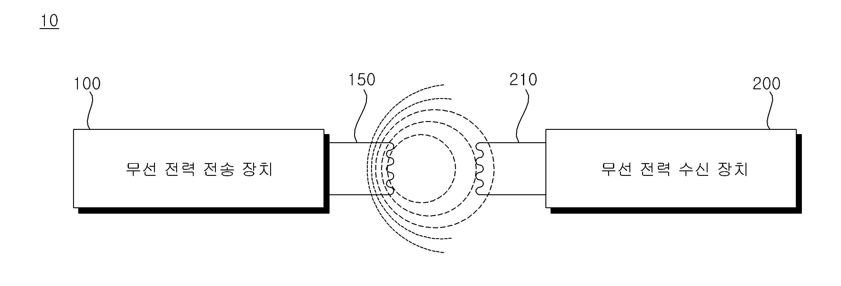
도 1을 참조하면, 무선 전력 시스템(10)은, 무선으로 전력을 전송하는 무선 전력 전송 장치(100) 및 전송된 전력을 수신하는 무선 전력 수신 장치(200)를 포함할 수 있다.Referring to FIG. 1, a wireless power system (10) may include a wireless power transmission device (100) that wirelessly transmits power and a wireless power reception device (200) that receives the transmitted power.
무선 전력 전송 장치(100)는, 코일(150)에 흐르는 전류에 의한 자기장의 변화에 따라, 무선 전력 수신 장치(200)에 구비된 코일(210)에 전류가 유도되는 자기 유도 현상을 이용하여, 무선 전력 수신 장치(200)에 무선으로 전력을 전달할 수 있다. The wireless power transmission device (100) can wirelessly transmit power to the wireless power reception device (200) by utilizing the magnetic induction phenomenon in which a current is induced in the coil (210) provided in the wireless power reception device (200) according to a change in the magnetic field caused by the current flowing in the coil (150).
이때, 무선 전력 전송 장치(100) 및 무선 전력 수신 장치(200)는, WPC(Wireless Power Consortium) 또는 PMA(Power Matters Alliance)에서 정의된 전자기 유도 방식의 무선 전력 공급 방식을 이용할 수 있다. At this time, the wireless power transmission device (100) and the wireless power reception device (200) can use a wireless power supply method using an electromagnetic induction method defined by WPC (Wireless Power Consortium) or PMA (Power Matters Alliance).
또는, 무선 전력 전송 장치(100) 및 무선 전력 수신 장치(200)는, A4WP(Alliance for Wireless Power)에서 정의된 자기공명 방식의 무선 전력 공급 방식을 이용할 수 있다.Alternatively, the wireless power transmission device (100) and the wireless power reception device (200) may use a wireless power supply method using the magnetic resonance method defined by the Alliance for Wireless Power (A4WP).
이하, 무선 전력 전송 장치(100)에 구비된 코일(150)과, 무선 전력 수신 장치(200)에 구비된 코일(210)의 구분을 위해, 무선 전력 전송 장치(100)에 구비된 코일(150)을 송신 코일로 명명할 수 있고, 무선 전력 수신 장치(200)에 구비된 코일(210)을 수신 코일로 명명할 수 있다.Hereinafter, in order to distinguish between the coil (150) equipped in the wireless power transmission device (100) and the coil (210) equipped in the wireless power reception device (200), the coil (150) equipped in the wireless power transmission device (100) may be referred to as a transmitting coil, and the coil (210) equipped in the wireless power reception device (200) may be referred to as a receiving coil.
일 실시예에 따라, 하나의 무선 전력 전송 장치(100)는, 복수의 무선 전력 수신 장치(200)에 전력을 전송할 수 있다. 이때, 무선 전력 전송 장치(100)는, 시분할 방식에 따라 복수의 무선 전력 수신 장치(200)에 전력을 전송할 수 있으나, 본 발명이 이에 한정되는 것은 아니며, 복수의 무선 전력 수신 장치(200) 각각에 할당된 상이한 주파수 대역을 이용하여 복수의 무선 전력 수신 장치(200)에 전력을 전송할 수도 있다. According to one embodiment, a single wireless power transmission device (100) may transmit power to a plurality of wireless power reception devices (200). At this time, the wireless power transmission device (100) may transmit power to a plurality of wireless power reception devices (200) according to a time division method, but the present invention is not limited thereto, and power may be transmitted to a plurality of wireless power reception devices (200) using different frequency bands allocated to each of the plurality of wireless power reception devices (200).
한편, 하나의 무선 전력 전송 장치(100)로부터 전력을 수신할 수 있는 무선 전력 수신 장치(200)의 개수는, 복수의 무선 전력 수신 장치(200) 각각의 요구 전력량, 무선 전력 전송 장치(100)의 가용 전력량 등을 고려하여 적응적으로 결정될 수 있다.Meanwhile, the number of wireless power receiving devices (200) that can receive power from one wireless power transmitting device (100) can be adaptively determined by considering the required power amount of each of the plurality of wireless power receiving devices (200), the available power amount of the wireless power transmitting device (100), etc.
무선 전력 수신 장치(200)는, 무선 전력 전송 장치(100)로부터 전송된 전력을 수신할 수 있다. 예를 들면, 무선 전력 수신 장치(200)는, 착즙기(citrus press), 핸드블렌더(handblender), 블렌더(blender), 쥬서기(juicer), 반죽기(kneader), 스마트팬(smart pan), 전기주전자(kettle), 밥솥(rice cooker)과 같은 소형 조리 기기일 수 있다.The wireless power receiving device (200) can receive power transmitted from the wireless power transmitting device (100). For example, the wireless power receiving device (200) can be a small cooking appliance such as a citrus press, a hand blender, a blender, a juicer, a kneader, a smart pan, an electric kettle, or a rice cooker.
무선 전력 전송 장치(100) 및 무선 전력 수신 장치(200)는, 상호 간에 통신할 수 있다. 실시예에 따라, 무선 전력 전송 장치(100) 및 무선 전력 수신 장치(200)는, 단방향 통신 또는 반이중 통신하는 것도 가능하다.The wireless power transmission device (100) and the wireless power reception device (200) can communicate with each other. According to an embodiment, the wireless power transmission device (100) and the wireless power reception device (200) can also communicate in one direction or half-duplex.
이 때, 통신 방식은, 무선 전력 전송에 사용되는 동작 주파수와 동일한 주파수 대역을 사용하는 인밴드(in-band) 통신 방식 및/또는 무선 전력 전송에 사용되는 동작 주파수와 상이한 주파수 대역을 사용하는 아웃오브밴드(out-of-band) 통신 방식일 수 있다.At this time, the communication method may be an in-band communication method that uses the same frequency band as the operating frequency used for wireless power transmission and/or an out-of-band communication method that uses a frequency band different from the operating frequency used for wireless power transmission.
한편, 무선 전력 전송 장치(100)와 무선 전력 수신 장치(200)가 상호 간에 송수신하는 데이터는, 장치의 상태에 관한 데이터, 전력 사용량에 관한 데이터, 배터리 충전에 관한 데이터, 전압 및/또는 전류에 관한 데이터, 제어 명령과 관련된 데이터 등을 포함할 수 있다.Meanwhile, data transmitted and received between the wireless power transmission device (100) and the wireless power reception device (200) may include data regarding the status of the device, data regarding power usage, data regarding battery charging, data regarding voltage and/or current, data regarding control commands, etc.
한편, 무선 전력 전송 장치(100)에 인접하여, 금속 냄비와 같은 조리도구(미도시)가 위치하는 경우, 송신 코일(150)에 흐르는 전류에 의해 발생된 자기장이 조리도구를 통과할 수 있다. 이때, 조리도구를 통과하는 자기장에 의해, 조리도구에 와류전류가 형성될 수 있고, 조리도구에 와류전류가 흐름에 따라 열이 생성되어 조리도구 자체가 가열되고, 조리도구 내의 내용물도 가열될 수 있다. 이때, 무선 전력 전송 장치(100)에 구비된 송신 코일(150)은, 송신 코일로 명명될 수 있다.Meanwhile, when a cooking utensil (not shown) such as a metal pot is positioned adjacent to the wireless power transmission device (100), a magnetic field generated by a current flowing through the transmission coil (150) may pass through the cooking utensil. At this time, an eddy current may be formed in the cooking utensil by the magnetic field passing through the cooking utensil, and as the eddy current flows through the cooking utensil, heat is generated, so that the cooking utensil itself is heated and the contents inside the cooking utensil may also be heated. At this time, the transmission coil (150) provided in the wireless power transmission device (100) may be referred to as a transmission coil.
또한, 무선 전기 포트와 같이, 전력을 수신하는 수신 코일(210)을 구비하지 않는 소형 조리 기기의 경우에도, 무선 전력 전송 장치(100)의 송신 코일(150)에 흐르는 전류에 의해, 소형 조리 기기의 발열부가 가열될 수 있다.In addition, even in the case of a small cooking appliance that does not have a receiving coil (210) for receiving power, such as a wireless electric pot, the heating part of the small cooking appliance can be heated by the current flowing in the transmitting coil (150) of the wireless power transmission device (100).
즉, 무선 전력 전송 장치(100)는, 무선 전력 수신 장치(200)에 전력을 공급하는 전력 공급 장치로서 동작할 수도 있고, 전자유도 가열방식을 통해 조리도구를 가열시키는 인덕션(Induction) 방식의 조리기기로서 동작할 수도 있다. That is, the wireless power transmission device (100) may operate as a power supply device that supplies power to the wireless power reception device (200), or may operate as an induction-type cooking appliance that heats cooking utensils through an electromagnetic induction heating method.
도 2a 및 2b는, 무선 전력 시스템에 포함되는 구성들의 일 실시예에 대한 설명에 참조되는 도면이다. FIGS. 2A and 2B are drawings for reference in describing one embodiment of components included in a wireless power system.
도 2a는, 무선 전력 전송 장치 및 무선 전력 수신 장치의 상면 사시도이고, 도 2b는, 무선 전력 전송 장치 및 무선 전력 수신 장치의 단면도이다.FIG. 2a is a top perspective view of a wireless power transmission device and a wireless power reception device, and FIG. 2b is a cross-sectional view of the wireless power transmission device and the wireless power reception device.
도 2a 및 2b를 참조하면, 무선 전력 전송 장치(100)에 인접하여 무선 전력 수신 장치(200)가 위치할 수 있고, 무선 전력 수신 장치(200)는 무선 전력 전송 장치(100)로부터 무선으로 전력을 공급받을 수 있다.Referring to FIGS. 2a and 2b, a wireless power receiving device (200) may be positioned adjacent to a wireless power transmitting device (100), and the wireless power receiving device (200) may wirelessly receive power from the wireless power transmitting device (100).
도 2b와 같이, 무선 전력 전송 장치(100)는 상판 글래스(11)를 포함할 수 있고, 무선 전력 수신 장치(200)는 상판 글래스(11) 상에 위치할 수 있다.As shown in FIG. 2b, the wireless power transmission device (100) may include a top glass (11), and the wireless power reception device (200) may be positioned on the top glass (11).
상판 글래스(11)는, 무선 전력 전송 장치(100)의 내부를 보호하고, 무선 전력 수신 장치(200)를 지지하도록 구성될 수 있다. 예를 들면, 상판 글래스(11)는, 여러 광물질을 합성한 세라믹 재질의 강화 유리로 형성될 수 있다. The top glass (11) may be configured to protect the interior of the wireless power transmission device (100) and support the wireless power reception device (200). For example, the top glass (11) may be formed of a reinforced ceramic glass material that synthesizes various minerals.
송신 코일(150)은, 상판 글래스(11)의 하부에 근접하여 배치될 수 있다.The transmitting coil (150) can be placed close to the lower part of the upper glass (11).
무선 전력 전송 장치(100)의 송신 코일(150)에 흐르는 전류에 의해 자기장(20)이 발생할 수 있고, 자기장(20)에 의해 무선 전력 수신 장치(200)의 수신 코일(210)에 전류가 유도될 수 있다.A magnetic field (20) can be generated by a current flowing in a transmitting coil (150) of a wireless power transmission device (100), and a current can be induced in a receiving coil (210) of a wireless power reception device (200) by the magnetic field (20).
무선 전력 전송 장치(100)는, 페라이트(ferrite)(13)를 더 포함할 수 있다. 페라이트(13)는, 투자율(permeability)이 높은 물질로 형성될 수 있다. 페라이트(13)는, 무선 전력 전송 장치(100)의 내부에 배치될 수 있다. The wireless power transmission device (100) may further include ferrite (13). The ferrite (13) may be formed of a material having high permeability. The ferrite (13) may be placed inside the wireless power transmission device (100).
페라이트(13)는, 누설 자기장이 저감되고, 자기장의 방향성이 극대화될 수 있도록, 송신 코일(150)로부터 발생되는 자기장이 방사되지 않고, 페라이트(13)를 통해 흐르도록 유도할 수 있다. Ferrite (13) can induce the magnetic field generated from the transmission coil (150) to flow through the ferrite (13) rather than being radiated, so that the leakage magnetic field can be reduced and the directionality of the magnetic field can be maximized.
무선 전력 수신 장치(200)는, 송신 코일(150)에 흐르는 전류에 의해 발생되는 자기장을 통해, 전력을 수신할 수 있다. The wireless power receiving device (200) can receive power through a magnetic field generated by a current flowing in a transmitting coil (150).
무선 전력 수신 장치(200)는, 수신 코일(210)을 통해 수신된 전력을 이용하여, 무선 전력 수신 장치(200)에 구비된 각 구성에 전원을 공급할 수 있고, 각 구성의 동작을 제어할 수 있다. 예를 들면, 도 2a와 같이 무선 전력 수신 장치(200)가 블렌더인 경우, 수신 코일(210)을 통해 수신된 전력을 이용하여, 부하(250)인 모터 및 칼날을 회전시킬 수 있다.The wireless power receiving device (200) can supply power to each component equipped in the wireless power receiving device (200) using the power received through the receiving coil (210) and control the operation of each component. For example, as shown in Fig. 2a, if the wireless power receiving device (200) is a blender, the motor and blade, which are loads (250), can be rotated using the power received through the receiving coil (210).
도 3a 및 3b는, 도 1의 무선 전력 전송 장치의 내부 회로도이다. FIGS. 3A and 3B are internal circuit diagrams of the wireless power transmission device of FIG. 1.
도 3a 및 3b를 참조하면, 무선 전력 전송 장치(100)는, 외부전원에 연결되는 정류부(120), dc 단 커패시터(130), 인버터(140), 송신 코일(150), 공진부(160) 및/또는 제어부(170)를 포함할 수 있다.Referring to FIGS. 3a and 3b, the wireless power transmission device (100) may include a rectifier (120) connected to an external power source, a dc capacitor (130), an inverter (140), a transmitting coil (150), a resonant unit (160), and/or a control unit (170).
정류부(120)는, 외부전원인 상용 전원(201)으로부터 입력되는 교류 전원을 정류하여 출력할 수 있다. 정류부(120)는, 상용 전원(201)을 통해 공급되는 교류 전압을 직류 전압으로 변환할 수 있다. 이때, 상용 전원(201)은, 단상 교류 전원 또는 3상 교류 전원일 수 있다. 예를 들면, 정류부(120)는, 각각 서로 직렬 연결되는 상암 다이오드 소자 및 하암 다이오드 소자가 한 쌍이 되며, 총 두 쌍 또는 세 쌍의 상, 하암 다이오드 소자가 서로 병렬로 연결되는, 브릿지 다이오드(미도시)를 구비할 수 있다. 한편, 정류부(120)는, 복수의 스위칭 소자를 더 포함할 수도 있다. The rectifier (120) can rectify and output AC power input from a commercial power source (201), which is an external power source. The rectifier (120) can convert AC voltage supplied through the commercial power source (201) into DC voltage. At this time, the commercial power source (201) can be a single-phase AC power source or a three-phase AC power source. For example, the rectifier (120) can be equipped with a bridge diode (not shown) in which an upper-arm diode element and a lower-arm diode element are each connected in series to each other, and a total of two or three pairs of upper and lower-arm diode elements are connected in parallel to each other. Meanwhile, the rectifier (120) may further include a plurality of switching elements.
dc 단 커패시터(130)는, 정류부(120)의 출력단인 dc 단에 접속될 수 있고, 정류부(120)로부터 공급되는 직류 전원을 평활하여 저장할 수 있다.The DC terminal capacitor (130) can be connected to the DC terminal, which is the output terminal of the rectifier (120), and can smooth and store the DC power supplied from the rectifier (120).
도면에서는, dc 단 커패시터(130)로 하나의 소자(Cp1)를 도시하고 있으나, 본 발명이 이에 한정되는 것은 아니며, 복수의 소자가 구비되어, 소자 안정성을 확보할 수도 있다.In the drawing, one element (Cp1) is illustrated as a dc capacitor (130), but the present invention is not limited thereto, and a plurality of elements may be provided to secure element stability.
인버터(140)는, 복수의 스위칭 소자(S1, S2)를 구비하고, 스위칭 소자(S1, S2)의 온/오프 동작에 의해, dc 단 커패시터(130)에 평활되어 저장된 직류 전원을 소정 주파수의 교류 전원으로 변환하여, 송신 코일(150)에 출력할 수 있다. 예를 들면, 스위칭 소자(S1, S2)가 IGBT(insulated gate bipolar transistor)인 경우, 펄스폭 변조 방식(pulse width modulation; PWM)의 신호에 의해 생성된 구동 신호가 제어부(180)로부터 출력되어, 스위칭 소자(S1, S2)의 게이트 단자에 입력될 수 있다. 이때, 구동 신호에 따른 스위칭 소자(S1, S2)의 온/오프 동작에 의해, 인버터(140)에서 고주파의 전류가 출력되어 송신 코일(150)에 흐를 수 있다.The inverter (140) is equipped with a plurality of switching elements (S1, S2), and can convert direct current power, which is smoothed and stored in a dc capacitor (130), into alternating current power of a predetermined frequency by the on/off operation of the switching elements (S1, S2), and output it to the transmitting coil (150). For example, when the switching elements (S1, S2) are insulated gate bipolar transistors (IGBTs), a driving signal generated by a pulse width modulation (PWM) signal can be output from the control unit (180) and input to the gate terminals of the switching elements (S1, S2). At this time, a high-frequency current can be output from the inverter (140) and flow to the transmitting coil (150) by the on/off operation of the switching elements (S1, S2) according to the driving signal.
인버터(140)에서 출력된 고주파의 전류가 송신 코일(150)에 흐르는 경우, 송신 코일(150)에서 자기장이 발생될 수 있고, 송신 코일(150)에서 발생된 자기장에 의해 무선 전력 수신 장치(200)의 수신 코일(210)에 소정 주파수의 전류가 유도될 수 있다.When a high-frequency current output from an inverter (140) flows to a transmitting coil (150), a magnetic field can be generated in the transmitting coil (150), and a current of a predetermined frequency can be induced in a receiving coil (210) of a wireless power receiving device (200) by the magnetic field generated in the transmitting coil (150).
인버터(140)는, 복수의 스너버 커패시터(Cs1, Cs2)를 더 포함할 수 있다. 복수의 스너버 커패시터(Cs1, Cs2)는, 복수의 스위칭 소자(S1, S2)에 각각 연결될 수 있다. The inverter (140) may further include a plurality of snubber capacitors (Cs1, Cs2). The plurality of snubber capacitors (Cs1, Cs2) may be respectively connected to a plurality of switching elements (S1, S2).
스너버 커패시터(Cs1, Cs2)는, 스위칭 소자(S1, S2)에 발생하는 돌입 전류 또는 과도 전압을 제어 및 경감하기 위해 구비되며, 경우에 따라 전자파 노이즈 제거용으로도 사용 가능하다.Snubber capacitors (Cs1, Cs2) are provided to control and reduce inrush current or excessive voltage occurring in switching elements (S1, S2), and in some cases can also be used to remove electromagnetic noise.
스너버 커패시터(Cs1, Cs2)는, 스위칭 소자(S1, S2)의 턴오프 동안 포화 전압 상승 비율을 조절하여, 턴오프 동안의 에너지 손실에 영향을 줄 수 있다. Snubber capacitors (Cs1, Cs2) can affect energy loss during turn-off by controlling the saturation voltage rise rate during turn-off of switching elements (S1, S2).
송신 코일(150)은, 원형(round), 부채꼴(circular sector) 형상이나, 삼각형(triangular), 사각형(rectangular)과 같은 다각형 형상을 포함할 수 있으나, 이에 한정되는 것은 아니다.The transmitting coil (150) may include, but is not limited to, a round or circular sector shape, or a polygonal shape such as a triangular or rectangular shape.
공진부(160)는, 정류부(120)의 출력단인 dc 단과 송신 코일(150) 사이에 접속되는 제1 공진 커패시터(Cr1)를 포함할 수 있다. 예를 들면, 제1 공진 커패시터(Cr1)는, 일단이 송신 코일(150)에 연결되고, 타단이 dc 단 커패시터(130)에 연결될 수 있다. The resonant unit (160) may include a first resonant capacitor (Cr1) connected between the dc terminal, which is the output terminal of the rectifier unit (120), and the transmitting coil (150). For example, the first resonant capacitor (Cr1) may have one end connected to the transmitting coil (150) and the other end connected to the dc terminal capacitor (130).
한편, 무선 전력 전송 장치(100)의 공진 주파수는, 공진부(160)의 커패시턴스(capacitance)에 따라 결정될 수 있다. 예를 들면, 무선 전력 전송 장치(100)의 공진 주파수는, 송신 코일(150)의 인덕턴스(inductance)와 공진부(160)의 커패시턴스에 따라 결정될 수 있다. Meanwhile, the resonant frequency of the wireless power transmission device (100) may be determined according to the capacitance of the resonant portion (160). For example, the resonant frequency of the wireless power transmission device (100) may be determined according to the inductance of the transmitting coil (150) and the capacitance of the resonant portion (160).
또한, 송신 코일(150)의 인덕턴스와 공진부(160)의 커패시턴스에 의해 결정된 공진 주파수를 중심으로 공진 곡선이 형성될 수 있다. 여기서, 공진 곡선은, 주파수에 따른 출력 전력을 나타내는 곡선일 수 있다. In addition, a resonance curve can be formed centered on a resonance frequency determined by the inductance of the transmitting coil (150) and the capacitance of the resonant portion (160). Here, the resonance curve can be a curve representing output power according to frequency.
송신 코일(150)의 인덕턴스와 공진부(160)의 커패시턴스에 따라, 품질 계수(quality factor; Q)가 결정될 수 있고, 품질 계수(Q)에 따라 공진 곡선이 상이하게 형성될 수 있다. Depending on the inductance of the transmitting coil (150) and the capacitance of the resonant portion (160), a quality factor (Q) can be determined, and a resonant curve can be formed differently depending on the quality factor (Q).
따라서, 송신 코일(150)의 인덕턴스와 공진부(160)의 커패시턴스에 따라, 무선 전력 전송 장치(100)는 상이한 출력 특성을 가질 수 있고, 최대 전력을 출력하는 주파수가 공진 주파수로 명명될 수 있다.Therefore, depending on the inductance of the transmitting coil (150) and the capacitance of the resonant portion (160), the wireless power transmission device (100) may have different output characteristics, and the frequency at which the maximum power is output may be named the resonant frequency.
한편, 공진부(160)는, 복수의 제1 공진 커패시터(Cr1)로 구성될 수도 있다. 이때, 복수의 제1 공진 커패시터(Cr1)의 커패시턴스는 동일할 수 있다. 예를 들면, 복수의 제1 공진 커패시터(Cr1) 중 어느 하나는, 일단이 dc 단 커패시터(130)의 일단에 연결되고, 송신 코일(150)에 연결될 수 있고, 복수의 제1 공진 커패시터(Cr1) 중 다른 어느 하나는, 일단이 dc 단 커패시터(130)의 타단에 연결되고, 타단이 송신 코일(150)에 연결될 수 있다.Meanwhile, the resonance unit (160) may be composed of a plurality of first resonance capacitors (Cr1). At this time, the capacitances of the plurality of first resonance capacitors (Cr1) may be the same. For example, one of the plurality of first resonance capacitors (Cr1) may have one end connected to one end of a dc single capacitor (130) and may be connected to the transmitting coil (150), and another of the plurality of first resonance capacitors (Cr1) may have one end connected to the other end of the dc single capacitor (130) and may be connected to the transmitting coil (150).
무선 전력 전송 장치(100)는, 공진 곡선의 공진 주파수를 기준으로, 공진 주파수보다 큰 주파수 대역을 이용할 수 있고, 주파수를 감소시켜 전송되는 전력의 레벨을 높이거나, 주파수를 증가시켜 전송되는 전력의 레벨을 낮출 수 있다. 예를 들면, 무선 전력 전송 장치(100)는, 20kHz 내지 75kHz의 주파수 대역의 주파수 중 어느 하나를, 인버터(140)에 구비된 스위칭 소자(S1, S2)의 스위칭 주파수로 결정할 수 있고, 결정된 스위칭 주파수에 따라 스위칭 소자(S1, S2)가 교대로 턴-온/오프 되도록 제어할 수 있다. 예를 들면, 무선 전력 전송 장치(100)는, 20kHz 내지 75kHz의 주파수 대역의 주파수 중 어느 하나를, 인버터(140)에 구비된 스위칭 소자(S1, S2)의 스위칭 주파수로 결정할 수 있고, 결정된 스위칭 주파수에 따라 스위칭 소자(S1, S2)가 교대로 턴-온/오프 되도록 제어할 수 있다. The wireless power transmission device (100) can use a frequency band larger than the resonance frequency based on the resonance frequency of the resonance curve, and can increase the level of transmitted power by decreasing the frequency, or decrease the level of transmitted power by increasing the frequency. For example, the wireless power transmission device (100) can determine any one of the frequencies in the frequency band of 20 kHz to 75 kHz as the switching frequency of the switching elements (S1, S2) provided in the inverter (140), and control the switching elements (S1, S2) to be alternately turned on/off according to the determined switching frequency. For example, the wireless power transmission device (100) can determine any one of the frequencies in the frequency band of 20 kHz to 75 kHz as the switching frequency of the switching elements (S1, S2) provided in the inverter (140), and control the switching elements (S1, S2) to be alternately turned on/off according to the determined switching frequency.
한편, 무선 전력 전송 장치(100)가 인덕션 방식의 조리기기로서 동작하는 경우, 무선 전력 전송 장치(100)는, 주파수를 감소시켜 화력 단계를 높이거나, 주파수를 증가시켜 화력 단계를 낮출 수도 있다. Meanwhile, when the wireless power transmission device (100) operates as an induction cooking appliance, the wireless power transmission device (100) may increase the heating power level by reducing the frequency, or may decrease the heating power level by increasing the frequency.
한편, 도 3b와 같이, 무선 전력 전송 장치(100)는, 제2 공진부(170)를 더 포함할 수도 있다. Meanwhile, as shown in FIG. 3b, the wireless power transmission device (100) may further include a second resonant unit (170).
제2 공진부(170)는, 전환 스위치(RL) 및 제2 공진 커패시터(Cr2)를 포함할 수 있다. 제2 공진부(170)는, 공진부(160)에 병렬 연결될 수 있다.The second resonant unit (170) may include a switching switch (RL) and a second resonant capacitor (Cr2). The second resonant unit (170) may be connected in parallel to the resonant unit (160).
전환 스위치(RL)는, 제어부(180)의 제어에 따라, 턴-온/오프 될 수 있다. 본 도면에서는, 전환 스위치(RL)가 코일에 흐르는 전류에 기초하여 턴-온/오프 되는 릴레이인 것으로 도시하였으나, 본 발명이 이에 한정되는 것은 아니며, 전환 스위치(RL)는 트랜지스터(transistor) 소자일 수도 있다. 예를 들면, 전환 스위치(RL)는, 양극성 접합 트랜지스터(Bipolar Junction Transistor; BJT) 또는 전계 효과 트랜지스터(Field Effective Transistor; FET)일 수 있다.The changeover switch (RL) can be turned on/off according to the control of the control unit (180). In this drawing, the changeover switch (RL) is illustrated as a relay that is turned on/off based on the current flowing in the coil, but the present invention is not limited thereto, and the changeover switch (RL) may be a transistor element. For example, the changeover switch (RL) may be a bipolar junction transistor (BJT) or a field effect transistor (FET).
제2 공진 커패시터(Cr2)는, 전환 스위치(RL)의 동작에 따라 제1 공진 커패시터(Cr1)에 병렬 연결될 수 있다. 예를 들면, 제2 공진 커패시터(Cr2)는, 전환 스위치(RL)가 턴-온 되는 경우, 제1 공진 커패시터(Cr1)에 병렬 연결될 수 있다. The second resonant capacitor (Cr2) can be connected in parallel to the first resonant capacitor (Cr1) depending on the operation of the changeover switch (RL). For example, the second resonant capacitor (Cr2) can be connected in parallel to the first resonant capacitor (Cr1) when the changeover switch (RL) is turned on.
제2 공진부(170)는, 무선 전력 전송 장치(100)의 공진 주파수를 변경하는 구성일 수 있다. The second resonant portion (170) may be configured to change the resonant frequency of the wireless power transmission device (100).
보다 구체적으로, 전환 스위치(RL)의 동작에 따라 제2 공진 커패시터(Cr2)가 제1 공진 커패시터(Cr1)에 병렬 연결되는 경우, 제1 공진 커패시터(Cr1)와 제2 공진 커패시터(Cr2)의 합성 커패시턴스는 증가하게 되며, 합성 커패시턴스가 증가함에 따라 무선 전력 전송 장치(100)의 공진 주파수는 감소된다. More specifically, when the second resonant capacitor (Cr2) is connected in parallel to the first resonant capacitor (Cr1) according to the operation of the changeover switch (RL), the composite capacitance of the first resonant capacitor (Cr1) and the second resonant capacitor (Cr2) increases, and as the composite capacitance increases, the resonant frequency of the wireless power transmission device (100) decreases.
한편, 전환 스위치(RL)는, 무선 전력 전송 장치(100)의 동작 모드에 따라, 턴-온/오프 될 수 있다. 예를 들면, 무선 전력 전송 장치(100)의 동작 모드가 무선으로 전력을 전송하는 전력 전송 모드인 경우, 무선 전력 전송 장치(100)의 공진 주파수가 감소하도록, 복수의 전환 스위치(RL)는 턴-온 될 수 있다. 예를 들면, 무선 전력 전송 장치(100)의 동작 모드가 인덕션 방식의 조리기기로서 동작하는 유도 가열 모드인 경우, 무선 전력 전송 장치(100)의 공진 주파수가 전력 전송 모드에 비해 증가하도록, 복수의 전환 스위치(RL)는 턴-오프 될 수 있다.Meanwhile, the switching switches (RL) can be turned on/off according to the operation mode of the wireless power transmission device (100). For example, when the operation mode of the wireless power transmission device (100) is a power transmission mode for transmitting power wirelessly, the plurality of switching switches (RL) can be turned on so that the resonance frequency of the wireless power transmission device (100) decreases. For example, when the operation mode of the wireless power transmission device (100) is an induction heating mode for operating as an induction-type cooking appliance, the plurality of switching switches (RL) can be turned off so that the resonance frequency of the wireless power transmission device (100) increases compared to the power transmission mode.
한편, 공진부(160)가 복수의 제1 공진 커패시터(Cr1)를 포함하는 경우, 제2 공진부(170)는 복수의 제2 공진 커패시터(Cr2)와, 복수의 전환 스위치(RL)를 포함할 수 있다. 이때, 복수의 제2 공진 커패시터(Cr2)의 커패시턴스는 동일할 수 있다.Meanwhile, when the resonant unit (160) includes a plurality of first resonant capacitors (Cr1), the second resonant unit (170) may include a plurality of second resonant capacitors (Cr2) and a plurality of switching switches (RL). At this time, the capacitances of the plurality of second resonant capacitors (Cr2) may be the same.
복수의 제2 공진 커패시터(Cr2)는, 복수의 제1 공진 커패시터(Cr1)에 각각 병렬 연결되도록 배치될 수 있다. 이때, 복수의 전환 스위치(RL)는, 턴-온 시, 복수의 제2 공진 커패시터(Cr2)가 복수의 제1 공진 커패시터(Cr1)에 각각 병렬 연결되도록, 복수의 제2 공진 커패시터(Cr2)에 각각 직렬 연결될 수 있다.A plurality of second resonant capacitors (Cr2) may be arranged to be connected in parallel to a plurality of first resonant capacitors (Cr1), respectively. At this time, a plurality of changeover switches (RL) may be connected in series to a plurality of second resonant capacitors (Cr2), respectively, such that when turned on, the plurality of second resonant capacitors (Cr2) are connected in parallel to a plurality of first resonant capacitors (Cr1), respectively.
복수의 전환 스위치(RL)는, 제어부(180)의 제어에 따라, 동시에 턴-온/오프 될 수 있다.Multiple changeover switches (RL) can be turned on/off simultaneously under the control of the control unit (180).
제어부(180)는, 무선 전력 전송 장치(100)에 구비된 각 구성과 연결되어, 각 구성의 전반적인 동작을 제어할 수 있다.The control unit (180) is connected to each component provided in the wireless power transmission device (100) and can control the overall operation of each component.
제어부(180)는, 무선 전력 전송 장치(100)의 동작 모드를 결정할 수 있다. 예를 들면, 제어부(180)는 사용자 입력에 따라 무선 전력 전송 장치(100)의 동작 모드를 결정할 수 있다.The control unit (180) can determine the operation mode of the wireless power transmission device (100). For example, the control unit (180) can determine the operation mode of the wireless power transmission device (100) according to a user input.
이를 위해, 무선 전력 전송 장치(100)는, 입력부(미도시)를 더 포함할 수 있다. 입력부는, 무선 전력 전송 장치(100)의 동작 제어의 조작을 위한 각종 스위치를 포함할 수 있다. 예를 들면, 입력부는, 무선 전력 전송 장치(100)의 온/오프나, 동작 모드의 선택을 위한 조작 스위치 등을 포함할 수 있다.To this end, the wireless power transmission device (100) may further include an input unit (not shown). The input unit may include various switches for operating the operation control of the wireless power transmission device (100). For example, the input unit may include an operating switch for turning the wireless power transmission device (100) on/off or selecting an operation mode.
제어부(180)는, 입력부를 통해 수신되는 사용자 입력에 따라, 무선 전력 전송 장치(100)의 동작 모드를 결정할 수 있다.The control unit (180) can determine the operation mode of the wireless power transmission device (100) according to user input received through the input unit.
제어부(180)는, 송신 코일(150)에 교류 전류가 흐르도록 인버터(140)의 동작을 제어할 수 있다. 이때, 제어부(180)는, 무선 전력 전송 장치(100)의 동작 모드에 따라, 인버터(140)의 동작을 제어할 수 있다. 예를 들면, 제어부(180)는, 무선 전력 전송 장치(100)의 동작 모드가 전력 전송 모드인 경우, 송신 코일(150)을 통해 무선 전력 수신 장치(200)로 전력이 전송되도록, 스위칭 소자(S1, S2)의 온/오프 동작을 제어할 수 있다. 예를 들면, 제어부(180)는, 무선 전력 전송 장치(100)의 동작 모드가 유도 가열 모드인 경우, 조리도구의 가열을 위한 자기장이 발생되도록, 스위칭 소자(S1, S2)의 온/오프 동작을 제어할 수 있다.The control unit (180) can control the operation of the inverter (140) so that an alternating current flows to the transmitting coil (150). At this time, the control unit (180) can control the operation of the inverter (140) according to the operation mode of the wireless power transmission device (100). For example, when the operation mode of the wireless power transmission device (100) is a power transmission mode, the control unit (180) can control the on/off operation of the switching elements (S1, S2) so that power is transmitted to the wireless power reception device (200) through the transmitting coil (150). For example, when the operation mode of the wireless power transmission device (100) is an induction heating mode, the control unit (180) can control the on/off operation of the switching elements (S1, S2) so that a magnetic field for heating the cooking utensil is generated.
제어부(180)는, 펄스폭 변조 방식(pulse width modulation; PWM)의 신호를 발생하는 PWM 발생부(미도시) 및 PWM 신호에 기초하여, 구동 신호(Sic)를 생성하여 인버터(140)의 스위칭 소자(S1, S2)로 출력하는 드라이버(미도시)를 구비할 수 있다.The control unit (180) may be equipped with a PWM generation unit (not shown) that generates a pulse width modulation (PWM) signal and a driver (not shown) that generates a driving signal (Sic) based on the PWM signal and outputs it to the switching elements (S1, S2) of the inverter (140).
제어부(180)는, 송신 코일(150)을 통해 전송되는 전력의 레벨(이하, 출력 레벨)을 산출할 수 있다. The control unit (180) can calculate the level of power transmitted through the transmitting coil (150) (hereinafter, output level).
제어부(180)는, 인버터(140)로부터 출력되어 송신 코일(150)에 흐르는 전류와, 인버터(140)의 출력단에 인가되는 전압에 기초하여, 송신 코일(150)을 통해 전송되는 전력의 출력 레벨을 산출할 수 있다. The control unit (180) can calculate the output level of power transmitted through the transmission coil (150) based on the current output from the inverter (140) and flowing to the transmission coil (150) and the voltage applied to the output terminal of the inverter (140).
이를 위해, 무선 전력 전송 장치(100)는, 인버터(140)로부터 출력되는 전류를 검출하는 전류 검출부(A)와, 인버터(140)의 출력단에 인가되는 전압을 검출하는 전압 검출부(B)를 더 포함할 수 있다.To this end, the wireless power transmission device (100) may further include a current detection unit (A) that detects a current output from an inverter (140) and a voltage detection unit (B) that detects a voltage applied to an output terminal of the inverter (140).
전류 검출부(A)는, 인버터(140)로부터 출력되는 전류의 검출을 위해, 변류기, 션트(shunt) 저항 등을 포함할 수 있고, 검출된 전류(Ir)는 제어부(180)에 입력될 수 있다. 예를 들면, 전류 검출부(A)를 통해 검출된 전류(Ir)에 대한 검출 값은, 펄스 형태의 이산 신호(discrete signal)로서, 제어부(180)에 입력될 수 있다.The current detection unit (A) may include a current transformer, a shunt resistor, etc., to detect the current output from the inverter (140), and the detected current (Ir) may be input to the control unit (180). For example, the detection value for the current (Ir) detected through the current detection unit (A) may be input to the control unit (180) as a discrete signal in the form of a pulse.
전압 검출부(B)는, 인버터(140)의 출력단에 인가되는 전압의 검출을 위해, 변압기(voltage transformer, VT), 저항 소자, OP AMP 등을 구비할 수 있다. 전압 검출부(B)를 통해 검출된 전압(Vs2)에 대한 검출 값은, 제어부(180)에 입력될 수 있다. 예를 들면, 전압 검출부(B)를 통해 검출된 전압(Vs2)에 대한 검출 값은, 펄스 형태의 이산 신호로서, 제어부(180)에 입력될 수 있다.The voltage detection unit (B) may be equipped with a voltage transformer (VT), a resistance element, an OP AMP, etc., to detect the voltage applied to the output terminal of the inverter (140). The detection value for the voltage (Vs2) detected through the voltage detection unit (B) may be input to the control unit (180). For example, the detection value for the voltage (Vs2) detected through the voltage detection unit (B) may be input to the control unit (180) as a discrete signal in the form of a pulse.
무선 전력 전송 장치(100)는, 통신부(미도시)를 더 포함할 수 있다. 통신부는, 무선 전력 수신 장치(200)와의 통신을 위한, 적어도 하나의 통신 모듈을 포함할 수 있다.The wireless power transmission device (100) may further include a communication unit (not shown). The communication unit may include at least one communication module for communication with the wireless power reception device (200).
이하, 무선 전력 전송 장치(100)에 구비된 통신부와, 무선 전력 수신 장치(200)에 구비된 통신부의 구분을 위해, 무선 전력 전송 장치(100)에 구비된 통신부를 송신측 통신부로 명명할 수 있고, 무선 전력 수신 장치(200)에 구비된 통신부를 수신측 통신부로 명명할 수 있다.Hereinafter, in order to distinguish between the communication unit equipped in the wireless power transmission device (100) and the communication unit equipped in the wireless power reception device (200), the communication unit equipped in the wireless power transmission device (100) may be referred to as a transmitting-side communication unit, and the communication unit equipped in the wireless power reception device (200) may be referred to as a receiving-side communication unit.
송신측 통신부는, 제1 및 제2 송신측 통신부(미도시)를 포함할 수 있다.The transmitting side communication unit may include first and second transmitting side communication units (not shown).
제1 송신측 통신부는, 제1 통신 방식으로 통신할 수 있다. 제1 송신측 통신부는, 장치의 상태에 관한 데이터, 전력 사용량에 관한 데이터 등을 포함하는 신호를 무선 전력 수신 장치(200)에 전송할 수 있고, 무선 전력 수신 장치(200)로부터 장치의 상태에 관한 데이터, 전력 사용량에 관한 데이터, 배터리 충전에 관한 데이터 등을 포함하는 신호를 수신할 수 있다.The first transmitting-side communication unit can communicate using the first communication method. The first transmitting-side communication unit can transmit a signal including data regarding the status of the device, data regarding power usage, etc. to the wireless power receiving device (200), and can receive a signal including data regarding the status of the device, data regarding power usage, data regarding battery charging, etc. from the wireless power receiving device (200).
제2 송신측 통신부는, 무선 전력 수신 장치(200)와 제1 통신 방식과는 상이한 제2 통신 방식으로 통신할 수 있다. 제2 송신측 통신부는, 장치의 상태에 관한 데이터, 전력 사용량에 관한 데이터 등을 포함하는 신호를 무선 전력 수신 장치(200)에 전송할 수 있고, 무선 전력 수신 장치(200)로부터 장치의 상태에 관한 데이터, 전력 사용량에 관한 데이터, 배터리 충전에 관한 데이터 등을 포함하는 신호를 수신할 수 있다.The second transmitting-side communication unit can communicate with the wireless power receiving device (200) in a second communication method that is different from the first communication method. The second transmitting-side communication unit can transmit a signal including data regarding the status of the device, data regarding power usage, etc. to the wireless power receiving device (200), and can receive a signal including data regarding the status of the device, data regarding power usage, data regarding battery charging, etc. from the wireless power receiving device (200).
제1 및 제2 송신측 통신부는, 무선 전력 전송 장치(100)에서 송출되는 신호 및 무선 전력 수신 장치(200)로부터 수신되는 신호를 변복조(modulation/demodulation)하기 위한, 변복조부(미도시)를 더 포함할 수 있다.The first and second transmitter-side communication units may further include a modulation/demodulation unit (not shown) for modulating/demodulating a signal transmitted from the wireless power transmission device (100) and a signal received from the wireless power reception device (200).
제1 및 제2 송신측 통신부는, 무선 전력 수신 장치(200)로부터 수신되는 신호를 필터링하는 필터부(미도시)를 더 포함할 수 있다. 이때, 필터부는, 대역통과필터(Band Pass Filter; BPF)를 구비할 수 있다.The first and second transmitter-side communication units may further include a filter unit (not shown) that filters a signal received from the wireless power receiving device (200). At this time, the filter unit may be equipped with a band pass filter (BPF).
한편, 제1 통신 방식은, 인밴드(in-band) 통신 방식일 수 있다. 예를 들면, 제1 송신측 통신부가 인밴드(in-band) 통신 방식으로 통신하는 경우, 제1 송신측 통신부와 송신 코일(150)은 하나의 구성으로 구현될 수 있고, 제1 송신측 통신부는 송신 코일(150)을 통해, 무선 전력 수신 장치(200)와 상호 간에 통신을 수행할 수 있다.Meanwhile, the first communication method may be an in-band communication method. For example, when the first transmission-side communication unit communicates in an in-band communication method, the first transmission-side communication unit and the transmission coil (150) may be implemented as a single configuration, and the first transmission-side communication unit may communicate with the wireless power receiving device (200) through the transmission coil (150).
한편, 제2 통신 방식은, 아웃오브밴드(out-of-band) 통신 방식일 수 있다. 예를 들면, 제2 송신측 통신부가 아웃오브밴드(out-of-band) 통신 방식으로 통신하는 경우, 제2 송신측 통신부와 송신 코일(150)은 서로 구분되는 구성으로 각각 구현될 수 있고, 제2 송신측 통신부는 별도의 통신 모듈을 통해, 무선 전력 수신 장치(200)와 상호 간에 통신을 수행할 수 있다. Meanwhile, the second communication method may be an out-of-band communication method. For example, when the second transmitting-side communication unit communicates in an out-of-band communication method, the second transmitting-side communication unit and the transmitting coil (150) may be implemented with separate configurations, and the second transmitting-side communication unit may communicate with the wireless power receiving device (200) through a separate communication module.
실시예에 따라, 아웃오브밴드(out-of-band) 통신 방식에서 사용되는 통신 모듈은, 블루투스(BlueTooth), 지그비(Zigbee), 무선랜(wireless LAN), NFC(Near Field Communication)과 같은 근거리 통신 방식을 사용할 수 있으나, 본 발명은 이에 한정되지 않는다.According to an embodiment, a communication module used in an out-of-band communication method may use a short-range communication method such as Bluetooth, Zigbee, wireless LAN, or NFC (Near Field Communication), but the present invention is not limited thereto.
한편, 무선 전력 전송 장치(100)에서 사용되는 통신 방식은, 무선 전력 수신 장치(200)에 대한 데이터 등에 기초하여, 제1 및 제2 통신 방식 중 적어도 어느 하나로 변경될 수 있다. Meanwhile, the communication method used in the wireless power transmission device (100) may be changed to at least one of the first and second communication methods based on data for the wireless power reception device (200).
제어부(180)는, 송신측 통신부를 통해, 무선 전력 수신 장치(200)와 상호 간에 데이터를 송수신할 수 있다. The control unit (180) can transmit and receive data with the wireless power receiving device (200) through the transmitting side communication unit.
제어부(180)는, 송신 코일(150)을 통해 전송되는 전력에 대한 지령치(이하, 목표 레벨)에 기초하여, 인버터(140)의 동작을 제어할 수 있다. The control unit (180) can control the operation of the inverter (140) based on a command value (hereinafter, target level) for power transmitted through the transmitting coil (150).
제어부(180)는, 송신 코일(150)을 통해 전송되는 전력의 출력 레벨과, 송신 코일(150)을 통해 전송되는 전력에 대한 목표 레벨을 비교할 수 있고, 비교 결과에 따라 인버터(140)의 동작을 제어할 수 있다.The control unit (180) can compare the output level of power transmitted through the transmission coil (150) with the target level for power transmitted through the transmission coil (150), and control the operation of the inverter (140) according to the comparison result.
예를 들면, 제어부(180)는, 출력 레벨이 목표 레벨보다 낮은 경우, 출력 레벨이 목표 레벨에 도달하도록, 인버터(140)의 동작을 제어할 수 있다. 이때, 제어부(180)는, 출력 레벨이 증가하도록, 인버터(140)의 스위칭 소자(S1, S2)의 스위칭 주파수를 감소시킬 수 있다.For example, the control unit (180) can control the operation of the inverter (140) so that the output level reaches the target level when the output level is lower than the target level. At this time, the control unit (180) can reduce the switching frequency of the switching elements (S1, S2) of the inverter (140) so that the output level increases.
예를 들면, 제어부(180)는, 출력 레벨이 목표 레벨보다 높은 경우, 출력 레벨이 목표 레벨에 도달하도록, 인버터(140)의 동작을 제어할 수 있다. 이때, 제어부(180)는, 출력 레벨이 감소하도록, 인버터(140)의 스위칭 소자(S1, S2)의 스위칭 주파수를 증가시킬 수 있다.For example, the control unit (180) can control the operation of the inverter (140) so that the output level reaches the target level when the output level is higher than the target level. At this time, the control unit (180) can increase the switching frequency of the switching elements (S1, S2) of the inverter (140) so that the output level decreases.
예를 들면, 제어부(180)는, 출력 레벨이 목표 레벨에 상응하는 경우, 출력 레벨이 유지되도록, 인버터(140)의 동작을 제어할 수 있다. 이때, 제어부(180)는, 출력 레벨이 유지되도록, 인버터(140)의 스위칭 소자(S1, S2)의 스위칭 주파수를 유지할 수 있다.For example, the control unit (180) can control the operation of the inverter (140) so that the output level is maintained when the output level corresponds to the target level. At this time, the control unit (180) can maintain the switching frequency of the switching elements (S1, S2) of the inverter (140) so that the output level is maintained.
제어부(180)는, 목표 레벨을 결정할 수 있다. 이때, 제어부(180)는, 무선 전력 수신 장치(200)로부터 수신되는 데이터에 기초하여, 목표 레벨을 결정할 수 있다.The control unit (180) can determine a target level. At this time, the control unit (180) can determine the target level based on data received from the wireless power receiving device (200).
제어부(180)는, 무선 전력 수신 장치(200)로부터 수신되는 전압, 전류 및 전력 중 적어도 하나에 대한 데이터에 기초하여, 목표 레벨을 결정할 수 있다. 예를 들면, 제어부(180)는, 무선 전력 수신 장치(200)의 구성 중 dc 단 커패시터(도 4의 230)에 인가되는 전압(Vo)(이하, dc단 전압)에 대한 데이터에 기초하여, 목표 레벨을 결정할 수 있다.The control unit (180) can determine the target level based on data on at least one of voltage, current, and power received from the wireless power receiving device (200). For example, the control unit (180) can determine the target level based on data on the voltage (Vo) (hereinafter, “dc voltage”) applied to a dc capacitor (230 in FIG. 4) among the components of the wireless power receiving device (200).
제어부(180)는, 무선 전력 수신 장치(200)로부터 수신되는 목표 레벨에 대한 데이터에 기초하여, 목표 레벨을 결정할 수 있다. 예를 들면, 제어부(180)는, 무선 전력 수신 장치(200)로부터 특정 목표 레벨을 지정하는 데이터를 수신하는 경우, 목표 레벨을 특정 목표 레벨로 변경할 수 있다. 예를 들면, 제어부(180)는, 무선 전력 수신 장치(200)로부터 목표 레벨의 증가를 요청하는 데이터가 수신되는 경우, 목표 레벨을, 현재 목표 레벨에서 기 설정된 레벨만큼 증가시킬 수 있고, 무선 전력 수신 장치(200)로부터 목표 레벨의 감소를 요청하는 데이터가 수신되는 경우, 목표 레벨을, 현재 목표 레벨에서 기 설정된 레벨만큼 감소시킬 수 있다. The control unit (180) can determine the target level based on data regarding the target level received from the wireless power receiving device (200). For example, when the control unit (180) receives data specifying a specific target level from the wireless power receiving device (200), the control unit (180) can change the target level to the specific target level. For example, when data requesting an increase in the target level is received from the wireless power receiving device (200), the control unit (180) can increase the target level by a preset level from the current target level, and when data requesting a decrease in the target level is received from the wireless power receiving device (200), the control unit (180) can decrease the target level by a preset level from the current target level.
제어부(180)는, 무선 전력 수신 장치(200)의 동작 상태를 판단할 수 있다. 예를 들면, 제어부(180)는, 무선 전력 수신 장치(200)로부터 수신되는, dc 단 커패시터(도 4의 230)에 인가되는 dc단 전압(Vo)에 대한 데이터에 기초하여, 무선 전력 수신 장치(200)에 과전압이 인가되는지 여부를 판단할 수 있다. 예를 들면, 제어부(180)는, 무선 전력 수신 장치(200)로부터 수신되는 과전압에 대한 데이터에 기초하여, 무선 전력 수신 장치(200)에 과전압이 인가되는지 여부를 판단할 수 있다.The control unit (180) can determine the operating state of the wireless power receiving device (200). For example, the control unit (180) can determine whether overvoltage is applied to the wireless power receiving device (200) based on data on the DC voltage (Vo) applied to the DC capacitor (230 of FIG. 4) received from the wireless power receiving device (200). For example, the control unit (180) can determine whether overvoltage is applied to the wireless power receiving device (200) based on data on the overvoltage received from the wireless power receiving device (200).
제어부(180)는, 무선 전력 수신 장치(200)의 부하 상태를 판단할 수 있다. 예를 들면, 무선 전력 수신 장치(200)의 부하(240)가 전부하 상태에서 동작하는 중, 경부하 또는 무부하 상태로 급격하게 변동되는 경우, 무선 전력 전송 장치(100)와 무선 전력 수신 장치(200) 간의 전력 송수신의 효율이 급격하게 낮아질 수 있다. 또한, 무선 전력 전송 장치(100)의 송신 코일(150)에 흐르는 전류가 작아지는 등의 변화가 발생할 수 있고, 이로 인해 무선 전력 전송 장치(100)에서 전송되는 전력의 출력 레벨이 목표 레벨보다 현저히 낮아질 수 있다.The control unit (180) can determine the load state of the wireless power receiving device (200). For example, when the load (240) of the wireless power receiving device (200) is rapidly changed from a full-load state to a light-load or no-load state while operating, the efficiency of power transmission and reception between the wireless power transmitting device (100) and the wireless power receiving device (200) may rapidly decrease. In addition, a change such as a decrease in the current flowing in the transmitting coil (150) of the wireless power transmitting device (100) may occur, and as a result, the output level of the power transmitted from the wireless power transmitting device (100) may be significantly lower than the target level.
제어부(180)는, 무선 전력 수신 장치(200)로부터 수신되는 부하 상태를 나타내는 데이터에 기초하여, 무선 전력 수신 장치(200)의 부하 상태를 판단할 수 있다.The control unit (180) can determine the load state of the wireless power receiving device (200) based on data indicating the load state received from the wireless power receiving device (200).
제어부(180)는, 출력 레벨 및 목표 레벨에 기초하여, 무선 전력 수신 장치(200)의 부하 상태를 판단할 수 있다. 예를 들면, 제어부(180)는, 목표 레벨이 출력 레벨보다 높고, 목표 레벨과 출력 레벨 간의 차이가 소정 차이 이상인 경우, 무선 전력 수신 장치(200)의 부하 상태를 비정상으로 판단할 수 있다. 예를 들면, 제어부(180)는, 목표 레벨이 기 설정된 제1 기준 레벨 이상이고, 출력 레벨이 제2 기준 레벨 미만인 경우, 무선 전력 수신 장치(200)의 부하 상태를 비정상으로 판단할 수 있다. 이때, 제1 기준 레벨은, 제2 기준 레벨보다 높은 레벨일 수 있다.The control unit (180) can determine the load state of the wireless power receiving device (200) based on the output level and the target level. For example, the control unit (180) can determine the load state of the wireless power receiving device (200) as abnormal if the target level is higher than the output level and the difference between the target level and the output level is equal to or greater than a predetermined difference. For example, the control unit (180) can determine the load state of the wireless power receiving device (200) as abnormal if the target level is equal to or greater than a preset first reference level and the output level is less than a second reference level. In this case, the first reference level may be a level higher than the second reference level.
여기서, 무선 전력 수신 장치(200)의 부하 상태에 대한 판단 기준인 소정 차이 및/또는 제1 및 제2 기준 레벨은, 설정에 따라 다양하게 변경될 수 있다.Here, the predetermined difference and/or the first and second reference levels, which are criteria for judging the load status of the wireless power receiving device (200), may be changed in various ways depending on the setting.
제어부(180)는, 무선 전력 수신 장치(200)의 부하 상태에 따라, 인버터(140)의 동작을 제어할 수 있다. The control unit (180) can control the operation of the inverter (140) according to the load status of the wireless power receiving device (200).
제어부(180)는, 무선 전력 수신 장치(200)의 부하 상태가 정상인 경우, 목표 레벨에 따라 인버터(140)의 동작을 제어할 수 있다. 예를 들면, 제어부(180)는, 무선 전력 수신 장치(200)의 부하 상태가 정상인 경우, 출력 레벨이 목표 레벨에 도달하도록, 인버터(140)의 동작을 제어할 수 있다. The control unit (180) can control the operation of the inverter (140) according to the target level when the load state of the wireless power receiving device (200) is normal. For example, the control unit (180) can control the operation of the inverter (140) so that the output level reaches the target level when the load state of the wireless power receiving device (200) is normal.
제어부(180)는, 무선 전력 수신 장치(200)의 부하 상태가 비정상인 경우, 목표 레벨보다 낮은 소정 전력 레벨에 따라 인버터(140)의 동작을 제어할 수 있다. 예를 들면, 제어부(180)는, 무선 전력 수신 장치(200)의 부하 상태가 비정상인 경우, 출력 레벨이 목표 레벨보다 낮은 소정 전력 레벨에 상응하여 유지되도록 인버터(140)의 동작을 제어할 수 있다. The control unit (180) can control the operation of the inverter (140) according to a predetermined power level lower than the target level when the load state of the wireless power receiving device (200) is abnormal. For example, the control unit (180) can control the operation of the inverter (140) so that the output level is maintained corresponding to a predetermined power level lower than the target level when the load state of the wireless power receiving device (200) is abnormal.
한편, 무선 전력 전송 장치(100)는, 출력부(미도시)를 더 포함할 수 있다. 출력부는, 디스플레이, 발광 다이오드(Light Emitting Diode: LED) 등의 표시 장치 및/또는 스피커, 버저 등의 오디오 장치를 구비할 수 있다.Meanwhile, the wireless power transmission device (100) may further include an output unit (not shown). The output unit may be equipped with a display device such as a display, a light emitting diode (LED), and/or an audio device such as a speaker or buzzer.
제어부(160)는, 출력부를 통해, 무선 전력 전송 장치(100)에 대한 메시지를 출력할 수 있다. 예를 들면, 제어부(160)는, 디스플레이를 통해, 무선 전력 전송 장치(100)의 동작 모드에 대한 메시지를 출력할 수 있다. The control unit (160) can output a message for the wireless power transmission device (100) through the output unit. For example, the control unit (160) can output a message for the operation mode of the wireless power transmission device (100) through the display.
제어부(160)는, 출력부를 통해, 무선 전력 수신 장치(200)에 대한 메시지를 출력할 수 있다. 예를 들면, 무선 전력 수신 장치(200)의 부하 상태가 비정상인 경우, 제어부(160)는, 스피커를 통해, 무선 전력 수신 장치(200)의 부하 상태에 대한 경고 메시지를 출력할 수 있다.The control unit (160) can output a message to the wireless power receiving device (200) through the output unit. For example, if the load status of the wireless power receiving device (200) is abnormal, the control unit (160) can output a warning message about the load status of the wireless power receiving device (200) through the speaker.
도 4는, 도 1의 무선 전력 수신 장치의 내부 회로도이다. Fig. 4 is an internal circuit diagram of the wireless power receiving device of Fig. 1.
도 4를 참조하면, 무선 전력 수신 장치(200)는, 수신 코일(210), 공진부(215), 정류부(220), dc 단 커패시터(230), 및/또는 부하(240)를 포함할 수 있다.Referring to FIG. 4, the wireless power receiving device (200) may include a receiving coil (210), a resonant unit (215), a rectifier unit (220), a dc capacitor (230), and/or a load (240).
수신 코일(210)은, 무선 전력 전송 장치(100)로부터 전송되는 전력을 수신할 수 있다. 예를 들면, 송신 코일(150)에서 발생된 자기장에 의해, 수신 코일(210)에 소정 주파수의 전류가 유도될 수 있고, 유도 전류에 따른 유도 기전력이 무선 전력 수신 장치(200)의 동작을 위한 전력으로서 공급될 수 있다. The receiving coil (210) can receive power transmitted from the wireless power transmission device (100). For example, a current of a predetermined frequency can be induced in the receiving coil (210) by a magnetic field generated from the transmitting coil (150), and an induced electromotive force according to the induced current can be supplied as power for the operation of the wireless power reception device (200).
공진부(215)는, 무선 전력 전송 장치(100)와 공진 회로를 형성하기 위한, 제3 공진 커패시터(Cr3)를 포함할 수 있다. 제3 공진 커패시터(Cr3)는, 수신 코일(210)에 직렬 접속될 수 있다.The resonant portion (215) may include a third resonant capacitor (Cr3) for forming a resonant circuit with the wireless power transmission device (100). The third resonant capacitor (Cr3) may be connected in series to the receiving coil (210).
전력 수신의 공진 주파수는, 공진부(215)의 커패시턴스에 따라 결정될 수 있다. 예를 들면, 전력 수신의 공진 주파수는, 수신 코일(210)의 인덕턴스와 공진부(215)의 커패시턴스에 따라 결정될 수 있다. The resonant frequency of power reception can be determined according to the capacitance of the resonant portion (215). For example, the resonant frequency of power reception can be determined according to the inductance of the receiving coil (210) and the capacitance of the resonant portion (215).
이때, 전력 전송의 공진 주파수와 전력 수신의 공진 주파수는, 동일할 수 있고, 송신 코일(150)에 흐르는 전류의 주파수와 동일한 주파수의 유도 전류가 수신 코일(210)에 흐를 수 있다. At this time, the resonant frequency of power transmission and the resonant frequency of power reception may be the same, and an induced current having the same frequency as the frequency of the current flowing in the transmitting coil (150) may flow in the receiving coil (210).
정류부(220)는, 수신 코일(210)로부터 전달되는 전원을 정류하여 출력할 수 있다. 정류부(220)는, 송신 코일(150)에서 발생된 자기장에 의해 수신 코일(210)에 유도되는 교류 전류를 직류 전류로 변환할 수 있다. The rectifier (220) can rectify and output power transmitted from the receiving coil (210). The rectifier (220) can convert an alternating current induced in the receiving coil (210) by a magnetic field generated in the transmitting coil (150) into a direct current.
정류부(220)는, 브릿지 다이오드(미도시)를 구비할 수 있고, 복수의 스위칭 소자를 더 포함할 수도 있다.The rectifier (220) may be equipped with a bridge diode (not shown) and may further include a plurality of switching elements.
한편, 무선 전력 수신 장치(200)의 정류부(220)에 포함되는 소자는, 무선 전력 전송 장치(100)의 정류부(120)에 포함되는 소자와 상이할 수 있다. 예를 들면, 무선 전력 수신 장치(200)의 정류부(220)에 포함되는 소자는, 수신 코일(210)를 통해 전달되는 높은 주파수(예: 32kHz)의 전원에 대응하는 소자일 수 있고, 무선 전력 전송 장치(100)의 정류부(120)에 포함되는 소자는, 상용 전원(205)을 통해 공급되는 낮은 주파수(예: 60Hz)의 전원에 대응하는 소자일 수 있다.Meanwhile, the element included in the rectifier (220) of the wireless power receiving device (200) may be different from the element included in the rectifier (120) of the wireless power transmitting device (100). For example, the element included in the rectifier (220) of the wireless power receiving device (200) may be an element corresponding to high frequency (e.g., 32 kHz) power transmitted through the receiving coil (210), and the element included in the rectifier (120) of the wireless power transmitting device (100) may be an element corresponding to low frequency (e.g., 60 Hz) power supplied through a commercial power source (205).
dc 단 커패시터(230)는, 정류부(220)의 출력단인 dc 단에 접속될 수 있고, 정류부(220)로부터 공급되는 직류 전원을 평활하여 저장할 수 있다. The DC terminal capacitor (230) can be connected to the DC terminal, which is the output terminal of the rectifier (220), and can smooth and store the DC power supplied from the rectifier (220).
dc 단 커패시터(235)는, 부하(240)의 입력단에 접속될 수 있다. The dc capacitor (235) can be connected to the input terminal of the load (240).
도면에서는, dc 단 커패시터(230)에 대하여, 하나의 소자(Cdc)를 도시하고 있으나, 본 발명이 이에 한정되는 것은 아니며, 복수의 소자가 구비되어, 소자 안정성을 확보할 수도 있다.In the drawing, one element (Cdc) is shown for the dc capacitor (230), but the present invention is not limited thereto, and a plurality of elements may be provided to secure element stability.
부하(240)는, dc 단 커패시터(230)에 저장되는 전원에 기초하여, 동작하는 구성일 수 있다.The load (240) may be configured to operate based on power stored in the dc capacitor (230).
예를 들면, 부하(240)는, dc 단 커패시터(230)에 저장되는 전원에 기초하여 충전되는 배터리일 수 있다. For example, the load (240) may be a battery that is charged based on power stored in the dc capacitor (230).
예를 들면, 부하(240)는, 복수의 스위칭 소자를 구비하고, dc 단 커패시터(230)에 평활되어 저장된 직류 전원을 소정 주파수의 교류 전원으로 변환하여 출력하는 인버터(미도시)를 포함할 수 있다. For example, the load (240) may include an inverter (not shown) that has a plurality of switching elements and converts and outputs direct current power stored in a dc capacitor (230) into alternating current power of a predetermined frequency.
이때, 부하(240)는, 교류 전원에 의해 구동하는 모터(미도시), 자기장을 발생시키는 워킹 코일(미도시) 등을 더 포함할 수 있다. At this time, the load (240) may further include a motor (not shown) driven by an AC power source, a working coil (not shown) that generates a magnetic field, etc.
예를 들면, 무선 전력 수신 장치(200)가 블렌더인 경우, 부하(240)는 모터를 더 포함할 수 있고, 무선 전력 수신 장치(200)는 인버터로부터 출력되는 교류 전원에 의해 회전하는 모터를 이용하여, 모터에 연결된 칼날을 회전시킴으로써, 음식물을 분쇄할 수 있다.For example, if the wireless power receiving device (200) is a blender, the load (240) may further include a motor, and the wireless power receiving device (200) may grind food by rotating a blade connected to the motor using the motor that rotates by AC power output from the inverter.
예를 들면, 무선 전력 수신 장치(200)가 미니 오븐인 경우, 부하(240)는 워킹 코일을 더 포함할 수 있고, 무선 전력 수신 장치(200)는 인버터로부터 출력되는 교류 전원에 의해 자기장을 발생시키는 워킹 코일을 이용하여, 워킹 코일에 인접하게 배치된 조리기구를 가열시킴으로써, 조리기구 내의 음식물을 가열시킬 수 있다. For example, if the wireless power receiving device (200) is a mini oven, the load (240) may further include a working coil, and the wireless power receiving device (200) may heat the cooking utensil placed adjacent to the working coil by using the working coil that generates a magnetic field by AC power output from the inverter, thereby heating the food inside the cooking utensil.
한편, 무선 전력 수신 장치(200)는, 무선 전력 전송 장치(100)와 통신하기 위한, 수신측 통신부(미도시)를 더 포함할 수 있다.Meanwhile, the wireless power receiving device (200) may further include a receiving-side communication unit (not shown) for communicating with the wireless power transmitting device (100).
수신측 통신부는, 제1 수신측 통신부(미도시) 및 제2 수신측 통신부(미도시)를 더 포함할 수 있다. 이때, 제1 수신측 통신부는, 무선 전력 전송 장치(100)에 포함된 제1 송신측 통신부와 동일 또는 유사한 구성일 수 있다. 또한, 제2 수신측 통신부는, 예를 들면, 무선 전력 전송 장치(100)에 포함된 제2 송신측 통신부와 동일 또는 유사한 구성일 수 있다.The receiving side communication unit may further include a first receiving side communication unit (not shown) and a second receiving side communication unit (not shown). At this time, the first receiving side communication unit may have the same or similar configuration as the first transmitting side communication unit included in the wireless power transmission device (100). In addition, the second receiving side communication unit may have the same or similar configuration as the second transmitting side communication unit included in the wireless power transmission device (100), for example.
예를 들면, 무선 전력 수신 장치(200)는, 제1 수신측 통신부를 통해, 인밴드(in-band) 통신 방식으로 무선 전력 전송 장치(100)와 통신을 수행할 수 있다.For example, the wireless power receiving device (200) can communicate with the wireless power transmitting device (100) in an in-band communication manner through the first receiving side communication unit.
예를 들면, 무선 전력 수신 장치(200)는, 제2 수신측 통신부를 통해, 아웃오브밴드(out-of-band) 통신 방식으로 무선 전력 전송 장치(100)와 통신을 수행할 수 있다.For example, the wireless power receiving device (200) can communicate with the wireless power transmitting device (100) in an out-of-band communication manner through the second receiving side communication unit.
무선 전력 수신 장치(200)는, 무선 전력 수신 장치(200)에 구비된 각 구성과 연결되어, 각 구성의 전반적인 동작을 제어하는 제어부(250)를 더 포함할 수 있다. 무선 전력 전송 장치(100)에 포함된 제어부(180)와의 구분을 위해, 제어부(250)를 수신측 제어부로 명명할 수 있다.The wireless power receiving device (200) may further include a control unit (250) that is connected to each component provided in the wireless power receiving device (200) and controls the overall operation of each component. In order to distinguish it from the control unit (180) included in the wireless power transmission device (100), the control unit (250) may be named a receiving-side control unit.
수신측 제어부(250)는, 부하(240)의 동작을 제어할 수 있다. 예를 들면, 부하(240)가 인버터 및 모터를 포함하는 경우, 수신측 제어부(250)는, 부하(240)의 인버터에 포함된 복수의 스위칭 소자(미도시)의 스위칭 동작을 제어하는 제어 신호(Sc)를 출력하여, 모터의 회전을 제어할 수 있다.The receiving control unit (250) can control the operation of the load (240). For example, when the load (240) includes an inverter and a motor, the receiving control unit (250) can control the rotation of the motor by outputting a control signal (Sc) that controls the switching operation of a plurality of switching elements (not shown) included in the inverter of the load (240).
수신측 제어부(250)는, 수신측 통신부를 통해 무선 전력 전송 장치(100)와 상호 간에 데이터를 송수신할 수 있다. The receiving side control unit (250) can transmit and receive data with the wireless power transmission device (100) through the receiving side communication unit.
예를 들면, 수신측 제어부(250)는, 수신측 통신부를 통해, 무선 전력 수신 장치(200)의 상태에 관한 데이터, 전력 사용량에 관한 데이터, 배터리 충전에 관한 데이터 등을, 무선 전력 전송 장치(100)와 상호 간에 송수신할 수 있다. For example, the receiving control unit (250) can transmit and receive data regarding the status of the wireless power receiving device (200), data regarding power usage, data regarding battery charging, etc., to and from the wireless power transmitting device (100) through the receiving communication unit.
무선 전력 수신 장치(200)는, 수신 코일(210)에 흐르는 전류를 검출하는 전류 검출부(C), 정류부(220)의 입력단에 인가되는 전압을 검출하는 제1 전압 검출부(D), 및/또는 dc 단 커패시터(230)에 인가되는 전압을 검출하는 제2 전압 검출부(E)를 더 포함할 수 있다.The wireless power receiving device (200) may further include a current detection unit (C) that detects a current flowing in a receiving coil (210), a first voltage detection unit (D) that detects a voltage applied to an input terminal of a rectifier (220), and/or a second voltage detection unit (E) that detects a voltage applied to a dc capacitor (230).
전류 검출부(C)는, 수신 코일(210)에 흐르는 전류의 검출을 위해, 변류기, 션트 저항 등을 포함할 수 있고, 검출된 전류(Iin)는 수신측 제어부(250)에 입력될 수 있다. 예를 들면, 전류 검출부(C)를 통해 검출된 전류(Iin)에 대한 검출 값은, 펄스 형태의 이산 신호로서, 수신측 제어부(250)에 입력될 수 있다.The current detection unit (C) may include a current transformer, a shunt resistor, etc., to detect the current flowing in the receiving coil (210), and the detected current (Iin) may be input to the receiving control unit (250). For example, the detection value for the current (Iin) detected through the current detection unit (C) may be input to the receiving control unit (250) as a discrete signal in the form of a pulse.
제1 전압 검출부(D)는, 정류부(220)의 입력단에 인가되는 전압의 검출을 위해, 변압기, 저항 소자, OP AMP 등을 구비할 수 있다. 제1 전압 검출부(D)를 통해 검출된 전압(Vin)에 대한 검출 값은, 수신측 제어부(250)에 입력될 수 있다. 예를 들면, 제1 전압 검출부(D)를 통해 검출된 전압(Vin)에 대한 검출 값은, 펄스 형태의 이산 신호로서, 수신측 제어부(250)에 입력될 수 있다.The first voltage detection unit (D) may be equipped with a transformer, a resistance element, an OP AMP, etc., to detect the voltage applied to the input terminal of the rectifier (220). The detection value for the voltage (Vin) detected through the first voltage detection unit (D) may be input to the receiving side control unit (250). For example, the detection value for the voltage (Vin) detected through the first voltage detection unit (D) may be input to the receiving side control unit (250) as a discrete signal in the form of a pulse.
제2 전압 검출부(E)는, dc 단 커패시터(230)에 인가되는 전압의 검출을 위해, 변압기, 저항 소자, OP AMP 등을 구비할 수 있다. 제2 전압 검출부(E)를 통해 검출된 dc단 전압(Vo)에 대한 검출 값은, 수신측 제어부(250)에 입력될 수 있다. 예를 들면, 제2 전압 검출부(E)를 통해 검출된 dc단 전압(Vo)에 대한 검출 값은, 펄스 형태의 이산 신호로서, 수신측 제어부(250)에 입력될 수 있다.The second voltage detection unit (E) may be equipped with a transformer, a resistance element, an OP AMP, etc., to detect the voltage applied to the dc capacitor (230). The detection value for the dc voltage (Vo) detected through the second voltage detection unit (E) may be input to the receiving control unit (250). For example, the detection value for the dc voltage (Vo) detected through the second voltage detection unit (E) may be input to the receiving control unit (250) as a discrete signal in the form of a pulse.
수신측 제어부(250)는, 전류 검출부(C), 제1 전압 검출부(D), 및/또는 제2 전압 검출부(E)를 통해 검출된 검출 값에 기초하여, 무선 전력 수신 장치(200)의 각 구성에 인가되는 전압, 각 구성에 흐르는 전류, 및/또는 전력을 산출할 수 있다. 예를 들면, 수신측 제어부(250)는, 제2 전압 검출부(E)를 통해 검출된 검출 값에 기초하여, dc 단 커패시터(230)에 인가되는 전압을 산출할 수 있다. The receiving side control unit (250) can calculate the voltage applied to each component of the wireless power receiving device (200), the current flowing to each component, and/or the power based on the detection value detected through the current detection unit (C), the first voltage detection unit (D), and/or the second voltage detection unit (E). For example, the receiving side control unit (250) can calculate the voltage applied to the dc capacitor (230) based on the detection value detected through the second voltage detection unit (E).
수신측 제어부(250)는, 수신측 통신부를 통해, 무선 전력 수신 장치(200)의 각 구성에 인가되는 전압, 각 구성에 흐르는 전류, 및/또는 전력에 대한 데이터를 무선 전력 전송 장치(100)에 전송할 수 있다. 예를 들면, 수신측 제어부(250)는, 전류 검출부(C) 및 제1 전압 검출부(D)를 통해 검출되는 검출 값에 기초하여, 무선 전력 전송 장치(100)로부터 전송되는 전력을 산출할 수 있다. The receiving side control unit (250) can transmit data on voltage applied to each component of the wireless power receiving device (200), current flowing through each component, and/or power to the wireless power transmission device (100) through the receiving side communication unit. For example, the receiving side control unit (250) can calculate power transmitted from the wireless power transmission device (100) based on a detection value detected through the current detection unit (C) and the first voltage detection unit (D).
수신측 제어부(250)는, 무선 전력 전송 장치(100)로부터 전송되는 전력과, 부하(240)의 동작에 필요한 전력에 기초하여, 목표 레벨에 대한 데이터를 무선 전력 전송 장치(100)로 전송할 수 있다. 예를 들면, 수신측 제어부(250)는, 무선 전력 수신 장치(200)의 동작 모드에 따라, 부하(240)의 동작에 필요한 전력을 결정할 수 있고, 부하(240)의 동작에 필요한 특정 목표 레벨을 지정하는 데이터를 무선 전력 전송 장치(100)로 전송할 수 있다.The receiving control unit (250) can transmit data on a target level to the wireless power transmission device (100) based on the power transmitted from the wireless power transmission device (100) and the power required for the operation of the load (240). For example, the receiving control unit (250) can determine the power required for the operation of the load (240) according to the operation mode of the wireless power reception device (200) and transmit data specifying a specific target level required for the operation of the load (240) to the wireless power transmission device (100).
이때, 무선 전력 수신 장치(200)는, 특정 목표 레벨을 이전 목표 레벨과 일정 수준 미만으로 차이가 나도록 지정하여, 무선 전력 전송 장치(100) 측으로 전달함으로써, 목표 레벨이 순차적으로 증가되도록 하여, 무선 전력 시스템(10)의 안정성을 향상시킬 수 있다. 예를 들면, 수신측 제어부(250)는, 무선 전력 전송 장치(100)로부터 전송되는 전력이 부하(240)의 동작에 필요한 전력보다 낮은 경우, 목표 레벨의 증가를 요청하는 데이터를, 무선 전력 전송 장치(100)로부터 전송되는 전력이 부하(240)의 동작에 필요한 전력보다 높은 경우, 목표 레벨의 감소를 요청하는 데이터를, 수신측 통신부를 통해 무선 전력 전송 장치(100)로 전송할 수 있다. At this time, the wireless power receiving device (200) may transmit a specific target level to the wireless power transmitting device (100) by specifying a difference between a previous target level and a predetermined level, thereby sequentially increasing the target level, thereby improving the stability of the wireless power system (10). For example, the receiving control unit (250) may transmit data requesting an increase in the target level when the power transmitted from the wireless power transmitting device (100) is lower than the power required for the operation of the load (240), or may transmit data requesting a decrease in the target level to the wireless power transmitting device (100) through the receiving communication unit when the power transmitted from the wireless power transmitting device (100) is higher than the power required for the operation of the load (240).
이때, 무선 전력 전송 장치(100)는, 목표 레벨의 증가 또는 감소를 요청하는 데이터가 수신되는 경우, 현재 목표 레벨과 일정 수준 미만으로 차이가 나도록 목표 레벨을 변경하여, 목표 레벨이 순차적으로 증가되도록 함으로써, 무선 전력 시스템(10)의 안정성을 향상시킬 수 있다.At this time, when data requesting an increase or decrease in the target level is received, the wireless power transmission device (100) changes the target level so that the difference is less than a certain level from the current target level, thereby allowing the target level to sequentially increase, thereby improving the stability of the wireless power system (10).
한편, 수신측 제어부(250)는, dc 단 커패시터(230)에 인가되는 전압이 소정 전압 값을 초과하는 경우, 과전압이 인가되는 것으로 판단할 수 있다. 여기서, 과전압 인가의 판단 기준인 소정 전압 값은, 무선 전력 수신 장치(200)에 포함된 구성들의 기준 사항(specification)에 따라 결정될 수 있다. Meanwhile, the receiving control unit (250) can determine that overvoltage is applied when the voltage applied to the dc capacitor (230) exceeds a predetermined voltage value. Here, the predetermined voltage value, which is a judgment criterion for applying overvoltage, can be determined according to the specifications of the components included in the wireless power receiving device (200).
수신측 제어부(250)는, 과전압이 인가되는 것으로 판단된 경우, 수신측 통신부를 통해, 과전압에 대한 데이터를 무선 전력 전송 장치(100)로 전송할 수 있다. 예를 들면, 부하(240)가 전부하 상태에서 동작하는 중, 경부하 또는 무부하 상태로 급격하게 변동되는 경우, 부하(240)에 흐르는 전류가 급격하게 작아질 수 있고, dc 단 커패시터(230)에 소정 전압 값을 초과하는 과전압이 인가될 수 있다.If it is determined that an overvoltage is applied, the receiving control unit (250) can transmit data on the overvoltage to the wireless power transmission device (100) through the receiving communication unit. For example, if the load (240) is operating in a full-load state and then suddenly changes to a light-load or no-load state, the current flowing to the load (240) may suddenly decrease, and an overvoltage exceeding a predetermined voltage value may be applied to the dc capacitor (230).
이때, 수신측 제어부(250)는, dc 단 커패시터(230)에 인가되는 전압에 기초하여, 과전압에 대한 데이터를 무선 전력 전송 장치(100)로 전송할 수 있다.At this time, the receiving control unit (250) can transmit data on overvoltage to the wireless power transmission device (100) based on the voltage applied to the dc capacitor (230).
한편, 무선 전력 수신 장치(200)는, 입력부(미도시)를 더 포함할 수 있다. 입력부는, 무선 전력 수신 장치(200)의 동작 제어의 조작을 위한 각종 스위치를 포함할 수 있다. 예를 들면, 입력부는, 무선 전력 수신 장치(200)의 온/오프나, 동작 모드의 선택을 위한 조작 스위치 등을 포함할 수 있다.Meanwhile, the wireless power receiving device (200) may further include an input unit (not shown). The input unit may include various switches for operating the operation control of the wireless power receiving device (200). For example, the input unit may include an operating switch for turning the wireless power receiving device (200) on/off or selecting an operation mode.
수신측 제어부(250)는, 입력부를 통해 수신되는 사용자 입력에 따라, 무선 전력 수신 장치(200)의 동작 모드를 결정할 수 있고, 무선 전력 수신 장치(200)의 동작 모드에 따라, 부하(240)의 동작에 필요한 전력을 결정할 수 있다.The receiving control unit (250) can determine the operation mode of the wireless power receiving device (200) based on user input received through the input unit, and can determine the power required for the operation of the load (240) based on the operation mode of the wireless power receiving device (200).
도 5는, 본 발명의 일 실시예에 따른, 무선 전력 전송 장치의 전력 전송을 위한 과정에 대한 순서도의 일 예이고, 도 6은, 도 5의 순서도에 따른, 무선 전력 전송 장치 및 무선 전력 수신 장치의 상태에 대한 설명에 참조되는 도면이다.FIG. 5 is an example of a flowchart for a process for power transmission of a wireless power transmission device according to an embodiment of the present invention, and FIG. 6 is a drawing referenced for an explanation of the states of a wireless power transmission device and a wireless power reception device according to the flowchart of FIG. 5.
도 5 및 6을 참조하면, 무선 전력 전송 장치(100)는, S510 동작에서, Idle 모드로 진입할 수 있다. Referring to FIGS. 5 and 6, the wireless power transmission device (100) may enter an Idle mode in operation S510.
여기서, Idle 모드는, 무선 전력 전송 장치(100)의 전원이 온(on)되는 경우, 무선 전력 전송 장치(100)에 포함된 각 구성에 전원이 인가되고, 제어부(180)가 활성화되는 모드를 의미할 수 있다.Here, the Idle mode may mean a mode in which power is supplied to each component included in the wireless power transmission device (100) and the control unit (180) is activated when the power of the wireless power transmission device (100) is turned on.
무선 전력 전송 장치(100)는, S520 동작에서, 무선 전력 전송 장치(100)의 동작 모드가 무선 전력 전송 모드인지 여부를 판단할 수 있다. 예를 들면, 무선 전력 전송 장치(100)는, 무선 전력 전송 장치(100)에 구비된 입력부를 통해 수신되는 사용자 입력에 따라, 무선 전력 전송 장치(100)의 동작 모드를 결정할 수 있다.The wireless power transmission device (100) can determine, in operation S520, whether the operation mode of the wireless power transmission device (100) is a wireless power transmission mode. For example, the wireless power transmission device (100) can determine the operation mode of the wireless power transmission device (100) according to a user input received through an input unit provided in the wireless power transmission device (100).
이때, 무선 전력 전송 장치(100)의 동작 모드가 무선 전력 전송 모드가 아닌 경우, 예를 들면, 유도 가열 모드인 경우, 무선 전력 전송 장치(100)는, 유도 가열 모드에 대응하는 동작을 수행할 수 있다.At this time, if the operation mode of the wireless power transmission device (100) is not the wireless power transmission mode, for example, if it is the induction heating mode, the wireless power transmission device (100) can perform an operation corresponding to the induction heating mode.
한편, 무선 전력 전송 장치(100)는, S530 동작에서, 무선 전력 전송 장치(100)의 동작 모드가 무선 전력 전송 모드인 경우, 송신 코일(150)에 인접하여 대상물이 존재하는지 여부를 감지할 수 있다. 예를 들면, 무선 전력 전송 장치(100)는, 송신 코일(150)에 소정 전류가 흐르도록, 인버터(140)에 포함된 스위칭 소자(S1, S2)가 제1 스위칭 주파수(예: 75kHz)에 따라 스위칭 동작을 수행하도록 제어할 수 있다. Meanwhile, the wireless power transmission device (100) can detect whether an object exists adjacent to the transmission coil (150) when the operation mode of the wireless power transmission device (100) is the wireless power transmission mode in operation S530. For example, the wireless power transmission device (100) can control the switching elements (S1, S2) included in the inverter (140) to perform a switching operation according to a first switching frequency (e.g., 75 kHz) so that a predetermined current flows to the transmission coil (150).
이때, 무선 전력 전송 장치(100)는, 송신 코일(150)에 인접하여 대상물이 존재하는지 여부 및/또는 대상물의 종류를 판단할 수 있다. 예를 들면, 무선 전력 전송 장치(100)는, 송신 코일(150)에 흐르는 전류, 송신 코일(150)에 인가되는 전압 등에 기초하여, 대상물이 존재하지 않는지 여부, 대상물이 송신 코일(150)에 인접하여 대상물이 수신 코일(210)을 포함하는 무선 전력 수신 장치(200)인지, 전력을 수신하는 수신 코일(210)을 구비하지 않는 소형 조리 기기인지, 냄비와 같은 일반적인 조리도구인지, 아니면 이물질인지 여부 등을 판단할 수 있다. 또한, 예를 들면, 무선 전력 전송 장치(100)는, 송신 코일(150)에 대한 대상물의 정렬 상태도 판단할 수 있다.At this time, the wireless power transmission device (100) can determine whether an object exists adjacent to the transmission coil (150) and/or the type of the object. For example, the wireless power transmission device (100) can determine whether an object does not exist, whether the object is a wireless power reception device (200) including a reception coil (210) adjacent to the transmission coil (150), whether it is a small cooking appliance that does not have a reception coil (210) that receives power, whether it is a general cooking utensil such as a pot, or whether it is a foreign substance, based on the current flowing in the transmission coil (150), the voltage applied to the transmission coil (150), etc. In addition, for example, the wireless power transmission device (100) can also determine the alignment state of the object with respect to the transmission coil (150).
한편, 무선 전력 전송 장치(100)는, S540 동작에서, 송신 코일(150)에 인접하여 대상물이 무선 전력 수신 장치(200)인 경우, Stand-by 모드로 진입할 수 있다.Meanwhile, in operation S540, the wireless power transmission device (100) can enter Stand-by mode when the target object adjacent to the transmission coil (150) is a wireless power reception device (200).
여기서, Stand-by 모드는, 송신 코일(150)에 인접하여 이물질(foreign object; FO)이 존재하는지 여부를 판단하기 이전에, 인버터(140)의 스위칭 소자(S1. S2)의 스위칭 동작을 위한 스위칭 주파수를, 대상물 감지를 위한 제1 스위칭 주파수(예: 75kHz)에서 제2 스위칭 주파수(예: 44kHz)로 변경하는 모드를 의미할 수 있다. 예를 들면, 무선 전력 전송 장치(100)는, Stand-by 모드에서, 스위칭 소자(S1. S2)의 스위칭 동작을 위한 스위칭 주파수가, 제1 스위칭 주파수(예: 75kHz)에서 제2 스위칭 주파수(예: 44kHz)로 주파수 스윕(sweep)되도록 제어할 수 있다. Here, the Stand-by mode may mean a mode in which the switching frequency for the switching operation of the switching elements (S1, S2) of the inverter (140) is changed from a first switching frequency (e.g., 75 kHz) for detecting the object to a second switching frequency (e.g., 44 kHz) before determining whether a foreign object (FO) exists adjacent to the transmitting coil (150). For example, the wireless power transmission device (100) may control the switching frequency for the switching operation of the switching elements (S1, S2) in the Stand-by mode to be frequency swept from the first switching frequency (e.g., 75 kHz) to the second switching frequency (e.g., 44 kHz).
이때, 대상물 감지 동작과 이물질 감지 동작 사이에서, Stand-by 모드를 수행하는 이유는, 무선 전력 전송 장치(100)의 dc 링크단의 전압이 충전된 상태에서, 처음부터 제1 스위칭 주파수(예: 75kHz)보다 낮은 제2 스위칭 주파수(예: 44kHz)에 따라 스위칭 소자(S1, S2)가 스위칭 동작하는 경우, 구동 소음이 발생할 수 있기 때문이다.At this time, the reason for performing the stand-by mode between the target detection operation and the foreign substance detection operation is that, when the voltage of the dc link terminal of the wireless power transmission device (100) is charged, if the switching elements (S1, S2) perform the switching operation according to the second switching frequency (e.g., 44 kHz) that is lower than the first switching frequency (e.g., 75 kHz) from the beginning, driving noise may occur.
한편, 무선 전력 전송 장치(100)는, S550 동작에서, 이물질(FO)이 존재하는지 여부를 판단하는 이물질 검출(foreign object detection; FOD) 동작을 수행할 수 있다. 예를 들면, 무선 전력 전송 장치(100)는, 송신 코일(150)에 교류 전류가 흐르도록, 제2 스위칭 주파수(예: 44kHz)에 따라 스위칭 소자(S1, S2)가 스위칭 동작하도록 제어할 수 있다. 이때, 제2 스위칭 주파수(예: 44kHz)는, 무선 전력 수신 장치(200)를 활성화(awake)시킬 수 있는 전력이 송신 코일(150)로부터 전송되는 경우의 스위칭 주파수일 수 있다.Meanwhile, the wireless power transmission device (100) may perform a foreign object detection (FOD) operation to determine whether a foreign object (FO) exists in operation S550. For example, the wireless power transmission device (100) may control the switching elements (S1, S2) to perform a switching operation according to a second switching frequency (e.g., 44 kHz) so that an AC current flows to the transmission coil (150). At this time, the second switching frequency (e.g., 44 kHz) may be a switching frequency when power capable of activating (awake) the wireless power reception device (200) is transmitted from the transmission coil (150).
이때, 무선 전력 수신 장치(200)의 수신 코일(210)에 유도 전류가 흐를 수 있고, 무선 전력 수신 장치(200)의 각 구성에 전원이 공급되어 활성화될 수 있다. 여기서, 무선 전력 수신 장치(200)의 모드를 wakeup 모드로 명명할 수 있고, wakeup 모드 이전 모드를 Sleep 모드로 명명할 수 있다.At this time, an induced current may flow in the receiving coil (210) of the wireless power receiving device (200), and power may be supplied to each component of the wireless power receiving device (200) to be activated. Here, the mode of the wireless power receiving device (200) may be named a wakeup mode, and the mode before the wakeup mode may be named a Sleep mode.
또한, 무선 전력 전송 장치(100)는, 활성화된 무선 전력 수신 장치(200)와 통신 페어링을 수행할 수 있고, 상호 간에 데이터를 송수신할 수 있다. 이때, 무선 전력 전송 장치(100)는, 무선 전력 수신 장치(200)에 유도된 전압에 대한 데이터를, 무선 전력 수신 장치(200)로부터 수신할 수 있고, 수신된 데이터에 기초하여, 이물질(FO)이 존재하는지 여부를 판단할 수 있다. In addition, the wireless power transmission device (100) can perform communication pairing with the activated wireless power reception device (200) and transmit and receive data between them. At this time, the wireless power transmission device (100) can receive data on the voltage induced in the wireless power reception device (200) from the wireless power reception device (200), and based on the received data, determine whether a foreign substance (FO) exists.
무선 전력 전송 장치(100)는, S530 동작에서 대상물이 무선 전력 수신 장치(200)가 아닌 것으로 판단된 경우, 또는 S550 동작에서 이물질(FO)이 존재하는 것으로 판단된 경우, S510 동작으로 분기하여, Idle 모드로 진입할 수 있다.The wireless power transmission device (100) may branch to operation S510 and enter an idle mode if it is determined in operation S530 that the target is not a wireless power reception device (200), or if it is determined in operation S550 that a foreign substance (FO) exists.
이때, 무선 전력 전송 장치(100)는, S530 동작에서 대상물이 무선 전력 수신 장치(200)가 아닌 것으로 판단된 경우, 또는 S550 동작에서 이물질(FO)이 존재하는 것으로 판단된 경우, 무선 전력 전송 장치(100)의 출력부를 통해, 대상물 또는 이물질에 대한 메시지를 출력할 수 있다.At this time, if the wireless power transmission device (100) determines in operation S530 that the target is not the wireless power reception device (200) or if it determines in operation S550 that a foreign substance (FO) exists, the wireless power transmission device (100) can output a message about the target or foreign substance through the output unit of the wireless power transmission device (100).
한편, 무선 전력 전송 장치(100)는, S560 동작에서, 이물질(FO)이 존재하는지 않는 것으로 판단된 경우, Soft start 모드로 진입할 수 있다.Meanwhile, the wireless power transmission device (100) may enter the soft start mode if it is determined that no foreign matter (FO) exists in operation S560.
여기서, Soft start 모드는, 송신 코일(150)을 통해 전송되는 전력의 레벨인 출력 레벨이, 무선 전력 수신 장치(200)의 정상적인 동작을 위한 전력 레벨(예: 목표 레벨)까지 상승되는 모드를 의미할 수 있다. 예를 들면, 무선 전력 전송 장치(100)는, 기 설정된 전력 레벨까지 출력 레벨을 상승시킬 수 있다. 또는, 예를 들면, 무선 전력 전송 장치(100)는, 무선 전력 수신 장치(200)로부터 전력 레벨에 대한 데이터를 수신할 수 있고, 수신된 목표 레벨에 따라 출력 레벨을 상승시킬 수 있다. Here, the soft start mode may mean a mode in which the output level, which is the level of power transmitted through the transmitting coil (150), is increased to a power level (e.g., target level) for normal operation of the wireless power receiving device (200). For example, the wireless power transmitting device (100) may increase the output level to a preset power level. Or, for example, the wireless power transmitting device (100) may receive data on the power level from the wireless power receiving device (200) and increase the output level according to the received target level.
이때, 무선 전력 전송 장치(100)는, 전력 레벨까지 출력 레벨이 증가하도록, 인버터(140)의 스위칭 소자(S1, S2)의 스위칭 주파수를 감소시킬 수 있다.At this time, the wireless power transmission device (100) can reduce the switching frequency of the switching elements (S1, S2) of the inverter (140) so that the output level increases to the power level.
무선 전력 전송 장치(100)는, S570 동작에서, 무선 전력 수신 장치(200)의 정상적인 동작을 위한 전력 레벨까지 출력 레벨이 상승된 경우, 정상 동작 모드로 진입할 수 있다.The wireless power transmission device (100) can enter a normal operation mode when the output level is increased to a power level for normal operation of the wireless power reception device (200) in operation S570.
여기서, 정상 동작 모드는, 무선 전력 전송 장치(100)가 출력 레벨과 목표 레벨을 비교하여, 비교 결과에 따라 출력 레벨을 조절하는 모드를 의미할 수 있다.Here, the normal operation mode may mean a mode in which the wireless power transmission device (100) compares the output level with the target level and adjusts the output level according to the comparison result.
무선 전력 전송 장치(100)는, 정상 동작 모드에서, 목표 레벨의 변화를 모니터링할 수 있다. The wireless power transmission device (100) can monitor changes in the target level in normal operation mode.
무선 전력 전송 장치(100)는, 무선 전력 수신 장치(200)로부터 목표 레벨에 대한 데이터를 수신할 수 있고, 수신된 목표 레벨에 대한 데이터에 기초하여, 목표 레벨의 변화를 모니터링할 수 있다. 예를 들면, 무선 전력 전송 장치(100)는, 무선 전력 수신 장치(200)로부터 부하(240)의 동작에 필요한 특정 목표 레벨을 지정하는 데이터가 수신되는 경우, 현재 목표 레벨과 특정 목표 레벨 간의 차이를 확인하여, 현재 목표 레벨을 유지, 증가 또는 감소시킬 수 있다. 예를 들면, 무선 전력 전송 장치(100)는, 무선 전력 수신 장치(200)로부터 목표 레벨의 증가를 요청하는 데이터, 또는 목표 레벨의 감소를 요청하는 데이터가 수신되는 경우, 수신된 데이터에 따라 현재 목표 레벨을 유지, 증가 또는 감소시킬 수 있다.The wireless power transmission device (100) can receive data on a target level from the wireless power reception device (200), and monitor changes in the target level based on the received data on the target level. For example, when data specifying a specific target level required for the operation of the load (240) is received from the wireless power reception device (200), the wireless power transmission device (100) can check the difference between the current target level and the specific target level, and maintain, increase, or decrease the current target level. For example, when data requesting an increase in the target level or data requesting a decrease in the target level is received from the wireless power reception device (200), the wireless power transmission device (100) can maintain, increase, or decrease the current target level according to the received data.
한편, 무선 전력 전송 장치(100)는, 정상 동작 모드에서, 목표 레벨에 따라 출력 레벨을 조절할 수 있다. 예를 들면, 무선 전력 전송 장치(100)는, 출력 레벨이 목표 레벨보다 낮은 경우, 출력 레벨이 목표 레벨까지 증가하도록, 인버터(140)의 스위칭 소자(S1, S2)의 스위칭 주파수를 감소시킬 수 있다. 예를 들면, 무선 전력 전송 장치(100)는, 출력 레벨이 목표 레벨보다 높은 경우, 출력 레벨이 목표 레벨까지 감소하도록, 인버터(140)의 스위칭 소자(S1, S2)의 스위칭 주파수를 증가시킬 수 있다. 예를 들면, 무선 전력 전송 장치(100)는, 출력 레벨이 목표 레벨에 상응하는 경우, 출력 레벨이 유지되도록, 인버터(140)의 스위칭 소자(S1, S2)의 스위칭 주파수를 유지할 수 있다.Meanwhile, the wireless power transmission device (100) can adjust the output level according to the target level in the normal operation mode. For example, the wireless power transmission device (100) can reduce the switching frequency of the switching elements (S1, S2) of the inverter (140) so that the output level increases to the target level when the output level is lower than the target level. For example, the wireless power transmission device (100) can increase the switching frequency of the switching elements (S1, S2) of the inverter (140) so that the output level decreases to the target level when the output level is higher than the target level. For example, the wireless power transmission device (100) can maintain the switching frequency of the switching elements (S1, S2) of the inverter (140) so that the output level is maintained when the output level corresponds to the target level.
또한, 무선 전력 전송 장치(100)는, 현재 목표 레벨이 변경되는 경우, 변경된 목표 레벨에 따라 출력 레벨을 조절할 수 있다.Additionally, the wireless power transmission device (100) can adjust the output level according to the changed target level when the current target level is changed.
한편, 무선 전력 전송 장치(100)는, 정상 동작 모드에서, 무선 전력 수신 장치(200)의 부하 상태를 판단할 수 있고, 무선 전력 수신 장치(200)의 부하 상태에 따라 인버터(140)의 동작을 제어할 수 있다. 이와 관련하여, 도 7a 및 7b를 참조하여 상세히 설명하도록 한다.Meanwhile, the wireless power transmission device (100) can determine the load status of the wireless power reception device (200) in the normal operation mode and control the operation of the inverter (140) according to the load status of the wireless power reception device (200). In this regard, a detailed description will be given with reference to FIGS. 7a and 7b.
도 7a 및 7b는, 본 발명의 일 실시예에 따른, 무선 전력 전송 장치의 동작방법에 대한 순서도의 일 예이고, 도 8a 내지 10은, 무선 전력 전송 장치의 동작방법에 대한 설명에 참조되는 도면이다.FIGS. 7A and 7B are examples of flowcharts for an operating method of a wireless power transmission device according to one embodiment of the present invention, and FIGS. 8A to 10 are drawings for reference in explaining an operating method of a wireless power transmission device.
도 7a를 참조하면, 무선 전력 전송 장치(100)는, S710 동작에서, 정상 동작 모드에서 동작 중인지 여부를 판단할 수 있다. 예를 들면, 무선 전력 전송 장치(100)는, 출력 레벨이 무선 전력 수신 장치(200)의 정상적인 동작을 위한 전력 레벨까지 상승된 이후, 목표 레벨에 따라 출력 레벨을 조절하는 중인지 여부를 판단할 수 있다.Referring to FIG. 7a, the wireless power transmission device (100) can determine whether it is operating in a normal operation mode in operation S710. For example, the wireless power transmission device (100) can determine whether it is adjusting the output level according to a target level after the output level has been increased to a power level for normal operation of the wireless power reception device (200).
무선 전력 전송 장치(100)는, 정상 동작 모드에서 동작 중이 아닌 경우, 무선 전력 전송 장치(100)가 진입한 모드에 해당하는 동작을 수행할 수 있다.The wireless power transmission device (100) can perform an operation corresponding to the mode into which the wireless power transmission device (100) has entered when it is not operating in a normal operation mode.
한편, 무선 전력 전송 장치(100)는, S720 동작에서, 목표 레벨에 따라, 무선 전력 수신 장치(100)로 전력을 전송할 수 있다. Meanwhile, the wireless power transmission device (100) can transmit power to the wireless power reception device (100) according to the target level in operation S720.
무선 전력 전송 장치(100)는, 무선 전력 수신 장치(200)로부터 부하(240)의 동작에 필요한 특정 목표 레벨을 지정하는 데이터가 수신되는 경우, 현재 목표 레벨과 특정 목표 레벨 간의 차이를 확인하여, 현재 목표 레벨을 유지, 증가 또는 감소시킬 수 있다. 예를 들면, 제어부(180)는, 무선 전력 수신 장치(200)로부터 특정 목표 레벨을 지정하는 데이터를 수신하는 경우, 목표 레벨을 특정 목표 레벨로 변경할 수 있다. When data specifying a specific target level required for the operation of a load (240) is received from a wireless power receiving device (200), the wireless power transmitting device (100) can check the difference between the current target level and the specific target level and maintain, increase, or decrease the current target level. For example, when the control unit (180) receives data specifying a specific target level from the wireless power receiving device (200), the control unit (180) can change the target level to the specific target level.
이때, 무선 전력 전송 장치(100)는, 출력 레벨이 목표 레벨에 도달하도록, 인버터(140)의 스위칭 소자(S1, S2)의 스위칭 주파수를 변경할 수 있다. 예를 들면, 무선 전력 전송 장치(100)는, 출력 레벨이 목표 레벨보다 낮은 경우, 출력 레벨이 목표 레벨까지 증가하도록, 인버터(140)의 스위칭 소자(S1, S2)의 스위칭 주파수를 감소시킬 수 있다. 예를 들면, 무선 전력 전송 장치(100)는, 출력 레벨이 목표 레벨보다 높은 경우, 출력 레벨이 목표 레벨까지 감소하도록, 인버터(140)의 스위칭 소자(S1, S2)의 스위칭 주파수를 증가시킬 수 있다. 예를 들면, 무선 전력 전송 장치(100)는, 출력 레벨이 목표 레벨에 상응하는 경우, 출력 레벨이 유지되도록, 인버터(140)의 스위칭 소자(S1, S2)의 스위칭 주파수를 유지할 수 있다.At this time, the wireless power transmission device (100) can change the switching frequency of the switching elements (S1, S2) of the inverter (140) so that the output level reaches the target level. For example, when the output level is lower than the target level, the wireless power transmission device (100) can decrease the switching frequency of the switching elements (S1, S2) of the inverter (140) so that the output level increases to the target level. For example, when the output level is higher than the target level, the wireless power transmission device (100) can increase the switching frequency of the switching elements (S1, S2) of the inverter (140) so that the output level decreases to the target level. For example, when the output level corresponds to the target level, the wireless power transmission device (100) can maintain the switching frequency of the switching elements (S1, S2) of the inverter (140) so that the output level is maintained.
무선 전력 전송 장치(100)는, S730 동작에서, 송신 코일(150)을 통해 전송되는 전력의 레벨인 출력 레벨을 산출할 수 있다. 예를 들면, 무선 전력 전송 장치(100)는, 인버터(140)로부터 출력되어 송신 코일(150)에 흐르는 전류와, 인버터(140)의 출력단에 인가되는 전압에 기초하여, 출력 레벨을 산출할 수 있다. The wireless power transmission device (100) can calculate an output level, which is a level of power transmitted through the transmission coil (150), in operation S730. For example, the wireless power transmission device (100) can calculate an output level based on a current output from an inverter (140) and flowing to the transmission coil (150) and a voltage applied to an output terminal of the inverter (140).
본 도면에서는, 무선 전력 전송 장치(100)가 S730 동작에서 출력 레벨을 산출하는 것으로 도시하였으나, 본 발명이 이에 한정되는 것은 아니며, 무선 전력 전송 장치(100)가 정상 동작 모드에서 동작 중인 경우, 출력 레벨을 지속적으로 산출하여, 송신 코일(150)을 통해 전송되는 전력을 모니터링할 수 있다.In this drawing, the wireless power transmission device (100) is illustrated as calculating the output level in the S730 operation, but the present invention is not limited thereto, and when the wireless power transmission device (100) is operating in a normal operation mode, the output level can be continuously calculated to monitor the power transmitted through the transmission coil (150).
한편, 정상 동작 모드에서 무선 전력 수신 장치(200)의 부하(240)가 전부하 상태에서 동작하는 중, 경부하 또는 무부하 상태로 급격하게 변동되는 경우, 무선 전력 수신 장치(200)에 포함된 구성들에 과전압이 인가될 수 있다. Meanwhile, when the load (240) of the wireless power receiving device (200) is rapidly changed from a full-load state to a light-load or no-load state while operating in normal operation mode, overvoltage may be applied to components included in the wireless power receiving device (200).
도 8a 및 8b는, 무선 전력 전송 장치(100)가 전력을 전송함에 따라, 무선 전력 수신 장치(200)의 dc 단 커패시터(230)에 인가되는 전압에 대한 그래프이다.FIGS. 8A and 8B are graphs of the voltage applied to the dc capacitor (230) of the wireless power receiving device (200) as the wireless power transmitting device (100) transmits power.
도 8a 및 8b를 참조하면, T1 구간은, 무선 전력 전송 장치(100)가 무선 전력 수신 장치(200)를 활성화시키는 전력을 전송하는 구간이고, T2 구간은, 무선 전력 전송 장치(100)가 무선 전력 수신 장치(200)를 활성화시키는 전력을 전송하는 동안, 무선 전력 수신 장치(200)의 부하(240)가 전부하 상태에서 동작하는 구간이고, T2' 구간은, 무선 전력 전송 장치(100)가 목표 레벨에 따라 전력을 전송하는 동안, 무선 전력 수신 장치(200)의 부하(240)가 전부하 상태에서 동작하는 구간이고, T3 구간은, 무선 전력 수신 장치(200)의 부하(240)가 경부하 또는 무부하 상태로 변경된 구간이다.Referring to FIGS. 8A and 8B, the T1 section is a section in which the wireless power transmission device (100) transmits power to activate the wireless power reception device (200), the T2 section is a section in which the load (240) of the wireless power reception device (200) operates in a full-load state while the wireless power transmission device (100) transmits power to activate the wireless power reception device (200), the T2' section is a section in which the load (240) of the wireless power reception device (200) operates in a full-load state while the wireless power transmission device (100) transmits power according to a target level, and the T3 section is a section in which the load (240) of the wireless power reception device (200) is changed to a light-load or no-load state.
여기서, 과전압 인가의 판단 기준인 소정 전압 값은 400V로 설정되나, 본 발명이 이에 한정되는 것은 아니며, 무선 전력 수신 장치(200)에 포함된 구성들의 기준 사항(specification)에 따라 설정될 수 있다. Here, the predetermined voltage value, which is the judgment criterion for overvoltage application, is set to 400 V, but the present invention is not limited thereto, and may be set according to the specifications of the components included in the wireless power receiving device (200).
도 8a를 참조하면, T1 내지 T3 구간에서, 무선 전력 전송 장치(100)가 무선 전력 수신 장치(200)를 활성화시키는 전력(예: 500W)을 전송하는 동안은, 무선 전력 수신 장치(200)의 부하 상태와 상관없이, 무선 전력 수신 장치(200)의 dc 단 커패시터(230)에 소정 전압 값(예: 400V) 미만의 전압이 인가되는 것을 확인할 수 있다.Referring to FIG. 8a, during the T1 to T3 sections, while the wireless power transmission device (100) transmits power (e.g., 500 W) that activates the wireless power reception device (200), it can be confirmed that a voltage lower than a predetermined voltage value (e.g., 400 V) is applied to the dc capacitor (230) of the wireless power reception device (200), regardless of the load state of the wireless power reception device (200).
보다 구체적으로, 무선 전력 전송 장치(100)가 무선 전력 수신 장치(200)를 활성화시키는 전력을 전송하는 동안, 무선 전력 수신 장치(200)의 부하(240)가 전부하 상태에서 동작하는 T2 구간에서는, 무선 전력 수신 장치(200)의 dc 단 커패시터(230)에 인가되는 전압 값이 172V이며, 피크(peak) 값 역시 269V에 불과하다.More specifically, during the T2 period when the load (240) of the wireless power receiving device (200) operates at full load while the wireless power transmitting device (100) transmits power to activate the wireless power receiving device (200), the voltage value applied to the dc capacitor (230) of the wireless power receiving device (200) is 172 V, and the peak value is also only 269 V.
또한, 무선 전력 전송 장치(100)가 무선 전력 수신 장치(200)를 활성화시키는 전력을 전송하는 동안, 무선 전력 수신 장치(200)의 부하(240)가 경부하 또는 무부하 상태로 변경되는 T3 구간에서도, 무선 전력 수신 장치(200)의 dc 단 커패시터(230)에 인가되는 전압 값은 275V에 불과하다.In addition, even in the T3 section where the load (240) of the wireless power receiving device (200) changes to a light load or no-load state while the wireless power transmitting device (100) transmits power to activate the wireless power receiving device (200), the voltage value applied to the dc capacitor (230) of the wireless power receiving device (200) is only 275 V.
한편, 도 8b를 참조하면, 무선 전력 전송 장치(100)가 목표 레벨(예: 2kW)에 따라 전력을 전송하는 동안, 무선 전력 수신 장치(200)의 부하(240)가 전부하 상태에서 동작하는 T2' 구간에서는, 무선 전력 수신 장치(200)의 dc 단 커패시터(230)에 소정 전압 값(예: 400V) 미만의 전압(예: 212V)이 인가되며, 피크 값 역시 326V에 불과한 것을 확인할 수 있다.Meanwhile, referring to FIG. 8b, during the T2' section where the load (240) of the wireless power receiving device (200) operates in a full-load state while the wireless power transmitting device (100) transmits power according to a target level (e.g., 2 kW), it can be confirmed that a voltage (e.g., 212 V) lower than a predetermined voltage value (e.g., 400 V) is applied to the dc capacitor (230) of the wireless power receiving device (200), and the peak value is also only 326 V.
그러나 무선 전력 전송 장치(100)가 목표 레벨(예: 2kW)에 따라 전력을 전송하는 동안, 무선 전력 수신 장치(200)의 부하(240)가 경부하 또는 무부하 상태로 변경되는 T3 구간에서는, 무선 전력 수신 장치(200)의 dc 단 커패시터(230)에 인가되는 전압이 증가하여, 소정 전압 값(예: 400V)을 초과하는 전압(예: 548V)이 인가되는 것을 확인할 수 있다.However, during the T3 section where the load (240) of the wireless power receiving device (200) changes to a light load or no-load state while the wireless power transmitting device (100) transmits power according to a target level (e.g., 2 kW), it can be confirmed that the voltage applied to the dc capacitor (230) of the wireless power receiving device (200) increases, and a voltage (e.g., 548 V) exceeding a predetermined voltage value (e.g., 400 V) is applied.
이와 같이, 무선 전력 전송 장치(100)가 목표 레벨에 따라 전력을 전송하는 동안, 무선 전력 수신 장치(200)의 부하(240)가 경부하 또는 무부하 상태로 급격하게 변동되는 경우, 무선 전력 수신 장치(200)의 dc 단 커패시터(230)에 소정 전압 값을 초과하는 과전압이 인가될 수 있고, 이로 인해 무선 전력 수신 장치(200)에 포함된 구성들이 손상될 수 있다. In this way, when the load (240) of the wireless power receiving device (200) rapidly changes to a light load or no-load state while the wireless power transmitting device (100) transmits power according to the target level, an overvoltage exceeding a predetermined voltage value may be applied to the dc capacitor (230) of the wireless power receiving device (200), and as a result, components included in the wireless power receiving device (200) may be damaged.
또한, 정상 동작 모드에서 무선 전력 수신 장치(200)의 부하(240)가 전부하 상태에서 동작하는 중, 경부하 또는 무부하 상태로 급격하게 변동되는 경우, 무선 전력 전송 장치(100)와 무선 전력 수신 장치(200) 간의 전력 송수신의 효율이 급격하게 낮아질 수 있고, 무선 전력 전송 장치(100)에서 전송되는 전력의 출력 레벨이 목표 레벨보다 현저히 낮아질 수 있다.In addition, when the load (240) of the wireless power receiving device (200) in the normal operation mode changes rapidly from a full-load state to a light-load or no-load state, the efficiency of power transmission and reception between the wireless power transmitting device (100) and the wireless power receiving device (200) may rapidly decrease, and the output level of power transmitted from the wireless power transmitting device (100) may be significantly lower than the target level.
다시 도 7a를 참조하면, 무선 전력 전송 장치(100)는, S740 동작에서, 출력 레벨 및 목표 레벨에 기초하여, 무선 전력 수신 장치(200)의 부하 상태를 판단할 수 있다. Referring again to FIG. 7a, the wireless power transmission device (100) can determine the load status of the wireless power reception device (200) based on the output level and the target level in operation S740.
도 7b를 참조하면, 무선 전력 전송 장치(100)는, S741 동작에서, 목표 레벨이 기 설정된 제1 기준 레벨 이상이고, 출력 레벨이 제2 기준 레벨 미만인지 여부를 판단할 수 있다.Referring to FIG. 7b, the wireless power transmission device (100) can determine, in operation S741, whether the target level is equal to or higher than a preset first reference level and whether the output level is less than a second reference level.
여기서, 제1 기준 레벨 및 제2 기준 레벨의 설정과 관련하여, 도 9를 참조하여 설명하도록 한다.Here, with regard to the setting of the first reference level and the second reference level, an explanation will be given with reference to Fig. 9.
도 9는, 무선 전력 수신 장치(200)의 dc 단 커패시터(230)에 인가되는 전압에 대한 그래프이다.Figure 9 is a graph of the voltage applied to the dc capacitor (230) of the wireless power receiving device (200).
이때, 도 9는, T2' 구간 및 T3 구간에서의 목표 레벨이, 1kW으로 설정된 경우에 있어서, 무선 전력 수신 장치(200)의 dc 단 커패시터(230)에 인가되는 전압에 대한 그래프이다.At this time, Fig. 9 is a graph of the voltage applied to the dc capacitor (230) of the wireless power receiving device (200) when the target level in the T2' section and the T3 section is set to 1 kW.
도 9를 참조하면, 목표 레벨이 1kW인 경우, 무선 전력 수신 장치(200)의 부하(240)가 전부하 상태에서 동작하는 T2' 구간에서는, 무선 전력 수신 장치(200)의 dc 단 커패시터(230)에 소정 전압 값(예: 400V) 미만의 전압)이 인가되는 것을 확인할 수 있다.Referring to FIG. 9, when the target level is 1 kW, it can be confirmed that a voltage lower than a predetermined voltage value (e.g., 400 V) is applied to the dc capacitor (230) of the wireless power receiving device (200) in the T2' section where the load (240) of the wireless power receiving device (200) operates in a full load state.
한편, 무선 전력 수신 장치(200)의 부하(240)가 경부하 또는 무부하 상태로 변경되는 T3 구간에서, 무선 전력 수신 장치(200)의 dc 단 커패시터(230)에 소정 전압 값(예: 400V)에 근접하는 전압(예: 399V)이 인가되는 것을 확인할 수 있다.Meanwhile, in the T3 section where the load (240) of the wireless power receiving device (200) changes to a light load or no-load state, it can be confirmed that a voltage (e.g., 399 V) close to a predetermined voltage value (e.g., 400 V) is applied to the dc capacitor (230) of the wireless power receiving device (200).
즉, 도 9와 같이, 무선 전력 수신 장치(200)의 부하(240)가 경부하 또는 무부하 상태로 변경되더라도, 무선 전력 전송 장치(100)가 일정 레벨 미만의 목표 레벨에 따라 전력을 전송하는 경우, 무선 전력 수신 장치(200)의 dc 단 커패시터(230)에 과전압이 인가되지 않을 수 있다. That is, as shown in FIG. 9, even if the load (240) of the wireless power receiving device (200) changes to a light load or no-load state, if the wireless power transmitting device (100) transmits power according to a target level below a certain level, overvoltage may not be applied to the dc capacitor (230) of the wireless power receiving device (200).
이에 기초할 때, 무선 전력 수신 장치(200)의 부하 상태에 대한 판단 기준인 제1 기준 레벨은, 무선 전력 수신 장치(200)의 부하(240)가 경부하 또는 무부하 상태로 변경되더라도, 무선 전력 수신 장치(200)의 dc 단 커패시터(230)에 과전압이 인가되지 않는 최대 목표 레벨(예: 1kW)일 수 있다. Based on this, the first reference level, which is a criterion for judging the load state of the wireless power receiving device (200), may be a maximum target level (e.g., 1 kW) at which no overvoltage is applied to the dc capacitor (230) of the wireless power receiving device (200) even if the load (240) of the wireless power receiving device (200) changes to a light load or no-load state.
한편, 무선 전력 수신 장치(200)의 부하 상태에 대한 또 다른 판단 기준인 제2 기준 레벨은, 무선 전력 수신 장치(200)의 각 구성에 전원이 인가될 수 있는 최소 목표 레벨일 수 있다. 예를 들면, 제2 기준 레벨은, 전력 수신 장치(200)를 활성화시키는 전력(예: 500W)에 상응할 수 있다.Meanwhile, the second reference level, which is another judgment criterion for the load state of the wireless power receiving device (200), may be a minimum target level at which power can be supplied to each component of the wireless power receiving device (200). For example, the second reference level may correspond to the power (e.g., 500 W) that activates the power receiving device (200).
또는, 제2 기준 레벨은, 무선 전력 수신 장치(200)의 부하 상태가 경부하 또는 무부하 상태인 경우에 있어서, 무선 전력 전송 장치(100)에서 산출되는 출력 레벨의 최대 레벨일 수 있다.Alternatively, the second reference level may be the maximum level of the output level produced by the wireless power transmission device (100) when the load state of the wireless power reception device (200) is a light load or no-load state.
무선 전력 전송 장치(100)는, S742 동작에서, 목표 레벨이 출력 레벨보다 높고, 목표 레벨과 출력 레벨 간의 차이가 소정 차이(예: 500W) 이상인 경우, 무선 전력 수신 장치(200)의 부하 상태를 비정상으로 판단할 수 있다. The wireless power transmission device (100) can determine the load status of the wireless power reception device (200) as abnormal when, in operation S742, the target level is higher than the output level and the difference between the target level and the output level is greater than or equal to a predetermined difference (e.g., 500 W).
여기서, 무선 전력 수신 장치(200)의 부하 상태에 대한 판단 기준인 소정 차이(예: 500W)는, 무선 전력 수신 장치(200)의 부하(240)가 목표 레벨과 출력 레벨 간에 벌어질 수 있는 최대 차이(예: 200W)보다 큰 전력 값일 수 있다.Here, the predetermined difference (e.g., 500 W), which is a judgment criterion for the load state of the wireless power receiving device (200), may be a power value greater than the maximum difference (e.g., 200 W) that the load (240) of the wireless power receiving device (200) can have between the target level and the output level.
무선 전력 전송 장치(100)는, S743 동작에서, 목표 레벨과 출력 레벨 간의 차이가 소정 차이 미만인 경우, 무선 전력 수신 장치(200)의 부하 상태가 정상인 것으로 판단할 수 있다.The wireless power transmission device (100) can determine that the load state of the wireless power reception device (200) is normal if the difference between the target level and the output level is less than a predetermined difference in operation S743.
한편, 무선 전력 전송 장치(100)는, S744 동작에서, 목표 레벨이 기 설정된 제1 기준 레벨 이상이고, 출력 레벨이 제2 기준 레벨 미만이거나, 목표 레벨과 출력 레벨 간의 차이가 소정 차이 이상인 경우, 무선 전력 수신 장치(200)의 부하 상태가 비정상인 것으로 판단할 수 있다.Meanwhile, the wireless power transmission device (100), in operation S744, may determine that the load state of the wireless power reception device (200) is abnormal if the target level is equal to or higher than a preset first reference level and the output level is lower than a second reference level, or if the difference between the target level and the output level is equal to or higher than a predetermined difference.
한편, 무선 전력 전송 장치(100)는, 무선 전력 수신 장치(200)의 부하 상태에 대한 판단에 있어서, S741 동작 및 S742 동작 중 어느 하나를 생략할 수도 있다.Meanwhile, the wireless power transmission device (100) may omit either operation S741 or operation S742 when determining the load status of the wireless power reception device (200).
다시 도 7a를 참조하면, 무선 전력 전송 장치(100)는, S750 동작에서, 무선 전력 수신 장치(200)의 부하 상태가 정상인 것으로 판단된 경우, 목표 레벨에 따라 인버터(140)의 동작을 제어할 수 있다. 예를 들면, 무선 전력 전송 장치(100)는, 무선 전력 수신 장치(200)의 부하 상태가 정상인 경우, 출력 레벨이 목표 레벨에 도달하도록, 인버터(140)의 동작을 제어할 수 있다.Referring again to FIG. 7a, the wireless power transmission device (100), in operation S750, if the load state of the wireless power reception device (200) is determined to be normal, the wireless power transmission device (100) can control the operation of the inverter (140) according to the target level. For example, if the load state of the wireless power reception device (200) is normal, the wireless power transmission device (100) can control the operation of the inverter (140) so that the output level reaches the target level.
한편, 무선 전력 전송 장치(100)는, S760 동작에서, 무선 전력 수신 장치(200)의 부하 상태가 비정상인 것으로 판단된 경우, 목표 레벨보다 낮은 소정 전력 레벨에 따라 인버터(140)의 동작을 제어할 수 있다. Meanwhile, in operation S760, if the load state of the wireless power receiving device (200) is determined to be abnormal, the wireless power transmission device (100) can control the operation of the inverter (140) according to a predetermined power level lower than the target level.
여기서, 소정 전력 레벨은, 무선 전력 수신 장치(200)의 각 구성에 전원이 인가될 수 있는 최소 목표 레벨 이상, 무선 전력 수신 장치(200)의 dc 단 커패시터(230)에 과전압이 인가되지 않는 최대 목표 레벨 미만일 수 있다. 예를 들면, 소정 전력 레벨은, 전력 수신 장치(200)를 활성화시키는 전력(예: 500W) 이상, 무선 전력 수신 장치(200)의 dc 단 커패시터(230)에 과전압이 인가되지 않는 최대 목표 레벨(예: 1kW) 미만인 레벨(예: 600W)일 수 있다. 예를 들면, 제어부(180)는, 무선 전력 수신 장치(200)의 부하 상태가 비정상인 경우, 출력 레벨이 소정 전력 레벨에 상응하여 유지되도록 인버터(140)의 동작을 제어할 수 있다.Here, the predetermined power level may be a minimum target level or higher at which power can be applied to each component of the wireless power receiving device (200) and less than a maximum target level at which no overvoltage is applied to the dc capacitor (230) of the wireless power receiving device (200). For example, the predetermined power level may be a level (e.g., 600 W) that is higher than the power (e.g., 500 W) that activates the power receiving device (200) and less than the maximum target level (e.g., 1 kW) at which no overvoltage is applied to the dc capacitor (230) of the wireless power receiving device (200). For example, when the load state of the wireless power receiving device (200) is abnormal, the control unit (180) may control the operation of the inverter (140) so that the output level is maintained corresponding to the predetermined power level.
도 10을 참조하면, 무선 전력 수신 장치(200)의 부하(240)가 경부하 또는 무부하 상태로 변경되는 T3 구간에서, 무선 전력 전송 장치(100)는 무선 전력 수신 장치(200)의 부하 상태를 비정상으로 판단하고, 출력 레벨이 소정 전력 레벨(예: 600W)에 상응하도록, 출력 레벨을 변경할 수 있다. Referring to FIG. 10, in the T3 section where the load (240) of the wireless power receiving device (200) changes to a light load or no-load state, the wireless power transmission device (100) determines that the load state of the wireless power receiving device (200) is abnormal and may change the output level so that the output level corresponds to a predetermined power level (e.g., 600 W).
이때, 무선 전력 수신 장치(200)의 부하(240)가 경부하 또는 무부하 상태인 경우에 있어서, 무선 전력 전송 장치(100)의 출력 레벨이 소정 전력 레벨(예: 600W)에 상응하여 유지되는 T3' 구간에서, 무선 전력 수신 장치(200)의 dc 단 커패시터(230)에 소정 전압 값(예: 400V) 미만의 전압(예: 305V)이 인가되는 것을 확인할 수 있다. At this time, when the load (240) of the wireless power receiving device (200) is in a light load or no-load state, it can be confirmed that a voltage (e.g., 305 V) lower than a predetermined voltage value (e.g., 400 V) is applied to the dc capacitor (230) of the wireless power receiving device (200) in the T3' section where the output level of the wireless power transmitting device (100) is maintained corresponding to a predetermined power level (e.g., 600 W).
도 11은, 본 발명의 다른 일 실시예에 따른, 무선 전력 전송 장치의 동작방법에 대한 순서도의 일 예이다. 도 7에서 설명한 내용과 중복되는 내용에 대해서는 상세한 설명을 생략하도록 한다.Fig. 11 is an example of a flow chart for an operating method of a wireless power transmission device according to another embodiment of the present invention. Detailed descriptions of contents overlapping with those described in Fig. 7 will be omitted.
도 11을 참조하면, 무선 전력 전송 장치(100)는, S1110 동작에서, 정상 동작 모드에서 동작 중인지 여부를 판단할 수 있다. Referring to FIG. 11, the wireless power transmission device (100) can determine, in operation S1110, whether it is operating in a normal operation mode.
무선 전력 전송 장치(100)는, 정상 동작 모드에서 동작 중이 아닌 경우, 무선 전력 전송 장치(100)가 진입한 모드에 해당하는 동작을 수행할 수 있다.The wireless power transmission device (100) can perform an operation corresponding to the mode into which the wireless power transmission device (100) has entered when it is not operating in a normal operation mode.
한편, 무선 전력 전송 장치(100)는, S1120 동작에서, 무선 전력 수신 장치(200)로부터 목표 레벨에 대한 데이터를 수신할 수 있다. 예를 들면, 무선 전력 전송 장치(100)는, 무선 전력 수신 장치(200)로부터 특정 목표 레벨을 지정하는 데이터를 수신할 수 있다. 예를 들면, 무선 전력 전송 장치(100)는, 목표 레벨의 증가, 감소 또는 유지를 요청하는 데이터를 수신할 수 있다.Meanwhile, the wireless power transmission device (100) may receive data on a target level from the wireless power reception device (200) in operation S1120. For example, the wireless power transmission device (100) may receive data specifying a specific target level from the wireless power reception device (200). For example, the wireless power transmission device (100) may receive data requesting an increase, decrease, or maintenance of the target level.
무선 전력 전송 장치(100)는, S1130 동작에서, 무선 전력 수신 장치(200)로부터 수신된 목표 레벨에 대한 데이터에 기초하여, 무선 전력 수신 장치(100)로 전력을 전송할 수 있다. The wireless power transmission device (100) can transmit power to the wireless power reception device (100) based on data on a target level received from the wireless power reception device (200) in operation S1130.
무선 전력 전송 장치(100)는, S1140 동작에서, 송신 코일(150)을 통해 전송되는 전력의 레벨인 출력 레벨을 산출할 수 있다. The wireless power transmission device (100) can calculate an output level, which is the level of power transmitted through the transmission coil (150), in operation S1140.
본 도면에서도, 무선 전력 전송 장치(100)가 S1140 동작에서 출력 레벨을 산출하는 것으로 도시하였으나, 본 발명이 이에 한정되는 것은 아니며, 무선 전력 전송 장치(100)가 정상 동작 모드에서 동작 중인 경우, 출력 레벨을 지속적으로 산출하여, 송신 코일(150)을 통해 전송되는 전력을 모니터링할 수 있다.In this drawing, the wireless power transmission device (100) is illustrated as calculating the output level in the S1140 operation, but the present invention is not limited thereto, and when the wireless power transmission device (100) is operating in a normal operation mode, the output level can be continuously calculated to monitor the power transmitted through the transmission coil (150).
무선 전력 전송 장치(100)는, S1150 동작에서, 무선 전력 수신 장치(200)로부터 과전압에 대한 데이터가 수신되는지 여부를 확인할 수 있다. 예를 들면, 무선 전력 수신 장치(200)의 dc 단 커패시터(230)에 소정 전압 값(예: 400V)을 초과하는 과전압이 인가되는 경우, 무선 전력 수신 장치(200)는 무선 전력 전송 장치(100)로 과전압에 대한 데이터를 전송할 수 있다. 이때, 무선 전력 전송 장치(100)는, 무선 전력 수신 장치(200)로부터 과전압에 대한 데이터가 수신되는 경우, 무선 전력 수신 장치(200)의 dc 단 커패시터(230)에 소정 전압 값(예: 400V)을 초과하는 과전압이 인가되는 것으로 판단할 수 있다. 예를 들면, 무선 전력 전송 장치(100)는, 무선 전력 수신 장치(200)로부터 dc 단 커패시터(230)에 인가되는 전압에 대한 데이터를 수신할 수 있다. 이때, 무선 전력 수신 장치(200)의 dc 단 커패시터(230)에 소정 전압 값(예: 400V)을 초과하는 과전압이 인가되는 것으로 판단된 경우, 무선 전력 전송 장치(100)는, 과전압에 대한 데이터가 수신된 것으로 판단할 수 있다.The wireless power transmission device (100) can determine, in operation S1150, whether data on overvoltage is received from the wireless power reception device (200). For example, if an overvoltage exceeding a predetermined voltage value (e.g., 400 V) is applied to the dc capacitor (230) of the wireless power reception device (200), the wireless power reception device (200) can transmit data on the overvoltage to the wireless power transmission device (100). At this time, if data on overvoltage is received from the wireless power reception device (200), the wireless power transmission device (100) can determine that an overvoltage exceeding a predetermined voltage value (e.g., 400 V) is applied to the dc capacitor (230) of the wireless power reception device (200). For example, the wireless power transmission device (100) can receive data on the voltage applied to the DC capacitor (230) from the wireless power reception device (200). At this time, if it is determined that an overvoltage exceeding a predetermined voltage value (e.g., 400 V) is applied to the DC capacitor (230) of the wireless power reception device (200), the wireless power transmission device (100) can determine that data on the overvoltage has been received.
무선 전력 전송 장치(100)는, S1160 동작에서, 무선 전력 수신 장치(200)로부터 과전압에 대한 데이터가 수신되지 않은 경우, 출력 레벨 및 목표 레벨에 기초하여, 무선 전력 수신 장치(200)의 부하 상태를 판단할 수 있다.The wireless power transmission device (100), in operation S1160, if data on overvoltage is not received from the wireless power reception device (200), can determine the load status of the wireless power reception device (200) based on the output level and target level.
무선 전력 전송 장치(100)는, 목표 레벨이 출력 레벨보다 높고, 목표 레벨과 출력 레벨 간의 차이가 소정 차이(예: 500W) 이상인 경우, 무선 전력 수신 장치(200)의 부하 상태를 비정상으로 판단할 수 있다.The wireless power transmission device (100) can determine the load state of the wireless power reception device (200) as abnormal when the target level is higher than the output level and the difference between the target level and the output level is greater than or equal to a predetermined difference (e.g., 500 W).
무선 전력 전송 장치(100)는, 목표 레벨이 기 설정된 제1 기준 레벨 이상(예; 1kW)이고, 출력 레벨이 제2 기준 레벨 미만(예: 500W)인 경우, 무선 전력 수신 장치(200)의 부하 상태를 비정상으로 판단할 수 있다.The wireless power transmission device (100) can determine the load status of the wireless power reception device (200) as abnormal when the target level is equal to or higher than a preset first reference level (e.g., 1 kW) and the output level is less than a second reference level (e.g., 500 W).
무선 전력 전송 장치(100)는, S1170 동작에서, 무선 전력 수신 장치(200)의 부하 상태가 정상인 것으로 판단된 경우, 목표 레벨에 따라 인버터(140)의 동작을 제어할 수 있다.The wireless power transmission device (100) can control the operation of the inverter (140) according to the target level when the load state of the wireless power reception device (200) is determined to be normal in operation S1170.
한편, 무선 전력 전송 장치(100)는, S1180 동작에서, 무선 전력 수신 장치(200)로부터 과전압에 대한 데이터가 수신된 경우, 또는 무선 전력 수신 장치(200)의 부하 상태가 비정상인 것으로 판단된 경우, 목표 레벨보다 낮은 소정 전력 레벨에 따라 인버터(140)의 동작을 제어할 수 있다.Meanwhile, in operation S1180, if data regarding overvoltage is received from the wireless power receiving device (200), or if the load state of the wireless power receiving device (200) is determined to be abnormal, the wireless power transmission device (100) can control the operation of the inverter (140) according to a predetermined power level lower than the target level.
상기와 같이, 본 발명의 다양한 실시예에 따르면, 무선 전력 전송 장치(100)로부터 전송되는 전력의 출력 레벨에 기초하여, 무선 전력 수신 장치(200)의 부하 상태를 판단할 수 있어, 무선 전력 수신 장치(200)의 부하 상태가 경부하 또는 무부하 상태로 급격하게 변동되는 경우에도, 무선 전력 수신 장치(200)의 부하 상태의 변화에 대하여 보다 신속하게 대응할 수 있다.As described above, according to various embodiments of the present invention, the load state of the wireless power receiving device (200) can be determined based on the output level of power transmitted from the wireless power transmitting device (100), so that even when the load state of the wireless power receiving device (200) changes rapidly to a light load or no-load state, the wireless power receiving device (200) can respond more quickly to changes in the load state.
또한, 본 발명의 다양한 실시예에 따르면, 무선 전력 수신 장치로부터 수신되는 전압에 대한 데이터, 과전압에 대한 데이터 등을 이용하여, 무선 전력 수신 장치(200)의 부하 상태를 보다 정확하게 판단할 수 있다.In addition, according to various embodiments of the present invention, the load status of the wireless power receiving device (200) can be more accurately determined using data on voltage, data on overvoltage, etc. received from the wireless power receiving device.
또한, 본 발명의 다양한 실시예에 따르면, 무선 전력 수신 장치(200)의 부하 상태에 따라, 무선 전력 수신 장치(200)로 전송되는 전력의 레벨을 조절함으로써, 무선 전력 수신 장치(200)에 과전압이 인가되는 것을 방지할 수 있고, 과전압 인가에 따른 무선 전력 수신 장치(200)에 구비된 소자들의 손상을 방지할 수 있다.In addition, according to various embodiments of the present invention, by controlling the level of power transmitted to the wireless power receiving device (200) according to the load state of the wireless power receiving device (200), it is possible to prevent overvoltage from being applied to the wireless power receiving device (200) and prevent damage to components provided in the wireless power receiving device (200) due to overvoltage application.
또한, 본 발명의 다양한 실시예에 따르면, 무선 전력 수신 장치(200)의 부하 상태가 비정상인 경우, 무선 전력 수신 장치(200)로부터 과전압에 대한 데이터 등을 수신하기 이전에도, 사용자에게 보다 신속하고 정확하게 경고 메시지를 출력할 수 있어, 사용자의 제품에 대한 신뢰성과 사용 만족도를 향상시킬 수 있다.In addition, according to various embodiments of the present invention, when the load state of the wireless power receiving device (200) is abnormal, a warning message can be output to the user more quickly and accurately even before receiving data on overvoltage, etc. from the wireless power receiving device (200), thereby improving the reliability and user satisfaction of the product.
첨부된 도면은 본 명세서에 개시된 실시예를 쉽게 이해할 수 있도록 하기 위한 것일 뿐, 첨부된 도면에 의해 본 명세서에 개시된 기술적 사상이 제한되지 않으며, 본 발명의 사상 및 기술 범위에 포함되는 모든 변경, 균등물 내지 대체물을 포함하는 것으로 이해되어야 한다.The attached drawings are only intended to facilitate understanding of the embodiments disclosed in this specification, and the technical ideas disclosed in this specification are not limited by the attached drawings, and should be understood to include all modifications, equivalents, or substitutes included in the spirit and technical scope of the present invention.
또한, 이상에서는 본 발명의 바람직한 실시예에 대하여 도시하고 설명하였지만, 본 발명은 상술한 특정의 실시예에 한정되지 아니하며, 청구범위에서 청구하는 본 발명의 요지를 벗어남이 없이 당해 발명이 속하는 기술분야에서 통상의 지식을 가진 자에 의해 다양한 변형실시가 가능한 것은 물론이고, 이러한 변형실시들은 본 발명의 기술적 사상이나 전망으로부터 개별적으로 이해되어서는 안될 것이다.In addition, although the preferred embodiments of the present invention have been illustrated and described above, the present invention is not limited to the specific embodiments described above, and various modifications may be made by those skilled in the art without departing from the gist of the present invention as claimed in the claims. Furthermore, such modifications should not be individually understood from the technical idea or prospect of the present invention.
Claims (20)
무선 전력 수신 장치에 전력을 전송하는 송신 코일;
복수의 스위칭 소자를 구비하고, 상기 복수의 스위칭 소자의 동작을 통해, 소정 주파수의 전류를 상기 송신 코일로 출력하는 인버터; 및
제어부를 포함하고,
상기 제어부는,
상기 송신 코일을 통해 전송되는 전력의 출력 레벨을 산출하고,
상기 송신 코일을 통해 전송되는 전력에 대한 목표 레벨과, 상기 산출된 출력 레벨에 기초하여, 상기 무선 전력 수신 장치의 부하 상태를 판단하고,
상기 판단된 무선 전력 수신 장치의 부하 상태에 따라, 상기 인버터를 제어하고,
상기 목표 레벨이 제1 기준 레벨 이상이고, 상기 출력 레벨이 상기 제1 기준 레벨보다 낮은 제2 기준 레벨 미만인 경우 및 상기 목표 레벨과 상기 출력 레벨 간의 차이가 소정 차이 이상인 경우 중 적어도 하나에 해당하면, 상기 무선 전력 수신 장치의 부하 상태를 비정상으로 판단하는 것을 특징으로 하는 무선 전력 전송 장치.In a wireless power transmission device,
A transmitting coil for transmitting power to a wireless power receiving device;
An inverter having a plurality of switching elements and outputting a current of a predetermined frequency to the transmitting coil through the operation of the plurality of switching elements; and
Including a control unit,
The above control unit,
Calculate the output level of the power transmitted through the above transmitting coil,
Based on the target level for power transmitted through the transmitting coil and the calculated output level, the load status of the wireless power receiving device is determined,
According to the load status of the wireless power receiving device determined above, the inverter is controlled,
A wireless power transmission device characterized in that the load state of the wireless power receiving device is determined to be abnormal when at least one of the following applies: the target level is equal to or higher than a first reference level, the output level is lower than a second reference level that is lower than the first reference level, and the difference between the target level and the output level is equal to or higher than a predetermined difference.
상기 제어부는,
상기 무선 전력 수신 장치의 부하 상태가 정상인 경우, 상기 목표 레벨에 따라 상기 인버터를 제어하고,
상기 무선 전력 수신 장치의 부하 상태가 비정상인 경우, 상기 목표 레벨보다 낮은 소정 전력 레벨에 따라 상기 인버터를 제어하는 것을 특징으로 하는 무선 전력 전송 장치.In the first paragraph,
The above control unit,
When the load status of the wireless power receiving device is normal, the inverter is controlled according to the target level,
A wireless power transmission device characterized in that, when the load state of the wireless power receiving device is abnormal, the inverter is controlled according to a predetermined power level lower than the target level.
상기 제어부는,
상기 무선 전력 수신 장치의 부하 상태가 정상인 경우, 상기 출력 레벨이 상기 목표 레벨에 도달하도록, 상기 인버터를 제어하고,
상기 무선 전력 수신 장치의 부하 상태가 비정상인 경우, 상기 출력 레벨이 상기 소정 전력 레벨에 따라 유지되도록, 상기 인버터를 제어하는 것을 특징으로 하는 무선 전력 전송 장치.In the second paragraph,
The above control unit,
When the load state of the wireless power receiving device is normal, the inverter is controlled so that the output level reaches the target level,
A wireless power transmission device characterized in that, when the load state of the wireless power receiving device is abnormal, the inverter is controlled so that the output level is maintained according to the predetermined power level.
상기 제어부는,
상기 목표 레벨이 상기 제1 기준 레벨 미만이거나, 상기 출력 레벨이 상기 제2 기준 레벨 이상인 경우, 상기 무선 전력 수신 장치의 부하 상태를 정상으로 판단하는 것을 특징으로 하는 무선 전력 전송 장치.In the first paragraph,
The above control unit,
A wireless power transmission device characterized in that the load state of the wireless power receiving device is determined to be normal when the target level is less than the first reference level or the output level is greater than or equal to the second reference level.
상기 제어부는,
상기 차이가 상기 소정 차이 미만인 경우, 상기 무선 전력 수신 장치의 부하 상태를 정상으로 판단하는 것을 특징으로 하는 무선 전력 전송 장치.In the first paragraph,
The above control unit,
A wireless power transmission device characterized in that the load state of the wireless power receiving device is determined to be normal when the above difference is less than the above predetermined difference.
상기 무선 전력 수신 장치와 통신을 수행하는 통신부를 더 포함하고,
상기 제어부는,
상기 통신부를 통해, 상기 무선 전력 수신 장치로부터 상기 목표 레벨에 대한 데이터를 수신하고,
상기 수신된 목표 레벨에 대한 데이터에 기초하여, 상기 목표 레벨을 결정하는 것을 특징으로 하는 무선 전력 전송 장치.In the first paragraph,
Further comprising a communication unit that performs communication with the wireless power receiving device,
The above control unit,
Through the above communication unit, data on the target level is received from the wireless power receiving device,
A wireless power transmission device characterized in that the target level is determined based on the data on the received target level.
상기 무선 전력 수신 장치와 통신을 수행하는 통신부를 더 포함하고,
상기 제어부는,
상기 통신부를 통해, 상기 무선 전력 수신 장치로부터 과전압에 대한 데이터를 수신하고,
상기 과전압에 대한 데이터에 기초하여, 상기 무선 전력 수신 장치의 부하 상태를 판단하는 것을 특징으로 하는 무선 전력 전송 장치.In the first paragraph,
Further comprising a communication unit that performs communication with the wireless power receiving device,
The above control unit,
Through the above communication unit, data on overvoltage is received from the wireless power receiving device,
A wireless power transmission device characterized in that the load state of the wireless power receiving device is determined based on the data on the overvoltage.
상기 제어부는,
상기 무선 전력 수신 장치로부터 상기 과전압에 대한 데이터가 수신되는 경우, 상기 무선 전력 수신 장치의 부하 상태를 비정상으로 판단하고,
상기 무선 전력 수신 장치로부터 상기 과전압에 대한 데이터가 수신되지 않는 경우, 상기 목표 레벨과 상기 출력 레벨에 기초하여, 상기 무선 전력 수신 장치의 부하 상태를 판단하는 것을 특징으로 하는 무선 전력 전송 장치.In Article 7,
The above control unit,
When data on the overvoltage is received from the wireless power receiving device, the load status of the wireless power receiving device is determined to be abnormal,
A wireless power transmission device characterized in that, when data on the overvoltage is not received from the wireless power receiving device, the load state of the wireless power receiving device is determined based on the target level and the output level.
상기 인버터로부터 출력되는 전류를 검출하는 전류 검출부; 및
상기 인버터의 출력단에 인가되는 전압을 검출하는 전압 검출부를 더 포함하고,
상기 제어부는,
상기 전류 검출부를 통해 검출되는 전류 값 및 상기 전압 검출부를 통해 검출되는 전압 값에 기초하여, 상기 출력 레벨을 산출하는 것을 특징으로 하는 무선 전력 전송 장치.In the first paragraph,
A current detection unit that detects the current output from the inverter; and
Further comprising a voltage detection unit for detecting the voltage applied to the output terminal of the inverter,
The above control unit,
A wireless power transmission device characterized in that the output level is calculated based on a current value detected through the current detection unit and a voltage value detected through the voltage detection unit.
출력부를 더 포함하고,
상기 제어부는,
상기 무선 전력 수신 장치의 부하 상태가 비정상인 경우, 상기 출력부를 통해 경고 메시지를 출력하는 것을 특징으로 하는 무선 전력 전송 장치.In the first paragraph,
Including more output sections,
The above control unit,
A wireless power transmission device characterized in that, when the load status of the wireless power receiving device is abnormal, a warning message is output through the output unit.
상기 무선 전력 전송 장치에 포함된 송신 코일을 통해 전송되는 전력의 출력 레벨을 산출하는 동작;
상기 송신 코일을 통해 전송되는 전력에 대한 목표 레벨과, 상기 산출된 출력 레벨에 기초하여, 무선 전력 수신 장치의 부하 상태를 판단하는 동작; 및
상기 판단된 무선 전력 수신 장치의 부하 상태에 따라, 상기 무선 전력 전송 장치에 포함된 인버터를 제어하는 동작을 포함하고,
상기 무선 전력 수신 장치의 부하 상태를 판단하는 동작은,
상기 목표 레벨이 제1 기준 레벨 이상이고, 상기 출력 레벨이 상기 제1 기준 레벨보다 낮은 제2 기준 레벨 미만인 경우 및 상기 목표 레벨과 상기 출력 레벨 간의 차이가 소정 차이 이상인 경우 중 적어도 하나에 해당하면, 상기 무선 전력 수신 장치의 부하 상태를 비정상으로 판단하는 동작을 포함하는 것을 특징으로 하는 무선 전력 전송 장치의 동작방법.In the operating method of a wireless power transmission device,
An operation for calculating an output level of power transmitted through a transmitting coil included in the wireless power transmission device;
An operation of determining a load state of a wireless power receiving device based on a target level for power transmitted through the transmitting coil and the calculated output level; and
Including an operation of controlling an inverter included in the wireless power transmission device according to the load state of the wireless power receiving device determined above,
The operation of determining the load status of the above wireless power receiving device is as follows:
An operating method of a wireless power transmission device, characterized in that it includes an operation of determining a load state of the wireless power receiving device as abnormal when at least one of the following applies: the target level is equal to or higher than a first reference level, the output level is lower than a second reference level that is lower than the first reference level, and the difference between the target level and the output level is equal to or higher than a predetermined difference.
상기 인버터를 제어하는 동작은,
상기 무선 전력 수신 장치의 부하 상태가 정상인 경우, 상기 목표 레벨에 따라 상기 인버터를 제어하는 동작; 및
상기 무선 전력 수신 장치의 부하 상태가 비정상인 경우, 상기 목표 레벨보다 낮은 소정 전력 레벨에 따라 상기 인버터를 제어하는 동작을 포함하는 것을 특징으로 하는 무선 전력 전송 장치의 동작방법.In Article 11,
The operation of controlling the above inverter is as follows:
When the load state of the wireless power receiving device is normal, an operation of controlling the inverter according to the target level; and
An operating method of a wireless power transmission device, characterized in that it includes an operation of controlling the inverter according to a predetermined power level lower than the target level when the load state of the wireless power receiving device is abnormal.
상기 목표 레벨에 따라 상기 인버터를 제어하는 동작은, 상기 출력 레벨이 상기 목표 레벨에 도달하도록, 상기 인버터를 제어하는 동작이고,
상기 소정 전력 레벨에 따라 상기 인버터를 제어하는 동작은, 상기 출력 레벨이 상기 소정 전력 레벨에 따라 유지되도록, 상기 인버터를 제어하는 동작인 것을 특징으로 하는 무선 전력 전송 장치의 동작방법.In Article 12,
The operation of controlling the inverter according to the target level is an operation of controlling the inverter so that the output level reaches the target level.
An operating method of a wireless power transmission device, characterized in that the operation of controlling the inverter according to the above-mentioned predetermined power level is an operation of controlling the inverter so that the output level is maintained according to the above-mentioned predetermined power level.
상기 목표 레벨이 상기 제1 기준 레벨 미만이거나, 상기 출력 레벨이 상기 제2 기준 레벨 이상인 경우, 상기 무선 전력 수신 장치의 부하 상태를 정상으로 판단하는 동작을 포함하는 것을 특징으로 하는 무선 전력 전송 장치의 동작방법.In Article 11,
An operating method of a wireless power transmission device, characterized in that it includes an operation of determining a load state of the wireless power receiving device as normal when the target level is less than the first reference level or the output level is greater than or equal to the second reference level.
상기 무선 전력 수신 장치의 부하 상태를 판단하는 동작은,
상기 차이가 상기 소정 차이 미만인 경우, 상기 무선 전력 수신 장치의 부하 상태를 정상으로 판단하는 동작을 더 포함하는 것을 특징으로 하는 무선 전력 전송 장치의 동작방법.In Article 11,
The operation of determining the load status of the above wireless power receiving device is as follows:
An operating method of a wireless power transmission device, characterized in that it further includes an operation of determining the load state of the wireless power receiving device as normal when the difference is less than the predetermined difference.
상기 무선 전력 전송 장치에 포함된 통신부를 통해, 상기 무선 전력 수신 장치로부터 상기 목표 레벨에 대한 데이터를 수신하는 동작; 및
상기 수신된 목표 레벨에 대한 데이터에 기초하여, 상기 목표 레벨을 결정하는 동작을 더 포함하는 것을 특징으로 하는 무선 전력 전송 장치의 동작방법.In Article 11,
An operation of receiving data on the target level from the wireless power receiving device through a communication unit included in the wireless power transmitting device; and
An operating method of a wireless power transmission device, characterized in that it further includes an operation of determining the target level based on the data on the received target level.
상기 무선 전력 전송 장치에 포함된 통신부를 통해, 상기 무선 전력 수신 장치로부터 과전압에 대한 데이터를 수신하는 동작; 및
상기 과전압에 대한 데이터에 기초하여, 상기 무선 전력 수신 장치의 부하 상태를 판단하는 초기 판단 동작을 더 포함하는 것을 특징으로 하는 무선 전력 전송 장치의 동작방법.In Article 11,
An operation of receiving data on overvoltage from the wireless power receiving device through a communication unit included in the wireless power transmitting device; and
An operating method of a wireless power transmission device, characterized in that it further includes an initial judgment operation for judging a load state of the wireless power receiving device based on data on the overvoltage.
상기 초기 판단 동작은,
상기 무선 전력 수신 장치로부터 상기 과전압에 대한 데이터가 수신되는 경우, 상기 무선 전력 수신 장치의 부하 상태를 비정상으로 판단하는 동작; 및
상기 무선 전력 수신 장치로부터 상기 과전압에 대한 데이터가 수신되지 않는 경우, 상기 목표 레벨과 상기 출력 레벨에 기초하여, 상기 무선 전력 수신 장치의 부하 상태를 판단하는 동작을 포함하는 것을 특징으로 하는 무선 전력 전송 장치의 동작방법.In Article 17,
The above initial judgment operation is,
When data on the overvoltage is received from the wireless power receiving device, an operation for determining the load status of the wireless power receiving device as abnormal; and
An operating method of a wireless power transmission device, characterized in that it includes an operation of determining a load state of the wireless power receiving device based on the target level and the output level when data on the overvoltage is not received from the wireless power receiving device.
상기 출력 레벨을 산출하는 동작은,
상기 인버터로부터 출력되는 전류를 검출하는 전류 검출 동작;
상기 인버터의 출력단에 인가되는 전압을 검출하는 전압 검출 동작; 및
상기 전류 검출 동작을 통해 검출되는 전류 값 및 상기 전압 검출 동작을 통해 검출되는 전압 값에 기초하여, 상기 출력 레벨을 산출하는 동작을 포함하는 것을 특징으로 무선 전력 전송 장치의 동작방법.In Article 11,
The operation for producing the above output level is:
A current detection operation for detecting the current output from the above inverter;
A voltage detection operation for detecting the voltage applied to the output terminal of the above inverter; and
An operating method of a wireless power transmission device, characterized in that it includes an operation of calculating the output level based on a current value detected through the current detection operation and a voltage value detected through the voltage detection operation.
상기 무선 전력 수신 장치의 부하 상태가 비정상인 경우, 상기 무선 전력 전송 장치에 포함된 출력부를 통해, 경고 메시지를 출력하는 동작을 더 포함하는 것을 특징으로 하는 무선 전력 전송 장치의 동작방법.In Article 11,
An operating method of a wireless power transmission device, characterized in that it further includes an operation of outputting a warning message through an output unit included in the wireless power transmission device when the load state of the wireless power receiving device is abnormal.
Priority Applications (4)
| Application Number | Priority Date | Filing Date | Title |
|---|---|---|---|
| KR1020200019887A KR102805643B1 (en) | 2020-02-18 | 2020-02-18 | Wireless power transfer apparatus and method thereof |
| US17/178,775 US11658515B2 (en) | 2020-02-18 | 2021-02-18 | Wireless power transmission apparatus and method of operating the same |
| EP21157886.9A EP3869666A1 (en) | 2020-02-18 | 2021-02-18 | Wireless power transmission apparatus and method of operating the same |
| US18/139,806 US11949246B2 (en) | 2020-02-18 | 2023-04-26 | Wireless power transmission apparatus and method of operating the same |
Applications Claiming Priority (1)
| Application Number | Priority Date | Filing Date | Title |
|---|---|---|---|
| KR1020200019887A KR102805643B1 (en) | 2020-02-18 | 2020-02-18 | Wireless power transfer apparatus and method thereof |
Publications (2)
| Publication Number | Publication Date |
|---|---|
| KR20210105205A KR20210105205A (en) | 2021-08-26 |
| KR102805643B1 true KR102805643B1 (en) | 2025-05-09 |
Family
ID=74668712
Family Applications (1)
| Application Number | Title | Priority Date | Filing Date |
|---|---|---|---|
| KR1020200019887A Active KR102805643B1 (en) | 2020-02-18 | 2020-02-18 | Wireless power transfer apparatus and method thereof |
Country Status (3)
| Country | Link |
|---|---|
| US (2) | US11658515B2 (en) |
| EP (1) | EP3869666A1 (en) |
| KR (1) | KR102805643B1 (en) |
Families Citing this family (3)
| Publication number | Priority date | Publication date | Assignee | Title |
|---|---|---|---|---|
| JP2024520402A (en) * | 2021-05-25 | 2024-05-24 | ゼネラル・エレクトリック・カンパニイ | Dynamic Control of Wireless Power for Variable Loads |
| KR102731744B1 (en) * | 2023-02-03 | 2024-11-18 | 대진대학교 산학협력단 | Wireless power transmission system using secondary sensorless type |
| KR20250099057A (en) | 2025-05-20 | 2025-07-01 | 전창익 | Wireless power transmitter and receiver device having a time-division type transmitting and receiving common coil and its control method |
Citations (1)
| Publication number | Priority date | Publication date | Assignee | Title |
|---|---|---|---|---|
| JP2017073968A (en) * | 2011-10-28 | 2017-04-13 | パナソニックIpマネジメント株式会社 | Non-contact electric power feeder and detection sensor |
Family Cites Families (18)
| Publication number | Priority date | Publication date | Assignee | Title |
|---|---|---|---|---|
| JPH11341711A (en) * | 1998-05-21 | 1999-12-10 | Sony Corp | Non-contact power supply circuit |
| JP2015084608A (en) * | 2012-02-09 | 2015-04-30 | 三菱電機株式会社 | Wireless power feeding system, power transmission device, and power transmission method |
| CN104124996B (en) * | 2013-04-28 | 2018-08-14 | 海尔集团技术研发中心 | Realize the method and system of radio energy transmission system wireless communication |
| JP6392550B2 (en) * | 2014-02-10 | 2018-09-19 | ローム株式会社 | Wireless power receiving apparatus and control circuit thereof, electronic device using the same, and abnormality detection method |
| KR20160144190A (en) * | 2015-06-08 | 2016-12-16 | 엘지이노텍 주식회사 | Method for managing power using wireless charging system and apparatus and system therefor |
| KR20170002903A (en) * | 2015-06-30 | 2017-01-09 | 엘지이노텍 주식회사 | Multiple Mode Wireless Power Transmitting Method and Apparatus Therefor |
| KR20170023523A (en) * | 2015-08-24 | 2017-03-06 | 엘지이노텍 주식회사 | Wireless Charging Battery and Wireless Charging Control Method |
| TR201910529T4 (en) | 2016-01-13 | 2019-08-21 | Koninklijke Philips Nv | Wireless inductive power transmission. |
| CN108575101A (en) * | 2016-01-14 | 2018-09-25 | Lg伊诺特有限公司 | Wireless power control method and device thereof |
| KR102588613B1 (en) * | 2016-05-13 | 2023-10-11 | 엘지이노텍 주식회사 | Wireless Charging Method and Apparatus and System therefor |
| KR20170135492A (en) * | 2016-05-31 | 2017-12-08 | 엘지이노텍 주식회사 | Wireless Power Transmission Method and Apparatus therefor |
| US10809343B2 (en) * | 2016-06-29 | 2020-10-20 | Lg Innotek Co., Ltd. | Wireless power transmission method and device in wireless charging system |
| BR112019018588B1 (en) * | 2017-04-07 | 2023-12-26 | Guangdong Oppo Mobile Telecommunications Corp., Ltd | DEVICE TO BE CHARGED, WIRELESS CHARGING SYSTEM AND WIRELESS CHARGING METHOD |
| CN118232544A (en) * | 2017-05-30 | 2024-06-21 | 通用电气公司 | Wireless charging device, receiver device and operation method thereof |
| EP3642718B1 (en) | 2017-06-23 | 2021-02-24 | Robert Bosch GmbH | Graphical user interface tool for configuring a vehicle's intrusion detection system |
| EP4468761A3 (en) * | 2017-08-24 | 2025-03-05 | LG Electronics Inc. | Apparatus and method for performing communication in wireless power transmission system |
| CN208078737U (en) * | 2017-10-24 | 2018-11-09 | 佛山市顺德区美的电热电器制造有限公司 | Induction wireless power supply system and its load sudden change protection circuit and separate type cooking apparatus |
| US10862351B2 (en) * | 2018-03-26 | 2020-12-08 | Lg Electronics Inc. | Method and apparatus for performing communication in wireless power transmission system |
-
2020
- 2020-02-18 KR KR1020200019887A patent/KR102805643B1/en active Active
-
2021
- 2021-02-18 EP EP21157886.9A patent/EP3869666A1/en active Pending
- 2021-02-18 US US17/178,775 patent/US11658515B2/en active Active
-
2023
- 2023-04-26 US US18/139,806 patent/US11949246B2/en active Active
Patent Citations (1)
| Publication number | Priority date | Publication date | Assignee | Title |
|---|---|---|---|---|
| JP2017073968A (en) * | 2011-10-28 | 2017-04-13 | パナソニックIpマネジメント株式会社 | Non-contact electric power feeder and detection sensor |
Also Published As
| Publication number | Publication date |
|---|---|
| US11658515B2 (en) | 2023-05-23 |
| US11949246B2 (en) | 2024-04-02 |
| US20210257858A1 (en) | 2021-08-19 |
| EP3869666A1 (en) | 2021-08-25 |
| US20230261524A1 (en) | 2023-08-17 |
| KR20210105205A (en) | 2021-08-26 |
Similar Documents
| Publication | Publication Date | Title |
|---|---|---|
| KR102889478B1 (en) | Wireless power transfer apparatus, wireless power reception apparatus, and system including the same | |
| US11949246B2 (en) | Wireless power transmission apparatus and method of operating the same | |
| EP3740032B1 (en) | Induction heating device having improved interference noise removal function and power control function | |
| US11523472B2 (en) | Induction heating apparatus | |
| KR20200106853A (en) | Method for controlling an induction coil, and induction coil apparatus | |
| US20240206022A1 (en) | Induction energy transmission system | |
| US12342443B2 (en) | Induction heating device with improved interference noise elimination and output control functions | |
| US20240215121A1 (en) | Induction energy supply device | |
| US20240188198A1 (en) | Induction energy transmission system | |
| CN107438299B (en) | Electromagnetic oven | |
| CN107567122B (en) | Electromagnetic heating cooking system and heating control device and control method thereof | |
| US11785676B2 (en) | Cooking apparatus and cooking system including the same | |
| US20250240853A1 (en) | Induction energy transmission system | |
| KR102782755B1 (en) | Induction heating device | |
| KR20170101040A (en) | induction cooker having wireless power transmitting for smart device | |
| US20250275021A1 (en) | Induction energy transmission system | |
| CN112770430B (en) | EMC (electro magnetic compatibility) optimization method, electromagnetic heating circuit and electromagnetic heating appliance | |
| JP2020004540A (en) | Electromagnetic induction controller and inductor connected to the same | |
| KR20230166872A (en) | Wireless power receiver and wireless power transceiver system comprising the same | |
| KR20230166873A (en) | Wireless power receiver and wireless power transceiver system comprising the same |
Legal Events
| Date | Code | Title | Description |
|---|---|---|---|
| PA0109 | Patent application |
Patent event code: PA01091R01D Comment text: Patent Application Patent event date: 20200218 |
|
| PG1501 | Laying open of application | ||
| A201 | Request for examination | ||
| PA0201 | Request for examination |
Patent event code: PA02012R01D Patent event date: 20230220 Comment text: Request for Examination of Application Patent event code: PA02011R01I Patent event date: 20200218 Comment text: Patent Application |
|
| E902 | Notification of reason for refusal | ||
| PE0902 | Notice of grounds for rejection |
Comment text: Notification of reason for refusal Patent event date: 20240725 Patent event code: PE09021S01D |
|
| E701 | Decision to grant or registration of patent right | ||
| PE0701 | Decision of registration |
Patent event code: PE07011S01D Comment text: Decision to Grant Registration Patent event date: 20250214 |
|
| GRNT | Written decision to grant | ||
| PR0701 | Registration of establishment |
Comment text: Registration of Establishment Patent event date: 20250507 Patent event code: PR07011E01D |
|
| PR1002 | Payment of registration fee |
Payment date: 20250507 End annual number: 3 Start annual number: 1 |
|
| PG1601 | Publication of registration |