KR102795646B1 - Apparatus for Infusing medical liquid - Google Patents
Apparatus for Infusing medical liquid Download PDFInfo
- Publication number
- KR102795646B1 KR102795646B1 KR1020220119157A KR20220119157A KR102795646B1 KR 102795646 B1 KR102795646 B1 KR 102795646B1 KR 1020220119157 A KR1020220119157 A KR 1020220119157A KR 20220119157 A KR20220119157 A KR 20220119157A KR 102795646 B1 KR102795646 B1 KR 102795646B1
- Authority
- KR
- South Korea
- Prior art keywords
- unit
- driving
- contact
- sensing
- drug
- Prior art date
- Legal status (The legal status is an assumption and is not a legal conclusion. Google has not performed a legal analysis and makes no representation as to the accuracy of the status listed.)
- Active
Links
Images


Classifications
-
- A—HUMAN NECESSITIES
- A61—MEDICAL OR VETERINARY SCIENCE; HYGIENE
- A61M—DEVICES FOR INTRODUCING MEDIA INTO, OR ONTO, THE BODY; DEVICES FOR TRANSDUCING BODY MEDIA OR FOR TAKING MEDIA FROM THE BODY; DEVICES FOR PRODUCING OR ENDING SLEEP OR STUPOR
- A61M5/00—Devices for bringing media into the body in a subcutaneous, intra-vascular or intramuscular way; Accessories therefor, e.g. filling or cleaning devices, arm-rests
- A61M5/14—Infusion devices, e.g. infusing by gravity; Blood infusion; Accessories therefor
- A61M5/142—Pressure infusion, e.g. using pumps
- A61M5/14244—Pressure infusion, e.g. using pumps adapted to be carried by the patient, e.g. portable on the body
-
- A—HUMAN NECESSITIES
- A61—MEDICAL OR VETERINARY SCIENCE; HYGIENE
- A61M—DEVICES FOR INTRODUCING MEDIA INTO, OR ONTO, THE BODY; DEVICES FOR TRANSDUCING BODY MEDIA OR FOR TAKING MEDIA FROM THE BODY; DEVICES FOR PRODUCING OR ENDING SLEEP OR STUPOR
- A61M5/00—Devices for bringing media into the body in a subcutaneous, intra-vascular or intramuscular way; Accessories therefor, e.g. filling or cleaning devices, arm-rests
- A61M5/14—Infusion devices, e.g. infusing by gravity; Blood infusion; Accessories therefor
- A61M5/142—Pressure infusion, e.g. using pumps
- A61M5/145—Pressure infusion, e.g. using pumps using pressurised reservoirs, e.g. pressurised by means of pistons
- A61M5/1452—Pressure infusion, e.g. using pumps using pressurised reservoirs, e.g. pressurised by means of pistons pressurised by means of pistons
-
- A—HUMAN NECESSITIES
- A61—MEDICAL OR VETERINARY SCIENCE; HYGIENE
- A61M—DEVICES FOR INTRODUCING MEDIA INTO, OR ONTO, THE BODY; DEVICES FOR TRANSDUCING BODY MEDIA OR FOR TAKING MEDIA FROM THE BODY; DEVICES FOR PRODUCING OR ENDING SLEEP OR STUPOR
- A61M5/00—Devices for bringing media into the body in a subcutaneous, intra-vascular or intramuscular way; Accessories therefor, e.g. filling or cleaning devices, arm-rests
- A61M5/14—Infusion devices, e.g. infusing by gravity; Blood infusion; Accessories therefor
- A61M5/168—Means for controlling media flow to the body or for metering media to the body, e.g. drip meters, counters ; Monitoring media flow to the body
- A61M5/172—Means for controlling media flow to the body or for metering media to the body, e.g. drip meters, counters ; Monitoring media flow to the body electrical or electronic
Landscapes
- Health & Medical Sciences (AREA)
- Vascular Medicine (AREA)
- Engineering & Computer Science (AREA)
- Anesthesiology (AREA)
- Biomedical Technology (AREA)
- Heart & Thoracic Surgery (AREA)
- Hematology (AREA)
- Life Sciences & Earth Sciences (AREA)
- Animal Behavior & Ethology (AREA)
- General Health & Medical Sciences (AREA)
- Public Health (AREA)
- Veterinary Medicine (AREA)
- Infusion, Injection, And Reservoir Apparatuses (AREA)
Abstract
본 발명은 약액 주입 장치를 제공하며, 베이스 바디와, 베이스 바디에 장착되는 니들 조립체와, 니들 조립체와 유체적으로 연결되며, 내부에 플런저를 가지는 레저버 유닛과, 외부로부터 동력을 전달받아, 플런저를 선형 이동시키며 길이 방향 중심축을 따라 연결단이 구비되는 구동 유닛 및 연결단과 접촉가능하며, 구동 유닛이 구동됨에 따라 미리 설정되는 방향으로 왕복 이동하며 구동 유닛의 구동을 감지하는 구동센싱부를 포함한다.The present invention provides a drug injection device, comprising: a base body; a needle assembly mounted on the base body; a reservoir unit fluidly connected to the needle assembly and having a plunger therein; a driving unit that receives power from the outside to linearly move the plunger and has a connecting end along a longitudinal central axis; and a driving sensing unit that can contact the connecting end and reciprocates in a preset direction as the driving unit is driven and detects driving of the driving unit.
Description
본 발명은 약액 주입 장치에 관한 것이다.The present invention relates to a drug injection device.
일반적으로 인슐린 주입장치와 같은 약액 주입 장치는 환자의 몸 안에 약액을 주입하기 위해 사용된다. 이러한 약액 주입 장치는 의사나 간호사와 같은 전문 의료진에 의해 사용되기도 하지만, 대부분의 경우 환자 자신 또는 보호자와 같은 일반인에 의해 사용되고 있다. Typically, drug infusion devices, such as insulin infusion devices, are used to inject drug solutions into a patient's body. These drug infusion devices are sometimes used by medical professionals such as doctors or nurses, but in most cases, they are used by laypeople such as the patients themselves or their guardians.
당뇨 환자 특히, 소아 당뇨 환자의 경우에는 인슐린과 같은 약액을 정해진 간격을 두고 인체에 주입할 필요가 있다. 일정한 기간 동안 인체에 부착하여 사용하는 패치 형태의 약액 주입 장치가 개발되고 있으며, 이러한 약액 주입 장치는 환자의 복부 또는 허리 등의 인체에 일정한 기간 동안 패치 형태로 부착한 상태로 사용될 수 있다.Diabetic patients, especially pediatric diabetics, need to inject medications such as insulin into their bodies at set intervals. A patch-type medication injection device that is attached to the body for a set period of time is being developed, and this medication injection device can be used by attaching it to the patient's body, such as the abdomen or waist, for a set period of time in the form of a patch.
약액 주입을 통한 효과의 증대를 위하여 약액 주입 장치는 약액을 환자의 몸에 정밀하게 주입하는 것이 제어될 필요가 있는데, 소형의 약액 주입 장치를 통하여 소량의 약액을 정밀하게 주입하는 것이 중요하다. In order to increase the effectiveness through drug injection, the drug injection device needs to be controlled to precisely inject the drug into the patient's body. It is important to precisely inject small amounts of drug using a small drug injection device.
약액 주입 장치는 인체에 부착될 경우 착용감이 우수하고 사용이 편리하며 내구성이 뛰어나고 저전력으로 구동될 필요성이 있다. 특히, 약액 주입 장치는 환자가 직접 피부에 부착되어 사용되므로, 사용자가 편리하고 안전하게 약액 주입 장치를 구동하는 것이 중요하다.
본 발명의 배경기술은 대한민국 공개특허공보 제10-2021-0077491호(2021.06.25. 공개, 발명의 명칭: 구동 시간 대칭 알고리즘이 적용된 약액 주입 장치, 구동 시간 대칭화 방법 및 이의 기록매체)에 개시되어 있다.When attached to the human body, the drug injection device needs to be comfortable to wear, convenient to use, durable, and operate with low power. In particular, since the drug injection device is used by attaching it directly to the patient's skin, it is important for the user to operate the drug injection device conveniently and safely.
The background technology of the present invention is disclosed in Korean Patent Publication No. 10-2021-0077491 (published on June 25, 2021, title of the invention: Drug injection device with operating time symmetry algorithm applied, operating time symmetry method, and recording medium thereof).
본 발명은 안전하게 구동되며, 정확하게 약물을 전달할 수 있는 약액 주입 장치를 제공한다.The present invention provides a drug injection device that operates safely and can accurately deliver a drug.
본 발명의 일 측면은, 베이스 바디; 상기 베이스 바디에 장착되는 니들 조립체; 상기 니들 조립체와 유체적으로 연결되며, 내부에 플런저를 가지는 레저버 유닛; 외부로부터 동력을 전달받아, 상기 플런저를 선형 이동시키며 길이 방향 중심축을 따라 연결단이 구비되는 구동 유닛; 및 상기 연결단과 접촉가능하며, 상기 구동 유닛이 구동됨에 따라 미리 설정되는 방향으로 왕복 이동하며 상기 구동 유닛의 구동을 감지하는 구동센싱부;를 포함하는, 약액 주입 장치를 제공한다.One aspect of the present invention provides a drug injection device including: a base body; a needle assembly mounted on the base body; a reservoir unit fluidly connected to the needle assembly and having a plunger therein; a driving unit that receives power from the outside to linearly move the plunger and has a connecting end provided along a longitudinal central axis; and a driving sensing unit that is contactable with the connecting end, reciprocates in a preset direction as the driving unit is driven, and detects driving of the driving unit.
또한, 상기 구동센싱부는, 상기 연결단과 접촉 가능하며, 상기 구동 유닛으로부터 동력을 전달받아 이동 가능한 센싱이동부; 상기 센싱이동부와 연결되며 왕복 운동이 가능한 구동센싱본체부; 및 상기 구동센싱본체부와 접촉 가능하게 배치되는 접촉단;을 포함할 수 있다.In addition, the driving sensing unit may include a sensing moving unit that is capable of contacting the connecting end and moving by receiving power from the driving unit; a driving sensing main body unit that is connected to the sensing moving unit and capable of reciprocating movement; and a contact end that is arranged to be capable of contacting the driving sensing main body unit.
또한, 상기 접촉단은 복수 개가 구비되며, 복수 개의 상기 접촉단 중 어느 하나는 상기 구동센싱본체부에 접촉된 상태를 유지하고, 복수 개의 상기 접촉단 중 다른 하나는 상기 구동센싱본체부가 이동함에 따라 상기 구동센싱본체부와 접촉가능할 수 있다.In addition, the contact terminals are provided in multiple numbers, and one of the multiple contact terminals maintains a state of being in contact with the driving sensing main body, and another of the multiple contact terminals can be in contact with the driving sensing main body as the driving sensing main body moves.
또한, 상기 접촉단은 탄성을 가질 수 있다.Additionally, the contact end may have elasticity.
또한, 상기 연결단은 복수 개가 구비되며, 상기 구동 유닛의 길이 방향 중심축을 따라 배치될 수 있다.In addition, the above connecting members may be provided in multiple numbers and arranged along the longitudinal central axis of the driving unit.
본 발명의 일 실시예에 따른 약액 주입 장치는, 장치가 정상적으로 구동되는지 확인할 수 있고, 구동 유닛의 1회 동작 여부를 확인할 수 있는 효과가 있다.A drug injection device according to one embodiment of the present invention has the effect of being able to confirm whether the device is operating normally and whether the driving unit has operated once.
또한, 구동 모듈로부터 동력을 전달받아 회전하는 구동 유닛이 미리 설정되는 범위만큼만 회전했는지 여부를 정확하게 측정할 수 있는 효과가 있다.In addition, there is an effect that can accurately measure whether the driving unit, which receives power from the driving module and rotates, has rotated only by a preset range.
또한, 구동센싱부가 구동휠부가 회전함에 따라 구동휠부에 형성되는 복수 개의 연결단과 교번하여 접촉가능하게 배치됨으로 인하여 구동 모듈로부터 동력을 전달받은 구동 유닛의 동작을 센싱할 수 있는 효과가 있다.In addition, since the drive sensing unit is arranged to be in contact with a plurality of connecting ends formed in the drive wheel unit alternately as the drive wheel unit rotates, there is an effect of being able to sense the operation of the drive unit that receives power from the drive module.
또한, 엔코더 유닛이 구동휠부의 회전에 관한 데이터를 정확하게 측정하여, 약액 주입 장치가 정상적으로 구동되는지를 센싱할 수 있다.In addition, the encoder unit can accurately measure data regarding the rotation of the driving wheel unit to sense whether the liquid injection device is operating normally.
도 1은 본 발명의 일 실시예에 따른 약액 주입 시스템을 도시하는 블록도이다.
도 2는 본 발명의 일 실시예에 따른 약액 주입 장치를 도시하는 사시도이다.
도 3은 본 발명의 일 실시예에 따른 약액 주입 장치에서 하우징이 개방된 상태를 도시하는 분해 사시도이다.
도 4는 도 3의 일부 구성을 도시하는 사시도이다.
도 5는 도 4의 일측을 부분적으로 도시하는 부분 평면도이다.
도 6은 본 발명의 일 실시예에 따른 구동휠부 및 구동센싱부를 도시하는 사시도이다.
도 7은 도 2의 약액 주입 장치의 일부 구성을 도시하는 블록도이다.
도 8 및 도 9는 도 5의 A부분에서의 동작 상태를 도시하는 도면이다.
도 10, 도 11은 도 8, 도 9의 I-I`선을 기준으로 단면 처리한 도면이다.
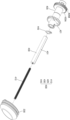
도 12는 본 발명의 일 실시예에 따른 플런저 및 구동 유닛을 도시하는 분해 사시도이다.
도 13은 본 발명의 일 실시예에 따른 레저버 유닛에 약액이 저장되기 전의 상태를 도시한 단면도이다.
도 14는 본 발명의 일 실시예에 따른 레저버 유닛에 약액이 저장된 상태를 도시한 단면도이다.FIG. 1 is a block diagram illustrating a drug injection system according to one embodiment of the present invention.
FIG. 2 is a perspective view illustrating a drug injection device according to one embodiment of the present invention.
FIG. 3 is an exploded perspective view showing a housing in an open state in a liquid injection device according to one embodiment of the present invention.
Figure 4 is a perspective view illustrating a part of the configuration of Figure 3.
Figure 5 is a partial plan view partially illustrating one side of Figure 4.
FIG. 6 is a perspective view illustrating a driving wheel unit and a driving sensing unit according to one embodiment of the present invention.
Fig. 7 is a block diagram illustrating a part of the configuration of the drug injection device of Fig. 2.
Figures 8 and 9 are drawings showing the operating state in part A of Figure 5.
Figures 10 and 11 are cross-sectional drawings taken along line II` of Figures 8 and 9.
FIG. 12 is an exploded perspective view illustrating a plunger and a drive unit according to one embodiment of the present invention.
FIG. 13 is a cross-sectional view illustrating a state before a drug is stored in a reservoir unit according to one embodiment of the present invention.
FIG. 14 is a cross-sectional view illustrating a state in which a drug solution is stored in a reservoir unit according to one embodiment of the present invention.
본 발명은 다양한 변환을 가할 수 있고 여러 가지 실시예를 가질 수 있는 바, 특정 실시예들을 도면에 예시하고 상세한 설명에 상세하게 설명하고자 한다. 본 발명의 효과 및 특징, 그리고 그것들을 달성하는 방법은 도면과 함께 상세하게 후술되어 있는 실시예들을 참조하면 명확해질 것이다. 그러나 본 발명은 이하에서 개시되는 실시예들에 한정되는 것이 아니라 다양한 형태로 구현될 수 있다.The present invention can be modified in various ways and has various embodiments, and specific embodiments are illustrated in the drawings and described in detail in the detailed description. The effects and features of the present invention and the methods for achieving them will become clear with reference to the embodiments described in detail below together with the drawings. However, the present invention is not limited to the embodiments disclosed below, and can be implemented in various forms.
이하, 첨부된 도면을 참조하여 본 발명의 실시예들을 상세히 설명하기로 하며, 도면을 참조하여 설명할 때 동일하거나 대응하는 구성 요소는 동일한 도면부호를 부여하고 이에 대한 중복되는 설명은 생략하기로 한다.Hereinafter, embodiments of the present invention will be described in detail with reference to the attached drawings. When describing with reference to the drawings, identical or corresponding components are given the same drawing reference numerals and redundant descriptions thereof are omitted.
이하의 실시예에서, 단수의 표현은 문맥상 명백하게 다르게 뜻하지 않는 한, 복수의 표현을 포함한다.In the examples below, singular expressions include plural expressions unless the context clearly indicates otherwise.
이하의 실시예에서, 포함하다 또는 가지다 등의 용어는 명세서상에 기재된 특징, 또는 구성요소가 존재함을 의미하는 것이고, 하나 이상의 다른 특징들 또는 구성요소가 부가될 가능성을 미리 배제하는 것은 아니다.In the examples below, terms such as “include” or “have” mean that a feature or component described in the specification is present, and do not exclude in advance the possibility that one or more other features or components may be added.
어떤 실시예가 달리 구현 가능한 경우에 특정한 공정 순서는 설명되는 순서와 다르게 수행될 수도 있다. 예를 들어, 연속하여 설명되는 두 공정이 실질적으로 동시에 수행될 수도 있고, 설명되는 순서와 반대의 순서로 진행될 수 있다.In some embodiments, where the implementation is otherwise feasible, a particular process sequence may be performed in a different order than the one described. For example, two processes described in succession may be performed substantially simultaneously, or in a reverse order from the one described.
도면에서는 설명의 편의를 위하여 구성 요소들이 그 크기가 과장 또는 축소될 수 있다. 예컨대, 도면에서 나타난 각 구성의 크기 및 두께는 설명의 편의를 위해 임의로 나타내었으므로, 이하의 실시예는 반드시 도시된 바에 한정되지 않는다.In the drawings, the sizes of components may be exaggerated or reduced for convenience of explanation. For example, the sizes and thicknesses of each component shown in the drawings are arbitrarily shown for convenience of explanation, and therefore the following embodiments are not necessarily limited to what is shown.
도 1은 본 발명의 일 실시예에 따른 약액 주입 시스템을 도시하는 블록도이다. FIG. 1 is a block diagram illustrating a drug injection system according to one embodiment of the present invention.
도 1을 참조하면, 본 발명의 일 실시예에 따른 약액 주입 시스템은 약액 주입 장치, 사용자 단말, 컨트롤러 및 생체 정보 센서를 구비할 수 있다. 약액 주입 시스템은 사용자 단말을 이용하여 사용자가 시스템을 구동 및 제어할 수 있으며, 생체 정보 센서에서 모니터링 되는 혈당 정보를 기초로, 약액 주입 장치에서 약액을 주기적으로 주입할 수 있다.Referring to FIG. 1, a drug injection system according to one embodiment of the present invention may include a drug injection device, a user terminal, a controller, and a biometric information sensor. The drug injection system may enable a user to drive and control the system using the user terminal, and may periodically inject a drug from the drug injection device based on blood sugar information monitored by the biometric information sensor.
도 1을 참조하면, 약액 주입 장치(1)는 생체 정보 센서(40)에서 센싱된 데이터를 기초로, 사용자에게 주입되어야 하는 약물, 예를 들어, 인슐린, 글루카곤, 마취제 진통제, 도파민, 성장 호르몬, 금연 보조제 등의 약물을 주입하는 기능을 수행하기도 한다.Referring to Fig. 1, the drug injection device (1) also performs the function of injecting drugs to be injected into the user, such as insulin, glucagon, anesthetic analgesics, dopamine, growth hormones, smoking cessation aids, etc., based on data sensed by the bio-information sensor (40).
또한, 약액 주입 장치(1)는, 장치의 잔여 배터리(350) 용량 정보, 장치의 부팅 성공 여부, 약액(D)의 주입 성공 여부 등을 포함하는 장치 상태 메시지를 컨트롤러(30)에 전달할 수 있다.In addition, the liquid injection device (1) can transmit a device status message including information on the remaining battery (350) capacity of the device, whether the device was booted successfully, whether the liquid (D) was injected successfully, etc., to the controller (30).
컨트롤러(30)로 전달된 메시지들은 컨트롤러(30)를 거쳐 사용자 단말(20)로 전달될 수 있다. 또는 컨트롤러(30)는 수신된 메시지들을 가공하여 만든 개량 데이터를 사용자 단말(20)로 전달할 수 있다.Messages transmitted to the controller (30) may be transmitted to the user terminal (20) via the controller (30). Alternatively, the controller (30) may transmit improved data created by processing the received messages to the user terminal (20).
본 발명의 일 실시예에 따른 약액 주입 장치(1)는 생체 정보 센서(40)와 별도로 구비되며, 사용 대상체에 이격되어 설치될 수 있다.A drug injection device (1) according to one embodiment of the present invention is provided separately from a bio-information sensor (40) and can be installed away from the subject of use.
선택적 실시예로서, 약액 주입 장치(1)와 생체 정보 센서(40)는 하나의 디바이스에 구비될 수 있다.As an optional embodiment, the drug injection device (1) and the bio-information sensor (40) may be provided in one device.
선택적 실시예로서, 약액 주입 장치(1)는 사용자의 몸에 장착될 수 있다. 또한, 약액 주입 장치(1)는 사람뿐만 아니라 동물에도 장착되어 약액(D)을 주입할 수 있다.As an optional embodiment, the drug injection device (1) can be mounted on the user's body. In addition, the drug injection device (1) can be mounted on not only humans but also animals to inject the drug (D).
사용자 단말(20)은 약액 주입 시스템(1)을 구동 및 제어하기 위해 사용자로부터 입력 신호를 입력, 전달받을 수 있다. 사용자 단말(20)은 컨트롤러(30)를 구동시키는 신호를 생성하여 컨트롤러(30)를 제어할 수 있고, 컨트롤러(30)를 제어하여 약액 주입 장치(1)를 구동시킬 수 있다. The user terminal (20) can input and receive an input signal from a user to drive and control the drug injection system (1). The user terminal (20) can generate a signal to drive the controller (30) to control the controller (30), and can drive the drug injection device (1) by controlling the controller (30).
또한, 사용자 단말(20)은 생체 정보 센서(40)로부터 측정된 생체 정보를 표시할 수 있으며, 약액 주입 장치(1)의 상태 정보를 표시할 수 있다.Additionally, the user terminal (20) can display biometric information measured from the biometric information sensor (40) and can display status information of the drug injection device (1).
사용자 단말(20)은 유무선 통신 환경에서 이용할 수 있는 통신 단말을 의미한다. 예를 들어, 사용자 단말(20)은 스마트폰, 태블릿 PC, PC, 스마트 TV, 휴대폰, PDA(personal digital assistant), 랩톱, 미디어 플레이어, 마이크로 서버, GPS(global positioning system) 장치, 전자책 단말기, 디지털방송용 단말기, 네비게이션, 키오스크, MP3 플레이어, 디지털 카메라, 가전기기, 카메라가 탑재된 디바이스 및 기타 모바일 또는 비 모바일 컴퓨팅 장치일 수 있다. 또한, 사용자 단말(20)은 통신 기능 및 데이터 프로세싱 기능을 구비한 시계, 안경, 헤어 밴드 및 반지 등의 웨어러블 디바이스일 수 있다. 그러나, 상술한 바와 같이 인터넷 통신이 가능한 애플리케이션을 탑재한 단말은 제한 없이 차용될 수 있다. The user terminal (20) refers to a communication terminal that can be used in a wired or wireless communication environment. For example, the user terminal (20) may be a smart phone, a tablet PC, a PC, a smart TV, a mobile phone, a PDA (personal digital assistant), a laptop, a media player, a micro server, a GPS (global positioning system) device, an e-book terminal, a digital broadcasting terminal, a navigation, a kiosk, an MP3 player, a digital camera, a home appliance, a device equipped with a camera, and other mobile or non-mobile computing devices. In addition, the user terminal (20) may be a wearable device such as a watch, glasses, a hair band, and a ring equipped with a communication function and a data processing function. However, as described above, a terminal equipped with an application capable of Internet communication may be borrowed without limitation.
사용자 단말(20)은 미리 등록된 컨트롤러(30)와 1대1로 연결될 수 있다. 사용자 단말(20)은 외부의 장치로부터의 컨트롤러(30)가 구동 및 제어되는 것을 막기 위해서, 컨트롤러(30)와 암호화되어 연결될 수 있다. The user terminal (20) can be connected one-to-one with a pre-registered controller (30). The user terminal (20) can be connected to the controller (30) in an encrypted manner to prevent the controller (30) from being driven and controlled by an external device.
일 실시예로, 사용자 단말(20)과 컨트롤러(30)는 각각 분리되어 별도의 장치로 구비될 수 있다. 예컨대, 컨트롤러(30)는 약액 주입 장치(1)가 장착된 대상자에게 구비되고, 사용자 단말(20)은 대상자 또는 제3자에게 구비될 수 있다. 보호자에 의해서 사용자 단말(20)이 구동되어, 약액 주입 시스템(1)의 안전성을 높일 수 있다. In one embodiment, the user terminal (20) and the controller (30) may be provided as separate devices, each separately. For example, the controller (30) may be provided to a subject equipped with a drug injection device (1), and the user terminal (20) may be provided to the subject or a third party. The user terminal (20) may be driven by a guardian, thereby increasing the safety of the drug injection system (1).
다른 실시예로, 사용자 단말(20)과 컨트롤러(30)는 하나의 디바이스로 구비될 수 있다. 사용자 단말(20)과 하나로 구비된 컨트롤러(30)가 약액 주입 장치(1)와 통신하여, 약물의 주입을 제어할 수 있다. In another embodiment, the user terminal (20) and the controller (30) may be provided as a single device. The user terminal (20) and the controller (30) provided as a single device may communicate with the drug injection device (1) to control the injection of the drug.
컨트롤러(30)는 약액 주입 장치(1)와 데이터를 송수신하는 기능을 수행하며, 약액 주입 장치(1)로 인슐린 등의 약물의 주입과 관련된 제어 신호를 전송하고, 생체 정보 센서(40)로부터 혈당 등의 생체값의 측정과 관련된 제어 신호를 수신 받을 수 있다. The controller (30) performs a function of transmitting and receiving data with the drug injection device (1), and can transmit a control signal related to the injection of a drug such as insulin to the drug injection device (1), and receive a control signal related to the measurement of a biological value such as blood sugar from a biological information sensor (40).
일 실시예로, 컨트롤러(30)는 사용자의 현 상태를 측정하라는 지시 요청을 약액 주입 장치(1)로 전송하고, 지시 요청의 응답으로 약액 주입 장치(1)로부터 측정 데이터를 수신 받을 수 있다. In one embodiment, the controller (30) may transmit an instruction request to measure the current state of the user to the drug injection device (1) and receive measurement data from the drug injection device (1) in response to the instruction request.
생체 정보 센서(40)는 목적에 따라 사용자의 혈당값, 혈압, 심박수 등의 생체값을 측정하는 기능을 수행할 수 있다. 생체 정보 센서(40)에서 측정된 데이터는 컨트롤러(30)에 전달될 수 있으며, 측정된 데이터를 기초로 약물이 주기 및/또는 주입량이 설정될 수 있다. 생체 정보 센서(40)에서 측정된 데이터는 사용자 단말(20)로 전달되어 표시될 수 있다.The biometric sensor (40) can perform a function of measuring the user's biometric values such as blood sugar level, blood pressure, and heart rate depending on the purpose. The data measured by the biometric sensor (40) can be transmitted to the controller (30), and the drug cycle and/or injection amount can be set based on the measured data. The data measured by the biometric sensor (40) can be transmitted to the user terminal (20) and displayed.
일 예로, 생체 정보 센서(40)는 대상체의 혈당량을 측정하는 센서일 수 있다. 연속 혈당 측정(CGM: Continuous Glucose Monitoring) 센서일 수 있다. 연속 혈당 측정 센서는 대상체에 부착되어 연속적으로 혈당량을 모니터링 할 수 있다.For example, the biometric information sensor (40) may be a sensor that measures the blood sugar level of the subject. It may be a continuous glucose monitoring (CGM) sensor. The continuous glucose monitoring sensor may be attached to the subject and continuously monitor the blood sugar level.
사용자 단말(20), 컨트롤러(30) 및 약액 주입 장치(1)는 네트워크를 이용하여 통신을 수행할 수 있다. 예를 들어, 네트워크는 근거리 통신망(Local Area Network; LAN), 광역 통신망(Wide Area Network; WAN), 부가가치 통신망(Value Added Network; VAN), 이동 통신망(mobile radio communication network), 위성 통신망 및 이들의 상호 조합을 포함하며, 각 네트워크 구성 주체가 서로 원활하게 통신을 할 수 있도록 하는 포괄적인 의미의 데이터 통신망이며, 유선 인터넷, 무선 인터넷 및 모바일 무선 통신망을 포함할 수 있다. 또한, 무선 통신은 예를 들어, 무선 랜(Wi-Fi), 블루투스, 블루투스 저 에너지(Bluetooth low energy), 지그비, WFD(Wi-Fi Direct), UWB(ultra-wideband), 적외선 통신(IrDA, infrared Data Association), NFC(Near Field Communication), 5G 등이 있을 수 있으나, 이에 한정되는 것은 아니다.The user terminal (20), the controller (30), and the drug injection device (1) can perform communication using a network. For example, the network includes a local area network (LAN), a wide area network (WAN), a value added network (VAN), a mobile radio communication network, a satellite communication network, and a combination thereof, and is a comprehensive data communication network that allows each network component to communicate smoothly with each other, and may include wired Internet, wireless Internet, and a mobile radio communication network. In addition, the wireless communication may include, but is not limited to, wireless LAN (Wi-Fi), Bluetooth, Bluetooth low energy, Zigbee, WFD (Wi-Fi Direct), UWB (ultra-wideband), infrared communication (IrDA, infrared Data Association), NFC (Near Field Communication), 5G, etc.
도 2는 본 발명의 일 실시예에 따른 약액 주입 장치를 도시하는 사시도이다. 도 3은 본 발명의 일 실시예에 따른 약액 주입 장치에서 하우징이 개방된 상태를 도시하는 분해 사시도이다. 도 4는 도 3의 일부 구성을 도시하는 사시도이다. 도 5는 도 4의 일측을 부분적으로 도시하는 부분 평면도이다. 도 6은 본 발명의 일 실시예에 따른 구동휠부 및 구동센싱부를 도시하는 사시도이다. 도 7은 도 2의 약액 주입 장치의 일부 구성을 도시하는 블록도이다. 도 8 및 도 9는 도 5의 A부분에서의 동작 상태를 도시하는 도면이다. 도 10, 도 11은 도 8, 도 9의 I-I`선을 기준으로 단면 처리한 도면이다. 도 12는 본 발명의 일 실시예에 따른 플런저 및 구동 유닛을 도시하는 분해 사시도이다. 도 13은 본 발명의 일 실시예에 따른 레저버 유닛에 약액이 저장되기 전의 상태를 도시한 단면도이다. 도 14는 본 발명의 일 실시예에 따른 레저버 유닛에 약액이 저장된 상태를 도시한 단면도이다.FIG. 2 is a perspective view illustrating a liquid injection device according to an embodiment of the present invention. FIG. 3 is an exploded perspective view illustrating a state in which a housing is opened in the liquid injection device according to an embodiment of the present invention. FIG. 4 is a perspective view illustrating a part of the configuration of FIG. 3. FIG. 5 is a partial plan view illustrating a side of FIG. 4. FIG. 6 is a perspective view illustrating a driving wheel unit and a driving sensing unit according to an embodiment of the present invention. FIG. 7 is a block diagram illustrating a part of the configuration of the liquid injection device of FIG. 2. FIGS. 8 and 9 are drawings illustrating an operating state in part A of FIG. 5. FIGS. 10 and 11 are cross-sectional views taken along the line I-I` of FIGS. 8 and 9. FIG. 12 is an exploded perspective view illustrating a plunger and a driving unit according to an embodiment of the present invention. FIG. 13 is a cross-sectional view illustrating a state before a liquid is stored in a reservoir unit according to an embodiment of the present invention. FIG. 14 is a cross-sectional view illustrating a state in which a drug solution is stored in a reservoir unit according to one embodiment of the present invention.
도 2 내지 도 5를 참조하면, 본 발명의 일 실시예에 따른 약액 주입 장치(1)는 약액(D)을 주입할 사용자에 부착될 수 있고, 내부에 저장된 약액(D)을 사용자에게 미리 설정된 정량으로 주입할 수 있다.Referring to FIGS. 2 to 5, a drug injection device (1) according to one embodiment of the present invention can be attached to a user who is to inject a drug (D), and can inject a drug (D) stored inside the device to the user in a preset amount.
약액 주입 장치(1)는 주입되는 약액(D)의 종류에 따라 다양한 용도로 사용될 수 있다. 예컨대, 약액(D)은 당뇨병 환자를 위한 인슐린 계열 약액(D)을 포함할 수 있고, 기타 췌장을 위한 약액(D), 심장용 약액(D) 기타 다양한 종류의 약액(D)을 포함할 수 있다.The drug injection device (1) can be used for various purposes depending on the type of drug (D) to be injected. For example, the drug (D) can include an insulin-based drug (D) for diabetic patients, and can also include other types of drug (D) for the pancreas, heart, and other types of drug (D).
본 발명의 일 실시예에 따른 약액 주입 장치(1)는 하우징(11), 부착부(12), 베이스 바디를 포함할 수 있다. 도 2 내지 도 4를 참조하면, 본 발명의 일 실시예에 따른 하우징(11)은 뒤에 설명할 니들 조립체(100), 레저버 유닛(200), 구동 모듈(300), 구동 유닛(400), 니들 구동부(600), 알람 유닛(800), 센서 유닛(900)을 커버하는 것으로 내측에 수용 공간이 형성될 수 있다.A drug injection device (1) according to one embodiment of the present invention may include a housing (11), an attachment part (12), and a base body. Referring to FIGS. 2 to 4, a housing (11) according to one embodiment of the present invention may cover a needle assembly (100), a reservoir unit (200), a driving module (300), a driving unit (400), a needle driving part (600), an alarm unit (800), and a sensor unit (900) to be described later, and an accommodation space may be formed inside.
도 2 내지 도 4를 참조하면, 본 발명의 일 실시예에 따른 부착부(12)는 사용자의 피부에 인접하게 위치할 수 있다. 부착부(12)와 사용자의 피부 사이에는 별도의 접합수단이 더 개재될 수 있으며, 접합수단에 의해 약액 주입 장치(1)는 피부에 고정될 수 있다.Referring to FIGS. 2 to 4, the attachment portion (12) according to one embodiment of the present invention may be positioned adjacent to the user's skin. A separate bonding means may be further interposed between the attachment portion (12) and the user's skin, and the drug injection device (1) may be fixed to the skin by the bonding means.
도 2 내지 도 14를 참조하면, 본 발명의 일 실시예에 따른 약액 주입 장치(1)는, 니들 조립체(100), 레저버 유닛(200), 구동 모듈(300), 배터리(350), 구동 유닛(400), 니들 구동부(600), 주입커버(700), 알람 유닛(800), 센서 유닛(900)을 포함할 수 있다. Referring to FIGS. 2 to 14, a drug injection device (1) according to one embodiment of the present invention may include a needle assembly (100), a reservoir unit (200), a driving module (300), a battery (350), a driving unit (400), a needle driving unit (600), an injection cover (700), an alarm unit (800), and a sensor unit (900).
도 2, 도 3, 도 4를 참조하면, 본 발명의 일 실시예에 따른 약액 주입 장치(1)는 베이스 바디(도면부호 미설정)를 포함할 수 있다.Referring to FIGS. 2, 3, and 4, a drug injection device (1) according to one embodiment of the present invention may include a base body (drawing symbol not set).
베이스 바디는 적어도 하나 이상의 바디를 통해 내부 부품을 지지하는 틀을 형성할 수 있다. 구체적으로 베이스 바디는 제1바디(13), 제2바디(14), 제3바디(15), 바디커버(16)를 포함할 수 있고, 제1바디(13), 제2바디(14), 제3바디(15), 바디커버(16)는 배치에 따라 구분될 수 있다.The base body can form a frame that supports internal components through at least one body. Specifically, the base body can include a first body (13), a second body (14), a third body (15), and a body cover (16), and the first body (13), the second body (14), the third body (15), and the body cover (16) can be distinguished according to the arrangement.
제1바디(13)는 하우징(11)의 아래에 배치되며, 각 개구 또는 홈에 니들 조립체(100), 레저버 유닛(200), 구동 모듈(300), 배터리(350) 등이 지지될 수 있다. 제2바디(14)는 제1바디(13)의 하측(도 3 기준)에 배치되며, 부착부(12)와 연결될 수 있고, 약액 주입 장치(1)의 하부를 커버할 수 있다.The first body (13) is placed below the housing (11), and a needle assembly (100), a reservoir unit (200), a driving module (300), a battery (350), etc. can be supported in each opening or groove. The second body (14) is placed on the lower side (based on FIG. 3) of the first body (13), can be connected to the attachment part (12), and can cover the lower part of the liquid injection device (1).
제3바디(15)는 제1바디(13)의 상측에 배치되어, 각 개구 또는 홈에 레저버 유닛(200), 구동 모듈(300), 배터리(350), 구동 유닛(400) 등이 지지될 수 있다. 바디커버(16)는 제3바디(15)의 상측에 배치되며, 제3바디(15)를 커버할 수 있다. The third body (15) is arranged on the upper side of the first body (13), and a reservoir unit (200), a driving module (300), a battery (350), a driving unit (400), etc. can be supported in each opening or groove. The body cover (16) is arranged on the upper side of the third body (15) and can cover the third body (15).
구체적으로 바디커버(16)는 볼트 등 체결부재에 의하여 제3바디(15)와 체결될 수 있으며, 뒤에 설명할 구동휠부(420)의 날개단(421) 및 구동 모듈(300)을 커버할 수 있다. Specifically, the body cover (16) can be fastened to the third body (15) by a fastening member such as a bolt, and can cover the wing end (421) of the driving wheel part (420) and the driving module (300) to be described later.
도 3을 참조하면, 도면에서는 제1바디(13), 제2바디(14), 제3바디(15) 및 바디커버(16)를 도시하나, 이에 한정하는 것은 아니고 일체로 구비될 수 있는 등 다양한 변형 실시가 가능하다.Referring to FIG. 3, the drawing illustrates a first body (13), a second body (14), a third body (15), and a body cover (16), but is not limited thereto and various modifications are possible, such as being provided as an integral unit.
도 10, 도 11을 참조하면, 본 발명의 일 실시예에 따른 약액 주입 장치(1)의 내부에는 제어 모듈(17)이 배치될 수 있다. 구체적으로 제2바디(14)의 아래에 회로 기판으로서 제어 모듈(17)이 배치될 수 있고, 약액 주입 장치(1)의 전체적인 구동을 제어할 수 있다. Referring to FIGS. 10 and 11, a control module (17) may be placed inside a drug injection device (1) according to one embodiment of the present invention. Specifically, the control module (17) may be placed as a circuit board under the second body (14) and may control the overall operation of the drug injection device (1).
본 발명의 일 실시예에 따른 제어 모듈(17)은 구동 모듈(300), 배터리(350), 알람 유닛(800) 및 센서 유닛(900)과 전기적으로 접촉하여, 이들의 구동을 제어할 수 있다. A control module (17) according to one embodiment of the present invention can electrically contact a driving module (300), a battery (350), an alarm unit (800), and a sensor unit (900) to control their operation.
도 3, 도 4, 도 5를 참조하면, 본 발명의 일 실시예에 따른 니들 조립체(100)는 베이스 바디, 구체적으로 제1바디(13)에 장착될 수 있다. 니들 조립체(100)는 슬리브(도면부호 미설정)의 회전에 의해 니들(N) 및/또는 캐뉼러(cannula)가 축 방향으로 이동될 수 있다.Referring to FIGS. 3, 4, and 5, a needle assembly (100) according to one embodiment of the present invention can be mounted on a base body, specifically, a first body (13). The needle assembly (100) can move a needle (N) and/or a cannula in the axial direction by rotation of a sleeve (drawing symbol not set).
니들(N)의 일단부는 레저버 유닛(200)에 연결되어 약액(D)이 전달될 수 있으며, 타단부는 캐뉼러에 삽입되어 캐뉼러를 따라 이동할 수 있다. 캐뉼러는 내부에 니들(N)을 수용할 수 있도록 중공의 도관 형상을 가지므로, 니들(N)에서 토출되는 약액(D)이 사용자로 주입될 수 있다.One end of the needle (N) is connected to a reservoir unit (200) so that the drug (D) can be delivered, and the other end is inserted into a cannula and can move along the cannula. Since the cannula has a hollow tube shape so that it can accommodate the needle (N) inside, the drug (D) discharged from the needle (N) can be injected into the user.
캐뉼러는 사용자의 피부에 삽입된 상태를 유지하나, 니들(N)은 캐뉼러의 내부에서 상승, 즉 사용자의 피부로부터 이격되는 방향으로 이동하며 대상체에서 분리된다.The cannula remains inserted into the user's skin, but the needle (N) moves upward within the cannula, i.e. away from the user's skin, and is separated from the target.
다만, 캐뉼러와 니들(N)은 유체가 이동되는 경로를 형성하여, 레저버에서 주입되는 약액(D)은 니들(N)과 캐뉼러를 통해서 사용자에게 주입될 수 있다.However, the cannula and the needle (N) form a path through which the fluid moves, so the drug (D) injected from the reservoir can be injected into the user through the needle (N) and the cannula.
도 2 내지 도 5를 참조하면, 본 발명의 일 실시예에 따른 니들 조립체(100)는 니들 구동부(600)로부터 동력을 전달받아 니들(N) 및/또는 캐뉼러를 이동시킬 수 있다.Referring to FIGS. 2 to 5, a needle assembly (100) according to one embodiment of the present invention can receive power from a needle drive unit (600) to move a needle (N) and/or a cannula.
본 발명의 일 실시예에 따른 니들 구동부(600)는 누름 방식으로 니들 조립체(100)에 동력을 전달할 수 있고, 탄성복원력을 가지는 탄성부재가 구비될 수 있다. A needle driving unit (600) according to one embodiment of the present invention can transmit power to a needle assembly (100) in a pressing manner and may be provided with an elastic member having elastic restoring force.
이로 인하여 사용자가 니들 구동부(600)에 힘을 가하면 니들 구동부(600)와 연결된 니들 조립체(100)에 동력이 전달되며 니들(N) 및/또는 캐뉼러가 사용자의 피부에 삽입되고, 사용자에 의해 니들 구동부(600)에 가해지는 힘이 제거되면, 탄성부재의 탄성복원력에 의해 니들 구동부(600)가 원위치로 이동하며, 니들(N)만 사용자의 피부에서 분리될 수 있다.Accordingly, when the user applies force to the needle drive unit (600), power is transmitted to the needle assembly (100) connected to the needle drive unit (600), and the needle (N) and/or cannula are inserted into the user's skin, and when the force applied to the needle drive unit (600) by the user is removed, the needle drive unit (600) moves to the original position by the elastic restoring force of the elastic member, and only the needle (N) can be separated from the user's skin.
본 발명의 일 실시예에 따른 니들 구동부(600)는 누름 방식으로 형성되나, 이에 한정하는 것은 아니고 별도의 모터 등에서 동력을 발생시켜 니들 조립체(100)로 동력을 전달하는 등 다양한 변형 실시가 가능하다. The needle drive unit (600) according to one embodiment of the present invention is formed in a pressing manner, but is not limited thereto, and various modifications are possible, such as generating power from a separate motor or the like and transmitting the power to the needle assembly (100).
도 3 내지 도 5, 도 13, 도 14를 참조하면, 본 발명의 일 실시예에 따른 레저버 유닛(200)은 제1바디(13) 및 제3바디(15)에 장착되며, 니들 조립체(100)와 연결될 수 있다. 레저버 유닛(200)은 니들 조립체(100)와 유체적으로 연결되며, 내부 공간에 약액(D)이 저장될 수 있다. Referring to FIGS. 3 to 5, 13, and 14, a reservoir unit (200) according to one embodiment of the present invention is mounted on the first body (13) and the third body (15), and can be connected to the needle assembly (100). The reservoir unit (200) is fluidically connected to the needle assembly (100), and a drug solution (D) can be stored in the internal space.
도 3, 도 13, 도 14를 참조하면, 본 발명의 일 실시예에 따른 레저버 유닛(200)은 레저버본체(210), 캡 커버(220), 플런저(230), 커넥터 부재(250)를 포함할 수 있다. 레저버본체(210)는 내부가 중공으로 형성되며, 내부에 약액(D)이 저장될 수 있다.Referring to FIG. 3, FIG. 13, and FIG. 14, a reservoir unit (200) according to one embodiment of the present invention may include a reservoir body (210), a cap cover (220), a plunger (230), and a connector member (250). The reservoir body (210) is formed with a hollow interior, and a liquid (D) may be stored therein.
레저버본체(210)는 니들 조립체(100), 구체적으로 니들(N) 및/또는 캐뉼러와 연결될 수 있고, 니들(N) 및/또는 캐뉼러를 통해 약액(D)이 유동될 수 있도록 한다. The reservoir body (210) can be connected to a needle assembly (100), specifically a needle (N) and/or a cannula, and allows the drug solution (D) to flow through the needle (N) and/or the cannula.
레저버본체(210)는 길이 방향으로 미리 설정된 길이로 연장 형성될 수 있고, 내부 공간에 약액(D)을 저장할 수 있다. 레저버본체(210)의 내부에는 플런저(230)가 이동가능하게 배치될 수 있고, 플런저(230)의 이동으로 약액(D)이 니들(N)로 토출될 수 있다.The reservoir body (210) can be formed to be extended to a preset length in the longitudinal direction and can store a liquid (D) in the internal space. A plunger (230) can be movably arranged inside the reservoir body (210), and the liquid (D) can be discharged through the needle (N) by the movement of the plunger (230).
도 13을 참조하면, 레저버본체(210)의 단부(도 13 기준 우측 단부)에는 캡 커버(220)가 장착될 수 있다. 캡 커버(220)는 레저버본체(210)를 커버하는 것으로, 캡 커버(220)에 형성되는 개구부(도면 미도시)를 통하여 뒤에 설명할 로드부(410) 및/또는 연결부재(430)가 이동할 수 있다.Referring to FIG. 13, a cap cover (220) may be mounted on an end portion (the right end based on FIG. 13) of the reservoir body (210). The cap cover (220) covers the reservoir body (210), and a load portion (410) and/or a connecting member (430) to be described later may move through an opening (not shown in the drawing) formed in the cap cover (220).
본 발명의 일 실시예에 따른 레저버본체(210)는 입구단과 출구단을 가질 수 있다. 입구단으로는 약액(D)이 주입되고 출구단에는 니들(N)이 설치되며, 니들(N)로 약액(D)이 배출될 수 있다.A reservoir body (210) according to one embodiment of the present invention may have an inlet end and an outlet end. A drug solution (D) is injected into the inlet end, a needle (N) is installed at the outlet end, and the drug solution (D) can be discharged through the needle (N).
플런저(230)는 레저버본체(210)의 내부에 배치되며, 구동 모듈(300) 및 구동 유닛(400)의 구동에 의해서 선형 이동(도 13 기준 좌우 방향)할 수 있다. 플런저(230)의 전진에 따라 약액(D)은 내부 공간에서 니들(N)로 배출될 수 있다.The plunger (230) is placed inside the reservoir body (210) and can move linearly (left and right as shown in FIG. 13) by driving the drive module (300) and the drive unit (400). As the plunger (230) advances, the liquid (D) can be discharged from the internal space to the needle (N).
플런저(230)의 외주면 형상은 마주보는 레저버본체(210)의 내주면 형상과 동일하게 형성될 수 있다. 이로 인하여 플런저(230)가 레저버본체(210)의 내주면에 밀착될 수 있다. The outer surface shape of the plunger (230) can be formed to be identical to the inner surface shape of the opposing reservoir body (210). As a result, the plunger (230) can be in close contact with the inner surface of the reservoir body (210).
플런저(230)는 후방으로 연장되는 커넥터 부재(250)와 연결될 수 있다. 도 5를 참조하면, 커넥터 부재(250)는 길이 방향으로 연장 형성되는 것으로, 플런저(230)에 연결되며 일측은 레저버본체(210)의 내부에 위치하고, 타측은 레저버본체(210)의 외부에 위치할 수 있다.The plunger (230) may be connected to a connector member (250) extending rearwardly. Referring to FIG. 5, the connector member (250) is formed to extend in the longitudinal direction, is connected to the plunger (230), and one side may be positioned inside the reservoir body (210) and the other side may be positioned outside the reservoir body (210).
커넥터 부재(250)는 플런저(230)에 연결되며, 플런저(230)의 선형 이동에 따라 함께 선형 이동할 수 있다. The connector member (250) is connected to the plunger (230) and can move linearly along with the linear movement of the plunger (230).
커넥터 부재(250)는 전기 전도성을 가지는 소재로 구비되고, 샤프트 형상을 가질 수 있다. 커넥터 부재(250)가 이동하면서 뒤에 설명할 레저버 센서 유닛(910)과 접촉이 가능하다. The connector member (250) is made of an electrically conductive material and may have a shaft shape. As the connector member (250) moves, it can come into contact with the reservoir sensor unit (910) to be described later.
도 5를 참조하면, 커넥터부재가 이동하면서 레저버 센서 유닛(910)과 접촉함으로써, 약물의 저장량을 측정하거나, 약액 주입 장치(1)의 구동을 시작할 수 있다. 도 5를 참조하면, 커넥터 부재(250)가 샤프트 형상을 가지는 것을 도시하나, 이에 한정하는 것은 아니고, 플런저(230)와 함께 이동하며 레저버 겐서 유닛과 접촉하여 전기적인 신호를 생성하는 기술적 사상 안에서 다양한 변형 실시가 가능하다.Referring to FIG. 5, by moving the connector member and coming into contact with the reservoir sensor unit (910), the amount of drug stored can be measured or the operation of the drug injection device (1) can be started. Referring to FIG. 5, the connector member (250) is illustrated as having a shaft shape, but is not limited thereto, and various modifications can be implemented within the technical concept of moving together with the plunger (230) and coming into contact with the reservoir sensor unit to generate an electrical signal.
약액(D)이 레저버본체(210)에 저장되어, 플런저(230)가 후퇴하면, 커넥터 부재(250)는 플런저(230)와 함께 후퇴할 수 있다. 또한, 약액(D)이 레저버에서 니들(N)로 토출되도록 플런저(230)가 전진하면, 커넥터 부재(250)는 플런저(230)와 함께 전진할 수 있다.When the liquid (D) is stored in the reservoir body (210), and the plunger (230) is retracted, the connector member (250) can be retracted together with the plunger (230). In addition, when the plunger (230) is advanced so that the liquid (D) is discharged from the reservoir to the needle (N), the connector member (250) can be advanced together with the plunger (230).
도 13을 참조하면, 본 발명의 일 실시예에 따른 플런저(230)는 레저버본체(210)의 내측벽과 접촉하는 부분에 실링링(도면부호 미설정)이 구비될 수 있다. 이로 인하여 레저버본체(210)의 내부에서 플런저(230)의 이동 시에 약액(D)이 누설되는 것을 방지할 수 있다. Referring to FIG. 13, the plunger (230) according to one embodiment of the present invention may be provided with a sealing ring (drawing symbol not set) at a portion that comes into contact with the inner wall of the reservoir body (210). This can prevent the liquid (D) from leaking when the plunger (230) moves inside the reservoir body (210).
도 3 내지 도 5를 참조하면, 본 발명의 일 실시예에 따른 구동 모듈(300)은 구동력을 생성하여 구동 유닛(400)에 구동력을 전달할 수 있다. 구동 유닛(400)에 전달되는 구동력은 레저버본체(210)의 내부에서 플런저(230)가 선형 이동되도록 하고, 플런저(230)가 선형 이동함에 따라 약액(D)을 레저버 유닛(200)의 외부로 배출할 수 있다.Referring to FIGS. 3 to 5, a driving module (300) according to one embodiment of the present invention can generate a driving force and transmit the driving force to a driving unit (400). The driving force transmitted to the driving unit (400) can cause a plunger (230) to move linearly inside a reservoir body (210), and as the plunger (230) moves linearly, the liquid (D) can be discharged to the outside of the reservoir unit (200).
도 5를 참조하면, 본 발명의 일 실시예에 따른 구동 모듈(300)은 구동원부(310), 동력전달부(330)를 포함할 수 있다. 구동원부(310)는 동력을 발생시키는 것이고, 동력전달부(330)는 구동원부(310)와 구동 유닛(400), 구체적으로 구동휠부(420) 사이에 배치되어 구동원부(310)에서 발생하는 동력을 동력전달부(330)로 전달하는 것이다.Referring to FIG. 5, a drive module (300) according to one embodiment of the present invention may include a drive source unit (310) and a power transmission unit (330). The drive source unit (310) generates power, and the power transmission unit (330) is arranged between the drive source unit (310) and the drive unit (400), specifically, the drive wheel unit (420), and transmits power generated in the drive source unit (310) to the power transmission unit (330).
도 5를 참조하면, 구동원부(310)에서 발생하는 동력은 동력전달부(330)를 통해 구동 유닛(400), 구체적으로 구동휠부(420)로 전달될 수 있다. 본 발명의 일 실시예에 따른 동력전달부(330)는 구동휠부(420)에 동력을 전달하여 구동휠부(420)를 회전시킬 수 있다.Referring to FIG. 5, power generated from the driving source (310) can be transmitted to the driving unit (400), specifically, the driving wheel unit (420), through the power transmission unit (330). The power transmission unit (330) according to one embodiment of the present invention can transmit power to the driving wheel unit (420) to rotate the driving wheel unit (420).
본 발명의 일 실시예에 따른 구동휠부(420)의 회전으로 로드부(410)가 선형 이동하여 플런저(230)가 레저버본체(210)의 내부에서 선형 이동할 수 있다. 플런저(230)가 선형 이동함에 따라 플런저(230)와 연결되는 커넥터 부재(250)도 함께 선형 이동할 수 있다.According to one embodiment of the present invention, the load part (410) moves linearly by the rotation of the driving wheel part (420), so that the plunger (230) can move linearly inside the reservoir body (210). As the plunger (230) moves linearly, the connector member (250) connected to the plunger (230) can also move linearly.
구동 모듈(300)은 전기에 의해 약액(D) 흡입력과 약액(D) 토출력을 갖는 모든 종류의 장치가 사용될 수 있다. 본 발명에서 구동 모듈(300)은 전기에너지를 역학적에너지로 바꾸는 모터(motor)가 사용될 수 있다. 구동 모듈(300), 구체적으로 구동원부(310)에서 발생하는 회전 동력이 동력전달부(330)를 통해 구동휠부(420)로 전달될 수 있다.The driving module (300) may be any type of device that has a liquid (D) suction power and a liquid (D) discharge power by electricity. In the present invention, the driving module (300) may be a motor that converts electric energy into mechanical energy. The rotational power generated in the driving module (300), specifically, the driving source unit (310), may be transmitted to the driving wheel unit (420) through the power transmission unit (330).
동력전달부(330) 및 구동휠부(420)는 기어 방식으로 서로 접촉이 가능하고, 구동원부(310)에서 발생하는 동력으로 인하여 구동휠부(420)가 회전하며 플런저(230)를 이동시킬 수 있다. The power transmission unit (330) and the driving wheel unit (420) can come into contact with each other in a gear manner, and the driving wheel unit (420) can rotate and move the plunger (230) due to the power generated from the driving source unit (310).
본 발명에서 구동 모듈(300)은 전동 모터 방식으로 형성되나, 이에 한정하는 것은 아니고, 기계 변위형 마이크로펌프와 전자기운동형 마이크로펌프 등의 모든 종류의 펌프가 사용될 수 있다. In the present invention, the driving module (300) is formed in an electric motor manner, but is not limited thereto, and all types of pumps, such as a mechanical displacement type micropump and an electromagnetic motion type micropump, can be used.
기계변위형 마이크로펌프는 유체의 흐름을 유도하기 위해 압력차를 일으키도록 기어나 다이어그램과 같은 고체 혹은 유체의 운동을 이용하는 펌프로서, 다이어프람 변위 펌프(Diaphragm displacement pump), 유체 변위 펌프(Fluid displacement pump), 회전 펌프(Rotary pump) 등이 있다.Mechanical displacement micropumps are pumps that use the movement of solids or fluids, such as gears or diaphragms, to create a pressure difference to induce the flow of fluid, and include diaphragm displacement pumps, fluid displacement pumps, and rotary pumps.
전자기운동형 마이크로펌프는 전기적 또는 자기적 형태의 에너지를 바로 유체의 이동에 이용하는 펌프로서, 전기유체역학 펌프(Electro hydrodynamic pump, EHD), 전기삼투식 펌프(Electro osmotic pump), 자기유체역학 펌프(Magneto hydrodynamic pump), 전기습식 펌프(Electro wetting pump)등이 있다.Electro-magnetic micropumps are pumps that use electrical or magnetic energy to move fluids, and include electro-hydrodynamic pumps (EHD), electro-osmotic pumps, magneto-hydrodynamic pumps, and electro-wetting pumps.
도 3 내지 도 5를 참조하면, 본 발명의 일 실시예에 따른 배터리(350)는 약액 주입 장치(1)에 전기를 공급하여, 각 부품을 활성화할 수 있다.Referring to FIGS. 3 to 5, a battery (350) according to one embodiment of the present invention can supply electricity to a liquid injection device (1) to activate each component.
도면에서는 한 쌍의 배터리(350)를 도시하나, 이에 한정되지 않으며, 약액 주입 장치(1)의 용량, 사용범위, 사용 시간 등에 따라 다양하게 설정될 수 있다. The drawing shows a pair of batteries (350), but is not limited thereto, and may be set in various ways depending on the capacity, usage range, usage time, etc. of the liquid injection device (1).
본 발명의 일 실시예에 따른 배터리(350)는 구동 모듈(300), 구동 유닛(400)에 인접하게 배치될 수 있고, 구동 모듈(300)로 전기를 공급할 수 있다. A battery (350) according to one embodiment of the present invention may be placed adjacent to the driving module (300) and the driving unit (400), and may supply electricity to the driving module (300).
또한, 배터리(350)는 제어 모듈(17)과 연결되며, 센서 유닛(900)에서 측정된 전기적 신호를 기초로 구동 유닛(400)의 회전 수 또는 회전 속도, 레저버 유닛(200), 구체적으로 레저버본체(210)에 저장되는 약액(D)량, 사용자에게 주입된 약액(D)량 등에 대한 데이터를 측정할 수 있다. In addition, the battery (350) is connected to the control module (17), and can measure data on the number of rotations or rotation speed of the drive unit (400), the amount of the drug (D) stored in the reservoir unit (200), specifically the reservoir body (210), and the amount of the drug (D) injected to the user, based on the electrical signal measured by the sensor unit (900).
도 3 내지 도 6, 도 8 내지 도 14를 참조하면, 본 발명의 일 실시예에 따른 구동 유닛(400)은 외부로부터 동력을 전달받아, 플런저(230)를 선형 이동시킬 수 있다.Referring to FIGS. 3 to 6 and 8 to 14, a driving unit (400) according to one embodiment of the present invention can receive power from the outside and move a plunger (230) linearly.
본 발명의 일 실시예에 따른 구동 유닛(400)은 구동 모듈(300)과 레저버 유닛(200) 사이에 설치되어, 구동 모듈(300)에서 생성된 구동력으로 레저버본체(210)의 내부에 배치되는 플런저(230)를 이동시킬 수 있다.A driving unit (400) according to one embodiment of the present invention is installed between a driving module (300) and a reservoir unit (200), and can move a plunger (230) disposed inside a reservoir body (210) with a driving force generated by the driving module (300).
도 12 내지 도 14를 참조하면, 본 발명의 일 실시예에 따른 구동 유닛(400)은 로드부(410), 구동휠부(420), 연결부재(430), 가력부재(440)를 포함할 수 있다. Referring to FIGS. 12 to 14, a drive unit (400) according to one embodiment of the present invention may include a load portion (410), a drive wheel portion (420), a connecting member (430), and a force member (440).
도 12 내지 도 14를 참조하면, 로드부(410)는 플런저(230)와 연결되는 것으로, 일 방향으로 연장될 수 있다. 로드부(410)는 캡 커버(220)의 개구에 삽입되고, 로드부(410)는 플런저(230)를 이동시키기 위해서 레저버본체(210)의 내부에서 길이 방향(도 13 기준 좌우 방향)을 따라 이동할 수 있다. Referring to FIGS. 12 to 14, the load portion (410) is connected to the plunger (230) and can extend in one direction. The load portion (410) is inserted into the opening of the cap cover (220), and the load portion (410) can move along the longitudinal direction (left-right direction based on FIG. 13) inside the reservoir body (210) to move the plunger (230).
본 발명의 일 실시예에 따른 로드부(410)는 표면에 나사산 형상을 가질 수 있다. 로드부(410)의 표면과 마주보는 연결부재(430)의 내주면에는 나사홈부가 형성되며, 로드부(410)와 연결부재(430)는 나사 방식으로 연결될 수 있다. The load portion (410) according to one embodiment of the present invention may have a screw thread shape on its surface. A screw groove is formed on the inner surface of the connecting member (430) facing the surface of the load portion (410), and the load portion (410) and the connecting member (430) may be connected in a screw manner.
도 10 내지 도 12를 참조하면, 본 발명의 일 실시예에 따른 로드부(410)는 길이 방향 중심축 둘레 방향을 따라 소정 구간에서 편평부(431)가 평면 형상으로 형성될 수 있다.Referring to FIGS. 10 to 12, a load section (410) according to one embodiment of the present invention may have a flat section (431) formed in a plane shape along a predetermined section of the longitudinal central axis.
로드부(410)의 둘레 방향을 따라 소정 구간에 형성되는 편평부(431)로 인하여 레저버본체(210)의 내부에 약액(D)이 주입되는 상태에서는 뒤에 설명할 구동휠부(420)의 내부로 삽입되며 이동이 가능하고, 약액(D)을 사용자의 체내로 주입하는 과정에서는 구동휠부(420)가 구동 모듈(300)로부터 동력을 전달받아 회전 시 함께 회전할 수 있다.When the drug (D) is injected into the interior of the reservoir body (210) due to the flat portion (431) formed along the circumference of the load portion (410), the drug (D) can be inserted into the interior of the drive wheel portion (420) described later and moved, and when the drug (D) is injected into the user's body, the drive wheel portion (420) can receive power from the drive module (300) and rotate together with the rotation.
즉, 구동휠부(420)와 로드부(410)를 연동시키기 위한 별도의 클러치 유닛이 필요없어 약액 주입 장치(1)의 구조가 단순화되는 효과가 있다.That is, there is no need for a separate clutch unit to link the driving wheel unit (420) and the load unit (410), which has the effect of simplifying the structure of the liquid injection device (1).
도 12 내지 도 14를 참조하면, 본 발명의 일 실시예에 따른 가력부재(440)는 연결부재(430)와 접촉 가능한 것으로, 연결부재(430)가 이동하는 방향과 반대로 힘을 가할 수 있다. Referring to FIGS. 12 to 14, a force member (440) according to one embodiment of the present invention can be in contact with a connecting member (430) and apply force in the opposite direction to the direction in which the connecting member (430) moves.
구체적으로 가력부재(440)는 연결부재(430)의 외주면과 접촉되며 마찰을 발생시키고, 연결부재(430)가 선형 이동하는 것을 제한할 수 있다. Specifically, the loading member (440) comes into contact with the outer surface of the connecting member (430) to generate friction and can restrict linear movement of the connecting member (430).
본 발명의 일 실시예에 따른 가력부재(440)는 연결부재(430)의 외주와 밀착되는 링 형상으로 형성되나, 이에 한정하는 것은 아니고 클립 형태의 탄성체로 형성되어 연결부재(430)의 외측을 가압할 수 있다.According to one embodiment of the present invention, the force member (440) is formed in a ring shape that is in close contact with the outer periphery of the connecting member (430), but is not limited thereto, and may be formed as an elastic body in the form of a clip to apply pressure to the outer side of the connecting member (430).
가력부재(440)는 연결부재(430)의 선형 이동 방향에 대하여 위치가 고정된 상태로, 연결부재(430)의 이동에 따른 마찰력을 생성할 수 있다.The force member (440) is fixed in position with respect to the linear movement direction of the connecting member (430), and can generate frictional force according to the movement of the connecting member (430).
선택적 실시예로서, 가력부재(440)는 스프링과 같은 탄성체로 형성될 수 있고, 연결부재(430)에 대하여 연결부재(430)가 이동하는 방향과 반대로 힘을 가할 수 있는 효과가 있다. As an optional embodiment, the force member (440) may be formed of an elastic body such as a spring and has the effect of applying force to the connection member (430) in the opposite direction to the direction in which the connection member (430) moves.
도 13, 도 14를 참조하면, 연결부재(430)의 외주면과 접촉 배치되는 가력부재(440)는 연결부재(430)에 외력이 작용하지 않는 경우에는 마찰력을 생성하지 않는다. Referring to FIG. 13 and FIG. 14, the loading member (440) placed in contact with the outer surface of the connecting member (430) does not generate frictional force when no external force is applied to the connecting member (430).
이와 달리 연결부재(430)에 외력이 작용하면, 가력부재(440)는 이에 대응하여 연결부재(430)에 작용하는 외력과 대향하는 마찰력을 발생시킬 수 있다. 이로 인하여 가력부재(440)에 의한 힘으로 연결부재(430)의 이동이 제한될 수 있다. In contrast, when an external force is applied to the connecting member (430), the loading member (440) can generate a frictional force opposing the external force applied to the connecting member (430) in response. As a result, the movement of the connecting member (430) can be restricted by the force of the loading member (440).
도 13, 도 14를 참조하면, 도 13의 상태에서 레저버본체(210)으로의 약액(D) 주입이 완료되기 전에 플런저(230)는 후방(도 13 기준 좌측에서 우측 방향)으로 이동할 수 있다.Referring to FIG. 13 and FIG. 14, in the state of FIG. 13, before the injection of the drug (D) into the reservoir body (210) is completed, the plunger (230) can move backward (from the left to the right based on FIG. 13).
약액(D)이 주입되는 과정에서 약액 주입 장치(1)에 충격이 가해질 수 있고, 이러한 외부 요인이 작용하면 플런저(230)가 후방으로 이동하면서 레저버본체(210)의 내부에 기체가 유입될 수 있다.During the process of injecting the drug (D), an impact may be applied to the drug injection device (1), and when such an external factor is applied, the plunger (230) may move backwards, causing gas to flow into the interior of the reservoir body (210).
본 발명의 일 실시예에 따른 가력부재(440)는 연결부재(430)가 필요 이상으로 이동하는 것을 제한함으로써, 레저버에 약액(D)의 주입이 완료되기 전에 기체가 유입되는 것을 방지할 수 있는 효과가 있다.According to one embodiment of the present invention, the force member (440) has the effect of preventing gas from flowing in before the injection of the drug (D) into the reservoir is completed by limiting the connection member (430) from moving more than necessary.
약액(D)의 주입이 완료된 다음에는 구동 모듈(300), 구체적으로 구동원부(310)에서 발생되는 동력이 동력전달부(330)를 통해 구동휠부(420)로 전달되고, 구동휠부(420)가 회전될 수 있다.After the injection of the drug solution (D) is completed, the power generated from the drive module (300), specifically the drive source unit (310), is transmitted to the drive wheel unit (420) through the power transmission unit (330), and the drive wheel unit (420) can rotate.
구동휠부(420)가 회전될 때는, 약액(D)의 주입에 따른 플런저(230) 및 로드부(410)의 이동으로 인하여 로드부(410)와 연결되는 연결부재(430)가 구동휠부(420)의 내부에 삽입된 상태이다.When the driving wheel part (420) rotates, the connecting member (430) connected to the load part (410) is inserted into the inside of the driving wheel part (420) due to the movement of the plunger (230) and the load part (410) according to the injection of the liquid (D).
도 12를 참조하면, 연결부재(430)에 길이 방향을 따라 연장 형성되는 편평부(431)로 인하여 구동휠부(420)의 회전에 연동되어 연결부재(430)도 함께 회전되며, 연결부재(430)와 나사 방식으로 연결되는 로드부(410)가 회전하며 플런저(230)를 약액(D) 주입 시의 이동 방향과 반대 방향으로 이동시키며 약액(D)을 니들(N) 측으로 배출시킬 수 있다.Referring to Fig. 12, due to the flat portion (431) formed to extend along the longitudinal direction of the connecting member (430), the connecting member (430) also rotates in conjunction with the rotation of the driving wheel portion (420), and the load portion (410) connected to the connecting member (430) in a screw manner rotates to move the plunger (230) in the opposite direction to the direction of movement when injecting the drug (D), thereby discharging the drug (D) toward the needle (N).
도 5, 도 6, 도 8 내지 도 14를 참조하면, 본 발명의 일 실시예에 따른 구동휠부(420)는 구동 모듈(300)과 접촉가능하게 연결되고, 구동 모듈(300)의 구동으로 회전할 수 있다. 구동휠부(420)는 로드부(410), 연결부재(430)와 길이 방향 중심축을 공유하며 길이 방향으로 연장 형성될 수 있다.Referring to FIGS. 5, 6, 8 to 14, a driving wheel unit (420) according to one embodiment of the present invention is connected to a driving module (300) so as to be in contact with it, and can rotate by driving the driving module (300). The driving wheel unit (420) shares a longitudinal central axis with the load unit (410) and the connecting member (430) and can be formed to extend in the longitudinal direction.
도 12 내지 도 14를 참조하면 본 발명의 일 실시예에 따른 구동휠부(420)는 연결부재(430)가 삽입 가능하도록 내부가 중공으로 형성될 수 있다. 구동휠부(420)의 길이 방향 중심축을 따라 형성되는 내부 공간의 내주면은 연결부재(430)의 외주면의 형상에 대응될 수 있다.Referring to FIGS. 12 to 14, the driving wheel part (420) according to one embodiment of the present invention may be formed with a hollow interior so that a connecting member (430) can be inserted. The inner surface of the internal space formed along the longitudinal central axis of the driving wheel part (420) may correspond to the shape of the outer surface of the connecting member (430).
본 발명의 일 실시예에 따른 구동휠부(420)의 내주면은 내주면 둘레를 따라 소정 구간에서 연결부재(430)에 형성되는 편평부(431)와 면접촉이 가능하다.According to one embodiment of the present invention, the inner surface of the driving wheel part (420) can make surface contact with a flat part (431) formed in the connecting member (430) at a predetermined section along the inner surface perimeter.
이로 인하여 약액(D) 주입이 완료되어 연결부재(430)가 구동휠부(420)의 내부에 삽입된 상태에서 구동 모듈(300)에서 발생하는 동력이 구동휠부(420)로 전달되면 연결부재(430)도 구동휠부(420)와 함께 회전될 수 있는 효과가 있다.As a result, when the injection of the liquid (D) is completed and the connecting member (430) is inserted into the inside of the driving wheel part (420), the power generated from the driving module (300) is transmitted to the driving wheel part (420), so that the connecting member (430) can also rotate together with the driving wheel part (420).
이에 더하여 연결부재(430)가 구동휠부(420)와 함께 회전됨에 따라 연결부재(430)와 나사 방식으로 연결되는 로드부(410)가 회전되며 플런저(230)를 레저버본체(210)의 내부에서 선형 이동시킬 수 있다.In addition, as the connecting member (430) rotates together with the driving wheel member (420), the rod member (410) connected to the connecting member (430) in a screw manner rotates, allowing the plunger (230) to move linearly within the reservoir body (210).
도 8 내지 도 14를 참조하면, 본 발명의 일 실시예에 따른 구동휠부(420)는 길이 방향(도 13 기준 좌우 방향)을 따라 날개단(421), 연결단(425)이 구비될 수 있다. 날개단(421), 연결단(425)은 구동휠부(420)의 길이 방향 중심축 및 회전 중심축을 기준으로 둘레 방향을 따라 기어 티스(teeth) 형상으로 형성될 수 있다. Referring to FIGS. 8 to 14, a driving wheel unit (420) according to one embodiment of the present invention may be provided with wing members (421) and connecting members (425) along the longitudinal direction (left-right direction based on FIG. 13). The wing members (421) and connecting members (425) may be formed in the shape of gear teeth along the circumferential direction based on the longitudinal central axis and the rotational central axis of the driving wheel unit (420).
구동휠부(420)에 형성되는 날개단(421)과 연결단(425)은 소정 간격 이격 배치될 수 있다. 날개단(421)은 구동 모듈(300), 구체적으로 동력전달부(330)와 접촉이 가능하며 구동원부(310)로부터 동력을 전달받은 동력전달부(330)가 회전됨에 따라 날개단(421)도 함께 회전하며 구동휠부(420)가 회전될 수 있는 효과가 있다. The wing member (421) and the connecting member (425) formed in the driving wheel unit (420) can be arranged at a predetermined interval. The wing member (421) can be in contact with the driving module (300), specifically, the power transmission unit (330), and as the power transmission unit (330) that receives power from the driving source unit (310) rotates, the wing member (421) also rotates, thereby enabling the driving wheel unit (420) to rotate.
구동 모듈(300), 구체적으로 구동원부(310)에서 발생한 동력은 동력전달부(330)로 전달되고, 동력전달부(330)는 다시 구동 유닛(400), 구체적으로 구동휠부(420)에 형성되는 날개단(421)으로 동력을 전달할 수 있다.Power generated from the drive module (300), specifically the drive source (310), is transmitted to the power transmission unit (330), and the power transmission unit (330) can then transmit power to the wing (421) formed in the drive unit (400), specifically the drive wheel unit (420).
도 5, 도 6, 도 8 내지 도 14를 참조하면, 본 발명의 일 실시예에 따른 연결단(425)은 구동휠부(420)의 길이 방향 중심축을 따라 형성되는 것으로, 날개단(421)과 소정 간격으로 이격 배치될 수 있다. Referring to FIGS. 5, 6, 8 to 14, a connecting member (425) according to one embodiment of the present invention is formed along the longitudinal central axis of the driving wheel member (420) and can be spaced apart from the wing member (421) by a predetermined interval.
본 발명의 일 실시예에 따른 연결단(425)은 날개단(421)과 마찬가지로 구동휠부(420)의 길이 방향 중심축 및 회전 중심축을 기준으로 둘레 방향을 따라 기어 티스 형상으로 형성될 수 있다.According to one embodiment of the present invention, the connecting member (425) may be formed in a gear tooth shape along the circumferential direction based on the longitudinal central axis and the rotational central axis of the driving wheel member (420), similar to the wing member (421).
본 발명의 일 실시예에 따른 연결단(425)은 복수 개가 구비될 수 있고, 구동 유닛(400)의 길이 방향 중심축을 따라 배치될 수 있다. A plurality of connecting ends (425) according to one embodiment of the present invention may be provided and may be arranged along the longitudinal central axis of the driving unit (400).
도 8 내지 도 12를 참조하면, 연결단(425)은 제1연결단(425A), 제2연결단(425B)을 포함할 수 있고, 제1연결단(425A), 제2연결단(425B)은 구동 유닛(400), 구체적으로 구동휠부(420)의 길이 방향 중심축을 따라 배치될 수 있다.Referring to FIGS. 8 to 12, the connecting end (425) may include a first connecting end (425A) and a second connecting end (425B), and the first connecting end (425A) and the second connecting end (425B) may be arranged along the longitudinal central axis of the driving unit (400), specifically, the driving wheel unit (420).
제1연결단(425A), 제2연결단(425B)은 마주보는 일면이 서로 면접촉되도록 배치될 수 있다. 그러나 이에 한정하는 것은 아니고 일체로 형성되는 등 다양한 변형 실시가 가능하다.The first connecting section (425A) and the second connecting section (425B) can be arranged so that their facing surfaces are in contact with each other. However, this is not limited to this, and various modifications, such as forming them as one piece, are possible.
복수 개의 연결단(425), 구체적으로 제1연결단(425A), 제2연결단(425B)은 구동 유닛(400)의 길이 방향 중심축을 기준으로 둘레 방향을 따라 복수 개의 기어돌출부(426)가 각각 구비되고, 복수 개의 기어돌출부(426) 사이에는 기어홈부(427)가 각각 형성될 수 있다.A plurality of connecting ends (425), specifically, a first connecting end (425A) and a second connecting end (425B), are each provided with a plurality of gear protrusions (426) along a circumferential direction based on the longitudinal central axis of the driving unit (400), and a gear groove (427) may be formed between each of the plurality of gear protrusions (426).
도 8 내지 도 11, 도 13, 도 14를 참조하면, 복수 개의 연결단(425)인 제1연결단(425A), 제2연결단(425B)에 각각 형성되는 기어돌출부(426)는 구동 유닛(400), 구체적으로 구동휠부(420)의 길이 방향 중심축 방향으로 중첩되지 않을 수 있다.Referring to FIGS. 8 to 11, 13, and 14, the gear protrusions (426) formed on each of the first connecting end (425A) and the second connecting end (425B), which are a plurality of connecting ends (425), may not overlap in the direction of the longitudinal central axis of the driving unit (400), specifically, the driving wheel unit (420).
다시 말하여, 도 10을 참조하면, 구동휠부(420)의 길이 방향 중심축에 수직인 면으로 단면 처리하여 바라보았을 때, 제1연결단(425A)에 형성되는 한 상의 기어돌출부(426) 사이에 형성되는 기어홈부(427)와 같은 선상에 제2연결단(425B)에 형성되는 기어돌출부(426)가 배치될 수 있다.In other words, referring to FIG. 10, when viewed in cross-section with a plane perpendicular to the longitudinal central axis of the driving wheel portion (420), the gear projection (426) formed on the second connection end (425B) can be arranged on the same line as the gear groove portion (427) formed between the gear projection portions (426) formed on the first connection end (425A).
제1연결단(425A)과 제2연결단(425B)에 각각 형성되는 기어돌출부(426)가 구동휠부(420)의 길이 방향으로 중첩되지 않음으로 인하여, 구동휠부(420)의 1회 회전 시 단일의 연결단(425)이 구비되는 것에 비하여 복수의 연결단(425)이 뒤에 설명할 구동센싱부(920)와 접촉 및 센싱됨으로써 상대적으로 정밀하게 구동 모듈(300)의 1회 동작 여부를 센싱할 수 있는 효과가 있다. Since the gear projections (426) formed on the first connecting section (425A) and the second connecting section (425B) respectively do not overlap in the longitudinal direction of the driving wheel section (420), compared to a case where a single connecting section (425) is provided for one rotation of the driving wheel section (420), multiple connecting sections (425) come into contact with and sense the driving sensing section (920) to be described later, thereby enabling the effect of sensing relatively precisely whether the driving module (300) has operated once.
이에 더하여 복수 개의 연결단(425), 구체적으로 제1연결단(425A), 제2연결단(425B)의 회전은 구동휠부(420)의 회전을 의미하는 것이므로, 구동센싱부(920)가 제1연결단(425A), 제2연결단(425B)과 교번하여 접촉됨으로써 구동 모듈(300)에서 구동 유닛(400)으로 동력이 잘 전달되었는지 여부를 센싱할 수 있는 효과가 있다.In addition, since the rotation of the plurality of connecting ends (425), specifically the first connecting end (425A) and the second connecting end (425B), means the rotation of the driving wheel unit (420), the driving sensing unit (920) can sense whether power is properly transmitted from the driving module (300) to the driving unit (400) by alternately contacting the first connecting end (425A) and the second connecting end (425B).
이에 더하여 구동센싱부(920)가 복수 개의 연결단(425), 구체적으로 제1연결단(425A), 제2연결단(425B)과 교번적으로 접촉, 센싱함으로써 구동휠부(420)의 회전된 각도를 측정할 수 있는 효과가 있다. In addition, there is an effect in which the driving sensing unit (920) can measure the rotation angle of the driving wheel unit (420) by alternately contacting and sensing a plurality of connecting terminals (425), specifically, the first connecting terminal (425A) and the second connecting terminal (425B).
도 2를 참조하면, 본 발명의 일 실시예에 따른 주입커버(700)는 레저버 유닛(200), 구체적으로 레저버본체(210)와 연결이 가능하다. 주입커버(700)는 레저버본체(210)에 형성되는 입구단(도면부호 미설정)에 삽입되며 연결될 수 있다. Referring to FIG. 2, an injection cover (700) according to one embodiment of the present invention can be connected to a reservoir unit (200), specifically, a reservoir body (210). The injection cover (700) can be inserted into and connected to an inlet (drawing symbol not set) formed in the reservoir body (210).
도 3을 참조하면, 본 발명의 일 실시예에 따른 알람 유닛(800)은 약액 주입 장치(1)의 내부 또는 외부에 배치되며, 약액 주입 장치(1)의 정상작동이나 오작동을 사용자에게 알릴 수 있다. Referring to FIG. 3, an alarm unit (800) according to one embodiment of the present invention is placed inside or outside a drug injection device (1) and can notify a user of normal operation or malfunction of the drug injection device (1).
본 발명의 일 실시예에 따른 알람 유닛(800)은 하우징(11)의 아래에 배치되며, 회로 기판에 연결된다. 알람 유닛(800)은 경고음을 생성하거나, 빛을 생성하여, 외부 사용자에게 알람을 전달할 수 있다.An alarm unit (800) according to one embodiment of the present invention is placed under the housing (11) and connected to the circuit board. The alarm unit (800) can generate a warning sound or generate light to transmit an alarm to an external user.
도 4, 도 5 내지 도 11 및 도 13, 도 14를 참조하면, 본 발명의 일 실시예에 따른 센서 유닛(900)은 약액 주입 장치(1)의 구동을 측정하는 것으로, 레저버 센서 유닛(910), 구동센싱부(920), 엔코더 유닛(930)을 포함할 수 있다.Referring to FIGS. 4, 5 to 11 and 13 and 14, a sensor unit (900) according to one embodiment of the present invention measures the operation of a drug injection device (1) and may include a reservoir sensor unit (910), a drive sensing unit (920), and an encoder unit (930).
본 발명의 일 실시예에 따른 센서 유닛(900)들은 레저버의 약액(D)의 저장량을 측정하거나, 구동 모듈(300)의 구동 여부, 구동 유닛(400)의 구동 여부, 구동휠부(420)의 회전각, 플런저(230)의 이동거리 등을 측정할 수 있다.The sensor units (900) according to one embodiment of the present invention can measure the storage amount of the liquid (D) in the reservoir, or measure whether the drive module (300) is driven, whether the drive unit (400) is driven, the rotation angle of the drive wheel part (420), the movement distance of the plunger (230), etc.
도 4, 도 5를 참조하면, 본 발명의 일 실시예에 따른 레저버 센서 유닛(910)은 레저버 유닛(200)에 저장되는 약액(D)의 저장량을 측정하는 것으로, 제1커넥터접촉단(911), 제2커넥터접촉단(912)을 포함할 수 있다.Referring to FIGS. 4 and 5, a reservoir sensor unit (910) according to one embodiment of the present invention measures the storage amount of a drug solution (D) stored in a reservoir unit (200), and may include a first connector contact terminal (911) and a second connector contact terminal (912).
제1커넥터접촉단(911), 제2커넥터접촉단(912)은 커넥터 부재(250)와의 전기적 접촉 여부를 측정하여 데이터를 측정할 수 있고, 구체적으로 약액(D)의 저장량을 측정할 수 있다.The first connector contact terminal (911) and the second connector contact terminal (912) can measure data by measuring whether there is electrical contact with the connector member (250), and specifically, the storage amount of the liquid (D) can be measured.
제1커넥터접촉단(911), 제2커넥터접촉단(912)은 커넥터 부재(250)와의 접촉으로 어느 하나의 단부의 위치가 변경될 수 있으며, 커넥터 부재(250)와의 접촉이 해제되면 복원력에 의해서 제자리로 돌아올 수 있다.The position of one end of the first connector contact end (911) and the second connector contact end (912) can be changed by contact with the connector member (250), and when the contact with the connector member (250) is released, the position can be returned to the original position by a restoring force.
본 발명의 일 실시예에 따른 제1커넥터접촉단(911), 제2커넥터접촉단(912)은 탄성을 가질 수 있고, 구체적으로 탄성 스프링 형태를 가질 수 있다. 제1커넥터접촉단(911), 제2커넥터접촉단(912)은 회로 기판인 제어 모듈(17)과 연결될 수 있다.According to one embodiment of the present invention, the first connector contact end (911) and the second connector contact end (912) may have elasticity, and specifically, may have an elastic spring shape. The first connector contact end (911) and the second connector contact end (912) may be connected to a control module (17), which is a circuit board.
도 4, 도 5를 참조하면, 레저버 센서 유닛(910)은 레저버 유닛(200)에 인접하게 배치될 수 있다. 레저버 센서 유닛(910)은 커넥터 부재(250)의 이동 경로 상에 배치될 수 있다. Referring to FIGS. 4 and 5, the reservoir sensor unit (910) may be positioned adjacent to the reservoir unit (200). The reservoir sensor unit (910) may be positioned on the movement path of the connector member (250).
제1커넥터접촉단(911), 제2커넥터접촉단(912)은 제2바디(14)의 고정홈(도면부호 미설정)에 장착될 수 있다. 레저버 유닛(200), 구체적으로 플런저(230)와 연결되는 커넥터 부재(250)가 이동하면서 복수 개의 제1커넥터접촉단(911), 제2커넥터접촉단(912) 중 적어도 어느 하나 이상과 접촉할 수 있다. The first connector contact end (911) and the second connector contact end (912) can be mounted in the fixed groove (drawing symbol not set) of the second body (14). When the connector member (250) connected to the reservoir unit (200), specifically the plunger (230), moves, it can come into contact with at least one of the plurality of first connector contact ends (911) and second connector contact ends (912).
제1커넥터접촉단(911), 제2커넥터접촉단(912)은 서로 이격되게 배치되며, 커넥터 부재(250)가 선형 이동하여 제1커넥터접촉단(911) 및/또는 제2커넥터접촉단(912)과 접촉할 수 있다.The first connector contact end (911) and the second connector contact end (912) are arranged spaced apart from each other, and the connector member (250) can move linearly to come into contact with the first connector contact end (911) and/or the second connector contact end (912).
도 4, 도 5를 참조하면, 약액(D)이 레저버본체(210)에 주입되는 과정에서 커넥터 부재(250)는 제1커넥터접촉단(911)에 먼저 접촉하고, 이후에 커넥터 부재(250)는 제2커넥터접촉단(912)과 접촉할 수 있다.Referring to FIGS. 4 and 5, in the process of injecting the liquid (D) into the reservoir body (210), the connector member (250) first comes into contact with the first connector contact end (911), and then the connector member (250) can come into contact with the second connector contact end (912).
본 발명의 일 실시예에 따른 커넥터 부재(250)는 제1커넥터접촉단(911), 제2커넥터접촉단(912)을 전기적으로 연결시킬 수 있다. 제1커넥터접촉단(911), 제2커넥터접촉단(912)이 커넥터 부재(250)를 통해서 전기적으로 연결되면, 제어 모듈(17)은 레저버 유닛(200)의 특정한 이벤트를 인식할 수 있다.A connector member (250) according to one embodiment of the present invention can electrically connect a first connector contact end (911) and a second connector contact end (912). When the first connector contact end (911) and the second connector contact end (912) are electrically connected through the connector member (250), the control module (17) can recognize a specific event of the reservoir unit (200).
예를 들어, 커넥터 부재(250)가 제1커넥터접촉단(911), 제2커넥터접촉단(912)과 접촉하면, 레저버 센서 유닛(910)은 레저버본체(210)에 저장된 약액(D)이 제1기준량(예를 들어, 10%, 20%, 30% 등)으로 저장된 것을 센싱할 수 있다.For example, when the connector member (250) comes into contact with the first connector contact end (911) and the second connector contact end (912), the reservoir sensor unit (910) can sense that the drug solution (D) stored in the reservoir body (210) is stored at a first reference amount (e.g., 10%, 20%, 30%, etc.).
레저버본체(210)에 약액(D)이 설정된 제1기준량으로 저장된 것을 인식하면, 제어 모듈(17)은 약액 주입 장치(1)를 깨울 수 있다(awake 기능). 즉, 제어 모듈(17)은 레저버본체(210)에 어느 정도의 약액(D)이 저장된 것을 확인하고, 일부 구동을 시작하여 약액 주입 장치(1)를 예열할 수 있다. When it is recognized that the drug (D) is stored in the reservoir body (210) as the set first reference amount, the control module (17) can wake up the drug injection device (1) (awake function). That is, the control module (17) can check that a certain amount of drug (D) is stored in the reservoir body (210) and start some operation to preheat the drug injection device (1).
선택적 실시예로서, 커넥터 부재(250)와 제1커넥터접촉단(911), 제2커넥터접촉단(912) 간의 접촉 여부에 따라서 제어 모듈(17)은 사용자에게 알람 신호를 전달할 수 있으며, 경우에 따라 제어 모듈(17)은 약액 주입 장치(1)를 강제로 종료하거나, 사용자 단말(20)에 계속하여 알람신호를 생성하거나, 사용자에게 주입되는 약액(D)의 량을 줄이거나 주입 주기를 늘릴 수 있다.As an optional embodiment, the control module (17) can transmit an alarm signal to the user depending on whether there is contact between the connector member (250) and the first connector contact end (911) and the second connector contact end (912), and in some cases, the control module (17) can forcibly terminate the drug injection device (1), continuously generate an alarm signal to the user terminal (20), reduce the amount of drug (D) injected to the user, or increase the injection cycle.
도 4 내지 도 6, 도 7 내지 도 11을 참조하면, 본 발명의 일 실시예에 따른 구동센싱부(920)는 구동휠부(420)에 형성되는 연결단(425)과 접촉가능하며, 구동 유닛(400)이 구동됨에 따라 미리 설정되는 방향으로 왕복 이동하며 구동 유닛(400)의 구동을 감지할 수 있다.Referring to FIGS. 4 to 6 and 7 to 11, a driving sensing unit (920) according to one embodiment of the present invention can be in contact with a connecting end (425) formed in a driving wheel unit (420), and can detect the driving of the driving unit (400) by reciprocating in a preset direction as the driving unit (400) is driven.
도 4 내지 도 6, 도 7 내지 도 11을 참조하면, 본 발명의 일 실시예에 따른 구동센싱부(920)는 센싱이동부(921), 구동센싱본체부(925), 접촉단(926), 지지부재(929)를 포함할 수 있다. Referring to FIGS. 4 to 6 and 7 to 11, a driving sensing unit (920) according to one embodiment of the present invention may include a sensing moving unit (921), a driving sensing main body unit (925), a contact end (926), and a support member (929).
도 10 내지 도 11을 참조하면, 본 발명의 일 실시예에 따른 센싱이동부(921)는 연결단(425)과 접촉 가능하며, 구동 유닛(400)으로부터 동력을 전달받아 이동할 수 있다. 구체적으로 센싱이동부(921)는 구동휠부(420)에 형성되는 연결단(425)이 구동 유닛(400)의 회전 중심축을 따라 회전 시 연결단(425)과 접촉되며 미리 설정되는 방향(도 10 기준 좌우 방향)을 따라 왕복 이동할 수 있다.Referring to FIGS. 10 and 11, a sensing moving part (921) according to one embodiment of the present invention can be in contact with a connecting part (425) and can move by receiving power from a driving unit (400). Specifically, the sensing moving part (921) can be in contact with a connecting part (425) formed on a driving wheel part (420) when the connecting part (425) rotates along the rotational center axis of the driving unit (400) and can reciprocate along a preset direction (left and right direction based on FIG. 10).
도 6, 도 8, 도 10을 참조하면, 센싱이동부(921)는 센싱이동본체(922)을 포함할 수 있다. 센싱이동본체(922)는 제2바디(14) 상에서 이동가능하게 배치될 수 있다. 센싱이동본체(922)의 일측(도 10 기준 좌측)은 구동휠부(420)에 형성되는 연결단(425)과 접촉이 가능하고, 이에 대향되는 타측(도 10 기준 우측)은 지지부재(929)와 연결될 수 있다.Referring to FIGS. 6, 8, and 10, the sensing moving unit (921) may include a sensing moving body (922). The sensing moving body (922) may be positioned movably on the second body (14). One side (left side as shown in FIG. 10) of the sensing moving body (922) may be in contact with a connecting end (425) formed on a driving wheel unit (420), and the other side (right side as shown in FIG. 10) opposite thereto may be connected to a supporting member (929).
지지부재(929)는 탄성 복원력을 가지는 것으로, 베이스 바디, 구체적으로 제2바디(14)에 위치 고정되며, 센싱이동부(921)와 제2바디(14) 사이에 배치될 수 있다. 지지부재(929)가 탄성 복원력을 가짐으로 인하여 센싱이동부(921), 구체적으로 센싱이동본체(922)는 연결단(425)을 향하거나 연결단(425)으로부터 이격되는 방향으로 왕복 이동할 수 있다.The support member (929) has elastic restoring force and is fixed in position to the base body, specifically the second body (14), and can be arranged between the sensing moving part (921) and the second body (14). Since the support member (929) has elastic restoring force, the sensing moving part (921), specifically the sensing moving main body (922), can reciprocate in a direction toward or away from the connecting end (425).
도 10 내지 도 11을 참조하면, 연결단(425)과 마주보는 센싱이동본체(922)의 일면은 경사지게 경사면(923)이 형성될 수 있고, 센싱이동본체(922)의 길이 방향 중심축과 소정 각도를 이루며 경사지게 형성되는 경사면(923)으로 인하여 구동휠부(420)에 형성되는 연결단(425)의 회전 운동이 센싱이동본체(922)의 선형 왕복 운동으로 용이하게 전달될 수 있도록 하는 효과가 있다.Referring to FIGS. 10 and 11, one side of the sensing moving body (922) facing the connecting end (425) can be formed with an inclined surface (923), and the inclined surface (923) formed at an inclined surface at a predetermined angle with respect to the longitudinal central axis of the sensing moving body (922) has the effect of allowing the rotational motion of the connecting end (425) formed in the driving wheel unit (420) to be easily transferred to the linear reciprocating motion of the sensing moving body (922).
도 10, 도 11을 참조하면, 본 발명의 일 실시예에 따른 구동휠부(420)에 형성되는 연결단(425)은 복수 개가 구비되며, 구체적으로 제1연결단(425A), 제2연결단(425B)이 교번하여 센싱이동부(921)와 접촉이 가능하며, 센싱이동부(921)에 동력을 전달할 수 있다.Referring to FIGS. 10 and 11, a plurality of connecting ends (425) formed in a driving wheel unit (420) according to one embodiment of the present invention are provided, and specifically, a first connecting end (425A) and a second connecting end (425B) can alternately come into contact with a sensing moving unit (921) and transmit power to the sensing moving unit (921).
도 5, 도 6 및 도 8, 도 10을 참조하면, 본 발명의 일 실시예에 따른 센싱이동부(921), 구체적으로 센싱이동본체(922)에는 걸림부재(924)가 돌출 형성될 수 있다. 걸림부재(924)는 센싱이동본체(922)의 길이 방향 중심축 및 왕복 이동 중심축과 직교를 이루는 방향(도 10 기준 상하 방향)으로 돌출 형성될 수 있다.Referring to FIGS. 5, 6, 8, and 10, a catch member (924) may be formed to protrude from a sensing moving part (921) according to one embodiment of the present invention, specifically, a sensing moving body (922). The catch member (924) may be formed to protrude in a direction (upper and lower direction based on FIG. 10) orthogonal to the longitudinal central axis and the reciprocating central axis of the sensing moving body (922).
도 6, 도 8, 도 10을 참조하면, 센싱이동본체(922) 상에 돌출 형성되는 걸림부재(924)는 뒤에 설명할 구동센싱본체부(925)에 형성되는 연결홀부(925H1)를 통과할 수 있다.Referring to FIGS. 6, 8, and 10, a catch member (924) formed to protrude on a sensing moving body (922) can pass through a connecting hole (925H1) formed on a driving sensing body part (925) to be described later.
도 8, 도 9를 참조하면, 걸림부재(924)가 구동센싱본체부(925)에 형성되는 연결홀부(925H1)에 관통되며 연결됨으로 인하여, 센싱이동본체(922)가 선형 왕복 운동할 때 구동센싱본체부(925)는 제2바디(14)에 형성되는 통과부재(14P)를 회전 중심축으로 하여 시계 방향 또는 반시계 방향으로 회전 운동할 수 있다.Referring to FIGS. 8 and 9, since the engaging member (924) penetrates and is connected to the connecting hole (925H1) formed in the driving sensing main body (925), when the sensing moving body (922) performs linear reciprocating motion, the driving sensing main body (925) can rotate clockwise or counterclockwise with the passing member (14P) formed in the second body (14) as the rotational center axis.
구체적으로 제2바디(14)에 형성되는 통과부재(14P)는 구동센싱본체부(925)에 형성되는 회동홀부(925H2)를 통과하며 회전 중심축으로 작용할 수 있다. 구동센싱본체부(925)가 제2바디(14)에 형성되는 통과부재(14P)의 길이 방향 중심축을 회전 중심축으로 하여 회전할 때 접촉단(926)에 접촉할 수 있고, 접촉단(926)과 전기적으로 연결됨에 따라 구동 유닛(400), 구체적으로 회전각, 회동수 등과 관련된 구동휠부(420)의 구동을 센싱할 수 있다. Specifically, the pass-through member (14P) formed in the second body (14) can pass through the rotation hole (925H2) formed in the driving sensing main body (925) and act as a rotational center axis. When the driving sensing main body (925) rotates around the longitudinal center axis of the pass-through member (14P) formed in the second body (14) as the rotational center axis, it can contact the contact end (926), and by being electrically connected to the contact end (926), it can sense the driving of the driving unit (400), specifically, the driving wheel part (420) related to the rotational angle, rotational number, etc.
도 9를 참조하면, 본 발명의 일 실시예에 따른 구동센싱본체부(925)에는 높이를 달리하도록 소정 구간에서 절곡되는 절곡부(925C)가 형성될 수 있다.Referring to FIG. 9, a driving sensing body (925) according to one embodiment of the present invention may have a bending section (925C) formed that bends at a predetermined section to vary the height.
절곡부(925C)로 인하여 구동센싱본체부에서 연결홀부(925H1) 및 회동홀부(925H2)가 형성되는 영역과 접촉단(926), 구체적으로 제1접촉단(927)에 접촉하는 영역의 높이가 다르게 형성될 수 있고, 제2바디(14) 상에서 회동 안정성을 향상시킬 수 있다. Due to the bending portion (925C), the heights of the area where the connection hole (925H1) and the rotation hole (925H2) are formed in the driving sensing body and the area that contacts the contact end (926), specifically the first contact end (927), can be formed differently, thereby improving rotational stability on the second body (14).
도 5, 도 6, 도 8을 참조하면, 본 발명의 일 실시예에 따른 접촉단(926)은 구동센싱본체부(925)와 접촉이 가능한 것으로 전기적 연결이 가능하다. 접촉단(926)은 복수 개가 구비되며, 제1접촉단(927), 제2접촉단(928)을 포함할 수 있다. Referring to FIGS. 5, 6, and 8, a contact terminal (926) according to one embodiment of the present invention is capable of making contact with the driving sensing main body (925) and being electrically connected. A plurality of contact terminals (926) are provided, and may include a first contact terminal (927) and a second contact terminal (928).
제1접촉단(927), 제2접촉단(928)은 서로 이격 배치되며 제어 모듈(17)에 구비되는 회로 기판에 배치될 수 있다. The first contact terminal (927) and the second contact terminal (928) are spaced apart from each other and can be placed on a circuit board provided in the control module (17).
제1접촉단(927)은 구동센싱본체부(925)와 회로 기판 사이에 배치되며 접촉된 상태를 유지할 수 있다. 구동센싱본체부(925)는 도전성 재질로 형성될 수 있고, 구동센싱본체부(925)가 제2바디(14)에 형성되는 통과부재(14P)를 회전 중심축으로 하여 회전 시 제2접촉단(928)과 접촉 또는 이격됨에 따라 구동센싱부(920)는 전기적 신호를 생성할 수 있다. The first contact section (927) is arranged between the driving sensing main body (925) and the circuit board and can maintain a contact state. The driving sensing main body (925) can be formed of a conductive material, and when the driving sensing main body (925) rotates around the passing member (14P) formed in the second body (14) as the rotational center axis, the driving sensing section (920) can generate an electrical signal as it comes into contact with or is separated from the second contact section (928).
상기 전기적 신호는 제어 모듈(17)로 전달될 수 있고, 구동 유닛(400)의 구동 여부를 센싱할 수 있다. 즉, 구동 모듈(300)에서 발생한 동력이 구동 유닛(400)에 제대로 전달되었는지 여부, 구동휠부(420)의 회동수 및 회전각을 측정할 수 있다. The above electrical signal can be transmitted to the control module (17) and can sense whether the driving unit (400) is driven. That is, it is possible to measure whether the power generated from the driving module (300) is properly transmitted to the driving unit (400) and the rotational speed and rotational angle of the driving wheel unit (420).
구동센싱부(920)에서 구동휠부(420)의 회전각을 측정하면, 플런저(230)가 선형적으로 이동한 거리를 산출할 수 있고, 상기 이동거리를 통해서 레저버본체(210)에서 배출된 약액(D)과 레저버본체(210)에 잔류하는 약액(D)을 측정할 수 있다. When the rotation angle of the driving wheel unit (420) is measured in the driving sensing unit (920), the distance that the plunger (230) has moved linearly can be calculated, and the amount of the drug (D) discharged from the reservoir body (210) and the amount of the drug (D) remaining in the reservoir body (210) can be measured through the movement distance.
도 4, 도 5, 도 8, 도 9를 참조하면, 본 발명의 일 실시예에 따른 엔코더 유닛(930)은 구동 유닛(400)의 일단에 배치되어, 구동 유닛(400)의 회전을 측정할 수 있다. 구체적으로 엔코더 유닛(930)은 구동휠부(420)의 회전을 측정할 수 있다.Referring to FIGS. 4, 5, 8, and 9, an encoder unit (930) according to one embodiment of the present invention is arranged at one end of a driving unit (400) and can measure the rotation of the driving unit (400). Specifically, the encoder unit (930) can measure the rotation of the driving wheel unit (420).
엔코더 유닛(930)은 제1엔코더접촉단(931), 제2엔코더접촉단(932), 엔코더 커버(933)를 포함할 수 있다. 제2엔코더접촉단(932)은 엔코더 커버(933)의 단부에 배치되어 항상 엔코더 커버(933)와 접촉을 유지할 수 있다. 제1엔코더접촉단(931)은 구동휠부(420)가 회전함에 따라 엔코더 커버(933)와 접촉되거나 접촉 해제될 수 있다. The encoder unit (930) may include a first encoder contact terminal (931), a second encoder contact terminal (932), and an encoder cover (933). The second encoder contact terminal (932) may be arranged at an end of the encoder cover (933) so as to always maintain contact with the encoder cover (933). The first encoder contact terminal (931) may come into contact with or be released from the encoder cover (933) as the driving wheel unit (420) rotates.
도 8을 참조하면, 제1엔코더접촉단(931)과 제2엔코더접촉단(932)은 반대측에 배치되나, 이에 한정하는 것은 아니고, 제1엔코더접촉단(931)과 제2엔코더접촉단(932) 중 어느 하나는 엔코더 커버(933)와 접촉된 상태를 유지하고, 다른 하나는 엔코더 커버(933)와 선택적으로 접촉될 수 있는 기술적 사상 안에서 다양한 변형 실시가 가능하다.Referring to FIG. 8, the first encoder contact terminal (931) and the second encoder contact terminal (932) are arranged on opposite sides, but this is not limited to this, and various modifications are possible within the technical concept in which one of the first encoder contact terminal (931) and the second encoder contact terminal (932) maintains contact with the encoder cover (933) and the other can selectively come into contact with the encoder cover (933).
엔코더 커버(933)는 구동휠부(420)의 일단에 삽입될 수 있다. 엔코더 커버(933)는 커버단(도면부호 미설정)과 티스단(도면부호 미설정)을 포함할 수 있다. The encoder cover (933) can be inserted into one end of the driving wheel part (420). The encoder cover (933) can include a cover end (drawing symbol not set) and a tooth end (drawing symbol not set).
커버단은 구동휠부(420)의 외주면을 일주하도록 연장 형성되나, 티스단은 커버단에서 연장되되 복수 개가 구동휠부(420)의 외주면을 따라 이격되게 배치될 수 있다. 티스단은 커버단에서 구동휠부(420)의 길이방향을 따라 연장될 수 있다. The cover section is formed to extend around the outer surface of the driving wheel section (420), but the teeth section may extend from the cover section and be arranged in multiple pieces spaced apart along the outer surface of the driving wheel section (420). The teeth section may extend from the cover section along the longitudinal direction of the driving wheel section (420).
엔코더 유닛(930)은 구동휠부(420)의 회전을 센싱하여, 구동센싱부(920)가 제대로 구동되고 있는지를 측정할 수 있다. 약액 주입 장치(1)가 정상적으로 작동시에, 엔코더 유닛(930)에서 구동휠부(420)의 회전이 측정되면, 구동센싱부(920)에서도 접촉단(926)과 구동센싱본체부(925)가 전기적으로 접촉되어야 한다.The encoder unit (930) can sense the rotation of the driving wheel unit (420) to measure whether the driving sensing unit (920) is being driven properly. When the liquid injection device (1) is operating normally, if the rotation of the driving wheel unit (420) is measured by the encoder unit (930), the contact end (926) and the driving sensing main body (925) of the driving sensing unit (920) must also be in electrical contact.
엔코더 유닛(930)에서 구동휠부(420)가 회전하지 않는 것으로 측정되면, 구동센싱부(920)에서도 구동센싱본체와 접촉단(926)과의 접촉이 발생되지 않아야 한다.If the encoder unit (930) measures that the driving wheel unit (420) is not rotating, contact between the driving sensing body and the contact end (926) in the driving sensing unit (920) must not occur.
따라서, 엔코더 유닛(930)에서 측정된 신호와 구동센싱부(920)에서 측정된 신호를 비교하여, 엔코더 유닛(930)은 구동센싱부(920)의 오류를 점검할 수 있다.Therefore, by comparing the signal measured by the encoder unit (930) with the signal measured by the drive sensing unit (920), the encoder unit (930) can check for errors in the drive sensing unit (920).
본 발명의 일 실시예에 따른 엔코더 유닛(930)은 제1엔코더접촉단(931)과 제2엔코더접촉단(932)의 전기적 연결 및 분리 여부 및 전기적 연결의 횟수를 측정하여, 구동휠부(420)의 회전각, 회전속도를 측정할 수 있고 구동 유닛(400)의 구동을 정확하게 측정할 수 있다.An encoder unit (930) according to one embodiment of the present invention can measure the rotation angle and rotation speed of a driving wheel unit (420) and accurately measure the driving of a driving unit (400) by measuring whether a first encoder contact terminal (931) and a second encoder contact terminal (932) are electrically connected and disconnected and the number of times electrically connected.
상기와 같은 본 발명의 일 실시예에 따른 약액 주입 장치(1)의 작동원리 및 효과를 설명한다.The operating principle and effect of the drug injection device (1) according to one embodiment of the present invention as described above are explained.
도 2, 도 3, 도 13, 도 14를 참조하면, 약액 주입 장치(1)를 사용자에게 부착하기 전에 레저버본체(210)로 약액(D)을 저장하고, 이후 레저버본체(210)에서 니들(N)로 약액(D)을 토출하여 약액(D)을 사용하는 주입과정을 설명하면 다음과 같다.Referring to FIGS. 2, 3, 13, and 14, the injection process of storing the drug (D) in the reservoir body (210) before attaching the drug injection device (1) to the user and then discharging the drug (D) from the reservoir body (210) with a needle (N) to use the drug (D) is described as follows.
<약물 저장 단계><Drug storage steps>
사용자는 외부의 약액(D) 주입기(미도시)를 이용하여 약액 주입 장치(1)의 레저버 유닛(200)에 약액(D)을 주입한다. 도 13을 보면, 약액(D)을 주입하기 전에는 레저버본체(210)의 전단에는 플런저(230)가 배치되며, 플런저(230)의 후단에는 로드부(410)가 연결부재(430)에 조립되어 있다. The user injects the drug (D) into the reservoir unit (200) of the drug injection device (1) using an external drug (D) injector (not shown). As shown in Fig. 13, before injecting the drug (D), a plunger (230) is placed at the front end of the reservoir body (210), and a load part (410) is assembled to a connecting member (430) at the rear end of the plunger (230).
사용자는 약액(D) 주입기(미도시)에 주입될 약액(D)을 넣고, 상기 약액(D) 주입기를 레저버 유닛(200)의 입구단으로 삽입한다. 이때, 레저버본체(210)의 내부에 잔류된 공기는 프라이밍 될 수 있다.The user puts the drug (D) to be injected into the drug (D) injector (not shown) and inserts the drug (D) injector into the inlet of the reservoir unit (200). At this time, the air remaining inside the reservoir body (210) can be primed.
상세히, 레저버 유닛(200)의 조립과정에서, 레저버본체(210)와 플런저(230) 사이에 공기가 잔류된다. 공기가 레저버본체(210)에 잔류된 상태에서 약액(D)을 주입하면, 공기도 함께 사용자에게 주입될 위험이 있으므로, 공기를 제거하는 동작(프라이밍 동작)이 필요하다.In detail, during the assembly process of the reservoir unit (200), air remains between the reservoir body (210) and the plunger (230). If the liquid (D) is injected while air remains in the reservoir body (210), there is a risk that air will also be injected to the user, so an operation to remove the air (priming operation) is required.
약액(D)이 약액(D) 주입기에서 레저버본체(210)로 유입되기 시작하면, 레저버본체(210)의 내표면과 플런저(230) 사이에 유입되면서 잔류된 기체를 니들(N)로 밀어 낸다. 이때, 안내홈(도면부호 미설정)을 따라 기체가 이동할 수 있다. When the liquid (D) starts to flow into the reservoir body (210) from the liquid (D) injector, the remaining gas is pushed out by the needle (N) while flowing between the inner surface of the reservoir body (210) and the plunger (230). At this time, the gas can move along the guide groove (drawing symbol not set).
즉, 레저버본체(210)의 내부에 잔류된 기체는 유입되는 약액(D)에 의해서 안내홈의 안내를 따라 니들(N)로 배출될 수 있다. 안내홈의 가이드에 의해서, 레저버본체(210)의 내부에 잔류된 기체는 신속하게 외부로 배출되어, 레저버본체(210)의 기체를 제거할 수 있다. That is, the gas remaining inside the reservoir body (210) can be discharged to the needle (N) along the guidance of the guide groove by the flowing liquid (D). By the guidance of the guide groove, the gas remaining inside the reservoir body (210) can be quickly discharged to the outside, thereby removing the gas in the reservoir body (210).
레저버본체(210)에 주입되는 약액(D)의 양에 따라 레저버 센서 유닛(910)이 구동될 수 있다. 약액(D)이 레저버본체(210)에 주입됨에 따라 플런저(230)에 연결되는 커넥터 부재(250)가 플런저(230) 및 플런저(230)에 연결되는 로드부(410)의 이동 방향 중심축을 따라 함께 이동하고, 커넥터 부재(250)가 이동함에 따라 제1커넥터접촉단(911), 제2커넥터접촉단(912)에 순차적으로 접촉될 수 있다. The reservoir sensor unit (910) can be driven depending on the amount of the drug (D) injected into the reservoir body (210). As the drug (D) is injected into the reservoir body (210), the connector member (250) connected to the plunger (230) moves together along the central axis of the movement direction of the plunger (230) and the load member (410) connected to the plunger (230), and as the connector member (250) moves, it can sequentially contact the first connector contact end (911) and the second connector contact end (912).
커넥터 부재(250)가 제1커넥터접촉단(911) 및 제2커넥터접촉단(912)에 접촉한 상태에서는 제1접촉단(927)과 제2접촉단(928)을 전기적으로 연결하며, 제1모드가 구동될 수 있다. 제1 모드는 약액 주입 장치(1)를 깨우는(AWAKE) 모드이며, 이후에 약액 주입 장치(1)가 사용자에게 부착되면 즉시 구동되도록 약액 주입 장치(1)를 미리 예열할 수 있다.When the connector member (250) is in contact with the first connector contact end (911) and the second connector contact end (912), the first contact end (927) and the second contact end (928) are electrically connected, and the first mode can be driven. The first mode is an AWAKE mode for waking up the drug injection device (1), and the drug injection device (1) can be preheated in advance so that it can be driven immediately when the drug injection device (1) is attached to the user.
또한, 사용자 단말(20) 등을 통해서 사용자에게 레저버본체(210)에 약액(D)이 미리 설정된 제1기준량이 저장된 것을 알려주어, 사용자가 약액 주입 장치(1)를 사용하도록 미리 알려줄 수 있다. In addition, the user can be notified in advance through a user terminal (20) or the like that a preset first standard amount of the drug (D) is stored in the reservoir body (210), thereby notifying the user in advance to use the drug injection device (1).
다른 실시예로, 커넥터 부재(250)가 제1커넥터접촉단(911)과 연결되면 제어 모듈(17)이 제1이벤트로 인식하고, 제2커넥터접촉단(912)과 연결되면 제어 모듈(17)이 제2이벤트로 인식할 수 있다. 즉, 커넥터 부재(250)가 각각의 다른 접촉단(926)과 접촉하면 서로 다른 이벤트를 인식하고, 상기 이벤트들을 사용자에게 전달할 수 있다.In another embodiment, when the connector member (250) is connected to the first connector contact end (911), the control module (17) can recognize it as a first event, and when it is connected to the second connector contact end (912), the control module (17) can recognize it as a second event. That is, when the connector member (250) is in contact with each different contact end (926), different events can be recognized and the events can be transmitted to the user.
<부착 단계><Attachment Step>
도 14와 같이, 전술한 약물 저장 단계에서 레저버본체(210)에 있던 기체가 제거되는 프라이밍 동작이 완료되고, 레저버본체(210)에 약물이 저장되면, 약액 주입 장치(1)는 사용자에게 부착될 수 있다. As shown in Fig. 14, when the priming operation in which the gas in the reservoir body (210) is removed in the aforementioned drug storage step is completed and the drug is stored in the reservoir body (210), the drug injection device (1) can be attached to the user.
사용자는 약액 주입 장치(1)를 사용자에게 부착하고, 니들 구동부(600)를 구동시켜 니들(N) 및 캐뉼러를 사용자의 피부에 삽입할 수 있다. 니들(N)은 캐뉼러와 함께 피부에 삽입되며, 캐뉼러가 피부에 삽입되는 것을 유도할 수 있다.A user can attach a drug injection device (1) to the user and drive a needle drive unit (600) to insert a needle (N) and a cannula into the user's skin. The needle (N) is inserted into the skin together with the cannula, and can induce the cannula to be inserted into the skin.
이후에 니들(N)은 피부에서 인출되되, 캐뉼러와 연결된 상태를 유지한다. 구체적으로 사용자가 니들 구동부(600)를 더욱 구동시키면, 니들(N)은 캐뉼러가 피부에 삽입된 상태에서 상부로 이동한다. Afterwards, the needle (N) is withdrawn from the skin, but remains connected to the cannula. Specifically, when the user further drives the needle drive unit (600), the needle (N) moves upward while the cannula is inserted into the skin.
구체적으로 본 발명의 일 실시예에 따른 니들 구동부(600)는 누름 방식으로 형성될 수 있고, 사용자가 니들 구동부(600)를 1회 더 누르게 되면 니들(N)은 캐뉼러가 피부에 삽입된 상태에서 상부로 이동할 수 있다.Specifically, the needle driving unit (600) according to one embodiment of the present invention can be formed in a pressing manner, and when the user presses the needle driving unit (600) once more, the needle (N) can move upward while the cannula is inserted into the skin.
캐뉼러 및 니들(N)은 적어도 일부가 연결되고, 약액(D)이 유동하는 경로를 형성 및 유지할 수 있다.The cannula and needle (N) are at least partially connected and can form and maintain a path through which the drug liquid (D) flows.
<약물 주입 단계><Drug injection stage>
캐뉼러와 니들(N)이 사용자에게 삽입되는 동작과 실질적으로 동시에, 구동 모듈(300) 및 구동 유닛(400)이 구동될 수 있다. 약액 주입 장치(1)는 약액(D)을 미리 설정된 주기 및 주입량에 따라 사용자에게 주입할 수 있다. The drive module (300) and the drive unit (400) can be driven substantially simultaneously with the operation of inserting the cannula and needle (N) into the user. The drug injection device (1) can inject the drug (D) into the user according to a preset cycle and injection amount.
니들 조립체(100)가 니들 구동부(600)로부터 동력을 전달받아 니들(N)과 캐뉼러를 피부에 삽입하게 되면, 구동 모듈(300)이 구동될 수 있다.When the needle assembly (100) receives power from the needle drive unit (600) to insert the needle (N) and the cannula into the skin, the drive module (300) can be driven.
도 4, 도 5를 참조하면, 본 발명의 일 실시예에 따른 구동 모듈(300)은 구동 유닛(400)으로 동력을 전달하는데, 구체적으로 구동원부(310)에서 동력이 발생되면 동력전달부(330)를 통해 구동 유닛(400)에 동력이 전달될 수 있다.Referring to FIGS. 4 and 5, a drive module (300) according to one embodiment of the present invention transmits power to a drive unit (400). Specifically, when power is generated in a drive source unit (310), the power can be transmitted to the drive unit (400) through a power transmission unit (330).
구동 유닛(400), 구체적으로 구동휠부(420)는 동력전달부(330)로부터 동력을 전달받아 길이 방향 중심축을 회전축으로 하여 회전할 수 있다.The drive unit (400), specifically the drive wheel unit (420), can receive power from the power transmission unit (330) and rotate around the longitudinal central axis as the rotation axis.
도 14를 참조하면, 약액(D)의 주입이 완료되고, 사용자에게 약액(D)을 주입하는 단계에서는 연결부재(430)는 구동휠부(420)의 내부에 삽입되고, 연결부재(430)의 외주면에 형성되는 편평부(431)로 인하여 별도의 클러치 유닛이 없어도 구동휠부(420)의 회전에 연동되며 연결부재(430)가 회전될 수 있다.Referring to Fig. 14, when the injection of the drug (D) is completed and the drug (D) is injected into the user, the connecting member (430) is inserted into the interior of the driving wheel part (420), and due to the flat part (431) formed on the outer surface of the connecting member (430), the connecting member (430) can rotate in conjunction with the rotation of the driving wheel part (420) without a separate clutch unit.
이에 더하여 연결부재(430)와 나사 결합 방식으로 연결되는 로드부(410)는 연결부재(430)가 회전됨에 따라 길이 방향 중심축을 따라 회전하게 되며, 레저버본체(210)의 전방을 향해 플런저(230)와 함께 이동할 수 있는 효과가 있다.In addition, the rod part (410) connected to the connecting member (430) in a screw-joint manner rotates along the longitudinal central axis as the connecting member (430) rotates, and has the effect of moving together with the plunger (230) toward the front of the reservoir body (210).
로드부(410) 및 플런저(230)가 함께 전방으로 이동하면서 약액(D)을 니들(N)로 배출할 수 있다. 이로 인하여 미리 설정된 구동 모듈(300)의 구동 주기, 구동 속도에 따라 약물이 사용자에게 안정적으로 주입될 수 있다. The load unit (410) and plunger (230) can move forward together to discharge the drug (D) through the needle (N). As a result, the drug can be stably injected into the user according to the preset driving cycle and driving speed of the driving module (300).
이때, 구동센싱부(920)는 구동휠부(420)에 형성되는 연결단(425)과 접촉가능하며, 구동 유닛(400)이 구동됨에 따라 미리 설정되는 방향으로 왕복 이동하며 구동 유닛(400)의 구동을 감지할 수 있다.At this time, the driving sensing unit (920) can come into contact with the connecting end (425) formed in the driving wheel unit (420), and can detect the driving of the driving unit (400) by moving back and forth in a preset direction as the driving unit (400) is driven.
도 5, 도 6, 도 8 내지 도 12를 참조하면, 연결단(425)은 복수 개가 구비되며, 제1연결단(425A), 제2연결단(425B)이 구동휠부(420)의 길이 방향 중심축 방향으로 각 기어돌출부(426)가 중첩되지 않도록 배치될 수 있다.Referring to FIGS. 5, 6, 8 to 12, a plurality of connecting ends (425) are provided, and the first connecting end (425A) and the second connecting end (425B) can be arranged so that the respective gear protrusions (426) do not overlap in the direction of the longitudinal central axis of the driving wheel part (420).
구동 유닛(400), 구체적으로 구동휠부(420)가 회전하게 되면서 연결단(425), 구체적으로 제1연결단(425A), 제2연결단(425B)이 회전하게 되는데, 이때 구동센싱부(920)와 교번하여 접촉하면서 구동센싱부(920), 구체적으로 센싱이동부(921)를 이동시킬 수 있다.As the driving unit (400), specifically the driving wheel part (420), rotates, the connecting part (425), specifically the first connecting part (425A) and the second connecting part (425B) rotate. At this time, the driving sensing part (920), specifically the sensing moving part (921) can be moved by alternately contacting the driving sensing part (920).
도 9, 도 11을 참조하면, 구동휠부(420)가 회전하면서 제1연결단(425A), 제2연결단(425B)이 교번하여 센싱이동부(921), 구체적으로 센싱이동본체(922)와 접촉하게 되며, 연결단(425)과 마주보는 센싱이동본체(922)의 일면이 구동휠부(420)에 형성되는 연결단(425)을 향해 하향 경사지게 형성됨으로 인하여 연결단(425)과 접촉 후 동력을 안정적으로 전달받을 수 있도록 한다.Referring to FIG. 9 and FIG. 11, as the driving wheel unit (420) rotates, the first connecting end (425A) and the second connecting end (425B) alternately come into contact with the sensing moving unit (921), specifically, the sensing moving main body (922), and one side of the sensing moving main body (922) facing the connecting end (425) is formed to be inclined downward toward the connecting end (425) formed in the driving wheel unit (420), thereby allowing power to be stably transmitted after coming into contact with the connecting end (425).
도 9, 도 11을 참조하면, 구동휠부(420)가 회전하면서 센싱이동부(921), 구체적으로 센싱이동본체(922)가 미리 설정되는 방향(도 11 기준 좌우 방향)으로 선형 이동을 하게 된다.Referring to FIG. 9 and FIG. 11, as the driving wheel part (420) rotates, the sensing moving part (921), specifically the sensing moving body (922), moves linearly in a preset direction (left and right direction based on FIG. 11).
도 9를 참조하면, 센싱이동본체(922)의 이동 방향 중심축과 소정 각도, 구체적으로 수직을 이루는 방향으로 걸림부재(924)가 돌출 형성될 수 있고, 걸림부재(924)는 구동센싱본체부(925)에 형성되는 연결홀부(925H1)를 관통할 수 있다.Referring to FIG. 9, a catch member (924) may be formed to protrude at a predetermined angle, specifically, in a direction perpendicular to the movement direction center axis of the sensing moving body (922), and the catch member (924) may penetrate a connecting hole (925H1) formed in the driving sensing body portion (925).
도 6, 도 9를 참조하면, 구동센싱본체에는 연결홀부(925H1) 외에 회동홀부(925H2)가 홀(hole)의 형상으로 형성되는데, 제2바디(14)에 형성되는 통과부재(14P)가 회동홀부(925H2)를 통과함으로 인하여, 구동센싱본체가 통과부재(14P)를 회전 중심으로 하여 시계 방향 또는 반시계 방향으로 회전할 수 있다.Referring to FIG. 6 and FIG. 9, in addition to the connecting hole (925H1), the driving sensing body has a rotation hole (925H2) formed in the shape of a hole. Since the passage member (14P) formed in the second body (14) passes through the rotation hole (925H2), the driving sensing body can rotate clockwise or counterclockwise with the passage member (14P) as the rotation center.
다시 말하여 구동 유닛(400)의 회전 운동이 센싱이동부(921)의 선형 운동으로 전환되며, 센싱이동부(921)가 선형 왕복 운동할 때 센싱이동부(921)와 연결되는 구동센싱본체부(925)가 통과부재(14P)를 회전 중심으로 하여 시계 방향 또는 반시계 방향으로 회전할 수 있다.In other words, the rotational motion of the driving unit (400) is converted into the linear motion of the sensing moving part (921), and when the sensing moving part (921) performs a linear reciprocating motion, the driving sensing main body part (925) connected to the sensing moving part (921) can rotate clockwise or counterclockwise with the passing member (14P) as the center of rotation.
도 10, 도 11을 참조하면, 경사면(923)이 형성되는 센싱이동본체(922)의 일단부에 대향되는 타단부는 지지부재(929)와 접촉할 수 있다. 지지부재(929)는 탄성 복원력을 가지는 것으로 센싱이동본체(922)와 제2바디(14) 사이에 배치되고, 센싱이동본체(922)를 탄성 지지함에 따라 구동휠부(420)에 형성되는 복수 개의 연결단(425)이 회전됨에 따라 센싱이동본체(922)가 선형 왕복 운동할 수 있는 효과가 있다.Referring to FIGS. 10 and 11, one end of the sensing moving body (922) opposite to the other end where the inclined surface (923) is formed can come into contact with the support member (929). The support member (929) has elastic restoring force and is positioned between the sensing moving body (922) and the second body (14), and as the sensing moving body (922) is elastically supported, the sensing moving body (922) can perform a linear reciprocating motion as the plurality of connecting ends (425) formed in the driving wheel unit (420) rotate.
도 6, 도 8, 도 9를 참조하면, 구동센싱본체부(925)는 접촉단(926)과 접촉이 가능하며, 접촉단(926)은 제1접촉단(927), 제2접촉단(928)을 포함할 수 있다. 제1접촉단(927), 제2접촉단(928)은 모두 제2바디(14)에 위치 고정되는 것으로, 전기적 경로를 형성할 수 있다.Referring to FIG. 6, FIG. 8, and FIG. 9, the driving sensing main body (925) can make contact with the contact terminal (926), and the contact terminal (926) can include a first contact terminal (927) and a second contact terminal (928). The first contact terminal (927) and the second contact terminal (928) are both fixedly positioned on the second body (14), and can form an electrical path.
제1접촉단(927)은 구동센싱본체부(925)와 접촉된 상태를 유지하고, 제2접촉단(928)은 제1접촉단(927)과 이격 배치되며, 구동센싱본체부(925)의 회전 운동에 의하여 접촉 및 접촉 해제될 수 있다.The first contact end (927) maintains a state of being in contact with the driving sensing main body (925), and the second contact end (928) is spaced apart from the first contact end (927) and can be brought into and out of contact by the rotational movement of the driving sensing main body (925).
제2접촉단(928)이 구동센싱본체부(925)에 접촉되는 경우, 구동센싱본체부(925)가 전기 전도성을 가짐으로 인하여 제1접촉단(927), 제2접촉단(928)이 전기적으로 연결될 수 있고, 이때 생성되는 전기적 신호는 회로 기판을 통해 제어 모듈(17)로 전달될 수 있다.When the second contact terminal (928) comes into contact with the driving sensing main body (925), the first contact terminal (927) and the second contact terminal (928) can be electrically connected because the driving sensing main body (925) has electrical conductivity, and the electrical signal generated at this time can be transmitted to the control module (17) through the circuit board.
다시 말하여 구동휠부(420)에 형성되는 연결단(425)은 제1연결단(425A), 제2연결단(425B)을 포함하고, 제1연결단(425A)과 제2연결단(425B)에 각각 형성되는 기어돌출부(426)가 교번하여 센싱이동본체(922)와 접촉되며 센싱이동본체(922)가 선형 이동함에 따라 센싱이동본체(922)와 연결되는 구동센싱본체부(925)가 회전하게 되고, 구동센싱본체부(925)에 따라 제1접촉단(927)과 제2접촉단(928)이 전기적으로 연결 또는 연결 해제됨을 센싱할 수 있다.In other words, the connecting end (425) formed in the driving wheel part (420) includes a first connecting end (425A) and a second connecting end (425B), and the gear protrusions (426) formed in each of the first connecting end (425A) and the second connecting end (425B) alternately come into contact with the sensing moving body (922), and as the sensing moving body (922) moves linearly, the driving sensing body part (925) connected to the sensing moving body (922) rotates, and it is possible to sense whether the first contact end (927) and the second contact end (928) are electrically connected or disconnected according to the driving sensing body part (925).
본 발명의 일 실시예에 따른 구동센싱부(920)는 구동센싱본체부(925)의 회전을 측정한 데이터를 기초로 구동 모듈(300)에 전력을 인가 후 구동휠부(420)에 형성되는 연결단(425)이 1회 회전해야 하는 각도를 정확하게 센싱할 수 있는 효과가 있다.The drive sensing unit (920) according to one embodiment of the present invention has the effect of accurately sensing the angle at which the connecting end (425) formed in the drive wheel unit (420) must rotate once after power is applied to the drive module (300) based on data measuring the rotation of the drive sensing main body unit (925).
즉, 약액 주입 장치(1)의 구동 모듈(300)의 1회 동작 여부를 확인할 수 있고, 구동 모듈(300)에서 구동 유닛(400)으로 동력이 제대로 전달되었는지 여부를 측정할 수 있다.That is, it is possible to check whether the drive module (300) of the liquid injection device (1) operates once, and to measure whether power is properly transmitted from the drive module (300) to the drive unit (400).
이에 더하여 구동휠부(420)의 회전각 및/또는 회전 속도를 측정하거나, 구동휠부(420)의 회전에 의해서 플런저(230)의 이동거리 및 약액(D)의 주입량을 측정할 수 있는 효과가 있다.In addition, there is an effect of being able to measure the rotation angle and/or rotation speed of the driving wheel part (420), or measure the movement distance of the plunger (230) and the injection amount of the liquid (D) by the rotation of the driving wheel part (420).
도 5, 도 8, 도 9를 참조하면, 본 발명의 일 실시예에 따른 구동휠부(420)가 회전하면, 엔코더 유닛(930)은 구동휠부(420)의 회전각, 회전 속도 등을 측정할 수 있다. 제2엔코더접촉단(932)은 엔코더 커버(933)와 전기적 접촉을 유지하나, 제1엔코더접촉단(931)은 엔코더 커버(933)와 전기적 접촉을 유지하거나 해제할 수 있다.Referring to FIGS. 5, 8, and 9, when the driving wheel unit (420) according to one embodiment of the present invention rotates, the encoder unit (930) can measure the rotation angle, rotation speed, etc. of the driving wheel unit (420). The second encoder contact terminal (932) maintains electrical contact with the encoder cover (933), but the first encoder contact terminal (931) can maintain or release electrical contact with the encoder cover (933).
구체적으로 제1엔코더접촉단(931)과 마주보는 엔코더 커버(933)의 소정 영역은 구동휠부(420)의 길이 방향 중심축을 기준으로 둘레 방향을 따라 커버단(도면부호 미설정)과 티스단(도면부호 미설정)이 형성될 수 있다. Specifically, a predetermined area of the encoder cover (933) facing the first encoder contact section (931) may be formed with a cover section (drawing symbol not set) and a tooth section (drawing symbol not set) along the circumferential direction based on the longitudinal central axis of the driving wheel section (420).
커버단은 구동휠부(420)의 외주면을 일주하도록 연장 형성되나, 제1엔코더접촉단(931)과 접촉가능한 티스단은 커버단에서 연장되되 복수 개가 구동휠부(420)의 외주면을 따라 이격되게 배치될 수 있다. 티스단은 커버단에서 구동휠부(420)의 길이방향을 따라 연장될 수 있다. The cover section is formed to extend around the outer surface of the driving wheel section (420), but a plurality of teeth sections that can come into contact with the first encoder contact section (931) may be extended from the cover section and arranged to be spaced apart from each other along the outer surface of the driving wheel section (420). The teeth sections may extend from the cover section along the longitudinal direction of the driving wheel section (420).
엔코더 유닛(930)은 전기적으로 연결 신호 및/또는 전기적으로 해제 신호를 측정하여, 구동휠부(420)의 회전과 관련된 데이터를 측정할 수 있다. 제어 모듈(17)은 엔코더 유닛(930)에서 측정된 데이터를 기초로 구동휠부(420)의 회전각, 회전 속도를 산출하고, 이를 기초로 플런저(230)의 이동거리 및 약액(D)의 토출량을 계산할 수 있다. The encoder unit (930) can measure data related to the rotation of the driving wheel unit (420) by measuring an electrical connection signal and/or an electrical release signal. The control module (17) can calculate the rotation angle and rotation speed of the driving wheel unit (420) based on the data measured by the encoder unit (930), and can calculate the movement distance of the plunger (230) and the discharge amount of the liquid (D) based on the data.
본 발명의 일 실시예에 따른 약액 주입 장치(1)는 장치가 정상적으로 구동되는지 확인할 수 있으며, 레저버본체(210)에 저장되는 약액(D)의 주입량을 측정할 수 있다.A drug injection device (1) according to one embodiment of the present invention can check whether the device is operating normally and measure the injection amount of drug (D) stored in the reservoir body (210).
또한, 구동센싱부(920)가 구동휠부(420)가 회전함에 따라 구동휠부(420)에 형성되는 복수 개의 연결단(425)과 교번하여 접촉가능하게 배치됨으로 인하여 구동 모듈(300)로부터 동력을 전달받은 구동 유닛(400)의 동작을 센싱할 수 있는 효과가 있다.In addition, since the drive sensing unit (920) is arranged to be in contact with a plurality of connecting ends (425) formed in the drive wheel unit (420) alternately as the drive wheel unit (420) rotates, there is an effect of being able to sense the operation of the drive unit (400) that receives power from the drive module (300).
또한, 엔코더 유닛(930)이 구동휠부(420)의 회전에 관한 데이터를 정확하게 측정하여, 약액 주입 장치(1)가 정상적으로 구동되는지를 센싱할 수 있다. In addition, the encoder unit (930) can accurately measure data regarding the rotation of the driving wheel unit (420) to sense whether the liquid injection device (1) is operating normally.
또한, 엔코더 유닛(930)이 구동휠부(420)의 회전각을 측정하여, 플런저(230)의 이동거리를 산출할 수 있으므로, 약액 주입 장치(1)에서 약액(D)이 사용자에게 주입된 양을 측정할 수 있다. In addition, since the encoder unit (930) can measure the rotation angle of the driving wheel unit (420) and calculate the movement distance of the plunger (230), the amount of the drug (D) injected to the user from the drug injection device (1) can be measured.
본 발명의 사상은 상기 설명된 실시예에 국한되어 정해져서는 아니되며, 후술하는 특허청구범위뿐만 아니라, 이 특허청구범위와 균등한 또는 이로부터 등가적으로 변경된 모든 범위는 본 발명의 사상의 범주에 속한다고 할 것이다.The idea of the present invention should not be limited to the embodiments described above, and not only the scope of the patent claims described below, but also all scopes equivalent to or equivalently modified from the scope of the patent claims are included in the scope of the idea of the present invention.
1: 약액 주입 시스템 N: 니들
10: 약액 주입 장치 11: 하우징
12: 부착부 13: 제1바디
14: 제2바디 14P: 통과부재
15: 제3바디 16: 바디커버
17: 제어 모듈 20: 사용자 단말
30: 컨트롤러 40: 생체 정보 센서
100: 니들 조립체 200: 레저버 유닛
210: 레저버본체 220: 캡 커버
230: 플런저 250: 커넥터 부재
300: 구동 모듈 310: 구동원부
330: 동력전달부 350: 배터리
400: 구동 유닛 410: 로드부
420: 구동휠부 421: 날개단
425: 연결단 425A: 제1연결단
425B: 제2연결단 426: 기어돌출부
427: 기어홈부 430: 연결부재
431: 편평부 440: 가력부재
600: 니들 구동부 700: 주입커버
800: 알람 유닛 900: 센서 유닛
910: 레저버 센서 유닛 911: 제1커넥터접촉단
912: 제2커넥터접촉단 920: 구동센싱부
921: 센싱이동부 922: 센싱이동본체
923: 경사면 924: 걸림부재
925: 구동센싱본체부 925H1: 연결홀부
925H2: 회동홀부 925C: 절곡부
926: 접촉단 927: 제1접촉단
928: 제2접촉단 929: 지지부재
930: 엔코더 유닛 931: 제1엔코더접촉단
932: 제2엔코더접촉단 933: 엔코더 커버1: Liquid injection system N: Needle
10: Liquid injection device 11: Housing
12: Attachment 13: First body
14:
15: 3rd body 16: Body cover
17: Control module 20: User terminal
30: Controller 40: Biometric sensor
100: Needle assembly 200: Reservoir unit
210: Reservoir body 220: Cap cover
230: Plunger 250: Connector Absence
300: Drive module 310: Drive unit
330: Powertrain 350: Battery
400: Drive unit 410: Load section
420: Drive wheel part 421: Wing part
425:
425B: Second connecting section 426: Gear projection
427: Gear home part 430: Connecting member
431: Flat part 440: Loading member
600: Needle drive unit 700: Injection cover
800: Alarm unit 900: Sensor unit
910: Reservoir sensor unit 911: First connector contact
912: Second connector contact 920: Drive sensing section
921: Sensing moving part 922: Sensing moving body
923: Slope 924: Hanging member
925: Drive sensing body 925H1: Connection hole
925H2:
926: Contact point 927: First contact point
928: Second contact point 929: Support member
930: Encoder unit 931: 1st encoder contact
932: 2nd encoder contact 933: Encoder cover
Claims (5)
상기 베이스 바디에 장착되는 니들 조립체;
상기 니들 조립체와 유체적으로 연결되며, 내부에 플런저를 가지는 레저버 유닛;
외부로부터 동력을 전달받아, 상기 플런저를 선형 이동시키며 길이 방향 중심축을 따라 연결단이 구비되는 구동 유닛; 및
상기 연결단과 접촉가능하며, 상기 구동 유닛이 구동됨에 따라 미리 설정되는 방향으로 왕복 이동하며 상기 구동 유닛의 구동을 감지하는 구동센싱부;를 포함하고,
상기 구동센싱부는, 상기 연결단과 접촉 가능하며, 상기 구동 유닛으로부터 동력을 전달받아 이동 가능한 센싱이동부와; 상기 센싱이동부와 연결되며 왕복 운동이 가능한 구동센싱본체부; 및 상기 구동센싱본체부와 접촉 가능하게 배치되는 접촉단;을 포함하며,
상기 접촉단은 복수 개가 구비되며,
복수 개의 상기 접촉단 중 어느 하나는 상기 구동센싱본체부에 접촉된 상태를 유지하고,
복수 개의 상기 접촉단 중 다른 하나는 상기 구동센싱본체부가 이동함에 따라 상기 구동센싱본체부와 접촉가능한, 약액 주입 장치.base body;
A needle assembly mounted on the above base body;
A reservoir unit fluidly connected to the needle assembly and having a plunger therein;
A driving unit that receives power from the outside, moves the plunger linearly, and has a connecting end along the longitudinal central axis; and
It includes a driving sensing unit that can be in contact with the above connecting terminal and moves back and forth in a preset direction as the driving unit is driven and detects the driving of the driving unit;
The above driving sensing unit includes a sensing moving unit that can be in contact with the connecting end and can move by receiving power from the driving unit; a driving sensing main body that is connected to the sensing moving unit and can reciprocate; and a contact end that is arranged to be in contact with the driving sensing main body.
The above contact terminal is provided in multiple numbers,
One of the plurality of above contact terminals is maintained in contact with the driving sensing body,
A liquid injection device, wherein another one of the plurality of contact terminals is capable of contacting the driving sensing main body as the driving sensing main body moves.
상기 접촉단은 탄성을 가지는, 약액 주입 장치.In the first paragraph,
The above contact end is an elastic, liquid injection device.
상기 연결단은 복수 개가 구비되며, 상기 구동 유닛의 길이 방향 중심축을 따라 배치되는, 약액 주입 장치.In the first paragraph,
A liquid injection device having a plurality of the above connecting sections, arranged along the longitudinal central axis of the driving unit.
Applications Claiming Priority (2)
| Application Number | Priority Date | Filing Date | Title |
|---|---|---|---|
| KR20220001048 | 2022-01-04 | ||
| KR1020220001048 | 2022-01-04 |
Publications (2)
| Publication Number | Publication Date |
|---|---|
| KR20230105632A KR20230105632A (en) | 2023-07-11 |
| KR102795646B1 true KR102795646B1 (en) | 2025-04-21 |
Family
ID=87159668
Family Applications (1)
| Application Number | Title | Priority Date | Filing Date |
|---|---|---|---|
| KR1020220119157A Active KR102795646B1 (en) | 2022-01-04 | 2022-09-21 | Apparatus for Infusing medical liquid |
Country Status (1)
| Country | Link |
|---|---|
| KR (1) | KR102795646B1 (en) |
Citations (1)
| Publication number | Priority date | Publication date | Assignee | Title |
|---|---|---|---|---|
| US20160263324A1 (en) | 2015-03-13 | 2016-09-15 | Yofimeter, Llc | Portable medicine injection device |
Family Cites Families (3)
| Publication number | Priority date | Publication date | Assignee | Title |
|---|---|---|---|---|
| CA2808738C (en) * | 2012-09-26 | 2014-03-18 | Gadlight, Inc | Portable medicine injection device and metering system |
| KR101551812B1 (en) * | 2014-01-14 | 2015-09-11 | 강원대학교산학협력단 | Niddle inserting apparatus for injection device and driving method thereof |
| KR102378501B1 (en) * | 2019-12-17 | 2022-03-25 | 이오플로우(주) | Drug injection device, driving time symmetry method and recording medium using driving time symmetry algorithm |
-
2022
- 2022-09-21 KR KR1020220119157A patent/KR102795646B1/en active Active
Patent Citations (1)
| Publication number | Priority date | Publication date | Assignee | Title |
|---|---|---|---|---|
| US20160263324A1 (en) | 2015-03-13 | 2016-09-15 | Yofimeter, Llc | Portable medicine injection device |
Also Published As
| Publication number | Publication date |
|---|---|
| KR20230105632A (en) | 2023-07-11 |
Similar Documents
| Publication | Publication Date | Title |
|---|---|---|
| KR102648584B1 (en) | Apparatus for Infusing medical liquid | |
| KR20220036797A (en) | Needle assembly and drug injection device comprising the same | |
| JP2023540357A (en) | Chemical injection device | |
| KR102795646B1 (en) | Apparatus for Infusing medical liquid | |
| KR20230117554A (en) | Apparatus for Infusing medical liquid | |
| US12539362B2 (en) | Liquid medicine injection device, drug injection device, and method for determining remaining amount of drug thereof | |
| KR20230042001A (en) | Apparatus for Infusing medical liquid | |
| KR20230169005A (en) | Needle assembly and drug injection device comprising the same | |
| KR102791438B1 (en) | Apparatus for Infusing medical liquid | |
| KR102619176B1 (en) | Apparatus for infusing medical liquid | |
| KR20240127100A (en) | Drug injection device | |
| KR102790229B1 (en) | Apparatus for Infusing medical liquid | |
| KR102784972B1 (en) | Apparatus for Infusing medical liquid | |
| KR102662719B1 (en) | Reservoir assembly and apparatus for infusing medical liquid comprising the same | |
| KR102697668B1 (en) | Needle assembly and drug injection device comprising the same | |
| CN116113455A (en) | Needle assembly and medical solution injection device including same | |
| US20240299647A1 (en) | Reservoir assembly and drug solution injection device comprising same | |
| KR102669673B1 (en) | Reservoir assembly and apparatus for infusing medical liquid comprising the same | |
| KR102515615B1 (en) | Apparatus for Infusing medical liquid | |
| KR20240162885A (en) | Apparatus for Infusing medical liquid | |
| KR20230105625A (en) | Apparatus for infusing medical liquid | |
| KR20240058506A (en) | Apparatus for infusing medical liquid | |
| KR20240097296A (en) | Apparatus for infusing medical liquid | |
| KR20230076205A (en) | Reservoir assembly and apparatus for infusing medical liquid comprising the same |
Legal Events
| Date | Code | Title | Description |
|---|---|---|---|
| PA0109 | Patent application |
St.27 status event code: A-0-1-A10-A12-nap-PA0109 |
|
| PA0201 | Request for examination |
St.27 status event code: A-1-2-D10-D11-exm-PA0201 |
|
| D13-X000 | Search requested |
St.27 status event code: A-1-2-D10-D13-srh-X000 |
|
| PG1501 | Laying open of application |
St.27 status event code: A-1-1-Q10-Q12-nap-PG1501 |
|
| D14-X000 | Search report completed |
St.27 status event code: A-1-2-D10-D14-srh-X000 |
|
| E902 | Notification of reason for refusal | ||
| PE0902 | Notice of grounds for rejection |
St.27 status event code: A-1-2-D10-D21-exm-PE0902 |
|
| T11-X000 | Administrative time limit extension requested |
St.27 status event code: U-3-3-T10-T11-oth-X000 |
|
| E13-X000 | Pre-grant limitation requested |
St.27 status event code: A-2-3-E10-E13-lim-X000 |
|
| P11-X000 | Amendment of application requested |
St.27 status event code: A-2-2-P10-P11-nap-X000 |
|
| P13-X000 | Application amended |
St.27 status event code: A-2-2-P10-P13-nap-X000 |
|
| R18-X000 | Changes to party contact information recorded |
St.27 status event code: A-3-3-R10-R18-oth-X000 |
|
| E701 | Decision to grant or registration of patent right | ||
| PE0701 | Decision of registration |
St.27 status event code: A-1-2-D10-D22-exm-PE0701 |
|
| PG1601 | Publication of registration |
St.27 status event code: A-4-4-Q10-Q13-nap-PG1601 |
|
| R18 | Changes to party contact information recorded |
Free format text: ST27 STATUS EVENT CODE: A-5-5-R10-R18-OTH-X000 (AS PROVIDED BY THE NATIONAL OFFICE) |
|
| R18-X000 | Changes to party contact information recorded |
St.27 status event code: A-5-5-R10-R18-oth-X000 |
|
| P22-X000 | Classification modified |
St.27 status event code: A-4-4-P10-P22-nap-X000 |