KR102791259B1 - Apparatus and method for controlling airbag - Google Patents
Apparatus and method for controlling airbag Download PDFInfo
- Publication number
- KR102791259B1 KR102791259B1 KR1020190161990A KR20190161990A KR102791259B1 KR 102791259 B1 KR102791259 B1 KR 102791259B1 KR 1020190161990 A KR1020190161990 A KR 1020190161990A KR 20190161990 A KR20190161990 A KR 20190161990A KR 102791259 B1 KR102791259 B1 KR 102791259B1
- Authority
- KR
- South Korea
- Prior art keywords
- collision
- airbag
- vehicle
- momentum
- threshold
- Prior art date
- Legal status (The legal status is an assumption and is not a legal conclusion. Google has not performed a legal analysis and makes no representation as to the accuracy of the status listed.)
- Active
Links
- 238000000034 method Methods 0.000 title claims abstract description 23
- 230000001133 acceleration Effects 0.000 claims abstract description 79
- 230000035515 penetration Effects 0.000 claims description 41
- 230000009467 reduction Effects 0.000 claims description 32
- 238000012545 processing Methods 0.000 claims description 28
- 238000010586 diagram Methods 0.000 description 12
- 230000001186 cumulative effect Effects 0.000 description 11
- 238000012360 testing method Methods 0.000 description 11
- 230000001788 irregular Effects 0.000 description 4
- 238000005516 engineering process Methods 0.000 description 3
- 238000004891 communication Methods 0.000 description 2
- 238000011161 development Methods 0.000 description 2
- 238000003491 array Methods 0.000 description 1
- 230000004888 barrier function Effects 0.000 description 1
- 230000008859 change Effects 0.000 description 1
- 230000003247 decreasing effect Effects 0.000 description 1
- 230000006870 function Effects 0.000 description 1
- 238000012986 modification Methods 0.000 description 1
- 230000004048 modification Effects 0.000 description 1
- 230000008569 process Effects 0.000 description 1
- 230000003068 static effect Effects 0.000 description 1
Images


Classifications
-
- B—PERFORMING OPERATIONS; TRANSPORTING
- B60—VEHICLES IN GENERAL
- B60R—VEHICLES, VEHICLE FITTINGS, OR VEHICLE PARTS, NOT OTHERWISE PROVIDED FOR
- B60R21/00—Arrangements or fittings on vehicles for protecting or preventing injuries to occupants or pedestrians in case of accidents or other traffic risks
- B60R21/02—Occupant safety arrangements or fittings, e.g. crash pads
- B60R21/16—Inflatable occupant restraints or confinements designed to inflate upon impact or impending impact, e.g. air bags
- B60R21/23—Inflatable members
- B60R21/231—Inflatable members characterised by their shape, construction or spatial configuration
- B60R21/2334—Expansion control features
-
- B—PERFORMING OPERATIONS; TRANSPORTING
- B60—VEHICLES IN GENERAL
- B60R—VEHICLES, VEHICLE FITTINGS, OR VEHICLE PARTS, NOT OTHERWISE PROVIDED FOR
- B60R16/00—Electric or fluid circuits specially adapted for vehicles and not otherwise provided for; Arrangement of elements of electric or fluid circuits specially adapted for vehicles and not otherwise provided for
- B60R16/02—Electric or fluid circuits specially adapted for vehicles and not otherwise provided for; Arrangement of elements of electric or fluid circuits specially adapted for vehicles and not otherwise provided for electric constitutive elements
- B60R16/023—Electric or fluid circuits specially adapted for vehicles and not otherwise provided for; Arrangement of elements of electric or fluid circuits specially adapted for vehicles and not otherwise provided for electric constitutive elements for transmission of signals between vehicle parts or subsystems
-
- B—PERFORMING OPERATIONS; TRANSPORTING
- B60—VEHICLES IN GENERAL
- B60R—VEHICLES, VEHICLE FITTINGS, OR VEHICLE PARTS, NOT OTHERWISE PROVIDED FOR
- B60R21/00—Arrangements or fittings on vehicles for protecting or preventing injuries to occupants or pedestrians in case of accidents or other traffic risks
- B60R21/01—Electrical circuits for triggering passive safety arrangements, e.g. airbags, safety belt tighteners, in case of vehicle accidents or impending vehicle accidents
- B60R21/013—Electrical circuits for triggering passive safety arrangements, e.g. airbags, safety belt tighteners, in case of vehicle accidents or impending vehicle accidents including means for detecting collisions, impending collisions or roll-over
- B60R21/0132—Electrical circuits for triggering passive safety arrangements, e.g. airbags, safety belt tighteners, in case of vehicle accidents or impending vehicle accidents including means for detecting collisions, impending collisions or roll-over responsive to vehicle motion parameters, e.g. to vehicle longitudinal or transversal deceleration or speed value
-
- B—PERFORMING OPERATIONS; TRANSPORTING
- B60—VEHICLES IN GENERAL
- B60R—VEHICLES, VEHICLE FITTINGS, OR VEHICLE PARTS, NOT OTHERWISE PROVIDED FOR
- B60R21/00—Arrangements or fittings on vehicles for protecting or preventing injuries to occupants or pedestrians in case of accidents or other traffic risks
- B60R21/01—Electrical circuits for triggering passive safety arrangements, e.g. airbags, safety belt tighteners, in case of vehicle accidents or impending vehicle accidents
- B60R21/013—Electrical circuits for triggering passive safety arrangements, e.g. airbags, safety belt tighteners, in case of vehicle accidents or impending vehicle accidents including means for detecting collisions, impending collisions or roll-over
- B60R21/0134—Electrical circuits for triggering passive safety arrangements, e.g. airbags, safety belt tighteners, in case of vehicle accidents or impending vehicle accidents including means for detecting collisions, impending collisions or roll-over responsive to imminent contact with an obstacle, e.g. using radar systems
-
- B—PERFORMING OPERATIONS; TRANSPORTING
- B60—VEHICLES IN GENERAL
- B60R—VEHICLES, VEHICLE FITTINGS, OR VEHICLE PARTS, NOT OTHERWISE PROVIDED FOR
- B60R21/00—Arrangements or fittings on vehicles for protecting or preventing injuries to occupants or pedestrians in case of accidents or other traffic risks
- B60R21/01—Electrical circuits for triggering passive safety arrangements, e.g. airbags, safety belt tighteners, in case of vehicle accidents or impending vehicle accidents
- B60R21/015—Electrical circuits for triggering passive safety arrangements, e.g. airbags, safety belt tighteners, in case of vehicle accidents or impending vehicle accidents including means for detecting the presence or position of passengers, passenger seats or child seats, and the related safety parameters therefor, e.g. speed or timing of airbag inflation in relation to occupant position or seat belt use
- B60R21/01512—Passenger detection systems
- B60R21/01516—Passenger detection systems using force or pressure sensing means
-
- B—PERFORMING OPERATIONS; TRANSPORTING
- B60—VEHICLES IN GENERAL
- B60W—CONJOINT CONTROL OF VEHICLE SUB-UNITS OF DIFFERENT TYPE OR DIFFERENT FUNCTION; CONTROL SYSTEMS SPECIALLY ADAPTED FOR HYBRID VEHICLES; ROAD VEHICLE DRIVE CONTROL SYSTEMS FOR PURPOSES NOT RELATED TO THE CONTROL OF A PARTICULAR SUB-UNIT
- B60W30/00—Purposes of road vehicle drive control systems not related to the control of a particular sub-unit, e.g. of systems using conjoint control of vehicle sub-units
- B60W30/08—Active safety systems predicting or avoiding probable or impending collision or attempting to minimise its consequences
-
- B—PERFORMING OPERATIONS; TRANSPORTING
- B60—VEHICLES IN GENERAL
- B60W—CONJOINT CONTROL OF VEHICLE SUB-UNITS OF DIFFERENT TYPE OR DIFFERENT FUNCTION; CONTROL SYSTEMS SPECIALLY ADAPTED FOR HYBRID VEHICLES; ROAD VEHICLE DRIVE CONTROL SYSTEMS FOR PURPOSES NOT RELATED TO THE CONTROL OF A PARTICULAR SUB-UNIT
- B60W40/00—Estimation or calculation of non-directly measurable driving parameters for road vehicle drive control systems not related to the control of a particular sub unit, e.g. by using mathematical models
- B60W40/08—Estimation or calculation of non-directly measurable driving parameters for road vehicle drive control systems not related to the control of a particular sub unit, e.g. by using mathematical models related to drivers or passengers
-
- B—PERFORMING OPERATIONS; TRANSPORTING
- B60—VEHICLES IN GENERAL
- B60W—CONJOINT CONTROL OF VEHICLE SUB-UNITS OF DIFFERENT TYPE OR DIFFERENT FUNCTION; CONTROL SYSTEMS SPECIALLY ADAPTED FOR HYBRID VEHICLES; ROAD VEHICLE DRIVE CONTROL SYSTEMS FOR PURPOSES NOT RELATED TO THE CONTROL OF A PARTICULAR SUB-UNIT
- B60W40/00—Estimation or calculation of non-directly measurable driving parameters for road vehicle drive control systems not related to the control of a particular sub unit, e.g. by using mathematical models
- B60W40/12—Estimation or calculation of non-directly measurable driving parameters for road vehicle drive control systems not related to the control of a particular sub unit, e.g. by using mathematical models related to parameters of the vehicle itself, e.g. tyre models
- B60W40/13—Load or weight
-
- B—PERFORMING OPERATIONS; TRANSPORTING
- B60—VEHICLES IN GENERAL
- B60R—VEHICLES, VEHICLE FITTINGS, OR VEHICLE PARTS, NOT OTHERWISE PROVIDED FOR
- B60R21/00—Arrangements or fittings on vehicles for protecting or preventing injuries to occupants or pedestrians in case of accidents or other traffic risks
- B60R21/01—Electrical circuits for triggering passive safety arrangements, e.g. airbags, safety belt tighteners, in case of vehicle accidents or impending vehicle accidents
- B60R2021/01013—Means for detecting collision, impending collision or roll-over
-
- B—PERFORMING OPERATIONS; TRANSPORTING
- B60—VEHICLES IN GENERAL
- B60R—VEHICLES, VEHICLE FITTINGS, OR VEHICLE PARTS, NOT OTHERWISE PROVIDED FOR
- B60R21/00—Arrangements or fittings on vehicles for protecting or preventing injuries to occupants or pedestrians in case of accidents or other traffic risks
- B60R21/01—Electrical circuits for triggering passive safety arrangements, e.g. airbags, safety belt tighteners, in case of vehicle accidents or impending vehicle accidents
- B60R21/013—Electrical circuits for triggering passive safety arrangements, e.g. airbags, safety belt tighteners, in case of vehicle accidents or impending vehicle accidents including means for detecting collisions, impending collisions or roll-over
- B60R21/0132—Electrical circuits for triggering passive safety arrangements, e.g. airbags, safety belt tighteners, in case of vehicle accidents or impending vehicle accidents including means for detecting collisions, impending collisions or roll-over responsive to vehicle motion parameters, e.g. to vehicle longitudinal or transversal deceleration or speed value
- B60R2021/01322—Electrical circuits for triggering passive safety arrangements, e.g. airbags, safety belt tighteners, in case of vehicle accidents or impending vehicle accidents including means for detecting collisions, impending collisions or roll-over responsive to vehicle motion parameters, e.g. to vehicle longitudinal or transversal deceleration or speed value comprising variable thresholds, e.g. depending from other collision parameters
-
- B—PERFORMING OPERATIONS; TRANSPORTING
- B60—VEHICLES IN GENERAL
- B60W—CONJOINT CONTROL OF VEHICLE SUB-UNITS OF DIFFERENT TYPE OR DIFFERENT FUNCTION; CONTROL SYSTEMS SPECIALLY ADAPTED FOR HYBRID VEHICLES; ROAD VEHICLE DRIVE CONTROL SYSTEMS FOR PURPOSES NOT RELATED TO THE CONTROL OF A PARTICULAR SUB-UNIT
- B60W2520/00—Input parameters relating to overall vehicle dynamics
- B60W2520/10—Longitudinal speed
- B60W2520/105—Longitudinal acceleration
-
- B—PERFORMING OPERATIONS; TRANSPORTING
- B60—VEHICLES IN GENERAL
- B60W—CONJOINT CONTROL OF VEHICLE SUB-UNITS OF DIFFERENT TYPE OR DIFFERENT FUNCTION; CONTROL SYSTEMS SPECIALLY ADAPTED FOR HYBRID VEHICLES; ROAD VEHICLE DRIVE CONTROL SYSTEMS FOR PURPOSES NOT RELATED TO THE CONTROL OF A PARTICULAR SUB-UNIT
- B60W2530/00—Input parameters relating to vehicle conditions or values, not covered by groups B60W2510/00 or B60W2520/00
- B60W2530/10—Weight
Landscapes
- Engineering & Computer Science (AREA)
- Mechanical Engineering (AREA)
- Automation & Control Theory (AREA)
- Transportation (AREA)
- Physics & Mathematics (AREA)
- Mathematical Physics (AREA)
- Radar, Positioning & Navigation (AREA)
- Remote Sensing (AREA)
- Air Bags (AREA)
Abstract
본 발명은 에어백 제어 장치 및 방법에 관한 것으로, 에어백, 상기 에어백을 전개하는 에어백 구동부, 및 차량 충돌 시 가속도 및 차량 속도를 기반으로 차량 운동량 및 충돌 진행 정도를 추정하고, 상기 차량 운동량 및 상기 충돌 진행 정도를 토대로 상기 에어백의 전개를 결정하여 상기 에어백 구동부에 지시하는 프로세서를 포함한다.The present invention relates to an airbag control device and method, comprising: an airbag; an airbag drive unit that deploys the airbag; and a processor that estimates vehicle momentum and a degree of collision progression based on acceleration and vehicle speed at the time of a vehicle collision, and determines deployment of the airbag based on the vehicle momentum and the degree of collision progression, and instructs the airbag drive unit to do so.
Description
본 발명은 에어백 제어 장치 및 방법에 관한 것이다.The present invention relates to an airbag control device and method.
일반적으로, 에어백(airbag)은 차량의 충돌 사고 시 가해지는 충격으로부터 운전자나 승객을 보호하기 위한 안전장치이다. 이러한 에어백 시스템은 차량에 장착된 가속도 센서의 측정값(가속도 센서값)으로 충돌을 감지하고 측정값이 임계치를 초과하면 에어백을 전개시킨다. 가속도 센서값은 차량이 가지는 운동에너지에 비례하기 때문에 차량 속도에 비례하여 측정된다. 그러나, 차량 충돌 시 측정되는 가속도 센서값은 동일한 조건에서도 충돌 속도, 차량 중량, 충돌 배리어(barrier)의 형상 및/또는 충돌 부위에 따라 상이하다. 이에, 종래와 같이 가속도 센서값만으로 에어백을 전개시키는 시키는 경우, 충돌로 인한 충격량에 비하여 불필요하게 에어백이 전개되거나 또는 에어백이 미전개되어 차량 탑승자의 안전을 위협할 수 있다.In general, an airbag is a safety device to protect drivers and passengers from impacts in a vehicle collision. This airbag system detects a collision using the measured value (acceleration sensor value) of an acceleration sensor installed in the vehicle, and deploys the airbag when the measured value exceeds a threshold. Since the acceleration sensor value is proportional to the kinetic energy of the vehicle, it is measured in proportion to the vehicle speed. However, the acceleration sensor value measured in a vehicle collision varies under the same conditions depending on the collision speed, vehicle weight, shape of the collision barrier, and/or the collision site. Therefore, in the case of deploying the airbag based only on the acceleration sensor value as in the past, the airbag may be unnecessarily deployed compared to the amount of impact caused by the collision, or the airbag may not be deployed, threatening the safety of vehicle occupants.
본 발명은 차량의 가속도, 차량 속도 및 차량 중량을 고려하여 에어백 전개를 결정하는 에어백 제어 장치 및 방법을 제공하고자 한다.The present invention seeks to provide an airbag control device and method that determine airbag deployment by taking into consideration vehicle acceleration, vehicle speed, and vehicle weight.
상기한 과제를 해결하기 위하여, 본 발명의 일 실시 예에 따른 에어백 제어 장치는, 에어백, 상기 에어백을 전개하는 에어백 구동부, 및 차량 충돌 시 가속도 및 차량 속도를 기반으로 차량 운동량 및 충돌 진행 정도를 추정하고, 상기 차량 운동량 및 상기 충돌 진행 정도를 토대로 상기 에어백의 전개를 결정하여 상기 에어백 구동부에 지시하는 프로세서를 포함한다.In order to solve the above-mentioned problem, an airbag control device according to an embodiment of the present invention includes an airbag, an airbag driving unit that deploys the airbag, and a processor that estimates vehicle momentum and a degree of collision progression based on acceleration and vehicle speed at the time of a vehicle collision, and determines deployment of the airbag based on the vehicle momentum and the degree of collision progression, and instructs the airbag driving unit to do so.
상기 프로세서는, 차량에 탑재되는 센서들 및 차내기기들로부터 입력되는 상기 가속도 및 상기 차량 속도를 이용하여 누적속도, 충돌 초기 속도 및 예상 현재 속도를 연산하여 출력하는 신호 처리부, 상기 가속도, 상기 충돌 초기 속도 및 상기 예상 현재 속도에 기초하여 상기 차량 운동량 및 충돌물체 침투거리를 산출하고 산출된 차량 운동량 및 충돌 물체 침투거리에 근거하여 임계치 감소율을 결정하는 추정부, 및 상기 임계치 감소율을 기반으로 에어백 전개 임계치를 결정하고, 상기 에어백 전개 임계치에 근거하여 에어백 전개 여부를 결정하는 제어부를 포함하는 것을 특징으로 한다.The above processor is characterized by including a signal processing unit which calculates and outputs accumulated speed, initial collision speed and expected current speed using the acceleration and the vehicle speed input from sensors and in-vehicle devices mounted on the vehicle, an estimation unit which calculates the vehicle momentum and the collision object penetration distance based on the acceleration, the initial collision speed and the expected current speed and determines a threshold reduction rate based on the calculated vehicle momentum and collision object penetration distance, and a control unit which determines an airbag deployment threshold based on the threshold reduction rate and determines whether to deploy the airbag based on the airbag deployment threshold.
상기 신호 처리부는, 차량 제원 정보에 포함된 공차중량을 기준으로 무게 센서에 의해 측정된 탑승자 무게 및 적재물 무게 중 적어도 하나를 반영하여 차량 중량을 산출하는 것을 특징으로 한다.The above signal processing unit is characterized in that it calculates the vehicle weight by reflecting at least one of the passenger weight and the load weight measured by the weight sensor based on the tolerance weight included in the vehicle specification information.
상기 추정부는, 상기 충돌 초기 속도, 상기 예상 현재 속도 및 차량 중량을 이용하여 충돌 전 운동량 및 현재 운동량을 산출하는 것을 특징으로 한다.The above estimation unit is characterized by calculating the pre-collision momentum and the current momentum using the initial collision velocity, the expected current velocity, and the vehicle weight.
상기 추정부는, 상기 충돌 전 운동량과 상기 현재 운동량의 차이에 근거하여 상기 임계치 감소율을 결정하는 것을 특징으로 한다.The above estimation unit is characterized in that it determines the threshold reduction rate based on the difference between the pre-collision momentum and the current momentum.
상기 추정부는, 충돌 대상이 고정 물체인 경우, 상기 충돌 초기 속도, 상기 예상 현재 속도 및 상기 차량 중량을 이용하여 유효 운동량을 산출하는 것을 특징으로 한다.The above estimation unit is characterized in that, when the collision target is a fixed object, it calculates effective momentum using the initial collision velocity, the expected current velocity, and the vehicle weight.
상기 추정부는, 충돌 대상이 이동 물체인 경우, 상기 이동 물체의 상대 충돌 초기 속도, 상기 예상 현재 속도, 상기 차량 중량 및 이동 물체 중량을 이용하여 유효 운동량을 산출하는 것을 특징으로 한다.The above estimation unit is characterized in that, when the collision target is a moving object, it calculates effective momentum using the relative initial collision velocity of the moving object, the expected current velocity, the vehicle weight, and the moving object weight.
상기 추정부는, 충돌 시작 시간, 현재 시간, 상기 예상 현재 속도, 상기 충돌 초기 속도 및 상기 가속도를 이용하여 상기 충돌물체 침투거리를 산출하는 것을 특징으로 한다.The above estimation unit is characterized by calculating the penetration distance of the colliding object using the collision start time, the current time, the expected current velocity, the initial collision velocity, and the acceleration.
상기 제어부는, 기본 에어백 전개 임계치에 상기 임계치 감소율을 반영하여 상기 에어백 전개 임계치를 결정하는 것을 특징으로 한다.The above control unit is characterized in that it determines the airbag deployment threshold by reflecting the threshold reduction rate to the basic airbag deployment threshold.
상기 제어부는, 상기 가속도가 가속도 임계치 이상이며, 상기 누적속도가 상기 에어백 전개 임계치 이상이면 에어백 전개를 결정하는 것을 특징으로 한다.The above control unit is characterized in that it determines airbag deployment when the acceleration is greater than or equal to an acceleration threshold and the accumulated speed is greater than or equal to the airbag deployment threshold.
한편, 본 발명의 일 실시 예에 따른 에어백 제어 방법은 차량 충돌 시 가속도 및 차량 속도를 검출하는 단계, 상기 가속도 및 상기 차량 속도를 기반으로 차량 운동량 및 충돌 진행 정도를 추정하는 단계, 상기 차량 운동량과 상기 충돌 진행 정보를 토대로 에어백의 전개를 결정하는 단계, 및 상기 에어백의 전개 결정에 따라 상기 에어백을 전개하는 단계를 포함한다.Meanwhile, an airbag control method according to an embodiment of the present invention includes a step of detecting acceleration and vehicle speed at the time of a vehicle collision, a step of estimating vehicle momentum and a degree of collision progression based on the acceleration and the vehicle speed, a step of determining deployment of an airbag based on the vehicle momentum and the collision progression information, and a step of deploying the airbag according to the determination to deploy the airbag.
상기 차량 운동량 및 충돌 진행 정도를 추정하는 단계는, 상기 가속도 및 상기 차량 속도를 이용하여 누적속도, 충돌 초기 속도 및 예상 현재 속도를 연산하는 단계, 상기 가속도, 상기 충돌 초기 속도 및 상기 예상 현재 속도에 기초하여 충돌 전 운동량, 현재 운동량 및 유효 운동량을 산출하는 단계, 및 상기 가속도 및 상기 예상 현재 속도를 이용하여 충돌물체 침투거리를 산출하는 단계를 포함하는 것을 특징으로 한다.The step of estimating the vehicle momentum and the degree of collision progression is characterized by including a step of calculating an accumulated velocity, an initial collision velocity and an expected current velocity using the acceleration and the vehicle speed, a step of calculating a pre-collision momentum, a current momentum and an effective momentum based on the acceleration, the initial collision velocity and the expected current velocity, and a step of calculating a collision object penetration distance using the acceleration and the expected current velocity.
상기 누적 속도, 충돌 초기 속도 및 예상 현재 속도 연산 시, 차량 제원 정보에 포함된 공차중량을 기준으로 무게 센서에 의해 측정된 탑승자 무게 및 적재물 무게 중 적어도 하나를 반영하여 차량 중량을 산출하는 단계를 더 포함하는 것을 특징으로 한다.It is characterized by further including a step of calculating the vehicle weight by reflecting at least one of the passenger weight and the load weight measured by the weight sensor based on the curb weight included in the vehicle specification information when calculating the above accumulated speed, initial collision speed and expected current speed.
상기 충돌 전 운동량 및 현재 운동량은, 상기 충돌 초기 속도, 상기 예상 현재 속도 및 상기 차량 중량을 이용하여 산출하는 것을 특징으로 한다.The above pre-collision momentum and current momentum are characterized in that they are calculated using the initial collision velocity, the expected current velocity, and the vehicle weight.
상기 임계치 감소율은 상기 충돌 전 운동량과 상기 현재 운동량의 차이에 근거하여 상기 임계치 감소율을 결정하는 것을 특징으로 한다.The above threshold reduction rate is characterized in that the threshold reduction rate is determined based on the difference between the momentum before the collision and the current momentum.
상기 유효 운동량은, 충돌 대상이 고정 물체인 경우, 상기 충돌 초기 속도, 상기 예상 현재 속도 및 상기 차량 중량을 이용하여 산출하는 것을 특징으로 한다.The above effective momentum is characterized in that it is calculated using the initial collision velocity, the expected current velocity, and the vehicle weight when the collision target is a fixed object.
상기 유효 운동량은, 충돌 대상이 이동 물체인 경우, 상기 이동 물체의 상대 충돌 초기 속도, 상기 예상 현재 속도, 상기 차량 중량 및 이동 물체 중량을 이용하여 산출하는 것을 특징으로 한다.The above effective momentum is characterized in that, when the collision target is a moving object, it is calculated using the relative initial collision velocity of the moving object, the expected current velocity, the vehicle weight, and the moving object weight.
상기 에어백 전개를 결정하는 단계는, 상기 차량 운동량 및 상기 충돌 물체 침투거리에 근거하여 임계치 감소율을 결정하는 단계, 상기 임계치 감소율을 기반으로 에어백 전개 임계치를 결정하는 단계, 및 상기 에어백 전개 임계치에 근거하여 상기 에어백의 전개여부를 결정하는 단계를 포함하는 것을 특징으로 한다.The step of determining the deployment of the airbag is characterized by including a step of determining a threshold reduction rate based on the vehicle momentum and the collision object penetration distance, a step of determining an airbag deployment threshold based on the threshold reduction rate, and a step of determining whether to deploy the airbag based on the airbag deployment threshold.
상기 에어백 전개 임계치를 결정하는 단계는, 기본 에어백 전개 임계치에 상기 임계치 감소율을 반영하여 상기 에어백 전개 임계치를 결정하는 것을 특징으로 한다.The step of determining the above airbag deployment threshold is characterized in that the airbag deployment threshold is determined by reflecting the threshold reduction rate to the basic airbag deployment threshold.
상기 에어백의 전개여부를 결정하는 단계는, 상기 가속도가 가속도 임계치 이상이며, 상기 누적속도가 상기 에어백 전개 임계치 이상이면 에어백 전개를 결정하는 것을 특징으로 한다.The step of determining whether to deploy the airbag is characterized in that the airbag deployment is determined if the acceleration is greater than or equal to an acceleration threshold and the accumulated speed is greater than or equal to the airbag deployment threshold.
본 발명에 따르면, 차량의 가속도, 차량 속도 및 차량 중량을 기반으로 충돌 직전 차량의 운동량 및 충돌물체 침투량을 추정하여 에어백 전개 시점을 조정하므로, 에어백 전개가 필요한 시점에 신속하게 에어백을 전개할 수 있다.According to the present invention, the timing of airbag deployment is adjusted by estimating the momentum of the vehicle and the amount of collision object penetration just before a collision based on the acceleration of the vehicle, the speed of the vehicle, and the weight of the vehicle, so that the airbag can be deployed quickly at the time when airbag deployment is required.
도 1은 본 발명의 일 실시 예에 따른 에어백 제어 장치를 도시한 블록구성도.
도 2는 본 발명의 일 실시 예 따른 유효 운동량 임계치 설정을 설명하기 위한 도면.
도 3 내지 도 5는 본 발명의 일 실시 예에 따른 운동량-침투량 임계치 모델 설정을 설명하기 위한 도면.
도 6은 본 발명의 일 실시 예에 따른 에어백 제어 방법을 도시한 흐름도.
도 7 내지 도 9는 본 발명의 일 실시 예에 따른 에어백 제어 장치가 탑재된 차량이 이동물체와 충돌하는 경우 에어백 제어 방법을 설명하기 위한 도면.
도 10은 본 발명과 관련된 충돌물체에 따른 가속도, 누적속도 및 충돌 전후 운동량을 비교한 도면.
도 11a 및 도 11b는 본 발명과 관련된 충돌물체에 따른 운동량 변화를 도시한 도면.
도 12a는 본 발명에 따른 충돌물체에 따른 충돌물체 침투량을 추정한 그래프.
도 12b 및 도 12c는 본 발명에 따른 충돌물체에 따른 실제 충돌물체 침투량을 도시한 도면.
도 13은 본 발명의 일 실시 예에 따른 유효 운동량과 충돌 물체 침투량에 따른 에어백 전개 시점 결정을 설명하기 위한 도면.
도 14 및 도 15는 종래기술과 본 발명의 에어백 제어 기술을 비교하기 위한 예시도.FIG. 1 is a block diagram illustrating an airbag control device according to one embodiment of the present invention.
FIG. 2 is a drawing for explaining setting an effective momentum threshold according to one embodiment of the present invention.
FIGS. 3 to 5 are diagrams for explaining the setting of a momentum-penetration threshold model according to one embodiment of the present invention.
Figure 6 is a flowchart illustrating an airbag control method according to one embodiment of the present invention.
FIGS. 7 to 9 are drawings for explaining an airbag control method when a vehicle equipped with an airbag control device according to one embodiment of the present invention collides with a moving object.
Figure 10 is a drawing comparing acceleration, cumulative velocity, and momentum before and after collision according to a collision object related to the present invention.
Figures 11a and 11b are diagrams illustrating changes in momentum according to a collision object related to the present invention.
Figure 12a is a graph estimating the amount of penetration of a collision object according to a collision object according to the present invention.
FIG. 12b and FIG. 12c are drawings showing actual impact body penetration amounts according to impact bodies according to the present invention.
FIG. 13 is a drawing for explaining the determination of the airbag deployment time according to the effective momentum and the amount of collision object penetration according to one embodiment of the present invention.
Figures 14 and 15 are exemplary diagrams for comparing the airbag control technology of the prior art and the present invention.
이하, 본 발명의 일부 실시 예들을 예시적인 도면을 통해 상세하게 설명한다. 각 도면의 구성요소들에 참조부호를 부가함에 있어서, 동일한 구성요소들에 대해서는 비록 다른 도면상에 표시되더라도 가능한 한 동일한 부호를 가지도록 하고 있음에 유의해야 한다. 또한, 본 발명의 실시 예를 설명함에 있어, 관련된 공지 구성 또는 기능에 대한 구체적인 설명이 본 발명의 실시 예에 대한 이해를 방해한다고 판단되는 경우에는 그 상세한 설명은 생략한다.Hereinafter, some embodiments of the present invention will be described in detail with reference to exemplary drawings. When adding reference numerals to components in each drawing, it should be noted that the same components are given the same numerals as much as possible even if they are shown in different drawings. In addition, when describing embodiments of the present invention, if it is determined that a specific description of a related known configuration or function hinders understanding of the embodiments of the present invention, the detailed description thereof will be omitted.
본 발명의 실시 예의 구성 요소를 설명하는 데 있어서, 제 1, 제 2, A, B, (a), (b) 등의 용어를 사용할 수 있다. 이러한 용어는 그 구성 요소를 다른 구성 요소와 구별하기 위한 것일 뿐, 그 용어에 의해 해당 구성 요소의 본질이나 차례 또는 순서 등이 한정되지 않는다. 또한, 다르게 정의되지 않는 한, 기술적이거나 과학적인 용어를 포함해서 여기서 사용되는 모든 용어들은 본 발명이 속하는 기술 분야에서 통상의 지식을 가진 자에 의해 일반적으로 이해되는 것과 동일한 의미를 가진다. 일반적으로 사용되는 사전에 정의되어 있는 것과 같은 용어들은 관련 기술의 문맥상 가지는 의미와 일치하는 의미를 가진 것으로 해석되어야 하며, 본 출원에서 명백하게 정의하지 않는 한, 이상적이거나 과도하게 형식적인 의미로 해석되지 않는다.In describing components of embodiments of the present invention, terms such as first, second, A, B, (a), (b), etc. may be used. These terms are only intended to distinguish the components from other components, and the nature, order, or sequence of the components are not limited by these terms. In addition, unless otherwise defined, all terms used herein, including technical or scientific terms, have the same meaning as generally understood by a person having ordinary skill in the art to which the present invention belongs. Terms defined in commonly used dictionaries should be interpreted as having a meaning consistent with the meaning they have in the context of the relevant technology, and shall not be interpreted in an idealistic or overly formal meaning, unless explicitly defined in this application.
도 1은 본 발명의 일 실시 예에 따른 에어백 제어 장치를 도시한 블록구성도이고, 도 2는 본 발명의 일 실시 예 따른 유효 운동량 임계치 설정을 설명하기 위한 도면이며, 도 3 내지 도 5는 본 발명의 일 실시 예에 따른 운동량-침투량 임계치 모델 설정을 설명하기 위한 도면이다.FIG. 1 is a block diagram illustrating an airbag control device according to an embodiment of the present invention, FIG. 2 is a diagram for explaining setting an effective momentum threshold according to an embodiment of the present invention, and FIGS. 3 to 5 are diagrams for explaining setting a momentum-penetration threshold model according to an embodiment of the present invention.
도 1에 도시된 바와 같이, 에어백 제어 장치는 센서들(110), 차내기기(120), 에어백(130), 에어백 구동부(140) 및 프로세서(150)를 포함한다.As illustrated in FIG. 1, the airbag control device includes sensors (110), an in-vehicle device (120), an airbag (130), an airbag driving unit (140), and a processor (150).
센서들(110)은 차량에 탑재되어 속도 정보 및/또는 무게 정보 등을 감지(검출)한다. 예를 들어, 센서들(110)은 차량의 가속도, 차량 속도(주행 속도), 탑승자 무게 및/또는 적재물 무게 등을 측정(센싱)할 수 있다. 센서들(110)은 가속도 센서, 휠 속도 센서, 무게 센서 및/또는 충돌 센서 등을 포함할 수 있다.Sensors (110) are mounted on a vehicle to detect (detect) speed information and/or weight information, etc. For example, the sensors (110) can measure (sense) acceleration of the vehicle, vehicle speed (driving speed), passenger weight, and/or load weight, etc. The sensors (110) may include an acceleration sensor, a wheel speed sensor, a weight sensor, and/or a collision sensor.
차내기기(120)는 차량에 탑재되어 주행정보를 검출할 수 있는 기기로, ADAS(Advanced Driver Assistance Systems), V2V(Vehicle to Vehicle) 통신기기, ESC(Electronic Stability Control) 및/또는 GPS(Global Positioning System) 수신기 등을 포함할 수 있다. 차내기기(120)는 차량 속도, 상대차량 속도 및/또는 상대차량 중량 등의 정보를 획득할 수 있다.The in-vehicle device (120) is a device mounted on a vehicle that can detect driving information, and may include an ADAS (Advanced Driver Assistance Systems), a V2V (Vehicle to Vehicle) communication device, an ESC (Electronic Stability Control) and/or a GPS (Global Positioning System) receiver. The in-vehicle device (120) can obtain information such as vehicle speed, relative vehicle speed, and/or relative vehicle weight.
에어백(130)은 운전대의 혼(horn) 영역, 차량 내 각 좌석의 전방 및 측방에 장착된다. 본 실시 예에서는 하나의 에어백(130)을 도시하고 있으나, 이에 한정되지 않고, 차량 내에는 하나 이상의 에어백(130)들이 장착된다. 예컨대, 차량 내에는 운전석을 향하는 사이드 에어백 및 정면 에어백과 조수석을 향하는 사이드 에어백 및 정면 에어백이 장착된다. 하나 이상의 에어백(130)들은 에어백 구동부(140)에 의해 선택적으로 전개될 수 있다. 다시 말해서, 하나 이상의 에어백(130)들은 각기 다른 전개압력, 전개속도 및 전개방향으로 전개될 수 있다. 에어백(130)은 전개 방향 제어를 위해 연결 부분에 6축 운동(x, y, z, x축 회전, y축 회전 및 z축 회전)이 가능하도록 모터(미도시)가 연결된다.The airbag (130) is mounted on the horn area of the steering wheel, and on the front and side of each seat in the vehicle. In the present embodiment, one airbag (130) is illustrated, but the present invention is not limited thereto, and one or more airbags (130) are mounted in the vehicle. For example, a side airbag and a front airbag facing the driver's seat and a side airbag and a front airbag facing the passenger seat are mounted in the vehicle. One or more airbags (130) can be selectively deployed by the airbag driving unit (140). In other words, one or more airbags (130) can be deployed with different deployment pressures, deployment speeds, and deployment directions. The airbag (130) is connected to a motor (not illustrated) at a connection portion to enable six-axis movement (x, y, z, x-axis rotation, y-axis rotation, and z-axis rotation) for deployment direction control.
에어백 구동부(140)는 프로세서(150)의 전개 요청에 따라 에어백(130)의 전개를 수행한다. 즉, 에어백 구동부(140)는 프로세서(150)의 에어백 전개 결정에 따라 에어백(130)을 전개한다.The airbag driving unit (140) deploys the airbag (130) according to the deployment request of the processor (150). That is, the airbag driving unit (140) deploys the airbag (130) according to the airbag deployment decision of the processor (150).
프로세서(150)는 에어백 제어 장치의 전반적인 동작을 제어한다. 프로세서(150)는 ASIC(Application Specific Integrated Circuit), DSP(Digital Signal Processor), PLD(Programmable Logic Devices), FPGAs(Field Programmable Gate Arrays), CPU(Central Processing unit), 마이크로 컨트롤러(microcontrollers) 및 마이크로 프로세서(microprocessors) 중 적어도 하나로 구현될 수 있다. 프로세서(150)는 메모리(미도시)를 포함할 수 있다. 메모리에는 프로세서(150)에 의해 실행되는 소프트웨어가 저장될 수 있다. 메모리는 플래시 메모리(flash memory), 하드디스크(hard disk), 램(Random Access Memory, RAM), SRAM(Static Random Access Memory), 롬(Read Only Memory, ROM), PROM(Programmable Read Only Memory), EEPROM(Electrically Erasable and Programmable ROM), EPROM(Erasable and Programmable ROM) 및 레지스터 등의 저장매체(기록매체) 중 적어도 하나로 구현될 수 있다.The processor (150) controls the overall operation of the airbag control device. The processor (150) may be implemented as at least one of an Application Specific Integrated Circuit (ASIC), a Digital Signal Processor (DSP), a Programmable Logic Devices (PLD), a Field Programmable Gate Arrays (FPGAs), a Central Processing unit (CPU), a microcontroller, and a microprocessor. The processor (150) may include a memory (not shown). The memory may store software executed by the processor (150). The memory may be implemented by at least one of storage media (recording media) such as flash memory, a hard disk, a random access memory (RAM), a static random access memory (SRAM), a read only memory (ROM), a programmable read only memory (PROM), an electrically erasable and programmable ROM (EEPROM), an erasable and programmable ROM (EPROM), and a register.
프로세서(150)는 차량의 가속도뿐만 아니라 차량 속도 및 차량 중량을 고려하여 에어백 전개 여부를 결정하여 에어백 전개를 요청한다. 이러한 프로세서(150)는 신호 처리부(151), 추정부(152) 및 제어부(153)를 포함한다.The processor (150) determines whether to deploy the airbag by considering not only the acceleration of the vehicle but also the vehicle speed and vehicle weight, and requests deployment of the airbag. The processor (150) includes a signal processing unit (151), an estimation unit (152), and a control unit (153).
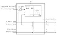
신호 처리부(151)는 센서들(110) 및 차내기기(120)들로부터 속도 정보 및 무게 정보를 입력 받아 처리한다. 신호 처리부(151)는 가속도 센서에 의해 측정되는 가속도 신호를 입력 받아 디지털화하여 가속도(longitudinal acceleration, Ax)를 출력한다. 가속도 Ax는 충돌 여부 및 충돌 정도를 판단하는데 사용된다.The signal processing unit (151) receives and processes speed information and weight information from sensors (110) and in-cabin devices (120). The signal processing unit (151) receives and digitizes an acceleration signal measured by an acceleration sensor and outputs acceleration (longitudinal acceleration, Ax). Acceleration Ax is used to determine whether or not a collision has occurred and the degree of the collision.
또한, 신호 처리부(151)는 가속도 센서에 의해 측정되는 가속도 신호를 누적하여 누적속도 dV를 산출한다. 누적속도 dV는 충돌진행 정도를 판단하는데 사용된다.In addition, the signal processing unit (151) accumulates the acceleration signal measured by the acceleration sensor and calculates the accumulated speed dV. The accumulated speed dV is used to determine the extent of collision progression.
신호 처리부(151)는 휠 속도 센서, ADAS, ESC 또는 GPS 등으로부터 차량 속도를 실시간으로 수신할 수 있다. 신호 처리부(151)는 가속도 센서를 통해 차량 충돌을 감지하면, 충돌 직전 차량 속도를 충돌 시 차량 속도로 판단하여, 해당 차량 속도를 충돌 초기 속도(initial crash speed, V0)로 저장한다.The signal processing unit (151) can receive the vehicle speed in real time from a wheel speed sensor, ADAS, ESC, or GPS. When the signal processing unit (151) detects a vehicle collision through an acceleration sensor, it determines the vehicle speed immediately before the collision as the vehicle speed at the time of the collision and stores the corresponding vehicle speed as the initial crash speed (V0).
신호 처리부(151)는 충돌 초기 속도 V0에서 누적속도 dV를 차감하여 예상 현재 속도(Estimated current vehicle speed, Vcrnt)를 산출한다. 예상 현재 속도 Vcrnt는 [수학식 1]과 같이 나타낼 수 있다.The signal processing unit (151) subtracts the accumulated speed dV from the initial collision speed V0 to calculate the estimated current vehicle speed (Vcrnt). The estimated current speed Vcrnt can be expressed as in [Mathematical Formula 1].
여기서, t0는 충돌 시작 시간(crash time)이고, tx은 현재 시간이다.Here, t0 is the crash time and tx is the current time.
신호 처리부(151)는 메모리에 기저장된 차량 제원 정보, 차량 내 탑승 정보(운전자 및 동승자) 및 적재물 정보 등을 활용하여 차량 중량(vehicle mass, m)을 산출한다. 여기서, 차량 내 탑승 정보는 좌석별로 장착된 무게 센서를 이용하여 획득할 수 있고, 적재물 정보는 적재함(예: 트렁크 등)에 장착된 무게 센서를 통해 획득할 수 있다. 예를 들어, 신호 처리부(151)는 차량 제원 정보에 포함된 공차중량과 무게 센서에 의해 측정된 탑승자 무게 및/또는 적재물 무게를 합하여 차량 중량 m을 구한다.The signal processing unit (151) calculates the vehicle weight (vehicle mass, m) by using the vehicle specification information, vehicle occupant information (driver and passengers), and cargo information stored in the memory. Here, the vehicle occupant information can be obtained by using a weight sensor mounted on each seat, and the cargo information can be obtained by a weight sensor mounted on a cargo area (e.g., trunk, etc.). For example, the signal processing unit (151) calculates the vehicle weight m by adding the curb weight included in the vehicle specification information and the passenger weight and/or cargo weight measured by the weight sensor.
추정부(152)는 신호 처리부(151)로부터 입력되는 정보를 기반으로 운동량 및 에어백 전개 임계치 감소율(Decrease Factor, DF)을 산출한다. 추정부(152)는 신호 처리부(151)로부터 가속도 Ax, 충돌 초기 속도 V0, 예상 현재 속도 Vcrnt 및 차량 중량 m를 입력 받아 충돌 전 운동량(momentum) P를 산출한다. 추정부(152)는 [수학식 2]를 이용하여 충돌 전 운동량 P를 산출한다.The estimation unit (152) calculates the momentum and airbag deployment threshold decrease factor (DF) based on the information input from the signal processing unit (151). The estimation unit (152) calculates the pre-crash momentum P by receiving the acceleration Ax, the initial collision velocity V0, the expected current velocity Vcrnt, and the vehicle weight m from the signal processing unit (151). The estimation unit (152) calculates the pre-crash momentum P using [Mathematical Formula 2].
여기서, V는 차량 속도 즉, 충돌 초기 속도 V0를 의미한다.Here, V represents the vehicle speed, i.e., the initial collision speed V0.
추정부(152)는 예상 현재 속도 Vcrnt와 차량 중량 m을 이용하여 충돌 이후 감소되고 있는 현재 운동량(current momentum, Pcrnt)을 계산한다. 현재 운동량 Pcrnt는 [수학식 3]과 같이 정의할 수 있다.The estimation unit (152) calculates the current momentum (Pcrnt) that is decreasing after the collision using the expected current speed Vcrnt and the vehicle weight m. The current momentum Pcrnt can be defined as in [Mathematical Formula 3].
추정부(152)는 충돌 초기 속도 V0, 예상 현재 속도 Vcrnt 및 차량 중량 m를 기반으로 유효 운동량 dP를 산출한다. 유효 운동량 dP는 차량이 특정 대상(충돌 물체 또는 충돌 대상)과 충돌하는 상황에서 차량 운동량을 의미한다. 다시 말해서, 유효 운동량 dP는 충돌 전 운동량과 충돌 후 운동량의 차이를 말한다.The estimation unit (152) calculates the effective momentum dP based on the initial collision velocity V0, the expected current velocity Vcrnt, and the vehicle weight m. The effective momentum dP refers to the vehicle momentum in a situation where the vehicle collides with a specific object (collision object or collision target). In other words, the effective momentum dP refers to the difference between the momentum before the collision and the momentum after the collision.
특정 대상이 고정 물체(예: 벽 등)인 경우, 유효 운동량 dP은 [수학식 4]와 같이 나타낼 수 있다.When a specific target is a fixed object (e.g., a wall), the effective momentum dP can be expressed as in [Mathematical Equation 4].
특정 대상이 이동 물체(예: 차량 등)인 경우, 유효 운동량 dP은 [수학식 5]를 이용하여 산출할 수 있다.When a specific target is a moving object (e.g., a vehicle), the effective momentum dP can be calculated using [Mathematical Formula 5].
여기서, mrel은 이동 물체의 중량이고, V0rel은 차량을 기준으로 이동 물체의 상대 충돌 초기 속도이다.Here, m rel is the weight of the moving object, and V0 rel is the initial collision velocity of the moving object relative to the vehicle.
또한, 추정부(152)는 예상 현재 속도 Vcrnt에 근거하여 충돌 시점 t0부터 현재 시점 tx까지의 차량 이동거리를 추정하여 충돌 물체가 차량 안으로 침투하는 정도를 판단한다. 다시 말해서, 추정부(152)는 [수학식 6]을 이용하여 충돌물체 침투 거리(침투량, PNTd)를 산출한다.In addition, the estimation unit (152) estimates the vehicle travel distance from the collision point t0 to the current point tx based on the expected current speed Vcrnt to determine the extent to which the collision object penetrates into the vehicle. In other words, the estimation unit (152) calculates the collision object penetration distance (penetration amount, PNTd) using [Mathematical Formula 6].
추정부(152)는 충돌 전 운동량 P과 현재 운동량 Pcrnt의 차이 즉, 유효 운동량 dP를 임계치 감소율 DF로 결정한다. 추정부(152)는 유효 운동량 dP와 충돌물체 침투량 PNTd의 관계를 고려하여 임계치 감소율 DF를 이용하여 에어백 전개 임계치에 조정할지를 결정한다.The estimation unit (152) determines the difference between the pre-collision momentum P and the current momentum Pcrnt, that is, the effective momentum dP, as the threshold reduction rate DF. The estimation unit (152) considers the relationship between the effective momentum dP and the impact object penetration amount PNTd and determines whether to adjust the airbag deployment threshold using the threshold reduction rate DF.
임계치 감소율 DF를 결정하는 방법은 유효 침투량 임계치를 설정하는 1단계, 유효 운동량 임계치를 설정하는 2단계, 및 운동량-침투량 임계 값 모델을 설정하는 3단계로 이루어진다.The method for determining the threshold reduction rate DF consists of three steps: step 1 of setting the effective penetration threshold,
1단계에서, 추정부(152)는 에어백을 전개하는데 요구되는 시간 즉, 요구 전개 시간(Required Time to Fire, RTTF)과 충돌 초기 속도(V0)를 곱하여 유효 침투량 임계치를 설정한다. 이때, 차량 전방 구조물(예: 범퍼 등)로부터 에어백 제어장치의 전원 공급 장치(미도시)까지의 레이아웃을 고려하여 충돌 시 전원 공급을 유지할 수 있는 위치 이내로 설정한다.In
예를 들어, 다음 충돌 상황에서 최소 유효 침투량 및 최대 유효 침투량이 0.7m 및 0.5m이면, 0.5m~0.7m 범위 내에서 유효 침투량 임계치(예: 500mm)를 설정한다.For example, in the following collision situation, if the minimum and maximum effective penetration amounts are 0.7 m and 0.5 m, the effective penetration amount threshold (e.g., 500 mm) is set within the range of 0.5 m to 0.7 m.
[충돌 상황][Conflict situation]
충돌 모드: 정면 Small overlap (pole) ~ 정면 poleCollision Mode: Front Small overlap (pole) ~ Front pole
충돌 초기 속도: 64kph ~ 32kphInitial collision speed: 64kph to 32kph
RTTF: 40ms ~ 55msRTTF: 40ms ~ 55ms
최소 유효 침투량: (64kph×1000/3600) × (40ms/1000) = 0.7mMinimum effective penetration: (64kph × 1000/3600) × (40ms/1000) = 0.7m
최대 유효 침투량: (32kph×1000/3600) × (55ms/1000) = 0.5mMaximum effective penetration: (32kph×1000/3600)×(55ms/1000) = 0.5m
2단계에서, 추정부(152)는 비정형 충돌 최저 속도 시험 데이터를 활용하여 에어백 전개가 요구된 시점(tx-RTTF)에 남아있는 운동량 즉, 유효 운동량 임계치를 결정한다. 유효 운동량 임계치를 결정하기 위해서는 미전개 속도 기준 운동량을 최소값으로 최소 비정형 충돌 전개 시점의 운동량을 기준으로 두 값의 기울기를 산출하고, 산출된 기울기를 이용하여 이후 차량 속도에 따른 유효 운동량 임계치를 결정(설정)한다.In the second step, the estimation unit (152) determines the effective momentum threshold, that is, the remaining momentum at the time (tx-RTTF) when airbag deployment is required, by utilizing the atypical crash minimum speed test data. In order to determine the effective momentum threshold, the slope of the two values is calculated based on the momentum at the minimum atypical crash deployment time as the minimum value based on the non-deployment speed reference momentum, and the calculated slope is used to determine (set) the effective momentum threshold according to the subsequent vehicle speed.
예를 들어, 도 2를 참조하면, 추정부(152)는 미전개 속도 기준 운동량 MIN과 최소 비정형 충돌 전개 시점의 운동량 7500Nm을 기준으로 두 값의 기울기를 산출한다. 그리고, 추정부(152)는 다음 충돌 상황에서 기산출된 기울기를 이용하여 충돌 속도가 32kph일 때 운동량 13000Nm을 산출하고, 그 산출된 운동량을 유효 운동량 임계치로 설정한다.For example, referring to FIG. 2, the estimation unit (152) calculates the slope of two values based on the momentum MIN based on the undeveloped speed and the momentum 7500 Nm at the minimum irregular collision development point. Then, the estimation unit (152) calculates the momentum 13000 Nm when the collision speed is 32 kph using the calculated slope in the next collision situation, and sets the calculated momentum as the effective momentum threshold.
[충돌 상황][Conflict situation]
충돌 모드: 정면 poleCollision Mode: Frontal Pole
충돌 시험속도: 32kphCrash test speed: 32kph
RTTF: 55msRTTF: 55ms
3단계에서는, 1단계 및 2단계에서 결정된 임계치를 기반으로 운동량-침투량 임계치 모델을 설정한다. 예컨대, 도 3에 도시된 바와 같이 유효 침투량 임계치를 500mm로 고정하고, 보간법을 활용하여 충돌 초기 속도별로 변화하는 유효 운동량 임계치를 설정한다.In
운동량-침투량 임계치 모델에 정면 충돌 시험 데이터를 적용해보면 도 4와 같은 그래프 경향을 보인다. 16kph 정면 충돌 시 충돌물체 침투량 PNTd은 유효 침투량 임계치인 500mm에 도달하지 않고, 유효 운동량 dP도 남아 있는 것이 없다. 반면, 고속 정면 충돌 시에는 속도별 비정형 충돌 요구 전개 시간 기준의 유효 운동량 임계치를 설정하였기 때문에 정면 충돌 초기에 유효 운동량이 남아 있지만 시간이 흐르면서 차량 구조물의 저항으로 더 이상 충돌물체의 침투가 일어나지 않게 된다.Applying the frontal crash test data to the momentum-penetration threshold model shows the graph trend as in Fig. 4. In the case of a 16 kph frontal crash, the impact object penetration PNTd does not reach the effective penetration threshold of 500 mm, and there is no effective momentum dP remaining. On the other hand, in the case of a high-speed frontal crash, the effective momentum threshold is set based on the required development time for the irregular crash by speed, so the effective momentum remains at the beginning of the frontal crash, but as time passes, the impact object no longer penetrates due to the resistance of the vehicle structure.
한편, 폴(pole)이나 날카로운 물체와 충돌이 일어나는 경우, 도 5와 같이 충돌물체 침투량 PNTd은 증가하지만 유효 운동량 dP의 감소는 적다. 충돌물체 침투가 지속되고 유효 운동량이 남아있는 경우 남아 있는 유효 운동량을 기준으로 에어백 전개 임계치를 저감시킬 수 있다.Meanwhile, when a collision occurs with a pole or sharp object, the impact object penetration amount PNTd increases as shown in Fig. 5, but the decrease in the effective momentum dP is small. When the impact object penetration continues and the effective momentum remains, the airbag deployment threshold can be reduced based on the remaining effective momentum.
제어부(153)는 가속도 Ax, 누적속도 dV 및 임계치 감소율 DF을 활용하여 에어백 전개 여부를 결정한다. 제어부(153)는 신호 처리부(151)로부터 가속도 Ax 및 누적속도 dV를 입력받고, 추정부(152)로부터 임계치 감소율 DF을 제공받는다. 제어부(153)는 임계치 감소율 DF를 이용하여 에어백 전개 임계치 Thdv.Fin를 결정한다. 여기서, 에어백 전개 임계치는 에어백 전개를 판단하는 기준이 되는 누적속도 임계치를 의미한다. 제어부(153)는 [수학식 7]과 같이 메모리에 기저장된 기본 에어백 전개 임계치 dV_Th.에 임계치 감소율 DF를 적용하여 에어백 전개 임계치 Thdv.Fin를 산출한다.The control unit (153) determines whether to deploy the airbag by utilizing the acceleration Ax, the cumulative speed dV, and the threshold reduction rate DF. The control unit (153) receives the acceleration Ax and the cumulative speed dV from the signal processing unit (151), and receives the threshold reduction rate DF from the estimation unit (152). The control unit (153) determines the airbag deployment threshold Thdv.Fin by utilizing the threshold reduction rate DF. Here, the airbag deployment threshold means the cumulative speed threshold which is the criterion for determining the airbag deployment. The control unit (153) calculates the airbag deployment threshold Thdv.Fin by applying the threshold reduction rate DF to the basic airbag deployment threshold dV_Th. pre-stored in the memory as in [Mathematical Formula 7].
제어부(153)는 충돌 중 차량이 가지고 있는 유효 운동량이 크고 차량 내부로 충돌물체가 충분히 침투했다고 판단하면, 에어백 전개를 요청하는 전개 요청 신호를 에어백 구동부(140)로 전송한다. 다시 말해서, 제어부(153)는 가속도 Ax가 가속도 임계치 ThAx 이상이며, 누적속도 dV가 에어백 전개 임계치 Thdv.Fin 이상이면 에어백 전개 요청을 에어백 구동부(140)에 전송한다. 에어백 구동부(140)는 제어부(153)의 에어백 전개 요청에 따라 에어백(130)을 전개한다.If the control unit (153) determines that the effective momentum of the vehicle during the collision is large and the collision object has sufficiently penetrated into the vehicle, it transmits a deployment request signal requesting airbag deployment to the airbag driving unit (140). In other words, if the acceleration Ax is greater than or equal to the acceleration threshold Th Ax and the accumulated velocity dV is greater than or equal to the airbag deployment threshold Thdv.Fin, the control unit (153) transmits an airbag deployment request to the airbag driving unit (140). The airbag driving unit (140) deploys the airbag (130) according to the airbag deployment request of the control unit (153).
한편, 제어부(153)는 가속도 Ax가 가속도 임계치 ThAx 미만 및/또는 누적속도 dV가 에어백 전개 임계치 Thdv.Fin 미만이면 에어백 전개 임계치 Thdv.Fin를 다시 결정한다.Meanwhile, the control unit (153) re-determines the airbag deployment threshold Thdv.Fin if the acceleration Ax is less than the acceleration threshold Th Ax and/or the accumulated velocity dV is less than the airbag deployment threshold Thdv.Fin.
도 6은 본 발명의 일 실시 예에 따른 에어백 제어 방법을 도시한 흐름도이다.FIG. 6 is a flowchart illustrating an airbag control method according to one embodiment of the present invention.
프로세서(150)는 충돌 감지 시 센서들(110) 및/또는 차내기기(120)들에 의해 측정된 가속도 Ax 및 차량 속도 V를 검출한다(S110). 프로세서(150)는 충돌 센서에 의해 차량 충돌이 감지되면 충돌 직전 또는 직후의 가속도 및 차량 속도를 검출한다.The processor (150) detects the acceleration Ax and the vehicle speed V measured by the sensors (110) and/or the in-vehicle devices (120) when a collision is detected (S110). When a vehicle collision is detected by the collision sensor, the processor (150) detects the acceleration and the vehicle speed immediately before or after the collision.
프로세서(150)는 가속도 및 차량 속도를 이용하여 누적속도 dV, 충돌 초기 속도 V0 및 예상 현재 속도 Vcrnt를 계산한다(S120). 프로세서(150)의 신호 처리부(151)는 가속도 센서로부터 입력되는 가속도 신호를 디지털화하고, 가속도 신호를 누적하여 누적속도 dV를 산출한다. 신호 처리부(151)는 충돌 직전 또는 직후에 측정된 차량 속도를 충돌 초기 속도 V0로 저장한다. 또한, 신호 처리부(151)는 충돌 초기 속도 V0에서 누적속도 dV를 차감하여 예상 현재 속도 Vcrnt를 산출한다. 또한, 신호 처리부(151)는 차량 제원 정보에 포함된 공차중량을 기반으로 무게 센서에 의해 측정된 탑승자 무게 및/또는 적재물 무게를 고려하여 차량 중량 m을 산출할 수 있다.The processor (150) calculates the cumulative speed dV, the initial collision speed V0, and the expected current speed Vcrnt using the acceleration and the vehicle speed (S120). The signal processing unit (151) of the processor (150) digitizes the acceleration signal input from the acceleration sensor, accumulates the acceleration signal, and calculates the cumulative speed dV. The signal processing unit (151) stores the vehicle speed measured immediately before or after the collision as the initial collision speed V0. In addition, the signal processing unit (151) subtracts the cumulative speed dV from the initial collision speed V0 to calculate the expected current speed Vcrnt. In addition, the signal processing unit (151) can calculate the vehicle weight m by considering the passenger weight and/or the load weight measured by the weight sensor based on the curb weight included in the vehicle specification information.
프로세서(150)는 가속도, 충돌 초기 속도, 예상 현재 속도 및 차량 중량을 기반으로 차량 운동량을 추정한다(S130). 프로세서(150) 내 추정부(152)는 차량 속도와 차량 중량을 이용하여 충돌 전 운동량을 추정한다. 추정부(152)는 예상 현재 속도와 차량 중량을 고려하여 현재 운동량을 추정한다. 추정부(152)는 충돌물체가 고정물체인 경우 예상 현재 속도와 차량 중량을 기반으로 유효 운동량을 추정하고, 충돌물체가 이동물체이면 차량 중량, 예상 현재 속도, 충돌물체의 중량 및 충돌물체의 상대 충돌 초기 속도를 토대로 유효 운동량을 추정한다.The processor (150) estimates vehicle momentum based on acceleration, initial collision velocity, expected current velocity, and vehicle weight (S130). The estimation unit (152) in the processor (150) estimates pre-collision momentum using the vehicle velocity and vehicle weight. The estimation unit (152) estimates current momentum by considering the expected current velocity and vehicle weight. If the collision object is a fixed object, the estimation unit (152) estimates effective momentum based on the expected current velocity and vehicle weight, and if the collision object is a moving object, the estimation unit (152) estimates effective momentum based on the vehicle weight, expected current velocity, weight of the collision object, and relative initial collision velocity of the collision object.
프로세서(150)는 가속도 및 예상 현재 속도를 이용하여 충돌물체 침투량 PNTd을 산출한다(S140). 추정부(152)는 충돌 초기 속도 및 가속도를 이용하여 예상 현재 속도를 산출하고, 산출되는 예상 현재 속도를 기반으로 충돌 시점부터 현재 시점까지 차량이 이동한 거리 즉, 충돌물체의 침투거리 PNTd를 계산한다.The processor (150) calculates the collision object penetration amount PNTd using the acceleration and the expected current speed (S140). The estimation unit (152) calculates the expected current speed using the initial collision speed and acceleration, and calculates the distance the vehicle has traveled from the collision point to the current point, i.e. the collision object penetration distance PNTd, based on the calculated expected current speed.
프로세서(150)는 유효 운동량 dP 및 충돌물체 침투량 PNTd을 기반으로 임계치 감소율 DF를 반영하여 에어백 전개 임계치를 조정할지를 결정한다(S150). 추정부(152)는 충돌물체 침투량이 유효 침투량 임계치 도달이 예상되는 경우, 충돌 전 운동량과 충돌 후 운동량(현재 운동량)의 차이 즉, 임계치 감소율 DF을 반영하여 에어백 전개 임계치 조정을 결정한다.The processor (150) determines whether to adjust the airbag deployment threshold by reflecting the threshold reduction rate DF based on the effective momentum dP and the impact object penetration amount PNTd (S150). If the impact object penetration amount is expected to reach the effective penetration amount threshold, the estimation unit (152) determines the airbag deployment threshold adjustment by reflecting the difference between the momentum before the collision and the momentum after the collision (current momentum), that is, the threshold reduction rate DF.
프로세서(150)는 임계치 감소율 DF을 반영하여 에어백 전개 임계치를 결정한다(S160). 프로세서(150) 내 제어부(153)는 디폴트로 설정된 기본 에어백 전개 임계치 dV_Th.에 임계치 감소율 DF을 반영하여 에어백 전개 임계치 Thdv.Fin를 결정한다. 프로세서(150)는 에어백 전개 임계치에 임계치 감소율 DF 미반영이 결정되면 기본 에어백 전개 임계치를 기준으로 에어백 전개를 결정한다. The processor (150) determines the airbag deployment threshold by reflecting the threshold reduction rate DF (S160). The control unit (153) within the processor (150) determines the airbag deployment threshold Thdv.Fin by reflecting the threshold reduction rate DF to the basic airbag deployment threshold dV_Th. set as default. If the processor (150) determines that the threshold reduction rate DF is not reflected in the airbag deployment threshold, it determines airbag deployment based on the basic airbag deployment threshold.
프로세서(150)는 가속도 Ax가 가속도 임계치 ThAx 이상이며 누적속도 dV가 에어백 전개 임계치 Thdv.Fin 이상인지를 확인한다(S170). 제어부(153)는 가속도 및 누적속도를 기반으로 에어백 전개여부를 결정한다. 제어부(153)는 에어백 전개가 결정되면 에어백 구동부(140)에 에어백 전개 요청을 전송한다.The processor (150) checks whether the acceleration Ax is greater than or equal to the acceleration threshold ThAx and the accumulated speed dV is greater than or equal to the airbag deployment threshold Thdv.Fin (S170). The control unit (153) determines whether to deploy the airbag based on the acceleration and accumulated speed. When airbag deployment is determined, the control unit (153) transmits an airbag deployment request to the airbag drive unit (140).
프로세서(150)는 가속도가 가속도 임계치 이상이며 누적속도가 에어백 전개 임계치 이상인 경우, 에어백 구동부(140)를 제어하여 에어백(130)을 전개한다(S180).The processor (150) controls the airbag drive unit (140) to deploy the airbag (130) when the acceleration is greater than or equal to the acceleration threshold and the accumulated speed is greater than or equal to the airbag deployment threshold (S180).
한편, 프로세서(150)는 가속도가 가속도 임계치 미만 및/또는 누적속도가 에어백 전개 임계치 미만인 경우 에어백 전개 임계치를 다시 결정한다.Meanwhile, the processor (150) re-determines the airbag deployment threshold if the acceleration is less than the acceleration threshold and/or the accumulated speed is less than the airbag deployment threshold.
도 7 내지 도 9는 본 발명의 일 실시 예에 따른 에어백 제어 장치가 탑재된 차량이 이동물체와 충돌하는 경우 에어백 제어 방법을 설명하기 위한 도면이다. 본 실시 예에서는 이동물체가 차량인 것을 예로 들어 설명한다.FIGS. 7 to 9 are drawings for explaining an airbag control method when a vehicle equipped with an airbag control device according to one embodiment of the present invention collides with a moving object. In this embodiment, an example in which the moving object is a vehicle is used for explanation.
도 7을 참조하면, 차량이 타차량과 충돌하는 경우, 차량의 신호 처리부(151)는 가속도 센서, ADAS, V2V 통신 및/또는 GPS 등을 통해 가속도 Ax, 충돌 시작 시간 T0, 차량 속도 V, 타차량 속도 V2, 차량의 중량 M 및 타차량의 중량 M2를 입력 받는다.Referring to FIG. 7, when a vehicle collides with another vehicle, the signal processing unit (151) of the vehicle receives acceleration Ax, collision start time T0, vehicle speed V, other vehicle speed V2, vehicle weight M, and other vehicle weight M2 through an acceleration sensor, ADAS, V2V communication, and/or GPS.
신호 처리부(151)는 가속도 Ax를 누적하여 누적속도 dV를 산출하고, 충돌 초기 속도 V0 및 누적속도 dV를 기반으로 차량의 예상 현재 속도 Vcrnt1을 추정할 수 있다. 또한, 신호 처리부(151)는 충돌 직전 타차량의 차량 속도 V2를 기준으로 차량의 가속도 센서값 Ax를 누적한 누적속도 dV를 고려하여 타차량의 예상 현재 속도 Vcrnt2를 추정할 수 있다. 신호 처리부(151)는 충돌 직전의 차량 속도 V 및 타차량 속도 V2를 차량의 충돌 초기 속도 V0_1 및 타차량의 충돌 초기 속도 V0_2로 각각 저장한다. 신호 처리부(151)는 차량과 타차량의 중량 M과 M2를 디지털화하여 m1과 m2로 출력한다.The signal processing unit (151) accumulates the acceleration Ax to calculate the accumulated speed dV, and can estimate the expected current speed Vcrnt1 of the vehicle based on the initial collision speed V0 and the accumulated speed dV. In addition, the signal processing unit (151) can estimate the expected current speed Vcrnt2 of the other vehicle by considering the accumulated speed dV that accumulates the acceleration sensor value Ax of the vehicle based on the vehicle speed V2 of the other vehicle immediately before the collision. The signal processing unit (151) stores the vehicle speed V and the other vehicle speed V2 immediately before the collision as the initial collision speed V0_1 of the vehicle and the initial collision speed V0_2 of the other vehicle, respectively. The signal processing unit (151) digitizes the weights M and M2 of the vehicle and the other vehicle and outputs them as m1 and m2.
도 8을 참조하면, 차량의 추정부(152)는 신호 처리부(151)에서 추정된 차량과 타차량의 예상 현재 속도 Vcrnt1 및 Vcrnt2와 차량과 타차량의 중량 m1 및 m2를 이용하여 차량의 현재 운동량과 타차량의 현재 운동량을 산출하고, 산출한 두 운동량을 합하여 현재 운동량(충돌 후 운동량) Pcrnt를 구한다. 또한, 추정부(152)는 차량의 충돌 초기 속도 V0_1와 타차량의 충돌 초기 속도 V0_2와 차량과 타차량의 중량 m1 및 m2를 이용하여 차량의 충돌 전 운동량과 타차량의 충돌 전 운동량을 산출하여 덧셈 연산을 수행하여 충돌 전 운동량 P을 산출한다.Referring to FIG. 8, the estimation unit (152) of the vehicle calculates the current momentum of the vehicle and the current momentum of the other vehicle by using the expected current velocities Vcrnt1 and Vcrnt2 of the vehicle and the other vehicle estimated by the signal processing unit (151) and the weights m1 and m2 of the vehicle and the other vehicle, and adds the two calculated momentums to obtain the current momentum (post-collision momentum) Pcrnt. In addition, the estimation unit (152) calculates the pre-collision momentum of the vehicle and the pre-collision momentum of the other vehicle by using the initial collision velocity V0_1 of the vehicle and the initial collision velocity V0_2 of the other vehicle and the weights m1 and m2 of the vehicle and the other vehicle, and performs an addition operation to calculate the pre-collision momentum P.
추정부(152)는 실시간으로 현재 운동량 Pcrnt가 변화하므로 충돌 전 운동량 P와 현재 운동량 Pcrnt의 차이인 유효 운동량 dP를 이용하여 임계치 감소율 DF%를 결정한다. 유효 운동량에 근거하여 임계치 감소율 DF%를 결정하므로, 차량이 정차 중이더라도 타차량의 속도 및/또는 중량 정보를 이용하여 충격량을 예측하여 에어백 전개를 앞당길 수 있다. 반면, 고속 충돌 시 운동량은 크지만 충돌물체의 강성이 작거나 충돌물체와 함께 이동하는 경우 에어백 전개를 빠르게 전개할 필요가 없으므로, 차량의 예상 현재 속도를 이용하여 충돌물체의 침투거리를 계산한 후 물체가 충분히 침투한 상황에 잔존 유효 운동량이 있는 경우, 에어백 전개 임계치를 낮추는 DF%를 최종 설정한다. 침투량 임계치는 에어백 제어 장치의 전원을 공급하는 배터리나 정션 박스 위치로 설정하며, 유효 운동량의 기준은 요구 전개 판단 시간을 기준으로 차량 시험을 통해 해당 시간에 발생한 유효 운동량으로 설정한다.The estimation unit (152) determines the threshold reduction rate DF% using the effective momentum dP, which is the difference between the pre-collision momentum P and the current momentum Pcrnt, since the current momentum Pcrnt changes in real time. Since the threshold reduction rate DF% is determined based on the effective momentum, even if the vehicle is stopped, the airbag deployment can be advanced by predicting the impact amount using the speed and/or weight information of other vehicles. On the other hand, in the case of a high-speed collision, the momentum is large, but if the rigidity of the collision object is small or the vehicle moves together with the collision object, there is no need to deploy the airbag quickly, so the penetration distance of the collision object is calculated using the estimated current speed of the vehicle, and if there is residual effective momentum in a situation where the object has sufficiently penetrated, the DF%, which lowers the airbag deployment threshold, is finally set. The penetration amount threshold is set to the battery or junction box position that supplies power to the airbag control device, and the effective momentum criterion is set to the effective momentum generated at the corresponding time through a vehicle test based on the required deployment judgment time.
차량 시험 데이터는 모든 속도별로 진행되기 어렵기 때문에 유효운동량은 정형 충돌 시험 시 얻은 운동량과 동일 속도의 비정형 물체 충돌시험 운동량을 비교하여 설정하고 충돌 초기 속도에 따라 보간법을 활용하여 해당하는 유효 운동량 임계치를 설정한다Since it is difficult to proceed with vehicle test data at all speeds, the effective momentum is set by comparing the momentum obtained in a typical crash test with the momentum obtained in an irregular object crash test at the same speed, and the corresponding effective momentum threshold is set by using an interpolation method according to the initial collision speed.
도 9를 참조하면, 제어부(153)는 최종 결정된 임계값 감소율을 기본 에어백 전개 임계치(누적속도 임계치)에 적용하여 에어백 전개 임계치(누적속도 기준 임계치)를 낮춰 에어백 전개를 앞당길 수 있다.Referring to FIG. 9, the control unit (153) can apply the final determined threshold reduction rate to the basic airbag deployment threshold (cumulative speed threshold) to lower the airbag deployment threshold (cumulative speed standard threshold) and advance the airbag deployment.
도 10은 본 발명과 관련된 충돌물체에 따른 가속도, 누적속도 및 충돌 전후 운동량을 비교한 도면이고, 도 11a 및 도 11b는 본 발명과 관련된 충돌물체에 따른 운동량 변화를 도시한 도면이며, 도 12a는 본 발명에 따른 충돌물체에 따른 충돌물체 침투량을 추정한 그래프이고, 도 12b 및 도 12c는 본 발명에 따른 충돌물체에 따른 실제 충돌물체 침투량을 도시한 도면이며, 도 13은 본 발명의 일 실시 예에 따른 유효 운동량과 충돌 물체 침투량에 따른 에어백 전개 시점 결정을 설명하기 위한 도면이고, 도 14 및 도 15는 종래기술과 본 발명의 에어백 제어 기술을 비교하기 위한 예시도이다.FIG. 10 is a diagram comparing acceleration, cumulative velocity, and momentum before and after collision according to a colliding object related to the present invention, FIGS. 11a and 11b are diagrams illustrating changes in momentum according to a colliding object related to the present invention, FIG. 12a is a graph estimating the amount of collision object penetration according to a colliding object according to the present invention, FIGS. 12b and 12c are diagrams illustrating the actual amount of collision object penetration according to a colliding object according to the present invention, FIG. 13 is a diagram for explaining determination of airbag deployment timing according to effective momentum and collision object penetration according to an embodiment of the present invention, and FIGS. 14 and 15 are exemplary diagrams for comparing the airbag control technology of the present invention with the prior art.
도 10에 도시된 바와 같이, 동일 속도 충돌인 경우, 충돌물체에 따라 다른 가속도 센서값이 출력되게 되면 충돌물체의 무게, 강성 또는 상대 속도에 비례하여 가속도 센서값이 입력되게 된다. 예컨대, 전봇대나 폴(pole) 같이 충돌부위가 좁은 형상의 충돌물체인 경우, 입력되는 가속도는 낮으나 차량 손상이 크고, 차량 구조물 안으로 충돌물체가 더욱 깊게 침투하게 되므로, 충돌 전후 차량의 운동량 P 및 Pcrnt을 추정하여 전개시점을 조절할 수 있다.As illustrated in Fig. 10, in the case of a same-speed collision, if different acceleration sensor values are output depending on the colliding object, the acceleration sensor value is input in proportion to the weight, stiffness, or relative speed of the colliding object. For example, in the case of a colliding object with a narrow collision area such as a utility pole or a pole, the input acceleration is low but the vehicle damage is large and the colliding object penetrates deeper into the vehicle structure, so the momentum P and Pcrnt of the vehicle before and after the collision can be estimated to control the unfolding timing.
비고정 물체와의 충돌이 발생한 경우, 파손부위는 크나 입력되는 가속도가 작기 때문에 11a에 도시된 바와 같이 동일 시간에 더 많은 운동량이 남아있게 된다. 도 11b와 같이 차량 시험 데이터에 따르면, 비고정 물체와의 충돌 시 운동량 변화량에 의한 구분성이 확실하며 해당 구분성으로 에어백 전개 임계치를 조정하여 비고정 물체와의 충돌이나 차대차 충돌에서 충돌물체(예: 차량)의 정보를 활용하여 운전자에게 큰 충격이 오기 전 에어백 전개 여부를 결정하는 성능을 향상 시킬 수 있다.In the case of a collision with a non-fixed object, since the damaged area is large but the input acceleration is small, more momentum remains in the same time as shown in 11a. As shown in Fig. 11b, according to the vehicle test data, the distinction by the change in momentum in the case of a collision with a non-fixed object is clear, and by adjusting the airbag deployment threshold with the distinction, the performance of determining whether to deploy the airbag before a large impact is applied to the driver by utilizing the information of the colliding object (e.g., vehicle) in a collision with a non-fixed object or a car-to-car collision can be improved.
비고정 물체(이동물체)나 비정형 충돌의 경우, 차량이 충돌 이후에도 차량 속도가 유지 되며 차량 속도가 유지되는 시간 동안 차량의 파손이 진행된다. 도 12a의 각 시험 모드별 충돌 이후 차량 추정 속도(예상 현재 속도)에 따른 충돌 물체의 내부 침투량을 추정한 결과와 도 12b 및 도 12c의 동일 시험 조건에서 실제 차량 시험 시 충돌물체의 내부 침투량을 비교해보면 유사한 경향을 보인다. In the case of a non-stationary object (moving object) or an irregular collision, the vehicle speed is maintained even after the collision, and the vehicle damage progresses during the time that the vehicle speed is maintained. The results of estimating the internal penetration of the crash object according to the estimated vehicle speed (estimated current speed) after the collision for each test mode in Fig. 12a are compared with the internal penetration of the crash object in an actual vehicle test under the same test conditions in Figs. 12b and 12c, and similar trends are shown.
본 발명에 따르면, 도 13과 같이 충돌물체가 유효 침투량 임계치 500mm 이상 침투한 상황에서 운동량이 상당 부분 남아 있음을 추정할 수 있다. 이 경우, 차량의 심각한 파손이 예상되므로, 충돌 이후 지속적으로 가속도가 상승하면 에어백 전개 임계치를 조정하여 에어백 전개시간을 앞당길 수 있다.According to the present invention, it can be estimated that a considerable amount of momentum remains in a situation where the impact object has penetrated more than the effective penetration threshold of 500 mm as shown in Fig. 13. In this case, since serious damage to the vehicle is expected, if the acceleration continues to increase after the impact, the airbag deployment threshold can be adjusted to advance the airbag deployment time.
예컨대, 도 14를 참조하면, 종래에는 에어백 전개 임계치(누적속도 임계치)를 6kph로 설정되어 고정물체와 충돌하는 경우 충돌 후 20ms 이후에 에어백을 전개하고 이동물체와 충돌하는 경우 100ms 이후 에어백을 전개할 수 있다. 한편, 도 15를 참조하면, 본 발명의 에어백 제어 방법 적용 시 충돌 이후 차량 후방 충돌의 경우 40ms, 폴 충돌의 경우 20ms 에어백 전개 시간을 단축할 수 있다. 즉, 본 발명은 충돌상황에 따라 에어백 전개 임계치를 조정하여 에어백 전개 시점을 제어할 수 있다. For example, referring to FIG. 14, the conventional airbag deployment threshold (cumulative speed threshold) is set to 6 kph, so that in the case of a collision with a fixed object, the airbag can be deployed 20 ms after the collision, and in the case of a collision with a moving object, the airbag can be deployed 100 ms after the collision. Meanwhile, referring to FIG. 15, when the airbag control method of the present invention is applied, the airbag deployment time can be shortened by 40 ms in the case of a rear-end collision and by 20 ms in the case of a pole collision. That is, the present invention can control the airbag deployment timing by adjusting the airbag deployment threshold depending on the collision situation.
이상의 설명은 본 발명의 기술 사상을 예시적으로 설명한 것에 불과한 것으로서, 본 발명이 속하는 기술 분야에서 통상의 지식을 가진 자라면 본 발명의 본질적인 특성에서 벗어나지 않는 범위에서 다양한 수정 및 변형이 가능할 것이다. 따라서, 본 발명에 개시된 실시 예들은 본 발명의 기술 사상을 한정하기 위한 것이 아니라 설명하기 위한 것이고, 이러한 실시 예에 의하여 본 발명의 기술 사상의 범위가 한정되는 것은 아니다. 본 발명의 보호 범위는 아래의 청구범위에 의하여 해석되어야 하며, 그와 동등한 범위 내에 있는 모든 기술 사상은 본 발명의 권리범위에 포함되는 것으로 해석되어야 할 것이다.The above description is merely an illustrative description of the technical idea of the present invention, and those skilled in the art will appreciate that various modifications and variations may be made without departing from the essential characteristics of the present invention. Accordingly, the embodiments disclosed in the present invention are not intended to limit the technical idea of the present invention but to explain it, and the scope of the technical idea of the present invention is not limited by these embodiments. The protection scope of the present invention should be interpreted by the following claims, and all technical ideas within a scope equivalent thereto should be interpreted as being included in the scope of the rights of the present invention.
110: 센서들 120: 차내기기
130: 에어백 140: 에어백 구동부
150: 프로세서 151: 신호 처리부
152: 추정부 153: 제어부110: Sensors 120: In-car equipment
130: Airbag 140: Airbag actuator
150: Processor 151: Signal processing unit
152: Estimation section 153: Control section
Claims (20)
상기 에어백을 전개하는 에어백 구동부, 및
차량 충돌 시 가속도 및 차량 속도를 기반으로 차량 운동량 및 충돌 진행 정도를 추정하고, 상기 차량 운동량 및 상기 충돌 진행 정도를 토대로 상기 에어백의 전개를 결정하여 상기 에어백 구동부에 지시하는 프로세서를 포함하고,
상기 프로세서는,
차량에 탑재되는 센서들 및 차내기기들로부터 입력되는 상기 가속도 및 상기 차량 속도를 이용하여 누적속도, 충돌 초기 속도 및 예상 현재 속도를 연산하여 출력하는 신호 처리부,
상기 가속도, 상기 충돌 초기 속도 및 상기 예상 현재 속도에 기초하여 상기 차량 운동량 및 충돌물체 침투거리를 산출하고 산출된 차량 운동량 및 충돌 물체 침투거리에 근거하여 임계치 감소율을 결정하는 추정부, 및
상기 임계치 감소율을 기반으로 에어백 전개 임계치를 결정하고, 상기 에어백 전개 임계치에 근거하여 에어백 전개 여부를 결정하는 제어부를 포함하는 에어백 제어 장치.
airbag,
An airbag driving unit that deploys the above airbag, and
A processor is included that estimates vehicle momentum and collision progression based on acceleration and vehicle speed in the event of a vehicle collision, determines deployment of the airbag based on the vehicle momentum and collision progression, and instructs the airbag driving unit to do so.
The above processor,
A signal processing unit that calculates and outputs the accumulated speed, initial collision speed, and expected current speed using the acceleration and vehicle speed input from sensors and in-vehicle devices mounted on the vehicle.
An estimation unit that calculates the vehicle momentum and the collision object penetration distance based on the acceleration, the initial collision velocity, and the expected current velocity, and determines a threshold reduction rate based on the calculated vehicle momentum and the collision object penetration distance; and
An airbag control device including a control unit that determines an airbag deployment threshold based on the above threshold reduction rate and determines whether to deploy the airbag based on the airbag deployment threshold.
상기 신호 처리부는, 차량 제원 정보에 포함된 공차중량을 기준으로 무게 센서에 의해 측정된 탑승자 무게 및 적재물 무게 중 적어도 하나를 반영하여 차량 중량을 산출하는 것을 특징으로 하는 에어백 제어 장치.
In the first paragraph,
An airbag control device characterized in that the signal processing unit calculates the vehicle weight by reflecting at least one of the passenger weight and the load weight measured by the weight sensor based on the tolerance weight included in the vehicle specification information.
상기 추정부는, 상기 충돌 초기 속도, 상기 예상 현재 속도 및 차량 중량을 이용하여 충돌 전 운동량 및 현재 운동량을 산출하는 것을 특징으로 하는 에어백 제어 장치.
In the third paragraph,
An airbag control device characterized in that the above estimation unit calculates the pre-collision momentum and the current momentum using the initial collision velocity, the estimated current velocity, and the vehicle weight.
상기 추정부는, 상기 충돌 전 운동량과 상기 현재 운동량의 차이에 근거하여 상기 임계치 감소율을 결정하는 것을 특징으로 하는 에어백 제어 장치.
In paragraph 4,
An airbag control device, characterized in that the estimation unit determines the threshold reduction rate based on the difference between the pre-collision momentum and the current momentum.
상기 추정부는, 충돌 대상이 고정 물체인 경우, 상기 충돌 초기 속도, 상기 예상 현재 속도 및 상기 차량 중량을 이용하여 유효 운동량을 산출하는 것을 특징으로 하는 에어백 제어 장치.
In paragraph 4,
An airbag control device characterized in that the above estimation unit calculates effective momentum using the initial collision velocity, the estimated current velocity, and the vehicle weight when the collision target is a fixed object.
상기 추정부는, 충돌 대상이 이동 물체인 경우, 상기 이동 물체의 상대 충돌 초기 속도, 상기 예상 현재 속도, 상기 차량 중량 및 이동 물체 중량을 이용하여 유효 운동량을 산출하는 것을 특징으로 하는 에어백 제어 장치.
In paragraph 4,
An airbag control device characterized in that the above estimation unit calculates effective momentum by using the relative initial collision velocity of the moving object, the expected current velocity, the vehicle weight, and the moving object weight when the collision target is a moving object.
상기 추정부는, 충돌 시작 시간, 현재 시간, 상기 예상 현재 속도, 상기 충돌 초기 속도 및 상기 가속도를 이용하여 상기 충돌물체 침투거리를 산출하는 것을 특징으로 하는 에어백 제어 장치.
In paragraph 4,
An airbag control device characterized in that the above estimation unit calculates the collision object penetration distance using the collision start time, the current time, the expected current speed, the collision initial speed, and the acceleration.
상기 제어부는, 기본 에어백 전개 임계치에 상기 임계치 감소율을 반영하여 상기 에어백 전개 임계치를 결정하는 것을 특징으로 하는 에어백 제어 장치.
In the first paragraph,
An airbag control device characterized in that the control unit determines the airbag deployment threshold by reflecting the threshold reduction rate to the basic airbag deployment threshold.
상기 제어부는, 상기 가속도가 가속도 임계치 이상이며, 상기 누적속도가 상기 에어백 전개 임계치 이상이면 에어백 전개를 결정하는 것을 특징으로 하는 에어백 제어 장치.
In Article 8,
An airbag control device, characterized in that the control unit determines airbag deployment when the acceleration is greater than or equal to an acceleration threshold and the accumulated speed is greater than or equal to the airbag deployment threshold.
상기 가속도 및 상기 차량 속도를 기반으로 차량 운동량 및 충돌 진행 정도를 추정하는 단계,
상기 차량 운동량과 상기 충돌 진행 정보를 토대로 에어백의 전개를 결정하는 단계, 및
상기 에어백의 전개 결정에 따라 상기 에어백을 전개하는 단계를 포함하고,
상기 차량 운동량 및 충돌 진행 정도를 추정하는 단계는,
상기 가속도 및 상기 차량 속도를 이용하여 누적속도, 충돌 초기 속도 및 예상 현재 속도를 연산하는 단계,
상기 가속도, 상기 충돌 초기 속도 및 상기 예상 현재 속도에 기초하여 충돌 전 운동량, 현재 운동량 및 유효 운동량을 산출하는 단계, 및
상기 가속도 및 상기 예상 현재 속도를 이용하여 충돌물체 침투거리를 산출하는 단계를 포함하는 에어백 제어 방법.
Steps to detect acceleration and vehicle speed in case of a vehicle collision;
A step of estimating the vehicle momentum and the extent of collision progression based on the above acceleration and the vehicle speed,
A step for determining the deployment of the airbag based on the above vehicle momentum and the above collision progression information, and
Including a step of deploying the airbag according to a deployment decision of the airbag,
The step of estimating the above vehicle momentum and collision progression is as follows:
A step of calculating the accumulated speed, the initial collision speed and the expected current speed using the above acceleration and the vehicle speed,
A step of calculating pre-collision momentum, current momentum and effective momentum based on the above acceleration, the initial collision velocity and the expected current velocity, and
An airbag control method comprising a step of calculating a collision object penetration distance using the above acceleration and the above estimated current velocity.
상기 누적 속도, 충돌 초기 속도 및 예상 현재 속도 연산 시, 차량 제원 정보에 포함된 공차중량을 기준으로 무게 센서에 의해 측정된 탑승자 무게 및 적재물 무게 중 적어도 하나를 반영하여 차량 중량을 산출하는 단계를 더 포함하는 것을 특징으로 하는 에어백 제어 방법.
In Article 11,
An airbag control method characterized in that it further includes a step of calculating the vehicle weight by reflecting at least one of the occupant weight and the load weight measured by the weight sensor based on the curb weight included in the vehicle specification information when calculating the above-mentioned accumulated speed, initial collision speed and expected current speed.
상기 충돌 전 운동량 및 현재 운동량은, 상기 충돌 초기 속도, 상기 예상 현재 속도 및 상기 차량 중량을 이용하여 산출하는 것을 특징으로 하는 에어백 제어 방법.
In Article 13,
An airbag control method, characterized in that the pre-collision momentum and current momentum are calculated using the initial collision velocity, the expected current velocity, and the vehicle weight.
상기 충돌 전 운동량과 상기 현재 운동량의 차이에 근거하여 임계치 감소율이 결정되는 것을 특징으로 하는 에어백 제어 방법.
In Article 14,
An airbag control method, characterized in that a threshold reduction rate is determined based on the difference between the pre-collision momentum and the current momentum.
상기 유효 운동량은, 충돌 대상이 고정 물체인 경우, 상기 충돌 초기 속도, 상기 예상 현재 속도 및 상기 차량 중량을 이용하여 산출하는 것을 특징으로 하는 에어백 제어 방법.
In Article 13,
An airbag control method characterized in that the effective momentum is calculated using the initial collision velocity, the expected current velocity, and the vehicle weight when the collision target is a fixed object.
상기 유효 운동량은, 충돌 대상이 이동 물체인 경우, 상기 이동 물체의 상대 충돌 초기 속도, 상기 예상 현재 속도, 상기 차량 중량 및 이동 물체 중량을 이용하여 산출하는 것을 특징으로 하는 에어백 제어 방법.
In Article 13,
An airbag control method characterized in that the effective momentum is calculated using the relative initial collision velocity of the moving object, the expected current velocity, the vehicle weight, and the moving object weight when the collision target is a moving object.
상기 에어백 전개를 결정하는 단계는,
상기 차량 운동량 및 상기 충돌 물체 침투거리에 근거하여 임계치 감소율을 결정하는 단계,
상기 임계치 감소율을 기반으로 에어백 전개 임계치를 결정하는 단계, 및
상기 에어백 전개 임계치에 근거하여 상기 에어백의 전개여부를 결정하는 단계를 포함하는 것을 특징으로 하는 에어백 제어 방법.
In Article 11,
The step of determining the deployment of the above airbag is:
A step of determining a threshold reduction rate based on the above vehicle momentum and the collision object penetration distance,
A step of determining an airbag deployment threshold based on the above threshold reduction rate, and
An airbag control method characterized by including a step of determining whether to deploy the airbag based on the airbag deployment threshold.
상기 에어백 전개 임계치를 결정하는 단계는,
기본 에어백 전개 임계치에 상기 임계치 감소율을 반영하여 상기 에어백 전개 임계치를 결정하는 것을 특징으로 하는 에어백 제어 방법.
In Article 18,
The step of determining the above airbag deployment threshold is:
An airbag control method characterized in that the airbag deployment threshold is determined by reflecting the threshold reduction rate to the basic airbag deployment threshold.
상기 에어백의 전개여부를 결정하는 단계는,
상기 가속도가 가속도 임계치 이상이며, 상기 누적속도가 상기 에어백 전개 임계치 이상이면 에어백 전개를 결정하는 것을 특징으로 하는 에어백 제어 방법.
In Article 18,
The step of determining whether or not the above airbag is deployed is:
An airbag control method characterized in that it determines airbag deployment when the acceleration is greater than or equal to an acceleration threshold and the accumulated speed is greater than or equal to the airbag deployment threshold.
Priority Applications (4)
| Application Number | Priority Date | Filing Date | Title |
|---|---|---|---|
| KR1020190161990A KR102791259B1 (en) | 2019-12-06 | 2019-12-06 | Apparatus and method for controlling airbag |
| US16/895,368 US11491937B2 (en) | 2019-12-06 | 2020-06-08 | Airbag control apparatus and airbag control method |
| DE102020208222.7A DE102020208222B4 (en) | 2019-12-06 | 2020-07-01 | Airbag control device and airbag control method |
| CN202010635146.9A CN112918420B (en) | 2019-12-06 | 2020-07-03 | Airbag control device and airbag control method |
Applications Claiming Priority (1)
| Application Number | Priority Date | Filing Date | Title |
|---|---|---|---|
| KR1020190161990A KR102791259B1 (en) | 2019-12-06 | 2019-12-06 | Apparatus and method for controlling airbag |
Publications (2)
| Publication Number | Publication Date |
|---|---|
| KR20210071616A KR20210071616A (en) | 2021-06-16 |
| KR102791259B1 true KR102791259B1 (en) | 2025-04-08 |
Family
ID=75962502
Family Applications (1)
| Application Number | Title | Priority Date | Filing Date |
|---|---|---|---|
| KR1020190161990A Active KR102791259B1 (en) | 2019-12-06 | 2019-12-06 | Apparatus and method for controlling airbag |
Country Status (4)
| Country | Link |
|---|---|
| US (1) | US11491937B2 (en) |
| KR (1) | KR102791259B1 (en) |
| CN (1) | CN112918420B (en) |
| DE (1) | DE102020208222B4 (en) |
Families Citing this family (5)
| Publication number | Priority date | Publication date | Assignee | Title |
|---|---|---|---|---|
| US11685326B2 (en) * | 2021-11-24 | 2023-06-27 | International Business Machines Corporation | Vehicle mass measurement for automated braking |
| CN114604193B (en) * | 2022-04-22 | 2023-07-28 | 奇瑞汽车股份有限公司 | Vehicle safety control method and vehicle |
| DE102022208013A1 (en) * | 2022-08-03 | 2024-02-08 | Robert Bosch Gesellschaft mit beschränkter Haftung | Method for operating an inertial measuring unit, inertial measuring unit and control system for a vehicle |
| CN119329451B (en) * | 2024-08-29 | 2025-10-28 | 广州汽车集团股份有限公司 | Control method and device of safety airbag, electronic equipment and storage medium |
| CN119568053B (en) * | 2025-01-23 | 2025-05-09 | 江西五十铃汽车有限公司 | A method for reverse development of airbag performance using computer software |
Citations (1)
| Publication number | Priority date | Publication date | Assignee | Title |
|---|---|---|---|---|
| JP2012096636A (en) | 2010-11-01 | 2012-05-24 | Nissan Motor Co Ltd | Device and method for protecting person on board |
Family Cites Families (22)
| Publication number | Priority date | Publication date | Assignee | Title |
|---|---|---|---|---|
| JP4166293B2 (en) | 1996-09-20 | 2008-10-15 | 三菱電機株式会社 | Vehicle collision detection device |
| US6173224B1 (en) * | 1998-07-17 | 2001-01-09 | Ford Global Technologies, Inc. | Occupant-restraint deployment method and system for automotive vehicle |
| US6433688B1 (en) * | 1999-08-26 | 2002-08-13 | Automotive Systems Laboratory, Inc. | Magnetic sensor |
| JP4334114B2 (en) * | 2000-07-05 | 2009-09-30 | 株式会社ホンダエレシス | Vehicle collision determination method and collision determination device |
| DE10039755B4 (en) | 2000-08-16 | 2014-02-13 | Volkswagen Ag | Method for triggering a personal protection system component, triggering device for a personal protection system and personal protection system |
| US7848885B2 (en) * | 2004-09-24 | 2010-12-07 | Keihin Corporation | Collision determining apparatus for a vehicle |
| JP2006264419A (en) * | 2005-03-23 | 2006-10-05 | Calsonic Kansei Corp | Deployment control device for air bag |
| US10600256B2 (en) * | 2006-12-13 | 2020-03-24 | Crown Equipment Corporation | Impact sensing usable with fleet management system |
| JP2014125019A (en) * | 2012-12-25 | 2014-07-07 | Keihin Corp | Vehicle collision determination device |
| CN103303237B (en) * | 2013-06-21 | 2015-06-17 | 湖南大学 | Air bag detonation control method based on genetic neural network |
| JP6042308B2 (en) * | 2013-10-29 | 2016-12-14 | 本田技研工業株式会社 | Vehicle collision determination device |
| JP6299208B2 (en) * | 2013-12-26 | 2018-03-28 | トヨタ自動車株式会社 | Vehicle surrounding situation estimation device |
| JP6032195B2 (en) * | 2013-12-26 | 2016-11-24 | トヨタ自動車株式会社 | Sensor abnormality detection device |
| US9637078B2 (en) * | 2014-11-14 | 2017-05-02 | Nxp Usa, Inc. | Object restraint systems and methods of operation thereof |
| KR20160090524A (en) * | 2015-01-22 | 2016-08-01 | 엘지전자 주식회사 | Electric Vehicle and Control Method Thereof |
| DE102015213576A1 (en) * | 2015-05-11 | 2016-11-17 | Robert Bosch Gmbh | Method for activating restraining means for a vehicle, computer program, electronic storage medium and device Control of restraining means for a vehicle |
| US9517767B1 (en) * | 2015-11-04 | 2016-12-13 | Zoox, Inc. | Internal safety systems for robotic vehicles |
| DE102016216738A1 (en) * | 2016-09-05 | 2018-03-08 | Robert Bosch Gmbh | Method and device for controlling a vehicle |
| JP6597528B2 (en) * | 2016-09-08 | 2019-10-30 | 株式会社デンソー | Acceleration / deceleration control system, acceleration / deceleration control method |
| DE102016223541B4 (en) * | 2016-11-28 | 2025-03-06 | Robert Bosch Gmbh | Method and control device for detecting the type and/or severity of a collision between a vehicle and a collision object |
| US10906494B1 (en) * | 2017-01-19 | 2021-02-02 | State Farm Mutual Automobile Insurance Company | Systems and methods for predicting occupant location based on vehicular collision |
| US10543837B2 (en) * | 2017-07-31 | 2020-01-28 | Microsoft Technology Licensing, Llc | Mitigating bodily injury in vehicle collisions by reducing the change in momentum resulting therefrom |
-
2019
- 2019-12-06 KR KR1020190161990A patent/KR102791259B1/en active Active
-
2020
- 2020-06-08 US US16/895,368 patent/US11491937B2/en active Active
- 2020-07-01 DE DE102020208222.7A patent/DE102020208222B4/en active Active
- 2020-07-03 CN CN202010635146.9A patent/CN112918420B/en active Active
Patent Citations (1)
| Publication number | Priority date | Publication date | Assignee | Title |
|---|---|---|---|---|
| JP2012096636A (en) | 2010-11-01 | 2012-05-24 | Nissan Motor Co Ltd | Device and method for protecting person on board |
Also Published As
| Publication number | Publication date |
|---|---|
| US20210170971A1 (en) | 2021-06-10 |
| KR20210071616A (en) | 2021-06-16 |
| CN112918420B (en) | 2024-09-27 |
| DE102020208222B4 (en) | 2024-05-29 |
| US11491937B2 (en) | 2022-11-08 |
| CN112918420A (en) | 2021-06-08 |
| DE102020208222A1 (en) | 2021-06-10 |
Similar Documents
| Publication | Publication Date | Title |
|---|---|---|
| KR102791259B1 (en) | Apparatus and method for controlling airbag | |
| CN108528442B (en) | Vehicle collision prediction algorithm using radar sensors and UPA sensors | |
| US9421929B2 (en) | Airbag deployment control apparatus and method | |
| JP6107839B2 (en) | Vehicle occupant protection device | |
| US7922196B2 (en) | Sensor integration for airbag deployment | |
| JP2002274318A (en) | A method for collision identification in automobiles | |
| JP2021147042A (en) | Vehicle safety system and method for performing weighted active-passive collision mode classification | |
| US9725059B2 (en) | Vehicle collision determination apparatus | |
| JP2008518830A (en) | A system for detecting the impending collision and adjusting the deployment of the safety device | |
| JP2008518831A (en) | Sensor system having a radar sensor and a visual sensor | |
| US20120259515A1 (en) | Method for activating and/or controlling at least one reversible restraining device | |
| US11964622B2 (en) | Vehicle occupant protection apparatus and method | |
| US9751483B2 (en) | Control device for occupant protection device | |
| JP3716733B2 (en) | Control system for occupant protection device | |
| KR102272076B1 (en) | Airbag deployment method in accordance with Small overlap collision | |
| JPH06144154A (en) | Shock absorber | |
| US11220260B2 (en) | Apparatus and method for controlling safety equipment of vehicle | |
| JP2008514496A (en) | Drive control method for occupant protection means and drive control device for occupant protection means | |
| US7140464B2 (en) | Triggering unit | |
| KR102368598B1 (en) | System and method for vehicle airbag control | |
| US12060021B2 (en) | Driving control device | |
| JP2015077826A (en) | Vehicle collision determination device | |
| KR102227219B1 (en) | Small overlap collision decision method for airbag deployment | |
| JP2003095058A (en) | Vehicle occupant protection system | |
| KR101596995B1 (en) | Impact absorption method for vehicles |
Legal Events
| Date | Code | Title | Description |
|---|---|---|---|
| PA0109 | Patent application |
Patent event code: PA01091R01D Comment text: Patent Application Patent event date: 20191206 |
|
| PG1501 | Laying open of application | ||
| A201 | Request for examination | ||
| PA0201 | Request for examination |
Patent event code: PA02012R01D Patent event date: 20221116 Comment text: Request for Examination of Application Patent event code: PA02011R01I Patent event date: 20191206 Comment text: Patent Application |
|
| E902 | Notification of reason for refusal | ||
| PE0902 | Notice of grounds for rejection |
Comment text: Notification of reason for refusal Patent event date: 20240531 Patent event code: PE09021S01D |
|
| E701 | Decision to grant or registration of patent right | ||
| PE0701 | Decision of registration |
Patent event code: PE07011S01D Comment text: Decision to Grant Registration Patent event date: 20250206 |
|
| GRNT | Written decision to grant | ||
| PR0701 | Registration of establishment |
Comment text: Registration of Establishment Patent event date: 20250401 Patent event code: PR07011E01D |
|
| PR1002 | Payment of registration fee |
Payment date: 20250402 End annual number: 3 Start annual number: 1 |
|
| PG1601 | Publication of registration |