KR102788893B1 - Inflatable outer shell - Google Patents
Inflatable outer shell Download PDFInfo
- Publication number
- KR102788893B1 KR102788893B1 KR1020207031857A KR20207031857A KR102788893B1 KR 102788893 B1 KR102788893 B1 KR 102788893B1 KR 1020207031857 A KR1020207031857 A KR 1020207031857A KR 20207031857 A KR20207031857 A KR 20207031857A KR 102788893 B1 KR102788893 B1 KR 102788893B1
- Authority
- KR
- South Korea
- Prior art keywords
- sheath
- layer
- diameter
- braided
- expandable
- Prior art date
- Legal status (The legal status is an assumption and is not a legal conclusion. Google has not performed a legal analysis and makes no representation as to the accuracy of the status listed.)
- Active
Links
Images


Classifications
-
- A—HUMAN NECESSITIES
- A61—MEDICAL OR VETERINARY SCIENCE; HYGIENE
- A61F—FILTERS IMPLANTABLE INTO BLOOD VESSELS; PROSTHESES; DEVICES PROVIDING PATENCY TO, OR PREVENTING COLLAPSING OF, TUBULAR STRUCTURES OF THE BODY, e.g. STENTS; ORTHOPAEDIC, NURSING OR CONTRACEPTIVE DEVICES; FOMENTATION; TREATMENT OR PROTECTION OF EYES OR EARS; BANDAGES, DRESSINGS OR ABSORBENT PADS; FIRST-AID KITS
- A61F2/00—Filters implantable into blood vessels; Prostheses, i.e. artificial substitutes or replacements for parts of the body; Appliances for connecting them with the body; Devices providing patency to, or preventing collapsing of, tubular structures of the body, e.g. stents
- A61F2/02—Prostheses implantable into the body
- A61F2/24—Heart valves ; Vascular valves, e.g. venous valves; Heart implants, e.g. passive devices for improving the function of the native valve or the heart muscle; Transmyocardial revascularisation [TMR] devices; Valves implantable in the body
- A61F2/2442—Annuloplasty rings or inserts for correcting the valve shape; Implants for improving the function of a native heart valve
- A61F2/2466—Delivery devices therefor
-
- A—HUMAN NECESSITIES
- A61—MEDICAL OR VETERINARY SCIENCE; HYGIENE
- A61F—FILTERS IMPLANTABLE INTO BLOOD VESSELS; PROSTHESES; DEVICES PROVIDING PATENCY TO, OR PREVENTING COLLAPSING OF, TUBULAR STRUCTURES OF THE BODY, e.g. STENTS; ORTHOPAEDIC, NURSING OR CONTRACEPTIVE DEVICES; FOMENTATION; TREATMENT OR PROTECTION OF EYES OR EARS; BANDAGES, DRESSINGS OR ABSORBENT PADS; FIRST-AID KITS
- A61F2/00—Filters implantable into blood vessels; Prostheses, i.e. artificial substitutes or replacements for parts of the body; Appliances for connecting them with the body; Devices providing patency to, or preventing collapsing of, tubular structures of the body, e.g. stents
- A61F2/02—Prostheses implantable into the body
- A61F2/24—Heart valves ; Vascular valves, e.g. venous valves; Heart implants, e.g. passive devices for improving the function of the native valve or the heart muscle; Transmyocardial revascularisation [TMR] devices; Valves implantable in the body
- A61F2/2427—Devices for manipulating or deploying heart valves during implantation
- A61F2/243—Deployment by mechanical expansion
-
- A—HUMAN NECESSITIES
- A61—MEDICAL OR VETERINARY SCIENCE; HYGIENE
- A61F—FILTERS IMPLANTABLE INTO BLOOD VESSELS; PROSTHESES; DEVICES PROVIDING PATENCY TO, OR PREVENTING COLLAPSING OF, TUBULAR STRUCTURES OF THE BODY, e.g. STENTS; ORTHOPAEDIC, NURSING OR CONTRACEPTIVE DEVICES; FOMENTATION; TREATMENT OR PROTECTION OF EYES OR EARS; BANDAGES, DRESSINGS OR ABSORBENT PADS; FIRST-AID KITS
- A61F2/00—Filters implantable into blood vessels; Prostheses, i.e. artificial substitutes or replacements for parts of the body; Appliances for connecting them with the body; Devices providing patency to, or preventing collapsing of, tubular structures of the body, e.g. stents
- A61F2/02—Prostheses implantable into the body
- A61F2/24—Heart valves ; Vascular valves, e.g. venous valves; Heart implants, e.g. passive devices for improving the function of the native valve or the heart muscle; Transmyocardial revascularisation [TMR] devices; Valves implantable in the body
- A61F2/2427—Devices for manipulating or deploying heart valves during implantation
- A61F2/2436—Deployment by retracting a sheath
-
- A—HUMAN NECESSITIES
- A61—MEDICAL OR VETERINARY SCIENCE; HYGIENE
- A61F—FILTERS IMPLANTABLE INTO BLOOD VESSELS; PROSTHESES; DEVICES PROVIDING PATENCY TO, OR PREVENTING COLLAPSING OF, TUBULAR STRUCTURES OF THE BODY, e.g. STENTS; ORTHOPAEDIC, NURSING OR CONTRACEPTIVE DEVICES; FOMENTATION; TREATMENT OR PROTECTION OF EYES OR EARS; BANDAGES, DRESSINGS OR ABSORBENT PADS; FIRST-AID KITS
- A61F2/00—Filters implantable into blood vessels; Prostheses, i.e. artificial substitutes or replacements for parts of the body; Appliances for connecting them with the body; Devices providing patency to, or preventing collapsing of, tubular structures of the body, e.g. stents
- A61F2/95—Instruments specially adapted for placement or removal of stents or stent-grafts
- A61F2/9522—Means for mounting a stent or stent-graft onto or into a placement instrument
- A61F2/9526—Means for mounting a stent or stent-graft onto or into a placement instrument using a mandrel
-
- A—HUMAN NECESSITIES
- A61—MEDICAL OR VETERINARY SCIENCE; HYGIENE
- A61F—FILTERS IMPLANTABLE INTO BLOOD VESSELS; PROSTHESES; DEVICES PROVIDING PATENCY TO, OR PREVENTING COLLAPSING OF, TUBULAR STRUCTURES OF THE BODY, e.g. STENTS; ORTHOPAEDIC, NURSING OR CONTRACEPTIVE DEVICES; FOMENTATION; TREATMENT OR PROTECTION OF EYES OR EARS; BANDAGES, DRESSINGS OR ABSORBENT PADS; FIRST-AID KITS
- A61F2/00—Filters implantable into blood vessels; Prostheses, i.e. artificial substitutes or replacements for parts of the body; Appliances for connecting them with the body; Devices providing patency to, or preventing collapsing of, tubular structures of the body, e.g. stents
- A61F2/95—Instruments specially adapted for placement or removal of stents or stent-grafts
- A61F2/962—Instruments specially adapted for placement or removal of stents or stent-grafts having an outer sleeve
- A61F2/966—Instruments specially adapted for placement or removal of stents or stent-grafts having an outer sleeve with relative longitudinal movement between outer sleeve and prosthesis, e.g. using a push rod
-
- A—HUMAN NECESSITIES
- A61—MEDICAL OR VETERINARY SCIENCE; HYGIENE
- A61M—DEVICES FOR INTRODUCING MEDIA INTO, OR ONTO, THE BODY; DEVICES FOR TRANSDUCING BODY MEDIA OR FOR TAKING MEDIA FROM THE BODY; DEVICES FOR PRODUCING OR ENDING SLEEP OR STUPOR
- A61M25/00—Catheters; Hollow probes
- A61M25/0009—Making of catheters or other medical or surgical tubes
- A61M25/0012—Making of catheters or other medical or surgical tubes with embedded structures, e.g. coils, braids, meshes, strands or radiopaque coils
-
- A—HUMAN NECESSITIES
- A61—MEDICAL OR VETERINARY SCIENCE; HYGIENE
- A61M—DEVICES FOR INTRODUCING MEDIA INTO, OR ONTO, THE BODY; DEVICES FOR TRANSDUCING BODY MEDIA OR FOR TAKING MEDIA FROM THE BODY; DEVICES FOR PRODUCING OR ENDING SLEEP OR STUPOR
- A61M25/00—Catheters; Hollow probes
- A61M25/0021—Catheters; Hollow probes characterised by the form of the tubing
- A61M25/0023—Catheters; Hollow probes characterised by the form of the tubing by the form of the lumen, e.g. cross-section, variable diameter
-
- A—HUMAN NECESSITIES
- A61—MEDICAL OR VETERINARY SCIENCE; HYGIENE
- A61M—DEVICES FOR INTRODUCING MEDIA INTO, OR ONTO, THE BODY; DEVICES FOR TRANSDUCING BODY MEDIA OR FOR TAKING MEDIA FROM THE BODY; DEVICES FOR PRODUCING OR ENDING SLEEP OR STUPOR
- A61M25/00—Catheters; Hollow probes
- A61M25/0043—Catheters; Hollow probes characterised by structural features
-
- A—HUMAN NECESSITIES
- A61—MEDICAL OR VETERINARY SCIENCE; HYGIENE
- A61M—DEVICES FOR INTRODUCING MEDIA INTO, OR ONTO, THE BODY; DEVICES FOR TRANSDUCING BODY MEDIA OR FOR TAKING MEDIA FROM THE BODY; DEVICES FOR PRODUCING OR ENDING SLEEP OR STUPOR
- A61M25/00—Catheters; Hollow probes
- A61M25/10—Balloon catheters
-
- B—PERFORMING OPERATIONS; TRANSPORTING
- B29—WORKING OF PLASTICS; WORKING OF SUBSTANCES IN A PLASTIC STATE IN GENERAL
- B29D—PRODUCING PARTICULAR ARTICLES FROM PLASTICS OR FROM SUBSTANCES IN A PLASTIC STATE
- B29D23/00—Producing tubular articles
-
- A—HUMAN NECESSITIES
- A61—MEDICAL OR VETERINARY SCIENCE; HYGIENE
- A61F—FILTERS IMPLANTABLE INTO BLOOD VESSELS; PROSTHESES; DEVICES PROVIDING PATENCY TO, OR PREVENTING COLLAPSING OF, TUBULAR STRUCTURES OF THE BODY, e.g. STENTS; ORTHOPAEDIC, NURSING OR CONTRACEPTIVE DEVICES; FOMENTATION; TREATMENT OR PROTECTION OF EYES OR EARS; BANDAGES, DRESSINGS OR ABSORBENT PADS; FIRST-AID KITS
- A61F2/00—Filters implantable into blood vessels; Prostheses, i.e. artificial substitutes or replacements for parts of the body; Appliances for connecting them with the body; Devices providing patency to, or preventing collapsing of, tubular structures of the body, e.g. stents
- A61F2/95—Instruments specially adapted for placement or removal of stents or stent-grafts
- A61F2/9517—Instruments specially adapted for placement or removal of stents or stent-grafts handle assemblies therefor
-
- A—HUMAN NECESSITIES
- A61—MEDICAL OR VETERINARY SCIENCE; HYGIENE
- A61F—FILTERS IMPLANTABLE INTO BLOOD VESSELS; PROSTHESES; DEVICES PROVIDING PATENCY TO, OR PREVENTING COLLAPSING OF, TUBULAR STRUCTURES OF THE BODY, e.g. STENTS; ORTHOPAEDIC, NURSING OR CONTRACEPTIVE DEVICES; FOMENTATION; TREATMENT OR PROTECTION OF EYES OR EARS; BANDAGES, DRESSINGS OR ABSORBENT PADS; FIRST-AID KITS
- A61F2/00—Filters implantable into blood vessels; Prostheses, i.e. artificial substitutes or replacements for parts of the body; Appliances for connecting them with the body; Devices providing patency to, or preventing collapsing of, tubular structures of the body, e.g. stents
- A61F2/95—Instruments specially adapted for placement or removal of stents or stent-grafts
- A61F2/9522—Means for mounting a stent or stent-graft onto or into a placement instrument
-
- A—HUMAN NECESSITIES
- A61—MEDICAL OR VETERINARY SCIENCE; HYGIENE
- A61F—FILTERS IMPLANTABLE INTO BLOOD VESSELS; PROSTHESES; DEVICES PROVIDING PATENCY TO, OR PREVENTING COLLAPSING OF, TUBULAR STRUCTURES OF THE BODY, e.g. STENTS; ORTHOPAEDIC, NURSING OR CONTRACEPTIVE DEVICES; FOMENTATION; TREATMENT OR PROTECTION OF EYES OR EARS; BANDAGES, DRESSINGS OR ABSORBENT PADS; FIRST-AID KITS
- A61F2/00—Filters implantable into blood vessels; Prostheses, i.e. artificial substitutes or replacements for parts of the body; Appliances for connecting them with the body; Devices providing patency to, or preventing collapsing of, tubular structures of the body, e.g. stents
- A61F2/95—Instruments specially adapted for placement or removal of stents or stent-grafts
- A61F2/958—Inflatable balloons for placing stents or stent-grafts
- A61F2002/9583—Means for holding the stent on the balloon, e.g. using protrusions, adhesives or an outer sleeve
-
- A—HUMAN NECESSITIES
- A61—MEDICAL OR VETERINARY SCIENCE; HYGIENE
- A61F—FILTERS IMPLANTABLE INTO BLOOD VESSELS; PROSTHESES; DEVICES PROVIDING PATENCY TO, OR PREVENTING COLLAPSING OF, TUBULAR STRUCTURES OF THE BODY, e.g. STENTS; ORTHOPAEDIC, NURSING OR CONTRACEPTIVE DEVICES; FOMENTATION; TREATMENT OR PROTECTION OF EYES OR EARS; BANDAGES, DRESSINGS OR ABSORBENT PADS; FIRST-AID KITS
- A61F2/00—Filters implantable into blood vessels; Prostheses, i.e. artificial substitutes or replacements for parts of the body; Appliances for connecting them with the body; Devices providing patency to, or preventing collapsing of, tubular structures of the body, e.g. stents
- A61F2/95—Instruments specially adapted for placement or removal of stents or stent-grafts
- A61F2/962—Instruments specially adapted for placement or removal of stents or stent-grafts having an outer sleeve
- A61F2002/9623—Instruments specially adapted for placement or removal of stents or stent-grafts having an outer sleeve the sleeve being reinforced
-
- A—HUMAN NECESSITIES
- A61—MEDICAL OR VETERINARY SCIENCE; HYGIENE
- A61F—FILTERS IMPLANTABLE INTO BLOOD VESSELS; PROSTHESES; DEVICES PROVIDING PATENCY TO, OR PREVENTING COLLAPSING OF, TUBULAR STRUCTURES OF THE BODY, e.g. STENTS; ORTHOPAEDIC, NURSING OR CONTRACEPTIVE DEVICES; FOMENTATION; TREATMENT OR PROTECTION OF EYES OR EARS; BANDAGES, DRESSINGS OR ABSORBENT PADS; FIRST-AID KITS
- A61F2/00—Filters implantable into blood vessels; Prostheses, i.e. artificial substitutes or replacements for parts of the body; Appliances for connecting them with the body; Devices providing patency to, or preventing collapsing of, tubular structures of the body, e.g. stents
- A61F2/95—Instruments specially adapted for placement or removal of stents or stent-grafts
- A61F2/962—Instruments specially adapted for placement or removal of stents or stent-grafts having an outer sleeve
- A61F2/966—Instruments specially adapted for placement or removal of stents or stent-grafts having an outer sleeve with relative longitudinal movement between outer sleeve and prosthesis, e.g. using a push rod
- A61F2002/9665—Instruments specially adapted for placement or removal of stents or stent-grafts having an outer sleeve with relative longitudinal movement between outer sleeve and prosthesis, e.g. using a push rod with additional retaining means
-
- A—HUMAN NECESSITIES
- A61—MEDICAL OR VETERINARY SCIENCE; HYGIENE
- A61F—FILTERS IMPLANTABLE INTO BLOOD VESSELS; PROSTHESES; DEVICES PROVIDING PATENCY TO, OR PREVENTING COLLAPSING OF, TUBULAR STRUCTURES OF THE BODY, e.g. STENTS; ORTHOPAEDIC, NURSING OR CONTRACEPTIVE DEVICES; FOMENTATION; TREATMENT OR PROTECTION OF EYES OR EARS; BANDAGES, DRESSINGS OR ABSORBENT PADS; FIRST-AID KITS
- A61F2250/00—Special features of prostheses classified in groups A61F2/00 - A61F2/26 or A61F2/82 or A61F9/00 or A61F11/00 or subgroups thereof
- A61F2250/0004—Special features of prostheses classified in groups A61F2/00 - A61F2/26 or A61F2/82 or A61F9/00 or A61F11/00 or subgroups thereof adjustable
- A61F2250/001—Special features of prostheses classified in groups A61F2/00 - A61F2/26 or A61F2/82 or A61F9/00 or A61F11/00 or subgroups thereof adjustable for adjusting a diameter
-
- A—HUMAN NECESSITIES
- A61—MEDICAL OR VETERINARY SCIENCE; HYGIENE
- A61M—DEVICES FOR INTRODUCING MEDIA INTO, OR ONTO, THE BODY; DEVICES FOR TRANSDUCING BODY MEDIA OR FOR TAKING MEDIA FROM THE BODY; DEVICES FOR PRODUCING OR ENDING SLEEP OR STUPOR
- A61M25/00—Catheters; Hollow probes
- A61M25/0021—Catheters; Hollow probes characterised by the form of the tubing
- A61M25/0023—Catheters; Hollow probes characterised by the form of the tubing by the form of the lumen, e.g. cross-section, variable diameter
- A61M2025/0024—Expandable catheters or sheaths
-
- A—HUMAN NECESSITIES
- A61—MEDICAL OR VETERINARY SCIENCE; HYGIENE
- A61M—DEVICES FOR INTRODUCING MEDIA INTO, OR ONTO, THE BODY; DEVICES FOR TRANSDUCING BODY MEDIA OR FOR TAKING MEDIA FROM THE BODY; DEVICES FOR PRODUCING OR ENDING SLEEP OR STUPOR
- A61M2205/00—General characteristics of the apparatus
- A61M2205/02—General characteristics of the apparatus characterised by a particular materials
- A61M2205/0216—Materials providing elastic properties, e.g. for facilitating deformation and avoid breaking
-
- A—HUMAN NECESSITIES
- A61—MEDICAL OR VETERINARY SCIENCE; HYGIENE
- A61M—DEVICES FOR INTRODUCING MEDIA INTO, OR ONTO, THE BODY; DEVICES FOR TRANSDUCING BODY MEDIA OR FOR TAKING MEDIA FROM THE BODY; DEVICES FOR PRODUCING OR ENDING SLEEP OR STUPOR
- A61M2210/00—Anatomical parts of the body
- A61M2210/12—Blood circulatory system
-
- A—HUMAN NECESSITIES
- A61—MEDICAL OR VETERINARY SCIENCE; HYGIENE
- A61M—DEVICES FOR INTRODUCING MEDIA INTO, OR ONTO, THE BODY; DEVICES FOR TRANSDUCING BODY MEDIA OR FOR TAKING MEDIA FROM THE BODY; DEVICES FOR PRODUCING OR ENDING SLEEP OR STUPOR
- A61M25/00—Catheters; Hollow probes
- A61M25/0043—Catheters; Hollow probes characterised by structural features
- A61M25/0045—Catheters; Hollow probes characterised by structural features multi-layered, e.g. coated
-
- A—HUMAN NECESSITIES
- A61—MEDICAL OR VETERINARY SCIENCE; HYGIENE
- A61M—DEVICES FOR INTRODUCING MEDIA INTO, OR ONTO, THE BODY; DEVICES FOR TRANSDUCING BODY MEDIA OR FOR TAKING MEDIA FROM THE BODY; DEVICES FOR PRODUCING OR ENDING SLEEP OR STUPOR
- A61M25/00—Catheters; Hollow probes
- A61M25/0043—Catheters; Hollow probes characterised by structural features
- A61M25/005—Catheters; Hollow probes characterised by structural features with embedded materials for reinforcement, e.g. wires, coils, braids
-
- A—HUMAN NECESSITIES
- A61—MEDICAL OR VETERINARY SCIENCE; HYGIENE
- A61M—DEVICES FOR INTRODUCING MEDIA INTO, OR ONTO, THE BODY; DEVICES FOR TRANSDUCING BODY MEDIA OR FOR TAKING MEDIA FROM THE BODY; DEVICES FOR PRODUCING OR ENDING SLEEP OR STUPOR
- A61M25/00—Catheters; Hollow probes
- A61M25/0067—Catheters; Hollow probes characterised by the distal end, e.g. tips
- A61M25/0074—Dynamic characteristics of the catheter tip, e.g. openable, closable, expandable or deformable
-
- A—HUMAN NECESSITIES
- A61—MEDICAL OR VETERINARY SCIENCE; HYGIENE
- A61M—DEVICES FOR INTRODUCING MEDIA INTO, OR ONTO, THE BODY; DEVICES FOR TRANSDUCING BODY MEDIA OR FOR TAKING MEDIA FROM THE BODY; DEVICES FOR PRODUCING OR ENDING SLEEP OR STUPOR
- A61M29/00—Dilators with or without means for introducing media, e.g. remedies
-
- B—PERFORMING OPERATIONS; TRANSPORTING
- B29—WORKING OF PLASTICS; WORKING OF SUBSTANCES IN A PLASTIC STATE IN GENERAL
- B29K—INDEXING SCHEME ASSOCIATED WITH SUBCLASSES B29B, B29C OR B29D, RELATING TO MOULDING MATERIALS OR TO MATERIALS FOR MOULDS, REINFORCEMENTS, FILLERS OR PREFORMED PARTS, e.g. INSERTS
- B29K2105/00—Condition, form or state of moulded material or of the material to be shaped
- B29K2105/06—Condition, form or state of moulded material or of the material to be shaped containing reinforcements, fillers or inserts
- B29K2105/08—Condition, form or state of moulded material or of the material to be shaped containing reinforcements, fillers or inserts of continuous length, e.g. cords, rovings, mats, fabrics, strands or yarns
- B29K2105/0809—Fabrics
- B29K2105/0827—Braided fabrics
Landscapes
- Health & Medical Sciences (AREA)
- Engineering & Computer Science (AREA)
- Life Sciences & Earth Sciences (AREA)
- Biomedical Technology (AREA)
- Heart & Thoracic Surgery (AREA)
- Cardiology (AREA)
- General Health & Medical Sciences (AREA)
- Veterinary Medicine (AREA)
- Public Health (AREA)
- Animal Behavior & Ethology (AREA)
- Transplantation (AREA)
- Vascular Medicine (AREA)
- Oral & Maxillofacial Surgery (AREA)
- Anesthesiology (AREA)
- Hematology (AREA)
- Biophysics (AREA)
- Pulmonology (AREA)
- Mechanical Engineering (AREA)
- Child & Adolescent Psychology (AREA)
- Media Introduction/Drainage Providing Device (AREA)
- Diaphragms And Bellows (AREA)
- Prostheses (AREA)
Abstract
제1 폴리머층 및 제1 폴리머층의 반경방향 외측에 위치된 편조층을 갖는 팽창 가능 외장이 본 명세서에 개시된다. 편조층은 함께 편조된 복수의 필라멘트를 포함한다. 팽창 가능 외장은 편조층의 반경방향 외측에 위치된 탄력적 탄성층을 더 포함한다. 탄성층은 편조층 및 제1 폴리머층에 반경방향 힘을 인가하도록 구성된다. 팽창 가능 외장은 탄성층의 반경방향 외측에 위치되고 편조층과 탄성층이 제1 및 제2 폴리머층 사이에 캡슐화되도록 제1 폴리머층에 접합되는 제2 폴리머층을 더 포함한다. 본 명세서에 개시된 디바이스의 제조 방법에 사용될 수도 있는 크림핑 디바이스와 같이, 본 명세서에 개시된 디바이스의 제조 방법 및 사용 방법이 또한 개시된다.An inflatable sheath having a first polymer layer and a braided layer positioned radially outer side of the first polymer layer is disclosed herein. The braided layer comprises a plurality of filaments braided together. The inflatable sheath further comprises a resilient elastomeric layer positioned radially outer side of the braided layer. The elastomeric layer is configured to apply a radial force to the braided layer and the first polymer layer. The inflatable sheath further comprises a second polymer layer positioned radially outer side of the elastomeric layer and bonded to the first polymer layer such that the braided layer and the elastomeric layer are encapsulated between the first and second polymer layers. Methods of making and using the devices disclosed herein are also disclosed, such as a crimping device that may be used in the methods of making the devices disclosed herein.

Description
관련 출원에 대한 상호 참조Cross-reference to related applications
본 출원은 2018년 4월 9일 출원된 미국 가출원 제62/655,059호, 및 2018년 8월 26일 출원된 미국 가출원 제62/722,958호의 이익을 주장한다. 이들 출원들 각각은 모든 목적으로 본 명세서에 그대로 참조로서 합체되어 있다.This application claims the benefit of U.S. Provisional Application No. 62/655,059, filed April 9, 2018, and U.S. Provisional Application No. 62/722,958, filed August 26, 2018. Each of these applications is incorporated herein by reference in its entirety for all purposes.
분야field
본 출원은 경도관 심장 판막(transcatheter heart valves)과 같은 인공 디바이스를 위한 팽창 가능한 도입기 외장(expandable introducer sheaths) 및 그 제조 방법에 관한 것이다.The present application relates to expandable introducer sheaths for artificial devices such as transcatheter heart valves and methods of making the same.
혈관내 전달 카테터 조립체는 수술에 의해 쉽게 접근 가능하지 않거나 침습성 수술 없는 접근이 바람직한 신체 내부의 장소에서, 인공 판막과 같은 인공 디바이스를 이식하는 데 사용된다. 예를 들어, 대동맥, 승모판, 삼첨판 및/또는 폐 인공 판막은 최소 침습성 수술 또는 기술을 사용하여 치료 부위로 전달될 수 있다.Intravascular delivery catheter assemblies are used to implant artificial devices, such as prosthetic valves, in locations within the body that are not readily accessible surgically or where non-invasive surgical access is desirable. For example, aortic, mitral, tricuspid, and/or pulmonary prosthetic valves can be delivered to the treatment site using minimally invasive surgery or techniques.
도입기 외장은 전달 장치를 환자의 혈관 구조(예를 들어, 대퇴 동맥) 내로 안전하게 도입하기 위해 사용될 수 있다. 도입기 외장은 일반적으로 혈관 구조 내에 삽입되는 세장형 슬리브 및 최소 혈액 손실로 전달 장치가 혈관 구조와 유체 연통하여 배치되게 하는 하나 이상의 밀봉 밸브를 수납하는 하우징을 갖는다. 이러한 도입기 외장은 반경방향으로 팽창 가능할 수도 있다. 그러나, 이러한 외장은, 일단 외장의 원래 직경보다 더 큰 직경을 갖는 디바이스가 도입되면 외장을 팽창 구성으로 유지하는 래칫팅(ratcheting) 메커니즘과 같은 복잡한 메커니즘을 갖는 경향이 있다. 기존의 팽창 가능 외장은 또한 외장을 통해 인공 디바이스를 통과시키는 데 수반되는 종방향 힘의 인가의 결과로서 축방향 신장하기 쉬울 수 있다. 이러한 신장은 외장의 직경의 대응하는 감소를 유발하여, 협소화된 외장을 통해 인공 디바이스를 삽입하는 데 요구되는 힘을 증가시킬 수 있다.An introducer sheath may be used to safely introduce a delivery device into a patient's vascular structure (e.g., the femoral artery). The introducer sheath typically has a housing that houses an elongated sleeve that is inserted into the vascular structure and one or more sealing valves that allow the delivery device to be placed in fluid communication with the vascular structure with minimal blood loss. Such introducer sheaths may be radially expandable. However, such sheaths tend to have complex mechanisms, such as a ratcheting mechanism, that maintain the sheath in an expanded configuration once a device having a diameter larger than the original diameter of the sheath is introduced. Conventional expandable sheaths may also be prone to axial elongation as a result of the longitudinal force involved in passing an artificial device through the sheath. Such elongation may result in a corresponding decrease in the diameter of the sheath, which may increase the force required to insert an artificial device through the narrowed sheath.
이에 따라, 판막 및 다른 인공 디바이스를 이식하기 위해 사용되는 혈관내 시스템을 위한 개선된 도입기 외장에 대한 요구가 관련 기술분야에 남아 있다.Accordingly, there remains a need in the art for improved introducer sheaths for endovascular systems used to implant valves and other prosthetic devices.
본 명세서에 개시된 팽창 가능 외장은 제1 폴리머층 및 제1 폴리머층의 반경방향 외측에 위치된 편조층을 포함한다. 편조층은 함께 편조된 복수의 필라멘트를 포함한다. 팽창 가능 외장은 편조층의 반경방향 외측에 위치된 탄력적 탄성층을 더 포함한다. 탄성층은 편조층 및 제1 폴리머층에 반경방향 힘을 인가하도록 구성된다. 본 명세서에 개시된 팽창 가능 외장은 탄성층의 반경방향 외측에 위치되고 편조층과 탄성층이 제1 및 제2 폴리머층 사이에 캡슐화되도록 제1 폴리머층에 접합되는 제2 폴리머층을 더 포함한다. 의료 디바이스가 외장을 통과할 때, 외장의 직경은 의료 디바이스 주위에서 제1 직경으로부터 제2 직경으로 팽창되고, 반면 제1 및 제2 폴리머층은 외장의 길이가 실질적으로 일정하게 유지되도록 외장의 축방향 신장에 저항한다. 외장은 의료 디바이스의 통과시에 탄성층에 의해 인가된 반경방향 힘에 의해 제1 직경으로 탄력적으로 복귀한다.An inflatable sheath disclosed herein comprises a first polymer layer and a braided layer positioned radially outwardly of the first polymer layer. The braided layer comprises a plurality of filaments braided together. The inflatable sheath further comprises a resilient elastomeric layer positioned radially outwardly of the braided layer. The elastic layer is configured to apply a radial force to the braided layer and the first polymer layer. The inflatable sheath disclosed herein further comprises a second polymer layer positioned radially outwardly of the elastic layer and bonded to the first polymer layer such that the braided layer and the elastic layer are encapsulated between the first and second polymer layers. When a medical device passes through the sheath, the diameter of the sheath expands from the first diameter to the second diameter around the medical device, while the first and second polymer layers resist axial elongation of the sheath such that the length of the sheath remains substantially constant. The sheath resiliently returns to the first diameter under the radial force applied by the elastic layer upon passage of the medical device.
몇몇 실시예에서, 제1 및 제2 폴리머층은 외장이 제1 직경에 있을 때 복수의 종방향 연장 절첩부를 포함한다. 종방향 연장 절첩부는 복수의 원주방향으로 이격된 리지 및 복수의 원주방향으로 이격된 골부를 생성한다. 의료 디바이스가 외장을 통과할 때, 리지 및 골부는 외장이 반경방향으로 팽창되게 하도록 평평해진다.In some embodiments, the first and second polymer layers include a plurality of longitudinally extending folds when the sheath is at the first diameter. The longitudinally extending folds create a plurality of circumferentially spaced ridges and a plurality of circumferentially spaced grooves. When the medical device passes through the sheath, the ridges and grooves flatten to allow the sheath to expand radially.
탄성층은 편조층 위에 나선형으로 권취된 하나 이상의 탄성 밴드를 포함할 수 있다. 몇몇 실시예에서, 2개의 탄성 밴드는 대향 나선성을 갖고 권취된다.The elastic layer may include one or more elastic bands wound helically over the braided layer. In some embodiments, two elastic bands are wound with opposing helicities.
전술된 바와 같이, 편조층은 제1 폴리머층의 반경방향 외측에 위치되지만, 제2 폴리머층의 반경방향 내측에 위치된다. 편조층의 필라멘트는, 의료 디바이스가 외장을 통과함에 따라 편조층이 반경방향으로 팽창할 수 있고 외장의 길이는 실질적으로 일정하게 유지되도록 제1 및 제2 폴리머층 사이에서 이동 가능할 수 있고, 몇몇 실시예에서, 편조층의 필라멘트는 제1 또는 제2 폴리머층에 전혀 맞물리거나 접착되지 않는다. 편조층의 필라멘트는 또한 외장이 제1 직경에 있을 때 탄력적으로 좌굴될 수 있다. 본 실시예에서, 제1 및 제2 폴리머층은 편조층의 필라멘트 사이의 복수의 개방 공간에서 서로 부착될 수 있다. 몇몇 실시예는 편조층에 부착된 하나 이상의 종방향 연장 코드를 포함할 수 있다.As described above, the braid layer is positioned radially outermost of the first polymer layer, but radially innermost of the second polymer layer. The filaments of the braid layer can be moveable between the first and second polymer layers such that the braid layer can expand radially as the medical device passes through the sheath while the length of the sheath remains substantially constant, and in some embodiments, the filaments of the braid layer do not interdigitate or adhere at all to either the first or second polymer layers. The filaments of the braid layer can also resiliently buckle when the sheath is at the first diameter. In this embodiment, the first and second polymer layers can be attached to each other in a plurality of open spaces between the filaments of the braid layer. Some embodiments can include one or more longitudinal extension cords attached to the braid layer.
외부 커버가 돌출부를 형성하기 위해 제1 폴리머층, 편조층, 탄성층 및 제2 폴리머층의 원위 단부를 넘어 종방향으로 연장할 수 있다. 몇몇 실시예에서, 외부 커버는 하나 이상의 종방향으로 연장하는 슬릿, 약화된 부분 또는 새김선을 포함한다. 몇몇 실시예에서, 외부 커버는 열 수축 재료로 형성된다. 몇몇 실시예에서, 외부 커버는 탄성중합성이다.The outer cover can extend longitudinally beyond the distal ends of the first polymer layer, the braided layer, the elastic layer, and the second polymer layer to form a protrusion. In some embodiments, the outer cover includes one or more longitudinally extending slits, weakened portions, or slits. In some embodiments, the outer cover is formed of a heat shrinkable material. In some embodiments, the outer cover is elastomeric.
팽창 가능 외장의 제조 방법이 또한 본 명세서에 개시된다. 방법은 맨드릴 상에 위치된 제1 폴리머층의 반경방향 외측에 편조층을 배치하는 단계(편조층은 함께 편조된 복수의 필라멘트를 포함하고, 맨드릴은 제1 직경을 가짐); 편조층의 반경방향 외측에 탄성층을 도포하는 단계(탄성층은 제1 폴리머층 및 편조층에 반경방향 힘을 인가하도록 구성됨); 탄성층의 반경방향 외측에 제2 폴리머층을 도포하는 단계; 제1 폴리머층, 편조층, 탄성층 및 제2 폴리머층에 열과 압력을 인가하는 단계(제1 및 제2 폴리머층이 서로 접합하고 편조층과 탄성층을 캡슐화하여 팽창 가능 외장을 형성하도록); 및 탄성층에 의해 인가된 반경방향 힘 하에서 제1 직경보다 작은 제2 직경으로 팽창 가능 외장이 적어도 부분적으로 반경방향으로 접히도록 맨드릴로부터 팽창 가능 외장을 제거하는 단계를 포함한다.A method of making an inflatable sheath is also disclosed herein. The method comprises: disposing a braided layer radially outer side of a first polymer layer positioned on a mandrel, the braided layer comprising a plurality of filaments braided together, the mandrel having a first diameter; applying an elastomeric layer radially outer side of the braided layer, the elastomeric layer configured to apply a radial force to the first polymer layer and the braided layer; applying a second polymer layer radially outer side of the elastomeric layer; applying heat and pressure to the first polymer layer, the braided layer, the elastomeric layer, and the second polymer layer, such that the first and second polymer layers bond to one another and encapsulate the braided layer and the elastomeric layer to form the inflatable sheath; and removing the inflatable sheath from the mandrel such that the inflatable sheath at least partially radially folds to a second diameter that is less than the first diameter under the radial force applied by the elastomeric layer.
몇몇 실시예에서, 탄성층 도포 단계는 편조층 주위에 하나 이상의 탄성 밴드를 랩핑하는 단계를 더 포함한다. 탄성 밴드는 신장된 구성으로 도포될 수 있다. 또는, 편조층의 도포 후에, 제1 폴리머층 및 편조층이 맨드릴로부터 제거될 수 있고, 탄성층이 이완된 또는 적당히 신장된 상태로 도포될 수 있다(그 후에 제2 폴리머층의 도포 전에 탄성층을 신장시키기 위해 제1 폴리머층, 편조층, 및 탄성층이 다시 맨드릴 상에 배치됨).In some embodiments, the step of applying the elastic layer further comprises the step of wrapping one or more elastic bands around the braided layer. The elastic bands may be applied in a stretched configuration. Alternatively, after application of the braided layer, the first polymer layer and the braided layer may be removed from the mandrel, and the elastic layer may be applied in a relaxed or moderately stretched state (after which the first polymer layer, the braided layer, and the elastic layer are again placed on the mandrel to stretch the elastic layer prior to application of the second polymer layer).
몇몇 실시예에서, 팽창 가능 외장을 제조하는 방법 중에 열 및 압력의 인가는 열 팽창 가능 재료를 격납하는 용기 내에 맨드릴을 배치하고, 용기 내에서 열 팽창 가능 재료를 가열함으로써 달성될 수 있다. 몇몇 실시예에서, 100 MPa 이상의 반경방향 압력이 열 팽창 가능 재료를 통해 맨드릴에 인가된다. 몇몇 실시예에서, 열 및 압력을 인가하는 단계는 제2 폴리머층 위에 열 수축 배관층을 도포하는 단계 및 열 수축 배관층에 열을 인가하는 단계를 더 포함한다.In some embodiments, the application of heat and pressure during the method of manufacturing the expandable shell can be accomplished by disposing a mandrel within a vessel containing a heat-expandable material and heating the heat-expandable material within the vessel. In some embodiments, a radial pressure of greater than or equal to 100 MPa is applied to the mandrel through the heat-expandable material. In some embodiments, the step of applying heat and pressure further comprises the step of applying a heat-shrinkable tubing layer over the second polymer layer and applying heat to the heat-shrinkable tubing layer.
외장의 제조 방법의 몇몇 실시예는 외장이 제2 직경으로 반경방향으로 접힘에 따라 외장의 편조층의 필라멘트를 탄력적으로 좌굴하는 단계를 포함한다. 몇몇 실시예는 편조층의 축방향 신장을 방지하기 위해 편조층에 하나 이상의 종방향 연장 코드를 부착하는 단계를 포함한다.Some embodiments of the method of making a sheath include the step of elastically buckling filaments of a braided layer of the sheath as the sheath is folded radially to a second diameter. Some embodiments include the step of attaching one or more longitudinal extension cords to the braided layer to prevent axial elongation of the braided layer.
몇몇 실시예에서, 외부 커버는, 외부 커버가 돌출부에서 제1 폴리머층, 편조층, 탄성층 및 제2 폴리머층의 원위 단부로부터 원위측으로 연장되도록 제거된 팽창 가능 외장 내로 압입될 수도 있다. 외부 커버는 열 수축 배관으로 형성될 수 있고 그리고/또는 탄성중합성일 수 있다.In some embodiments, the outer cover may be press-fitted into the expandable sheath so that the outer cover extends distally from the distal end of the first polymer layer, the braided layer, the elastic layer, and the second polymer layer at the protrusion. The outer cover may be formed of heat shrinkable tubing and/or may be elastomeric.
방법은 팽창 가능 외장을 제3 직경으로 크림핑하는 단계를 더 포함할 수 있고, 제3 직경은 제1 직경 및 제2 직경보다 작다. 몇몇 실시예에서, 팽창 가능 외장을 크림핑하는 방법은 원추형 단부를 갖는 세장형 맨드릴 상에 비크림핑된 외장의 전체 길이의 내부면을 지지하는 단계(원추형 단부는 크림핑 메커니즘의 협소화 루멘 내에 포개짐); 비크림핑된 부분이 맨드릴에 의해 지지되는 동안 원추형 단부 위로 그리고 협소화 루멘을 통해 팽창 가능 외장을 전진시키는 단계; 및 크림핑된 단편의 협소화 루멘의 내부면으로부터의 압력을 통해 제3 크림핑된 직경으로 외장을 압축하는 단계를 포함한다. 몇몇 실시예에서, 팽창 가능 외장을 크림핑하는 단계는 외장의 단부를 복수의 반경방향으로 배열된 디스크형 롤러와 접촉시키는 단계, 복수의 디스크형 롤러를 통해 외장을 전진시키는 단계, 외장의 외부면을 따라 롤링됨에 따라 각각의 디스크형 롤러의 원형 에지로부터의 압력을 통해 제3 크림핑된 직경으로 외장을 압축하는 단계를 포함한다. 몇몇 실시예에서, 팽창 가능 외장을 크림핑하는 단계는 외장의 외부면에 제1 열 수축 튜브를 적용하는 단계, 제1 열 수축 튜브를 중간 직경으로 수축시킴으로써 외장을 압축하는 단계, 제1 열 수축 튜브를 제거하는 단계, 외장의 외부면에 제2 열 수축 튜브를 적용하는 단계, 중간 직경보다 작은 직경으로 제2 열 수축 튜브를 수축시킴으로써 외장을 압축하는 단계, 및 제2 열 수축 튜브를 제거하는 단계를 포함한다. 외장이 제3 직경으로 압축될 때까지 부가의 연속적으로 더 작은 열 수축 튜브들이 적용되고 수축될 수 있다.The method may further comprise the step of crimping the expandable sheath to a third diameter, wherein the third diameter is smaller than the first diameter and the second diameter. In some embodiments, the method of crimping the expandable sheath comprises the steps of: supporting an inner surface of the entire length of the uncrimped sheath on an elongated mandrel having a conical end, the conical end residing within a narrowing lumen of a crimping mechanism; advancing the expandable sheath over the conical end and through the narrowing lumen while the uncrimped portion is supported by the mandrel; and compressing the sheath to the third crimped diameter via pressure from the inner surface of the narrowing lumen of the crimped segment. In some embodiments, the step of crimping the expandable sheath comprises: contacting an end of the sheath with a plurality of radially arranged disc-shaped rollers; advancing the sheath through the plurality of disc-shaped rollers; and compressing the sheath to the third crimped diameter via pressure from a circular edge of each of the disc-shaped rollers as the sheath rolls along the outer surface of the sheath. In some embodiments, the step of crimping the expandable sheath comprises the steps of applying a first heat shrink tubing to an outer surface of the sheath, compressing the sheath by shrinking the first heat shrink tubing to a medium diameter, removing the first heat shrink tubing, applying a second heat shrink tubing to the outer surface of the sheath, compressing the sheath by shrinking the second heat shrink tubing to a diameter smaller than the medium diameter, and removing the second heat shrink tubing. Additional successively smaller heat shrink tubings can be applied and shrunk until the sheath is compressed to a third diameter.
라미네이트 제품을 형성하는 방법이 또한 본 명세서에 개시된다. 방법은 2개 이상의 재료층이 열 팽창 가능 재료에 의해 둘러싸이도록 용기 내부에 2개 이상의 재료층을 배치하는 단계를 포함할 수 있다. 몇몇 실시예는 열 팽창 가능 재료가 팽창하고 2개 이상의 재료층에 열과 압력을 인가하여 라미네이트 제품을 형성하도록 용기 내에 열 팽창 가능 재료를 가열하는 단계를 포함한다. 방법은 맨드릴 위에 위치된 2개 이상의 재료층을 갖는 것을 더 포함할 수 있다.A method of forming a laminate product is also disclosed herein. The method may include disposing two or more layers of material within a vessel such that the two or more layers of material are surrounded by a thermally expandable material. Some embodiments include heating the thermally expandable material within the vessel such that the thermally expandable material expands and applies heat and pressure to the two or more layers of material to form the laminate product. The method may further include having the two or more layers of material positioned over a mandrel.
조립체가 또한 본 명세서에 개시된다. 조립체는 팽창 가능 외장을 포함할 수 있다. 팽창 가능 외장은 제1 직경과 제2 직경 사이에서 탄력적으로 팽창 가능한 원위 단부를 또한 포함할 수 있다. 몇몇 실시예는 외장 내에 배치된 혈관 확장기를 포함한다. 혈관 확장기는 테이퍼진 노즈 원추 및 외장의 원위 단부 위로 적어도 부분적으로 연장하고 제1 직경에서 외장의 원위 단부를 보유하도록 구성되는 보유 부재를 포함할 수 있다. 몇몇 실시예에서, 원위 단부는 팽창 구성을 향해 열 고정되고, 외장의 탄성층은 외장의 원위 단부의 근위측에서 종료된다. 몇몇 실시예에서, 편조층의 원위 단부는 확개 구성을 향해 열 고정된다. 몇몇 실시예에서, 보유 부재는 폴리머 열 수축 층이다. 몇몇 실시예에서, 보유 부재는 탄성중합성이고 외장의 원위 단부를 압축하도록 구성된다. 몇몇 실시예에서, 보유 부재는 외장에 접착되거나 융합된다. 몇몇 실시예에서, 보유 메커니즘은 확장기와 외장 사이에 배치된 샤프트를 포함한다. 몇몇 실시예에서, 샤프트는 확장기와 외장의 모두에 기계적으로 맞물리고 수동으로 비활성화될 수 있는 해제 가능한 커플링을 포함한다. 몇몇 실시예에서, 보유 메커니즘은 확장기와 외장 사이에 배치된 하나 이상의 벌룬을 포함할 수 있다.An assembly is also disclosed herein. The assembly can include an inflatable sheath. The inflatable sheath can also include a distal end that is resiliently expandable between a first diameter and a second diameter. Some embodiments include a vasodilator disposed within the sheath. The vasodilator can include a tapered nose cone and a retention member that extends at least partially over the distal end of the sheath and is configured to retain the distal end of the sheath at the first diameter. In some embodiments, the distal end is heat-set toward the expanded configuration, and the elastic layer of the sheath terminates proximal to the distal end of the sheath. In some embodiments, the distal end of the braided layer is heat-set toward the expanded configuration. In some embodiments, the retention member is a polymeric heat shrinkable layer. In some embodiments, the retention member is elastomeric and is configured to compress the distal end of the sheath. In some embodiments, the retention member is bonded or fused to the sheath. In some embodiments, the retention mechanism includes a shaft disposed between the dilator and the sheath. In some embodiments, the shaft includes a releasable coupling that is mechanically engaged with both the dilator and the sheath and can be manually deactivated. In some embodiments, the retention mechanism may include one or more balloons positioned between the expander and the enclosure.
의료 디바이스를 전달하는 방법이 또한 본 명세서에 개시된다. 의료 디바이스를 전달하는 방법은 혈관 내에 조립체를 삽입하는 단계를 포함할 수 있다. 조립체는 팽창 가능 외장 내에 배치된 혈관 확장기를 포함할 수 있다. 혈관 확장기는 테이퍼진 노즈 원추를 포함할 수 있다. 팽창 가능 외장은 제1 폴리머층, 제1 폴리머층의 반경방향 외측에 있는 편조층, 편조층의 반경방향 외측에 있는 탄력적 탄성층, 및 탄성층의 반경방향 외측에 있는 제2 폴리머층을 포함할 수 있다. 방법은 외장을 통해 혈관 확장기를 후퇴시키는 단계를 포함할 수 있다. 방법은 외장의 제1 직경보다 최대 3배 더 큰 최대 직경을 갖는 의료 디바이스를 외장을 통해 전진시키는 단계를 포함할 수 있다. 방법은 외장의 길이가 실질적으로 일정하게 유지되도록 의료 디바이스가 외장을 통해 전진함에 따라 외장의 축방향 신장에 저항하는 단계를 더 포함할 수 있다. 방법은 탄성층에 의해 인가된 반경방향 힘을 통해 제1 직경으로 외장을 복귀시키는 단계를 또한 포함할 수 있다. 몇몇 실시예에서, 혈관 내에 조립체를 삽입하는 단계는 보유 부재를 외장에 대해 가압함으로써 혈관 확장기 및 외장을 맞물리게 하는 단계를 더 포함할 수 있다. 몇몇 실시예에서, 외장의 원위측으로 혈관 확장기를 전진시키는 단계는 보유 부재와 외장 사이의 접착 접합을 파괴하는 단계를 더 포함할 수 있다. 방법은 외장의 원위측으로 혈관 확장기를 전진시키기 전에 확장기와 외장의 모두를 기계적으로 맞물리게 하는 해제 가능한 커플링을 수동으로 비활성화하는 단계를 포함할 수 있다. 방법은 외장의 원위측으로 혈관 확장기를 전진시키기 전에 확장기와 외장 사이에 배치된 하나 이상의 벌룬을 수축시키는 단계를 더 포함할 수 있다.A method of delivering a medical device is also disclosed herein. The method of delivering the medical device can include inserting an assembly into a blood vessel. The assembly can include a vasodilator disposed within an inflatable sheath. The vasodilator can include a tapered nose cone. The inflatable sheath can include a first polymer layer, a braided layer radially outer side of the first polymer layer, an elastic elastomeric layer radially outer side of the braided layer, and a second polymer layer radially outer side of the elastic layer. The method can include retracting the vasodilator through the sheath. The method can include advancing a medical device through the sheath having a maximum diameter that is at most three times greater than a first diameter of the sheath. The method can further include resisting axial elongation of the sheath as the medical device is advanced through the sheath such that the length of the sheath remains substantially constant. The method can also include returning the sheath to the first diameter via a radial force applied by the elastic layer. In some embodiments, the step of inserting the assembly into the vessel may further comprise engaging the vessel dilator and the sheath by pressing the retaining member against the sheath. In some embodiments, the step of advancing the vessel dilator distally of the sheath may further comprise disrupting an adhesive bond between the retaining member and the sheath. The method may further comprise manually deactivating a releasable coupling that mechanically engages both the dilator and the sheath prior to advancing the vessel dilator distally of the sheath. The method may further comprise deflating one or more balloons disposed between the dilator and the sheath prior to advancing the vessel dilator distally of the sheath.
몇몇 실시예에서, 혈관 확장기는 제1 직경에서 외장의 원위 단부를 보유하도록 구성된 보유 부재를 더 포함할 수 있다. 방법은 보유 부재가 외장의 원위 단부를 해제하도록 외장의 원위측으로 혈관 확장기를 전진시키는 단계를 또한 포함할 수 있고, 외장의 원위 단부는 제2 직경으로 팽창된다. 몇몇 실시예에서, 혈관 내에 조립체를 삽입하는 단계는 혈관 확장기의 외부면 상에 외장의 외부 커버의 돌출부를 가압함으로써 혈관 확장기와 외장을 맞물리게 하는 단계를 포함할 수 있다. 몇몇 실시예에서, 외장을 통해 의료 디바이스를 전진시키는 단계는 복수의 종방향 연장 절첩부에 의해 생성된 리지 및 골부를 평평하게 하는 단계를 포함할 수 있다. 몇몇 실시예에서, 외장의 축방향 신장에 저항하는 단계는 편조층의 좌굴된 필라멘트를 직선화하는 단계를 포함할 수 있다.In some embodiments, the vasodilator can further include a retaining member configured to retain the distal end of the sheath at the first diameter. The method can also include advancing the vasodilator distally of the sheath such that the retaining member releases the distal end of the sheath, wherein the distal end of the sheath is expanded to the second diameter. In some embodiments, inserting the assembly into the vessel can include engaging the sheath with the vasodilator by pressing a protrusion of an outer cover of the sheath over an outer surface of the vasodilator. In some embodiments, advancing the medical device through the sheath can include flattening the ridges and grooves created by the plurality of longitudinally extending folds. In some embodiments, resisting axial elongation of the sheath can include straightening buckled filaments of the braided layer.
크림핑 메커니즘이 또한 본 명세서에 개시된다. 크림핑 메커니즘은 제1 단부면, 제2 단부면, 및 이들을 통해 연장하는 종축을 포함할 수 있다. 크림핑 메커니즘은 종축 주위에 반경방향으로 배열된 복수의 디스크형 롤러를 포함할 수 있다. 각각의 디스크형 롤러는 원형 에지, 제1 측면, 제2 측면, 및 제1 측면의 중심점과 제2 측면의 중심점 사이에서 연장하는 중심축을 가질 수 있고, 복수의 디스크형 롤러는 디스크형 롤러의 중심축이 각각 크림핑 메커니즘의 종축에 수직으로 연장하도록 배향된다.A crimping mechanism is also disclosed herein. The crimping mechanism can include a first end face, a second end face, and a longitudinal axis extending therethrough. The crimping mechanism can include a plurality of disc-shaped rollers arranged radially about the longitudinal axis. Each of the disc-shaped rollers can have a circular edge, a first side, a second side, and a central axis extending between a center point of the first side and a center point of the second side, and the plurality of disc-shaped rollers are oriented such that the central axes of the disc-shaped rollers each extend perpendicularly to the longitudinal axis of the crimping mechanism.
크림핑 메커니즘은 크림핑 메커니즘의 종축을 따라 연장하고 반경방향으로 배열된 복수의 디스크형 롤러의 원형 에지에 의해 적어도 부분적으로 형성되는 축방향 연장 통로를 포함할 수 있다.The crimping mechanism may include an axially extending passageway extending along a longitudinal axis of the crimping mechanism and at least partially defined by circular edges of a plurality of radially arranged disc-shaped rollers.
몇몇 실시예에서, 각각의 디스크형 롤러는 크림핑 메커니즘의 제1 및 제2 단부면 사이에 적어도 부분적으로 배열된다. 몇몇 실시예에서, 각각의 디스크형 롤러는 크림핑 메커니즘에 각각 부착된 반경방향으로 배열된 복수의 커넥터에 의해 반경방향으로 배열된 구성으로 유지된다. 몇몇 실시예에서, 각각의 반경방향으로 배열된 커넥터는 원형 에지로부터 디스크형 롤러의 중심부까지 선택된 디스크형 롤러 위에서 연장하는 제1 및 제2 아암, 및 제1 및 제2 아암에 부착되고 그 사이로 연장하는 볼트를 포함하고, 디스크형 롤러가 디스크형 롤러의 중심축 주위에서 회전하게 하기 위해 디스크형 롤러의 제1 및 제2 측면의 중심점 사이에 형성된 루멘 내에 로드가 느슨하게 위치된다. 몇몇 실시예에서, 각각의 반경방향으로 배열된 커넥터는 하나 이상의 체결구에 의해 크림핑 메커니즘에 부착된다. 몇몇 실시예에서, 각각의 디스크형 롤러는 반경방향으로 배열된 복수의 커넥터에 의해 반경방향으로 배열된 구성으로 유지되고, 복수의 커넥터의 각각의 장소는 크림핑 메커니즘의 제1 단부면에 대해 고정된다.In some embodiments, each disc-shaped roller is at least partially arranged between the first and second end faces of the crimping mechanism. In some embodiments, each disc-shaped roller is held in a radially arranged configuration by a plurality of radially arranged connectors, each of which is attached to the crimping mechanism. In some embodiments, each radially arranged connector includes first and second arms extending over the disc-shaped roller selected from a circular edge to a center of the disc-shaped roller, and a bolt attached to and extending between the first and second arms, wherein a rod is loosely positioned within a lumen formed between the center points of the first and second sides of the disc-shaped roller to cause the disc-shaped roller to rotate about a central axis of the disc-shaped roller. In some embodiments, each radially arranged connector is attached to the crimping mechanism by one or more fasteners. In some embodiments, each disc-shaped roller is held in a radially arranged configuration by a plurality of radially arranged connectors, each location of the plurality of connectors being secured relative to the first end face of the crimping mechanism.
세장형 외장을 크림핑하기 위한 디바이스가 또한 본 명세서에 포함된다. 세장형 외장을 크림핑하기 위한 디바이스는 세장형 베이스 및 세장형 베이스 위에 위치된 세장형 맨드릴을 포함할 수 있다. 세장형 맨드릴은 원추형 단부를 포함할 수 있다. 세장형 외장을 크림핑하기 위한 디바이스는 세장형 베이스에 부착되고 상승된 위치에서 세장형 맨드릴을 지지하는 유지 메커니즘을 또한 포함할 수 있다. 유지 메커니즘은 크림핑 메커니즘을 포함하는 제1 단부편을 포함할 수 있다. 크림핑 메커니즘은 맨드릴의 원추형 단부와 정합하는 협소화 루멘을 포함할 수 있다. 세장형 외장을 크림핑하기 위한 디바이스는 제1 단부편과 제2 단부편 사이의 거리가 조정 가능하도록 세장형 베이스에 대해 이동 가능한 제2 단부편을 더 포함할 수 있다.Also included herein is a device for crimping an elongated sheath. The device for crimping an elongated sheath can include an elongated base and an elongated mandrel positioned on the elongated base. The elongated mandrel can include a conical end. The device for crimping an elongated sheath can also include a retaining mechanism attached to the elongated base and supporting the elongated mandrel in a raised position. The retaining mechanism can include a first end piece comprising the crimping mechanism. The crimping mechanism can include a narrowing lumen that mates with the conical end of the mandrel. The device for crimping an elongated sheath can further include a second end piece that is movable relative to the elongated base such that a distance between the first end piece and the second end piece is adjustable.
실시예에서, 맨드릴의 원추형 단부는 원추형 단부 위로 그리고 협소화 루멘을 통한 세장형 외장의 통과를 용이하게 하기 위해 제1 단부편의 협소화 루멘 내에 느슨하게 위치된다. 실시예에서, 세장형 베이스는 적어도 하나의 세장형 활주 트랙을 포함할 수 있고, 제2 단부편은 적어도 하나의 가역성 체결구를 통해 적어도 하나의 세장형 활주 트랙과 활주 가능하게 맞물린다. 실시예에서, 가역성 체결구는 제2 단부편, 세장형 활주 트랙, 및 세장형 베이스를 통해 연장하는 볼트를 포함할 수 있다. 실시예에서, 맨드릴은 원추형 단부로부터 외향으로 연장하는 원통형 단부를 더 포함할 수 있고, 원통형 단부는 맨드릴의 단부를 형성한다. 실시예에서, 크림핑 메커니즘의 협소화 루멘은 디바이스의 제2 단부편을 향해 개방되는 제1 테이퍼부를 포함할 수 있고, 제1 테이퍼부는 크림핑 메커니즘의 협소화 루멘의 원통형 부분으로 개방되는 협소한 단부를 갖는다. 실시예에서, 크림핑 메커니즘의 협소화 루멘은 디바이스의 제2 단부편 및 제1 테이퍼부로부터 이격하여 개방되는 제2 테이퍼부를 더 포함할 수 있고, 제2 테이퍼부는 크림핑 메커니즘의 협소화 루멘의 원통형 부분으로 개방되는 협소한 단부를 갖는다.In an embodiment, the conical end of the mandrel is loosely positioned within the narrowing lumen of the first end piece to facilitate passage of the elongated sheath over the conical end and through the narrowing lumen. In an embodiment, the elongated base can include at least one elongated slide track, and the second end piece is slidably engaged with the at least one elongated slide track via at least one reversible fastener. In an embodiment, the reversible fastener can include a bolt extending through the second end piece, the elongated slide track, and the elongated base. In an embodiment, the mandrel can further include a cylindrical end extending outwardly from the conical end, the cylindrical end forming an end of the mandrel. In an embodiment, the narrowed lumen of the crimping mechanism can include a first tapered portion opening toward the second end piece of the device, the first tapered portion having a narrowed end opening into a cylindrical portion of the narrowed lumen of the crimping mechanism. In an embodiment, the narrowed lumen of the crimping mechanism can further include a second tapered portion opening spaced apart from the second end piece of the device and the first tapered portion, the second tapered portion having a narrowed end opening into the cylindrical portion of the narrowed lumen of the crimping mechanism.
몇몇 실시예에서, 제2 폴리머층은 외장의 원위 단부를 형성하기 위해 제1 폴리머층, 편조층 및 탄성층의 원위 단부를 넘어 종방향으로 연장할 수 있다. 원위 단부는 몇몇 실시예에서, 외장이 접힘 구성에 있을 때 다수의 원주방향 절첩부를 포함할 수 있다. 더욱이, 원위 단부는 몇몇 실시예에서, 폴리머 재료의 다수의 층을 포함할 수 있다.In some embodiments, the second polymer layer can extend longitudinally beyond the distal end of the first polymer layer, the braided layer, and the elastic layer to form a distal end of the sheath. The distal end can, in some embodiments, include a plurality of circumferential folds when the sheath is in a folded configuration. Furthermore, the distal end can, in some embodiments, include a plurality of layers of polymeric material.
도 1은 일 실시예에 따른, 심혈관 인공 디바이스용 전달 시스템을 도시하고 있다.
도 2는 일 실시예에 따른, 도 1의 전달 시스템과 조합하여 사용될 수 있는 팽창 가능 외장을 도시하고 있다.
도 3은 도 2의 팽창 가능 외장의 부분의 확대도이다.
도 4는 도 2의 팽창 가능 외장의 부분의 측면 입면 단면도이다.
도 5a는 외부층이 예시의 목적으로 제거되어 있는 도 2의 팽창 가능 외장의 부분의 확대도이다.
도 5b는 도 2의 외장의 편조층의 부분의 확대도이다.
도 6은 인공 디바이스가 외장을 통해 전진됨에 따른 외장의 팽창을 도시하고 있는 도 2의 팽창 가능 외장의 부분의 확대도이다.
도 7은 맨드릴 상에 배치된 도 2의 외장의 구성층을 도시하고 있는 부분 확대 단면도이다.
도 8은 팽창 가능 외장의 다른 실시예를 도시하고 있는 확대도이다.
도 9는 일 실시예에 따른, 팽창 가능 외장을 형성하는 데 사용될 수 있는 장치의 단면도이다.
도 10a 내지 도 10d는 외장이 반경방향 접힘 상태에 있을 때 편조층의 필라멘트가 좌굴하도록 구성되는 편조층의 다른 실시예를 도시하고 있다.
도 11은 혈관 확장기를 갖는 팽창 가능 외장 조립체의 측단면도를 도시하고 있다.
도 12는 도 11의 조립체 실시예의 혈관 확장기를 도시하고 있다.
도 13은 팽창 가능 외장 및 혈관 확장기를 포함하는 다른 조립체 실시예의 측면도를 도시하고 있다.
도 14는 혈관 확장기가 팽창 가능 외장으로부터 부분적으로 이격하여 압박되어 있는 상태에서, 도 13의 조립체 실시예의 측면도를 도시하고 있다.
도 15는 혈관 확장기가 팽창 가능 외장으로부터 완전히 이격하여 압박되어 있는 상태에서, 도 13의 조립체 실시예의 측면도를 도시하고 있다.
도 16은 혈관 확장기가 팽창 가능 외장 내로 수축되어 있는 상태에서, 도 13의 조립체 실시예의 측면도를 도시하고 있다.
도 17은 혈관 확장기가 팽창 가능 외장 내로 더 수축되어 있는 상태에서, 도 13의 조립체 실시예의 측면도를 도시하고 있다.
도 18은 혈관 확장기가 팽창 가능 외장 내로 완전히 수축되어 있는 상태에서, 도 13의 조립체 실시예의 측면도를 도시하고 있다.
도 19는 팽창 가능 외장 및 혈관 확장기를 포함하는 다른 조립체 실시예의 측단면도를 도시하고 있다.
도 20은 본 명세서에 설명된 팽창 가능 외장과 조합하여 사용될 수도 있는 혈관 확장기의 실시예를 도시하고 있다.
도 21은 본 명세서에 설명된 팽창 가능 외장과 조합하여 사용될 수도 있는 혈관 확장기의 실시예를 도시하고 있다.
도 22는 외부 커버 및 돌출부를 갖는 팽창 가능 외장의 실시예의 단면으로의 절결부를 갖는 측면도를 도시하고 있다.
도 23은 종방향 새김선을 갖는 외부 커버의 예시적인 실시예를 도시하고 있다.
도 24는 팽창 가능 외장의 편조층의 실시예의 단부를 도시하고 있다.
도 25a는 팽창 가능 외장을 크림핑하기 위한 롤러 기반 크림핑 메커니즘 실시예의 사시도를 도시하고 있다.
도 25b는 도 25a에 도시되어 있는 크림핑 메커니즘의 디스크형 롤러 및 커넥터의 측면도를 도시하고 있다.
도 25c는 도 25a에 도시되어 있는 크림핑 메커니즘의 디스크형 롤러 및 커넥터의 평면도를 도시하고 있다.
도 26은 세장형 팽창 가능 외장을 크림핑하기 위한 디바이스의 실시예를 도시하고 있다. 디바이스의 에워싸인 부분은 도면의 좌측의 삽화에 확대되어 있다.
도 27은 새김선을 갖는 내부층을 갖는 팽창 가능 외장의 실시예를 도시하고 있다.
도 28은 팽창 가능 외장의 편조층의 부가의 실시예를 도시하고 있다.
도 29는 부가의 팽창 가능 외장 실시예의 사시도를 도시하고 있다.
도 30은 외부 열 수축 배관층이 내부 외장층으로부터 부분적으로 인열되어 있는 도 29의 실시예의 사시도를 도시하고 있다.
도 31은 그를 통한 전달 시스템의 이동 전의 외장 실시예의 측면도를 도시하고 있다.
도 32는 전달 시스템이 이동하여 열 수축 배관층을 분할함에 따른 외장 실시예의 측면도를 도시하고 있다.
도 33은 전달 시스템이 완전히 이동되고, 열 수축 배관층이 외장의 길이를 따라 완전히 분할되어 있는 외장 실시예의 측면도를 도시하고 있다.
도 34는 도입기 주위에 절첩된 원위 단부를 갖는 외장 실시예의 사시도를 도시하고 있다.
도 35는 도입기 주위에 절첩된 원위 단부의 확대 단면도를 도시하고 있다.FIG. 1 illustrates a delivery system for a cardiovascular prosthetic device, according to one embodiment.
FIG. 2 illustrates an inflatable enclosure that may be used in combination with the delivery system of FIG. 1, according to one embodiment.
Figure 3 is an enlarged view of a portion of the expandable shell of Figure 2.
Figure 4 is a side elevational cross-sectional view of a portion of the expandable shell of Figure 2.
FIG. 5a is an enlarged view of a portion of the expandable shell of FIG. 2 with the outer layer removed for illustrative purposes.
Figure 5b is an enlarged view of a portion of the braided layer of the exterior of Figure 2.
FIG. 6 is an enlarged view of a portion of the expandable enclosure of FIG. 2 illustrating expansion of the enclosure as the artificial device advances through the enclosure.
Figure 7 is a partially enlarged cross-sectional view showing the constituent layers of the outer shell of Figure 2 arranged on a mandrel.
Figure 8 is an enlarged view illustrating another embodiment of an inflatable shell.
FIG. 9 is a cross-sectional view of a device that may be used to form an inflatable shell, according to one embodiment.
FIGS. 10A to 10D illustrate other embodiments of a braided layer in which the filaments of the braided layer are configured to buckle when the sheath is in a radially folded state.
FIG. 11 illustrates a cross-sectional side view of an inflatable outer shell assembly having a vasodilator.
FIG. 12 illustrates a vasodilator of the assembly embodiment of FIG. 11.
FIG. 13 illustrates a side view of another assembly embodiment including an inflatable sheath and a vasodilator.
FIG. 14 illustrates a side view of the assembly embodiment of FIG. 13 with the vasodilator partially separated from and compressed by the inflatable sheath.
FIG. 15 illustrates a side view of the assembly embodiment of FIG. 13 with the vasodilator fully compressed and separated from the inflatable sheath.
FIG. 16 illustrates a side view of the assembly embodiment of FIG. 13 with the vasodilator contracted within the inflatable sheath.
FIG. 17 illustrates a side view of the assembly embodiment of FIG. 13 with the vasodilator further contracted within the inflatable sheath.
FIG. 18 illustrates a side view of the assembly embodiment of FIG. 13 with the vasodilator fully deflated within the inflatable sheath.
FIG. 19 illustrates a cross-sectional side view of another assembly embodiment including an inflatable sheath and a vasodilator.
FIG. 20 illustrates an embodiment of a vasodilator that may be used in combination with the inflatable sheath described herein.
FIG. 21 illustrates an embodiment of a vasodilator that may be used in combination with the inflatable sheath described herein.
FIG. 22 illustrates a side view with a cut-out section of an embodiment of an inflatable shell having an outer cover and protrusions.
Figure 23 illustrates an exemplary embodiment of an outer cover having longitudinal engraving lines.
Figure 24 illustrates an end view of an embodiment of a braided layer of an inflatable outer shell.
FIG. 25a illustrates a perspective view of an embodiment of a roller-based crimping mechanism for crimping an expandable shell.
Figure 25b illustrates a side view of the disc-shaped roller and connector of the crimping mechanism illustrated in Figure 25a.
Figure 25c illustrates a plan view of the disc-shaped roller and connector of the crimping mechanism illustrated in Figure 25a.
FIG. 26 illustrates an embodiment of a device for crimping an elongated expandable sheath. The enclosed portion of the device is enlarged in the illustration on the left side of the drawing.
FIG. 27 illustrates an embodiment of an inflatable shell having an inner layer having engraved lines.
Figure 28 illustrates an additional embodiment of a braided layer of an inflatable shell.
FIG. 29 illustrates a perspective view of an additional expandable outer shell embodiment.
FIG. 30 illustrates a perspective view of the embodiment of FIG. 29 with the outer heat shrinkable tubing layer partially torn from the inner outer layer.
Figure 31 illustrates a side view of an embodiment of the exterior prior to movement of the transmission system therethrough.
FIG. 32 illustrates a side view of an embodiment of an enclosure as the transfer system moves to divide the heat shrinkable tubing layers.
Figure 33 illustrates a side view of an embodiment of the enclosure in which the transmission system is fully moved and the heat shrink tubing layer is fully segmented along the length of the enclosure.
FIG. 34 illustrates a perspective view of an embodiment of an enclosure having a distal end folded around an introduction member.
Figure 35 shows an enlarged cross-sectional view of the distal end folded around the introduction device.
본 명세서에 설명된 팽창 가능 도입기 외장은 환자의 혈관 구조를 통해 신체 내의 시술 부위로 인공 디바이스를 전달하는 데 사용될 수 있다. 외장은 외장의 축방향 신장, 및 이에 의해 루멘의 바람직하지 않은 협소화를 제한하면서, 반경방향으로 고도로 팽창 가능하고 접힘 가능하도록 구성될 수 있다. 일 실시예에서, 팽창 가능 외장은 편조층, 하나 이상의 비교적 얇은 비탄성중합층 및 탄성층을 포함한다. 외장은 인공 디바이스가 외장을 통해 전진함에 따라 그 원래 직경으로부터 팽창된 직경으로 탄력적으로 팽창될 수 있고, 탄성층의 영향 하에서 인공 디바이스의 통과시에 그 원래 직경으로 복귀할 수 있다. 특정 실시예에서, 하나 이상의 폴리머층은 편조층과 맞물릴 수 있고, 편조층의 축방향 신장을 방지하면서 편조층의 반경방향 팽창을 허용하도록 구성될 수 있는데, 이는 그렇지 않으면 외장의 신장 및 협소화를 야기할 것이다.The expandable introducer sheath described herein can be used to deliver an artificial device through a patient's vascular structure to a surgical site within the body. The sheath can be configured to be highly expandable and collapsible in the radial direction while limiting axial elongation of the sheath, and thereby undesirable narrowing of the lumen. In one embodiment, the expandable sheath includes a braided layer, one or more relatively thin inelastic polymeric layers, and an elastomeric layer. The sheath can be elastically expanded from its original diameter to an expanded diameter as the artificial device advances through the sheath, and can return to its original diameter upon passage of the artificial device under the influence of the elastomeric layer. In certain embodiments, the one or more polymeric layers can be interdigitated with the braided layer and configured to permit radial expansion of the braided layer while preventing axial elongation of the braided layer, which would otherwise result in elongation and narrowing of the sheath.
도 1은 인공 심장 판막 또는 다른 인공 이식물과 같은 의료 디바이스를 환자에게 전달하기 위한 대표적인 전달 장치(10)를 도시하고 있다. 전달 장치(10)는 단지 예시일 뿐이고, 본 명세서에 설명된 임의의 팽창 가능 외장 실시예와 조합하여 사용될 수 있다. 마찬가지로, 본 명세서에 개시된 외장은 임의의 다양한 공지된 전달 장치와 조합하여 사용될 수 있다. 예시된 전달 장치(10)는 일반적으로 조향 가능 가이드 카테터(14) 및 가이드 카테터(14)를 통해 연장하는 벌룬 카테터(16)를 포함할 수 있다. 인공 심장 판막(12)과 같은 인공 디바이스는 벌룬 카테터(16)의 원위 단부에 위치될 수 있다. 가이드 카테터(14) 및 벌룬 카테터(16)는 환자의 신체의 이식 부위에서 인공 심장 판막(12)의 전달 및 위치설정을 용이하게 하기 위해 서로에 대해 종방향으로 활주하도록 구성될 수 있다. 가이드 카테터(14)는 핸들부(18) 및 핸들부(18)로부터 연장하는 세장형 가이드 튜브 또는 샤프트(20)를 포함한다.FIG. 1 illustrates a representative delivery device (10) for delivering a medical device, such as an artificial heart valve or other artificial implant, to a patient. The delivery device (10) is exemplary only and may be used in combination with any of the inflatable sheath embodiments described herein. Likewise, the sheaths disclosed herein may be used in combination with any of a variety of known delivery devices. The exemplary delivery device (10) may generally include a steerable guide catheter (14) and a balloon catheter (16) extending through the guide catheter (14). An artificial device, such as an artificial heart valve (12), may be positioned at the distal end of the balloon catheter (16). The guide catheter (14) and the balloon catheter (16) may be configured to glide longitudinally relative to one another to facilitate delivery and positioning of the artificial heart valve (12) at the implantation site in the patient's body. The guide catheter (14) includes a handle portion (18) and an elongated guide tube or shaft (20) extending from the handle portion (18).
인공 심장 판막(12)은 반경방향 압축 구성으로 환자의 신체 내로 전달될 수 있고 원하는 전개 부위에서 반경방향 팽창 구성으로 반경방향으로 팽창될 수 있다. 예시된 실시예에서, 인공 심장 판막(12)은 벌룬 카테터(16)의 벌룬 상에 반경방향 압축 구성으로 환자의 신체 내로 전달되고(도 1에 도시되어 있는 바와 같이) 이어서 벌룬을 팽창시킴으로써(또는 전달 장치의 다른 유형의 팽창 디바이스를 작동시킴으로써) 전개 부위에서 반경방향 팽창 구성으로 반경방향으로 팽창되는 소성 팽창 가능 인공 판막이다. 본 명세서에 개시된 디바이스를 사용하여 이식될 수 있는 소성 팽창 가능 심장 판막에 관한 추가의 상세는 본 명세서에 참조로서 합체되어 있는 미국 특허 출원 공개 제2012/0123529호에 개시되어 있다. 다른 실시예에서, 인공 심장 판막(12)은 외장 또는 전달 장치의 다른 구성요소에 의해 반경방향 압축 구성으로 구속되고 외장 또는 전달 장치의 다른 구성요소에 의해 해제될 때 반경방향 팽창 구성으로 자기 팽창되는 자기 팽창 가능 심장 판막일 수 있다. 본 명세서에 개시된 디바이스를 사용하여 이식될 수 있는 자기 팽창 가능 심장 판막에 관한 추가의 상세는 본 명세서에 참조로서 합체되어 있는 미국 특허 출원 공개 제2012/0239142호에 개시되어 있다. 또 다른 실시예에서, 인공 심장 판막(12)은 힌지 또는 피봇 조인트에 의해 연결된 복수의 지주를 포함하고 인공 판막에 팽창력을 인가하는 팽창 메커니즘을 작동시킴으로써 반경방향 압축 구성으로부터 반경방향 팽창 구성으로 팽창 가능한 기계적 팽창 가능 심장 판막일 수 있다. 본 명세서에 개시된 디바이스를 사용하여 이식될 수 있는 기계적 팽창 가능 심장 판막에 관한 추가의 상세는 본 명세서에 참조로서 합체되어 있는 미국 특허 출원 공개 제2018/0153689호에 개시되어 있다. 또 다른 실시예에서, 인공 판막은 전술된 기술 중 2개 이상을 통합할 수 있다. 예를 들어, 자기 팽창 가능 심장 판막은 인공 심장 판막의 팽창을 보조하기 위해 팽창 디바이스와 조합하여 사용될 수 있다.The artificial heart valve (12) can be delivered into a patient's body in a radial compression configuration and radially expanded into a radial expansion configuration at a desired deployment site. In the illustrated embodiment, the artificial heart valve (12) is a plastic expandable artificial valve that is delivered into a patient's body in a radial compression configuration on a balloon of a balloon catheter (16) (as illustrated in FIG. 1 ) and then radially expanded into a radial expansion configuration at the deployment site by inflating the balloon (or by actuating another type of inflation device of the delivery device). Additional details regarding plastic expandable heart valves that can be implanted using the devices disclosed herein are disclosed in U.S. Patent Application Publication No. 2012/0123529 , which is incorporated herein by reference. In another embodiment, the artificial heart valve (12) can be a self-expandable heart valve that is restrained in a radial compression configuration by a sheath or other component of the delivery device and self-expands into a radial expansion configuration when released by the sheath or other component of the delivery device. Additional details regarding self-expandable heart valves that can be implanted using the devices disclosed herein are disclosed in U.S. Patent Application Publication No. 2012/0239142, which is incorporated herein by reference. In another embodiment, the artificial heart valve (12) can be a mechanically expandable heart valve that can be expanded from a radially compressed configuration to a radially expanded configuration by actuating an inflation mechanism that applies an inflation force to the artificial valve and includes a plurality of struts connected by hinge or pivot joints. Additional details regarding mechanically expandable heart valves that can be implanted using the devices disclosed herein are disclosed in U.S. Patent Application Publication No. 2018/0153689, which is incorporated herein by reference. In another embodiment, the artificial valve can incorporate two or more of the techniques described above. For example, the self-expandable heart valve can be used in combination with an inflation device to assist in inflation of the artificial heart valve.
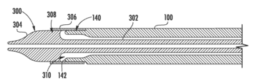
도 2는 일 실시예에 따른, 환자의 신체 내에 전달 장치(10) 및 인공 디바이스(12)를 도입하는 데 사용될 수 있는 조립체(90)(도입기 디바이스 또는 조립체라 칭할 수 있음)를 도시하고 있다. 도입기 디바이스(90)는 디바이스의 근위 단부에 있는 하우징(92) 및 하우징(92)으로부터 원위측으로 연장하는 팽창 가능 외장(100)을 포함할 수 있다. 하우징(92)은 디바이스용 핸들로서 기능할 수 있다. 팽창 가능 외장(100)은 인공 심장 판막용 전달 장치의 통과를 안내하기 위한 중앙 루멘(112)(도 4)을 갖는다. 일반적으로, 사용 중에, 외장(100)의 원위 단부는 환자의 피부를 통과하여 대퇴부 동맥과 같은 혈관 내에 삽입된다. 전달 장치(10)는 그 이식물(12)과 함께 이어서 하우징(92) 및 외장(100)을 통해 삽입될 수 있고, 환자의 혈관 구조를 통해 치료 부위로 전진되고, 여기서 이식물이 환자 내에 전달되고 이식된다. 특정 실시예에서, 도입기 하우징(92)은 압축된 혈액의 누출을 방지하기 위해 일단 하우징을 통해 삽입되면 가이드 카테터(14)의 외부면 주위에 밀봉부를 형성하는 지혈 밸브를 포함할 수 있다.FIG. 2 illustrates an assembly (90) (which may be referred to as an introducer device or assembly) that may be used to introduce a delivery device (10) and an artificial device (12) into a patient's body, according to one embodiment. The introducer device (90) may include a housing (92) at a proximal end of the device and an expandable sheath (100) extending distally from the housing (92). The housing (92) may function as a handle for the device. The expandable sheath (100) has a central lumen (112) ( FIG. 4 ) for guiding passage of the delivery device for an artificial heart valve. Typically, during use, the distal end of the sheath (100) is inserted through the patient's skin into a blood vessel, such as the femoral artery. The delivery device (10) can be subsequently inserted through the housing (92) and sheath (100) along with its implant (12) and advanced through the patient's vasculature to the treatment site where the implant is delivered and implanted into the patient. In certain embodiments, the introducer housing (92) can include a hemostatic valve that forms a seal around the outer surface of the guide catheter (14) once inserted through the housing to prevent leakage of compressed blood.
대안 실시예에서, 도입기 디바이스(90)는 하우징(92)을 포함할 필요가 없다. 예를 들어, 외장(100)은 가이드 카테터와 같은 전달 장치(10)의 구성요소의 일체형 부분일 수 있다. 예를 들어, 외장은 가이드 카테터의 핸들(18)로부터 연장될 수 있다.In an alternative embodiment, the introduction device (90) need not include a housing (92). For example, the sheath (100) may be an integral part of a component of the delivery device (10), such as a guide catheter. For example, the sheath may extend from a handle (18) of the guide catheter.
도 3은 팽창 가능 외장(100)을 더 상세히 도시하고 있다. 도 3을 참조하면, 외장(100)은 원래 비팽창 외경(D1)을 가질 수 있다. 특정 실시예에서, 팽창 가능 외장(100)은 외장의 길이(L)의 적어도 일부를 따라 연장하는 복수의 동축 층을 포함할 수 있다(도 2). 예를 들어, 도 4를 참조하면, 팽창 가능 외장(100)은 제1 층(102)(또한 내부층이라고도 칭함), 제1 층(102) 주위 및 반경방향 외측에 배치된 제2 층(104), 제2 층(104) 주위 및 반경방향 외측에 배치된 제3 층(106), 및 제3 층(106) 주위 및 반경방향 외측에 배치된 제4 층(108)(또한 외부층이라고도 칭함)을 포함할 수 있다. 예시된 구성에서, 내부층(102)은 중심축(114)을 따라 연장하는 외장의 루멘(112)을 형성할 수 있다.FIG. 3 illustrates the inflatable shell (100) in more detail. Referring to FIG. 3, the shell (100) can have an original unexpanded outer diameter (D 1 ). In certain embodiments, the inflatable shell (100) can include a plurality of coaxial layers extending along at least a portion of the length (L) of the shell (FIG. 2). For example, referring to FIG. 4, the inflatable shell (100) can include a first layer (102) (also referred to as an inner layer), a second layer (104) disposed about and radially outwardly of the first layer (102), a third layer (106) disposed about and radially outwardly of the second layer (104), and a fourth layer (108) disposed about and radially outwardly of the third layer (106) (also referred to as an outer layer). In the illustrated configuration, the inner layer (102) can form a lumen (112) of the outer shell extending along the central axis (114).
도 3을 참조하면, 외장(100)이 비팽창 상태에 있을 때, 내부층(102) 및/또는 외부층(108)은 외장의 표면이 복수의 리지(126)를 포함하도록 종방향 연장 절첩부 또는 주름부(본 명세서에서 또한 "절첩부"라 칭함)를 형성할 수 있다. 리지(126)는 종방향 연장 골부(128)에 의해 서로로부터 원주방향으로 이격될 수 있다. 외장이 그 원래 직경(D1)을 넘어 팽창할 때, 리지(126) 및 골부(128)는 이하에 더 설명되는 바와 같이, 표면이 반경방향으로 팽창되고 원주가 증가함에 따라 평평하게 되거나 들어올려질 수 있다. 외장이 원래 직경으로 다시 접혀질 때, 리지(126)와 골부(128)는 재형성될 수 있다.Referring to FIG. 3, when the sheath (100) is in its non-expanded state, the inner layer (102) and/or the outer layer (108) may form longitudinally extending folds or creases (also referred to herein as “folds”) such that the surface of the sheath includes a plurality of ridges (126). The ridges (126) may be circumferentially spaced from one another by longitudinally extending grooves (128). When the sheath expands beyond its original diameter (D 1 ), the ridges (126) and grooves (128) may flatten or lift as the surface expands radially and the circumference increases, as further described below. When the sheath folds back to its original diameter, the ridges (126) and grooves (128) may be reshaped.
특정 실시예에서, 내부층(102) 및/또는 외부층(108)은 비교적 얇은 폴리머 재료의 층을 포함할 수 있다. 예를 들어, 몇몇 실시예에서, 내부층(102)의 두께는 0.01 mm 내지 0.5 mm, 0.02 mm 내지 0.4 mm, 또는 0.03 mm 내지 0.25 mm일 수 있다. 특정 실시예에서, 외부층(108)의 두께는 0.01 mm 내지 0.5 mm, 0.02 mm 내지 0.4 mm, 또는 0.03 mm 내지 0.25 mm일 수 있다.In certain embodiments, the inner layer (102) and/or the outer layer (108) may comprise a relatively thin layer of polymeric material. For example, in some embodiments, the inner layer (102) may have a thickness of from 0.01 mm to 0.5 mm, from 0.02 mm to 0.4 mm, or from 0.03 mm to 0.25 mm. In certain embodiments, the outer layer (108) may have a thickness of from 0.01 mm to 0.5 mm, from 0.02 mm to 0.4 mm, or from 0.03 mm to 0.25 mm.
특정 예에서, 내부층(102) 및/또는 외부층(108)은 윤활, 저마찰 및/또는 비교적 비탄성 재료를 포함할 수 있다. 특정 실시예에서, 내부층(102) 및/또는 외부층(108)은 400 MPa 이상의 탄성 계수를 갖는 폴리머 재료를 포함할 수 있다. 예시적인 재료는 초고분자량 폴리에틸렌(UHMWPE)(예를 들어, Dyneema®), 고분자량 폴리에틸렌(HMWPE) 또는 폴리에테르 에테르 케톤(PEEK)을 포함할 수 있다. 특히, 내부층(102)과 관련하여, 이러한 낮은 마찰 계수 재료는 루멘(112)을 통한 인공 디바이스의 통과를 용이하게 할 수 있다. 내부층 및 외부층을 위한 다른 적합한 재료는 폴리테트라플루오로에틸렌(PTFE), 발포 폴리테트라플루오로에틸렌(ePTFE), 에틸렌 테트라플루오로에틸렌(ETFE), 나일론, 폴리에틸렌, 폴리에테르 블록 아미드(예를 들어, Pebax) 및/또는 상기 재료들 중 임의의 조합을 포함할 수 있다. 외장(100)의 몇몇 실시예는 내부층(102)의 내부면 상에 윤활 라이너를 포함할 수 있다. 적합한 윤활 라이너의 예는 PTFE, 폴리에틸렌, 폴리비닐리딘 플루오라이드 및 이들의 조합과 같은 내부층(102)의 마찰 계수를 더 감소시킬 수 있는 재료를 포함한다. 윤활 라이너를 위한 적합한 재료는 바람직하게는 0.1 이하의 마찰 계수를 갖는 다른 재료를 또한 포함한다.In certain instances, the inner layer (102) and/or the outer layer (108) may comprise a lubricating, low-friction, and/or relatively inelastic material. In certain embodiments, the inner layer (102) and/or the outer layer (108) may comprise a polymeric material having a modulus of elasticity greater than or equal to 400 MPa. Exemplary materials may include ultra-high molecular weight polyethylene (UHMWPE) (e.g., Dyneema®), high molecular weight polyethylene (HMWPE), or polyether ether ketone (PEEK). In particular, with respect to the inner layer (102), such low coefficient of friction materials may facilitate passage of the prosthetic device through the lumen (112). Other suitable materials for the inner layer and outer layer may include polytetrafluoroethylene (PTFE), expanded polytetrafluoroethylene (ePTFE), ethylene tetrafluoroethylene (ETFE), nylon, polyethylene, polyether block amide (e.g., Pebax), and/or combinations of any of the foregoing. Some embodiments of the outer shell (100) may include a lubricating liner on the inner surface of the inner layer (102). Examples of suitable lubricating liners include materials that can further reduce the coefficient of friction of the inner layer (102), such as PTFE, polyethylene, polyvinylidene fluoride, and combinations thereof. Suitable materials for the lubricating liner also preferably include other materials having a coefficient of friction of less than or equal to 0.1.
부가적으로, 외장(100)의 몇몇 실시예는 외부층(108)의 외부면 상에 외부 친수성 코팅을 포함할 수 있다. 이러한 친수성 코팅은 환자의 혈관 내로의 외장(100)의 삽입을 용이하여, 잠재적인 손상을 감소시킬 수 있다. 적합한 친수성 코팅의 예는 미국 미네소타주 이든 프레이리 소재의 SurModics, Inc.로부터 입수 가능한 HarmonyTM Advanced Lubricity Coatings 및 다른 진보형 친수성 코팅을 포함한다. DSM 의료용 코팅(네덜란드 헤를렌 소재의 Koninklijke DSM N.V로부터 입수 가능함), 뿐만 아니라 다른 친수성 코팅(예를 들어, PTFE, 폴리에틸렌, 폴리비닐리딘 플루오라이드)이 또한 외장(100)과 함께 사용하기에 적합하다. 이러한 친수성 코팅은 또한 외장과 전달 시스템 사이의 마찰을 감소시키기 위해 내부층(102)의 내부면에 포함되어, 이에 의해 사용을 용이하게 하고 안전성을 향상시킬 수 있다. 몇몇 실시예에서, 페릴렌과 같은 소수성 코팅은 마찰을 감소시키기 위해 외부층(108)의 외부면 또는 내부층(102)의 내부면에 사용될 수도 있다.Additionally, some embodiments of the sheath (100) may include an external hydrophilic coating on the external surface of the outer layer (108). Such a hydrophilic coating may facilitate insertion of the sheath (100) into a patient's blood vessel, thereby reducing potential damage. Examples of suitable hydrophilic coatings include Harmony TM Advanced Lubricity Coatings available from SurModics, Inc. of Eden Prairie, Minn., and other advanced hydrophilic coatings. DSM Medical Coatings (available from Koninklijke DSM NV of Heerlen, Netherlands), as well as other hydrophilic coatings (e.g., PTFE, polyethylene, polyvinylidene fluoride), are also suitable for use with the sheath (100). Such hydrophilic coatings may also be included on the internal surface of the inner layer (102) to reduce friction between the sheath and the delivery system, thereby facilitating use and enhancing safety. In some embodiments, a hydrophobic coating, such as perylene, may be used on the outer surface of the outer layer (108) or the inner surface of the inner layer (102) to reduce friction.
특정 실시예에서, 제2 층(104)은 편조층일 수 있다. 도 5a 및 도 5b는 탄성층(106)을 노출시키기 위해 외부층(108)이 제거되어 있는 외장(100)을 도시하고 있다. 도 5a 및 도 5b를 참조하면, 편조층(104)은 함께 편조된 복수의 부재 또는 필라멘트(110)(예를 들어, 금속 또는 합성 와이어 또는 섬유)를 포함할 수 있다. 편조층(104)은 임의의 적합한 수의 축을 따라 함께 배향되고 편조될 수 있는 임의의 원하는 수의 필라멘트(110)를 가질 수 있다. 예를 들어, 도 5b를 참조하면, 필라멘트(110)는 제1 축(A)에 평행하게 배향된 제1 세트의 필라멘트(110A) 및 제2 축(B)에 평행하게 배향된 제2 세트의 필라멘트(110B)를 포함할 수 있다. 필라멘트(110A, 110B)는 축(A)을 따라 배향된 필라멘트(110A)가 축(B)을 따라 배향된 필라멘트(110B)와 각도(θ)를 형성하도록 2축 편조로 함께 편조될 수 있다. 특정 실시예에서, 각도(θ)는 5° 내지 70°, 10° 내지 60°, 10° 내지 50°, 또는 10° 내지 45°일 수 있다. 예시된 실시예에서, 각도(θ)는 45°이다. 다른 실시예에서, 필라멘트(110)는 또한 3개의 축을 따라 배향되고 3축 편조로 편조될 수 있거나, 또는 임의의 수의 축을 따라 배향되고 임의의 적합한 편조 패턴으로 편조될 수 있다.In certain embodiments, the second layer (104) may be a braided layer. FIGS. 5A and 5B illustrate the sheath (100) with the outer layer (108) removed to expose the elastic layer (106). Referring to FIGS. 5A and 5B , the braided layer (104) may include a plurality of elements or filaments (110) (e.g., metal or synthetic wires or fibers) that are braided together. The braided layer (104) may have any desired number of filaments (110) that may be oriented and braided together along any suitable number of axes. For example, referring to FIG. 5B , the filaments (110) may include a first set of filaments (110A) oriented parallel to a first axis (A) and a second set of filaments (110B) oriented parallel to a second axis (B). The filaments (110A, 110B) may be braided together in a biaxial braid such that the filaments (110A) oriented along axis (A) form an angle (θ) with the filaments (110B) oriented along axis (B). In certain embodiments, the angle (θ) may be from 5° to 70°, from 10° to 60°, from 10° to 50°, or from 10° to 45°. In the illustrated embodiment, the angle (θ) is 45°. In other embodiments, the filaments (110) may also be oriented along three axes and braided in a triaxial braid, or may be oriented along any number of axes and braided in any suitable braid pattern.
편조층(104)은 외장(100)의 실질적으로 전체 길이(L)를 따라 연장될 수 있거나, 또는 대안적으로 외장의 길이의 일부를 따라서만 연장될 수 있다. 특정 실시예에서, 필라멘트(110)는 금속(예를 들어, 니티놀, 스테인리스 강 등) 또는 탄소 섬유와 같은 임의의 다양한 폴리머 또는 폴리머 복합 재료로부터 제조된 와이어일 수 있다. 특정 실시예에서, 필라멘트(110)는 둥근형일 수 있고, 0.01 mm 내지 0.5 mm, 0.03 mm 내지 0.4 mm, 또는 0.05 mm 내지 0.25 mm의 직경을 가질 수 있다. 다른 실시예에서, 필라멘트(110)는 0.01 mm×0.01 mm 내지 0.5 mm×0.5 mm, 또는 0.05 mm×0.05 mm 내지 0.25 mm×0.25 mm의 치수를 갖는 편평한 단면을 가질 수 있다. 일 실시예에서, 편평한 단면을 갖는 필라멘트(110)는 0.1 mm×0.2 mm의 치수를 가질 수 있다. 그러나, 다른 기하학 형상 및 크기가 또한 특정 실시예에 적합하다. 편조된 와이어가 사용되면, 편조 밀도가 변경될 수 있다. 몇몇 실시예는 인치당 10 pick 내지 인치당 80 pick의 편조 밀도를 갖고, 다양한 편조 패턴으로 8개의 와이어, 16개의 와이어, 또는 최대 52개의 와이어를 포함할 수 있다. 다른 실시예에서, 제2 층(104)은 튜브로부터 레이저 절단될 수 있거나, 시트 스톡으로부터 레이저 절단, 스탬핑, 펀칭 등이 되고 관형 구성으로 롤링될 수 있다. 층(104)은 또한 필요에 따라 직조되거나 편직될 수 있다.The braided layer (104) may extend substantially along the entire length (L) of the sheath (100), or alternatively may extend only along a portion of the length of the sheath. In certain embodiments, the filaments (110) may be wires manufactured from any of a variety of polymers or polymer composite materials, such as metals (e.g., nitinol, stainless steel, etc.) or carbon fibers. In certain embodiments, the filaments (110) may be round and may have a diameter of from 0.01 mm to 0.5 mm, from 0.03 mm to 0.4 mm, or from 0.05 mm to 0.25 mm. In other embodiments, the filaments (110) may have a flat cross-section having dimensions of from 0.01 mm×0.01 mm to 0.5 mm×0.5 mm, or from 0.05 mm×0.05 mm to 0.25 mm×0.25 mm. In one embodiment, the filaments (110) having a flat cross-section may have dimensions of 0.1 mm×0.2 mm. However, other geometries and sizes are also suitable for particular embodiments. If braided wire is used, the braid density may vary. Some embodiments have a braid density of from 10 picks per inch to 80 picks per inch, and may include 8 wires, 16 wires, or up to 52 wires in various braid patterns. In other embodiments, the second layer (104) may be laser cut from a tube, or may be laser cut, stamped, punched, etc. from sheet stock and rolled into a tubular configuration. The layer (104) may also be woven or knitted, as desired.
제3 층(106)은 탄력적 탄성층(또한 탄성 재료층이라고도 칭함)일 수 있다. 특정 실시예에서, 탄성층(106)은 외장이 외장을 통한 전달 장치의 통과에 의해 그 원래 직경을 넘어 팽창할 때 반경방향으로(예를 들어, 외장의 중심축(114)을 향해) 아래에 놓인 층(102, 104)에 힘을 인가하도록 구성될 수 있다. 달리 말하면, 탄성층(106)은 외장의 팽창을 상쇄하기 위해 탄성층(106) 아래의 외장의 층에 포위 압력을 인가하도록 구성될 수 있다. 반경방향 내향 지향력은 전달 장치가 외장을 통과한 후에 외장이 그 비팽창 상태로 다시 반경방향으로 접히게 하기에 충분하다.The third layer (106) may be an elastic elastomeric layer (also referred to as an elastic material layer). In certain embodiments, the elastic layer (106) may be configured to apply a force radially (e.g., toward the central axis (114) of the sheath) to the underlying layers (102, 104) when the sheath expands beyond its original diameter due to passage of the delivery device through the sheath. In other words, the elastic layer (106) may be configured to apply an enveloping pressure to the layers of the sheath beneath the elastic layer (106) to offset the expansion of the sheath. The radially inward force is sufficient to cause the sheath to radially fold back to its unexpanded state after passage of the delivery device through the sheath.
예시된 실시예에서, 탄성층(106)은 편조층(104) 주위에 나선형으로 랩핑된 스트랜드, 리본 또는 밴드(116)로서 구성된 하나 이상의 부재를 포함할 수 있다. 예를 들어, 예시된 실시예에서, 탄성층(106)은 대향 나선성을 갖고 편조된 층 주위에 랩핑된 2개의 탄성 밴드(116A, 116B)를 포함하지만, 탄성층은 원하는 특성에 따라 임의의 수의 밴드를 포함할 수도 있다. 탄성 밴드(116A, 116B)는 예를 들어, 실리콘 고무, 천연 고무, 임의의 다양한 열가소성 엘라스토머, 폴리우레탄 실록산 공중합체와 같은 폴리우레탄, 우레탄, 가소화된 폴리비닐클로라이드(PVC), 스티렌계 블록 공중합체, 폴리올레핀 엘라스토머 등을 포함하는 임의의 다양한 천연 또는 합성 엘라스토머로부터 제조될 수 있다. 몇몇 실시예에서, 탄성층은 200 MPa 이하의 탄성 계수를 갖는 탄성중합 재료를 포함할 수 있다. 몇몇 실시예에서, 탄성층(106)은 200% 이상의 파괴 연신율, 또는 400% 이상의 파괴 연신율을 나타내는 재료를 포함할 수 있다. 탄성층(106)은 또한 탄성중합 재료, 메시, 열 수축 배관층과 같은 수축성 폴리머층 등을 포함하는 관형층과 같은 다른 형태를 취할 수 있다. 탄성층(106) 대신에, 또는 그에 추가하여, 외장(100)은 외부층(108) 주위에 탄성중합 또는 열 수축 배관층을 또한 포함할 수도 있다. 이러한 탄성중합층의 예는 본 명세서에 참조로서 합체되어 있는 미국 특허 출원 공개 제2014/0379067호, 미국 특허 출원 공개 제2016/0296730호 및 미국 특허 출원 공개 제2018/0008407호에 개시되어 있다. 다른 실시예에서, 탄성층(106)은 또한 폴리머층(108)의 반경방향 외측에 있을 수 있다.In the illustrated embodiment, the elastic layer (106) can include one or more members configured as strands, ribbons, or bands (116) helically wrapped around the braided layer (104). For example, in the illustrated embodiment, the elastic layer (106) includes two elastic bands (116A, 116B) having opposing helicities and wrapped around the braided layer, although the elastic layer may include any number of bands depending on the desired properties. The elastic bands (116A, 116B) can be manufactured from any of a variety of natural or synthetic elastomers, including, for example, silicone rubber, natural rubber, any of a variety of thermoplastic elastomers, polyurethanes such as polyurethane siloxane copolymers, urethanes, plasticized polyvinyl chloride (PVC), styrenic block copolymers, polyolefin elastomers, and the like. In some embodiments, the elastic layer can include an elastomeric material having a modulus of elasticity of less than or equal to 200 MPa. In some embodiments, the elastic layer (106) can include a material exhibiting a break elongation of greater than 200%, or a break elongation of greater than 400%. The elastic layer (106) can also take other forms, such as a tubular layer comprising an elastomeric material, a mesh, a shrinkable polymer layer, such as a heat shrinkable tubing layer, or the like. Instead of, or in addition to, the elastic layer (106), the sheath (100) can also include an elastomeric or heat shrinkable tubing layer around the outer layer (108). Examples of such elastomeric layers are disclosed in U.S. Patent Application Publication No. 2014/0379067, U.S. Patent Application Publication No. 2016/0296730, and U.S. Patent Application Publication No. 2018/0008407, which are incorporated herein by reference. In other embodiments, the elastic layer (106) can also be radially outer of the polymer layer (108).
특정 실시예에서, 내부층(102) 및/또는 외부층(108) 중 하나 또는 모두는 외장이 팽창할 때 외장(100)의 축방향 신장에 저항하도록 구성될 수 있다. 더 구체적으로, 내부층(102) 및/또는 외부층(108) 중 하나 또는 모두는, 외장이 팽창 및 수축함에 따라 길이(L)가 실질적으로 일정하게 유지되도록 인공 디바이스와 외장의 내부면 사이의 마찰에 의해 야기되는 종방향 힘에 대한 신장에 저항할 수 있다. 외장의 길이(L)와 관련하여 본 명세서에서 사용될 때, 용어 "실질적으로 일정"은 외장의 길이(L)가 1% 이하만큼, 5% 이하만큼, 10% 이하만큼, 15% 이하만큼 또는 20% 이하만큼 증가하는 것을 의미한다. 한편, 도 5b를 참조하면, 편조층의 필라멘트(110A, 110B)는 외장이 팽창 및 수축함에 따라 각도(θ)가 변경되도록 서로에 대해 각도를 이루어 이동하는 것이 허용될 수 있다. 이는 층(102, 108)의 종방향 절첩부(126)와 조합하여, 인공 디바이스가 그를 통해 전진함에 따라 외장의 루멘(112)이 팽창되게 할 수 있다.In certain embodiments, one or both of the inner layer (102) and/or the outer layer (108) can be configured to resist axial elongation of the sheath (100) as the sheath expands. More specifically, one or both of the inner layer (102) and/or the outer layer (108) can resist elongation due to longitudinal forces caused by friction between the artificial device and the inner surface of the sheath such that the length (L) remains substantially constant as the sheath expands and contracts. As used herein with respect to the length (L) of the sheath, the term "substantially constant" means that the length (L) of the sheath increases by no more than 1%, no more than 5%, no more than 10%, no more than 15%, or no more than 20%. Meanwhile, referring to FIG. 5B , the filaments (110A, 110B) of the braided layers can be allowed to move angularly with respect to one another such that the angle (θ) changes as the sheath expands and contracts. This, in combination with the longitudinal folds (126) of the layers (102, 108), can allow the lumen (112) of the sheath to expand as the artificial device advances through it.
예를 들어, 몇몇 실시예에서 내부층(102) 및 외부층(108)은 편조층(104) 및 탄성층(106)이 층(102, 108) 사이에 캡슐화되도록 제조 프로세스 중에 열 접합될 수 있다. 더 구체적으로, 특정 실시예에서, 내부층(102) 및 외부층(108)은 편조층(104)의 필라멘트(110) 사이의 공간 및/또는 탄성 밴드(116) 사이의 공간을 통해 서로 접착될 수 있다. 층(102, 108)은 또한 외장의 근위 단부 및/또는 원위 단부에서 함께 접합되거나 접착될 수 있다. 특정 실시예에서, 층(102, 108)은 필라멘트(110)에 접착되지 않는다. 이는 필라멘트(110)가 서로에 대해 그리고 층(102, 108)에 대해 각도를 이루어 이동하게 하여, 편조층(104)의 직경 및 이에 의해 외장의 직경이 증가 또는 감소되게 할 수 있게 한다. 필라멘트(110A, 110B) 사이의 각도(θ)가 변경됨에 따라, 편조층(104)의 길이도 또한 변경될 수 있다. 예를 들어, 각도(θ)가 증가함에 따라, 편조층(104)은 단축될 수 있고, 각도(θ)가 감소함에 따라, 편조층(104)은 층(102, 108)이 접합되는 영역에 의해 허용되는 범위까지 길어질 수 있다. 그러나, 편조층(104)이 층(102, 108)에 접착되지 않기 때문에, 필라멘트(110A, 110B) 사이의 각도(θ)의 변화를 수반하는 편조층의 길이의 변화는 외장의 길이(L)의 상당한 변화를 초래하지 않는다.For example, in some embodiments, the inner layer (102) and the outer layer (108) may be heat bonded during the manufacturing process such that the braided layer (104) and the elastic layer (106) are encapsulated between the layers (102, 108). More specifically, in certain embodiments, the inner layer (102) and the outer layer (108) may be bonded to each other through the spaces between the filaments (110) of the braided layer (104) and/or the spaces between the elastic bands (116). The layers (102, 108) may also be bonded or adhered together at the proximal end and/or the distal end of the sheath. In certain embodiments, the layers (102, 108) are not bonded to the filaments (110). This allows the filaments (110) to move at an angle relative to each other and to the layers (102, 108), thereby causing the diameter of the braided layer (104) and thereby the diameter of the sheath to increase or decrease. As the angle (θ) between the filaments (110A, 110B) changes, the length of the braided layer (104) can also change. For example, as the angle (θ) increases, the braided layer (104) can shorten, and as the angle (θ) decreases, the braided layer (104) can lengthen to a degree permitted by the area where the layers (102, 108) are bonded. However, since the braided layer (104) is not bonded to the layers (102, 108), a change in the length of the braided layer that accompanies a change in the angle (θ) between the filaments (110A, 110B) does not result in a significant change in the length (L) of the sheath.
도 6은 인공 디바이스(12)가 화살표(132)의 방향으로(예를 들어, 원위측으로) 외장을 통과함에 따른 외장(100)의 반경방향 팽창을 도시하고 있다. 인공 디바이스(12)가 외장(100)을 통해 전진함에 따라, 외장은 인공 디바이스의 크기 또는 직경에 대응하는 제2 직경(D2)으로 탄력적으로 팽창될 수 있다. 인공 디바이스(12)가 외장(100)을 통해 전진함에 따라, 인공 디바이스는 인공 디바이스와 외장의 내부면 사이의 마찰 접촉에 의해 운동 방향으로 외장에 종방향 힘을 인가할 수 있다. 그러나, 전술된 바와 같이, 내부층(102) 및/또는 외부층(108)은 외장의 길이(L)가 일정하게 또는 실질적으로 일정하게 유지되도록 축방향 신장에 저항할 수 있다. 이는 편조층(104)이 길어지는 것을 감소시키거나 방지할 수 있고, 이에 의해 루멘(112)을 수축시킬 수 있다.FIG. 6 illustrates radial expansion of the sheath (100) as the artificial device (12) passes through the sheath in the direction of arrow (132) (e.g., distally). As the artificial device (12) advances through the sheath (100), the sheath may elastically expand to a second diameter (D 2 ) corresponding to the size or diameter of the artificial device. As the artificial device (12) advances through the sheath (100), the artificial device may apply a longitudinal force to the sheath in the direction of motion by frictional contact between the artificial device and the inner surface of the sheath. However, as described above, the inner layer (102) and/or the outer layer (108) may resist axial elongation such that the length (L) of the sheath remains constant or substantially constant. This may reduce or prevent elongation of the braided layer (104), thereby constricting the lumen (112).
한편, 필라멘트(110A, 110B) 사이의 각도(θ)는 인공 판막을 수용하기 위해 외장이 제2 직경(D2)으로 팽창함에 따라 증가할 수 있다. 이는 편조층(104)이 단축되게 할 수 있다. 그러나, 필라멘트(110)가 층(102 또는 108)에 맞물리거나 접착되지 않기 때문에, 각도(θ)의 증가에 수반되는 편조층(104)의 단축은 외장의 전체 길이(L)에 영향을 미치지 않는다. 더욱이, 층(102, 108)에 형성된 종방향 연장 절첩부(126)로 인해, 층(102, 108)은 비교적 얇고 비교적 비탄성임에도 불구하고, 파열 없이 제2 직경(D2)으로 팽창될 수 있다. 이 방식으로, 외장(100)은, 인공 디바이스가 연장 없이 그리고 수축 없이 외장을 통해 전진함에 따라 그 원래 직경(D1)으로부터 직경(D1)보다 큰 제2 직경(D2)까지 탄력적으로 팽창될 수 있다. 따라서, 외장을 통해 인공 이식물을 압박하는 데 필요한 힘이 상당히 감소된다.Meanwhile, the angle (θ) between the filaments (110A, 110B) may increase as the sheath expands to the second diameter (D 2 ) to accommodate the artificial valve. This may cause the braided layer (104) to shorten. However, since the filaments (110) are not interdigitated or bonded to the layers (102 or 108), the shortening of the braided layer (104) accompanying the increase in the angle (θ) does not affect the overall length (L) of the sheath. Furthermore, due to the longitudinally extending folds (126) formed in the layers (102, 108), the layers (102, 108) may expand to the second diameter (D 2 ) without rupture, even though they are relatively thin and relatively inelastic. In this manner, the sheath (100) can be elastically expanded from its original diameter (D 1 ) to a second diameter (D 2 ) that is larger than the diameter (D 1 ) as the artificial device advances through the sheath without extension and without retraction. Accordingly, the force required to compress the artificial implant through the sheath is significantly reduced.
부가적으로, 탄성층(106)에 의해 인가된 반경방향 힘으로 인해, 외장(100)의 반경방향 팽창은 인공 디바이스에 의해 점유되는 외장의 특정 부분에 국소화될 수 있다. 예를 들어, 도 6을 참조하면, 인공 디바이스(12)가 외장(100)을 통해 원위측으로 이동함에 따라, 인공 디바이스(12)에 바로 근위측의 외장의 부분은 탄성층(106)의 영향 하에서 초기 직경(D1)으로 다시 반경방향으로 접힐 수 있다. 층(102, 108)은 또한 외장의 원주가 감소됨에 따라 좌굴될 수 있어, 리지(126) 및 골부(128)가 재형성될 수 있게 한다. 이는 주어진 크기의 인공 디바이스를 도입하는 데 필요한 외장의 크기를 감소시킬 수 있다. 부가적으로, 일시적인 국소 팽창 특성은, 인공 디바이스에 의해 점유된 외장의 단지 일부만이 외장의 원래 직경을 넘어 팽창하고 외장은 일단 디바이스가 통과되면 초기 직경으로 다시 접히기 때문에, 주위 조직과 함께, 외장이 삽입되는 혈관에 대한 외상을 감소시킬 수 있다. 이는 인공 디바이스를 도입하기 위해 신장되어야 하는 조직의 양과 혈관의 주어진 부분이 확장되어야 하는 시간의 양을 제한한다.Additionally, due to the radial force applied by the elastic layer (106), the radial expansion of the sheath (100) may be localized to a particular portion of the sheath occupied by the artificial device. For example, referring to FIG. 6 , as the artificial device (12) moves distally through the sheath (100), a portion of the sheath immediately proximal to the artificial device (12) may radially fold back to its initial diameter (D 1 ) under the influence of the elastic layer (106). The layers (102, 108) may also buckle as the circumference of the sheath decreases, allowing the ridges (126) and grooves (128) to re-form. This may reduce the size of the sheath required to introduce a given size of artificial device. Additionally, the temporary localized expansion characteristics may reduce trauma to the vessel into which the sheath is inserted, as only a portion of the sheath occupied by the artificial device will expand beyond the original diameter of the sheath and the sheath will collapse back to its initial diameter once the device is passed through, along with the surrounding tissue. This limits the amount of tissue that must be stretched to introduce the artificial device and the amount of time a given portion of the vessel must be dilated.
상기 장점에 추가하여, 본 명세서에 설명된 팽창 가능 외장 실시예는 공지된 도입기 외장에 비해 놀랍게도 우수한 성능을 제공할 수 있다. 예를 들어, 외장의 원래 외경보다 2배, 2.5배, 또는 심지어 3배 더 큰 직경을 갖는 인공 디바이스를 전달하기 위해 본 명세서에 설명된 바와 같이 구성된 외장을 사용하는 것이 가능하다. 예를 들어, 일 실시예에서, 7.2 mm의 직경을 갖는 크림핑된 인공 심장 판막이 전술된 바와 같이 구성되고 3.7 mm의 원래 외경을 갖는 외장을 통해 성공적으로 전진되었다. 인공 판막이 외장을 통해 전진함에 따라, 인공 판막에 의해 점유되는 외장의 부분의 외경이 8 mm로 증가되었다. 달리 말하면, 외장의 외경의 2배 초과의 직경을 갖는 인공 디바이스를 외장을 통해 전진시키는 것이 가능하였고, 그 동안 외장의 외경이 216%만큼 탄력적으로 증가했다. 다른 예에서, 4.5 mm 내지 5 mm의 초기 또는 원래 외경을 갖는 외장은 8 mm 내지 9 mm의 외경으로 팽창되도록 구성될 수 있다.In addition to the above advantages, the inflatable sheath embodiments described herein can provide surprisingly superior performance over known introducer sheaths. For example, it is possible to use sheaths constructed as described herein to deliver artificial devices having diameters that are 2x, 2.5x, or even 3x larger than the original outer diameter of the sheath. For example, in one embodiment, a crimped artificial heart valve having a diameter of 7.2 mm was successfully advanced through a sheath constructed as described above and having an original outer diameter of 3.7 mm. As the artificial valve was advanced through the sheath, the outer diameter of the portion of the sheath occupied by the artificial valve increased to 8 mm. In other words, it was possible to advance an artificial device having a diameter greater than 2x the outer diameter of the sheath through the sheath, while at the same time elastically increasing the outer diameter of the sheath by as much as 216%. In another example, a sheath having an initial or original outer diameter of 4.5 mm to 5 mm can be configured to expand to an outer diameter of 8 mm to 9 mm.
대안 실시예에서, 외장(100)은 원하는 특정 특성에 따라, 층(108)을 갖지 않는 층(102) 또는 층(102)을 갖지 않는 층(108)을 선택적으로 포함할 수도 있다.In alternative embodiments, the sheath (100) may optionally include a layer (102) without a layer (108) or a layer (108) without a layer (102), depending on the particular characteristics desired.
도 10a 내지 도 10d는 필라멘트(110)가 좌굴하도록 구성된 편조층(104)의 다른 실시예를 도시하고 있다. 예를 들어, 도 10a는 완전 팽창 상태의 편조층에 대응하는 구성의 편조층(104)의 단위 셀(134)을 도시하고 있다. 예를 들어, 도 10a에 도시되어 있는 팽창 상태는, 도 7을 참조하여 이하에 더 설명되는 바와 같이, 외장이 그 기능적 설계 직경(D1)으로 반경방향으로 접히기 전에, 외장(100)의 초기 구성 중에 전술된 직경(D2), 및/또는 편조층의 직경에 대응할 수 있다. 필라멘트(110A, 110B) 사이의 각도(θ)는 예를 들어 40°일 수 있고, 단위 셀(134)은 x-방향(도시되어 있는 직교 좌표축 참조)을 따른 길이(Lx)를 가질 수 있다. 도 10b는 팽창 상태의 단위 셀(134)의 어레이를 포함하는 편조층(104)의 부분을 도시하고 있다.FIGS. 10A-10D illustrate other embodiments of a braided layer (104) configured to buckle filaments (110). For example, FIG. 10A illustrates a unit cell (134) of a braided layer (104) having a configuration corresponding to a fully expanded state of the braided layer. For example, the expanded state illustrated in FIG. 10A may correspond to the diameter (D 2 ) described above during the initial configuration of the sheath (100), and/or the diameter of the braided layer, prior to the sheath being radially folded to its functional design diameter (D 1 ), as further described below with reference to FIG. 7 . The angle (θ) between the filaments (110A, 110B) may be, for example, 40°, and the unit cell (134) may have a length (L x ) along the x-direction (see the illustrated Cartesian coordinate axes). FIG. 10b illustrates a portion of a braided layer (104) comprising an array of unit cells (134) in an expanded state.
예시된 실시예에서, 편조층(104)은 전술된 바와 같이, 폴리머층(102, 108) 사이에 배치된다. 예를 들어, 폴리머층(102, 108)은 외장(100)의 단부에서 그리고/또는 단위 셀(134)에 의해 형성된 개방 공간(136)에서 필라멘트(110) 사이에서 서로 접착되거나 또는 적층될 수 있다. 따라서, 도 10c 및 도 10d를 참조하면, 외장(100)이 그 기능적 직경(D1)으로 반경방향으로 접혀질 때, 편조층(104)의 직경은 각도(θ)가 감소함에 따라 감소할 수 있다. 그러나, 접합된 폴리머층(102, 108)은 편조층(104)이 반경방향으로 접힘에 따라 길어지는 것을 구속하거나 방지할 수 있다. 이는 필라멘트(110)가 도 10c 및 도 10d에 도시되어 있는 바와 같이, 축방향으로 탄력적으로 좌굴되게 할 수 있다. 좌굴의 정도는 단위 셀(134)의 길이(Lx)가 외장의 접힌 직경과 완전 팽창 직경 사이에서 동일하거나, 또는 실질적으로 동일하도록 이루어질 수 있다. 이는 편조층(104)의 전체 길이가 외장의 원래 직경(D1)과 팽창 직경(D2) 사이에서 일정하거나, 또는 실질적으로 일정하게 유지될 수 있는 것을 의미한다. 외장이 의료 디바이스의 통과 중에 그 초기 직경(D1)으로부터 팽창함에 따라, 필라멘트(110)는 좌굴이 완화됨에 따라 직선화될 수 있고, 외장은 반경방향으로 팽창될 수 있다. 의료 디바이스가 외장을 통과함에 따라, 편조층(104)은 탄성층(106)에 의해 초기 직경(D1)으로 다시 압박될 수 있고, 필라멘트(110)는 다시 탄력적으로 좌굴될 수 있다. 도 10a 내지 도 10c의 구성을 사용하여, 외장의 원래 외경(D1)보다 2배, 2.5배, 또는 심지어 3배 더 큰 직경을 갖는 인공 디바이스를 수용하는 것이 또한 가능하다.In the illustrated embodiment, the braided layer (104) is disposed between the polymer layers (102, 108), as described above. For example, the polymer layers (102, 108) may be bonded to or laminated with each other between the filaments (110) at the ends of the sheath (100) and/or in the open spaces (136) formed by the unit cells (134). Thus, referring to FIGS. 10c and 10d, when the sheath (100) is folded radially to its functional diameter (D 1 ), the diameter of the braided layer (104) may decrease as the angle (θ) decreases. However, the bonded polymer layers (102, 108) may restrain or prevent the braided layer (104) from elongating as it is folded radially. This can cause the filament (110) to buckle elastically in the axial direction, as illustrated in FIGS. 10c and 10d. The degree of buckling can be such that the length (L x ) of the unit cell (134) is equal to, or substantially equal to, the folded diameter of the sheath and the fully expanded diameter. This means that the overall length of the braided layer (104) can be constant or substantially constant between the original diameter (D 1 ) and the expanded diameter (D 2 ) of the sheath. As the sheath expands from its initial diameter (D 1 ) during passage of the medical device, the filament (110) can straighten as the buckling is relieved, and the sheath can expand radially. As the medical device passes through the sheath, the braided layer (104) can be compressed back to the initial diameter (D 1 ) by the elastic layer (106), and the filament (110) can buckle elastically again. Using the configurations of FIGS. 10a to 10c, it is also possible to accommodate artificial devices having a diameter that is 2, 2.5, or even 3 times larger than the original outer diameter (D 1 ) of the enclosure.
이제, 팽창 가능 외장을 제조하는 방법으로 넘어가면, 도 7은 일 실시예에 따른, 원통형 맨드릴(118) 상에 배치된 팽창 가능 외장(100)의 층(102 내지 108)을 도시하고 있다. 특정 실시예에서, 맨드릴(118)은 완성된 외장의 원하는 원래 외경(D1)보다 큰 직경(D3)을 가질 수 있다. 예를 들어, 몇몇 실시예에서, 외장의 외경(D1)에 대한 맨드릴의 직경(D3)의 비는 1.5:1, 2:1, 2.5:1, 3:1, 또는 그 초과일 수 있다. 특정 실시예에서, 맨드릴의 직경(D3)은 외장의 팽창 직경(D2)과 동일할 수 있다. 달리 말하면, 맨드릴의 직경(D3)은 인공 디바이스가 외장을 통해 전진할 때 외장의 원하는 팽창 직경(D2)과 동일하거나, 또는 거의 동일할 수 있다. 따라서, 특정 실시예에서, 비팽창된 외장의 접힌 외경(D1)에 대한 팽창된 외장의 팽창된 외경(D2)의 비는 1.5:1, 2:1, 2.5:1, 3:1, 또는 그 초과일 수 있다.Now turning to a method of manufacturing an inflatable sheath, FIG. 7 illustrates layers (102-108) of an inflatable sheath (100) disposed on a cylindrical mandrel (118), according to one embodiment. In certain embodiments, the mandrel (118) can have a diameter (D 3 ) that is larger than the desired original outer diameter (D 1 ) of the finished sheath. For example, in some embodiments, the ratio of the diameter (D 3 ) of the mandrel to the outer diameter (D 1 ) of the sheath can be 1.5:1, 2:1, 2.5:1, 3:1, or more. In certain embodiments, the diameter (D 3 ) of the mandrel can be equal to the expansion diameter (D 2 ) of the sheath. In other words, the diameter (D 3 ) of the mandrel can be equal to, or approximately equal to, the desired expansion diameter (D 2 ) of the sheath as the artificial device advances through the sheath. Thus, in certain embodiments, the ratio of the expanded outer diameter (D 2 ) of the expanded sheath to the folded outer diameter (D 1 ) of the unexpanded sheath can be 1.5:1, 2:1, 2.5:1, 3:1, or more.
도 7을 참조하면, 팽창 가능 외장(100)은 맨드릴(118) 주위에 ePTFE 층(120)을 랩핑하거나 위치시키고, 이어서 제1 폴리머층(102)을 랩핑하거나 위치시킴으로써 제조될 수 있다. 몇몇 실시예에서, ePTFE 층은 제조 프로세스의 완료시에 맨드릴(118)로부터 외장(100)을 제거하는 것을 보조할 수 있다. 제1 폴리머층(102)은 맨드릴(118) 주위에 랩핑됨으로써 도포되는 미리 제조된 시트의 형태일 수도 있거나, 또는 딥 코팅(dip-coating), 전기 방사(electro-spinning) 등에 의해 맨드릴에 도포될 수도 있다. 편조층(104)은 제1 층(102), 이어서 탄성층(106) 주위에 위치될 수 있다. 탄성층(106)이 하나 이상의 탄성 밴드(116)를 포함하는 실시예에서, 밴드(116)는 편조층(104) 주위에 나선형으로 랩핑될 수 있다. 다른 실시예에서, 탄성층(106)은 딥 코팅, 전기 방사 등이 될 수도 있다. 외부 폴리머층(108)은 이어서 탄성층(106), 이어서 ePTFE의 다른 층(122) 및 열 수축 배관 또는 열 수축 테이프의 하나 이상의 층(124) 주위에 랩핑되고, 위치되거나 또는 도포될 수 있다.Referring to FIG. 7, the inflatable shell (100) can be manufactured by wrapping or positioning an ePTFE layer (120) around a mandrel (118), followed by wrapping or positioning a first polymer layer (102). In some embodiments, the ePTFE layer may aid in removing the shell (100) from the mandrel (118) upon completion of the manufacturing process. The first polymer layer (102) may be in the form of a pre-fabricated sheet that is applied by wrapping around the mandrel (118), or may be applied to the mandrel by dip-coating, electro-spinning, or the like. A braided layer (104) may be positioned around the first layer (102), followed by an elastic layer (106). In embodiments where the elastic layer (106) includes one or more elastic bands (116), the bands (116) may be helically wrapped around the braided layer (104). In other embodiments, the elastic layer (106) may be dip coated, electrospun, etc. An outer polymer layer (108) may then be wrapped, positioned, or applied around the elastic layer (106), followed by another layer of ePTFE (122) and one or more layers of heat shrink tubing or heat shrink tape (124).
특정 실시예에서, 탄성 밴드(116)는 신장되거나, 팽팽하거나, 연장된 상태로 편조층(104)에 도포될 수 있다. 예를 들어, 특정 실시예에서, 밴드(116)는 그 원래 이완된 길이의 2배인 길이로 신장된 편조층(104)에 도포될 수 있다. 이는 맨드릴로부터 제거될 때 완성된 외장이 탄성층의 영향 하에서 반경방향으로 접히게 할 것인데, 이는 이하에 설명되는 바와 같이, 탄성층의 대응하는 이완을 유발할 수 있다. 다른 실시예에서, 층(102) 및 편조층(104)은 맨드릴로부터 제거될 수 있고, 탄성층(106)은 이완된 상태 또는 적당히 신장된 상태로 도포될 수 있으며, 이어서 조립체는 탄성층이 외부층(108)의 도포 전에 팽팽한 상태로 반경방향으로 팽창되고 신장되도록 맨드릴 상에 다시 배치될 수 있다.In certain embodiments, the elastic band (116) may be applied to the braided layer (104) in a stretched, taut, or extended state. For example, in certain embodiments, the band (116) may be applied to the braided layer (104) stretched to a length that is twice its original relaxed length. This will cause the finished sheath when removed from the mandrel to radially fold under the influence of the elastic layer, which may cause a corresponding relaxation of the elastic layer, as described below. In other embodiments, the layers (102) and the braided layer (104) may be removed from the mandrel, the elastic layer (106) may be applied in a relaxed or moderately stretched state, and then the assembly may be placed back on the mandrel such that the elastic layer is radially expanded and stretched to a taut state prior to application of the outer layer (108).
조립체는 이어서 열 수축 층(124)이 수축하여 층(102 내지 108)을 함께 압축하는 충분히 높은 온도로 가열될 수 있다. 특정 실시예에서, 조립체는 폴리머 내부층 및 외부층(102, 108)이 연성 및 점성이 되고, 편조층(104)과 탄성층(106) 사이의 개방 공간에서 서로 접합하고 편조층과 탄성층을 캡슐화하도록 충분히 높은 온도로 가열될 수 있다. 다른 실시예에서, 내부층 및 외부층(102, 108)은 이들이 편조층(104) 및 탄성층(106) 주위 및 이들을 통해 유동하도록 리플로우되거나 용융될 수 있다. 예시적인 실시예에서, 조립체는 20 내지 30분 동안 150℃에서 가열될 수 있다.The assembly can then be heated to a sufficiently high temperature that the heat shrinkable layer (124) shrinks and compresses the layers (102-108) together. In certain embodiments, the assembly can be heated to a sufficiently high temperature that the polymeric inner and outer layers (102, 108) become ductile and viscous and bond to each other in the open space between the braided layer (104) and the elastomeric layer (106) and encapsulate the braided layer and the elastomeric layer. In other embodiments, the inner and outer layers (102, 108) can be reflowed or melted such that they flow around and through the braided layer (104) and the elastomeric layer (106). In an exemplary embodiment, the assembly can be heated at 150° C. for 20 to 30 minutes.
가열 후에, 외장(100)은 맨드릴(118)로부터 제거될 수 있고, 열 수축 배관(124) 및 ePTFE 층(120, 122)이 제거될 수 있다. 맨드릴(118)로부터 제거시에, 외장(100)은 탄성층(106)의 영향 하에 원래 설계 직경(D1)으로 적어도 부분적으로 반경방향으로 접힐 수 있다. 특정 실시예에서, 외장은 크림핑 메커니즘의 선택적인 보조에 의해 설계 직경으로 반경방향으로 접힐 수 있다. 수반하는 원주의 감소는, 종방향 연장 절첩부(126)를 형성하기 위해 내부층 및 외부층(102, 108)과 함께, 도 10c 및 도 10d에 도시되어 있는 바와 같이 필라멘트(110)를 좌굴할 수 있다.After heating, the sheath (100) can be removed from the mandrel (118) and the heat shrink tubing (124) and ePTFE layers (120, 122) can be removed. Upon removal from the mandrel (118), the sheath (100) can be at least partially radially folded back to the original design diameter (D 1 ) under the influence of the elastic layer (106). In certain embodiments, the sheath can be radially folded back to the design diameter with the optional assistance of a crimping mechanism. The resulting reduction in circumference can buckle the filaments (110), together with the inner and outer layers (102, 108), to form a longitudinally extending fold (126), as illustrated in FIGS. 10c and 10d .
특정 실시예에서, PTFE의 층은, 각각의 ePTFE 층(120, 122)으로부터 내부 및 외부 폴리머층(102, 108)의 분리를 용이하게 하기 위해, ePTFE 층(120)과 내부층(102) 사이 및/또는 외부층(108)과 ePTFE 층(122) 사이에 개재될 수 있다. 다른 실시예에서, 전술된 바와 같이, 내부층(102) 또는 외부층(108) 중 하나는 생략될 수도 있다.In certain embodiments, a layer of PTFE may be interposed between the ePTFE layer (120) and the inner layer (102) and/or between the outer layer (108) and the ePTFE layer (122) to facilitate separation of the inner and outer polymer layers (102, 108) from each of the ePTFE layers (120, 122). In other embodiments, as described above, either the inner layer (102) or the outer layer (108) may be omitted.
도 8은 외장을 따라 종방향으로 연장하고 편조층(104)에 부착된 얀 또는 코드(130)로서 구성된 하나 이상의 부재를 포함하는 팽창 가능 외장(100)의 다른 실시예를 도시하고 있다. 단지 하나의 코드(130)만이 도 8에 도시되어 있지만, 실제로 외장은 동일한 각도 간격으로 외장의 원주 주위에 배열된 2개의 코드, 4개의 코드, 6개의 코드 등을 포함할 수도 있다. 코드(130)는 편조층(104)의 외부에 봉합될 수 있지만, 다른 구성 및 부착 방법이 가능하다. 편조층(104)에 부착됨으로써, 코드(130)는 인공 디바이스가 외장을 통과할 때 편조층(104)의 축방향 신장을 방지하도록 구성될 수 있다. 코드(130)는 탄성층(106)과 조합하여 또는 개별적으로 채용될 수도 있다. 코드(130)는 또한 원하는 특정 특성에 따라, 내부층 및/또는 외부층(102, 108) 중 하나 또는 모두와 조합하여 사용될 수도 있다. 코드(130)는 또한 편조층(104)의 내부에(예를 들어, 내부층(102)과 편조층(104) 사이에) 배치될 수도 있다.FIG. 8 illustrates another embodiment of an inflatable sheath (100) comprising one or more members configured as yarns or cords (130) extending longitudinally along the sheath and attached to the braided layer (104). Although only one cord (130) is illustrated in FIG. 8, in practice the sheath may include two cords, four cords, six cords, etc. arranged around the circumference of the sheath at equal angular intervals. The cords (130) may be sutured to the exterior of the braided layer (104), although other configurations and methods of attachment are possible. By being attached to the braided layer (104), the cords (130) may be configured to prevent axial elongation of the braided layer (104) when an artificial device passes through the sheath. The cords (130) may be employed in combination with the elastic layer (106) or separately. The code (130) may also be used in combination with one or both of the inner layer and/or the outer layer (102, 108), depending on the specific characteristics desired. The code (130) may also be positioned within the braided layer (104) (e.g., between the inner layer (102) and the braided layer (104).
팽창 가능 외장(100)은 또한 다른 방식으로 제조될 수 있다. 예를 들어, 도 9는 격납 용기(202) 및 214에 개략적으로 도시되어 있는 가열 시스템을 포함하는 장치(200)를 도시하고 있다. 장치(200)는 2개 이상의 재료층으로 구성된 디바이스(의료 디바이스 또는 비의료용 디바이스)를 형성하기 위해 특히 적합하다. 장치(200)에 의해 형성된 디바이스는 외장(100) 또는 카테터용 샤프트와 같은 2개 이상의 동축 재료층으로부터 형성될 수 있다. 장치(200)에 의해 형성된 디바이스는 대안적으로 서로의 위에 적층된 2개 이상의 층과 같은 2개 이상의 비-동축 층에 의해 형성될 수 있다.The inflatable shell (100) may also be manufactured in other ways. For example, FIG. 9 illustrates a device (200) comprising a containment vessel (202) and a heating system, which is schematically illustrated at 214. The device (200) is particularly suitable for forming a device (medical device or non-medical device) comprised of two or more layers of material. A device formed by the device (200) may be formed from two or more coaxial layers of material, such as the shell (100) or a shaft for a catheter. A device formed by the device (200) may alternatively be formed by two or more non-coaxial layers, such as two or more layers laminated on top of one another.
격납 용기(202)는 내부 체적 또는 챔버(204)를 형성할 수 있다. 예시된 실시예에서, 용기(202)는 폐쇄 단부(206) 및 개방 단부(208)를 포함하는 금속 튜브일 수 있다. 용기(202)는 비교적 높은 열 팽창 계수를 갖는 열 팽창 가능 재료(210)로 적어도 부분적으로 충전될 수 있다. 특정 실시예에서, 열 팽창 가능 재료(210)는 2.4×10⁻⁴/℃ 이상의 열 팽창 계수를 가질 수도 있다. 예시적인 열 팽창 가능 재료는 실리콘 재료와 같은 엘라스토머를 포함한다. 실리콘 재료는 5.9×10⁻⁴/℃ 내지 7.9×10⁻⁴/℃의 열 팽창 계수를 가질 수 있다.The containment vessel (202) can define an internal volume or chamber (204). In an illustrated embodiment, the vessel (202) can be a metal tube having a closed end (206) and an open end (208). The vessel (202) can be at least partially filled with a thermally expandable material (210) having a relatively high coefficient of thermal expansion. In certain embodiments, the thermally expandable material (210) may have a coefficient of thermal expansion of greater than or equal to 2.4×10 -4 /° C. Exemplary thermally expandable materials include elastomers, such as silicone materials. Silicone materials can have a coefficient of thermal expansion of from 5.9×10 -4 /° C. to 7.9×10 -4 /° C.
도 7의 맨드릴(118)과 유사하고 그 주위에 배치된 외장 재료층의 원하는 조합을 포함하는 맨드릴은 열 팽창 가능 재료(210) 내에 삽입될 수 있다. 대안적으로, 맨드릴(118)은 챔버(204) 내에 삽입될 수 있고, 챔버의 나머지 체적은 맨드릴이 재료(210)에 의해 둘러싸이도록 열 팽창 가능 재료(210)로 충전될 수 있다. 맨드릴(118)은 예시를 위해 개략적으로 도시되어 있다. 이와 같이, 맨드릴(118)은 도 7에 도시되어 있는 바와 같이 원통형일 수 있다. 마찬가지로, 재료(210)의 내부면 및 용기(202)의 내부면은 맨드릴(118)의 형상 및 외장(100)의 최종 형상에 대응하는 원통형 형상을 가질 수 있다. 원통형 또는 둥근형 맨드릴(118)의 배치를 용이하게 하기 위해, 용기(202)는 2개의 부분이 용기의 내부에 맨드릴을 배치하기 위한 개방 구성과 맨드릴 주위로 연장하는 폐쇄 구성 사이에서 이동할 수 있게 하기 위해 힌지에 의해 서로 연결되는 2개의 부분을 포함할 수 있다. 예를 들어, 도 9에 도시되어 있는 용기의 상부 및 하부 반부는 용기의 폐쇄측(도 9에서 용기의 좌측)에서 힌지에 의해 서로 연결될 수 있다.A mandrel similar to the mandrel (118) of FIG. 7 and including a desired combination of sheathing material layers disposed therearound may be inserted into the thermally expandable material (210). Alternatively, the mandrel (118) may be inserted into the chamber (204) and the remainder of the volume of the chamber may be filled with the thermally expandable material (210) such that the mandrel is surrounded by the material (210). The mandrel (118) is schematically illustrated for illustration purposes. As such, the mandrel (118) may be cylindrical, as illustrated in FIG. 7. Likewise, the inner surface of the material (210) and the inner surface of the container (202) may have a cylindrical shape corresponding to the shape of the mandrel (118) and the final shape of the sheath (100). To facilitate placement of a cylindrical or round mandrel (118), the container (202) may include two parts connected to each other by a hinge so that the two parts can move between an open configuration for placing the mandrel inside the container and a closed configuration extending around the mandrel. For example, the upper and lower halves of the container illustrated in FIG. 9 may be connected to each other by a hinge on the closed side of the container (the left side of the container in FIG. 9).
용기(202)의 개방 단부(208)는 캡(212)으로 폐쇄될 수 있다. 용기(202)는 이어서 가열 시스템(214)에 의해 가열될 수 있다. 가열 시스템(214)에 의한 가열은 재료(210)가 챔버(204) 내에서 팽창하고 맨드릴(118) 상의 재료층에 대해 반경방향 압력을 인가하게 할 수 있다. 열과 압력의 조합은 맨드릴(118) 상의 층이 외장을 형성하기 위해 서로 접합하거나 접착되게 할 수 있다. 특정 실시예에서, 장치(200)를 사용하여 맨드릴(118)에 100 MPa 이상의 반경방향 압력을 인가하는 것이 가능하다. 맨드릴에 인가되는 반경방향 힘의 양은, 예를 들어 선택된 재료(210)의 유형 및 양, 그 열 팽창 계수, 맨드릴(118)을 둘러싸는 재료(210)의 두께, 재료(210)가 가열되는 온도 등에 의해 제어될 수 있다.The open end (208) of the container (202) can be closed with a cap (212). The container (202) can then be heated by a heating system (214). Heating by the heating system (214) can cause the material (210) to expand within the chamber (204) and apply a radial pressure against the layers of material on the mandrel (118). The combination of heat and pressure can cause the layers on the mandrel (118) to bond or adhere to one another to form a sheath. In certain embodiments, it is possible to apply a radial pressure of greater than 100 MPa to the mandrel (118) using the device (200). The amount of radial force applied to the mandrel can be controlled by, for example, the type and amount of material (210) selected, its coefficient of thermal expansion, the thickness of the material (210) surrounding the mandrel (118), the temperature to which the material (210) is heated, and the like.
몇몇 실시예에서, 가열 시스템(214)은 용기(202)가 배치되는 오븐일 수 있다. 몇몇 실시예에서, 가열 시스템은 용기(202) 주위에 위치된 하나 이상의 가열 요소를 포함할 수 있다. 몇몇 실시예에서, 용기(202)는 가열 시스템(214)에 의해 제어되는 전기 저항 가열 요소 또는 유도 가열 요소일 수 있다. 몇몇 실시예에서, 가열 요소는 열 팽창 가능 재료(210) 내에 매립될 수 있다. 몇몇 실시예에서, 재료(210)는 예를 들어 탄소 섬유 또는 금속 입자와 같은 전기 전도성 충전제 재료를 첨가함으로써 가열 요소로서 구성될 수 있다.In some embodiments, the heating system (214) may be an oven in which the vessel (202) is placed. In some embodiments, the heating system may include one or more heating elements positioned around the vessel (202). In some embodiments, the vessel (202) may be an electrical resistance heating element or an induction heating element controlled by the heating system (214). In some embodiments, the heating elements may be embedded within the thermally expandable material (210). In some embodiments, the material (210) may be configured as a heating element by adding an electrically conductive filler material, such as carbon fibers or metal particles, for example.
장치(200)는 그 길이를 따른 맨드릴(118)로의 반경방향 힘의 균일하고 고도로 제어 가능한 인가 및 높은 반복성을 포함하여, 공지된 외장 제조 방법에 비해 다수의 장점을 제공할 수 있다. 장치(200)는 또한 열 팽창 가능 재료(210)의 고속 및 정확한 가열을 촉진할 수 있고, 열 수축 배관 및/또는 테이프에 대한 필요성을 감소시키거나 제거하여, 재료 비용 및 노동력을 감소시킬 수 있다. 인가된 반경방향 힘의 양은 또한 예를 들어 주위 재료(210)의 유형 또는 두께를 변경함으로써 맨드릴의 길이를 따라 변경될 수 있다. 특정 실시예에서, 다수의 용기(202)가 단일 고정구 내에서 처리될 수 있고, 그리고/또는 다수의 외장이 단일 용기(202) 내에서 처리될 수 있다. 장치(200)는 또한 샤프트 또는 카테터와 같은 다른 디바이스를 생산하는 데 사용될 수 있다.The device (200) may provide several advantages over known methods of fabricating a sheath, including uniform and highly controllable application of radial force along its length to the mandrel (118), and high repeatability. The device (200) may also facilitate rapid and accurate heating of the thermally expandable material (210), and may reduce or eliminate the need for heat shrink tubing and/or tape, thereby reducing material costs and labor. The amount of radial force applied may also be varied along the length of the mandrel, for example, by changing the type or thickness of the surrounding material (210). In certain embodiments, multiple containers (202) may be processed within a single fixture, and/or multiple sheaths may be processed within a single container (202). The device (200) may also be used to produce other devices, such as shafts or catheters.
일 특정 방법에서, 외장(100)은 맨드릴(118) 상에 층(102, 104, 106, 108)을 배치하고, 열 팽창 가능 재료(210)가 최외부층(108)을 둘러싸는 상태로 용기(202) 내부에 층을 갖는 맨드릴을 배치함으로써 형성될 수 있다. 원하는 경우, ePTFE(또는 유사한 재료)의 하나 이상의 내부층(120) 및 ePTFE(또는 유사한 재료)의 하나 이상의 외부층(122)이 맨드릴(118) 및 재료(210)로부터 완성된 외장의 제거를 용이하게 하기 위해 사용될 수 있다(도 7에 도시되어 있는 바와 같이). 조립체는 이어서 층(102, 108)을 리플로우하기 위해 가열 시스템(214)으로 가열된다. 후속 냉각시에, 층(102, 108)은 서로 적어도 부분적으로 접합되게 되고 층(104, 106)을 적어도 부분적으로 캡슐화한다.In one particular method, the shell (100) can be formed by placing layers (102, 104, 106, 108) on a mandrel (118) and placing the mandrel inside the vessel (202) with the thermally expandable material (210) surrounding the outermost layer (108). If desired, one or more inner layers (120) of ePTFE (or similar material) and one or more outer layers (122) of ePTFE (or similar material) can be used to facilitate removal of the completed shell from the mandrel (118) and material (210) (as illustrated in FIG. 7). The assembly is then heated with a heating system (214) to reflow the layers (102, 108). Upon subsequent cooling, the layers (102, 108) become at least partially bonded to one another and at least partially encapsulate the layers (104, 106).
도 11은 팽창 가능 외장(100)이 예비 도입기 또는 혈관 확장기(300)로서 구성된 장치를 수용하도록 구성되는 다른 실시예를 도시하고 있다. 특정 실시예에서, 도입기 디바이스(90)는 혈관 확장기(300)를 포함할 수 있다. 도 12를 참조하면, 혈관 확장기(300)는 샤프트 부재(302)의 원위 단부에 위치된 노즈 원추(304)로서 구성된 테이퍼진 확장기 부재를 포함하는 샤프트 부재(302)를 포함할 수 있다. 혈관 확장기(300)는, 원주방향 공간(310)이 샤프트 부재(302)의 외부면과 보유 부재(306)의 내부면 사이에 형성되도록 노즈 원추(304)의 근위 단부(308)로부터 근위측으로 연장하는 캡슐 또는 보유 부재(306)를 더 포함할 수 있다. 특정 실시예에서, 보유 부재(306)는 이하에 더 설명되는 바와 같이, 얇은 폴리머층 또는 시트로서 구성될 수 있다.FIG. 11 illustrates another embodiment in which the inflatable sheath (100) is configured to receive a device configured as a pre-introducer or vasodilator (300). In certain embodiments, the introducer device (90) may include the vasodilator (300). Referring to FIG. 12 , the vasodilator (300) may include a shaft member (302) including a tapered dilator member configured as a nose cone (304) positioned at a distal end of the shaft member (302). The vasodilator (300) may further include a capsule or retaining member (306) extending proximally from a proximal end (308) of the nose cone (304) such that a circumferential space (310) is formed between an outer surface of the shaft member (302) and an inner surface of the retaining member (306). In certain embodiments, the retaining member (306) may be configured as a thin polymeric layer or sheet, as further described below.
도 11 및 도 13을 참조하면, 외장(100)의 제1 또는 원위 단부(140)는 외장이 노즈 원추(304)와 맞물리도록 그리고/또는 보유 부재(306)가 외장의 원위 단부(140) 위로 연장되도록 공간(310) 내에 수용될 수 있다. 사용시, 커플링되거나 조립된 혈관 확장기(300) 및 외장(100)은 이어서 절개부를 통해 혈관 내로 삽입될 수 있다. 노즈 원추(304)의 테이퍼진 원추 형상은 혈관 및 주위 조직에 대한 외상을 최소화하면서 혈관 및 접근 부위를 점진적으로 확장하는 것을 보조할 수 있다. 일단 조립체가 원하는 깊이로 삽입되면, 혈관 확장기(300)는 도 14에 도시되어 있는 바와 같이, 외장(100)이 안정 상태로 유지되는 동안 혈관 내로 더 전진될 수 있다(예를 들어, 원위측으로).Referring to FIGS. 11 and 13, the first or distal end (140) of the sheath (100) can be received within the space (310) such that the sheath engages the nose cone (304) and/or the retaining member (306) extends over the distal end (140) of the sheath. In use, the coupled or assembled vascular dilator (300) and sheath (100) can then be inserted into the vessel through the incision. The tapered conical shape of the nose cone (304) can assist in gradually dilating the vessel and access site while minimizing trauma to the vessel and surrounding tissue. Once the assembly is inserted to a desired depth, the vascular dilator (300) can be advanced further into the vessel (e.g., distally) while the sheath (100) remains stable, as illustrated in FIG. 14.
도 15를 참조하면, 혈관 확장기(300)는 보유 부재(306)가 외장(100)의 원위 단부(140) 위로부터 제거될 때까지 외장(100)을 통해 원위측으로 전진될 수 있다. 특정 실시예에서, 외장의 나선형으로 랩핑된 탄성층(106)은 외장의 원위 단부(142)의 근위측에서 종료할 수 있다. 따라서, 외장의 원위 단부(140)가 커버되지 않을 때, 원위 단부(열 경화될 수 있음)는 확개되거나 팽창될 수 있어, 제1 직경(D1)(도 13)으로부터 제2 더 큰 직경(D2)(도 15)으로 원위 단부(142)에서 개구의 직경을 증가시킨다. 혈관 확장기(300)는 이어서 도 16 내지 도 18에 도시되어 있는 바와 같이 외장(100)을 통해 후퇴될 수 있어, 외장(100)을 혈관 내에 적소에 남겨둔다.Referring to FIG. 15, the vasodilator (300) can be advanced distally through the sheath (100) until the retaining member (306) is removed from above the distal end (140) of the sheath (100). In certain embodiments, the helically wrapped elastic layer (106) of the sheath can terminate proximal to the distal end (142) of the sheath. Thus, when the distal end (140) of the sheath is uncovered, the distal end (which may be heat cured) can be expanded or dilated to increase the diameter of the opening at the distal end (142) from a first diameter (D 1 ) ( FIG. 13 ) to a second, larger diameter (D 2 ) ( FIG. 15 ). The vasodilator (300) can then be retracted through the sheath (100) as illustrated in FIGS. 16 through 18, leaving the sheath (100) in place within the blood vessel.
혈관 확장기(300)는 외장(100)을 맞물리고 보유하기 위한 다양한 능동 및/또는 수동 메커니즘을 포함할 수 있다. 예를 들어, 특정 실시예에서, 보유 부재(306)는 외장(100)의 원위 단부 주위에서 접힐 수 있는 폴리머 열 수축층을 포함할 수 있다. 도 1에 도시되어 있는 실시예에서, 보유 부재는 외장(100)의 원위 단부(140)를 압축하도록 구성된 탄성 부재를 포함할 수 있다. 또 다른 실시예에서, 보유 부재(306) 및 외장(100)은 선택된 양의 힘의 인가가 보유 부재(306) 사이의 접착 접합을 외장(100)으로부터 자유롭게 파괴하여 혈관 확장기가 후퇴될 수 있게 하는 방식으로 함께 접착되거나 융합(예를 들어, 열 접합)될 수 있다. 몇몇 실시예에서, 편조층(104)의 단부는, 혈관 확장기(300)의 대응 부분에 압력을 인가하기 위해, 반경방향 내향으로 또는 외향으로 확개하거나 팽창하도록 열 고정될 수 있다.The vasodilator (300) may include a variety of active and/or passive mechanisms for engaging and retaining the sheath (100). For example, in certain embodiments, the retaining member (306) may include a polymeric heat shrinkable layer that is foldable about the distal end of the sheath (100). In the embodiment illustrated in FIG. 1 , the retaining member may include an elastomeric member configured to compress the distal end (140) of the sheath (100). In another embodiment, the retaining member (306) and the sheath (100) may be bonded or fused together (e.g., thermally bonded) in such a manner that application of a selected amount of force breaks the adhesive bond between the retaining member (306) free from the sheath (100), allowing the vasodilator to be retracted. In some embodiments, the ends of the braided layers (104) may be thermally secured to expand or spread radially inwardly or outwardly to apply pressure to a corresponding portion of the vasodilator (300).
도 19를 참조하면, 조립체는 확장기 샤프트 부재(302)와 외장(100) 사이에 배치된 샤프트(312)와 같은 기계적 작동식 보유 메커니즘을 포함할 수 있다. 특정 실시예에서, 샤프트(312)는 혈관 확장기(300)를 외장(100)에 해제 가능하게 커플링할 수 있고, 신체 외부로부터 작동될 수 있다(즉, 수동으로 비활성화될 수 있음).Referring to FIG. 19, the assembly may include a mechanically actuated retaining mechanism, such as a shaft (312) disposed between the dilator shaft member (302) and the sheath (100). In certain embodiments, the shaft (312) may releasably couple the vasodilator (300) to the sheath (100) and may be actuated from outside the body (i.e., manually deactivated).
도 20 및 도 21을 참조하면, 몇몇 실시예에서 샤프트(304)는 그 외부면 주위에 원주방향으로 배열되고 팽창될 때 외장(100)과 맞물리도록 구성된 하나 이상의 벌룬(314)을 포함할 수 있다. 벌룬(314)은 외장(100)을 해제하고 혈관 확장기를 후퇴하기 위해 선택적으로 수축될 수 있다. 예를 들어, 팽창될 때, 벌룬은 혈관 확장기에 대해 외장을 적소에 유지하는 것을 보조하기 위해 캡슐(306)의 내부면에 대해 외장(100)의 포획된 원위 단부를 가압한다. 벌룬이 수축될 때, 혈관 확장기는 외장(100)에 대해 더 쉽게 이동할 수 있다.Referring to FIGS. 20 and 21, in some embodiments, the shaft (304) may include one or more balloons (314) arranged circumferentially around its outer surface and configured to engage the sheath (100) when inflated. The balloons (314) may be optionally deflated to release the sheath (100) and retract the angioplasty. For example, when inflated, the balloons urge a captured distal end of the sheath (100) against an inner surface of the capsule (306) to assist in holding the sheath in place relative to the angioplasty. When the balloons are deflated, the angioplasty may move more readily relative to the sheath (100).
다른 실시예에서, 전술된 바와 같이 구성된 팽창 가능 외장은 도 22에 도시되어 있는 열 수축 배관층(400)과 같은 수축 가능한 폴리머 외부 커버를 더 포함할 수 있다. 열 수축 배관층(400)은 혈관 확장기(300)와 외장의 원위 단부(140) 사이의 원활한 전이를 허용하도록 구성될 수 있다. 열 수축 배관층(400)은 또한 외장을 선택된 초기의 감소된 외경으로 구속할 수 있다. 특정 실시예에서, 열 수축 배관층(400)은 외장(100)의 길이에 걸쳐 완전히 연장되고, 클램프, 너트, 접착제, 열 용접, 레이저 용접, 또는 탄성 클램프와 같은 기계적 고정 수단에 의해 외장 핸들에 부착될 수 있다. 몇몇 실시예에서, 외장은 제조 중에 열 수축 배관층에 압입된다.In another embodiment, the expandable sheath constructed as described above can further include a shrinkable polymer outer cover, such as the heat shrink tubing layer (400) illustrated in FIG. 22. The heat shrink tubing layer (400) can be configured to allow a smooth transition between the vasodilator (300) and the distal end (140) of the sheath. The heat shrink tubing layer (400) can also constrain the sheath to a selected initial reduced outer diameter. In certain embodiments, the heat shrink tubing layer (400) extends completely across the length of the sheath (100) and can be attached to the sheath handle by mechanical fastening means, such as clamps, nuts, adhesives, heat welds, laser welds, or elastomeric clamps. In some embodiments, the sheath is press-fitted into the heat shrink tubing layer during manufacturing.
몇몇 실시예에서, 열 수축 배관층(400)은 도 22에 도시되어 있는 원위 돌출부(408)로서 외장의 원위 단부(140)를 넘어 원위측으로 연장될 수 있다. 혈관 확장기는 외장 루멘(112)을 통해 그리고 돌출부(408)의 원위 에지를 넘어 삽입될 수 있다. 돌출부(408)는 조합된 확장기와 외장의 삽입을 용이하게 하기 위해 확장기 직경과 외장 직경 사이의 원활한 전이를 제공하도록 삽입된 혈관 확장기에 긴밀하게 합치한다. 혈관 확장기가 제거될 때, 돌출부(408)는 외장(100)의 부분으로서 용기에 잔류한다. 열 수축 배관층(400)은 종축을 따라 외장의 전체 외경을 수축시키는 부가의 이익을 제공한다.In some embodiments, the heat shrink tubing layer (400) can extend distally beyond the distal end (140) of the sheath as a distal protrusion (408) as illustrated in FIG. 22. A vessel dilator can be inserted through the sheath lumen (112) and beyond the distal edge of the protrusion (408). The protrusion (408) closely conforms to the inserted vessel dilator to provide a smooth transition between the dilator diameter and the sheath diameter to facilitate insertion of the combined dilator and sheath. When the sheath is removed, the protrusion (408) remains in the container as part of the sheath (100). The heat shrink tubing layer (400) provides the additional benefit of shrinking the entire outer diameter of the sheath along its longitudinal axis.
몇몇 실시예에서, 열 수축 배관층은 전달 장치(10)와 같은 전달 장치가 외장을 통해 전진함에 따라 분할 개방되도록 구성될 수 있다. 예를 들어, 특정 실시예에서, 열 수축 배관층은 선택된 장소에서 층의 분할을 시작하도록 구성된 도 22에 도시되어 있는 것들과 같은 하나 이상의 종방향 연장 개구, 슬릿, 또는 약화된 세장형 새김선(406)을 포함할 수 있다. 전달 장치(10)가 외장을 통해 전진함에 따라, 열 수축 배관층(400)은 계속 분할 개방될 수 있어, 감소된 힘으로 전술된 바와 같이 외장이 팽창하게 한다. 특정 실시예에서, 외장은 열 수축 배관층이 분할 개방될 때 외장이 초기 감소 직경으로부터 팽창하도록 탄성층(106)을 포함할 필요가 없다. 열 수축 배관층(400)은 폴리에틸렌 또는 다른 적합한 재료를 포함할 수 있다.In some embodiments, the heat shrink tubing layer can be configured to split open as the delivery device, such as the delivery device (10), advances through the sheath. For example, in certain embodiments, the heat shrink tubing layer can include one or more longitudinally extending apertures, slits, or weakened elongated slits (406), such as those illustrated in FIG. 22, configured to initiate splitting of the layer at selected locations. As the delivery device (10) advances through the sheath, the heat shrink tubing layer (400) can continue to split open, thereby allowing the sheath to expand as described above with reduced force. In certain embodiments, the sheath need not include an elastic layer (106) to allow the sheath to expand from an initial reduced diameter as the heat shrink tubing layer splits open. The heat shrink tubing layer (400) can include polyethylene or other suitable material.
도 23은 일 실시예에 따른, 본 명세서에 설명된 팽창 가능 외장 주위에 배치될 수 있는 열 수축 배관층(400)을 도시하고 있다. 몇몇 실시예에서, 열 수축 배관층(400)은, 배관층(400)을 따라 축방향으로 연장하고 원형 개구(404)로서 구성된 원위 응력 릴리프 특징부에서 종료하는 복수의 절단부 또는 새김선(402)을 포함할 수 있다. 원위 응력 릴리프 특징부는 예를 들어 타원형 및/또는 난형 개구를 포함하는 임의의 다른 규칙적 또는 불규칙적 곡선 형상으로 구성될 수 있는 것으로 고려된다. 열 수축 배관층(400)을 따라 그리고 그 주위에 다양한 형상의 원위 응력 릴리프 특징부가 또한 고려된다. 전달 장치(10)가 외장을 통해 전진함에 따라, 열 수축 배관층(400)은 새김선(402)을 따라 분할 개방될 수 있고, 원위측에 위치된 개구(404)는 각각의 새김선을 따라 배관층의 추가 인열 또는 분할을 저지할 수 있다. 이와 같이, 열 수축 배관층(400)은 외장 길이를 따라 외장에 부착된 상태로 유지된다. 예시된 실시예에서, 새김선 및 연관 개구(404)는 서로로부터 종방향으로 그리고 원주방향으로 오프셋되거나 엇갈리게 된다. 따라서, 외장이 팽창함에 따라, 새김선(402)은 마름모꼴 구조를 형성할 수 있다. 새김선은 또한 외장의 종축 주위로 나선형으로 또는 지그재그 패턴으로와 같이, 다른 방향으로 연장될 수 있다.FIG. 23 illustrates a heat shrink tubing layer (400) that can be disposed about an expandable sheath described herein, according to one embodiment. In some embodiments, the heat shrink tubing layer (400) can include a plurality of cuts or nicks (402) extending axially along the tubing layer (400) and terminating in distal stress relief features configured as circular openings (404). It is contemplated that the distal stress relief features can be configured as any other regular or irregular curved shape, including, for example, oval and/or egg-shaped openings. Various shapes of distal stress relief features along and about the heat shrink tubing layer (400) are also contemplated. As the delivery device (10) advances through the sheath, the heat shrink tubing layer (400) can be split open along the nicks (402), and the distally located openings (404) can resist further tearing or splitting of the tubing layer along each nick. In this way, the heat shrinkable tubing layer (400) remains attached to the sheath along the length of the sheath. In the illustrated embodiment, the slits and associated openings (404) are offset or staggered longitudinally and circumferentially from one another. Thus, as the sheath expands, the slits (402) can form a diamond-shaped structure. The slits can also extend in other directions, such as spirally or in a zigzag pattern around the longitudinal axis of the sheath.
다른 실시예에서, 열 수축 배관층의 분할 또는 인열은 예를 들어 화학적 용매 적용, 절단, 스코어링 또는 기구 또는 레이저에 의한 표면 융삭에 의해 배관 표면 상에 약화된 영역을 형성함으로써, 그리고/또는 벽 두께를 감소시키거나 또는 배관벽에 캐비티를 형성함으로써(예를 들어, 펨토초 레이저 융삭에 의해), 다양한 다른 방식으로 유도될 수 있다.In other embodiments, splitting or tearing of the heat shrinkable tubing layer may be induced in a variety of other ways, such as by forming a weakened region on the tubing surface by application of a chemical solvent, cutting, scoring, or surface ablation by a tool or laser, and/or by reducing the wall thickness or forming a cavity in the tubing wall (e.g., by femtosecond laser ablation).
몇몇 실시예에서, 열 수축 배관층은 접착제, 용접 또는 임의의 다른 적합한 고정 수단에 의해 외장의 본체에 부착될 수도 있다. 도 29는 내부층(802), 편조층(804), 탄성층(806), 외부층(808) 및 열 수축 배관층(809)을 포함하는 외장 실시예의 사시도를 도시하고 있다. 열 수축 배관층(809)은 열 수축 배관층(809)을 따라 연장하는 분할부(811) 및 천공부(813)를 포함한다. 열 수축 배관층(809)은 접착 시임(815)에서 외부층(808)에 접합된다. 예를 들어, 특정 실시예에서 열 수축 배관층(809)은 시임(815)에서 용접되고, 열 접합되고, 화학적 접합되고, 초음파 접합되고, 그리고/또는 접착제(이들에 한정되는 것은 아니지만, LDPE 섬유 고온 아교와 같은 고온 아교를 포함함)를 사용하여 접합될 수 있다. 외부층(808)은 시임(815)에서 외장을 따라 축방향으로 또는 소용돌이형 또는 나선형 방식으로 열 수축 배관층(809)에 접합될 수 있다. 도 30은 그를 통한 전달 시스템의 이동 전에, 열 수축 배관층(809)을 갖는 외장을 도시하고 있다. 도 32는 외장의 사시도를 도시하고 있고, 여기서, 열 수축 배관층(809)은 통과 전달 시스템이 외장의 직경을 확장함에 따라 부분적으로 인열 개방되고 탈착되어 있다. 열 수축 배관층(809)은 접착 시임(815)에 의해 보유된다. 이 방식으로 열 수축 배관층(809)을 외장에 부착하는 것은 도 33에 도시되어 있는 바와 같이, 층이 분할되고 외장이 팽창된 후에 열 수축 배관층(809)을 외장에 부착 유지하는 것을 도울 수 있는데, 여기서 전달 시스템(817)은 외장을 통해 완전히 이동되고 외장의 전체 길이를 따라 열 수축 배관층(809)을 인열한다.In some embodiments, the heat shrink tubing layer may be attached to the body of the sheath by an adhesive, welding, or any other suitable securing means. FIG. 29 illustrates a perspective view of an embodiment of a sheath including an inner layer (802), a braided layer (804), an elastic layer (806), an outer layer (808), and a heat shrink tubing layer (809). The heat shrink tubing layer (809) includes a split portion (811) and an aperture (813) extending along the heat shrink tubing layer (809). The heat shrink tubing layer (809) is joined to the outer layer (808) at an adhesive seam (815). For example, in certain embodiments, the heat shrink tubing layer (809) may be welded, thermally bonded, chemically bonded, ultrasonically bonded, and/or joined using an adhesive (including but not limited to a high temperature glue such as an LDPE fiber high temperature glue). The outer layer (808) can be bonded to the heat shrink tubing layer (809) axially along the sheath at the seam (815) or in a spiral or helical manner. FIG. 30 illustrates an sheath having a heat shrink tubing layer (809) prior to movement of the delivery system therethrough. FIG. 32 illustrates a perspective view of the sheath, wherein the heat shrink tubing layer (809) has been partially torn open and detached as the delivery system passes through and expands the diameter of the sheath. The heat shrink tubing layer (809) is retained by the adhesive seam (815). Attaching the heat shrink tubing layer (809) to the sheath in this manner can assist in maintaining the heat shrink tubing layer (809) attached to the sheath after the layers are separated and the sheath has expanded, as illustrated in FIG. 33, wherein the delivery system (817) has moved fully through the sheath and has torn the heat shrink tubing layer (809) along the entire length of the sheath.
다른 실시예에서, 팽창 가능 외장은 탄성 열가소성 재료(예를 들어, Pebax)를 포함하는 원위 단부 또는 팁 부분을 가질 수 있는데, 이는 혈관 확장기(300)의 대응 부분에 간섭 끼워맞춤 또는 간섭 기하학 형상을 제공하도록 구성될 수 있다. 특정 구성에서, 외장의 외부층은 원위 단부를 외장의 본체에 용접하기 위해 폴리아미드(예를 들어, 나일론)를 포함할 수도 있다. 특정 실시예에서, 원위 단부는 전달 장치가 원위 단부를 통해 전진함에 따라 원위 단부가 분리될 수 있게 하기 위한 의도적으로 약화된 부분, 새김선, 슬릿 등을 포함할 수 있다.In other embodiments, the inflatable sheath may have a distal end or tip portion comprising an elastomeric thermoplastic material (e.g., Pebax) that may be configured to provide an interference fit or interference geometry with a corresponding portion of the vasodilator (300). In certain configurations, the outer layer of the sheath may also comprise a polyamide (e.g., nylon) to weld the distal end to the body of the sheath. In certain embodiments, the distal end may include intentionally weakened portions, seams, slits, or the like to allow the distal end to detach as the delivery device is advanced through the distal end.
다른 실시예에서, 전체 외장은 핸들로부터 외장의 원위 단부(140)까지 종방향으로 연장하여, 도 22에 도시되어 있는 돌출부(408)와 유사한 돌출부를 생성하기 위해 전방으로 연장하는 탄성중합 외부 커버를 가질 수 있다. 탄성중합 돌출부는 혈관 확장기에 긴밀하게 합치하지만, 일단 혈관 확장기가 제거되면 외장의 부분으로 잔류한다. 전달 시스템이 통과함에 따라, 탄성중합 돌출부는 팽창되고 이어서 접혀서 그를 통과한다. 탄성중합 돌출부 또는 전체 탄성중합 외부 커버는 전달 장치가 원위 단부를 통해 전진함에 따라 원위 단부가 분리될 수 있게 하기 위한 의도적으로 약화된 부분, 새김선, 슬릿 등을 포함할 수 있다.In another embodiment, the entire sheath can have an elastomeric outer cover that extends longitudinally from the handle to the distal end (140) of the sheath and extends forward to create a protrusion similar to the protrusion (408) illustrated in FIG. 22. The elastomeric protrusion conforms closely to the angioplasty, but remains part of the sheath once the angioplasty is removed. As the delivery system passes through, the elastomeric protrusion expands and then collapses to pass through it. The elastomeric protrusion or the entire elastomeric outer cover can include intentionally weakened portions, notches, slits, or the like to allow the distal end to detach as the delivery device is advanced through the distal end.
도 24는 필라멘트가 외장을 따라 대향 방향으로 후방으로 루프 형성되거나 연장되도록, 편조된 필라멘트(110)의 부분(150)이 루프(152)를 형성하기 위해 굴곡되는 편조층(104)의 다른 실시예의 단부(예를 들어, 원위 단부)를 도시하고 있다. 필라멘트(110)는 다양한 필라멘트(110)의 루프(152)가 편조부 내에서 서로로부터 축방향으로 오프셋되도록 배열될 수 있다. 편조층(104)의 원위 단부를 향해(도면에서 우측으로) 이동시키면, 편조 필라멘트(110)의 수가 감소할 수 있다. 예를 들어, 5로 지시된 필라멘트는 먼저 루프(152)를 형성하고, 이어서 4, 3 및 2로 지시된 필라멘트를 형성하고, 1에서의 필라멘트는 최원위 루프(152)를 형성한다. 따라서, 편조부 내의 필라멘트(110)의 수는 원위방향으로 감소하는데, 이는 편조층(104)의 반경방향 가요성을 증가시킬 수 있다.FIG. 24 illustrates an end (e.g., a distal end) of another embodiment of a braided layer (104) in which a portion (150) of a braided filament (110) is bent to form a loop (152) such that the filaments are looped or extended backward along the sheath in an opposite direction. The filaments (110) may be arranged such that the loops (152) of the various filaments (110) are axially offset from one another within the braid. Moving toward the distal end of the braided layer (104) (to the right in the drawing), the number of braided filaments (110) may decrease. For example, the filament indicated as 5 may form a loop (152) first, followed by the filaments indicated as 4, 3 and 2, with the filament at 1 forming the most distal loop (152). Therefore, the number of filaments (110) within the braided portion decreases in the distal direction, which can increase the radial flexibility of the braided layer (104).
다른 실시예에서, 팽창 가능 외장의 원위 단부는 혈관 확장기(300)의 직경으로 테이퍼질 수 있는 Dyneema®과 같은 폴리머를 포함할 수 있다. 점선 절단부, 스코어링 등과 같은 약화된 부분이 원위 단부가 반복 가능한 방식으로 개방 및/또는 팽창될 것이도록 원위 단부에 적용될 수 있다.In another embodiment, the distal end of the expandable sheath may comprise a polymer, such as Dyneema®, that may be tapered to the diameter of the vasodilator (300). A weakened portion, such as a dotted cut, scoring, or the like, may be applied to the distal end to allow the distal end to open and/or expand in a repeatable manner.
본 명세서에 설명된 팽창 가능 외장 실시예의 크림핑은 전술된 바와 같이 다양한 방식으로 수행될 수 있다. 부가의 실시예에서, 외장은 더 긴 외장을 따라 종방향으로 다수회 종래의 짧은 크림퍼를 사용하여 크림핑될 수 있다. 다른 실시예에서, 외장은 외장이 열 수축 배관 내에 랩핑되고 가열 하에서 접혀지는 하나 또는 일련의 스테이지에서 지정된 크림핑된 직경으로 접혀질 수도 있다. 예를 들어, 제1 열 수축 튜브는 외장의 외부면에 적용될 수 있고, 외장은 제1 열 수축 튜브를 수축시킴으로써(열을 통해) 중간 직경으로 압축될 수 있고, 제1 열 수축 튜브는 제거될 수 있고, 제2 열 수축 튜브는 외장의 외부면에 적용될 수 있고, 제2 열 수축 튜브는 열을 통해 중간 직경보다 작은 직경으로 압축될 수 있고, 제2 열 수축 튜브는 제거될 수 있다. 이는 원하는 크림핑된 외장 직경을 달성하기 위해 필요한만큼 많은 라운드 동안 계속될 수 있다.Crimping of the expandable sheath embodiments described herein can be performed in a variety of ways as described above. In additional embodiments, the sheath can be crimped longitudinally multiple times along a longer sheath using a conventional short crimper. In other embodiments, the sheath can be folded to a specified crimped diameter in one or a series of stages in which the sheath is wrapped in a heat shrink tubing and folded under heat. For example, a first heat shrink tubing can be applied to an outer surface of the sheath, the sheath can be compressed to an intermediate diameter by shrinking (via heat) the first heat shrink tubing, the first heat shrink tubing can be removed, a second heat shrink tubing can be applied to an outer surface of the sheath, the second heat shrink tubing can be compressed via heat to a diameter smaller than the intermediate diameter, and the second heat shrink tubing can be removed. This can be continued for as many rounds as necessary to achieve the desired crimped sheath diameter.
본 명세서에 설명된 팽창 가능 외장 실시예의 크림핑은 전술된 바와 같이 다양한 방식으로 수행될 수 있다. 도 25a 내지 도 25c에 도시되어 있는 것과 같은, 롤러 기반 크림핑 메커니즘(602)은 본 명세서에 개시된 외장과 같은 세장형 구조를 크림핑하기 위해 유리할 수 있다. 크림핑 메커니즘(602)은 제1 단부면(604), 제2 단부면(605), 및 제1 및 제2 단부면(604, 605) 사이에서 연장하는 종축(a-a)을 갖는다. 복수의 디스크형 롤러(606a 내지 606f)는 종축(a-a)을 중심으로 반경방향으로 배열되고, 각각은 크림핑 메커니즘(602)의 제1 및 제2 단부면 사이에 적어도 부분적으로 위치된다. 도시된 실시예에서 6개의 롤러가 도시되어 있지만, 롤러의 수는 다양할 수도 있다. 각각의 디스크형 롤러(606)는 커넥터(608)에 의해 더 큰 크림핑 메커니즘에 부착된다. 개별 디스크형 롤러(606) 및 커넥터(608)의 측단면도가 도 25b에 도시되어 있고, 개별 디스크형 롤러(606) 및 커넥터(608)의 평면도가 도 25c에 도시되어 있다. 개별 디스크형 롤러(606)는 도 25c에 도시되어 있는 바와 같이, 원형 에지(610), 제1 측면(612), 제2 측면(614) 및 제1 및 제2 측면(612, 614)의 중심점 사이에서 연장하는 중심축(c-c)을 갖는다. 복수의 디스크형 롤러(606a 내지 606f)는 디스크형 롤러(606)의 각각의 중심축(c-c)이 크림핑 메커니즘(602)의 종축(a-a)에 수직으로 배향되도록 크림핑 메커니즘(602)의 종축(a-a)을 중심으로 반경방향으로 배열된다. 디스크형 롤러의 원형 에지(610)는 종축(a-a)을 따라 크림핑 메커니즘(602)을 통해 축방향으로 연장하는 통로를 부분적으로 형성한다.Crimping of the expandable sheath embodiments described herein may be performed in a variety of ways, as described above. A roller-based crimping mechanism (602), such as that illustrated in FIGS. 25A-25C , may be advantageous for crimping elongated structures, such as the sheaths disclosed herein. The crimping mechanism (602) has a first end face (604), a second end face (605), and a longitudinal axis (a-a) extending between the first and second end faces (604, 605). A plurality of disc-shaped rollers (606a-606f) are arranged radially about the longitudinal axis (a-a), each at least partially positioned between the first and second end faces of the crimping mechanism (602). While six rollers are illustrated in the illustrated embodiment, the number of rollers may vary. Each disc-shaped roller (606) is attached to a larger crimping mechanism by a connector (608). A side cross-sectional view of an individual disc-shaped roller (606) and a connector (608) is illustrated in FIG. 25b, and a plan view of the individual disc-shaped roller (606) and the connector (608) is illustrated in FIG. 25c. The individual disc-shaped roller (606) has a circular edge (610), a first side (612), a second side (614), and a central axis (c-c) extending between the center points of the first and second sides (612, 614), as illustrated in FIG. 25c. A plurality of disc-shaped rollers (606a to 606f) are arranged radially about the longitudinal axis (a-a) of the crimping mechanism (602) such that each of the central axes (c-c) of the disc-shaped rollers (606) is oriented perpendicular to the longitudinal axis (a-a) of the crimping mechanism (602). The circular edge (610) of the disc-shaped roller partially forms a passage extending axially through the crimping mechanism (602) along the longitudinal axis (a-a).
각각의 디스크형 롤러(606)는 하나 이상의 체결구(619)를 통해 크림핑 메커니즘(602)에 부착된 커넥터(608)에 의해 반경방향으로 배열된 구성으로 적소에 유지되어, 복수의 커넥터의 각각의 장소가 크림핑 메커니즘(602)의 제1 단부면에 대해 고정되게 된다. 도시되어 있는 실시예에서, 체결구(619)는 디스크형 롤러(606)의 반경방향 외측에서, 크림핑 메커니즘(602)의 외부 부분에 인접하여 위치된다. 도시된 실시예에서 2개의 체결구(619)가 각각의 커넥터(608)를 위치설정하기 위해 사용되지만, 체결구(619)의 수는 다양할 수 있다. 도 25b 및 도 25c에 도시되어 있는 바와 같이, 커넥터(608)는 제1 아암(616) 및 제2 아암(618)을 갖는다. 제1 및 제2 아암(616, 618)은 원형 에지(610)의 반경방향 외측부로부터 디스크형 롤러(608)의 중심부까지 디스크형 롤러(608) 위로 연장된다. 볼트(620)가 제1 및 제2 아암(616, 618)을 통해 그리고 디스크형 롤러(608)의 중앙 루멘을 통해 연장되고, 중앙 루멘은 전방면(612)의 중심점으로부터 중심축(c-c)을 따라 디스크형 롤러(606)의 후방면(614)의 중심점까지 통과한다. 볼트(620)는 디스크형 롤러(608)가 중심축(c-c)을 중심으로 회전하게 하기 위한 상당한 간극/공간을 갖고 루멘 내에 느슨하게 위치된다.Each disc-shaped roller (606) is held in place in a radially arranged configuration by a connector (608) attached to the crimping mechanism (602) via one or more fasteners (619) such that each location of the plurality of connectors is secured against a first end face of the crimping mechanism (602). In the illustrated embodiment, the fasteners (619) are positioned radially outer of the disc-shaped roller (606), adjacent an outer portion of the crimping mechanism (602). Although in the illustrated embodiment two fasteners (619) are used to position each connector (608), the number of fasteners (619) may vary. As illustrated in FIGS. 25B and 25C , the connector (608) has a first arm (616) and a second arm (618). The first and second arms (616, 618) extend above the disc roller (608) from the radially outer side of the circular edge (610) to the center of the disc roller (608). A bolt (620) extends through the first and second arms (616, 618) and through the central lumen of the disc roller (608), the central lumen passing from the center point of the front face (612) to the center point of the rear face (614) of the disc roller (606) along the central axis (c-c). The bolt (620) is loosely positioned within the lumen with a significant gap/space to allow the disc roller (608) to rotate about the central axis (c-c).
사용 중에, 세장형 외장은 크림핑 메커니즘(602)의 제1 측면(604)으로부터 롤러들 사이의 축방향 통로를 통해 크림핑 메커니즘(602)의 제2 측면(605) 외부로 전진한다. 디스크형 롤러(606)의 원형 에지(610)로부터의 압력은 세장형 외장의 외부면을 따라 롤링함에 따라 외장의 직경을 크림핑된 직경으로 감소시킨다.In use, the elongated sheath advances from the first side (604) of the crimping mechanism (602) through the axial passage between the rollers outward to the second side (605) of the crimping mechanism (602). Pressure from the circular edge (610) of the disc-shaped roller (606) reduces the diameter of the sheath to a crimped diameter as it rolls along the outer surface of the elongated sheath.
도 26은 외장과 같은 세장형 구조체의 크림핑을 용이하게 하도록 설계된 크림핑 디바이스(700)의 실시예를 도시하고 있다. 크림핑 디바이스는 세장형 베이스(704), 및 세장형 베이스(704) 위에 위치된 세장형 맨드릴(706), 및 세장형 베이스(704)에 부착된 유지 메커니즘(708)을 포함한다. 유지 메커니즘(708)은 베이스(704) 위의 상승된 위치에서 맨드릴(706)을 지지한다. 유지 메커니즘은 크림핑 메커니즘(702)을 포함하는 제1 단부편(710)을 포함한다. 맨드릴(706)은 제1 단부편(710)의 협소화 루멘(714)의 제1 테이퍼부(713) 내에 포개지는 원추형 단부(712)를 포함한다. 맨드릴(706)의 원추형 단부(712)는, 맨드릴(706)의 원추형 단부(712) 위로 그리고 협소화 루멘(714)을 통해 세장형 외장의 통과를 허용하기 위해 원추형 단부(712)와 루멘(714) 사이에 충분한 공간 또는 간극을 갖고, 협소화 루멘(714) 내에 느슨하게 위치된다. 사용 중에, 원추형 단부(712)는 크림핑 중에 외장의 원주방향 좌굴을 회피하는 것을 돕는다. 몇몇 실시예에서, 맨드릴(706)은 원추형 단부(712)로부터 외향으로 연장하고 맨드릴(706)의 단부(726)를 형성하는 원통형 단부(724)를 또한 포함할 수 있다.FIG. 26 illustrates an embodiment of a crimping device (700) designed to facilitate crimping of an elongated structure, such as a sheath. The crimping device includes an elongated base (704), an elongated mandrel (706) positioned over the elongated base (704), and a retaining mechanism (708) attached to the elongated base (704). The retaining mechanism (708) supports the mandrel (706) in an elevated position over the base (704). The retaining mechanism includes a first end piece (710) including the crimping mechanism (702). The mandrel (706) includes a conical end piece (712) that is swept within a first tapered portion (713) of a narrowed lumen (714) of the first end piece (710). The conical end (712) of the mandrel (706) is loosely positioned within the narrowed lumen (714) with sufficient space or clearance between the conical end (712) and the lumen (714) to allow passage of the elongated sheath over the conical end (712) of the mandrel (706) and through the narrowed lumen (714). In use, the conical end (712) helps avoid circumferential buckling of the sheath during crimping. In some embodiments, the mandrel (706) may also include a cylindrical end (724) extending outwardly from the conical end (712) and forming an end (726) of the mandrel (706).
협소화 루멘(714)의 제1 테이퍼부(713)는 유지 메커니즘(708)의 제2 단부편(711)을 향해 개방되어, 테이퍼의 가장 넓은 측면이 제1 단부편(710)의 내부면(722)에 위치되게 된다. 도시되어 있는 실시예에서, 제1 테이퍼부(713)는 협소화 루멘(714)의 협소한 원통형 부분(716)과 연결되는 협소한 단부(715)로 협소화된다. 본 실시예에서, 협소한 원통형 부분(716)은 협소화 루멘(714)의 가장 협소한 직경을 규정한다. 맨드릴(706)의 원통형 단부(724)는, 세장형 외장의 통과를 허용하기 위해 루멘의 협소한 원통형 부분(716)과 원통형 단부(724) 사이에 충분한 공간 또는 간극을 갖고, 협소화 루멘(714)의 협소한 원통형 부분(716) 내에 느슨하게 포개질 수도 있다. 협소한 원통형 부분(716)의 세장형 특성은 맨드릴의 원추형 단부(712) 위로 통과된 후에 크림핑된 외장의 평활화를 촉진할 수 있다. 그러나, 협소화 루멘(714)의 원통형 부분(716)의 길이는 본 발명을 한정하는 것을 의미하지 않고, 몇몇 실시예에서, 크림핑 메커니즘(702)은 단지 협소화 루멘(714)의 제1 테이퍼부(713)만을 포함할 수도 있고, 여전히 세장형 외장을 크림핑하는 데 효과적일 수도 있다.A first tapered portion (713) of the narrowing lumen (714) is opened toward the second end piece (711) of the retaining mechanism (708) such that the widest side of the taper is positioned on the inner surface (722) of the first end piece (710). In the illustrated embodiment, the first tapered portion (713) narrows into a narrowed end piece (715) that connects with a narrowed cylindrical portion (716) of the narrowing lumen (714). In this embodiment, the narrowed cylindrical portion (716) defines a narrowest diameter of the narrowing lumen (714). The cylindrical end (724) of the mandrel (706) may be loosely draped within the narrowed cylindrical portion (716) of the narrowed lumen (714) with sufficient space or gap between the narrowed cylindrical portion (716) and the cylindrical end (724) to allow passage of the elongated sheath. The elongated nature of the narrowed cylindrical portion (716) may facilitate smoothing of the crimped sheath after it passes over the conical end (712) of the mandrel. However, the length of the cylindrical portion (716) of the narrowed lumen (714) is not meant to limit the present invention, and in some embodiments, the crimping mechanism (702) may include only the first tapered portion (713) of the narrowed lumen (714) and still be effective in crimping the elongated sheath.
도 26에 도시되어 있는 제1 단부편(710)의 대향 단부에서, 협소화 루멘(714)의 제2 테이퍼부(718)는 테이퍼부의 가장 넓은 측면이 제1 단부편(710)의 외부면(720) 상에 위치되도록 협소한 원통형 부분(716)으로부터 개방된다. 제2 테이퍼부(718)의 협소한 단부(719)는 크림핑 메커니즘(702)의 내부에서 협소화 루멘(714)의 협소한 원통형 부분(716)과 연결된다. 협소화 루멘(714)의 제2 테이퍼부(718)는 몇몇 실시예에서 존재하지 않을 수도 있다.At the opposite end of the first end piece (710) as illustrated in FIG. 26, a second tapered portion (718) of the narrowed lumen (714) is opened from the narrowed cylindrical portion (716) such that the widest side of the tapered portion is positioned on the outer surface (720) of the first end piece (710). The narrowed end (719) of the second tapered portion (718) is connected to the narrowed cylindrical portion (716) of the narrowed lumen (714) within the crimping mechanism (702). The second tapered portion (718) of the narrowed lumen (714) may be absent in some embodiments.
유지 메커니즘(708)은 제1 단부편(710)으로부터 세장형 베이스(704)의 대향측에 위치된 제2 단부편(711)을 더 포함한다. 제2 단부편(711)은 제1 단부편(710)과 제2 단부편(711) 사이의 거리가 조정 가능하고 따라서 다양한 크기의 맨드릴을 지지할 수 있도록 세장형 베이스(704)에 대해 이동 가능하다. 몇몇 실시예에서, 세장형 베이스(704)는 하나 이상의 세장형 활주 트랙(728)을 포함할 수도 있다. 제2 단부편(711)은 이에 한정되는 것은 아니지만, 제2 단부편(711) 및 세장형 활주 트랙(728) 내로 또는 그를 통해 연장하는 볼트와 같은 적어도 하나의 가역성 체결구(730)를 통해 활주 트랙(728)에 활주 가능하게 맞물릴 수 있다. 제2 단부편(711)을 이동시키기 위해, 사용자는 가역성 체결구(730)를 풀거나 제거하고, 제2 단부편(711)을 원하는 장소로 활주시키고, 가역성 체결구(730)를 교체하거나 조일 것이다.The retaining mechanism (708) further includes a second end piece (711) positioned on an opposite side of the elongated base (704) from the first end piece (710). The second end piece (711) is movable relative to the elongated base (704) such that the distance between the first end piece (710) and the second end piece (711) is adjustable and thus capable of supporting mandrels of various sizes. In some embodiments, the elongated base (704) may include one or more elongated slide tracks (728). The second end piece (711) may be slidably engaged with the slide track (728) via at least one reversible fastener (730), such as a bolt, extending into or through the second end piece (711) and the elongated slide track (728). To move the second end piece (711), the user would loosen or remove the reversible fastener (730), slide the second end piece (711) to the desired location, and replace or tighten the reversible fastener (730).
사용시에, 비크림핑된 직경의 외장은 도 26에 도시되어 있는 크림핑 디바이스(700)의 세장형 맨드릴(706) 위에 배치될 수 있어, 비크림핑된 외장의 전체 길이의 내부면이 맨드릴에 의해 지지되게 한다. 비크림핑된 외장은 이어서 원추형 단부(712) 위로 그리고 크림핑 메커니즘(702)의 협소화 루멘(714)을 통해 전진된다. 비크림핑된 외장은 협소화 루멘(714)의 내부면으로부터의 압력을 통해 더 작은 크림핑된 직경으로 크림핑된다. 몇몇 실시예에서, 외장은 크림핑 메커니즘(702)을 빠져나가기 전에 협소화 루멘(714)의 제1 테이퍼부(713) 및 원통형 부분(716) 모두를 통해 전진된다. 몇몇 실시예에서, 외장은 크림핑 메커니즘(702)을 빠져나가기 전에 협소화 루멘(714)의 제1 테이퍼부(713), 원통형 부분(716), 및 제2 테이퍼부(718)를 통해 전진된다.In use, the uncrimped diameter sheath can be placed over an elongated mandrel (706) of a crimping device (700) as illustrated in FIG. 26 such that the entire length of the uncrimped sheath's inner surface is supported by the mandrel. The uncrimped sheath is then advanced over the conical end (712) and through the narrowing lumen (714) of the crimping mechanism (702). The uncrimped sheath is crimped to a smaller crimped diameter via pressure from the inner surface of the narrowing lumen (714). In some embodiments, the sheath is advanced through both the first tapered portion (713) and the cylindrical portion (716) of the narrowing lumen (714) before exiting the crimping mechanism (702). In some embodiments, the sheath is advanced through the first tapered portion (713), the cylindrical portion (716), and the second tapered portion (718) of the narrowing lumen (714) before exiting the crimping mechanism (702).
몇몇 실시예에서, 도 25a에 도시되어 있는 크림핑 메커니즘(602)은 도 26에 도시되어 있는 크림핑 디바이스(700)와 같은 더 큰 크림핑 디바이스 내에 위치될 수도 있다. 예를 들어, 크림핑 메커니즘(602)은 크림핑 메커니즘(702) 대신에 또는 그와 조합하여 크림핑 디바이스(700)의 제1 단부편(710) 내에 위치될 수 있다. 예를 들어, 롤링 크림핑 메커니즘(602)은 크림핑 메커니즘(702)의 협소화 루멘(714)을 완전히 대체할 수 있고, 또는 롤링 크림핑 메커니즘(602)은 크림핑 메커니즘(702)의 협소화 루멘(714)의 협소한 원통형 부분(716) 내에 포개질 수 있어, 제1 테이퍼부(713)가 복수의 반경방향으로 배열된 디스크형 롤러(606)를 통해 팽창 가능 외장을 이송하게 된다.In some embodiments, the crimping mechanism (602) illustrated in FIG. 25A may be positioned within a larger crimping device, such as the crimping device (700) illustrated in FIG. 26. For example, the crimping mechanism (602) may be positioned within the first end piece (710) of the crimping device (700) in place of, or in combination with, the crimping mechanism (702). For example, the rolling crimping mechanism (602) may completely replace the narrowed lumen (714) of the crimping mechanism (702), or the rolling crimping mechanism (602) may be encased within a narrowed cylindrical portion (716) of the narrowed lumen (714) of the crimping mechanism (702), such that the first tapered portion (713) conveys the expandable sheath through a plurality of radially arranged disc-shaped rollers (606).
도 34 내지 도 36은 근위 방향으로 외장을 따라 종방향으로 연장하는 외부 커버의 연장부일 수 있는 원위 단부(902)를 포함하는 외장 실시예를 도시하고 있다. 도 34는 도입기 주위에서 절첩된 원위 단부(902)를 도시하고 있다(크림핑 및 접힘 구성에서). 도 35는 도입기(908) 주위에서 절첩된 원위 단부(902)의 단면도를 도시하고 있다(크림핑 및 접힘 구성에서). 도 36은 통과 전달 시스템에 의해 개방된 후에 원위 단부(902)를 도시하고 있다. 원위 단부(902)는 예를 들어 외장의 외부층을 형성하는 데 사용되는 유사하거나 동일한 재료의 하나 이상의 층으로 형성될 수 있다. 몇몇 실시예에서, 원위 단부(902)는 별개의 처리 기술에 의해 추가된 하나 이상의 부가의 층을 갖거나 갖지 않는 외장의 외부층의 연장부를 포함한다. 원위 단부는 1 내지 8개의 재료층(1, 2, 3, 4, 5, 6, 7, 및 8개의 재료층을 포함함)을 포함할 수 있다. 몇몇 실시예에서, 원위 단부는 Dyneema® 재료의 다수의 층을 포함한다. 원위 단부(902)는 편조층(904) 및 탄성층(906)을 포함하는 외장의 종방향 부분을 넘어 원위측으로 연장할 수 있다. 실제로, 몇몇 실시예에서, 편조층(904)은 탄성층(906)을 넘어 원위측으로 연장될 수도 있고, 원위 단부(902)는 도 34 내지 도 36에 도시되어 있는 바와 같이, 편조층(904) 및 탄성층(906)의 모두를 넘어 원위측으로 연장될 수도 있다.FIGS. 34-36 illustrate embodiments of an outer cover that include a distal end (902) that may be an extension of the outer cover that extends longitudinally along the outer cover in a proximal direction. FIG. 34 illustrates the distal end (902) folded around an introducer (in a crimped and folded configuration). FIG. 35 illustrates a cross-sectional view of the distal end (902) folded around an introducer (908) (in a crimped and folded configuration). FIG. 36 illustrates the distal end (902) after being opened by a pass-through delivery system. The distal end (902) may be formed of, for example, one or more layers of similar or identical materials used to form the outer layer of the cover. In some embodiments, the distal end (902) comprises an extension of the outer layer of the cover, with or without one or more additional layers added by a separate processing technique. The distal end can include from one to eight layers of material (including 1, 2, 3, 4, 5, 6, 7, and 8 layers of material). In some embodiments, the distal end includes multiple layers of Dyneema® material. The distal end (902) can extend distally beyond the longitudinal portion of the sheath that includes the braided layer (904) and the elastic layer (906). Indeed, in some embodiments, the braided layer (904) can extend distally beyond the elastic layer (906), and the distal end (902) can extend distally beyond both the braided layer (904) and the elastic layer (906), as illustrated in FIGS. 34-36 .
원위 단부(902)는 외장의 더 근위부보다 더 작은 접힘 직경을 가질 수도 있어, 테이퍼진 외관을 제공한다. 이는 도입기/확장기와 외장 사이의 전이를 원활하게 하여, 외장이 환자 내에 삽입 중에 조직에 대해 박히지 않는 것을 보장한다. 더 작은 접힘 직경은 원위 단부 주위에 원주방향으로(균일하게 또는 불균일하게 이격됨) 배치된 다수의 절첩부(예를 들어, 1, 2, 3, 4, 5, 6, 7, 또는 8개의 절첩부)의 결과일 수 있다. 예를 들어, 원위 단부의 원주방향 세그먼트는 함께 모이고 이어서 중첩하는 절첩부를 생성하기 위해 원위 단부의 인접한 외부면에 대해 놓일 수 있다. 접힘 구성에서, 절첩부의 중첩부는 원위 단부(902)를 따라 종방향으로 연장된다. 예시적인 절첩 방법 및 구성은 그 각각이 본 명세서에 그대로 참조로서 합체되어 있는 미국 출원 제14/880,109호 및 미국 출원 제14/880,111호에 설명되어 있다. 스코어링은 원위 단부의 절첩에 대안으로서 또는 추가하여 사용될 수 있다. 원위 단부(902)의 스코어링 및 절첩의 모두는 전달 시스템의 통과시에 원위 단부의 팽창을 허용하고, 일단 시술이 완료되면 외장 내로의 전달 시스템의 수축을 용이하게 한다.The distal end (902) may have a smaller fold diameter than the more proximal portion of the sheath, providing a tapered appearance. This facilitates the transition between the introducer/dilator and the sheath, ensuring that the sheath does not lodge against tissue during insertion into the patient. The smaller fold diameter may be the result of multiple folds (e.g., 1, 2, 3, 4, 5, 6, 7, or 8 folds) arranged circumferentially (either evenly or unevenly spaced) around the distal end. For example, the circumferential segments of the distal end may be brought together and then laid against adjacent outer surfaces of the distal end to create overlapping folds. In a folded configuration, the overlapping portions of the folds extend longitudinally along the distal end (902). Exemplary folding methods and configurations are described in U.S. patent applications Ser. No. 14/880,109 and Ser. No. 14/880,111, each of which is incorporated herein by reference in its entirety. Scoring may be used as an alternative to, or in addition to, folding the distal end. Both the scoring and folding of the distal end (902) allow for expansion of the distal end during passage of the delivery system, and facilitate retraction of the delivery system into the sheath once the procedure is complete.
몇몇 실시예에서, 원위 단부가 추가될 수 있고, 외장 및 팁이 크림핑될 수 있고, 원위 단부 및 외장의 크림핑이 이하의 방법에 의해 유지될 수 있다. 전술된 바와 같이, 원위 단부(902)는 외장의 외부층의 연장부일 수 있다. 이는 또한 팁 크림핑 처리 단계 이전에 외장의 잔여부에 열 접합되는 별개의 다층 배관일 수 있다. 몇몇 실시예에서, 별개의 다층 배관은 원위 단부(902)를 형성하기 위해 외장의 외부층의 원위 연장부에 열 접합된다. 팁 부착 후 외장의 크림핑을 위해, 외장은 작은 맨드릴 상에서 가열된다. 원위 단부(902)는 도 34에 도시되어 있는 절첩 구성을 생성하기 위해 맨드릴 주위에 절첩될 수 있다. 절첩부는 팁 크림핑 프로세스 전에 원위 단부(902)에, 또는 팁 크림핑 프로세스 중에 중간 지점에서 추가된다. 몇몇 실시예에서, 작은 맨드릴은 직경이 약 2 mm 내지 약 4 mm일 수 있다(약 2.2 mm, 약 2.4 mm, 약 2.6 mm, 약 2.8 mm, 약 3.0 mm, 약 3.2 mm, 약 3.4 mm, 약 3.6 mm, 약 3.8 mm 및 약 4.0 mm). 가열 온도는 사용되는 재료의 융점보다 낮을 것이다. 이는 재료가 자체적으로 특정 정도로 수축되게 할 수 있다. 예를 들어, Dyneema® 재료가 외장 외부층 및/또는 원위 단부 재료의 부분으로서 이용되는 것과 같은 몇몇 실시예에서, 외장 크림핑 프로세스는 3 mm 맨드릴 상의 외장을 섭씨 약 125도(섭씨 약 140도의 Dyneema® 융점보다 낮음)까지 가열함으로써 시작된다. 이는 외장이 약 6 mm 외경으로 자체로 크림핑되게 한다. 이 시점에서, 외장 및 원위 단부 영역(902)이 냉각되게 된다. 열 수축 튜브가 이어서 적용될 수 있다. 몇몇 실시예에서, 열 수축 튜브는 원위 단부 재료의 융점과 대략 동일한 융점을 가질 수 있다. 열 수축 튜브가 외장 및 원위 단부(902) 위로 연장하는 상태로 외장은 다시 가열되어(예를 들어, Dyneema® 외부층 및 원위 단부를 포함하는 외장의 경우 섭씨 약 125도까지), 외장이 더욱 더 작은 직경으로 크림핑되게 한다. 원위 단부(902)에서, 더 높은 온도가 인가될 수 있어(예를 들어, Dyneema® 재료의 경우 섭씨 약 145℃ 내지 섭씨 약 155℃) 재료층이 도 34에 도시되어 있는 절첩 구성으로 함께 용융되게 한다(절첩부가 이 프로세스 중의 임의의 지점에 추가될 수 있음). 고온 용융 단계에 의해 유도된 원위 단부(902)에서의 접합부는 통과 전달 시스템에 의해 파괴될 수 있을 만큼 여전히 취약할 것이다. 마지막 단계에서, 열 수축 튜브가 제거되고, 외장의 형상이 크림핑된 직경으로 유지된다.In some embodiments, a distal end may be added, the sheath and tip may be crimped, and the crimping of the distal end and sheath may be maintained by the following methods. As described above, the distal end (902) may be an extension of the outer layer of the sheath. It may also be a separate multilayer tubing that is heat bonded to the remainder of the sheath prior to the tip crimping process step. In some embodiments, the separate multilayer tubing is heat bonded to the distal extension of the outer layer of the sheath to form the distal end (902). For crimping of the sheath after tip attachment, the sheath is heated over a small mandrel. The distal end (902) may be folded around the mandrel to create the folded configuration illustrated in FIG. 34. The fold is added to the distal end (902) prior to the tip crimping process, or at an intermediate point during the tip crimping process. In some embodiments, the small mandrel may have a diameter of about 2 mm to about 4 mm (e.g., about 2.2 mm, about 2.4 mm, about 2.6 mm, about 2.8 mm, about 3.0 mm, about 3.2 mm, about 3.4 mm, about 3.6 mm, about 3.8 mm and about 4.0 mm). The heating temperature will be below the melting point of the material being used. This will allow the material to shrink to a certain degree on its own. For example, in some embodiments where Dyneema® material is utilized as part of the outer layer of the sheath and/or the distal end material, the sheath crimping process begins by heating the sheath on a 3 mm mandrel to about 125 degrees Celsius (which is lower than the melting point of Dyneema® of about 140 degrees Celsius). This causes the sheath to crimp to itself to about 6 mm outer diameter. At this point, the sheath and distal end region (902) are allowed to cool. Heat shrink tubing may then be applied. In some embodiments, the heat shrink tubing can have a melting point that is approximately the same as the melting point of the distal end material. With the heat shrink tubing extending over the sheath and distal end (902), the sheath is reheated (e.g., to about 125 degrees Celsius for a sheath including a Dyneema® outer layer and a distal end) to crimp the sheath to a smaller diameter. At the distal end (902), a higher temperature can be applied (e.g., about 145 degrees Celsius to about 155 degrees Celsius for a Dyneema® material) to melt the material layers together into a folded configuration as illustrated in FIG. 34 (the fold can be added at any point during this process). The joint at the distal end (902) induced by the high temperature melting step will still be brittle enough to be broken by the pass-through conveying system. In a final step, the heat shrink tubing is removed, leaving the shape of the sheath at the crimped diameter.
본 명세서에 설명된 외장의 실시예는 친수성 또는 소수성 코팅 및/또는 표면 블루밍 첨가제 또는 코팅을 포함하는, 다양한 윤활 외부 코팅을 포함할 수도 있다.Embodiments of the exterior described herein may also include various lubricating exterior coatings, including hydrophilic or hydrophobic coatings and/or surface blooming additives or coatings.
도 27은 관형 내부층(502)을 포함하는 외장(500)의 다른 실시예를 도시하고 있다. 내부층(502)은 나일론과 같은 탄성 열가소성 재료로부터 형성될 수도 있고, 관형층(502)이 복수의 길고 얇은 리브 또는 부분(506)으로 분할되도록 그 길이를 따라 복수의 절단부 또는 새김선(504)을 포함할 수 있다. 전달 장치(10)가 관형층(502)을 통해 전진할 때, 새김선(504)은 탄력적으로 팽창되거나 개방될 수 있어, 리브(506)가 확개 이격되게 하고, 전달 장치를 수용하기 위해 층(502)의 직경을 증가되게 한다.FIG. 27 illustrates another embodiment of a sheath (500) including a tubular inner layer (502). The inner layer (502) may be formed from an elastomeric thermoplastic material, such as nylon, and may include a plurality of cuts or notches (504) along its length such that the tubular layer (502) is divided into a plurality of long, thin ribs or segments (506). As the delivery device (10) advances through the tubular layer (502), the notches (504) may resiliently expand or open, causing the ribs (506) to spread apart and increasing the diameter of the layer (502) to accommodate the delivery device.
다른 실시예에서, 새김선(504)은 마름모꼴, 육각형 등 또는 이들의 조합과 같은 다양한 기하학 형상을 갖는 개구 또는 절결부로서 구성될 수 있다. 육각형 개구의 경우, 개구는 팽창될 때 외장의 단축을 감소시키기 위해 비교적 긴 축방향 치수를 갖는 불규칙적인 육각형일 수 있다.In other embodiments, the engraving line (504) may be configured as an opening or cutout having various geometric shapes, such as a diamond, a hexagon, or a combination thereof. In the case of a hexagonal opening, the opening may be an irregular hexagon with a relatively long axial dimension to reduce shortening of the shell when expanded.
외장(500)은 비교적 낮은 듀로미터, 탄성 열가소성 재료(예를 들어, Pebax, 폴리우레탄 등)를 포함할 수 있고 내부 나일론층에 접합될 수 있는(예를 들어, 열 또는 초음파 용접 등에 의해서와 같은, 접착제 또는 용접에 의해) 외부층(도시 생략)을 더 포함할 수 있다. 외부층을 내부층(502)에 부착하는 것은 외장의 반경방향 팽창 및 접힘 중에 내부층에 대한 외부층의 축방향 이동을 감소시킬 수 있다. 외부층은 또한 외장의 원위 팁을 형성할 수도 있다.The sheath (500) may further include an outer layer (not shown) that may comprise a relatively low durometer, elastomeric thermoplastic material (e.g., Pebax, polyurethane, etc.) and may be bonded to the inner nylon layer (e.g., by an adhesive or weld, such as by heat or ultrasonic welding). Attaching the outer layer to the inner layer (502) may reduce axial movement of the outer layer relative to the inner layer during radial expansion and folding of the sheath. The outer layer may also form a distal tip of the sheath.
도 28은 본 명세서에 설명된 임의의 외장 실시예와 조합하여 사용될 수 있는 편조층(600)의 다른 실시예를 도시하고 있다. 편조층(600)은 편조층의 필라멘트가 함께 편조되는 복수의 편조부(602), 및 필라멘트가 편조되지 않고 얽히지 않고 축방향으로 연장되는 비편조부(604)를 포함할 수 있다. 특정 실시예에서, 편조부(602) 및 비편조부(604)는 편조층(600)의 길이를 따라 교번할 수 있거나, 또는 임의의 다른 적합한 패턴으로 통합될 수도 있다. 편조부(602) 및 비편조부(604)에 주어진 편조층(600)의 길이의 비율은 편조층의 팽창 및 단축 특성의 선택 및 제어를 허용할 수 있다.FIG. 28 illustrates another embodiment of a braided layer (600) that may be used in combination with any of the outer covering embodiments described herein. The braided layer (600) may include a plurality of braided portions (602) in which the filaments of the braided layer are braided together, and non-braided portions (604) in which the filaments are not braided and extend axially without being entangled. In certain embodiments, the braided portions (602) and non-braided portions (604) may alternate along the length of the braided layer (600), or may be incorporated in any other suitable pattern. The ratio of the lengths of the braided layer (600) given to the braided portions (602) and non-braided portions (604) may allow for selection and control of the expansion and contraction characteristics of the braided layer.
몇몇 실시예에서, 외장(및/또는 혈관 확장기)의 원위 단부는 외장의 초기 직경(예를 들어, 8 mm)으로부터 3.3 mm(10F)로 감소할 수 있고, 가이드 와이어의 직경으로 감소할 수도 있어, 외장 및/또는 혈관 확장기(300)가 가이드 와이어 상에서 연장할 수 있게 한다.In some embodiments, the distal end of the sheath (and/or angioplasty) may be tapered from an initial diameter of the sheath (e.g., 8 mm) to 3.3 mm (10F), and may also be tapered to the diameter of the guide wire, allowing the sheath and/or angioplasty (300) to extend over the guide wire.
일반적인 고려사항General Considerations
이 설명의 목적으로, 본 개시내용의 실시예의 특정 양태, 장점, 및 신규한 특징이 본 명세서에 설명된다. 개시된 방법, 장치, 및 시스템은 임의의 방식으로 한정으로서 해석되어서는 안된다. 대신에, 본 개시내용은 단독으로 그리고 서로 다양한 조합 및 서브조합으로, 다양한 개시된 실시예의 모든 신규한 및 자명하지 않은 특징 및 양태에 관한 것이다. 방법, 장치, 및 시스템은 임의의 특정 양태 또는 특징 또는 이들의 조합에 한정되는 것은 아니고, 또한 개시된 실시예는 임의의 하나 이상의 특정 장점이 존재하거나 문제가 해결되는 것을 요구하는 것도 아니다.For the purpose of this description, certain aspects, advantages, and novel features of embodiments of the present disclosure are described herein. The disclosed methods, devices, and systems are not to be construed as limiting in any way. Instead, the disclosure relates to all novel and non-obvious features and aspects of the various disclosed embodiments, both singly and in various combinations and subcombinations with one another. The methods, devices, and systems are not limited to any particular aspect or feature or combination thereof, nor do the disclosed embodiments require that any one or more specific advantages be present or problems be solved.
개시된 실시예의 일부의 동작은 편리한 제시를 위해 특정 순차적인 순서로 설명되었지만, 특정 순서화가 이하에 설명된 특정 언어에 의해 요구되지 않으면, 이 설명의 방식은 재배열을 포함한다는 것이 이해되어야 한다. 예를 들어, 순차적으로 설명된 동작은 몇몇 경우에 재배열되거나 또는 동시에 수행될 수도 있다. 더욱이, 간단화를 위해, 부착된 도면은 개시된 방법이 다른 방법과 함께 사용될 수 있는 다양한 방식을 도시하지 않을 수도 있다. 부가적으로, 설명은 때때로 개시된 방법을 설명하기 위해 "제공" 또는 "달성"과 같은 용어를 사용한다. 이들 용어는 수행되는 실제 동작의 고레벨 추상 개념이다. 이들 용어에 대응하는 실제 동작은 특정 구현예에 따라 다양할 수도 있고, 통상의 기술자에 의해 즉시 인식 가능하다.Although some of the operations of the disclosed embodiments have been described in a particular sequential order for convenience of presentation, it should be understood that this manner of description includes rearrangement, unless a particular ordering is required by the particular language described below. For example, operations described sequentially may in some cases be rearranged or performed concurrently. Moreover, for simplicity, the attached drawings may not illustrate the various ways in which the disclosed method may be used with other methods. Additionally, the description sometimes uses terms such as “providing” or “achieving” to describe the disclosed method. These terms are high-level abstractions of the actual operations that are performed. The actual operations corresponding to these terms may vary depending on the particular implementation and are readily recognizable to those of ordinary skill in the art.
본 명세서 및 청구범위에 사용될 때, 단수 형태는 문맥상 명백히 달리 지시되지 않으면, 복수 형태를 포함한다. 부가적으로, 용어 "구비한다"는 "포함한다"를 의미한다. 또한, 용어 "커플링된" 및 "연관된"은 일반적으로 전기적으로, 전자기적으로, 그리고/또는 물리적으로(예를 들어, 기계적으로 또는 화학적으로) 커플링되거나 연결된 것을 의미하고, 특정 대조적인 용어의 부재시에 커플링된 또는 연관된 아이템 사이의 중간 요소의 존재를 배제하는 것은 아니다.As used in this specification and claims, the singular forms include the plural forms unless the context clearly dictates otherwise. Additionally, the term "comprising" means "including." Also, the terms "coupled" and "associated" generally mean electrically, electromagnetically, and/or physically (e.g., mechanically or chemically) coupled or connected, and do not exclude the presence of intermediate elements between coupled or associated items in the absence of a specific contrasting term.
본 출원의 맥락에서, 용어 "하부" 및 "상부"는 용어 "유입" 및 "유출"과 각각 상호 교환 가능하게 사용된다. 따라서, 예를 들어, 판막의 하단부는 그 유입 단부이고 판막의 상단부는 그 유출 단부이다.In the context of the present application, the terms "lower" and "upper" are used interchangeably with the terms "inflow" and "outflow", respectively. Thus, for example, the lower portion of a valve is its inflow end and the upper portion of the valve is its outflow end.
본 명세서에 사용될 때, 용어 "근위"는 사용자에 더 근접하고 이식 부위로부터 더 멀리 이격하여 있는 디바이스의 위치, 방향, 또는 부분을 칭한다. 본 명세서에 사용될 때, 용어 "원위"는 사용자로부터 더 멀리 이격하고 이식 부위에 더 근접하여 있는 디바이스의 위치, 방향, 또는 부분을 칭한다. 따라서, 예를 들어, 디바이스의 근위측 모션은 사용자를 향한 디바이스의 모션이고, 반면에 디바이스의 원위측 모션은 사용자로부터 이격하는 디바이스의 모션이다. 용어 "종방향" 및 "축방향"은 달리 명시적으로 정의되지 않으면, 근위 및 원위 방향으로 연장하는 축을 칭한다.As used herein, the term "proximal" refers to a location, orientation, or portion of a device that is closer to a user and further away from the implantation site. As used herein, the term "distal" refers to a location, orientation, or portion of a device that is further away from a user and closer to the implantation site. Thus, for example, proximal motion of a device is motion of the device toward the user, whereas distal motion of the device is motion of the device away from the user. The terms "longitudinal" and "axial" refer to an axis extending in the proximal and distal directions, unless explicitly defined otherwise.
달리 지시되지 않으면, 명세서 또는 청구범위에 사용된 바와 같은 치수, 성분의 양, 분자량, 백분율, 온도, 힘, 시간 등의 양을 표현하는 모든 수치는 용어 "약"에 의해 수식되는 것으로서 이해되어야 한다. 이에 따라, 암시적으로 또는 명시적으로 달리 지시되지 않으면, 설명된 수치 파라미터는 통상의 기술자에게 친숙한 시험 조건/방법 하에서 추구되는 요구된 특성 및/또는 검출 한계에 의존할 수 있는 근사치이다. 실시예를 설명된 종래 기술과 직접적이고 명시적으로 구별할 때, 단어 "약"이 언급되지 않으면 실시예 수치는 근사치가 아니다. 더욱이, 본 명세서에 언급된 모든 대안이 등가인 것은 아니다.Unless otherwise indicated, all numbers expressing quantities, such as dimensions, amounts of ingredients, molecular weights, percentages, temperatures, forces, times, and the like, used in the specification or claims are to be understood as being modified by the term "about." Accordingly, unless indicated implicitly or explicitly otherwise, the numerical parameters set forth are approximations that may depend on the desired properties and/or detection limits sought under test conditions/methods familiar to those of ordinary skill in the art. Unless the word "about" is mentioned to directly and explicitly distinguish the examples from the prior art described, the example numbers are not approximations. Moreover, not all alternatives mentioned herein are equivalent.
개시된 기술의 원리가 적용될 수도 있는 다수의 가능한 실시예의 견지에서, 예시된 실시예는 단지 바람직한 예일 뿐이고, 본 개시내용의 범주를 한정하는 것으로서 취해져서는 안된다는 것이 인식되어야 한다. 오히려, 본 개시내용의 범주는 적어도 이하의 청구범위만큼 넓다. 본 출원인은 따라서 이들 청구범위의 범주 및 사상 내에 있는 모든 것을 본 발명으로서 청구한다.In view of the many possible embodiments to which the principles of the disclosed technology may be applied, it should be recognized that the illustrated embodiments are only preferred examples and should not be taken as limiting the scope of the present disclosure. Rather, the scope of the present disclosure is at least as broad as the following claims. Applicants therefore claim as their invention everything that comes within the scope and spirit of these claims.
Claims (66)
제1 폴리머층;
제1 폴리머층의 반경방향 외측에 있는 편조층으로서, 편조층은 함께 편조된 복수의 필라멘트를 포함하는, 편조층;
편조층의 반경방향 외측에 있는 탄력적 탄성층으로서, 탄성층은 편조층 및 제1 폴리머층에 반경방향 힘을 인가하도록 구성되는, 탄성층; 및
탄성층의 반경방향 외측에 있고 편조층과 탄성층이 제1 및 제2 폴리머층 사이에 캡슐화되도록 제1 폴리머층에 접합되는 제2 폴리머층을 포함하고;
편조층의 복수의 필라멘트는, 의료 디바이스가 외장을 통과함에 따라 편조층이 반경방향으로 팽창하도록 구성되도록 제1 및 제2 폴리머층 사이에서 이동 가능하며;
의료 디바이스가 외장을 통과할 때, 외장의 직경은 의료 디바이스 주위에서 제1 직경으로부터 제2 직경으로 팽창되고, 반면 제1 및 제2 폴리머층은 외장의 길이가 실질적으로 일정하게 유지되도록 외장의 축방향 신장에 저항하고;
외장은 의료 디바이스의 통과시에 탄성층에 의해 인가된 반경방향 힘에 의해 제1 직경으로 탄력적으로 복귀하는, 팽창 가능 외장.An inflatable shell for deploying a medical device,
first polymer layer;
A braided layer located radially outside the first polymer layer, the braided layer comprising a plurality of filaments braided together;
An elastic layer, which is an elastic layer on the radially outer side of the braided layer, wherein the elastic layer is configured to apply a radial force to the braided layer and the first polymer layer; and
A second polymer layer is bonded to the first polymer layer such that the elastic layer and the braided layer are encapsulated between the first and second polymer layers and are radially outer side of the elastic layer;
The plurality of filaments of the braided layer are moveable between the first and second polymer layers such that the braided layer expands radially as the medical device passes through the sheath;
As the medical device passes through the sheath, the diameter of the sheath expands from a first diameter to a second diameter around the medical device, while the first and second polymer layers resist axial elongation of the sheath such that the length of the sheath remains substantially constant;
An expandable sheath, wherein the sheath elastically returns to the first diameter by a radial force applied by the elastic layer upon passage of the medical device.
제1 및 제2 폴리머층은 외장이 제1 직경에 있을 때 복수의 종방향 연장 절첩부를 포함하는, 팽창 가능 외장.In the first paragraph,
An inflatable shell, wherein the first and second polymer layers include a plurality of longitudinally extending folds when the shell is at the first diameter.
맨드릴 상에 위치된 제1 폴리머층의 반경방향 외측에 편조층을 배치하는 단계로서, 편조층은 함께 편조된 복수의 필라멘트를 포함하고, 맨드릴은 제1 직경을 갖는, 편조층 배치 단계;
편조층의 반경방향 외측에 탄성층을 도포하는 단계로서, 탄성층은 제1 폴리머층 및 편조층에 반경방향 힘을 인가하도록 구성되는, 탄성층 도포 단계;
탄성층의 반경방향 외측에 제2 폴리머층을 도포하는 단계;
제1 및 제2 폴리머층이 서로 접합하고 편조층과 탄성층을 캡슐화하여 팽창 가능 외장을 형성하도록 제1 폴리머층, 편조층, 탄성층 및 제2 폴리머층에 열과 압력을 인가하는 단계;
탄성층에 의해 인가된 반경방향 힘 하에서 팽창 가능 외장이 제1 직경보다 작은 제2 직경으로 적어도 부분적으로 반경방향으로 접히도록 맨드릴로부터 팽창 가능 외장을 제거하는 단계; 및
외장이 제2 직경으로 반경방향으로 접힘에 따라 편조층의 필라멘트를 탄력적으로 좌굴하는 단계를 포함하는, 팽창 가능 외장의 제조 방법.A method for manufacturing an inflatable outer shell,
A step of arranging a braided layer radially outer side of a first polymer layer positioned on a mandrel, wherein the braided layer comprises a plurality of filaments braided together, and the mandrel has a first diameter;
A step of applying an elastic layer to the radially outer side of a braided layer, wherein the elastic layer is configured to apply a radial force to the first polymer layer and the braided layer;
A step of applying a second polymer layer to the radially outer side of the elastic layer;
A step of applying heat and pressure to the first polymer layer, the braided layer, the elastic layer and the second polymer layer to bond the first and second polymer layers to each other and encapsulate the braided layer and the elastic layer to form an expandable shell;
A step of removing the expandable sheath from the mandrel such that the expandable sheath is at least partially radially folded to a second diameter smaller than the first diameter under a radial force applied by the elastic layer; and
A method for making an expandable jacket, comprising the step of elastically buckling filaments of a braided layer as the jacket is folded radially to a second diameter.
맨드릴 위에 위치되어 적어도 편조층 및 탄성층을 포함하는 2개 이상의 재료층이 열 팽창 가능 재료에 의해 둘러싸이도록 용기 내부에 2개 이상의 재료층을 배치하는 단계 - 맨드릴은 제1 직경을 갖고, 편조층은 함께 편조된 복수의 필라멘트를 포함함 -;
열 팽창 가능 재료가 팽창하고 2개 이상의 재료층에 열과 압력을 인가하여 라미네이트 제품을 형성하도록 용기 내에 열 팽창 가능 재료를 가열하는 단계;
탄성층에 의해 인가된 반경방향 힘 하에서 라미네이트 제품이 제1 직경보다 작은 제2 직경으로 적어도 부분적으로 반경방향으로 접히도록 맨드릴로부터 라미네이트 제품을 제거하는 단계; 및
라미네이트 제품이 제2 직경으로 반경방향으로 접힘에 따라 편조층의 필라멘트를 탄력적으로 좌굴하는 단계를 포함하는, 라미네이트 제품을 형성하는 방법.A method for forming a laminate product,
A step of disposing two or more layers of material within a vessel such that the two or more layers of material, including at least a braided layer and an elastic layer, are surrounded by a thermally expandable material, wherein the mandrel has a first diameter, and the braided layer comprises a plurality of filaments braided together;
A step of heating a thermally expandable material within a container so that the thermally expandable material expands and applies heat and pressure to two or more material layers to form a laminate product;
A step of removing the laminate product from the mandrel such that the laminate product is at least partially radially folded to a second diameter that is smaller than the first diameter under a radial force applied by the elastic layer; and
A method of forming a laminate product, comprising the step of elastically buckling filaments of a braided layer as the laminate product is folded radially to a second diameter.
Priority Applications (1)
| Application Number | Priority Date | Filing Date | Title |
|---|---|---|---|
| KR1020257009919A KR20250049430A (en) | 2018-04-09 | 2019-04-08 | Expandable sheath |
Applications Claiming Priority (5)
| Application Number | Priority Date | Filing Date | Title |
|---|---|---|---|
| US201862655059P | 2018-04-09 | 2018-04-09 | |
| US62/655,059 | 2018-04-09 | ||
| US201862722958P | 2018-08-26 | 2018-08-26 | |
| US62/722,958 | 2018-08-26 | ||
| PCT/US2019/026383 WO2019199692A1 (en) | 2018-04-09 | 2019-04-08 | Expandable sheath |
Related Child Applications (1)
| Application Number | Title | Priority Date | Filing Date |
|---|---|---|---|
| KR1020257009919A Division KR20250049430A (en) | 2018-04-09 | 2019-04-08 | Expandable sheath |
Publications (2)
| Publication Number | Publication Date |
|---|---|
| KR20200144106A KR20200144106A (en) | 2020-12-28 |
| KR102788893B1 true KR102788893B1 (en) | 2025-04-02 |
Family
ID=66248782
Family Applications (2)
| Application Number | Title | Priority Date | Filing Date |
|---|---|---|---|
| KR1020207031857A Active KR102788893B1 (en) | 2018-04-09 | 2019-04-08 | Inflatable outer shell |
| KR1020257009919A Pending KR20250049430A (en) | 2018-04-09 | 2019-04-08 | Expandable sheath |
Family Applications After (1)
| Application Number | Title | Priority Date | Filing Date |
|---|---|---|---|
| KR1020257009919A Pending KR20250049430A (en) | 2018-04-09 | 2019-04-08 | Expandable sheath |
Country Status (15)
| Country | Link |
|---|---|
| US (3) | US11273062B2 (en) |
| EP (1) | EP3773336A1 (en) |
| JP (2) | JP7483624B2 (en) |
| KR (2) | KR102788893B1 (en) |
| CN (2) | CN112105318B (en) |
| AU (2) | AU2019253565B2 (en) |
| BR (1) | BR112020019698A2 (en) |
| CA (1) | CA3094248A1 (en) |
| CR (1) | CR20200440A (en) |
| DE (1) | DE112019001843T5 (en) |
| IL (2) | IL315635A (en) |
| MX (1) | MX2020009658A (en) |
| SG (1) | SG11202009365UA (en) |
| WO (1) | WO2019199692A1 (en) |
| ZA (1) | ZA202006257B (en) |
Families Citing this family (84)
| Publication number | Priority date | Publication date | Assignee | Title |
|---|---|---|---|---|
| US10285720B2 (en) | 2014-03-11 | 2019-05-14 | Neuravi Limited | Clot retrieval system for removing occlusive clot from a blood vessel |
| WO2015189354A1 (en) | 2014-06-13 | 2015-12-17 | Neuravi Limited | Devices for removal of acute blockages from blood vessels |
| IL269007B (en) | 2017-03-10 | 2022-08-01 | Abiomed Inc | Expandable introducer sheath for medical device |
| EP4667032A2 (en) * | 2017-08-21 | 2025-12-24 | Eli Lilly and Company | Medication delivery device with sensing system |
| WO2019195860A2 (en) | 2018-04-04 | 2019-10-10 | Vdyne, Llc | Devices and methods for anchoring transcatheter heart valve |
| CN110614765B (en) * | 2018-06-19 | 2021-08-17 | 四川蓝光英诺生物科技股份有限公司 | Method for producing lumen tissue construct |
| EP4275629A3 (en) * | 2018-09-20 | 2023-12-27 | Three Peaks Medical Pty Ltd | Adjustable sheath device |
| US11071627B2 (en) | 2018-10-18 | 2021-07-27 | Vdyne, Inc. | Orthogonally delivered transcatheter heart valve frame for valve in valve prosthesis |
| US10321995B1 (en) | 2018-09-20 | 2019-06-18 | Vdyne, Llc | Orthogonally delivered transcatheter heart valve replacement |
| US11344413B2 (en) | 2018-09-20 | 2022-05-31 | Vdyne, Inc. | Transcatheter deliverable prosthetic heart valves and methods of delivery |
| US10595994B1 (en) | 2018-09-20 | 2020-03-24 | Vdyne, Llc | Side-delivered transcatheter heart valve replacement |
| US11278437B2 (en) | 2018-12-08 | 2022-03-22 | Vdyne, Inc. | Compression capable annular frames for side delivery of transcatheter heart valve replacement |
| US12186187B2 (en) | 2018-09-20 | 2025-01-07 | Vdyne, Inc. | Transcatheter deliverable prosthetic heart valves and methods of delivery |
| US11109969B2 (en) | 2018-10-22 | 2021-09-07 | Vdyne, Inc. | Guidewire delivery of transcatheter heart valve |
| US10653522B1 (en) | 2018-12-20 | 2020-05-19 | Vdyne, Inc. | Proximal tab for side-delivered transcatheter heart valve prosthesis |
| US11253359B2 (en) | 2018-12-20 | 2022-02-22 | Vdyne, Inc. | Proximal tab for side-delivered transcatheter heart valves and methods of delivery |
| WO2020146842A1 (en) | 2019-01-10 | 2020-07-16 | Vdyne, Llc | Anchor hook for side-delivery transcatheter heart valve prosthesis |
| US11185409B2 (en) | 2019-01-26 | 2021-11-30 | Vdyne, Inc. | Collapsible inner flow control component for side-delivered transcatheter heart valve prosthesis |
| US11273032B2 (en) | 2019-01-26 | 2022-03-15 | Vdyne, Inc. | Collapsible inner flow control component for side-deliverable transcatheter heart valve prosthesis |
| AU2020231221B2 (en) | 2019-03-05 | 2025-07-31 | Vdyne, Inc. | Tricuspid regurgitation control devices for orthogonal transcatheter heart valve prosthesis |
| US10758346B1 (en) | 2019-03-14 | 2020-09-01 | Vdyne, Inc. | A2 clip for side-delivered transcatheter mitral valve prosthesis |
| US10631983B1 (en) | 2019-03-14 | 2020-04-28 | Vdyne, Inc. | Distal subannular anchoring tab for side-delivered transcatheter valve prosthesis |
| US11173027B2 (en) | 2019-03-14 | 2021-11-16 | Vdyne, Inc. | Side-deliverable transcatheter prosthetic valves and methods for delivering and anchoring the same |
| US11076956B2 (en) | 2019-03-14 | 2021-08-03 | Vdyne, Inc. | Proximal, distal, and anterior anchoring tabs for side-delivered transcatheter mitral valve prosthesis |
| CA3138875A1 (en) | 2019-05-04 | 2020-11-12 | Vdyne, Inc. | Cinch device and method for deployment of a side-delivered prosthetic heart valve in a native annulus |
| AU2020334080B2 (en) | 2019-08-20 | 2025-11-27 | Vdyne, Inc. | Delivery and retrieval devices and methods for side-deliverable transcatheter prosthetic valves |
| CN120531525A (en) | 2019-08-26 | 2025-08-26 | 维迪内股份有限公司 | Laterally deliverable transcatheter prosthetic valve and method for its delivery and anchoring |
| ES2987037T3 (en) | 2019-09-11 | 2024-11-13 | Neuravi Ltd | Expandable buccal catheter |
| KR20220072847A (en) * | 2019-09-30 | 2022-06-02 | 아비오메드, 인크. | malleable sheath body |
| DE102019007222A1 (en) * | 2019-10-17 | 2021-04-22 | Xenios Ag | Guide element for a controllable vasodilator system |
| US12539130B2 (en) | 2019-11-27 | 2026-02-03 | Neuravi Limited | Aspiration catheter, systems, and methods thereof |
| CA3166717A1 (en) | 2020-01-13 | 2021-07-22 | Edwards Lifesciences Corporation | Handle locking mechanisms for a transcatheter delivery system |
| US11234813B2 (en) | 2020-01-17 | 2022-02-01 | Vdyne, Inc. | Ventricular stability elements for side-deliverable prosthetic heart valves and methods of delivery |
| WO2021159139A2 (en) | 2020-02-03 | 2021-08-12 | Abiomed, Inc. | Expandable sheath with interlock dilator |
| US11759217B2 (en) * | 2020-04-07 | 2023-09-19 | Neuravi Limited | Catheter tubular support |
| US12161312B2 (en) * | 2020-04-30 | 2024-12-10 | Innovex Medical Co., Ltd | Sheath, surgical assembly and method of using the same |
| JP7758574B2 (en) * | 2020-05-08 | 2025-10-22 | エドワーズ ライフサイエンシーズ コーポレイション | Expandable sheath for introducing an intravascular delivery device into the body - Patent Application 20070122997 |
| JP2023535689A (en) * | 2020-07-17 | 2023-08-21 | エドワーズ ライフサイエンシーズ コーポレイション | Expandable introducer for widening the distal tip of the introducer sheath |
| CN114053555A (en) * | 2020-08-07 | 2022-02-18 | 上海启功医疗科技有限公司 | Guide sheath for artery blood vessel and guide sheath assembly |
| EP4228730A1 (en) * | 2020-10-13 | 2023-08-23 | Edwards Lifesciences Corporation | Expandable sheath including smart introducer |
| CN218247496U (en) * | 2020-10-14 | 2023-01-10 | 爱德华兹生命科学公司 | Expandable sheath with radiopaque feature |
| EP4237071A1 (en) | 2020-11-02 | 2023-09-06 | Edwards Lifesciences Corporation | Assemblies, apparatuses, and methods for electrically stimulating the body |
| WO2022099000A1 (en) | 2020-11-05 | 2022-05-12 | Edwards Lifesciences Corporation | Self-expanding, two component sheath and methods of using the same |
| WO2022125512A1 (en) * | 2020-12-07 | 2022-06-16 | Medtronic, Inc. | Delivery systems for prosthetic heart valves |
| US20220175527A1 (en) * | 2020-12-07 | 2022-06-09 | Medtronic, Inc. | Delivery systems for prosthetic heart valves |
| US11969343B2 (en) | 2020-12-07 | 2024-04-30 | Medtronic, Inc. | Transcatheter heart valve prosthesis systems and methods for rotational alignment |
| US12502520B2 (en) * | 2020-12-22 | 2025-12-23 | Boston Scientific Scimed Inc. | Constraint delivery—hinge and constraint delivery—corset |
| CN218685644U (en) * | 2021-01-18 | 2023-03-24 | 爱德华兹生命科学公司 | Medical device delivery system including dilator |
| EP4281158A1 (en) | 2021-01-19 | 2023-11-29 | Edwards Lifesciences Corporation | Expandable sheath |
| US12011186B2 (en) | 2021-10-28 | 2024-06-18 | Neuravi Limited | Bevel tip expandable mouth catheter with reinforcing ring |
| US20230136282A1 (en) * | 2021-10-29 | 2023-05-04 | Conrad A. Flick, III | Thermoformed medical syringe |
| US20230255766A1 (en) * | 2022-02-11 | 2023-08-17 | Boston Scientific Scimed, Inc. | Sheath with collapsible capsule |
| EP4466056A1 (en) * | 2022-02-22 | 2024-11-27 | Boston Scientific Scimed, Inc. | Seamless expandable introducer sheath |
| TW202417231A (en) * | 2022-07-22 | 2024-05-01 | 美商阿比奥梅德公司 | Method to laminate eptfe to a nitinol braid with a smooth outer diameter |
| EP4561498A1 (en) | 2022-07-25 | 2025-06-04 | Edwards Lifesciences Corporation | Medical device introducers, methods of making the same, and methods of sterilization of the same |
| US20240066186A1 (en) * | 2022-08-26 | 2024-02-29 | Zeus Company Inc. | Uhmwpe dip-coated tubes |
| EP4580722A1 (en) | 2022-08-30 | 2025-07-09 | Edwards Lifesciences Corporation | Introducer with expandable plug |
| WO2024107693A1 (en) | 2022-11-17 | 2024-05-23 | Edwards Lifesciences Corporation | Expandable sheath including strain relief layer |
| EP4618902A1 (en) | 2022-11-18 | 2025-09-24 | Edwards Lifesciences Corporation | Systems for packaging and preparing a prosthetic valve delivery system |
| CN120435268A (en) * | 2022-12-16 | 2025-08-05 | W.L.戈尔及同仁股份有限公司 | Composite materials and laminates |
| EP4648722A1 (en) | 2023-01-11 | 2025-11-19 | Edwards Lifesciences Corporation | Sheath and loader assembly for delivering a prosthetic device |
| EP4669406A1 (en) | 2023-02-23 | 2025-12-31 | Edwards Lifesciences Corporation | EXPANDABLE INSERTOR |
| EP4688076A1 (en) | 2023-03-24 | 2026-02-11 | Edwards Lifesciences Corporation | Inflatable introducer sheath |
| WO2024216196A1 (en) | 2023-04-14 | 2024-10-17 | Edwards Lifesciences Corporation | Folding mechanism for an introducer sheath |
| WO2024226928A1 (en) | 2023-04-27 | 2024-10-31 | Edwards Lifesciences Corporation | Expandable sheath and pre-dilation tool |
| WO2024238737A1 (en) | 2023-05-17 | 2024-11-21 | Edwards Lifesciences Corporation | Lead screw driven sheath dilator |
| WO2024263844A1 (en) | 2023-06-22 | 2024-12-26 | Edwards Lifesciences Corporation | Pre-dilated expandable sheath with protective cover |
| WO2025019168A1 (en) | 2023-07-14 | 2025-01-23 | Edwards Lifesciences Corporation | Two component introducer assembly |
| WO2025029777A1 (en) | 2023-08-01 | 2025-02-06 | Edwards Lifesciences Corporation | Introducer/dilator with folded balloon |
| USD1084324S1 (en) * | 2023-08-01 | 2025-07-15 | Edwards Lifesciences Corporation | Handle for implant delivery device |
| WO2025034435A1 (en) * | 2023-08-04 | 2025-02-13 | Edwards Lifesciences Corporation | Hybrid expandable sheath |
| WO2025128301A1 (en) | 2023-12-13 | 2025-06-19 | Edwards Lifesciences Corporation | Expandable introducer sheath |
| WO2025155804A1 (en) | 2024-01-18 | 2025-07-24 | Edwards Lifesciences Corporation | Sheath hub assembly |
| WO2025199058A1 (en) | 2024-03-21 | 2025-09-25 | Edwards Lifesciences Corporation | Water-soluble lubricants and applications for transcatheter valve replacement therapies |
| WO2025227014A1 (en) | 2024-04-26 | 2025-10-30 | Edwards Lifesciences Corporation | In-vessel sheath dilator |
| WO2025235475A1 (en) | 2024-05-07 | 2025-11-13 | Edwards Lifesciences Corporation | Expandable sheath and introducer |
| WO2025240167A1 (en) | 2024-05-15 | 2025-11-20 | Edwards Lifesciences Corporation | Expandable sheath and introducer |
| WO2025255006A1 (en) | 2024-06-03 | 2025-12-11 | Edwards Lifesciences Corporation | Delivery sheath stabilization devices and systems |
| WO2025264699A1 (en) | 2024-06-20 | 2025-12-26 | Edwards Lifesciences Corporation | Catheter introducer releasably coupled to a normally expanded stretchable sheath |
| WO2025264701A1 (en) | 2024-06-21 | 2025-12-26 | Edwards Lifesciences Corporation | Mechanically expanding sheath tip |
| WO2026006081A1 (en) | 2024-06-24 | 2026-01-02 | Edwards Lifesciences Corporation | Hybrid proximal cap design for access sheath and manufacturing method |
| WO2026015636A1 (en) | 2024-07-10 | 2026-01-15 | Edwards Lifesciences Corporation | Delivery assemblies with everting sleeves |
| WO2026015256A1 (en) | 2024-07-11 | 2026-01-15 | Edwards Lifesciences Corporation | Expandable sheath with distal tip restraining member |
| WO2026024430A1 (en) | 2024-07-22 | 2026-01-29 | Edwards Lifesciences Corporation | Spacer for expandable introducer sheath |
Citations (9)
| Publication number | Priority date | Publication date | Assignee | Title |
|---|---|---|---|---|
| US20040176740A1 (en) | 2003-03-05 | 2004-09-09 | Scimed Life Systems, Inc. | Multi-braid exterior tube |
| WO2005018728A2 (en) * | 2003-08-19 | 2005-03-03 | Nmt Medical, Inc. | Expandable sheath tubing |
| US20060135981A1 (en) | 2004-09-09 | 2006-06-22 | Jay Lenker | Expandable transluminal sheath |
| US20090234428A1 (en) | 2004-06-28 | 2009-09-17 | Xtent, Inc. | Devices and methods for controlling expandable prostheses during deployment |
| US20090240202A1 (en) | 2008-03-21 | 2009-09-24 | William Joseph Drasler | Expandable introducer sheath |
| US20130158653A1 (en) | 2011-12-20 | 2013-06-20 | Boston Scientific Scimed, Inc. | Medical device delivery systems |
| US20140276644A1 (en) | 2013-03-15 | 2014-09-18 | Hlt, Inc. | Elastic Catheter |
| JP2014188213A (en) * | 2013-03-27 | 2014-10-06 | Sumitomo Bakelite Co Ltd | Medical instrument, and manufacturing method for medical instrument |
| US20150119859A1 (en) | 2013-10-24 | 2015-04-30 | St. Jude Medical, Cardiology Division, Inc. | Flexible catheter shaft and method of manufacture |
Family Cites Families (133)
| Publication number | Priority date | Publication date | Assignee | Title |
|---|---|---|---|---|
| IT1212547B (en) | 1982-08-09 | 1989-11-30 | Iorio Domenico | INSTRUMENT FOR SURGICAL USE INTENDED TO MAKE INTERVENTIONS FOR THE IMPLANTATION OF BIOPROTESIS IN HUMAN ORGANS EASIER AND SAFER |
| US4710181A (en) | 1985-06-11 | 1987-12-01 | Genus Catheter Technologies, Inc. | Variable diameter catheter |
| US4738666A (en) | 1985-06-11 | 1988-04-19 | Genus Catheter Technologies, Inc. | Variable diameter catheter |
| US4601713A (en) | 1985-06-11 | 1986-07-22 | Genus Catheter Technologies, Inc. | Variable diameter catheter |
| US4921479A (en) | 1987-10-02 | 1990-05-01 | Joseph Grayzel | Catheter sheath with longitudinal seam |
| US5104388A (en) | 1990-05-08 | 1992-04-14 | Fbk International Corporation | Membrane splittable tubing |
| DK124690D0 (en) | 1990-05-18 | 1990-05-18 | Henning Rud Andersen | FAT PROTECTION FOR IMPLEMENTATION IN THE BODY FOR REPLACEMENT OF NATURAL FLEET AND CATS FOR USE IN IMPLEMENTING A SUCH FAT PROTECTION |
| US5201756A (en) | 1990-06-20 | 1993-04-13 | Danforth Biomedical, Inc. | Radially-expandable tubular elements for use in the construction of medical devices |
| US20020032459A1 (en) | 1990-06-20 | 2002-03-14 | Danforth Biomedical, Inc. | Radially-expandable tubular elements for use in the construction of medical devices |
| US5178158A (en) * | 1990-10-29 | 1993-01-12 | Boston Scientific Corporation | Convertible guidewire-catheter with soft tip |
| US6652492B1 (en) | 1991-12-13 | 2003-11-25 | Endovascular Technologies, Inc. | Dual valve, flexible sheath and method |
| US6090072A (en) | 1992-10-15 | 2000-07-18 | Scimed Life Systems, Inc. | Expandable introducer sheath |
| US6338730B1 (en) | 1993-02-04 | 2002-01-15 | Peter M. Bonutti | Method of using expandable cannula |
| US5674240A (en) | 1993-02-04 | 1997-10-07 | Peter M. Bonutti | Expandable cannula |
| US5320611A (en) | 1993-02-04 | 1994-06-14 | Peter M. Bonutti | Expandable cannula having longitudinal wire and method of use |
| EP0697226B1 (en) | 1994-02-07 | 2005-01-26 | Kabushikikaisha Igaki Iryo Sekkei | Stent device and stent supply system |
| US5501667A (en) | 1994-03-15 | 1996-03-26 | Cordis Corporation | Perfusion balloon and method of use and manufacture |
| CA2213403C (en) * | 1995-02-22 | 2007-01-16 | Menlo Care, Inc. | Covered expanding mesh stent |
| US6824553B1 (en) * | 1995-04-28 | 2004-11-30 | Target Therapeutics, Inc. | High performance braided catheter |
| US5810776A (en) | 1996-02-13 | 1998-09-22 | Imagyn Medical, Inc. | Method and apparatus for performing laparoscopy |
| US5997508A (en) | 1996-03-28 | 1999-12-07 | Medtronic, Inc. | Expandable percutaneous introducer sheath |
| US6090136A (en) | 1996-07-29 | 2000-07-18 | Radiance Medical Systems, Inc. | Self expandable tubular support |
| US6391032B2 (en) * | 1996-08-23 | 2002-05-21 | Scimed Life Systems, Inc. | Stent delivery system having stent securement means |
| US6080141A (en) | 1997-12-22 | 2000-06-27 | Becton, Dickinson And Company | Splittable tubular medical device and method for manufacture |
| US6190357B1 (en) | 1998-04-21 | 2001-02-20 | Cardiothoracic Systems, Inc. | Expandable cannula for performing cardiopulmonary bypass and method for using same |
| US6346092B1 (en) | 1998-12-14 | 2002-02-12 | Datascope Investment Corp. | Intra-aortic balloon catheter and insertion sheath |
| US6312443B1 (en) | 1998-12-23 | 2001-11-06 | Nuvasive, Inc. | Expandable cannula |
| ATE432729T1 (en) | 1999-01-28 | 2009-06-15 | Salviac Ltd | CATHETER HAVING AN EXPANDABLE END SECTION |
| US6632236B2 (en) | 1999-03-12 | 2003-10-14 | Arteria Medical Science, Inc. | Catheter having radially expandable main body |
| US6358238B1 (en) | 1999-09-02 | 2002-03-19 | Scimed Life Systems, Inc. | Expandable micro-catheter |
| US7655016B2 (en) | 1999-09-17 | 2010-02-02 | Covidien | Mechanical pump for removal of fragmented matter and methods of manufacture and use |
| FR2799364B1 (en) * | 1999-10-12 | 2001-11-23 | Jacques Seguin | MINIMALLY INVASIVE CANCELING DEVICE |
| US6443979B1 (en) | 1999-12-20 | 2002-09-03 | Advanced Cardiovascular Systems, Inc. | Expandable stent delivery sheath and method of use |
| US6322586B1 (en) * | 2000-01-10 | 2001-11-27 | Scimed Life Systems, Inc. | Catheter tip designs and method of manufacture |
| US7181608B2 (en) | 2000-02-03 | 2007-02-20 | Realtime Data Llc | Systems and methods for accelerated loading of operating systems and application programs |
| US6554820B1 (en) * | 2000-03-08 | 2003-04-29 | Scimed Life Systems, Inc. | Composite flexible tube for medical applications |
| US6595950B1 (en) * | 2000-05-11 | 2003-07-22 | Zevex, Inc. | Apparatus and method for preventing free flow in an infusion line |
| DE10060443A1 (en) | 2000-11-29 | 2002-06-06 | Biotronik Mess & Therapieg | Stent, in particular in the form of a coronary stent contains at least one wall section consisting of a human or animal tissue possessing sufficient elasticity |
| US6899727B2 (en) | 2001-01-22 | 2005-05-31 | Gore Enterprise Holdings, Inc. | Deployment system for intraluminal devices |
| US6494860B2 (en) | 2001-02-08 | 2002-12-17 | Oscor Inc. | Introducer with multiple sheaths and method of use therefor |
| US7678128B2 (en) | 2001-06-29 | 2010-03-16 | Advanced Cardiovascular Systems, Inc. | Delivery and recovery sheaths for medical devices |
| DE10148185B4 (en) | 2001-09-28 | 2005-08-11 | Alveolus, Inc. | Instrument for implanting vascular prostheses |
| US6945970B2 (en) * | 2001-12-27 | 2005-09-20 | Scimed Life Systems, Inc. | Catheter incorporating a curable polymer layer to control flexibility and method of manufacture |
| AU2003223749A1 (en) | 2002-04-25 | 2003-11-10 | The Board Of Trustees Of The Leland Stanford Junior University | Expandable guide sheath and apparatus and methods using such sheaths |
| US7329268B2 (en) | 2002-07-02 | 2008-02-12 | Warsaw Orthopedic, Inc. | Expandable percutaneous sheath |
| GB2390883A (en) * | 2002-07-12 | 2004-01-21 | Nelson Stokes Ltd | Multiple layer hose, method of producing a multiple layer hose and apparatus therefor |
| AU2003284976A1 (en) | 2002-10-25 | 2004-05-13 | Nmt Medical, Inc. | Expandable sheath tubing |
| US7390317B2 (en) * | 2002-12-02 | 2008-06-24 | Applied Medical Resources Corporation | Universal access seal |
| US7547304B2 (en) | 2002-12-19 | 2009-06-16 | Gore Enterprise Holdings, Inc. | Guidewire-centering catheter tip |
| US8377035B2 (en) * | 2003-01-17 | 2013-02-19 | Boston Scientific Scimed, Inc. | Unbalanced reinforcement members for medical device |
| US7591832B2 (en) | 2003-04-24 | 2009-09-22 | Medtronic, Inc. | Expandable guide sheath and apparatus with distal protection and methods for use |
| CA2540470A1 (en) | 2003-10-03 | 2005-04-14 | Acumen Medical, Inc. | Expandable guide sheath and apparatus and methods for making them |
| US9241735B2 (en) | 2003-12-05 | 2016-01-26 | Onset Medical Corporation | Expandable percutaneous sheath |
| US7780692B2 (en) | 2003-12-05 | 2010-08-24 | Onset Medical Corporation | Expandable percutaneous sheath |
| US7747308B2 (en) | 2004-02-06 | 2010-06-29 | Wake Forest University Health Sciences | Non-invasive systems and methods for the determination of cardiac injury using a characterizing portion of a voxel histogram |
| US7682381B2 (en) * | 2004-04-23 | 2010-03-23 | Boston Scientific Scimed, Inc. | Composite medical textile material and implantable devices made therefrom |
| US7303580B2 (en) | 2004-07-26 | 2007-12-04 | Cook Incorporated | Stent delivery system allowing controlled release of a stent |
| US7892203B2 (en) | 2004-09-09 | 2011-02-22 | Onset Medical Corporation | Expandable transluminal sheath |
| US20060135962A1 (en) | 2004-09-09 | 2006-06-22 | Kick George F | Expandable trans-septal sheath |
| US7875049B2 (en) | 2004-10-04 | 2011-01-25 | Medtronic, Inc. | Expandable guide sheath with steerable backbone and methods for making and using them |
| EP2253338B1 (en) * | 2005-03-02 | 2012-05-30 | Cook Medical Technologies LLC | Introducer Sheath |
| US8092481B2 (en) | 2005-06-03 | 2012-01-10 | Onset Medical Corporation | Expandable percutaneous sheath |
| US20080004571A1 (en) | 2006-06-28 | 2008-01-03 | Abbott Laboratories | Expandable introducer sheath |
| US7553387B2 (en) | 2005-10-04 | 2009-06-30 | Ilh, Llc | Catheters with lubricious linings and methods for making and using them |
| JP4863683B2 (en) | 2005-10-17 | 2012-01-25 | テルモ株式会社 | Catheter manufacturing method |
| US7665016B2 (en) | 2005-11-14 | 2010-02-16 | Sun Microsystems, Inc. | Method and apparatus for virtualized XML parsing |
| US7637902B2 (en) | 2005-11-23 | 2009-12-29 | Medtronic, Inc. | Slittable and peelable sheaths and methods for making and using them |
| US7740609B2 (en) * | 2006-03-03 | 2010-06-22 | Boston Scientific Scimed, Inc. | Balloon catheter |
| US20100198160A1 (en) | 2006-06-28 | 2010-08-05 | Abbott Vascular Inc. | Expandable Introducer Sheaths and Methods for Manufacture and Use |
| US8876895B2 (en) | 2006-09-19 | 2014-11-04 | Medtronic Ventor Technologies Ltd. | Valve fixation member having engagement arms |
| US20080082083A1 (en) * | 2006-09-28 | 2008-04-03 | Forde Sean T | Perforated expandable implant recovery sheath |
| US8153181B2 (en) | 2006-11-14 | 2012-04-10 | Boston Scientific Scimed, Inc. | Medical devices and related methods |
| US9393041B2 (en) | 2006-12-08 | 2016-07-19 | Onset Medical Corporation | Expandable medical access sheath |
| US20080161902A1 (en) | 2006-12-26 | 2008-07-03 | William Cook Europe Aps | Delivery system and sheath for endoluminal prosthesis |
| WO2008101206A2 (en) | 2007-02-15 | 2008-08-21 | St. Jude Medical, Atrial Fibrillation Division, Inc. | Catheter and method of manufacture |
| WO2008121888A1 (en) | 2007-03-30 | 2008-10-09 | Onset Medical Corporation | Expandable trans-septal sheath |
| US7833218B2 (en) * | 2007-04-17 | 2010-11-16 | Medtronic Vascular, Inc. | Catheter with reinforcing layer having variable strand construction |
| US20080294248A1 (en) | 2007-05-25 | 2008-11-27 | Medical Entrepreneurs Ii, Inc. | Prosthetic Heart Valve |
| US7927309B2 (en) | 2007-05-29 | 2011-04-19 | Cordis Corporation | Expandable sheath introducer |
| US8377036B2 (en) | 2007-09-14 | 2013-02-19 | Avalon Laboratories, Inc. | Cannula reinforcing band and method |
| US7914515B2 (en) | 2007-07-18 | 2011-03-29 | St. Jude Medical, Atrial Fibrillation Division, Inc. | Catheter and introducer catheter having torque transfer layer and method of manufacture |
| US9308086B2 (en) | 2010-09-21 | 2016-04-12 | Hocor Cardiovascular Technologies Llc | Method and system for balloon counterpulsation during aortic valve replacement |
| US8562559B2 (en) | 2008-05-14 | 2013-10-22 | Onset Medical Corporation | Expandable iliac sheath and method of use |
| US9440054B2 (en) | 2008-05-14 | 2016-09-13 | Onset Medical Corporation | Expandable transapical sheath and method of use |
| US8690936B2 (en) | 2008-10-10 | 2014-04-08 | Edwards Lifesciences Corporation | Expandable sheath for introducing an endovascular delivery device into a body |
| WO2010042869A1 (en) | 2008-10-10 | 2010-04-15 | Intervalve, Inc. | Valvuloplasty catheter and methods |
| US8790387B2 (en) | 2008-10-10 | 2014-07-29 | Edwards Lifesciences Corporation | Expandable sheath for introducing an endovascular delivery device into a body |
| US7951110B2 (en) | 2008-11-10 | 2011-05-31 | Onset Medical Corporation | Expandable spinal sheath and method of use |
| US8454578B2 (en) | 2009-02-18 | 2013-06-04 | AUST Development, LLC | Apparatus and methods for making coated liners and tubular devices including such liners |
| CN102573703B (en) | 2009-08-27 | 2014-12-10 | 麦德托尼克公司 | Transcatheter valve delivery systems and methods |
| US20110112567A1 (en) | 2009-09-11 | 2011-05-12 | Onset Medical Corporation | Expandable cerebrovascular sheath and method of use |
| WO2011035327A1 (en) | 2009-09-21 | 2011-03-24 | Medtronic Inc. | Stented transcatheter prosthetic heart valve delivery system and method |
| US20110190697A1 (en) | 2010-02-03 | 2011-08-04 | Circulite, Inc. | Vascular introducers having an expandable section |
| US8998980B2 (en) | 2010-04-09 | 2015-04-07 | Medtronic, Inc. | Transcatheter prosthetic heart valve delivery system with recapturing feature and method |
| US10369327B2 (en) | 2010-04-28 | 2019-08-06 | Clph, Llc | Catheters with lubricious linings and methods for making and using them |
| US9192752B2 (en) | 2010-07-05 | 2015-11-24 | AUST Development, LLC | Serial valves and hubs for tubular devices and methods for making and using them |
| JP2012040145A (en) | 2010-08-18 | 2012-03-01 | Terumo Corp | Medical tube protective cover |
| WO2012040655A2 (en) | 2010-09-23 | 2012-03-29 | Cardiaq Valve Technologies, Inc. | Replacement heart valves, delivery devices and methods |
| US8262619B2 (en) | 2010-09-30 | 2012-09-11 | Tyco Healthcare Group Lp | Introducer sheath for catheters |
| ES2781788T5 (en) | 2010-10-05 | 2025-08-11 | Edwards Lifesciences Corp | Prosthetic heart valve |
| US20170112480A9 (en) | 2010-12-17 | 2017-04-27 | Boston Scientific Scimed, Inc. | Expandable device sheath for vascular closure plug deployment |
| US9211395B2 (en) | 2010-12-20 | 2015-12-15 | Boston Scientific Scimed, Inc. | Expandable sheath |
| US9155619B2 (en) | 2011-02-25 | 2015-10-13 | Edwards Lifesciences Corporation | Prosthetic heart valve delivery apparatus |
| WO2013044942A1 (en) | 2011-09-27 | 2013-04-04 | Invatec S.P.A. | Balloon catheter with polymeric balloon having a surface modified by a photoactivation reaction and method for making |
| EP2766081A1 (en) * | 2011-10-11 | 2014-08-20 | Boston Scientific Scimed, Inc. | Recapture sheath |
| US9439653B2 (en) | 2011-12-07 | 2016-09-13 | Traumatek Solutions B.V. | Devices and methods for endovascular access and therapy |
| US10118020B2 (en) | 2011-12-07 | 2018-11-06 | Traumatek Solutions B.V. | Devices and methods for endovascular access and therapy |
| JP5964063B2 (en) * | 2012-01-30 | 2016-08-03 | 株式会社グッドマン | catheter |
| US9579198B2 (en) | 2012-03-01 | 2017-02-28 | Twelve, Inc. | Hydraulic delivery systems for prosthetic heart valve devices and associated methods |
| US9192751B2 (en) | 2012-10-26 | 2015-11-24 | Medtronic, Inc. | Elastic introducer sheath |
| US9907931B2 (en) | 2012-10-26 | 2018-03-06 | Medtronic, Inc. | Elastic introducer sheath |
| US20140228814A1 (en) * | 2013-02-09 | 2014-08-14 | Boston Scientific Scimed, Inc. | Expandable sheath |
| US20160067444A1 (en) | 2013-03-15 | 2016-03-10 | National University Of Ireland, Galway | A Catheter Having an Expansile Sheath |
| EP2996755B1 (en) * | 2013-05-17 | 2020-12-09 | Transaortic Medical, Inc. | Expandable introducer sheath |
| US9788944B2 (en) | 2013-10-21 | 2017-10-17 | St. Jude Medical, Cardiology Division, Inc. | Transcatheter valve implantation access sheaths |
| US9555214B2 (en) * | 2013-12-12 | 2017-01-31 | RG Innovation, LLC | Expandable introducer sheath and related methods |
| US9320508B2 (en) | 2014-02-27 | 2016-04-26 | Gyrus Acmi, Inc. | Expandable medical access sheath |
| JP5954747B2 (en) | 2014-03-20 | 2016-07-20 | 朝日インテック株式会社 | catheter |
| US9801657B2 (en) | 2014-09-12 | 2017-10-31 | Freudenberg Medical, Llc | Expandable introducer sheath |
| RU2721288C2 (en) | 2014-09-17 | 2020-05-18 | Метэктив Медикал, Инк. | Medical device for saccular aneurysm treatment |
| US10918829B2 (en) | 2015-01-22 | 2021-02-16 | Boston Scientific Scimed, Inc. | Fully compliant large bore expandable sheath |
| US10327896B2 (en) * | 2015-04-10 | 2019-06-25 | Edwards Lifesciences Corporation | Expandable sheath with elastomeric cross sectional portions |
| US10792471B2 (en) | 2015-04-10 | 2020-10-06 | Edwards Lifesciences Corporation | Expandable sheath |
| US10398469B2 (en) | 2015-07-17 | 2019-09-03 | Creganna Unlimited Company | Expandable introducer sheath |
| US20170072163A1 (en) | 2015-09-11 | 2017-03-16 | Cathera, Inc. | Catheter shaft and associated devices, systems, and methods |
| US20170209133A1 (en) | 2016-01-21 | 2017-07-27 | Boston Scientific Scimed, Inc. | Medical devices and related methods of use |
| US10548631B2 (en) | 2016-03-04 | 2020-02-04 | Boston Scientific Scimed Inc. | Introducer with expandable capabilities |
| CN107296670B (en) * | 2016-04-15 | 2024-02-20 | 浙江脉通智造科技(集团)有限公司 | Medical composite hollow fiber tube and interventional medical instrument |
| US10856981B2 (en) | 2016-07-08 | 2020-12-08 | Edwards Lifesciences Corporation | Expandable sheath and methods of using the same |
| US10603165B2 (en) | 2016-12-06 | 2020-03-31 | Edwards Lifesciences Corporation | Mechanically expanding heart valve and delivery apparatus therefor |
| EP3551103B1 (en) | 2016-12-09 | 2025-03-12 | Boston Scientific Scimed, Inc. | Introducer with expandable capabilities |
| CN110461399B (en) | 2017-01-18 | 2022-03-29 | 波士顿科学国际有限公司 | Introducer with expandable capability |
| EP3579905B1 (en) | 2017-02-09 | 2022-11-30 | Boston Scientific Scimed Inc. | Introducer with expandable capabilities |
-
2019
- 2019-04-08 KR KR1020207031857A patent/KR102788893B1/en active Active
- 2019-04-08 BR BR112020019698-3A patent/BR112020019698A2/en unknown
- 2019-04-08 SG SG11202009365UA patent/SG11202009365UA/en unknown
- 2019-04-08 US US16/378,417 patent/US11273062B2/en active Active
- 2019-04-08 CN CN201980031477.7A patent/CN112105318B/en active Active
- 2019-04-08 MX MX2020009658A patent/MX2020009658A/en unknown
- 2019-04-08 AU AU2019253565A patent/AU2019253565B2/en active Active
- 2019-04-08 IL IL315635A patent/IL315635A/en unknown
- 2019-04-08 CN CN202410318661.2A patent/CN118217058A/en active Pending
- 2019-04-08 KR KR1020257009919A patent/KR20250049430A/en active Pending
- 2019-04-08 EP EP19719050.7A patent/EP3773336A1/en active Pending
- 2019-04-08 JP JP2020555138A patent/JP7483624B2/en active Active
- 2019-04-08 IL IL277700A patent/IL277700B2/en unknown
- 2019-04-08 CA CA3094248A patent/CA3094248A1/en active Pending
- 2019-04-08 DE DE112019001843.4T patent/DE112019001843T5/en active Pending
- 2019-04-08 WO PCT/US2019/026383 patent/WO2019199692A1/en not_active Ceased
- 2019-04-08 CR CR20200440A patent/CR20200440A/en unknown
-
2020
- 2020-10-08 ZA ZA2020/06257A patent/ZA202006257B/en unknown
-
2022
- 2022-02-16 US US17/673,601 patent/US12127960B2/en active Active
-
2024
- 2024-04-30 JP JP2024073781A patent/JP2024102195A/en active Pending
- 2024-06-19 US US18/747,761 patent/US20240335310A1/en active Pending
-
2025
- 2025-05-19 AU AU2025203626A patent/AU2025203626A1/en active Pending
Patent Citations (9)
| Publication number | Priority date | Publication date | Assignee | Title |
|---|---|---|---|---|
| US20040176740A1 (en) | 2003-03-05 | 2004-09-09 | Scimed Life Systems, Inc. | Multi-braid exterior tube |
| WO2005018728A2 (en) * | 2003-08-19 | 2005-03-03 | Nmt Medical, Inc. | Expandable sheath tubing |
| US20090234428A1 (en) | 2004-06-28 | 2009-09-17 | Xtent, Inc. | Devices and methods for controlling expandable prostheses during deployment |
| US20060135981A1 (en) | 2004-09-09 | 2006-06-22 | Jay Lenker | Expandable transluminal sheath |
| US20090240202A1 (en) | 2008-03-21 | 2009-09-24 | William Joseph Drasler | Expandable introducer sheath |
| US20130158653A1 (en) | 2011-12-20 | 2013-06-20 | Boston Scientific Scimed, Inc. | Medical device delivery systems |
| US20140276644A1 (en) | 2013-03-15 | 2014-09-18 | Hlt, Inc. | Elastic Catheter |
| JP2014188213A (en) * | 2013-03-27 | 2014-10-06 | Sumitomo Bakelite Co Ltd | Medical instrument, and manufacturing method for medical instrument |
| US20150119859A1 (en) | 2013-10-24 | 2015-04-30 | St. Jude Medical, Cardiology Division, Inc. | Flexible catheter shaft and method of manufacture |
Also Published As
| Publication number | Publication date |
|---|---|
| BR112020019698A2 (en) | 2021-01-05 |
| US20220168125A1 (en) | 2022-06-02 |
| AU2025203626A1 (en) | 2025-06-12 |
| CN112105318A (en) | 2020-12-18 |
| CN112105318B (en) | 2024-04-16 |
| SG11202009365UA (en) | 2020-10-29 |
| KR20200144106A (en) | 2020-12-28 |
| ZA202006257B (en) | 2021-09-29 |
| US12127960B2 (en) | 2024-10-29 |
| US20190307589A1 (en) | 2019-10-10 |
| US11273062B2 (en) | 2022-03-15 |
| IL277700B1 (en) | 2024-10-01 |
| CR20200440A (en) | 2020-12-07 |
| WO2019199692A1 (en) | 2019-10-17 |
| KR20250049430A (en) | 2025-04-11 |
| JP2021520873A (en) | 2021-08-26 |
| EP3773336A1 (en) | 2021-02-17 |
| JP7483624B2 (en) | 2024-05-15 |
| JP2024102195A (en) | 2024-07-30 |
| IL277700B2 (en) | 2025-02-01 |
| IL315635A (en) | 2024-11-01 |
| IL277700A (en) | 2020-11-30 |
| MX2020009658A (en) | 2020-10-08 |
| CA3094248A1 (en) | 2019-10-17 |
| DE112019001843T5 (en) | 2021-01-21 |
| US20240335310A1 (en) | 2024-10-10 |
| AU2019253565B2 (en) | 2025-02-20 |
| AU2019253565A1 (en) | 2020-10-08 |
| CN118217058A (en) | 2024-06-21 |
Similar Documents
| Publication | Publication Date | Title |
|---|---|---|
| KR102788893B1 (en) | Inflatable outer shell | |
| US20230149674A1 (en) | Expandable introducer for dilating the distal tip of an introducer sheath | |
| CN218247496U (en) | Expandable sheath with radiopaque feature | |
| US20220233310A1 (en) | Expandable sheath | |
| KR20240041965A (en) | scalable system | |
| KR102914350B1 (en) | inflatable shell | |
| CN118103100A (en) | Expandable sheath | |
| US20260033968A1 (en) | Folding mechanism for an introducer sheath | |
| KR20260012832A (en) | Expandable sheath | |
| WO2024216196A1 (en) | Folding mechanism for an introducer sheath | |
| HK40042336A (en) | Expandable sheath | |
| HK40042336B (en) | Expandable sheath |
Legal Events
| Date | Code | Title | Description |
|---|---|---|---|
| PA0105 | International application |
St.27 status event code: A-0-1-A10-A15-nap-PA0105 |
|
| PG1501 | Laying open of application |
St.27 status event code: A-1-1-Q10-Q12-nap-PG1501 |
|
| PA0201 | Request for examination |
St.27 status event code: A-1-2-D10-D11-exm-PA0201 |
|
| D13-X000 | Search requested |
St.27 status event code: A-1-2-D10-D13-srh-X000 |
|
| D14-X000 | Search report completed |
St.27 status event code: A-1-2-D10-D14-srh-X000 |
|
| E902 | Notification of reason for refusal | ||
| PE0902 | Notice of grounds for rejection |
St.27 status event code: A-1-2-D10-D21-exm-PE0902 |
|
| T11-X000 | Administrative time limit extension requested |
St.27 status event code: U-3-3-T10-T11-oth-X000 |
|
| E13-X000 | Pre-grant limitation requested |
St.27 status event code: A-2-3-E10-E13-lim-X000 |
|
| P11-X000 | Amendment of application requested |
St.27 status event code: A-2-2-P10-P11-nap-X000 |
|
| P13-X000 | Application amended |
St.27 status event code: A-2-2-P10-P13-nap-X000 |
|
| E701 | Decision to grant or registration of patent right | ||
| PE0701 | Decision of registration |
St.27 status event code: A-1-2-D10-D22-exm-PE0701 |
|
| PA0104 | Divisional application for international application |
St.27 status event code: A-0-1-A10-A16-div-PA0104 |
|
| PR0701 | Registration of establishment |
St.27 status event code: A-2-4-F10-F11-exm-PR0701 |
|
| PR1002 | Payment of registration fee |
St.27 status event code: A-2-2-U10-U12-oth-PR1002 |
|
| PG1601 | Publication of registration |
St.27 status event code: A-4-4-Q10-Q13-nap-PG1601 |